Embed Size (px)
Citation preview
DC Cook Reactor Controls Instrumentation Replacement Project
2013 Scientech User’s Symposium
Robert AmmonAugust 2013
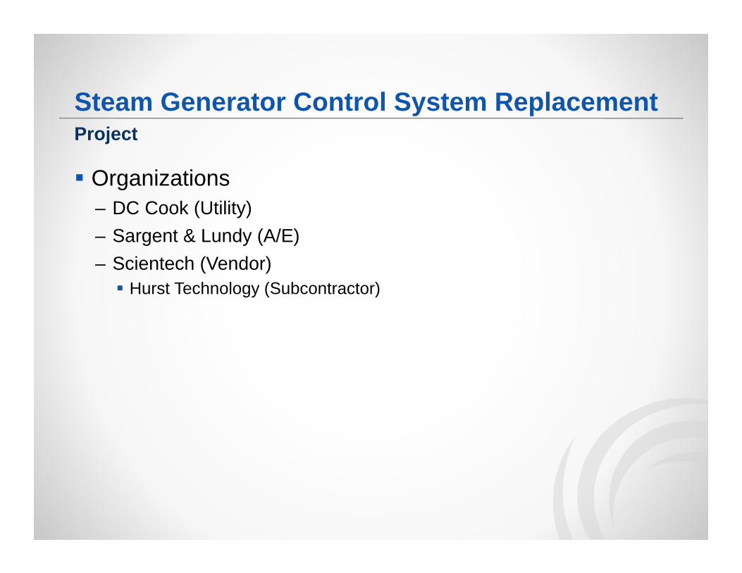
Steam Generator Control System Replacement
Organizations– DC Cook (Utility)– Sargent & Lundy (A/E)– Scientech (Vendor) Hurst Technology (Subcontractor)
Project
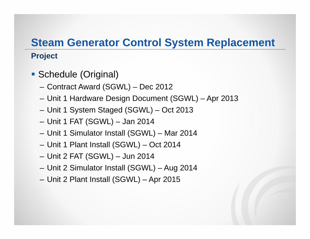
Steam Generator Control System Replacement
Schedule (Original)– Contract Award (SGWL) – Dec 2012– Unit 1 Hardware Design Document (SGWL) – Apr 2013– Unit 1 System Staged (SGWL) – Oct 2013– Unit 1 FAT (SGWL) – Jan 2014– Unit 1 Simulator Install (SGWL) – Mar 2014– Unit 1 Plant Install (SGWL) – Oct 2014– Unit 2 FAT (SGWL) – Jun 2014– Unit 2 Simulator Install (SGWL) – Aug 2014– Unit 2 Plant Install (SGWL) – Apr 2015
Project
Steam Generator Control System Replacement
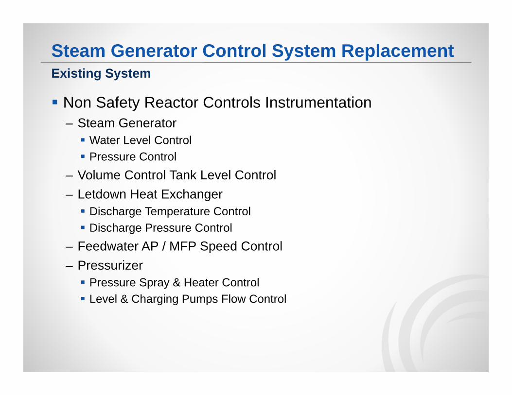
Non Safety Reactor Controls Instrumentation– Steam Generator Water Level Control Pressure Control
– Volume Control Tank Level Control– Letdown Heat Exchanger Discharge Temperature Control Discharge Pressure Control
– Feedwater AP / MFP Speed Control– Pressurizer Pressure Spray & Heater Control Level & Charging Pumps Flow Control
Existing System
RCI Control System Replacement
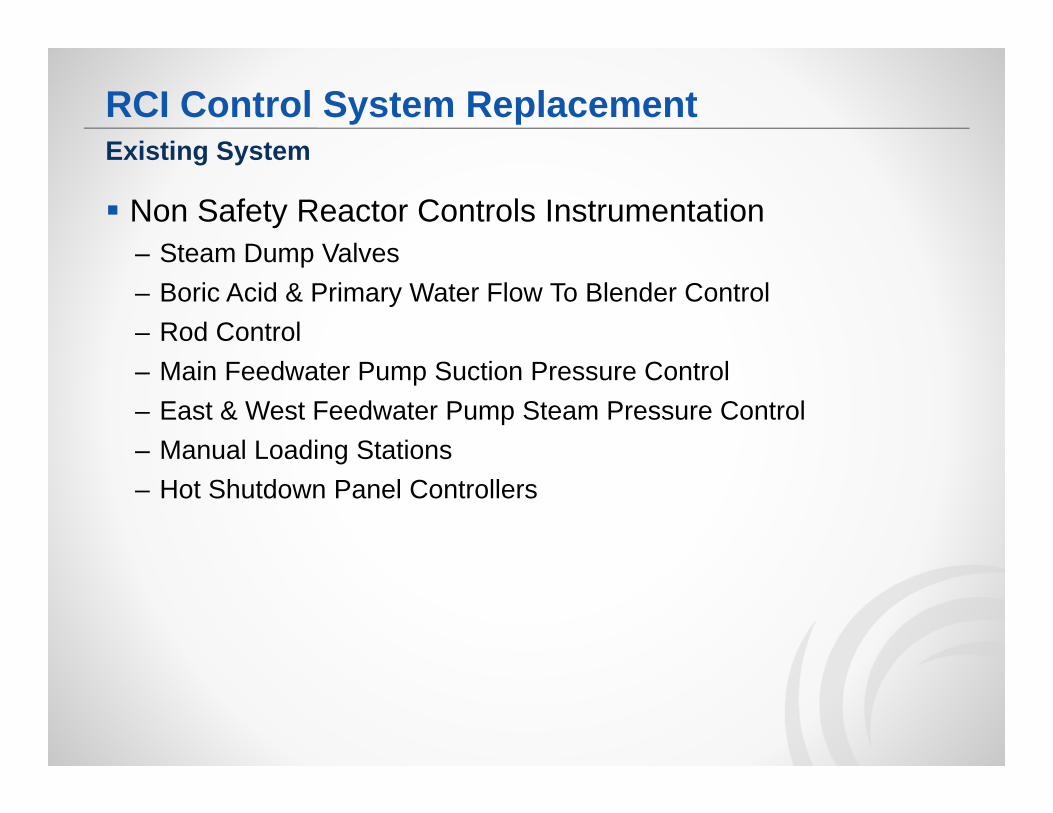
Non Safety Reactor Controls Instrumentation– Steam Dump Valves– Boric Acid & Primary Water Flow To Blender Control– Rod Control– Main Feedwater Pump Suction Pressure Control– East & West Feedwater Pump Steam Pressure Control– Manual Loading Stations– Hot Shutdown Panel Controllers
Existing System
RCI Control System Replacement
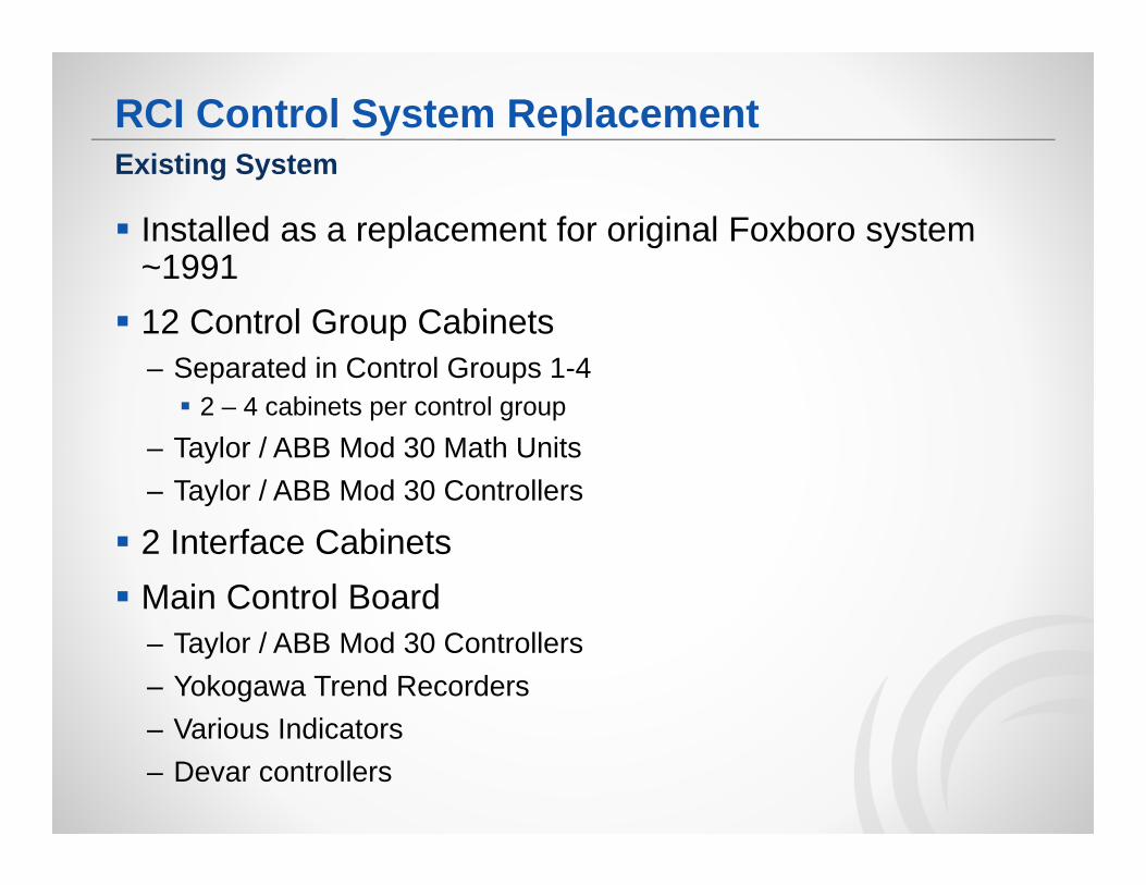
Installed as a replacement for original Foxboro system ~1991 12 Control Group Cabinets
– Separated in Control Groups 1-4 2 – 4 cabinets per control group
– Taylor / ABB Mod 30 Math Units– Taylor / ABB Mod 30 Controllers
2 Interface Cabinets Main Control Board
– Taylor / ABB Mod 30 Controllers– Yokogawa Trend Recorders– Various Indicators– Devar controllers
Existing System
RCI Control System Replacement
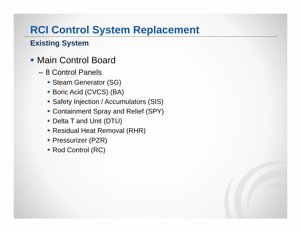
Main Control Board– 8 Control Panels Steam Generator (SG) Boric Acid (CVCS) (BA) Safety Injection / Accumulators (SIS) Containment Spray and Relief (SPY) Delta T and Unit (DTU) Residual Heat Removal (RHR) Pressurizer (PZR) Rod Control (RC)
Existing System
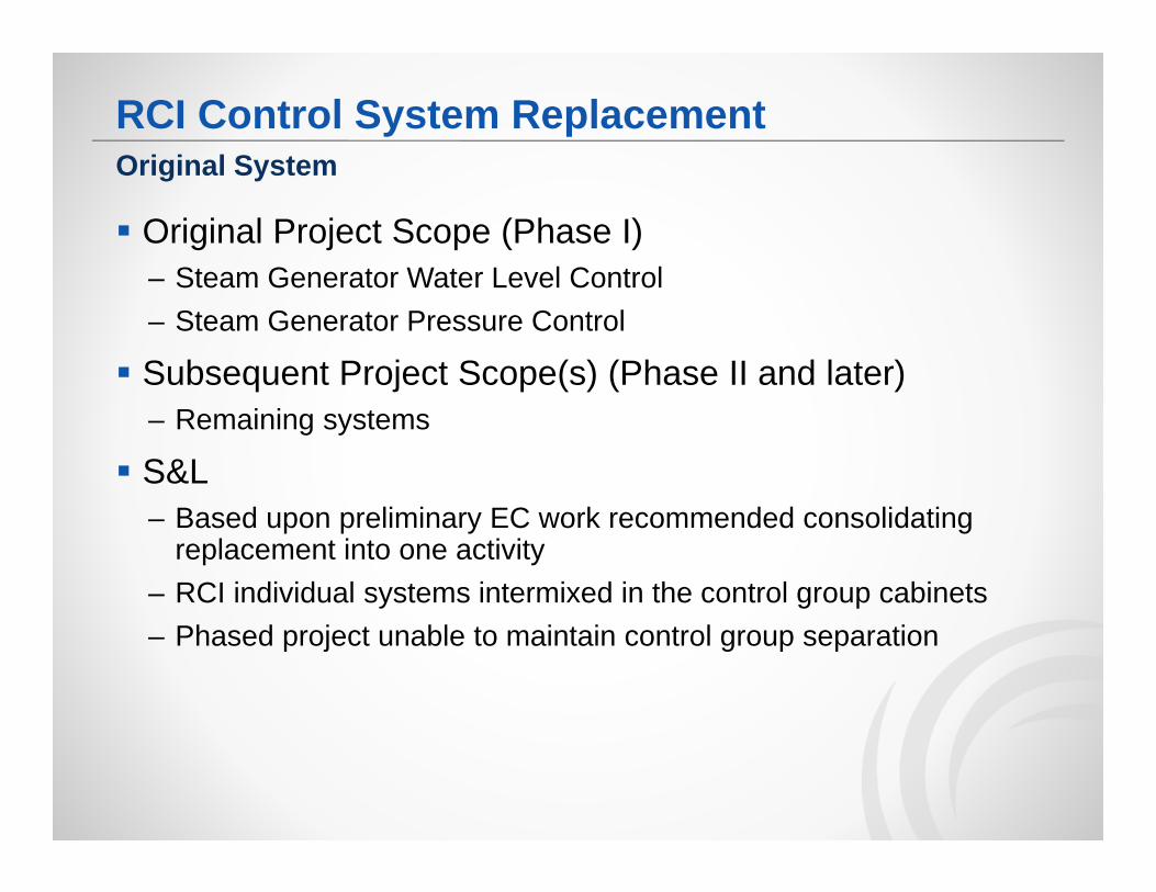
RCI Control System Replacement
Original Project Scope (Phase I)– Steam Generator Water Level Control– Steam Generator Pressure Control
Subsequent Project Scope(s) (Phase II and later)– Remaining systems
S&L– Based upon preliminary EC work recommended consolidating
replacement into one activity– RCI individual systems intermixed in the control group cabinets– Phased project unable to maintain control group separation
Original System
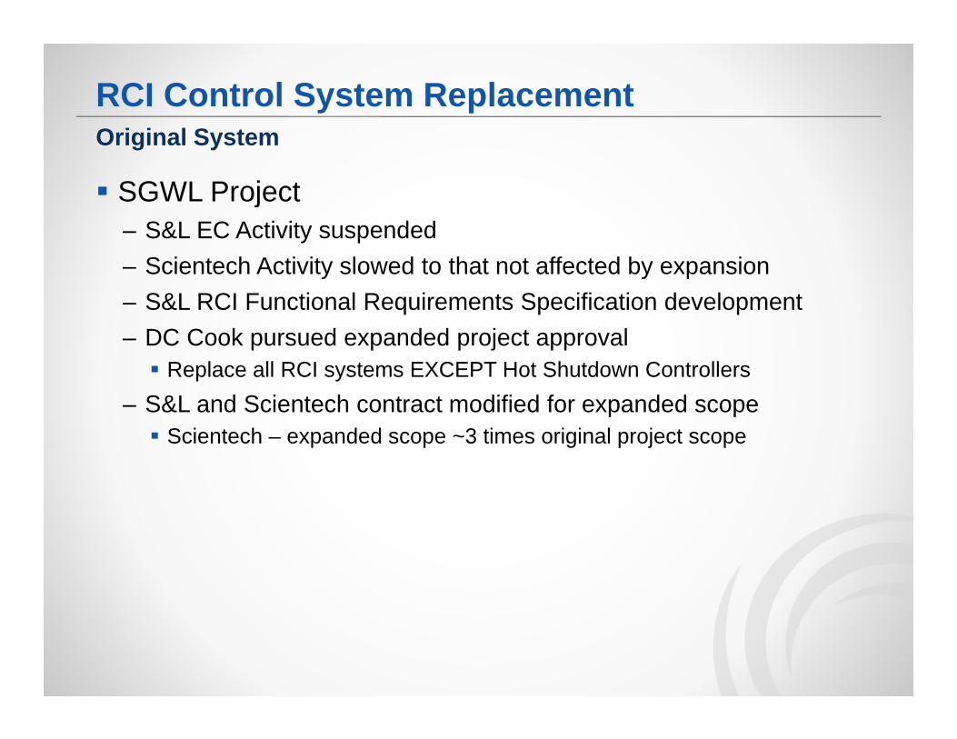
RCI Control System Replacement
SGWL Project– S&L EC Activity suspended– Scientech Activity slowed to that not affected by expansion– S&L RCI Functional Requirements Specification development– DC Cook pursued expanded project approval Replace all RCI systems EXCEPT Hot Shutdown Controllers
– S&L and Scientech contract modified for expanded scope Scientech – expanded scope ~3 times original project scope
Original System
Reactor Controls Instrumentation (RCI) Control System Replacement
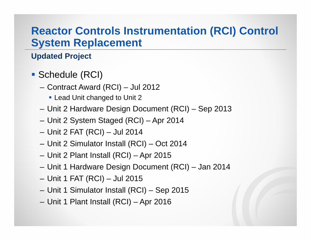
Schedule (RCI)– Contract Award (RCI) – Jul 2012 Lead Unit changed to Unit 2
– Unit 2 Hardware Design Document (RCI) – Sep 2013– Unit 2 System Staged (RCI) – Apr 2014– Unit 2 FAT (RCI) – Jul 2014– Unit 2 Simulator Install (RCI) – Oct 2014– Unit 2 Plant Install (RCI) – Apr 2015– Unit 1 Hardware Design Document (RCI) – Jan 2014– Unit 1 FAT (RCI) – Jul 2015– Unit 1 Simulator Install (RCI) – Sep 2015– Unit 1 Plant Install (RCI) – Apr 2016
Updated Project
RCI Control System Replacement
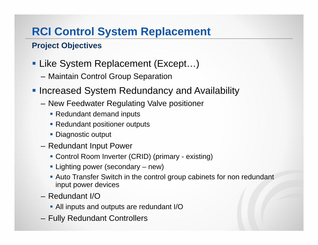
Like System Replacement (Except…)– Maintain Control Group Separation
Increased System Redundancy and Availability– New Feedwater Regulating Valve positioner Redundant demand inputs Redundant positioner outputs Diagnostic output
– Redundant Input Power Control Room Inverter (CRID) (primary - existing) Lighting power (secondary – new) Auto Transfer Switch in the control group cabinets for non redundant
input power devices– Redundant I/O All inputs and outputs are redundant I/O
– Fully Redundant Controllers
Project Objectives
RCI Control System Replacement
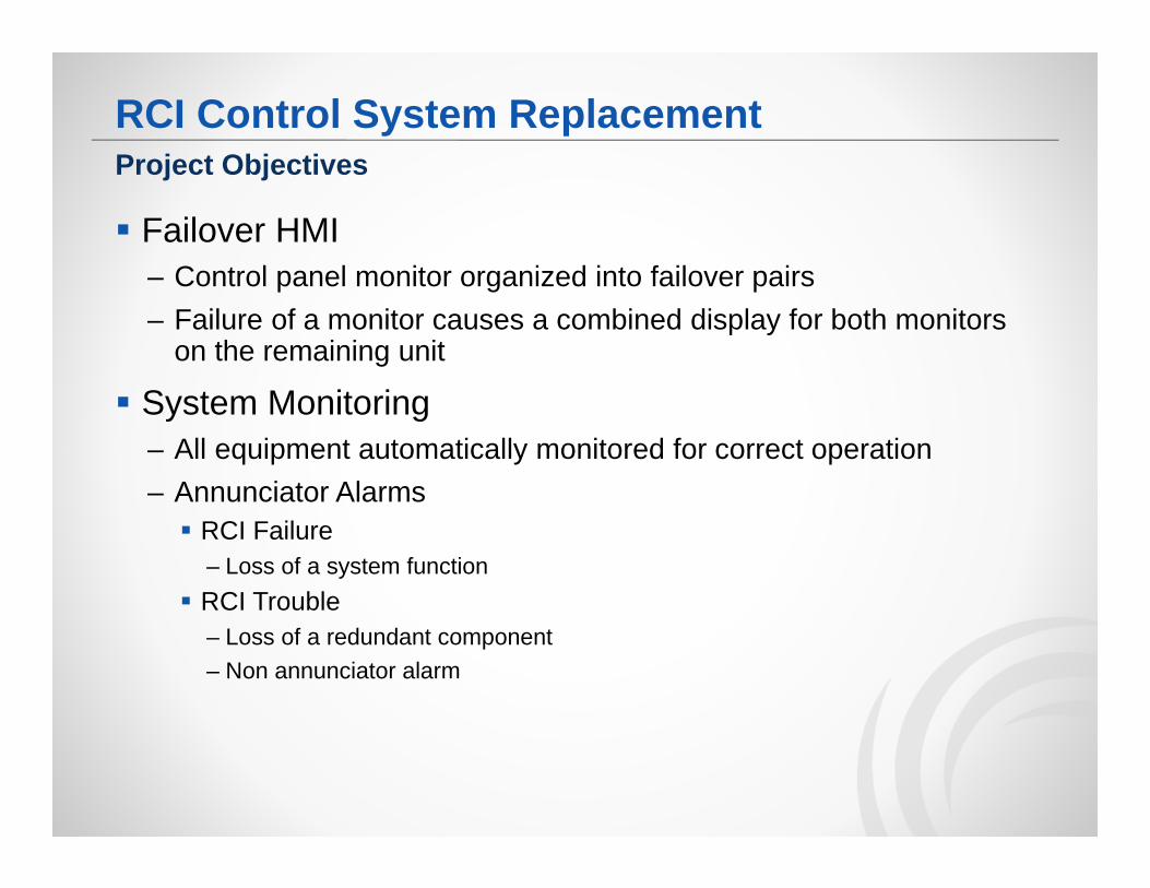
Failover HMI– Control panel monitor organized into failover pairs– Failure of a monitor causes a combined display for both monitors
on the remaining unit
System Monitoring– All equipment automatically monitored for correct operation– Annunciator Alarms RCI Failure
– Loss of a system function RCI Trouble
– Loss of a redundant component– Non annunciator alarm
Project Objectives
RCI Control System Replacement
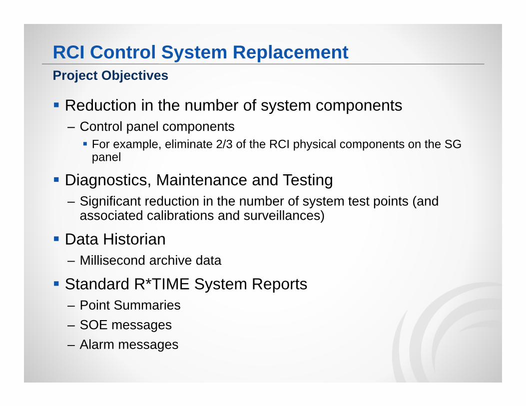
Reduction in the number of system components– Control panel components For example, eliminate 2/3 of the RCI physical components on the SG
panel
Diagnostics, Maintenance and Testing– Significant reduction in the number of system test points (and
associated calibrations and surveillances)
Data Historian– Millisecond archive data
Standard R*TIME System Reports– Point Summaries– SOE messages– Alarm messages
Project Objectives
RCI Control System Replacement
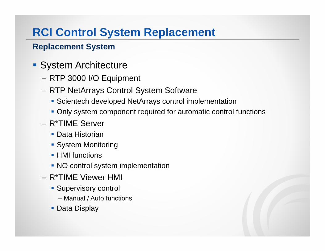
System Architecture– RTP 3000 I/O Equipment– RTP NetArrays Control System Software Scientech developed NetArrays control implementation Only system component required for automatic control functions
– R*TIME Server Data Historian System Monitoring HMI functions NO control system implementation
– R*TIME Viewer HMI Supervisory control
– Manual / Auto functions Data Display
Replacement System
RCI Control System Replacement
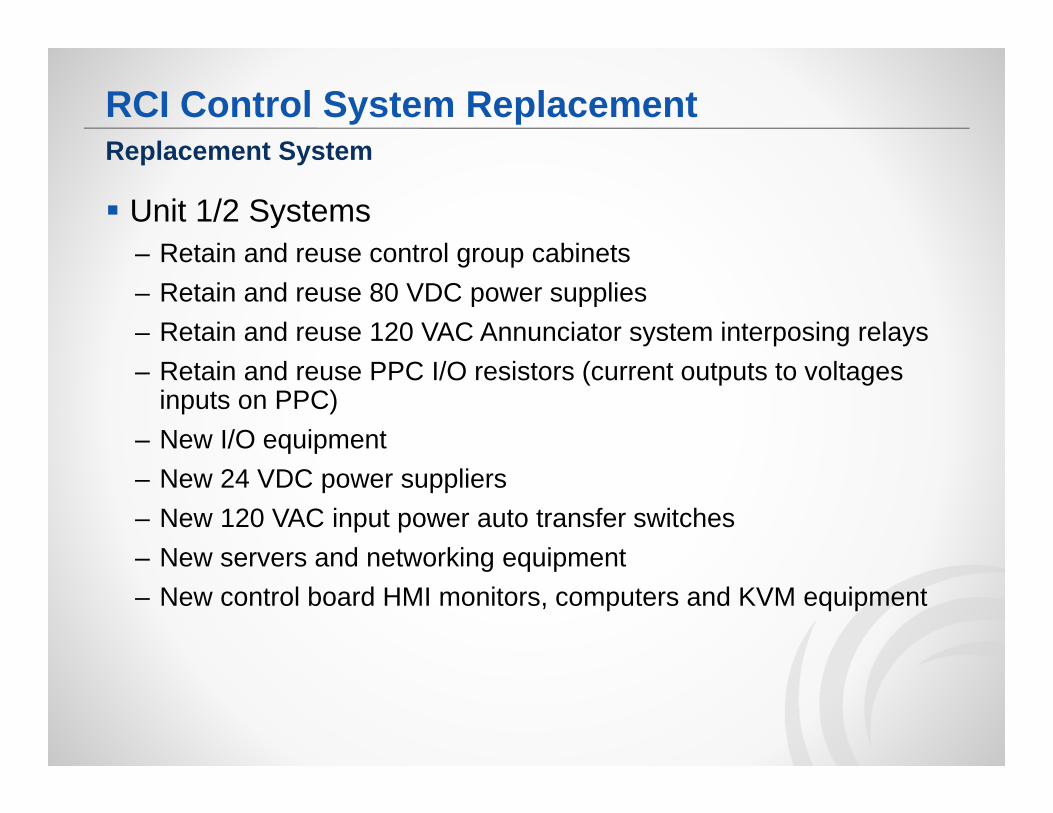
Unit 1/2 Systems– Retain and reuse control group cabinets– Retain and reuse 80 VDC power supplies– Retain and reuse 120 VAC Annunciator system interposing relays– Retain and reuse PPC I/O resistors (current outputs to voltages
inputs on PPC)– New I/O equipment– New 24 VDC power suppliers– New 120 VAC input power auto transfer switches– New servers and networking equipment– New control board HMI monitors, computers and KVM equipment
Replacement System
RCI Control System Replacement
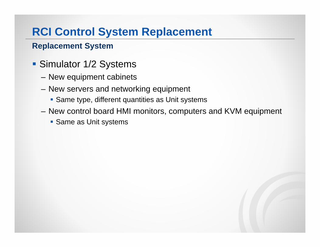
Simulator 1/2 Systems– New equipment cabinets– New servers and networking equipment Same type, different quantities as Unit systems
– New control board HMI monitors, computers and KVM equipment Same as Unit systems
Replacement System
RCI Control System Replacement
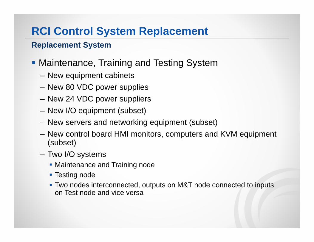
Maintenance, Training and Testing System– New equipment cabinets– New 80 VDC power supplies– New 24 VDC power suppliers– New I/O equipment (subset)– New servers and networking equipment (subset)– New control board HMI monitors, computers and KVM equipment
(subset)– Two I/O systems Maintenance and Training node Testing node Two nodes interconnected, outputs on M&T node connected to inputs
on Test node and vice versa
Replacement System
RCI Control System Replacement
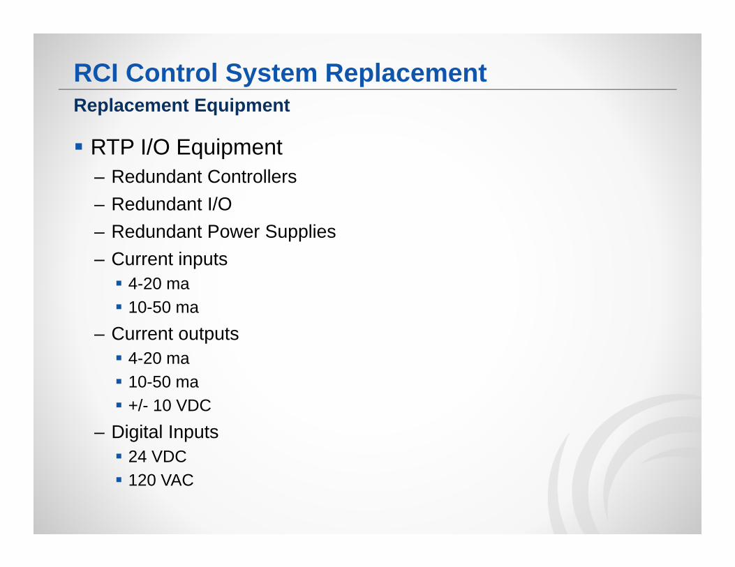
RTP I/O Equipment– Redundant Controllers– Redundant I/O – Redundant Power Supplies– Current inputs 4-20 ma 10-50 ma
– Current outputs 4-20 ma 10-50 ma +/- 10 VDC
– Digital Inputs 24 VDC 120 VAC
Replacement Equipment
RCI Control System Replacement
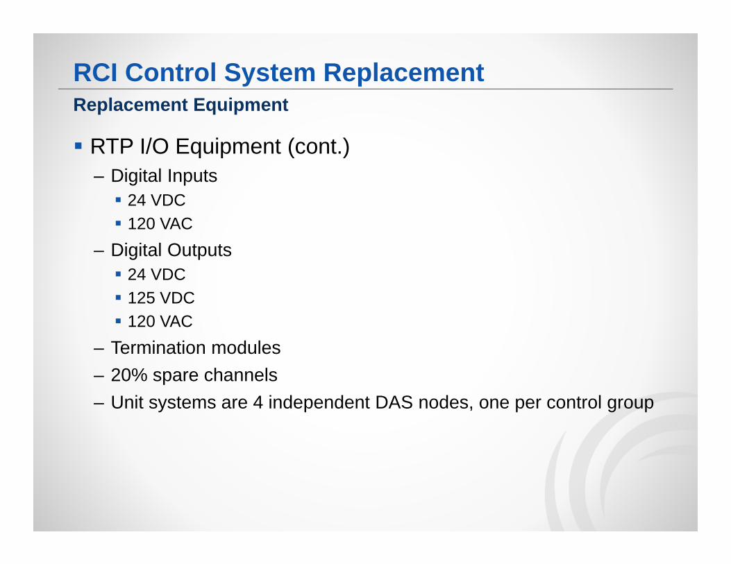
RTP I/O Equipment (cont.)– Digital Inputs 24 VDC 120 VAC
– Digital Outputs 24 VDC 125 VDC 120 VAC
– Termination modules– 20% spare channels– Unit systems are 4 independent DAS nodes, one per control group
Replacement Equipment
RCI Control System Replacement
Servers– Installed in the control group cabinets– Redundant servers– Environmental requirement is 104 °F Unable to use main stream equipment (Dell, HP, IBM, etc.) Built to order servers from Advantech
– Unit systems are 4 independent systems, one per control group– Simulator systems are 1 system per simulator
Replacement Equipment
RCI Control System Replacement
Networks– Network switches installed in the control group cabinets– Three separate networks I/O network HMI network Display network
– Dual Redundant switches (HMI / DAS network)– Triple Redundant switches (I/O network)– Servers connected directly to I/O network via separate VLAN
configuration on I/O network switches
Replacement Equipment
RCI Control System Replacement
Networks– HMI Network separated into A train and B train network switches A train and B train network switch per control group A train switches interconnected B train switches interconnected A and B train switches NOT interconnected
– All network cabling new CAT-6 Ethernet
Replacement Equipment
RCI Control System Replacement
HMI Equipment– Cyber Research panel mounted monitors Touchscreen Through panel mounting 6”, 8” 10” and 21” sizes Landscape and portrait orientation
Replacement Equipment
RCI Control System Replacement
Display Creation– 30 unique displays at 4 different video resolutions and 2 different
video orientations– Normal displays and failover displays
Database Creation– Because the original system was not a computer based system, it
has to be created from scratch
Temporary Control Group Cabinets– Support staging of the replacement system in Idaho Falls
Development Process
RCI Control System Replacement
Equipment Testing– Seismic II/I for control panel monitors and KVM extenders– EMI/RFI for control panel monitors and KVM extenders– EMI/RFI for Control Group Cabinet equipment Representative cabinet configuration (12 different cabinet
configurations, will use a “maximum” cabinet configuration)
System Testing– Simulator Development Test Unit 2 Simulator system delivered early Interfaced to Simulator inline with existing system Full suite of “operational” and “upset” test conditions Comparison of replacement system to existing system
Development Process
RCI Control System Replacement
System Testing– FAT test Each of I/O input and output verified Each control system function verified Each HMI display verified
– Data display– Failover– Operator supervisory control actions
System redundancy verified– Servers– Networks– I/O equipment– System monitoring
Development Process
RCI Control System Replacement
System Testing– SAT test Restage replacement system at DC Cook Near repeat of the FAT test
Development Process
RCI Control System Replacement
Scientech Factory Staging– 125 VDC power Reuse variable power supplies purchased to support ANN system
– 80 VDC control loop power supplies Purchase units for use in Idaho Falls and deliver to DC Cook as spares
– 120 VAC interposing relays TBD
Implementation Issues
RCI Control System Replacement
I/O Equipment– New I/O cards required 10-50 ma analog current input
– new termination module 4-20 ma analog current output
– 600 Ohm load 10-50 ma analog current output
– 600 Ohm load
Replacement System Challenges
RCI Control System Replacement
HMI Equipment– Control panel mounting of monitors– No space for HMI computers in or behind control panel Computer mounted in the control group cabinets KVM extenders connect monitor and computer
– Rack mounted units in control group cabinets– Mini adapter (no power required) on monitor in control panel
Replacement System Challenges
RCI Control System ReplacementReplacement System Challenges
RCI Control System Replacement
Environmental Requirements– 104 °F requirement– No control group cabinet ventilation– New model of server computers, HMI computers and engineering
workstation Advantech Industrial Computers
Replacement System Challenges
RCI Control System Replacement
Control Algorithm– 4 separate NetArrays project implementations (Unit) Common components (Steam Generator) Different components (Other systems)
– Use same control implementation in the Simulator No I/O equipment or controllers Same control algorithm
– Build single NetArrays project by merging the 4 separate unit projects and remove controller and I/O equipment specifics
Limitation on single RTP Simulator– Multiple instances of RTP Simulator not supported on a single computer
Limitation on RTP Simulator interface– RTP Simulator accepts connections from local computer only– Utilize DCMNODE for R*TIME Interface– Develop proxy agent for Simulator interface
Replacement System Challenges
RCI Control System Replacement
System Staging– Temporary cabinets– Temporary 80 VDC power supplies– Temporary 120 VAC interposing relays– New Feedwater Regulating Valve positioner– Mounting 30 control panel monitors
Replacement System Challenges
RCI Control System Replacement
30 Control Panel Monitors– New control panel cutouts– Clearance with front side control board controls– Clearance with back side control board supports– No redundant AC power available– No location available for computers
Replacement System Challenges
RCI Control System Replacement
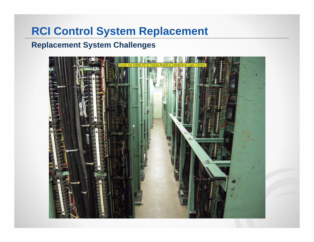
Control Group Cabinets– Cabinets have to be retained to retain field termination wiring– Test panels need redesigned / replaced
Replacement System Challenges
RCI Control System Replacement
Project– Change from a pure I&C system to a system with IT components– Cyber Security requirements still not defined– Unit 1 and Unit 2 systems are similar but not identical– Aggressive Schedule– Utilize lessons learned from PPC and ANN projects
Replacement System Challenges
RCI Control System Replacement
Installation– SAT Test Restage complete system in temporary location for testing prior to
physical installation– Outage based Significant concern on the amount of work required to be performed
– Air Conditioning Back Control Panel
– Some control group cabinets receive minimal room air conditioning cause higher cabinet temperatures
Replacement System Challenges
RCI Control System Replacement
Questions?