Embed Size (px)
Citation preview

Oleśnica 2016-02-18
1/45 DTR-4-FUN-AP1-EN-V1
“4-FUN” PLC Controller
Application: Type 1
Fan-Coil Unit
Chilled beams
Lighting
Floor heating
Blinds
Technical documentation
EL-Piast Sp. z o.o.
ul. Marszałka Józefa Piłsudskiego 74
50-020 Wrocław
tel. +48 (71) 343-37-19
www.el-piast.com

Oleśnica 2016-02-18
2/45 DTR-4-FUN-AP1-EN-V1
Table of contents
1. General information ............................................................................................................................................. 3
2. Description of the HMI Advanced control panel items ........................................................................... 7
3. Description of 4-FUN controller elements ................................................................................................... 8
4. The Fan-Coil Unit .................................................................................................................................................. 9
4.1 Description of function .......................................................................................................... 9
4.2 Graphic screen .................................................................................................................... 10
4.3 Text screen .......................................................................................................................... 11
4.4 Alarms .................................................................................................................................. 15
5. Chilled beam ......................................................................................................................................................... 17
5.1 Description of functions ...................................................................................................... 17
5.2 Text screen .......................................................................................................................... 17
5.3 Alarms .................................................................................................................................. 19
6. Floor heating ......................................................................................................................................................... 19
6.1 Description of functions ...................................................................................................... 19
6.2 Text screen .......................................................................................................................... 20
6.3 Alarms .................................................................................................................................. 22
7. Lighting ................................................................................................................................................................... 22
7.1 Description of operation...................................................................................................... 22
7.2 Text screen .......................................................................................................................... 23
8. Blinds ....................................................................................................................................................................... 24
8.1 Description of functions ...................................................................................................... 24
8.2 Text screen .......................................................................................................................... 24
9. Startup .................................................................................................................................................................... 25
9.1 4-FUN controller as a MASTER ........................................................................................... 26
9.2 4-FUN controller as a SLAVE .............................................................................................. 29
10. Modbus RTU Communication ....................................................................................................................... 31
11. Bacnet MS-TP communication with the BMS system ......................................................................... 39
12. Website control ................................................................................................................................................. 40
13. Instructions, advice, recommendations .................................................................................................. 45

Oleśnica 2016-02-18
3/45 DTR-4-FUN-AP1-EN-V1
1. General information
The “4-Fun” controller is designed to control the room comfort trough:
- Controlling a 2- or 4-pipe FCU,
- Controlling a chilled beam,
- Controlling floor heating system,
- Controlling lighting,
- Controlling the blinds.
Default factory settings of the “4 Fun” controller are for operation with a 4-pipe FCU
equipped with a 3 speed drive motor (PK1…PK3 or Aout3), heating valve (PK4 or Aout1),
cooling valve (PK5 or Aout2), and the temperature adjustment is facilitated in relation to
the temperature sensor that is built in the HMI controller, as connected to the HMI CON
connector.
The “4-Fun” controller is freely configurable and the configuration of additional functions may be
performed with use of the HMI controller, through the “Service menu/In- and out- functions”.
The “4-Fun” controller may be used as the main, “Master” controller or an auxiliary, additional “Slave”
controller extending the FCU group.
The “4-Fun” controller in the “Master” configuration is the main controller in which all additional
functions can be activated (the sole limit is the number of in/out lines).
The “4-Fun” controller in the “Slave” mode is just an extension of the digital and analogue connectors,
with states that are identical to the states of the digital and analogue outputs of the “Master”
controller.
Each of the “4-Fun” controllers comes equipped with a RS485-1 connector for connection of
primary devices, and a RS485-2 connector to connect the controlled devices.
When configured as a “Master” the RS485-1 connector can be used to connect a BMS system:
Modbus RS485 or BacNet MS-TP (configured with use of HMI).
When configured as a “Slave” the RS485-1 connector is used to connect with the RS485-2
connector of the “Master” device.

Oleśnica 2016-02-18
4/45 DTR-4-FUN-AP1-EN-V1
The controller is equipped with 5 digital line-ins marked (D1…D5), connecting an input signal of
24VAC/DC switches the input on. Each of those lines can have one of the functions listed below. The
configuration is to be performed with use of HMI controller – “Service menu/Input functions”.
Function Description
Inactive The line is not used
Window
If a 24VAC/DC signal is not given to the digital line-in this means a
window is open and the fan and the FCU and chilled beam valves
halted.
Remote stop If a 24VAC/DC signal is not given to the digital line-in the work mode of
the fan and FCU valves is locked
ECO 24VAC/DC signal given to the digital line-in switches the ECO mode on,
lowering the preset work temperature for FCU
Vent 24VAC/DC signal given to the digital line-in switches the temporary
ventilation (fan speed and time to be set in settings menu) for FCU
Filter
24VAC/DC signal given to the digital line-in displays the FCU filter full
alarm (this alarm can be displayed after exceeding the maximum
operation time for fan)
Compress If a 24VAC/DC signal is not given to the digital line-in within 30 seconds
after the fan starts it displays the error of lack of FCU compression
Light Single 24VAC/DC signal given to the digital line-in switches the state of
the line-out controlling the lighting
Blind Single 24VAC/DC signal given to the digital line-in causes a 1s pulse to
be passed by the line out to the blind controller
Dew If a 24VAC/DC signal is not given to the digital line-in it means that the
chilled beam exceeded the dew point

Oleśnica 2016-02-18
5/45 DTR-4-FUN-AP1-EN-V1
The controller is equipped with five relay line outs (PK1…PK5) and two on/off 24VDC digital outputs
marked as PWM1, PWM2. These are switched as per controller algorithm. Each of those line outs may
have one of the functions listed below. The configuration is to be performed with use of HMI controller
– “Service menu/Output functions”
Function Description
Inactive No function
Speed 1 FCU fan – speed 1
Speed 2 FCU fan – speed 2
Speed 3 FCU fan – speed 3
Heating FCU on/off valve - heating
Cooling FCU on/off valve - cooling
Heat/Cool FCU valve - heating or cooling
Cool.Unt Chiller (active heat/cool or cooling valve of the FCU)
Heat node Heat node (active heat/cool or heating valve of the FCU)
Fan FCU Fan operating
Lighting Lighting
Floor heating Floor heating
Blinds Blinds controller
Univ.Out Universal output
Chill.beam Valve of chilled beam
Alarm General malfunction

Oleśnica 2016-02-18
6/45 DTR-4-FUN-AP1-EN-V1
The controller is equipped with five input lines for PT1000 resistance sensors marked (P1…P5),
configuration of functions of those lines is to be performed with “Main menu/settings”. The following
functions of sensor line-ins are available for choice:
- main sensor of the FCU
- main sensor of the chilled beam,
- main sensor of the floor heating
- temperature sensor of the feed or return water of the FCU
- temperature sensor of the feed or return water of the chilled beam,
- temperature sensor of the feed or return water of the floor heating.
The controller is equipped with one analog 0-10VDC input marked Ain1, that as of now has no
functions attached.
The controller is equipped with four analog 0-10VDC outputs marked (Aout1…Aout4). Control of the
output as per the algorithm of the controller.
Output Description
Aout1 Heating valve of the FCU (active if at least one of the digital outputs is
used for control purposes connected with FCU)
Aout2 Cooling valve of the FCU (active if at least one of the digital outputs is
used for control purposes connected with FCU)
Aout3 FCU fan control (active if at least one of the digital outputs is used for
control purposes connected with FCU)
Aout4 Lighting power control (active if at least one of the digital outputs is
used for control purposes connected with lighting)

Oleśnica 2016-02-18
7/45 DTR-4-FUN-AP1-EN-V1
2. Description of the HMI Advanced control panel items
Main menu icons:
Mode of operation setting: “Stop”, “1st speed”,
“2nd speed”, “3rd speed”, “Auto”, “Calendar”
Set temperature
Main temperature sensor readout
Current heater setting
Current cooling setting
FCU fan setting
After longer (approx. 3 seconds) simultaneous pressing of the “ “ and “ “ keys the display will switch
to the display settings menu.
Description of parameters:
Minimal brightness – minimum backlight brightness
Maximal brightness – maximum backlight brightness
Activity time – time after the display is dimmed
After activity time – what to do after activity time (noting; in case of an alarm – the alarm menu will
appear; in case of alarm to the alarm menu, in other cases – to first item of main menu)
T sensor offset – adjustment of the temperature sensor readout in the HMI controller
Menu skin – the choice of “skin” of the HMI menu
Communication settings – settings menu for HMI controller and RS485 Master connector of the ELP
controller
Exit the menu by pressing the C key.
Menu navigation, change of
parameters
Hold for 3 seconds to access the text
menu
Press once to edit the “Mode of operation”, “Temperature setting”
parameters and confirm them.
Hold for 3 seconds to access the alarm
menu
Press once to go one level back in the menu

Oleśnica 2016-02-18
8/45 DTR-4-FUN-AP1-EN-V1
3. Description of 4-FUN controller elements
A 20VA transformer is built in the 4-FUN controller.
Power consumption of the 4-FUN controller together with control module is 10VA.
In case of use of actuators of the 24VAC powered valves with a power consumption level hogher than 10VA
use an external power source for the valves and connect the GND of the power source with the GND of the
4-fun connector.
20VA, 24VAC
Transformer
PWM1,PWM2
24VDC, 100mA
digital outputs
HMI CON:
connector controller
power and
communication
0.63Amp transformer
fuse
F2…F4 fuses of the
230VAC lines L1…L4
230VAC Power
supply
230VAC Line
outs with F2…F4
fuses
PK1…PK5
Potential-free
relay line-outs
Max 5 (2) A
DI1…5 digital
imputs reacting
to 24V AC/DC
signal
0-10VDC
Aout1…Aout4
Analog
outputs
PT1000
temperature
sensor
connectors
RS485-2 bus for
slave devices
(Modbus)
RS485-1 bus for
slave devices
(Modbus or
BacNet)
E
T
H
Ethernet controller
(optional)

Oleśnica 2016-02-18
9/45 DTR-4-FUN-AP1-EN-V1
4. The Fan-Coil Unit
4.1 Description of function
Function Condition for
work Description of operation
Tem
pera
ture
and fan s
peed a
dju
stm
ent
1st speed operation
- set 1st speed mode
- fan starts working with 1st speed (constant operation)
- comparison of current temperature measured with main sensor with the value set on controller or panel and adjustment of heat/cold exchangers
2nd speed
operation
- set 2nd speed
mode
- fan starts working with 2nd speed (constant
operation) - comparison of current temperature measured with main sensor with the value set on controller
or panel and adjustment of heat/cold exchangers
3rd speed operation
- set 3rd speed mode
- fan starts working with 3rd speed (constant operation)
- comparison of current temperature measured with main sensor with the value set on controller or panel and adjustment of heat/cold exchangers
Auto - set Auto mode
- starting the fan with a speed adjusted to the
increased or lowered demand for heating/cooling (automated start and operation till the set temperature value is reached)
- comparison of current temperature measured with main sensor with the value set on controller
or panel and adjustment of heat/cold exchangers
Calendar - set calendar mode
- FCU works with the chosen mode of operation as per timer settings of the controller’s calendar
Additional functions: - window switch, stopping the system, - remote stop through digital or BMS input,
- ventilating function through digital or BMS input (for a set period of time the fan works with chosen speed, without the valves working, stop only after the set time, blocking by window
opening, or through digital or BMS input signal), - Eco function through digital or BMS input (lowering the temperature setting), - testing the filter through measurement of filter operation time or with use of pressure
switch connected to the digital input, - testing fan compression with use of pressure switch connected to the digital input,
- measurement of feed water temperature, - measurement of returning water temperature,
- universal digital output that can be switched with BMS variable or together with the FCU.

Oleśnica 2016-02-18
10/45 DTR-4-FUN-AP1-EN-V1
4.2 Graphic screen
Graphic screen (displayed as start screed after power on, active if at least one of the outputs is used to
control a valve or fan of the FCU)
Mode of operation setting: “Stop”, “1st speed”,
“2nd speed”, “3rd speed”, “Auto”, “Calendar”
Set temperature
Main temperature sensor readout
Current heater setting
Current cooling setting
FCU fan setting
In case of active ventilation mode, instead of the “Mode of operation” icon an inscription reading
“VENTILATING” is displayed.
In case of active lock of FCU instead of the “Mode of operation” icon an inscription reading
“SYSTEM HALTED” is displayed, symbolizing an open window, lack of acceptance from BMS or digital
input. In order to investigate the reason behind the FCU lock enter the text menu by pressing and
holding the “OK” button and read the state of the respective functions.

Oleśnica 2016-02-18
11/45 DTR-4-FUN-AP1-EN-V1
4.3 Text screen
Main menu/FCU:
Name Default
value Description
Mode of
operation Stop
Stop – system halted, fan does not work
1st speed – system works, the fan operates continuously on 1st
gear and so does the heater and/or cooler, depending on the
demand and the “Temperature mode” setting.
2nd speed – system works, the fan operates continuously on 2nd
gear and so does the heater and/or cooler, depending on the
demand and the “Temperature mode” setting.
3rd speed – system works, the fan operates continuously on 3rd
gear and so does the heater and/or cooler, depending on the
demand and the “Temperature mode” setting.
Auto – system works, the fan operates with a speed that
depends on the current heating/cooling demand and stops after
the set temperature is reached, heater and/or cooler operate,
depending on the demand and the “Temperature mode” setting
Calendar – operations according to time schedule, as set in the
controller’s calendar
Operation - Readout of the current fan speed selection
Temperature
mode
Heating/
cooling
Ventilation – only the fan operates, without temperature
adjustment
Heating – the heater may operate when the system is working
Cooling – the cooler may operate when the system is working
Heating/cooling – the heater/cooler may operate when the
system is working
Temperature
setting 22°C Allows for change of temperature setting
Set
temperature …°C
Readout of the currently set temperature (can be different from
the one set due to Eco function and connected lowering of
setting)
Main
temperature - Main temperature sensor readout
Supply water
temperature - Readout of the temperature sensor at the FCU water inlet.

Oleśnica 2016-02-18
12/45 DTR-4-FUN-AP1-EN-V1
Return water
temperature - Readout of the temperature sensor at the FCU water outlet.
Heating ...% Readout of the heater valve setting
Cooling ...% Readout of the cooler valve setting
Eco - Readout informing about active/inactive economic mode, that is
the lowering of the temperature setting
Ventilation -
Readout informing about active/inactive ventilation mode, that is
the set speed of fan for set time (without actuating heating and
cooling valves)
Window - Readout informing about open/closed window (the FCU will only
work with the window closed)
dig.in. stop - Readout informing about engaged/disengaged digital input (the
FCU will only work with engaged digital input)
BMS stop -
Readout informing about the Modbus or BacNET supplied/non-
supplied start signal from the BMS system (the FCU will only
work after such a signal is supplied)
Universal
output - Readout informing about the condition of the universal output
Calendar - Time and date settings for the real time clock of the controller
and possibility of changing the timer program settings

Oleśnica 2016-02-18
13/45 DTR-4-FUN-AP1-EN-V1
Main menu / Settings / FCU:
Access to those settings is password-protected (default password is: 1111).
Group Name Default
value Description
Sensors
Main
sensor HMI (CON)
HMI (CON) – temperature adjustment according to the
HMI sensor connected through HMI CON connector
HMI (RS485 Master) – temperature adjustment
according to the HMI sensor connected through RS485
Master connector
PT1 – temperature adjustment according to a sensor
connected to the PT1 connector
PT2 – temperature adjustment according to a sensor
connected to the PT2 connector
PT3 – temperature adjustment according to a sensor
connected to the PT3 connector
PT1/2 – temperature adjustment according to the
average measurement of sensors connected to the PT1
and PT2 connectors
PT1/2/3 – temperature adjustment according to the
average measurement of sensors connected to the PT1,
PT2 and PT3 connectors
Supply
water
temp.
Inactive Activation or deactivation of temperature measurement
at the water inlet on selected sensor connector PT1…PT5
Return
water
temp.
Inactive
Activation or deactivation of temperature measurement
at the water outlet on selected sensor connector
PT1…PT5
Temperature
adjustment /
Fan
Diff1 1°C Hysteresis of the main and set temperature above which
the system will work with 1st speed (Auto mode only).
Diff2 1°C
Sum of Dif1+Dif2 is the hysteresis of the main and set
temperature above which the system will work with 2nd
speed (Auto mode only).
Diff3 1°C
Sum of Dif2+Dif3 is the hysteresis of the main and set
temperature above which the system will work with 3rd
speed (Auto mode only).
Temperature - 1 Kp – amplification of temperature adjuster

Oleśnica 2016-02-18
14/45 DTR-4-FUN-AP1-EN-V1
adjustment /
Valves 60s
Ti – constant of integration of temperature adjuster
In case of use of on/off valves, you can lower the “Ti”
parameter to speed up valve reaction time
Sensitivity
threshold 10%
The movement from the zero point at the temperature
controller above which the opening of heating/cooling
valves takes place
Eco - 2°C The value the temperature setting is lowered in ECO
mode
Ventilating - 1 min Time – time of ventilation
3rd speed Speed – fan speed setting for ventilation
Filter
Time Inactive Inactive – filter operation time measurement inactive
Active – filter operation time measurement active
Counter … hour Number of work hours of the filter
Limit 3600 hour Number of filter work hours after which the dirty filter
alarm will be displayed
Reset - Reset the work hour counter of the filter
Fan
0-10VDC - -
0-10VDC settings for the respective fan speeds, the
value is given to the analog Aout4 output
Main menu / Settings / Universal output:
Access to those settings is password-protected (default password is: 1111).
Group Name Preset
value Description
Universal
output - Start KLM
Stop – output always off
Start – output always on
Start BMS – output off/on with BMS system
variable
Start KLM – output off/on together with FCU fan
Start BMS&KLM – output off/on together with
simultaneous FCU fan and BMS variable

Oleśnica 2016-02-18
15/45 DTR-4-FUN-AP1-EN-V1
4.4 Alarms
Alarms are displayed by flashing display, an icon of alarm on the main screen of controller
and with use of red LED on the controller.
Alarm information can be read from the “Alarm Menu”. The alarm menu is accessed
automatically after 30 seconds of the alarm, or through pressing the “C” key for approx. 3 seconds.
List of alarms
ALARMS Type of
alarm System reaction, procedure
PT1000 sensor inputs
A_TmainFC Vanishing
Testing the correct operations of FCU main temperature sensor:
Normal state – no alarm, sensor connected
Alarm state – alarm, the sensor is disconnected or damaged
Reaction to alarm: the system works without temperature
adjustment, check the sensor and its connection to the
controller and the configuration of choice of main sensor, find
the reason for error, after the cause was remedied the system
will return to operation automatically.
A_SupFilter Vanishing
Testing filter condition with use of pressure switch:
Normal state – the filter in acceptable condition, pressure
difference prior and after the filter is below the one set on
pressure switch, no 24VAC signal on the digital input
Alarm state – inacceptable contamination, pressure difference
prior and after the filter is above the one set on pressure
switch, a 24VAC signal on the digital input
Reaction to alarm: the system works on, clogged filter alarm
displayed, in case of such an alarm replace the filter
immediately, operation with a clogged filter lowers the fan
efficiency and may cause it’s mechanical tearing, which may
lead to damage of heat/cold exchangers that will be culpable to
the customer
Testing filter condition with use of filter operation time:
Normal state – the filter in acceptable condition, time limit is
not exceeded
Alarm state – inacceptable contamination, time limit for system
operation exceeded
Reaction to alarm: the system works on, clogged filter alarm
displayed, in case of such an alarm replace the filter
immediately, operation with a clogged filter lowers the fan
efficiency and may cause it’s mechanical tearing, which may
lead to damage of heat/cold exchangers that will be culpable to
the customer
A_PresVent Vanishing
Checking fan operations with use of pressure switch:
Normal state – after 30 seconds after system start the fan

Oleśnica 2016-02-18
16/45 DTR-4-FUN-AP1-EN-V1
pressure is checked, the pressure difference prior and after the
fan should be higher than that set on pressure switch, there is a
24VAC signal on the digital input
Alarm conditions - after 30 seconds after system start the fan
pressure is not present, the pressure difference prior and after
the fan is lower than that set on pressure switch, there is no
24VAC signal on the digital input
Reaction to alarm: information about alarm, check the fan and
the reason behind lack of compression.
A_ComSlave
1..16 Vanishing
Testing the proper RS485 communication of Master contro ller
with Slave controllers:
Normal state – communication inactive or correct
Alarm state – communication active and incorrect
Reaction to alarm: information about alarm, the MASTER and
the SLAVE controllers work correctly, check the RS485
connections between Master and Slave controllers, check if the
Slave controller addresses are not repeated within one group.
A_In_Emul Vanishing
Input emulation:
Normal condition – no alarm, none of the inputs is in emulated
mode
Alarm condition – at least one of the digital, analog or PT1000
inputs is in emulation mode
Reaction to alarm: the controller will not react to physical
changes in the emulated input, the system works with values
set in emulator of the service menu
A_OutForce Vanishing
Output forcing:
Normal condition – no alarm, none of the outputs is in forced
mode
Alarm condition – at least one of the digital or analog outputs is
in forced mode
Reaction to alarm: the system works, still the forced output will
not react to the control algorithm and is set with “force output”
menu in the service menu

Oleśnica 2016-02-18
17/45 DTR-4-FUN-AP1-EN-V1
5. Chilled beam
5.1 Description of functions
Function Condition for work Description of operation
Tem
pera
ture
adju
stm
ent
Cooling
- set the Start mode
- dew sensor does not
detect dew (if active)
- window closed (if
active)
- compares current temperature measured
with use of main sensor with the value set in
the controller/control panel and actuation of
on/off valve
Additional functions:
- window switch, system stop,
- measurement of inlet water temperature,
- measurement of outlet water temperature.
5.2 Text screen
In case of active graphical screen of FCU the text screen and options of the chilled beam can be
accessed through longer pressing of the “OK” button.
Main menu/Chilled beam:
Name Default
value Description
Mode of operation Stop
Stop – system stopped, temperature adjustment inactive,
cold water valve closed
Start – system works, temperature adjustment active, cold
water valve open/closed, depending on the needs
Temperature setting 22°C Possibility of changing the temperature set
Main temperature - Temperature readout of the main sensor
Inlet water
temperature -
Readout of the temperature sensor at the water inlet of the
chilled beam
Outlet water
temperature -
Readout of the temperature sensor at the water outlet of
the chilled beam
Valve - Readout of the current valve actuator position
Dew sensor - Readout of the current state of dew sensor
Window - Readout informing about open/closed window (operations of
chilled beam is only possible when the window is closed)

Oleśnica 2016-02-18
18/45 DTR-4-FUN-AP1-EN-V1
Main menu / Settings / Chilled beam:
Access to those settings is password-protected (default password is: 1111).
Group Name Default
value Description
Sensors
Main
sensor HMI (CON)
HMI (CON) – temperature adjustment according
to the HMI sensor connected through HMI CON
connector
HMI (RS485 Master) – temperature adjustment
according to the HMI sensor connected through
RS485 Master connector
PT1 – temperature adjustment according to a
sensor connected to the PT1 connector
PT2 – temperature adjustment according to a
sensor connected to the PT2 connector
PT3 – temperature adjustment according to a
sensor connected to the PT3 connector
PT1/2 – temperature adjustment according to the
average measurement of sensors connected to the
PT1 and PT2 connectors
PT1/2/3 – temperature adjustment according to
the average measurement of sensors connected to
the PT1, PT2 and PT3 connectors
Supply
water
temp.
Inactive
Activation or deactivation of temperature
measurement at the water inlet on selected sensor
connector PT1…PT5
Return
water
temp.
Inactive
Activation or deactivation of temperature
measurement at the water outlet on selected
sensor connector PT1…PT5
Temperature
adjustment Histeresis 2°C
Histeresis of the main and set temperature above
which the actuator of the cold water valve will open
till the set temperature is reached (or dew
detected)

Oleśnica 2016-02-18
19/45 DTR-4-FUN-AP1-EN-V1
5.3 Alarms
Alarms are displayed by flashing display, an icon of alarm on the main screen of controller
and with use of red LED on the controller.
Alarm information can be read from the “Alarm Menu”. The alarm menu is accessed
automatically after 30 seconds of the alarm, or through pressing the “C” key for approx. 3 seconds.
List of alarms.
ALARMS Alarm type System reaction, procedure
PT1000 Sensor input
A_TmainChill Vanishing
Test of correct operation of the main temperature sensor of the
chilled beam:
Normal state – no alarm, sensor connected
Alarm state – alarm, sensor disconnected or defective
Reaction to the alarm: temperature adjustment halted, check
the sensor and its connection to the controller, the main sensor
configuration, find the source of error, after the error was
removed the system returns to normal operation automatically
6. Floor heating
6.1 Description of functions
Function Condition for work Description of operation
Tem
pera
ture
adju
stm
ent
Heating - set Start mode
- compares current temperature measured
with the main sensor with the temperature
set on the controller/control panel and gives
the on/off signal for heating device.
Additional functions:
- measurement of inlet water temperature,
- measurement of outlet water temperature.
Oleśnica 2016-02-18
20/45 DTR-4-FUN-AP1-EN-V1
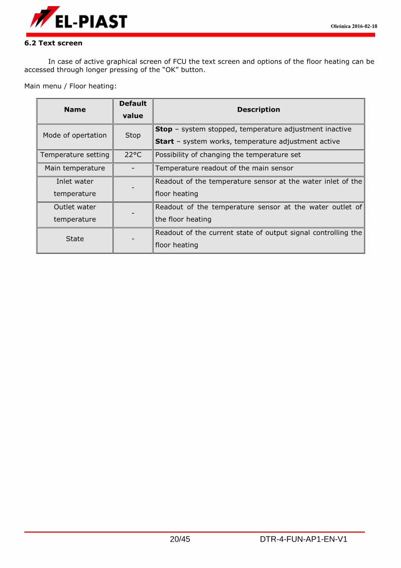
6.2 Text screen
In case of active graphical screen of FCU the text screen and options of the floor heating can be
accessed through longer pressing of the “OK” button.
Main menu / Floor heating:
Name Default
value Description
Mode of opertation Stop Stop – system stopped, temperature adjustment inactive
Start – system works, temperature adjustment active
Temperature setting 22°C Possibility of changing the temperature set
Main temperature - Temperature readout of the main sensor
Inlet water
temperature -
Readout of the temperature sensor at the water inlet of the
floor heating
Outlet water
temperature -
Readout of the temperature sensor at the water outlet of
the floor heating
State - Readout of the current state of output signal controlling the
floor heating

Oleśnica 2016-02-18
21/45 DTR-4-FUN-AP1-EN-V1
Main menu / Settings / Floor heating:
Access to those settings is password-protected (default password is: 1111).
Group Name Default
value Description
Sensors
Main
sensor HMI (CON)
HMI (CON) – temperature adjustment according
to the HMI sensor connected through HMI CON
connector
HMI (RS485 Master) – temperature adjustment
according to the HMI sensor connected through
RS485 Master connector
PT1 – temperature adjustment according to a
sensor connected to the PT1 connector
PT2 – temperature adjustment according to a
sensor connected to the PT2 connector
PT3 – temperature adjustment according to a
sensor connected to the PT3 connector
PT1/2 – temperature adjustment according to the
average measurement of sensors connected to the
PT1 and PT2 connectors
PT1/2/3 – temperature adjustment according to
the average measurement of sensors connected to
the PT1, PT2 and PT3 connectors
Supply
water
temp.
Inactive
Activation or deactivation of temperature
measurement at the water inlet on selected sensor
connector PT1…PT5
Return
water
temp.
Inactive
Activation or deactivation of temperature
measurement at the water outlet on selected
sensor connector PT1…PT5
Temperature
adjustment Histeresis 2°C
Histeresis of the main and set temperature above
which the actuator of the cold water valve will open
till the set temperature is reached (or dew
detected)

Oleśnica 2016-02-18
22/45 DTR-4-FUN-AP1-EN-V1
6.3 Alarms
Alarms are displayed by flashing display, an icon of alarm on the main screen of controller
and with use of red LED on the controller.
Alarm information can be read from the “Alarm Menu”. The alarm menu is accessed
automatically after 30 seconds of the alarm, or through pressing the “C” key for approx. 3 seconds.
List of alarms
ALARMS Alarm type System reaction, procedure
PT1000 Sensor input
A_TmainFloor Vanishing
Test of correct operation of the main temperature sensor of the
floor heating:
Normal state – no alarm, sensor connected
Alarm state – alarm, sensor disconnected or defective
Reaction to the alarm: temperature adjustment halted, check
the sensor and its connection to the controller, the main sensor
configuration, find the source of error, after the error was
removed the system returns to normal operation automatically
7. Lighting
7.1 Description of operation
Function Condition for work Description of operation
Switching
- a press of the switch,
digital contact or BMS
signal
- switching the digital output to the opposite
state
Power adjustment
(function can be activated
in the settings/lighting
menu, after activation of
lighting function)
- first press of the
switch, digital contact or
BMS signal
- switching the digital output on and setting
the analog output to full power
- holding the switch,
digital contact - gradual power decrease, up to switching off
- overwriting BMS
variable
- instant change of power level to the one
required

Oleśnica 2016-02-18
23/45 DTR-4-FUN-AP1-EN-V1
7.2 Text screen
In case of active graphical screen of FCU the text screen and options of lighting can be accessed
through longer pressing of the “OK” button.
Main menu / Lighting:
Name Default
value Description
Switch Off
Off – switch off, lighting control output inactive
On – switch on, the lighting control reacts with binary or
analog output
Set power …% Change of lighting intensity from the menu level or in BMS
State - Readout of current state of the digital output signal
controlling the lighting
Power …% Readout of current state of the analog output (Aout4) signal
controlling the lighting
Main menu / Settings / Lighting:
Access to those settings is password-protected (default password is: 1111).
Group Name Default
value Description
0-100%
Adjustment - Active
Active – lighting power adjustment with use of 0-
10VDC signal (Aout4) active
Inactive – lighting power adjustment inactivated

Oleśnica 2016-02-18
24/45 DTR-4-FUN-AP1-EN-V1
8. Blinds
8.1 Description of functions
Function Condition for work Description of operation
Opening / closing
- a press of the switch,
digital contact or BMS
signal
- switching the digital output to the opposite
state or sending a 1s pulse to the digital
output
The function of blinds is adjusted to single button blind control, in case of which each press of
the switch switches the blinds to the opposite state. The controller only passes the signal from a wall-
mounted switch or BMS system on a single-switch controller of blinds, that is not supplied with the “4-
Fun” controller.
8.2 Text screen
In case of active graphical screen of FCU the text screen and options of blinds can be accessed
through longer pressing of the “OK” button.
Main menu / Blinds:
Name Default
value Description
Switch Off Off – switch off, blind control output inactive
On – switch on, the blind control reacts
State - Readout of the current state of the blind control output
signal
Main menu / Settings / Blinds:
Access to those settings is password-protected (default password is: 1111).
Group Name Default
value Description
Calibration
of position - Inactive
Active – the controller gives a signal to the blind
controller to switch to the opposite state
Inactive – the blind control output works as per
the algorithm

Oleśnica 2016-02-18
25/45 DTR-4-FUN-AP1-EN-V1
Output - Pulse
Pulse – the output of the blind controller sends a
1s pulse after each press of the blind control
switch, or a signal coming from the BMS
On/off – the bling controling output is switched to
opposite state after each press of the blind control
switch, or a signal coming from the BMS
9. Startup
In order to start the system for the first time one should:
read this manual carefully,
install the controller in its housing,
connect wiring as per diagram, guidelines of this manual and the desired input/output scheme
of the contractor,
connect the electricity to the HMI controller,
check the correctness of connection of sensors and executing elements (actuators, etc.),
power up the controller,
with use of the HMI panel choose the function of the controller:
“Master” – main controller, other controllers, BMS (if present), sensors, actuators, fans and
other in/out functions chosen for startup are to be connected to it, as set in Service menu/Input
and output functions,
“Slave” – the controller widens the group of devices with additional FCUs (the FCUs of the
respective group work in parallel mode),
check the correctness of readouts and location of sensors,
check the operation of actuators, always check the free travel, full opening and full closing of
actuators,
check if there are no alarms, remove any,
start the system,
check again for alarms, remove any alarms.
Independent from the factory settings of the controller check the correctness of system
temperature calibration.
Choose temperature settings in such a way, that the system adjusts itself as fast as possible
without oversteering (in order to slow down the system reaction lower the Kp parameter value or/and
increase the Ti parameter value)

Oleśnica 2016-02-18
26/45 DTR-4-FUN-AP1-EN-V1
9.1 4-FUN controller as a MASTER
Function Condition for work Description of operation
Main controller
- type of controller set to
“MASTER” in service
menu
The “4-FUN” controller is design to control
the room comfort through:
- control of a 2 or 4-pipe FCU,
- control of chilled beam,
- control of floor heating,
- control of lighting,
- control of blinds.
These functions are activated automatically,
after activation of respective input/output
functions in service menu.
Controller power supply voltage is 230VAC, recommended cable type 3x1.5mm2, the power line is to
be protected with use of B10 overcurrent circuit breaker.
The HMI panel is to be connected with a shielded-shielded twisted pair cable (that is every pair of
twisted wire is shielded, and the whole is shielded again) of the S-STP or BUS O2YS(St)CY
1x2x0.64/2.6mm type. It is important for the communication signals A,B to be sent through pair of
twisted wires.
Connection of PT1000 sensors – LIYCY shielded cable (in case of variation of sensor readouts connect
the shielding to the “G” connector).

Oleśnica 2016-02-18
27/45 DTR-4-FUN-AP1-EN-V1
Signals of the digital inputs with LIYY line type of cable.
Connection of 3 speed FCU motor (230VAC), actuators (24VAC, 0-10VDC) and Y1-heating, Y2-cooling
valves.

Oleśnica 2016-02-18
28/45 DTR-4-FUN-AP1-EN-V1
Connection of actuators (24VAC, on-off) of Y1- heating, Y2 – cooling valves.
Connection of actuators (230VAC, on-off) of Y1- heating, Y2 – cooling valves.

Oleśnica 2016-02-18
29/45 DTR-4-FUN-AP1-EN-V1
Communication connection of MASTER controllers with the BMS and communication connections
between MASTER and SLAVE controllers (optional ETH adapter can be used for communication with
BMS).
9.2 4-FUN controller as a SLAVE

Oleśnica 2016-02-18
30/45 DTR-4-FUN-AP1-EN-V1
Function Condition for work Description of operation
Widening a group of
parallel-controlled FCUs
- setting the controller
as a “SLAVE” in service
menu
- connection of Master
and Slave controllers as
per diagram
- setting the Modbus
communication
parameters of the SLAVE
controller
- setting the Modbus
addresses in the SLAVE
controllers
- activation of set
number of SLAVE
controllers in the menu
of the MASTER controller
Passing the state of digital outputs :
PK1 – 1st fan speed
PK2 – 2nd fan speed
PK3 – 3rd fan speed
PK4 – heating valve
PK5 – cooling valve
and 0-10VDC analog outputs:
Aout1 – heating valve
Aout2 – cooling valve
Aout3 – fan speed
As per the FCU operating algorithm of the
MASTER controller

Oleśnica 2016-02-18
31/45 DTR-4-FUN-AP1-EN-V1
10. Modbus RTU Communication
The controller is equipped with Modbus RTU protocol implementation. In order to connect network:
- connect the HMI panel to the 4-FUN controller used as “MASTER”
- enter the HMI menu: COMMUNICATION SETTINGS / RS485 MASTER COM SETTINGS and set the BUS
MODE parameter to “Modbus/ELPbus”
- enter the HMI menu: COMMUNICATION SETTINGS / RS485 MASTER COM SETTINGS and set the MAC
ADDRESS to a freely chosen Modbus address (the individual address of that controller)
- connect the RS-485 bus to the RS485-1 port of the controller bar.
Default communication parameters (can be changed with use of a connected HMI panel):
● transmission speed 9600 bps
● 8 bits of frame
● 1 stop bit
● no parity
All variables are 32-bit Holding Register values. Modbus registers are 16-bit that is why each 32-bit
variable occupies 2 16-bit variables. The readout of variables with use of Modbus 0x03 command,
writing 16 bits of single variable with the 0x06 command, many variables with 0x10 command.
Presentation of variables
Table below lists all variables of the control system. Variables have several numerical representations:
Multistate – the total variable values correspond to the described states
Decimal – 32-bit value of variable treated as a total type with character
Fixed – fixed position type in which the 8 least important bits are for the fraction part, the
remaining 24 bits for the absolute numbers. Thus the accuracy of fixed value is 1/256. In order
to scale the Fixed value to the target (actual) value multiply it by 1/256 = 0.00390625.
Fan-Coil Unit
Address Variable Description Values Type
Read
[R]
/Write
[W]
002 ModeVent Mode of operation
0 - stop, 1 - I speed, 2 - II
speed, 4 - III speed, 8 -
Auto, 16 - calendar
Decimal R/W
004 Vent State of operation 0 - stop, 1 - I speed, 2 - II
speed, 4 - III speed Decimal R
006 ModeTemp Temperature mode 0 - ventilation, 1 - heating, 2
- cooling, 3 – heating/cooling Decimal R/W
008 Tset Temperature setting 1°C = 256 (22 °C = 22*256
= 5632 = 0x1600) Fixed R/W
00A TsetAct Set temperature 1°C = 256 (22 °C = 22*256
= 5632 = 0x1600) Fixed R
00C Tmain Main temperature 1°C = 256 (22 °C = 22*256
= 5632 = 0x1600) Fixed R
00E Bin1 Inlet water temperature 1°C = 256 (22 °C = 22*256
= 5632 = 0x1600) Fixed R
010 Bout1 Outlet water temperature 1°C = 256 (22 °C = 22*256
= 5632 = 0x1600) Fixed R

Oleśnica 2016-02-18
32/45 DTR-4-FUN-AP1-EN-V1
012 Y1 Heating 1% = 256 (22 % = 22*256
= 5632 = 0x1600) Fixed R
014 Y2 Cooling 1% = 256 (22 % = 22*256
= 5632 = 0x1600) Fixed R
016 Eco Eco mode 0 - off, 1 - on Decimal R
018 Refresh Ventilation function 0 - off, 1 - on Decimal R
01A Window Window 0 - open, 1 - closed Decimal R
01C StopDI Remote start (digital
input)
0 – system stop, 1 – system
works Decimal R
01E StopBMS Remote start (BMS) 0 – system stop, 1 – system
works Decimal R
020 W1 Universal output 0 - off, 1 - on Decimal R
022 ChMain Main sensor
1 - HMI(CON), 2 - HMI
(RS485 master), 3 - PT1, 4 -
PT2, 5 - PT3, 6 - PT1/PT2, 7
- PT1/2/3
Decimal R/W
024 chBin1 Inlet water temperature 0 - inactive, 1 - PT1, 2 - PT2,
3 - PT3, 4 - PT4, 5 - PT5 Decimal R/W
026 chBout1 Outlet water temperature 0 - inactive, 1 - PT1, 2 - PT2,
3 - PT3, 4 - PT4, 5 - PT5 Decimal R/W
028 Dif1 Vent. Dif1 histeresis 1°C = 256 (22 °C = 22*256
= 5632 = 0x1600) Fixed R/W
02A Dif2 Vent. Dif2 histeresis 1°C = 256 (22 °C = 22*256
= 5632 = 0x1600) Fixed R/W
02C Dif3 Vent. Dif3 histeresis 1°C = 256 (22 °C = 22*256
= 5632 = 0x1600) Fixed R/W
02E Kp Kp amplification 1 = 256 (22 = 22*256 =
5632 = 0x1600) Fixed R/W
030 Ti Ti integral constant 1s = 256 (22s = 22*256 =
5632 = 0x1600) Fixed R/W
032 dReg Insensitivity 1% = 256 (22 % = 22*256
= 5632 = 0x1600) Fixed R/W
034 EcoCor Eco correction 1°C = 256 (22 °C = 22*256
= 5632 = 0x1600) Fixed R/W
036 RefrTime Czas przewietrzania 1min = 256 (22min =
22*256 = 5632 = 0x1600) Fixed R/W
038 RefrGear Ventilation speed 1 - I speed, 2 - II speed, 4 -
III speed Decimal R/W
03A ActFilterTime Filter Operation Time 0 - inactive, 1 - active Decimal R/W
03C Hour Counter of filter hours 1h = 256 (22 h = 22*256 =
5632 = 0x1600) Fixed R
03E LimHour Limit of filter hours 1h = 256 (22 h = 22*256 =
5632 = 0x1600) Fixed R/W
040 Res Reset the counter 0 - inactive, 1 - active Decimal R/W
042 SetG1 Aout4 setting for speed 1 1% = 256 (22 % = 22*256
= 5632 = 0x1600) Fixed R/W
044 SetG2 Aout4 setting for speed 2 1% = 256 (22 % = 22*256
= 5632 = 0x1600) Fixed R/W
046 SetG3 Aout4 setting for speed 3 1% = 256 (22 % = 22*256
= 5632 = 0x1600) Fixed R/W

Oleśnica 2016-02-18
33/45 DTR-4-FUN-AP1-EN-V1
Chilled beam
Address Variable Description Values Type
Read
[R]
/Write
[W]
048 ModeChill Mode of operation 0 - stop, 1 - start Decimal R/W
04A TsetChill Temperature setting 1°C = 256 (22 °C = 22*256
= 5632 = 0x1600) Fixed R/W
04C TmainChill Main temperature 1°C = 256 (22 °C = 22*256
= 5632 = 0x1600) Fixed R
04E Bin2 Inlet water temperature 1°C = 256 (22 °C = 22*256
= 5632 = 0x1600) Fixed R
050 Bout2 Outlet water temperature 1°C = 256 (22 °C = 22*256
= 5632 = 0x1600) Fixed R
052 ChillValve Chilled beam valve 0 - off, 1 - on Decimal R
054 DEW Dew sensor 0 - alarm, 1 – no alarm Decimal R
056 ChMainChill Main sensor
1 - HMI(CON), 2 - HMI
(RS485 master), 3 - PT1, 4 -
PT2, 5 - PT3, 6 - PT1/PT2, 7
- PT1/2/3
Decimal R/W
058 chBin2 Inlet water temperature 0 - inactive, 1 - PT1, 2 - PT2,
3 - PT3, 4 - PT4, 5 - PT5 Decimal R/W
05A chBout2 Outlet water temperature 0 - inactive, 1 - PT1, 2 - PT2,
3 - PT3, 4 - PT4, 5 - PT5 Decimal R/W
05C HistChill Histeresis 1°C = 256 (22 °C = 22*256
= 5632 = 0x1600) Fixed R/W
Floor
heating
Address Variable Description Values Type
Read
[R]
/Write
[W]
05E ModeFloor Mode of operation 0 - stop, 1 - start Decimal R/W
060 TsetFloor Temperature setting 1°C = 256 (22 °C = 22*256
= 5632 = 0x1600) Fixed R/W
062 TmainFloor Main temperature 1°C = 256 (22 °C = 22*256
= 5632 = 0x1600) Fixed R
064 Bin3 Inlet water temperature 1°C = 256 (22 °C = 22*256
= 5632 = 0x1600) Fixed R
066 Bout3 Outlet water temperature 1°C = 256 (22 °C = 22*256
= 5632 = 0x1600) Fixed R
068 Floor State of output controlling
the floor heating 0 - off, 1 - on Decimal R
06A ChMainFloor Main sensor
1 - HMI(CON), 2 - HMI
(RS485 master), 3 - PT1, 4 -
PT2, 5 - PT3, 6 - PT1/PT2, 7
- PT1/2/3
Decimal R/W
06C chBin3 Inlet water temperature 0 - inactive, 1 - PT1, 2 - PT2,
3 - PT3, 4 - PT4, 5 - PT5 Decimal R/W
06E chBout3 Outlet water temperature 0 - inactive, 1 - PT1, 2 - PT2,
3 - PT3, 4 - PT4, 5 - PT5 Decimal R/W

Oleśnica 2016-02-18
34/45 DTR-4-FUN-AP1-EN-V1
070 HistFloor Histeresis 1°C = 256 (22 °C = 22*256
= 5632 = 0x1600) Fixed R/W
Lighting
Address Variable Description Values Type
Read
[R]
/Write
[W]
072 WMLight HMI or BMS switch 0 - off, 1 - on Decimal R/W
074 SetLightReg HMI or BMS power setting 1% = 256 (22 % = 22*256
= 5632 = 0x1600) Fixed R/W
076 Light State of lighting
controlling output 0 - off, 1 - on Decimal R
078 LightRegVal Currently set light power 1% = 256 (22 % = 22*256
= 5632 = 0x1600) Fixed R
07A LightRegAct Light power adjustment
activation 0 - inactive, 1 - active Decimal R/W
Blinds
Address Variable Description Values Type
Read
[R]
/Write
[W]
07C WMblindSwitch HMI or BMS switch 0 - off, 1 - on Decimal R/W
07E Blinds State of blinds 0 - closed, 1 - open Decimal R
080 BlindCalibration Calibration of the above
state indication 0 - off, 1 - on Decimal R/W
082 ReBlindFun Blind control output 0 - pulse, 1 - on/off Decimal R/W
Universal output
Address Variable Description Values Type
Read
[R]
/Write
[W]
084 StartW1
Start BMS signal of the
W1 output active after
selecting the ModeW1
value of 2 or 8
0 - off, 1 - on Decimal R/W
086 ModeW1 Mode of the Universal
output
0 - stop, 1 - start, 2 - start
BMS, 4 - start KLM, 8 - start
BMS&KLM
Decimal R/W
Service menu
Address Variable Description Values Type
Read
[R]
/Write
[W]
088 Type Controller type 0 - slave, 1 - master Decimal R/W

Oleśnica 2016-02-18
35/45 DTR-4-FUN-AP1-EN-V1
08A SlavesQuanty Number of slave type
controllers (16 max)
1 = 256 (22 = 22*256 =
5632 = 0x1600) Fixed R/W
08C Tcom Time for communication
with a single device
1s = 256 (22s = 22*256 =
5632 = 0x1600) Fixed R/W
08E Twait
Communication waiting
time (set higher than the
Tcom multiplied by the
number of devices
participating in the
communication)
1s = 256 (22s = 22*256 =
5632 = 0x1600) Fixed R/W
090 ChDi1F D1 digital input function 0 - inactive, 1 - window, 2 -
stop digital input, 3 - ECO, 4
- ventilation, 5 - filter, 6 –
compress., 7 - lighting, 8 -
blind, 9 - dew
Decimal R/W
092 ChDi2F D2 digital input function
094 ChDi3F D3 digital input function
096 ChDi4F D4 digital input function
098 ChDi5F D5 digital input function
09A ChRe1 PK1 relay output function
0 - inactive, 1 - window, 2 -
stop digital input, 3 - ECO, 4
- ventilation, 5 - filter, 6 –
compress., 7 - lighting, 8 -
blind, 9 - dew
Decimal R/W
09C ChRe2 PK2 relay output function
09E ChRe3 PK3 relay output function
0A0 ChRe4 PK4 relay output function
0A2 ChRe5 PK5 relay output function
0A4 ChPWM1 24VDC, PWM1 digital
output function
0A6 ChPWM2 24VDC, PWM2 digital
output function
0A8 ActWMremote Stop activation from BMS
level
0 – system stop, 1 – system
works Decimal R
0AA ActWMeco "ECO" activation from BMS
level 0 - off, 1 - on Decimal R
0AC ActWMrefr Ventilation activation from
BMS level 0 - off, 1 - on Decimal R
0AE ActWMlight Lighting switch activation
from BMS level 0 - off, 1 - on Decimal R
0B0 ActBMSblind Blind switch activation
from BMS level 0 - off, 1 - on Decimal R
0B2 OfsPT1
Correction of the
temperature measurement
point for the temperature
sensor connected to the
PT1 input
1°C = 256 (22 °C = 22*256
= 5632 = 0x1600) Fixed R
0B4 OfsPT2
Correction of the
temperature measurement
point for the temperature
sensor connected to the
PT2 input
1°C = 256 (22 °C = 22*256
= 5632 = 0x1600) Fixed R
0B6 OfsPT3
Correction of the
temperature measurement
point for the temperature
sensor connected to the
PT3 input
1°C = 256 (22 °C = 22*256
= 5632 = 0x1600) Fixed R
0B8 OfsPT4
Correction of the
temperature measurement
point for the temperature
1°C = 256 (22 °C = 22*256
= 5632 = 0x1600) Fixed R

Oleśnica 2016-02-18
36/45 DTR-4-FUN-AP1-EN-V1
sensor connected to the
PT4 input
0BA OfsPT5
Correction of the
temperature measurement
point for the temperature
sensor connected to the
PT5 input
1°C = 256 (22 °C = 22*256
= 5632 = 0x1600) Fixed R
0BC OfsHMICon
Correction of the
temperature measurement
point for the temperature
sensor connected to the
HMI CON connector
1°C = 256 (22 °C = 22*256
= 5632 = 0x1600) Fixed R
0BE OfsHMIRS
Correction of the
temperature measurement
point for the temperature
sensor connected to the
MASTER RS485 bus
1°C = 256 (22 °C = 22*256
= 5632 = 0x1600) Fixed R
0C0 _DIN1 Readout of the state of
digital input no. 1 0 - open, 1 - closed Decimal R
0C2 _DIN2 Readout of the state of
digital input no. 2 0 - open, 1 - closed Decimal R
0C4 _DIN3 Readout of the state of
digital input no. 3 0 - open, 1 - closed Decimal R
0C6 _DIN4 Readout of the state of
digital input no. 4 0 - open, 1 - closed Decimal R
0C8 _DIN5 Readout of the state of
digital input no. 5 0 - open, 1 - closed Decimal R
0CA Ain_1 Readout of the state of
analog input no. 1
1V = 256 (22V = 22*256 =
5632 = 0x1600) Fixed R
0CC Re1 Readout of the state of the
PK1 relay output 0 - off, 1 - on Decimal R
0CE Re2 Readout of the state of the
PK2 relay output 0 - off, 1 - on Decimal R
0D0 Re3 Readout of the state of the
PK3 relay output 0 - off, 1 - on Decimal R
0D2 Re4 Readout of the state of the
PK4 relay output 0 - off, 1 - on Decimal R
0D4 Re5 Readout of the state of the
PK5 relay output 0 - off, 1 - on Decimal R
0D6 RePWM1
Readout of the state of the
24VDC, PWM1 digital
output
0 - off, 1 - on Decimal R
0D8 RePWM2
Readout of the state of the
24VDC, PWM2 digital
output
0 - off, 1 - on Decimal R
0DA AO1 Readout of the state of the
analog output no. 1
1V = 256 (10V = 10*256 =
2560 = 0xA00) Fixed R
0DC AO2 Readout of the state of the
analog output no. 2
1V = 256 (10V = 10*256 =
2560 = 0xA00) Fixed R
0DE AO3 Readout of the state of the
analog output no. 3
1V = 256 (10V = 10*256 =
2560 = 0xA00) Fixed R
0E0 AO4 Readout of the state of the
analog output no. 4
1V = 256 (10V = 10*256 =
2560 = 0xA00) Fixed R
0E2 F_DIN1 Emulation of the digital
input no. 1
0 – no emulation, 1 – set as
open, 3 – set as closed Decimal R/W

Oleśnica 2016-02-18
37/45 DTR-4-FUN-AP1-EN-V1
0E4 F_DIN2 Emulation of the digital
input no. 2
0 – no emulation, 1 – set as
open, 3 – set as closed Decimal R/W
0E6 F_DIN3 Emulation of the digital
input no. 3
0 – no emulation, 1 – set as
open, 3 – set as closed Decimal R/W
0E8 F_DIN4 Emulation of the digital
input no. 4
0 – no emulation, 1 – set as
open, 3 – set as closed Decimal R/W
0EA F_DIN5 Emulation of the digital
input no. 5
0 – no emulation, 1 – set as
open, 3 – set as closed Decimal R/W
0EC Em_Ai1 Emulation of the analog
input no. 1 0 - inactive, 1 - active Decimal R/W
0EE E_Ai1 Emulated value for the
analog input no. 1
1V = 256 (10V = 10*256 =
2560 = 0xA00) Fixed R/W
0F0 Em_PT1 Input emulation of the
PT1000 1 sensor 0 - inactive, 1 - active Decimal R/W
0F2 E_PT1 Emulated value of the
PT1000 1 sensor
1°C = 256 (22 °C = 22*256
= 5632 = 0x1600) Fixed R/W
0F4 Em_PT2 Input emulation of the
PT1000 2 sensor 0 - inactive, 1 - active Decimal R/W
0F6 E_PT2 Emulated value of the
PT1000 2 sensor
1°C = 256 (22 °C = 22*256
= 5632 = 0x1600) Fixed R/W
0F8 Em_PT3 Input emulation of the
PT1000 3 sensor 0 - inactive, 1 - active Decimal R/W
0FA E_PT3 Emulated value of the
PT1000 3 sensor
1°C = 256 (22 °C = 22*256
= 5632 = 0x1600) Fixed R/W
0FC Em_PT4 Input emulation of the
PT1000 4 sensor 0 - inactive, 1 - active Decimal R/W
0FE E_PT4 Emulated value of the
PT1000 4 sensor
1°C = 256 (22 °C = 22*256
= 5632 = 0x1600) Fixed R/W
100 Em_PT5 Input emulation of the
PT1000 5 sensor 0 - inactive, 1 - active Decimal R/W
102 E_PT5 Emulated value of the
PT1000 5 sensor
1°C = 256 (22 °C = 22*256
= 5632 = 0x1600) Fixed R/W
104 Em_Hcon
Emulation of the sensor
input of the controller
connected to the HMI CON
0 - inactive, 1 - active Decimal R/W
106 E_Hcon
Emulated value of the
sensor of the controller
connected to the HMI CON
1°C = 256 (22 °C = 22*256
= 5632 = 0x1600) Fixed R/W
108 Em_Hrs
Emulation of the sensor
input of the controller
connected to the RS485
bus
0 - inactive, 1 - active Decimal R/W
10A E_Hrs
Emulated value of the
sensor of the controller
connected to the RS485
bus
1°C = 256 (22 °C = 22*256
= 5632 = 0x1600) Fixed R/W
10C F_Re1 Forcing PK1 relay output 0 – do not force, 1 – forcing
off, 3 – forcing on Decimal R/W
10E F_Re2 Forcing PK2 relay output 0 – do not force, 1 – forcing
off, 3 – forcing on Decimal R/W
110 F_Re3 Forcing PK3 relay output 0 – do not force, 1 – forcing
off, 3 – forcing on Decimal R/W
112 F_Re4 Forcing PK4 relay output 0 – do not force, 1 – forcing
off, 3 – forcing on Decimal R/W
114 F_Re5 Forcing PK5 relay output 0 – do not force, 1 – forcing
off, 3 – forcing on Decimal R/W

Oleśnica 2016-02-18
38/45 DTR-4-FUN-AP1-EN-V1
116 F_PWM1 Forcing 24VDC, PWM1
digital output
0 – do not force, 1 – forcing
off, 3 – forcing on Decimal R/W
118 F_PWM2 Forcing 24VDC, PWM2
digital output
0 – do not force, 1 – forcing
off, 3 – forcing on Decimal R/W
11A FoAO1 Forcing analog output no.
1 0 - inactive, 1 - active Decimal R/W
11C F_AO1 Value in the forcing mode
of the analog output no. 1
1V = 256 (10V = 10*256 =
2560 = 0xA00) Fixed R/W
11E FoAO2 Forcing analog output no.
2 0 - inactive, 1 - active Decimal R/W
120 F_AO2 Value in the forcing mode
of the analog output no. 2
1V = 256 (10V = 10*256 =
2560 = 0xA00) Fixed R/W
122 FoAO3 Forcing analog output no.
3 0 - inactive, 1 - active Decimal R/W
124 F_AO3 Value in the forcing mode
of the analog output no. 3
1V = 256 (10V = 10*256 =
2560 = 0xA00) Fixed R/W
126 FoAO4 Forcing analog output no.
4 0 - inactive, 1 - active Decimal R/W
128 F_AO4 Value in the forcing mode
of the analog output no. 4
1V = 256 (10V = 10*256 =
2560 = 0xA00) Fixed R/W
Alarms
Address Variable Description Values Type
Read
[R]
/Write
[W]
12A A_TmainFC Main sensor of fan-coil
unit damaged 0 – no alarm, 1 - alarm Decimal R
12C A_Filter Dirty FCU filter 0 – no alarm, 1 - alarm Decimal R
12E A_PresVent No fan compression in the
fan-coil unit 0 – no alarm, 1 - alarm Decimal R
130 A_TmainChill Main sensor of cooler
board damaged 0 – no alarm, 1 - alarm Decimal R
132 A_TmainFloor Main sensor of floor
heating damaged 0 – no alarm, 1 - alarm Decimal R
134 A_InEmul Alarm of controller input
emulation 0 – no alarm, 1 - alarm Decimal R
136 A_OutForce Alarm of controller output
forcing 0 – no alarm, 1 - alarm Decimal R
138 A_ComSlave1
Alarm – no communication
of master controller with
the slave controller no. 1
0 – no alarm, 1 - alarm Decimal R
13A A_ComSlave2
Alarm – no communication
of master controller with
the slave controller no.2
0 – no alarm, 1 - alarm Decimal R
13C A_ComSlave3
Alarm – no communication
of master controller with
the slave controller no.3
0 – no alarm, 1 - alarm Decimal R
13E A_ComSlave4
Alarm – no communication
of master controller with
the slave controller no.4
0 – no alarm, 1 - alarm Decimal R
140 A_ComSlave5
Alarm – no communication
of master controller with
the slave controller no.5
0 – no alarm, 1 - alarm Decimal R

Oleśnica 2016-02-18
39/45 DTR-4-FUN-AP1-EN-V1
142 A_ComSlave6
Alarm – no communication
of master controller with
the slave controller no.6
0 – no alarm, 1 - alarm Decimal R
144 A_ComSlave7
Alarm – no communication
of master controller with
the slave controller no.7
0 – no alarm, 1 - alarm Decimal R
146 A_ComSlave8
Alarm – no communication
of master controller with
the slave controller no.8
0 – no alarm, 1 - alarm Decimal R
148 A_ComSlave9
Alarm – no communication
of master controller with
the slave controller no.9
0 – no alarm, 1 - alarm Decimal R
14A A_ComSlave10
Alarm – no communication
of master controller with
the slave controller no.10
0 – no alarm, 1 - alarm Decimal R
14C A_ComSlave11
Alarm – no communication
of master controller with
the slave controller no.11
0 – no alarm, 1 - alarm Decimal R
14E A_ComSlave12
Alarm – no communication
of master controller with
the slave controller no.12
0 – no alarm, 1 - alarm Decimal R
150 A_ComSlave13
Alarm – no communication
of master controller with
the slave controller no.13
0 – no alarm, 1 - alarm Decimal R
152 A_ComSlave14
Alarm – no communication
of master controller with
the slave controller no.14
0 – no alarm, 1 - alarm Decimal R
154 A_ComSlave15
Alarm – no communication
of master controller with
the slave controller no.15
0 – no alarm, 1 - alarm Decimal R
156 A_ComSlave16
Alarm – no communication
of master controller with
the slave controller no.16
0 – no alarm, 1 - alarm Decimal R
158 AnyAlarm Collective alarm 0 – no alarm, 1 - alarm Decimal R
11. Bacnet MS-TP communication with the BMS system
The BacNet variables are to be searched for after connecting an operating controller and inputting the
correct settings of the BacNet network (see item 2)

Oleśnica 2016-02-18
40/45 DTR-4-FUN-AP1-EN-V1
12. Website control
The controller is equipped with an option of controlling through a website. The hardware required for that is an optional Ethernet adapter installed in the location marked on the image below:
In order to connect from a local computer connected directly to the ETH adapter with use of a
cable: Set the below listed values of the TCP4 protocol for the network adapter of the computer:
RJ45 connector
ETH adapter

Oleśnica 2016-02-18
41/45 DTR-4-FUN-AP1-EN-V1
Then run your Internet browser and type in the default controller address: 192.168.0.8
A window will display for you to type in the default login: admin and password: admin
After typing in the login and password, and confirming with a click of “Login” button the HMI
screen of the controller will be displayed and settings and readout of the full controller menu are possible.

Oleśnica 2016-02-18
42/45 DTR-4-FUN-AP1-EN-V1
The controller has an Ethernet interface, thus in order to connect the controller wirelessly with the local wireless Network (WiFi) and additional router should be used – configure the
local WiFi network as the access point and then plug the controller to the router. The network settings of the router and controller must match. Ports of the controller are to be redirected
to the external address of the router.

Oleśnica 2016-02-18
43/45 DTR-4-FUN-AP1-EN-V1
Below schemes of different types of connection:
1. Connecting the controller to LAN through WiFi
Router with port redirection: 80. Thus from the controller: 192.168.0.8:80 to the example outside address of the router: 10.10.10.31. This makes the controller visible in the local WiFi network.
When connecting from within the local network direct access through http://10.10.10.31
2. Direct communication of controller through WiFi router
Router with port redirection: 80. Thus from the controller: 192.168.0.8:80 to the example
outside address of the router: 192.168.0.1. This makes the controller visible in the local WiFi network.
When connecting to the dedicated network controller access is granted at: http://192.168.0.8

Oleśnica 2016-02-18
44/45 DTR-4-FUN-AP1-EN-V1
3. Including the controller in the local WiFi Network and making it available from
outside the network
Redirection on the main router from the WiFi router of the controller: port: 80 from IP: 10.10.10.31 to external IP port: 80 IP: 83.100.100.1
Router with port redirection: 80. Thus from the controller: 192.168.0.8:80 to the example outside address of the router: 10.10.10.31. This makes the controller visible in the local WiFi
network. When connecting from any other Internet location the controller can be accessed at http://83.100.100.1

Oleśnica 2016-02-18
45/45 DTR-4-FUN-AP1-EN-V1
13. Instructions, advice, recommendations
Automated elements to be connected as per diagram and the following instructions:
230VAC power cables of the YLY type,
24VAC,DC control cables for digital on/off signals of the types LIYY, LIYCY no thinner than
0.5mm2,
24VAC,DC control cables for analog 0-10VDC signals or temperature sensors of the LIYCY type,
for communication of the HMI interface use a shielded-shielded twisted pair cable (that is every
pair of twisted wire is shielded, and the whole is shielded again) of the S-STP or BUS
O2YS(St)CY 1x2x0.64/2.6mm type.
BUS O2YS(St)CY 1x2x0.64/2.6mm type cable for communication with the BMS Modbus RS485
or BacNet MS-TP communication,
in no event shall communication cables be placed together with control and power cables,
construct separate cable ducts for communication cables,
the HMI panel is to be installed within 100m of the controller,
in no event twisted pair cables are to be used for control purposes for on/off, 24V, 230V, 0-
10VDC signals.
“Slave” devices are to be connected in the serial topology of the Modbus RS485 network.
“Master” device and the BMS system can be connected in the serial topology of the Modbus RS485 or
BacNet MS-TP networks, or - with use of additional Eth adapters - through a Modbus TCP/IP or BacNet
IP network.
Failure to observe the above recommendations may result in erroneous operation, serious of electric
shock and void the warranty.
WARNING!!! The controller is 230VAC powered, prior to switching on the power supply make
sure the controller is in a casing that prevents touching the controller and secure the
powering cable with use of overcurrent protection, as per applicable standards. Only a
qualified and properly trained technician may perform the actions listed above. Failure to
observe the above recommendations may result in electric shock.
As we constantly develop our devices content of this manual may slightly differ from the actually
available functions and the controller or panel may differ insignificantly from their actual appearance.