Embed Size (px)
Citation preview
SANGER SUBSTATION EXPANSION PROJECT
PROJECT DESCRIPTION
DRAFT FINAL IS/MND 4-1 JANUARY MARCH 2017
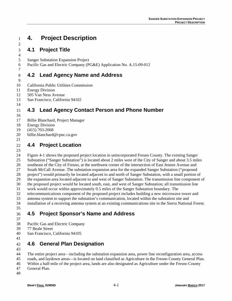
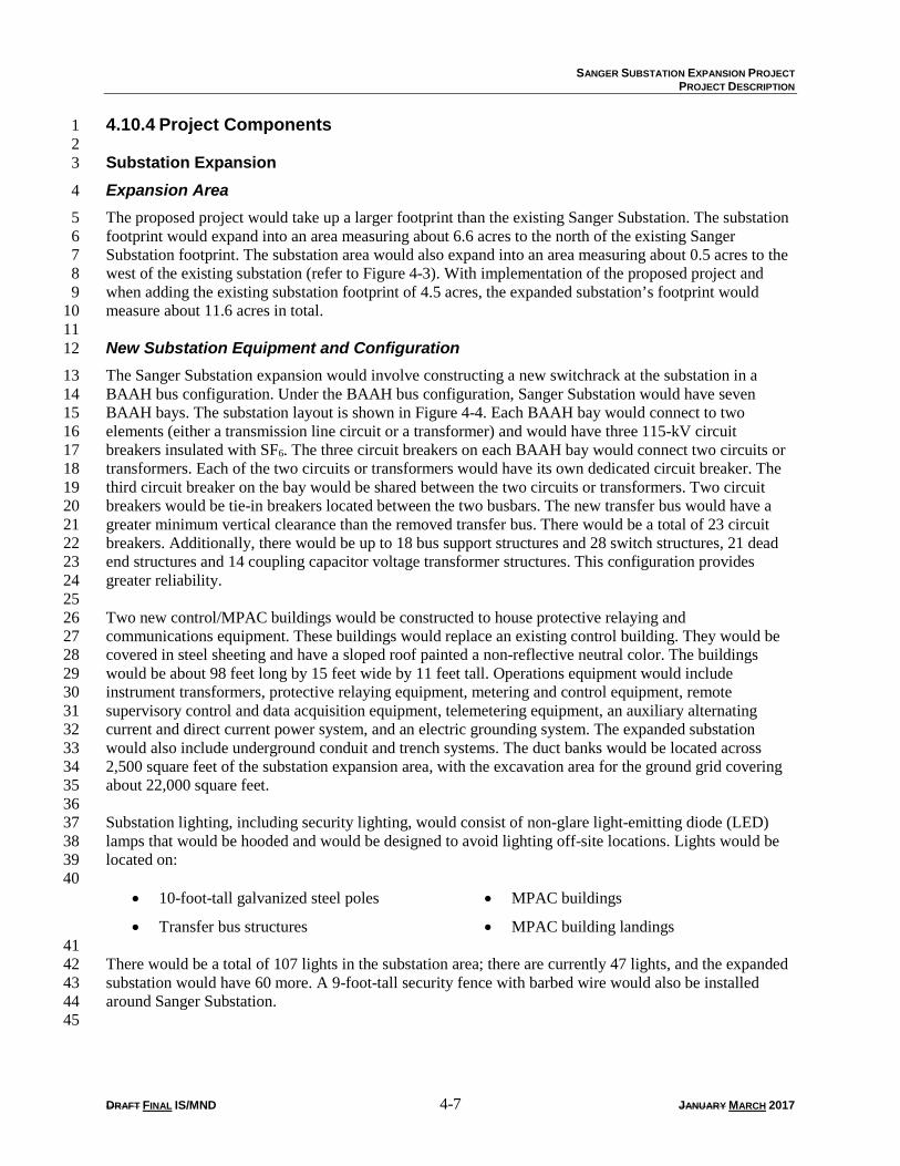
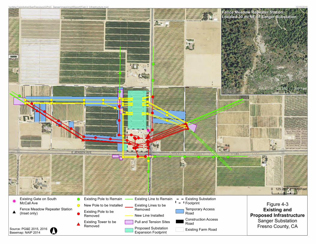
4. Project Description 1 2 4.1 Project Title 3 4 Sanger Substation Expansion Project 5 Pacific Gas and Electric Company (PG&E) Application No. A.15-09-012 6 7 4.2 Lead Agency Name and Address 8 9 California Public Utilities Commission 10 Energy Division 11 505 Van Ness Avenue 12 San Francisco, California 94102 13 14 4.3 Lead Agency Contact Person and Phone Number 15 16 Billie Blanchard, Project Manager 17 Energy Division 18 (415) 703-2068 19 [email protected] 20 21 4.4 Project Location 22 23 Figure 4-1 shows the proposed project location in unincorporated Fresno County. The existing Sanger 24 Substation (“Sanger Substation”) is located about 2 miles west of the City of Sanger and about 3.5 miles 25 southeast of the City of Fresno, at the northwest corner of the intersection of East Jensen Avenue and 26 South McCall Avenue. The substation expansion area for the expanded Sanger Substation (“proposed 27 project”) would primarily be located adjacent to and north of Sanger Substation, with a small portion of 28 the expansion area located adjacent to and west of Sanger Substation. The transmission line component of 29 the proposed project would be located south, east, and west of Sanger Substation; all transmission line 30 work would occur within approximately 0.5 miles of the Sanger Substation boundary. The 31 telecommunications component of the proposed project includes building a new microwave tower and 32 antenna system to support the substation’s communication, located within the substation site and 33 installation of a receiving antenna system at an existing communications site in the Sierra National Forest. 34 35 4.5 Project Sponsor’s Name and Address 36 37 Pacific Gas and Electric Company 38 77 Beale Street 39 San Francisco, California 94105 40 41 4.6 General Plan Designation 42 43 The entire project area—including the substation expansion area, power line reconfiguration area, access 44 roads, and laydown areas—is located on land classified as Agriculture in the Fresno County General Plan. 45 Within a half-mile of the project area, lands are also designated as Agriculture under the Fresno County 46 General Plan. 47 48
PG&E Sanger SubstationExpansion Project
City ofFresno
City ofSanger
City ofParlier
City ofFowler
City ofFresno
Communityof Del Rey
Community of CentervilleCommunity
of Sunnyside
Communityof Bowles
Communityof Malaga
Communityof Calwa
SMCC
ALLA
VE
E JENSEN AVE
E NORTH AVE
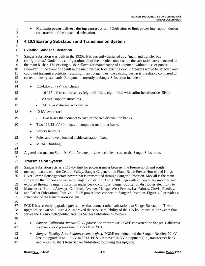
E LINCOLN AVE
CHURCH AVE
J ST
E ADAMS AVE
NORTH AVE
K AVE
S IND
IA NOL
A AVE
CHERRY AVE
E MALAGA AVE
SCED
ARAV
E
SME N
DOCI
NOAV
E
MADS
ENAV
E
T AIT
A VE
E MANNING AVE
E CENTRAL AVE
FIG ST
E JEFFERSON AVE
E CHURCH AVE
E ANNADALE AVE
QUAL IT YAVE
S DEL
REYA
VE
N AVE
MARYAVE
K ST
LORENAAVE
E FLORENCE AVE
SPEA
CHAV
E
S ACA
DEMY
AVE
E SUMNER AVE
TUCK
ERAV
E
E SOUTH AVE
E CLAYTON AVE
EFANTZ AVE
MOIRAVE
S GOLDEN STATE BLVD
E CENTRALFTRD S
STEM
PERA
NCE A
VE
O AVES A
RMST
RONG
AVE
HOLTAVE J AVE
S FOW
LER
AVE
I AVE
VINEAVE
E WALTER AVE
E CALIFORNIA AVE
SRAILROAD
AVE
SMAP
LEAV
E
S RAINBO
W AVE
E EDGAR AVE
SLOC
A NAV
E
E PARLIER AVE
STHO
MPS O
NAV
E
E MOTT AVE
SOR A
NGEA
VE
E MUSCAT AVE
E DATEAVE
SVIL L
AAVE
E VINEAVE
SKEN
N ETH
AVE
SMIN
NEWA
WAAV
E
SHI
GHL A
N DA V
E
SSUN
NYSID
EAVE
SBET
HELA
V E
SNEWMARK
AVE
FALLER AVE
SCH E
STNU
T AVE
ACAD
EMY A
VE
ROAD A
SWILL
OWAV
E
SCL O
VISAV
E
SLEO
NARD
AVE
SDEW
OLF A
VE
SGRE
ENW O
ODAV
E
# Fence Meadow Repeater StationProposed Substation Expansion FootprintExisting Substation Footprint
0 0.5 1 Miles
\\prtbhp1\gis\Active\SanFrancisco\CPUC_Sanger\maps\mxd\Report\Fig4-1_ProjectLocation_WithFenceMeadow.mxd
Figure 4-1Project LocationSanger SubstationFresno County, CA
6/3/2016
°
Source: PG&E 2015Basemap: ESRI 2010
FRESNOCOUNTYMain
ProjectLocationPacific
Ocean
Fence MeadowRepeater Station
AZ
CA
ID
NV
ORUT
#
ROSS
CROS
SING
RD
BIGCR
EEK
RD
Fence MeadowRepeaterStation
Located 30 mi NEof Sanger Substation
0 0.5 1 Miles
SANGER SUBSTATION EXPANSION PROJECT
PROJECT DESCRIPTION
DRAFT FINAL IS/MND 4-3 JANUARY MARCH 2017
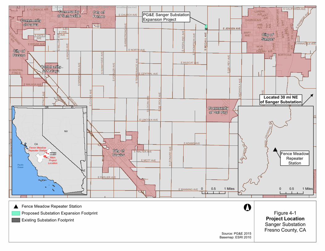
4.7 Zoning 1 2 The zoning designation for the entire project area is Exclusive Agricultural District, 20-acre minimum lot 3 size (AE-20) lands. Within a half-mile of the project area, lands are also zoned as AE-20 under the Fresno 4 County zoning ordinance. 5 6 4.8 Surrounding Land Uses and Setting 7 8 Land use in the project area is predominantly agriculture and existing utility infrastructure. The proposed 9 project area would be located on agricultural land adjacent to the existing substation and currently used to 10 grow row crops. Existing land uses along the proposed reconfigured power line routes include primarily 11 agricultural uses (i.e., row crops and vineyards). Within a half-mile of the project area, land use is mainly 12 agricultural. Residences, a church, and some commercial buildings (e.g., a small market) are also located 13 nearby. 14 15 4.9 Other Public Agencies Whose Approval is Required 16 17 The California Public Utilities Commission (CPUC) is the lead agency under the California 18 Environmental Quality Act (CEQA) because it must determine whether or not to issue a Permit to 19 Construct for the proposed project. In addition to the Permit to Construct, PG&E would need to obtain 20 other permits to implement the proposed project. Table 4-1 lists the permits and approvals that PG&E 21 may need to construct the proposed project. It is not anticipated that permits from federal agencies would 22 be needed. 23 24 Table 4-1 Potential Permits and Approvals
Permit/Approval Agency Requirement National Pollutant Discharge Elimination System (General Construction Storm water Permit)
State Water Resources Control Board PG&E would disturb more than 1 acre of land during proposed project construction.
Roadway Encroachment Permit Fresno County PG&E would conduct work within Fresno County roadways (East Jensen Avenue and South McCall Avenue) and construct two new driveways off South McCall Avenue for substation access.
Building Permit Fresno County PG&E would construct two Modular Protection Automation Control buildings and a 9-foot-tall security fence.
Dust Control Plan San Joaquin Valley Air Pollution Control District
PG&E would disturb more than 5 acres during proposed project construction.
Informal Notification United States Forest Service, Sierra National Forest
PG&E would install an antenna system at the Fence Meadow Repeater Station.
Source: PG&E 2015. Key: PG&E Pacific Gas and Electric Company 25
SANGER SUBSTATION EXPANSION PROJECT
PROJECT DESCRIPTION
DRAFT FINAL IS/MND 4-4 JANUARY MARCH 2017
4.10 Description of the Proposed Project 1 2 PG&E proposes to expand Sanger Substation and modify existing power lines to connect to the expanded 3 substation. 4 5 4.10.1 Overview 6 7 PG&E’s proposed project consists of expanding Sanger Substation in unincorporated Fresno County, 8 California, to contain a new breaker-and-a-half (BAAH) bus1 configuration. The proposed project 9 consists of the following components: 10 11
• Substation Expansion: PG&E would install equipment including circuit breakers, 12 switches/disconnects, steel support structures for disconnect switches, bus supports and Capacitor 13 Coupling Voltage Transformer equipment, two Modular Protection Automation Control (MPAC) 14 buildings, and a microwave tower for communications. PG&E would also elevate the existing 15 transfer bus and make alterations to interconnect reconfigured power lines. 16
• Substation Equipment Removal: PG&E would remove obsolete circuit breakers, switches, steel 17 support structures, and the concrete control building at the existing substation. 18
• Power Line Reconfiguration: PG&E would rearrange existing power lines leading to the 19 substation by removing existing lattice steel towers (LSTs) and wood poles and installing tubular 20 steel poles (TSPs) in a different alignment. Existing power lines would be relocated to change 21 their angle. 22
• Existing Substation Changes: On transformer bank 1, PG&E would remove wood poles that 23 support a temporary line from the dead end structure and would replace them with a new TSP to 24 terminate the new 115kV line for bank 1. On transformer bank 3, PG&E would relocate the 25 existing dead end structure to terminate at the new 115kV line for bank 3 using new TSPs. 26
• Telecommunications Receiver: PG&E would install two antenna dishes on an existing 27 microwave tower at the Fence Meadow Repeater Station. 28
29 4.10.2 Project Objectives 30 31 The objectives of the proposed project, as defined by the CPUC based on objectives provided by PG&E 32 in the Proponent’s Environmental Assessment (PEA), are: 33 34
• Upgrade equipment at Sanger Substation to meet current utility standards: Aging 35 equipment would be upgraded to be in conformance with PG&E’s internal design standards 36 (based on industry best practices) as well as with Institute of Electrical and Electronic Engineers’ 37 safety standards. 38
• Build a more reliable substation: The upgrade to a BAAH bus configuration would increase the 39 reliability of the substation because only two circuit breakers on each BAAH bay would be in use 40 at any given time, allowing the third breaker to be removed from service for maintenance without 41 service interruption at either of the two circuits; a failure of one of the dedicated circuit breakers 42 would affect only the circuit it is connected to; and the two circuit breakers between the busbars 43 would allow for operational flexibility in failure conditions. 44
• Minimize ratepayer costs and environmental impacts: PG&E seeks to design and build the 45 project in a cost-effective manner that will also minimize environmental impacts. 46
1 A busbar or bus is a conductor that connects two or more electrical circuits.
SANGER SUBSTATION EXPANSION PROJECT
PROJECT DESCRIPTION
DRAFT FINAL IS/MND 4-5 JANUARY MARCH 2017
• Maintain power delivery during construction: PG&E aims to limit power interruption during 1 construction of the expanded substation. 2
3 4.10.3 Existing Substation and Transmission System 4 5 Existing Sanger Substation 6
Sanger Substation was built in the 1920s. It is currently designed as a “main and transfer bus 7 configuration.” Under this configuration, all of the circuits connected to the substation are connected to 8 the main busbar. The existing busbar allows for maintenance of equipment without loss of power. 9 However, in the event of a fault in the main busbar, both existing circuit breakers would be affected and 10 could not transmit electricity, resulting in an outage; thus, the existing busbar is unreliable compared to 11 current industry standards. Equipment currently at Sanger Substation includes: 12 13
• 115-kilovolt (kV) switchrack 14
- 16 115-kV circuit breakers (eight oil-filled, eight filled with sulfur hexafluoride [SF6]) 15
- 83 steel support structures 16
- 24 115-kV disconnect switches 17
• 12-kV switchrack 18
- Two buses that connect to each of the two distribution banks 19
• Two 115/12-kV 30-megavolt ampere transformer banks 20
• Battery building 21
• Poles and towers located inside substation fence. 22
• MPAC Building 23 24 A gated entrance on South McCall Avenue provides vehicle access to the Sanger Substation. 25 26 Transmission System 27
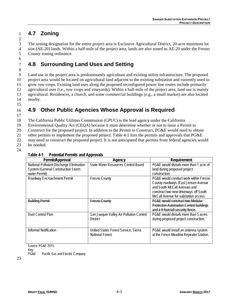
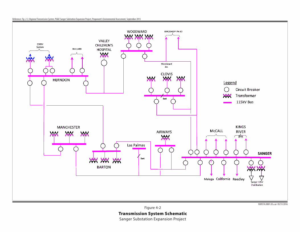
Sanger Substation acts as a 115-kV hub for power transfer between the Fresno north and south 28 metropolitan areas in the Central Valley. Sanger Cogeneration Plant, Balch Power House, and Kings 29 River Power House generate power that is transmitted through Sanger Substation. McCall is the main 30 substation that imports power into Sanger Substation. About 200 megawatts of power are imported and 31 exported through Sanger Substation under peak conditions. Sanger Substation distributes electricity to 32 Manchester, Barton, Airways, California Avenue, Malaga, West Fresno, Las Palmas, Clovis, Reedley, 33 and Parlier Substations. Twelve 115-kV power lines connect to Sanger Substation. Figure 4-2 provides a 34 schematic of the transmission system. 35 36 PG&E has recently upgraded power lines that connect other substations to Sanger Substation. These 37 upgrades, shown on Figure 4-2, improved the service reliability of the 115-kV transmission system that 38 serves the Fresno metropolitan area via Sanger Substation as follows: 39 40
• Sanger–California Avenue 70-kV power line conversion: PG&E converted the Sanger–California 41 Avenue 70-kV power line to 115 kV in 2011. 42
• Sanger–Reedley Area Reinforcement project: PG&E reconductored the Sanger–Reedley 70-kV 43 line to upgrade it to 115 kV in 2013. PG&E removed 70-kV equipment (i.e., transformer bank 44 and 70-kV busbar) from Sanger Substation following this upgrade. 45
E Jensen Ave
evA llaCcM S
evA nospmohT . S
1009376.0001.03.a.ai 05/31/2016
Reference: Fig. 2-3, Regional Transmission System, PG&E Sanger Substation Expansion Project, Proponent’s Environmental Assessment, September 2015
Transmission System SchematicSanger Substation Expansion Project
Figure 4-2
SANGER SUBSTATION EXPANSION PROJECT
PROJECT DESCRIPTION
DRAFT FINAL IS/MND 4-7 JANUARY MARCH 2017
4.10.4 Project Components 1 2 Substation Expansion 3
Expansion Area 4
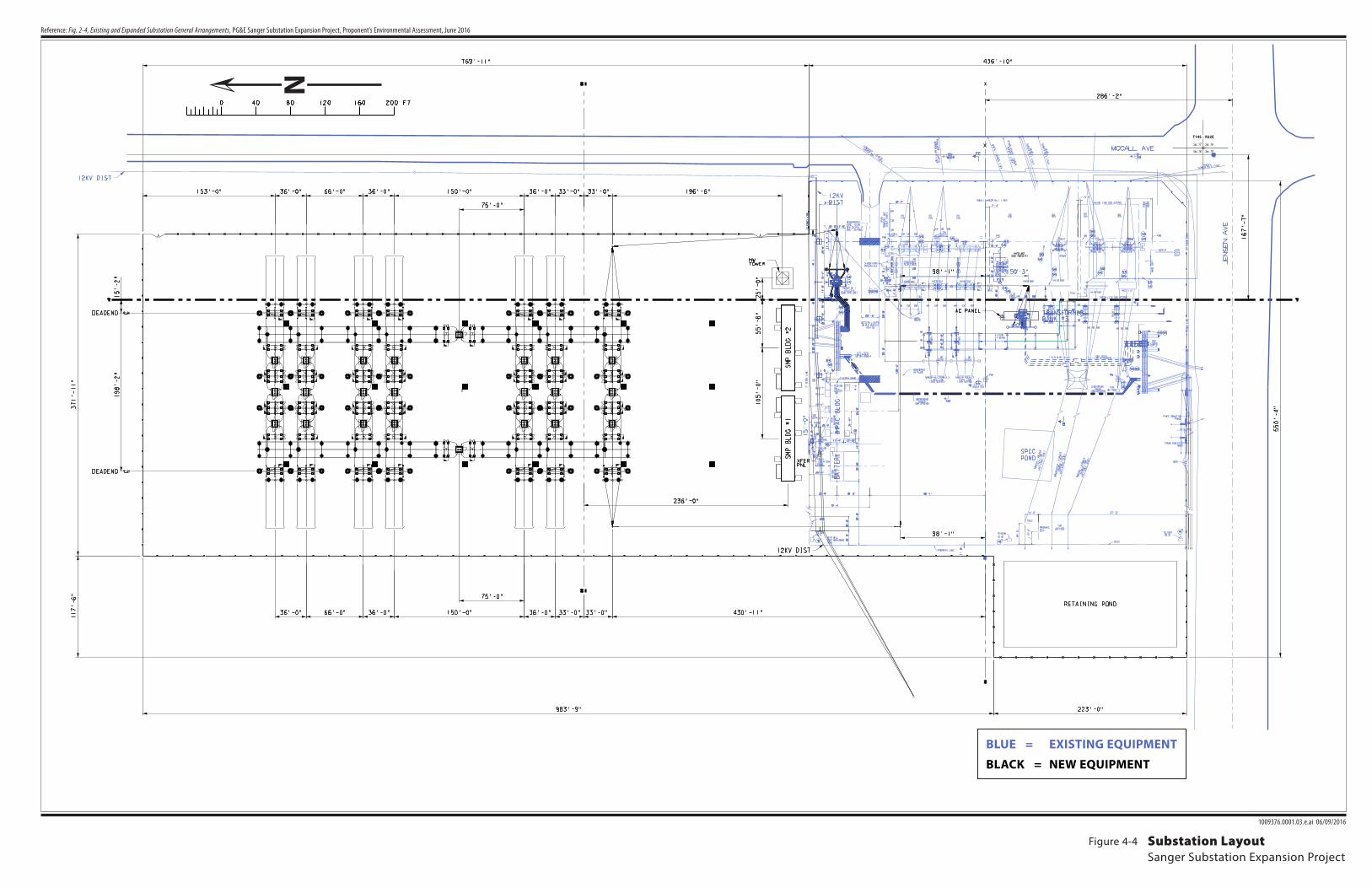
The proposed project would take up a larger footprint than the existing Sanger Substation. The substation 5 footprint would expand into an area measuring about 6.6 acres to the north of the existing Sanger 6 Substation footprint. The substation area would also expand into an area measuring about 0.5 acres to the 7 west of the existing substation (refer to Figure 4-3). With implementation of the proposed project and 8 when adding the existing substation footprint of 4.5 acres, the expanded substation’s footprint would 9 measure about 11.6 acres in total. 10 11 New Substation Equipment and Configuration 12
The Sanger Substation expansion would involve constructing a new switchrack at the substation in a 13 BAAH bus configuration. Under the BAAH bus configuration, Sanger Substation would have seven 14 BAAH bays. The substation layout is shown in Figure 4-4. Each BAAH bay would connect to two 15 elements (either a transmission line circuit or a transformer) and would have three 115-kV circuit 16 breakers insulated with SF6. The three circuit breakers on each BAAH bay would connect two circuits or 17 transformers. Each of the two circuits or transformers would have its own dedicated circuit breaker. The 18 third circuit breaker on the bay would be shared between the two circuits or transformers. Two circuit 19 breakers would be tie-in breakers located between the two busbars. The new transfer bus would have a 20 greater minimum vertical clearance than the removed transfer bus. There would be a total of 23 circuit 21 breakers. Additionally, there would be up to 18 bus support structures and 28 switch structures, 21 dead 22 end structures and 14 coupling capacitor voltage transformer structures. This configuration provides 23 greater reliability. 24 25 Two new control/MPAC buildings would be constructed to house protective relaying and 26 communications equipment. These buildings would replace an existing control building. They would be 27 covered in steel sheeting and have a sloped roof painted a non-reflective neutral color. The buildings 28 would be about 98 feet long by 15 feet wide by 11 feet tall. Operations equipment would include 29 instrument transformers, protective relaying equipment, metering and control equipment, remote 30 supervisory control and data acquisition equipment, telemetering equipment, an auxiliary alternating 31 current and direct current power system, and an electric grounding system. The expanded substation 32 would also include underground conduit and trench systems. The duct banks would be located across 33 2,500 square feet of the substation expansion area, with the excavation area for the ground grid covering 34 about 22,000 square feet. 35 36 Substation lighting, including security lighting, would consist of non-glare light-emitting diode (LED) 37 lamps that would be hooded and would be designed to avoid lighting off-site locations. Lights would be 38 located on: 39 40
• 10-foot-tall galvanized steel poles
• Transfer bus structures
• MPAC buildings
• MPAC building landings 41 There would be a total of 107 lights in the substation area; there are currently 47 lights, and the expanded 42 substation would have 60 more. A 9-foot-tall security fence with barbed wire would also be installed 43 around Sanger Substation. 44 45
!(
!(
!(
!(
!(
!(
!(
!(
!(
!(
!(!( !( !( !( !(!( !( !( !( !(
!(
!(
!(!(
!(
!(
!(
!(
!(
!(
!(
!(
!(
!(
!(
!(
!(
!( !( !(!(
!(
!(
!(
!(
!(
!(
!(!(!(!( !(
!(!(!(
!( !( !(!(
!(
!( !( !( !( !(
#*#*#*
#*
#*
#*#* #*
#* #*
#*#*#*#*#*#*#*
E JENSEN AVES
MCCA
LLAV
E
S TH O
MPS O
NAV
E
k
kExisting Gate on SouthMcCall Ave
#Fence Meadow Repeater Station(Inset only)
!( Existing Pole to Remain!( New Pole to be Installed
!(Existing Pole to beRemoved
#*Existing Tower to beRemoved
Existing Line to RemainExisting Lines to beRemovedNew Line InstalledPull and Tension SitesProposed SubstationExpansion Footprint
Existing SubstationFootprintTemporary AccessRoadConstruction AccessRoadExisting Farm Road
0 250 500125 Feet
\\prtbhp1\gis\Active\SanFrancisco\CPUC_Sanger\maps\mxd\Report\Fig4-3_Infrastructure.mxd
Figure 4-3Existing and
Proposed InfrastructureSanger SubstationFresno County, CA
12/15/2016
°Source: PG&E 2015, 2016Basemap: NAIP 2014
Fence Meadow Repeater StationFence Meadow Repeater StationLocated 30 mi NE of Sanger SubstationLocated 30 mi NE of Sanger Substation
0 250 500125 Feet
N
Sec. 17 Sec. 16
Sec. 18 Sec. 19
T14S – R22E
BLUE = EXISTING EQUIPMENT
BLACK = NEW EQUIPMENT
1009376.0001.03.e.ai 06/09/2016
Reference: Fig. 2-4, Existing and Expanded Substation General Arrangements, PG&E Sanger Substation Expansion Project, Proponent’s Environmental Assessment, June 2016
Substation LayoutSanger Substation Expansion Project
Figure 4-4

This page intentionally left blank.
SANGER SUBSTATION EXPANSION PROJECT
PROJECT DESCRIPTION
DRAFT FINAL IS/MND 4-11 JANUARY MARCH 2017
1 The expanded substation would have space for five additional BAAH bays. Further build out of the 2 substation is unlikely to occur for at least 20 years, if at all. There are no known planned generation 3 projects proposing to connect to Sanger Substation. This potential future expansion is therefore not 4 considered reasonably foreseeable and its impacts are not analyzed in this Initial Study/Mitigated 5 Negative Declaration (IS/MND). 6 7 Stormwater Retention 8
A stormwater retention basin (approximately 200 by 100 feet wide and 2 feet deep) would be constructed 9 in the expansion area located to the west of the southern portion of the existing substation, just north of 10 East Jensen Avenue. Refer to Figure 4-3. The substation site would be graded slightly downslope from 11 east to west toward the retention basin. The substation site would be tied into the basin with a swale. 12 13 Telecommunications Tower 14
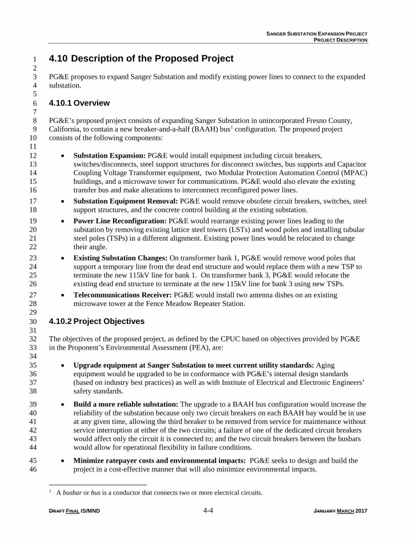
PG&E would install a microwave tower at the substation site to support a new antenna system. The tower 15 would be 80 to 100 feet tall and would be within the expanded substation’s fenceline. The location of the 16 tower is shown on Figure 4-3; a diagram of a typical tower is shown in Figure 4-5. The tower would 17 require either a reinforced concrete slab foundation or a drilled pier foundation. A reinforced concrete 18 slab foundation can be up to approximately 42 inches thick, covering a 25-by-25-foot area. A drilled pier 19 foundation can be approximately 40 feet deep. The antennas mounted on the microwave tower would 20 communicate with the existing PG&E Fence Meadow Repeater Station, which is located approximately 21 30 miles north of Sanger Substation as shown on Figure 4-1. Only the receiving antenna system would be 22 installed at the Fence Meadow Repeater Station. PG&E would mount two dishes on an existing tower at 23 the Fence Meadow Repeater Station. Each dish would measure about 4 feet in diameter. Existing dishes 24 on the existing tower at the Fence Meadow Repeater Station are shown in a photograph in Figure 4-5. 25 26 Removal of Existing Substation Equipment 27
The existing 115/12-kV transformer banks at Sanger Substation would be retained, as would the 12-kV 28 distribution facilities. Facilities to be removed from Sanger Substation include the switchrack, which 29 contains: 30 31
• 16 115-kV circuit breakers (eight SF6-filled, eight oil-filled) 32
• 24 disconnect switches 33
• 71 steel support structures 34
• Main and transfer buses 35
• Existing control and relay racks, which will be removed from the existing MPAC building 36
37 The concrete control building would also be demolished. 38 39 Substation Access 40
Permanent substation access would be provided through two new driveways and access roads from South 41 McCall Avenue. 42 43
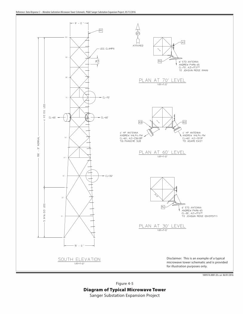
1009376.0001.03.c.ai 06/01/2016
Reference: Data Response 3 – Mendota Substation Microwave Tower Schematic, PG&E Sanger Substation Expansion Project, 05/13/2016
Diagram of Typical Microwave TowerSanger Substation Expansion Project
Figure 4-5
Disclaimer: This is an example of a typicalmicrowave tower schematic and is providedfor illustration purposes only.
SANGER SUBSTATION EXPANSION PROJECT
PROJECT DESCRIPTION
DRAFT FINAL IS/MND 4-13 JANUARY MARCH 2017
Power Line Reconfiguration 1
No new power lines would be constructed. The power lines that currently connect to Sanger Substation 2 would be realigned due to the change in equipment positioning at Sanger Substation. New structures were 3 designed in accordance with PG&E Overhead Transmission Line Design Criteria 068177 and also meet 4 the recommendations from Avian Power Line Interaction Committee (APLIC) regarding separation of 5 transmission lines. The existing structures were designed and constructed prior to the organization of 6 APLIC. However, existing structures are consistent with current APLIC recommendations. 7 8 Poles 9
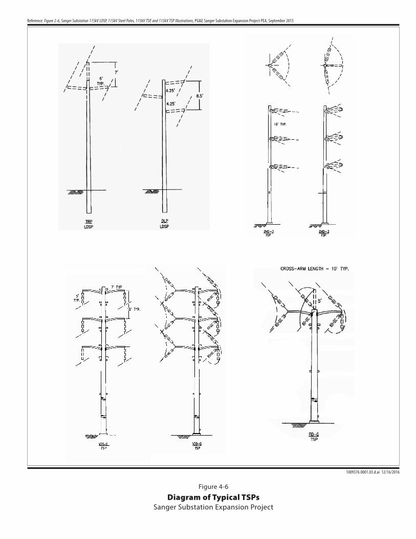
Approximately 18 wood poles and 17 LSTs would be replaced with TSPs. Four wood poles and two light 10 duty steel poles (LDSPs) would not be removed but instead would be topped, with distribution lines 11 remaining on the shortened poles. Approximately 29 TSPs would be installed. Figure 4-6 shows typical 12 pole diagrams. Guy poles are not currently planned as part of the proposed project. 13 14 TSPs are self-supported, with a reinforced concrete foundation. The poles would be 60 to 110 feet tall and 15 2 to 3.5 feet in diameter. Diagrams of TSPs are provided in Figure 2.5-2. Switches, breakers, and 16 structures would be replaced for incoming power lines. 17 18 Refer to Figure 4-3 for the locations of the existing 115-kV power lines, their relocated alignments, and 19 pole locations. 20 21 Conductor 22
Single circuit lines would contain three conductors. Double circuit lines would contain two circuits, with 23 three conductors on each circuit. Space between each circuit would be 10 vertical feet and 15 horizontal 24 feet. Conductor types to be used include 2433 AAC, 1113 AAC, 477 ACSS, 397 AAC, and 715 AAC. 25 26 4.10.5 Project Construction 27 28 Project construction would be completed in five phases: 29 30
• Phase 1: Substation Site Grading, Access, and Security Fencing 31
• Phase 2: Substation Foundation and Footing 32
• Phase 3: Substation Equipment and Components, Microwave Receiver Installation at Fence 33 Meadow Repeater Station 34
• Phase 4a: Power Line Reconfiguration (install pole foundations) 35
• Phase 4b: Power Line Reconfiguration (install poles) 36
• Phase 4c: Power Line Reconfiguration (string power lines) 37
• Phase 4d: Power Line Reconfiguration (remove pull sites and restore impacted property) 38
• Phase 5: Existing Substation Equipment Removal and Post-Construction Cleanup 39 40 These phases would occur sequentially, except that a portion of Phase 3 would overlap with Phase 4. 41 42
E Jense n Av e
evA lla
CcM
Se
vA n
osp
moh
T .S
E Jense n Av e
evA lla
CcM
Se
vA n
osp
moh
T .S
1009376.0001.03.d.ai 12/16/2016
Reference: Figure 2-6, Sanger Substation 115kV LDSP, 115kV Steel Poles, 115kV TSP, and 115kV TSP Illustrations, PG&E Sanger Substation Expansion Project PEA, September 2015
Diagram of Typical TSPsSanger Substation Expansion Project
Figure 4-6
SANGER SUBSTATION EXPANSION PROJECT
PROJECT DESCRIPTION
DRAFT FINAL IS/MND 4-15 JANUARY MARCH 2017
Phase 1: Substation Site Grading, Access, and Security Fencing 1
PG&E would first employ Storm Water Pollution Prevention Plan (SWPPP) best management practices 2 (BMPs), including the use of fiber rolls, silt fence, and mulch around the substation expansion area. 3 Surveyors would place stakes around the access road alignments and areas to be graded. Two 20-foot-4 wide access roads would be constructed to the expanded substation footprint area from South McCall 5 Avenue, as shown on Figure 4-3, with access provided between the two entry sites within the substation 6 footprint. Trucks would travel one way through the substation site after entering through one driveway 7 and would exit the substation through the other driveway. Up to 10 trucks and 30 worker vehicles may be 8 within the substation site at any given time during construction. Access to the existing substation would 9 be maintained through the existing gate on South McCall Avenue, as shown on Figure 4-3. 10 11 Vegetation, including grasses and agricultural crops, would be removed from the expansion area. No tree 12 removal is anticipated in this phase. Trimming of agricultural trees may be needed. Vegetation would be 13 stockpiled in the expanded substation footprint and eventually chipped and mulched on site. Topsoil 14 would be salvaged and stockpiled (for restoration or agricultural use), and then PG&E would grade and 15 compact the substation pad. The expanded substation pad would be adjacent to the existing substation. 16 With the expanded substation being constructed adjacent to the existing substation, the existing substation 17 would remain in service during expansion to avoid electricity service interruptions. Minimal grading of 18 the site would be required due to the area already being quite level. 19 20 PG&E anticipates that 3 feet of over-excavation and re-compaction would be required due to 21 recommendations in the Geotechnical Report prepared for the proposed project (Kleinfelder 2015). Some 22 soil may be imported. The anticipated source is located in Sanger, California. A conservative estimate of 23 the amount of soil to be imported is approximately 59,000 cubic yards, based on an overall increase of 24 2 feet across the site. PG&E would conduct fine grading to implement drainage on the site and would 25 then place surface gravel on the site to stabilize the work area. PG&E would also construct the retention 26 pond in the southwest corner of the site. 27 28 After grading, PG&E would install the perimeter security fence and video security system to replace the 29 existing fencing and security system. PG&E would obtain power for construction from the existing 30 Sanger Substation. 31 32 Phase 2: Substation Foundation and Footing 33
The subsurface ground grid and conduit chases would be excavated. The ground grid would be 34 approximately 1.5 feet below finish grade, with conduit duct banks approximately 4 feet below grade. 35 PG&E would excavate an area 4 to 6 feet below grade for slab foundations, then pour concrete footings 36 and foundations for substation aboveground components. The foundation for the microwave tower would 37 also be constructed. The foundation would either be a reinforced slab foundation or a drilled pier 38 foundation. For a reinforced slab foundation, PG&E would excavate the foundation area, then build a 39 reinforced steel cage for the foundation. Concrete would then be poured. For a drilled pier foundation, 40 PG&E would bore a hole with a boring machine, pour slurry into the hole, and then install a reinforced 41 steel column with a crane. PG&E would install ground wells and pull boxes. 42 43 Phase 3: Substation Equipment and Components, Microwave Receiver Installation at 44 Fence Meadow Repeater Station 45
PG&E would construct building foundations, bus work structures, dead-end switch structures, circuit 46 breakers, MPAC buildings, and control system hardware once the concrete foundations have cured. 47 Equipment would be secured by bolting or welding to foundation slabs and footings. Metallic structures 48 would be connected to the substation’s grounding grid. PG&E would install the microwave 49 telecommunications tower on its foundation, using a crane, during this phase. 50
SANGER SUBSTATION EXPANSION PROJECT
PROJECT DESCRIPTION
DRAFT FINAL IS/MND 4-16 JANUARY MARCH 2017
1 Gravel would be placed on all unpaved portions of the substation site. Gravel would be compacted where 2 equipment access is needed during operations and maintenance. PG&E would test and commission 3 equipment and place it into service; this would be done in parallel with work during Phase 4. 4 5 During Phase 3, PG&E would install two dishes, each measuring about 4 feet in diameter, on an existing 6 tower at the Fence Meadow Repeater Station. Installation would take approximately one week with a 3-7 person construction crew. No ground disturbance would occur. Construction equipment would include 8 one crane as well as up to two utility trucks with equipment. Construction workers would access the site 9 from State Route 168, from which they would take Dinkey Creek Road to Ross Crossing Road, which 10 leads to the Fence Meadow Repeater Station. 11 12 Phase 4: Power Line Reconfiguration 13
Phase 4 would consist of four sub-phases: (4a) install pole foundations, (4b) install poles, (4c) string 14 power lines, and (4d) remove pull sites and restore impacted property. Work in Phase 4 would be 15 performed in parallel with work in Phase 3. 16 17 Phase 4a: Power Line Access and Work Area Preparation 18
Vegetation, such as agricultural crops and grasses, would be removed from work areas and access road 19 areas. Up to 50 agricultural trees may be removed for this phase. A backhoe would likely be used to 20 remove vegetation, including trees. 21 22 Access to power line work areas would be from South McCall Avenue, East Jensen Avenue, and 23 Thompson Road. All new pole locations would be accessed utilizing a combination of existing access 24 roads and cross country access routes. No grading would be needed for cross-country access routes. 25 Preliminary locations for access roads and work areas are shown on Figure 4-3. 26 27 PG&E would establish work areas around existing poles and in new locations by removing vegetation. 28 Work areas around LSTs would be approximately 0.08 acres. Work areas to remove wood poles would be 29 about 0.2 acres. SWPPP BMPs would be implemented at the pole work areas. 30 31 Shoo-Fly Installation 32
Shoo-fly lines could be used during foundation installation where possible safety conflicts exist with 33 equipment. A shoo-fly line is a line used for temporary power service while construction work is 34 completed. Wooden poles would be installed, and conductor from the 115-kV power lines leading to 35 Sanger Substation would be transferred from existing wood poles and LSTs onto the shoo-fly poles. 36 Conductor would then be transferred from existing LSTs and wood poles. 37 38 Foundation Installation 39
Tubular Steel Poles. Concrete foundations would be poured for TSPs. PG&E would bore a foundation 40 hole measuring 4.5 to 7 feet in diameter and 15 to 30 feet deep. Reinforcing steel would be placed in the 41 excavation and secured to a bolt assembly plate. A prefabricated concrete form would be placed in the 42 excavated hole, and concrete would be poured into the form. The excavated area around the concrete form 43 would be backfilled with excavated or imported soil. The concrete foundation would be 1 to 2 feet above 44 ground level after backfilling. 45 46
SANGER SUBSTATION EXPANSION PROJECT
PROJECT DESCRIPTION
DRAFT FINAL IS/MND 4-17 JANUARY MARCH 2017
Phase 4b: Install Tubular Steel Poles 1
Pole Installation 2
Poles would be delivered to the site by flatbed trucks to be installed once foundations are constructed and 3 holes are augered. 4 5 Tubular Steel Poles. The TSP itself would be installed in two to three sections. The base section would 6 be lifted with a crane and bolted onto the foundation. The remaining sections would be placed by crane. 7 Arms and insulators on the top TSP section would be placed prior to TSP assembly. 8 9 Lattice Steel Tower Demolition and Wood Pole Removal 10
Conductor would be removed from the existing 115-kV power line structures. Lines would be de-11 energized, and then the conductor would be cut into pieces, removed, and recycled. Guard structures may 12 be used to prevent conductor from falling onto roadways. LSTs and wood poles that conflict with line re-13 routes would be removed. LSTs would be unbolted in sections. The sections would then be lifted with a 14 crane onto a work area for further dismantling. LST material would be recycled. Concrete foundations 15 under LSTs would be excavated to approximately 6 feet below the ground surface using a backhoe or air 16 compressor powered hand tools. Foundation material below 6 feet below the ground surface would be left 17 in place. The excavation would be filled with material from the site (e.g., from excavating new TSP 18 foundations) or imported soil. To remove wood poles, workers would use a bucket truck to first remove 19 cross arms and wires. Then a boom truck would be used to loosen the poles and extricate them from the 20 ground. Wood poles would be disposed of at an environmental disposal site or salvaged for future use. 21 22 Distribution Modification 23
Four wood poles and two LDSPs would be topped and would retain the distribution line while the power 24 line is moved onto new structures. To top poles, a line truck and aerial lift would be used to access the 25 pole. A chainsaw would be used to cut the top off of the poles 1 foot above where the distribution line is 26 attached to the pole. Removed portions of poles would be disposed of at an environmental disposal site. 27 28 Guard Structure Installation 29
Clearance structures (also called guard structures) would be used when stringing over East Jensen Avenue 30 and South McCall Avenue, and non-energized 12-kV lines would be used to prevent the 115-kV lines and 31 sock lines from falling onto roads and 12-kV lines. No energized electric lines would be crossed. 32 Clearance structures would be H- or Y-frame structures and would be installed directly into the ground to 33 a depth of 6 to 10 feet. Structures would be placed on one or either side of the infrastructure to be crossed. 34 Netting may be placed between the structures, spanning the road or 12-kV line. Traffic control would be 35 used as needed during installation of the clearance structures. 36 37 Pull and Tension Site Preparation 38
Up to eight pull and tension sites would be established, as shown in Figure 4-3. Vegetation and trees 39 would be removed with a backhoe to prep the sites. No compaction of soil would be needed. 40 41 Phase 4c: String Power Lines 42
Conductor Stringing 43
Conductor stringing would be completed using pull and tensioning equipment. Sheaves (rollers) would be 44 used to facilitate pulling conductor through each structure and would be attached to the transmission 45 structure cross arm. Pull and tensioning equipment would be positioned in the pulling/tensioning areas. 46 Sock line (rope) would be installed at the pull and tensioning equipment, attached to the conductor, then 47
SANGER SUBSTATION EXPANSION PROJECT
PROJECT DESCRIPTION
DRAFT FINAL IS/MND 4-18 JANUARY MARCH 2017
pulled tight through the sheaves. Conductor sags between structures would be adjusted to a specified 1 height (at least 29 feet) above the ground surface. Conductor would then be clamped to hardware on each 2 insulator to keep the conductor in place. Sheaves would be removed, and additional minor equipment, 3 such as vibration dampers, would be installed on structures. The line would then be connected and tested. 4 5 Tower and Wood Pole Removal 6
LSTs and wood poles not removed in Phase 4b would be removed using the same method described for 7 Phase 4b. 8 9 Guard Structure and Shoo-Fly Removal 10
Guard structures and shoo-flies would be removed after stringing and testing. The holes would be 11 backfilled. Traffic control would be used as needed during removal of the clearance structures. 12 13 Phase 4d: Remove Pull Sites and Restore Impacted Property 14
Once overland routes have been used, they would be restored to approximately pre-project conditions. 15 LST foundation piers would be removed. Pull sites would be restored. Work sites around removed poles 16 and LSTs would be restored. Base rock material would be salvaged and provided to the landowner, if 17 requested. 18 19 Phase 5: Existing Substation Equipment Removal and Post-Construction Cleanup 20
Existing Sanger Substation Area 21
Unneeded structures and materials (e.g., towers, poles, and conductor removed as part of the project) 22 would be disposed of or recycled. Transmission equipment, bus work, and structures would be removed. 23 Five of the existing SF6 circuit breakers would be retained in PG&E’s surplus inventory. The remaining 24 three SF6 circuit breakers would be scrapped, with any spare parts in good condition retained as part of 25 PG&E’s surplus inventory. Connections would be reconfigured to take the relocated 115-kV power lines. 26 Existing control building structures and foundations would be removed. The site would be restored and 27 graded as needed. 28 29 Expanded Substation Area 30
The permanent access roads would be covered with base rock, then paved with asphalt. Grading would be 31 done to match the original contours. Access roads for power line reconfiguration would be restored. 32 Connections would be reconfigured to accept the relocated 115-kV infrastructure. SWPPP BMP 33 structures would be removed. 34 35 Construction Staging and Soil Stockpile 36
Parking, material lay down, and construction staging would be within the boundaries of the expanded 37 substation. The staging area would likely move within the constraint area during construction but would 38 not extend beyond the boundary of the expanded substation area. Soil would also be stockpiled within the 39 expanded substation site and may move within the constraint area throughout construction. 40 41 Water Use 42
During construction, water would be used for soil compaction and dust control. The average water use 43 would be 1,500 gallons per day, with the total maximum water usage totaling 1 million gallons of water. 44 Water could be obtained from the City of Sanger, the City of Fowler, or from Sunnyside Farms (which 45 would be located adjacent to the substation expansion area). The City of Fowler and City of Sanger have 46 hydrant meters from which PG&E could fill water trucks and then transport to the project site. 47
SANGER SUBSTATION EXPANSION PROJECT
PROJECT DESCRIPTION
DRAFT FINAL IS/MND 4-19 JANUARY MARCH 2017
1 Concrete Import 2
About 1,420 cubic yards of concrete would be imported for building and structure foundations. 3 4 Construction Equipment 5
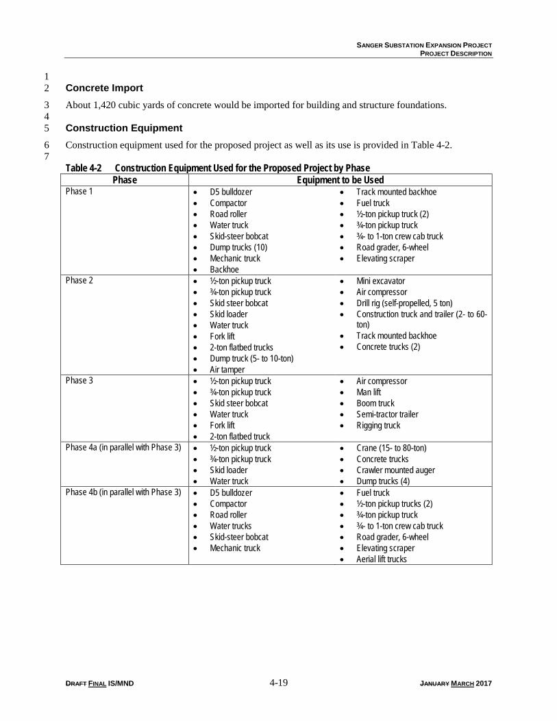
Construction equipment used for the proposed project as well as its use is provided in Table 4-2. 6 7 Table 4-2 Construction Equipment Used for the Proposed Project by Phase
Phase Equipment to be Used Phase 1 • D5 bulldozer
• Compactor • Road roller • Water truck • Skid-steer bobcat • Dump trucks (10) • Mechanic truck • Backhoe
• Track mounted backhoe • Fuel truck • ½-ton pickup truck (2) • ¾-ton pickup truck • ¾- to 1-ton crew cab truck • Road grader, 6-wheel • Elevating scraper
Phase 2 • ½-ton pickup truck • ¾-ton pickup truck • Skid steer bobcat • Skid loader • Water truck • Fork lift • 2-ton flatbed trucks • Dump truck (5- to 10-ton) • Air tamper
• Mini excavator • Air compressor • Drill rig (self-propelled, 5 ton) • Construction truck and trailer (2- to 60-
ton) • Track mounted backhoe • Concrete trucks (2)
Phase 3 • ½-ton pickup truck • ¾-ton pickup truck • Skid steer bobcat • Water truck • Fork lift • 2-ton flatbed truck
• Air compressor • Man lift • Boom truck • Semi-tractor trailer • Rigging truck
Phase 4a (in parallel with Phase 3) • ½-ton pickup truck • ¾-ton pickup truck • Skid loader • Water truck
• Crane (15- to 80-ton) • Concrete trucks • Crawler mounted auger • Dump trucks (4)
Phase 4b (in parallel with Phase 3) • D5 bulldozer • Compactor • Road roller • Water trucks • Skid-steer bobcat • Mechanic truck
• Fuel truck • ½-ton pickup trucks (2) • ¾-ton pickup truck • ¾- to 1-ton crew cab truck • Road grader, 6-wheel • Elevating scraper • Aerial lift trucks
SANGER SUBSTATION EXPANSION PROJECT
PROJECT DESCRIPTION
DRAFT FINAL IS/MND 4-20 JANUARY MARCH 2017
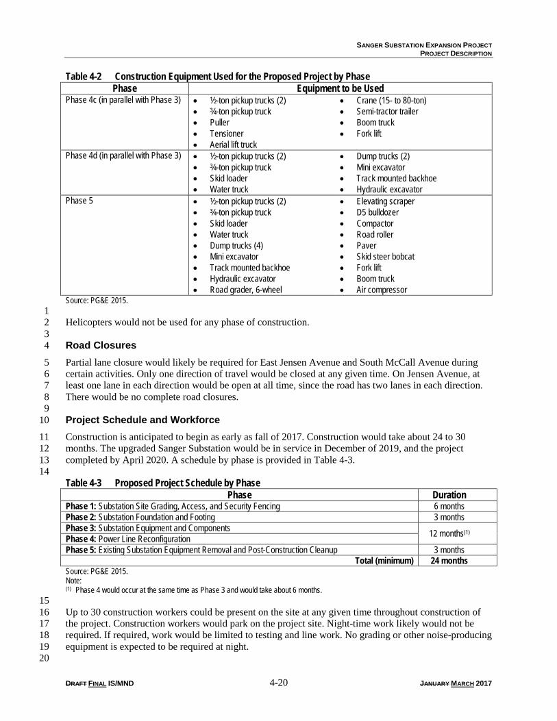
Table 4-2 Construction Equipment Used for the Proposed Project by Phase Phase Equipment to be Used
Phase 4c (in parallel with Phase 3) • ½-ton pickup trucks (2) • ¾-ton pickup truck • Puller • Tensioner • Aerial lift truck
• Crane (15- to 80-ton) • Semi-tractor trailer • Boom truck • Fork lift
Phase 4d (in parallel with Phase 3) • ½-ton pickup trucks (2) • ¾-ton pickup truck • Skid loader • Water truck
• Dump trucks (2) • Mini excavator • Track mounted backhoe • Hydraulic excavator
Phase 5 • ½-ton pickup trucks (2) • ¾-ton pickup truck • Skid loader • Water truck • Dump trucks (4) • Mini excavator • Track mounted backhoe • Hydraulic excavator • Road grader, 6-wheel
• Elevating scraper • D5 bulldozer • Compactor • Road roller • Paver • Skid steer bobcat • Fork lift • Boom truck • Air compressor
Source: PG&E 2015. 1 Helicopters would not be used for any phase of construction. 2 3 Road Closures 4
Partial lane closure would likely be required for East Jensen Avenue and South McCall Avenue during 5 certain activities. Only one direction of travel would be closed at any given time. On Jensen Avenue, at 6 least one lane in each direction would be open at all time, since the road has two lanes in each direction. 7 There would be no complete road closures. 8 9 Project Schedule and Workforce 10
Construction is anticipated to begin as early as fall of 2017. Construction would take about 24 to 30 11 months. The upgraded Sanger Substation would be in service in December of 2019, and the project 12 completed by April 2020. A schedule by phase is provided in Table 4-3. 13 14 Table 4-3 Proposed Project Schedule by Phase
Phase Duration Phase 1: Substation Site Grading, Access, and Security Fencing 6 months Phase 2: Substation Foundation and Footing 3 months Phase 3: Substation Equipment and Components 12 months(1) Phase 4: Power Line Reconfiguration Phase 5: Existing Substation Equipment Removal and Post-Construction Cleanup 3 months
Total (minimum) 24 months Source: PG&E 2015. Note: (1) Phase 4 would occur at the same time as Phase 3 and would take about 6 months. 15 Up to 30 construction workers could be present on the site at any given time throughout construction of 16 the project. Construction workers would park on the project site. Night-time work likely would not be 17 required. If required, work would be limited to testing and line work. No grading or other noise-producing 18 equipment is expected to be required at night. 19 20
SANGER SUBSTATION EXPANSION PROJECT
PROJECT DESCRIPTION
DRAFT FINAL IS/MND 4-21 JANUARY MARCH 2017
4.10.6 Project Operation and Maintenance 1 2 System Monitoring and Control 3
Sanger Substation would not be staffed. The expanded Sanger Substation would be operated from 4 PG&E’s Grid Control Center in Vacaville, California. A dedicated phone line would connect the 5 substation and the control center to transmit station and line alarms. 6 7 Maintenance 8
As is true for the existing substation, maintenance and alarm responses would be staffed through PG&E’s 9 local maintenance center. All maintenance of the substation would occur within the substation site and 10 access roads. Tree trimming is not anticipated during project operation. Future maintenance activities are 11 expected to be generally the same as what is occurring at the existing Sanger Substation. 12 13 Facility Inspection 14
Inspection of power lines would be conducted in the same manner as inspections of the existing power 15 lines. Power line inspection is conducted annually by ground or with a flyover. The substation would be 16 inspected monthly or as needed for emergencies. Staff would park within the substation fence line. 17 18 Water Use 19
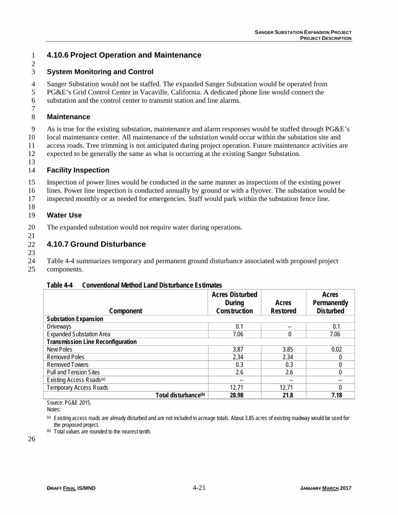
The expanded substation would not require water during operations. 20 21 4.10.7 Ground Disturbance 22 23 Table 4-4 summarizes temporary and permanent ground disturbance associated with proposed project 24 components. 25
Table 4-4 Conventional Method Land Disturbance Estimates
Component
Acres Disturbed During
Construction Acres
Restored
Acres Permanently
Disturbed Substation Expansion Driveways 0.1 -- 0.1 Expanded Substation Area 7.06 0 7.06 Transmission Line Reconfiguration New Poles 3.87 3.85 0.02 Removed Poles 2.34 2.34 0 Removed Towers 0.3 0.3 0 Pull and Tension Sites 2.6 2.6 0 Existing Access Roads(a) -- -- -- Temporary Access Roads 12.71 12.71 0
Total disturbance(b) 28.98 21.8 7.18 Source: PG&E 2015. Notes: (a) Existing access roads are already disturbed and are not included in acreage totals. About 3.85 acres of existing roadway would be used for
the proposed project. (b) Total values are rounded to the nearest tenth. 26
SANGER SUBSTATION EXPANSION PROJECT
PROJECT DESCRIPTION
DRAFT FINAL IS/MND 4-22 JANUARY MARCH 2017
4.10.8 Right-of-Way Acquisition 1 2 Substation Expansion 3
PG&E intends to acquire the land necessary for the substation expansion. 4 5 Power Line Reconfiguration 6
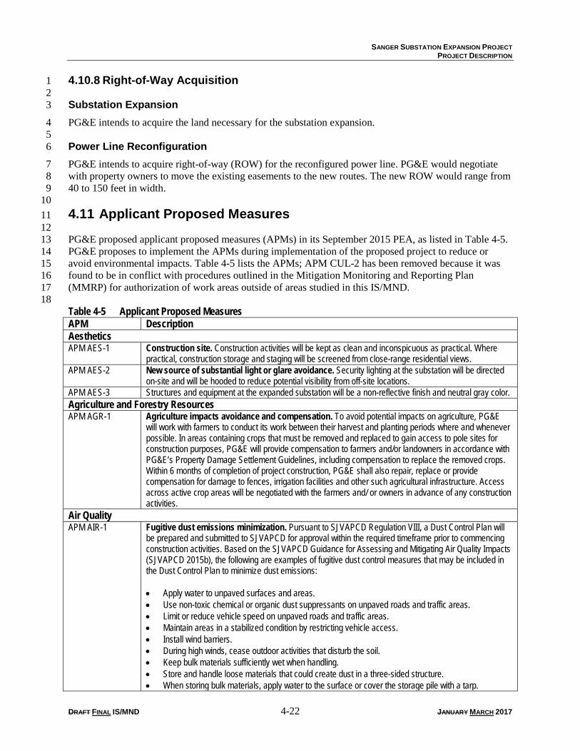
PG&E intends to acquire right-of-way (ROW) for the reconfigured power line. PG&E would negotiate 7 with property owners to move the existing easements to the new routes. The new ROW would range from 8 40 to 150 feet in width. 9 10 4.11 Applicant Proposed Measures 11 12 PG&E proposed applicant proposed measures (APMs) in its September 2015 PEA, as listed in Table 4-5. 13 PG&E proposes to implement the APMs during implementation of the proposed project to reduce or 14 avoid environmental impacts. Table 4-5 lists the APMs; APM CUL-2 has been removed because it was 15 found to be in conflict with procedures outlined in the Mitigation Monitoring and Reporting Plan 16 (MMRP) for authorization of work areas outside of areas studied in this IS/MND. 17 18 Table 4-5 Applicant Proposed Measures APM Description Aesthetics APM AES-1 Construction site. Construction activities will be kept as clean and inconspicuous as practical. Where
practical, construction storage and staging will be screened from close-range residential views. APM AES-2 New source of substantial light or glare avoidance. Security lighting at the substation will be directed
on-site and will be hooded to reduce potential visibility from off-site locations. APM AES-3 Structures and equipment at the expanded substation will be a non-reflective finish and neutral gray color. Agriculture and Forestry Resources APM AGR-1 Agriculture impacts avoidance and compensation. To avoid potential impacts on agriculture, PG&E
will work with farmers to conduct its work between their harvest and planting periods where and whenever possible. In areas containing crops that must be removed and replaced to gain access to pole sites for construction purposes, PG&E will provide compensation to farmers and/or landowners in accordance with PG&E’s Property Damage Settlement Guidelines, including compensation to replace the removed crops. Within 6 months of completion of project construction, PG&E shall also repair, replace or provide compensation for damage to fences, irrigation facilities and other such agricultural infrastructure. Access across active crop areas will be negotiated with the farmers and/ or owners in advance of any construction activities.
Air Quality APM AIR-1 Fugitive dust emissions minimization. Pursuant to SJVAPCD Regulation VIII, a Dust Control Plan will
be prepared and submitted to SJVAPCD for approval within the required timeframe prior to commencing construction activities. Based on the SJVAPCD Guidance for Assessing and Mitigating Air Quality Impacts (SJVAPCD 2015b), the following are examples of fugitive dust control measures that may be included in the Dust Control Plan to minimize dust emissions: • Apply water to unpaved surfaces and areas. • Use non-toxic chemical or organic dust suppressants on unpaved roads and traffic areas. • Limit or reduce vehicle speed on unpaved roads and traffic areas. • Maintain areas in a stabilized condition by restricting vehicle access. • Install wind barriers. • During high winds, cease outdoor activities that disturb the soil. • Keep bulk materials sufficiently wet when handling. • Store and handle loose materials that could create dust in a three-sided structure. • When storing bulk materials, apply water to the surface or cover the storage pile with a tarp.
SANGER SUBSTATION EXPANSION PROJECT
PROJECT DESCRIPTION
DRAFT FINAL IS/MND 4-23 JANUARY MARCH 2017
Table 4-5 Applicant Proposed Measures APM Description
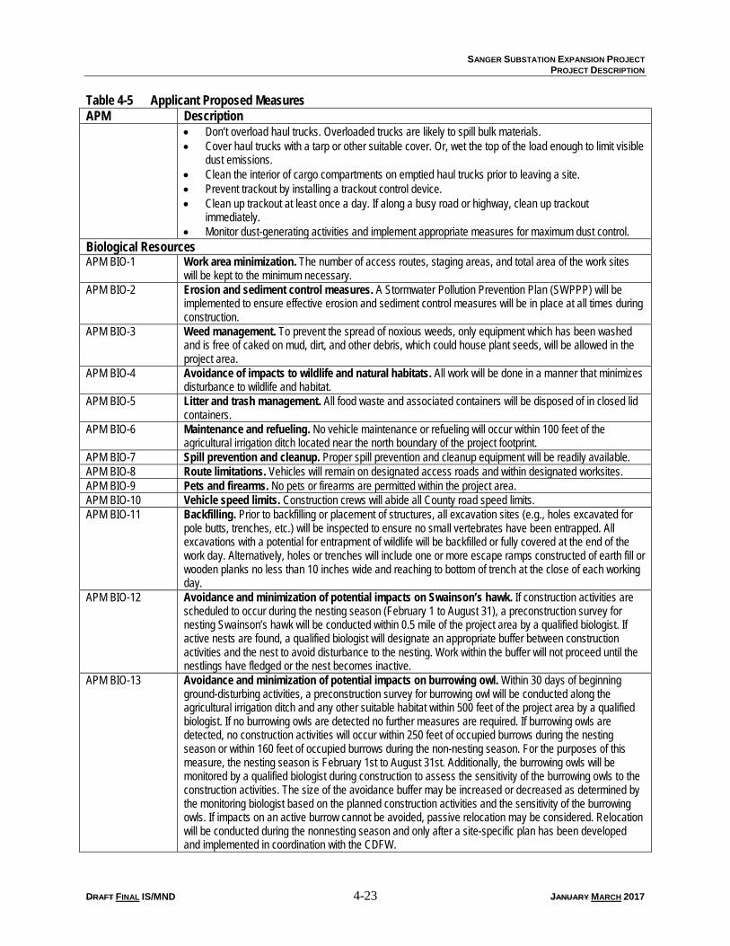
• Don’t overload haul trucks. Overloaded trucks are likely to spill bulk materials. • Cover haul trucks with a tarp or other suitable cover. Or, wet the top of the load enough to limit visible
dust emissions. • Clean the interior of cargo compartments on emptied haul trucks prior to leaving a site. • Prevent trackout by installing a trackout control device. • Clean up trackout at least once a day. If along a busy road or highway, clean up trackout
immediately. • Monitor dust-generating activities and implement appropriate measures for maximum dust control.
Biological Resources APM BIO-1 Work area minimization. The number of access routes, staging areas, and total area of the work sites
will be kept to the minimum necessary. APM BIO-2 Erosion and sediment control measures. A Stormwater Pollution Prevention Plan (SWPPP) will be
implemented to ensure effective erosion and sediment control measures will be in place at all times during construction.
APM BIO-3 Weed management. To prevent the spread of noxious weeds, only equipment which has been washed and is free of caked on mud, dirt, and other debris, which could house plant seeds, will be allowed in the project area.
APM BIO-4 Avoidance of impacts to wildlife and natural habitats. All work will be done in a manner that minimizes disturbance to wildlife and habitat.
APM BIO-5 Litter and trash management. All food waste and associated containers will be disposed of in closed lid containers.
APM BIO-6 Maintenance and refueling. No vehicle maintenance or refueling will occur within 100 feet of the agricultural irrigation ditch located near the north boundary of the project footprint.
APM BIO-7 Spill prevention and cleanup. Proper spill prevention and cleanup equipment will be readily available. APM BIO-8 Route limitations. Vehicles will remain on designated access roads and within designated worksites. APM BIO-9 Pets and firearms. No pets or firearms are permitted within the project area. APM BIO-10 Vehicle speed limits. Construction crews will abide all County road speed limits. APM BIO-11 Backfilling. Prior to backfilling or placement of structures, all excavation sites (e.g., holes excavated for
pole butts, trenches, etc.) will be inspected to ensure no small vertebrates have been entrapped. All excavations with a potential for entrapment of wildlife will be backfilled or fully covered at the end of the work day. Alternatively, holes or trenches will include one or more escape ramps constructed of earth fill or wooden planks no less than 10 inches wide and reaching to bottom of trench at the close of each working day.
APM BIO-12 Avoidance and minimization of potential impacts on Swainson’s hawk. If construction activities are scheduled to occur during the nesting season (February 1 to August 31), a preconstruction survey for nesting Swainson’s hawk will be conducted within 0.5 mile of the project area by a qualified biologist. If active nests are found, a qualified biologist will designate an appropriate buffer between construction activities and the nest to avoid disturbance to the nesting. Work within the buffer will not proceed until the nestlings have fledged or the nest becomes inactive.
APM BIO-13 Avoidance and minimization of potential impacts on burrowing owl. Within 30 days of beginning ground-disturbing activities, a preconstruction survey for burrowing owl will be conducted along the agricultural irrigation ditch and any other suitable habitat within 500 feet of the project area by a qualified biologist. If no burrowing owls are detected no further measures are required. If burrowing owls are detected, no construction activities will occur within 250 feet of occupied burrows during the nesting season or within 160 feet of occupied burrows during the non-nesting season. For the purposes of this measure, the nesting season is February 1st to August 31st. Additionally, the burrowing owls will be monitored by a qualified biologist during construction to assess the sensitivity of the burrowing owls to the construction activities. The size of the avoidance buffer may be increased or decreased as determined by the monitoring biologist based on the planned construction activities and the sensitivity of the burrowing owls. If impacts on an active burrow cannot be avoided, passive relocation may be considered. Relocation will be conducted during the nonnesting season and only after a site-specific plan has been developed and implemented in coordination with the CDFW.
SANGER SUBSTATION EXPANSION PROJECT
PROJECT DESCRIPTION
DRAFT FINAL IS/MND 4-24 JANUARY MARCH 2017
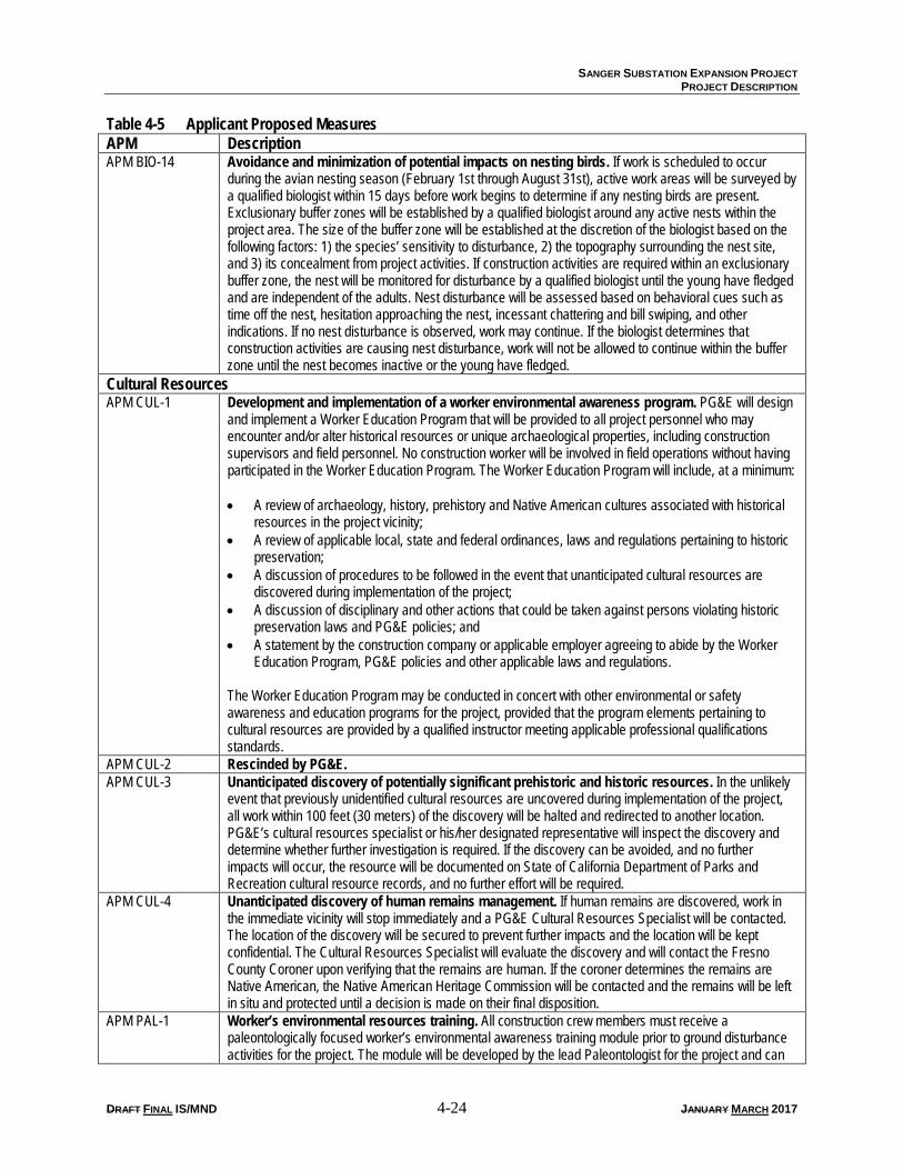
Table 4-5 Applicant Proposed Measures APM Description APM BIO-14 Avoidance and minimization of potential impacts on nesting birds. If work is scheduled to occur
during the avian nesting season (February 1st through August 31st), active work areas will be surveyed by a qualified biologist within 15 days before work begins to determine if any nesting birds are present. Exclusionary buffer zones will be established by a qualified biologist around any active nests within the project area. The size of the buffer zone will be established at the discretion of the biologist based on the following factors: 1) the species’ sensitivity to disturbance, 2) the topography surrounding the nest site, and 3) its concealment from project activities. If construction activities are required within an exclusionary buffer zone, the nest will be monitored for disturbance by a qualified biologist until the young have fledged and are independent of the adults. Nest disturbance will be assessed based on behavioral cues such as time off the nest, hesitation approaching the nest, incessant chattering and bill swiping, and other indications. If no nest disturbance is observed, work may continue. If the biologist determines that construction activities are causing nest disturbance, work will not be allowed to continue within the buffer zone until the nest becomes inactive or the young have fledged.
Cultural Resources APM CUL-1 Development and implementation of a worker environmental awareness program. PG&E will design
and implement a Worker Education Program that will be provided to all project personnel who may encounter and/or alter historical resources or unique archaeological properties, including construction supervisors and field personnel. No construction worker will be involved in field operations without having participated in the Worker Education Program. The Worker Education Program will include, at a minimum: • A review of archaeology, history, prehistory and Native American cultures associated with historical
resources in the project vicinity; • A review of applicable local, state and federal ordinances, laws and regulations pertaining to historic
preservation; • A discussion of procedures to be followed in the event that unanticipated cultural resources are
discovered during implementation of the project; • A discussion of disciplinary and other actions that could be taken against persons violating historic
preservation laws and PG&E policies; and • A statement by the construction company or applicable employer agreeing to abide by the Worker
Education Program, PG&E policies and other applicable laws and regulations. The Worker Education Program may be conducted in concert with other environmental or safety awareness and education programs for the project, provided that the program elements pertaining to cultural resources are provided by a qualified instructor meeting applicable professional qualifications standards.
APM CUL-2 Rescinded by PG&E. APM CUL-3 Unanticipated discovery of potentially significant prehistoric and historic resources. In the unlikely
event that previously unidentified cultural resources are uncovered during implementation of the project, all work within 100 feet (30 meters) of the discovery will be halted and redirected to another location. PG&E’s cultural resources specialist or his/her designated representative will inspect the discovery and determine whether further investigation is required. If the discovery can be avoided, and no further impacts will occur, the resource will be documented on State of California Department of Parks and Recreation cultural resource records, and no further effort will be required.
APM CUL-4 Unanticipated discovery of human remains management. If human remains are discovered, work in the immediate vicinity will stop immediately and a PG&E Cultural Resources Specialist will be contacted. The location of the discovery will be secured to prevent further impacts and the location will be kept confidential. The Cultural Resources Specialist will evaluate the discovery and will contact the Fresno County Coroner upon verifying that the remains are human. If the coroner determines the remains are Native American, the Native American Heritage Commission will be contacted and the remains will be left in situ and protected until a decision is made on their final disposition.
APM PAL-1 Worker’s environmental resources training. All construction crew members must receive a paleontologically focused worker’s environmental awareness training module prior to ground disturbance activities for the project. The module will be developed by the lead Paleontologist for the project and can
SANGER SUBSTATION EXPANSION PROJECT
PROJECT DESCRIPTION
DRAFT FINAL IS/MND 4-25 JANUARY MARCH 2017
Table 4-5 Applicant Proposed Measures APM Description
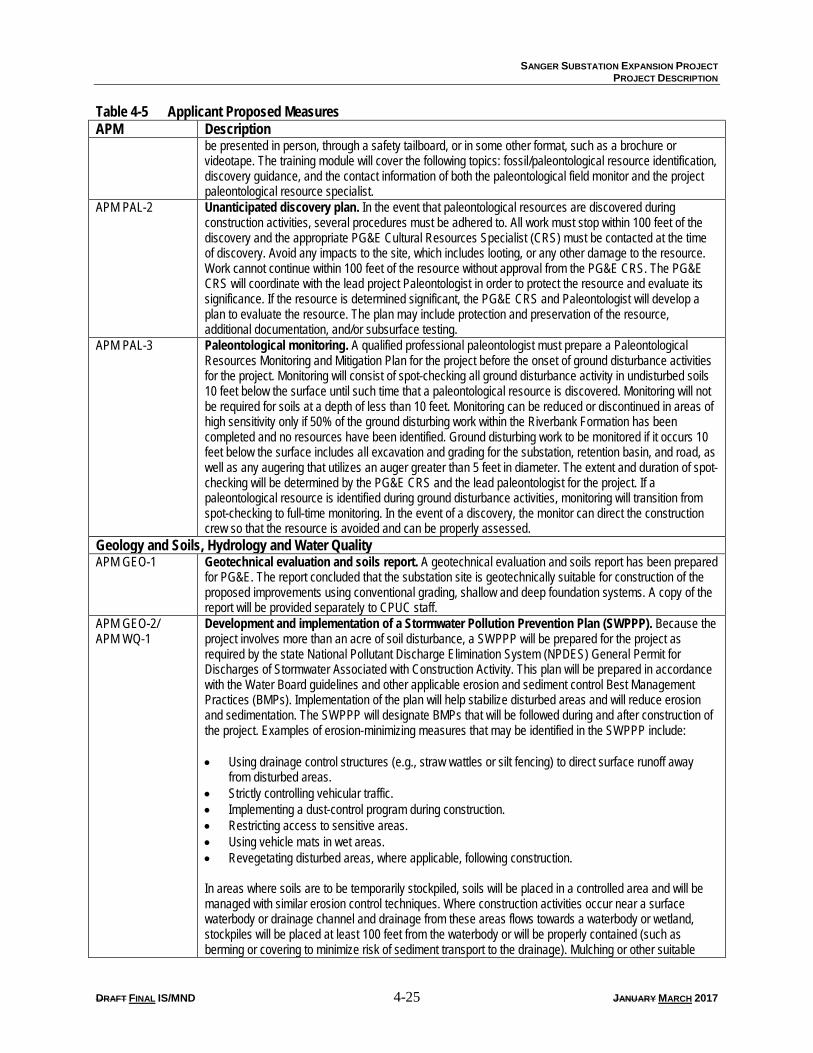
be presented in person, through a safety tailboard, or in some other format, such as a brochure or videotape. The training module will cover the following topics: fossil/paleontological resource identification, discovery guidance, and the contact information of both the paleontological field monitor and the project paleontological resource specialist.
APM PAL-2 Unanticipated discovery plan. In the event that paleontological resources are discovered during construction activities, several procedures must be adhered to. All work must stop within 100 feet of the discovery and the appropriate PG&E Cultural Resources Specialist (CRS) must be contacted at the time of discovery. Avoid any impacts to the site, which includes looting, or any other damage to the resource. Work cannot continue within 100 feet of the resource without approval from the PG&E CRS. The PG&E CRS will coordinate with the lead project Paleontologist in order to protect the resource and evaluate its significance. If the resource is determined significant, the PG&E CRS and Paleontologist will develop a plan to evaluate the resource. The plan may include protection and preservation of the resource, additional documentation, and/or subsurface testing.
APM PAL-3 Paleontological monitoring. A qualified professional paleontologist must prepare a Paleontological Resources Monitoring and Mitigation Plan for the project before the onset of ground disturbance activities for the project. Monitoring will consist of spot-checking all ground disturbance activity in undisturbed soils 10 feet below the surface until such time that a paleontological resource is discovered. Monitoring will not be required for soils at a depth of less than 10 feet. Monitoring can be reduced or discontinued in areas of high sensitivity only if 50% of the ground disturbing work within the Riverbank Formation has been completed and no resources have been identified. Ground disturbing work to be monitored if it occurs 10 feet below the surface includes all excavation and grading for the substation, retention basin, and road, as well as any augering that utilizes an auger greater than 5 feet in diameter. The extent and duration of spot-checking will be determined by the PG&E CRS and the lead paleontologist for the project. If a paleontological resource is identified during ground disturbance activities, monitoring will transition from spot-checking to full-time monitoring. In the event of a discovery, the monitor can direct the construction crew so that the resource is avoided and can be properly assessed.
Geology and Soils, Hydrology and Water Quality APM GEO-1 Geotechnical evaluation and soils report. A geotechnical evaluation and soils report has been prepared
for PG&E. The report concluded that the substation site is geotechnically suitable for construction of the proposed improvements using conventional grading, shallow and deep foundation systems. A copy of the report will be provided separately to CPUC staff.
APM GEO-2/ APM WQ-1
Development and implementation of a Stormwater Pollution Prevention Plan (SWPPP). Because the project involves more than an acre of soil disturbance, a SWPPP will be prepared for the project as required by the state National Pollutant Discharge Elimination System (NPDES) General Permit for Discharges of Stormwater Associated with Construction Activity. This plan will be prepared in accordance with the Water Board guidelines and other applicable erosion and sediment control Best Management Practices (BMPs). Implementation of the plan will help stabilize disturbed areas and will reduce erosion and sedimentation. The SWPPP will designate BMPs that will be followed during and after construction of the project. Examples of erosion-minimizing measures that may be identified in the SWPPP include: • Using drainage control structures (e.g., straw wattles or silt fencing) to direct surface runoff away
from disturbed areas. • Strictly controlling vehicular traffic. • Implementing a dust-control program during construction. • Restricting access to sensitive areas. • Using vehicle mats in wet areas. • Revegetating disturbed areas, where applicable, following construction. In areas where soils are to be temporarily stockpiled, soils will be placed in a controlled area and will be managed with similar erosion control techniques. Where construction activities occur near a surface waterbody or drainage channel and drainage from these areas flows towards a waterbody or wetland, stockpiles will be placed at least 100 feet from the waterbody or will be properly contained (such as berming or covering to minimize risk of sediment transport to the drainage). Mulching or other suitable
SANGER SUBSTATION EXPANSION PROJECT
PROJECT DESCRIPTION
DRAFT FINAL IS/MND 4-26 JANUARY MARCH 2017
Table 4-5 Applicant Proposed Measures APM Description
stabilization measures will be used to protect exposed areas during and after construction activities. Erosion-control measures will be installed, as necessary, before any clearing during the wet season and before the onset of winter rains. Temporary measures, such as silt fences or wattles intended to minimize erosion from temporarily disturbed areas, will remain in place until disturbed areas have stabilized. The SWPPP will be designed specifically for the hydrologic setting of the project.
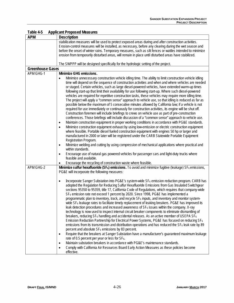
Greenhouse Gases APM GHG-1 Minimize GHG emissions.
• Minimize unnecessary construction vehicle idling time. The ability to limit construction vehicle idling time will depend on the sequence of construction activities and when and where vehicles are needed or staged. Certain vehicles, such as large diesel-powered vehicles, have extended warm-up times following start-up that limit their availability for use following start-up. Where such diesel-powered vehicles are required for repetitive construction tasks, these vehicles may require more idling time. The project will apply a “common sense” approach to vehicle use, so that idling is reduced as far as possible below the maximum of 5 consecutive minutes allowed by California law; if a vehicle is not required for use immediately or continuously for construction activities, its engine will be shut off. Construction foremen will include briefings to crews on vehicle use as part of pre-construction conferences. Those briefings will include discussion of a “common sense” approach to vehicle use.
• Maintain construction equipment in proper working conditions in accordance with PG&E standards. • Minimize construction equipment exhaust by using low-emission or electric construction equipment
where feasible. Portable diesel fueled construction equipment with engines 50 hp or larger and manufactured in 2000 or later will be registered under the CARB Statewide Portable Equipment Registration Program.
• Minimize welding and cutting by using compression of mechanical applications where practical and within standards.
• Encourage use of natural gas powered vehicles for passenger cars and light-duty trucks where feasible and available.
• Encourage the recycling of construction waste where feasible. APM GHG-2 Minimize sulfur hexafluoride (SF6) emissions. To avoid and minimize fugitive (leakage) SF6 emissions,
PG&E will incorporate the following measures: • Incorporate Sanger Substation into PG&E’s system-wide SF6 emission reduction program. CARB has
adopted the Regulation for Reducing Sulfur Hexafluoride Emissions from Gas Insulated Switchgear sections 95350 to 95359, title 17, California Code of Regulations, which requires that company-wide SF6 emission rate not exceed 1 percent by 2020. Since 1998, PG&E has implemented a programmatic plan to inventory, track, and recycle SF6 inputs, and inventory and monitor system-wide SF6 leakage rates to facilitate timely replacement of leaking breakers. PG&E has improved its leak detection procedures and increased awareness of SF6 issues within the company. X-ray technology is now used to inspect internal circuit breaker components to eliminate dismantling of breakers, reducing SF6 handling and accidental releases. As an active member of USEPA SF6 Emission Reduction Partnership for Electrical Power Systems, PG&E has focused on reducing SF6 emissions from its transmission and distribution operations and has reduced the SF6 leak rate by 89 percent and absolute SF6 emissions by 83 percent.
• Require that the breakers at Sanger Substation have a manufacturer’s guaranteed maximum leakage rate of 0.5 percent per year or less for SF6.
• Maintain substation breakers in accordance with PG&E’s maintenance standards. • Comply with California Air Resources Board Early Action Measures as these policies become
effective.
SANGER SUBSTATION EXPANSION PROJECT
PROJECT DESCRIPTION
DRAFT FINAL IS/MND 4-27 JANUARY MARCH 2017
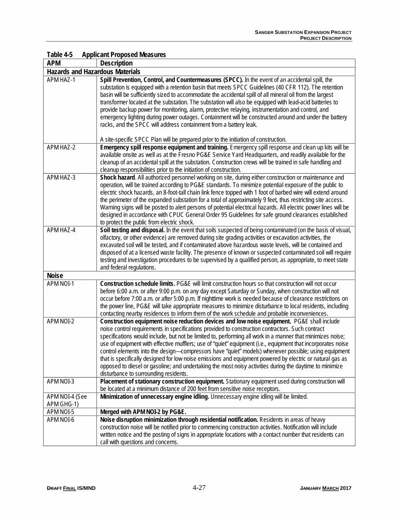
Table 4-5 Applicant Proposed Measures APM Description Hazards and Hazardous Materials APM HAZ-1 Spill Prevention, Control, and Countermeasures (SPCC). In the event of an accidental spill, the
substation is equipped with a retention basin that meets SPCC Guidelines (40 CFR 112). The retention basin will be sufficiently sized to accommodate the accidental spill of all mineral oil from the largest transformer located at the substation. The substation will also be equipped with lead-acid batteries to provide backup power for monitoring, alarm, protective relaying, instrumentation and control, and emergency lighting during power outages. Containment will be constructed around and under the battery racks, and the SPCC will address containment from a battery leak. A site-specific SPCC Plan will be prepared prior to the initiation of construction.
APM HAZ-2 Emergency spill response equipment and training. Emergency spill response and clean up kits will be available onsite as well as at the Fresno PG&E Service Yard Headquarters, and readily available for the cleanup of an accidental spill at the substation. Construction crews will be trained in safe handling and cleanup responsibilities prior to the initiation of construction.
APM HAZ-3 Shock hazard. All authorized personnel working on site, during either construction or maintenance and operation, will be trained according to PG&E standards. To minimize potential exposure of the public to electric shock hazards, an 8-foot-tall chain link fence topped with 1 foot of barbed wire will extend around the perimeter of the expanded substation for a total of approximately 9 feet, thus restricting site access. Warning signs will be posted to alert persons of potential electrical hazards. All electric power lines will be designed in accordance with CPUC General Order 95 Guidelines for safe ground clearances established to protect the public from electric shock.
APM HAZ-4 Soil testing and disposal. In the event that soils suspected of being contaminated (on the basis of visual, olfactory, or other evidence) are removed during site grading activities or excavation activities, the excavated soil will be tested, and if contaminated above hazardous waste levels, will be contained and disposed of at a licensed waste facility. The presence of known or suspected contaminated soil will require testing and investigation procedures to be supervised by a qualified person, as appropriate, to meet state and federal regulations.
Noise APM NOI-1 Construction schedule limits. PG&E will limit construction hours so that construction will not occur
before 6:00 a.m. or after 9:00 p.m. on any day except Saturday or Sunday, when construction will not occur before 7:00 a.m. or after 5:00 p.m. If nighttime work is needed because of clearance restrictions on the power line, PG&E will take appropriate measures to minimize disturbance to local residents, including contacting nearby residences to inform them of the work schedule and probable inconveniences.
APM NOI-2 Construction equipment noise reduction devices and low noise equipment. PG&E shall include noise control requirements in specifications provided to construction contractors. Such contract specifications would include, but not be limited to, performing all work in a manner that minimizes noise; use of equipment with effective mufflers; use of “quiet” equipment (i.e., equipment that incorporates noise control elements into the design—compressors have “quiet” models) whenever possible; using equipment that is specifically designed for low noise emissions and equipment powered by electric or natural gas as opposed to diesel or gasoline; and undertaking the most noisy activities during the daytime to minimize disturbance to surrounding residents.
APM NOI-3 Placement of stationary construction equipment. Stationary equipment used during construction will be located at a minimum distance of 200 feet from sensitive noise receptors.
APM NOI-4 (See APM GHG-1)
Minimization of unnecessary engine idling. Unnecessary engine idling will be limited.
APM NOI-5 Merged with APM NOI-2 by PG&E. APM NOI-6 Noise disruption minimization through residential notification. Residents in areas of heavy
construction noise will be notified prior to commencing construction activities. Notification will include written notice and the posting of signs in appropriate locations with a contact number that residents can call with questions and concerns.
SANGER SUBSTATION EXPANSION PROJECT
PROJECT DESCRIPTION
DRAFT FINAL IS/MND 4-28 JANUARY MARCH 2017
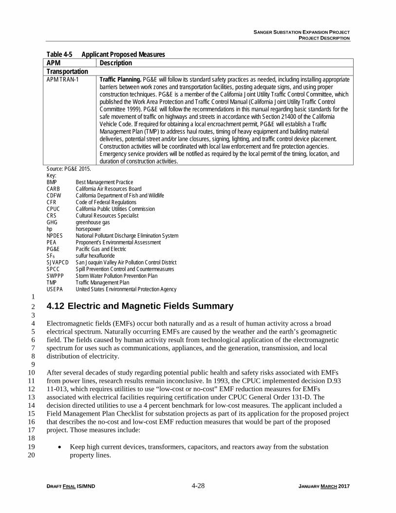
Table 4-5 Applicant Proposed Measures APM Description Transportation APM TRAN-1 Traffic Planning. PG&E will follow its standard safety practices as needed, including installing appropriate
barriers between work zones and transportation facilities, posting adequate signs, and using proper construction techniques. PG&E is a member of the California Joint Utility Traffic Control Committee, which published the Work Area Protection and Traffic Control Manual (California Joint Utility Traffic Control Committee 1999). PG&E will follow the recommendations in this manual regarding basic standards for the safe movement of traffic on highways and streets in accordance with Section 21400 of the California Vehicle Code. If required for obtaining a local encroachment permit, PG&E will establish a Traffic Management Plan (TMP) to address haul routes, timing of heavy equipment and building material deliveries, potential street and/or lane closures, signing, lighting, and traffic control device placement. Construction activities will be coordinated with local law enforcement and fire protection agencies. Emergency service providers will be notified as required by the local permit of the timing, location, and duration of construction activities.
Source: PG&E 2015. Key: BMP Best Management Practice CARB California Air Resources Board CDFW California Department of Fish and Wildlife CFR Code of Federal Regulations CPUC California Public Utilities Commission CRS Cultural Resources Specialist GHG greenhouse gas hp horsepower NPDES National Pollutant Discharge Elimination System PEA Proponent’s Environmental Assessment PG&E Pacific Gas and Electric SF6 sulfur hexafluoride SJVAPCD San Joaquin Valley Air Pollution Control District SPCC Spill Prevention Control and Countermeasures SWPPP Storm Water Pollution Prevention Plan TMP Traffic Management Plan USEPA United States Environmental Protection Agency 1 4.12 Electric and Magnetic Fields Summary 2 3 Electromagnetic fields (EMFs) occur both naturally and as a result of human activity across a broad 4 electrical spectrum. Naturally occurring EMFs are caused by the weather and the earth’s geomagnetic 5 field. The fields caused by human activity result from technological application of the electromagnetic 6 spectrum for uses such as communications, appliances, and the generation, transmission, and local 7 distribution of electricity. 8 9 After several decades of study regarding potential public health and safety risks associated with EMFs 10 from power lines, research results remain inconclusive. In 1993, the CPUC implemented decision D.93 11 11-013, which requires utilities to use “low-cost or no-cost” EMF reduction measures for EMFs 12 associated with electrical facilities requiring certification under CPUC General Order 131-D. The 13 decision directed utilities to use a 4 percent benchmark for low-cost measures. The applicant included a 14 Field Management Plan Checklist for substation projects as part of its application for the proposed project 15 that describes the no-cost and low-cost EMF reduction measures that would be part of the proposed 16 project. Those measures include: 17 18
• Keep high current devices, transformers, capacitors, and reactors away from the substation 19 property lines. 20
SANGER SUBSTATION EXPANSION PROJECT
PROJECT DESCRIPTION
DRAFT FINAL IS/MND 4-29 JANUARY MARCH 2017
• For underground duct banks, the minimum distance should be 12 feet from the adjacent property 1 lines or as close to 12 feet as practical. 2
• Locate new substations close to existing power lines to the extent practical. 3
• Increase the substation property boundary to the extent practical. 4 5 CPUC D.93 11-013 also implemented a number of EMF measurement, research, and education programs. 6 The CPUC did not adopt any specific numerical limits or regulation of EMF levels related to electric 7 power facilities. 8 9 The CPUC’s January 27, 2006, decision (D.06-01-042) affirmed the 1993 decision on the low-cost/no-10 cost policy to mitigate EMF exposure for new utility transmission and substation projects. Additionally, 11 the 2006 decision directs the CPUC’s Energy Division to pursue and review all available studies 12 regarding EMFs and to review scientific information and report on new findings. The CPUC has been 13 unable to determine whether there is a significant scientifically verifiable relationship between EMF 14 exposure and negative health consequences, and no change to the CPUC EMF policy has been made to 15 date. The CPUC will reconsider its EMF policies and open a new rulemaking, as necessary, if new 16 findings indicate negative EMF health impacts. 17 18 At present, the CPUC does not consider EMFs, in the context of California Environmental Quality Act 19 (CEQA), to be an environmental impact because there is no agreement among scientists that EMFs create 20 a potential health risk and because CEQA does not define or adopt standards for defining any potential 21 risk from EMFs. Therefore, EMFs are not addressed in the Environmental Impacts and Assessment 22 section of this resource section. 23 24 For further information about EMFs and CPUC guidelines, refer to: 25 http://www.cpuc.ca.gov/PUC/energy/Environment/ElectroMagnetic+Fields. 26 27

SANGER SUBSTATION EXPANSION PROJECT
PROJECT DESCRIPTION
DRAFT FINAL IS/MND 4-30 JANUARY MARCH 2017
This page intentionally left blank.