Embed Size (px)
DESCRIPTION
SAD
Citation preview

C. Buck-Boost Converter ModelingIn Fig. 5 a DC-DC buck-boost converter is shown. The switching period is T and the duty cycle is D. Assuming continuous conduction mode of operation, when the switch is ON, the state space equations are given by, [1]
and when the switch is OFF
These equations are implemented in Simulink as shown in Fig. 6 using multipliers, summing blocks, and gain blocks, and subsequently fed into two integrators to obtain the states and
, [2] [3] [4].
D. Cuk Converter Modeling
The Cuk converter of Fig. 7 with switching period of T and duty cycle of D is considered. During the continuous conduction mode of operation, the state space equations are as follows, [1]
When the switch is OFF the state space equations are represented by
these equations are implemented in Simulink as shown in Fig. 8 using multipliers, summing blocks, and gain blocks, and subsequently fed into
Fig. 5 DC-DC Buck-Boost Converter
Fig. 6 Open-loop of Buck-Boost DC-DC Converters
Fig.7 DC-DC Cuk converter

two
integrators to obtain the states and , [2] [3] [4].
E. SubsystemsEach of the power electronic models represents subsystems within the simulation environment. These blocks have been developed so they can be interconnected in a consistent and simple manner for the construction of complex systems. The subsystems are masked, meaning that the user interface displays
only the complete subsystem, and user prompts gather parameters for the entire subsystem. Relevant parameters can be set by double-clicking a mouse or pointer on each subsystem block, then entering the appropriate values in the resulting dialogue window [4].
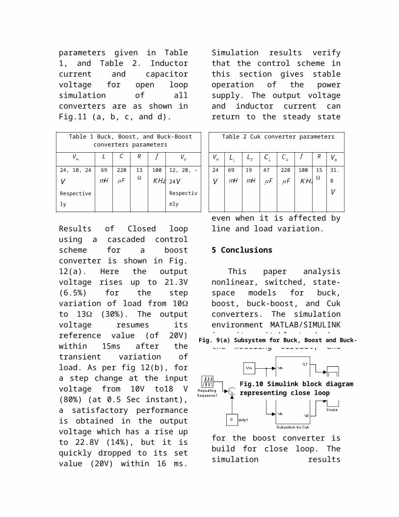
To facilitate the subsequent simulation analysis and feedback controller verification, the pulse-width-modulation signal to control the ideal switch can also be built into the masked subsystem Fig. 9(a) and Fig. 9(b). For each converter to verity it’s working in open loop configuration trigger pulses have been derived using a repeating sequence generator and duty cycle block. Function block compares the duty cycle and saw tooth from repeating sequence- derived trigger pulses are connected as
an input to the switch control. Hence inputs for the masked subsystem are duty ratio and input voltage, and the outputs are chosen to be inductor current, capacitor voltage, and output
Fig. 8 Open-loop modeling of Cuk DC-DC converters

voltage. When double-clicking the pointer on the masked subsystem, one enters parameter values of the switching converter circuit in a dialogue window. The intuitive signal flow interface in SIMULINK makes this mathematical model and its corresponding masked subsystem very easy to create.
4 Simulation Closed-Loop of DC-DC Converters Using Cascaded Control
The simulation model for cascaded control of DC-DC switching converters is build using the above-mentioned steps is as shown in Fig. 10. The DC-DC buck, boost, buck-boost, and Cuk converters was previously designed, and simulated on digital computer using Matlab package with the parameters given in Table 1, and Table 2. Inductor current and capacitor voltage for open loop simulation of all converters are as shown in Fig.11 (a, b, c, and d).
Results of Closed loop using a cascaded control scheme for a boost converter is shown in Fig. 12(a). Here the output voltage rises up to 21.3V (6.5%) for the step variation of load from 10 to 13 (30%). The output voltage resumes its reference value (of 20V) within 15ms after the transient variation of load. As per fig 12(b), for a step change at the input voltage from 10V to18 V (80%) (at 0.5 Sec instant), a satisfactory performance is obtained in the output voltage which has a rise up to 22.8V
(14%), but it is quickly dropped to its set value (20V) within 16 ms. Simulation results verify that the control scheme in this section gives stable operation of the power supply. The output voltage and inductor current can return to the steady state even when it is affected by line and load variation.
5 Conclusions
This paper analysis nonlinear, switched, state-space models for buck, boost, buck-boost, and Cuk converters. The simulation environment MATLAB/SIMULINK is quite suitable to design the modeling circuit, and to learn the dynamic behavior of different converter structures in open loop. The simulation model in MATLAB/SIMULINK for the boost converter is build for close loop. The simulation results obtained, show that the
output voltage and inductor current can return to steady state even when it is
affected by input voltage and load variation, with a very small over shoot and settling time.
Table 1 Buck, Boost, and Buck-Boost converters parameters
Table 2 Cuk converter parameters
24, 10, 24
Respectively
69 220 13 100 12, 20, -24
Respectively
24 69 19 47 220 100 15
31.8
Fig. 9(a) Subsystem for Buck, Boost and Buck-Boost converters
Fig.10 Simulink block diagram representing close loop Scheme of Boost converter using cascaded control
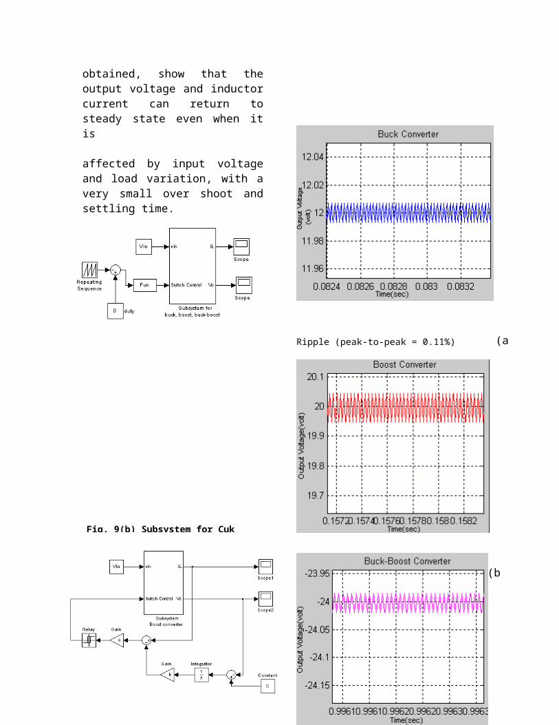
Ripple (peak-to-peak = 0.11%)
Ripple (peak-to-peak = 0.43%)
Ripple (peak-to-peak = 0.12%)
Fig. 9(b) Subsystem for Cuk converters
(b)
(a)
(c)
Ripple (peak-to-peak = 1.96%)
6 References
[1] J.Mahdavi, A.Emadi, H.A.Toliyat, Application of State Space Averaging Method to Sliding Mode Control of PWM DC/DC Converters, IEEE Industry Applications Society October 1997. [2] Vitor Femao Pires, Jose Fernando A. Silva, Teaching Nonlinear Modeling, Simulation, and Control of Electronic Power Converters Using MATLAB/SIMULINK, IEEE Transactions on Education, vol. 45, no. 3, August 2002.
(a)
(d)Fig. 11 Output voltage and inductor current Open-loop for (a) Buck (b) Boost (c) Buck-Boost (d) Cuk Converters
Fig. 12 Output voltage of SMC Boost Converter when (a) load variation (b) input voltage variation

[3] Juing-Huei Su, Jiann-Jong Chen, Dong-Shiuh Wu, Learning Feedback Controller Design of Switching Converters Via MATLAB/SIMULINK, IEEE Transactions on Education, vol. 45, November 2002.[4] Daniel Logue, Philip. T. Krein, Simulation of Electric Machinery and Power Electronics Interfacing Using MATLAB/SIMULINK, in 7th Workshop Computer in Power Electronics, 2000,pp. 34-39. [5] N. Mohan, T. Undeland, W. Robbins, Power Electronics Converters, Applications and Design, ISBN 9814-12-692-6.
(b)


