Embed Size (px)
Citation preview

Application of this type of control may cause flame rollout on initial startup and could cause personal injury and/or property damage.
Check product specification and cross reference before replacing existing module. Do not use if existing module is not listed. Use of a program key other than listed can result in appliance malfunction.
50E47-843Universal Hot Surface Ignition Control
INSTALLATION INSTRUCTIONS
FAILURE TO READ AND FOLLOW ALL INSTRUCTIONS CAREFULLY BEFORE INSTALLING OR OPERATING THIS CONTROL COULD CAUSE PERSONAL INJURY AND/OR PROPERTY DAMAGE.
CONTENTSDescription ................................................................... 1Precautions .................................................................. 1Specifications ............................................................... 2Installation .................................................................... 2 Mounting & WiringOperation & Troubleshooting ......................................... 4
DESCRIPTION
PRECAUTIONS
The 50E47-843 is a universal replacement Hot Surface Ignition (HSI) control designed for maximum compatibility with existing systems. It features:
•A card port and six program keys to select the Trial for Ignition Time, Retries, Pre-purge and Igniter Warm Up timings.
•AJumpertoaccommodatesystemsusingDirect Sense (sensing through ignitor) or Indirect Sense (using a Flame Sensor).
•LEDindicatorforquicksystemandmodulediagnosticsand troubleshooting.
GENERAL PRECAUTION!
Do not use on circuits exceeding specified voltage. Higher voltage will damage control and could cause shock or fire hazard.
Do not short out terminals on gas valve or primary control to test. Short or incorrect wiring will damage thermostat and could cause personal injury and/or property damage.
WARNING!
To prevent electrical shock and/or equipment damage, disconnect electric power to system at main fuse or circuit breaker box until installation is complete.
Label all wires prior to disconnection when servicing controls. Wiring errors can cause improper and dan-gerous operation.
This control is not intended for use in locations where it may come in contact with water. Suitable protection must be provided to shield the control from exposure to water (dripping, spraying, rain, etc.).
CAUTION! CAUTION!
If in doubt about whether your wiring is millivolt, line, or low volt-age,haveitinspectedbyaqualifiedheatingandairconditioningcontractor or licensed electrician.
Do not exceed the specification ratings.
Allwiringmustconformtolocalandnationalelectricalcodesand ordinances.
This control is a precision instrument, and should be handled carefully. Rough handling or distorting components could cause the control to malfunction.
www.white-rodgers.comwww.emersonclimate.com
PART NO. 37-6426GReplaces 37-6426F
1424
2
SPECIFICATIONS
INSTALLATION
MOUNTING AND WIRING NOTE
ELECTRICAL RATINGS:
Input Voltage: 18to30VAC,60Hz
Current: 0.2 amp
Relay Contact Ratings: ValveRelay: [email protected] IgnitorRelay: 6.0amp@120VAC60Hz- resistive
Flame Current Requirements: Minimumcurrenttoinsureflamedetection:2µADC* Maximumcurrentfornon-detection:0.2µADC* Maximumallowableleakageresistance:100Mohms
*MeasuredwithaDCmicroammeterinserieswiththeflameprobe lead
OPERATING TEMPERATURE RANGE: -40° to 175°F (-40° to 80°C)
HUMIDITY RANGE: To 95% relative humidity (non-condensing)
MOUNTING: Surface mount or 4" x 4" junction box
GASES APPROVED: Natural,Manufactured,Mixed,LiquidPetroleum,andLPGasAirMixtures.
Replace control as unit –no user serviceable parts.
Allwiringshouldbeinstalledaccordingtolocalandnationalelectrical codes and ordinances.
The control may be mounted in any orientation on a convenient surface using two #6 x 5/8” sheet metal screws. If desired, control can be mounted on a 4” x 4” junction box using two #8-32 x 5/8” machine screws. The control must be secured to an area that will experience a minimum of vibration and remain below the maximum ambient temperature rating of 175°F. The control is approved for minimum ambient temperatures of -40°F.
Refer to the wiring diagrams and wiring table when connecting the control to other components of the system.
ULapproved105°Crated18gaugeminimumwireisrecommendedforalllowvoltageconnections.ULapproved105°C rated 16 gauge minimum wire is recommended for all line voltage connections. Refer to table below for recommended terminals to mate with those on the control.
Afterinstallationorreplacement,followappliancemanufacturer’s recommended installation/service instructions to insure proper operation.
Do not use on circuits exceeding specified voltage. Higher voltage will damage control and could cause shock or fire hazard.
WARNING!
To prevent electrical shock and/or equipment dam-age, disconnect electric power to system at main fuse or circuit breaker box until installation is complete. Failure to earth ground the appliance or reversing the neutral and hot wire connection to the line can cause shock hazard.
Shut off main gas to heating system until installation is complete.
Route and secure all wiring as far from flame as practical to prevent fire and/or equipment damage.
CAUTION!
Program Key Timing Specifications Quick Reference
Timing and Retry
ProgramKey (Color)
Trial for Ignition Retries Prepurge
Interpurge Ignitor
(Warmup)A(blue) 4 Sec. 0 30 Sec. 45 Sec.B (red) 4 Sec. 2 30 Sec. 45 Sec.C (green) 7 Sec. 0 30 Sec. 45 Sec.D (violet) 7 Sec. 2 30 Sec. 45 Sec.E (orange) 4 Sec. 2 30 Sec. 17 Sec.F (yellow) 7 Sec. 2 30 Sec. 17 Sec.
NOTE: Programkeysareletteredandcolorcoded.

3
aRemovequick-connectandreplacewiththeincluded1/4"quick-connect. b Use green adapter cable (provided) to connect terminal to chassis ground. c Do not use the MV2 terminal. MV2 and TR are interconnected in the appliance wiring. dRemovequick-connectandreplacewiththeincluded3/16"quick-connect. eGroundthisterminalusinggreenadaptercableifmodelbeingreplaceddoesnothave120Vneutralpowersupplyconnection. f Use the red wire on the included adapter cable. g Use the blue wire on the included adapter cable. hOnindirectsensemodels,removejumperquick-connectfromFPterminal,cutjumperwireatcircuitboardanddiscard. On direct sense models, jumper connected to FP terminal, see figure 4. i Remove jumper from FP terminal, cut jumper wire at circuit board and discard.
Fig. 1 – Typical hookup for White-Rodgers replacement with indirect sense using flame probe
Fig. 2 – Typical hookup for competitive replacement with direct flame sense through ignitor
MV2
TR
GND
TH
L2
FP
THERMOSTAT ORCONTROLLER
ALTERNATE LIMIT
L1(HOT)
L2
LIMITCONTROLLER
MV
MVGAS
VALVE
BURNERGROUND
HOTSURFACEIGNITER
HS2
FLAME PROBE
L1
MV1
HS1
TRANSFORMER
JUMPER
MV2
TR
GND
TH
MV1
L2
FP
L1
HS1
THERMOSTAT ORCONTROLLER
ALTERNATE LIMIT
L1(HOT)
L2
LIMITCONTROLLER
FLAME PROBE
RED
ADAPTER
BLUE
HOTSURFACEIGNITER
MV
MVGAS
VALVE
BURNERGROUND
HS2
TRANSFORMER
JUMPER(clip)
Fig. 3 – Typical hookup for competitive replacement with indirect sense using flame probe
Fig. 4 – Program Key installation/Jumper for models with indirect sense clip jumper
MV2
TR
GND
TH
L2
FP
THERMOSTAT ORCONTROLLER
ALTERNATE LIMIT
L1(HOT)
L2
LIMITCONTROLLER
MV
MVGAS
VALVE
BURNERGROUND
HOTSURFACEIGNITER
HS2
FLAME PROBE
L1
MV1
HS1
TRANSFORMER
JUMPER(clip)
Jumper
Program Keys
Terminal Wiring Cross ReferenceOriginal Control Replacement Control
Terminal FunctionHoneywell
S89/S890 TerminalRobertshaw
HS780 TerminalOld White-Rodgers50E/F47 Terminal 50E47-843
BurnerGroundConnection GND(BURNER) a TR(GNDCLIP) b GND GNDTransformer Secondary(unswitched leg) 24V(GND) a GND TR TR
Main Valve Common VALVE(GND) a — cMV a (next toTR terminal) MV2
Transformer Secondary(switched leg) 24V a TH TH TH
Main Valve Operator VALVE VALVEd MV d MV1
120VacNeutralLeg L2120VNEUTRAL L2 — L2e
Power Supply
120VacHotLeg L1120VHOT L1 Lf L1120VHOT
Power SupplyHot Surface Igniter Element HSI 120V IGN — HS2
Hot Surface Igniter Element HSI 120V IGN IGNg HSI
Flame Sensor SEN h RS h FP i FP h
INSTALLATION
4
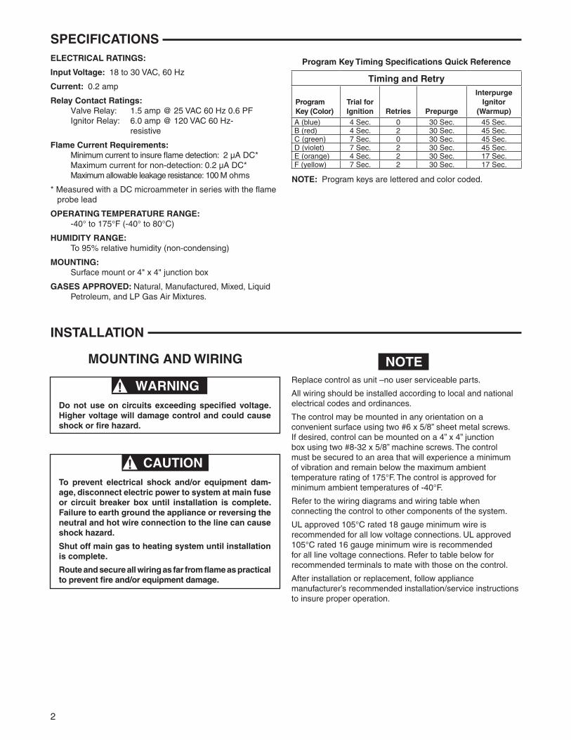
INSTALLATION INSTALL PROGRAM KEYThe control replaces all listed models with the following features:
• 120volthotsurfaceignitor• remoterodflamesenseordirectflamesensethroughignitor• oneorthreeignitiontries• Sevenorfoursecondtrialforignitionintervals• Pre-purgeof30secondsorless• 60secondinter-purgetime• 17or45secondignitorwarm-uptimes
Sixprogramkeysareprovidedfordifferentapplications.TimingsandRetriesforeachprogramkeyareshowninthe
Specifications section of this installation manual. Choose the properprogramkeyfortheapplicationbyusingtheModuleCrossReference(37-7209).Installtheselectedprogramkeyinthe slot on the left side of the module (see figure 4 on page 3).
If the module you are replacing is not listed in the Cross Reference, contact the manufacturer of the appliance for a recommended replacement or retrofit.
Afterinsertingtheproperprogramkey,disposeoftheremainingkeystoensurethecorrectkeyremainsinthemodule.
Reversal of gas valve leads or open connection to MV1 and MV2maycausecontroltolockout.Seetroubleshootingguidefor remedy.
OPERATION
TROUBLESHOOTING
TYPICAL FURNACE INSTALLATIONInatypicalapplicationthe50E47-843isdesignedtoenergizethe ignitor and gas valve and monitor the flame sensor. It isa100%shutoffdesignthatlocksoutthegasvalveiftheburner does not light within the trial for ignition period. The ignitionsequencebeginswithacallforheatfromtheroomthermostat. The thermostat applies power to the control. Afterpre-purgeinterval,theignitorwarmsupfortheselectedtime.Thecontrolenergizesthegasvalvefortheselected
trial for ignition period. If the burner lights within the allowed period the gas valve will remain open until the call for heat is satisfied. During the trial for ignition period the ignitor is turned off. If the burner does not light, the control will either gointolockoutormaketwomoreignitionretriesdependingontheoptionsselected.Thecontrolcanberesetfromlockoutby cycling the thermostat to remove power for a minimum of 3seconds.Itincludesasystemanalysis/troubleshootingLEDthatindicatesnormaloperation,lockout,weakflamesignalorinternal control fault.
For proper control operation, the control must be electrically connected to the gas valve and all the ignitor wiring connec-torspluggedin.Gasvalveswithanelectric"ON/OFF"switchmust have the switch set to "ON".
The light on the control provides a self-diagnosis indication. If the red light on the module is on continuously, the fault is likelytobeinternaltothemodule.Tomakesure,interruptthe line or 24 volt thermostat power for a few seconds and then restore. If the internal fault is indicated again, and flame sensorisnotshortedtoground,replacethecontrol.Aflash-
inglightindicatestheproblemismostlikelyintheexternalcomponents or wiring (see chart below). Proceed as follows:
Threevisualchecks1. The ignitor will warm up and glow red2. The main burner flame will ignite3. The main burner flame will continue to burn after the
ignitor is turned offTroubleshootingthesystemconsistsofcheckingforthesethree visual indications. The chart on the next page defines the proper action if any of these indications do not occur.
LED ConditionGreenSolid On
Normal
GreenRapid Flashing
Weakflamesignal
RedRapid Flash
ControlinlockoutFlame sensed whenthere should be none
Red1 Flash
ControlinlockoutIgnition retries exceeded
Red2 Flash
Controlinlockout Ignition recycles exceeded
YellowSolid On
Internalselfcheck
YellowRapid Flashing
Improper Polarity
OFF Internal FailureRedSolid On
GasvalvemiswiredorInternal error detected

5
TROUBLESHOOTING
yes
yes
yes
no
no
no
no
no
no
no
no
yes
yes
yes
yes
Reset control to clear lockout and confirm fault.Rapid Flash = Flame Sensed when no flame should be present. 1 Flash = Number of Retries exceeded, control locked out.2 Flashes = Recycles Exceeded, control locked out.RedLightcontinuousindicateseitheraninternal fault or miswired gas valve. CheckwiresatMV1andMV2for proper connection or swap wires to correct fault. If fault persists, replace module.
Call for heat, Thermostat contacts close
Does YellowLEDlightfor approximately 2 seconds? (Module Self Check)
Does YellowLEDFlash?
DoesRedLEDFlashorremainlit?
CheckLow Voltage to module (TH-TR). If no voltage:CheckLimitSwitchesCheckvent pressure switch (if used).
Measure AC voltage between terminalL1andTH. If voltage is approximately 145 VAC, polarity is reversed; reverse secondary leads on control transformer. Correct reading should be approximately 95 VAC.
CheckLow Voltage to module (TH-TR).CheckLimitSwitchesCheckvent pressure switch (if used).
Indicates a poor flame sense signal. Checkfor short in Flame Sensor wiring, Poor Furnace or BurnerGround,Shorting flame sensor, flame sensor wiring, or dirty flame probe.Clean flame probe.
Confirm 120 Volts to ignitor terminals(HS1andL2onmodule) If voltage is present replace ignitor.
Checkgassupplyandpressuretovalve.Checkfor 24 volt output on module (terminals MV1 and MV2). If no voltage replace module. If gas valve is receiving voltage but not opening replace valve.
Checklimitswitches.Checksensorleadandgroundfor continuity.Checkinsulatorofflamesensororignitorfor excessive temperature. Temperature above 1000 deg F. can ground flame sense.
Does system run until call for heat ends?
Does the main burner light?
Afterprepurgedoesignitorglow red?
DoesGreenLEDFlash?
DoesGreenLEDLight?
YesNormal Operation

White-Rodgers is a business of Emerson Electric Co.
The Emerson logo is a trademarkandservicemark of Emerson Electric Co.
www.white-rodgers.comwww.emersonclimate.com

50E47-843Control de encendido de superficie caliente universal
INSTRUCCIONES DE INSTALACIÓN
EL NO LEER Y SEGUIR CON CUIDADO TODAS LAS INSTRUCCIONES ANTES DE INSTALAR O UTILIZAR ESTE CONTROL, PODRÍA CAUSAR LESIONES PERSONALES Y/O DAÑOS MATERIALES.
CONTENIDODescripción ............................................................................ 1Precauciones ......................................................................... 1Especificaciones .................................................................... 2Instalación ............................................................................. 2 Montaje y ConexionesFuncionamiento y Solución de problemas .............................. 4
DESCRIPCIÓN
PRECAUCIONES
El 50E47-843 es un control de encendido de superficie caliente de repuesto diseñado para ofrecer la máxima compatibilidad con los sistemas existentes. Este control incluye:
•Un puerto de tarjeta y seis teclas de programa para seleccionar los tiempos de prueba de encendido, rein tentos, pre-purgado y calentamiento del dispositivo de encendido. • Unpuenteparaadaptarelcontrolasistemasqueutilizan detección directa (detección a través del dispositivo de en cendido) o detección indirecta (usando un detector de llama). • IndicadordeLEDparafacilitareldiagnósticoy solución de fallas en el sistema y el módulo.
No utilizar en circuitos que excedan el voltaje especificado ya que los voltajes más altos dañarán el control y pueden causar riesgos de electrocución o incendio.
No cortocircuite las terminales de la válvula de gas ni del control principal para probarlos. Un cortocircuito o una conexión incorrecta dañará el termostato y podría causar lesiones personales y/o daños materiales.
¡ADVERTENCIA!!
Para evitar descargas eléctricas y/o daños al equipo, desconecte la alimentación eléctrica en la caja de fusibles o disyuntores principal hasta que haya finalizado la instalación del sistema.
Identifique todos los cables antes de desconectarlos cuando realice tareas de mantenimiento en los controles. Los errores en las conexiones pueden dar lugar al funcionamiento incorrecto y peligroso del dispositivo.
Este control no está diseñado para ser utilizado en lugares en los que puede entrar en contacto con agua. Debe proporcionarse una protección adecuada para proteger el control de su exposición al agua (goteo, rociado, lluvia, etc.).
¡PRECAUCIÓN!!
Si tiene dudas acerca de si su conexión eléctrica es milivoltio, de línea odebajovoltaje,hágalainspeccionarporuntécnicoespecializadoenequiposdecalefacciónyaireacondicionadooporunelectricistaautorizado.
No exceda los valores nominales especificados.
Todaslasconexionesdebencumplirconloscódigosyreglamentacio-nes locales y nacionales.
Este control es un instrumento de precisión y debe manipularse con cuidado.Lamanipulacióndescuidadaoladistorsióndeloscomponentespodríanhacerqueelcontrolnofuncionaracorrectamente.
La aplicación de este tipo de control podría causar llamaradas al poner en marcha el equipo y producir lesiones personales y/o daños materiales.
Verifique las especificaciones del producto y las referen-cias cruzadas antes de cambiar el módulo existente. No lo utilice si el módulo existente no está incluido en la lista. El uso de una tecla de programa que no esté incluida en la lista puede producir el mal funcionamiento del equipo.
¡PRECAUCIÓN GENERAL!!
www.white-rodgers.comwww.emersonclimate.com
N° DE PIEZA 37-6426G Reemplaza37-6426F
1424

2
ESPECIFICACIONES
INSTALACIÓN
MONTAJE Y CONEXIONES
CARACTERÍSTICAS ELÉCTRICAS:
Voltaje de entrada: 18a30VCA,60Hz
Corriente: 0.2 amp
Características de contacto de los relés: Relédeválvula:1.5ampa25VCA60Hz0.6PF Relédeldispositivodeencendido:6.0ampa120VCA60Hz- resistivo
Requisitos de corriente de llama: Corrientemínimaparaasegurarladeteccióndelallama: 2 µA CC* Corriente máxima para la no detección: 0.2 µA CC* Resistenciaafugasmáximapermitida:100Mohmios
* Medida con un microamperímetro de CC en serie con el electrodo de sonda de llama
RANGO DE TEMPERATURA OPERATIVA: -40° a 175°F (-40° a 80°C)
RANGO DE HUMEDAD: Hasta95%dehumedadrelativa(sincondensación)
SOPORTE: Soportedesuperficieocajadeconexionesde4pulg.x4pulg.
GASES APROBADOS: natural,fabricado,mixto,gaslicuadodepetróleoymezclasdeaireygaslicuadodepetróleo.
Especificaciones de tiempos de las teclas de programaReferencia rápida
Tiempos y reintentos TECLA DE PRUEBA CALENTAR PROGRAMA DE RE PRE- DISPOSITIVO (COLOR) ENCENDIDO INTENTOS PURGADO ENCENDIDO
A(azul) 4Seg. 0 30Seg. 45Seg.
B(roja) 4Seg. 2 30Seg. 45Seg.
C(verde) 7Seg. 0 30Seg. 45Seg.
D(violeta) 7Seg. 2 30Seg. 45Seg.
E(anaranjada) 4Seg. 2 30Seg. 17Seg.
F(amarilla) 7Seg. 2 30Seg. 17Seg.
Cambie el control entero en caso de ser necesario. No contiene piezasquepuedanserreparadasporelusuario.
Todaslasconexionesdebeninstalarseconformealoscódigosyreglamentacioneslocalesynacionales.
Elcontrolpuedemontarseconcualquierorientaciónsobreunasuperficie conveniente usando dos tornillos autorroscantes calibre 6x5/8pulg.Silodesea,elcontrolpuedemontarsesobreunacajadeconexionesde4pulg.x4pulg.usandodostornillosmecánicoscalibre8-32x5/8pulg.Elcontroldebefijarseenunlugarqueestésujetoaunmínimodevibracionesyquesemantengapordebajodela temperatura ambiente nominal de 175°F. El control está aprobado para temperaturas ambientes mínimas de -40°F.
Refiérasealosdiagramasyalatabladeconexionesparaconectarel control a otros componentes del sistema.
Paratodaslasconexionesdebajovoltajeserecomiendautilizarcables calibre 18 como mínimo aptos para 105°C y aprobados por lasnormasUL.Paratodaslasconexionesdevoltajedelíneasere-comiendautilizarcablescalibre16comomínimoaptospara105°CyaprobadosporlasnormasUL.Consultelasiguientetablaparalacombinación de terminales recomendada para el control.
Unavezfinalizadalainstalaciónoelreemplazo,sigalasinstruccio-nesdeinstalación/mantenimientorecomendadasporelfabricantedelequipoparaasegurarsucorrectofuncionamiento.
NOTA: lasteclasdeprogramaestánidentificadas con letras y colores.
NOTA
No utilizar en circuitos que excedan el voltaje especificado ya que los voltajes más altos dañarán el control y pueden causar riesgos de electrocución o incendio.
¡ADVERTENCIA!!
Para evitar descargas eléctricas y/o daños al equipo, desconecte la alimentación eléctrica en la caja de fusibles o disyuntores principal hasta que haya finalizado la instalación del sistema. Si no se conecta a tierra el equipo o se invierte la conexión del cable neutro y el vivo a la línea pueden producirse riesgos de descarga eléctrica.
Cierre la alimentación de gas principal al sistema de calefacción hasta haber terminado la instalación.
Pase y fije todos los cables lo más lejos posible de la llama para evitar incendios y/o daños al equipo.
¡PRECAUCIÓN!!
3
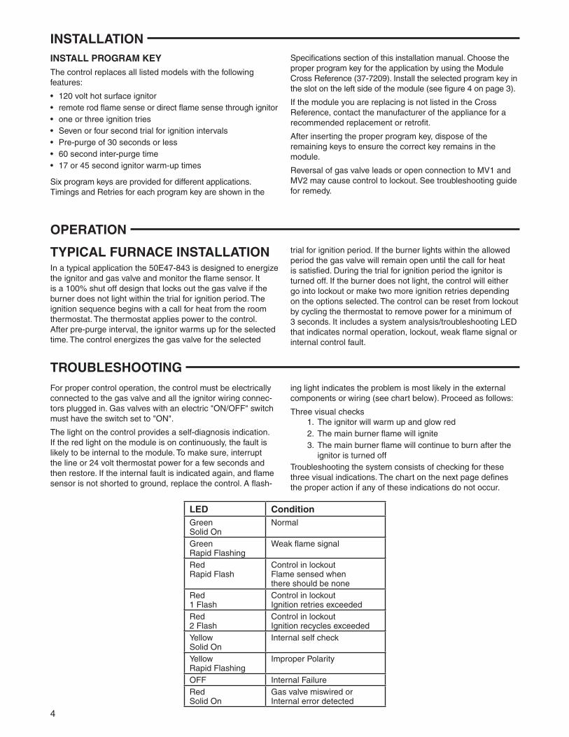
Referencia cruzada de conexiones de las terminales Control original Control de repuesto Terminal Terminal Terminal White-Rodgers Función de la terminal Honeywell S89/S890 Robertshaw HS780 50E/F47 anterior 50E47-843
Conexiónatierradelquemador GND(QUEMADOR)a TR(CLIPDETIERRA) b GND GND
Secundariodeltransformador 24V(GND) a GND TR TR (pata no conmutada)
Comúndeválvulaprincipal VÁLVULA(GND) a — c MV a (junto a la MV2 terminal TR) Secundario del transformador 24V a TH TH TH (pata conmutada)
Operadordeválvulaprincipal VÁLVULA VÁLVULAd MV d MV1
Pataneutrade120Vca L2120VNEUTRO L2 — L2e
Alimentación
Patavivo120Vca L1120VVIVO L1 Lf L1120VVIVO
Alimentación Elementodispositivode HSI120V IGN — HS2 encendido de superficie caliente
Elementodispositivode HSI120V IGN IGNg HSI encendido de superficie caliente
Detector de llama SEN h RS h FP i FP h
MV2
TR
GND
TH
MV1
L2
FP
L1
HS1
TERMOSTATO O CONTROLADOR
LÍMITE ALTERNO
L1(VIVO)
L2
CONTROLADOR DE LÍMITE
SONDA DE LLAMA
ROJO
ADAPTADOR
AZUL
DISPOSITIVO DE ENCENDIDO DE
SUPERFICIE CALIENTEMV
MVVÁLVULA DE GAS
TIERRA DEL
QUEMADOR
HS2
TRANSFORMADOR
PUENTE(corte)
MV2
TR
GND
TH
L2
FP
TERMOSTATO O CONTROLADOR
LÍMITE ALTERNO
L1(VIVO)
L2
CONTROLADOR DE LÍMITE
MV
MVVÁLVULA DE GAS
TIERRA DEL
QUEMADOR
DISPOSITIVO DE ENCENDIDO DE
SUPERFICIE CALIENTE
HS2
SONDA DE LLAMA
L1
MV1
HS1
TRANSFORMADOR
PUENTE(corte)
Fig. 1 – Conexión típica para el repuesto de White-Rodgers con detección indirecta usando
una sonda de llama
Fig. 3 – Conexión típica para el repuesto de la competencia con detección de llama indirecta a
través de una sonda de llama
aRetirelaconexiónrápidaycámbielaporlaconexiónrápidade1/4pulg.suministrada. bUtiliceelcableadaptadorverde(suministrado)paraconectarlaterminalalatierradelchasis. cNoutilicelaterminalMV2.MV2yTRestáninterconectadasenlasconexionesdelequipo. dRetirelaconexiónrápidaycámbielaporlaconexiónrápidade3/16pulg.suministrada. e Conecteatierraestaterminalusandoelcableadaptadorverdesielmodeloquevaacambiarnotieneunaconexióndealimentaciónneutrade120V. fUtiliceelcablerojoenelcableadaptadorsuministrado. gUtiliceelcableazulenelcableadaptadorsuministrado. h En los modelos de detección indirecta, retire la conexión rápida del puente de la terminal FP, corte el cable puente en el tablero de circuitos y deséchelo. Enlosmodelosdedeteccióndirecta,conelpuenteconectadoalaterminalFP,vealafigura4. i Retire el puente de la terminal FP, corte el cable del puente en el tablero de circuitos y deséchelo.
Puente
Teclasdeprograma
Fig. 4 – Instalación de la tecla del programa/puente para modelos de detección indirecta
Corte el puente
MV2
TR
GND
TH
L2
FP
TERMOSTATO O CONTROLADOR
LÍMITE ALTERNO
L1(VIVO)
L2
CONTROLADOR DE LÍMITE
MV
MVVÁLVULA DE GAS
TIERRA DEL
QUEMADOR
DISPOSITIVO DE ENCENDIDO DE
SUPERFICIE CALIENTE
HS2
SONDA DE LLAMA
L1
MV1
HS1
TRANSFORMADOR
PUENTE
Fig. 2 – Conexión típica para el repuesto de la competencia con detección de llama directa a
través del dispositivo de encendido
INSTALACIÓN

4
INSTALE LA TECLA DE PROGRAMAElcontrolreemplazatodoslosmodelosincluidosenlalistaconlassiguientescaracterísticas:• Dispositivodeencendidodesuperficiecalientede120voltios• Deteccióndellamaconvarillaremotaodeteccióndellama directa a través del dispositivo de encendido• Unootresintentosdeencendido• Intervalosdepruebadeencendidodesieteocuatrosegundos• Pre-purgadode30segundosomenos• Tiempoentrepurgadosde60segundos• Tiemposdecalentamientodeldispositivodeencendidode 17ó45segundos
Sesuministranseisteclasdeprogramaparadiferentesaplicaciones.Lostiemposyelnúmerodereintentosparacadatecladepro-gramaseindicanenlasecciónEspecificacionesdeestemanualde
INSTALACIÓNinstalación.Elijalatecladeprogramaadecuadaparalaaplicaciónusando la ReferenciacruzadaparamódulosdeWhite-Rodgers(37-7209).Instalelatecladeprogramaseleccionadaenlaranuradelladoizquierdodelmódulo(vealafigura4enlapágina3).SielmóduloquedeseacambiarnoestáincluidoenlastablasdemódulosdeWhite-Rodgersodelacompetencia,póngaseencon-tactoconelfabricantedelequipoparaconsultarporunrepuestooreacondicionamiento recomendado. Despuésdeinsertarlatecladeprogramaadecuada,desechelasteclasrestantesparaasegurarsedequequedelateclacorrectaenel módulo.LainversióndeloscablesdelaválvuladegasounaconexiónabiertaaMV1yMV2puedenhacerqueelcontrolsebloquee.Veacómoprocederenlaguíadesolucióndeproblemas.
FUNCIONAMIENTO
Enunaaplicacióntípicael50E47-843estádiseñadoparaenergizareldispositivodeencendidoylaválvuladegasy monitoreareldetectordellama.Esundiseñoconcierre100%quebloquealaválvuladegassielquemadornoseenciendedentrodelperíododepruebadeencendido.Lasecuenciadeencendidocomienzaconunallamadadecalordeltermostatodela habitación. El termostato aplica alimentación al control. Después delintervalopre-purgado,eldispositivodeencendidosecalientaduranteeltiemposeleccionado.Elcontrolenergizalaválvuladegasduranteelperíododepruebadeencendidoseleccionado.Si
INSTALACIÓN TÍPICA DE LA CALDERA elquemadorseenciendedentrodelperíodopermitido,laválvuladegaspermaneceráabiertahastaquesesatisfagalallamadadecalor. Durante el período de prueba de encendido, el dispositivo de encendidoseapaga. Sielquemadornoseenciende,elcontrolsebloquearáorealizarádosintentosmásdeencendidosegúnlasopciones seleccionadas.Elcontrolpuededesbloquearseencendiendoyapagandoeltermostatoparadesconectarlaalimentación duranteunmínimode3segundos.IncluyeunLEDdeanálisisdelsistema/solucióndeproblemasqueindicafuncionamientonormal,bloqueo,señaldellamadébilofalladelcontrolinterno.

5
Para el funcionamiento adecuado del control, éste debe estar eléctricamenteconectadoalaválvuladegasytodoslosconectoresde los cables del dispositivo de encendido deben estar enchufados. LasválvulasdegasconuninterruptoreléctricodeAPAGADO/ENCENDIDOdebentenerelinterruptorcolocadoenlaposiciónENCENDIDO.
Laluzdelcontrolproporcionaunaindicacióndeautodiagnóstico.Silaluzrojadelmóduloestápermanentementeencendida,esprobablequesetratedeunafallainternadelmódulo.Paraasegurarse,interrumpalaalimentacióndelíneaolaalimen-taciónde24voltiosaltermostatodurantealgunossegundosyluegovuelvaa conectarla. Si vuelve a indicar una falla interna y el detector de llamanoestáencortocircuitocontierra,cambieelcontrol.Una
SOLUCIÓN DE PROBLEMASluzintermitenteindicaqueesmuyprobablequeelproblemaseencuentre en los componentes externos o en las conexiones (vea el siguientecuadro).Procedacomoseindicaacontinuación:
Tres verificaciones visuales
1) El dispositivo de encendido se calienta y se ilumina de color rojo
2) Lallamadelquemadorprincipalseenciende3) Lallamadelquemadorprincipalcontinuaardiendo
despuésdeapagareldispositivodeencendido
Lasolucióndeproblemasdelsistemaconsisteenverificarestastresindicacionesvisuales.Elcuadrodelasiguientepáginaindicacómoprocedersinoseproduceningunadeestasindicaciones.
LED EstadoVerde
fijoNormal
Verdeintermitente rápido
Señal de llama débil
Rojaintermitente rápido
ElcontrolestábloqueadoSe detectó una llama cuando en realidad no deberíahaberninguna
Roja1 intermitente
ControlbloqueadoSe excedió la cantidad dereintentos de encendido
Roja2 intermitentes
ControlbloqueadoSe excedió la cantidad deciclosdeapagado/
encendido
Amarillafijo
Autoverificación interna
Amarillaintermitente rápido
Polaridad inadecuada
APAGADO Falla interna
Rojafijo
Laválvuladegasestámalconectada o se detectó un
error interno

sí
sí
sí
no
no
no
no
no
no
no
no
sí
sí
sí
sí
Reseteeelcontrolparadesbloquearloyconfirmarlafalla.Intermitente rápido = se detecta llama cuando no debería haber una llama presente.1intermitente=seexcediólacantidaddereintentos,elcontrolestábloqueado.2intermitentes=seexcediólacantidaddeciclosdeapagado/encendido,elcontrolestábloqueado.Laluzrojacontinuaindicaunafallainternaounaválvuladegasmalconectada.VerifiquequeloscablesenMV1yMV2esténbienconectados o intercambie los cables para solucionar la falla. Si la falla persiste, cambie el módulo.
Llamadadecalor,loscontactos del termostato se cierran
¿ElLEDamarillopermaneceencendido aproximadamente 2 segundos?(autoverificacióndelmódulo)
¿ElLEDamarilloesintermitente?
¿ElLEDrojoesintermitenteopermaneceencendido?
Verifiquesielvoltajealmóduloesbajo(TH-TR).Sinohayvoltaje:VerifiquelosinterruptoreslimitadoresVerifiqueelinterruptordepresióndeventeo(siseutiliza).
MidaelvoltajeCAentrelaterminalL1yTH.Sielvoltajeesdeaproximadamente 145 VCA, la polaridad esta invertida; invierta los cablesdelsecundariodeltransformadordecontrol.Lalecturacorrectadeberíaserdeaproximadamente95VCA.
Verifiquesielvoltajealmóduloesbajo(TH-TR).VerifiquelosinterruptoreslimitadoresVerifiqueelinterruptordepresióndeventeo(siseutiliza).
Indicaunaseñaldedeteccióndellamadébil.Verifiquequenohayaun cortocircuito en las conexiones del detector de llama, una mala conexiónatierradelacalderaodelquemador,undetectordellama en cortocircuito, las conexiones del detector de llama o una sondadellamasucia.Limpielasondadelallama.
Verifiquequehaya120voltiosenlasterminalesdeldispositivodeencendido(HS1yL2delmódulo).Sihayvoltajepresente,cambieel dispositivo de encendido.
Verifiqueelsuministrodegasylapresiónalaválvula.Verifiquelasalidade24voltiosenelmódulo(terminalesMV1yMV2).Si no hay voltaje, cambie el módulo.Silaválvuladegasestárecibiendovoltajeperonoseabre,cambie la válvula.
Verifiquelosinterruptoreslimitadores.Verifiquelacontinuidaddelcabledeldetectorylatierra.Verifiquequelatemperaturadelaisladordeldetectordellamaodeldispositivodeencendidonoseaexcesiva.Lastemperaturassuperiores a los 1000 °F pueden conectar a tierra el detector de llama.
¿Elsistemafuncionahastaqueterminalallamadadecalor?
¿Elquemadorprincipalseenciende?
Despuésdelpre-purgado,¿el dispositivo de encendido seenciendedecolorrojo?
¿ElLEDverdeparpadea?
¿ElLEDverdeesintermitente?
SíFuncionamiento normal
SOLUCIÓN DE PROBLEMAS
White-Rodgersesunanegocio de Emerson Electric Co.
EllogotipodeEmersonesunamarca comercial y una marca de servicio de Emerson Electric Co.
www.white-rodgers.comwww.emersonclimate.com