Embed Size (px)
Citation preview
6-1 Chapter 6 - Datapath and Control
Principles of Computer Architecture by M. Murdocca and V. Heuring © 1999 M. Murdocca and V. Heuring
Principles of Computer ArchitectureMiles Murdocca and Vincent Heuring
Chapter 6: Datapath and Control
6-2 Chapter 6 - Datapath and Control
Principles of Computer Architecture by M. Murdocca and V. Heuring © 1999 M. Murdocca and V. Heuring
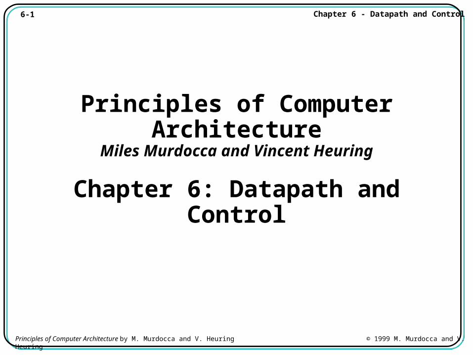
Chapter Contents
6.1 Basics of the Microarchitecture
6.2 A Microarchitecture for the ARC
6.3 Hardwired Control
6.4 Case Study: The VHDL Hardware Description Language
6-3 Chapter 6 - Datapath and Control
Principles of Computer Architecture by M. Murdocca and V. Heuring © 1999 M. Murdocca and V. Heuring
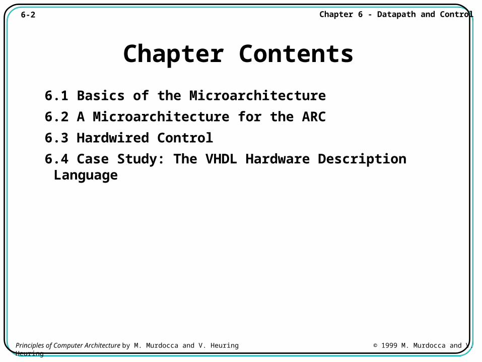
The Fetch-Execute Cycle
• The steps that the control unit carries out in executing a program are:
(1) Fetch the next instruction to be executed from memory.
(2) Decode the opcode.
(3) Read operand(s) from main memory, if any.
(4) Execute the instruction and store results.
(5) Go to step 1.
6-4 Chapter 6 - Datapath and Control
Principles of Computer Architecture by M. Murdocca and V. Heuring © 1999 M. Murdocca and V. Heuring
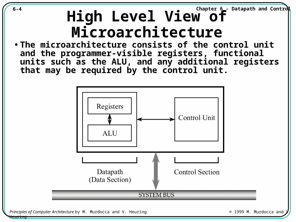
High Level View of Microarchitecture• The microarchitecture consists of the control unit and
the programmer-visible registers, functional units such as the ALU, and any additional registers that may be required by the control unit.
6-5 Chapter 6 - Datapath and Control
Principles of Computer Architecture by M. Murdocca and V. Heuring © 1999 M. Murdocca and V. Heuring
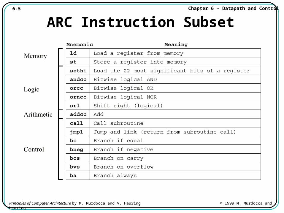
ARC Instruction Subset
6-6 Chapter 6 - Datapath and Control
Principles of Computer Architecture by M. Murdocca and V. Heuring © 1999 M. Murdocca and V. Heuring
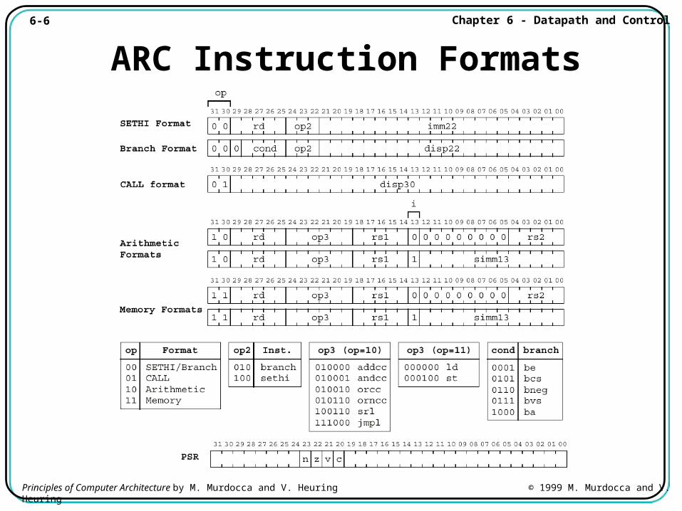
ARC Instruction Formats
6-7 Chapter 6 - Datapath and Control
Principles of Computer Architecture by M. Murdocca and V. Heuring © 1999 M. Murdocca and V. Heuring
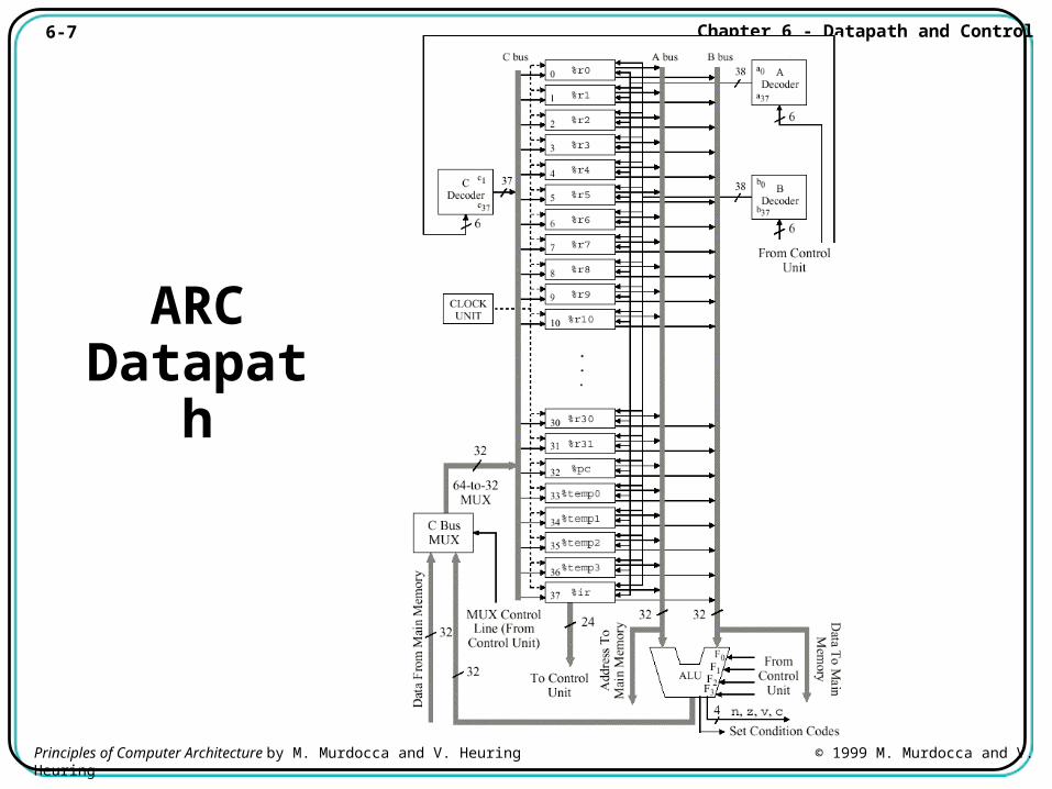
ARC Datapath
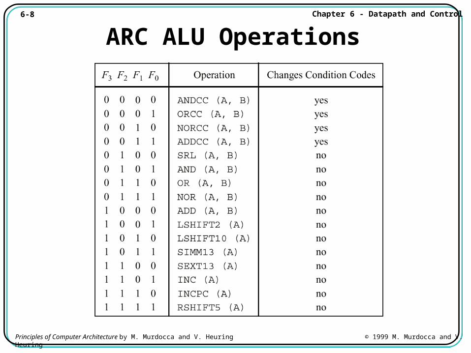
6-8 Chapter 6 - Datapath and Control
Principles of Computer Architecture by M. Murdocca and V. Heuring © 1999 M. Murdocca and V. Heuring
ARC ALU Operations
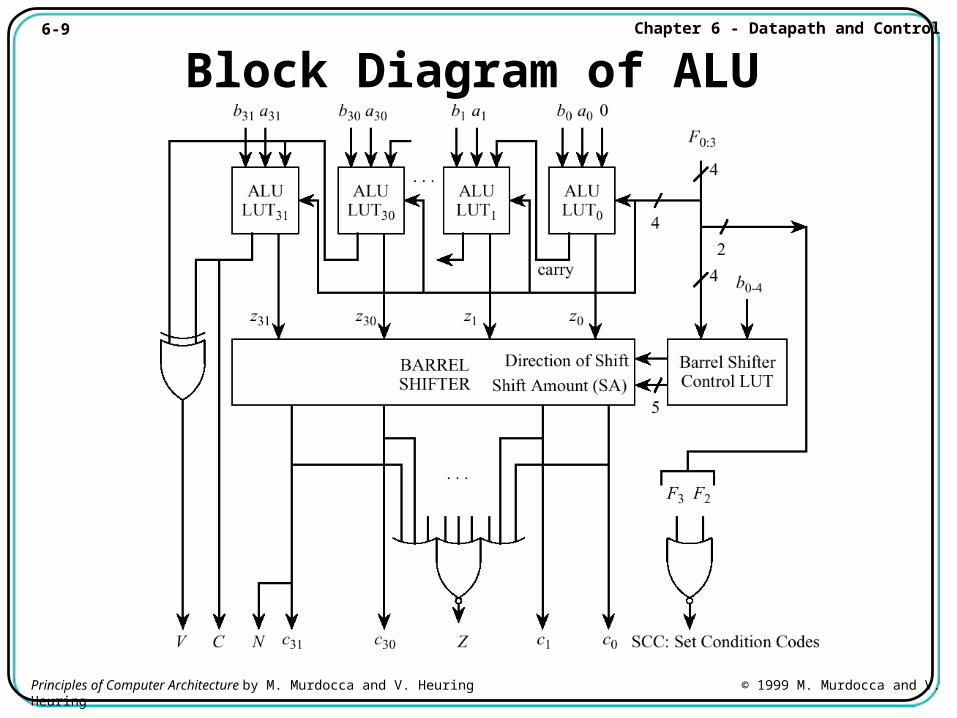
6-9 Chapter 6 - Datapath and Control
Principles of Computer Architecture by M. Murdocca and V. Heuring © 1999 M. Murdocca and V. Heuring
Block Diagram of ALU
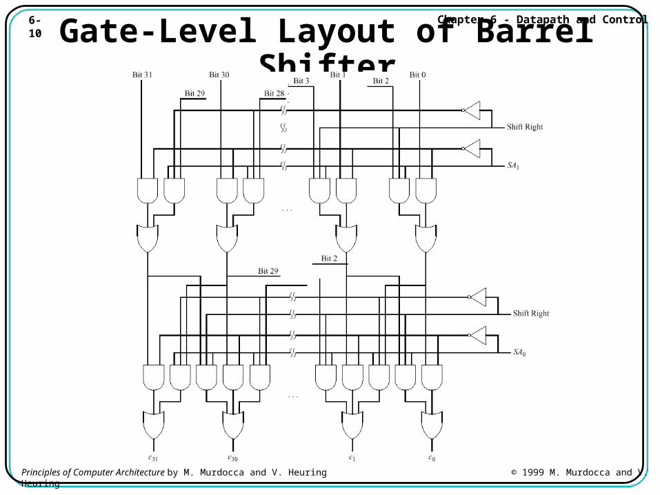
6-10 Chapter 6 - Datapath and Control
Principles of Computer Architecture by M. Murdocca and V. Heuring © 1999 M. Murdocca and V. Heuring
Gate-Level Layout of Barrel Shifter
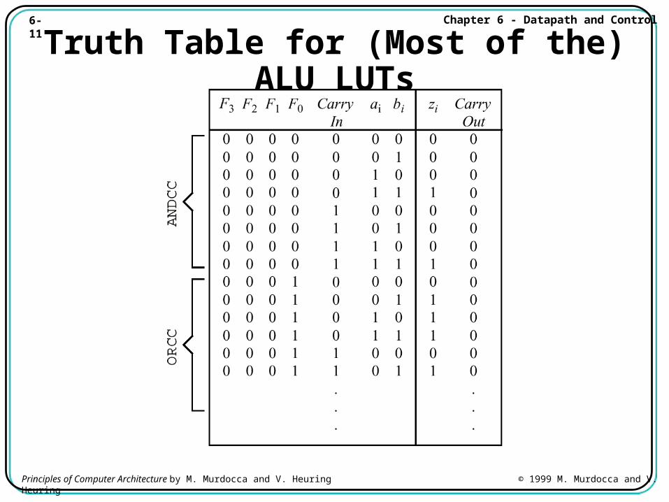
6-11 Chapter 6 - Datapath and Control
Principles of Computer Architecture by M. Murdocca and V. Heuring © 1999 M. Murdocca and V. Heuring
Truth Table for (Most of the) ALU LUTs
6-12 Chapter 6 - Datapath and Control
Principles of Computer Architecture by M. Murdocca and V. Heuring © 1999 M. Murdocca and V. Heuring
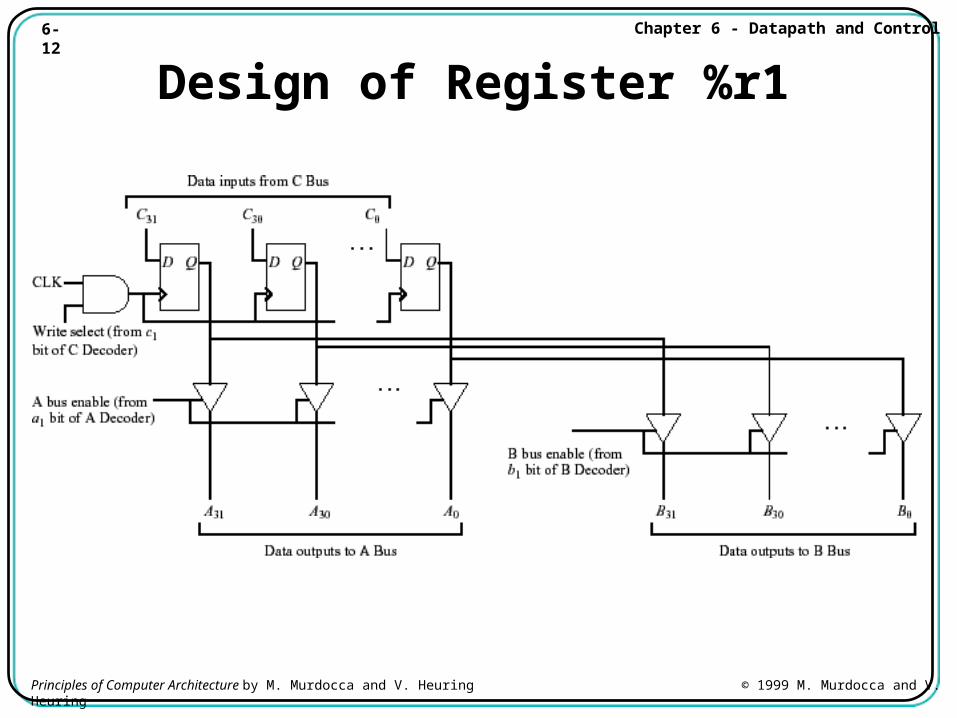
Design of Register %r1
6-13 Chapter 6 - Datapath and Control
Principles of Computer Architecture by M. Murdocca and V. Heuring © 1999 M. Murdocca and V. Heuring
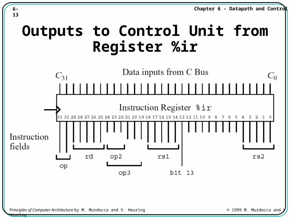
Outputs to Control Unit fromRegister %ir
6-14 Chapter 6 - Datapath and Control
Principles of Computer Architecture by M. Murdocca and V. Heuring © 1999 M. Murdocca and V. Heuring
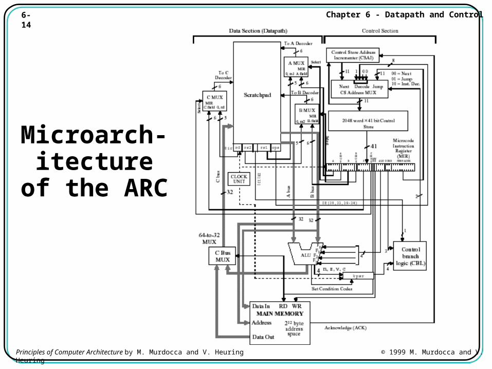
Microarch-itecture of the ARC
6-15 Chapter 6 - Datapath and Control
Principles of Computer Architecture by M. Murdocca and V. Heuring © 1999 M. Murdocca and V. Heuring
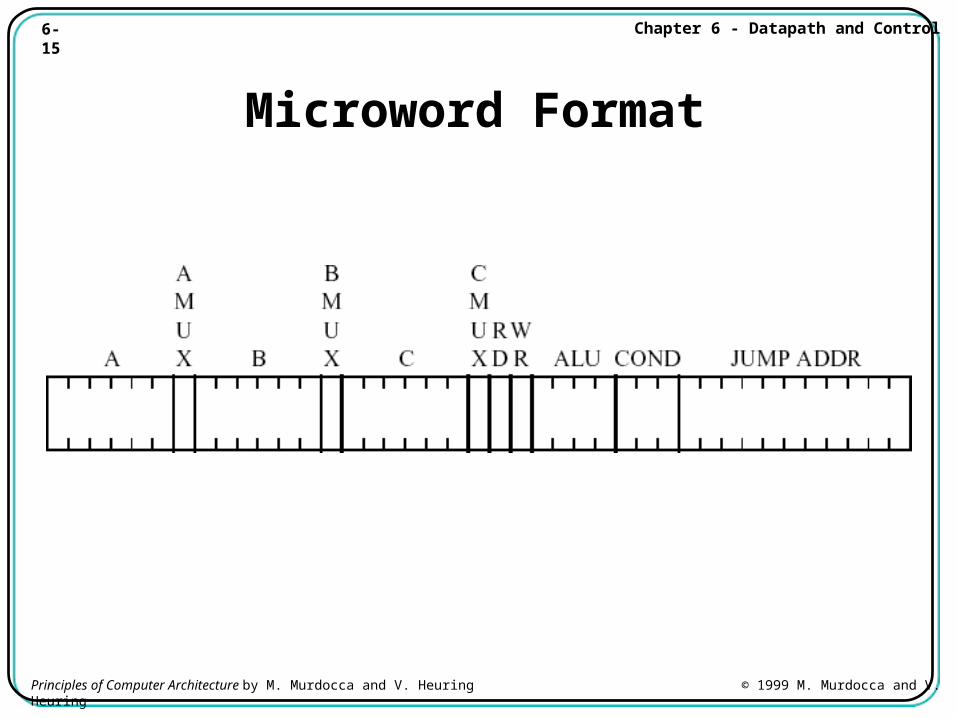
Microword Format
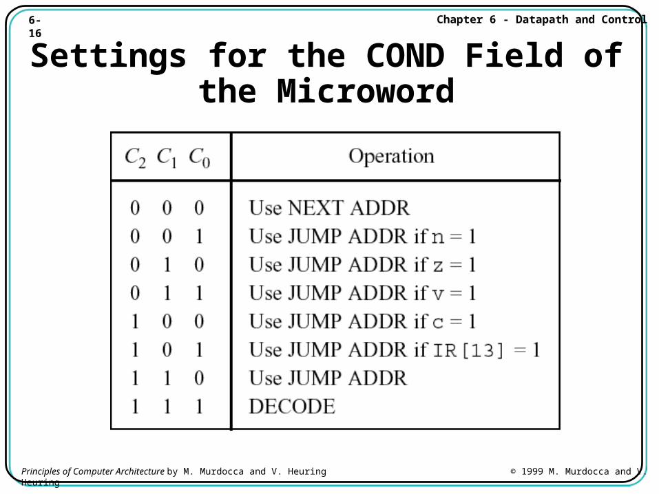
6-16 Chapter 6 - Datapath and Control
Principles of Computer Architecture by M. Murdocca and V. Heuring © 1999 M. Murdocca and V. Heuring
Settings for the COND Field of the Microword
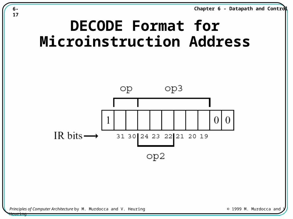
6-17 Chapter 6 - Datapath and Control
Principles of Computer Architecture by M. Murdocca and V. Heuring © 1999 M. Murdocca and V. Heuring
DECODE Format for Microinstruction Address
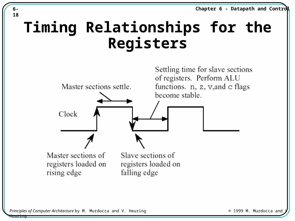
6-18 Chapter 6 - Datapath and Control
Principles of Computer Architecture by M. Murdocca and V. Heuring © 1999 M. Murdocca and V. Heuring
Timing Relationships for the Registers
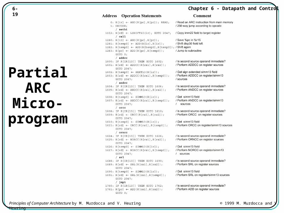
6-19 Chapter 6 - Datapath and Control
Principles of Computer Architecture by M. Murdocca and V. Heuring © 1999 M. Murdocca and V. Heuring
Partial ARC
Micro-program
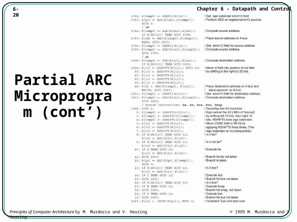
6-20 Chapter 6 - Datapath and Control
Principles of Computer Architecture by M. Murdocca and V. Heuring © 1999 M. Murdocca and V. Heuring
Partial ARC Microprogram
(cont’)
6-21 Chapter 6 - Datapath and Control
Principles of Computer Architecture by M. Murdocca and V. Heuring © 1999 M. Murdocca and V. Heuring
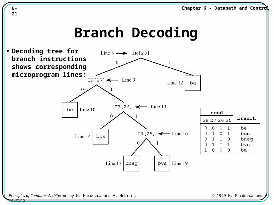
Branch Decoding• Decoding tree for
branch instructions shows corresponding microprogram lines:
6-22 Chapter 6 - Datapath and Control
Principles of Computer Architecture by M. Murdocca and V. Heuring © 1999 M. Murdocca and V. Heuring
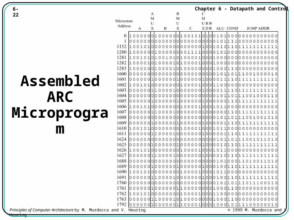
Assembled ARC
Microprogram
6-23 Chapter 6 - Datapath and Control
Principles of Computer Architecture by M. Murdocca and V. Heuring © 1999 M. Murdocca and V. Heuring
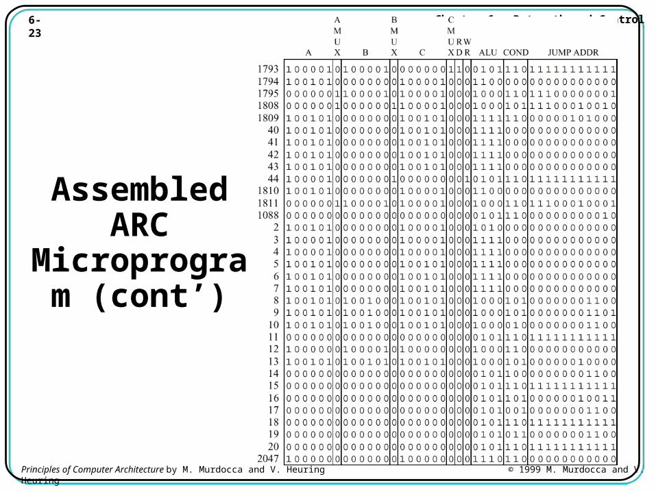
Assembled ARC
Microprogram (cont’)
6-24 Chapter 6 - Datapath and Control
Principles of Computer Architecture by M. Murdocca and V. Heuring © 1999 M. Murdocca and V. Heuring
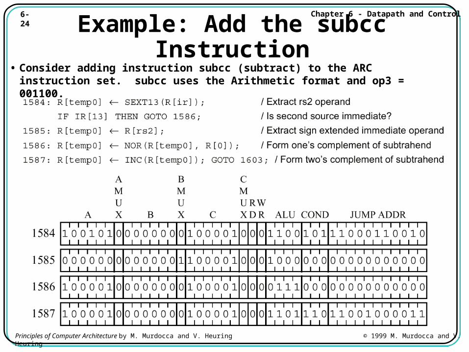
Example: Add the subcc Instruction• Consider adding instruction subcc (subtract) to the ARC instruction
set. subcc uses the Arithmetic format and op3 = 001100.
6-25 Chapter 6 - Datapath and Control
Principles of Computer Architecture by M. Murdocca and V. Heuring © 1999 M. Murdocca and V. Heuring
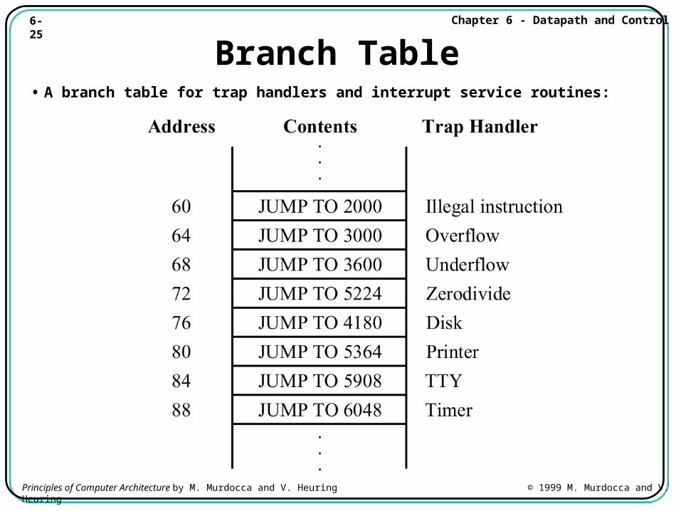
Branch Table• A branch table for trap handlers and interrupt service routines:
6-26 Chapter 6 - Datapath and Control
Principles of Computer Architecture by M. Murdocca and V. Heuring © 1999 M. Murdocca and V. Heuring
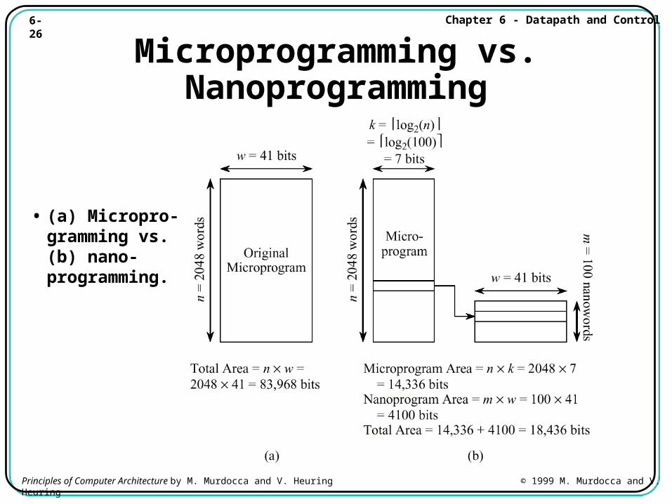
Microprogramming vs. Nanoprogramming
• (a) Micropro-gramming vs. (b) nano-programming.
6-27 Chapter 6 - Datapath and Control
Principles of Computer Architecture by M. Murdocca and V. Heuring © 1999 M. Murdocca and V. Heuring
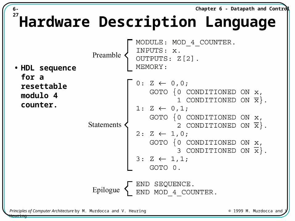
Hardware Description Language
• HDL sequence for a resettable modulo 4 counter.
6-28 Chapter 6 - Datapath and Control
Principles of Computer Architecture by M. Murdocca and V. Heuring © 1999 M. Murdocca and V. Heuring
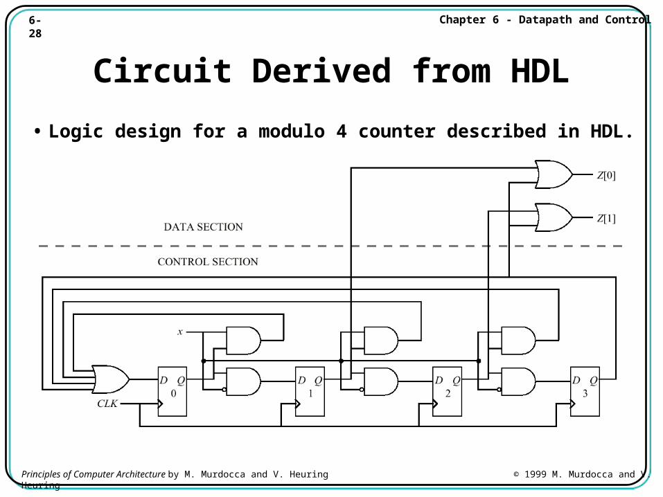
Circuit Derived from HDL
• Logic design for a modulo 4 counter described in HDL.
6-29 Chapter 6 - Datapath and Control
Principles of Computer Architecture by M. Murdocca and V. Heuring © 1999 M. Murdocca and V. Heuring
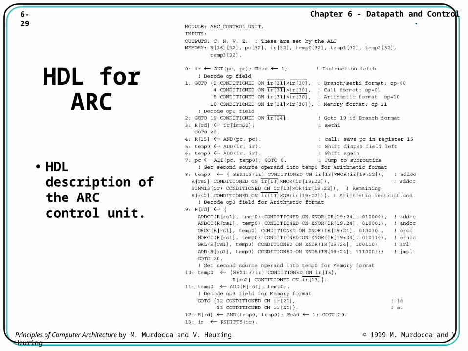
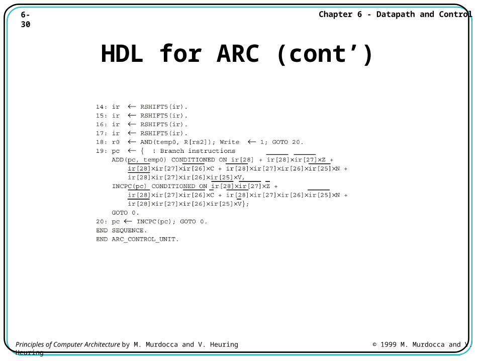
HDL for ARC
• HDL description of the ARC control unit.
6-30 Chapter 6 - Datapath and Control
Principles of Computer Architecture by M. Murdocca and V. Heuring © 1999 M. Murdocca and V. Heuring
HDL for ARC (cont’)
6-31 Chapter 6 - Datapath and Control
Principles of Computer Architecture by M. Murdocca and V. Heuring © 1999 M. Murdocca and V. Heuring
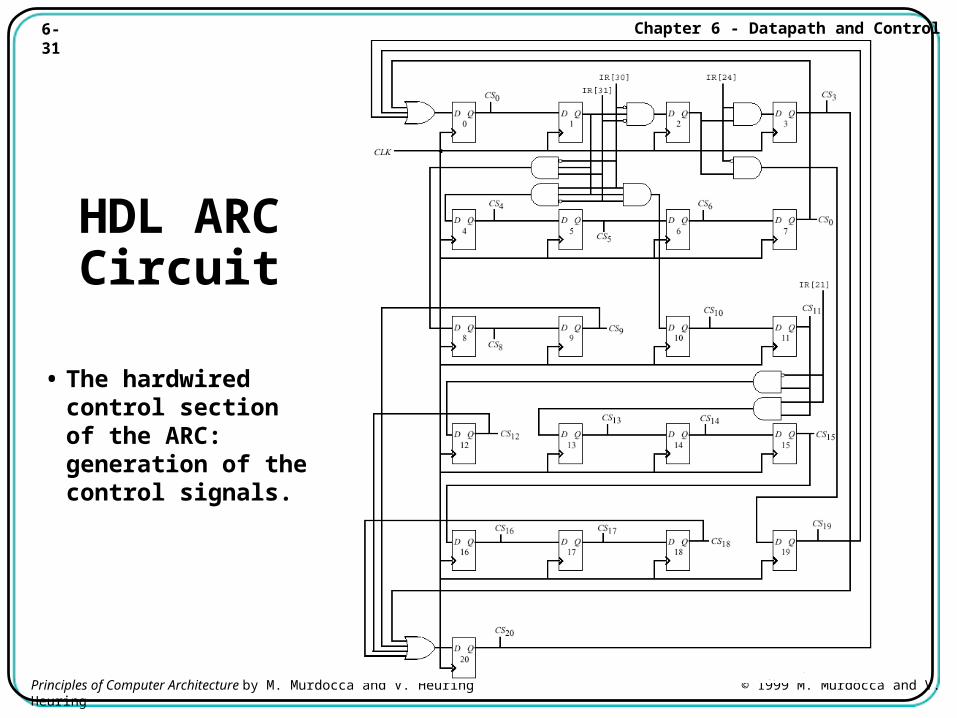
HDL ARC Circuit
• The hardwired control section of the ARC: generation of the control signals.
6-32 Chapter 6 - Datapath and Control
Principles of Computer Architecture by M. Murdocca and V. Heuring © 1999 M. Murdocca and V. Heuring
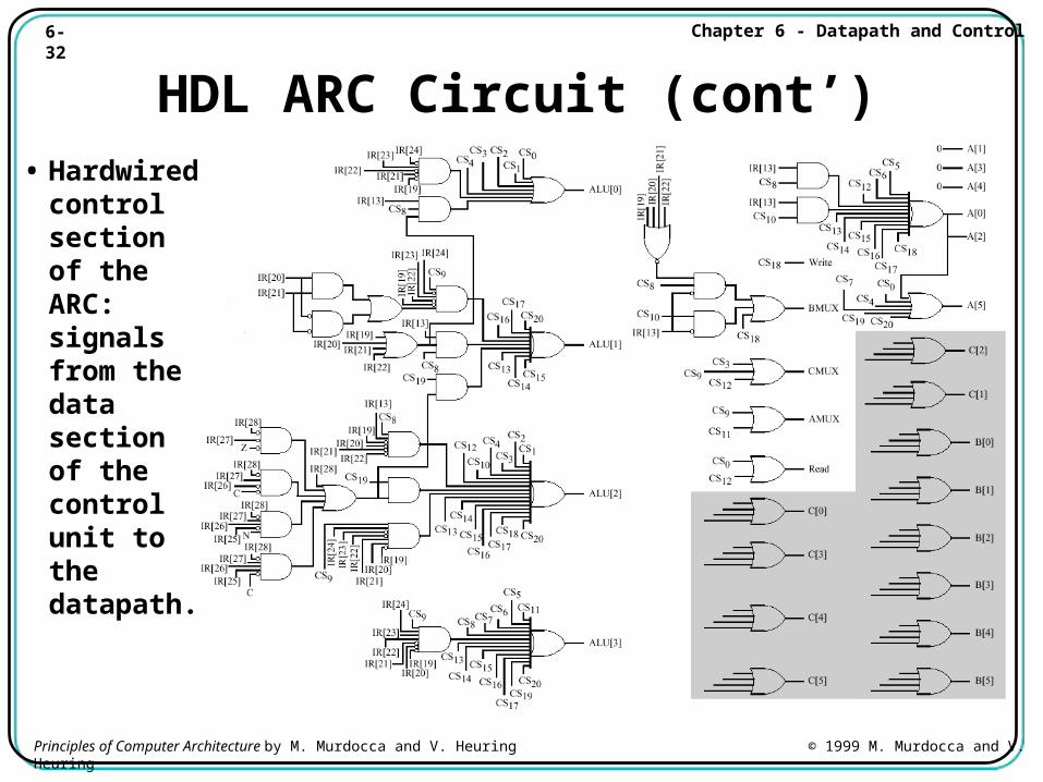
HDL ARC Circuit (cont’)• Hardwired
control section of the ARC: signals from the data section of the control unit to the datapath.
6-33 Chapter 6 - Datapath and Control
Principles of Computer Architecture by M. Murdocca and V. Heuring © 1999 M. Murdocca and V. Heuring
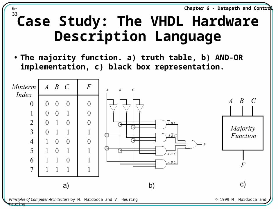
Case Study: The VHDL Hardware Description Language
• The majority function. a) truth table, b) AND-OR implementation, c) black box representation.
6-34 Chapter 6 - Datapath and Control
Principles of Computer Architecture by M. Murdocca and V. Heuring © 1999 M. Murdocca and V. Heuring
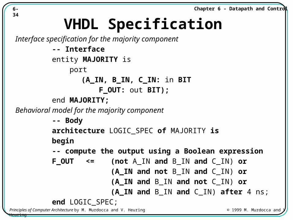
VHDL SpecificationInterface specification for the majority component
-- Interfaceentity MAJORITY is port
(A_IN, B_IN, C_IN: in BIT F_OUT: out BIT);
end MAJORITY;Behavioral model for the majority component -- Body
architecture LOGIC_SPEC of MAJORITY isbegin-- compute the output using a Boolean expressionF_OUT <= (not A_IN and B_IN and C_IN) or
(A_IN and not B_IN and C_IN) or(A_IN and B_IN and not C_IN) or(A_IN and B_IN and C_IN) after 4 ns;
end LOGIC_SPEC;
6-35 Chapter 6 - Datapath and Control
Principles of Computer Architecture by M. Murdocca and V. Heuring © 1999 M. Murdocca and V. Heuring
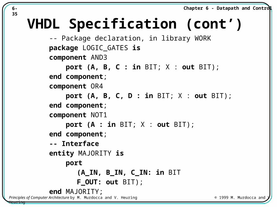
VHDL Specification (cont’)-- Package declaration, in library WORKpackage LOGIC_GATES iscomponent AND3 port (A, B, C : in BIT; X : out BIT);end component;component OR4 port (A, B, C, D : in BIT; X : out BIT);end component;component NOT1 port (A : in BIT; X : out BIT);end component;-- Interfaceentity MAJORITY is port
(A_IN, B_IN, C_IN: in BITF_OUT: out BIT);
end MAJORITY;
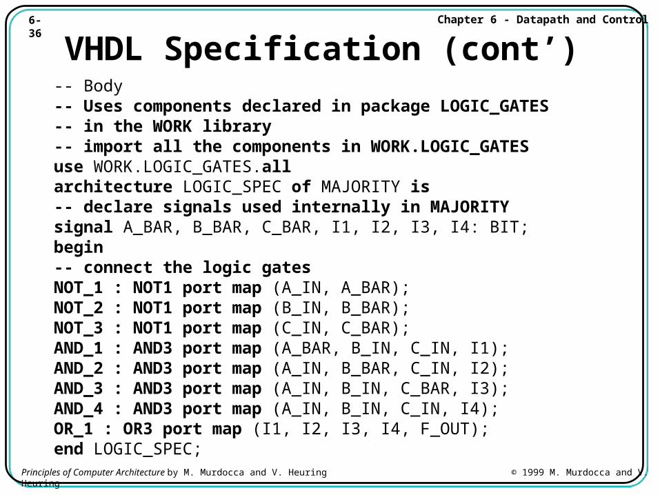
6-36 Chapter 6 - Datapath and Control
Principles of Computer Architecture by M. Murdocca and V. Heuring © 1999 M. Murdocca and V. Heuring
VHDL Specification (cont’)-- Body-- Uses components declared in package LOGIC_GATES -- in the WORK library-- import all the components in WORK.LOGIC_GATESuse WORK.LOGIC_GATES.all architecture LOGIC_SPEC of MAJORITY is-- declare signals used internally in MAJORITYsignal A_BAR, B_BAR, C_BAR, I1, I2, I3, I4: BIT;begin-- connect the logic gatesNOT_1 : NOT1 port map (A_IN, A_BAR);NOT_2 : NOT1 port map (B_IN, B_BAR);NOT_3 : NOT1 port map (C_IN, C_BAR);AND_1 : AND3 port map (A_BAR, B_IN, C_IN, I1);AND_2 : AND3 port map (A_IN, B_BAR, C_IN, I2);AND_3 : AND3 port map (A_IN, B_IN, C_BAR, I3);AND_4 : AND3 port map (A_IN, B_IN, C_IN, I4);OR_1 : OR3 port map (I1, I2, I3, I4, F_OUT);end LOGIC_SPEC;


![4-1 Parte 4 Memória. 4-2 Bibliografia [1] Miles J. Murdocca e Vincent P. Heuring, “Introdução à Arquitetura de Computadores” [2] Notas de Aula do Prof](https://img.pdfslide.net/doc/110x75/570638461a28abb8238f31ab/4-1-parte-4-memoria-4-2-bibliografia-1-miles-j-murdocca-e-vincent-p-heuring.jpg)


![5-1 Parte 5 Entrada e Saída. 5-2 Bibliografia [1] Miles J. Murdocca e Vincent P. Heuring, “Introdução à Arquitetura de Computadores” [2] Andrew S. Tanenbaum,](https://img.pdfslide.net/doc/110x75/552fc17b497959413d8f08a6/5-1-parte-5-entrada-e-saida-5-2-bibliografia-1-miles-j-murdocca-e-vincent-p-heuring-introducao-a-arquitetura-de-computadores-2-andrew-s-tanenbaum.jpg)