Embed Size (px)
Citation preview
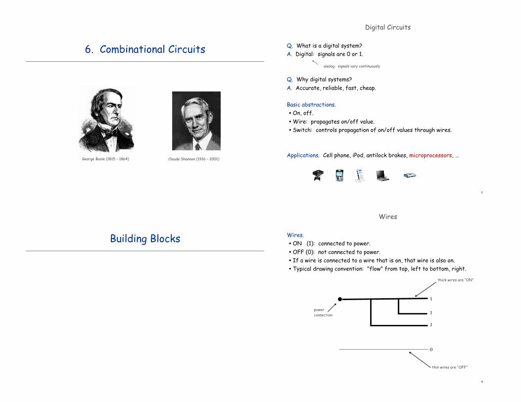
6. Combinational Circuits
George Boole (1815 – 1864) Claude Shannon (1916 – 2001)
2
Digital Circuits
Q. What is a digital system?A. Digital: signals are 0 or 1.
Q. Why digital systems?A. Accurate, reliable, fast, cheap.
Basic abstractions.•On, off.•Wire: propagates on/off value.• Switch: controls propagation of on/off values through wires.
Applications. Cell phone, iPod, antilock brakes, microprocessors, …
analog: signals vary continuously
Building Blocks
4
Wires
Wires.•ON (1): connected to power.•OFF (0): not connected to power.• If a wire is connected to a wire that is on, that wire is also on.• Typical drawing convention: "flow" from top, left to bottom, right.
0
powerconnection
1
1
1
thick wires are “ON”
thin wires are “OFF”
5
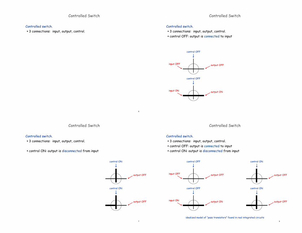
Controlled switch. • 3 connections: input, output, control.
Controlled Switch
Controlled switch. • 3 connections: input, output, control.• control OFF: output is connected to input
Controlled Switch
control OFF
output OFF
output ON
input OFF
input ON
control OFF
7
Controlled switch. • 3 connections: input, output, control.
• control ON: output is disconnected from input
Controlled Switch
output OFF
output OFF
control ON
control ON
8
Controlled switch. • 3 connections: input, output, control.• control OFF: output is connected to input • control ON: output is disconnected from input
Controlled Switch
output OFF
output OFF
control OFF
output OFF
output ON
input OFF
input ON
control OFF
idealized model of “pass transistors” found in real integrated circuits
control ON
control ON
9
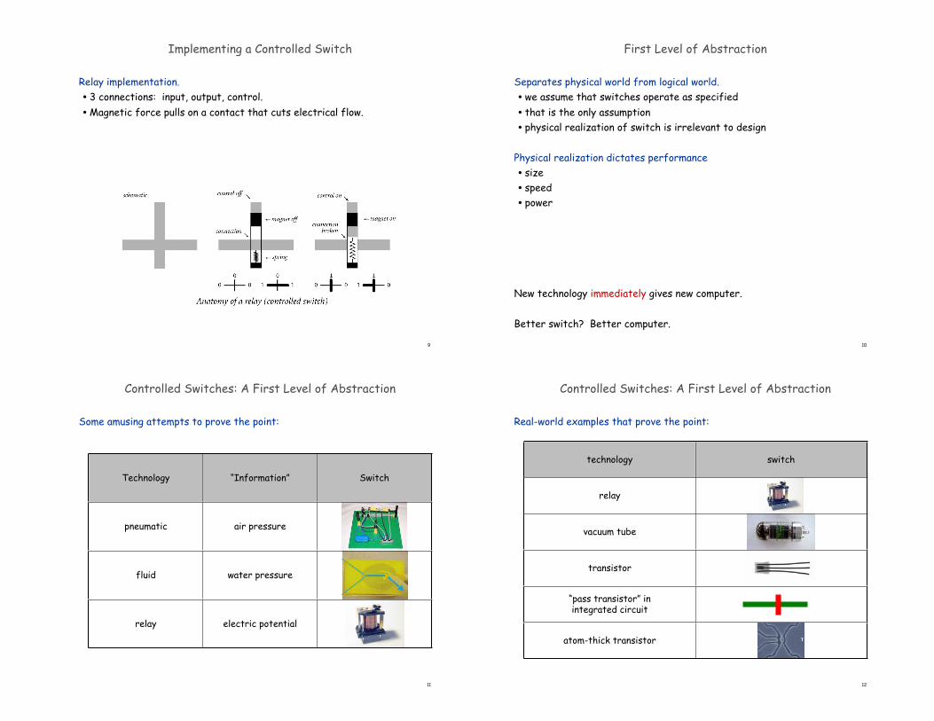
Relay implementation. • 3 connections: input, output, control.•Magnetic force pulls on a contact that cuts electrical flow.
Implementing a Controlled Switch First Level of Abstraction
Separates physical world from logical world.• we assume that switches operate as specified• that is the only assumption• physical realization of switch is irrelevant to design
Physical realization dictates performance• size• speed• power
New technology immediately gives new computer.
Better switch? Better computer.
10
Controlled Switches: A First Level of Abstraction
Some amusing attempts to prove the point:
11
Technology “Information” Switch
pneumatic air pressure
fluid water pressure
relay electric potential
Controlled Switches: A First Level of Abstraction
Real-world examples that prove the point:
12
technology switch
relay
vacuum tube
transistor
“pass transistor” inintegrated circuit
atom-thick transistor
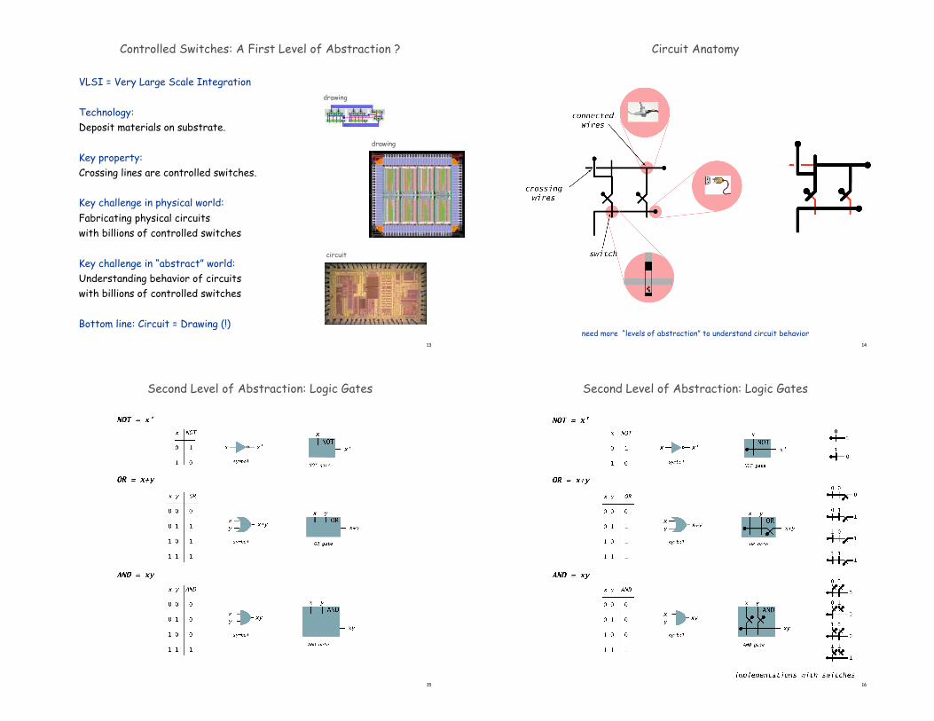
Controlled Switches: A First Level of Abstraction ?
VLSI = Very Large Scale Integration
Technology:Deposit materials on substrate.
Key property:Crossing lines are controlled switches.
Key challenge in physical world: Fabricating physical circuitswith billions of controlled switches
Key challenge in “abstract” world:Understanding behavior of circuitswith billions of controlled switches
Bottom line: Circuit = Drawing (!)
13
drawing
drawing
circuit
14
Circuit Anatomy
need more “levels of abstraction” to understand circuit behavior
15
Second Level of Abstraction: Logic Gates
16
Second Level of Abstraction: Logic Gates
17
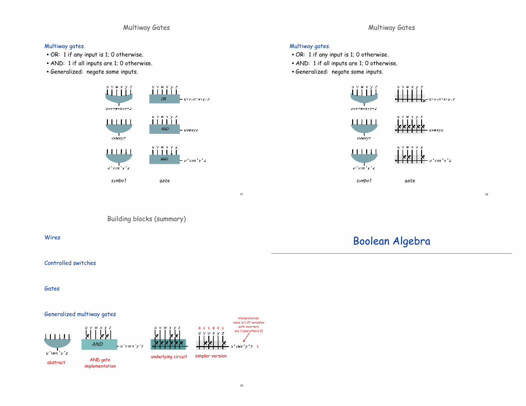
Multiway Gates
Multiway gates.•OR: 1 if any input is 1; 0 otherwise.•AND: 1 if all inputs are 1; 0 otherwise.• Generalized: negate some inputs.
18
Multiway Gates
Multiway gates.•OR: 1 if any input is 1; 0 otherwise.•AND: 1 if all inputs are 1; 0 otherwise.• Generalized: negate some inputs.
Building blocks (summary)
Wires
Controlled switches
Gates
Generalized multiway gates
19
abstractsimpler version
interpretation:value is 1 iff variables
with invertersare 1 (and others 0)
0 1 1 0 0 1
1
AND gateimplementation
u v w x y z
u ’ v w x ’ y ’ zAND
u v w x y z
underlying circuit
Boolean Algebra
21
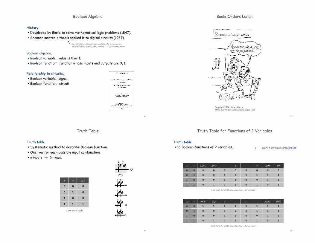
History.•Developed by Boole to solve mathematical logic problems (1847).• Shannon master's thesis applied it to digital circuits (1937).
Boolean algebra.• Boolean variable: value is 0 or 1.• Boolean function: function whose inputs and outputs are 0, 1.
Relationship to circuits.• Boolean variable: signal.• Boolean function: circuit.
Boolean Algebra
“possibly the most important, and also the most famous, master's thesis of the [20th] century” — Howard Gardner
22
Copyright 2004, Sidney Harrishttp://www.sciencecartoonsplus.com
Boole Orders Lunch
23
Truth Table
Truth table.• Systematic method to describe Boolean function.•One row for each possible input combination.• n inputs ! 2n rows.
AND truth table
0 0
0 1
1 0
1 1
0
0
0
1
x y x y
24
Truth Table for Functions of 2 Variables
Truth table.• 16 Boolean functions of 2 variables.
ZERO
truth table for all Boolean functions of 2 variables
y
0 0
0 1 0
1 0 0
1 1 0
0
0
1
0
0
1
0
0
x
0
0
1
1
AND
0
0
0
1
y
0
1
0
1
XOR
0
1
1
0
OR
0
1
1
1
x
0
NOR
truth table for all Boolean functions of 2 variables
y
0 1
0 1 0
1 0 0
1 1 0
y'
1
0
1
0
x'
1
1
0
0
1
0
1
1
EQ
1
0
0
1
1
1
0
1
NAND
1
1
1
0
ONE
1
1
1
1
x
0
every 4-bit value represents one
25
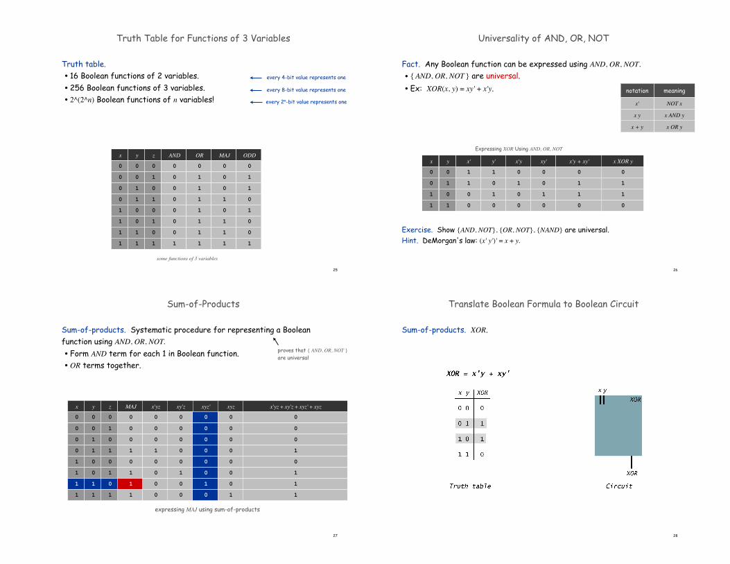
Truth Table for Functions of 3 Variables
Truth table.• 16 Boolean functions of 2 variables.• 256 Boolean functions of 3 variables.• 2^(2^n) Boolean functions of n variables!
AND
some functions of 3 variables
z
0 0
0 1 0
1 0 0
1 1 0
y
0
x
0
0
0
0
0
0 1
1 0
1 1
01
1
1
1
0
0
0
1
OR
0
1
1
1
1
1
1
1
MAJ
0
0
0
1
0
1
1
1
ODD
0
1
1
0
1
0
0
1
every 4-bit value represents one
every 8-bit value represents one
every 2n-bit value represents one
26
Universality of AND, OR, NOT
Fact. Any Boolean function can be expressed using AND, OR, NOT.
• { AND, OR, NOT } are universal.
• Ex: XOR(x, y) = xy' + x'y.
Exercise. Show {AND, NOT}, {OR, NOT}, {NAND} are universal.Hint. DeMorgan's law: (x' y')' = x + y.
x'
Expressing XOR Using AND, OR, NOT
y
0 1
1 1
0 0
1 0
x'y
0
1
0
0
x'y + xy'
0
1
1
0
xy'
0
0
1
0
y'
1
0
1
0
x XOR y
0
1
1
0
x
0
0
1
1
NOT xx'
x AND yx y
x OR y
meaningnotation
x + y
27
Sum-of-Products
Sum-of-products. Systematic procedure for representing a Boolean function using AND, OR, NOT.
• Form AND term for each 1 in Boolean function.• OR terms together.
x'yz
expressing MAJ using sum-of-products
z xyz' xyzxy'zMAJyx
0
0
0
1
0
1
1
1
0
1
0
1
0
1
0
1
0
0
1
1
0
0
1
1
0
0
0
0
1
1
1
1
0
0
0
1
0
0
0
0
0
0
0
0
0
1
0
0
0
0
0
0
0
0
1
0
0
0
0
0
0
0
0
1
x'yz + xy'z + xyz' + xyz
0
0
0
1
0
1
1
1
proves that { AND, OR, NOT }are universal
28
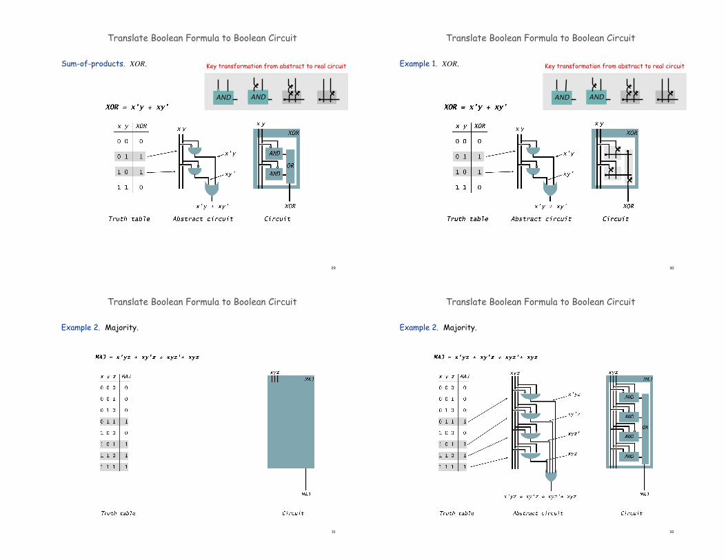
Translate Boolean Formula to Boolean Circuit
Sum-of-products. XOR.
29
Translate Boolean Formula to Boolean Circuit
Sum-of-products. XOR.
AND AND
Key transformation from abstract to real circuit
30
Translate Boolean Formula to Boolean Circuit
Example 1. XOR.
AND AND
Key transformation from abstract to real circuit
31
Translate Boolean Formula to Boolean Circuit
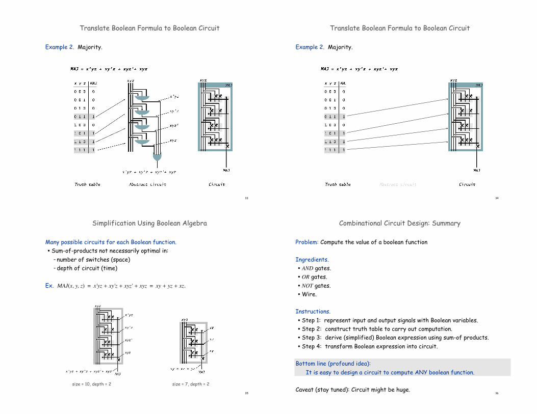
Example 2. Majority.
32
Translate Boolean Formula to Boolean Circuit
Example 2. Majority.
33
Translate Boolean Formula to Boolean Circuit
Example 2. Majority.
34
Translate Boolean Formula to Boolean Circuit
Example 2. Majority.
35
size = 7, depth = 2size = 10, depth = 2
Simplification Using Boolean Algebra
Many possible circuits for each Boolean function.• Sum-of-products not necessarily optimal in:
– number of switches (space)– depth of circuit (time)
Ex. MAJ(x, y, z) = x'yz + xy'z + xyz' + xyz = xy + yz + xz.
36
Combinational Circuit Design: Summary
Problem: Compute the value of a boolean function
Ingredients.• AND gates.• OR gates.• NOT gates.•Wire.
Instructions.• Step 1: represent input and output signals with Boolean variables.• Step 2: construct truth table to carry out computation.• Step 3: derive (simplified) Boolean expression using sum-of products.• Step 4: transform Boolean expression into circuit.
Bottom line (profound idea): It is easy to design a circuit to compute ANY boolean function.
Caveat (stay tuned): Circuit might be huge.
37
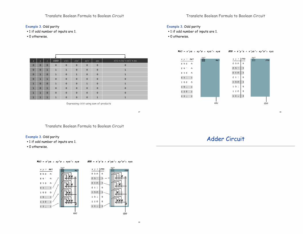
Translate Boolean Formula to Boolean Circuit
Example 3. Odd parity• 1 if odd number of inputs are 1. • 0 otherwise.
x'y'z
Expressing ODD using sum-of-products
z xy'z' xyzx'yz'ODDyx
0
1
1
0
1
0
0
1
0
1
0
1
0
1
0
1
0
0
1
1
0
0
1
1
0
0
0
0
1
1
1
1
0
1
0
0
0
0
0
0
0
0
1
0
0
0
0
0
0
0
0
0
1
0
0
0
0
0
0
0
0
0
0
1
x'y'z + x'yz' + xy'z' + xyz
0
1
1
0
1
0
0
1
38
Translate Boolean Formula to Boolean Circuit
Example 3. Odd parity• 1 if odd number of inputs are 1. • 0 otherwise.
39
Translate Boolean Formula to Boolean Circuit
Example 3. Odd parity• 1 if odd number of inputs are 1. • 0 otherwise.
Adder Circuit
41
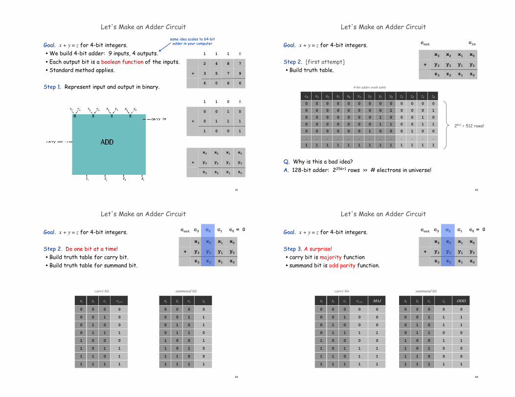
Let's Make an Adder Circuit
Goal. x + y = z for 4-bit integers.•We build 4-bit adder: 9 inputs, 4 outputs.• Each output bit is a boolean function of the inputs.• Standard method applies.
Step 1. Represent input and output in binary.
x1x2x3 x0
y1y2y3 y0+
z1z2z3 z0
100 0
110 1+
001 1
011
842 7
753 9+
606 6
111 0
0
same idea scales to 64-bitadder in your computer
42
Let's Make an Adder Circuit
Goal. x + y = z for 4-bit integers.
Step 2. [first attempt]• Build truth table.
Q. Why is this a bad idea?A. 128-bit adder: 2256+1 rows >> # electrons in universe!
x1x2x3 x0
y1y2y3 y0+
z1z2z3 z0
4-bit adder truth table
y2y3
0
0
0
0
1
.
1
0
0
0
0
0
.
1
x0x1
0
0
0
0
0
.
1
0
0
0
0
0
.
1
x2x3
0
0
0
0
0
.
1
0
0
0
0
0
.
1
y0y1
0
1
0
1
0
.
1
0
0
1
1
0
.
1
z2z3
0
0
0
0
1
.
1
0
0
0
0
0
.
1
z0z1
0
1
0
1
0
.
1
0
0
1
1
0
.
1
28+1 = 512 rows!
c0
0
0
0
0
0
.
1
cincout
43
Let's Make an Adder Circuit
Goal. x + y = z for 4-bit integers.
Step 2. Do one bit at a time!• Build truth table for carry bit.• Build truth table for summand bit.
x1x2x3 x0
y1y2y3 y0+
z1z2z3 z0
c1c2c3 c0 = 0
carry bit
ci ci+1yixi
0
0
0
1
0
1
1
1
0
1
0
1
0
1
0
1
0
0
1
1
0
0
1
1
0
0
0
0
1
1
1
1
summand bit
ci ziyixi
0
1
1
0
1
0
0
1
0
1
0
1
0
1
0
1
0
0
1
1
0
0
1
1
0
0
0
0
1
1
1
1
cout
44
Let's Make an Adder Circuit
Goal. x + y = z for 4-bit integers.
Step 3. A surprise!• carry bit is majority function• summand bit is odd parity function.
MAJ
0
0
0
1
0
1
1
1
ODD
0
1
1
0
1
0
0
1
ci ci+1yixi
0
0
0
1
0
1
1
1
0
1
0
1
0
1
0
1
0
0
1
1
0
0
1
1
0
0
0
0
1
1
1
1
ci ziyixi
0
1
1
0
1
0
0
1
0
1
0
1
0
1
0
1
0
0
1
1
0
0
1
1
0
0
0
0
1
1
1
1
x1x2x3 x0
y1y2y3 y0+
z1z2z3 z0
c1c2c3 c0 = 0cout
carry bit summand bit
45
Let's Make an Adder Circuit
Goal. x + y = z for 4-bit integers.
Step 4.• Transform Boolean expression into circuit (use known components!).• Chain together 1-bit adders.• That’s it!
46
Adder: Interface
z0z1z2z3
x0x1x2x3y0y1y2y3
input buses
output bus
A bus is a group of wires that connect (carry data values) to other components.
47
Adder: Component Level View
z0z1z2z3
x0x1x2x3y0y1y2y3
input buses
output bus
48
Adder: Switch Level View
z0z1z2z3
x0x1x2x3y0y1y2y3
input buses
output bus
Adder
Incrementer (easy, add 0001)
Bitwise AND, XOR (easy)
Decoder [next slide]
Shifter (clever, but we’ll skip details)
Multiplexer [next lecture]
Useful Combinational Circuits
49 50
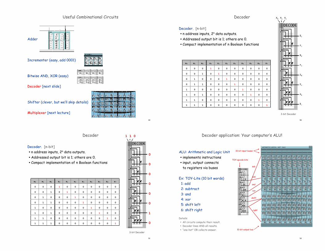
Decoder
Decoder. [n-bit]• n address inputs, 2n data outputs.•Addressed output bit is 1; others are 0.• Compact implementation of n Boolean functions
3-bit Decoder
x0 x1 x2 z0 z1 z2 z3 z4 z5 z6 z7
0 0 0 1 0 0 0 0 0 0 0
0 0 1 0 1 0 0 0 0 0 0
0 1 0 0 0 1 0 0 0 0 0
0 1 1 0 0 0 1 0 0 0 0
1 0 0 0 0 0 0 1 0 0 0
1 0 1 0 0 0 0 0 1 0 0
1 1 0 0 0 0 0 0 0 1 0
1 1 1 0 0 0 0 0 0 0 1
51
Decoder
Decoder. [n-bit]• n address inputs, 2n data outputs.•Addressed output bit is 1; others are 0.• Compact implementation of n Boolean functions
3-bit Decoder
x0 x1 x2 z0 z1 z2 z3 z4 z5 z6 z7
0 0 0 1 0 0 0 0 0 0 0
0 0 1 0 1 0 0 0 0 0 0
0 1 0 0 0 1 0 0 0 0 0
0 1 1 0 0 0 1 0 0 0 0
1 0 0 0 0 0 0 1 0 0 0
1 0 1 0 0 0 0 0 1 0 0
1 1 0 0 0 0 0 0 0 1 0
1 1 1 0 0 0 0 0 0 0 1
0 0 1
0
1
0
0
0
0
0
0
1 1 0
0
0
0
0
0
0
1
0
Decoder application: Your computer’s ALU!
ALU: Arithmetic and Logic Unit• implements instructions• input, output connects
to registers via buses
Ex: TOY-Lite (10 bit words) 1: add 2: subtract 3: and 4: xor 5: shift left 6: shift right
Details:• All circuits compute their result.• Decoder lines AND all results.• “one-hot” OR collects answer.
52
TOY opcode bits
add
and
xor
shift
right
sub
10-bit output bus
10-bit input buses
53
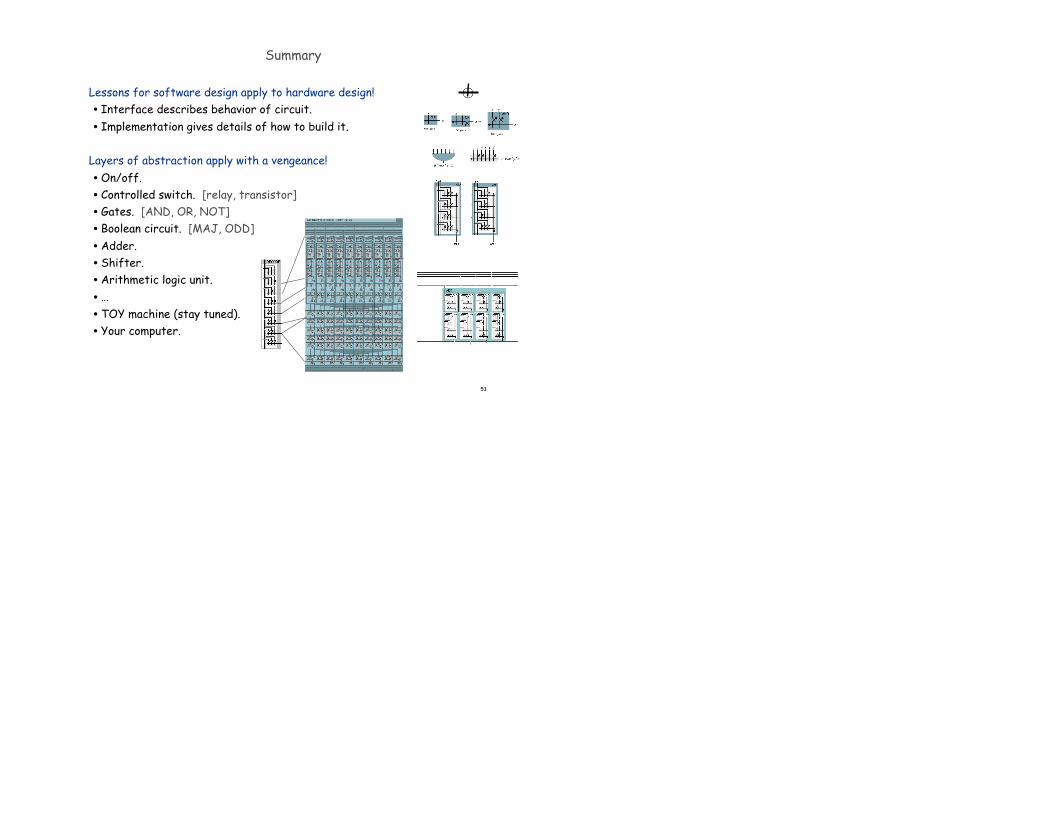
Summary
Lessons for software design apply to hardware design!• Interface describes behavior of circuit.• Implementation gives details of how to build it.
Layers of abstraction apply with a vengeance!•On/off.• Controlled switch. [relay, transistor]• Gates. [AND, OR, NOT]• Boolean circuit. [MAJ, ODD]•Adder.• Shifter.•Arithmetic logic unit.• …•TOY machine (stay tuned).• Your computer.