Embed Size (px)
Citation preview
711411zz 3Îwlldil RADIO , TELEVISION AND ELECTRONICS
43rd YEAR OF PUBLICATION
Managing Editor : HUGH S. POCOCK, M.I.E.E.
Editor: H. F. SMITH
SEPTEMBER 1953
In This Issue EDITORIAL COMMENT .. .. .. 391
WIDE -BAND V.H.F. PANORAMIC RECEIVER. By J. B.
Lovell Foot .. .. .. .. 392
C.C.I.R. LONDON MEETING 396
20TH NATIONAL RADIO EXHIBITION 397
ELECTRONICS IN MEDICINE .. 407
PORTABLE MAGNETIC RECORDER 409
WORLD OF WIRELESS .. 412
LETTERS TO THE EDITOR 415
VALVES FOR MICROWAVES -1. By " Cathode Ray " 417
INTERNATIONAL MONITORING By J. Treeby Dickinson 422
PORTABLE ALUMINIUM MAST .. .. 424
METER OVERLOAD PROTECTION. By J. de Gruchy.. .. 425
IMPROVING THE F.M. FEEDER UNIT. By S. W. Amos and G. G. Johnstone .. .. .. .. 428
SIMPLE DISTORTION METER. By V. J. Tyler 431
PACKAGED CIRCUITS. By Michael Lorant 433
TRANSISTORS -8. By Thomas Roddam.. 435
SIMPLIFIED CALCULATIONS. By Francis Oakes 439
MANUFACTURERS' PRODUCTS .. .. 441
RANDOM RADIATIONS. By " Diallist " 442
UNBIASED. By " Free Grid " . 444
PUBLISHED MONTHLY (last Tuesday of preceding month) by ILIFFE & SONS LTD., Dorset House, Stamford
Street, London, S.E.1. Telephone : Waterloo 3833 (60 lines). Telegrams : ".Ethaworld, Sedist, London." Annual
Subscription : Home and Overseas, £1 Is. Od. L.S.A. $4.50. Canada $4.00. BRANCH OFFICES : Birmingham : King Edward
House, New Street, 2. Coventry : 8-10 Corporation Street. Glasgow : 26a Renfield Street, C.2. Manchester : 260, Deansgate, 3.
I Ile www.americanradiohistory.com

82 WIRELESS WORLD SEPTEMBER, 1953
VALVES, TUBES E CIRCUITS 9. AN EXPERIMENTAL SPOT -WOBBLE CIRCUIT
The line structure of a television picture is an unpleasant feature, and is emphasized to the point at which it may become intolerable as the focus becomes sharper. The high horizontal definition achieved by good focus can be retained and at the same time the line structure removed by elongating the spot vertically. The most convenient way of doing this is by deflecting the spot vertically at a frequency which is high compared with the line frequency. This is called "spot wobble". The best circuit arrangement for producing spot wobble depends upon the picture tube used, its associated components, and the layout of the receiver. A good starting point for experiments in this field is provided by the circuit described below. It should be appreciated, however, that if the interlace is not good, or if the spot is astigmatic, or if there is appreciable deflection defocusing, spot wobble is unlikely to effect any considerable improvement. These points should therefore be looked into before attempting to apply spot wobble. The diagram shows a simple oscillator in which the spot -wobble deflector coils form part of the oscillatory circuit. An EF80 pentode is employed, connected as a triode, and the total drain on a 180 volt H.T. line is about 12 mA.
The amplitude control RI is used to adjust the elongation of the spot to the condition in which the lines just merge. The switch SW1 permits the spot wobble to be switched off while the normal focus is being adjusted. The spot -wobble deflector coils consist of a pair of saddle windings similar to conventional deflector coils. There is, however, no yoke, and the windings are much smaller, each coil consisting of five turns of 0.018" dia- meter (26 S.W.G.) enamelled copper wire. These should be wound on a rectangular former 1g"x 1r. When removed from the former the flat winding is applied to the tube by folding the longer sides round the neck, i.e., with the 18' width parallel to the axis of the tube. The two coils are mounted on opposite sides of the tube neck directly behind the normal deflection coils and are connected in series in such a way that their magnetic fields assist each other.
VISIT MULLARD
AT THE
RADIO SHOW STAND 91
TRADE DEMONSTRATION
ROOM D7
RI SWI +I80V 10kí12
L2 Bulgin
C2 C4 SW68 68013F 2200 pF
EF80 GI
3-30pF
C3 68pF
R2
22 KIl
Leads to coils less
/than 6in in length
L
Reprints of this adrertiseme nt together with additional practical hints, may be ottai ned free of charge front the address below.
NULLARD LTD., Technical Publications Dept, Century House, Shaftesbury Avenue, London, W.C.2
M V M239
www.americanradiohistory.com

.i 1 L.
SEPTEMBER 1953
Two Bites at a Cherry
IN last month's Wireless World we suggested (with some diffidence and with all due deference to the recently published findings of the Television Advisory Committee) that it might be a good thing to abandon all idea of using Band 3 (174-216 Mc/s) for television in this country. The band is at present largely occupied by other services and it is doubtful whether it could be entirely cleared. We argued that, sooner or later, television was bound to go to the higher frequencies; why not pass to them at once, and avoid making two bites at a cherry? The exist- ence of a handful of stations operating in Band 3,
and giving much less than nation-wide coverage, would be a grave embarrassment to producers and distributors of receivers. To pass direct to Band 4
(470-585 Mc/s) seemed to us to be much more orderly, economic and, in the long run, likely to lead to more rapid development of the art.
We have been surprised by the amount of support given to a suggestion put forward so tentatively. One of the strongest arguments put before us is that competitive television, in the proper sense of the term, cannot come into being without a large number of competing stations-a larger number than could be accommodated in Band 3, even if the whole of it could be freed. And the chances of freeing it seem rather remote. According to a statement in Parlia- ment by the Assistant Postmaster -General, there are at present some 1,680 fixed and mobile stations at the lower end of the band, while aeronautical navigational aids occupy the upper end from 200 to 216 Mc/s. Other services within the band, including P.O. tele- phone links, B.B.C. outside -broadcast links and 75 short-term experimental stations, could be rather more easily moved, though time would be needed for changes. The Asst. P.M.G. has, indeed, spoken of clearing the band gradually " over a period of
years." This statement seems to dispel all hopes that
effective and worth -while use can be made of Band 3
in the immediate future. It also serves as an answer to a critic of our proposal who urges that the relin- quishing of Band 3 would mean intolerable delay
WIRELESS WORLD, SEPTEMBER 1953
VOL. LIX No. 9
in the introduction of an alternative television ser- vice. Admittedly, in the preent state of the art the industry is not ready to make mass -production receivers for Bands 4 or 5, but it is well on the way towards being able to do so. Indeed, if the industry has a clear-cut objective on which to concentrate, it is likely to be able to produce sets for the higher frequencies long before Band 3 can be freed.
Another indirect argument against making use of the two channels that are at present available in Band 3 was provided by another statement of the Asst. P.M.G. in Parliament. He said that the B.B.C. now believe their plan for virtually complete coverage of the country with a single programme can be completed without going outside the present television Band 1. That, of course, avoids an undesirable complication in receivers designed for use in the immediate future.
Mobile radio, an increasingly important branch of our art, must also be considered. The question of dis- placing those mobile stations already operating in Band 3 is a thorny one. Instead of doing that, there is much to be said in favour of allocating even more channels in the band to " business radio " and other mobile services.
Perhaps the strongest argument against using Band 3 for television is that it might call for the use of receivers or convertors for three bands. That would be an expensive complication which the view- ing public could not be expected to tolerate.
Radio on Parade THE trend towards television at the forthcoming National Radio Exhibition will be more marked than last year. For the first time, the number of exhi- bitors of television receivers will exceed those of sound -only sets. The Show, which opens on September 2, will be predominantly of equipment for the home, with sound recorders as runners-up to radio gear proper. Very wisely, however, the organ- izers are increasing their efforts to show the public that there is more in radio than broadcasting.
391
www.americanradiohistory.com

SPECIFICATION Signal -frequency range : 80-220 Mc/s. Sensitivity : 4µV. at 80 Mc/s ; 10 V. at 220 Mc/s for
twice the peak amplitude of internal noise. Scanning ranges : 0-10 Mc/s ; 0-2 Mc/s ; 0-0.4 Mc/s. Stability : 0.25 Mc/s after the first 15 mins. Resolution : About 150 kc/s for 10 Mc/s sweep.
30 2 Mc/s f) 15 0.4 Mc/s
Scanning system : Electronic. Repetition rate : 25 per sec. Input impedance : 7112 unbalanced. Frequency marker signals spaced 2 Mc/s or 10 Mc/s are
provided. Provision is made for the connection of headphones.
Wide -Band V.H.F. Panoramic Receiver Zero Beat Method of Producing
By J. B. LOVELL FOOT, A.M.I.E.E.*
Indicating Pulses
APANORAMIC receiver provides a visual display on a cathode-ray tube of the signals that are present in a given frequency band. The signals are usually represented by vertical pulses on a base -line repre- senting frequency. The display is produced by auto- matically swinging the tuning of the receiver over the band of frequency in synchronism with the scan- ning of the cathode-ray tube. The repetition rate is preferably higher than the persistence of vision so that a picture free from flicker is obtained.
Receivers of this type are often used in the field of radio communication for monitoring radio stations, or for search purposes.
There are so many measurements which can be carried out more quickly on a panoramic display than by other methods, that it is surprising that such a receiver is not more often included in the general equipment of a radio laboratory.
A few of the many possible applications are as follows :-
To facilitate the rapid frequency calibration and testing of oscillators, for example in the production of standard signal generators or of frequency converters for receivers. For this work a panoramic display can be used to show oscillator drift, frequency modula- tion, harmonic or spurious radiations, sideband radiations or variations of signal amplitude. It can also be used to measure the effectiveness of screening, or for the location and investigation of radio inter- ference.
With the exception of certain specialized equip- ments, most panoramic displays described in the past have been designed as additional units for use with existing communication receivers. These convert the
392
receiver circuit to that of a double superheterodyne by adding a sweeping oscillator as frequency converter at the input. The output is taken from a suitable point in the receiver (usually after the output from the i.f. amplifier) and is made to deflect the trace of a cathode-ray tube.
Such instruments often suffer serious disadvan- tages; there is a limitation of the bandwidth that can be scanned, and a wide variation in sensitivity over the band under examination. In addition, the applica- tion of the double superheterodyne principle for the receiver system has given rise to spurious responses which confuse the displayed picture.
For a panoramic receiver to be of greatest value it must be free from these defects. It should have a high sensitivity and provide the best resolution com- patible with the high rate of frequency scanning (in Mc/s/s). For convenience the scanning range should be adjustable without changing the frequency on which the receiver is centred, and the scanning range should be adjustable down to zero with facilities pro- vided for listening to modulated signals. Signals of known frequency should be made available for com- parison purposes at intervals throughout the band.
The photograph at the head of this article shows a commercial form of receiver which was designed with these requirements in mind. Here the double super- heterodyne principle has been retained, but unlike the system just described the second local oscillator has been made the sweeping oscillator. Spurious re- sponses have been eliminated, except when the receiver is badly overloaded by strong signals. This
*Research Laboratories, The General Electric Company.
WIRELESS WORLD, SEPTEMBER 1953
www.americanradiohistory.com

E
CRYSTAL CALIBRATOR
r1st. LOCAL
OSCILLATOR
R. F. 1st. WIDE -BAND nd
R.E.
INPUT
AMPLIFIER MIXER I. F. AMPLIF ER MIXER
A B D A
WIDE -BAND
L J
BUFFER AMPI IF !FR
K
MAINS LOCKING
SAW -TOOTH WAVE
GENERATCR
BAH -TOOTH AMPLIFIER
-4-
F
VARIABLE BANDWIDTH
L.F AMPLIFIER
SWEEP
OSCILLATOR
Fig. I. Block diagram of panoramic receiver.
was done by carefully choosing the frequencies of the various sections to minimize the number and strength of unwanted internally produced signals fall- ing within the r.f. and i.f. bands. Harmonic frequen- cies of the sweeping oscillator that cannot be entirely avoided are prevented by screening from causing trouble.
Principle of Operation.-Fig. 1 shows a block dia- gram of the general arrangement. The first local oscillator C determines the mean frequency of opera- tion and the second local oscillator H determines the sweep bandwidth. A received signal in the band under examination is first amplified by a broad -band r.f. amplifier A. This feeds a first mixer B where the signal is converted to an i.f. by mixing with output from C. The signal after amplification in a wide - band i.f. amplifier D is then converted by mixing with the output from the frequency -modulated sweep oscil- lator H to produce a second i.f. at the second mixer E. This is a swinging frequency from which a narrow band is selected by the amplifier F. The width of the pass band of this amplifier determines the width of the displayed pulse. For obtaining the highest resolution this should be adjustable so that the narrowest width consistent with the rate of frequency scanning can be used.
Turning now to the requirements of the second frequency converter a problem arises in the choice of frequency for the second i.f. amplifier and a sweep oscillator. If the frequency of the second i.f. is high we shall have difficulty in making filters of a suffi- ciently narrow bandwidth for shaping the pulse. On the other hand, if the frequency is not considerably higher than the maximum bandwidth to be scanned there will be insufficient attenuation outside the pass band of the first i.f. amplifier to prevent second - channel break -through.
This difficulty was avoided by sweeping the second local oscillator frequency through the same band as that covered by the first i.f. amplifier, so that beats of low frequency are provided as the oscillator sweeps across the converted signal frequencies. This pro- duces a zero beat condition for each signal, rising in frequency on both sides. If we now limit the upper and lower beat frequency range by a selection of simple filters included in the i.f. amplifier F we can easily produce a controllable pulse width. The pre- cise shape of this pulse, after rectification at G, will depend on the frequency response of the amplifier as
WIRELESS WORLD, SEPTEMBER 1953
G
RECTIFIER
PHASE I
INVERTEx
X GOI
a whole, but will be of the double form shown ex- panded in Fig. 2(a). A smoothing capacitor after the rectifier combines the double pulse shape to form a single pulse. It is desirable to limit the beats of very low frequency since they give rise to variation of pulse amplitude in successive displays.
The second mixer must not produce a low - frequency output from a signal except when mixing takes place with the sweep oscillator, otherwise any modulated signal within the band under examination would produce a deflection of the cathode-ray tube trace over the whole band. To prevent such an effect a balanced mixer is used. The circuit employed is shown in Fig. 3, and consists of four germanium crystals forming a ring. The signals are applied from the i.f. amplifier to a bandpass circuit which is coupled to the diode ring and no output is produced across the l.f. output terminals in the absence of signal from the sweep oscillator. The sweep oscillator produces a voltage across the diodes which is large compared with any of the signal voltages.
R.F. Amplifier and First Local Oscillator.-A type EF95 valve is employed as an r.f. amplifier; this operates over a frequency band of 80-220 Mc/s.
Fig. 2. (a) Expanded pulse, showing dip at zero beat, (b) 10 -Mc s
sweep, crystal calibra- tor markers spaced by 2 Mc/s. (c) 2-Mc/s sweep showing I0012V
signal between two marker signals spaced by 2 Mc/s. (d) 400 kc s
sweep, crystal calibra- tor marker and signal spaced by 50 kc/s.
I
(a)
(b)
it -
(c)
(d)
393
www.americanradiohistory.com

Tuning is carried out by a ganged variable inductor, which has a spiral scale of about 5ft in length and is calibrated directly in frequency. Three sections of the tuner are associated with the r.f. amplifier and a fourth provides the control for the first local oscillator. The oscillator valve is a type A1714 and operates at a fre- quency 60 Mc/s higher than the signal -frequency circuits.
The signal and oscillator frequencies are both applied to the grid of an EF95 valve where mixing takes place, and an i.f. in the band 55-65 Mc/s is produced.
Wide -band I.F. Amplifier.-This consists of five stages using type Z77 valves. Tuning is carried out in the valve anode circuits by coils fitted with adjust- able brass cores. The amplifier is stagger -tuned to produce a bandwidth of about ± 6 Mc/s. The band- width is obtained by tuning alternate coils to the high- and low -frequency ends respectively. The fifth circuit is tuned near the middle of the band.
The Sweep Oscillator.-Scanning could be carried out either mechanically or electrically. A small motor has often been used to vary either L or C of the frequency -determining circuit of the oscillator. This is a particularly useful method when a very high ratio of frequency change to mean frequency is required. In the present case the ability to change the scanning range without appreciable change of centre frequency is important. As the centre frequency is 60 Mc/s,
-fl I.F SIGNAL INPUT
o
GERMANIUM CRYSTALS TYPE GEX66
o--- III SWEEP
OSCILL ATOR
Fig. 3. Circuit diagram of balanced second mixer circuit.
Fig. 4. Circuit diagram of frequency -modulated oscillator.
SAW -TOOTH VOLTAGE
AF
100 k fl CENTRE
FREQUENCY ADJUSTMENT
294
the percentage change of frequency is not very great, and the required range of ± 5 Mc/s can be obtained electrically without great difficulty. The circuit em- ployed is the phase -shift oscillator shown in Fig. 4. This consists of an amplifier and three cathode followers arranged in a closed ring. The cathode followers feed into capacitive loads, formed mainly by the valve interelectrode capacities shown dotted in the diagram. Oscillation occurs at the frequency at which there is a total phase shift around the ring of 360 degrees, provided that the gain is greater than unity. Variation of the voltage applied to the grids of the cathode followers changes the gm of the valves, and a phase shift occurs. Since the total phase change must equal 360 deg, a change of frequency takes place to restore the required condition.
Output is taken from the first cathode follower in the ring sequence at a very low level, and drives a wide -band " buffer " amplifier (I in Fig. 1) for feeding to the mixer. This amplifies the signal to the re- quired level and prevents frequency -pulling by strong signals near the zero beat condition. The relation- ship between oscillator frequency and voltage applied to the grids of the cathode followers in the oscillator is not quite linear, but this is corrected as described later.
Low -frequency Amplifier and Rectifier.-This amplifier is fed from the second mixer and consists of three stages employing type Z77 valves. A gain control is provided between the first and second stages. The bandwidth is controlled in three steps by a switch mechanically coupled to the sweep range switch, so that the narrowest band is selected for the narrowest sweep. Three widths are provided, the widest being the normal amplifier bandwidth and the other two are produced by the inclusion of RC filters
between the second and third valves.
A transformer with a push-pull output couples the amplifier
L F to a pair of diodes
OUTPUT where the output is formed into a pulse for deflecting the cathode- ray tube. A capacitor is introduced across the output of the diodes for removing higher frequency com- ponents and the dip at zero beat, thus providing a pulse of + H.T.
smoother appearance on the display.
C.R.T. and " X " Deflection Circuits.- It was decided, for reasons of circuit sim- plicity, to employ a magnetically deflected c.r.t. This also has other minor advan- tages compared with the corresponding elec- trostatic tube. A 6in screen was considered to be the most suitable size, as this leads to a portable instrument
WIRELESS WORLD, SEPTEMBER 1953
www.americanradiohistory.com

I i w
and still provides a trace that can be viewed by the operator at a convenient distance. A saw- toothed waveform generator, J in Fig. 1, driving an amplifier K, produces the current for deflecting the base line of the c.r.t. and for controlling the frequency of the sweep oscillator. This operates at a repetition rate of 25 per sec., which is the lowest frequency that can be used without introducing appreciable flicker, and is locked by a circuit L to alternate cycles of the a.c. mains. Locking prevents instability of the viewed pulse due to beats between the saw -tooth generator and any stray magnetic field from mains transformers.
The c.r.t. trace is blacked out during the flyback period by a pulse of voltage produced from the ampli- fier. The voltage for controlling the sweep oscillator is provided by the p.d. across a resistance R con- nected in series with the " X " deflection coil. This gives accurate synchronization and makes the line- arity of the trace independent of changes in the saw- toothed waveform. The frequency linearity of the trace has been improved as follows: The saw-toothed voltage waveform for the control of the sweep oscil- lator is changed in phase by 180 deg. by means of a negative -feedback amplifier M. The waveform is then shaped by the coupling circuit which has a suit- able time constant, so that a shape roughly compen- sating for oscillator non -linearity is obtained. This voltage is fed to the sweep oscillator, instead of the original voltage.
Crystal Calibrator.-A crystal calibrator N is built into the equipment. This provides a spectrum of harmonics over the entire signal frequency range. The spacing of the harmonic frequencies is equal to the crystal frequency and is useful when, (a) setting the mean frequency of the sweep oscillator. (b) checking the frequency calibrations of the first
local oscillator. (c) marker signals of known frequency are required
on the display. (d) adjusting the receiver to give a " flat " frequency
output response over the band under examina- tion.
Normally a 2-Mc/s crystal is used to provide marker signals, but by operation of a push-button switch, markers spaced by 10 Mc/s are provided. This allows the positive identification of the 2-Mc/s spaced signals which are multiples of 10 Mc/s.
Because the crystal harmonics are injected into the first tuned circuit of the receiver, these give an imme- diate indication of the overall sensitivity of the set and of the uniformity of gain over the band under examination. This latter can be adjusted by an r.f. trimmer controlled from the front panel.
The level of the signals produced by the crystal oscillator is too low to produce appreciable radiation when the receiver is connected to an aerial.
General Construction.-The equipment is con- structed in three parts: the receiver, the c.r.t. display unit and the power unit. The power unit is mounted on the baseplate of a carrying case, and the receiver and c.r.t. sections, which slide into the case on guide rails, are secured by screw on the front panels. A detachable cover to protect the controls is fitted over the front of the set. Interconnection between the sections is by plugs and sockets.
The power supply required is a.c., 50-60 c/s, and a series voltage -regulator valve maintains a constant h.t. voltage on the receiver. A small fan ventilates the containing case.
WIRELESS WORLD, SEPTEMBER 1953
Additional Facilities.-As an alternative to the panoramic display, the receiver can be used for listen- ing to modulated signals and a telephone jack pro- vides the connection for this purpose. The change- over is effected by setting the sweep oscillator range to zero on the bandspread control, and switching out the filter in the l.f. amplifier. If the receiver tuning is then set in a slightly "off tune" condition a second i.f. of, say, 30 kc/s will be produced in the l.f. ampli- fier, and normal detection takes place in the rectifier. For the identification of signals picked up while scan- ning over a wide band, it is convenient to reduce the scanning range to zero, keeping the signal in the middle of the c.r.t. trace with the tuner, and finally to listen to the modulation. This operation can be carried out in a few seconds without losing the signal.
REFERENCES Thomasson, D. W., " The Principles and Practice of
Panoramic Display," 7. Brit. I.R.E., VIII, 171, 1948. Cormack, A., " Wide -range Variable Frequency Oscil-
lator," Wireless Engineer, September, 1951. Crompton, E. W., "A V.H.F. Multi -band Panoramic
Receiver," Electronic Engineering, November, 1952. British Patent Application No. 19487/51.
ELECTRICAL CONTACT PROBLEMS
THE making, maintenance and breaking of circuits carry- ing current is of such fundamental importance that people concerned with electricity must early acquire a rule -of - thumb working knowledge of materials suitable for switch contacts, and the conditions which influence arcing and cause deterioration of the contact surfaces. An extensive literature has accumulated on the subject, mostly dealing with specialized applications, which makes it difficult for the designer to find reliable basic principles.
To remedy this state of affairs, Prof. F. Llewellyn Jones has prepared a report* which presents a critical review of rival theories, establishes a coherent picture of basic principles, and suggests directions in which research might most profitably be extended.
The pamphlet, which will be invaluable to the specialist, contains much of interest for a general reader. For instance, it is surprising to learn that in the microscopic bridges conducting current between the salient irregu- larities of the contact surface, temperatures are so high that it is the boiling point which determines the suitability of a contact metal. They all melt locally, and, due to the Thomsont effect and the reversal of temperature gradient across the bridge, the highest temperature is biased away from the centre. When the bridge is ruptured more material usually adheres to the cathode contact, and photo- graphs of this typical "pip and crater" wear, as well as photomicrographs of actual molten bridges are included.
Not all damage results during the " break " and at the instant before " make," when the contacts are about 2 x 10 -'cm apart, the electrostatic forces of attraction, when the potential difference is only 1 volt, may exceed the yield stress of the material and pull off particles. There is also an electron discharge before contact, which im- pinges on the anode contact and can cause pitting as well as a rise in temperature relative to the cathode contact.
Theoretical as well as experimental evidencé is produced in support of these and other interesting views of contact phenomena. The report concludes with a 79 -item bibliography and a good index.
* Radio Research Special Report No. 24, " Fundamental Pro- cesses of Electrical Contact Phenomena," published by Her Majesty's Stationery Office, price 3s.
t E.M.F. due to a temperature gradient in a metal; conversely, heating or cooling, depending on direction of current, relative to temperature gradient.
395
www.americanradiohistory.com

London Meeting FOR the first time a Plenary Assembly of the
C.C.I.R. (Comité Consultatif International des Radiocommunications) will be meeting in London in September. There will be over 300 participants, representing about 50 countries, at this seventh plenary assembly, which will be opened by the Post- master General at Church House, Westminster, on September 3rd and is scheduled to close on October 7th. The last meeting was in Geneva in 1951. The proceedings of the meetings will be conducted in English and simultaneous translations in French, Spanish and Russian will be available to delegates.
Entrusted with " the study of technical radio ques- tions and operating questions, the solution of which depends principally on considerations of a technical radio character," the C.C.I.R. meets biannually to con- sider the reports and recommendations presented by the national study groups appointed by each of the member nations.
Before summarizing the matters to be discussed at the assembly we should, perhaps, state the general principles governing membership of the C.C.I.R. which is one of the permanent organizations of the International Telecommunications Union; others being the International Frequency Registration Board, International Telegraph Consultative Committee (C.C.I.T.) and the International Telephone Consulta- tive Committee (C.C.I.F.). Administrations of any of the 80 or so members of the I.T.U. have the right to be members of the International consultative committees, and, upon request, " recognized private operating agencies " which are defined as companies operating a telecommunication installation. Scientific or manu- facturing organizations engaged in the study of tele- communications problems or in the design of telecom- munications equipment may be admitted to participate in certain meetings. So far as this country is concerned the Post Office is the co-ordinating body for the official delegation which will include representatives of the
396
Services, B.B.C., D.S.I.R., R.I.C. and the British Joint Communications Electronics Board. In addition, however, representatives of Cable and Wireless, Inter- national Marine Radio Co., Marconi International, Redifon and Siemens will be participating in their own right. The complete U.K. delegation will total about 50 and will be lead by H. Faulkner, deputy engineer -in -chief at the Post Office. The deputy leader is H. Stanesby (P.O. staff engineer).
The business of the assembly can be epitomized by the phrase " to secure the maximum economy and efficiency in the use of the spectrum." Some idea of the diversity of subjects to be covered will be gained from the following list of fourteen study groups with, in brackets, the names of the chairmen of the U.K. groups :-
I. Transmitters (A. Cook, P.O.). 2. Receivers (W. J. Bray, P.O.). 3. Complete radio systems (J. A. Smale, C. & W.). 4. Ground -wave propagation. 5. Tropospheric propagation. 6. Ionospheric propagation. 7. Radio time signals and standard frequencies (H. B. Law,
P.O.). 8. International monitoring (C. W. Sowton, P.O.). 9. General technical questions (H. Stanesby, P.O.).
10. Broadcasting (E. L. E. Pawley, B.B.C.). 11. Television (H. Faulkner, P.O.). 12. Tropical broadcasting (P. Adorian, Redifon.). 13. Operational questions. 14. Vocabulary (H. T. Mitchell, P.O.).
Groups similar to these in each of the member countries submit their reports to Geneva and a co-ordinated summary of them will be presented at the London meeting by the international chairman of the appropriate group. The text of each of the national reports is available in full and some 300 con- tributions will have been circulated to delegates before the opening of the assembly.
We hope to be able to deal with the findings and recommendations of the assembly in a future issue.
(Dr. R. L. Smith -Rose, D.S.I.R.).
AMATEUR TELEVISION HOME constructed equipment pro-
vided the pictures which were " piped " to various receivers around the Institu- non of Electronics exhibition at Man- chester. The temporary studio contained a 405 -line camera, a flying -spot scanner, two monitor screens, a vision transmitter and a large -screen front projection receiver. A signal generator acted as the sound transmitter and its output was combined with the vision signal in a bridge network. Here the camera is shown televising through an open win- dow interviews with men working on a new extension to the College of Tech- nology, with the sound coming by way of a Marconi walkie-talkie. The demon- stration was organized by the local branch of the Television Society, and the equipment was provided by Ian McWhirter, who is also a well-known member of the British Amateur Tele- vision Club. The call sign of his ama- teur station is G3ETI.
WIRELESS WORLD, SEPTEMBER 1953
www.americanradiohistory.com

SEPTEMBER, 1953 WIRELESS WORLD 83
BRITISH MADE
VALVES More reliable
than EVER! Years of experience in the design and manufacture of Trustworthy special quality valves has resulted in increased reliability throughout the entire BRIMAR
Range.
New techniques and the more accurate control of vital processes have resulted in manufacture of a more uniform and reliable product and in a
lower rate of rejection. This, in spite of the fact
that testing is more rigorous.
Reliability is especially important in the modern T/V Receiver which employs four times as many
valves as radio and - fewer rejects in the factory will mean fewer failures in the field !
The Brimar 6AM6/8D3 and its direct equivalents the Z77, SP6, EF9I and 6FI2 have been some of the most widely used valve types in post-war Television Receivers. Large quan- tities have been used in the following Manufacturers' sets :- BAIRD K -B BUSH MARCONIPHONE COSSOR MASTERADIO ENGLISH McMICHAEL
ELECTRIC PHILCO ETRONIC PILOT G.E.C. VIDOR H.M.V.
Use the improved BRIMAR 6AM6/8D3
to replace these valves at NO EXTRA COST
<e>7 now is the time to MAHZF/ 5tandard Telephones and Cables Limited
FOOTSCRAY SIDCUP KENT FOOtscray 3333
www.americanradiohistory.com

84
Make a bee -line for
First of the o em ce G - REG
WIRELESS WORLD
.O.Err
SEPTEMBER, 1953
and see for yourself:
series of pick-ups & cartridges
/
A brand new range of inexpensive microphones / / /
Acos crystal devices are protected by patents and patent applications in Great Britain and other countries.
COSMOCORD LIMITED ENFIELD MIDDLESEX
/ /
Acos "Hi -g " Pick-ups are the first commercially available pick-ups that will track the highest modulation levels capable of being engraved on either standard or long playing records. They thus add an important advance in pick-up design to the already outstanding reproduction qualities associated with Acos crystal products.
... always well ahead
www.americanradiohistory.com

20th National
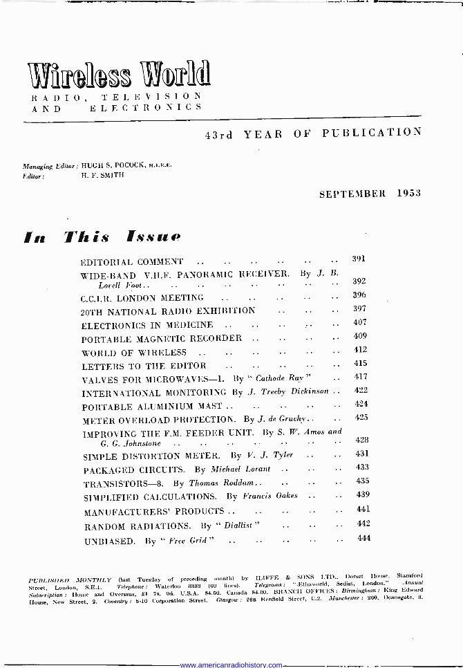
Radio Exhibition Introduction to the Show : Classified Guide to the Principal Exhibits
0 September 2nd at 11 o'clock the 20th British National Radio Exhibition (Earls Court, London), organized by the Radio Industry Council, will be
opened to the public. The previous day will be a
pre -view for specially invited guests. Admission to the Show, which will be open daily (except Sunday) from 11 a.m. to 10 p.m. until September 12th, is 2s 6d
(children under 16, 1s). The available floor space appears from the plan
given on another page to be more fully occupied than in previous years, all the space not allocated to stand - holders having been utilized by the R.I.C. for the staging of displays and demonstra- tions of electronic gear. Of the 112 exhibitors (four more than last year), 40 are manu- facturers of broadcast and tele- vision receivers. There are, in fact, two more exhibitors of television than sound sets.
Once again we have prepared our pre -view of the Show in the form of classified lists in graphical form, but with one important difference. HitBerto, there were several separate tables each embracing an asso- ciated group of items, and while they certainly enabled all the makers of any particular product to be found quite readily, it was not so easy to extract from these tables everything that each exhibitor manufactured.
We think this small defect has been overcome by the use of the single tabulated list which has been compiled for this year's pre -view. It enables the majority of the products shown by any one firm, or the names of all the firms making any particular pro- duct, to be extracted from the table merely by running a finger along or down the appropriate column.
Exhibitors are listed in alphabetical order under their trade names or the abbreviated names of the firm, as appropriate, and also numerically by stand numbers. These lists together with the plan will enable any exhibitor to be quickly located in the exhibition.
While we would like to have included every item shown in the exhibition limitation of space necessi- tated the omission of a few items, of which only one or two examples are shown. A case in point is the very specialized air-sea rescue beacons shown by
Vidor-Burndept and by Ultra. Both are miniature lightweight radio beacons for attachment to an air- man's life-saving jacket and both provide also for radio -telephone communication. In this section also would have been included radar air -field approach equipment made by Ekco.
Coil winders find no place in our table, as again one firm only shows them (Avo), and they are also specialists in testing equipment which is included.
WIRELESS WORLD, SEPTEMBER 1953
PLACE : Earls Court, London, S.W.5
DATE : September 2nd to 12th
TIME : 11 a.m. to 10 p.m.
ADMISSION : 2s 6d (Children Is)
Scientific, industrial and medical equipment is another omission, but it would have had three entries only, Dynatron for counters, Ediswan for electro - medical apparatus and K.B. for a hearing aid.
In addition to the commercial exhibits listed in the tables and those already referred to, there are a num- ber of radio users who have taken stands. Two of the largest displays will be staged by the Army and the R.A.F., and will together show the operation and main- tenance of radio equipment in the Services and the training of radio personnel. One of the main objectives
of the Army display is the recruitment of radio special- ists into the Army Emergency Reserves of the Royal Corps of Signals and the Royal Elec- trical and Mechanical En- gineers. The B.B.C. has a stand and is again co-operat- ing with the R.I.C. in the pro- vision of a television studio.
Some stands will be devoted by the holders exclu- sively to information centres, among them the Asso- ciation of Radio Battery Manufacturers, British Iron and Steel Federation, British Railways, Bowmakers (industrial bankers) and the Electrical Trades Union. Others, like the four banks, are providing services for exhibitors and visitors.
In collaboration with Philips Electrical, Ltd., who employ several blind workers, the United Appeal for the Blind is providing a demonstration of blind workers assembling radio components.
As far as is practicable each of the ten displays of electronic equipment staged by the Radio Industry Council will be devoted to a specific application of electronics.
On the stand devoted to electronics in the air, E. K. Cole will be displaying airfield radar approach equip- ment, and Ultra Electric the air-sea rescue radio beacon " Sarah," which was described in our August issue. Electronics at sea is represented by a display of Cossor and Kelvin -Hughes marine and harbour radar gear, Kelvin -Hughes echo -sounder and a crystal - controlled clock coder for m.f. marine radio beacons provided by Trinity House.
Industrial applications of electronics as diverse as watch -timing and seed -sorting are provided in another display.
Electronic business equipment, including a card sorter handling 650 cards a minute provided by Inter- national Business Machines, Ltd., and desk facsimile equipment by Creed, are grouped on another stand. Examples of the applicatión of electronics in medicine include Leland Instruments auscultoscope for the observation of the functioning of the heart and lungs.
An analogue computor by E.M.I. Engineering
397
www.americanradiohistory.com

Development, a model of the radio telescope being con- structed for installation at the Jodrell Bank Research Station, radio -controlled models operating on 465 Mc/s provided by the International Radio -Controlled Models Society, a large scale model of a guided missile and examples of sub -miniature component assemblies (Ministry of Supply) are among other electronic exhibits. r
The central feature of the Hall will be a radio -con- trolled clock which will be governed by pulses received by radio from the Post Office station at Rugby. This is being installed by the Telephone Manufacturing Company.
The Television Avenue, giving visitors an oppor- tunity of comparing side -by -side forty sets in opera- tion, will again be a feature of the Show.
In view of the controversy on adaptors for standard television receivers, the display of a 400-Mc/s adaptor on the Television Society's stand is of considerable interest. The Society will also be exhibiting its 405 - line transmitter which, when installed at the Norwood Technical College, will operate on 427 Mc/s vision and 423.5 Mc/s sound.
It will be recollected that for the first time last year projection receivers were installed at each side of the stage in the B.B.C. television studio to enable the audience to see the picture being transmitted as well as the whole action on the stage. This year a cinema - size screen measuring 21ft x 16ft will be mounted over
ALPHABETICAL Name
A.R.B.M. . .
Acos (Cosmocord) Aerialite Air Ministry Alba (Balcombe) Allan Radio Ambassador Antiference Argosy Radiovision.. Avo (Automatic Coil Winder)
B.B.C. .. Baird.. Bakers " Selhurst " Belling -Lee .. Bernards (Publishers) Boosey & Hawkes ..
the proscenium in the studio so that every member of the audience of nearly 1,000 may see clearly the transmitted picture. The equipment will be installed by Cinema -Television. For the benefit of front -row occupants, smaller screens will be installed in the wings as last year.
The Technical Training display, which was an in- novation last year, is being enlarged. Five colleges and the B.B.C. Engineering Training Establishment are participating in the provision of the "how it works" models and displays. An information section is being included and a leaflet will be available out- lining the opportunities and type of work offered by the various sections of the radio industry.
As in previous years the television programme feed- ing the receivers on the stands and those in the tele- vision avenue will be distributed at r.f. on Channel 4 to avoid the possibility of interference caused by the direct pick-up of the Alexandra Palace transmission. Each outlet will feed only one receiver at a signal level of 1 mV±3 db into 70 ohms unbalanced. Programmes for distribution throughout the exhibition via the R.I.C. control room on the first floor may be ob- tained by direct pick-up of the Alexandra Palace trans- mission, from the film scanner in the control room, from the small studio which forms part of the control room, from a camera covering the celebrity dais, and, of course, from the B.B.C. studio on the first floor of the exhibition.
LIST OF EXHIBITORS AND GUIDE TO THE STANDS Stand
99 .. 234
79 .. 205 .. 101 .. 85
5 53
3 15
200 59
14(D2*) .. 102 .. 232 .. 209
210 Brimar (S.T.C.) .. 9 British Iron and Steel Federation 12 British Radio and Television 25 British Railways .. 2 Brown Brothers .. 70 Dulgin .. 1
Bush 74 and 97
Champion .. Collaro Cossor
71 35 (D6)
90 (D13)
Decca .. 48 (D26 and 27) Defiant (Co-op Wholesale Soc.) 6 (D28) Domain .. .. .. .. 13 Dubilier .. .. 98 Dynatron .. 112
E.M.I. 93 and 104 (D24) E.T.U. .. .. 202 Econasign .. 20 Ediswan 51 (D8) Ekco (E. K. Cole) .. 100 (D14) Electrical and Radio Trading .. 86 Electric Audio Reproducers .. 22 Elpreq (Electronic Precision Equip-
ment) .. .. .. .. 222 * Demonstration rooms and offices are pr
398
Name English Electric Ever Ready ..
Ferguson Ferranti
G.E.C. Garrard Goodmans
Stand Name 52 Practical Wireless 30 Television
Prowse, Keith 57 (D3 and 4) Pye . . .. 49 (D25)
89 (D9) .. 103 .. 37
H.M.V. (Gramophone Co.) Hobday Brothers .. Hunt
Imhof Invicta
J. B. Cabinets J. G. Publications
K.B. Kerry's
Linguaphone Lloyds Bank Lugton
McMichael . .
Marconiphone Masteradio Midland Bank Mullard Multicore Murphy ...
.. 34 58 (D23) .. 46
91 (D7 and 1139)
.. 111 (D16) .. 31 (D1)
National Provincial Bank .. 23
Pamphonic 108 Peto Scott .. 77 (D5) Petter .. .. .. 223 Philco .. 50 Philips 33 (D21) Pilot .. 56 Plessey 113 (D19) Portogram .. 36
efised with "D ". A number of man
92 (D10) .. 96 .. 88
211 47
. 27
. 24 T.C.C. 107 (D12) Taylor 105
. 32 Telequipment 28
. 38 Telerection 7 Television Society .. 220
19 Thompson, Diamond and Butcher 78 84 Trix 16
204 Truchord (Reproducers Electronic) 233 Truvox .. .. 106 (D17)
R.G.D. Reflectograph Regentone ..
Roberts .. Rola-Celestion
S.T.C. Simon Slingsby Sobell The Star Stella
Stand and Practical
.. 87 114
76 (D29)
.. 94
.. 208
.. 60
.. 11 8
.. 81 .. 95 .. 62 .. 55 .. 221 .. 72
Ultra 73 United Appeal for the Blind 201
Valradio Vidor-Burndept
2 75 (D1807)
War Office .. 206 Waveforms .. .. 26 Westinghouse .. 54 Westminster Bank .. 10 White-Ibbotson .. .. 4 Whiteley .. .. 109 (D15) Wireless and Electrical Trader .. 63 Wireless World and Wireless Engineer 45 Wolsey .. .. .. .. 61 Wright & Weaire .. .. .. 110
ufacturers have demonstration rooms on their main stands.
WIRELESS WORLD, SEPTEMBER 1953
www.americanradiohistory.com

ELECTRONIC EXHIBITS E 1 Radio -controlled models. E 2 Electronic aids to com-
merce. E 4 G.P.O. radio -interference
detector van. E 5 Electronics in medicine. E 6 Aeronautical electronics.
WEST BROMPTON
DIO
L DII
09 EI
D 13
I D12
Iodlosl
84 86
85 87 88
4;4e 1 53
Exhibitors are listed alphabeti- cally under trade names or abbreviated titles on the opposite page and numerically by stand number on page 406. Demon- stration rooms and offices are prefixed with " D " and electronic exhibits with " E " (see list above).
79
®®
78
54
12 -
014
104
89
77
SS
52
f50I
90
76
56
SI
31
102
i911
75
a<
101
92
74
57 58
fl49
32
10
33
6
18
100
93
73
59
48
34
4
99
94
72
60
47
35
3
98
95
7
61
46
1 -OVERSEAS b9it RECEPTION Z GROUND FLOOR
PUBLIC LOUNGE
WARWICK ROAD
0
FIRST FLOOR
ELECTRONIC EXHIBITS E 7 Mobile television field -
strength research unit. E 8 Electronics at sea. E 9 Industrial electronics E 10 Guided missile. E 11 Electronics " in control."
97
96 E7 J
E10
39
*D26
( Wireless World
PH/LBEACH (EX/T ONLY)
WIRELESS WORLD, SEPTEMBER 1953 399
www.americanradiohistory.com

20th NATIONAL RADIO EXHIBITION .
Ambassador TV ¡OCR radio 'television receiver.
A 17 -in rectangular tube is used in the Stella ST8,317U receiver.
continued
Ferranti Model I7K3 receiver.
Argosy Model T2 television set with °y', ¡ Ekco Model T207 table television set. J7 -in tube.
Below : Invicta Model 120 receiver.
Pye television console receiver (V4C) with 14 -in tube.
Below : Bush 17 -in television receiver Model TV36.
4010 WIRELESS WORLD, SEPTEMBER 1953
www.americanradiohistory.com

-11 .. . 1 IL'
Below: 'idor "Henley" mains/ battery porbble.
MasterafioMacel TC' 7 I7 -in television receiver.
Constructors television set with 15 -in tube (Elpreq).
Model CV87 17 -in television console (Pilot).
Above . Model 1.712C 17 -in tele- vision console (Peto Scott). Left :
Sky Queen " portable made by Ever -Ready. Right : Cossor Model 508 receiver.
WIRELESS WORLD, SEPTEMBER 1953
Murphy 62I6C 'S -in television console re- ceiver.
Ph,iips Model 1,437U console receiver.
401
www.americanradiohistory.com

20th NATIONAL RADIO EXHIBITION
SOUND RECEIVERS
PRODUCT
Portable, battery Portable, A.C. . ... Portable, A.C./D.C. ... Portable, mains/battery Table, battery ... ... Table, A.C. . ... Table, A.C./D.C. Console . ... ... Radiogram, portable ... Radiogram, table ... Radiogram, console ... F.M. receivers ... Radio feeder units ... Chassis ... Kits... ...
1
2 3 4 S
6 7 8 9
10 11
12 13 14 15
TELEVISION RECEIVERS
Direct -viewing I2in and under Direct -viewing over 12in ... Projection, back Projection, forward Television -broadcast Chassis ... ...
16 17 18 19 20 21 22
SPECIAL-PURPOSE SETS
Schools ... Car
... 23
... 24
COMPONENTS
SOUND REPRODUCING
EQUIPMENT
Capacitors, fixed ... ... Trimmers . Reistors, fixed and variable ... Switches ... ... ... Coils, R.F. .. ... Transformers, mains ... ... Transformers, audio . ... Plugs, sockets, connectors Chassis fittings, valveholders Cabinets, chassis and stands Dials, drives, knobs Thermal cut-outs and fuses ... Vibrators... Television scanning components TV focus and ion -trap magnets Microphones ... ... ... Pickups ... ... ... ... Amplifiers Loudspeakers, Domestic Loudspeakers, P.A. Gramophone motors ... Record changers ...
Record players ... ... Electric gramophones Magnetic recorders ... Magnetic tape and wire Magnetic recording components Intercom. sets ... ... ...
ACCESSORIES
TEST AND MEASURING GEAR
402
Aerials, Broadcast Aerials, Television ... Aerials, Anti -interference ... Aerials, Car Aerial accessories Valves ... C.R. tubes ... ... Photocells Metal rectifiers ... ... ... Crystal diodes ... Transistors ... ... Batteries ... ... ... ... Battery ch Power units and eliminators Interference suppressors ... Wire and cable ... ... ... R.F. cable... Television pre -amplifiers Television optical accessories Television tuners ... ... Single -range pointer meters Multi -range meters ... Bridges and accessories ... Valve voltmeters ... ...
Signal sources ... Television signal sources ... Oscilloscopes ... ... ...
25 26 27 28 29 30 31 32 33 34 35 36 37 38 39
40 41 42 43 44 45 46 47 48 49 50 51 52
53 54 55 56 57 58 59 60 61
62 63 64
S
<
ó S g
sÿ O v v i = ; ^ _ r
C e ó e ó = C m` r. e?j^ Ñ-"g+v';âi.âÑo i"á«áo9°c11, E.Fá9 ióxYiéa°E e _ = E pp p 4 4 4 4 4 4 4 m m m O m m m( O V O O C D O W W W
o POoPOoo ... _ :.. ... óóDá :::: .....:::::::::::::::::.. ..:.. ..:::::::::::::::: áD
.:: ::: :::
:::
... ..: ... .. ... ... ..: :.: ::: ... :.. ... ... . .. ::: ;.. päoDDáóoö ::::....::: :::::::..:::......::::..:::::::::::::::::::::::::.:::::.: ooMoMpIopooM :.:...::::::..:....:::.:..:.....::..:.:.:...:::::::::::::::::::::..:::.:: ó00000ooooo ááááDóöö . . . ...:.. .. ......:::::... ááDááápDáDD
... ... ... ... ... .. .. :::: ::::::::::::::::::::::::::::::;::::::::;:: ::: ::: ::: ::: ::: :. . gotiooáDDmD
. gpppööpöoáoDo ::: ..: .:: ... .: ::: .
::: ..:
:: ::: ..: . ::: : :: : :: :: : äpp000pppoaopopoaoöoPoä
o0000ooo000goB :: ::: ::: ::: ::: ::: ::: ::: ::: ::: ::: ::: ::: ::: ::: ::: ::: ::: ::: ::: ::: ::: ::: :: Pop0000
: ::: ::: : : ::: :::
::: ::: :: :.: ... :. ... ::: ... . . .. ..: ::: ::: 000P4PPPooDó .::: .....:...::.:......::::.: ...::::::;..::::::::::: ... . ... .. gooa00000PooóDoo
..........::::::::...:::::::::::: ü:::..;...i:::.....:..::.:::: Dáá DDoááöödöä .: ::: ::: ::: ::: ::: ..: :.: :.. .. ... :.: ::: :.: ::: ::: :.. .:. .:: :.. .. opooáöDoo .. :.: .:: ::: ::: :: :: ... ... ... ::: ::: ... ... ..: :.: ... ..;
o PoPPPPpoDoo ........... ..:......:.. .....:;..:::::.;.._......::. ...: . ... . . 000óDá000000ppppD
.: ... ..: :.. ... .. ... ..: :.: ... ::: : :: : : :.. ..: ..: .:: .. áDöóDoDDááDDöáööáDDá ::: ::: : : ::: ::: ::: ::: ::: ::: ::: ::: :: ::: ::: ::: ::: ::: ::: :: ::: ::: ::: ::: ::: 0000PaDDD1á
::: .:: ::: oopD áóáápoáiDáDá
: ::. ... .. ..: .:: ..: .:: ... i ::: :.. -: ::: ::: :: :: :: ::: ::: ::: ;:: ::: ..: :. Dóäó000póoDp .. ._. ...
' :i: ::: r: ..: :.. ;.; :c :r : :i ri üi i:i i:: .: :.: opáoDoooop
... ... .:: :.: :.. ::: :.. :.. :.. ::: ..: .:: :.: ... ... . ..; ;.: ... .:: óoopPDö.PPPööö
..: ..: .:: ...
üi üi pööpöpöpöäöööögögpgpööo . e::: oo
.. ... ... ::: .: ::: :.. :: . . ... ..: :.. ..: ..: ::: : : ::: ... ... ..: ::: ooóoááM.
.. ..: ..: ::. ::: ::: ::: ;;. ... ..: .: ..: .:. ..: :.. :.: ::: ::: :.: ::: :.: DDáDDD . ... ..... .::::..::.. :..::: ....:..::: ... . ooöááDá
.: ..: -
. .
: :.. ..: .:: ::. :.: :.: ..: páòáïóoöööD .:... ;.: : ::...:::::.:..:::.:..: 000óóooDöoDDDD - --- --- -_ ..- --- -- -- :r i:: ó5ááDDööäööäööáóöpppáá DD
:.: ::: :.: :.: ::: ::: 6éÖQDDDÓááPpDÖáDá ........:...:.::::::::::......::::.::::::::::=:::::::.:..:::::..::: 69DDDáo ..... . ... ... ... ... ... ... ... .:: ::: ::: ::: ::: ::: ::: :.: ... ::: ::: .:. ::: 71áÖáDááápDöDDDDo
.. ... ::. ... ... ... ... ... ... ... ... .. ... ... ... ... ... ... . . ...
73 74 75 76 77 78 79 80
0 :....:..:...:::..: .:::::::::;;. L]o o : :::::::::...:;.; öäpppoáDáD o ..: ... :: ::: ::: :.. :: : : DááDDöááDp ::::::::::::::::::::i:::::::::::::::::::::::::::::::::::::::::::::::::::
WIRELESS WORLD, SEPTEMBER 1953
www.americanradiohistory.com
CLASSIFIED GUIDE TO TUE PRINCIPAL EXHIBITS
«
ó ÿ ñ ÿ 9 C
É gc
Ç
',3-'-i2n.. aóA
C
S.,ÿ !il o
.r.-
.. _ÿ mm
p e
..-41 C ÿ
O á:oo^'c
..
.. -u ..
YiñM ...
é
6 ee= ÿ w
2 , . c O
e^ÿ éEeé -"a tg et
O
r1 fV
9.rÿ ê ?..Er O O 9
e o m N
7
L r ó e ó...
..
.é
s
SiwCpyEiOw3eCVOÁLá.O6NÓC°YVm ----?..2u-leo-
' Lu i u F. 2 L 2
w01p
. Y .412..0-7.....N..-1-4.:-..., U =uVÓTÉ`rÇeí90 äíbiñ
Y WIW
L C> W W
Lp
LLLLU' -nnr,nr,nnnnnnnnnnnnnnnnOL. L
W p iU' O . O 2IIEEEEEE C
. E
V C m u
L -1 R 10 7 7 E 7 M Q e 2 O i= O
0 r C e doemaeoeu,Y14101FFFFFI-F e 0 0s 0 íei V h e i L L- FD%%;33; e.-
3
uuuuuuu .................. ... . . ... ... .. . : :.. .. .. ... ..: ... :. ::: .: :. - . ._ . . ... ... .. ... ... . .. ..
::: :.. ... ... ..: ... . ö0öánáááòoá0GáoO ::: :...: ... ...: : ... .: . ... ... öäDooáo0óopááci ::: ....:..:::::::.:::.. :.... . 0ó0óá00ooópoop0000áö0oo00
1
2 3 4 5 6 7 8
::: .. ..: ... :.. ppp0óáá0P0áó0óááóá0óóóo' ::.:. ...:: :.: .. .::..... :: .:..... :::. 12 ppoODoopp0oá00oáö00011 ,..... ::..::::::::::: 000oo4Ppòo00ópooäó0OOpÓ0op0áóó000i0000óóò13
: : ..: .: ... ... ... ... : :.. . .. .:
óóó00öó00óö0Uáá00000óáá0á0áóóáááóóóóIS ;:: ::: :;: ::: ::: ::: ::: ::: :: ::: ::: ::: ::: ::: ::: ::: ::: :;: ::: ::: :;: ::. ::: ::: :;: .,_ ::: ::: :: ::: ::: ::: ... ::: ..: ::: ;:: ... .:: ::: ::: ;:: ::: ::: Ia UáU0U Oáá oP017
:. .. .. . ... 18
öööööiööpppööppöpppoppo0p0opop000opámaoopoöp20 ..::::. .::; ;.: ::: : ::: :: ::: :: ::: : :
. á00000pöo00ppóDoOopDó00ó0ópáoó0áá0021 ::: ::: ::: :: ::: ::: ::: ..: :.: .:: ..: .:: .:: ::: ..: .:: .:: .:: :.. ::: ... ::: .:. . : :.. ::: ::: : .. ::: ::: ... ... .:. ... ::: :: ::: :::::::::::::::: .................................... ... .......................
000000000000PD000oDDooDoDOPpDpppo00000023 ::: ::E ::: ::: :EE :E: ::: ::E :iE ::: ::: ü :i: üE ::: ::: :E: ::: ëi üi :i: :.: :::EEi 24
... .. ... ... ... .. ... 000000000000000000000000000D000... 25
.:. ... . ... .. . .. ... ... ... ...
... ... ... :: ::. . .: . : .. ... ... ... ... ... ... ... :. ... .
:: ::: ::: ::: :.. ... ...
pöpöp400poáoooD0o0000oD0ööDDoóáoOPpoppp0o27 .......... ..............:: ... 28 ... . ... ..: ..
.:: : ::: ::: ::: ::: ::: ::: ::: ::: ::: ::: ::: ::: ::: ::: ::: ::: ::: ... ... ... ... ... ... ... ... ... ... ... ... ... ... ... ... ... ... ...
.. . .. . .. :.. . .. pg0goo0d0Pogpó00o0040000000000000000000000029 ::: :: ::: ::: ::: :::E: :::: ::: :E: ::: ::: ::: E:E :EE ::: ::: ::: :E: ::: ::: ::: ::E :E: ::: ::: ::: ::E :EE EE: ::E EEE EEE :E: .E: :E: :EE E:E EEE E:E ::E :E: ::E :E: ::: 30
Do00opOpïD000000p0000oD00000000P4P0000P00P00o000031 :.. 32
EEööEööööööööööpöööppppppppppppppööpppppï0011 öööööpäöqpöio o ........................................... :::::E::::34 ::: ::: ::: ::: ::: ::: :: ::: ::: ::: ::: ::: ::: ::: ::: ::: ::: ::: ::: ::: ::: ::: ::: ... ::: ::: ... ... ... ::: ::: ::: ::i ::E :E: :E: ::: ::: ::: ::: ::: ::: ::: ::: ::: ::
pPP00004D0D0oD000DD0D0000000000000D0P0p04000000093S . ... ... ...
::: ::: ::: ::: ::: ::: ::: :: ::: ::: ::: ::: ::: ::: ::E ::: ::E ::E ::E ::E .:E ::: ::: ::: ::: ::: ::: EE: ::: ::: ::: ::: ::: ::: ::: ::: ::: ::: ::: ::: ::: ::: ::: ::: ::: ::: ::: ::: ::: :::
oapa0P0op000D0000040000op00oo000ooOPD000D037 ... ... ...
.:: ..: 38
ööööööäöiöä6öööööööööööóööóääöööööööóööööäööööööööö39 :: ::: ::: ::: EEE EEE EEE EEE EEE EEE EEE EEE EEE sEE EEE EEE EEE EEE EEE EEE EEE EEE EEE EEE FE EEE E:: EiE EEE EEE EEE EEE EEE EEE EEE E:E EEE EEE EEE EEE EEE EE: EEE
öödöööömo0 0 0 D0Do00000 00poDDOP0o D0 0opo00; : ::E EEE E:: :EE ::: ::E ::: :E: :EE E:E :EE :EE EEE E:E ::: EEE EEE :EE ::: ::E ::: :EE sEE 42
ööööÖOögïööööpppppöpppöppp0a0000ooop00oDP00043 :: s ::: EEE EEE EEE ::: ::: ::: ::E ::: E:E :EE ::E ::E ::: :E: ::: :EE EEE EE: EE: EEE EEE EEE EEE :EE E:E EE: E:E EEE EEE ::: :EE :EE :EE EEE ::: ::: ::: :::::: 44
ööpöööpo0o000o000Doo0ooD0o0000D040o0000000D006 ::: E:: EE: EEE EEE :EE :EE E:E ::E EEE ::E ::: E:: EEE EEE
ïäÖÖÖÖoDD0000000000o04P0D4DDo0!D0000000047 ::: EEE EEE EEE EEE :E: :E: ::: EEE E:E EEE :E: :E: ::: :E: ::: ::E :EE ::E .:: ::: :E; ::: ::: EEE E:E ::: ::: ::: ::: ::: ::: ::E E:E :EE EEE E:E : :: EEE EEE ::: ::: ::: ::: ::: ::E ::: ::: 48
DEEDED00D000000000000000000D!0Po00p0po000000 45ó E:E ::E EEE ::E ::: ::: ::: ::E :E: EEE EEE EEE ::E :E: ::: ::: ::: EEE : ::E ::: ::: ::E ::: ::: .:: :EE EEE ::: ::: ::: ::: ::: EEE :EE E:E :EE :EE EEE :E: :E: EEE EEE EEE ::E ::E ::: ::
000000D0000O00000000...00DDD00P0000D000D0D0!D00000051 ::. : ... .:: ..: ... .. ... ..: .:: ::.
EE: EEE EEE .:: EEE :EE ::: EEE :EE ::E EEE ::E EEE 52
öäöppöööpöpööppöä0o0o0000000000000000000oDo0o0053 EE: E:E ::E :EE ::E :EE :E: ::E ::: E:E EEE ::: :E: ::E ::: :E: ::E E :: ::: ::: ::: ::: ::: ::: ::E E:E .:: ::: ::: :EE ::: :E: ::: ::E ::: :E: EEE EEE EEE :EE EEE EEE :EE ::: ::: ::: ::: EE: E:E 54
opD0o0POpD0D0PoODOOOOpP0D000Dpppoo0000OOpCIpS6 . ..
.. ... .:: . ... .: ..: ::: ::E :EE ::: ::: ::: :EE ::: ::: ::: ::: EEE ::: ::E ::: ::: ::: ::E :EE ::: ::: ::: :EE EEE E:E E:E E:E ::E :E: ::: :E: :::
. .. .
ööpööpöpppppppöäDO0000P00p000D0D0D000DoDo01pSe ..
:EE EEE ::E :EE ::: ::: ::E ::E ::E ::: ::: ::E ::: ::E ::E ::E ::: :E: ::: ::: ::: :EE E:E ::: ::: :E: :EE :E: EEE ::E E:E ::: ::: EEE EEE EEE E:E EEE EEE E:E EEE EE: .E : ::: :::::: ::: :
ööoD0o00ooOpD0DD00D000D00000Pooo0000"::éó ... . ... ... . ..
: ::: ::: E : ::E sEE ::: EEE E:E E:E :EE ::: ::: :EE ::E :E: ::E ::: :EE ::E ::E ::E EEE EEE :.: ::: ::: ::: ::: .:: .:: ::: ::: ::: EEE EEE EEE EEE EEE :EE E:E E:E EEE ::i :EE ::: EEE :::
ööööö00DD0000o000400000D00000000Po0000PD000061 : EEE ::: :EE ::: ::: EE: E:E ::: ::: ::E ::: ::: ::E :.: :EE :.: ::: ::: :E: ::: :E: :E: E:E :E: ::: ::: ::E :EE :E: ::E ::E E:: ::: EEE EEE EE: EEE :E: :E: :EE ::E ::: .:: ::: ::: :::::: az
ÖÖDÖ00Pppp00pDODP0040Po00o40PD0P0PO400POp.O000063 : EEE EEE EEE ::E ::E ::: ::: :E: ::: ::: ::E ::: ::: ::: ::: ::: :E: ::: ::: .:: ::: ::: ::: :EE EE: ::: ::: ::: ::: ::: ::: ::: ::: ::: ::: EEE ::: ::: EEE :E: :E: :EE ::: ::: ::: ::: E:E ::E ::: a4
ppo000000D00004000D000D00000P00040pP00400oDooop0D06 ::: ::: ::: ::: : :: ::: ::: ::: ::: ::: ::: ::: ::: :E: ::: ::: ::: ::: ::: ::: ::: ::: ::: ::: ::: ::: :EE EEE ::: ::: ::: :EE E:: ::: ::: ::: ::: ::: ::: ::: ::: ::: ::: :E: ::: ::: ::: ::: ::: ::E ::: 6
00000000000000000000DD0D00000000P40D0004D40P00000067 68 ....DOpppDDODDpppOpp 69 pöppöpööööödöäöööppö0 ................................. :::::E:70 . .. ... .
EEE E:E EEE EEE ::: ::: :EE ::E ::: ::: ::: ::: ::: ::: ::: ::: ::: ::: ::: ::: ::: ::: ::E :E: ::: ::: ::E EEE :E: EEE EEE ::E ::E ::E ::: ::: ::: ::
P0IRP40440!P00o00000000PP00D0PP40P0P0PP0poOoPPOP... ....... . ...........:::E::::E:E .::::72
000p0o00P00000000P4000PP00000P0P000PppOooO0073 ... .. ..: ... ... ... ... .: ... ... ..: ..: .:: ..: ..: ..: ... ..: ...... .: ..: ... .: ..: ..: ..: ... .. ... ..: ... ... .: ..:
EEE EEE EEE :E: :E: :E: :E: :E: :EE EE: ::: ..:.:: :E: :E. 74
öööö0ööppöïööppöppöC]P9pppppppöpppgöpppo0000000400P076 EEE E:: EEE ::E :E. ::: :s: ::: :E: ::: :E: :E: :E. ::: ..:
öööööööööïöööpäppppp44ööppggöpooDopoOp004;e p ï P p p 4 ö p .P. ... . ... ... . : :EE ::: :E: EEE EEE E:E EE: :EE ::: E:: ::: ::E E:: .EE E:E :..
::: ::: ::: ::: ::: ::. ..: ::: :.. .:: ... ... ... ... ... ... ... ... ... .. ... ..: .:: ::: ::: ::: ::: ::E ::E ::: :E: :E: :EE ::: ::
DD000óp00DD000D000P40000000000000000iP00000000000p79 . . . ::: :EE E:: ::: :: : ::: ::: ::: ::: :EE ::: ::: 8)
::E :EE E:E E:E EEE ::E i:: ::E ::E ::E ::E ::E ::: ::: ::E ::E ::: ::: ::: ::: :: . ::: ::: ::: ::: ::: ::: ::: ::: ::: ::: ::: ::: ::: .:: :::
WIRELESS WORLD, SEPTEMBER 1953 403
www.americanradiohistory.com
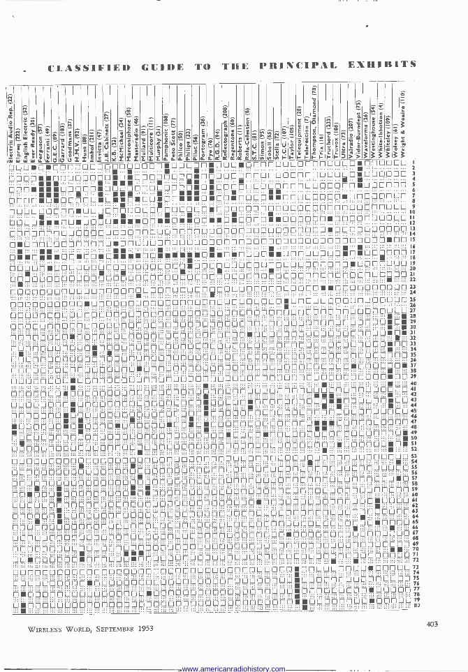
20th NATIONAL it.%Hie EXHIBITION
Kolster-Brandes 10 -waveband receiver, Model KR40T
Telequipment " Mono - scope " signal generator.
=4111**t:
New " Soundmaster " tape recorder (Baird), and (right) Reflectograph transportable tape recorder.
Left : Perma- nent -magnet focusing unit (Goodmans).
Right : Ratchet bracket for fixing tele- vision aerials. Belling-Lee1.
Regentone Model A133 table receiver
a
continued
Sob&i table receiver, Model 513.
CI) () tpy
Wright & Weaire tape re- corder
"Reporter 'portable tape recorder) Boosey & Hawkes).
WIRELESS WORLD, SEPTEMBER 1953
www.americanradiohistory.com

C
Whiteley Electrical cambric - cone loudspeaker
Below : Collaro RC532 3 -speed record changer.
Left : New " Dublex " hori- zontal television aerial (Aerialite).
Right : Horizontal "Paravex" television aerial, made by
Telerection.
Champion " Rev-Ier " a.c. trans- portable record player.
H.M.V. Portable Model 1,507.
radio gramophone,
f
Selection of Westing- Capacitance analyser and resistance
house rectifiers. bridge (Hunt).
T.C.C. automatic mica -stacking machine used in transmitter capacitor assembly.
Range of new " Bafflettes " extension loudspeakers (Richard - Allan).
WIRELESS WORLD, SEPTEMBER 1953 405
www.americanradiohistory.com

20th NATIONAL RADIO EXHIBITION
Remote picture control unit (Truchord). Metal -case capacitors for tropical conditions (Dubilier Type 5,200).
Slingsby truck for handling television receivers.
continued
Garrard Model RC90 automatic record changer with extra spindles.
Right : Six -way inter -communication equipment (Trix Intervox).
NUMERICAL LIST OF STANDHOLDERS 1 A. P. Bulgin & Co. Ltd., Bye -Pas, Road, Barking,
Essex. 2 British Railway', Railway Executive, 222, Maryle
bone Road, London,18.W.1. 3 Argosy Radiovision Ltd., Argosy Works, Hertford
Road, Barking, Eeeex. 4 White-Ibbot'on Ltd., 205, Station Road, Harrow,
Middlesex. 5 Ambassador Radio, Princess Works, Brighouse,
Yorke. 6 Co-operative Wholesale Society Ltd. [Defiant], 99,
Leman Street, London, E.1. 7 Telerection Ltd., Antenna Works, St. Paule, Chel-
tenham, Glos. 8 Rola Celestion Ltd., Ferry Works, Summer Road,
Thames ninon, Surrey. 9 Standard Telephones & Cables Ltd. [Brimer],
Footseray, Sidcup, Kent. 10 Westminster Bank Ltd., 51, Threadneedle Street,
London, E.C.2. 11 Hobert', Radio Co., Ltd., Creek Road, East Molesey,
Surrey. 12 British Iron and Steel Federation, Steel House,
Tothill Street, London, S.W.1. 13 Domain Products Ltd., Domain Works, Barnaby
Street, London, N.W.1. 14 Bakers "Selhurst" Radio, 24, Dingwall Road,
Croydon, Surrey. 15 Automatic Coil Winder & Electrical Equipment Co.
Ltd. [Avo], Winder House, Douglas Street, London, S.W.1.
18 Trios EleetriealCo.Ltd.,1/5, Maple Place, Tottenham Court Road, London, W.I.
19 Lingaaphone In'titute Ltd., 207/209, Regent Street, London, W.I.
20 Econasign Co. Ltd., 92, Victoria Street, London, S.W.1.
22 Electric Audio Reproducers Ltd., 17, Little St. Leonardo, Mortlake, London, S.W.14.
23 National Provincial Bank Ltd., 15, Bl.hopogate, London, E.C.2.
24 J. G. Publication, Ltd., 56A, Rochester Row, London, S.W.1.
25 "British Radio and Television." 92, Fleet Street, London, E.C.4.
28 Waveforms Ltd., Radar Works, Truro Road, London, N.M.
27 J.B. Manufacturing Co. (Cabinets) Ltd., 56, Palmer- ston Road, Walthamstow, London, E.17.
28 Telequipmeat Ltd., 1319A, High Road, Whetstone, London, N.20.
30 Ever Ready Co.(G.BJLtd.,Herculee Place, Holloway, London, N.7.
31 Murphy Radio Ltd., Welwyn Garden City, Herts. 32 Kol'ter-Brandes Ltd., Footsemy, Sidcup, Kent. 83 Philips Electrical Ltd.. Century House, Shaftesbury
Avenue London, W.C.2. 84 McMichael Radio Ltd..190, Strand, London, W.C.2. 35 Colla,o Ltd., Ripple Work,, Bye -Paso Road,
Barking, Essex. 36 Portogram Radio Electrical Industries Ltd.. Prell
Works, St. Rule Street, London, S.W.B. 87 Goodman' Industries Ltd., Axiom Work,, Wembley,
Middlesex. 38 Kerry's (Gt, Britain) Ltd., Warton Road, Stratford,
London, E.15. 39 Midland Bank Ltd., Poultry, London,' E.C.2. 45 Me & Sons Ltd.. [Wireless World], Dorset House,
Stamford Street, London, S.E.1. 48 Nuteradio Ltd., 10/20, Fitzroy Place, London
N.W.1.
406
47 Invites Radio Ltd., Parkhurst Road, Holloway, London, N.7.
48 Decca Record Co. Ltd., 1/3, Brixton Road, London, S.W.9.
49 Ferranti Ltd., Hollinwood, Lance. 50 Philon (Overseas) Ltd., Romford Road, Chigwell,
Essex. 51 Edison Swan Electric Co. Ltd., 155, Charing Cross
Road, London, W.C.2. 52 English Electric Co. Ltd., Queen. House, Kingeway,
London, W.C.2. 53 Anti!erence Ltd., 67, Bryanoton Street, London,
W.I. 54 Westinghouse Brake and Signal Co. Ltd., 82, York
Way, King, Cross, London, N.1. 55 Sobel] Industries Ltd., Langley Park, Slough,
Bucks. 58 Pilot Radio Ltd., 31/37, Park Royal Road, London,
N.W.10. 57 Ferguson Radio Corporation Ltd., 105, Judd Street,
L7ndon, W.C.1. 58 Marconiphone Co. Ltd., Haye., Middlesex. 59 Baird Television Ltd., Lancelot Road, Wembley,
Middlesex. 80 Regenten, Radio and Television Ltd., Eastern
Avenue West, Mawney,, Romford, Essex. 81 Wolsey Television Ltd., 43 45, Knights Hill, West
Norwood, London, S.E.27. 62 H. C. Slingsby Ltd., 89/97, Kingeway, London,
W.C.2. 63 Trader Publishing Co. Ltd., [Wireless and Electrical
Trader], Dorset House, Stamford Street, London, S.E.I.
70 Brown Brothers Ltd., Great Eastern Street, London, E.C.2.
71 Champion Electric Corporation, Champion Work,, Newhaven, Sussex.
72 Stella Radro and Television Co. Ltd., Oxford House, 9/15, Oxford Street, London, W.1.
73 Ultra Electric Ltd.,Weetern Avenue, Acton, London, W.3.
74 Bush Radio Ltd., Power Road, Chiswick, London, W.4.
75 Vidor Ltd., West Street, Eritb, Kent. 78 Pye Limited, Radio Works, Cambridge. 77 Peto Scott Electrical Instrument, Ltd., Addlestone
Road, Weybridge, Surrey. 78 Thomson, Diamond and Butcher Ltd., 34 Farr(ngdon
Road, London, E.C.1. 79 Aerialite Ltd., Castle Works, Stalybridge, Cheshire. 81 Standard Telephone' and Cables Ltd., Connaught
House, Aldwych, London, W.C.2. 84 Lloyds Bank Ltd.. 71, Lombard Street, London,
E.C.3. 85 Richard Allan Radio Ltd., Taylor Street, Batley,
Yorke. 88 Odhams Press Ltd. [Electrical and Radio Training].
96, Long Acre, London, W.C.2. 87 Geo. Newnes Ltd., Tower Home, Southampton
Street, London, W.C.2. 88 A. H. Hunt (Capacitors) Ltd., Bendon Valley,
Garratt Lane, Wandsworth, London, S.W.IS. 89 General Electric Co. Ltd., Magnet House, Kingeway,
London, W.C.2. 90 A. C. Cossor Ltd., Cossor House, Highbury Grove,
London, N,5. 91 Mallard Ltd., Century House, Shaftesbury Avenue,
London, W.C.2. 92 Gramophone Co. Ltd. [H.M.V.], Hayes, Middlesex. 98 E.Y.I. Sales and Service Ltd., Hayes, Middlesex.
94 Radio Gramophone Development Co. Ltd., Eastern Avenue West, Mawneys, Romford, Essex.
95 Simon Sound Service Ltd.. 48, George Street, Portman Square, London, W.1.
96 Hobday Brothers Ltd., 21/27, Great Eastern Street, London, E.C.2.
97 Bush Radio Ltd., Power Road, Chiswick, London, W.4.
98 Dubilier Condenser Co. (1925) Ltd., Ducon Works, Victoria Road, North Acton, London, W.3.
99 Association of Radio Battery Manufacturers, 41, Gordon Square, London, W.C.1.
100 E. K. Cole Ltd., Ekco Works, Southend-on-Sea. Essex.
101 A. J. Balcombe Ltd. [Alba], 52, Tabernacle Street, London, E.C.2.
102 Belling & Lee Ltd., Cambridge Arterial Road, Enfield, Middlesex.
103 Garrard Engineering and Manufacturing Co. Ltd., Newcastle Street, Swindon, Wilts.
104 E.M.I. Sales and Service Ltd., Hayes, Middlesex. 105 Taylor Electrical Instrument. Ltd., 419, Montrose
Avenue, Slough, Bucks. 106 Trovox Ltd., Exhibition Grounds, Wembley,
Middlesex. 107 Telegraph Condenser Co. Ltd., Wale, Fern, Road,
North Acton, London, W.3. 108 Pamphonic Sales Ltd., 400, Holloway Road,
London, N.7. 109 Whiteley Electrical Radio Co. Ltd., Victoria Street,
Mansfield, Notts. 110 Wright and Weaire Ltd., 138, Sloane Street.
London, S.W.1. 111 Multicore Solders Ltd., Maylands Avenue, Hemel
Hempstead, Herts. 112 Dynatron Radio Ltd., "The Fire," fritte Hill
Maidenhead, Berks. 113 Plessey Co. Ltd., Vicarage Lane, Ilford, Essex. 114 Keith Prows' & Co. Ltd., 159, New Bond Street
London, W.I. 200 S.B.C., Broadcasting House, London, W.I. 201 United Appeal for the Blind, 204/6, Great Portland
Street, London, W.I. 202 Electrical Trades Union, Hayes Court, West
Common Road, Bromley, Kent. 204 Lugtoo & Co. Ltd., 209/212, Tottenham Court Road,
London, W.I. 205 Air Ministry, Whitehall Gardens, London, S.W.I. 206 War Mae, Whitehall, London, S.W.1. 207 Valradio Ltd., New Chapel Road, Feltham,
Middlesex. 208 Rudman, Darlington (Electronics) Ltd. [Reflecto
graph], Lichfield Road, Wedneafield, Staffs. 209 Boosey and Hawkes Ltd.. Electronics Division,
Deanebrook Road, Edgware, Middlesex. 210 Bowmaker Ltd., Lansdowne, Bournemouth, Hante. 211 Alfred Imhof Ltd., 112/116, New Oxford Street,
London, W.C.1. 220 Television Society, 184, Shaftesbury Avenue,
London, W.C.2. 221 "The Star." 12/22, Bouverie Street, London, E.C.4. 222 Electronic Precision Equipment Ltd. [Elpreq],
High Street, Wealdstone. Middlesex. 223 Petter Radio and Electrical Supplies. 201/207,
Forest Road, W-althametow, London, E.17. 232 Bernard. (Publishers) Ltd ., The Grampians, Western
Gate, London, W.6. 233 Reproducer. (Electronic) Ltd., (Truehord] 82, Great
Portland Street, London, W.1. 234 Coemoeord Ltd. [Acne], 700, Great Cambridge Road,
Enfield, Middlesex.
WIRELESS WORLD, SEPTEMBER 1953
www.americanradiohistory.com

Electronics in Medicine Apparatus on Show at Manchester
cc
F electronic engineers were acquainted with those problems confronting the medical profession which require their specialized knowledge, perhaps more of them would be attracted to the service of medicine." This observation was made about three years ago by a prominent member of Guy's Hospital Medical School. Since then, there have been signs that en- gineers are becoming more and more aware of the ways in which they can be of use to the medical world. The fact that their interest is growing is largely due to the efforts of the small band of tech- nicians who spend their lives making specialized electro -medical apparatus in various hospitals around the country. Most of these technicians are men with a strong sense of vocation. They prefer working in the cause of medical science, for somewhat less pay than they could get in industry, simply because it gives them more personal satisfaction than making, say, guided missiles. Now they are beginning to organize themselves and make their presence felt in various ways.
A recent event which gave some prominence to their work was the Eighth Annual Exhibition of Elec- tronic Devices, organized by the north-western branch of the Insti- tution of Electronics at the Man- chester College of Technology. The "Research" section of the ex- hibition was largely dominated by the stands of various hospitals and medical schools, and quite a
number of firms were showing examples of commer- cial electro -medical apparatus. In addition, over a third of the lectures given during the course of the exhibition were on electro -medical subjects. This being the dominant theme, it was appropriate that the proceedings should have been opened by Sir Geoffrey Jefferson, C.B.E., F.R.S., who is professor of neuro -surgery at Manchester University.
Although electronic techniques are used in both diagnostic and therapeutic work, there is perhaps more scope in the diagnostic field because of the wide range of different phenomena in the human body that can be detected or measured. The most common instruments here are probably the electro- cardiograph, for amplifying and recording heart potentials, the electro -encephalograph, for brain
Six -channel Marconi electro -encephalo- graph, notable for being entirely operated from the mains and having very well -regulated power supplies.
Television -type images of the distribu- tion of radioactive material in patients are given by this apparatus developed by the University of London Institute of Cancer Research. On the right is the scintillation -counter scanning head mounted on a pantograph and on the left the associated electronic equipment.
407 WIRELESS WORLD, SEPTEMBER 1953
www.americanradiohistory.com

potentials, and the electro-myograph, for muscle potentials. After this the apparatus becomes more specialized. The auscultoscope; for example, is an amplifying stethoscope for examining heart and lung 'sounds. The phonoelectrocardioscope amplifies heart sounds at the same time as recording the heart potentials, while the cardiotachometer measures the heart rate in beats per minute. Other instruments measure the rate of flow of blood and the amount of oxygen in it, and one called the sphygmograph registers pulse waves in the veins and arteries.
On the therapeutic side, the diathermy apparatus, or r.f. heater, is probably the best-known type of instrument. Nowadays it is quite often used by surgeons for making incisions and cauterizing wounds. Then there are stimulators. Most of these are devices for applying electrical waveforms directly to the body, but some generate flashes of light for visual stimulation and others sound pulses for aural stimulation. One stimulator made by Lorenz in Germany is used for giving artificial respiration by applying electrical impulses to the stomach muscles to produce a rhythmic contraction of the stomach wall. A new type of treatment which seems to be developing very rapidly is ultrasonic therapy, although most of the work seems to be confined to the Continent at the moment.
At one time radioactive substances were only used for therapeutic purposes, but they are now coming into the diagnostic field and bringing with them various electronic devices for detecting and measur- ing the radioactivity. In diagnosing cancer of the thyroid gland, for example, a dose of radioactive iodine is given to the patient; the iodine is selectively absorbed by the thyroid tissue and any cancer, and the 'resulting concentration of radioactivity gives an indication of whether a cancer is there or not and how big it is.
Ionization chambers and Geiger -Muller tubes are often used for detecting the radioactivity, but a much more sensitive instrument now coming into use is the scintillation counter. In this the radioactive particles impinge on a phosphor and produce flashes of light, which 'are detected by a photo -multiplier tube. The output of pulses from the tube is then fed into an electronic counter, or rate -of -count meter, which indicates the strength of. the radioactivity. One of these devices was shown at Manchester by Isotope Developments.
This flying -spot microscope, made by Cinema -Television, is an engineered version of J. Z. Young's apparatus, described in our April, 1951, issue.
408
Unfortunately, the photo -multiplier tube introduces a certain amount of noise, which could lead to errors in the pulse. counting. A way of overcoming this is to have two photo -multipliers " looking" at the phosphor and arrange their electronic circuitry so that only coincident pulses are counted. Any pulses coming separately from either tube are obviously noise and are therefore not counted.
One scintillation counter working on this principle was shown at the exhibition by the University of Leeds. Another one was part of an extremely inter- esting apparatus, built by the University of London Institute of Cancer Research, which displays an image of the distribution of radioactive material in a patient's body on the screen of a cathode-ray tube. The patient is scanned mechanically by the scintil- lation counter, which moves backwards and forwards across him on a kind of large pantograph. Pulses from the counter are fed to an electrostatic storage tube (E.M.I. type VCRX350) and arranged to modu- late its " writing " beam, which scans the target of the tube in synchronism with the mechanical scanning of the patient.
In this way a charge pattern is slowly built up on the target of the tube corresponding to the distribu- tion of radioactive material in the patient's body. When a complete charge pattern has been formed, the "reading" beam scans the target at something like normal 'television speed, and the output signal is fed to the c.r.t. display to produce a corresponding visual pattern on the screen. The image formed in the storage tube can be "read" and displayed for about 'an hour before it fades away. One of the great advantages of the television type of display is that the contrast of the image can be altered electronic- ally as required-a feature which was also to be seen in the flying -spot microscope shown by Cinema - Television.
A characteristic feature of the biological amplifiers used in medical work is that they usually have a differential input stage, consisting of a pair of valves with a common cathode load. The object of this circuit is to get rid of any interference picked up from the patient, which it does because the inter- ference signal is usually in the same phase as both input grids and so cancels out at the anodes. To make the circuit give a high rejection ratio, however, the two valves have to be carefully matched so that they give exactly the same amplification, and this is
not always easy to do. A new cir- cuit, shown by the University of Manchester, overcomes this diffi- culty by using only one triode valve, and connecting the two input leads, each through a cathode follower, to its grid and cathode. With this arrangement the ratio of wanted sig- nal to interference signal at the in- put is increased over a thousand times at the output, and the inter- ference signal can be hundreds of times greater than the wanted one before it has any appreciable effect.
Lewisham Hospital showed an apparatus for amplifying and re- cording 'the heart sounds of unborn babies-the purpose being to detect any changes in the heart rate indi- cating` physical distress. The signals are displayed visually and a meter indicates their repetition rate.
WIRELESS WORLD, SEPTEMBER 1933
www.americanradiohistory.com

SEPTEMBER, 1953 WIRELESS WORLD (Advt.) 85
THE "BELLING -LEE" PAGE Mechanical improvements and special features in the design of Belling -
Lee Television Aerials to be seen at the Radio Show on Stand No. 102
Something Revolutionary in Television Aerial Design.
Improved Designs This last year or so has seen
great improvements in engineering design of T.V. aerials. When television first started, aerials offered by some of the smaller manufacturers were not much bet- ter than different assemblies of standard conduit fittings, but makers who did not improve on that standard, quickly fell by the way.
Designs improved all round, and lately, the improvements have been very real. As manufacturers with enormous sales, " Belling -Lee" could afford to spend large sums on tools to mass produce the ingenious castings which keep their aerials well to the fore, presenting a stream- lined appearance and considerably easing the task of erection. A most ingenious reflector casting was released last year, which allowed both the reflector elements and the cross arm to be securely held in true alignment by the tightening of one tin. high -tensile bolt.
The design is such that the pieces just pull and lock into position, and cannot get out of position afterwards. This one refinement cuts out many minutes of fiddling and is covered by U.K. Patent Nos. 519883 and 677108.
The "Kayrod " Television Aerial
With a performance comparable t o that of the well-known " Belling - Lee " Junior " H " series of cranked mast aerials, the " Kayrod," Reg. Design 869286, illustrated top left, has a far higher vision gain than any known aerial in its price range.
The "Kayrod" dispenses with a mast, a lower element serving as the support arm, while ingenious de- signing has made a cross arm unnecessary. The " Kayrod " is much lighter and easier to erect than most types of television aerials. The " Belling -Lee " ratchet bracket (Reg. Design 869363), is incorporated in the lashing kit, ensuring safe, speedy and sensible himney fixing, while the insulator
is designed to give connections the utmost protection against weather. PRICES. Channels r and 2, £4/4/-. Channels 3, 4 and 5, £3/19/6. The " Belling -Lee " Ratchet
Bracket
For Safety, Speed and Sense.
This bracket enables an aerial rigger to spend less time on the roof and to make a better job. We have already made our aerial and mast the easiest to wire and assemble-we cannot do very much to simplify cable runs, except to provide the simplest and most efficient outlet boxes and plugs, but we have now improved bracket and lashing design, to make a sounder, speedier and more efficient streamlined job. Horizontal Aerials with an Up-
lift You can increase the diameter and
gauge of the elements to unecon- omical figures without gaining much. So we tried to put a "set" in the element so that its "droop" would bring it horizontal. From this thought we uplifted the elements considerably and now all " Belling -Lee " horizontal aerials are instantly recognised by their
pswept appearance. They are ex- ceedingly well known around Pontop Pike and Belfast. Adjustable Mast Head Adaptor
This is invaluable where an aerial is being fitted to a non- standard wooden or metal mast of from 14-in.-2in. diameter. The cross arm fits snugly into its slot and is secured by the standard mast cap which pulls the cross arm into position and assures that it is correctly aligned. Feeder arrange- ments for both metal and wooden masts are provided for.
Tilting Mast Cap If we felt that there was any
genera] advantage in a tilted aerial we would make them that way. The advantage is the exception rather than the rule, although some people like the look of a tilted aerial. -
The " Belling -Lee " tilting mast head adaptor is a beautifully designed job in three castings, calibrated from horizontal to 25°. This adaptor can be used either direct on to a " Belling -Lee " metal mast, or with the adjustable mast head adaptor described above. As a feature of all these castings, true alignment is positive, the parts lock together so that they cannot be out of alignment even through carelessness.
Written 24th July, 1953.
BELLING E LEE LTD UMBRIDGE ARTERIAL RD., ENFIELD, MIDDX., ENGLAND
www.americanradiohistory.com

86 WIRELESS W ORI.D SEPTEMBER, 1953
MARCONI
mobile radio
Marconi mobile radio is the general name
for a range of V.H.F. transmitter/receiver
equipment designed to work under the most
strenuous operating conditions. The range
offers a choice of power up to 12W
and a wide selection of frequencies
to meet all operating requirements.
MARCONI mobile radio
PLANNED INSTALLED SERVICED
MARCONI'S WIRELESS TELEGRAPH COMPANY LTD CHELMSFORD ESSEX
www.americanradiohistory.com

HEAD SHIELD
Portable Magnetic Recorder Interesting Mechanical Details in the Grundig, Type 7ooL
BEFORE its introduction to the British market the Grundig tape recorder was already well established on the Continent. It is a well -tried design, and one which bristles with ingenuity of detail. Its compact and neat exterior suggest easy portability, but on closer acquaintance this impression is modified by the dis- covery that it weighs 351b. No doubt pressure has been brought to bear on those responsible for the design of the " innards " to reduce this figure, but no compromise with performance has been made which involves any reduction in the mass and inertia of mov- ing parts, which, in the present state of the art, is
necessary for steady tape speed and freedom from " wow."
The machine accommodates tape reels up to lin diameter (1,200ft) and records on half the tape width. Alternative speeds of 72 and 3-,in/sec are available, giving total playing times of 1 and 2 hours per reel, respectively. The usual facilities for fast forward and reverse winding are provided, and there is an inter- mittent stop switch in addition to the normal cancel- ling stop switch. All functions are selected by push- buttons with mechanical interlocks.
The microphone supplied with the machine is of the condenser type. A plastic film, gold -sputtered on its outer surface, is stretched in physical contact with a rigid back plate which is perforated with a large num- ber of small holes. The variation of capacitance results from the depression, under the influence of the sound pressure, of the numerous elements of the film cover- ing the holes. The polarizing voltage is low, and is
EM 3¢ "MAGIC EYE" LEVEL INDICATOR
SPEED CHANGE SWITCH 80X
in fact derived from a potential divider across the h.t. supply, yet the sensitivity appears to be remarkably high.
Performance.-A good test for tape speed constancy is to record the B.B.C. 1,000 -c/s tuning note (not the
Dimensions of the carrying case when closed are I6in x
12ín x Bin.
ML META
MOTOR SPINDLE
Top panel with cover removed, showing magnetic clutches for transmitting the drive to the reel cabstans.
WIRELESS WORLD, SEPTEMBER 1953 409
www.americanradiohistory.com

TAPE REEL CAPSTAN
FELT FRICTION WASHER
FIXED SPINDLE
TOP SOLENOID FIXED TO SPINDLE
DRIVING PULLEY
_-LIFTING PINS
CHASSIS
BOTTOM SOLENOID
"---ARMATURE
Arrangement of solenoids in the magnetic clutches.
Third Programme 440 c/s) at 3;in/sec and replay it at 7-}in/sec. The Grundig passes this test easily; no trace of fluctuation is perceptible to the ear.
The hum level in low-the makers claim 40 db below maximum signal level on the tape-but it is wise to record always at as high a level as possible as slight hum may otherwise obtrude if an external loud- speaker with a good bass response is used instead of the small -diameter internal loudspeaker.
Basically the quality of reproduction is excellent, and is limited by the reproducing amplifier and loud- speaker rather than by the qualities of the recording heads, the tape and the tape transport mechanism.
The large single driving motor, wh?'ch is of the split -phase induction type, can be switched to give two speeds of rotation. The outer cage revolves round a central stator.
TAPE GUIDE MUMETAL HOOD ERASE HEAD , RECOROIREPRCO:
r
AOJUSTIN6 SCREWS
TAPE PRESSURE,' SPRN65
PRESSURE ROUTE
,TAPE GU/OES,
MOTOR SPINOLE
AO TAPE PRESSUR& ABM
PNfSSUh'E -[!£N(v2
MOTOR POELEr
Those who care to take the trouble to reproduce the tape through an amplifier of greater power -handling capacity and a high-grade loudspeaker will not be dis- appointed. Particularly impressive is the perform- ance at 3;in/sec, and for all but the highest quality musical programmes it seems rather a waste of tape to use the 71in/sec speed. A response up to at least 10 kc/s was confirmed, at 7Zin/sec, by using a cali- brated test tape.
Tape handling involves no more than dropping the leading edge intò a slot, and no mishandling of the controls could be devised to make the tape spill or misbehave itself in any way.
Mechanical Design.-A large single motor drives the tape transport mechanism. It is of the split - phase induction type and is remarkable for the fact that the outer body of the motor rotates. The field coils are wound in slots in what would normally be regarded as the armature. Change of speed is effected by switching these windings so that only alternate segments are energized at the higher speed. One advantage of this arrangement is that speed can be changed while running without the risk of wearing flats on idler wheels, as is the case in purely mechani- cal speed -change mechanisms. The motor speeds are of the order of 900 and 450 r.p.m., with capstan diameter of about 5/32in. The tape makes only a line contact with the capstan and the drive is effected virtually on the back of the tape via the rubber pinch roller, which overlaps the edges of the tape and picks up the drive direct from the capstan. Both the pinch roller and the pressure pads for holding the tape in contact with the erase and record/reproduce heads are mounted in a bar which is pulled forward by a solenoid in the h.t. circuit, and is operative only when recording or reproducing.
Control of the supply and take-up tape reels is effected by magnetic clutches which are energized, in the appropriate sequence, by switches associated with the push-button controls. Loose pulleys (B), driven by a round plastic belt at a speed in excess of the fastest reel speed re- quired, are carried on spindles fixed vertically on the chassis. The reel capstans (A) also rotate freely on the spindles. Inside A and B is a fixed solenoid winding, mounted on the vertical spindle. The winding is shrouded by annular cores pressed into A and B. When energized this solenoid pulls A and B hard to- gether and provides maximum friction for fast forward or reverse winding according to whether the right- or left-hand capstan is clamped.
When starting to record or repro- duce tape the bottom solenoid only of the right-hand take-up capstan is energized, and its armature plate, to which three pins are fixed, lifts B until it is supporting A together with the empty reel. The pressure between A and B, due to the weight of the reel, is small, but so also is the torque required to tension the tape at the minimum spool diameter. As the spool fills its
410 WIRELESS WORLD, SEPTEMBER 1953
www.americanradiohistory.com

weight increases, and so does the friction in the clutch. Thus practically constant tape tension is assured whatever the state of the reel. During running, overspill from the supply tape is pre- vented by light friction from an internal spring in the bearing of the capstan. When the "Stop" button is pressed, both bottom solenoids are energized, and contrary tension is provided by the normal friction of both clutches while the motor is slow- ing to a stop.
Circuit. - The main record/reproduce ampli- fier consists of four stages : an EF40 low - noise pentode (in later models an EF86) is fol- lowed by a twin -triode ECC81 and an EL42 out- put pentode. The EF40 is underrun to reduce residual hum, and the heater is fed from a separate winding and earthed via a " hum- dinger." Feedback through RC circuits is used to give pre -emphasis on all recordings of 10 db over the range of frequencies from 1 to IOkc/s. On play back the normal equalization is effected by other RC feedback net- works giving 22 to 25 db rise at 50 c/s referred to 4kc/s and a further rise of 3 to 5db between 4 and 10 kc/s. At the lower of the two tape speeds an additional cathode bypass capacitor in the first half of the ECC81 is used to lift the response 10 db over the range 500c/s to 6kc/s.
Input sockets are provided for the condenser micro- phone, for recording from radio or gramophone pickup and for recording telephone conversations by inductive pick-up from a coil attached to the outside of the instrument. Other types of high -impedance micro- phone, and a diode connection from a radio receiver can also be used with the second input socket. High - and low -impedance output connections are also pro- vided for monitoring with headphones or connection to an external amplifier, and for feeding an external loudspeaker.
The bias oscillator is an EL42 and its frequency (approximately 50kc/s) is adjusted by means of a dust core. It feeds the high -impedance record/reproduce head through a capacitance from the tuned winding; current for the low -impedance erase head is supplied from a third winding coupled to the oscillator coils. A " humbucking " coil is fitted in series with the record/reproduce head.
A type EM34 " magic eye " is used as a volume level indicator. It is fed through a small half -wave rectifier and a suitable time -constant circuit from the output of
the second half of the ECC81 double triode. The h.t. supply is derived from a full -wave bridge metal rectifier.
WIRELESS WORLD, SEPTEMBER 1953
VOCVME CONTROL
FLEXIBLE DRIVE
.. - .. '.. /C STAGE r: ïn,,,« i f 40 $:gr
Underside of chassis. Valves are readily accessible, and the ampi Fier sub -assemblies can be
reached, as seen at each side of the driving motor, by removing coverplates.
In conclusion, a special word of commendation must be reserved for the service manual which has been prepared for the use of dealers. This is one of the clearest and most detailed works of its kind which has so far come our way, and is in keeping with the thoroughness with which the rest of the design has been carried out.
NEW LONDON TELEVISION STATION WILL the new London television transmitter at
Crystal Palace be much the same as the last high -power one built at Wenvoe, or something entirely different in design ? The B.B.C. itself is not yet prepared to say, but one of its engineers has publicly given his own personal opinion on what form it may possibly take.
Speaking recently at Manchester, C. Buckle, the engineer in charge of Holme Moss, said he thought the Crystal Palace station would represent a completely new approach to television .ransrnitter design. It would probably have a self-supporting mast, after the style of
the Eiffel Tower, and a dual arrangement of two vision transmitters and two sound transmitters. At the top of the mast would be eight sets of dipoles stacked one above the other, the upper four being fed from one combined vision and sound otitput and the lower four from the other. Each vision transmitter would have an output power of 75kW, making a total of 150kW, and with an aerial gain of about 8 this would give an effective radiated power of 1,200kW
If one transmitter broke down the other would con- tinue radiating the programme, and there would be a
switching arrangement to enable either sound transmitter to be combined with either vision transmitter. The new station, concluded Mr. Buckle, would be a culmination of all that had been worked for since 1936 when the television service began.
411
www.americanradiohistory.com

WORLD OF WIRELESS Co-ordinating Radar Research Station + Television News
Radar Research WITH the object of integrating more closely all radar
research and to ensure a more rapid interchange of tech- nical information, the two research establishments at Malvem are to be amalgamated. From September 1st the Telecommunications Research Establishment and the Radar Research and Development Establishment will cease to exist as separate entities and will in future be known as the Radar Reseerch Establishment. W. J. Richards will be the director of the new organization (see "Personalities "). In announcing this change the Minister of Supply stated that the combined organization would be working for all three Services.
Components in Sweden AN EIGHTH of the radio industry's total exports last
year went to Scandinavia and to foster this interest in British radio equipment some 20 manufacturers will be participating in an exhibition of radio and electronic com- ponents, valves and test gear which is being organized in Stockholm by the British Radio and Electronic Component Manufacturers' Federation.
The exhibition will be held at the Kungshallen, Kungs- gatan, where a similar exhibition was held in 1948, from 10.0-6.30 on September 25th, 26th, 28th and 29th.
New Receiving Station SOME MONTHS AGO we reported the decision of
the European Broadcasting Union to build a new receiving and measuring station in Belgium for monitoring the broadcasting bands and for research work on radio propa- gation, especially on its bearing on the effective utiliza- tion of the spectrum.
The new station, known as Jurbise-Masnuy, was opened on July 22nd by M. Georges Conus, president of the E.B.U. and director of the Swiss Broadcasting Cor- poration, in the presence of representatives of the member organizations and of the Union, including General Sir
RADIO -TELEPHONE equipment is being installed in some of the 4,000 German passenger -carrying Post Office buses enabling passengers to be called by telephone subscribers. This photograph was taken at the German Communications
and Transport Exhibition, being held in Munich.
412
+ E.B.U. Receiving + Radio Courses
Ian Jacob, director-general of the B.B.C. and founder - president of the E.B.U. During the opening ceremony, the Belgian Minister of Communications recalled the reasons for selecting south-west Belgium for the station, as it is the broadcasting " centre of gravity " of Europe.
A description of the new station by the chief engineer of the E.B.U. appears on page 422.
Modern P.A. Installation PORTABLE v.h.f. radio telephones were used by
technicians when adjusting the levels of individual loud- speakers in the new p.a. system, designed and installed by G.E.C., at the Glasgow Central Station.
Existing loudspeakers on the platforms have been retained, but for the circulating area and the booking - halls a Goodmans " Concentric " diffuser type of unit, modified for this particular application in collaboration with G.E.C. Research Laboratories, has -been adopted.
Normally the installation is fed by two 120 -watt ampli- fiers, but in the event of failure of one amplifier the other can be switched with automatic re -matching to carry both loads in parallel. A dummy load is also connected across the faulty amplifier in readiness for service testing.
One of the most interesting features of the new installa- tion is the use of alternative equalizing circuits designed to give the maximum intelligibility and naturalness with male or female voices when operating at unnaturally high levels.
Television Plans EQUIPMENT for the five medium -power television stations (Northern Ireland, Plymouth, Isle of Wight, Aberdeen and Pontop Pike) has now been ordered by the B.B.C. and construction of all five stations will start as soon as possible. It is planned to provide temporary stations at Plymouth,
Isle of Wight and Aberdeen within the next 18 months as has been done at the other two stations. The Brighton booster station will close down when the temporary station is brought into service at Rowridge, Isle of Wight.
It may not generally be known that a booster station was installed in the Isle of Man by a private concern in time for the Coronation, but has since been taken out of service. As stated in our summary of the T.A.C. Report, the B.B.C. plans to provide a station on the Island working in Channel 4.
Educational Opportunities WITH the opening of the scholastic year in September
a large number of colleges and institutes are offering special part-time radio and allied courses in addition to the recognized full-time courses in telecommunications. Complete syllabuses and regulations covering courses in telecommunications, radio and television servicing and for the radio amateurs' examination is issued at 2s by the Department of Technology of the City & Guilds of London Institute. Prospectuses covering both full-time and part-time courses have also been received from the Northern Polytechnic, London, N.7, and the S.E. London Technical College, London, S.E.4 The Polytechnic, London, W.1, has issued a prospectus of evening courses in telecommunications approved for the award of the Ordinary and Higher National Certificates.
Before referring to some of the special courses brought to our notice, we should mention the "Bulletin of Special Courses in Higher Technology " issued by the London and Home Counties Regional Advisory Council for Higher
WIRELESS WORLD, SEPTEMBER 1953
www.americanradiohistory.com

Technological Education, Tavistock Square, London, W.C.1, price is 6d.
A course of eight lectures on crystal valves and tran- sistors will be given at the Borough Polytechnic, London, S.E.1, on Tuesdays, commencing October 20th (fee 30s). Twenty-four lectures on communication networks will be given at the S.E. London Technical College, Lewisham, S.E.4, on Fridays from October 23rd (fee 30s).
Classes for the Radio Amateurs' Examination are being held at the Wembley Evening Institute, Copland School, High Road, Wembley, on Mondays (fee lOs per annum); Ilford Literary Institute, Cranbrook Road, Ilford, Essex, on Wednesdays (fee 10s), and the Brentford Evening Institute on Wednesdays.
OUR AUTHORS J. de Gruchy, who writes on the protection of meters in
this issue, is a measurements engineer and was responsible for radio test gear design for Everett Edgcumbe & Co. for many years. Before and during the last war he was a teacher at the Borough Polytechnic, London, and also taught at the Telecommunications Research Establishment. He was at one time engaged on air -to -ground telemetering and upon the development of the British pulsed altimeter. He is now head of the Instrument Department of the Electrical Apparatus Co., of St. Albans, Herts. Mr. de Gruchy was an original member of the Radio Trades Examination Board.
J. Treeby Dickinson, who, in an article in this issue, describes the new E.B.U. receiving station in Belgium, studied electro -communications at the Imperial College of Science and Technology and in 1927 joined the Telegraph Construction and Maintenance Co., Ltd. He transferred from submarine cables to radio, and from 1929 was engaged on receiver development in several of the European companies of the International Standard Electric Corporation. In 1937 he joined the Engineering Division of the B.B.C., to which he returned after war service in the R.A.F.V.R., latterly as assistant chief engineer of No. 26 (Signals) Group. He was seconded by the B.B.C. in 1950 to the European Broadcasting Union, as chief engineer.
V. J. Tyler, contributor of the article in this issue on a
simple distortion meter, joined Marconi's W.T. Co. in 1935 and worked on transmitter development until 1941 when he joined the R.A.F. He rejoined Marconi's in 1946 for work on marine transmitters and remote control systems and is now engaged on the development of broadcasting transmitters.
PERSONALITIES .
W. J. Richards, C.B.E., chief superintendent of the Tele- communications Research Establishment, Malvern, since 1946, has been appointed director of the new Radar Research Establishment, Malvern, which, as stated elsewhere, will embrace the existing establishments-T.R.E. and R.R.D.E. He joined the Royal Aircraft Establishment at Farnborough in 1925 and during the war was Deputy Director of Scientific Research (Armament) at the Ministry of Aircraft Production.
W. E. Miller, M.A.(Cantab.), editor of our contemporary Wireless and Electrical Trader since 1945 and president of the British Institution of Radio Engineers, has been elected to the Freedom and Livery of the Worshipful Company of Musicians.
A. E. Lawson, who was at one time London manager of the Edison Bell Co. and has been television manager for the Gramophone Co. since April, 1949, has been appointed assistant sales manager for H.M.V. radio, television and gramophones. During the last war he was associated with the development of inter -Service radar and was Deputy Assistant Director of Ordnance Services in charge of the radar branch at the War Office. Mr. Lawson succeeds A. E. Newland, who has been appointed to an executive position in the E.M.I. International Department in Dublin.
F. W. J. Grinter, who began his career as a sea -going radio officer with the Marconi Marine Company in 1927 and has been in charge of the Grimsby depot for the past year, will be the new manager at Hull in succession to J. R. Thomson, who is retiring. He will also remain responsible for Grimsby pending the appointment of a new manager.
On the retirement of F. M. Dimmock, O.B.E., head of the Equipment Department of the B.B.C., in October after 28 years' service with the Corporation, E. C. Drewe, M.I.E.E., who has been assistant head of the Research Department since September, 1950, will succeed him. A. B. Howe, A.M.I.E.E., research consultant, will be the new assistant head of the Research Department.
WIRELESS WORLD, SEPTEMBER 1953
A. J. Brunker, B.Sc. (Eng.), A.M.I.E.E., who joined E. K. Cole, Ltd., in 1947 from the Ministry of Supply where he was Deputy Director, Radio Production, has now been appointed a director and general manager of Ekco Electronics, Ltd., the recently formed subsidiary of E. K. Cole, Ltd. He is general export manager of the parent company, and be- fore the formation of the new company was also respon- sible for commercial activities of the Electronics Division.
C. R. Bates, A.M.I.E.E., has given up his practice as an industrial -electronic consultant in order to specialize in elec- tronic welding -controls. He has been appointed a director of Bates & Bates, Ltd., 73, Ashville Avenue, Birmingham, 34, a company manufacturing synchronous controls to his designs and patents.
T. D. Humphreys, M.Brit.I.R.E., has been appointed general manager of Reproducers and Amplifiers, Ltd. He has been in the radio industry for the past 20 years, including a long period with Cossor's and more recently with Radar Com- ponents, Ltd., where he was general manager.
O. E. Trivett, A.M.I.E.E., M.Brit.I.R.E., who joined Aerialite, Ltd., as personal assistant to the managing director in 1950, has been appointed a director of the Company.
John Beard, previously communications controller, has been appointed communications manager of Aer Lingus. He is responsible for all matters relating to the development of airborne radio equipment, electronic flight instruments and public address systems, and the administration of the com- munications organization of Aer Lingus.
IN BRIEF Broadcast Receiving Licences in the U.K. at the end of
June totalled 12,964,065, including 2,415,305 for television and 191,433 for sets fitted in cars. Television licences increased by 98,705 during the month.
Harwell Electronics Course. The seventh specialized course on the design, use and maintenance of electronic in- struments used in nuclear physics, radio chemistry and work with radioisotopes will take place at the Isotope School, Atomic Energy Research Establishment, Harwell, from September 28th to October 2nd. Applications for partici- pation are invited from physicists and electronic engineers holding a degree or equivalent qualification. Application forms for the course, for which the fee is 12 guineas, can be obtained from the Electronics Division, A.E.R.E., Harwell, near Didcot, Berks.
Amateur Show.-The seventh annual Amateur Radio Show to be organized by the Radio Society of Great Britain will be opened at the Royal Hotel, Woburn Place London, W.C.1, at noon on November 25th by Rene Klein (Ô8NK), a founder member of the Society in 1913. The exhibition will remain open daily from 11.0 to 9.0 until November 28th.
Marine Radio.-Concurrently with the Earls Court Radio Show the 19th Engineering Marine and Welding Exhibition will be held at Olympia, London (September 3rd -17th), at which a number of radio manufacturers, including B.T.H., Cossor, Decca, English Electric, G.E.C., Mullard and Redifon are exhibiting.
German Radio Show.-F.M. vies with TV at the pièce de résistance at the second post-war German Radio Show, which is being held in Dusseldorf from August 29th to September 6th. There are about 90 F.M. stations in opera- tion in Western Germany and it is estimated that there are some four million f.m. receivers or adaptors already in use.
Royal Society Research Appointment.-B. J. Robinson, B.Sc., of Sydney University, has been appointed a Rutherford Memorial Scholar, by the Royal Society, to carry out iono- spheric research at the Cavendish Laboratory, Cambridge.
Amateur Television Transmission over a distance of 30 miles using a peak -white power of only 2 watts on 436 Mc/s was achieved by R. L. Royle (G20j/T), of Great Canfield, near Dunmow, Essex, on August 1st. The transmitter, pulse
413
www.americanradiohistory.com

generator, camera, etc., were home -constructed. The receiver at Abbots Langley, Herts, which was operated by L. V. Dent G3GDR) was locked perfectly by the line and frame sync
pulses and the pictures were clearly identified. B.S.R.A.-The Manchester centre of the British Sound
Recording Association opens the session's meetings with a lecture on " Tape Recording with Special Reference to Stereophonic Techniques," by J. S. Holiday, at 7.30 on September 21st at the Engineers' Club, Albert Square, Man- chester. G. A. Briggs (Wharfedale) will give a demonstration - lecture on loudspeakers at a meeting of the south-west centre of the Association at 7 45 on September 10th at Callard's Café, Torquay.
Brit.I.R.E.-The first meeting of the new session of the British Institution of Radio Engineers (London Section) will be held at 6.30 on September 30th at the London School of Hygiene and Tropical Medicine, Keppel Street, London, W.C.1, when D. A. Bell, M.A., B:Sc., Ph.D., will speak on " The Impact of Communication Theory on Television."
E.P.T.A.-There will be a general meeting of the Electro- Physiologcal Technologists' Association at the Burden Neuro- logical Institute, Stoke Lane, Stapleton, Bristol, at 10.30 on September 19th. There will be papers and demonstrations at this meeting at which non-members may attend. Details are obtainable from G. Johnson, Hurstwood Park Hospital, Haywards Heath, Sussex.
I.P.R.E.-A north-west section of the Institute of Practical Radio Engineers was recently inaugurated in Manchester with an initial membership of 82. Details of lectures, which will commence in September, are obtainable from the secretary, H. Budworth, 466, Holden Road, Leigh, Lancs.
I.E.E. Students.-The new officers of the I.E.E. London Students' Section Committee are : chairman, M. H. Alder (S.T.C.); vice-chairman, R. Thomas (Sperry); hon. sec., M. C. Cubitt (Pye).
Institute of Physics.-The 33rd Annual Report of the Insti- tute records that the membership at the end of 1952 was 4,347, an increase of 267 on the previous year. The Electronics Group has a membership of 314.
Telecraft, Ltd., ask us to say that an obvious error in the position of the masthead mounting, as illustrated in their advertisement on p. 33 of this issue, was not detected until the page had gone to press.
PUBLICATIONS Weekly Publication is to be resumed by our trade con-
temporary Wireless & Electrical Trader (with its first show issue on August 29th) after more than 12 years' fortnightly pub- lication. Originally published as a monthly in 1923, it started weekly publication in 1925 and continued as such until May, 1941, when prevailing conditions forced it to become a fort- nightly. A feature of the journal, which is exclusively for bona fide members of the trade, is the service data sheets on commercial receivers published with each issue.
A Buyers' Guide listing alphabetically over 3,750 British products, with the names of the manufacturers and Canadian suppliers, is included in the CABMA Register, 1953, recently published jointly by Kelly's Directories, Ltd., and our pub- lishers for the Canadian Association of British Manufacturers and Agencies. The 800 -page volume, which also lists pro- prietary names and trade marks and gives a complete English - French glossary of the headings used in the Buyers' Guide, costs 42s.
Standards Yearbook.-The 1953 edition of the British Standards Yearbook includes brief details of some 2,000 speci- fications current at the end of March. It also gives a brief outline of the work being undertaken by each of the Indus- trial Committees. In the case of the telecommunications industry it includes " microwave measuring instruments," " performance of radio receivers," " definitions of the elec- trical characteristics of receivers " and the revision of a num- ber of existing Standards. The Yearbook is obtainable from the British Standards Institution, 24, Victoria Street, London, S.W.1, price 12s 6d.
Plastics Industry.-The 23rd edition of the "British Plastics Yearbook "-first published in 1931-includes in its nine sections classified lists of manufacturers of plastic materials, products and equipment, proprietary names and a review of important plastics patents issued in the past year. The 562 -page Yearbook is published by Iliffe & Sons Ltd., price 30s.
" Wire and Radio Communications " is the new title of our New York contemporary Telegraph and Telephone Age, which has been in circulation since 1883. The change, say the editors, has been dictated by the fundamental change in the field of world-wide communications.
BUSINESS NOTES Nigerian Posts and Telegraphs Department has ordered
from Marconi's equipment for an extensive network of v.h.f. multi -channel radio stations to link the telephone systems of many towns and provide additional channels on existing overhead wire routes. The network (forming roughly a triangle) provides twin -path v.h.f. interconnections between Ibadan (which is already linked by radio with Lagos), Enugu and Minna.
Ekco Electronics, Ltd., Southend-on-Sea, Essex, has been formed as a subsidiary of E. K. Cole, Ltd., to handle the production, marketing, installation and maintenance of elec- tronic and nucleonic equipment previously handled by the company's Electronics Division.
Plessey-Amplion Agreement.-The arrangement whereby Ediswan acted as distributors for Plessey components having terminated, Amplion (1932), Ltd., have been appointed dis- tributors to the wholesale and retail trade for the sale of Plessey radio and television components.
Electric Audio Reproducers, Ltd., of 17, Little St. Leonards, Mortlake, S.W.14 (Tel.: Prospect 4466), has been formed to manufacture the Microgram portable electric gramophones previously made by Collaro, Ltd. The new company will incorporate Phono Disc, Ltd., and will market the record - playing equipment previously manufactured by Phono Disc. The managing director of E.A.R. is Leonard Stone, who has resigned the general managership of the Trix Electrical Co., Ltd., with which he has been associated since 1943.
Marconi's are to supply a 5 -kW vision transmitter, 3 -kW sound transmitter, with combining unit and ancillary studio and O.B. equipment for Canada's fourth television station which is being built in Vancouver, B.C. When the 525 -line station opens towards the end of the year it will have a temporary aerial which eventually will be replaced by a 12 - stack array increasing the effective radiated power to approxi- mately 100 kW.
Naval R/T Equipment, worth approximately $278,000, has been ordered by the U.S. Naval Purchasing Office from Pye, Ltd.
A Magnetizer of ring magnets and small power magnets has been produced by Advance Components, Ltd., of Back Road, Shernhall Street, Walthamstow, E.17. The Advance magnetizer, Type K1, has a power consumption of only 30 watts.
Blick Time Recorders, Ltd., announce the introduction of a new vacuum impregnator by their subsidiary Blickvac, of 505, Lordship Lane, London, S.E.22, which also provides an impregnation service.
Sky -masts, of Beadon Road, London, W.6, have marketed a new 45 -ft patent mast for erection on roofs and in inacces- sible places. It is available with a rotatable array.
Savage Transformers. Ltd., are this year celebrating their Silver Jubilee.
NEW. ADDRESSES British Standards Institution moved into its new premises
at 2, Park Street, London, W.1 (Tel.: Mayfair 9000), on August 17th.
Dynatron Radio, Ltd., have moved their main office and service department from the works at Ray Lea Road, Maiden- head to " The Firs," Castle Hill, Maidenhead, Berks. (Tel.: Maidenhead 3811.)
Rees Mace Marine, Ltd., have opened depots at 26, Coed Celyn Road, Derwen Fawr, Swansea, and 187, Snargate Street, Dover.
Exeter Branch Office of B.I. Callender's Cables, Ltd., is now at 40, Whipton Village Road, Whipton, Exeter. (Tel.: Exeter 67308.)
NEW " W.W." BOOKS AT THE SHOW " Television Engineering: Principles and Practice."
Vol. 1: Fundamentals -camera tubes-television and electron optics. By S. W. Amos, D. C. Birkinshaw and J. L. Bliss (all of the B.B.C.). Price 30s (postage 8d)
" Guide to Broadcasting Stations ": 7th edition, com- pletely revised and enlarged. Price 2s (postage 2d)
"Wireless World Television Receiver: Model 2 ": Reprints of W.W. articles. Price 3s 6d (postage 3d)
414 WIRELESS WORLD, SEPTEMBER 1953
www.americanradiohistory.com

LETTERS TO THE EDITOR The Editor does not necessarily endorse the opinions expressed by his correspondents
Through Unofficial Channels HAVING suffered an abnormal spate of " sporadic E "
this year, the repeated statements by the B.B.C. that " nothing can be done " tend to wear a little thin.
Following interference from automatic morse at terrific strength recently, I hung on till I got the call -sign during an " idling " period and then wrote to the station con- cerned. I was somewhat agreeably surprised to receive the accompanying letter in reply. Thus one of the sources of trouble has been removed-without international inter- vention!
I assume from their letter that the Swedish station had had no "official" notification of the signals, and I wonder how many other signals that cause trouble are also third harmonics which could receive similar atten- tion.
Reading, Berks. R. C. HORSNELL.
Letter from the Engineer -in -Chief, Varbergs radio station, Grimeton, Sweden, to Mr. Horsnell.
WE thank you for your letter of July 22nd, 1953, telling us that the 3rd harmonic of our transmitter SDQ5 (13,832.5 kc/s) interfered with the B.B.C. television pro- gramme on 41.5 Mc/s (channel 1) on July 18th at 14.15- 14.45 B.S.T. According to our log SDQ5 had on this occasion a c.w. telegraphy transmission directed to east Asia.
We very much regret this interference, and beg to inform you that we are now taking measures in order to suppress the 3rd harmonic.
It is very unusual that we have complaints regarding interference of harmonics from our transmitters, and we find it remarkable that such a high frequency as 41.49 Mc/s can interfere with your transmitters at the comparatively great distance from our transmitter.
However, we are very grateful to you for your message, and will very much appreciate further reports regarding our transmissions.
Re -defining " Electronics " ELECTRONICS; the study and application of sub -
molecular phenommena as elements of control (?) Farnborough, Hants. R. A. FAIRTHORNE.
" ELECTRONICS " having been branded as an esoteric term, everyone is entitled to his own definition. Mine I share with the lay public, and it covers a very wide field-" anything electrical which I do not understand."
Support for this view is coming in from quite unex- pected quarters and in the preface to a recently published textbook on the principles of electronics we read: " The first five chapters are devoted to the basic facts and theory underlying electronic work. Some of the concepts here may be a little difficult of comprehension, but this is inherent in the nature of the subject and need not deter the reader from proceeding." The italics are mine..
Hindhead, Surrey. HENRY MORGAN.
Commercial Television : Industry's Attitude WHAT is the matter with the British TV manufac-
turers? Don't they realize that the reason why people buy TV is to see the programmes and that with better programmes and greater alternatives available, more people will buy TV? Why are they so frightened to openly support an additional television system in com- petition with the B.B.C.
I see from The Daily Telegraph of Wednesday, July 8th,
WIRELESS WORLD, SEPTEMBER 1953
referring to the first report of the Television Advisory Committee 1952, that there is one manufacturer who feels that the present position is " highly unsatisfactory " and is fighting for more frequencies for TV. Now is the time for all manufacturers who value their future business and stability of the industry to come in in support.
Imhof's, Ltd., London, W.C.1. A. GODFREY IMHOF.
" Stereoscopic Television" I WAS most interested in the suggestion by R. A.
Fairthorne (August issue) that transmissions of stereo- scopic television could be viewed without any apparatus. However, an investigation of the visual problems involved suggests that the system would not be very satisfactory.
Assuming an average screen size of 12in, an inter- pupillary distance of 60 millimetres, and a viewing dis- tance of 3 metres, the relative convergence necessary for clear viewing would be approximately 7 prism dioptres.* A survey has shown that the average positive fusion reserve for healthy young adults, wearing their proper refractive corrections, is between 10 and 14 prism dioptres. It is accepted that for comfort a visual effort should not employ more than one-third of the available reserve. In this case rather more than one-half is required, and discomfort would ensue after protracted viewing. GEORGE E. WEAVER.
Stourbridge, Worcs.
* The prism dioptre is an optical unit defined as the strength of a prism that causes a deviation of 1 cm at a distance of 1 metre. In practice it works out to be roughly equal to a degre.-En.
The Ohmmeter IN dealing with the shunt form of ohmmeter in the July
issue, W. Tusting stated that by shunting the meter the lower ranges can be extended indefinitely, but at the expense of the simple one -pole switching applicable to the basic shunt type. This objection does not hold if a single - valued low -resistance shunt is used on the battery side of R., as shown here. R. is made equal to the mid -scale value of R. on the lowest range; i.e., with the range switch connecting R. directly across Re. In order to make the same scale fit all ranges, Rb ought to be sufficiently large for the connecting of R, on the lowest range not to affect the battery current significantly; at the same time it must pass sufficient current to set up across R. the full-scale millivoltage input of the meter with R, +R, in series. Therefore the more sensitive the meter the wider the range of resistance measurable.
A four -range ohmmeter of this type to the writer's design* was produced by the Cambridge Instrument Co., Ltd., as an accessory to their " Unipivot " galvanometer, and covers 0.001 to 1,000 ohms, being particularly useful
* M. G. Scroggie, Patent No. 407,341. " A Multi -Range Direct - Reading Ohmmeter," Wireless Engineer, November, 1933, pp. 606- 608.
Rb R + Rz
415
www.americanradiohistory.com

LETTERS TO THE EDITOR . continued
for testing switch contacts and low resistance transformer and tuning coil windings.
An incidental advantage of this type of ohmmeter is that variations in e.m.f. and resistance of the battery do not require separate compensation, a preliminary full-scale set- ting by adjustment of Rb being all that is needed.
Bromley, Kent. M. G. SCROGGIE.
Broadcast Transmitter Distortion I HAVE been most interested in the corres-
pondence on the quality of B.B.C. transmissions. Since the matter was raised some two or three months ago, and it was stated that the transmissions were liable to be modulated practically 100 per cent, particularly on high notes, I have realized that my own demodulation circuit might well be responsible for much of the distortion from which I was a frequent sufferer. High soprano voices in a choir were particular offenders in loud passages, and I concluded therefore that a poor a.c./d.c. load ratio, caused by unsuitable r.f. filter component values, was the likeliest cause of the trouble. I therefore altered my diode circuit, formerly all too conventional, to the following :-
This has proved completely satisfactory, so that per- sonally I now have little, if any, criticism to make of the quality transmitted. I estimate that this circuit pro- duces a ratio of at least 95 per cent at the highest frequency likely to be transmitted at a high modulation level. What figure to give to this frequency is difficult to say, hence my use of the word "estimate." One might reckon that only fundamental tones are likely to be fully modulated, but some instruments such as the oboe have harmonics stronger than the fundamental. Because of this consideration I am unable to understand Ian Leslie's statement that his a.c./d.c. load ratio is 98.9 per cent, and I would feel happier in accepting his con- clusions if he would either publish the values used in his circuit or state the highest frequency used in his calcula- tions.
Salisbury, Wilts. J. D. HERRING.
" Reactivating the Dry Cell" I HAVE been reactivating dry cells for about two years
and, as my method is somewhat different from that described in your August issue, it may be of interest.
Many of the batteries I have experimented with have been in very bad shape, with internal resistances so high that initial currents of 0.1 ampere would be impossible, about 20-30 volts per cell being required to drive such currents, and at such voltages the battery disintegrates.
My method is to apply 2 volts per cell and leave on until the charging current has settled to a steady value for a few minutes. This steady value is considerably in excess of the normal discharge currents-about 0.5 A for a 3 -cell fiat battery, 1.25 A for a U2, and 2 A for a twin -cell cycle -lamp battery. The time required varies from about
416
half an hour for a partially discharged cell in good condi- tion to many hours for a cell in such bad condition that the initial current is less than 10 mA. Many of these badly discharged cells refuse to respond, but the chance is about equal and when successful they compare quite favourably with other reactivated cells in terms of renewed life.
The same treatment with 2.5 V per cell proves to be destructive, as also does the application of 2 V for about an hour after current reaches peak value. A cell accepting a large current should be removed immediately if the cur- rent begins to fall, as this indicates " cooking," but a cell accepting only a few millamps may be very erratic for hours and should be persevered with until there appears to be no hope of the current reaching a higher value.
Voltages below 1.8 per cell give very little reactivation. A relative of mine without an electric supply has an all-
dry portable, the batteries of which used to last about 3 months. Her present h.t. battery, reactivated four times, is 13 months old; the 1.t. battery (a bell cell), once reacti- vated, is 8 months old. The 90-V h.t. battery, last treated 3 weeks ago, showed (after a 12 -hour period to settle from reactivating) 87 volts on a 10 -mA load. The recondition- ing of both these batteries is mainly guess -work because for the h.t. battery I have a supply limited to 80 mA and for the bell cell my limit is 5 A, neither currents. being peak for the particular sizes of cell. However, cycle lamp and torch batteries on my l.t. charger capable of up to 5 A have been reactivated many times before cells punctured.
Barkingside, Essex. E. HURRAN.
Technical Qualifications THE letter from " J. S. A." (your August issue) on the
lack of appreciation of the City & Guilds full technologi- cal certificate is unfortunately all too often justified. As one of the moderators for these examinations I can testify to the high standard required and as one responsible for the training of staff, and therefore having an interest in their future progress, I can confirm that successful candi- dates in the City & Guilds examinations have proved excellent material.
It is difficult to see what more can be done to educate employers in the value of these certificates except through the personal efforts of people like " J. S. A." It is possible that the recognition now being accorded to the important class of technician in the electrical industry will help to establish the status of these examinations.
" J. S. A." may feel that his letter has not been in vain if I say that at least one public corporation has for some time recognized the value of the full technological certi- ficate. The B.B.C. specifies it as one of the qualifications for promotion to the higher ranks of its engineering division. K. R. STURLEY.
B.B.C. Engineering Training Department.
Your correspondent " J. S. A." (August issue) is pre- sumably unaware of the conditions of enrolment on the Technical and Scientific Register of the Ministry of Labour. It is these conditions which limit a man's pos- sible employment rather than the view of the radio industry as a whole since, as he has pointed out, such employers as have given him an interview have been agreeably surprised at the high standards required for his City and Guilds Technological Certificate.
Recruitment of radio engineers through the Ministry of Labour is governed by the conditions laid down by the Technical and Scientific Register (Electrical En- gineering Section) where the conditions for enrolment are dependent on holding a university degree or membership of a particular professional institution.
The meeting of these requirements involves a 5 -year study of electrical engineering, and thus the full tech- nological certificate in telecommunication engineering is not taken into consideration in determining eligibility for enrolment on the Register.
" PERSONNEL MANAGER."
WIRELESS WORLD, SEPTEMBER 1953
www.americanradiohistory.com

SEPTEMBER, 1953 WIRELESS WORLD S7
There is 25 years experience
behind the design and manu-
facture of every SAVAGE Electronic apparatus specify
Transformer. Perhaps this and SAVAGE TRANSFORMERS
its conscientious application is wherever Performance and
the reason why research Reliability are considered. Qk*sfORA1.
(SAVAGE IDEVIZES) Mil
SAVAGE TRANSFORMERS LTD., NURSTEED ROAD, DEVIZES, WILTS.
workers, enthusiastic amateurs
and makers of High Grade
reieph.ne : DEVIZES 536.
E 1 r.
www.americanradiohistory.com
WIRELESS WORLD SEPTEMBER, 1953
First ami foremost ...
We are proud to introduce the CLAROSTAT Type 58 Wire -wound Potentiometer, designed by the world's foremost Potentiometer manufacturers and produced for the first time in this country. The type 58 has many features which will immediately appeal to the discriminating user.
FEATURES
* Rated at 3 watts and available in
all values up to 100,000 ohms linear.
* Special windings are available to requirements.
* High Grade Bakelite Casing, of rugged construction. Solder Tags
heavily silver-plated and of special design making them completely immovable under all conditions.
* Metal cover firmly keyed into Bakelite Casing, cannot loosen or turn. Connected to fixing bush
providing automatic "grounding" of cover.
* Obtainable with single or double pole mains switch.
* Dimensions : Diameter, l;in. Depth of case without switch, hin.
* Samples and full specifications available on application.
t Regd. Trade Mark.
WHOLESALERS
CLAROSTAT TYPE
58 Wire -Wound
Potentiometers are
supplied individually
packed in attractive
printed cartons. De-
livery is prompt.
Write for price list
and details of very
attractive trade
terms.
METAL PRODUCTS LIMITED. 16, Berkeley Street, London, W.I.
Phone: GROsvenor 5206/7
www.americanradiohistory.com

Ill l 1 _ 111
Valves for
Microwaves COTLAND and the north of England depend for
their daily television on radio links working at frequencies around 4,000 Mc/s. And this is only one of the present-day uses of frequencies above about 1,000 Mc/s, commonly called microwaves. Radar, for instance. Most of you probably know that ordinary valves are no good at all at these frequencies, and that weird types such as klystrons and magnetrons are used, but you may be rather vague about how these special types work. They have been described from time to time, especially just after the War, but to the younger readers at least that might as well have been in the days of William the Conqueror for all the notice they were able to take of it at the time; and in any case these descriptions are rather scattered, and either refrain from getting down to the basic principles or explain them too learnedly to be understood. So what I propose to do this month is to review the main types of microwave valve.
First of all, though, a brief reminder of why special types are needed. There are several reasons; but mainly two. The first is transit time. In the ordinary types of valve, electrons are released from the cathode and attracted across a short space to the anode by the positive voltage maintained there. The flow is usually controlled by one or more grids encountered on the way. Imagine that a negative voltage is sud- denly applied to the control grid, sufficient to cut off the flow of electrons-and hence the anode current- completely. At the instant this happens a large number of electrons are actually in transit between cathode and anode. So there is inevitably a sort of " amber phase " while the traffic is getting clear of the crossing. During it, the signal at the grid is not completely effective in stopping the arrivals at the anodç. Moreover-and we shall look into this later on-the crowds of electrons departing from the grid in both directions, although not actually in contact with it, are equivalent to a temporary conducting path from the grid, damping the source of the signal. Thanks to the agility of the electron traffic and the narrowness of the crossing, this phase is only of the order of a thousand -millionth of a second-little enough to be negligible in comparison with each cycle at ordinary broadcasting frequencies. At television frequencies it is not negligible, but is insufficient to upset the working of the valve completely. The result of raising the signal frequency to thousands of mega- cycles per second, however, is rather like raising the frequency of the signal lights at a busy crossing to a cycle every few seconds-traffic would be only half- way across in response to the green when they would go red, and a state of chaos would ensue.
The other difficulty at such high frequencies is that the free -space wavelength is only a few centimetres, and half that distance corresponds to a complete reversal of phase. At 4,000 Mc/s, for example, it is only about one and a half inches. So if that hap -
WIRELESS WORLD, SEPTEMBER 1953
I.-Mainly on the Magnetron
By "CATHODE RAY"
pened to be the distance between the grid of a valve and the point where it was connected to the circuit, the result might well be the exact opposite of what was intended! A different aspect of the same thing is the capacitance and inductance of the electrodes and their leads, which tend to make nonsense of con- ventional valve circuit design. If, in order to avoid this, the dimensions of the valve were made small compared with the wavelength it would be too small to handle appreciable power.
Nevertheless, such is human ingenuity that the design of the ordinary triode has been developed to the extent that it works at well over 3,000 Mc/s. There is actually a type in the current Mullard cata- logue, designated the ME1001 and having the very conventional heater rating of 6.3 V, 0.4 A, capable of working down to 8 cm wavelength (3,750 Mc/s). Such valves are called disk -seal triodes, because of the tech- nique mainly responsible for this surprising per- formance. The construction is shown in Fig. 1.
Whereas in ordinary valves the leads to the electrodes each come out through the glass at one point, or perhaps two, here the grid and anode are the central parts of disks which emerge through the glass wall all round, dividing it into three sections. So it was necessary to devise a technique for sealing the metal disks to sections of glass tube. One advantage of this construction is that the grid and anode " leads " are equivalent to a vast number of wire leads in parallel, so their inductance is correspondingly small. Another advantage is that they can be fitted to a coaxial cylinder tuning system, of which they form the end disks. The cathode is an extension of the innermost cylinder or rod. Still another advantage is the large
Fig. I. Section of disk - seal triode, showing how
the glass bulb is divided into three sections by
the anode and grid disks,
and the way in which the electrodes form ter- minations of the coaxial cylinders (shown dotted) used as tuning circuits. The spacing between the grid and cathode is
actually somewhat less
than shown here.
417
www.americanradiohistory.com

amount of cooling that can be brought to bear on what is usually the weakest point when it is concen- trated around a wire lead-the glass seal.
As for transit time, that is reduced by phenomenally close spacing; in some types the distance between grid and cathode is literally only the thickness of a sheet of paper. Needless to say, all this precision costs money. And the oscillator power obtainable falls off with fre- quency, until at 4,000 Mc/s it is difficult to get any at all. At 3,000 Mc/s it is usually about half a watt maximum. This may not sound impressive for a radio transmitter, but it must be remembered that at such short wavelengths the radiation can be concentrated into a narrow beam so that a very little power goes quite a long way.
The idea of using triodes for r.f. amplification at even 1 Mc/s sounds very pre-1925-ish, so it may startle some to learn that this kind of triode can amplify effectively up to thousands of megacycles. An earthed - grid circuit must be used, of course, and Fig. 1 shows how the disk -seal construction makes the grid an extremely effective anode -to -cathode screen, which can easily be continued externally.
That is about as far as what we may call the straightforward approach to microwave valve design has gone so far, and for present requirements it is not far enough. So we come to the main subject :
the microwave valves based on entirely different prin- ciples, to wit, the magnetron, the klystron, and the travelling -wave tube.
If I were to assure you that anybody who is familiar with ordinary valve electronics can quite quickly and easily learn how these other types work it might be comforting but it wouldn't be true. Although there is nothing really mysterious about them, and their functioning can be explained in terms of basic elec- trical principles, the particular combinations of those principles will be unfamiliar to many readers. Any- body can keep on throwing a ball up in the air and catching it, and in principle it makes no difference if there are three or four balls, but in practice it is much more difficult than with one ball only. While attention is being concentrated on one the others get the better of us.
Here are four principles I hope I may call well known:
(1) A negative charge is attracted by a positive charge. That is why electrons, which are negative charges, move smartly towards the positively charged anode of a valve.
(2) Charges in motion are an electric current. So the stream of electrons across the empty space in a valve is a current. (Since unfortunately they happen to be called negative, the positive direction of current must be from anode to cathode.)
(3) When a current flows through a magnetic field it experiences a force at right angles to its own direc- tion and to the direction of the field, as shown by the left-hand rule (Fig. 2).
(4) When a charge moves under the force of attrac- tion as in (1), energy is imparted to it by the source of the attraction; but when it moves against a force it imparts energy. This may sound rather highbrow, but it is merely the electrical counterpart of the well- known fact that if á brick is allowed to fall under the attraction of gravity, it acquires energy-enough, perhaps, to crack one's skull-but if it is thrown upwards it parts with its energy of motion and con- sequently slows down.
In the magnetron all these things are going on at
418
DIRECTION OF FORCE
DIRECTION OF MAGNETIC FIELD
\ DIRECTION OF CURRENT
Fig. 2. Left-hand rule for indicating the direction in which a magnetic field exerts a force on an electric current. The direction of the current is reckoned as opposite to the direction in which the electrons constituting the current are moving.
Fig. 3. In the normal mode of oscillation of a resonant cavity in a magnetron, a current flows to and fro between A and B, making them alternately positive and negative.
Fig. 4. If there were an odd number of resonant cavities they could not all oscillate in the normal mode, for the reason shown here.
the same time, so it. becomes difficult to follow-even when the speed of the action is mentally reduced from, say, 3,000,000,000 cycles per second to about 1. Still, by giving a little thought to the matter one can get at least a rough idea; and it is certainly interesting and wonderful enough to be well worth the attempt.
I am assuming that the workings of ordinary valves and tuning circuits are familiar. If your understand- ing of tuning circuits has so far been confined to the sorts in which the inductance and capacitance are separate, one being provided by a coil and the other by a system of parallel plates, then it is first necessary to get used to the idea that when in order to make the wavelength very short indeed the number of turns is reduced to one or less and the " plates " are very small and far apart the form of the tuned " circuit " may become quite different, and in general the in- ductance and capacitance are all mixed up together. A half -wave dipole is an example. For purely tuning purposes, however, it is unsuitable because of the
WIREL ìSS WORLD, SEPTEMBER 1953
www.americanradiohistory.com

heavy losses by radiation. In the frequency band we are now considering, one of the best forms of tuning circuit is what is called a resonant cavity. The sub- stitution of sheet for wire is a good idea, because at these high frequencies the current flows mainly near the surface (" skin effect "). An important thing to keep in mind is that a cavity or suchlike generally has several frequencies at which it can resonate, depending on the pattern of current and charge and the associated magnetic and electric fields. A rect- angular metal box, for example, could resonate from end to end, or at a higher frequency from side to side or top to bottom. The flow of current to and fro is associated with inductance (because of the magnetic fields set up), and the alternating accu- mulations of charge piled up are associated with capacitance (because of the electric fields set up); so these kinds of tuning circuit are really the same in principle as the old coil and condenser.
If you were to take a cylindrical block of copper and drill several big holes through it as in Fig. 3, cutting slots from the centre hole to all the others, you would have a multiple tuning circuit or resonator. There are various ways or " modes " of oscillation, each at a different frequency. In one of these, current
COAXIAL LINE
(a)
Fig. 5. Two methods of taking off the power developed in a magne- tron: (a) by inductive coupling to a coaxial feeder, and (b) by wave - guide.
Fig. 6. Directions of electron flow in a magne- tron with no magnetic field.
ANODE (-F)
CATHODE (-)
Fig. 7. Here the cylindrical cathode -anode space in Fig. 6
is " rolled out flat " and no divisions are shown between cavity poles. (a) shows the path of an electron with no
magnetic field; (b) -(d) with increasing field.
WIRELESS WORLD, SEPTEMBER 1953
flows to and fro around the hole as shown by. the arrows, causing alternating potentials and electric field that are especially concentrated between the opposite slot faces A and B. The three other outer holes are, of course, identical resonators, and since they are all electrically coupled together it is only necessary to start current in one of them as shown and the whole lot are soon oscillating merrily.
In discussing the evolution of the ordinary triode into the disk -seal type I pointed out that the valve electrodes find themselves unavoidably forming a significant part of the tuning circuits. - In the magne- tron there is no attempt to make any distinction between valve and tuners; both are completely com- bined. The anode of the original cavity -resonator magnetron was made exactly as in Fig. 3, except that there were six outer holes, and nowadays there are eight or more. The reason for an even number is that it is necessary if oscillation is to take place in the mode shown. If the number were odd, then one " pole " would have to be both positive and negative at once, which would be awkward for it (Fig. 4). Rather than do that, it would oscillate in some other mode, which would probably be less efficient and at the wrong frequency.
Just as one knows perfectly well that the hero of a thriller is bound to survive, however improbable that may appear from time to time, in the same way you will I am sure be quite confident that before the pre- sent story is ended a means will be found for main- taining powerful oscillations in the cylindrical cavities just described. So you will not be worrying about whether or not this is possible, but confidently assum- ing the possibility will be able with undivided atten- tion to admire the excellent features of this tuning system. It is delightfully simpler (Though in case it looks just too dead easy to manufacture I ought to mention that in order to ensure that all the resonators peak at the same frequency it has to be a real precision job). Then the losses are very low (Q high). This is not only because the current path is entirely through copper and is short and wide, and because there is no other material present where the fields are-not even air-but because radiation is almost completely cancelled out by the symmetry of the sys- tem. And this smallness of losses, combined with the unequalled possibilities of cooling, suggests the pos- sibility of exceptional power. It is doubtful, however, whether even the inventors expected power of the order that was soon actually obtained. Instead of fractions of a watt, or even of a kilowatt, the output at 3,000 Mc/s soon leapt up to thousands of kilowatts. Admittedly this was peak power under pulse condi- tions, but even so it seemed as difficult to believe as some of the exploits of the hero of fiction.
You may be wondering how one takes delivery of this power. A usual type of outlet is a ridiculous little coupling " coil " in one of the cavities-a single turn about the size of the curl in a safety pin, leading to a coaxial cable (Fig. 5a). Another scheme is an external slot leading direct into a waveguide (Fig. 5b).
And now, having counted our kilowatts before they are hatched, we can no longer dodge the mental jug- glery of visualizing the hatching. The cathode, if you didn't know or haven't already guessed, is situated along the axis of the centre hole. So when the h.t. is applied, and if there were no magnet, the electrons would fly radially off in all directions (as in Fig. 6) to the walls of this hole, which as well as being the anode, incidentally form the poles of the resonators.
419
www.americanradiohistory.com

.--= , -- -- ., '..--í ._ =:'. _ -__ _
Fig. 8. When alternate oscillatory potentials are super- imposed on the high positive potential of the anode as a whole, electrons moving in paths such as Fig. 7(d) interact with the oscillatory fields; those moving against the field, as at position I, give up some of their energy to the field in being decelerated by it; those moving with the field receive some of its energy and are accelerated thereby.
External appearance of a typical modern magnetron. It works at about 9,400 M/cs and has a power output of 14kW. The light-coloured piece of metal is the magnet.
There is no grid to complicate this simple process. But when we take account of what the magnet does we shall not want to have even a slight unnecessary complication, so to simplify matters still further let us imagine that the radial space between cathode and anode is "unrolled" into a parallel one, as in Fig. 7. Then the natural paths of the electrons are all verti- cally upward (a), in accordance with our Principle No. 1.
As its name suggests, the magnetron is incomplete without a magnet, and this we now put into position, with its poles at opposite ends of the cylindrical space through which the electrons travel. The direction of the magnetic field is therefore parallel to the cathode, or end to end. This is the direction in which we are looking in Fig. 6, and also in the unrolled version, Fig. 7-down into the paper. Since the electrons are an electric current (Principle No. 2), Principle No. 3 comes into force. Applying the left-hand rule (Fig. 2) and remembering that the direction of the current is downward, we gather that the electrons will find themselves to be what the Communists would describe as right deviationists. So far we have not gone into details about the actual strength of the force that is now controlling their destiny. It is proportional to the amount of charge carried by the electron (which is an unchangeable constant of nature) and to the strength of the field (as one would expect). It is also proportional to the speed of the electron, and this introduces the most fascinating mathematical com- plications into the problem. For the speed is not constant but steadily accelerates as it approaches the anode. And it is also accelerating sideways due to the magnetic influence, but the amount of this acceleration is proportional to its velocity. All this may sound bewildering. To anybody familiar with differential equations it is not terribly difficult, and even with ordinary description one should be able to see that the curious paths that electrons actually take are more or less what one would expect.
If the magnetism is relatively weak it is to be expected that the path would be something like the sample shown at (b) in Fig. 7. A somewhat stronger field would cause a greater deviation, as at (c). Remember that by the time the electron is close to the anode it is moving much faster than near the start, so is the more powerfully deflected. And remember too that when you have taken a turning to the right your right is now back in the direction from which you
420
started. So you will not be surprised that when the magnetic field is increased beyond a certain point the electrons miss the anode altogether and find themselves driven back on to the cathode, as at (d).
So much is plain sailing. It is when account is taken of the oscillating potentials of the anode seg- ments or poles, superimposed on the steady positive h.t. voltage, that things become rather tricky. You may think I am cheating by first assuming that oscilla- tion exists before showing how it is maintained, but we all know by experience that when the conditions for maintaining oscillation exist in any valve circuit there is no need to do anything special about starting it; the slightest disturbance, such as switching on the h.t., or even just the arrival of a batch of electrons, shock -excites a resonant circuit into some slight oscillation and it very quickly builds up. So we are entitled to suppose that the cavities are already in a state of oscillation, which if it is in the usual mode results in alternate polarities (above and below + h.t.) as shown in Fig. 8. This is, as it were, an instantaneous snapshot at peak voltage during one half -cycle. In addition to the electric field due to the h.t. there will be a field distribution as shown dotted. The arrows show the directions in which an electron would tend to be urged by it.
Suppose an electron has reached position 1 (compare Fig. 7(d)). It is being impelled by the combined influence of h.t. field and magnetic field against the oscillatory (dotted) field. So, bringing on Principle No. 4, we know that it is giving up some of its energy to that field, contributing in its own small -way to maintaining the oscillation. And being slowed down thereby it is deflected less forcibly by the magnetic field, and the pull of the h.t. is able to regain some degree of control. If everything is right (h.t. voltage, magnetic field strength, and resonant frequency of the cavities) this electron should find itself near the next gap to the right (position 2) just when the progress of the oscillation cycle has reversed the polarity, making it the same as it was at position 1 half a cycle previously. So it continues to give up energy towards maintaining oscillation and at the same time allowing itself to be drawn nearer the anode, on which it ultimately lands.
Now consider an electron that has been born out of due season, so that unluckily it happens to be around position 2 when the polarity is as shown. It is accelerated by the oscillatory field, drawing off energy therefrom and tending to damp out the oscillation. Its
WIRELESS WORLD, SEPTEMBER 1953
www.americanradiohistory.com

greater speed enables the magnetic field to gain greater control, dashing it the more violently back to the cathode. Although this electron-and others like it -are technically stigmatized as " unfavourable," they have a chance to redeem their character, as we shall see in a few moments. The foregoing account may make it seem that there are precisely equal chances of electrons helping or hindering oscillation, so that it would inevitably die out, but the situation is saved by the fact that whereas unfavourable electrons are rejected at the first attempt the favourable ones con- inue in good works for several half -cycles before being
finally received into the anode of the blest. This is, of course, a vastly simplified picture. There
are all sorts of subsidiary effects; for instance, electrons that are a little behind the most favourable ones find themselves in a part of the oscillatory field that has a vertical component, which tends to speed them up slightly into the more favourable position. Contrari- wise, those just ahead are slowed down. So there is a tendency for all the favourable electrons to move around together, like the spokes of a wheel. Although the individual contributions of the electrons to the oscillatory power are so small, their combined efforts synchronized in this way are responsible for the enormous powers actually obtained, with efficiencies of up to 50 per cent.
If you were a bit incredulous-as you well might have been-when I said that some magnetrons have an output of thousands of kilowatts, you may have performed a rough mental calculation. Whether you did then or not, you can do it now. A certain type
has a peak output of 2 megawatts. Even if the effi- ciency is as much as 50 per cent, that means an input of 4 MW. The h.t. voltage is 40 kV. Then it is easy to work out that the anode current must be 100 amps. Looking up a catalogue of conventional transmitting valves you will see, for example, that a type giving a peak emission of 100 A requires a filament consuming 600 A at 27.5 V, or 16.5 kW, and you may be wondering how such a heater can be got into a space only an inch or two long and a fraction of an inch in diameter, and what happens to the magnetron when it is switched on. The fact is that only quite a small heater is needed in the magnetron, and after it has been running a short time even that can be switched off ! The apparent failures, the " unfavourable " electrons, in their fall back on to the cathode dislodge other electrons by secondary emission, which then go up to take their chance with the rest. The more these are the more are emitted, and the number made available in this way is about a thousand -fold greater than the heater alone can provide. So the "unfavourable" electrons are in fact essential to the working of the high -power magnetron.
If you want to know more about these fascinating valves, which incidentally may well have made the difference between defeat and victory in the last war, I can recommend two books: "The Resonant Cavity Magetron," by R. S. H. Boulding (Newnes), and " The Magnetron," by R. Latham, A. H. King and L. Rush - forth (Chapman & Hall). As for the klystron and travelling -wave tube, they will have to wait until next month.
NEW POLICE TRANSMITTER Frequency -modulated 250 -watt V.H.F.
Radio -telephone
ONE of the most powerful v.h.f. radio telephone trans- mitters used so far by the police in this country has been supplied by the General Electric Company to the Metropolitan Police for use at their transmitting station at Forest Hill, London.
In this case the requirement was for a single transmitter to give communication with mobile patrols anywhere within a built-up area of some 750 square miles. As the fringe areas are considerable distances from the transmit- ting station high power was required and this has been provided by the G.E.C. model BRT108, which is capable of supplying an r.f. output of 250 watts on any spot fre- quency within the band 70 to 100 Mc/s.
The transmitter, which is crystal stabilized, is in its early stages phase modulated but corrected to give a frequency - modulated output with a deviation of ± 12 to 15 kc/s.
As the illustration shows there are actually two BRT108 transmitters installed side by side. One is a standby set kept ready for immediate operation in the event of failure of the other.
The transmitters, which are remotely controlled from the police operations room, consume 1,100 watts each on full power and 280 watts on stand-by.
A 70 -ohm co -axial feeder conveys the r.f. output to the aerial at the top of a 100 -ft lattice tower and as the site is one of the highest in London (the aerial is some 450 ft above sea level) the high power available ensures a good signal throughout the service area.
Special attention is given to the all-important matter of maintenance. All parts are very accessible and by a
system of runners and studied distribution of weight any of the several units can be removed and replaced by one person.
r NHHUUHNHNIHNN HUHNINillOtit!i!(illNIN
The two ßR7108 v.h.f. f -m transmitters suppbed by the
G.E.C. to the Metropolitan Police Force.
WIRELESS WORLD, SEPTEMBER 1953 421
www.americanradiohistory.com

International Monitorire Receiving Station of the European
Broadcasting Union
By J. TREEBY DICKINSON*
THE European Broadcasting Union was founded in February, 1950, at a meeting of representatives of Western European broadcasting organizations and its present membership includes the broadcasting organizations of 23 countries in the European Broad- casting Area, with 11 broadcasting organizations in other parts of the world as associate members. Its objects are : to facilitate and co-ordinate the ex- change of information on all aspects of broadcasting; to undertake research work of general interest; and to put forward the common viewpoint of its members at international conferences.
The activities of the E.B.U. are divided between two establishments, one at Geneva, which deals with cultural and legal matters, and the other, called the Technical Centre, at Brussels. The building that houses the Technical Centre was originally con- structed for the offices and receiving station of the International Broadcasting Union (the predecessor of the E.B.U.), in what was then an almost rural district on the outskirts of the city. As a result of steady development over the last two decades and parti- cularly since the war, the Centre is now in the middle of a busy suburb, and the level of electrical inter- ference is such that the location is no longer suitable for a receiving station. It was, therefore, decided in October, 1951, to build a new receiving station on a technically more suitable site.
The search for a site was not an easy one. In addition to the obvious requirement of low noise level, which suggested a site remote from roads, rail- ways, power lines and transmitting stations, it was necessary to stipulate reasonable communications and services. It was necessary, also, to be reasonably sure that the noise level would remain low. This was particularly difficult as there is no law in Belgium corresponding to the British town and country plan- ning regulations, and there could be no certainty that a factory using radio -frequency heating or making and testing electro -medical apparatus might not be built on an adjoining site. Finally it was decided that the safest solution would be to seek a site as close as possible to a long-distance radiotelegraph receiving station then being built by the Belgian Department of Telegraphs and Telephones at Jurbise, near Mons,- This would solve the problems of com- munications and power supply, and the E.B.U. should profit by anything the Administration did to protect its own station from man-made interference. The Union was actually able to lease about six acres of the Administration's own site, with wayleave to erect additional aerials on the rest of the Administration's ground.
The new building, which was officially opened as the Jurbise-Masnuy receiving station on July 22nd, is a one -storeyed building of about 80 feet by 40 feet with underground accommodation for the frequency standards, stores, batteries and the central -heating plant.
The Technical Equipment Before discussing the technical equipment it is per-
haps appropriate to mention some of the functions which the station has to perform. These may be divided roughly into (a) routine operations and (b) special studies. The former include a regular and continuous watch on all the broadcasting bands. The information so obtained is used, in conjunction with data obtained at the receiving stations operated by member organizations, in the compilation of the periodical reports on conditions in the bands. These reports are prepared primarily for the benefit of the members of the E.B.U. by the Technical Secretariat which remains in the original offices in Brussels.
These routine operations are carried out in three of the five receiving cubicles, each measuring approxi- mately 16 feet by 8 feet 6 inches in size, which are provided in the new building. In these cubicles have been installed receivers designed and constructed by the Technical Centre. The first cubicle is devoted to v.h.f. reception, the second to h.f. and the third to the long- and medium -wave broadcasting bands. The fourth cubicle is normally held in reserve and the fifth is used for the special studies undertaken at the request of individual members, or as contributions to the study programmes of the several Working Parties set up by the Technical Committee of the E.B.U.
Normally receivers are required to stay tuned to a given transmission for a considerable time, but at this station they are required to stay tuned to a transmission only long enough to identify it, measure its frequency and assess the standard of reception. The shorter the time taken to deal with one station the better. The electrical requirements are therefore a high and variable selectivity, low receiver noise and, particularly, the minimum of spurious responses. The mechanical requirements include extremely robust and easily operated tuning arrangements and easily read tuning scales.
The arrangement adopted for the layout of the receivers might be considered as a compromise be- tween the vertical rack arrangement and the so-called
*European Broadcasting Union.
422 WIRELESS WORLD, SEPTEMBER 1953
www.americanradiohistory.com

The new E.B.U. receiving centre at Jurbise-Masnuy, near Mons, Belgium.
" console." The main units of the receivers and the frequency -measuring sets are mounted on the upper parts of racks, with the power -supply units beneath, and in front of these are mounted wide sloping desks on which are the controls and the interpolation devices for frequency measuring. Provision has been made for magnetic -tape recording as an aid to identifi- cation, and it is planned to provide in due course a cathode-ray display of received signals over more or less narrow bands of frequencies.
As mentioned earlier, the frequency standards are installed in an underground compartment which is thermostatically maintained at a uniform temperature. There are two standards, one basically a " Tele- funken" instrument of pre-war design, obtained from the U.I.R. and extensively modernized. The quartz crystal frequency of 500 kc/s is fed to a doubling stage before the multi -vibrator, from which outputs spaced at 100, 10 and 1 kc/s, and, of course, at 1,000 kc/s, are distributed. The frequency is nor- mally constant within 3 or 4 parts in 108. The other standard is of American manufacture.
Frequency Measurement The method adopted for frequency measurement is
fundamentally one of the classical methods, and the only novelty introduced is its adaptation to rapid operation. To minimize the risk of operators' errors, which can be quite serious towards the end of a period of duty, as many operations as possible have been made automatic and, among other devices, a simple arrangement has been incorporated to give an immediate indication of the sense of the frequency difference between the signal to be measured and the locally generated oscillation.
The receiver having been tuned accurately to the signal to be measured, a signal is injected into the r.f. amplifier of the receiver. The injected r.f. signal is selected so that the heterodyne frequency produced in the receiver output is a fairly low audio frequency, the local signal having the lower frequency. Next a locally generated audio frequency is injected into the a.f. chain of the receiver and adjusted to zero - beat with the first heterodyne tone. The reading of the a.f. oscillator then gives the amount to be added to the whole number of kc/s to obtain the frequency of the signal being measured. The accuracy of this method depends upon the accuracy of the frequency of the injected radio frequency signal and upon that
of the audio -frequency oscillator. The injected fre- quency is checked at each observation by reference to the multi -vibrator output and the a.f. oscillator is accurate to within one or two cycles per second. Measurements made by this method in the ordinary course of routine operations have an accuracy of four or five parts in 10'.
.This method of frequency measuring is generally used but when, as often happens, the signal frequency is within a few cycles of a known integral number of kilocycles per second, the output of the 1 -kc/s multi -vibrator is injected into the r.f. amplifier of the receiver and the beats are counted against a chrono- meter. The sense of the difference is determined by introducing a phase -change in the feed to the multi - vibrator, which has the effect of changing the local frequency in a known sense. Work is at present going forward on a scheme to extend the application of this method by utilizing electronic counting.
The Aerials
For long and medium waves, inverted "L " aerials are used as they are effective for both ground and sky waves. For h.f. broadcasting, elevated horizontal dipoles have been found most satisfactory. Two sets have been erected at right -angles, giving approxi- mately E -W and N -S directivity.
For v.h.f. a rigid horizontal dipole is used. It is slung, complete with its rotation motor, immediately above the v.h.f. receiving cubicle. It can be readily lowered and for measuring v.h.f. field -strengths the dipole elements are removed and a signal from a standard -signal generator injected into the matching unit to obtain the same signal at the receiver.
It is planned to erect in due course a direction - finding aerial for use on h.f. and medium waves, mainly as a means of facilitating reception of indivi- dual stations in crowded channels. In the meantime, large rotating frame aerials are being used.
Three h.f. feeders, buried coaxial for the first 100 yards and thereafter overhead open wires, join the E.B.U. building to that of the Belgian R.T.T. station. These enable any of the aerials of the point-to-point station, which are mainly rhombics, to be connected to the E.B.U.'s receiving station. The same feeders can also be used to make the Union's standard fre- quencies available to the R.T.T. station.
fSIG
R.F. AMPLIFIER
A.F. AMPLIFIER
-nxlkc/s
R.F HETERODYNE SELECTOR
1/ I kc/s + 2 kc/s +3 kc/s ETC.
MULTIVIBRATOR ( I kc/s)
FROM FREQUENCY
STANDARD
I fSIG- 'HET
J
fOSC - fSIG fHET
A.F. OSCILLATOR
Block diagram of method of frequency measuring employed at the Jurbise- Masnuy receiving station.
423 WIRELESS WORLD, SEPTEMBER 1953
www.americanradiohistory.com

PORTABLE ALUMINIUM MAST
200 ft Lightweight Structure for
Experimental Use
DURING the early stages of planning a micro -wave relay chain, it is often necessary to try out several likely sites at each relay point before finally deciding on the most suitable one. This generally involves erecting a mast and testing aerials at various heights.
The design of the mast and the materials from which it is made can therefore be quite important and should be such that the minimum effort is required to erect and dismantle it.
A sectional mast intended to meet these require- ments has been constructed from a special lightweight alloy known as Noral 51SWP. It is an aluminium - silicon -magnesium alloy having a typical tensile proof stress of 18 tons/sq in.
As an example, a 200 -ft mast made of Noral 51SWP complete with steel head, base plates and wire ropes, but excluding anchorage pickets, weighs just over lz tons. With the pickets in position it is possible to erect such a mast in an eight -hour working day with a team of six men.
The mast, which is prefabricated, is triangular in section and is of lattice construction. It is built up from a number of sections each 8 ft 4 in long and weighing 110 lb. These are easily handled by two men working on the mast with the aid of a suitable erecting pole. One can be seen at the top of the mast in the illustration and, like the mast itself, is made of lightweight alloy.
Sections of the mast are bolted together by high - tensile steel bolts and these and the few other steel parts used are galvanized as a protection against the weather.
The main longitudinal members of the mast are shaped as shown in the drawing and this particular cross-section is said to enable equipment and aerials to be raised easily up the mast for testing at the various desired levels. The use of aluminium alloy simplifies the production of extruded sections of this kind.
Another advantage of aluminium for outdoor struc-
0.3 in DIA. 0.2in
4
0.125 in
Cross-section of one of the main longitudinal uprights made from extruded aluminium alloy.
Part of a 200 -ft experimental portable mast made of light- weight aluminium alloy to facilitate transport and erection.
tures is its inherent resistance to weather conditions without the help of protective paint, an important feature in a mast which is frequently being assembled and dismantled since paint would have a very short useful life.
The mast illustrated was built by Painter Brothers to the design of British Insulated Callender's Con- struction Company, from Noral 51SWP supplied by the Northern Aluminium Company.
Book on Communication Theory IN September last year a Symposium entitled " Appli-
cations of Communication Theory " was held at the I.E.E., and in our November issue we reviewed some of the more practical topics which emerged from the proceedings. Now, the complete set of papers and the discussions which followed them have been published in book form under the title of " Communication Theory " by Butterworths Scientific Publications.
The papers have been arranged under five main head- ings : transmission systems and coding; transmission in the presence of noise and signal discrimination; characteristics of transmission channels; applications of the theory in television; and transmission and analysis of speech. Other papers not falling into these groups are on information generators, hearing, the statistical structure of language, semantic information, and the application of information theory to optics. In addition there is a very useful sum- mary of the whole field of communication theory by Dr. D. Gabor and an opening address by Professor Willis Jackson, who organized the Symposium.
The book is very well produced and for those interested in this field of study is well worth the price of 65s.
424 WIRELESS WORLD, SEPTEMBER 1953
www.americanradiohistory.com

SEPTEMBER, 1953 WIRELESS WORLD 89
* Your training is provided by the only Postal College which is part of a world-wLde Industrial Organisation.
NE LEARN THE PRACTICAL WAY
With many courses we supply actual equip-
ment thus combining theory and practice
In the correct educational sequence.
The equipment, specially prepared and
designed, remains your property. Courses
include: Radio, Television, Electronics,
Draughtsmanship, Carpentry, Photography
and Commercial Art, Amateur S.W. Radio,
Electricity, Languages,
Mechanics, etc.
11WISTI TUTJS THE ONLY POSTAL COLLEGE WHICH
IS PART OF A WORLD-WIDE INDUSTRIAL ORGANISATION
POST THE COUPON TODAY
FOR OUR BROCHURE ON THE
LATEST METHODS OF HOME
TRAINING FOR OVER
150 CAREERS AND HOBBIES
THE ADVANTAGES OF E.M.I. TRAINING
* The teaching methods are planned to meet modern industrial requirements.
* We offer training in all subjects which provide lucrative jobs or interesting hobbies.
* The student is taken carefully and thoroughly through his chosen subject.
* A tutor is personally allotted by name to ensure private and individual tuition.
Free advice covering all aspects of training is given to students before and after enrolment with us.
* PRIVATE AND INDIVIDUAL TUITI3N IN YOUR OWN HOME
Accountancy Advertising Aeronautical
Engineering Automobile
Engineering Banking
Book-keeping
Building Business
Management Carpentry Chemistry Civil Service Civil Engineering Commercial Subjects Commercial Art &
Drawing
Customs & Excise Officer
Draughtsmanship Dressmaking Economics Electrical
Engineering Electronics Fashion Drawing Heating &
Ventilating Engineering
Industrial Administration
Journalism Languages Marine
Engineering Mathematics
M.C.A. Licences Mechanical
Engineering Motor Engineering Photography P.M.G. Licences Police Production
Engineering Public Speaking Radar Radio & Television
Servicing Radio Engineering Refrigeration Retail Shop
Management Salesmanship Sanitation
Secretaryship Sheet Metal Work Shorthand &
Typing Sound Recording Structural
Engineering Tele-
communications Television Time & Motion
Study Tracing Welding Writing Workshop Practice Works Manage-
ment and many others.
Also courses for University Degrees, General Certificate of Education, B,Sc.Eng., A,M.I,Mech,E.,
L.I.D.B., A.C.C.A., A.C.I.S,, A.M.Brit.I.R,E., A,M,I.I,A,, City & Guilds Examinations, R.S.A.
Certificates, etc.
Courses from £1 per month
POST THIS COUPON TODAY Please send without obligation your FREE book.
E.M.I. INSTITUTES Dept. 121k,
43 Grove Park Road, London, W.4. Phone:
NAME
ADDRESS
SUBJECT(S) OF INTEREST
Chiswick 4417/8.
ICJ
www.americanradiohistory.com

90 WIRELESS WORLD SEPTEMBER, 1953
POLYTAGS... lead -through and stand-off insulators Polytetrafluoroethylene (P.T.F.E.) is an outstanding insulator. It is tough, durable and will not crack or arc. Its dielectric properties are substantially constant over a frequency range of 60 c.p.s. to at least 300 Mc.p.s. and are unaffected by temperature changes between minus 100°C. and plus 288°C. It has zero moisture absorption and is water repellent. It is, therefore, a most suitable material for stand-off and feed -through insulator terminals and has been chosen by Ediswan for this purpose. Ediswan Polytags are available in five types as illustrated below.
PT I & 2. Lead -through
CONDUCTOR (TINNED)
PT 3 & 4. Stand-off
BODY
A I
B C
PT I .750 .375 .188
PT 2 .875 .500 .188
PT 3 .563 .375 - PT 4 .688 .500
PT 5. Component mounting
O40 DIA. HOLE THROUGH POST
NAT. HEMISPHERICAL RAD.
414
308 290
250 203
.020 C.T.S.
031RAD.
Fixing: Polytags are primarily designed for fixing with a 5 B.A. nut-PT 1-4 or an 8 B.A. nut PT S.They are self -tapping. We are equipped to produce components fabricated or moulded in P.T.F.E. to individual specifications and enquiries will be welcomed.
EDISWAN L III IOI
THE EDISON SWAN ELECTRIC CO., LTD., Sales Department P.T.F.E 6, 21 Bruton Street, London, W.1. Telephone: Mayfair 5543 ER24 Head Office: 155 Charing Cross Road, London, W.C.2. Member of the A.E.I. Group of Companies
www.americanradiohistory.com

Meier Overload Protection Use of Metal Rectifiers as a Safeguard
for Delicate Instruments
Typical example of a rectifier pro- tected microam- meter.
THE wide use of microantmeters in the field of com- munications and electronic engineering has produced a need for a protective system to safeguard these deli- cate instruments.
In case anyone challenges the use of the word " delicate," they should check the power consumption of representative moving -coil movements. They will find that instrument users of twenty years ago were well satisfied with a 1 -mA, 100 -ohm movement, i.e.,
100 microwatts for full-scale deflection. Nowadays, circumstances sometimes compel the rejection of a
1,000 -ohm 50-µA movement (which requires only 2.5
microwatts for full-scale deflection) on the grounds that its resistance is too high. Although modern mag- nets have made some improvement, it is nothing like the forty times change in power sensitivity noted above. The user of this 50 -/AA instrument will expect the pointer to move off zero when a half microamp flows through its 1,000 -ohm coil (i.e., a 1-% deflection) and when this current ceases to flow he will expect the control spring to bring the pointer smartly back to zero against the frictional torque, despite the fact that the power involved in its excursion is a quarter of a milli-microwatt.
Users could do much towards making the micro - ammeter a less vulnerable instrument by studying their circuit conditions and specifying the maximum resistance that the circuit will permit.
A high resistance winding has more ampere turns, and hence a larger working force for a given current; this permits the use of relatively strong control springs which will return the pointer more accurately to its
zero without external assistance. Furthermore, the
By J. de GRUCM' .
high resistance will help to limit any fault current that may appear in the circuit and thus provide a measure of protection on its own account.
It is unfortunately true that there are many applica- tions where the permissible circuit resistance for the microammeter is in excess of the maximum value that is commercially available. In the meter the limit is
set by the dimensions of the magnet gap, the angular deflection of the coil and the diameter of the wire. The first two are settled by conventional design, whilst the wire diameter is fixed by the skill of the operator in the factory.
It is a relatively simple matter to magnify an in- strument pivot by optical means, so that the operator who is polishing the 0.001 -in radius at its tip, thinks that he or she is dealing with the business end of a 6 -in wire nail. It is not so easy to persuade the operator winding 50-s.w.g. enamelled wire (d=0.001 in) that it is 22 s.w.g., particularly when it comes to removing the enamel and soldering the connection.
These factors lead to the adoption of 2,000 to 2,500
turns of 50 s.w.g. as the highest resistance generally available, the resistance being of the order of 3,000 ohms.
Whilst there would be a real advantage in employ- ing 52 s.w.g. (d= 0.00006 in) in order to reduce the weight of the copper winding, the difficulty in hand- ling this fine wire restricts its use to the more specialized type of instruments.
The characteristics of a number of commercial in- struments using a " Ticonal " magnet and a 0.625 -in tunnel are shown in Table 1.
This table shows that it is possible to provide the normal torque at any current sensitivity down to 100 ioA with an increasing volt drop as the current sensitivity is increased, until at 100 /kA full-scale de- flection, the volt drop on the movement is 350 milli- volts.
When a full-scale deflection with less than 100'AÁ
* Electrical Apparatus Co.
TABLE I
Res. (ohms) Torque (mg. cm. for 100)
Millivolts at F.S.D.
Micro watts at F.S.D. Current for Full
Scale Deflection Turns
mA 1
100 µA .. .. 100 .. ..
50 .. .. 50 .. .. 25 .. ..
120 240
2,400 1,200 2,400 1,200 2,400
9 36
3,500 1,000 3,500 1,000 3,500
80 80 80 40 40 20 20
18 36
350 100 175 50 87.5
36 36 35 10 8.75 2.5 2.2
WIRELESS WORLD, SEPTEMBER 1953 425
www.americanradiohistory.com

is required some torque must be sacrificed and it is here that the case for a high resistance coil becomes apparent.
The microammeter is delicate, therefore, because of its lightweight construction, made necessary by the limited torque available, and also by reason of the fine wire winding on the moving coil. Protection of a microammeter then requires, first, mechanical pro- tection against damage to the movement and, secondly, protection of the fine wire coil from thermal overload.
It will be understood that a fine wire fuse, such as the Wollaston wire fuse described by F. R. W. Straf- ford (W.W., Feb., 1953, page 90) will be scarcely suit- able for the present purpose since reference to Fig. 1
of that article shows that a 600 -times overload on our 50-µA instrument takes some five seconds to clear the fault, and although the winding may be protected from thermal damage, the pointer will, in all proba- bility, be found at some quite unexpected angle rela- tive to the coil former.
In order that we may assess the relative merits of different overload protection methods, it becomes necessary to define overload capacity. As far as the writer is aware, no one has yet put forward a definition of overload capacity of a moving coil in- strument, and he is well aware that the following definition, while quite practical in its application, may not at first be readily acceptable.
It should be stressed, therefore, that the mechanical overload factor described here is not to be taken as the maximum overload that the movement will with- stand. It is a figure of comparison only, and the safe overload factor will be of the order of one-half of the values quoted below.
It is as well at this juncture to consider the effect of an overload on a moving -coil instrument. There is first of all the side thrust on the pivots when the coil
IA
I00mA
IOmA
IoµA
1µA 10mV
ISHarliiiliiiii i ir:Ziiii ii iii io.-.i i=nSiii1 III1I111.IIIIII.II1III1 ____I11111111111111i:1111111I1 ...........1 .. ...:,....I.:......1 _-on.uul-o. uu1-OnO_. BIZ .I1..I111 MI .I :..I'l l l 111B .I I..IIII IZO11111111111111.3I,Í111/11111Z1111111111111 .M;;i1....o nGx.u...o...mmx_...;Gijoii; AI.u..,me u o_.oume u, -.0uo.uo. _or/oni-on_meu .1l..uu r.RR1.II.m1 M11I111111i u p.I11111111113111111111Ì1
---==--==-___==___=_ . ::_.: iiiii.m..i...i...1 IM-..RM.EERIIO/-... 0...110.-.. M..ERMI IMIZ1II11III M1111.1111.1111111p11 .11111111Pí1111111111111111111111111111111 Inm--ä.:a:7:...,mmomu......:::me_-: alii: -.o..uomeno--..n o-u..-iimeiiiiil 0.-.1s.0uuM1-..M I..unMII-..u.o.u1 mer/II..I 1mr,1..I111zol. II.Ip11 sa1111111Ì1111111/0111111111f11111111
_---......I- ---.....MI---..::.R.1 --........11 WA -........11--........1 IM111..II!:O.11..1111M.111.1..11 31111!!:a11IIMIZ1111111111111111111111
oOmV 1000 mV
VOLTS (D.0
oV
Fig. I. D.C. voltage/current relationship for metal rectifiers. Curve A, selenium type H9 ; curve 8, copper oxide type I.I.1.BNS.
Fig. 2. Test curve of microammeter with rectifiers and fuse for overload protection.
and pointer are arrested. There is a danger, if the end play is excessive, that the pivot tip may strike the edge of the jewel cup, but beyond this the writer has yet to find a damaged pivot due to simple overload.
Bending of the pointer as the result of an overload will almost certainly upset the balance of the instru- ment, and it then becomes necessary to re -balance and re -calibrate the instrument before it can be used as a measuring tool. There is also a risk on heavy overloads that the control spring will fly out and be caught up on any nearby obstruction. Spring guards on the spring anchors will help to reduce this risk.
Lastly, under thermal overload, the insulation be- tween turns or between layers may be damaged, and short-circuited turns or layers will cause the instru- ment to read low.
Mechanical Overload Tests For the tests described below, the "mechanical
overload factor " is taken as the reciprocal of the ratio of the full-scale current to that current which, when applied suddenly in a forward direction to the moving coil (standing previously with the pointer in line with a side zero mark) causes the pointer so to bend on impact with the top stop that upon the removal of the current (with the scale plate in a horizontal plane), the pointer comes to rest 1 % of the full-scale deflec- tion away from the zero mark. Tests on three repre- sentative microammeters showed that they exhibited mechanical overload factors of 140, 150 and 225 respec- tively, as defined above.
These values may be somewhat higher than the reader might have expected. Little information has been published on this subject, although makers, par- ticularly those in the multi -range meter field, have been actively engaged for many years in making their products as rugged as possible.
10mA
SmA
1 mA
500µA
IooµA
50µA
10µA
-. -...u1 -.111III.11111..IW.11111 .111 ..11111.n1111I..nlll'.I11111MIMI I. .IIIII IIlll! 111w -. 111..111 IIu - 60mA .ou1 .-ul -.q/ - © nulLIr.ul. 1111111II1111' 1111111111111
MICROAMMETER Hq 11111111111NI11: , BOµ OOil.D. 1111111111411111,
111111111111111111111111111111,411111 -.E.uu u.ulun -.EM1111-.En111 _.E111 -.EM1111. 11 f MIMI III.111111.111«.111 .I111' 1 I11 IP pl IIIIIIII 111I 11113M1,41 I I11111 1111 I 111111 111111 íllll i1111111' -...I 1 -.1111-.ui -..Io -.I , -.nu 1 -.nul -..u1 I auul I-OIII I .I11 II MIMI 11V.:'1 .I111111.I11111 131111N111113138011 W3211111 .111111 I11111 11111 11111'2811111 11111 11111 111111111 1111:í11 1111111111111111111111111111'
11111111 ld11IIN111I1111 E111111 31111111
1111111 /111111 11111111111111 1111111 -..mn Malian -.men1 -.meu1V -.El' -.R11 I-.EM11 I -.ER111 -.Rn111 .In'I .I111 .IRI 1 .IIIIII .111111' 11111 p111I 111111 11111II1111 .1E1uunu1 1
-.n111m1 BEIM 3:1111,1111111111 -.uu1-mw IMMESH L BM/ n .uuu p.Inu1 .nnm.nl 1 '111111 1111 1111 IIIIIIIIIII I!
/11111111111111 11111 II11111 1111 f
11111IIII111111111111111111111111 1111 l'
/111111 1111111113111111 3111111 31111111
YEN 11111III111111111111111MIR
x 50 x40
x 30
xzo
x10
xS
x4
x3
xZ
xl
100µA mA 0 m 100 mA IA
TOTAL CURRENT
426 WIRELESS WORLD, SEPTEMBER 1953
www.americanradiohistory.com

The movements used for these tests have a generous' magnet and are more than critically damped. In addi- tion, the resilient pointer -stops are set to support the pointer just below the spade. Whilst a short knife - edged pointer can be made to exhibit similar charac- teristics, some difficulty is experienced to protecting a pointer with a long knife edge, such as is needed to cover the multitude of scales that are sometimes seen on multi -range instruments.
In the ideal case, the movement would withstand a mechanical overload equal to its inaximum thermal overload. The thermal overload capacity is controlled by the surface area of the coil former and the prox- imity of cooling mass. For a 32 -in instrument, the safe thermal dissipation will be of the order of 500 milliwatts. Taking 10 microwatts as the consumption of our microammeter, this represents a thermal over- load of 50,000 times, or a current overload of
500,000 =220 times. Even when we have provided this measure of pro-
tection, it will be seen that it requires 22 volts only to overload a 100-µA 1,000-52 microammeter.
Since voltage of at least ten times this value might be encountered, it becomes necessary to provide an auxiliary safeguard. Such a device should also have the property of reducing the maximum overload under any circumstance to a figure well within the capabili- ties of the instrument movement.
To give complete protection, therefore, a non-linear resistance is connected across the moving coil so that it has negligible shunting effect whilst the pointer is
on the scale, but its decrease of resistance with applied voltage allows it to shunt an increasing proportion of the current when the pointer has exceeded a full-scale deflection.
This non-linear resistance has the effect of shunting the movement during overload, and this shunt also serves to pass the current due to the self -generated voltage caused by the movement of the coil. This secondary effect increases the braking torque, and thus softens the impact of pointer on the stop.
The choice of the non-linear resistance will lie be- tween a copper oxide or selenium rectifier disc, and it is necessary to employ discs facing in each direc- tion, to protect the movement against both a forward and a reverse current overload.
The characteristics of a 1.1.1.b.n.s. copper oxide and an H9 selenium rectifier are shown in Fig. 1. Where the full-scale volt drop exceeds 50 millivolts, the copper oxide rectifier is scarcely suitable, on account of the large value of the shunt current at full-scale deflection. Under these circumstances the selenium disc is to be preferred. On the other hand, for the protection of milli -voltmeters having a volt drop of
less than 50 millivolts at full scale, the copper oxide rectifier would give a greater measure of protection.
Since these rectifier discs exhibit a negative coeffi-
cient of resistance with temperature, a coefficient which may approach 1 % per degree C at small current densities, it is imperative that the current shunted at full-scale deflection shall be a small proportion of the total. With a full-scale deflection with 150 millivolts and a typical H9 rectifier passing 3.5 µA at this volt- age, the effect of a 10 ° C change in temperature will
give rise to a 0.35-µA increase of current in the recti- fier, or a reduction of full-scale deflection current of
less than 1 % on a 50-µA instrument. It is only in the case of microammeters that this
shunt error will be observed. When the full-scale deflection is 1 mA or more, the millivolt drop at full
WIRELESS WORLD, SEPTEMBER 1953
scale will be so small that from Fig. 1 it will be seen that the shunt current can be ignored.
In addition to the protection of the moving coil which is given by the rectifier shunt, we now need protection for the rectifier itself. This can be obtained conveniently by means of a 60 -mA fuse (the continuous rating of the H9 rectifier is 75 mA) and a
double fuse holder carrying a spare fuse can be fitted to the back of the instrument case.
Perusal of the test results in Fig 2, which were taken with the fuse short circuited, show that the rectifier and instrument combination could withstand, for a short period, an overload representing 10,000
times full-scale current of the instrument. The fuse, if connected, would have opened the circuit at about point F in Fig. 2, where the total current in the cir- cuit was 120 mA, representing a 10 times overload on the movement. As explained above, such an overload would do no harm to the movement, and the cost of
carelessness will be only the price of a new fuse.
Short-wave Conditions Predictions for September
THE full -line curves given here indicate the highest frequencies likely to be usable at any time of the day or night for reliable communications over four long-distance paths from this country during September.
Broken -line curves give the highest frequencies that will sustain a partial service throughout the same period.
44
40
36
32
28 to
24
20
16
Iz
8
40
MONTREAL
4 8 12 16 20 24
44
40
36
32
28
--j". 24
20
16
12
8
BUENOS AIRES
40
i r \
4 8 12 16 20 24
,
44
40
36
32
28
24
20
16
12
8
44 CAPE TOWN CHUNGK NG
40
36
32
28
24
20 ,
too ,, 16
12 .. 8
40 4 8 12 16
G.M.T.
20 24 40 4 12 16
G.M.T.
20
FREQUENCY BELOW WHICH COMMUNICATION SHOULD
BE POSSIBLE ON ALL UNDISTURBED DAYS
- - - PREDICTED AVERAGE MAXIMUM USABLE FREQUENCY
FREQUENCY BELOW WHICH COMMUNICATION SHOULD BE POSSIBLE FOR 25°4 OF THE TOTAL TIME
24
427
www.americanradiohistory.com

SINCE the publication of the original articles on the f.m. feeder unit in the September and October 1952 and February, 1953 issues, the authors have continued work on the design and have succeeded in improving the performance in a number of respects. The chief feature of the improved design is a new frequency -changer circuit which, though simpler than the original gives better oscillator stability. Another feature is a pre-set potentiometer which is included in the discriminator circuit and greatly facilitates adjustment of the unit for minimum response to a.m. signals. The complete circuit of the revised unit is given in Fig. 1 in which, where possible, components have been given the same numbers as in the original circuit in the September issue but do not necessarily have the same values. This circuit as drawn is suitable for use with an EF91 (or equivalent) as r.f. amplifier but the new design is equally suited for use with an EF95 in this position ; the EF95 will, however, require the screen potential divider shown in the original circuit and in Fig. 2.
The essential features of the new frequency changer circuit are shown in Fig. 3. Signals from the anode of the r.f. valve are injected into the cathode circuit of the oscillator via the series inductor L3. This par- ticular form of signal injection into the frequency changer was adopted because, as shown below, it
NEW COIL SPECIFICATION TABLE.
Circuit position
Circuit reference
Winding details
r.f. anode coil
oscillator coil
L3.
L6
8 turns 26 s.w.g. enamelled copper wire occupying a length of 0.5¡in ap- proximately.
3 turns 26 s.w g. enamelled copper wire occupying a length of 0.3¡ in ap- proximately.
Formers: Aladdin type PP5892 or PPF 16055. Dust -iron cores : Aladdin type PP5804 or Neosid 901.
Improving the readily permits an improvement in frequency stability. This inductor L3 together with the anode capacitance of V, and C,U constitute a ir -section matching network and the value of C,O is chosen to give maximum voltage transfer to the low cathode input impedance of V,. L, is effectively tuned by the anode capacitance of V, and C,0 in series and its inductance is chosen to give resonance at the centre of the tuning range. Winding details for L, are given in the accompanying table. Best results are obtained with a low value of capacitance across the input to the 7r -section network and, to keep this capacitance low, the anode load resistor R, for the r.f. stage is connected to the output side of the network. C; is a d.c. blocking component and its capacitance is not critical provided its reactance is small at the frequency handled.
Because of the presence of the r -section network, the cathode circuit of the oscillator is effectively inductive over a small frequency range below the resonant frequency of the a -section network, and is effectively capacitative above it. As the cathode - coupled Colpitt's oscillator requires a capacitative cathode circuit, the oscillator must work above the signal frequency. This is a departure from the original circuit in which the oscillator operates below the signal frequency. The necessary increase in oscillator frequency is obtained by reducing the number of turns on the tuning inductor Ls, winding details for which are also given in the table. It might be thought that oscillation would be difficult to maintain with such a large value (15 pi -7) of cathode capacitance, C,,,, but in fact the effective capacitance is appreciably less than the physical value because of the presence of L, and V, output capacitance.
The stability of an oscillator is dependent on a number of factors but the principal cause of frequency drift in v.h.f. oscillators is variation in valve capaci- tances ; such drift is very obvious, of course, in the period immediately after switching on when the valve is warming up. In the original oscillator circuit the valve is connected directly across the LC circuit and is thus tightly coupled to it. This gives good amplitude
Fig. I. Complete circuit diagram of the modified F.M. Feeder Unit. Circuit numbers are the same as in the original, but their values may be different (See list of components).
L,
Cz
C4
Rb
R,
w
L
C13 jr C14
R22
18'
V3
u
L
4
A.r. OUTPUT
f
..p O
Q O p
428 WIRELESS WORLD, SEPTEMBER 1933
www.americanradiohistory.com

KM. Feeder Unit Modifications Giving Better
Oscillator Stability and Simpler Adjustment of Discriminator
By S. W. AMOS,* B.Sc. (Hons.), A.M.I.E.E., and G. G. JOHNSTONE,* B.Sc. (Hons.)
of oscillation and efficient frequency conversion but is not the condition for maximum stability of oscilla- tion frequency. The latter is achieved by coupling the valve very loosely to the LC circuit but if the degree of coupling is reduced below a certain value it is impossible to maintain oscillation. Best stability is thus obtained by using a coupling slightly greater than the minimum value necessary to secure oscillation ; this entails a slight loss in conversion efficiency.
Alternatively, stability can be improved by using a tuned circuit of lower L/C value. For a given reson- ance frequency this implies increased capacitance which tends to " swamp " any variations in valve capacitance. This also entails a loss in conversion efficiency. Increased oscillator stability has been obtained in the new frequency -changer circuit by a combination of both methods, i.e., by use of a larger capacitance across the valve and by reduced coupling to the LC circuit.
Experiments on the f.m. feeder unit showed that if the capacitance across L8 is made up of two equal capacitors in series, a valve connected across one of them gives adequate oscillation amplitude and good conversion efficiency. In such a circuit, a change in valve capacitance gives one quarter the change in oscillation frequency which is obtained when the valve is directly connected across the same inductor. Thus by tapping the valve down the tuned circuit in this manner, the oscillator stability has been quad- rupled. The factor of improvement actually realised with this circuit is such that tuning drift is negligible after the initial warming -up period.
The capacitance in parallel with L8, i.e., the effective tuning capacitance is made up of four sources namely Ce, C8, C9 and the input capacitance of V2. The latter capacitance varies from valve to valve but an average value for this particular circuit is 8 pF. These four capacitances must satisfy the following :
1. They must tune Ls to the required frequency. 2. They must give the correct frequency coverage
(98.2-110.7 Mc/s) as C, is rotated from maximum to minimum. (oscillator coverage).
3. They must he such that the valve is effectively tapped half -way down the resonant circuit.
If Le is fixed, these three conditions determine pre- cisely the capacitances of C6, C8 and C9. If L6 is decreased, the capacitances must be increased to meet these conditions and it is advantageous to make L6 as small as is consistent with the maintenance of oscillation, because the large capacitance required across the valve ensures high stability. Oscillation is possible with L6 consisting of a single turn only but a larger inductance is advisable.
It will be noticed that there is no oscillator grid capacitor (such as C, in the original circuit) ; this capacitor is not necessary because the lower end of L8 is not directly earthed but includes C8 and C9 in parallel, these functioning as a grid capacitor.
It was pointed out in an earlier article that the values of R11 and R18 (Fig. 1 in the Sept., 1952 article) should be chosen to give minimum output when the
* B.B.C. Engineering Training Department.
Fig. 2. Modified circuit of the RF stage for use with the EF95 valve.
LI
L,
V,
T
a
+H.T.
C, VZ
-CATHODE
H.T.
A.G.C.
Fig. 3. Essential features of the new frequency changer circuit. Only components necessary for its understanding are included.
WIRELESS WORLD, SEPTEMBER 1933 429
www.americanradiohistory.com

R, 180 S2
R, 270 f2
R, 22 ks2 R, 47 kS2 1 W. R, 10 k0 1 W. R, 4.7 kn R, 33 kf2 R, 1.8 kd2 R 1kS2 R 4.7 ka R 180 S2 Rl, 1 kS2
unit is tuned to an a.m. transmission, the value of R1s+RI, remaining at 2.5 kit. This adjustment is desirable to obtain the maximum degree of amplitude limiting. - The discriminator circuit has been revised to facilitate this adjustment ; the four resistor R14 to R15 constituting the discriminator load are now arranged in a different order, R18 and R17 being next to the crystals and being shunted respectively by C22 and CS3. This re -arrangement was made to give R1b and R18 a common earth connection ; these resistors can thus be replaced by the potentio- meter R24 which has its slider earthed. As a 2.5-k S2
potentiometer may be difficult to obtain, a 5-k it component (with the shaft allotted for screw -driver operation) is used and is shunted by a fixed 4.7 -kit resistor R2, to give an effective resistance of approxi- mately 2.5 k O. The potentiometer can be mounted on the rear flange of the chassis close to the discrimina- tor components. It should be adjusted to give minimum a.f. output when the unit is tuned to an a.m. signal such as the transmission from Wrotham on 93.8 Mc/s or the output of an a.tn. signal generator. It may be found that the potentiometer setting required for minimum output varies slightly with the amplitude of the signal input to the unit. The reason is that the difference between the forward resistances of the
LIST OF COMPONENTS Resistors.
R,, 47 SZ R 6.8 k0* R 6.8 kn* R 47 kn R 470 0 R 10 kS2 R 330 0 R 4.7 ks2 R 5 k0 pre-set potenti- ometer.
R,, 1 mn * Close tolerance. All resistors 1/4W unless otherwise stated.
C,
C.
C,
C.
C,
C. C, C,
Cl, C Cl,
Cl, C C1, C1,
0.001 µF ceramic. 0.001 /IF miniature ceramic. 0.001 uF miniature ceramic. 0.001 µF miniature ceramic. 0.001 µF miniature ceramic. 15 pF* 15 pF* 15 pF max. airspaced variable. 15 pF. 0.001 µF miniature ceramic. 0.001 µF miniature ceramic. 10 pF* 10 pF* 4 µF electrolytic. 0.01 uF 350 V.
* Close tolerance.
Capacitors. miniature C
G, C C:, C,1 C Cz, C:, C,e
C C C C,,
Cal
C C
0.01 µF 350 V. 10 pF* 35 pF* 300 pF 300 pF 300 pF 0.01 µF 350 V 0.001 µF 0.001 µF miniature ceramic. 0.001 µF miniature ceramic. 0.001 µF miniature ceramic. 0.1 µF 0.001 µF miniature ceramic. 0.001 µF miniature ceramic. 25 µF 25 V electroly- tic. 25 MF 25 V electroly- tic.
Valves. V, EF91, 6AM6, Z77, V,, V, EF91, 6AM6, Z77,
8D3, 6F12 EF95; or 8D3 or 6F12. 6AK5.
two crystals does not, in general, remain constant when these resistances are reduced by the application of larger signals to the crystals.
Because of the inclusion of R2, and R24 the a.g.c. line is no longer effectively decoupled to earth by the electrolytic capacitor C25, as in the original model, and the additional components R25 C29 are introduced to filter any audio signals from the a.g.c. line. To avoid congestion around the input side of the r.f. valveholder, these components are included in the a.g.c. line before it enters the screened input compart- ment of the r.f. valve.
The changes introduced do not affect the method of lining up the i.f. transformers described in previous issues if the slider of R24 is set to the mid position. The adjustment of amplitude limiting can be carried out afterwards, following which the r.f. and oscillator circuits should be adjusted as follows :
If V2 does not oscillate at all, or if it oscillates only when the tuning capacitor is near minimum capaci- tance, this is probably due to the inductor L, being too low and the dust -iron core should be screwed fully in. When oscillation is satisfactory, the oscil- lator inductance should be adjusted to give the correct frequency coverage. First set Cs at maximum and adjust L8 to receive an input to the unit at 87.5 Mc/s. Now set C9 to minimum and find the frequency to which the unit is tuned. If this is considerably above 100 Mc/s, C9 should be increased and if it is consider- ably below 100 Mc/s C8 should be decreased. if C9 needs alteration, Le must again be adjusted at the low -frequency end of the band. L1 and L3 can now be adjusted to give maximum sensitivity at the centre of the 87.5-100 Mc/s band. If the Wrotham a.m. transmission is receivable this will serve as a carrier on which to carry out the adjustment ; otherwise the adjustment can be made on the output of a signal generator set to 94 Mc/s. It will be found that adjustment of L, affects the oscillator frequency slightly and, as L, is varied, the tuning control should be rocked so as to keep the unit accurately tuned.
Ideally it should not be necessary to advance the slugs of L1; L, and Le into the centre of the windings in order to line them up. A dust -iron slug in such a position with respect to a winding usually lowers the Q of the inductor at frequencies of the order of 100 Mc/s and better results can be obtained if one end of the slug just enters the winding.
A number of enquiries have been received about the use of an f.m. feeder unit with an audio amplifier which includes a mains unit of which the 6.3 -volt winding has an earthed centre tap. In general it is preferable to modify the feeder unit for use with an l.t. supply of this type rather than to transfer the earth connection to one side of the 6.3 -volt winding in the amplifier (which might lead to hum). The feeder unit can be adapted by bringing out both sides of all the heaters to connections on the supply socket. Both sides of the heaters should be decoupled to earth by 0.001-µF miniature ceramic capacitors mounted on or very close to the valveholders. A number of such amplifiers supply 400 volts h.t.; this should be reduced to not more than 250 volts for the unit by a series resistor of 4.7-k S2 decoupled to earth on the unit side by an electrolytic capacitor of 450 volts rating and, say 16 µF capacitance. The resistor must be of at least 5 watts rating and will get hot in use. It should not therefore be mounted underneath the f.m. unit for it may cause tuning drift by warming up the oscillator components.
430 WIRELESS WORLD, SEPTEMBER 1953
www.americanradiohistory.com

SEPTEMBER, 1953 WIRELESS WORLD yI
Marconi Television evision for Canada
Equipment supplied includes:
Marconi Image Orthicon Cameras
5 kW vision transmitters
3 kW sound transmitters
High -gain aerial systems
Associated monitoring and control equipment
f Ir. t. 14
IIIIIIIIIIi
The U.S.A.. Italy, Venezuela, Thailand, Canaca-these are some of the cauntries which have specified Marconi televi;ion equipment.
In Canada, Montreal and Toronto already p assess Marconi television studios ins:alkd by the Canadian Marconi Company. The new Marconi Transmitter for Ottawa is an impor.ant link in the television chain planned by Canadian Broadcasting Corporation to span the entire country.
Marconi high or medium power transmitters, and high power aerials are installed in every one of the B.B.C.'s television transmitter stations.
MARCONI television transmitting equipment
MARCONI'S WIRELESS TELEGRAPH COMPANY LTD CHELMSFORD ESSEX
www.americanradiohistory.com

92 - WIRELESS WORLD SEPTEMBER, 1953
n a glass clearly...." The elements that have conspired to confound man for centuries can now be
plotted against-by radar. "Blind" approaches in fog and "dirty weather" are thereby made more safe. And another link is forged in the chain of confidence
at sea.
Navigators have faith in their instruments and manufacturers of radar equipment realise their responsibility. They for their part demand from
each component the absolute in reliability. Parmeko transformers are
often chosen for inclusion in radar equipment for, although their part is small, it is important and for over a quarter of a century Parmeko
have proved the strength of their link in the chain of confidence.
PARM EKO of LEICESTER Makers of Transf.jr ncrs for the Electronic and Electrical Industries
e 'Photograph by kind permission of Decca Radar Ltd.
www.americanradiohistory.com

Simple Distortion Meter Provision for Qualitative Inspection of Distortion Products
By V. J. TYLER, B.Sc., A.I14.I.E.E. *
DISTORTION factor, or total percentage harmonic distortion, is a common indication of the quality of an amplifier, since it is an easy quantity to measure. It is not the best indication, for reasons explained later. However, when used in conjunction with an oscilloscope, a distortion -factor meter can be a powerful and subtle tool for analyzing circuit be- haviour. When distortion products are purged of the last traces of fundamental, and presented at high level for visual inspection, their complicated nature and great variety are revealed. At the same time it be- comes clear that meter readings of percentage distor- tion may mean anything or nothing, according to the type of distortion present. An accurate meter may therefore be an unnecessary luxury for many measure- ments. More often, all that is needed is a simple instrument capable of presenting distortion products in a form suitable for oscilloscopic presentation, and, less importantly, to give a reasonably accurate idea of their level on a meter for rough comparison purposes.
A " double -T " bridge -type filter is used for remov- ing the fundamental -frequency component of the waveform to be analyzed. With two of the resistive elements variable as shown in Fig. 1, the fundamental can be absolutely removed. When the bridge is nearly balanced, the changes in output caused by adjusting the two controls are in quadrature phase relationship. Consequently, the controls do not react upon each other, and the bridge can be balanced in two or three moves. The advantages of the double -T bridge for removing the fundamental are, firstly, that it is more compact than most types normally used, and, secondly, that it can be used at very low frequencies without massive inductors. The disadvantage is that different harmonics are differently attenuated and phase -shifted
UNEQ. lOkn IOkn ISkn '-' --VV\r--ydi,-vnnr-
C C
220 kn 1--.
5kn
5kn
47 kn.
v2C
6.8 kn.
READ
CAL.
by the bridge, but this is avoided in the present circuit by adding an equalizer after the bridge.
Fig. 2 shows the attenuation characteristics of a plain bridge, A, and with the addition of an equalizer, B. Since the insertion loss of the equalizer at har- monic frequencies is about 15 db, a switch is provided to cut it out where maximum sensitivity is'more im- portant than truthful presentation.
The frequency range of the bridge and equalizer * Marconi Wireless Telegraph Company.
db
2
I
A
1
B
al 2 3 4 3 H
HARMONIC NUMBER
Fig. 2. Response of simple double -T bridge (A), and with the addition of an equalizing circuit (B)
n
+30oV 1OmA
10 kn EXTERNAL INDICATOR
2N F EXT.
'o INT.
o1µF
Fig. I. Circuit diagram of filter -amplifier for removing the fundamental frequency. At I kc/s, c = 0.01µF.
2mA Ar.
WIRELESS WORLD, SEPTEMBI..R 1953 431
www.americanradiohistory.com

(b)
'
\.+d `9:
\AAA.)
(h)
Fig. 3. Oscillograms of typical distortion displays, described in text
network is a matter of choice. If the fixed 15-k2 resistor is replaced by another 10 or 20 k12 variable, ganged to the one already shown, smooth " tuning " over a 2:1 frequency range is possible. The four capacitors can then be switched to give overlapping ranges, keeping them always in the ratio shown. The centre frequency of each range is inversely propor- tional to the value of C, which is about 0.01 µF for 1 kc/s. In the writer's experience, however, only four spot frequencies are necessary to obtain distortion characteristics for an average amplifier, say, 20 c/s, 100 c/s, 1 kc/s and 5 kc/s. These can easily be obtained by switching capacitors, leaving the resistor arrangement as shown in Fig. 1. Components of ± 5 per cent tolerance should be used for the bridge and equalizer.
The distortion products leave the bridge at a level of the order of a millivolt, and are amplified by the straightforward amplifier shown. Since only the dis- tortion is amplified, reasonable further distortion in this amplifier is of second -order importance, and no unusual precautions are needed in respect of linearity. The design shown gives about 70 db gain over the range 16 c/s -16 kc/s, but the characteristics may be altered to suit individual cases. The harmonics are measured by diverting the current output of the final pentode through a 2 -mA rectifier meter, which gives a direct linear reading of distortion percentage. The meter indicates the average value instead of the more usual r.m.s. value, but there is no point in being academic over so equivocal a quantity as percentage distortion, and in actual practice the average value is little more or less meaningful than the r.m.s. value. The amplifier output can be switched through to an external terminal for oscilloscope use, or for connec- tion to an external r.m.s. indicator if the craving for an r.m.s. value proves irresistible.
A calibration signal is obtained from a potentio- meter connected across the source, components for this being of ± 2 per cent tolerance. This gives a signal which is the equivalent of 10 per cent distortion, and the amplifier gain is adjusted to make this coin- cide with any convenient scale marking, according to the expected value of the distortion to be measured. The meter can conveniently be scaled 0-50 divisions, either 10 or 50 divisions being used as 10 per cent
432
marks. Alternatively, two separate scales of 0-10 and 0-50 per cent can be used, and the gain control adjusted on calibration to indicate either of the 10 per cent marks. The input to the bridge needs to be be- tween 0.2 and 2.0 V, r.m.s., with the equalizer out, and between 1.0 and 10.0 V, r.m.s., with it in, for full- scale deflection at 10 per cent distortion.
The meter is operated as follows. First turn the gain to zero and connect up the source at the correct input level and frequency. With the switch at READ, turn up the gain to full-scale deflection and balance the bridge, using both controls to obtain minimum meter reading; turn up the gain further if necessary to see the correct null point clearly. Turn down the gain, switch to CAL, and set the gain for the appro- priate 10 per cent mark. Switch to READ and read off distortion on the chosen scale. Switch to EXT. and observe the distortion wave form on an oscillo- scope before drawing any conclusions from the measured value.
The oscillograms shown in Fig. 3 illustrate the kind of information obtained in this way. In each case the upper trace is the input to, and the lower trace the output from, a distortion meter having the circuit of Fig. 1. Oscillogram (a) shows second -harmonie dis- tortion due to a large current excursion in a single - sided amplifier. The picture is complicated by the fact that, after generation, the harmonic has been shifted in phase by circuit reactances. This can be seen by comparing the phases of the upper and lower traces, and, with distortion of this magnitude (which corresponds to a meter reading of 7 per cent); it can also be deduced from the visible " slant " of the input waveform.
The result of cleaning up this waveform with a simple filter is shown in (b). Most of the second - harmonic has vanished, but about 0.6 per cent (measured) third harmonic remains, which, when am- plified, shows a characteristic shape indicating the presence of an iron -cored component in the filter.
Harmonic distortion products may be mixed with hum, which can also be considered as a kind of dis- tortion; this is illustrated in oscillograms (c) and (d). These are of a 500 c/s wave viewed at scan fre- quencies of 250 c/s and 25 c/s respectively. The first gives an idea of the distortion waveform, the
WIRELESS WORLD, SEPTEMBER 1953
www.americanradiohistory.com

second of the hum waveform. The mixture gives a distortion meter reading of 0.5 per cent, but it is clear that about 0.3 per cent is hum and 0.2 per cent harmonic distortion.
In the cases considered so far, distortion percentage figures agreeing within about 10 per cent of the measured values were obtained, whether or not the equalizer was used. In the remaining cases, showing distortion of an abrupt kind, considerable differences in these figures can be obtained.
In (e) is shown the effect of slight but sharp limit- ing on the tip of the positive half -cycle. Clearly the distortion should consist of a narrow negative peak, and is shown as such on the trace below which was taken with the equalizer in circuit. The unequalized trace (f) gives a false picture because of phase -shift effects in the bridge. The meter indicated 1.8 per cent for (e) and only 1.3 per cent for (f), while, for the same waveform, a more conventional instrument of vast dimensions condescended to indicate a true value of 1.9 per cent !
Similarly (g) and (h) show equalized and unequal- ized distortions corresponding to an input waveform violently limited over each positive half -cycle. This is correctly interpreted in (g) as negative -going " full - wave -rectifier " distortion of 47 per cent, which is about right, while (h) shows a false distortion -wave- form with a meter indication of 38 per cent.
The meter as described can be relied upon to read percentage distortion to within about ± 20 per cent of the " correct " value with the equalizer in circuit. There is little point in better accuracy, since har- monic -type distortion is not the only kind present in audio amplification, and percentage harmonic figures are only a rough guide to quality.
The proof of the acoustical pudding is in the hear- ing, and it is seldom that one listens to pure tone from a loudspeaker. Any amplifier which generates harmonics from pure tone will also generate inter - modulation products from speech and music, and any amplifier having a limited upper -frequency response will distort the reproduction of percussive or ex- plosive sounds. Harmonic distortion is a quality which causes speech or music to sound " rough " or even " rattly." Intermodulation products cause musical sounds to appear "edgy" or off key, and can convert a Chopin polonaise into a meaningless jumble of sounds. Poor transient response, usually associated with poor high -frequency response, causes either " woolliness," or a metallic " ringing " colouration, of sounds which otherwise would be sharp and clear.
Intermodulation products can be measured with fairly complicated apparatus, and, provided that the correct frequencies are chosen, their level is a better measure of quality than harmonic distortion. Inter - modulation figures are being used increasingly for specification purposes, since it is possible for a poor amplifier to have good harmonic figures over the whole of its frequency range, but not to have low intermodulation products at all frequencies.
As one of many possible instances of this sort of thing, consider an audio power amplifier with an out- put transformer having an inadequate high -frequency response. At high frequencies the load line may be opened out into an ellipse by the transformer's re- active effect, causing grid -current or anode -bend limiting not present at lower frequencies. The har- monics of such high frequencies. may all be above the cut-off frequency of the transformer, and will not
appear at the output terminals of the amplifier. Its measured distortion will therefore be low at all fre- quencies. But if the amplifier is driven with a mix- ture of, say, 55 kc/s and 3 kc/s, intermodulation products of 2 kc/s, 1 kc/s and other frequencies will be formed if any distortion is present, and these will pass readily through the transformer.
Poor transient response is best revealed by a square -wave generator and an oscilloscope. High - frequency cut-off shows as a rounding -off of leading edges, usually due to excessive stray capacity at high - impedance parts of the circuit, while attempts to remedy this with added inductance may result in " overshoot," or damped wave -trains following each rise or fall.
These considerations might be taken as indicating that it is hardly worth while measuring harmonic distortion at all, but they are brought up here only as a warning against taking distortion figures too seri- ously.
There are mathematical formula connecting har- monic distortion and intermodulation products, but for the reasons already explained, these do not always agree in practice, and it is better to keep one's har- monic and intermodulation evaluations of quality in separate mental compartments.
The quality assessment of an amplifier therefore requires at least three tests, in addition to the obvious one of listening to it, and the final opinion is seldom more than a subjective synthesis of all the results ob- tained. The meter described in this article will con- tribute to this synthesis a pictorial (and therefore memorable) idea of the harmonic distortion, with a reasonably accurate estimate of its relative level.
The cost is reasonable, being two miniature valves, a handful of other components (mostly wire -ended) and ten-milliamps-worth of h.t.
In conclusion, the writer would like to thank G. Ellerby for mathematical verification of the empirical equalizer design.
Packaged Circuits Standardized Plug-in Units for
Electronic Computors
By MICHAEL LORANT
111ODERN electronic computors, like other highly complex electronic equipment, must have provision for rapid testing and replacement of components if a high order of satisfactory operating time is to be attained. An electronic computor generally contains tens of thousands of components-valves, germanium diodes, and other parts-and hundreds of thousands of soldered connections. Even momentary failure of a single component or connection may cause incorrect performance and tie up thousands of pounds worth of equipment. However high the quality of components and workmanship, failures will occur at intervals, and the practical value of a complicated and costly corn- putor may well depend largely on the speed with which troubles can be located and corrected.
The U.S. National Bureau of Standards has recently
WIRELESS WORLD, SEPTEMBER 1953
Tr
433
www.americanradiohistory.com

developed an improved system of standardized plug- in circuitry " packages " for use in the construction of electronic computors. These rapidly replaceable units, if adopted by manufacturers, promise to combine re- duced manufacturing and repair costs with improved computor reliability. By the proper interconnection of a sufficient number of the new units, most of the circuitry of large and complex computors can be con- structed. The present system is an extension of simi- lar improvements under development by industry.
Developed in the Bureau's electronic computors laboratory, the new circuit packages are being incor- porated in an advanced computor, designed for special experimental requirements. Each unit has a large number of connections brought out to pins, making it possible to use the unit in many different ways. Test jacks in the tops of the units help to locate defective ones, and as soon as a faulty package is found a new one can be inserted in its place.
A distinctive feature of the Bureau's computor design, both past and present, is the general similarity of most of the circuit stages. Although many hundreds of stages are required, a single
Left : One of the plug-in units. Underneath the plate carrying the etched circuit are mainly resis- tors and germanium diodes.
Below : A similar system of plug-in units has been developed by Elliott Brothers (London) for a computor built for the National Research De- velopment Corporation. Here one of the units is being withdrawn from the computor.
basic valve circuit, with minor modifications, is adapted to the great majority of requirements. Thus in the Bureau's SEAC (National Bureau of Standards Eastern Automatic Computor), as well as in the new computor, the same basic circuit serves as a low - impedance pulse generator, as a flip-flop, and for a number of gating functions. This general circuit uniformity invites the use of mass-produced circuit packages.
The Bureau's package consists of an amplifying valve, a pulse transformer, and a number of ger- manium diodes. The total number of diodes re- quired per package may be as high as 38. For economy, since not all applications will require as many as this, four slightly altered versions of the new unit are provided, embodying different numbers of diodes. Differences between the four versions are so minor that they do not interfere with mass pro- duction.
A second type of package, identical in size to that containing the valve and diodes, houses delay lines for interconnection between stages. Both types are designed for ruggedness, mass production, ana quicK testing and servicing by easily trained personnel. Etched circuitry and dip -soldering help to make the construction simple and foolproof.
The packages measure approximately 1 inch high by 31 inches wide by 7 inches deep. Plans for the Bureau's computor call for some 800 packages, plugged into 10 chassis holding 80 packages each. The chassis will be mounted on racks measuring about 7 feet high by 3 feet wide. Each rack holds four chassis. A handle at the end of each package facilitates insertion and withdrawal. Heavy guide pins assure correct insertion and at the same time protect the 60 connecting pins from accidental damage in handling. Many of the components in the package are connected to separate pins and have no connection with other components when the package is unplugged. This has two advantages : it permits flexibility in external connection and also permits testing the unplugged package for faulty components without improvised circuit paths. The test jack at the top of each unit permits easy checking of output signals by means of an oscilloscope.
Defective components within individual packages are quickly located with the aid of a test unit. The package is plugged into the test equipment and a selector switch is rotated to obtain quick checks on the condition of each component. Trouble -free packages are similarly tested periodically as a routine maintenance measure, and components whose charac- teristics have drifted beyond acceptable tolerances are replaced.
A type 6AN5 miniature valve is used for the trans- former -coupled pulse amplifier that forms the heart of each package. The transformer has a 10: 1 turns ratio, giving an extremely low output impedance- less than 100 ohms. This results in a high degree of freedom from noise pick-up and permits the use of long signal leads.
Sufficient heat is dissipated in each of the compact packages to make forced -air cooling 'desirable, par- ticularly since the packages are mounted close to- gether in large numbers. In the new computor, air from suitably located ducts in the sides of the racks is forced into a hole in the side of each package. The incoming air flows first over the temperature sensitive germanium diodes, then over the heat producing valve and resistors, and finally out through a hole in the end of the package.
434 WIRELESS WORLD, SEPTEMBER 1953
www.americanradiohistory.com

SEI UMBER, 1953 WIRELESS WORLD 93
VORTEXION TAPE RECORDER
FEATURES WV®R7l'H NOTING
The amplifier, speaker and case, with detachable lid,
measures 8-,'in. x 22fin. x 15;ín. and weighs 30 lb.
PRICE, complete with WEARITE TAPE DECK E84 0 0
POWER SUPPLY UNIT to work from 12
50 cycles within 1%. Suppressed for use with Tape Recorder.
* The noise level is extremely low and audibly the hum level and Johnson noise of the amplifier and deck are approximately equal. Only 25", of this small amount of hum is given by the amplifier alone. * Extremely low distortion and background noise, with a frequency response of 50 c s.-10 Kc s.,
plus or minus 1.5 db. A meter is fitted for the measurement of signal level and bias level. * Sufficient power is available for recording on disc, either direct or from the tape, without additional amplifiers. * A heavy mu -metal shielded microphone trans- former is built in for 15-30 ohms balanced and screened line, and requires only 7 micro -volts approximately to fully load. * The .5 megohm input is fully loaded by 18
millivolts and is suitable for crystal P.U.'s, micro- phone or radio inputs. * A power plug is provided for a radio feeder unit, etc. Variable bass and treble controls are fitted for control of the play back signal.
* The power output is 3.5 watts heavily damped by negative feedback and an oval internal speaker is built in for monitoring purposes. * Facilities are provided for using the amplifier alone and using power output or headphones while recording or to drive additional amplifiers. * The unit may be left running on record or play back even with 1,750 ft. reels with the lid closed.
volt Battery with an output of 230 v., 120 watts,
PRICE EI8 0 O.
The FOUR CHANNEL ELECTRONIC MIXER is almost essential for the professional or semi- professional where a number of different items have to be mixed on one tape recording. It is recommended by a number of tape recorder manufacturers for this purpose. Any normal input impedance can be supplied to order, balanced or unbalanced, the standard being 15-30 ohms balanced. The normal output is 0.5 volt on 20,000 ohms or less,
but 600 ohms is available as an alternative. The steel stove enamelled case is polished and fitted with an engraved white panel suitable for making temporary pencil notes. An internal screened power pack and selenium rectifier feed the five low noise non-microphonic valves. Used in many hundreds of large public address installations and recording studios throughout the world.
PRICE £36.15.0
Manufactured by
VORTEXION LIMITED, 257-263, The Broadway, Wimbledon, London, S.W.19
Telephones: LlBerty 2814 and 6242-3 Telegrams: "Vortexion, Wimble, London."
www.americanradiohistory.com

94 WIRELESS WORLD SEPTEMBER, 1953
Inexpensive, featherweight SenTerCel Rectifiers types M-1 and M-3 can be suspended even in light wiring, and in most cases will replace a thermionic rectifier. They measure 9/32" diam. x *" thick ... and will operate at input levels of 0'5 volt upwards at frequencies up to 5 Mc/s. Less wiring! No valve -holder ! No heat !
TYPE M-1 For A.F. 2nd detectors. AGC rectifiers. Muting circuits. Contrast expansion and compression. Level indicators. Modulation depth indicators. Limiters. Automatic frequency control.
Average characteristics :
Self Capacitance .... .... 22 pF Forward resistance at 5 V D.C..... .... .... 10 k ti Reverse resistance at 5 V D.C. .... ..:. .... 1000 M Ì Maximum peak inverse voltage .... .... 68 V Minimum A.C. input .... .... 0'5 V
TYPE M-3 Has similar characteristics and application with a maximum frequency of 100 kc/s.
Average characteristics :
Self Capacitance .... 65pF Forward resistance at 5 V D.C. .... 1'2 k 12
Reverse resistance at 5 V D.C. .... 45 M ti K t L 1 1 F Maximum peak inverse voltage .... 68 V Minimum A.C. input 0'5 V o sreaca iRAU
WE SHALL BE AT le RAIN SHOW Standard Telephones and Cables Limited EARLS CURT Registered Office: Connaught House, Aldwych, London, W.C.2,
RECTIFIER DIVISION : Warwick Road, Boreham Wood, Hertfordshire L. SEPT. 2-12 Telephone : Elstree 2401 Telegrams : SenTerCel, Borehamwood
www.americanradiohistory.com

'l'ßANSISTORS 8.-Use of Duality, in Transistor Circuit Design
By THOMAS RODDAM
BEFORE proceeding we must look at the dual of a transistor, to see if it really is something familiar. The basic transistor equations have been given in earlier articles. For the grounded base connection we may restate them as follows :
ve = r11 ie + V12 i0
V0 = rß1 ie + rßß t0
= rßß (i0 + fie) where a = rß1/rzr
Let us now dualize these equations, writing it=ve/r; i2 = ve/r ; vl = ie/r and v2 = ie/r. Then we have
i r - r11 v1 r12 v2 Or l - r,1 vl r1ß vß 1
r r 1
r2 r2
ißr = rßß/r (v1 + avß), or i2 = Ya
(v1 + av2).
The second equation is of the same form as the triode equation :
is = 1
(ve, -I- µv,). The dual of a transistor is there-
fore something like a triode with anode resistance r2/r2ß and amplification factor µ = a. The first equation, which in the triode would correspond to the equation for grid current, should, of course, be simply it = O. Provided r11 and r1, are small enough com- pared with r, this is approximately true.
This has been rather mathematical: a more practical view of this triode -transistor duality can be obtained from Fig. 1, which shows the valve charac- s
teristics and the transistor collector characteristics ar- ranged to accentuate the similarity. The scale change between the two sets of curves is 66 volts' 10 mA, so that the scale resistance is 6,600 ohms. Since this is a fairly typical value, we can use it to check what happens if r11 and r1, are not zero, but are, as in the newest transistors, of the order of 100 ohms. s
The effect of this is to introduce resistances of the
Fig. 1. When transistor currents are compared with valve voltages, and vice versa, the character- istics of a transistor resemble those of a triode.
E
6
o
WIRELESS WORLD, SEPTEMBER 1953
66
VQ (voLTs)
order of (6600)2/100 between grid and cathode, and grid and anode, in the true dual triode. This gives us 436,000 ohms as a typical interelectrode leakage resistance, and as the dual triode is of very low the performance will hardly be affected.
It should be fairly clear now how we proceed to design a transistor circuit to do a job for which a valve circuit already exists. The valve circuit is taken and converted, element by element, into its dual. Where the phase is important, each valve transforms into a transistor plus an ideal phase -reversing transformer :
where phase can be neglected the ideal transformer is omitted. A fully developed example of this kind, with all the Kirchhoff equations, is shown in Fig. 2 on the next page. The anti -resonant load circuit in the anode of the valve becomes a resonant circuit in series with the collector, the low impedance anode battery becomes a current source of infinite impedance, and the coupling capacitor becomes a shunt coupling choke. it is of some interest to note that away from the resonant frequency, at which the circuit operates as an amplifier, the collector load impedance is high. This helps to keep the transistor amplifier stable when the transistor is liable to short-circuit instability.
The circuit shown in Fig. 3 is rather less obvious than the example in Fig. 2. The tuned amplifier is a linear system, converting according to the rules already discussed. The push-pull amplifier works at maximum efficiency in Class B. The valve conditions are well known : the grids are held negative, near to cut-off, so that there is very little anode current.
1)2
60
40
20
o 10
- Ie,(mA)
20
435
www.americanradiohistory.com

vQ,- - E1 = o
E1+e1-ee,-eR = o
192 - eR = 0
e = ec
iQ,+ie,+ it. +ie = o
i92 + iR - i = o
(a)
= o
(b)
Fig. 2. Tuned valve amplifier stage, and the transistor dual. The parallel tuned circuit becomes a series circuit and the coupling capacitor a chcke. The change of phase is represented by an ideal transformer.
Although the full anode supply voltage then appears across the valves, the dissipation is small and only becomes a limitation when a signal is applied. Transistors can be operated in this way, too, and my own experience suggests that it is the most satis- factory way to use them. For strict duality, however, the collector voltages must be made small and full collector current taken. In the valve circuit a signal caused current to flow in one valve for a half -cycle, while the other valve is completely cut off. During this period, as Class B designers know to their cost, half the output transformer primary is open -circuited.
The transistor circuit is very different. As the upper emitter is driven negative from an emitter bias of, say, 8 mA, the collector voltage swings negative. The
v9j - e, + E, = o
vg2 + e, + E, = o
vQl - e2 - E2 = o
V¢2 + e2 - E2 = o
¡el - ig2 - i = 0
41 - iQ2 + 4 = 0
(a)
Fig. 3. Circuit conditions in a Class
436
- i¡+ = o
-ie2+ lj + = o
-41-z2-I; = o
- ie2 + ij - Iz = o
-Vey+Vet - Q; = o
-Vci+V¢2+QT = o
B amplifier and the transistor dual.
lower transistor acts as a short-circuit, because it is being driven from saturation to over -saturation. The two transistors are thus in series with each other in feeding the load, not in parallel like the valves. Ordinary point transistors which give about 20 mW output under Class A conditions will give some hundreds of milliwatts in this circuit.
My own experience has been that this discussion is over -simplified. Using Type 1768 transistors it is possible to get out these large powers, but it does not seem possible to avoid crossover distortion, because the transistor characteristic in the region of saturation is not at all parabolic. The valve designers have produced valves which fit into each other very nicely for Class B working, but the transistor designers are
still worrying about the Class A characteristics or the switching properties, and have not much time for the low -distortion problem. More satisfactory perform- ance is obtained by oper- ating at zero emitter bias,
+ corresponding rather closely to the conventional Class B circuit rather than to its dual. This break- down of the duality method, however, is merely a result of the particular characteristics of the transistor used.
Other Dual Circuits Some more conventional
dual circuits must be discussed in order to clarify the design process. The single -stage RC amplifier shown in Fig. 4(a) has as its dual the transistor cir- cuit shown in Fig. 4(b). Working through the circuit
(b)
WIRELESS WORLD, SEPTEMBER 1953
www.americanradiohistory.com

. III I . .Y
from left to right, the series capacitance C, which passes altern- ating current but blocks direct voltage, has as its dual the shunt inductance L, which allows the maintenance of alternating voltage but short circuits the direct current. R which ideally approaches infinity, allows the bias to reach the grid without absorbing any of the signal. Its dual, R1', allows the signal to reach the emitter, since the current bias supply is an open circuit, and the ideal value of R1' is zero. The output battery circuit is similar to the bias circuit, and the two loads, ZL and Z'1, are duals. I should prefer in this figure to draw Z'L as a horizontal element with a short- circuit closing the loop, and to add a parallel open -circuit on the right of Fig. 4(a). The voltage gain of the valve circuit can be written in the form
gI 1 1 1
p R2 ZL
The current gain of the transistor circuit is
r,,,
r f R', + R' and the term -by -term duality is quite obvious. Earlier in this article I pointed out that the dual relationship between valve and transistor needed a phase -reversing transformer to make it complete. Fig. 5(a) shows a two - stage RC amplifier, its " false dual " (b), and two true duals. The im- portance of the true dual forms appears when feedback is applied round the circuit. The feedback may be the positive feedback needed to produce a multivibrator or the negative feedback of an amplifier, but in either case the false dual leads to a reversal of the feedback sign. The rather odd -looking circuit in Fig. 5(c) is of some value if a multistage amplifier using only one battery is required. Fig. 6 shows the two -stage variant of this with the additional resistors R2 and R1 needed to provide the collector and emitter voltages. This sort of amplifier circuit will, when elaborated to give more gain and more gain stability, play a very large part in line communications, because the supplies can be fed over the line.
Going back to Fig. 5(a) for a moment, we sometimes allow R1 and C to provide the necessary bias, and omit the bias battery. Positive peaks on the grid produce grid current and charge the grid side of C negative. In operation C is charged until only very short grid - current pulses are passed to main- tain the charge. The working
WIRELESS WORLD, SEPTEMBER 1933
(a) (b) Fig. 4. RC coupled valve amplifier and the transistor dual.
(a)
(b)
(c)
( d )
Fig. 5. (a) Two -stage RC valve amplifier, (b) "false" dual, (c) and (d) true transistor duals.
Fig. 6. Two -stage transistor amplifier designed to operate from a single battery supply.
437
www.americanradiohistory.com

condition is that the time constant CR must be long compared with the frequencies involved. In the transistor circuit the emitter presents a high impedance to negative currents and the negative half - cycles tend to build up a negative current down through L.
, This is equally properly defined as a
positive bias current up through L, and when it is established L is " charged," or " polarized," or . .
there is no word for it, except that by analogy with relays I would say " magnetized." Provided that L is large enough compared with R1' (L/R1' large) a steady emitter bias current is produced by L, with short emitter voltage peaks making up the loss. Like its valve counterpart this is not a low -distortion circuit, but it is easily adapted to oscillation applica- tions in which Class C operation is wanted. The inductance L must then produce enough emitter current to keep the transistor collector below voltage cut-off for almost all the cycle, the current in the transistor falling and the voltage rising during an " on " period of less than 180 degrees.
The three triode detector circuits and their duals are shown in Fig. 7. I do not propose to discuss these because the mode of operation should be fairly clear from the general discussion above. The infinite impedance detector (zero impedance detector) needs a very wide band transformer and is thus pretty useless. Another detector and its dual are shown in Fig. 8. This is not a transistor circuit, but is included because in many transistor circuits a simple rectifica -
(a)
(b)
(c;
tion is needed. For a transistor you must produce rectified, smoothed current.
Duality in Reverse I do not doubt for a moment that fairly soon the
use of duality will be abandoned, except, perhaps, to enable the electronic historians to explain the working of the valve to their transistorized readers. With our present stock of valve circuitry, the duality method pròvides us with a simple and fairly straightforward way of establishing the transistor circuit configurations which deserve more detailed study. But the title of the Bell System Technical Journal article on this subject should also be a warning : " Duality as a Guide.... " You still need to design the circuit.
Acknowledgment. Figs. 1 to 8 are based on Figs. 1, 4, 6, 14, 15, 16, 19, 20 and 21 of " Duality as a Guide in Transistor Circuit Design," by R. L. Wallace, Jr., and G. Raisbeck. B.S.T.J., Vol. 30, April 1951.
,l T
Fig. 8. A dual pair of rectifier circuits.
Fig. 7. Typical valve detector circuits and their transistor duals. (a) ancde, (b) leaky grid and (c) negative feedback (infinite impedance).
438 WIRELESS WORLD, SEPTEMBER 1953
www.americanradiohistory.com

SEPTEMBER, 1953 WIRELESS WORLD 95
Pri
Practical courses in many other subjects including Draughtsmanship Carpentry Chemistry Photography Commercial Art
r1J s 3 +_i Cl/
yi r THE ONLY POSTAL COLLEGE WHICH
IS PART OF A WORLD-WIDE INDUSTRIAL ORGANISATION (1(:20)
LEARN THE PRACTICAL WAY
Instructions Equipment Here at last is the only real way of making home study truly successful. Actual equipment is supplied, thus combining theory with practice in the correct educational sequence. Whether your need be for career, hobby or general interest, here is the ideal method for acquiring the knowledge in the most efficient way possible.
QUICKER - BETTER - MORE INTERESTING With these components you can carry out practical experiments in your own home thus gaining knowledge far more rapidly. This equipment, specially prepared and designed, remains your property, and it provides thoroughly sound basic sets which can easily be ex- panded to meet your growing knowledge.
Also over 150 standard courses including: Aerodynamics. Automobile Eng. Jig & Tool Design. Mechanical Eng. Quantity Surveying.
Surveying. Radar. Tele- communications,
etc.
POST THIS COUPON TODAY I Please send me your FREE book on Practical Courses.
To E.M.I. INSTITUTES, Dept. 127X, 43 Grove Park Road, Chiswick, W.4.
NAME
ADDRESS _
We will not worry you with personal visit;
www.americanradiohistory.com

yr, WIRELESS Wula.0
THE WESTON
E772 Super Sensitive
Analyser No IO. Multi -Range Testing Instruments Best known of all instruments for the testing and servicing of radio and television equipment is undoubtedly the Weston Model E.772 Analyser, a first-class portable instrument with a sensitivity of 20,000 ohms per volt on all D.C. ranges and
1,000 ohms per volt on all A.C. ranges. The additional features of wide range coverage, robust construction and
simplicity in operation contribute toward making the E.772
ideal also for laboratory and research work. Full details of this instrument and also of the Model S.75-a Test Set
covering 53 ranges-will gladly be supplied on request.
SANGALIO WESTON LIMIT1:1) ENFIELD, MIl)I) LESE X GRAMS : SAN WEST, ENFIELD TELEPHONE : ENFIELD 3434 (6 lines) and 1242 (4 lines).
Branches : London Office : St. Georges Court, New Oxford Street, W.C.I. Telephone : CHAncery 4971. GLASGOW MANCHESTER NEWCASTLE LEEDS LIVERPOOL WOLVERHAMPTON NOTTINGHAM BRISTOL SOUTHAMPTON BRIGHTON Central Central Newcastle Leeds Central Wolverhnmpton Nottingham Bristol Southampton Brighton 6208 7904 26867 30867 0230 21912 42403 21781 3328 28497
MEET THE FAMILY CLOSE-UP OF A VERY
PROMINENT MEMBER THE SUPERHET RADIO UNIT
COMPACTNESS 4- EFFICIENCY GIVING " FULL SIZED " RESULTS - SIZE 112" long, 44" high, 4" deep - WAVE RANGE 190 to 570 m - 800 to 2,000 m - PLUS VARIABLE SELECTIVITY DELAYED AVC AND VOLUME CONTROL. H.T. CONSUMPTION 15 m.a. - 270 v. - LT 1.5 amp. - 6.3 v.
PROJECTION TELEVISION - THE FAMOUS AZ AMPLIFIERS MINIATURE - JUNIOR- SENIOR-PHASE INVERTER SPEAKERS
SCRATCH FILTERS - TRANSFORMERS AND CHOKES
1
£12.15.0 Plus P.T.
WEBB'S RADIO 14 Soho Street, Oxford Street, W.1
Telephone : GERrard 2089
SOUND SALES LTD
WEST STREET FARNHAM, SURREY
Telephone : Farnham 6461-2-3
y HOLLEY'S RADIO STORES 285 Camberwell Rd., London, S.E.5
Telephone : RODney 4988
www.americanradiohistory.com
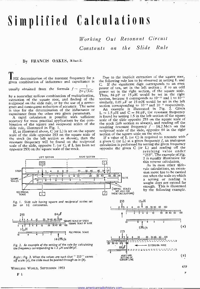
Simplified Calculations Working Out Resonant Circuit
Constants on the Slide Rule
By FRANCIS OAKES, M.Inst.E.
THE determination of the resonant frequency for a given combination of inductance and capacitance is
1
i usually obtained from the formula f = 27r (LC
by a somewhat tedious combination of multiplication, extraction of the square root, and finding of the reciprocal on the slide rule, or by the use of a nomo- gram and consequent reduction of accuracy. The same is true for the determination of the inductance or capacitance from the other two given parameters.
A rapid calculation is possible with sufficient accuracy for most practical applications by the com- bination of the square and reciprocal scales of the slide rule, illustrated in Fig. 1.
If, as illustrated above, C (or L) is set on the square scale of the slide opposite 253 on the square scale of the stock (in the left section as shown), then the resonant frequency will be found on the reciprocal scale of the slide, opposite L (or C, if L has been set opposite 253) on the square scale of the stock.
STOCK
SQUARE - SCALES
LEFT SECTION RIGHT SECTION
1
Due to the implicit extraction of the square root, the following rule has to be observed in setting L and C. If the significant digit corresponds to an even power of ten, set in the left section ; if to an odd power set in the right section, of the square scale. Thus, 84 pF or 15µH would be set in the right section, because 8 corresponds to 10-11 and 1 to 10-5 similarly, 0.01 µF or 15 mH would be set in the left section corresponding to 10-8 and 10-2 respectively.
An example is illustrated in Fig. 2. Given L = 1.511H and C = 84 pF, the resonant frequency is found by setting 1.5 in the left section of the square scale of the slide opposite 253 on the square scale of the stock (left section as always), and reading off the resulting resonant frequency f = 14.2 Mc/s on the reciprocal scale of the slide, opposite 84 in the right section of the square scale on the stock.
If a value of L (or C) is required to resonate with r a given C (or L) at a given frequency f, an analogous calculation is performed by setting the given frequency opposite the given C (or L) and reading off the
resulting value under "253". The example of Fig. 2 is equally illustrative for
n; this reverse calculation. As in most other slide -
-1'i A
10 r-
2 Y 3 4 6 8 IO rY!ó 20 30 40 60 8íi 100
PMUM", 20 30 40 60 80 100
SLIDE 1 i
r . S r t
RECIPROCAL SCALE
Fig. I. Slide rule having square and reciprocal scales set for an LC
253
calculation.
84 pF
I 2'}3 4 6 10 20 30 40 60 1100 SQUARE SCALE OF STOCK
SCALE OF SLIDE Ì 2 3 4 6 10
SQUARE 3040 60 100
15µ1i I RECIPROCAL SCALE
IO 6 4 3 2 t
I
14.2Mc/s
Fig. 2. M example of the setting of the rule for calculating the frequency corresponding to 1.5 µH and 84 pF.
Right : Fig. 3. When the values are such that " 253 " comes
off scale (a), the slide must be pushed through as in (b).
WIRELESS WORLD, SEPTEMBER 1953
F1
(NORMAL SCALES NOT USED FOR
of THESE CALCULATIONS)
253
I 234
t 2
253
I 2 / 3 4 6
20 3040 6f1 1
68113E
2
rule calculations, an exten- sion move has to be carried out when the scale on which a setting or reading is sought does not extend far enough. This is illustrated by the following example.
154 10 i 20 30 40 60 100
3 4 6 10
11111 20 30 40 60 100
6 4 3 2
I
5 Mc/5 (a)
10 20 3040 60 100
EXTENSION MOVE
AUXI IARY SETTING OF CURSOR LINE
(b)
439
F
www.americanradiohistory.com

Required the value of C to resonate with L = 15 pH at f = 5 Mc/s. As shown in Fig. 3(a), the scale on the slide does not extend far enough, and a reading opposite 253 cannot be obtained. The cursor is therefore set to the end mark, and the slide pushed right through. The result 68 pF can then be read off as shown in Fig. 3(b). It may be observed that in this particular case, the result could have been obtained without extension move, opposite 253 in the right section of the square scale on the stock, but care must be taken when this procedure is adopted, in order to ensure correct results. Beginners are therefore advised to adhere strictly to the instructions as set out above, until the process is thoroughly understood.
APPENDIX Proof of this method of calculation is given by the
following :- As illustrated in Fig. 4, f on the reciprocal scale
corresponds to 1/f2 on the square scale.
253 C
L d f2
f Fig. 4. Diagram used to prove the method.
Bearing in mind that the scales are logarithmic, and that 1/(27r)2 = 0.0253, the following equations can be obtained from inspection of Fig. 4.
Upper scale d = log C - log 1
(2.7)2
Lower scale d = log f2 - log L
.. log C - log (277)2 log F2 - log L
.. log C + log L = log (27r12
-1- log f2
1 CL =
(227f)2
2rr VLC
Measurement of "Vow" and "Flutter"
CONSIDERABLE diversity exists, both in this country and in the U.S., in the definition and methods of measure- ment of those undesired variations of frequency in repro- duced sound which go under the above descriptive terms.
While it is considered premature to attempt to lay down standards of performance for these factors, a more precise definition of the terms commonly used, and the conditions of physical measurement, is desirable, and the British Standards Institution has issued a memorandum (BS1988 : 1953) which puts forward the views of the Acoustics Industry Standards Committee in this country.
Until further data are available on the subjective effect of different frequency elements in the disturbance, it is proposed that the " unweighted " r.m.s. summation of all components in a band from 1 c/s to 200 c/s, expressed
440
as a percentage of the test frequency of 3 kc/s, shall be accepted. Below 1 c/s peak -to -peak measurements are normally used, and below 0.1 c/s it is proposed that the deviation should be described as " drift," together with other slow deviations of a unidirectional character. " Wow " is used for frequency deviations from 0.1 to 10-20 c/s, which are recognizable as charges of pitch, and " flutter " for deviations occurring at frequencies of 10-20 c/s of more.
The memorandum discusses instruments giving readings of other than r.m.s. values, and gives tentative ratings of performance ranging from " very high " (0.05 per cent) to " poor " (0.5 per cent). It is obtainable from the British Standards Institution, 24 Victoria Street, London, S.W.1, price Is.
Manufacturers' Literature Delayed -action Relay, using solenoid and rubber bellows,
available with delay times from -16 second to 180 seconds and intended for controlling mains -operated equipment. Descrip- tion and specification on a leaflet from Electro Methods, Caxton Way, Stevenage, Herts.
Anti -rust Preservative comprising zinc, carbon and rubber latex; is applied as a solution and dries to form a protective coating. Descriptive leaflet from Cowanite (Anti -Corrosive), P.O. Box No. 61, 15 Tithebarn Street, Liverpool, 2.
Portable D.C. Potentiometer with three ranges permitting measurements from 1007 to 1.8 V with an accuracy of 0.05 per cent of the maximum reading on each range. Leaflet from the Doran Instrument Co., Stroud, Glos.
Small Soldering Iron, weighing 31oz and 9in long, with a consumption of 25 W on 220/240 V mains. Special mech- anical features described in a leaflet from W. T. Henley's Telegraph Works Co., 51-53 Hatton Garden, London, E.C.1.
Surplus Equipment, valves, components and accessories listed in a 1953 mail order catalogue from Duke and Co., 621 Romford Road, Manor Park, London, E.12. -
Operating Instructions for the Series 2 magnetic recording Tape Decks, together with amplifier circuit, notes on the choice of operating conditions, and a fault analysis table, are included in " The Manual of the Tape Deck," issued by Wright and Weaire, 138 Sloane Street, London, S.W.1, price 2s 6d.
New Silicone Electrical Varnishes are described in note C11 (Varnish MS994 for coating glass cloth and bonding mica - glass); note C16 (MS997 impregnating varnish with improved heat stability and rapid curing characteristics); and note L20 (Banding resin MS2105, with improved dielectric strength up to 250°C) issued by Midland Silicones, 19 Upper Brook Street, London, W.1.
Comprehensive catalogue of communications receivers, sound recording and reproduction equipment, test gear and a wide range of short-wave components from Webb's Radio, 14 Soho Street, London, W.1. Price ls.
Ceramic Components; electrical and physical data of the wide range of ceramic parts produced for the radio and elec- tronics industries from United Insulator. Co., Oakcroft Road, Tolworth, Surbiton, Surrey.
Constant Voltage Transformers with output maintained within ± 1 per cent for input variations up to ± 15 per cent. Descriptive leaflet listing types available from Advance Com- ponents, Back Road, Shernhall Street, Walthamstow, London, E.17. Also a leaflet on an Adjustable A.C. Voltage Stabilizer consisting of a constant voltage transformer with harmonic filter and a variable transformer.
Busbars for Soldering Irons with low -voltage supply from transformer (20 V) and two -pin plugs for irons. Descriptive leaflet from Electrical Remote Control Co., East Industrial Estate, Harlow New Town, Essex.
Silver -zinc Accumulators (1.5 V) ranging from 0.75 Ah cell weighing ¡oz to 80 Ah cell weighing 30oz. Illustrated brochure describing their special features and including discharge characteristics, dimensions and weights of various types made by Venner Accumulators, Kingston By -Pass, New Malden, Surrey.
Control Knobs moulded in walnut and ivory with various inscriptions engraved in gold. Leaflet from Uncles, Bliss and Co., 139 Cherry Orchard Road, East Croydon, Surrey.
WIRELESS WORLD, SEPTEMBER 1953
www.americanradiohistory.com
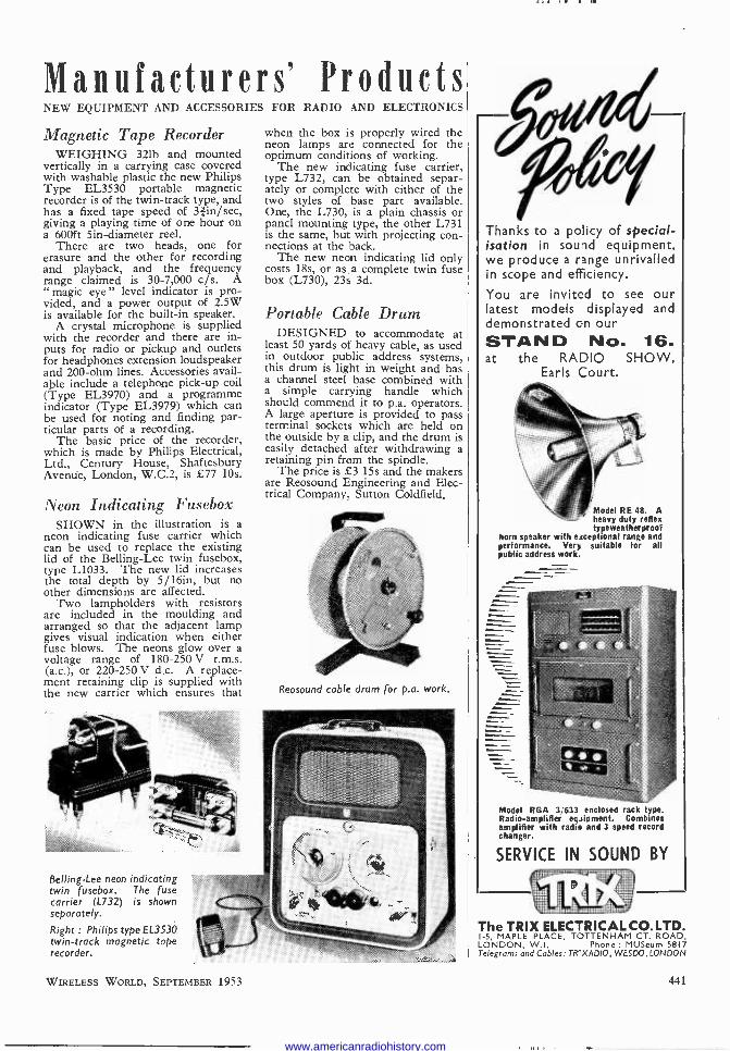
Manufacturers' Products NEW EQUIPMENT AND ACCESSORIES FOR RADIO AND ELECTRONICS
Magnetic Tape Recorder WEIGHING 321b and mounted
vertically in a carrying case covered with washable plastic the new Philips Type EL3530 portable magnetic recorder is of the twin -track type, and has a fixed tape speed of 3áin/sec, giving a playing time of one hour on a 600ft 5in-diameter reel.
There are two heads, one for erasure and the other for recording and playback, and the frequency range claimed is 30-7,000 c/s. A " magic eye " level indicator is pro- vided, and a power output of 2.5W is available for the built-in speaker.
A crystal microphone is supplied with the recorder and there are in- puts for radio or pickup and outlets for headphones extension loudspeaker and 200 -ohm lines. Accessories avail- able include a telephone pick-up coil (Type EL3970) and a programme indicator (Type EL3979) which can be used for noting and finding par- ticular parts of a recording.
The basic price of the recorder, which is made by Philips Electrical, Ltd., Century House, Shaftesbury Avenue, London, W.C.2, is £77 10s.
Neon Indicating Fusebox SHOWN in the illustration is a
neon indicating fuse carrier which can be used to replace the existing lid of the Belling -Lee twin fusebox, type L1033. The new lid increases the total depth by 5/16in, but no other dimensions are affected.
Two lampholders with resistors are included in the moulding and arranged so that the adjacent lamp gives visual indication when either fuse blows. The neons glow over a voltage range of 180-250 V r.m.s. (a.c.), or 220-250 V d.c. A replace- ment retaining clip is supplied with the new carrier which ensures that
Belling -Lee neon indicating twin fusebox. The fuse carrier (L732) is shown separately.
Right : Philips type EL3530 twin -track magnetic tape recorder.
when the box is properly wired the neon lamps are connected for the optimum conditions of working.
The new indicating fuse carrier, type L732, can be obtained separ- ately or complete with either of the two styles of base part available. One, the L730, is a plain chassis or panel mounting type, the other L731 is the same, but with projecting con- nections at the back.
The new neon indicating lid only costs 18s, or as a complete twin fuse box (L730), 23s 3d.
Portable Cable Drum DESIGNED to accommodate at
least 50 yards of heavy cable, as used in outdoor public address systems, this drum is light in weight and has a channel steel base combined with a simple carrying handle which should commend it to p.a. operators. A large aperture is provided to pass terminal sockets which are held on the outside by a clip, and the drum is easily detached after withdrawing a retaining pin from the spindle.
The price is £3 15s and the makers are Reosound Engineering and Elec- trical Company, Sutton Goldfield.
Reosound cable drum for p.a. work.
Thanks to a policy of special- isation in sound equipment, we produce a range unrivalled in scope and efficiency.
You are invited to see our latest models displayed and demonstrated on our STAND No. 16. at the RADIO SHOW,
Earls Court.
Model RE 48. A heavy duty reflex typeweatherproot
horn speaker with exceptional range and performance. Very suitable for all public address work.
Model RGA 3,633 enclosed rack type. Radio -amplifier equipment. Combines amplifier with radio and 3 speed record changer.
SERVICE IN SOUND BY
The TRIX ELECTRICAL CO. LTD. 1-5, MAPLE PLACE, TOTTENHAM CT. ROAD, LONDON, W.I. Phone : MUSeum 5817 Telegrams and Cables: TRIXADIO, WESDO, LONDON
WIRELESS WORLD, SEPTEMBER 1953 441
www.americanradiohistory.com

RANDOM RADIATIONS By EE DIALLIST "
House and Home THE TELEVISION position in France
to -day is very much like that in our own country a little before the war :
people flock to exhibitions and pack demonstration rooms to the point of suffocation; they flatten their noses against the window of any shop dis- playing TV sets; they read avidly any item about television in the newspapers; they talk about tele- vision; they probably dream about it ... but they don't buy many tele- vision receivers! One possible rea- son is that the average Frenchman has to work a good deal longer than his opposite number in Britain to earn the price of a set; I believe, though, that the main reason why television is not making more rapid progress in France is that it is so essentially a home form of entertain- ment. The Frenchman's house, or flat, or cottage is seldom his home in quite our sense of the word. He goes out, for instance, much more than we do for meals, or for amuse- ment. You may know him inti- mately for years without being asked to his house. The French must even speak of le home, not having a word of their own for it. Once it got under way, television caught on rapidly in this country and in the United States, where the home is so important a part of everyone's life. Is it possible that in France and other Latin countries the process may be reversed? Instead of the home fostering the development of tele- vision, television may foster the development of the home-and give them a word for it!
Tubes and Picture Sizes How BIG A PICTURE with an aspect
ratio of 4:3 should a c.r. tube of given diameter be able to display? One's often asked the question; and it's not easy to give a definite answer, for so much depends on the curvature near the circumference of the screen; which means how much defocusing and distortion near the corners of the image (or, alterna- tively, how much masking) can be tolerated. People want bigger and bigger pictures and don't seem to mind a considerable rounding -off of the corners by the mask. Hence manufacturers tend to get the utmost out of any tube in the way of picture
size. The ideal from the quality point of view would, I suppose, be to make the corners of the rectangle just touch the circumference of the screen of a reasonably flat -ended tube and to do only a modest amount of rounding off. Given those condi- tions, it's easy to find the maximum picture size for a circular tube of any diameter. We have a rectangle inscribed in a circle, divided by its diagonal (which is a diameter of the circle) into a couple of right-angled triangles. In these the shorter sides have the ratio 4:3 and recollections of the Pons Asinorum show that the corresponding figure for the third side is 5. Calling the diameter d,
4d 3d we have : width = 5 ; height = 5 This gives 9.6 x 7.2 inches for the pic- ture on a 12 -inch tube, or 11.2 x 8.4 inches for that on a 14 -inch c.r.t. In practice, the corners of the rectangle are usually off the screen alto- gether, so that for the average domes- tic set the picture width may be taken
as 56
. The figures hold good also
for square -ended tubes, which are sized by their diagonal measure- ments. The picture areas in square inches that are sometimes quoted are a little misleading. For some queer
reason " area " has come to mean extreme width multiplied by extreme height and to include the bits of the image covered by the mask-or even off the screen altogether!
Channel -minded YEARS AGO I made what I still
regard as. the eminently sensible sug- gestion that the channels allotted to European stations for " sound " broadcasting should be numbered and the tuning dials of receivers graduated accordingly. Now that people have become used to speaking of Channels 1 to 5 in television Band 1 (and may soon be doing the same with those in other bands), it seems possible that they may grow sufficiently channel -minded to adopt similar divisions of the long -wave and medium -wave broadcast bands. Whatever " plan " is in force, the carrier -frequencies assigned to parti- cular channels don't vary very much. They can't, when you come to think of it, so long as the frequency limit of the bands remains fixed and a 9 -kc/s separation between channels is retained. The numbering of channels would save a heap of trouble : it's much easier, for example, to remember that a station
igTED "WIRELESS WORLD" PUBLICATIONS DC
ILIFFE cqE eoo.s Net By
Price Post GUIDE TO BROADCASTING STATIONS. Compiled by
Wireless World." 6th Edition INTRODUCTION TO VALVES. R. W. Hallows, M.A. (Cantab.)
M.I.E.E. and H. W. Milward, B.Sc., A.M.I.E.E.... ... ... 8/6 9/ - TELEVISION ENGINEERING : Principles and Practice.
VOLUME ONE : Fundamentals, Camera Tubes, Television Optics, Electron Optics. A B.B.C. Engineering Training Manual. S. W. Amos, B.Sc.(Hons.), A.M.I.E.E., and D. C. Birkinshaw, M.A., M.B.E., M.I.E.E., in collaboration with J. L. Bliss, A.M.I.E.E. ... ... ... ... ... ...
WIRELESS WORLD TELEVISION RECEIVER MODEL II: Complete constructional details with notes on modernizing the original design ... ... ... ... ... ... ...
RADIO DESIGNER'S HANDBOOK. F. Langford -Smith, B.Sc., B.E., M.I.R.E., A.M.I.E.E., A.M.I.E. 4th Edition .
RADIO INTERFERENCE SUPPRESSION as Applied to Radio and Television Reception. G. L. Stephens, A.M.I.E.E.... ...
SOUND RECORDING AND REPRODUCTION. J. W. Godfrey and S. W. Amos, B.Sc. A.M.I.E.E:, in collaboration with the B.B.C. Engineering Division ... ... ..
ADVANCED THEORY OF WAVEGUIDES. L. Lewin ... ... 30/ - FOUNDATIONS OF WIRELESS. M. G. Scroggie, B.Sc.,
M.I.E.E. 5th Edition ... ... ... ... ... ... 12/6 13/ - TELEVISION RECEIVING EQUIPMENT. W. T. Cocking,
IS/- 18/8 M.I.E.E. 3rd Edition ... ... ... ... ... ...
A complete list of books is available on application. Obtainable from all leading booksellers or from
ILIFFE & SONS LTD., Dorset House, Stamford Street, London, S.E.I.
2/- 2/2
30/- 30/8
3/6 3/9
42/- 43/6
10/6 10/11
307- 30/8 30/7
442 WIRELESS WORLD, SEPTEMBER 1953
www.americanradiohistory.com
All
uses, say, channel No. 27 than that its wavelength is so many point something metres or that its carrier - frequency is such and such a number of kilocycles per second. The tuning dials of receivers would look neater with numbers instead of a mass of station names. The latter are seldom correct for long, anyhow. Such is the modern passion for changing the names of towns that if you want to tune in a concert from Pszcrwk, you have to remind yourself that the place was called Dummburg when the dial of your set was made-unless, of course, the set is more than three years old, in which case it will appear as Slonk!
Bands 4 and 5 THE REPORT of the Television
Advisory Committee makes it pretty plain that if we are going to provide anything like nation-wide coverage for the B.B.C.'s first and second pro- grammes, and for commercial pro- grammes, we shall have to make full use of Bands 4 and 5 (470-960 Mc/s) in the not -far -distant future. What rather surprises me is so many of those with whom one discusses the Report regard these decimetre wave- lengths as almost unexplored regions. Mapmakers of the Middle Ages used to show large chunks of land blank except for pictures of ape -men, ogres and fearsome beasts, and for legends such as HERE BEE HIPPO- GRYFFES. To -day, there are some who seem to look on the Band 4 and Band 5 parts of the frequency spectrum as unknown tracts in- habited by gremlins. Actually, designers have no little experience of even higher frequencies in tele- vision, radio -links and in radar. Ten -centimetre radar was in service from 1941 onwards during the war and since 1946 the standard British wavelength for marine radar has been 3 centimetres. In comparison, the wavelengths of Bands 4 and 5 can almost be described as long : 51-64cm for Band 4 and 31-49cm for Band 5.
I've heard it suggested that entirely new valves and other components will have to be designed for these bands. That's hardly so, for valves and so on able to cope with far higher frequencies are already in use, though they have not yet been mass- produced here for television recep- tion. U.H.F. television will no doubt have its problems; but I don't think that they'll be all that difficult to solve. To me the nigger in the woodpile is the probable rather high cost of the " all -channel " television receiver of the near future.
RADIO EXHIBITION EVER"( NATION
SINCE.
ß1TO
GE 1 927
ROM the earliest days
Radio Industry,of from the House
Bulgins been shown gulgin have demonstrated
ec
every Annual
Exhibition, sNialising
in one
{field only'
deviation he
ever been attempted to depart
the policy of manu
factoring from radio and electronic
of the highest
components quality.
Visitors to the 20th RADIO
SHOW " at Earls Court on
September 206.12íh, 1g53 are
d to 1 invite
visitO. St 040 and most
5ee the largestdio comprehensive
range of ra
and electronic components
in
the world, now used in
d
equipment manufacture
of bal manufacturers
teadi of radio and electronic
typ apparatus.
* Our new 104 Page Catalogue is now available listing over 5,000 components, Ref. No. l91/WW. Price 1/- post free.
OF CRITICS
1927 1928 1929 1930 1931 1932 1933 1934 1 9 3 5 1 9 3 6
1937 1 9 3 S
1939 1947 1949 1950 1 951 1952 1953
MANUFACTURERS OF RADIO AND ELECTRONIC COMPONENTS
A. F. BULGIN & CO., LTD., BYE -PASS RD., BARKING, ESSEX
Telephone: RIPpleway 3474 (5 lines
WIRELESS WORLD, SEPTEMBER 1953
www.americanradiohistory.com

UNBIASED
" In the Red" THE JACOB'S -COAT SYSTEM used to
indicate the values of our resistors is not so old as broadcasting but, of course, a greatly simplified system, using two colours only, has been used for other purposes ever since radio communication officially began on June 2nd, 1896, exactly 57 years be- fore its greatest triumph on June 2nd, 1953. I refer to the use of red to indicate the + terminal of certain electrical instruments; the man who first did this was undoubtedly the inventor of colour coding in electrical and therefore radio circuits.
I have often wondered who he was and why he chose an arrangement which was so contrary to everyday usage, where red denotes deficiency or a negative quantity. To be " in the red " means an overdrawn account, as my bank manager recently reminded me when making the outrageous suggestion that my account should be debited with the cost of the red ink used to keep it. The reason for choosing red to indi- cate positive could be that this is the colour of the lead oxide paste which is used to fill the grids of the posi- tive plates of an accumulator.
Such an explanation is far too simple, however, and I hope some of you can furnish me with the correct answer; maybe the librarian of the I.E.E. can find the explanation in the archives of the Institution. My own theory is that the universally accepted sign of danger was chosen to indicate the positive pole of a battery or other d.c. generator because, in the far-off pre -electronic days, it was believed that this was the terminal from which the electric current emerged to com- mence its travels around the external circuit. What more natural than to label the supposedly " hot " terminal or "live wire" with the danger sign.
As for the reason why red is always used for danger, this is, of course, nothing to do with electrical or radio
Unsettling effect on the male sex.
444
By FREE GRID
matters; it is due to the unsettling psychological effect this colour has on the male sex as exemplified by the reaction of bulls to a red rag and of men-usually staid and respectable married men-to a passing " Red- head." In the case of Helen of Troy we are told that it was her face that launched a thousand ships, but I have always doubted it. As the sailor said to his shipmates who criticized the homely features of his pin-up girl, " Faces ain't everything."
Tunes Without Tuning I AM GLAD to see that one pro-
minent radio manufacturer has marketed an up-to-date push-button set without a tuning dial. It is true that it employs a multi -position switch and so to the literally minded it is not, therefore, really a push- button set, and it is equally true that only four pre -selected stations are available. But it is, at any rate, a beginning and other makers will, I feel sure, soon have something on the market to compete with it.
Its most attractive feature, in my opinion, is that it has no tuning dial. I always resented having to pay for something I didn't want in the old days when push-button sets had tun- ing dials. I have always favoured a set with pre -selection switching because with such a receiver every- thing " inside the box " (such as circuit coupling) can be arranged to suit the particular frequency which is pre -selected. There need be no compromises such as are unavoidable when a set is designed to have one - knob tuning and at the same time to cover a whole gamut of fre- quencies. Above all, the complete absence of a tuning dial saves even the most ham-handed of our Harriets from the sin of sideband sibilance.
Things to Come Tests is the silver jubilee year of
the talkies, as anybody who cares to turn up the files of Wireless World for 1928 can verify. The cinema moguls are not celebrating it, how- ever. Maybe, they realize that, barring an unexpected invention, their days are numbered.
Broadcasting (owing to the inten- sive work it caused to be put into the development of the thermionic valve and the moving -coil loudspeaker) fathered the talkies, but television will act as their undertaker, for it can offer real stereoscopic pictures without the necessity of the audience wearing polarized or coloured spec- tacles. By real stereo I mean, of course, pukka two -eyed stereo and not merely a half-hearted pseudo-
stereo effect which can be obtained by juggling with the shape of the screen.
Technically speaking, real stereo without any other form of stereoscope could be demonstrated to -day on TV by arranging a two -channel vision chain from cameras to c.r.t. screens. At the receiving end we should, of course, require two pictures side by side in the same cabinet, but they would be quite small and the two small c.r. tubes would cost less than one large tube. But everything else, except the power pack, would have to be duplicated. A correspondent in the August issue maintains that only one channel is necessary; if so, my technical education has been sadly neglected.
3D TV.
It will naturally be asked how the two adjacent pictures could be fused into one without special spectacles or some other kind of stereoscope. The answer is that to view stereoscopic pictures in this manner is an art which can be acquired by anybody who cares to take the trouble to do so. It doesn't matter whether you normally wear spectacles or not. There is nothing very new in it; it is, in fact, dealt with in most books on stereoscopic photography. It is rather like learning to ride a bicycle, inasmuch as it seems difficult at first, but eventually becomes second nature. Once acquired, the art is never lost.
It would be quite impossible for cinemas to adopt this system as owing to the large size of the two pictures on the screen, homologous points would be too widely separated for the eyes to achieve correct fusion. If you want to try out the idea, take a few stereo photographs. You don't need any special apparatus. The cheapest form of one -eyed box camera will serve the purpose if used in the manner described in all photo- graphic textbooks and from time to time in journals devoted to photo- graphy.
WIRELESS WORLD, SEPTEMBER 1953
www.americanradiohistory.com