Embed Size (px)
Citation preview
Answers for energy
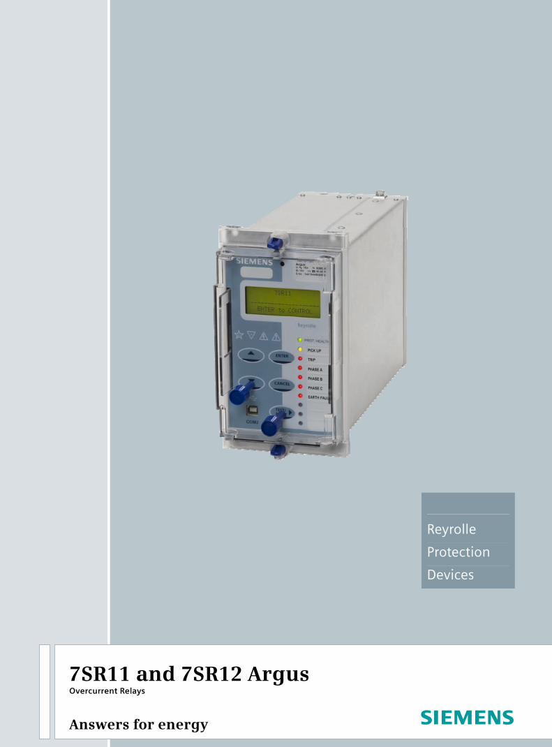
7SR11 and 7SR12 Argus Overcurrent Relays
Reyrolle
Protection
Devices
Siemens Protection Devices Limited 2
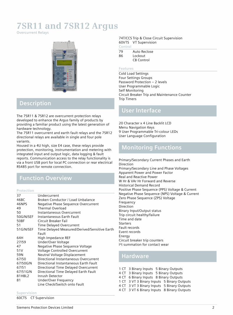
The 7SR11 & 7SR12 are overcurrent protection relays developed to enhance the Argus family of products by providing a familiar product using the latest generation of hardware technology. The 7SR11 overcurrent and earth fault relays and the 7SR12 directional relays are available in single and four pole variants. Housed in a 4U high, size E4 case, these relays provide protection, monitoring, instrumentation and metering with integrated input and output logic, data logging & fault reports. Communication access to the relay functionality is via a front USB port for local PC connection or rear electrical RS485 port for remote connection.
Protection 37 Undercurrent 46BC Broken Conductor / Load Unbalance 46NPS Negative Phase Sequence Overcurrent 49 Thermal Overload 50 Instantaneous Overcurrent 50G/N/SEF Instantaneous Earth Fault 50BF Circuit Breaker Fail 51 Time Delayed Overcurrent 51G/N/SEF Time Delayed Measured/Derived/Sensitive Earth
Fault 64H High Impedance REF 27/59 Under/Over Voltage 47 Negative Phase Sequence Voltage 51V Voltage Controlled Overcurrent 59N Neutral Voltage Displacement 67/50 Directional Instantaneous Overcurrent 67/50G/N Directional Instantaneous Earth Fault 67/51 Directional Time Delayed Overcurrent 67/51G/N Directional Time Delayed Earth Fault 81HBL2 Inrush Detector 81 Under/Over Frequency Line Check/Switch onto Fault Supervision 60CTS CT Supervision
74T/CCS Trip & Close Circuit Supervision 60VTS VT Supervision Control 79 Auto Reclose 86 Lockout CB Control Features Cold Load Settings Four Settings Groups Password Protection – 2 levels User Programmable Logic Self Monitoring Circuit Breaker Trip and Maintenance Counter Trip Timers
20 Character x 4 Line Backlit LCD Menu Navigation Keys 9 User Programmable Tri-colour LEDs User Language Configuration
Primary/Secondary Current Phases and Earth Direction Primary/Secondary Line and Phase Voltages Apparent Power and Power Factor Real and Reactive Power W Hr & VAr Hr Forward and Reverse Historical Demand Record Positive Phase Sequence (PPS) Voltage & Current Negative Phase Sequence (NPS) Voltage & Current Zero Phase Sequence (ZPS) Voltage Frequency Direction Binary Input/Output status Trip circuit healthy/failure Time and date Starters Fault records Event records Energy Circuit breaker trip counters I2t summation for contact wear
1 CT 3 Binary Inputs 5 Binary Outputs 4 CT 3 Binary Inputs 5 Binary Outputs 4 CT 6 Binary Inputs 8 Binary Outputs 1 CT 3 VT 3 Binary Inputs 5 Binary Outputs 4 CT 3 VT 3 Binary Inputs 5 Binary Outputs 4 CT 3 VT 6 Binary Inputs 8 Binary Outputs
7SR11 and 7SR12 Argus Overcurrent Relays
Description User Interface
Hardware
Monitoring Functions
Function Overview
Siemens Protection Devices Limited 3
Front USB port + Rear RS485 port Protocols - IEC60870-5-103, DNP3.0 or Modbus RTU Event Records – User Configurable Fault Records Waveform Records Measurands Commands Time Synchronism Viewing and Changing Settings
The Argus is a numerical overcurrent protection relay intended for use on distribution and industrial networks. It provides a highly comprehensive functional software package with a range of integral application functions aimed at reducing installation, wiring and engineering time. An extensive range of metered values can be viewed on the front LCD or at a remote point via the communication channel. The integrated control feature allows operation of a single circuit breaker and monitoring of its trip and close circuits.
FUN
CTI
ON
FUN
CTI
ON
AL
REQ
UIR
EMEN
T
7SR
11
01
-1*
A1
2-*
*A
0
7SR
11
01
-3*
A1
2-*
*A
0
7SR
11
02
-1*
A1
2-*
*A
0
7SR
11
02
-3*
A1
2-*
*A
0
7SR
12
04
-2*
A1
2-*
*A
0
7SR
12
04
-4*
A1
2-*
*A
0
7SR
12
05
-2*
A1
2-*
*A
0
7SR
12
05
-4*
A1
2-*
*A
0
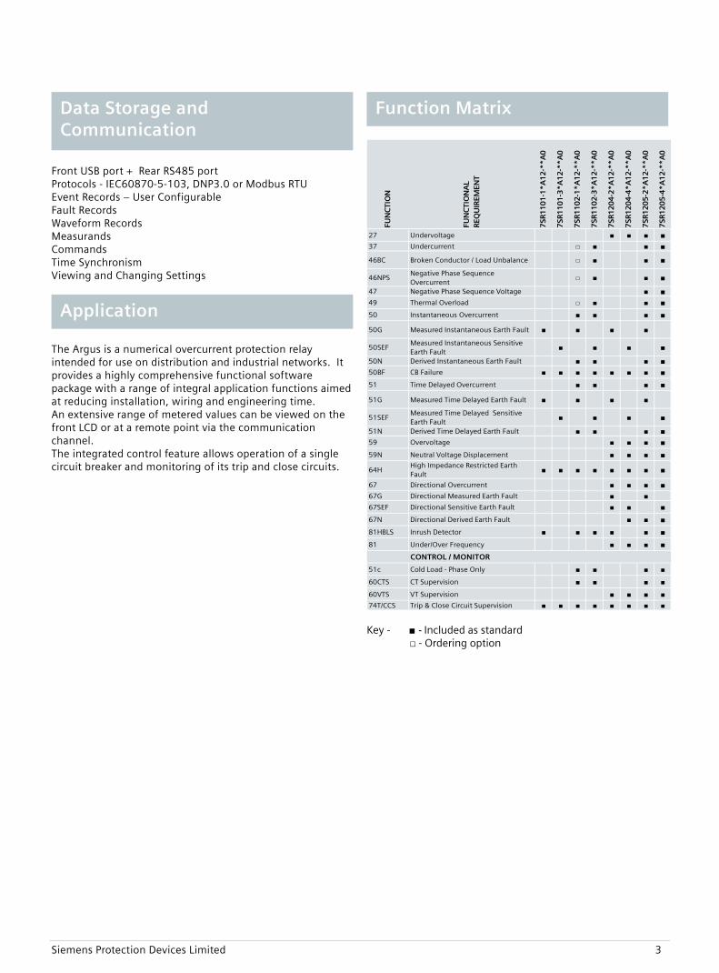
27 Undervoltage ■ ■ ■ ■37 Undercurrent □ ■ ■ ■
46BC Broken Conductor / Load Unbalance □ ■ ■ ■
46NPSNegative Phase Sequence Overcurrent
□ ■ ■ ■
47 Negative Phase Sequence Voltage ■ ■49 Thermal Overload □ ■ ■ ■50 Instantaneous Overcurrent ■ ■ ■ ■
50G Measured Instantaneous Earth Fault ■ ■ ■ ■
50SEFMeasured Instantaneous Sensitive Earth Fault
■ ■ ■ ■
50N Derived Instantaneous Earth Fault ■ ■ ■ ■50BF CB Failure ■ ■ ■ ■ ■ ■ ■ ■51 Time Delayed Overcurrent ■ ■ ■ ■
51G Measured Time Delayed Earth Fault ■ ■ ■ ■
51SEFMeasured Time Delayed Sensitive Earth Fault
■ ■ ■ ■
51N Derived Time Delayed Earth Fault ■ ■ ■ ■59 Overvoltage ■ ■ ■ ■59N Neutral Voltage Displacement ■ ■ ■ ■
64HHigh Impedance Restricted Earth Fault
■ ■ ■ ■ ■ ■ ■ ■
67 Directional Overcurrent ■ ■ ■ ■67G Directional Measured Earth Fault ■ ■67SEF Directional Sensitive Earth Fault ■ ■ ■67N Directional Derived Earth Fault ■ ■ ■81HBLS Inrush Detector ■ ■ ■ ■ ■ ■81 Under/Over Frequency ■ ■ ■ ■
CONTROL / MONITOR
51c Cold Load - Phase Only ■ ■ ■ ■
60CTS CT Supervision ■ ■ ■ ■
60VTS VT Supervision ■ ■ ■ ■74T/CCS Trip & Close Circuit Supervision ■ ■ ■ ■ ■ ■ ■ ■
Key - ■ - Included as standard
□ - Ordering option
Application
Function Matrix Data Storage and Communication
Siemens Protection Devices Limited 4
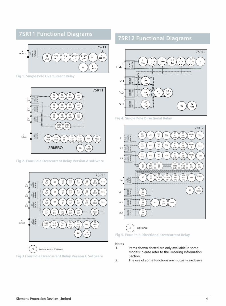
Fig 1. Single Pole Overcurrent Relay
7SR1150
(x2)51
(x2)
50G(x2)
51G(x2)
50BF
50N(x2)
51N(x2)
50(x2)
50BF
50(x2)
50BF
74T/CCS
51(x2)
51(x2)
81HBL2
G
I4(IG/ISEF)
IL1
(IA)
IL2
(IB)
IL3
(IC)
60 CTS
60 CTS
60 CTS
50 SEF (x2)
51 SEF (x2)
64H50BF
3BI/5BO 86
Fig 2. Four Pole Overcurrent Relay Version A software
7SR1137
(x2)49
50(x2)
51(x2)
50G(x2)
51G(x2)
50BF
50N(x2)
51N(x2)
46BC
46NPS(x2)
81HBL2
37(x2)
4950
(x2)50BF
81HBL2
37(x2)
4950
(x2)50BF
81HBL2
74T/CCS
51(x2)
51(x2)
81HBL2
N
81HBL2
G
I4(IG/ISEF)
IL1
(IA)
IL2
(IB)
IL3
(IC)
60 CTS
60 CTS
60 CTS
50 SEF (x2)
51 SEF (x2)
64H50BF
79 Optional Version D Software
51c
51c
51c
37(x2)
86
Fig 3 Four Pole Overcurrent Relay Version C Software
Fig 4. Single Pole Directional Relay
7SR12
64H
46BC
46NPS(x2)
37 (x2)
4950BF
VL1
VL2
VL3
IL1
37 (x2)
4950BF
IL2
37 (x2)
4950BF
IL3
60CTS
60VTS
I4
74T/CCS
67/50
(x4)
67/51
(x4)
67/50N(x4)
67/50
(x4)
67/50
(x4)
67/51
(x4)
67/51
(x4)
67/51N(x4)
67/50G(x4)
67/51G(x4)
2759
(x4)
2759
(x4)
2759
(x4)
59N47
79 Optional
50BF
50BF
37
81HBL2
81HBL2
81HBL2
51V
51V
51V
67/50SEF(
x2)
67/51SEF(
x2)
81HBL2
51c
51c
51c
81(x4)
86
Fig 5. Four Pole Directional Overcurrent Relay
Notes 1. Items shown dotted are only available in some
models; please refer to the Ordering Information Section.
2. The use of some functions are mutually exclusive
7SR12 Functional Diagrams 7SR11 Functional Diagrams
Siemens Protection Devices Limited 5
27/59 Under/Over Voltage Each element has settings for pickup level, drop-off level and Definite Time Lag (DTL) delays. Operates if voltage exceeds setting for duration of delay. 37 Undercurrent Each element has settings for pickup level and Definite Time Lag (DTL) delays. Operates if current falls below setting for duration of delay. 46BC Phase Unbalance/Broken Conductor Element has settings for pickup level and DTL delay. With the circuit breaker closed, if the NPS:PPS current ratio is above setting this could be due to a broken conductor. 46NPS Negative Phase Sequence Overcurrent Each element has user settings for pickup level and IDMTL or DTL delay, operates if NPS current exceeds setting and delay. NPS current elements can be used to detect unbalances on the system or remote earth faults when a delta-star transformer is in circuit. 47 Negative Phase Sequence Voltage Each element has settings for pickup level and Definite Time Lag (DTL) delays. Operates if NPS voltage exceeds setting for duration of delay. 49 Thermal Overload The thermal algorithm calculates the thermal states from the measured currents and can be applied to lines, cables and transformers. Alarm outputs are given for thermal overload and thermal capacity. 50BF Circuit Breaker Fail The circuit breaker fail function may be triggered from an internal trip signal or from a binary input. Line currents and earth currents are monitored following a trip signal and an output is issued if any current is still detected, above setting, after a specified time interval. Alternatively, if the trip is from a mechanical protection the circuit breaker position can be used to determine a failure. A second time delay is available to enable another stage to be utilized if required. An input is also available to bypass the time delays when the circuit breaker is known to be faulty. 51c Cold Load Pickup If a circuit breaker is closed onto a ‘cold’ load, i.e. one that has not been powered for a prolonged period, this can impose a higher than normal load-current demand on the system which could exceed normal settings. These conditions can exist for an extended period and must not be interpreted as a fault. To allow optimum setting levels to be applied for normal operation, the cold load pickup feature will apply alternative current settings for a limited period. The feature resets when either the circuit breaker has been closed for a settable period, or if the current has reduced beneath a set level for a user set period.
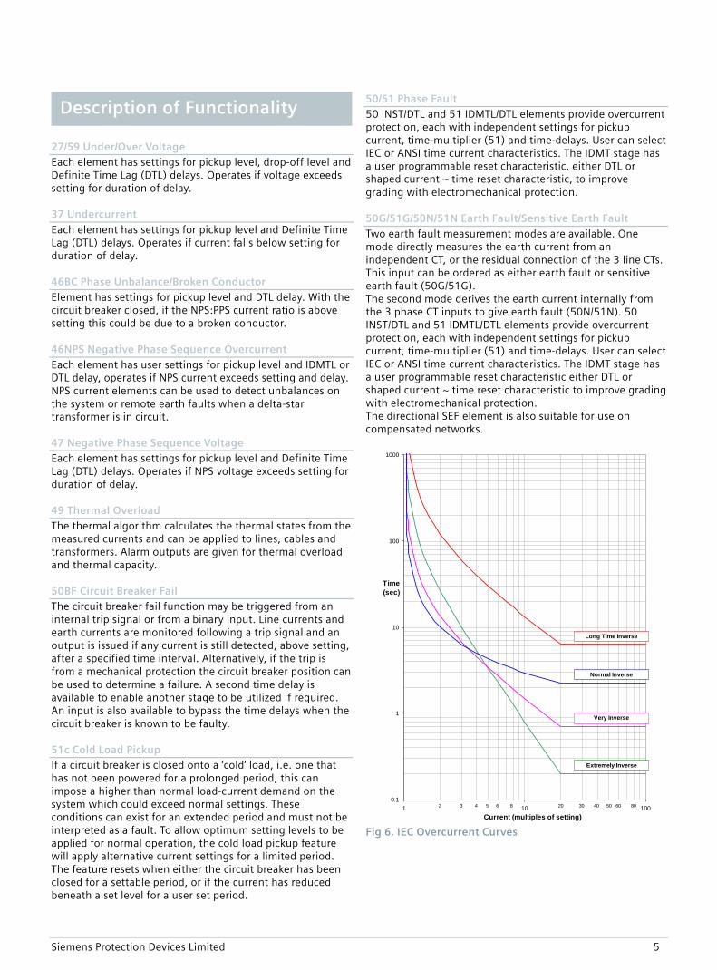
50/51 Phase Fault 50 INST/DTL and 51 IDMTL/DTL elements provide overcurrent protection, each with independent settings for pickup current, time-multiplier (51) and time-delays. User can select IEC or ANSI time current characteristics. The IDMT stage has a user programmable reset characteristic, either DTL or shaped current ~ time reset characteristic, to improve grading with electromechanical protection. 50G/51G/50N/51N Earth Fault/Sensitive Earth Fault Two earth fault measurement modes are available. One mode directly measures the earth current from an independent CT, or the residual connection of the 3 line CTs. This input can be ordered as either earth fault or sensitive earth fault (50G/51G). The second mode derives the earth current internally from the 3 phase CT inputs to give earth fault (50N/51N). 50 INST/DTL and 51 IDMTL/DTL elements provide overcurrent protection, each with independent settings for pickup current, time-multiplier (51) and time-delays. User can select IEC or ANSI time current characteristics. The IDMT stage has a user programmable reset characteristic either DTL or shaped current ~ time reset characteristic to improve grading with electromechanical protection. The directional SEF element is also suitable for use on compensated networks.
0.1
1
10
100
1000
1 10 100Current (multiples of setting)
Time(sec)
2 3 4 5 6 8 20 30 40 50 60 80
Long Time Inverse
Normal Inverse
Very Inverse
Extremely Inverse
Fig 6. IEC Overcurrent Curves
Description of Functionality
Siemens Protection Devices Limited 6
0.1
1
10
100
1000
1 10 100Current (multiples of setting)
Time(sec)
2 3 4 5 6 8 20 30 40 50 60 80
Moderately Inverse
Extremely Inverse
Very Inverse
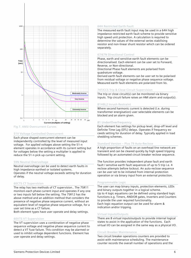
Fig 7. ANSI Overcurrent Curves 51V Voltage Controlled Overcurrent Each phase shaped overcurrent element can be independently controlled by the level of measured input voltage. For applied voltages above setting the 51-n element operates in accordance with its current setting but for voltages below the setting a multiplier is applied to reduce the 51-n pick up current setting. 59N Neutral Overvoltage Neutral overvoltage can be used to detect earth faults in high impedance earthed or isolated systems. Operates if the neutral voltage exceeds setting for duration of delay. 60CTS CT Supervision The relay has two methods of CT supervision.. The 7SR11 monitors each phase current input and operates if any one or two inputs fall below the setting. The 7SR12 has the above method and an addition method that considers the presence of negative phase sequence current, without an equivalent level of negative phase sequence voltage, for a user set time as a CT failure. Both element types have user operate and delay settings. 60VTS VT Supervision The VT supervision uses a combination of negative phase sequence voltage and negative phase sequence current to detect a VT fuse failure. This condition may be alarmed or used to inhibit voltage dependent functions. Element has user operate and delay settings.
64H Restricted Earth Fault The measured earth fault input may be used in a 64H high impedance restricted earth fault scheme to provide sensitive high speed unit protection. A calculation is required to determine the values of the external series stabilising resistor and non-linear shunt resistor which can be ordered separately. 67/67N Directional Control Phase, earth and sensitive earth fault elements can be directionalised. Each element can be user set to Forward, Reverse, or Non-directional. Directional Phase Fault elements are polarised from quadrature voltage. Derived earth fault elements can be user set to be polarised from residual voltage or negative phase sequence voltage. Measured earth fault elements are polarized from Vo. 74T/CCS Trip & Close Circuit Supervision The trip or close circuit(s) can be monitored via binary inputs. Trip circuit failure raises an HMI alarm and output(s). 81HBL2 Inrush Restraint Where second harmonic current is detected (i.e. during transformer energisation) user selectable elements can be blocked and an alarm given. 81 Under/Overfrequency Each element has settings for pickup level, drop-off level and Definite Time Lag (DTL) delays. Operates if frequency ex-ceeds setting for duration of delay. Typically applied in load shedding schemes. Standard Version – Plus 79 Auto-Reclose A high proportion of faults on an overhead line network are transient and can be cleared quickly by high speed tripping followed by an automated circuit breaker reclose sequence. The function provides independent phase fault and earth fault / sensitive earth fault sequences of up to 5 trip i.e. 4 reclose attempts before lockout. An auto-reclose sequence can be user set to be initiated from internal protection operation or via binary input from an external protection. Programmable Logic The user can map binary inputs, protection elements, LEDs and binary outputs together in a logical scheme. Up to 4 logic equations can be defined using standard logic functions e.g. Timers, AND/OR gates, Inverters and Counters to provide the user required functionality. Each logic equation output can be used for alarm & indication and/or tripping. Virtual Inputs/Outputs There are 8 virtual inputs/outputs to provide internal logical states to assist in the application of the functions. Each virtual I/O can be assigned in the same way as a physical I/O. Circuit Breaker Maintenance Two circuit breaker operations counters are provided to assist with maintenance scheduling. The maintenance counter records the overall number of operations and the
Siemens Protection Devices Limited 7
delta counter records the number of operations since the last reset. An I2t summation counter provides a measure of the contact wear indicating the total energy interrupted by the circuit breaker contacts. Each counter has a user set target operations count which, when reached, can be mapped to raise alarms/ binary outputs. A CB Trip Time meter is also available, which measures the time between the trip or open command being issued and the auxiliary contacts changing state. Control Mode The relay has a control menu with access to commonly used command operations. Access to the control commands is restricted by a 4 character control function password. Each command requires a select then execute operation, if the execute operation is not performed within a time window the command is aborted. The following control functions are available: CB Operation Auto Reclose In/Out Auto Reclose Trip & Reclose Auto Reclose Trip & Lockout SEF In/Out Inst Prot In/Out Hot Line Working In/Out
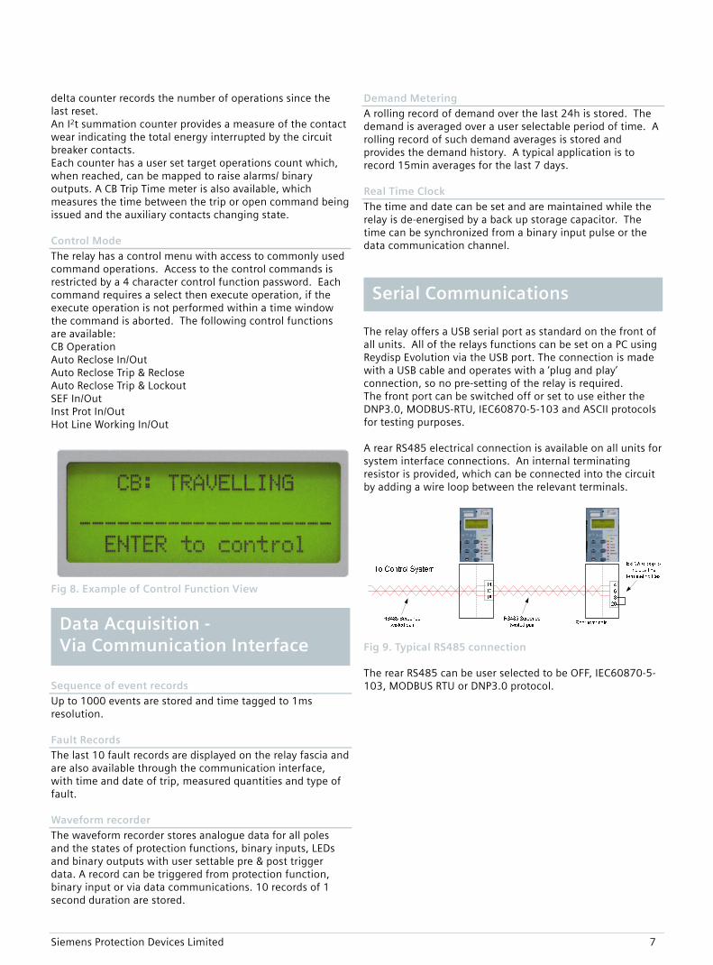
Fig 8. Example of Control Function View
Sequence of event records Up to 1000 events are stored and time tagged to 1ms resolution. Fault Records The last 10 fault records are displayed on the relay fascia and are also available through the communication interface, with time and date of trip, measured quantities and type of fault. Waveform recorder The waveform recorder stores analogue data for all poles and the states of protection functions, binary inputs, LEDs and binary outputs with user settable pre & post trigger data. A record can be triggered from protection function, binary input or via data communications. 10 records of 1 second duration are stored.
Demand Metering A rolling record of demand over the last 24h is stored. The demand is averaged over a user selectable period of time. A rolling record of such demand averages is stored and provides the demand history. A typical application is to record 15min averages for the last 7 days. Real Time Clock The time and date can be set and are maintained while the relay is de-energised by a back up storage capacitor. The time can be synchronized from a binary input pulse or the data communication channel.
The relay offers a USB serial port as standard on the front of all units. All of the relays functions can be set on a PC using Reydisp Evolution via the USB port. The connection is made with a USB cable and operates with a ‘plug and play’ connection, so no pre-setting of the relay is required. The front port can be switched off or set to use either the DNP3.0, MODBUS-RTU, IEC60870-5-103 and ASCII protocols for testing purposes. A rear RS485 electrical connection is available on all units for system interface connections. An internal terminating resistor is provided, which can be connected into the circuit by adding a wire loop between the relevant terminals.
Fig 9. Typical RS485 connection The rear RS485 can be user selected to be OFF, IEC60870-5-103, MODBUS RTU or DNP3.0 protocol.
Serial Communications
Data Acquisition - Via Communication Interface
Siemens Protection Devices Limited 8
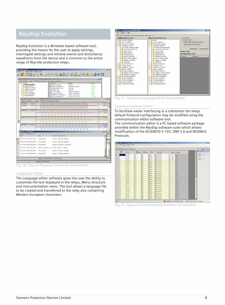
Reydisp Evolution is a Windows based software tool, providing the means for the user to apply settings, interrogate settings and retrieve events and disturbance waveforms from the device and is common to the entire range of Reyrolle protection relays.
Fig 10. Typical Reydisp Evolution Screenshot Language Editor The Language editor software gives the user the ability to customize the text displayed in the relays, Menu structure and instrumentation views. The tool allows a language file to be created and transferred to the relay also containing Western European characters.
Fig 11. Typical Language Editor Screenshot Communications Editor To facilitate easier interfacing to a substation the relays default Protocol configuration may be modified using the communication editor software tool. The communication editor is a PC based software package provided within the Reydisp software suite which allows modification of the IEC60870-5-103, DNP 3.0 and MODBUS Protocols.
Fig 12. Typical Communications Editor Screenshot
Reydisp Evolution
Siemens Protection Devices Limited 9
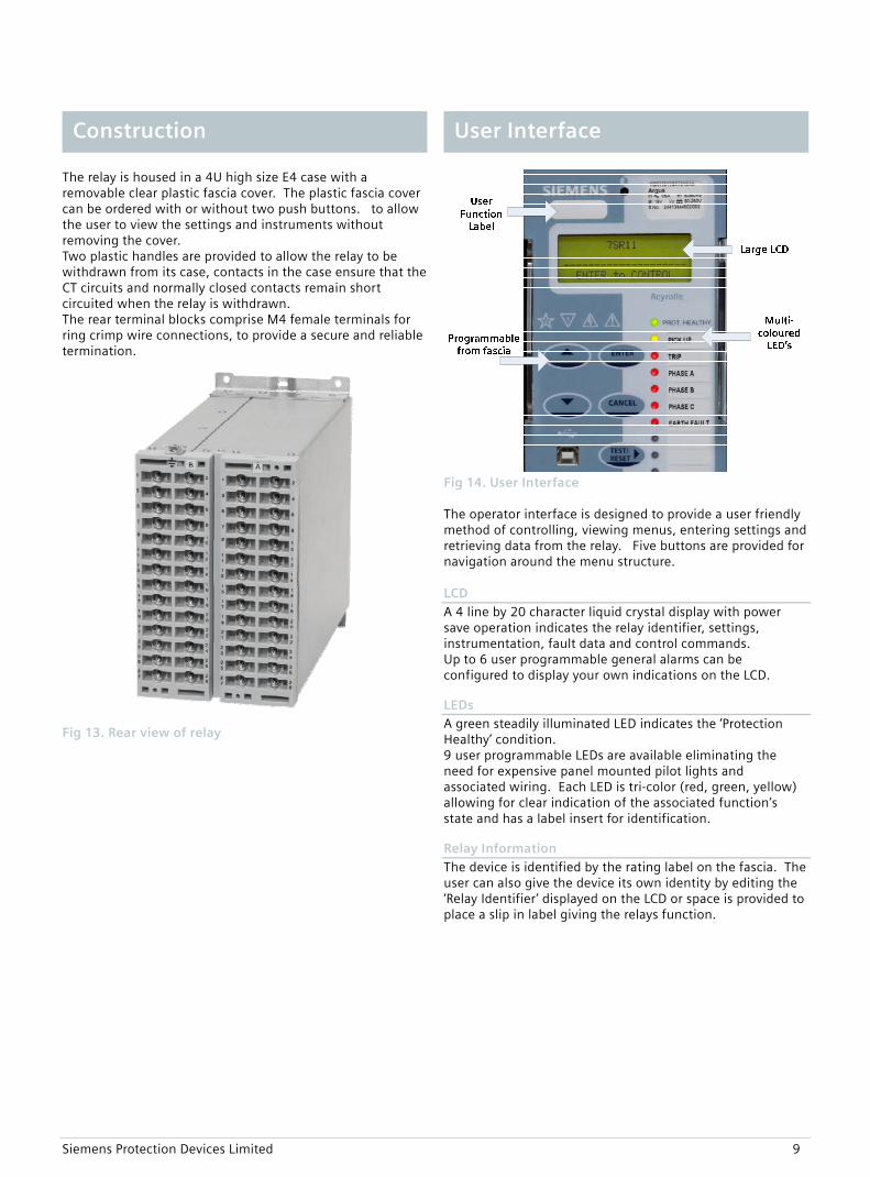
The relay is housed in a 4U high size E4 case with a removable clear plastic fascia cover. The plastic fascia cover can be ordered with or without two push buttons. to allow the user to view the settings and instruments without removing the cover. Two plastic handles are provided to allow the relay to be withdrawn from its case, contacts in the case ensure that the CT circuits and normally closed contacts remain short circuited when the relay is withdrawn. The rear terminal blocks comprise M4 female terminals for ring crimp wire connections, to provide a secure and reliable termination.
Fig 13. Rear view of relay
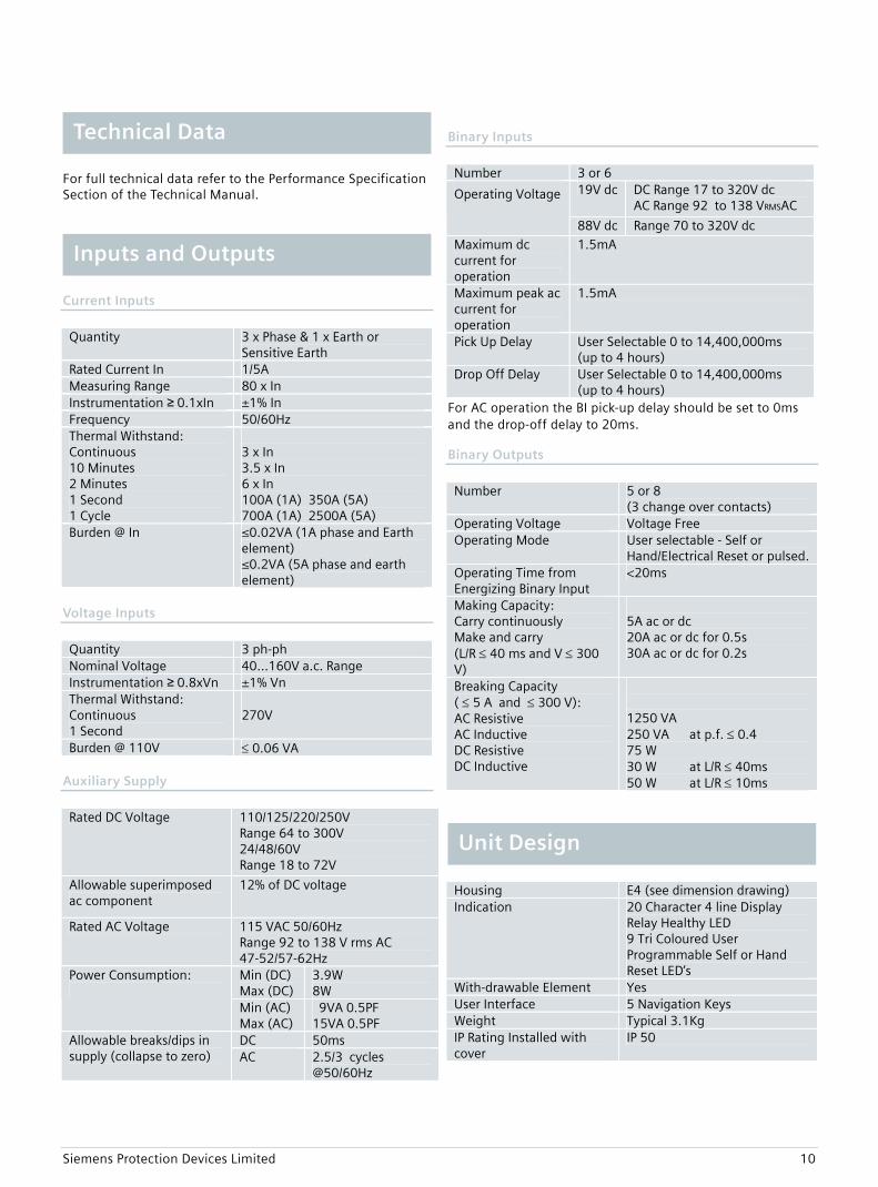
Fig 14. User Interface The operator interface is designed to provide a user friendly method of controlling, viewing menus, entering settings and retrieving data from the relay. Five buttons are provided for navigation around the menu structure. LCD A 4 line by 20 character liquid crystal display with power save operation indicates the relay identifier, settings, instrumentation, fault data and control commands. Up to 6 user programmable general alarms can be configured to display your own indications on the LCD. LEDs A green steadily illuminated LED indicates the ‘Protection Healthy’ condition. 9 user programmable LEDs are available eliminating the need for expensive panel mounted pilot lights and associated wiring. Each LED is tri-color (red, green, yellow) allowing for clear indication of the associated function’s state and has a label insert for identification. Relay Information The device is identified by the rating label on the fascia. The user can also give the device its own identity by editing the ‘Relay Identifier’ displayed on the LCD or space is provided to place a slip in label giving the relays function.
User Interface Construction
Siemens Protection Devices Limited 10
For full technical data refer to the Performance Specification Section of the Technical Manual.
Current Inputs
Quantity 3 x Phase & 1 x Earth or
Sensitive Earth Rated Current In 1/5A Measuring Range 80 x In Instrumentation ≥ 0.1xIn ±1% In Frequency 50/60Hz Thermal Withstand: Continuous 10 Minutes 2 Minutes 1 Second 1 Cycle
3 x In 3.5 x In 6 x In 100A (1A) 350A (5A) 700A (1A) 2500A (5A)
Burden @ In ≤0.02VA (1A phase and Earth element) ≤0.2VA (5A phase and earth element)
Voltage Inputs
Quantity 3 ph-ph Nominal Voltage 40…160V a.c. Range Instrumentation ≥ 0.8xVn ±1% Vn Thermal Withstand: Continuous 1 Second
270V
Burden @ 110V ≤ 0.06 VA Auxiliary Supply
Rated DC Voltage 110/125/220/250V
Range 64 to 300V 24/48/60V Range 18 to 72V
Allowable superimposed ac component
12% of DC voltage
Rated AC Voltage 115 VAC 50/60Hz Range 92 to 138 V rms AC 47-52/57-62Hz Min (DC) Max (DC)
3.9W 8W
Power Consumption:
Min (AC) Max (AC)
9VA 0.5PF 15VA 0.5PF
DC 50ms Allowable breaks/dips in supply (collapse to zero) AC 2.5/3 cycles
@50/60Hz
Binary Inputs
Number 3 or 6
19V dc DC Range 17 to 320V dc AC Range 92 to 138 VRMSAC
Operating Voltage
88V dc Range 70 to 320V dc
Maximum dc current for operation
1.5mA
Maximum peak ac current for operation
1.5mA
Pick Up Delay User Selectable 0 to 14,400,000ms (up to 4 hours)
Drop Off Delay User Selectable 0 to 14,400,000ms (up to 4 hours)
For AC operation the BI pick-up delay should be set to 0ms and the drop-off delay to 20ms. Binary Outputs
Number 5 or 8
(3 change over contacts) Operating Voltage Voltage Free Operating Mode User selectable - Self or
Hand/Electrical Reset or pulsed. Operating Time from Energizing Binary Input
<20ms
Making Capacity: Carry continuously Make and carry (L/R ≤ 40 ms and V ≤ 300 V)
5A ac or dc 20A ac or dc for 0.5s 30A ac or dc for 0.2s
Breaking Capacity ( ≤ 5 A and ≤ 300 V): AC Resistive AC Inductive DC Resistive DC Inductive
1250 VA 250 VA at p.f. ≤ 0.4 75 W 30 W at L/R ≤ 40ms 50 W at L/R ≤ 10ms
Housing E4 (see dimension drawing) Indication 20 Character 4 line Display
Relay Healthy LED 9 Tri Coloured User Programmable Self or Hand Reset LED’s
With-drawable Element Yes User Interface 5 Navigation Keys Weight Typical 3.1Kg IP Rating Installed with cover
IP 50
Unit Design
Inputs and Outputs
Technical Data
Siemens Protection Devices Limited 11
Communication Port Front USB Type B
Rear RS485 2 wire electrical Protocols IEC60870-5-103
MODBUS RTU DNP3.0
Fault Record 10 Waveform Record 10 x 1sec
2 x 5sec 5 x 2sec 1 x 10sec Pre trigger 10…90%
Events 1000 1ms Resolution
Vibration (Sinusoidal)
IEC 60255-21-1 Class I Type Level Variation Vibration response 0.5 gn ≤ 5 % Vibration response 1.0 gn ≤ 5 %
Shock and Bump
IEC 60255-21-2 Class I Type Level Variation Shock response 5 gn, 11 ms ≤ 5 % Shock withstand 15 gn, 11 ms ≤ 5 % Bump test 10 gn, 16 ms ≤ 5 %
Seismic
IEC 60255-21-3 Class I Type Level Variation
Seismic response
X-plane - 3.5mm displacement below crossover freq (8-9Hz) 1gn and above Y-plane – 1.5mm displacement below crossover freq (8-9Hz) 0.5gn above
≤ 5 %
Mechanical Classification
Durability >106 operations
Insulation
IEC 60255-5 Type Level
Between any terminal and earth
2.0 kV AC RMS for 1 min
Between independent circuits
2.0 kV AC RMS for 1 min
Across normally open contacts
1.0 kV AC RMS for 1 min
High Frequency Disturbance
IEC 60255-22-1 Class III Type Level Variation Common (longitudinal) mode
2.5 kV ≤ 5 %
Series (transverse) mode
1.0 kV ≤ 5 %
Electrostatic Discharge
IEC 60255-22-2 Class IV Type Level Variation Contact discharge 8.0 kV ≤ 5 %
Fast Transients
IEC 60255-22-4 Class A (2002) Type Level Variation 5/50 ns 2.5 kHz repetitive
4kV ≤ 5 %
Surge Immunity
IEC 60255-22-5 Type Level Variation Between all terminals and earth
4.0 kV
≤ 10 %
Between any two independent circuits
2.0kV ≤ 10 % *
*Note 45ms pick up delay for DTL applied to binary inputs. Conducted Radio Frequency Interference
IEC 60255-22-6 Type Level Variation 0.15 to 80 MHz 10 V ≤ 5 %
Electrical Tests
Serial Interface
Mechanical Tests
Data Storage
Siemens Protection Devices Limited 12
Radiated Radio Frequency
IEC 60255-25 Type Limits at 10 m, Quasi-peak 30 to 230 MHz 40 dB(μV) 230 to 10000 MHz 47 dB(μV)
Conducted Radio Frequency
Limits Type Quasi-peak Average
0.15 to 0.5 MHz 79 dB(μV) 66 dB(μV) 0.5 to 30 MHz 73 dB(μV) 60 dB(μV)
Radiated Immunity
IEC 60255-22-3 Class III Type Level 80 MHz to 1000 MHz Sweep 10 V/m
1.4GHz to 2.7GHz Sweep 10V/m
80,160,380,450,900,1850,2150 MHz Spot
10V/m
Temperature
IEC 60068-2-1/2 Operating Range -10 °C to +55 °C Storage range -25 °C to +70 °C
Humidity
IEC 60068-2-78 Operational test 56 days at 40 °C and 93 %
relative humidity
27/59 Under/Over Voltage
Number of Elements 4 Under or Over Operate Any phase or All phases Voltage Guard 1,1.5…200V Setting Range Vs 5,5.5…200V Hysteresis Setting 0.0.1…80% Vs Operate Level 100% Vs, ±1% or ±0.25V Reset Level: Overvoltage Undervoltage
=(100%-hyst)xVop, ±1% =(100%+hyst)xVop, ±1%
Delay Setting td 0.00,0.01…20,20.5…100,101…1000,1010…10000,10100…14400s
Basic Operate Time : 0 to 1.1xVs 0 to 2.0xVs 1.1 to 0.5xVs
73ms ±10ms 63ms ±10ms 58ms ±10ms
Operate time following delay.
Tbasic +td , ±1% or ±10ms
Inhibited by Binary or Virtual Input VT Supervision Voltage Guard
37 Undercurrent
Number of Elements 2 Phase and 2 EF Operate Any phase or ALL Setting Range Is 0.05,0.10…5.0 x In Operate Level 100% Is, ±5% or ±1%xIn Current Guard Phase 0.05,0.1…5.0 x In Delay Setting td 0.00,0.01…20,20.5…100,101…
1000,1010…10000,10100…14400s
Basic Operate Time: 1.1 to 0.5xIn
35ms ±10ms
Operate time following delay.
Tbasic +td , ±1% or ±10ms
Overshoot Time < 40ms Inhibited by Binary or Virtual Input
Performance
Climatic Tests
Siemens Protection Devices Limited 13
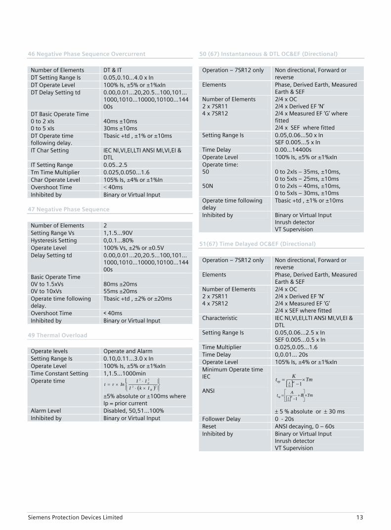
46 Negative Phase Sequence Overcurrent
Number of Elements DT & IT DT Setting Range Is 0.05,0.10…4.0 x In DT Operate Level 100% Is, ±5% or ±1%xIn DT Delay Setting td 0.00,0.01…20,20.5…100,101…
1000,1010…10000,10100…14400s
DT Basic Operate Time 0 to 2 xIs 0 to 5 xIs
40ms ±10ms 30ms ±10ms
DT Operate time following delay.
Tbasic +td , ±1% or ±10ms
IT Char Setting IEC NI,VI,EI,LTI ANSI MI,VI,EI & DTL
IT Setting Range 0.05..2.5 Tm Time Multiplier 0.025,0.050…1.6 Char Operate Level 105% Is, ±4% or ±1%In Overshoot Time < 40ms Inhibited by Binary or Virtual Input
47 Negative Phase Sequence
Number of Elements 2 Setting Range Vs 1,1.5…90V Hysteresis Setting 0,0.1…80% Operate Level 100% Vs, ±2% or ±0.5V Delay Setting td 0.00,0.01…20,20.5…100,101…
1000,1010…10000,10100…14400s
Basic Operate Time 0V to 1.5xVs 0V to 10xVs
80ms ±20ms 55ms ±20ms
Operate time following delay.
Tbasic +td , ±2% or ±20ms
Overshoot Time < 40ms Inhibited by Binary or Virtual Input
49 Thermal Overload Operate levels Operate and Alarm Setting Range Is 0.10,0.11…3.0 x In Operate Level 100% Is, ±5% or ±1%xIn Time Constant Setting 1,1.5…1000min Operate time
( ) ⎪⎭
⎪⎬⎫
⎪⎩
⎪⎨⎧
×⋅
⋅×= 22
22
B
p
IkIII
Int τ
±5% absolute or ±100ms where Ip = prior current
Alarm Level Disabled, 50,51…100% Inhibited by Binary or Virtual Input
50 (67) Instantaneous & DTL OC&EF (Directional)
Operation – 7SR12 only Non directional, Forward or
reverse Elements Phase, Derived Earth, Measured
Earth & SEF Number of Elements 2 x 7SR11 4 x 7SR12
2/4 x OC 2/4 x Derived EF ‘N’ 2/4 x Measured EF ‘G’ where fitted 2/4 x SEF where fitted
Setting Range Is
0.05,0.06…50 x In SEF 0.005…5 x In
Time Delay 0.00…14400s Operate Level 100% Is, ±5% or ±1%xIn Operate time: 50 50N
0 to 2xIs – 35ms, ±10ms, 0 to 5xIs – 25ms, ±10ms 0 to 2xIs – 40ms, ±10ms, 0 to 5xIs – 30ms, ±10ms
Operate time following delay
Tbasic +td , ±1% or ±10ms
Inhibited by Binary or Virtual Input Inrush detector VT Supervision
51(67) Time Delayed OC&EF (Directional)
Operation – 7SR12 only Non directional, Forward or
reverse Elements Phase, Derived Earth, Measured
Earth & SEF Number of Elements 2 x 7SR11 4 x 7SR12
2/4 x OC 2/4 x Derived EF ‘N’ 2/4 x Measured EF ‘G’ 2/4 x SEF where fitted
Characteristic IEC NI,VI,EI,LTI ANSI MI,VI,EI & DTL
Setting Range Is 0.05,0.06…2.5 x In SEF 0.005…0.5 x In
Time Multiplier 0.025,0.05…1.6 Time Delay 0,0.01… 20s Operate Level 105% Is, ±4% or ±1%xIn Minimum Operate time IEC ANSI
[ ] TmKtIsIop ×
−=
1α
[ ] TmBAt PIsIop ×⎥
⎦
⎤⎢⎣
⎡+
−=
1
± 5 % absolute or ± 30 ms Follower Delay 0 - 20s Reset ANSI decaying, 0 – 60s Inhibited by Binary or Virtual Input
Inrush detector VT Supervision
Siemens Protection Devices Limited 14
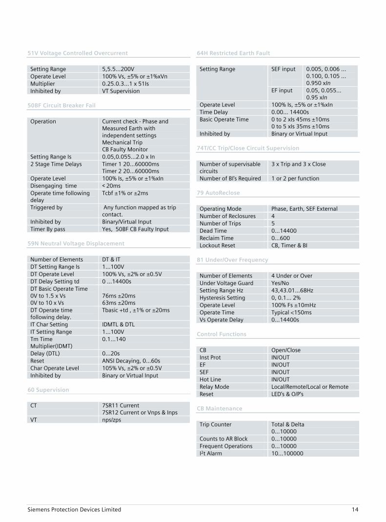
51V Voltage Controlled Overcurrent
Setting Range 5,5.5…200V Operate Level 100% Vs, ±5% or ±1%xVn Multiplier 0.25.0.3…1 x 51Is Inhibited by VT Supervision
50BF Circuit Breaker Fail
Operation Current check - Phase and
Measured Earth with independent settings Mechanical Trip CB Faulty Monitor
Setting Range Is 0.05,0.055…2.0 x In 2 Stage Time Delays Timer 1 20…60000ms
Timer 2 20…60000ms Operate Level 100% Is, ±5% or ±1%xIn Disengaging time < 20ms Operate time following delay
Tcbf ±1% or ±2ms
Triggered by Any function mapped as trip contact.
Inhibited by Binary/Virtual Input Timer By pass Yes, 50BF CB Faulty Input
59N Neutral Voltage Displacement
Number of Elements DT & IT DT Setting Range Is 1…100V DT Operate Level 100% Vs, ±2% or ±0.5V DT Delay Setting td 0 …14400s DT Basic Operate Time 0V to 1.5 x Vs 0V to 10 x Vs
76ms ±20ms 63ms ±20ms
DT Operate time following delay.
Tbasic +td , ±1% or ±20ms
IT Char Setting IDMTL & DTL IT Setting Range 1…100V Tm Time Multiplier(IDMT)
0.1…140
Delay (DTL) 0…20s Reset ANSI Decaying, 0…60s Char Operate Level 105% Vs, ±2% or ±0.5V Inhibited by Binary or Virtual Input
60 Supervision CT 7SR11 Current
7SR12 Current or Vnps & Inps VT nps/zps
64H Restricted Earth Fault
SEF input
0.005, 0.006 … 0.100, 0.105 … 0.950 xIn
Setting Range
EF input 0.05, 0.055... 0.95 xIn
Operate Level 100% Is, ±5% or ±1%xIn Time Delay 0.00… 14400s Basic Operate Time 0 to 2 xIs 45ms ±10ms
0 to 5 xIs 35ms ±10ms Inhibited by Binary or Virtual Input
74T/CC Trip/Close Circuit Supervision
Number of supervisable circuits
3 x Trip and 3 x Close
Number of BI’s Required 1 or 2 per function 79 AutoReclose
Operating Mode Phase, Earth, SEF External Number of Reclosures 4 Number of Trips 5 Dead Time 0…14400 Reclaim Time 0…600 Lockout Reset CB, Timer & BI
81 Under/Over Frequency
Number of Elements 4 Under or Over Under Voltage Guard Yes/No Setting Range Hz 43,43.01…68Hz Hysteresis Setting 0, 0.1… 2% Operate Level 100% Fs ±10mHz Operate Time Typical <150ms Vs Operate Delay 0…14400s
Control Functions
CB Open/Close Inst Prot IN/OUT EF IN/OUT SEF IN/OUT Hot Line IN/OUT Relay Mode Local/Remote/Local or Remote Reset LED’s & O/P’s
CB Maintenance
Trip Counter Total & Delta
0…10000 Counts to AR Block 0…10000 Frequent Operations 0…10000 I2t Alarm 10…100000
Siemens Protection Devices Limited 15
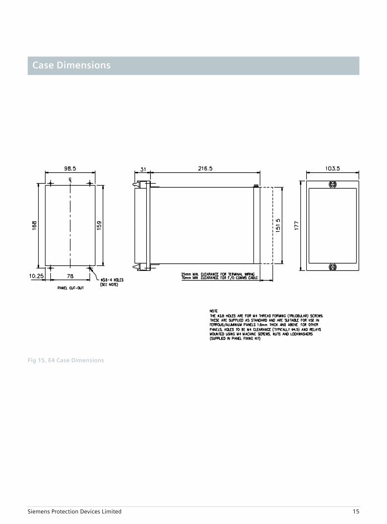
Fig 15. E4 Case Dimensions
Case Dimensions
Siemens Protection Devices Limited 16
BO 1
GND.
BI 1
A
RS
485GND
B
Term.
+ve
-ve
+ve
-ve
IL1
22
24
28
2
4
BI 2+ve
-ve
6
8
BI 3+ve
-ve
10
12
14
16
18
20
IL2
IL3
IL4
25
26
27
28
BO 2 6
5
4
1
2
3
BO 38
7
BO 410
9
BO 512
11
1A
5A
13
14
15
16
1A
5A
17
18
19
20
1A
5A
21
22
23
24
1A
5A
AB
1 2
27 28
1 2
27 28
A
B
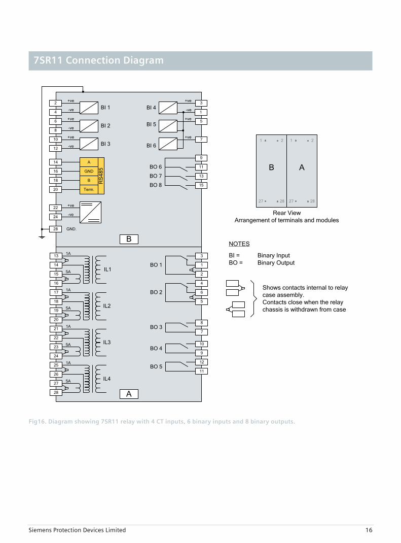
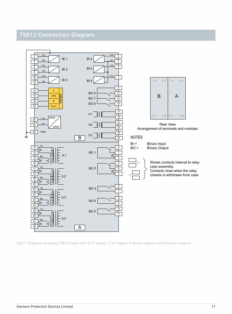
Shows contacts internal to relay case assembly.Contacts close when the relay chassis is withdrawn from case
NOTES
BI = Binary InputBO = Binary Output
Rear ViewArrangement of terminals and modules
BI 4+ve 3
BI 5+ve 5
BI 6
+ve
-ve
7
1
BO 7
11
13
BO 8 15
9
BO 6
Fig16. Diagram showing 7SR11 relay with 4 CT inputs, 6 binary inputs and 8 binary outputs.
7SR11 Connection Diagram
Siemens Protection Devices Limited 17
BO 1
GND.
BI 1
A
RS
485GND
B
Term.
+ve
-ve
+ve
-ve
IL1
22
24
28
2
4
BI 2+ve
-ve
6
8
BI 3+ve
-ve
10
12
14
16
18
20
IL2
IL3
IL4
25
26
27
28
BI 4+ve
3
BI 5+ve 5
BI 6
+ve
-ve
7
1
BO 2 6
5
4
1
2
3
BO 38
7
BO 7
11
13
BO 8 15
9
BO 410
9
BO 512
11
1A
5A
13
14
15
16
1A
5A
17
18
19
20
1A
5A
21
22
23
24
1A
5A
AB
1 2
27 28
1 2
27 28
A
BO 6
V117
19
V221
23
V325
27
Rear ViewArrangement of terminals and modules
Shows contacts internal to relay case assembly.Contacts close when the relay chassis is withdrawn from case
NOTES
BI = Binary InputBO = Binary Output
B
Fig17. Diagram showing 7SR12 relay with 4 CT inputs, 3 VT inputs, 6 binary inputs and 8 binary outputs.
7SR12 Connection Diagram
Siemens Protection Devices Limited 18
1 2 3 4 5 6 7 8 9 10 11 12 13 14 15 16
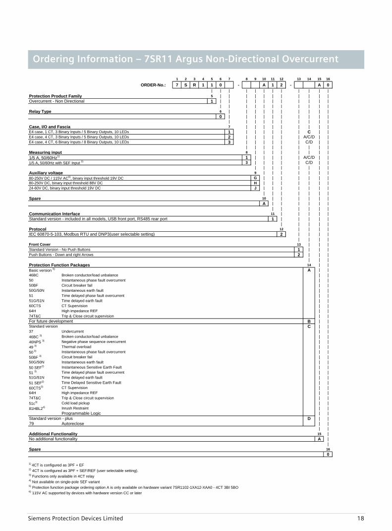
ORDER-No.: 7 S R 1 1 0 - A 1 2 - A 0| | | | | | | | | | | |
Protection Product Family 5 | | | | | | | | | | |Overcurrent - Non Directional 1 | | | | | | | | | | |
| | | | | | | | | | |Relay Type 6 | | | | | | | | | |
0 | | | | | | | | | || | | | | | | | | |
Case, I/O and Fascia 7 | | | | | | | | |E4 case, 1 CT, 3 Binary Inputs / 5 Binary Outputs, 10 LEDs 1 | | | | | | C | |E4 case, 4 CT, 3 Binary Inputs / 5 Binary Outputs, 10 LEDs 2 | | | | | | A/C/D | |E4 case, 4 CT, 6 Binary Inputs / 8 Binary Outputs, 10 LEDs 3 | | | | | | C/D | |
| | | | | | | | |Measuring input 8 | | | | | | | |1/5 A, 50/60Hz1) 1 | | | | | A/C/D | |1/5 A, 50/60Hz with SEF Input 2) 3 | | | | | C/D | |
| | | | | | | |Auxiliary voltage 9 | | | | | | |80-250V DC / 115V AC6), binary input threshold 19V DC G | | | | | | |80-250V DC, binary input threshold 88V DC H | | | | | | |24-60V DC, binary input threshold 19V DC J | | | | | | |
| | | | | | |Spare 10 | | | | | |
A | | | | | || | | | | |
Communication Interface 11 | | | | |Standard version - included in all models, USB front port, RS485 rear port 1 | | | | |
| | | | |Protocol 12 | | | |IEC 60870-5-103, Modbus RTU and DNP3(user selectable setting) 2 | | | |
| | | |Front Cover 13 | | |Standard Version - No Push Buttons 1 | | |Push Buttons - Down and right Arrows 2 | | |
| | |Protection Function Packages 14 | |Basic version 5) A | |46BC Broken conductor/load unbalance | |50 Instantaneous phase fault overcurrent | |50BF Circuit breaker fail | |50G/50N Instantaneous earth fault | |51 Time delayed phase fault overcurrent | |51G/51N Time delayed earth fault | |60CTS CT Supervision | |64H High impedance REF | |74T&C Trip & Close circuit supervision | |For future development B | |Standard version C | |37 Undercurrent | |46BC 3) Broken conductor/load unbalance | |46NPS 3) Negative phase sequence overcurrent | |49 3) Thermal overload | |50 3) Instantaneous phase fault overcurrent | |50BF 3) Circuit breaker fail | |50G/50N Instantaneous earth fault | |50 SEF2) Instantaneous Sensitive Earth Fault | |51 3) Time delayed phase fault overcurrent | |51G/51N Time delayed earth fault | |51 SEF2) Time Delayed Sensitive Earth Fault | |60CTS3) CT Supervision | |64H High impedance REF | |74T&C Trip & Close circuit supervision | |51c3) Cold load pickup | |81HBL24) Inrush Restraint | |
Programmable Logic | |Standard version - plus D | |79 Autoreclose | |
| |Additional Functionality 15 |No additional functionality A |
|Spare 16
0
1) 4CT is configured as 3PF + EF2) 4CT is configured as 3PF + SEF/REF (user selectable setting). 3) Functions only available in 4CT relay 4) Not available on single-pole SEF variant5) Protection function package ordering option A is only available on hardware variant 7SR1102-1XA12-XAA0 - 4CT 3BI 5BO 6) 115V AC supported by devices with hardware version CC or later
Ordering Information – 7SR11 Argus Non-Directional Overcurrent
Siemens Protection Devices Limited 19
1 2 3 4 5 6 7 8 9 10 11 12 13 14 15 16
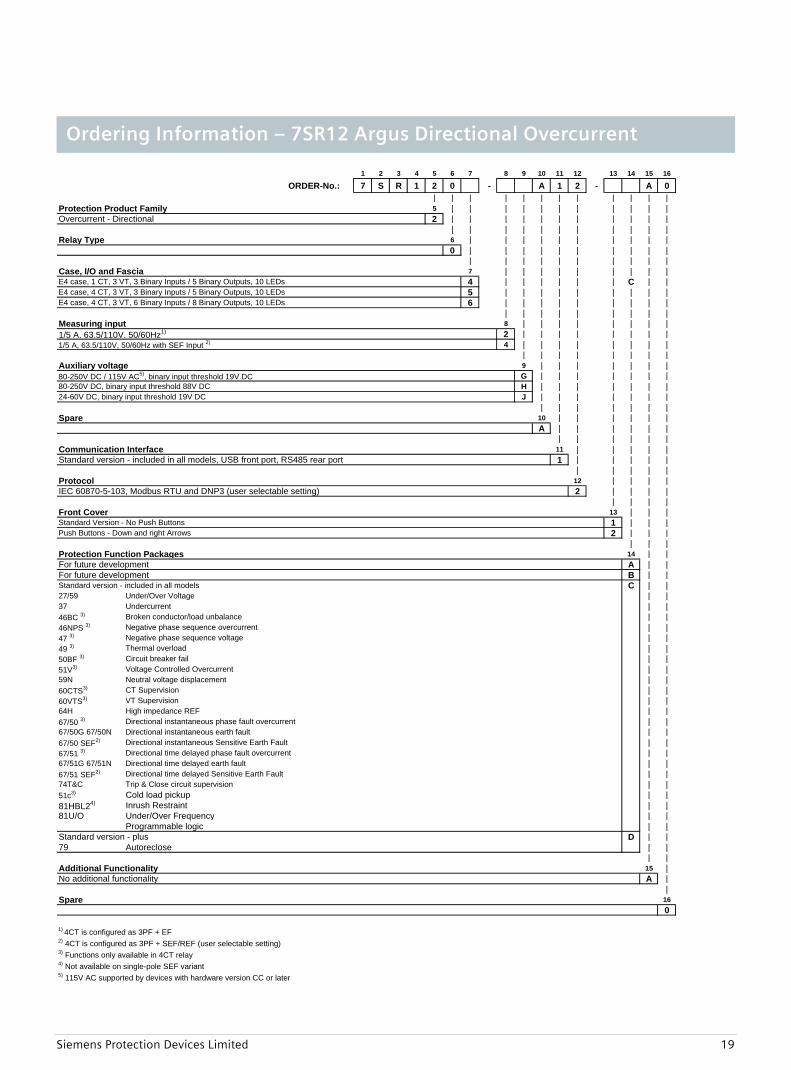
ORDER-No.: 7 S R 1 2 0 - A 1 2 - A 0| | | | | | | | | | | |
Protection Product Family 5 | | | | | | | | | | |Overcurrent - Directional 2 | | | | | | | | | | |
| | | | | | | | | | |Relay Type 6 | | | | | | | | | |
0 | | | | | | | | | || | | | | | | | | |
Case, I/O and Fascia 7 | | | | | | | | |E4 case, 1 CT, 3 VT, 3 Binary Inputs / 5 Binary Outputs, 10 LEDs 4 | | | | | | C | |E4 case, 4 CT, 3 VT, 3 Binary Inputs / 5 Binary Outputs, 10 LEDs 5 | | | | | | | | |E4 case, 4 CT, 3 VT, 6 Binary Inputs / 8 Binary Outputs, 10 LEDs 6 | | | | | | | | |
| | | | | | | | |Measuring input 8 | | | | | | | |1/5 A, 63.5/110V, 50/60Hz1) 2 | | | | | | | |1/5 A, 63.5/110V, 50/60Hz with SEF Input 2) 4 | | | | | | | |
| | | | | | | |Auxiliary voltage 9 | | | | | | |80-250V DC / 115V AC5), binary input threshold 19V DC G | | | | | | |80-250V DC, binary input threshold 88V DC H | | | | | | |24-60V DC, binary input threshold 19V DC J | | | | | | |
| | | | | | |Spare 10 | | | | | |
A | | | | | || | | | | |
Communication Interface 11 | | | | |Standard version - included in all models, USB front port, RS485 rear port 1 | | | | |
| | | | |Protocol 12 | | | |IEC 60870-5-103, Modbus RTU and DNP3 (user selectable setting) 2 | | | |
| | | |Front Cover 13 | | |Standard Version - No Push Buttons 1 | | |Push Buttons - Down and right Arrows 2 | | |
| | |Protection Function Packages 14 | |For future development A | |For future development B | |Standard version - included in all models C | |27/59 Under/Over Voltage | |37 Undercurrent | |46BC 3) Broken conductor/load unbalance | |46NPS 3) Negative phase sequence overcurrent | |47 3) Negative phase sequence voltage | |49 3) Thermal overload | |50BF 3) Circuit breaker fail | |51V3) Voltage Controlled Overcurrent | |59N Neutral voltage displacement | |60CTS3) CT Supervision | |60VTS3) VT Supervision | |64H High impedance REF | |67/50 3) Directional instantaneous phase fault overcurrent | |67/50G 67/50N Directional instantaneous earth fault | |67/50 SEF2) Directional instantaneous Sensitive Earth Fault | |67/51 3) Directional time delayed phase fault overcurrent | |67/51G 67/51N Directional time delayed earth fault | |67/51 SEF2) Directional time delayed Sensitive Earth Fault | |74T&C Trip & Close circuit supervision | |51c3) Cold load pickup | |81HBL24) Inrush Restraint | |81U/O Under/Over Frequency | |
Programmable logic | |Standard version - plus D | |79 Autoreclose | |
| |Additional Functionality 15 |No additional functionality A |
|Spare 16
0
1) 4CT is configured as 3PF + EF2) 4CT is configured as 3PF + SEF/REF (user selectable setting)3) Functions only available in 4CT relay4) Not available on single-pole SEF variant5) 115V AC supported by devices with hardware version CC or later
Ordering Information – 7SR12 Argus Directional Overcurrent
Siemens Protection Devices Limited 20
www. siemens.com/energy
Published by and copyright © 2010:
Siemens AG
Infrastructure & Cities Sector
Freyeslebenstrasse 1
91058 Erlangen, Germany
Siemens Protection Devices Limited
P.O. Box 8
North Farm Road
Hebburn
Tyne & Wear
NE31 1TZ
United Kingdom
Phone: +44 (0)191 401 7901
Fax: +44 (0)191 401 5575
www.siemens.com/energy
For more information, please contact our
Customer Support Center.
Phone: +49 180/524 70 00
Fax: +49 180/524 24 71(Charges depending on provider)
E-mail: [email protected]
Power Distribution Division Order No. E53000-K7076-C29-4
Printed in Fürth
Printed on elementary chlorine-free bleached paper.
All rights reserved.
Trademarks mentioned in this document are the property of Siemens AG, its affili-
ates, or their respective owners.
Subject to change without prior notice.
The information in this document contains general
descriptions of the technical options available, which
may not apply in all cases. The required technical
options should therefore be specified in the contract.