Embed Size (px)
Citation preview

HARDWARE MANUAL
FX1S SERIES PROGRAMMABLE CONTROLLERS
FX1S Series Programmable Controllers
Foreword
• This manual contains text, diagrams and explanations which will guide the reader in the correct installationand operation of the FX1S Series Programmable Controllers. It should be read and understood beforeattempting to install or use the unit.
• Further information can be found in the FX Series Programming Manual II.
• If in doubt at any stage of the installation of an FX1S Series Programmable Controller always consult aprofessional electrical engineer who is qualified and trained to the local and national standards which apply tothe installation site.
• If in doubt about the operation or use of FX1S Series Programmable Controller please consult the nearestMitsubisi Electric distributor.
• This manual is subject to change without notice.
i
FX1S Series Programmable Controllers
Hardware Manual
FX1S Series Programmable Controllers
Manual number : JY992D83901
Manual revision : E
Date : June 2001

FX1S Series Programmable Controllers
ii
f the FX1S.
manual has been written to besuch a person or persons is as
n and construction of automaticual, should be of a competent
standards required to fulfill thatpects of safety with regards to
competent nature, trained andfulfill that job. These engineersf the completed product. This
cumentation for said product. Allstablished safety practices.
ned to use that product in a safesafety practices. The operatorsnected with the actual operation
arty constructed device whichal.
Guidelines for the Safety of the User and Protection o
This manual provides information for the use of the FX1S. Theused by trained and competent personnel. The definition offollows:
a) Any engineer who is responsible for the planning, desigequipment using the product associated with this mannature, trained and qualified to the local and nationalrole. These engineers should be fully aware of all asautomated equipment.
b) Any commissioning or service engineer must be of aqualified to the local and national standards required toshould also be trained in the use and maintenance oincludes being completely familiar with all associated domaintenance should be carried out in accordance with e
c) All operators of the completed equipment should be traiand coordinated manner in compliance to establishedshould also be familiar with documentation which is conof the completed equipment.
Note : The term ‘completed equipment’ refers to a third pcontains or uses the product associated with this manu
FX1S Series Programmable Controllers
iii
ill be used to highlight points ofafety and protect the integrity ofntered its associated note mustlisted with a brief description of
ysical and property damage.
LY cause physical and property
nation.
his element of software.
ociate software element should
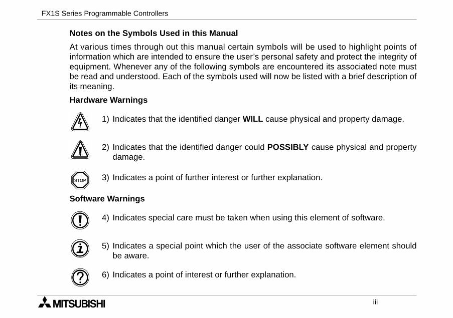
Notes on the Symbols Used in this Manual
At various times through out this manual certain symbols winformation which are intended to ensure the user’s personal sequipment. Whenever any of the following symbols are encoube read and understood. Each of the symbols used will now beits meaning.
Hardware Warnings
1) Indicates that the identified danger WILL cause ph
2) Indicates that the identified danger could POSSIBdamage.
3) Indicates a point of further interest or further expla
Software Warnings
4) Indicates special care must be taken when using t
5) Indicates a special point which the user of the assbe aware.
6) Indicates a point of interest or further explanation.
FX1S Series Programmable Controllers
iv
• Under no circumstances will Mitsubishi Electric be liable for any consequential damage thatmay arise as a result of the installation or use of this equipment.
• All examples and diagrams shown in this manual are intended only as an aid tounderstanding the text, not to guarantee operation. Mitsubishi Electric will accept noresponsibility for actual use of the product based on these illustrative examples.
• Owing to the very great variety in possible application of this equipment, you must satisfyyourself as to its suitability for your specific application.
v
.................................ii
................................1-1...................................... 1-4...................................... 1-5...................................... 1-5...................................... 1-6........................................... 1-7........................................... 1-8...................................... 1-9........................................... 1-9........................................... 1-9
................................2-1...................................... 2-1...................................... 2-2...................................... 2-3...................................... 2-4
FX1S Series Programmable Controllers
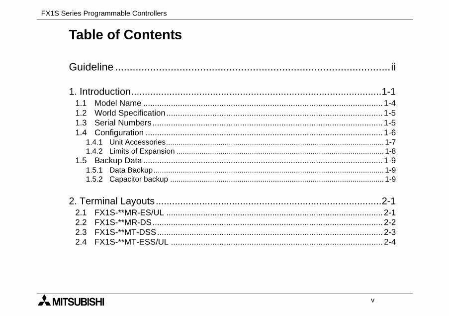
Table of Contents
Guideline .............................................................
1. Introduction............................................................1.1 Model Name ..................................................................1.2 World Specification........................................................1.3 Serial Numbers..............................................................1.4 Configuration .................................................................
1.4.1 Unit Accessories.............................................................1.4.2 Limits of Expansion ........................................................
1.5 Backup Data ..................................................................1.5.1 Data Backup...................................................................1.5.2 Capacitor backup ...........................................................
2. Terminal Layouts...................................................2.1 FX1S-**MR-ES/UL ........................................................2.2 FX1S-**MR-DS..............................................................2.3 FX1S-**MT-DSS............................................................2.4 FX1S-**MT-ESS/UL ......................................................
FX1S Series Programmable Controllers
vi
................................3-1...................................... 3-2...................................... 3-3...................................... 3-4...................................... 3-5...................................... 3-6...................................... 3-6...................................... 3-7........................................... 3-7........................................... 3-8
................................4-1...................................... 4-1...................................... 4-1...................................... 4-1...................................... 4-2...................................... 4-3...................................... 4-5
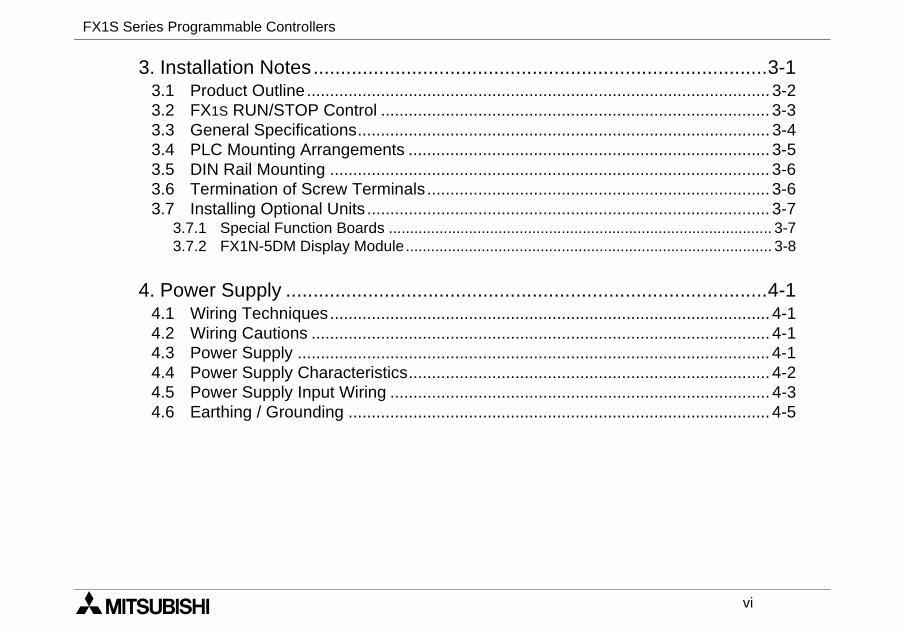
3. Installation Notes...................................................3.1 Product Outline..............................................................3.2 FX1S RUN/STOP Control ..............................................3.3 General Specifications...................................................3.4 PLC Mounting Arrangements ........................................3.5 DIN Rail Mounting .........................................................3.6 Termination of Screw Terminals....................................3.7 Installing Optional Units .................................................
3.7.1 Special Function Boards ................................................3.7.2 FX1N-5DM Display Module............................................
4. Power Supply ........................................................4.1 Wiring Techniques.........................................................4.2 Wiring Cautions .............................................................4.3 Power Supply ................................................................4.4 Power Supply Characteristics........................................4.5 Power Supply Input Wiring ............................................4.6 Earthing / Grounding .....................................................
FX1S Series Programmable Controllers
vii
................................5-1...................................... 5-1...................................... 5-2........................................... 5-2........................................... 5-3........................................... 5-3........................................... 5-4
................................6-1...................................... 6-2...................................... 6-3...................................... 6-4...................................... 6-5...................................... 6-6
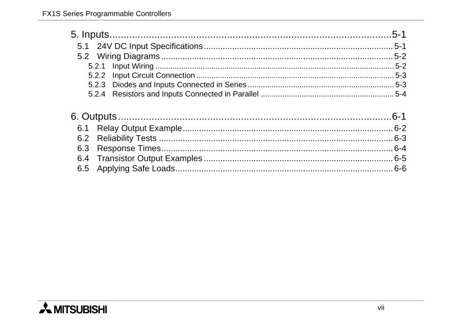
5. Inputs.....................................................................5.1 24V DC Input Specifications..........................................5.2 Wiring Diagrams ............................................................
5.2.1 Input Wiring ....................................................................5.2.2 Input Circuit Connection .................................................5.2.3 Diodes and Inputs Connected in Series .........................5.2.4 Resistors and Inputs Connected in Parallel ...................
6. Outputs..................................................................6.1 Relay Output Example...................................................6.2 Reliability Tests .............................................................6.3 Response Times............................................................6.4 Transistor Output Examples ..........................................6.5 Applying Safe Loads......................................................
FX1S Series Programmable Controllers
viii
................................7-1...................................... 7-1...................................... 7-2...................................... 7-3...................................... 7-3...................................... 7-4...................................... 7-5...................................... 7-6...................................... 7-7...................................... 7-8.................................... 7-11
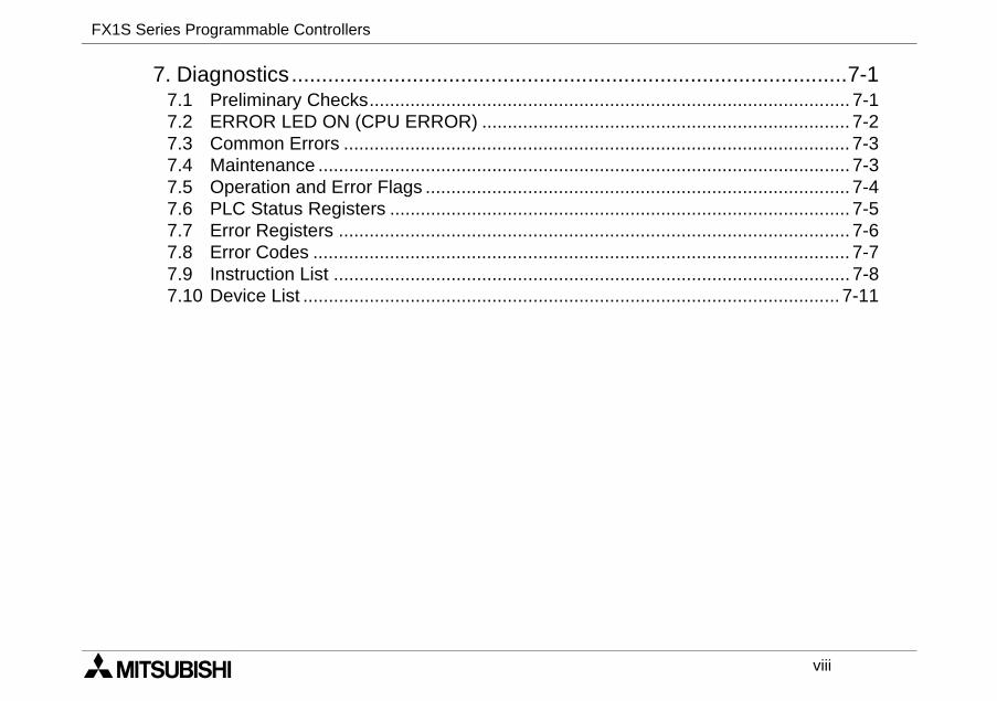
7. Diagnostics............................................................7.1 Preliminary Checks........................................................7.2 ERROR LED ON (CPU ERROR) ..................................7.3 Common Errors .............................................................7.4 Maintenance ..................................................................7.5 Operation and Error Flags .............................................7.6 PLC Status Registers ....................................................7.7 Error Registers ..............................................................7.8 Error Codes ...................................................................7.9 Instruction List ...............................................................7.10 Device List .....................................................................
FX1S Series Programmable Controllers Introduction 1
1 INTRODUCTION
2 TERMINAL LAYOUTS
3 INSTALLATION NOTES
4 POWER SUPPLY
5 INPUTS
6 OUTPUTS
7 DIAGNOSTICS
FX1S Series Programmable Controllers Introduction 1
FX1S Series Programmable Controllers Introduction 1
1-1
the FX1S Series Programmable
DIMENSIONSmm (inches)
MASS (WEIGHT)kg (lbs)
602.4)
90(3.5)
75(3.0)
0.30(0.66)
753.0)
0.40(0.88)
1003.9)
0.45(0.99)
DIMENSIONSmm (inches)
MASS (WEIGHT)kg (lbs)
602.4)
90(3.5)
49(1.9)
0.22(0.48)
753.0)
0.30(0.66)
1003.9)
0.35(0.77)
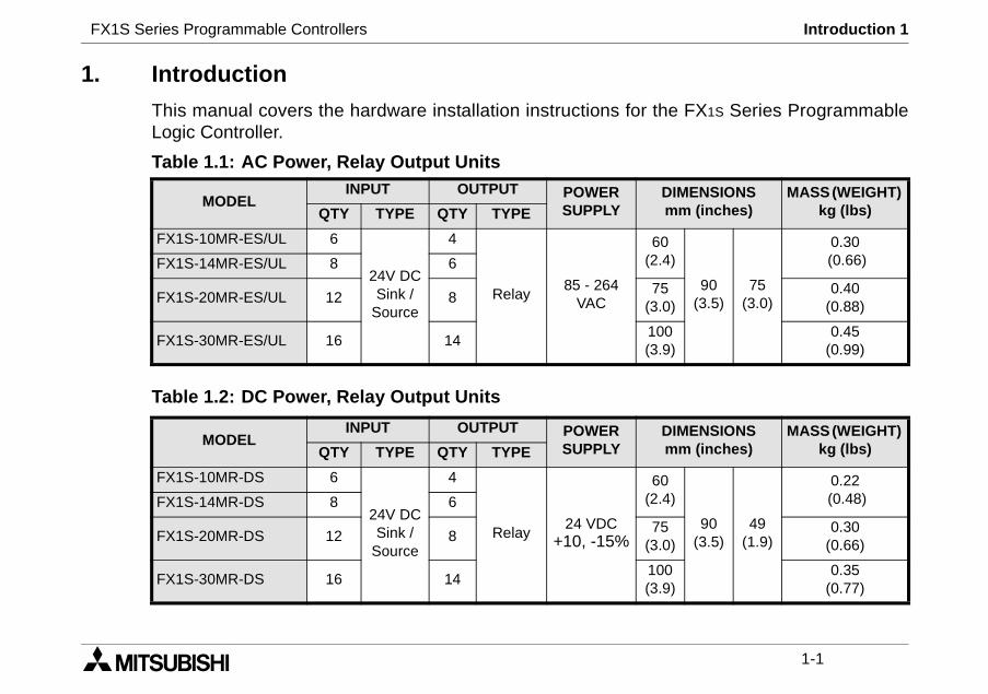
1. Introduction
This manual covers the hardware installation instructions forLogic Controller.
Table 1.1: AC Power, Relay Output Units
Table 1.2: DC Power, Relay Output Units
MODELINPUT OUTPUT POWER
SUPPLYQTY TYPE QTY TYPE
FX1S-10MR-ES/UL 6
24V DCSink /
Source
4
Relay85 - 264
VAC
(FX1S-14MR-ES/UL 8 6
FX1S-20MR-ES/UL 12 8(
FX1S-30MR-ES/UL 16 14(
MODELINPUT OUTPUT POWER
SUPPLYQTY TYPE QTY TYPE
FX1S-10MR-DS 6
24V DCSink /
Source
4
Relay24 VDC
+10, -15%
(FX1S-14MR-DS 8 6
FX1S-20MR-DS 12 8(
FX1S-30MR-DS 16 14(
FX1S Series Programmable Controllers Introduction 1
1-2
DIMENSIONSmm (inches)
MASS(WEIGHT)kg (lbs)
60(2.4)
90(3.5)
49(1.9)
0.22(0.48)
75(3.0)
0.30(0.66)
100(3.9)
0.35(0.77)
DIMENSIONSmm (inches)
MASS(WEIGHT)kg (lbs)
60(2.4)
90(3.5)
75(3.0)
0.3(0.66)
75(3.0)
0.4(0.88)
100(3.9)
0.45(0.99)
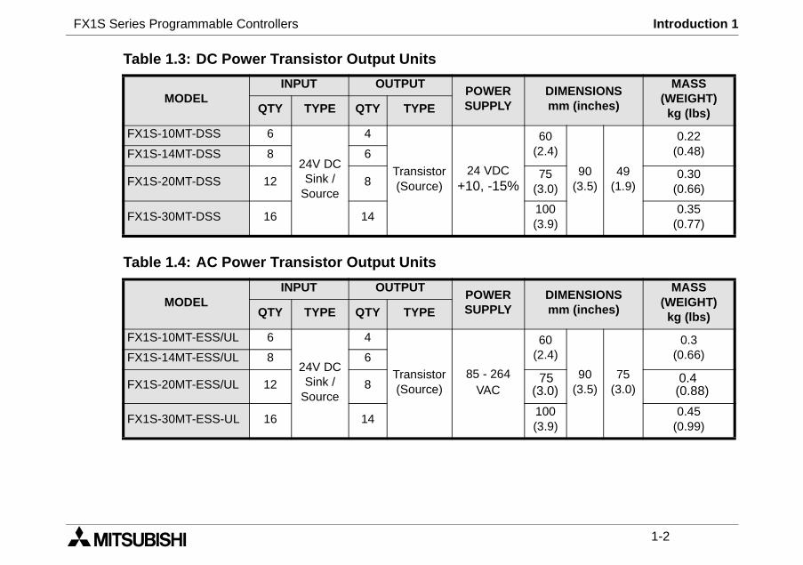
Table 1.3: DC Power Transistor Output Units
Table 1.4: AC Power Transistor Output Units
MODELINPUT OUTPUT
POWERSUPPLYQTY TYPE QTY TYPE
FX1S-10MT-DSS 6
24V DCSink /
Source
4
Transistor(Source)
24 VDC+10, -15%
FX1S-14MT-DSS 8 6
FX1S-20MT-DSS 12 8
FX1S-30MT-DSS 16 14
MODELINPUT OUTPUT
POWERSUPPLYQTY TYPE QTY TYPE
FX1S-10MT-ESS/UL 6
24V DCSink /
Source
4
Transistor(Source)
85 - 264VAC
FX1S-14MT-ESS/UL 8 6
FX1S-20MT-ESS/UL 12 8
FX1S-30MT-ESS-UL 16 14
FX1S Series Programmable Controllers Introduction 1
1-3
) less than the width of the unit.nt.
ail)
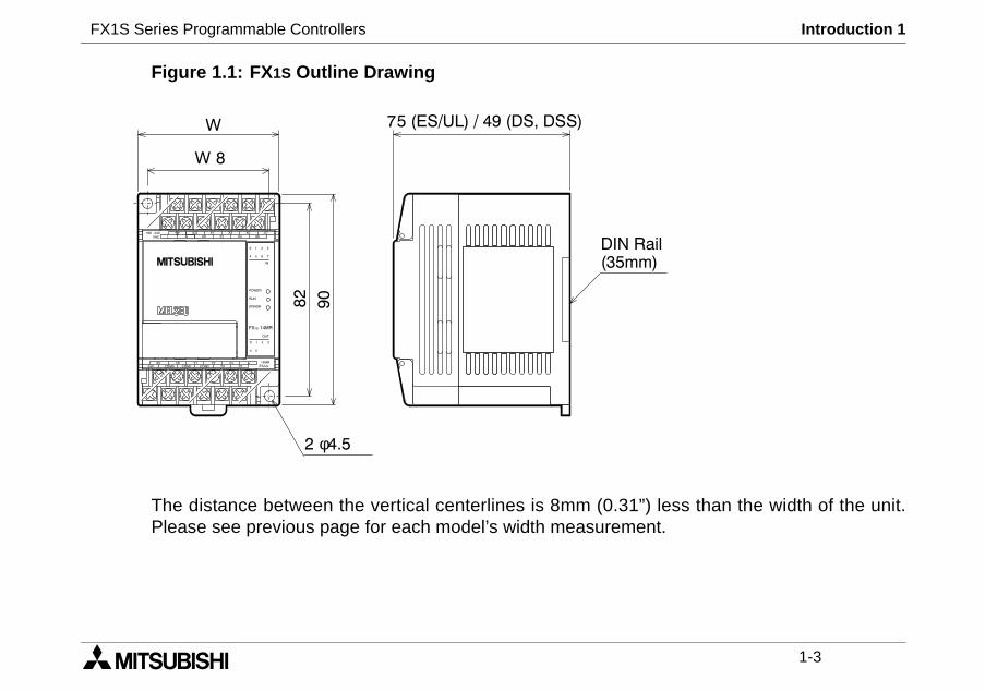
Figure 1.1: FX1S Outline Drawing
The distance between the vertical centerlines is 8mm (0.31”Please see previous page for each model’s width measureme
POWER
ERROR
IN
OUT
4 5
2 3
RUN
0 1
6 754
0 1
2 3
W
W 8
75 (ES/UL) / 49 (DS, DSS)
82
90
2 φ4.5
DIN R(35mm
FX1S 14MR
14MRES/ULY3
0VY5
Y0 Y2Y1COM2COM124V COM0
Y4
X4X5
X6L N X0 X2S/S X7X1 X3100 240
VAC
FX1S Series Programmable Controllers Introduction 1
1-4
pply, Japanese specification
pply, Japanese specification
pply, World specification, Relay Out-Registered
pply, World specification, DC sourceput, CE & UL Registered
upply, World specification, relay
pply, World Specification, DC Sourceput
ered product
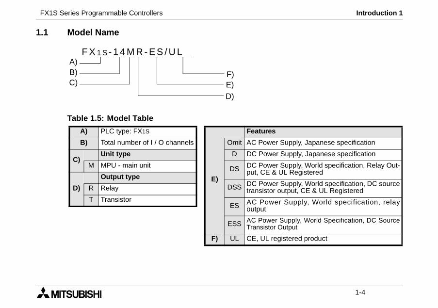
1.1 Model Name
Table 1.5: Model Table
F X 1 S- 1 4 M R - E S / U L
C)
A)B)
D)
F)E)
A) PLC type: FX1S
B) Total number of I / O channels
C)Unit type
M MPU - main unit
D)
Output type
R Relay
T Transistor
E)
Features
Omit AC Power Su
D DC Power Su
DS DC Power Suput, CE & UL
DSS DC Power Sutransistor out
ES AC Power Soutput
ESS AC Power SuTransistor Out
F) UL CE, UL regist
FX1S Series Programmable Controllers Introduction 1
1-5
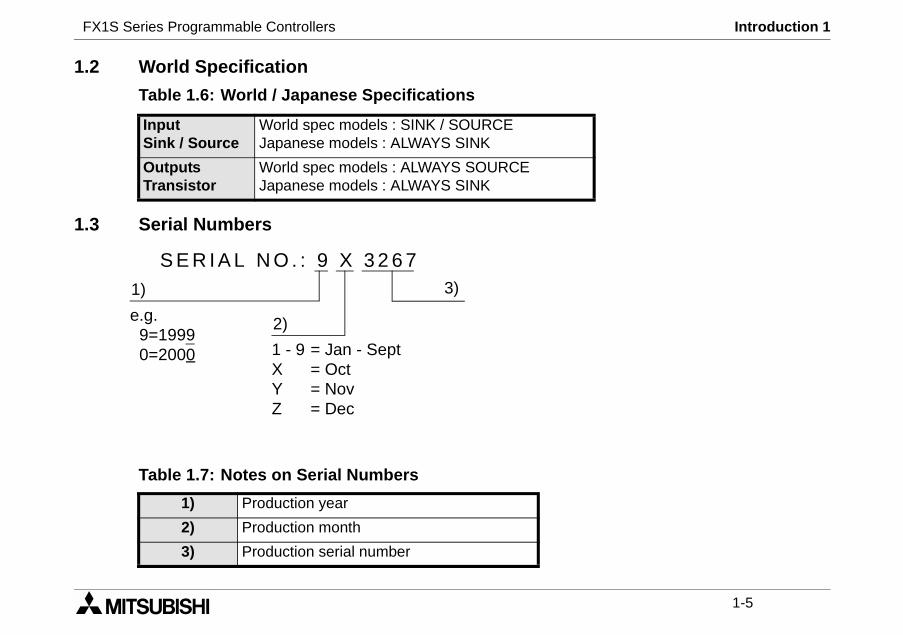
1.2 World Specification
Table 1.6: World / Japanese Specifications
1.3 Serial Numbers
Table 1.7: Notes on Serial Numbers
InputSink / Source
World spec models : SINK / SOURCEJapanese models : ALWAYS SINK
OutputsTransistor
World spec models : ALWAYS SOURCEJapanese models : ALWAYS SINK
1) Production year
2) Production month
3) Production serial number
S E R I A L N O . : 9 X 3 2 6 73)1)
2)e.g.9=19990=2000 1 - 9 = Jan - Sept
X = OctY = NovZ = Dec
FX1S Series Programmable Controllers Introduction 1
1-6
square B or C, and G. To useremove and install next module.
0MT-ESS/UL4MT-ESS/UL0MT-ESS/UL0MT-ESS/UL
0MT-DSS4MT-DSS0MT-DSS0MT-DSS
A
X-40DU-ESX-40DU-TK -ESX-50DU-TKS-E
940GOT
G
H
-CNV-BD
e with0 or above
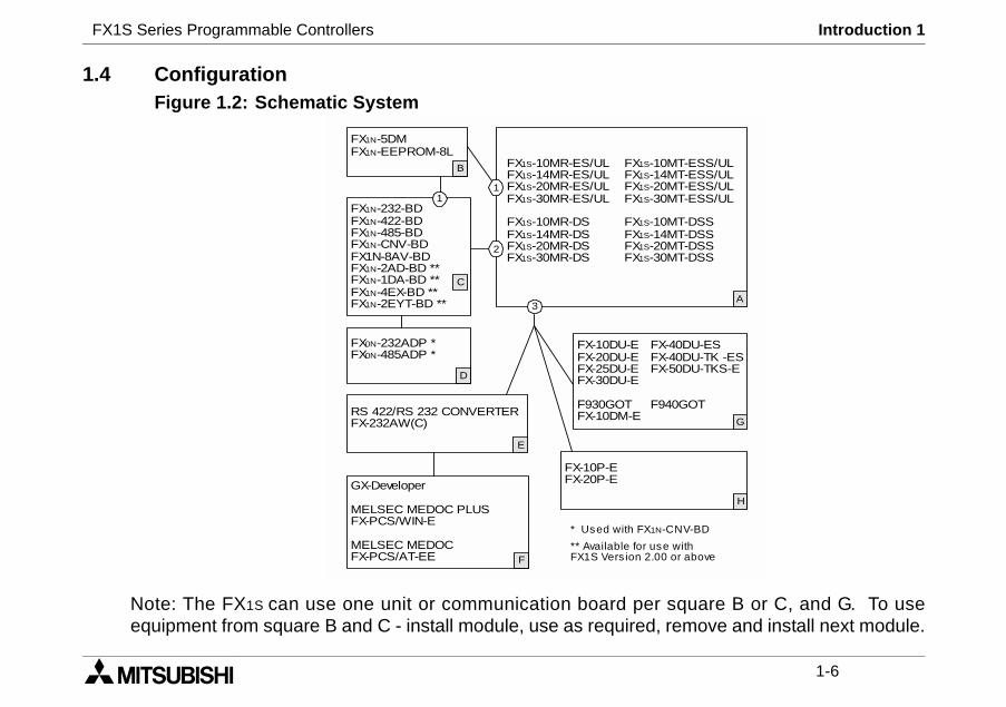
1.4 ConfigurationFigure 1.2: Schematic System
Note: The FX1S can use one unit or communication board perequipment from square B and C - install module, use as required,
FX1S-10MR-ES/UL FX1S-1FX1S-14MR-ES/UL FX1S-1FX1S-20MR-ES/UL FX1S-2FX1S-30MR-ES/UL FX1S-3
FX1S-10MR-DS FX1S-1FX1S-14MR-DS FX1S-1FX1S-20MR-DS FX1S-2FX1S-30MR-DS FX1S-3
FX1N-232-BDFX1N-422-BDFX1N-485-BDFX1N-CNV-BDFX1N-8AV-BDFX1N-2AD-BD **FX1N-1DA-BD **FX1N-4EX-BD **FX1N-2EYT-BD **
C
1
2
3
RS 422/RS 232 CONVERTERFX-232AW(C)
FX-10DU-E FFX-20DU-E FFX-25DU-E FFX-30DU-E
F930GOT FFX-10DM-E
F
GX-Developer
MELSEC MEDOC PLUSFX-PCS/WIN-E
MELSEC MEDOCFX-PCS/AT-EE
E
1
D
FX0N-232ADP *FX0N-485ADP *
B
FX1N-5DMFX1N-EEPROM-8L
FX-10P-EFX-20P-E
* Used with FX1N
** Available for usFX1S Vers ion 2.0
FX1S Series Programmable Controllers Introduction 1
1-7
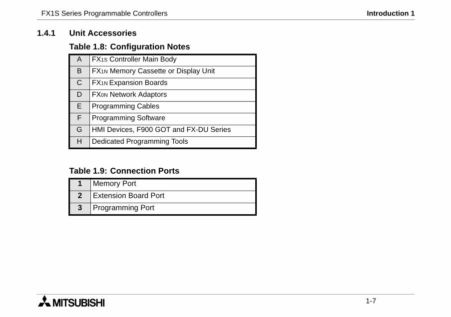
1.4.1 Unit Accessories
Table 1.8: Configuration NotesA FX1S Controller Main Body
B FX1N Memory Cassette or Display Unit
C FX1N Expansion Boards
D FX0N Network Adaptors
E Programming Cables
F Programming Software
G HMI Devices, F900 GOT and FX-DU Series
H Dedicated Programming Tools
Table 1.9: Connection Ports
1 Memory Port
2 Extension Board Port
3 Programming Port
FX1S Series Programmable Controllers Introduction 1
1-8
ries PLC:
or example, the configuration
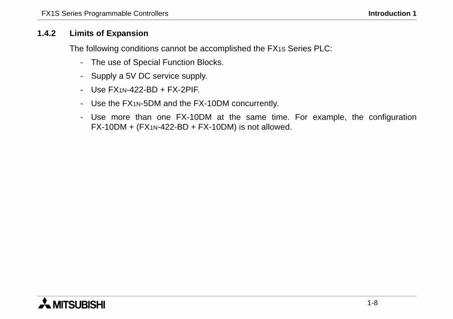
1.4.2 Limits of Expansion
The following conditions cannot be accomplished the FX1S Se
- The use of Special Function Blocks.
- Supply a 5V DC service supply.
- Use FX1N-422-BD + FX-2PIF.
- Use the FX1N-5DM and the FX-10DM concurrently.
- Use more than one FX-10DM at the same time. FFX-10DM + (FX1N-422-BD + FX-10DM) is not allowed.
FX1S Series Programmable Controllers Introduction 1
1-9
~ D2499), and parameter data.
e following data will be saved in
.
ata is not saved!
and the capacitor requires 30
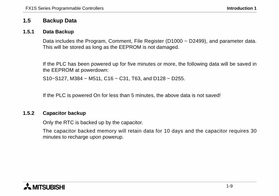
1.5 Backup Data
1.5.1 Data Backup
Data includes the Program, Comment, File Register (D1000This will be stored as long as the EEPROM is not damaged.
If the PLC has been powered up for five minutes or more, ththe EEPROM at powerdown:
S10~S127, M384 ~ M511, C16 ~ C31, T63, and D128 ~ D255
If the PLC is powered On for less than 5 minutes, the above d
1.5.2 Capacitor backup
Only the RTC is backed up by the capacitor.
The capacitor backed memory will retain data for 10 daysminutes to recharge upon powerup.

FX1S Series Programmable Controllers Introduction 1
1-10
FX1S Series Programmable Controllers Terminal layouts 2
1 INTRODUCTION
2 TERMINAL LAYOUTS
3 INSTALLATION NOTES
4 POWER SUPPLY
5 INPUTS
6 OUTPUTS
7 DIAGNOSTICS

FX1S Series Programmable Controllers Terminal layouts 2
FX1S Series Programmable Controllers Terminal Layouts 2
2-1
FX1S product range.aid the creation of wiring dia-
X6
L
5 X7
3COM4
X11 X13X10 X12
Y5Y6
Y7Y4
X4
L
3 X5
4Y5
X7 X11X6
X13 X15X12X10 X14 X16
X17
Y6Y7 Y11
Y10Y14Y12
Y13COM4 Y15COM3
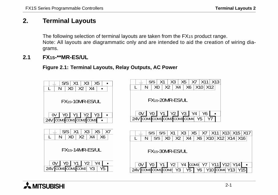
2. Terminal Layouts
The following selection of terminal layouts are taken from theNote: All layouts are diagrammatic only and are intended tograms.
2.1 FX1S-**MR-ES/UL
Figure 2.1: Terminal Layouts, Relay Outputs, AC Power
S/S X1N X0 X4
FX1S-20MR-ES/U
X
0V Y0 Y1 Y2 Y
X3X2
24V COM0 COM1 COM3COM2
L
S/S S/SN S/S X2
FX1S-30MR-ES/U
X
0V Y0 Y1 Y2 Y
X1X0
24V COM0 COM1 Y3COM2
L
S/S X1N X0 X4
FX1S-10MR-ES/UL
X5
0V Y0 Y1 Y2 Y3
X3X2
24V COM0 COM1 COM3COM2
L
S/S X1N X0 X4 X6
FX1S-14MR-ES/UL
X5 X7
0V Y0 Y1 Y2 Y4
X3X2
24V COM0 COM1 Y3 Y5COM2
L
FX1S Series Programmable Controllers Terminal Layouts 2
2-2
X6
DS
5 X7
3COM4
X11 X13X10 X12
Y5Y6
Y7Y4
X4
-DS
3 X5
4Y5
X7 X11X6
X13 X15X12X10 X14 X16
X17
Y6Y7 Y11
Y10Y14Y12
Y13COM4 Y15COM3
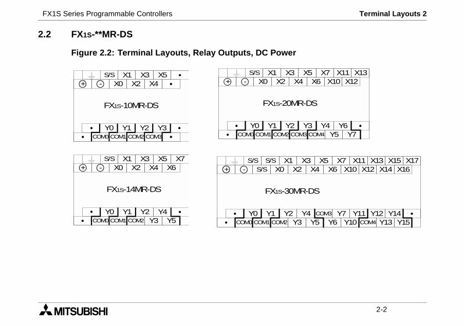
2.2 FX1S-**MR-DS
Figure 2.2: Terminal Layouts, Relay Outputs, DC Power
S/S X1- X0 X4 X6
FX1S-14MR-DS
X5 X7
Y0 Y1 Y2 Y4
X3X2
COM0 COM1 Y3 Y5COM2
+
S/S X1- X0 X4
FX1S-10MR-DS
X5
Y0 Y1 Y2 Y3
X3X2
COM0 COM1 COM3COM2
+
S/S X1- X0 X4
FX1S-20MR-
X
Y0 Y1 Y2 Y
X3X2
COM0 COM1 COM3COM2
+
S/S S/S- S/S X2
FX1S-30MR
X
Y0 Y1 Y2 Y
X1X0
COM0 COM1 Y3COM2
+
FX1S Series Programmable Controllers Terminal Layouts 2
2-3
er
X6
SS
5 X7
3+V4
X11 X13X10 X12
Y5Y6
Y7Y4
X4
DSS
3 X5
4Y5
X7 X11X6
X13 X15X12X10 X14 X16
X17
Y6Y7 Y11
Y10Y14Y12
Y13+V4 Y15+V3
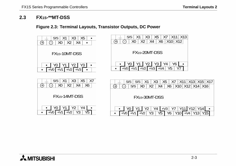
2.3 FX1S-**MT-DSS
Figure 2.3: Terminal Layouts, Transistor Outputs, DC Pow
S/S X1- X0 X4 X6
FX1S-14MT-DSS
X5 X7
Y0 Y1 Y2 Y4
X3X2
+V0 +V1 Y3 Y5+V2
+
S/S X1- X0 X4
FX1S-10MT-DSS
X5
Y0 Y1 Y2 Y3
X3X2
+V0 +V1 +V3+V2
+
S/S X1- X0 X4
FX1S-20MT-D
X
Y0 Y1 Y2 Y
X3X2
+V0 +V1 +V3+V2
+
S/S S/S- S/S X2
FX1S-30MT-
X
Y0 Y1 Y2 Y
X1X0
+V0 +V1 Y3+V2
+
FX1S Series Programmable Controllers Terminal Layouts 2
2-4
er
X4
L
3 X5
4Y5
X7 X11X6
X13 X15X12X10 X14 X16
X17
Y6Y7 Y11
Y10Y14Y12
Y13+V4 Y15+V3
X6
L
5 X7
3+V4
X11 X13X10 X12
Y5Y6
Y7Y4
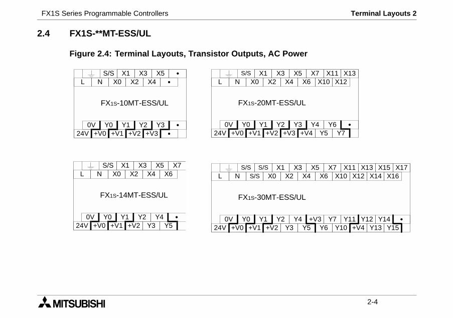
2.4 FX1S-**MT-ESS/UL
Figure 2.4: Terminal Layouts, Transistor Outputs, AC Pow
S/S X1N X0 X4 X6
FX1S-14MT-ESS/UL
X5 X7
0V Y0 Y1 Y2 Y4
X3X2
24V +V0 +V1 Y3 Y5+V2
LS/S S/S
N S/S X2
FX1S-30MT-ESS/U
X
0V Y0 Y1 Y2 Y
X1X0
24V +V0 +V1 Y3+V2
L
S/S X1N X0 X4
FX1S-10MT-ESS/UL
X5
0V Y0 Y1 Y2 Y3
X3X2
24V +V0 +V1 +V3+V2
LS/S X1
N X0 X4
FX1S-20MT-ESS/U
X
0V Y0 Y1 Y2 Y
X3X2
24V +V0 +V1 +V3+V2
L
FX1S Series Programmable Controllers Installation notes 3
1 INTRODUCTION
2 TERMINAL LAYOUTS
3 INSTALLATION NOTES
4 POWER SUPPLY
5 INPUTS
6 OUTPUTS
7 DIAGNOSTICS
FX1S Series Programmable Controllers Installation notes 3
FX1S Series Programmable Controllers Installation Notes 3
3-1
fe and easy. When the productsally, they must be installed in atalled in accordance to the local
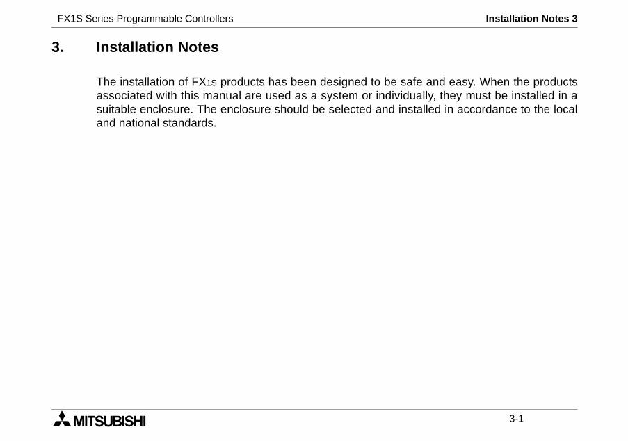
3. Installation Notes
The installation of FX1S products has been designed to be saassociated with this manual are used as a system or individusuitable enclosure. The enclosure should be selected and insand national standards.
FX1S Series Programmable Controllers Installation Notes 3
3-2
ting Clip
ment port - Memory Cassette, FX1N-8AV, and CNV BDs, FX1N-5DM
ort
ts. D8030 read from VR1, the top trimd from VR2, the bottom trim pot.
h
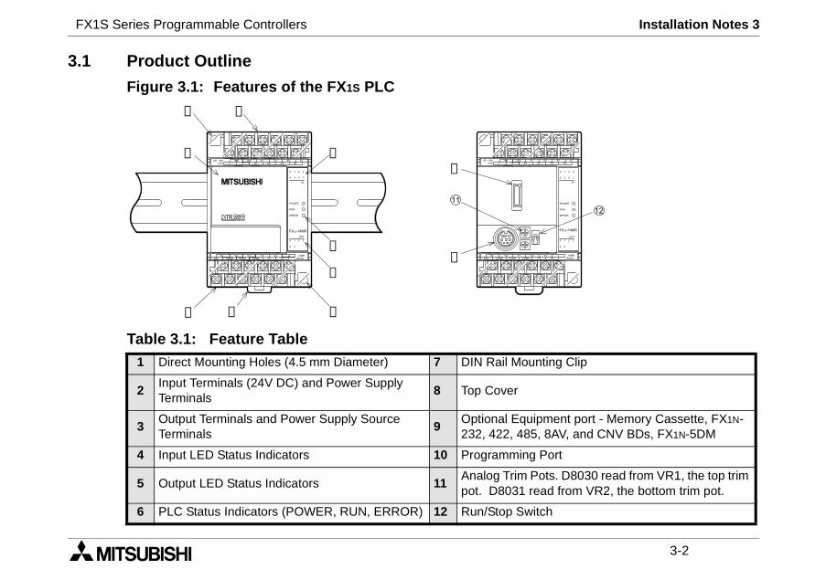
3.1 Product Outline
Figure 3.1: Features of the FX1S PLC
Table 3.1: Feature Table1 Direct Mounting Holes (4.5 mm Diameter) 7 DIN Rail Moun
2Input Terminals (24V DC) and Power SupplyTerminals
8 Top Cover
3Output Terminals and Power Supply SourceTerminals
9Optional Equip232, 422, 485,
4 Input LED Status Indicators 10 Programming P
5 Output LED Status Indicators 11Analog Trim Popot. D8031 rea
6 PLC Status Indicators (POWER, RUN, ERROR) 12 Run/Stop Switc
➈
➀ ➁
➇
➂ ➆
➄
➃
➅➉
➀
FX1S Series Programmable Controllers Installation Notes 3
3-3
ort.
ters.
eripheral.
RUN input terminal. Please
ermined by the most recently
is made from a personalP switch by first moving the
s Table
INPUTINAL
FX1S MPUSTATUS
RUN
RUN
STOP
RUN
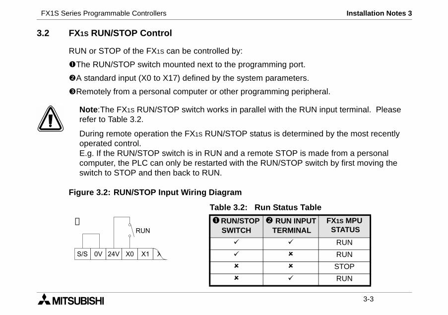
3.2 FX1S RUN/STOP Control
RUN or STOP of the FX1S can be controlled by:
The RUN/STOP switch mounted next to the programming p
A standard input (X0 to X17) defined by the system parame
Remotely from a personal computer or other programming p
Note:The FX1S RUN/STOP switch works in parallel with therefer to Table 3.2.
During remote operation the FX1S RUN/STOP status is detoperated control.E.g. If the RUN/STOP switch is in RUN and a remote STOPcomputer, the PLC can only be restarted with the RUN/STOswitch to STOP and then back to RUN.
Figure 3.2: RUN/STOP Input Wiring Diagram
Table 3.2: Run Statu
RUN/STOPSWITCH
RUNTERM
➁
FX1S Series Programmable Controllers Installation Notes 3
3-4
tion
ation
ation
mm Half Amplitude
/s2 Accelerationes (80 min in each direction)
mm Half Amplitude
/s2 Accelerationes (80 min in each direction)
ration, Action Time: 11 msction X, Y, and Z
sted by noise simulator
, tested between all points, terminals,
tested between all points, terminals
er terminals and ground
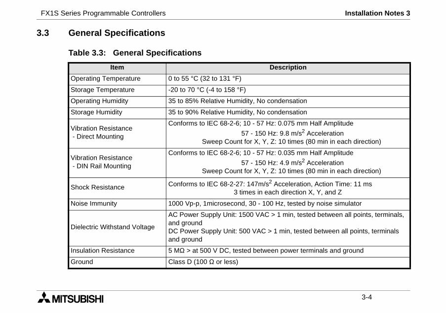
3.3 General Specifications
Table 3.3: General Specifications
Item Descrip
Operating Temperature 0 to 55 °C (32 to 131 °F)
Storage Temperature -20 to 70 °C (-4 to 158 °F)
Operating Humidity 35 to 85% Relative Humidity, No condens
Storage Humidity 35 to 90% Relative Humidity, No condens
Vibration Resistance- Direct Mounting
Conforms to IEC 68-2-6; 10 - 57 Hz: 0.075
57 - 150 Hz: 9.8 mSweep Count for X, Y, Z: 10 tim
Vibration Resistance- DIN Rail Mounting
Conforms to IEC 68-2-6; 10 - 57 Hz: 0.035
57 - 150 Hz: 4.9 mSweep Count for X, Y, Z: 10 tim
Shock Resistance Conforms to IEC 68-2-27: 147m/s2 Accele3 times in each dire
Noise Immunity 1000 Vp-p, 1microsecond, 30 - 100 Hz, te
Dielectric Withstand Voltage
AC Power Supply Unit: 1500 VAC > 1 minand groundDC Power Supply Unit: 500 VAC > 1 min,and ground
Insulation Resistance 5 MΩ > at 500 V DC, tested between pow
Ground Class D (100 Ω or less)
FX1S Series Programmable Controllers Installation Notes 3
3-5
ever mount them to the floor or
wing conditions: excessive orr rain, excessive heat, regular
it during installation e.g. cute the protective paper band to
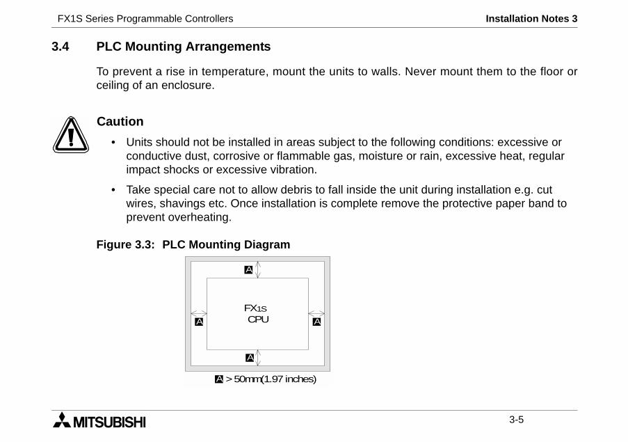
3.4 PLC Mounting Arrangements
To prevent a rise in temperature, mount the units to walls. Nceiling of an enclosure.
Caution
• Units should not be installed in areas subject to the folloconductive dust, corrosive or flammable gas, moisture oimpact shocks or excessive vibration.
• Take special care not to allow debris to fall inside the unwires, shavings etc. Once installation is complete removprevent overheating.
Figure 3.3: PLC Mounting Diagram
FX1SCPU
A
A
AA
>50mm(1.97 inches)A
FX1S Series Programmable Controllers Installation Notes 3
3-6
22). To release, pull the spring
uld be fitted with insulated crimptightened to between 0.5 to 0.8se connection from causing a
!"#$!%&'()*")(+!%,-
3.5 DIN Rail Mounting
Units can be snap mounted to 35mm DIN rail (DIN EN 500loaded clips away from the rail and slide the unit off and up.
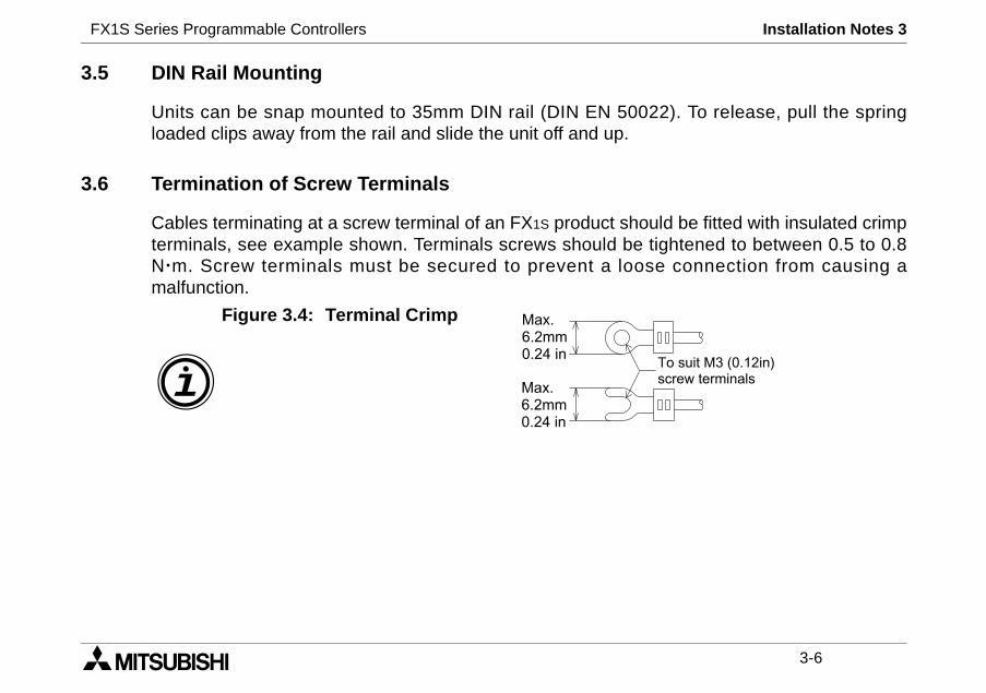
3.6 Termination of Screw Terminals
Cables terminating at a screw terminal of an FX1S product shoterminals, see example shown. Terminals screws should beNm. Screw terminals must be secured to prevent a loomalfunction.
,.$$++$!%
,.$$++$!%
Figure 3.4: Terminal Crimp
FX1S Series Programmable Controllers Installation Notes 3
3-7
cial function board to the FX1S
l unit, please see the relevant
special function board. Only onerds.
quipment board.r port.
r.
B).
crews C).
removing section D)’ to expose)
ew E).
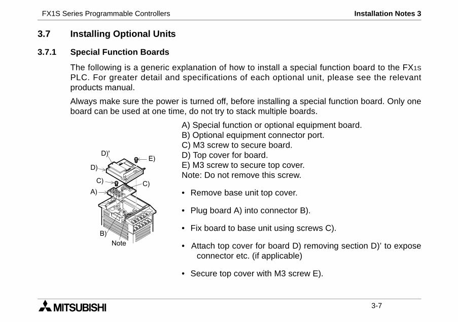
3.7 Installing Optional Units
3.7.1 Special Function Boards
The following is a generic explanation of how to install a spePLC. For greater detail and specifications of each optionaproducts manual.
Always make sure the power is turned off, before installing aboard can be used at one time, do not try to stack multiple boa
A) Special function or optional eB) Optional equipment connectoC) M3 screw to secure board.D) Top cover for board.E) M3 screw to secure top coveNote: Do not remove this screw.
• Remove base unit top cover.
• Plug board A) into connector
• Fix board to base unit using s
• Attach top cover for board D)connector etc. (if applicable
• Secure top cover with M3 scr
&
/&
&
0&
0&1&
")
&
FX1S Series Programmable Controllers Installation Notes 3
3-8
5DM.
anual.
&
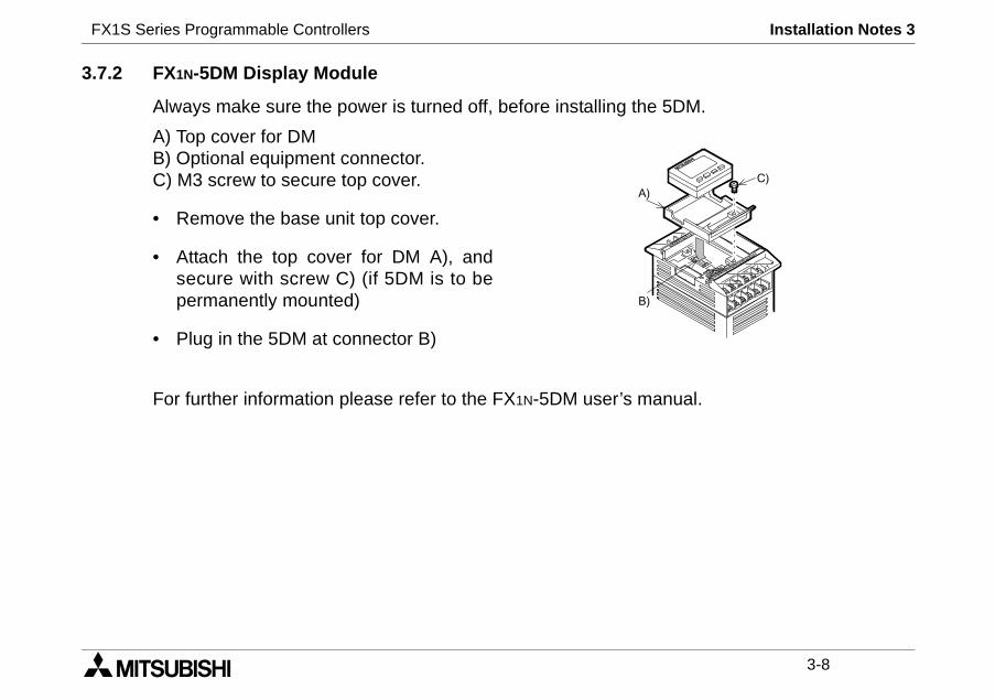
3.7.2 FX1N-5DM Display Module
Always make sure the power is turned off, before installing the
A) Top cover for DMB) Optional equipment connector.C) M3 screw to secure top cover.
• Remove the base unit top cover.
• Attach the top cover for DM A), andsecure with screw C) (if 5DM is to bepermanently mounted)
• Plug in the 5DM at connector B)
For further information please refer to the FX1N-5DM user’s m
/&
&
FX1S Series Programmable Controllers Power supply 4
1 INTRODUCTION
2 TERMINAL LAYOUTS
3 INSTALLATION NOTES
4 POWER SUPPLY
5 INPUTS
6 OUTPUTS
7 DIAGNOSTICS

FX1S Series Programmable Controllers Power supply 4
FX1S Series Programmable Controllers Power Supply 4
4-1
easy. If during the installation ofontact a professional electricianthe installation site.
output signals or allow them to
hem to share the same trunkingr insulated with regard to high
e consideration for voltage drop
cted to the “L” terminal and theOT connect the “Live” wire to the
erup.
4. Power Supply
4.1 Wiring Techniques
The wiring of FX1S products has been designed to be safe andthese product or associated products concern is felt, please cwho is trained to the local and national standards applicable to
4.2 Wiring Cautions
• Do not run input signals in the same multicore cable asshare the same wire.
• Do not lay I/O signal cables next to power cables or allow tduct. Low voltage cables should be reliably separated ovoltage cabling.
• Where I/O signal lines are used over an extended distancand noise interference should be made.
4.3 Power Supply
When wiring AC supplies the “Live” cable should be conne“Neutral” cable should be connected to the “N” terminal. Do N“N” terminal, the user might receive a dangerous shock on pow
FX1S Series Programmable Controllers Power Supply 4
4-2
DSS
UL, ESS/UL
1S-20M FX1S-30M, 50/60 Hz
will continue operation.ill shut down×0.79 inches)for 5msfor 5ms
20W 21W
1S-20M FX1S-30M-15%
ill continue operation.ill shut down
1 ms7W 8W
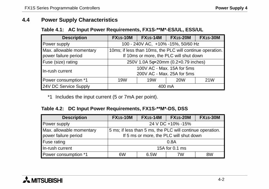
4.4 Power Supply Characteristics
*1 Includes the input current (5 or 7mA per point).
Table 4.2: DC Input Power Requirements, FX1S-**M*-DS,
Table 4.1: AC Input Power Requirements, FX1S-**M*-ES/
Description FX1S-10M FX1S-14M FXPower supply 100 - 240V AC, +10% -15%Max. allowable momentarypower failure period
10ms; if less than 10ms, the PLCIf 10ms or more, the PLC w
Fuse (size) rating 250V 1.0A 5φ×20mm (0.2
In-rush current100V AC - Max. 15A200V AC - Max. 25A
Power consumption *1 19W 19W24V DC Service Supply 400 mA
Description FX1S-10M FX1S-14M FXPower supply 24 V DC +10%Max. allowable momentarypower failure period
5 ms; if less than 5 ms, the PLC wIf 5 ms or more, the PLC w
Fuse rating 0.8AIn-rush current 15A for 0.Power consumption *1 6W 6.5W
FX1S Series Programmable Controllers Power Supply 4
4-3
ly 100 - 240V AC, +10% -15%,
ctor or Fuse
stop
ly switch
pilot indicator
ly for loads
resistor 100Ω or less (class D)
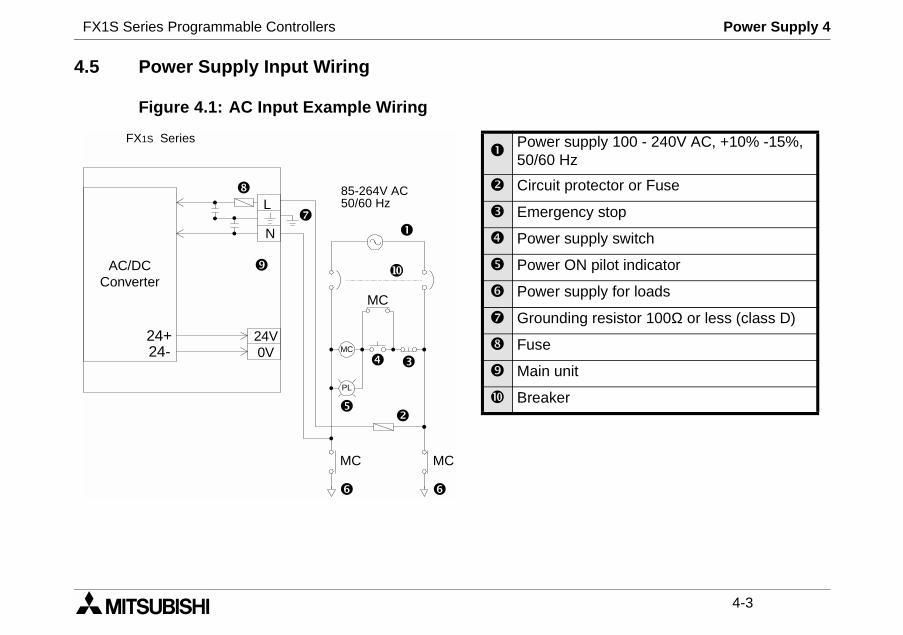
4.5 Power Supply Input Wiring
Figure 4.1: AC Input Example Wiring
AC/DCConverter
FX1S Series
MC
PL
MC
MC MC
L
N
85-264V AC50/60 Hz
24V24- 0V24+
Power supp50/60 Hz
Circuit prote
Emergency
Power supp
Power ON
Power supp
Grounding
Fuse
Main unit
Breaker
FX1S Series Programmable Controllers Power Supply 4
4-4
ly 24V DC, +10% -15%
ctor or Fuse
stop
ly switch
ilot indicator
ly for loads
esistor 100Ω or less (class D)
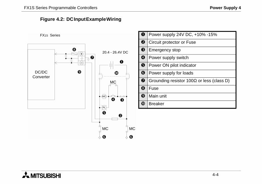
Figure 4.2: DCInputExampleWiring
DC/DCConverter
FX1S Series
MC
PL
MC
MC MC
+
_
20.4 - 26.4V DC
Power supp
Circuit prote
Emergency
Power supp
Power ON p
Power supp
Grounding r
Fuse
Main unit
Breaker
FX1S Series Programmable Controllers Power Supply 4
4-5
t. Ground resistance must benot be connected to the sameut if a proper ground cannot be
rounded.
4.6 Earthing / Grounding
Use a cable at least 0.2mm2 (AWG24) to ground equipmenless than 100Ω (class D). Note that the ground cable mustground as the power circuits. Grounding is recommended bprovided the PLC will still operate correctly without being g

FX1S Series Programmable Controllers Power Supply 4
4-6
FX1S Series Programmable Controllers Inputs 5
1 INTRODUCTION
2 TERMINAL LAYOUTS
3 INSTALLATION NOTES
4 POWER SUPPLY
5 INPUTS
6 OUTPUTS
7 DIAGNOSTICS

FX1S Series Programmable Controllers Inputs 5
FX1S Series Programmable Controllers Inputs 5
5-1
A
use.
5. Inputs
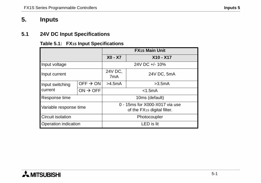
5.1 24V DC Input Specifications
Table 5.1: FX1S Input SpecificationsFX1S Main Unit
X0 - X7 X10 - X17
Input voltage 24V DC +/- 10%
Input current24V DC,
7mA24V DC, 5m
Input switchingcurrent
OFF ON >4.5mA >3.5mA
ON OFF <1.5mA
Response time 10ms (default)
Variable response time0 - 15ms for X000-X017 via
of the FX1S digital filter
Circuit isolation Photocoupler
Operation indication LED is lit
FX1S Series Programmable Controllers Inputs 5
5-2
S/S X0 X1 X2
X1S-**M*-ES/UL, ESS/UL
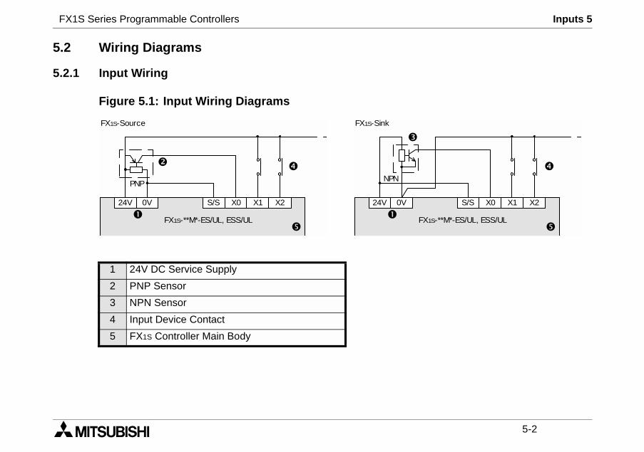
5.2 Wiring Diagrams
5.2.1 Input Wiring
Figure 5.1: Input Wiring Diagrams
1 24V DC Service Supply
2 PNP Sensor
3 NPN Sensor
4 Input Device Contact
5 FX1S Controller Main Body
24V 0V
NPN
F
FX1S-SinkFX1S-Source
24V 0V S/S X0 X1 X2
PNP
FX1S-**M*-ES/UL, ESS/UL
FX1S Series Programmable Controllers Inputs 5
5-3
24V
X24VDC
0VS/S
/S)
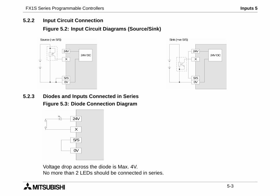
5.2.2 Input Circuit Connection
Figure 5.2: Input Circuit Diagrams (Source/Sink)
5.2.3 Diodes and Inputs Connected in SeriesFigure 5.3: Diode Connection Diagram
Voltage drop across the diode is Max. 4V.No more than 2 LEDs should be connected in series.
24V
X24VDC
0VS/S
Source (-veS/S) Sink (+veS
24V
X
0V
S/S
FX1S Series Programmable Controllers Inputs 5
5-4
than the stated value, then add
akage is greater than the stated
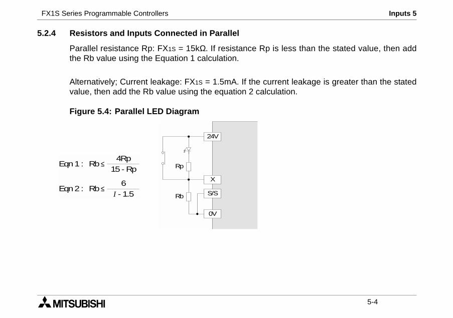
5.2.4 Resistors and Inputs Connected in Parallel
Parallel resistance Rp: FX1S = 15kΩ. If resistance Rp is lessthe Rb value using the Equation 1 calculation.
Alternatively; Current leakage: FX1S = 1.5mA. If the current levalue, then add the Rb value using the equation 2 calculation.
Figure 5.4: Parallel LED Diagram
24V
X
0V
S/S
Rp
Rb
Rb ≤4Rp
15 - RpEqn1 :
Rb ≤6
I - 1.5Eqn2 :
FX1S Series Programmable Controllers Outputs 6
1 INTRODUCTION
2 TERMINAL LAYOUTS
3 INSTALLATION NOTES
4 POWER SUPPLY
5 INPUTS
6 OUTPUTS
7 DIAGNOSTICS

FX1S Series Programmable Controllers Outputs 6
FX1S Series Programmable Controllers Outputs 6
6-1
OM
-
Y1 only)
; <5µs (Y0,Y1 only)
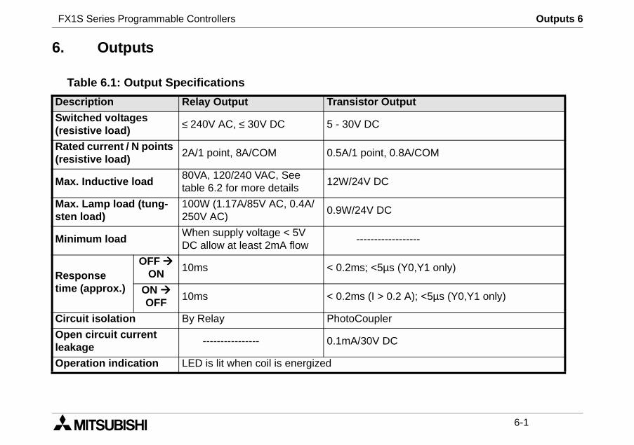
6. Outputs
Table 6.1: Output Specifications
Description Relay Output Transistor Output
Switched voltages(resistive load)
≤ 240V AC, ≤ 30V DC 5 - 30V DC
Rated current / N points(resistive load)
2A/1 point, 8A/COM 0.5A/1 point, 0.8A/C
Max. Inductive load80VA, 120/240 VAC, Seetable 6.2 for more details
12W/24V DC
Max. Lamp load (tung-sten load)
100W (1.17A/85V AC, 0.4A/250V AC)
0.9W/24V DC
Minimum loadWhen supply voltage < 5VDC allow at least 2mA flow
-----------------
Responsetime (approx.)
OFF
ON10ms < 0.2ms; <5µs (Y0,
ON
OFF10ms < 0.2ms (I > 0.2 A)
Circuit isolation By Relay PhotoCoupler
Open circuit currentleakage
---------------- 0.1mA/30V DC
Operation indication LED is lit when coil is energized
FX1S Series Programmable Controllers Outputs 6
6-2
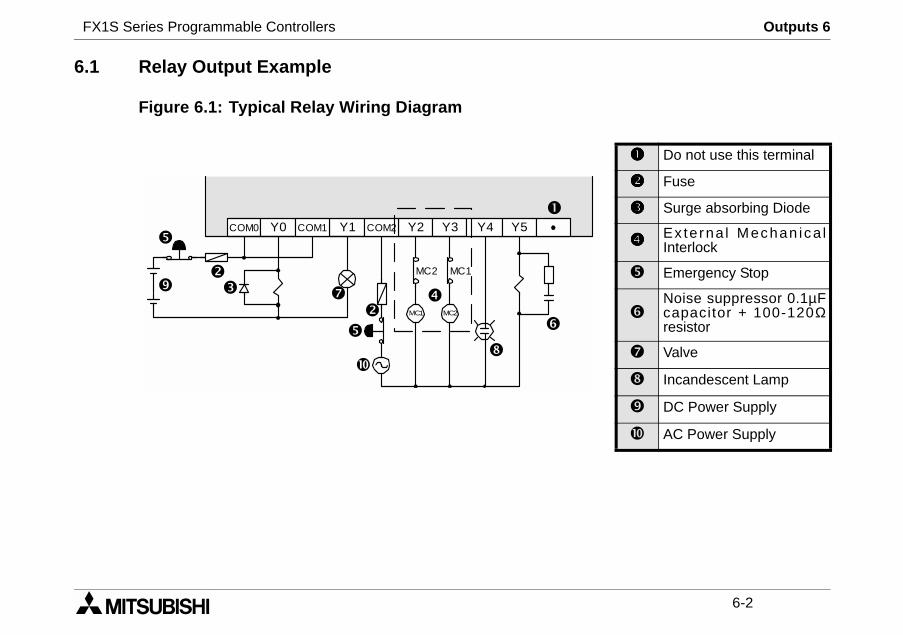
Do not use this terminal
Fuse
Surge absorbing Diode
Ex terna l Mechan ica lInterlock
Emergency Stop
Noise suppressor 0.1µFcapacitor + 100-120Ωresistor
Valve
Incandescent Lamp
DC Power Supply
AC Power Supply
6.1 Relay Output Example
Figure 6.1: Typical Relay Wiring Diagram
COM0 Y0 Y1 Y2 Y3COM1 COM2 Y4 Y5
MC1 MC2
MC2 MC1
FX1S Series Programmable Controllers Outputs 6
6-3
OFF test cycle. Please note thatcontacts service life. The ratedvalve is 500,000 operations at
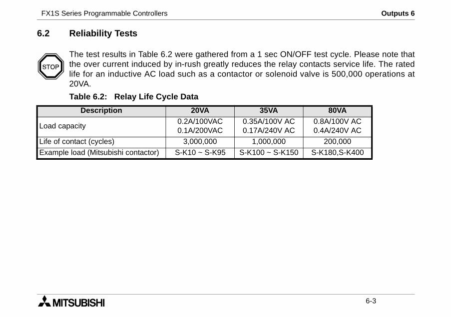
80VA0.8A/100V AC0.4A/240V AC
200,000
S-K180,S-K400
6.2 Reliability Tests
The test results in Table 6.2 were gathered from a 1 sec ON/the over current induced by in-rush greatly reduces the relaylife for an inductive AC load such as a contactor or solenoid20VA.
Table 6.2: Relay Life Cycle Data
Description 20VA 35VA
Load capacity0.2A/100VAC0.1A/200VAC
0.35A/100V AC0.17A/240V AC
Life of contact (cycles) 3,000,000 1,000,000
Example load (Mitsubishi contactor) S-K10 ~ S-K95 S-K100 ~ S-K150
FX1S Series Programmable Controllers Outputs 6
6-4
re 6.2. If a response time of 0.5y' resistor and ensure the signal
wing characteristics:
must be used.
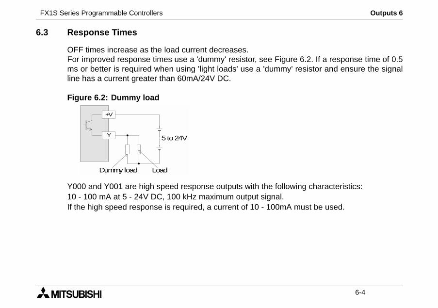
6.3 Response Times
OFF times increase as the load current decreases.For improved response times use a 'dummy' resistor, see Figums or better is required when using 'light loads' use a 'dummline has a current greater than 60mA/24V DC.
Figure 6.2: Dummy load
Y000 and Y001 are high speed response outputs with the follo10 - 100 mA at 5 - 24V DC, 100 kHz maximum output signal.If the high speed response is required, a current of 10 - 100mA
5to24VY
+V
Dummy load Load
FX1S Series Programmable Controllers Outputs 6
6-5
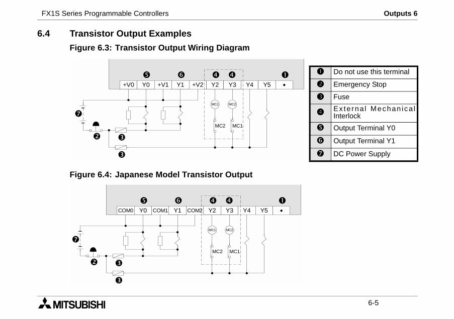
Do not use this terminal
Emergency Stop
Fuse
Ex terna l Mechan ica lInterlock
Output Terminal Y0
Output Terminal Y1
DC Power Supply
6.4 Transistor Output Examples
Figure 6.3: Transistor Output Wiring Diagram
Figure 6.4: Japanese Model Transistor Output
+V0 Y0 Y1 Y2 Y3+V1 +V2 Y4 Y5
MC1 MC2
MC2 MC1
COM0 Y0 Y1 Y2 Y3COM1 COM2 Y4 Y5
MC1 MC2
MC2 MC1
FX1S Series Programmable Controllers Outputs 6
6-6
output, see previous figures.irection control of a motor),PLC's sequencing alone.rcuits, see previous figures.
6.5 Applying Safe Loads
Ensure all loads are applied to the same side of each PLCLoads which should NEVER simultaneously operate (e.g. dbecause of a safety critical situation, should not rely on theMechanical interlocks MUST be fitted to all safety critical ci
FX1S Series Programmable Controllers Diagnostics 7
1 INTRODUCTION
2 TERMINAL LAYOUTS
3 INSTALLATION NOTES
4 POWER SUPPLY
5 INPUTS
6 OUTPUTS
7 DIAGNOSTICS

FX1S Series Programmable Controllers Diagnostics 7
FX1S Series Programmable Controllers Diagnostics 7
7-1
orrectly.
Down load a smalle it has been writtenrcibly turn ON/OFF
k the previouslyare complete take
any live or
7. Diagnostics
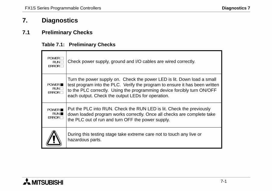
7.1 Preliminary Checks
Table 7.1: Preliminary Checks
Check power supply, ground and I/O cables are wired c
Turn the power supply on. Check the power LED is lit.test program into the PLC. Verify the program to ensurto the PLC correctly. Using the programming device foeach output. Check the output LEDs for operation.
Put the PLC into RUN. Check the RUN LED is lit. Checdown loaded program works correctly. Once all checksthe PLC out of run and turn OFF the power supply.
During this testing stage take extreme care not to touchhazardous parts.
POWERRUN
ERROR
POWERRUN
ERROR
POWERRUN
ERROR
FX1S Series Programmable Controllers Diagnostics 7
7-2
s the memory cassette beentalled or removed while the units still powered On?
amming error. Ensure the earth/correctly rewired.
A
PLC M/C PLC M/C
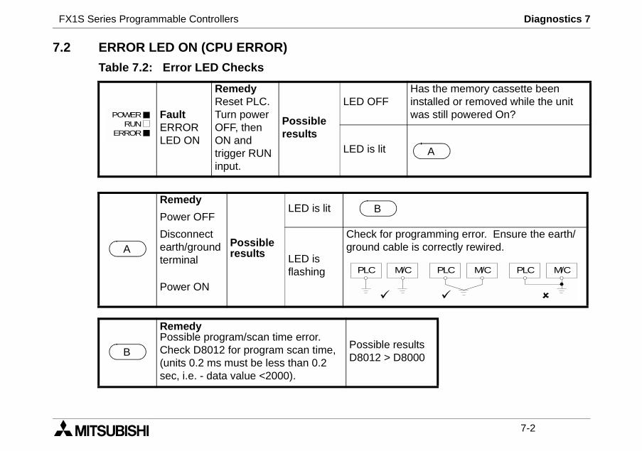
7.2 ERROR LED ON (CPU ERROR)
Table 7.2: Error LED Checks
FaultERRORLED ON
RemedyReset PLC.Turn powerOFF, thenON andtrigger RUNinput.
Possibleresults
LED OFFHainswa
LED is lit
Remedy
Possibleresults
LED is litPower OFF
Disconnectearth/groundterminal LED is
flashing
Check for progrground cable is
Power ON
RemedyPossible program/scan time error.Check D8012 for program scan time,(units 0.2 ms must be less than 0.2sec, i.e. - data value <2000).
Possible resultsD8012 > D8000
POWERRUN
ERROR
A
B
PLC M/C
B
FX1S Series Programmable Controllers Diagnostics 7
7-3
ting range.
taken by one program scan.
ue to vibration).
7.3 Common Errors
- Corroded contact points at some point in an I/O line.
- An I/O device has been used outside its specified opera
- An input signal occurs in a shorter time period than that
7.4 Maintenance
- Check interior temperature of the panel.
- Check panel air filters if fitted.
- Check for loosening of terminals or mounting facilities (d
FX1S Series Programmable Controllers Diagnostics 7
7-4
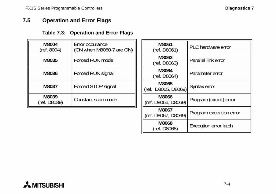
Parallel link error
Parameter error
Syntaxerror
Program(circuit) error
Programexecutionerror
Executionerror latch
9)
9)
9)
PLChardwareerror
7.5 Operation and Error Flags
Table 7.3: Operation and Error Flags
M8063(ref. D8063)
M8064(ref. D8064)
M8065(ref. D8065, D806
M8066(ref. D8066, D806
M8067(ref. D8067, D806
M8068(ref. D8068)
M8061(ref. D8061)
M8004(ref. 8004)
M8035
M8036
M8037
M8039(ref. D8039)
Error occurance(ONwhenM8060-7areON)
ForcedRUNmode
ForcedRUNsignal
ForcedSTOPsignal
Constant scanmode
FX1S Series Programmable Controllers Diagnostics 7
7-5
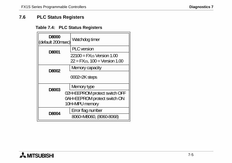
7.6 PLC Status Registers
Table 7.4: PLC Status Registers
02H=EEPROMprotect switchOFF0AH=EEPROMprotect switchON10H=MPUmemory
D8000(default 200msec)
D8001
D8002
D8003
D8004
Watchdog timer
PLCversion
22100=FX1S Version1.0022=FX1S, 100=Version1.00
Memory capacity
0002=2Ksteps
Memory type
Error flagnumber8060=M8060, (8060-8068)
FX1S Series Programmable Controllers Diagnostics 7
7-6
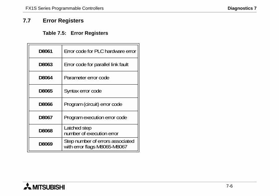
7.7 Error Registers
Table 7.5: Error Registers
D8061
D8063
D8064
D8065
D8066
D8067
D8068
D8069
Error codefor PLChardwareerror
Error codefor parallel link fault
Parameter error code
Syntaxerror code
Program(circuit) error code
Programexecutionerror code
Latchedstepnumber of executionerror
Stepnumber of errors associatedwitherror flagsM8065-M8067
FX1S Series Programmable Controllers Diagnostics 7
7-7
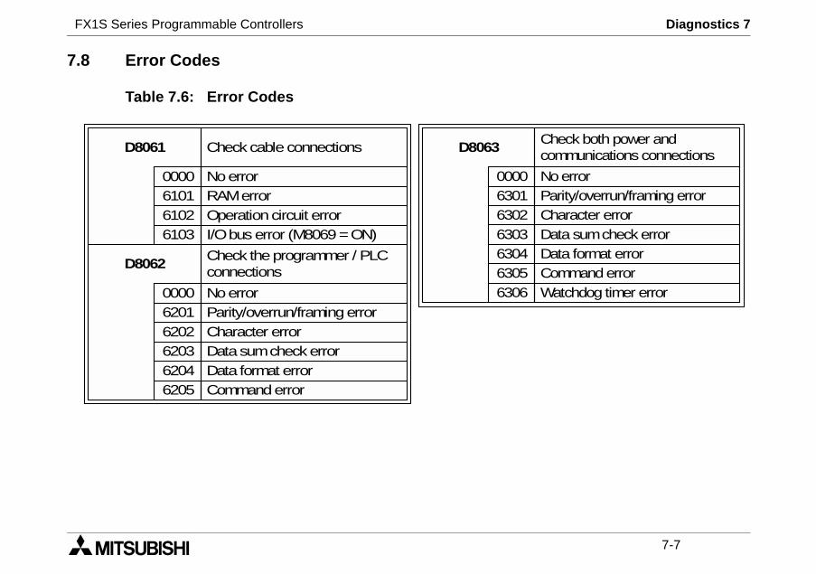
Check both power andcommunications connections
NoerrorParity/overrun/framing errorCharacter errorData sumcheck errorData format errorCommand errorWatchdog timer error
7.8 Error Codes
Table 7.6: Error Codes
D8061 Checkcableconnections
Noerror0000RAMerror6101Operationcircuit error6102I/Obus error (M8069=ON)6103
D8062Check theprogrammer / PLCconnections
Noerror0000Parity/overrun/framingerror6201Character error6202Datasumcheckerror6203Data format error6204Commanderror6205
D8063
0000630163026303630463056306
FX1S Series Programmable Controllers Diagnostics 7
7-8
6FEND
WAND
SPDALT
VRSC
7WDT
WOR
PLSYRAMP
8FORBCDWXORSFWR
PWM
PID
9NEXTBIN
SFRD
PLSR
ZRN
TRD
OR≥AND≠LD<
PLSV
TWR
AND≤
DRVI
AND≥LD≠
DRVA
HOUR
LD≤
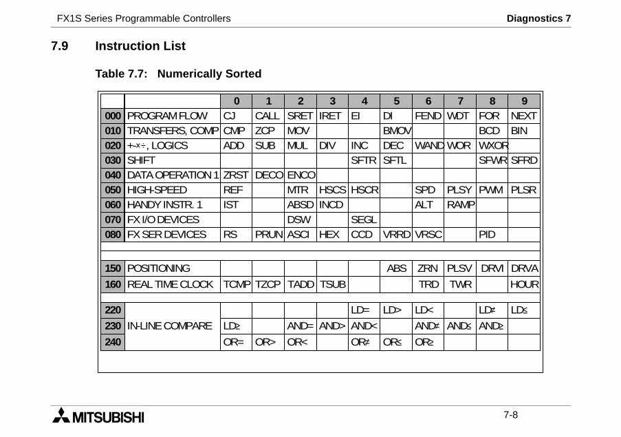
7.9 Instruction List
Table 7.7: Numerically Sorted
000010020030040050060070080
TRANSFERS, COMPPROGRAMFLOW
+-×÷, LOGICSSHIFTDATAOPERATION1HIGH-SPEEDHANDYINSTR. 1FXI/ODEVICESFXSERDEVICES
0CJCMPADD
ZRSTREFIST
RS
1CALLZCPSUB
DECO
PRUN
2SRETMOVMUL
ENCOMTRABSDDSWASCI
3IRET
DIV
HSCSINCD
HEX
4EI
INCSFTR
HSCR
SEGLCCD
5DIBMOVDECSFTL
VRRD
150
160
220
230
240
POSITIONING
REALTIMECLOCK
IN-LINECOMPARE
TCMP
OR=
LD≥
TZCP
OR>
TADD
OR<
AND=
TSUB
AND>
OR≠AND<
LD=
ABS
OR≤
LD>
FX1S Series Programmable Controllers Diagnostics 7
7-9
Symbol FNCNo. D PHEX 083
IRETISTLD
003060
224-230MOVMTRMUL
012052022
NEXT 009OR 240-246
HSCR 054HSCS 053INCINCD
024063
HOUR 169
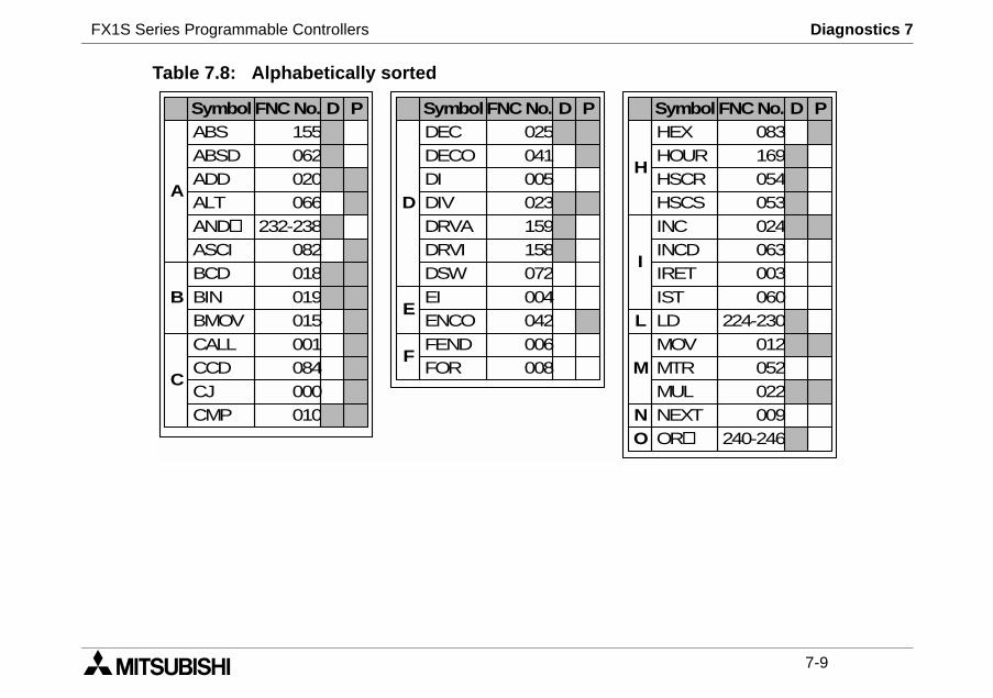
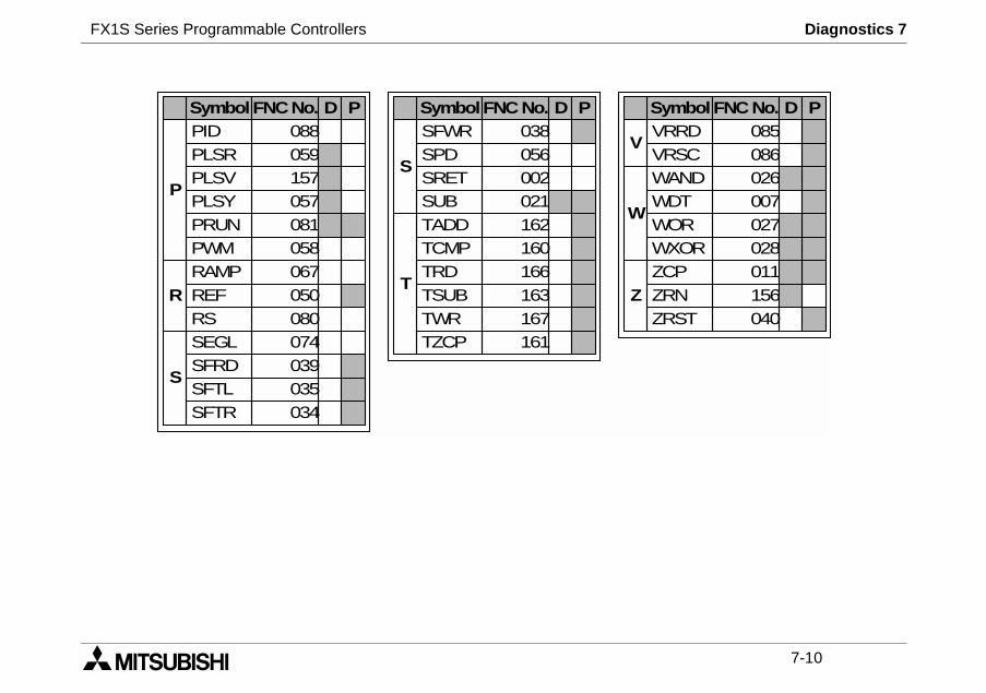
Table 7.8: Alphabetically sorted
A
SymbolABSABSDADD
AND
ASCI
FNC No.155062020066
232-238082
D P
BBCDBINBMOV
018019015
CALLCCD
010
084C
CJCMP
000
001
DECDECO
025041
DDIDIVDRVA
005023159
E
DRVIDSW
158072
F
SymbolFNC No. D P
H
I
L
M
NO
ALT
EI 004ENCO 042FEND 006FOR 008
FX1S Series Programmable Controllers Diagnostics 7
7-10
VRRDVRSC
085086
WANDWDTWOR
026007027
Symbol FNC No. D P
WXORZCPZRNZRST
028011156040
P
SymbolPIDPLSRPLSVPLSYPRUNPWMRAMP
FNCNo.088059157057081058067
D P
R
S
SFWR 038
S
T
SymbolFNC No. D P
V
W
ZREF 050RS 080SEGL 074SFRD 039SFTLSFTR
035034
SPD 056
TADDTCMP
162160
SRET 002SUB 021
TRD 166TSUB 163TWRTZCP
167161
FX1S Series Programmable Controllers Diagnostics 7
7-11
Description
internal EEPROMr-EEPROM-8L
(X + Y) ≤ 30 pts Max.
M0-M383 (384 pts)
M384-M511 (128 pts)
8000-M8255 (256 pts)
10 pts), same as latched state relay
S10-S127 (118 pts)
T0-T62 (63 pts)
On, T32 - T62 are 10ms timers(31 pts)
T63 (1 pt)
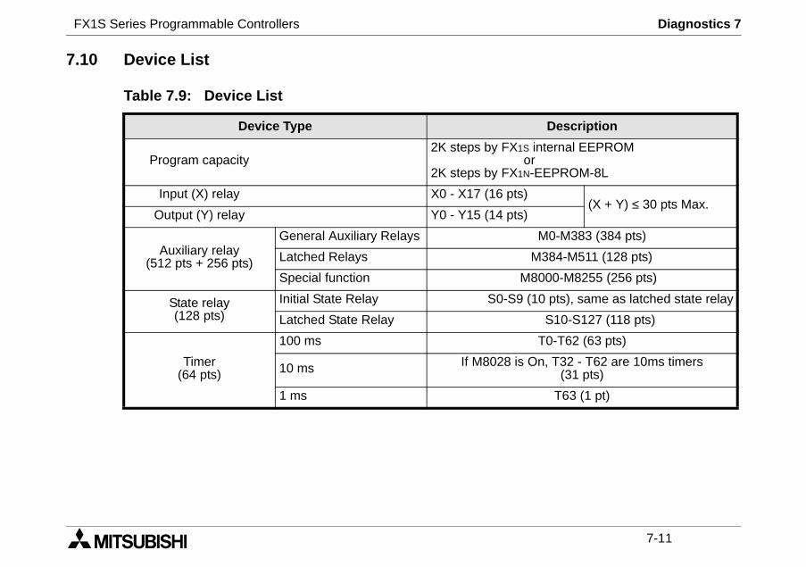
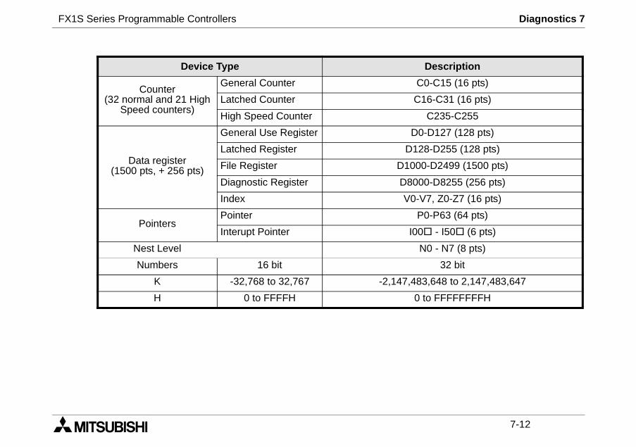
7.10 Device List
Table 7.9: Device List
Device Type
Program capacity2K steps by FX1S
o2K steps by FX1N
Input (X) relay X0 - X17 (16 pts)
Output (Y) relay Y0 - Y15 (14 pts)
Auxiliary relay(512 pts + 256 pts)
General Auxiliary Relays
Latched Relays
Special function M
State relay(128 pts)
Initial State Relay S0-S9 (
Latched State Relay
Timer(64 pts)
100 ms
10 ms If M8028 is
1 ms
FX1S Series Programmable Controllers Diagnostics 7
7-12
Description
C0-C15 (16 pts)
16-C31 (16 pts)
C235-C255
0-D127 (128 pts)
28-D255 (128 pts)
0-D2499 (1500 pts)
00-D8255 (256 pts)
-V7, Z0-Z7 (16 pts)
P0-P63 (64 pts)
0 - I50 (6 pts)
N0 - N7 (8 pts)
32 bit
83,648 to 2,147,483,647
to FFFFFFFFH
Device Type
Counter(32 normal and 21 High
Speed counters)
General Counter
Latched Counter C
High Speed Counter
Data register(1500 pts, + 256 pts)
General Use Register D
Latched Register D1
File Register D100
Diagnostic Register D80
Index V0
PointersPointer
Interupt Pointer I0
Nest Level
Numbers 16 bit
K -32,768 to 32,767 -2,147,4
H 0 to FFFFH 0

FX1S Series Programmable Controllers

HEAD OFFICE: MITSUBISHI DENKI BLDG MARUNOUCHI TOKYO 100-8310 TELEX: J24532 CABLE MELCO TOKYOHIMEJI WORKS: 840, CHIYODA CHO, HIMEJI, JAPAN
JY992D83901E(MEE0106)
Effective June 2001Specifications are subjectto change without notice.
HARDWARE MANUALFX1S SERIES PROGRAMMABLE CONTROLLERS