Embed Size (px)
Citation preview
Beam shaping to generate uniform “Laser Light Sheet”
and Linear Laser Spots
Alexander Laskin, Vadim Laskin
AdlOptica GmbH, Rudower Chaussee 29, 12489 Berlin, Germany
ABSTRACT
Generation of “Laser Light Sheet” beams and linear laser spots characterized by uniform irradiance distribution is important in various laser techniques like Particle Image Velocimetry (PIV), Laser-Induced Fluorescence (LIF), hardening, annealing, cladding, uniform laser illumination of linear spatial light modulators. This task can be successfully solved with using refractive beam shaping optics of field mapping type in combination with additional optical components. Due to their unique features: low output divergence, high transmittance, flatness of output phase front and irradiance profile, as well as extended depth of field, the refractive field mappers provide freedom in further manipulation of intensity profile and shape of output beam. Typically design of refractive field mapping beam shapers has circular symmetry; therefore to create linear spot shapes it is suggested to apply anamorphic optical components like cylinder lenses, prism pairs, etc. The combined beam shaping systems allow achieving very high aspect ratio, up to 1:1000, of linear spots with simultaneous providing extended depth of field, i.e. it is possible to realize a “Laser Light Sheet” characterized by keeping uniform intensity of linear spot over extended distance along optical axis.
This paper will describe some design basics of refractive beam shapers of the field mapping type and optical layouts for
creating linear laser spots and “Laser Light Sheet”. Examples of real implementations will be presented as well. Keywords: beam shaping, flattop, tophat, laser line, Laser Light Sheet, hardening, cladding, PIV, LIF.
1. INTRODUCTION The tasks of creating a linear laser spot with uniform intensity along its length are today frequently asked in many
industrial and scientific applications, some of them are mentioned above. And using various beam shaping optics2 is
typical approach to solve these tasks with providing high efficient usage of laser energy and high homogeneity. The
solutions on the base of field mapping refractive beam shapers like Shaper are featured by high flexibility in building of
different beam shaping optical layouts due to their unique features: high transmittance, capability to work with TEM00
and multimode lasers, conserving consistency of laser beam and, hence, low output divergence, flatness of output wave
front and intensity profiles. Therefore, it is possible to apply ordinary optical components, very often just off-the-shelf
optics, in combination with a beam shaper and realize an optimum for a particular application shape and profile of laser
spot. Low beam divergence provided by refractive beam shapers makes it possible to realize so called “Laser Light
Sheet” – the beam specified by uniform intensity in one section, small width in another section and extended depth of
field. There will be considered in this paper some practical optical layouts built on the base of Shapers with emphasize
on features being important for particular laser techniques.
2. THEORETICAL CONSIDERATIONS
For purposes of clarity of further considerations it is important to describe some basic features of refractive beam shapers
and behavior of flattop laser beams while propagation in space and focusing.
2.1 Refractive Beam Shaper
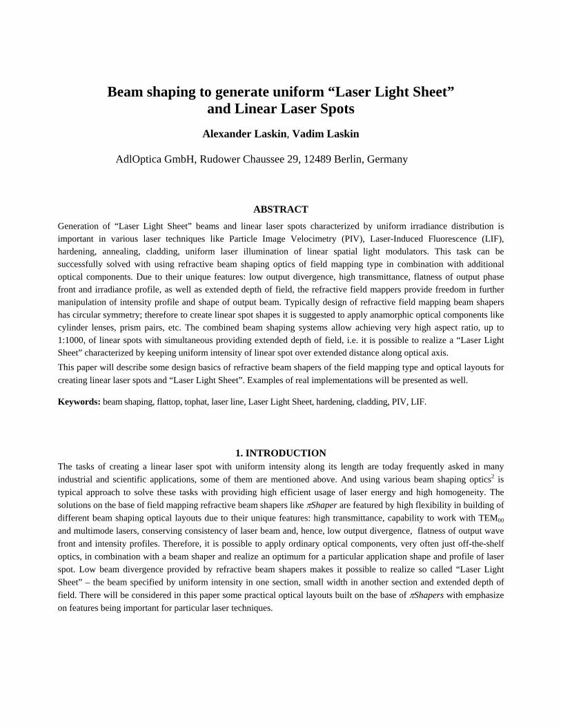
Among popular types of beam shaping optics the field mapping refractive beam shapers1,2,3,4 like Shaper6,7,10,11,12,
Fig. 1, demonstrate high flexibility in building various optical systems due to their principle of operation implying saving
of beam consistency and providing a flat wave front of output beam.
Their main optical features are:
- refractive optical systems to transform laser intensity
distribution from Gaussian to flattop (tophat, uniform);
- almost 100% efficiency;
- high transmittance;
- the transformation is realized through the phase
profile manipulation in a control manner, without
deterioration of the beam consistency and increasing
its divergence;
- changing the input beam diameter leads to changing
the output profile:
o round Gaussian input is transformed to round
flattop output beam,
o elliptic Gaussian input is transformed to
Roof-like output beam;
- the output phase profile is maintained flat, hence
output beam has low divergence;
- adaptability to real lasers through variation of distance
between the Shaper components;
- TEM00 or multimode beams applied;
- Output beam is collimated and resulting beam profile
is kept stable over large distance;
- Galilean design, no internal focusing; Figure 1 Principle of the Shaper operation
- achromatic optical design - several lasers can be used simultaneously.
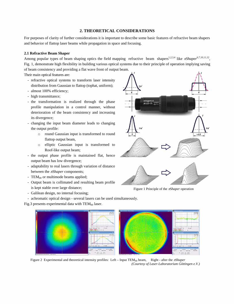
Fig.3 presents experimental data with TEM00 laser.
Figure 2 Experimental and theoretical intensity profiles: Left – Input TEM00 beam, Right - after the Shaper (Courtesy of Laser-Laboratorium Göttingen e.V.)
Important feature of the refractive field mapping beam shapers is that the transformation is realized in control manner by
accurate introducing and further compensation of wave aberration, therefore the resulting collimated output beam has
low divergence and there is no deterioration of the beam consistency. On the other hand this allows adapting the beam
shapers to create final laser spots of required shape and intensity profile.
Most popular implementation of the refractive beam shapers is telescopic optical system transforming collimated
Gaussian or Gaussian-like beam to collimated beam with uniform intensity. The design technique allows also creating
collimating Shaper realizing transformation of divergent Gaussian input beam to collimated flattop output; this type of
beam shapers is important for more and more popular fiber lasers as well as fiber-coupled diode and solid-state lasers.
There is one more important feature of the refractive field mapping beam shapers – their operational principle presumes
the input beam has a certain size - usually defined as diameter at 1/e2 intensity level, and a certain intensity profile -
Gaussian or similar profiles with peak intensity in the centre. If an input beam size differs from the pre-determined one
the resulting profile deviates from the flattop as well, for example, when an input beam is essentially smaller, say 2-3
times less than a specified value, the beam shaper operates as an ordinary beam-expander, so the output beam is about
1.6 times expanded but the resulting profile stays almost the same like at the entrance i.e. Gaussian. This effect is
demonstrated on Fig. 1. It can be used, for example, to generate a Roof-like beam profile with uniform intensity in one
direction and Gaussian in another one – this is easily achieved when an elliptic input beam with a long axis of proper
length (according to a Shaper design), Fig. 1. With using the effect of dependence of output beam profile and shape
from the input beam size it is possible to build various optical system realizing various shapes and intensity profiles of
final laser spots.
In contrast to many other beam shaping techniques the physical principle of operation of refractive field mappers doesn’t
require the input beam to be obligatory a TEM00 one, i.e. to have a common phase front. The beam shapers like Shaper work
perfect with multimode beams as well, the only condition is that the irradiance distribution of input beam to be similar to
Gaussian function, i.e. to have irradiance characterized by peak in center and decreasing towards periphery, for example
parabolic. Gaussian-like irradiance profiles are typical for high power multimode solid-state lasers, as well as for fiber coupled
multimode solid-state and diode lasers. Therefore collimating refractive beam shapers converting laser radiation from a fiber
directly to a collimated beam with uniform irradiance profile meet the demands of modern industrial technologies like welding,
cladding, hardening. Capability to work simultaneously with TEM00 and multimode lasers allows switching easily from one
laser source to another.
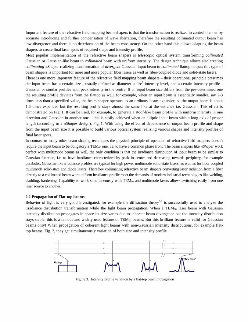
2.2 Propagation of Flat-top beams
Behavior of light is very good investigated, for example the diffraction theory5,8 is successfully used to analyze the
irradiance distribution transformation while the light beam propagation. When a TEM00 laser beam with Gaussian
intensity distribution propagates in space its size varies due to inherent beam divergence but the intensity distribution
stays stable, this is a famous and widely used feature of TEM00 beams. But this brilliant feature is valid for Gaussian
beams only! When propagation of coherent light beams with non-Gaussian intensity distributions, for example flat-
top beams, Fig. 3, they get simultaneously variation of both size and intensity profile.
Figure 3. Intensity profile variation by a flat-top beam propagation
At certain distance from initial plane with uniform intensity distribution there appears a bright rim that is then transformed to more complicated circular fringe pattern, finally at long distance (far field) the profile is featured with relatively bright central spot and weak diffraction rings – this is the well-known “Airy disk” intensity distribution described mathematically by formula
I () = I0 [J1(2)/(2)]2 (1)
where J1 is the Bessel function of 1st kind, 1st order, is polar radius, I0 is a constant. The “Airy disk” function is result of Fourier-Bessel transform for a circular beam of uniform initial intensity8. Evidently, even a “pure” theoretical flattop beam is transformed to a beam with essentially non-uniform intensity profile. There exists, however, certain propagation length where the profile is relatively stable, - this length is in reverse proportion to wavelength and in square proportion to beam size. For visible light and flattop beam of 6 mm diameter the length, where deviation from uniformity doesn’t exceed +10%, is about 250 mm, for the 12 mm beam - about 1 meter.
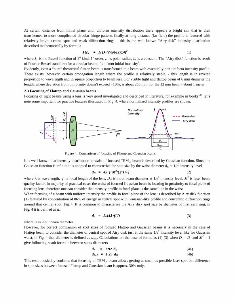
2.3 Focusing of Flattop and Gaussian beams Focusing of light beams using a lens is very good investigated and described in literature, for example in books5,8, let’s note some important for practice features illustrated in Fig. 4, where normalized intensity profiles are shown.
Figure 4. Comparison of focusing of Flattop and Gaussian beams
It is well-known that intensity distribution in waist of focused TEM00 beam is described by Gaussian function. Since the Gaussian function is infinite it is adopted to characterize the spot size by the waist diameter dG at 1/e2 intensity level
dG = 4HfHM2/(HDG ) (2)
where is wavelength, f is focal length of the lens, DG is input beam diameter at 1/e2 intensity level, M2 is laser beam quality factor. In majority of practical cases the waist of focused Gaussian beam is locating in proximity to focal plane of focusing lens, therefore one can consider the intensity profile in focal plane is the same like in the waist. When focusing of a beam with uniform intensity the profile in focal plane of the lens is described by Airy disk function (1) featured by concentration of 86% of energy in central spot with Gaussian-like profile and concentric diffraction rings around that central spot, Fig. 4. It is common to characterize the Airy disk spot size by diameter of first zero ring, in Fig. 4 it is defined as dA
dA = 2.44Hf/ D (3)
where D is input beam diameter. However, for correct comparison of spot sizes of focused Flattop and Gaussian beams it is necessary in the case of Flattop beam to consider the diameter of central spot of Airy disk just at the same 1/e2 intensity level like for Gaussian waist, in Fig. 4 that diameter is defined as dAe2. Calculations on the base of formulas (1)-(3) when DG = D and M2 = 1 give following result for ratio between spots diameters
dA = 1.92HdG (4a)
dAe2 = 1.29HdG (4b)
This result basically confirms that focusing of TEM00 beam allows getting as small as possible laser spot but difference in spot sizes between focused Flattop and Gaussian beam is approx. 30% only.
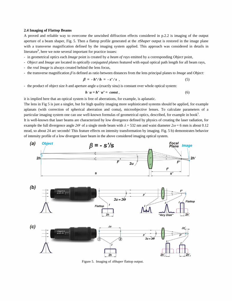
2.4 Imaging of Flattop Beams
A proved and reliable way to overcome the unwished diffraction effects considered in p.2.2 is imaging of the output
aperture of a beam shaper, Fig. 5. Then a flattop profile generated at the Shaper output is restored in the image plane
with a transverse magnification defined by the imaging system applied. This approach was considered in details in
literature9, here we note several important for practice issues:
- in geometrical optics each Image point is created by a beam of rays emitted by a corresponding Object point,
- Object and Image are located in optically conjugated planes featured with equal optical path length for all beam rays,
- the real Image is always created behind the lens focus,
- the transverse magnification is defined as ratio between distances from the lens principal planes to Image and Object:
= - h’ / h = - s’ / s , (5)
- the product of object size h and aperture angle u (exactly sinu) is constant over whole optical system:
h . u = h’ . u’ = const , (6)
it is implied here that an optical system is free of aberrations, for example, is aplanatic.
The lens in Fig 5 is just a singlet, but for high quality imaging more sophisticated systems should be applied, for example
aplanats (with correction of spherical aberration and coma), microobjective lenses. To calculate parameters of a
particular imaging system one can use well-known formulas of geometrical optics, described, for example in book5.
It is well-known that laser beams are characterized by low divergence defined by physics of creating the laser radiation, for
example the full divergence angle 2 of a single mode beam with = 532 nm and waist diameter 2 = 6 mm is about 0.12
mrad, so about 24 arc seconds! This feature effects on intensity transformation by imaging. Fig. 5 b) demonstrates behavior
of intensity profile of a low divergent laser beam in the above considered imaging optical system.
Figure 5. Imaging of Shaper flattop output.
It is assumed here that the Object plane is featured with uniform intensity profile and flat wave front, a beamlet from each
point of the object plane has low divergence - near the same like divergence 2 of a laser beam of the similar size, i.e.
2u = 2; these conditions are typical for output beam of a refractive field mapping beam shaper like Shaper.
Considering of intensity profiles transformation on the base of the diffraction theory5,8 shows that uniform intensity
distribution at the Object is transformed to Airy disk (1) in focus F’ and is then restored to uniform one in Image plane. It
is implied that the Image plane is just working plane, therefore, the evident conclusion for practice is that it doesn’t
matter how the intensity profile is transformed along the beam path, since the intensity distribution in the Image plane
repeats the Object plane distribution with taking into account transverse magnification. This conclusion is valid not only
for flattop beams but also for any other intensity profile. For instance, the Shaper allow realizing also such profiles like
“inverse Gauss” or super-Gauss10 and these profiles can be successfully reproduced in the Image plane as well. To avoid
any unwished diffraction effects it is necessary to take care to transmitting of full light energy through an optical system
and prevent any clipping of a beam.
Another important feature of imaging of low divergent laser beams is extended depth of field; this effect is illustrated in
Fig. 5 c). The Object at the exit of the Shaper can be implemented as a physical aperture or iris diaphragm, then the
Image will have very sharp edges and repeat the shape of that aperture. If no apertures applied and output collimated
beam simply propagates towards the imaging lens the Object has no a definite plane and whole space after the Shaper,
where the intensity profile is flattop, will be mapped to a corresponding space on the Image side. As discussed in
paragraph 2.2 that length s of stable profile in the Object space depends on wavelength and beam size, it can achieve
values of several hundreds of mm or several meters depending on applied laser and Shaper. Hence, the beam profile is
stable over relatively long length s’ in the Image space as well, in other words the extended depth of field (DOF) is
provided. The DOF length can be approximately evaluated with taking into account that longitudinal magnification of
imaging system is equal to square of the transverse magnification5.
3. OPTICAL LAYOUTS TO GENERATE LINEAR SPOTS
Typically under a Laser Line one understands a narrow linear spot with uniform intensity along the line length; the
intensity profile in narrow section is usually not specified, it can be flattop, Gaussian or Gaussian-like as well. The most
straight and usual way to get as narrow as possible spot size is just focusing of a laser beam. At the same time the
uniform intensity profile can be provided by a refractive beam shaper, and the necessary final size of flattop spot, as was
shown in p.2.4, can be realized by applying of imaging optics after the beam shaper. Evidently, a Laser Line can be
created by combining of these two techniques using anamorphic optics realizing simultaneously focusing and imaging of
a beam after the beam shaper. In further consideration of optical layouts we will analyse intensity distribution
transformation in two separate orthogonal sections: Focusing Section and Imaging Section.
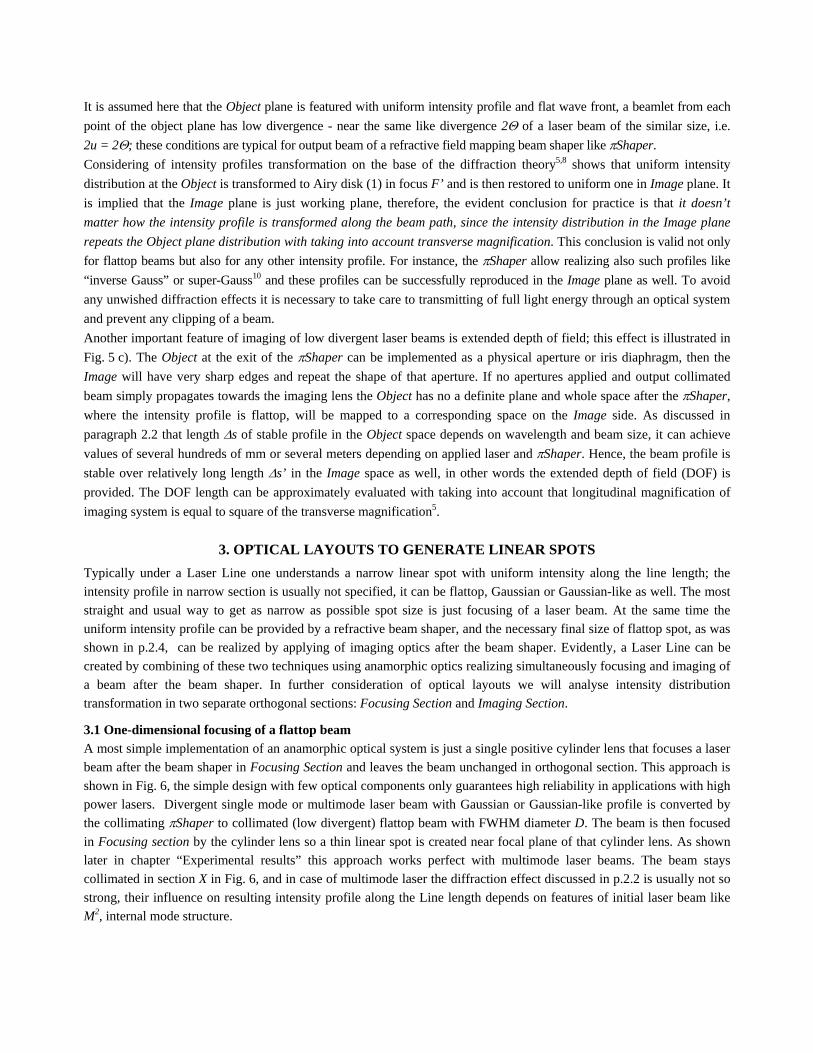
3.1 One-dimensional focusing of a flattop beam
A most simple implementation of an anamorphic optical system is just a single positive cylinder lens that focuses a laser
beam after the beam shaper in Focusing Section and leaves the beam unchanged in orthogonal section. This approach is
shown in Fig. 6, the simple design with few optical components only guarantees high reliability in applications with high
power lasers. Divergent single mode or multimode laser beam with Gaussian or Gaussian-like profile is converted by
the collimating Shaper to collimated (low divergent) flattop beam with FWHM diameter D. The beam is then focused
in Focusing section by the cylinder lens so a thin linear spot is created near focal plane of that cylinder lens. As shown
later in chapter “Experimental results” this approach works perfect with multimode laser beams. The beam stays
collimated in section X in Fig. 6, and in case of multimode laser the diffraction effect discussed in p.2.2 is usually not so
strong, their influence on resulting intensity profile along the Line length depends on features of initial laser beam like
M2, internal mode structure.
Figure 6. Focusing of flattop beam using cylinder optics.
When multimode fiber lasers or high power fiber-coupled diode and solid-state lasers featured with strong mixing of
laser modes it is possible to reach intensity uniformity of linear spot acceptable for majority of applications like
cladding, hardening, where these high power lasers are used.
Optimum spot shape for some laser applications is rather rectangular or elliptic. Evidently, the elliptic spot can be easy
realized by shifting the working plane from focal plane to the lens. It is very good seen in Fig. 6 that in space between
the cylinder lens and its focal plane the spot shape is transformed gradually from a circle to an ellipse and then to line
which is in reality an ellipse with high aspect ratio; and by choosing of an appropriate working distance after the cylinder
lens one can provide necessary aspect ratio of elliptic spot.
One of important features of refractive beam shapers like Shaper is capability to realize various output intensity
profiles: flattop, super-Gauss, inverse-Gauss, by varying the input beam size or internal settings, these features are in
details described in papers10,12. The intensity distribution created at the Shaper output stays stable in space between the
lens and its focal plane where wave front has low curvature and, hence, weak variation of profile due to diffraction. As
result, it is possible, for example, to realize elliptic spot with concave intensity profile (inverse-Gauss) like shown in
Fig. 11, bottom - such a profile is optimum in laser heat treatment techniques since provides uniform temperature
distribution on a work piece.
One more additional mean to vary the resulting intensity profile is variable aberration at the Shaper output. As
discussed in p.2.1 the basic idea of the Shaper operation is to introduce certain controlled aberration by first optical
component in order to get intensity distribution transformation; that aberration is then compensated by the second optical
component, so output beam is aberration-free. Varying of distance between the Shaper components leads to appearing
of uncompensated aberration, which influences on the final intensity distribution – this is a powerful tool to optimize the
profile in elliptic or linear working spot. Result of optimization of intensity distribution in linear spot is shown in
Fig. 11, top: the resulting profile presents a trade-off between effects of intensity re-distribution by 1-dimensioanl
focusing and intensity variation due to uncompensated aberration.
All the above considered effects work well for multimode beams, but in case of single mode lasers it is necessary to take
into account the discussed in p.2.2 intensity distribution variation because of diffraction while beam propagation. This
non-uniformity of intensity profile happens inevitably in the section X in Fig. 6, and it is necessary to analyze its
acceptability in a particular application. To avoid the intensity variation due to diffraction and provide uniform linear
spot it is suggested to apply imaging technique discussed in p.2.4.

3.2 Combining of Focusing and Imaging in an anamorphic optical system Combination of focusing technique to provide narrow line and imaging of Shaper output to avoid diffraction effects and save intensity uniformity along the line length can be realized using anamorphic optical system composed from positive spherical and negative cylinder lenses, example of such a system is shown in Fig. 7.
Figure 7. Combining of Focusing (top) and Imaging (bottom) of output beam to generate Linear spot.
The lens 2 serves as an imaging lens creating in the Imaging section X the sharp image of the Shaper output (round beam of FWHM diameter D) in working plane behind the lens focus F’2. The transverse magnification in this example is -1/3X. The negative cylinder lens 1, typically of low optical power, is shifting in the Focusing section Y the common focus F’1+2 of lenses 1 and 2 into the same working plane like by imaging. As result, there is created a narrow line which length defined by transverse magnification of the imaging system. Layout in Fig. 7 presents simple anamorphic imaging/focusing system from 2 lenses, in real applications usually more sophisticated optical system should be applied.
3.3 Focusing / Imaging approach for high aspect ratio Laser Line As shown in p.2.3 the spot size by focusing of a Gaussian beam is smaller than one for a flattop beam. This can be used to get a narrower line and, hence, higher aspect ratio by modification of the anamorphic system like presented in Fig. 8.
Figure 8. Realizing of Focusing/Imaging approach with elliptic input beam to get a Linear spot of high aspect ratio.
The basic idea is to provide elliptic beam at the Shaper entrance by applying of anamorphic optics ahead of the beam
shaper – this can be for example cylinder beam expander, Fig. 8, or prism pair. One of basic features of refractive field
mapping beam shapers is dependence of output profile from input beam size, - as result and elliptic beam with Gaussian
profiles is transformed to roof-like profile featured with uniform intensity in one section and almost Gaussian in
orthogonal section. This profile matches perfect to focusing/imaging approach: the Gaussian profile in the Focusing
section is optimum for as small as possible line width, while the uniform output intensity in the Imaging section is
reproduced in image plane, as result as narrow as possible line of required length is created.
As discussed in paper 10 the Shaper presents a telescope with function of beam shaping, typically the paraxial beam size
magnification is about 1.6X, therefore when an input Gaussian beam size is essentially smaller than proper one the
Shaper works as an ordinary beam expander and the output beam is enlarged, but its intensity profile stays close to
Gaussian. To reach smallest line width in the Focusing section the optimum aspect ratio of input elliptic beam to be
approximately 1:2:
- if this value is bigger the output intensity profile would be closer to flattop and, hence, the final line width will
be bigger as well,
- smaller aspect ratio would result smaller beam size at the entrance of focusing optics and, consequentially,
wider final line.
The optical layouts presented in Fig. 7 and 8 are very useful in applications where line lengths are several hundreds of
micrometers or few millimetres and non-collimated beams are acceptable, for example silicon annealing or flow
cytometry. But if a particular laser technique requires a resulting beam being collimated in one section it is necessary to
apply more sophisticated focusing/imaging system, for example based on telecentric imaging optics. This approach is
considered in next paragraph.
3.4 Generation of “Laser Light Sheet”
Further development of the focusing/imaging anamorphic optical system makes it possible to realize a laser beam called
as “Laser Light Sheet” being collimated in Imaging Section and having extended depth of field in Focusing section. This
type of laser beam is important in such applications like annealing, illumination of linear Spatial Light Modulators in
Laser Direct Imaging technique in PCB production, laser heat treatment techniques implying material processing with a
linear laser spot, and many others.
The best way to realize a flattop collimated beam is applying of a telecentric imaging system that, indeed, presents a
Keplerian telescope, this imaging optics is discussed in details in paper9. One of possible implementations of optical
system is shown in Fig. 9.
Basic features of this optical system are:
- elliptic beam Shaper entrance is provided by anamorphic beam expander in form of prism pair, it can be also a
pair of cylinder lenses,
- Shaper creates collimated beam with Roof-like profile,
- telecentric system, composed from lenses 1 and 2, creates in the Imaging section collimated beam with uniform
intensity around focal plane of the lens 2,
- cylinder lens 3 focuses beam in the Focusing section, then small line with is provided,
- focal planes of lenses 2 and 3 are brought in coincidence.
Typically the required line lengths are bigger than beam size at the Shaper output, and the imaging system creates a
magnified image. Since the longitudinal magnification of an imaging system is in square proportion to the transverse
magnification there is provided extended depth of field (DOF) in the Imaging section.
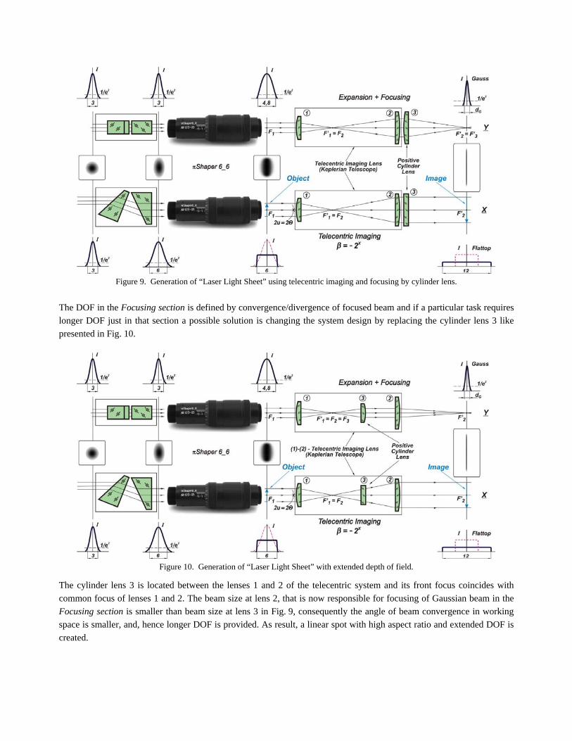
Figure 9. Generation of “Laser Light Sheet” using telecentric imaging and focusing by cylinder lens.
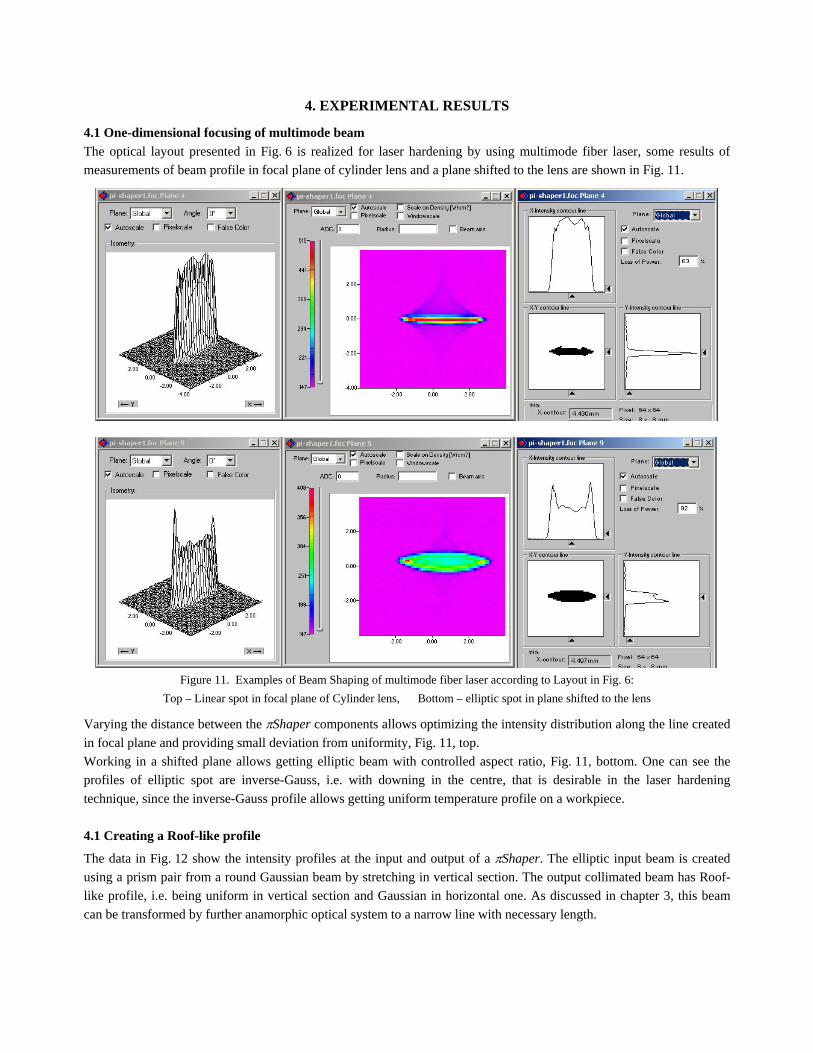
The DOF in the Focusing section is defined by convergence/divergence of focused beam and if a particular task requires
longer DOF just in that section a possible solution is changing the system design by replacing the cylinder lens 3 like
presented in Fig. 10.
Figure 10. Generation of “Laser Light Sheet” with extended depth of field.
The cylinder lens 3 is located between the lenses 1 and 2 of the telecentric system and its front focus coincides with
common focus of lenses 1 and 2. The beam size at lens 2, that is now responsible for focusing of Gaussian beam in the
Focusing section is smaller than beam size at lens 3 in Fig. 9, consequently the angle of beam convergence in working
space is smaller, and, hence longer DOF is provided. As result, a linear spot with high aspect ratio and extended DOF is
created.
4. EXPERIMENTAL RESULTS
4.1 One-dimensional focusing of multimode beam
The optical layout presented in Fig. 6 is realized for laser hardening by using multimode fiber laser, some results of
measurements of beam profile in focal plane of cylinder lens and a plane shifted to the lens are shown in Fig. 11.
Figure 11. Examples of Beam Shaping of multimode fiber laser according to Layout in Fig. 6:
Top – Linear spot in focal plane of Cylinder lens, Bottom – elliptic spot in plane shifted to the lens
Varying the distance between the Shaper components allows optimizing the intensity distribution along the line created
in focal plane and providing small deviation from uniformity, Fig. 11, top.
Working in a shifted plane allows getting elliptic beam with controlled aspect ratio, Fig. 11, bottom. One can see the
profiles of elliptic spot are inverse-Gauss, i.e. with downing in the centre, that is desirable in the laser hardening
technique, since the inverse-Gauss profile allows getting uniform temperature profile on a workpiece.
4.1 Creating a Roof-like profile
The data in Fig. 12 show the intensity profiles at the input and output of a Shaper. The elliptic input beam is created
using a prism pair from a round Gaussian beam by stretching in vertical section. The output collimated beam has Roof-
like profile, i.e. being uniform in vertical section and Gaussian in horizontal one. As discussed in chapter 3, this beam
can be transformed by further anamorphic optical system to a narrow line with necessary length.

Fig. 12 Beam Shaping of elliptic beam by Shaper in Layouts in Fig. 8, 9 and 10: Left – elliptic input beam, Right – Roof-like output.
5. CONCLUSIONS
Despite the circular symmetry of optical design of the refractive field mapping beam shapers these systems are capable to generate non-circular shapes of homogenized laser beams. This unique feature is possible due to their operational principle implying low divergence of output collimated beam and, hence, extended space after a beam shaper where a resulting beam profile is kept stable, which, in turn, guarantees the long depth of field of a combined optical system. Applying of additional optical anamorphic components like cylinder lenses or prisms makes it possible to create elliptic and linear spots with various aspect ratios and with flattop, Roof-like, “inverse Gauss” intensity profiles. This extends the range of capabilities of refractive beam shapers and makes these devices a convenient tool to build beam shaping optics for various industrial, medical and scientific applications.
6. REFERENCES [1] Dickey, F. M., Holswade, S. C., [Laser Beam Shaping: Theory and Techniques], Marcel Dekker, New York, (2000). [2] Dickey, F. M., Holswade, S. C., Shealy, D.L., [Laser Beam Shaping Applications], CRC Press, Boca Raton, (2006). [3] Hoffnagle, J. A., Jefferson, C. M., “Design and performance of a refractive optical system that converts a Gaussian to
a flattop beam” Appl. Opt. vol. 39, 5488-5499 (2000). [4] Kreuzer, J., “Coherent light optical system yielding an output beam of desired intensity distribution at a desired
equiphase surface” US Patent 3476463, (1969). [5] Smith, W.J. [Modern Optical Engineering], McGraw-Hill, New York, (2000). [6] Laskin, A. “Achromatic refractive beam shaping optics for broad spectrum laser applications” Proc. SPIE 7430,
Paper 7430-03 (2009). [7] Laskin, A., “Achromatic Optical System for Beam Shaping” US Patent 8023206, (2011). [8] Goodman, J.W. [Introduction to Fourier Optics], McGraw-Hill, New York, (1996). [9] Laskin, A., Laskin, V. “Imaging techniques with refractive beam shaping optics” Proc. SPIE 8490, Paper 8490-19 (2012). [10] Laskin A., Laskin V. “Variable beam shaping with using the same field mapping refractive beam shaper” Proc. SPIE
8236, Paper 82360D (2012). [11] Laskin, A.V. [http://www.piShaper.com]. [12] Laskin, A., Laskin, V. “Refractive beam shapers for material processing with high power single mode and
multimode lasers” Proc. SPIE 8600, Paper 8600-38 (2013).
7. ACKNOWLEDGEMENTS
The authors are grateful to users of Shaper in Laser-Laboratorium Göttingen e.V. for their active and patient work with optics discussed in this paper and kind permission to publish some results achieved during their experiments.


![Unusual Spatial Patterns of Industrial Firm Locations ... · non-uniform spread of customers were also studied [9], and yet the sellers generate a similar market splitting response](https://img.pdfslide.net/doc/110x75/5e22b558a93ea45f143b4fd0/unusual-spatial-patterns-of-industrial-firm-locations-non-uniform-spread-of.jpg)


![Estimation of a proportion with survey datajse.amstat.org/v11n3/duchesne.pdf · Step 2. Generate N variables independently from a uniform distribution U[0, 1].Denote the values obtained](https://img.pdfslide.net/doc/110x75/5f5a008cde3cca36f0625a0c/estimation-of-a-proportion-with-survey-step-2-generate-n-variables-independently.jpg)