Embed Size (px)
Citation preview
(8527+(50'5,9(6
938&)UHTXHQF\,QYHUWHU
3URGXFW#0DQXDO+$7983468334##,VVXH#7
#&RS\ULJKW#(XURWKHUP#'ULYHV#/LPLWHG#4<<<All rights strictly reserved. No part of this document may be stored in a retrieval system, or transmitted in any form orby any means to persons not employed by a Eurotherm group company without written permission from EurothermDrives Ltd.
Although every effort has been taken to ensure the accuracy of this document it may be necessary, without notice, tomake amendments or correct omissions. Eurotherm Drives cannot accept responsibility for damage, injury, or expensesresulting therefrom.
&RPSDWLEOH#ZLWK#9HUVLRQ#81[#6RIWZDUH

&RQW15
:$55$17<Eurotherm Drives warrants the goods against defects in design, materials and workmanship
for the period of 12 months from the date of delivery on the termsdetailed in Eurotherm Drives Standard Conditions of Sale IA058393C.
Eurotherm Drives reserves the right to change the content and product specification without notice.

&RQW16
5HTXLUHPHQWV,03257$17=# 3OHDVH#UHDG#WKLV#LQIRUPDWLRQ#%()25(#LQVWDOOLQJ#WKH#HTXLSPHQW1
,QWHQGHG#8VHUVThis manual is to be made available to all persons who are required to install, configure orservice equipment described herein, or any other associated operation.
The information given is intended to highlight safety issues, and to enable the user to obtainmaximum benefit from the equipment.
Complete the following table for future reference detailing how the unit is to be installed andused.
,167$//$7,21#'(7$,/6
Serial Number(see product label)
Where installed(for your owninformation)
Unit used as a:(refer to Certificationfor the Inverter)
R Component R Relevant Apparatus
Unit fitted: R Wall-mounted R Enclosure
$SSOLFDWLRQ#$UHDThe equipment described is intended for industrial motor speed control utilising AC induction orAC synchronous machines.
3HUVRQQHOInstallation, operation and maintenance of the equipment should be carried out by qualifiedpersonnel. A qualified person is someone who is technically competent and familiar with allsafety information and established safety practices; with the installation process, operation andmaintenance of this equipment; and with all the hazards involved.
$6DIHW\#,QIRUPDWLRQ

&RQW17
+D]DUGV
:$51,1*$# 7KLV#HTXLSPHQW#FDQ#HQGDQJHU#OLIH#WKURXJK#URWDWLQJ#PDFKLQHU\#DQG#KLJK#YROWDJHV1)DLOXUH#WR#REVHUYH#WKH#IROORZLQJ#ZLOO#FRQVWLWXWH#DQ#(/(&75,&$/#6+2&.#+$=$5'1
• The equipment must be permanently earthed due to the high earth leakage current.
• The drive motor must be connected to an appropriate safety earth.
• The equipment contains high value capacitors which take time to discharge after removal ofthe mains supply.
• Before working on the equipment, ensure isolation of the mains supply from terminals L1,L2 and L3. Wait for at least 3 minutes for the dc link terminals (DC+ and DC-) to dischargeto safe voltage levels (<50V). Measure the DC+ and DC- terminal voltage with a meter toconfirm that the voltage is less than 50V.
• Never perform high voltage resistance checks on the wiring without first disconnecting thedrive from the circuit being tested.
• When replacing a drive in an application and before returning to use, it is essential that alluser defined parameters for the product’s operation are correctly installed.
• This equipment contains electrostatic discharge (ESD) sensitive parts. Observe staticcontrol precautions when handling, installing and servicing this product.
,03257$17=# 0HWDO#SDUWV#PD\#UHDFK#D#WHPSHUDWXUH#RI#<3#GHJUHHV#FHQWLJUDGH#LQ#RSHUDWLRQ1
$SSOLFDWLRQ#5LVNThe specifications, processes and circuitry described herein are for guidance only and may needto be adapted to the user’s specific application. Refer to page 3-1.
Eurotherm Drives does not guarantee the suitability of the equipment described in this Manualfor individual applications.
5LVN#$VVHVVPHQWUnder fault conditions, power loss or other operating conditions not intended, the equipmentmay not operate as specified. In particular:
• The motor speed may not be controlled
• The direction of rotation of the motor may not be controlled
• The motor may be energised
*XDUGVThe user must provide guarding and /or additional safety systems to prevent risk of injury andelectric shock.
3URWHFWLYH#,QVXODWLRQ• All control and signal terminals are SELV, i.e. protected by double insulation. Ensure all
wiring is rated for the highest system voltage.
1RWH=# 7KHUPDO#VHQVRUV#FRQWDLQHG#ZLWKLQ#WKH#PRWRU#PXVW#EH#GRXEOH#LQVXODWHG1
• All exposed metalwork in the Inverter is protected by basic insulation and bonding to asafety earth.
5&'VThese are not recommended for use with this product but ,where their use is mandatory, onlyType B RCDs should be used.
$6DIHW\#,QIRUPDWLRQ
&RQWHQWV
&RQWHQWV##############################################################################################################3DJH
&RQW18
&KDSWHU#4 *(77,1* #67$57(',QWURGXFWLRQ 11111111111111111111111111111111111111111111111111111111111111111111111111111111111111111111111111 404
2SWLRQDO#(TXLSPHQW 11111111111111111111111111111111111111111111111111111111111111111111111111111111111111111111111111404
(TXLSPHQW#,QVSHFWLRQ11111111111111111111111111111111111111111111111111111111111111111111111111111111111 405
$ERXW#WKLV#0DQXDO 1111111111111111111111111111111111111111111111111111111111111111111111111111111111111111 405
,QLWLDO#6WHSV1111111111111111111111111111111111111111111111111111111111111111111111111111111111111111111111111111111111111111405
+RZ#WKH#0DQXDO#LV#2UJDQLVHG 11111111111111111111111111111111111111111111111111111111111111111111111111111111111405
• $SSOLFDWLRQ#%ORFN#'LDJUDPV 11111111111111111111111111111111111111111111111111111111111111111111406
• ,QIRUPDWLRQ#IRU#8VHUV#ZLWKRXW#DQ#2SHUDWRU#6WDWLRQ 11111111111111111111111111111111111406
&KDSWHU#5 $1 #29(59,(: #2) #7+( #,19(57(5
&RPSRQHQW#,GHQWLILFDWLRQ11111111111111111111111111111111111111111111111111111111111111111111111111111 504
&RQWURO#)HDWXUHV 1111111111111111111111111111111111111111111111111111111111111111111111111111111111111111111 505
8QGHUVWDQGLQJ#WKH#3URGXFW#&RGH 11111111111111111111111111111111111111111111111111111111111111111 506
)XQFWLRQDO#2YHUYLHZ1111111111111111111111111111111111111111111111111111111111111111111111111111111111111 507
3RZHU#%RDUG11111111111111111111111111111111111111111111111111111111111111111111111111111111111111111111111111111111111111507
&RQWURO#%RDUG 11111111111111111111111111111111111111111111111111111111111111111111111111111111111111111111111111111111111507
• 3URFHVVRU111111111111111111111111111111111111111111111111111111111111111111111111111111111111111111111111507
• 7HFKQRORJ\#2SWLRQ#,QWHUIDFH 1111111111111111111111111111111111111111111111111111111111111111111507
• 2SHUDWRU#6WDWLRQ#,QWHUIDFH11111111111111111111111111111111111111111111111111111111111111111111111507
&KDSWHU#6 ,167$//,1* #7+( #,19(57(5
0HFKDQLFDO#,QVWDOODWLRQ 11111111111111111111111111111111111111111111111111111111111111111111111111111111 604
0RXQWLQJ#WKH#,QYHUWHU1111111111111111111111111111111111111111111111111111111111111111111111111111111111111111111111111604
0LQLPXP#$LU#&OHDUDQFHV 1111111111111111111111111111111111111111111111111111111111111111111111111111111111111111111604
• 9HQWLODWLRQ 1111111111111111111111111111111111111111111111111111111111111111111111111111111111111111111111604
• $LU#&OHDUDQFH=#&XELFOH00RXQW#3URGXFW2$SSOLFDWLRQ11111111111111111111111111111111111605
• $LU#&OHDUDQFH=#:DOO00RXQW#3URGXFW2$SSOLFDWLRQ 111111111111111111111111111111111111111605
(OHFWULFDO#,QVWDOODWLRQ 111111111111111111111111111111111111111111111111111111111111111111111111111111111111 606
:LULQJ#WKH#,QYHUWHU 11111111111111111111111111111111111111111111111111111111111111111111111111111111111111111111111111111606
• 3URWHFWLYH#(DUWK#+3(,#&RQQHFWLRQV# 111111111111111111111111111111111111111111111111111111608
• 3RZHU#:LULQJ#&RQQHFWLRQV 1111111111111111111111111111111111111111111111111111111111111111111111608
• &RQWURO#:LULQJ#&RQQHFWLRQV 11111111111111111111111111111111111111111111111111111111111111111111609
2SWLRQDO#(TXLSPHQW 1111111111111111111111111111111111111111111111111111111111111111111111111111111111111 60:
• )LWWLQJ#WKH#5HPRWH#9384#2SHUDWRU#6WDWLRQ11111111111111111111111111111111111111111111111160:
• 7RS#&RYHU 111111111111111111111111111111111111111111111111111111111111111111111111111111111111111111111160;
• 7HFKQRORJ\#2SWLRQV1111111111111111111111111111111111111111111111111111111111111111111111111111111160<
• ([WHUQDO#%UDNH#5HVLVWRU 111111111111111111111111111111111111111111111111111111111111111111111111116043
&RQWHQWV
&RQWHQWV##############################################################################################################3DJH
&RQW19
• ([WHUQDO#$XSSO\#(0&#)LOWHU 1111111111111111111111111111111111111111111111111111111111111116044
• 2XWSXW#&RQWDFWRUV 111111111111111111111111111111111111111111111111111111111111111111111111111111116045
• (DUWK#)DXOW#0RQLWRULQJ#6\VWHPV111111111111111111111111111111111111111111111111111111111111116045
• /LQH#&KRNHV#+LQSXW, 11111111111111111111111111111111111111111111111111111111111111111111111111111116046
• $�RWRU#&KRNH#+RXWSXW, 11111111111111111111111111111111111111111111111111111111111111111111116046
&KDSWHU#7 23(5$7,1* #7+( #,19(57(5
3UH02SHUDWLRQ#&KHFNV 1111111111111111111111111111111111111111111111111111111111111111111111111111111111 704
&RQWURO#3KLORVRSK\ 111111111111111111111111111111111111111111111111111111111111111111111111111111111111111 705
6WDUW26WRS#DQG#6SHHG#&RQWURO 1111111111111111111111111111111111111111111111111111111111111111111111 705
• 6HOHFWLQJ#/RFDO#RU#5HPRWH#&RQWURO 11111111111111111111111111111111111111111111111111111111111706
6WDUW0XS#5RXWLQHV111111111111111111111111111111111111111111111111111111111111111111111111111111111111111111 707
5HPRWH#&RQWURO#XVLQJ#&RQWURO#7HUPLQDOV#+GHIDXOW#VHW0XS, 111111111111111111111111111111111111111111111707
• 5HDGLQJ#WKH#6WDWXV#/('V 11111111111111111111111111111111111111111111111111111111111111111111111111707
/RFDO#&RQWURO#XVLQJ#WKH#2SHUDWRU#6WDWLRQ1111111111111111111111111111111111111111111111111111111111111111111111111708
6HWWLQJ0XS#WKH#,QYHUWHU111111111111111111111111111111111111111111111111111111111111111111111111111111111 708
4XLFN#6HW0XS#DV#DQ#2SHQ0ORRS#,QYHUWHU#+92)#IOX[LQJ, 111111111111111111111111111111111111111111111111111708
6HW0XS#XVLQJ#WKH#6HQVRUOHVV#9HFWRU#)OX[LQJ#0RGH 11111111111111111111111111111111111111111111111111111111709
7KH#$XWRWXQH#)HDWXUH1111111111111111111111111111111111111111111111111111111111111111111111111111111111111111111111111709
0DQXDO#7XQLQJ 111111111111111111111111111111111111111111111111111111111111111111111111111111111111111111111111111111111170:
• 7XQLQJ#XVLQJ#WKH#0RWRU#(TXLYDOHQW#&LUFXLW 11111111111111111111111111111111111111111111111170:
• 7XQLQJ#XVLQJ#D#6LPSOH#7XQLQJ#6HTXHQFH 1111111111111111111111111111111111111111111111111170:
7XQLQJ#'LIILFXOWLHV 11111111111111111111111111111111111111111111111111111111111111111111111111111111111111111111111111111170;
7KH#6WDUW26WRS#0RGH#([SODLQHG11111111111111111111111111111111111111111111111111111111111111111111 70;
6WDUWLQJ#DQG#6WRSSLQJ#0HWKRGV 1111111111111111111111111111111111111111111111111111111111111111111 70<
1RUPDO#6WRSSLQJ#0HWKRGV 1111111111111111111111111111111111111111111111111111111111111111111111111111111111111111170<
• 5DPS#WR#6WRS11111111111111111111111111111111111111111111111111111111111111111111111111111111111111111170<
• &RDVW#WR#6WRS11111111111111111111111111111111111111111111111111111111111111111111111111111111111111117043
$GYDQFHG#6WRSSLQJ#0HWKRGV1111111111111111111111111111111111111111111111111111111111111111111111111111111111117043
• )RUFHG#)DVW#6WRS 111111111111111111111111111111111111111111111111111111111111111111111111111111111117043
• )RUFHG#&RDVW#6WRS 111111111111111111111111111111111111111111111111111111111111111111111111111111117044
• 7KH#7ULS#&RQGLWLRQ 111111111111111111111111111111111111111111111111111111111111111111111111111111117044
• /RJLF#6WRSSLQJ111111111111111111111111111111111111111111111111111111111111111111111111111111111111117044
1RUPDO#6WDUWLQJ#0HWKRG 1111111111111111111111111111111111111111111111111111111111111111111111111111111111111111117045
$GYDQFHG#6WDUWLQJ#0HWKRGV111111111111111111111111111111111111111111111111111111111111111111111111111111111111117045
• 6WDUWLQJ#6HYHUDO#,QYHUWHUV#6LPXOWDQHRXVO\1111111111111111111111111111111111111111111111117045
• 6LQJOH#:LUH#/RJLF#6WDUWLQJ 1111111111111111111111111111111111111111111111111111111111111111111117045
• 7ZR#:LUH#/RJLF#6WDUWLQJ11111111111111111111111111111111111111111111111111111111111111111111111117046
• 7KUHH#:LUH#/RJLF#6WDUWLQJ 11111111111111111111111111111111111111111111111111111111111111111111117046
&RQWHQWV
&RQWHQWV##############################################################################################################3DJH
&RQW1:
&KDSWHU#8 7+( #23(5$725 #67$7,21
&RQQHFWLQJ#WKH#2SHUDWRU#6WDWLRQ 11111111111111111111111111111111111111111111111111111111111111111 804
• :HOFRPH#6FUHHQ 1111111111111111111111111111111111111111111111111111111111111111111111111111111111111804
&XVWRPLVLQJ#WKH#2SHUDWRU#6WDWLRQ1111111111111111111111111111111111111111111111111111111111111111 804
&RQWUROOLQJ#WKH#2SHUDWRU#6WDWLRQ 11111111111111111111111111111111111111111111111111111111111111111 805
&RQWURO#.H\V11111111111111111111111111111111111111111111111111111111111111111111111111111111111111111111111111111111111111805
• .H\V#IRU#2SHUDWLQJ#WKH#,QYHUWHU#/RFDOO\ 1111111111111111111111111111111111111111111111111111805
• .H\V#IRU#3URJUDPPLQJ#WKH#,QYHUWHU11111111111111111111111111111111111111111111111111111111111805
/('#,QGLFDWLRQV1111111111111111111111111111111111111111111111111111111111111111111111111111111111111111111111111111111111806
7KH#0HQX#6\VWHP 11111111111111111111111111111111111111111111111111111111111111111111111111111111111111111 807
1DYLJDWLQJ#WKH#0HQX#6\VWHP11111111111111111111111111111111111111111111111111111111111111111111111111111111111111807
• 7KH#0HQX#6\VWHP#0DS1111111111111111111111111111111111111111111111111111111111111111111111111111808
&KDQJLQJ#D#3DUDPHWHU#9DOXH1111111111111111111111111111111111111111111111111111111111111111111111111111111111111809
:KDW#GR#WKH#6\PEROV#PHDQ#QH[W#WR#VRPH#3DUDPHWHUV"111111111111111111111111111111111111111111111111809
• 3DUDPHWHU#6WDWXV#,QIRUPDWLRQ##→##←## 111111111111111111111111111111111111111111111111111809
• ([SDQGHG#0HQX#,QIRUPDWLRQ##!! 11111111111111111111111111111111111111111111111111111111111809
$OHUW#0HVVDJH#'LVSOD\V 111111111111111111111111111111111111111111111111111111111111111111111111111111111111111111111180:
7KH#352*#.H\ 111111111111111111111111111111111111111111111111111111111111111111111111111111111111111111111111111111111180:
7KH#/25#.H\ 11111111111111111111111111111111111111111111111111111111111111111111111111111111111111111111111111111111111111180:
0HQX#6KRUWFXWV#DQG#6SHFLDO#.H\#&RPELQDWLRQV1111111111111111111111111111111111111111111111111111111111180;
• 4XLFN#/LQN#,QIRUPDWLRQ 11111111111111111111111111111111111111111111111111111111111111111111111111180;
• 4XLFN#6DYH#WR#0HPRU\111111111111111111111111111111111111111111111111111111111111111111111111111180;
• &KDQJLQJ#WKH#'LVSOD\#/DQJXDJH 111111111111111111111111111111111111111111111111111111111111180;
• 4XLFN#'ULYH#&RS\ 1111111111111111111111111111111111111111111111111111111111111111111111111111111111180;
• &KDQJLQJ#WKH#3URGXFW#&RGH 1111111111111111111111111111111111111111111111111111111111111111111180<
• 4XLFN#5HVWRUH#'HIDXOW 1111111111111111111111111111111111111111111111111111111111111111111111111111180<
6SHFLDO#0HQX#)HDWXUHV 111111111111111111111111111111111111111111111111111111111111111111111111111111111 80<
0HQX#9LHZLQJ#/HYHOV 111111111111111111111111111111111111111111111111111111111111111111111111111111111111111111111111180<
• 6WDUWXS#6FUHHQ#7LPHRXWV 1111111111111111111111111111111111111111111111111111111111111111111111118043
6HOHFWLQJ#WKH#'LVSOD\#/DQJXDJH111111111111111111111111111111111111111111111111111111111111111111111111111111118043
&RQWURO#.H\#(QDEOH2'LVDEOH 11111111111111111111111111111111111111111111111111111111111111111111111111111111111118043
3DVVZRUG#3URWHFWLRQ 11111111111111111111111111111111111111111111111111111111111111111111111111111111111111111111111118043
• 7R#$FWLYDWH#3DVVZRUG#3URWHFWLRQ 11111111111111111111111111111111111111111111111111111111111118043
• 7R#'HDFWLYDWH#3DVVZRUG#3URWHFWLRQ1111111111111111111111111111111111111111111111111111111118044
6HOHFWLQJ#3DUDPHWHUV#IRU#WKH#2SHUDWRU#0HQX 1111111111111111111111111111111111111111111111111111111111118044
• 6HOHFWLQJ#D#6WDUWXS#6FUHHQ 1111111111111111111111111111111111111111111111111111111111111111111118044
• &XVWRPLVLQJ#WKH#:HOFRPH#6FUHHQ11111111111111111111111111111111111111111111111111111111118045
• &UHDWLQJ#&XVWRP#6FUHHQV 11111111111111111111111111111111111111111111111111111111111111111111118045
&RQWHQWV
&RQWHQWV##############################################################################################################3DJH
&RQW1;
+RZ#WR#6DYH/#5HVWRUH#DQG#&RS\#\RXU#6HWWLQJV 1111111111111111111111111111111111111111111 8045
6DYLQJ#<RXU#$SSOLFDWLRQ11111111111111111111111111111111111111111111111111111111111111111111111111111111111111111118045
5HVWRULQJ#6DYHG#6HWWLQJV 1111111111111111111111111111111111111111111111111111111111111111111111111111111111111111118045
&RS\LQJ#DQ#$SSOLFDWLRQ 11111111111111111111111111111111111111111111111111111111111111111111111111111111111111111118046
• 7UDQVIHUULQJ#<RXU#$SSOLFDWLRQ#WR#$QRWKHU#,QYHUWHU 111111111111111111111111111111111118046
• %DFNLQJ0XS#<RXU#$SSOLFDWLRQ 111111111111111111111111111111111111111111111111111111111111111118046
&KDSWHU#9 352*5$00,1* #<285 #$33/,&$7,21
,QWURGXFLQJ#WKH#0DFUR 1111111111111111111111111111111111111111111111111111111111111111111111111111111111 904
3URJUDPPLQJ#ZLWK#%ORFN#'LDJUDPV 1111111111111111111111111111111111111111111111111111111111111 904
0RGLI\LQJ#D#%ORFN#'LDJUDP 111111111111111111111111111111111111111111111111111111111111111111111111111111111111111904
• &RQILJXUDWLRQ#DQG#3DUDPHWHULVDWLRQ#0RGHV 111111111111111111111111111111111111111111111904
• 0DNLQJ#DQG#%UHDNLQJ#/LQNV#LQ#&RQILJXUDWLRQ#0RGH1111111111111111111111111111111111904
• 3URJUDPPLQJ#5XOHV111111111111111111111111111111111111111111111111111111111111111111111111111111111905
• ([HFXWLRQ#5XOHV 111111111111111111111111111111111111111111111111111111111111111111111111111111111111111905
• 6DYLQJ#<RXU#0RGLILFDWLRQV 11111111111111111111111111111111111111111111111111111111111111111111111906
8QGHUVWDQGLQJ#WKH#)XQFWLRQ#%ORFN#'HVFULSWLRQ 111111111111111111111111111111111111111111111111111111111111906
• 00,#0HQX#0DSV 111111111111111111111111111111111111111111111111111111111111111111111111111111111111906
+H[DGHFLPDO#5HSUHVHQWDWLRQ#RI#7ULSV11111111111111111111111111111111111111111111111111111111111111111111111111907
)XQFWLRQ#%ORFN#'HVFULSWLRQV11111111111111111111111111111111111111111111111111111111111111111111111111 908
• $1$/2*#',*,11111111111111111111111111111111111111111111111111111111111111111111111111111111111111909
• $1$/2*#,1387 111111111111111111111111111111111111111111111111111111111111111111111111111111111111190;
• $1$/2*#287387 11111111111111111111111111111111111111111111111111111111111111111111111111111119044
• $872#5(67$5711111111111111111111111111111111111111111111111111111111111111111111111111111111111119046
• $872781(1111111111111111111111111111111111111111111111111111111111111111111111111111111111111111119048
• %5$.(#&21752/1111111111111111111111111111111111111111111111111111111111111111111111111111111119049
• &2006#&21752/ 11111111111111111111111111111111111111111111111111111111111111111111111111111904:
• &855(17#)(('%$&.1111111111111111111111111111111111111111111111111111111111111111111111111111904;
• &855(17#/,0,7 1111111111111111111111111111111111111111111111111111111111111111111111111111111111119053
• &86720#6&5((1 111111111111111111111111111111111111111111111111111111111111111111111111111111119054
• '(08/7,3/(;(5 111111111111111111111111111111111111111111111111111111111111111111111111111111111119056
• ',*,7$/#,138711111111111111111111111111111111111111111111111111111111111111111111111111111111111119057
• ',*,7$/#287387 1111111111111111111111111111111111111111111111111111111111111111111111111111111119058
• '<1$0,&#%5$.,1* 111111111111111111111111111111111111111111111111111111111111111111111111111119059
• (1&2'(511111111111111111111111111111111111111111111111111111111111111111111111111111111111111111111905:
• )/8;,1* 1111111111111111111111111111111111111111111111111111111111111111111111111111111111111111111111905;
• )/<&$7&+,1*11111111111111111111111111111111111111111111111111111111111111111111111111111111111119063
• ,1-#%5$.,1*11111111111111111111111111111111111111111111111111111111111111111111111111111111111111119065
• ,22#75,3611111111111111111111111111111111111111111111111111111111111111111111111111111111111111111111119066
&RQWHQWV
&RQWHQWV##############################################################################################################3DJH
&RQW1<
• ,-W#75,3111111111111111111111111111111111111111111111111111111111111111111111111111111111111111111111111119067
• -2*111111111111111111111111111111111111111111111111111111111111111111111111111111111111111111111111111119068
• /2&$/#&21752/111111111111111111111111111111111111111111111111111111111111111111111111111111119069
• /2*,&#)81&7,21 111111111111111111111111111111111111111111111111111111111111111111111111111111906:
• 0,1,080#63(('11111111111111111111111111111111111111111111111111111111111111111111111111111111119074
• 08/7,3/(;(511111111111111111111111111111111111111111111111111111111111111111111111111111111111111119075
• 23(5$725#0(18 111111111111111111111111111111111111111111111111111111111111111111111111111111119076
• 23#67$7,21 11111111111111111111111111111111111111111111111111111111111111111111111111111111111111119077
• 3$66:25' 1111111111111111111111111111111111111111111111111111111111111111111111111111111111111111119079
• 3$77(51#*(1 11111111111111111111111111111111111111111111111111111111111111111111111111111111111111907:
• 3,'1111111111111111111111111111111111111111111111111111111111111111111111111111111111111111111111111111111907;
• 35(6(7 11111111111111111111111111111111111111111111111111111111111111111111111111111111111111111111111119083
• 5$,6(2/2:(51111111111111111111111111111111111111111111111111111111111111111111111111111111111111119085
• 5()(5(1&( 1111111111111111111111111111111111111111111111111111111111111111111111111111111111111111119086
• 6(48(1&,1*#/2*,&111111111111111111111111111111111111111111111111111111111111111111111111119088
• 6(732,17#6&$/(1111111111111111111111111111111111111111111111111111111111111111111111111111111111908:
• 6.,3#)5(48(1&,(6 111111111111111111111111111111111111111111111111111111111111111111111111111111908;
• 6/(:#5$7(#/,0,7 11111111111111111111111111111111111111111111111111111111111111111111111111111111119093
• 6/,3#&20311111111111111111111111111111111111111111111111111111111111111111111111111111111111111111119094
• 67$%,/,6$7,2111111111111111111111111111111111111111111111111111111111111111111111111111111111111119095
• 67$//#75,3111111111111111111111111111111111111111111111111111111111111111111111111111111111111111111119096
• 672311111111111111111111111111111111111111111111111111111111111111111111111111111111111111111111111111119097
• 6<67(0#3257#+36,111111111111111111111111111111111111111111111111111111111111111111111111111111119098
• 6<67(0#5$03 111111111111111111111111111111111111111111111111111111111111111111111111111111111111119099
• 7(í,211111111111111111111111111111111111111111111111111111111111111111111111111111111111111111909;
• 75,36#+,6725< 1111111111111111111111111111111111111111111111111111111111111111111111111111111111111909<
• 75,36#67$786 11111111111111111111111111111111111111111111111111111111111111111111111111111111111111190:3
• 81'(5/$3#&203 1111111111111111111111111111111111111111111111111111111111111111111111111111111190:5
• 9$/8(#)81& 11111111111111111111111111111111111111111111111111111111111111111111111111111111111111190:6
• 9(&725#)/8;,1* 1111111111111111111111111111111111111111111111111111111111111111111111111111111190;3
• 92/7$*(#&21752/ 11111111111111111111111111111111111111111111111111111111111111111111111111190;4
• =(52#63(('1111111111111111111111111111111111111111111111111111111111111111111111111111111111111111190;5
0RWRU06SHFLILF#3DUDPHWHUV 1111111111111111111111111111111111111111111111111111111111111111111111111 90;6
4XDGUDWLF#7RUTXH#6HOHFWLRQ111111111111111111111111111111111111111111111111111111111111111111111111 90;7
&RQWHQWV
&RQWHQWV##############################################################################################################3DJH
&RQW143
&KDSWHU#: 75,36 #$1' #)$8/7 #),1',1*
7ULSV11111111111111111111111111111111111111111111111111111111111111111111111111111111111111111111111111111111111111 :04
:KDW#+DSSHQV#ZKHQ#D#7ULS#2FFXUV 1111111111111111111111111111111111111111111111111111111111111111111111111111:04
• ,QYHUWHU#,QGLFDWLRQV1111111111111111111111111111111111111111111111111111111111111111111111111111111111:04
• 2SHUDWRU#6WDWLRQ#,QGLFDWLRQV#+ZKHQ#FRQQHFWHG, 1111111111111111111111111111111111111111:04
5HVHWWLQJ#D#7ULS#&RQGLWLRQ 111111111111111111111111111111111111111111111111111111111111111111111111111111111111111111:04
8VLQJ#WKH#2SHUDWRU#6WDWLRQ#WR#0DQDJH#7ULSV111111111111111111111111111111111111111111111111111111111111111:05
• 7ULS#0HVVDJHV 1111111111111111111111111111111111111111111111111111111111111111111111111111111111111111:05
• $XWRPDWLF#7ULS#5HVHW 1111111111111111111111111111111111111111111111111111111111111111111111111111111:06
• 6HWWLQJ#7ULS#&RQGLWLRQV 1111111111111111111111111111111111111111111111111111111111111111111111111111:06
• 9LHZLQJ#7ULS#&RQGLWLRQV 11111111111111111111111111111111111111111111111111111111111111111111111111:06
&KHFNVXP#)DLO11111111111111111111111111111111111111111111111111111111111111111111111111111111111111111111111111111111111:07
• ,QYHUWHU#,QGLFDWLRQV1111111111111111111111111111111111111111111111111111111111111111111111111111111111:07
• 2SHUDWRU#6WDWLRQ#,QGLFDWLRQV#+ZKHQ#FRQQHFWHG, 1111111111111111111111111111111111111111:07
)DXOW#)LQGLQJ 111111111111111111111111111111111111111111111111111111111111111111111111111111111111111111111111 :07
&KDSWHU#; 5287,1( #0$,17(1$1&( #$1' #5(3$,55RXWLQH#0DLQWHQDQFH 11111111111111111111111111111111111111111111111111111111111111111111111111111111111 ;04
5HSDLU 11111111111111111111111111111111111111111111111111111111111111111111111111111111111111111111111111111111111 ;04
6DYLQJ#<RXU#$SSOLFDWLRQ#'DWD1111111111111111111111111111111111111111111111111111111111111111111111111111111111111;04
5HWXUQLQJ#WKH#8QLW#WR#(XURWKHUP#'ULYHV 11111111111111111111111111111111111111111111111111111111111111111111111;04
&KDSWHU#< 6(48(1&,1* #/2*,&
3ULQFLSOH#6WDWH#0DFKLQH11111111111111111111111111111111111111111111111111111111111111111111111111111111 <04
0DLQ#6HTXHQFLQJ#6WDWHV 111111111111111111111111111111111111111111111111111111111111111111111111111111111111111111111<04
6WDWH#2XWSXWV#RI#WKH#6(48(1&,1*#/2*,&#)XQFWLRQ#%ORFN 11111111111111111111111111111111111111111<04
7UDQVLWLRQ#RI#6WDWHV 1111111111111111111111111111111111111111111111111111111111111111111111111111111111111111111111111111<05
6WDWH#'LDJUDP 11111111111111111111111111111111111111111111111111111111111111111111111111111111111111111111111111111111111<06
([WHUQDO#&RQWURO#RI#WKH#,QYHUWHU 1111111111111111111111111111111111111111111111111111111111111111111 <07
&RPPXQLFDWLRQV#&RPPDQG 11111111111111111111111111111111111111111111111111111111111111111111111111111111111111<07
• ([DPSOH#&RPPDQGV1111111111111111111111111111111111111111111111111111111111111111111111111111111<08
&RPPXQLFDWLRQV#6WDWXV 111111111111111111111111111111111111111111111111111111111111111111111111111111111111111111111<09
&KDSWHU#43 3$5$0(7(5 #63(&,),&$7,21
6SHFLILFDWLRQ#7DEOH=#7DJ#1XPEHU#2UGHU 1111111111111111111111111111111111111111111111111111 4305
3URGXFW05HODWHG#'HIDXOW#9DOXHV 111111111111111111111111111111111111111111111111111111111111111 4304<
• /DQJXDJH#'HSHQGDQW#'HIDXOWV 1111111111111111111111111111111111111111111111111111111111114304<
• $XSSO\#9ROWDJH#DQG#3RZHU#5DWLQJ#'HSHQGDQW#'HIDXOWV1111111111111111111143053
&RQWHQWV
&RQWHQWV##############################################################################################################3DJH
&RQW144
&KDSWHU#44 7(&+1,&$/ #63(&,),&$7,216
938�RGHO#5HFRJQLWLRQ 111111111111111111111111111111111111111111111111111111111111111111111111111111111111111114404
(QYLURQPHQWDO#'HWDLOV 11111111111111111111111111111111111111111111111111111111111111111111111111111111111111111111114404
(DUWKLQJ26DIHW\#'HWDLOV1111111111111111111111111111111111111111111111111111111111111111111111111111111111111111111114405
7HUPLQDO#%ORFN#:LUH#6L]HV 11111111111111111111111111111111111111111111111111111111111111111111111111111111111111114405
(OHFWULFDO#5DWLQJV1111111111111111111111111111111111111111111111111111111111111111111111111111111111111111111111111111114406
&DEOLQJ#5HTXLUHPHQWV#IRU#(0&#&RPSOLDQFH 11111111111111111111111111111111111111111111111111111111111114407
(0&#&RPSOLDQFH 11111111111111111111111111111111111111111111111111111111111111111111111111111111111111111111111111114407
([WHUQDO#$XSSO\#+5),,#)LOWHUV 1111111111111111111111111111111111111111111111111111111111111111111111111111111114407
,QWHUQDO#'\QDPLF#%UDNH#6ZLWFK 1111111111111111111111111111111111111111111111111111111111111111111111111111111114408
&RQWURO#7HUPLQDOV11111111111111111111111111111111111111111111111111111111111111111111111111111111111111111111111111114409
$QDORJ#,QSXWV22XWSXWV111111111111111111111111111111111111111111111111111111111111111111111111111111111111111111111440:
'LJLWDO#,QSXWV 11111111111111111111111111111111111111111111111111111111111111111111111111111111111111111111111111111111111440:
'LJLWDO#2XWSXWV 11111111111111111111111111111111111111111111111111111111111111111111111111111111111111111111111111111111440:
6XSSO\#+DUPRQLF#$QDO\VLV1111111111111111111111111111111111111111111111111111111111111111111111111111111111111111440;
&KDSWHU#45 &(57,),&$7,21 #)25 #7+( #,19(57(5
5HTXLUHPHQWV#IRU#(0&#&RPSOLDQFH 111111111111111111111111111111111111111111111111111111111111 4504
0LQLPLVLQJ#5DGLDWHG#(PLVVLRQV1111111111111111111111111111111111111111111111111111111111111111111111111111111114504
(DUWKLQJ#5HTXLUHPHQWV 1111111111111111111111111111111111111111111111111111111111111111111111111111111111111111111114504
• 3URWHFWLYH#(DUWK#+3(,#&RQQHFWLRQV111111111111111111111111111111111111111111111111111111111114504
• (0&#(DUWK#&RQQHFWLRQV 1111111111111111111111111111111111111111111111111111111111111111111111114504
&DEOLQJ#5HTXLUHPHQWV 1111111111111111111111111111111111111111111111111111111111111111111111111111111111111111111114505
• 3ODQQLQJ#&DEOH#5XQV111111111111111111111111111111111111111111111111111111111111111111111111111114505
• ,QFUHDVLQJ#0RWRU#&DEOH#/HQJWK 11111111111111111111111111111111111111111111111111111111111114505
(0&#,QVWDOODWLRQ#2SWLRQV 111111111111111111111111111111111111111111111111111111111111111111111111111111111111111114506
• 6FUHHQLQJ#)#(DUWKLQJ#+ZDOO#PRXQWHG/#&ODVV#$,11111111111111111111111111111111111111114506
• 6FUHHQLQJ#)#(DUWKLQJ#+FXELFOH#PRXQWHG/#&ODVV#%,1111111111111111111111111111111111114506
• 6WDU#3RLQW#(DUWKLQJ 111111111111111111111111111111111111111111111111111111111111111111111111111111114508
• 6HQVLWLYH#(TXLSPHQW 1111111111111111111111111111111111111111111111111111111111111111111111111111114509
5HTXLUHPHQWV#IRU#8/#&RPSOLDQFH111111111111111111111111111111111111111111111111111111111111111 450:
• 6ROLG06WDWH#0RWRU#2YHUORDG#3URWHFWLRQ 111111111111111111111111111111111111111111111111111450:
• 6KRUW#&LUFXLW#5DWLQJ 1111111111111111111111111111111111111111111111111111111111111111111111111111111450:
• 6ROLG06WDWH#6KRUW0&LUFXLW#3URWHFWLRQ111111111111111111111111111111111111111111111111111111111450:
• 5HFRPPHQGHG#%UDQFK#&LUFXLW#3URWHFWLRQ111111111111111111111111111111111111111111111111450:
• 0RWRU#%DVH#)UHTXHQF\ 11111111111111111111111111111111111111111111111111111111111111111111111111450:
• )LHOG#:LULQJ#7HPSHUDWXUH#5DWLQJ 11111111111111111111111111111111111111111111111111111111111450:
• )LHOG#:LULQJ#7HUPLQDO#0DUNLQJV1111111111111111111111111111111111111111111111111111111111111450:
• 3RZHU#:LULQJ#7HUPLQDOV 111111111111111111111111111111111111111111111111111111111111111111111111450:
&RQWHQWV
&RQWHQWV##############################################################################################################3DJH
&RQW145
• 7HUPLQDO#7LJKWHQLQJ#7RUTXH 111111111111111111111111111111111111111111111111111111111111111111450:
• )LHOG#*URXQGLQJ#7HUPLQDOV11111111111111111111111111111111111111111111111111111111111111111111450;
• 2SHUDWLQJ#$PELHQW#7HPSHUDWXUH11111111111111111111111111111111111111111111111111111111111450;
• 'LUHFW#:DOO00RXQWDEOH#0RGHOV 11111111111111111111111111111111111111111111111111111111111111450;
(XURSHDQ#'LUHFWLYHV#DQG#WKH#&(#0DUN 1111111111111111111111111111111111111111111111111111111 450<
&(#0DUNLQJ#IRU#/RZ#9ROWDJH#'LUHFWLYH 1111111111111111111111111111111111111111111111111111111111111111111111450<
&(#0DUNLQJ#IRU#(0�#:KR#LV#5HVSRQVLEOH" 1111111111111111111111111111111111111111111111111111111111111450<
• /HJDO#5HTXLUHPHQWV#IRU#&(#0DUNLQJ1111111111111111111111111111111111111111111111111111145043
• $SSO\LQJ#IRU#&(#0DUNLQJ#IRU#(0& 111111111111111111111111111111111111111111111111111111145043
:KLFK#6WDQGDUGV#$SSO\" 111111111111111111111111111111111111111111111111111111111111111111111111111111111111111145043
• 3RZHU#'ULYH#3URGXFW#6SHFLILF#RU#*HQHULF#6WDQGDUGV 11111111111111111111111111111145043
&HUWLILFDWHV 11111111111111111111111111111111111111111111111111111111111111111111111111111111111111111111111111111111111145045
&KDSWHU#46 $33/,&$7,21 #127(6
6\QFKURQRXV#0RWRU#&RQWURO 111111111111111111111111111111111111111111111111111111111111111111111111 4604
%UDNH#0RWRUV1111111111111111111111111111111111111111111111111111111111111111111111111111111111111111111111 4604
8VLQJ#/LQH#&KRNHV 11111111111111111111111111111111111111111111111111111111111111111111111111111111111111 4605
8VLQJ#2XWSXW#&RQWDFWRUV 1111111111111111111111111111111111111111111111111111111111111111111111111111 4605
8VLQJ#0RWRU#&KRNHV 11111111111111111111111111111111111111111111111111111111111111111111111111111111111 4605
8VLQJ#0XOWLSOH#0RWRUV#RQ#D#6LQJOH#'ULYH 111111111111111111111111111111111111111111111111111 4606
'\QDPLF#%UDNLQJ1111111111111111111111111111111111111111111111111111111111111111111111111111111111111111 4606
%UDNH#5HVLVWRU#6HOHFWLRQ 11111111111111111111111111111111111111111111111111111111111111111111111111111111111111111114607
+LJK#6WDUWLQJ#7RUTXH1111111111111111111111111111111111111111111111111111111111111111111111111111111111 4608
&KDSWHU#47 6(5,$/ #&20081,&$7,216
&RPPXQLFDWLRQV#7HFKQRORJ\#2SWLRQ 1111111111111111111111111111111111111111111111111111111111 4704
&RQILJ(G#/LWH111111111111111111111111111111111111111111111111111111111111111111111111111111111111111111111111111111111114704
&RQQHFWLRQ#WR#WKH#36#3RUW 111111111111111111111111111111111111111111111111111111111111111111111111111 4704
&RQWHQWV
&RQWHQWV##############################################################################################################3DJH
&RQW146
&KDSWHU#48 $33/,&$7,21 #0$&526
7KH#'HIDXOW#$SSOLFDWLRQ111111111111111111111111111111111111111111111111111111111111111111111111111111 4804
+RZ#WR#/RDG#D#0DFUR 111111111111111111111111111111111111111111111111111111111111111111111111111111111 4804
0DFUR#'HVFULSWLRQV 1111111111111111111111111111111111111111111111111111111111111111111111111111111111111 4804
0DFUR#3 1111111111111111111111111111111111111111111111111111111111111111111111111111111111111111111111111111111111111111114804
0DFUR#4=#%DVLF#6SHHG#&RQWURO#+GHIDXOW, 111111111111111111111111111111111111111111111111111111111111111111114806
0DFUR#5=#5XQ#)RUZDUG25XQ#5HYHUVH 11111111111111111111111111111111111111111111111111111111111111111111111114808
0DFUR#6=#5DLVH2/RZHU#7ULP 11111111111111111111111111111111111111111111111111111111111111111111111111111111111111480:
0DFUR#7=#3URFHVV#3,'11111111111111111111111111111111111111111111111111111111111111111111111111111111111111111111111480<
0DFUR#8=#3UHVHW#6SHHGV 1111111111111111111111111111111111111111111111111111111111111111111111111111111111111111148044
0DFUR#9=#&ORVHG0/RRS#6SHHG#)HHGEDFN 1111111111111111111111111111111111111111111111111111111111111111148046
0DFUR#<<=#8;76#&RPSDWLEOH#$SSOLFDWLRQ111111111111111111111111111111111111111111111111111111111111111148048
*HQHUDO#:LULQJ#'LDJUDP#IRU#0DFUR#<< 1111111111111111111111111111111111111111111111111111111111111111114804;
0DFUR#&RQWURO#%ORFNV 111111111111111111111111111111111111111111111111111111111111111111111111111111111111111111114804<
0DFUR#8VHU#%ORFNV111111111111111111111111111111111111111111111111111111111111111111111111111111111111111111111111148053

&RQWHQWV
&RQWHQWV##############################################################################################################3DJH
&RQW147
*HWWLQJ#6WDUWHG##404
938&#)UHTXHQF\#,QYHUWHU
4#*(77,1*#67$57(',QWURGXFWLRQ
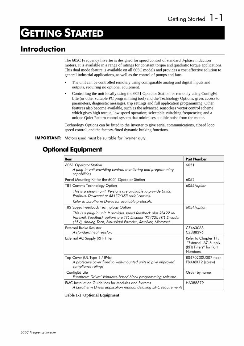
The 605C Frequency Inverter is designed for speed control of standard 3-phase inductionmotors. It is available in a range of ratings for constant torque and quadratic torque applications.This dual mode feature is available on all 605C models and provides a cost effective solution togeneral industrial applications, as well as the control of pumps and fans.
• The unit can be controlled remotely using configurable analog and digital inputs andoutputs, requiring no optional equipment.
• Controlling the unit locally using the 6051 Operator Station, or remotely using ConfigEdLite (or other suitable PC programming tool) and the Technology Options, gives access toparameters, diagnostic messages, trip settings and full application programming. Otherfeatures also become available, such as the advanced sensorless vector control schemewhich gives high torque, low speed operation; selectable switching frequencies; and aunique Quiet Pattern control system that minimises audible noise from the motor.
Technology Options can be fitted to the Inverter to give serial communications, closed loopspeed control, and the factory-fitted dynamic braking functions.
,03257$17=# 0RWRUV#XVHG#PXVW#EH#VXLWDEOH#IRU#LQYHUWHU#GXW\1
2SWLRQDO#(TXLSPHQW,WHP,WHP,WHP,WHP 3DUW#1XPEHU3DUW#1XPEHU3DUW#1XPEHU3DUW#1XPEHU
9384#2SHUDWRU#6WDWLRQ$#SOXJ0LQ#XQLW#SURYLGLQJ#FRQWURO/#PRQLWRULQJ#DQG#SURJUDPPLQJFDSDELOLWLHV
9384
3DQHO#0RXQWLQJ#.LW#IRU#WKH#9384#2SHUDWRU#6WDWLRQ 9385
7%4#&RPPV#7HFKQRORJ\#2SWLRQ
7KLV#LV#D#SOXJ0LQ#XQLW1#9HUVLRQV#DUH#DYDLODEOH#WR#SURYLGH#/LQN5/3URILEXV/#'HYLFHQHW#RU#5675527;8#VHULDO#FRPPV1
5HIHU#WR#(XURWKHUP#'ULYHV#IRU#DYDLODEOH#SURWRFROV1
93882RSWLRQ
7%5#6SHHG#)HHGEDFN#7HFKQRORJ\#2SWLRQ
7KLV#LV#D#SOXJ0LQ#XQLW1#,W#SURYLGHV#VSHHG#IHHGEDFN#SOXV#56755#UH0WUDQVPLW1#)HHGEDFN#RSWLRQV#DUH#77/#(QFRGHU#+56755,/#+7/#(QFRGHU+489,/#$QDORJ#7DFK/#6LQXVRLGDO#(QFRGHU/#5HVROYHU/#0LFURWDFK1
93872RSWLRQ
([WHUQDO#%UDNH#5HVLVWRU$#VWDQGDUG#KHDW#UHVLVWRU1
&=79639;&=6;;6<9
([WHUQDO#$XSSO\#+5),,#)LOWHU 5HIHU#WR#&KDSWHU#44=#´([WHUQDO##$XSSO\+5),,#)LOWHUVµ#IRU#3DUW1XPEHUV
7RS#&RYHU#+8/#7\SH#4#2#,37[,$#SURWHFWLYH#FRYHU#ILWWHG#WR#ZDOO0PRXQWHG#XQLWV#WR#JLYH#LPSURYHGFRPSOLDQFH#UDWLQJV
%37:3563833:#+WRS,)%36;.45#+VFUHZ,
&RQILJ(G#/LWH(XURWKHUP#'ULYHV·#:LQGRZV0EDVHG#EORFN#SURJUDPPLQJ#VRIWZDUH
2UGHU#E\#QDPH
(0&#,QVWDOODWLRQ#*XLGHOLQHV#IRU#0RGXOHV#DQG#6\VWHPV$#(XURWKHUP#'ULYHV#DSSOLFDWLRQ#PDQXDO#GHWDLOLQJ#(0&#UHTXLUHPHQWV
+$6;;;:<
Table 1-1 Optional Equipment
405##*HWWLQJ#6WDUWHG
938&#)UHTXHQF\#,QYHUWHU
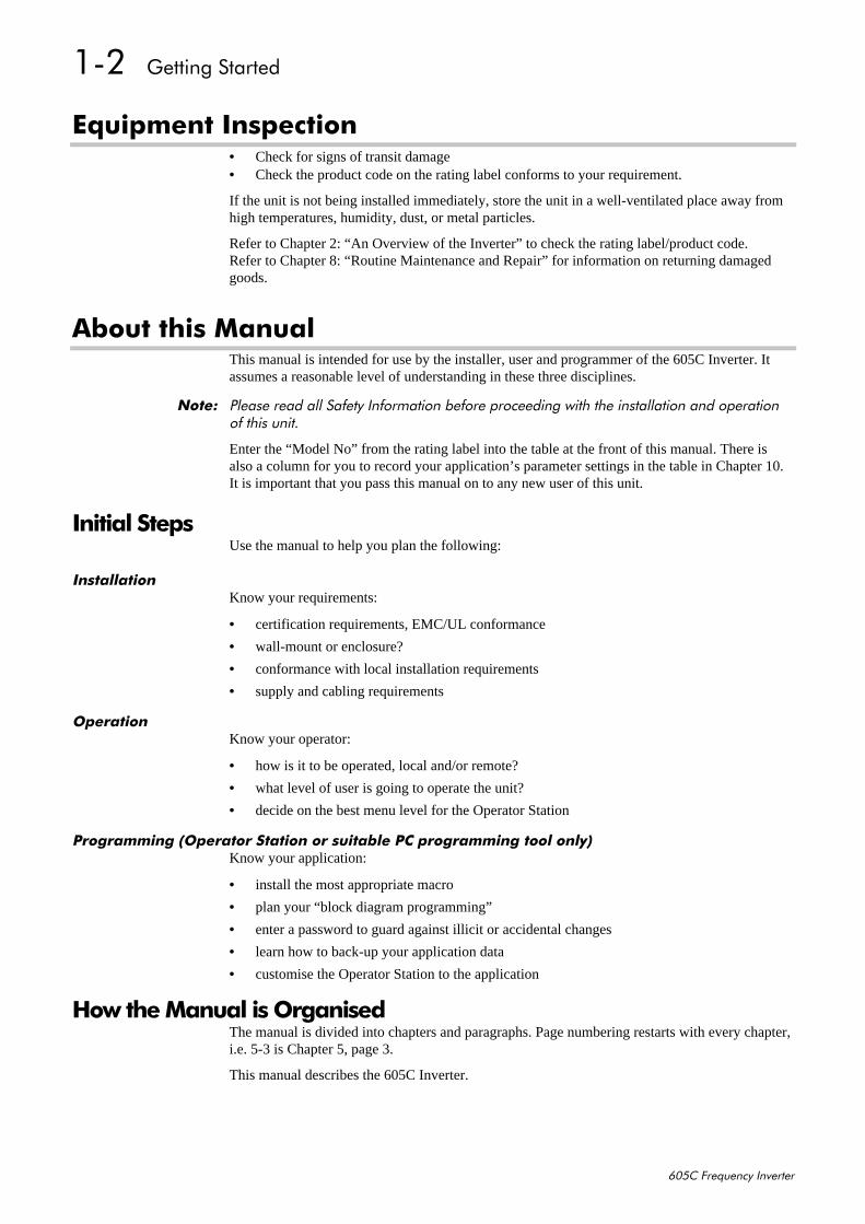
(TXLSPHQW#,QVSHFWLRQ• Check for signs of transit damage• Check the product code on the rating label conforms to your requirement.
If the unit is not being installed immediately, store the unit in a well-ventilated place away fromhigh temperatures, humidity, dust, or metal particles.
Refer to Chapter 2: “An Overview of the Inverter” to check the rating label/product code.Refer to Chapter 8: “Routine Maintenance and Repair” for information on returning damagedgoods.
$ERXW#WKLV#0DQXDOThis manual is intended for use by the installer, user and programmer of the 605C Inverter. Itassumes a reasonable level of understanding in these three disciplines.
1RWH=# 3OHDVH#UHDG#DOO#6DIHW\#,QIRUPDWLRQ#EHIRUH#SURFHHGLQJ#ZLWK#WKH#LQVWDOODWLRQ#DQG#RSHUDWLRQRI#WKLV#XQLW1
Enter the “Model No” from the rating label into the table at the front of this manual. There isalso a column for you to record your application’s parameter settings in the table in Chapter 10.It is important that you pass this manual on to any new user of this unit.
,QLWLDO#6WHSVUse the manual to help you plan the following:
,QVWDOODWLRQKnow your requirements:
• certification requirements, EMC/UL conformance
• wall-mount or enclosure?
• conformance with local installation requirements
• supply and cabling requirements
2SHUDWLRQKnow your operator:
• how is it to be operated, local and/or remote?
• what level of user is going to operate the unit?
• decide on the best menu level for the Operator Station
3URJUDPPLQJ#+2SHUDWRU#6WDWLRQ#RU#VXLWDEOH#3&#SURJUDPPLQJ#WRRO#RQO\,Know your application:
• install the most appropriate macro
• plan your “block diagram programming”
• enter a password to guard against illicit or accidental changes
• learn how to back-up your application data
• customise the Operator Station to the application
+RZ#WKH#0DQXDO#LV#2UJDQLVHGThe manual is divided into chapters and paragraphs. Page numbering restarts with every chapter,i.e. 5-3 is Chapter 5, page 3.
This manual describes the 605C Inverter.

*HWWLQJ#6WDUWHG##406
938&#)UHTXHQF\#,QYHUWHU
$SSOLFDWLRQ#%ORFN#'LDJUDPVYou will find these at the rear of the manual. The pages unfold to show a complete blockdiagram, these will become your programming tool as you become more familiar with the 605’ssoftware.
,QIRUPDWLRQ#IRU#8VHUV#ZLWKRXW#DQ#2SHUDWRU#6WDWLRQThis symbol identifies important text for users operating the 605C Inverter using the default(factory) set-up.
If the text is italic, such as this, then the information is especially for users without the OperatorStation or suitable PC programming tool.
'()$8/7

407##*HWWLQJ#6WDUWHG
938&#)UHTXHQF\#,QYHUWHU
$Q#2YHUYLHZ#RI#WKH#,QYHUWHU##504
938&#)UHTXHQF\#,QYHUWHU
5#$1#29(59,(:#2)#7+(#,19(57(5&RPSRQHQW#,GHQWLILFDWLRQ
2
78
14 15
4
13
12
9
5
10
11
Front View (with items removed)
1
6
3
16
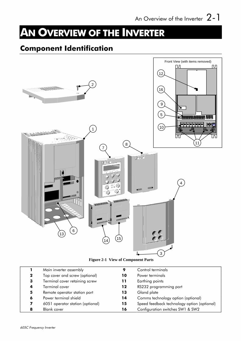
Figure 2-1 View of Component Parts
4 0DLQ#LQYHUWHU#DVVHPEO\ < &RQWURO#WHUPLQDOV5 7RS#FRYHU#DQG#VFUHZ#+RSWLRQDO, 43 3RZHU#WHUPLQDOV6 7HUPLQDO#FRYHU#UHWDLQLQJ#VFUHZ 44 (DUWKLQJ#SRLQWV7 7HUPLQDO#FRYHU 45 56565#SURJUDPPLQJ#SRUW8 5HPRWH#RSHUDWRU#VWDWLRQ#SRUW 46 *ODQG#SODWH9 3RZHU#WHUPLQDO#VKLHOG 47 &RPPV#WHFKQRORJ\#RSWLRQ#+RSWLRQDO,: 9384#RSHUDWRU#VWDWLRQ#+RSWLRQDO, 48 6SHHG#IHHGEDFN#WHFKQRORJ\#RSWLRQ#+RSWLRQDO,; %ODQN#FRYHU 49 &RQILJXUDWLRQ#VZLWFKHV#6:4#)#6:5
505##$Q#2YHUYLHZ#RI#WKH#,QYHUWHU
938&#)UHTXHQF\#,QYHUWHU
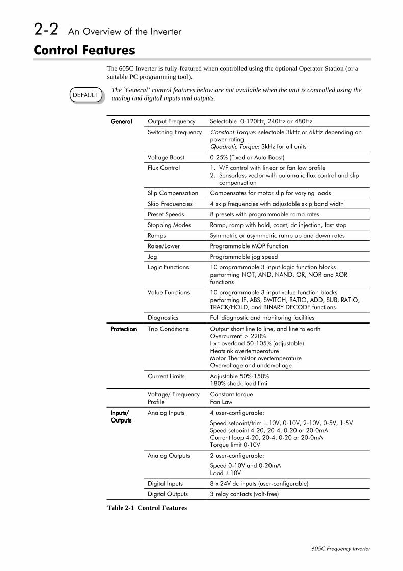
&RQWURO#)HDWXUHVThe 605C Inverter is fully-featured when controlled using the optional Operator Station (or asuitable PC programming tool).
The `General’ control features below are not available when the unit is controlled using theanalog and digital inputs and outputs.
*HQHUDO*HQHUDO*HQHUDO*HQHUDO 2XWSXW#)UHTXHQF\ 6HOHFWDEOH##30453+]/#573+]#RU#7;3+]
6ZLWFKLQJ#)UHTXHQF\ &RQVWDQW#7RUTXH=#VHOHFWDEOH#6N+]#RU#9N+]#GHSHQGLQJ#RQSRZHU#UDWLQJ4XDGUDWLF#7RUTXH=#6N+]#IRU#DOO#XQLWV
9ROWDJH#%RRVW 3058(#+)L[HG#RU#$XWR#%RRVW,
)OX[#&RQWURO 41##92)#FRQWURO#ZLWK#OLQHDU#RU#IDQ#ODZ#SURILOH51##6HQVRUOHVV#YHFWRU#ZLWK#DXWRPDWLF#IOX[#FRQWURO#DQG#VOLS#####FRPSHQVDWLRQ
6OLS#&RPSHQVDWLRQ &RPSHQVDWHV#IRU#PRWRU#VOLS#IRU#YDU\LQJ#ORDGV
6NLS#)UHTXHQFLHV 7#VNLS#IUHTXHQFLHV#ZLWK#DGMXVWDEOH#VNLS#EDQG#ZLGWK
3UHVHW#6SHHGV ;#SUHVHWV#ZLWK#SURJUDPPDEOH#UDPS#UDWHV
6WRSSLQJ#0RGHV 5DPS/#UDPS#ZLWK#KROG/#FRDVW/#GF#LQMHFWLRQ/#IDVW#VWRS
5DPSV 6\PPHWULF#RU#DV\PPHWULF#UDPS#XS#DQG#GRZQ#UDWHV
5DLVH2/RZHU 3URJUDPPDEOH#023#IXQFWLRQ
-RJ 3URJUDPPDEOH#MRJ#VSHHG
/RJLF#)XQFWLRQV 43#SURJUDPPDEOH#6#LQSXW#ORJLF#IXQFWLRQ#EORFNVSHUIRUPLQJ#127/#$1'/#1$1'/#25/#125#DQG#;25IXQFWLRQV
9DOXH#)XQFWLRQV 43#SURJUDPPDEOH#6#LQSXW#YDOXH#IXQFWLRQ#EORFNVSHUIRUPLQJ#,)/#$%6/#6:,7&+/#5$7,2/#$''/#68%/#5$7,2/75$&.2+2/'/#DQG#%,1$5<#'(&2'(#IXQFWLRQV
'LDJQRVWLFV )XOO#GLDJQRVWLF#DQG#PRQLWRULQJ#IDFLOLWLHV
3URWHFWLRQ3URWHFWLRQ3URWHFWLRQ3URWHFWLRQ 7ULS#&RQGLWLRQV 2XWSXW#VKRUW#OLQH#WR#OLQH/#DQG#OLQH#WR#HDUWK2YHUFXUUHQW#!#553(,#[#W#RYHUORDG#830438(#+DGMXVWDEOH,+HDWVLQN#RYHUWHPSHUDWXUH0RWRU#7KHUPLVWRU#RYHUWHPSHUDWXUH2YHUYROWDJH#DQG#XQGHUYROWDJH
&XUUHQW#/LPLWV $GMXVWDEOH#83(0483(4;3(#VKRFN#ORDG#OLPLW
9ROWDJH2#)UHTXHQF\3URILOH
&RQVWDQW#WRUTXH)DQ#/DZ
,QSXWV2,QSXWV2,QSXWV2,QSXWV22XWSXWV2XWSXWV2XWSXWV2XWSXWV
$QDORJ#,QSXWV 7#XVHU0FRQILJXUDEOH=
6SHHG#VHWSRLQW2WULP#439/#30439/#50439/#3089/#40896SHHG#VHWSRLQW#7053/#5307/#3053#RU#5303P$&XUUHQW#ORRS#7053/#5307/#3053#RU#5303P$7RUTXH#OLPLW#30439
$QDORJ#2XWSXWV 5#XVHU0FRQILJXUDEOH=
6SHHG#30439#DQG#3053P$/RDG#439
'LJLWDO#,QSXWV ;#[#579#GF#LQSXWV#+XVHU0FRQILJXUDEOH,
'LJLWDO#2XWSXWV 6#UHOD\#FRQWDFWV#+YROW0IUHH,
Table 2-1 Control Features
'()$8/7
$Q#2YHUYLHZ#RI#WKH#,QYHUWHU##506
938&#)UHTXHQF\#,QYHUWHU
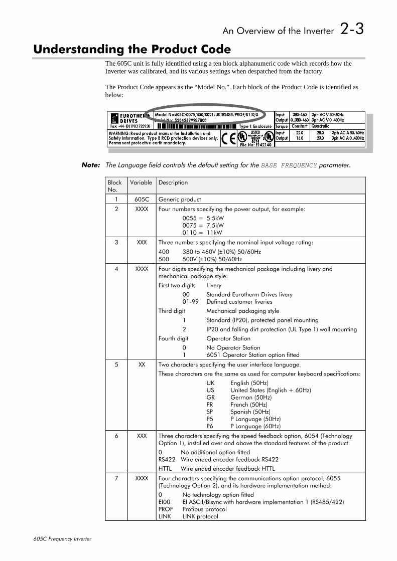
8QGHUVWDQGLQJ#WKH#3URGXFW#&RGHThe 605C unit is fully identified using a ten block alphanumeric code which records how theInverter was calibrated, and its various settings when despatched from the factory.
The Product Code appears as the “Model No.”. Each block of the Product Code is identified asbelow:
1RWH=# 7KH#/DQJXDJH#ILHOG#FRQWUROV#WKH#GHIDXOW#VHWWLQJ#IRU#WKH#BASE FREQUENCY#SDUDPHWHU1
%ORFN1R1
9DULDEOH 'HVFULSWLRQ
4 938& *HQHULF#SURGXFW
5 ;;;; )RXU#QXPEHUV#VSHFLI\LQJ#WKH#SRZHU#RXWSXW/#IRU#H[DPSOH=
3388# 818N:33:8# # :18N:3443# # 44N:
6 ;;; 7KUHH#QXPEHUV#VSHFLI\LQJ#WKH#QRPLQDO#LQSXW#YROWDJH#UDWLQJ=
733 6;3#WR#7939#+±43(,#83293+]833# 8339#+±43(,#83293+]
7 ;;;; )RXU#GLJLWV#VSHFLI\LQJ#WKH#PHFKDQLFDO#SDFNDJH#LQFOXGLQJ#OLYHU\#DQGPHFKDQLFDO#SDFNDJH#VW\OH=
)LUVW#WZR#GLJLWV /LYHU\
33 6WDQGDUG#(XURWKHUP#'ULYHV#OLYHU\340<< 'HILQHG#FXVWRPHU#OLYHULHV
7KLUG#GLJLW 0HFKDQLFDO#SDFNDJLQJ#VW\OH
4 6WDQGDUG#+,353,/#SURWHFWHG#SDQHO#PRXQWLQJ
5 ,353#DQG#IDOOLQJ#GLUW#SURWHFWLRQ#+8/#7\SH#4,#ZDOO#PRXQWLQJ
)RXUWK#GLJLW 2SHUDWRU#6WDWLRQ
3 1R#2SHUDWRU#6WDWLRQ4 9384#2SHUDWRU#6WDWLRQ#RSWLRQ#ILWWHG
8 ;; 7ZR#FKDUDFWHUV#VSHFLI\LQJ#WKH#XVHU#LQWHUIDFH#ODQJXDJH1
7KHVH#FKDUDFWHUV#DUH#WKH#VDPH#DV#XVHG#IRU#FRPSXWHU#NH\ERDUG#VSHFLILFDWLRQV=
8. (QJOLVK#+83+],86 8QLWHG#6WDWHV#+(QJOLVK#.#93+],*5 *HUPDQ#+83+],)5 )UHQFK#+83+],63 6SDQLVK#+83+],38 3#/DQJXDJH#+83+],39 3#/DQJXDJH#+93+],
9 ;;; 7KUHH#FKDUDFWHUV#VSHFLI\LQJ#WKH#VSHHG#IHHGEDFN#RSWLRQ/#9387#+7HFKQRORJ\2SWLRQ#4,/#LQVWDOOHG#RYHU#DQG#DERYH#WKH#VWDQGDUG#IHDWXUHV#RI#WKH#SURGXFW=
3 1R#DGGLWLRQDO#RSWLRQ#ILWWHG56755 :LUH#HQGHG#HQFRGHU#IHHGEDFN#56755
+77/# :LUH#HQGHG#HQFRGHU#IHHGEDFN#+77/
: ;;;; )RXU#FKDUDFWHUV#VSHFLI\LQJ#WKH#FRPPXQLFDWLRQV#RSWLRQ#SURWRFRO/#9388+7HFKQRORJ\#2SWLRQ#5,/#DQG#LWV#KDUGZDUH#LPSOHPHQWDWLRQ#PHWKRG=
3 1R#WHFKQRORJ\#RSWLRQ#ILWWHG(,33 (,#$6&,,2%LV\QF#ZLWK#KDUGZDUH#LPSOHPHQWDWLRQ#4#+567;82755,352) 3URILEXV#SURWRFRO/,1. /,1.#SURWRFRO
507##$Q#2YHUYLHZ#RI#WKH#,QYHUWHU
938&#)UHTXHQF\#,QYHUWHU
%ORFN1R1
9DULDEOH 'HVFULSWLRQ
; ;; 7ZR#FKDUDFWHUV#VSHFLI\LQJ#WKH#EUDNLQJ#RSWLRQ=
%3 %UDNH#SRZHU#VZLWFK#ILWWHG#0#QR#EUDNLQJ#UHVLVWRUV#VXSSOLHG1RWH=#([WHUQDO#EUDNLQJ#UHVLVWRUV#VKRXOG#EH#VSHFLILHG#DQG#RUGHUHG#VHSDUDWHO\1
< ;;; 7KUHH#FKDUDFWHUV#VSHFLI\LQJ#WKH#DX[LOLDU\#PDLQV#SRZHU#VXSSO\1
3 5HVHUYHG
43 ;;; 6#GLJLWV#VSHFLI\LQJ#HQJLQHHULQJ#VSHFLDO#RSWLRQV=
3 1R#VSHFLDO#RSWLRQ
)XQFWLRQDO#2YHUYLHZ
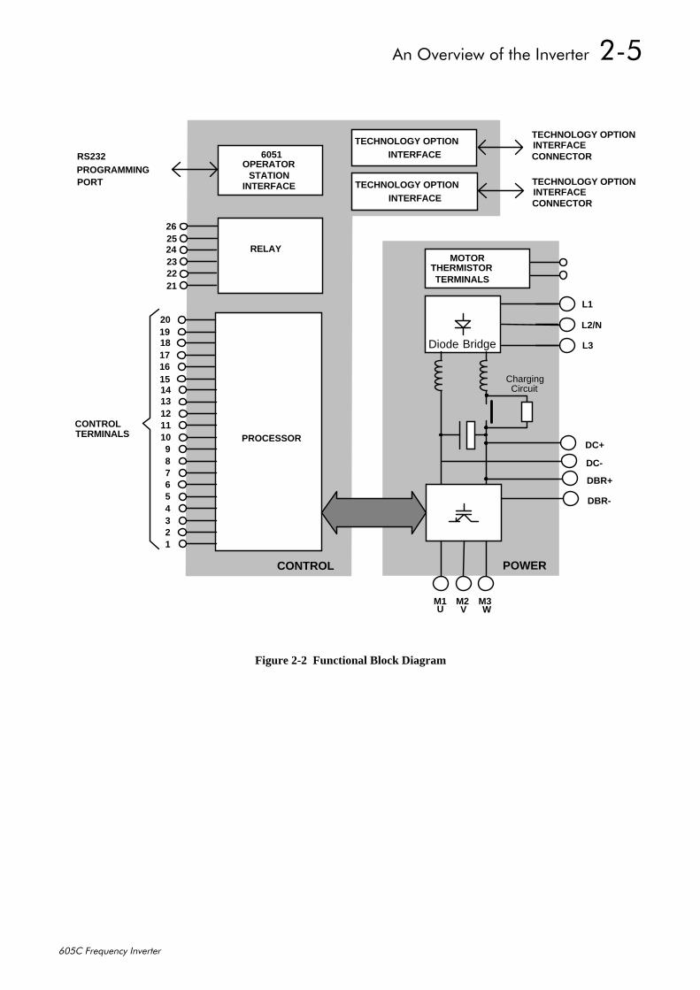
3RZHU#%RDUGDC link capacitors smooth the dc voltage output prior to the Inverter power stage. The IGBT(Insulated Gate Bi-polar Transistor) output stage converts the dc input to a three phase outputused to drive the motor.
&RQWURO#%RDUG3URFHVVRUThe processor provides for a range of analog and digital inputs and outputs, together with theirreference supplies. For further details refer to Chapter 11: “Technical Specifications” - ControlTerminals.
The I/O configuration switches (SW1 & SW2) on the control board can be seen when theterminal cover and the left-hand Technology Option is removed. These switches configure theanalog i/o terminals. Refer to Chapter 6: “Programming Your Application” - ANALOG INPUTand ANALOG OUTPUT.
7HFKQRORJ\#2SWLRQ#,QWHUIDFHThis is a multi-way connector and processor bus with control signals allowing Speed Feedbackand Communications Technology Options to be fitted to the 605C Inverter.
2SHUDWRU#6WDWLRQ#,QWHUIDFHThis is a non-isolated RS232 serial link for communication with the Operator Station.Alternatively, a PC running Eurotherm Drives’ “ConfigEd Lite” Windows-based configurationsoftware (or some other suitable PC programming tool) can be used to graphically program andconfigure the 605C Inverter.
'()$8/7
$Q#2YHUYLHZ#RI#WKH#,QYHUWHU##508
938&#)UHTXHQF\#,QYHUWHU
Figure 2-2 Functional Block Diagram
1413121110987654321
PROCESSOR
POWERCONTROL
M1 M2 M3
DC+
DC-
DBR-
CONTROLTERMINALS
6051
18171615
L1
L2/N
L3
PROGRAMMINGPORT
U V W
RS232OPERATOR
INTERFACESTATION
Diode Bridge
INTERFACETECHNOLOGY OPTION
INTERFACETECHNOLOGY OPTION
TECHNOLOGY OPTIONINTERFACECONNECTOR
ChargingCircuit
DBR+
MOTOR
TERMINALSTHERMISTOR
2019
RELAY24232221
2625
TECHNOLOGY OPTIONINTERFACECONNECTOR

509##$Q#2YHUYLHZ#RI#WKH#,QYHUWHU
938&#)UHTXHQF\#,QYHUWHU
,QVWDOOLQJ#WKH#,QYHUWHU#604
938&#)UHTXHQF\#,QYHUWHU
6#,167$//,1*#7+(#,19(57(5,03257$17=# 5HDG#&KDSWHU#45=#´&HUWLILFDWLRQ#IRU#WKH#,QYHUWHUµ#EHIRUH#LQVWDOOLQJ#WKLV#XQLW1
0HFKDQLFDO#,QVWDOODWLRQ
0RGHO#5HFRJQLWLRQ0RGHO#5HFRJQLWLRQ0RGHO#5HFRJQLWLRQ0RGHO#5HFRJQLWLRQ3URGXFW#&RGH3URGXFW#&RGH3URGXFW#&RGH3URGXFW#&RGH+%ORFNV#5#)#6,+%ORFNV#5#)#6,+%ORFNV#5#)#6,+%ORFNV#5#)#6,
:HLJKW:HLJKW:HLJKW:HLJKWNJ2OEVNJ2OEVNJ2OEVNJ2OEV
++++DOO#PRGHOV
+4+4+4+4DOO#PRGHOV
::::DOO#PRGHOV
:4:4:4:4DOO#PRGHOV
''''DOO#PRGHOV
((((DOO#PRGHOV
)L[LQJV)L[LQJV)L[LQJV)L[LQJVDOO#PRGHOV
33882733 4:172:1<33:82733 53152<1534432733 53182<16 67;13 69813 53413 483 53;13 66813 6ORW#:PP#ZLGH133882833 4:172:1< +461:3, +4716:, +:1<4, +81<3, +;14<, +4614<, 8VH#08#RU#0933:82833 53152<15 IL[LQJV134432833 53182<16
$OO#GLPHQVLRQV#DUH#LQ#PLOOLPHWUHV#+LQFKHV,
1RWH=# 'HWDLOV#RI#D#WKURXJK0SDQHO#PRXQWLQJ#RSWLRQ#IRU#GLUW\#DLU#FRROLQJ#DUH#DYDLODEOH#IURP(XURWKHUP#'ULYHV1
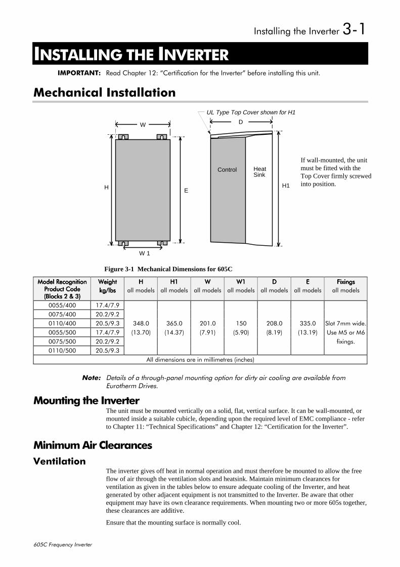
0RXQWLQJ#WKH#,QYHUWHUThe unit must be mounted vertically on a solid, flat, vertical surface. It can be wall-mounted, ormounted inside a suitable cubicle, depending upon the required level of EMC compliance - referto Chapter 11: “Technical Specifications” and Chapter 12: “Certification for the Inverter”.
0LQLPXP#$LU#&OHDUDQFHV9HQWLODWLRQ
The inverter gives off heat in normal operation and must therefore be mounted to allow the freeflow of air through the ventilation slots and heatsink. Maintain minimum clearances forventilation as given in the tables below to ensure adequate cooling of the Inverter, and heatgenerated by other adjacent equipment is not transmitted to the Inverter. Be aware that otherequipment may have its own clearance requirements. When mounting two or more 605s together,these clearances are additive.
Ensure that the mounting surface is normally cool.
If wall-mounted, the unitmust be fitted with theTop Cover firmly screwedinto position.
W
H
W 1
HeatSink
Control
D
EH1
UL Type Top Cover shown for H1
Figure 3-1 Mechanical Dimensions for 605C
605##,QVWDOOLQJ#WKH#,QYHUWHU
938&#)UHTXHQF\#,QYHUWHU
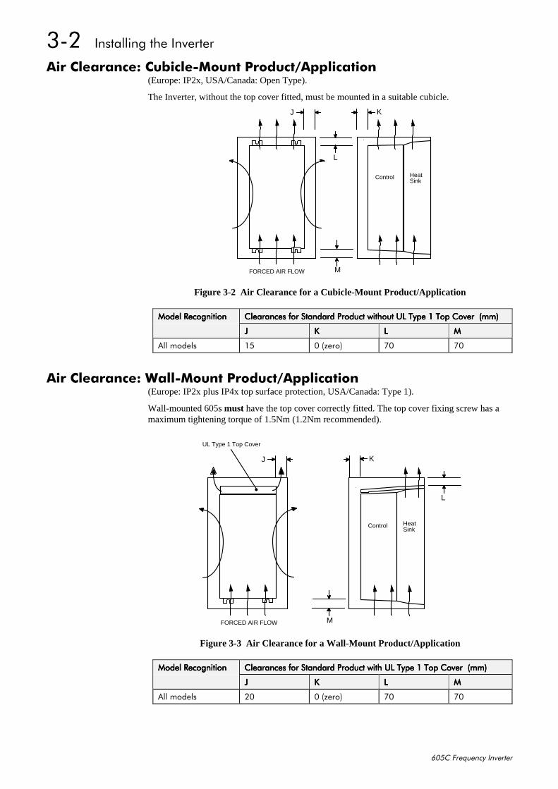
$LU#&OHDUDQFH=#&XELFOH00RXQW#3URGXFW2$SSOLFDWLRQ(Europe: IP2x, USA/Canada: Open Type).
The Inverter, without the top cover fitted, must be mounted in a suitable cubicle.
Control HeatSink
J K
L
M
FORCED AIR FLOW
Figure 3-2 Air Clearance for a Cubicle-Mount Product/Application
0RGHO#5HFRJQLWLRQ0RGHO#5HFRJQLWLRQ0RGHO#5HFRJQLWLRQ0RGHO#5HFRJQLWLRQ &OHDUDQFHV#IRU#6WDQGDUG#3URGXFW#ZLWKRXW#8/#7\SH#4#7RS#&RYHU##+PP,&OHDUDQFHV#IRU#6WDQGDUG#3URGXFW#ZLWKRXW#8/#7\SH#4#7RS#&RYHU##+PP,&OHDUDQFHV#IRU#6WDQGDUG#3URGXFW#ZLWKRXW#8/#7\SH#4#7RS#&RYHU##+PP,&OHDUDQFHV#IRU#6WDQGDUG#3URGXFW#ZLWKRXW#8/#7\SH#4#7RS#&RYHU##+PP,
---- .... //// 0000
$OO#PRGHOV 48 3#+]HUR, :3 :3
$LU#&OHDUDQFH=#:DOO00RXQW#3URGXFW2$SSOLFDWLRQ(Europe: IP2x plus IP4x top surface protection, USA/Canada: Type 1).
Wall-mounted 605s must have the top cover correctly fitted. The top cover fixing screw has amaximum tightening torque of 1.5Nm (1.2Nm recommended).
UL Type 1 Top Cover
J
Control HeatSink
K
L
M
FORCED AIR FLOW
Figure 3-3 Air Clearance for a Wall-Mount Product/Application
0RGHO#5HFRJQLWLRQ0RGHO#5HFRJQLWLRQ0RGHO#5HFRJQLWLRQ0RGHO#5HFRJQLWLRQ &OHDUDQFHV#IRU#6WDQGDUG#3URGXFW#ZLWK#8/#7\SH#4#7RS#&RYHU##+PP,&OHDUDQFHV#IRU#6WDQGDUG#3URGXFW#ZLWK#8/#7\SH#4#7RS#&RYHU##+PP,&OHDUDQFHV#IRU#6WDQGDUG#3URGXFW#ZLWK#8/#7\SH#4#7RS#&RYHU##+PP,&OHDUDQFHV#IRU#6WDQGDUG#3URGXFW#ZLWK#8/#7\SH#4#7RS#&RYHU##+PP,
---- .... //// 0000
$OO#PRGHOV 53 3#+]HUR, :3 :3
,QVWDOOLQJ#WKH#,QYHUWHU#606
938&#)UHTXHQF\#,QYHUWHU
#(OHFWULFDO#,QVWDOODWLRQ,03257$17=# 3OHDVH#UHDG#WKH#6DIHW\#,QIRUPDWLRQ#RQ#SDJH#&RQW1#6#)#7#EHIRUH#SURFHHGLQJ1
:LULQJ#WKH#,QYHUWHU
:$51,1*$# (QVXUH#WKDW#DOO#ZLULQJ#LV#HOHFWULFDOO\#LVRODWHG#DQG#FDQQRW#EH#PDGH#´OLYHµ
XQLQWHQWLRQDOO\#E\#RWKHU#SHUVRQQHO1
1RWH=# 5HIHU#WR#&KDSWHU#44=#´7HFKQLFDO#6SHFLILFDWLRQVµ#IRU#DGGLWLRQDO#&DEOLQJ#5HTXLUHPHQWV#DQG7HUPLQDO#%ORFN#:LUH#6L]HV1
LQYHUWHU
ILOWHU
PRWRU
EUDNH#UHVLVWRU
+QRLV\,
+QRLV\,
VLJQDO2FRQWURO#FDEOH
+VHQVLWLYH,
SRZHUVXSSO\
+FOHDQ,
FDEOH DF
IXVH#RU#VXLWDEOHFLUFXLW#EUHDNHU
+5&'#QRW UHFRPPHQGHG,
OLQHFKRNH
+QRLV\,
PRWRUFDEOH
VXSSO\(0&
PRWRUFKRNH
+QRLV\,
ILOWHU
PRWRURXWSXW
H[WHUQDO (0&
+LI#UHTXLUHG,
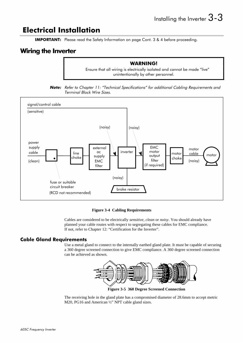
Figure 3-4 Cabling Requirements
Cables are considered to be electrically sensitive, clean or noisy. You should already haveplanned your cable routes with respect to segregating these cables for EMC compliance.If not, refer to Chapter 12: “Certification for the Inverter”.
&DEOH#*ODQG#5HTXLUHPHQWVUse a metal gland to connect to the internally earthed gland plate. It must be capable of securinga 360 degree screened connection to give EMC compliance. A 360 degree screened connectioncan be achieved as shown.
The receiving hole in the gland plate has a compromised diameter of 28.6mm to accept metricM20, PG16 and American ½” NPT cable gland sizes.
Figure 3-5 360 Degree Screened Connection
607##,QVWDOOLQJ#WKH#,QYHUWHU
938&#)UHTXHQF\#,QYHUWHU
DBR+ DBR-
MOT/TEMP
Power Board
REM OP STA 1 2 3 4 5 6 7 8 9 10 11 12 13 14 15 16 17 18 19 20 21 22 23 24 25 26
L1 L2 L3 DC+ DC- M1/U M2/V M3/W
P3
TB3TB1 TB4
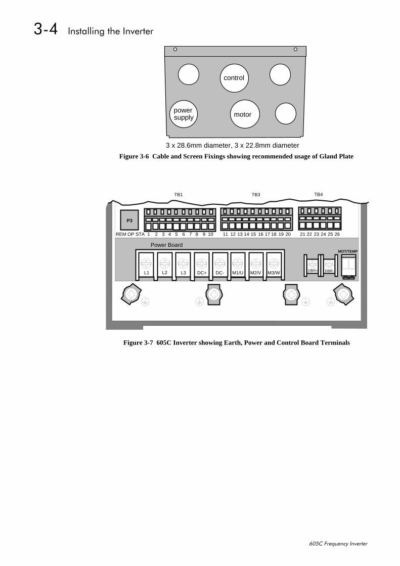
Figure 3-7 605C Inverter showing Earth, Power and Control Board Terminals
3 x 28.6mm diameter, 3 x 22.8mm diameter
powersupply
control
motor
Figure 3-6 Cable and Screen Fixings showing recommended usage of Gland Plate
,QVWDOOLQJ#WKH#,QYHUWHU#608
938&#)UHTXHQF\#,QYHUWHU
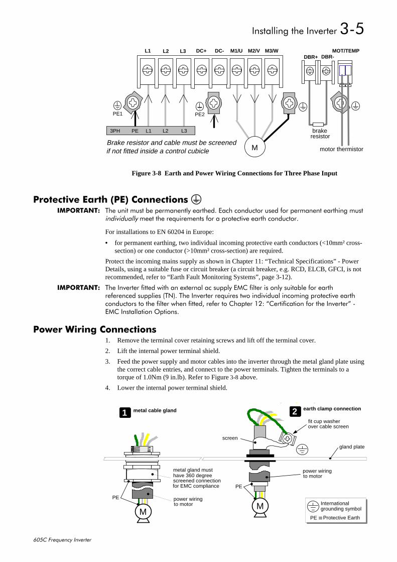
3URWHFWLYH#(DUWK#+3(,#&RQQHFWLRQV#,03257$17=# 7KH#XQLW#PXVW#EH#SHUPDQHQWO\#HDUWKHG1#(DFK#FRQGXFWRU#XVHG#IRU#SHUPDQHQW#HDUWKLQJ#PXVW
LQGLYLGXDOO\#PHHW#WKH#UHTXLUHPHQWV#IRU#D#SURWHFWLYH#HDUWK#FRQGXFWRU1
For installations to EN 60204 in Europe:
• for permanent earthing, two individual incoming protective earth conductors (<10mm² cross-section) or one conductor (>10mm² cross-section) are required.
Protect the incoming mains supply as shown in Chapter 11: “Technical Specifications” - PowerDetails, using a suitable fuse or circuit breaker (a circuit breaker, e.g. RCD, ELCB, GFCI, is notrecommended, refer to “Earth Fault Monitoring Systems”, page 3-12).
,03257$17=# 7KH#,QYHUWHU#ILWWHG#ZLWK#DQ#H[WHUQDO#DF#VXSSO\#(0&#ILOWHU#LV#RQO\#VXLWDEOH#IRU#HDUWKUHIHUHQFHG#VXSSOLHV#+71,1#7KH#,QYHUWHU#UHTXLUHV#WZR#LQGLYLGXDO#LQFRPLQJ#SURWHFWLYH#HDUWKFRQGXFWRUV#WR#WKH#ILOWHU#ZKHQ#ILWWHG/#UHIHU#WR#&KDSWHU#45=#´&HUWLILFDWLRQ#IRU#WKH#,QYHUWHUµ#0(0&#,QVWDOODWLRQ#2SWLRQV1
3RZHU#:LULQJ#&RQQHFWLRQV1. Remove the terminal cover retaining screws and lift off the terminal cover.
2. Lift the internal power terminal shield.
3. Feed the power supply and motor cables into the inverter through the metal gland plate usingthe correct cable entries, and connect to the power terminals. Tighten the terminals to atorque of 1.0Nm (9 in.lb). Refer to Figure 3-8 above.
4. Lower the internal power terminal shield.
DBR+ DBR-
brakeresistor
MOT/TEMP
PE1 PE2
3PH PE L1 L2 L3
MBrake resistor and cable must be screenedif not fitted inside a control cubicle
L1 L2 DC+ DC- M1/U M2/V M3/WL3
motor thermistor
Figure 3-8 Earth and Power Wiring Connections for Three Phase Input
PE power wiringto motor
metal gland musthave 360 degreescreened connectionfor EMC compliance
M
PE
PE Protective Earth
Internationalgrounding symbolM
power wiringto motor
gland plate
2 earth clamp connection1 metal cable gland
fit cup washerover cable screen
screen
609##,QVWDOOLQJ#WKH#,QYHUWHU
938&#)UHTXHQF\#,QYHUWHU
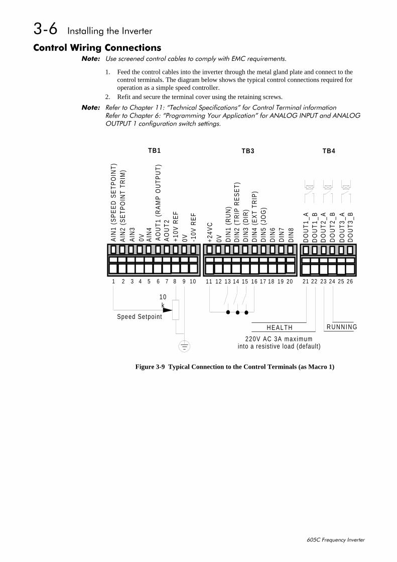
&RQWURO#:LULQJ#&RQQHFWLRQV1RWH=# 8VH#VFUHHQHG#FRQWURO#FDEOHV#WR#FRPSO\#ZLWK#(0&#UHTXLUHPHQWV1
1. Feed the control cables into the inverter through the metal gland plate and connect to thecontrol terminals. The diagram below shows the typical control connections required foroperation as a simple speed controller.
2. Refit and secure the terminal cover using the retaining screws.
1RWH=# 5HIHU#WR#&KDSWHU#44=#´7HFKQLFDO#6SHFLILFDWLRQVµ#IRU#&RQWURO#7HUPLQDO#LQIRUPDWLRQ5HIHU#WR#&KDSWHU#9=#´3URJUDPPLQJ#<RXU#$SSOLFDWLRQµ#IRU#$1$/2*#,1387#DQG#$1$/2*287387#4#FRQILJXUDWLRQ#VZLWFK#VHWWLQJV1
HEALTH
Speed Setpoint
10k
220V AC 3A max imum
TB1 TB3 TB4
into a resistive load (default)
1 2 3 4 5 6 7 8 9 10
11 12 13 14 15 16 17 18 19 20
DO
UT
1_A
DO
UT
1_B
DO
UT
2_A
DO
UT
2_B
DO
UT
3_A
DO
UT
3_B
21 22 23 24 25 26
AIN
1 (S
PE
ED
SE
TP
OIN
T)
AIN
2 (S
ET
PO
INT
TR
IM)
AIN
30V A
IN4
AO
UT
1 (R
AM
P O
UT
PU
T)
AO
UT
2+1
0V R
EF
0V -10V
RE
F
+24V
C0V D
IN1
(RU
N)
DIN
2 (T
RIP
RE
SE
T)D
IN3
(DIR
)D
IN4
(EX
T TR
IP)
DIN
5 (J
OG
)D
IN6
DIN
7D
IN8
RUNNING
Figure 3-9 Typical Connection to the Control Terminals (as Macro 1)
,QVWDOOLQJ#WKH#,QYHUWHU#60:
938&#)UHTXHQF\#,QYHUWHU
2SWLRQDO#(TXLSPHQW
)LWWLQJ#WKH#5HPRWH#9384#2SHUDWRU#6WDWLRQ
A
B
C
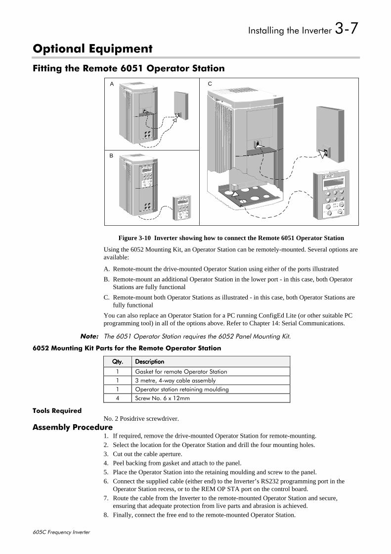
Figure 3-10 Inverter showing how to connect the Remote 6051 Operator Station
Using the 6052 Mounting Kit, an Operator Station can be remotely-mounted. Several options areavailable:
A. Remote-mount the drive-mounted Operator Station using either of the ports illustrated
B. Remote-mount an additional Operator Station in the lower port - in this case, both OperatorStations are fully functional
C. Remote-mount both Operator Stations as illustrated - in this case, both Operator Stations arefully functional
You can also replace an Operator Station for a PC running ConfigEd Lite (or other suitable PCprogramming tool) in all of the options above. Refer to Chapter 14: Serial Communications.
1RWH=# 7KH#9384#2SHUDWRU#6WDWLRQ#UHTXLUHV#WKH#9385#3DQHO#0RXQWLQJ#.LW1
9385#0RXQWLQJ#.LW#3DUWV#IRU#WKH#5HPRWH#2SHUDWRU#6WDWLRQ
4W\14W\14W\14W\1 'HVFULSWLRQ'HVFULSWLRQ'HVFULSWLRQ'HVFULSWLRQ
4 *DVNHW#IRU#UHPRWH#2SHUDWRU#6WDWLRQ4 6#PHWUH/#70ZD\#FDEOH#DVVHPEO\4 2SHUDWRU#VWDWLRQ#UHWDLQLQJ#PRXOGLQJ7 6FUHZ#1R1#9#[#45PP
7RROV#5HTXLUHGNo. 2 Posidrive screwdriver.
$VVHPEO\#3URFHGXUH1. If required, remove the drive-mounted Operator Station for remote-mounting.2. Select the location for the Operator Station and drill the four mounting holes.3. Cut out the cable aperture.4. Peel backing from gasket and attach to the panel.5. Place the Operator Station into the retaining moulding and screw to the panel.6. Connect the supplied cable (either end) to the Inverter’s RS232 programming port in the
Operator Station recess, or to the REM OP STA port on the control board.7. Route the cable from the Inverter to the remote-mounted Operator Station and secure,
ensuring that adequate protection from live parts and abrasion is achieved.8. Finally, connect the free end to the remote-mounted Operator Station.
60;##,QVWDOOLQJ#WKH#,QYHUWHU
938&#)UHTXHQF\#,QYHUWHU
&XWRXW#'LPHQVLRQV
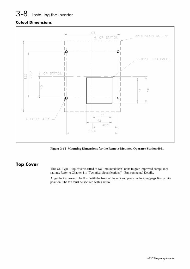
Figure 3-11 Mounting Dimensions for the Remote-Mounted Operator Station 6051
7RS#&RYHUThis UL Type 1 top cover is fitted to wall-mounted 605C units to give improved complianceratings. Refer to Chapter 11: “Technical Specifications” - Environmental Details.
Align the top cover to be flush with the front of the unit and press the locating pegs firmly intoposition. The top must be secured with a screw.
,QVWDOOLQJ#WKH#,QYHUWHU#60<
938&#)UHTXHQF\#,QYHUWHU
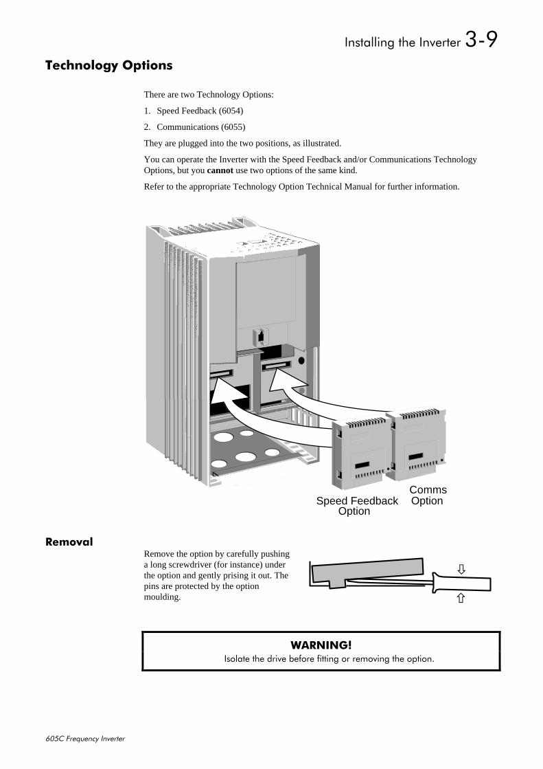
7HFKQRORJ\#2SWLRQV
There are two Technology Options:
1. Speed Feedback (6054)
2. Communications (6055)
They are plugged into the two positions, as illustrated.
You can operate the Inverter with the Speed Feedback and/or Communications TechnologyOptions, but you cannot use two options of the same kind.
Refer to the appropriate Technology Option Technical Manual for further information.
5HPRYDORemove the option by carefully pushinga long screwdriver (for instance) underthe option and gently prising it out. Thepins are protected by the optionmoulding.
:$51,1*$# ,VRODWH#WKH#GULYH#EHIRUH#ILWWLQJ#RU#UHPRYLQJ#WKH#RSWLRQ1
Speed FeedbackOption
CommsOption
×
Ø
6043##,QVWDOOLQJ#WKH#,QYHUWHU
938&#)UHTXHQF\#,QYHUWHU
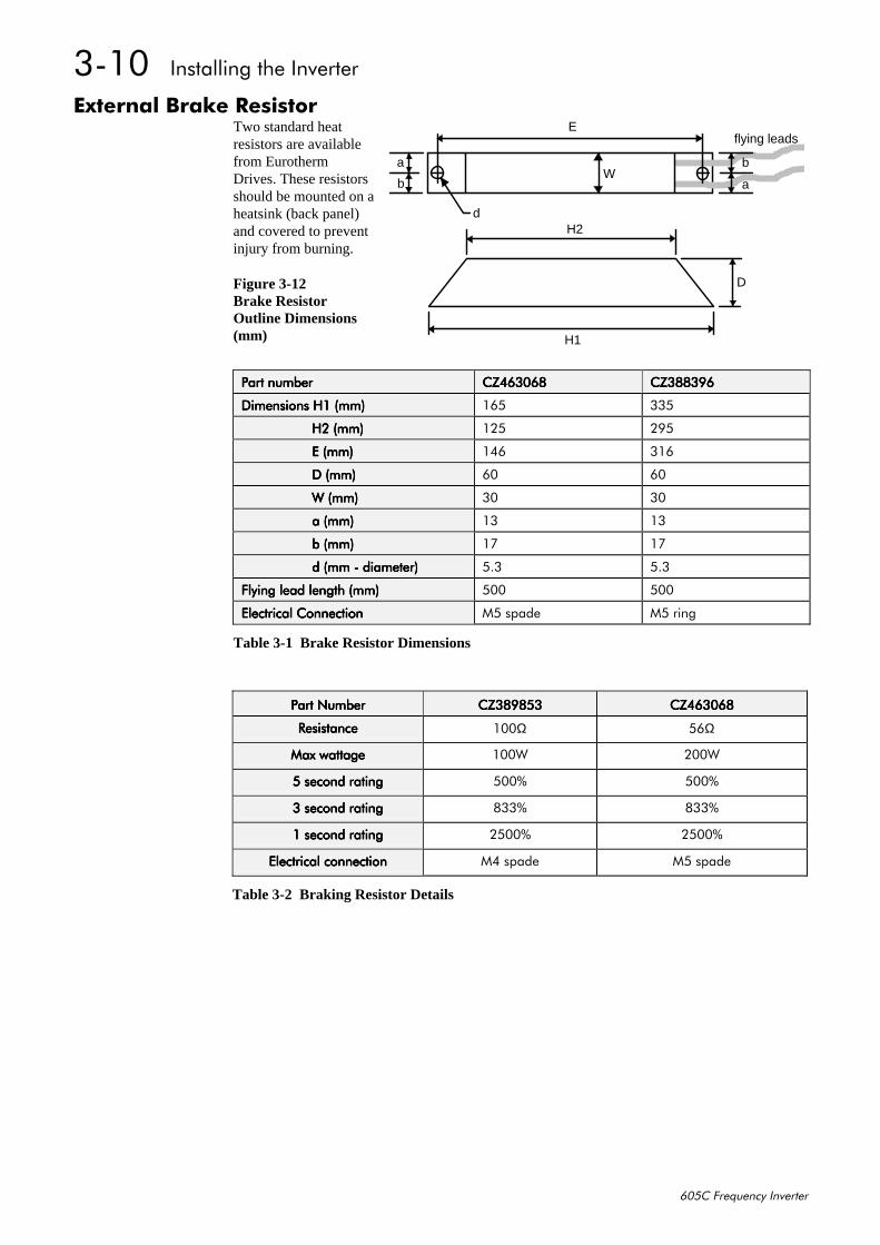
([WHUQDO#%UDNH#5HVLVWRUTwo standard heatresistors are availablefrom EurothermDrives. These resistorsshould be mounted on aheatsink (back panel)and covered to preventinjury from burning.
Figure 3-12Brake ResistorOutline Dimensions(mm)
3DUW#QXPEHU3DUW#QXPEHU3DUW#QXPEHU3DUW#QXPEHU &=79639;&=79639;&=79639;&=79639; &=6;;6<9&=6;;6<9&=6;;6<9&=6;;6<9
'LPHQVLRQV#+4#+PP,'LPHQVLRQV#+4#+PP,'LPHQVLRQV#+4#+PP,'LPHQVLRQV#+4#+PP, 498 668
##################+5#+PP,##################+5#+PP,##################+5#+PP,##################+5#+PP, 458 5<8
##################(#+PP,##################(#+PP,##################(#+PP,##################(#+PP, 479 649
##################'#+PP,##################'#+PP,##################'#+PP,##################'#+PP, 93 93
##################:#+PP,##################:#+PP,##################:#+PP,##################:#+PP, 63 63
##################D#+PP,##################D#+PP,##################D#+PP,##################D#+PP, 46 46
##################E#+PP,##################E#+PP,##################E#+PP,##################E#+PP, 4: 4:
##################G#+PP#0#GLDPHWHU,##################G#+PP#0#GLDPHWHU,##################G#+PP#0#GLDPHWHU,##################G#+PP#0#GLDPHWHU, 816 816
)O\LQJ#OHDG#OHQJWK#+PP,)O\LQJ#OHDG#OHQJWK#+PP,)O\LQJ#OHDG#OHQJWK#+PP,)O\LQJ#OHDG#OHQJWK#+PP, 833 833
(OHFWULFDO#&RQQHFWLRQ(OHFWULFDO#&RQQHFWLRQ(OHFWULFDO#&RQQHFWLRQ(OHFWULFDO#&RQQHFWLRQ 08#VSDGH 08#ULQJ
Table 3-1 Brake Resistor Dimensions
H1
D
flying leadsE
H2
Wa
b
d
a
b
3DUW#1XPEHU3DUW#1XPEHU3DUW#1XPEHU3DUW#1XPEHU &=6;<;86&=6;<;86&=6;<;86&=6;<;86 &=79639;&=79639;&=79639;&=79639;
5HVLVWDQFH5HVLVWDQFH5HVLVWDQFH5HVLVWDQFH 433Ω 89Ω
0D[#ZDWWDJH0D[#ZDWWDJH0D[#ZDWWDJH0D[#ZDWWDJH 433: 533:
#####8#VHFRQG#UDWLQJ#####8#VHFRQG#UDWLQJ#####8#VHFRQG#UDWLQJ#####8#VHFRQG#UDWLQJ 833( 833(
#####6#VHFRQG#UDWLQJ#####6#VHFRQG#UDWLQJ#####6#VHFRQG#UDWLQJ#####6#VHFRQG#UDWLQJ ;66( ;66(
#####4#VHFRQG#UDWLQJ#####4#VHFRQG#UDWLQJ#####4#VHFRQG#UDWLQJ#####4#VHFRQG#UDWLQJ 5833( 5833(
(OHFWULFDO#FRQQHFWLRQ(OHFWULFDO#FRQQHFWLRQ(OHFWULFDO#FRQQHFWLRQ(OHFWULFDO#FRQQHFWLRQ 07#VSDGH 08#VSDGH
Table 3-2 Braking Resistor Details

,QVWDOOLQJ#WKH#,QYHUWHU#6044
938&#)UHTXHQF\#,QYHUWHU
([WHUQDO#$XSSO\#(0&#)LOWHU
0RGHO0RGHO0RGHO0RGHO ++++ +4+4+4+4 +5+5+5+5 :::: :4:4:4:4 '''' '4'4'4'4
&27984;;8353 55< 54: 589 88 75 447 :9
&27984;;8369 5:5 58; 5<8 :7 93 494 456
0RGHO0RGHO0RGHO0RGHO 3KDVH3KDVH3KDVH3KDVH )UHTXHQF\)UHTXHQF\)UHTXHQF\)UHTXHQF\ &XUUHQW&XUUHQW&XUUHQW&XUUHQW 9ROWDJH9ROWDJH9ROWDJH9ROWDJH :DWW#/RVV:DWW#/RVV:DWW#/RVV:DWW#/RVV
&27984;;8353 6 83293+] 53$ 8539$& 46:
&27984;;8369 6 83293+] 69$ 8539$& 49:
Table 3-3 External AC Supply EMC Filter Details (dimensions are in millimetres)
:$51,1*$# 'R#QRW#XVH#DQ#H[WHUQDO#DF#VXSSO\#(0&#ILOWHU#ZLWK#VXSSOLHV#WKDW#DUH#QRW#EDODQFHGZLWK#UHVSHFW#WR#HDUWK#+,7,1#7KH\#PXVW#RQO\#EH#XVHG#ZLWK#HDUWK#UHIHUHQFHG#VXSSOLHV#+71,1
'R#QRW#WRXFK#ILOWHU#WHUPLQDOV#RU#FDEOLQJ#IRU#DW#OHDVW#6#PLQXWHV#DIWHU#UHPRYLQJ#WKH#DFVXSSO\1
2QO\#XVH#WKH#DF#VXSSO\#ILOWHU#ZLWK#D#SHUPDQHQW#HDUWK#FRQQHFWLRQ1
Mount the filter as close as possible to the inverter.
If the filter is wall-mounted, it must be mounted vertically and fitted with the gland box base (A)and gland box cover (B). These items are not required if the filter is mounted inside a suitablecubicle.
Fit a gland box base (A) to the filter at both ends and secure the filter on the wall. Bring theconduit into each end and complete the wiring. Finally, secure the gland box covers (B) using thescrews and washers.
B
H
H1W
W1
D
condui t
A
H2
D1
condui t
vertical mounting
gland boxbase
gland boxcover
Figure 3-13 External AC Supply EMC Filter Outline Dimensions(CO465188U036 illustrated)

6045##,QVWDOOLQJ#WKH#,QYHUWHU
938&#)UHTXHQF\#,QYHUWHU
The completed filter assembly provides IP4x rating from above and below, the remainingsurfaces are IP2x.
• CO465188U020 External AC Supply EMC Filter: back mounting - 4 x M6 earth terminals - M5 stud mass - 1.2kg BA465189U020 Gland Box Kit (both ends supplied): conduit hole diameter - 28.6mm (gland box base) • CO465188U036 External AC Supply EMC Filter:
back mounting - 4 x M7earth terminals - M6 studmass - 2.7kg
BA465189U036 Gland Box Kit (both ends supplied):conduit hole diameter - 28.6mm (gland box base)
Follow the cabling requirements given in Chapter 11: “Technical Specifications”
(0�RWRU#2XWSXW#)LOWHUThis can help the Inverter achieve EMC and filter thermal conformance with cable lengthsgreater than those specified. It also ensures longer motor life by reducing the high voltage slewrate and overvoltage stresses. Mount the filter as close to the VSD as possible. Please refer toEurotherm Drives for the selection of a suitable filter.
2XWSXW#&RQWDFWRUVOutput contactors can be used, although we recommend that this type of operation is limited toemergency use only, or in a system where the inverter can be inhibited before closing or openingthis contactor.
(DUWK#)DXOW#0RQLWRULQJ#6\VWHPVWe do not recommend the use of circuit breakers (e.g. RCD, ELCB, GFCI), but where their useis mandatory, they should:
• Operate correctly with dc and ac protective earth currents (i.e. type B RCDs as inAmendment 2 of IEC755).
• Have adjustable trip amplitude and time characteristics to prevent nuisance tripping onswitch-on.
When the ac supply is switched on, a pulse of current flows to earth to charge theinternal/external ac supply EMC filter’s internal capacitors which are connected between phaseand earth. This has been minimised in Eurotherm Drives’ filters, but may still trip out any circuitbreaker in the earth system. In addition, high frequency and dc components of earth leakagecurrents will flow under normal operating conditions. Under certain fault conditions larger dcprotective earth currents may flow. The protective function of some circuit breakers cannot beguaranteed under such operating conditions.
:$51,1*$# &LUFXLW#EUHDNHUV#XVHG#ZLWK#96'V#DQG#RWKHU#VLPLODU#HTXLSPHQW#DUH#QRW####VXLWDEOH#IRU
SHUVRQQHO#SURWHFWLRQ1#8VH#DQRWKHU#PHDQV#WR#SURYLGH#SHUVRQDO#VDIHW\1#5HIHU#WR(1834:;#+4<<:,#2#9'(3493#+4<<7,#2#(19353704#+4<<7,
,QVWDOOLQJ#WKH#,QYHUWHU#6046
938&#)UHTXHQF\#,QYHUWHU
/LQH#&KRNHV#+LQSXW,Line chokes may be used to reduce the harmonic content of the supply current where this aparticular requirement of the application or where greater protection from mains borne transientsis required. Please refer to Eurotherm Drives for the selection of a suitable line choke.
$�RWRU#&KRNH#+RXWSXW,Installations with longer than specified motor cable runs may suffer from nuisance overcurrenttrips, refer to Chapter 11: “Technical Specifications” - Cabling Requirements for maximum cablelengths. A choke may be fitted in the inverter output to limit capacitive current. Screened cablehas a higher capacitance and may cause problems in shorter runs.
1RWH=# 0RWRU#FKRNHV#PXVW#EH#ILWWHG#IRU#6;307939#DQG#8339#XQLWV#ZLWK#VFUHHQHG#FDEOH#UXQV#LQH[FHVV#RI#83P>#OLPLW#WKH#VZLWFKLQJ#IUHTXHQF\#WR#6N+]#LQ#WKHVH#DSSOLFDWLRQV1#5HIHU#WR&KDSWHU#9=#´3URJUDPPLQJ#<RXU#$SSOLFDWLRQµ#0#3$77(51#*(11
Contact Eurotherm Drives for further information.

6047##,QVWDOOLQJ#WKH#,QYHUWHU
938&#)UHTXHQF\#,QYHUWHU
2SHUDWLQJ#WKH#,QYHUWHU##704
938&#)UHTXHQF\#,QYHUWHU
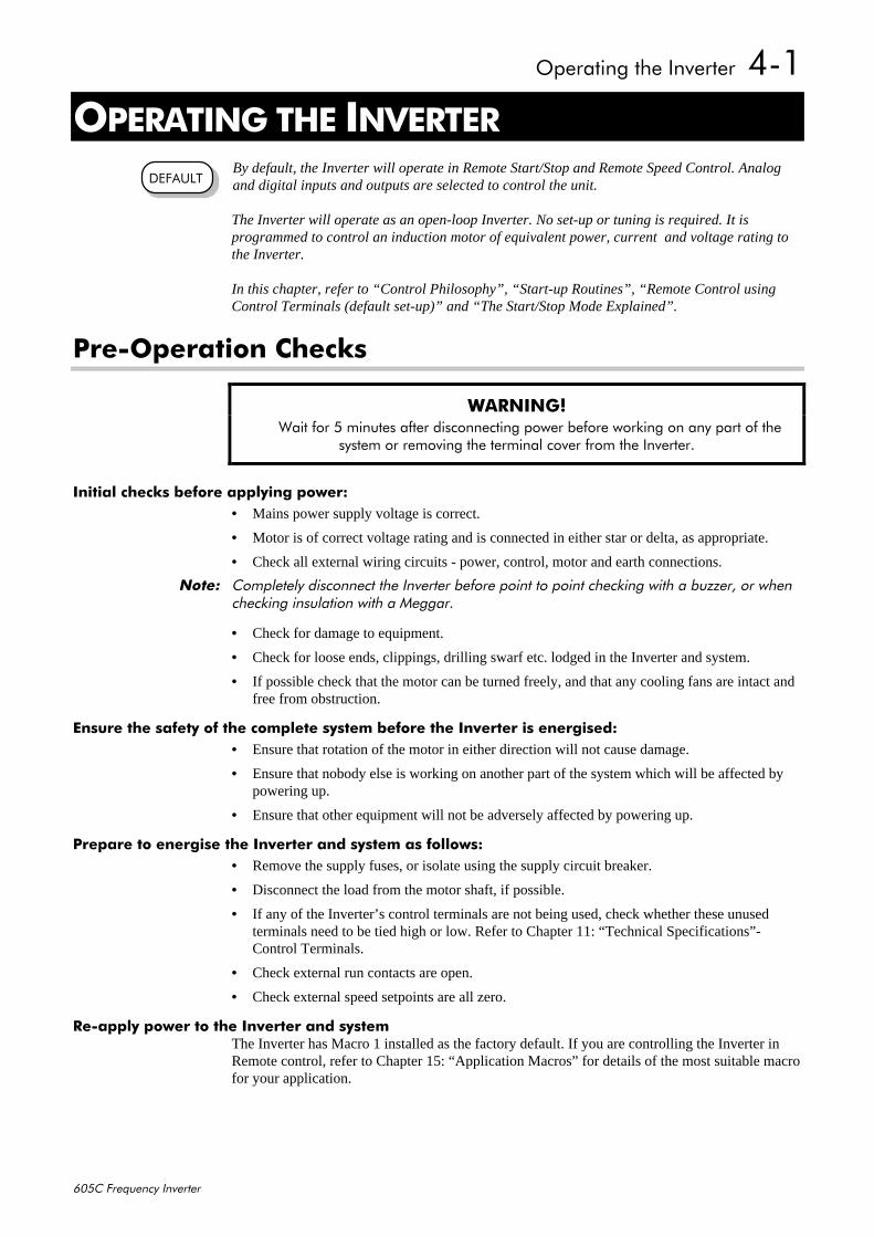
7#23(5$7,1*#7+(#,19(57(5By default, the Inverter will operate in Remote Start/Stop and Remote Speed Control. Analogand digital inputs and outputs are selected to control the unit.
The Inverter will operate as an open-loop Inverter. No set-up or tuning is required. It isprogrammed to control an induction motor of equivalent power, current and voltage rating tothe Inverter.
In this chapter, refer to “Control Philosophy”, “Start-up Routines”, “Remote Control usingControl Terminals (default set-up)” and “The Start/Stop Mode Explained”.
3UH02SHUDWLRQ#&KHFNV
:$51,1*$# :DLW#IRU#8#PLQXWHV#DIWHU#GLVFRQQHFWLQJ#SRZHU#EHIRUH#ZRUNLQJ#RQ#DQ\#SDUW#RI#WKH
V\VWHP#RU#UHPRYLQJ#WKH#WHUPLQDO#FRYHU#IURP#WKH#,QYHUWHU1
,QLWLDO#FKHFNV#EHIRUH#DSSO\LQJ#SRZHU=• Mains power supply voltage is correct.
• Motor is of correct voltage rating and is connected in either star or delta, as appropriate.
• Check all external wiring circuits - power, control, motor and earth connections.
1RWH=# &RPSOHWHO\#GLVFRQQHFW#WKH#,QYHUWHU#EHIRUH#SRLQW#WR#SRLQW#FKHFNLQJ#ZLWK#D#EX]]HU/#RU#ZKHQFKHFNLQJ#LQVXODWLRQ#ZLWK#D#0HJJDU1
• Check for damage to equipment.
• Check for loose ends, clippings, drilling swarf etc. lodged in the Inverter and system.
• If possible check that the motor can be turned freely, and that any cooling fans are intact andfree from obstruction.
(QVXUH#WKH#VDIHW\#RI#WKH#FRPSOHWH#V\VWHP#EHIRUH#WKH#,QYHUWHU#LV#HQHUJLVHG=• Ensure that rotation of the motor in either direction will not cause damage.
• Ensure that nobody else is working on another part of the system which will be affected bypowering up.
• Ensure that other equipment will not be adversely affected by powering up.
3UHSDUH#WR#HQHUJLVH#WKH#,QYHUWHU#DQG#V\VWHP#DV#IROORZV=• Remove the supply fuses, or isolate using the supply circuit breaker.
• Disconnect the load from the motor shaft, if possible.
• If any of the Inverter’s control terminals are not being used, check whether these unusedterminals need to be tied high or low. Refer to Chapter 11: “Technical Specifications”-Control Terminals.
• Check external run contacts are open.
• Check external speed setpoints are all zero.
5H0DSSO\#SRZHU#WR#WKH#,QYHUWHU#DQG#V\VWHPThe Inverter has Macro 1 installed as the factory default. If you are controlling the Inverter inRemote control, refer to Chapter 15: “Application Macros” for details of the most suitable macrofor your application.
'()$8/7
705##2SHUDWLQJ#WKH#,QYHUWHU
938&#)UHTXHQF\#,QYHUWHU
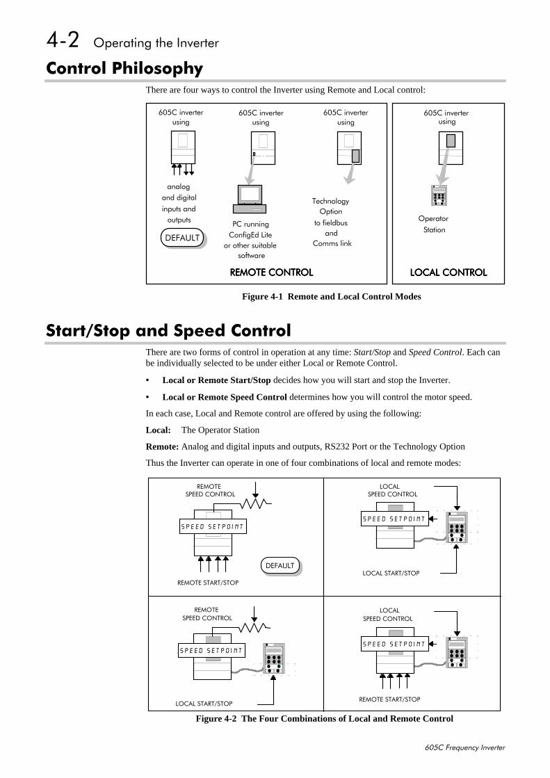
&RQWURO#3KLORVRSK\There are four ways to control the Inverter using Remote and Local control:
6WDUW26WRS#DQG#6SHHG#&RQWUROThere are two forms of control in operation at any time: Start/Stop and Speed Control. Each canbe individually selected to be under either Local or Remote Control.
• Local or Remote Start/Stop decides how you will start and stop the Inverter.
• Local or Remote Speed Control determines how you will control the motor speed.
In each case, Local and Remote control are offered by using the following:
Local: The Operator Station
Remote: Analog and digital inputs and outputs, RS232 Port or the Technology Option
Thus the Inverter can operate in one of four combinations of local and remote modes:
DQDORJDQG#GLJLWDO
LQSXWV#DQGRXWSXWV 3&#UXQQLQJ
&RQILJ(G#/LWHRU#RWKHU#VXLWDEOH
VRIWZDUH
7HFKQRORJ\
5(027(#&21752/5(027(#&21752/5(027(#&21752/5(027(#&21752/
938&#LQYHUWHUXVLQJ
938&#LQYHUWHUXVLQJ
938&#LQYHUWHUXVLQJ
/2&$/#&21752//2&$/#&21752//2&$/#&21752//2&$/#&21752/
938&#LQYHUWHUXVLQJ
2SWLRQ
WR#ILHOGEXVDQG
&RPPV#OLQN
2SHUDWRU
6WDWLRQ'()$8/7
Figure 4-1 Remote and Local Control Modes
5(027(#67$5726723
5(027(
/2&$/#67$5726723
/2&$/
5(027(#67$5726723
/2&$/
/2&$/#67$5726723
5(027(
63(('#&21752/
63(('#&21752/
63(('#&21752/
63(('#&21752/
'()$8/7
63(('û6(732,1763(('û6(732,17
63(('û6(732,1763(('û6(732,17
Figure 4-2 The Four Combinations of Local and Remote Control
2SHUDWLQJ#WKH#,QYHUWHU##706
938&#)UHTXHQF\#,QYHUWHU
1RWH=# 6WDUW26WRS#LV#DOVR#NQRZQ#DV#´6HTXHQFLQJµ16SHHG#&RQWURO#LV#DOVR#NQRZQ#DV#´5HIHUHQFH#*HQHUDWLRQµ1
6HOHFWLQJ#/RFDO#RU#5HPRWH#&RQWUROIf the default combination of remote Start/Stop and Speed Control is not suitable for yourapplication, follow the instructions below using the Operator Station or a suitable PCprogramming tool to select suitable combinations of local or remote control.
1RWH=# <RX#FDQ#RQO\#FKDQJH#EHWZHHQ#/RFDO#DQG#5HPRWH#FRQWURO#ZKHQ#WKH#,QYHUWHU#LV#´VWRSSHGµ1
7R#FKDQJH#D#FRPELQDWLRQ#WKH#2SHUDWRU#6WDWLRQ#PXVW#KDYH##WKH#´$GYDQFHGµ#YLHZLQJ#OHYHOVHOHFWHG>#DOORZLQJ#\RX#WR#YLHZ#HQRXJK#RI#WKH#PHQX#VWUXFWXUH#WR#PDNH#WKH#FKDQJH1#5HIHU#WR&KDSWHU#8=#´#7KH#2SHUDWRU#6WDWLRQµ#0#0HQX#9LHZLQJ#/HYHOV1
The L/R key on the Operator Station toggles between Local and Remote control, changing bothStart/Stop and Speed Control modes at the same time1
However, you can “fix” either or both modes in software to be either Local or Remote control.This makes the L/R key inoperative for that mode. In this way, you can select a combinationwhere both Local and Remote modes are present.
To do this, go to the LOCAL CONTROL menu at level 4 and selecteither:
LOCAL ONLY Sets Local control
REMOTE ONLY Sets Remote control
LOCAL/REMOTE Gives selection powers back to the L/R key.
Fixing only one of the modes will mean that the L/R key will stilltoggle the other mode between Local and Remote control.
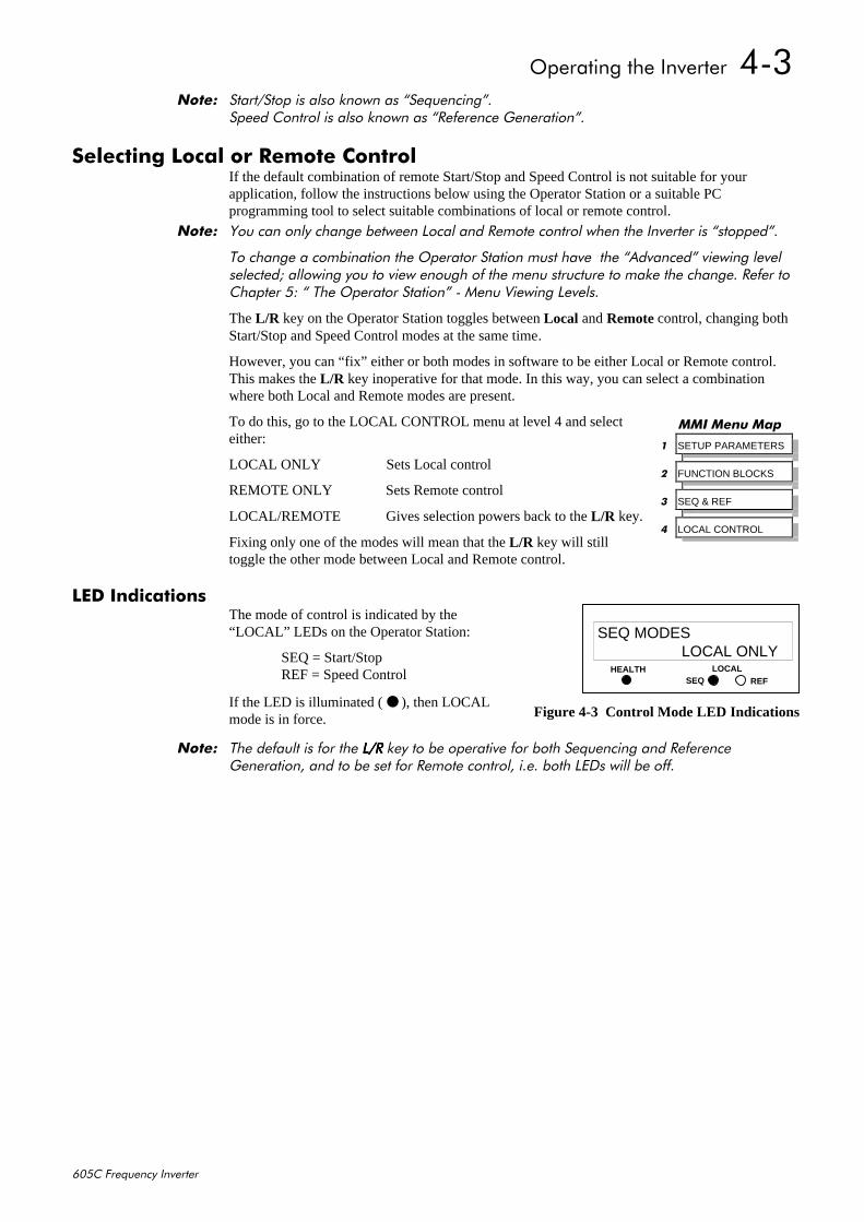
/('#,QGLFDWLRQVThe mode of control is indicated by the“LOCAL” LEDs on the Operator Station:
SEQ = Start/StopREF = Speed Control
If the LED is illuminated ( ), then LOCALmode is in force.
1RWH=# 7KH#GHIDXOW#LV#IRU#WKH#/25/25/25/25#NH\#WR#EH#RSHUDWLYH#IRU#ERWK#6HTXHQFLQJ#DQG#5HIHUHQFH*HQHUDWLRQ/#DQG#WR#EH#VHW#IRU#5HPRWH#FRQWURO/#L1H1#ERWK#/('V#ZLOO#EH#RII1
00,#0HQX#0DS
4 SETUP PARAMETERS
5 FUNCTION BLOCKS
6 SEQ & REF
7 LOCAL CONTROL
HEALTH LOCALSEQ REF
SEQ MODESLOCAL ONLY
Figure 4-3 Control Mode LED Indications
707##2SHUDWLQJ#WKH#,QYHUWHU
938&#)UHTXHQF\#,QYHUWHU
6WDUW0XS#5RXWLQHV,03257$17=# 5HIHU#WR#WKH#$1$/2*#,1387#DQG#$1$/2*#287387#IXQFWLRQ#EORFNV#LQ#&KDSWHU#9#IRU#WKH
FRUUHFW#VHWWLQJV#RI#&RQILJXUDWLRQ#6ZLWFKHV#6:4#DQG#6:5#EHIRUH#RSHUDWLRQ1
5HPRWH#&RQWURO#XVLQJ#&RQWURO#7HUPLQDOV#+GHIDXOW#VHW0XS,This is the simplest method of operating the Inverter. No Set-up or tuning is required.
This routine assumes that the Inverter’s control terminals are wired as shown in Figure 3-9.
1RWH=# (QVXUH#WKDW#WKH#VSHHG#SRWHQWLRPHWHU#LV#VHW#WR#]HUR1
1. Power-up the unit. The HEALTH LED will light (the RUN LED remains off).If the HEALTH LED flashes, the Inverter has tripped. Refer to Chapter 7: “Trips and FaultFinding” to investigate and remove the cause of the trip. Reset the unit by momentarilyclosing either the RESET switch or the RUN switch. The HEALTH LED will now light.
2. Close the RUN switch. The RUN LED will flash if the setpoint is at zero. Turn the speedpotentiometer up a little to apply a small speed setpoint. The RUN LED will light and themotor will rotate slowly.
Reverse the motor’s direction of rotation either by pressing the DIR key, or by swapping two ofthe motor phases (WARNING: Disconnect the mains supply first).
5HDGLQJ#WKH#6WDWXV#/('VThe HEALTH and RUN LEDs indicate status. TheLEDs are considered to operate in five different ways:
OFF
SHORT FLASH
EQUAL FLASH
LONG FLASH
ON
Table 4-1 Status indications given by the Health and Run LEDs
'()$8/7
EUROTHERMDRIVES
RUNHEALTH
Figure 4-4 Blank Covershowing LEDs
+($/7++($/7++($/7++($/7+ 581581581581 ,QYHUWHU#6WDWH,QYHUWHU#6WDWH,QYHUWHU#6WDWH,QYHUWHU#6WDWH
Re-configuration, or corrupted non-volatile memory at power-up
Tripped
Auto Restarting
Stopped
Running with zero reference
Running
Stopping
Braking and running with zero reference
Braking and running
Braking and stopping
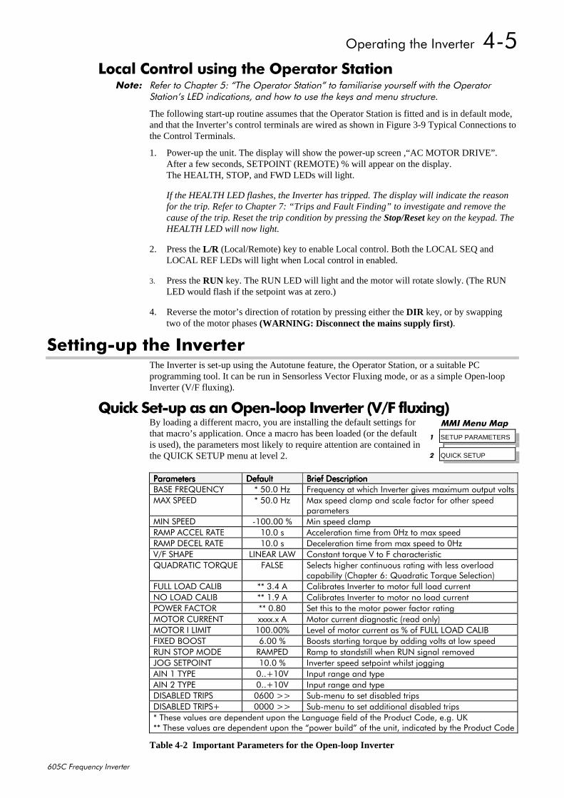
2SHUDWLQJ#WKH#,QYHUWHU##708
938&#)UHTXHQF\#,QYHUWHU
/RFDO#&RQWURO#XVLQJ#WKH#2SHUDWRU#6WDWLRQ1RWH=# 5HIHU#WR#&KDSWHU#8=#´7KH#2SHUDWRU#6WDWLRQµ#WR#IDPLOLDULVH#\RXUVHOI#ZLWK#WKH#2SHUDWRU
6WDWLRQ·V#/('#LQGLFDWLRQV/#DQG#KRZ#WR#XVH#WKH#NH\V#DQG#PHQX#VWUXFWXUH1
The following start-up routine assumes that the Operator Station is fitted and is in default mode,and that the Inverter’s control terminals are wired as shown in Figure 3-9 Typical Connections tothe Control Terminals.
1. Power-up the unit. The display will show the power-up screen ,“AC MOTOR DRIVE”.After a few seconds, SETPOINT (REMOTE) % will appear on the display.The HEALTH, STOP, and FWD LEDs will light.
If the HEALTH LED flashes, the Inverter has tripped. The display will indicate the reasonfor the trip. Refer to Chapter 7: “Trips and Fault Finding” to investigate and remove thecause of the trip. Reset the trip condition by pressing the Stop/Reset key on the keypad. TheHEALTH LED will now light.
2. Press the L/R (Local/Remote) key to enable Local control. Both the LOCAL SEQ andLOCAL REF LEDs will light when Local control in enabled.
3. Press the RUN key. The RUN LED will light and the motor will rotate slowly. (The RUNLED would flash if the setpoint was at zero.)
4. Reverse the motor’s direction of rotation by pressing either the DIR key, or by swappingtwo of the motor phases (WARNING: Disconnect the mains supply first).
6HWWLQJ0XS#WKH#,QYHUWHUThe Inverter is set-up using the Autotune feature, the Operator Station, or a suitable PCprogramming tool. It can be run in Sensorless Vector Fluxing mode, or as a simple Open-loopInverter (V/F fluxing).
4XLFN#6HW0XS#DV#DQ#2SHQ0ORRS#,QYHUWHU#+92)#IOX[LQJ,By loading a different macro, you are installing the default settings forthat macro’s application. Once a macro has been loaded (or the defaultis used), the parameters most likely to require attention are contained inthe QUICK SETUP menu at level 2.
3DUDPHWHUV3DUDPHWHUV3DUDPHWHUV3DUDPHWHUV 'HIDXOW'HIDXOW'HIDXOW'HIDXOW %ULHI#'HVFULSWLRQ%ULHI#'HVFULSWLRQ%ULHI#'HVFULSWLRQ%ULHI#'HVFULSWLRQ%$6(#)5(48(1&< -#8313#+] )UHTXHQF\#DW#ZKLFK#,QYHUWHU#JLYHV#PD[LPXP#RXWSXW#YROWV0$;#63((' -#8313#+] 0D[#VSHHG#FODPS#DQG#VFDOH#IDFWRU#IRU#RWKHU#VSHHG
SDUDPHWHUV0,1#63((' 0433133#( 0LQ#VSHHG#FODPS5$03#$&&(/#5$7( 4313#V $FFHOHUDWLRQ#WLPH#IURP#3+]#WR#PD[#VSHHG5$03#'(&(/#5$7( 4313#V 'HFHOHUDWLRQ#WLPH#IURP#PD[#VSHHG#WR#3+]92)#6+$3( /,1($5#/$: &RQVWDQW#WRUTXH#9#WR#)#FKDUDFWHULVWLF48$'5$7,𑭤( )$/6( 6HOHFWV#KLJKHU#FRQWLQXRXV#UDWLQJ#ZLWK#OHVV#RYHUORDG
FDSDELOLW\#+&KDSWHU#9=#4XDGUDWLF#7RUTXH#6HOHFWLRQ,)8//#/2$'#&$/,% --#617#$ &DOLEUDWHV#,QYHUWHU#WR#PRWRU#IXOO#ORDG#FXUUHQW12#/2$'#&$/,% --#41<#$ &DOLEUDWHV#,QYHUWHU#WR#PRWRU#QR#ORDG#FXUUHQW32:(5#)$&725 --#31;3 6HW#WKLV#WR#WKH#PRWRU#SRZHU#IDFWRU#UDWLQJ02725#&855(17 [[[[1[#$ 0RWRU#FXUUHQW#GLDJQRVWLF#+UHDG#RQO\,02725#,#/,0,7 433133( /HYHO#RI#PRWRU#FXUUHQW#DV#(#RI#)8//#/2$'#&$/,%),;('#%2267 9133#( %RRVWV#VWDUWLQJ#WRUTXH#E\#DGGLQJ#YROWV#DW#ORZ#VSHHG581#6723#02'( 5$03(' 5DPS#WR#VWDQGVWLOO#ZKHQ#581#VLJQDO#UHPRYHG-2*#6(732,17 4313#( ,QYHUWHU#VSHHG#VHWSRLQW#ZKLOVW#MRJJLQJ$,1#4#7<3( 311.439 ,QSXW#UDQJH#DQG#W\SH$,1#5#7<3( 311.439 ,QSXW#UDQJH#DQG#W\SH',6$%/('#75,36 3933#!! 6XE0PHQX#WR#VHW#GLVDEOHG#WULSV',6$%/('#75,36. 3333#!! 6XE0PHQX#WR#VHW#DGGLWLRQDO#GLVDEOHG#WULSV-#7KHVH#YDOXHV#DUH#GHSHQGHQW#XSRQ#WKH#/DQJXDJH#ILHOG#RI#WKH#3URGXFW#&RGH/#H1J1#8.--#7KHVH#YDOXHV#DUH#GHSHQGHQW#XSRQ#WKH#´SRZHU#EXLOGµ#RI#WKH#XQLW/#LQGLFDWHG#E\#WKH#3URGXFW#&RGH
Table 4-2 Important Parameters for the Open-loop Inverter
00,#0HQX#0DS
4 SETUP PARAMETERS
5 QUICK SETUP

709##2SHUDWLQJ#WKH#,QYHUWHU
938&#)UHTXHQF\#,QYHUWHU
6HW0XS#XVLQJ#WKH#6HQVRUOHVV#9HFWRU#)OX[LQJ#0RGHThe Inverter must be tuned to the motor in use by matching the motor parameters in the Inverterto those of the motor being controlled. The most important motor parameters are:
• Per-phase stator resistance
• Per-phase leakage inductance
• Per-phase mutual (magnetising) inductance
Tuning can be performed manually by entering known parameter values, or by calculating theparameter values using the motor manufacturer’s per-phase equivalent circuit.
Enter values for the following parameters, found under VECTOR SETUP menu at level 2.
9(&725#6(7839(&725#6(7839(&725#6(7839(&725#6(7833DUDPHWHUV3DUDPHWHUV3DUDPHWHUV3DUDPHWHUV
'HIDXOW'HIDXOW'HIDXOW'HIDXOW %ULHI#'HVFULSWLRQ%ULHI#'HVFULSWLRQ%ULHI#'HVFULSWLRQ%ULHI#'HVFULSWLRQ
9(&725#(1$%/( )$/6( 6OLS#FRPSHQVDWLRQ#LV#HQDEOHG1#&KDQJH#WR758(#WR#HQDEOH#VHQVRUOHVV#YHFWRU#RSHUDWLRQ
1$0(3/$7(#530 --#4753#Q2PLQ#+USP, 0RWRU#QDPHSODWH#VSHHG
02725#32/(6 7 1XPEHU#RI#PRWRU#SROHV
02725#92/76 --#73313#9 0D[LPXP#PRWRU#RXWSXW#YROWDJH
6833/<#92/7$*( --#[[[[1[#9 /LQH0WR0OLQH#UPV#VXSSO\#YROWDJH#WR#WKH#,QYHUWHU+UHDG0RQO\,
02725#&211(&7,21 --#'(/7$ 7\SH#RI#PRWRU#FRQQHFWLRQ
$872781(#(1$%/( )$/6( (QDEOHV#WKH#$XWRWXQH#IHDWXUH
67$725#5(6 --#413#2KP 0RWRU#SHU0SKDVH#VWDWRU#UHVLVWDQFH
),(/' 313( 'LDJQRVWLF#RQO\
/($.$*(#,1'8& --#4313#P+ 0RWRU#SHU0SKDVH#VWDWRU#OHDNDJH#LQGXFWDQFH
0878$/#,1'8& --#433313P+ 0RWRU#SHU0SKDVH#VWDWRU#PXWXDO#+PDJQHWLVLQJ,LQGXFWDQFH
--#7KHVH#YDOXHV#DUH#GHSHQGHQW#XSRQ#WKH#´SRZHU#EXLOGµ#RI#WKH#XQLW/#LQGLFDWHG#E\#WKH#3URGXFW#&RGH
Table 4-3 Important Parameters for the Sensorless Vector Fluxing Mode
7KH#$XWRWXQH#)HDWXUHThe Autotune feature can be used to identify and store the following parameters:
STATOR RESLEAKAGE INDUCMUTUAL INDUCCURRENT FEEDBACK (if selected in the AUTOTUNE function block)
The remaining important parameters are preset to a value depending on the overall “power-build”, as detailed in the table above.
Operating the Inverter with the Autotune function block enabled startsthe Autotune sequence.
• With ADVANCED view level selected, select the AUTOTUNEmenu at level 4. Press the M key to reveal the AUTOTUNEENABLE page.
• Press the M key. The up (∆∆∆∆) and down (∇∇∇∇) keys toggle theparameter between TRUE and FALSE. Set to TRUE. Press the Ekey to exit the parameter.
• On starting the Inverter, the Autotune sequence is initiated. Whencomplete (after a maximum of 10 seconds), the Inverter is returned to the stopped conditionand the AUTOTUNE ENABLE parameter is reset to FALSE.
Refer to Chapter 6: “Programming Your Application” - AUTOTUNE for further information.
00,#0HQX#0DS
4 SETUP PARAMETERS
5 VECTOR SETUP
00,#0HQX#0DS
4 SETUP PARAMETERS
5 FUNCTION BLOCKS
6 MOTOR CONTROL
7 AUTOTUNE
AUTOTUNE ENABLE
AUTOTUNE MODE
AUTOTUNE ACTIVE
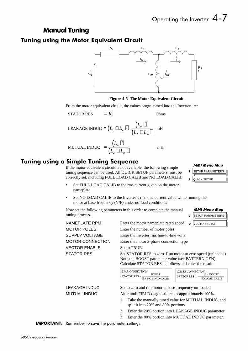
2SHUDWLQJ#WKH#,QYHUWHU##70:
938&#)UHTXHQF\#,QYHUWHU
0DQXDO#7XQLQJ7XQLQJ#XVLQJ#WKH#0RWRU#(TXLYDOHQW#&LUFXLW
V
I
I
I
R L
L
L
RS
1
m m
2s
s r
s
r
Figure 4-5 The Motor Equivalent Circuit
From the motor equivalent circuit, the values programmed into the Inverter are:
STATOR RES = Rs Ohms
LEAKAGE INDUC ( ) ( )( )= + −
+L L
L
L Lmm
m1
2
2
mH
MUTUAL INDUC ( )
( )=+
L
L Lm
m
2
2
mH
7XQLQJ#XVLQJ#D#6LPSOH#7XQLQJ#6HTXHQFHIf the motor equivalent circuit is not available, the following simpletuning sequence can be used. All QUICK SETUP parameters must becorrectly set, including FULL LOAD CALIB and NO LOAD CALIB:
• Set FULL LOAD CALIB to the rms current given on the motornameplate
• Set NO LOAD CALIB to the Inverter’s rms line current value while running the motor at base frequency (V/F) under no-load conditions.
Now set the following parameters in this order to complete the manualtuning process.
NAMEPLATE RPM Enter the motor nameplate rated speed
MOTOR POLES Enter the number of motor poles
SUPPLY VOLTAGE Enter the Inverter rms line-to-line volts
MOTOR CONNECTION Enter the motor 3-phase connection type
VECTOR ENABLE Set to TRUE.
STATOR RES Set STATOR RES to zero. Run motor at zero speed (unloaded).Note the BOOST parameter value (see PATTERN GEN). Calculate STATOR RES as follows and enter the result:
STATOR RES = BOOST
3 x NO LOAD CALIB
STAR CONNECTION
STATOR RES = NO LOAD CALIB
DELTA CONNECTION3 x BOOST
LEAKAGE INDUC Set to zero and run motor at base-frequency un-loaded
MUTUAL INDUC Alter until FIELD diagnostic reads approximately 100%.
1. Take the manually tuned value for MUTUAL INDUC, andsplit it into 20% and 80% portions.
2. Enter the 20% portion into LEAKAGE INDUC parameter
3. Enter the 80% portion into MUTUAL INDUC parameter.
,03257$17=# 5HPHPEHU#WR#VDYH#WKH#SDUDPHWHU#VHWWLQJV1
00,#0HQX#0DS
4 SETUP PARAMETERS
5 QUICK SETUP
00,#0HQX#0DS
4 SETUP PARAMETERS
5 VECTOR SETUP
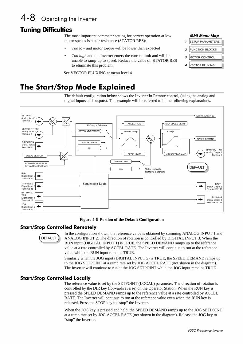
70;##2SHUDWLQJ#WKH#,QYHUWHU
938&#)UHTXHQF\#,QYHUWHU
7XQLQJ#'LIILFXOWLHVThe most important parameter setting for correct operation at lowmotor speeds is stator resistance (STATOR RES):
• Too low and motor torque will be lower than expected
• Too high and the Inverter enters the current limit and will beunable to ramp-up to speed. Reduce the value of STATOR RESto eliminate this problem.
See VECTOR FLUXING at menu level 4.
7KH#6WDUW26WRS#0RGH#([SODLQHGThe default configuration below shows the Inverter in Remote control, (using the analog anddigital inputs and outputs). This example will be referred to in the following explanations.
6WDUW26WRS#&RQWUROOHG#5HPRWHO\In the configuration shown, the reference value is obtained by summing ANALOG INPUT 1 andANALOG INPUT 2. The direction of rotation is controlled by DIGITAL INPUT 3. When theRUN input (DIGITAL INPUT 1) is TRUE, the SPEED DEMAND ramps up to the referencevalue at a rate controlled by ACCEL RATE. The Inverter will continue to run at the referencevalue while the RUN input remains TRUE.Similarly when the JOG input (DIGITAL INPUT 5) is TRUE, the SPEED DEMAND ramps upto the JOG SETPOINT at a ramp rate set by JOG ACCEL RATE (not shown in the diagram).The Inverter will continue to run at the JOG SETPOINT while the JOG input remains TRUE.
6WDUW26WRS#&RQWUROOHG#/RFDOO\The reference value is set by the SETPOINT (LOCAL) parameter. The direction of rotation iscontrolled by the DIR key (forward/reverse) on the Operator Station. When the RUN key ispressed the SPEED DEMAND ramps up to the reference value at a rate controlled by ACCELRATE. The Inverter will continue to run at the reference value even when the RUN key isreleased. Press the STOP key to “stop” the Inverter.
When the JOG key is pressed and held, the SPEED DEMAND ramps up to the JOG SETPOINTat a ramp rate set by JOG ACCEL RATE (not shown in the diagram). Release the JOG key to“stop” the Inverter.
00,#0HQX#0DS
4 SETUP PARAMETERS
5 FUNCTION BLOCKS
6 MOTOR CONTROL
7 VECTOR FLUXING
'()$8/7
SETPOINTAnalog Input 1Terminal 1
SETPOINT TRIMAnalog Input 2Terminal 2
RUNDigital Input 1Terminal 20
TRIP RESEDigital Input 2Terminal 21
DIRECTIONDigital Input 3Terminal 22
JOGDigital Input 5Terminal 24
.0
.0 MAX SPEED CLAMP
MIN SPEED CLAMP
System Ramp Clamp
DECEL RATE
ACCEL RATE
Sequencing Logic
Reference Selection
SETPOINT(REMOTE)
LOCAL SETPOINT
JOG SETPOINT
0%
HEALTHDigital Output 1Terminal 12, 13
RUNNINGDigital Output 2Terminal 14, 15
RAMP OUTPUTAnalog Output 1
Terminal 7
..
SPEED TRIM
SPEED DEMAND
FORWARD/REVERSEKey on Operator Station
.0
SPEED SETPOIN
0% Selected withREMOTE SETPOIN
EXTERNALTRIPDigital Input 4Terminal 23
Figure 4-6 Portion of the Default Configuration
'()$8/7
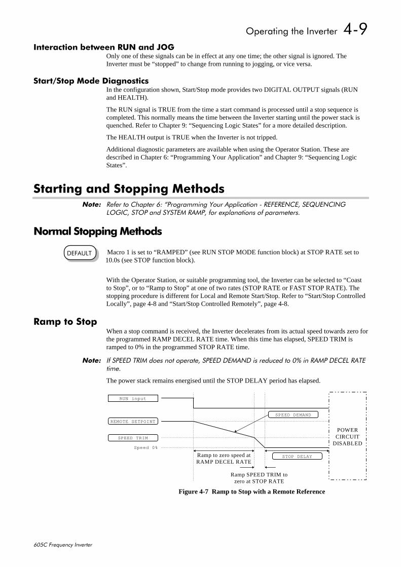
2SHUDWLQJ#WKH#,QYHUWHU##70<
938&#)UHTXHQF\#,QYHUWHU
,QWHUDFWLRQ#EHWZHHQ#581#DQG#-2*Only one of these signals can be in effect at any one time; the other signal is ignored. TheInverter must be “stopped” to change from running to jogging, or vice versa.
6WDUW26WRS#0RGH#'LDJQRVWLFVIn the configuration shown, Start/Stop mode provides two DIGITAL OUTPUT signals (RUNand HEALTH).
The RUN signal is TRUE from the time a start command is processed until a stop sequence iscompleted. This normally means the time between the Inverter starting until the power stack isquenched. Refer to Chapter 9: “Sequencing Logic States” for a more detailed description.
The HEALTH output is TRUE when the Inverter is not tripped.
Additional diagnostic parameters are available when using the Operator Station. These aredescribed in Chapter 6: “Programming Your Application” and Chapter 9: “Sequencing LogicStates”.
6WDUWLQJ#DQG#6WRSSLQJ#0HWKRGV1RWH=# 5HIHU#WR#&KDSWHU#9=#´3URJUDPPLQJ#<RXU#$SSOLFDWLRQ#0#5()(5(1&(/#6(48(1&,1*
/2*,&/#6723#DQG#6<67(0#5$03/#IRU#H[SODQDWLRQV#RI#SDUDPHWHUV1
1RUPDO#6WRSSLQJ#0HWKRGV
Macro 1 is set to “RAMPED” (see RUN STOP MODE function block) at STOP RATE set to10.0s (see STOP function block).
With the Operator Station, or suitable programming tool, the Inverter can be selected to “Coastto Stop”, or to “Ramp to Stop” at one of two rates (STOP RATE or FAST STOP RATE). Thestopping procedure is different for Local and Remote Start/Stop. Refer to “Start/Stop ControlledLocally”, page 4-8 and “Start/Stop Controlled Remotely”, page 4-8.
5DPS#WR#6WRSWhen a stop command is received, the Inverter decelerates from its actual speed towards zero forthe programmed RAMP DECEL RATE time. When this time has elapsed, SPEED TRIM isramped to 0% in the programmed STOP RATE time.
1RWH=# ,I#63(('#75,0#GRHV#QRW#RSHUDWH/#63(('#'(0$1'#LV#UHGXFHG#WR#3(#LQ#5$03#'(&(/#5$7(WLPH1
The power stack remains energised until the STOP DELAY period has elapsed.
'()$8/7
SPEED DEMAND
REMOTE SETPOINT
Speed 0%
RUN input
Ramp to zero speed atRAMP DECEL RATE
Ramp SPEED TRIM tozero at STOP RATE
SPEED TRIM
POWERCIRCUIT
DISABLED
STOP DELAY
Figure 4-7 Ramp to Stop with a Remote Reference
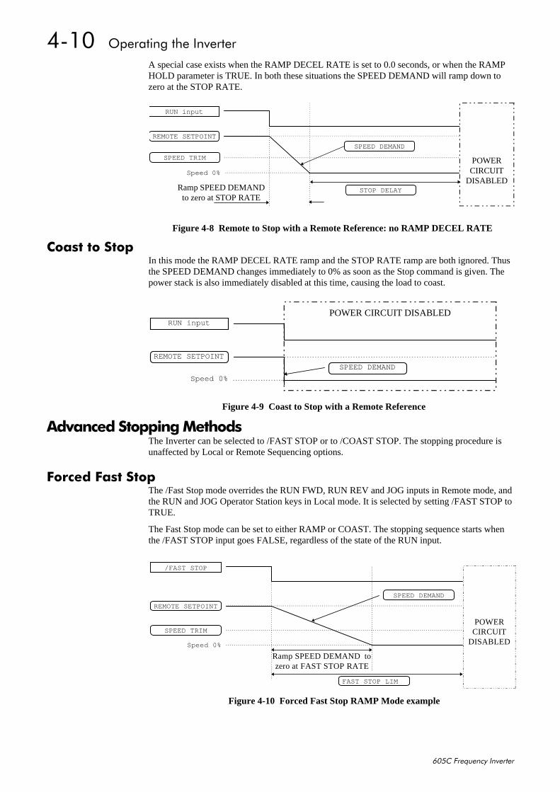
7043##2SHUDWLQJ#WKH#,QYHUWHU
938&#)UHTXHQF\#,QYHUWHU
A special case exists when the RAMP DECEL RATE is set to 0.0 seconds, or when the RAMPHOLD parameter is TRUE. In both these situations the SPEED DEMAND will ramp down tozero at the STOP RATE.
&RDVW#WR#6WRSIn this mode the RAMP DECEL RATE ramp and the STOP RATE ramp are both ignored. Thusthe SPEED DEMAND changes immediately to 0% as soon as the Stop command is given. Thepower stack is also immediately disabled at this time, causing the load to coast.
$GYDQFHG#6WRSSLQJ#0HWKRGVThe Inverter can be selected to /FAST STOP or to /COAST STOP. The stopping procedure isunaffected by Local or Remote Sequencing options.
)RUFHG#)DVW#6WRSThe /Fast Stop mode overrides the RUN FWD, RUN REV and JOG inputs in Remote mode, andthe RUN and JOG Operator Station keys in Local mode. It is selected by setting /FAST STOP toTRUE.
The Fast Stop mode can be set to either RAMP or COAST. The stopping sequence starts whenthe /FAST STOP input goes FALSE, regardless of the state of the RUN input.
SPEED DEMAND
REMOTE SETPOINT
Speed 0%
RUN input
Ramp SPEED DEMANDto zero at STOP RATE
SPEED TRIM POWERCIRCUIT
DISABLEDSTOP DELAY
Figure 4-8 Remote to Stop with a Remote Reference: no RAMP DECEL RATE
POWER CIRCUIT DISABLED
SPEED DEMAND
REMOTE SETPOINT
Speed 0%
RUN input
Figure 4-9 Coast to Stop with a Remote Reference
SPEED DEMAND
REMOTE SETPOINT
Speed 0%
Ramp SPEED DEMAND tozero at FAST STOP RATE
SPEED TRIMPOWERCIRCUIT
DISABLED
FAST STOP LIM
/FAST STOP
Figure 4-10 Forced Fast Stop RAMP Mode example
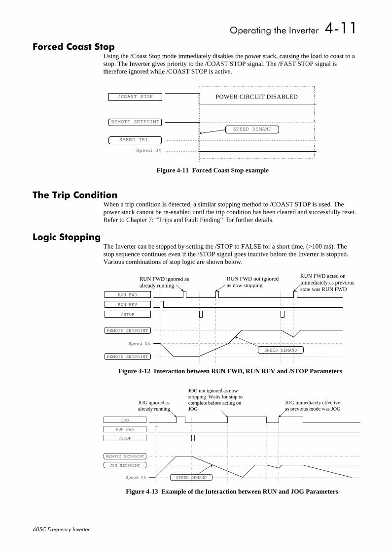
2SHUDWLQJ#WKH#,QYHUWHU##7044
938&#)UHTXHQF\#,QYHUWHU
)RUFHG#&RDVW#6WRSUsing the /Coast Stop mode immediately disables the power stack, causing the load to coast to astop. The Inverter gives priority to the /COAST STOP signal. The /FAST STOP signal istherefore ignored while /COAST STOP is active.
7KH#7ULS#&RQGLWLRQWhen a trip condition is detected, a similar stopping method to /COAST STOP is used. Thepower stack cannot be re-enabled until the trip condition has been cleared and successfully reset.Refer to Chapter 7: “Trips and Fault Finding” for further details.
/RJLF#6WRSSLQJThe Inverter can be stopped by setting the /STOP to FALSE for a short time, (>100 ms). Thestop sequence continues even if the /STOP signal goes inactive before the Inverter is stopped.Various combinations of stop logic are shown below.
POWER CIRCUIT DISABLED
SPEED DEMAND
REMOTE SETPOINT
Speed 0%
SPEED TRI
/COAST STOP
Figure 4-11 Forced Coast Stop example
SPEED DEMAND
REMOTE SETPOINT
Speed 0%
RUN FWD
/STOP
REMOTE SETPOINT
RUN REV
RUN FWD ignored asalready running
RUN FWD acted onimmediately as previousstate was RUN FWD
RUN FWD not ignoredas now stopping
Figure 4-12 Interaction between RUN FWD, RUN REV and /STOP Parameters
SPEED DEMAND
JOG SETPOINT
Speed 0%
RUN FWD
/STOP
REMOTE SETPOINT
JOG
JOG ignored asalready running
JOG immediately effectiveas previous mode was JOG
JOG not ignored as nowstopping. Waits for stop tocomplete before acting onJOG.
Figure 4-13 Example of the Interaction between RUN and JOG Parameters
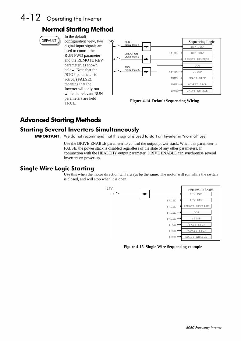
7045##2SHUDWLQJ#WKH#,QYHUWHU
938&#)UHTXHQF\#,QYHUWHU
1RUPDO#6WDUWLQJ#0HWKRGIn the defaultconfiguration view, twodigital input signals areused to control theRUN FWD parameterand the REMOTE REVparameter, as shownbelow. Note that the/STOP parameter isactive, (FALSE),meaning that theInverter will only runwhile the relevant RUNparameters are heldTRUE.
$GYDQFHG#6WDUWLQJ#0HWKRGV6WDUWLQJ#6HYHUDO#,QYHUWHUV#6LPXOWDQHRXVO\
,03257$17=# :H#GR#QRW#UHFRPPHQG#WKDW#WKLV#VLJQDO#LV#XVHG#WR#VWDUW#DQ#,QYHUWHU#LQ#´QRUPDOµ#XVH1
Use the DRIVE ENABLE parameter to control the output power stack. When this parameter isFALSE, the power stack is disabled regardless of the state of any other parameters. Inconjunction with the HEALTHY output parameter, DRIVE ENABLE can synchronise severalInverters on power-up.
6LQJOH#:LUH#/RJLF#6WDUWLQJUse this when the motor direction will always be the same. The motor will run while the switchis closed, and will stop when it is open.
RUNDigital Input 1
DIRECTIONDigital Input 3
JOGDigital Input 5
Sequencing LogicRUN FWD
REMOTE REVERSE
JOG
RUN REVFALSE
/STOP
/FAST STOP
/COAST STOP
DRIVE ENABLE
FALSE
TRUE
TRUE
TRUE
24V
Figure 4-14 Default Sequencing Wiring
'()$8/7
Sequencing LogicRUN FWD
REMOTE REVERSE
JOG
RUN REVFALSE
/STOP
/FAST STOP
/COAST STOP
DRIVE ENABLE
FALSE
TRUE
TRUE
TRUE
24V
FALSE
FALSE
Figure 4-15 Single Wire Sequencing example
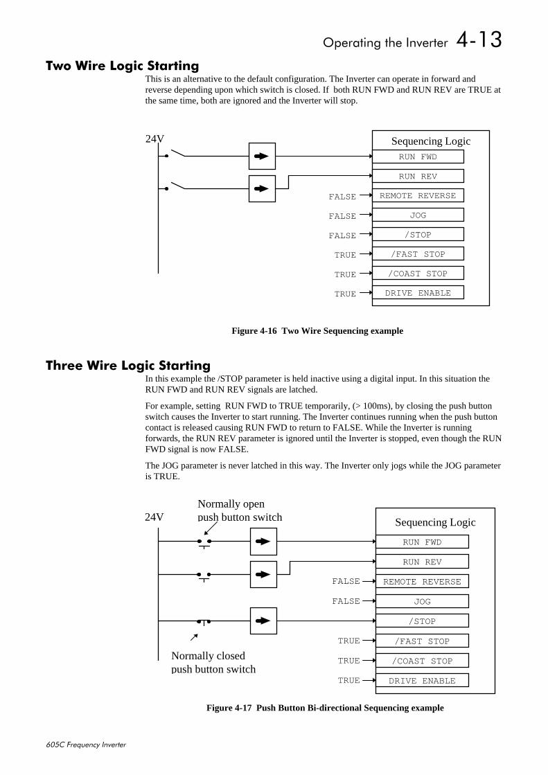
2SHUDWLQJ#WKH#,QYHUWHU##7046
938&#)UHTXHQF\#,QYHUWHU
7ZR#:LUH#/RJLF#6WDUWLQJThis is an alternative to the default configuration. The Inverter can operate in forward andreverse depending upon which switch is closed. If both RUN FWD and RUN REV are TRUE atthe same time, both are ignored and the Inverter will stop.
7KUHH#:LUH#/RJLF#6WDUWLQJIn this example the /STOP parameter is held inactive using a digital input. In this situation theRUN FWD and RUN REV signals are latched.
For example, setting RUN FWD to TRUE temporarily, (> 100ms), by closing the push buttonswitch causes the Inverter to start running. The Inverter continues running when the push buttoncontact is released causing RUN FWD to return to FALSE. While the Inverter is runningforwards, the RUN REV parameter is ignored until the Inverter is stopped, even though the RUNFWD signal is now FALSE.
The JOG parameter is never latched in this way. The Inverter only jogs while the JOG parameteris TRUE.
Sequencing LogicRUN FWD
REMOTE REVERSE
JOG
RUN REV
/STOP
/FAST STOP
/COAST STOP
DRIVE ENABLE
FALSE
TRUE
TRUE
TRUE
24V
FALSE
FALSE
Figure 4-16 Two Wire Sequencing example
Sequencing Logic
RUN FWD
REMOTE REVERSE
JOG
RUN REV
/STOP
/FAST STOP
/COAST STOP
DRIVE ENABLE
FALSE
TRUE
TRUE
TRUE
24V
FALSE
Normally closedpush button switch
Normally openpush button switch
Figure 4-17 Push Button Bi-directional Sequencing example

7047##2SHUDWLQJ#WKH#,QYHUWHU
938&#)UHTXHQF\#,QYHUWHU
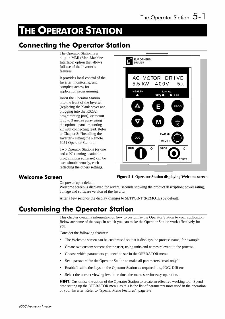
7KH#2SHUDWRU#6WDWLRQ##804
938&#)UHTXHQF\#,QYHUWHU
8#7+(#23(5$725#67$7,21&RQQHFWLQJ#WKH#2SHUDWRU#6WDWLRQ
The Operator Station is aplug-in MMI (Man-MachineInterface) option that allowsfull use of the Inverter’sfeatures.
It provides local control of theInverter, monitoring, andcomplete access forapplication programming.
Insert the Operator Stationinto the front of the Inverter(replacing the blank cover andplugging into the RS232programming port); or mountit up to 3 metres away usingthe optional panel mountingkit with connecting lead. Referto Chapter 3: “Installing theInverter - Fitting the Remote6051 Operator Station.
Two Operator Stations (or oneand a PC running a suitableprogramming software) can beused simultaneously, eachreflecting the others settings.
:HOFRPH#6FUHHQOn power-up, a defaultWelcome screen is displayed for several seconds showing the product description; power rating,voltage and software version of the Inverter.
After a few seconds the display changes to SETPOINT (REMOTE) by default.
&XVWRPLVLQJ#WKH#2SHUDWRU#6WDWLRQThis chapter contains information on how to customise the Operator Station to your application.Below are some of the ways in which you can make the Operator Station work effectively foryou.
Consider the following features:
• The Welcome screen can be customised so that it displays the process name, for example.
• Create two custom screens for the user, using units and names relevant to the process.
• Choose which parameters you need to see in the OPERATOR menu.
• Set a password for the Operator Station to make all parameters “read-only”
• Enable/disable the keys on the Operator Station as required, i.e., JOG, DIR etc.
• Select the correct viewing level to reduce the menu size for easy operation.
+,17= Customise the action of the Operator Station to create an effective working tool. Spendtime setting up the OPERATOR menu, as this is the list of parameters most used in the operationof your Inverter. Refer to “Special Menu Features”, page 5-9.
HEALTH LOCALSEQ REF
FWD
REV
STOPRUN
JOG
E
M
PROG
RESET
LR
EUROTHERMDRIVES
44
AC MO ORT D I VR EkW5 5 4 00 V 5.x
Figure 5-1 Operator Station displaying Welcome screen
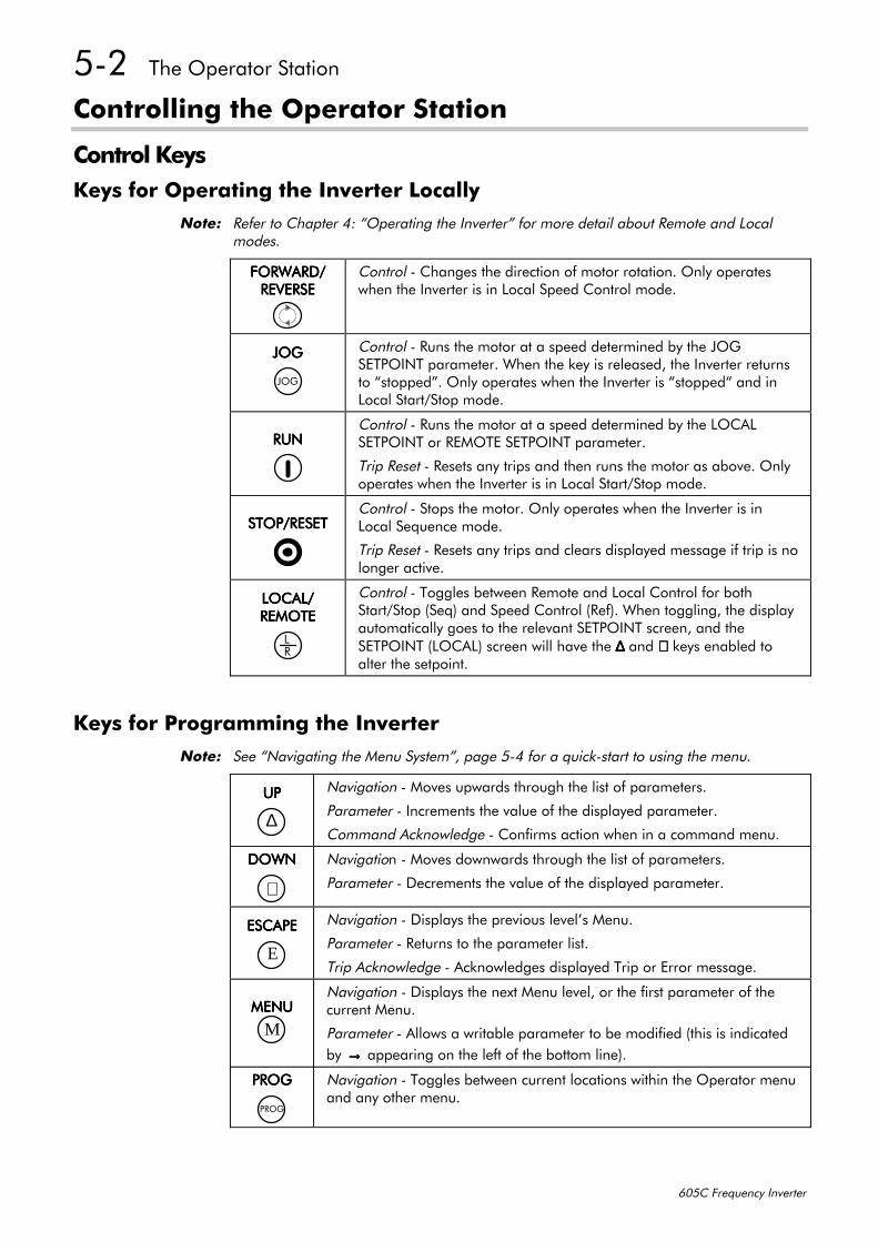
805##7KH#2SHUDWRU#6WDWLRQ
938&#)UHTXHQF\#,QYHUWHU
&RQWUROOLQJ#WKH#2SHUDWRU#6WDWLRQ
&RQWURO#.H\V.H\V#IRU#2SHUDWLQJ#WKH#,QYHUWHU#/RFDOO\
1RWH=# 5HIHU#WR#&KDSWHU#7=#´2SHUDWLQJ#WKH#,QYHUWHUµ#IRU#PRUH#GHWDLO#DERXW#5HPRWH#DQG#/RFDOPRGHV1
)25:$5'2)25:$5'2)25:$5'2)25:$5'25(9(56(5(9(56(5(9(56(5(9(56(
&RQWURO#0#&KDQJHV#WKH#GLUHFWLRQ#RI#PRWRU#URWDWLRQ1#2QO\#RSHUDWHVZKHQ#WKH#,QYHUWHU#LV#LQ#/RFDO#6SHHG#&RQWURO#PRGH1
-2*-2*-2*-2*
-2*
&RQWURO#0#5XQV#WKH#PRWRU#DW#D#VSHHG#GHWHUPLQHG#E\#WKH#-2*6(732,17#SDUDPHWHU1#:KHQ#WKH#NH\#LV#UHOHDVHG/#WKH#,QYHUWHU#UHWXUQVWR#´VWRSSHGµ1#2QO\#RSHUDWHV#ZKHQ#WKH#,QYHUWHU#LV#´VWRSSHG´#DQG#LQ/RFDO#6WDUW26WRS#PRGH1
581581581581&RQWURO#0#5XQV#WKH#PRWRU#DW#D#VSHHG#GHWHUPLQHG#E\#WKH#/2&$/6(732,17#RU#5(027(#6(732,17#SDUDPHWHU1
7ULS#5HVHW#0#5HVHWV#DQ\#WULSV#DQG#WKHQ#UXQV#WKH#PRWRU#DV#DERYH1#2QO\RSHUDWHV#ZKHQ#WKH#,QYHUWHU#LV#LQ#/RFDO#6WDUW26WRS#PRGH1
672367236723672325(6(725(6(725(6(725(6(7&RQWURO#0#6WRSV#WKH#PRWRU1#2QO\#RSHUDWHV#ZKHQ#WKH#,QYHUWHU#LV#LQ/RFDO#6HTXHQFH#PRGH1
7ULS#5HVHW#0#5HVHWV#DQ\#WULSV#DQG#FOHDUV#GLVSOD\HG#PHVVDJH#LI#WULS#LV#QRORQJHU#DFWLYH1
/2&$/2/2&$/2/2&$/2/2&$/25(027(5(027(5(027(5(027(
5/
&RQWURO#0#7RJJOHV#EHWZHHQ#5HPRWH#DQG#/RFDO#&RQWURO#IRU#ERWK6WDUW26WRS#+6HT,#DQG#6SHHG#&RQWURO#+5HI,1#:KHQ#WRJJOLQJ/#WKH#GLVSOD\DXWRPDWLFDOO\#JRHV#WR#WKH#UHOHYDQW#6(732,17#VFUHHQ/#DQG#WKH6(732,17#+/2&$/,#VFUHHQ#ZLOO#KDYH#WKH#∆∆∆∆####DQG#∇∇∇∇####NH\V#HQDEOHG#WRDOWHU#WKH#VHWSRLQW1
.H\V#IRU#3URJUDPPLQJ#WKH#,QYHUWHU1RWH=# 6HH#´1DYLJDWLQJ#WKH#0HQX#6\VWHPµ/#SDJH#807#IRU#D#TXLFN0VWDUW#WR#XVLQJ#WKH#PHQX1
83838383
∆
1DYLJDWLRQ#0#0RYHV#XSZDUGV#WKURXJK#WKH#OLVW#RI#SDUDPHWHUV1
3DUDPHWHU#0#,QFUHPHQWV#WKH#YDOXH#RI#WKH#GLVSOD\HG#SDUDPHWHU1
&RPPDQG#$FNQRZOHGJH#0#&RQILUPV#DFWLRQ#ZKHQ#LQ#D#FRPPDQG#PHQX1
'2:1'2:1'2:1'2:1
∇
1DYLJDWLRQ#0#0RYHV#GRZQZDUGV#WKURXJK#WKH#OLVW#RI#SDUDPHWHUV1
3DUDPHWHU#0#'HFUHPHQWV#WKH#YDOXH#RI#WKH#GLVSOD\HG#SDUDPHWHU1
(6&$3((6&$3((6&$3((6&$3(
E
1DYLJDWLRQ#0#'LVSOD\V#WKH#SUHYLRXV#OHYHO·V#0HQX1
3DUDPHWHU#0#5HWXUQV#WR#WKH#SDUDPHWHU#OLVW1
7ULS#$FNQRZOHGJH#0#$FNQRZOHGJHV#GLVSOD\HG#7ULS#RU#(UURU#PHVVDJH1
0(180(180(180(18
M
1DYLJDWLRQ#0#'LVSOD\V#WKH#QH[W#0HQX#OHYHO/#RU#WKH#ILUVW#SDUDPHWHU#RI#WKHFXUUHQW#0HQX1
3DUDPHWHU#0#$OORZV#D#ZULWDEOH#SDUDPHWHU#WR#EH#PRGLILHG#+WKLV#LV#LQGLFDWHGE\#→→→→#DSSHDULQJ#RQ#WKH#OHIW#RI#WKH#ERWWRP#OLQH,1
352*352*352*352*
352*
1DYLJDWLRQ#0#7RJJOHV#EHWZHHQ#FXUUHQW#ORFDWLRQV#ZLWKLQ#WKH#2SHUDWRU#PHQXDQG#DQ\#RWKHU#PHQX1
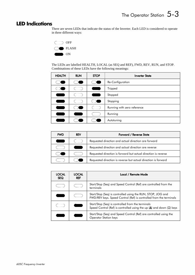
7KH#2SHUDWRU#6WDWLRQ##806
938&#)UHTXHQF\#,QYHUWHU
/('#,QGLFDWLRQVThere are seven LEDs that indicate the status of the Inverter. Each LED is considered to operatein three different ways:
The LEDs are labelled HEALTH, LOCAL (as SEQ and REF), FWD, REV, RUN, and STOP.Combinations of these LEDs have the following meanings:
+($/7++($/7++($/7++($/7+ 581581581581 6723672367236723 ,QYHUWHU#6WDWH,QYHUWHU#6WDWH,QYHUWHU#6WDWH,QYHUWHU#6WDWH
5H0&RQILJXUDWLRQ
7ULSSHG
6WRSSHG
6WRSSLQJ
5XQQLQJ#ZLWK#]HUR#UHIHUHQFH
5XQQLQJ
$XWRWXQLQJ
):'):'):'):' 5(95(95(95(9 )RUZDUG#2#5HYHUVH#6WDWH)RUZDUG#2#5HYHUVH#6WDWH)RUZDUG#2#5HYHUVH#6WDWH)RUZDUG#2#5HYHUVH#6WDWH
5HTXHVWHG#GLUHFWLRQ#DQG#DFWXDO#GLUHFWLRQ#DUH#IRUZDUG
5HTXHVWHG#GLUHFWLRQ#DQG#DFWXDO#GLUHFWLRQ#DUH#UHYHUVH
5HTXHVWHG#GLUHFWLRQ#LV#IRUZDUG#EXW#DFWXDO#GLUHFWLRQ#LV#UHYHUVH
5HTXHVWHG#GLUHFWLRQ#LV#UHYHUVH#EXW#DFWXDO#GLUHFWLRQ#LV#IRUZDUG
/2&$//2&$//2&$//2&$/6(46(46(46(4
/2&$//2&$//2&$//2&$/5()5()5()5()
/RFDO#2#5HPRWH#0RGH/RFDO#2#5HPRWH#0RGH/RFDO#2#5HPRWH#0RGH/RFDO#2#5HPRWH#0RGH
6WDUW26WRS#+6HT,#DQG#6SHHG#&RQWURO#+5HI,#DUH#FRQWUROOHG#IURP#WKHWHUPLQDOV
6WDUW26WRS#+6HT,#LV#FRQWUROOHG#XVLQJ#WKH#581/#6723/#-2*#DQG):'25(9#NH\V1#6SHHG#&RQWURO#+5HI,#LV#FRQWUROOHG#IURP#WKH#WHUPLQDOV
6WDUW26WRS#+6HT,#LV#FRQWUROOHG#IURP#WKH#WHUPLQDOV6SHHG#&RQWURO#+5HI,#LV#FRQWUROOHG#XVLQJ#WKH#XS####+∆∆∆∆,#DQG#GRZQ#+∇∇∇∇,#NH\V
6WDUW26WRS#+6HT,#DQG#6SHHG#&RQWURO#+5HI,#DUH#FRQWUROOHG#XVLQJ#WKH2SHUDWRU#6WDWLRQ#NH\V
OFF
FLASH
ON
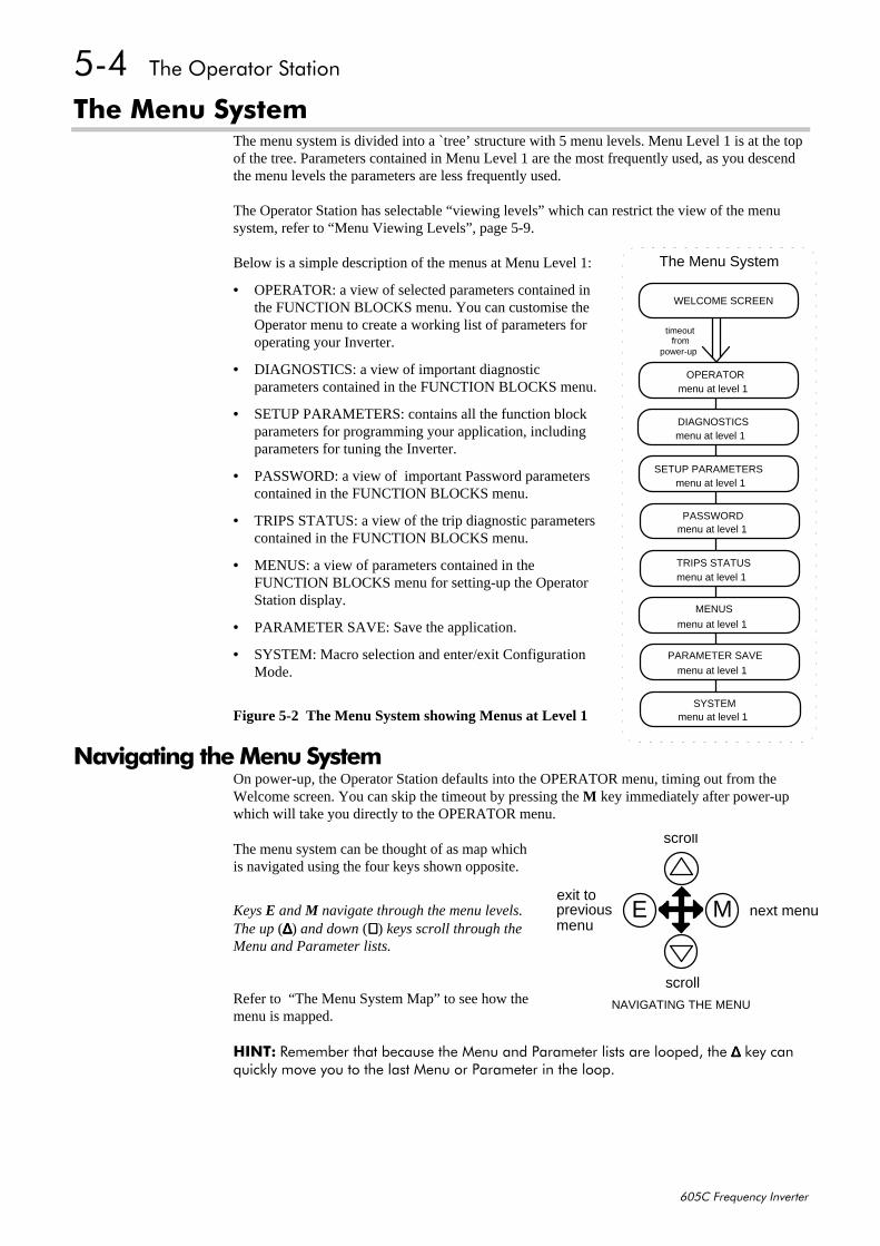
807##7KH#2SHUDWRU#6WDWLRQ
938&#)UHTXHQF\#,QYHUWHU
7KH#0HQX#6\VWHPThe menu system is divided into a `tree’ structure with 5 menu levels. Menu Level 1 is at the topof the tree. Parameters contained in Menu Level 1 are the most frequently used, as you descendthe menu levels the parameters are less frequently used.
The Operator Station has selectable “viewing levels” which can restrict the view of the menusystem, refer to “Menu Viewing Levels”, page 5-9.
Below is a simple description of the menus at Menu Level 1:
• OPERATOR: a view of selected parameters contained inthe FUNCTION BLOCKS menu. You can customise theOperator menu to create a working list of parameters foroperating your Inverter.
• DIAGNOSTICS: a view of important diagnosticparameters contained in the FUNCTION BLOCKS menu.
• SETUP PARAMETERS: contains all the function blockparameters for programming your application, includingparameters for tuning the Inverter.
• PASSWORD: a view of important Password parameterscontained in the FUNCTION BLOCKS menu.
• TRIPS STATUS: a view of the trip diagnostic parameterscontained in the FUNCTION BLOCKS menu.
• MENUS: a view of parameters contained in theFUNCTION BLOCKS menu for setting-up the OperatorStation display.
• PARAMETER SAVE: Save the application.
• SYSTEM: Macro selection and enter/exit ConfigurationMode.
Figure 5-2 The Menu System showing Menus at Level 1
1DYLJDWLQJ#WKH#0HQX#6\VWHPOn power-up, the Operator Station defaults into the OPERATOR menu, timing out from theWelcome screen. You can skip the timeout by pressing the M key immediately after power-upwhich will take you directly to the OPERATOR menu.
The menu system can be thought of as map whichis navigated using the four keys shown opposite.
Keys E and M navigate through the menu levels.The up (∆∆∆∆) and down (∇∇∇∇) keys scroll through theMenu and Parameter lists.
Refer to “The Menu System Map” to see how themenu is mapped.
+,17= 5HPHPEHU#WKDW#EHFDXVH#WKH#0HQX#DQG#3DUDPHWHU#OLVWV#DUH#ORRSHG/#WKH#∆∆∆∆#NH\#FDQTXLFNO\#PRYH#\RX#WR#WKH#ODVW#0HQX#RU#3DUDPHWHU#LQ#WKH#ORRS1
WELCOME SCREEN
OPERATOR
The Menu System
timeoutfrom
power-up
DIAGNOSTICS
SETUP PARAMETERS
PASSWORD
TRIPS STATUS
MENUS
PARAMETER SAVE
SYSTEM
menu at level 1
menu at level 1
menu at level 1
menu at level 1
menu at level 1
menu at level 1
menu at level 1
menu at level 1
scroll
scroll
exit topreviousmenu
next menu
NAVIGATING THE MENU
E M
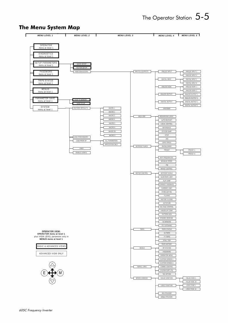
7KH#2SHUDWRU#6WDWLRQ##808
938&#)UHTXHQF\#,QYHUWHU
7KH#0HQX#6\VWHP#0DSMENU LEVEL 2
INPUTS & OUTPUTS
SEQ & REF
SETPOINT FUNCS
MOTOR CONTROL
TRIPS
MENUS
SERIAL LINKS
ANALOG INPUT 1
ANALOG INPUT 4
ENCODER
DIGITAL INPUT 1
DIGITAL INPUT 8
ANALOG DIGIN 1
ANALOG DIGIN 2
ANALOG OUTPUT 1
ANALOG OUTPUT 2
DIGITAL OUTPUT 1
DIGITAL OUTPUT 3
PRESET 1
PRESET 8
VALUE FUNC 1
VALUE FUNC 10
LOGIC FUNC 1
LOGIC FUNC 10
ANALOG INPUT
DIGITAL INPUT
ANALOG DIGIN
ANALOG OUTPUT
DIGITAL OUTPUT
SEQUENCING LOGIC
AUTO RESTART
LOCAL CONTROL
REFERENCE
SYSTEM RAMP
STOP
JOG
ZERO SPEED
RAISE/LOWER
PRESET
SKIP FREQUENCIES
MINIMUM SPEED
PID
BRAKE CONTROL
MISCELLANEOUS
MULTIPLEXER
DEMULTIPLEXER
SETPOINT SCALE
SLEW RATE LIMIT
SLIP COMP
CURRENT FEEDBACK
CURRENT LIMIT
STABILISATION
FLUXING
VECTOR FLUXING
AUTOTUNE
VOLTAGE CONTROL
UNDERLAP COMP
PATTERN GEN
DYNAMIC BRAKING
INJ BRAKING
FLY CATCHING
TRIPS STATUS
I/O TRIPS
I*T TRIPS
STALL TRIP
TRIPS HISTORY
OP STATION
PASSWORD
OPERATOR MENU
CUSTOM SCREEN 1
CUSTOM SCREEN 2
COMMS CONTROL
SYSTEM PORT (P3)
ALL PARAMETERS
APPLICATION ONLY
E M
A D V A N C E D V I E W O N L Y
MENU LEVEL 3 MENU LEVEL 4 MENU LEVEL 5MENU LEVEL 1
QUICK SETUP
VECTOR SETUP
S E T U P P A R A M E T E R Smenu at leve l 1
P A S S W O R Dmenu at leve l 1
MACRO 1
MACRO 2
MACRO 3
MACRO 4
ENABLE CONFIG
RESTORE DEFAULTS
LOAD FROM MEMORY
LOAD FROM OP
LINKS
SAVE TO MEMORY
SAVE TO OP
T R I P S S T A T U Smenu at leve l 1
M E N U Smenu at leve l 1
S Y S T E Mmenu at leve l 1
P A R A M E T E R S A V Emenu at leve l 1
D I A G N O S T I C Smenu a t leve l 1
FUNCTION BLOCKS
B A S I C & A D V A N C E D V I E W S
OPERATOR VIEW:OPERATOR menu at level 1
p lus V IEW LEVEL paramete r on ly inMENUS menu at level 1
MACRO 5
VALUE FUNCTION
LOGIC FUNCTION
MACRO 6
TEC OPTION
O P E R A T O Rmenu at leve l 1
MACRO 99
MACRO 0
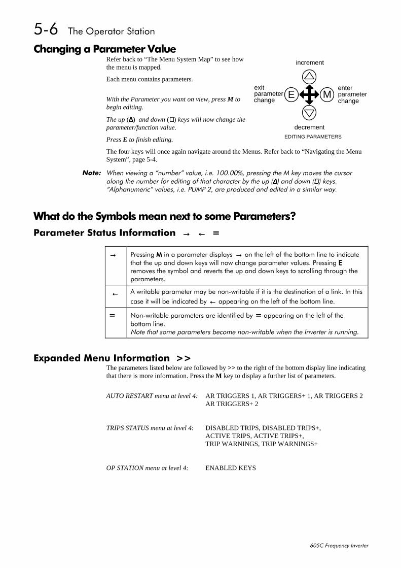
809##7KH#2SHUDWRU#6WDWLRQ
938&#)UHTXHQF\#,QYHUWHU
&KDQJLQJ#D#3DUDPHWHU#9DOXHRefer back to “The Menu System Map” to see howthe menu is mapped.
Each menu contains parameters.
With the Parameter you want on view, press M tobegin editing.
The up (∆∆∆∆) and down (∇∇∇∇) keys will now change theparameter/function value.
Press E to finish editing.
The four keys will once again navigate around the Menus. Refer back to “Navigating the MenuSystem”, page 5-4.
1RWH=# :KHQ#YLHZLQJ#D#´QXPEHUµ#YDOXH/#L1H1#433133(/#SUHVVLQJ#WKH#0#NH\#PRYHV#WKH#FXUVRUDORQJ#WKH#QXPEHU#IRU#HGLWLQJ#RI#WKDW#FKDUDFWHU#E\#WKH#XS#+∆∆∆∆,#DQG#GRZQ#+∇∇∇∇,#NH\V1´$OSKDQXPHULFµ#YDOXHV/#L1H1#3803#5/#DUH#SURGXFHG#DQG#HGLWHG#LQ#D#VLPLODU#ZD\1
:KDW#GR#WKH#6\PEROV#PHDQ#QH[W#WR#VRPH#3DUDPHWHUV"3DUDPHWHU#6WDWXV#,QIRUPDWLRQ##→→→→##←←←←##
→→→→ 3UHVVLQJ#0000#LQ#D#SDUDPHWHU#GLVSOD\V####→→→→#RQ#WKH#OHIW#RI#WKH#ERWWRP#OLQH#WR#LQGLFDWHWKDW#WKH#XS#DQG#GRZQ#NH\V#ZLOO#QRZ#FKDQJH#SDUDPHWHU#YDOXHV1#3UHVVLQJ#((((UHPRYHV#WKH#V\PERO#DQG#UHYHUWV#WKH#XS#DQG#GRZQ#NH\V#WR#VFUROOLQJ#WKURXJK#WKHSDUDPHWHUV1
####←←←← $#ZULWDEOH#SDUDPHWHU#PD\#EH#QRQ0ZULWDEOH#LI#LW#LV#WKH#GHVWLQDWLRQ#RI#D#OLQN1#,Q#WKLVFDVH#LW#ZLOO#EH#LQGLFDWHG#E\#←←←←#DSSHDULQJ#RQ#WKH#OHIW#RI#WKH#ERWWRP#OLQH1
1RQ0ZULWDEOH#SDUDPHWHUV#DUH#LGHQWLILHG#E\# # # # #DSSHDULQJ#RQ#WKH#OHIW#RI#WKHERWWRP#OLQH11RWH#WKDW#VRPH#SDUDPHWHUV#EHFRPH#QRQ0ZULWDEOH#ZKHQ#WKH#,QYHUWHU#LV#UXQQLQJ1
([SDQGHG#0HQX#,QIRUPDWLRQ##!!The parameters listed below are followed by >> to the right of the bottom display line indicatingthat there is more information. Press the M key to display a further list of parameters.
AUTO RESTART menu at level 4:AR TRIGGERS 1, AR TRIGGERS+ 1, AR TRIGGERS 2AR TRIGGERS+ 2
TRIPS STATUS menu at level 4: DISABLED TRIPS, DISABLED TRIPS+,ACTIVE TRIPS, ACTIVE TRIPS+,TRIP WARNINGS, TRIP WARNINGS+
OP STATION menu at level 4: ENABLED KEYS
increment
decrement
parameterchange
exitparameterchange
EDITING PARAMETERS
E Menter
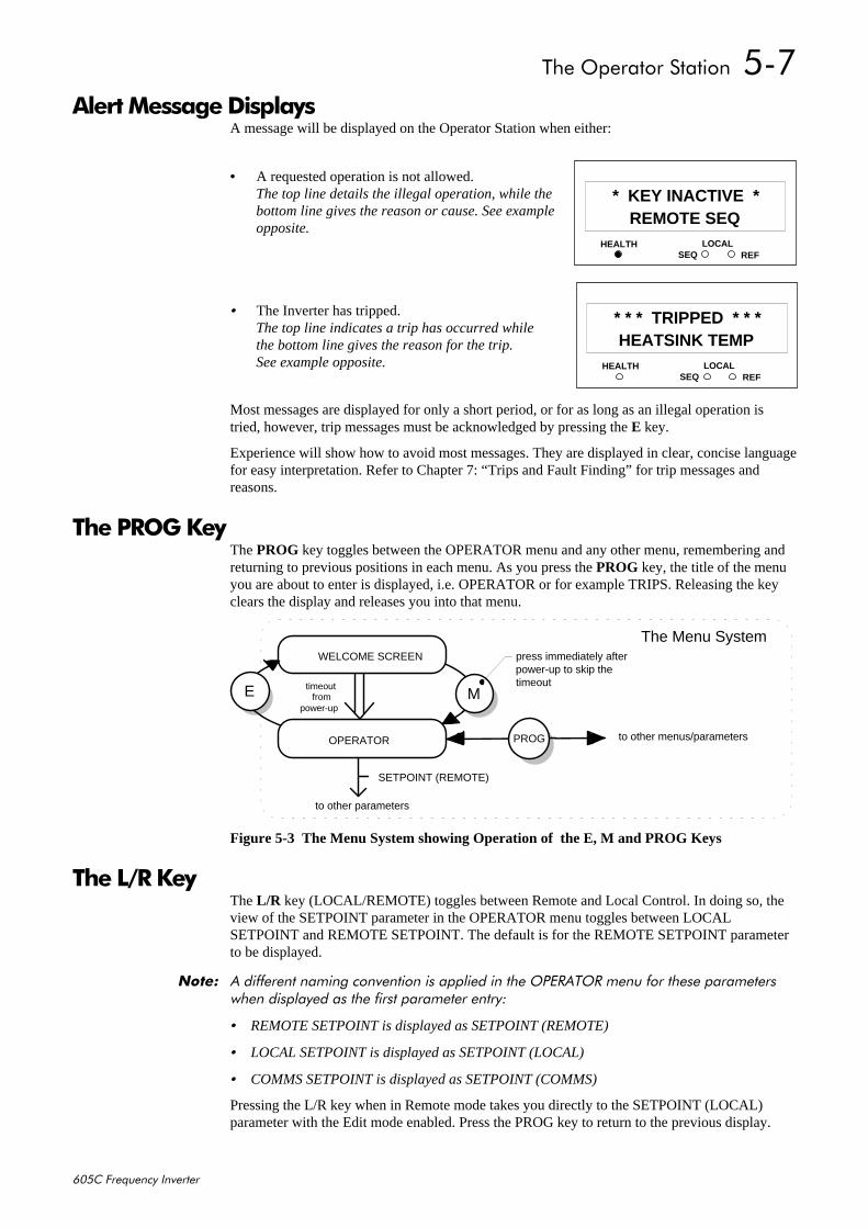
7KH#2SHUDWRU#6WDWLRQ##80:
938&#)UHTXHQF\#,QYHUWHU
$OHUW#0HVVDJH#'LVSOD\VA message will be displayed on the Operator Station when either:
• A requested operation is not allowed.The top line details the illegal operation, while thebottom line gives the reason or cause. See exampleopposite.
• The Inverter has tripped.The top line indicates a trip has occurred whilethe bottom line gives the reason for the trip.See example opposite.
Most messages are displayed for only a short period, or for as long as an illegal operation istried, however, trip messages must be acknowledged by pressing the E key.
Experience will show how to avoid most messages. They are displayed in clear, concise languagefor easy interpretation. Refer to Chapter 7: “Trips and Fault Finding” for trip messages andreasons.
7KH#352*#.H\The PROG key toggles between the OPERATOR menu and any other menu, remembering andreturning to previous positions in each menu. As you press the PROG key, the title of the menuyou are about to enter is displayed, i.e. OPERATOR or for example TRIPS. Releasing the keyclears the display and releases you into that menu.
WELCOME SCREEN
OPERATOR PROG
The Menu System
ME
SETPOINT (REMOTE)
to other parameters
to other menus/parameters
press immediately afterpower-up to skip thetimeouttimeout
frompower-up
Figure 5-3 The Menu System showing Operation of the E, M and PROG Keys
7KH#/25#.H\The L/R key (LOCAL/REMOTE) toggles between Remote and Local Control. In doing so, theview of the SETPOINT parameter in the OPERATOR menu toggles between LOCALSETPOINT and REMOTE SETPOINT. The default is for the REMOTE SETPOINT parameterto be displayed.
1RWH=# $#GLIIHUHQW#QDPLQJ#FRQYHQWLRQ#LV#DSSOLHG#LQ#WKH#23(5$725#PHQX#IRU#WKHVH#SDUDPHWHUVZKHQ#GLVSOD\HG#DV#WKH#ILUVW#SDUDPHWHU#HQWU\=
• REMOTE SETPOINT is displayed as SETPOINT (REMOTE)
• LOCAL SETPOINT is displayed as SETPOINT (LOCAL)
• COMMS SETPOINT is displayed as SETPOINT (COMMS)
Pressing the L/R key when in Remote mode takes you directly to the SETPOINT (LOCAL)parameter with the Edit mode enabled. Press the PROG key to return to the previous display.
HEALTH LOCALSEQ REF
44REMOTE SEQ
* KEY INACTIVE *
HEALTH LOCALSEQ REF
44HEATSINK TEMP
* * * TRIPPED * * *

80;##7KH#2SHUDWRU#6WDWLRQ
938&#)UHTXHQF\#,QYHUWHU
0HQX#6KRUWFXWV#DQG#6SHFLDO#.H\#&RPELQDWLRQV4XLFN#/LQN#,QIRUPDWLRQ
When in Advanced view level, pressing the M key for approximately 3 seconds in any parameterwill display link information about that parameter (a message may be displayed during this time).The information is displayed in the following format:
éêçïûïûïûåûï">êèç@6RXUFH#WDJ#QXPEHU /LQN#QXPEHU 'HVWLQDWLRQ#WDJ#QXPEHU
1RWH=# 7KH#,QYHUWHU#PXVW#EH#LQ#&RQILJXUDWLRQ#PRGH#EHIRUH#OLQNV#FDQ#EH#HGLWHG1#+RZHYHU/#KROGLQJWKH#0000#NH\#GRZQ#LQ#3DUDPHWHULVDWLRQ#PRGH#ZLOO#DOORZ#WKH#LQIRUPDWLRQ#WR#EH#GLVSOD\HG#EXWWKH#LQIRUPDWLRQ#GLVDSSHDUV#ZKHQ#WKH#NH\#LV#UHOHDVHG1
Use the up (∆∆∆∆) and down (∇∇∇∇) keys to change the source tag number. If the source number ischanged from zero, the next available link number will be assigned. Press E twice to clear thelink information and return to the parameter.
All link information is also available through the menu LINKS, menu at level 2.
4XLFN#6DYH#WR#0HPRU\Holding down the PROG key for about 2 seconds quickly takes you to the SAVE TOMEMORY menu in the PARAMETER SAVE menu at level 1.
After saving, press the PROG key to return to the previous display.
&KDQJLQJ#WKH#'LVSOD\#/DQJXDJHHolding down the PROG key at power-up takes you immediately to the DISPLAYLANGUAGE parameter in the MENUS menu at level 1.
Refer to “Selecting the Display Language”, page 5-10 for information on selecting a language.
The selected view level (when previously powered-down) determines how you will exit theparameter:
• Operator: releases you into the OPERATOR menu at level 1
• Basic: releases you into the MENUS menu at level 1
• Advanced: releases you into the MENUS menu at level 1
4XLFN#'ULYH#&RS\With an application stored in the Operator Station (referto “Copying an Application”, page 5-13), holding thedown (∇∇∇∇) key at power-up takes you immediately to theALL PARAMETERS display in the LOAD FROM OPmenu at level 2. The Advanced view mode isautomatically selected.
1RWH=# 3UHVVLQJ#WKH#XS#+∆∆∆∆,,,,#NH\/#DV#LQVWUXFWHG/#FRSLHV#DOO#SDUDPHWHU#VHWWLQJV#LQFOXGLQJ#PRWRUVSHFLILF#GDWD#IURP#WKH#2SHUDWRU#6WDWLRQ#WR#WKH#,QYHUWHU1
The Operator Station will still contain the application data, allowing transfer to successive units.This information is replaced by any subsequent SAVE TO OP operation.
HEALTH LOCALSEQ REF
44`UP` FOR ACTION
ALL PARAMETERS
7KH#2SHUDWRU#6WDWLRQ##80<
938&#)UHTXHQF\#,QYHUWHU
&KDQJLQJ#WKH#3URGXFW#&RGHOn rare occasions it may be necessary to change the default settings by changing the ProductCode. The Product Code is referred to in Chapter 2. You can select a different Language field(with associated frequency) and power rating for the Inverter; other information is automaticallyread from the power board.
A special key combination is required to change the product code. This feature is only availableat power-up as a security measure.
• Hold down the ∆∆∆∆, E and PROG keys, then power-up the Inverter
An alert message may be displayed, “ALERT CONFIG MODE”. This is warning you thatyou have initialised the Operator Station into the configuration mode and thereforeparameters can be changed.
• Use the up (∆∆∆∆) and down (∇∇∇∇) keys to select a default setting
• Hold down the E key to exit
The new settings will be saved automatically, and all defaults will be restored.
1RWH=# +ROGLQJ#GRZQ#WKH#∆∆∆∆/#(#(#(#(#DQG#352*352*352*352*#NH\V#ZKLOVW#GLVSOD\LQJ#WKH#:HOFRPH#VFUHHQ#ZLOO#DOVRGLVSOD\#WKH#SURGXFW#FRGH/#EXW#\RX#ZLOO#EH#XQDEOH#WR#FKDQJH#WKH#SDUDPHWHU1#7R#JR#WR#WKH:HOFRPH#VFUHHQ/#SUHVV#WKH#352*#352*#352*#352*#NH\#XQWLO#\RX#HQWHU#WKH#2SHUDWRU#PHQX#V\VWHP/#WKHQSUHVV#WKH#((((#NH\#XQWLO#WKH#:HOFRPH#VFUHHQ#LV#GLVSOD\HG1
4XLFN#5HVWRUH#'HIDXOWA special key combination restores to the Inverter the current product code default values andMacro 1 parameter values. This feature is only available at power-up as a security measure.
• Hold down the up (∆∆∆∆) and down (∇∇∇∇) and keys, then power-up the Inverter.
6SHFLDO#0HQX#)HDWXUHV
0HQX#9LHZLQJ#/HYHOVFor ease of operation, there are three `viewing levels` for the Operator Station. The setting forthe viewing level decides how much of the menu system will be displayed.
The choice of menu for each has been designed around a type of user, hence we have theOperator, Basic and Advanced viewing levels.
1RWH=# 7KH#FRQWHQWV#RI#WKH#23(5$725#PHQX#UHPDLQV#XQFKDQJHG#IRU#DOO#YLHZ#OHYHOV1
Refer to “The Menu System Map”, page 5-5 to see how the viewing level changes the displayedmenu.
To change the viewing level, go to MENUS menu at level 1. The first parameter in this menu,VIEW LEVEL, selects the viewing level.

8043##7KH#2SHUDWRU#6WDWLRQ
938&#)UHTXHQF\#,QYHUWHU
6WDUWXS#6FUHHQ#7LPHRXWVAnother action of selecting different viewing levels is to introduce a timeout to the Startupscreen. By default, the Startup screen is the SETPOINT parameter, but you can select anyparameter to be the Startup screen.
2SHUDWRU#YLHZLQJ#OHYHOThe Startup screen will be displayed after an extended period without a key press whenviewing the Welcome screen or the VIEW LEVEL parameter in the MENUS menu atlevel 1.
%DVLF#YLHZLQJ#OHYHOThere is no timeout
$GYDQFHG#YLHZLQJ#OHYHOThere is no timeout
6HOHFWLQJ#WKH#'LVSOD\#/DQJXDJHThere is an option to select a different display language without changing the product codeinformation.
The choice of display language is selected by the LANGUAGE parameter in MENUS menu atlevel 1. Although the display language will change, the unit will still be operating with theexisting product code information. Remember to use the SAVE TO MEMORY parameter if youneed the new language to be saved on power-down.
The available languages are: ENGLISH, FRENCH, GERMAN, SPANISH.
&RQWURO#.H\#(QDEOH2'LVDEOHThe ENABLED KEYS parameter, in the OP STATION menu at level 4, allows you to enableand disable the control keys on the front of the Operator Station. This may be very important insituations where say, changing the direction of the Inverter could have disastrous results.
Refer to Chapter 6: “Programming Your Application “ - OP STATION.
3DVVZRUG#3URWHFWLRQWhen in force, the password prevents unauthorised parameter modification by making allparameters “read-only”. If you attempt to modify a password protected parameter, it will causean ‘alert/reason’ message to be displayed. By default, the password feature is disabled, i.e. 0000.
There are two password parameters, stored in the PASSWORD menu at level 1:ENTER PASSWORD and CHANGE PASSWORD.
The ENTER PASSWORD and CHANGE PASSWORD values are hidden by “XXXX” until youpress the M key to begin editing the parameter.
7R#$FWLYDWH#3DVVZRUG#3URWHFWLRQ
1. Use the ∆∆∆∆ and ∇∇∇∇ keys in the CHANGE PASSWORDparameter to set a password (anything other than0000). Press the E key to exit the parameter.
2. Move to the ENTER PASSWORD parameter. Enterany number other than the password and press the Ekey to exit. The system is now `password locked’.
Having activated the password protection, you can nolonger edit the CHANGE PASSWORD parameter untilyou deactivate the password protection.
HEALTH LOCALSEQ REF
110000
CHANGE PASSWORD
HEALTH LOCALSEQ REF
110000
ENTER PASSWORD
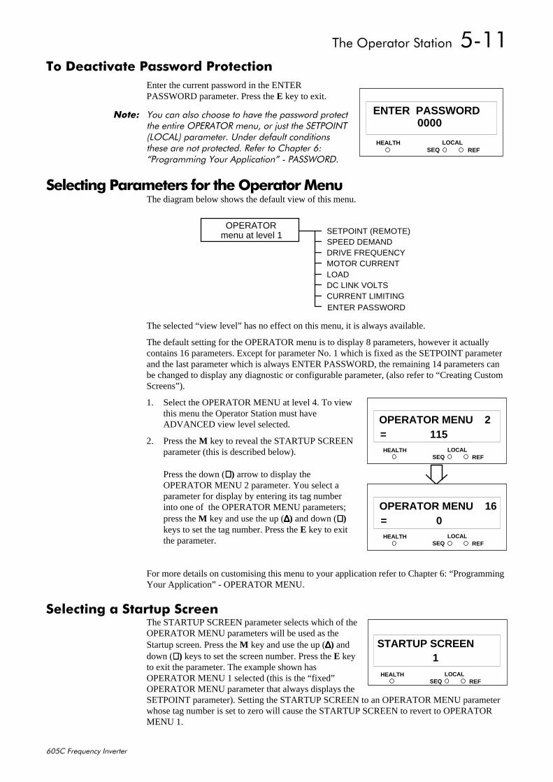
7KH#2SHUDWRU#6WDWLRQ##8044
938&#)UHTXHQF\#,QYHUWHU
7R#'HDFWLYDWH#3DVVZRUG#3URWHFWLRQEnter the current password in the ENTERPASSWORD parameter. Press the E key to exit.
1RWH=# <RX#FDQ#DOVR#FKRRVH#WR#KDYH#WKH#SDVVZRUG#SURWHFWWKH#HQWLUH#23(5$725#PHQX/#RU#MXVW#WKH#6(732,17+/2&$/,#SDUDPHWHU1#8QGHU#GHIDXOW#FRQGLWLRQVWKHVH#DUH#QRW#SURWHFWHG1#5HIHU#WR#&KDSWHU#9=´3URJUDPPLQJ#<RXU#$SSOLFDWLRQµ#0#3$66:25'1
6HOHFWLQJ#3DUDPHWHUV#IRU#WKH#2SHUDWRU#0HQXThe diagram below shows the default view of this menu.
The selected “view level” has no effect on this menu, it is always available.
The default setting for the OPERATOR menu is to display 8 parameters, however it actuallycontains 16 parameters. Except for parameter No. 1 which is fixed as the SETPOINT parameterand the last parameter which is always ENTER PASSWORD, the remaining 14 parameters canbe changed to display any diagnostic or configurable parameter, (also refer to “Creating CustomScreens”).
1. Select the OPERATOR MENU at level 4. To viewthis menu the Operator Station must haveADVANCED view level selected.
2. Press the M key to reveal the STARTUP SCREENparameter (this is described below).
Press the down (∇∇∇∇) arrow to display theOPERATOR MENU 2 parameter. You select aparameter for display by entering its tag numberinto one of the OPERATOR MENU parameters;press the M key and use the up (∆∆∆∆) and down (∇∇∇∇)keys to set the tag number. Press the E key to exitthe parameter.
For more details on customising this menu to your application refer to Chapter 6: “ProgrammingYour Application” - OPERATOR MENU.
6HOHFWLQJ#D#6WDUWXS#6FUHHQThe STARTUP SCREEN parameter selects which of theOPERATOR MENU parameters will be used as theStartup screen. Press the M key and use the up (∆∆∆∆) anddown (∇∇∇∇) keys to set the screen number. Press the E keyto exit the parameter. The example shown hasOPERATOR MENU 1 selected (this is the “fixed”OPERATOR MENU parameter that always displays theSETPOINT parameter). Setting the STARTUP SCREEN to an OPERATOR MENU parameterwhose tag number is set to zero will cause the STARTUP SCREEN to revert to OPERATORMENU 1.
HEALTH LOCALSEQ REF
110000
ENTER PASSWORD
SETPOINT (REMOTE)SPEED DEMANDDRIVE FREQUENCYMOTOR CURRENTLOADDC LINK VOLTSCURRENT LIMITINGENTER PASSWORD
OPERATORmenu at level 1
HEALTH LOCALSEQ REF
11= 115
OPERATOR MENU 2
HEALTH LOCALSEQ REF
11= 0
OPERATOR MENU 16
HEALTH LOCALSEQ REF
11 1
STARTUP SCREEN
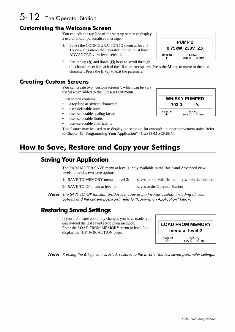
8045##7KH#2SHUDWRU#6WDWLRQ
938&#)UHTXHQF\#,QYHUWHU
&XVWRPLVLQJ#WKH#:HOFRPH#6FUHHQYou can edit the top line of the start-up screen to displaya useful and/or personalised message.
1. Select the CONFIGURATION ID menu at level 3.To view this menu the Operator Station must haveADVANCED view level selected.
2. Use the up (∆∆∆∆) and down (∇∇∇∇) keys to scroll throughthe character set for each of the 16 character spaces. Press the M key to move to the nextcharacter. Press the E key to exit the parameter.
&UHDWLQJ#&XVWRP#6FUHHQVYou can create two “custom screens”, which can be veryuseful when added to the OPERATOR menu.
Each screen contains:• a top line of sixteen characters• user-definable units• user-selectable scaling factor• user-selectable limits• user-selectable coefficientsThis feature may be used to re-display the setpoint, for example, in more convenient units. Referto Chapter 6: “Programming Your Application” - CUSTOM SCREEN.
+RZ#WR#6DYH/#5HVWRUH#DQG#&RS\#\RXU#6HWWLQJV
6DYLQJ#<RXU#$SSOLFDWLRQThe PARAMETER SAVE menu at level 1, only available in the Basic and Advanced viewlevels, provides two save options:
1. SAVE TO MEMORY menu at level 2: saves to non-volatile memory within the Inverter
2. SAVE TO OP menu at level 2: saves to the Operator Station
1RWH=# 7KH#6$9(#72#23#IXQFWLRQ#SURGXFHV#D#FRS\#RI#WKH#,QYHUWHU·V#VHWXS/#LQFOXGLQJ#DOO#XVHURSWLRQV#DQG#WKH#FXUUHQW#SDVVZRUG/#UHIHU#WR#´&RS\LQJ#DQ#$SSOLFDWLRQµ#EHORZ1
5HVWRULQJ#6DYHG#6HWWLQJVIf you are unsure about any changes you have made, youcan re-load the last saved setup from memory.Enter the LOAD FROM MEMORY menu at level 2 todisplay the `UP` FOR ACTION page.
1RWH=# 3UHVVLQJ#WKH#∆∆∆∆#NH\/#DV#LQVWUXFWHG/#UHVWRUHV#WR#WKH#,QYHUWHU#WKH#ODVW#VDYHG#SDUDPHWHU#VHWWLQJV1
HEALTH LOCALSEQ REF
110.75kW 230V 2.x
PUMP 2
HEALTH LOCALSEQ REF
11103.0 l/s
WHISKY PUMPED
HEALTH LOCALSEQ REF
11menu at level 2
LOAD FROM MEMORY
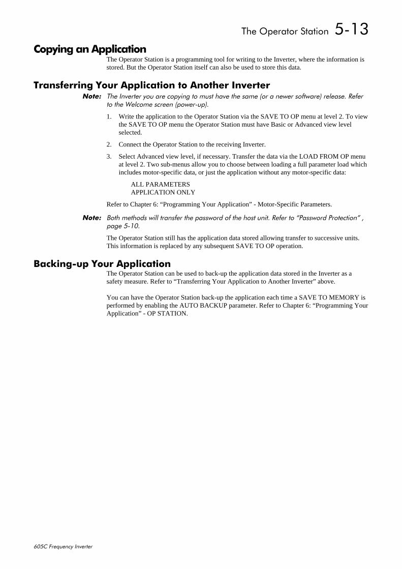
7KH#2SHUDWRU#6WDWLRQ##8046
938&#)UHTXHQF\#,QYHUWHU
&RS\LQJ#DQ#$SSOLFDWLRQThe Operator Station is a programming tool for writing to the Inverter, where the information isstored. But the Operator Station itself can also be used to store this data.
7UDQVIHUULQJ#<RXU#$SSOLFDWLRQ#WR#$QRWKHU#,QYHUWHU1RWH=# 7KH#,QYHUWHU#\RX#DUH#FRS\LQJ#WR#PXVW#KDYH#WKH#VDPH#+RU#D#QHZHU#VRIWZDUH,#UHOHDVH1#5HIHU
WR#WKH#:HOFRPH#VFUHHQ#+SRZHU0XS,1
1. Write the application to the Operator Station via the SAVE TO OP menu at level 2. To viewthe SAVE TO OP menu the Operator Station must have Basic or Advanced view levelselected.
2. Connect the Operator Station to the receiving Inverter.
3. Select Advanced view level, if necessary. Transfer the data via the LOAD FROM OP menuat level 2. Two sub-menus allow you to choose between loading a full parameter load whichincludes motor-specific data, or just the application without any motor-specific data:
ALL PARAMETERSAPPLICATION ONLY
Refer to Chapter 6: “Programming Your Application” - Motor-Specific Parameters.
1RWH=# %RWK#PHWKRGV#ZLOO#WUDQVIHU#WKH#SDVVZRUG#RI#WKH#KRVW#XQLW1#5HIHU#WR#´3DVVZRUG#3URWHFWLRQµ#/SDJH#80431
The Operator Station still has the application data stored allowing transfer to successive units.This information is replaced by any subsequent SAVE TO OP operation.
%DFNLQJ0XS#<RXU#$SSOLFDWLRQThe Operator Station can be used to back-up the application data stored in the Inverter as asafety measure. Refer to “Transferring Your Application to Another Inverter” above.
You can have the Operator Station back-up the application each time a SAVE TO MEMORY isperformed by enabling the AUTO BACKUP parameter. Refer to Chapter 6: “Programming YourApplication” - OP STATION.

8047##7KH#2SHUDWRU#6WDWLRQ
938&#)UHTXHQF\#,QYHUWHU
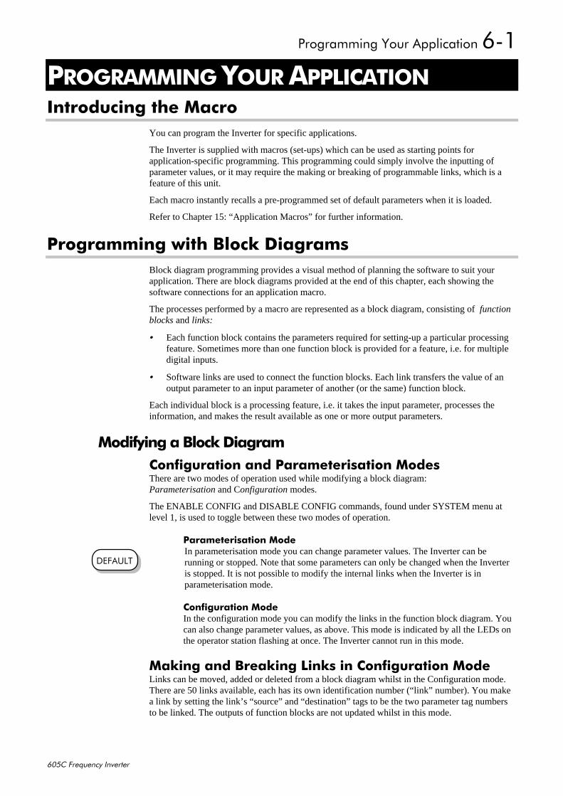
3URJUDPPLQJ#<RXU#$SSOLFDWLRQ#904
938&#)UHTXHQF\#,QYHUWHU
4#352*5$00,1*#<285#$33/,&$7,21,QWURGXFLQJ#WKH#0DFUR
You can program the Inverter for specific applications.
The Inverter is supplied with macros (set-ups) which can be used as starting points forapplication-specific programming. This programming could simply involve the inputting ofparameter values, or it may require the making or breaking of programmable links, which is afeature of this unit.
Each macro instantly recalls a pre-programmed set of default parameters when it is loaded.
Refer to Chapter 15: “Application Macros” for further information.
3URJUDPPLQJ#ZLWK#%ORFN#'LDJUDPVBlock diagram programming provides a visual method of planning the software to suit yourapplication. There are block diagrams provided at the end of this chapter, each showing thesoftware connections for an application macro.
The processes performed by a macro are represented as a block diagram, consisting of functionblocks and links:
• Each function block contains the parameters required for setting-up a particular processingfeature. Sometimes more than one function block is provided for a feature, i.e. for multipledigital inputs.
• Software links are used to connect the function blocks. Each link transfers the value of anoutput parameter to an input parameter of another (or the same) function block.
Each individual block is a processing feature, i.e. it takes the input parameter, processes theinformation, and makes the result available as one or more output parameters.
0RGLI\LQJ#D#%ORFN#'LDJUDP&RQILJXUDWLRQ#DQG#3DUDPHWHULVDWLRQ#0RGHVThere are two modes of operation used while modifying a block diagram:Parameterisation and Configuration modes.
The ENABLE CONFIG and DISABLE CONFIG commands, found under SYSTEM menu atlevel 1, is used to toggle between these two modes of operation.
3DUDPHWHULVDWLRQ#0RGHIn parameterisation mode you can change parameter values. The Inverter can berunning or stopped. Note that some parameters can only be changed when the Inverteris stopped. It is not possible to modify the internal links when the Inverter is inparameterisation mode.
&RQILJXUDWLRQ#0RGHIn the configuration mode you can modify the links in the function block diagram. Youcan also change parameter values, as above. This mode is indicated by all the LEDs onthe operator station flashing at once. The Inverter cannot run in this mode.
0DNLQJ#DQG#%UHDNLQJ#/LQNV#LQ#&RQILJXUDWLRQ#0RGHLinks can be moved, added or deleted from a block diagram whilst in the Configuration mode.There are 50 links available, each has its own identification number (“link” number). You makea link by setting the link’s “source” and “destination” tags to be the two parameter tag numbersto be linked. The outputs of function blocks are not updated whilst in this mode.
'()$8/7
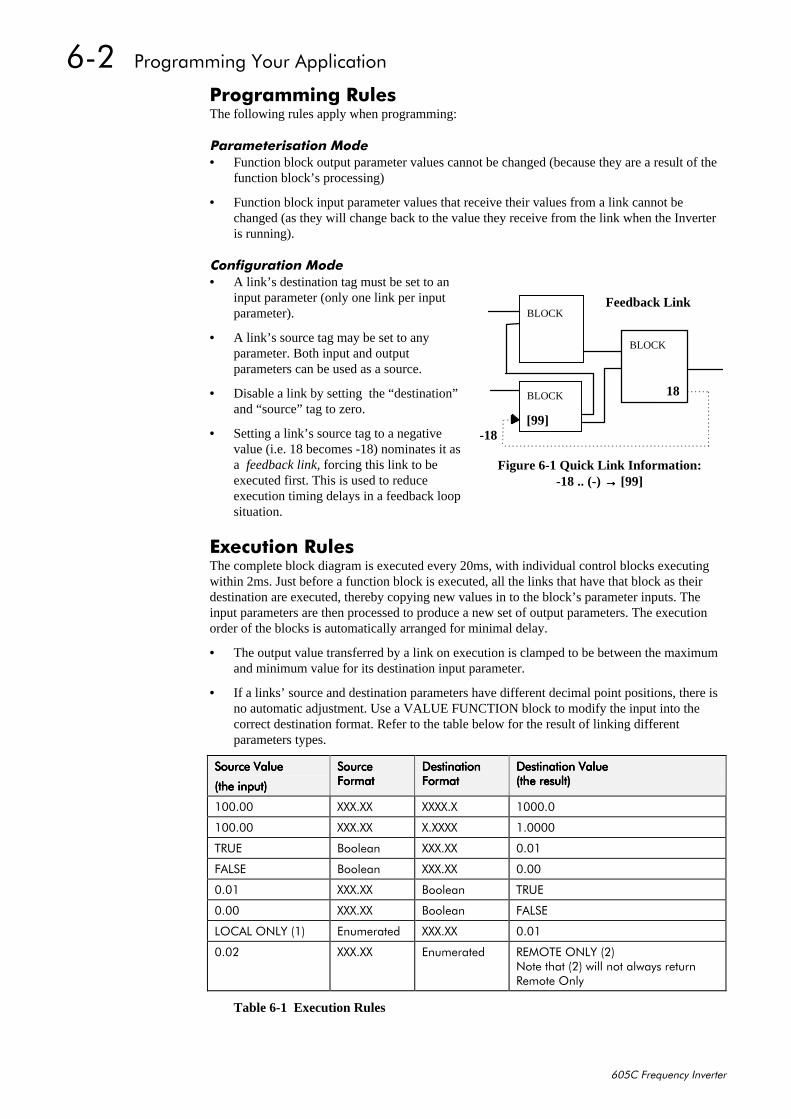
905##3URJUDPPLQJ#<RXU#$SSOLFDWLRQ
938&#)UHTXHQF\#,QYHUWHU
3URJUDPPLQJ#5XOHVThe following rules apply when programming:
3DUDPHWHULVDWLRQ#0RGH• Function block output parameter values cannot be changed (because they are a result of the
function block’s processing)
• Function block input parameter values that receive their values from a link cannot bechanged (as they will change back to the value they receive from the link when the Inverteris running).
&RQILJXUDWLRQ#0RGH• A link’s destination tag must be set to an
input parameter (only one link per inputparameter).
• A link’s source tag may be set to anyparameter. Both input and outputparameters can be used as a source.
• Disable a link by setting the “destination”and “source” tag to zero.
• Setting a link’s source tag to a negativevalue (i.e. 18 becomes -18) nominates it asa feedback link, forcing this link to beexecuted first. This is used to reduceexecution timing delays in a feedback loopsituation.
([HFXWLRQ#5XOHVThe complete block diagram is executed every 20ms, with individual control blocks executingwithin 2ms. Just before a function block is executed, all the links that have that block as theirdestination are executed, thereby copying new values in to the block’s parameter inputs. Theinput parameters are then processed to produce a new set of output parameters. The executionorder of the blocks is automatically arranged for minimal delay.
• The output value transferred by a link on execution is clamped to be between the maximumand minimum value for its destination input parameter.
• If a links’ source and destination parameters have different decimal point positions, there isno automatic adjustment. Use a VALUE FUNCTION block to modify the input into thecorrect destination format. Refer to the table below for the result of linking differentparameters types.
6RXUFH#9DOXH6RXUFH#9DOXH6RXUFH#9DOXH6RXUFH#9DOXH
+WKH#LQSXW,+WKH#LQSXW,+WKH#LQSXW,+WKH#LQSXW,
6RXUFH6RXUFH6RXUFH6RXUFH)RUPDW)RUPDW)RUPDW)RUPDW
'HVWLQDWLRQ'HVWLQDWLRQ'HVWLQDWLRQ'HVWLQDWLRQ)RUPDW)RUPDW)RUPDW)RUPDW
'HVWLQDWLRQ#9DOXH'HVWLQDWLRQ#9DOXH'HVWLQDWLRQ#9DOXH'HVWLQDWLRQ#9DOXH+WKH#UHVXOW,+WKH#UHVXOW,+WKH#UHVXOW,+WKH#UHVXOW,
433133 ;;;1;; ;;;;1; 433313
433133 ;;;1;; ;1;;;; 413333
758( %RROHDQ ;;;1;; 3134
)$/6( %RROHDQ ;;;1;; 3133
3134 ;;;1;; %RROHDQ 758(
3133 ;;;1;; %RROHDQ )$/6(
/2&$/#21/<#+4, (QXPHUDWHG ;;;1;; 3134
3135 ;;;1;; (QXPHUDWHG 5(027(#21/<#+5,1RWH#WKDW#+5,#ZLOO#QRW#DOZD\V#UHWXUQ5HPRWH#2QO\
Table 6-1 Execution Rules
Feedback Link
18
BLOCK
BLOCK
BLOCK
[99] -18
Figure 6-1 Quick Link Information:-18 .. (-) →→→→ [99]
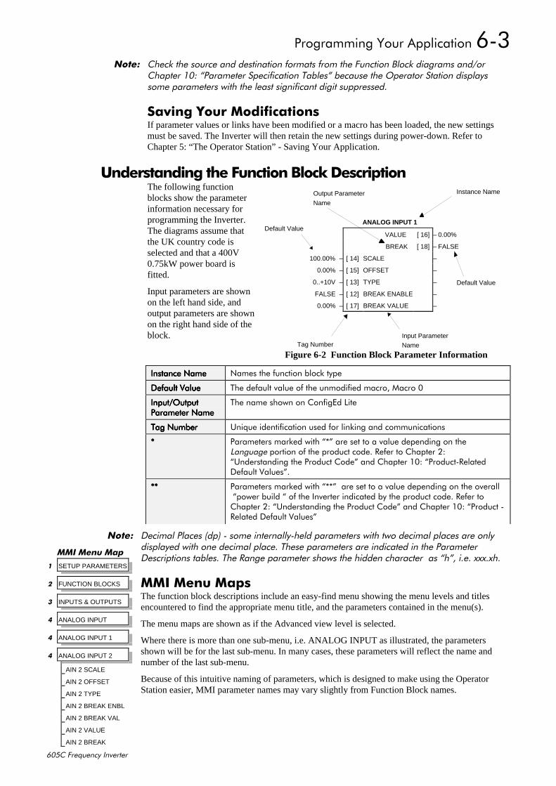
3URJUDPPLQJ#<RXU#$SSOLFDWLRQ#906
938&#)UHTXHQF\#,QYHUWHU
1RWH=# &KHFN#WKH#VRXUFH#DQG#GHVWLQDWLRQ#IRUPDWV#IURP#WKH#)XQFWLRQ#%ORFN#GLDJUDPV#DQG2RU&KDSWHU#43=#´3DUDPHWHU#6SHFLILFDWLRQ#7DEOHVµ#EHFDXVH#WKH#2SHUDWRU#6WDWLRQ#GLVSOD\VVRPH#SDUDPHWHUV#ZLWK#WKH#OHDVW#VLJQLILFDQW#GLJLW#VXSSUHVVHG1
6DYLQJ#<RXU#0RGLILFDWLRQVIf parameter values or links have been modified or a macro has been loaded, the new settingsmust be saved. The Inverter will then retain the new settings during power-down. Refer toChapter 5: “The Operator Station” - Saving Your Application.
#8QGHUVWDQGLQJ#WKH#)XQFWLRQ#%ORFN#'HVFULSWLRQThe following functionblocks show the parameterinformation necessary forprogramming the Inverter.The diagrams assume thatthe UK country code isselected and that a 400V0.75kW power board isfitted.
Input parameters are shownon the left hand side, andoutput parameters are shownon the right hand side of theblock.
,QVWDQFH#1DPH,QVWDQFH#1DPH,QVWDQFH#1DPH,QVWDQFH#1DPH 1DPHV#WKH#IXQFWLRQ#EORFN#W\SH
'HIDXOW#9DOXH'HIDXOW#9DOXH'HIDXOW#9DOXH'HIDXOW#9DOXH 7KH#GHIDXOW#YDOXH#RI#WKH#XQPRGLILHG#PDFUR/#0DFUR#3
,QSXW22XWSXW,QSXW22XWSXW,QSXW22XWSXW,QSXW22XWSXW3DUDPHWHU#1DPH3DUDPHWHU#1DPH3DUDPHWHU#1DPH3DUDPHWHU#1DPH
7KH#QDPH#VKRZQ#RQ#&RQILJ(G#/LWH
7DJ#1XPEHU7DJ#1XPEHU7DJ#1XPEHU7DJ#1XPEHU 8QLTXH#LGHQWLILFDWLRQ#XVHG#IRU#OLQNLQJ#DQG#FRPPXQLFDWLRQV
---- 3DUDPHWHUV#PDUNHG#ZLWK#´-µ#DUH#VHW#WR#D#YDOXH#GHSHQGLQJ#RQ#WKH/DQJXDJH#SRUWLRQ#RI#WKH#SURGXFW#FRGH1#5HIHU#WR#&KDSWHU#5=´8QGHUVWDQGLQJ#WKH#3URGXFW#&RGHµ#DQG#&KDSWHU#43=#´3URGXFW05HODWHG'HIDXOW#9DOXHVµ1
-------- 3DUDPHWHUV#PDUNHG#ZLWK#´--µ##DUH#VHW#WR#D#YDOXH#GHSHQGLQJ#RQ#WKH#RYHUDOO#´SRZHU#EXLOG#´#RI#WKH#,QYHUWHU#LQGLFDWHG#E\#WKH#SURGXFW#FRGH1#5HIHU#WR&KDSWHU#5=#´8QGHUVWDQGLQJ#WKH#3URGXFW#&RGHµ#DQG#&KDSWHU#43=#´3URGXFW#05HODWHG#'HIDXOW#9DOXHVµ
1RWH=# 'HFLPDO#3ODFHV#+GS,#0#VRPH#LQWHUQDOO\0KHOG#SDUDPHWHUV#ZLWK#WZR#GHFLPDO#SODFHV#DUH#RQO\GLVSOD\HG#ZLWK#RQH#GHFLPDO#SODFH1#7KHVH#SDUDPHWHUV#DUH#LQGLFDWHG#LQ#WKH#3DUDPHWHU'HVFULSWLRQV#WDEOHV1#7KH#5DQJH#SDUDPHWHU#VKRZV#WKH#KLGGHQ#FKDUDFWHU##DV#´Kµ/#L1H1#[[[1[K1
00,#0HQX#0DSVThe function block descriptions include an easy-find menu showing the menu levels and titlesencountered to find the appropriate menu title, and the parameters contained in the menu(s).
The menu maps are shown as if the Advanced view level is selected.
Where there is more than one sub-menu, i.e. ANALOG INPUT as illustrated, the parametersshown will be for the last sub-menu. In many cases, these parameters will reflect the name andnumber of the last sub-menu.
Because of this intuitive naming of parameters, which is designed to make using the OperatorStation easier, MMI parameter names may vary slightly from Function Block names.
Default Value
Input Parameter
Name
Output Parameter
Name
Default Value
Instance Name
ANALOG INPUT 1
VALUE [ 16] – 0.00%
BREAK [ 18] – FALSE
100.00% – [ 14] SCALE –
0.00% – [ 15] OFFSET –
0..+10V – [ 13] TYPE –
FALSE – [ 12] BREAK ENABLE –
0.00% – [ 17] BREAK VALUE –
Tag Number
Figure 6-2 Function Block Parameter Information
00,#0HQX#0DS
4 SETUP PARAMETERS
5 FUNCTION BLOCKS
6 INPUTS & OUTPUTS
7 ANALOG INPUT
7 ANALOG INPUT 1
7 ANALOG INPUT 2
AIN 2 SCALE
AIN 2 OFFSET
AIN 2 TYPE
AIN 2 BREAK ENBL
AIN 2 BREAK VAL
AIN 2 VALUE
AIN 2 BREAK
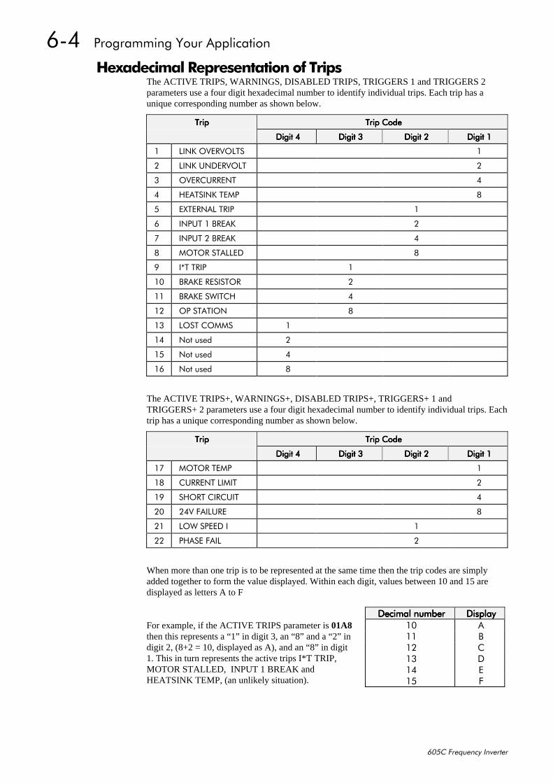
907##3URJUDPPLQJ#<RXU#$SSOLFDWLRQ
938&#)UHTXHQF\#,QYHUWHU
+H[DGHFLPDO#5HSUHVHQWDWLRQ#RI#7ULSVThe ACTIVE TRIPS, WARNINGS, DISABLED TRIPS, TRIGGERS 1 and TRIGGERS 2parameters use a four digit hexadecimal number to identify individual trips. Each trip has aunique corresponding number as shown below.
7ULS7ULS7ULS7ULS 7ULS#&RGH7ULS#&RGH7ULS#&RGH7ULS#&RGH
'LJLW#7'LJLW#7'LJLW#7'LJLW#7 'LJLW#6'LJLW#6'LJLW#6'LJLW#6 'LJLW#5'LJLW#5'LJLW#5'LJLW#5 'LJLW#4'LJLW#4'LJLW#4'LJLW#4
4 /,1.#29(592/76 4
5 /,1.#81'(592/7 5
6 29(5&855(17 7
7 +($76,1.#7(03 ;
8 (;7(51$/#75,3 4
9 ,1387#4#%5($. 5
: ,1387#5#%5($. 7
; 02725#67$//(' ;
< ,-7#75,3 4
43 %5$.(#5(6,6725 5
44 %5$.(#6:,7&+ 7
45 23#67$7,21 ;
46 /267#&2006 4
47 1RW#XVHG 5
48 1RW#XVHG 7
49 1RW#XVHG ;
The ACTIVE TRIPS+, WARNINGS+, DISABLED TRIPS+, TRIGGERS+ 1 andTRIGGERS+ 2 parameters use a four digit hexadecimal number to identify individual trips. Eachtrip has a unique corresponding number as shown below.
7ULS7ULS7ULS7ULS 7ULS#&RGH7ULS#&RGH7ULS#&RGH7ULS#&RGH
'LJLW#7'LJLW#7'LJLW#7'LJLW#7 'LJLW#6'LJLW#6'LJLW#6'LJLW#6 'LJLW#5'LJLW#5'LJLW#5'LJLW#5 'LJLW#4'LJLW#4'LJLW#4'LJLW#4
4: 02725#7(03 4
4; &855(17#/,0,7 5
4< 6+257#&,5&8,7 7
53 579#)$,/85( ;
54 /2:#63(('#, 4
55 3+$6(#)$,/ 5
When more than one trip is to be represented at the same time then the trip codes are simplyadded together to form the value displayed. Within each digit, values between 10 and 15 aredisplayed as letters A to F
For example, if the ACTIVE TRIPS parameter is 01A8then this represents a “1” in digit 3, an “8” and a “2” indigit 2, (8+2 = 10, displayed as A), and an “8” in digit1. This in turn represents the active trips I*T TRIP,MOTOR STALLED, INPUT 1 BREAK andHEATSINK TEMP, (an unlikely situation).
'HFLPDO#QXPEHU'HFLPDO#QXPEHU'HFLPDO#QXPEHU'HFLPDO#QXPEHU 'LVSOD\'LVSOD\'LVSOD\'LVSOD\43 $44 %45 &46 '47 (48 )
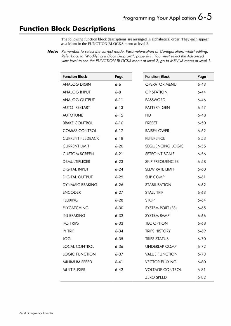
3URJUDPPLQJ#<RXU#$SSOLFDWLRQ#908
938&#)UHTXHQF\#,QYHUWHU
)XQFWLRQ#%ORFN#'HVFULSWLRQVThe following function block descriptions are arranged in alphabetical order. They each appearas a Menu in the FUNCTION BLOCKS menu at level 2.
1RWH=# 5HPHPEHU#WR#VHOHFW#WKH#FRUUHFW#PRGH/#3DUDPHWHULVDWLRQ#RU#&RQILJXUDWLRQ/#ZKLOVW#HGLWLQJ15HIHU#EDFN#WR#´0RGLI\LQJ#D#%ORFN#'LDJUDPµ/#SDJH#9041#<RX#PXVW#VHOHFW#WKH#$GYDQFHGYLHZ#OHYHO#WR#VHH#WKH#)81&7,21#%/2&.6#PHQX#DW#OHYHO#5/#JR#WR#0(186#PHQX#DW#OHYHO#41
)XQFWLRQ#%ORFN)XQFWLRQ#%ORFN)XQFWLRQ#%ORFN)XQFWLRQ#%ORFN 3DJH3DJH3DJH3DJH )XQFWLRQ#%ORFN)XQFWLRQ#%ORFN)XQFWLRQ#%ORFN)XQFWLRQ#%ORFN 3DJH3DJH3DJH3DJH
$1$/2*#',*,1 909 23(5$725#0(18 9076
$1$/2*#,1387 90; 23#67$7,21 9077
$1$/2*#287387 9044 3$66:25' 9079
$872##5(67$57 9046 3$77(51#*(1 907:
$872781( 9048 3,' 907;
%5$.(#&21752/ 9049 35(6(7 9083
&2006#&21752/ 904: 5$,6(2/2:(5 9085
&855(17#)(('%$&. 904; 5()(5(1&( 9086
&855(17#/,0,7 9053 6(48(1&,1*#/2*,& 9088
&86720#6&5((1 9054 6(732,17#6&$/( 9089
'(08/7,3/(;(5 9056 6.,3#)5(48(1&,(6 908;
',*,7$/#,1387 9057 6/(:#5$7(#/,0,7 9093
',*,7$/#287387 9058 6/,3#&203 9094
'<1$0,&#%5$.,1* 9059 67$%,/,6$7,21 9095
(1&2'(5 905: 67$//#75,3 9096
)/8;,1* 905; 6723 9097
)/<&$7&+,1* 9063 6<67(0#3257#+36, 9098
,1-#%5$.,1* 9065 6<67(0#5$03 9099
,22#75,36 9066 7(í,21 909;
,-W#75,3 9067 75,36#+,6725< 909<
-2* 9068 75,36#67$786 90:3
/2&$/#&21752/ 9069 81'(5/$3#&203 90:5
/2*,&#)81&7,21 906: 9$/8(#)81&7,21 90:6
0,1,080#63((' 9074 9(&725#)/8;,1* 90;3
08/7,3/(;(5 9075 92/7$*(#&21752/ 90;4
=(52#63((' 90;5
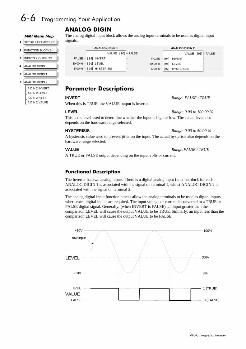
909##3URJUDPPLQJ#<RXU#$SSOLFDWLRQ
938&#)UHTXHQF\#,QYHUWHU
$1$/2*#',*,1The analog digital input block allows the analog input terminals to be used as digital inputsignals.
)XQFWLRQDO#'HVFULSWLRQ
The Inverter has two analog inputs. There is a digital analog input function block for each:ANALOG DIGIN 1 is associated with the signal on terminal 1, whilst ANALOG DIGIN 2 isassociated with the signal on terminal 2.
The analog digital input function blocks allow the analog terminals to be used as digital inputswhere extra digital inputs are required. The input voltage or current is converted to a TRUE orFALSE digital signal. Generally, (when INVERT is FALSE), an input greater than thecomparison LEVEL will cause the output VALUE to be TRUE. Similarly, an input less than thecomparison LEVEL will cause the output VALUE to be FALSE.
+10V
-10V 0%
30%
100%
0 (FALSE)
1 (TRUE)
LEVEL
TRUE
FALSE
VALUE
raw input
00,#0HQX#0DS
4 SETUP PARAMETERS
5 FUNCTION BLOCKS
6 INPUTS & OUTPUTS
7 ANALOG DIGIN
8 ANALOG DIGIN 1
8 ANALOG DIGIN 2
A DIN 2 INVERT
A DIN 2 LEVEL
A DIN 2 HYST
A DIN 2 VALUE
ANALOG DIGIN 2
VALUE [95] – FALSE
FALSE – [94] INVERT –
30.00 % – [96] LEVEL –
5.00 % – [97] HYSTERISIS –
3DUDPHWHU#'HVFULSWLRQVINVERT Range: FALSE / TRUE
When this is TRUE, the VALUE output is inverted.
LEVEL Range: 0.00 to 100.00 %
This is the level used to determine whether the input is high or low. The actual level alsodepends on the hardware range selected.
HYSTERISIS Range: 0.00 to 50.00 %
A hysterisis value used to prevent jitter on the input. The actual hysterisis also depends on thehardware range selected.
VALUE Range:FALSE / TRUE
A TRUE or FALSE output depending on the input volts or current.
ANALOG DIGIN 1
VALUE [ 90] – FALSE
FALSE – [ 89] INVERT –
30.00 % – [ 91] LEVEL –
5.00 % – [ 92] HYSTERISIS –
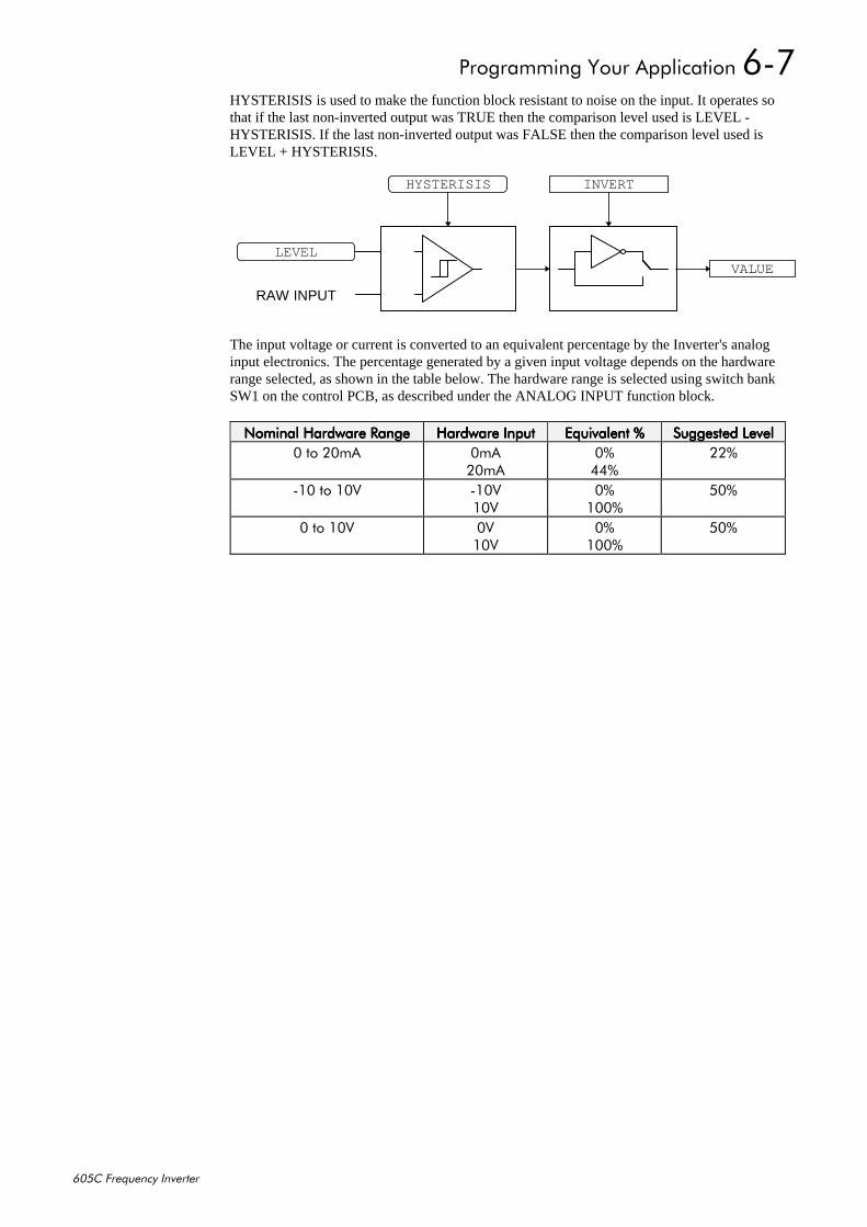
3URJUDPPLQJ#<RXU#$SSOLFDWLRQ#90:
938&#)UHTXHQF\#,QYHUWHU
HYSTERISIS is used to make the function block resistant to noise on the input. It operates sothat if the last non-inverted output was TRUE then the comparison level used is LEVEL -HYSTERISIS. If the last non-inverted output was FALSE then the comparison level used isLEVEL + HYSTERISIS.
LEVEL
RAW INPUT
VALUE
INVERTHYSTERISIS
The input voltage or current is converted to an equivalent percentage by the Inverter's analoginput electronics. The percentage generated by a given input voltage depends on the hardwarerange selected, as shown in the table below. The hardware range is selected using switch bankSW1 on the control PCB, as described under the ANALOG INPUT function block.
1RPLQDO#+DUGZDUH#5DQJH1RPLQDO#+DUGZDUH#5DQJH1RPLQDO#+DUGZDUH#5DQJH1RPLQDO#+DUGZDUH#5DQJH +DUGZDUH#,QSXW+DUGZDUH#,QSXW+DUGZDUH#,QSXW+DUGZDUH#,QSXW (TXLYDOHQW#((TXLYDOHQW#((TXLYDOHQW#((TXLYDOHQW#( 6XJJHVWHG#/HYHO6XJJHVWHG#/HYHO6XJJHVWHG#/HYHO6XJJHVWHG#/HYHO3#WR#53P$ 3P$
53P$3(77(
55(
043#WR#439 0439439
3(433(
83(
3#WR#439 39439
3(433(
83(
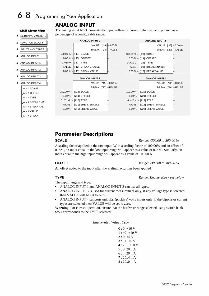
90;##3URJUDPPLQJ#<RXU#$SSOLFDWLRQ
938&#)UHTXHQF\#,QYHUWHU
$1$/2*#,1387The analog input block converts the input voltage or current into a value expressed as apercentage of a configurable range.
00,#0HQX#0DS
4 SETUP PARAMETERS
5 FUNCTION BLOCKS
6 INPUTS & OUTPUTS
7 ANALOG INPUT
8 ANALOG INPUT 1
8 ANALOG INPUT 2
8 ANALOG INPUT 3
8 ANALOG INPUT 4
AIN 4 SCALE
AIN 4 OFFSET
AIN 4 TYPE
AIN 4 BREAK ENBL
AIN 4 BREAK VAL
AIN 4 VALUE
AIN 4 BREAK
ANALOG INPUT 1
VALUE [ 16] – 0.00 %
BREAK [ 18] – FALSE
100.00 % – [ 14] SCALE –
0.00 % – [ 15] OFFSET –
0..+10 V – [ 13] TYPE –
FALSE – [ 12] BREAK ENABLE –
0.00 % – [ 17] BREAK VALUE –
ANALOG INPUT 2
VALUE [ 25] – 0.00 %
BREAK [ 27] – FALSE
100.00 % – [ 23] SCALE –
0.00 % – [ 24] OFFSET –
0..+10 V – [ 22] TYPE –
FALSE – [ 21] BREAK ENABLE –
0.00 % – [ 26] BREAK VALUE –
ANALOG INPUT 4
VALUE [722] – 0.00 %
BREAK [724] – FALSE
100.00 % – [720] SCALE –
0.00 % – [721] OFFSET –
0..+10 V – [719] TYPE –
FALSE – [718] BREAK ENABLE –
0.00 % – [723] BREAK VALUE –
ANALOG INPUT 3
VALUE [715] – 0.00 %
BREAK [717] – FALSE
100.00 % – [713] SCALE –
0.00 % – [714] OFFSET –
0..20 mA – [712] TYPE –
FALSE – [711] BREAK ENABLE –
0.00 % – [716] BREAK VALUE –
3DUDPHWHU#'HVFULSWLRQVSCALE Range: -300.00 to 300.00 %
A scaling factor applied to the raw input. With a scaling factor of 100.00% and an offset of0.00%, an input equal to the low input range will appear as a value of 0.00%. Similarly, aninput equal to the high input range will appear as a value of 100.00%.
OFFSET Range: -300.00 to 300.00 %
An offset added to the input after the scaling factor has been applied.
TYPE Range: Enumerated - see below
The input range and type.• ANALOG INPUT 1 and ANALOG INPUT 2 can use all types.• ANALOG INPUT 3 is used for current measurement only, if any voltage type is selected
then VALUE will be set to zero.• ANALOG INPUT 4 supports unipolar (positive) volts inputs only, if the bipolar or current
types are selected then VALUE will be set to zero.Warning : For correct operation, ensure that the hardware range selected using switch bankSW1 corresponds to the TYPE selected.
Enumerated Value : Type
0 : 0..+10 V1 : +2..+10 V2 : 0..+5 V3 : +1..+5 V4 : -10..+10 V5 : 0..20 mA6 : 4..20 mA7 : 20..4 mA8 : 20..0 mA
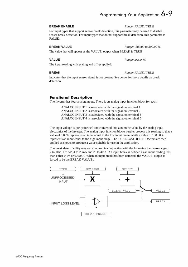
3URJUDPPLQJ#<RXU#$SSOLFDWLRQ#90<
938&#)UHTXHQF\#,QYHUWHU
)XQFWLRQDO#'HVFULSWLRQThe Inverter has four analog inputs. There is an analog input function block for each:
ANALOG INPUT 1 is associated with the signal on terminal 1ANALOG INPUT 2 is associated with the signal on terminal 2ANALOG INPUT 3 is associated with the signal on terminal 3ANALOG INPUT 4 is associated with the signal on terminal 5
The input voltage is pre-processed and converted into a numeric value by the analog inputelectronics of the Inverter. The analog input function blocks further process this reading so that avalue of 0.00% represents an input equal to the low input range, while a value of 100.00%represents an input equal to the high input range. The SCALE and OFFSET factors are thenapplied as shown to produce a value suitable for use in the application.
The break detect facility may only be used in conjunction with the following hardware ranges:2 to 10V, 1 to 5V, 4 to 20mA and 20 to 4mA. An input break is defined as an input reading lessthan either 0.1V or 0.45mA. When an input break has been detected, the VALUE output isforced to be the BREAK VALUE .
BREAK ENABLE Range: FALSE / TRUE
For input types that support sensor break detection, this parameter may be used to disablesensor break detection. For input types that do not support break detection, this parameter isFALSE.
BREAK VALUE Range: -300.00 to 300.00 %
The value that will appear as the VALUE output when BREAK is TRUE
VALUE Range: xxx.xx %
The input reading with scaling and offset applied.
BREAK Range: FALSE / TRUE
Indicates that the input sensor signal is not present. See below for more details on breakdetection.
.VALUE
SCALING OFFSET
;INPUT
BREAK VALU
INPUT LOSS LEVEL
BREAK ENABLE
BREAK
TYPE
UNPROCESSED
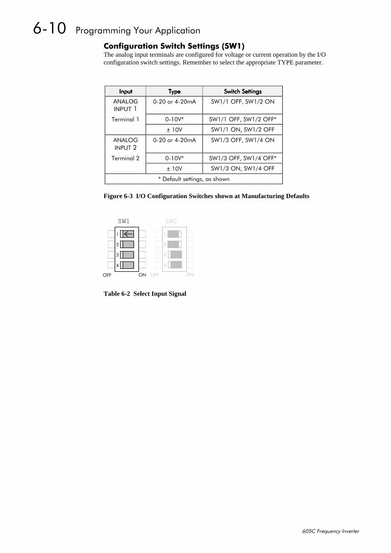
9043##3URJUDPPLQJ#<RXU#$SSOLFDWLRQ
938&#)UHTXHQF\#,QYHUWHU
&RQILJXUDWLRQ#6ZLWFK#6HWWLQJV#+6:4,The analog input terminals are configured for voltage or current operation by the I/Oconfiguration switch settings. Remember to select the appropriate TYPE parameter.
Figure 6-3 I/O Configuration Switches shown at Manufacturing Defaults
Table 6-2 Select Input Signal
,QSXW,QSXW,QSXW,QSXW 7\SH7\SH7\SH7\SH 6ZLWFK#6HWWLQJV6ZLWFK#6HWWLQJV6ZLWFK#6HWWLQJV6ZLWFK#6HWWLQJV
ANALOGINPUT#4
3053#RU#7053P$ 6:424#2))/#6:425#21
7HUPLQDO#4 30439- 6:424#2))/#6:425#2))-
±#439 6:424#21/#6:425#2))
$1$/2*,1387#5
3053#RU#7053P$ 6:426#2))/#6:427#21
7HUPLQDO#5 30439- 6:426#2))/#6:427#2))-
±#439 6:426#21/#6:427#2))
-#'HIDXOW#VHWWLQJV/#DV#VKRZQ
SW1
7
6
5
4
212))
SW2
7
6
5
4
212))
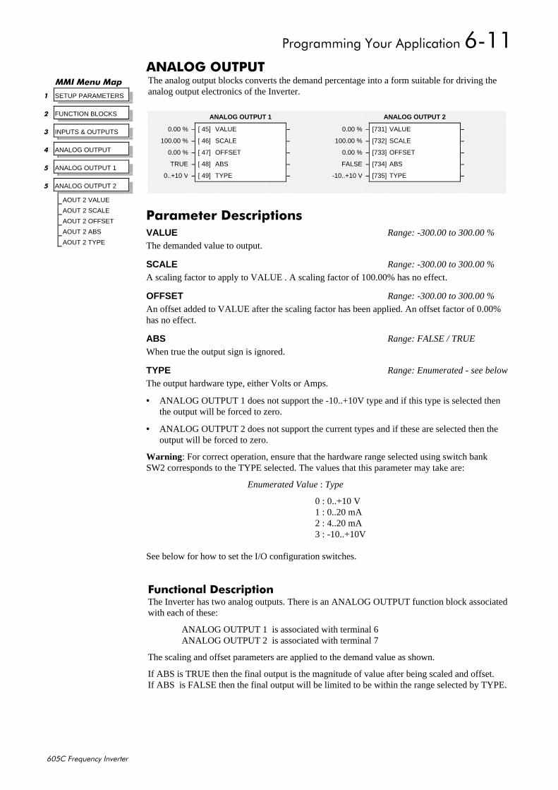
3URJUDPPLQJ#<RXU#$SSOLFDWLRQ#9044
938&#)UHTXHQF\#,QYHUWHU
$1$/2*#287387The analog output blocks converts the demand percentage into a form suitable for driving theanalog output electronics of the Inverter.
)XQFWLRQDO#'HVFULSWLRQThe Inverter has two analog outputs. There is an ANALOG OUTPUT function block associatedwith each of these:
ANALOG OUTPUT 1 is associated with terminal 6ANALOG OUTPUT 2 is associated with terminal 7
The scaling and offset parameters are applied to the demand value as shown.
If ABS is TRUE then the final output is the magnitude of value after being scaled and offset.If ABS is FALSE then the final output will be limited to be within the range selected by TYPE.
00,#0HQX#0DS
4 SETUP PARAMETERS
5 FUNCTION BLOCKS
6 INPUTS & OUTPUTS
7 ANALOG OUTPUT
8 ANALOG OUTPUT 1
8 ANALOG OUTPUT 2
AOUT 2 VALUE
AOUT 2 SCALE
AOUT 2 OFFSET
AOUT 2 ABS
AOUT 2 TYPE
ANALOG OUTPUT 2
0.00 % – [731] VALUE –
100.00 % – [732] SCALE –
0.00 % – [733] OFFSET –
FALSE – [734] ABS –
-10..+10 V – [735] TYPE –
ANALOG OUTPUT 1
0.00 % – [ 45] VALUE –
100.00 % – [ 46] SCALE –
0.00 % – [ 47] OFFSET –
TRUE – [ 48] ABS –
0..+10 V – [ 49] TYPE –
3DUDPHWHU#'HVFULSWLRQVVALUE Range: -300.00 to 300.00 %
The demanded value to output.
SCALE Range: -300.00 to 300.00 %
A scaling factor to apply to VALUE . A scaling factor of 100.00% has no effect.
OFFSET Range: -300.00 to 300.00 %
An offset added to VALUE after the scaling factor has been applied. An offset factor of 0.00%has no effect.
ABS Range: FALSE / TRUE
When true the output sign is ignored.
TYPE Range: Enumerated - see below
The output hardware type, either Volts or Amps.
• ANALOG OUTPUT 1 does not support the -10..+10V type and if this type is selected thenthe output will be forced to zero.
• ANALOG OUTPUT 2 does not support the current types and if these are selected then theoutput will be forced to zero.
Warning : For correct operation, ensure that the hardware range selected using switch bankSW2 corresponds to the TYPE selected. The values that this parameter may take are:
Enumerated Value : Type
0 : 0..+10 V1 : 0..20 mA2 : 4..20 mA3 : -10..+10V
See below for how to set the I/O configuration switches.
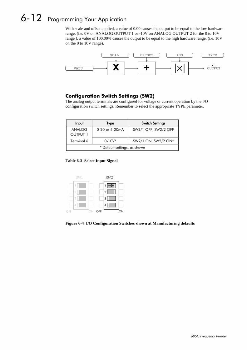
9045##3URJUDPPLQJ#<RXU#$SSOLFDWLRQ
938&#)UHTXHQF\#,QYHUWHU
With scale and offset applied, a value of 0.00 causes the output to be equal to the low hardwarerange, (i.e. 0V on ANALOG OUTPUT 1 or -10V on ANALOG OUTPUT 2 for the 0 to 10Vrange ), a value of 100.00% causes the output to be equal to the high hardware range, (i.e. 10Von the 0 to 10V range).
&RQILJXUDWLRQ#6ZLWFK#6HWWLQJV#+6:5,The analog output terminals are configured for voltage or current operation by the I/Oconfiguration switch settings. Remember to select the appropriate TYPE parameter.
Table 6-3 Select Input Signal
Figure 6-4 I/O Configuration Switches shown at Manufacturing defaults
; OUTPUT
SCAL
.
OFFSET
VALU
ABS TYPE
,QSXW,QSXW,QSXW,QSXW 7\SH7\SH7\SH7\SH 6ZLWFK#6HWWLQJV6ZLWFK#6HWWLQJV6ZLWFK#6HWWLQJV6ZLWFK#6HWWLQJV
$1$/2*287387#4
3053#RU#7053P$ 6:524#2))/#6:525#2))
7HUPLQDO#9 30439- 6:524#21/#6:525#21-
-#'HIDXOW#VHWWLQJV/#DV#VKRZQ
SW1
7
6
5
4
212))
SW2
7
6
5
4
212))
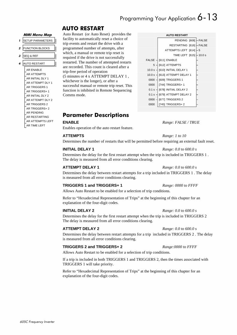
3URJUDPPLQJ#<RXU#$SSOLFDWLRQ#9046
938&#)UHTXHQF\#,QYHUWHU
$872#5(67$57Auto Restart (or Auto Reset) provides thefacility to automatically reset a choice oftrip events and restart the drive with aprogrammed number of attempts, afterwhich, a manual or remote trip reset isrequired if the drive is not successfullyrestarted. The number of attempted restartsare recorded. This count is cleared after atrip-free period of operation(5 minutes or 4 x ATTEMPT DELAY 1 ,whichever is the longer), or after asuccessful manual or remote trip reset. Thisfunction is inhibited in Remote SequencingComms mode.
00,#0HQX#0DS
4 SETUP PARAMETERS
5 FUNCTION BLOCKS
6 SEQ & REF
7 AUTO RESTART
AR ENABLE
AR ATTEMPTS
AR INITIAL DLY 1
AR ATTEMPT DLY 1
AR TRIGGERS 1
AR TRIGGERS+ 1
AR INITIAL DLY 2
AR ATTEMPT DLY 2
AR TRIGGERS 2
AR TRIGGERS+ 2
AR PENDING
AR RESTARTING
AR ATTEMPTS LEFT
AR TIME LEFT
AUTO RESTART
PENDING [608] – FALSE
RESTARTING [616] – FALSE
ATTEMPTS LEFT [614] – 5
TIME LEFT [615] – 10.0 s
FALSE – [611] ENABLE –
5 – [612] ATTEMPTS –
10.0 s – [610] INITIAL DELAY 1 –
10.0 s – [613] ATTEMPT DELAY 1 –
0000 – [609] TRIGGERS 1 –
0000 [744] TRIGGERS+ 1 –
0.1 s – [678] INITIAL DELAY 2 –
0.1 s – [679] ATTEMPT DELAY 2 –
0000 – [677] TRIGGERS 2 –
0000 [745] TRIGGERS+ 2 –
3DUDPHWHU#'HVFULSWLRQVENABLE Range: FALSE / TRUE
Enables operation of the auto restart feature.
ATTEMPTS Range: 1 to 10
Determines the number of restarts that will be permitted before requiring an external fault reset.
INITIAL DELAY 1 Range: 0.0 to 600.0 s
Determines the delay for the first restart attempt when the trip is included in TRIGGERS 1 .The delay is measured from all error conditions clearing.
ATTEMPT DELAY 1 Range: 0.0 to 600.0 s
Determines the delay between restart attempts for a trip included in TRIGGERS 1 . The delayis measured from all error conditions clearing.
TRIGGERS 1 and TRIGGERS+ 1 Range: 0000 to FFFF
Allows Auto Restart to be enabled for a selection of trip conditions.
Refer to “Hexadecimal Representation of Trips” at the beginning of this chapter for anexplanation of the four-digit codes.
INITIAL DELAY 2 Range: 0.0 to 600.0 s
Determines the delay for the first restart attempt when the trip is included in TRIGGERS 2The delay is measured from all error conditions clearing.
ATTEMPT DELAY 2 Range: 0.0 to 600.0 s
Determines the delay between restart attempts for a trip included in TRIGGERS 2 . The delayis measured from all error conditions clearing.
TRIGGERS 2 and TRIGGERS+ 2 Range:0000 to FFFF
Allows Auto Restart to be enabled for a selection of trip conditions.
If a trip is included in both TRIGGERS 1 and TRIGGERS 2, then the times associated withTRIGGERS 1 will take priority.
Refer to “Hexadecimal Representation of Trips” at the beginning of this chapter for anexplanation of the four-digit codes.

9047##3URJUDPPLQJ#<RXU#$SSOLFDWLRQ
938&#)UHTXHQF\#,QYHUWHU
PENDING Range: FALSE / TRUE
Indicates that an auto restart will occur after the programmed delay.
RESTARTING Range: FALSE / TRUE
Indicates that an auto restart is occurring.
ATTEMPTS LEFT Range: xxxxx
Indicates the number of attempts left before an external fault reset is required.
TIME LEFT Range: xxxx.x s
When in the timing sub-state, this parameter indicates the time left before an auto restartattempt will be permitted. When non-zero, this value is unaffected by changes to ATTEMPTDELAY 1.
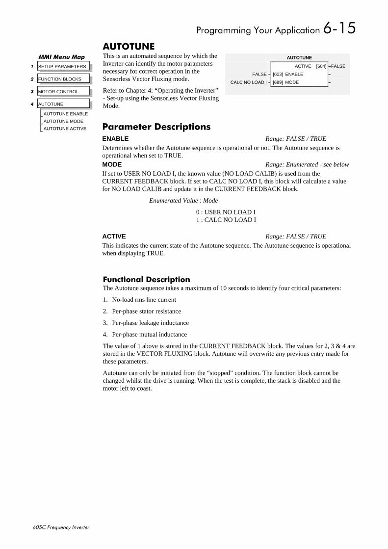
3URJUDPPLQJ#<RXU#$SSOLFDWLRQ#9048
938&#)UHTXHQF\#,QYHUWHU
$872781(This is an automated sequence by which theInverter can identify the motor parametersnecessary for correct operation in theSensorless Vector Fluxing mode.
Refer to Chapter 4: “Operating the Inverter”- Set-up using the Sensorless Vector FluxingMode.
)XQFWLRQDO#'HVFULSWLRQThe Autotune sequence takes a maximum of 10 seconds to identify four critical parameters:
1. No-load rms line current
2. Per-phase stator resistance
3. Per-phase leakage inductance
4. Per-phase mutual inductance
The value of 1 above is stored in the CURRENT FEEDBACK block. The values for 2, 3 & 4 arestored in the VECTOR FLUXING block. Autotune will overwrite any previous entry made forthese parameters.
Autotune can only be initiated from the “stopped” condition. The function block cannot bechanged whilst the drive is running. When the test is complete, the stack is disabled and themotor left to coast.
00,#0HQX#0DS
4 SETUP PARAMETERS
5 FUNCTION BLOCKS
6 MOTOR CONTROL
7 AUTOTUNE
AUTOTUNE ENABLE
AUTOTUNE MODE
AUTOTUNE ACTIVE
AUTOTUNE
ACTIVE [604] –FALSE
FALSE – [603] ENABLE –
CALC NO LOAD I – [689] MODE –
3DUDPHWHU#'HVFULSWLRQVENABLE Range: FALSE / TRUE
Determines whether the Autotune sequence is operational or not. The Autotune sequence isoperational when set to TRUE.
MODE Range: Enumerated - see below
If set to USER NO LOAD I, the known value (NO LOAD CALIB) is used from theCURRENT FEEDBACK block. If set to CALC NO LOAD I, this block will calculate a valuefor NO LOAD CALIB and update it in the CURRENT FEEDBACK block.
Enumerated Value : Mode
0 : USER NO LOAD I1 : CALC NO LOAD I
ACTIVE Range: FALSE / TRUE
This indicates the current state of the Autotune sequence. The Autotune sequence is operationalwhen displaying TRUE.
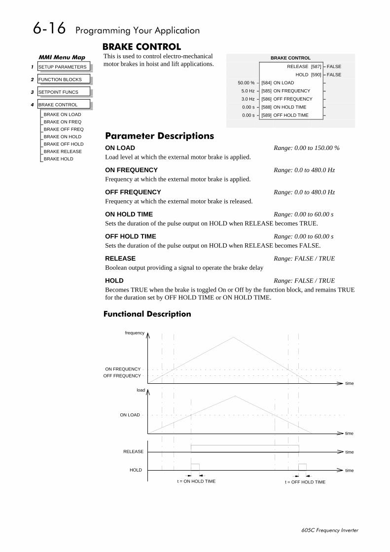
9049##3URJUDPPLQJ#<RXU#$SSOLFDWLRQ
938&#)UHTXHQF\#,QYHUWHU
%5$.(#&21752/This is used to control electro-mechanicalmotor brakes in hoist and lift applications.
)XQFWLRQDO#'HVFULSWLRQ
time
time
time
time
frequency
ON FREQUENCY
OFF FREQUENCY
RELEASE
HOLD
ON LOAD
load
t = ON HOLD TIME t = OFF HOLD TIME
00,#0HQX#0DS
4 SETUP PARAMETERS
5 FUNCTION BLOCKS
6 SETPOINT FUNCS
7 BRAKE CONTROL
BRAKE ON LOAD
BRAKE ON FREQ
BRAKE OFF FREQ
BRAKE ON HOLD
BRAKE OFF HOLD
BRAKE RELEASE
BRAKE HOLD
BRAKE CONTROL
RELEASE [587] – FALSE
HOLD [590] – FALSE
50.00 % – [584] ON LOAD –
5.0 Hz – [585] ON FREQUENCY –
3.0 Hz – [586] OFF FREQUENCY –
0.00 s – [588] ON HOLD TIME –
0.00 s – [589] OFF HOLD TIME –
3DUDPHWHU#'HVFULSWLRQVON LOAD Range: 0.00 to 150.00 %
Load level at which the external motor brake is applied.
ON FREQUENCY Range: 0.0 to 480.0 Hz
Frequency at which the external motor brake is applied.
OFF FREQUENCY Range: 0.0 to 480.0 Hz
Frequency at which the external motor brake is released.
ON HOLD TIME Range: 0.00 to 60.00 s
Sets the duration of the pulse output on HOLD when RELEASE becomes TRUE.
OFF HOLD TIME Range: 0.00 to 60.00 s
Sets the duration of the pulse output on HOLD when RELEASE becomes FALSE.
RELEASE Range: FALSE / TRUE
Boolean output providing a signal to operate the brake delay
HOLD Range: FALSE / TRUE
Becomes TRUE when the brake is toggled On or Off by the function block, and remains TRUEfor the duration set by OFF HOLD TIME or ON HOLD TIME.
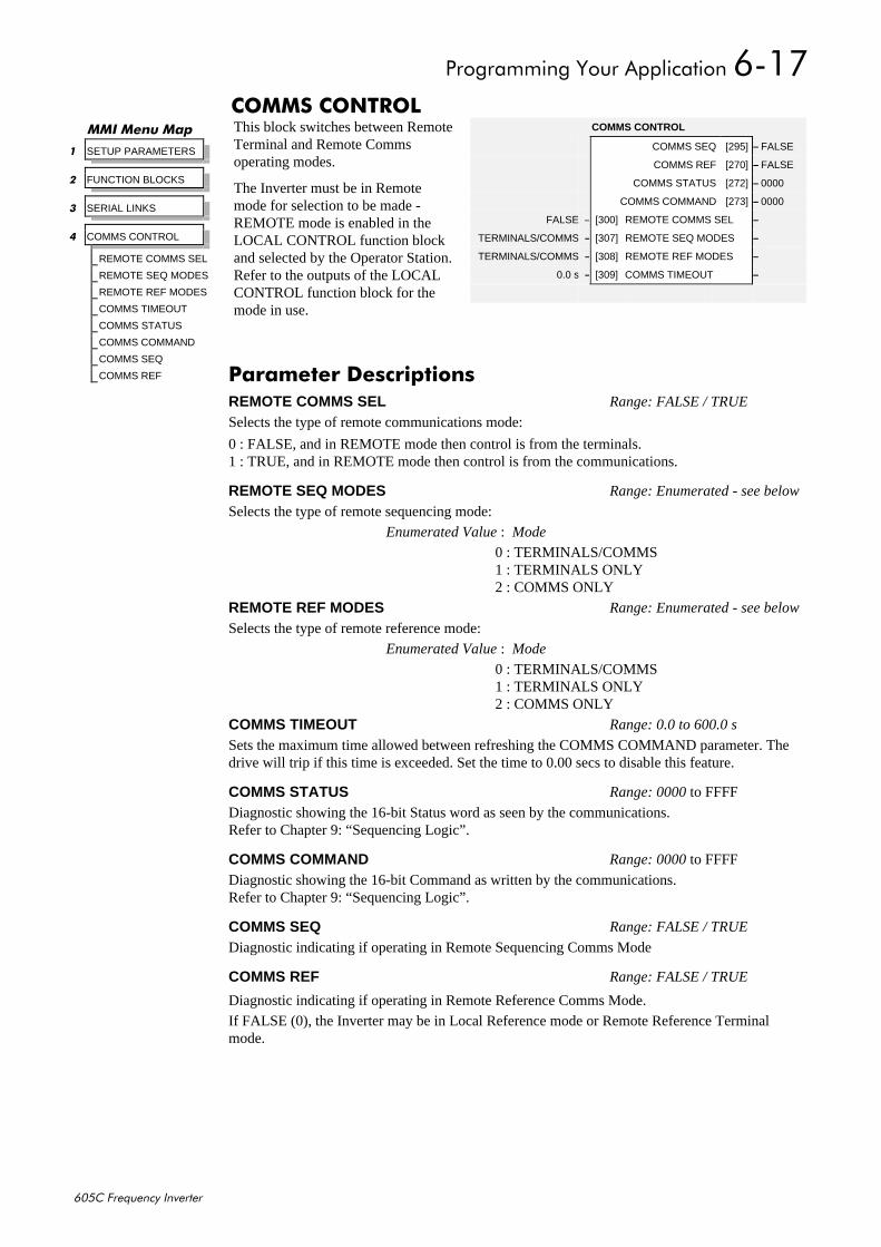
3URJUDPPLQJ#<RXU#$SSOLFDWLRQ#904:
938&#)UHTXHQF\#,QYHUWHU
&2006#&21752/This block switches between RemoteTerminal and Remote Commsoperating modes.
The Inverter must be in Remotemode for selection to be made -REMOTE mode is enabled in theLOCAL CONTROL function blockand selected by the Operator Station.Refer to the outputs of the LOCALCONTROL function block for themode in use.
00,#0HQX#0DS
4 SETUP PARAMETERS
5 FUNCTION BLOCKS
6 SERIAL LINKS
7 COMMS CONTROL
REMOTE COMMS SEL
REMOTE SEQ MODES
REMOTE REF MODES
COMMS TIMEOUT
COMMS STATUS
COMMS COMMAND
COMMS SEQ
COMMS REF
COMMS CONTROL
COMMS SEQ [295] – FALSE
COMMS REF [270] – FALSE
COMMS STATUS [272] – 0000
COMMS COMMAND [273] – 0000
FALSE – [300] REMOTE COMMS SEL –
TERMINALS/COMMS – [307] REMOTE SEQ MODES –
TERMINALS/COMMS – [308] REMOTE REF MODES –
0.0 s – [309] COMMS TIMEOUT –
3DUDPHWHU#'HVFULSWLRQVREMOTE COMMS SEL Range: FALSE / TRUE
Selects the type of remote communications mode:
0 : FALSE, and in REMOTE mode then control is from the terminals.1 : TRUE, and in REMOTE mode then control is from the communications.
REMOTE SEQ MODES Range: Enumerated - see below
Selects the type of remote sequencing mode:Enumerated Value : Mode
0 : TERMINALS/COMMS1 : TERMINALS ONLY2 : COMMS ONLY
REMOTE REF MODES Range: Enumerated - see below
Selects the type of remote reference mode:Enumerated Value : Mode
0 : TERMINALS/COMMS1 : TERMINALS ONLY2 : COMMS ONLY
COMMS TIMEOUT Range: 0.0 to 600.0 s
Sets the maximum time allowed between refreshing the COMMS COMMAND parameter. Thedrive will trip if this time is exceeded. Set the time to 0.00 secs to disable this feature.
COMMS STATUS Range: 0000 to FFFF
Diagnostic showing the 16-bit Status word as seen by the communications.Refer to Chapter 9: “Sequencing Logic”.
COMMS COMMAND Range: 0000 to FFFF
Diagnostic showing the 16-bit Command as written by the communications.Refer to Chapter 9: “Sequencing Logic”.
COMMS SEQ Range: FALSE / TRUE
Diagnostic indicating if operating in Remote Sequencing Comms Mode
COMMS REF Range: FALSE / TRUE
Diagnostic indicating if operating in Remote Reference Comms Mode.If FALSE (0), the Inverter may be in Local Reference mode or Remote Reference Terminalmode.
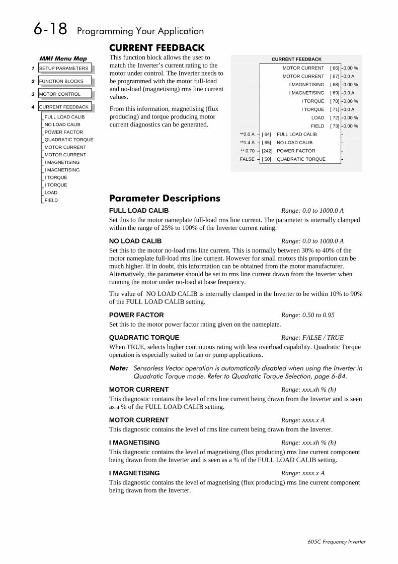
904;##3URJUDPPLQJ#<RXU#$SSOLFDWLRQ
938&#)UHTXHQF\#,QYHUWHU
&855(17#)(('%$&.This function block allows the user tomatch the Inverter’s current rating to themotor under control. The Inverter needs tobe programmed with the motor full-loadand no-load (magnetising) rms line currentvalues.
From this information, magnetising (fluxproducing) and torque producing motorcurrent diagnostics can be generated.
00,#0HQX#0DS
4 SETUP PARAMETERS
5 FUNCTION BLOCKS
6 MOTOR CONTROL
7 CURRENT FEEDBACK
FULL LOAD CALIB
NO LOAD CALIB
POWER FACTOR
QUADRATIC TORQUE
MOTOR CURRENT
MOTOR CURRENT
I MAGNETISING
I MAGNETISING
I TORQUE
I TORQUE
LOAD
FIELD
CURRENT FEEDBACK
MOTOR CURRENT [ 66] –0.00 %
MOTOR CURRENT [ 67] –0.0 A
I MAGNETISING [ 68] –0.00 %
I MAGNETISING [ 69] –0.0 A
I TORQUE [ 70] –0.00 %
I TORQUE [ 71] –0.0 A
LOAD [ 72] –0.00 %
FIELD [ 73] –0.00 %
**2.0 A – [ 64] FULL LOAD CALIB –
**1.4 A – [ 65] NO LOAD CALIB –
** 0.70 – [242] POWER FACTOR –
FALSE – [ 50] QUADRATIC TORQUE –
3DUDPHWHU#'HVFULSWLRQVFULL LOAD CALIB Range: 0.0 to 1000.0 A
Set this to the motor nameplate full-load rms line current. The parameter is internally clampedwithin the range of 25% to 100% of the Inverter current rating.
NO LOAD CALIB Range: 0.0 to 1000.0 A
Set this to the motor no-load rms line current. This is normally between 30% to 40% of themotor nameplate full-load rms line current. However for small motors this proportion can bemuch higher. If in doubt, this information can be obtained from the motor manufacturer.Alternatively, the parameter should be set to rms line current drawn from the Inverter whenrunning the motor under no-load at base frequency.
The value of NO LOAD CALIB is internally clamped in the Inverter to be within 10% to 90%of the FULL LOAD CALIB setting.
POWER FACTOR Range: 0.50 to 0.95
Set this to the motor power factor rating given on the nameplate.
QUADRATIC TORQUE Range: FALSE / TRUE
When TRUE, selects higher continuous rating with less overload capability. Quadratic Torqueoperation is especially suited to fan or pump applications.
1RWH=# 6HQVRUOHVV#9HFWRU#RSHUDWLRQ#LV#DXWRPDWLFDOO\#GLVDEOHG#ZKHQ#XVLQJ#WKH#,QYHUWHU#LQ4XDGUDWLF#7RUTXH#PRGH1#5HIHU#WR#4XDGUDWLF#7RUTXH#6HOHFWLRQ/#SDJH#90;71
MOTOR CURRENT Range: xxx.xh % (h)
This diagnostic contains the level of rms line current being drawn from the Inverter and is seenas a % of the FULL LOAD CALIB setting.
MOTOR CURRENT Range: xxxx.x A
This diagnostic contains the level of rms line current being drawn from the Inverter.
I MAGNETISING Range: xxx.xh % (h)
This diagnostic contains the level of magnetising (flux producing) rms line current componentbeing drawn from the Inverter and is seen as a % of the FULL LOAD CALIB setting.
I MAGNETISING Range: xxxx.x A
This diagnostic contains the level of magnetising (flux producing) rms line current componentbeing drawn from the Inverter.
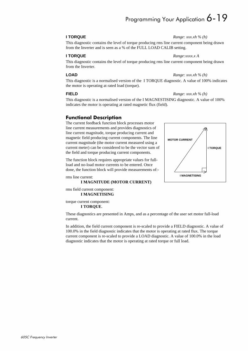
3URJUDPPLQJ#<RXU#$SSOLFDWLRQ#904<
938&#)UHTXHQF\#,QYHUWHU
)XQFWLRQDO#'HVFULSWLRQThe current feedback function block processes motorline current measurements and provides diagnostics ofline current magnitude, torque producing current andmagnetic field producing current components. The linecurrent magnitude (the motor current measured using acurrent meter) can be considered to be the vector sum ofthe field and torque producing current components.
The function block requires appropriate values for full-load and no-load motor currents to be entered. Oncedone, the function block will provide measurements of:-
rms line current:I MAGNITUDE (MOTOR CURRENT)
rms field current component:I MAGNETISING
torque current component:I TORQUE .
These diagnostics are presented in Amps, and as a percentage of the user set motor full-loadcurrent.
In addition, the field current component is re-scaled to provide a FIELD diagnostic. A value of100.0% in the field diagnostic indicates that the motor is operating at rated flux. The torquecurrent component is re-scaled to provide a LOAD diagnostic. A value of 100.0% in the loaddiagnostic indicates that the motor is operating at rated torque or full load.
I TORQUE Range: xxx.xh % (h)
This diagnostic contains the level of torque producing rms line current component being drawnfrom the Inverter and is seen as a % of the FULL LOAD CALIB setting.
I TORQUE Range:xxxx.x A
This diagnostic contains the level of torque producing rms line current component being drawnfrom the Inverter.
LOAD Range: xxx.xh % (h)
This diagnostic is a normalised version of the I TORQUE diagnostic. A value of 100% indicatesthe motor is operating at rated load (torque).
FIELD Range: xxx.xh % (h)
This diagnostic is a normalised version of the I MAGNESTISING diagnostic. A value of 100%indicates the motor is operating at rated magnetic flux (field).
I TORQUE
I MAGNETISING
MOTOR CURRENT
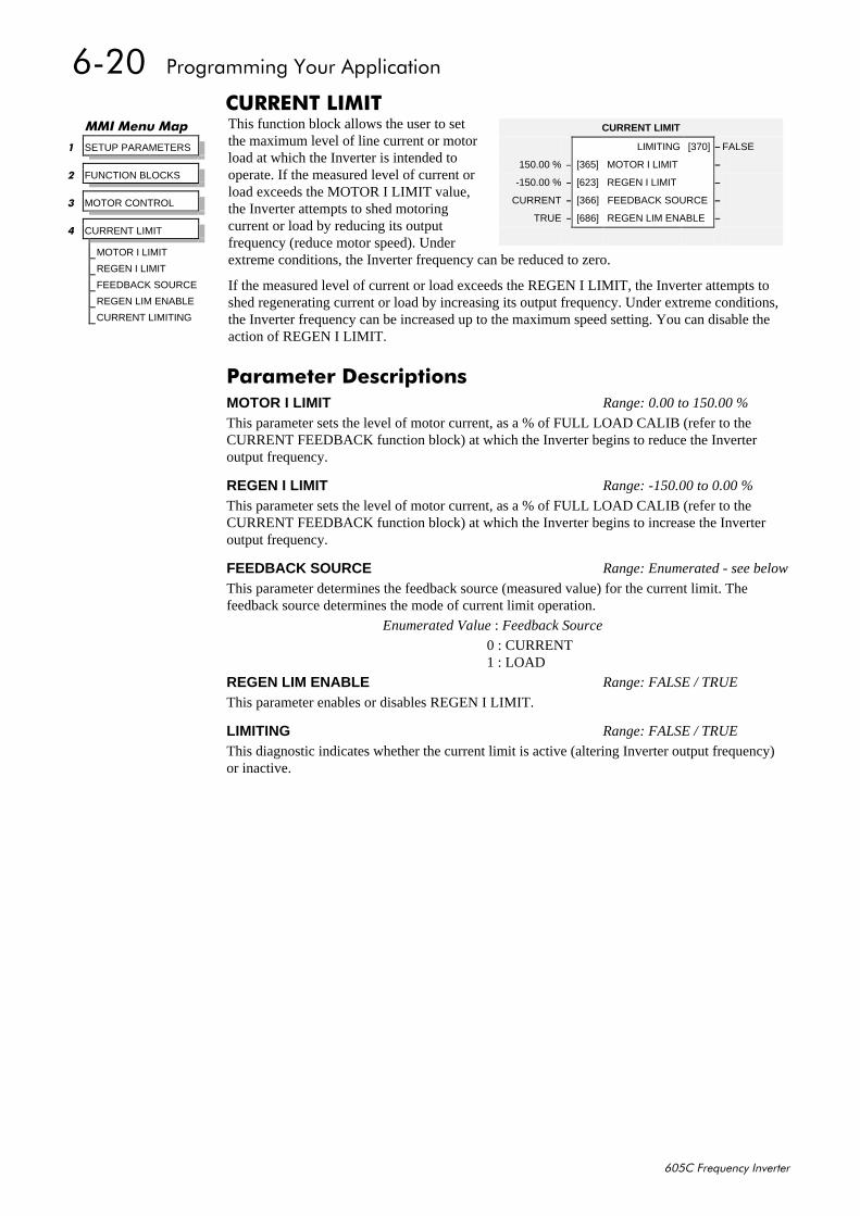
9053##3URJUDPPLQJ#<RXU#$SSOLFDWLRQ
938&#)UHTXHQF\#,QYHUWHU
&855(17#/,0,7This function block allows the user to setthe maximum level of line current or motorload at which the Inverter is intended tooperate. If the measured level of current orload exceeds the MOTOR I LIMIT value,the Inverter attempts to shed motoringcurrent or load by reducing its outputfrequency (reduce motor speed). Underextreme conditions, the Inverter frequency can be reduced to zero.
If the measured level of current or load exceeds the REGEN I LIMIT, the Inverter attempts toshed regenerating current or load by increasing its output frequency. Under extreme conditions,the Inverter frequency can be increased up to the maximum speed setting. You can disable theaction of REGEN I LIMIT.
00,#0HQX#0DS
4 SETUP PARAMETERS
5 FUNCTION BLOCKS
6 MOTOR CONTROL
7 CURRENT LIMIT
MOTOR I LIMIT
REGEN I LIMIT
FEEDBACK SOURCE
REGEN LIM ENABLE
CURRENT LIMITING
CURRENT LIMIT
LIMITING [370] – FALSE
150.00 % – [365] MOTOR I LIMIT –
-150.00 % – [623] REGEN I LIMIT –
CURRENT – [366] FEEDBACK SOURCE –
TRUE – [686] REGEN LIM ENABLE –
3DUDPHWHU#'HVFULSWLRQVMOTOR I LIMIT Range: 0.00 to 150.00 %
This parameter sets the level of motor current, as a % of FULL LOAD CALIB (refer to theCURRENT FEEDBACK function block) at which the Inverter begins to reduce the Inverteroutput frequency.
REGEN I LIMIT Range: -150.00 to 0.00 %
This parameter sets the level of motor current, as a % of FULL LOAD CALIB (refer to theCURRENT FEEDBACK function block) at which the Inverter begins to increase the Inverteroutput frequency.
FEEDBACK SOURCE Range: Enumerated - see below
This parameter determines the feedback source (measured value) for the current limit. Thefeedback source determines the mode of current limit operation.
Enumerated Value : Feedback Source
0 : CURRENT1 : LOAD
REGEN LIM ENABLE Range: FALSE / TRUE
This parameter enables or disables REGEN I LIMIT.
LIMITING Range: FALSE / TRUE
This diagnostic indicates whether the current limit is active (altering Inverter output frequency)or inactive.
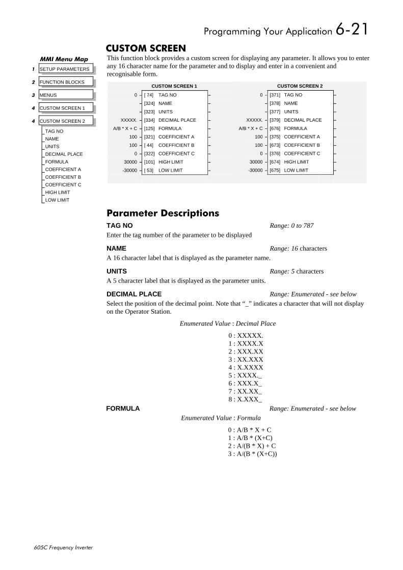
3URJUDPPLQJ#<RXU#$SSOLFDWLRQ#9054
938&#)UHTXHQF\#,QYHUWHU
&86720#6&5((1This function block provides a custom screen for displaying any parameter. It allows you to enterany 16 character name for the parameter and to display and enter in a convenient andrecognisable form.
00,#0HQX#0DS
4 SETUP PARAMETERS
5 FUNCTION BLOCKS
6 MENUS
7 CUSTOM SCREEN 1
7 CUSTOM SCREEN 2
TAG NO
NAME
UNITS
DECIMAL PLACE
FORMULA
COEFFICIENT A
COEFFICIENT B
COEFFICIENT C
HIGH LIMIT
LOW LIMIT
3DUDPHWHU#'HVFULSWLRQVTAG NO Range: 0 to 787
Enter the tag number of the parameter to be displayed
NAME Range: 16 characters
A 16 character label that is displayed as the parameter name.
UNITS Range: 5 characters
A 5 character label that is displayed as the parameter units.
DECIMAL PLACE Range: Enumerated - see below
Select the position of the decimal point. Note that “_” indicates a character that will not displayon the Operator Station.
Enumerated Value : Decimal Place
0 : XXXXX.1 : XXXX.X2 : XXX.XX3 : XX.XXX4 : X.XXXX5 : XXXX._6 : XXX.X_7 : XX.XX_8 : X.XXX_
CUSTOM SCREEN 1
0 – [ 74] TAG NO –
– [324] NAME –
– [323] UNITS –
XXXXX. – [334] DECIMAL PLACE –
A/B * X + C – [125] FORMULA –
100 – [321] COEFFICIENT A –
100 – [ 44] COEFFICIENT B –
0 – [322] COEFFICIENT C –
30000 – [101] HIGH LIMIT –
-30000 – [ 53] LOW LIMIT –
CUSTOM SCREEN 2
0 – [371] TAG NO –
– [378] NAME –
– [377] UNITS –
XXXXX. – [379] DECIMAL PLACE –
A/B * X + C – [676] FORMULA –
100 – [375] COEFFICIENT A –
100 – [673] COEFFICIENT B –
0 – [376] COEFFICIENT C –
30000 – [674] HIGH LIMIT –
-30000 – [675] LOW LIMIT –
FORMULA Range: Enumerated - see below
Enumerated Value : Formula
0 : A/B * X + C1 : A/B * (X+C)2 : A/(B * X) + C3 : A/(B * (X+C))
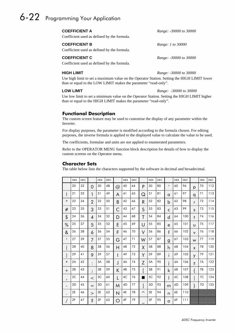
9055##3URJUDPPLQJ#<RXU#$SSOLFDWLRQ
938&#)UHTXHQF\#,QYHUWHU
)XQFWLRQDO#'HVFULSWLRQThe custom screen feature may be used to customise the display of any parameter within theInverter.
For display purposes, the parameter is modified according to the formula chosen. For editingpurposes, the inverse formula is applied to the displayed value to calculate the value to be used.
The coefficients, formulae and units are not applied to enumerated parameters.
Refer to the OPERATOR MENU function block description for details of how to display thecustom screens on the Operator menu.
&KDUDFWHU#6HWVThe table below lists the characters supported by the software in decimal and hexadecimal.
COEFFICIENT A Range: -30000 to 30000
Coefficient used as defined by the formula.
COEFFICIENT B Range: 1 to 30000
Coefficient used as defined by the formula.
COEFFICIENT C Range: -30000 to 30000
Coefficient used as defined by the formula.
HIGH LIMIT Range: -30000 to 30000
Use high limit to set a maximum value on the Operator Station. Setting the HIGH LIMIT lowerthan or equal to the LOW LIMIT makes the parameter “read-only”.
LOW LIMIT Range: -30000 to 30000
Use low limit to set a minimum value on the Operator Station. Setting the HIGH LIMIT higherthan or equal to the HIGH LIMIT makes the parameter “read-only”.
+(; '(& +(; '(& +(; '(& +(; '(& +(; '(& +(; '(&
53 65 3 63 7; # 73 97 3 83 ;3 · 93 <9 S :3 445
$ 54 66 4 64 7< $ 74 98 4 84 ;4 D 94 <: T :4 446
´ 55 67 5 65 83 % 75 99 5 85 ;5 E 95 <; U :5 447
& 56 68 6 66 84 & 76 9: 6 86 ;6 F 96 << V :6 448
' 57 69 7 67 85 ' 77 9; 7 87 ;7 G 97 433 W :7 449
( 58 6: 8 68 86 ( 78 9< 8 88 ;8 H 98 434 X :8 44:
) 59 6; 9 69 87 ) 79 :3 9 89 ;9 I 99 435 Y :9 44;
¶ 5: 6< : 6: 88 * 7: :4 : 8: ;: J 9: 436 Z :: 44<
+ 5; 73 ; 6; 89 + 7; :5 ; 8; ;; K 9; 437 [ :; 453
, 5< 74 < 6< 8: , 7< :6 < 8< ;< L 9< 438 \ :< 454
- 5$ 75 = 6$ 8; - 7$ :7 = 8$ <3 M 9$ 439 ] :$ 455
. 5% 76 > 6% 8< . 7% :8 > 8% <4 N 9% 43: ^ :% 456
/ 5& 77 ? 6& 93 / 7& :9 8& <5 O 9& 43; _ :& 457
0 5' 78 6' 94 0 7' :: @ 8' <6 P 9' 43< ` :' 458
1 5( 79 ! 6( 95 1 7( :; A 8( <7 Q 9( 443
2 5) 7: " 6) 96 2 7) :< B 8) <8 R 9) 444
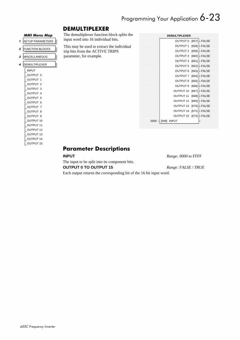
3URJUDPPLQJ#<RXU#$SSOLFDWLRQ#9056
938&#)UHTXHQF\#,QYHUWHU
'(08/7,3/(;(5The demultiplexer function block splits theinput word into 16 individual bits.
This may be used to extract the individualtrip bits from the ACTIVE TRIPSparameter, for example.
00,#0HQX#0DS
4 SETUP PARAMETERS
5 FUNCTION BLOCKS
6 MISCELLANEOUS
7 DEMULTIPLEXER
INPUT
OUTPUT 0
OUTPUT 1
OUTPUT 2
OUTPUT 3
OUTPUT 4
OUTPUT 5
OUTPUT 6
OUTPUT 7
OUTPUT 8
OUTPUT 9
OUTPUT 10
OUTPUT 11
OUTPUT 12
OUTPUT 13
OUTPUT 14
OUTPUT 15
DEMULTIPLEXER
OUTPUT 0 [657] – FALSE
OUTPUT 1 [658] – FALSE
OUTPUT 2 [659] – FALSE
OUTPUT 3 [660] – FALSE
OUTPUT 4 [661] – FALSE
OUTPUT 5 [662] – FALSE
OUTPUT 6 [663] – FALSE
OUTPUT 7 [664] – FALSE
OUTPUT 8 [665] – FALSE
OUTPUT 9 [666] – FALSE
OUTPUT 10 [667] – FALSE
OUTPUT 11 [668] – FALSE
OUTPUT 12 [669] – FALSE
OUTPUT 13 [670] – FALSE
OUTPUT 14 [671] – FALSE
OUTPUT 15 [672] – FALSE
0000 – [599] INPUT –
3DUDPHWHU#'HVFULSWLRQVINPUT Range: 0000 to FFFF
The input to be split into its component bits.
OUTPUT 0 TO OUTPUT 15 Range: FALSE / TRUE
Each output returns the corresponding bit of the 16 bit input word.
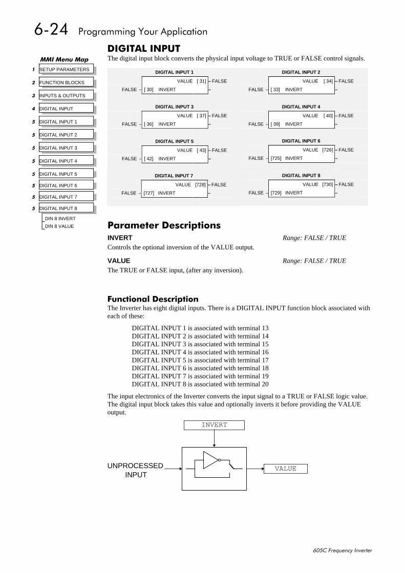
9057##3URJUDPPLQJ#<RXU#$SSOLFDWLRQ
938&#)UHTXHQF\#,QYHUWHU
',*,7$/#,1387The digital input block converts the physical input voltage to TRUE or FALSE control signals.
)XQFWLRQDO#'HVFULSWLRQThe Inverter has eight digital inputs. There is a DIGITAL INPUT function block associated witheach of these:
DIGITAL INPUT 1 is associated with terminal 13DIGITAL INPUT 2 is associated with terminal 14DIGITAL INPUT 3 is associated with terminal 15DIGITAL INPUT 4 is associated with terminal 16DIGITAL INPUT 5 is associated with terminal 17DIGITAL INPUT 6 is associated with terminal 18DIGITAL INPUT 7 is associated with terminal 19DIGITAL INPUT 8 is associated with terminal 20
The input electronics of the Inverter converts the input signal to a TRUE or FALSE logic value.The digital input block takes this value and optionally inverts it before providing the VALUEoutput.
INPUTVALUE
INVERT
UNPROCESSED
00,#0HQX#0DS7
4 SETUP PARAMETERS
7
5 FUNCTION BLOCKS
6 INPUTS & OUTPUTS
7 DIGITAL INPUT
8 DIGITAL INPUT 1
8 DIGITAL INPUT 2
8 DIGITAL INPUT 3
8 DIGITAL INPUT 4
8 DIGITAL INPUT 5
8 DIGITAL INPUT 6
8 DIGITAL INPUT 7
8 DIGITAL INPUT 8
DIN 8 INVERT
DIN 8 VALUE
DIGITAL INPUT 6
VALUE [726] – FALSE
FALSE – [725] INVERT –
DIGITAL INPUT 8
VALUE [730] – FALSE
FALSE – [729] INVERT –
DIGITAL INPUT 1
VALUE [ 31] – FALSE
FALSE – [ 30] INVERT –
DIGITAL INPUT 3
VALUE [ 37] – FALSE
FALSE – [ 36] INVERT –
DIGITAL INPUT 5
VALUE [ 43] – FALSE
FALSE – [ 42] INVERT –
DIGITAL INPUT 2
VALUE [ 34] – FALSE
FALSE – [ 33] INVERT –
DIGITAL INPUT 4
VALUE [ 40] – FALSE
FALSE – [ 39] INVERT –
DIGITAL INPUT 7
VALUE [728] – FALSE
FALSE – [727] INVERT –
3DUDPHWHU#'HVFULSWLRQVINVERT Range: FALSE / TRUE
Controls the optional inversion of the VALUE output.
VALUE Range: FALSE / TRUE
The TRUE or FALSE input, (after any inversion).
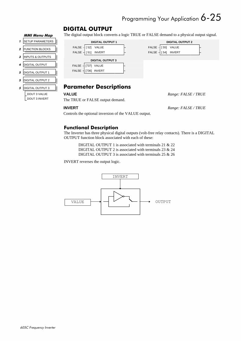
3URJUDPPLQJ#<RXU#$SSOLFDWLRQ#9058
938&#)UHTXHQF\#,QYHUWHU
',*,7$/#287387The digital output block converts a logic TRUE or FALSE demand to a physical output signal.
)XQFWLRQDO#'HVFULSWLRQThe Inverter has three physical digital outputs (volt-free relay contacts). There is a DIGITALOUTPUT function block associated with each of these:
DIGITAL OUTPUT 1 is associated with terminals 21 & 22DIGITAL OUTPUT 2 is associated with terminals 23 & 24DIGITAL OUTPUT 3 is associated with terminals 25 & 26
INVERT reverses the output logic.
00,#0HQX#0DS
4 SETUP PARAMETERS
5 FUNCTION BLOCKS
6 INPUTS & OUTPUTS
7 DIGITAL OUTPUT
8 DIGITAL OUTPUT 1
8 DIGITAL OUTPUT 2
8 DIGITAL OUTPUT 3
DOUT 3 VALUE
DOUT 3 INVERT
DIGITAL OUTPUT 2
FALSE – [ 55] VALUE –
FALSE – [ 54] INVERT –
DIGITAL OUTPUT 1
FALSE – [ 52] VALUE –
FALSE – [ 51] INVERT –
DIGITAL OUTPUT 3
FALSE – [737] VALUE –
FALSE – [736] INVERT –
3DUDPHWHU#'HVFULSWLRQVVALUE Range: FALSE / TRUE
The TRUE or FALSE output demand.
INVERT Range: FALSE / TRUE
Controls the optional inversion of the VALUE output.
OUTPUT
INVERT
VALUE
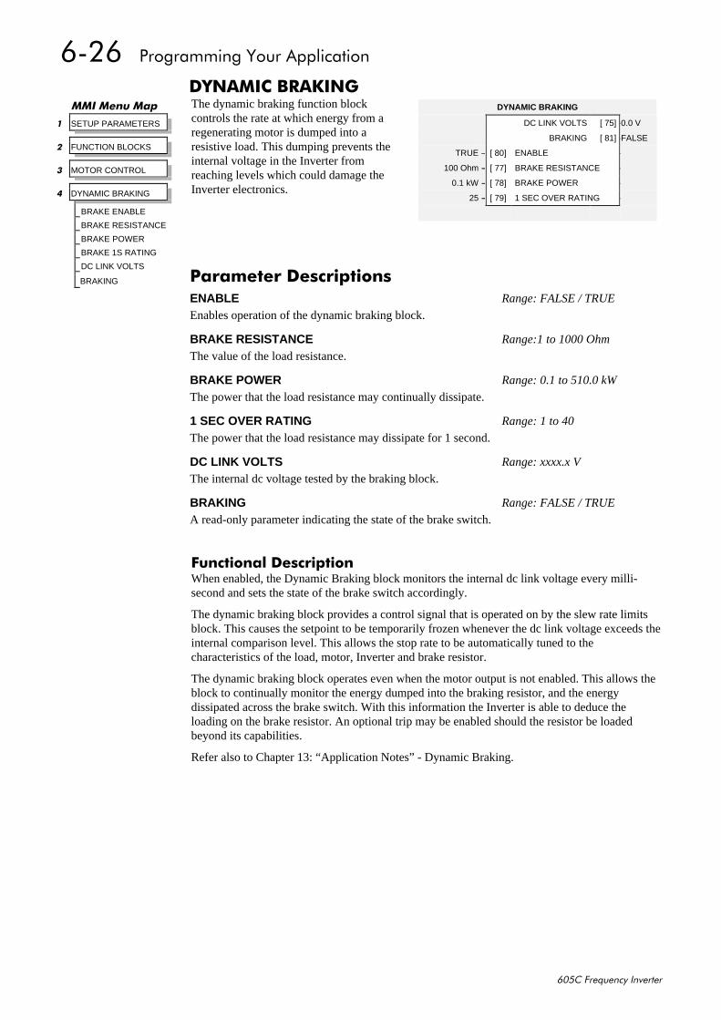
9059##3URJUDPPLQJ#<RXU#$SSOLFDWLRQ
938&#)UHTXHQF\#,QYHUWHU
'<1$0,&#%5$.,1*The dynamic braking function blockcontrols the rate at which energy from aregenerating motor is dumped into aresistive load. This dumping prevents theinternal voltage in the Inverter fromreaching levels which could damage theInverter electronics.
)XQFWLRQDO#'HVFULSWLRQWhen enabled, the Dynamic Braking block monitors the internal dc link voltage every milli-second and sets the state of the brake switch accordingly.
The dynamic braking block provides a control signal that is operated on by the slew rate limitsblock. This causes the setpoint to be temporarily frozen whenever the dc link voltage exceeds theinternal comparison level. This allows the stop rate to be automatically tuned to thecharacteristics of the load, motor, Inverter and brake resistor.
The dynamic braking block operates even when the motor output is not enabled. This allows theblock to continually monitor the energy dumped into the braking resistor, and the energydissipated across the brake switch. With this information the Inverter is able to deduce theloading on the brake resistor. An optional trip may be enabled should the resistor be loadedbeyond its capabilities.
Refer also to Chapter 13: “Application Notes” - Dynamic Braking.
00,#0HQX#0DS
4 SETUP PARAMETERS
5 FUNCTION BLOCKS
6 MOTOR CONTROL
7 DYNAMIC BRAKING
BRAKE ENABLE
BRAKE RESISTANCE
BRAKE POWER
BRAKE 1S RATING
DC LINK VOLTS
BRAKING
DYNAMIC BRAKING
DC LINK VOLTS [ 75] –0.0 V
BRAKING [ 81] –FALSE
TRUE – [ 80] ENABLE –
100 Ohm – [ 77] BRAKE RESISTANCE –
0.1 kW – [ 78] BRAKE POWER –
25 – [ 79] 1 SEC OVER RATING –
3DUDPHWHU#'HVFULSWLRQVENABLE Range: FALSE / TRUE
Enables operation of the dynamic braking block.
BRAKE RESISTANCE Range:1 to 1000 Ohm
The value of the load resistance.
BRAKE POWER Range: 0.1 to 510.0 kW
The power that the load resistance may continually dissipate.
1 SEC OVER RATING Range: 1 to 40
The power that the load resistance may dissipate for 1 second.
DC LINK VOLTS Range: xxxx.x V
The internal dc voltage tested by the braking block.
BRAKING Range: FALSE / TRUE
A read-only parameter indicating the state of the brake switch.
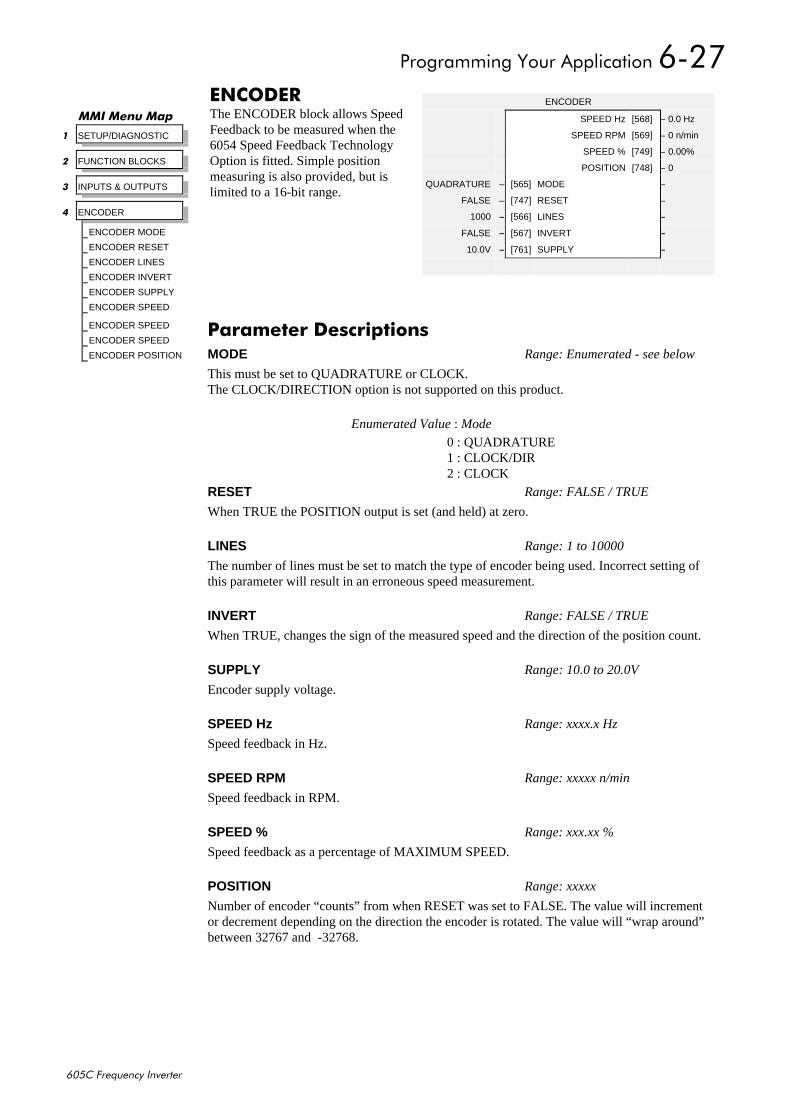
3URJUDPPLQJ#<RXU#$SSOLFDWLRQ#905:
938&#)UHTXHQF\#,QYHUWHU
(1&2'(5The ENCODER block allows SpeedFeedback to be measured when the6054 Speed Feedback TechnologyOption is fitted. Simple positionmeasuring is also provided, but islimited to a 16-bit range.
00,#0HQX#0DS
4 SETUP/DIAGNOSTIC
5 FUNCTION BLOCKS
6 INPUTS & OUTPUTS
7 ENCODER
ENCODER MODE
ENCODER RESET
ENCODER LINES
ENCODER INVERT
ENCODER SUPPLY
ENCODER SPEED
ENCODER SPEED
ENCODER SPEED
ENCODER POSITION
ENCODER
SPEED Hz [568] – 0.0 Hz
SPEED RPM [569] – 0 n/min
SPEED % [749] – 0.00%
POSITION [748] – 0
QUADRATURE – [565] MODE –
FALSE – [747] RESET –
1000 – [566] LINES –
FALSE – [567] INVERT –
10.0V – [761] SUPPLY –
3DUDPHWHU#'HVFULSWLRQVMODE Range: Enumerated - see below
This must be set to QUADRATURE or CLOCK.The CLOCK/DIRECTION option is not supported on this product.
Enumerated Value : Mode
0 : QUADRATURE1 : CLOCK/DIR2 : CLOCK
RESET Range: FALSE / TRUE
When TRUE the POSITION output is set (and held) at zero.
LINES Range: 1 to 10000
The number of lines must be set to match the type of encoder being used. Incorrect setting ofthis parameter will result in an erroneous speed measurement.
INVERT Range: FALSE / TRUE
When TRUE, changes the sign of the measured speed and the direction of the position count.
SUPPLY Range: 10.0 to 20.0V
Encoder supply voltage.
SPEED Hz Range: xxxx.x Hz
Speed feedback in Hz.
SPEED RPM Range: xxxxx n/min
Speed feedback in RPM.
SPEED % Range: xxx.xx %
Speed feedback as a percentage of MAXIMUM SPEED.
POSITION Range: xxxxx
Number of encoder “counts” from when RESET was set to FALSE. The value will incrementor decrement depending on the direction the encoder is rotated. The value will “wrap around”between 32767 and -32768.
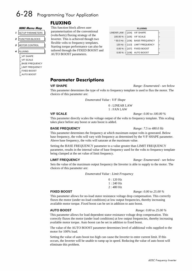
905;##3URJUDPPLQJ#<RXU#$SSOLFDWLRQ
938&#)UHTXHQF\#,QYHUWHU
)/8;,1*This function block allows userparameterisation of the conventional(volts/hertz) fluxing strategy of theInverter. This is achieved though twoflexible volts to frequency templates.Starting torque performance can also betailored through the FIXED BOOST andAUTO BOOST parameters.
00,#0HQX#0DS
4 SETUP PARAMETERS
5 FUNCTION BLOCKS
6 MOTOR CONTROL
7 FLUXING
V/F SHAPE
V/F SCALE
BASE FREQUENCY
LIMIT FREQUENCY
FIXED BOOST
AUTO BOOST
FLUXING
LINEAR LAW – [104] V/F SHAPE –
100.00 % – [105] V/F SCALE –
* 50.0 Hz – [106] BASE FREQUENCY –
120 Hz – [113] LIMIT FREQUENCY –
0.00 % – [107] FIXED BOOST –
0.00 % – [108] AUTO BOOST –
3DUDPHWHU#'HVFULSWLRQVV/F SHAPE Range: Enumerated - see below
This parameter determines the type of volts to frequency template is used to flux the motor. Thechoices of this parameter are:
Enumerated Value : V/F Shape
0 : LINEAR LAW1 : FAN LAW
V/F SCALE Range: 0.00 to 100.00 %
This parameter directly scales the voltage output of the volts to frequency template. This scalingtakes place before any boost or auto boost is added.
BASE FREQUENCY Range: 7.5 to 480.0 Hz
This parameter determines the frequency at which maximum output volts is generated. Belowbase frequency, the volts will vary with frequency as determined by the V/F SHAPE parameter.Above base frequency, the volts will saturate at the maximum value.
Setting the BASE FREQUENCY parameter to a value greater than LIMIT FREQUENCYparameter, results in the internal value of base frequency used for the volts to frequency templatebeing clamped at the set value of limit frequency.
LIMIT FREQUENCY Range: Enumerated - see below
Sets the value of the maximum output frequency the Inverter is able to supply to the motor. Thechoices of this parameter are:
Enumerated Value : Limit Frequency
0 : 120 Hz1 : 240 Hz2 : 480 Hz
FIXED BOOST Range: 0.00 to 25.00 %
This parameter allows for no-load stator resistance voltage drop compensation. This correctlyfluxes the motor (under no-load conditions) at low output frequencies, thereby increasingavailable motor torque. Fixed boost can be set in addition to auto boost.
AUTO BOOST Range: 0.00 to 25.00 %
This parameter allows for load dependent stator resistance voltage drop compensation. Thiscorrectly fluxes the motor (under load conditions) at low output frequencies, thereby increasingavailable motor torque. Auto boost can be set in addition to fixed boost.
The value of the AUTO BOOST parameter determines level of additional volts supplied to themotor for 100% load.
Setting the value of auto boost too high can cause the Inverter to enter current limit. If thisoccurs, the Inverter will be unable to ramp up in speed. Reducing the value of auto boost willeliminate this problem.
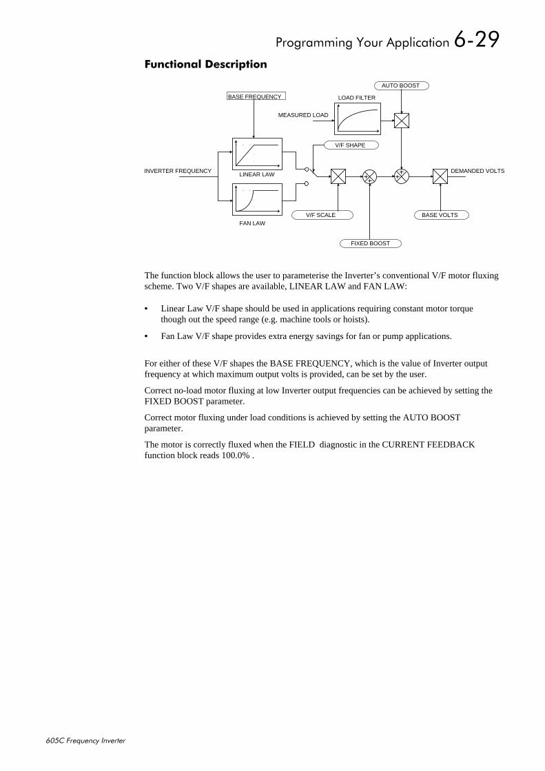
3URJUDPPLQJ#<RXU#$SSOLFDWLRQ#905<
938&#)UHTXHQF\#,QYHUWHU
)XQFWLRQDO#'HVFULSWLRQ
The function block allows the user to parameterise the Inverter’s conventional V/F motor fluxingscheme. Two V/F shapes are available, LINEAR LAW and FAN LAW:
• Linear Law V/F shape should be used in applications requiring constant motor torquethough out the speed range (e.g. machine tools or hoists).
• Fan Law V/F shape provides extra energy savings for fan or pump applications.
For either of these V/F shapes the BASE FREQUENCY, which is the value of Inverter outputfrequency at which maximum output volts is provided, can be set by the user.
Correct no-load motor fluxing at low Inverter output frequencies can be achieved by setting theFIXED BOOST parameter.
Correct motor fluxing under load conditions is achieved by setting the AUTO BOOSTparameter.
The motor is correctly fluxed when the FIELD diagnostic in the CURRENT FEEDBACKfunction block reads 100.0% .
LINEAR LAW
FAN LAW
LOAD FILTER
DEMANDED VOLTSINVERTER FREQUENCY
MEASURED LOAD
V/F SHAPE
BASE FREQUENCY
AUTO BOOST
FIXED BOOST
V/F SCALE BASE VOLTS
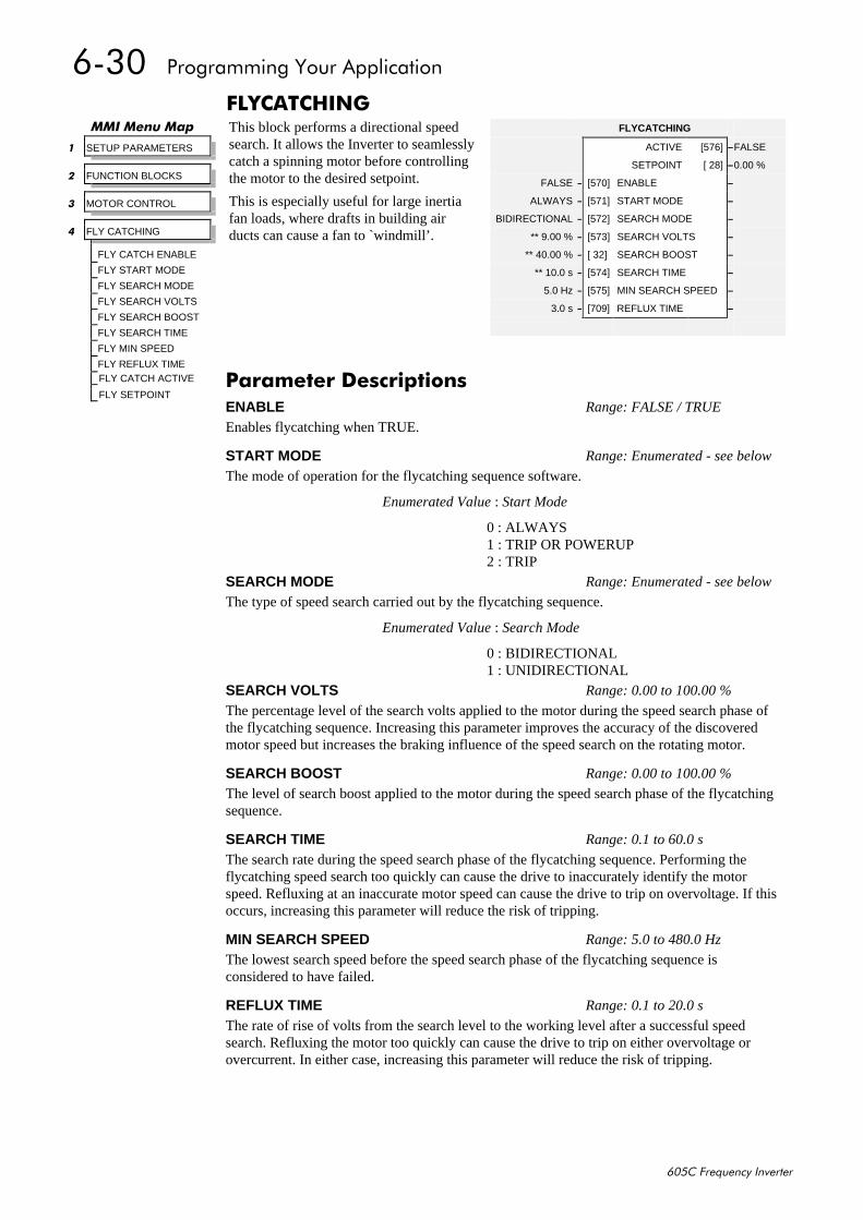
9063##3URJUDPPLQJ#<RXU#$SSOLFDWLRQ
938&#)UHTXHQF\#,QYHUWHU
)/<&$7&+,1*This block performs a directional speedsearch. It allows the Inverter to seamlesslycatch a spinning motor before controllingthe motor to the desired setpoint.
This is especially useful for large inertiafan loads, where drafts in building airducts can cause a fan to `windmill’.
00,#0HQX#0DS
4 SETUP PARAMETERS
5 FUNCTION BLOCKS
6 MOTOR CONTROL
7 FLY CATCHING
FLY CATCH ENABLE
FLY START MODE
FLY SEARCH MODE
FLY SEARCH VOLTS
FLY SEARCH BOOST
FLY SEARCH TIME
FLY MIN SPEED
FLY REFLUX TIMEFLY CATCH ACTIVE
FLY SETPOINT
FLYCATCHING
ACTIVE [576] –FALSE
SETPOINT [ 28] –0.00 %
FALSE – [570] ENABLE –
ALWAYS – [571] START MODE –
BIDIRECTIONAL – [572] SEARCH MODE –
** 9.00 % – [573] SEARCH VOLTS –
** 40.00 % – [ 32] SEARCH BOOST –
** 10.0 s – [574] SEARCH TIME –
5.0 Hz – [575] MIN SEARCH SPEED –
3.0 s – [709] REFLUX TIME –
3DUDPHWHU#'HVFULSWLRQVENABLE Range: FALSE / TRUE
Enables flycatching when TRUE.
START MODE Range: Enumerated - see below
The mode of operation for the flycatching sequence software.
Enumerated Value : Start Mode
0 : ALWAYS1 : TRIP OR POWERUP2 : TRIP
SEARCH MODE Range: Enumerated - see below
The type of speed search carried out by the flycatching sequence.
Enumerated Value : Search Mode
0 : BIDIRECTIONAL1 : UNIDIRECTIONAL
SEARCH VOLTS Range: 0.00 to 100.00 %
The percentage level of the search volts applied to the motor during the speed search phase ofthe flycatching sequence. Increasing this parameter improves the accuracy of the discoveredmotor speed but increases the braking influence of the speed search on the rotating motor.
SEARCH BOOST Range: 0.00 to 100.00 %
The level of search boost applied to the motor during the speed search phase of the flycatchingsequence.
SEARCH TIME Range: 0.1 to 60.0 s
The search rate during the speed search phase of the flycatching sequence. Performing theflycatching speed search too quickly can cause the drive to inaccurately identify the motorspeed. Refluxing at an inaccurate motor speed can cause the drive to trip on overvoltage. If thisoccurs, increasing this parameter will reduce the risk of tripping.
MIN SEARCH SPEED Range: 5.0 to 480.0 Hz
The lowest search speed before the speed search phase of the flycatching sequence isconsidered to have failed.
REFLUX TIME Range: 0.1 to 20.0 s
The rate of rise of volts from the search level to the working level after a successful speedsearch. Refluxing the motor too quickly can cause the drive to trip on either overvoltage orovercurrent. In either case, increasing this parameter will reduce the risk of tripping.
3URJUDPPLQJ#<RXU#$SSOLFDWLRQ#9064
938&#)UHTXHQF\#,QYHUWHU
)XQFWLRQDO#'HVFULSWLRQThe flycatching function enables the drive to be restarted smoothly into a spinning motor. Itapplies small search voltages to the motor whilst ramping the Inverter frequency from maximumspeed to zero. When the motor load goes from motoring to regenerating, the speed search hassucceeded and is terminated. If the search frequency falls below the minimum search speed, thespeed search has failed and the Inverter will ramp to the speed setpoint from zero.
The flycatching sequence can be triggered by different starting conditions:
ALWAYS: All starts (after controlled or uncontrolled stop, or after a power-up)TRIP or POWER-UP: After uncontrolled stop, i.e. trip or coast, or after a power-upTRIP: After uncontrolled stop, i.e. trip or coast
The type of speed sequence may be Bidirectional or Unidirectional:
%LGLUHFWLRQDOInitially, the search is performed in the direction of the speed setpoint. If the drive failsto identify the motor speed in this direction, a second speed search is performed in thereverse direction.
8QLGLUHFWLRQDOThe search is performed only in the direction of the speed setpoint.
ACTIVE Range: FALSE / TRUE
A diagnostic output indicating whether the flycatching sequence is active.
SETPOINT Range xxx.xx %
This diagnostic output is the setpoint caught at the end of a successful flycatching sequence.
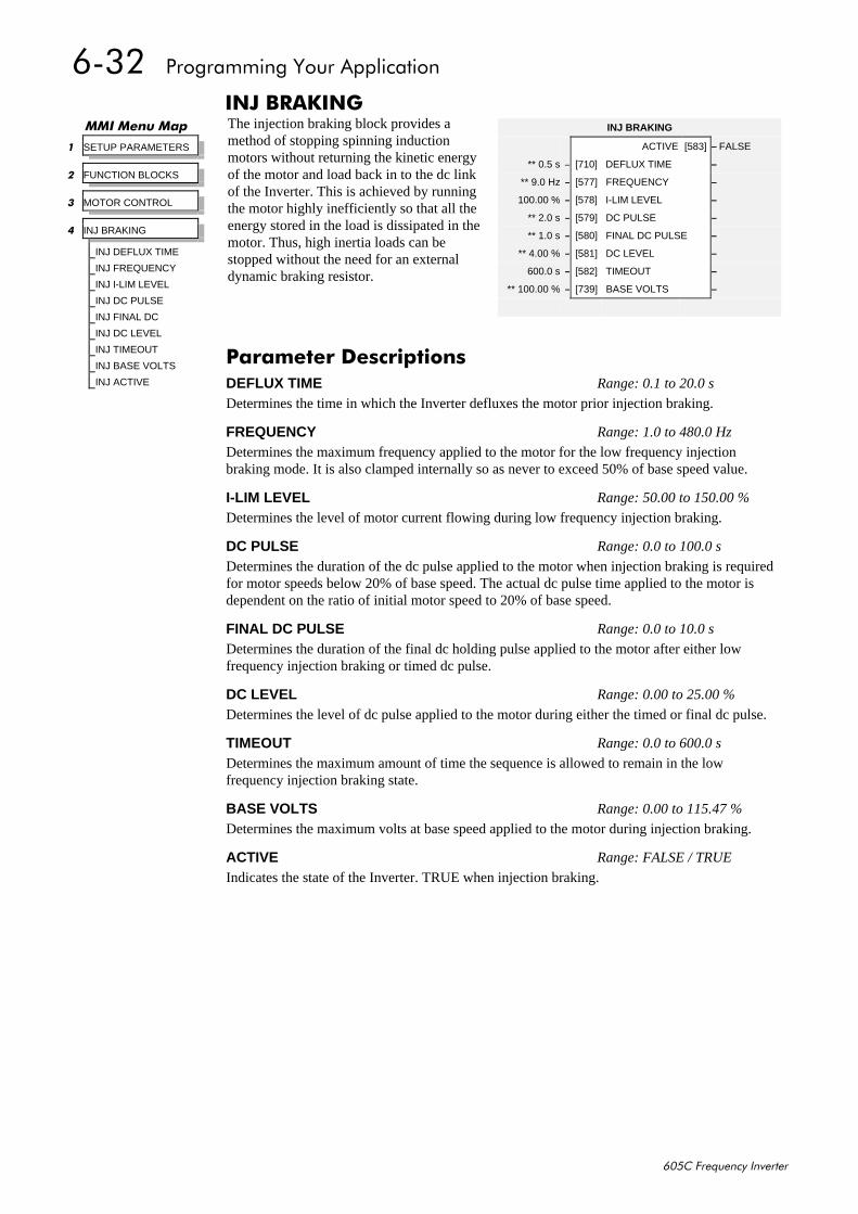
9065##3URJUDPPLQJ#<RXU#$SSOLFDWLRQ
938&#)UHTXHQF\#,QYHUWHU
,1-#%5$.,1*The injection braking block provides amethod of stopping spinning inductionmotors without returning the kinetic energyof the motor and load back in to the dc linkof the Inverter. This is achieved by runningthe motor highly inefficiently so that all theenergy stored in the load is dissipated in themotor. Thus, high inertia loads can bestopped without the need for an externaldynamic braking resistor.
00,#0HQX#0DS
4 SETUP PARAMETERS
5 FUNCTION BLOCKS
6 MOTOR CONTROL
7 INJ BRAKING
INJ DEFLUX TIME
INJ FREQUENCY
INJ I-LIM LEVEL
INJ DC PULSE
INJ FINAL DC
INJ DC LEVEL
INJ TIMEOUT
INJ BASE VOLTS
INJ ACTIVE
INJ BRAKING
ACTIVE [583] – FALSE
** 0.5 s – [710] DEFLUX TIME –
** 9.0 Hz – [577] FREQUENCY –
100.00 % – [578] I-LIM LEVEL –
** 2.0 s – [579] DC PULSE –
** 1.0 s – [580] FINAL DC PULSE –
** 4.00 % – [581] DC LEVEL –
600.0 s – [582] TIMEOUT –
** 100.00 % – [739] BASE VOLTS –
3DUDPHWHU#'HVFULSWLRQVDEFLUX TIME Range: 0.1 to 20.0 s
Determines the time in which the Inverter defluxes the motor prior injection braking.
FREQUENCY Range: 1.0 to 480.0 Hz
Determines the maximum frequency applied to the motor for the low frequency injectionbraking mode. It is also clamped internally so as never to exceed 50% of base speed value.
I-LIM LEVEL Range: 50.00 to 150.00 %
Determines the level of motor current flowing during low frequency injection braking.
DC PULSE Range: 0.0 to 100.0 s
Determines the duration of the dc pulse applied to the motor when injection braking is requiredfor motor speeds below 20% of base speed. The actual dc pulse time applied to the motor isdependent on the ratio of initial motor speed to 20% of base speed.
FINAL DC PULSE Range: 0.0 to 10.0 s
Determines the duration of the final dc holding pulse applied to the motor after either lowfrequency injection braking or timed dc pulse.
DC LEVEL Range: 0.00 to 25.00 %
Determines the level of dc pulse applied to the motor during either the timed or final dc pulse.
TIMEOUT Range: 0.0 to 600.0 s
Determines the maximum amount of time the sequence is allowed to remain in the lowfrequency injection braking state.
BASE VOLTS Range: 0.00 to 115.47 %
Determines the maximum volts at base speed applied to the motor during injection braking.
ACTIVE Range: FALSE / TRUE
Indicates the state of the Inverter. TRUE when injection braking.
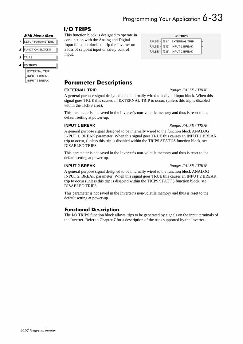
3URJUDPPLQJ#<RXU#$SSOLFDWLRQ#9066
938&#)UHTXHQF\#,QYHUWHU
,22#75,36This function block is designed to operate inconjunction with the Analog and DigitalInput function blocks to trip the Inverter ona loss of setpoint input or safety controlinput.
)XQFWLRQDO#'HVFULSWLRQThe I/O TRIPS function block allows trips to be generated by signals on the input terminals ofthe Inverter. Refer to Chapter 7 for a description of the trips supported by the Inverter.
00,#0HQX#0DS
4 SETUP PARAMETERS
5 FUNCTION BLOCKS
6 TRIPS
7 I/O TRIPS
EXTERNAL TRIP
INPUT 1 BREAK
INPUT 2 BREAK
I/O TRIPS
FALSE – [234] EXTERNAL TRIP –
FALSE – [235] INPUT 1 BREAK –
FALSE – [236] INPUT 2 BREAK –
3DUDPHWHU#'HVFULSWLRQVEXTERNAL TRIP Range: FALSE / TRUE
A general purpose signal designed to be internally wired to a digital input block. When thissignal goes TRUE this causes an EXTERNAL TRIP to occur, (unless this trip is disabledwithin the TRIPS area).
This parameter is not saved in the Inverter’s non-volatile memory and thus is reset to thedefault setting at power-up.
INPUT 1 BREAK Range: FALSE / TRUE
A general purpose signal designed to be internally wired to the function block ANALOGINPUT 1, BREAK parameter. When this signal goes TRUE this causes an INPUT 1 BREAKtrip to occur, (unless this trip is disabled within the TRIPS STATUS function block, seeDISABLED TRIPS.
This parameter is not saved in the Inverter’s non-volatile memory and thus is reset to thedefault setting at power-up.
INPUT 2 BREAK Range: FALSE / TRUE
A general purpose signal designed to be internally wired to the function block ANALOGINPUT 2, BREAK parameter. When this signal goes TRUE this causes an INPUT 2 BREAKtrip to occur (unless this trip is disabled within the TRIPS STATUS function block, seeDISABLED TRIPS.
This parameter is not saved in the Inverter’s non-volatile memory and thus is reset to thedefault setting at power-up.
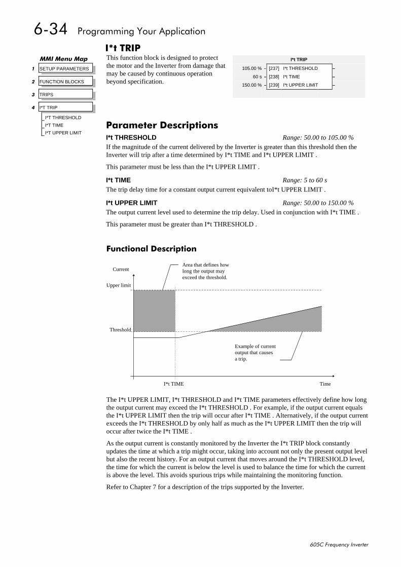
9067##3URJUDPPLQJ#<RXU#$SSOLFDWLRQ
938&#)UHTXHQF\#,QYHUWHU
,-W#75,3This function block is designed to protectthe motor and the Inverter from damage thatmay be caused by continuous operationbeyond specification.
)XQFWLRQDO#'HVFULSWLRQ
The I*t UPPER LIMIT, I*t THRESHOLD and I*t TIME parameters effectively define how longthe output current may exceed the I*t THRESHOLD . For example, if the output current equalsthe I*t UPPER LIMIT then the trip will occur after I*t TIME . Alternatively, if the output currentexceeds the I*t THRESHOLD by only half as much as the I*t UPPER LIMIT then the trip willoccur after twice the I*t TIME .
As the output current is constantly monitored by the Inverter the I*t TRIP block constantlyupdates the time at which a trip might occur, taking into account not only the present output levelbut also the recent history. For an output current that moves around the I*t THRESHOLD level,the time for which the current is below the level is used to balance the time for which the currentis above the level. This avoids spurious trips while maintaining the monitoring function.
Refer to Chapter 7 for a description of the trips supported by the Inverter.
00,#0HQX#0DS
4 SETUP PARAMETERS
5 FUNCTION BLOCKS
6 TRIPS
7 I*T TRIP
I*T THRESHOLD
I*T TIME
I*T UPPER LIMIT
I*t TRIP
105.00 % – [237] I*t THRESHOLD –
60 s – [238] I*t TIME –
150.00 % – [239] I*t UPPER LIMIT –
3DUDPHWHU#'HVFULSWLRQVI*t THRESHOLD Range: 50.00 to 105.00 %
If the magnitude of the current delivered by the Inverter is greater than this threshold then theInverter will trip after a time determined by I*t TIME and I*t UPPER LIMIT .
This parameter must be less than the I*t UPPER LIMIT .
I*t TIME Range: 5 to 60 s
The trip delay time for a constant output current equivalent toI*t UPPER LIMIT .
I*t UPPER LIMIT Range: 50.00 to 150.00 %
The output current level used to determine the trip delay. Used in conjunction with I*t TIME .
This parameter must be greater than I*t THRESHOLD .
Time
CurrentArea that defines howlong the output mayexceed the threshold.
Example of currentoutput that causesa trip.
Upper limit
Threshold
I*t TIME
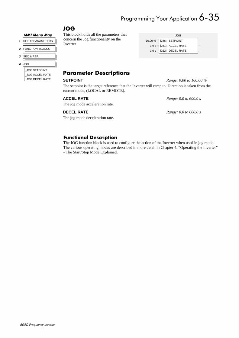
3URJUDPPLQJ#<RXU#$SSOLFDWLRQ#9068
938&#)UHTXHQF\#,QYHUWHU
-2*This block holds all the parameters thatconcern the Jog functionality on theInverter.
)XQFWLRQDO#'HVFULSWLRQThe JOG function block is used to configure the action of the Inverter when used in jog mode.The various operating modes are described in more detail in Chapter 4: “Operating the Inverter”- The Start/Stop Mode Explained.
00,#0HQX#0DS
4 SETUP PARAMETERS
5 FUNCTION BLOCKS
6 SEQ & REF
7 JOG
JOG SETPOINT
JOG ACCEL RATE
JOG DECEL RATE
JOG
10.00 % – [246] SETPOINT –
1.0 s – [261] ACCEL RATE –
1.0 s – [262] DECEL RATE –
3DUDPHWHU#'HVFULSWLRQVSETPOINT Range: 0.00 to 100.00 %
The setpoint is the target reference that the Inverter will ramp to. Direction is taken from thecurrent mode, (LOCAL or REMOTE).
ACCEL RATE Range: 0.0 to 600.0 s
The jog mode acceleration rate.
DECEL RATE Range: 0.0 to 600.0 s
The jog mode deceleration rate.
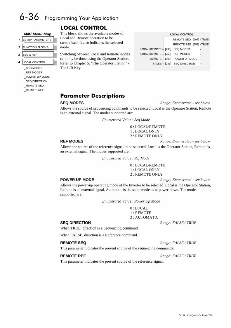
9069##3URJUDPPLQJ#<RXU#$SSOLFDWLRQ
938&#)UHTXHQF\#,QYHUWHU
/2&$/#&21752/This block allows the available modes ofLocal and Remote operation to becustomised. It also indicates the selectedmode.
Switching between Local and Remote modescan only be done using the Operator Station.Refer to Chapter 5: “The Operator Station” -The L/R Key.
00,#0HQX#0DS
4 SETUP PARAMETERS
5 FUNCTION BLOCKS
6 SEQ & REF
7 LOCAL CONTROL
SEQ MODES
REF MODES
POWER UP MODE
SEQ DIRECTION
REMOTE SEQ
REMOTE REF
LOCAL CONTROL
REMOTE SEQ [297] –TRUE
REMOTE REF [257] –TRUE
LOCAL/REMOTE – [298] SEQ MODES –
LOCAL/REMOTE – [265] REF MODES –
REMOTE – [299] POWER UP MODE –
FALSE – [281] SEQ DIRECTION –
3DUDPHWHU#'HVFULSWLRQVSEQ MODES Range: Enumerated - see below
Allows the source of sequencing commands to be selected. Local is the Operator Station, Remoteis an external signal. The modes supported are:
Enumerated Value : Seq Mode
0 : LOCAL/REMOTE1 : LOCAL ONLY2 : REMOTE ONLY
REF MODES Range: Enumerated - see below
Allows the source of the reference signal to be selected. Local is the Operator Station, Remote isan external signal. The modes supported are:
Enumerated Value : Ref Mode
0 : LOCAL/REMOTE1 : LOCAL ONLY2 : REMOTE ONLY
POWER UP MODE Range: Enumerated - see below
Allows the power-up operating mode of the Inverter to be selected. Local is the Operator Station,Remote is an external signal, Automatic is the same mode as at power-down. The modessupported are:
Enumerated Value : Power Up Mode
0 : LOCAL1 : REMOTE2 : AUTOMATIC
SEQ DIRECTION Range: FALSE / TRUE
When TRUE, direction is a Sequencing command.
When FALSE, direction is a Reference command.
REMOTE SEQ Range: FALSE / TRUE
This parameter indicates the present source of the sequencing commands.
REMOTE REF Range: FALSE / TRUE
This parameter indicates the present source of the reference signal.
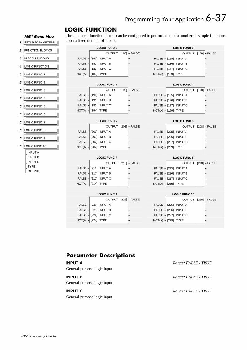
3URJUDPPLQJ#<RXU#$SSOLFDWLRQ#906:
938&#)UHTXHQF\#,QYHUWHU
/2*,&#)81&7,21These generic function blocks can be configured to perform one of a number of simple functionsupon a fixed number of inputs.
00,#0HQX#0DS
4 SETUP PARAMETERS
5 FUNCTION BLOCKS
6 MISCELLANEOUS
7 LOGIC FUNCTION
8 LOGIC FUNC 1
8 LOGIC FUNC 2
8 LOGIC FUNC 3
8 LOGIC FUNC 4
8 LOGIC FUNC 5
8 LOGIC FUNC 6
8 LOGIC FUNC 7
8 LOGIC FUNC 8
8 LOGIC FUNC 9
8 LOGIC FUNC 10
INPUT A
INPUT B
INPUT C
TYPE
OUTPUT
LOGIC FUNC 2
OUTPUT [188] – FALSE
FALSE – [185] INPUT A –
FALSE – [186] INPUT B –
FALSE – [187] INPUT C –
NOT(A) – [189] TYPE –
LOGIC FUNC 4
OUTPUT [198] – FALSE
FALSE – [195] INPUT A –
FALSE – [196] INPUT B –
FALSE – [197] INPUT C –
NOT(A) – [199] TYPE –
LOGIC FUNC 6
OUTPUT [208] – FALSE
FALSE – [205] INPUT A –
FALSE – [206] INPUT B –
FALSE – [207] INPUT C –
NOT(A) – [209] TYPE –
LOGIC FUNC 8
OUTPUT [218] – FALSE
FALSE – [215] INPUT A –
FALSE – [216] INPUT B –
FALSE – [217] INPUT C –
NOT(A) – [219] TYPE –
LOGIC FUNC 10
OUTPUT [228] – FALSE
FALSE – [225] INPUT A –
FALSE – [226] INPUT B –
FALSE – [227] INPUT C –
NOT(A) – [229] TYPE –
LOGIC FUNC 1
OUTPUT [183] – FALSE
FALSE – [180] INPUT A –
FALSE – [181] INPUT B –
FALSE – [182] INPUT C –
NOT(A) – [184] TYPE –
LOGIC FUNC 3
OUTPUT [193] – FALSE
FALSE – [190] INPUT A –
FALSE – [191] INPUT B –
FALSE – [192] INPUT C –
NOT(A) – [194] TYPE –
LOGIC FUNC 5
OUTPUT [203] – FALSE
FALSE – [200] INPUT A –
FALSE – [201] INPUT B –
FALSE – [202] INPUT C –
NOT(A) – [204] TYPE –
LOGIC FUNC 7
OUTPUT [213] – FALSE
FALSE – [210] INPUT A –
FALSE – [211] INPUT B –
FALSE – [212] INPUT C –
NOT(A) – [214] TYPE –
LOGIC FUNC 9
OUTPUT [223] – FALSE
FALSE – [220] INPUT A –
FALSE – [221] INPUT B –
FALSE – [222] INPUT C –
NOT(A) – [224] TYPE –
3DUDPHWHU#'HVFULSWLRQVINPUT A Range: FALSE / TRUE
General purpose logic input.
INPUT B Range: FALSE / TRUE
General purpose logic input.
INPUT C Range: FALSE / TRUE
General purpose logic input.
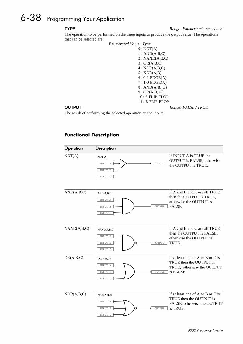
906;##3URJUDPPLQJ#<RXU#$SSOLFDWLRQ
938&#)UHTXHQF\#,QYHUWHU
)XQFWLRQDO#'HVFULSWLRQ
2SHUDWLRQ2SHUDWLRQ2SHUDWLRQ2SHUDWLRQ 'HVFULSWLRQ'HVFULSWLRQ'HVFULSWLRQ'HVFULSWLRQ
NOT(A)
OUTPUTINPUT A
INPUT B
INPUT C
NOT(A) If INPUT A is TRUE theOUTPUT is FALSE, otherwisethe OUTPUT is TRUE.
AND(A,B,C)
OUTPUT
INPUT A
INPUT B
INPUT C
AND(A,B,C) If A and B and C are all TRUEthen the OUTPUT is TRUE,otherwise the OUTPUT isFALSE.
NAND(A,B,C)
OUTPUT
INPUT A
INPUT B
INPUT C
NAND(A,B,C) If A and B and C are all TRUEthen the OUTPUT is FALSE,otherwise the OUTPUT isTRUE.
OR(A,B,C)
OUTPUT
INPUT A
INPUT B
INPUT C
OR(A,B,C) If at least one of A or B or C isTRUE then the OUTPUT isTRUE, otherwise the OUTPUTis FALSE.
NOR(A,B,C)
OUTPUT
INPUT A
INPUT B
INPUT C
NOR(A,B,C) If at least one of A or B or C isTRUE then the OUTPUT isFALSE, otherwise the OUTPUTis TRUE.
TYPE Range: Enumerated - see below
The operation to be performed on the three inputs to produce the output value. The operationsthat can be selected are:
Enumerated Value : Type0 : NOT(A)1 : AND(A,B,C)2 : NAND(A,B,C)3 : OR(A,B,C)4 : NOR(A,B,C)5 : XOR(A,B)6 : 0-1 EDGE(A)7 : 1-0 EDGE(A)8 : AND(A,B,!C)9 : OR(A,B,!C)10 : S FLIP-FLOP11 : R FLIP-FLOP
OUTPUT Range: FALSE / TRUE
The result of performing the selected operation on the inputs.
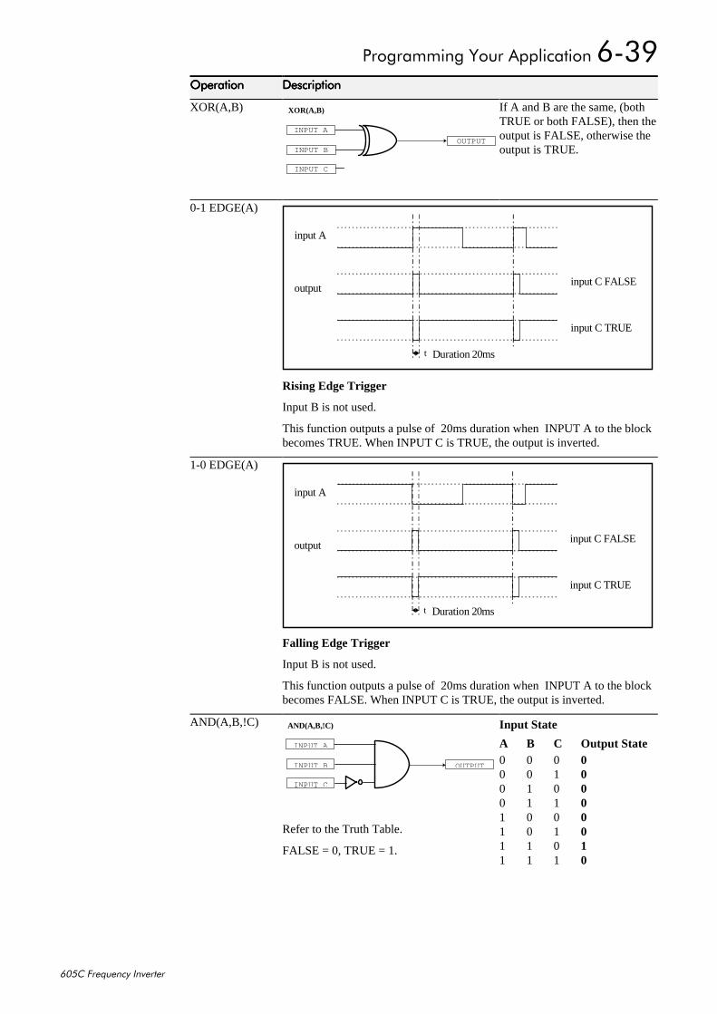
3URJUDPPLQJ#<RXU#$SSOLFDWLRQ#906<
938&#)UHTXHQF\#,QYHUWHU
2SHUDWLRQ2SHUDWLRQ2SHUDWLRQ2SHUDWLRQ 'HVFULSWLRQ'HVFULSWLRQ'HVFULSWLRQ'HVFULSWLRQ
XOR(A,B)
OUTPUT
INPUT A
INPUT B
INPUT C
XOR(A,B) If A and B are the same, (bothTRUE or both FALSE), then theoutput is FALSE, otherwise theoutput is TRUE.
0-1 EDGE(A)
input A
outputinput C FALSE
input C TRUE
Duration 20mst
Rising Edge Trigger
Input B is not used.
This function outputs a pulse of 20ms duration when INPUT A to the blockbecomes TRUE. When INPUT C is TRUE, the output is inverted.
1-0 EDGE(A)
input A
outputinput C FALSE
input C TRUE
Duration 20mst
Falling Edge Trigger
Input B is not used.
This function outputs a pulse of 20ms duration when INPUT A to the blockbecomes FALSE. When INPUT C is TRUE, the output is inverted.
AND(A,B,!C)
OUTPUT
INPUT A
INPUT B
I NPUT C
AND(A,B,!C)
Refer to the Truth Table.
FALSE = 0, TRUE = 1.
Input State
A B C Output State0 0 0 00 0 1 00 1 0 00 1 1 01 0 0 01 0 1 01 1 0 11 1 1 0
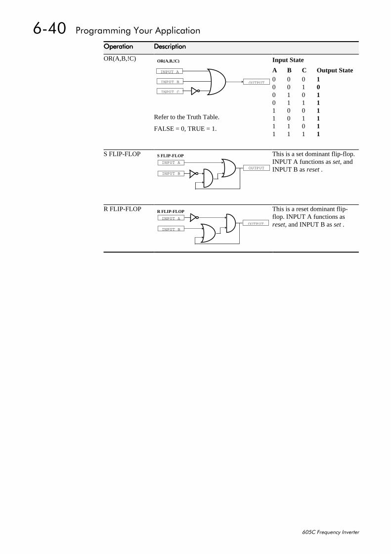
9073##3URJUDPPLQJ#<RXU#$SSOLFDWLRQ
938&#)UHTXHQF\#,QYHUWHU
2SHUDWLRQ2SHUDWLRQ2SHUDWLRQ2SHUDWLRQ 'HVFULSWLRQ'HVFULSWLRQ'HVFULSWLRQ'HVFULSWLRQ
OR(A,B,!C)
OUTPUT
I NPUT A
INPUT B
INPUT C
OR(A,B,!C)
Refer to the Truth Table.
FALSE = 0, TRUE = 1.
Input State
A B C Output State0 0 0 10 0 1 00 1 0 10 1 1 11 0 0 11 0 1 11 1 0 11 1 1 1
S FLIP-FLOP
OUTPUTINPUT A
S FLIP-FLOP
INPUT B
This is a set dominant flip-flop.INPUT A functions as set, andINPUT B as reset .
R FLIP-FLOP
OUTPUTINPUT A
R FLIP-FLOP
INPUT B
This is a reset dominant flip-flop. INPUT A functions asreset, and INPUT B as set .
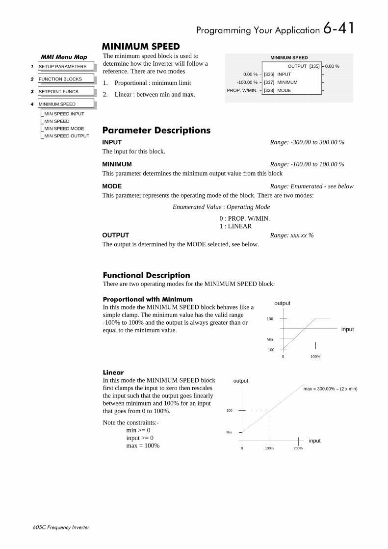
3URJUDPPLQJ#<RXU#$SSOLFDWLRQ#9074
938&#)UHTXHQF\#,QYHUWHU
0,1,080#63(('The minimum speed block is used todetermine how the Inverter will follow areference. There are two modes
1. Proportional : minimum limit
2. Linear : between min and max.
)XQFWLRQDO#'HVFULSWLRQThere are two operating modes for the MINIMUM SPEED block:
3URSRUWLRQDO#ZLWK#0LQLPXPIn this mode the MINIMUM SPEED block behaves like asimple clamp. The minimum value has the valid range-100% to 100% and the output is always greater than orequal to the minimum value.
/LQHDUIn this mode the MINIMUM SPEED blockfirst clamps the input to zero then rescalesthe input such that the output goes linearlybetween minimum and 100% for an inputthat goes from 0 to 100%.
Note the constraints:-min >= 0input >= 0max = 100%
00,#0HQX#0DS
4 SETUP PARAMETERS
5 FUNCTION BLOCKS
6 SETPOINT FUNCS
7 MINIMUM SPEED
MIN SPEED INPUT
MIN SPEED
MIN SPEED MODE
MIN SPEED OUTPUT
MINIMUM SPEED
OUTPUT [335] – 0.00 %
0.00 % – [336] INPUT –
-100.00 % – [337] MINIMUM –
PROP. W/MIN. – [338] MODE –
3DUDPHWHU#'HVFULSWLRQVINPUT Range: -300.00 to 300.00 %
The input for this block.
MINIMUM Range: -100.00 to 100.00 %
This parameter determines the minimum output value from this block
MODE Range: Enumerated - see below
This parameter represents the operating mode of the block. There are two modes:
Enumerated Value : Operating Mode
0 : PROP. W/MIN.1 : LINEAR
OUTPUT Range: xxx.xx %
The output is determined by the MODE selected, see below.
Min
0 100%
100
-100
input
output
100
Min
0 100%
output
input200%
max = 300.00% – (2 x min)
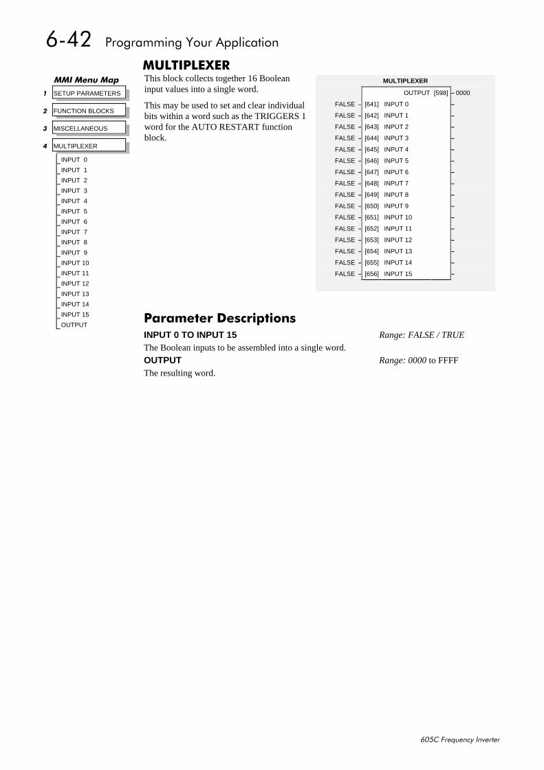
9075##3URJUDPPLQJ#<RXU#$SSOLFDWLRQ
938&#)UHTXHQF\#,QYHUWHU
08/7,3/(;(5This block collects together 16 Booleaninput values into a single word.
This may be used to set and clear individualbits within a word such as the TRIGGERS 1word for the AUTO RESTART functionblock.
00,#0HQX#0DS
4 SETUP PARAMETERS
5 FUNCTION BLOCKS
6 MISCELLANEOUS
7 MULTIPLEXER
INPUT 0
INPUT 1
INPUT 2
INPUT 3
INPUT 4
INPUT 5
INPUT 6
INPUT 7
INPUT 8
INPUT 9
INPUT 10
INPUT 11
INPUT 12
INPUT 13
INPUT 14
INPUT 15
OUTPUT
MULTIPLEXER
OUTPUT [598] – 0000
FALSE – [641] INPUT 0 –
FALSE – [642] INPUT 1 –
FALSE – [643] INPUT 2 –
FALSE – [644] INPUT 3 –
FALSE – [645] INPUT 4 –
FALSE – [646] INPUT 5 –
FALSE – [647] INPUT 6 –
FALSE – [648] INPUT 7 –
FALSE – [649] INPUT 8 –
FALSE – [650] INPUT 9 –
FALSE – [651] INPUT 10 –
FALSE – [652] INPUT 11 –
FALSE – [653] INPUT 12 –
FALSE – [654] INPUT 13 –
FALSE – [655] INPUT 14 –
FALSE – [656] INPUT 15 –
3DUDPHWHU#'HVFULSWLRQVINPUT 0 TO INPUT 15 Range: FALSE / TRUE
The Boolean inputs to be assembled into a single word.
OUTPUT Range: 0000 to FFFF
The resulting word.
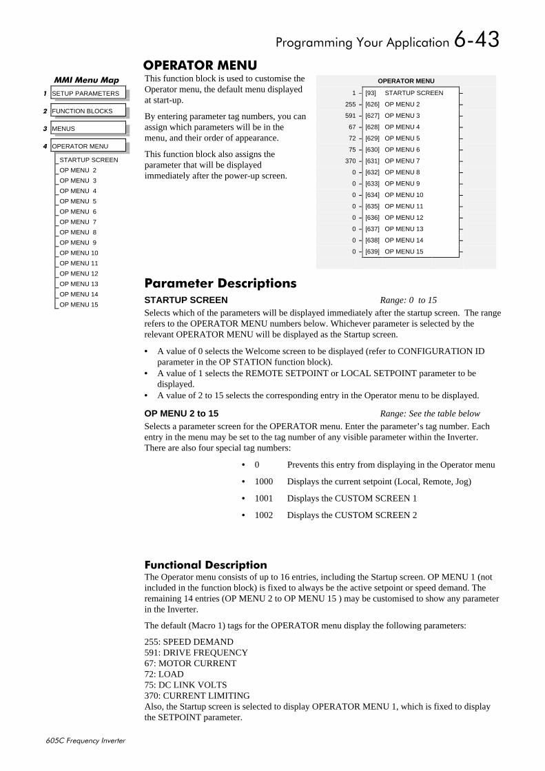
3URJUDPPLQJ#<RXU#$SSOLFDWLRQ#9076
938&#)UHTXHQF\#,QYHUWHU
23(5$725#0(18This function block is used to customise theOperator menu, the default menu displayedat start-up.
By entering parameter tag numbers, you canassign which parameters will be in themenu, and their order of appearance.
This function block also assigns theparameter that will be displayedimmediately after the power-up screen.
)XQFWLRQDO#'HVFULSWLRQThe Operator menu consists of up to 16 entries, including the Startup screen. OP MENU 1 (notincluded in the function block) is fixed to always be the active setpoint or speed demand. Theremaining 14 entries (OP MENU 2 to OP MENU 15 ) may be customised to show any parameterin the Inverter.
The default (Macro 1) tags for the OPERATOR menu display the following parameters:
255: SPEED DEMAND591: DRIVE FREQUENCY67: MOTOR CURRENT72: LOAD75: DC LINK VOLTS370: CURRENT LIMITINGAlso, the Startup screen is selected to display OPERATOR MENU 1, which is fixed to displaythe SETPOINT parameter.
00,#0HQX#0DS
4 SETUP PARAMETERS
5 FUNCTION BLOCKS
6 MENUS
7 OPERATOR MENU
STARTUP SCREEN
OP MENU 2
OP MENU 3
OP MENU 4
OP MENU 5
OP MENU 6
OP MENU 7
OP MENU 8
OP MENU 9
OP MENU 10
OP MENU 11
OP MENU 12
OP MENU 13
OP MENU 14
OP MENU 15
OPERATOR MENU
1 – [93] STARTUP SCREEN –
255 – [626] OP MENU 2 –
591 – [627] OP MENU 3 –
67 – [628] OP MENU 4 –
72 – [629] OP MENU 5 –
75 – [630] OP MENU 6 –
370 – [631] OP MENU 7 –
0 – [632] OP MENU 8 –
0 – [633] OP MENU 9 –
0 – [634] OP MENU 10 –
0 – [635] OP MENU 11 –
0 – [636] OP MENU 12 –
0 – [637] OP MENU 13 –
0 – [638] OP MENU 14 –
0 – [639] OP MENU 15 –
3DUDPHWHU#'HVFULSWLRQVSTARTUP SCREEN Range: 0 to 15
Selects which of the parameters will be displayed immediately after the startup screen. The rangerefers to the OPERATOR MENU numbers below. Whichever parameter is selected by therelevant OPERATOR MENU will be displayed as the Startup screen.
• A value of 0 selects the Welcome screen to be displayed (refer to CONFIGURATION IDparameter in the OP STATION function block).
• A value of 1 selects the REMOTE SETPOINT or LOCAL SETPOINT parameter to bedisplayed.
• A value of 2 to 15 selects the corresponding entry in the Operator menu to be displayed.
OP MENU 2 to 15 Range: See the table below
Selects a parameter screen for the OPERATOR menu. Enter the parameter’s tag number. Eachentry in the menu may be set to the tag number of any visible parameter within the Inverter.There are also four special tag numbers:
• 0 Prevents this entry from displaying in the Operator menu
• 1000 Displays the current setpoint (Local, Remote, Jog)
• 1001 Displays the CUSTOM SCREEN 1
• 1002 Displays the CUSTOM SCREEN 2
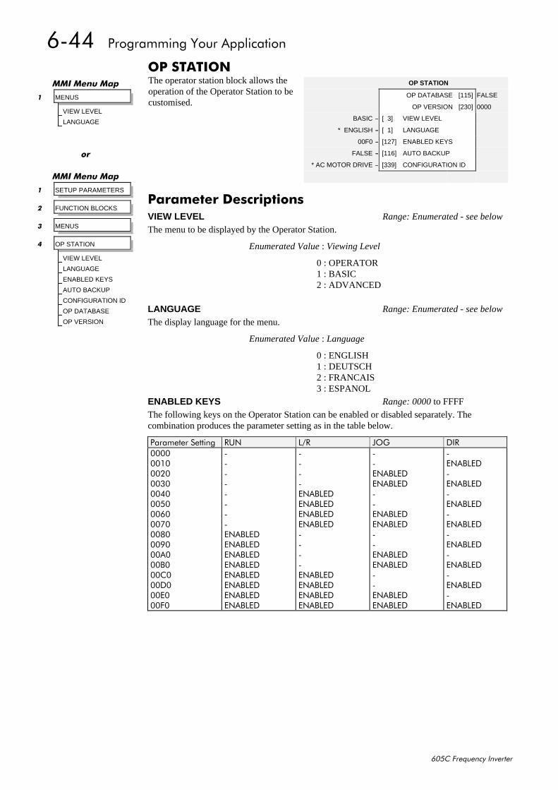
9077##3URJUDPPLQJ#<RXU#$SSOLFDWLRQ
938&#)UHTXHQF\#,QYHUWHU
23#67$7,21The operator station block allows theoperation of the Operator Station to becustomised.
OP STATION
OP DATABASE [115] –FALSE
OP VERSION [230] –0000
BASIC – [ 3] VIEW LEVEL –
* ENGLISH – [ 1] LANGUAGE –
00F0 – [127] ENABLED KEYS –
FALSE – [116] AUTO BACKUP –
* AC MOTOR DRIVE – [339] CONFIGURATION ID –
00,#0HQX#0DS
4 MENUS
VIEW LEVEL
LANGUAGE
RU
00,#0HQX#0DS
4 SETUP PARAMETERS
5 FUNCTION BLOCKS
6 MENUS
7 OP STATION
VIEW LEVEL
LANGUAGE
ENABLED KEYS
AUTO BACKUP
CONFIGURATION ID
OP DATABASE
OP VERSION
3DUDPHWHU#'HVFULSWLRQVVIEW LEVEL Range: Enumerated - see below
The menu to be displayed by the Operator Station.
Enumerated Value : Viewing Level
0 : OPERATOR1 : BASIC2 : ADVANCED
LANGUAGE Range: Enumerated - see below
The display language for the menu.
Enumerated Value : Language
0 : ENGLISH1 : DEUTSCH2 : FRANCAIS3 : ESPANOL
ENABLED KEYS Range: 0000 to FFFF
The following keys on the Operator Station can be enabled or disabled separately. Thecombination produces the parameter setting as in the table below.
3DUDPHWHU#6HWWLQJ 581 /25 -2* ',5333333433353336333733383339333:333;333<333$333%333&333'333(333)3
00000000(1$%/('(1$%/('(1$%/('(1$%/('(1$%/('(1$%/('(1$%/('(1$%/('
0000(1$%/('(1$%/('(1$%/('(1$%/('0000(1$%/('(1$%/('(1$%/('(1$%/('
00(1$%/('(1$%/('00(1$%/('(1$%/('00(1$%/('(1$%/('00(1$%/('(1$%/('
0(1$%/('0(1$%/('0(1$%/('0(1$%/('0(1$%/('0(1$%/('0(1$%/('0(1$%/('

3URJUDPPLQJ#<RXU#$SSOLFDWLRQ#9078
938&#)UHTXHQF\#,QYHUWHU
AUTO BACKUP Range: FALSE / TRUE
When this input is set to TRUE, performing a SAVE TO MEMORY function block operationalso saves the configuration of the Inverter to the connected Operator Station.
CONFIGURATION ID Range: 16 characters
This 16 character string is displayed as the top line of the Welcome screen.
OP DATABASE Range: FALSE / TRUE
When TRUE, this diagnostic output indicates that the connected Operator Station contains aconfiguration that may be loaded into the Inverter.
OP VERSION Range: 0000 to FFFF
Displays the software version of the Operator Station. It is cleared to 0000 if no OperatorStation is connected.
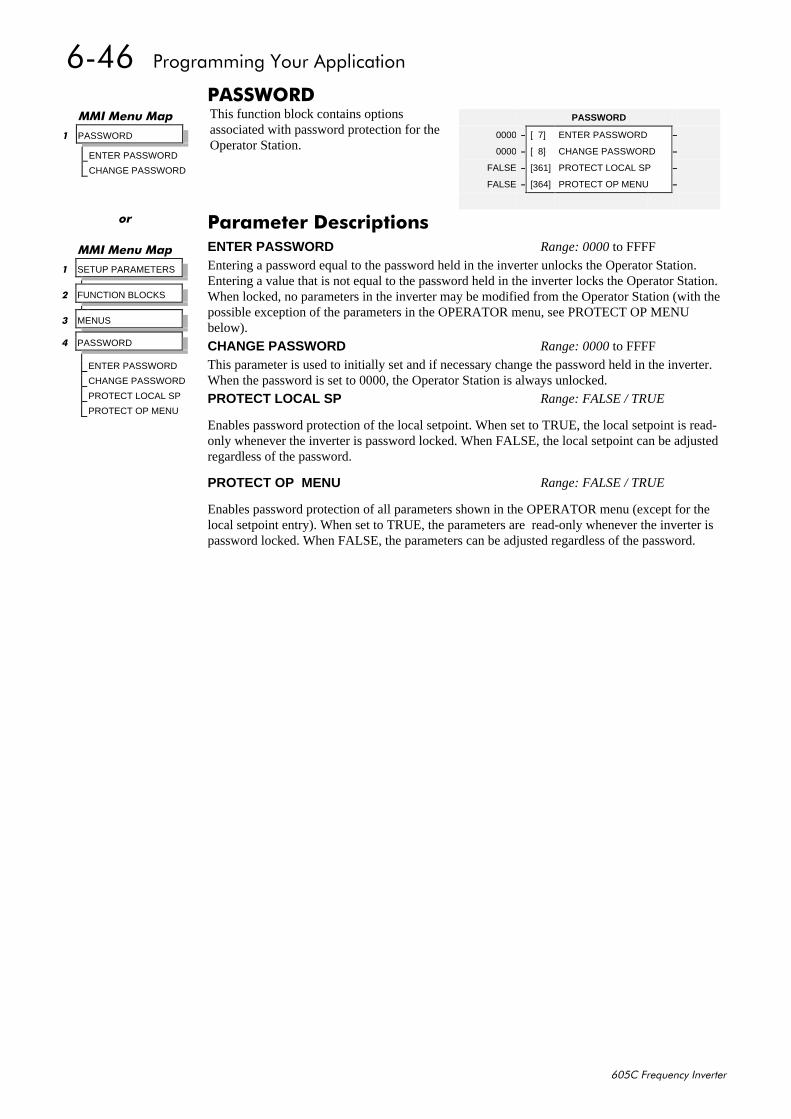
9079##3URJUDPPLQJ#<RXU#$SSOLFDWLRQ
938&#)UHTXHQF\#,QYHUWHU
3$66:25'This function block contains optionsassociated with password protection for theOperator Station.
00,#0HQX#0DS
4 PASSWORD
ENTER PASSWORD
CHANGE PASSWORD
PASSWORD
0000 – [ 7] ENTER PASSWORD –
0000 – [ 8] CHANGE PASSWORD –
FALSE – [361] PROTECT LOCAL SP –
FALSE – [364] PROTECT OP MENU –
RU
00,#0HQX#0DS
4 SETUP PARAMETERS
5 FUNCTION BLOCKS
6 MENUS
7 PASSWORD
ENTER PASSWORD
CHANGE PASSWORD
PROTECT LOCAL SP
PROTECT OP MENU
3DUDPHWHU#'HVFULSWLRQVENTER PASSWORD Range: 0000 to FFFF
Entering a password equal to the password held in the inverter unlocks the Operator Station.Entering a value that is not equal to the password held in the inverter locks the Operator Station.When locked, no parameters in the inverter may be modified from the Operator Station (with thepossible exception of the parameters in the OPERATOR menu, see PROTECT OP MENUbelow).
CHANGE PASSWORD Range: 0000 to FFFF
This parameter is used to initially set and if necessary change the password held in the inverter.When the password is set to 0000, the Operator Station is always unlocked.
PROTECT LOCAL SP Range: FALSE / TRUE
Enables password protection of the local setpoint. When set to TRUE, the local setpoint is read-only whenever the inverter is password locked. When FALSE, the local setpoint can be adjustedregardless of the password.
PROTECT OP MENU Range: FALSE / TRUE
Enables password protection of all parameters shown in the OPERATOR menu (except for thelocal setpoint entry). When set to TRUE, the parameters are read-only whenever the inverter ispassword locked. When FALSE, the parameters can be adjusted regardless of the password.
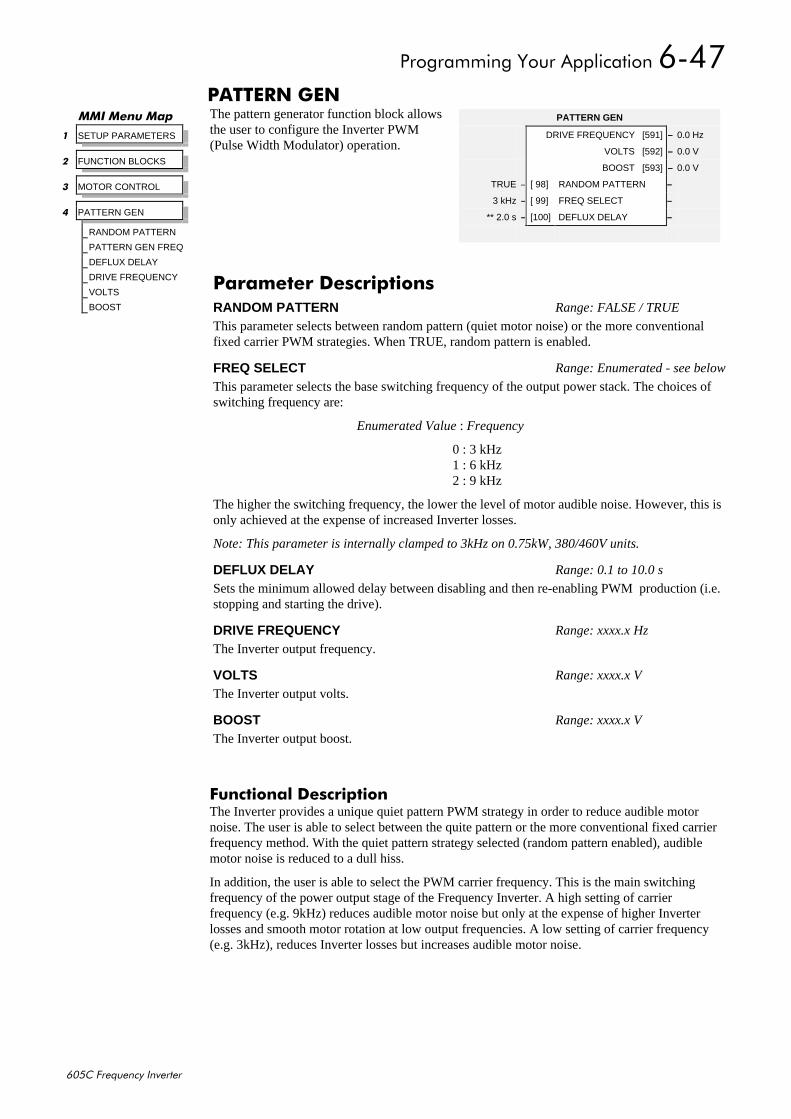
3URJUDPPLQJ#<RXU#$SSOLFDWLRQ#907:
938&#)UHTXHQF\#,QYHUWHU
3$77(51#*(1The pattern generator function block allowsthe user to configure the Inverter PWM(Pulse Width Modulator) operation.
)XQFWLRQDO#'HVFULSWLRQThe Inverter provides a unique quiet pattern PWM strategy in order to reduce audible motornoise. The user is able to select between the quite pattern or the more conventional fixed carrierfrequency method. With the quiet pattern strategy selected (random pattern enabled), audiblemotor noise is reduced to a dull hiss.
In addition, the user is able to select the PWM carrier frequency. This is the main switchingfrequency of the power output stage of the Frequency Inverter. A high setting of carrierfrequency (e.g. 9kHz) reduces audible motor noise but only at the expense of higher Inverterlosses and smooth motor rotation at low output frequencies. A low setting of carrier frequency(e.g. 3kHz), reduces Inverter losses but increases audible motor noise.
00,#0HQX#0DS
4 SETUP PARAMETERS
5 FUNCTION BLOCKS
6 MOTOR CONTROL
7 PATTERN GEN
RANDOM PATTERN
PATTERN GEN FREQ
DEFLUX DELAY
DRIVE FREQUENCY
VOLTS
BOOST
PATTERN GEN
DRIVE FREQUENCY [591] – 0.0 Hz
VOLTS [592] – 0.0 V
BOOST [593] – 0.0 V
TRUE – [ 98] RANDOM PATTERN –
3 kHz – [ 99] FREQ SELECT –
** 2.0 s – [100] DEFLUX DELAY –
3DUDPHWHU#'HVFULSWLRQVRANDOM PATTERN Range: FALSE / TRUE
This parameter selects between random pattern (quiet motor noise) or the more conventionalfixed carrier PWM strategies. When TRUE, random pattern is enabled.
FREQ SELECT Range: Enumerated - see below
This parameter selects the base switching frequency of the output power stack. The choices ofswitching frequency are:
Enumerated Value : Frequency
0 : 3 kHz1 : 6 kHz2 : 9 kHz
The higher the switching frequency, the lower the level of motor audible noise. However, this isonly achieved at the expense of increased Inverter losses.
Note: This parameter is internally clamped to 3kHz on 0.75kW, 380/460V units.
DEFLUX DELAY Range: 0.1 to 10.0 s
Sets the minimum allowed delay between disabling and then re-enabling PWM production (i.e.stopping and starting the drive).
DRIVE FREQUENCY Range: xxxx.x Hz
The Inverter output frequency.
VOLTS Range: xxxx.x V
The Inverter output volts.
BOOST Range: xxxx.x V
The Inverter output boost.
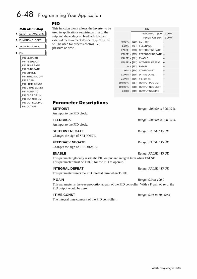
907;##3URJUDPPLQJ#<RXU#$SSOLFDWLRQ
938&#)UHTXHQF\#,QYHUWHU
3,'This function block allows the Inverter to beused in applications requiring a trim to thesetpoint, depending on feedback from anexternal measurement device. Typically thiswill be used for process control, i.e.pressure or flow.
00,#0HQX#0DS
4 SETUP PARAMETERS
5 FUNCTION BLOCKS
6 SETPOINT FUNCS
7 PID
PID SETPOINT
PID FEEDBACK
PID SP NEGATE
PID FB NEGATE
PID ENABLE
PID INTEGRAL OFF
PID P GAIN
PID I TIME CONST
PID D TIME CONST
PID FILTER TC
PID OUT POS LIM
PID OUT NEG LIM
PID OUT SCALING
PID OUTPUT
PID
PID OUTPUT [320] – 0.00 %
PID ERROR [766] – 0.00 %
0.00 % – [310] SETPOINT –
0.00% – [764] FEEDBACK –
FALSE – [763] SETPOINT NEGATE –
FALSE – [765] FEEDBACK NEGATE –
FALSE – [311] ENABLE –
FALSE – [312] INTEGRAL DEFEAT –
1.0 – [313] P GAIN –
1.00 s – [314] I TIME CONST –
0.000 s – [315] D TIME CONST –
2.000 s – [316] FILTER TC –
100.00 % – [317] OUTPUT POS LIMIT –
-100.00 % – [318] OUTPUT NEG LIMIT –
1.0000 – [319] OUTPUT SCALING –
3DUDPHWHU#'HVFULSWLRQVSETPOINT Range: -300.00 to 300.00 %
An input to the PID block.
FEEDBACK Range: -300.00 to 300.00 %
An input to the PID block.
SETPOINT NEGATE Range: FALSE / TRUE
Changes the sign of SETPOINT.
FEEDBACK NEGATE Range: FALSE / TRUE
Changes the sign of FEEDBACK.
ENABLE Range: FALSE / TRUE
This parameter globally resets the PID output and integral term when FALSE.This parameter must be TRUE for the PID to operate.
INTEGRAL DEFEAT Range: FALSE / TRUE
This parameter resets the PID integral term when TRUE.
P GAIN Range: 0.0 to 100.0
This parameter is the true proportional gain of the PID controller. With a P gain of zero, thePID output would be zero.
I TIME CONST Range: 0.01 to 100.00 s
The integral time constant of the PID controller.
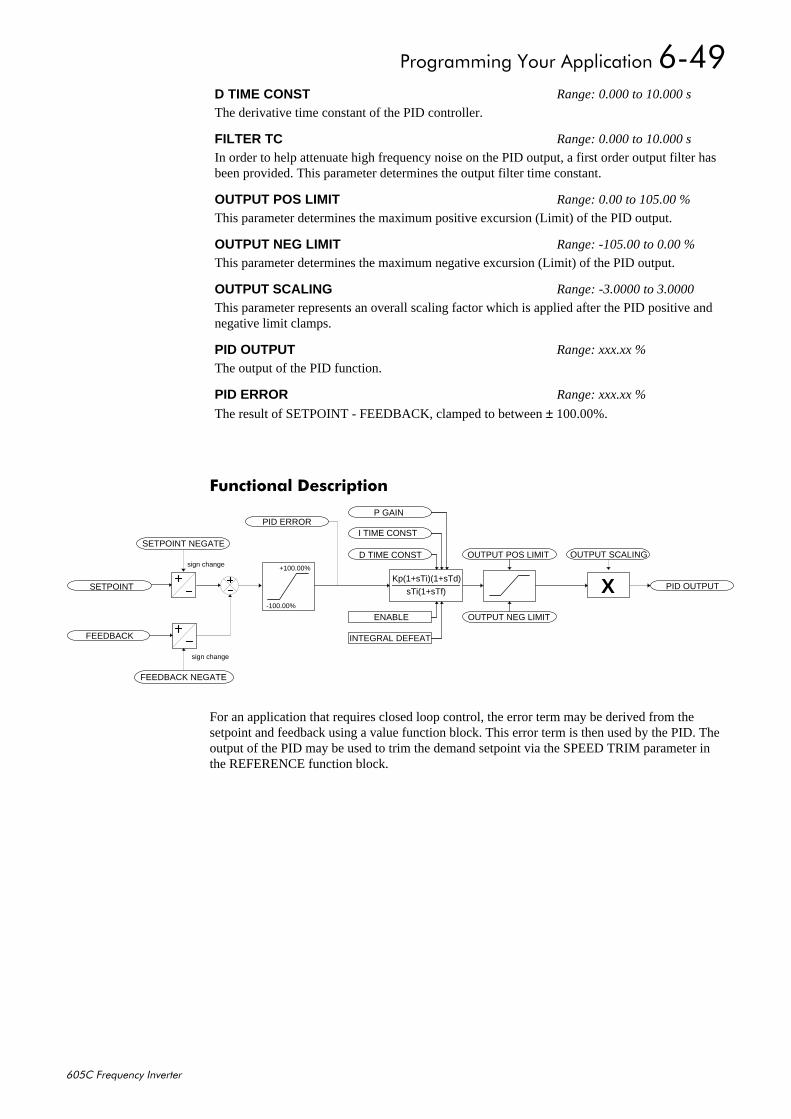
3URJUDPPLQJ#<RXU#$SSOLFDWLRQ#907<
938&#)UHTXHQF\#,QYHUWHU
)XQFWLRQDO#'HVFULSWLRQ
Kp(1+sTi)(1+sTd)
sTi(1+sTf)
D TIME CONST
I TIME CONST
P GAIN
ENABLE
INTEGRAL DEFEAT
X PID OUTPUT
OUTPUT NEG LIMIT
OUTPUT POS LIMIT OUTPUT SCALING
SETPOINT
FEEDBACK
SETPOINT NEGATE
FEEDBACK NEGATE
+100.00%
-100.00%
PID ERROR
sign change
sign change
For an application that requires closed loop control, the error term may be derived from thesetpoint and feedback using a value function block. This error term is then used by the PID. Theoutput of the PID may be used to trim the demand setpoint via the SPEED TRIM parameter inthe REFERENCE function block.
D TIME CONST Range: 0.000 to 10.000 s
The derivative time constant of the PID controller.
FILTER TC Range: 0.000 to 10.000 s
In order to help attenuate high frequency noise on the PID output, a first order output filter hasbeen provided. This parameter determines the output filter time constant.
OUTPUT POS LIMIT Range: 0.00 to 105.00 %
This parameter determines the maximum positive excursion (Limit) of the PID output.
OUTPUT NEG LIMIT Range: -105.00 to 0.00 %
This parameter determines the maximum negative excursion (Limit) of the PID output.
OUTPUT SCALING Range: -3.0000 to 3.0000
This parameter represents an overall scaling factor which is applied after the PID positive andnegative limit clamps.
PID OUTPUT Range: xxx.xx %
The output of the PID function.
PID ERROR Range: xxx.xx %
The result of SETPOINT - FEEDBACK, clamped to between ± 100.00%.
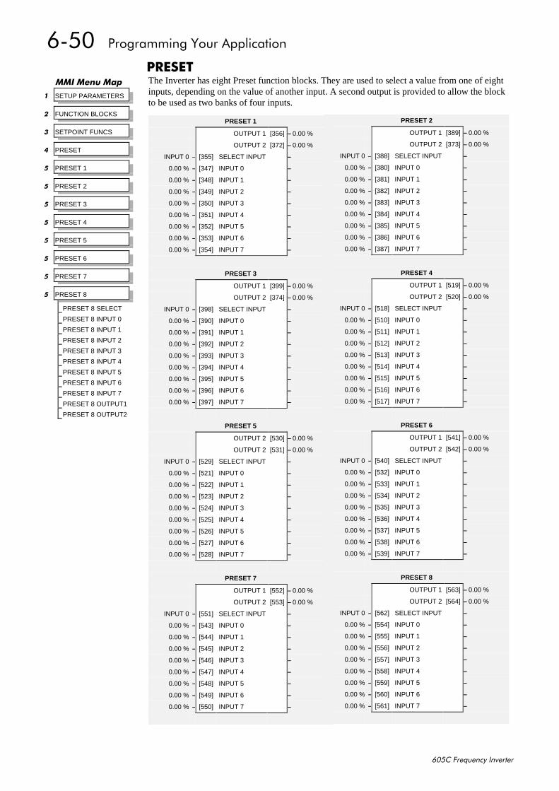
9083##3URJUDPPLQJ#<RXU#$SSOLFDWLRQ
938&#)UHTXHQF\#,QYHUWHU
35(6(7The Inverter has eight Preset function blocks. They are used to select a value from one of eightinputs, depending on the value of another input. A second output is provided to allow the blockto be used as two banks of four inputs.
00,#0HQX#0DS
4 SETUP PARAMETERS
5 FUNCTION BLOCKS
6 SETPOINT FUNCS
7 PRESET
8 PRESET 1
8 PRESET 2
8 PRESET 3
8 PRESET 4
8 PRESET 5
8 PRESET 6
8 PRESET 7
8 PRESET 8
PRESET 8 SELECT
PRESET 8 INPUT 0
PRESET 8 INPUT 1
PRESET 8 INPUT 2
PRESET 8 INPUT 3
PRESET 8 INPUT 4
PRESET 8 INPUT 5
PRESET 8 INPUT 6
PRESET 8 INPUT 7
PRESET 8 OUTPUT1
PRESET 8 OUTPUT2
PRESET 1
OUTPUT 1 [356] – 0.00 %
OUTPUT 2 [372] – 0.00 %
INPUT 0 – [355] SELECT INPUT –
0.00 % – [347] INPUT 0 –
0.00 % – [348] INPUT 1 –
0.00 % – [349] INPUT 2 –
0.00 % – [350] INPUT 3 –
0.00 % – [351] INPUT 4 –
0.00 % – [352] INPUT 5 –
0.00 % – [353] INPUT 6 –
0.00 % – [354] INPUT 7 –
PRESET 3
OUTPUT 1 [399] – 0.00 %
OUTPUT 2 [374] – 0.00 %
INPUT 0 – [398] SELECT INPUT –
0.00 % – [390] INPUT 0 –
0.00 % – [391] INPUT 1 –
0.00 % – [392] INPUT 2 –
0.00 % – [393] INPUT 3 –
0.00 % – [394] INPUT 4 –
0.00 % – [395] INPUT 5 –
0.00 % – [396] INPUT 6 –
0.00 % – [397] INPUT 7 –
PRESET 5
OUTPUT 2 [530] – 0.00 %
OUTPUT 2 [531] – 0.00 %
INPUT 0 – [529] SELECT INPUT –
0.00 % – [521] INPUT 0 –
0.00 % – [522] INPUT 1 –
0.00 % – [523] INPUT 2 –
0.00 % – [524] INPUT 3 –
0.00 % – [525] INPUT 4 –
0.00 % – [526] INPUT 5 –
0.00 % – [527] INPUT 6 –
0.00 % – [528] INPUT 7 –
PRESET 7
OUTPUT 1 [552] – 0.00 %
OUTPUT 2 [553] – 0.00 %
INPUT 0 – [551] SELECT INPUT –
0.00 % – [543] INPUT 0 –
0.00 % – [544] INPUT 1 –
0.00 % – [545] INPUT 2 –
0.00 % – [546] INPUT 3 –
0.00 % – [547] INPUT 4 –
0.00 % – [548] INPUT 5 –
0.00 % – [549] INPUT 6 –
0.00 % – [550] INPUT 7 –
PRESET 2
OUTPUT 1 [389] – 0.00 %
OUTPUT 2 [373] – 0.00 %
INPUT 0 – [388] SELECT INPUT –
0.00 % – [380] INPUT 0 –
0.00 % – [381] INPUT 1 –
0.00 % – [382] INPUT 2 –
0.00 % – [383] INPUT 3 –
0.00 % – [384] INPUT 4 –
0.00 % – [385] INPUT 5 –
0.00 % – [386] INPUT 6 –
0.00 % – [387] INPUT 7 –
PRESET 4
OUTPUT 1 [519] – 0.00 %
OUTPUT 2 [520] – 0.00 %
INPUT 0 – [518] SELECT INPUT –
0.00 % – [510] INPUT 0 –
0.00 % – [511] INPUT 1 –
0.00 % – [512] INPUT 2 –
0.00 % – [513] INPUT 3 –
0.00 % – [514] INPUT 4 –
0.00 % – [515] INPUT 5 –
0.00 % – [516] INPUT 6 –
0.00 % – [517] INPUT 7 –
PRESET 6
OUTPUT 1 [541] – 0.00 %
OUTPUT 2 [542] – 0.00 %
INPUT 0 – [540] SELECT INPUT –
0.00 % – [532] INPUT 0 –
0.00 % – [533] INPUT 1 –
0.00 % – [534] INPUT 2 –
0.00 % – [535] INPUT 3 –
0.00 % – [536] INPUT 4 –
0.00 % – [537] INPUT 5 –
0.00 % – [538] INPUT 6 –
0.00 % – [539] INPUT 7 –
PRESET 8
OUTPUT 1 [563] – 0.00 %
OUTPUT 2 [564] – 0.00 %
INPUT 0 – [562] SELECT INPUT –
0.00 % – [554] INPUT 0 –
0.00 % – [555] INPUT 1 –
0.00 % – [556] INPUT 2 –
0.00 % – [557] INPUT 3 –
0.00 % – [558] INPUT 4 –
0.00 % – [559] INPUT 5 –
0.00 % – [560] INPUT 6 –
0.00 % – [561] INPUT 7 –
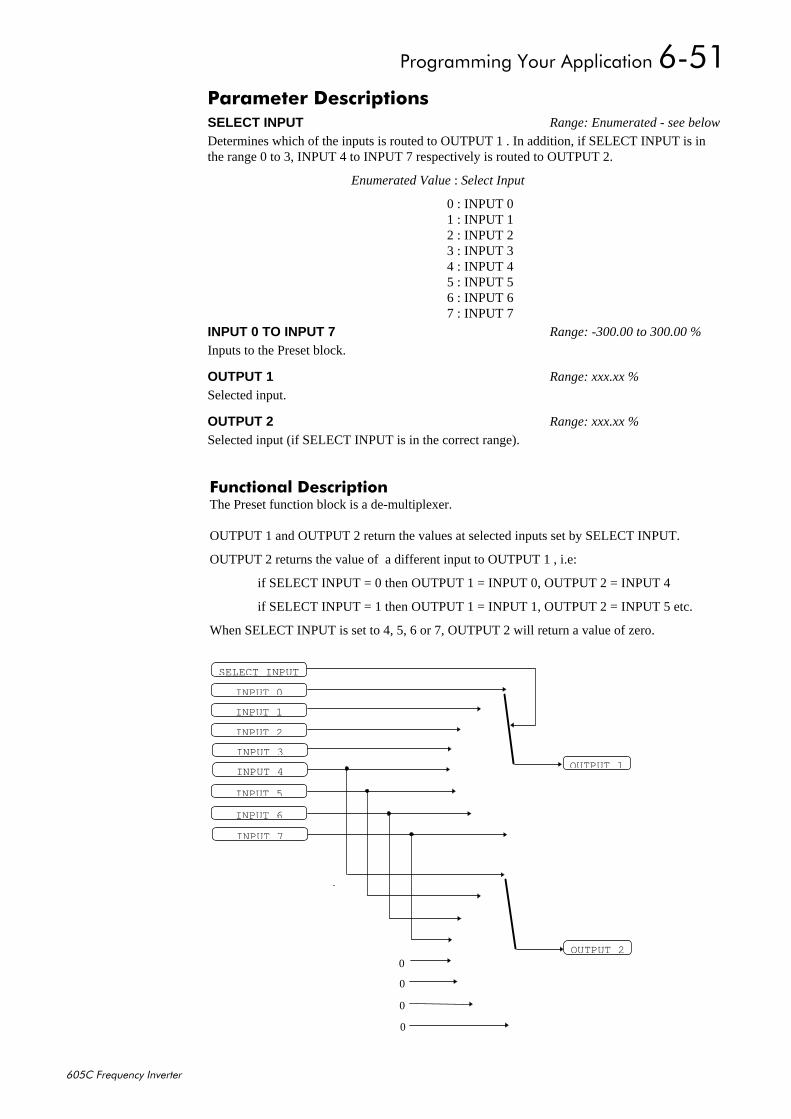
3URJUDPPLQJ#<RXU#$SSOLFDWLRQ#9084
938&#)UHTXHQF\#,QYHUWHU
)XQFWLRQDO#'HVFULSWLRQThe Preset function block is a de-multiplexer.
OUTPUT 1 and OUTPUT 2 return the values at selected inputs set by SELECT INPUT.
OUTPUT 2 returns the value of a different input to OUTPUT 1 , i.e:
if SELECT INPUT = 0 then OUTPUT 1 = INPUT 0, OUTPUT 2 = INPUT 4
if SELECT INPUT = 1 then OUTPUT 1 = INPUT 1, OUTPUT 2 = INPUT 5 etc.
When SELECT INPUT is set to 4, 5, 6 or 7, OUTPUT 2 will return a value of zero.
3DUDPHWHU#'HVFULSWLRQVSELECT INPUT Range: Enumerated - see below
Determines which of the inputs is routed to OUTPUT 1 . In addition, if SELECT INPUT is inthe range 0 to 3, INPUT 4 to INPUT 7 respectively is routed to OUTPUT 2.
Enumerated Value : Select Input
0 : INPUT 01 : INPUT 12 : INPUT 23 : INPUT 34 : INPUT 45 : INPUT 56 : INPUT 67 : INPUT 7
INPUT 0 TO INPUT 7 Range: -300.00 to 300.00 %
Inputs to the Preset block.
OUTPUT 1 Range: xxx.xx %
Selected input.
OUTPUT 2 Range: xxx.xx %
Selected input (if SELECT INPUT is in the correct range).
OUTPUT 1
SELECT I NPUT
INPUT 0
I NPUT 1
INPUT 2
INPUT 3
INPUT 4
INPUT 5
I NPUT 6
INPUT 7
OUTPUT 20
0
0
0
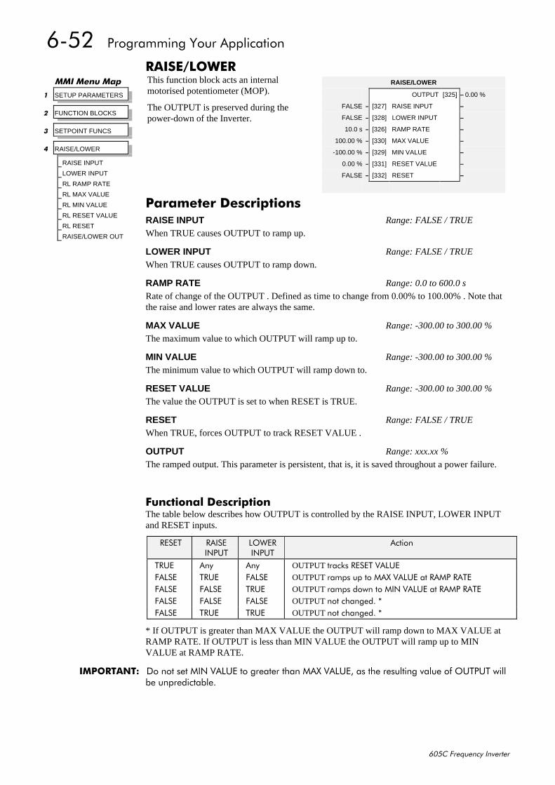
9085##3URJUDPPLQJ#<RXU#$SSOLFDWLRQ
938&#)UHTXHQF\#,QYHUWHU
5$,6(2/2:(5This function block acts an internalmotorised potentiometer (MOP).
The OUTPUT is preserved during thepower-down of the Inverter.
)XQFWLRQDO#'HVFULSWLRQThe table below describes how OUTPUT is controlled by the RAISE INPUT, LOWER INPUTand RESET inputs.
5(6(7 5$,6(,1387
/2:(5,1387
$FWLRQ
758( $Q\ $Q\ OUTPUT WUDFNV#5(6(7#9$/8()$/6( 758( )$/6( OUTPUT UDPSV#XS#WR#0$;#9$/8(#DW#5$03#5$7()$/6( )$/6( 758( OUTPUT UDPSV#GRZQ#WR#0,1#9$/8(#DW#5$03#5$7()$/6( )$/6( )$/6( OUTPUT QRW#FKDQJHG1#-)$/6( 758( 758( OUTPUT QRW#FKDQJHG1#-
* If OUTPUT is greater than MAX VALUE the OUTPUT will ramp down to MAX VALUE atRAMP RATE. If OUTPUT is less than MIN VALUE the OUTPUT will ramp up to MINVALUE at RAMP RATE.
,03257$17=# 'R#QRW#VHW#0,1#9$/8(#WR#JUHDWHU#WKDQ#0$;#9$/8(/#DV#WKH#UHVXOWLQJ#YDOXH#RI#287387#ZLOOEH#XQSUHGLFWDEOH1
00,#0HQX#0DS
4 SETUP PARAMETERS
5 FUNCTION BLOCKS
6 SETPOINT FUNCS
7 RAISE/LOWER
RAISE INPUT
LOWER INPUT
RL RAMP RATE
RL MAX VALUE
RL MIN VALUE
RL RESET VALUE
RL RESET
RAISE/LOWER OUT
RAISE/LOWER
OUTPUT [325] – 0.00 %
FALSE – [327] RAISE INPUT –
FALSE – [328] LOWER INPUT –
10.0 s – [326] RAMP RATE –
100.00 % – [330] MAX VALUE –
-100.00 % – [329] MIN VALUE –
0.00 % – [331] RESET VALUE –
FALSE – [332] RESET –
3DUDPHWHU#'HVFULSWLRQVRAISE INPUT Range: FALSE / TRUE
When TRUE causes OUTPUT to ramp up.
LOWER INPUT Range: FALSE / TRUE
When TRUE causes OUTPUT to ramp down.
RAMP RATE Range: 0.0 to 600.0 s
Rate of change of the OUTPUT . Defined as time to change from 0.00% to 100.00% . Note thatthe raise and lower rates are always the same.
MAX VALUE Range: -300.00 to 300.00 %
The maximum value to which OUTPUT will ramp up to.
MIN VALUE Range: -300.00 to 300.00 %
The minimum value to which OUTPUT will ramp down to.
RESET VALUE Range: -300.00 to 300.00 %
The value the OUTPUT is set to when RESET is TRUE.
RESET Range: FALSE / TRUE
When TRUE, forces OUTPUT to track RESET VALUE .
OUTPUT Range: xxx.xx %
The ramped output. This parameter is persistent, that is, it is saved throughout a power failure.
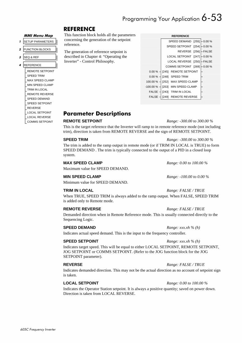
3URJUDPPLQJ#<RXU#$SSOLFDWLRQ#9086
938&#)UHTXHQF\#,QYHUWHU
5()(5(1&(This function block holds all the parametersconcerning the generation of the setpointreference.
The generation of reference setpoint isdescribed in Chapter 4: “Operating theInverter” - Control Philosophy.
00,#0HQX#0DS
4 SETUP PARAMETERS
5 FUNCTION BLOCKS
6 SEQ & REF
7 REFERENCE
REMOTE SETPOINT
SPEED TRIM
MAX SPEED CLAMP
MIN SPEED CLAMP
TRIM IN LOCAL
REMOTE REVERSE
SPEED DEMAND
SPEED SETPOINT
REVERSE
LOCAL SETPOINT
LOCAL REVERSE
COMMS SETPOINT
REFERENCE
SPEED DEMAND [255] – 0.00 %
SPEED SETPOINT [254] – 0.00 %
REVERSE [256] – FALSE
LOCAL SETPOINT [247] – 0.00 %
LOCAL REVERSE [250] – FALSE
COMMS SETPOINT [269] – 0.00 %
0.00 % – [245] REMOTE SETPOINT –
0.00 % – [248] SPEED TRIM –
100.00 % – [252] MAX SPEED CLAMP –
-100.00 % – [253] MIN SPEED CLAMP –
FALSE – [243] TRIM IN LOCAL –
FALSE – [249] REMOTE REVERSE –
3DUDPHWHU#'HVFULSWLRQVREMOTE SETPOINT Range: -300.00 to 300.00 %
This is the target reference that the Inverter will ramp to in remote reference mode (not includingtrim), direction is taken from REMOTE REVERSE and the sign of REMOTE SETPOINT.
SPEED TRIM Range: -300.00 to 300.00 %
The trim is added to the ramp output in remote mode (or if TRIM IN LOCAL is TRUE) to formSPEED DEMAND . The trim is typically connected to the output of a PID in a closed loopsystem.
MAX SPEED CLAMP Range: 0.00 to 100.00 %
Maximum value for SPEED DEMAND.
MIN SPEED CLAMP Range: -100.00 to 0.00 %
Minimum value for SPEED DEMAND.
TRIM IN LOCAL Range: FALSE / TRUE
When TRUE, SPEED TRIM is always added to the ramp output. When FALSE, SPEED TRIMis added only to Remote mode.
REMOTE REVERSE Range: FALSE / TRUE
Demanded direction when in Remote Reference mode. This is usually connected directly to theSequencing Logic.
SPEED DEMAND Range: xxx.xh % (h)
Indicates actual speed demand. This is the input to the frequency controller.
SPEED SETPOINT Range: xxx.xh % (h)
Indicates target speed. This will be equal to either LOCAL SETPOINT, REMOTE SETPOINT,JOG SETPOINT or COMMS SETPOINT. (Refer to the JOG function block for the JOGSETPOINT parameter).
REVERSE Range: FALSE / TRUE
Indicates demanded direction. This may not be the actual direction as no account of setpoint signis taken.
LOCAL SETPOINT Range: 0.00 to 100.00 %
Indicates the Operator Station setpoint. It is always a positive quantity; saved on power down.Direction is taken from LOCAL REVERSE.
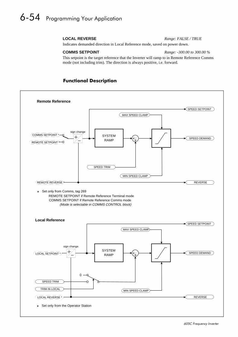
9087##3URJUDPPLQJ#<RXU#$SSOLFDWLRQ
938&#)UHTXHQF\#,QYHUWHU
)XQFWLRQDO#'HVFULSWLRQ
LOCAL REVERSE Range: FALSE / TRUE
Indicates demanded direction in Local Reference mode, saved on power down.
COMMS SETPOINT Range: -300.00 to 300.00 %
This setpoint is the target reference that the Inverter will ramp to in Remote Reference Commsmode (not including trim). The direction is always positive, i.e. forward.
MAX SPEED CLAMP
MIN SPEED CLAMP
SPEED SETPOINT
SPEED DEMAND
REVERSE
SPEED TRIM
REMOTE SETPOINT *
REMOTE REVERSE *
SYSTEMRAMP
MAX SPEED CLAMP
MIN SPEED CLAMP
SPEED SETPOINT
SPEED DEMAND
REVERSE
SPEED TRIM
TRIM IN LOCAL
LOCAL SETPOINT *
LOCAL REVERSE *
SYSTEMRAMP
0
COMMS SETPOINT *
* Set only from Comms, tag 269REMOTE SETPOINT if Remote Reference Terminal modeCOMMS SETPOINT if Remote Reference Comms mode
* Set only from the Operator Station
(Mode is selectable in COMMS CONTROL block)
Remote Reference
Local Reference
sign change
sign change
++
++
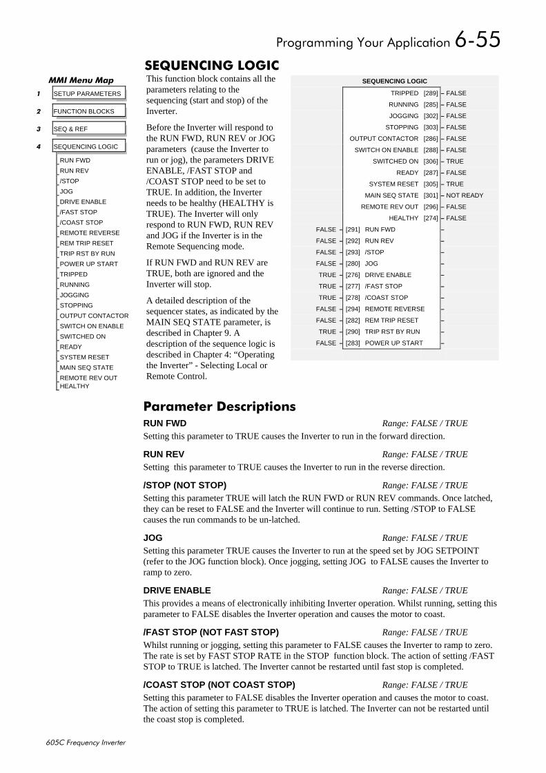
3URJUDPPLQJ#<RXU#$SSOLFDWLRQ#9088
938&#)UHTXHQF\#,QYHUWHU
6(48(1&,1*#/2*,&This function block contains all theparameters relating to thesequencing (start and stop) of theInverter.
Before the Inverter will respond tothe RUN FWD, RUN REV or JOGparameters (cause the Inverter torun or jog), the parameters DRIVEENABLE, /FAST STOP and/COAST STOP need to be set toTRUE. In addition, the Inverterneeds to be healthy (HEALTHY isTRUE). The Inverter will onlyrespond to RUN FWD, RUN REVand JOG if the Inverter is in theRemote Sequencing mode.
If RUN FWD and RUN REV areTRUE, both are ignored and theInverter will stop.
A detailed description of thesequencer states, as indicated by theMAIN SEQ STATE parameter, isdescribed in Chapter 9. Adescription of the sequence logic isdescribed in Chapter 4: “Operatingthe Inverter” - Selecting Local orRemote Control.
00,#0HQX#0DS
4 SETUP PARAMETERS
5 FUNCTION BLOCKS
6 SEQ & REF
7 SEQUENCING LOGIC
RUN FWD
RUN REV
/STOP
JOG
DRIVE ENABLE
/FAST STOP
/COAST STOP
REMOTE REVERSE
REM TRIP RESET
TRIP RST BY RUN
POWER UP START
TRIPPED
RUNNING
JOGGING
STOPPING
OUTPUT CONTACTOR
SWITCH ON ENABLE
SWITCHED ON
READY
SYSTEM RESET
MAIN SEQ STATE
REMOTE REV OUTHEALTHY
SEQUENCING LOGIC
TRIPPED [289] – FALSE
RUNNING [285] – FALSE
JOGGING [302] – FALSE
STOPPING [303] – FALSE
OUTPUT CONTACTOR [286] – FALSE
SWITCH ON ENABLE [288] – FALSE
SWITCHED ON [306] – TRUE
READY [287] – FALSE
SYSTEM RESET [305] – TRUE
MAIN SEQ STATE [301] – NOT READY
REMOTE REV OUT [296] – FALSE
HEALTHY [274] – FALSE
FALSE – [291] RUN FWD –
FALSE – [292] RUN REV –
FALSE – [293] /STOP –
FALSE – [280] JOG –
TRUE – [276] DRIVE ENABLE –
TRUE – [277] /FAST STOP –
TRUE – [278] /COAST STOP –
FALSE – [294] REMOTE REVERSE –
FALSE – [282] REM TRIP RESET –
TRUE – [290] TRIP RST BY RUN –
FALSE – [283] POWER UP START –
3DUDPHWHU#'HVFULSWLRQVRUN FWD Range: FALSE / TRUE
Setting this parameter to TRUE causes the Inverter to run in the forward direction.
RUN REV Range: FALSE / TRUE
Setting this parameter to TRUE causes the Inverter to run in the reverse direction.
/STOP (NOT STOP) Range: FALSE / TRUE
Setting this parameter TRUE will latch the RUN FWD or RUN REV commands. Once latched,they can be reset to FALSE and the Inverter will continue to run. Setting /STOP to FALSEcauses the run commands to be un-latched.
JOG Range: FALSE / TRUE
Setting this parameter TRUE causes the Inverter to run at the speed set by JOG SETPOINT(refer to the JOG function block). Once jogging, setting JOG to FALSE causes the Inverter toramp to zero.
DRIVE ENABLE Range: FALSE / TRUE
This provides a means of electronically inhibiting Inverter operation. Whilst running, setting thisparameter to FALSE disables the Inverter operation and causes the motor to coast.
/FAST STOP (NOT FAST STOP) Range: FALSE / TRUE
Whilst running or jogging, setting this parameter to FALSE causes the Inverter to ramp to zero.The rate is set by FAST STOP RATE in the STOP function block. The action of setting /FASTSTOP to TRUE is latched. The Inverter cannot be restarted until fast stop is completed.
/COAST STOP (NOT COAST STOP) Range: FALSE / TRUE
Setting this parameter to FALSE disables the Inverter operation and causes the motor to coast.The action of setting this parameter to TRUE is latched. The Inverter can not be restarted untilthe coast stop is completed.
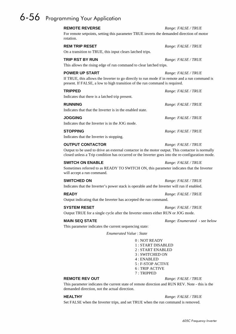
9089##3URJUDPPLQJ#<RXU#$SSOLFDWLRQ
938&#)UHTXHQF\#,QYHUWHU
REMOTE REVERSE Range: FALSE / TRUE
For remote setpoints, setting this parameter TRUE inverts the demanded direction of motorrotation.
REM TRIP RESET Range: FALSE / TRUE
On a transition to TRUE, this input clears latched trips.
TRIP RST BY RUN Range: FALSE / TRUE
This allows the rising edge of run command to clear latched trips.
POWER UP START Range: FALSE / TRUE
If TRUE, this allows the Inverter to go directly to run mode if in remote and a run command ispresent. If FALSE, a low to high transition of the run command is required.
TRIPPED Range: FALSE / TRUE
Indicates that there is a latched trip present.
RUNNING Range: FALSE / TRUE
Indicates that that the Inverter is in the enabled state.
JOGGING Range: FALSE / TRUE
Indicates that the Inverter is in the JOG mode.
STOPPING Range: FALSE / TRUE
Indicates that the Inverter is stopping.
OUTPUT CONTACTOR Range: FALSE / TRUE
Output to be used to drive an external contactor in the motor output. This contactor is normallyclosed unless a Trip condition has occurred or the Inverter goes into the re-configuration mode.
SWITCH ON ENABLE Range: FALSE / TRUE
Sometimes referred to as READY TO SWITCH ON, this parameter indicates that the Inverterwill accept a run command.
SWITCHED ON Range: FALSE / TRUE
Indicates that the Inverter’s power stack is operable and the Inverter will run if enabled.
READY Range: FALSE / TRUE
Output indicating that the Inverter has accepted the run command.
SYSTEM RESET Range: FALSE / TRUE
Output TRUE for a single cycle after the Inverter enters either RUN or JOG mode.
MAIN SEQ STATE Range: Enumerated - see below
This parameter indicates the current sequencing state:
Enumerated Value : State
0 : NOT READY1 : START DISABLED2 : START ENABLED3 : SWITCHED ON4 : ENABLED5 : F-STOP ACTIVE6 : TRIP ACTIVE7 : TRIPPED
REMOTE REV OUT Range: FALSE / TRUE
This parameter indicates the current state of remote direction and RUN REV. Note - this is thedemanded direction, not the actual direction.
HEALTHY Range: FALSE / TRUE
Set FALSE when the Inverter trips, and set TRUE when the run command is removed.
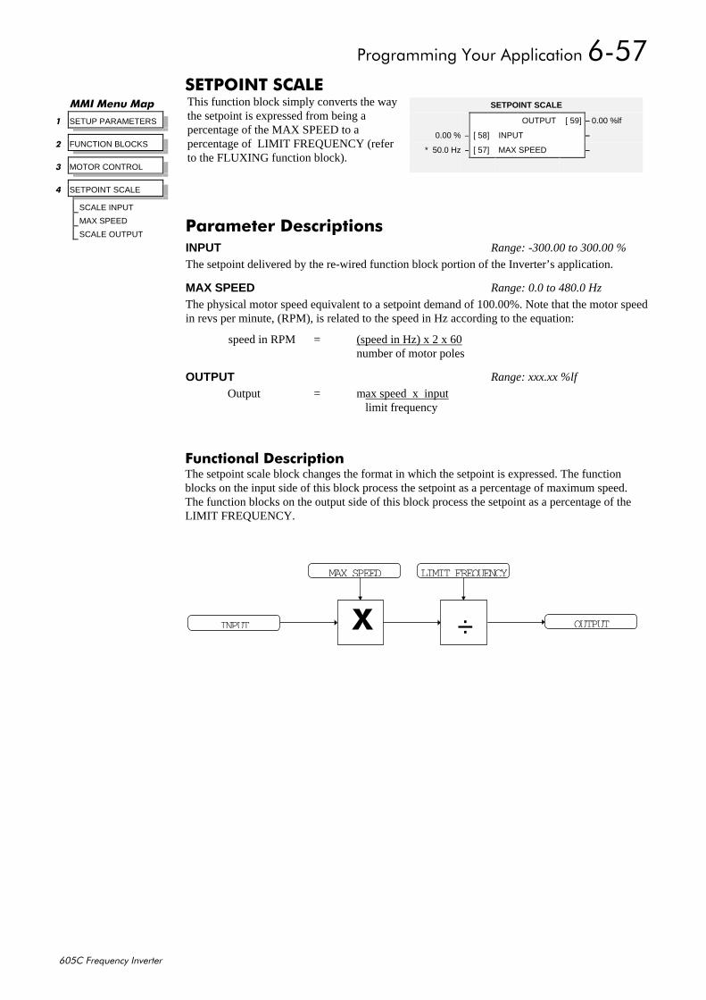
3URJUDPPLQJ#<RXU#$SSOLFDWLRQ#908:
938&#)UHTXHQF\#,QYHUWHU
6(732,17#6&$/(This function block simply converts the waythe setpoint is expressed from being apercentage of the MAX SPEED to apercentage of LIMIT FREQUENCY (referto the FLUXING function block).
)XQFWLRQDO#'HVFULSWLRQThe setpoint scale block changes the format in which the setpoint is expressed. The functionblocks on the input side of this block process the setpoint as a percentage of maximum speed.The function blocks on the output side of this block process the setpoint as a percentage of theLIMIT FREQUENCY.
00,#0HQX#0DS
4 SETUP PARAMETERS
5 FUNCTION BLOCKS
6 MOTOR CONTROL
7 SETPOINT SCALE
SCALE INPUT
MAX SPEED
SCALE OUTPUT
SETPOINT SCALE
OUTPUT [ 59] – 0.00 %lf
0.00 % – [ 58] INPUT –
* 50.0 Hz – [ 57] MAX SPEED –
3DUDPHWHU#'HVFULSWLRQVINPUT Range: -300.00 to 300.00 %
The setpoint delivered by the re-wired function block portion of the Inverter’s application.
MAX SPEED Range: 0.0 to 480.0 Hz
The physical motor speed equivalent to a setpoint demand of 100.00%. Note that the motor speedin revs per minute, (RPM), is related to the speed in Hz according to the equation:
speed in RPM = (speed in Hz) x 2 x 60number of motor poles
OUTPUT Range: xxx.xx %lf
Output = max speed x input limit frequency
÷
LIMIT FREQUENCY
;
MAX SPEED
INPUT OUTPUT
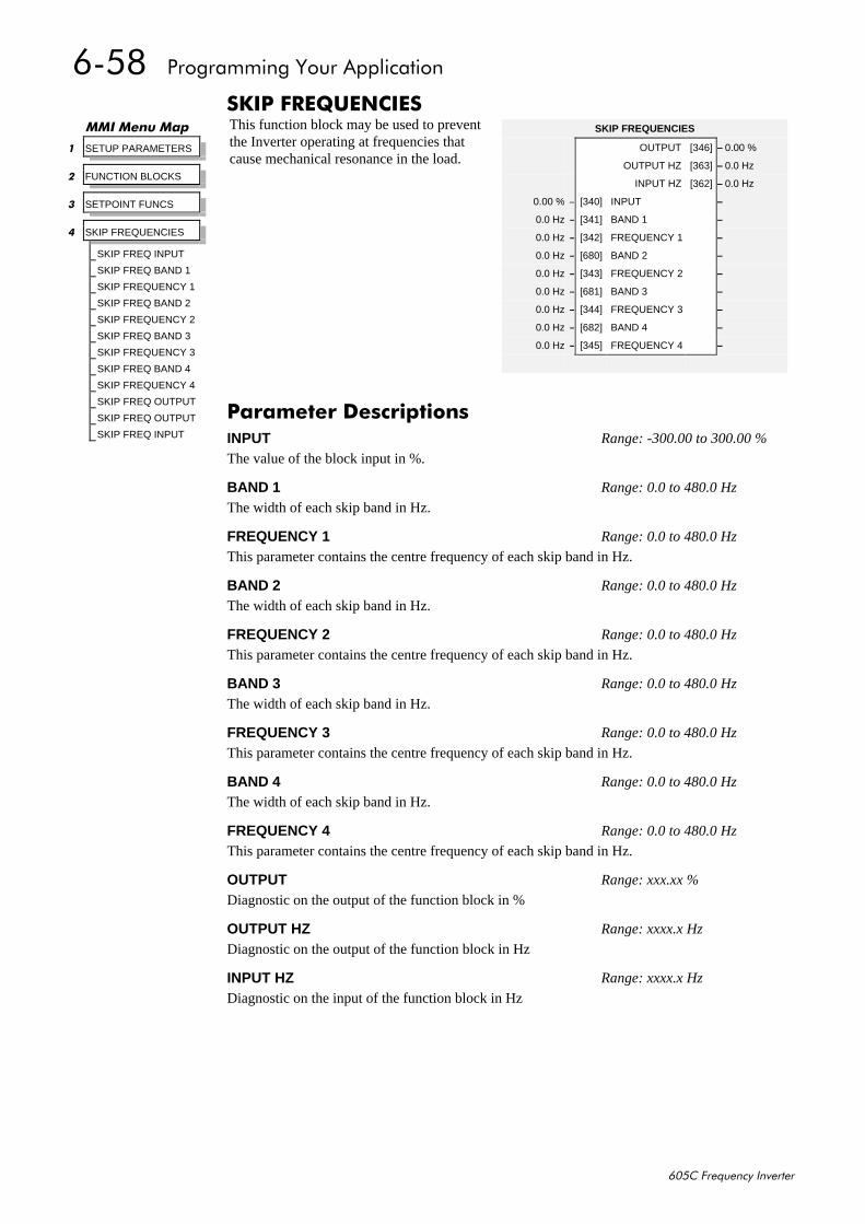
908;##3URJUDPPLQJ#<RXU#$SSOLFDWLRQ
938&#)UHTXHQF\#,QYHUWHU
6.,3#)5(48(1&,(6This function block may be used to preventthe Inverter operating at frequencies thatcause mechanical resonance in the load.
00,#0HQX#0DS
4 SETUP PARAMETERS
5 FUNCTION BLOCKS
6 SETPOINT FUNCS
7 SKIP FREQUENCIES
SKIP FREQ INPUT
SKIP FREQ BAND 1
SKIP FREQUENCY 1
SKIP FREQ BAND 2
SKIP FREQUENCY 2
SKIP FREQ BAND 3
SKIP FREQUENCY 3
SKIP FREQ BAND 4
SKIP FREQUENCY 4
SKIP FREQ OUTPUT
SKIP FREQ OUTPUT
SKIP FREQ INPUT
SKIP FREQUENCIES
OUTPUT [346] – 0.00 %
OUTPUT HZ [363] – 0.0 Hz
INPUT HZ [362] – 0.0 Hz
0.00 % – [340] INPUT –
0.0 Hz – [341] BAND 1 –
0.0 Hz – [342] FREQUENCY 1 –
0.0 Hz – [680] BAND 2 –
0.0 Hz – [343] FREQUENCY 2 –
0.0 Hz – [681] BAND 3 –
0.0 Hz – [344] FREQUENCY 3 –
0.0 Hz – [682] BAND 4 –
0.0 Hz – [345] FREQUENCY 4 –
3DUDPHWHU#'HVFULSWLRQVINPUT Range: -300.00 to 300.00 %
The value of the block input in %.
BAND 1 Range: 0.0 to 480.0 Hz
The width of each skip band in Hz.
FREQUENCY 1 Range: 0.0 to 480.0 Hz
This parameter contains the centre frequency of each skip band in Hz.
BAND 2 Range: 0.0 to 480.0 Hz
The width of each skip band in Hz.
FREQUENCY 2 Range: 0.0 to 480.0 Hz
This parameter contains the centre frequency of each skip band in Hz.
BAND 3 Range: 0.0 to 480.0 Hz
The width of each skip band in Hz.
FREQUENCY 3 Range: 0.0 to 480.0 Hz
This parameter contains the centre frequency of each skip band in Hz.
BAND 4 Range: 0.0 to 480.0 Hz
The width of each skip band in Hz.
FREQUENCY 4 Range: 0.0 to 480.0 Hz
This parameter contains the centre frequency of each skip band in Hz.
OUTPUT Range: xxx.xx %
Diagnostic on the output of the function block in %
OUTPUT HZ Range: xxxx.x Hz
Diagnostic on the output of the function block in Hz
INPUT HZ Range: xxxx.x Hz
Diagnostic on the input of the function block in Hz
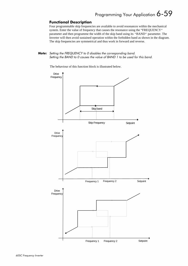
3URJUDPPLQJ#<RXU#$SSOLFDWLRQ#908<
938&#)UHTXHQF\#,QYHUWHU
)XQFWLRQDO#'HVFULSWLRQFour programmable skip frequencies are available to avoid resonances within the mechanicalsystem. Enter the value of frequency that causes the resonance using the “FREQUENCY”parameter and then programme the width of the skip band using its “ BAND” parameter. TheInverter will then avoid sustained operation within the forbidden band as shown in the diagram.The skip frequencies are symmetrical and thus work in forward and reverse.
1RWH=# 6HWWLQJ#WKH#)5(48(1&<#WR#3#GLVDEOHV#WKH#FRUUHVSRQGLQJ#EDQG16HWWLQJ#WKH#%$1'#WR#3#FDXVHV#WKH#YDOXH#RI#%$1'#4#WR#EH#XVHG#IRU#WKLV#EDQG1
The behaviour of this function block is illustrated below.
Setpoint
DriveFrequency
Frequency 1 Frequency 2
Skip band
Skip Frequency Setpoint
DriveFrequency
Setpoint
DriveFrequency
Frequency 1 Frequency 2
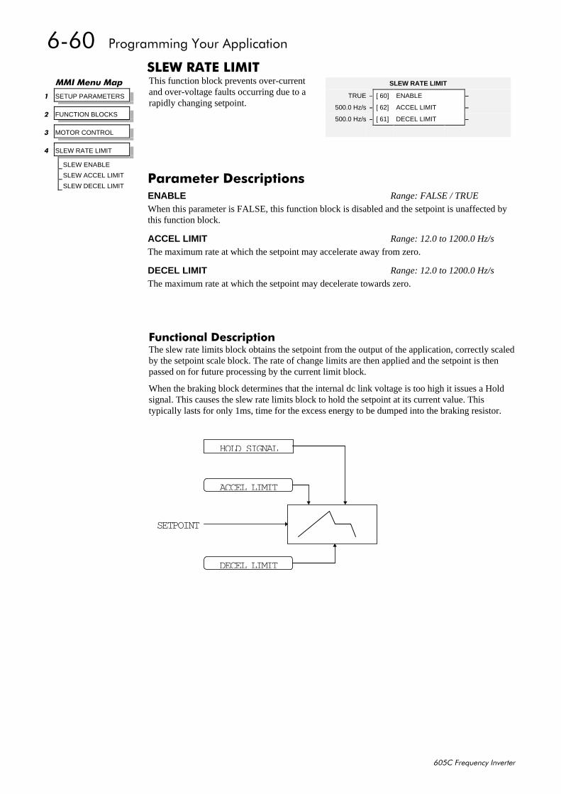
9093##3URJUDPPLQJ#<RXU#$SSOLFDWLRQ
938&#)UHTXHQF\#,QYHUWHU
6/(:#5$7(#/,0,7This function block prevents over-currentand over-voltage faults occurring due to arapidly changing setpoint.
)XQFWLRQDO#'HVFULSWLRQThe slew rate limits block obtains the setpoint from the output of the application, correctly scaledby the setpoint scale block. The rate of change limits are then applied and the setpoint is thenpassed on for future processing by the current limit block.
When the braking block determines that the internal dc link voltage is too high it issues a Holdsignal. This causes the slew rate limits block to hold the setpoint at its current value. Thistypically lasts for only 1ms, time for the excess energy to be dumped into the braking resistor.
00,#0HQX#0DS
4 SETUP PARAMETERS
5 FUNCTION BLOCKS
6 MOTOR CONTROL
7 SLEW RATE LIMIT
SLEW ENABLE
SLEW ACCEL LIMIT
SLEW DECEL LIMIT
SLEW RATE LIMIT
TRUE – [ 60] ENABLE –
500.0 Hz/s – [ 62] ACCEL LIMIT –
500.0 Hz/s – [ 61] DECEL LIMIT –
3DUDPHWHU#'HVFULSWLRQVENABLE Range: FALSE / TRUE
When this parameter is FALSE, this function block is disabled and the setpoint is unaffected bythis function block.
ACCEL LIMIT Range: 12.0 to 1200.0 Hz/s
The maximum rate at which the setpoint may accelerate away from zero.
DECEL LIMIT Range: 12.0 to 1200.0 Hz/s
The maximum rate at which the setpoint may decelerate towards zero.
SETPOINT
DECEL LIMIT
ACCEL LIMIT
HOLD SIGNAL
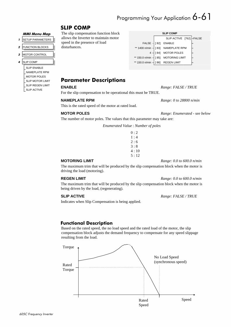
3URJUDPPLQJ#<RXU#$SSOLFDWLRQ#9094
938&#)UHTXHQF\#,QYHUWHU
6/,3#&203The slip compensation function blockallows the Inverter to maintain motorspeed in the presence of loaddisturbances.
)XQFWLRQDO#'HVFULSWLRQBased on the rated speed, the no load speed and the rated load of the motor, the slipcompensation block adjusts the demand frequency to compensate for any speed slippageresulting from the load.
00,#0HQX#0DS
4 SETUP PARAMETERS
5 FUNCTION BLOCKS
6 MOTOR CONTROL
7 SLIP COMP
SLIP ENABLE
NAMEPLATE RPM
MOTOR POLES
SLIP MOTOR LIMIT
SLIP REGEN LIMIT
SLIP ACTIVE
SLIP COMP
SLIP ACTIVE [762] –FALSE
FALSE – [ 82] ENABLE –
** 1400 n/min – [ 83] NAMEPLATE RPM –
4 – [ 84] MOTOR POLES –
** 150.0 n/min – [ 85] MOTORING LIMIT –
** 150.0 n/min – [ 86] REGEN LIMIT –
3DUDPHWHU#'HVFULSWLRQVENABLE Range: FALSE / TRUE
For the slip compensation to be operational this must be TRUE.
NAMEPLATE RPM Range: 0 to 28800 n/min
This is the rated speed of the motor at rated load.
MOTOR POLES Range: Enumerated - see below
The number of motor poles. The values that this parameter may take are:
Enumerated Value : Number of poles
0 : 21 : 42 : 63 : 84 : 105 : 12
MOTORING LIMIT Range: 0.0 to 600.0 n/min
The maximum trim that will be produced by the slip compensation block when the motor isdriving the load (motoring).
REGEN LIMIT Range: 0.0 to 600.0 n/min
The maximum trim that will be produced by the slip compensation block when the motor isbeing driven by the load, (regenerating).
SLIP ACTIVE Range: FALSE / TRUE
Indicates when Slip Compensation is being applied.
SpeedRatedSpeed
No Load Speed(synchronous speed)
RatedTorque
Torque
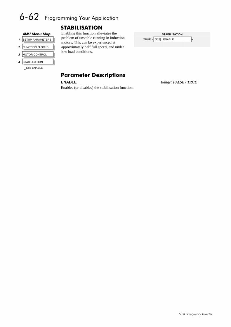
9095##3URJUDPPLQJ#<RXU#$SSOLFDWLRQ
938&#)UHTXHQF\#,QYHUWHU
67$%,/,6$7,21Enabling this function alleviates theproblem of unstable running in inductionmotors. This can be experienced atapproximately half full speed, and underlow load conditions.
00,#0HQX#0DS
4 SETUP PARAMETERS
5 FUNCTION BLOCKS
6 MOTOR CONTROL
7 STABILISATION
STB ENABLE
STABILISATION
TRUE – [128] ENABLE –
3DUDPHWHU#'HVFULSWLRQVENABLE Range: FALSE / TRUE
Enables (or disables) the stabilisation function.
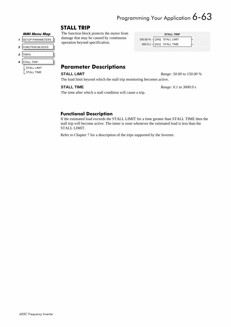
3URJUDPPLQJ#<RXU#$SSOLFDWLRQ#9096
938&#)UHTXHQF\#,QYHUWHU
67$//#75,3The function block protects the motor fromdamage that may be caused by continuousoperation beyond specification.
)XQFWLRQDO#'HVFULSWLRQIf the estimated load exceeds the STALL LIMIT for a time greater than STALL TIME then thestall trip will become active. The timer is reset whenever the estimated load is less than theSTALL LIMIT.
Refer to Chapter 7 for a description of the trips supported by the Inverter.
00,#0HQX#0DS
4 SETUP PARAMETERS
5 FUNCTION BLOCKS
6 TRIPS
7 STALL TRIP
STALL LIMIT
STALL TIME
STALL TRIP
100.00 % – [240] STALL LIMIT –
600.0 s – [241] STALL TIME –
3DUDPHWHU#'HVFULSWLRQVSTALL LIMIT Range: 50.00 to 150.00 %
The load limit beyond which the stall trip monitoring becomes active.
STALL TIME Range: 0.1 to 3000.0 s
The time after which a stall condition will cause a trip.
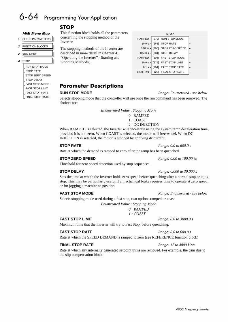
9097##3URJUDPPLQJ#<RXU#$SSOLFDWLRQ
938&#)UHTXHQF\#,QYHUWHU
6723This function block holds all the parametersconcerning the stopping method of theInverter.
The stopping methods of the Inverter aredescribed in more detail in Chapter 4:“Operating the Inverter” - Starting andStopping Methods..
00,#0HQX#0DS
4 SETUP PARAMETERS
5 FUNCTION BLOCKS
6 SEQ & REF
7 STOP
RUN STOP MODE
STOP RATE
STOP ZERO SPEED
STOP DELAY
FAST STOP MODE
FAST STOP LIMIT
FAST STOP RATE
FINAL STOP RATE
STOP
RAMPED – [279] RUN STOP MODE –
10.0 s – [263] STOP RATE –
0.10 % – [266] STOP ZERO SPEED –
0.500 s – [284] STOP DELAY –
RAMPED – [304] FAST STOP MODE –
30.0 s – [275] FAST STOP LIMIT –
0.1 s – [264] FAST STOP RATE –
1200 Hz/s – [126] FINAL STOP RATE –
3DUDPHWHU#'HVFULSWLRQVRUN STOP MODE Range: Enumerated - see below
Selects stopping mode that the controller will use once the run command has been removed. Thechoices are:
Enumerated Value : Stopping Mode
0 : RAMPED1 : COAST2 : DC INJECTION
When RAMPED is selected, the Inverter will decelerate using the system ramp deceleration time,provided it is non zero. When COAST is selected, the motor will free-wheel. When DCINJECTION is selected, the motor is stopped by applying dc current.
STOP RATE Range: 0.0 to 600.0 s
Rate at which the demand is ramped to zero after the ramp has been quenched.
STOP ZERO SPEED Range: 0.00 to 100.00 %
Threshold for zero speed detection used by stop sequences.
STOP DELAY Range: 0.000 to 30.000 s
Sets the time at which the Inverter holds zero speed before quenching after a normal stop or a jogstop. This may be particularly useful if a mechanical brake requires time to operate at zero speed,or for jogging a machine to position.
FAST STOP MODE Range: Enumerated - see below
Selects stopping mode used during a fast stop, two options ramped or coast.Enumerated Value : Stopping Mode
0 : RAMPED1 : COAST
FAST STOP LIMIT Range: 0.0 to 3000.0 s
Maximum time that the Inverter will try to Fast Stop, before quenching.
FAST STOP RATE Range: 0.0 to 600.0 s
Rate at which the SPEED DEMAND is ramped to zero (see REFERENCE function block)
FINAL STOP RATE Range: 12 to 4800 Hz/s
Rate at which any internally generated setpoint trims are removed. For example, the trim due tothe slip compensation block.
3URJUDPPLQJ#<RXU#$SSOLFDWLRQ#9098
938&#)UHTXHQF\#,QYHUWHU
6<67(0#3257#+36,The unisolated RS232 programming portallows for connection to the OperatorStation, or to a personal computer for driveconfiguration and storage of parameters.The parameters below are used to identifythe Inverter to the controlling software.
The port uses the Eurotherm standard EI BISYNCH ASCII protocol.
)XQFWLRQDO#'HVFULSWLRQThe unit will always respond to GID = 0 and UID = 0, as this is the “broadcast” address used bythe Operator Station.
1RWH=# 7KH#7HFKQRORJ\#2SWLRQ#XVHV#D#GLIIHUHQW#SRUW#DQG#DGGUHVV1#,W#GRHV#QRW#UHVSRQG#WR#WKH´EURDGFDVWµ#DGGUHVV1
SYSTEM PORT (P3)
0 – [102] GROUP ID (GID) –
0 – [103] UNIT ID (UID) –
00,#0HQX#0DS
4 SETUP PARAMETERS
5 FUNCTION BLOCKS
6 SERIAL LINKS
7 SYSTEM PORT (P3)
GROUP ID (GID)
UNIT ID (UID) 3DUDPHWHU#'HVFULSWLRQVGROUP ID (GID) Range: 0 to 9
The Eurotherm protocol group identity address.
UNIT ID (UID) Range: 0 to 15
The Eurotherm protocol unit identity address
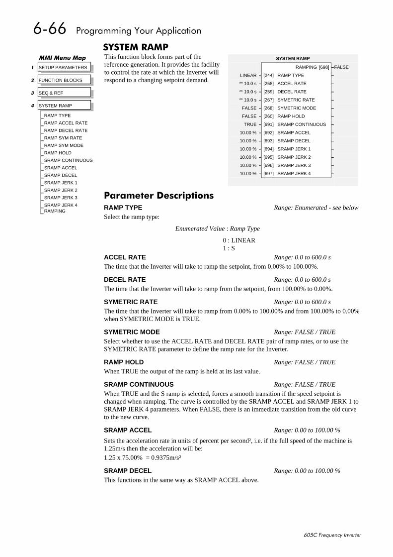
9099##3URJUDPPLQJ#<RXU#$SSOLFDWLRQ
938&#)UHTXHQF\#,QYHUWHU
6<67(0#5$03This function block forms part of thereference generation. It provides the facilityto control the rate at which the Inverter willrespond to a changing setpoint demand.
00,#0HQX#0DS
4 SETUP PARAMETERS
5 FUNCTION BLOCKS
6 SEQ & REF
7 SYSTEM RAMP
RAMP TYPE
RAMP ACCEL RATE
RAMP DECEL RATE
RAMP SYM RATE
RAMP SYM MODE
RAMP HOLD
SRAMP CONTINUOUS
SRAMP ACCEL
SRAMP DECEL
SRAMP JERK 1
SRAMP JERK 2
SRAMP JERK 3
SRAMP JERK 4RAMPING
SYSTEM RAMP
RAMPING [698] –FALSE
LINEAR – [244] RAMP TYPE –
** 10.0 s – [258] ACCEL RATE –
** 10.0 s – [259] DECEL RATE –
** 10.0 s – [267] SYMETRIC RATE –
FALSE – [268] SYMETRIC MODE –
FALSE – [260] RAMP HOLD –
TRUE – [691] SRAMP CONTINUOUS –
10.00 % – [692] SRAMP ACCEL –
10.00 % – [693] SRAMP DECEL –
10.00 % – [694] SRAMP JERK 1 –
10.00 % – [695] SRAMP JERK 2 –
10.00 % – [696] SRAMP JERK 3 –
10.00 % – [697] SRAMP JERK 4 –
3DUDPHWHU#'HVFULSWLRQVRAMP TYPE Range: Enumerated - see below
Select the ramp type:
Enumerated Value : Ramp Type
0 : LINEAR1 : S
ACCEL RATE Range: 0.0 to 600.0 s
The time that the Inverter will take to ramp the setpoint, from 0.00% to 100.00%.
DECEL RATE Range: 0.0 to 600.0 s
The time that the Inverter will take to ramp from the setpoint, from 100.00% to 0.00%.
SYMETRIC RATE Range: 0.0 to 600.0 s
The time that the Inverter will take to ramp from 0.00% to 100.00% and from 100.00% to 0.00%when SYMETRIC MODE is TRUE.
SYMETRIC MODE Range: FALSE / TRUE
Select whether to use the ACCEL RATE and DECEL RATE pair of ramp rates, or to use theSYMETRIC RATE parameter to define the ramp rate for the Inverter.
RAMP HOLD Range: FALSE / TRUE
When TRUE the output of the ramp is held at its last value.
SRAMP CONTINUOUS Range: FALSE / TRUE
When TRUE and the S ramp is selected, forces a smooth transition if the speed setpoint ischanged when ramping. The curve is controlled by the SRAMP ACCEL and SRAMP JERK 1 toSRAMP JERK 4 parameters. When FALSE, there is an immediate transition from the old curveto the new curve.
SRAMP ACCEL Range: 0.00 to 100.00 %
Sets the acceleration rate in units of percent per second², i.e. if the full speed of the machine is1.25m/s then the acceleration will be:1.25 x 75.00% = 0.9375m/s²
SRAMP DECEL Range: 0.00 to 100.00 %
This functions in the same way as SRAMP ACCEL above.
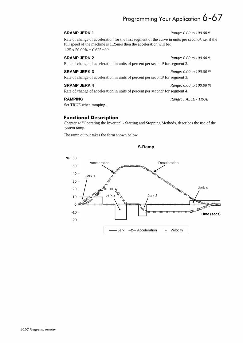
3URJUDPPLQJ#<RXU#$SSOLFDWLRQ#909:
938&#)UHTXHQF\#,QYHUWHU
)XQFWLRQDO#'HVFULSWLRQChapter 4: “Operating the Inverter” - Starting and Stopping Methods, describes the use of thesystem ramp.
The ramp output takes the form shown below.
S-Ramp
-20
-10
0
10
20
30
40
50
60
Time (secs)
%
Jerk Acceleration Velocity
Jerk 3
Jerk 4
Jerk 2
Jerk 1
Acceleration Deceleration
SRAMP JERK 1 Range: 0.00 to 100.00 %
Rate of change of acceleration for the first segment of the curve in units per second³, i.e. if thefull speed of the machine is 1.25m/s then the acceleration will be:1.25 x 50.00% = 0.625m/s³
SRAMP JERK 2 Range: 0.00 to 100.00 %
Rate of change of acceleration in units of percent per second³ for segment 2.
SRAMP JERK 3 Range: 0.00 to 100.00 %
Rate of change of acceleration in units of percent per second³ for segment 3.
SRAMP JERK 4 Range: 0.00 to 100.00 %
Rate of change of acceleration in units of percent per second³ for segment 4.
RAMPING Range: FALSE / TRUE
Set TRUE when ramping.
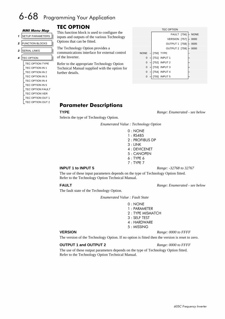
909;##3URJUDPPLQJ#<RXU#$SSOLFDWLRQ
938&#)UHTXHQF\#,QYHUWHU
7(í,21This function block is used to configure theinputs and outputs of the various TechnologyOptions that can be fitted.
The Technology Option provides acommunications interface for external controlof the Inverter.
Refer to the appropriate Technology OptionTechnical Manual supplied with the option forfurther details.
00,#0HQX#0DS
4 SETUP PARAMETERS
5 FUNCTION BLOCKS
6 SERIAL LINKS
7 TEC OPTION
TEC OPTION TYPE
TEC OPTION IN 1
TEC OPTION IN 2
TEC OPTION IN 3
TEC OPTION IN 4
TEC OPTION IN 5
TEC OPTION FAULT
TEC OPTION VER
TEC OPTION OUT 1
TEC OPTION OUT 2
TEC OPTION
FAULT [756] – NONE
VERSION [757] – 0000
OUTPUT 1 [758] – 0000
OUTPUT 2 [759] – 0000
NONE – [750] TYPE –
0 – [751] INPUT 1 –
0 – [752] INPUT 2 –
0 – [753] INPUT 3 –
0 – [754] INPUT 4 –
0 – [755] INPUT 5 –
3DUDPHWHU#'HVFULSWLRQVTYPE Range: Enumerated - see below
Selects the type of Technology Option.
Enumerated Value : Technology Option
3#=#121(4#=#567;85#=#352),%86#'36#=#/,1.7#=#'(9,&(1(78#=#&$123(19#=#7<3(#9:#=#7<3(#:
INPUT 1 to INPUT 5 Range: -32768 to 32767
The use of these input parameters depends on the type of Technology Option fitted.Refer to the Technology Option Technical Manual.
FAULT Range: Enumerated - see below
The fault state of the Technology Option.
Enumerated Value : Fault State
3#=#121(4#=#3$5$0(7(55#=#7<3(#0,60$7&+6#=#6(/)#7(677#=#+$5':$5(8#=#0,66,1*
VERSION Range: 0000 to FFFF
The version of the Technology Option. If no option is fitted then the version is reset to zero.
OUTPUT 1 and OUTPUT 2 Range: 0000 to FFFF
The use of these output parameters depends on the type of Technology Option fitted.Refer to the Technology Option Technical Manual.
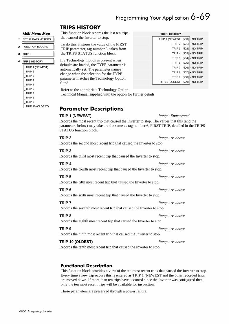
3URJUDPPLQJ#<RXU#$SSOLFDWLRQ#909<
938&#)UHTXHQF\#,QYHUWHU
75,36#+,6725<This function block records the last ten tripsthat caused the Inverter to stop.
To do this, it stores the value of the FIRSTTRIP parameter, tag number 6, taken fromthe TRIPS STATUS function block.
If a Technology Option is present whendefaults are loaded, the TYPE parameter isautomatically set. The parameter nameschange when the selection for the TYPEparameter matches the Technology Optionfitted.
Refer to the appropriate Technology OptionTechnical Manual supplied with the option for further details.
)XQFWLRQDO#'HVFULSWLRQThis function block provides a view of the ten most recent trips that caused the Inverter to stop.Every time a new trip occurs this is entered as TRIP 1 (NEWEST and the other recorded tripsare moved down. If more than ten trips have occurred since the Inverter was configured thenonly the ten most recent trips will be available for inspection.
These parameters are preserved through a power failure.
00,#0HQX#0DS
4 SETUP PARAMETERS
5 FUNCTION BLOCKS
6 TRIPS
7 TRIPS HISTORY
TRIP 1 (NEWEST)
TRIP 2
TRIP 3
TRIP 4
TRIP 5
TRIP 6
TRIP 7
TRIP 8
TRIP 9
TRIP 10 (OLDEST)
TRIPS HISTORY
TRIP 1 (NEWEST [500] – NO TRIP
TRIP 2 [501] – NO TRIP
TRIP 3 [502] – NO TRIP
TRIP 4 [503] – NO TRIP
TRIP 5 [504] – NO TRIP
TRIP 6 [505] – NO TRIP
TRIP 7 [506] – NO TRIP
TRIP 8 [507] – NO TRIP
TRIP 9 [508] – NO TRIP
TRIP 10 (OLDEST [509] – NO TRIP
3DUDPHWHU#'HVFULSWLRQVTRIP 1 (NEWEST) Range: Enumerated
Records the most recent trip that caused the Inverter to stop. The values that this (and theparameters below) may take are the same as tag number 6, FIRST TRIP, detailed in the TRIPSSTATUS function block.
TRIP 2 Range: As above
Records the second most recent trip that caused the Inverter to stop.
TRIP 3 Range: As above
Records the third most recent trip that caused the Inverter to stop.
TRIP 4 Range: As above
Records the fourth most recent trip that caused the Inverter to stop.
TRIP 5 Range: As above
Records the fifth most recent trip that caused the Inverter to stop.
TRIP 6 Range: As above
Records the sixth most recent trip that caused the Inverter to stop.
TRIP 7 Range: As above
Records the seventh most recent trip that caused the Inverter to stop.
TRIP 8 Range: As above
Records the eighth most recent trip that caused the Inverter to stop.
TRIP 9 Range: As above
Records the ninth most recent trip that caused the Inverter to stop.
TRIP 10 (OLDEST) Range: As above
Records the tenth most recent trip that caused the Inverter to stop.
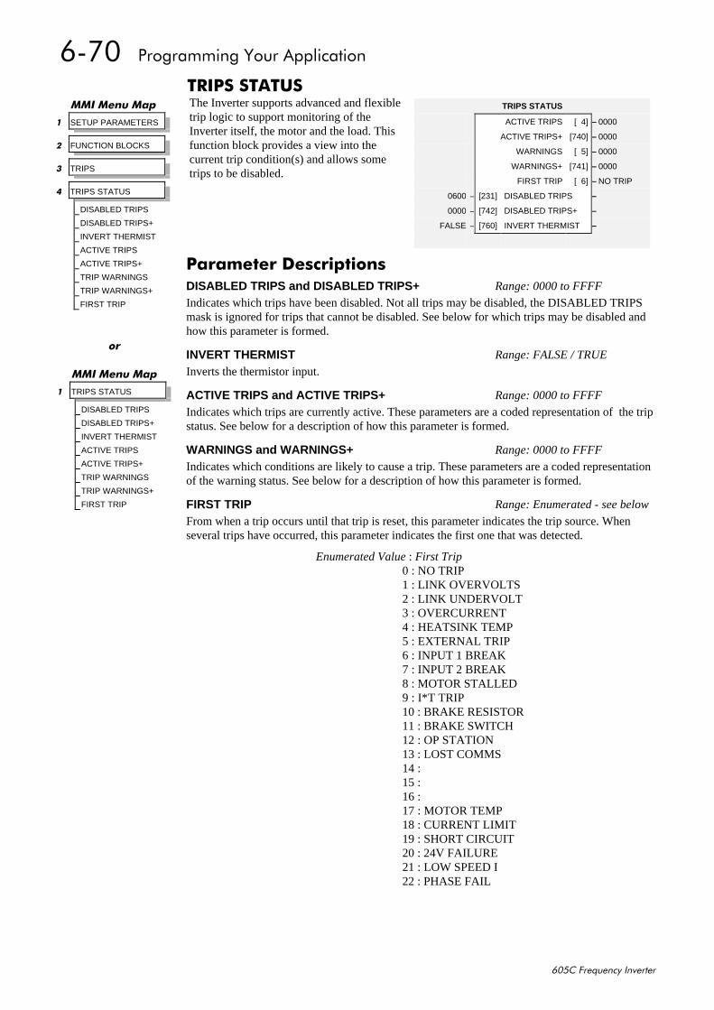
90:3##3URJUDPPLQJ#<RXU#$SSOLFDWLRQ
938&#)UHTXHQF\#,QYHUWHU
75,36#67$786The Inverter supports advanced and flexibletrip logic to support monitoring of theInverter itself, the motor and the load. Thisfunction block provides a view into thecurrent trip condition(s) and allows sometrips to be disabled.
00,#0HQX#0DS
4 SETUP PARAMETERS
5 FUNCTION BLOCKS
6 TRIPS
7 TRIPS STATUS
DISABLED TRIPS
DISABLED TRIPS+
INVERT THERMIST
ACTIVE TRIPS
ACTIVE TRIPS+
TRIP WARNINGS
TRIP WARNINGS+
FIRST TRIP
TRIPS STATUS
ACTIVE TRIPS [ 4] – 0000
ACTIVE TRIPS+ [740] – 0000
WARNINGS [ 5] – 0000
WARNINGS+ [741] – 0000
FIRST TRIP [ 6] – NO TRIP
0600 – [231] DISABLED TRIPS –
0000 – [742] DISABLED TRIPS+ –
FALSE – [760] INVERT THERMIST –
3DUDPHWHU#'HVFULSWLRQVDISABLED TRIPS and DISABLED TRIPS+ Range: 0000 to FFFF
Indicates which trips have been disabled. Not all trips may be disabled, the DISABLED TRIPSmask is ignored for trips that cannot be disabled. See below for which trips may be disabled andhow this parameter is formed.
INVERT THERMIST Range: FALSE / TRUE
Inverts the thermistor input.
ACTIVE TRIPS and ACTIVE TRIPS+ Range: 0000 to FFFF
Indicates which trips are currently active. These parameters are a coded representation of the tripstatus. See below for a description of how this parameter is formed.
WARNINGS and WARNINGS+ Range: 0000 to FFFF
Indicates which conditions are likely to cause a trip. These parameters are a coded representationof the warning status. See below for a description of how this parameter is formed.
FIRST TRIP Range: Enumerated - see below
From when a trip occurs until that trip is reset, this parameter indicates the trip source. Whenseveral trips have occurred, this parameter indicates the first one that was detected.
Enumerated Value : First Trip0 : NO TRIP1 : LINK OVERVOLTS2 : LINK UNDERVOLT3 : OVERCURRENT4 : HEATSINK TEMP5 : EXTERNAL TRIP6 : INPUT 1 BREAK7 : INPUT 2 BREAK8 : MOTOR STALLED9 : I*T TRIP10 : BRAKE RESISTOR11 : BRAKE SWITCH12 : OP STATION13 : LOST COMMS14 :15 :16 :17 : MOTOR TEMP18 : CURRENT LIMIT19 : SHORT CIRCUIT20 : 24V FAILURE21 : LOW SPEED I22 : PHASE FAIL
RU
00,#0HQX#0DS
4 TRIPS STATUS
DISABLED TRIPS
DISABLED TRIPS+
INVERT THERMIST
ACTIVE TRIPS
ACTIVE TRIPS+
TRIP WARNINGS
TRIP WARNINGS+
FIRST TRIP
3URJUDPPLQJ#<RXU#$SSOLFDWLRQ#90:4
938&#)UHTXHQF\#,QYHUWHU
)XQFWLRQDO#'HVFULSWLRQThe table below shows the possible parameter values for FIRST TRIP, and the TRIPS HISTORYfunction block. Also shown is whether or not the trip may be disabled.
7ULS#QDPH7ULS#QDPH7ULS#QDPH7ULS#QDPH (QXPHUDWHG#YDOXH(QXPHUDWHG#YDOXH(QXPHUDWHG#YDOXH(QXPHUDWHG#YDOXH 0D\#EH#'LVDEOHG0D\#EH#'LVDEOHG0D\#EH#'LVDEOHG0D\#EH#'LVDEOHG
12#75,3 #3 12$
/,1.#29(592/76 #4 1R
/,1.#81'(592/7 #5 1R
29(5&855(17 #6 1R
+($76,1.#7(03 #7 1R
(;7(51$/#75,3 #8 <HV
,1387#4#%5($. #9 <HV
,1387#5#%5($. #: <HV
02725#67$//(' #; <HV
,-7#75,3 #< 1R
%5$.(#5(6,6725 43 <HV
%5$.(#6:,7&+ 44 <HV
23#67$7,21 45 <HV
/267#&2006 46 <HV
47
48
49
02725#7(03 4: <HV
&855(17#/,0,7 4; 1R
6+257#&,5&8,7 4< 1R
579#)$,/85( 53 <HV
/2:#63(('#, 54 1R
3+$6(#)$,/ 55 <HV
+H[DGHFLPDO#5HSUHVHQWDWLRQ#RI#7ULSV
The ACTIVE TRIPS, WARNINGS and DISABLED TRIPS parameters use a four digithexadecimal number to identify individual trips. Each trip has a unique corresponding number.Refer to “Hexadecimal Representation of Trips” at the beginning of this Chapter.
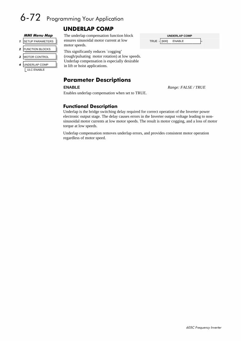
90:5##3URJUDPPLQJ#<RXU#$SSOLFDWLRQ
938&#)UHTXHQF\#,QYHUWHU
81'(5/$3#&203The underlap compensation function blockensures sinusoidal motor current at lowmotor speeds.
This significantly reduces `cogging’(rough/pulsating motor rotation) at low speeds.Underlap compensation is especially desirablein lift or hoist applications.
)XQFWLRQDO#'HVFULSWLRQUnderlap is the bridge switching delay required for correct operation of the Inverter powerelectronic output stage. The delay causes errors in the Inverter output voltage leading to non-sinusoidal motor currents at low motor speeds. The result is motor cogging, and a loss of motortorque at low speeds.
Underlap compensation removes underlap errors, and provides consistent motor operationregardless of motor speed.
00,#0HQX#0DS
4 SETUP PARAMETERS
5 FUNCTION BLOCKS
6 MOTOR CONTROL
7 UNDERLAP COMP
ULC ENABLE
UNDERLAP COMP
TRUE – [600] ENABLE –
3DUDPHWHU#'HVFULSWLRQVENABLE Range: FALSE / TRUE
Enables underlap compensation when set to TRUE.
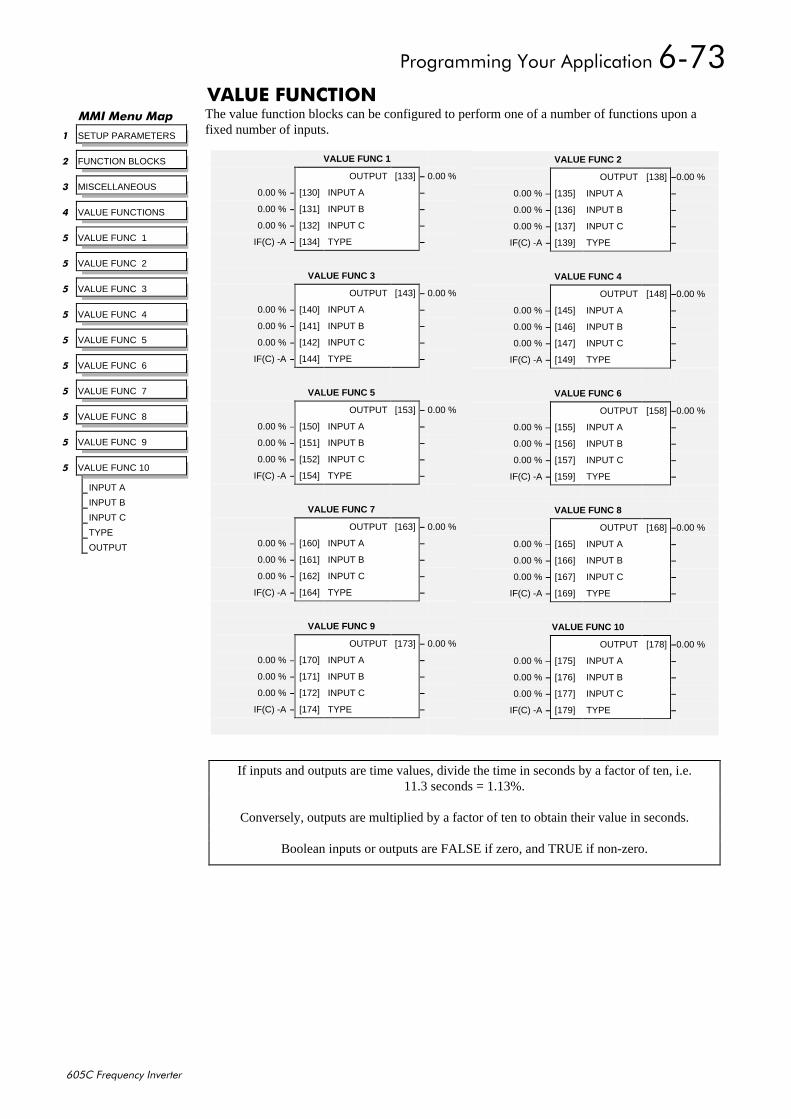
3URJUDPPLQJ#<RXU#$SSOLFDWLRQ#90:6
938&#)UHTXHQF\#,QYHUWHU
9$/8(#)81&7,21The value function blocks can be configured to perform one of a number of functions upon afixed number of inputs.
00,#0HQX#0DS
4 SETUP PARAMETERS
5 FUNCTION BLOCKS
6 MISCELLANEOUS
7 VALUE FUNCTIONS
8 VALUE FUNC 1
8 VALUE FUNC 2
8 VALUE FUNC 3
8 VALUE FUNC 4
8 VALUE FUNC 5
8 VALUE FUNC 6
8 VALUE FUNC 7
8 VALUE FUNC 8
8 VALUE FUNC 9
8 VALUE FUNC 10
INPUT A
INPUT B
INPUT C
TYPE
OUTPUT
VALUE FUNC 1
OUTPUT [133] – 0.00 %
0.00 % – [130] INPUT A –
0.00 % – [131] INPUT B –
0.00 % – [132] INPUT C –
IF(C) -A – [134] TYPE –
VALUE FUNC 3
OUTPUT [143] – 0.00 %
0.00 % – [140] INPUT A –
0.00 % – [141] INPUT B –
0.00 % – [142] INPUT C –
IF(C) -A – [144] TYPE –
VALUE FUNC 5
OUTPUT [153] – 0.00 %
0.00 % – [150] INPUT A –
0.00 % – [151] INPUT B –
0.00 % – [152] INPUT C –
IF(C) -A – [154] TYPE –
VALUE FUNC 7
OUTPUT [163] – 0.00 %
0.00 % – [160] INPUT A –
0.00 % – [161] INPUT B –
0.00 % – [162] INPUT C –
IF(C) -A – [164] TYPE –
VALUE FUNC 9
OUTPUT [173] – 0.00 %
0.00 % – [170] INPUT A –
0.00 % – [171] INPUT B –
0.00 % – [172] INPUT C –
IF(C) -A – [174] TYPE –
VALUE FUNC 2
OUTPUT [138] –0.00 %
0.00 % – [135] INPUT A –
0.00 % – [136] INPUT B –
0.00 % – [137] INPUT C –
IF(C) -A – [139] TYPE –
VALUE FUNC 4
OUTPUT [148] –0.00 %
0.00 % – [145] INPUT A –
0.00 % – [146] INPUT B –
0.00 % – [147] INPUT C –
IF(C) -A – [149] TYPE –
VALUE FUNC 6
OUTPUT [158] –0.00 %
0.00 % – [155] INPUT A –
0.00 % – [156] INPUT B –
0.00 % – [157] INPUT C –
IF(C) -A – [159] TYPE –
VALUE FUNC 8
OUTPUT [168] –0.00 %
0.00 % – [165] INPUT A –
0.00 % – [166] INPUT B –
0.00 % – [167] INPUT C –
IF(C) -A – [169] TYPE –
VALUE FUNC 10
OUTPUT [178] –0.00 %
0.00 % – [175] INPUT A –
0.00 % – [176] INPUT B –
0.00 % – [177] INPUT C –
IF(C) -A – [179] TYPE –
If inputs and outputs are time values, divide the time in seconds by a factor of ten, i.e.11.3 seconds = 1.13%.
Conversely, outputs are multiplied by a factor of ten to obtain their value in seconds.
Boolean inputs or outputs are FALSE if zero, and TRUE if non-zero.
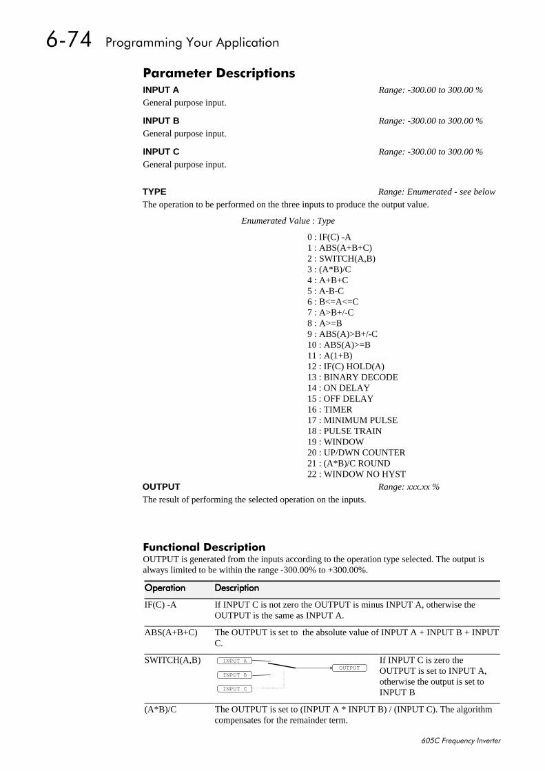
90:7##3URJUDPPLQJ#<RXU#$SSOLFDWLRQ
938&#)UHTXHQF\#,QYHUWHU
)XQFWLRQDO#'HVFULSWLRQOUTPUT is generated from the inputs according to the operation type selected. The output isalways limited to be within the range -300.00% to +300.00%.
2SHUDWLRQ2SHUDWLRQ2SHUDWLRQ2SHUDWLRQ 'HVFULSWLRQ'HVFULSWLRQ'HVFULSWLRQ'HVFULSWLRQ
IF(C) -A If INPUT C is not zero the OUTPUT is minus INPUT A, otherwise theOUTPUT is the same as INPUT A.
ABS(A+B+C) The OUTPUT is set to the absolute value of INPUT A + INPUT B + INPUTC.
SWITCH(A,B)OUTPUT
INPUT A
INPUT B
INPUT C
If INPUT C is zero theOUTPUT is set to INPUT A,otherwise the output is set toINPUT B
(A*B)/C The OUTPUT is set to (INPUT A * INPUT B) / (INPUT C). The algorithmcompensates for the remainder term.
3DUDPHWHU#'HVFULSWLRQVINPUT A Range: -300.00 to 300.00 %
General purpose input.
INPUT B Range: -300.00 to 300.00 %
General purpose input.
INPUT C Range: -300.00 to 300.00 %
General purpose input.
TYPE Range: Enumerated - see below
The operation to be performed on the three inputs to produce the output value.
Enumerated Value : Type
0 : IF(C) -A1 : ABS(A+B+C)2 : SWITCH(A,B)3 : (A*B)/C4 : A+B+C5 : A-B-C6 : B<=A<=C7 : A>B+/-C8 : A>=B9 : ABS(A)>B+/-C10 : ABS(A)>=B11 : A(1+B)12 : IF(C) HOLD(A)13 : BINARY DECODE14 : ON DELAY15 : OFF DELAY16 : TIMER17 : MINIMUM PULSE18 : PULSE TRAIN19 : WINDOW20 : UP/DWN COUNTER21 : (A*B)/C ROUND22 : WINDOW NO HYST
OUTPUT Range: xxx.xx %
The result of performing the selected operation on the inputs.
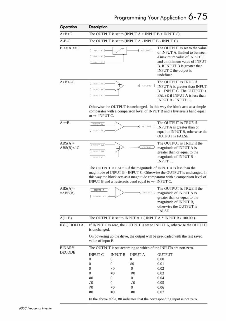
3URJUDPPLQJ#<RXU#$SSOLFDWLRQ#90:8
938&#)UHTXHQF\#,QYHUWHU
2SHUDWLRQ2SHUDWLRQ2SHUDWLRQ2SHUDWLRQ 'HVFULSWLRQ'HVFULSWLRQ'HVFULSWLRQ'HVFULSWLRQ
A+B+C The OUTPUT is set to (INPUT A + INPUT B + INPUT C).
A-B-C The OUTPUT is set to (INPUT A - INPUT B - INPUT C).
B <= A <= COUTPUTINPUT A
INPUT B
INPUT C
The OUTPUT is set to the valueof INPUT A, limited to betweena maximum value of INPUT Cand a minimum value of INPUTB. If INPUT B is greater thanINPUT C the output isundefined.
A>B+/-COUTPUT
INPUT A
INPUT B
INPUT C
The OUTPUT is TRUE ifINPUT A is greater than INPUTB + INPUT C. The OUTPUT isFALSE if INPUT A is less thanINPUT B - INPUT C.
Otherwise the OUTPUT is unchanged. In this way the block acts as a simplecomparator with a comparison level of INPUT B and a hysteresis band equalto +/- INPUT C.
A>=BOUTPUT
INPUT A
INPUT B
The OUTPUT is TRUE ifINPUT A is greater than orequal to INPUT B, otherwise theOUTPUT is FALSE.
ABS(A)>ABS(B)+/-C OUTPUT
| INP UT A |
|INPUT B|
INPUT C
The OUTPUT is TRUE if themagnitude of INPUT A isgreater than or equal to themagnitude of INPUT B -INPUT C.
The OUTPUT is FALSE if the magnitude of INPUT A is less than themagnitude of INPUT B - INPUT C. Otherwise the OUTPUT is unchanged. Inthis way the block acts as a magnitude comparator with a comparison level ofINPUT B and a hysteresis band equal to +/- INPUT C.
ABS(A)>=ABS(B) OUTPUT
| INPUT A |
| INPUT B |
The OUTPUT is TRUE if themagnitude of INPUT A isgreater than or equal to themagnitude of INPUT B,otherwise the OUTPUT isFALSE.
A(1+B) The OUTPUT is set to INPUT A + ( INPUT A * INPUT B / 100.00 ).
IF(C) HOLD A If INPUT C is zero, the OUTPUT is set to INPUT A, otherwise the OUTPUTis unchanged.
On powering up the drive, the output will be pre-loaded with the last savedvalue of input B.
BINARYDECODE
The OUTPUT is set according to which of the INPUTs are non-zero.
INPUT C INPUT B INPUT A OUTPUT0 0 0 0.000 0 ≠0 0.010 ≠0 0 0.020 ≠0 ≠0 0.03≠0 0 0 0.04≠0 0 ≠0 0.05≠0 ≠0 0 0.06≠0 ≠0 ≠0 0.07
In the above table, ≠0 indicates that the corresponding input is not zero.
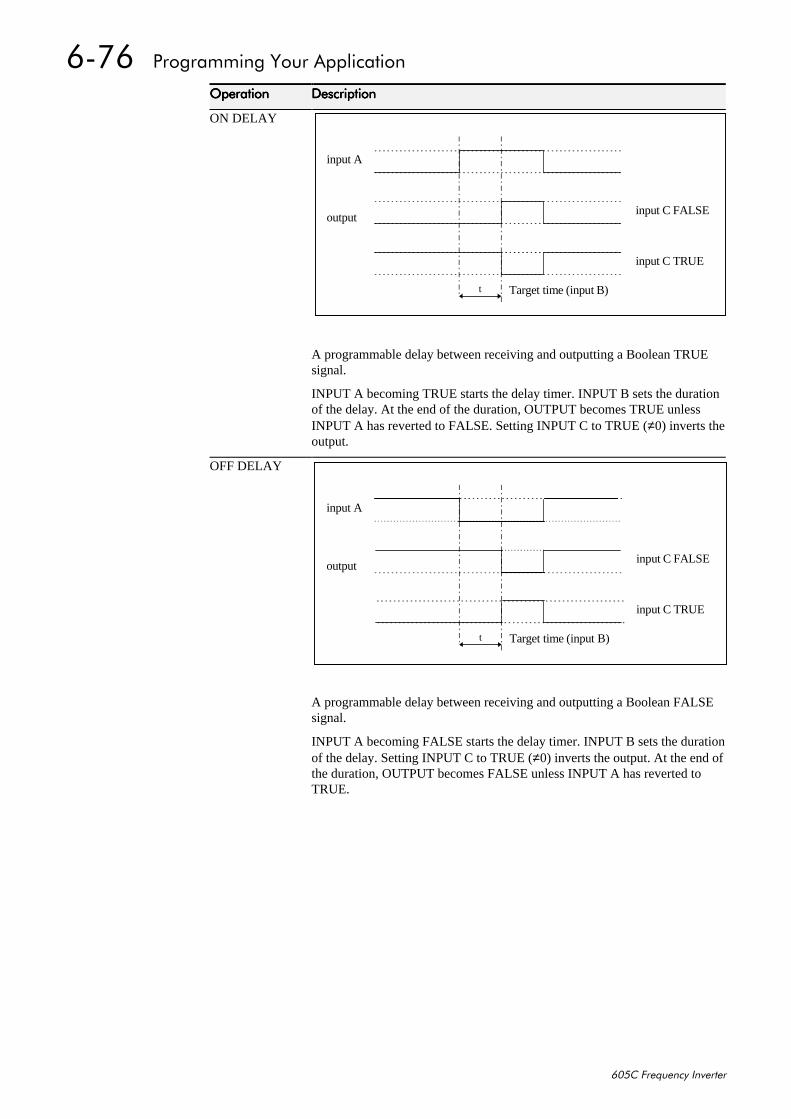
90:9##3URJUDPPLQJ#<RXU#$SSOLFDWLRQ
938&#)UHTXHQF\#,QYHUWHU
2SHUDWLRQ2SHUDWLRQ2SHUDWLRQ2SHUDWLRQ 'HVFULSWLRQ'HVFULSWLRQ'HVFULSWLRQ'HVFULSWLRQ
ON DELAY
A programmable delay between receiving and outputting a Boolean TRUEsignal.
INPUT A becoming TRUE starts the delay timer. INPUT B sets the durationof the delay. At the end of the duration, OUTPUT becomes TRUE unlessINPUT A has reverted to FALSE. Setting INPUT C to TRUE (≠0) inverts theoutput.
OFF DELAY
A programmable delay between receiving and outputting a Boolean FALSEsignal.
INPUT A becoming FALSE starts the delay timer. INPUT B sets the durationof the delay. Setting INPUT C to TRUE (≠0) inverts the output. At the end ofthe duration, OUTPUT becomes FALSE unless INPUT A has reverted toTRUE.
input A
outputinput C FALSE
input C TRUE
Target time (input B)t
input A
outputinput C FALSE
input C TRUE
Target time (input B)t
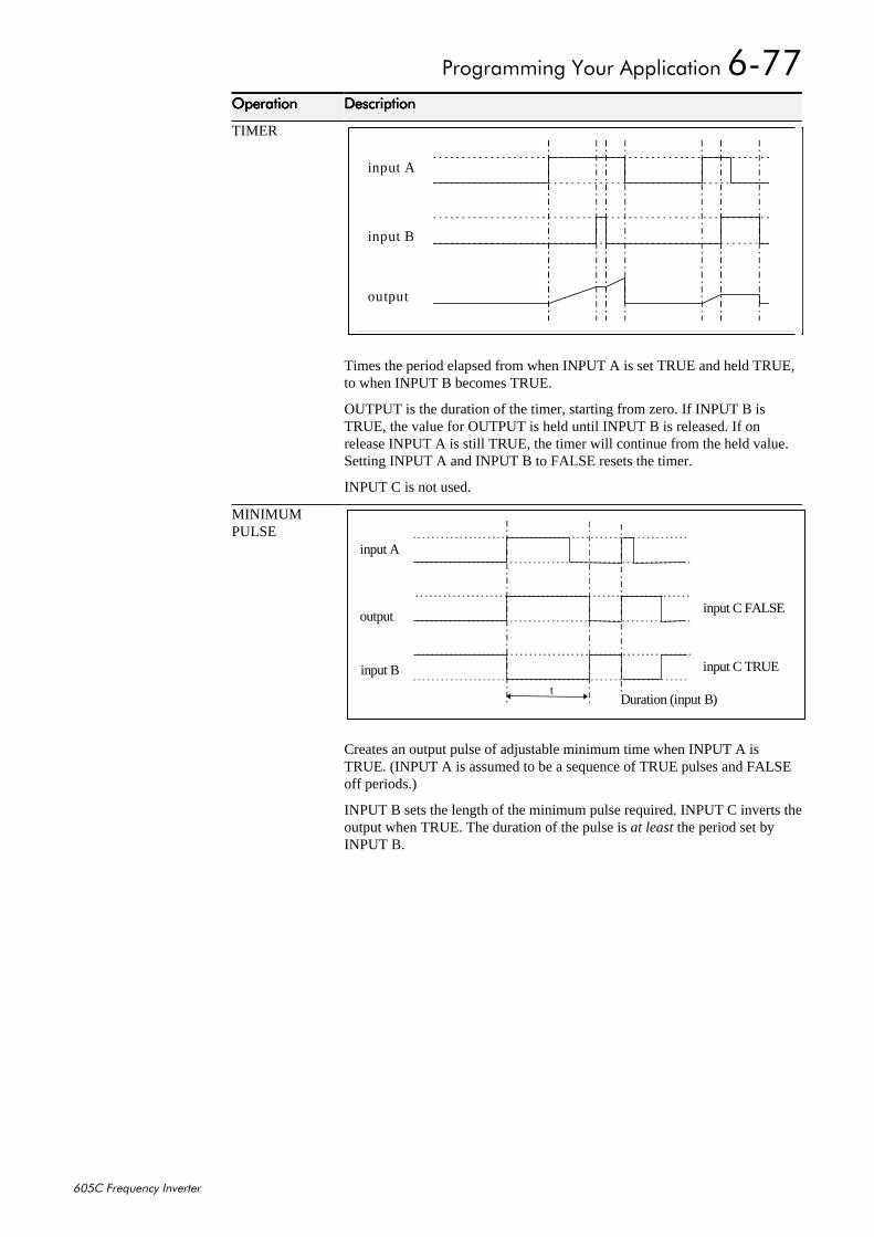
3URJUDPPLQJ#<RXU#$SSOLFDWLRQ#90::
938&#)UHTXHQF\#,QYHUWHU
2SHUDWLRQ2SHUDWLRQ2SHUDWLRQ2SHUDWLRQ 'HVFULSWLRQ'HVFULSWLRQ'HVFULSWLRQ'HVFULSWLRQ
TIMER
Times the period elapsed from when INPUT A is set TRUE and held TRUE,to when INPUT B becomes TRUE.
OUTPUT is the duration of the timer, starting from zero. If INPUT B isTRUE, the value for OUTPUT is held until INPUT B is released. If onrelease INPUT A is still TRUE, the timer will continue from the held value.Setting INPUT A and INPUT B to FALSE resets the timer.
INPUT C is not used.
MINIMUMPULSE
Creates an output pulse of adjustable minimum time when INPUT A isTRUE. (INPUT A is assumed to be a sequence of TRUE pulses and FALSEoff periods.)
INPUT B sets the length of the minimum pulse required. INPUT C inverts theoutput when TRUE. The duration of the pulse is at least the period set byINPUT B.
input A
input B
output
input A
outputinput C FALSE
input C TRUE
Duration (input B)t
input B
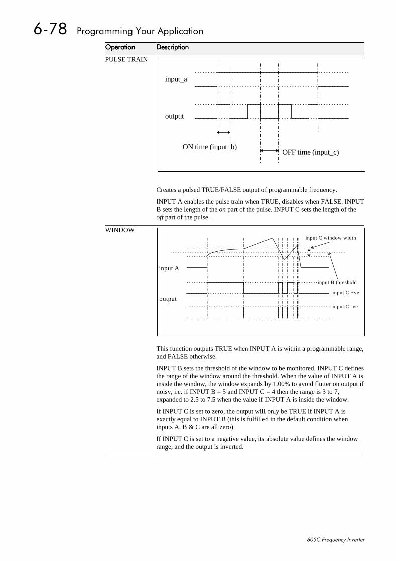
90:;##3URJUDPPLQJ#<RXU#$SSOLFDWLRQ
938&#)UHTXHQF\#,QYHUWHU
2SHUDWLRQ2SHUDWLRQ2SHUDWLRQ2SHUDWLRQ 'HVFULSWLRQ'HVFULSWLRQ'HVFULSWLRQ'HVFULSWLRQ
PULSE TRAIN
Creates a pulsed TRUE/FALSE output of programmable frequency.
INPUT A enables the pulse train when TRUE, disables when FALSE. INPUTB sets the length of the on part of the pulse. INPUT C sets the length of theoff part of the pulse.
WINDOW
This function outputs TRUE when INPUT A is within a programmable range,and FALSE otherwise.
INPUT B sets the threshold of the window to be monitored. INPUT C definesthe range of the window around the threshold. When the value of INPUT A isinside the window, the window expands by 1.00% to avoid flutter on output ifnoisy, i.e. if INPUT B = 5 and INPUT C = 4 then the range is 3 to 7,expanded to 2.5 to 7.5 when the value if INPUT A is inside the window.
If INPUT C is set to zero, the output will only be TRUE if INPUT A isexactly equal to INPUT B (this is fulfilled in the default condition wheninputs A, B & C are all zero)
If INPUT C is set to a negative value, its absolute value defines the windowrange, and the output is inverted.
input_a
output
ON time (input_b)OFF time (input_c)
input A
output
input B threshold
input C window width
input C +ve
input C -ve
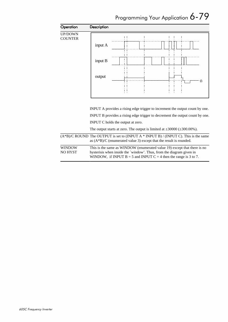
3URJUDPPLQJ#<RXU#$SSOLFDWLRQ#90:<
938&#)UHTXHQF\#,QYHUWHU
2SHUDWLRQ2SHUDWLRQ2SHUDWLRQ2SHUDWLRQ 'HVFULSWLRQ'HVFULSWLRQ'HVFULSWLRQ'HVFULSWLRQ
UP/DOWNCOUNTER
input A
input B
output0
INPUT A provides a rising edge trigger to increment the output count by one.
INPUT B provides a rising edge trigger to decrement the output count by one.
INPUT C holds the output at zero.
The output starts at zero. The output is limited at ±30000 (±300.00%).
(A*B)/C ROUND The OUTPUT is set to (INPUT A * INPUT B) / (INPUT C). This is the sameas (A*B)/C (enumerated value 3) except that the result is rounded.
WINDOWNO HYST
This is the same as WINDOW (enumerated value 19) except that there is nohysterisis when inside the `window’. Thus, from the diagram given inWINDOW, if INPUT B = 5 and INPUT C = 4 then the range is 3 to 7.
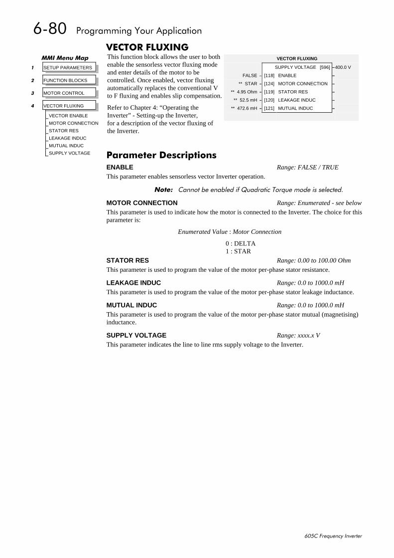
90;3##3URJUDPPLQJ#<RXU#$SSOLFDWLRQ
938&#)UHTXHQF\#,QYHUWHU
9(&725#)/8;,1*This function block allows the user to bothenable the sensorless vector fluxing modeand enter details of the motor to becontrolled. Once enabled, vector fluxingautomatically replaces the conventional Vto F fluxing and enables slip compensation.
Refer to Chapter 4: “Operating theInverter” - Setting-up the Inverter,for a description of the vector fluxing ofthe Inverter.
00,#0HQX#0DS
4 SETUP PARAMETERS
5 FUNCTION BLOCKS
6 MOTOR CONTROL
7 VECTOR FLUXING
VECTOR ENABLE
MOTOR CONNECTION
STATOR RES
LEAKAGE INDUC
MUTUAL INDUC
SUPPLY VOLTAGE
VECTOR FLUXING
SUPPLY VOLTAGE [596] –400.0 V
FALSE – [118] ENABLE –
** STAR – [124] MOTOR CONNECTION –
** 4.95 Ohm – [119] STATOR RES –
** 52.5 mH – [120] LEAKAGE INDUC –
** 472.6 mH – [121] MUTUAL INDUC –
3DUDPHWHU#'HVFULSWLRQVENABLE Range: FALSE / TRUE
This parameter enables sensorless vector Inverter operation.
1RWH=# &DQQRW#EH#HQDEOHG#LI#4XDGUDWLF#7RUTXH#PRGH#LV#VHOHFWHG1
MOTOR CONNECTION Range: Enumerated - see below
This parameter is used to indicate how the motor is connected to the Inverter. The choice for thisparameter is:
Enumerated Value : Motor Connection
0 : DELTA1 : STAR
STATOR RES Range: 0.00 to 100.00 Ohm
This parameter is used to program the value of the motor per-phase stator resistance.
LEAKAGE INDUC Range: 0.0 to 1000.0 mH
This parameter is used to program the value of the motor per-phase stator leakage inductance.
MUTUAL INDUC Range: 0.0 to 1000.0 mH
This parameter is used to program the value of the motor per-phase stator mutual (magnetising)inductance.
SUPPLY VOLTAGE Range: xxxx.x V
This parameter indicates the line to line rms supply voltage to the Inverter.
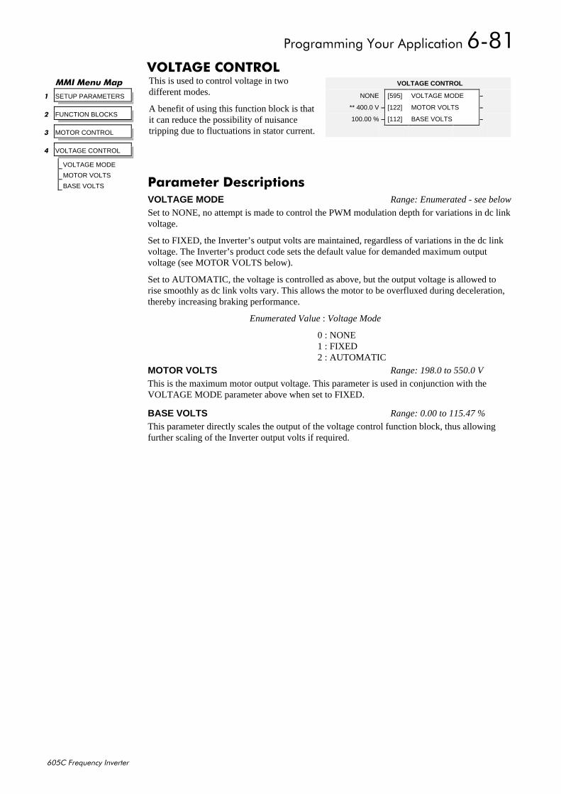
3URJUDPPLQJ#<RXU#$SSOLFDWLRQ#90;4
938&#)UHTXHQF\#,QYHUWHU
92/7$*(#&21752/This is used to control voltage in twodifferent modes.
A benefit of using this function block is thatit can reduce the possibility of nuisancetripping due to fluctuations in stator current.
00,#0HQX#0DS
4 SETUP PARAMETERS
5 FUNCTION BLOCKS
6 MOTOR CONTROL
7 VOLTAGE CONTROL
VOLTAGE MODE
MOTOR VOLTS
BASE VOLTS
VOLTAGE CONTROL
NONE [595] VOLTAGE MODE –
** 400.0 V – [122] MOTOR VOLTS –
100.00 % – [112] BASE VOLTS –
3DUDPHWHU#'HVFULSWLRQVVOLTAGE MODE Range: Enumerated - see below
Set to NONE, no attempt is made to control the PWM modulation depth for variations in dc linkvoltage.
Set to FIXED, the Inverter’s output volts are maintained, regardless of variations in the dc linkvoltage. The Inverter’s product code sets the default value for demanded maximum outputvoltage (see MOTOR VOLTS below).
Set to AUTOMATIC, the voltage is controlled as above, but the output voltage is allowed torise smoothly as dc link volts vary. This allows the motor to be overfluxed during deceleration,thereby increasing braking performance.
Enumerated Value : Voltage Mode
0 : NONE1 : FIXED2 : AUTOMATIC
MOTOR VOLTS Range: 198.0 to 550.0 V
This is the maximum motor output voltage. This parameter is used in conjunction with theVOLTAGE MODE parameter above when set to FIXED.
BASE VOLTS Range: 0.00 to 115.47 %
This parameter directly scales the output of the voltage control function block, thus allowingfurther scaling of the Inverter output volts if required.
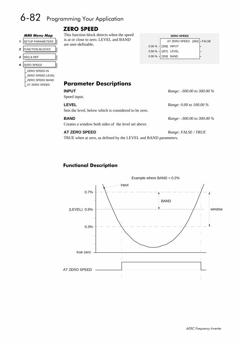
90;5##3URJUDPPLQJ#<RXU#$SSOLFDWLRQ
938&#)UHTXHQF\#,QYHUWHU
=(52#63(('This function block detects when the speedis at or close to zero. LEVEL and BANDare user-definable.
)XQFWLRQDO#'HVFULSWLRQ
true zero
(LEVEL)
input
AT ZERO SPEED
0.5%
0.3%
0.7%
BAND
window
Example where BAND = 0.2%
00,#0HQX#0DS
4 SETUP PARAMETERS
5 FUNCTION BLOCKS
6 SEQ & REF
7 ZERO SPEED
ZERO SPEED IN
ZERO SPEED LEVEL
ZERO SPEED BAND
AT ZERO SPEED
ZERO SPEED
AT ZERO SPEED [360] – FALSE
0.00 % – [358] INPUT –
0.50 % – [357] LEVEL –
0.00 % – [359] BAND –
3DUDPHWHU#'HVFULSWLRQVINPUT Range: -300.00 to 300.00 %
Speed input.
LEVEL Range: 0.00 to 100.00 %
Sets the level, below which is considered to be zero.
BAND Range: -300.00 to 300.00 %
Creates a window both sides of the level set above.
AT ZERO SPEED Range: FALSE / TRUE
TRUE when at zero, as defined by the LEVEL and BAND parameters.
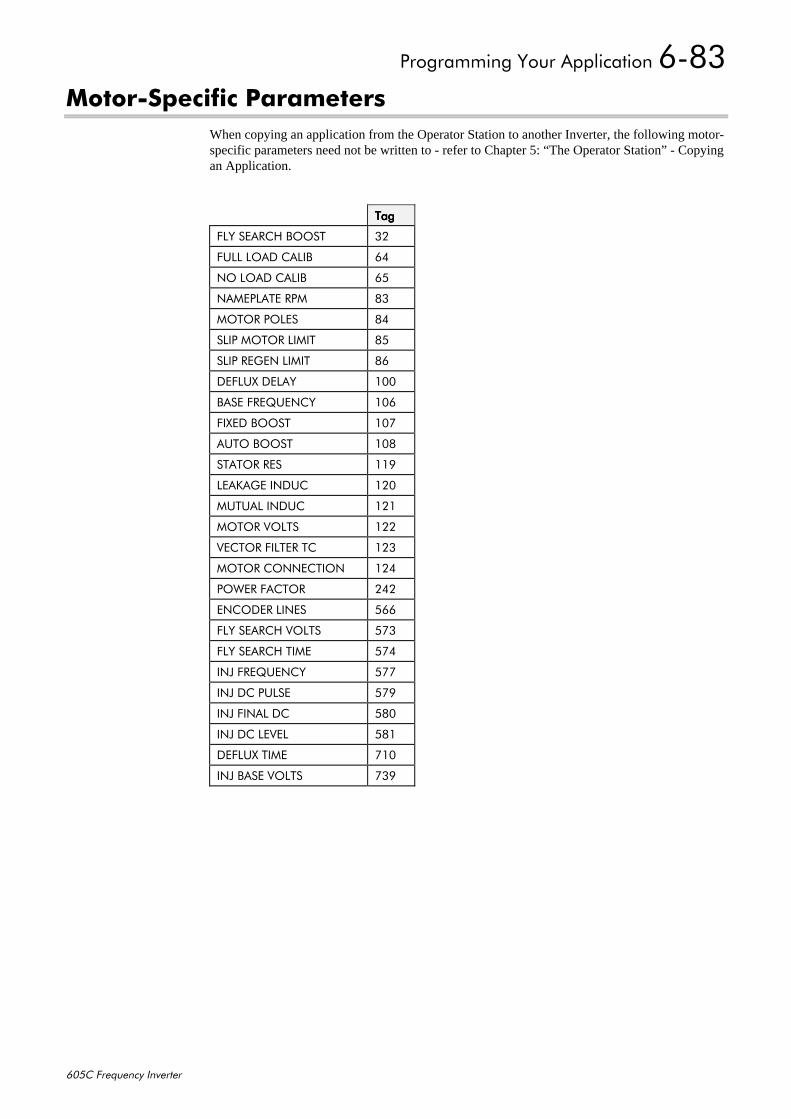
3URJUDPPLQJ#<RXU#$SSOLFDWLRQ#90;6
938&#)UHTXHQF\#,QYHUWHU
0RWRU06SHFLILF#3DUDPHWHUVWhen copying an application from the Operator Station to another Inverter, the following motor-specific parameters need not be written to - refer to Chapter 5: “The Operator Station” - Copyingan Application.
7DJ7DJ7DJ7DJ
)/<#6($5&+#%2267 65
)8//#/2$'#&$/,% 97
12#/2$'#&$/,% 98
1$0(3/$7(#530 ;6
02725#32/(6 ;7
6/,3#02725#/,0,7 ;8
6/,3#5(*(1#/,0,7 ;9
'()/8;#'(/$< 433
%$6(#)5(48(1&< 439
),;('#%2267 43:
$872#%2267 43;
67$725#5(6 44<
/($.$*(#,1'8& 453
0878$/#,1'8& 454
02725#92/76 455
9(&725#),/7(5#7& 456
02725#&211(&7,21 457
32:(5#)$&725 575
(1&2'(5#/,1(6 899
)/<#6($5&+#92/76 8:6
)/<#6($5&+#7,0( 8:7
,1-#)5(48(1&< 8::
,1-#'&/6( 8:<
,1-#),1$/#'& 8;3
,1-#'&#/(9(/ 8;4
'()/8;#7,0( :43
,1-#%$6(#92/76 :6<
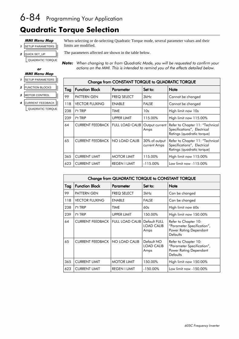
90;7##3URJUDPPLQJ#<RXU#$SSOLFDWLRQ
938&#)UHTXHQF\#,QYHUWHU
4XDGUDWLF#7RUTXH#6HOHFWLRQWhen selecting or de-selecting Quadratic Torque mode, several parameter values and theirlimits are modified.
The parameters affected are shown in the table below.
1RWH=# :KHQ#FKDQJLQJ#WR#RU#IURP#4XDGUDWLF#0RGH/#\RX#ZLOO#EH#UHTXHVWHG#WR#FRQILUP#\RXUDFWLRQV#RQ#WKH#00,1#7KLV#LV#LQWHQGHG#WR#UHPLQG#\RX#RI#WKH#HIIHFWV#GHWDLOHG#EHORZ1
00,#0HQX#0DS
4 SETUP PARAMETERS
5 QUICK SET_UP
QUADRATIC TORQUE
RU00,#0HQX#0DS
4 SETUP PARAMETERS
5 FUNCTION BLOCKS
6 MOTOR CONTROL
7 CURRENT FEEDBACK
QUADRATIC TORQUE
&KDQJH#IURP#&2167$17#72548(#WR#48$'5$7,𑭤(&KDQJH#IURP#&2167$17#72548(#WR#48$'5$7,𑭤(&KDQJH#IURP#&2167$17#72548(#WR#48$'5$7,𑭤(&KDQJH#IURP#&2167$17#72548(#WR#48$'5$7,𑭤(
7DJ7DJ7DJ7DJ )XQFWLRQ#%ORFN)XQFWLRQ#%ORFN)XQFWLRQ#%ORFN)XQFWLRQ#%ORFN 3DUDPHWHU3DUDPHWHU3DUDPHWHU3DUDPHWHU 6HW#WR=6HW#WR=6HW#WR=6HW#WR= 1RWH1RWH1RWH1RWH
<< 3$77(51#*(1 )5(4#6(/(&7 6N+] &DQQRW#EH#FKDQJHG
44; 9(&725#)/8;,1* (1$%/( )$/6( &DQQRW#EH#FKDQJHG
56; ,-W#75,3 7,0( 43V +LJK#OLPLW#QRZ#43V
56< ,-W#75,3 833(5#/,0,7 448133( +LJK#OLPLW#QRZ#448133(
97 &855(17#)(('%$&. )8//#/2$'#&$/,% 2XWSXW#FXUUHQW$PSV
5HIHU#WR#&KDSWHU#44=#´7HFKQLFDO6SHFLILFDWLRQVµ/##(OHFWULFDO5DWLQJV#+TXDGUDWLF#WRUTXH,
98 &855(17#)(('%$&. 12#/2$'#&$/,% 63(#RI#RXWSXWFXUUHQW#$PSV
5HIHU#WR#&KDSWHU#44=#´7HFKQLFDO6SHFLILFDWLRQVµ/##(OHFWULFDO5DWLQJV#+TXDGUDWLF#WRUTXH,
698 &855(17#/,0,7 02725#/,0,7 448133( +LJK#OLPLW#QRZ#448133(
956 &855(17#/,0,7 5(*(1#,#/,0,7 0448133( /RZ#OLPLW#QRZ#0448133(
&KDQJH#IURP#48$'5$7,𑭤(#WR#&2167$17#72548(&KDQJH#IURP#48$'5$7,𑭤(#WR#&2167$17#72548(&KDQJH#IURP#48$'5$7,𑭤(#WR#&2167$17#72548(&KDQJH#IURP#48$'5$7,𑭤(#WR#&2167$17#72548(
7DJ7DJ7DJ7DJ )XQFWLRQ#%ORFN)XQFWLRQ#%ORFN)XQFWLRQ#%ORFN)XQFWLRQ#%ORFN 3DUDPHWHU3DUDPHWHU3DUDPHWHU3DUDPHWHU 6HW#WR=6HW#WR=6HW#WR=6HW#WR= 1RWH1RWH1RWH1RWH
<< 3$77(51#*(1 )5(4#6(/(&7 6N+] &DQ#EH#FKDQJHG
44; 9(&725#)/8;,1* (1$%/( )$/6( &DQ#EH#FKDQJHG
56; ,-W#75,3 7,0( 93V +LJK#OLPLW#QRZ#93V
56< ,-W#75,3 833(5#/,0,7 483133( +LJK#OLPLW#QRZ#483133(
97 &855(17#)(('%$&. )8//#/2$'#&$/,% 'HIDXOW#)8///2$'#&$/,%$PSV
5HIHU#WR#&KDSWHU#43=´3DUDPHWHU#6SHFLILFDWLRQµ/3RZHU#5DWLQJ#'HSHQGDQW'HIDXOWV
98 &855(17#)(('%$&. 12#/2$'#&$/,% 'HIDXOW#12/2$'#&$/,%$PSV
5HIHU#WR#&KDSWHU#43=´3DUDPHWHU#6SHFLILFDWLRQµ/3RZHU#5DWLQJ#'HSHQGDQW'HIDXOWV
698 &855(17#/,0,7 02725#/,0,7 483133( +LJK#OLPLW#QRZ#483133(
956 &855(17#/,0,7 5(*(1#,#/,0,7 0483133( /RZ#OLPLW#QRZ#0483133(
7ULSV#DQG#)DXOW#)LQGLQJ##:04
938&#)UHTXHQF\#,QYHUWHU
:#75,36#$1'#)$8/7#),1',1*7ULSV
:KDW#+DSSHQV#ZKHQ#D#7ULS#2FFXUVWhen a trip occurs, the Inverter’s power stage is immediately disabled causing the motor andload to coast to a stop. The trip is latched until action is taken to reset it. This ensures that tripsdue to transient conditions are captured and the Inverter is disabled, even when the original causeof the trip is no longer present
,QYHUWHU#,QGLFDWLRQVIf a trip condition is detected the unit displays and performs the following actions.
1. The HEALTH LED flashes indicating a Trip condition has occurred. (Investigate, find andremove the cause of the trip.)
2. The programming block SEQUENCING LOGIC::TRIPPED signal is set to TRUE.The DIGITAL OUTPUT 1 (HEALTH) digital output changes between TRUE/FALSE,depending on the output logic.
2SHUDWRU#6WDWLRQ#,QGLFDWLRQV#+ZKHQ#FRQQHFWHG,If a trip condition is detected the MMI displays and performs the following actions.
1. The HEALTH LED on the Operator Station flashes indicating a Trip condition has occurredand a trip message is displayed stating the cause of the trip.
2. The programming block SEQUENCING LOGIC::TRIPPED signal is set to TRUE.The DIGITAL OUTPUT 1 (HEALTH) digital output changes between TRUE/FALSE,depending on the output logic.
3. The trip message(s) must be acknowledged by pressing the E key. Refer to Chapter 5: “TheOperator Station” - Alert Message Displays.
5HVHWWLQJ#D#7ULS#&RQGLWLRQAll trips must be reset before the Inverter can be re-enabled. A trip can only be reset once the tripcondition is no longer active, i.e. a trip due to a heatsink over-temperature will not reset until thetemperature is below the trip level.
1RWH=# 0RUH#WKDQ#RQH#WULS#FDQ#EH#DFWLYH#DW#DQ\#WLPH1#)RU#H[DPSOH/#LW#LV#SRVVLEOH#IRU#ERWK#WKH+($76,1.#7(03#DQG#WKH#/,1.#29(592/76#WULSV#WR#EH#DFWLYH1#$OWHUQDWLYHO\#LW#LV#SRVVLEOHIRU#WKH#,QYHUWHU#WR#WULS#GXH#WR#DQ#29(5&855(17#HUURU#DQG#WKHQ#IRU#WKH#+($76,1.#7(03WULS#WR#EHFRPH#DFWLYH#DIWHU#WKH#,QYHUWHU#KDV#VWRSSHG#+WKLV#PD\#RFFXU#GXH#WR#WKH#WKHUPDOWLPH#FRQVWDQW#RI#WKH#KHDWVLQN,1
Reset the trip(s) using the remote trip reset input, or by pressing the STOP/RESET key on theOperator Station.
Success is indicated by the HEALTH LED (on the unit or MMI) ceasing to flash and returning toa healthy “ON” state. The programming block SEQUENCING LOGIC::TRIPPED output isreset to FALSE.
'()$8/7
'()$8/7
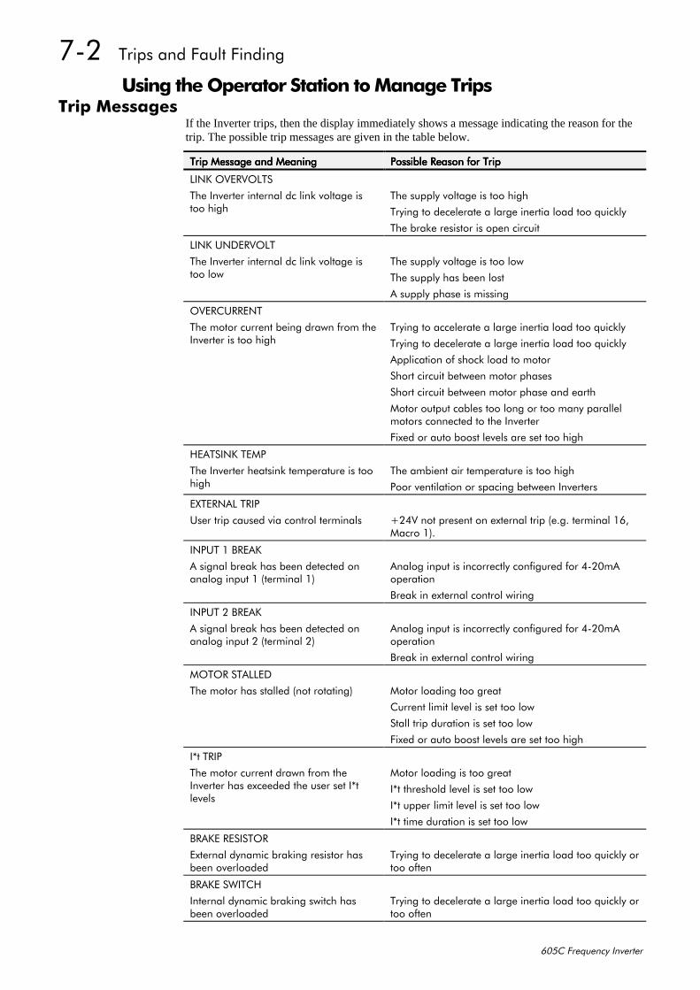
:05##7ULSV#DQG#)DXOW#)LQGLQJ
938&#)UHTXHQF\#,QYHUWHU
8VLQJ#WKH#2SHUDWRU#6WDWLRQ#WR#0DQDJH#7ULSV7ULS#0HVVDJHV
If the Inverter trips, then the display immediately shows a message indicating the reason for thetrip. The possible trip messages are given in the table below.
7ULS#0HVVDJH#DQG#0HDQLQJ7ULS#0HVVDJH#DQG#0HDQLQJ7ULS#0HVVDJH#DQG#0HDQLQJ7ULS#0HVVDJH#DQG#0HDQLQJ 3RVVLEOH#5HDVRQ#IRU#7ULS3RVVLEOH#5HDVRQ#IRU#7ULS3RVVLEOH#5HDVRQ#IRU#7ULS3RVVLEOH#5HDVRQ#IRU#7ULS
/,1.#29(592/76
7KH#,QYHUWHU#LQWHUQDO#GF#OLQN#YROWDJH#LVWRR#KLJK
7KH#VXSSO\#YROWDJH#LV#WRR#KLJK
7U\LQJ#WR#GHFHOHUDWH#D#ODUJH#LQHUWLD#ORDG#WRR#TXLFNO\
7KH#EUDNH#UHVLVWRU#LV#RSHQ#FLUFXLW
/,1.#81'(592/7
7KH#,QYHUWHU#LQWHUQDO#GF#OLQN#YROWDJH#LVWRR#ORZ
7KH#VXSSO\#YROWDJH#LV#WRR#ORZ
7KH#VXSSO\#KDV#EHHQ#ORVW
$#VXSSO\#SKDVH#LV#PLVVLQJ
29(5&855(17
7KH#PRWRU#FXUUHQW#EHLQJ#GUDZQ#IURP#WKH,QYHUWHU#LV#WRR#KLJK
7U\LQJ#WR#DFFHOHUDWH#D#ODUJH#LQHUWLD#ORDG#WRR#TXLFNO\
7U\LQJ#WR#GHFHOHUDWH#D#ODUJH#LQHUWLD#ORDG#WRR#TXLFNO\
$SSOLFDWLRQ#RI#VKRFN#ORDG#WR#PRWRU
6KRUW#FLUFXLW#EHWZHHQ#PRWRU#SKDVHV
6KRUW#FLUFXLW#EHWZHHQ#PRWRU#SKDVH#DQG#HDUWK
0RWRU#RXWSXW#FDEOHV#WRR#ORQJ#RU#WRR#PDQ\#SDUDOOHOPRWRUV#FRQQHFWHG#WR#WKH#,QYHUWHU
)L[HG#RU#DXWR#ERRVW#OHYHOV#DUH#VHW#WRR#KLJK
+($76,1.#7(03
7KH#,QYHUWHU#KHDWVLQN#WHPSHUDWXUH#LV#WRRKLJK
7KH#DPELHQW#DLU#WHPSHUDWXUH#LV#WRR#KLJK
3RRU#YHQWLODWLRQ#RU#VSDFLQJ#EHWZHHQ#,QYHUWHUV
(;7(51$/#75,3
8VHU#WULS#FDXVHG#YLD#FRQWURO#WHUPLQDOV .579#QRW#SUHVHQW#RQ#H[WHUQDO#WULS#+H1J1#WHUPLQDO#49/0DFUR#4,1
,1387#4#%5($.
$#VLJQDO#EUHDN#KDV#EHHQ#GHWHFWHG#RQDQDORJ#LQSXW#4#+WHUPLQDO#4,
$QDORJ#LQSXW#LV#LQFRUUHFWO\#FRQILJXUHG#IRU#7053P$RSHUDWLRQ
%UHDN#LQ#H[WHUQDO#FRQWURO#ZLULQJ
,1387#5#%5($.
$#VLJQDO#EUHDN#KDV#EHHQ#GHWHFWHG#RQDQDORJ#LQSXW#5#+WHUPLQDO#5,
$QDORJ#LQSXW#LV#LQFRUUHFWO\#FRQILJXUHG#IRU#7053P$RSHUDWLRQ
%UHDN#LQ#H[WHUQDO#FRQWURO#ZLULQJ
02725#67$//('
7KH#PRWRU#KDV#VWDOOHG#+QRW#URWDWLQJ, 0RWRU#ORDGLQJ#WRR#JUHDW
&XUUHQW#OLPLW#OHYHO#LV#VHW#WRR#ORZ
6WDOO#WULS#GXUDWLRQ#LV#VHW#WRR#ORZ
)L[HG#RU#DXWR#ERRVW#OHYHOV#DUH#VHW#WRR#KLJK
,-W#75,3
7KH#PRWRU#FXUUHQW#GUDZQ#IURP#WKH,QYHUWHU#KDV#H[FHHGHG#WKH#XVHU#VHW#,-WOHYHOV
0RWRU#ORDGLQJ#LV#WRR#JUHDW
,-W#WKUHVKROG#OHYHO#LV#VHW#WRR#ORZ
,-W#XSSHU#OLPLW#OHYHO#LV#VHW#WRR#ORZ
,-W#WLPH#GXUDWLRQ#LV#VHW#WRR#ORZ
%5$.(#5(6,6725
([WHUQDO#G\QDPLF#EUDNLQJ#UHVLVWRU#KDVEHHQ#RYHUORDGHG
7U\LQJ#WR#GHFHOHUDWH#D#ODUJH#LQHUWLD#ORDG#WRR#TXLFNO\#RUWRR#RIWHQ
%5$.(#6:,7&+
,QWHUQDO#G\QDPLF#EUDNLQJ#VZLWFK#KDVEHHQ#RYHUORDGHG
7U\LQJ#WR#GHFHOHUDWH#D#ODUJH#LQHUWLD#ORDG#WRR#TXLFNO\#RUWRR#RIWHQ
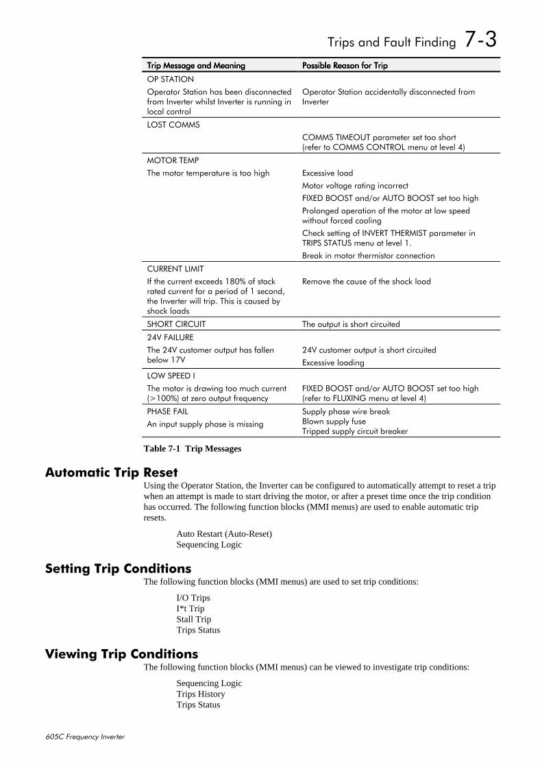
7ULSV#DQG#)DXOW#)LQGLQJ##:06
938&#)UHTXHQF\#,QYHUWHU
7ULS#0HVVDJH#DQG#0HDQLQJ7ULS#0HVVDJH#DQG#0HDQLQJ7ULS#0HVVDJH#DQG#0HDQLQJ7ULS#0HVVDJH#DQG#0HDQLQJ 3RVVLEOH#5HDVRQ#IRU#7ULS3RVVLEOH#5HDVRQ#IRU#7ULS3RVVLEOH#5HDVRQ#IRU#7ULS3RVVLEOH#5HDVRQ#IRU#7ULS
23#67$7,21
2SHUDWRU#6WDWLRQ#KDV#EHHQ#GLVFRQQHFWHGIURP#,QYHUWHU#ZKLOVW#,QYHUWHU#LV#UXQQLQJ#LQORFDO#FRQWURO
2SHUDWRU#6WDWLRQ#DFFLGHQWDOO\#GLVFRQQHFWHG#IURP,QYHUWHU
/267#&2006
&2006#7,0(287#SDUDPHWHU#VHW#WRR#VKRUW+UHIHU#WR#&2006#&21752/#PHQX#DW#OHYHO#7,
02725#7(03
7KH#PRWRU#WHPSHUDWXUH#LV#WRR#KLJK ([FHVVLYH#ORDG
0RWRU#YROWDJH#UDWLQJ#LQFRUUHFW
),;('#%2267#DQG2RU#$872#%2267#VHW#WRR#KLJK
3URORQJHG#RSHUDWLRQ#RI#WKH#PRWRU#DW#ORZ#VSHHGZLWKRXW#IRUFHG#FRROLQJ
&KHFN#VHWWLQJ#RI#,19(57#7+(50,67#SDUDPHWHU#LQ75,36#67$786#PHQX#DW#OHYHO#41
%UHDN#LQ#PRWRU#WKHUPLVWRU#FRQQHFWLRQ
&855(17#/,0,7
,I#WKH#FXUUHQW#H[FHHGV#4;3(#RI#VWDFNUDWHG#FXUUHQW#IRU#D#SHULRG#RI#4#VHFRQG/WKH#,QYHUWHU#ZLOO#WULS1#7KLV#LV#FDXVHG#E\VKRFN#ORDGV
5HPRYH#WKH#FDXVH#RI#WKH#VKRFN#ORDG
6+257#&,5&8,7 7KH#RXWSXW#LV#VKRUW#FLUFXLWHG
579#)$,/85(
7KH#579#FXVWRPHU#RXWSXW#KDV#IDOOHQEHORZ#4:9
579#FXVWRPHU#RXWSXW#LV#VKRUW#FLUFXLWHG
([FHVVLYH#ORDGLQJ
/2:#63(('#,
7KH#PRWRU#LV#GUDZLQJ#WRR#PXFK#FXUUHQW+!433(,#DW#]HUR#RXWSXW#IUHTXHQF\
),;('#%2267#DQG2RU#$872#%2267#VHW#WRR#KLJK+UHIHU#WR#)/8;,1*#PHQX#DW#OHYHO#7,
3+$6(#)$,/
$Q#LQSXW#VXSSO\#SKDVH#LV#PLVVLQJ
6XSSO\#SKDVH#ZLUH#EUHDN%ORZQ#VXSSO\#IXVH7ULSSHG#VXSSO\#FLUFXLW#EUHDNHU
Table 7-1 Trip Messages
$XWRPDWLF#7ULS#5HVHWUsing the Operator Station, the Inverter can be configured to automatically attempt to reset a tripwhen an attempt is made to start driving the motor, or after a preset time once the trip conditionhas occurred. The following function blocks (MMI menus) are used to enable automatic tripresets.
Auto Restart (Auto-Reset)Sequencing Logic
6HWWLQJ#7ULS#&RQGLWLRQVThe following function blocks (MMI menus) are used to set trip conditions:
I/O TripsI*t TripStall TripTrips Status
9LHZLQJ#7ULS#&RQGLWLRQVThe following function blocks (MMI menus) can be viewed to investigate trip conditions:
Sequencing LogicTrips HistoryTrips Status
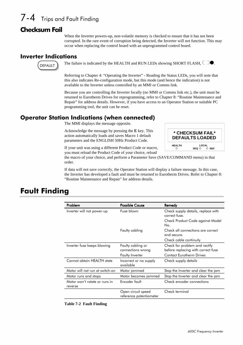
:07##7ULSV#DQG#)DXOW#)LQGLQJ
938&#)UHTXHQF\#,QYHUWHU
&KHFNVXP#)DLOWhen the Inverter powers-up, non-volatile memory is checked to ensure that it has not beencorrupted. In the rare event of corruption being detected, the Inverter will not function. This mayoccur when replacing the control board with an unprogrammed control board.
,QYHUWHU#,QGLFDWLRQV The failure is indicated by the HEALTH and RUN LEDs showing SHORT FLASH, .
Referring to Chapter 4: “Operating the Inverter” - Reading the Status LEDs, you will note thatthis also indicates Re-configuration mode, but this mode (and hence the indication) is notavailable to the Inverter unless controlled by an MMI or Comms link.
Because you are controlling the Inverter locally (no MMI or Comms link etc.), the unit must bereturned to Eurotherm Drives for reprogramming, refer to Chapter 8: “Routine Maintenance andRepair” for address details. However, if you have access to an Operator Station or suitable PCprogramming tool, the unit can be reset.
2SHUDWRU#6WDWLRQ#,QGLFDWLRQV#+ZKHQ#FRQQHFWHG,The MMI displays the message opposite.
Acknowledge the message by pressing the E key. Thisaction automatically loads and saves Macro 1 defaultparameters and the ENGLISH 50Hz Product Code.
If your unit was using a different Product Code or macro,you must reload the Product Code of your choice, reloadthe macro of your choice, and perform a Parameter Save (SAVE/COMMAND menu) in thatorder.
If data will not save correctly, the Operator Station will display a failure message. In this case,the Inverter has developed a fault and must be returned to Eurotherm Drives. Refer to Chapter 8:“Routine Maintenance and Repair" for address details.
)DXOW#)LQGLQJ
3UREOHP3UREOHP3UREOHP3UREOHP 3RVVLEOH#&DXVH3RVVLEOH#&DXVH3RVVLEOH#&DXVH3RVVLEOH#&DXVH 5HPHG\5HPHG\5HPHG\5HPHG\
,QYHUWHU#ZLOO#QRW#SRZHU0XS )XVH#EORZQ &KHFN#VXSSO\#GHWDLOV/#UHSODFH#ZLWKFRUUHFW#IXVH1&KHFN#3URGXFW#&RGH#DJDLQVW#0RGHO1R1
)DXOW\#FDEOLQJ &KHFN#DOO#FRQQHFWLRQV#DUH#FRUUHFWDQG#VHFXUH1&KHFN#FDEOH#FRQWLQXLW\
,QYHUWHU#IXVH#NHHSV#EORZLQJ )DXOW\#FDEOLQJ#RUFRQQHFWLRQV#ZURQJ
&KHFN#IRU#SUREOHP#DQG#UHFWLI\EHIRUH#UHSODFLQJ#ZLWK#FRUUHFW#IXVH
)DXOW\#,QYHUWHU &RQWDFW#(XURWKHUP#'ULYHV&DQQRW#REWDLQ#+($/7+#VWDWH ,QFRUUHFW#RU#QR#VXSSO\
DYDLODEOH&KHFN#VXSSO\#GHWDLOV
0RWRU#ZLOO#QRW#UXQ#DW#VZLWFK0RQ 0RWRU#MDPPHG 6WRS#WKH#,QYHUWHU#DQG#FOHDU#WKH#MDP0RWRU#UXQV#DQG#VWRSV 0RWRU#EHFRPHV#MDPPHG 6WRS#WKH#,QYHUWHU#DQG#FOHDU#WKH#MDP0RWRU#ZRQ·W#URWDWH#RU#UXQV#LQUHYHUVH
(QFRGHU#IDXOW &KHFN#HQFRGHU#FRQQHFWLRQV
2SHQ#FLUFXLW#VSHHGUHIHUHQFH#SRWHQWLRPHWHU
&KHFN#WHUPLQDO
Table 7-2 Fault Finding
'()$8/7
HEALTH LOCALSEQ REF
11DEFAULTS LOADED
* CHECKSUM FAIL*
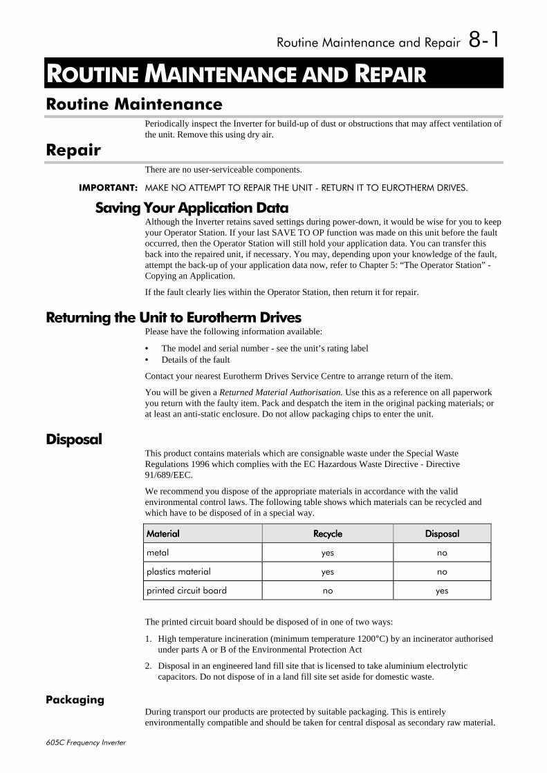
5RXWLQH#0DLQWHQDQFH#DQG#5HSDLU##;04
938&#)UHTXHQF\#,QYHUWHU
;#5287,1(#0$,17(1$1&(#$1'#5(3$,55RXWLQH#0DLQWHQDQFH
Periodically inspect the Inverter for build-up of dust or obstructions that may affect ventilation ofthe unit. Remove this using dry air.
5HSDLUThere are no user-serviceable components.
,03257$17=# 0$.(#12#$77(037#72#5(3$,5#7+(#81,7#0#5(7851#,7#72#(8527+(50#'5,9(61
6DYLQJ#<RXU#$SSOLFDWLRQ#'DWDAlthough the Inverter retains saved settings during power-down, it would be wise for you to keepyour Operator Station. If your last SAVE TO OP function was made on this unit before the faultoccurred, then the Operator Station will still hold your application data. You can transfer thisback into the repaired unit, if necessary. You may, depending upon your knowledge of the fault,attempt the back-up of your application data now, refer to Chapter 5: “The Operator Station” -Copying an Application.
If the fault clearly lies within the Operator Station, then return it for repair.
5HWXUQLQJ#WKH#8QLW#WR#(XURWKHUP#'ULYHVPlease have the following information available:
• The model and serial number - see the unit’s rating label• Details of the fault
Contact your nearest Eurotherm Drives Service Centre to arrange return of the item.
You will be given a Returned Material Authorisation. Use this as a reference on all paperworkyou return with the faulty item. Pack and despatch the item in the original packing materials; orat least an anti-static enclosure. Do not allow packaging chips to enter the unit.
'LVSRVDOThis product contains materials which are consignable waste under the Special WasteRegulations 1996 which complies with the EC Hazardous Waste Directive - Directive91/689/EEC.
We recommend you dispose of the appropriate materials in accordance with the validenvironmental control laws. The following table shows which materials can be recycled andwhich have to be disposed of in a special way.
0DWHULDO0DWHULDO0DWHULDO0DWHULDO 5HF\FOH5HF\FOH5HF\FOH5HF\FOH 'LVSRVDO'LVSRVDO'LVSRVDO'LVSRVDO
PHWDO \HV QR
SODVWLFV#PDWHULDO \HV QR
SULQWHG#FLUFXLW#ERDUG QR \HV
The printed circuit board should be disposed of in one of two ways:
1. High temperature incineration (minimum temperature 1200°C) by an incinerator authorisedunder parts A or B of the Environmental Protection Act
2. Disposal in an engineered land fill site that is licensed to take aluminium electrolyticcapacitors. Do not dispose of in a land fill site set aside for domestic waste.
3DFNDJLQJDuring transport our products are protected by suitable packaging. This is entirelyenvironmentally compatible and should be taken for central disposal as secondary raw material.

;05##5RXWLQH#0DLQWHQDQFH#DQG#5HSDLU
938&#)UHTXHQF\#,QYHUWHU
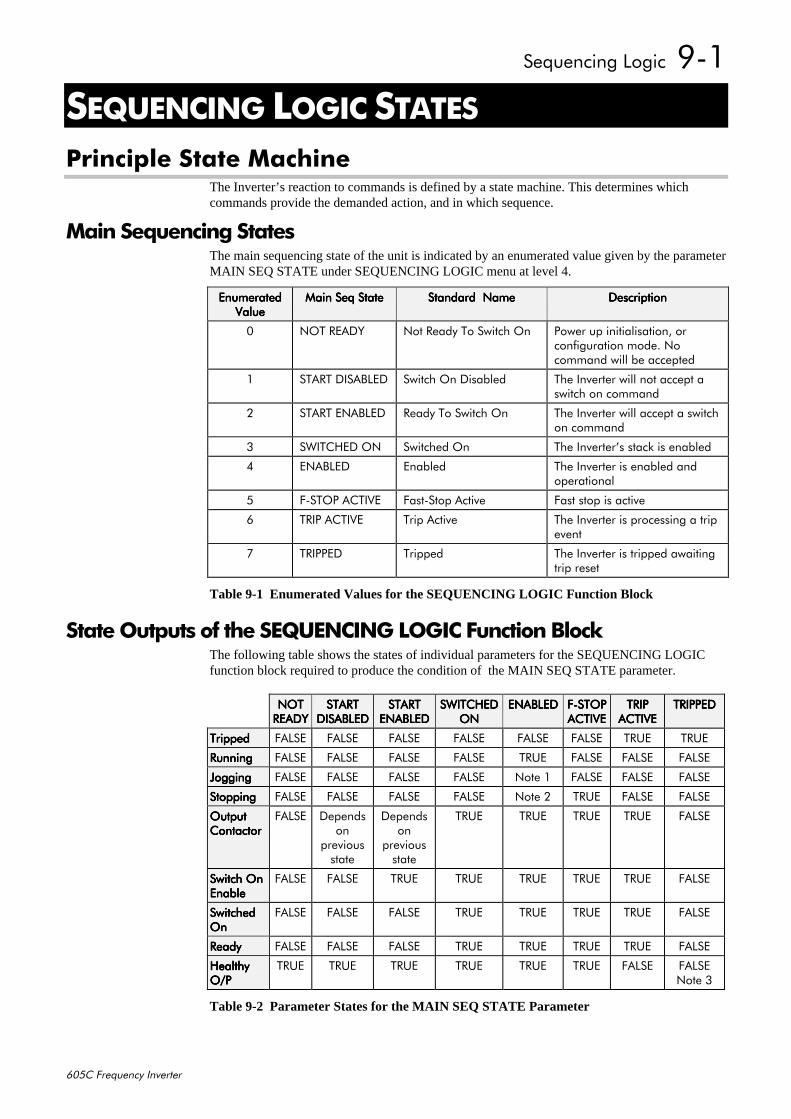
6HTXHQFLQJ#/RJLF##<04
938&#)UHTXHQF\#,QYHUWHU
<#6(48(1&,1*#/2*,C$7(63ULQFLSOH#6WDWH#0DFKLQH
The Inverter’s reaction to commands is defined by a state machine. This determines whichcommands provide the demanded action, and in which sequence.
0DLQ#6HTXHQFLQJ#6WDWHVThe main sequencing state of the unit is indicated by an enumerated value given by the parameterMAIN SEQ STATE under SEQUENCING LOGIC menu at level 4.
(QXPHUDWHG(QXPHUDWHG(QXPHUDWHG(QXPHUDWHG9DOXH9DOXH9DOXH9DOXH
0DLQ#6HT#6WDWH0DLQ#6HT#6WDWH0DLQ#6HT#6WDWH0DLQ#6HT#6WDWH 6WDQGDUG##1DPH6WDQGDUG##1DPH6WDQGDUG##1DPH6WDQGDUG##1DPH 'HVFULSWLRQ'HVFULSWLRQ'HVFULSWLRQ'HVFULSWLRQ
3 127#5($'< 1RW#5HDG\#7R#6ZLWFK#2Q 3RZHU#XS#LQLWLDOLVDWLRQ/#RUFRQILJXUDWLRQ#PRGH1#1RFRPPDQG#ZLOO#EH#DFFHSWHG
4 67$57#',6$%/(' 6ZLWFK#2Q#'LVDEOHG 7KH#,QYHUWHU#ZLOO#QRW#DFFHSW#DVZLWFK#RQ#FRPPDQG
5 67$57#(1$%/(' 5HDG\#7R#6ZLWFK#2Q 7KH#,QYHUWHU#ZLOO#DFFHSW#D#VZLWFKRQ#FRPPDQG
6 6:,7&+('#21 6ZLWFKHG#2Q 7KH#,QYHUWHU·V#VWDFN#LV#HQDEOHG
7 (1$%/(' (QDEOHG 7KH#,QYHUWHU#LV#HQDEOHG#DQGRSHUDWLRQDO
8 )06723#$&7,9( )DVW06WRS#$FWLYH )DVW#VWRS#LV#DFWLYH
9 75,3#$&7,9( 7ULS#$FWLYH 7KH#,QYHUWHU#LV#SURFHVVLQJ#D#WULSHYHQW
: 75,33(' 7ULSSHG 7KH#,QYHUWHU#LV#WULSSHG#DZDLWLQJWULS#UHVHW
Table 9-1 Enumerated Values for the SEQUENCING LOGIC Function Block
6WDWH#2XWSXWV#RI#WKH#6(48(1&,1*#/2*,&#)XQFWLRQ#%ORFNThe following table shows the states of individual parameters for the SEQUENCING LOGICfunction block required to produce the condition of the MAIN SEQ STATE parameter.
1271271271275($'<5($'<5($'<5($'<
67$5767$5767$5767$57',6$%/('',6$%/('',6$%/('',6$%/('
67$5767$5767$5767$57(1$%/('(1$%/('(1$%/('(1$%/('
6:,7&+('6:,7&+('6:,7&+('6:,7&+('21212121
(1$%/('(1$%/('(1$%/('(1$%/(' )06723)06723)06723)06723$&7,9($&7,9($&7,9($&7,9(
75,375,375,375,3$&7,9($&7,9($&7,9($&7,9(
75,33('75,33('75,33('75,33('
7ULSSHG7ULSSHG7ULSSHG7ULSSHG )$/6( )$/6( )$/6( )$/6( )$/6( )$/6( 758( 758(
5XQQLQJ5XQQLQJ5XQQLQJ5XQQLQJ )$/6( )$/6( )$/6( )$/6( 758( )$/6( )$/6( )$/6(
-RJJLQJ-RJJLQJ-RJJLQJ-RJJLQJ )$/6( )$/6( )$/6( )$/6( 1RWH#4 )$/6( )$/6( )$/6(
6WRSSLQJ6WRSSLQJ6WRSSLQJ6WRSSLQJ )$/6( )$/6( )$/6( )$/6( 1RWH#5 758( )$/6( )$/6(
2XWSXW2XWSXW2XWSXW2XWSXW&RQWDFWRU&RQWDFWRU&RQWDFWRU&RQWDFWRU
)$/6( 'HSHQGVRQ
SUHYLRXVVWDWH
'HSHQGVRQ
SUHYLRXVVWDWH
758( 758( 758( 758( )$/6(
6ZLWFK#2Q6ZLWFK#2Q6ZLWFK#2Q6ZLWFK#2Q(QDEOH(QDEOH(QDEOH(QDEOH
)$/6( )$/6( 758( 758( 758( 758( 758( )$/6(
6ZLWFKHG6ZLWFKHG6ZLWFKHG6ZLWFKHG2Q2Q2Q2Q
)$/6( )$/6( )$/6( 758( 758( 758( 758( )$/6(
5HDG\5HDG\5HDG\5HDG\ )$/6( )$/6( )$/6( 758( 758( 758( 758( )$/6(
+HDOWK\+HDOWK\+HDOWK\+HDOWK\223223223223
758( 758( 758( 758( 758( 758( )$/6( )$/6(1RWH#6
Table 9-2 Parameter States for the MAIN SEQ STATE Parameter
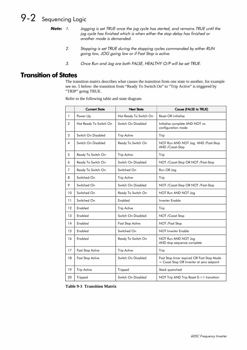
<05##6HTXHQFLQJ#/RJLF
938&#)UHTXHQF\#,QYHUWHU
1RWH=# 41 -RJJLQJ#LV#VHW#758(#RQFH#WKH#MRJ#F\FOH#KDV#VWDUWHG/#DQG#UHPDLQV#758(#XQWLO#WKH#MRJ#F\FOH#KDV#ILQLVKHG#ZKLFK#LV#ZKHQ#HLWKHU#WKH#VWRS#GHOD\#KDV#ILQLVKHG#RU#DQRWKHU#PRGH#LV#GHPDQGHG1
51 6WRSSLQJ#LV#VHW#758(#GXULQJ#WKH#VWRSSLQJ#F\FOHV#FRPPDQGHG#E\#HLWKHU#581#JRLQJ#ORZ/#-2*#JRLQJ#ORZ#RU#LI#)DVW#6WRS#LV#DFWLYH1
61 2QFH#5XQ#DQG#-RJ#DUH#ERWK#)$/6(/#+($/7+<#223#ZLOO#EH#VHW#758(1
7UDQVLWLRQ#RI#6WDWHVThe transition matrix describes what causes the transition from one state to another, for examplesee no. 5 below: the transition from “Ready To Switch On” to “Trip Active” is triggered by“TRIP” going TRUE.
Refer to the following table and state diagram.
&XUUHQW#6WDWH&XUUHQW#6WDWH&XUUHQW#6WDWH&XUUHQW#6WDWH 1H[W#6WDWH1H[W#6WDWH1H[W#6WDWH1H[W#6WDWH &DXVH#+)$/6(#WR#758(,&DXVH#+)$/6(#WR#758(,&DXVH#+)$/6(#WR#758(,&DXVH#+)$/6(#WR#758(,
4 3RZHU#8S 1RW#5HDG\#7R#6ZLWFK#2Q 5HVHW#25#LQLWLDOLVH
5 1RW#5HDG\#7R#6ZLWFK#2Q 6ZLWFK#2Q#'LVDEOHG ,QLWLDOLVH#FRPSOHWH#$1'#127#UH0FRQILJXUDWLRQ#PRGH
6 6ZLWFK#2Q#'LVDEOHG 7ULS#$FWLYH 7ULS
7 6ZLWFK#2Q#'LVDEOHG 5HDG\#7R#6ZLWFK#2Q 127#5XQ#$1'#127#-RJ##$1'#2)DVW06WRS$1'#2&RDVW06WRS
8 5HDG\#7R#6ZLWFK#2Q 7ULS#$FWLYH 7ULS
9 5HDG\#7R#6ZLWFK#2Q 6ZLWFK#2Q#'LVDEOHG 127#2&RDVW06WRS#25#127#2)DVW06WRS
: 5HDG\#7R#6ZLWFK#2Q 6ZLWFKHG#2Q 5XQ#25#-RJ
; 6ZLWFKHG#2Q 7ULS#$FWLYH 7ULS
< 6ZLWFKHG#2Q 6ZLWFK#2Q#'LVDEOHG 127#2&RDVW06WRS#25#127#2)DVW06WRS
43 6ZLWFKHG#2Q 5HDG\#7R#6ZLWFK#2Q 127#5XQ#$1'#127#-RJ
44 6ZLWFKHG#2Q (QDEOHG ,QYHUWHU#(QDEOH
45 (QDEOHG 7ULS#$FWLYH 7ULS
46 (QDEOHG 6ZLWFK#2Q#'LVDEOHG 127#2&RDVW#6WRS
47 (QDEOHG )DVW#6WRS#$FWLYH 127#2)DVW#6WRS
48 (QDEOHG 6ZLWFKHG#2Q 127#,QYHUWHU#(QDEOH
49 (QDEOHG 5HDG\#7R#6ZLWFK#2Q 127#5XQ#$1'#127#-RJ$1'#VWRS#VHTXHQFH#FRPSOHWH
4: )DVW#6WRS#$FWLYH 7ULS#$FWLYH 7ULS
4; )DVW#6WRS#$FWLYH 6ZLWFK#2Q#'LVDEOHG )DVW#6WRS#WLPHU#H[SLUHG#25#)DVW#6WRS#0RGH #&RDVW#6WRS#25#,QYHUWHU#DW#]HUR#VHWSRLQW
4< 7ULS#$FWLYH 7ULSSHG 6WDFN#TXHQFKHG
53 7ULSSHG 6ZLWFK#2Q#'LVDEOHG 127#7ULS#$1'#7ULS#5HVHW#30!4#WUDQVLWLRQ
Table 9-3 Transition Matrix
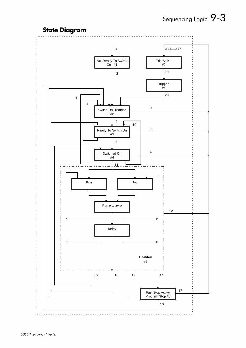
6HTXHQFLQJ#/RJLF##<06
938&#)UHTXHQF\#,QYHUWHU
6WDWH#'LDJUDP
Not Ready To SwitchOn #1
Ready To Switch On#3
Switch On Disabled#2
Run Jog
Ramp to zero
Delay
Fast Stop ActiveProgram Stop #6
Enabled
Trip Active#7
1
2
11
15 14
7
20
4
16
3,5,8,12,17
Switched On#4
6
9
Tripped#8
19
13
18
#5
10
3
5
8
12
17
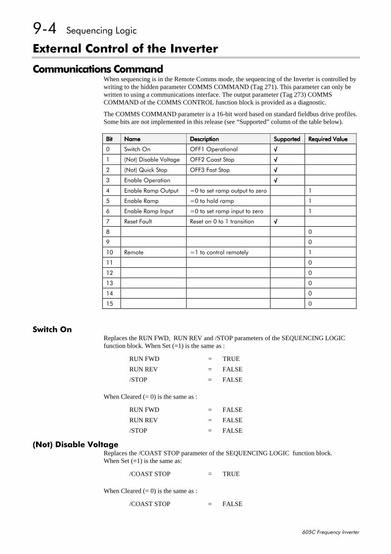
<07##6HTXHQFLQJ#/RJLF
938&#)UHTXHQF\#,QYHUWHU
([WHUQDO#&RQWURO#RI#WKH#,QYHUWHU
&RPPXQLFDWLRQV#&RPPDQGWhen sequencing is in the Remote Comms mode, the sequencing of the Inverter is controlled bywriting to the hidden parameter COMMS COMMAND (Tag 271). This parameter can only bewritten to using a communications interface. The output parameter (Tag 273) COMMSCOMMAND of the COMMS CONTROL function block is provided as a diagnostic.
The COMMS COMMAND parameter is a 16-bit word based on standard fieldbus drive profiles.Some bits are not implemented in this release (see “Supported” column of the table below).
%LW%LW%LW%LW 1DPH1DPH1DPH1DPH 'HVFULSWLRQ'HVFULSWLRQ'HVFULSWLRQ'HVFULSWLRQ 6XSSRUWHG6XSSRUWHG6XSSRUWHG6XSSRUWHG 5HTXLUHG#9DOXH5HTXLUHG#9DOXH5HTXLUHG#9DOXH5HTXLUHG#9DOXH
3 6ZLWFK#2Q 2))4#2SHUDWLRQDO √√√√
4 +1RW,#'LVDEOH#9ROWDJH 2))5#&RDVW#6WRS √√√√
5 +1RW,#4XLFN#6WRS 2))6#)DVW#6WRS √√√√
6 (QDEOH#2SHUDWLRQ √√√√
7 (QDEOH#5DPS#2XWSXW 3#WR#VHW#UDPS#RXWSXW#WR#]HUR 4
8 (QDEOH#5DPS 3#WR#KROG#UDPS 4
9 (QDEOH#5DPS#,QSXW 3#WR#VHW#UDPS#LQSXW#WR#]HUR 4
: 5HVHW#)DXOW 5HVHW#RQ#3#WR#4#WUDQVLWLRQ √√√√
; 3
< 3
43 5HPRWH 4#WR#FRQWURO#UHPRWHO\ 4
44 3
45 3
46 3
47 3
48 3
6ZLWFK#2QReplaces the RUN FWD, RUN REV and /STOP parameters of the SEQUENCING LOGICfunction block. When Set (=1) is the same as :
RUN FWD = TRUE
RUN REV = FALSE
/STOP = FALSE
When Cleared (= 0) is the same as :
RUN FWD = FALSE
RUN REV = FALSE
/STOP = FALSE
+1RW,#'LVDEOH#9ROWDJHReplaces the /COAST STOP parameter of the SEQUENCING LOGIC function block.When Set (=1) is the same as:
/COAST STOP = TRUE
When Cleared (= 0) is the same as :
/COAST STOP = FALSE
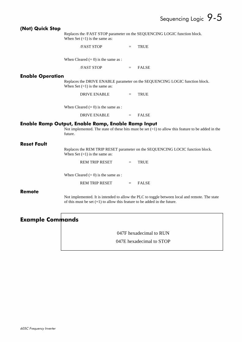
6HTXHQFLQJ#/RJLF##<08
938&#)UHTXHQF\#,QYHUWHU
+1RW,#4XLFN#6WRSReplaces the /FAST STOP parameter on the SEQUENCING LOGIC function block.When Set (=1) is the same as:
/FAST STOP = TRUE
When Cleared (= 0) is the same as :
/FAST STOP = FALSE
(QDEOH#2SHUDWLRQReplaces the DRIVE ENABLE parameter on the SEQUENCING LOGIC function block.When Set (=1) is the same as:
DRIVE ENABLE = TRUE
When Cleared (= 0) is the same as :
DRIVE ENABLE = FALSE
(QDEOH#5DPS#2XWSXW/#(QDEOH#5DPS/#(QDEOH#5DPS#,QSXWNot implemented. The state of these bits must be set (=1) to allow this feature to be added in thefuture.
5HVHW#)DXOWReplaces the REM TRIP RESET parameter on the SEQUENCING LOCIC function block.When Set (=1) is the same as:
REM TRIP RESET = TRUE
When Cleared (= 0) is the same as :
REM TRIP RESET = FALSE
5HPRWHNot implemented. It is intended to allow the PLC to toggle between local and remote. The stateof this must be set (=1) to allow this feature to be added in the future.
([DPSOH#&RPPDQGV
047F hexadecimal to RUN
047E hexadecimal to STOP
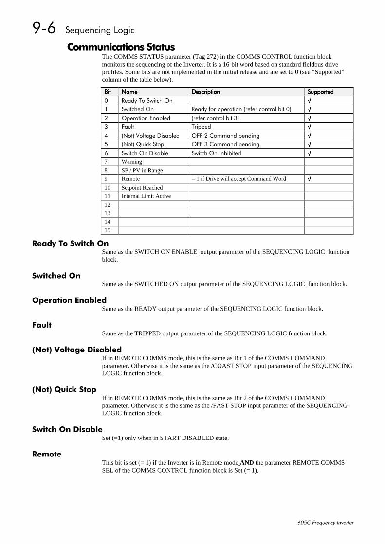
<09##6HTXHQFLQJ#/RJLF
938&#)UHTXHQF\#,QYHUWHU
&RPPXQLFDWLRQV#6WDWXVThe COMMS STATUS parameter (Tag 272) in the COMMS CONTROL function blockmonitors the sequencing of the Inverter. It is a 16-bit word based on standard fieldbus driveprofiles. Some bits are not implemented in the initial release and are set to 0 (see “Supported”column of the table below).
%LW%LW%LW%LW 1DPH1DPH1DPH1DPH 'HVFULSWLRQ'HVFULSWLRQ'HVFULSWLRQ'HVFULSWLRQ 6XSSRUWHG6XSSRUWHG6XSSRUWHG6XSSRUWHG3 5HDG\#7R#6ZLWFK#2Q √√√√4 6ZLWFKHG#2Q 5HDG\#IRU#RSHUDWLRQ#+UHIHU#FRQWURO#ELW#3, √√√√5 2SHUDWLRQ#(QDEOHG +UHIHU#FRQWURO#ELW#6, √√√√6 )DXOW 7ULSSHG √√√√7 +1RW,#9ROWDJH#'LVDEOHG 2))#5#&RPPDQG#SHQGLQJ √√√√8 +1RW,#4XLFN#6WRS 2))#6#&RPPDQG#SHQGLQJ √√√√9 6ZLWFK#2Q#'LVDEOH 6ZLWFK#2Q#,QKLELWHG √√√√7 Warning
8 SP / PV in Range
9 Remote = 1 if Drive will accept Command Word √√√√10 Setpoint Reached
11 Internal Limit Active
12
13
14
15
5HDG\#7R#6ZLWFK#2QSame as the SWITCH ON ENABLE output parameter of the SEQUENCING LOGIC functionblock.
6ZLWFKHG#2QSame as the SWITCHED ON output parameter of the SEQUENCING LOGIC function block.
2SHUDWLRQ#(QDEOHGSame as the READY output parameter of the SEQUENCING LOGIC function block.
)DXOWSame as the TRIPPED output parameter of the SEQUENCING LOGIC function block.
+1RW,#9ROWDJH#'LVDEOHGIf in REMOTE COMMS mode, this is the same as Bit 1 of the COMMS COMMANDparameter. Otherwise it is the same as the /COAST STOP input parameter of the SEQUENCINGLOGIC function block.
+1RW,#4XLFN#6WRSIf in REMOTE COMMS mode, this is the same as Bit 2 of the COMMS COMMANDparameter. Otherwise it is the same as the /FAST STOP input parameter of the SEQUENCINGLOGIC function block.
6ZLWFK#2Q#'LVDEOHSet (=1) only when in START DISABLED state.
5HPRWHThis bit is set (= 1) if the Inverter is in Remote mode AND the parameter REMOTE COMMSSEL of the COMMS CONTROL function block is Set (= 1).
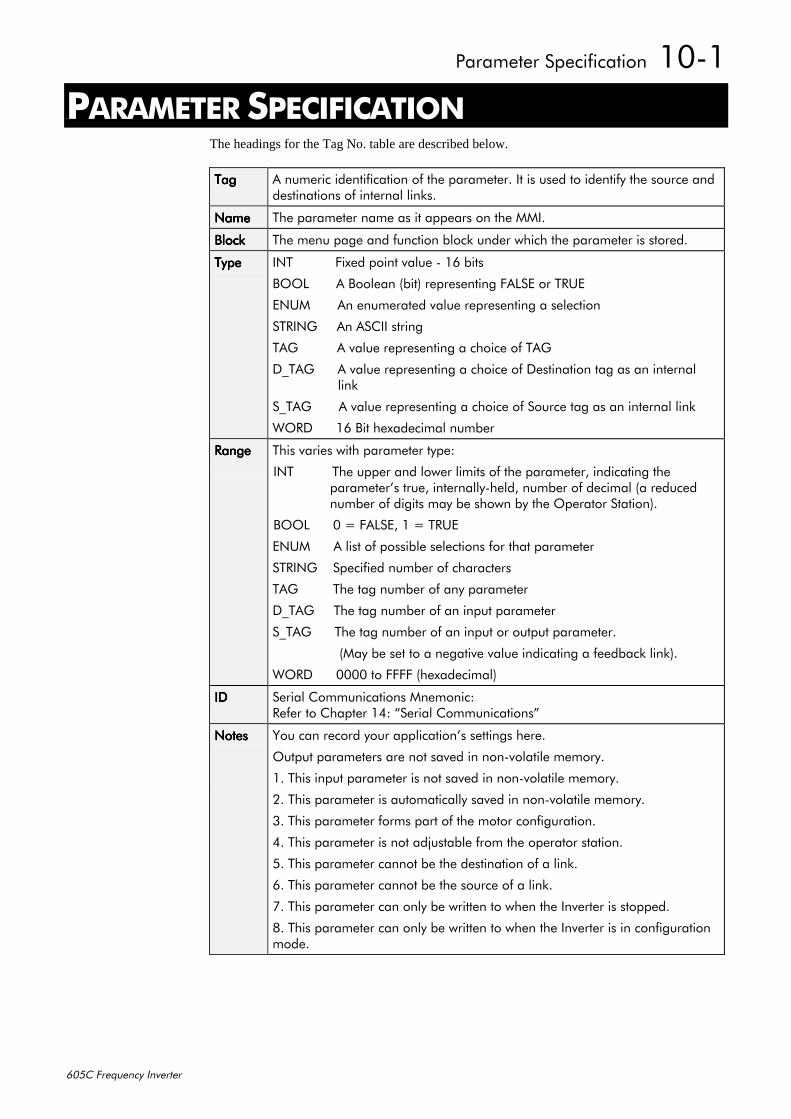
3DUDPHWHU#6SHFLILFDWLRQ##4304
938&#)UHTXHQF\#,QYHUWHU
43#3$5$0(7(5#63(&,),&$7,21The headings for the Tag No. table are described below.
7DJ7DJ7DJ7DJ $#QXPHULF#LGHQWLILFDWLRQ#RI#WKH#SDUDPHWHU1#,W#LV#XVHG#WR#LGHQWLI\#WKH#VRXUFH#DQGGHVWLQDWLRQV#RI#LQWHUQDO#OLQNV1
1DPH1DPH1DPH1DPH 7KH#SDUDPHWHU#QDPH#DV#LW#DSSHDUV#RQ#WKH#00,1
%ORFN%ORFN%ORFN%ORFN 7KH#PHQX#SDJH#DQG#IXQFWLRQ#EORFN#XQGHU#ZKLFK#WKH#SDUDPHWHU#LV#VWRUHG1
7\SH7\SH7\SH7\SH ,17###########)L[HG#SRLQW#YDOXH#0#49#ELWV
%22/#######$#%RROHDQ#+ELW,#UHSUHVHQWLQJ#)$/6(#RU#758(
(180#######$Q#HQXPHUDWHG#YDOXH#UHSUHVHQWLQJ#D#VHOHFWLRQ
675,1*#####$Q#$6&,,#VWULQJ
7$*##########$#YDOXH#UHSUHVHQWLQJ#D#FKRLFH#RI#7$*
'B7$*######$#YDOXH#UHSUHVHQWLQJ#D#FKRLFH#RI#'HVWLQDWLRQ#WDJ#DV#DQ#LQWHUQDO#################OLQN
6B7$*#######$#YDOXH#UHSUHVHQWLQJ#D#FKRLFH#RI#6RXUFH#WDJ#DV#DQ#LQWHUQDO#OLQN
:25'######49#%LW#KH[DGHFLPDO#QXPEHU
5DQJH5DQJH5DQJH5DQJH 7KLV#YDULHV#ZLWK#SDUDPHWHU#W\SH=
,17##########7KH#XSSHU#DQG#ORZHU#OLPLWV#RI#WKH#SDUDPHWHU/#LQGLFDWLQJ#WKHSDUDPHWHU·V#WUXH/#LQWHUQDOO\0KHOG/#QXPEHU#RI#GHFLPDO#+D#UHGXFHGQXPEHU#RI#GLJLWV#PD\#EH#VKRZQ#E\#WKH#2SHUDWRU#6WDWLRQ,1
%22/######3# #)$/6(/#4# #758(
(180######$#OLVW#RI#SRVVLEOH#VHOHFWLRQV#IRU#WKDW#SDUDPHWHU
675,1*####6SHFLILHG#QXPEHU#RI#FKDUDFWHUV
7$*#########7KH#WDJ#QXPEHU#RI#DQ\#SDUDPHWHU
'B7$*#####7KH#WDJ#QXPEHU#RI#DQ#LQSXW#SDUDPHWHU
6B7$*######7KH#WDJ#QXPEHU#RI#DQ#LQSXW#RU#RXWSXW#SDUDPHWHU1
+0D\#EH#VHW#WR#D#QHJDWLYH#YDOXH#LQGLFDWLQJ#D#IHHGEDFN#OLQN,1
:25'######3333#WR#))))#+KH[DGHFLPDO,
,',',',' 6HULDO#&RPPXQLFDWLRQV#0QHPRQLF=5HIHU#WR#&KDSWHU#47=#´6HULDO#&RPPXQLFDWLRQVµ
1RWHV1RWHV1RWHV1RWHV <RX#FDQ#UHFRUG#\RXU#DSSOLFDWLRQ·V#VHWWLQJV#KHUH1
2XWSXW#SDUDPHWHUV#DUH#QRW#VDYHG#LQ#QRQ0YRODWLOH#PHPRU\1
41#7KLV#LQSXW#SDUDPHWHU#LV#QRW#VDYHG#LQ#QRQ0YRODWLOH#PHPRU\1
51#7KLV#SDUDPHWHU#LV#DXWRPDWLFDOO\#VDYHG#LQ#QRQ0YRODWLOH#PHPRU\1
61#7KLV#SDUDPHWHU#IRUPV#SDUW#RI#WKH#PRWRU#FRQILJXUDWLRQ1
71#7KLV#SDUDPHWHU#LV#QRW#DGMXVWDEOH#IURP#WKH#RSHUDWRU#VWDWLRQ1
81#7KLV#SDUDPHWHU#FDQQRW#EH#WKH#GHVWLQDWLRQ#RI#D#OLQN1
91#7KLV#SDUDPHWHU#FDQQRW#EH#WKH#VRXUFH#RI#D#OLQN1
:1#7KLV#SDUDPHWHU#FDQ#RQO\#EH#ZULWWHQ#WR#ZKHQ#WKH#,QYHUWHU#LV#VWRSSHG1
;1#7KLV#SDUDPHWHU#FDQ#RQO\#EH#ZULWWHQ#WR#ZKHQ#WKH#,QYHUWHU#LV#LQ#FRQILJXUDWLRQPRGH1
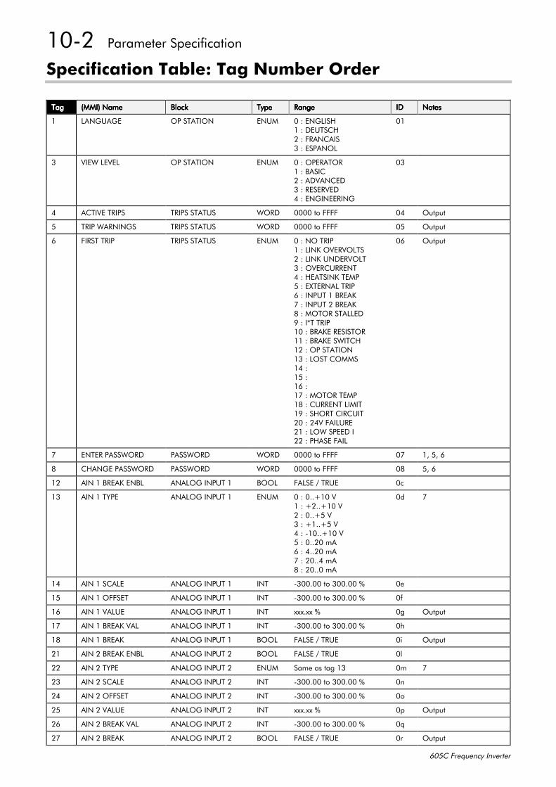
4305##3DUDPHWHU#6SHFLILFDWLRQ
938&#)UHTXHQF\#,QYHUWHU
6SHFLILFDWLRQ#7DEOH=#7DJ#1XPEHU#2UGHU
7DJ7DJ7DJ7DJ +00,,#1DPH+00,,#1DPH+00,,#1DPH+00,,#1DPH %ORFN%ORFN%ORFN%ORFN 7\SH7\SH7\SH7\SH 5DQJH5DQJH5DQJH5DQJH ,',',',' 1RWHV1RWHV1RWHV1RWHV
4 /$1*8$*( 23#67$7,21 (180 3#=#(1*/,6+4#=#'(876&+5#=#)5$1&$,66#=#(63$12/
34
6 9,(:#/(9(/ 23#67$7,21 (180 3#=#23(5$7254#=#%$6,&5#=#$'9$1&('6#=#5(6(59('7#=#(1*,1((5,1*
36
7 $&7,9(#75,36 75,36#67$786 :25' 3333#WR#)))) 37 2XWSXW
8 75,3#:$51,1*6 75,36#67$786 :25' 3333#WR#)))) 38 2XWSXW
9 ),567#75,3 75,36#67$786 (180 3#=#12#75,34#=#/,1.#29(592/765#=#/,1.#81'(592/76#=#29(5&855(177#=#+($76,1.#7(038#=#(;7(51$/#75,39#=#,1387#4#%5($.:#=#,1387#5#%5($.;#=#02725#67$//('<#=#,-7#75,343#=#%5$.(#5(6,672544#=#%5$.(#6:,7&+45#=#23#67$7,2146#=#/267#&200647#=48#=49#=4:#=#02725#7(034;#=#&855(17#/,0,74<#=#6+257#&,5&8,753#=#579#)$,/85(54#=#/2:#63(('#,55#=#3+$6(#)$,/
39 2XWSXW
: (17(5#3$66:25' 3$66:25' :25' 3333#WR#)))) 3: 4/#8/#9
; &+$1*(#3$66:25' 3$66:25' :25' 3333#WR#)))) 3; 8/#9
45 $,1#4#%5($.#(1%/ $1$/2*#,1387#4 %22/ )$/6(#2#758( 3F
46 $,1#4#7<3( $1$/2*#,1387#4 (180 3#=#311.43#94#=#.511.43#95#=#311.8#96#=#.411.8#97#=#04311.43#98#=#31153#P$9#=#71153#P$:#=#53117#P$;#=#53113#P$
3G :
47 $,1#4#6&$/( $1$/2*#,1387#4 ,17 0633133#WR#633133#( 3H
48 $,1#4#2))6(7 $1$/2*#,1387#4 ,17 0633133#WR#633133#( 3I
49 $,1#4#9$/8( $1$/2*#,1387#4 ,17 [[[1[[#( 3J 2XWSXW
4: $,1#4#%5($.#9$/ $1$/2*#,1387#4 ,17 0633133#WR#633133#( 3K
4; $,1#4#%5($. $1$/2*#,1387#4 %22/ )$/6(#2#758( 3L 2XWSXW
54 $,1#5#%5($.#(1%/ $1$/2*#,1387#5 %22/ )$/6(#2#758( 3O
55 $,1#5#7<3( $1$/2*#,1387#5 (180 6DPH#DV#WDJ#46 3P :
56 $,1#5#6&$/( $1$/2*#,1387#5 ,17 0633133#WR#633133#( 3Q
57 $,1#5#2))6(7 $1$/2*#,1387#5 ,17 0633133#WR#633133#( 3R
58 $,1#5#9$/8( $1$/2*#,1387#5 ,17 [[[1[[#( 3S 2XWSXW
59 $,1#5#%5($.#9$/ $1$/2*#,1387#5 ,17 0633133#WR#633133#( 3T
5: $,1#5#%5($. $1$/2*#,1387#5 %22/ )$/6(#2#758( 3U 2XWSXW
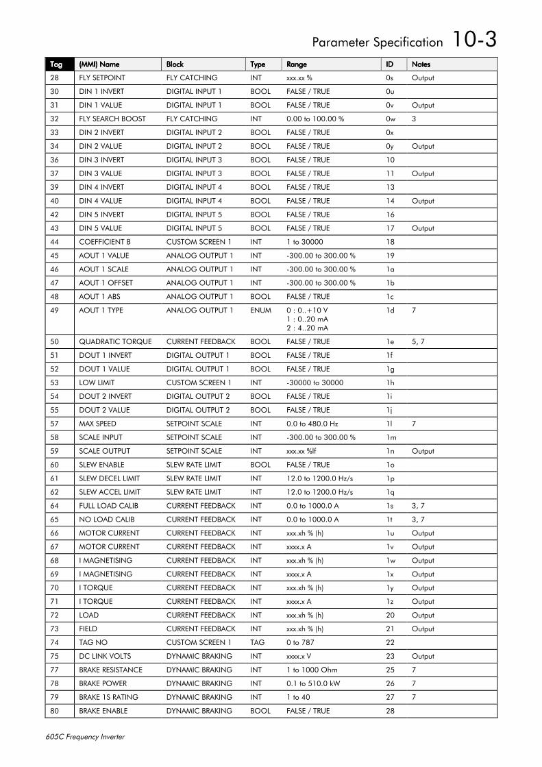
3DUDPHWHU#6SHFLILFDWLRQ##4306
938&#)UHTXHQF\#,QYHUWHU
7DJ7DJ7DJ7DJ +00,,#1DPH+00,,#1DPH+00,,#1DPH+00,,#1DPH %ORFN%ORFN%ORFN%ORFN 7\SH7\SH7\SH7\SH 5DQJH5DQJH5DQJH5DQJH ,',',',' 1RWHV1RWHV1RWHV1RWHV
5; )/<#6(732,17 )/<#&$7&+,1* ,17 [[[1[[#( 3V 2XWSXW
63 ',1#4#,19(57 ',*,7$/#,1387#4 %22/ )$/6(#2#758( 3X
64 ',1#4#9$/8( ',*,7$/#,1387#4 %22/ )$/6(#2#758( 3Y 2XWSXW
65 )/<#6($5&+#%2267 )/<#&$7&+,1* ,17 3133#WR#433133#( 3Z 6
66 ',1#5#,19(57 ',*,7$/#,1387#5 %22/ )$/6(#2#758( 3[
67 ',1#5#9$/8( ',*,7$/#,1387#5 %22/ )$/6(#2#758( 3\ 2XWSXW
69 ',1#6#,19(57 ',*,7$/#,1387#6 %22/ )$/6(#2#758( 43
6: ',1#6#9$/8( ',*,7$/#,1387#6 %22/ )$/6(#2#758( 44 2XWSXW
6< ',1#7#,19(57 ',*,7$/#,1387#7 %22/ )$/6(#2#758( 46
73 ',1#7#9$/8( ',*,7$/#,1387#7 %22/ )$/6(#2#758( 47 2XWSXW
75 ',1#8#,19(57 ',*,7$/#,1387#8 %22/ )$/6(#2#758( 49
76 ',1#8#9$/8( ',*,7$/#,1387#8 %22/ )$/6(#2#758( 4: 2XWSXW
77 &2()),&,(17#% &86720#6&5((1#4 ,17 4#WR#63333 4;
78 $287#4#9$/8( $1$/2*#287387#4 ,17 0633133#WR#633133#( 4<
79 $287#4#6&$/( $1$/2*#287387#4 ,17 0633133#WR#633133#( 4D
7: $287#4#2))6(7 $1$/2*#287387#4 ,17 0633133#WR#633133#( 4E
7; $287#4#$%6 $1$/2*#287387#4 %22/ )$/6(#2#758( 4F
7< $287#4#7<3( $1$/2*#287387#4 (180 3#=#311.43#94#=#31153#P$5#=#71153#P$
4G :
83 48$'5$7,𑭤( &855(17#)(('%$&. %22/ )$/6(#2#758( 4H 8/#:
84 '287#4#,19(57 ',*,7$/#287387#4 %22/ )$/6(#2#758( 4I
85 '287#4#9$/8( ',*,7$/#287387#4 %22/ )$/6(#2#758( 4J
86 /2:#/,0,7 &86720#6&5((1#4 ,17 063333#WR#63333 4K
87 '287#5#,19(57 ',*,7$/#287387#5 %22/ )$/6(#2#758( 4L
88 '287#5#9$/8( ',*,7$/#287387#5 %22/ )$/6(#2#758( 4M
8: 0$;#63((' 6(732,17#6&$/( ,17 313#WR#7;313#+] 4O :
8; 6&$/(#,1387 6(732,17#6&$/( ,17 0633133#WR#633133#( 4P
8< 6&$/(#287387 6(732,17#6&$/( ,17 [[[1[[#(OI 4Q 2XWSXW
93 6/(:#(1$%/( 6/(:#5$7(#/,0,7 %22/ )$/6(#2#758( 4R
94 6/(:#'(&(/#/,0,7 6/(:#5$7(#/,0,7 ,17 4513#WR#453313#+]2V 4S
95 6/(:#$&&(/#/,0,7 6/(:#5$7(#/,0,7 ,17 4513#WR#453313#+]2V 4T
97 )8//#/2$'#&$/,% &855(17#)(('%$&. ,17 313#WR#433313#$ 4V 6/#:
98 12#/2$'#&$/,% &855(17#)(('%$&. ,17 313#WR#433313#$ 4W 6/#:
99 02725#&855(17 &855(17#)(('%$&. ,17 [[[1[K#(#+K, 4X 2XWSXW
9: 02725#&855(17 &855(17#)(('%$&. ,17 [[[[1[#$ 4Y 2XWSXW
9; ,#0$*1(7,6,1* &855(17#)(('%$&. ,17 [[[1[K#(#+K, 4Z 2XWSXW
9< ,#0$*1(7,6,1* &855(17#)(('%$&. ,17 [[[[1[#$ 4[ 2XWSXW
:3 ,#72548( &855(17#)(('%$&. ,17 [[[1[K#(#+K, 4\ 2XWSXW
:4 ,#72548( &855(17#)(('%$&. ,17 [[[[1[#$ 4] 2XWSXW
:5 /2$' &855(17#)(('%$&. ,17 [[[1[K#(#+K, 53 2XWSXW
:6 ),(/' &855(17#)(('%$&. ,17 [[[1[K#(#+K, 54 2XWSXW
:7 7$*#12 &86720#6&5((1#4 7$* 3#WR#:;: 55
:8 '&#/,1.#92/76 '<1$0,&#%5$.,1* ,17 [[[[1[#9 56 2XWSXW
:: %5$.(#5(6,67$1&( '<1$0,&#%5$.,1* ,17 4#WR#4333#2KP 58 :
:; %5$.(#32:(5 '<1$0,&#%5$.,1* ,17 314#WR#84313#N: 59 :
:< %5$.(#46#5$7,1* '<1$0,&#%5$.,1* ,17 4#WR#73 5: :
;3 %5$.(#(1$%/( '<1$0,&#%5$.,1* %22/ )$/6(#2#758( 5;
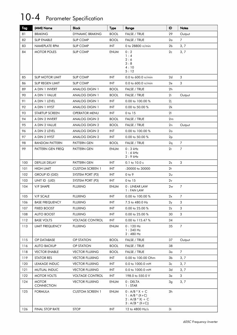
4307##3DUDPHWHU#6SHFLILFDWLRQ
938&#)UHTXHQF\#,QYHUWHU
7DJ7DJ7DJ7DJ +00,,#1DPH+00,,#1DPH+00,,#1DPH+00,,#1DPH %ORFN%ORFN%ORFN%ORFN 7\SH7\SH7\SH7\SH 5DQJH5DQJH5DQJH5DQJH ,',',',' 1RWHV1RWHV1RWHV1RWHV
;4 %5$.,1* '<1$0,&#%5$.,1* %22/ )$/6(#2#758( 5< 2XWSXW
;5 6/,3#(1$%/( 6/,3#&203 %22/ )$/6(#2#758( 5D :
;6 1$0(3/$7(#530 6/,3#&203 ,17 3#WR#5;;33#Q2PLQ 5E 6/#:
;7 02725#32/(6 6/,3#&203 (180 3#=#54#=#75#=#96#=#;7#=#438#=#45
5F 6/#:
;8 6/,3#02725#/,0,7 6/,3#&203 ,17 313#WR#93313#Q2PLQ 5G 6
;9 6/,3#5(*(1#/,0,7 6/,3#&203 ,17 313#WR#93313#Q2PLQ 5H 6
;< $#',1#4#,19(57 $1$/2*#',*,1#4 %22/ )$/6(#2#758( 5K
<3 $#',1#4#9$/8( $1$/2*#',*,1#4 %22/ )$/6(#2#758( 5L 2XWSXW
<4 $#',1#4#/(9(/ $1$/2*#',*,1#4 ,17 3133#WR#433133#( 5M
<5 $#',1#4#+<67 $1$/2*#',*,1#4 ,17 3133#WR#83133#( 5N
<6 67$5783#6&5((1 23(5$725#0(18 ,17 3#WR#48 5O
<7 $#',1#5#,19(57 $1$/2*#',*,1#5 %22/ )$/6(#2#758( 5P
<8 $#',1#5#9$/8( $1$/2*#',*,1#5 %22/ )$/6(#2#758( 5Q 2XWSXW
<9 $#',1#5#/(9(/ $1$/2*#',*,1#5 ,17 3133#WR#433133#( 5R
<: $#',1#5#+<67 $1$/2*#',*,1#5 ,17 3133#WR#83133#( 5S
<; 5$1'20#3$77(51 3$77(51#*(1 %22/ )$/6(#2#758( 5T :
<< 3$77(51#*(1#)5(4 3$77(51#*(1 (180 3#=#6#N+]4#=#9#N+]5#=#<#N+]
5U :
433 '()/8;#'(/$< 3$77(51#*(1 ,17 314#WR#4313#V 5V 6
434 +,*+#/,0,7 &86720#6&5((1#4 ,17 063333#WR#63333 5W
435 *5283#,'#+*,', 6<67(0#3257#+36, ,17 3#WR#< 5X
436 81,7#,'##+8,', 6<67(0#3257#+36, ,17 3#WR#48 5Y
437 92)#6+$3( )/8;,1* (180 3#=#/,1($5#/$:4#=#)$1#/$:
5Z :
438 92)#6&$/( )/8;,1* ,17 3133#WR#433133#( 5[ :
439 %$6(#)5(48(1&< )/8;,1* ,17 :18#WR#7;313#+] 5\ 6
43: ),;('#%2267 )/8;,1* ,17 3133#WR#58133#( 5] 6
43; $872#%2267 )/8;,1* ,17 3133#WR#58133#( 63 6
445 %$6(#92/76 92/7$*(#&21752/ ,17 3133#WR#44817:#( 67
446 /,0,7#)5(48(1&< )/8;,1* (180 3#=#453#+]4#=#573#+]5#=#7;3#+]
68 :
448 23#'$7$%$6( 23#67$7,21 %22/ )$/6(#2#758( 6: 2XWSXW
449 $872#%$&.83 23#67$7,21 %22/ )$/6(#2#758( 6;
44; 9(&725#(1$%/( 9(&725#)/8;,1* %22/ )$/6(#2#758( 6D :
44< 67$725#5(6 9(&725#)/8;,1* ,17 3133#WR#433133#2KP 6E 6/#:
453 /($.$*(#,1'8& 9(&725#)/8;,1* ,17 313#WR#433313#P+ 6F 6/#:
454 0878$/#,1'8& 9(&725#)/8;,1* ,17 313#WR#433313#P+ 6G 6/#:
455 02725#92/76 92/7$*(#&21752/ ,17 4<;13#WR#88313#9 6H 6
457 02725&211(&7,21
9(&725#)/8;,1* (180 3#=#'(/7$4#=#67$5
6J 6/#:
458 )2508/$ &86720#6&5((1#4 (180 3#=#$2%#-#;#.#&4#=#$2%#-#+;.&,5#=#$2+%#-#;,#.#&6#=#$2+%#-#+;.&,,
6K
459 ),1$/#6723#5$7( 6723 ,17 45#WR#7;33#+]2V 6L
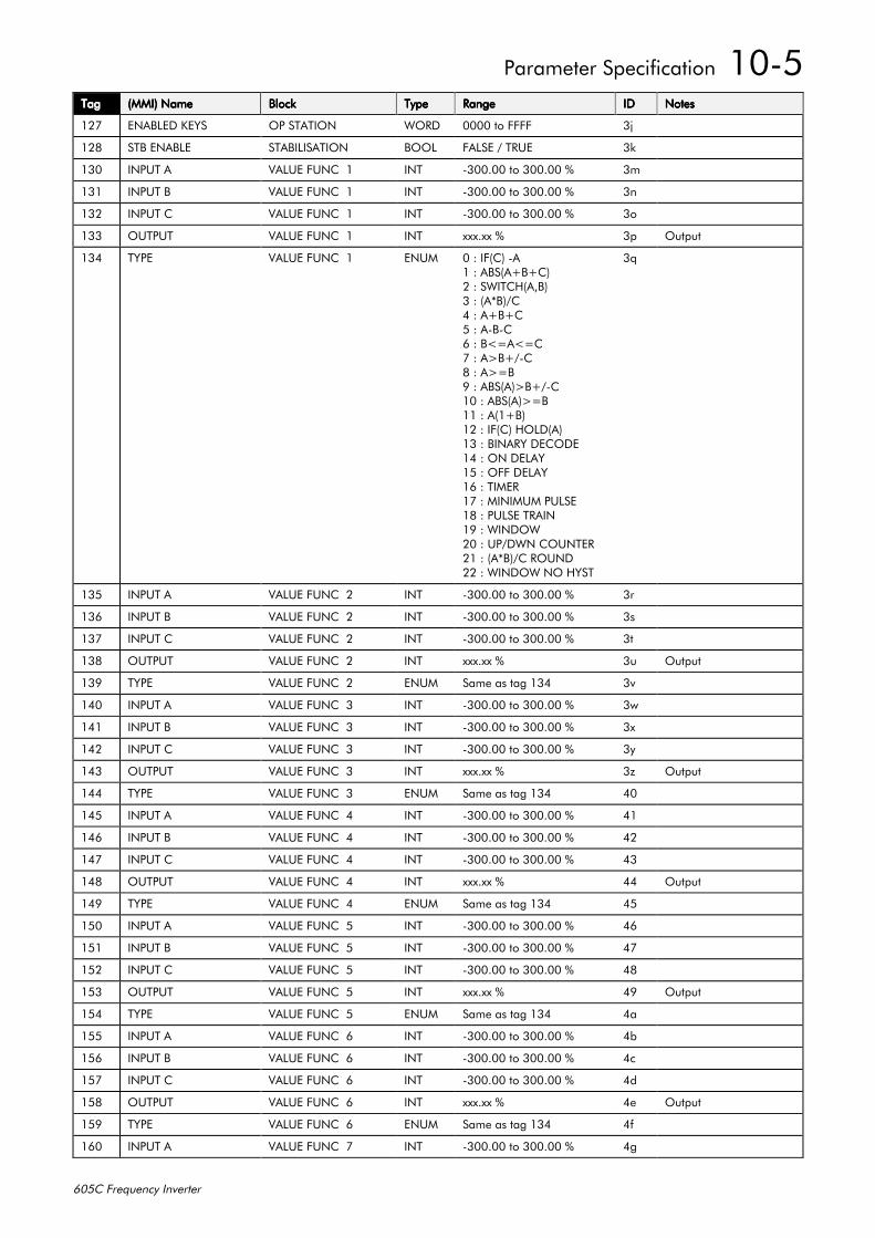
3DUDPHWHU#6SHFLILFDWLRQ##4308
938&#)UHTXHQF\#,QYHUWHU
7DJ7DJ7DJ7DJ +00,,#1DPH+00,,#1DPH+00,,#1DPH+00,,#1DPH %ORFN%ORFN%ORFN%ORFN 7\SH7\SH7\SH7\SH 5DQJH5DQJH5DQJH5DQJH ,',',',' 1RWHV1RWHV1RWHV1RWHV
45: (1$%/('#.(<6 23#67$7,21 :25' 3333#WR#)))) 6M
45; 67%#(1$%/( 67$%,/,6$7,21 %22/ )$/6(#2#758( 6N
463 ,1387#$ 9$/8(#)81&##4 ,17 0633133#WR#633133#( 6P
464 ,1387#% 9$/8(#)81&##4 ,17 0633133#WR#633133#( 6Q
465 ,1387#& 9$/8(#)81&##4 ,17 0633133#WR#633133#( 6R
466 287387 9$/8(#)81&##4 ,17 [[[1[[#( 6S 2XWSXW
467 7<3( 9$/8(#)81&##4 (180 3#=#,)+&,#0$4#=#$%6+$.%.&,5#=#6:,7&++$/%,6#=#+$-%,2&7#=#$.%.&8#=#$0%0&9#=#%? $? &:#=#$!%.20&;#=#$! %<#=#$%6+$,!%.20&43#=#$%6+$,! %44#=#$+4.%,45#=#,)+&,#+2/'+$,46#=#%,1$5<#'(&2'(47#=#21#'(/$<48#=#2))#'(/$<49#=#7,0(54:#=#0,1,080#38/6(4;#=#38/6(#75$,14<#=#:,1'2:53#=#832':1#&2817(554#=#+$-%,2ᒡ'55#=#:,1'2:#12#+<67
6T
468 ,1387#$ 9$/8(#)81&##5 ,17 0633133#WR#633133#( 6U
469 ,1387#% 9$/8(#)81&##5 ,17 0633133#WR#633133#( 6V
46: ,1387#& 9$/8(#)81&##5 ,17 0633133#WR#633133#( 6W
46; 287387 9$/8(#)81&##5 ,17 [[[1[[#( 6X 2XWSXW
46< 7<3( 9$/8(#)81&##5 (180 6DPH#DV#WDJ#467 6Y
473 ,1387#$ 9$/8(#)81&##6 ,17 0633133#WR#633133#( 6Z
474 ,1387#% 9$/8(#)81&##6 ,17 0633133#WR#633133#( 6[
475 ,1387#& 9$/8(#)81&##6 ,17 0633133#WR#633133#( 6\
476 287387 9$/8(#)81&##6 ,17 [[[1[[#( 6] 2XWSXW
477 7<3( 9$/8(#)81&##6 (180 6DPH#DV#WDJ#467 73
478 ,1387#$ 9$/8(#)81&##7 ,17 0633133#WR#633133#( 74
479 ,1387#% 9$/8(#)81&##7 ,17 0633133#WR#633133#( 75
47: ,1387#& 9$/8(#)81&##7 ,17 0633133#WR#633133#( 76
47; 287387 9$/8(#)81&##7 ,17 [[[1[[#( 77 2XWSXW
47< 7<3( 9$/8(#)81&##7 (180 6DPH#DV#WDJ#467 78
483 ,1387#$ 9$/8(#)81&##8 ,17 0633133#WR#633133#( 79
484 ,1387#% 9$/8(#)81&##8 ,17 0633133#WR#633133#( 7:
485 ,1387#& 9$/8(#)81&##8 ,17 0633133#WR#633133#( 7;
486 287387 9$/8(#)81&##8 ,17 [[[1[[#( 7< 2XWSXW
487 7<3( 9$/8(#)81&##8 (180 6DPH#DV#WDJ#467 7D
488 ,1387#$ 9$/8(#)81&##9 ,17 0633133#WR#633133#( 7E
489 ,1387#% 9$/8(#)81&##9 ,17 0633133#WR#633133#( 7F
48: ,1387#& 9$/8(#)81&##9 ,17 0633133#WR#633133#( 7G
48; 287387 9$/8(#)81&##9 ,17 [[[1[[#( 7H 2XWSXW
48< 7<3( 9$/8(#)81&##9 (180 6DPH#DV#WDJ#467 7I
493 ,1387#$ 9$/8(#)81&##: ,17 0633133#WR#633133#( 7J
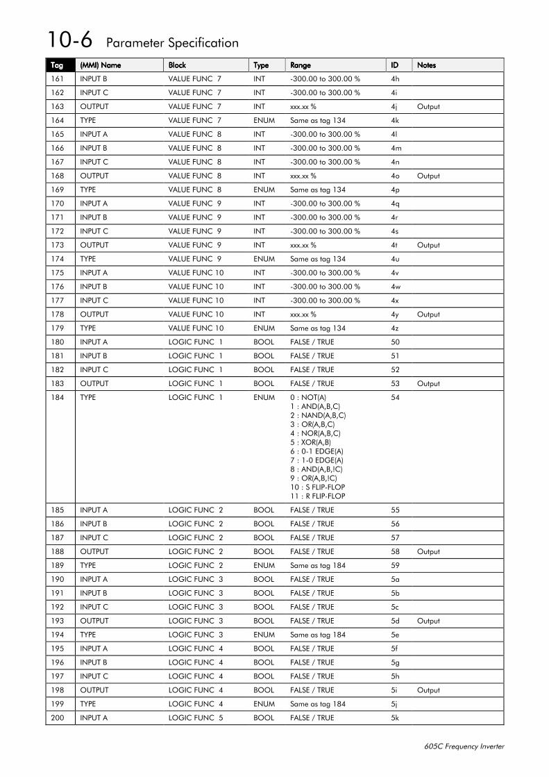
4309##3DUDPHWHU#6SHFLILFDWLRQ
938&#)UHTXHQF\#,QYHUWHU
7DJ7DJ7DJ7DJ +00,,#1DPH+00,,#1DPH+00,,#1DPH+00,,#1DPH %ORFN%ORFN%ORFN%ORFN 7\SH7\SH7\SH7\SH 5DQJH5DQJH5DQJH5DQJH ,',',',' 1RWHV1RWHV1RWHV1RWHV
494 ,1387#% 9$/8(#)81&##: ,17 0633133#WR#633133#( 7K
495 ,1387#& 9$/8(#)81&##: ,17 0633133#WR#633133#( 7L
496 287387 9$/8(#)81&##: ,17 [[[1[[#( 7M 2XWSXW
497 7<3( 9$/8(#)81&##: (180 6DPH#DV#WDJ#467 7N
498 ,1387#$ 9$/8(#)81&##; ,17 0633133#WR#633133#( 7O
499 ,1387#% 9$/8(#)81&##; ,17 0633133#WR#633133#( 7P
49: ,1387#& 9$/8(#)81&##; ,17 0633133#WR#633133#( 7Q
49; 287387 9$/8(#)81&##; ,17 [[[1[[#( 7R 2XWSXW
49< 7<3( 9$/8(#)81&##; (180 6DPH#DV#WDJ#467 7S
4:3 ,1387#$ 9$/8(#)81&##< ,17 0633133#WR#633133#( 7T
4:4 ,1387#% 9$/8(#)81&##< ,17 0633133#WR#633133#( 7U
4:5 ,1387#& 9$/8(#)81&##< ,17 0633133#WR#633133#( 7V
4:6 287387 9$/8(#)81&##< ,17 [[[1[[#( 7W 2XWSXW
4:7 7<3( 9$/8(#)81&##< (180 6DPH#DV#WDJ#467 7X
4:8 ,1387#$ 9$/8(#)81+ ,17 0633133#WR#633133#( 7Y
4:9 ,1387#% 9$/8(#)81+ ,17 0633133#WR#633133#( 7Z
4:: ,1387#& 9$/8(#)81+ ,17 0633133#WR#633133#( 7[
4:; 287387 9$/8(#)81+ ,17 [[[1[[#( 7\ 2XWSXW
4:< 7<3( 9$/8(#)81+ (180 6DPH#DV#WDJ#467 7]
4;3 ,1387#$ /2*,&#)81&##4 %22/ )$/6(#2#758( 83
4;4 ,1387#% /2*,&#)81&##4 %22/ )$/6(#2#758( 84
4;5 ,1387#& /2*,&#)81&##4 %22/ )$/6(#2#758( 85
4;6 287387 /2*,&#)81&##4 %22/ )$/6(#2#758( 86 2XWSXW
4;7 7<3( /2*,&#)81&##4 (180 3#=#127+$,4#=#$1'+$/%/&,5#=#1$1'+$/%/&,6#=#25+$/%/&,7#=#125+$/%/&,8#=#;25+$/%,9#=#304#('*(+$,:#=#403#('*(+$,;#=#$1'+$/%/$&,<#=#25+$/%/$&,43#=#6#)/,30)/2344#=#5#)/,30)/23
87
4;8 ,1387#$ /2*,&#)81&##5 %22/ )$/6(#2#758( 88
4;9 ,1387#% /2*,&#)81&##5 %22/ )$/6(#2#758( 89
4;: ,1387#& /2*,&#)81&##5 %22/ )$/6(#2#758( 8:
4;; 287387 /2*,&#)81&##5 %22/ )$/6(#2#758( 8; 2XWSXW
4;< 7<3( /2*,&#)81&##5 (180 6DPH#DV#WDJ#4;7 8<
4<3 ,1387#$ /2*,&#)81&##6 %22/ )$/6(#2#758( 8D
4<4 ,1387#% /2*,&#)81&##6 %22/ )$/6(#2#758( 8E
4<5 ,1387#& /2*,&#)81&##6 %22/ )$/6(#2#758( 8F
4<6 287387 /2*,&#)81&##6 %22/ )$/6(#2#758( 8G 2XWSXW
4<7 7<3( /2*,&#)81&##6 (180 6DPH#DV#WDJ#4;7 8H
4<8 ,1387#$ /2*,&#)81&##7 %22/ )$/6(#2#758( 8I
4<9 ,1387#% /2*,&#)81&##7 %22/ )$/6(#2#758( 8J
4<: ,1387#& /2*,&#)81&##7 %22/ )$/6(#2#758( 8K
4<; 287387 /2*,&#)81&##7 %22/ )$/6(#2#758( 8L 2XWSXW
4<< 7<3( /2*,&#)81&##7 (180 6DPH#DV#WDJ#4;7 8M
533 ,1387#$ /2*,&#)81&##8 %22/ )$/6(#2#758( 8N
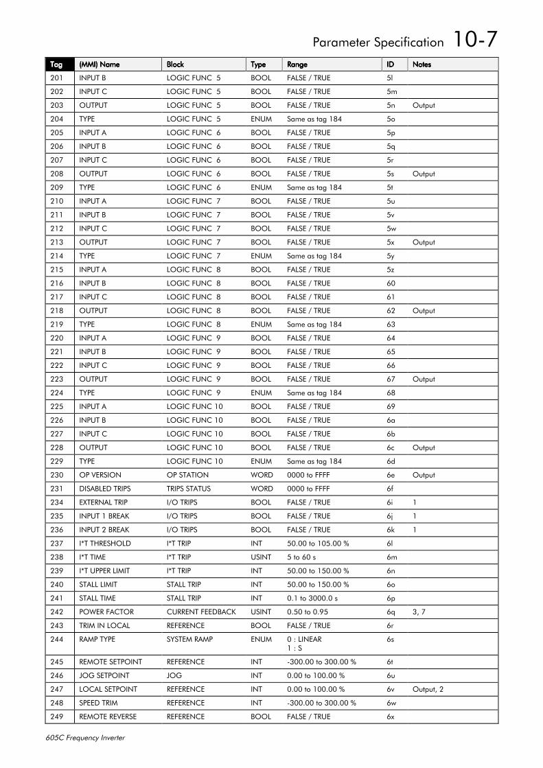
3DUDPHWHU#6SHFLILFDWLRQ##430:
938&#)UHTXHQF\#,QYHUWHU
7DJ7DJ7DJ7DJ +00,,#1DPH+00,,#1DPH+00,,#1DPH+00,,#1DPH %ORFN%ORFN%ORFN%ORFN 7\SH7\SH7\SH7\SH 5DQJH5DQJH5DQJH5DQJH ,',',',' 1RWHV1RWHV1RWHV1RWHV
534 ,1387#% /2*,&#)81&##8 %22/ )$/6(#2#758( 8O
535 ,1387#& /2*,&#)81&##8 %22/ )$/6(#2#758( 8P
536 287387 /2*,&#)81&##8 %22/ )$/6(#2#758( 8Q 2XWSXW
537 7<3( /2*,&#)81&##8 (180 6DPH#DV#WDJ#4;7 8R
538 ,1387#$ /2*,&#)81&##9 %22/ )$/6(#2#758( 8S
539 ,1387#% /2*,&#)81&##9 %22/ )$/6(#2#758( 8T
53: ,1387#& /2*,&#)81&##9 %22/ )$/6(#2#758( 8U
53; 287387 /2*,&#)81&##9 %22/ )$/6(#2#758( 8V 2XWSXW
53< 7<3( /2*,&#)81&##9 (180 6DPH#DV#WDJ#4;7 8W
543 ,1387#$ /2*,&#)81&##: %22/ )$/6(#2#758( 8X
544 ,1387#% /2*,&#)81&##: %22/ )$/6(#2#758( 8Y
545 ,1387#& /2*,&#)81&##: %22/ )$/6(#2#758( 8Z
546 287387 /2*,&#)81&##: %22/ )$/6(#2#758( 8[ 2XWSXW
547 7<3( /2*,&#)81&##: (180 6DPH#DV#WDJ#4;7 8\
548 ,1387#$ /2*,&#)81&##; %22/ )$/6(#2#758( 8]
549 ,1387#% /2*,&#)81&##; %22/ )$/6(#2#758( 93
54: ,1387#& /2*,&#)81&##; %22/ )$/6(#2#758( 94
54; 287387 /2*,&#)81&##; %22/ )$/6(#2#758( 95 2XWSXW
54< 7<3( /2*,&#)81&##; (180 6DPH#DV#WDJ#4;7 96
553 ,1387#$ /2*,&#)81&##< %22/ )$/6(#2#758( 97
554 ,1387#% /2*,&#)81&##< %22/ )$/6(#2#758( 98
555 ,1387#& /2*,&#)81&##< %22/ )$/6(#2#758( 99
556 287387 /2*,&#)81&##< %22/ )$/6(#2#758( 9: 2XWSXW
557 7<3( /2*,&#)81&##< (180 6DPH#DV#WDJ#4;7 9;
558 ,1387#$ /2*,&#)81+ %22/ )$/6(#2#758( 9<
559 ,1387#% /2*,&#)81+ %22/ )$/6(#2#758( 9D
55: ,1387#& /2*,&#)81+ %22/ )$/6(#2#758( 9E
55; 287387 /2*,&#)81+ %22/ )$/6(#2#758( 9F 2XWSXW
55< 7<3( /2*,&#)81+ (180 6DPH#DV#WDJ#4;7 9G
563 23#9(56,21 23#67$7,21 :25' 3333#WR#)))) 9H 2XWSXW
564 ',6$%/('#75,36 75,36#67$786 :25' 3333#WR#)))) 9I
567 (;7(51$/#75,3 ,22#75,36 %22/ )$/6(#2#758( 9L 4
568 ,1387#4#%5($. ,22#75,36 %22/ )$/6(#2#758( 9M 4
569 ,1387#5#%5($. ,22#75,36 %22/ )$/6(#2#758( 9N 4
56: ,-7#7+5(6+2/' ,-7#75,3 ,17 83133#WR#438133#( 9O
56; ,-7#7,0( ,-7#75,3 86,17 8#WR#93#V 9P
56< ,-7#833(5#/,0,7 ,-7#75,3 ,17 83133#WR#483133#( 9Q
573 67$//#/,0,7 67$//#75,3 ,17 83133#WR#483133#( 9R
574 67$//#7,0( 67$//#75,3 ,17 314#WR#633313#V 9S
575 32:(5#)$&725 &855(17#)(('%$&. 86,17 3183#WR#31<8 9T 6/#:
576 75,0#,1#/2&$/ 5()(5(1&( %22/ )$/6(#2#758( 9U
577 5$03#7<3( 6<67(0#5$03 (180 3#=#/,1($54#=#6
9V
578 5(027(#6(732,17 5()(5(1&( ,17 0633133#WR#633133#( 9W
579 -2*#6(732,17 -2* ,17 3133#WR#433133#( 9X
57: /2&$/#6(732,17 5()(5(1&( ,17 3133#WR#433133#( 9Y 2XWSXW/#5
57; 63(('#75,0 5()(5(1&( ,17 0633133#WR#633133#( 9Z
57< 5(027(#5(9(56( 5()(5(1&( %22/ )$/6(#2#758( 9[
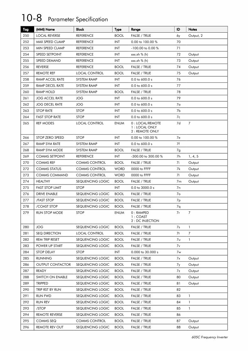
430;##3DUDPHWHU#6SHFLILFDWLRQ
938&#)UHTXHQF\#,QYHUWHU
7DJ7DJ7DJ7DJ +00,,#1DPH+00,,#1DPH+00,,#1DPH+00,,#1DPH %ORFN%ORFN%ORFN%ORFN 7\SH7\SH7\SH7\SH 5DQJH5DQJH5DQJH5DQJH ,',',',' 1RWHV1RWHV1RWHV1RWHV
583 /2&$/#5(9(56( 5()(5(1&( %22/ )$/6(#2#758( 9\ 2XWSXW/#5
585 0$;#63(('#&/$03 5()(5(1&( ,17 3133#WR#433133#( :3
586 0,1#63(('#&/$03 5()(5(1&( ,17 0433133#WR#3133#( :4
587 63(('#6(732,17 5()(5(1&( ,17 [[[1[K#(#+K, :5 2XWSXW
588 63(('#'(0$1' 5()(5(1&( ,17 [[[1[K#(#+K, :6 2XWSXW
589 5(9(56( 5()(5(1&( %22/ )$/6(#2#758( :7 2XWSXW
58: 5(027(#5() /2&$/#&21752/ %22/ )$/6(#2#758( :8 2XWSXW
58; 5$03#$&&(/#5$7( 6<67(0#5$03 ,17 313#WR#93313#V :9
58< 5$03#'(&(/#5$7( 6<67(0#5$03 ,17 313#WR#93313#V ::
593 5$03#+2/' 6<67(0#5$03 %22/ )$/6(#2#758( :;
594 -2*#$&&(/#5$7( -2* ,17 313#WR#93313#V :<
595 -2*#'(&(/#5$7( -2* ,17 313#WR#93313#V :D
596 6723#5$7( 6723 ,17 313#WR#93313#V :E
597 )$67#6723#5$7( 6723 ,17 313#WR#93313#V :F
598 5()#02'(6 /2&$/#&21752/ (180 3#=#/2&$/25(027(4#=#/2&$/#21/<5#=#5(027(#21/<
:G :
599 6723#=(52#63((' 6723 ,17 3133#WR#433133#( :H
59: 5$03#6<0#5$7( 6<67(0#5$03 ,17 313#WR#93313#V :I
59; 5$03#6<0#02'( 6<67(0#5$03 %22/ )$/6(#2#758( :J
59< &2006#6(732,17 5()(5(1&( ,17 0633133#WR#633133#( :K 4/#7/#8
5:3 &2006#5() &2006#&21752/ %22/ )$/6(#2#758( :L 2XWSXW
5:5 &2006#67$786 &2006#&21752/ :25' 3333#WR#)))) :N 2XWSXW
5:6 &2006#&200$1' &2006#&21752/ :25' 3333#WR#)))) :O 2XWSXW
5:7 +($/7+< 6(48(1&,1*#/2*,& %22/ )$/6(#2#758( :P 2XWSXW
5:8 )$67#6723#/,0,7 6723 ,17 313#WR#633313#V :Q
5:9 '5,9(#(1$%/( 6(48(1&,1*#/2*,& %22/ )$/6(#2#758( :R
5:: 2)$67#6723 6(48(1&,1*#/2*,& %22/ )$/6(#2#758( :S
5:; 2&2$67#6723 6(48(1&,1*#/2*,& %22/ )$/6(#2#758( :T
5:< 581#6723#02'( 6723 (180 3#=#5$03('4#=#&2$675#=#'&#,1-(&7,21
:U :
5;3 -2* 6(48(1&,1*#/2*,& %22/ )$/6(#2#758( :V 4
5;4 6(4#',5(&7,21 /2&$/#&21752/ %22/ )$/6(#2#758( :W :
5;5 5(0#75,3#5(6(7 6(48(1&,1*#/2*,& %22/ )$/6(#2#758( :X 4
5;6 32:(5#83#67$57 6(48(1&,1*#/2*,& %22/ )$/6(#2#758( :Y
5;7 6723#'(/$< 6723 ,17 31333#WR#631333#V :Z
5;8 5811,1* 6(48(1&,1*#/2*,& %22/ )$/6(#2#758( :[ 2XWSXW
5;9 287387#&217$&725 6(48(1&,1*#/2*,& %22/ )$/6(#2#758( :\ 2XWSXW
5;: 5($'< 6(48(1&,1*#/2*,& %22/ )$/6(#2#758( :] 2XWSXW
5;; 6:,7&+#21#(1$%/( 6(48(1&,1*#/2*,& %22/ )$/6(#2#758( ;3 2XWSXW
5;< 75,33(' 6(48(1&,1*#/2*,& %22/ )$/6(#2#758( ;4 2XWSXW
5<3 75,3#567#%<#581 6(48(1&,1*#/2*,& %22/ )$/6(#2#758( ;5
5<4 581#):' 6(48(1&,1*#/2*,& %22/ )$/6(#2#758( ;6 4
5<5 581#5(9 6(48(1&,1*#/2*,& %22/ )$/6(#2#758( ;7 4
5<6 26723 6(48(1&,1*#/2*,& %22/ )$/6(#2#758( ;8 4
5<7 5(027(#5(9(56( 6(48(1&,1*#/2*,& %22/ )$/6(#2#758( ;9
5<8 &2006#6(4 &2006#&21752/ %22/ )$/6(#2#758( ;: 2XWSXW
5<9 5(027(#5(9#287 6(48(1&,1*#/2*,& %22/ )$/6(#2#758( ;; 2XWSXW
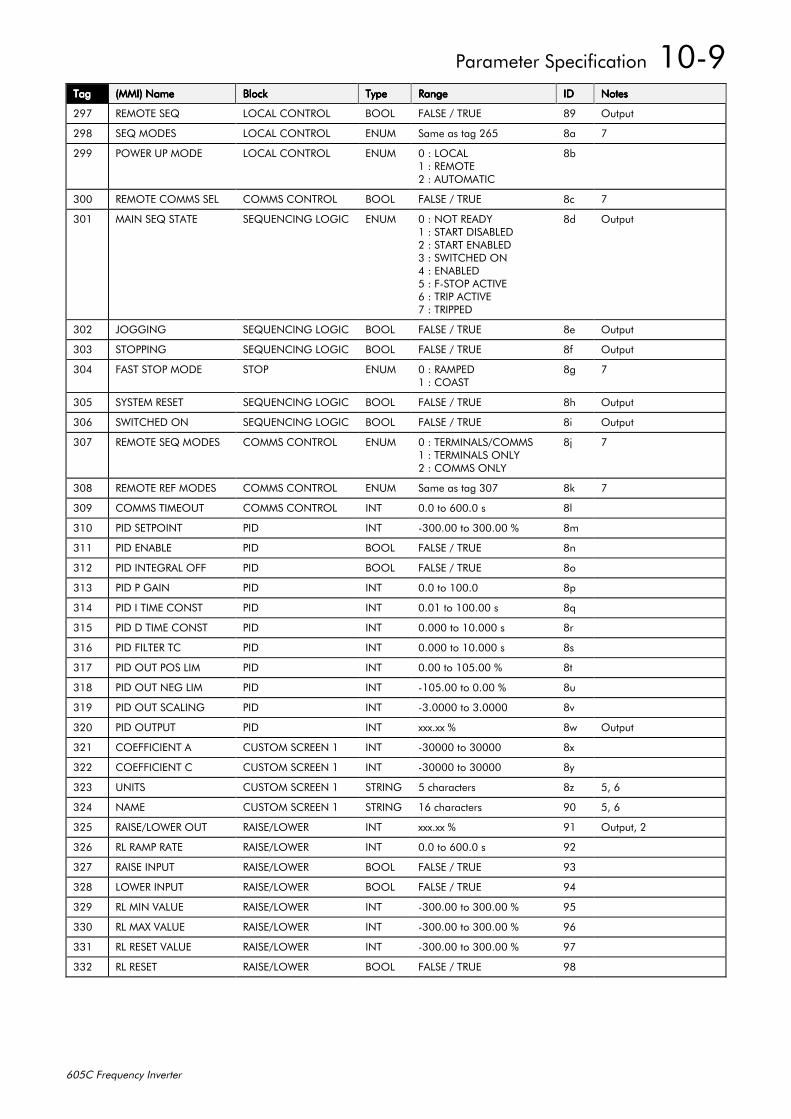
3DUDPHWHU#6SHFLILFDWLRQ##430<
938&#)UHTXHQF\#,QYHUWHU
7DJ7DJ7DJ7DJ +00,,#1DPH+00,,#1DPH+00,,#1DPH+00,,#1DPH %ORFN%ORFN%ORFN%ORFN 7\SH7\SH7\SH7\SH 5DQJH5DQJH5DQJH5DQJH ,',',',' 1RWHV1RWHV1RWHV1RWHV
5<: 5(027(#6(4 /2&$/#&21752/ %22/ )$/6(#2#758( ;< 2XWSXW
5<; 6(4#02'(6 /2&$/#&21752/ (180 6DPH#DV#WDJ#598 ;D :
5<< 32:(5#83#02'( /2&$/#&21752/ (180 3#=#/2&$/4#=#5(027(5#=#$8720$7,&
;E
633 5(027(#&2006#6(/ &2006#&21752/ %22/ )$/6(#2#758( ;F :
634 0$,1#6(4#67$7( 6(48(1&,1*#/2*,& (180 3#=#127#5($'<4#=#67$57#',6$%/('5#=#67$57#(1$%/('6#=#6:,7&+('#217#=#(1$%/('8#=#)06723#$&7,9(9#=#75,3#$&7,9(:#=#75,33('
;G 2XWSXW
635 -2**,1* 6(48(1&,1*#/2*,& %22/ )$/6(#2#758( ;H 2XWSXW
636 67233,1* 6(48(1&,1*#/2*,& %22/ )$/6(#2#758( ;I 2XWSXW
637 )$67#6723#02'( 6723 (180 3#=#5$03('4#=#&2$67
;J :
638 6<67(0#5(6(7 6(48(1&,1*#/2*,& %22/ )$/6(#2#758( ;K 2XWSXW
639 6:,7&+('#21 6(48(1&,1*#/2*,& %22/ )$/6(#2#758( ;L 2XWSXW
63: 5(027(#6(4#02'(6 &2006#&21752/ (180 3#=#7(50,1$/62&20064#=#7(50,1$/6#21/<5#=#&2006#21/<
;M :
63; 5(027(#5()#02'(6 &2006#&21752/ (180 6DPH#DV#WDJ#63: ;N :
63< &2006#7,0(287 &2006#&21752/ ,17 313#WR#93313#V ;O
643 3,'#6(732,17 3,' ,17 0633133#WR#633133#( ;P
644 3,'#(1$%/( 3,' %22/ )$/6(#2#758( ;Q
645 3,'#,17(*5$/#2)) 3,' %22/ )$/6(#2#758( ;R
646 3,'#3#*$,1 3,' ,17 313#WR#43313 ;S
647 3,'#,#7,0(#&2167 3,' ,17 3134#WR#433133#V ;T
648 3,'#'#7,0(#&2167 3,' ,17 31333#WR#431333#V ;U
649 3,'#),/7(5#7& 3,' ,17 31333#WR#431333#V ;V
64: 3,'#287#326#/,0 3,' ,17 3133#WR#438133#( ;W
64; 3,'#287#1(*#/,0 3,' ,17 0438133#WR#3133#( ;X
64< 3,'#287#6&$/,1* 3,' ,17 0613333#WR#613333 ;Y
653 3,'#287387 3,' ,17 [[[1[[#( ;Z 2XWSXW
654 &2()),&,(17#$ &86720#6&5((1#4 ,17 063333#WR#63333 ;[
655 &2()),&,(17#& &86720#6&5((1#4 ,17 063333#WR#63333 ;\
656 81,76 &86720#6&5((1#4 675,1* 8#FKDUDFWHUV ;] 8/#9
657 1$0( &86720#6&5((1#4 675,1* 49#FKDUDFWHUV <3 8/#9
658 5$,6(2/2:(5#287 5$,6(2/2:(5 ,17 [[[1[[#( <4 2XWSXW/#5
659 5/#5$03#5$7( 5$,6(2/2:(5 ,17 313#WR#93313#V <5
65: 5$,6(#,1387 5$,6(2/2:(5 %22/ )$/6(#2#758( <6
65; /2:(5#,1387 5$,6(2/2:(5 %22/ )$/6(#2#758( <7
65< 5/#0,1#9$/8( 5$,6(2/2:(5 ,17 0633133#WR#633133#( <8
663 5/#0$;#9$/8( 5$,6(2/2:(5 ,17 0633133#WR#633133#( <9
664 5/#5(6(7#9$/8( 5$,6(2/2:(5 ,17 0633133#WR#633133#( <:
665 5/#5(6(7 5$,6(2/2:(5 %22/ )$/6(#2#758( <;
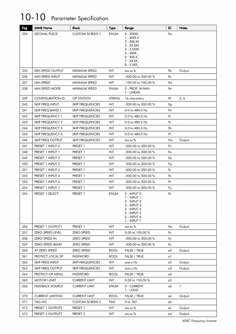
43043##3DUDPHWHU#6SHFLILFDWLRQ
938&#)UHTXHQF\#,QYHUWHU
7DJ7DJ7DJ7DJ +00,,#1DPH+00,,#1DPH+00,,#1DPH+00,,#1DPH %ORFN%ORFN%ORFN%ORFN 7\SH7\SH7\SH7\SH 5DQJH5DQJH5DQJH5DQJH ,',',',' 1RWHV1RWHV1RWHV1RWHV
667 '(&,0$/#3/$&( &86720#6&5((1#4 (180 3#=#;;;;;14#=#;;;;1;5#=#;;;1;;6#=#;;1;;;7#=#;1;;;;8#=#;;;;1B9#=#;;;1;B:#=#;;1;;B;#=#;1;;;B
<D
668 0,1#63(('#287387 0,1,080#63((' ,17 [[[1[[#( <E 2XWSXW
669 0,1#63(('#,1387 0,1,080#63((' ,17 0633133#WR#633133#( <F
66: 0,1#63((' 0,1,080#63((' ,17 0433133#WR#433133#( <G
66; 0,1#63(('#02'( 0,1,080#63((' (180 3#=#35231#:20,114#=#/,1($5
<H
66< &21),*85$7,21#,' 23#67$7,21 675,1* 49#FKDUDFWHUV <I 8/#9
673 6.,3#)5(4#,1387 6.,3#)5(48(1&,(6 ,17 0633133#WR#633133#( <J
674 6.,3#)5(4#%$1'#4 6.,3#)5(48(1&,(6 ,17 313#WR#7;313#+] <K
675 6.,3#)5(48(1&<#4 6.,3#)5(48(1&,(6 ,17 313#WR#7;313#+] <L
676 6.,3#)5(48(1&<#5 6.,3#)5(48(1&,(6 ,17 313#WR#7;313#+] <M
677 6.,3#)5(48(1&<#6 6.,3#)5(48(1&,(6 ,17 313#WR#7;313#+] <N
678 6.,3#)5(48(1&<#7 6.,3#)5(48(1&,(6 ,17 313#WR#7;313#+] <O
679 6.,3#)5(4#287387 6.,3#)5(48(1&,(6 ,17 [[[1[[#( <P 2XWSXW
67: 35(6(7#4#,1387#3 35(6(7#4 ,17 0633133#WR#633133#( <Q
67; 35(6(7#4#,1387#4 35(6(7#4 ,17 0633133#WR#633133#( <R
67< 35(6(7#4#,1387#5 35(6(7#4 ,17 0633133#WR#633133#( <S
683 35(6(7#4#,1387#6 35(6(7#4 ,17 0633133#WR#633133#( <T
684 35(6(7#4#,1387#7 35(6(7#4 ,17 0633133#WR#633133#( <U
685 35(6(7#4#,1387#8 35(6(7#4 ,17 0633133#WR#633133#( <V
686 35(6(7#4#,1387#9 35(6(7#4 ,17 0633133#WR#633133#( <W
687 35(6(7#4#,1387#: 35(6(7#4 ,17 0633133#WR#633133#( <X
688 35(6(7#4#6(/(&7 35(6(7#4 (180 3#=#,1387#34#=#,1387#45#=#,1387#56#=#,1387#67#=#,1387#78#=#,1387#89#=#,1387#9:#=#,1387#:
<Y
689 35(6(7#4#2873874 35(6(7#4 ,17 [[[1[[#( <Z 2XWSXW
68: =(52#63(('#/(9(/ =(52#63((' ,17 3133#WR#433133#( <[
68; =(52#63(('#,1 =(52#63((' ,17 0633133#WR#633133#( <\
68< =(52#63(('#%$1' =(52#63((' ,17 0633133#WR#633133#( <]
693 $7#=(52#63((' =(52#63((' %22/ )$/6(#2#758( D3 2XWSXW
694 3527(&7#/2&$/#63 3$66:25' %22/ )$/6(#2#758( D4
695 6.,3#)5(4#,1387 6.,3#)5(48(1&,(6 ,17 [[[[1[#+] D5 2XWSXW
696 6.,3#)5(4#287387 6.,3#)5(48(1&,(6 ,17 [[[[1[#+] D6 2XWSXW
697 3527(&7#23#0(18 3$66:25' %22/ )$/6(#2#758( D7
698 02725#,#/,0,7 &855(17#/,0,7 ,17 3133#WR#483133#( D8
699 )(('%$&.#6285&( &855(17#/,0,7 (180 3#=#&855(174#=#/2$'
D9 :
6:3 &855(17#/,0,7,1* &855(17#/,0,7 %22/ )$/6(#2#758( DD 2XWSXW
6:4 7$*#12 &86720#6&5((1#5 7$* 3#WR#:;: DE
6:5 35(6(7#4#2873875 35(6(7#4 ,17 [[[1[[#( DF 2XWSXW
6:6 35(6(7#5#2873875 35(6(7#5 ,17 [[[1[[#( DG 2XWSXW
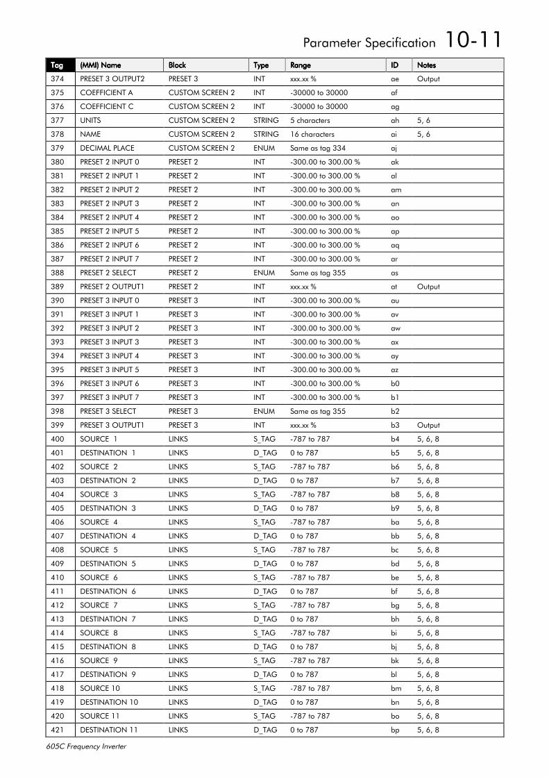
3DUDPHWHU#6SHFLILFDWLRQ##43044
938&#)UHTXHQF\#,QYHUWHU
7DJ7DJ7DJ7DJ +00,,#1DPH+00,,#1DPH+00,,#1DPH+00,,#1DPH %ORFN%ORFN%ORFN%ORFN 7\SH7\SH7\SH7\SH 5DQJH5DQJH5DQJH5DQJH ,',',',' 1RWHV1RWHV1RWHV1RWHV
6:7 35(6(7#6#2873875 35(6(7#6 ,17 [[[1[[#( DH 2XWSXW
6:8 &2()),&,(17#$ &86720#6&5((1#5 ,17 063333#WR#63333 DI
6:9 &2()),&,(17#& &86720#6&5((1#5 ,17 063333#WR#63333 DJ
6:: 81,76 &86720#6&5((1#5 675,1* 8#FKDUDFWHUV DK 8/#9
6:; 1$0( &86720#6&5((1#5 675,1* 49#FKDUDFWHUV DL 8/#9
6:< '(&,0$/#3/$&( &86720#6&5((1#5 (180 6DPH#DV#WDJ#667 DM
6;3 35(6(7#5#,1387#3 35(6(7#5 ,17 0633133#WR#633133#( DN
6;4 35(6(7#5#,1387#4 35(6(7#5 ,17 0633133#WR#633133#( DO
6;5 35(6(7#5#,1387#5 35(6(7#5 ,17 0633133#WR#633133#( DP
6;6 35(6(7#5#,1387#6 35(6(7#5 ,17 0633133#WR#633133#( DQ
6;7 35(6(7#5#,1387#7 35(6(7#5 ,17 0633133#WR#633133#( DR
6;8 35(6(7#5#,1387#8 35(6(7#5 ,17 0633133#WR#633133#( DS
6;9 35(6(7#5#,1387#9 35(6(7#5 ,17 0633133#WR#633133#( DT
6;: 35(6(7#5#,1387#: 35(6(7#5 ,17 0633133#WR#633133#( DU
6;; 35(6(7#5#6(/(&7 35(6(7#5 (180 6DPH#DV#WDJ#688 DV
6;< 35(6(7#5#2873874 35(6(7#5 ,17 [[[1[[#( DW 2XWSXW
6<3 35(6(7#6#,1387#3 35(6(7#6 ,17 0633133#WR#633133#( DX
6<4 35(6(7#6#,1387#4 35(6(7#6 ,17 0633133#WR#633133#( DY
6<5 35(6(7#6#,1387#5 35(6(7#6 ,17 0633133#WR#633133#( DZ
6<6 35(6(7#6#,1387#6 35(6(7#6 ,17 0633133#WR#633133#( D[
6<7 35(6(7#6#,1387#7 35(6(7#6 ,17 0633133#WR#633133#( D\
6<8 35(6(7#6#,1387#8 35(6(7#6 ,17 0633133#WR#633133#( D]
6<9 35(6(7#6#,1387#9 35(6(7#6 ,17 0633133#WR#633133#( E3
6<: 35(6(7#6#,1387#: 35(6(7#6 ,17 0633133#WR#633133#( E4
6<; 35(6(7#6#6(/(&7 35(6(7#6 (180 6DPH#DV#WDJ#688 E5
6<< 35(6(7#6#2873874 35(6(7#6 ,17 [[[1[[#( E6 2XWSXW
733 6285&(##4 /,1.6 6B7$* 0:;:#WR#:;: E7 8/#9/#;
734 '(67,1$7,21##4 /,1.6 'B7$* 3#WR#:;: E8 8/#9/#;
735 6285&(##5 /,1.6 6B7$* 0:;:#WR#:;: E9 8/#9/#;
736 '(67,1$7,21##5 /,1.6 'B7$* 3#WR#:;: E: 8/#9/#;
737 6285&(##6 /,1.6 6B7$* 0:;:#WR#:;: E; 8/#9/#;
738 '(67,1$7,21##6 /,1.6 'B7$* 3#WR#:;: E< 8/#9/#;
739 6285&(##7 /,1.6 6B7$* 0:;:#WR#:;: ED 8/#9/#;
73: '(67,1$7,21##7 /,1.6 'B7$* 3#WR#:;: EE 8/#9/#;
73; 6285&(##8 /,1.6 6B7$* 0:;:#WR#:;: EF 8/#9/#;
73< '(67,1$7,21##8 /,1.6 'B7$* 3#WR#:;: EG 8/#9/#;
743 6285&(##9 /,1.6 6B7$* 0:;:#WR#:;: EH 8/#9/#;
744 '(67,1$7,21##9 /,1.6 'B7$* 3#WR#:;: EI 8/#9/#;
745 6285&(##: /,1.6 6B7$* 0:;:#WR#:;: EJ 8/#9/#;
746 '(67,1$7,21##: /,1.6 'B7$* 3#WR#:;: EK 8/#9/#;
747 6285&(##; /,1.6 6B7$* 0:;:#WR#:;: EL 8/#9/#;
748 '(67,1$7,21##; /,1.6 'B7$* 3#WR#:;: EM 8/#9/#;
749 6285&(##< /,1.6 6B7$* 0:;:#WR#:;: EN 8/#9/#;
74: '(67,1$7,21##< /,1.6 'B7$* 3#WR#:;: EO 8/#9/#;
74; 6285&(#43 /,1.6 6B7$* 0:;:#WR#:;: EP 8/#9/#;
74< '(67,1$7,21#43 /,1.6 'B7$* 3#WR#:;: EQ 8/#9/#;
753 6285&(#44 /,1.6 6B7$* 0:;:#WR#:;: ER 8/#9/#;
754 '(67,1$7,21#44 /,1.6 'B7$* 3#WR#:;: ES 8/#9/#;
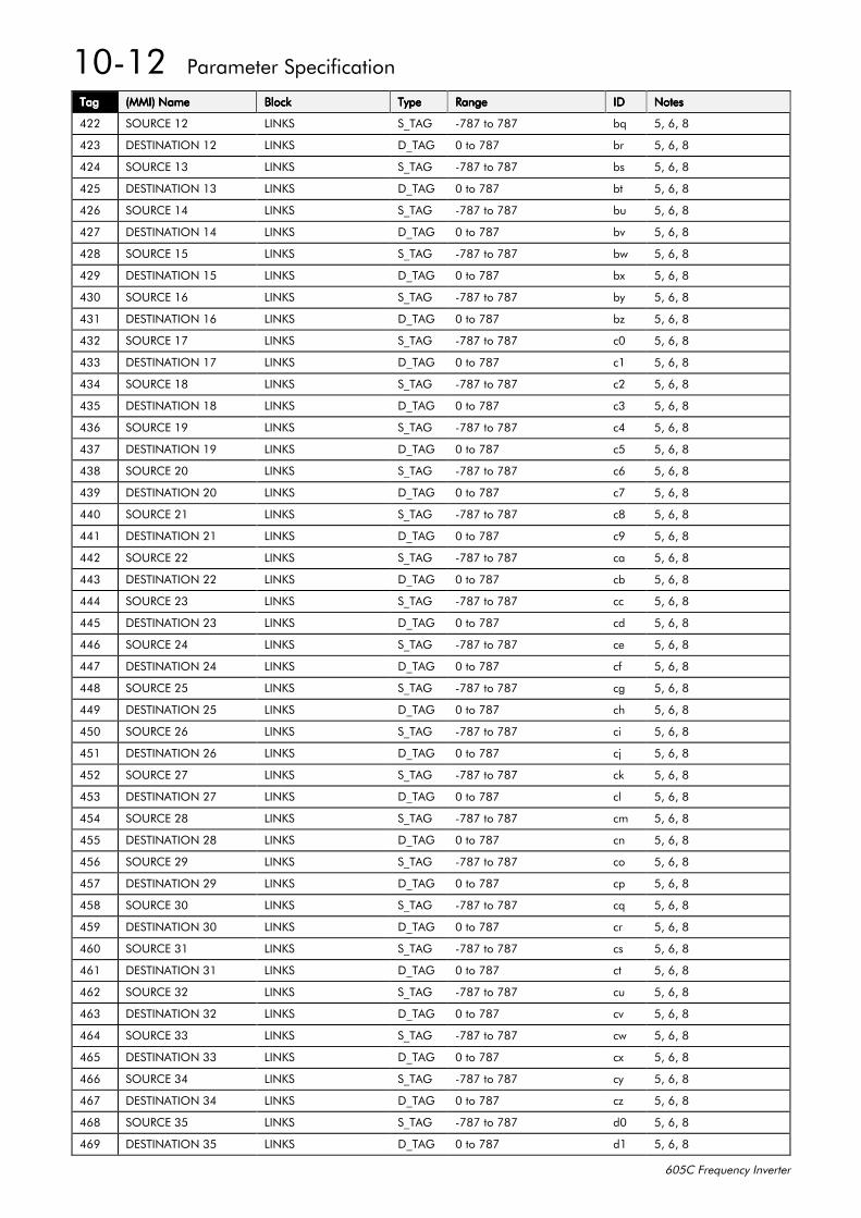
43045##3DUDPHWHU#6SHFLILFDWLRQ
938&#)UHTXHQF\#,QYHUWHU
7DJ7DJ7DJ7DJ +00,,#1DPH+00,,#1DPH+00,,#1DPH+00,,#1DPH %ORFN%ORFN%ORFN%ORFN 7\SH7\SH7\SH7\SH 5DQJH5DQJH5DQJH5DQJH ,',',',' 1RWHV1RWHV1RWHV1RWHV
755 6285&(#45 /,1.6 6B7$* 0:;:#WR#:;: ET 8/#9/#;
756 '(67,1$7,21#45 /,1.6 'B7$* 3#WR#:;: EU 8/#9/#;
757 6285&(#46 /,1.6 6B7$* 0:;:#WR#:;: EV 8/#9/#;
758 '(67,1$7,21#46 /,1.6 'B7$* 3#WR#:;: EW 8/#9/#;
759 6285&(#47 /,1.6 6B7$* 0:;:#WR#:;: EX 8/#9/#;
75: '(67,1$7,21#47 /,1.6 'B7$* 3#WR#:;: EY 8/#9/#;
75; 6285&(#48 /,1.6 6B7$* 0:;:#WR#:;: EZ 8/#9/#;
75< '(67,1$7,21#48 /,1.6 'B7$* 3#WR#:;: E[ 8/#9/#;
763 6285&(#49 /,1.6 6B7$* 0:;:#WR#:;: E\ 8/#9/#;
764 '(67,1$7,21#49 /,1.6 'B7$* 3#WR#:;: E] 8/#9/#;
765 6285&(#4: /,1.6 6B7$* 0:;:#WR#:;: F3 8/#9/#;
766 '(67,1$7,21#4: /,1.6 'B7$* 3#WR#:;: F4 8/#9/#;
767 6285&(#4; /,1.6 6B7$* 0:;:#WR#:;: F5 8/#9/#;
768 '(67,1$7,21#4; /,1.6 'B7$* 3#WR#:;: F6 8/#9/#;
769 6285&(#4< /,1.6 6B7$* 0:;:#WR#:;: F7 8/#9/#;
76: '(67,1$7,21#4< /,1.6 'B7$* 3#WR#:;: F8 8/#9/#;
76; 6285&(#53 /,1.6 6B7$* 0:;:#WR#:;: F9 8/#9/#;
76< '(67,1$7,21#53 /,1.6 'B7$* 3#WR#:;: F: 8/#9/#;
773 6285&(#54 /,1.6 6B7$* 0:;:#WR#:;: F; 8/#9/#;
774 '(67,1$7,21#54 /,1.6 'B7$* 3#WR#:;: F< 8/#9/#;
775 6285&(#55 /,1.6 6B7$* 0:;:#WR#:;: FD 8/#9/#;
776 '(67,1$7,21#55 /,1.6 'B7$* 3#WR#:;: FE 8/#9/#;
777 6285&(#56 /,1.6 6B7$* 0:;:#WR#:;: FF 8/#9/#;
778 '(67,1$7,21#56 /,1.6 'B7$* 3#WR#:;: FG 8/#9/#;
779 6285&(#57 /,1.6 6B7$* 0:;:#WR#:;: FH 8/#9/#;
77: '(67,1$7,21#57 /,1.6 'B7$* 3#WR#:;: FI 8/#9/#;
77; 6285&(#58 /,1.6 6B7$* 0:;:#WR#:;: FJ 8/#9/#;
77< '(67,1$7,21#58 /,1.6 'B7$* 3#WR#:;: FK 8/#9/#;
783 6285&(#59 /,1.6 6B7$* 0:;:#WR#:;: FL 8/#9/#;
784 '(67,1$7,21#59 /,1.6 'B7$* 3#WR#:;: FM 8/#9/#;
785 6285&(#5: /,1.6 6B7$* 0:;:#WR#:;: FN 8/#9/#;
786 '(67,1$7,21#5: /,1.6 'B7$* 3#WR#:;: FO 8/#9/#;
787 6285&(#5; /,1.6 6B7$* 0:;:#WR#:;: FP 8/#9/#;
788 '(67,1$7,21#5; /,1.6 'B7$* 3#WR#:;: FQ 8/#9/#;
789 6285&(#5< /,1.6 6B7$* 0:;:#WR#:;: FR 8/#9/#;
78: '(67,1$7,21#5< /,1.6 'B7$* 3#WR#:;: FS 8/#9/#;
78; 6285&(#63 /,1.6 6B7$* 0:;:#WR#:;: FT 8/#9/#;
78< '(67,1$7,21#63 /,1.6 'B7$* 3#WR#:;: FU 8/#9/#;
793 6285&(#64 /,1.6 6B7$* 0:;:#WR#:;: FV 8/#9/#;
794 '(67,1$7,21#64 /,1.6 'B7$* 3#WR#:;: FW 8/#9/#;
795 6285&(#65 /,1.6 6B7$* 0:;:#WR#:;: FX 8/#9/#;
796 '(67,1$7,21#65 /,1.6 'B7$* 3#WR#:;: FY 8/#9/#;
797 6285&(#66 /,1.6 6B7$* 0:;:#WR#:;: FZ 8/#9/#;
798 '(67,1$7,21#66 /,1.6 'B7$* 3#WR#:;: F[ 8/#9/#;
799 6285&(#67 /,1.6 6B7$* 0:;:#WR#:;: F\ 8/#9/#;
79: '(67,1$7,21#67 /,1.6 'B7$* 3#WR#:;: F] 8/#9/#;
79; 6285&(#68 /,1.6 6B7$* 0:;:#WR#:;: G3 8/#9/#;
79< '(67,1$7,21#68 /,1.6 'B7$* 3#WR#:;: G4 8/#9/#;
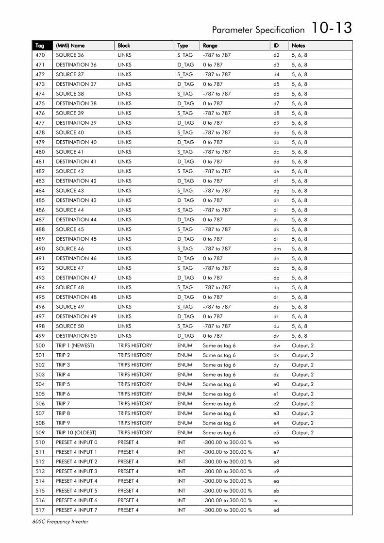
3DUDPHWHU#6SHFLILFDWLRQ##43046
938&#)UHTXHQF\#,QYHUWHU
7DJ7DJ7DJ7DJ +00,,#1DPH+00,,#1DPH+00,,#1DPH+00,,#1DPH %ORFN%ORFN%ORFN%ORFN 7\SH7\SH7\SH7\SH 5DQJH5DQJH5DQJH5DQJH ,',',',' 1RWHV1RWHV1RWHV1RWHV
7:3 6285&(#69 /,1.6 6B7$* 0:;:#WR#:;: G5 8/#9/#;
7:4 '(67,1$7,21#69 /,1.6 'B7$* 3#WR#:;: G6 8/#9/#;
7:5 6285&(#6: /,1.6 6B7$* 0:;:#WR#:;: G7 8/#9/#;
7:6 '(67,1$7,21#6: /,1.6 'B7$* 3#WR#:;: G8 8/#9/#;
7:7 6285&(#6; /,1.6 6B7$* 0:;:#WR#:;: G9 8/#9/#;
7:8 '(67,1$7,21#6; /,1.6 'B7$* 3#WR#:;: G: 8/#9/#;
7:9 6285&(#6< /,1.6 6B7$* 0:;:#WR#:;: G; 8/#9/#;
7:: '(67,1$7,21#6< /,1.6 'B7$* 3#WR#:;: G< 8/#9/#;
7:; 6285&(#73 /,1.6 6B7$* 0:;:#WR#:;: GD 8/#9/#;
7:< '(67,1$7,21#73 /,1.6 'B7$* 3#WR#:;: GE 8/#9/#;
7;3 6285&(#74 /,1.6 6B7$* 0:;:#WR#:;: GF 8/#9/#;
7;4 '(67,1$7,21#74 /,1.6 'B7$* 3#WR#:;: GG 8/#9/#;
7;5 6285&(#75 /,1.6 6B7$* 0:;:#WR#:;: GH 8/#9/#;
7;6 '(67,1$7,21#75 /,1.6 'B7$* 3#WR#:;: GI 8/#9/#;
7;7 6285&(#76 /,1.6 6B7$* 0:;:#WR#:;: GJ 8/#9/#;
7;8 '(67,1$7,21#76 /,1.6 'B7$* 3#WR#:;: GK 8/#9/#;
7;9 6285&(#77 /,1.6 6B7$* 0:;:#WR#:;: GL 8/#9/#;
7;: '(67,1$7,21#77 /,1.6 'B7$* 3#WR#:;: GM 8/#9/#;
7;; 6285&(#78 /,1.6 6B7$* 0:;:#WR#:;: GN 8/#9/#;
7;< '(67,1$7,21#78 /,1.6 'B7$* 3#WR#:;: GO 8/#9/#;
7<3 6285&(#79 /,1.6 6B7$* 0:;:#WR#:;: GP 8/#9/#;
7<4 '(67,1$7,21#79 /,1.6 'B7$* 3#WR#:;: GQ 8/#9/#;
7<5 6285&(#7: /,1.6 6B7$* 0:;:#WR#:;: GR 8/#9/#;
7<6 '(67,1$7,21#7: /,1.6 'B7$* 3#WR#:;: GS 8/#9/#;
7<7 6285&(#7; /,1.6 6B7$* 0:;:#WR#:;: GT 8/#9/#;
7<8 '(67,1$7,21#7; /,1.6 'B7$* 3#WR#:;: GU 8/#9/#;
7<9 6285&(#7< /,1.6 6B7$* 0:;:#WR#:;: GV 8/#9/#;
7<: '(67,1$7,21#7< /,1.6 'B7$* 3#WR#:;: GW 8/#9/#;
7<; 6285&(#83 /,1.6 6B7$* 0:;:#WR#:;: GX 8/#9/#;
7<< '(67,1$7,21#83 /,1.6 'B7$* 3#WR#:;: GY 8/#9/#;
833 75,3#4#+1(:(67, 75,36#+,6725< (180 6DPH#DV#WDJ#9 GZ 2XWSXW/#5
834 75,3#5 75,36#+,6725< (180 6DPH#DV#WDJ#9 G[ 2XWSXW/#5
835 75,3#6 75,36#+,6725< (180 6DPH#DV#WDJ#9 G\ 2XWSXW/#5
836 75,3#7 75,36#+,6725< (180 6DPH#DV#WDJ#9 G] 2XWSXW/#5
837 75,3#8 75,36#+,6725< (180 6DPH#DV#WDJ#9 H3 2XWSXW/#5
838 75,3#9 75,36#+,6725< (180 6DPH#DV#WDJ#9 H4 2XWSXW/#5
839 75,3#: 75,36#+,6725< (180 6DPH#DV#WDJ#9 H5 2XWSXW/#5
83: 75,3#; 75,36#+,6725< (180 6DPH#DV#WDJ#9 H6 2XWSXW/#5
83; 75,3#< 75,36#+,6725< (180 6DPH#DV#WDJ#9 H7 2XWSXW/#5
83< 75,3#43#+2/'(67, 75,36#+,6725< (180 6DPH#DV#WDJ#9 H8 2XWSXW/#5
843 35(6(7#7#,1387#3 35(6(7#7 ,17 0633133#WR#633133#( H9
844 35(6(7#7#,1387#4 35(6(7#7 ,17 0633133#WR#633133#( H:
845 35(6(7#7#,1387#5 35(6(7#7 ,17 0633133#WR#633133#( H;
846 35(6(7#7#,1387#6 35(6(7#7 ,17 0633133#WR#633133#( H<
847 35(6(7#7#,1387#7 35(6(7#7 ,17 0633133#WR#633133#( HD
848 35(6(7#7#,1387#8 35(6(7#7 ,17 0633133#WR#633133#( HE
849 35(6(7#7#,1387#9 35(6(7#7 ,17 0633133#WR#633133#( HF
84: 35(6(7#7#,1387#: 35(6(7#7 ,17 0633133#WR#633133#( HG
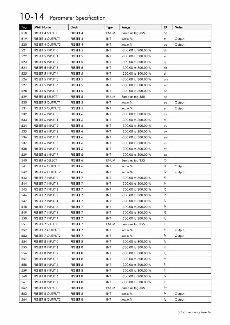
43047##3DUDPHWHU#6SHFLILFDWLRQ
938&#)UHTXHQF\#,QYHUWHU
7DJ7DJ7DJ7DJ +00,,#1DPH+00,,#1DPH+00,,#1DPH+00,,#1DPH %ORFN%ORFN%ORFN%ORFN 7\SH7\SH7\SH7\SH 5DQJH5DQJH5DQJH5DQJH ,',',',' 1RWHV1RWHV1RWHV1RWHV
84; 35(6(7#7#6(/(&7 35(6(7#7 (180 6DPH#DV#WDJ#688 HH
84< 35(6(7#7#2873874 35(6(7#7 ,17 [[[1[[#( HI 2XWSXW
853 35(6(7#7#2873875 35(6(7#7 ,17 [[[1[[#( HJ 2XWSXW
854 35(6(7#8#,1387#3 35(6(7#8 ,17 0633133#WR#633133#( HK
855 35(6(7#8#,1387#4 35(6(7#8 ,17 0633133#WR#633133#( HL
856 35(6(7#8#,1387#5 35(6(7#8 ,17 0633133#WR#633133#( HM
857 35(6(7#8#,1387#6 35(6(7#8 ,17 0633133#WR#633133#( HN
858 35(6(7#8#,1387#7 35(6(7#8 ,17 0633133#WR#633133#( HO
859 35(6(7#8#,1387#8 35(6(7#8 ,17 0633133#WR#633133#( HP
85: 35(6(7#8#,1387#9 35(6(7#8 ,17 0633133#WR#633133#( HQ
85; 35(6(7#8#,1387#: 35(6(7#8 ,17 0633133#WR#633133#( HR
85< 35(6(7#8#6(/(&7 35(6(7#8 (180 6DPH#DV#WDJ#688 HS
863 35(6(7#8#2873874 35(6(7#8 ,17 [[[1[[#( HT 2XWSXW
864 35(6(7#8#2873875 35(6(7#8 ,17 [[[1[[#( HU 2XWSXW
865 35(6(7#9#,1387#3 35(6(7#9 ,17 0633133#WR#633133#( HV
866 35(6(7#9#,1387#4 35(6(7#9 ,17 0633133#WR#633133#( HW
867 35(6(7#9#,1387#5 35(6(7#9 ,17 0633133#WR#633133#( HX
868 35(6(7#9#,1387#6 35(6(7#9 ,17 0633133#WR#633133#( HY
869 35(6(7#9#,1387#7 35(6(7#9 ,17 0633133#WR#633133#( HZ
86: 35(6(7#9#,1387#8 35(6(7#9 ,17 0633133#WR#633133#( H[
86; 35(6(7#9#,1387#9 35(6(7#9 ,17 0633133#WR#633133#( H\
86< 35(6(7#9#,1387#: 35(6(7#9 ,17 0633133#WR#633133#( H]
873 35(6(7#9#6(/(&7 35(6(7#9 (180 6DPH#DV#WDJ#688 I3
874 35(6(7#9#2873874 35(6(7#9 ,17 [[[1[[#( I4 2XWSXW
875 35(6(7#9#2873875 35(6(7#9 ,17 [[[1[[#( I5 2XWSXW
876 35(6(7#:#,1387#3 35(6(7#: ,17 0633133#WR#633133#( I6
877 35(6(7#:#,1387#4 35(6(7#: ,17 0633133#WR#633133#( I7
878 35(6(7#:#,1387#5 35(6(7#: ,17 0633133#WR#633133#( I8
879 35(6(7#:#,1387#6 35(6(7#: ,17 0633133#WR#633133#( I9
87: 35(6(7#:#,1387#7 35(6(7#: ,17 0633133#WR#633133#( I:
87; 35(6(7#:#,1387#8 35(6(7#: ,17 0633133#WR#633133#( I;
87< 35(6(7#:#,1387#9 35(6(7#: ,17 0633133#WR#633133#( I<
883 35(6(7#:#,1387#: 35(6(7#: ,17 0633133#WR#633133#( ID
884 35(6(7#:#6(/(&7 35(6(7#: (180 6DPH#DV#WDJ#688 IE
885 35(6(7#:#2873874 35(6(7#: ,17 [[[1[[#( IF 2XWSXW
886 35(6(7#:#2873875 35(6(7#: ,17 [[[1[[#( IG 2XWSXW
887 35(6(7#;#,1387#3 35(6(7#; ,17 0633133#WR#633133#( IH
888 35(6(7#;#,1387#4 35(6(7#; ,17 0633133#WR#633133#( II
889 35(6(7#;#,1387#5 35(6(7#; ,17 0633133#WR#633133#( IJ
88: 35(6(7#;#,1387#6 35(6(7#; ,17 0633133#WR#633133#( IK
88; 35(6(7#;#,1387#7 35(6(7#; ,17 0633133#WR#633133#( IL
88< 35(6(7#;#,1387#8 35(6(7#; ,17 0633133#WR#633133#( IM
893 35(6(7#;#,1387#9 35(6(7#; ,17 0633133#WR#633133#( IN
894 35(6(7#;#,1387#: 35(6(7#; ,17 0633133#WR#633133#( IO
895 35(6(7#;#6(/(&7 35(6(7#; (180 6DPH#DV#WDJ#688 IP
896 35(6(7#;#2873874 35(6(7#; ,17 [[[1[[#( IQ 2XWSXW
897 35(6(7#;#2873875 35(6(7#; ,17 [[[1[[#( IR 2XWSXW
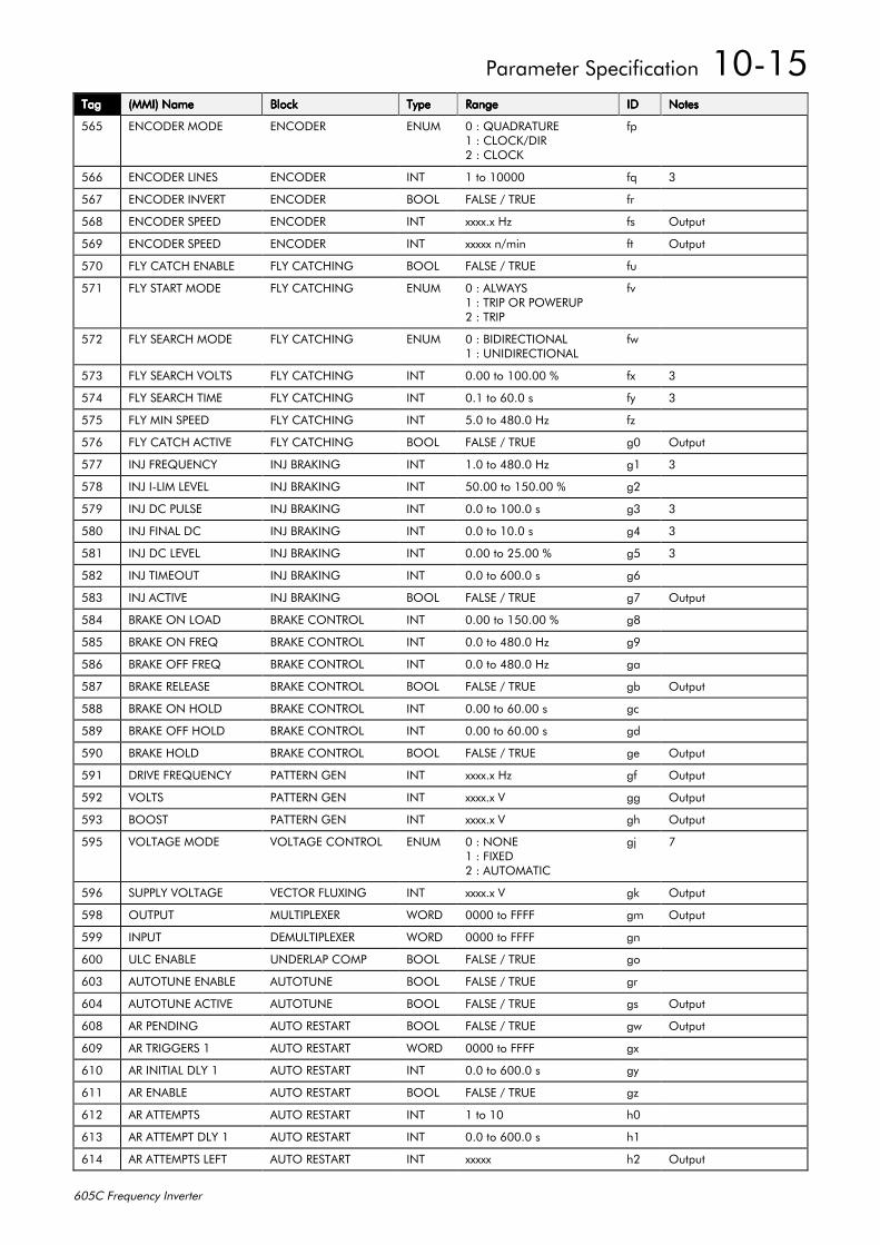
3DUDPHWHU#6SHFLILFDWLRQ##43048
938&#)UHTXHQF\#,QYHUWHU
7DJ7DJ7DJ7DJ +00,,#1DPH+00,,#1DPH+00,,#1DPH+00,,#1DPH %ORFN%ORFN%ORFN%ORFN 7\SH7\SH7\SH7\SH 5DQJH5DQJH5DQJH5DQJH ,',',',' 1RWHV1RWHV1RWHV1RWHV
898 (1&2'(5#02'( (1&2'(5 (180 3#=#48$'5$785(4#=#&/2&.2',55#=#&/2&.
IS
899 (1&2'(5#/,1(6 (1&2'(5 ,17 4#WR#43333 IT 6
89: (1&2'(5#,19(57 (1&2'(5 %22/ )$/6(#2#758( IU
89; (1&2'(5#63((' (1&2'(5 ,17 [[[[1[#+] IV 2XWSXW
89< (1&2'(5#63((' (1&2'(5 ,17 [[[[[#Q2PLQ IW 2XWSXW
8:3 )/<#&$7&+#(1$%/( )/<#&$7&+,1* %22/ )$/6(#2#758( IX
8:4 )/<#67$57#02'( )/<#&$7&+,1* (180 3#=#$/:$<64#=#75,3#25#32:(5835#=#75,3
IY
8:5 )/<#6($5&+#02'( )/<#&$7&+,1* (180 3#=#%,',5(&7,21$/4#=#81,',5(&7,21$/
IZ
8:6 )/<#6($5&+#92/76 )/<#&$7&+,1* ,17 3133#WR#433133#( I[ 6
8:7 )/<#6($5&+#7,0( )/<#&$7&+,1* ,17 314#WR#9313#V I\ 6
8:8 )/<#0,1#63((' )/<#&$7&+,1* ,17 813#WR#7;313#+] I]
8:9 )/<#&$7&+#$&7,9( )/<#&$7&+,1* %22/ )$/6(#2#758( J3 2XWSXW
8:: ,1-#)5(48(1&< ,1-#%5$.,1* ,17 413#WR#7;313#+] J4 6
8:; ,1-#,0/,0#/(9(/ ,1-#%5$.,1* ,17 83133#WR#483133#( J5
8:< ,1-#'&/6( ,1-#%5$.,1* ,17 313#WR#43313#V J6 6
8;3 ,1-#),1$/#'& ,1-#%5$.,1* ,17 313#WR#4313#V J7 6
8;4 ,1-#'&#/(9(/ ,1-#%5$.,1* ,17 3133#WR#58133#( J8 6
8;5 ,1-#7,0(287 ,1-#%5$.,1* ,17 313#WR#93313#V J9
8;6 ,1-#$&7,9( ,1-#%5$.,1* %22/ )$/6(#2#758( J: 2XWSXW
8;7 %5$.(#21#/2$' %5$.(#&21752/ ,17 3133#WR#483133#( J;
8;8 %5$.(#21#)5(4 %5$.(#&21752/ ,17 313#WR#7;313#+] J<
8;9 %5$.(#2))#)5(4 %5$.(#&21752/ ,17 313#WR#7;313#+] JD
8;: %5$.(#5(/($6( %5$.(#&21752/ %22/ )$/6(#2#758( JE 2XWSXW
8;; %5$.(#21#+2/' %5$.(#&21752/ ,17 3133#WR#93133#V JF
8;< %5$.(#2))#+2/' %5$.(#&21752/ ,17 3133#WR#93133#V JG
8<3 %5$.(#+2/' %5$.(#&21752/ %22/ )$/6(#2#758( JH 2XWSXW
8<4 '5,9(#)5(48(1&< 3$77(51#*(1 ,17 [[[[1[#+] JI 2XWSXW
8<5 92/76 3$77(51#*(1 ,17 [[[[1[#9 JJ 2XWSXW
8<6 %2267 3$77(51#*(1 ,17 [[[[1[#9 JK 2XWSXW
8<8 92/7$*(#02'( 92/7$*(#&21752/ (180 3#=#121(4#=#),;('5#=#$8720$7,&
JM :
8<9 6833/<#92/7$*( 9(&725#)/8;,1* ,17 [[[[1[#9 JN 2XWSXW
8<; 287387 08/7,3/(;(5 :25' 3333#WR#)))) JP 2XWSXW
8<< ,1387 '(08/7,3/(;(5 :25' 3333#WR#)))) JQ
933 8/&#(1$%/( 81'(5/$3#&203 %22/ )$/6(#2#758( JR
936 $872781(#(1$%/( $872781( %22/ )$/6(#2#758( JU
937 $872781(#$&7,9( $872781( %22/ )$/6(#2#758( JV 2XWSXW
93; $5#3(1',1* $872#5(67$57 %22/ )$/6(#2#758( JZ 2XWSXW
93< $5#75,**(56#4 $872#5(67$57 :25' 3333#WR#)))) J[
943 $5#,1,7,$/#'/<#4 $872#5(67$57 ,17 313#WR#93313#V J\
944 $5#(1$%/( $872#5(67$57 %22/ )$/6(#2#758( J]
945 $5#$77(0376 $872#5(67$57 ,17 4#WR#43 K3
946 $5#$77(037#'/<#4 $872#5(67$57 ,17 313#WR#93313#V K4
947 $5#$77(0376#/()7 $872#5(67$57 ,17 [[[[[ K5 2XWSXW
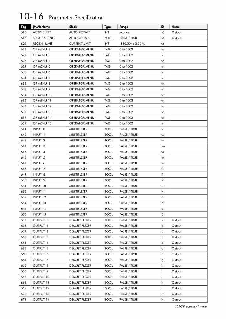
43049##3DUDPHWHU#6SHFLILFDWLRQ
938&#)UHTXHQF\#,QYHUWHU
7DJ7DJ7DJ7DJ +00,,#1DPH+00,,#1DPH+00,,#1DPH+00,,#1DPH %ORFN%ORFN%ORFN%ORFN 7\SH7\SH7\SH7\SH 5DQJH5DQJH5DQJH5DQJH ,',',',' 1RWHV1RWHV1RWHV1RWHV
948 $5#7,0(#/()7 $872#5(67$57 ,17 [[[[1[#V K6 2XWSXW
949 $5#5(67$57,1* $872#5(67$57 %22/ )$/6(#2#758( K7 2XWSXW
956 5(*(1#,#/,0,7 &855(17#/,0,7 ,17 0483133#WR#3133#( KE
959 23#0(18##5 23(5$725#0(18 7$* 3#WR#4335 KH
95: 23#0(18##6 23(5$725#0(18 7$* 3#WR#4335 KI
95; 23#0(18##7 23(5$725#0(18 7$* 3#WR#4335 KJ
95< 23#0(18##8 23(5$725#0(18 7$* 3#WR#4335 KK
963 23#0(18##9 23(5$725#0(18 7$* 3#WR#4335 KL
964 23#0(18##: 23(5$725#0(18 7$* 3#WR#4335 KM
965 23#0(18##; 23(5$725#0(18 7$* 3#WR#4335 KN
966 23#0(18##< 23(5$725#0(18 7$* 3#WR#4335 KO
967 23#0(18#43 23(5$725#0(18 7$* 3#WR#4335 KP
968 23#0(18#44 23(5$725#0(18 7$* 3#WR#4335 KQ
969 23#0(18#45 23(5$725#0(18 7$* 3#WR#4335 KR
96: 23#0(18#46 23(5$725#0(18 7$* 3#WR#4335 KS
96; 23#0(18#47 23(5$725#0(18 7$* 3#WR#4335 KT
96< 23#0(18#48 23(5$725#0(18 7$* 3#WR#4335 KU
974 ,1387##3 08/7,3/(;(5 %22/ )$/6(#2#758( KW
975 ,1387##4 08/7,3/(;(5 %22/ )$/6(#2#758( KX
976 ,1387##5 08/7,3/(;(5 %22/ )$/6(#2#758( KY
977 ,1387##6 08/7,3/(;(5 %22/ )$/6(#2#758( KZ
978 ,1387##7 08/7,3/(;(5 %22/ )$/6(#2#758( K[
979 ,1387##8 08/7,3/(;(5 %22/ )$/6(#2#758( K\
97: ,1387##9 08/7,3/(;(5 %22/ )$/6(#2#758( K]
97; ,1387##: 08/7,3/(;(5 %22/ )$/6(#2#758( L3
97< ,1387##; 08/7,3/(;(5 %22/ )$/6(#2#758( L4
983 ,1387##< 08/7,3/(;(5 %22/ )$/6(#2#758( L5
984 ,1387#43 08/7,3/(;(5 %22/ )$/6(#2#758( L6
985 ,1387#44 08/7,3/(;(5 %22/ )$/6(#2#758( L7
986 ,1387#45 08/7,3/(;(5 %22/ )$/6(#2#758( L8
987 ,1387#46 08/7,3/(;(5 %22/ )$/6(#2#758( L9
988 ,1387#47 08/7,3/(;(5 %22/ )$/6(#2#758( L:
989 ,1387#48 08/7,3/(;(5 %22/ )$/6(#2#758( L;
98: 287387##3 '(08/7,3/(;(5 %22/ )$/6(#2#758( L< 2XWSXW
98; 287387##4 '(08/7,3/(;(5 %22/ )$/6(#2#758( LD 2XWSXW
98< 287387##5 '(08/7,3/(;(5 %22/ )$/6(#2#758( LE 2XWSXW
993 287387##6 '(08/7,3/(;(5 %22/ )$/6(#2#758( LF 2XWSXW
994 287387##7 '(08/7,3/(;(5 %22/ )$/6(#2#758( LG 2XWSXW
995 287387##8 '(08/7,3/(;(5 %22/ )$/6(#2#758( LH 2XWSXW
996 287387##9 '(08/7,3/(;(5 %22/ )$/6(#2#758( LI 2XWSXW
997 287387##: '(08/7,3/(;(5 %22/ )$/6(#2#758( LJ 2XWSXW
998 287387##; '(08/7,3/(;(5 %22/ )$/6(#2#758( LK 2XWSXW
999 287387##< '(08/7,3/(;(5 %22/ )$/6(#2#758( LL 2XWSXW
99: 287387#43 '(08/7,3/(;(5 %22/ )$/6(#2#758( LM 2XWSXW
99; 287387#44 '(08/7,3/(;(5 %22/ )$/6(#2#758( LN 2XWSXW
99< 287387#45 '(08/7,3/(;(5 %22/ )$/6(#2#758( LO 2XWSXW
9:3 287387#46 '(08/7,3/(;(5 %22/ )$/6(#2#758( LP 2XWSXW
9:4 287387#47 '(08/7,3/(;(5 %22/ )$/6(#2#758( LQ 2XWSXW
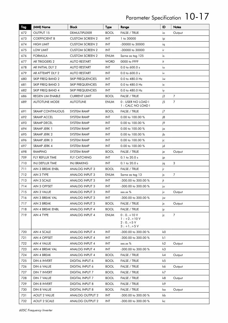
3DUDPHWHU#6SHFLILFDWLRQ##4304:
938&#)UHTXHQF\#,QYHUWHU
7DJ7DJ7DJ7DJ +00,,#1DPH+00,,#1DPH+00,,#1DPH+00,,#1DPH %ORFN%ORFN%ORFN%ORFN 7\SH7\SH7\SH7\SH 5DQJH5DQJH5DQJH5DQJH ,',',',' 1RWHV1RWHV1RWHV1RWHV
9:5 287387#48 '(08/7,3/(;(5 %22/ )$/6(#2#758( LR 2XWSXW
9:6 &2()),&,(17#% &86720#6&5((1#5 ,17 4#WR#63333 LS
9:7 +,*+#/,0,7 &86720#6&5((1#5 ,17 063333#WR#63333 LT
9:8 /2:#/,0,7 &86720#6&5((1#5 ,17 063333#WR#63333 LU
9:9 )2508/$ &86720#6&5((1#5 (180 6DPH#DV#WDJ#458 LV
9:: $5#75,**(56#5 $872#5(67$57 :25' 3333#WR#)))) LW
9:; $5#,1,7,$/#'/<#5 $872#5(67$57 ,17 313#WR#93313#V LX
9:< $5#$77(037#'/<#5 $872#5(67$57 ,17 313#WR#93313#V LY
9;3 6.,3#)5(4#%$1'#5 6.,3#)5(48(1&,(6 ,17 313#WR#7;313#+] LZ
9;4 6.,3#)5(4#%$1'#6 6.,3#)5(48(1&,(6 ,17 313#WR#7;313#+] L[
9;5 6.,3#)5(4#%$1'#7 6.,3#)5(48(1&,(6 ,17 313#WR#7;313#+] L\
9;9 5(*(1#/,0#(1$%/( &855(17#/,0,7 %22/ )$/6(#2#758( M5 :
9;< $872781(#02'( $872781( (180 3#=#86(5#12#/2$'#,4#=#&$/#/2$'#,
M8 :
9<4 65$03#&217,18286 6<67(0#5$03 %22/ )$/6(#2#758( M:
9<5 65$03#$&&(/ 6<67(0#5$03 ,17 3133#WR#433133#( M;
9<6 65$03#'(&(/ 6<67(0#5$03 ,17 3133#WR#433133#( M<
9<7 65$03#-(5.#4 6<67(0#5$03 ,17 3133#WR#433133#( MD
9<8 65$03#-(5.#5 6<67(0#5$03 ,17 3133#WR#433133#( ME
9<9 65$03#-(5.#6 6<67(0#5$03 ,17 3133#WR#433133#( MF
9<: 65$03#-(5.#7 6<67(0#5$03 ,17 3133#WR#433133#( MG
9<; 5$03,1* 6<67(0#5$03 %22/ )$/6(#2#758( MH 2XWSXW
:3< )/<#5()/8;#7,0( )/<#&$7&+,1* ,17 314#WR#5313#V MS
:43 ,1-#'()/8;#7,0( ,1-#%5$.,1* ,17 314#WR#5313#V MT 6
:44 $,1#6#%5($.#(1%/ $1$/2*#,1387#6 %22/ )$/6(#2#758( MU
:45 $,1#6#7<3( $1$/2*#,1387#6 (180 6DPH#DV#WDJ#46 MV :
:46 $,1#6#6&$/( $1$/2*#,1387#6 ,17 0633133#WR#633133#( MW
:47 $,1#6#2))6(7 $1$/2*#,1387#6 ,17 0633133#WR#633133#( MX
:48 $,1#6#9$/8( $1$/2*#,1387#6 ,17 [[[1[[#( MY 2XWSXW
:49 $,1#6#%5($.#9$/ $1$/2*#,1387#6 ,17 0633133#WR#633133#( MZ
:4: $,1#6#%5($. $1$/2*#,1387#6 %22/ )$/6(#2#758( M[ 2XWSXW
:4; $,1#7#%5($.#(1%/ $1$/2*#,1387#7 %22/ )$/6(#2#758( M\
:4< $,1#7#7<3( $1$/2*#,1387#7 (180 3#=#311.43#94#=#.511.43#95#=#311.8#96#=#.411.8#9
M] :
:53 $,1#7#6&$/( $1$/2*#,1387#7 ,17 0633133#WR#633133#( N3
:54 $,1#7#2))6(7 $1$/2*#,1387#7 ,17 0633133#WR#633133#( N4
:55 $,1#7#9$/8( $1$/2*#,1387#7 ,17 [[[1[[#( N5 2XWSXW
:56 $,1#7#%5($.#9$/ $1$/2*#,1387#7 ,17 0633133#WR#633133#( N6
:57 $,1#7#%5($. $1$/2*#,1387#7 %22/ )$/6(#2#758( N7 2XWSXW
:58 ',1#9#,19(57 ',*,7$/#,1387#9 %22/ )$/6(#2#758( N8
:59 ',1#9#9$/8( ',*,7$/#,1387#9 %22/ )$/6(#2#758( N9 2XWSXW
:5: ',1#:#,19(57 ',*,7$/#,1387#: %22/ )$/6(#2#758( N:
:5; ',1#:#9$/8( ',*,7$/#,1387#: %22/ )$/6(#2#758( N; 2XWSXW
:5< ',1#;#,19(57 ',*,7$/#,1387#; %22/ )$/6(#2#758( N<
:63 ',1#;#9$/8( ',*,7$/#,1387#; %22/ )$/6(#2#758( ND 2XWSXW
:64 $287#5#9$/8( $1$/2*#287387#5 ,17 0633133#WR#633133#( NE
:65 $287#5#6&$/( $1$/2*#287387#5 ,17 0633133#WR#633133#( NF
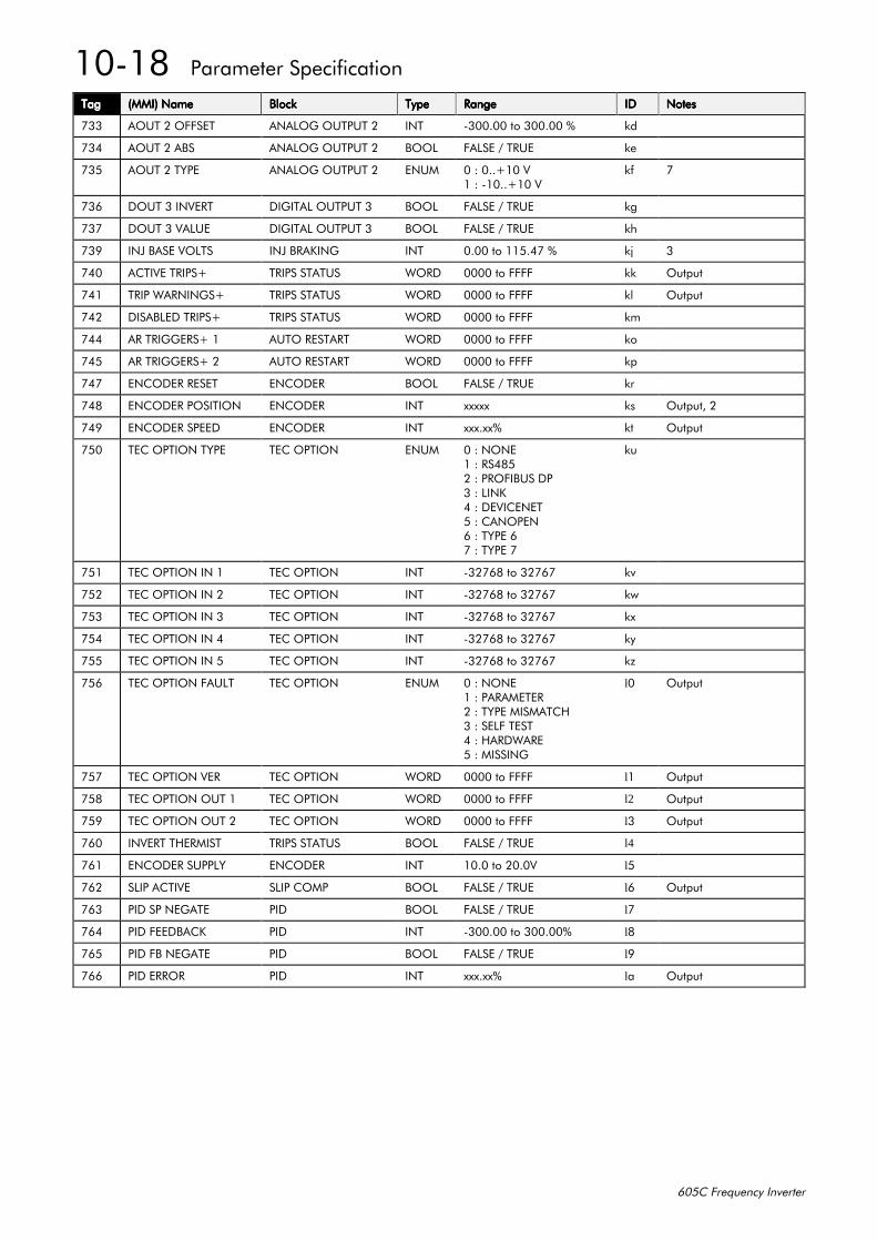
4304;##3DUDPHWHU#6SHFLILFDWLRQ
938&#)UHTXHQF\#,QYHUWHU
7DJ7DJ7DJ7DJ +00,,#1DPH+00,,#1DPH+00,,#1DPH+00,,#1DPH %ORFN%ORFN%ORFN%ORFN 7\SH7\SH7\SH7\SH 5DQJH5DQJH5DQJH5DQJH ,',',',' 1RWHV1RWHV1RWHV1RWHV
:66 $287#5#2))6(7 $1$/2*#287387#5 ,17 0633133#WR#633133#( NG
:67 $287#5#$%6 $1$/2*#287387#5 %22/ )$/6(#2#758( NH
:68 $287#5#7<3( $1$/2*#287387#5 (180 3#=#311.43#94#=#04311.43#9
NI :
:69 '287#6#,19(57 ',*,7$/#287387#6 %22/ )$/6(#2#758( NJ
:6: '287#6#9$/8( ',*,7$/#287387#6 %22/ )$/6(#2#758( NK
:6< ,1-#%$6(#92/76 ,1-#%5$.,1* ,17 3133#WR#44817:#( NM 6
:73 $&7,9(#75,36. 75,36#67$786 :25' 3333#WR#)))) NN 2XWSXW
:74 75,3#:$51,1*6. 75,36#67$786 :25' 3333#WR#)))) NO 2XWSXW
:75 ',6$%/('#75,36. 75,36#67$786 :25' 3333#WR#)))) NP
:77 $5#75,**(56.#4 $872#5(67$57 :25' 3333#WR#)))) NR
:78 $5#75,**(56.#5 $872#5(67$57 :25' 3333#WR#)))) NS
:7: (1&2'(5#5(6(7 (1&2'(5 %22/ )$/6(#2#758( NU
:7; (1&2'(5#326,7,21 (1&2'(5 ,17 [[[[[ NV 2XWSXW/#5
:7< (1&2'(5#63((' (1&2'(5 ,17 [[[1[[( NW 2XWSXW
:83 7(í,21#7<3( 7(í,21 (180 3#=#121(4#=#567;85#=#352),%86#'36#=#/,1.7#=#'(9,&(1(78#=#&$123(19#=#7<3(#9:#=#7<3(#:
NX
:84 7(í,21#,1#4 7(í,21 ,17 065:9;#WR#65:9: NY
:85 7(í,21#,1#5 7(í,21 ,17 065:9;#WR#65:9: NZ
:86 7(í,21#,1#6 7(í,21 ,17 065:9;#WR#65:9: N[
:87 7(í,21#,1#7 7(í,21 ,17 065:9;#WR#65:9: N\
:88 7(í,21#,1#8 7(í,21 ,17 065:9;#WR#65:9: N]
:89 7(í,21#)$8/7 7(í,21 (180 3#=#121(4#=#3$5$0(7(55#=#7<3(#0,60$7&+6#=#6(/)#7(677#=#+$5':$5(8#=#0,66,1*
l3 2XWSXW
:8: 7(í,21#9(5 7(í,21 :25' 3333#WR#)))) l4 2XWSXW
:8; 7(í,21#287#4 7(í,21 :25' 3333#WR#)))) l2 2XWSXW
:8< 7(í,21#287#5 7(í,21 :25' 3333#WR#)))) l6 2XWSXW
:93 ,19(57#7+(50,67 75,36#67$786 %22/ )$/6(#2#758( l4
:94 (1&2'(5#6833/< (1&2'(5 ,17 4313#WR#53139 l8
:95 6/,3#$&7,9( 6/,3#&203 %22/ )$/6(#2#758( l9 2XWSXW
:96 3,'#63#1(*$7( 3,' %22/ )$/6(#2#758( l:
:97 3,'#)(('%$&. 3,' ,17 0633133#WR#633133( l;
:98 3,'#)%#1(*$7( 3,' %22/ )$/6(#2#758( l<
:99 3,'#(5525 3,' ,17 [[[1[[( lD 2XWSXW
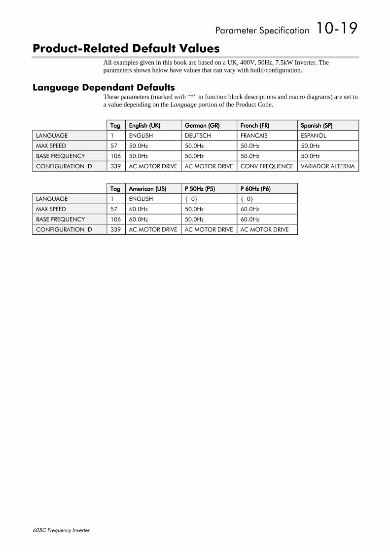
3DUDPHWHU#6SHFLILFDWLRQ##4304<
938&#)UHTXHQF\#,QYHUWHU
3URGXFW05HODWHG#'HIDXOW#9DOXHVAll examples given in this book are based on a UK, 400V, 50Hz, 7.5kW Inverter. Theparameters shown below have values that can vary with build/configuration.
/DQJXDJH#'HSHQGDQW#'HIDXOWVThese parameters (marked with “*” in function block descriptions and macro diagrams) are set toa value depending on the Language portion of the Product Code.
7DJ7DJ7DJ7DJ (QJOLVK#+8.,(QJOLVK#+8.,(QJOLVK#+8.,(QJOLVK#+8., *HUPDQ#+*5,*HUPDQ#+*5,*HUPDQ#+*5,*HUPDQ#+*5, )UHQFK#+)5,)UHQFK#+)5,)UHQFK#+)5,)UHQFK#+)5, 6SDQLVK#+63,6SDQLVK#+63,6SDQLVK#+63,6SDQLVK#+63,
/$1*8$*( 4 (1*/,6+ '(876&+ )5$1&$,6 (63$12/
0$;#63((' 8: 8313+] 8313+] 8313+] 8313+]
%$6(#)5(48(1&< 439 8313+] 8313+] 8313+] 8313+]
&21),*85$7,21#,' 66< $થ#'5,9( $થ#'5,9( &219#)5(48(1&( 9$5,$'25#$/7(51$
7DJ7DJ7DJ7DJ $PHULFDQ#+86,$PHULFDQ#+86,$PHULFDQ#+86,$PHULFDQ#+86, 3#83+]#+38,3#83+]#+38,3#83+]#+38,3#83+]#+38, 3#93+]#+39,3#93+]#+39,3#93+]#+39,3#93+]#+39,
/$1*8$*( 4 (1*/,6+ ^##3` ^##3`
0$;#63((' 8: 9313+] 8313+] 9313+]
%$6(#)5(48(1&< 439 9313+] 8313+] 9313+]
&21),*85$7,21#,' 66< $થ#'5,9( $થ#'5,9( $થ#'5,9(
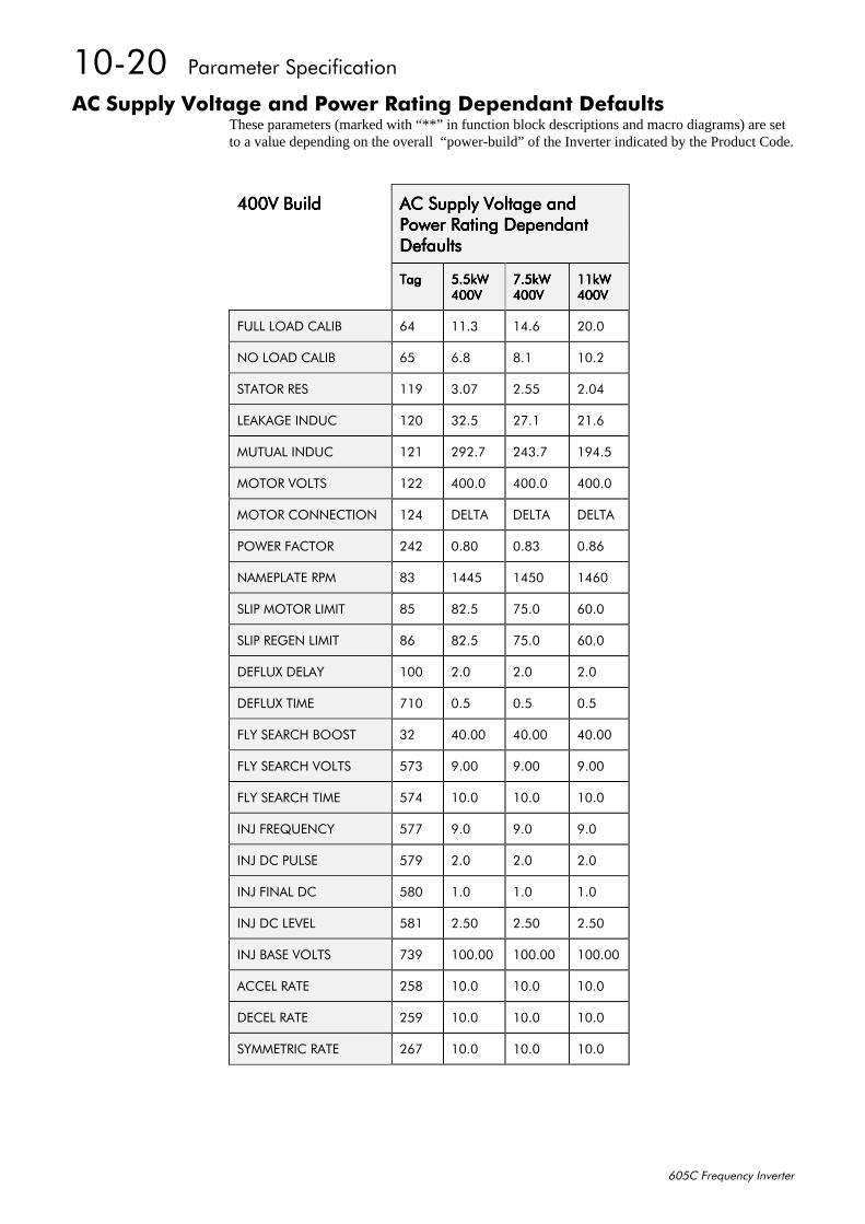
43053##3DUDPHWHU#6SHFLILFDWLRQ
938&#)UHTXHQF\#,QYHUWHU
$XSSO\#9ROWDJH#DQG#3RZHU#5DWLQJ#'HSHQGDQW#'HIDXOWVThese parameters (marked with “**” in function block descriptions and macro diagrams) are setto a value depending on the overall “power-build” of the Inverter indicated by the Product Code.
7339#%XLOG7339#%XLOG7339#%XLOG7339#%XLOG $XSSO\#9ROWDJH#DQG$XSSO\#9ROWDJH#DQG$XSSO\#9ROWDJH#DQG$XSSO\#9ROWDJH#DQG3RZHU#5DWLQJ#'HSHQGDQW3RZHU#5DWLQJ#'HSHQGDQW3RZHU#5DWLQJ#'HSHQGDQW3RZHU#5DWLQJ#'HSHQGDQW'HIDXOWV'HIDXOWV'HIDXOWV'HIDXOWV
7DJ7DJ7DJ7DJ 818N:818N:818N:818N:7339733973397339
:18N::18N::18N::18N:7339733973397339
44N:44N:44N:44N:7339733973397339
)8//#/2$'#&$/,% 97 4416 4719 5313
12#/2$'#&$/,% 98 91; ;14 4315
67$725#5(6 44< 613: 5188 5137
/($.$*(#,1'8& 453 6518 5:14 5419
0878$/#,1'8& 454 5<51: 5761: 4<718
02725#92/76 455 73313 73313 73313
02725#&211(&7,21 457 '(/7$ '(/7$ '(/7$
32:(5#)$&725 575 31;3 31;6 31;9
1$0(3/$7(#530 ;6 4778 4783 4793
6/,3#02725#/,0,7 ;8 ;518 :813 9313
6/,3#5(*(1#/,0,7 ;9 ;518 :813 9313
'()/8;#'(/$< 433 513 513 513
'()/8;#7,0( :43 318 318 318
)/<#6($5&+#%2267 65 73133 73133 73133
)/<#6($5&+#92/76 8:6 <133 <133 <133
)/<#6($5&+#7,0( 8:7 4313 4313 4313
,1-#)5(48(1&< 8:: <13 <13 <13
,1-#'&/6( 8:< 513 513 513
,1-#),1$/#'& 8;3 413 413 413
,1-#'&#/(9(/ 8;4 5183 5183 5183
,1-#%$6(#92/76 :6< 433133 433133 433133
$&&(/#5$7( 58; 4313 4313 4313
'(&(/#5$7( 58< 4313 4313 4313
6<00(75,$7( 59: 4313 4313 4313
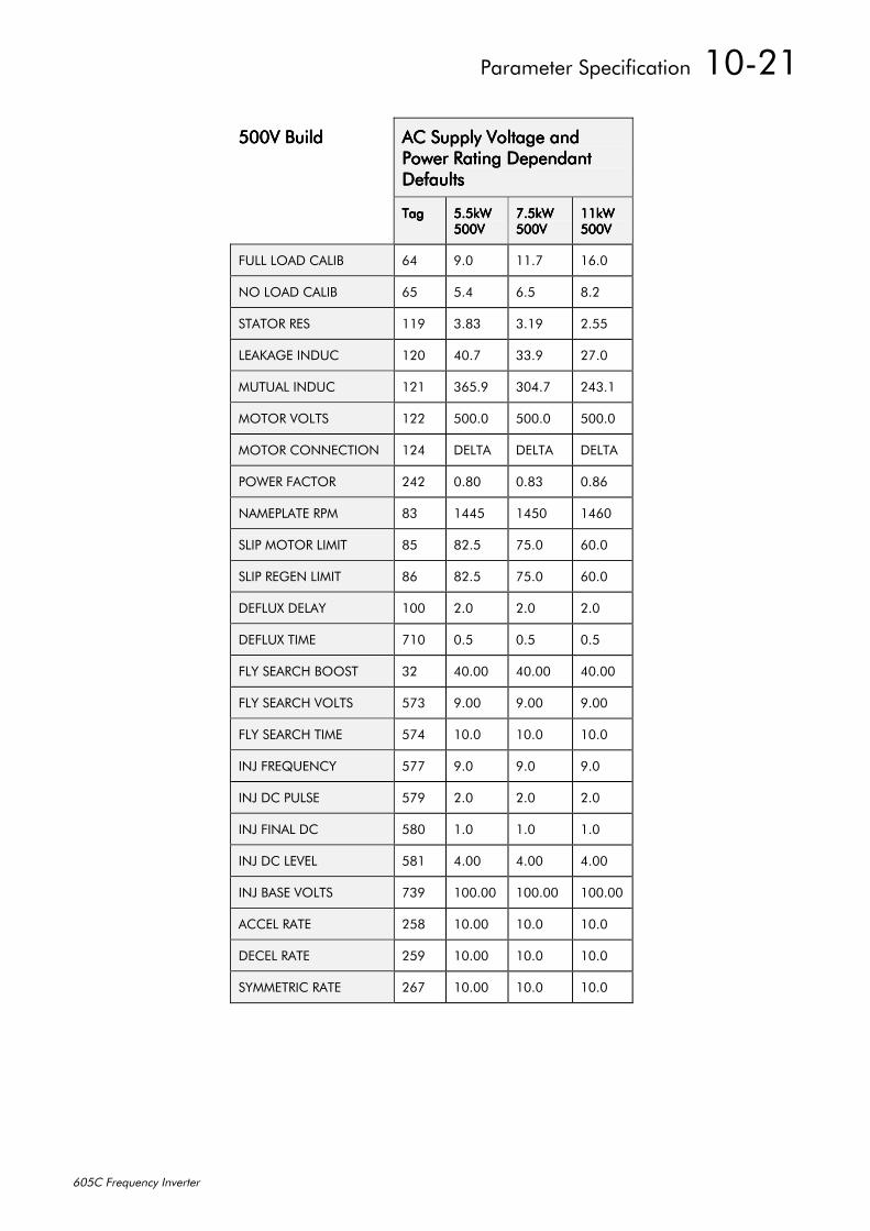
3DUDPHWHU#6SHFLILFDWLRQ##43054
938&#)UHTXHQF\#,QYHUWHU
8339#%XLOG8339#%XLOG8339#%XLOG8339#%XLOG $XSSO\#9ROWDJH#DQG$XSSO\#9ROWDJH#DQG$XSSO\#9ROWDJH#DQG$XSSO\#9ROWDJH#DQG3RZHU#5DWLQJ#'HSHQGDQW3RZHU#5DWLQJ#'HSHQGDQW3RZHU#5DWLQJ#'HSHQGDQW3RZHU#5DWLQJ#'HSHQGDQW'HIDXOWV'HIDXOWV'HIDXOWV'HIDXOWV
7DJ7DJ7DJ7DJ 818N:818N:818N:818N:8339833983398339
:18N::18N::18N::18N:8339833983398339
44N:44N:44N:44N:8339833983398339
)8//#/2$'#&$/,% 97 <13 441: 4913
12#/2$'#&$/,% 98 817 918 ;15
67$725#5(6 44< 61;6 614< 5188
/($.$*(#,1'8& 453 731: 661< 5:13
0878$/#,1'8& 454 6981< 6371: 57614
02725#92/76 455 83313 83313 83313
02725#&211(&7,21 457 '(/7$ '(/7$ '(/7$
32:(5#)$&725 575 31;3 31;6 31;9
1$0(3/$7(#530 ;6 4778 4783 4793
6/,3#02725#/,0,7 ;8 ;518 :813 9313
6/,3#5(*(1#/,0,7 ;9 ;518 :813 9313
'()/8;#'(/$< 433 513 513 513
'()/8;#7,0( :43 318 318 318
)/<#6($5&+#%2267 65 73133 73133 73133
)/<#6($5&+#92/76 8:6 <133 <133 <133
)/<#6($5&+#7,0( 8:7 4313 4313 4313
,1-#)5(48(1&< 8:: <13 <13 <13
,1-#'&/6( 8:< 513 513 513
,1-#),1$/#'& 8;3 413 413 413
,1-#'&#/(9(/ 8;4 7133 7133 7133
,1-#%$6(#92/76 :6< 433133 433133 433133
$&&(/#5$7( 58; 43133 4313 4313
'(&(/#5$7( 58< 43133 4313 4313
6<00(75,$7( 59: 43133 4313 4313

43055##3DUDPHWHU#6SHFLILFDWLRQ
938&#)UHTXHQF\#,QYHUWHU
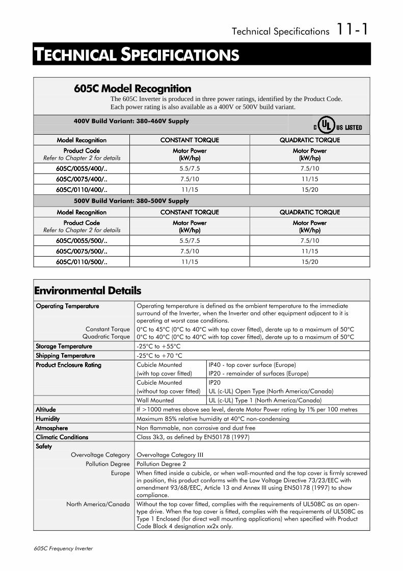
7HFKQLFDO#6SHFLILFDWLRQV##4404
938&#)UHTXHQF\#,QYHUWHU
44#7(&+1,&$/#63(&,),&$7,216
938�RGHO#5HFRJQLWLRQThe 605C Inverter is produced in three power ratings, identified by the Product Code.Each power rating is also available as a 400V or 500V build variant.
7339#%XLOG#9DULDQW=#6;307939#6XSSO\
0RGHO#5HFRJQLWLRQ0RGHO#5HFRJQLWLRQ0RGHO#5HFRJQLWLRQ0RGHO#5HFRJQLWLRQ &2167$17#72548(&2167$17#72548(&2167$17#72548(&2167$17#72548( 48$'5$7,𑭤(48$'5$7,𑭤(48$'5$7,𑭤(48$'5$7,𑭤(
3URGXFW#&RGH3URGXFW#&RGH3URGXFW#&RGH3URGXFW#&RGH5HIHU#WR#&KDSWHU#5#IRU#GHWDLOV
0RWRU#3RZHU0RWRU#3RZHU0RWRU#3RZHU0RWRU#3RZHU+N:2KS,+N:2KS,+N:2KS,+N:2KS,
0RWRU#3RZHU0RWRU#3RZHU0RWRU#3RZHU0RWRU#3RZHU+N:2KS,+N:2KS,+N:2KS,+N:2KS,
938&233882733211938&233882733211938&233882733211938&233882733211 8182:18 :18243
938&233:82733211938&233:82733211938&233:82733211938&233:82733211 :18243 44248
938&234432733211938&234432733211938&234432733211938&234432733211 44248 48253
8339#%XLOG#9DULDQW=#6;308339#6XSSO\
0RGHO#5HFRJQLWLRQ0RGHO#5HFRJQLWLRQ0RGHO#5HFRJQLWLRQ0RGHO#5HFRJQLWLRQ &2167$17#72548(&2167$17#72548(&2167$17#72548(&2167$17#72548( 48$'5$7,𑭤(48$'5$7,𑭤(48$'5$7,𑭤(48$'5$7,𑭤(
3URGXFW#&RGH3URGXFW#&RGH3URGXFW#&RGH3URGXFW#&RGH5HIHU#WR#&KDSWHU#5#IRU#GHWDLOV
0RWRU#3RZHU0RWRU#3RZHU0RWRU#3RZHU0RWRU#3RZHU+N:2KS,+N:2KS,+N:2KS,+N:2KS,
0RWRU#3RZHU0RWRU#3RZHU0RWRU#3RZHU0RWRU#3RZHU+N:2KS,+N:2KS,+N:2KS,+N:2KS,
938&233882833211938&233882833211938&233882833211938&233882833211 8182:18 :18243
938&233:82833211938&233:82833211938&233:82833211938&233:82833211 :18243 44248
938&234432833211938&234432833211938&234432833211938&234432833211 44248 48253
(QYLURQPHQWDO#'HWDLOV2SHUDWLQJ#7HPSHUDWXUH2SHUDWLQJ#7HPSHUDWXUH2SHUDWLQJ#7HPSHUDWXUH2SHUDWLQJ#7HPSHUDWXUH
&RQVWDQW#7RUTXH4XDGUDWLF#7RUTXH
2SHUDWLQJ#WHPSHUDWXUH#LV#GHILQHG#DV#WKH#DPELHQW#WHPSHUDWXUH#WR#WKH#LPPHGLDWHVXUURXQG#RI#WKH#,QYHUWHU/#ZKHQ#WKH#,QYHUWHU#DQG#RWKHU#HTXLSPHQW#DGMDFHQW#WR#LW#LVRSHUDWLQJ#DW#ZRUVW#FDVH#FRQGLWLRQV13°&#WR#78°&#+3°&#WR#73°&#ZLWK#WRS#FRYHU#ILWWHG,/#GHUDWH#XS#WR#D#PD[LPXP#RI#83°&3°&#WR#73°&#+3°&#WR#73°&#ZLWK#WRS#FRYHU#ILWWHG,/#GHUDWH#XS#WR#D#PD[LPXP#RI#83°&
6WRUDJH#7HPSHUDWXUH6WRUDJH#7HPSHUDWXUH6WRUDJH#7HPSHUDWXUH6WRUDJH#7HPSHUDWXUH 058°&#WR#.88°&6KLSSLQJ#7HPSHUDWXUH6KLSSLQJ#7HPSHUDWXUH6KLSSLQJ#7HPSHUDWXUH6KLSSLQJ#7HPSHUDWXUH 058°&#WR#.:3#°&3URGXFW#(QFORVXUH#5DWLQJ3URGXFW#(QFORVXUH#5DWLQJ3URGXFW#(QFORVXUH#5DWLQJ3URGXFW#(QFORVXUH#5DWLQJ &XELFOH#0RXQWHG
+ZLWK#WRS#FRYHU#ILWWHG,,373#0#WRS#FRYHU#VXUIDFH#+(XURSH,,353#0#UHPDLQGHU#RI#VXUIDFHV#+(XURSH,
&XELFOH#0RXQWHG+ZLWKRXW#WRS#FRYHU#ILWWHG,
,3538/#+F08/,#2SHQ#7\SH#+1RUWK#$PHULFD2&DQDGD,
:DOO#0RXQWHG 8/#+F08/,#7\SH#4#+1RUWK#$PHULFD2&DQDGD,$OWLWXGH$OWLWXGH$OWLWXGH$OWLWXGH ,I#!4333#PHWUHV#DERYH#VHD#OHYHO/#GHUDWH#0RWRU#3RZHU#UDWLQJ#E\#4(#SHU#433#PHWUHV+XPLGLW\+XPLGLW\+XPLGLW\+XPLGLW\ 0D[LPXP#;8(#UHODWLYH#KXPLGLW\#DW#73°&#QRQ0FRQGHQVLQJ$WPRVSKHUH$WPRVSKHUH$WPRVSKHUH$WPRVSKHUH 1RQ#IODPPDEOH/#QRQ#FRUURVLYH#DQG#GXVW#IUHH&OLPDWLF#&RQGLWLRQV&OLPDWLF#&RQGLWLRQV&OLPDWLF#&RQGLWLRQV&OLPDWLF#&RQGLWLRQV &ODVV#6N6/#DV#GHILQHG#E\#(1834:;#+4<<:,6DIHW\6DIHW\6DIHW\6DIHW\
2YHUYROWDJH#&DWHJRU\ 2YHUYROWDJH#&DWHJRU\#III
3ROOXWLRQ#'HJUHH 3ROOXWLRQ#'HJUHH#5(XURSH :KHQ#ILWWHG#LQVLGH#D#FXELFOH/#RU#ZKHQ#ZDOO0PRXQWHG#DQG#WKH#WRS#FRYHU#LV#ILUPO\#VFUHZHG
LQ#SRVLWLRQ/#WKLV#SURGXFW#FRQIRUPV#ZLWK#WKH#/RZ#9ROWDJH#'LUHFWLYH#:62562((&#ZLWKDPHQGPHQW#<629;2((&/#$UWLFOH#46#DQG#$QQH[#,,,#XVLQJ#(1834:;#+4<<:,#WR#VKRZFRPSOLDQFH1
1RUWK#$PHULFD2&DQDGD :LWKRXW#WKH#WRS#FRYHU#ILWWHG/#FRPSOLHV#ZLWK#WKH#UHTXLUHPHQWV#RI#8/83;&#DV#DQ#RSHQ0W\SH#GULYH1#:KHQ#WKH#WRS#FRYHU#LV#ILWWHG/#FRPSOLHV#ZLWK#WKH#UHTXLUHPHQWV#RI#8/83;&#DV7\SH#4#(QFORVHG#+IRU#GLUHFW#ZDOO#PRXQWLQJ#DSSOLFDWLRQV,#ZKHQ#VSHFLILHG#ZLWK#3URGXFW&RGH#%ORFN#7#GHVLJQDWLRQ#[[5[#RQO\1
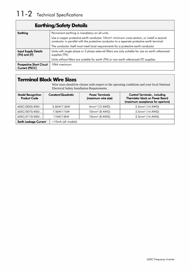
4405##7HFKQLFDO#6SHFLILFDWLRQV
938&#)UHTXHQF\#,QYHUWHU
(DUWKLQJ26DIHW\#'HWDLOV(DUWKLQJ(DUWKLQJ(DUWKLQJ(DUWKLQJ 3HUPDQHQW#HDUWKLQJ#LV#PDQGDWRU\#RQ#DOO#XQLWV1
8VH#D#FRSSHU#SURWHFWLYH#HDUWK#FRQGXFWRU#43PPò#PLQLPXP#FURVV0VHFWLRQ/#RU#LQVWDOO#D#VHFRQGFRQGXFWRU#LQ#SDUDOOHO#ZLWK#WKH#SURWHFWLYH#FRQGXFWRU#WR#D#VHSDUDWH#SURWHFWLYH#HDUWK#WHUPLQDO
7KH#FRQGXFWRU#LWVHOI#PXVW#PHHW#ORFDO#UHTXLUHPHQWV#IRU#D#SURWHFWLYH#HDUWK#FRQGXFWRU
,QSXW#6XSSO\#'HWDLOV,QSXW#6XSSO\#'HWDLOV,QSXW#6XSSO\#'HWDLOV,QSXW#6XSSO\#'HWDLOV+71,#DQG#+,7,+71,#DQG#+,7,+71,#DQG#+,7,+71,#DQG#+,7,
8QLWV#ZLWK#VLQJOH#SKDVH#RU#6#SKDVH#H[WHUQDO#ILOWHUV#DUH#RQO\#VXLWDEOH#IRU#XVH#RQ#HDUWK#UHIHUHQFHGVXSSOLHV#+71,1
8QLWV#ZLWKRXW#ILOWHUV#DUH#VXLWDEOH#IRU#HDUWK#+71,#RU#QRQ0HDUWK#UHIHUHQFHG#+,7,#VXSSOLHV1
3URVSHFWLYH#6KRUW#&LUFXLW3URVSHFWLYH#6KRUW#&LUFXLW3URVSHFWLYH#6KRUW#&LUFXLW3URVSHFWLYH#6KRUW#&LUFXLW&XUUHQW#+36&&,&XUUHQW#+36&&,&XUUHQW#+36&&,&XUUHQW#+36&&,
43N$#PD[LPXP
7HUPLQDO#%ORFN#:LUH#6L]HVWire sizes should be chosen with respect to the operating conditions and your local NationalElectrical Safety Installation Requirements.
0RGHO#5HFRJQLWLRQ0RGHO#5HFRJQLWLRQ0RGHO#5HFRJQLWLRQ0RGHO#5HFRJQLWLRQ3URGXFW#&RGH3URGXFW#&RGH3URGXFW#&RGH3URGXFW#&RGH
&RQVWDQW24XDGUDWLF&RQVWDQW24XDGUDWLF&RQVWDQW24XDGUDWLF&RQVWDQW24XDGUDWLF 3RZHU#7HUPLQDOV3RZHU#7HUPLQDOV3RZHU#7HUPLQDOV3RZHU#7HUPLQDOV+PD[LPXP#ZLUH#VL]H,+PD[LPXP#ZLUH#VL]H,+PD[LPXP#ZLUH#VL]H,+PD[LPXP#ZLUH#VL]H,
&RQWURO#7HUPLQDOV#/#LQFOXGLQJ&RQWURO#7HUPLQDOV#/#LQFOXGLQJ&RQWURO#7HUPLQDOV#/#LQFOXGLQJ&RQWURO#7HUPLQDOV#/#LQFOXGLQJ7KHUPLVWRU#EORFN#RQ#3RZHU#%RDUG7KHUPLVWRU#EORFN#RQ#3RZHU#%RDUG7KHUPLVWRU#EORFN#RQ#3RZHU#%RDUG7KHUPLVWRU#EORFN#RQ#3RZHU#%RDUG+PD[LPXP#DFFHSWDQFH#IRU#DSHUWXUH,+PD[LPXP#DFFHSWDQFH#IRU#DSHUWXUH,+PD[LPXP#DFFHSWDQFH#IRU#DSHUWXUH,+PD[LPXP#DFFHSWDQFH#IRU#DSHUWXUH,
938&233882733211 818N:2:18N: 7PPò#+45#$:*, 518PPò#+47#$:*,
938&233:82733211 :18N:244N: 43PPò#+;#$:*, 518PPò#+47#$:*,
938&234432733211 44N:248N: 43PPò#+;#$:*, 518PPò#+47#$:*,
(DUWK#/HDNDJH#&XUUHQW(DUWK#/HDNDJH#&XUUHQW(DUWK#/HDNDJH#&XUUHQW(DUWK#/HDNDJH#&XUUHQW !43P$#+DOO#PRGHOV,
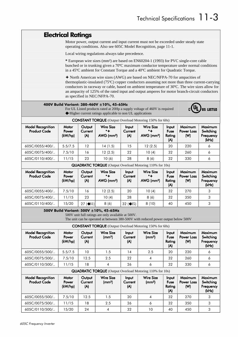
7HFKQLFDO#6SHFLILFDWLRQV##4406
938&#)UHTXHQF\#,QYHUWHU
(OHFWULFDO#5DWLQJVMotor power, output current and input current must not be exceeded under steady stateoperating conditions. Also see 605C Model Recognition, page 11-1.
Local wiring regulations always take precedence.
* European wire sizes (mm²) are based on EN60204-1 (1993) for PVC single-core cablebunched or in trunking given a 70ºC maximum conductor temperature under normal conditionsin a 45ºC ambient for Constant Torque and a 40ºC ambient for Quadratic Torque.
North American wire sizes (AWG) are based on NEC/NFPA-70 for ampacities ofthermoplastic-insulated (75ºC) copper conductors assuming not more than three current-carryingconductors in raceway or cable, based on ambient temperature of 30ºC. The wire sizes allow foran ampacity of 125% of the rated input and output amperes for motor branch-circuit conductorsas specified in NEC/NFPA-70.
7339#%XLOG#9DULDQW=#6;307939#43(/#78098+]For UL Listed products rated at 20Hp a supply voltage of 460V is required=Higher current ratings applicable to non UL applications
&2167$17#72548(#&2167$17#72548(#&2167$17#72548(#&2167$17#72548(#(Output Overload Motoring 150% for 60s)
0RGHO#5HFRJQLWLRQ0RGHO#5HFRJQLWLRQ0RGHO#5HFRJQLWLRQ0RGHO#5HFRJQLWLRQ3URGXFW#&RGH3URGXFW#&RGH3URGXFW#&RGH3URGXFW#&RGH
0RWRU0RWRU0RWRU0RWRU3RZHU3RZHU3RZHU3RZHU+N:2KS,+N:2KS,+N:2KS,+N:2KS,
2XWSXW2XWSXW2XWSXW2XWSXW&XUUHQW&XUUHQW&XUUHQW&XUUHQW+$,+$,+$,+$,
:LUH#6L]H:LUH#6L]H:LUH#6L]H:LUH#6L]H----
$:*#+PPò,$:*#+PPò,$:*#+PPò,$:*#+PPò,
,QSXW,QSXW,QSXW,QSXW&XUUHQW&XUUHQW&XUUHQW&XUUHQW+$,+$,+$,+$,
:LUH#6L]H:LUH#6L]H:LUH#6L]H:LUH#6L]H----
$:*#+PPò,$:*#+PPò,$:*#+PPò,$:*#+PPò,
,QSXW,QSXW,QSXW,QSXW)XVH)XVH)XVH)XVH5DWLQJ5DWLQJ5DWLQJ5DWLQJ+$,+$,+$,+$,
0D[LPXP0D[LPXP0D[LPXP0D[LPXP3RZHU#/RVV3RZHU#/RVV3RZHU#/RVV3RZHU#/RVV
+:,+:,+:,+:,
0D[LPXP0D[LPXP0D[LPXP0D[LPXP6ZLWFKLQJ6ZLWFKLQJ6ZLWFKLQJ6ZLWFKLQJ)UHTXHQF\)UHTXHQF\)UHTXHQF\)UHTXHQF\+N+],+N+],+N+],+N+],
938&233882733211 8182:18 45 47#+418, 48 45#+518, 53 553 9
938&233:82733211 :18243 49 45#+518, 55 43#+7, 65 593 9
938&234432733211 44248 56 43#+9, 5; ;#+9, 65 663 9
48$'5$7,𑭤(#48$'5$7,𑭤(#48$'5$7,𑭤(#48$'5$7,𑭤(#(Output Overload Motoring 110% for 10s)
0RGHO#5HFRJQLWLRQ0RGHO#5HFRJQLWLRQ0RGHO#5HFRJQLWLRQ0RGHO#5HFRJQLWLRQ3URGXFW#&RGH3URGXFW#&RGH3URGXFW#&RGH3URGXFW#&RGH
0RWRU0RWRU0RWRU0RWRU3RZHU3RZHU3RZHU3RZHU+N:2KS,+N:2KS,+N:2KS,+N:2KS,
2XWSXW2XWSXW2XWSXW2XWSXW&XUUHQW&XUUHQW&XUUHQW&XUUHQW+$,+$,+$,+$,
:LUH#6L]H:LUH#6L]H:LUH#6L]H:LUH#6L]H----
$:*#+PPò,$:*#+PPò,$:*#+PPò,$:*#+PPò,
,QSXW,QSXW,QSXW,QSXW&XUUHQW&XUUHQW&XUUHQW&XUUHQW+$,+$,+$,+$,
:LUH#6L]H:LUH#6L]H:LUH#6L]H:LUH#6L]H----
$:*#+PPò,$:*#+PPò,$:*#+PPò,$:*#+PPò,
,QSXW,QSXW,QSXW,QSXW)XVH)XVH)XVH)XVH5DWLQJ5DWLQJ5DWLQJ5DWLQJ+$,+$,+$,+$,
0D[LPXP0D[LPXP0D[LPXP0D[LPXP3RZHU#/RVV3RZHU#/RVV3RZHU#/RVV3RZHU#/RVV
+:,+:,+:,+:,
0D[LPXP0D[LPXP0D[LPXP0D[LPXP6ZLWFKLQJ6ZLWFKLQJ6ZLWFKLQJ6ZLWFKLQJ)UHTXHQF\)UHTXHQF\)UHTXHQF\)UHTXHQF\+N+],+N+],+N+],+N+],
938&233882733211 :18243 49 45#+518, 53 43#+7, 65 5:3 6
938&233:82733211 44248 56 43#+7, 5; ;#+9, 65 683 6
938&234432733211 48253 5:#+31, ;#+9, 65#+35, ;#+43, 73 783 6
8339#%XLOG#9DULDQW=#8339#43(/#78098+]500V unit full ratings are only available at 500V.The unit can be operated at between 380-500V with reduced power output below 500V
&2167$17#72548(#&2167$17#72548(#&2167$17#72548(#&2167$17#72548(#(Output Overload Motoring 150% for 60s)
0RGHO#5HFRJQLWLRQ0RGHO#5HFRJQLWLRQ0RGHO#5HFRJQLWLRQ0RGHO#5HFRJQLWLRQ3URGXFW#&RGH3URGXFW#&RGH3URGXFW#&RGH3URGXFW#&RGH
0RWRU0RWRU0RWRU0RWRU3RZHU3RZHU3RZHU3RZHU+N:2KS,+N:2KS,+N:2KS,+N:2KS,
2XWSXW2XWSXW2XWSXW2XWSXW&XUUHQW&XUUHQW&XUUHQW&XUUHQW+$,+$,+$,+$,
:LUH#6L]H:LUH#6L]H:LUH#6L]H:LUH#6L]H+PPò,+PPò,+PPò,+PPò,
,QSXW,QSXW,QSXW,QSXW&XUUHQW&XUUHQW&XUUHQW&XUUHQW+$,+$,+$,+$,
:LUH#6L]H:LUH#6L]H:LUH#6L]H:LUH#6L]H+PPò,+PPò,+PPò,+PPò,
,QSXW,QSXW,QSXW,QSXW)XVH)XVH)XVH)XVH5DWLQJ5DWLQJ5DWLQJ5DWLQJ+$,+$,+$,+$,
0D[LPXP0D[LPXP0D[LPXP0D[LPXP3RZHU#/RVV3RZHU#/RVV3RZHU#/RVV3RZHU#/RVV
+:,+:,+:,+:,
0D[LPXP0D[LPXP0D[LPXP0D[LPXP6ZLWFKLQJ6ZLWFKLQJ6ZLWFKLQJ6ZLWFKLQJ)UHTXHQF\)UHTXHQF\)UHTXHQF\)UHTXHQF\+N+],+N+],+N+],+N+],
938&233882833211 8182:18 43 418 47 518 53 553 9
938&233:82833211 :18243 4518 518 55 7 65 593 9
938&234432833211 44248 4; 7 59 9 65 663 9
48$'5$7,𑭤(#48$'5$7,𑭤(#48$'5$7,𑭤(#48$'5$7,𑭤(#(Output Overload Motoring 110% for 10s)
0RGHO#5HFRJQLWLRQ0RGHO#5HFRJQLWLRQ0RGHO#5HFRJQLWLRQ0RGHO#5HFRJQLWLRQ3URGXFW#&RGH3URGXFW#&RGH3URGXFW#&RGH3URGXFW#&RGH
0RWRU0RWRU0RWRU0RWRU3RZHU3RZHU3RZHU3RZHU+N:2KS,+N:2KS,+N:2KS,+N:2KS,
2XWSXW2XWSXW2XWSXW2XWSXW&XUUHQW&XUUHQW&XUUHQW&XUUHQW+$,+$,+$,+$,
:LUH#6L]H:LUH#6L]H:LUH#6L]H:LUH#6L]H+PPò,+PPò,+PPò,+PPò,
,QSXW,QSXW,QSXW,QSXW&XUUHQW&XUUHQW&XUUHQW&XUUHQW+$,+$,+$,+$,
:LUH#6L]H:LUH#6L]H:LUH#6L]H:LUH#6L]H+PPò,+PPò,+PPò,+PPò,
,QSXW,QSXW,QSXW,QSXW)XVH)XVH)XVH)XVH5DWLQJ5DWLQJ5DWLQJ5DWLQJ+$,+$,+$,+$,
0D[LPXP0D[LPXP0D[LPXP0D[LPXP3RZHU#/RVV3RZHU#/RVV3RZHU#/RVV3RZHU#/RVV
+:,+:,+:,+:,
0D[LPXP0D[LPXP0D[LPXP0D[LPXP6ZLWFKLQJ6ZLWFKLQJ6ZLWFKLQJ6ZLWFKLQJ)UHTXHQF\)UHTXHQF\)UHTXHQF\)UHTXHQF\+N+],+N+],+N+],+N+],
938&233882833211 :18243 4518 418 53 7 65 5:3 6
938&233:82833211 44248 4; 518 59 9 65 683 6
938&234432833211 48253 57 7 65 43 73 783 6
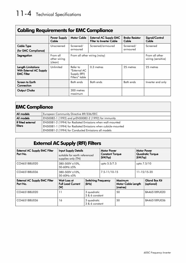
4407##7HFKQLFDO#6SHFLILFDWLRQV
938&#)UHTXHQF\#,QYHUWHU
&DEOLQJ#5HTXLUHPHQWV#IRU#(0&#&RPSOLDQFH3RZHU#6XSSO\3RZHU#6XSSO\3RZHU#6XSSO\3RZHU#6XSSO\&DEOH&DEOH&DEOH&DEOH
0RWRU#&DEOH0RWRU#&DEOH0RWRU#&DEOH0RWRU#&DEOH ([WHUQDO#$XSSO\#(0&([WHUQDO#$XSSO\#(0&([WHUQDO#$XSSO\#(0&([WHUQDO#$XSSO\#(0&)LOWHU#WR#,QYHUWHU#&DEOH)LOWHU#WR#,QYHUWHU#&DEOH)LOWHU#WR#,QYHUWHU#&DEOH)LOWHU#WR#,QYHUWHU#&DEOH
%UDNH#5HVLVWRU%UDNH#5HVLVWRU%UDNH#5HVLVWRU%UDNH#5HVLVWRU&DEOH&DEOH&DEOH&DEOH
6LJQDO2&RQWURO6LJQDO2&RQWURO6LJQDO2&RQWURO6LJQDO2&RQWURO&DEOH&DEOH&DEOH&DEOH
&DEOH#7\SH&DEOH#7\SH&DEOH#7\SH&DEOH#7\SH
+IRU#(0&#&RPSOLDQFH,+IRU#(0&#&RPSOLDQFH,+IRU#(0&#&RPSOLDQFH,+IRU#(0&#&RPSOLDQFH,
8QVFUHHQHG 6FUHHQHG2DUPRXUHG
6FUHHQHG2DUPRXUHG 6FUHHQHG2DUPRXUHG
6FUHHQHG
6HJUHJDWLRQ6HJUHJDWLRQ6HJUHJDWLRQ6HJUHJDWLRQ )URP#DOORWKHU#ZLULQJ+FOHDQ,
)URP#DOO#RWKHU#ZLULQJ#+QRLV\, )URP#DOO#RWKHUZLULQJ#+VHQVLWLYH,
/HQJWK#/LPLWDWLRQV/HQJWK#/LPLWDWLRQV/HQJWK#/LPLWDWLRQV/HQJWK#/LPLWDWLRQV:LWK#([WHUQDO#$XSSO\:LWK#([WHUQDO#$XSSO\:LWK#([WHUQDO#$XSSO\:LWK#([WHUQDO#$XSSO\(0&#)LOWHU(0&#)LOWHU(0&#)LOWHU(0&#)LOWHU
8QOLPLWHG 5HIHU#WR´([WHUQDO#$&6XSSO\#+5),,)LOWHUVµ#WDEOH
316#PHWUHV 58#PHWUHV 58#PHWUHV
6FUHHQ#WR#(DUWK6FUHHQ#WR#(DUWK6FUHHQ#WR#(DUWK6FUHHQ#WR#(DUWK&RQQHFWLRQ&RQQHFWLRQ&RQQHFWLRQ&RQQHFWLRQ
%RWK#HQGV %RWK#HQGV %RWK#HQGV ,QYHUWHU#HQG#RQO\
2XWSXW#&KRNH2XWSXW#&KRNH2XWSXW#&KRNH2XWSXW#&KRNH 633#PHWUHVPD[LPXP
(0&#&RPSOLDQFH$OO#PRGHOV$OO#PRGHOV$OO#PRGHOV$OO#PRGHOV (XURSHDQ#&RPPXQLW\#'LUHFWLYH#;<26692((&$OO#PRGHOV$OO#PRGHOV$OO#PRGHOV$OO#PRGHOV (1833;504#+4<<5,#DQG#SU(1833;505#+4<<5,#IRU#LPPXQLW\,I#ILWWHG#H[WHUQDO,I#ILWWHG#H[WHUQDO,I#ILWWHG#H[WHUQDO,I#ILWWHG#H[WHUQDOILOWHUVILOWHUVILOWHUVILOWHUV
(1833;405#+4<<7,#IRU#5DGLDWHG#(PLVVLRQV#ZKHQ#ZDOO0PRXQWHG(1833;404#+4<<7,#IRU#5DGLDWHG#(PLVVLRQV#ZKHQ#FXELFOH0PRXQWHG(1833;405#+4<<7,#IRU#&RQGXFWHG#(PLVVLRQV#DOO#PRGHOV
([WHUQDO#$XSSO\#+5),,#)LOWHUV([WHUQDO#$XSSO\#(0&#)LOWHU([WHUQDO#$XSSO\#(0&#)LOWHU([WHUQDO#$XSSO\#(0&#)LOWHU([WHUQDO#$XSSO\#(0&#)LOWHU3DUW#1R13DUW#1R13DUW#1R13DUW#1R1
,QSXW#6XSSO\#'HWDLOV,QSXW#6XSSO\#'HWDLOV,QSXW#6XSSO\#'HWDLOV,QSXW#6XSSO\#'HWDLOV
VXLWDEOH#IRU#HDUWK#UHIHUHQFHGVXSSOLHV#RQO\#+71,
0RWRU#3RZHU0RWRU#3RZHU0RWRU#3RZHU0RWRU#3RZHU&RQVWDQW#7RUTXH&RQVWDQW#7RUTXH&RQVWDQW#7RUTXH&RQVWDQW#7RUTXH+N:2KS,+N:2KS,+N:2KS,+N:2KS,
0RWRU#3RZHU0RWRU#3RZHU0RWRU#3RZHU0RWRU#3RZHU4XDGUDWLF#7RUTXH4XDGUDWLF#7RUTXH4XDGUDWLF#7RUTXH4XDGUDWLF#7RUTXH+N:2KS,+N:2KS,+N:2KS,+N:2KS,
&27984;;8353 6;308339#±43(/83093+]#±8(
XSWR#8182:18 XSWR#:18243
&27984;;8369 6;308339#±43(/83093+]#±8(
:18044243048 44048248053
([WHUQDO#$XSSO\#(0&#)LOWHU([WHUQDO#$XSSO\#(0&#)LOWHU([WHUQDO#$XSSO\#(0&#)LOWHU([WHUQDO#$XSSO\#(0&#)LOWHU3DUW#1R13DUW#1R13DUW#1R13DUW#1R1
:DWW#/RVV#DW:DWW#/RVV#DW:DWW#/RVV#DW:DWW#/RVV#DW)XOO#/RDG#&XUUHQW)XOO#/RDG#&XUUHQW)XOO#/RDG#&XUUHQW)XOO#/RDG#&XUUHQW+:,+:,+:,+:,
6ZLWFKLQJ#)UHTXHQF\6ZLWFKLQJ#)UHTXHQF\6ZLWFKLQJ#)UHTXHQF\6ZLWFKLQJ#)UHTXHQF\+N+],+N+],+N+],+N+],
0D[LPXP0D[LPXP0D[LPXP0D[LPXP0RWRU#&DEOH#/HQJWK0RWRU#&DEOH#/HQJWK0RWRU#&DEOH#/HQJWK0RWRU#&DEOH#/HQJWK+PHWUHV,+PHWUHV,+PHWUHV,+PHWUHV,
*ODQG#%R[#.LW*ODQG#%R[#.LW*ODQG#%R[#.LW*ODQG#%R[#.LW+RSWLRQDO,+RSWLRQDO,+RSWLRQDO,+RSWLRQDO,
&27984;;8353 44 6#TXDGUDWLF6#)#9#FRQVWDQW
83 %$7984;<8353
&27984;;8369 49 6#TXDGUDWLF6#)#9#FRQVWDQW
83 %$7984;<8369
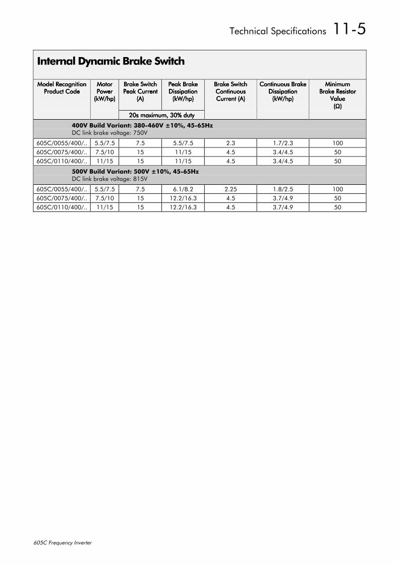
7HFKQLFDO#6SHFLILFDWLRQV##4408
938&#)UHTXHQF\#,QYHUWHU
,QWHUQDO#'\QDPLF#%UDNH#6ZLWFK
0RGHO#5HFRJQLWLRQ0RGHO#5HFRJQLWLRQ0RGHO#5HFRJQLWLRQ0RGHO#5HFRJQLWLRQ3URGXFW#&RGH3URGXFW#&RGH3URGXFW#&RGH3URGXFW#&RGH
0RWRU0RWRU0RWRU0RWRU3RZHU3RZHU3RZHU3RZHU+N:2KS,+N:2KS,+N:2KS,+N:2KS,
%UDNH#6ZLWFK%UDNH#6ZLWFK%UDNH#6ZLWFK%UDNH#6ZLWFK3HDN#&XUUHQW3HDN#&XUUHQW3HDN#&XUUHQW3HDN#&XUUHQW
+$,+$,+$,+$,
3HDN#%UDNH3HDN#%UDNH3HDN#%UDNH3HDN#%UDNH'LVVLSDWLRQ'LVVLSDWLRQ'LVVLSDWLRQ'LVVLSDWLRQ+N:2KS,+N:2KS,+N:2KS,+N:2KS,
%UDNH#6ZLWFK%UDNH#6ZLWFK%UDNH#6ZLWFK%UDNH#6ZLWFK&RQWLQXRXV&RQWLQXRXV&RQWLQXRXV&RQWLQXRXV&XUUHQW#+$,&XUUHQW#+$,&XUUHQW#+$,&XUUHQW#+$,
&RQWLQXRXV#%UDNH&RQWLQXRXV#%UDNH&RQWLQXRXV#%UDNH&RQWLQXRXV#%UDNH'LVVLSDWLRQ'LVVLSDWLRQ'LVVLSDWLRQ'LVVLSDWLRQ+N:2KS,+N:2KS,+N:2KS,+N:2KS,
0LQLPXP0LQLPXP0LQLPXP0LQLPXP%UDNH#5HVLVWRU%UDNH#5HVLVWRU%UDNH#5HVLVWRU%UDNH#5HVLVWRU
9DOXH9DOXH9DOXH9DOXH++++ΩΩΩΩ,,,,
53V#PD[LPXP/#63(#GXW\53V#PD[LPXP/#63(#GXW\53V#PD[LPXP/#63(#GXW\53V#PD[LPXP/#63(#GXW\
7339#%XLOG#9DULDQW=#6;307939#43(/#78098+]'&#OLQN#EUDNH#YROWDJH=#:839
938&233882733211 8182:18 :18 8182:18 516 41:2516 433938&233:82733211 :18243 48 44248 718 6172718 83938&234432733211 44248 48 44248 718 6172718 83
8339#%XLOG#9DULDQW=#8339#43(/#78098+]'&#OLQN#EUDNH#YROWDJH=#;489
938&233882733211 8182:18 :18 9142;15 5158 41;2518 433938&233:82733211 :18243 48 451524916 718 61:271< 83938&234432733211 44248 48 451524916 718 61:271< 83
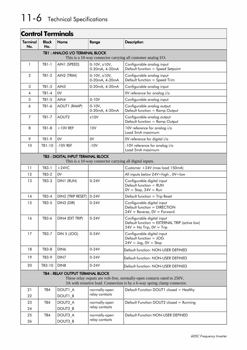
4409##7HFKQLFDO#6SHFLILFDWLRQV
938&#)UHTXHQF\#,QYHUWHU
&RQWURO#7HUPLQDOV7HUPLQDO7HUPLQDO7HUPLQDO7HUPLQDO1R11R11R11R1
%ORFN%ORFN%ORFN%ORFN1R11R11R11R1
1DPH1DPH1DPH1DPH 5DQJH5DQJH5DQJH5DQJH 'HVFULSWLRQ'HVFULSWLRQ'HVFULSWLRQ'HVFULSWLRQ
7%4#=#$1$/2*#,22#7(50,1$/#%/2&.7%4#=#$1$/2*#,22#7(50,1$/#%/2&.7%4#=#$1$/2*#,22#7(50,1$/#%/2&.7%4#=#$1$/2*#,22#7(50,1$/#%/2&.This is a 10-way connector carrying all customer analog I/O.
4 7%404 $,14#+63((', 30439/#±439/3053P$/#7053P$
&RQILJXUDEOH#DQDORJ#LQSXW'HIDXOW#IXQFWLRQ# #6SHHG#6HWSRLQW
5 7%405 $,15#+75,0, 30439/#±439/3053P$/#7053P$
&RQILJXUDEOH#DQDORJ#LQSXW'HIDXOW#IXQFWLRQ# #6SHHG#7ULP
6 7%406 $,16 3053P$/#7053P$ &RQILJXUDEOH#DQDORJ#LQSXW
7 7%407 39 39#UHIHUHQFH#IRU#DQDORJ#L2R
8 7%408 $,17 30439 &RQILJXUDEOH#DQDORJ#LQSXW
9 7%409 $2874#+5$03, 30439/3053P$/#7053P$
&RQILJXUDEOH#DQDORJ#RXWSXW'HIDXOW#IXQFWLRQ# #5DPS#2XWSXW
: 7%40: $2875 ±439 &RQILJXUDEOH#DQDORJ#RXWSXW'HIDXOW#IXQFWLRQ# #5DPS#2XWSXW
; 7%40; .439#5() 439 439#UHIHUHQFH#IRU#DQDORJ#L2R/RDG#8P$#PD[LPXP
< 7%40< 39 39 39#UHIHUHQFH#IRU#GLJLWDO#L2R
43 7%4043 0439#5() 0439 0439#UHIHUHQFH#IRU#DQDORJ#L2R/RDG#8P$#PD[LPXP
7%6#=#',*,7$/#,1387#7(50,1$/#%/2&.7%6#=#',*,7$/#,1387#7(50,1$/#%/2&.7%6#=#',*,7$/#,1387#7(50,1$/#%/2&.7%6#=#',*,7$/#,1387#7(50,1$/#%/2&.This is a 10-way connector carrying all digital inputs.
44 7%604 .579& &XVWRPHU#.579#+PD[#ORDG#483P$,
45 7%605 39 $OO#LQSXWV#EHORZ#579 KLJK#/#39 ORZ
46 7%606 ',14#+581, 30579 &RQILJXUDEOH#GLJLWDO#LQSXW'HIDXOW#IXQFWLRQ# #58139# #6WRS/#579# #5XQ
47 7%607 ',15#+75,3#5(6(7, 30579 'HIDXOW#IXQFWLRQ# #7ULS#5HVHW
48 7%608 ',16#+',5, 30579 &RQILJXUDEOH#GLJLWDO#LQSXW'HIDXOW#IXQFWLRQ# #',5(&7,21579# #5HYHUVH/#39# #)RUZDUG
49 7%609 ',17#+(;7#75,3, 30579 &RQILJXUDEOH#GLJLWDO#LQSXW'HIDXOW#IXQFWLRQ# #(;7(51$/#75,3#+DFWLYH#ORZ,579# #1R#7ULS/#39# #7ULS
4: 7%60: ',1#8#+-2*, 30579 &RQILJXUDEOH#GLJLWDO#LQSXW'HIDXOW#IXQFWLRQ# #-2*579# #-RJ/#39# #6WRS
4; 7%60; ',19 30579 'HIDXOW#IXQFWLRQ=#121086(5#'(),1('
4< 7%60< ',1: 30579 'HIDXOW#IXQFWLRQ=#121086(5#'(),1('
53 7%6043 ',1; 30579 'HIDXOW#IXQFWLRQ=#121086(5#'(),1('
7%7#=#5(/$<#287387#7(50,1$/#%/2&.7%7#=#5(/$<#287387#7(50,1$/#%/2&.7%7#=#5(/$<#287387#7(50,1$/#%/2&.7%7#=#5(/$<#287387#7(50,1$/#%/2&.These relay ouputs are volt-free, normally-open contacts rated to 250V,3A with resistive load. Connection is by a 6-way spring clamp connector.
54
55
7%7 '2874B$
'2874B%
QRUPDOO\0RSHQUHOD\#FRQWDFWV
'HIDXOW#)XQFWLRQ#'2874#FORVHG# #+HDOWK\
56
57
7%7 '2875B$
'2875B%
QRUPDOO\0RSHQUHOD\#FRQWDFWV
'HIDXOW#)XQFWLRQ#'2875#FORVHG# #5XQQLQJ
58
59
7%7 '2876B$
'2876B%
QRUPDOO\0RSHQUHOD\#FRQWDFWV
'HIDXOW#)XQFWLRQ#121086(5#'(),1('
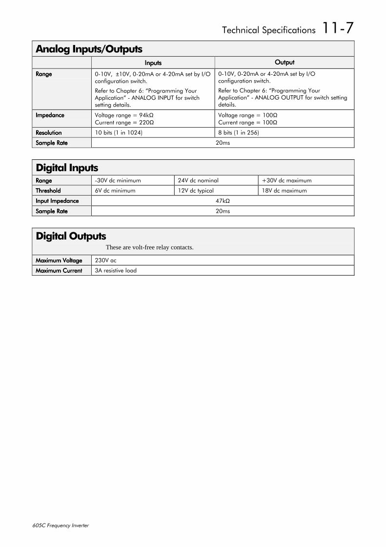
7HFKQLFDO#6SHFLILFDWLRQV##440:
938&#)UHTXHQF\#,QYHUWHU
$QDORJ#,QSXWV22XWSXWV,QSXWV,QSXWV,QSXWV,QSXWV 2XWSXW2XWSXW2XWSXW2XWSXW
5DQJH5DQJH5DQJH5DQJH 30439/##±439/#3053P$#RU#7053P$#VHW#E\#,22FRQILJXUDWLRQ#VZLWFK1
5HIHU#WR#&KDSWHU#9=#´3URJUDPPLQJ#<RXU$SSOLFDWLRQµ#0#$1$/2*#,1387#IRU#VZLWFKVHWWLQJ#GHWDLOV1
30439/#3053P$#RU#7053P$#VHW#E\#,22FRQILJXUDWLRQ#VZLWFK1
5HIHU#WR#&KDSWHU#9=#´3URJUDPPLQJ#<RXU$SSOLFDWLRQµ#0#$1$/2*#287387#IRU#VZLWFK#VHWWLQJGHWDLOV1
,PSHGDQFH,PSHGDQFH,PSHGDQFH,PSHGDQFH 9ROWDJH#UDQJH# #<7NΩ&XUUHQW#UDQJH# #553Ω
9ROWDJH#UDQJH# #433Ω&XUUHQW#UDQJH# #433Ω
5HVROXWLRQ5HVROXWLRQ5HVROXWLRQ5HVROXWLRQ 43#ELWV#+4#LQ#4357, ;#ELWV#+4#LQ#589,
6DPSOH#5DWH6DPSOH#5DWH6DPSOH#5DWH6DPSOH#5DWH 53PV
'LJLWDO#,QSXWV5DQJH5DQJH5DQJH5DQJH 0639#GF#PLQLPXP 579#GF#QRPLQDO .639#GF#PD[LPXP
7KUHVKROG7KUHVKROG7KUHVKROG7KUHVKROG 99#GF#PLQLPXP 459#GF#W\SLFDO 4;9#GF#PD[LPXP
,QSXW#,PSHGDQFH,QSXW#,PSHGDQFH,QSXW#,PSHGDQFH,QSXW#,PSHGDQFH 7:NΩ
6DPSOH#5DWH6DPSOH#5DWH6DPSOH#5DWH6DPSOH#5DWH 53PV
'LJLWDO#2XWSXWVThese are volt-free relay contacts.
0D[LPXP#9ROWDJH0D[LPXP#9ROWDJH0D[LPXP#9ROWDJH0D[LPXP#9ROWDJH 5639#DF
0D[LPXP#&XUUHQW0D[LPXP#&XUUHQW0D[LPXP#&XUUHQW0D[LPXP#&XUUHQW 6$#UHVLVWLYH#ORDG
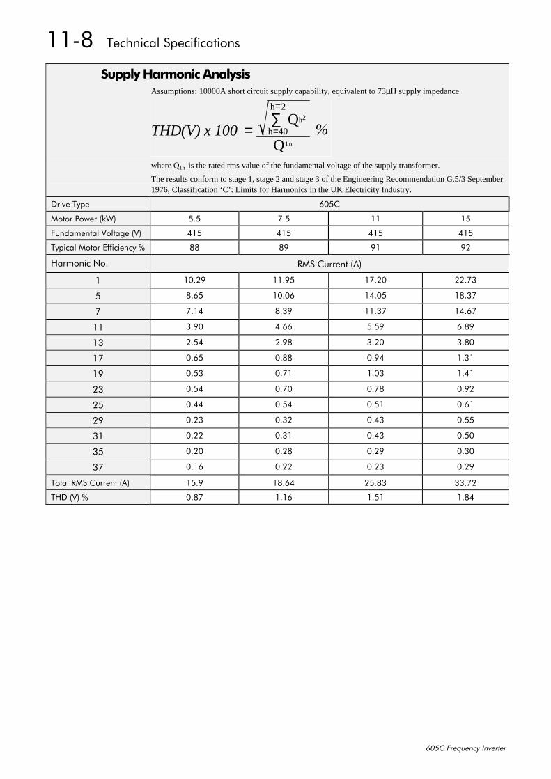
440;##7HFKQLFDO#6SHFLILFDWLRQV
938&#)UHTXHQF\#,QYHUWHU
6XSSO\#+DUPRQLF#$QDO\VLVAssumptions: 10000A short circuit supply capability, equivalent to 73µH supply impedance
THD(V) x 100= =∑ Q
Q
h2
1n
h 40
=h 2
%
where Q1n is the rated rms value of the fundamental voltage of the supply transformer.
The results conform to stage 1, stage 2 and stage 3 of the Engineering Recommendation G.5/3 September1976, Classification ‘C’: Limits for Harmonics in the UK Electricity Industry.
'ULYH#7\SH 938&
0RWRU#3RZHU#+N:, 818 :18 44 48
)XQGDPHQWDO#9ROWDJH#+9, 748 748 748 748
7\SLFDO#0RWRU#(IILFLHQF\#( ;; ;< <4 <5
+DUPRQLF#1R1 506#&XUUHQW#+$,
4 4315< 441<8 4:153 551:6
8 ;198 43139 47138 4;16:
: :147 ;16< 4416: 4719:
44 61<3 7199 818< 91;<
46 5187 51<; 6153 61;3
4: 3198 31;; 31<7 4164
4< 3186 31:4 4136 4174
56 3187 31:3 31:; 31<5
58 3177 3187 3184 3194
5< 3156 3165 3176 3188
64 3155 3164 3176 3183
68 3153 315; 315< 3163
6: 3149 3155 3156 315<
7RWDO#506#&XUUHQW#+$, 481< 4;197 581;6 661:5
7+'#+9,#( 31;: 4149 4184 41;7

&HUWLILFDWLRQ#IRU#WKH#,QYHUWHU##4504
938&#)UHTXHQF\#,QYHUWHU
45#&(57,),&$7,21#)25#7+(#,19(57(55HTXLUHPHQWV#IRU#(0&#&RPSOLDQFH
All Variable Speed Drives (VSDs) potentially produce electrical emissions which are radiatedinto the environment and conducted back into the ac supply. VSDs are inherently immune to anyadditional external electrical noise. The following information is provided to maximise theElectro Magnetic Compatibility (EMC) of VSDs and systems in their intended operatingenvironment, by minimising their emissions and maximising their immunity.
0LQLPLVLQJ#5DGLDWHG#(PLVVLRQVEN55011/EN55022 radiated emission measurements are made between 30MHz and 1GHz in thefar field at a distance of 10 to 30 metres. Limits lower than 30MHz or in close proximity are notspecified. Emissions from individual components tend to be additive.
• Use a screened/armoured cable between VSD/cubicle and motor containing the motorprotective earth (PE) connection. It should have a 360° screen termination. Earth screen atboth ends connecting to the motor frame and cubicle (or gland box if wall mounted).Maintain the screen integrity using 360° terminations.
1RWH=# 6RPH#KD]DUGRXV#DUHD#LQVWDOODWLRQV#PD\#SUHFOXGH#GLUHFW#HDUWKLQJ#DW#ERWK#HQGV#RI#WKHVFUHHQ/#LQ#WKLV#FDVH#HDUWK#RQH#HQG#YLD#D#4µ)#839DF#FDSDFLWRU/#DQG#WKH#RWKHU#DV#QRUPDO1
• Keep unshielded cable as short as possible inside the cubicle.
• Always maintain the integrity of the shield.
• If the cable is interrupted to insert contactors etc., re-connect the screen using the shortestpossible route.
• Keep the length of screen stripped-back as short as possible when making screenconnections.
• Ideally use 360° screen terminations using cable glands or `U’ clips on power screen rails.
If a shielded cable is not available, lay unshielded motor cables in a metal conduit which will actas a shield. The conduit must be continuous with a direct electrical contact to the VSD and motorhousing. If links are necessary, use braid with a minimum cross sectional area of 10mm2.
1RWH=# 6RPH#PRWRU#JODQG#ER[HV#DQG#FRQGXLW#JODQGV#DUH#PDGH#RI#SODVWLF/#LI#WKLV#LV#WKH#FDVH/#WKHQEUDLG#PXVW#EH#FRQQHFWHG#EHWZHHQ#WKH#VFUHHQ#DQG#WKH#FKDVVLV1#,Q#DGGLWLRQ#DW#WKH#PRWRUHQG/#HQVXUH#WKDW#WKH#VFUHHQ#LV#HOHFWULFDOO\#FRQQHFWHG#WR#WKH#PRWRU#IUDPH#VLQFH#VRPHWHUPLQDO#ER[HV#DUH#LQVXODWHG#IURP#WKH#IUDPH#E\#JDVNHW2SDLQW1
(DUWKLQJ#5HTXLUHPHQWV,03257$17=# 3URWHFWLYH#HDUWKLQJ#DOZD\V#WDNHV#SUHFHGHQFH#RYHU#(0&#HDUWKLQJ1
3URWHFWLYH#(DUWK#+3(,#&RQQHFWLRQV1RWH=# ,Q#DFFRUGDQFH#ZLWK#LQVWDOODWLRQV#WR#(193537/#RQO\#RQH#SURWHFWLYH#HDUWK#FRQGXFWRU#LV
SHUPLWWHG#DW#HDFK#SURWHFWLYH#HDUWK#WHUPLQDO#FRQWDFWLQJ#SRLQW1
Local wiring regulations may require the protective earth connection of the motor to beconnected locally, i.e. not as specified in these instructions. This will not cause shieldingproblems because of the relatively high RF impedance of the local earth connection.
(0&#(DUWK#&RQQHFWLRQVFor compliance with EMC requirements, we recommend that the “0V/signal ground” isseparately earthed. When a number of units are used in a system, these terminals should beconnected together at a single, local earthing point.

4505##&HUWLILFDWLRQ#IRU#WKH#,QYHUWHU
938&#)UHTXHQF\#,QYHUWHU
Control and signal cables for the encoder, all analog inputs, and communications requirescreening with the screen connected only at the VSD end. However, if high frequency noise isstill a problem, earth screen at the non VSD end via a 0.1µF capacitor.
1RWH=# &RQQHFW#WKH#VFUHHQ#+DW#WKH#96'#HQG,#WR#WKH#96'#SURWHFWLYH#HDUWK#SRLQW/#DQG#QRW#WR#WKHFRQWURO#ERDUG#WHUPLQDOV1
&DEOLQJ#5HTXLUHPHQWV1RWH=# 5HIHU#WR#&KDSWHU#44=#´7HFKQLFDO#6SHFLILFDWLRQVµ#IRU#DGGLWLRQDO#&DEOLQJ#5HTXLUHPHQWV1
3ODQQLQJ#&DEOH#5XQV• Use the shortest possible motor cable lengths.
• Use a single length of cable to a star junction point to feed multiple motors.
• Keep electrically noisy and sensitive cables apart.
• Keep electrically noisy and sensitive parallel cable runs to a minimum. Separate parallelcable runs by at least 0.25 metres. For runs longer than 10 metres, separation should beincreased proportionally. For example if the parallel runs were 50m, then the separationwould be (50/10) x 0.25m = 1.25m.
• Sensitive cables should cross noisy cables at 90°.
• Never run sensitive cables close or parallel to the motor, dc link and braking chopper circuitfor any distance.
• Never run supply, dc link or motor cables in the same bundle as the signal/control andfeedback cables, even if they are screened.
• Ensure EMC filter input and output cables are separately routed and do not couple acrossthe filter.
,QFUHDVLQJ#0RWRU#&DEOH#/HQJWKBecause cable capacitance and hence conducted emissions increase with motor cable length,conformance to EMC limits is only guaranteed with the specified ac supply filter option using amaximum cable length as specified in Chapter 11: “Technical Specifications”.
This maximum cable length can be improved using the specified external input or output filters.Refer to Chapter 11: “Technical Specifications” - External Filters.
Screened/armoured cable has significant capacitance between the conductors and screen whichincreases linearly with cable length (typically 200pF/m but varies with cable type and currentrating).
Long cable lengths may have the following undesirable effects:
• Tripping on `overcurrent’ as the cable capacitance is charged and discharged at theswitching frequency.
• Producing increased conducted emissions which degrade the performance of the EMC filterdue to saturation.
• Causing RCDs (Residual Current Devices) to trip due to increased high frequency earthcurrent.
• Producing increased heating inside the EMC ac supply filter from the increased conductedemissions.
These effects can be overcome by adding chokes or output filters at the output of the VSD.
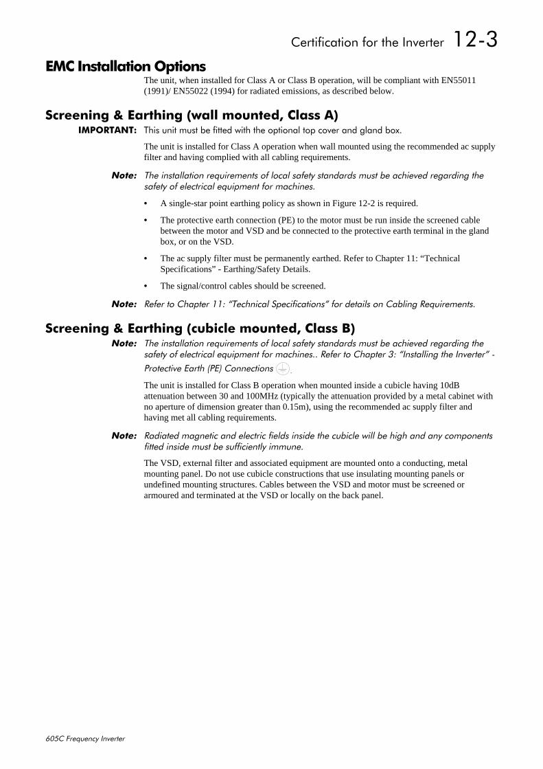
&HUWLILFDWLRQ#IRU#WKH#,QYHUWHU##4506
938&#)UHTXHQF\#,QYHUWHU
(0&#,QVWDOODWLRQ#2SWLRQVThe unit, when installed for Class A or Class B operation, will be compliant with EN55011(1991)/ EN55022 (1994) for radiated emissions, as described below.
6FUHHQLQJ#)#(DUWKLQJ#+ZDOO#PRXQWHG/#&ODVV#$,,03257$17=# 7KLV#XQLW#PXVW#EH#ILWWHG#ZLWK#WKH#RSWLRQDO#WRS#FRYHU#DQG#JODQG#ER[1
The unit is installed for Class A operation when wall mounted using the recommended ac supplyfilter and having complied with all cabling requirements.
1RWH=# 7KH#LQVWDOODWLRQ#UHTXLUHPHQWV#RI#ORFDO#VDIHW\#VWDQGDUGV#PXVW#EH#DFKLHYHG#UHJDUGLQJ#WKHVDIHW\#RI#HOHFWULFDO#HTXLSPHQW#IRU#PDFKLQHV1
• A single-star point earthing policy as shown in Figure 12-2 is required.
• The protective earth connection (PE) to the motor must be run inside the screened cablebetween the motor and VSD and be connected to the protective earth terminal in the glandbox, or on the VSD.
• The ac supply filter must be permanently earthed. Refer to Chapter 11: “TechnicalSpecifications” - Earthing/Safety Details.
• The signal/control cables should be screened.
1RWH=# 5HIHU#WR#&KDSWHU#44=#´7HFKQLFDO#6SHFLILFDWLRQVµ#IRU#GHWDLOV#RQ#&DEOLQJ#5HTXLUHPHQWV1
6FUHHQLQJ#)#(DUWKLQJ#+FXELFOH#PRXQWHG/#&ODVV#%,1RWH=# 7KH#LQVWDOODWLRQ#UHTXLUHPHQWV#RI#ORFDO#VDIHW\#VWDQGDUGV#PXVW#EH#DFKLHYHG#UHJDUGLQJ#WKH
VDIHW\#RI#HOHFWULFDO#HTXLSPHQW#IRU#PDFKLQHV11#5HIHU#WR#&KDSWHU#6=#´,QVWDOOLQJ#WKH#,QYHUWHUµ#0
3URWHFWLYH#(DUWK#+3(,#&RQQHFWLRQV# 1
The unit is installed for Class B operation when mounted inside a cubicle having 10dBattenuation between 30 and 100MHz (typically the attenuation provided by a metal cabinet withno aperture of dimension greater than 0.15m), using the recommended ac supply filter andhaving met all cabling requirements.
1RWH=# 5DGLDWHG#PDJQHWLF#DQG#HOHFWULF#ILHOGV#LQVLGH#WKH#FXELFOH#ZLOO#EH#KLJK#DQG#DQ\#FRPSRQHQWVILWWHG#LQVLGH#PXVW#EH#VXIILFLHQWO\#LPPXQH1
The VSD, external filter and associated equipment are mounted onto a conducting, metalmounting panel. Do not use cubicle constructions that use insulating mounting panels orundefined mounting structures. Cables between the VSD and motor must be screened orarmoured and terminated at the VSD or locally on the back panel.
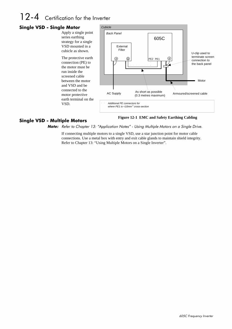
4507##&HUWLILFDWLRQ#IRU#WKH#,QYHUWHU
938&#)UHTXHQF\#,QYHUWHU
6LQJOH#96'#0#6LQJOH#0RWRUApply a single pointseries earthingstrategy for a singleVSD mounted in acubicle as shown.
The protective earthconnection (PE) tothe motor must berun inside thescreened cablebetween the motorand VSD and beconnected to themotor protectiveearth terminal on theVSD.
6LQJOH#96'#0#0XOWLSOH#0RWRUV1RWH=# 5HIHU#WR#&KDSWHU#46=#´$SSOLFDWLRQ#1RWHVµ#0#8VLQJ#0XOWLSOH#0RWRUV#RQ#D#6LQJOH#'ULYH1
If connecting multiple motors to a single VSD, use a star junction point for motor cableconnections. Use a metal box with entry and exit cable glands to maintain shield integrity.Refer to Chapter 13: “Using Multiple Motors on a Single Inverter”.
605CBack Panel
Cubicle
Motor
AC Supply
U-clip used to terminate screenconnection tothe back panel
Armoured/screened cableAs short as possible(0.3 metres maximum)
ExternalFilter
PE2 PE1
Additional PE connectors forwhere PE1 is <10mm cross-section2
Figure 12-1 EMC and Safety Earthing Cabling
&HUWLILFDWLRQ#IRU#WKH#,QYHUWHU##4508
938&#)UHTXHQF\#,QYHUWHU
6WDU#3RLQW#(DUWKLQJ
A star-point earthing policy separates `noisy’ and `clean’ earths. Four separate earth busbars(three are insulated from the mounting panel) connect to a single earth point (star point) near theincoming safety earth from the main supply. Flexible, large cross-section cable is used to ensurea low HF impedance. Busbars are arranged so that connection to the single earth point is as shortas possible.
4#&OHDQ#(DUWK#%XVEDU#+LQVXODWHG#IURP#WKH#PRXQWLQJ#SDQHO,Used as a reference point for all signal and control cabling. This may be further subdivided intoan analog and a digital reference busbar, each separately connected to the star earthing point.The digital reference is also used for any 24V control.
1RWH=# 7KH#938&#XVHV#D#VLQJOH#FOHDQ#HDUWK#EXVEDU#IRU#DQDORJ#DQG#GLJLWDO1
5#'LUW\#(DUWK#%XVEDU#+LQVXODWHG#IURP#WKH#PRXQWLQJ#SDQHO,Used for all power earths, i.e. protective earth connection. It is also used as a reference for any110 or 220V control used, and for the control transformer screen.
Doors Metal Work
110VControl
24V Control
unscreened signals
STAR POINT
Incoming Safety Earth (PE)
Analogue Clean Earth
Dirty Earth
Digital Clean Earth
Signal/Control Screen
all screened signals not
Back Panel
U-clip used to terminate screenconnection to the back panel
PE = Protective Earth
0A = 0 Volts Analogue
0D = 0 Volts Digital
f = External FilterVSD = Variable Speed DrivePLC = Programmable Logic Controller
going directly to a VSD
Metal Work Earth
BackPanel
PLC
PE PE PE0D 0D 0D 0D0A 0A 0A
to motor to motor to motor
screened screened
PE
VSD VSDVSDf f f
f
PEPEPE
Figure 12-2 Star Point Earthing
4509##&HUWLILFDWLRQ#IRU#WKH#,QYHUWHU
938&#)UHTXHQF\#,QYHUWHU
6#0HWDO#:RUN#(DUWK#%XVEDUThe back panel is used as this earth busbar, and should provide earthing points for all parts of thecubicle including panels and doors. This busbar is also used for power screened cables whichterminate near to (10cm) or directly into a VSD - such as motor cables, braking choppers andtheir resistors, or between VSDs - refer to the appropriate product manual to identify these. UseU-clips to clamp the screened cables to the back panel to ensure optimum HF connection.
7#6LJQDO2&RQWURO#6FUHHQ#(DUWK#%XVEDU#+LQVXODWHG#IURP#WKH#PRXQWLQJ#SDQHO,Used for signal/control screened cables which do not go directly to the VSD. Place this busbaras close as possible to the point of cable entry. `U’ clamp the screened cables to the busbars toensure an optimum HF connection.
6HQVLWLYH#(TXLSPHQWThe proximity of the source and victim circuit has a large effect on radiated coupling. Theelectromagnetic fields produced by VSDs falls off rapidly with distance from the cabling/cubicle.Remember that the radiated fields from EMC compliant drive systems are measured at least 10mfrom the equipment, over the band 30-1000MHz. Any equipment placed closer than this will seelarger magnitude fields, especially when very close to the Inverter.
Do not place magnetic/electric field sensitive equipment within 0.25 metres of the followingparts of the VSD system:
• Variable Speed Drive (VSD)
• EMC output filters
• Input or output chokes/transformers
• The cable between VSD and motor (even when screened/armoured)
• Connections to external braking chopper and resistor (even when screened/armoured)
• AC/DC brushed motors (due to commutation)
• DC link connections (even when screened/armoured)
• Relays and contactors (even when suppressed)
From experience, the following equipment is particularly sensitive and requires carefulinstallation.
• Any transducers which produce low level analog outputs (<1V) , e.g. load cells, straingauges, thermocouples, piezoelectric transducers, anemometers, LVDTs
• Wide band width control inputs (>100Hz)
• AM radios (long and medium wave only)
• Video cameras and closed circuit TV
• Office personal computers
• Capacitive devices such as proximity sensors and level transducers
• Mains borne communication systems
• Equipment not suitable for operation in the intended EMC environment, i.e. with insufficientimmunity to new EMC standards

&HUWLILFDWLRQ#IRU#WKH#,QYHUWHU##450:
938&#)UHTXHQF\#,QYHUWHU
5HTXLUHPHQWV#IRU#8/#&RPSOLDQFH6ROLG06WDWH#0RWRU#2YHUORDG#3URWHFWLRQ
These devices provide Class 10 motor overload protection. The maximum internal overloadprotection level (current limit) is 150% for 60 seconds. Refer to Chapter 6: Programming YourApplication - I*t TRIP for user current limit adjustment information.
An external motor overload protective device must be provided by the installer where the motorhas a full-load ampere rating of less than 50% of the Inverter output rating.
6KRUW#&LUFXLW#5DWLQJAll models of this Inverter are suitable for use on a circuit capable of delivering not more than10,000 RMS Symmetrical Amperes, 480V maximum.
6ROLG06WDWH#6KRUW0&LUFXLW#3URWHFWLRQThese devices are provided with Solid-State Short-Circuit (output) Protection. Branch circuitprotection requirements must be in accordance with the latest edition of the National ElectricalCode NEC/NFPA-70.
5HFRPPHQGHG#%UDQFK#&LUFXLW#3URWHFWLRQIt is recommended that UL Listed (JDDZ) non-renewable cartridge fuses, Class K5 or H; or ULListed (JDRX) renewable cartridge fuses, Class H, are installed upstream of the Inverter. Referto Chapter 11: “Technical Specifications” - Power Details for recommended fuse ratings.
0RWRU#%DVH#)UHTXHQF\The motor base frequency rating is 480Hz maximum.
)LHOG#:LULQJ#7HPSHUDWXUH#5DWLQJUse 75°C Copper conductors only.
)LHOG#:LULQJ#7HUPLQDO#0DUNLQJVFor correct field wiring connections that are to be made to each terminal refer to Chapter 3:“Installing the Inverter” - Power Wiring Connections, and Control Wiring Connections.
3RZHU#:LULQJ#7HUPLQDOV0RGHO#5HFRJQLWLRQ0RGHO#5HFRJQLWLRQ0RGHO#5HFRJQLWLRQ0RGHO#5HFRJQLWLRQ
3URGXFW#&RGH3URGXFW#&RGH3URGXFW#&RGH3URGXFW#&RGH+%ORFN#5#)#6,+%ORFN#5#)#6,+%ORFN#5#)#6,+%ORFN#5#)#6,
Power Terminals(maximum wire size)
Brake Terminals(maximum wire size)
Thermistor Terminals(maximum wire size)
33882733 45#$:*#+616PPò, 45#$:*#+616PPò, 45#$:*#+616PPò,
33:82733 ;#$:*#+;17PPò, 45#$:*#+616PPò, 45#$:*#+616PPò,
34432733 ;#$:*#+;17PPò, 45#$:*#+616PPò, 45#$:*#+616PPò,
7HUPLQDO#7LJKWHQLQJ#7RUTXH0RGHO#5HFRJQLWLRQ0RGHO#5HFRJQLWLRQ0RGHO#5HFRJQLWLRQ0RGHO#5HFRJQLWLRQ
3URGXFW#&RGH3URGXFW#&RGH3URGXFW#&RGH3URGXFW#&RGH+%ORFN#5#)#6,+%ORFN#5#)#6,+%ORFN#5#)#6,+%ORFN#5#)#6,
Power Terminals(lb-in)
Brake Terminals(lb-in)
33882733 45 45
33:82733 49 45
34432733 49 45
450;##&HUWLILFDWLRQ#IRU#WKH#,QYHUWHU
938&#)UHTXHQF\#,QYHUWHU
)LHOG#*URXQGLQJ#7HUPLQDOVThe field grounding terminals are identified with the International Grounding Symbol(IEC Publication 417, Symbol 5019).
2SHUDWLQJ#$PELHQW#7HPSHUDWXUHHeavy duty devices are considered acceptable for use in a maximum ambient temperature of45°C (40°C for models with a Type 1 Enclosure). Normal duty devices are considered suitablefor use in a maximum ambient temperature of 40°C for both `open type’ and Type 1 Enclosedmodels.
'LUHFW#:DOO00RXQWDEOH#0RGHOVAll model of this Inverter with a Product Code Block 4 designation xx2x are suitable for directwall mounting applications as they have a “Type 1 Enclosure” rating.
In order to preserve this enclosure rating, it is important to maintain the environmental integrityof the enclosure. Therefore, the installer must provide correct Type 1 closures for all unusedclearance holes provided within the Inverter’s glandplate.
Type 1 Enclosed models are suitable for use in no worse than a Pollution Degree 2 environment.

&HUWLILFDWLRQ#IRU#WKH#,QYHUWHU##450<
938&#)UHTXHQF\#,QYHUWHU
(XURSHDQ#'LUHFWLYHV#DQG#WKH#&(#0DUNThe following information is supplied to provide a basic understanding of the EMC and lowvoltage directives CE marking requirements. The following literature is recommended for furtherinformation:
• Recommendations for Application of Power Drive Systems (PDS), European CouncilDirectives - CE Marking and Technical Standardisation - (CEMEP)
Available from your local trade association or Eurotherm Drives office
• EMC Installation Guidelines for Modules and Systems - (Eurotherm Drives)
Available from your local Eurotherm Drives office, part number HA388879
The European machines and drives manufacturers via their national trade associations haveformed the European Committee of Manufacturers of Electrical Machines and Power Electronics(CEMEP). Eurotherm Drives and other major European drives manufacturers are working to theCEMEP recommendations on CE marking. The CE mark shows that a product complies with therelevant EU directives, in our case the Low Voltage Directive and, in some instances, the EMCDirective.
&(#0DUNLQJ#IRU#/RZ#9ROWDJH#'LUHFWLYHWhen installed in accordance with this manual, the 605C Inverter is CE marked by EurothermDrives Ltd in accordance with the low voltage directive (S.I. No. 3260 implements this LVDdirective into UK law). An EC Declaration of Conformity (low voltage directive) is included atthe end of this chapter.
&(#0DUNLQJ#IRU#(0�#:KR#LV#5HVSRQVLEOH"1RWH=# 7KH#VSHFLILHG#(0&#HPLVVLRQ#DQG#LPPXQLW\#SHUIRUPDQFH#RI#WKLV#XQLW#FDQ#RQO\#EH#DFKLHYHG
ZKHQ#WKH#XQLW#LV#LQVWDOOHG#WR#WKH#(0&#,QVWDOODWLRQ#,QVWUXFWLRQV#JLYHQ#LQ#WKLV#PDQXDO1
According to S.I. No. 2373 which implements the EMC directive into UK law, the requirementfor CE marking this unit falls into two categories:
1. Where the supplied unit has an intrinsic/direct function to the end user, then the unit isclassed as relevant apparatus.
2. Where the supplied unit is incorporated into a higher system/apparatus or machine whichincludes (at least) the motor, cable and a driven load but is unable to function without thisunit, then the unit is classed as a component.
#5HOHYDQW#$SSDUDWXV#0#(XURWKHUP#'ULYHV#5HVSRQVLELOLW\Occasionally, say in a case where an existing fixed speed motor - such as a fan or pump - isconverted to variable speed with an add-on drive module (relevant apparatus), it becomes theresponsibility of Eurotherm Drives to apply the CE mark and issue an EC Declaration ofConformity for the EMC Directive. This declaration and the CE mark is included at the end ofthis chapter.
#&RPSRQHQW#0#&XVWRPHU#5HVSRQVLELOLW\The majority of Eurotherm Drives’ products are classed as components and therefore we cannotapply the CE mark or produce an EC Declaration of Conformity in respect of EMC. It istherefore the manufacturer/supplier/installer of the higher system/apparatus or machine who mustconform to the EMC directive and CE mark.

45043##&HUWLILFDWLRQ#IRU#WKH#,QYHUWHU
938&#)UHTXHQF\#,QYHUWHU
/HJDO#5HTXLUHPHQWV#IRU#&(#0DUNLQJ,03257$17=# %HIRUH#LQVWDOODWLRQ/#FOHDUO\#XQGHUVWDQG#ZKR#LV#UHVSRQVLEOH#IRU#FRQIRUPDQFH#ZLWK#WKH#(0&
GLUHFWLYH1#0LVDSSURSULDWLRQ#RI#WKH#&(#PDUN#LV#D#FULPLQDO#RIIHQFH1
It is important that you have now defined who is responsible for conforming to the EMCdirective, either:
#(XURWKHUP#'ULYHV#5HVSRQVLELOLW\You intend to use the unit as relevant apparatus.
When the specified EMC filter is correctly fitted to the unit following EMC installationinstructions, it complies with the relevant standards indicated in the following tables. The fittingof the filter is mandatory for the CE marking of this unit to apply.
The relevant declarations are to be found at the end of this chapter. The CE mark is displayed onthe EC Declaration of Conformity (EMC Directive) provided at the end of this chapter.
#&XVWRPHU#5HVSRQVLELOLW\You intend to use the unit as a component, therefore you have a choice:
1. To fit the specified filter following EMC installation instructions, which may help you gainEMC compliance for the final machine/system.
2. Not to fit the specified filter, but use a combination of global or local filtering and screeningmethods, natural migration through distance, or the use of distributed parasitic elements ofthe existing installation.
1RWH=# :KHQ#WZR#RU#PRUH#(0&#FRPSOLDQW#FRPSRQHQWV#DUH#FRPELQHG#WR#IRUP#WKH#ILQDOPDFKLQH2V\VWHP/#WKH#UHVXOWLQJ#PDFKLQH2V\VWHP#PD\#QR#ORQJHU#EH#FRPSOLDQW/#+HPLVVLRQVWHQG#WR#EH#DGGLWLYH/#LPPXQLW\#LV#GHWHUPLQHG#E\#WKH#OHDVW#LPPXQH#FRPSRQHQW,1#8QGHUVWDQGWKH#(0&#HQYLURQPHQW#DQG#DSSOLFDEOH#VWDQGDUGV#WR#NHHS#DGGLWLRQDO#FRPSOLDQFH#FRVWV#WR#DPLQLPXP1
$SSO\LQJ#IRU#&(#0DUNLQJ#IRU#(0&We have supplied a Manufacturer’s EMC Declaration at the end of this chapter that you can useas a basis for your own justification of overall compliance with the EMC directive. There arethree methods of demonstrating conformity:
1. Self-certification to a relevant standard
2. Third party testing to a relevant standard
3. Writing a technical construction file stating the technical rationale as to why your finalmachine/system is compliant. An EMC “competent body” must then assess this and issue atechnical report or certificate to demonstrate compliance.Refer to Article 10(2) of Directive 89/336/EEC.
With EMC compliance, an EC Declaration of Conformity and the CE mark will be issued foryour final machine/system.
,03257$17=# 3URIHVVLRQDO#HQG#XVHUV#ZLWK#(0&#H[SHUWLVH#ZKR#DUH#XVLQJ#GULYH#PRGXOHV#DQG#FXELFOH3URIHVVLRQDO#HQG#XVHUV#ZLWK#(0&#H[SHUWLVH#ZKR#DUH#XVLQJ#GULYH#PRGXOHV#DQG#FXELFOH3URIHVVLRQDO#HQG#XVHUV#ZLWK#(0&#H[SHUWLVH#ZKR#DUH#XVLQJ#GULYH#PRGXOHV#DQG#FXELFOH3URIHVVLRQDO#HQG#XVHUV#ZLWK#(0&#H[SHUWLVH#ZKR#DUH#XVLQJ#GULYH#PRGXOHV#DQG#FXELFOHV\VWHPV#GHILQHG#DV#FRPSRQHQWV#ZKR#VXSSO\/#SODFH#RQ#WKH#PDUNHW#RU#LQVWDOO#WKH#UHOHYDQWV\VWHPV#GHILQHG#DV#FRPSRQHQWV#ZKR#VXSSO\/#SODFH#RQ#WKH#PDUNHW#RU#LQVWDOO#WKH#UHOHYDQWV\VWHPV#GHILQHG#DV#FRPSRQHQWV#ZKR#VXSSO\/#SODFH#RQ#WKH#PDUNHW#RU#LQVWDOO#WKH#UHOHYDQWV\VWHPV#GHILQHG#DV#FRPSRQHQWV#ZKR#VXSSO\/#SODFH#RQ#WKH#PDUNHW#RU#LQVWDOO#WKH#UHOHYDQWDSSDUDWXV#PXVW#WDNH#UHVSRQVLELOLW\#IRU#GHPRQVWUDWLQJ#(0&#FRQIRUPDQFH#DQG#DSSO\LQJ#WKHDSSDUDWXV#PXVW#WDNH#UHVSRQVLELOLW\#IRU#GHPRQVWUDWLQJ#(0&#FRQIRUPDQFH#DQG#DSSO\LQJ#WKHDSSDUDWXV#PXVW#WDNH#UHVSRQVLELOLW\#IRU#GHPRQVWUDWLQJ#(0&#FRQIRUPDQFH#DQG#DSSO\LQJ#WKHDSSDUDWXV#PXVW#WDNH#UHVSRQVLELOLW\#IRU#GHPRQVWUDWLQJ#(0&#FRQIRUPDQFH#DQG#DSSO\LQJ#WKH&(#PDUN#DQG#LVVXLQJ#DQ#(&#'HFODUDWLRQ#RI#&RQIRUPLW\1&(#PDUN#DQG#LVVXLQJ#DQ#(&#'HFODUDWLRQ#RI#&RQIRUPLW\1&(#PDUN#DQG#LVVXLQJ#DQ#(&#'HFODUDWLRQ#RI#&RQIRUPLW\1&(#PDUN#DQG#LVVXLQJ#DQ#(&#'HFODUDWLRQ#RI#&RQIRUPLW\1
:KLFK#6WDQGDUGV#$SSO\"3RZHU#'ULYH#3URGXFW#6SHFLILF#RU#*HQHULF#6WDQGDUGV
The standards that may apply to this unit come under two broad categories:
1. Emission - these standards limit the interference caused by operating (this) drive module.
2. Immunity - these standards limit the effect of interference (on this unit) from other electricaland electronic apparatus.
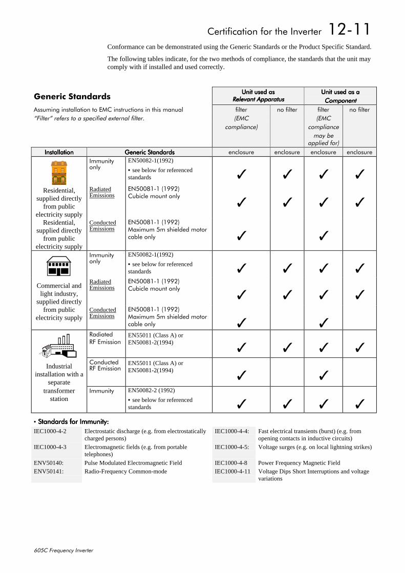
&HUWLILFDWLRQ#IRU#WKH#,QYHUWHU##45044
938&#)UHTXHQF\#,QYHUWHU
Conformance can be demonstrated using the Generic Standards or the Product Specific Standard.
The following tables indicate, for the two methods of compliance, the standards that the unit maycomply with if installed and used correctly.
*HQHULF#6WDQGDUGV8QLW#XVHG#DV8QLW#XVHG#DV8QLW#XVHG#DV8QLW#XVHG#DV
5HOHYDQW#$SSDUDWXV5HOHYDQW#$SSDUDWXV5HOHYDQW#$SSDUDWXV5HOHYDQW#$SSDUDWXV8QLW#XVHG#DV#D8QLW#XVHG#DV#D8QLW#XVHG#DV#D8QLW#XVHG#DV#D&RPSRQHQW&RPSRQHQW&RPSRQHQW&RPSRQHQW
$VVXPLQJ#LQVWDOODWLRQ#WR#(0&#LQVWUXFWLRQV#LQ#WKLV#PDQXDO´)LOWHUµ#UHIHUV#WR#D#VSHFLILHG#H[WHUQDO#ILOWHU1
ILOWHU+(0&
FRPSOLDQFH,
QR#ILOWHU ILOWHU+(0&
FRPSOLDQFHPD\#EH
DSSOLHG#IRU,
QR#ILOWHU
,QVWDOODWLRQ,QVWDOODWLRQ,QVWDOODWLRQ,QVWDOODWLRQ *HQHULF#6WDQGDUGV*HQHULF#6WDQGDUGV*HQHULF#6WDQGDUGV*HQHULF#6WDQGDUGV HQFORVXUH HQFORVXUH HQFORVXUH HQFORVXUH,PPXQLW\RQO\
EN50082-1(1992)
• see below for referencedstandards
Residential,supplied directly
from publicelectricity supply
RadiatedEmissions
(1833;404#+4<<5,&XELFOH#PRXQW#RQO\
Residential,supplied directly
from publicelectricity supply
ConductedEmissions
(1833;404#+4<<5,0D[LPXP#8P#VKLHOGHG#PRWRUFDEOH#RQO\
,PPXQLW\RQO\
EN50082-1(1992)
• see below for referencedstandards
Commercial andlight industry,
supplied directly
RadiatedEmissions
(1833;404#+4<<5,&XELFOH#PRXQW#RQO\
from public
electricity supplyConductedEmissions
(1833;404#+4<<5,0D[LPXP#8P#VKLHOGHG#PRWRUFDEOH#RQO\
5DGLDWHG5)#(PLVVLRQ
EN55011 (Class A) orEN50081-2(1994)
Industrialinstallation with a
separate
&RQGXFWHG5)#(PLVVLRQ
EN55011 (Class A) orEN50081-2(1994)
transformer
station,PPXQLW\ EN50082-2 (1992)
• see below for referencedstandards
• 6WDQGDUGV#IRU#,PPXQLW\=6WDQGDUGV#IRU#,PPXQLW\=6WDQGDUGV#IRU#,PPXQLW\=6WDQGDUGV#IRU#,PPXQLW\=IEC1000-4-2 Electrostatic discharge (e.g. from electrostatically
charged persons)IEC1000-4-4: Fast electrical transients (burst) (e.g. from
opening contacts in inductive circuits)
IEC1000-4-3 Electromagnetic fields (e.g. from portabletelephones)
IEC1000-4-5: Voltage surges (e.g. on local lightning strikes)
ENV50140: Pulse Modulated Electromagnetic Field IEC1000-4-8 Power Frequency Magnetic FieldENV50141: Radio-Frequency Common-mode IEC1000-4-11 Voltage Dips Short Interruptions and voltage
variations
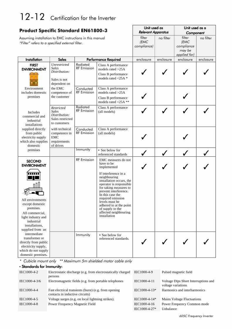
45045##&HUWLILFDWLRQ#IRU#WKH#,QYHUWHU
938&#)UHTXHQF\#,QYHUWHU
3URGXFW#6SHFLILF#6WDQGDUG#(194;33068QLW#XVHG#DV8QLW#XVHG#DV8QLW#XVHG#DV8QLW#XVHG#DV
5HOHYDQW#$SSDUDWXV5HOHYDQW#$SSDUDWXV5HOHYDQW#$SSDUDWXV5HOHYDQW#$SSDUDWXV8QLW#XVHG#DV#D8QLW#XVHG#DV#D8QLW#XVHG#DV#D8QLW#XVHG#DV#D&RPSRQHQW&RPSRQHQW&RPSRQHQW&RPSRQHQW
$VVXPLQJ#LQVWDOODWLRQ#WR#(0&#LQVWUXFWLRQV#LQ#WKLV#PDQXDO´)LOWHUµ#UHIHUV#WR#D#VSHFLILHG#H[WHUQDO#ILOWHU1
ILOWHU+(0&
FRPSOLDQFH,
QR#ILOWHU ILOWHU+(0&
FRPSOLDQFHPD\#EH
DSSOLHG#IRU,
QR#ILOWHU
,QVWDOODWLRQ,QVWDOODWLRQ,QVWDOODWLRQ,QVWDOODWLRQ 6DOHV6DOHV6DOHV6DOHV 3HUIRUPDQFH#5HTXLUHG3HUIRUPDQFH#5HTXLUHG3HUIRUPDQFH#5HTXLUHG3HUIRUPDQFH#5HTXLUHG HQFORVXUH HQFORVXUH HQFORVXUH HQFORVXUH
),567),567),567),567(19,5210(17(19,5210(17(19,5210(17(19,5210(17
UnrestrictedSalesDistribution:
Sales is notdependent on
5DGLDWHG5)#(PLVVLRQ
Class A performancemodels rated >25A
Class B performancemodels rated <25A *
Environmentincludes domestic
premises
the EMCcompetence ofthe customer
&RQGXFWHG5)#(PLVVLRQ
Class A performancemodels rated >25A
Class B performancemodels rated <25A **
Includescommercial and
industrialinstallations
RestrictedSalesDistribution:Sales restrictedto customers
5DGLDWHG5)#(PLVVLRQ
Class A performance(all models)
supplied directlyfrom public
electricity supplywhich also supplies
domestic
with technicalcompetence inEMCrequirementsof drives
&RQGXFWHG5)#(PLVVLRQ
Class A performance(all models)
premises ,PPXQLW\ •#See below forreferenced standards
6(&21'6(&21'6(&21'6(&21'(19,5210(17(19,5210(17(19,5210(17(19,5210(17
All environmentsexcept domestic
premises.
All commercial,light industry and
industrialinstallations,
supplied from an
5)#(PLVVLRQ EMC measures do nothave to beimplemented
If interference in aneighbouringinstallation occurs, theoperator is responsiblefor taking measures toprevent interference.In this case therequired emissionlevels must beadhered to at the pointof supply to theaffected neighbouringinstallation
intermediatetransformer or
directly from publicelectricity supply,
which do not supplydomestic premises.
,PPXQLW\ • See below forreferenced standards.
-##&XELFOH#PRXQW#RQO\###--#0D[LPXP#8P#VKLHOGHG#PRWRU#FDEOH#RQO\• 6WDQGDUGV#IRU#,PPXQLW\=6WDQGDUGV#IRU#,PPXQLW\=6WDQGDUGV#IRU#,PPXQLW\=6WDQGDUGV#IRU#,PPXQLW\=IEC1000-4-2 Electrostatic discharge (e.g. from electrostatically charged
personsIEC1000-4-9 Pulsed magnetic field
IEC1000-4-3/6 Electromagnetic fields (e.g. from portable telephones IEC1000-4-11 Voltage Dips Short Interruptions andvoltage variations
IEC1000-4-4 Fast electrical transients (burst) (e.g. from openingcontacts in inductive circuits)
IEC1000-4-13* Harmonics and interharmonics
IEC1000-4-5 Voltage surges (e.g. on local lightning strikes). IEC1000-4-14* Mains Voltage FluctuationsIEC1000-4-8 Power Frequency Magnetic Field IEC1000-4-16 Power Frequency Common mode
IEC1000-4-27* Unbalance
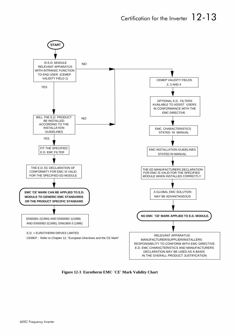
&HUWLILFDWLRQ#IRU#WKH#,QYHUWHU##45046
938&#)UHTXHQF\#,QYHUWHU
THE E.D. EC DECLARATION OF CONFORMITY FOR EMC IS VALID FOR THE SPECIFIED ED MODULE
START
IS E.D. MODULE RELEVANT APPARATUS
WITH INTRINSIC FUNCTION TO END USER (CEMEP
VALIDITY FIELD 1)
NO
YES
FIT THE SPECIFIED E.D. EMC FILTER
WILL THE E.D. PRODUCT BE INSTALLED
ACCORDING TO THE INSTALLATIONGUIDELINES
NO
YES
E.D. = EUROTHERM DRIVES LIMITED
EMC 'CE' MARK CAN BE APPLIED TO E.D.
MODULE TO GENERIC EMC STANDARDS
EN50081-2(1994) AND EN50082-1(1998)
AND EN50082-2(1995), EN61800-3 (1996)
EMC CHARACTERISTICS STATED IN MANUAL
OPTIONAL E.D. FILTERS AVAILABLE TO ASSIST USERSIN CONFORMANCE WITH THE
EMC DIRECTIVE
EMC INSTALLATION GUIDELINES
STATED IN MANUAL
CEMEP VALIDITY FIELDS
2, 3 AND 4
NO EMC 'CE' MARK APPLIED TO E.D. MODULE.
A GLOBAL EMC SOLUTION
MAY BE ADVANTAGEOUS
MANUFACTURER/SUPPLIER/INSTALLERSRESPONSIBILITY TO CONFORM WITH EMC DIRECTIVE.E.D. EMC CHARACTERISTICS AND MANUFACTURERS
IN THE OVERALL PRODUCT JUSTIFICATION
RELEVANT APPARATUS
THE ED MANUFACTURERS DECLARATIONFOR EMC IS VALID FOR THE SPECIFIEDMODULE WHEN INSTALLED CORRECTLY
DECLARATION MAY BE USED AS A BASIS
CEMEP : Refer to Chapter 12, "European Directives and the CE Mark"
OR THE PRODUCT SPECIFIC STANDARD
Figure 12-3 Eurotherm EMC `CE' Mark Validity Chart
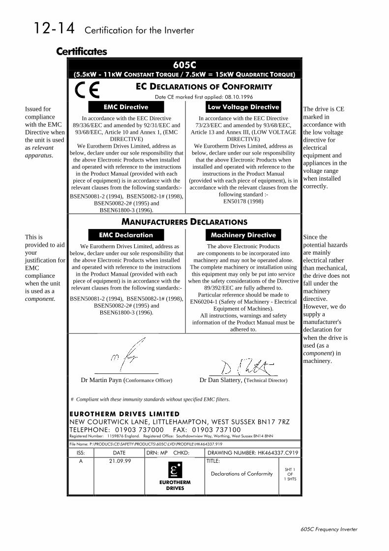
45047##&HUWLILFDWLRQ#IRU#WKH#,QYHUWHU
938&#)UHTXHQF\#,QYHUWHU
&HUWLILFDWHV938&
+818.:#0#44.:#&2167$17#72548(#2#:18.:# #48.:#48$'5$7,𑭤(,
(&#'(&/$5$7,216#2)#&21)250,7<'DWH#&(#PDUNHG#ILUVW#DSSOLHG=#3;14314<<9
Issued for (0&#'LUHFWLYH /RZ#9ROWDJH#'LUHFWLYH The drive is CEcompliancewith the EMCDirective whenthe unit is usedas relevantapparatus.
In accordance with the EEC Directive89/336/EEC and amended by 92/31/EEC and93/68/EEC, Article 10 and Annex 1, (EMC
DIRECTIVE)We Eurotherm Drives Limited, address as
below, declare under our sole responsibility thatthe above Electronic Products when installedand operated with reference to the instructions
in the Product Manual (provided with eachpiece of equipment) is in accordance with the
relevant clauses from the following standards:-
BSEN50081-2 (1994), BSEN50082-1# (1998),BSEN50082-2# (1995) and
BSEN61800-3 (1996).
In accordance with the EEC Directive73/23/EEC and amended by 93/68/EEC,
Article 13 and Annex III, (LOW VOLTAGEDIRECTIVE)
We Eurotherm Drives Limited, address asbelow, declare under our sole responsibility
that the above Electronic Products wheninstalled and operated with reference to the
instructions in the Product Manual(provided with each piece of equipment), is inaccordance with the relevant clauses from the
following standard :-EN50178 (1998)
marked inaccordance withthe low voltagedirective forelectricalequipment andappliances in thevoltage rangewhen installedcorrectly.
0$18)$&785(56#'(&/$5$7,216
This is (0&#'HFODUDWLRQ 0DFKLQHU\#'LUHFWLYH Since theprovided to aidyourjustification forEMCcompliancewhen the unitis used as acomponent.
###We Eurotherm Drives Limited, address asbelow, declare under our sole responsibility that
the above Electronic Products when installedand operated with reference to the instructions
in the Product Manual (provided with eachpiece of equipment) is in accordance with the
relevant clauses from the following standards:-
BSEN50081-2 (1994), BSEN50082-1# (1998),BSEN50082-2# (1995) and
BSEN61800-3 (1996).
The above Electronic Productsare components to be incorporated into
machinery and may not be operated alone.The complete machinery or installation usingthis equipment may only be put into service
when the safety considerations of the Directive89/392/EEC are fully adhered to.
Particular reference should be made toEN60204-1 (Safety of Machinery - Electrical
Equipment of Machines).All instructions, warnings and safety
information of the Product Manual must beadhered to.
potential hazardsare mainlyelectrical ratherthan mechanical,the drive does notfall under themachinerydirective.However, we dosupply amanufacturer'sdeclaration forwhen the drive isused (as acomponent) inmachinery.
Dr Martin Payn (Conformance Officer) Dr Dan Slattery, (Technical Director)
# Compliant with these immunity standards without specified EMC filters.
(8527+(50 #'5,9(6#/,0,7('1(:#&2857:,&.#/$1(/#/,77/(+$03721/#:(67#6866(;#%14:#:5=7(/(3+21(=##34<36#:6:333####)$;=##34<36#:6:4335HJLVWHUHG#1XPEHU=###448<;:9#(QJODQG1###5HJLVWHUHG#2IILFH=##6RXWKGRZQYLHZ#:D\/#:RUWKLQJ/#:HVW#6XVVH[#%147#;11
)LOH#1DPH=#3=?352'8&6?&(?6$)(7<?352'8&76?938&?/9'?352'),/(?+.79766:1<4<
,66= '$7( '51=#03 &+.'= '5$:,1*#180%(5=#+.79766:1&<4<
$ #5413<1<<
##
(8527+(50'5,9(6
7,7/(=
'HFODUDWLRQV#RI#&RQIRUPLW\6+7#42)
4#6+76
$SSOLFDWLRQ#1RWHV##4604
938&#)UHTXHQF\#,QYHUWHU
46#$33/,&$7,21#127(6Application advice is available through our Technical Support Department, who can also arrangefor on-site assistance if required. Refer to Chapter 8: “Routine Maintenance and Repair” for theaddress of your local Eurotherm Drives company.
• Always use gold flash relays, or others designed for low current operation (5mA), on allcontrol wiring.
• Remove all power factor correction equipment from the motor side of the Inverter beforeuse.
• Avoid using motors with low efficiency and small cos ø (power factor) as they require alarger kVA rated Inverter to produce the correct shaft kW.
6\QFKURQRXV#0RWRU#&RQWUROAlthough intended primarily for use with induction (asynchronous) motors, Inverters can also beused for speed control of synchronous motors. Synchronous motors can offer economicsolutions in applications where tight control of speed is required together with the lowmaintenance characteristics of an ac motor.
The two most common types of synchronous ac motor are permanent magnet and wound rotor.
In contrast to induction motors, synchronous motors run at synchronous speed whether on fullload or no load. Synchronous speed is set by the frequency of the supply applied to the stator.The stator flux can be kept constant by keeping the stator volts/frequency ratio constant, as withan induction motor.
Torque is produced in the motor by an increase in load angle between the stator and rotor fluxes.Maximum torque occurs when the load angle approaches 90°. If the load angle exceeds thisvalue then torque drops and the motor will stall. Systems involving synchronous motors needcareful design to ensure that the motor can accelerate the load and handle transient load changeswithout stalling.
%UDNH#0RWRUVBrake motors are used in applications requiring a mechanical brake for safety or otheroperational reasons. The motor can be a standard induction motor fitted with an electro-mechanical brake, or it could be a special conical rotor machine. In the case of a conical rotormachine the spring-loaded brake is controlled by the motor terminal voltage as follows:
• At rest the motor is braked.
• When the motor is energised an axial component of the magnetic field due to the conical air-gap overcomes the force of the brake spring and draws the rotor into the stator. This axialdisplacement releases the brake and allows the motor to accelerate like a normal inductionmotor.
• When the motor is de-energised the magnetic field collapses and the brake spring displacesthe rotor, pushing the brake disc against the braking surface.
Inverters can be used to control the speed of conical rotor brake motors since the linear V/Fcharacteristic maintains the motor magnetic field constant over the speed range. It will benecessary to set the FIXED BOOST parameter to overcome motor losses at low speed (seeFLUXING menu at level 3).
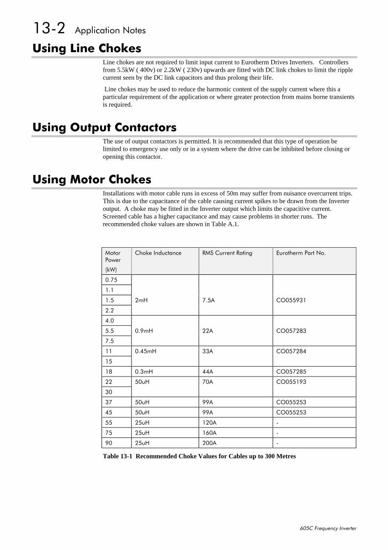
4605##$SSOLFDWLRQ#1RWHV
938&#)UHTXHQF\#,QYHUWHU
8VLQJ#/LQH#&KRNHVLine chokes are not required to limit input current to Eurotherm Drives Inverters. Controllersfrom 5.5kW ( 400v) or 2.2kW ( 230v) upwards are fitted with DC link chokes to limit the ripplecurrent seen by the DC link capacitors and thus prolong their life.
Line chokes may be used to reduce the harmonic content of the supply current where this aparticular requirement of the application or where greater protection from mains borne transientsis required.
8VLQJ#2XWSXW#&RQWDFWRUVThe use of output contactors is permitted. It is recommended that this type of operation belimited to emergency use only or in a system where the drive can be inhibited before closing oropening this contactor.
8VLQJ#0RWRU#&KRNHVInstallations with motor cable runs in excess of 50m may suffer from nuisance overcurrent trips.This is due to the capacitance of the cable causing current spikes to be drawn from the Inverteroutput. A choke may be fitted in the Inverter output which limits the capacitive current.Screened cable has a higher capacitance and may cause problems in shorter runs. Therecommended choke values are shown in Table A.1.
0RWRU3RZHU
+N:,
&KRNH#,QGXFWDQFH 506#&XUUHQW#5DWLQJ (XURWKHUP#3DUW#1R1
31:8
414
418 5P+ :18$ &2388<64
515
713
818 31<P+ 55$ &238:5;6
:18
44 3178P+ 66$ &238:5;7
48
4; 316P+ 77$ &238:5;8
55 83X+ :3$ &23884<6
63
6: 83X+ <<$ &2388586
78 83X+ <<$ &2388586
88 58X+ 453$ 0
:8 58X+ 493$ 0
<3 58X+ 533$ 0
Table 13-1 Recommended Choke Values for Cables up to 300 Metres
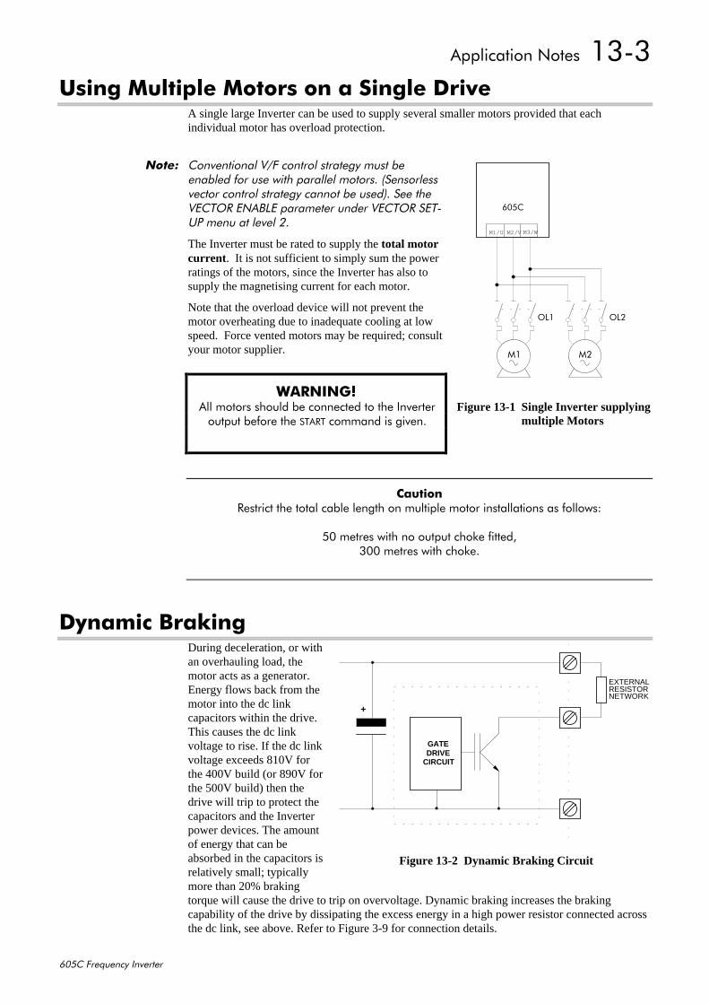
$SSOLFDWLRQ#1RWHV##4606
938&#)UHTXHQF\#,QYHUWHU
8VLQJ#0XOWLSOH#0RWRUV#RQ#D#6LQJOH#'ULYHA single large Inverter can be used to supply several smaller motors provided that eachindividual motor has overload protection.
1RWH=# &RQYHQWLRQDO#92)#FRQWURO#VWUDWHJ\#PXVW#EHHQDEOHG#IRU#XVH#ZLWK#SDUDOOHO#PRWRUV1#+6HQVRUOHVVYHFWRU#FRQWURO#VWUDWHJ\#FDQQRW#EH#XVHG,1#6HH#WKH9(&725#(1$%/(#SDUDPHWHU#XQGHU#9(&725#6(7083#PHQX#DW#OHYHO#51
The Inverter must be rated to supply the total motorcurrent . It is not sufficient to simply sum the powerratings of the motors, since the Inverter has also tosupply the magnetising current for each motor.
Note that the overload device will not prevent themotor overheating due to inadequate cooling at lowspeed. Force vented motors may be required; consultyour motor supplier.
:$51,1*$#$OO#PRWRUV#VKRXOG#EH#FRQQHFWHG#WR#WKH#,QYHUWHURXWSXW#EHIRUH#WKH#67$57#FRPPDQG#LV#JLYHQ1
&DXWLRQ#5HVWULFW#WKH#WRWDO#FDEOH#OHQJWK#RQ#PXOWLSOH#PRWRU#LQVWDOODWLRQV#DV#IROORZV=
83#PHWUHV#ZLWK#QR#RXWSXW#FKRNH#ILWWHG/633#PHWUHV#ZLWK#FKRNH1
'\QDPLF#%UDNLQJDuring deceleration, or withan overhauling load, themotor acts as a generator.Energy flows back from themotor into the dc linkcapacitors within the drive.This causes the dc linkvoltage to rise. If the dc linkvoltage exceeds 810V forthe 400V build (or 890V forthe 500V build) then thedrive will trip to protect thecapacitors and the Inverterpower devices. The amountof energy that can beabsorbed in the capacitors isrelatively small; typicallymore than 20% brakingtorque will cause the drive to trip on overvoltage. Dynamic braking increases the brakingcapability of the drive by dissipating the excess energy in a high power resistor connected acrossthe dc link, see above. Refer to Figure 3-9 for connection details.
04 05
938&
2/4 2/5
M1/U M2/V M3/W
Figure 13-1 Single Inverter supplying multiple Motors
GATEDRIVE
CIRCUIT
+
EXTERNALRESISTORNETWORK
Figure 13-2 Dynamic Braking Circuit
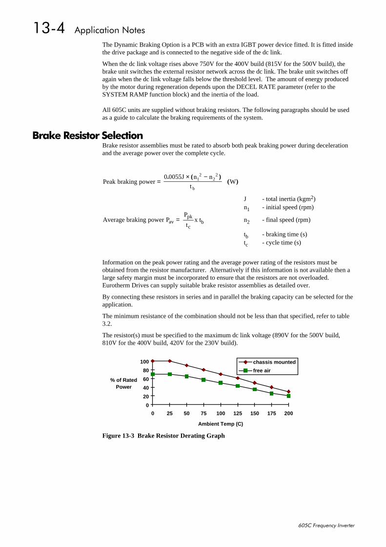
4607##$SSOLFDWLRQ#1RWHV
938&#)UHTXHQF\#,QYHUWHU
The Dynamic Braking Option is a PCB with an extra IGBT power device fitted. It is fitted insidethe drive package and is connected to the negative side of the dc link.
When the dc link voltage rises above 750V for the 400V build (815V for the 500V build), thebrake unit switches the external resistor network across the dc link. The brake unit switches offagain when the dc link voltage falls below the threshold level. The amount of energy producedby the motor during regeneration depends upon the DECEL RATE parameter (refer to theSYSTEM RAMP function block) and the inertia of the load.
All 605C units are supplied without braking resistors. The following paragraphs should be usedas a guide to calculate the braking requirements of the system.
%UDNH#5HVLVWRU#6HOHFWLRQBrake resistor assemblies must be rated to absorb both peak braking power during decelerationand the average power over the complete cycle.
Peak braking power0 0055J n n
tW1
22
2
b=
× −. ( )( )
J - total inertia (kgm2)n1 - initial speed (rpm)
Average braking power PP
tavpk
c= x tb n2 - final speed (rpm)
tb - braking time (s)tc - cycle time (s)
Information on the peak power rating and the average power rating of the resistors must beobtained from the resistor manufacturer. Alternatively if this information is not available then alarge safety margin must be incorporated to ensure that the resistors are not overloaded.Eurotherm Drives can supply suitable brake resistor assemblies as detailed over.
By connecting these resistors in series and in parallel the braking capacity can be selected for theapplication.
The minimum resistance of the combination should not be less than that specified, refer to table3.2.
The resistor(s) must be specified to the maximum dc link voltage (890V for the 500V build,810V for the 400V build, 420V for the 230V build).
Figure 13-3 Brake Resistor Derating Graph
0
20
40
60
80
100
0 25 50 75 100 125 150 175 200
Ambient Temp (C)
% of Rated Power
chassis mounted
free air
$SSOLFDWLRQ#1RWHV##4608
938&#)UHTXHQF\#,QYHUWHU
+LJK#6WDUWLQJ#7RUTXHApplications requiring high motor starting torque (greater than 100% of rated torque) needcareful setup of the drive voltage boost feature. For most motors, a FIXED BOOST parameter(FLUXING function block) setting of 6.0% is usually adequate. Setting the FIXED BOOSTparameter level too high can cause the drive current limit feature to operate. If this occurs, thedrive will be unable to ramp up in frequency. The LIMITING diagnostic (CURRENT LIMITfunction block) will indicate TRUE when the current limit feature is operating. Simply reducingthe level of the FIXED BOOST parameter will remove this problem. It is important to use theminimum level of FIXED BOOST necessary to accelerate the load. Using a level of FIXEDBOOST higher than necessary will lead to increased motor heating and increased risk of driveoverload.
1RWH=# 0RWRU#WRUTXHV#JUHDWHU#WKDQ#433(#UHTXLUH#KLJK#FXUUHQWV#WR#EH#GUDZQ#IURP#WKH#GULYH1#7KXV/WKH#MOTOR I LIMIT#SDUDPHWHU#+&855(17#/,0,7#IXQFWLRQ#EORFN,#ZLOO#KDYH#WR#EH#VHWDFFRUGLQJO\#VXFK#WKDW#WKH#GULYH#FXUUHQW#OLPLW#IHDWXUH#ZLOO#QRW#DFWLYDWH#ZKHQ#DFFHOHUDWLQJ#WKHORDG1
The best motor starting performance can be achieved by setting up the SLIP COMP functionblock, refer to Chapter 6: SLIP COMP. Also setting the BASE VOLTS parameter (VOLTAGECONTROL function block) to 115.4% and the SWITCHING FREQ parameter (PATTERNGEN function block) to 3kHz, can help to start difficult loads in the most extreme cases.

4609##$SSOLFDWLRQ#1RWHV
938&#)UHTXHQF\#,QYHUWHU

6HULDO#&RPPXQLFDWLRQV##4704
938&#)UHTXHQF\#,QYHUWHU
47#6(5,$/#&20081,&$7,216&RPPXQLFDWLRQV#7HFKQRORJ\#2SWLRQ
The plug-in COMMS Technology Option provides a serial data port, allowing Inverters to belinked to form a network. Using a PLC/SCADA or other intelligent device, this network can becontinuously controlled to provide supervision and monitoring for each Inverter in the system.
Refer to the Communications Interface Technical Manual for further details.
&RQILJ(G#/LWHThis is Eurotherm Drives’ Windows-based block programming software. It has a graphical user-interface and drawing tools to allow you to create block programming diagrams quickly andeasily. Contact your local Eurotherm Drives sales office.
&RQQHFWLRQ#WR#WKH#36#3RUWThere are two P3 ports; one is on the front of the unit (used by the fixed Operator Station), andthe second is on the Control Board.
Using the P3 port on the Inverter, parameters can be monitored and updated by a suitable PCprogramming tool.
The port is an un-isolated RS232, 19200 Baud, supporting the standard EI bisynch ASCIIcommunications protocol. Contact Eurotherm Drives for further information.
36#3RUWA standard P3 lead is used to connect to the Inverter.
1 2 3 4
36#3RUW#3LQ36#3RUW#3LQ36#3RUW#3LQ36#3RUW#3LQ /HDG/HDG/HDG/HDG 6LJQDO6LJQDO6LJQDO6LJQDO
4 %ODFN 39
5 5HG 89
6 *UHHQ 7;
7 <HOORZ 5;
90:D\#/HDG#WR#'%<2'%58#&RQQHFWRU1RWH=# 7KHUH#LV#89#SUHVHQW#RQ#SLQ#5#RI#WKH#36#SRUW#0#GR#QRW#FRQQHFW#WKLV#WR#\RXU#3&1
36#3RUW#3LQ36#3RUW#3LQ36#3RUW#3LQ36#3RUW#3LQ /HDG/HDG/HDG/HDG )HPDOH#'%<#3LQ)HPDOH#'%<#3LQ)HPDOH#'%<#3LQ)HPDOH#'%<#3LQ )HPDOH#'%58#3LQ)HPDOH#'%58#3LQ)HPDOH#'%58#3LQ)HPDOH#'%58#3LQ
4 %ODFN 8 :
5 5HG QRW#FRQQHFWHG QRW#FRQQHFWHG
6 *UHHQ 5 6
7 <HOORZ 6 5

4705##6HULDO#&RPPXQLFDWLRQV
938&#)UHTXHQF\#,QYHUWHU
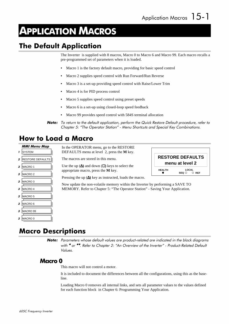
$SSOLFDWLRQ#0DFURV##4804
938&#)UHTXHQF\#,QYHUWHU
48#$33/,&$7,21#0$&526
7KH#'HIDXOW#$SSOLFDWLRQThe Inverter is supplied with 8 macros, Macro 0 to Macro 6 and Macro 99. Each macro recalls apre-programmed set of parameters when it is loaded.
• Macro 1 is the factory default macro, providing for basic speed control
• Macro 2 supplies speed control with Run Forward/Run Reverse
• Macro 3 is a set-up providing speed control with Raise/Lower Trim
• Macro 4 is for PID process control
• Macro 5 supplies speed control using preset speeds
• Macro 6 is a set-up using closed-loop speed feedback
• Macro 99 provides speed control with 584S terminal allocation
1RWH=# 7R#UHWXUQ#WR#WKH#GHIDXOW#DSSOLFDWLRQ/#SHUIRUP#WKH#4XLFN#5HVWRUH#'HIDXOW#SURFHGXUH/#UHIHU#WR&KDSWHU#8=#´7KH#2SHUDWRU#6WDWLRQµ#0#0HQX#6KRUWFXWV#DQG#6SHFLDO#.H\#&RPELQDWLRQV1
+RZ#WR#/RDG#D#0DFURIn the OPERATOR menu, go to the RESTOREDEFAULTS menu at level 2, press the M key.
The macros are stored in this menu.
Use the up (∆∆∆∆) and down (∇∇∇∇) keys to select theappropriate macro, press the M key.
Pressing the up (∆∆∆∆) key as instructed, loads the macro.
Now update the non-volatile memory within the Inverter by performing a SAVE TOMEMORY. Refer to Chapter 5: “The Operator Station” - Saving Your Application.
0DFUR#'HVFULSWLRQV1RWH=# 3DUDPHWHUV#ZKRVH#GHIDXOW#YDOXHV#DUH#SURGXFW0UHODWHG#DUH#LQGLFDWHG#LQ#WKH#EORFN#GLDJUDPV
ZLWK#----#RU#--------1#5HIHU#WR#&KDSWHU#5=#´$Q#2YHUYLHZ#RI#WKH#,QYHUWHUµ#0#3URGXFW05HODWHG#'HIDXOW9DOXHV1
0DFUR#3This macro will not control a motor.
It is included to document the differences between all the configurations, using this as the base-line.
Loading Macro 0 removes all internal links, and sets all parameter values to the values definedfor each function block in Chapter 6: Programming Your Application.
HEALTH LOCALSEQ REF
44menu at level 2
RESTORE DEFAULTS
00,#0HQX#0DS
4 SYSTEM
5 RESTORE DEFAULTS
6 MACRO 1
6 MACRO 2
6 MACRO 3
6 MACRO 4
6 MACRO 5
6 MACRO 6
6 MACRO 99
6 MACRO 0

4805##$SSOLFDWLRQ#0DFURV
938&#)UHTXHQF\#,QYHUWHU
7KH#23(5$725#0HQX#IRU#0DFUR#3The default OPERATOR menu is shown below.
SETPOINT (REMOTE)SPEED DEMANDDRIVE FREQUENCYMOTOR CURRENTLOADDC LINK VOLTSCURRENT LIMITINGENTER PASSWORD
STARTUP SCREEN
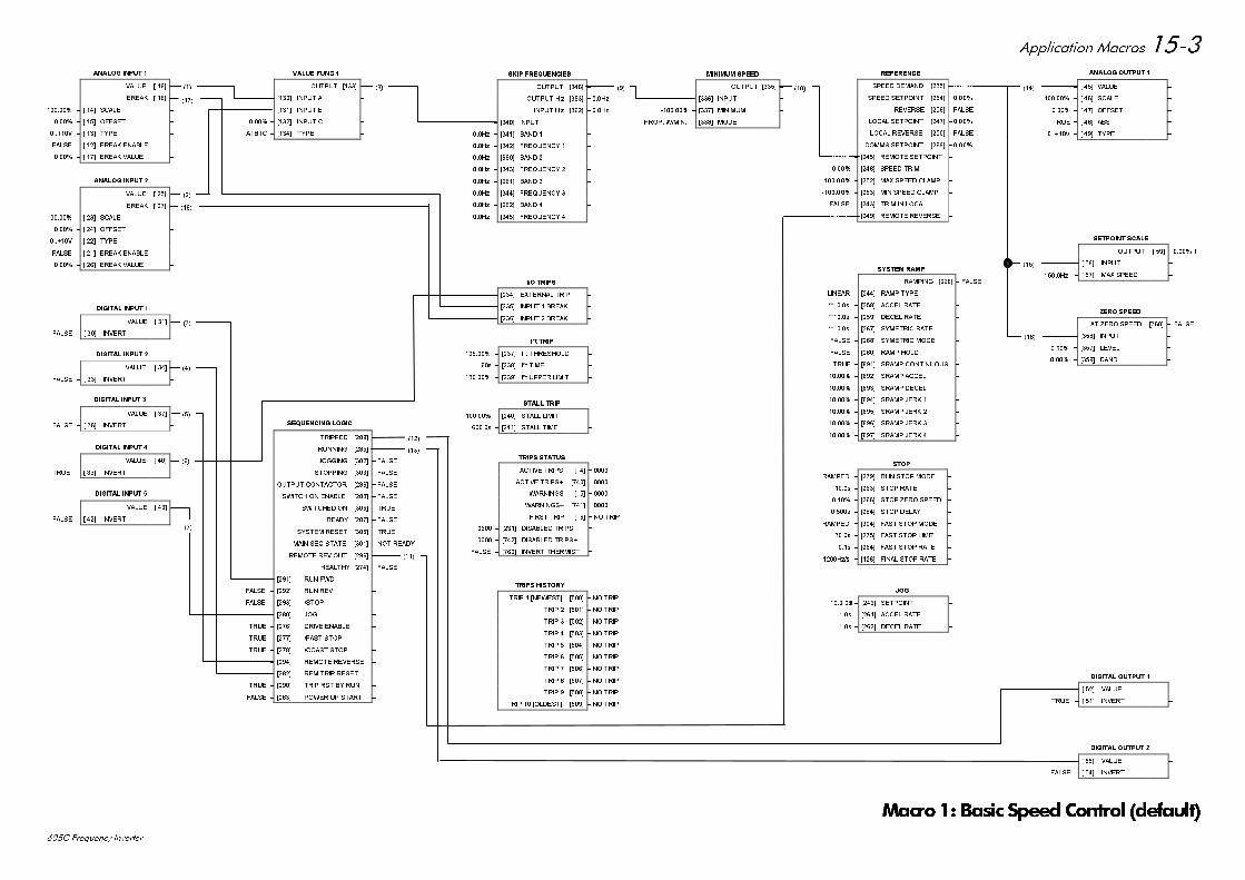
$SSOLFDWLRQ 0DFURV
& )UHTXHQF\ ,QYHUWHU
)$/6(
$1$/2* ,1387
9$/8( > @ ±
%5($. > @ ±
± > @ 6&$/( ±
± > @ 2))6(7 ±
9 ± > @ 7<3( ±
)$/6( ± > @ %5($. (1$%/( ±
± > @ %5($. 9$/8( ±
)$/6(
$1$/2* ,1387
9$/8( > @ ±
%5($. > @ ±
± > @ 6&$/( ±
± > @ 2))6(7 ±
9 ± > @ 7<3( ±
)$/6( ± > @ %5($. (1$%/( ±
± > @ %5($. 9$/8( ±
',*,7$/ ,1387
9$/8( > @ ± )$/6(
)$/6( ± > @ ,19(57 ±
',*,7$/ ,1387
9$/8( > @ ± )$/6(
)$/6( ± > @ ,19(57 ±
',*,7$/ ,1387
9$/8( > @ ± )$/6(
)$/6( ± > @ ,19(57 ±
',*,7$/ ,1387
9$/8( > @ ± )$/6(
)$/6( ± > @ ,19(57 ±
)$/6(
',*,7$/ ,1387
9$/8( > @ ±
758( ± > @ ,19(57 ±
6(48(1&,1* /2*,&
75,33(' >@ ± )$/6(
5811,1* >@ ± )$/6(
-2**,1* >@ ± )$/6(
67233,1* >@ ± )$/6(
287387 &217$&725 >@ ± )$/6(
6:,7&+ 21 (1$%/( >@ ± )$/6(
6:,7&+(' 21 >@ ± 758(
5($'< >@ ± )$/6(
6<67(0 5(6(7 >@ ± 758(
0$,1 6(4 67$7( >@ ± 127 5($'<
5(027( 5(9 287 >@ ± )$/6(
+($/7+< >@ ± )$/6(
)$/6( ± >@ 581 ):' ±
)$/6( ± >@ 581 5(9 ±
)$/6( ± >@ 6723 ±
)$/6( ± >@ -2* ±
758( ± >@ '5,9( (1$%/( ±
758( ± >@ )$67 6723 ±
758( ± >@ &2$67 6723 ±
)$/6( ± >@ 5(027( 5(9(56( ±
)$/6( ± >@ 5(0 75,3 5(6(7 ±
758( ± >@ 75,3 567 %< 581 ±
)$/6( ± >@ 32:(5 83 67$57 ±
6.,3 )5(48(1&,(6
287387 >@ ±
287387 +] >@ ± +]
,1387 + ] >@ ± +]
± >@ ,1387 ±
+] ± >@ %$1' ±
+] ± >@ )5(48(1&< ±
+] ± >@ %$1' ±
+] ± >@ )5(48(1&< ±
+] ± >@ %$1' ±
+] ± >@ )5(48(1&< ±
+] ± >@ %$1' ±
+] ± >@ )5(48(1&< ±
,2 75,36
)$/6( ± >@ (;7(51$/ 75,3 ±
)$/6( ± >@ ,1387 %5($. ±
)$/6( ± >@ ,1387 %5($. ±
, W 75,3
± >@ , W 7+5(6+2/' ±
V ± >@ , W 7,0( ±
± >@ , W 833(5 /,0,7 ±
67$// 75,3
± >@ 67$// /,0,7 ±
V ± >@ 67$// 7,0( ±
75,36 +,6725<
75,3 >1(:(67@ >@ ± 12 75,3
75,3 >@ ± 12 75,3
75,3 >@ ± 12 75,3
75,3 >@ ± 12 75,3
75,3 >@ ± 12 75,3
75,3 >@ ± 12 75,3
75,3 >@ ± 12 75,3
75,3 >@ ± 12 75,3
75,3 >@ ± 12 75,3
75,3 >2/'(67@ >@ ± 12 75,3
0,1,080 63(('
287387 >@ ±
± >@ ,1387 ±
± >@ 0,1,080 ±
3523 :0,1 ± >@ 02'( ±
-2*
V ± >@ 6(732,17 ±
V ± >@ $&&(/ 5$7( ±
V ± >@ '(&(/ 5$7( ±
$1$/2* 287387
± > @ 9$/8( ±
± > @ 6&$/( ±
± > @ 2))6(7 ±
758( ± > @ $%6 ±
9 ± > @ 7<3( ±
6(732,17 6&$/(
287387 > @ ± OI
± > @ ,1387 ±
+] ± > @ 0$; 63((' ±
=(52 63(('
$7 =(52 63((' >@ ±
± >@ ,1387 ±
± >@ /(9(/ ±
± >@ %$1' ±
',*,7$/ 287387
)$/6( ± > @ 9$/8( ±
758( ± > @ ,19(57 ±
',*,7$/ 287387
)$/6( ± > @ 9$/8( ±
)$/6( ± > @ ,19(57 ±
9$/8( )81&
287387 >@ ±
± >@ ,1387 $ ±
± >@ ,1387 % ±
± >@ ,1387 & ±
$%& ± >@ 7<3( ±
5$,6(/2:(5
287387 >@ ±
)$/6( ± >@ 5$,6( ,1387 ±
)$/6( ± >@ /2:(5 ,1387 ±
V ± >@ 5$03 5$7( ±
± >@ 0$; 9$/8( ±
± >@ 0,1 9$/8( ±
± >@ 5(6(7 9$/8( ±
)$/6( ± >@ 5(6(7 ±
5()(5(1&(
63((' '(0$1' >@ ±
63((' 6(732,17 >@ ±
5(9(56( >@ ± )$/6(
/2&$/ 6(732,17 >@ ±
/2&$/ 5(9(56( >@ ± )$/6(
&2006 6(732,17 >@ ±
± >@ 5(027( 6(732,17 ±
± >@ 63((' 75,0 ±
± >@ 0$; 63((' &/$03 ±
± >@ 0,1 63((' &/$03 ±
)$/6( ± >@ 75,0 ,1 /2&$/ ±
)$/6( ± >@ 5(027( 5(9(56( ±
6723
5$03(' ± >@ 581 6723 02'( ±
V ± >@ 6723 5$7( ±
± >@ 6723 =(52 63((' ±
V ± >@ 6723 '(/$< ±
5$03(' ± >@ )$67 6723 02'( ±
V ± >@ )$67 6723 /,0,7 ±
V ± >@ )$67 6723 5$7( ±
+]V ± >@ ),1$/ 6723 5$7( ±
6<67(0 5$03
5$03,1* >@ ± )$/6(
/,1($5 ± >@ 5$03 7<3( ±
V ± >@ $&&(/ 5$7( ±
V ± >@ '(&(/ 5$7( ±
V ± >@ 6<0(75,& 5$7( ±
)$/6( ± >@ 6<0(75,& 02'( ±
)$/6( ± >@ 5$03 +2/' ±
758( ± >@ 65$03 &217,18286 ±
± >@ 65$03 $&&(/ ±
± >@ 65$03 '(&(/ ±
± >@ 65$03 -(5. ±
± >@ 65$03 -(5. ±
± >@ 65$03 -(5. ±
± >@ 65$03 -(5. ±
)$/6(
75,36 67$786
$&7,9( 75,36 > @ ±
$&7,9( 75,36 >@ ±
:$51,1*6 > @ ±
:$51,1*6 >@ ±
),567 75,3 > @ ± 12 75,3
± >@ ',6$%/(' 75,36 ±
± >@ ',6$%/(' 75,36 ±
)$/6( ± >@ ,19(57 7+(50,67 ±
0DFUR%DVLF 6SHHG&RQWURO GHIDXOW
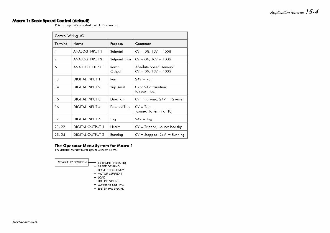
$SSOLFDWLRQ 0DFURV
& )UHTXHQF\ ,QYHUWHU
0DFUR%DVLF 6SHHG&RQWURO GHIDXOW7KLV PDFUR SURYLGHV VWDQGDUG FRQWURO RI WKH LQYHUWHU
&RQWURO :LULQJ ,2&RQWURO :LULQJ ,2
7HUPLQDO7HUPLQDO 1DPH1DPH 3XUSRVH3XUSRVH &RPPHQW&RPPHQW
$1$/2* ,1387 6HWSRLQW 9 9
$1$/2* ,1387 6HWSRLQW 7ULP 9 9
$1$/2* 287387 5DPS2XWSXW
$EVROXWH 6SHHG 'HPDQG9 9
',*,7$/ ,1387 5XQ 9 5XQ
',*,7$/ ,1387 7ULS 5HVHW 9 WR 9 WUDQVLWLRQWR UHVHW WULSV
',*,7$/ ,1387 'LUHFWLRQ 9 )RUZDUG 9 5HYHUVH
',*,7$/ ,1387 ([WHUQDO 7ULS 9 7ULSFRQQHFW WR WHUPLQDO
',*,7$/ ,1387 -RJ 9 -RJ
',*,7$/ 287387 +HDOWK 9 7ULSSHG LH QRW KHDOWK\
',*,7$/ 287387 5XQQLQJ 9 6WRSSHG 9 5XQQLQJ
7KH 2SHUDWRU 0HQX 6\VWHP IRU 0DFUR 7KH GHIDXOW 2SHUDWRU PHQX V\VWHP LV VKRZQ EHORZ
6(732,17 5(027(
63((' '(0$1'
'5,9( )5(48(1&<
02725 &855(17
/2$'
'& /,1. 92/76
&855(17 /,0,7,1*
(17(5 3$66:25'
67$5783 6&5((1

$SSOLFDWLRQ 0DFURV
& )UHTXHQF\ ,QYHUWHU
)$/6(
$1$/2* ,1387
9$/8( > @ ±
%5($. > @ ±
± > @ 6&$/( ±
± > @ 2))6(7 ±
9 ± > @ 7<3( ±
)$/6( ± > @ %5($. (1$%/( ±
± > @ %5($. 9$/8( ±
)$/6(
$1$/2* ,1387
9$/8( > @ ±
%5($. > @ ±
± > @ 6&$/( ±
± > @ 2))6(7 ±
9 ± > @ 7<3( ±
)$/6( ± > @ %5($. (1$%/( ±
± > @ %5($. 9$/8( ±
',*,7$/ ,1387
9$/8( > @ ± )$/6(
)$/6( ± > @ ,19(57 ±
',*,7$/ ,1387
9$/8( > @ ± )$/6(
)$/6( ± > @ ,19(57 ±
',*,7$/ ,1387
9$/8( > @ ± )$/6(
)$/6( ± > @ ,19(57 ±
',*,7$/ ,1387
9$/8( > @ ± )$/6(
)$/6( ± > @ ,19(57 ±
)$/6(
',*,7$/ ,1387
9$/8( > @ ±
758( ± > @ ,19(57 ±
)$/6(
)$/6(
)$/6(
)$/6(
)$/6(
)$/6(
758(
)$/6(
758(
)$/6(
)$/6(
6(48(1&,1* /2*,&
75,33(' >@ ±
5811,1* >@ ±
-2**,1* >@ ±
67233,1* >@ ±
287387 &217$&725 >@ ±
6:,7&+ 21 (1$%/( >@ ±
6:,7&+(' 21 >@ ±
5($'< >@ ±
6<67(0 5(6(7 >@ ±
0$,1 6(4 67$7( >@ ± 127 5($'<
5(027( 5(9 287 >@ ±
+($/7+< >@ ±
)$/6( ± >@ 581 ):' ±
)$/6( ± >@ 581 5(9 ±
)$/6( ± >@ 6723 ±
)$/6( ± >@ -2* ±
758( ± >@ '5,9( (1$%/( ±
758( ± >@ )$67 6723 ±
758( ± >@ &2$67 6723 ±
)$/6( ± >@ 5(027( 5(9(56( ±
)$/6( ± >@ 5(0 75,3 5(6(7 ±
758( ± >@ 75,3 567 %< 581 ±
)$/6( ± >@ 32:(5 83 67$57 ±
6.,3 )5(48(1&,(6
287387 >@ ±
287387 +] >@ ± +]
,1387 + ] >@ ± +]
± >@ ,1387 ±
+] ± >@ %$1' ±
+] ± >@ )5(48(1&< ±
+] ± >@ %$1' ±
+] ± >@ )5(48(1&< ±
+] ± >@ %$1' ±
+] ± >@ )5(48(1&< ±
+] ± >@ %$1' ±
+] ± >@ )5(48(1&< ±
,2 75,36
)$/6( ± >@ (;7(51$/ 75,3 ±
)$/6( ± >@ ,1387 %5($. ±
)$/6( ± >@ ,1387 %5($. ±
, W 75,3
± >@ , W 7+5(6+2/' ±
V ± >@ , W 7,0( ±
± >@ , W 833(5 /,0,7 ±
67$// 75,3
± >@ 67$// /,0,7 ±
V ± >@ 67$// 7,0( ±
75,36 +,6725<
75,3 >1(:(67@ >@ ± 12 75,3
75,3 >@ ± 12 75,3
75,3 >@ ± 12 75,3
75,3 >@ ± 12 75,3
75,3 >@ ± 12 75,3
75,3 >@ ± 12 75,3
75,3 >@ ± 12 75,3
75,3 >@ ± 12 75,3
75,3 >@ ± 12 75,3
75,3 >2/'(67@ >@ ± 12 75,3
0,1,080 63(('
287387 >@ ±
± >@ ,1387 ±
± >@ 0,1,080 ±
3523 :0,1 ± >@ 02'( ±
-2*
± >@ 6(732,17 ±
V ± >@ $&&(/ 5$7( ±
V ± >@ '(&(/ 5$7( ±
$1$/2* 287387
± > @ 9$/8( ±
± > @ 6&$/( ±
± > @ 2))6(7 ±
758( ± > @ $%6 ±
9 ± > @ 7<3( ±
6(732,17 6&$/(
287387 > @ ± OI
± > @ ,1387 ±
+] ± > @ 0$; 63((' ±
=(52 63(('
$7 =(52 63((' >@ ±
± >@ ,1387 ±
± >@ /(9(/ ±
± >@ %$1' ±
',*,7$/ 287387
)$/6( ± > @ 9$/8( ±
758( ± > @ ,19(57 ±
',*,7$/ 287387
)$/6( ± > @ 9$/8( ±
)$/6( ± > @ ,19(57 ±
9$/8( )81&
287387 >@ ±
± >@ ,1387 $ ±
± >@ ,1387 % ±
± >@ ,1387 & ±
$%& ± >@ 7<3( ±
5$,6(/2:(5
287387 >@ ±
)$/6( ± >@ 5$,6( ,1387 ±
)$/6( ± >@ /2:(5 ,1387 ±
V ± >@ 5$03 5$7( ±
± >@ 0$; 9$/8( ±
± >@ 0,1 9$/8( ±
± >@ 5(6(7 9$/8( ±
)$/6( ± >@ 5(6(7 ±
6723
5$03(' ± >@ 581 6723 02'( ±
V ± >@ 6723 5$7( ±
± >@ 6723 =(52 63((' ±
V ± >@ 6723 '(/$< ±
5$03(' ± >@ )$67 6723 02'( ±
V ± >@ )$67 6723 /,0,7 ±
V ± >@ )$67 6723 5$7( ±
+]V ± >@ ),1$/ 6723 5$7( ±
5()(5(1&(
63((' '(0$1' >@ ±
63((' 6(732,17 >@ ±
5(9(56( >@ ± )$/6(
/2&$/ 6(732,17 >@ ±
/2&$/ 5(9(56( >@ ± )$/6(
&2006 6(732,17 >@ ±
± >@ 5(027( 6(732,17 ±
± >@ 63((' 75,0 ±
± >@ 0$; 63((' &/$03 ±
± >@ 0,1 63((' &/$03 ±
)$/6( ± >@ 75,0 ,1 /2&$/ ±
)$/6( ± >@ 5(027( 5(9(56( ±
6<67(0 5$03
5$03,1* >@ ± )$/6(
/,1($5 ± >@ 5$03 7<3( ±
V ± >@ $&&(/ 5$7( ±
V ± >@ '(&(/ 5$7( ±
V ± >@ 6<0(75,& 5$7( ±
)$/6( ± >@ 6<0(75,& 02'( ±
)$/6( ± >@ 5$03 +2/' ±
758( ± >@ 65$03 &217,18286 ±
± >@ 65$03 $&&(/ ±
± >@ 65$03 '(&(/ ±
± >@ 65$03 -(5. ±
± >@ 65$03 -(5. ±
± >@ 65$03 -(5. ±
± >@ 65$03 -(5. ±
)$/6(
75,36 67$786
$&7,9( 75,36 > @ ±
$&7,9( 75,36 >@ ±
:$51,1*6 > @ ±
:$51,1*6 >@ ±
),567 75,3 > @ ± 12 75,3
± >@ ',6$%/(' 75,36 ±
± >@ ',6$%/(' 75,36 ±
)$/6( ± >@ ,19(57 7+(50,67 ±
0DFUR5XQ)RUZDUG5XQ5HYHUVH
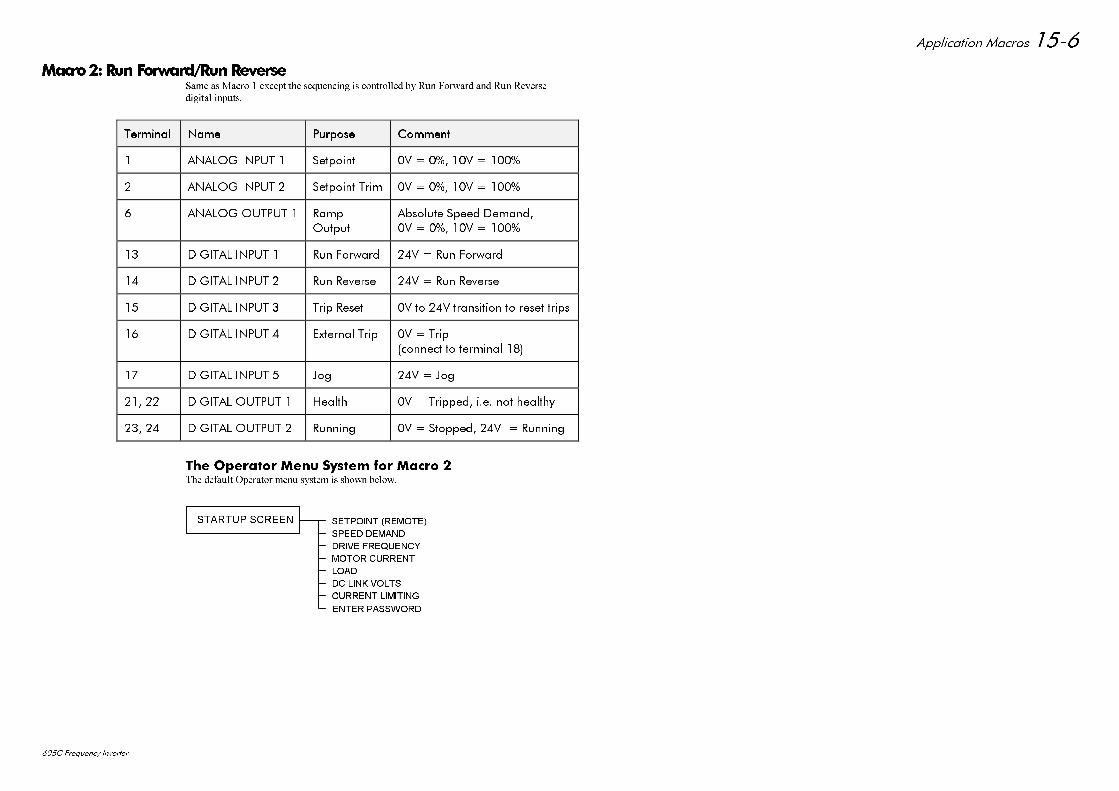
$SSOLFDWLRQ 0DFURV
& )UHTXHQF\ ,QYHUWHU
0DFUR5XQ)RUZDUG5XQ5HYHUVH6DPH DV 0DFUR H[FHSW WKH VHTXHQFLQJ LV FRQWUROOHG E\ 5XQ )RUZDUG DQG 5XQ 5HYHUVH
GLJLWDO LQSXWV
7HUPLQDO7HUPLQDO 1DPH1DPH 3XUSRVH3XUSRVH &RPPHQW&RPPHQW
$1$/2* ,1387 6HWSRLQW 9 9
$1$/2* ,1387 6HWSRLQW 7ULP 9 9
$1$/2* 287387 5DPS2XWSXW
$EVROXWH 6SHHG 'HPDQG9 9
',*,7$/ ,1387 5XQ )RUZDUG 9 5XQ )RUZDUG
',*,7$/ ,1387 5XQ 5HYHUVH 9 5XQ 5HYHUVH
',*,7$/ ,1387 7ULS 5HVHW 9 WR 9 WUDQVLWLRQ WR UHVHW WULSV
',*,7$/ ,1387 ([WHUQDO 7ULS 9 7ULSFRQQHFW WR WHUPLQDO
',*,7$/ ,1387 -RJ 9 -RJ
',*,7$/ 287387 +HDOWK 9 7ULSSHG LH QRW KHDOWK\
',*,7$/ 287387 5XQQLQJ 9 6WRSSHG 9 5XQQLQJ
7KH 2SHUDWRU 0HQX 6\VWHP IRU 0DFUR 7KH GHIDXOW 2SHUDWRU PHQX V\VWHP LV VKRZQ EHORZ
6(732,17 5(027(
63((' '(0$1'
'5,9( )5(48(1&<
02725 &855(17
/2$'
'& /,1. 92/76
&855(17 /,0,7,1*
(17(5 3$66:25'
67$5783 6&5((1
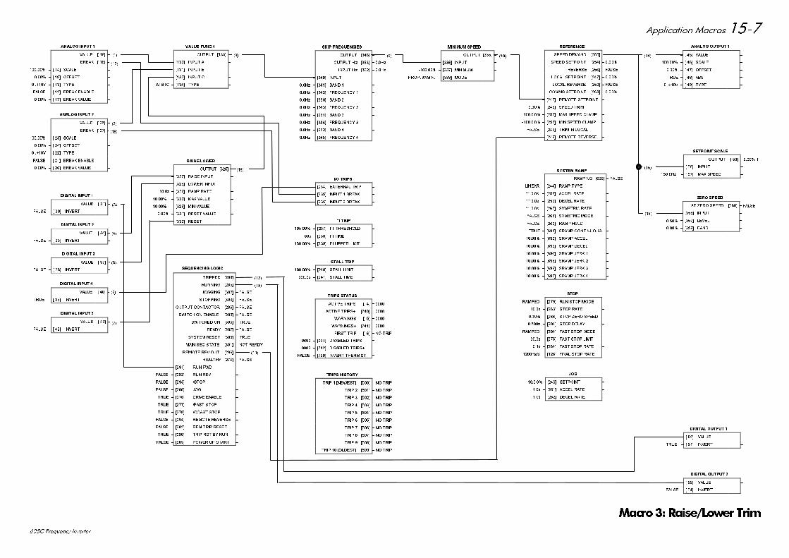
$SSOLFDWLRQ 0DFURV
& )UHTXHQF\ ,QYHUWHU
)$/6(
$1$/2* ,1387
9$/8( > @ ±
%5($. > @ ±
± > @ 6&$/( ±
± > @ 2))6(7 ±
9 ± > @ 7<3( ±
)$/6( ± > @ %5($. (1$%/( ±
± > @ %5($. 9$/8( ±
)$/6(
$1$/2* ,1387
9$/8( > @ ±
%5($. > @ ±
± > @ 6&$/( ±
± > @ 2))6(7 ±
9 ± > @ 7<3( ±
)$/6( ± > @ %5($. (1$%/( ±
± > @ %5($. 9$/8( ±
',*,7$/ ,1387
9$/8( > @ ± )$/6(
)$/6( ± > @ ,19(57 ±
',*,7$/ ,1387
9$/8( > @ ± )$/6(
)$/6( ± > @ ,19(57 ±
',*,7$/ ,1387
9$/8( > @ ± )$/6(
)$/6( ± > @ ,19(57 ±
',*,7$/ ,1387
9$/8( > @ ± )$/6(
)$/6( ± > @ ,19(57 ±
)$/6(
',*,7$/ ,1387
9$/8( > @ ±
758( ± > @ ,19(57 ±
)$/6(
)$/6(
)$/6(
)$/6(
)$/6(
)$/6(
758(
)$/6(
758(
)$/6(
)$/6(
6(48(1&,1* /2*,&
75,33(' >@ ±
5811,1* >@ ±
-2**,1* >@ ±
67233,1* >@ ±
287387 &217$&725 >@ ±
6:,7&+ 21 (1$%/( >@ ±
6:,7&+(' 21 >@ ±
5($'< >@ ±
6<67(0 5(6(7 >@ ±
0$,1 6(4 67$7( >@ ± 127 5($'<
5(027( 5(9 287 >@ ±
+($/7+< >@ ±
)$/6( ± >@ 581 ):' ±
)$/6( ± >@ 581 5(9 ±
)$/6( ± >@ 6723 ±
)$/6( ± >@ -2* ±
758( ± >@ '5,9( (1$%/( ±
758( ± >@ )$67 6723 ±
758( ± >@ &2$67 6723 ±
)$/6( ± >@ 5(027( 5(9(56( ±
)$/6( ± >@ 5(0 75,3 5(6(7 ±
758( ± >@ 75,3 567 %< 581 ±
)$/6( ± >@ 32:(5 83 67$57 ±
6.,3 )5(48(1&,(6
287387 >@ ±
287387 +] >@ ± +]
,1387 + ] >@ ± +]
± >@ ,1387 ±
+] ± >@ %$1' ±
+] ± >@ )5(48(1&< ±
+] ± >@ %$1' ±
+] ± >@ )5(48(1&< ±
+] ± >@ %$1' ±
+] ± >@ )5(48(1&< ±
+] ± >@ %$1' ±
+] ± >@ )5(48(1&< ±
,2 75,36
)$/6( ± >@ (;7(51$/ 75,3 ±
)$/6( ± >@ ,1387 %5($. ±
)$/6( ± >@ ,1387 %5($. ±
, W 75,3
± >@ , W 7+5(6+2/' ±
V ± >@ , W 7,0( ±
± >@ , W 833(5 /,0,7 ±
67$// 75,3
± >@ 67$// /,0,7 ±
V ± >@ 67$// 7,0( ±
75,36 +,6725<
75,3 >1(:(67@ >@ ± 12 75,3
75,3 >@ ± 12 75,3
75,3 >@ ± 12 75,3
75,3 >@ ± 12 75,3
75,3 >@ ± 12 75,3
75,3 >@ ± 12 75,3
75,3 >@ ± 12 75,3
75,3 >@ ± 12 75,3
75,3 >@ ± 12 75,3
75,3 >2/'(67@ >@ ± 12 75,3
0,1,080 63(('
287387 >@ ±
± >@ ,1387 ±
± >@ 0,1,080 ±
3523 :0,1 ± >@ 02'( ±
-2*
± >@ 6(732,17 ±
V ± >@ $&&(/ 5$7( ±
V ± >@ '(&(/ 5$7( ±
$1$/2* 287387
± > @ 9$/8( ±
± > @ 6&$/( ±
± > @ 2))6(7 ±
758( ± > @ $%6 ±
9 ± > @ 7<3( ±
6(732,17 6&$/(
287387 > @ ± OI
± > @ ,1387 ±
+] ± > @ 0$; 63((' ±
=(52 63(('
$7 =(52 63((' >@ ±
± >@ ,1387 ±
± >@ /(9(/ ±
± >@ %$1' ±
',*,7$/ 287387
)$/6( ± > @ 9$/8( ±
758( ± > @ ,19(57 ±
',*,7$/ 287387
)$/6( ± > @ 9$/8( ±
)$/6( ± > @ ,19(57 ±
9$/8( )81&
287387 >@ ±
± >@ ,1387 $ ±
± >@ ,1387 % ±
± >@ ,1387 & ±
$%& ± >@ 7<3( ±
5$,6(/2:(5
287387 >@ ±
)$/6( ± >@ 5$,6( ,1387 ±
)$/6( ± >@ /2:(5 ,1387 ±
V ± >@ 5$03 5$7( ±
± >@ 0$; 9$/8( ±
± >@ 0,1 9$/8( ±
± >@ 5(6(7 9$/8( ±
)$/6( ± >@ 5(6(7 ±
5()(5(1&(
63((' '(0$1' >@ ±
63((' 6(732,17 >@ ±
5(9(56( >@ ± )$/6(
/2&$/ 6(732,17 >@ ±
/2&$/ 5(9(56( >@ ± )$/6(
&2006 6(732,17 >@ ±
± >@ 5(027( 6(732,17 ±
± >@ 63((' 75,0 ±
± >@ 0$; 63((' &/$03 ±
± >@ 0,1 63((' &/$03 ±
)$/6( ± >@ 75,0 ,1 /2&$/ ±
)$/6( ± >@ 5(027( 5(9(56( ±
6723
5$03(' ± >@ 581 6723 02'( ±
V ± >@ 6723 5$7( ±
± >@ 6723 =(52 63((' ±
V ± >@ 6723 '(/$< ±
5$03(' ± >@ )$67 6723 02'( ±
V ± >@ )$67 6723 /,0,7 ±
V ± >@ )$67 6723 5$7( ±
+]V ± >@ ),1$/ 6723 5$7( ±
6<67(0 5$03
5$03,1* >@ ± )$/6(
/,1($5 ± >@ 5$03 7<3( ±
V ± >@ $&&(/ 5$7( ±
V ± >@ '(&(/ 5$7( ±
V ± >@ 6<0(75,& 5$7( ±
)$/6( ± >@ 6<0(75,& 02'( ±
)$/6( ± >@ 5$03 +2/' ±
758( ± >@ 65$03 &217,18286 ±
± >@ 65$03 $&&(/ ±
± >@ 65$03 '(&(/ ±
± >@ 65$03 -(5. ±
± >@ 65$03 -(5. ±
± >@ 65$03 -(5. ±
± >@ 65$03 -(5. ±
)$/6(
75,36 67$786
$&7,9( 75,36 > @ ±
$&7,9( 75,36 >@ ±
:$51,1*6 > @ ±
:$51,1*6 >@ ±
),567 75,3 > @ ± 12 75,3
± >@ ',6$%/(' 75,36 ±
± >@ ',6$%/(' 75,36 ±
)$/6( ± >@ ,19(57 7+(50,67 ±
0DFUR5DLVH/RZHU 7ULP
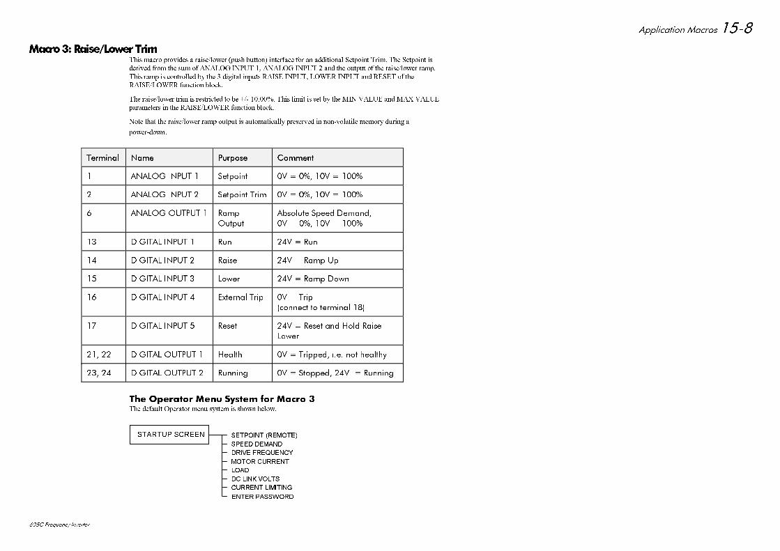
$SSOLFDWLRQ 0DFURV
& )UHTXHQF\ ,QYHUWHU
0DFUR5DLVH/RZHU7ULP7KLV PDFUR SURYLGHV D UDLVHORZHU SXVK EXWWRQ LQWHUIDFH IRU DQ DGGLWLRQDO 6HWSRLQW 7ULP 7KH 6HWSRLQW LV
GHULYHG IURP WKH VXP RI $1$/2* ,1387 $1$/2* ,1387 DQG WKH RXWSXW RI WKH UDLVHORZHU UDPS
7KLV UDPS LV FRQWUROOHG E\ WKH GLJLWDO LQSXWV 5$,6( ,1387 /2:(5 ,1387 DQG 5(6(7 RI WKH
5$,6(/2:(5 IXQFWLRQ EORFN
7KH UDLVHORZHU WULP LV UHVWULFWHG WR EH 7KLV OLPLW LV VHW E\ WKH 0,1 9$/8( DQG 0$; 9$/8(
SDUDPHWHUV LQ WKH 5$,6(/2:(5 IXQFWLRQ EORFN
1RWH WKDW WKH UDLVHORZHU UDPS RXWSXW LV DXWRPDWLFDOO\ SUHVHUYHG LQ QRQYRODWLOH PHPRU\ GXULQJ D
SRZHUGRZQ
7HUPLQDO7HUPLQDO 1DPH1DPH 3XUSRVH3XUSRVH &RPPHQW&RPPHQW
$1$/2* ,1387 6HWSRLQW 9 9
$1$/2* ,1387 6HWSRLQW 7ULP 9 9
$1$/2* 287387 5DPS2XWSXW
$EVROXWH 6SHHG 'HPDQG9 9
',*,7$/ ,1387 5XQ 9 5XQ
',*,7$/ ,1387 5DLVH 9 5DPS 8S
',*,7$/ ,1387 /RZHU 9 5DPS 'RZQ
',*,7$/ ,1387 ([WHUQDO 7ULS 9 7ULSFRQQHFW WR WHUPLQDO
',*,7$/ ,1387 5HVHW 9 5HVHW DQG +ROG 5DLVH/RZHU
',*,7$/ 287387 +HDOWK 9 7ULSSHG LH QRW KHDOWK\
',*,7$/ 287387 5XQQLQJ 9 6WRSSHG 9 5XQQLQJ
7KH 2SHUDWRU 0HQX 6\VWHP IRU 0DFUR 7KH GHIDXOW 2SHUDWRU PHQX V\VWHP LV VKRZQ EHORZ
6(732,17 5(027(
63((' '(0$1'
'5,9( )5(48(1&<
02725 &855(17
/2$'
'& /,1. 92/76
&855(17 /,0,7,1*
(17(5 3$66:25'
67$5783 6&5((1
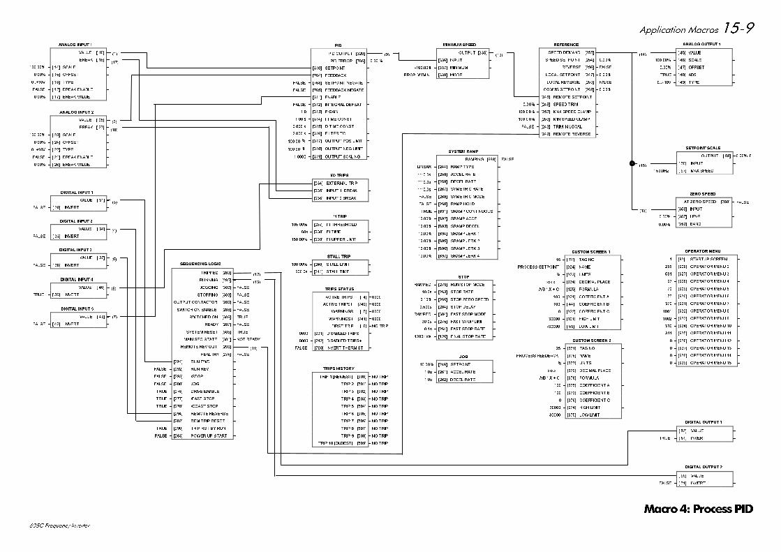
$SSOLFDWLRQ 0DFURV
& )UHTXHQF\ ,QYHUWHU
)$/6(
$1$/2* ,1387
9$/8( > @ ±
%5($. > @ ±
± > @ 6&$/( ±
± > @ 2))6(7 ±
9 ± > @ 7<3( ±
)$/6( ± > @ %5($. (1$%/( ±
± > @ %5($. 9$/8( ±
)$/6(
$1$/2* ,1387
9$/8( > @ ±
%5($. > @ ±
± > @ 6&$/( ±
± > @ 2))6(7 ±
9 ± > @ 7<3( ±
)$/6( ± > @ %5($. (1$%/( ±
± > @ %5($. 9$/8( ±
',*,7$/ ,1387
9$/8( > @ ± )$/6(
)$/6( ± > @ ,19(57 ±
',*,7$/ ,1387
9$/8( > @ ± )$/6(
)$/6( ± > @ ,19(57 ±
',*,7$/ ,1387
9$/8( > @ ± )$/6(
)$/6( ± > @ ,19(57 ±
',*,7$/ ,1387
9$/8( > @ ± )$/6(
)$/6( ± > @ ,19(57 ±
)$/6(
',*,7$/ ,1387
9$/8( > @ ±
758( ± > @ ,19(57 ±
6(48(1&,1* /2*,&
75,33(' >@ ± )$/6(
5811,1* >@ ± )$/6(
-2**,1* >@ ± )$/6(
67233,1* >@ ± )$/6(
287387 &217$&725 >@ ± )$/6(
6:,7&+ 21 (1$%/( >@ ± )$/6(
6:,7&+(' 21 >@ ± 758(
5($'< >@ ± )$/6(
6<67(0 5(6(7 >@ ± 758(
0$,1 6(4 67$7( >@ ± 127 5($'<
5(027( 5(9 287 >@ ± )$/6(
+($/7+< >@ ± )$/6(
)$/6( ± >@ 581 ):' ±
)$/6( ± >@ 581 5(9 ±
)$/6( ± >@ 6723 ±
)$/6( ± >@ -2* ±
758( ± >@ '5,9( (1$%/( ±
758( ± >@ )$67 6723 ±
758( ± >@ &2$67 6723 ±
)$/6( ± >@ 5(027( 5(9(56( ±
)$/6( ± >@ 5(0 75,3 5(6(7 ±
758( ± >@ 75,3 567 %< 581 ±
)$/6( ± >@ 32:(5 83 67$57 ±
,2 75,36
)$/6( ± >@ (;7(51$/ 75,3 ±
)$/6( ± >@ ,1387 %5($. ±
)$/6( ± >@ ,1387 %5($. ±
, W 75,3
± >@ , W 7+5(6+2/' ±
V ± >@ , W 7,0( ±
± >@ , W 833(5 /,0,7 ±
67$// 75,3
± >@ 67$// /,0,7 ±
V ± >@ 67$// 7,0( ±
75,36 +,6725<
75,3 >1(:(67@ >@ ± 12 75,3
75,3 >@ ± 12 75,3
75,3 >@ ± 12 75,3
75,3 >@ ± 12 75,3
75,3 >@ ± 12 75,3
75,3 >@ ± 12 75,3
75,3 >@ ± 12 75,3
75,3 >@ ± 12 75,3
75,3 >@ ± 12 75,3
75,3 >2/'(67@ >@ ± 12 75,3
0,1,080 63(('
287387 >@ ±
± >@ ,1387 ±
± >@ 0,1,080 ±
3523 :0,1 ± >@ 02'( ±
-2*
± >@ 6(732,17 ±
V ± >@ $&&(/ 5$7( ±
V ± >@ '(&(/ 5$7( ±
$1$/2* 287387
± > @ 9$/8( ±
± > @ 6&$/( ±
± > @ 2))6(7 ±
758( ± > @ $%6 ±
9 ± > @ 7<3( ±
6(732,17 6&$/(
287387 > @ ± OI
± > @ ,1387 ±
+] ± > @ 0$; 63((' ±
=(52 63(('
$7 =(52 63((' >@ ±
± >@ ,1387 ±
± >@ /(9(/ ±
± >@ %$1' ±
',*,7$/ 287387
)$/6( ± > @ 9$/8( ±
758( ± > @ ,19(57 ±
',*,7$/ 287387
)$/6( ± > @ 9$/8( ±
)$/6( ± > @ ,19(57 ±
5$,6(/2:(5
287387 >@ ±
)$/6( ± >@ 5$,6( ,1387 ±
)$/6( ± >@ /2:(5 ,1387 ±
V ± >@ 5$03 5$7( ±
± >@ 0$; 9$/8( ±
± >@ 0,1 9$/8( ±
± >@ 5(6(7 9$/8( ±
)$/6( ± >@ 5(6(7 ±
5()(5(1&(
63((' '(0$1' >@ ±
63((' 6(732,17 >@ ±
5(9(56( >@ ± )$/6(
/2&$/ 6(732,17 >@ ±
/2&$/ 5(9(56( >@ ± )$/6(
&2006 6(732,17 >@ ±
± >@ 5(027( 6(732,17 ±
± >@ 63((' 75,0 ±
± >@ 0$; 63((' &/$03 ±
± >@ 0,1 63((' &/$03 ±
)$/6( ± >@ 75,0 ,1 /2&$/ ±
)$/6( ± >@ 5(027( 5(9(56( ±
6723
5$03(' ± >@ 581 6723 02'( ±
V ± >@ 6723 5$7( ±
± >@ 6723 =(52 63((' ±
V ± >@ 6723 '(/$< ±
5$03(' ± >@ )$67 6723 02'( ±
V ± >@ )$67 6723 /,0,7 ±
V ± >@ )$67 6723 5$7( ±
+]V ± >@ ),1$/ 6723 5$7( ±
6<67(0 5$03
5$03,1* >@ ± )$/6(
/,1($5 ± >@ 5$03 7<3( ±
V ± >@ $&&(/ 5$7( ±
V ± >@ '(&(/ 5$7( ±
V ± >@ 6<0(75,& 5$7( ±
)$/6( ± >@ 6<0(75,& 02'( ±
)$/6( ± >@ 5$03 +2/' ±
758( ± >@ 65$03 &217,18286 ±
± >@ 65$03 $&&(/ ±
± >@ 65$03 '(&(/ ±
± >@ 65$03 -(5. ±
± >@ 65$03 -(5. ±
± >@ 65$03 -(5. ±
± >@ 65$03 -(5. ±
)$/6(
23(5$725 0(18
± >@ 67$5783 6&5((1 ±
± >@ 23(5$725 0(18 ±
± >@ 23(5$725 0(18 ±
± >@ 23(5$725 0(18 ±
± >@ 23(5$725 0(18 ±
± >@ 23(5$725 0(18 ±
± >@ 23(5$725 0(18 ±
± >@ 23(5$725 0(18 ±
± >@ 23(5$725 0(18 ±
± >@ 23(5$725 0(18 ±
± >@ 23(5$725 0(18 ±
± >@ 23(5$725 0(18 ±
± >@ 23(5$725 0(18 ±
± >@ 23(5$725 0(18 ±
± >@ 23(5$725 0(18 ±
&86720 6&5((1
± > @ 7$* 12 ±
± >@ 1$0( ±
± >@ 81,76 ±
[[[[B ± >@ '(&,0$/ 3/$&( ±
$% ; & ± >@ )2508/$ ±
± >@ &2()),&,(17 $ ±
± > @ &2()),&,(17 % ±
± >@ &2()),&,(17 & ±
± >@ +,*+ /,0,7 ±
± > @ /2: /,0,7 ±
352&(66 6(732,17
&86720 6&5((1
± >@ 7$* 12 ±
± >@ 1$0( ±
± >@ 81,76 ±
[[[[B ± >@ '(&,0$/ 3/$&( ±
$% ; & ± >@ )2508/$ ±
± >@ &2()),&,(17 $ ±
± >@ &2()),&,(17 % ±
± >@ &2()),&,(17 & ±
± >@ +,*+ /,0,7 ±
± >@ /2: /,0,7 ±
352&(66 )(('%$&.
75,36 67$786
$&7,9( 75,36 > @ ±
$&7,9( 75,36 >@ ±
:$51,1*6 > @ ±
:$51,1*6 >@ ±
),567 75,3 > @ ± 12 75,3
± >@ ',6$%/(' 75,36 ±
± >@ ',6$%/(' 75,36 ±
)$/6( ± >@ ,19(57 7+(50,67 ±
3,'
3,' 287387 >@ ±
3,' (5525 >@ ±
± >@ 6(732,17 ±
± >@ )(('%$&. ±
)$/6( ± >@ 6(732,17 1(*$7( ±
)$/6( ± >@ )(('%$&. 1(*$7( ±
± >@ (1$%/( ±
)$/6( ± >@ ,17(*5$/ '()($7 ±
± >@ 3 *$,1 ±
V ± >@ , 7,0( &2167 ±
V ± >@ ' 7,0( &2167 ±
V ± >@ ),/7(5 7& ±
± >@ 287387 326 /,0,7 ±
± >@ 287387 1(* /,0,7 ±
± >@ 287387 6&$/,1* ±
0DFUR 3URFHVV3,'
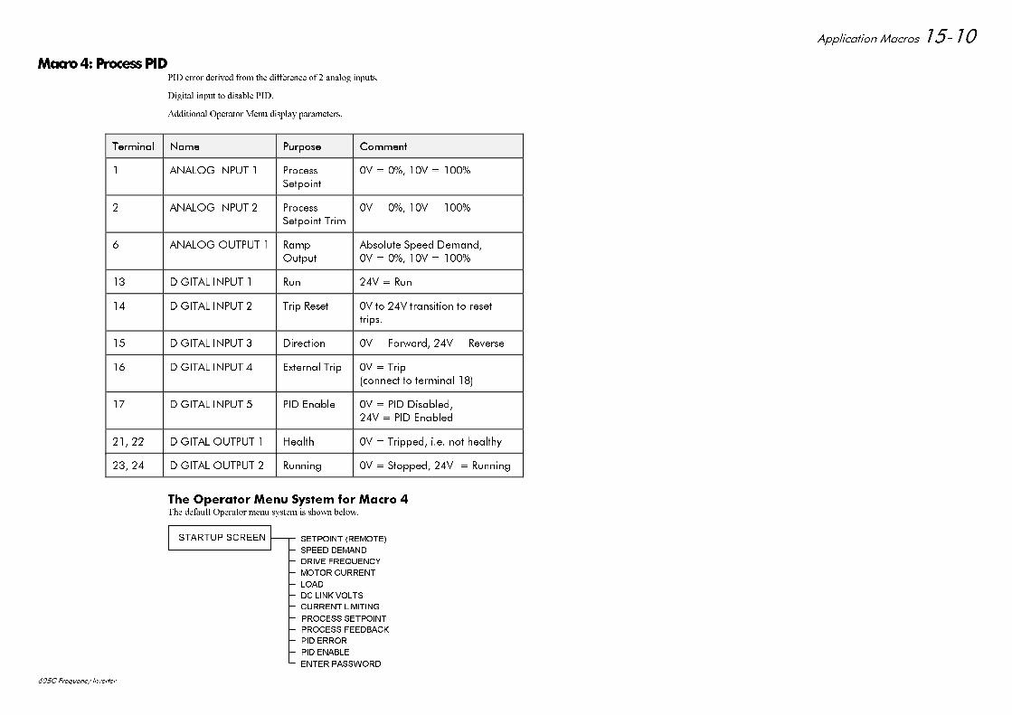
$SSOLFDWLRQ 0DFURV
& )UHTXHQF\ ,QYHUWHU
0DFUR3URFHVV3,'3,' HUURU GHULYHG IURP WKH GLIIHUHQFH RI DQDORJ LQSXWV
'LJLWDO LQSXW WR GLVDEOH 3,'
$GGLWLRQDO 2SHUDWRU 0HQX GLVSOD\ SDUDPHWHUV
7HUPLQDO7HUPLQDO 1DPH1DPH 3XUSRVH3XUSRVH &RPPHQW&RPPHQW
$1$/2* ,1387 3URFHVV
6HWSRLQW
9 9
$1$/2* ,1387 3URFHVV6HWSRLQW 7ULP
9 9
$1$/2* 287387 5DPS2XWSXW
$EVROXWH 6SHHG 'HPDQG9 9
',*,7$/ ,1387 5XQ 9 5XQ
',*,7$/ ,1387 7ULS 5HVHW 9 WR 9 WUDQVLWLRQ WR UHVHWWULSV
',*,7$/ ,1387 'LUHFWLRQ 9 )RUZDUG 9 5HYHUVH
',*,7$/ ,1387 ([WHUQDO 7ULS 9 7ULSFRQQHFW WR WHUPLQDO
',*,7$/ ,1387 3,' (QDEOH 9 3,' 'LVDEOHG9 3,' (QDEOHG
',*,7$/ 287387 +HDOWK 9 7ULSSHG LH QRW KHDOWK\
',*,7$/ 287387 5XQQLQJ 9 6WRSSHG 9 5XQQLQJ
7KH 2SHUDWRU 0HQX 6\VWHP IRU 0DFUR 7KH GHIDXOW 2SHUDWRU PHQX V\VWHP LV VKRZQ EHORZ
6(732,17 5(027(
63((' '(0$1'
'5,9( )5(48(1&<
02725 &855(17
/2$'
'& /,1. 92/76
&855(17 /,0,7,1*
352&(66 6(732,17
67$5783 6&5((1
352&(66 )(('%$&.
3,' (5525
3,' (1$%/(
(17(5 3$66:25'

$SSOLFDWLRQ 0DFURV
& )UHTXHQF\ ,QYHUWHU
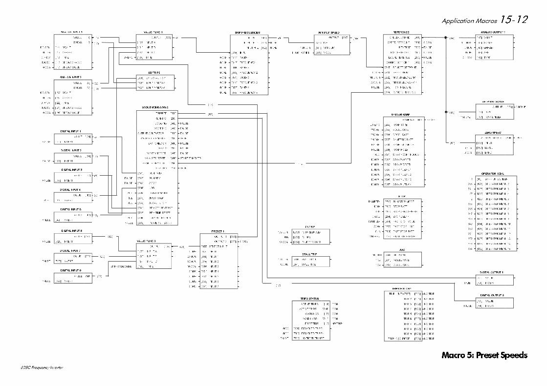
$SSOLFDWLRQ 0DFURV
& )UHTXHQF\ ,QYHUWHU
)$/6(
$1$/2* ,1387
9$/8( > @ ±
%5($. > @ ±
± > @ 6&$/( ±
± > @ 2))6(7 ±
9 ± > @ 7<3( ±
)$/6( ± > @ %5($. (1$%/( ±
± > @ %5($. 9$/8( ±
)$/6(
$1$/2* ,1387
9$/8( > @ ±
%5($. > @ ±
± > @ 6&$/( ±
± > @ 2))6(7 ±
9 ± > @ 7<3( ±
)$/6( ± > @ %5($. (1$%/( ±
± > @ %5($. 9$/8( ±
',*,7$/ ,1387
9$/8( > @ ± )$/6(
)$/6( ± > @ ,19(57 ±
',*,7$/ ,1387
9$/8( > @ ± )$/6(
)$/6( ± > @ ,19(57 ±
',*,7$/ ,1387
9$/8( > @ ± )$/6(
)$/6( ± > @ ,19(57
',*,7$/ ,1387
9$/8( > @ ± )$/6(
)$/6( ± > @ ,19(57 ±
)$/6(
',*,7$/ ,1387
9$/8( > @ ±
758( ± > @ ,19(57 ±
)$/6(
)$/6(
)$/6(
)$/6(
)$/6(
758(
)$/6(
)$/6(
)$/6(
)$/6(
758(
6(48(1&,1* /2*,&
75,33(' >@ ±
5811,1* >@ ±
-2**,1* >@ ±
67233,1* >@ ±
287387 &217$&725 >@ ±
6:,7&+ 21 (1$%/( >@ ±
6:,7&+(' 21 >@ ±
5($'< >@ ±
6<67(0 5(6(7 >@ ±
0$,1 6(4 67$7( >@ ± 67$57 (1$%/('
5(027( 5(9 287 >@ ±
+($/7+< >@ ±
)$/6( ± >@ 581 ):' ±
)$/6( ± >@ 581 5(9 ±
)$/6( ± >@ 6723 ±
± >@ -2* ±
758( ± >@ '5,9( (1$%/( ±
758( ± >@ )$67 6723 ±
758( ± >@ &2$67 6723 ±
± >@ 5(027( 5(9(56( ±
± >@ 5(0 75,3 5(6(7 ±
758( ± >@ 75,3 567 %< 581 ±
)$/6( ± >@ 32:(5 83 67$57 ±
6.,3 )5(48(1&,(6
287387 >@ ±
287387 + ] >@ ± +]
,1387 + ] >@ ± +]
± >@ ,1387 ±
+] ± >@ %$1' ±
+] ± >@ )5(48(1&< ±
+] ± >@ %$1' ±
+] ± >@ )5(48(1&< ±
+] ± >@ %$1' ±
+] ± >@ )5(48(1&< ±
+] ± >@ %$1' ±
+] ± >@ )5(48(1&< ±
)$/6(
)$/6(
)$/6(
,2 75,36
± >@ (;7(51$/ 75,3 ±
± >@ ,1387 %5($. ±
± >@ ,1387 %5($. ±
, W 75,3
± >@ , W 7+5(6+2/' ±
V ± >@ , W 7,0( ±
± >@ , W 833(5 /,0,7 ±
67$// 75,3
± >@ 67$// /,0,7 ±
V ± >@ 67$// 7,0( ±
75,36 +,6725<
75,3 >1(:(67@ >@ ± 12 75,3
75,3 >@ ± 12 75,3
75,3 >@ ± 12 75,3
75,3 >@ ± 12 75,3
75,3 >@ ± 12 75,3
75,3 >@ ± 12 75,3
75,3 >@ ± 12 75,3
75,3 >@ ± 12 75,3
75,3 >@ ± 12 75,3
75,3 >2/'(67@ >@ ± 12 75,3
0,1,080 63(('
287387 >@ ±
± >@ ,1387 ±
± >@ 0,1,080 ±
3523 :0,1 ± >@ 02'( ±
-2*
± >@ 6(732,17 ±
V ± >@ $&&(/ 5$7( ±
V ± >@ '(&(/ 5$7( ±
$1$/2* 287387
± > @ 9$/8( ±
± > @ 6&$/( ±
± > @ 2))6(7 ±
758( ± > @ $%6 ±
9 ± > @ 7<3( ±
6(732,17 6&$/(
287387 > @ ± OI
± > @ ,1387 ±
+] ± > @ 0$; 63((' ±
=(52 63(('
$7 =(52 63((' >@ ±
± >@ ,1387 ±
± >@ /(9(/ ±
± >@ %$1' ±
',*,7$/ 287387
)$/6( ± > @ 9$/8( ±
758( ± > @ ,19(57 ±
',*,7$/ 287387
)$/6( ± > @ 9$/8( ±
)$/6( ± > @ ,19(57 ±
9$/8( )81&
287387 >@ ±
± >@ ,1387 $ ±
± >@ ,1387 % ±
± >@ ,1387 & ±
$%& ± >@ 7<3( ±
5()(5(1&(
63((' '(0$1' >@ ±
63((' 6(732,17 >@ ±
5(9(56( >@ ± )$/6(
/2&$/ 6(732,17 >@ ±
/2&$/ 5(9(56( >@ ± )$/6(
&2006 6(732,17 >@ ±
± >@ 5(027( 6(732,17 ±
± >@ 63((' 75,0 ±
± >@ 0$; 63((' &/$03 ±
± >@ 0,1 63((' &/$03 ±
)$/6( ± >@ 75,0 ,1 /2&$/ ±
)$/6( ± >@ 5(027( 5(9(56( ±
6723
5$03(' ± >@ 581 6723 02'( ±
V ± >@ 6723 5$7( ±
± >@ 6723 =(52 63((' ±
V ± >@ 6723 '(/$< ±
5$03(' ± >@ )$67 6723 02'( ±
V ± >@ )$67 6723 /,0,7 ±
V ± >@ )$67 6723 5$7( ±
+]V ± >@ ),1$/ 6723 5$7( ±
6<67(0 5$03
5$03,1* >@ ± )$/6(
/,1($5 ± >@ 5$03 7<3( ±
V ± >@ $&&(/ 5$7( ±
V ± >@ '(&(/ 5$7( ±
V ± >@ 6<0(75,& 5$7( ±
)$/6( ± >@ 6<0(75,& 02'( ±
)$/6( ± >@ 5$03 +2/' ±
758( ± >@ 65$03 &217,18286 ±
± >@ 65$03 $&&(/ ±
± >@ 65$03 '(&(/ ±
± >@ 65$03 -(5. ±
± >@ 65$03 -(5. ±
± >@ 65$03 -(5. ±
± >@ 65$03 -(5. ±
758(
75,36 67$786
$&7,9( 75,36 > @ ±
$&7,9( 75,36 >@ ±
:$51,1*6 > @ ±
:$51,1*6 >@ ±
),567 75,3 > @ ± 12 75,3
± >@ ',6$%/(' 75,36 ±
± >@ ',6$%/(' 75,36 ±
)$/6( ± >@ ,19(57 7+(50,67 ±
',*,7$/ ,1387
9$/8( >@ ±
)$/6( ± >@ ,19(57 ±
',*,7$/ ,1387
9$/8( >@ ±
)$/6( ± >@ ,19(57 ±
',*,7$/ ,1387
9$/8( >@ ±
)$/6( ± >@ ,19(57 ±
35(6(7
287387 >@ ±
287387 >@ ±
± >@ 6(/(&7 ,1387 ±
± >@ ,1387 ±
± >@ ,1387 ±
± >@ ,1387 ±
± >@ ,1387 ±
± >@ ,1387 ±
± >@ ,1387 ±
± >@ ,1387 ±
± >@ ,1387 ±
9$/8( )81&
287387 >@ ±
± >@ ,1387 $ ±
± >@ ,1387 % ±
± >@ ,1387 & ±
%,1$5< '(&2'( ± >@ 7<3( ±
23(5$725 0(18
± >@ 67$5783 6&5((1 ±
± >@ 23(5$725 0(18 ±
± >@ 23(5$725 0(18 ±
± >@ 23(5$725 0(18 ±
± >@ 23(5$725 0(18 ±
± >@ 23(5$725 0(18 ±
± >@ 23(5$725 0(18 ±
± >@ 23(5$725 0(18 ±
± >@ 23(5$725 0(18 ±
± >@ 23(5$725 0(18 ±
± >@ 23(5$725 0(18 ±
± >@ 23(5$725 0(18 ±
± >@ 23(5$725 0(18 ±
± >@ 23(5$725 0(18 ±
± >@ 23(5$725 0(18 ±
0DFUR 3UHVHW 6SHHGV
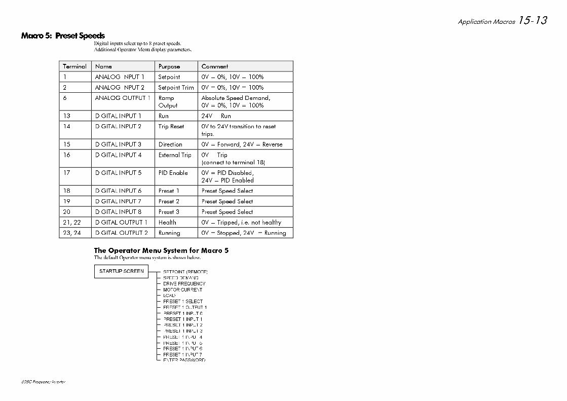
$SSOLFDWLRQ 0DFURV
& )UHTXHQF\ ,QYHUWHU
0DFUR 3UHVHW 6SHHGV'LJLWDO LQSXWV VHOHFW XS WR SUHVHW VSHHGV
$GGLWLRQDO 2SHUDWRU 0HQX GLVSOD\ SDUDPHWHUV
7HUPLQDO7HUPLQDO 1DPH1DPH 3XUSRVH3XUSRVH &RPPHQW&RPPHQW
$1$/2* ,1387 6HWSRLQW 9 9
$1$/2* ,1387 6HWSRLQW 7ULP 9 9
$1$/2* 287387 5DPS
2XWSXW
$EVROXWH 6SHHG 'HPDQG9 9
',*,7$/ ,1387 5XQ 9 5XQ
',*,7$/ ,1387 7ULS 5HVHW 9 WR 9 WUDQVLWLRQ WR UHVHWWULSV
',*,7$/ ,1387 'LUHFWLRQ 9 )RUZDUG 9 5HYHUVH
',*,7$/ ,1387 ([WHUQDO 7ULS 9 7ULSFRQQHFW WR WHUPLQDO
',*,7$/ ,1387 3,' (QDEOH 9 3,' 'LVDEOHG9 3,' (QDEOHG
',*,7$/ ,1387 3UHVHW 3UHVHW 6SHHG 6HOHFW
',*,7$/ ,1387 3UHVHW 3UHVHW 6SHHG 6HOHFW
',*,7$/ ,1387 3UHVHW 3UHVHW 6SHHG 6HOHFW
',*,7$/ 287387 +HDOWK 9 7ULSSHG LH QRW KHDOWK\
',*,7$/ 287387 5XQQLQJ 9 6WRSSHG 9 5XQQLQJ
7KH 2SHUDWRU 0HQX 6\VWHP IRU 0DFUR 7KH GHIDXOW 2SHUDWRU PHQX V\VWHP LV VKRZQ EHORZ
6(732,17 5(027(
63((' '(0$1'
'5,9( )5(48(1&<
02725 &855(17
/2$'
35(6(7 6(/(&7
35(6(7 287387
35(6(7 ,1387
67$5783 6&5((1
35(6(7 ,1387
35(6(7 ,1387
35(6(7 ,1387
35(6(7 ,1387
35(6(7 ,1387
35(6(7 ,1387
35(6(7 ,1387
(17(5 3$66:25'
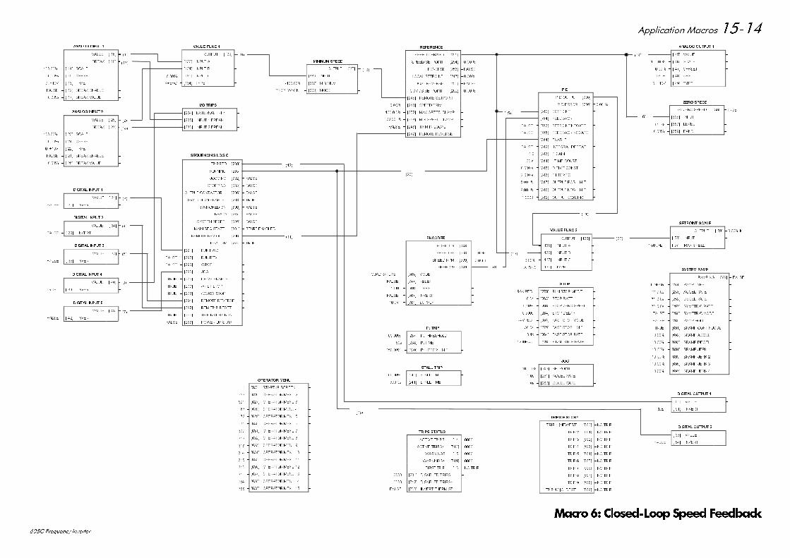
$SSOLFDWLRQ 0DFURV
& )UHTXHQF\ ,QYHUWHU
)$/6(
$1$/2* ,1387
9$/8( > @ ±
%5($. > @ ±
± > @ 6&$/( ±
± > @ 2))6(7 ±
9 ± > @ 7<3( ±
)$/6( ± > @ %5($. (1$%/( ±
± > @ %5($. 9$/8( ±
)$/6(
$1$/2* ,1387
9$/8( > @ ±
%5($. > @ ±
± > @ 6&$/( ±
± > @ 2))6(7 ±
9 ± > @ 7<3( ±
)$/6( ± > @ %5($. (1$%/( ±
± > @ %5($. 9$/8( ±
',*,7$/ ,1387
9$/8( > @ ± )$/6(
)$/6( ± > @ ,19(57 ±
',*,7$/ ,1387
9$/8( > @ ± )$/6(
)$/6( ± > @ ,19(57 ±
',*,7$/ ,1387
9$/8( > @ ± )$/6(
)$/6( ± > @ ,19(57
',*,7$/ ,1387
9$/8( > @ ± )$/6(
)$/6( ± > @ ,19(57 ±
)$/6(
',*,7$/ ,1387
9$/8( > @ ±
758( ± > @ ,19(57 ±
)$/6(
)$/6(
)$/6(
)$/6(
)$/6(
758(
)$/6(
)$/6(
)$/6(
)$/6(
758(
6(48(1&,1* /2*,&
75,33(' >@ ±
5811,1* >@ ±
-2**,1* >@ ±
67233,1* >@ ±
287387 &217$&725 >@ ±
6:,7&+ 21 (1$%/( >@ ±
6:,7&+(' 21 >@ ±
5($'< >@ ±
6<67(0 5(6(7 >@ ±
0$,1 6(4 67$7( >@ ± 67$57 (1$%/('
5(027( 5(9 287 >@ ±
+($/7+< >@ ±
)$/6( ± >@ 581 ):' ±
)$/6( ± >@ 581 5(9 ±
)$/6( ± >@ 6723 ±
± >@ -2* ±
758( ± >@ '5,9( (1$%/( ±
758( ± >@ )$67 6723 ±
758( ± >@ &2$67 6723 ±
± >@ 5(027( 5(9(56( ±
± >@ 5(0 75,3 5(6(7 ±
758( ± >@ 75,3 567 %< 581 ±
)$/6( ± >@ 32:(5 83 67$57 ±
)$/6(
)$/6(
)$/6(
,2 75,36
± >@ (;7(51$/ 75,3 ±
± >@ ,1387 %5($. ±
± >@ ,1387 %5($. ±
, W 75,3
± >@ , W 7+5(6+2/' ±
V ± >@ , W 7,0( ±
± >@ , W 833(5 /,0,7 ±
67$// 75,3
± >@ 67$// /,0,7 ±
V ± >@ 67$// 7,0( ±
75,36 +,6725<
75,3 >1(:(67@ >@ ± 12 75,3
75,3 >@ ± 12 75,3
75,3 >@ ± 12 75,3
75,3 >@ ± 12 75,3
75,3 >@ ± 12 75,3
75,3 >@ ± 12 75,3
75,3 >@ ± 12 75,3
75,3 >@ ± 12 75,3
75,3 >@ ± 12 75,3
75,3 >2/'(67@ >@ ± 12 75,3
0,1,080 63(('
287387 >@ ±
± >@ ,1387 ±
± >@ 0,1,080 ±
3523 :0,1 ± >@ 02'( ±
-2*
± >@ 6(732,17 ±
V ± >@ $&&(/ 5$7( ±
V ± >@ '(&(/ 5$7( ±
$1$/2* 287387
± > @ 9$/8( ±
± > @ 6&$/( ±
± > @ 2))6(7 ±
758( ± > @ $%6 ±
9 ± > @ 7<3( ±
6(732,17 6&$/(
287387 > @ ± OI
± > @ ,1387 ±
+] ± > @ 0$; 63((' ±
=(52 63(('
$7 =(52 63((' >@ ±
± >@ ,1387 ±
± >@ /(9(/ ±
± >@ %$1' ±
',*,7$/ 287387
)$/6( ± > @ 9$/8( ±
758( ± > @ ,19(57 ±
',*,7$/ 287387
)$/6( ± > @ 9$/8( ±
)$/6( ± > @ ,19(57 ±
9$/8( )81&
287387 >@ ±
± >@ ,1387 $ ±
± >@ ,1387 % ±
± >@ ,1387 & ±
$%& ± >@ 7<3( ±
5()(5(1&(
63((' '(0$1' >@ ±
63((' 6(732,17 >@ ±
5(9(56( >@ ± )$/6(
/2&$/ 6(732,17 >@ ±
/2&$/ 5(9(56( >@ ± )$/6(
&2006 6(732,17 >@ ±
± >@ 5(027( 6(732,17 ±
± >@ 63((' 75,0 ±
± >@ 0$; 63((' &/$03 ±
± >@ 0,1 63((' &/$03 ±
)$/6( ± >@ 75,0 ,1 /2&$/ ±
± >@ 5(027( 5(9(56( ±
6723
5$03(' ± >@ 581 6723 02'( ±
V ± >@ 6723 5$7( ±
± >@ 6723 =(52 63((' ±
V ± >@ 6723 '(/$< ±
5$03(' ± >@ )$67 6723 02'( ±
V ± >@ )$67 6723 /,0,7 ±
V ± >@ )$67 6723 5$7( ±
+]V ± >@ ),1$/ 6723 5$7( ±
6<67(0 5$03
5$03,1* >@ ± )$/6(
/,1($5 ± >@ 5$03 7<3( ±
V ± >@ $&&(/ 5$7( ±
V ± >@ '(&(/ 5$7( ±
V ± >@ 6<0(75,& 5$7( ±
)$/6( ± >@ 6<0(75,& 02'( ±
)$/6( ± >@ 5$03 +2/' ±
758( ± >@ 65$03 &217,18286 ±
± >@ 65$03 $&&(/ ±
± >@ 65$03 '(&(/ ±
± >@ 65$03 -(5. ±
± >@ 65$03 -(5. ±
± >@ 65$03 -(5. ±
± >@ 65$03 -(5. ±
758(
75,36 67$786
$&7,9( 75,36 > @ ±
$&7,9( 75,36 >@ ±
:$51,1*6 > @ ±
:$51,1*6 >@ ±
),567 75,3 > @ ± 12 75,3
± >@ ',6$%/(' 75,36 ±
± >@ ',6$%/(' 75,36 ±
)$/6( ± >@ ,19(57 7+(50,67 ±
9$/8( )81&
287387 >@ ±
± >@ ,1387 $ ±
± >@ ,1387 % ±
± >@ ,1387 & ±
$%& ± >@ 7<3( ±
(1&2'(5
326,7,21 >@ ±
63((' +] >@ ± +]
63((' 530 >@ ± QPLQ
63((' >@ ±
48$'5$785( ± >@ 02'( ±
)$/6( ± >@ 5(6(7 ±
± >@ /,1(6 ±
)$/6( ± >@ ,19(57 ±
9 ± >@ 6833/< ±
3,'
3,' 287387 >@ ±
3,' (5525 >@ ±
± >@ 6(732,17 ±
± >@ )(('%$&. ±
)$/6( ± >@ 6(732,17 1(*$7( ±
)$/6( ± >@ )(('%$&. 1(*$7( ±
± >@ (1$%/( ±
)$/6( ± >@ ,17(*5$/ '()($7 ±
± >@ 3 *$,1 ±
V ± >@ , 7,0( &2167 ±
V ± >@ ' 7,0( &2167 ±
V ± >@ ),/7(5 7& ±
± >@ 287387 326 /,0,7 ±
± >@ 287387 1(* /,0,7 ±
± >@ 287387 6&$/,1* ±
23(5$725 0(18
± >@ 67$5783 6&5((1 ±
± >@ 23(5$725 0(18 ±
± >@ 23(5$725 0(18 ±
± >@ 23(5$725 0(18 ±
± >@ 23(5$725 0(18 ±
± >@ 23(5$725 0(18 ±
± >@ 23(5$725 0(18 ±
± >@ 23(5$725 0(18 ±
± >@ 23(5$725 0(18 ±
± >@ 23(5$725 0(18 ±
± >@ 23(5$725 0(18 ±
± >@ 23(5$725 0(18 ±
± >@ 23(5$725 0(18 ±
± >@ 23(5$725 0(18 ±
± >@ 23(5$725 0(18 ±
0DFUR &ORVHG/RRS6SHHG)HHGEDFN
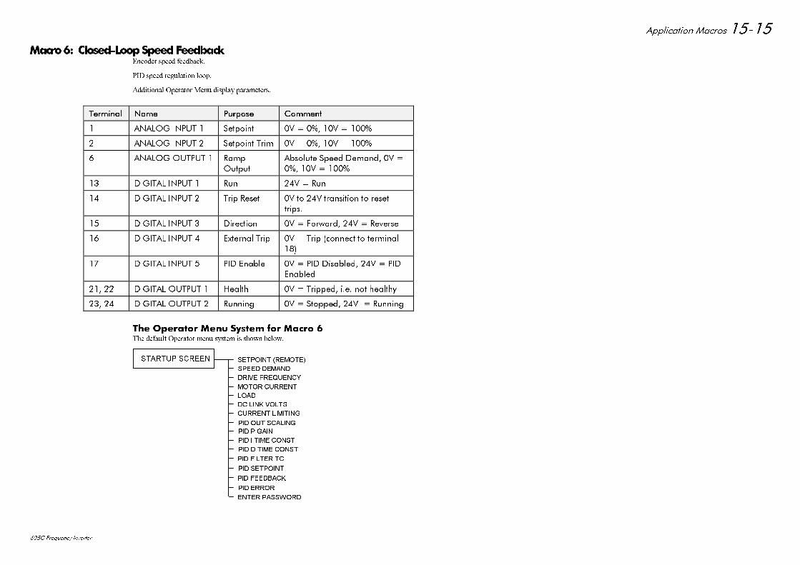
$SSOLFDWLRQ 0DFURV
& )UHTXHQF\ ,QYHUWHU
0DFUR &ORVHG/RRS6SHHG)HHGEDFN(QFRGHU VSHHG IHHGEDFN
3,' VSHHG UHJXODWLRQ ORRS
$GGLWLRQDO 2SHUDWRU 0HQX GLVSOD\ SDUDPHWHUV
7HUPLQDO7HUPLQDO 1DPH1DPH 3XUSRVH3XUSRVH &RPPHQW&RPPHQW
$1$/2* ,1387 6HWSRLQW 9 9
$1$/2* ,1387 6HWSRLQW 7ULP 9 9
$1$/2* 287387 5DPS2XWSXW
$EVROXWH 6SHHG 'HPDQG 9 9
',*,7$/ ,1387 5XQ 9 5XQ
',*,7$/ ,1387 7ULS 5HVHW 9 WR 9 WUDQVLWLRQ WR UHVHWWULSV
',*,7$/ ,1387 'LUHFWLRQ 9 )RUZDUG 9 5HYHUVH
',*,7$/ ,1387 ([WHUQDO 7ULS 9 7ULS FRQQHFW WR WHUPLQDO
',*,7$/ ,1387 3,' (QDEOH 9 3,' 'LVDEOHG 9 3,'(QDEOHG
',*,7$/ 287387 +HDOWK 9 7ULSSHG LH QRW KHDOWK\
',*,7$/ 287387 5XQQLQJ 9 6WRSSHG 9 5XQQLQJ
7KH 2SHUDWRU 0HQX 6\VWHP IRU 0DFUR 7KH GHIDXOW 2SHUDWRU PHQX V\VWHP LV VKRZQ EHORZ
6(732,17 5(027(
63((' '(0$1'
'5,9( )5(48(1&<
02725 &855(17
/2$'
'& /,1. 92/76
&855(17 /,0,7,1*
3,' 287 6&$/,1*
67$5783 6&5((1
3,' 3 *$,1
3,' , 7,0( &2167
3,' ' 7,0( &2167
3,' ),/7(5 7&
3,' 6(732,17
3,' )(('%$&.
3,' (5525
(17(5 3$66:25'
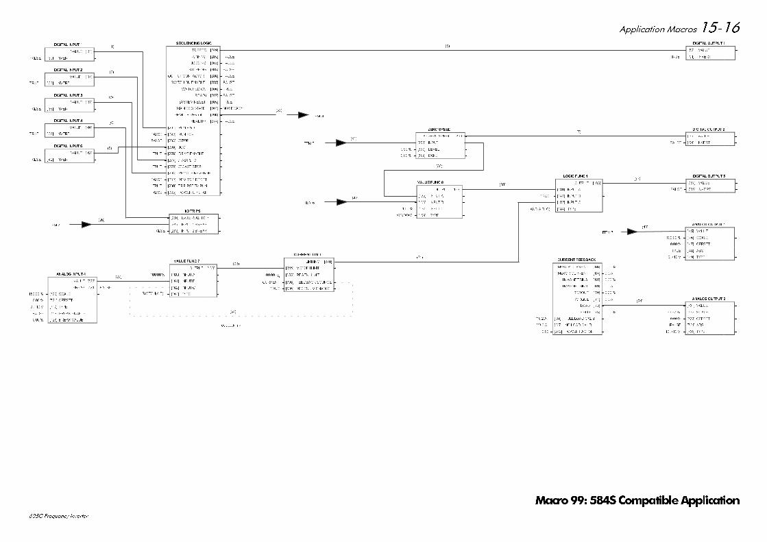
$SSOLFDWLRQ 0DFURV
& )UHTXHQF\ ,QYHUWHU
',*,7$/ ,1387
9$/8( > @ ± )$/6(
)$/6( ± > @ ,19(57 ±
',*,7$/ ,1387
9$/8( > @ ± )$/6(
)$/6( ± > @ ,19(57 ±
',*,7$/ ,1387
9$/8( > @ ± )$/6(
)$/6( ± > @ ,19(57 ±
',*,7$/ ,1387
9$/8( > @ ± )$/6(
758( ± > @ ,19(57 ±
',*,7$/ ,1387
9$/8( > @ ± )$/6(
758( ± > @ ,19(57 ±
$1$/2* ,1387
9$/8( >@ ±
%5($. >@ ± )$/6(
± >@ 6&$/( ±
± >@ 2))6(7 ±
9 ± >@ 7<3( ±
)$/6( ± >@ %5($. (1$%/( ±
± >@ %5($. 9$/8( ±
6(48(1&,1* /2*,&
75,33(' >@ ± )$/6(
5811,1* >@ ± )$/6(
-2**,1* >@ ± )$/6(
67233,1* >@ ± )$/6(
287387 &217$&725 >@ ± )$/6(
6:,7&+ 21 (1$%/( >@ ± )$/6(
6:,7&+(' 21 >@ ± 758(
5($'< >@ ± )$/6(
6<67(0 5(6(7 >@ ± 758(
0$,1 6(4 67$7( >@ ± 127 5($'<
5(027( 5(9 287 >@ ± )$/6(
+($/7+< >@ ± )$/6(
)$/6( ± >@ 581 ):' ±
)$/6( ± >@ 581 5(9 ±
)$/6( ± >@ 6723 ±
)$/6( ± >@ -2* ±
758( ± >@ '5,9( (1$%/( ±
758( ± >@ )$67 6723 ±
758( ± >@ &2$67 6723 ±
)$/6( ± >@ 5(027( 5(9(56( ±
)$/6( ± >@ 5(0 75,3 5(6(7 ±
758( ± >@ 75,3 567 %< 581 ±
)$/6( ± >@ 32:(5 83 67$57 ±
,2 75,36
)$/6( ± >@ (;7(51$/ 75,3 ±
)$/6( ± >@ ,1387 %5($. ±
)$/6( ± >@ ,1387 %5($. ±
9$/8( )81&
287387 >@ ±
± >@ ,1387 $ ±
± >@ ,1387 % ±
± >@ ,1387 & ±
6:,7&+$% ± >@ 7<3( ±
&855(17 /,0,7
/,0,7,1* >@ ±)$/6(
± >@ 02725 , /,0,7 ±
± >@ 5(*(1 , /,0,7 ±
&855(17 ± >@ )(('%$&. 6285&( ±
758( ± >@ 5(*(1 /,0 (1$%/( ±
=(52 63(('
$7 =(52 63((' >@ ± )$/6(
± >@ ,1387 ±
± >@ /(9(/ ±
± >@ %$1' ±
9$/8( )81&
287387 >@ ±
± >@ ,1387 $ ±
± >@ ,1387 % ±
± >@ ,1387 & ±
:,1'2: ± >@ 7<3( ±
/2*,& )81&
287387 >@ ±)$/6(
)$/6( ± >@ ,1387 $ ±
758( ± >@ ,1387 % ±
758( ± >@ ,1387 & ±
$1'$%& ± >@ 7<3( ±
&855(17 )(('%$&.
02725 &855(17 > @ ±
02725 &855(17 > @ ± $
, 0$*1(7,6,1* > @ ±
, 0$*1(7,6,1* > @ ± $
, 72548( > @ ±
, 72548( > @ ± $
/2$' > @ ±
),(/' > @ ±
$ ± > @ )8// /2$' &$/,% ±
$ ± > @ 12 /2$' &$/,% ±
± >@ 32:(5 )$&725 ±
',*,7$/ 287387
)$/6( ± > @ 9$/8( ±
758( ± > @ ,19(57 ±
',*,7$/ 287387
)$/6( ± > @ 9$/8( ±
)$/6( ± > @ ,19(57 ±
',*,7$/ 287387
)$/6( ± >@ 9$/8( ±
)$/6( ± >@ ,19(57 ±
$1$/2* 287387
± > @ 9$/8( ±
± > @ 6&$/( ±
± > @ 2))6(7 ±
758( ± > @ $%6 ±
9 ± > @ 7<3( ±
$1$/2* 287387
± >@ 9$/8( ±
± >@ 6&$/( ±
± >@ 2))6(7 ±
)$/6( ± >@ $%6 ±
9 ± >@ 7<3( ±
,7(0
,7(0
,7(0
,7(0
,7(0
IHHGEDFN OLQN
0DFUR6&RPSDWLEOH$SSOLFDWLRQ
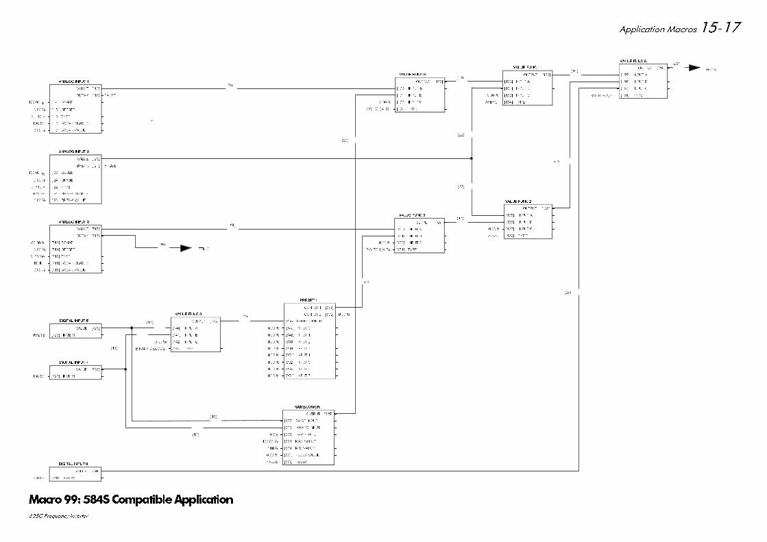
$SSOLFDWLRQ 0DFURV
& )UHTXHQF\ ,QYHUWHU
',*,7$/ ,1387
9$/8( >@ ± )$/6(
)$/6( ± >@ ,19(57 ±
',*,7$/ ,1387
9$/8( >@ ± )$/6(
)$/6( ± >@ ,19(57 ±
',*,7$/ ,1387
9$/8( >@ ±
)$/6(
)$/6( ± >@ ,19(57 ±
9$/8( )81&
287387 >@ ±
± >@ ,1387 $ ±
± >@ ,1387 % ±
± >@ ,1387 & ±
$%& ± >@ 7<3( ±
9$/8( )81&
287387 >@ ±
± >@ ,1387 $ ±
± >@ ,1387 % ±
± >@ ,1387 & ±
%,1$5< '(&2'( ± >@ 7<3( ±
9$/8( )81&
287387 >@ ±
± >@ ,1387 $ ±
± >@ ,1387 % ±
± >@ ,1387 & ±
6:,7&+ $% ± >@ 7<3( ±
9$/8( )81&
287387 >@ ±
± >@ ,1387 $ ±
± >@ ,1387 % ±
± >@ ,1387 & ±
6:,7&+$% ± >@ 7<3( ±
9$/8( )81&
287387 >@ ±
± >@ ,1387 $ ±
± >@ ,1387 % ±
± >@ ,1387 & ±
$%& ± >@ 7<3( ±
9$/8( )81&
287387 >@ ±
± >@ ,1387 $ ±
± >@ ,1387 % ±
± >@ ,1387 & ±
6:,7&+$% ± >@ 7<3( ±
$1$/2* ,1387
9$/8( > @ ±
%5($. > @ ± )$/6(
± > @ 6&$/( ±
± > @ 2))6(7 ±
9 ± > @ 7<3( ±
)$/6( ± > @ %5($. (1$%/( ±
± > @ %5($. 9$/8( ±
$1$/2* ,1387
9$/8( > @ ±
%5($. > @ ± )$/6(
± > @ 6&$/( ±
± > @ 2))6(7 ±
9 ± > @ 7<3( ±
)$/6( ± > @ %5($. (1$%/( ±
± > @ %5($. 9$/8( ±
$1$/2* ,1387
9$/8( >@ ±
%5($. >@ ± )$/6(
± >@ 6&$/( ±
± >@ 2))6(7 ±
P$ ± >@ 7<3( ±
758( ± >@ %5($. (1$%/( ±
± >@ %5($. 9$/8( ±
35(6(7
287387 >@ ±
287387 >@ ±
,1387 ± >@ 6(/(&7 ,1387 ±
± >@ ,1387 ±
± >@ ,1387 ±
± >@ ,1387 ±
± >@ ,1387 ±
± >@ ,1387 ±
± >@ ,1387 ±
± >@ ,1387 ±
± >@ ,1387 ±
5$,6(/2:(5
287387 >@ ±
)$/6( ± >@ 5$,6( ,1387 ±
)$/6( ± >@ /2:(5 ,1387 ±
V ± >@ 5$03 5$7( ±
± >@ 0$; 9$/8( ±
± >@ 0,1 9$/8( ±
± >@ 5(6(7 9$/8( ±
)$/6( ± >@ 5(6(7 ±
,7(0
,7(0
0DFUR6&RPSDWLEOH$SSOLFDWLRQ
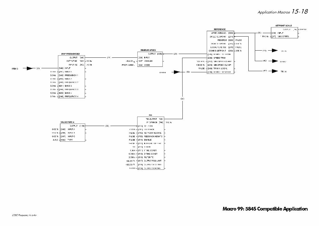
$SSOLFDWLRQ 0DFURV
& )UHTXHQF\ ,QYHUWHU
9$/8( )81&
287387 >@ ±
± >@ ,1387 $ ±
± >@ ,1387 % ±
± >@ ,1387 & ±
$%& ± >@ 7<3( ±
6.,3 )5(48(1&,(6
287387 >@ ±
287387 += >@ ± +]
,1387 += >@ ± +]
± >@ ,1387 ±
+] ± >@ %$1' ±
+] ± >@ )5(48(1&< ±
+] ± >@ %$1' ±
+] ± >@ )5(48(1&< ±
+] ± >@ %$1' ±
+] ± >@ )5(48(1&< ±
+] ± >@ %$1' ±
+] ± >@ )5(48(1&< ±
0,1,080 63(('
287387 >@ ±
± >@ ,1387 ±
± >@ 0,1,080 ±
3523 :0,1 ± >@ 02'( ±
5()(5(1&(
63((' '(0$1' >@ ±
63((' 6(732,17 >@ ±
5(9(56( >@ ± )$/6(
/2&$/ 6(732,17 >@ ±
/2&$/ 5(9(56( >@ ± )$/6(
&2006 6(732,17 >@ ±
± >@ 5(027( 6(732,17 ±
± >@ 63((' 75,0 ±
± >@ 0$; 63((' &/$03 ±
± >@ 0,1 63((' &/$03 ±
)$/6( ± >@ 75,0 ,1 /2&$/ ±
)$/6( ± >@ 5(027( 5(9(56( ±
6(732,17 6&$/(
287387 > @ ± OI
± > @ ,1387 ±
+] ± > @ 0$; 63((' ±
,7(0
,7(0
,7(0
,7(0
,7(0
3,'
3,' 287387 >@ ±
3,' (5525 >@ ±
± >@ 6(732,17 ±
± >@ )(('%$&. ±
)$/6( ± >@ 6(732,17 1(*$7( ±
)$/6( ± >@ )(('%$&. 1(*$7( ±
)$/6( ± >@ (1$%/( ±
)$/6( ± >@ ,17(*5$/ '()($7 ±
± >@ 3 *$,1 ±
V ± >@ , 7,0( &2167 ±
V ± >@ ' 7,0( &2167 ±
V ± >@ ),/7(5 7& ±
± >@ 287387 326 /,0,7 ±
± >@ 287387 1(* /,0,7 ±
± >@ 287387 6&$/,1* ±
0DFUR6&RPSDWLEOH$SSOLFDWLRQ
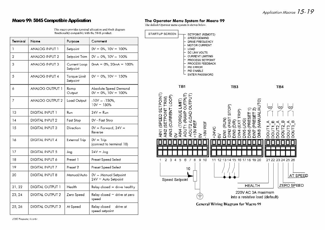
$SSOLFDWLRQ 0DFURV
& )UHTXHQF\ ,QYHUWHU
0DFUR6&RPSDWLEOH$SSOLFDWLRQ
7KLV PDFUR SURYLGHV WHUPLQDO DOORFDWLRQ DQG EORFN GLDJUDP
IXQFWLRQDOLW\ FRPSDWLEOH ZLWK WKH 6 SURGXFW
7HUPLQDO7HUPLQDO 1DPH1DPH 3XUSRVH3XUSRVH &RPPHQW&RPPHQW
$1$/2* ,1387 6HWSRLQW 9 9
$1$/2* ,1387 6HWSRLQW 7ULP 9 9
$1$/2* ,1387 &XUUHQW /RRS6HWSRLQW
P$ P$
$1$/2* ,1387 7RUTXH /LPLW6HWSRLQW
9 9
$1$/2* 287387 5DPS2XWSXW
$EVROXWH 6SHHG 'HPDQG9 9
$1$/2* 287387 /RDG 2XWSXW 9 9
',*,7$/ ,1387 5XQ 9 5XQ
',*,7$/ ,1387 )DVW 6WRS 9 )DVW 6WRS
',*,7$/ ,1387 'LUHFWLRQ 9 )RUZDUG 9 5HYHUVH
',*,7$/ ,1387 ([WHUQDO 7ULS 9 7ULSFRQQHFW WR WHUPLQDO
',*,7$/ ,1387 -RJ 9 -RJ
',*,7$/ ,1387 3UHVHW 3UHVHW 6SHHG 6HOHFW
',*,7$/ ,1387 3UHVHW 3UHVHW 6SHHG 6HOHFW
',*,7$/ ,1387 0DQXDO$XWR 9 0DQXDO 6HWSRLQW9 $XWR 6HWSRLQW
',*,7$/ 287387 +HDOWK 5HOD\ FORVHG GULYH KHDOWK\
',*,7$/ 287387 =HUR 6SHHG 5HOD\ FORVHG GULYH DW ]HURVSHHG
',*,7$/ 287387 $W 6SHHG 5HOD\ FORVHG GULYH DWVSHHG VHWSRLQW
+($/7+
6SHHG 6HWSRLQW
N
9 $& $ PD[LPXP
7% 7% 7%
LQWR D UHVLVWLYH ORDG GHIDXOW
'287B$
'287B%
'287B$
'287B%
'287B$
'287B%
$,163(('6(732,17
$,16(732,1775,0
$,1&855(17/223
9 $,172548(/,0,7
$2875$03287387
$287/2$'287387
95()
9
95()
9&
9
',1581
',1)$676723
',1',5
',1(;775,3
',1-2*
',135(6(7
',135(6(7
',10$18$/$872
=(52 63(('
$7 63(('
*HQHUDO :LULQJ 'LDJUDP IRU 0DFUR
7KH 2SHUDWRU 0HQX 6\VWHP IRU 0DFUR 7KH GHIDXOW 2SHUDWRU PHQX V\VWHP LV VKRZQ EHORZ
6(732,17 5(027(
63((' '(0$1'
'5,9( )5(48(1&<
02725 &855(17
/2$'
'& /,1. 92/76
&855(17 /,0,7,1*
352&(66 6(732,17
67$5783 6&5((1
352&(66 )(('%$&.
3,' (5525
3,' (1$%/(
(17(5 3$66:25'
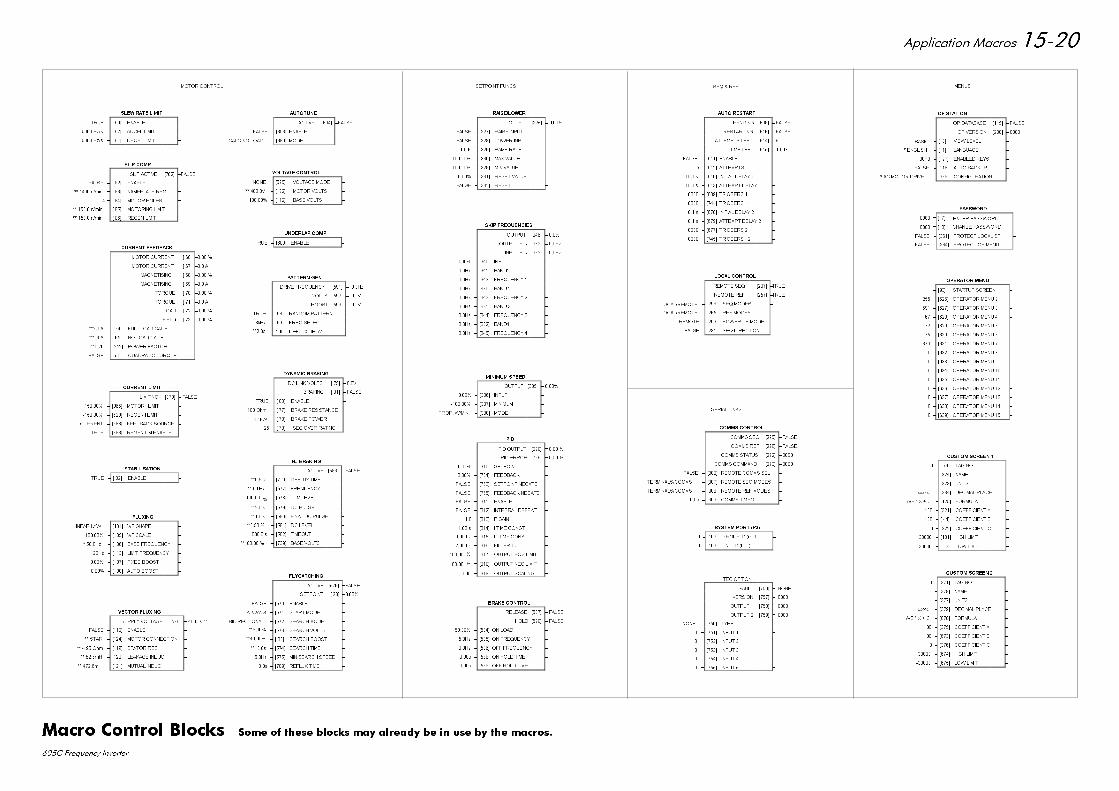
$SSOLFDWLRQ 0DFURV
& )UHTXHQF\ ,QYHUWHU
$872781(
$&7,9( >@ ±)$/6(
)$/6( ± >@ (1$%/( ±
&$/& 12 /2$' , ± >@ 02'( ±
&855(17 /,0,7
/,0,7,1* >@ ± )$/6(
± >@ 02725 , /,0,7 ±
± >@ 5(*(1 , /,0,7 ±
&855(17 ± >@ )(('%$&. 6285&( ±
758( ± >@ 5(*(1 /,0 (1$%/( ±
'<1$0,& %5$.,1*
'& /,1. 92/76 > @ ± 9
%5$.,1* > @ ± )$/6(
758( ± > @ (1$%/( ±
2KP ± > @ %5$.( 5(6,67$1&( ±
N: ± > @ %5$.( 32:(5 ±
± > @ 6(& 29(5 5$7,1* ±
)/8;,1*
/,1($5 /$: ± >@ 9) 6+$3( ±
± >@ 9) 6&$/( ±
+] ± >@ %$6( )5(48(1&< ±
+] ± >@ /,0,7 )5(48(1&< ±
± >@ ),;(' %2267 ±
± >@ $872 %2267 ±)/<&$7&+,1*
$&7,9( >@ ±)$/6(
6(732,17 > @ ±
)$/6( ± >@ (1$%/( ±
$/:$<6 ± >@ 67$57 02'( ±
%,',5(&7,21$/ ± >@ 6($5&+ 02'( ±
± >@ 6($5&+ 92/76 ±
± > @ 6($5&+ %2267 ±
V ± >@ 6($5&+ 7,0( ±
+] ± >@ 0,1 6($5&+ 63((' ±
V ± >@ 5()/8; 7,0( ±
6/(: 5$7( /,0,7
758( ± > @ (1$%/( ±
+]V ± > @ $&&(/ /,0,7 ±
+]V ± > @ '(&(/ /,0,7 ±
67$%,/,6$7,21
758( ± > @ (1$%/( ±
81'(5/$3 &203
758( ± >@ (1$%/( ±
9(&725 )/8;,1*
6833/< 92/7$*( >@ ± 9
)$/6( ± >@ (1$%/( ±
67$5 ± >@ 02725 &211(&7,21 ±
2KP ± >@ 67$725 5(6 ±
P+ ± >@ /($.$*( ,1'8& ±
P+ ± >@ 0878$/ ,1'8& ±
92/7$*( &21752/
121( >@ 92/7$*( 02'( ±
9 ± >@ 02725 92/76 ±
± >@ %$6( 92/76 ±
%5$.( &21752/
5(/($6( >@ ± )$/6(
+2/' >@ ± )$/6(
± >@ 21 /2$' ±
+] ± >@ 21 )5(48(1&< ±
+] ± >@ 2)) )5(48(1&< ±
V ± >@ 21 +2/' 7,0( ±
V ± >@ 2)) +2/' 7,0( ±
0,1,080 63(('
287387 >@ ±
± >@ ,1387 ±
± >@ 0,1,080 ±
3523 :0,1 ± >@ 02'( ±
5$,6(/2:(5
287387 >@ ±
)$/6( ± >@ 5$,6( ,1387 ±
)$/6( ± >@ /2:(5 ,1387 ±
V ± >@ 5$03 5$7( ±
± >@ 0$; 9$/8( ±
± >@ 0,1 9$/8( ±
± >@ 5(6(7 9$/8( ±
)$/6( ± >@ 5(6(7 ±
6.,3 )5(48(1&,(6
287387 >@ ±
287387 + ] >@ ± +]
,1387 + ] >@ ± +]
± >@ ,1387 ±
+] ± >@ %$1' ±
+] ± >@ )5(48(1&< ±
+] ± >@ %$1' ±
+] ± >@ )5(48(1&< ±
+] ± >@ %$1' ±
+] ± >@ )5(48(1&< ±
+] ± >@ %$1' ±
+] ± >@ )5(48(1&< ±
/2&$/ &21752/
5(027( 6(4 >@ ±758(
5(027( 5() >@ ±758(
/2&$/5(027( ± >@ 6(4 02'(6 ±
/2&$/5(027( ± >@ 5() 02'(6 ±
5(027( ± >@ 32:(5 83 02'( ±
)$/6( ± >@ 6(4 ',5(&7,21 ±
&2006 &21752/
&2006 6(4 >@ ± )$/6(
&2006 5() >@ ± )$/6(
&2006 67$786 >@ ±
&2006 &200$1' >@ ±
)$/6( ± >@ 5(027( &2006 6(/ ±
7(50,1$/6&2006 ± >@ 5(027( 6(4 02'(6 ±
7(50,1$/6&2006 ± >@ 5(027( 5() 02'(6 ±
V ± >@ &2006 7,0(287 ±
6<67(0 3257 3
± >@ *5283 ,' *,' ±
± >@ 81,7 ,' 8,' ±
&86720 6&5((1
± > @ 7$* 12 ±
± >@ 1$0( ±
± >@ 81,76 ±
[[[[[ ± >@ '(&,0$/ 3/$&( ±
$% ; & ± >@ )2508/$ ±
± >@ &2()),&,(17 $ ±
± > @ &2()),&,(17 % ±
± >@ &2()),&,(17 & ±
± >@ +,*+ /,0,7 ±
± > @ /2: /,0,7 ±
&86720 6&5((1
± >@ 7$* 12 ±
± >@ 1$0( ±
± >@ 81,76 ±
[[[[[ ± >@ '(&,0$/ 3/$&( ±
$% ; & ± >@ )2508/$ ±
± >@ &2()),&,(17 $ ±
± >@ &2()),&,(17 % ±
± >@ &2()),&,(17 & ±
± >@ +,*+ /,0,7 ±
± >@ /2: /,0,7 ±
23(5$725 0(18
± >@ 67$5783 6&5((1 ±
± >@ 23(5$725 0(18 ±
± >@ 23(5$725 0(18 ±
± >@ 23(5$725 0(18 ±
± >@ 23(5$725 0(18 ±
± >@ 23(5$725 0(18 ±
± >@ 23(5$725 0(18 ±
± >@ 23(5$725 0(18 ±
± >@ 23(5$725 0(18 ±
± >@ 23(5$725 0(18 ±
± >@ 23(5$725 0(18 ±
± >@ 23(5$725 0(18 ±
± >@ 23(5$725 0(18 ±
± >@ 23(5$725 0(18 ±
± >@ 23(5$725 0(18 ±
23 67$7,21
23 '$7$%$6( >@ ± )$/6(
23 9(56,21 >@ ±
%$6,& ± > @ 9,(: /(9(/ ±
(1*/,6+ ± > @ /$1*8$*( ±
) ± >@ (1$%/(' .(<6 ±
)$/6( ± >@ $872 %$&.83 ±
$& 02725 '5,9( ± >@ &21),*85$7,21 ,' ±
3$66:25'
(17(5 3$66:25'> @±
&+$1*( 3$66:25'> @±
)$/6( ± >@ 3527(&7 /2&$/ 63 ±
)$/6( ± >@ 3527(&7 23 0(18 ±
02725 &21752/ 6(732,17 )81&6
6(5,$/ /,1.6
6(4 5() 0(186
3$77(51 *(1
'5,9( )5(48(1&< >@ ± +]
92/76 >@ ± 9
%2267 >@ ± 9
758( ± > @ 5$1'20 3$77(51 ±
N+] ± > @ )5(4 6(/(&7 ±
V ± >@ '()/8; '(/$< ±
&855(17 )(('%$&.
02725 &855(17 > @ ±
02725 &855(17 > @ ± $
, 0$*1(7,6,1* > @ ±
, 0$*1(7,6,1* > @ ± $
, 72548( > @ ±
, 72548( > @ ± $
/2$' > @ ±
),(/' > @ ±
$ ± > @ )8// /2$' &$/,% ±
$ ± > @ 12 /2$' &$/,% ±
± >@ 32:(5 )$&725 ±
)$/6( ± > @ 48$'5$7,& 72548( ±
,1- %5$.,1*
$&7,9( >@ ± )$/6(
V ± >@ '()/8; 7,0( ±
+] ± >@ )5(48(1&< ±
± >@ ,/,0 /(9(/ ±
V ± >@ '& 38/6( ±
V ± >@ ),1$/ '& 38/6( ±
± >@ '& /(9(/ ±
V ± >@ 7,0(287 ±
± >@ %$6( 92/76 ±
$872 5(67$57
3(1',1* >@ ± )$/6(
5(67$57,1* >@ ± )$/6(
$77(0376 /()7 >@ ±
7,0( /()7 >@ ± V
)$/6( ± >@ (1$%/( ±
± >@ $77(0376 ±
V ± >@ ,1,7,$/ '(/$< ±
V ± >@ $77(037 '(/$< ±
± >@ 75,**(56 ±
>@ 75,**(56 ±
V ± >@ ,1,7,$/ '(/$< ±
V ± >@ $77(037 '(/$< ±
± >@ 75,**(56 ±
>@ 75,**(56 ±
6/,3 &203
6/,3 $&7,9( >@ ±)$/6(
)$/6( ± > @ (1$%/( ±
QPLQ ± > @ 1$0(3/$7( 530 ±
± > @ 02725 32/(6 ±
QPLQ ± > @ 02725,1* /,0,7 ±
QPLQ ± > @ 5(*(1 /,0,7 ±
3,'
3,' 287387 >@ ±
3,' (5525 >@ ±
± >@ 6(732,17 ±
± >@ )(('%$&. ±
)$/6( ± >@ 6(732,17 1(*$7( ±
)$/6( ± >@ )(('%$&. 1(*$7( ±
)$/6( ± >@ (1$%/( ±
)$/6( ± >@ ,17(*5$/ '()($7 ±
± >@ 3 *$,1 ±
V ± >@ , 7,0( &2167 ±
V ± >@ ' 7,0( &2167 ±
V ± >@ ),/7(5 7& ±
± >@ 287387 326 /,0,7 ±
± >@ 287387 1(* /,0,7 ±
± >@ 287387 6&$/,1* ±
7(& 237,21
)$8/7 >@ ± 121(
9(56,21 >@ ±
287387 >@ ±
287387 >@ ±
121( ± >@ 7<3( ±
± >@ ,1387 ±
± >@ ,1387 ±
± >@ ,1387 ±
± >@ ,1387 ±
± >@ ,1387 ±
0DFUR &RQWURO %ORFNV 6RPH RI WKHVH EORFNV PD\ DOUHDG\ EH LQ XVH E\ WKH PDFURV
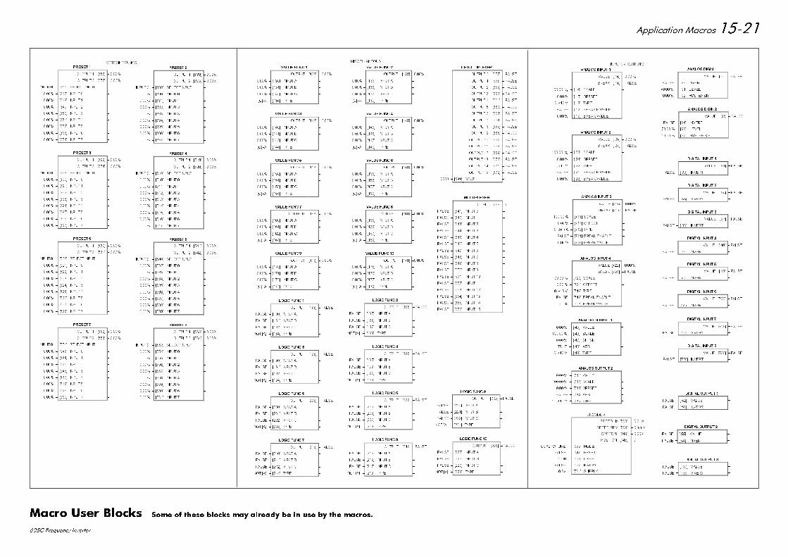
$SSOLFDWLRQ 0DFURV
& )UHTXHQF\ ,QYHUWHU
35(6(7
287387 >@ ±
287387 >@ ±
,1387 ± >@ 6(/(&7 ,1387 ±
± >@ ,1387 ±
± >@ ,1387 ±
± >@ ,1387 ±
± >@ ,1387 ±
± >@ ,1387 ±
± >@ ,1387 ±
± >@ ,1387 ±
± >@ ,1387 ±
35(6(7
287387 >@ ±
287387 >@ ±
,1387 ± >@ 6(/(&7 ,1387 ±
± >@ ,1387 ±
± >@ ,1387 ±
± >@ ,1387 ±
± >@ ,1387 ±
± >@ ,1387 ±
± >@ ,1387 ±
± >@ ,1387 ±
± >@ ,1387 ±
35(6(7
287387 >@ ±
287387 >@ ±
,1387 ± >@ 6(/(&7 ,1387 ±
± >@ ,1387 ±
± >@ ,1387 ±
± >@ ,1387 ±
± >@ ,1387 ±
± >@ ,1387 ±
± >@ ,1387 ±
± >@ ,1387 ±
± >@ ,1387 ±
35(6(7
287387 >@ ±
287387 >@ ±
,1387 ± >@ 6(/(&7 ,1387 ±
± >@ ,1387 ±
± >@ ,1387 ±
± >@ ,1387 ±
± >@ ,1387 ±
± >@ ,1387 ±
± >@ ,1387 ±
± >@ ,1387 ±
± >@ ,1387 ±
35(6(7
287387 >@ ±
287387 >@ ±
,1387 ± >@ 6(/(&7 ,1387 ±
± >@ ,1387 ±
± >@ ,1387 ±
± >@ ,1387 ±
± >@ ,1387 ±
± >@ ,1387 ±
± >@ ,1387 ±
± >@ ,1387 ±
± >@ ,1387 ±
35(6(7
287387 >@ ±
287387 >@ ±
,1387 ± >@ 6(/(&7 ,1387 ±
± >@ ,1387 ±
± >@ ,1387 ±
± >@ ,1387 ±
± >@ ,1387 ±
± >@ ,1387 ±
± >@ ,1387 ±
± >@ ,1387 ±
± >@ ,1387 ±
35(6(7
287387 >@ ±
287387 >@ ±
,1387 ± >@ 6(/(&7 ,1387 ±
± >@ ,1387 ±
± >@ ,1387 ±
± >@ ,1387 ±
± >@ ,1387 ±
± >@ ,1387 ±
± >@ ,1387 ±
± >@ ,1387 ±
± >@ ,1387 ±
35(6(7
287387 >@ ±
287387 >@ ±
,1387 ± >@ 6(/(&7 ,1387 ±
± >@ ,1387 ±
± >@ ,1387 ±
± >@ ,1387 ±
± >@ ,1387 ±
± >@ ,1387 ±
± >@ ,1387 ±
± >@ ,1387 ±
± >@ ,1387 ±
9$/8( )81&
287387 >@ ±
± >@ ,1387 $ ±
± >@ ,1387 % ±
± >@ ,1387 & ±
,)>&@$ ± >@ 7<3( ±
9$/8( )81&
287387 >@ ±
± >@ ,1387 $ ±
± >@ ,1387 % ±
± >@ ,1387 & ±
,)>&@ $ ± >@ 7<3( ±
9$/8( )81&
287387 >@ ±
± >@ ,1387 $ ±
± >@ ,1387 % ±
± >@ ,1387 & ±
,)>&@ $ ± >@ 7<3( ±
9$/8( )81&
2877387 >@ ±
± >@ ,1387 $ ±
± >@ ,1387 % ±
± >@ ,1387 & ±
,)>&@ $ ± >@ 7<3( ±
9$/8( )81&
287387 >@ ±
± >@ ,1387 $ ±
± >@ ,1387 % ±
± >@ ,1387 & ±
,)>&@ $ ± >@ 7<3( ±
9$/8( )81&
287387 >@ ±
± >@ ,1387 $ ±
± >@ ,1387 % ±
± >@ ,1387 & ±
,)>&@ $ ± >@ 7<3( ±
9$/8( )81&
287387 >@ ±
± >@ ,1387 $ ±
± >@ ,1387 % ±
± >@ ,1387 & ±
,)>&@ $ ± >@ 7<3( ±
9$/8( )81&
287387 >@ ±
± >@ ,1387 $ ±
± >@ ,1387 % ±
± >@ ,1387 & ±
,)>&@ $ ± >@ 7<3( ±
9$/8( )81&
2877387 >@ ±
± >@ ,1387 $ ±
± >@ ,1387 % ±
± >@ ,1387 & ±
,)>&@ $ ± >@ 7<3( ±
9$/8( )81&
287387 >@ ±
± >@ ,1387 $ ±
± >@ ,1387 % ±
± >@ ,1387 & ±
,)>&@ $ ± >@ 7<3( ±
/2*,& )81&
287387 >@ ±)$/6(
)$/6( ± >@ ,1387 $ ±
)$/6( ± >@ ,1387 % ±
)$/6( ± >@ ,1387 & ±
127 >$@ ± >@ 7<3( ±
/2*,& )81&
287387 >@ ±)$/6(
)$/6( ± >@ ,1387 $ ±
)$/6( ± >@ ,1387 % ±
)$/6( ± >@ ,1387 & ±
127 >$@ ± >@ 7<3( ±
/2*,& )81&
287387 >@ ±)$/6(
)$/6( ± >@ ,1387 $ ±
)$/6( ± >@ ,1387 % ±
)$/6( ± >@ ,1387 & ±
127 >$@ ± >@ 7<3( ±
/2*,& )81&
287387 >@ ±)$/6(
)$/6( ± >@ ,1387 $ ±
)$/6( ± >@ ,1387 % ±
)$/6( ± >@ ,1387 & ±
127 >$@ ± >@ 7<3( ±
/2*,& )81&
287387 >@ ±)$/6(
)$/6( ± >@ ,1387 $ ±
)$/6( ± >@ ,1387 % ±
)$/6( ± >@ ,1387 & ±
127 >$@ ± >@ 7<3( ±
/2*,& )81&
287387 >@ ±)$/6(
)$/6( ± >@ ,1387 $ ±
)$/6( ± >@ ,1387 % ±
)$/6( ± >@ ,1387 & ±
127 >$@ ± >@ 7<3( ±
/2*,& )81&
287387 >@ ±)$/6(
)$/6( ± >@ ,1387 $ ±
)$/6( ± >@ ,1387 % ±
)$/6( ± >@ ,1387 & ±
127 >$@ ± >@ 7<3( ±
/2*,& )81&
287387 >@ ±)$/6(
)$/6( ± >@ ,1387 $ ±
)$/6( ± >@ ,1387 % ±
)$/6( ± >@ ,1387 & ±
127 >$@ ± >@ 7<3( ±
/2*,& )81&
287387 >@ ±)$/6(
)$/6( ± >@ ,1387 $ ±
)$/6( ± >@ ,1387 % ±
)$/6( ± >@ ,1387 & ±
127 >$@ ± >@ 7<3( ±
/2*,& )81&
287387 >@ ±)$/6(
)$/6( ± >@ ,1387 $ ±
)$/6( ± >@ ,1387 % ±
)$/6( ± >@ ,1387 & ±
127 >$@ ± >@ 7<3( ±
'(08/7,3/(;(5
287387 >@ ± )$/6(
287387 >@ ± )$/6(
287387 >@ ± )$/6(
287387 >@ ± )$/6(
287387 >@ ± )$/6(
287387 >@ ± )$/6(
287387 >@ ± )$/6(
287387 >@ ± )$/6(
287387 >@ ± )$/6(
287387 >@ ± )$/6(
287387 >@ ± )$/6(
287387 >@ ± )$/6(
287387 >@ ± )$/6(
287387 >@ ± )$/6(
287387 >@ ± )$/6(
287387 >@ ± )$/6(
± >@ ,1387 ±
08/7,3/(;(5
287387 >@ ±
)$/6( ± >@ ,1387 ±
)$/6( ± >@ ,1387 ±
)$/6( ± >@ ,1387 ±
)$/6( ± >@ ,1387 ±
)$/6( ± >@ ,1387 ±
)$/6( ± >@ ,1387 ±
)$/6( ± >@ ,1387 ±
)$/6( ± >@ ,1387 ±
)$/6( ± >@ ,1387 ±
)$/6( ± >@ ,1387 ±
)$/6( ± >@ ,1387 ±
)$/6( ± >@ ,1387 ±
)$/6( ± >@ ,1387 ±
)$/6( ± >@ ,1387 ±
)$/6( ± >@ ,1387 ±
)$/6( ± >@ ,1387 ±
6(732,17 )81&6 0,6&(//$1(286
$1$/2* ,1387
9$/8( > @ ±
%5($. > @ ± )$/6(
± > @ 6&$/( ±
± > @ 2))6(7 ±
9 ± > @ 7<3( ±
)$/6( ± > @ %5($. (1$%/( ±
± > @ %5($. 9$/8( ±
$1$/2* ,1387
9$/8( > @ ±
%5($. > @ ± )$/6(
± > @ 6&$/( ±
± > @ 2))6(7 ±
9 ± > @ 7<3( ±
)$/6( ± > @ %5($. (1$%/( ±
± > @ %5($. 9$/8( ±
$1$/2* ,1387
9$/8( >@ ±
%5($. >@ ± )$/6(
± >@ 6&$/( ±
± >@ 2))6(7 ±
P$ ± >@ 7<3( ±
)$/6( ± >@ %5($. (1$%/( ±
± >@ %5($. 9$/8( ±
$1$/2* ,1387
9$/8( >@ ±
%5($. >@ ± )$/6(
± >@ 6&$/( ±
± >@ 2))6(7 ±
9 ± >@ 7<3( ±
)$/6( ± >@ %5($. (1$%/( ±
± >@ %5($. 9$/8( ±
$1$/2* ',*,1
9$/8( > @ ± )$/6(
)$/6( ± > @ ,19(57 ±
± > @ /(9(/ ±
± > @ +<67(5,6,6 ±
$1$/2* ',*,1
9$/8( >@ ± )$/6(
)$/6( ± >@ ,19(57 ±
± >@ /(9(/ ±
± >@ +<67(5,6,6 ±
$1$/2* 287387
± > @ 9$/8( ±
± > @ 6&$/( ±
± > @ 2))6(7 ±
758( ± > @ $%6 ±
9 ± > @ 7<3( ±
$1$/2* 287387
± >@ 9$/8( ±
± >@ 6&$/( ±
± >@ 2))6(7 ±
)$/6( ± >@ $%6 ±
9 ± >@ 7<3( ±
',*,7$/ ,1387
9$/8( > @ ±)$/6(
)$/6( ± > @ ,19(57 ±
',*,7$/ ,1387
9$/8( > @ ±)$/6(
)$/6( ± > @ ,19(57 ±
',*,7$/ ,1387
9$/8( > @ ± )$/6(
)$/6( ± > @ ,19(57 ±
',*,7$/ ,1387
9$/8( > @ ± )$/6(
)$/6( ± > @ ,19(57 ±
',*,7$/ ,1387
9$/8( > @ ±)$/6(
)$/6( ± > @ ,19(57 ±
',*,7$/ ,1387
9$/8( >@ ±)$/6(
)$/6( ± >@ ,19(57 ±
',*,7$/ ,1387
9$/8( >@ ±)$/6(
)$/6( ± >@ ,19(57 ±
',*,7$/ ,1387
9$/8( >@ ±)$/6(
)$/6( ± >@ ,19(57 ±
',*,7$/ 287387
)$/6( ± > @ 9$/8( ±
)$/6( ± > @ ,19(57 ±
',*,7$/ 287387
)$/6( ± > @ 9$/8( ±
)$/6( ± > @ ,19(57 ±
',*,7$/ 287387
)$/6( ± >@ 9$/8( ±
)$/6( ± >@ ,19(57 ±
,13876 2873876
(1&2'(5
63((' +] >@ ± +]
63((' 530 >@ ± QPLQ
63((' >@ ±
326,7,21 >@ ±
48$'5$785( ± >@ 02'( ±
)$/6( ± >@ 5(6(7 ±
± >@ /,1(6 ±
)$/6( ± >@ ,19(57 ±
9 ± >@ 6833/< ±
0DFUR 8VHU %ORFNV 6RPH RI WKHVH EORFNV PD\ DOUHDG\ EH LQ XVH E\ WKH PDFURV
,66 02',),&$7,21 (&1 1R '$7( '5$:1 &+.'
,QLWLDO ,VVXH +$8 &0 %%
&KDSWHU DQG 0DFURV UHZRUNHG 2WKHU VPDOOLPSURYHPHQWV
&0 .-
&RQILJXUDWLRQ VZLWFK 6: UHWUDFNHG 1HZ LQIRUPDWLRQRQ SDJH
&0 66
8SGDWHG WR 9HUVLRQ 6RIWZDUH 9DULRXV RWKHU VPDOODPHQGPHQWV
&0 .-
3DJH $GGHG ,PSRUWDQW QRWH&KDSWHU 5HSODFHG &HUWLILFDWHV ZLWK QHZ IRUPDWHGYHUVLRQ
3DJH 5HPRYHG RSWLRQ % IURP EORFN
3DJH 5HSODFHG 02725 &855(17 ZLWK ,0$*1(7,6,1* XQGHU ),(/' SDUDPHWHU
3DJH &KDQJHG WHUPLQDO WR WHUPLQDO
),567 86(' 21 02',),&$7,21 5(&25'
& )UHTXHQF\ ,QYHUWHU
(8527+(50 '5,9(6
'5$:,1* 180%(5
==&
6+7
2)