Embed Size (px)
DESCRIPTION
9500 Product Doc
Citation preview

Alcatel-Lucent 9500MICROWAVE PACKET RADIO for ANSI | RELEASE 4.2.0Indoor: MSS-8/MSS-4/MSS-1/MPT-HL Outdoor: ODU300/MPT-HC/MPT-XP/9558HC
Alcatel-Lucent ProprietaryThis document contains proprietary information of Alcatel-Lucent and is not to be disclosedor used except in accordance with applicable agreements.Copyright 2013 © Alcatel-Lucent. All rights reserved.
Main Documentation
Product Information
Product Information3EM23952AM Edition 01

Alcatel-Lucent assumes no responsibility for the accuracy of the information presented, which is subject to change without notice.
Alcatel, Lucent, Alcatel-Lucent and the Alcatel-Lucent logo are trademarks of Alcatel-Lucent. All other trademarks are the property of their respective owners.
Copyright 2013 Alcatel-Lucent.
All rights reserved.
Disclaimers
Alcatel-Lucent products are intended for commercial uses. Without the appropriate network design engineering, they must not be sold, licensed or otherwise distributed for use in any hazardous environments requiring fail-safe performance, such as in the operation of nuclear facilities, aircraft navigation or communication systems, air traffic control, direct life-support machines, or weapons systems, in which the failure of products could lead directly to death, personal injury, or severe physical or environmental damage. The customer hereby agrees that the use, sale, license or other distribution of the products for any such application without the prior written consent of Alcatel-Lucent, shall be at the customer's sole risk. The customer hereby agrees to defend and hold Alcatel-Lucent harmless from any claims for loss, cost, damage, expense or liability that may arise out of or in connection with the use, sale, license or other distribution of the products in such applications.
This document may contain information regarding the use and installation of non-Alcatel-Lucent products. Please note that this information is provided as a courtesy to assist you. While Alcatel-Lucent tries to ensure that this information accurately reflects information provided by the supplier, please refer to the materials provided with any non-Alcatel-Lucent product and contact the supplier for confirmation. Alcatel-Lucent assumes no responsibility or liability for incorrect or incomplete information provided about non-Alcatel-Lucent products.
However, this does not constitute a representation or warranty. The warranties provided for Alcatel-Lucent products, if any, are set forth in contractual documentation entered into by Alcatel-Lucent and its customers.
This document was originally written in English. If there is any conflict or inconsistency between the English version and any other version of a document, the English version shall prevail.
© Alcatel-Lucent 2013 - All Rights ReservedPrinted in U.S.A.
THIS PRODUCT COMPLIES WITH D.H.H.S. RADIATION PERFORMANCE STANDARDS 21CFR, 1040.10, FOR A CLASS 1 LASER PRODUCT.
DANGER
Invisible laser radiation is present when the optic connector is open. AVOID DIRECTEXPOSURE TO BEAM.
WARNING
This equipment has been tested and found to comply with the limits for a Class A digital device, pursuantto Part 15 of the FCC Rules. These limits are designed to provide reasonable protection against harmfulinterference when the equipment is operated in a commercial environment. This equipment generates,uses, and can radiate radio frequency energy and, if not installed and used in accordance with theinstruction manual, may cause harmful interference to radio communications. Operation of this equipmentin a residential area is likely to cause harmful interference in which case users will be required to correct theinterference at their own expense.
NOTICE
This manual applies to 9500 MPR-A R4.2.0 software. Release notes describing revisions to this softwaremay impact operations described in this manual.
This transfer of commodities, technology, or software, if from the United States, is an export in accordancewith the U.S. Export Administration Regulations. Diversion contrary to U.S. law is prohibited. The export orre-export (further transfer) of such commodities, technology, software or products made from suchtechnology is prohibited without proper authorization(s) from the U.S. Department of Commerce or otherappropriate U.S. government agency(s).
All rights reserved. No part of this manual may be reproduced, translated, stored in a retrieval system, ortransmitted or distributed by any means, electronic or mechanical, by photocopying, recording, or otherwise,without the written permission of Alcatel-Lucent. Preparing derivative works or providing instruction basedon the material is prohibited unless agreed to in writing by Alcatel-Lucent.
The product specification and/or performance levels contained in this document are for informationpurposes only and are subject to change without notice. They do not represent any obligation on the part ofAlcatel-Lucent. Such obligations will only be committed to in a written sales agreement signed byAlcatel-Lucent.

© Alcatel-Lucent USA 2013 - All Rights ReservedPrinted in U.S.A.

3EM23952AMIssue 01, February 2013
© Alcatel-Lucent 2013 - All Rights Reserved i
ALCATEL-LUCENT PRACTICEStandard
Table of Contents
FCC part 15 subpart B
1. 9500 MPR-A unlicensed radio . . . . . . . . . . . . . . . . . . . . . . . . . . . . . . . . . . . . . . . . . 1-1FCC Class B compliance statement. . . . . . . . . . . . . . . . . . . . . . . . . . . . . . . 1-1FCC Class B requirements. . . . . . . . . . . . . . . . . . . . . . . . . . . . . . . . . . . . . . 1-2
9500 MPR-A general system description
1. Introduction. . . . . . . . . . . . . . . . . . . . . . . . . . . . . . . . . . . . . . . . . . . . . . . . . . . . . . . . 2-1Purpose and function . . . . . . . . . . . . . . . . . . . . . . . . . . . . . . . . . . . . . . . . . . 2-1Innovative solutions . . . . . . . . . . . . . . . . . . . . . . . . . . . . . . . . . . . . . . . . . . . 2-29500 MPR-A family overview . . . . . . . . . . . . . . . . . . . . . . . . . . . . . . . . . . . . 2-5Documentation . . . . . . . . . . . . . . . . . . . . . . . . . . . . . . . . . . . . . . . . . . . . . . . 2-7Standards . . . . . . . . . . . . . . . . . . . . . . . . . . . . . . . . . . . . . . . . . . . . . . . . . . . 2-8JF6-9558H and JF6-9558HC (unlicensed) radio . . . . . . . . . . . . . . . . . . . . 2-11
2. System administration . . . . . . . . . . . . . . . . . . . . . . . . . . . . . . . . . . . . . . . . . . . . . . 2-13
3. Features . . . . . . . . . . . . . . . . . . . . . . . . . . . . . . . . . . . . . . . . . . . . . . . . . . . . . . . . . 2-15
4. Equipment layout . . . . . . . . . . . . . . . . . . . . . . . . . . . . . . . . . . . . . . . . . . . . . . . . . . 2-25Rack assemblies . . . . . . . . . . . . . . . . . . . . . . . . . . . . . . . . . . . . . . . . . . . . 2-25Constraints . . . . . . . . . . . . . . . . . . . . . . . . . . . . . . . . . . . . . . . . . . . . . . . . . 2-29Shelf assemblies . . . . . . . . . . . . . . . . . . . . . . . . . . . . . . . . . . . . . . . . . . . . 2-31
5. Unit descriptions. . . . . . . . . . . . . . . . . . . . . . . . . . . . . . . . . . . . . . . . . . . . . . . . . . . 2-37
6. Functional operation. . . . . . . . . . . . . . . . . . . . . . . . . . . . . . . . . . . . . . . . . . . . . . . . 2-77Microwave service switch (MSS) . . . . . . . . . . . . . . . . . . . . . . . . . . . . . . . . 2-77Radio . . . . . . . . . . . . . . . . . . . . . . . . . . . . . . . . . . . . . . . . . . . . . . . . . . . . . 2-79Ethernet . . . . . . . . . . . . . . . . . . . . . . . . . . . . . . . . . . . . . . . . . . . . . . . . . . 2-132Managed services and profiles. . . . . . . . . . . . . . . . . . . . . . . . . . . . . . . . . 2-177Traffic interfaces . . . . . . . . . . . . . . . . . . . . . . . . . . . . . . . . . . . . . . . . . . . . 2-186MPT-HC/MPT-XP/9558HC external power interfaces . . . . . . . . . . . . . . . 2-190Configurations . . . . . . . . . . . . . . . . . . . . . . . . . . . . . . . . . . . . . . . . . . . . . 2-192Cross-connections . . . . . . . . . . . . . . . . . . . . . . . . . . . . . . . . . . . . . . . . . . 2-200Database backup and restore . . . . . . . . . . . . . . . . . . . . . . . . . . . . . . . . . 2-201In-service upgrade . . . . . . . . . . . . . . . . . . . . . . . . . . . . . . . . . . . . . . . . . . 2-201LAG (link aggregation group) . . . . . . . . . . . . . . . . . . . . . . . . . . . . . . . . . . 2-202License key management. . . . . . . . . . . . . . . . . . . . . . . . . . . . . . . . . . . . . 2-204Loopback . . . . . . . . . . . . . . . . . . . . . . . . . . . . . . . . . . . . . . . . . . . . . . . . . 2-207Network Management . . . . . . . . . . . . . . . . . . . . . . . . . . . . . . . . . . . . . . . 2-212

3EM23952AMIssue 01, February 2013
Table of Contentsii
NE time. . . . . . . . . . . . . . . . . . . . . . . . . . . . . . . . . . . . . . . . . . . . . . . . . . . 2-212Non-administrator user . . . . . . . . . . . . . . . . . . . . . . . . . . . . . . . . . . . . . . . 2-213Performance monitoring . . . . . . . . . . . . . . . . . . . . . . . . . . . . . . . . . . . . . . 2-213Port segregation . . . . . . . . . . . . . . . . . . . . . . . . . . . . . . . . . . . . . . . . . . . . 2-217Remote inventory . . . . . . . . . . . . . . . . . . . . . . . . . . . . . . . . . . . . . . . . . . . 2-224Security. . . . . . . . . . . . . . . . . . . . . . . . . . . . . . . . . . . . . . . . . . . . . . . . . . . 2-224Software package rollback . . . . . . . . . . . . . . . . . . . . . . . . . . . . . . . . . . . . 2-226Stacking for EAS/MPT access cards . . . . . . . . . . . . . . . . . . . . . . . . . . . . 2-227Synchronization . . . . . . . . . . . . . . . . . . . . . . . . . . . . . . . . . . . . . . . . . . . . 2-227IP addressing . . . . . . . . . . . . . . . . . . . . . . . . . . . . . . . . . . . . . . . . . . . . . . 2-275Network provisioning . . . . . . . . . . . . . . . . . . . . . . . . . . . . . . . . . . . . . . . . 2-287TMN communication channels . . . . . . . . . . . . . . . . . . . . . . . . . . . . . . . . . 2-304Protection schemes . . . . . . . . . . . . . . . . . . . . . . . . . . . . . . . . . . . . . . . . . 2-309
7. Engineering specifications . . . . . . . . . . . . . . . . . . . . . . . . . . . . . . . . . . . . . . . . . . 2-321Rack specifications. . . . . . . . . . . . . . . . . . . . . . . . . . . . . . . . . . . . . . . . . . 2-321Power specifications. . . . . . . . . . . . . . . . . . . . . . . . . . . . . . . . . . . . . . . . . 2-321Environmental specifications . . . . . . . . . . . . . . . . . . . . . . . . . . . . . . . . . . 2-321Component weights . . . . . . . . . . . . . . . . . . . . . . . . . . . . . . . . . . . . . . . . . 2-321Radio profiles . . . . . . . . . . . . . . . . . . . . . . . . . . . . . . . . . . . . . . . . . . . . . . 2-321Signal interface. . . . . . . . . . . . . . . . . . . . . . . . . . . . . . . . . . . . . . . . . . . . . 2-322Control interface . . . . . . . . . . . . . . . . . . . . . . . . . . . . . . . . . . . . . . . . . . . . 2-323
Unit Data Sheets (UDSs)
UDS-100 9500 MPR-A unit data sheet cross-reference . . . . . . . . . . . . . . . . . . . . . . . . . . . . . . . . 3-1
UDS-101 MSS-8 microwave service switch shelf . . . . . . . . . . . . . . . . . . . . . . . . . . . . . . . . . . . . 3-17
UDS-102 MPT-HL microwave packet transport-long haul shelf . . . . . . . . . . . . . . . . . . . . . . . . . 3-35
UDS-103 Core-E control and switching module . . . . . . . . . . . . . . . . . . . . . . . . . . . . . . . . . . . . . 3-41
UDS-104 MOD300 radio interface . . . . . . . . . . . . . . . . . . . . . . . . . . . . . . . . . . . . . . . . . . . . . . . . 3-45
UDS-105 P32E1DS1 DS1 PDH card. . . . . . . . . . . . . . . . . . . . . . . . . . . . . . . . . . . . . . . . . . . . . . 3-49
UDS-106 P2E3DS3 DS3 PDH card. . . . . . . . . . . . . . . . . . . . . . . . . . . . . . . . . . . . . . . . . . . . . . . 3-53
UDS-107 P8ETH ethernet access switch card . . . . . . . . . . . . . . . . . . . . . . . . . . . . . . . . . . . . . . 3-57
UDS-108 ODU300 outdoor unit . . . . . . . . . . . . . . . . . . . . . . . . . . . . . . . . . . . . . . . . . . . . . . . . . . 3-61
UDS-109 MPT-HL transceiver . . . . . . . . . . . . . . . . . . . . . . . . . . . . . . . . . . . . . . . . . . . . . . . . . . . 3-71
UDS-110 Fan cards . . . . . . . . . . . . . . . . . . . . . . . . . . . . . . . . . . . . . . . . . . . . . . . . . . . . . . . . . . . 3-77

3EM23952AMIssue 01, February 2013
Table of Contents iii
UDS-111 GigE SFP . . . . . . . . . . . . . . . . . . . . . . . . . . . . . . . . . . . . . . . . . . . . . . . . . . . . . . . . . . . 3-81
UDS-112 Power distribution unit (PDU). . . . . . . . . . . . . . . . . . . . . . . . . . . . . . . . . . . . . . . . . . . . 3-85
UDS-113 Type N adapter bracket . . . . . . . . . . . . . . . . . . . . . . . . . . . . . . . . . . . . . . . . . . . . . . . . 3-91
UDS-114 DS1 RJ-45 Patch Panel . . . . . . . . . . . . . . . . . . . . . . . . . . . . . . . . . . . . . . . . . . . . . . . . 3-93
UDS-115 DS1/MSS-1 d-connector patch panel. . . . . . . . . . . . . . . . . . . . . . . . . . . . . . . . . . . . . . 3-97
UDS-116 3 dB hybrid splitter . . . . . . . . . . . . . . . . . . . . . . . . . . . . . . . . . . . . . . . . . . . . . . . . . . . 3-101
UDS-117 MSS-4 microwave service switch shelf . . . . . . . . . . . . . . . . . . . . . . . . . . . . . . . . . . . 3-103
UDS-118 MPTACC MPT access card . . . . . . . . . . . . . . . . . . . . . . . . . . . . . . . . . . . . . . . . . . . . 3-115
UDS-119 MPT-HC/XP microwave packet transport-high capacity . . . . . . . . . . . . . . . . . . . . . . 3-121
UDS-120 AUX auxiliary card . . . . . . . . . . . . . . . . . . . . . . . . . . . . . . . . . . . . . . . . . . . . . . . . . . . 3-135
UDS-122 Power injector . . . . . . . . . . . . . . . . . . . . . . . . . . . . . . . . . . . . . . . . . . . . . . . . . . . . . . 3-141
UDS-123 +24/-48 volt converter . . . . . . . . . . . . . . . . . . . . . . . . . . . . . . . . . . . . . . . . . . . . . . . . 3-145
UDS-124 MPT Power Unit . . . . . . . . . . . . . . . . . . . . . . . . . . . . . . . . . . . . . . . . . . . . . . . . . . . . . 3-149
UDS-125 MPT Extended Power Unit . . . . . . . . . . . . . . . . . . . . . . . . . . . . . . . . . . . . . . . . . . . . . 3-161
UDS-126 SDHACC OC-3 SDH card . . . . . . . . . . . . . . . . . . . . . . . . . . . . . . . . . . . . . . . . . . . . . 3-175
UDS-127 MSS-1 microwave service switch shelf . . . . . . . . . . . . . . . . . . . . . . . . . . . . . . . . . . . 3-179
Appendix A: Glossary . . . . . . . . . . . . . . . . . . . . . . . . . . . . . . . . . . . . . . . . . . . . . . . . . . . . . . . . . . .A-1
Appendix B: 9500 MPR-A RF band channel plans9500 MPR-A channel plan . . . . . . . . . . . . . . . . . . . . . . . . . . . . . . . . . . . . . .B-1

3EM23952AMIssue 01, February 2013
Table of Contentsiv
3EM23952AMIssue 01, February 2013
List of Figures v
List of FiguresFigure 1-1. Multiservice aggregation layer................................................................................... 2-3Figure 1-2. Service awareness .................................................................................................... 2-4Figure 1-3. Packet node............................................................................................................... 2-4Figure 1-4. Service-driven packet adaptive modulation............................................................... 2-5Figure 1-5. 9500 MPR-A family.................................................................................................... 2-6Figure 4-1. Standard equal flange aluminum rack assembly (PN 694-9000-006) ..................... 2-26Figure 4-2. Unequal flange seismic rack assembly (PN 1AD014120046) ................................. 2-27Figure 4-3. MSS-8 shelf, front view............................................................................................ 2-33Figure 4-4. MSS-4 shelf, front view............................................................................................ 2-34Figure 4-5. MPT-HL shelf, front view ......................................................................................... 2-35Figure 6-1 Example of traffic 28MHz bandwidth and admission control ................................... 2-82Figure 6-2 Example of traffic 28MHz bandwidth and modulation downgraded to 16QAM ....... 2-83Figure 6-3 Example of traffic 28MHz bandwidth and modulation downgraded to 4QAM ......... 2-83Figure 6-4 Fiber-microwave protection ..................................................................................... 2-84Figure 6-5 Fiber-microwave protection - operation ................................................................... 2-85Figure 6-6 Fiber-microwave protection on tail links .................................................................. 2-86Figure 6-7 L1 LAG block diagram ............................................................................................ 2-90Figure 6-8 Types of L1 LAG...................................................................................................... 2-92Figure 6-9 Intra plug-in L1 link aggregation scenario................................................................ 2-92Figure 6-10 Single P8ETH 1+0 intra plug-in L1 LAG configurations .......................................... 2-93Figure 6-11 Dual P8ETH 1+0 intra plug-in L1 LAG configurations ............................................. 2-93Figure 6-12 Cross plug-in L1 link aggregation scenario ............................................................. 2-94Figure 6-13 1+0 cross plug-in L1 LAG configurations ................................................................ 2-95Figure 6-14 Protected 1+1 cross plug-in L1 link aggregation scenario....................................... 2-96Figure 6-15 Protected 2x(1+1) cross plug-in L1 LAG configurations.......................................... 2-97Figure 6-16 Mix 1+0 and 1+1 protected cross plug-in L1 LAG configurations............................ 2-97Figure 6-17 Protected 3x(1+1)/4x(1+1) cross plug-in L1 LAG configurations............................. 2-98Figure 6-18 Radio L2 LAG........................................................................................................ 2-110Figure 6-19 Radio L2 LAG block diagram................................................................................. 2-111Figure 6-20 Single 2+0 XPIC .................................................................................................... 2-116Figure 6-21 Double 2x(1+1) HSB co-channel XPIC ................................................................. 2-117Figure 6-22 Automatic remote TX mute.................................................................................... 2-119Figure 6-23 Automatic remote TX mute complete loop ............................................................ 2-120Figure 6-6. Branching box block diagram ................................................................................ 2-123Figure 6-7. Branching box band-pass detail ............................................................................ 2-123Figure 6-24 Frequency plan MPT-HL: 5.725 to 5.850 GHz unlicensed band (FCC
Part 15 and IC RSS-210)....................................................................................... 2-131Figure 6-25 Frequency plan 9558HC: 5.725 to 5.850 GHz unlicensed band (FCC
Part 15 and IC RSS-210)....................................................................................... 2-132Figure 6-26 QoS configuration.................................................................................................. 2-136Figure 6-27 QoS in the Core-E unit .......................................................................................... 2-145Figure 6-28 QoS in the modem card......................................................................................... 2-146Figure 6-29 Per-VLAN Per-COS rate limiters with duplicate PCP values................................. 2-154Figure 6-30 Per-VLAN Per-CoS Rate Limiter and VLAN Rate Limiter with the same
VLAN ID................................................................................................................. 2-154Figure 6-31 Per-VLAN Per-CoS Rate Limiter with VLAN ID = Any and a VLAN Rate
Limiter.................................................................................................................... 2-154

3EM23952AMIssue 01, February 2013
List of Figuresvi
Figure 6-32 Input/output flow control block diagram................................................................. 2-157Figure 6-33 Ethernet ring protection, normal operation ............................................................ 2-168Figure 6-34 Ethernet ring protection, single link failure............................................................. 2-169Figure 6-35 Two ERP instances, normal operation .................................................................. 2-171Figure 6-36 Two ERP instances, single link failure................................................................... 2-172Figure 6-37 Ethernet L2 LAG block diagram ............................................................................ 2-173Figure 6-38 TDM2TDM flow diagram........................................................................................ 2-178Figure 6-39 TDM2Eth flow diagram.......................................................................................... 2-179Figure 6-40 Eth to Eth flow diagram ......................................................................................... 2-180Figure 6-41 Traffic profiles ........................................................................................................ 2-180Figure 6-42 Traffic profiles ........................................................................................................ 2-182Figure 6-43 TDM2TDM E1/DS1/DS3 traffic.............................................................................. 2-183Figure 6-44 TDM2Eth E1/DS1/DS3 traffic ................................................................................ 2-184Figure 6-45 SDH2SDH OC-3 traffic .......................................................................................... 2-185Figure 6-46 Eth2Eth DS1/DS3 traffic ........................................................................................ 2-186Figure 6-47 MSS-8 shelf - front view ........................................................................................ 2-193Figure 6-48 MSS-8 shelf, unprotected Core-E configuration .................................................... 2-194Figure 6-49 MSS-8 shelf, protected Core-E configuration ........................................................ 2-195Figure 6-50 MSS-4 shelf - front view ........................................................................................ 2-195Figure 6-51 MSS-4 shelf, unprotected Core-E configuration .................................................... 2-196Figure 6-52 MSS-4 shelf, protected Core-E configuration ........................................................ 2-196Figure 6-53 MSS-1 shelf ........................................................................................................... 2-197Figure 6-54 MSS-1.................................................................................................................... 2-197Figure 6-55 Stacking configuration with 3 MSS-8, unprotected Core-E cards.......................... 2-198Figure 6-56 Stacking configuration with 3 MSS-8, protected Core-E cards.............................. 2-199Figure 6-57 Cross-connection................................................................................................... 2-200Figure 6-58 Core and radio facing radio loopbacks .................................................................. 2-208Figure 6-59 Port segregation ODU300 ..................................................................................... 2-218Figure 6-60 Port segregation scenario: MPT access................................................................ 2-220Figure 6-61 Port segregation scenario: MPT access................................................................ 2-222Figure 6-62 Synchronization block diagram.............................................................................. 2-229Figure 6-63 Differential clock recovery ..................................................................................... 2-231Figure 6-64 Adaptive clock recovery......................................................................................... 2-231Figure 6-65 Ring network with SSMs and port priorities normal situation ................................ 2-234Figure 6-66 Ring network in restoration process - last node switched reference ..................... 2-235Figure 6-67 Ring network in restoration process - final situation .............................................. 2-235Figure 6-68 Synchronization connection in stacking configuration with core protection........... 2-245Figure 6-69 Protected split mount radio.................................................................................... 2-246Figure 6-70 Protected full indoor mount radio........................................................................... 2-247Figure 6-71 Not protected split mount radio.............................................................................. 2-247Figure 6-72 Not protected full indoor mount radio .................................................................... 2-248Figure 6-73 Core-E card block diagram.................................................................................... 2-249Figure 6-74 Core-E Card front panel view ................................................................................ 2-250Figure 6-75 P32E1DS1 PDH card block diagram..................................................................... 2-251Figure 6-76 P32E1DS1 PDH card front panel .......................................................................... 2-252Figure 6-77 P2E3DS3 PDH card block diagram....................................................................... 2-252Figure 6-78 P2E3DS3 PDH card front panel ............................................................................ 2-253Figure 6-79 SDHACC SDH card block diagram ....................................................................... 2-254
3EM23952AMIssue 01, February 2013
List of Figures vii
Figure 6-80 SDHACC SDH card front panel............................................................................. 2-255Figure 6-81 Modem radio interface card block diagram ........................................................... 2-256Figure 6-82 Modem unit............................................................................................................ 2-258Figure 6-83 MPT access unit (with PFoE) block diagram......................................................... 2-259Figure 6-84 MPT access unit (with PFoE) ................................................................................ 2-261Figure 6-85 ODU300 and antenna, integrated mount configuration ......................................... 2-263Figure 6-86 ODU300 block diagram ......................................................................................... 2-264Figure 6-87 MPT system........................................................................................................... 2-267Figure 6-88 5.8 to 38 GHz MPT-HC/XP/9558HC housing........................................................ 2-268Figure 6-89 MPT-HC/XP block diagram ................................................................................... 2-268Figure 6-90 7/8 GHz MPT-HC/XP architecture......................................................................... 2-273Figure 6-91 11 to 38 GHz MPT-HC architecture....................................................................... 2-274Figure 6-92 Typical interconnect/addressing method ............................................................... 2-280Figure 6-93 Typical interconnect/addressing method details continued ................................... 2-281Figure 6-94 Typical terminal addressing................................................................................... 2-284Figure 6-95 Typical terminal attached to external LAN............................................................. 2-286Figure 6-96 Back-to-back terminal and repeater configuration addressing .............................. 2-287Figure 6-97 Back-to-back terminal and repeater configuration addressing .............................. 2-288Figure 6-98 NE-1: NEtO logon window..................................................................................... 2-289Figure 6-99 NE-1: Ethernet interface provisioning.................................................................... 2-290Figure 6-100 NE-1: Local configuration window ......................................................................... 2-290Figure 6-101 NE-1: IP static routing configuration window......................................................... 2-291Figure 6-102 NE-1: OSPF area configuration............................................................................. 2-292Figure 6-103 NE-1: IP routing configuration window .................................................................. 2-293Figure 6-104 NE-2: NEtO logon window..................................................................................... 2-294Figure 6-105 NE-2: TMN ethernet interface window................................................................... 2-295Figure 6-106 NE-2: local configuration window .......................................................................... 2-295Figure 6-107 NE-2: OSPF area configuration............................................................................. 2-296Figure 6-108 NE-2: IP routing information window ..................................................................... 2-297Figure 6-109 NE-3: NEtO logon window..................................................................................... 2-298Figure 6-110 NE-3: TMN ethernet interface provisioning ........................................................... 2-298Figure 6-111 NE-3: local configuration window .......................................................................... 2-299Figure 6-112 NE-3: OSPF area configuration............................................................................. 2-299Figure 6-113 NE-3: IP routing information window ..................................................................... 2-300Figure 6-114 NE-4: NEtO logon window..................................................................................... 2-301Figure 6-115 NE-4: TMN ethernet interface provisioning ........................................................... 2-301Figure 6-116 NE-4: local configuration window .......................................................................... 2-302Figure 6-117 NE-4: IP static routing configuration window......................................................... 2-302Figure 6-118 NE-4: OSPF area configuration............................................................................. 2-303Figure 6-119 NE-4: IP routing information window ..................................................................... 2-304Figure 6-120 NE TMN_RF port belongs to subnet 2 .................................................................. 2-306Figure 6-121 NE TMN_RF port belongs to subnet 1 .................................................................. 2-307Figure 6-122 NE TMN_RF port belongs to separate subnet 3 ................................................... 2-308Figure 6-123 MOD300/ODU300 protection scheme block diagram ........................................... 2-310Figure 6-124 MPT-HL protection scheme block diagram ........................................................... 2-313Figure 6-125 MPT-HC/XP protection schemes........................................................................... 2-316Figure 7-1. DS1 format template.............................................................................................. 2-334Figure 7-2. DS1 input jitter accommodation............................................................................. 2-335

3EM23952AMIssue 01, February 2013
List of Figuresviii
Figure 7-3. DS1 jitter transfer characteristics........................................................................... 2-335Figure 7-4. DS1 jitter measurement filter characteristics ......................................................... 2-336Figure 7-5. Asynchronous DS3 format template...................................................................... 2-338Figure 7-6. DS3 input jitter accommodation............................................................................. 2-339Figure 7-7. DS3 jitter transfer characteristics........................................................................... 2-339Figure 7-8. DS3 jitter measurement filter characteristics ......................................................... 2-340Figure 101-1. Microwave service switch (MSS-8) shelf ................................................................. 3-19Figure 101-2. MSS-8 shelf dimensions.......................................................................................... 3-19Figure 101-3. MSS-8 shelf slot definitions ..................................................................................... 3-20Figure 101-4. MSS-8 shelf, unprotected Core-E configuration ...................................................... 3-22Figure 101-5. MSS-8 shelf, protected Core-E configuration .......................................................... 3-23Figure 101-6. MSS-8 stand-alone shelf, equipped with P32E1DS1 (DS1 Card) ........................... 3-24Figure 101-7. MSS-8 stand-alone shelf, equipped with P2E3DS3 (DS3 Card) ............................. 3-25Figure 101-8. MSS-8 shelf, split mount, 1+0 drop and insert repeater configuration .................... 3-26Figure 101-9. MSS-8 shelf, split mount, 1+1 drop and insert repeater configuration .................... 3-26Figure 101-10. MSS-8 shelf, split mount MPT-HC/XP, 1+0 12-way nodal junction
configuration ............................................................................................................ 3-27Figure 101-11. MSS-8 shelf, all indoor mount, 1+1 4-way junction configuration............................ 3-28Figure 101-12. MSS-8 shelf, all indoor mount, 1+0 4-way junction configuration............................ 3-29Figure 101-13. MSS-8 shelf, all indoor mount, 1+1 4-way junction configuration............................ 3-29Figure 101-14. MSS-8 shelf, 1+0, 12 spoke hub configuration........................................................ 3-30Figure 101-15. MSS-8 shelf, 1+0, 12 spoke hub configuration........................................................ 3-31Figure 101-16. MSS-8 shelf block diagram...................................................................................... 3-32Figure 102-1. Microwave packet transport-long haul (MPT-HL) shelf ........................................... 3-36Figure 102-2. MPT-HL shelf dimensions ....................................................................................... 3-36Figure 102-3. MPT-HL shelf w/diplexer dimensions - top view...................................................... 3-37Figure 102-4. MPT-HL shelf w/one waveguide bracket dimensions - top view ............................. 3-37Figure 102-5. MPT-HL shelf w/two waveguide brackets dimensions - top view ............................ 3-38Figure 103-1. Core-E front panel details........................................................................................ 3-43Figure 104-1. MOD300 card (MSS/MD300) .................................................................................. 3-46Figure 104-2. MOD300 card block diagram................................................................................... 3-47Figure 105-1. P32E1DS1 DS1 card (MSS/DS1) front panel view ................................................. 3-50Figure 105-2. P32E1DS1 DS1 block diagram ............................................................................... 3-51Figure 106-1. P2E3DS3 DS3 card (MSS/DS3) front panel view ................................................... 3-54Figure 106-2. P2E3DS3 DS3 block diagram ................................................................................. 3-55Figure 107-1. P8ETH card (MSS/P8ETH) ..................................................................................... 3-58Figure 107-2. P8ETH block diagram.............................................................................................. 3-60Figure 108-1. ODU300 and antenna, integrated mount configuration ........................................... 3-68Figure 108-2. ODU300 and antenna, integrated mount with HSB coupler .................................... 3-68Figure 109-1. MPT-HL transceiver................................................................................................. 3-73Figure 109-2. MPT-HL transceiver block diagram ......................................................................... 3-75Figure 110-1. Fan 2U card w/alarms (front view)........................................................................... 3-78Figure 111-1. Optical SFP module................................................................................................. 3-83Figure 111-2. Optical SFP module block diagram ......................................................................... 3-84Figure 112-1. Power distribution unit (PDU) isometric view........................................................... 3-86Figure 112-2. Power distribution unit (PDU) front panel view ........................................................ 3-87Figure 112-3. PDU indicator and connector locations ................................................................... 3-87Figure 113-1. Type N adapter bracket (front view) ........................................................................ 3-91

3EM23952AMIssue 01, February 2013
List of Figures ix
Figure 113-2. Type N adapter bracket dimensions........................................................................ 3-92Figure 114-1. DS1 RJ-45 patch panel (front view)......................................................................... 3-94Figure 114-2. DS1 RJ-45 patch panel (rear view) ......................................................................... 3-94Figure 115-1. DS1 RJ-45 patch panel (front view)......................................................................... 3-98Figure 115-2. DS1 RJ-45 patch panel (rear view) ......................................................................... 3-98Figure 116-1. Hybrid splitter interconnect .................................................................................... 3-101Figure 117-1. Microwave service switch (MSS-4) shelf ............................................................... 3-105Figure 117-2. MSS-4 shelf dimensions........................................................................................ 3-105Figure 117-3. MSS-4 shelf slot definitions ................................................................................... 3-106Figure 117-4. MSS-4 shelf, unprotected Core-E configuration .................................................... 3-107Figure 117-5. MSS-4 shelf, protected Core-E configuration ........................................................ 3-107Figure 117-6. MSS-4 stand-alone shelf, equipped with P32E1DS1 (DS1 card).......................... 3-108Figure 117-7. MSS-4 stand-alone shelf, equipped with P2E3DS3 (DS3 card)............................ 3-108Figure 117-8. MSS-4 shelf, split mount using MOD300, 1+0 drop and insert repeater
configuration .......................................................................................................... 3-109Figure 117-9. MSS-4 shelf, split mount using MOD300, 1+1 terminal configuration ................... 3-109Figure 117-10. MSS-4 shelf, split mount using MPTACC, 1+0 2-way junction configuration ........ 3-110Figure 117-11. MSS-4 shelf, split mount using MPTACC, 1+1 2-way junction configuration ........ 3-110Figure 117-12. MSS-4 shelf, split mount using MPTACC, 1+0 4-way junction configuration ........ 3-111Figure 117-13. MSS-4 shelf, all indoor mount, 1+0 4-way junction configuration.......................... 3-111Figure 117-14. MSS-4 shelf, all indoor mount, 1+1 4-way junction configuration.......................... 3-112Figure 117-15. MSS-4 shelf, 1+0, 12 spoke hub configuration...................................................... 3-112Figure 117-16. MSS-4 shelf block diagram.................................................................................... 3-113Figure 118-1. MPTACC card (MSS/MPTACC) ............................................................................ 3-117Figure 118-2. MPTACC card block diagram................................................................................ 3-119Figure 119-1. Composition of MPT-HC/XP with external diplexer ............................................... 3-127Figure 119-2. Branching box block diagram ................................................................................ 3-128Figure 119-3. Branching box band-pass detail ............................................................................ 3-129Figure 119-4. MPT-HC/XP TRANSCEIVER and BRANCHING boxes coupling surfaces ........... 3-130Figure 119-5. MPT-HC/XP........................................................................................................... 3-131Figure 119-6. Views of MPT-HC with embedded diplexer (6, 11-38 GHz) .................................. 3-132Figure 119-7. Views of MPT-HC/XP/9558HC with external diplexer (5.8 to 8 GHz).................... 3-133Figure 120-1. AUX card (MSS/AUX)............................................................................................ 3-136Figure 120-2. Housekeeping alarm polarity ................................................................................. 3-137Figure 120-3. 64 Kb/s service channel DCE co-directional ......................................................... 3-139Figure 122-1. Power injector box ................................................................................................ 3-142Figure 122-2. Power injector box and bracket ............................................................................ 3-143Figure 122-3. Power injector card............................................................................................... 3-143Figure 123-1. +24/-48 volt converter card................................................................................... 3-146Figure 124-1. MPT power unit front panel view ........................................................................... 3-150Figure 124-2. MPT power unit upper view of box ........................................................................ 3-151Figure 124-3. MPT power unit upper view of board..................................................................... 3-152Figure 124-4. MPT power unit block diagram.............................................................................. 3-154Figure 124-5. MPT power unit mounting bracket......................................................................... 3-159Figure 125-1. MPT Extended Power Unit Front Panel View........................................................ 3-163Figure 125-2. MPT Extended Power Unit Upper View of Box ..................................................... 3-163Figure 125-3. MPT Extended Power Unit Upper View of Board .................................................. 3-164Figure 125-4. MPT Extended Power Unit Block Diagram............................................................ 3-166

3EM23952AMIssue 01, February 2013
List of Figuresx
Figure 125-5. MPT Extended Power Unit mounting bracket........................................................ 3-173Figure 126-1. SDHACC OC-3 card (MSS/SDH (OC-3)) front panel view.................................... 3-176Figure 127-1. Microwave service switch (MSS-1) shelf ............................................................... 3-180Figure 127-2. MSS-1 shelf dimensions........................................................................................ 3-180Figure 127-3. MSS-1 shelf block diagram.................................................................................... 3-181

3EM23952AMIssue 01, February 2013
List of Tables xi
List of TablesTable 4-A. Standard equipment rack specifications.................................................................. 2-28Table 4-B. Seismic equipment rack specifications.................................................................... 2-29Table 4-C. Environmental condition specifications.................................................................... 2-30Table 5-A. MSS-1/4/8 shelf unit descriptions ............................................................................ 2-37Table 5-B. ODU300 unit descriptions........................................................................................ 2-41Table 5-C. MPT-HL shelf unit descriptions................................................................................ 2-47Table 5-D. MPT-HC/XP/9558HC unit descriptions.................................................................... 2-56Table 5-E. Power, patch panels, and cable assemblies ........................................................... 2-69Table 5-F. Software, RTU capacity license, and documentation unit descriptions ................... 2-74Table 6-A. Intra plug-in L1 LAG supported 1+0 configurations: single LAG group ................. 2-102Table 6-B. Cross plug-in L1 LAG supported 1+0 configurations: single LAG group............... 2-102Table 6-C. Cross plug-in L1 LAG supported 1+1 configurations: single L1 LAG group.......... 2-103Table 6-D. Cross plug-in L1 LAG supported 1+1 configurations: dual L1 LAG groups........... 2-104Table 6-E. Tx Mute characteristics.......................................................................................... 2-114Table 6-H. Lower 6 GHz 10 MHZ channel plan ...................................................................... 2-126Table 6-I. Unlicensed radio.................................................................................................... 2-128Table 6-J. 5.8 GHz unlicensed antenna options..................................................................... 2-129Table 6-K. Default 802.1p QoS classification criteria to internal forwarding class .................. 2-140Table 6-L. Default DiffServ QoS classification criteria to internal forwarding class ................ 2-141Table 6-M. Default queue scheduling algorithm ...................................................................... 2-143Table 6-N. Reserved multicast addresses .............................................................................. 2-158Table 6-O. Configurations ....................................................................................................... 2-192Table 6-P. Software upgrade paths to R4.2.0......................................................................... 2-202Table 6-Q. Releases supporting software package rollback ................................................... 2-227Table 6-R. SSM quality levels ................................................................................................. 2-236Table 6-S. SSM quality levels ................................................................................................. 2-237Table 6-T. Commonly used subnet masks and associated subnet sizes ............................... 2-283Table 7-A. Standard equipment rack specifications................................................................ 2-324Table 7-B. Seismic equipment rack specifications.................................................................. 2-324Table 7-C. Primary power interface specifications � MSS-8 shelf......................................... 2-325Table 7-D. Primary power interface specifications � MSS-4 self........................................... 2-326Table 7-E. Primary power interface specifications � MSS-1 shelf......................................... 2-328Table 7-F. Power consumption � MSS-4/8 shelf cards ......................................................... 2-328Table 7-G. Primary power interface specifications � MPT-HL shelf ...................................... 2-329Table 7-H. Environmental condition specifications.................................................................. 2-330Table 7-I. 9500 MPR-A engineering data (component weight).............................................. 2-332Table 7-J. DS1 interface specifications .................................................................................. 2-332Table 7-K. DS3 interface specifications .................................................................................. 2-336Table 101-A. MSS-8 shelf card complement ................................................................................ 3-21Table 102-A. MPT-HL shelf card complement .............................................................................. 3-39Table 103-A. Core-E front panel indicator details ......................................................................... 3-44Table 103-B. Core-E front panel connector details ....................................................................... 3-44Table 104-A. MOD300 front panel indicator details ...................................................................... 3-46Table 104-B. MOD300 front panel connector details .................................................................... 3-46Table 105-A. P32E1DS1 DS1 card front panel indicator details................................................... 3-50Table 105-B. P32E1DS1 DS1 card front panel connector details................................................. 3-50Table 106-A. P2E3DS3 DS3 card front panel indicator details..................................................... 3-54

3EM23952AMIssue 01, February 2013
List of Tablesxii
Table 106-B. P2E3DS3 DS3 card front panel connector details................................................... 3-54Table 107-A. P8ETH front panel indicator details ......................................................................... 3-58Table 107-B. P8ETH front panel connector details....................................................................... 3-59Table 108-A. Core-E front panel connector details ....................................................................... 3-69Table 108-C. RSSI table ............................................................................................................... 3-69Table 108-D. ODU300 waveguide flange data.............................................................................. 3-70Table 109-A. MPT-HL transceiver front panel indicator details..................................................... 3-74Table 109-B. MPT-HL transceiver front panel connector details .................................................. 3-74Table 109-C. MPT-HL transceiver front panel control details ....................................................... 3-75Table 110-A. FAN 2U w/alarms front panel indicator details ........................................................ 3-79Table 110-B. FAN 2U w/alarms front panel connector details ...................................................... 3-79Table 110-C. FAN 2U w/alarms front panel control details ........................................................... 3-79Table 110-D. Fan 2U card office alarm and control connector / cable detail ................................ 3-79Table 110-E. Input alarm electrical behavior................................................................................. 3-80Table 111-A. SFP indicator details................................................................................................ 3-82Table 111-B. SFP connector details ............................................................................................. 3-82Table 112-A. PDU connector details............................................................................................. 3-88Table 114-A. P32E1DS1 DS1 card front panel connector details................................................. 3-94Table 114-B. MSS-1 front panel connector details ....................................................................... 3-95Table 115-A. P32E1DS1 DS1 card front panel connector details................................................. 3-98Table 115-B. MSS-1 front panel connector details ....................................................................... 3-99Table 116-A. Hybrid splitter connector detail .............................................................................. 3-102Table 117-A. MSS-4 shelf card complement .............................................................................. 3-106Table 118-A. MPTACC front panel indicator details ................................................................... 3-118Table 118-B. MPTACC front panel connector details ................................................................. 3-118Table 119-A. Branching box details ............................................................................................ 3-128Table 119-B. MPT-HC with internal diplexer connector details................................................... 3-131Table 119-C. MPT-HC/XP: RF interface ..................................................................................... 3-131Table 119-H. RSSI table ............................................................................................................. 3-134Table 120-A. AUX front panel indicator details ........................................................................... 3-136Table 120-B. AUX front panel connector details ......................................................................... 3-137Table 122-A. Power injector box connector details..................................................................... 3-143Table 122-B. Power injector card indicator connector details ..................................................... 3-143Table 123-A. +24/-48 volt converter card indicator details.......................................................... 3-147Table 123-B. +24/-48 volt converter card connector details ....................................................... 3-147Table 124-A. Operational environment requirements ................................................................. 3-153Table 124-B. MPT power unit electrical characteristics of DC in interfaces................................ 3-154Table 124-C. MPT power unit electrical characteristics of DC out interfaces ............................. 3-154Table 124-D. MPT power unit electrical connections of DC in interfaces ................................... 3-155Table 124-E. MPT power unit electrical connections of DC out interfaces ................................. 3-155Table 124-F. MPT power unit electrical connections of housekeeping interfaces ...................... 3-156Table 124-G. Main cases of alarms and LEDs by VDC MPT input battery ................................. 3-157Table 124-H. VDC input battery operation ranges ...................................................................... 3-157Table 124-J. DC output MPT (ODU) operation ranges .............................................................. 3-158Table 124-I. Main cases of alarms and LEDs by VDC MPT output (N connectors) .................. 3-158Table 124-K. Maximum allowed cable length for MPT Power Unit ............................................. 3-159Table 125-A. Operational environment requirements ................................................................. 3-165Table 125-B. MPT Extended Power Unit Electrical Characteristics of DC In Interfaces............. 3-166
3EM23952AMIssue 01, February 2013
List of Tables xiii
Table 125-C. MPT Extended Power Unit Electrical Characteristics of DC Out Interfaces .......... 3-167Table 125-D. MPT Extended Power Unit Electrical Characteristics of dual-stacked
RJ-45 connectors .................................................................................................. 3-167Table 125-E. MPT Extended Power Unit Electrical Connections of housekeeping
interface................................................................................................................. 3-168Table 125-F. MPT Extended Power Unit Interleaved Forward Clamp Topology Main
Features ................................................................................................................ 3-168Table 125-G. MPT Extended Power Unit Electrical Connections of DC In Interfaces................. 3-169Table 125-H. MPT Extended Power Unit Electrical Connections of DC Out Interfaces.............. 3-169Table 125-I. MPT Extended Power Unit Electrical Connections of top section of
dual-stacked RJ-45 connector............................................................................... 3-170Table 125-J. MPT Extended Power Unit Electrical Connections of bottom section of
dual-stacked RJ-45 connector............................................................................... 3-170Table 125-K. Main cases of alarms and LEDs by VDC MPT input battery ................................. 3-171Table 125-L. VDC Input Battery Operation Ranges ................................................................... 3-171Table 125-M. Main cases of alarms and LEDs by VDC MPT output (N/RJ-45 connectors)........ 3-171Table 125-N. DC output MPT (ODU) Operation Ranges ............................................................ 3-172Table 125-O. Maximum allowed cable length for MPT Extended Power Unit............................. 3-172Table 126-A. SDHACC OC-3 card front panel indicator details.................................................. 3-176Table 126-B. SDHACC OC-3 card front panel connector details................................................ 3-176Table 127-A. MSS-1 ports........................................................................................................... 3-182Table 127-B. MSS-1 pinout RJ-45 connector (NMS+Debug) ..................................................... 3-183Table 127-C. 68 pin SCSI cable input (RCV) pinout ................................................................... 3-183Table 127-D. 68 pin SCSI cable output (XMT) pinout ................................................................. 3-184Table 127-E. MSS-1 house-keeping pinout (sub D15 female).................................................... 3-185Table 127-F. Status LED behavior.............................................................................................. 3-187Table 127-G. MSS-1 office alarm and control connector / cable detail ....................................... 3-187Table 127-H. Input alarm electrical behavior............................................................................... 3-188Table B-A. Unlicensed band: 65 MHz separation, channel plan .................................................B-2Table B-B. Unlicensed band: 64 MHz separation, channel plan .................................................B-2Table B-C. Lower 6 GHz: 252.04 MHz separation, 10/30 MHz channel plan..............................B-3Table B-D. Lower 6 GHz: 252.04 MHz separation, 30 MHz split C channel plan........................B-4Table B-E. Lower 6 GHz: 252.04 MHz separation, 30 MHz Split U channel plan .......................B-4Table B-F. Lower 6 GHz: 252.04 MHz separation, 5 MHz channel plan.....................................B-5Table B-G. Upper 6 GHz: 160/170 MHz separation, channel plan ..............................................B-5Table B-H. Upper 6 GHz: 340 MHz separation, channel plan .....................................................B-7Table B-I. 7 GHz: 175 MHz separation, Canada Industry (Sub-Plan I) channel plan ................B-8Table B-J. 7 GHz: 150 MHz separation, Canada Industry (Sub-Plan II) channel plan ...............B-8Table B-K. 8 GHz: 300 MHz separation, Canada Industry channel plan ....................................B-9Table B-L. 11 GHz: 490/500 MHz separation, channel plan.....................................................B-10Table B-M. 15 GHz: 475 MHz separation, Canada Industry channel plan ................................B-12Table B-N. 18 GHz: 1560 MHz separation, channel plan..........................................................B-14Table B-O. 23 GHz: 1200 MHz separation, channel plan..........................................................B-16

3EM23952AMIssue 01, February 2013
List of Tablesxiv

3EM23952AMIssue 01, February 2013
FCC part 15 subpart B 1-1
FCC part 15 subpart B
1. 9500 MPR-A unlicensed radio
1.1 The JF6-9558H/6933B-9500MPT (MPT-HL) unlicensed radio provides fast deployment of service with microwave radio. No license and small antennas (no FCC and Industry Canada requirements) allow immediate turn-up. After the license is received, the unlicensed MPT-HL radio can be easily converted to the lower 6 GHz licensed band.
1.2 The JF6-9558HC/6933B-9558HC (9558HC) unlicensed radio provides fast deployment of service with microwave radio. No license and small antennas (no FCC and Industry Canada requirements) allow immediate turn-up. The 9558HC unlicensed radio can not be upgraded to licensed operation.
1.3 The JF6-9558H/6933B-9500MPT and JF6-9558HC/6933B-9558HC unlicensed radio operates in the 5725-5850 Information, Scientific, and Medical (ISM) band in accordance with FCC Part 15.247 and IC RSS-210. This unlicensed radio, although operating in the same band as a spread spectrum radio, operates using narrower bandwidths than spread spectrum.
1.4 The 9558HC 5.8 Unlicensed band (JF6-9558HC/6933B-9558HC) has been certified by the FCC and Industry Canada as of August 7, 2012.
FCC Class B compliance statement
1.5 The JF6-9558H/6933B-9500MPT and JF6-9558HC/6933B-9558HC unlicensed radio have been tested and found to comply with the limits for a Class B digital device, pursuant to Part 15 of the FCC Rules and IC RSS-210. These limits are designed to provide reasonable protection against harmful interference when the equipment is operated in a commercial environment. This equipment generates, uses, and can radiate radio frequency energy and, if not installed and used in accordance with the instruction manual, may cause harmful interference to radio communications. Operation of this equipment in a residential area is likely to cause harmful interference in which case the user will be required to correct the interference at his own expense.

3EM23952AMIssue 01, February 2013
FCC part 15 subpart B1-2
FCC Class B requirements
1.6 This device complies with part 15 of the FCC Rules and IC RSS-210. Operation is subject to the following three conditions: (1) this device may not cause harmful interference. (2) This device must accept any interference received, including interference that may cause undesired operation. (3) This device must be professionally installed.
1.7 Cet appareil radio est conforme à IC RSS-210. Son fonctionnement respecte les trois conditions suivantes: 1) cette radio ne cause pas d�interférences néfastes, 2) cette radio peut recevoir des interférences, ainsi que des interférences qui peuvent causer des opérations non désirées, et 3) cette radio doit être installée par des Professionnels.
CAUTION Possibility of service interruption. Changes or modifications not expressly approved by Alcatel-Lucent could void the authority to operate the JF6-9558H/6933B-9500MPT and JF6-9558HC/6933B-9558HC (unlicensed) radio.
CAUTION Possibility of service interruption. Installation, Turn-Up, Maintenance, and Operation Instruction supplied with the JF6-9558H/6933B-9500MPT and JF6-9558HC/6933B-9558HC (unlicensed) radio require strict adherence for continued part 15 of the FCC Rules and IC RSS-210 compliance.
Regulatory compliance warning: Physical changes or modifications to the JF6-9558H/6933B-9500MPT and JF6-9558HC/6933B-9558HC (unlicensed) radio are strictly prohibited.
3EM23952AMIssue 01, February 2013
9500 MPR-A general system description 2-1
9500 MPR-A general system description
1. Introduction
1.1 This General System Description applies to 9500 MPR-A software Release 4.1.0 (hereafter called R4.2.0) and any subsequent or maintenance release to this release. It describes system applications, floor space, and power requirements. Signal input and output characteristics are also defined. This manual can be used by system and operations staff who plan to operate, install, commission, or maintain a 9500 MPR-A, and by any others who must be familiar with the equipment.
1.2 Alcatel-Lucent 9500 MPR-A Microwave Packet radio (9500 MPR-A) is a solution for smooth transformation of backhaul networks from TDM to IP.
1.3 The Alcatel-Lucent 9500 MPR-A efficiently transports multimedia traffic since it handles packets natively, while still supporting legacy TDM DS1/DS3/OC-3 traffic. It also provides the quality of service needed to satisfy end-users. This solution improves packet aggregation, increases bandwidth and optimizes Ethernet connectivity. With the Alcatel-Lucent 9500 MPR-A the network can easily and efficiently absorb rapid growth in multimedia traffic, because it handles packets natively by adapting the transmission of the packets to the air conditions and the quality required by the different types of services.
Purpose and function
1.4 The 9500 MPR-A is a microwave digital radio family that supports both PDH and packet data (Ethernet) for migrating from TDM to IP. The 9500 MPR-A provides a generic, modular IP platform for multiple network applications (including 2G/3G/HSDPA/WiMAX back hauling to Metro Ethernet areas) to accommodate broadband services. The 9500 MPR-A radio family supports low, medium, and high capacity applications using ANSI data rates, frequencies, channel plans, and tributary interfaces.
• TDM/PDH Data Rates: DS1, DS3 and OC-3
• Ethernet Data Speeds: 10. 100, 1000 Mb/s
• RF Frequency Range: 6 to 38 GHz
3EM23952AMIssue 01, February 2013
9500 MPR-A general system description2-2
Innovative solutions
1.5 The 9500 MPR-A innovative solutions:
• Multiservice aggregation layer: the capacity to use Ethernet as a common transmission layer to transport any kind of traffic, independently by the type of interface. Ethernet becomes the convergence layer.
• Service awareness: traffic handling and quality management, queuing traffic according to the type of service assigned, independently by the type of interface
• Packet node: no service aggregation limits with all traffic aggregated in packets, in term of: capacity, type of service requirements and type of interface
• Service-driven adaptive modulation: fully exploit the air bandwidth in its entirety by changing modulation scheme according to the propagation availability and allocate transport capacity, discriminating traffic by different services, only possible in a packet-based environment.
Multiservice aggregation layer
1.6 9500 MPR-A aggregates and carries over a COMMON PACKET LAYER: TDM 2G, 3G, LTE, and IP/Ethernet. This allows sharing of common packet transmission infrastructures, regardless of the nature of carried traffic.
1.7 Due to the nature of Ethernet, each service can be discriminated based on several parameters like quality of service.
1.8 Mapping different access technologies over Ethernet is achieved by standardized protocols like circuit emulation and pseudo-wire.

3EM23952AMIssue 01, February 2013
9500 MPR-A general system description 2-3
Service awareness
1.9 Service awareness means the ability to discriminate the different traffic types carried over the converged Ethernet stream. The traffic flow can be composed by DS1, DS3, OC-3, and/or IP/Eth, coming from different sources, and therefore having different requirements.
1.10 For instance DS1 traffic from a 3G base stations can carry voice (high priority, real time service) and data (lower priority and possibly non real time with high variability load, such as internet browsing, music download or video streaming).
1.11 Service awareness is what allows identifying the traffic types, and in case of the non real time variable bit rate one, optimize the band with overbooking of the radio scarce resource.
Figure 1-1. Multiservice aggregation layer
nxE1
Ethernet
ISAM, WiMAX
2GAggregated trafficover Ethernet
Packet Backhaul network
Ethernet aggregation layer
Access network
Any TDM/Ethernet interfaces
nxE1
3G HSDPAVoice on R99
9500 MPR
GSM
Single technology throughout the network: Ethernet as convergence layer
3EM23952AMIssue 01, February 2013
9500 MPR-A general system description2-4
Packet node
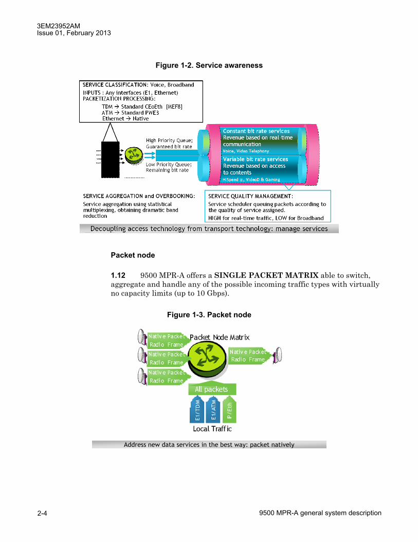
1.12 9500 MPR-A offers a SINGLE PACKET MATRIX able to switch, aggregate and handle any of the possible incoming traffic types with virtually no capacity limits (up to 10 Gbps).
Figure 1-2. Service awareness
Figure 1-3. Packet node
Address new data services in the best way: packet natively
3EM23952AMIssue 01, February 2013
9500 MPR-A general system description 2-5
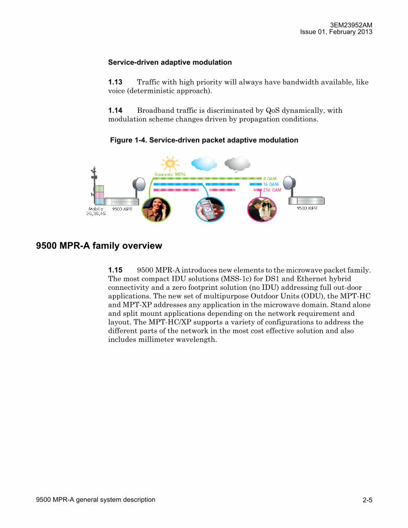
Service-driven adaptive modulation
1.13 Traffic with high priority will always have bandwidth available, like voice (deterministic approach).
1.14 Broadband traffic is discriminated by QoS dynamically, with modulation scheme changes driven by propagation conditions.
9500 MPR-A family overview
1.15 9500 MPR-A introduces new elements to the microwave packet family. The most compact IDU solutions (MSS-1c) for DS1 and Ethernet hybrid connectivity and a zero footprint solution (no IDU) addressing full out-door applications. The new set of multipurpose Outdoor Units (ODU), the MPT-HC and MPT-XP addresses any application in the microwave domain. Stand alone and split mount applications depending on the network requirement and layout. The MPT-HC/XP supports a variety of configurations to address the different parts of the network in the most cost effective solution and also includes millimeter wavelength.
Figure 1-4. Service-driven packet adaptive modulation
3EM23952AMIssue 01, February 2013
9500 MPR-A general system description2-6
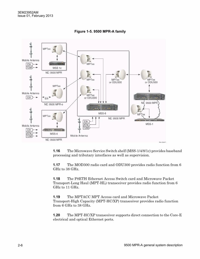
1.16 The Microwave Service Switch shelf (MSS-1/4/8/1c) provides baseband processing and tributary interfaces as well as supervision.
1.17 The MOD300 radio card and ODU300 provides radio function from 6 GHz to 38 GHz.
1.18 The P8ETH Ethernet Access Switch card and Microwave Packet Transport-Long Haul (MPT-HL) transceiver provides radio function from 6 GHz to 11 GHz.
1.19 The MPTACC MPT Access card and Microwave Packet Transport-High Capacity (MPT-HC/XP) transceiver provides radio function from 6 GHz to 38 GHz.
1.20 The MPT-HC/XP transceiver supports direct connection to the Core-E electrical and optical Ethernet ports.
Figure 1-5. 9500 MPR-A family
3EM23952AMIssue 01, February 2013
9500 MPR-A general system description 2-7
1.21 The MPT-HC/XP transceiver supports direct connection to the P8ETH optical Ethernet ports.
1.22 9500 MPR-A replaces the traditional terminal or single-link based approach to networking with a nodal solution.
1.23 The MOD300 and ODU300 support up to six RF links for operation on the same or different frequency bands. An ODU300 for each link is connected to plug-in MOD300 card Radio Interface inside the MSS-4/8 shelf.
1.24 The MPT-HC/XP supports up to twelve RF links for operation on the same or different frequency bands. An MPT-HC/XP for each link is connected to a plug-in card inside the MSS-1/4/8 shelf. The following cards support connection to MPT-HC/XP Transceivers:
• Core-E: supports up to six MPT-HC/XP Transceivers
• P8ETH: supports up to three MPT-HC/XP Transceivers
• MPTACC: supports up to two MPT-HC/XP Transceivers
1.25 Four MPT-HL shelves support up to eight RF links for operation on the same or different frequency bands. A Transceiver card in the MPT-HL shelf for each link is connected to a Core-E, MSS/CORE, or P8ETH Ethernet Access Switch card inside the MSS-1/4/8 shelf.
1.26 A mixture of radio transceiver technologies supports up to a maximum of eighteen radio interfaces.
1.27 Other plug-in cards provide line interface access and management. Supports a mix of non-protected and protected or diversity operation for single link, repeater, nodal or hub radio configurations.
1.28 System control and synchronization is provided by the Enhanced Control and Switching Module (Core-E) card.
Documentation
1.29 For additional information, refer to the following related documentation:
• 9500 MPR-A Installation Practices manual (PN 3EM23953AM)
• 9500 MPR-A Operation and Administration manual (PN 3EM23954AM)

3EM23952AMIssue 01, February 2013
9500 MPR-A general system description2-8
• 9500 MPR-A Turn-Up manual (PN 3EM23955AM)
• 9500 MPR-A Maintenance and Trouble Clearing manual (PN 3EM23956AM)
• 9500 MPR-A Engineering Support Documentation manual (PN 3EM23957AM)
• 9500 MPR MPT-GC User Manual (PN 3DB19025AA)
• 9500 MPR MPR-e User Manual (PN 3DB19901EC)
• 9500 MPR MSS-1c User Manual (PN 3DB19901DC)
Standards
1.30 The following is a partial list of the standards that have influenced certain behavioral aspects of the 9500 MPR-A:
• 21 CFR PART 1040.10 and 1040.11
• ANSI Z136.2
• ATIS 0600315
• Banned substances list
• CENELEC EN 61000-3-2
• CENELEC EN 61000-3-3
• CENELEC EN 61000-4-8
• CISPR/I/105/CDV-CISPR/I/29/CD-CISPR/I/106/CDV
• CISPR 16-1-1
• CISPR 16-1-2
• CISPR 16-1-4
• CISPR 16-2-1
• CISPR 16-2-3
• CISPR 16-2-4
• CISPR 16-4-2

3EM23952AMIssue 01, February 2013
9500 MPR-A general system description 2-9
• CISPR 22
• CSA-C22.2 No 60950
• EC RoHS Directive 2002/95/EU, compliance with
• EC WEEE Directive 2002/96/EU, compliance with
• EN 301 751
• EN 302 217-2-2
• EN 50 385
• EN 50 383
• ETSI and RTTE directive: health and safety
• ETSI and RTTE directive: electromagnetic compatibility
• ETSI and RTTE directive: ETSI standard
• ETSI and RTTE directive: EN 302 217
• ETSI standards: Transmitter requirements
• ETSI standards: Receiving requirements
• ETSI standards: Note
• ETSI EN 302 217-1 to 4
• ETSI EN 301 489
• ETSI EN 300 019
• ETSI EN 300 753
• ETSI EN 300 119
• ETSI EN 300 132-2
• ETSI EN 300 132-3
• ETSI EN 300253
• ETSI EN 300 386
• ETSI EN 55022
• EU Directive EuP Directive 92/42/EEC, Compliance with proposal
3EM23952AMIssue 01, February 2013
9500 MPR-A general system description2-10
• FCC OET 65
• FCC Title 247, Part 15
• GR-63
• GR-78
• GR-487-CORE
• GR-1089-CORE
• GR-3108
• IC RSS-210
• IEC 61000-4
• ICES 003
• ICNIRP
• IEC EN 60950-1
• IEC EN 50385
• IEC EN 60825-1/-2:2000
• IEC UL 60950-1
• IEC 60529
• IEEE Std 802.3
• IEEE Std 802.1D
• IEEE Std 802.1Q
• IEEE 1613
• IETF RFC 2474
• IETF RFC 2475
• IETF RFC 3550
• IETF RFC 0793
• IETF RFC 0791
• IETF RFC 1157

3EM23952AMIssue 01, February 2013
9500 MPR-A general system description 2-11
• IETF RFC 768
• IETF RFC 2616
• ITU-T G.664
• ITU-T G.703
• ITU-T G.704
• ITU-T G.706
• ITU-T G.775
• ITU-T G.823
• ITU-T G.8261
• ITU-T G.826
• ITU-T G.921
• ITU-T Recommendation K20
• ITU-T Recommendation K21
• ITU-T Recommendation K45
• ITU-T Recommendation K44
• MEF 8
• NAR EIA-310
• Safety (Canada)
• SR-332
• TR NWT 000499
• TR TSY 000191
JF6-9558H and JF6-9558HC (unlicensed) radio
1.31 The JF6-9558H/6933B-9500MPT (MPT-HL) and JF6-9558HC/6933B-9558HC (MPT-HC) unlicensed radio provides fast deployment of service with microwave radio. No license and small antennas (no FCC and Industry Canada requirements) allow immediate turn-up. After the license is received, the unlicensed radio can be easily converted to the lower 6 GHz licensed band.

3EM23952AMIssue 01, February 2013
9500 MPR-A general system description2-12
1.32 The JF6-9558H/6933B-9500MPT and JF6-9558HC/6933B-9558HC unlicensed radio operates in the 5725-5850 Information, Scientific, and Medical (ISM) band in accordance with FCC Part 15.247 and IC RSS-210. This unlicensed radio, although operating in the same band as a spread spectrum radio, operates using narrower bandwidths than spread spectrum.
1.33 The MPT-HC 5.8 Unlicensed band (JF6-9558HC/6933B-9558HC) is currently being certified and is not available for quote, sale, or deployment.
FCC class B compliance statement
1.34 The JF6-9558H/6933B-9500MPT and JF6-9558HC/6933B-9558HC unlicensed radio have been tested and found to comply with the limits for a Class B digital device, pursuant to Part 15 of the FCC Rules and IC RSS-210. These limits are designed to provide reasonable protection against harmful interference when the equipment is operated in a commercial environment. This equipment generates, uses, and can radiate radio frequency energy and, if not installed and used in accordance with the instruction manual, may cause harmful interference to radio communications. Operation of this equipment in a residential area is likely to cause harmful interference in which case the user will be required to correct the interference at his own expense.
FCC class B requirements
1.35 This device complies with part 15 of the FCC Rules and IC RSS-210. Operation is subject to the following three conditions: (1) this device may not cause harmful interference. (2) This device must accept any interference received, including interference that may cause undesired operation. (3) This device must be professionally installed.
CAUTION Possibility of service interruption. Changes or modifications not expressly approved by Alcatel-Lucent could void the authority to operate the JJF6-9558H/6933B-9500MPT and JF6-9558HC/6933B-9558HC unlicensed radio.
CAUTION Possibility of service interruption. Installation, Turn-Up, Maintenance, and Operation Instruction supplied with the JF6-9558H/6933B-9500MPT and JF6-9558HC/6933B-9558HC unlicensed radio require strict adherence for continued part 15 of the FCC Rules and IC RSS-210 compliance.
3EM23952AMIssue 01, February 2013
9500 MPR-A general system description 2-13
2. System administration
2.1 Three applications are available for 9500 MPR-A system administration:
1. Craft Terminal (CT)
2. WebEML
3. MIB
2.2 The Craft Terminal and WebEML provide a Graphical User Interface (GUI) to enable a user to view and perform system administration for all Network Elements (NEs) in a network, including remote 9500 MPR-A systems. The Craft Terminal and WebEML as an interface for performing provisioning, monitoring, and alarm management for the 9500 MPR-A.
2.3 For more information on the The Craft Terminal and WebEML refer to the 9500 MPR-A R4.2.0 Operation and Administration manual (PN 3EM23954AM).
2.4 Network Management support using Alcatel-Lucent 1350 OMS, 1352 Compact, and 5620 SAM.

3EM23952AMIssue 01, February 2013
9500 MPR-A general system description2-14

3EM23952AMIssue 01, February 2013
9500 MPR-A general system description 2-15
3. Features
3.1 The following lists the features of R4.2.0 of 9500 MPR-A. To administer these features by the Craft Terminal and WebEML refer to the 9500 MPR-A Operation and Administration manual (PN 3EM23954AM).
Microwave service switch (MSS)
• MSS-8 shelf
• MSS-4 shelf
• MSS-1 shelf
• MSS-1c shelf
Radio
• Radio configuration
� 1+0 and 1+1 Terminal
� 1+0 and 1+1 Drop and Insert Repeater
� 1+0 and 1+1 3-Way Junction
� 1+0 and 1+1 Nodal x-Way Junction
• Protection schemes
� 1+0 unprotected
� 1+1 Hot StandBy (HSB)
� 1+1 Space Diversity (SD)
� 1+1 Frequency Diversity (FD)
� 2x(1+0) XPIC
� 4x(1+0) XPIC
� 2x(1+1) XPIC
• Channel spacing
• Static Modulation

3EM23952AMIssue 01, February 2013
9500 MPR-A general system description2-16
• Adaptive modulation
� Admission control
• Adaptive equalization
• Fiber-microwave protection
• Frequency agility
• Link identifier
• Loopback
� Core facing radio digital loopback
� Radio facing circuit loopback
� Core facing IF cable loopback
� Core facing RF loopback
• Performance monitoring
� Adaptive modulation PM
� Radio analog PM
� Radio ethernet PM
� Radio hop PM
� Radio link PM
� Radio QoS PM
� Radio RSL PM
• Power monitoring
• Radio direction label
• Radio L1 LAG
• Radio L2 LAG
• Transmit power control
� ATPC
� RTPC
3EM23952AMIssue 01, February 2013
9500 MPR-A general system description 2-17
• Tx mute
� Manual timed Tx mute
• XPIC
Radio transceivers
• MPT-GC
• MPT-HC/XP/9558HC
� MPR-e (standalone MPT-HC/XP)
� Unlicensed radio for MPT-HL and 9558HC
• MPT-HL
� Lower 6 GHz frequency plan
� Unlicensed radio for MPT-HL and 9558HC
• ODU300
Ethernet
• Ethernet traffic management
� 802.1D
� 802.1Q
� 802.1ad
• Frame type
� Ethernet v2
� 802.3
� 802.1Q

3EM23952AMIssue 01, February 2013
9500 MPR-A general system description2-18
• Quality of service (QoS)
� QoS classification
� QoS priority value to internal forwarding class
� Internal forwarding class to queue mapping
� Queue scheduler algorithm
� Queue size
� QoS with jumbo frame
� QoS in the Core-E card
� QoS in the modem MOD300 card
� QoS in the MPT-HC/XP
� QoS in the MPT-HL
• IP addressing
� IPv4 addressing for the local IP address
� IPv4 addressing for the TMN local Ethernet interface IP address
� IPv6 addressing for the local IP address
� IPv6 addressing for the TMN local Ethernet interface IP address
• Ethernet features provisioned by craft terminal
� C-VLAN translation
� Port based rate limiting
� Storm control (broadcast, multicast, and unknown unicast)
� VLAN based rate limiter
� Per-VLAN per-COS rate limiter

3EM23952AMIssue 01, February 2013
9500 MPR-A general system description 2-19
• Ethernet features configured by enhanced configuration file
� Access control list
� Out of range VLAN swap
� Per-flow policer
� Stacked VLAN (Q-in-Q) tagging
� VLAN remarking
� VLAN swap
• Input/output flow control
• Reserved multicast addresses
• Traffic mode
• Ethernet synchronization messaging channel
• Ethernet connectivity fault management
• TACACS+
• Ethernet ring protection
• Jumbo frame
• Ethernet L2 LAG
• Packet throughput booster (Header compression)
• Performance monitoring
• Port segregation
• VLAN IDs
Managed services and profiles
• TDM2TDM
• TDM2ETH
• SDH2SDH
• ETH2ETH

3EM23952AMIssue 01, February 2013
9500 MPR-A general system description2-20
Traffic interfaces
• Core-E
� 10/100/1000 Base-T ethernet interfaces
� GigE SFP ethernet interfaces
� MPT-HC/XP radio interface
� MPT-HL radio interface
• DS1 PDH interface
• DS3 PDH interface
• OC-3 SDH interface
• Ethernet access switch
� 10/100/1000Base-T ethernet interfaces
� GigE SFP ethernet interfaces
� MPT-HL radio interface
• MODEM 300 radio interface
• MPT access
• MSS-1 Shelf
MPT-HC/MPT-XP/9558HC external power interfaces
• Power injector box
• MPT power unit
• MPT Extended Power Unit
Configurations
• MSS-8 shelf configurations
• MSS-4 shelf configurations
• MSS-1 shelf configuration
• Stand alone MSS-1/MSS-4/MSS-8 shelf

3EM23952AMIssue 01, February 2013
9500 MPR-A general system description 2-21
• Stacking MSS-1/MSS-4/MSS-8 shelf configuration
Alarm management
Cross-connections
• DS1/DS3 Cross-connections
• OC-3 Cross-connections
• Radio-radio cross-connections
• Ethernet cross-connections
Database backup and restore
In-service upgrade
LAG (link aggregation group)
• L1/L2 link aggregation on radio ports (radio L1/L2 LAG)
• L2 Link aggregation on user ethernet ports (ethernet L2 LAG)
License key management
Loopback
• Core facing radio digital loopback
• Radio facing circuit loopback
• Core facing IF cable loopback
• Core facing RF loopback
• Line facing PDH (DS1/DS3) loopback
• Radio facing PDH (DS1/DS3) loopback
• Loopback time-out
Network Management
• Alcatel-Lucent 1350 OMS
• Alcatel-Lucent 1352 CM

3EM23952AMIssue 01, February 2013
9500 MPR-A general system description2-22
• Alcatel-Lucent 1353 NM
• Alcatel-Lucent 5620 SAM
NE time
Non-administrator user
Performance monitoring
• Adaptive modulation PM
• Ethernet user port PM
• PDH PM (DS1)
• Radio analog PM
• Radio ethernet PM
• Radio hop PM
• Radio link PM
• Radio QoS PM
• Radio RSL PM
Port segregation
• TDM ports
• MPT access and P8ETH Ethernet ports
• MPT-HC/XPs number for each MPT plug in
• ODU300
• ODU300 and MPTACC
• ODU300 and P8ETH
• MPT-HC/XPs in protection
• MPT-HC/XPs protected on different plug-ins
• MPT-HC/XPs protected on the same plug-in
• ERPS Ring ports
3EM23952AMIssue 01, February 2013
9500 MPR-A general system description 2-23
Remote inventory
Security
• User authentication
• User profile management
• SNMP operating mode (SNMPv3 support)
• SSH and SFTP support
Software package rollback
Stacking for EAS/MPT access cards
Synchronization
• Differential clock recovery
• Adaptive clock recovery
• SyncE
• Synchronization protection
• Quality level priority
• Hold-off and wait-to-restore

3EM23952AMIssue 01, February 2013
9500 MPR-A general system description2-24
3EM23952AMIssue 01, February 2013
9500 MPR-A general system description 2-25
4. Equipment layout
4.1 The 9500 MPR-A contains cards that plug into shelf assemblies and mechanical equipment housed in equipment racks. Power and signaling connections are made through backplane connectors.
Rack assemblies
4.2 MSS-1/4/8/1c and MPT-HL shelf assemblies are mounted in either an equal flange aluminum equipment rack or an unequal flange seismic rack. See Figure 4-1 equal flange aluminum equipment rack. See Figure 4-2 for unequal flange seismic rack. Each rack uses 1.75-inch Electronic Industries Association (EIA) rack mounting increments. A 7 feet equal flange aluminum rack provides 46 EIA rack increments. A 7 feet unequal flange seismic rack provides 43 EIA rack increments.
4.3 Seismic racks meet EIA specifications regarding earthquake resistance.
4.4 Refer to table 4-A for standard equipment rack specifications. Refer to table 4-B for seismic equipment rack specifications.

3EM23952AMIssue 01, February 2013
9500 MPR-A general system description2-26
Figure 4-1. Standard equal flange aluminum rack assembly (PN 694-9000-006)
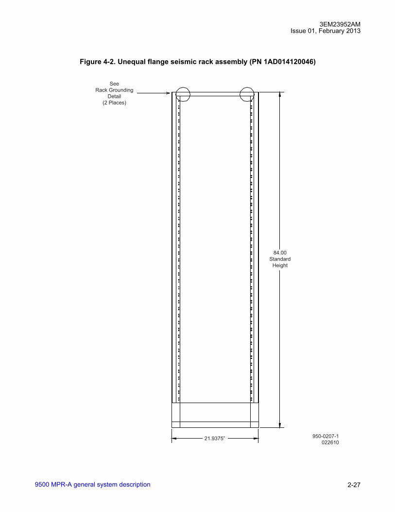
3EM23952AMIssue 01, February 2013
9500 MPR-A general system description 2-27
Figure 4-2. Unequal flange seismic rack assembly (PN 1AD014120046)
950-0207-1
022610
84.00
Standard
Height
See
Rack Grounding
Detail
(2 Places)
21.9375”

3EM23952AMIssue 01, February 2013
9500 MPR-A general system description2-28
Table 4-A. Standard equipment rack specificationsITEM CHARACTERISTICS1. Description Equal-flange aluminum rack provides mounting space for shelves in
areas where zone 4 earthquake compliance is NOT required2. Physical dimensions (bays)
HeightWidthDepth
MSS-8 Stand-Alone Shelf
MSS-4 Stand-Alone Shelf
MSS-1 Stand-Alone Shelf
MSS-1c Stand-Alone Shelf
MPT-HL Shelf W/diplexer
MPT-HL Shelf W/One Waveguide Bracket
MPT-HL Shelf W/Two Waveguide Bracket
7 ft 0 in.20.5 in.
12 in.
12 in.
12 in.
12 in.
13.5 in.
17 in.
22.0 in.

3EM23952AMIssue 01, February 2013
9500 MPR-A general system description 2-29
Constraints
4.5 Certain constraints must be considered when integrating the system into a physical network environment. Each installation presents its own set of considerations.
Environment
4.6 The MSS shelf is designed for placement in a �partially controlled� environment. Refer to table 4-C for environmental condition specifications.
Table 4-B. Seismic equipment rack specificationsITEM CHARACTERISTICS1. Description Unequal-flange seismic rack provides mounting space for shelves in
areas where zone 4 earthquake compliance is required2. Physical dimensions (bays)
HeightWidthDepth
MSS-8 Stand-Alone Shelf
MSS-4 Stand-Alone Shelf
MSS-1 Stand-Alone Shelf
MSS-1c Stand-Alone Shelf
MPT-HL Shelf W/diplexer
MPT-HL Shelf W/One Waveguide Bracket
MPT-HL Shelf W/Two Waveguide Bracket
7 ft 0 in.22 in.
12 in.
12 in.
12 in.
12 in.
13.5 in.
17 in.
22.0 in.
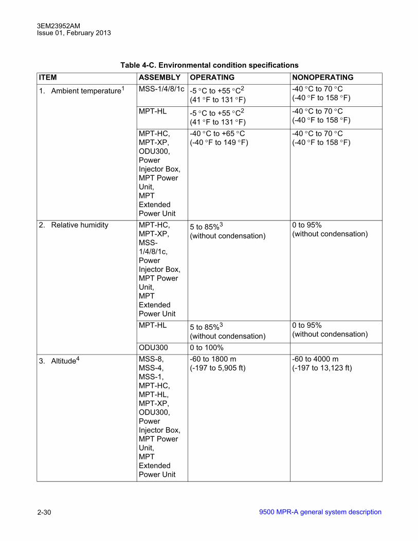
3EM23952AMIssue 01, February 2013
9500 MPR-A general system description2-30
Table 4-C. Environmental condition specificationsITEM ASSEMBLY OPERATING NONOPERATING
1. Ambient temperature1 MSS-1/4/8/1c -5 °C to +55 °C2
(41 °F to 131 °F)-40 °C to 70 °C(-40 °F to 158 °F)
MPT-HL -5 °C to +55 °C2
(41 °F to 131 °F)-40 °C to 70 °C(-40 °F to 158 °F)
MPT-HC, MPT-XP,ODU300, Power Injector Box, MPT Power Unit, MPT Extended Power Unit
-40 °C to +65 °C(-40 °F to 149 °F)
-40 °C to 70 °C(-40 °F to 158 °F)
2. Relative humidity MPT-HC, MPT-XP,MSS-1/4/8/1c, Power Injector Box, MPT Power Unit, MPT Extended Power Unit
5 to 85%3
(without condensation)0 to 95%(without condensation)
MPT-HL 5 to 85%3
(without condensation)0 to 95%(without condensation)
ODU300 0 to 100%
3. Altitude4 MSS-8, MSS-4,MSS-1,MPT-HC, MPT-HL, MPT-XP,ODU300, Power Injector Box, MPT Power Unit, MPT Extended Power Unit
-60 to 1800 m(-197 to 5,905 ft)
-60 to 4000 m(-197 to 13,123 ft)

3EM23952AMIssue 01, February 2013
9500 MPR-A general system description 2-31
Shelf assemblies
4.7 System shelf assemblies follow:
• MSS-8 shelf
• MSS-4 shelf
• MSS-1 shelf
• MSS-1c shelf
• MPT-HL shelf
4.8 System OutDoor Unit (ODU) assemblies follow:
4. Cooling MSS-1/4/8/1c, MPT-HL
Forced air
5. Vibration and shock MSS-8, MSS-4,MSS-1,MPT-HC, MPT-HL, MPT-XP,ODU300, Power Injector Box
Earthquake requirements
6. Duty cycle MSS-8, MSS-4,MSS-1,MPT-HC, MPT-HL, MPT-XP,ODU300, Power Injector Box
Continuous, unattended
[1] Room temperature is measured at a location 1.5 m (59 in.) above the floor and 400 mm (15.8 in.) in front of theequipment.[2] Short term operating ambient temperature is -5 °C to +55 °C (23 °F to 149 °F) for a period not to exceed 96consecutive hours and a total of not more than 15 days in 1 year.[3] Short term operating Relative humidity is 5 to 90% for a period not to exceed 96 consecutive hours and atotal of not more than 15 days in 1 year.[4] At installation between 1800 m to 4000 m (5905 ft to 13,123 ft) above sea level, with an ambient aisletemperature not to exceed of 30 °C (113 °F).
Table 4-C. Environmental condition specifications (cont.)

3EM23952AMIssue 01, February 2013
9500 MPR-A general system description2-32
• ODU300
• MPT-HC
• MPT-XP
• MPT-GC
4.9 The following assemblies are also installed in rack assemblies:
• Power Distribution Unit (PDU)
• DS1 37 Pin D-Sub Patch Panel Assembly
• DS1 RJ45 Patch Panel Assembly
• DS3 BNC Patch Panel
• Type N Adapter Plate Assembly
MSS-8 shelf
4.10 The MSS-8 shelf mounts in a standard 19-inch rack. See figure 4-3.
4.11 Adapter brackets are available to mount MSS-8 shelf in a standard 23-inch rack.
4.12 The MSS-8 shelf houses the following cards:
• Core-E�Enhanced Control and Switching Module - Core-E
• P32E1DS1 (DS1)�DS1 PDH card
• P2E3DS3 (DS3)�DS3 PDH card
• SDHACC (OC-3)�OC-3 SDH card
• P8ETH (EAS)�Ethernet Access Switch card
• MPTACC (RADIO)�MPT Access card
• MOD300 (RADIO)�Modem card
• AUX�Auxiliary card
• Power Injector card
• Power Converter

3EM23952AMIssue 01, February 2013
9500 MPR-A general system description 2-33
• FAN�MSS Fan
• A-FAN�MSS Enhanced Fan with Alarms
MSS-4 shelf
4.13 The MSS-4 shelf mounts in a standard 19-inch rack. See figures 4-4.
4.14 Adapter brackets are available to mount MSS-4 shelf in standard 23-inch rack.
4.15 The MSS-4 shelf houses the following cards:
• Core-E�Enhanced Control and Switching Module
• P32E1DS1 (DS1)�DS1 PDH card
• P2E3DS3 (DS3)�DS3 PDH card
• SDHACC (OC-3)�OC-3 SDH card
• P8ETH (EAS)�Ethernet Access Switch card
Figure 4-3. MSS-8 shelf, front view
950-0003-3
092010
CSM-E
(Spare)
Transport Card Transport Card
Transport Card Transport Card
Transport CardTransport Card
or
Auxiliary Card
CSM-E
(Main)
Fan
92
4
6
8
1
3
5
7

3EM23952AMIssue 01, February 2013
9500 MPR-A general system description2-34
• MOD300 (RADIO)�Modem card
• MPTACC (RADIO)�MPT Access card
• AUX�Auxiliary card
• Power Injector card
• FAN�MSS Fan
MSS-1 shelf
4.16 The MSS-1 shelf mounts horizontally or vertically in a standard 19-inch rack.
4.17 Adapter brackets are available to mount MSS-1 shelf in a standard 23-inch rack.
MPT-HL shelf
4.18 The MPT-HL shelf mounts in a standard 19-inch rack. See figures 4-5.
4.19 Adapter brackets are available to mount the MPT-HL shelf in a standard 23-inch rack.
4.20 The MPT-HL shelf houses the MPT-HL Transceiver card.
Figure 4-4. MSS-4 shelf, front view
950-0025-1
091410
CSM-E
(Main)
Fan
52
4
1
3
CSM-E
(Spare)
Any Transport
Any Transport
or
Auxiliary Card
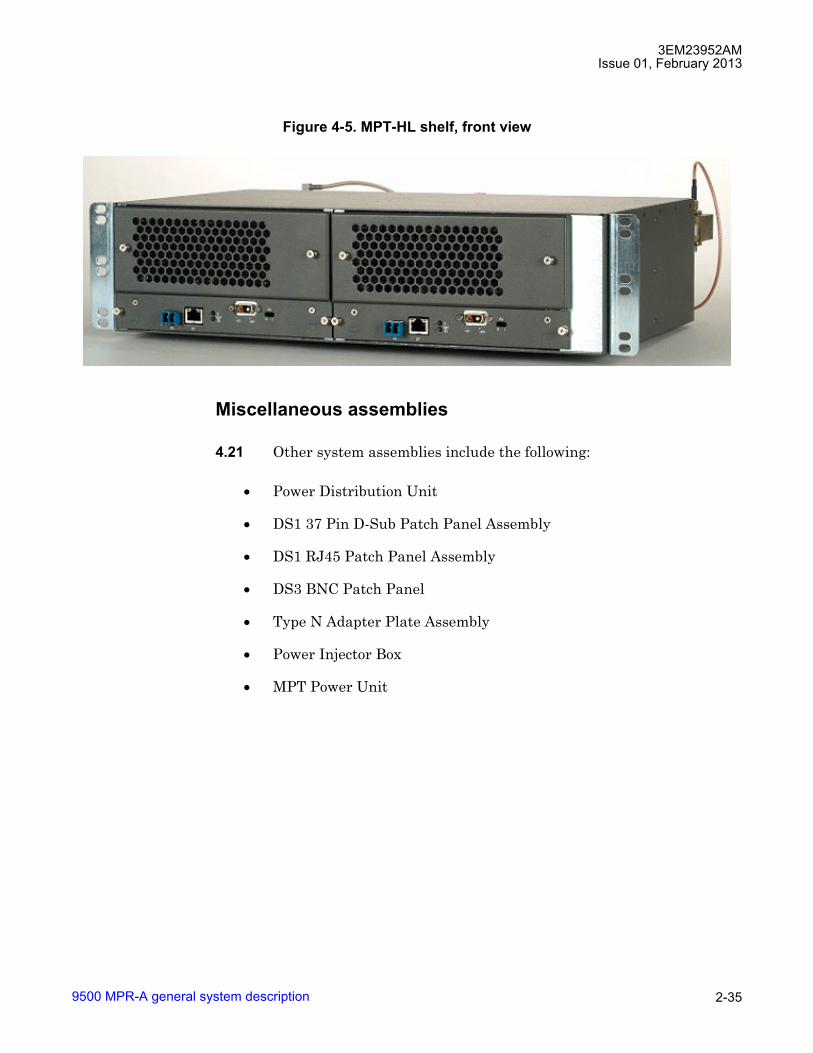
3EM23952AMIssue 01, February 2013
9500 MPR-A general system description 2-35
Miscellaneous assemblies
4.21 Other system assemblies include the following:
• Power Distribution Unit
• DS1 37 Pin D-Sub Patch Panel Assembly
• DS1 RJ45 Patch Panel Assembly
• DS3 BNC Patch Panel
• Type N Adapter Plate Assembly
• Power Injector Box
• MPT Power Unit
Figure 4-5. MPT-HL shelf, front view

3EM23952AMIssue 01, February 2013
9500 MPR-A general system description2-36
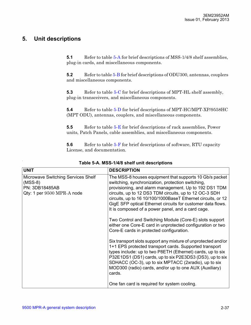
3EM23952AMIssue 01, February 2013
9500 MPR-A general system description 2-37
5. Unit descriptions
5.1 Refer to table 5-A for brief descriptions of MSS-1/4/8 shelf assemblies, plug-in cards, and miscellaneous components.
5.2 Refer to table 5-B for brief descriptions of ODU300, antennas, couplers and miscellaneous components.
5.3 Refer to table 5-C for brief descriptions of MPT-HL shelf assembly, plug-in transceivers, and miscellaneous components.
5.4 Refer to table 5-D for brief descriptions of MPT-HC/MPT-XP/9558HC (MPT ODU), antennas, couplers, and miscellaneous components.
5.5 Refer to table 5-E for brief descriptions of rack assemblies, Power units, Patch Panels, cable assemblies, and miscellaneous components.
5.6 Refer to table 5-F for brief descriptions of software, RTU capacity License, and documentation.
1-
Table 5-A. MSS-1/4/8 shelf unit descriptionsUNIT DESCRIPTIONMicrowave Switching Services Shelf (MSS-8) PN: 3DB18485ABQty: 1 per 9500 MPR-A node
The MSS-8 houses equipment that supports 10 Gb/s packet switching, synchronization, protection switching, provisioning, and alarm management. Up to 192 DS1 TDM circuits, up to 12 DS3 TDM circuits, up to 12 OC-3 SDH circuits, up to 16 10/100/1000BaseT Ethernet circuits, or 12 GigE SFP optical Ethernet circuits for customer data flows. It is composed of a power panel, and a card cage.
Two Control and Switching Module (Core-E) slots support either one Core-E card in unprotected configuration or two Core-E cards in protected configuration.
Six transport slots support any mixture of unprotected and/or 1+1 EPS protected transport cards. Supported transport types include: up to two P8ETH (Ethernet) cards, up to six P32E1DS1 (DS1) cards, up to six P2E3DS3 (DS3), up to six SDHACC (OC-3), up to six MPTACC (2xradio), up to six MOD300 (radio) cards, and/or up to one AUX (Auxiliary) cards.
One fan card is required for system cooling.

3EM23952AMIssue 01, February 2013
9500 MPR-A general system description2-38
MSS-8 shelf KitsPN: 3EM22715AB, 3EM22715ACQty: 1 per 9500 MPR-A node
MSS-8 shelf kits provide one MSS-8 shelf, power cables, FAN card, and miscellaneous rack hardware.
PN: 3EM22715AB is MSS-8 shelf kit W/FAN CardPN: 3EM22715AC is MSS-8 shelf kit W/Alarm FAN Card
Microwave Switching Services Shelf (MSS-4) PN: 3DB18219ABQty: 1 per 9500 MPR-A node
The MSS-4 houses equipment that supports 10 Gb/s packet switching, synchronization, protection switching, provisioning, and alarm management. Up to 64 DS1 TDM circuits, up to 4 DS3 TDM circuits, up to 4 SDHACC (OC-3) circuits, up to 16 10/100/1000BaseT Ethernet circuits, or 12 GigE SFP optical Ethernet circuits for customer data flows. It is composed of a power panel, and a card cage.
Two Control and Switching Module (Core-E) slots support either one Core-E card in unprotected configuration or two Core-E cards in protected configuration.
Two transport slots support any mixture of unprotected or 1+1 EPS protected transport cards. Supported transport types include: up to two P8ETH (Ethernet) cards, up to two P32E1DS1 (DS1) cards, up to two P2E3DS3 (DS3), up to two SDHACC (OC-3), up to two MPTACC (2xradio), up to two MOD300 (radio) cards, and/or up to one AUX (Auxiliary) cards.
One fan card is required for system cooling.MSS-4 shelf KitPN: 3EM24463AAQty: 1 per 9500 MPR-A node
MSS-4 shelf kit provides one MSS-4 shelf, power cable, FAN card, and miscellaneous rack hardware.
Microwave Switching Services Shelf (MSS-1) PN: 3DB19015AAQty: 1 per 9500 MPR-A node
The MSS-1 houses equipment that supports 10 Gb/s packet switching, synchronization, protection switching, provisioning, and alarm management. It is composed of a monoboard.
The monoboard provides the functions of one Control and Switching Module (Core-E) card and one P32E1DS1 (DS1) card with 16 ports.
MSS-1 shelf KitPN: 3MU00109AAQty: 1 per 9500 MPR-A node
MSS-1 shelf kit provides one MSS-1 shelf, power cable, and miscellaneous rack hardware.
Table 5-A. MSS-1/4/8 shelf unit descriptions (cont.)UNIT DESCRIPTION
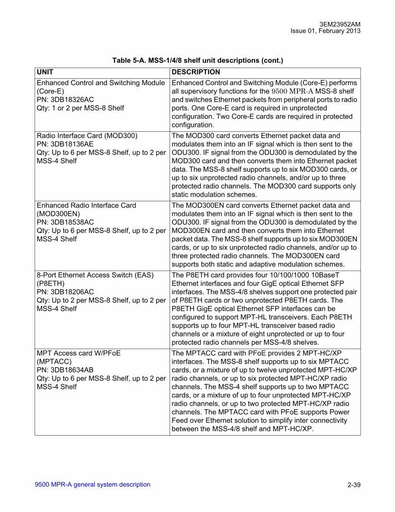
3EM23952AMIssue 01, February 2013
9500 MPR-A general system description 2-39
Enhanced Control and Switching Module (Core-E)PN: 3DB18326ACQty: 1 or 2 per MSS-8 Shelf
Enhanced Control and Switching Module (Core-E) performs all supervisory functions for the 9500 MPR-A MSS-8 shelf and switches Ethernet packets from peripheral ports to radio ports. One Core-E card is required in unprotected configuration. Two Core-E cards are required in protected configuration.
Radio Interface Card (MOD300)PN: 3DB18136AEQty: Up to 6 per MSS-8 Shelf, up to 2 per MSS-4 Shelf
The MOD300 card converts Ethernet packet data and modulates them into an IF signal which is then sent to the ODU300. IF signal from the ODU300 is demodulated by the MOD300 card and then converts them into Ethernet packet data. The MSS-8 shelf supports up to six MOD300 cards, or up to six unprotected radio channels, and/or up to three protected radio channels. The MOD300 card supports only static modulation schemes.
Enhanced Radio Interface Card (MOD300EN)PN: 3DB18538ACQty: Up to 6 per MSS-8 Shelf, up to 2 per MSS-4 Shelf
The MOD300EN card converts Ethernet packet data and modulates them into an IF signal which is then sent to the ODU300. IF signal from the ODU300 is demodulated by the MOD300EN card and then converts them into Ethernet packet data. The MSS-8 shelf supports up to six MOD300EN cards, or up to six unprotected radio channels, and/or up to three protected radio channels. The MOD300EN card supports both static and adaptive modulation schemes.
8-Port Ethernet Access Switch (EAS) (P8ETH)PN: 3DB18206ACQty: Up to 2 per MSS-8 Shelf, up to 2 per MSS-4 Shelf
The P8ETH card provides four 10/100/1000 10BaseT Ethernet interfaces and four GigE optical Ethernet SFP interfaces. The MSS-4/8 shelves support one protected pair of P8ETH cards or two unprotected P8ETH cards. The P8ETH GigE optical Ethernet SFP interfaces can be configured to support MPT-HL transceivers. Each P8ETH supports up to four MPT-HL transceiver based radio channels or a mixture of eight unprotected or up to four protected radio channels per MSS-4/8 shelves.
MPT Access card W/PFoE(MPTACC)PN: 3DB18634ABQty: Up to 6 per MSS-8 Shelf, up to 2 per MSS-4 Shelf
The MPTACC card with PFoE provides 2 MPT-HC/XP interfaces. The MSS-8 shelf supports up to six MPTACC cards, or a mixture of up to twelve unprotected MPT-HC/XP radio channels, or up to six protected MPT-HC/XP radio channels. The MSS-4 shelf supports up to two MPTACC cards, or a mixture of up to four unprotected MPT-HC/XP radio channels, or up to two protected MPT-HC/XP radio channels. The MPTACC card with PFoE supports Power Feed over Ethernet solution to simplify inter connectivity between the MSS-4/8 shelf and MPT-HC/XP.
Table 5-A. MSS-1/4/8 shelf unit descriptions (cont.)UNIT DESCRIPTION
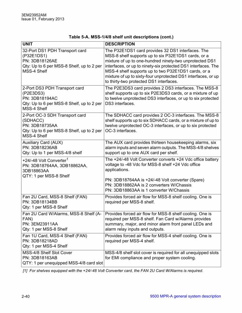
3EM23952AMIssue 01, February 2013
9500 MPR-A general system description2-40
32-Port DS1 PDH Transport card (P32E1DS1)PN: 3DB18126AEQty: Up to 6 per MSS-8 Shelf, up to 2 per MSS-4 Shelf
The P32E1DS1 card provides 32 DS1 interfaces. The MSS-8 shelf supports up to six P32E1DS1 cards, or a mixture of up to one-hundred ninety-two unprotected DS1 interfaces, or up to ninety-six protected DS1 interfaces. The MSS-4 shelf supports up to two P32E1DS1 cards, or a mixture of up to sixty-four unprotected DS1 interfaces, or up to thirty-two protected DS1 interfaces.
2-Port DS3 PDH Transport card (P2E3DS3)PN: 3DB18194ACQty: Up to 6 per MSS-8 Shelf, up to 2 per MSS-4 Shelf
The P2E3DS3 card provides 2 DS3 interfaces. The MSS-8 shelf supports up to six P2E3DS3 cards, or a mixture of up to twelve unprotected DS3 interfaces, or up to six protected DS3 interfaces.
2-Port OC-3 SDH Transport card (SDHACC)PN: 3DB18735AAQty: Up to 6 per MSS-8 Shelf, up to 2 per MSS-4 Shelf
The SDHACC card provides 2 OC-3 interfaces. The MSS-8 shelf supports up to six SDHACC cards, or a mixture of up to twelve unprotected OC-3 interfaces, or up to six protected OC-3 interfaces.
Auxiliary Card (AUX)PN: 3DB18236ABQty: Up to 1 per MSS-4/8 shelf
The AUX card provides thirteen housekeeping alarms, six alarm inputs and seven alarm outputs. The MSS-4/8 shelves support up to one AUX card per shelf.
+24/-48 Volt Converter1PN: 3DB18764AA, 3DB18862AA, 3DB18863AAQTY: 1 per MSS-8 Shelf
The +24/-48 Volt Converter converts +24 Vdc office battery voltage to -48 Vdc for MSS-8 shelf +24 Vdc office applications.
PN: 3DB18764AA is +24/-48 Volt converter (Spare)PN: 3DB18862AA is 2 converters W/ChassisPN: 3DB18863AA is 1 converter W/Chassis
Fan 2U Card, MSS-8 Shelf (FAN)PN: 3DB18134BBQty: 1 per MSS-8 Shelf
Provides forced air flow for MSS-8 shelf cooling. One is required per MSS-8 shelf.
Fan 2U Card W/Alarms, MSS-8 Shelf (A-FAN)PN: 3EM23911AAQty: 1 per MSS-8 Shelf
Provides forced air flow for MSS-8 shelf cooling. One is required per MSS-8 shelf. Fan Card w/Alarms provides summary, major, and minor alarm front panel LEDs and alarm relay inputs and outputs.
Fan 1U Card, MSS-4 Shelf (FAN)PN: 3DB18218ADQty: 1 per MSS-4 Shelf
Provides forced air flow for MSS-4 shelf cooling. One is required per MSS-4 shelf.
MSS-4/8 Shelf Slot CoverPN: 3DB18163ABQTY: 1 per unequipped MSS-4/8 card slot
MSS-4/8 shelf slot cover is required for all unequipped slots for EMI compliance and proper system cooling.
[1] For shelves equipped with the +24/-48 Volt Converter card, the FAN 2U Card W/Alarms is required.
Table 5-A. MSS-1/4/8 shelf unit descriptions (cont.)UNIT DESCRIPTION

3EM23952AMIssue 01, February 2013
9500 MPR-A general system description 2-41
Table 5-B. ODU300 unit descriptionsUNIT DESCRIPTIONOutDoor Unit (ODU300)ODU300 W/Lightning Surge Suppressor,lower 6 GHz, 252.04 MHz SeparationPN: 3DB23215HA/3DB23215HFQty: 1 per Lower 6 GHz, 252.04 MHz Separation Radio Channel
The ODU300 is a microprocessor controlled transceiver that interfaces the MSS-8 shelf MOD300 card with the antenna. Supports static and adaptive modulation schemes. Channel frequency is software selectable within tuning range of the ODU300. The ODU300 is frequency dependent. ODU300 includes built-in lightning surge suppressor.
PN: 3DB23215HA is ODU300, 5930 - 6020 MHz, HP, TX LowPN: 3DB23215HD is ODU300, 6182 - 6272 MHz, HP, TX HighPN: 3DB23215HB is ODU300, 5989 - 6079 MHz, HP, TX LowPN: 3DB23215HE is ODU300, 6241 - 6331 MHz, HP, TX HighPN: 3DB23215HC is ODU300, 6078 - 6168 MHz, HP, TX LowPN: 3DB23215HF is ODU300, 6330 - 6420 MHz, HP, TX High
OutDoor Unit (ODU300)ODU300 W/Lightning Surge Suppressor,Upper 6 GHz, 160 MHz SeparationPN: 3DB23214HA/3DB23214HFQty: 1 per Upper 6 GHz, 160 MHz Separation Radio Channel
The ODU300 is a microprocessor controlled transceiver that interfaces the MSS-8 shelf MOD300 card with the antenna. Supports static and adaptive modulation schemes. Channel frequency is software selectable within tuning range of the ODU300. The ODU300 is frequency dependent. ODU300 includes built-in lightning surge suppressor.
PN: 3DB23214HA is ODU300, 6540 - 6610 MHz, HP, TX LowPN: 3DB23214HB is ODU300, 6710 - 6780 MHz, HP, TX HighPN: 3DB23214HC is ODU300, 6590 - 6660 MHz, HP, TX LowPN: 3DB23214HD is ODU300, 6760 - 6830 MHz, HP, TX HighPN: 3DB23214HE is ODU300, 6640 - 6710 MHz, HP, TX LowPN: 3DB23214HF is ODU300, 6800 - 6870 MHz, HP, TX High

3EM23952AMIssue 01, February 2013
9500 MPR-A general system description2-42
OutDoor Unit (ODU300)ODU300 W/Lightning Surge Suppressor,Upper 6 GHz, 340 MHz SeparationPN: 3DB23216HA/3DB23216HFQty: 1 per Upper 6 GHz, 340 MHz Separation Radio Channel
The ODU300 is a microprocessor controlled transceiver that interfaces the MSS-8 shelf MOD300 card with the antenna. Supports static and adaptive modulation schemes. Channel frequency is software selectable within tuning range of the ODU300. The ODU300 is frequency dependent. ODU300 includes built-in lightning surge suppressor.
PN: 3DB23216HA is ODU300, 6430 - 6590 MHz, HP, TX LowPN: 3DB23216HB is ODU300, 6770 - 6930 MHz, HP, TX HighPN: 3DB23216HC is ODU300, 6515 - 6675 MHz, HP, TX LowPN: 3DB23216HD is ODU300, 6855 - 7015 MHz, HP, TX HighPN: 3DB23216HE is ODU300, 6600 - 6760 MHz, HP, TX LowPN: 3DB23216HF is ODU300, 6940 - 7100 MHz, HP, TX High
OutDoor Unit (ODU300)ODU300 W/Lightning Surge Suppressor,7 GHz, 175 MHz SeparationPN: 3DB23223HA/3DB23228HA,Qty: 1 per 7 GHz, 175 MHz Separation Radio Channel
The ODU300 is a microprocessor controlled transceiver that interfaces the MSS-8 shelf MOD300 card with the antenna. Supports static and adaptive modulation schemes. Channel frequency is software selectable within tuning range of the ODU300. The ODU300 is frequency dependent. ODU300 includes built-in lightning surge suppressor.
PN: 3DB23223HA is ODU300, 7124 - 7185 MHz, HP, TX LowPN: 3DB23224HA is ODU300, 7299 - 7360 MHz, HP, TX HighPN: 3DB23225HA is ODU300, 7157.5 - 7217.5 MHz, HP, TX LowPN: 3DB23226HA is ODU300, 7332.5 - 7392.5 MHz, HP, TX HighPN: 3DB23227HA is ODU300, 7190 - 7250 MHz, HP, TX LowPN: 3DB23228HA is ODU300, 7365 - 7425 MHz, HP, TX High
Table 5-B. ODU300 unit descriptions (cont.)UNIT DESCRIPTION

3EM23952AMIssue 01, February 2013
9500 MPR-A general system description 2-43
OutDoor Unit (ODU300)ODU300 W/Lightning Surge Suppressor,7 GHz, 150 MHz SeparationPN: 3DB23217HA/3DB23222HAQty: 1 per 7 GHz, 150 MHz Separation Radio Channel
The ODU300 is a microprocessor controlled transceiver that interfaces the MSS-8 shelf MOD300 card with the antenna. Supports static and adaptive modulation schemes. Channel frequency is software selectable within tuning range of the ODU300. The ODU300 is frequency dependent. ODU300 includes built-in lightning surge suppressor.
PN: 3DB23217HA is ODU300, 7424 - 7485 MHz, HP, TX LowPN: 3DB23218HA is ODU300, 7574 - 7635 MHz, HP, TX HighPN: 3DB23219HA is ODU300, 7470 - 7530 MHz, HP, TX LowPN: 3DB23220HA is ODU300, 7620 - 7680 MHz, HP, TX HighPN: 3DB23221HA is ODU300, 7515 - 7575 MHz, HP, TX LowPN: 3DB23222HA is ODU300, 7665 - 7725 MHz, HP, TX High
OutDoor Unit (ODU300)ODU300 W/Lightning Surge Suppressor,8 GHz, 300 MHz SeparationPN: 3DB23033HA/3DB23033HDQty: 1 per Upper 8 GHz, 300 MHz Separation Radio Channel
The ODU300 is a microprocessor controlled transceiver that interfaces the MSS-8 shelf MOD300 card with the antenna. Supports static and adaptive modulation schemes. Channel frequency is software selectable within tuning range of the ODU300. The ODU300 is frequency dependent. ODU300 includes built-in lightning surge suppressor.
PN: 3DB23033HA is ODU300, 7722.5 - 7859 MHz, HP, TX LowPN: 3DB23033HC is ODU300, 8025 - 8171 MHz, HP, TX HighPN: 3DB23033HB is ODU300, 7844 - 7981 MHz, HP, TX LowPN: 3DB23033HD is ODU300, 8145 - 8287 MHz, HP, TX High
Table 5-B. ODU300 unit descriptions (cont.)UNIT DESCRIPTION

3EM23952AMIssue 01, February 2013
9500 MPR-A general system description2-44
OutDoor Unit (ODU300)ODU300 W/Lightning Surge Suppressor,11 GHz, 490-500 MHz SeparationPN: 3DB23035HA/3DB23035HHQty: 1 per 11 GHz, 490-500 MHz Separation Radio Channel
The ODU300 is a microprocessor controlled transceiver that interfaces the MSS-8 shelf MOD300 card with the antenna. Supports static and adaptive modulation schemes. Channel frequency is software selectable within tuning range of the ODU300. The ODU300 is frequency dependent. ODU300 includes built-in lightning surge suppressor.
PN: 3DB23035HA is ODU300, 10675 - 10835 MHz, TX LowPN: 3DB23035HE is ODU300, 11200 - 11345 MHz, TX HighPN: 3DB23035HB is ODU300, 10795 - 10955 MHz, TX LowPN: 3DB23035HF is ODU300, 11310 - 11465 MHz, TX HighPN: 3DB23035HC is ODU300, 10915 - 11075 MHz, TX LowPN: 3DB23035HG is ODU300, 11430 - 11585 MHz, TX HighPN: 3DB23035HD is ODU300, 11035 - 11200 MHz, TX LowPN: 3DB23035HH is ODU300, 11550 - 11705 MHz, TX High
OutDoor Unit (ODU300)ODU300 W/Lightning Surge Suppressor,15 GHz, 475/490 MHz SeparationPN: 3DB23039HC, 3DB23039HDQty: 1 per 15 GHz, 475/490 MHz Separation Radio Channel
The ODU300 is a microprocessor controlled transceiver that interfaces the MSS-8 shelf MOD300 card with the antenna. Supports static and adaptive modulation schemes. Channel frequency is software selectable within tuning range of the ODU300. The ODU300 is frequency dependent. ODU300 includes built-in lightning surge suppressor.
PN: 3DB23039HC is ODU300, 14500 - 14660 MHz, TX LowPN: 3DB23039HD is ODU300, 14975 - 15135 MHz, TX Low
OutDoor Unit (ODU300)ODU300 W/Lightning Surge Suppressor,18 GHz, 1560 MHz SeparationPN: 3DB23062HC, 3DB23062HDQty: 1 per 18 GHz, 1560 MHz Separation Radio Channel
The ODU300 is a microprocessor controlled transceiver that interfaces the MSS-8 shelf MOD300 card with the antenna. Supports static and adaptive modulation schemes. Channel frequency is software selectable within tuning range of the ODU300. The ODU300 is frequency dependent. ODU300 includes built-in lightning surge suppressor.
PN: 3DB23062HC is ODU300, 17700 - 18060 MHz, TX LowPN: 3DB23062HD is ODU300, 19260 - 19620 MHz, TX Low
Table 5-B. ODU300 unit descriptions (cont.)UNIT DESCRIPTION
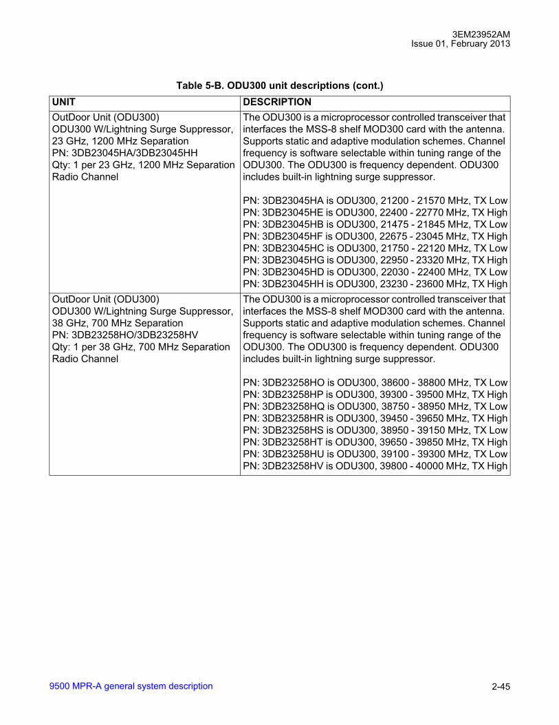
3EM23952AMIssue 01, February 2013
9500 MPR-A general system description 2-45
OutDoor Unit (ODU300)ODU300 W/Lightning Surge Suppressor,23 GHz, 1200 MHz SeparationPN: 3DB23045HA/3DB23045HHQty: 1 per 23 GHz, 1200 MHz Separation Radio Channel
The ODU300 is a microprocessor controlled transceiver that interfaces the MSS-8 shelf MOD300 card with the antenna. Supports static and adaptive modulation schemes. Channel frequency is software selectable within tuning range of the ODU300. The ODU300 is frequency dependent. ODU300 includes built-in lightning surge suppressor.
PN: 3DB23045HA is ODU300, 21200 - 21570 MHz, TX LowPN: 3DB23045HE is ODU300, 22400 - 22770 MHz, TX HighPN: 3DB23045HB is ODU300, 21475 - 21845 MHz, TX LowPN: 3DB23045HF is ODU300, 22675 - 23045 MHz, TX HighPN: 3DB23045HC is ODU300, 21750 - 22120 MHz, TX LowPN: 3DB23045HG is ODU300, 22950 - 23320 MHz, TX HighPN: 3DB23045HD is ODU300, 22030 - 22400 MHz, TX LowPN: 3DB23045HH is ODU300, 23230 - 23600 MHz, TX High
OutDoor Unit (ODU300)ODU300 W/Lightning Surge Suppressor,38 GHz, 700 MHz SeparationPN: 3DB23258HO/3DB23258HVQty: 1 per 38 GHz, 700 MHz Separation Radio Channel
The ODU300 is a microprocessor controlled transceiver that interfaces the MSS-8 shelf MOD300 card with the antenna. Supports static and adaptive modulation schemes. Channel frequency is software selectable within tuning range of the ODU300. The ODU300 is frequency dependent. ODU300 includes built-in lightning surge suppressor.
PN: 3DB23258HO is ODU300, 38600 - 38800 MHz, TX LowPN: 3DB23258HP is ODU300, 39300 - 39500 MHz, TX HighPN: 3DB23258HQ is ODU300, 38750 - 38950 MHz, TX LowPN: 3DB23258HR is ODU300, 39450 - 39650 MHz, TX HighPN: 3DB23258HS is ODU300, 38950 - 39150 MHz, TX LowPN: 3DB23258HT is ODU300, 39650 - 39850 MHz, TX HighPN: 3DB23258HU is ODU300, 39100 - 39300 MHz, TX LowPN: 3DB23258HV is ODU300, 39800 - 40000 MHz, TX High
Table 5-B. ODU300 unit descriptions (cont.)UNIT DESCRIPTION
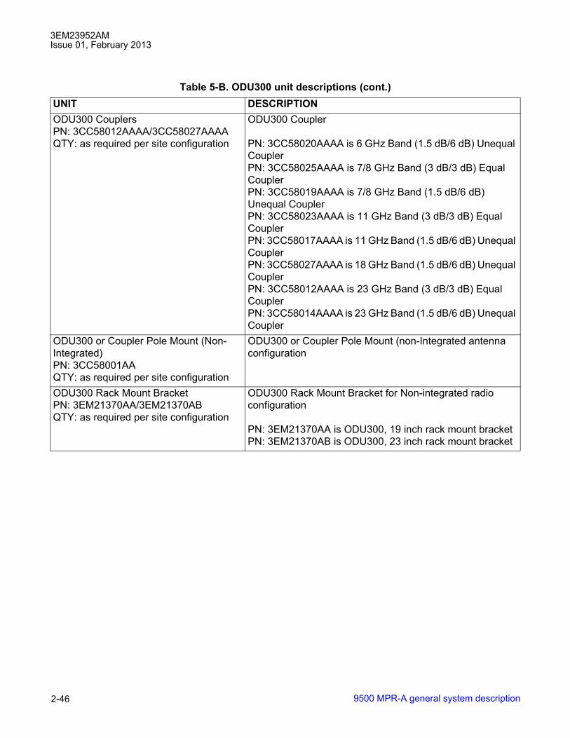
3EM23952AMIssue 01, February 2013
9500 MPR-A general system description2-46
ODU300 CouplersPN: 3CC58012AAAA/3CC58027AAAAQTY: as required per site configuration
ODU300 Coupler
PN: 3CC58020AAAA is 6 GHz Band (1.5 dB/6 dB) Unequal CouplerPN: 3CC58025AAAA is 7/8 GHz Band (3 dB/3 dB) Equal CouplerPN: 3CC58019AAAA is 7/8 GHz Band (1.5 dB/6 dB) Unequal CouplerPN: 3CC58023AAAA is 11 GHz Band (3 dB/3 dB) Equal CouplerPN: 3CC58017AAAA is 11 GHz Band (1.5 dB/6 dB) Unequal CouplerPN: 3CC58027AAAA is 18 GHz Band (1.5 dB/6 dB) Unequal CouplerPN: 3CC58012AAAA is 23 GHz Band (3 dB/3 dB) Equal CouplerPN: 3CC58014AAAA is 23 GHz Band (1.5 dB/6 dB) Unequal Coupler
ODU300 or Coupler Pole Mount (Non-Integrated)PN: 3CC58001AAQTY: as required per site configuration
ODU300 or Coupler Pole Mount (non-Integrated antenna configuration
ODU300 Rack Mount BracketPN: 3EM21370AA/3EM21370ABQTY: as required per site configuration
ODU300 Rack Mount Bracket for Non-integrated radio configuration
PN: 3EM21370AA is ODU300, 19 inch rack mount bracketPN: 3EM21370AB is ODU300, 23 inch rack mount bracket
Table 5-B. ODU300 unit descriptions (cont.)UNIT DESCRIPTION
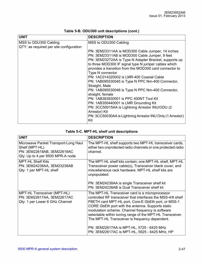
3EM23952AMIssue 01, February 2013
9500 MPR-A general system description 2-47
MSS to ODU300 CablingQTY: as required per site configuration
MSS to ODU300 Cabling
PN: 3EM23311AA is MOD300 Cable Jumper, 14 inchesPN: 3EM23311AB is MOD300 Cable Jumper, 9 feetPN: 3EM23272AA is Type N Adapter Bracket, supports up to three MOD300 IF signal type N jumper cables which provides a transition from the MOD300 card connector to Type N connectorPN: 1AC014320002 is LMR-400 Coaxial CablePN: 1AB095530045 is Type N PPC Nm-400 Connector, Straight, MalePN: 1AB095530046 is Type N PPC Nm-400 Connector, straight, femalePN: 1AB383930001 is PPC 400NT Tool KitPN: 1AB350440001 is LMR Grounding KitPN: 3CC50015AA is Lightning Arrestor INU/ODU (2 Arrestor) KitPN: 3CC50030AA is Lightning Arrestor INU Only (1 Arrestor) Kit
Table 5-C. MPT-HL shelf unit descriptionsUNIT DESCRIPTIONMicrowave Packet Transport-Long Haul Shelf (MPT-HL) PN: 3EM22618AB, 3EM22618ACQty: Up to 4 per 9500 MPR-A node
The MPT-HL shelf supports two MPT-HL transceiver cards, either two unprotected radio channels or one protected radio channel.
MPT-HL Shelf KitsPN: 3EM24238AA, 3EM23238ABQty: 1 per MPT-HL shelf
The MPT-HL shelf kits contain; one MPT-HL shelf, MPT-HL Transceiver power cable(s), Transceiver blank cover, and miscellaneous rack hardware. MPT-HL shelf kits are unpopulated.
PN: 3EM24238AA is single Transceiver shelf kitPN: 3EM24238AB is Dual Transceiver shelf kit
MPT-HL Transceiver (MPT-HL)PN: 3EM22617AA, 3EM22617ACQty: 1 per Lower 6 GHz Channel
The MPT-HL Transceiver card is a microprocessor controlled RF transceiver that interfaces the MSS-4/8 shelf P8ETH card MPT-HL port, Core-E GbEth port, or MSS-1 CORE GbEth port with the antenna. Supports static modulation scheme. Channel frequency is software selectable within tuning range of the MPT-HL Transceiver. The MPT-HL Transceiver is frequency dependent.
PN: 3EM22617AA is MPT-HL, 5725 - 6425 MHzPN: 3EM22617AC is MPT-HL, 5925 - 6425 MHz, HP
Table 5-B. ODU300 unit descriptions (cont.)UNIT DESCRIPTION

3EM23952AMIssue 01, February 2013
9500 MPR-A general system description2-48
MPT-HL Transceiver (MPT-HL)PN: 3EM22617AB, 3EM22617ADQty: 1 per Upper 6 GHz Channel
The MPT-HL Transceiver card is a microprocessor controlled RF transceiver that interfaces the MSS-4/8 shelf P8ETH card MPT-HL port, Core-E GbEth port, or MSS-1 CORE GbEth port with the antenna. Supports static modulation scheme. Channel frequency is software selectable within tuning range of the MPT-HL Transceiver. The MPT-HL Transceiver is frequency dependent.
PN: 3EM22617AB is MPT-HL, 6425 - 6930 MHzPN: 3EM22617AD is MPT-HL, 6425 - 6930 MHz, HP
MPT-HL Transceiver (MPT-HL)PN: 3EM24627AAQty: 1 per 7 GHz Channel
The MPT-HL Transceiver card is a microprocessor controlled RF transceiver that interfaces the MSS-4/8 shelf P8ETH card MPT-HL port, Core-E GbEth port, or MSS-1 CORE GbEth port with the antenna. Supports static modulation scheme. Channel frequency is software selectable within tuning range of the MPT-HL Transceiver. The MPT-HL Transceiver is frequency dependent.
PN: 3EM24627AA is MPT-HL, 7125-7775 MHzMPT-HL Transceiver (MPT-HL)PN: 3EM24627ABQty: 1 per 8 GHz Channel
The MPT-HL Transceiver card is a microprocessor controlled RF transceiver that interfaces the MSS-4/8 shelf P8ETH card MPT-HL port, Core-E GbEth port, or MSS-1 CORE GbEth port with the antenna. Supports static modulation scheme. Channel frequency is software selectable within tuning range of the MPT-HL Transceiver. The MPT-HL Transceiver is frequency dependent.
PN: 3EM24627AB is MPT-HL, 7725-8500 MHzMPT-HL Transceiver (MPT-HL)PN: 3EM23888AAQty: 1 per 10.5 GHz Channel
The MPT-HL Transceiver card is a microprocessor controlled RF transceiver that interfaces the MSS-4/8 shelf P8ETH card MPT-HL port, Core-E GbEth port, or MSS-1 CORE GbEth port with the antenna. Supports static modulation scheme. Channel frequency is software selectable within tuning range of the MPT-HL Transceiver. The MPT-HL Transceiver is frequency dependent.
PN: 3EM23888AA is MPT-HL, 10400 - 10700 MHz
Table 5-C. MPT-HL shelf unit descriptions (cont.)UNIT DESCRIPTION
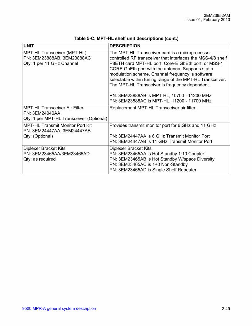
3EM23952AMIssue 01, February 2013
9500 MPR-A general system description 2-49
MPT-HL Transceiver (MPT-HL)PN: 3EM23888AB, 3EM23888ACQty: 1 per 11 GHz Channel
The MPT-HL Transceiver card is a microprocessor controlled RF transceiver that interfaces the MSS-4/8 shelf P8ETH card MPT-HL port, Core-E GbEth port, or MSS-1 CORE GbEth port with the antenna. Supports static modulation scheme. Channel frequency is software selectable within tuning range of the MPT-HL Transceiver. The MPT-HL Transceiver is frequency dependent.
PN: 3EM23888AB is MPT-HL, 10700 - 11200 MHzPN: 3EM23888AC is MPT-HL, 11200 - 11700 MHz
MPT-HL Transceiver Air FilterPN: 3EM24040AAQty: 1 per MPT-HL Transceiver (Optional)
Replacement MPT-HL Transceiver air filter.
MPT-HL Transmit Monitor Port KitPN: 3EM24447AA, 3EM24447ABQty: (Optional)
Provides transmit monitor port for 6 GHz and 11 GHz
PN: 3EM24447AA is 6 GHz Transmit Monitor PortPN: 3EM24447AB is 11 GHz Transmit Monitor Port
Diplexer Bracket KitsPN: 3EM23465AA/3EM23465ADQty: as required
Diplexer Bracket KitsPN: 3EM23465AA is Hot Standby 1:10 CouplerPN: 3EM23465AB is Hot Standby W/space DiversityPN: 3EM23465AC is 1+0 Non-StandbyPN: 3EM23465AD is Single Shelf Repeater
Table 5-C. MPT-HL shelf unit descriptions (cont.)UNIT DESCRIPTION

3EM23952AMIssue 01, February 2013
9500 MPR-A general system description2-50
Diplexer Clamp and Isolator KitsPN: 3EM23466AA/3EM23466AM, 3EM24188AA/3EM24188ADQty: as required
Diplexer Clamp and Isolator Kits:Frequency Band: 5725-5850 GHZPN: 3EM23466AJ is Hot Standby 1:10 couplerPN: 3EM23466AK is Hot Standby W/space DiversityPN: 3EM23466AL is 1+0 Non-StandbyPN: 3EM23466AM is Single Shelf RepeaterFrequency Band: 5925-6425PN: 3EM23466AA is Hot Standby 1:10 couplerPN: 3EM23466AB is Hot Standby W/space DiversityPN: 3EM23466AC is 1+0 Non-StandbyPN: 3EM23466AD is Single Shelf RepeaterFrequency Band: 6525-6875 GHZPN: 3EM23466AE is Hot Standby 1:10 couplerPN: 3EM23466AF is Hot Standby W/space DiversityPN: 3EM23466AG is 1+0 Non-StandbyPN: 3EM23466AH is Single Shelf RepeaterFrequency Band: 7125-8500 GHZPN: 3EM24728AA is Hot Standby 1:10 couplerPN: 3EM24728AB is Hot Standby W/space DiversityPN: 3EM24728AC is 1+0 Non-StandbyPN: 3EM24728AD is Single Shelf RepeaterFrequency Band: 10500-11700 GHZPN: 3EM24188AA is Hot Standby 1:10 couplerPN: 3EM24188AB is Hot Standby W/space DiversityPN: 3EM24188AC is 1+0 Non-StandbyPN: 3EM24188AD is Single Shelf Repeater
Waveguide Transition KitsPN: 3EM23511AA/3EM23511AJQty: as required
Waveguide Transition KitsFrequency Band: 5725-5850 GHZPN: 3EM23511AA is A2 (6 GHz) Position KitPN: 3EM23511AB is A3 (6 GHz) Position KitPN: 3EM23511AC is A4 (6 GHz) Position KitPN: 3EM23511AD is A5 (6 GHz) Position KitPN: 3EM23511AE is Flat Bracket KitPN: 3EM23511AF is A2 (11 GHz) Position KitPN: 3EM23511AG is A3 (11 GHz) Position KitPN: 3EM23511AH is A4 (11 GHz) Position KitPN: 3EM23511AJ is A5 (11 GHz) Position Kit
Table 5-C. MPT-HL shelf unit descriptions (cont.)UNIT DESCRIPTION
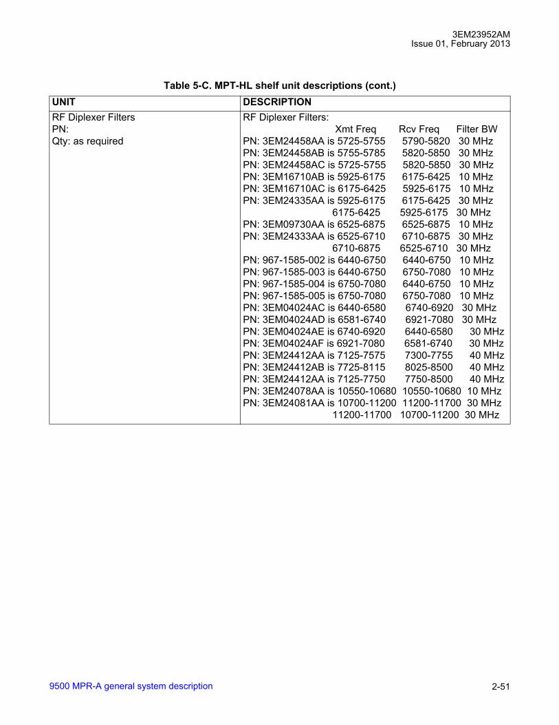
3EM23952AMIssue 01, February 2013
9500 MPR-A general system description 2-51
RF Diplexer FiltersPN: Qty: as required
RF Diplexer Filters:Xmt Freq Rcv Freq Filter BW
PN: 3EM24458AA is 5725-5755 5790-5820 30 MHzPN: 3EM24458AB is 5755-5785 5820-5850 30 MHzPN: 3EM24458AC is 5725-5755 5820-5850 30 MHzPN: 3EM16710AB is 5925-6175 6175-6425 10 MHzPN: 3EM16710AC is 6175-6425 5925-6175 10 MHzPN: 3EM24335AA is 5925-6175 6175-6425 30 MHz
6175-6425 5925-6175 30 MHzPN: 3EM09730AA is 6525-6875 6525-6875 10 MHzPN: 3EM24333AA is 6525-6710 6710-6875 30 MHz
6710-6875 6525-6710 30 MHzPN: 967-1585-002 is 6440-6750 6440-6750 10 MHzPN: 967-1585-003 is 6440-6750 6750-7080 10 MHzPN: 967-1585-004 is 6750-7080 6440-6750 10 MHzPN: 967-1585-005 is 6750-7080 6750-7080 10 MHzPN: 3EM04024AC is 6440-6580 6740-6920 30 MHzPN: 3EM04024AD is 6581-6740 6921-7080 30 MHzPN: 3EM04024AE is 6740-6920 6440-6580 30 MHzPN: 3EM04024AF is 6921-7080 6581-6740 30 MHzPN: 3EM24412AA is 7125-7575 7300-7755 40 MHzPN: 3EM24412AB is 7725-8115 8025-8500 40 MHzPN: 3EM24412AA is 7125-7750 7750-8500 40 MHzPN: 3EM24078AA is 10550-10680 10550-10680 10 MHzPN: 3EM24081AA is 10700-11200 11200-11700 30 MHz
11200-11700 10700-11200 30 MHz
Table 5-C. MPT-HL shelf unit descriptions (cont.)UNIT DESCRIPTION

3EM23952AMIssue 01, February 2013
9500 MPR-A general system description2-52
Space Diversity FiltersPN: Qty: as required
Space Diversity Filters:
PN: Freq Band Filter BW3EM11649AA is Space Div Filter 5725-5755 30 MHz3EM11649AB is Space Div Filter 5755-5785 30 MHz3EM11649AC is Space Div Filter 5790-5820 30 MHz3EM11649AD is Space Div Filter 5820-5850 30 MHz967-0506-002 is Space Div Filter 5925-6175 10 MHz967-0506-003 is Space Div Filter 6175-6425 10 MHz3EM04182AA is Space Div Filter 5925-6050 30 MHz3EM04182AB is Space Div Filter 6050-6175 30 MHz3EM04182AC is Space Div Filter 6175-6300 30 MHz3EM04182AD is Space Div Filter 6300-6425 30 MHz3EM19463AA is Space Div Filter 6525-6875 10 MHz3EM04235AA is Space Div Filter 6525-6710 30 MHz3EM04235AB is Space Div Filter 6710-6875 30 MHz967-0506-004 is Space Div Filter 6440-6750 10 MHz967-0506-005 is Space Div Filter 6750-7080 10 MHz3EM04235AC is Space Div Filter 6440-6580 30 MHz3EM04235AD is Space Div Filter 6580-6740 30 MHz3EM04235AE is Space Div Filter 6740-6920 30 MHz3EM04235AF is Space Div Filter 6920-7080 30 MHz3EM19619AA is Space Div Filter 7125-7750 30 MHz3EM19619AB is Space Div Filter 7750-8500 30 MHz695-8307-001 is Space Div Filter 10550-10680 10 MHz3EM24310AA is Space Div Filter 10700-11200 30 MHz3EM24310AB is Space Div Filter 11200-11700 30 MHz
Table 5-C. MPT-HL shelf unit descriptions (cont.)UNIT DESCRIPTION

3EM23952AMIssue 01, February 2013
9500 MPR-A general system description 2-53
RF Stacking FiltersPN: Qty: as required
RF Stacking Filters:
PN: Freq Band Filter BW3EM16948AA is RF Stack Filter, Rcv 5925-6175 30 MHz3EM16949AB is RF Stack Filter, Xmt 6175-6425 30 MHz3EM16948AB is RF Stack Filter, Rcv 6175-6425 30 MHz3EM16949AA is RF Stack Filter, Xmt 5925-6175 30 MHz3EM16948AD is RF Stack Filter, Rcv 6525-6875 30 MHz3EM16949AD is RF Stack Filter, Xmt 6525-6875 30 MHz3EM16948AE is RF Stack Filter, Rcv 6440-6740 30 MHz3EM16949AF is RF Stack Filter, Xmt 6740-7080 30 MHz3EM16948AF is RF Stack Filter, Rcv 6740-7080 30 MHz3EM16949AE is RF Stack Filter, Xmt 6440-6740 30 MHz3MU00071AA is RF Stack Filter, Rcv 7125-7445 30 MHz3MU00071AF is RF Stack Filter, Xmt 7445-7750 30 MHz3MU00071AB is RF Stack Filter, Rcv 7445-7750 30 MHz3MU00071AE is RF Stack Filter, Xmt 7125-7445 30 MHz3MU00071AC is RF Stack Filter, Rcv 7750-8125 30 MHz3MU00071AH is RF Stack Filter, Xmt 8125-8500 30 MHz3MU00071AD is RF Stack Filter, Rcv 8125-8500 30 MHz3MU00071AG is RF Stack Filter, Xmt 7750-8125 30 MHz3EM05115AA is RF Stack Filter, Rcv 10.7-11.2 30 MHz3EM05114AC is RF Stack Filter, Xmt 11.2-11.7 30 MHz3EM05115AC is RF Stack Filter, Rcv 11.2-11.7 30 MHz3EM05114AA is RF Stack Filter, Xmt 10.7-11.2 30 MHz
Isolator KitsPN: 3EM23524AA/3EM23524AF, 3EM24189AA/3EM24189ACQty: as required
Isolator Kits:Frequency Band: 5725-6425 GHZPN: 3EM23524AA is Hot Standby 1:10 couplerPN: 3EM23524AB is Hot Standby W/Space DiversityPN: 3EM23524AC is 1+0 Non-StandbyFrequency Band: 6400-7080 GHZPN: 3EM23524AD is Hot Standby 1:10 couplerPN: 3EM23524AE is Hot Standby W/Space DiversityPN: 3EM23524AF is 1+0 Non-StandbyFrequency Band: 7125-8500 GHZPN: 3MU00074AA is Hot Standby 1:10 couplerPN: 3MU00074AB is Hot Standby W/Space DiversityPN: 3MU00074AC is 1+0 Non-StandbyFrequency Band: 10700-11700 GHZPN: 3EM24189AA is Hot Standby 1:10 couplerPN: 3EM24189AB is Hot Standby W/space DiversityPN: 3EM24189AC is 1+0 Non-Standby
Table 5-C. MPT-HL shelf unit descriptions (cont.)UNIT DESCRIPTION

3EM23952AMIssue 01, February 2013
9500 MPR-A general system description2-54
Waveguide Extension KitsPN: 3EM24123AR, 3EM24123AS,3EM24166AQ, 3EM24166ARQty: as required
Waveguide Extension KitsPN: 3EM24123AR is Xmt/Rcv W/G Ext A8/A11 (6 GHz)PN: 3EM24123AS is Space Div W/G Ext A8/A11 (6 GHz)PN: 3EM24166AQ is Xmt/Rcv W/G Ext A8/A11 (11 GHz)PN: 3EM24166AR is Space Div W/G Ext A8/A11 (11 GHz)
Stacking Filter Waveguide Kits: 6 GHzPN: 3EM24123AA/3EM24123AQQty: as required
Stacking Filter Waveguide Kits: 6 GHzPN: 3EM24123AA is Hot Standby 1st MPT, Xmt and RcvPN: 3EM24123AB is Hot Standby 1st and 2nd MPT, Xmt and RcvPN: 3EM24123AC is Hot Standby 3rd MPT, Xmt and RcvPN: 3EM24123AD is Hot Standby 3rd and 4th MPT, Xmt and RcvPN: 3EM24123AE is Add-On Space Diversity 1st MPTPN: 3EM24123AF is Add-On Space Diversity 1st and 2nd MPTPN: 3EM24123AG is Add-On Space Diversity 3rd MPTPN: 3EM24123AH is Add-On Space Diversity 3rd and 4th MPTPN: 3EM24123AL is Field Add-On Xmt and Rcv Circulator KitPN: 3EM24123AM is Freq Diversity 1st MPTPN: 3EM24123AN is Freq Diversity 1st and 2nd MPTPN: 3EM24123AP is Freq Diversity 3rd MPTPN: 3EM24123AQ is Freq Diversity 3rd and 4th MPT
Stacking Filter Waveguide Kits: 8 GHzPN: 3MU00075AA/3MU00075AKQty: as required
Stacking Filter Waveguide Kits: 6 GHzPN: 3MU00075AA is Hot Standby 1st MPT, Xmt and RcvPN: 3MU00075AB is Hot Standby 1st and 2nd MPT, Xmt and RcvPN: 3MU00075AC is Hot Standby 3rd MPT, Xmt and RcvPN: 3MU00075AD is Hot Standby 3rd and 4th MPT, Xmt and RcvPN: 3MU00075AE is Add-On Space Diversity 1st MPTPN: 3MU00075AF is Add-On Space Diversity 1st and 2nd MPTPN: 3MU00075AG is Add-On Space Diversity 3rd MPTPN: 3MU00075AH is Add-On Space Diversity 3rd and 4th MPTPN: 3MU00075AK is Field Add-On Xmt and Rcv Circulator KitPN: 3MU00075AL is Freq Diversity 1st MPTPN: 3MU00075AM is Freq Diversity 1st and 2nd MPTPN: 3MU00075AN is Freq Diversity 3rd MPTPN: 3MU00075AP is Freq Diversity 3rd and 4th MPT
Table 5-C. MPT-HL shelf unit descriptions (cont.)UNIT DESCRIPTION
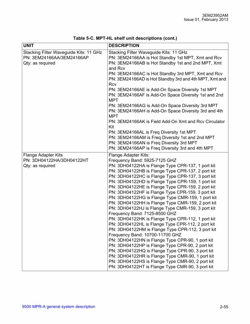
3EM23952AMIssue 01, February 2013
9500 MPR-A general system description 2-55
Stacking Filter Waveguide Kits: 11 GHzPN: 3EM24166AA/3EM24166APQty: as required
Stacking Filter Waveguide Kits: 11 GHzPN: 3EM24166AA is Hot Standby 1st MPT, Xmt and RcvPN: 3EM24166AB is Hot Standby 1st and 2nd MPT, Xmt and RcvPN: 3EM24166AC is Hot Standby 3rd MPT, Xmt and RcvPN: 3EM24166AD is Hot Standby 3rd and 4th MPT, Xmt and RcvPN: 3EM24166AE is Add-On Space Diversity 1st MPTPN: 3EM24166AF is Add-On Space Diversity 1st and 2nd MPTPN: 3EM24166AG is Add-On Space Diversity 3rd MPTPN: 3EM24166AH is Add-On Space Diversity 3rd and 4th MPTPN: 3EM24166AK is Field Add-On Xmt and Rcv Circulator KitPN: 3EM24166AL is Freq Diversity 1st MPTPN: 3EM24166AM is Freq Diversity 1st and 2nd MPTPN: 3EM24166AN is Freq Diversity 3rd MPTPN: 3EM24166AP is Freq Diversity 3rd and 4th MPT
Flange Adapter KitsPN: 3DH04122HA/3DH04122HTQty: as required
Flange Adapter Kits:Frequency Band: 5925-7125 GHZPN: 3DH04122HA is Flange Type CPR-137, 1 port kitPN: 3DH04122HB is Flange Type CPR-137, 2 port kitPN: 3DH04122HC is Flange Type CPR-137, 3 port kitPN: 3DH04122HD is Flange Type CPR-159, 1 port kitPN: 3DH04122HE is Flange Type CPR-159, 2 port kitPN: 3DH04122HF is Flange Type CPR-159, 3 port kitPN: 3DH04122HG is Flange Type CMR-159, 1 port kitPN: 3DH04122HH is Flange Type CMR-159, 2 port kitPN: 3DH04122HJ is Flange Type CMR-159, 3 port kitFrequency Band: 7125-8500 GHZPN: 3DH04122HK is Flange Type CPR-112, 1 port kitPN: 3DH04122HL is Flange Type CPR-112, 2 port kitPN: 3DH04122HM is Flange Type CPR-112, 3 port kitFrequency Band: 10700-11700 GHZPN: 3DH04122HN is Flange Type CPR-90, 1 port kitPN: 3DH04122HP is Flange Type CPR-90, 2 port kitPN: 3DH04122HQ is Flange Type CPR-90, 3 port kitPN: 3DH04122HR is Flange Type CMR-90, 1 port kitPN: 3DH04122HS is Flange Type CMR-90, 2 port kitPN: 3DH04122HT is Flange Type CMR-90, 3 port kit
Table 5-C. MPT-HL shelf unit descriptions (cont.)UNIT DESCRIPTION
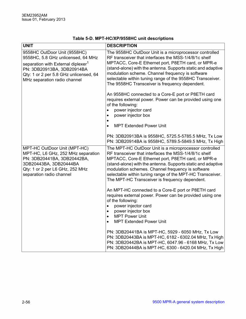
3EM23952AMIssue 01, February 2013
9500 MPR-A general system description2-56
Table 5-D. MPT-HC/XP/9558HC unit descriptionsUNIT DESCRIPTION9558HC OutDoor Unit (9558HC)9558HC, 5.8 GHz unlicensed, 64 MHz separation with External diplexer1PN: 3DB20913BA, 3DB20914BAQty: 1 or 2 per 5.8 GHz unlicensed, 64 MHz separation radio channel
The 9558HC OutDoor Unit is a microprocessor controlled RF transceiver that interfaces the MSS-1/4/8/1c shelf MPTACC, Core-E Ethernet port, P8ETH card, or MPR-e (stand-alone) with the antenna. Supports static and adaptive modulation scheme. Channel frequency is software selectable within tuning range of the 9558HC Transceiver. The 9558HC Transceiver is frequency dependent.
An 9558HC connected to a Core-E port or P8ETH card requires external power. Power can be provided using one of the following: • power injector card• power injector box•• MPT Extended Power Unit
PN: 3DB20913BA is 9558HC, 5725.5-5785.5 MHz, Tx LowPN: 3DB20914BA is 9558HC, 5789.5-5849.5 MHz, Tx High
MPT-HC OutDoor Unit (MPT-HC)MPT-HC, L6 GHz, 252 MHz separationPN: 3DB20441BA, 3DB20442BA,3DB20443BA, 3DB20444BAQty: 1 or 2 per L6 GHz, 252 MHz separation radio channel
The MPT-HC OutDoor Unit is a microprocessor controlled RF transceiver that interfaces the MSS-1/4/8/1c shelf MPTACC, Core-E Ethernet port, P8ETH card, or MPR-e (stand-alone) with the antenna. Supports static and adaptive modulation schemes. Channel frequency is software selectable within tuning range of the MPT-HC Transceiver. The MPT-HC Transceiver is frequency dependent.
An MPT-HC connected to a Core-E port or P8ETH card requires external power. Power can be provided using one of the following: • power injector card• power injector box• MPT Power Unit• MPT Extended Power Unit
PN: 3DB20441BA is MPT-HC, 5929 - 6050 MHz, Tx LowPN: 3DB20443BA is MPT-HC, 6182 - 6302.04 MHz, Tx HighPN: 3DB20442BA is MPT-HC, 6047.96 - 6168 MHz, Tx LowPN: 3DB20444BA is MPT-HC, 6300 - 6420.04 MHz, Tx High
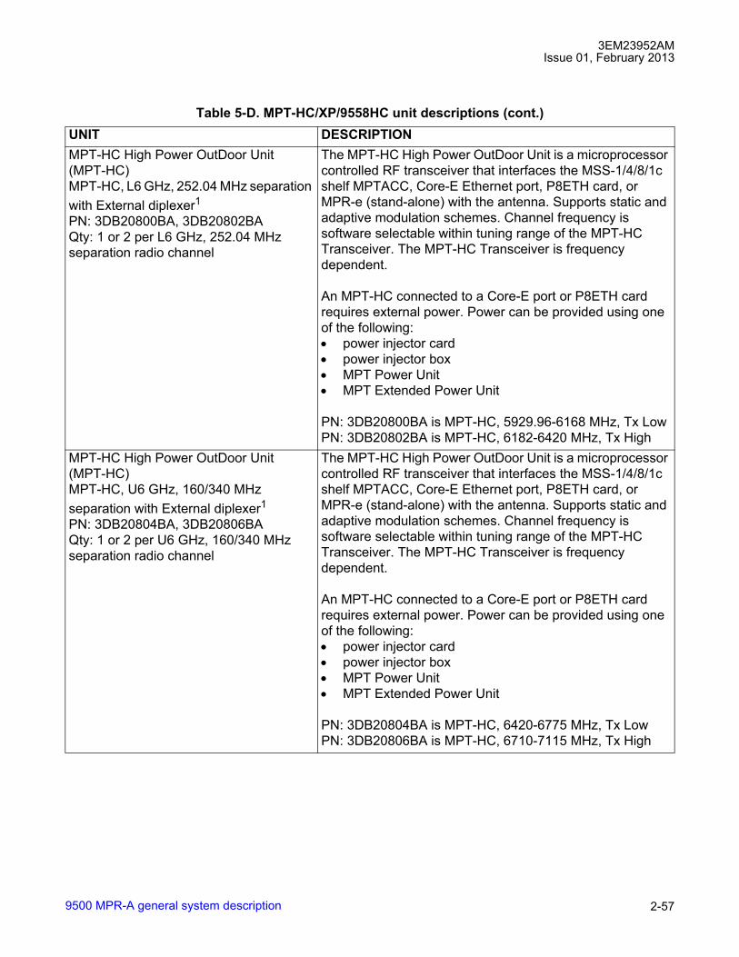
3EM23952AMIssue 01, February 2013
9500 MPR-A general system description 2-57
MPT-HC High Power OutDoor Unit (MPT-HC)MPT-HC, L6 GHz, 252.04 MHz separation with External diplexer1PN: 3DB20800BA, 3DB20802BAQty: 1 or 2 per L6 GHz, 252.04 MHz separation radio channel
The MPT-HC High Power OutDoor Unit is a microprocessor controlled RF transceiver that interfaces the MSS-1/4/8/1c shelf MPTACC, Core-E Ethernet port, P8ETH card, or MPR-e (stand-alone) with the antenna. Supports static and adaptive modulation schemes. Channel frequency is software selectable within tuning range of the MPT-HC Transceiver. The MPT-HC Transceiver is frequency dependent.
An MPT-HC connected to a Core-E port or P8ETH card requires external power. Power can be provided using one of the following: • power injector card• power injector box• MPT Power Unit• MPT Extended Power Unit
PN: 3DB20800BA is MPT-HC, 5929.96-6168 MHz, Tx LowPN: 3DB20802BA is MPT-HC, 6182-6420 MHz, Tx High
MPT-HC High Power OutDoor Unit (MPT-HC)MPT-HC, U6 GHz, 160/340 MHz separation with External diplexer1PN: 3DB20804BA, 3DB20806BAQty: 1 or 2 per U6 GHz, 160/340 MHz separation radio channel
The MPT-HC High Power OutDoor Unit is a microprocessor controlled RF transceiver that interfaces the MSS-1/4/8/1c shelf MPTACC, Core-E Ethernet port, P8ETH card, or MPR-e (stand-alone) with the antenna. Supports static and adaptive modulation schemes. Channel frequency is software selectable within tuning range of the MPT-HC Transceiver. The MPT-HC Transceiver is frequency dependent.
An MPT-HC connected to a Core-E port or P8ETH card requires external power. Power can be provided using one of the following: • power injector card• power injector box• MPT Power Unit• MPT Extended Power Unit
PN: 3DB20804BA is MPT-HC, 6420-6775 MHz, Tx LowPN: 3DB20806BA is MPT-HC, 6710-7115 MHz, Tx High
Table 5-D. MPT-HC/XP/9558HC unit descriptions (cont.)UNIT DESCRIPTION

3EM23952AMIssue 01, February 2013
9500 MPR-A general system description2-58
MPT-HC OutDoor Unit (MPT-HC)MPT-HC, 7/8 GHz, 175/300 MHz separation with External Diplexer1PN: 3DB20454BC, 3DB20456BBQty: 1 or 2 per 7/8 GHz, 175/300 MHz separation radio channel
The MPT-HC OutDoor Unit is a microprocessor controlled RF transceiver with External Diplexer that interfaces the MSS-1/4/8/1c shelf MPTACC, Core-E Ethernet port, P8ETH card, or MPR-e (stand-alone) with the antenna. Supports static and adaptive modulation schemes. Channel frequency is software selectable within tuning range of the MPT-HC Transceiver. The MPT-HC Transceiver is frequency dependent.
An MPT-HC connected to a Core-E port or P8ETH card requires external power. Power can be provided using one of the following: • power injector card• power injector box• MPT Power Unit• MPT Extended Power Unit
PN: 3DB20454BC is MPT-HC, 7107 - 8377 MHz, Tx LowPN: 3DB20456BC is MPT-HC, 7261 - 8496.114 MHz, Tx High
MPT-HC OutDoor Unit (MPT-HC)MPT-HC, 11 GHz, 490/500 MHz separationPN: 3DB20371BB, 3DB20546BB,3DB20547BB, 3DB20548BBQty: 1 or 2 per 11 GHz, 490/500 MHz separation radio channel
The MPT-HC OutDoor Unit is a microprocessor controlled RF transceiver that interfaces the MSS-1/4/8/1c shelf MPTACC, Core-E Ethernet port, P8ETH card, or MPR-e (stand-alone) with the antenna. Supports static and adaptive modulation schemes. Channel frequency is software selectable within tuning range of the MPT-HC Transceiver. The MPT-HC Transceiver is frequency dependent.
An MPT-HC connected to a Core-E port or P8ETH card requires external power. Power can be provided using one of the following: • power injector card• power injector box• MPT Power Unit• MPT Extended Power Unit
PN: 3DB20371BB is MPT-HC, 10695 - 10955 MHz, Tx LowPN: 3DB20547BB is MPT-HC, 11205 - 11485 MHz, Tx HighPN: 3DB20546BB is MPT-HC, 10935 - 11205 MHz, Tx LowPN: 3DB20548BB is MPT-HC, 11445 - 11705 MHz, Tx High
Table 5-D. MPT-HC/XP/9558HC unit descriptions (cont.)UNIT DESCRIPTION

3EM23952AMIssue 01, February 2013
9500 MPR-A general system description 2-59
MPT-HC OutDoor Unit (MPT-HC)MPT-HC, 15 GHz, 475 MHz separationPN: 3DB20373BA, 3DB20423BAQty: 1 or 2 per 15 GHz, 475 MHz separation radio channel
The MPT-HC OutDoor Unit is a microprocessor controlled RF transceiver that interfaces the MSS-1/4/8/1c shelf MPTACC, Core-E Ethernet port, P8ETH card, or MPR-e (stand-alone) with the antenna. Supports static and adaptive modulation schemes. Channel frequency is software selectable within tuning range of the MPT-HC Transceiver. The MPT-HC Transceiver is frequency dependent.
An MPT-HC connected to a Core-E port or P8ETH card requires external power. Power can be provided using one of the following: • power injector card• power injector box• MPT Power Unit• MPT Extended Power Unit
PN: 3DB20373BA is MPT-HC, 14500 - 14724 MHz, Tx LowPN: 3DB20423BA is MPT-HC, 14920 - 15144 MHz, Tx High
MPT-HC OutDoor Unit (MPT-HC)MPT-HC, 18 GHz, 1560 MHz separationPN: 3DB20432BB, 3DB20433BBQty: 1 or 2 per 18 GHz, 1560 MHz separation radio channel
The MPT-HC OutDoor Unit is a microprocessor controlled RF transceiver that interfaces the MSS-1/4/8/1c shelf MPTACC, Core-E Ethernet port, P8ETH card, or MPR-e (stand-alone) with the antenna. Supports static and adaptive modulation schemes. Channel frequency is software selectable within tuning range of the MPT-HC Transceiver. The MPT-HC Transceiver is frequency dependent.
An MPT-HC connected to a Core-E port or P8ETH card requires external power. Power can be provided using one of the following: • power injector card• power injector box• MPT Power Unit• MPT Extended Power Unit
PN: 3DB20432BB is MPT-HC, 17700 - 18140.5 MHz, Tx LowPN: 3DB20433BB is MPT-HC, 19260 - 19700.5 MHz, Tx High
Table 5-D. MPT-HC/XP/9558HC unit descriptions (cont.)UNIT DESCRIPTION

3EM23952AMIssue 01, February 2013
9500 MPR-A general system description2-60
MPT-HC OutDoor Unit (MPT-HC)MPT-HC, 23 GHz Channel, 1200/1232 MHz separationPN: 3DB20473BA, 3DB20474BA, 3DB20475BA, 3DB20476BA Qty: 1 or 2 per 23 GHz, 1200/1232 MHz separation radio channel
The MPT-HC OutDoor Unit is a microprocessor controlled RF transceiver that interfaces the MSS-1/4/8/1c shelf MPTACC, Core-E Ethernet port, P8ETH card, or MPR-e (stand-alone) with the antenna. Supports static and adaptive modulation schemes. Channel frequency is software selectable within tuning range of the MPT-HC Transceiver. The MPT-HC Transceiver is frequency dependent.
An MPT-HC connected to a Core-E port or P8ETH card requires external power. Power can be provided using one of the following: • power injector card• power injector box• MPT Power Unit• MPT Extended Power Unit
PN: 3DB20473BA is MPT-HC, 21198 - 21819 MHz, Tx LowPN: 3DB20475BA is MPT-HC, 22400 - 23019 MHz, Tx HighPN: 3DB20474BA is MPT-HC, 21781 - 22400 MHz, Tx LowPN: 3DB20476BA is MPT-HC, 22981 - 23600 MHz, Tx High
MPT-HC OutDoor Unit (MPT-HC)MPT-HC, 38 GHz Channel, 700 MHz separationPN: 3DB20379BA, 3DB20562BA, 3DB20563BA, 3DB20564BAQty: 1 or 2 per 38 GHz, 700 MHz separation radio channel
The MPT-HC OutDoor Unit is a microprocessor controlled RF transceiver that interfaces the MSS-1/4/8/1c shelf MPTACC, Core-E Ethernet port, P8ETH card, or MPR-e (stand-alone) with the antenna. Supports static and adaptive modulation schemes. Channel frequency is software selectable within tuning range of the MPT-HC Transceiver. The MPT-HC Transceiver is frequency dependent.
An MPT-HC connected to a Core-E port or P8ETH card requires external power. Power can be provided using one of the following: • power injector card• power injector box• MPT Power Unit• MPT Extended Power Unit
PN: 3DB20379BA is MPT-HC, 38600 - 38950 MHz, Tx LowPN: 3DB20563BA is MPT-HC, 39300 - 39650 MHz, Tx HighPN: 3DB20562BA is MPT-HC, 38950 - 39300 MHz, Tx LowPN: 3DB20564BA is MPT-HC, 39650 - 40000 MHz, Tx High
Table 5-D. MPT-HC/XP/9558HC unit descriptions (cont.)UNIT DESCRIPTION
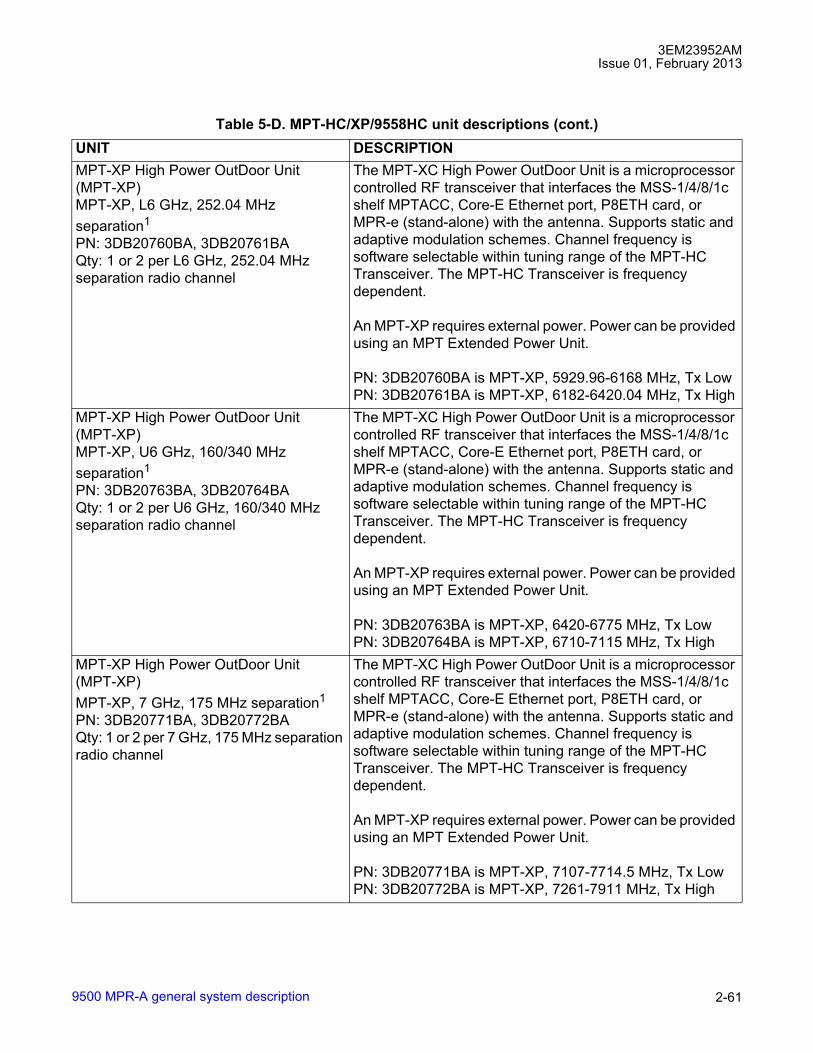
3EM23952AMIssue 01, February 2013
9500 MPR-A general system description 2-61
MPT-XP High Power OutDoor Unit (MPT-XP)MPT-XP, L6 GHz, 252.04 MHz separation1
PN: 3DB20760BA, 3DB20761BAQty: 1 or 2 per L6 GHz, 252.04 MHz separation radio channel
The MPT-XC High Power OutDoor Unit is a microprocessor controlled RF transceiver that interfaces the MSS-1/4/8/1c shelf MPTACC, Core-E Ethernet port, P8ETH card, or MPR-e (stand-alone) with the antenna. Supports static and adaptive modulation schemes. Channel frequency is software selectable within tuning range of the MPT-HC Transceiver. The MPT-HC Transceiver is frequency dependent.
An MPT-XP requires external power. Power can be provided using an MPT Extended Power Unit.
PN: 3DB20760BA is MPT-XP, 5929.96-6168 MHz, Tx LowPN: 3DB20761BA is MPT-XP, 6182-6420.04 MHz, Tx High
MPT-XP High Power OutDoor Unit (MPT-XP)MPT-XP, U6 GHz, 160/340 MHz separation1
PN: 3DB20763BA, 3DB20764BAQty: 1 or 2 per U6 GHz, 160/340 MHz separation radio channel
The MPT-XC High Power OutDoor Unit is a microprocessor controlled RF transceiver that interfaces the MSS-1/4/8/1c shelf MPTACC, Core-E Ethernet port, P8ETH card, or MPR-e (stand-alone) with the antenna. Supports static and adaptive modulation schemes. Channel frequency is software selectable within tuning range of the MPT-HC Transceiver. The MPT-HC Transceiver is frequency dependent.
An MPT-XP requires external power. Power can be provided using an MPT Extended Power Unit.
PN: 3DB20763BA is MPT-XP, 6420-6775 MHz, Tx LowPN: 3DB20764BA is MPT-XP, 6710-7115 MHz, Tx High
MPT-XP High Power OutDoor Unit (MPT-XP)MPT-XP, 7 GHz, 175 MHz separation1
PN: 3DB20771BA, 3DB20772BAQty: 1 or 2 per 7 GHz, 175 MHz separation radio channel
The MPT-XC High Power OutDoor Unit is a microprocessor controlled RF transceiver that interfaces the MSS-1/4/8/1c shelf MPTACC, Core-E Ethernet port, P8ETH card, or MPR-e (stand-alone) with the antenna. Supports static and adaptive modulation schemes. Channel frequency is software selectable within tuning range of the MPT-HC Transceiver. The MPT-HC Transceiver is frequency dependent.
An MPT-XP requires external power. Power can be provided using an MPT Extended Power Unit.
PN: 3DB20771BA is MPT-XP, 7107-7714.5 MHz, Tx LowPN: 3DB20772BA is MPT-XP, 7261-7911 MHz, Tx High
Table 5-D. MPT-HC/XP/9558HC unit descriptions (cont.)UNIT DESCRIPTION
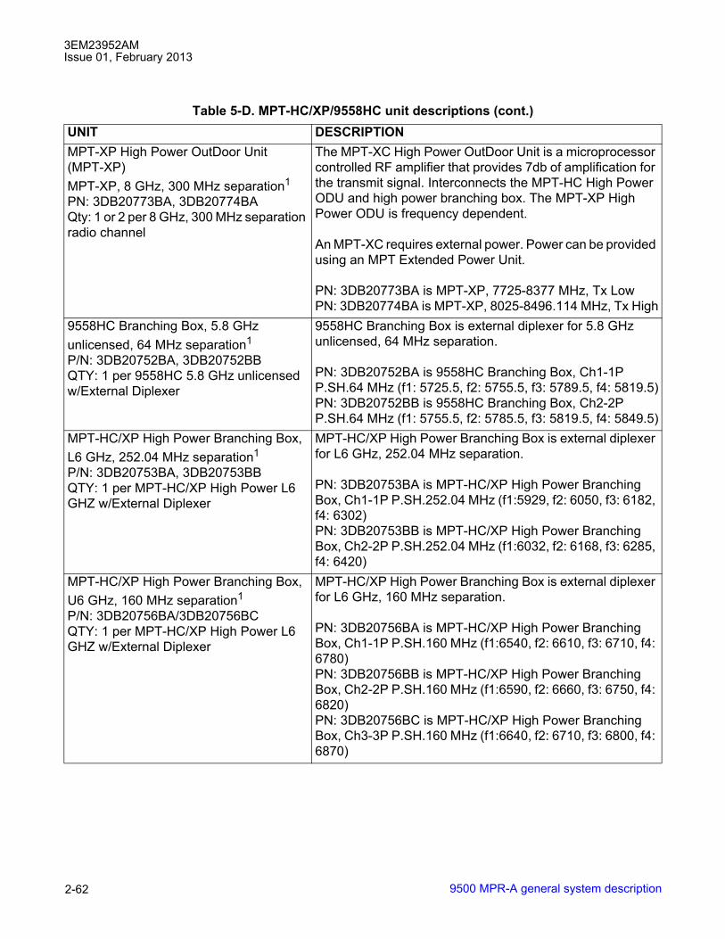
3EM23952AMIssue 01, February 2013
9500 MPR-A general system description2-62
MPT-XP High Power OutDoor Unit (MPT-XP)MPT-XP, 8 GHz, 300 MHz separation1
PN: 3DB20773BA, 3DB20774BAQty: 1 or 2 per 8 GHz, 300 MHz separation radio channel
The MPT-XC High Power OutDoor Unit is a microprocessor controlled RF amplifier that provides 7db of amplification for the transmit signal. Interconnects the MPT-HC High Power ODU and high power branching box. The MPT-XP High Power ODU is frequency dependent.
An MPT-XC requires external power. Power can be provided using an MPT Extended Power Unit.
PN: 3DB20773BA is MPT-XP, 7725-8377 MHz, Tx LowPN: 3DB20774BA is MPT-XP, 8025-8496.114 MHz, Tx High
9558HC Branching Box, 5.8 GHz unlicensed, 64 MHz separation1
P/N: 3DB20752BA, 3DB20752BBQTY: 1 per 9558HC 5.8 GHz unlicensed w/External Diplexer
9558HC Branching Box is external diplexer for 5.8 GHz unlicensed, 64 MHz separation.
PN: 3DB20752BA is 9558HC Branching Box, Ch1-1P P.SH.64 MHz (f1: 5725.5, f2: 5755.5, f3: 5789.5, f4: 5819.5)PN: 3DB20752BB is 9558HC Branching Box, Ch2-2P P.SH.64 MHz (f1: 5755.5, f2: 5785.5, f3: 5819.5, f4: 5849.5)
MPT-HC/XP High Power Branching Box, L6 GHz, 252.04 MHz separation1
P/N: 3DB20753BA, 3DB20753BBQTY: 1 per MPT-HC/XP High Power L6 GHZ w/External Diplexer
MPT-HC/XP High Power Branching Box is external diplexer for L6 GHz, 252.04 MHz separation.
PN: 3DB20753BA is MPT-HC/XP High Power Branching Box, Ch1-1P P.SH.252.04 MHz (f1:5929, f2: 6050, f3: 6182, f4: 6302)PN: 3DB20753BB is MPT-HC/XP High Power Branching Box, Ch2-2P P.SH.252.04 MHz (f1:6032, f2: 6168, f3: 6285, f4: 6420)
MPT-HC/XP High Power Branching Box, U6 GHz, 160 MHz separation1
P/N: 3DB20756BA/3DB20756BCQTY: 1 per MPT-HC/XP High Power L6 GHZ w/External Diplexer
MPT-HC/XP High Power Branching Box is external diplexer for L6 GHz, 160 MHz separation.
PN: 3DB20756BA is MPT-HC/XP High Power Branching Box, Ch1-1P P.SH.160 MHz (f1:6540, f2: 6610, f3: 6710, f4: 6780)PN: 3DB20756BB is MPT-HC/XP High Power Branching Box, Ch2-2P P.SH.160 MHz (f1:6590, f2: 6660, f3: 6750, f4: 6820)PN: 3DB20756BC is MPT-HC/XP High Power Branching Box, Ch3-3P P.SH.160 MHz (f1:6640, f2: 6710, f3: 6800, f4: 6870)
Table 5-D. MPT-HC/XP/9558HC unit descriptions (cont.)UNIT DESCRIPTION

3EM23952AMIssue 01, February 2013
9500 MPR-A general system description 2-63
MPT-HC/XP High Power Branching Box, U6 GHz, 340 MHz separation1
P/N: 3DB20755BA/3DB20755BCQTY: 1 per MPT-HC/XP High Power L6 GHZ w/External Diplexer
MPT-HC/XP High Power Branching Box is external diplexer for L6 GHz, 340 MHz separation.
PN: 3DB20755BA is MPT-HC/XP High Power Branching Box, Ch1-1P P.SH.340 MHz (f1:6420, f2: 6600, f3: 6760, f4: 6940)PN: 3DB20755BB is MPT-HC/XP High Power Branching Box, Ch2-2P P.SH.340 MHz (f1:6565, f2: 6720, f3: 6905, f4: 7060)PN: 3DB20755BC is MPT-HC/XP High Power Branching Box, Ch3-3P P.SH.340 MHz (f1:6595, f2: 6775, f3: 6935, f4: 7115)
MPT-HC/XP Branching Box, 7 GHz, 175 MHz separation1
P/N: 3CC40072AC, 3CC40072ADQTY: 1 per MPT-HC/XP 7/8 GHZ w/External Diplexer
MPT-HC/XP Branching Box is external diplexer for 7 GHz, 175 MHz separation.
PN: 3CC40072AC is MPT-HC/XP Branching Box, Ch1-1P P.SH.175 MHz (f1:7125, f2: 7215, f3: 7300, f4: 7390)PN: 3CC40072AD is MPT-HC/XP Branching Box, Ch2-2P P.SH.175 MHz (f1:7155, f2: 7250, f3: 7330, f4: 7425)
MPT-HC/XP Branching Box, 8 GHz, 300/310 MHz separation1
P/N: 3CC40073AC, 3CC40073ADQTY: 1 per MPT-HC/XP 8 GHZ w/External Diplexer
MPT-HC/XP Branching Box is external diplexer for 8 GHz, 300/310 MHz separation.
PN: 3CC40073AC is MPT-HC/XP Branching Box, Ch1-1P P.SH.300/310 MHz (f1:7725, f2: 7845, f3: 8025, f4: 8155)PN: 3CC40073AD is MPT-HC/XP Branching Box, Ch2-2P P.SH.300/310 MHz (f1:7845, f2: 7975, f3: 8145, f4: 8275)
RPS ModulePN: 3DB20117BAQTY: 1 per MPT-HC/XP configured with RPS 1+1 protection
RPS Module configures MPT-HC/XP ODU for 1+1 Receive Protection Switching configuration. 1 required for each MPT-HC/XP configured for 1+1 RPS protection.
XPIC+RPS ModulePN: 3DB20116BBQTY: 1 per MPT-HC/XP configured with Cross Polarization
XPIC+RPS Module configures MPT-HC/XP ODU for XPIC and/or 1+1 RPS. 1 required for each MPT-HC/XP configured for XPIC and/or 1+1 RPS.
Table 5-D. MPT-HC/XP/9558HC unit descriptions (cont.)UNIT DESCRIPTION

3EM23952AMIssue 01, February 2013
9500 MPR-A general system description2-64
MPT-HC/XP/9558HC CouplerQTY: per radio configuration
MPT-HC/XP/9558HC Coupler
PN: 3CC58276AB is 5.8 GHz Unlicensed Band Unequal Loss CouplerPN: 3CC58056AA is 6 GHz Band (3:3 dB) Equal CouplerPN: 3CC58056AB is 6 GHz Band (1:10 dB) Unequal CouplerPN: 3CC14536AA is 7/8 GHz Band (3:3 dB) Equal CouplerPN: 3CC14536AB is 7/8 GHz Band (1:10 dB) Unequal CouplerPN: 3CC14140AA is 11 GHz Band (3:3 dB) Equal CouplerPN: 3CC14140AB is 11 GHz Band (1:10 dB) Unequal CouplerPN: 3CC13472AA is 13/15 GHz Band (3:3 dB) Equal CouplerPN: 3CC13472AB is 13/15 GHz Band (1:10 dB) Unequal CouplerPN: 3CC13473AA is 18/25 GHz Band (3:3 dB) Unequal CouplerPN: 3CC13473AB is 18/25 GHz Band (1:10 dB) Equal CouplerPN: 3CC13474AA is 28/38 GHz Band (3:3 dB) Unequal CouplerPN: 3CC13474AB is 28/38 GHz Band (1:10 dB) Equal Coupler
MPT-HC/XP OMT (XPIC) CouplerQTY: per radio configuration
MPT-HC/XP OMT 2x(1+0) XPIC Coupler (horizontal and vertical)
PN: 3CC58134AA is L6 GHz Band XPIC CouplerPN: 3CC58186AA is U6 GHz Band XPIC CouplerPN: 3CC58124AA is 7 GHz Band XPIC CouplerPN: 3CC58133AA is 8 GHz Band XPIC CouplerPN: 3CC58116AA is 11 GHz Band XPIC CouplerPN: 3CC58163AA is 15 GHz Band XPIC CouplerPN: 3CC58164AA is 18 GHz Band XPIC CouplerPN: 3CC58165AA is 23 GHz Band XPIC Coupler
Table 5-D. MPT-HC/XP/9558HC unit descriptions (cont.)UNIT DESCRIPTION

3EM23952AMIssue 01, February 2013
9500 MPR-A general system description 2-65
MPT-HC OMT-C (XPIC) CouplerQTY: per radio configuration
MPT-HC OMT-C 4x(1+0) XPIC Coupler (2 horizontal and 2 vertical)
PN: 3CC58244AA is L6 GHz Band 4 ODU OMT-C XPIC CouplerPN: 3CC58200AA is 11 GHz Band 4 ODU OMT-C XPIC CouplerPN: 3CC58200AA is 11 GHz Band 4 ODU OMT-C XPIC CouplerPN: 3CC58201AA is 18 GHz Band 4 ODU OMT-C XPIC CouplerPN: 3CC58202AA is 23 GHz Band 4 ODU OMT-C XPIC Coupler
MPT-HC/XP Loads for unused coupler portsQTY: per radio configuration
OMT/OMT-C Loads for unused coupler ports PN: 3CC58220AA is 27.25-40 GHz Load (WR28 Termination)PN: 3CC58221AA is 18-25 GHz Load (WR42 Termination)PN: 3CC58228AA is 13-15 GHz Load (WR62 Termination)PN: 3CC58223AA is 11 GHz Load (WR75 Termination)PN: 3CC58230AA is 7/8 GHz Load (WR112 Termination)PN: 3CC58225AA is 6 GHz Load (WR137 Termination)
MPT ODU Nose AdapterQTY: per radio configuration
Nose Adapter for MPT ODUPN: 3CC50172AA is MPT ODU, 5.8 GHz Nose Adapter (N-Type)PN: 3DB01460AB is MPT ODU, 5.8 & 6 GHz Nose Adapter (WR137)PN: 3DB10135AA is MPT ODU, 7/8 GHz Nose Adapter (WR112)PN: 3CC50125AA is MPT ODU, 11 GHz Nose Adapter (UBR100)PN: 3CC50177AA is MPT ODU, 15 GHz Nose Adapter (WR62)PN: 3CC50178AA is MPT ODU, 18/23 GHz Nose Adapter (WR42)PN: 3DB02082AA is MPT ODU, 38 GHz Nose Adapter (WR28)
Table 5-D. MPT-HC/XP/9558HC unit descriptions (cont.)UNIT DESCRIPTION

3EM23952AMIssue 01, February 2013
9500 MPR-A general system description2-66
MPT ODU or Coupler Pole MountQTY: as required per site configuration
MPT ODU or Coupler Pole Mount
PN: 3CC06071AA is pole mount assembly for integrated antenna configurationPN: 3CC10752AB IS is pole mount assembly for integrated antenna configurationPN: 3CC13034AA is pole mount assembly for not-integrated antenna configurationPN; 3DB10137AA is pole mount assembly for not-integrated antenna configuration
MPT ODU Universal Rack Mount KitPN: 3EM24705AAQTY: as required per site configuration
MPT ODU Universal Rack Mount Bracket kit provides 19 inch rack bracket, and miscellaneous hardware for use in Non-integrated 1+0 and 1+1 configuration. Add appropriate nose adapter for specific application.
PN: 3EM24705AA � Universal Rack Mount KitPower Injector CardPN: 3CC50128AAQTY: per radio link configuration
Power Injector combines DC battery and Ethernet connections for interconnections with MPT-HC for interconnection between MSS-1/4/8 Core-E Ethernet ports. Install in MSS-4/8 slot.
Power Injector BoxPN: 3CC50129AAQTY: per radio link configuration
Power Injector combines DC battery and Ethernet connections for interconnections with MPT-HC for interconnection between MSS-1/4/8 Core-E Ethernet ports. Mounts to rack. Power connections A & B directly to battery supply.
Power Injector BracketPN: 3DB77008ACQTY: per radio link configuration
Bracket used to install Power Injector box in a 19 inch rack.
21 inch Adapter KitPN: 3CC50065AAQTY: per radio link configuration
Kit used with Power Injector bracket to install Power Injector box in a 21 inch rack.
Table 5-D. MPT-HC/XP/9558HC unit descriptions (cont.)UNIT DESCRIPTION
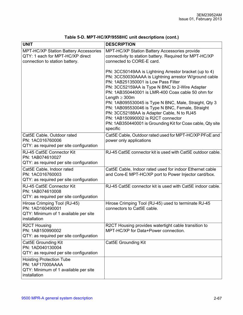
3EM23952AMIssue 01, February 2013
9500 MPR-A general system description 2-67
MPT-HC/XP Station Battery AccessoriesQTY: 1 each for MPT-HC/XP direct connection to station battery.
MPT-HC/XP Station Battery Accessories provide connectivity to station battery. Required for MPT-HC/XP connected to CORE-E card.
PN: 3CC50149AA is Lightning Arrestor bracket (up to 4)PN: 3CC50030AAAA is Lightning arrestor W/ground cablePN: 1AB251350001 is Low Pass FilterPN: 3CC52159AA is Type N BNC to 2-Wire AdapterPN: 1AB350440001 is LMR-400 Coax cable 50 ohm for Length ≥ 300mPN: 1AB095530045 is Type N BNC, Male, Straight, Qty 3PN: 1AB095530046 is Type N BNC, Female, StraightPN: 3CC52188AA is Adapter Cable, N to RJ45PN: 1AB150990002 is R2CT connectorPN: 1AB350440001 is Grounding Kit for Coax cable, Qty site specific
Cat5E Cable, Outdoor ratedPN: 1AC016760006QTY: as required per site configuration
Cat5E Cable, Outdoor rated used for MPT-HC/XP PFoE and power only applications
RJ-45 Cat5E Connector KitPN: 1AB074610027QTY: as required per site configuration
RJ-45 Cat5E connector kit is used with Cat5E outdoor cable.
Cat5E Cable, Indoor ratedPN: 1AC016760003QTY: as required per site configuration
Cat5E Cable, Indoor rated used for indoor Ethernet cable and Core-E MPT-HC/XP port to Power Injector card/box.
RJ-45 Cat5E Connector KitPN: 1AB074610008QTY: as required per site configuration
RJ-45 Cat5E connector kit is used with Cat5E indoor cable.
Hirose Crimping Tool (RJ-45)PN: 1AD160490001QTY: Minimum of 1 available per site installation
Hirose Crimping Tool (RJ-45) used to terminate RJ-45 connectors to Cat5E cable.
R2CT HousingPN: 1AB150990002QTY: as required per site configuration
R2CT Housing provides watertight cable transition to MPT-HC/XP for Data+Power connection.
Cat5E Grounding KitPN: 1AD040130004QTY: as required per site configuration
Cat5E Grounding Kit
Hoisting Protection TubePN: 1AF17000AAAAQTY: Minimum of 1 available per site installation
Table 5-D. MPT-HC/XP/9558HC unit descriptions (cont.)UNIT DESCRIPTION

3EM23952AMIssue 01, February 2013
9500 MPR-A general system description2-68
SFP Module1AB187280040, 1AB187280045QTY: 2 per MPT-HC/XP optical interconnection per NE configuration
SFP Module for data interconnection between MPT-HC/XP and CORE-E card and MPT Access card.
PN: 1AB187280040 is SFP Module, 1000BaseT-Lx SM fiber up to 5 kmPN: 1AB187280045 is SFP Module, 1000BaseT-Sx MM fiber up to 550 meter
MPT-HC/XP IDU/ODU FiberPN: 3CC52170BA/3CC52170BLQTY: as required per NE configuration
MPT-HC/XP IDU/ODU Fiber are Multi-Mode Fibers with LC to LC optical Ethernet connectivity and includes Q-XCO housing for outdoor applications.
PN: 3CC52170BN is MPT-HC/XP IDU/ODU Fiber, 25 meterPN: 3CC52170BM is MPT-HC/XP IDU/ODU Fiber, 50 meterPN: 3CC52170BA is MPT-HC/XP IDU/ODU Fiber, 80 meterPN: 3CC52170BB is MPT-HC/XP IDU/ODU Fiber, 100 meterPN: 3CC52170BC is MPT-HC/XP IDU/ODU Fiber, 120 meterPN: 3CC52170BD is MPT-HC/XP IDU/ODU Fiber, 140 meterPN: 3CC52170BE is MPT-HC/XP IDU/ODU Fiber, 160 meterPN: 3CC52170BF is MPT-HC/XP IDU/ODU Fiber, 180 meterPN: 3CC52170BG is MPT-HC/XP IDU/ODU Fiber, 200 meterPN: 3CC52170BH is MPT-HC/XP IDU/ODU Fiber, 220 meterPN: 3CC52170BI is MPT-HC/XP IDU/ODU Fiber, 250 meterPN: 3CC52170BL is MPT-HC/XP IDU/ODU Fiber, 300 meter
MPT-HC/XP RPS FiberPN: 3CC52169BA/3CC52169BB/3CC52169BCQTY: as required per NE configuration
MPT-HC/XP RPS Fibers are LC to LC fibers and includes Q-XCO housing for outdoor applications.
PN: 3CC52169BA is MPT-HC/XP RPS Fiber, 1 meterPN: 3CC52169BB is MPT-HC/XP RPS Fiber, 10 meterPN: 3CC52169BC is MPT-HC/XP RPS Fiber, 20 meter
MPT-HC/XP XPIC CablePN: 3CC52186AA/3CC52186ACQTY: as required per NE configuration
MPT-HC/XP RPS Fibers are LC to LC fibers and includes Q-XCO housing for outdoor applications.
PN: 3CC52186AA is MPT-HC/XP XPIC Cable, 1 meterPN: 3CC52186AB is MPT-HC/XP XPIC Cable, 2.5 meterPN: 3CC52186AC is MPT-HC/XP XPIC Cable, 8 meter
[1] MPT-HC/9558HC supporting 5.8 GHz unlicensed or 7/8 GHz requires selecting the appropriate Branching Box.
Table 5-D. MPT-HC/XP/9558HC unit descriptions (cont.)UNIT DESCRIPTION
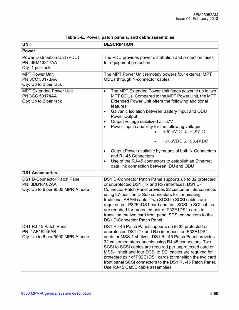
3EM23952AMIssue 01, February 2013
9500 MPR-A general system description 2-69
Table 5-E. Power, patch panels, and cable assembliesUNIT DESCRIPTIONPower Power Distribution Unit (PDU)PN: 3EM13317AAQty: 1 per rack
The PDU provides power distribution and protection fuses for equipment protection.
MPT Power UnitPN 3CC 50173AAQty: Up to 2 per rack
The MPT Power Unit remotely powers four external MPT ODUs through N-connector cables.
MPT Extended Power UnitPN 3CC 50174AAQty: Up to 2 per rack
• The MPT Extended Power Unit feeds power to up to two MPT ODUs. Compared to the MPT Power Unit, the MPT Extended Power Unit offers the following additional features:
• Galvanic Isolation between Battery Input and ODU Power Output
• Output voltage stabilized at -57V• Power Input capability for the following voltages:
• +20.4VDC to +28VDC
• -57.6VDC to -38.4VDC
• Output Power available by means of both N-Connectors and RJ-45 Connectors
• Use of the RJ-45 connectors to establish an Ethernet data link connection between IDU and ODU
DS1 AccessoriesDS1 D-Connector Patch PanelPN: 3DB16102AAQty: Up to 6 per 9500 MPR-A node
DS1 D-Connector Patch Panel supports up to 32 protected or unprotected DS1 (Tx and Rx) interfaces. DS1 D-Connector Patch Panel provides 32 customer interconnects using 37-position D-Sub connectors for terminating traditional ABAM cable. Two SCSI to SCSI cables are required per P32E1DS1 card and four SCSI to SCI cables are required for protected pair of P32E1DS1 cards to transition the two card front panel SCSI connectors to the DS1 D-Connector Patch Panel.
DS1 RJ-45 Patch PanelPN: 1AF15245ABQty: Up to 6 per 9500 MPR-A node
DS1 RJ-45 Patch Panel supports up to 32 protected or unprotected DS1 (Tx and Rx) interfaces on P32E1DS1 cards or MSS-1 shelves. DS1 RJ-45 Patch Panel provides 32 customer interconnects using RJ-45 connectors. Two SCSI to SCSI cables are required per unprotected card or MSS-1 shelf and four SCSI to SCI cables are required for protected pair of P32E1DS1 cards to transition the two card front panel SCSI connectors to the DS1 RJ-45 Patch Panel. Use RJ-45 Cat5E cable assemblies.

3EM23952AMIssue 01, February 2013
9500 MPR-A general system description2-70
DS1 to X-Connect CablesPN: 3EM23110AA/3EM23110ADQTY: as required per NE configuration
Protected ABAM 8 DS1 pair cable assemblies. Cables are designed to interconnect with the 37 pin DSUB customer interconnect panel. Cables are pigtails with connector on one end only.
PN: 3EM23110AA is DS1 to X-Connect cable 15 ft.PN: 3EM23110AB is DS1 to X-Connect cable 30 ft.PN: 3EM23110AC is DS1 to X-Connect cable 50 ft.PN: 3EM23110AD is DS1 to X-Connect cable 100 ft.
P32E1DS1 to Patch Panel CablePN: 3CC52118AAQTY: 2 per Non-Protected P32E1DS1QTY: 4 per Protected P32E1DS1 Pair
P32E1DS1 to Patch Panel cable interconnects P32E1DS1 card or MSS-1 68 pin SCSI connector to the DS1 D-Sub or DS1 RJ-45 patch panel.
P32E1DS1 68 Pin SCSI to X-Connect CablesPN: 3EM21339AA/3EM21339ADQTY: as required per NE configuration
Non-Protected ABAM 16 DS1 pair cable assemblies. Cables are designed to interconnect with the 68 pin SCSI connectors on the P32E1DS1 card or MSS-1 shelf. Cables are pigtails with connector on one end only.
PN: 3EM21339AA is P32E1DS1 to X-Connect cable, Left Side Rack Exit (Slots 3, 5, and 7), 25 ft.PN: 3EM21339AB is P32E1DS1 to X-Connect cable, Right Side Rack Exit (Slots 4, 6, and 8), 25 ft.PN: 3EM21339AC is P32E1DS1 to X-Connect cable, Left Side Rack Exit (Slots 3, 5, and 7), 50 ft.PN: 3EM21339AD is P32E1DS1 to X-Connect cable, Right Side Rack Exit (Slots 4, 6, and 8), 50 ft.
DS3 AccessoriesDS3 Hybrid Splitter Grooming Panel KitPN: 3EM24462AAQTY: 1 per 6 DS3 Hybrid Splitters
Hybrid Splitter Grooming Panel provides mounting location for up to 6 input/output pairs to manage handle multiple hybrid splitters.
DS3 Hybrid SplitterPN: 3EM22900AAQTY: 2 per protected DS3 interface
DS3 Hybrid splitter is an external 3 dB splitter used to interconnect a protected DS3 signal.
DS3 BNC to Mini-BNC Cable AssemblyPN: 3EM22687AA/3EM22687ABQTY: 4 per P2E3DS3 Card
DS3 BNC to Mini-BNC Cable Assembly interconnects P2E3DS3 Mini-BNC to X-Connect.
PN: 3EM22687AA is DS3 BNC to Mini-BNC Cable, 2 metersPN: 3EM22687AB is DS3 BNC to Mini-BNC Cable, 5 meters
OC-3 Accessories
Table 5-E. Power, patch panels, and cable assemblies (cont.)UNIT DESCRIPTION

3EM23952AMIssue 01, February 2013
9500 MPR-A general system description 2-71
SFP STM-1/OC-3 (SFP)PN: 1AB194670005/3CC50166AAAA, 1AB194670007/3CC50165AAAAQTY: Up to 2 per SDHACC
Provides an STM-1/OC-3 SFP interface for SDH Access card (SDHACC).
PN: 1AB194670005/3CC50166AAAA is STM-1/OC-3 SFP, 850 nmPN: 1AB194670007/3CC50165AAAA is STM-1/OC-3 SFP, 1310 nm
Multi-Mode Fiber, LC to SCPN: 3EM07646AA/3EM07646AEQTY: as required per NE configuration
Multi-Mode Fiber, LC to SC for optical Ethernet connectivity.
PN: 3EM07646AA is Multi-Mode Fiber, LC to SC, 1 meterPN: 3EM07646AB is Multi-Mode Fiber, LC to SC, 2 meterPN: 3EM07646AC is Multi-Mode Fiber, LC to SC, 3 meterPN: 3EM07646AD is Multi-Mode Fiber, LC to SC, 5 meterPN: 3EM07646AE is Multi-Mode Fiber, LC to SC, 10 meter
Single-Mode Fiber, LC to SCPN: 3EM07646AF/3EM07646AKQTY: as required per NE configuration
Single-Mode Fiber, LC to SC for optical Ethernet connectivity.
PN: 3EM07646AF is Single-Mode Fiber, LC to SC, 1 meterPN: 3EM07646AG is Single-Mode Fiber, LC to SC, 2 meterPN: 3EM07646AH is Single-Mode Fiber, LC to SC, 3 meterPN: 3EM07646AJ is Single-Mode Fiber, LC to SC, 5 meterPN: 3EM07646AK is Single-Mode Fiber, LC to SC, 10 meter
Optical Splitter/CombinerPN: 1AB123320022/1AB123320023
Optical Splitter/Combiner for Core-E card GigE SFP port protection.
PN: 1AB123320022 is Multi-Mode, SC, optical 50/50 fiber coupler unitPN: 1AB123320023 is Single-Mode, SC, optical 50/50 fiber coupler unit
Fiber Management PanelPN: 3EM09257AA
Fiber Management Panel for OC-3, Ethernet fiber storage.
PN: 3EM09257AA is Fiber Management Panel
Table 5-E. Power, patch panels, and cable assemblies (cont.)UNIT DESCRIPTION

3EM23952AMIssue 01, February 2013
9500 MPR-A general system description2-72
Ethernet SFPs, Electrical, Optical Cable Assemblies
RJ-45 Cat5E Cable Assemblies1
PN: 3EM15052AA/3EM15052BDQTY: as required per NE configuration
RJ-45 Cat5E Cable assemblies. Cables are designed to interconnect with electrical Ethernet ports and the DS1 RJ-45 Patch Panel. One cable is required for each electrical Ethernet/DS1 port. Cable assemblies are not TIA/EIA T568A color pin out compliant.
PN: 3EM15052AA is RJ-45 to RJ-45 cable 3 ft.PN: 3EM15052AD is RJ-45 to RJ-45 cable 6 ft.PN: 3EM15052AH is RJ-45 to RJ-45 cable 10 ft.PN: 3EM15052AN is RJ-45 to RJ-45 cable 20 ft.PN: 3EM15052AQ is RJ-45 to RJ-45 cable 30 ft.PN: 3EM15052AU is RJ-45 to RJ-45 cable 50 ft.PN: 3EM15052AY is RJ-45 to RJ-45 cable 70 ft.PN: 3EM15052BB is RJ-45 to RJ-45 cable 100 ft.PN: 3EM15052BC is RJ-45 to RJ-45 cable 200 ft.PN: 3EM15052BD is RJ-45 to RJ-45 cable 300 ft.
SFP GigE Interface (SFP)PN: 3EM20277AA/3EM20277ADQTY: Up to 2 per Core-E, up to 4 per P8ETH
Provides a 1.25 Gb/s Gigabit Ethernet (GigE) SFP interface for Control and Switching Module (Core-E) and Ethernet Access Switch Card (P8ETH).
PN: 3EM20277AA is GigE SFP, 1000Base-SX, 850 nm, 550 mPN: 3EM20277AB is GigE SFP, 1000Base-LX, 1310 nm, 10 kmPN: 3EM20277AC is GigE SFP, 1000Base-EX, 1310 nm, 40 kmPN: 3EM20277AD is GigE SFP, 1000Base-ZX, 1550 nm, 80 km
Multi-Mode Fiber, LC to LCPN: 3EM07641AA/3EM07641AEQTY: as required per NE configuration
Multi-Mode Fiber, LC to LC for optical Ethernet connectivity.
PN: 3EM07641AA is Multi-Mode Fiber, LC to LC, 1 meterPN: 3EM07641AB is Multi-Mode Fiber, LC to LC, 2 meterPN: 3EM07641AC is Multi-Mode Fiber, LC to LC, 3 meterPN: 3EM07641AD is Multi-Mode Fiber, LC to LC, 5 meterPN: 3EM07641AE is Multi-Mode Fiber, LC to LC, 10 meter
Single-Mode Fiber, LC to LCPN: 3EM07641AF/3EM07641AKQTY: as required per NE configuration
Single-Mode Fiber, LC to LC for optical Ethernet connectivity.
PN: 3EM07641AF is Single-Mode Fiber, LC to LC, 1 meterPN: 3EM07641AG is Single-Mode Fiber, LC to LC, 2 meterPN: 3EM07641AH is Single-Mode Fiber, LC to LC, 3 meterPN: 3EM07641AJ is Single-Mode Fiber, LC to LC, 5 meterPN: 3EM07641AK is Single-Mode Fiber, LC to LC, 10 meter
Table 5-E. Power, patch panels, and cable assemblies (cont.)UNIT DESCRIPTION
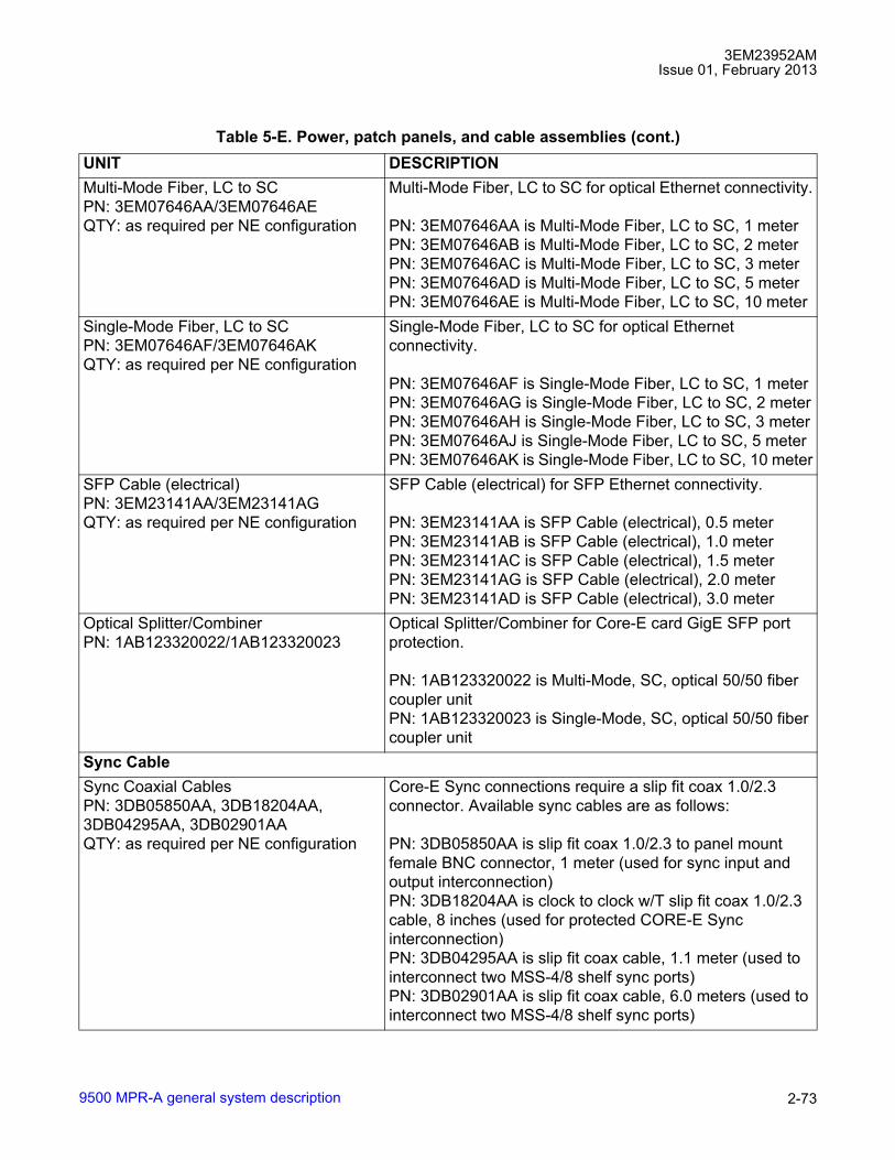
3EM23952AMIssue 01, February 2013
9500 MPR-A general system description 2-73
Multi-Mode Fiber, LC to SCPN: 3EM07646AA/3EM07646AEQTY: as required per NE configuration
Multi-Mode Fiber, LC to SC for optical Ethernet connectivity.
PN: 3EM07646AA is Multi-Mode Fiber, LC to SC, 1 meterPN: 3EM07646AB is Multi-Mode Fiber, LC to SC, 2 meterPN: 3EM07646AC is Multi-Mode Fiber, LC to SC, 3 meterPN: 3EM07646AD is Multi-Mode Fiber, LC to SC, 5 meterPN: 3EM07646AE is Multi-Mode Fiber, LC to SC, 10 meter
Single-Mode Fiber, LC to SCPN: 3EM07646AF/3EM07646AKQTY: as required per NE configuration
Single-Mode Fiber, LC to SC for optical Ethernet connectivity.
PN: 3EM07646AF is Single-Mode Fiber, LC to SC, 1 meterPN: 3EM07646AG is Single-Mode Fiber, LC to SC, 2 meterPN: 3EM07646AH is Single-Mode Fiber, LC to SC, 3 meterPN: 3EM07646AJ is Single-Mode Fiber, LC to SC, 5 meterPN: 3EM07646AK is Single-Mode Fiber, LC to SC, 10 meter
SFP Cable (electrical)PN: 3EM23141AA/3EM23141AGQTY: as required per NE configuration
SFP Cable (electrical) for SFP Ethernet connectivity.
PN: 3EM23141AA is SFP Cable (electrical), 0.5 meterPN: 3EM23141AB is SFP Cable (electrical), 1.0 meterPN: 3EM23141AC is SFP Cable (electrical), 1.5 meterPN: 3EM23141AG is SFP Cable (electrical), 2.0 meterPN: 3EM23141AD is SFP Cable (electrical), 3.0 meter
Optical Splitter/CombinerPN: 1AB123320022/1AB123320023
Optical Splitter/Combiner for Core-E card GigE SFP port protection.
PN: 1AB123320022 is Multi-Mode, SC, optical 50/50 fiber coupler unitPN: 1AB123320023 is Single-Mode, SC, optical 50/50 fiber coupler unit
Sync CableSync Coaxial CablesPN: 3DB05850AA, 3DB18204AA, 3DB04295AA, 3DB02901AAQTY: as required per NE configuration
Core-E Sync connections require a slip fit coax 1.0/2.3 connector. Available sync cables are as follows:
PN: 3DB05850AA is slip fit coax 1.0/2.3 to panel mount female BNC connector, 1 meter (used for sync input and output interconnection)PN: 3DB18204AA is clock to clock w/T slip fit coax 1.0/2.3 cable, 8 inches (used for protected CORE-E Sync interconnection)PN: 3DB04295AA is slip fit coax cable, 1.1 meter (used to interconnect two MSS-4/8 shelf sync ports)PN: 3DB02901AA is slip fit coax cable, 6.0 meters (used to interconnect two MSS-4/8 shelf sync ports)
Table 5-E. Power, patch panels, and cable assemblies (cont.)UNIT DESCRIPTION

3EM23952AMIssue 01, February 2013
9500 MPR-A general system description2-74
s
Fan Alarm CablesFan Alarm CablePN: 3EM24105AA, 3EM24105ABQty: 1 per FAN 2U W/Alarms
Provides fan alarm cable stub.
PN: 3EM24105AA is Fan Alarm Cable 25 Ft.PN: 3EM24105AB is Fan Alarm Cable 50 Ft.
[1] RJ-45 Cat5E Cable assemblies 3EM15052AA/BD are being phased out and replaced with TIA/EIA 568Bcompliant RJ-45 cable assemblies 3MU00085AA/AM.
Table 5-F. Software, RTU capacity license, and documentation unit descriptionsUNIT DESCRIPTION9500 MPR-A CT LicensePN: 3EM23067AAAAQty: 1 per PC Installed
Craft Terminal license for PC used to interface with 9500 MPR-A.
9500 MPR-A R4.2.0 SWP License/CDPN: 3EM23085AOAAQty: 1 per 9500 MPR-A NE
Software and software license CD-ROM. Includes NE, WebEML, MCT, and MIB software.
9500 MPR-A R4.2.0 Flash CardPN: 3EM23086AOAAQty: 1 per Core-E
Flash Card for main and spare Core-E unit in MSS-4/MSS-8 shelf.
RTU Capacity LicensePN: 3EM23068AAAA/3EM23068AEAAQty: 1 per radio channel
Right To Use (RTU) Capacity Licenses conditions the 9500 MPR-A NE to the maximum capacity of a radio channel. The RTU capacity license supports the entire band supported by the radio. An RTU Capacity license is required for each radio channel configured on the 9500 MPR-A NE.
PN: 3EM23068AAAA is RTU up to 40Mbps TRx CapacityPN: 3EM23068ABAA is RTU up to 80Mbps TRx CapacityPN: 3EM23068ACAA is RTU up to 120Mbps TRx CapacityPN: 3EM23068ADAA is RTU up to 160Mbps TRx CapacityPN: 3EM23068AEAA is RTU up to 320Mbps TRx Capacity
RTU Adaptive Modulation (License)PN: 3EM23073AAAAQty: 1 per adaptive modulation radio channel
Right To Use (RTU) Adaptive Modulation License conditions the 9500 MPR-A NE to the number of radio channels which can be configured with adaptive modulation. An RTU Adaptive Modulation license is required for each radio channel configured with adaptive modulation.
RTU 5.8 GHz Unlicensed Band (License)PN: 3EM23261AAAAQty: 1 per unlicensed band radio channel
Right To Use (RTU) 5.8 GHz Unlicensed Band License conditions the 9500 MPR-A NE to restrict the use of a RTU Capacity License to the 5.8 GHz Unlicensed Band. When the RTU 5.8 GHz Unlicensed Band License is present the radio must operated in the 5.8 GHz unlicensed band. The RTU 5.8 GHz Unlicensed Band license is used in conjunction with a RTU Capacity license.
Table 5-E. Power, patch panels, and cable assemblies (cont.)UNIT DESCRIPTION

3EM23952AMIssue 01, February 2013
9500 MPR-A general system description 2-75
RTU 9500 MSP Ring (License)PN: 3MU00086AAAA Qty: 1 per Ring configured with MPT-HC/XP
Right To Use (RTU) 9500 MSP Ring RTU License conditions the 9500 MPR-A NE to the number of Ethernet Ring Protection which can be configured in the NE which include MPT-HC/XP radio. A 9500 MSP Ring license is required for each ERPS Ring configured with MPT-HC/XP on the NE.
RTU 9500 Packet Throughput Booster (License)PN: 3MU00092AAAA Qty: 1 per NE
Right To Use (RTU) 9500 Packet Throughput Booster RTU License conditions the 9500 MPR-A NE to enable the Packet Throughput Booster on MPT-HC/XP/9558HC radio interfaces.
RTU Capacity License UpgradesPN: 3EM23577AAAA/3EM23577AGAAQty: 1 per each additional radio channel/capability
Right To Use (RTU) Capacity License Upgrade conditions the 9500 MPR-A NE to increase the number of radio channels supported on the NE and the maximum capacity of the additional radio channel. A RTU license is required for each radio channel configured on the 9500 MPR-A NE.
PN: 3EM23577AAAA is RTU up to 40Mbps TRx Capacity UpgradePN: 3EM23577ABAA is RTU up to 80Mbps TRx Capacity UpgradePN: 3EM23577ACAA is RTU up to 120Mbps TRx Capacity UpgradePN: 3EM23577ADAA is RTU up to 160Mbps TRx Capacity UpgradePN: 3EM23577AEAA is RTU up to 320Mbps TRx Capacity UpgradePN: 3EM23577AFAA is RTU Adaptive Modulation UpgradePN: 3EM23577AGAA is RTU 5.8 GHz Unlicensed Band UpgradePN: 3EM23577AUAA is 9500 MSP Ring RTU UpgradePN: 3EM23577AVAA is RTU Packet Throughput Booster Upgrade
Table 5-F. Software, RTU capacity license, and documentation unit descriptions (cont.)UNIT DESCRIPTION

3EM23952AMIssue 01, February 2013
9500 MPR-A general system description2-76
Capacity UpgradesPN: 3EM23577AHAA/3EM23577ASAAQty: 1 per radio channel capacity increase
Capacity Upgrades increases the maximum capacity of radio channels supported on an 9500 MPR-A NE.
PN: 3EM23577AHAA is MPT-TR-40T80 (40 Mbps to 80 Mbps) PN: 3EM23577AJAA is MPT-TR-40T120 (40 Mbps to 120 Mbps) PN: 3EM23577AKAA is MPT-TR-40T160 (40 Mbps to 160 Mbps) PN: 3EM23577ALAA is MPT-TR-40T320 (40 Mbps to 320 Mbps) PN: 3EM23577AMAA is MPT-TR-80T120 (80 Mbps to 120 Mbps) PN: 3EM23577ANAA is MPT-TR-80T160 (80 Mbps to 160 Mbps) PN: 3EM23577APAA is MPT-TR-80T320 (80 Mbps to 320 Mbps) PN: 3EM23577AQAA is MPT-TR-120T160 (120 Mbps to 160 Mbps) PN: 3EM23577ARAA is MPT-TR-120T320 (120 Mbps to 320 Mbps) PN: 3EM23577ASAA is MPT-TR-160T320 (160 Mbps to 320 Mbps)
9500 MPR-A R4.2.0 Customer Documentation Library (CD-ROMPN: 3EM23951AMAAQty: 1 per documentation library CD-ROM
9500 MPR-A R4.2.0 Customer Documentation Library CD-ROM contains the user documentation covering 9500 MPR-A product release.
Table 5-F. Software, RTU capacity license, and documentation unit descriptions (cont.)UNIT DESCRIPTION
3EM23952AMIssue 01, February 2013
9500 MPR-A general system description 2-77
6. Functional operation
Microwave service switch (MSS)
6.1 Microwave Service Switch (MSS) shelves provides up to 16 Gb/s packet switch node.
6.2 The MSS provides the base�band processing, cross-connection, port aggregation, switching, equipment management, tributaries interfaces, and modem functionality when ODU300 is connected.
6.3 The MSS-4 and MSS-8 shelf consists of card cage and backplane in which mounts access and radio peripheral and Core-E control cards. The MSS-1 and MSS-1c shelves are monoboards.
6.4 The MSS is frequency�independent.
6.5 Four MSS shelves are available:
• MSS-8 shelf
• MSS-4 shelf
• MSS-1
• MSS-1c shelf
MSS-8 shelf
6.6 A fully equipped Microwave Service Switch (MSS-8) shelf provides up to 314 Mb/s full-duplex Ethernet transport capacity per radio carrier channel.
6.7 MSS-8 shelf provides up to 16 Gb/s packet switching which creates flexible aggregate capacity sharing across DS1, DS3, OC-3, and Ethernet traffic.
6.8 The MSS-8 shelf supports the following:
• 1 or 2 Core-E Cards (Main & Spare)
• up to 6 Transport cards
• 1 AUX peripheral unit (optional: supported in transport slot #8)
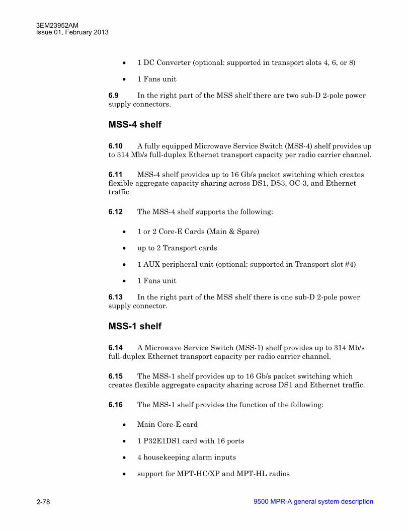
3EM23952AMIssue 01, February 2013
9500 MPR-A general system description2-78
• 1 DC Converter (optional: supported in transport slots 4, 6, or 8)
• 1 Fans unit
6.9 In the right part of the MSS shelf there are two sub-D 2-pole power supply connectors.
MSS-4 shelf
6.10 A fully equipped Microwave Service Switch (MSS-4) shelf provides up to 314 Mb/s full-duplex Ethernet transport capacity per radio carrier channel.
6.11 MSS-4 shelf provides up to 16 Gb/s packet switching which creates flexible aggregate capacity sharing across DS1, DS3, OC-3, and Ethernet traffic.
6.12 The MSS-4 shelf supports the following:
• 1 or 2 Core-E Cards (Main & Spare)
• up to 2 Transport cards
• 1 AUX peripheral unit (optional: supported in Transport slot #4)
• 1 Fans unit
6.13 In the right part of the MSS shelf there is one sub-D 2-pole power supply connector.
MSS-1 shelf
6.14 A Microwave Service Switch (MSS-1) shelf provides up to 314 Mb/s full-duplex Ethernet transport capacity per radio carrier channel.
6.15 The MSS-1 shelf provides up to 16 Gb/s packet switching which creates flexible aggregate capacity sharing across DS1 and Ethernet traffic.
6.16 The MSS-1 shelf provides the function of the following:
• Main Core-E card
• 1 P32E1DS1 card with 16 ports
• 4 housekeeping alarm inputs
• support for MPT-HC/XP and MPT-HL radios
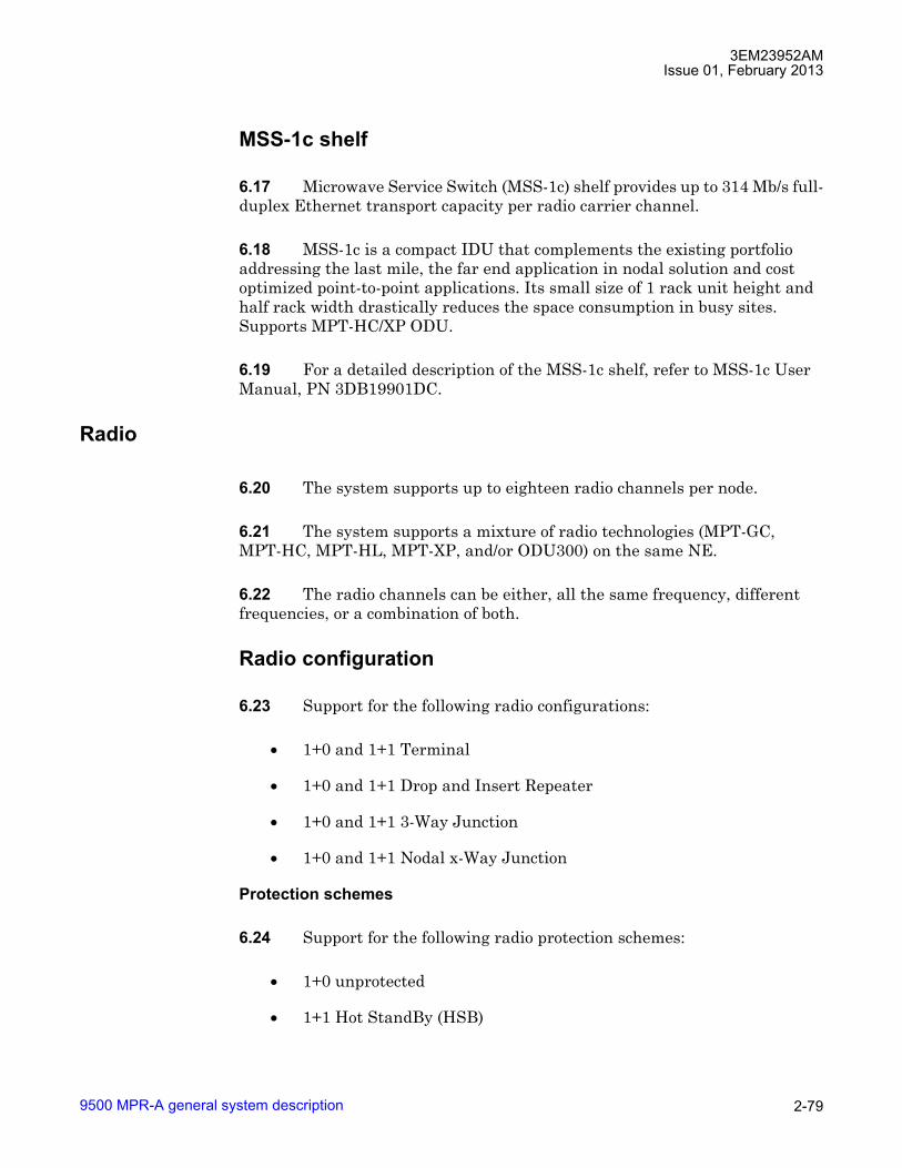
3EM23952AMIssue 01, February 2013
9500 MPR-A general system description 2-79
MSS-1c shelf
6.17 Microwave Service Switch (MSS-1c) shelf provides up to 314 Mb/s full-duplex Ethernet transport capacity per radio carrier channel.
6.18 MSS-1c is a compact IDU that complements the existing portfolio addressing the last mile, the far end application in nodal solution and cost optimized point-to-point applications. Its small size of 1 rack unit height and half rack width drastically reduces the space consumption in busy sites. Supports MPT-HC/XP ODU.
6.19 For a detailed description of the MSS-1c shelf, refer to MSS-1c User Manual, PN 3DB19901DC.
Radio
6.20 The system supports up to eighteen radio channels per node.
6.21 The system supports a mixture of radio technologies (MPT-GC, MPT-HC, MPT-HL, MPT-XP, and/or ODU300) on the same NE.
6.22 The radio channels can be either, all the same frequency, different frequencies, or a combination of both.
Radio configuration
6.23 Support for the following radio configurations:
• 1+0 and 1+1 Terminal
• 1+0 and 1+1 Drop and Insert Repeater
• 1+0 and 1+1 3-Way Junction
• 1+0 and 1+1 Nodal x-Way Junction
Protection schemes
6.24 Support for the following radio protection schemes:
• 1+0 unprotected
• 1+1 Hot StandBy (HSB)
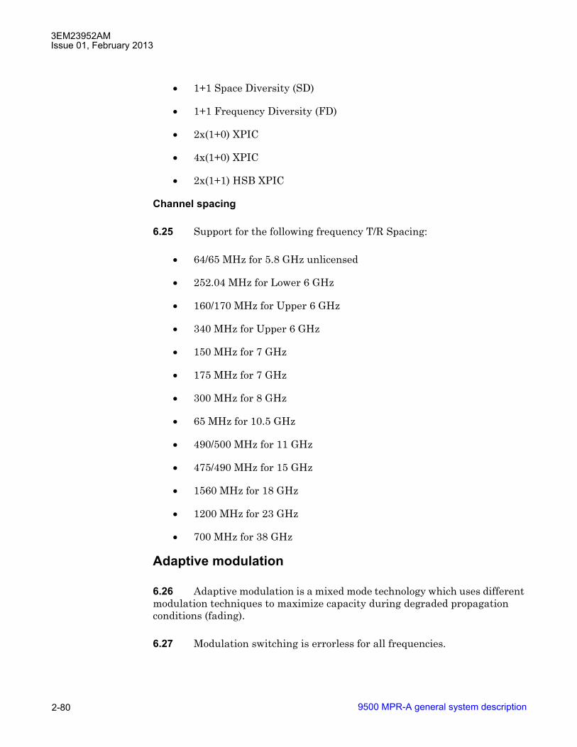
3EM23952AMIssue 01, February 2013
9500 MPR-A general system description2-80
• 1+1 Space Diversity (SD)
• 1+1 Frequency Diversity (FD)
• 2x(1+0) XPIC
• 4x(1+0) XPIC
• 2x(1+1) HSB XPIC
Channel spacing
6.25 Support for the following frequency T/R Spacing:
• 64/65 MHz for 5.8 GHz unlicensed
• 252.04 MHz for Lower 6 GHz
• 160/170 MHz for Upper 6 GHz
• 340 MHz for Upper 6 GHz
• 150 MHz for 7 GHz
• 175 MHz for 7 GHz
• 300 MHz for 8 GHz
• 65 MHz for 10.5 GHz
• 490/500 MHz for 11 GHz
• 475/490 MHz for 15 GHz
• 1560 MHz for 18 GHz
• 1200 MHz for 23 GHz
• 700 MHz for 38 GHz
Adaptive modulation
6.26 Adaptive modulation is a mixed mode technology which uses different modulation techniques to maximize capacity during degraded propagation conditions (fading).
6.27 Modulation switching is errorless for all frequencies.

3EM23952AMIssue 01, February 2013
9500 MPR-A general system description 2-81
6.28 When a terminal operates in adaptive modulation, it is possible to commission the total capacity of both Ethernet and TDM traffic, up to a bandwidth corresponding to the maximum modulation scheme chosen by the operator. This capacity depends on the channel spacing and the modulation scheme.
Admission control
6.29 Admission control ensures that TDM flows are maintained when the modulation scheme is downgraded automatically by the system due to degraded propagation conditions. The number of TDM links supported is limited to the capacity of the lowest modulation technique selected (typically 4 or 64 QAM).
6.30 The Admission Control feature protects the TDM traffic when TDM traffic is provisioned.
6.31 The maximum number of DS1 links that can be provisioned (or cross-connected in a given radio direction) equals the number of DS1s supported by the lowest modulation provisioned, typically 4 QAM or 64 QAM capacity. The remaining capacity is devoted to other types of traffic such as Ethernet best effort.
6.32 From the system point of view, it is not possible to provision more DS1s than are supported by the lowest modulation scheme. When the modulation scheme is downgraded to the lowest value (16QAM to 4QAM), it is not possible for the system to know which DS1s should be maintained and which should be dropped because all DS1 links have the same priority.
6.33 Admission control checks have been added at the CT level, preventing the user from provisioning more DS1s than are supported by the lowest modulation scheme bandwidth.
6.34 When RSL (received signal level) value decreases, modulation scheme is downgraded first from 64QAM to 16QAM: the traffic with lower priority exceeding 16QAM bandwidth is dropped and all the DS1s are kept.
6.35 If the RSL value further decreases, modulation scheme is downgraded to 4QAM and any traffic exceeding 4QAM bandwidth is dropped while the DS1s are maintained.
6.36 Figures 6-1, 6-2, and 6-3 below show how the system operates, in case of modulation changes with admission control (case of 28 MHz bandwidth).

3EM23952AMIssue 01, February 2013
9500 MPR-A general system description2-82
6.37 In this case, the operator has commissioned 13xE1�s. Additionally two other kinds of traffic are provisioned, Ethernet traffic #1 and Fast Ethernet traffic #2. Ethernet traffic #1 has a higher QoS priority than Fast Ethernet traffic #2. See Figure 6-1 for an example of this configuration in normal operating mode,
6.38 The 13xE1s are saved even in the case of a degradation of the modulation down to 4QAM. Remaining available capacity is used to transmit other types of traffic.
6.39 When the modulation is degraded from 64QAM to 16QAM (Figure 6-2), the E1 flows are maintained while the Ethernet traffic with lowest priority (Fast Ethernet traffic #2) is reduced.
Figure 6-1 Example of traffic 28MHz bandwidth and admission control
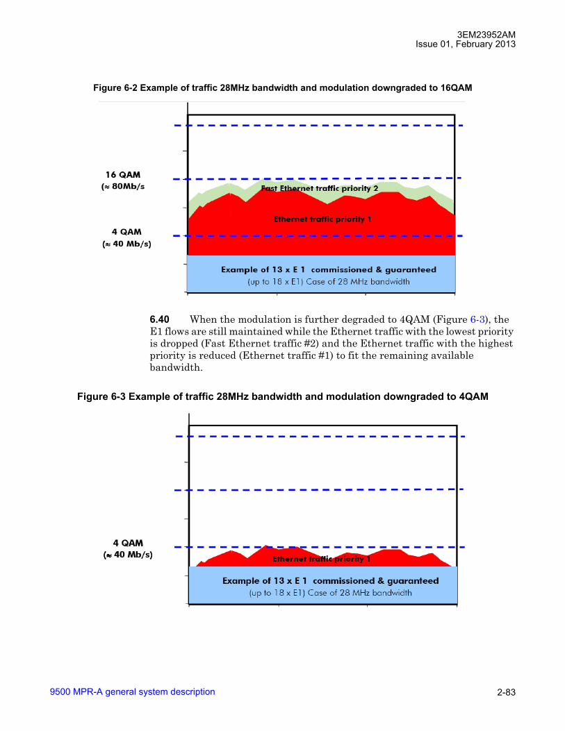
3EM23952AMIssue 01, February 2013
9500 MPR-A general system description 2-83
6.40 When the modulation is further degraded to 4QAM (Figure 6-3), the E1 flows are still maintained while the Ethernet traffic with the lowest priority is dropped (Fast Ethernet traffic #2) and the Ethernet traffic with the highest priority is reduced (Ethernet traffic #1) to fit the remaining available bandwidth.
Figure 6-2 Example of traffic 28MHz bandwidth and modulation downgraded to 16QAM
Figure 6-3 Example of traffic 28MHz bandwidth and modulation downgraded to 4QAM

3EM23952AMIssue 01, February 2013
9500 MPR-A general system description2-84
Adaptive equalization
6.41 Adaptive equalization (AE) is employed to improve reliability of operation under dispersive fade conditions, typically encountered over long and difficult paths.
6.42 This is achieved through a multi-tap equalizer consisting of two registers, one with feed-forward taps, the other with feed-back taps. Each of these registers multiply successive delayed samples of the received signal by weighting-coefficients to remove propagation induced inter-symbol interference.
Fiber-microwave protection
6.43 The Fiber-Microwave Protection feature allows to protect an Optical Fiber link with a Microwave link.
6.44 The Main protection resource is the Optical Fiber, while the Spare protection resource is the Microwave link.
6.45 The Optical Fiber link can be either a physical connection between two MPR NEs or a connection between two MPR NEs by a Wireline network, where the access to that Wireline network by MPR NEs is made by Optical Fiber connections. See Figure 6-4.
Figure 6-4 Fiber-microwave protection

3EM23952AMIssue 01, February 2013
9500 MPR-A general system description 2-85
6.46 Normally the traffic (Ethernet and TDM) is transmitted on the Optical Fiber link.
6.47 In case of failure of the Optical Fiber link, the traffic is rerouted automatically to the Microwave link. When the Optical Fiber connection is restored, the traffic is rerouted again on the Optical Fiber link following a Revertive behavior. See Figure 6-5.
6.48 The switching criteria for the Optical fiber link are:
� Ethernet LOS (Core unit)
� SFP Card Missing
� SFP Card Fail
Figure 6-5 Fiber-microwave protection - operation

3EM23952AMIssue 01, February 2013
9500 MPR-A general system description2-86
6.49 The Fiber-Microwave Protection feature is supported by MPR NE using ERPS performing the following configuration:
� Create a Topology having a radio interface and an optical User Ethernet interface as Ring Ports;
� Create a single Instance in the Topology created before. Since it is requested to manage the overall traffic either over Fiber connection or over radio link, the usage of two Instances to load balance traffic in the Ring is not supported;
� Define one of the two NEs as RPL Owner and configure the radio interface as RPL. In no-fault condition, this will set the Ring Port related to the radio interface in blocking, allowing the traffic to be forwarded over Ethernet optical connection.
6.50 In case of Core protection the following configuration has to performed by the operator in order to guarantee a consistent behavior of the Fiber-Microwave Protection:
� Usage of optical splitter;
� Disable auto-negotiation on optical User Ethernet interface;
� Disable Ethernet LOS as switching criteria for Core protection;
� Disable Static-LAG.
6.51 The Fiber-Microwave Protection feature is applicable to Tail links at the leaf of the backhauling tree.
6.52 The Fiber-Microwave Protection can be implemented also on Tail links having one MPR NE working as Node, according to the following scenario. See Figure 6-6.
Figure 6-6 Fiber-microwave protection on tail links
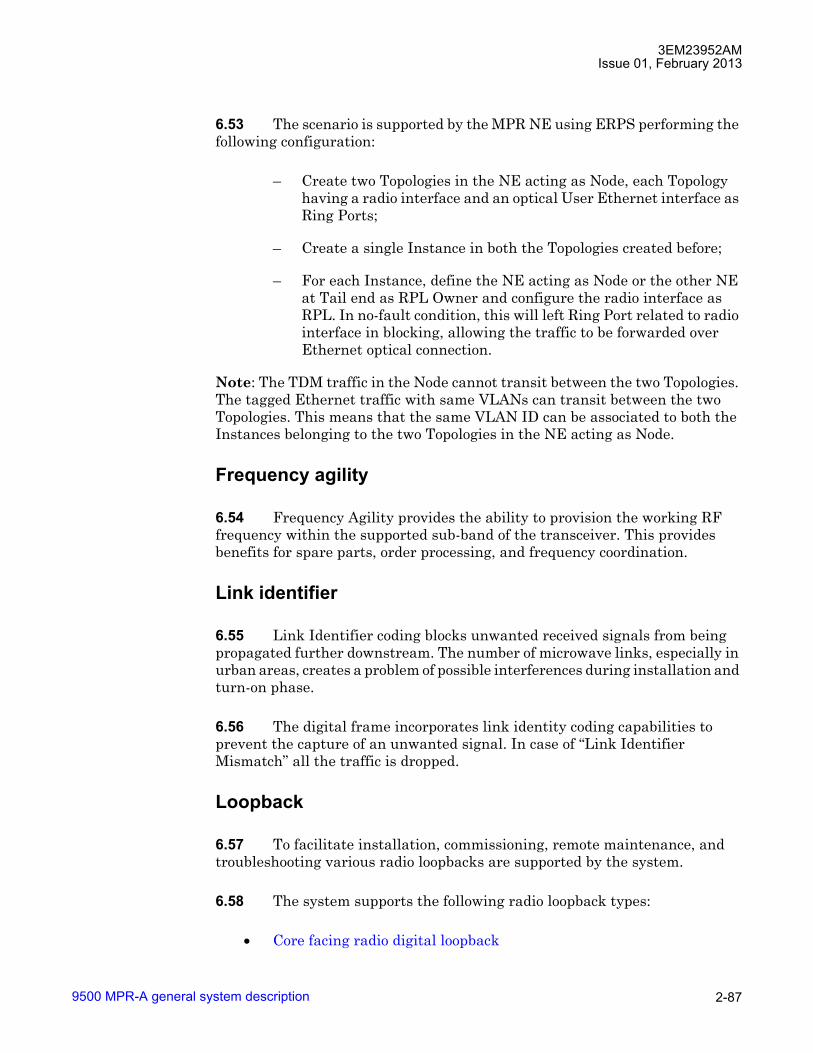
3EM23952AMIssue 01, February 2013
9500 MPR-A general system description 2-87
6.53 The scenario is supported by the MPR NE using ERPS performing the following configuration:
� Create two Topologies in the NE acting as Node, each Topology having a radio interface and an optical User Ethernet interface as Ring Ports;
� Create a single Instance in both the Topologies created before;
� For each Instance, define the NE acting as Node or the other NE at Tail end as RPL Owner and configure the radio interface as RPL. In no-fault condition, this will left Ring Port related to radio interface in blocking, allowing the traffic to be forwarded over Ethernet optical connection.
Note: The TDM traffic in the Node cannot transit between the two Topologies. The tagged Ethernet traffic with same VLANs can transit between the two Topologies. This means that the same VLAN ID can be associated to both the Instances belonging to the two Topologies in the NE acting as Node.
Frequency agility
6.54 Frequency Agility provides the ability to provision the working RF frequency within the supported sub-band of the transceiver. This provides benefits for spare parts, order processing, and frequency coordination.
Link identifier
6.55 Link Identifier coding blocks unwanted received signals from being propagated further downstream. The number of microwave links, especially in urban areas, creates a problem of possible interferences during installation and turn-on phase.
6.56 The digital frame incorporates link identity coding capabilities to prevent the capture of an unwanted signal. In case of �Link Identifier Mismatch� all the traffic is dropped.
Loopback
6.57 To facilitate installation, commissioning, remote maintenance, and troubleshooting various radio loopbacks are supported by the system.
6.58 The system supports the following radio loopback types:
• Core facing radio digital loopback

3EM23952AMIssue 01, February 2013
9500 MPR-A general system description2-88
• Radio facing circuit loopback
• Core facing IF cable loopback
• Core facing RF loopback
6.59 For a detailed description of radio loopbacks, refer to Loopback in this manual.
Performance monitoring
6.60 To facilitate commissioning, remote maintenance, and troubleshooting various radio PM counters are supported by the system.
6.61 The system supports the following radio PM counters:
• Adaptive modulation PM
• Radio analog PM
• Radio ethernet PM
• Radio hop PM
• Radio link PM
• Radio QoS PM
• Radio RSL PM
6.62 For a detailed description of radio PM, refer to Performance monitoring in this manual.
Power monitoring
6.63 The radio transceivers incorporate a detector for Tx power measurement. It is used to provide measurement of forward power as a performance parameter, and to provide a calibration input for transmitter operation over temperature and output range.
6.64 Viewed Tx power ranges always match the capabilities of the radio transceivers for a given modulation. When modulation is changed, the CT automatically adjusts/restricts Tx Power to be within valid range.

3EM23952AMIssue 01, February 2013
9500 MPR-A general system description 2-89
Radio direction label
6.65 Radio Direction Label provides an aid to users in the identification of radio directions. Radio direction labels may be up to fifteen characters in length. Labels are supported on Radio LAG. The radio direction label is displayed on applicable Craft Terminal screens (Cross-Connection, Port Segregation, Equipment Tree, etc.)
Radio L1 LAG
6.66 Layer1 Link Aggregation allows the aggregation of multiple links in order to obtain a unique logical connection with increased traffic capacity.
6.67 A Layer1 Link Aggregation Group (L1 LAG) represents the group of links bundled together between two Aggregation Systems (NEs connected through the L1 LAG).
6.68 Each Aggregation System comprises the following entities:
• QoS: performs buffering and scheduling functions based on the L1 LAG aggregated bandwidth
• Distributor: spreads the traffic over aggregation links belonging to L1 LAG according to a distribution algorithm
• Collector: receives traffic from aggregation links belonging to L1 LAG and combines them together to create a single traffic flow
• Re-ordering: based on Sequence Number fields inserted at the transmitter side, restores the original traffic ordering
A block diagram of L1 Link Aggregation system is shown in Figure 6-7.
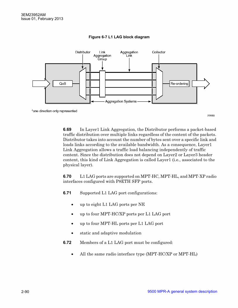
3EM23952AMIssue 01, February 2013
9500 MPR-A general system description2-90
6.69 In Layer1 Link Aggregation, the Distributor performs a packet-based traffic distribution over multiple links regardless of the content of the packets. Distributor takes into account the number of bytes sent over a specific link and loads links according to the available bandwidth. As a consequence, Layer1 Link Aggregation allows a traffic load balancing independently of traffic content. Since the distribution does not depend on Layer2 or Layer3 header content, this kind of Link Aggregation is called Layer1 (i.e., associated to the physical layer).
6.70 L1 LAG ports are supported on MPT-HC, MPT-HL, and MPT-XP radio interfaces configured with P8ETH SFP ports.
6.71 Supported L1 LAG port configurations:
• up to eight L1 LAG ports per NE
• up to four MPT-HC/XP ports per L1 LAG port
• up to four MPT-HL ports per L1 LAG port
• static and adaptive modulation
6.72 Members of a L1 LAG port must be configured:
• All the same radio interface type (MPT-HC/XP or MPT-HL)
Figure 6-7 L1 LAG block diagram

3EM23952AMIssue 01, February 2013
9500 MPR-A general system description 2-91
• All radio interfaces configured with the same modem profile
� modulation type (mode)
� channel spacing (Reference Channel Spacing)
� modulation
� option
• MPT-HC/MPT-HL/MPT-XP radio interface must be configured with P8ETH card. The following radio configurations are supported:
� 1+0 MPT-HC/XP connected to P8ETH SFP port
� 1+0 MPT-HL connected to P8ETH SFP port
� 1+1 MPT-HL connected to P8ETH SFP port
• radio interfaces must reside on the same horizontal shelf row (i.e., MSS-8 shelf, slots 3 and/or 4)
6.73 Radio interfaces configured for adaptive modulation must be configured with Modulation and Supported Modulation parameters set to the same value (i.e., if Modulation is 64 QAM, Supported Modulation must also be set to 64 QAM).
Types of L1 link aggregation
6.74 L1 Link Aggregation is implemented inside the P8ETH card.
6.75 Two configuration are supported to create L1 LAG:
• Intra plug-in LAG
• Cross Plug-in LAG
A block diagram of L1 Link Aggregation configurations is shown in Figure 6-8.

3EM23952AMIssue 01, February 2013
9500 MPR-A general system description2-92
Intra Plug-in L1 link aggregation scenario
6.76 Intra plug-in LAG is a LAG with MPT-HCs/HLs/XPs connected to the same P8ETH card.
6.77 An example of Intra Plug-in LAG implementation is shown in Figure 6-9. Site A is configured with four radio links in an Intra Plug-in LAG configuration. Site B is configured with two intra Plug-in LAGs to implement a radio repeater configuration.
Figure 6-8 Types of L1 LAG
Figure 6-9 Intra plug-in L1 link aggregation scenario

3EM23952AMIssue 01, February 2013
9500 MPR-A general system description 2-93
6.78 In the event of a radio link failure, the capacity of the LAG is reduced by the capacity of the radio link.
6.79 In the event of a Plug-in (P8ETH) failure, the associated LAG direction is lost.
6.80 Single P8ETH card, Intra Plug-in supported L1 LAG configurations are shown in Figure 6-10. Dual P8ETH cards, Intra Plug-in supported L1 LAG configurations are shown in Figure 6-11.
Figure 6-10 Single P8ETH 1+0 intra plug-in L1 LAG configurations
Figure 6-11 Dual P8ETH 1+0 intra plug-in L1 LAG configurations

3EM23952AMIssue 01, February 2013
9500 MPR-A general system description2-94
Cross plug-in L1 LAG sceneries
6.81 Cross Plug-in LAG is a LAG with MPT-HCs/HLs/XPs connected to two P8ETH cards on the same MSS row.
6.82 An example of Cross Plug-in LAG implementation is shown in Figure 6-12. Site A is configured with four radio links in a Cross Plug-in LAG configuration. Site B is configured with two Cross Plug-in LAGs to implement a radio repeater configuration.
6.83 In the event of a radio link failure, the capacity of the LAG is reduced by the capacity of the radio link.
6.84 In the event of a Plug-in (P8ETH) failure, the LAG capacity is reduced, but the LAG direction is maintained utilizing the remaining radio interfaces supported by the other Plug-in.
6.85 Supported Cross Plug-in L1 LAG configurations are shown in Figure 6-13.
Figure 6-12 Cross plug-in L1 link aggregation scenario
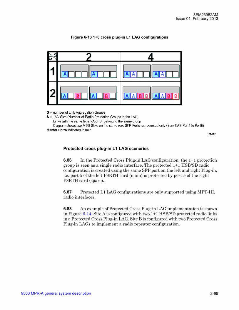
3EM23952AMIssue 01, February 2013
9500 MPR-A general system description 2-95
Protected cross plug-in L1 LAG sceneries
6.86 In the Protected Cross Plug-in LAG configuration, the 1+1 protection group is seen as a single radio interface. The protected 1+1 HSB/SD radio configuration is created using the same SFP port on the left and right Plug-in, i.e. port 5 of the left P8ETH card (main) is protected by port 5 of the right P8ETH card (spare).
6.87 Protected L1 LAG configurations are only supported using MPT-HL radio interfaces.
6.88 An example of Protected Cross Plug-in LAG implementation is shown in Figure 6-14. Site A is configured with two 1+1 HSB/SD protected radio links in a Protected Cross Plug-in LAG. Site B is configured with two Protected Cross Plug-in LAGs to implement a radio repeater configuration.
Figure 6-13 1+0 cross plug-in L1 LAG configurations

3EM23952AMIssue 01, February 2013
9500 MPR-A general system description2-96
6.89 In this configuration, radio protection handles a failure of a single radio hop belonging to the 1+1 HSB/SD protection group. LAG capacity is not affected by a single radio hop failure belonging to the protection group.
6.90 Supported Protected Cross Plug-in L1 LAG 2x(1+1) configurations are shown in Figure 6-15.
Figure 6-14 Protected 1+1 cross plug-in L1 link aggregation scenario

3EM23952AMIssue 01, February 2013
9500 MPR-A general system description 2-97
6.91 A mixture of protected and not protected L1 LAGs are supported. The protected pair can reside in any of the available P8ETH port pairs. Shown in Figure 6-16 the protected pairs reside in ports 5 and 7.
6.92 An extension of the supported protected Cross Plug-in configuration supports 3x(1+1) and 4x(1+1) as shown in Figure 6-17.
Figure 6-15 Protected 2x(1+1) cross plug-in L1 LAG configurations
Figure 6-16 Mix 1+0 and 1+1 protected cross plug-in L1 LAG configurations

3EM23952AMIssue 01, February 2013
9500 MPR-A general system description2-98
L1 LAG creation
6.93 L1 LAG is created using the following parameters:
• LAG ID (LAG Identifier): is mandatory parameter that identifies the LAG in the NE
• LAG Name: is an optional parameter which assist the operator to identify the virtual radio direction. LAG Name is up to 32 characters in length.
• LAG Type: is a mandatory parameter that defines the LAG type (i.e., L1 Radio, L2 Radio, L2 Ethernet).
• LAG Size: is a mandatory parameter that configures the maximum number of radio links included in the L1 LAG. LAG Size cannot be lower than the number of radio links belonging to the LAG.
• Administrative Status: indicates the operational status of the LAG and is configured by the operator
6.94 LAG ID is selected with the following restrictions:
• integer from 1 to 14
• cannot be same as LAG ID of an existing L1/L2 LAG ID
• cannot be equal to the Administrative Key of an existing L2 LAG
Figure 6-17 Protected 3x(1+1)/4x(1+1) cross plug-in L1 LAG configurations
3EM23952AMIssue 01, February 2013
9500 MPR-A general system description 2-99
6.95 When the administrative state of the LAG is disabled, no traffic is sent out the LAG. No LAG alarms are reported to the WebEML.
6.96 When the administrative state of the LAG is enabled, the LAG is available for the following:
• cross-connections
• 802.1Q port membership
• selected as synchronization reference
6.97 A LAG cannot be disabled when involved in any of the following:
• cross-connections
• 802.1Q port membership
• selected as synchronization reference
6.98 The following features are supported at the L1 LAG level:
• Wait-To-Restore (WTR)
• PPP RF
• SSM
6.99 A Wait-To-Restore timer provides a mechanism to minimize the impact to LAG capacity by fast/intermittent failures on a radio link member of the LAG. WTR time is configurable from 100 milliseconds to 8 seconds. The default value is 1 second.
6.100 When a radio link member of a LAG declares a traffic affecting condition, that member is removed from the available radio links and the capacity of the LAG is reduced accordingly. Once the failure condition is cleared, the WTR period is applied. Upon expiration of the WTR period, if the radio link remains condition free, the radio link is restored as a member of the LAG and becomes available to carry traffic. The capacity of the LAG is increased accordingly.
6.101 The following LAG parameters can be modified after creation:
• Port membership
• LAG Name
3EM23952AMIssue 01, February 2013
9500 MPR-A general system description2-100
• LAG Size
• Wait to Restore time
L1 LAG lowest index port
6.102 A LAG Lowest Index Port is defined for each LAG. The Lowest index Port is responsible to transmit traffic from the Distributor (near end) towards the Collector (far end) and vice versa.
6.103 Lowest index Port is selected from P8ETH SFP ports 5 or 7 depending on LAG configuration scenario.
6.104 Lowest index Port is configured using the following:
• Intra Plug-in
� Port 5 or Port 7
� Lowest index Port shall have the lowest index in the LAG port membership (i.e., if Lowest index Port is Port 7, Port 5 and/or Port 6 cannot be added to the LAG).
� one Lowest index Port per LAG
• Cross Plug-in
� port 5 or port 7 on both P8ETH configured in LAG
� Lowest index Ports shall have the lowest index in the LAG port membership (i.e., if Lowest Index Port is port 7, port 5 or port 6 cannot be added to the LAG).
� one lowest index port is main (active)
� one lowest index port is spare (standby)
6.105 For Intra Plug-in LAG, the active lowest index port is configured on the P8ETH hosting LAG.
6.106 For Cross Plug-in LAG, the active lowest index port is configured:
� left P8ETH (slots 3, 5, or 7) port 5 when available
� right P8ETH (slots 4, 6, or 8) port 7 when available

3EM23952AMIssue 01, February 2013
9500 MPR-A general system description 2-101
6.107 When a mixture of Intra/Cross Plug-in LAGs are configured on the same row, the active lowest index port of the Cross Plug-in LAG is configured on a different plug-in used by the Intra Plug-in LAG.
Port provisioning rules
6.108 During port membership add/remove operation, the following rules apply:
• Lowest index Port(s) must always be present in the set of ports attached to the LAG
• considering the slot, lowest index port shall have the lowest index in the LAG port membership.
� Port 5 or Port 7
� one Lowest index Port per Intra Plug-in L1 LAG
� two Lowest index Ports per Cross Plug-in L1 LAG
• Set of ports added to the LAG shall be adjacent considering the slot. No holes are allowed in the L1 LAG port membership filtered by slot (i.e., ports 5, 7, and 8 are not an allowed configuration).
• For Cross Plug-in configuration, the maximum number of ports per slot is two. It is not supported to aggregate 3 ports on one Plug-in and 1 port on the other Plug-in.
• Lowest index Port cannot be changed. If lowest index port is Port 7, Port 5 and Port 6 cannot be added to the L1 LAG.
• Port add/remove operation rules are applied for all port add and port remove operation. Checks are performed on the entire set of ports.
• radio port is eligible to be a member of only one L1 LAG
Intra plug-in port membership
6.109 Table 6-A provides a list of supported 1+0 Intra Plug-in L1 LAG configurations. L1 LAG group lowest index port is indicated in bold, �X�.

3EM23952AMIssue 01, February 2013
9500 MPR-A general system description2-102
Cross plug-in port membership configurations
6.110 Table 6-B provides a list of supported 1+0 Cross Plug-in L1 LAG configurations. L1 LAG group lowest index ports (active and standby) are indicated in bold, �X�.
Table 6-A. Intra plug-in L1 LAG supported 1+0 configurations: single LAG groupCONFIG LAG
SIZELEFT P8ETH (SLOTS 3, 5, 7) RIGHT P8ETH (SLOTS 4, 6, 8)P5 P6 P7 P8 P5 P6 P7 P8
I1 1 X � � � � � � �I2 2 X X � � � � � �I3 3 X X X � � � � �I4 4 X X X X � � � �I5 1 � � � � X � � �I6 2 � � � � X X � �I7 3 � � � � X X X �I8 4 � � � � X X X XI9 1 � � X � � � � �I10 2 � � X X � � � �I11 1 � � � � � � X �I12 2 � � � � � � X X
Table 6-B. Cross plug-in L1 LAG supported 1+0 configurations: single LAG groupCONFIG LAG
SIZELEFT P8ETH (SLOTS 3, 5,7) RIGHT P8ETH (SLOTS 4, 6, 8)P5 P6 P7 P8 P5 P6 P7 P8
C1 2 X � � � X � � �C2 3 X X � � X � � �C3 3 X � � � X X � �C4 4 X X � � X X � �C5 2 � � X � � � X �C6 3 � � X X � � X �C7 3 � � X � � � X XC8 4 � � X X � � X X

3EM23952AMIssue 01, February 2013
9500 MPR-A general system description 2-103
Protected cross plug-in port membership configurations
6.111 Table 6-C provides a list of supported protected Cross Plug-in L1 LAG configurations. Supported configurations contain a mixture of 1+1 and 1+0 radio directions. The L1 LAG group lowest index ports (active and standby) are indicated in bold, �X� (1+0 port), �M� (1+1 main port), and �S� (1+1 spare port).
Dual L1 LAG port membership configurations
6.112 Up to two L1 LAGs are supported on a horizontal row of the MSS-4/8 shelf.
6.113 When two L1 LAGs are located on the same horizontal row, the system locates the master LAG port on different Plug-in cards when possible. This optimizes throughput and re-order capabilities for both LAGs.
6.114 When a mixture of Intra/Cross Plug-in LAGs are configured on the same row, the active lowest index port of the Cross Plug-in LAG is configured on a different plug-in used by the Intra Plug-in LAG.
Table 6-C. Cross plug-in L1 LAG supported 1+1 configurations: single L1 LAG groupCONFIG LAG
SIZELEFT P8ETH (SLOTS 3, 5,7) RIGHT P8ETH (SLOTS 4, 6, 8)P5 P6 P7 P8 P5 P6 P7 P8
C1 1 M � � � S � � �C2 2 M X � � S � � �C3 2 M � � � S X � �C4 3 M X � � S X � �
3 X M � � X S � �2 M M � � S S � �
C5 1 � � M � � � S �C6 2 � � M X � � S �C7 2 � � M � � � S XC8 3 � � M X � � S X
3 � � X M � � X S2 � � M M � � S S
C9 3 M M M � S S S �C10 4 M M M M S S S S

3EM23952AMIssue 01, February 2013
9500 MPR-A general system description2-104
Protected dual L1 LAG port membership configurations
6.115 Up to two protected L1 LAGs are supported on a horizontal row of the MSS-4/8 shelf. Supported configurations contain a mixture of 1+1 and 1+0 radio directions.
6.116 When two protected L1 LAGs are located on the same horizontal row, the system locates the master LAG port on different Plug-in cards when possible. This optimizes throughput and re-order capabilities for both LAGs.
6.117 Table 6-D provides a list of supported dual protected 1+1/1+0 L1 LAG configurations. Members of LAG group A are indicated with an �A�. Members of LAG group B are indicated with a �B�. L1 LAG group lowest index ports (active and standby) are indicated in bold, �A� (LAG group A) and �B� (LAG group B). Main 1+1 ports are indicated with an �M�. Spare 1+1 ports are indicated with an �S�.
Table 6-D. Cross plug-in L1 LAG supported 1+1 configurations: dual L1 LAG groupsGROUP A GROUP B LEFT P8ETH
(SLOTS 3, 5,7)RIGHT P8ETH(SLOTS 4, 6, 8)
CONFIG LAGSIZE
CONFIG LAGSIZE
P5 P6 P7 P8 P5 P6 P7 P8
C1 1 C5 1 A M � B M � A S � B S �C6 2 A M � B M B A S � B S �C7 2 A M � B M � A S � B S BC8 3 A M � B M B A S � B S BC8 3 A M � B B M A S � B B SC8 2 A M � B M B M A S � B S B S
C2 2 C5 1 A M A B M � A S � B S �C6 2 A M A B M B A S � B S �C7 2 A M A B M � A S � B S BC8 3 A M A B M B A S � B S BC8 3 A M A B B M A S � B B SC8 2 A M A B M B M A S � B S B S
C3 2 C5 1 A M � B M � A S A B S �C6 2 A M � B M B A S A B S �C7 2 A M � B M � A S A B S BC8 3 A M � B M B A S A B S BC8 3 A M � B B M A S A B BC8 2 A M � B M B M A S A B S B S

3EM23952AMIssue 01, February 2013
9500 MPR-A general system description 2-105
Port add restrictions
6.118 To add a radio direction to a Radio L1 LAG port, the radio direction must NOT be provisioned as a member to any of the following:
• cross-connection
• VLAN
• port segregation
• PPP RF enabled on the radio channel
• Synchronization reference
• SSM
C4 3 C5 1 A M A B M � A S A B S �C6 2 A M A B M B A S A B S �C7 2 A M A B M � A S A B S BC8 3 A M A B M B A S A B S BC8 3 A M A B B M A S A B B SC8 2 A M A B M B M A S A B S B S
C4 3 C5 1 A A M B M � A A S B S �C6 2 A A M B M B A A S B S �C7 2 A A M B M � A A S B S BC8 3 A A M B M B A A S B S BC8 3 A A M B B M A A S B B SC8 2 A A M B M B M A A S B S B S
C4 2 C5 1 A M A M B M � A S A S B S �C6 2 A M A M B M B A S A S B S �C7 2 A M A M B M � A S A S B S BC8 3 A M A M B M B A S A S B S BC8 3 A M A M B B M A S A S B B SC8 2 A M A M B M B M A S A S B S B S
Table 6-D. Cross plug-in L1 LAG supported 1+1 configurations: dual L1 LAG groups (cont.)GROUP A GROUP B LEFT P8ETH
(SLOTS 3, 5,7)RIGHT P8ETH(SLOTS 4, 6, 8)
CONFIG LAGSIZE
CONFIG LAGSIZE
P5 P6 P7 P8 P5 P6 P7 P8
3EM23952AMIssue 01, February 2013
9500 MPR-A general system description2-106
6.119 ALL cross-connections, VLANs, and port segregation provisioning must be removed before adding a Radio direction to a Radio LAG port.
6.120 TX Mute must be provisioned enabled to add a radio direction to an enabled L1 LAG port. TX Mute should not be disabled until both sides of the radio direction are ready to carry traffic through the LAG port.
6.121 When adding an MPT-HL, Lowest index Port to L1 LAG, the port add restrictions does not apply. During this operation, the following actions are performed by the NE:
• is denied if radio direction:
� is configured with more than 254 cross-connections
� is member of 1+1 protection group
� is MPT-HC/XP
• LAG administrative state is set to Enabled
• WebEML/Craft Terminal is automatically shutdown
• operation results in an impact to traffic
Port removal restrictions
6.122 To remove a radio direction from an L1 LAG port, TX Mute must be provisioned enabled on both sides of the LAG direction.
6.123 ALL cross-connections, VLANs, and port segregation provisioning must be removed from the L1 LAG port before removing the lowest index port.
6.124 To remove the Lowest index Port from a L1 LAG port, the following conditions must exist on the L1 LAG port:
• all other radio ports must be removed from the L1 LAG port
• L1 LAG port must be disabled
• no cross-connections are configured on L1 LAG
• L1 LAG is member of no 802.1Q VLANs (except default VLAN 1)
• L1 LAG is member of no port segregation
• L1 LAG is not provisioned as a synchronization reference
3EM23952AMIssue 01, February 2013
9500 MPR-A general system description 2-107
• PPP RF is disabled on the L1 LAG port
• SSM is disabled on the L1 LAG port
Provisionable radio parameters for members of L1 LAG
6.125 After a radio port has been added to an L1 Radio LAG port, the following radio interface parameters may be modified:
• Link Identifier
• Tx Power/ATPC
• Remote Switching Threshold (in Adaptive Modulation)
• Tx Mute
• Loopback (Note)
• Performance Monitoring
• Alarm Profile
Note: When the MPT-HC/MPT-HL/MPT-XP is configured in a Radio L1 LAG, the loopback of a single radio is not forbidden, but is not supported.
L1 radio LAG deletion
6.126 A L1 LAG can be deleted if:
• Administrative state is Disabled
• no ports are members of the L1 LAG
L1 radio LAG QoS configuration
6.127 NE QoS and queue size settings are applied to the L1 Radio LAG port.
• QoS Scheduler settings
• QoS Mapping
• Radio Queue size
6.128 When a radio port is added to the L1 LAG port all custom QoS and queue size configuration is lost.

3EM23952AMIssue 01, February 2013
9500 MPR-A general system description2-108
6.129 When a radio port is removed from a L1 LAG port, the NE QoS settings are applied to the radio port. The queue sizes are set to the default values.
L1 radio LAG rate
6.130 L1 LAG rate represents the total capacity of the L1 LAG port. The LAG rate is determined by multiplying the capacity of the master LAG port by the number of links in the LAG membership.
Admission control
6.131 Admission control is not performed on L1 LAG.
6.132 Bandwidth of cross-connected traffic should not exceed the capacity of a single LAG port member.
Available P8ETH user ports
6.133 Electrical and optical P8ETH ports which are not members of a L1 LAG may be used for user Ethernet or radio interface ports.
Maximum ethernet frame length
6.134 The maximum Ethernet frame length is:
• 1540 bytes for mixed TDM and Ethernet traffic
• 9728 bytes for pure Ethernet traffic
Maximum number of cross-connections
6.135 The maximum number of cross-connections supported by L1 LAG is 254.
Performance monitoring
6.136 Ethernet statistics related to the L1 Radio LAG direction monitors all the TDM and Ethernet traffic passing through the Lowest Index Port.
6.137 To facilitate commissioning, remote maintenance, and troubleshooting the following L1 radio LAG PM counters are supported:
• Total Number of Tx Packets
3EM23952AMIssue 01, February 2013
9500 MPR-A general system description 2-109
• Total Number of Tx Bytes
• Total Number of Tx Discarded Packets
• Available Capacity
• TTO Throughput
• TDF Ratio
6.138 For a detailed description of radio PM, refer to Performance monitoring in this manual.
Port segregation
6.139 Port segregation involving the L1 LAG is supported.
6.140 The following port segregation involving an L1 LAG are supported:
• segregation to user Ethernet or radio ports belonging to same P8ETH
• segregation to user Ethernet ports or radio ports belonging to an P8ETH on the same MSS row
• segregation of P8ETH card involved in Intra Plug-in L1 LAG to user Ethernet port connected to CSM-E or other P8ETH cards
• segregation of P8ETH card involved in Intra Plug-in L1 LAG to radio ports connected to CSM-E, MOD300, MPTACC, or other P8ETH cards
• segregation of both P8ETH cards involved in Cross Plug-in L1 LAG to user Ethernet port connected to CSM-E or other P8ETH cards
• segregation of both P8ETH cards involved in Cross Plug-in L1 LAG to radio ports connected to CSM-E, MOD300, MPTACC, or other P8ETH cards
PPP-RF configuration
6.141 PPP-RF is configured at the L1 LAG level.
SSM
6.142 SSM is configured at the L1 LAG level.
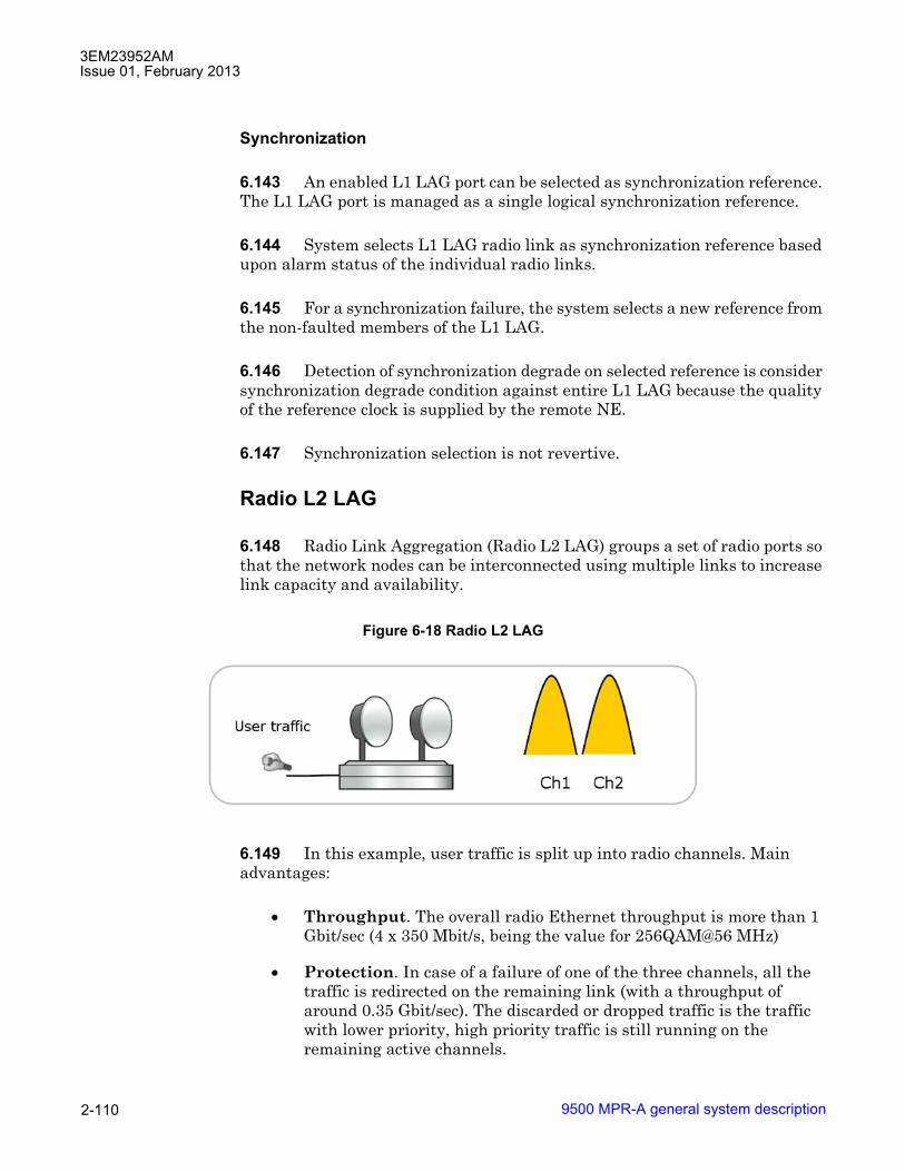
3EM23952AMIssue 01, February 2013
9500 MPR-A general system description2-110
Synchronization
6.143 An enabled L1 LAG port can be selected as synchronization reference. The L1 LAG port is managed as a single logical synchronization reference.
6.144 System selects L1 LAG radio link as synchronization reference based upon alarm status of the individual radio links.
6.145 For a synchronization failure, the system selects a new reference from the non-faulted members of the L1 LAG.
6.146 Detection of synchronization degrade on selected reference is consider synchronization degrade condition against entire L1 LAG because the quality of the reference clock is supplied by the remote NE.
6.147 Synchronization selection is not revertive.
Radio L2 LAG
6.148 Radio Link Aggregation (Radio L2 LAG) groups a set of radio ports so that the network nodes can be interconnected using multiple links to increase link capacity and availability.
6.149 In this example, user traffic is split up into radio channels. Main advantages:
• Throughput. The overall radio Ethernet throughput is more than 1 Gbit/sec (4 x 350 Mbit/s, being the value for 256QAM@56 MHz)
• Protection. In case of a failure of one of the three channels, all the traffic is redirected on the remaining link (with a throughput of around 0.35 Gbit/sec). The discarded or dropped traffic is the traffic with lower priority, high priority traffic is still running on the remaining active channels.
Figure 6-18 Radio L2 LAG

3EM23952AMIssue 01, February 2013
9500 MPR-A general system description 2-111
6.150 Radio L2 LAG ports are supported on MOD300/ODU300, MPT-HC, MPT-HL, and MPT-XP radio interfaces.
6.151 Radio L2 LAG is supported on radio interfaces in both static and adaptive modulation.
6.152 Members of a radio L2 LAG port must be configured:
• All the same radio interface type
• MPT-HC/XP radio interface must be configured with MPT Access card, one radio interface per MPT Access card
• MPT-HL radio interface must be configured with P8ETH card, one radio interface per P8ETH card
• 1+0 unprotected
6.153 Radio L2 LAG ports configured in Active/Standby mode are NOT recommended in this release of the 9500 MPR-A.
6.154 Radio LAG size is restricted to the following:
• up to eight Radio L2 LAG ports per NE
• up to six MOD300/ODU300 ports per Radio L2 LAG port
• up to six MPT-HC/XP ports per Radio L2 LAG port
• up to four MPT-HL ports per Radio L2 LAG port
6.155 PPP RF should be disabled on ALL radio interfaces of a Radio L2 LAG port.
Figure 6-19 Radio L2 LAG block diagram

3EM23952AMIssue 01, February 2013
9500 MPR-A general system description2-112
6.156 TMN In-Band should be cross-connected with only one radio interface of a Radio L2 LAG port.
6.157 To add a radio port to a Radio L2 LAG port, the radio port must NOT be provisioned as a member to any of the following:
• cross-connection
• VLAN
• port segregation
• PPP RF enabled on the radio channel
6.158 ALL cross-connections, VLANs, and port segregation provisioning must be removed before adding the Radio port to a Radio L2 LAG port.
6.159 After a radio port has been added to a Radio L2 LAG port, the following radio interface parameters may be modified:
• Mode (Static, Adaptive Modulation)
• Reference Channel Spacing
• Modulation Scheme
• Options
• Link Identifier
• Tx Power/ATPC
• Modulation Range (in Adaptive Modulation)
• Driving MSE (in Adaptive Modulation)
• Remote Switching Threshold (in Adaptive Modulation)
• Manual Operation (in Adaptive Modulation)
• Tx Mute
• Loopback
• Performance Monitoring
• Alarm Profile

3EM23952AMIssue 01, February 2013
9500 MPR-A general system description 2-113
6.160 After a radio port has been added to a Radio L2 LAG port, the following radio interface parameters may NOT be modified:
• Tx and Rx Frequency
• Shifter
• SSM support
Transmit power control
6.161 Transmit power control is controlled using one of two modalities:
• Automatic Transmit Power Control (ATPC)
• Remote Transmit Power Control (RTPC)
ATPC
6.162 ATPC function automatically increases or decreases the transmit output power upon request from the downstream receiver. The downstream receiver constantly monitors Receive Signal Level (RSL), receive signal quality, and aggregate Bit Error Rate (BER) of the receive signal.
6.163 When ATPC is enabled, the transmit output power will remain at it's lowest level until a fade occurs (or a receive circuit alarm is detected). When a change in RSL is detected at the receive end, a command is sent to the transmit end to increase power in 0.5 dB steps, up to the maximum level if required. After the fade is over, the receive end commands the transmit power to decrease in 0.5 dB steps to the lowest level.
6.164 The ATPC range (minimum and maximum limits) is variable, determined by link distance, link location, and link frequency. When ATPC is enabled, the range values (minimum and maximum) are user provisionable within the supported ATPC Range.
RTPC
6.165 RTPC manages the output power level in a static or fixed mode. RTPC may be preferred to ATPC when hop length or interface problems present a condition that a fixed transmit power level is preferred.
6.166 The range of output power supported is band and modulation dependent.
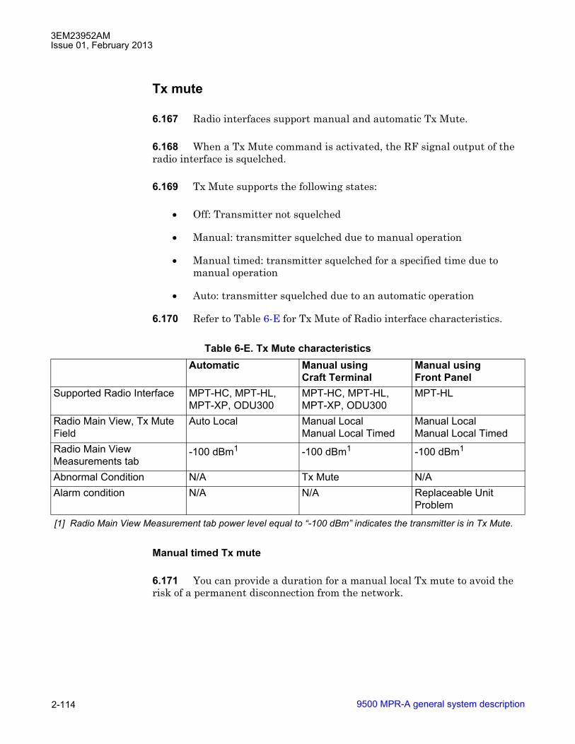
3EM23952AMIssue 01, February 2013
9500 MPR-A general system description2-114
Tx mute
6.167 Radio interfaces support manual and automatic Tx Mute.
6.168 When a Tx Mute command is activated, the RF signal output of the radio interface is squelched.
6.169 Tx Mute supports the following states:
• Off: Transmitter not squelched
• Manual: transmitter squelched due to manual operation
• Manual timed: transmitter squelched for a specified time due to manual operation
• Auto: transmitter squelched due to an automatic operation
6.170 Refer to Table 6-E for Tx Mute of Radio interface characteristics.
Manual timed Tx mute
6.171 You can provide a duration for a manual local Tx mute to avoid the risk of a permanent disconnection from the network.
Table 6-E. Tx Mute characteristicsAutomatic Manual using
Craft TerminalManual usingFront Panel
Supported Radio Interface MPT-HC, MPT-HL, MPT-XP, ODU300
MPT-HC, MPT-HL, MPT-XP, ODU300
MPT-HL
Radio Main View, Tx Mute Field
Auto Local Manual LocalManual Local Timed
Manual LocalManual Local Timed
Radio Main View Measurements tab
-100 dBm1
[1] Radio Main View Measurement tab power level equal to �-100 dBm� indicates the transmitter is in Tx Mute.
-100 dBm1 -100 dBm1
Abnormal Condition N/A Tx Mute N/AAlarm condition N/A N/A Replaceable Unit
Problem

3EM23952AMIssue 01, February 2013
9500 MPR-A general system description 2-115
6.172 The following options appear in the Tx Mute field:
� Manual Local: Choose On to mute the transmitter manually, or Timed to provide a duration that the transmitter will be muted.
� Timeout: Length of time the transmitter will be muted. The default duration is 30 minutes. The maximum is 2 days, 0 hours, 0 minutes.
Note: If the MSS restarts, the timeout counter will be lost. If the MPT restarts, the timeout will be retained.
6.173 After the Timed Tx Mute command has been applied, the NE provides the remaining duration of the command to the managing system.
6.174 If the NE is reachable from the managing system after the execution of a Timed Tx Mute command, you can reconfigure the timeout. The new timeout will overwrite the previous value and the timer starts again from the current timestamp.
6.175 It is not possible to configure a timed Tx mute and a non-timed Tx mute at the same time.
XPIC
6.176 Cross-Polarized Interference Cancellation (XPIC) provides the ability two operate two links on the same radio channel frequency, one using vertical polarization and the other using the horizontal polarization. XPIC typically provides 20 dB improvement in polarization discrimination. The actual improvement will depend on the native discrimination provided by the antenna alignment and any reduction of this discrimination caused by atmospheric effects (fading).
6.177 XPIC feature supports the following radio configurations:
• Single 2x(1+0) XPIC
• Double 2x(1+1) HSB XPIC
• 4x(1+0) XPIC
6.178 Refer to Figure 6-20 for an example of the single 2x(1+0) XPIC configuration.
6.179 Refer to Figure 6-21 for an example of the double 2x(1+1) HSB co-channel XPIC configuration.

3EM23952AMIssue 01, February 2013
9500 MPR-A general system description2-116
Figure 6-20 Single 2+0 XPIC
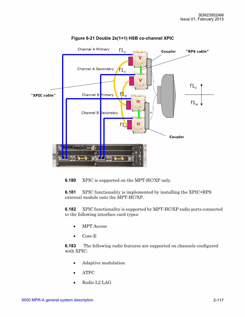
3EM23952AMIssue 01, February 2013
9500 MPR-A general system description 2-117
6.180 XPIC is supported on the MPT-HC/XP only.
6.181 XPIC functionality is implemented by installing the XPIC+RPS external module onto the MPT-HC/XP.
6.182 XPIC functionality is supported by MPT-HC/XP radio ports connected to the following interface card types:
• MPT Access
• Core-E
6.183 The following radio features are supported on channels configured with XPIC:
• Adaptive modulation
• ATPC
• Radio L2 LAG
Figure 6-21 Double 2x(1+1) HSB co-channel XPIC

3EM23952AMIssue 01, February 2013
9500 MPR-A general system description2-118
6.184 The following radio parameters must be configured the same on both MPT-HC/XP radio channels configured with XPIC:
• Modulation/Capacity
• Tx Frequency
• Rx Frequency
• Shifter Value
• Modulation mode (static/adaptive)
6.185 XPIC is supported using the following radio features:
• Radio Channels:
� Lower 6 GHz
� Upper 6 GHz
� 7 GHz
� 8 GHz
� 11 GHz
� 15 GHz
� 18 GHz
� 23 GHz
� 38 GHz
• Modulation Schemes:
� 64 QAM
� 128 QAM
� 256 QAM
• Radio Channel Spacing:
� 30 MHz
� 40 MHz
� 50 MHz

3EM23952AMIssue 01, February 2013
9500 MPR-A general system description 2-119
• Radio L2 LAG
XPIC automatic remote TX mute
6.186 Automatic remote TX mute is an automatic procedure, which starts in a receiver failure condition to continue ensuring the working of the remaining link. This procedure is automatically disabled when at least one of the radio directions involved in the XPIC association is configured in a protected scheme.
6.187 In case of double failure conditions, for example, two MPT cards fail or XPIC module card fail alarms affecting both channels having the same polarization, it is acceptable to lose all traffic for both polarizations, because the cancellation function may not work. Under some specific conditions (see Root causes), the remote transmitter signal on the failed link is muted to prevent unwanted interference on the remaining receiver. Figure 6-22 explains this occurrence.
6.188 The MPT-V on the Far end is squelched, because the MPT-HC/XP on the Near end could not correctly cancel the V component from the co-polar signal.
6.189 Upon specific conditions occurrence on one MPT, the MSS (near end) redirects the automatic remote transmitter mute request over the correct radio direction, that is, over its associated channel. When these specific conditions are no longer present and the related alarms are cleared, then the MSS (near end) redirects the automatic remote transmitter unmute request over the same link.
Figure 6-22 Automatic remote TX mute

3EM23952AMIssue 01, February 2013
9500 MPR-A general system description2-120
6.190 As soon as the MPT (far end) receives an automatic mute/unmute remote request, it communicates this information to the MSS. The MSS mutes/unmutes the MPT corresponding to the associated channel, which is the radio direction associated to the one from which the command has been received.
6.191 Figure 6-23 explains the complete loop.
Root causes
6.192 The procedure of automatic remote transmitter mute is activated (sending message number 2 in Figure 6-23) on the radio interface associated in XPIC mode to the other if one of the following alarms (listed in priority order, starting from higher priority one) is activated:
• MPT Power Supply Failure alarm (used only if MPT is connected to MPT Access unit)
• MPT/EAS access card fail (used only if the two MPTs associated in XPIC mode are connected to two different EAS/MPT access peripherals)
• ICP
Figure 6-23 Automatic remote TX mute complete loop

3EM23952AMIssue 01, February 2013
9500 MPR-A general system description 2-121
• MPT card fail
• XPIC module card fail
6.193 The procedure is automatically activated when both radio directions involved in XPIC mode raise XPIC cable loss alarms. In case of monodirectional XPIC cable loss (alarm associated to only one radio direction involved in XPIC mode), the procedure does not start.
Radio transceivers
6.194 Four types of RF transceiver types are available:
• Microwave Packet Transport - Gigabit Capacity (MPT-GC) ODU
• Microwave Packet Transport - High Capacity (MPT-HC/XP/9558HC) ODU
• Microwave Packet Transport - Long Haul (MPT-HL) IDU
• OutDoor Unit 300 (ODU300) ODU
MPT-GC
6.195 MPT-GC is a multipurpose split mount ODU to address 80 GHz microwave applications. Extremely compact in size providing 1185 Mbps maximum capacity.
6.196 For a detailed description of the MPT-GC, see the MPT-GC User Manual, PN 3DB19025AA.
MPT-HC/XP/9558HC
6.197 MPT-HC/XP/9558HC is a multipurpose split mount ODU to address any microwave application. The unit is optimal for urban links: it is extremely compact in size providing 314 Mbps maximum capacity.
6.198 MPT-HC/XP/9558HC can be deployed in stand-alone configuration (MPR-e) or it can be deployed in split mount solution connected to MSS-1/4/8/1c IDU.
• Up to eighteen MPT-HC/XP connected to MSS-8
• Up to fourteen MPT-HC/XP connected to MSS-4
• Up to six MPT-HC/XP connected to MSS-1

3EM23952AMIssue 01, February 2013
9500 MPR-A general system description2-122
• Up to two MPT-HC/XPs connected to MSS-1c
6.199 9558HC supports the 5.8 GHz Unlicensed frequency band.
6.200 MPT-HC supports L6, U6, 7, 8, 11, 15, 18, 23, and 38 GHz frequency bands.
6.201 MPT-XP supports L6, U6, and 8 GHz frequency bands.
6.202 MPT-HC/XP/9558HC supports 64 QAM, 128 QAM, and 256 QAM static modulation techniques.
6.203 MPT-HC/XP/9558HC supports 4/16/32/64/128/256 QAM adaptive modulation techniques.
6.204 MPT-HC/XP/9558HC supports 5, 10, 30, 40, and 50 MHz channel bandwidths.
6.205 MPT-HC/XP/9558HC supports standard and high system gain profiles.
6.206 MPT-HC/XP/9558HC supports 1+0 Unprotected, 1+1 HSB, 1+1 SD, 1+1 FD, 2x(1+0) XPIC, 4x(1+0) XPIC, and 2x(1+1) HSB XPIC radio configurations.
6.207 Two mechanical solutions are adopted:
• with embedded diplexer for cost optimization (L6, 11 to 38 GHz)
• with external diplexer (5.8 unlicensed, L6, U6, 7, and 8 GHz)
6.208 The external diplexer included in the available branching assemblies refers to ITU�R F.385, 386 and RF special customers channelling with Tx/Rx separation.
6.209 Each branching box diplexer is a 3-port passive device with two band�pass filters as described in Figure 6-6.
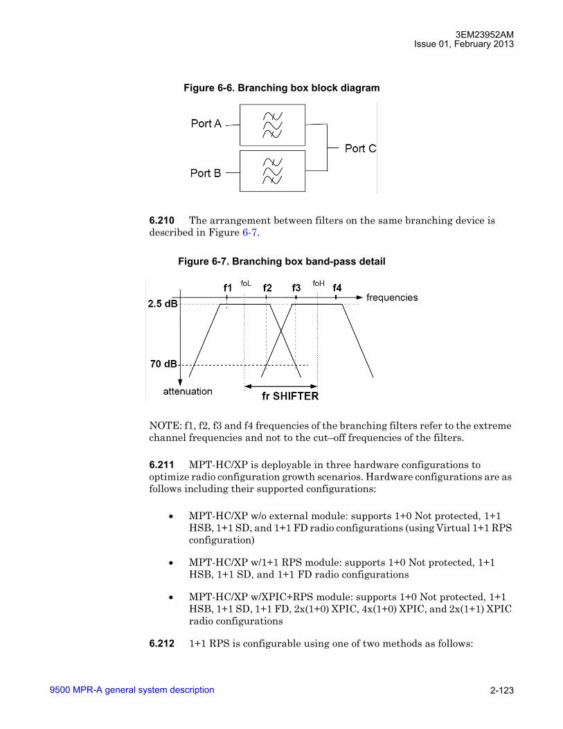
3EM23952AMIssue 01, February 2013
9500 MPR-A general system description 2-123
6.210 The arrangement between filters on the same branching device is described in Figure 6-7.
NOTE: f1, f2, f3 and f4 frequencies of the branching filters refer to the extreme channel frequencies and not to the cut�off frequencies of the filters.
6.211 MPT-HC/XP is deployable in three hardware configurations to optimize radio configuration growth scenarios. Hardware configurations are as follows including their supported configurations:
• MPT-HC/XP w/o external module: supports 1+0 Not protected, 1+1 HSB, 1+1 SD, and 1+1 FD radio configurations (using Virtual 1+1 RPS configuration)
• MPT-HC/XP w/1+1 RPS module: supports 1+0 Not protected, 1+1 HSB, 1+1 SD, and 1+1 FD radio configurations
• MPT-HC/XP w/XPIC+RPS module: supports 1+0 Not protected, 1+1 HSB, 1+1 SD, 1+1 FD, 2x(1+0) XPIC, 4x(1+0) XPIC, and 2x(1+1) XPIC radio configurations
6.212 1+1 RPS is configurable using one of two methods as follows:
Figure 6-6. Branching box block diagram
Figure 6-7. Branching box band-pass detail

3EM23952AMIssue 01, February 2013
9500 MPR-A general system description2-124
• Cabled 1+1 RPS: RPS module and RPS cable required between main and spare MPT-HC/XPs
• Virtual 1+1 RPS: RPS module and RPS cable are not required between main and spare MPT-HC/XPs
6.213 Supports Ethernet ring protection Switching connected to MPT Access and Core-E.
6.214 Integrated antenna mounts, Ethernet (electrical and optical) connectivity, and power connectivity to MSS-1c/4/8 shelves simplify installation.
6.215 MPT-HC/XP supports FEC including Reed Solomon Decoding and TCM 2D/4D. The FEC configuration is a direct consequence of the modem profile provisioned and is not configurable.
MPT-XP
6.216 MPT-XP is very high power version of MPT-HC/XP. The unit provides an additional 7 dB of transmit power when compared with MPT-HC.
6.217 Supports L6, U6, 7, and 8 GHz frequency bands.
6.218 Mechanical solution using external diplexer.
MPR-e (standalone MPT-HC/XP)
6.219 MPR-e is the stand alone, full outdoor application of the MPT-HC/XP to address full Ethernet site backhauling (fix or mobile) and to address converged MPLS metro networks reducing the number of deployed equipment.
6.220 For a detailed description of the MPR-e, refer to MPR-e User Manual, PN 3DB19901EC.
MPT-HL
6.221 MPT-HL is an IDU transceiver to address long haul microwave applications providing 245 Mbps maximum capacity.
6.222 MPT-HL is deployed in an all indoor mount solution. Connects to the MSS-1 shelf or a Core-E unit or Ethernet Access Switch (P8ETH) housed in the MSS-4/8 shelf.
• Up to eighteen MPT-HL connected to MSS-8
3EM23952AMIssue 01, February 2013
9500 MPR-A general system description 2-125
• Up to ten MPT-HL connected to MSS-4
• Up to two MPT-HL connected to MSS-1
6.223 Supports 5.8 Unlicensed, L6, U6, 7, 8, 10.5, and 11 GHz frequency bands.
6.224 Supports 32 QAM, 128 QAM, and 256 QAM static modulation techniques.
6.225 Supports 4/16/64/128/256 QAM adaptive modulation techniques.
6.226 Supports Bandwidths: 5, 10, 30, and 40 MHz
6.227 Supports standard and high system gain support
6.228 Supports 1+0 Unprotected, 1+1 HSB, 1+1 SD, and 1+1 FD radio configurations.
6.229 MPT-HL supports FEC including Reed Solomon Decoding and TCM 2D/4D. The FEC configuration is a direct consequence of the modem profile provisioned and is not configurable.
Lower 6 GHz frequency plan
6.230 Refer to 9500 MPR-A Equipping Options drawing, found in Engineering Support Documentation manual (PN 3EM23957AM) for lower 6 GHz radio configurations and equipping options.

3EM23952AMIssue 01, February 2013
9500 MPR-A general system description2-126
ODU300
6.231 ODU300 is a multipurpose ODU to address any microwave application and is optimal for urban links. The ODU is extremely compact in size providing 306 Mbps maximum capacity.
6.232 ODU300 is deployed in split mount solution connected to the Radio Interface (MOD300) card housed in the MSS-4/8 shelf.
• Up to six ODU300s connected to an MSS-8
Table 6-H. Lower 6 GHz 10 MHZ channel planGO RETURN
CHANNEL FREQUENCY
DESIGNATOR CHANNEL FREQUENCY
DESIGNATOR
5935.320 L6.D1.L 6187.360 L6.D1.H5945.200 L6.D2.L 6197.240 L6.D2.H5955.080 L6.D3.L 6207.120 L6.D3.H5964.970 L6.D4.L 6217.010 L6.D4.H5974.850 L6.D5.L 6226.890 L6.D5.H5974.730 L6.D6.L 6236.770 L6.D6.H5994.620 L6.D7.L 6246.660 L6.D7.H6004.500 L6.D8.L 6256.540 L6.D8.H6014.380 L6.D9.L 6266.420 L6.D9.H6024.270 L6.D10.L 6276.310 L6.D10.H6034.150 L6.D11.L 6286.190 L6.D11.H6044.030 L6.D12.L 6296.070 L6.D12.H6053.920 L6.D13.L 6305.960 L6.D13.H6063.800 L6.D14.L 6315.840 L6.D14.H6073.680 L6.D15.L 6325.720 L6.D15.H6083.570 L6.D16.L 6335.610 L6.D16.H6093.450 L6.D17.L 6345.490 L6.D17.H6103.330 L6.D18.L 6355.370 L6.D18.H6113.220 L6.D19.L 6365.260 L6.D19.H6123.100 L6.D20.L 6375.140 L6.D20.H6132.980 L6.D21.L 6385.020 L6.D21.H6142.870 L6.D22.L 6394.910 L6.D22.H6152.750 L6.D23.L 6404.790 L6.D23.H6162.630 L6.D24.L 6414.670 L6.D24.H

3EM23952AMIssue 01, February 2013
9500 MPR-A general system description 2-127
• Up to two ODU300s connected to an MSS-4
6.233 Supports 6L, 6U, 7, 8, 11, 15, 18, 23, and 38 GHz frequency bands.
6.234 Supports 4 QAM, 16 QAM, 32 QAM, and 64 QAM, 128 QAM, and 256 QAM static modulation techniques.
6.235 Supports 4/16 QAM, 4/16/64 QAM, 4/16/64/128 QAM and 4/16/64/128/256 QAM Adaptive modulation techniques.
6.236 Supports 10, 30, 40, and 50 MHz channel bandwidths.
6.237 Supports standard and high system gain profiles.
6.238 Supports 1+0 Unprotected, 1+1 HSB, 1+1 SD, and 1+1 FD radio configurations.
6.239 Supports Ethernet ring protection Switching.
6.240 Integrated antenna mounts and coaxial connection to the MSS-4/8 shelf simplify installation.
6.241 ODU300 is available with and without lightning surge suppressor.
6.242 ODU300 Supports FEC including Reed Solomon Decoding and TCM 2D/4D. The FEC configuration is a direct consequence of the modem profile provisioned and is not configurable.
Unlicensed radio for MPT-HL and 9558HC
6.243 The JF6-9558H/6933B-9500MPT (MPT-HL) unlicensed radio provide fast deployment of service with microwave radio. No license and small antennas (no FCC and Industry Canada (IC) requirements) allow immediate Turn-Up. After the license is received, the unlicensed MPT-HL radio can be easily converted to the lower 6 GHz licensed band.
6.244 The JF6-9558HC/6933B-9558HC (9558HC) unlicensed radio provide fast deployment of service with microwave radio. No license and small antennas (no FCC and Industry Canada (IC) requirements) allow immediate Turn-Up. The 9558HC unlicensed radio can not be upgraded to licensed operation.
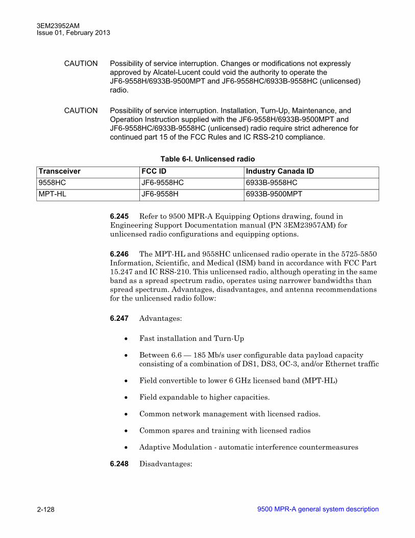
3EM23952AMIssue 01, February 2013
9500 MPR-A general system description2-128
CAUTION Possibility of service interruption. Changes or modifications not expressly approved by Alcatel-Lucent could void the authority to operate the JF6-9558H/6933B-9500MPT and JF6-9558HC/6933B-9558HC (unlicensed) radio.
CAUTION Possibility of service interruption. Installation, Turn-Up, Maintenance, and Operation Instruction supplied with the JF6-9558H/6933B-9500MPT and JF6-9558HC/6933B-9558HC (unlicensed) radio require strict adherence for continued part 15 of the FCC Rules and IC RSS-210 compliance.
6.245 Refer to 9500 MPR-A Equipping Options drawing, found in Engineering Support Documentation manual (PN 3EM23957AM) for unlicensed radio configurations and equipping options.
6.246 The MPT-HL and 9558HC unlicensed radio operate in the 5725-5850 Information, Scientific, and Medical (ISM) band in accordance with FCC Part 15.247 and IC RSS-210. This unlicensed radio, although operating in the same band as a spread spectrum radio, operates using narrower bandwidths than spread spectrum. Advantages, disadvantages, and antenna recommendations for the unlicensed radio follow:
6.247 Advantages:
• Fast installation and Turn-Up
• Between 6.6 � 185 Mb/s user configurable data payload capacity consisting of a combination of DS1, DS3, OC-3, and/or Ethernet traffic
• Field convertible to lower 6 GHz licensed band (MPT-HL)
• Field expandable to higher capacities.
• Common network management with licensed radios.
• Common spares and training with licensed radios
• Adaptive Modulation - automatic interference countermeasures
6.248 Disadvantages:
Table 6-I. Unlicensed radioTransceiver FCC ID Industry Canada ID9558HC JF6-9558HC 6933B-9558HCMPT-HL JF6-9558H 6933B-9500MPT
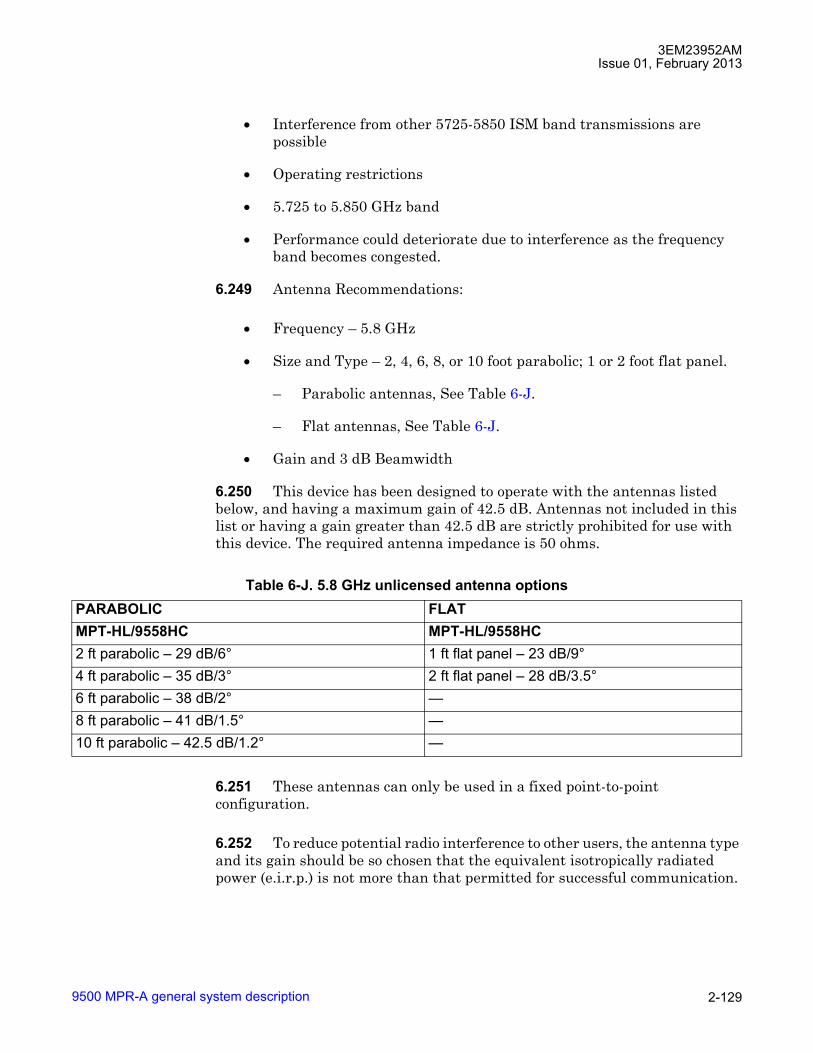
3EM23952AMIssue 01, February 2013
9500 MPR-A general system description 2-129
• Interference from other 5725-5850 ISM band transmissions are possible
• Operating restrictions
• 5.725 to 5.850 GHz band
• Performance could deteriorate due to interference as the frequency band becomes congested.
6.249 Antenna Recommendations:
• Frequency � 5.8 GHz
• Size and Type � 2, 4, 6, 8, or 10 foot parabolic; 1 or 2 foot flat panel.
� Parabolic antennas, See Table 6-J.
� Flat antennas, See Table 6-J.
• Gain and 3 dB Beamwidth
6.250 This device has been designed to operate with the antennas listed below, and having a maximum gain of 42.5 dB. Antennas not included in this list or having a gain greater than 42.5 dB are strictly prohibited for use with this device. The required antenna impedance is 50 ohms.
6.251 These antennas can only be used in a fixed point-to-point configuration.
6.252 To reduce potential radio interference to other users, the antenna type and its gain should be so chosen that the equivalent isotropically radiated power (e.i.r.p.) is not more than that permitted for successful communication.
Table 6-J. 5.8 GHz unlicensed antenna optionsPARABOLIC FLATMPT-HL/9558HC MPT-HL/9558HC2 ft parabolic � 29 dB/6° 1 ft flat panel � 23 dB/9°4 ft parabolic � 35 dB/3° 2 ft flat panel � 28 dB/3.5°6 ft parabolic � 38 dB/2° �8 ft parabolic � 41 dB/1.5° �10 ft parabolic � 42.5 dB/1.2° �

3EM23952AMIssue 01, February 2013
9500 MPR-A general system description2-130
6.253 The antenna(s) used for this transmitter must be installed to provide a separation distance of at least 12 meters from all persons and must not be co-located or operating in conjunction with any other antenna or transmitter.
DANGER Possibility of personal injury. Danger of public exposure to long term RF radiated energy. When using a 1 ft flat panel antenna with a 1 watt (+30 dBm) output power, the antenna must be located in an area that does not allow the general population access to within 12 meters (5.8 Ghz) of the antenna.
6.254 Frequency Plan:
• For MPT-HL frequency plan for the 5.725 and 5.850 GHz unlicensed band, refer to Figure 6-24.
• For 9558HC frequency plan for the 5.725 and 5.850 GHz unlicensed band, refer to Figure 6-25.
6.255 Output Power: A requirement of operating in the unlicensed band is to limit transmit output power to not more than +30.0 dBm at the antenna port. It is the responsibility of the user to transmit not more than +30.0 dBm.
NOTE: To meet FCC part 15 requirements, output power for 9558HC 30 MHz 4QAM and 8QAM channels must not be provisioned greater than 24 dBm. This is not enforced by the user interface and is the responsibility of the operator to guarantee provisioning of the radio transmit power. For transmit power specification, refer to the 9500 MPR-A MPT-HC Modem Specifications (PN 3EM23959AAAATQZZA).

3EM23952AMIssue 01, February 2013
9500 MPR-A general system description 2-131
Figure 6-24 Frequency plan MPT-HL: 5.725 to 5.850 GHz unlicensed band(FCC Part 15 and IC RSS-210)
950-0255-1041612
The drawing above shows the 5 MHz bandwidth channels used by the JF6-9558H/6933B-9500MPT
radio. Gray channels are designated "G". Blue channels are designated "B". Transmit
and receive channels have a 65 MHz frequency separation.
1.
2.
3.
Notes:
RF filters are centered on channels G3, B3, G3', and B3'.
The flexibility of the JF6-9558H/6933B-9500MPT allows any radio to grow to 183 Mb/s without a
hardware upgrade.
G1 G2 G3 G4 G5 B1 B2 B3 B4 B5
G1 G3 G5 B1 B3 B5
G2 G4 B2 B4
G3 B3
G1' G2' G3' G4' G5' B1' B2' B3' B4' B5'
G1' G3' G5' B1' B3' B5'
G2' G4' B2' B4'
G3' B3'
5 MHz
10 MHz
10 MHz
30 MHz
5725 5787.5 5850 MHz
TransmitChannel
FrequencyMHz
ReceiveChannel
FrequencyMHz
G1 5730 G1' 5795
G2 5735 G2' 5800
G3 5740 G3' 5805
G4 5745 G4' 5810
G5 5750 G5' 5815
B1 5760 B1' 5825
B2 5765 B2' 5830
B3 5770 B3' 5835
B4 5775 B4' 5840
B5 5780 B5' 5845
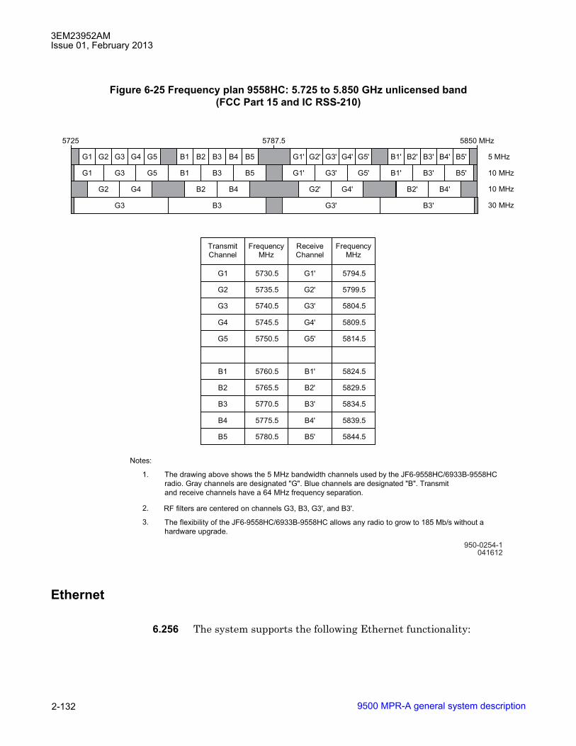
3EM23952AMIssue 01, February 2013
9500 MPR-A general system description2-132
Ethernet
6.256 The system supports the following Ethernet functionality:
Figure 6-25 Frequency plan 9558HC: 5.725 to 5.850 GHz unlicensed band(FCC Part 15 and IC RSS-210)
950-0254-1041612
The drawing above shows the 5 MHz bandwidth channels used by the JF6-9558HC/6933B-9558HC
radio. Gray channels are designated "G". Blue channels are designated "B". Transmit
and receive channels have a 64 MHz frequency separation.
1.
2.
3.
Notes:
RF filters are centered on channels G3, B3, G3', and B3'.
The flexibility of the JF6-9558HC/6933B-9558HC allows any radio to grow to 185 Mb/s without a
hardware upgrade.
G1 G2 G3 G4 G5 B1 B2 B3 B4 B5
G1 G3 G5 B1 B3 B5
G2 G4 B2 B4
G3 B3
G1' G2' G3' G4' G5' B1' B2' B3' B4' B5'
G1' G3' G5' B1' B3' B5'
G2' G4' B2' B4'
G3' B3'
5 MHz
10 MHz
10 MHz
30 MHz
5725 5787.5 5850 MHz
TransmitChannel
FrequencyMHz
ReceiveChannel
FrequencyMHz
G1 5730.5 G1' 5794.5
G2 5735.5 G2' 5799.5
G3 5740.5 G3' 5804.5
G4 5745.5 G4' 5809.5
G5 5750.5 G5' 5814.5
B1 5760.5 B1' 5824.5
B2 5765.5 B2' 5829.5
B3 5770.5 B3' 5834.5
B4 5775.5 B4' 5839.5
B5 5780.5 B5' 5844.5
3EM23952AMIssue 01, February 2013
9500 MPR-A general system description 2-133
Ethernet traffic management
6.257 Ethernet traffic is all the traffic entering the MPR-A network from user Ethernet ports.
6.258 Ethernet traffic is switched using either 802.1D MAC Address Bridge, 802.1Q Virtual Bridge, or 802.1ad Provider Bridge.
802.1D
6.259 When the system is configured in 802.1D mode all Ethernet traffic is routed according to the destination MAC address without regard to VLAN ID.
802.1Q
6.260 When the system is configured in 802.1Q mode all Ethernet traffic is routed according to the VLAN IDs.
6.261 When 802.1Q mode is enable, VLAN 1 is automatically created. All user Ethernet ports and all radio ports are members of VLAN 1. VLAN 1 is not editable. In egress VLAN 1 is always removed from all ports.
6.262 The default configuration is 802.1Q.
802.1ad
6.263 When the NE is configured in Provider Bridge mode, the forwarding of Ethernet traffic is managed according to Service VLAN (S-VLAN). Each Service VLAN represents a service instance that Ethernet traffic from a customer network is mapped to.
6.264 In Provider Bridge mode, an S-VLAN is assigned to all Ethernet frames managed by the NE. The assignment of an S-VLAN to an Ethernet frame ingressing the NE is done according to the type of the Provider Bridge port:
• NNI: this is an interface internal to the Provider Bridged Network. S-VLAN is assigned based on S-VLAN ID carried by S-VLAN Tag or based on the ingress interface in case of S-VLAN untagged frames
• UNI (port based): this is an interface at the edge of the Provider Bridged Network. S-VLAN is assigned based on User Ethernet port (Port-based service interface) regardless of the type of customer traffic (C-VLAN tagged or untagged)

3EM23952AMIssue 01, February 2013
9500 MPR-A general system description2-134
• UNI: this is an interface at the edge of the Provider Bridged Network. S-VLAN is assigned based on C-VLAN ID carried by C-VLAN Tag or based on User Ethernet port in case of untagged frames (C-tagged service interface)
6.265 UNI (non port based) is not managed in the current release. This means that only Port-based services can be setup enabling Provider Bridge mode.
Provider bridge components
6.266 A bridge whose ports are all NNIs or a mixture of NNIs and UNI (port based) is supported by a single S-VLAN Component. An S-VLAN Component is a VLAN-aware bridge able to recognize, insert, and remove S-VLAN tags. It is managed by an S-VLAN Table and by parameters related to NNI and UNI (port based).
6.267 A bridge having one or more ports configured as CEP, is supported by a single S-VLAN Component and as many C-VLAN Components as the number of CEPs. A C-VLAN Component is a VLAN-aware bridge able to recognize, insert, and remove C-VLAN tags. In the context of Provider Bridge management it is managed by parameters related to CEP, mainly to define the C-VLAN to S-VLAN mapping.
Ethernet frames processing
6.268 When the NE is working in Provider Bridge mode, all the switches process Ethernet frames according to S-VLAN Tag to perform forwarding, filtering, policing, etc. The tag of a single tagged Ethernet frame or the outer tag of a double tagged frame is recognized as an S-VLAN Tag according to the port S-VLAN TPID.
Cross-connected flows processing
6.269 When the NE is working in Provider Bridge mode, cross-connected flows are managed as single S-VLAN tagged frames. This implies that User Ethernet ports being end-point of a cross-connection must be NNIs. The NE does not allow the set of a cross-connection not having a NNI as end-point.
6.270 You cannot change a NNI to a UNI (port based) when cross-connections are present that use the NNI as an end-point.
6.271 Provider Bridge mode and Ethernet L2 LAG are not compatible.

3EM23952AMIssue 01, February 2013
9500 MPR-A general system description 2-135
Bridge type change
6.272 To change the NE bridge mode from 802.1D (MAC Bridge) to 802.1ad (Provider Bridge) all cross-connections must be removed. The NE does not check for cross-connections before performing the change.
If Provider Bridge mode is activated with cross-connections still configured, the delivery of cross-connected traffic is not guaranteed.
All User Ethernet interfaces are set as NNI with S-VLAN TPID equal to 0x8100. The S-VLAN Table is empty except for S-VLAN having S-VLAN ID 1.
6.273 The change of NE bridge mode from 802.1Q (Virtual Bridge) to 802.1ad (Provider Bridge) does not require the removal of existing cross-connections or the removal of VLANs defined in the VLAN Table.
Changing from Virtual Bridge to Provider Bridge will cause the NE to perform a restart.
CAUTION Possibility of service interruption. There may be an impact on the delivery of cross-connected and Ethernet traffic.
All User Ethernet interfaces are set as NNI with S-VLAN TPID equal to 0x8100. The S-VLAN Table is filled with S-VLANs having S-VLAN ID equal to the VLAN ID of VLANs previously defined in the VLAN Table. Port VLAN ID and Port Priority assigned to User Ethernet interfaces are assigned as Port S-VLAN ID and Port Priority of NNIs. This allows continuing to deliver existing C-VLAN tagged Ethernet traffic even if the NE bridge mode is changed to Provider Bridge. C-VLANs are seen by the NE as S-VLANs since all the ports are NNI with an S-VLAN TPID the same as the C-VLAN TPID.
The C-VLAN Translation feature is not available when the NE is configured in Provider Bridge mode. The request to enable the Provider Bridge mode when there are translated C-VLANs on any User Ethernet interface will be refused.
6.274 To change the NE bridge mode from 802.1ad (Provider Bridge) to 802.1D (MAC Bridge) all defined S-VLANs must be removed.
The NE will check for S-VLANs before performing the change. If an S-VLAN is present, the NE will refuse to migrate from Provider Bridge to MAC Bridge mode.
6.275 To change the NE bridge mode from 802.1ad (Provider Bridge) to 802.1Q (Virtual Bridge) all defined S-VLANs must be removed.

3EM23952AMIssue 01, February 2013
9500 MPR-A general system description2-136
The NE will check for S-VLANs before performing the change. If an S-VLAN is present, the NE will refuse to migrate from Provider Bridge to Virtual Bridge mode.
6.276 To change the bridge type from 802.1Q (Virtual Bridge) to 802.1D (MAC bridge), the content of the VLAN table and the VLAN assigned to the user Ethernet ports have to be deleted before the bridge type is changed.
Frame type
6.277 The system supports the following Ethernet Frame types:
• Ethernet v2
• 802.3
• 802.1Q
Quality of service (QoS)
6.278 The QoS feature assigns the priority for Ethernet packets according to the selected QoS mode. See Figure 6-26 for an overview of the QoS implementation.
6.279 QoS feature provides eight internal queues to support different traffic priorities. The QoS function assigns Ethernet packets to one of the eight egress traffic queues.
Figure 6-26 QoS configuration
3EM23952AMIssue 01, February 2013
9500 MPR-A general system description 2-137
QoS classification
6.280 QoS classification determines the method the system uses to assign packet priority.
6.281 QoS classification criterion is assigned at the NE level and applied to all radio and Ethernet ports.
6.282 The system supports the following QoS classification modes:
• Disabled
• DiffServ
• IEEE 802.1p
Disabled
6.283 All Ethernet traffic has the same priority (FIFO).
6.284 All packets are assigned the lowest priority queue.
6.285 Disabled is the default QoS classification mode.
DiffServ
6.286 Default Ethernet traffic QoS classification is per RFC2474.
6.287 Each packet is classified based on Differentiated Service Code Point (DSCP) field in the IPv4 or IPv6 packet header to determine packet priority.
6.288 DSCP values are mapped to one of five internal Forwarding Classes.
6.289 DSCP values apply to the following VLAN bridge modes:
• 802.1Q Virtual Bridge
• 802.1D MAC Address Bridge
6.290 When incoming packets are not IPv4 or IPv6, the packets are assigned to Q1.

3EM23952AMIssue 01, February 2013
9500 MPR-A general system description2-138
IPv4 traffic class management
6.291 The system supports IPv4 Traffic class management. IPv4 Traffic management provides customization of DiffServ priority to Queue for IPv4 frames for queuing/delivery purposes.
6.292 IPv4 Traffic class management is supported on all P8ETH and CSM-E user Ethernet ports, ODU300, and MPT ODU radio ports.
6.293 IPv4 Traffic class management is not supported on MPT-HL radio ports.
IPv6 traffic class management
6.294 The system supports IPv6 Traffic class management. IPv6 Traffic class management is used to identify and distinguish between different classes and priorities of IPv6 packets for queuing/delivery purposes.
6.295 IPv6 Traffic class management is supported on all P8ETH and CSM-E user Ethernet ports, ODU300, and MPT ODU radio ports.
6.296 IPv6 Traffic class management is not supported on MPT-HL radio ports.
IEEE 802.1p
6.297 Default Ethernet traffic QoS classification is per IEEE 802.1Q.
6.298 Priority value is carried by Priority Code Point (PCP) field.
6.299 PCP values are mapped to one of five internal forwarding classes.
6.300 PCP values apply to the following VLAN bridge modes:
• 802.1Q Virtual Bridge
• 802.1D MAC Address Bridge
6.301 When incoming packets do not carry a valid 802.1p priority tag (untagged frame), priority is assigned according to the following:
• 802.1Q Virtual Bridge: port priority
• 802.1D MAC Address Bridge: priority 1

3EM23952AMIssue 01, February 2013
9500 MPR-A general system description 2-139
Priority queue mapping
6.302 The system supports priority queue mapping. Priority queue mapping allows a user to provision the priority queue management of Diffserv, 802.1p, and MEF-8 external traffic flows.
6.303 Priority queue mapping is supported on all P8ETH and CSM-E user Ethernet ports and all radio ports except MPT-HL radio ports.
QoS priority value to internal forwarding class
6.304 The QoS feature allows the user to customize QoS priority values (PCP or DSCP) to internal forwarding class on a per priority value basis.
6.305 QoS priority values to internal forwarding classes are provisionable using the following:
• Internal forwarding classes FC0 through FC4 are provisionable
• Internal forwarding classes FC5 through FC7 are NOT provisionable
• Provisioned at the NE level and applied to all radio and Ethernet ports
• QoS priority to internal forwarding classes are provisionable for the following QoS classification criterion:
� IEEE 802.1p
� DiffServ
IEEE 802.1p
6.306 802.1p priority values to internal forwarding classes are provisionable using the following:
• each PCP value can be mapped to only one internal forwarding class
• multiple PCP values can be mapped to the same internal forwarding class
• each time 802.1 p QoS classification criterion is provisioned, the default mapping between PCP values and internal forwarding classes is applied
• default internal forwarding class values may be retrieved
• provisioned internal forwarding class values may be restored

3EM23952AMIssue 01, February 2013
9500 MPR-A general system description2-140
6.307 Refer to Table 6-K for default 802.1p to internal forwarding class mapping.
DiffServ
6.308 DiffServ priority values to internal forwarding classes are provisionable using the following:
• each DSCP value can be mapped to only one internal forwarding class
• multiple DSCP values can be mapped to the same internal forwarding class
• when DiffServ classification criterion is provisioned, the default mapping between DSCP values and internal forwarding classes are applied
• default internal forwarding class values may be retrieved
• provisioned internal forwarding class values may be restored
6.309 Refer to Table 6-L for default DiffServ to internal forwarding class mapping.
Table 6-K. Default 802.1p QoS classification criteria to internal forwarding classPCP Internal
ForwardingClass
DefaultEgressQueue
Traffic Type
N/A 7 (Highest) Q8 TDM2TDMN/A 6 Q7 TDM2ETHN/A 5 Q6 TMN111 (7) 4 Q5 Generic Ethernet110 (6) 3 Q4101 (5) 2 Q3100 (4) 2 Q3011 (3) 1 Q2010 (2) 1 Q2001 (1) 0 Q1000 (0) 0 (Lowest) Q1

3EM23952AMIssue 01, February 2013
9500 MPR-A general system description 2-141
Internal forwarding class to queue mapping
6.310 The QoS feature does not support customizing the mapping from internal forwarding class the egress queue. The QoS configuration tool does allow the user to view internal forwarding classes to Ethernet output queues mapping.
Table 6-L. Default DiffServ QoS classification criteria to internal forwarding classPCP Internal
ForwardingClass
DefaultEgressQueue
TrafficType
N/A 7 (Highest) Q8 TDM2TDMN/A 6 Q7 TDM2ETHN/A 5 Q6 TMN111000 (56) Class Selector 7 4 Q5 Generic Ethernet110000 (48) Class Selector 6 4 Q51011100 (46) EF 4 Q5101000 (40) Class Selector 5 4 Q5100110 (38) AF4 High 3 Q4100100 (36) AF4 Medium 3 Q4100010 (34) AF4 Low 3 Q4100000 (32) Class Selector 4 3 Q4011110 (30) AF3 High 2 Q3011100 (28) AF3 Medium 2 Q3011010 (26) AF3 Low 2 Q3011000 (24) Class Selector 3 2 Q3010110 (22) AF2 High 1 Q2010100 (20) AF2 Medium 1 Q2010010 (18) AF2 Low 1 Q2010000 (16) Class Selector 2 1 Q2001110 (14) AF1 High 1 Q2001100 (12) AF1 Medium 1 Q2001010 (10) AF1 Low 1 Q2001000 (8) Class Selector 1 1 Q2000000 (0) Class Selector 0 1 Q2All Remaining Values 0 (Lowest) Q1

3EM23952AMIssue 01, February 2013
9500 MPR-A general system description2-142
Scheduler type queue mapping
6.311 The system supports scheduler type queue mapping. Scheduler type queue mapping allows a user to provision the scheduler of Diffserv, 802.1p, and MEF-8 external traffic flows as either High Queue Preempt (HQP) or Deficit Weighted Round Robin (DWRR) scheduling.
6.312 Priority queue mapping is supported on all P8ETH and CSM-E user Ethernet ports and all radio ports except MPT-HL radio ports.
Queue scheduler algorithm
6.313 The QoS queue scheduler algorithm determines the method queues are serviced.
6.314 The QoS queue scheduler algorithm maybe customized using the following:
• Provisioned at the NE level and applied to all radio QoS
• Queues Q6 through Q8 are NOT provisionable
• Queues Q1 through Q5 are provisionable
• Supported scheduling algorithms:
� Deficit Weighted Round Robin (DWRR) (supported weight range: 1 to 32)
� Strict Priority (SP)
• Provisioned continuos with SP always applied to the highest priority queues
• Default values may be retrieved
• Provisioned values may be restored
6.315 Refer to Table 6-M for the default queue scheduling algorithm.
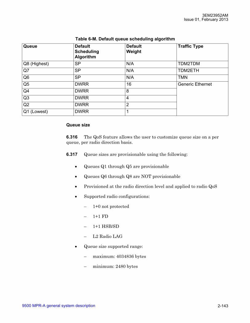
3EM23952AMIssue 01, February 2013
9500 MPR-A general system description 2-143
Queue size
6.316 The QoS feature allows the user to customize queue size on a per queue, per radio direction basis.
6.317 Queue sizes are provisionable using the following:
• Queues Q1 through Q5 are provisionable
• Queues Q6 through Q8 are NOT provisionable
• Provisioned at the radio direction level and applied to radio QoS
• Supported radio configurations:
� 1+0 not protected
� 1+1 FD
� 1+1 HSB/SD
� L2 Radio LAG
• Queue size supported range:
� maximum: 4034836 bytes
� minimum: 2480 bytes
Table 6-M. Default queue scheduling algorithmQueue Default
SchedulingAlgorithm
DefaultWeight
Traffic Type
Q8 (Highest) SP N/A TDM2TDMQ7 SP N/A TDM2ETHQ6 SP N/A TMNQ5 DWRR 16 Generic EthernetQ4 DWRR 8Q3 DWRR 4Q2 DWRR 2Q1 (Lowest) DWRR 1

3EM23952AMIssue 01, February 2013
9500 MPR-A general system description2-144
• Modem profile change to one of the following parameters restores the default queue size values:
� channel spacing
� modulation
� adaptive modulation reference modulation
• Protection configuration change:
� for 1+0 to 1+1:
the spare radio channel takes the queue sizes of the main radio channel
� for 1+1 to 1+0:
main radio channel maintains the queue sizes of the main radio channel
spare radio channel takes the default queue sizes according to the configured modem profile
• Default values may be retrieved using QoS Configuration tool
• Provisioned values may be restored using QoS Configuration tool
6.318 An estimated maximum delay for an Ethernet frame is displayed by the QoS Configuration tool based upon the provisioned QoS values.
6.319 The estimated maximum delay is calculated according to the following provisioned parameters:
• Queue size in bytes
• Ethernet available bandwidth of the radio channel
• Scheduling algorithm applied to the queue
• Weight (for scheduling algorithm DWRR)
QoS with jumbo frame
6.320 While there is no physical limitation to the number of ports that can receive jumbo frames. If jumbo flows are transmitted toward the same port into two different queues, the QoS could adversely affect the jumbo frames sent to the lowest priority queue. It is recommended to forward jumbo frame only to queue Q1 (lowest priority).

3EM23952AMIssue 01, February 2013
9500 MPR-A general system description 2-145
QoS in the Core-E card
6.321 Figure 6-27 shows an overview of the QoS implementation inside the switch.
6.322 The QoS feature of the Ethernet switch provides eight internal queues per port to support different traffic priorities. Typically the high-priority traffic experiences less delay than that low-priority in the switch under congested conditions.
6.323 According to QoS mode configured in the switch, packets are mapped to the appropriate egress queue on each Ethernet/radio port.
6.324 Packets are not mapped directly to egress queues. Instead packet are first mapped to one of eight internal forwarding classes according to the QoS mode selected. These internal forwarding classes are then mapped to one of eight egress queues.
6.325 The eight egress queues are as follows:
• Queue 8: TDM2TDM traffic (highest priority)
• Queue 7: TDM2ETH traffic
• Queue 6: TMN traffic
Figure 6-27 QoS in the Core-E unit

3EM23952AMIssue 01, February 2013
9500 MPR-A general system description2-146
• Queues 1 to 5: generic Ethernet traffic
QoS in the modem MOD300 card
6.326 Figure 6-27 shows an overview of the QoS implementation inside the Modem card which is used to interface the ODU300.
6.327 The QoS feature provides eight internal queues to support different traffic priorities. The QoS function assigns packets to one of the eight egress transmit queues as defined by Ethernet flow classification.
QoS in the MPT-HC/XP
6.328 The Radio QoS is implemented on the MPT-HC/XP (not on the MPT Access Card).
6.329 The MPT-HC/XP radio QoS features are identical to the QoS in the modem MOD300 card.
QoS in the MPT-HL
6.330 The Radio QoS is implemented on the MPT-HL (not on the Ethernet Access Card).
Figure 6-28 QoS in the modem card

3EM23952AMIssue 01, February 2013
9500 MPR-A general system description 2-147
6.331 The MPT-HL radio QoS features are identical to the QoS in the modem MOD300 card.
6.332 The QoS function inside the system is the result of a distributed implementation in the switch and Radio Interface modules. Both of these QoS functions must be properly configured in order to get the desired behavior on Ethernet flows that will be transmitted on the Radios.
Ethernet features provisioned by craft terminal
6.333 The following Ethernet features are supported provisioned using the Craft Terminal.
C-VLAN translation
6.334 The system supports C-VLAN Translation on user Ethernet interfaces, the translation is applied bi-directional.
6.335 Tagged ingress frames entering the User Ethernet interface, C-VLAN ID (From), are changed to a new C-VLAN ID (To). At the same time, tagged egress frames, C-VLAN ID (To) are changed to C-VLAN ID (From) exiting the User Ethernet interface.
6.336 The PCP field and CFI field are left unchanged.
6.337 The available set of C-VLAN IDs (To) is the list of VLAN IDs which have the User Ethernet interface as a member of the VLAN port set and which have at most two ports (User Ethernet interface and another Ethernet or Radio port) as members of the VLAN port set.
6.338 C-VLAN Translation is supported:
• in 802.1Q Virtual Bridge mode
• on Core-E and MSS/CORE user Ethernet interfaces
• on P8ETH user Ethernet interfaces
• up to eight C-VLAN IDs (from) can be translated to C-VLAN IDs (to) per user Ethernet interface
6.339 A User Ethernet interface can not be disabled when the C-VLAN Translation feature is enabled on the interface.
3EM23952AMIssue 01, February 2013
9500 MPR-A general system description2-148
6.340 When a C-VLAN ID is selected as C-VLAN ID (To), the following actions are not permitted:
• modification of the C-VLAN parameters
• deletion of the C-VLAN ID
6.341 C-VLAN Translation is provisioned using the Craft Terminal.
6.342 The VLAN ID selected as C-VLAN ID (From) does not require VLAN creation using the VLAN Configuration Tool.
6.343 When a VLAN ID is selected as C-VLAN ID (From), the creation/modification of that VLAN in the VLAN Configuration Tool is not supported.
6.344 C-VLAN Translation feature is not supported with the following features:
• Ethernet Ring Protection Switching (ERPS)
• L2 Radio Link Aggregation
• VLAN Rate Limiter
• ECFM
Port based rate limiting
6.345 The system supports Port based Rate Limiting on user Ethernet interfaces. Port based Rate Limiting allows a user to provision on a per user Ethernet port basis the maximum data rate on ingress and egress directions.
6.346 The Rate Limiter is managed according to a Leaky Bucket algorithm, Ethernet frames that do not find room in the Bucket are dropped.
6.347 The parameters of Rate Limiter are:
• Committed Information Rate (CIR): Ethernet throughput not taking into account Preamble and IFG frames.
• Committed Burst Size (CBS)
6.348 CIR is configured in the range from 64 Kbit/s to 1,000,000 Kbit/s in step of 64 Kbit/s. The default value for CIR is 64 Kbit/s.

3EM23952AMIssue 01, February 2013
9500 MPR-A general system description 2-149
6.349 CBS is configured in the range from 4 Kbytes (4096 bytes) to 16 MBytes in steps of 4 Kbytes. The default value for CBS is 12 Kbytes.
6.350 Ingress Rate Limiter and Egress Rate Limiter can be enabled/disabled independently.
6.351 Port based Rate Limiting is supported:
• in 802.1D MAC Bridge mode
• in 802.1Q Virtual Bridge mode
• in 802.1ad Provider Bridge mode
• on Core-E user Ethernet interfaces
• on P8ETH user Ethernet interfaces
6.352 A User Ethernet interface can not be disabled when the Port based Rate Limiting feature is enabled on the interface.
6.353 Port based Rate Limiting is provisioned using the Craft Terminal.
6.354 In cases were Port based Rate Limiting was provisioned using file based configuration, it is required to remove the file based Port based Rate Limiting configuration prior to provisioning using the Craft Terminal.
Storm control (broadcast, multicast, and unknown unicast)
6.355 The system supports traffic Storm Control for the following Ethernet traffic frame types:
• Broadcast
• Multicast
• Unknown Unicast
6.356 Storm Control provides a mechanism to control the effects of broadcast, multicast, and unknown unicast storms on physical user Ethernet interfaces. This helps prevent traffic storms from being disruptive and degrading network performance.
6.357 When storm control is enabled, and in a 1 second time interval, the number of broadcast, multicast, and/or unknown unicast Ethernet frames exceeds the configured threshold, a dropping mechanism is applied.

3EM23952AMIssue 01, February 2013
9500 MPR-A general system description2-150
6.358 Frame rate thresholds are provisionable for broadcast, multicast, and unknown unicast traffic. Frame rate thresholds are configured from 0 Frame/s to 16,777,215 Frame/s. The default threshold for all frame types is 100 Frame/s.
6.359 Storm Control is supported:
• in 802.1D MAC Bridge mode
• in 802.1Q Virtual Bridge mode
• in 802.1ad Provider Bridge mode
• on Core-E user Ethernet interfaces
• on P8ETH user Ethernet interfaces
6.360 Storm Control is enabled/disabled for all supported frame types at one time.
6.361 A User Ethernet interface can not be disabled when the Storm Control feature is enabled on the interface.
6.362 Storm Control is provisioned using the Craft Terminal.
6.363 In cases were the Storm Control feature was provisioned using file based configuration, it is required to remove the file based Storm Control configuration prior to provisioning using the Craft Terminal.
VLAN based rate limiter
6.364 The system supports a VLAN based Rate Limiter on user Ethernet interfaces for the ingress direction. VLAN based Rate Limiter allows a user to provision, on a per VLAN ID basis, the maximum data rate for the ingress direction.
6.365 The VLAN IDs available for VLAN based Rate Limiter are those which include the User Ethernet interface as a member of the VLAN port set.
6.366 The Rate Limiter is managed according to a Token Bucket algorithm, Ethernet frames that do not find available tokens are dropped.
6.367 The parameters of VLAN Rate Limiter are:
• Committed Information Rate (CIR): Ethernet throughput not taking into account Preamble and IFG frames.
3EM23952AMIssue 01, February 2013
9500 MPR-A general system description 2-151
• Committed Burst Size (CBS)
6.368 CIR is configured in the range from 64 Kbit/s to 32 Gbit/s in step of 64 Kbit/s. The default value for CIR is 64 Kbit/s.
6.369 CBS is configured in the range from 4 Kbytes (4096 bytes) to 2 MBytes. The default value for CBS is 16 Kbytes.
6.370 VLAN based Rate Limiter is supported:
• in 802.1Q Virtual Bridge mode
• in 802.1ad Provider Bridge mode
• on Core-E user Ethernet interfaces
• on P8ETH user Ethernet interfaces
• up to eight VLAN IDs per user Ethernet interface
6.371 A User Ethernet interface can not be disabled when the VLAN based Rate Limiter feature is enabled on the interface.
6.372 When a VLAN based Rate Limiter is enabled on a VLAN ID, the following actions are not permitted:
• modification of the VLAN parameters
• deletion of the VLAN ID
6.373 VLAN Rate Limiter should not be activated in conjunction with Port based Rate Limiter
6.374 VLAN based Rate Limiter is provisioned using the Craft Terminal.
6.375 In cases where a VLAN based Rate Limiter was provisioned using file based configuration, it is required to remove the file based VLAN based Rate Limiter configuration prior to provisioning using the Craft Terminal.
Per-VLAN per-COS rate limiter
6.376 The system supports a per-VLAN per-COS Rate Limiter on user Ethernet interfaces for the ingress direction.
3EM23952AMIssue 01, February 2013
9500 MPR-A general system description2-152
6.377 The rate limiter is applied to a tagged Ethernet flow classified according to the VLAN ID and PCP fields of the VLAN tag. The flow is identified by one VLAN ID value and one PCP value.
6.378 The VLAN IDs available for per-VLAN per-COS Rate Limiter are those which include the User Ethernet interface as a member of the VLAN port set.
6.379 The Rate Limiter is managed according to a Token Bucket algorithm, Ethernet frames that do not find available tokens are dropped.
6.380 The parameters of per-VLAN per-COS Rate Limiter are:
• Committed Information Rate (CIR): Ethernet throughput not taking into account Preamble and IFG frames.
• Committed Burst Size (CBS)
6.381 CIR is configured in the range from 0 Kbit/s to 1 Gbit/s in step of 64 Kbit/s. The default value for CIR is 64 Kbit/s. A value of 0 Kbit/s indicates a drop of the Ethernet flow.
6.382 CBS is configured in the range from 4 Kbytes (4096 bytes) to 16 MBytes. The default value for CBS is 16 Kbytes. The allowed values for CBS are:
• 4 Kbytes
• 8 Kbytes
• 16 Kbytes
• 32 Kbytes
• 64 Kbytes
• 128 Kbytes
• 256 Kbytes
• 512 Kbytes
• 1 Mbytes
• 2 Mbytes
• 4 Mbytes
3EM23952AMIssue 01, February 2013
9500 MPR-A general system description 2-153
• 8 Mbytes
• 16 Mbytes
6.383 Per-VLAN Per-COS Rate Limiter is supported:
• in 802.1Q Virtual Bridge mode
• in 802.1ad Provider Bridge mode
• on Core-E user Ethernet interfaces
• on P8ETH user Ethernet interfaces
• Up to 16 Rate Limiters can be activated per User Ethernet interface, up to 32 Rate Limiters can be activated on a Core-E card and up to 32 Rate Limiters can be activated on each P8ETH card.
6.384 A User Ethernet interface can not be disabled when the per-VLAN per-COS Rate Limiter feature is enabled on the interface.
6.385 When a per-VLAN per-COS Rate Limiter is enabled on a VLAN ID, the following actions are not permitted:
• modification of the VLAN parameters
• deletion of the VLAN ID
6.386 Per-VLAN per-COS Rate Limiter should not be activated in conjunction with VLAN based Rate Limiter.
CAUTION Possibility of service interruption. When a Per-VLAN Per-CoS Rate Limiter is activated in conjunction with a Port Rate Limiter, the Per-VLAN Per-CoS Rate Limiter must apply to Ethernet frames that meet the Port Rate Limiter parameters.
6.387 Per-VLAN per-COS Rate Limiter is provisioned using the Craft Terminal.
6.388 In cases where a VLAN based Rate Limiter was provisioned using file based configuration, it is required to remove the file based VLAN based Rate Limiter configuration prior to provisioning using the Craft Terminal.

3EM23952AMIssue 01, February 2013
9500 MPR-A general system description2-154
6.389 The value Any can be used as the VLAN ID: the tagged Ethernet flow will be classified according to the value of the PCP field only. The CT and the NE perform a check to verify that two Per-VLAN Per-CoS rate limiters do not exist on the same port where one is identified by PCP value only and another is identified by a specific VLAN ID and the same PCP value as shown in Figure 6-29.
6.390 A check is also performed to verify that a Per-VLAN Per-CoS rate limiter is not created on the same port with a VLAN ID that is already in use to perform a VLAN Rate Limiter, as shown in Figure 6-30.
6.391 A check is performed to verify that a Per-VLAN Per-CoS Rate Limiter identified by PCP value only (VLAN ID = Any) is not created when there is already a VLAN Rate Limiter on the same port, as shown in Figure 6-31.
Ethernet features configured by enhanced configuration file
6.392 The following Ethernet features can be configured using an Enhanced Configuration File.
Figure 6-29 Per-VLAN Per-COS rate limiters with duplicate PCP values
Figure 6-30 Per-VLAN Per-CoS Rate Limiter and VLAN Rate Limiter with the same VLAN ID
Figure 6-31 Per-VLAN Per-CoS Rate Limiter with VLAN ID = Any and a VLAN Rate Limiter
3EM23952AMIssue 01, February 2013
9500 MPR-A general system description 2-155
Access control list
6.393 The system supports Access Control List. Access Control List allows a user to restrict MAC addresses allowed in the network.
Enabling Access Control List feature automatically drops ALL MAC addresses which are not specifically provisioned by the user.
Out of range VLAN swap
6.394 The system supports Out of Range VLAN swap. Out of Range VLAN swap allows transport of VLANs outside the supported range (4081-4094). The out of range VLAN ID is swapped to one supported by the system on ingress and vice versa.
6.395 VLAN swapping is supported on all P8ETH and Core-E user Ethernet ports and all radio ports except MPT-HL radio ports.
Per-flow policer
6.396 The system supports scheduler type queue mapping. Scheduler type queue mapping allows a user to provision the scheduler for Diffserv, 802.1p, and MEF-8 external traffic flows as either High Queue Preempt (HQP) or Deficit Weighted Round Robin (DWRR) scheduling.
6.397 Priority queue mapping is configured via configuration file. Supported on all P8ETH and Core-E user Ethernet ports.
Stacked VLAN (Q-in-Q) tagging
6.398 The system supports Stacked VLAN (Q-in-Q) Tagging. VLAN stacking allows all traffic from a single customer (which could be multiple VLANs) into a single VLAN simplifying management across the network.
6.399 Stacked VLAN (Q-in-Q) Tagging is supported on all P8ETH and Core-E user Ethernet ports and all radio ports except MPT-HL radio ports.
VLAN remarking
6.400 The system supports 802.1p remarking. VLAN remarking allows packets to be remarked specifying a different priority level in the packet header.
3EM23952AMIssue 01, February 2013
9500 MPR-A general system description2-156
6.401 VLAN swapping is configured via configuration file. Supported on all P8ETH and Core-E user Ethernet ports and all radio ports except MPT-HL radio ports.
VLAN swap
6.402 The system supports VLAN swap. VLAN swap allows the inner and outer tags to be swapped on double tagged packets. The inner tag becomes the outer tag and vice versa.
6.403 VLAN remarking is supported on all P8ETH and Core-E user Ethernet ports and all radio ports except MPT-HL radio ports.
Input/output flow control
6.404 The system support for 802.3x asymmetric pause frame towards the link partner.
Input pause feature
6.405 This feature makes the auto-negotiation function willing to stop receiving traffic. When the radio input buffers approach overflow, the function sends a pause message to the link partner that is transmitting data to the radio, telling the device to temporarily stop sending data. The link partner will stop sending data if the device has and is provisioned with the Allow Option Pause function. See Figure 6-32.
6.406 If the link partner is either not equipped with or is not provisioned for input pause, data overflowing the registers in the radio will be lost, regardless of the provisioning for input pause in the radio. Any time there is an overflow, the radio will alarm and indicate Dropped Frames on the Performance Monitor screens.
Output pause feature
6.407 The system does not support 802.3x receive pause frames. When the system receives a pause frame, the pause frame will be dropped.
6.408 Data overflowing the registers in the link partner will be lost regardless of the provisioning for output pause.

3EM23952AMIssue 01, February 2013
9500 MPR-A general system description 2-157
Reserved multicast addresses
6.409 The system handles reserved multicast addresses uniquely since they are designed for layer 2 control protocols. The following actions are supported by the system:
• Discard - The system discards all ingress Ethernet frames and must not generate any egress Ethernet Frame carrying the reserved multicast address.
• Forward - The system accepts all ingress Ethernet frames as standard multicast frames and forwards them accordingly.
• Peer - The system acts as a peer of the connected device in the operation of the relevant Layer 2 Control Protocol.
Figure 6-32 Input/output flow control block diagram
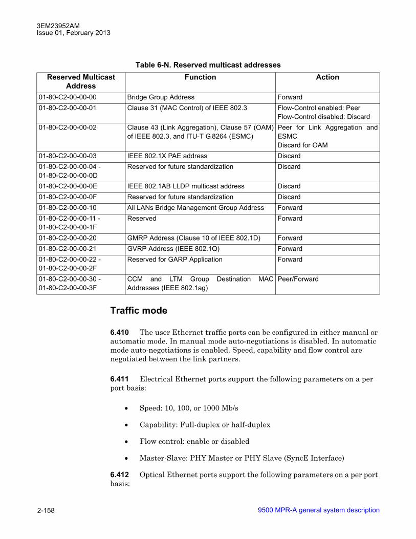
3EM23952AMIssue 01, February 2013
9500 MPR-A general system description2-158
Traffic mode
6.410 The user Ethernet traffic ports can be configured in either manual or automatic mode. In manual mode auto-negotiations is disabled. In automatic mode auto-negotiations is enabled. Speed, capability and flow control are negotiated between the link partners.
6.411 Electrical Ethernet ports support the following parameters on a per port basis:
• Speed: 10, 100, or 1000 Mb/s
• Capability: Full-duplex or half-duplex
• Flow control: enable or disabled
• Master-Slave: PHY Master or PHY Slave (SyncE Interface)
6.412 Optical Ethernet ports support the following parameters on a per port basis:
Table 6-N. Reserved multicast addressesReserved Multicast
Address Function Action
01-80-C2-00-00-00 Bridge Group Address Forward 01-80-C2-00-00-01 Clause 31 (MAC Control) of IEEE 802.3 Flow-Control enabled: Peer
Flow-Control disabled: Discard01-80-C2-00-00-02 Clause 43 (Link Aggregation), Clause 57 (OAM)
of IEEE 802.3, and ITU-T G.8264 (ESMC) Peer for Link Aggregation andESMCDiscard for OAM
01-80-C2-00-00-03 IEEE 802.1X PAE address Discard 01-80-C2-00-00-04 - 01-80-C2-00-00-0D
Reserved for future standardization Discard
01-80-C2-00-00-0E IEEE 802.1AB LLDP multicast address Discard 01-80-C2-00-00-0F Reserved for future standardization Discard 01-80-C2-00-00-10 All LANs Bridge Management Group Address Forward 01-80-C2-00-00-11 - 01-80-C2-00-00-1F
Reserved Forward
01-80-C2-00-00-20 GMRP Address (Clause 10 of IEEE 802.1D) Forward 01-80-C2-00-00-21 GVRP Address (IEEE 802.1Q) Forward 01-80-C2-00-00-22 - 01-80-C2-00-00-2F
Reserved for GARP Application Forward
01-80-C2-00-00-30 - 01-80-C2-00-00-3F
CCM and LTM Group Destination MACAddresses (IEEE 802.1ag)
Peer/Forward

3EM23952AMIssue 01, February 2013
9500 MPR-A general system description 2-159
• Speed: 1000 Mb/s
• Capability: Full-duplex
• Flow control: enable or disabled
• Master-Slave: PHY Master or PHY Slave (SyncE Interface)
Auto-negotiation
6.413 Auto-negotiation is not a stand-alone function, and proper operation and use of all available functions depends on the capabilities of the external customer equipment that is connected to the radio. Just because an auto-negotiation function is checked for provisioning does not automatically mean that function is fully operable. The device on the other end of the cable must also have the capability and be provisioned with a matching function.
6.414 Auto-Negotiate details are beyond the scope of this supplement. When unsure of what functions to check or change from factory default provisioning, leave at default (all auto-negotiation functions are checked). Full auto-negotiation capability is becoming standard for manufacturers of Ethernet devices.
Allow 10, 100, and/or 1000 Mb/s half and full duplex
6.415 If in doubt as to the link speed and mode of the external device connecting Ethernet to the radio, check all boxes for speeds and modes. If you know the external Ethernet device has speed and/or mode limitations, check only the boxes that apply.
Ethernet synchronization messaging channel
6.416 Ethernet Synchronization Messaging Channel (ECSM) is supported on Ethernet interfaces configured for synchronous operation mode support SSM and ESMC processing according to ITU-T G.8264.
6.417 ESMC is supported on Core-E user Ethernet ports.
Ethernet connectivity fault management
6.418 The system supports Ethernet Connectivity Fault Management (CFM). CFM provides the capability for detecting, verifying, and isolating connectivity failures in Virtual Bridged Local Area Networks.
6.419 CFM is supported using the CLI tool.

3EM23952AMIssue 01, February 2013
9500 MPR-A general system description2-160
TACACS+
6.420 The system supports a TACACS+ client as defined by IETF draft-grant-tacacs-02 to perform centralized Authentication, Authorization, and Accounting (AAA) of user logins.
6.421 TACACS+ is supported on MSS-4/8 SNMP, http, and telnet/SSH interfaces.
6.422 Server messages for the SSH interface are discarded if the authentication or authorization is not successful since there will not be a service to display them.
6.423 TACACS+ is transparent to existing 9500MPR authentication procedures.
6.424 Login requests are authenticated using TACACS+ instead of the local user database, whenever TACACS+ is enabled and a configured server is available. The EC shell telnet login is not managed by TACACS+ and is authenticated locally.
6.425 TACACS+ Authorization shall only be used to determine user membership in one of the existing 9500MPR privilege groups. Authorization of individual commands is not supported.
6.426 To avoid a possible password conflict due to the same username in both the TACACS+ and local user databases, user modification of their local account password is denied when TACACS+ is enabled on the SNMP interface. If a password needs to be changed, the change can be completed by an administrator.
6.427 The local user account management by an administrator is not affected by TACACS+ operation except that the administrator must be re-authenticated through TACACS+, when it is enabled on the SNMP interface and a server is available.
6.428 TACACS+ Accounting is supported on a limited basis for WT-CLI and SNMP commands.
Server support
6.429 The client supports a priority list of up to four TACACS+ servers with a unique server encryption key for each.

3EM23952AMIssue 01, February 2013
9500 MPR-A general system description 2-161
6.430 All server exchanges are secured by the TACACS+ protocol by multiplexing the appropriate contents with a string of MD5 hashes based on the provisioned server secret key. The unencrypted mode of operation is not supported. Only the PAP login type (cleartext username and password) is supported. The TACACS+ server must support PAP authentication.
6.431 Server messages and custom prompts received in a TACACS+ response are accepted but not displayed to users.
Authentication/authorization
6.432 Each time an authentication is required on a user interface, the client uses the server selection process to determine if a TACACS+ server is available. When no servers are available, the local login database is used. The authentication request is denied if a matching username and password are not found. If a server is available, the client opens a TCP connection to the selected server and perform authentication/authorization as follows.
6.433 If the connection is successful, an authentication START request is sent. The request contains the PAP username and password, the port type (snmp, http, telnet, test), and the client/manager IP address (http or snmp only).
6.434 If the authentication response is PASS, an authorization REQUEST to start a shell exec service is sent in order to determine the user privilege group.
6.435 The authorization response of PASS-ADD is parsed to locate a command pair, �vacm={administrator | craftperson | operator | viewer}�, that assigns the privilege group for the user. The authorization is denied for any other authorization response or if no valid privilege group is defined for the user. This provides security against authentication of valid users, who are not authorized to access the NE. If the authorization response does not include the command pair �vacm={administrator | craftperson | operator | viewer}�, the login procedure will fail.
6.436 User authentication and authorization management by remote TACACS+ server is not compatible with SNMPv3 user management; see SNMP operating mode (SNMPv3 support). If the NE is configured in SNMPv3 mode, it is not possible to enable TACACS+ on the SNMP interface using the Ethernet features shell.
If TACACS+ is enabled on the SNMP interface, it is not possible to configure the NE in SNMPv3 mode.
3EM23952AMIssue 01, February 2013
9500 MPR-A general system description2-162
Accounting
6.437 When commands are received on a user interface where accounting is enabled, the client uses the server selection process to determine where to send an accounting request. When no servers are available, the latest notifications are held in queue on a space available basis for later reporting. When a server is available, the client opens a TCP connection to the selected server and performs the accounting request as follows:
If the connection is successful, an accounting STOP REQUEST is sent. The request contains a task ID (separate count for each interface), the NE IP address, the client/manager IP address, the port type (snmp, telnet, SSH), stop time, and command notification strings. The username and privilege group is included for the telnet/SSH ports.
An accounting REPLY of SUCCESS indicates that the request was accepted by the server. Any other response from the server is ignored.
6.438 The TACACS+ single-connection mode is not supported. Each TCP connection is closed after the accounting transfer is complete and a new TCP connection is used for the next request. The telnet/SSH interfaces report all WT-CLI commands including any arguments.
6.439 The SNMP interface reports all object ID strings and values contained in any SET command received from a registered manager. The SET commands to register a manager and SET commands to perform a registration or deletion are also reported.
6.440 Accounting notifications are not supported for commands received on the HTTP interface.
6.441 A circular message queue is supported that is capable of storing at least 20 accounting notification events. When the queue is full, the oldest notifications will be removed to keep the latest notifications. Multiple notifications for the same port, user, and client/manager IP address may be included in a single accounting request. The request may be deferred until a minimum number of notifications are held in the queue, a minimum time has passed without additional notifications, or the maximum notifications for a single request have been received.
3EM23952AMIssue 01, February 2013
9500 MPR-A general system description 2-163
Parameters for multiple notifications in a single accounting request
6.442 The deferring of an accounting request is managed according to the following parameters:
� Minimum number of notifications to hold in the queue is 1
� Minimum time to pass without additional notifications is 500 ms
� Maximum number of notifications for a single request is the number that can be held in a payload of 200-1400 bytes.
Server selection
6.443 The server selection process determines the server or authentication method to be used based on the following process:
6.444 The server list is searched to find the highest priority server that currently has no attempt failures (i.e. skip any servers with attempt failures).
6.445 The primary server is selected, if any lower priority servers have no attempt failures and the time since the primary server last failure exceeds the configured holdoff time. This allows the primary server to again be used for the first connection attempt of the authentication request but return directly to the last reachable server if the attempt fails. Otherwise, the highest priority server with no attempt failures is selected.
6.446 When all servers have attempt failures, the highest priority server from those with the minimum attempt count not exceeding the retry attempt limit is selected. When all servers have exceeded their retry attempt limit, the highest priority server with a time since last attempt failure that exceeds the configured holdoff time is selected.
6.447 The selection process does attempt to use another server or use the local login database if an authentication/authorization request is denied by a reachable server.
Configuration
6.448 The TACACS+ management is implemented through a command in the Ethernet Features shell.
6.449 The command is only supported for users with administrator privilege.
3EM23952AMIssue 01, February 2013
9500 MPR-A general system description2-164
6.450 The command individually enables TACACS+ for telnet/http/snmp/all ports.
6.451 The command supports individual configuration of the following parameters for each server:
• index (1 to 4, 1 is highest priority)
• IP address (IPv4 or IPv6)
• secret key (up to 32 printable characters, default to 0)
• port number (0 to 65535, default to 49)
• timeout (1 to 10 seconds, default to 3)
• retry attempt limit (1 to 3, default to 1)
6.452 Server parameters for the same index may be combined on a single line.
6.453 The command can support configuration of the server holdoff time (45 to 600 seconds, default to 300).
6.454 The user has the responsibility to ensure that valid settings and unique server IP addresses are assigned to each server. Invalid server configuration will result in failed server communication with no configuration warnings.
6.455 The user has the responsibility to ensure that the worst case combination of number of servers, connection attempts and timeouts does not exceed the time limit for the authentication process.
Server monitoring
6.456 TACACS+ status monitoring is implemented through a command in the Ethernet Features shell.
6.457 The command is only supported for users with administrator privilege.
6.458 The command displays the current TACACS+ configuration, attempt failures for each server, and time since last server failure.
3EM23952AMIssue 01, February 2013
9500 MPR-A general system description 2-165
Server validation
6.459 TACACS+ validation testing is implemented through a command in the Ethernet Features shell. This test allows to monitor round-trip response times for determining proper timeout settings and to confirm correct secret keys.
6.460 The command is only supported for users with administrator privilege.
6.461 The command generates a single �dummy� authentication request to each configured server. The authentication response status is reported as TCP Timeout, AA Timeout, or OK. The elapsed time from TCP connection start to the initiation of TCP connection close is reported with tenths of a second resolution.
6.462 The request is sent regardless of holdoff status or attempt counts.
6.463 The server attempt counts are cleared for any server that receives an authentication response (authorization is not required).
6.464 A server response failure is managed the same as any other authentication request.
Ethernet ring protection
6.465 Ethernet Ring Protection (ERP) Switching is implemented according to ITU-T G.8032 specifications which specify a protection switching mechanism and the Automatic Protection Switching (APS) protocol for Ethernet ring topologies.
6.466 The fundamentals of ring protection switching architectures are loop avoidance and the utilization of learning, forwarding, and address table management.
ERP topology
6.467 An ERP topology is a collection of Ethernet Ring Nodes forming a closed physical loop.
6.468 A minimum of two and maximum of sixteen Ethernet Ring Nodes are supported per ERP topology.
6.469 One ERP topology is supported per NE.
3EM23952AMIssue 01, February 2013
9500 MPR-A general system description2-166
6.470 Up to two ERP instances are supported per ERP topology.
6.471 ERP Switching is supported in 802.1Q Bridging Mode ONLY.
6.472 ERP is supported using the following 1+0 unprotected radio interfaces:
• MOD300/ODU300
• MPT-HC/XP connected to MPT Access (support for only one MPT-HC/XP when configured as Ethernet Ring port)
• MPT-HC/XP connected to Core-E (support for up to two MPT-HC/XP configured as Ethernet Ring ports)
6.473 Supported radio interface configurations as Ring Ports are as follows:
• MOD300/ODU300 radio interface as one Ring port (East/West) and MOD300/ODU300 radio interface as other Ring port (West/East)
• MPT-HC/XP connected to MPT Access radio interface as one Ring port (East/West) and MPT-HC/XP connected to MPT Access radio interface as other Ring port (West/East)
• MPT-HC/XP connected to Core-E radio interface as one Ring port (East/West) and MPT-HC/XP connected to Core-E radio interface as other Ring port (West/East)
• MPT-HC/XP connected to MPT Access radio interface as one Ring port (East/West) and MPT-HC/XP connected to Core-E radio interface as other Ring port (West/East)
Ring link
6.474 Ethernet Ring Links connect two adjacent Ethernet Ring Nodes participating in the same ERP Topology.
Ring port
6.475 The Ethernet port used to construct the Ethernet Ring Link is called a Ring Port.
Ring protection link (RPL)
6.476 Loop avoidance in the ring is achieved by guaranteeing that at any time, traffic may flow on all but one of the Ring Links. This particular link is called the Ring Protection Link (RPL).
3EM23952AMIssue 01, February 2013
9500 MPR-A general system description 2-167
RPL owner
6.477 One designated node, the RPL Owner, is responsible to block traffic over the RPL.
6.478 Under a ring failure condition, the RPL Owner is responsible to unblock the RPL, allowing traffic to flow across the RPL.
R-APS protocol
6.479 Ring Automatic Protection Switching (R-APS) protocol is used to coordinate the protection actions over the ring.
ERP instance
6.480 An ERP Instance is responsible for protection of the VLANs that transport traffic over the physical ERP Topology. Up to two ERP Instances are supported per ERP Topology. Each ERP Instance is independent of the other ERP Instance.
6.481 Each ERP Instance has its own RPL and RPL Owner.
6.482 Additionally, each ERP Instance has its own independent R-APS protocol session using dedicated R-APS VLAN ID for protection coordination.
ERP operation
6.483 The protection switching mechanism is based on the Automatic Switching protocol for Ethernet ring topologies, R-APS, and is used to coordinate the protection actions over the ring.
6.484 The fundamentals of this ring protection architecture are:
• principle of loop avoidance.
• utilization of learning, forwarding, and address table mechanisms defined in the Ethernet flow forwarding function.
6.485 Under normal operating conditions the RPL is blocked, and traffic flows on all links in the ring except the RPL. See Figure 6-33 for an example of an ERP Instance in normal operating condition.

3EM23952AMIssue 01, February 2013
9500 MPR-A general system description2-168
6.486 Under a ring link failure condition, the RPL owner is responsible to unblock the RPL. The Ring Node (or nodes) which perform local detection of the signal fail condition, put their Ring Ports in a blocking state the set of VLANs assigned to the ERP Instance on the radio interface where the failure has been detected. See Figure 6-34 for an example of an ERP Instance in a link failure operating condition.
Figure 6-33 Ethernet ring protection, normal operation
950-0223-1
040611
Flow n°1 VLAN A
Flow n°2 VLAN B
Flow n°3 VLAN C
Radio East Radio WestNode C
Node D
Radio East
Radio West
Radio West Radio EastNode A
RPL Owner Radio West
Radio East
Node B
Ring Protection Link (RPL)
RPL Connection Point (Blocked)
VLAN A, VLAN B and VLAN C are Blocked
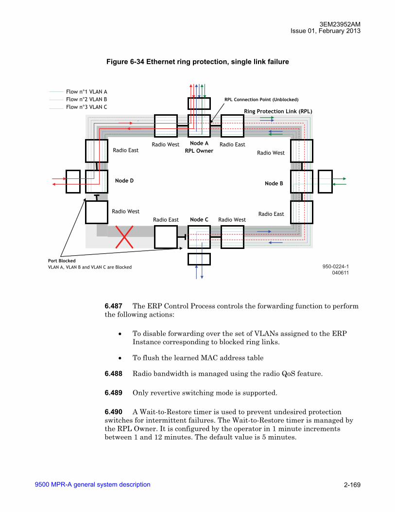
3EM23952AMIssue 01, February 2013
9500 MPR-A general system description 2-169
6.487 The ERP Control Process controls the forwarding function to perform the following actions:
• To disable forwarding over the set of VLANs assigned to the ERP Instance corresponding to blocked ring links.
• To flush the learned MAC address table
6.488 Radio bandwidth is managed using the radio QoS feature.
6.489 Only revertive switching mode is supported.
6.490 A Wait-to-Restore timer is used to prevent undesired protection switches for intermittent failures. The Wait-to-Restore timer is managed by the RPL Owner. It is configured by the operator in 1 minute increments between 1 and 12 minutes. The default value is 5 minutes.
Figure 6-34 Ethernet ring protection, single link failure
950-0224-1
040611
Radio East Radio WestNode C
Node D
Radio East
Radio West
Radio West Radio EastNode A
RPL Owner Radio West
Radio East
Node B
Ring Protection Link (RPL)
RPL Connection Point (Unblocked)
Port Blocked
VLAN A, VLAN B and VLAN C are Blocked
Flow n°1 VLAN A
Flow n°2 VLAN B
Flow n°3 VLAN C
3EM23952AMIssue 01, February 2013
9500 MPR-A general system description2-170
6.491 A Guard Timer is used to prevent ring nodes from receiving outdated R-APS messages. During the guard timer period, all received R-APS messages are ignored by the ERP Control Process. It is configured by the operator in 10 ms increments between 10 ms and 2 seconds. The default value is 500 ms.
6.492 Ethernet traffic is managed only in 802.1Q bridging configuration.
6.493 Traffic is switched according to MAC learning.
6.494 Each Radio interface belonging to the ring is seen as a single interface in the VLAN table port membership.
6.495 In order to deliver Ethernet traffic over the Ring, the operator creates the VLAN and assigns the ring�s ports as members of that VLAN.
Two ERP instances
6.496 Two ERP instances are supported on each ring�s node. Each Ring Instance has its own RPL and RPL Owner. See Figure 6-35 for an example of two ERP Instances in normal operating condition.

3EM23952AMIssue 01, February 2013
9500 MPR-A general system description 2-171
6.497 Under a ring link failure condition, both RPL owners are responsible to unblock their RPL. The Ring Node (or nodes) which perform local detection of the signal fail condition, puts in blocking state for the set of VLANs assigned to both ERP Instances on the radio interface where the failure has been detected. Ethernet flows are managed using radio QoS. Lower priority Ethernet flows may be dropped to maintain higher priority Ethernet flows. See Figure 6-36 for an example of two ERP Instances in a link failure operating condition.
Figure 6-35 Two ERP instances, normal operation
950-0225-1
040611
Flow n°1 VLAN AFlow n°2 VLAN BFlow n°3 VLAN CFlow n°4 VLAN D
Radio East Radio WestNode C
Node D
Radio East
Radio West
Radio West Radio EastNode AERP 1 RPL OwnerERP 2 RPL Owner
Radio West
Radio East
Node B
ERP 2 Instance
ERP 1 Instance
ERP 1 Ring Protection Link (RPL)
RPL Connection Point (Blocked)
VLAN A and VLAN B are Blocked
ERP 2 Ring Protection Link (RPL)
RPL Connection Point (Blocked)
VLAN C and VLAN D are Blocked
Ring bandwidth up to two flows

3EM23952AMIssue 01, February 2013
9500 MPR-A general system description2-172
TDM traffic
6.498 TDM traffic is switched according to cross-connections.
6.499 In normal operation, the VLAN IDs assigned to TDM traffic are cross-connected to an ERP Instance.
6.500 Under a ring link failure condition, the RPL owner is responsible to unblock its RPL. The Ring Node (or nodes) which perform local detection of the signal fail condition, puts in blocking state for the set of TDM VLANs assigned to the ERP Instance on the radio interface where the failure has been detected.
6.501 VLANs used for TDM traffic can not be used for User Ethernet traffic.
TMN
6.502 PPPoE connections are established over each ring�s link.
Figure 6-36 Two ERP instances, single link failure
950-0226-1
040611
Flow n°1 VLAN AFlow n°2 VLAN BFlow n°3 VLAN CFlow n°4 VLAN D
Radio East Radio WestNode C
Node D
Radio East
Radio West
Radio West Radio EastNode AERP 1 RPL OwnerERP 2 RPL Owner
Radio West
Radio East
Node B
ERP 2 Instance
ERP 1 Instance
ERP 1 Ring Protection Link (RPL)
RPL Connection Point (Unblocked)
ERP 2 Ring Protection Link (RPL)
RPL Connection Point (Unblocked)
VLAN C and VLAN D are Blocked
Ring bandwidth up to two flows
Port Blocked for both ERP 1 and ERP 2
VLAN A, VLAN B, VLAN C and VLAN D are Blocked
Ethernet flow dropped
by radio QoS

3EM23952AMIssue 01, February 2013
9500 MPR-A general system description 2-173
6.503 Flooding of Ethernet frames carrying PPPoE must be avoided by sending the frame only to the relevant Ethernet switch interface facing the radio where PPP connection has to be established.
6.504 The OSPF routing protocol must be enabled on every PPP interface. The OSPF calculates the routing path breaking the loop from an IP point of view.
6.505 In case of ring link failure, the PPP connection will cause a recalculation of the OSPF topology in order to have all nodes reachable.
6.506 Static route which have PPP interfaces belonging to the ring as gateway are not supported.
6.507 The VLAN used to deliver TMN traffic is not blocked by any ERP Instance.
Jumbo frame
6.508 The system supports Jumbo frame lengths up to 9728 bytes with VLAN tag or 9724 without VLAN tag.
Ethernet L2 LAG
6.509 The system supports 802.1ad Ethernet Link Aggregation (L2 LAG).
6.510 User Ethernet ports (electrical or optical) on the same Core-E card can be provisioned as a member of an Ethernet L2 LAG port.
Figure 6-37 Ethernet L2 LAG block diagram

3EM23952AMIssue 01, February 2013
9500 MPR-A general system description2-174
6.511 Ethernet L2 LAG ports supports a minimum of two and maximum of four user Ethernet ports.
6.512 Ethernet L2 LAG size is restricted to the following:
• up to eight Ethernet L2 LAG ports per NE
• up to four electrical Ethernet ports per Ethernet L2 LAG
• up to two optical Ethernet ports per Ethernet L2 LAG
6.513 The LACP protocol is supported.
6.514 Members of an Ethernet L2 LAG port must be:
• same media type (either all electrical or optical)
• full duplex
• a single data rate
• same data rate as all other members of the L2 LAG
• provisioned either Auto negotiations enabled or disabled on all user Ethernet ports
6.515 To add a user Ethernet port to an Ethernet L2 LAG port the user Ethernet port must NOT be provisioned as a member to any of the following:
• cross-connection
• VLAN
• port segregation
6.516 If the Ethernet ports that will be part of the Ethernet L2 LAG will be used as TMN in-band interfaces, the TMN in-band must be configured before the Ethernet L2 LAG is created. After the Ethernet L2 LAG has been created, the TMN in-band parameters cannot be changed. To change the TMN in-band parameters, the Ethernet L2 LAG must be removed.
Note: The user interfaces that are part of the Ethernet L2 LAG will not be shown in the Associated Ethernet Ports panel of the TMN in-band interface.
6.517 ALL cross-connections, VLAN, and port segregation provisioning must be removed before adding the user Ethernet port to an Ethernet L2 LAG port.

3EM23952AMIssue 01, February 2013
9500 MPR-A general system description 2-175
6.518 After a user Ethernet port has been added to an Ethernet L2 LAG port, the following user Ethernet port parameters may not be modified:
• Link Capacity (10, 100, 1000 Mbps)
• Duplex Mode
• VLAN 802.1Q port priority
• VLAN 802.1Q port filter mode
• Auto Negotiation Enabled/Disabled
• Disable the port
• Synchronous Ethernet Operation Mode
• SynchE Master/Slave (electrical only)
• SSM support
6.519 In 802.1Q virtual bridge mode, filter mode (acceptable frame type), Port VLAN ID, and port priority are provisioned at the L2 LAG level through the Craft Terminal.
6.520 Ethernet L2 LAG and 802.1ad Provider Bridge mode are not compatible.
Packet throughput booster (Header compression)
6.521 Packet throughput booster utilizes a proprietary algorithm to compress header fields in a loss less manner on standard protocol fields within incoming data streams in order to save radio bandwidth.
6.522 Packet throughput booster is supported on MPT-HC/MPT-XP/9558HC ODUs (MPT ODU).
6.523 Packet throughput booster is supported with the following system configurations:
• Bridge types:
� 802.1D
� 802.1Q
� 802.1ad

3EM23952AMIssue 01, February 2013
9500 MPR-A general system description2-176
• TCP/IP Stacks:
� IPv4
� IPv6
• L2 Radio LAG
• Ethernet ring protection (ERP)
• 1+1 radio protection; HSB, SD, or FD (with and without virtual RPS)
• XPIC
6.524 Packet throughput booster is not supported with L1 Radio LAG.
6.525 Packet throughput booster is enabled individually using the JUSM interface.
6.526 Packet throughput booster must be enabled on both ends of the radio link for the feature to function.
Layer 2 header compression
6.527 The following is a list Layer2 header fields which the algorithm can compress:
• up to 64 dst and src MAC address pairs (dynamically learned)
• up to 2 TPIDs corresponding to C-VLAN and S-VLAN respectively
• single Ethertype
� MPLS uni/multicast
� IPv4
� IPv6
� up to three user defined Ether types
Layer 3 header compression
6.528 The following is a list Layer3 header fields which the algorithm can compress:
• up to 64 dst and src IPv4 address pairs (dynamically learned)
3EM23952AMIssue 01, February 2013
9500 MPR-A general system description 2-177
• up to 64 dst and src IPv6 address pairs (dynamically learned)
Dynamically learned address pairs
6.529 Dynamically learned address pairs are subject to a learning table size of sixty-four learned address pairs. When the table is full no additional address pairs can be learned. Table entries are removed from the table using an aging timer within the MPT ODU.
Automatic fade control
6.530 To guarantee delivery of compressed header fields, the Early Warning condition is utilized to detect a fade condition and automatically disengage header compression. Header compression will remain disengaged until the Early Warning condition is cleared., at which time header compression automatically is re-engaged.
Performance monitoring
6.531 To facilitate commissioning, remote maintenance, and troubleshooting various Ethernet PM counters are supported by the system.
6.532 The system supports Ethernet user port PM counters:
6.533 For a detailed description of radio PM, see Performance monitoring.
Port segregation
6.534 Port segregation provides the ability to prohibit packet flow from one port to another port.
6.535 For a detailed description of port segregation, see Port segregation.
VLAN IDs
6.536 The system supports VLAN IDs in the range of (0-4080). VLAN IDs outside the supported range are dropped. VLAN IDs associated with TDM flows are accepted.
Managed services and profiles
6.537 Here below the association of managed services and profiles:

3EM23952AMIssue 01, February 2013
9500 MPR-A general system description2-178
• TDM2TDM � This is the typical service associated to a traditional TDM network in which DS1 traffic is transported, switched and terminated inside a MPR network.
• TDM2ETH � This is the service allowing the TDM traffic to be aggregated and output in a single ETH stream. On this service specific algorithms are applied in order the DS1 is transported, switched and provided to an external ETH network in standard format (MEF-8).
• SDH2SDH � This is the typical service associated to a traditional TDM network in which OC-3 traffic is transported, switched and terminated inside a MPR network.
• ETH2ETH � This is not a real CES due to the native IP architecture of MPR. Ethernet traffic is directly managed by the L2 switch on the Core board, thanks to the auto-learning algorithm, VLANs etc.
TDM2TDM
6.538 Definition: This service identifies a flow inside MPR network, in which DS1 is transported, switched and terminated.
6.539 Application: Typical microwave 2G back hauling application, in which DS1s are terminated before entering into aggregation network.
TDM2ETH
6.540 Definition: DS1 TDM input signals are packetized according to MEF8 standard; DS1s are transported, switched and provided to an external ETH network in standard format (MEF-8).
6.541 Application:
Figure 6-38 TDM2TDM flow diagram
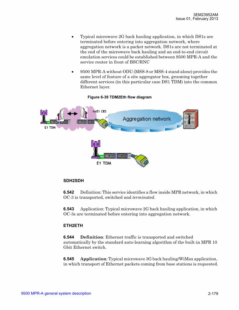
3EM23952AMIssue 01, February 2013
9500 MPR-A general system description 2-179
• Typical microwave 2G back hauling application, in which DS1s are terminated before entering into aggregation network, where aggregation network is a packet network. DS1s are not terminated at the end of the microwave back hauling and an end-to-end circuit emulation services could be established between 9500 MPR-A and the service router in front of BSC/RNC
• 9500 MPR-A without ODU (MSS-8 or MSS-4 stand alone) provides the same level of feature of a site aggregator box, grooming together different services (in this particular case DS1 TDM) into the common Ethernet layer.
SDH2SDH
6.542 Definition: This service identifies a flow inside MPR network, in which OC-3 is transported, switched and terminated.
6.543 Application: Typical microwave 2G back hauling application, in which OC-3s are terminated before entering into aggregation network.
ETH2ETH
6.544 Definition: Ethernet traffic is transported and switched automatically by the standard auto-learning algorithm of the built-in MPR 10 Gbit Ethernet switch.
6.545 Application: Typical microwave 3G back hauling/WiMax application, in which transport of Ethernet packets coming from base stations is requested.
Figure 6-39 TDM2Eth flow diagram

3EM23952AMIssue 01, February 2013
9500 MPR-A general system description2-180
TDM and ethernet traffic management
6.546 Three kinds of traffic management have been identified:
• TDM2TDM (9500 MPR-A ⇔ 9500 MPR-A, internal to the MPR network)
• TDM2ETH (9500 MPR-A ⇔ TDM to Ethernet)
• ETH2ETH (Ethernet to Ethernet)
6.547 The first two profiles meet MEF8 standard.
Figure 6-40 Eth to Eth flow diagram
Figure 6-41 Traffic profiles
E1 or STM-1
E1 or STM-1

3EM23952AMIssue 01, February 2013
9500 MPR-A general system description 2-181
Case ① for DS1/DS3 (TDM2TDM)
6.548 The DS1/DS3 stream is inserted in Node 1 and extracted in Node 2. In this case the two IWFs used to packetize the traffic for the Ethernet switch in the Core-E module are both internal to the 9500 MPR-A network. The Circuit Emulation Service is TDM2TDM in Node 1 and Node 2. The Cross connections to be implemented are PDH-Radio type.
Case ① for OC-3 (SDH2SDH)
6.549 The OC-3 stream is inserted in Node 1 and extracted in Node 2. In this case the two IWFs used to packetize the traffic for the Ethernet switch in the Core-E module are both internal to the 9500 MPR-A network. The Circuit Emulation Service is SDH2SDH in Node 1 and Node 2. The Cross connections to be implemented are SDH-Radio type.
Case ➁ for TDM2Eth
6.550 The DS1/DS3 stream is inserted in Node 1 and extracted in Node 2. One IWF is inside the 9500 MPR-A, but the second IWF is external to the 9500 MPR-A network. The Circuit Emulation Service is TDM2ETH in Node 1 and Node 2. The Cross connections to be implemented are PDH-Radio type in Node 1 and Radio-Eth type in Node 2.
Case ③ for TDM2Eth
6.551 The DS1/DS3 stream is inserted/extracted in Node 1. One IWF is inside the 9500 MPR-A, but the second IWF is external to the 9500 MPR-A network. The Circuit Emulation Service is TDM2ETH in Node 1 and Node 2. The Cross connections to be implemented are PDH-Eth type in Node 1.

3EM23952AMIssue 01, February 2013
9500 MPR-A general system description2-182
Case ④ and ⑤ for ETH2ETH
6.552 In these cases Ethernet packets enter Node 1 and are extracted in Node 2. In case 4 the Ethernet packets encapsulate the DS1/DS3 stream; in case 5 the packets are native Ethernet packets. None of the IWFs belongs to the 9500 MPR-A network. The Circuit Emulation Service is ETH2ETH in Node 1 and Node 2. No Cross connections must be implemented. The path is automatically implemented with the standard auto-learning algorithm of the 9500 MPR-A Ethernet switch.
TDM2TDM
6.553 DS1 traffic packetized only internally to 9500 MPR-A equipment.
Figure 6-42 Traffic profiles
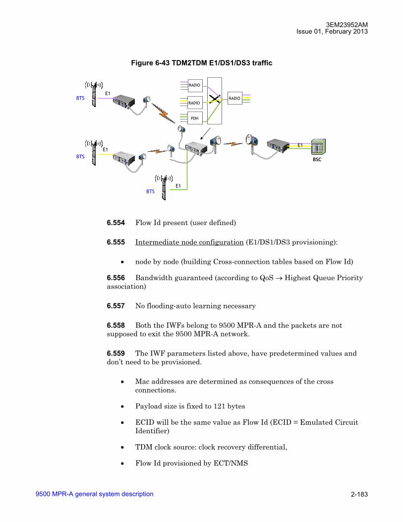
3EM23952AMIssue 01, February 2013
9500 MPR-A general system description 2-183
6.554 Flow Id present (user defined)
6.555 Intermediate node configuration (E1/DS1/DS3 provisioning):
• node by node (building Cross-connection tables based on Flow Id)
6.556 Bandwidth guaranteed (according to QoS → Highest Queue Priority association)
6.557 No flooding-auto learning necessary
6.558 Both the IWFs belong to 9500 MPR-A and the packets are not supposed to exit the 9500 MPR-A network.
6.559 The IWF parameters listed above, have predetermined values and don�t need to be provisioned.
• Mac addresses are determined as consequences of the cross connections.
• Payload size is fixed to 121 bytes
• ECID will be the same value as Flow Id (ECID = Emulated Circuit Identifier)
• TDM clock source: clock recovery differential,
• Flow Id provisioned by ECT/NMS
Figure 6-43 TDM2TDM E1/DS1/DS3 traffic
E1
BSC
PDH
RADIORADIO
RADIO
BTS
E1
BTSE1
BTSE1
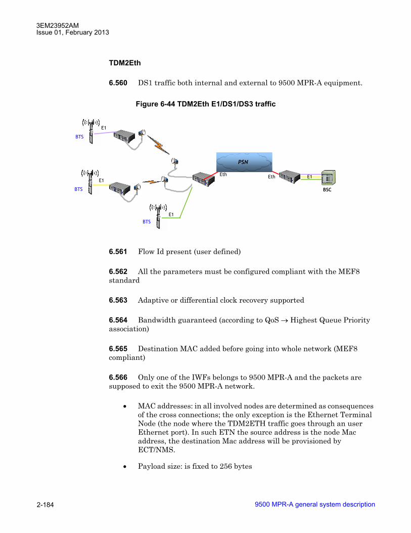
3EM23952AMIssue 01, February 2013
9500 MPR-A general system description2-184
TDM2Eth
6.560 DS1 traffic both internal and external to 9500 MPR-A equipment.
6.561 Flow Id present (user defined)
6.562 All the parameters must be configured compliant with the MEF8 standard
6.563 Adaptive or differential clock recovery supported
6.564 Bandwidth guaranteed (according to QoS → Highest Queue Priority association)
6.565 Destination MAC added before going into whole network (MEF8 compliant)
6.566 Only one of the IWFs belongs to 9500 MPR-A and the packets are supposed to exit the 9500 MPR-A network.
• MAC addresses: in all involved nodes are determined as consequences of the cross connections; the only exception is the Ethernet Terminal Node (the node where the TDM2ETH traffic goes through an user Ethernet port). In such ETN the source address is the node Mac address, the destination Mac address will be provisioned by ECT/NMS.
• Payload size: is fixed to 256 bytes
Figure 6-44 TDM2Eth E1/DS1/DS3 traffic
E1
BSC
E1EthEth
PSNPSN
BTS
BTS
BTSE1
E1
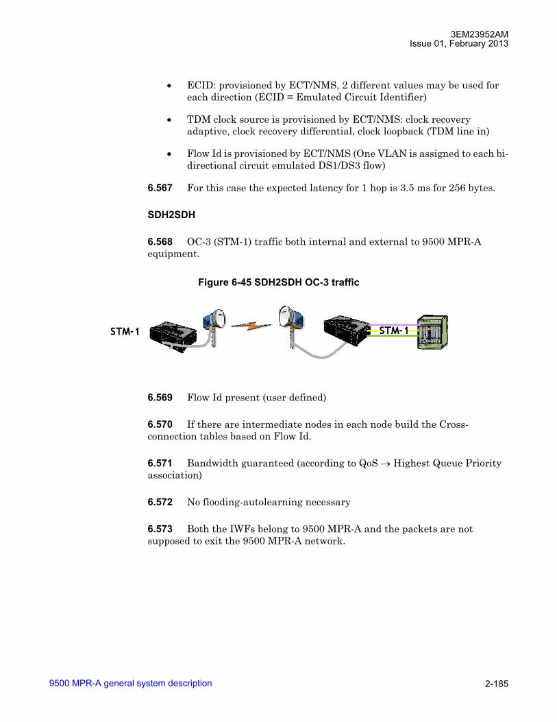
3EM23952AMIssue 01, February 2013
9500 MPR-A general system description 2-185
• ECID: provisioned by ECT/NMS, 2 different values may be used for each direction (ECID = Emulated Circuit Identifier)
• TDM clock source is provisioned by ECT/NMS: clock recovery adaptive, clock recovery differential, clock loopback (TDM line in)
• Flow Id is provisioned by ECT/NMS (One VLAN is assigned to each bi-directional circuit emulated DS1/DS3 flow)
6.567 For this case the expected latency for 1 hop is 3.5 ms for 256 bytes.
SDH2SDH
6.568 OC-3 (STM-1) traffic both internal and external to 9500 MPR-A equipment.
6.569 Flow Id present (user defined)
6.570 If there are intermediate nodes in each node build the Cross-connection tables based on Flow Id.
6.571 Bandwidth guaranteed (according to QoS → Highest Queue Priority association)
6.572 No flooding-autolearning necessary
6.573 Both the IWFs belong to 9500 MPR-A and the packets are not supposed to exit the 9500 MPR-A network.
Figure 6-45 SDH2SDH OC-3 traffic

3EM23952AMIssue 01, February 2013
9500 MPR-A general system description2-186
6.574 The IWF parameters listed above, have predetermined values and don�t need to be provisioned.
� Mac addresses are determined as consequences of the cross connections.
� Payload size is fixed
� Clock source: clock recovery differential/node timing
� Flow Id provisioned by ECT/NMS
ETH2ETH
6.575 None of the IWFs belongs to 9500 MPR-A.
6.576 None of the parameters listed in the previous slide has to be configured (the 9500 MPR-A is transparent).
6.577 Any packet belonging to an Eth2Eth TDM flow is treated as any other Ethernet packet with the only exception of giving it an higher priority based on the MEF 8 Ethertype.
Traffic interfaces
6.578 The system supports the following traffic interfaces:
• Core-E
• DS1 PDH interface (P32E1DS1)
Figure 6-46 Eth2Eth DS1/DS3 traffic
Eth
Eth
RNCEth
Eth
WiMAX(NodeB)
WiMAX(NodeB)
WiMAX(NodeB)
EthEth
EthRNC
PSNPSN
PSNPSN

3EM23952AMIssue 01, February 2013
9500 MPR-A general system description 2-187
• DS3 PDH interface (P2E3DS3)
• OC-3 SDH interface (SDHACC)
• Ethernet access switch (P8ETH)
• MODEM 300 radio interface (MOD300)
• MPT access (MPTACC)
Core-E
6.579 The Core-E, Control Switching Module card provides six user Ethernet interfaces, up to four 10/100/1000BaseT electrical Ethernet Interfaces, up to two 1000 Base-X (GigE) SFP Ethernet interfaces, the local WebEML interface, and local debug interface.
6.580 The Core-E card has two roles, main and spare Core-E.
6.581 The main Core-E performs key node management, control functions, provisioning, configuration management, and cross-connection matrix. The matrix is a standard Ethernet switch based on VLAN. The card also houses a plug-in flash card which stores node configuration and license data. The main Core-E card is required.
6.582 The spare Core-E card provides aggregate traffic and control platform protection. The spare Core-E card is optional.
CAUTION Possibility of service interruption. If an MPT-HL is connected to the main Core-E card, Core-E protection is not supported. A protection switch will cause communication with the MPT-HL to be lost.
10/100/1000 Base-T ethernet interfaces
6.583 Four 10/100/1000Base-T interfaces provide access for traffic, data, or MPT-HC/XP connections.
GigE SFP ethernet interfaces
6.584 Two GigE SFP Ethernet interfaces are 1000 Base-X, Base-T, or copper cable access for traffic, data, MPT-HC/XP, or MPT-HL connections.
3EM23952AMIssue 01, February 2013
9500 MPR-A general system description2-188
MPT-HC/XP radio interface
6.585 The 10/100/1000 BaseT Ethernet interfaces support connectivity for up to four 1+0 MPT-HC/XP ODUs or two 1+1 MPT-HC/XP ODUs.
6.586 The GigE SFP interfaces support connectivity for up to two 1+0 MPT-HC/XP ODUs or one 1+1 MPT-HC/XP.
MPT-HL radio interface
6.587 The GigE SFP interfaces support connectivity for up to two 1+0 MPT-HL connections.
DS1 PDH interface
6.588 The P32E1DS1, DS1 PDH Interface card is a transport card which provides the external interfaces for up to 32 DS1 tributaries. Manages the encapsulation/reconstruction of PDH data to/from standard Ethernet packets, and sends/receives standard Ethernet packets to/from both Core-E cards. Supports 1+1 EPS protection switching. Contains DC/DC converter unit.
6.589 The system supports up to six 1+0 unprotected (192 DS1s) or up to 3 pairs of 1+1 EPS protected (96 DS1s) P32E1DS1 cards per MSS-8 shelf.
6.590 The system supports up to two 1+0 unprotected (64 DS1s) or up to 1 pair of 1+1 EPS protected (32 DS1s) P32E1DS1 cards per MSS-4 shelf.
6.591 System supports unframed format, Superframe Format (SF), and Extended Superframe Format (ESF) DS1 frame formats.
6.592 The system supports PM on incoming and outgoing DS1 signals. For a detailed description of DS1 PDH PM, refer to Performance monitoring.
6.593 The system supports insertion of AIS upon detection of Loss of Frame (LOF) on DS1 inputs and outputs. This behavior is provisionable enable or disable at the NE level.
DS3 PDH interface
6.594 The P2E3DS3, DS3 TDM Interface card is a transport card which provides the external interfaces for up to 2 DS3 tributaries. Manages the encapsulation/reconstruction of PDH data to/from standard Ethernet packets, and sends/receives standard Ethernet packets to/from both Core-E cards. Supports 1+1 EPS protection switching. Contains DC/DC converter unit.
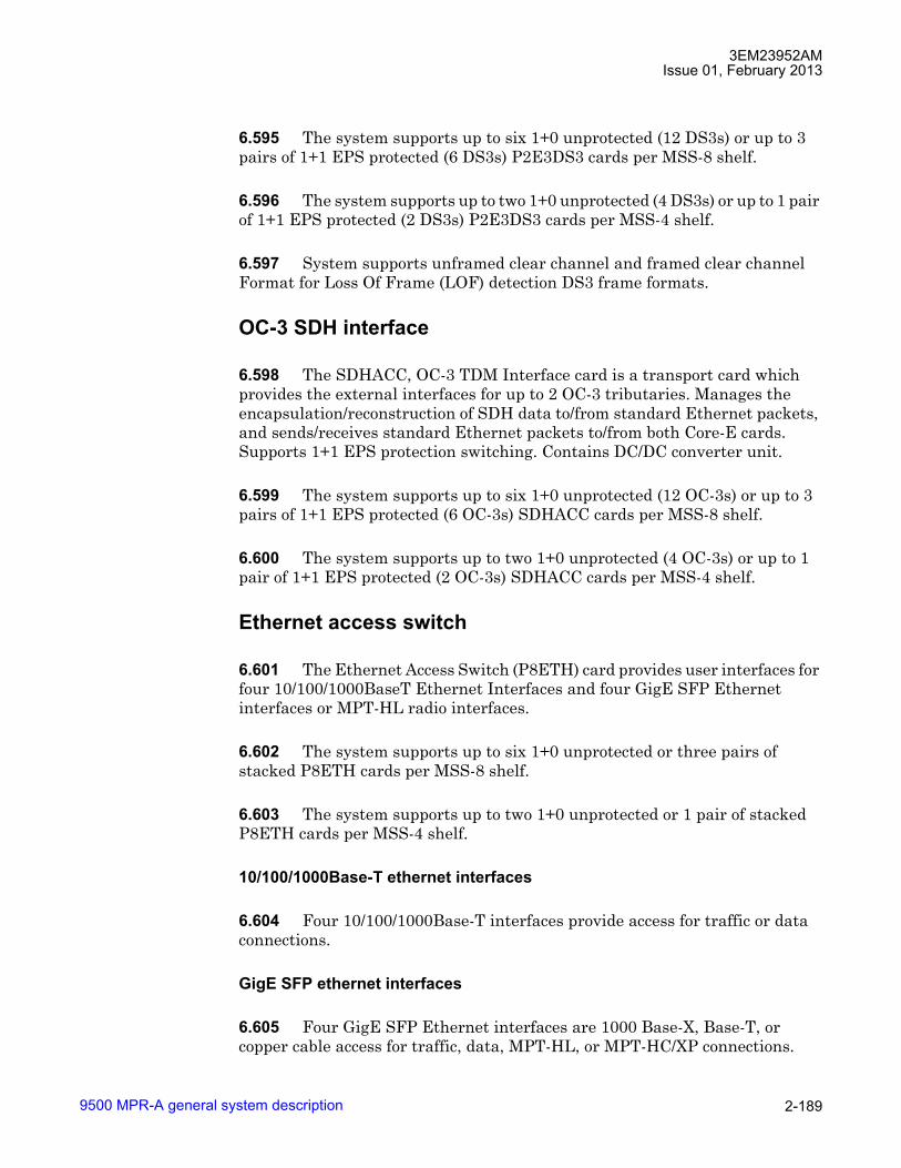
3EM23952AMIssue 01, February 2013
9500 MPR-A general system description 2-189
6.595 The system supports up to six 1+0 unprotected (12 DS3s) or up to 3 pairs of 1+1 EPS protected (6 DS3s) P2E3DS3 cards per MSS-8 shelf.
6.596 The system supports up to two 1+0 unprotected (4 DS3s) or up to 1 pair of 1+1 EPS protected (2 DS3s) P2E3DS3 cards per MSS-4 shelf.
6.597 System supports unframed clear channel and framed clear channel Format for Loss Of Frame (LOF) detection DS3 frame formats.
OC-3 SDH interface
6.598 The SDHACC, OC-3 TDM Interface card is a transport card which provides the external interfaces for up to 2 OC-3 tributaries. Manages the encapsulation/reconstruction of SDH data to/from standard Ethernet packets, and sends/receives standard Ethernet packets to/from both Core-E cards. Supports 1+1 EPS protection switching. Contains DC/DC converter unit.
6.599 The system supports up to six 1+0 unprotected (12 OC-3s) or up to 3 pairs of 1+1 EPS protected (6 OC-3s) SDHACC cards per MSS-8 shelf.
6.600 The system supports up to two 1+0 unprotected (4 OC-3s) or up to 1 pair of 1+1 EPS protected (2 OC-3s) SDHACC cards per MSS-4 shelf.
Ethernet access switch
6.601 The Ethernet Access Switch (P8ETH) card provides user interfaces for four 10/100/1000BaseT Ethernet Interfaces and four GigE SFP Ethernet interfaces or MPT-HL radio interfaces.
6.602 The system supports up to six 1+0 unprotected or three pairs of stacked P8ETH cards per MSS-8 shelf.
6.603 The system supports up to two 1+0 unprotected or 1 pair of stacked P8ETH cards per MSS-4 shelf.
10/100/1000Base-T ethernet interfaces
6.604 Four 10/100/1000Base-T interfaces provide access for traffic or data connections.
GigE SFP ethernet interfaces
6.605 Four GigE SFP Ethernet interfaces are 1000 Base-X, Base-T, or copper cable access for traffic, data, MPT-HL, or MPT-HC/XP connections.
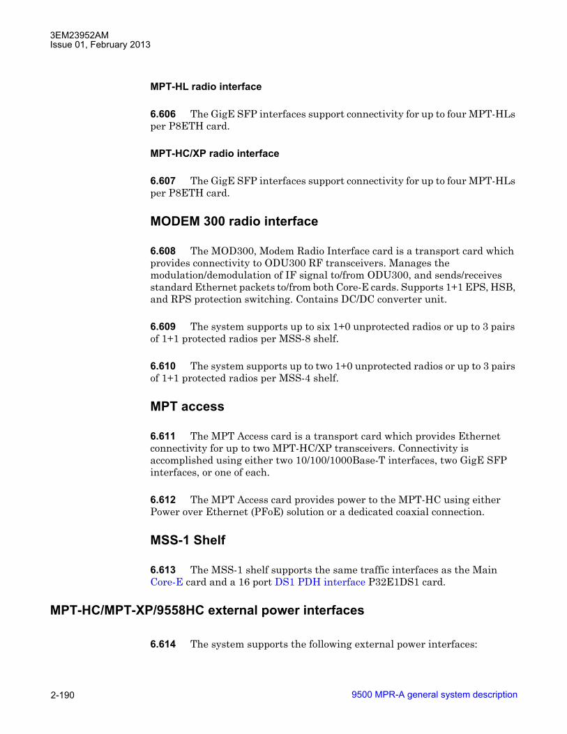
3EM23952AMIssue 01, February 2013
9500 MPR-A general system description2-190
MPT-HL radio interface
6.606 The GigE SFP interfaces support connectivity for up to four MPT-HLs per P8ETH card.
MPT-HC/XP radio interface
6.607 The GigE SFP interfaces support connectivity for up to four MPT-HLs per P8ETH card.
MODEM 300 radio interface
6.608 The MOD300, Modem Radio Interface card is a transport card which provides connectivity to ODU300 RF transceivers. Manages the modulation/demodulation of IF signal to/from ODU300, and sends/receives standard Ethernet packets to/from both Core-E cards. Supports 1+1 EPS, HSB, and RPS protection switching. Contains DC/DC converter unit.
6.609 The system supports up to six 1+0 unprotected radios or up to 3 pairs of 1+1 protected radios per MSS-8 shelf.
6.610 The system supports up to two 1+0 unprotected radios or up to 3 pairs of 1+1 protected radios per MSS-4 shelf.
MPT access
6.611 The MPT Access card is a transport card which provides Ethernet connectivity for up to two MPT-HC/XP transceivers. Connectivity is accomplished using either two 10/100/1000Base-T interfaces, two GigE SFP interfaces, or one of each.
6.612 The MPT Access card provides power to the MPT-HC using either Power over Ethernet (PFoE) solution or a dedicated coaxial connection.
MSS-1 Shelf
6.613 The MSS-1 shelf supports the same traffic interfaces as the Main Core-E card and a 16 port DS1 PDH interface P32E1DS1 card.
MPT-HC/MPT-XP/9558HC external power interfaces
6.614 The system supports the following external power interfaces:

3EM23952AMIssue 01, February 2013
9500 MPR-A general system description 2-191
• Power injector card
• Power injector box
• MPT power unit
• MPT Extended Power Unit
Power injector card
6.615 The Power Injector card is installed in the MSS-4/8 slot. The card combines DC battery and Ethernet connections for interconnections with MPT-HC for interconnection between MSS-4/8 Core-E and P8ETH Ethernet ports.
Power injector box
6.616 The Power Injector box mounts to the rack. The box combines DC battery and Ethernet connections for interconnections with MPT-HC for interconnection between MSS-1/4/8 Core-E Ethernet ports. Power connections A & B connect directly to battery supply.
MPT power unit
6.617 The MPT Power Unit mounts to the rack and remotely powers four external MPT-HC ODUs through N-connector cables.
MPT Extended Power Unit
6.618 The MPT Extended Power Unit mounts to the rack and feeds power to up to two MPT-HC/XP ODUs. Compared to the standard power bar, the MPT Extended Power Unit offers the following additional features:
• Galvanic Isolation between Battery Input and ODU Power Output
• Output voltage stabilized at -57V
• Power Input capability for the following voltages:
� +20.4VDC to +28VDC
� -57.6VDC to -38.4VDC
• Output Power available by means of both N-Connectors and RJ-45 Connectors

3EM23952AMIssue 01, February 2013
9500 MPR-A general system description2-192
• Use of the RJ-45 connectors to establish an Ethernet data link connection between IDU and ODU.
Configurations
6.619 Refer to table 6-O for descriptions of the modular configurations the system supports.
Table 6-O. ConfigurationsITEM DESCRIPTIONMicrowave Switching Services (MSS-8) ShelfPN: 3DB18001AAQty: 1 per node
The MSS-8 houses equipment that supports 16 Gb/s packet switching, synchronization, protection switching, provisioning, and alarm management utilizing either one Core-E card in unprotected configuration or two Core-E cards in protected configuration.
Six transport slots support any mixture of unprotected and/or 1+1 EPS protected transport cards. Supported transport types include: up to six P8ETH (Ethernet) cards, up to six P32E1DS1 (DS1) cards, up to six P2E3DS3 (DS3), up to six SDHACC (OC-3), up to six MOD300 (radio), and/or up to six MPTACC (radio) cards.
One fan card is required for system cooling.Microwave Switching Services (MSS-4) ShelfPN: 3DB18219ABQty: 1 per node
The MSS-4 houses equipment that supports 16 Gb/s packet switching, synchronization, protection switching, provisioning, and alarm management utilizing either one Core-E card in unprotected configuration or two Core-E cards in protected configuration.
Two transport slots support either unprotected and/or 1+1 EPS protected transport cards. Supported transport types include: up to two P8ETH (Ethernet) cards, up to two P32E1DS1 (DS1) cards, up to two P2E3DS3 (DS3), up to two SDHACC (OC-3), up to two MOD300 (radio), and/or up to two MPTACC (radio) cards.
One fan card is required for system cooling.Microwave Switching Services Shelf (MSS-1) PN: 3DB19015AAQty: 1 per node
The MSS-1 houses equipment that supports 10 Gb/s packet switching, synchronization, protection switching, provisioning, and alarm management. It is composed of a monoboard.
The monoboard provides the functions of one Control and Switching Module (Core-E) card and one P32E1DS1 (DS1) card with 16 ports.

3EM23952AMIssue 01, February 2013
9500 MPR-A general system description 2-193
MSS-8 shelf configurations
6.620 MSS-8 shelf has a modular design: Consists of backplane, card cage, and nine front access card slots. Two slots are dedicated for the Core-E, Control Switching Module (Core-E) Six slots are dedicated for Transport, Auxiliary or Power Converter cards. One slot is dedicated for the FAN card. See Figure 6-47 for a front view of the MSS-8 shelf.
6.621 MSS-8 shelf slot 1 is dedicated to the main Core-E card and is required in every application. See figure 6-48 to see an example of the unprotected Core-E configuration.
6.622 Slot 2 is dedicated for an optional spare Core-E card for protected Core-E configurations. See Figure 6-49 to see an example of the MSS-8 protected Core-E configuration.
Microwave Packet Transport-Long Haul (MPT-HL) ShelfPN: 3EM22618AB, 3EM22618ACQty: Up to 4 per 9500 MPR-A node
The MPT-HL shelf supports two MPT-HL transceiver radio cards.
Transport cards Thirty-two port P32E1DS1 for DS1(T1) interfaceTwo port P2E3DS3 for DS3(T3) interfaceTwo port SDHACC for OC-3 interfaceEight port P8ETH for 10,100,1000,GigE Ethernet Ports
I/O interface types DS1, DS3, OC-3, EthernetBattery feeds Independent, redundant battery feeds
Independent, isolated battery returnsPower supply redundancy 1:1 protectedBay power distribution PDU
Figure 6-47 MSS-8 shelf - front view
Table 6-O. Configurations (cont.)ITEM DESCRIPTION

3EM23952AMIssue 01, February 2013
9500 MPR-A general system description2-194
6.623 Slots 3 through 8 support any Transport cards, MPTACC, MOD300, P2E3DS3, P32E1DS1, SDHACC, and P8ETH cards. Slot 8 supports the Auxiliary card. Power Converter card is supported in slots 4, 6, and 8, one per shelf.
6.624 Slot 9 supports the Fan card.
6.625 Unprotected 1+0 transport cards are supported in any slots 3 through 8. Protected 1+1 transport cards are horizontally located. The main transport cards are located in slots 3, 5, and 7 and the spare transport cards are located in slots 4, 6, and 8 respectively.
Figure 6-48 MSS-8 shelf, unprotected Core-E configuration
950-0006-2
091410
Filler Panel
Any Transport Any Transport
Any Transport Any Transport
Any TransportAny Transport
or
Auxiliary Card
CSM-E
(Main)
Fan
92
4
6
8
1
3
5
7
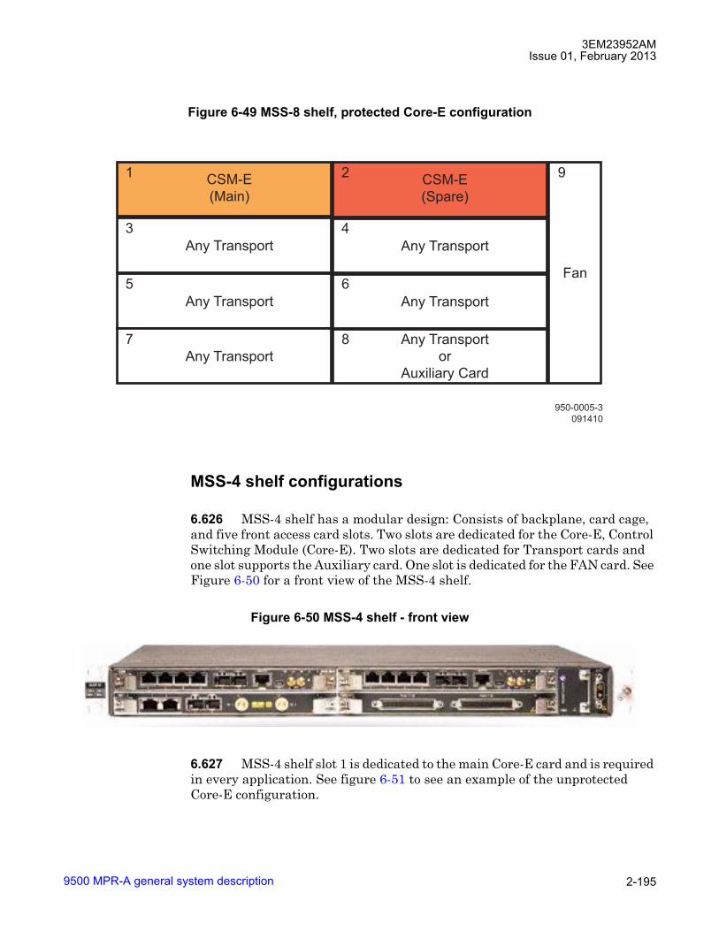
3EM23952AMIssue 01, February 2013
9500 MPR-A general system description 2-195
MSS-4 shelf configurations
6.626 MSS-4 shelf has a modular design: Consists of backplane, card cage, and five front access card slots. Two slots are dedicated for the Core-E, Control Switching Module (Core-E). Two slots are dedicated for Transport cards and one slot supports the Auxiliary card. One slot is dedicated for the FAN card. See Figure 6-50 for a front view of the MSS-4 shelf.
6.627 MSS-4 shelf slot 1 is dedicated to the main Core-E card and is required in every application. See figure 6-51 to see an example of the unprotected Core-E configuration.
Figure 6-49 MSS-8 shelf, protected Core-E configuration
Figure 6-50 MSS-4 shelf - front view
950-0005-3
091410
CSM-E
(Spare)
Any Transport Any Transport
Any Transport Any Transport
Any Transport
Any Transport
or
Auxiliary Card
CSM-E
(Main)
Fan
92
4
6
8
1
3
5
7
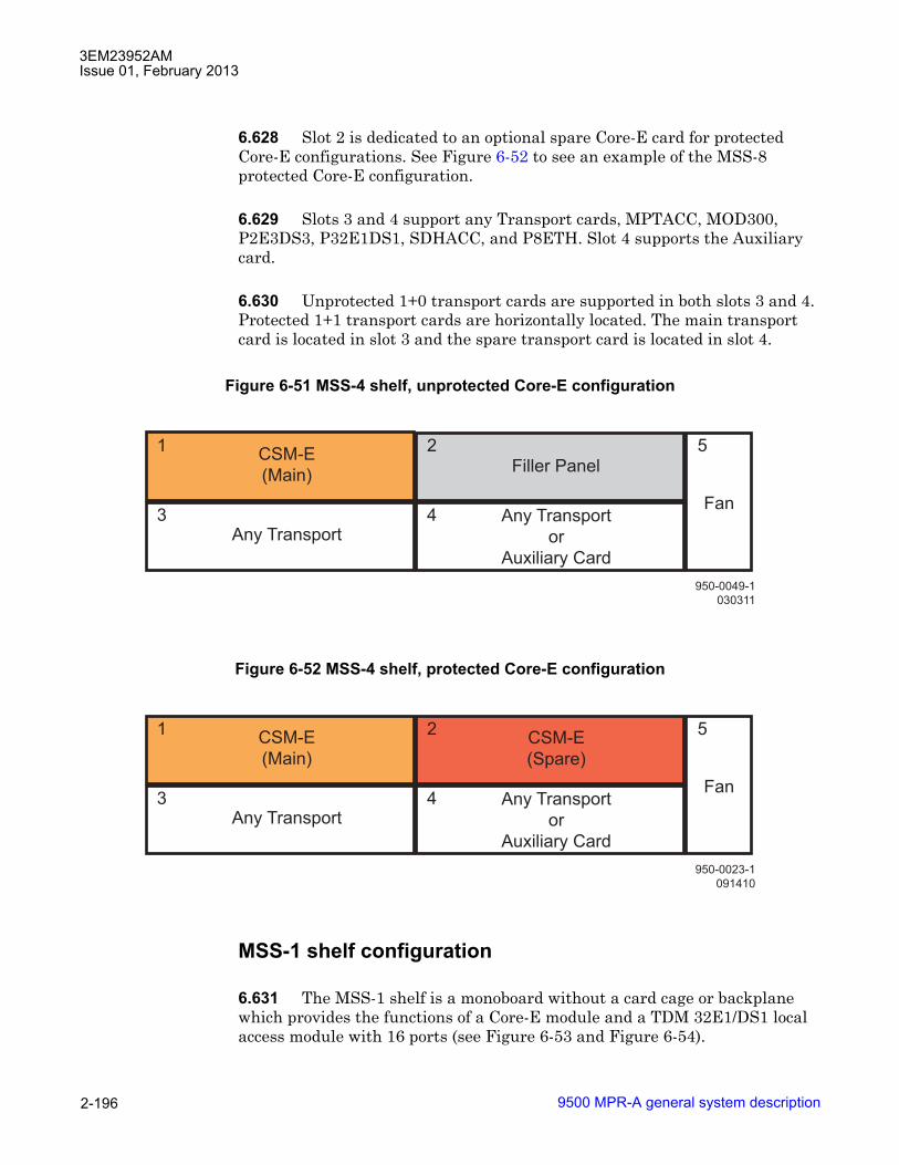
3EM23952AMIssue 01, February 2013
9500 MPR-A general system description2-196
6.628 Slot 2 is dedicated to an optional spare Core-E card for protected Core-E configurations. See Figure 6-52 to see an example of the MSS-8 protected Core-E configuration.
6.629 Slots 3 and 4 support any Transport cards, MPTACC, MOD300, P2E3DS3, P32E1DS1, SDHACC, and P8ETH. Slot 4 supports the Auxiliary card.
6.630 Unprotected 1+0 transport cards are supported in both slots 3 and 4. Protected 1+1 transport cards are horizontally located. The main transport card is located in slot 3 and the spare transport card is located in slot 4.
MSS-1 shelf configuration
6.631 The MSS-1 shelf is a monoboard without a card cage or backplane which provides the functions of a Core-E module and a TDM 32E1/DS1 local access module with 16 ports (see Figure 6-53 and Figure 6-54).
Figure 6-51 MSS-4 shelf, unprotected Core-E configuration
Figure 6-52 MSS-4 shelf, protected Core-E configuration
950-0049-1
030311
Any TransportAny Transport
or
Auxiliary Card
CSM-E
(Main)
Fan
52
4
1
3
Filler Panel
950-0023-1
091410
CSM-E
(Spare)
Any TransportAny Transport
or
Auxiliary Card
CSM-E
(Main)
Fan
52
4
1
3

3EM23952AMIssue 01, February 2013
9500 MPR-A general system description 2-197
Stand alone MSS-1/MSS-4/MSS-8 shelf
6.632 MSS-4/8 may be deployed in standalone configuration and provides up to 16 Gb/s packet aggregation for DS1, DS3, OC-3, and Ethernet traffic.
Stacking MSS-1/MSS-4/MSS-8 shelf configuration
6.633 To manage more directions the �Stacking configuration� can be realized by installing up to 3 MSS-1/MSS-4/MSS-8 shelves, interconnected through the Ethernet ports and Synchronization ports on the Core-E cards. An example of three stacked MSS-8 shelves equipped with unprotected Core-E cards is shown in Figure 6-55. An example of three stacked MSS-8 shelves equipped with protected Core-E cards is shown in Figure 6-56.
6.634 For the Stacking configuration it is recommended to enable the Static Lag Criteria.
6.635 With Core-E protection a maximum of three MSS-1/MSS-4/MSS-8 shelves can be interconnected as shown in Figure 6-56.
6.636 To implement this configuration the LOS alarm on the Ethernet ports must be enabled as switching criterion for Core-E protection. To enable this functionality the �Ethernet LOS Criteria� feature must be enabled.
Figure 6-53 MSS-1 shelf
Figure 6-54 MSS-1
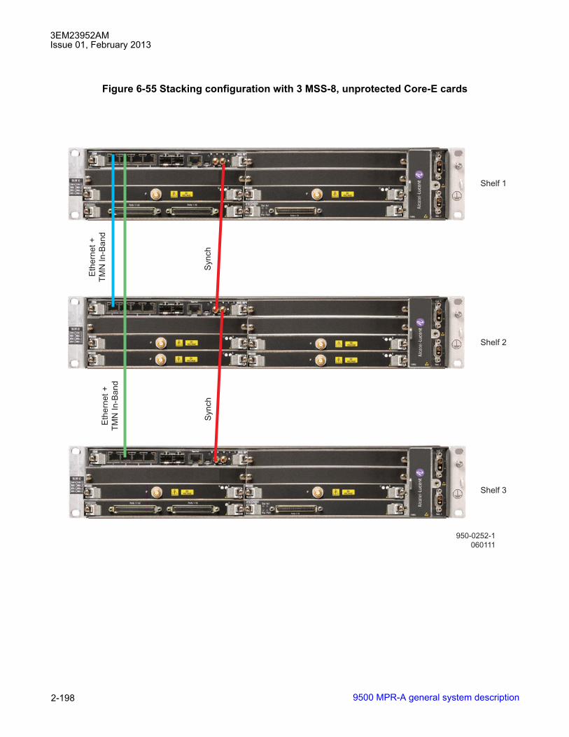
3EM23952AMIssue 01, February 2013
9500 MPR-A general system description2-198
Figure 6-55 Stacking configuration with 3 MSS-8, unprotected Core-E cards
950-0252-1
060111
Shelf 1
Eth
ern
et
+
TM
N I
n-B
an
dE
the
rne
t +
TM
N I
n-B
an
d
Shelf 2
Shelf 3
Syn
ch
Syn
ch
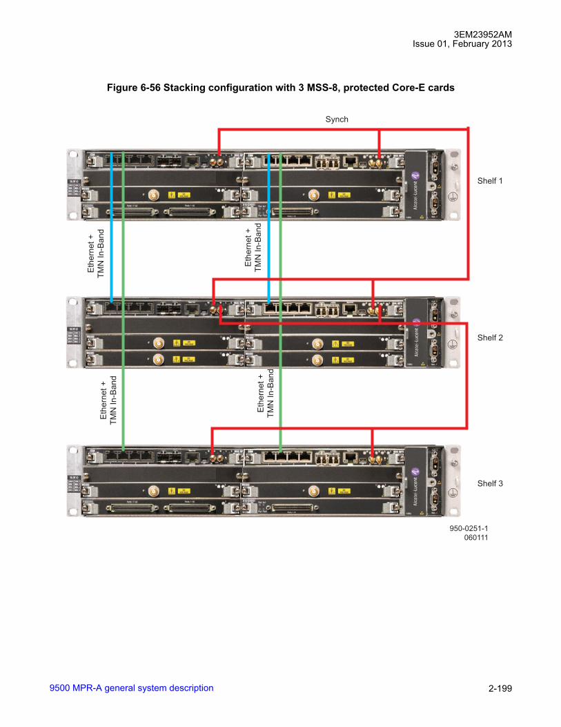
3EM23952AMIssue 01, February 2013
9500 MPR-A general system description 2-199
Figure 6-56 Stacking configuration with 3 MSS-8, protected Core-E cards
950-0251-1
060111
Shelf 1
Eth
ern
et
+
TM
N I
n-B
an
dE
the
rne
t +
TM
N I
n-B
an
d
Eth
ern
et
+
TM
N I
n-B
an
dE
the
rne
t +
TM
N I
n-B
an
d
Shelf 2
Shelf 3
Synch

3EM23952AMIssue 01, February 2013
9500 MPR-A general system description2-200
Alarm management
Cross-connections
6.637 The cross-connections between slots and between slot and Ethernet user ports are realized with a Layer-2 Ethernet Switch inside the Core-E unit.
6.638 The decision made by the switch to forward the received packet is based on the destination MAC address.
DS1/DS3 Cross-connections
6.639 Each DS1/DS3 can be cross connected independently.
6.640 DS1/DS3s can be cross connected to the following interfaces:
• Radio interface
• Ethernet interface
6.641 Each DS1/DS3 (board #, port #) must be associated to an unique signal flow ID.
Figure 6-57 Cross-connection

3EM23952AMIssue 01, February 2013
9500 MPR-A general system description 2-201
OC-3 Cross-connections
6.642 Each OC-3 can be cross connected independently.
6.643 OC-3s can be cross connected to Radio interface.
6.644 Each OC-3 (board #, port #) must be associated to an unique signal flow ID.
Radio-radio cross-connections
6.645 Ethernet frames, coming from a radio direction, can be cross-connected to another radio direction.
Ethernet cross-connections
Generic ethernet flows
6.646 All flows different from the TDM2TDM, TDM2ETH, and SDH2SDH ones are managed as the standard Ethernet packets: if the 802.1Q is enabled the related management is performed looking the VLAN and then, according to the destination address, each packet is switched to the correct port: radio, user Ethernet, or DS1. If the 802.1D is enabled only the destination MAC address is considered.
6.647 For each radio interface, the bandwidth assigned, globally, to the Ethernet traffic is the consequence, with a given radio capacity, of the number of DS1s cross-connected on that radio interface. Hence the available bandwidth for Ethernet flows will be the configured radio bandwidth decreased by bandwidth used by TDM2TDM, TDM2ETH, and SDH2SDH traffic flows.
Database backup and restore
6.648 The system supports a full database backup and restore from the Craft Terminal or network manager, including provisioning and configuration information stored on the NE.
In-service upgrade
6.649 Systems software and hardware can be upgraded to a new release, as specified in the upgrade procedure. The upgrade procedure can be completed in less than four hours and within one maintenance window. Default values used when upgrading to are defined for all new provisioning parameters.

3EM23952AMIssue 01, February 2013
9500 MPR-A general system description2-202
6.650 The system saves and maintains the content of the customer�s existing generic database through the upgrade process, including the alarm database and all provisioning. Historical PM data and the log file are not preserved.
6.651 Software upgrade to version R4.2.0 is supported. Refer to Table 6-P for supported software upgrade paths based on existing software versions.
LAG (link aggregation group)
LAG overview
6.652 Link Aggregation groups a set of ports so that two network nodes can be interconnected using multiple links to increase link capacity and availability between them.
6.653 When aggregated, two or more physical links operate as a single logical link with a traffic capacity that is the sum of the individual link capacities.
6.654 This doubling, tripling or quadrupling of capacity is relevant where more capacity is required than can be provided on one physical link.
6.655 Link aggregation also provides redundancy between the aggregated links. If a link fails, its traffic is redirected onto the remaining link, or links.
Table 6-P. Software upgrade paths to R4.2.0SOURCE RELEASE UPGRADE PATH
R1.02.x1
[1] Upgrade from R1.2.x to R3.1.0 requires replacement from CORE-B card to CORE-E card.
R1.2.x > R3.1.0 > R3.4.x > R4.2.x
R2.0.x R2.0.x > R2.1.0 > R2.2.1 > R3.1.x > R3.4.x > R4.2.xR2.1.0 R2.1.0 > R2.2.1 > R3.1.x > R3.4.x > R4.2.xR2.2.3 R2.2.3 > R3.2.x > R3.4.x > R4.2.xR2.2.x R2.2.x > R3.1.x > R3.4.x > R4.2.xR3.0.x R3.0.x > R3.1.x > R3.4.x > R4.2.xR3.1.x R3.1.x > R3.4.x/R4.0.x > R4.2.xR3.2.x R3.2.x > R3.4.x/R4.0.x > R4.2.xR3.3.x R3.3.x > R3.4.x/R4.0.x > R4.2.xR3.4.x R3.4.x > R4.2.xR4.0.x R4.0.x > R4.2.xR4.1.x R4.1.x > R4.2.x

3EM23952AMIssue 01, February 2013
9500 MPR-A general system description 2-203
6.656 If the remaining link or links do not have the capacity needed to avoid a traffic bottleneck, appropriate QoS settings are used to prioritize traffic so that all high priority traffic continues to get through.
6.657 The Link Aggregation is performed according to 802.3ad and can be applied to Radio ports and to User Ethernet ports.
6.658 Supported LAG ID numbers are 1 to 14.
L2 LAG hashing
6.659 L2 LAG hashing provides two different traffic load balancing algorithms configured on the LAG: Layer2 (L2 Hash) and Layer3 (L3 Hash).
• L2 Hash (load balancing algorithm is based on fields contained in the Ethernet MAC frame header:
� Destination MAC Address + Source MAC Address + VLAN ID + EtherType + Ethernet Switch Source Port
� Destination MAC Address + Source MAC Address + Ethernet Switch Source Port (for Multicast, Broadcast, and Unknown traffic)
• L3 Hash (load balancing algorithm is based on fields contained in the IP frame header and TCP/UDP ports):
� Destination MAC Address + Source MAC Address + TCP/UDP Destination Port + TCP/UDP Source Port
� Destination MAC Address + Source MAC Address (for Multicast IP traffic)
• If the frame is not IP and Destination and Source IP Addresses are not available, Destination MAC Address + Source MAC Address are used to evaluate the traffic distribution.
The chosen algorithm applies only to traffic learnt by the switch.
6.660 The same interface will be used for all packets in Ethernet flow. Traffic from the same flow is not evenly distributed over all the interfaces. Even if multiple physical interfaces are used at the same time for traffic forwarding, it is not guaranteed at all to have a complete and full load balance on ports in L2 LAG. This means that a single physical port can be overloaded in L2 LAG and consequently discards all traffic in excess (according to QoS priorities) even when other physical ports in the L2 LAG have residual bandwidth not exploited.

3EM23952AMIssue 01, February 2013
9500 MPR-A general system description2-204
6.661 Neither Revertive nor Not Revertive behavior can be associated to frame distribution performed by the hashing function. It is not guaranteed that the association of a traffic flow to a specific interface is maintained when the interface has been removed from L2 LAG due to a failure and then re-inserted in the L2 LAG due to the clear of the failure.
L1/L2 link aggregation on radio ports (radio L1/L2 LAG)
6.662 Link aggregation can be applied to radio ports, in this case it is named Radio L1/L2 Link Aggregation (Radio L1/L2 LAG).
6.663 For a detailed description of Radio L1 LAG, refer to Radio L1 LAG.
6.664 For a detailed description of Radio L2 LAG, refer to Radio L2 LAG.
L2 Link aggregation on user ethernet ports (ethernet L2 LAG)
6.665 User Ethernet ports (electrical or optical) on the same Core-E card can be provisioned as a member of an Ethernet L2 LAG port.
6.666 For a detailed description of Ethernet L2 LAG, refer to Ethernet L2 LAG.
License key management
6.667 License Key Management provides the mechanism to enable features on the basis of the customer needs, considering a predefined set of different functionalities as different elementary licenses. A set of key features is identified and each one of them is associated to one elementary license, giving the possibility to add features in an incremental approach.
6.668 The management of the license key is managed utilizing the following items:
• RMU Serial Number: The Serial Number of the Flash Card (read-only field)
• License String: The license string displays the set of key features supported by the NE (read-only field)
• License Key: This field is used to upgrade the license string
6.669 Provisioning the RMU Serial Number, License String, and License Key are supported from the Craft Terminal.

3EM23952AMIssue 01, February 2013
9500 MPR-A general system description 2-205
6.670 The RMU Serial Number and License String are viewable from the Web Server.
License String
6.671 The following unique Elementary Licenses (EL) are available to construct the License String. The loaded License String determines the provisionable features on the NE. The available ELs are as follows:
• Transmission Capacity
• Unlicensed Option
• Adaptive Modulation
• Data Awareness
• ERPS
• Packet throughput booster
Transmission Capacity
6.672 Transmission Capacity defines the maximum net Ethernet throughput for the radio interface. Ethernet throughput is based on the radio profile�s channel spacing and modulation technique selected. Ethernet throughput is rounded to the nearest 10 Mbps to determine the minimum required Transmission Capacity EL. The Transmission Capacity EL consists of two parts, number of radio interfaces and maximum net Ethernet throughput. Up to eighteen radio interfaces may be licensed with one Transmission Capacity EL.
6.673 There are five levels of Transmission Capacity supported. Transmission Capacity uses the following format: YCapXXX, where �Y� equals the number of radio interfaces licensed and �XXX� equals the maximum throughput of the radio interface(s). The supported Transmission Capacity throughputs are as follows:
• 40 Mbps: Format: YCap040. Example: 1Cap040 means only one license available for radio interface capacity up to 40 Mbps.
• 80 Mbps: Format: YCap080. Example: 3Cap080 means three licenses available for radio interface capacities up to 80 Mbps.
• 120 Mbps: Format: YCap120. Example: 4Cap120 means four licenses available for radio interface capacities up to 120 Mbps.

3EM23952AMIssue 01, February 2013
9500 MPR-A general system description2-206
• 160 Mbps: Format: YCap160. Example: 8Cap160 means eight licenses available for radio interface capacities up to 160 Mbps.
• 320 Mbps: Format: YCap320. Example: 12Cap320 means twelve licenses available for radio capacities up to 320 Mbps.
6.674 More than one Transmission Capacity EL is supported in a single license string. Example: 4Cap080/2Cap160/TDM2ETH means four licenses available for radio interface capacities up to 80 Mbps and two licenses available for radio interface capacities up to 160 Mbps.
Unlicensed Option
6.675 Unlicensed Option EL restricts the usage of Transmission Capacity license(s) to the unlicensed band (5725 to 5875 MHz). Unlicensed Option EL uses the following format: YUnlOpt, where �Y� equals the number of radio interfaces restricted to unlicensed radio profile(s), up to the total of Transmission Capacity licenses available. When no Unlicensed Option EL is present, none of the available Transmission Capacity licenses are restricted to the unlicensed band. The following are examples of license strings with and without Unlicensed Option LE:
• 4Cap160/TDM2ETH; means four licenses available for radio interface capacities up to 160 Mbps, none are restricted to the unlicensed band.
• 6Cap080/2Cap320/TDM2ETH/2UnlOpt; means six licenses available for radio interface capacities up to 80 Mbps, two licenses available for radio interface capacities up to 320 Mbps, and two of the eight available Transmission Capacity licenses are restricted to the unlicensed band.
Adaptive Modulation
6.676 Adaptive Modulation EL provides the right to use adaptive modulation for Transmission Capacity license(s). Adaptive Modulation EL uses the following format: YModAdp, where �Y� equals the number of radio profiles available to use adaptive modulation radio profile(s), up to the total of Transmission Capacity licenses available. When no Adaptive Modulation EL is present, none of the available Transmission Capacity licenses are available to be configured with adaptive modulation. The following are examples of license strings with and without Adaptive Modulation EL:
• 7Cap080/TDM2ETH; means seven licenses available for radio interface capacities up to 80 Mbps, none are available for adaptive modulation.
3EM23952AMIssue 01, February 2013
9500 MPR-A general system description 2-207
• 6Cap080/3ModAdp/TDM2ETH/1UnlOpt; means six licenses available for radio interface capacities up to 80 Mbps, three Transmission Capacity licenses are available for adaptive modulation, and one of the six available Transmission Capacity licenses are restricted to the unlicensed band.
Data Awareness
6.677 Data Awareness EL provides the right to support TDM over Ethernet, MEF8 standard traffic. Data Awareness license uses the following format: TDM2ETH. Currently all license strings available include the Data Awareness EL.
ERPS
6.678 ERPS EL provides the right to configure ERPS Topology with any type of interface as Ring Port. ERPS license uses the following format: Ring.
Packet throughput booster
6.679 The Packet throughput booster EL provides the right to configure a packet throughput booster on an MPT-HC/XP/9558HC radio interface. The Packet throughput booster license uses the following format: PTB.
Loopback
6.680 To facilitate installation, commissioning, remote maintenance, and troubleshooting various loopbacks are supported by the system.
6.681 The activation of a loopback affects traffic. The presence of a loopback is indicated with an abnormal condition.
6.682 The system supports the following loopback types:
• Core facing radio digital loopback
• Radio facing circuit loopback
• Core facing IF cable loopback
• Core facing RF loopback
• Line facing PDH (DS1/DS3) loopback
• Radio facing PDH (DS1/DS3) loopback

3EM23952AMIssue 01, February 2013
9500 MPR-A general system description2-208
Core facing radio digital loopback
6.683 Core facing radio digital loopback is an internal loopback on the aggregate traffic.For MPT-HC/XP, this loopback routes data from the output of the Tx Data Awareness block (after compression) to the input of the Rx data awareness block (before decompression).For MPT-HL, this loopback routes the Tx modem signal (after compression and QoS) to Rx modem signal (before decompression). This loopback type is shown in Figure 6-58.
1. Core facing radio digital loopback
2. Radio facing circuit loopback
6.684 This loopback is supported by MPT-HC/XP ODUs and MPT-HL transceivers.
6.685 This loopback is loop and continue.
6.686 This loopback is configured using the Craft Terminal.
6.687 The Core facing radio loopback operation applies an "Automatic Tx mute" before the execution of the command and the "Tx mute removed" after the execution of the loopback command.
6.688 When this loopback is activated the behavior is as follows:
Figure 6-58 Core and radio facing radio loopbacks
PDH boardMPT Access
board
CORESWITCHNxE1 LIU FPGA SerDesFPGA FPGA
1 2
MPT-HC/XP
FPGA

3EM23952AMIssue 01, February 2013
9500 MPR-A general system description 2-209
• Compressed flows (TDM2TDM and TDM2ETH) are forwarded back to Core module with proper assignment of source and destination MAC addresses (e.g. incoming MAC SA is used as MAC DA for looped frame, while MAC SA in the looped frame is the MAC assigned to slot hosting radio card).
• For TDM2ETH flows the loopback works only if the ECID Tx and ECID Rx values are the same. In cases where the ECID Tx is different form ECID Rx, the TDM2ETH flows are dropped.
• Generic Ethernet flows are dropped.
Radio facing circuit loopback
6.689 Radio facing loopback is a remote loopback which provides an over-the-air loopback test on the aggregate traffic. This loopback connects the receive data interface to the transmit data interface. This loopback type is shown in Figure 6-58.
6.690 This loopback is supported by MPT-HC/XP ODUs only.
6.691 This loopback is loop and continue.
6.692 This loopback is a line external loopback on the aggregate signal level.
6.693 This loopback is configured using the Craft Terminal.
6.694 When this loopback is activated the behavior is as follows:
• Compressed flows (TDM2TDM and TDM2ETH) are forwarded back to Core module with proper assignment of source and destination MAC addresses (e.g. incoming MAC SA is used as MAC DA for looped frame, while MAC SA in the looped frame is the MAC assigned to slot hosting radio card).
• For TDM2ETH flows the loopback works only if the ECID Tx and ECID Rx values are the same. In cases where the ECID Tx is different form ECID Rx, the TDM2ETH flows are dropped.
• Generic Ethernet flows are dropped.
Core facing IF cable loopback
6.695 Core facing IF cable loopback provides a method to troubleshoot the IF cable connecting the MSS to the ODU300. This loopback is implemented by routing the analog IF Tx output (towards ODU300) to the IF Rx input.

3EM23952AMIssue 01, February 2013
9500 MPR-A general system description2-210
6.696 This loopback is supported by ODU300 transceivers only.
6.697 This loopback can be activated only on the aggregate traffic.
6.698 This loopback is configured using the Craft Terminal.
6.699 This loopback is loop and cut type.
6.700 When this loopback is activated the behavior is as follows:
• TDM2TDM flows: before transmitting the packets towards the switch, the FPGA looking the VLAN will rebuild the right Ethernet header.
• TDM2ETH flows: before transmitting the packets towards the switch, the FPGA looking the VLAN will rebuild the right Ethernet header.
• The Ethernet flows are dropped.
Core facing RF loopback
6.701 Local core facing RF loopback provides a method to troubleshoot RF paths constructed with MPT-HLs. The mode is enabled by the user provisioning the MPT-HL Tx and Rx frequencies to the same value.
6.702 This loopback is supported by MPT-HL transceivers only.
6.703 This loopback requires an external Tx to Rx connection to guarantee operation.
6.704 This loopback is traffic affecting.
Line facing PDH (DS1/DS3) loopback
6.705 Line facing PDH loopback is a local loopback which loops the receive line signal (from the line) onto the transmit signal (towards the Line).
6.706 This loopback is drop and continue.
6.707 This loopback is configured using the Craft Terminal.

3EM23952AMIssue 01, February 2013
9500 MPR-A general system description 2-211
Radio facing PDH (DS1/DS3) loopback
6.708 Radio facing PDH loopback is a remote loopback which loops the receive tributary signal (from the Core) onto the transmit signal (towards the Core).
6.709 This loopback may be activated for each DS1/DS3 tributary port.
6.710 This loopback is loop and continue.
6.711 This loopback is configured using the Craft Terminal.
Loopback time-out
6.712 The system supports a loopback time-out mechanism to avoid the risk of a permanent disconnection from the Craft Terminal to a remote NE after executing a loopback.
6.713 The time--out period is entered into the management system expressed in days/hours/minutes.
6.714 The maximum time-out period is 4 days.
6.715 The default time-out period is 5 minutes
Loopback activation
6.716 Loopbacks can be activated by local or remote management systems. The activation command includes the duration of the loopback (time-out).
6.717 Core facing and Radio facing loopbacks are not supported at the same time.
6.718 The time-out period starts at the activation time and expires at the end of the time-out period.
6.719 The operator has the option to deactivate the loopback during the activation period.
6.720 The operator also has the option to extend the time-out period during the activation period. In this case, the time-out period is re-initiated. The specified time period starts over from the new activation date, overwriting the previous activation date and time-out values.
3EM23952AMIssue 01, February 2013
9500 MPR-A general system description2-212
Network Management
6.721 The system supports the following network managers:
• Alcatel-Lucent 1350 OMS
• Alcatel-Lucent 1352 CM (Compact Manager)
• Alcatel-Lucent 1353 NM
• Alcatel-Lucent 5620 SAM
NE time
6.722 NE time (date and time) is used for time and date stamping of alarm conditions and alarm logs, abnormal conditions, event, and PM functions.
6.723 NE time can be provisioned to use one of the following:
• PC/laptop operating system time
• set manually by the operator
• Network Time Protocol (NTP)
6.724 The date format is yyyy/mm/dd, where yyyy equals the four digit year, mm equals the two digit month, and dd equals the two digit day.
6.725 The time format is hh:mm:ss, where hh equals the two digit hour (00 - 23), mm equals the two digit minute (00 - 59), and ss equals the two digit second (00 - 59).
6.726 NE Time is provisionable from the Craft Terminal and Web Server.
6.727 When using the Web Server, NE time can be provisioned manually or to the PC/laptop operating system time. NTP provisioning is not supported using the web server.
6.728 It is recommended that NTP be used to maintain consistent NE times within the network. This allows for easy correlation of alarm/event/PM timestamps with an external time reference. To minimize NTP traffic within the TMN network, each NE could use the next NE toward the external time reference as the main server.

3EM23952AMIssue 01, February 2013
9500 MPR-A general system description 2-213
6.729 When the NE is configured with NTP, NE time can not be provisioned manually.
6.730 Time stamp events appear in time stamp order.
6.731 After an NE time change, time stamp events (alarm and event logs PM history intervals) may not appear in chronological order but in NE time order. To prevent this from occurring, when changing NE time, it is recommended to save then clear alarm and event logs, PM history, to prevent reporting erroneous events and data.
6.732 After a power cycle on an NE not provisioned with NTP, the NE time will revert to the default NE time.
6.733 The default NE time is approximately January 1st, 1970 (ex. 1970/01/01 00/00/00).
Non-administrator user
6.734 The system supports non-administrator users and user groups.
6.735 It is NOT mandatory that TCO Suite applications be launched by a user with Administrator privileges. Full control permissions are required to allow TCO Suite software applications to write their own log files.
6.736 Non-administrator users MUST have full control permissions applied to the folder where the TCO Suite is saved for proper operation of the TCO Suite software applications.
Performance monitoring
6.737 Performance Monitoring (PM) is supported by the system. PM is performed through the PM Tool. PM data is collected in 15 minute and 24 hour time periods. PM counters the system supports are described in the following paragraphs.
Ethernet user port PM
6.738 PM of the Ethernet physical interface statistics related to the Tx and Rx packets are supported on all user Ethernet interfaces. The available Ethernet PM counters are:
• Total Number of Tx Packets

3EM23952AMIssue 01, February 2013
9500 MPR-A general system description2-214
• Total Number of Tx Bytes
• Total Number of Tx Discarded Packets
• Total Number of Tx Unicast Packets
• Total Number of Tx Broadcast Packets
• Total Number of Tx Multicast Packets
• Total Number of Rx Packets
• Total Number of Rx Bytes
• Total Number of Rx Discarded Packets
• Total Number of Rx Unicast Packets
• Total Number of Rx Broadcast Packets
• Total Number of Rx Multicast Packets
• Total Number of Rx Errored Packets
Adaptive modulation PM
6.739 PM of the Tx modulation scheme is monitored when adaptive modulation is enabled. For 1+1 HSB radio configurations, the statistics are related to the active radio channel. PM tracks the amount of time elapsed in each modulation technique.
L1 radio LAG ethernet port PM
6.740 PM of the L1 Radio LAG Ethernet port statistics related to the Tx packets are supported on all L1 Radio LAG Ethernet ports. The available Ethernet PM counters are:
• Total Transmitted Octets (TTO)�Equals the number of good transmitted Octets on the port
• Total Transmitted Frames (TTF)�Equals the total number of good transmitted frames on the port
• Total Discarded Frames (TDF)�Equals the number of transmitted frames discarded on the port
• Available Capacity�Equals the available capacity of the L1 radio LAG Lowest Index Port

3EM23952AMIssue 01, February 2013
9500 MPR-A general system description 2-215
• Used Capacity�Equals the ratio of TTF to Capacity of the L1 radio LAG Ethernet flow
• TTO Throughput�Equals the TTO Throughput of the L1 radio LAG Ethernet flow
• TDF Ratio�Equals the ratio of TDF to TTF of the L1 radio LAG Ethernet flow
Radio analog PM
6.741 PM of the local analog Tx and Rx power levels are supported on MPT-HC and ODU300. PM counters are available for each radio hop and link (in 1+1 Rx side only). The available radio analog PM counters are:
• Tx Minimum Power Level
• Tx Maximum Power Level
• Tx Average Power Level
• Rx Minimum Power Level
• Rx Maximum Power Level
• Rx Average Power Level
Radio ethernet PM
6.742 PM of the radio Ethernet statistics related to the Tx radio link are supported for each radio direction. The available Radio Ethernet PM counters are:
• Total Number of Tx Packets
• Total Number of Tx Bytes
• Total Number of Tx Discarded Packets
Radio hop PM
6.743 PM of the radio hop section (before radio protection switching) is supported for each radio hop. The available Radio hop PM counters are:
• Errored Seconds (ES)
• Severely Errored Seconds (SES)

3EM23952AMIssue 01, February 2013
9500 MPR-A general system description2-216
• Background Block Errors (BBE)
• Unavailable Seconds (UAS).
Radio link PM
6.744 PM of the protected radio channel (after radio protection switching) is supported for each radio link. The available Radio link PM counters are:
• Errored Seconds (ES)
• Severely Errored Seconds (SES)
• Background Block Errors (BBE)
• Unavailable Seconds (UAS).
Radio QoS PM
6.745 PM of the radio QoS queues (queues 1 to 5) related to Ethernet traffic for each radio direction are supported. The available Radio Qos PM counters are:
• Number of Tx Packets
• Number of Tx Bytes
• Number of Tx Discarded Packets
• Number of Rx Packets
• Number of Rx Bytes
Radio RSL PM
6.746 PM of the local Receive Signal Level (RSL) and Transmit Signal Level (TSL) is supported for each MPT-HL radio link. For radio links configured with 1+1 RPS, the RSL of the active channel in monitored. The available Radio RSL PM counters are:
• Lowest RSL
• Highest RSL
• Average RSL
• Lowest TSL

3EM23952AMIssue 01, February 2013
9500 MPR-A general system description 2-217
• Highest TSL
• Average TSL
PDH PM
6.747 PM of the incoming and outgoing signals associated with a DS1 PDH signal is supported. The available DS1 PDH PM counters are:
• Errored Second (ES)�When a defect second is set or if there is at least one or more errored blocks
• Severely Errored Seconds (SES)�When a defect second is set and if the errored block count is greater or equal to 30% of the blocks in one second
• Background Block Error (BBE)�The number of block errors in a one second period and the second is not an SES
• Unavailable Seconds (UAS)�A time period starting after ten consecutive SES events are detected. The qualifying ten consecutive SES seconds are included in the UAS time period. Ending upon the detection of ten consecutive non SES events. These non SES seconds are not included in the UAS time period
Port segregation
6.748 This feature is based on the port based VLAN feature supported by the Ethernet switch and allows the following behavior: all traffic received/transmitted from one user Ethernet port or radio direction can not be exchanged with specific user Ethernet ports/radio directions.
6.749 Port segregation allows partitioning of Core-E, P8ETH, MPT Access Ethernet and Radio switch ports into virtual private domains. For example, if all traffic from one Ethernet port must be forwarded only in one radio direction, it is recommended to enable traffic exchange only between these ports. Each packet received on a specific port will be forwarded only to the ports in the same virtual private domain.
6.750 If a port is segregated from all other available ports or peripherals, all packets are blocked.
6.751 The default configuration foresees:
• Every user Ethernet port is cross-connected to all Radio directions (bidirectional connection)
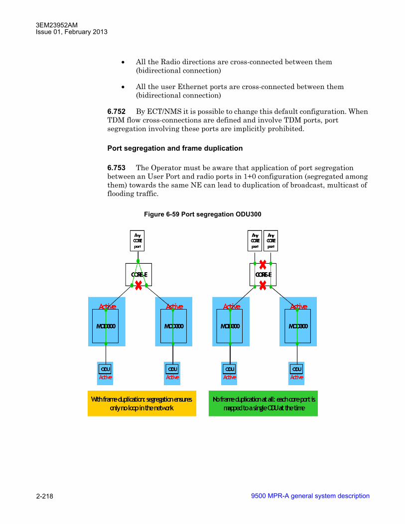
3EM23952AMIssue 01, February 2013
9500 MPR-A general system description2-218
• All the Radio directions are cross-connected between them (bidirectional connection)
• All the user Ethernet ports are cross-connected between them (bidirectional connection)
6.752 By ECT/NMS it is possible to change this default configuration. When TDM flow cross-connections are defined and involve TDM ports, port segregation involving these ports are implicitly prohibited.
Port segregation and frame duplication
6.753 The Operator must be aware that application of port segregation between an User Port and radio ports in 1+0 configuration (segregated among them) towards the same NE can lead to duplication of broadcast, multicast of flooding traffic.
Figure 6-59 Port segregation ODU300

3EM23952AMIssue 01, February 2013
9500 MPR-A general system description 2-219
TDM ports
6.754 Port Segregation is not supported for TDM ports (DS1/DS3/OC-3) by ECT/NMS. At system level TDM ports are segregated among them and not segregated from Radio directions involved in TDM flows cross-connections.
MPT access and P8ETH Ethernet ports
6.755 The information in this section applies to MPT access peripheral ports, P8ETH user ports, and P8ETH radio ports.
6.756 Port segregation can be applied by operator at two different points:
• between ports connected to MPT-HC/XPs: to segregate connected MPT-HC/XPs
• between ports connected to MSS backplane and the other backplane ports: to segregate all connected MPT-HC/XPs towards User Ports or other radio directions.
6.757 In case only one MPT is connected to the port, the port segregation behavior is the same as with ODU300 radio direction.
6.758 Assuming 2 MPT-HC/XPs in 1+0 configuration are connected to the same card, (the only configuration supported within this release with more than one MPT on same MPT Access peripheral), three scenarios have to be considered:
1. no port segregation is applied by operator between ports and to port towards backplane: in this case, all the involved ports can exchange the data among them (case A);
2. port segregation is applied by operator between ports, while no port segregation is applied by operator to port towards backplane: in this case, the two MPT-HC/XPs cannot exchange data (case B); in this case, frame duplication for broadcast, multicast and flooding traffic will surely occur in case the two radio directions are towards the same NE;
3. no port segregation is applied by operator between ports, while operator applies segregation to port towards backplane. This case represents a card isolated from MSS backplane, in such case, the two MPT-HC/XPs can only exchange data between them (case C).

3EM23952AMIssue 01, February 2013
9500 MPR-A general system description2-220
A fourth scenario for application of port segregation is possible, but in this release is not applicable:
4. port segregation is applied by operator between ports and port towards backplane, no traffic can be exchanged between MPT-HC/XPs and with MSS with the current number of supported ports. No check has been implemented to forbid this application of port segregation since it can be applied in future releases where use of all MPT Access peripheral ports is supported (case D).
6.759 When two P8ETH or MPT Access plug-ins are equipped in the same shelf row, port segregation can be applied between all ports across the two plug-ins.
6.760 Port segregation can be applied to:
• User ports (either electrical or optical)
• a User port and a Radio port
• Radio ports
6.761 Port segregation between P8ETH or MPT Access port and Core-E ports is not allowed.
Figure 6-60 Port segregation scenario: MPT access

3EM23952AMIssue 01, February 2013
9500 MPR-A general system description 2-221
6.762 For any individual port on a P8ETH or MPT Access port, port segregation between User or Radio ports in different shelf rows is not allowed.
MPT-HC/XPs number for each MPT plug in
6.763 If port segregation is applied by operator to an MSS User port and to MPT Access plug-in port towards backplane, MPT ODUs connected to same MPT Access plug-in will have the same segregation.
6.764 This application of port segregation by operator has no consequence on the capability to provision up to 2 MPT ODUs on the same MPT Access plug-in (in 1+0).
6.765 Below it is reported an example of applicable port segregation configuration by operator.
6.766 In this case the goal of port segregation is the MPT1-MPT3 pair does not exchange traffic with MPT2-MPT4 pair.
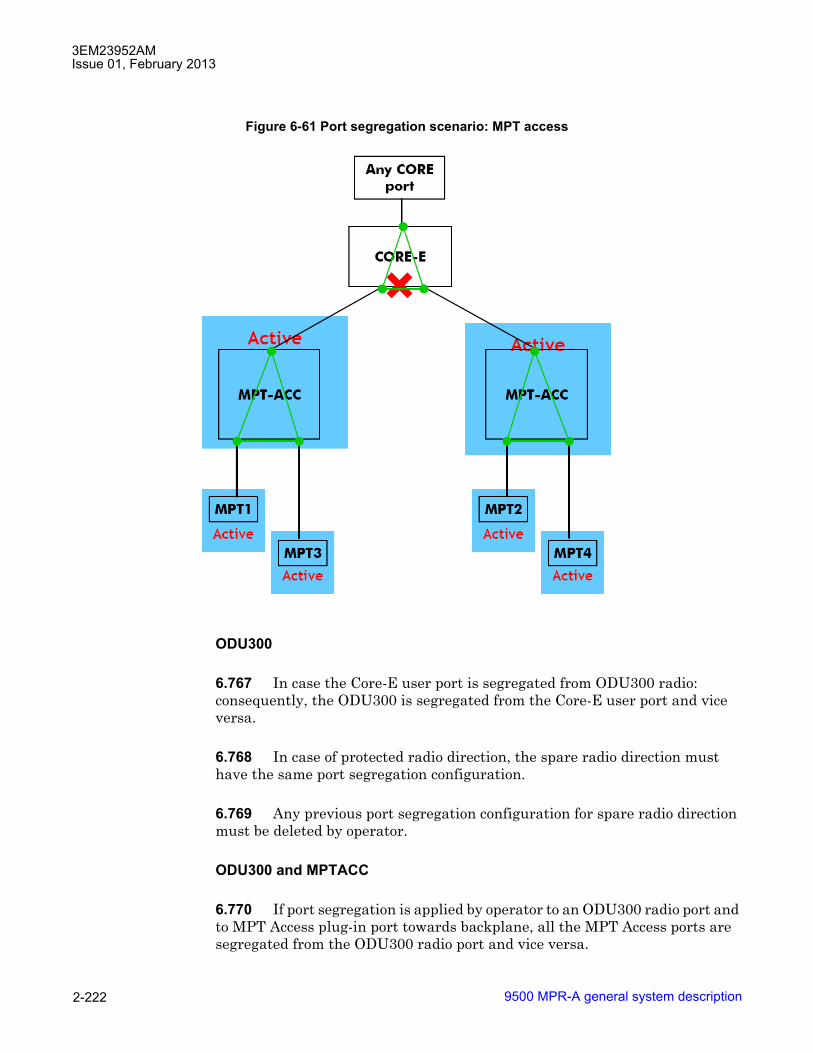
3EM23952AMIssue 01, February 2013
9500 MPR-A general system description2-222
ODU300
6.767 In case the Core-E user port is segregated from ODU300 radio: consequently, the ODU300 is segregated from the Core-E user port and vice versa.
6.768 In case of protected radio direction, the spare radio direction must have the same port segregation configuration.
6.769 Any previous port segregation configuration for spare radio direction must be deleted by operator.
ODU300 and MPTACC
6.770 If port segregation is applied by operator to an ODU300 radio port and to MPT Access plug-in port towards backplane, all the MPT Access ports are segregated from the ODU300 radio port and vice versa.
Figure 6-61 Port segregation scenario: MPT access
3EM23952AMIssue 01, February 2013
9500 MPR-A general system description 2-223
ODU300 and P8ETH
6.771 If port segregation is applied by operator to an ODU300 radio port and to P8ETH plug-in port towards backplane, all the P8ETH ports are segregated from the ODU300 radio port and vice versa.
MPT-HC/XPs in protection
6.772 Explicit port segregation between protected MPTs is not allowed. MPT protection cannot be configured if the associated SFPs have been segregated.
6.773 Port segregation between protected MPTs is implicitly applied. Port segregation is removed when the protection is removed.
MPT-HC/XPs protected on different plug-ins
6.774 When two MPT-HC/XPs are provisioned for 1+1 protected configuration on two different P8ETH or MPT Access peripherals, the plug-in ports towards backplane will not be implicitly segregated from each other.
6.775 Otherwise, when a future release supports the possibility to connect another MPT to the same MPT Access peripheral(s), it would not be possible to have it in repeater configuration with the protected MPT pair.
6.776 Operator is allowed to apply port segregation to MPT Access peripherals hosting an MPT pair in 1+1, but since connection to other MPT on same plug-in is not supported in this release, only the segregation of MPT Access port towards the backplane is effective.
6.777 The spare radio direction must have the same port segregation configuration (for MPT Access plug-in port towards backplane).
6.778 Any previous port segregation configuration for spare radio direction must be deleted by operator.
MPT-HC/XPs protected on the same plug-in
6.779 When two MPT-HC/XPs are provisioned for 1+1 protected configuration on the same P8ETH or MPT Access peripheral, the plug-in ports facing the MPTs have to be segregated from each other. The MPT Access interface facing the Core-E card can be segregated from other peripheral interfaces of User Ethernet interfaces of the Core-E card.
3EM23952AMIssue 01, February 2013
9500 MPR-A general system description2-224
ERPS Ring ports
6.780 To segregate one port from ERPS Ring ports both Ring ports must be segregated from that port. Segregation of one port from one Ring port causes inconsistent behavior of traffic delivery over the ring.
Remote inventory
6.781 Remote Inventory (RI) provides operators with the capability to remotely determine what equipment is installed in the system. RI data contains information programmed in the factory to indicate the configuration, capability, and compatibility of the installed MSS cards, ODU300, MPT-HC, MPT-HL, and MPT-XP transceivers.
Security
6.782 The system provides a mechanism to protect access to the NE.
User authentication
6.783 Communication access is accomplished using Username and Password authentication.
6.784 An NE supports a maximum of twenty-three provisioned users.
User profile management
6.785 NE rejects username and passwords that do not meet complexity parameters. These complexity parameters are as follows:
• Username length: Username must not exceed twenty characters in length.
• Password length: Passwords must not be less than eight and not longer than twenty characters in length.
• Password composition: Passwords must be composed of UPPER case, lower case, numeric, and special characters.
6.786 Access privileges to the system are controlled using four user profiles. User profiles privileges are as follows:
• Administrator: Full access to the NE including security parameters.

3EM23952AMIssue 01, February 2013
9500 MPR-A general system description 2-225
• CraftPerson: Users assigned to installation and maintenance tasks at the radio site. Full access to the NE except security parameters.
• Operator: Users assigned to operational tasks at the network level, not at the radio site.
• Viewer: Users who require read only access.
SNMP operating mode (SNMPv3 support)
6.787 The SNMP operating mode of the NE can be set using the WebEML or the web interface.
6.788 The following SNMP operating modes are supported:
• SNMPv2: Only SNMPv2 or v1 managers can access the NE. This is the default operating mode.
• SNMPv3: Only SNMPv3 managers can access the NE.
6.789 SNMPv3 addresses security problems by adding two new features on top of the existing SNMPv1 and SNMPv2 network management protocols:
• Authentication using hashing and time stamps.
• Confidentiality using encryption.
6.790 SNMPv3 is based on the following:
• The User based Security Model (USM), which provides strong user authentication, data integrity, privacy(encryption) and time stamp management (timeliness),
• The View base Access Control Model (VACM), which provides a mechanism for managing what information is available to users.
6.791 Authentication is provided using the HMAC-MD5-96 standard authentication protocol.
6.792 The SNMP operating mode is stored in permanent memory on a Flash card.
SNMPv2 community string
6.793 The system supports SNMPv2 Community String (CS).
6.794 Two Community Strings are supported, �Get CS� and �Set CS�.

3EM23952AMIssue 01, February 2013
9500 MPR-A general system description2-226
6.795 CS must not be less than six and not longer than ten characters in length. Only alphanumeric characters are supported.
SSH and SFTP support
6.796 The system supports the client-server model for SSH. The server mode is enabled at startup and cannot be disabled.
6.797 The client mode is supported only for file downloads using SFTP.
6.798 SFTP is not used for internal file transfers between CPUs within a 9500MPR system.
6.799 FTP or SFTP can be used to download software. When SFTP is used, the server host key fingerprint must be provided during download initialization. FTP is the default protocol selection.
6.800 If FTP is disabled, only SFTP can be used. SFTP cannot be disabled.
6.801 Backup and restore file transfers can also be performed using either FTP or SFTP.
6.802 To initiate an SFTP session, the user must have either administrator or craftperson privileges.
Software package rollback
6.803 The system supports software package rollback to the previous committed software version. Software package rollback is supported when the software package and the MSS database for the previous committed software version are both still present on the Core-E flash card.
6.804 All configuration changes applied to the NE after the software version upgrade will be lost during the software package rollback operation.
6.805 Software package rollback operation WILL impact traffic including a possible long out-of service period. For this reason software package rollback should be considered as a critical operation to be performed as a last resort only after all other alternatives have been explored.
6.806 Software package rollback functionality was added in R4.0.0 and is available for software upgrades from R4.0.0 and greater.

3EM23952AMIssue 01, February 2013
9500 MPR-A general system description 2-227
6.807 Software package rollback is NOT supported between the following software releases:
• release versions that differ by ICS version only (i.e., Rxx.xx.xx ICS01 and Rxx.xx.xx ICS02)
• release versions that differ by the last digits of the release version number((i.e., Rxx.xx.00 and Rxx.xx.01)
For these cases, a revert to the previous release version and a database restore is required. Contact the next level of technical support for assistance.
6.808 Table 6-Q provides a list of supported software package rollbacks:
Stacking for EAS/MPT access cards
6.809 Two EAS cards or two MPT Access cards installed on the same row (i.e. slot #3 and slot #4) are automatically configured in stacking configuration.
6.810 The benefits of stacking are:
• The intra-board traffic between the two cards does not transit through the Core-E card (no traffic impact in case of Core-E switch).
• Each port of the cards can be individually segregated from the other ports.
Synchronization
6.811 All 9500 MPR-A radios in the network must be synchronized to the same clock. One radio in the network is provisioned Master. All other radios in the network must be provisioned Slave. The slave radios all sync to the clock provided by the master.
Table 6-Q. Releases supporting software package rollback Initial software release version(Current Status: �Stand by�)
Upgrade software release version(Current Status: �Committed�)
Software package rollback support
R3.2.0, R3.3.0, or R3.4.0 R4.0.0 NoR3.4.0 R 4.0.0 or R4.1.0 NoR4.0.0 or later R4.1.0 or later Yes

3EM23952AMIssue 01, February 2013
9500 MPR-A general system description2-228
Normal operation
6.812 During normal operation, the master can be provisioned to get sync clock from two separate sources: an internal local oscillator (most common source) or external clock from customer provided equipment. The slave radios can be provisioned to receive the sync clock from one of two sources: clock recovered by the radio receiver or the sync clock from another radio in the network. Normally at a repeater, the sync clock is received over the RF path and recovered by the radio receiver. A typical slave terminal uses the clock from an adjacent radio.
Failed primary operation
6.813 With the exception of the master when the radio is provisioned to sync off the local oscillator, the provisioned secondary sync source is enabled if the primary source fails. When the master, provisioned to accept sync clock at the CSM-E (Control and Switching Module) from an external source, fails, the internal free-running local oscillator is enabled. Provisioning choices for the secondary source for slave radios are dependent upon the choices made from the primary source. Refer to the following descriptions for details.
Sync switching
6.814 With the exception of the master when the radio is provisioned to sync from the local oscillator, the sync clock source is switched from primary to secondary if the primary source fails. Sync clock switching provisioning is dependent on the role of the radio in the network (master or slave) and on user preference. A revertive switching feature is a provisioning option that restores the sync clock to the original source when the alarm on the primary source is cleared. If revertive switching is not selected, the secondary sync source will continue to provide sync clock, and if the secondary source fails, must be manually switched to the primary source.
6.815 The MPT-HL sends out Do Not Use signals (DUS) in the following situations:
• The MPT-HL is not receiving reliable timing information from the Ethernet port, or there is a timing issue with a P8ETH or MPTACC peripheral.
• An NE upstream of the MPT-HL and an NE downstream of the MPT-HL are using the MPT-HL as a synchronization source. This creates the possibility of a timing loop.
6.816 If the NE receiving the DUS is using the MPT-HL as a synchronization source, the DUS will trigger a synchronization switch.

3EM23952AMIssue 01, February 2013
9500 MPR-A general system description 2-229
Synchronization for PDH/SDH/DATA
Synchronization overview
6.817 PDH/SDH data flow is fragmented and the fragments are transmitted over a Packet Switched Network (PSN);
6.818 The received fragments need to be reassembled in the original PDH/SDH data flow at the �original bit rate�
6.819 Three main methods can be used to recover at the Rx site, the original bit rate:
• Differential clock recovery (DCR): recalculation of the original clock based of the Delta respect to a reference clock that is available at both Tx and Rx site (Differential: used in case of clock distribution on the whole network. It�s more reliable than Adaptive; also used in TDM2TDM traffic (MPR to MPR)). This method can be selected for each DS1/DS3/OC-3 stream.
Figure 6-62 Synchronization block diagram

3EM23952AMIssue 01, February 2013
9500 MPR-A general system description2-230
• Adaptive clock recovery (ACR): based on the average rate at which the packets (fragments) arrive at RX site (Adaptive: simpler network, but performances depends on the PDV (Packet Delay Variation) in the Network. Always used when the reference clock isn�t distributed on the whole network). This method can be selected for each DS1/DS3/OC-3 stream.
• Node Timing: timing from the network clock as defined in G.8261. The enabling of the Node Timing is applied to all DS1/DS3/OC-3s of the PDH/SDH unit.
• This feature (called either �network clock re-timing� or �node timing� or, according to G. 8261 wording, �network-synchronous operation for service clock�) introduces an additional possibility to recover the clock.
• Node timing is a way to recover the clock quite popular in the industry of service routers and site aggregator boxes. This feature inside the 9500 MPR-A platform is adding interworking capabilities with third parties service routers and circuit emulations gateway.
• In node-timing working mode, all the DS1/DS3/OC-3s are re-sampled with the network element clock. This means that, as also reported in G8261, this method does not preserve the service timing (DS1/DS3/OC-3 clock).
• Recovered DS1/DS3/OC-3 clock is according to G. 823 synchronization masks.
6.820 The available clock recovery techniques with TDM2TDM and SDH2SDH profiles are:
• DCR: differential clock recovery
• Node timing
6.821 The available clock recovery techniques with TDM2ETH profile are:
• ACR: adaptive clock recovery (if a common reference clock is not available)
• DCR: differential clock recovery
• Node timing.
NOTE: In meshed networks (rings) do not close the synchronization configuration.
Note
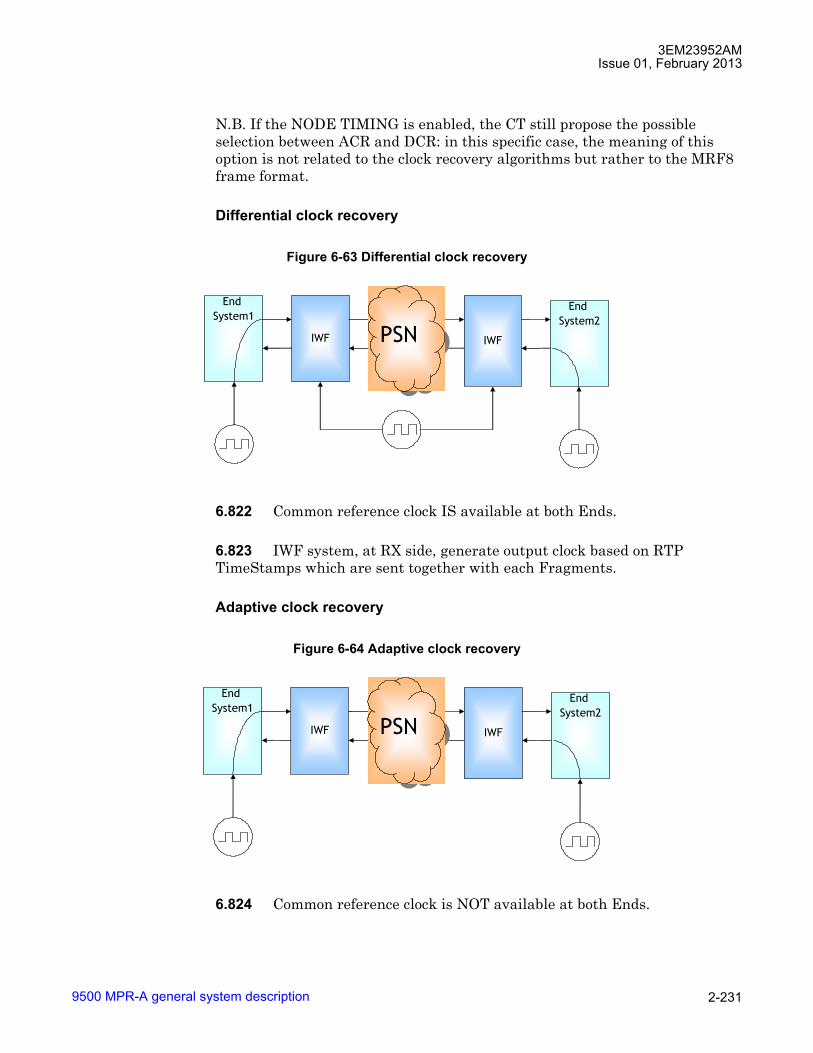
3EM23952AMIssue 01, February 2013
9500 MPR-A general system description 2-231
N.B. If the NODE TIMING is enabled, the CT still propose the possible selection between ACR and DCR: in this specific case, the meaning of this option is not related to the clock recovery algorithms but rather to the MRF8 frame format.
Differential clock recovery
6.822 Common reference clock IS available at both Ends.
6.823 IWF system, at RX side, generate output clock based on RTP TimeStamps which are sent together with each Fragments.
Adaptive clock recovery
6.824 Common reference clock is NOT available at both Ends.
Figure 6-63 Differential clock recovery
Figure 6-64 Adaptive clock recovery
End System1
IWF IWF
End System2
PSNPSN
End System1
IWF IWF
End System2
PSNPSN

3EM23952AMIssue 01, February 2013
9500 MPR-A general system description2-232
6.825 IWF system, at RX side, generate output clock based on data arrival rate: TDM clock is slowly adjusted to maintain the average fill level of a jitter buffer at its midpoint.
SyncE
6.826 The system supports electrical and optical Synchronous Ethernet (SyncE) signals on Core-E Ethernet ports. When SyncE is enabled on a port, the receive side extracts the frequency of the input signal and passes it to the system clock as a candidate frequency reference.
6.827 SyncE interfaces support SSM for synchronous Ethernet and ESMC processing according to ITU-T G.8264.
6.828 SyncE is supported in the following configurations:
• Core-E Ethernet Ports (electrical and optical)
� When Electrical Ethernet Port, the user must configure the port as Master or Slave
• User Ethernet port must be configured 1000 Mb/s
• SyncE is NOT supported on P8ETH Ethernet ports
Synchronization protection
6.829 In order to get any node in a meshed network or ring topology network always locked for each node the synchronization sources and the automatic selection process are defined, as described in the following points.
6.830 Sync status messages (SSM) are supported by SyncE enabled interfaces (Core-E User Ethernet interfaces working in synchronous operation mode), radio interfaces (ODU 300, MPT-HL/MPT-HC/MPT-XP) and L1 LAG ports.
6.831 SSM carries information about the quality level of the source clock from clock to clock along the network. There are a number of pre-defined quality levels (QL) corresponding to existing clock specifications i.e. QL-PRC, QL-SSU-A, QL-SSU-B, QL-SEC and QL-DNU. The last message means �Do Not Use�. This signaling system is used for controlling protection switching in case of link or clock failures and protecting against sync loops. Of course, SSM also exists in Synchronous Ethernet. It works in exactly the same way as in SDH and SONET. The only difference is the communication channel used for transferring the SSM from clock to clock. In SDH and SONET the SSM is contained in the SSM Byte (SSMB) of the STM-n or OC-n frame overhead.

3EM23952AMIssue 01, February 2013
9500 MPR-A general system description 2-233
Synchronous Ethernet uses �Ethernet Synchronization Messaging Channel� or ESMC. It consists of special Ethernet frames. The important point to note here is that there is a perfect continuity between SDH and SONET on side, Hybrid NEs and Synchronous Ethernet on the other.
6.832 SSM messages represent the quality level of the system clocks located in the various network elements. SSM contains the Clock Quality Level (QL) and Quality Level Priority (QLP). QLP is optional. Quality level refers to the holdover performance of a clock.
6.833 SSM messages shall be received and monitored on interfaces that are configured as sync sources and with SSM support enabled; otherwise received messages shall be ignored and silently discarded. In this case, The default (initial) value for the QL is DNU and QLP is Undefined until a valid QL/QLP is received over the interface. When a valid QL is received by an interface providing a sync source signal, the carried SSM-QL is assigned as the clock QL of this interface and used by the system clock selection algorithm. Lack of reception of an SSM within a five-second period results in the QL of the interface being set to QL-FAILED and QL Priority being set to Undefined. Loss of ESMC defect is raised and it is cleared on receipt of the first SSM.
6.834 SSM messages are generated on interfaces with SSM enabled. These messages are generated once per second.
6.835 Given two sync sources, the NEC will use QL/QLP to determine the selected sync source. The selected QL/QLP will be sent out over interfaces with SSM enabled.
6.836 The selection process works always in QL-enabled mode, the selected synchronization clock source is used to lock the NEC. The QL of the selected synchronization clock source determines the QL of the NEC, unless the NEC is in Holdover mode.
6.837 The selection process has two nominated synchronization clock source inputs:
• Primary clock source input;
• Secondary clock source input.
6.838 For such sources the following selection criteria are defined:
• Clock Source Fail when the source is not available;

3EM23952AMIssue 01, February 2013
9500 MPR-A general system description2-234
• Clock Source Degrade when the frequency of the source is away from its nominal value with the following rules: the degrade alarm will never be asserted if the actual frequency is within ±10 ppm of its nominal value; the degrade alarm will always be asserted if the actual frequency is not within ±50 ppm of its nominal value;
• Clock Source Quality Level (QL) according to ITU-T G.781;
• Clock Source Quality Level Priority
6.839 The QL-DNU and QL Priority Undefined are advertised over the synchronization interface that is currently selected to avoid sync loops.
6.840 When a Signal Fail or Signal Degrade defects are detected on a synchronization clock source input, the Quality Level of this source input is set to QL-FAILED value.
6.841 When the NEC goes into holdover, the QL is set to QL-SEC/QL-EEC1.
6.842 Figure 6-65 to 6-67 is a ring example using DNU to prevent loops and used during protection switching:
Figure 6-65 Ring network with SSMs and port priorities normal situation

3EM23952AMIssue 01, February 2013
9500 MPR-A general system description 2-235
6.843 SSM ESMC messages are queued in Q6. SSM are sent one per second, so the bandwidth is very low. 32 octets but future extensions could be larger.
Figure 6-66 Ring network in restoration process - last node switched reference
Figure 6-67 Ring network in restoration process - final situation

3EM23952AMIssue 01, February 2013
9500 MPR-A general system description2-236
Synchronization quality level
6.844 According to Table 8 of ITU-T G.781 the Clock Source Quality Level is identified by the following SSM Codes:
• 0010 - QL-PRC for timing quality generated by a primary reference clock as defined in ITU-T G.811;
• 0100 - QL-SSU-A for timing quality generated by a type I or V slave clock as defined in ITU-T G.812;
• 1000 - QL-SSU-B for timing quality generated by a type VI slave clock as defined in ITU-T G.812;
• 1011 - QL-SEC/QL-EEC1 for timing quality generated by a SEC or EEC as defined in ITU-T G.813/ITU-T G.8262;
• 1111 - QL-DNU (Do Not Use).
6.845 Any other SSM Code values different from the ones listed above must be considered as an Invalid Quality Level (QL-INV).
6.846 The QL of the NEC is advertised over radio interfaces and Synchronous Ethernet interfaces.
Quality level priority
6.847 A QL Priority parameter is defined for each node and assigned to synchronization clock sources and to the NEC.
6.848 The QL Priority values are identified by the following codes:
• 0x01 - Master1
• 0x10 - Slave1
Table 6-R. SSM quality levelsQuality Level Order
QL-PRC HighestQL-SSU-A |QL-SSU-B |
QL-SEC/QL-EEC1 |QL-DNU |
QL-FAILED/QL-INV Lowest
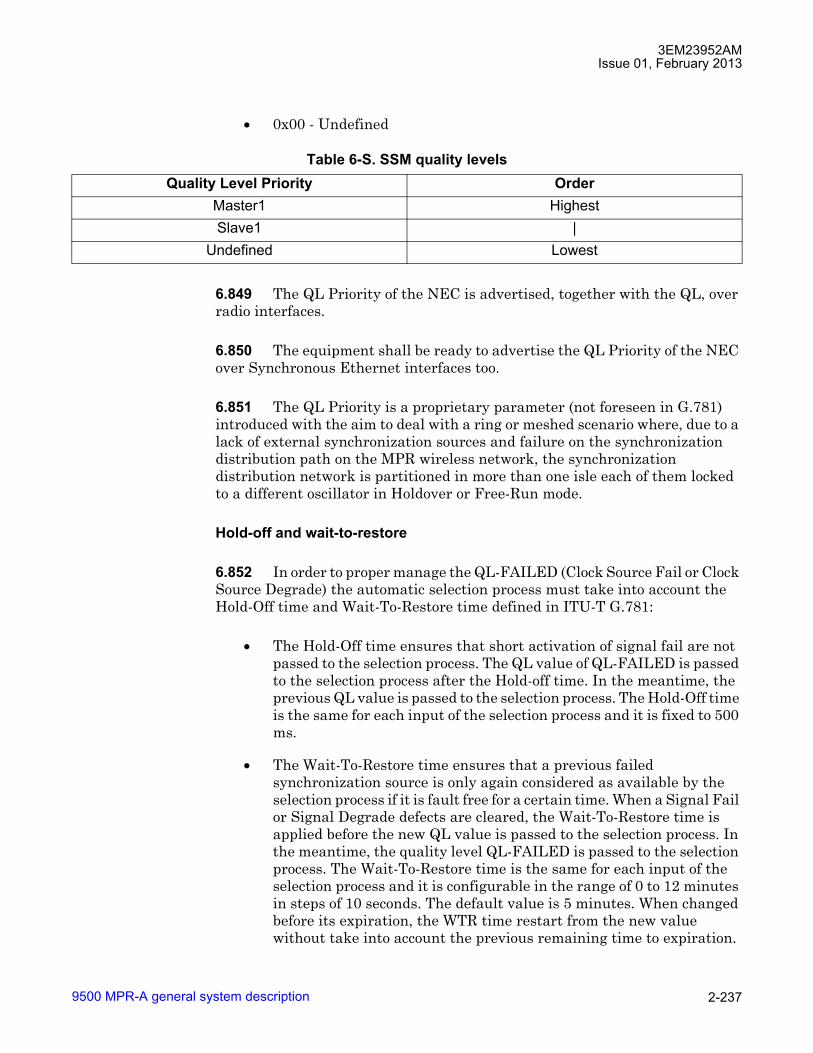
3EM23952AMIssue 01, February 2013
9500 MPR-A general system description 2-237
• 0x00 - Undefined
6.849 The QL Priority of the NEC is advertised, together with the QL, over radio interfaces.
6.850 The equipment shall be ready to advertise the QL Priority of the NEC over Synchronous Ethernet interfaces too.
6.851 The QL Priority is a proprietary parameter (not foreseen in G.781) introduced with the aim to deal with a ring or meshed scenario where, due to a lack of external synchronization sources and failure on the synchronization distribution path on the MPR wireless network, the synchronization distribution network is partitioned in more than one isle each of them locked to a different oscillator in Holdover or Free-Run mode.
Hold-off and wait-to-restore
6.852 In order to proper manage the QL-FAILED (Clock Source Fail or Clock Source Degrade) the automatic selection process must take into account the Hold-Off time and Wait-To-Restore time defined in ITU-T G.781:
• The Hold-Off time ensures that short activation of signal fail are not passed to the selection process. The QL value of QL-FAILED is passed to the selection process after the Hold-off time. In the meantime, the previous QL value is passed to the selection process. The Hold-Off time is the same for each input of the selection process and it is fixed to 500 ms.
• The Wait-To-Restore time ensures that a previous failed synchronization source is only again considered as available by the selection process if it is fault free for a certain time. When a Signal Fail or Signal Degrade defects are cleared, the Wait-To-Restore time is applied before the new QL value is passed to the selection process. In the meantime, the quality level QL-FAILED is passed to the selection process. The Wait-To-Restore time is the same for each input of the selection process and it is configurable in the range of 0 to 12 minutes in steps of 10 seconds. The default value is 5 minutes. When changed before its expiration, the WTR time restart from the new value without take into account the previous remaining time to expiration.
Table 6-S. SSM quality levelsQuality Level Priority Order
Master1 HighestSlave1 |
Undefined Lowest

3EM23952AMIssue 01, February 2013
9500 MPR-A general system description2-238
The WTR time is also applied when a LOS of ESMC defect is cleared on a synchronization clock source, also in that case the quality level QL-FAILED is passed to the selection process until the WTR time expires.

3EM23952AMIssue 01, February 2013
9500 MPR-A general system description 2-239
Synchronization sources assignment
6.853 The physical interfaces to be assigned to Primary and Secondary synchronization sources can be selected from the following:
1. Free Run Local Oscillator:
� is not affected by any alarm (no Fail, no Degrade)
� Quality Level value is fixed to QL-SEC/EEC1 (G.812/G8262)
� QL Priority is Master1 if the NEC is configured as Master
� QL Priority is Slave1 if the NEC is configured as Slave
2. DS1 which is enabled on input traffic interface:
� meets the interface requirements in G.824, Section 6
� the specific DS1 port must be selected
� For these sources the Fail alarm has to be detected by CRU when LOS, AIS, or LOF (in case of DS1s framed) occurs
� Default value for Quality Level is QL-SSU-A (G.812)
� QL Priority is Master1 if the NEC is configured as Master
� QL Priority is Slave1 if the NEC is configured as Slave.
3. synchronization signal available from the dedicated Sync-In port
must be configured from the following options:
a. 2.048 MHz, electrical levels according to G.703, clause 13
b. 5 MHz, + 6 dBm into 50 ohm, sine-wave
c. 10 MHz, + 6 dBm into 50 ohm, sine-wave
d. 1.024 MHz, electrical levels according to G.703, clause 13 with the following exception:
timing properly scaled from 2.048 MHz to 1.024 MHz.
� Fail alarm is detected by CRU when LOS occurs
� Default value for Quality Level is QL-SSU-A (G.812)
� QL Priority is Master1 if the NEC is configured as Master

3EM23952AMIssue 01, February 2013
9500 MPR-A general system description2-240
� QL Priority is Slave1 if the NEC is configured as Slave
4. The Symbol Rate of the RX signal of any available Radio:
� the specific Radio Port must be selected
� Fail alarm must be detected by CRU when a DEM-Fail or a Loss of Radio Frame occurs
� When SSM support is enabled, the QL and QL Priority are acquired from ESMC PDUs received on the selected radio interface
� When SSM support is disabled, the default value for Quality Level is QL-SSU-A (G.812)
� QL Priority is Master1 if the NEC is configured as Master
� QL Priority is Slave1 if the NEC is configured as Slave
5. A SyncE clock source available at enabled User Ethernet traffic interface:
� electrical or optical interface configured in synchronous operation mode
� at 1000 Mbit/s
� the specific User Ethernet port must be selected
� from ITU-T G.8261 point of view, the MSS is Synchronous Ethernet equipment, equipped with a system clock (NEC) following the ITU-T G.8262 recommendation.
� When SSM support is enabled, the QL is acquired from ESMC PDUs received on the specific Synchronous Ethernet interface
� by default, the QL Priority is not advertised by ESMC PDUs
� QL Priority is Master1 if the NEC is configured as Master
� QL Priority is Slave1 if the NEC is configured as Slave
� when the QL Priority is advertised by ESMC PDUs, the QL Priority is acquired from them
� when the SSM support is disabled, the default Quality Level is QL-SSU-A (G.812)
QL Priority is Master1 if the NEC is configured as Master

3EM23952AMIssue 01, February 2013
9500 MPR-A general system description 2-241
QL Priority is Slave1 if the NEC is configured as Slave
� electrical User Ethernet interfaces perform link auto negotiation to determine the master/slave role for clock delivery over the link
� The clock slave role must be configured as part of auto negotiation parameters in order to use the interface as Synchronous Ethernet clock source input, either as Primary or Secondary. This check is performed by CT/NMS but not by EC.
� The clock master role must be configured as part of auto negotiation parameters in order to use the interface as Synchronous Ethernet clock source output to distribute NEC to other equipment.
� For Synchronous Ethernet clock sources from electrical User Ethernet ports the Fail alarm will be raised when Loss of Synch (i.e. Ethernet Link Down) occurs.
� For Synchronous Ethernet clock sources from optical User Ethernet ports the Fail alarm will be raised when Loss of Optical signal occurs.
6. Any OC-3 (STM1) available at SDH input traffic interface:
� the specific OC-3 (STM1) port must be selected
� Fail alarm will be raised when LOS, LOF, TIM, MS-AIS, or High BER occurs
� Default value for Quality Level is QL-SSU-A (G.812)
� QL Priority is Master1 if the NEC is configured as Master
� QL Priority is Slave1 if the NEC is configured as Slave.
7. Any L1 Radio LAG with administrative state enabled.
� NE selects one of the LAG members according to current alarm status
� in case of synchronization failure to the current reference, the NE performs a selection switch to another member of the LAG
� When SSM support is enabled, the QL Priority is advertised by ESMC PDUs, the QL Priority is acquired from them
� when the SSM support is disabled, the default Quality Level is QL-SSU-A (G.812)
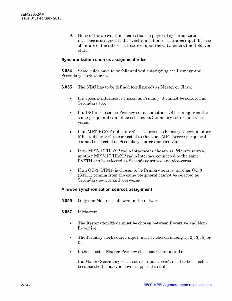
3EM23952AMIssue 01, February 2013
9500 MPR-A general system description2-242
8. None of the above, this means that no physical synchronization interface is assigned to the synchronization clock source input. In case of failure of the other clock source input the CRU enters the Holdover state.
Synchronization sources assignment rules
6.854 Some rules have to be followed while assigning the Primary and Secondary clock sources:
6.855 The NEC has to be defined (configured) as Master or Slave.
• If a specific interface is chosen as Primary, it cannot be selected as Secondary too.
• If a DS1 is chosen as Primary source, another DS1 coming from the same peripheral cannot be selected as Secondary source and vice-versa.
• If an MPT-HC/XP radio interface is chosen as Primary source, another MPT radio interface connected to the same MPT Access peripheral cannot be selected as Secondary source and vice-versa.
• If an MPT-HC/HL/XP radio interface is chosen as Primary source, another MPT-HC/HL/XP radio interface connected to the same P8ETH can be selected as Secondary source and vice-versa
• If an OC-3 (STM1) is chosen to be Primary source, another OC-3 (STM1) coming from the same peripheral cannot be selected as Secondary source and vice-versa.
Allowed synchronization sources assignment
6.856 Only one Master is allowed in the network.
6.857 If Master:
• The Restoration Mode must be chosen between Revertive and Non-Revertive;
• The Primary clock source input must be chosen among 1), 2), 3), 5) or 6).
• If the selected Master Primary clock source input is 1):
the Master Secondary clock source input doesn't need to be selected because the Primary is never supposed to fail.

3EM23952AMIssue 01, February 2013
9500 MPR-A general system description 2-243
• If the selected Master Primary clock source input is 2), 3), 5) or 6):
the Master Secondary clock source input must be selected among 1), 2), 3), 5), 6) or 8).
6.858 If Slave:
• The Restoration Mode is fixed to Revertive.
• The Primary clock source input must be chosen among 3), 4), 5), or 7).
Slave Primary clock source input is allowed to be 3) or 5) for full indoor configuration and for Piling configuration.
• The Secondary clock source input must be chosen among 1), 2), 3), 4), 5), 6), 7), or 8).
6.859 When SSM is enabled on the secondary reference, the user should ensure that the QL and QLP will not exceed the normal QL and QLP of the primary reference.
Note: Any link that has been assigned as a timing reference at both ends (Primary source on one side and Secondary source on the other side) must have SSM support enabled on both synchronization sources at either side of the link.
QL and QL priority configuration
6.860 In the current release the QL of synchronization interfaces is not configurable by the operator and, when applicable, takes the default values.
6.861 The QL Priority of the node is not configurable by the operator.
Synchronization source with MPT
6.862 In order to use the symbol rate of the Rx signal of an MPT as selectable synchronization source for the NEC, the following is needed:
• if an Optical Ethernet connection is used, then the optical Ethernet port of MPT must be locked, at transmission, to symbol rate of the Rx signal;
• if an Electrical Ethernet connection is used, it shall be Synch-E capable, meaning that a common clock at physical layer level, not locked to the NEC, is available between MSS and MPT for a differential clock recovery method based on custom time-stamp protocol (referred to Symbol Rate of the air Rx Signal).
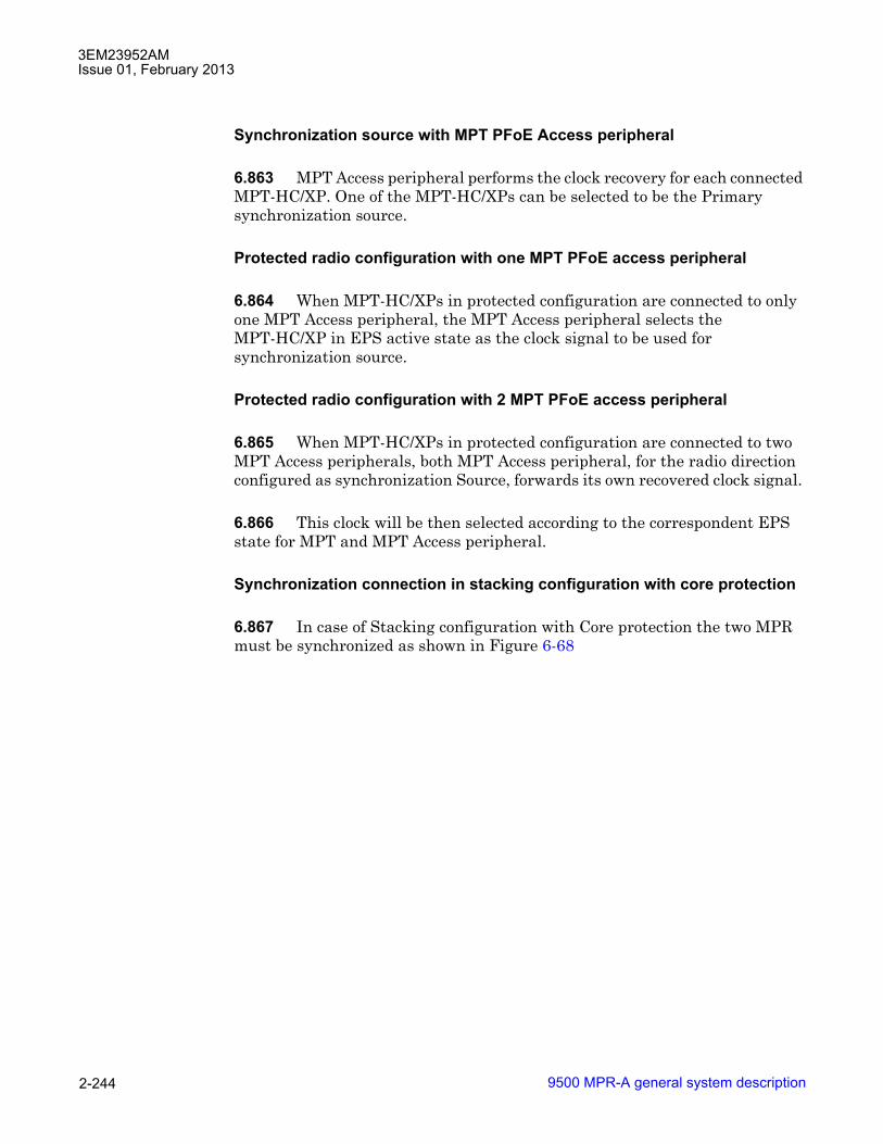
3EM23952AMIssue 01, February 2013
9500 MPR-A general system description2-244
Synchronization source with MPT PFoE Access peripheral
6.863 MPT Access peripheral performs the clock recovery for each connected MPT-HC/XP. One of the MPT-HC/XPs can be selected to be the Primary synchronization source.
Protected radio configuration with one MPT PFoE access peripheral
6.864 When MPT-HC/XPs in protected configuration are connected to only one MPT Access peripheral, the MPT Access peripheral selects the MPT-HC/XP in EPS active state as the clock signal to be used for synchronization source.
Protected radio configuration with 2 MPT PFoE access peripheral
6.865 When MPT-HC/XPs in protected configuration are connected to two MPT Access peripherals, both MPT Access peripheral, for the radio direction configured as synchronization Source, forwards its own recovered clock signal.
6.866 This clock will be then selected according to the correspondent EPS state for MPT and MPT Access peripheral.
Synchronization connection in stacking configuration with core protection
6.867 In case of Stacking configuration with Core protection the two MPR must be synchronized as shown in Figure 6-68

3EM23952AMIssue 01, February 2013
9500 MPR-A general system description 2-245
Functional block diagram
6.868 The 9500 MPR-A supports protected radio and not protected radio configurations.
Figure 6-68 Synchronization connection in stacking configuration with core protection

3EM23952AMIssue 01, February 2013
9500 MPR-A general system description2-246
6.869 See Figure 6-69 for a block diagram of a typical split mount protected radio configuration.
6.870 See Figure 6-70 for a block diagram of a typical full indoor mount protected radio configuration.
6.871 See Figure 6-71 for a block diagram of a typical split mount not protected radio configuration.
6.872 See Figure 6-72 for a block diagram of a typical full indoor mount not protected radio configuration.
Figure 6-69 Protected split mount radio

3EM23952AMIssue 01, February 2013
9500 MPR-A general system description 2-247
Figure 6-70 Protected full indoor mount radio
Figure 6-71 Not protected split mount radio
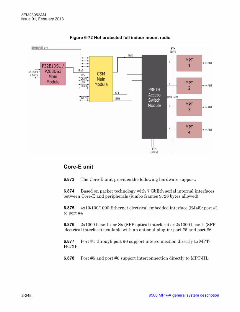
3EM23952AMIssue 01, February 2013
9500 MPR-A general system description2-248
Core-E unit
6.873 The Core-E unit provides the following hardware support:
6.874 Based on packet technology with 7 GbEth serial internal interfaces between Core-E and peripherals (jumbo frames 9728 bytes allowed)
6.875 4x10/100/1000 Ethernet electrical embedded interface (RJ45): port #1 to port #4
6.876 2x1000 base-Lx or Sx (SFP optical interface) or 2x1000 base-T (SFP electrical interface) available with an optional plug-in: port #5 and port #6
6.877 Port #1 through port #6 support interconnection directly to MPT-HC/XP.
6.878 Port #5 and port #6 support interconnection directly to MPT-HL.
Figure 6-72 Not protected full indoor mount radio

3EM23952AMIssue 01, February 2013
9500 MPR-A general system description 2-249
Main functions
• Controller
• Layer 2+ Eth Switch, VLAN management & MAC based
� Ethernet MAC learning
� Cross-connect function for PDH and Data payload traffic
� For any �packetized� data flow, the layer 2 switch is in charge to manage the EPS protection
� QoS management.
• Selection of the synchronization clock distributed to all plug-in.
6.879 The Core-E unit has the option to equip 1GigE Ethernet interface in the SFP ports (port #5, port #6). These ports can be used to connect Ethernet user traffic or to connect directly an MPT-HC/XP or MPT-HL.
6.880 Three modules are available:
• 1000BASE-LX (optical)
Figure 6-73 Core-E card block diagram

3EM23952AMIssue 01, February 2013
9500 MPR-A general system description2-250
• 1000BASE-SX (optical)
• 1000BASE-T (electrical)
6.881 The flash card stores the licence type, the equipment software, the equipment MIB and the equipment MAC address.
6.882 Warning: The optional optical SFP plug-in, which may be installed in port #5 and port #6 of the Core-E unit, contains a Class 1 laser source. The laser source is placed in the left side of the SFP plug-in. According to the IEC 60825-1 the explanatory label is not included on the equipment due to the lack of space.
Figure 6-74 Core-E Card front panel view
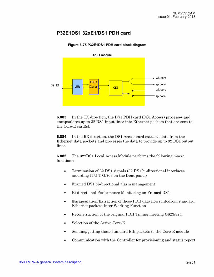
3EM23952AMIssue 01, February 2013
9500 MPR-A general system description 2-251
P32E1DS1 32xE1/DS1 PDH card
6.883 In the TX direction, the DS1 PDH card (DS1 Access) processes and encapsulates up to 32 DS1 input lines into Ethernet packets that are sent to the Core-E card(s).
6.884 In the RX direction, the DS1 Access card extracts data from the Ethernet data packets and processes the data to provide up to 32 DS1 output lines.
6.885 The 32xDS1 Local Access Module performs the following macro functions:
• Termination of 32 DS1 signals (32 DS1 bi-directional interfaces according ITU-T G.703 on the front panel)
• Framed DS1 bi-directional alarm management
• Bi-directional Performance Monitoring on Framed DS1
• Encapsulation/Extraction of those PDH data flows into/from standard Ethernet packets Inter Working Function
• Reconstruction of the original PDH Timing meeting G823/824.
• Selection of the Active Core-E
• Sending/getting those standard Eth packets to the Core-E module
• Communication with the Controller for provisioning and status report
Figure 6-75 P32E1DS1 PDH card block diagram
CES32 E1 LIUs
32 E1 module
wk core
sp core
wk core
sp core
FPGA(Ceres)
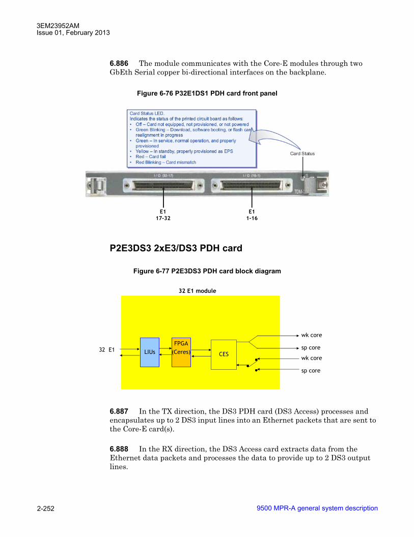
3EM23952AMIssue 01, February 2013
9500 MPR-A general system description2-252
6.886 The module communicates with the Core-E modules through two GbEth Serial copper bi-directional interfaces on the backplane.
P2E3DS3 2xE3/DS3 PDH card
6.887 In the TX direction, the DS3 PDH card (DS3 Access) processes and encapsulates up to 2 DS3 input lines into an Ethernet packets that are sent to the Core-E card(s).
6.888 In the RX direction, the DS3 Access card extracts data from the Ethernet data packets and processes the data to provide up to 2 DS3 output lines.
Figure 6-76 P32E1DS1 PDH card front panel
Figure 6-77 P2E3DS3 PDH card block diagram
E117-32
E11-16
CES32 E1 LIUs
32 E1 module
wk core
sp core
wk core
sp core
FPGA(Ceres)

3EM23952AMIssue 01, February 2013
9500 MPR-A general system description 2-253
6.889 The 2xE3DS3 Local Access Module performs the following macro functions:
• Termination of 2 DS3 signals (2 DS3 bi-directional interfaces according ITU-T G.703 on the front panel)
• Framed DS3 bi-directional alarm management
• Bi-directional Performance Monitoring on Framed DS3
• Encapsulation/Extraction of those PDH data flows into/from standard Ethernet packets Inter Working Function
• Reconstruction of the original PDH Timing meeting G823/824.
• Selection of the Active Core-E
• Sending/getting those standard Eth packets to the Core-E module
• Communication with the Controller for provisioning and status report
6.890 The module communicates with the Core-E modules through two GbEth Serial copper bi-directional interfaces on the backplane.
Figure 6-78 P2E3DS3 PDH card front panel
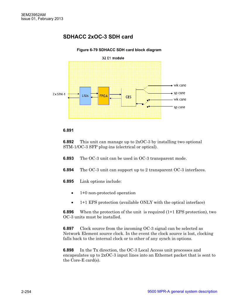
3EM23952AMIssue 01, February 2013
9500 MPR-A general system description2-254
SDHACC 2xOC-3 SDH card
6.891
6.892 This unit can manage up to 2xOC-3 by installing two optional STM-1/OC-3 SFP plug-ins (electrical or optical).
6.893 The OC-3 unit can be used in OC-3 transparent mode.
6.894 The OC-3 unit can support up to 2 transparent OC-3 interfaces.
6.895 Link options include:
• 1+0 non-protected operation
• 1+1 EPS protection (available ONLY with the optical interface)
6.896 When the protection of the unit is required (1+1 EPS protection), two OC-3 units must be installed.
6.897 Clock source from the incoming OC-3 signal can be selected as Network Element source clock. In the event the clock source is lost, clocking falls back to the internal clock or to other of any synch in options.
6.898 In the Tx direction, the OC-3 Local Access unit processes and encapsulates up to 2xOC-3 input lines into an Ethernet packet that is sent to the Core-E card(s).
Figure 6-79 SDHACC SDH card block diagram

3EM23952AMIssue 01, February 2013
9500 MPR-A general system description 2-255
6.899 In the Rx direction, the OC-3 Local Access unit extracts data from the Ethernet data packets and processes the data to provide up to 2 OC-3 output lines.
• The 2xOC-3 Local Access Unit performs the following macro functions:
• Transparent or channelized transport of the OC-3
• Encapsulation/Extraction of the OC-3 into/from standard Ethernet packets Inter Working Function
• Reconstruction of the original OC-3 Timing
• Selection of the Active Core-E
• Sending/getting those std Eth packets to the Core-E module
• Communication with the Controller for provisioning and status report
6.900 The unit communicates with the Core-E modules through two GbEth Serial copper bi-directional interfaces on the backplane.
Figure 6-80 SDHACC SDH card front panel
Optional SFP (electrical or optical)

3EM23952AMIssue 01, February 2013
9500 MPR-A general system description2-256
Modem radio interface card
6.901 In Tx direction, the MODEM unit generates the IF signal to be sent to an Outdoor Unit. Such signal contains a Constant Bit Rate signal built with the Ethernet packets coming from the Core-E; those packets are managed in a different way depending on their own native nature.
Digital framer
• Classification of incoming packets from the Core-E (QoS)
• Fragmentation
• Air Frame Generation (synchronous with NE clock)
Figure 6-81 Modem radio interface card block diagram
Tx
Mod
Rx
Demod
MODEM
ASIC
950-0190-1
062710
MOD300 Radio Access
Air Framer
PDH/Data
Management
IDU/ODU
Communication
FPGA
Air Framer
PDH/Data
Management
IDU/ODU
Communication
EPS
Tx
RPS
Rx
Analog
Chain
DAC
DAC
IF Tx
Q
I
ADC
ADC
IF Rx
Q
I
diplexer
From Alternate
Radio Board
for RPS
From/To
Alternate Radio
Board for EPS

3EM23952AMIssue 01, February 2013
9500 MPR-A general system description 2-257
Digital modulator
TX analog chain
• DAC & low pass filtering
• Modulation to 311 MHz IF TX
6.902 In Rx direction, the MODEM 300 Module terminates the IF signal coming from the ODU300 extracting the original CBR and then the original Ethernet packets to be given the Core-E which distributes them to the proper Module.
RX analog chain
• 126 MHz IF RX demodulation to I & Q
• low pass filtering & ADC
Digital demodulator
• Carrier & CK recovery
• Equalization
• Error Correction
Digital deframer
• RPS (hitless)
• Defragmentation
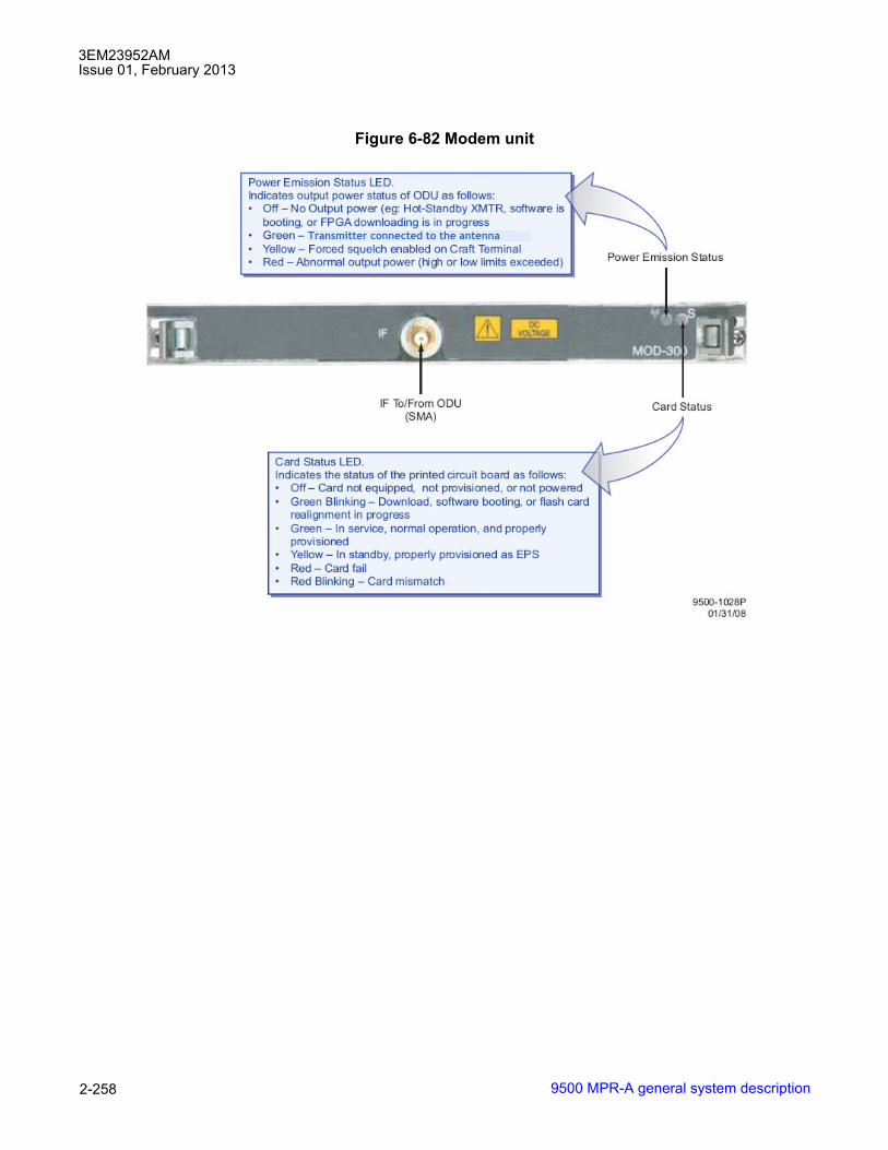
3EM23952AMIssue 01, February 2013
9500 MPR-A general system description2-258
Figure 6-82 Modem unit
Transmitter connected to the antenna

3EM23952AMIssue 01, February 2013
9500 MPR-A general system description 2-259
MPT access unit (with PFoE)
6.903 The MPT Access Unit is the interface for two MPT-HC/XPs.
6.904 Two MPT-HC/XP can be connected to one MPT Access unit.
6.905 The two MPT-HC/XPs can be configured in unprotected or protected configuration.
Figure 6-83 MPT access unit (with PFoE) block diagram
950-0036-1
092410
Digital
Processing

3EM23952AMIssue 01, February 2013
9500 MPR-A general system description2-260
6.906 The connection to the MPT-HC/XP can be realized:
1. by using two cables:
� one DC power supply cable to send the power supply to the MPT-HC/XP
� one Gigabit Ethernet cable (electrical or optical) to send the Ethernet traffic and the Ethernet control frames to the MPT-HC/XP
2. or by using only one electrical Ethernet cable and enabling the PFoE (Power Feed over Ethernet) function (Ethernet traffic + Power Supply on the same cable).
6.907 When an optical port has to be used, an SFP plug-in must be installed.
6.908 When port #1 is enabled (optical or electrical), the associated Power Supply port is #1.
6.909 When port #2 is enabled (optical or electrical), the associated Power Supply port is #2.
Main functions
• Provide the power supply interface and the Ethernet interface
• Provide the Power Feed over Ethernet function
• Lightning and surge protection
• Ethernet and power interface supervision
• EPS/HSB management function
• Clock distribution function
• L2 packet based Proprietary clock algorithm
• Ethernet link quality monitor function
• Radio Link Quality notification through MPR Protection Protocol frames
• Communication with Core controller for provisioning and status report.
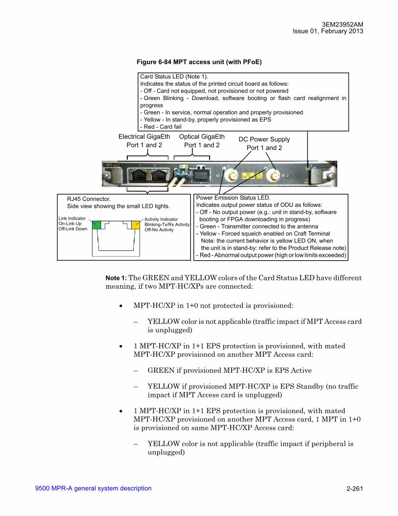
3EM23952AMIssue 01, February 2013
9500 MPR-A general system description 2-261
Note 1: The GREEN and YELLOW colors of the Card Status LED have different meaning, if two MPT-HC/XPs are connected:
• MPT-HC/XP in 1+0 not protected is provisioned:
� YELLOW color is not applicable (traffic impact if MPT Access card is unplugged)
• 1 MPT-HC/XP in 1+1 EPS protection is provisioned, with mated MPT-HC/XP provisioned on another MPT Access card:
� GREEN if provisioned MPT-HC/XP is EPS Active
� YELLOW if provisioned MPT-HC/XP is EPS Standby (no traffic impact if MPT Access card is unplugged)
• 1 MPT-HC/XP in 1+1 EPS protection is provisioned, with mated MPT-HC/XP provisioned on another MPT Access card, 1 MPT in 1+0 is provisioned on same MPT-HC/XP Access card:
� YELLOW color is not applicable (traffic impact if peripheral is unplugged)
Figure 6-84 MPT access unit (with PFoE)
Card Status LED (Note 1).Indicates the status of the printed circuit board as follows:- Off - Card not equipped, not provisioned or not powered- Green Blinking - Download, software booting or flash card realignment inprogress- Green - In service, normal operation and properly provisioned- Yellow - In stand-by, properly provisioned as EPS- Red - Card fail
Power Emission Status LED.Indicates output power status of ODU as follows:- Off - No output power (e.g.: unit in stand-by, softwarebooting or FPGA downloading in progress)
- Green - Transmitter connected to the antenna- Yellow - Forced squelch enabled on Craft Terminal
Note: the current behavior is yellow LED ON, whenthe unit is in stand-by: refer to the Product Release note)
- Red - Abnormal output power (high or low limits exceeded)
RJ45 Connector.Side view showing the small LED lights.
Link IndicatorOn-Link UpOff-Link Down
Activity IndicatorBlinking-Tx/Rx ActivityOff-No Activity
Electrical GigaEthPort 1 and 2
Optical GigaEthPort 1 and 2
DC Power SupplyPort 1 and 2

3EM23952AMIssue 01, February 2013
9500 MPR-A general system description2-262
• 2 MPT-HC/XPs in 1+1 EPS protection are provisioned, with mated MPT-HC/XP provisioned on a different MPT Access card:
� GREEN if at least one of provisioned MPT-HC/XP is EPS Active
� YELLOW if both MPT-HC/XPs are EPS Standby (no traffic impact if MPT Access is unplugged)
• 2 MPT-HC/XPs in 1+1 EPS protection on the same MPT Access card are provisioned:
� YELLOW color is not applicable (traffic impact if peripheral is unplugged)
Warning: The optional SFP plug-in, which may be installed in the MPT Access card, contains a Class 1 laser source. The laser source is placed in the left side of the SFP plug-in.
6.910 According to the IEC 60825-1 the explanatory label is not included on the equipment due to the lack of space.
ODU300
6.911 The ODU300s include a waveguide antenna port, type-N female connector for the ODU IF cable, a BNC female connector (with captive protection cap) for RSSI access, and a grounding stud.
6.912 The ODU300s, are designed for direct antenna attachment via a 9500 MPR-A-specific mounting collar supplied with the antennas.
6.913 ODU300 polarization is determined by the position of a polarization rotator fitted within the antenna mounting collar.
6.914 A remote ODU300 mounting kit is also available as an option. These may be used to connect an ODU to a standard antenna, or to a dual-polarized antenna for co-channel link operation.
6.915 ODU300s are fixed for Tx High or Tx Low operation.
6.916 Where two ODU300 are to be connected to a single antenna for hot-standby or frequency diversity configurations, a direct-mounting coupler is used. They are available for equal or unequal loss operation. Balanced loss is nominally 3 dB. Unbalanced loss is nominally 1/6 dB.

3EM23952AMIssue 01, February 2013
9500 MPR-A general system description 2-263
6.917 The ODU300 assembly meets the ASTME standard for a 2000 hour salt-spray test, and relevant IEC, UL, and Bellcore standards for wind-driven rain.
6.918 The ODU300 housing comprises:
• Cast aluminium base (alloy 380)
• Pressed aluminium cover (sheet grade alloy 1050).
• Base and cover passivated and then polyester powder coated
• Compression seal for base-cover weatherproofing
• Carry-handle
6.919 ODU300s are frequency-band specific, but within each band are capacity-independent up to their design maximums.
ODU300 block diagram
Figure 6-86 shows the ODU300 block diagram.
Figure 6-85 ODU300 and antenna, integrated mount configuration
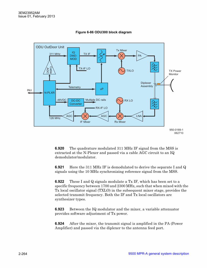
3EM23952AMIssue 01, February 2013
9500 MPR-A general system description2-264
6.920 The quadrature modulated 311 MHz IF signal from the MSS is extracted at the N-Plexer and passed via a cable AGC circuit to an IQ demodulator/modulator.
6.921 Here the 311 MHz IF is demodulated to derive the separate I and Q signals using the 10 MHz synchronizing reference signal from the MSS.
6.922 These I and Q signals modulate a Tx IF, which has been set to a specific frequency between 1700 and 2300 MHz, such that when mixed with the Tx local oscillator signal (TXLO) in the subsequent mixer stage, provides the selected transmit frequency. Both the IF and Tx local oscillators are synthesizer types.
6.923 Between the IQ modulator and the mixer, a variable attenuator provides software adjustment of Tx power.
6.924 After the mixer, the transmit signal is amplified in the PA (Power Amplifier) and passed via the diplexer to the antenna feed port.
Figure 6-86 ODU300 block diagram
950-0189-1
062710
ODU OutDoor Unit
N-PLXR
IQ
DMD-
MOD
uP
PA
AGC AGC LNA
Cable
AG
C
RX LO
TXLO
DC-DC
Converter
-48VDC Multiple DC rails
RX-IF LO
IF Mixer Rx Mixer
TX-IF LO
311 MHz TX IF
Tx Mixer
TelemetryINU
126 MHz
Diplexer
Assembly
TX Power
Monitor

3EM23952AMIssue 01, February 2013
9500 MPR-A general system description 2-265
6.925 A microprocessor in the ODU300 supports configuration of the synthesizers, transmit power, and alarm and performance monitoring. The ODU microprocessor is managed under the NCC microprocessor, with which it communicates via the telemetry channel.
6.926 A DC-DC converter provides the required low-voltage DC rails from the -48 Vdc supply.
6.927 In the receive direction, the signal from the diplexer is passed via the LNA (Low Noise Amplifier) to the Rx mixer, where it is mixed with the receive local oscillator (RXLO) input to provide an IF of between 1700 and 2300 MHz. It is then amplified in a gain-controlled stage to compensate for fluctuations in receive level, and in the IF mixer, is converted to a 126 MHz IF for transport via the ODU300 cable to the MSS.
6.928 The offset of the transmit frequencies at each end of the link is determined by the required Tx/Rx split. The split options provided are based on ETSI plans for each frequency band. The actual frequency range per band and the allowable Tx/Rx splits are range-limited within 9500 MPR-A to prevent incorrect user selection.
6.929 A power monitor circuit is included in the common port of the diplexer assembly to provide measurement of transmit power. It is used to confirm transmit output power for performance monitoring purposes, and to provide a closed-loop for power level management over the specified ODU300 temperature and frequency range.
ODU300 coupler
6.930 The ODU300 coupler is used in the 1+1 HSB or 1+1/2x(1+0) FD co-polar configurations.
6.931 The coupler can be equal type (3 dB/3 dB insertion loss) or unequal type (1.5 dB on the main path/6 dB on the secondary path).
6.932 The couplers are connected between the cabinets and the antenna.
MPT-HC/XP
6.933 MPT-HC/XP (Microwave Packet Transport) is a Microwave Equipment capable to transport the Ethernet traffic over an RF radio channel.

3EM23952AMIssue 01, February 2013
9500 MPR-A general system description2-266
6.934 The MPT-HC/XP includes a waveguide antenna port, type-N female connector for the DC connection, a maintenance connector (with captive protection cap) for RSSI access, 1 electrical GE interface, 2 GE optical interfaces (1 for data, 1 for RPS) and a grounding stud.
6.935 The MPT-HC/XP can be installed on an integrated antenna or on standard poles, wall or pedestal mount, with an appropriate fastening system.
6.936 The MPT-HC/XP (one or two depending on the configuration 1+0 or 1+1, each one with a solar shield) incorporates the complete RF transceiver and can be associated with an integrated or separate antenna.
6.937 The cabinet is a very compact and robust weatherproof (IP 67) container, designed to be compatible with hot and very sunny climatic zones.
6.938 The MPT-HC/XP/9558HC can be rapidly installed on standard poles with an appropriate fastening system. The pole mounting is the same for 1+0 or 1+1 configurations from 5.8 to 38 GHz.
6.939 The MPT-XP can be rapidly installed on standard poles with an appropriate fastening system. The pole mounting is the same for 1+0 or 1+1 configurations from 6 to 8 GHz.
6.940 The MPT-HC/XP is fixed by means of quick latches. This system allows to change the MPT-HC/XP without altering antenna pointing.
6.941 For L6, 11 GHz to 38 GHz, the MPT-HC polarization is determined by the rotation of the nose fitted in the antenna port of the MPT-HC in 1+0 configuration and by the position of a polarization rotator fitted within the coupler in 1+1 configuration.
6.942 For 5.8 to 8 GHz, the MPT-HC polarization is determined by the rotation of the MPT-HC/XP/9558HC mounted to the antenna port in 1+0 configuration and by the position of a polarization rotator fitted within the coupler in 1+1 configuration.
6.943 For 6 to 8 GHz, the MPT-XP polarization is determined by the rotation of the MPT-XP mounted to the antenna port in 1+0 configuration and by the position of a polarization rotator fitted within the coupler in 1+1 configuration.
6.944 Where two MPT-HC/XP have to be connected to a single antenna for hot-standby or frequency diversity configurations, a direct-mounting coupler is used. They are available for equal or unequal loss operation. Equal loss is nominally 3 dB. Unequal is nominally 1/10 dB.
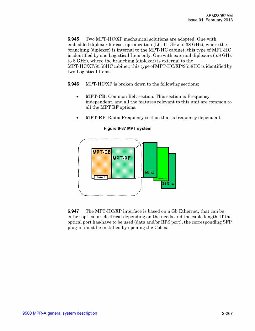
3EM23952AMIssue 01, February 2013
9500 MPR-A general system description 2-267
6.945 Two MPT-HC/XP mechanical solutions are adopted. One with embedded diplexer for cost optimization (L6, 11 GHz to 38 GHz), where the branching (diplexer) is internal to the MPT-HC cabinet; this type of MPT-HC is identified by one Logistical Item only. One with external diplexers (5.8 GHz to 8 GHz), where the branching (diplexer) is external to the MPT-HC/XP/9558HC cabinet; this type of MPT-HC/XP/9558HC is identified by two Logistical Items.
6.946 MPT-HC/XP is broken down to the following sections:
• MPT-CB: Common Belt section. This section is Frequency independent, and all the features relevant to this unit are common to all the MPT RF options.
• MPT-RF: Radio Frequency section that is frequency dependent.
6.947 The MPT-HC/XP interface is based on a Gb Ethernet, that can be either optical or electrical depending on the needs and the cable length. If the optical port has/have to be used (data and/or RPS port), the corresponding SFP plug-in must be installed by opening the Cobox.
Figure 6-87 MPT system
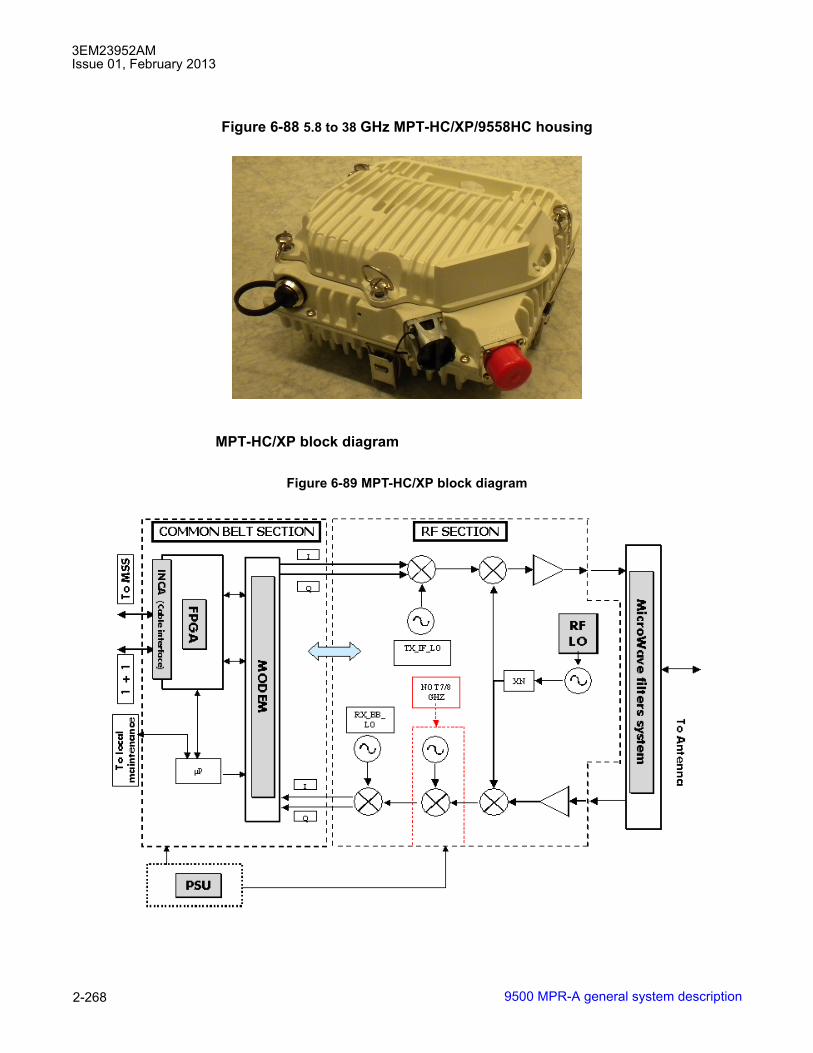
3EM23952AMIssue 01, February 2013
9500 MPR-A general system description2-268
MPT-HC/XP block diagram
Figure 6-88 5.8 to 38 GHz MPT-HC/XP/9558HC housing
Figure 6-89 MPT-HC/XP block diagram
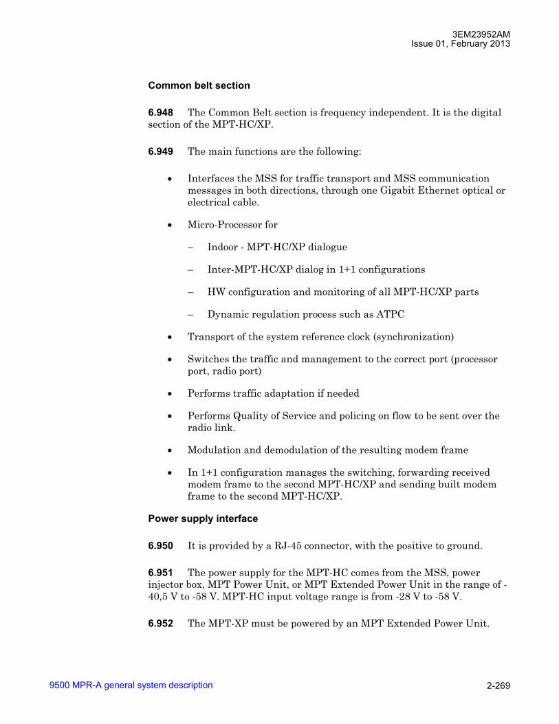
3EM23952AMIssue 01, February 2013
9500 MPR-A general system description 2-269
Common belt section
6.948 The Common Belt section is frequency independent. It is the digital section of the MPT-HC/XP.
6.949 The main functions are the following:
• Interfaces the MSS for traffic transport and MSS communication messages in both directions, through one Gigabit Ethernet optical or electrical cable.
• Micro-Processor for
� Indoor - MPT-HC/XP dialogue
� Inter-MPT-HC/XP dialog in 1+1 configurations
� HW configuration and monitoring of all MPT-HC/XP parts
� Dynamic regulation process such as ATPC
• Transport of the system reference clock (synchronization)
• Switches the traffic and management to the correct port (processor port, radio port)
• Performs traffic adaptation if needed
• Performs Quality of Service and policing on flow to be sent over the radio link.
• Modulation and demodulation of the resulting modem frame
• In 1+1 configuration manages the switching, forwarding received modem frame to the second MPT-HC/XP and sending built modem frame to the second MPT-HC/XP.
Power supply interface
6.950 It is provided by a RJ-45 connector, with the positive to ground.
6.951 The power supply for the MPT-HC comes from the MSS, power injector box, MPT Power Unit, or MPT Extended Power Unit in the range of -40,5 V to -58 V. MPT-HC input voltage range is from -28 V to -58 V.
6.952 The MPT-XP must be powered by an MPT Extended Power Unit.

3EM23952AMIssue 01, February 2013
9500 MPR-A general system description2-270
Lightning protection
6.953 The lightning protection is internal to the MPT-HC/XP. No external protection must be used.
6.954 This protection applies to:
• the Ethernet electrical cable
• the XPIC cable
INCA module
6.955 The INCA module hosts the physical Ethernet interfaces:
• One optical SFP device for traffic interface.
• One electrical device for traffic interface.
• One optical SFP device for 1+1 protection interface with the associated MPT-HC/XP.
6.956 In order to reach 500m the MPT-HC/XP uses an SFP Multi-Mode 805 nm with a 50/125 fibre.
Tx side
6.957 Following the flow from user Ethernet port to radio, the section performs:
• Reception of incoming Ethernet frames from the optical or electrical user interface (through INCA)
• Recovery of the clock coming from the MSS
• Management of the 1+1 EPS protection layer 2 messages
• Switch of the management frames from user port to internal processor
• Generation of MPT-HC/XP to MPT-HC/XP messages needed for radio link (ATPC, ACM,...)
• Compression of the TDM2Eth frames header (TDM2TDM - MEF8, TDM2ETH - MEF8)
• Management of the Quality of Service

3EM23952AMIssue 01, February 2013
9500 MPR-A general system description 2-271
• Fragmentation of the Ethernet frames
• Shaping of the traffic to adapt it to radio bandwidth
• Tx Modem frame building
• In 1+1 duplication of the built Tx modem frame and sending to the second MPT-HC/XP through the protection coupling port
• In 1+1, reception of the Tx modem frame coming from the second MPT-HC/XP
• In 1+1, switch of the Tx modem frame between the local and the one coming from second MPT-HC/XP depending on the EPS position
• Tx Radio frame building (FEC, pilots,...)
• Synchronization of the symbol rate to the MSS recovered clock
• Modulation in I and Q analogue signals to be sent to the RF section.
Rx side
6.958 Following the flow from radio to user Ethernet port, the section performs:
• Reception of the I and Q analogue signals coming from the RF section
• Demodulation of the Rx radio frame into Rx modem frame
• In 1+1, Recovery of the symbol clock and duplication to the second MPT-HC/XP
• In 1+1, duplication of the Rx modem frame and sending to the second MPT-HC/XP through the protection coupling port
• In 1+1, reception of the Rx modem frame coming from the second MPT-HC/XP
• In 1+1, hosts the RPS decision machine
• In 1+1, switch of the Rx modem frame between the local and the one coming from second MPT-HC/XP depending on the traditional RPS position and the modem frames quality
• Enhanced RPS
• In 1+1, switch of the recovered clock between the local and the one coming from second MPT-HC/XP depending on the traditional RPS position

3EM23952AMIssue 01, February 2013
9500 MPR-A general system description2-272
• Deframing of the Rx modem frame
• Re-assembly of fragmented Ethernet frame
• Decompression of TDM2Eth frames header
• Extraction of MPT-HC/XP to MPT-HC/XP messages needed for radio link (ATPC, ACM,...)
• Management of service channels frames
• Switch of the management frames from internal processor to user port.
• Management of the 1+1 EPS protection layer 2 messages
• Send the recovered clock to the MSS
• In 1+1 EPS, transmit or not the Ethernet frames to the MSS depending on the EPS position
RF section
6.959 There are two architectures, the difference between these two architectures are only on Rx side:
• For the first one (used in MPT-HC/XP band 7/8 GHz) there are only two frequency conversions between RF input frequency and base band frequency. 7/8 GHz MPT-HC/XPs are not supported in this release.
• For the second one (used for all other MPT-HC/XP bands) there are three frequency conversions
6.960 The block diagrams of these two architectures are shown hereafter.

3EM23952AMIssue 01, February 2013
9500 MPR-A general system description 2-273
Figure 6-90 7/8 GHz MPT-HC/XP architecture
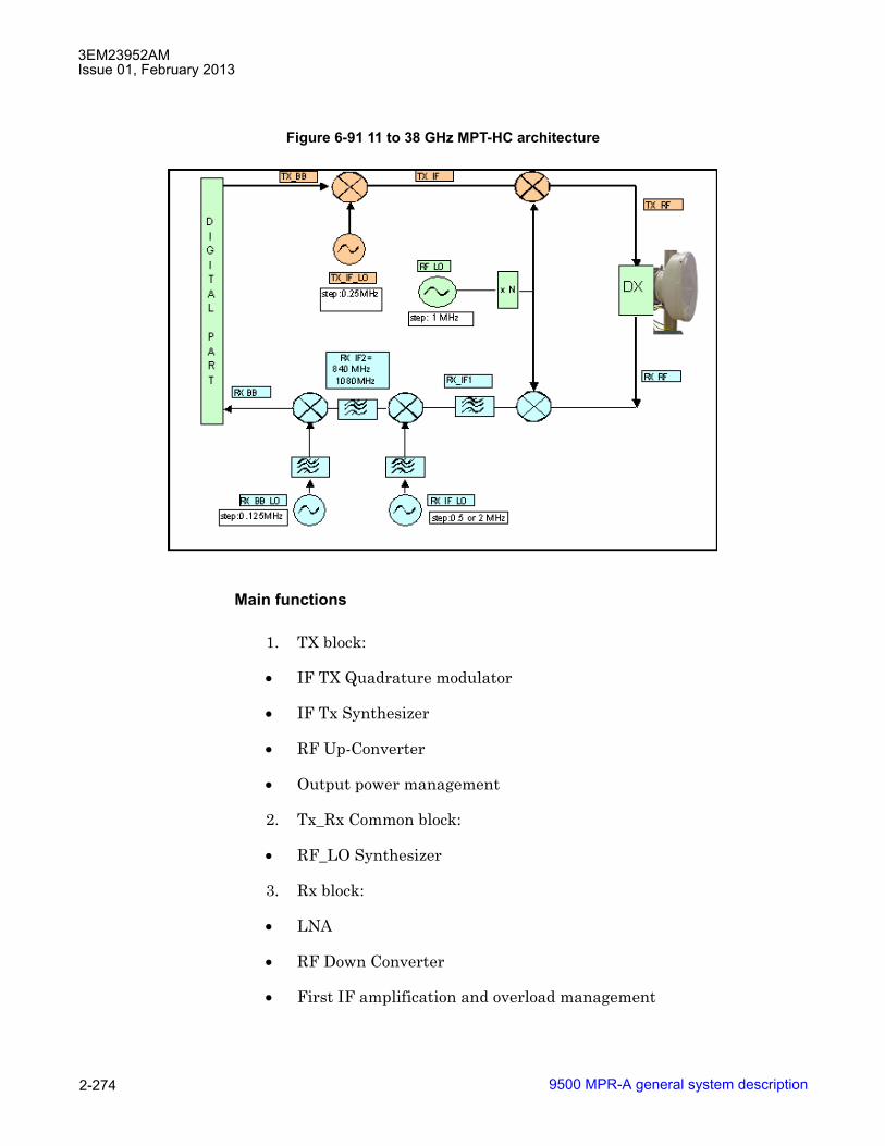
3EM23952AMIssue 01, February 2013
9500 MPR-A general system description2-274
Main functions
1. TX block:
• IF TX Quadrature modulator
• IF Tx Synthesizer
• RF Up-Converter
• Output power management
2. Tx_Rx Common block:
• RF_LO Synthesizer
3. Rx block:
• LNA
• RF Down Converter
• First IF amplification and overload management
Figure 6-91 11 to 38 GHz MPT-HC architecture

3EM23952AMIssue 01, February 2013
9500 MPR-A general system description 2-275
• First IF down conversion
• Second IF amplification and filtering (not present in 7/8 GHz)
• Quadrature demodulator
• Base band filter and AGC loop
MPT-HC/XP coupler
6.961 The coupler is used in the 1+1 HSB or 1+1/2x(1+0) FD co-polar configurations.
6.962 The coupler can be equal type (3 dB/3 dB insertion loss) or unequal type (1 dB on the main path/10 dB on the secondary path).
6.963 The couplers are connected between the MPT and the antenna.
IP addressing
Local NE interface
6.964 The NE TMN_RF interface (hereafter referred to as the Local NE interface) is an unnumbered Point-to-Point interface. It uses a single IP address as an endpoint identifier. The Local NE interface is always active and cannot be disabled. This Local NE IP address is the same as the Mgmt Port IP address (if enabled) or ETH Port 4 IP address (if enabled) but not both. Refer to TMN communication channels for details.
6.965 The 9500 MPR supports both IPv4 and IPv6 addressing.
CAUTION Possibility of service interruption. Mixed configuration of IPv4 and IPv6 NEs is not supported.
Note: In an IPv6 environment, the maximum LSA handled by the 9500 MPR is 1 280 bytes.
IPv4 addressing for the local IP address
6.966 The default IPv4 address is 10.0.1.2.

3EM23952AMIssue 01, February 2013
9500 MPR-A general system description2-276
6.967 The local IPv4 address must be configured according to the following rules:
� Only Class A, Class B and Class C IP addresses are allowed. Classless addressing is allowed.
� IP Address 0.0.0.0 is not allowed.
� IP addresses from 127.0.0.0 to 127.255.255.255 are not allowed.
� IP addresses having 0 or 255 in the last byte of the address are not allowed.
IPv4 addressing for the TMN local Ethernet interface IP address
6.968 The TMN local Ethernet interface is used to connect the NE to LAN exchanging TMN information. It has its own IP address and subnet mask assigned using a management system.
6.969 The IP address of TMN Local Ethernet interface can be equal to the Local IP address. If the IP address is different from the Local IP address, they must belong to different subnets.
6.970 The default address is 10.0.1.2. The default subnet mask is 255.255.255.0.
6.971 The IPv4 address must be configured according to the following rules:
� Class A, Class B and Class C IP addresses are allowed. Classless addressing is allowed.
� IP Address 0.0.0.0 is not allowed.
� IP address from 127.0.0.0 to 127.255.255.255 are not allowed.
� IP Address must be checked with Subnet Mask to prevent the IP address referring to the subnet itself (all 0 in the Host portion of the address) or referring to the subnet broadcast address (all 1 in the Host portion of the address).
6.972 The subnet assigned to this interface must be different from the one assigned to the other TMN Ethernet interfaces.
IPv6 addressing for the local IP address
6.973 The NE Local IPv6 address is a Global Unicast address which identifies the NE in the DCN.

3EM23952AMIssue 01, February 2013
9500 MPR-A general system description 2-277
6.974 The default address is FEC0:0:0:1::1. The prefix length is not configurable and is fixed to 128.
6.975 The NE Local IPv6 address must be configured according to the following rules:
� IPv6 addresses having the Interface ID portion equal to all 0 are not allowed.
� IPv6 address ::/128 (Unspecified address) is not allowed.
� IPv6 address ::1/128 (Loopback Address) is not allowed.
� IPv6 addresses having FF00::/8 as high-order bits (Multicast addresses) are not allowed.
� IPv6 addresses having FE80::/10 as high-order bits (Link Local Addresses) are not allowed.
6.976 Every time the Local IPv6 address is changed a NE warm restart is automatically performed.
IPv6 addressing for the TMN local Ethernet interface IP address
6.977 The Local Ethernet interface dedicated to TMN is used to connect the NE to LAN exchanging TMN information. It has its own Global Unicast IPv6 address and prefix length assigned using a management system.
6.978 The IPv6 Global Unicast address of the TMN Local Ethernet interface can be equal to the Local IPv6 address provided that the IPv6 address of other TMN interfaces have not been already set to the same address.
6.979 If the IPv6 address of the TMN local Ethernet interface is different from the Local IPv6 address, they must belong to different subnets. The subnet number of the Local IPv6 address is obtained and applied to the subnet prefix assigned to the TMN Local Ethernet interface.
6.980 The default address is FEC0:0:0:1::1/64.

3EM23952AMIssue 01, February 2013
9500 MPR-A general system description2-278
6.981 The TMN Local Ethernet IPv6 address must be configured according to the following rules:
� IPv6 addresses having the Interface ID portion equal to all 0 are not allowed.
� IPv6 address ::/128 (Unspecified address) is not allowed.
� IPv6 address ::1/128 (Loopback Address) is not allowed.
� IPv6 addresses having FF00::/8 as high-order bits (Multicast addresses) are not allowed.
� IPv6 addresses having FE80::/10 as high-order bits (Link Local Addresses) are not allowed.
6.982 The TMN Local Ethernet IPv6 address must belong to a subnet number different than the ones associated with other TMN interfaces (the subnet numbers resulting from applying the shortest prefix length must not be the same).
6.983 When TMN Local Ethernet is disabled, its IPv6 configuration is lost.
6.984 Every time the TMN Local Ethernet interface is enabled or its IPv6 Global Unicast address is modified, Duplicate Address Detection must be performed prior to assigning it to the TMN interface. When a duplicate address is detected an alarm is raised. You need to change the IPv6 address to remove duplicates.
6.985 IPv6 addresses FF02::1 (All nodes) and FF02::2 (All Routers) Multicast Group addresses must be joined by an enabled TMN Local Ethernet interface.
6.986 NDP (Neighbor Discovery Protocol) is used to perform Neighbor Address Resolution to retrieve MAC address-IPv6 address association over the LAN.
6.987 NDP is used to perform IPv6 Stateless Address Autoconfiguration to assign an IPv6 Global Unicast address to the host connected to TMN Local Ethernet.
Mgmt port interface
6.988 The Mgmt Port is provisioned independently from the Local NE interface, and unlike the Local NE interface, the Mgmt Port can be disabled if not needed. Refer to the Core-E (Control and Switching Module) provisioning for details.

3EM23952AMIssue 01, February 2013
9500 MPR-A general system description 2-279
6.989 When addressing the Mgmt Port interface, you may follow CIDR guidelines and use Variable Length Subnet Masks (VLSM) as defined in RFC-1519 and in RFC-1878. The longest usable netmask for the Mgmt Port interface is 30 bits (Netmask 255.255.255.252).
6.990 If the Mgmt Port interface is enabled, it is recommended that it be assigned the same IP address as the Local NE interface. This allows the radio to be known throughout the network by only one IP address, and eliminates a potential problem of one radio appearing to be two different pieces of equipment to an SNMP manager.
6.991 It should be noted that the factory default IP address assigned to the Local NE and Mgmt Port is 10.0.1.1. Use of this IP address within the radio network should be avoided, since installing a new 9500 MPR-A could possibly cause a disruption of the network if that address is already in use.
ETH port 4 interface
6.992 A backup for the Mgmt Port is provided by enabling Ethernet Port 4 to transport TMN data. The ETH Port 4 interface is provisioned independently from the Local NE interface and Mgmt Port interface, and can be disabled if not needed. Refer to the Core-E (Control and Switching Module) provisioning for details.
6.993 ETH Port 4 and Mgmt Port IP addresses must be different. If the ETH Port 4 interface is enabled, and the Mgmt Port interface is disabled, it is recommended that it be assigned the same IP address as the Local NE interface.
Typical interconnect/addressing method
6.994 See Figures 6-92 and 6-93 for a typical interconnect and addressing method, using the Local NE interface to connect sites and Mgmt Port interface to connect radios at each site. IPv4 addressing is used.
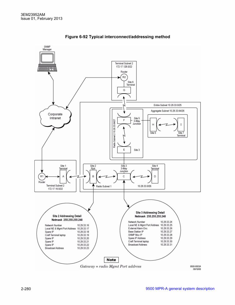
3EM23952AMIssue 01, February 2013
9500 MPR-A general system description2-280
Figure 6-92 Typical interconnect/addressing method
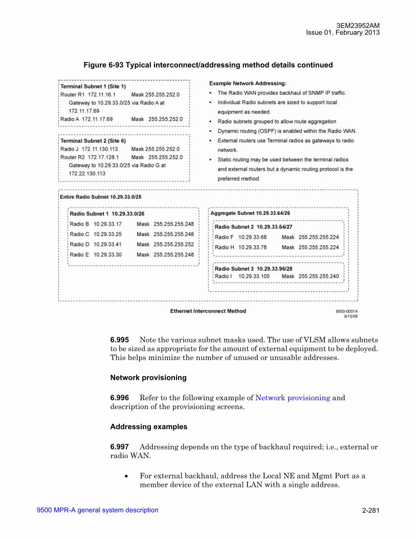
3EM23952AMIssue 01, February 2013
9500 MPR-A general system description 2-281
6.995 Note the various subnet masks used. The use of VLSM allows subnets to be sized as appropriate for the amount of external equipment to be deployed. This helps minimize the number of unused or unusable addresses.
Network provisioning
6.996 Refer to the following example of Network provisioning and description of the provisioning screens.
Addressing examples
6.997 Addressing depends on the type of backhaul required; i.e., external or radio WAN.
• For external backhaul, address the Local NE and Mgmt Port as a member device of the external LAN with a single address.
Figure 6-93 Typical interconnect/addressing method details continued
3EM23952AMIssue 01, February 2013
9500 MPR-A general system description2-282
• IF the Radio is providing backhaul for IP traffic, the recommended addressing scheme is to assign a small subnet to each radio. The radio and Mgmt Port can share one IP address from the subnet and the remaining address(es) of the subnet can then be used to address additional local equipment. The local equipment can then use the radio as the default gateway for IP transport. To assign radio subnets, follow the general procedures shown in Radio Level Subnet Addressing.
Assumptions
• OSPF will be enabled within the radio network.
• The recommended configuration is such that the Ethernet port will have the same IP address as the radio.
• Radios that attach directly to external networks (Corporate LAN/WAN) should be addressed as members of the subnet to which they attach.
IP address assignments
6.998 Since the size of the Static Routing table is limited, IP Address assignment should strive to minimize the size of the Static Routing table.
• In general, IP addresses should increase (or decrease) as distance increases away from terminals or junction. This allows the use of route aggregation when specifying static routes.
• The static routing table size is inversely related to IP address efficiency. Although there is less impact when used with OSPF, a side effect of minimizing the static routing table size can leave more unused/unusable addresses.

3EM23952AMIssue 01, February 2013
9500 MPR-A general system description 2-283
Radio level subnet addressing
6.999 Assign Radio Level Subnets as follows:
1. Radios connected by RF, or PPP links must each get their own subnet.
2. Radios connected by Ethernet need to share a subnet. Each radio will use one address from the Ethernet subnet.
3. Determine the radio and external equipment configuration at each site/radio.
4. Size the Ethernet subnet based on the number of devices that will be attached, both known and anticipated.
5. Determine the number of required addresses at each radio, and round this number up to the next highest usable hosts number; see Table 1. From the usable hosts number, select the size of the radio subnet. The minimum amount of address space to assign to a radio subnet is 4 addresses (2 usable host addresses).
Example:
6.1000 A radio has a single SNMP device attached via the Ethernet. Planned future expansion will add two more SNMP devices for a total of four devices. From Table 6-T, the nearest usable subnet size provides for a total of 6 usable addresses. This correlates to a required radio subnet size of 8, and an Ethernet Subnet mask of 29 bits (255.255.255.248).
Table 6-T. Commonly used subnet masks and associated subnet sizesETHERNETSUBNETMASK
MASKBITS
HOST BITS TOTAL NUMBEROF ADDRESSESIN RANGE1
[1] The first and last addresses of a subnet are reserved for the network number and broadcast addressrespectively. This makes the number of usable host addresses two less than the total number of addresses in thesubnet.
USABLEHOSTADDRESSES1
255.255.255.254 31 1 2 0 (unusable) 255.255.255.252 30 2 4 2 255.255.255.248 29 3 8 6 255.255.255.240 28 4 16 14 255.255.255.224 27 5 32 30 255.255.255.192 26 6 64 62 255.255.255.128 25 7 128 126 255.255.255.0 24 8 256 254
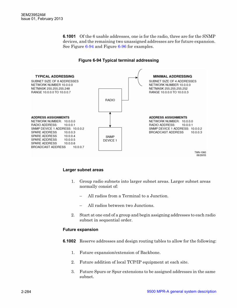
3EM23952AMIssue 01, February 2013
9500 MPR-A general system description2-284
6.1001 Of the 6 usable addresses, one is for the radio, three are for the SNMP devices, and the remaining two unassigned addresses are for future expansion. See Figure 6-94 and Figure 6-96 for examples.
Larger subnet areas
1. Group radio subnets into larger subnet areas. Larger subnet areas normally consist of:
� All radios from a Terminal to a Junction.
� All radios between two Junctions.
2. Start at one end of a group and begin assigning addresses to each radio subnet in sequential order.
Future expansion
6.1002 Reserve addresses and design routing tables to allow for the following:
1. Future expansion/extension of Backbone.
2. Future addition of local TCP/IP equipment at each site.
3. Future Spurs or Spur extensions to be assigned addresses in the same subnet.
Figure 6-94 Typical terminal addressing

3EM23952AMIssue 01, February 2013
9500 MPR-A general system description 2-285
6.1003 It is possible to disable the Ethernet interface of the TMN card, assign only one IP address to the radio, and still use the radio WAN for IP transport. This method is discouraged because it leaves no IP addresses available within the radio WAN for expansion or addition of new Ethernet equipment at radio sites.
CAUTION Possibility of service interruption. Obtaining additional address space in the future may require readdressing of the entire network. Readdressing of a radio network requires a site visit for each radio affected and, until the process is complete, radio WAN communications (SNMP management and WAN IP transport) could possibly be unavailable.
Addressing terminals
6.1004 (See Figure 6-94 and Figure 6-95)
External LAN attached
6.1005 For terminals attached to external LAN see Figure 6-95. When attached to external LAN, proceed as follows:
1. Address both the WAN and LAN interfaces of the radio as a member device in the external LAN and enable OSPF.
2. Interfacing to external routers
a. If external routers use OSPF, the radio network can be integrated with the external OSPF design.
b. If the external routers do not support dynamic routing, or if it is desired to keep the radio network dynamic routing separated from the external network, set a static route in the radio to point to the default gateway in the external LAN. Configure the external router to use the radio as a gateway to the radio network.
External LAN not attached
6.1006 For terminals not attached to external LAN, proceed as follows:
1. Assign an IP Subnet to the Radio and enable OSPF, otherwise set the default route in the radio to point to the �RF� interface.
2. Set the default route in all local Ethernet equipment to point to the Radio.

3EM23952AMIssue 01, February 2013
9500 MPR-A general system description2-286
Addressing back-to-back terminals, Other asynchronous radios, and repeaters
Preferred addressing method
6.1007 See Figure 6-96.
1. Assign one subnet for the site, address radios as members of that subnet and enable OSPF.
2. Interconnect the radios using Ethernet (Avoid loops or other problematic connections).
3. Provision the default gateway of any locally attached Ethernet equipment to point to a radio.
Figure 6-95 Typical terminal attached to external LAN
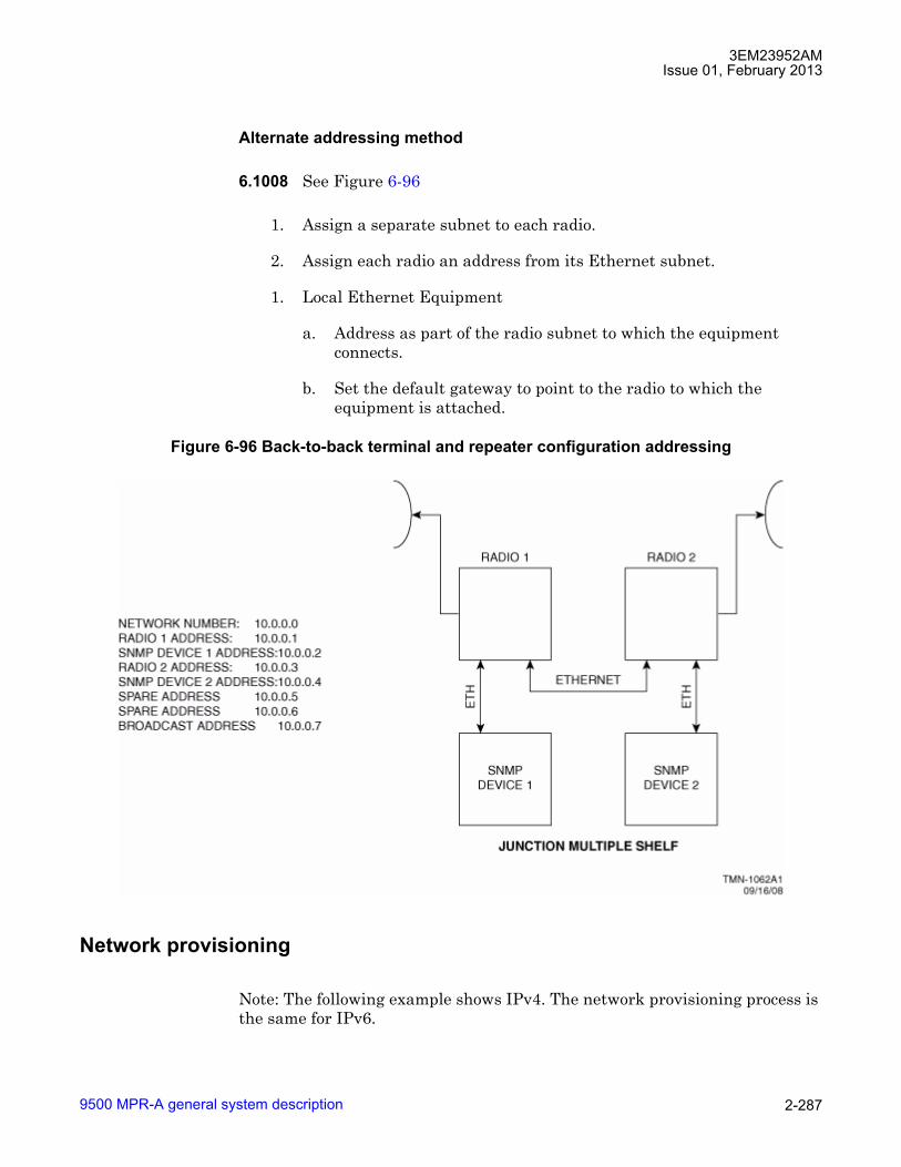
3EM23952AMIssue 01, February 2013
9500 MPR-A general system description 2-287
Alternate addressing method
6.1008 See Figure 6-96
1. Assign a separate subnet to each radio.
2. Assign each radio an address from its Ethernet subnet.
1. Local Ethernet Equipment
a. Address as part of the radio subnet to which the equipment connects.
b. Set the default gateway to point to the radio to which the equipment is attached.
Network provisioning
Note: The following example shows IPv4. The network provisioning process is the same for IPv6.
Figure 6-96 Back-to-back terminal and repeater configuration addressing
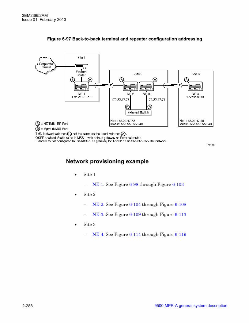
3EM23952AMIssue 01, February 2013
9500 MPR-A general system description2-288
Network provisioning example
• Site 1
� NE-1: See Figure 6-98 through Figure 6-103
• Site 2
� NE-2: See Figure 6-104 through Figure 6-108
� NE-3: See Figure 6-109 through Figure 6-113
• Site 3
� NE-4: See Figure 6-114 through Figure 6-119
Figure 6-97 Back-to-back terminal and repeater configuration addressing
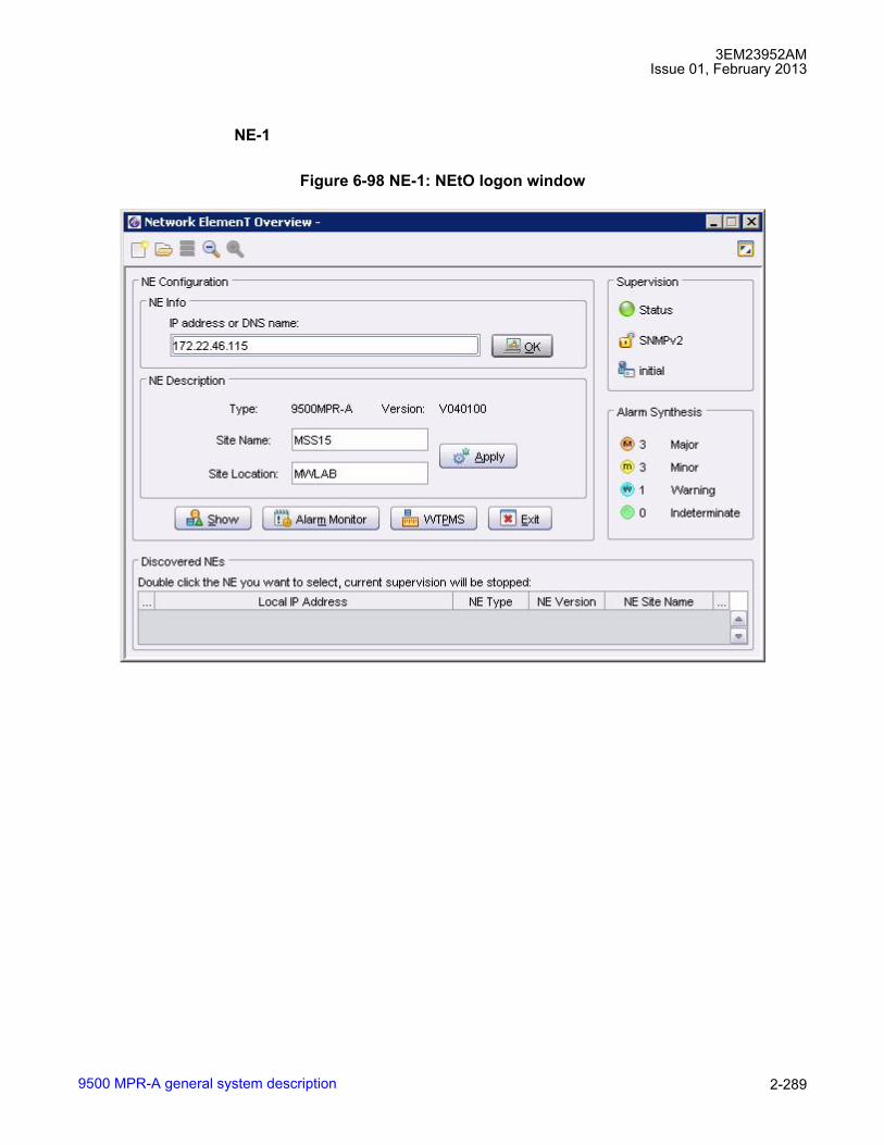
3EM23952AMIssue 01, February 2013
9500 MPR-A general system description 2-289
NE-1
Figure 6-98 NE-1: NEtO logon window

3EM23952AMIssue 01, February 2013
9500 MPR-A general system description2-290
Figure 6-99 NE-1: Ethernet interface provisioning
Figure 6-100 NE-1: Local configuration window

3EM23952AMIssue 01, February 2013
9500 MPR-A general system description 2-291
Figure 6-101 NE-1: IP static routing configuration window

3EM23952AMIssue 01, February 2013
9500 MPR-A general system description2-292
Figure 6-102 NE-1: OSPF area configuration
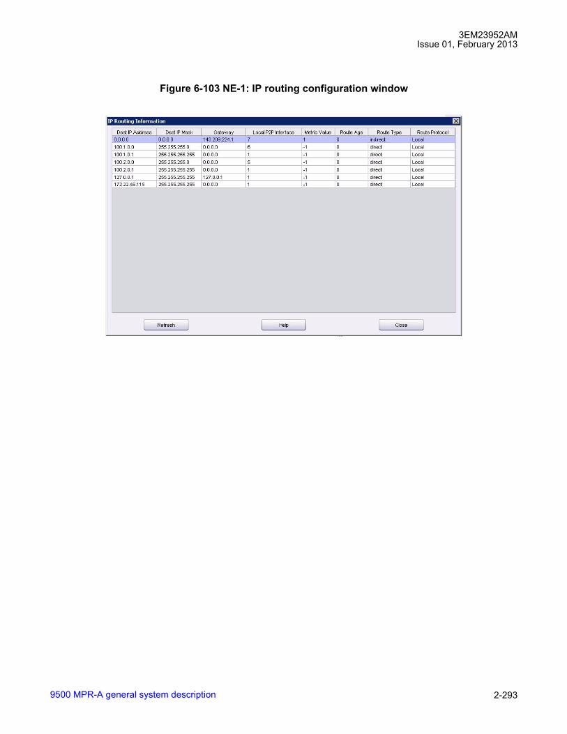
3EM23952AMIssue 01, February 2013
9500 MPR-A general system description 2-293
Figure 6-103 NE-1: IP routing configuration window
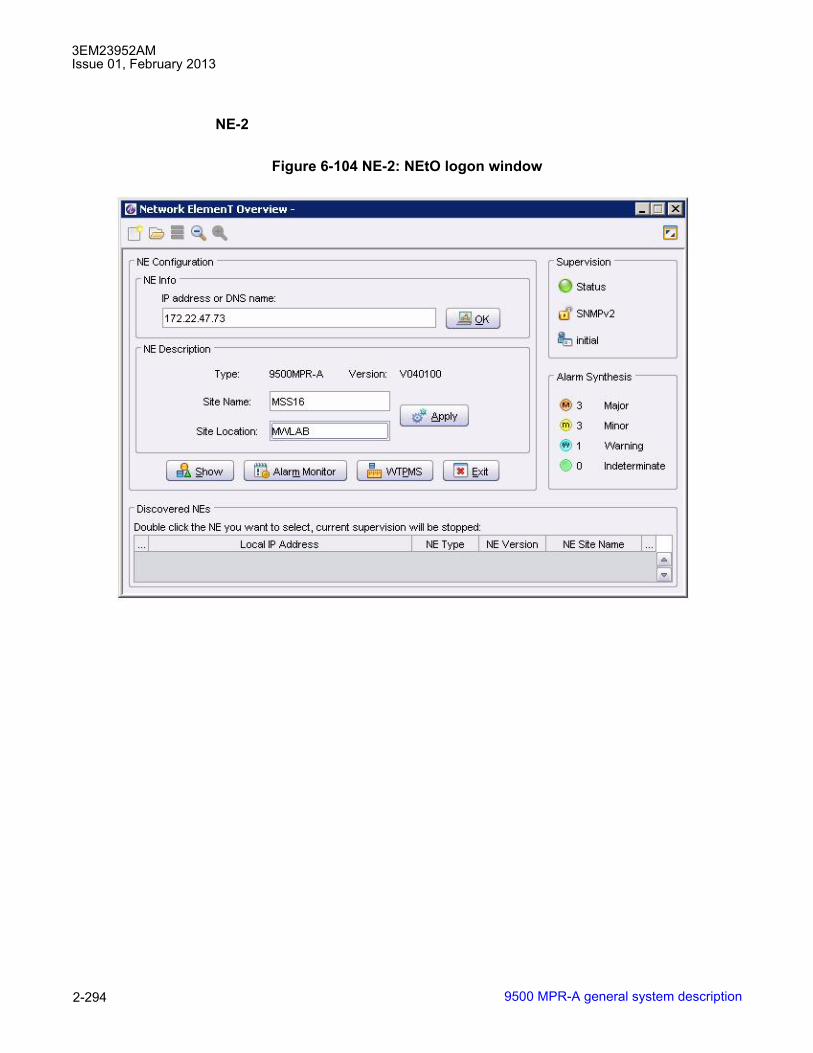
3EM23952AMIssue 01, February 2013
9500 MPR-A general system description2-294
NE-2
Figure 6-104 NE-2: NEtO logon window

3EM23952AMIssue 01, February 2013
9500 MPR-A general system description 2-295
Figure 6-105 NE-2: TMN ethernet interface window
Figure 6-106 NE-2: local configuration window

3EM23952AMIssue 01, February 2013
9500 MPR-A general system description2-296
Figure 6-107 NE-2: OSPF area configuration
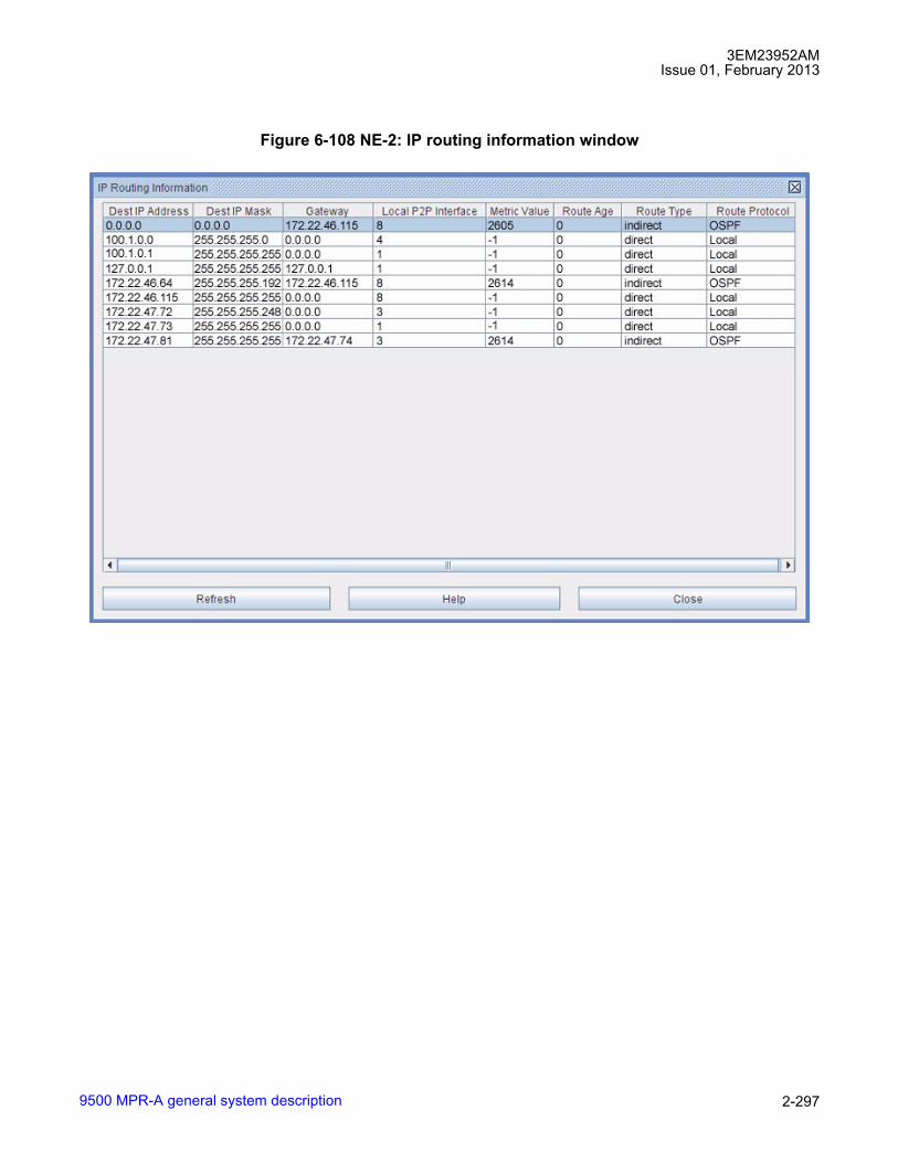
3EM23952AMIssue 01, February 2013
9500 MPR-A general system description 2-297
Figure 6-108 NE-2: IP routing information window

3EM23952AMIssue 01, February 2013
9500 MPR-A general system description2-298
NE-3
Figure 6-109 NE-3: NEtO logon window
Figure 6-110 NE-3: TMN ethernet interface provisioning
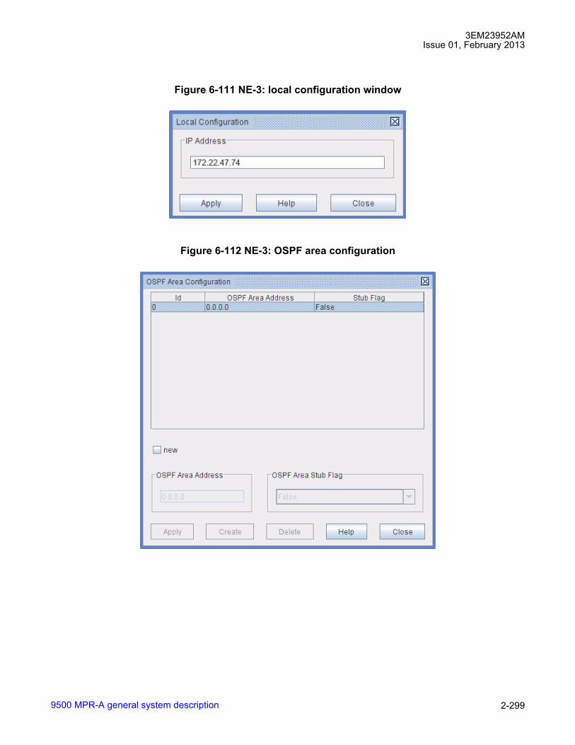
3EM23952AMIssue 01, February 2013
9500 MPR-A general system description 2-299
Figure 6-111 NE-3: local configuration window
Figure 6-112 NE-3: OSPF area configuration
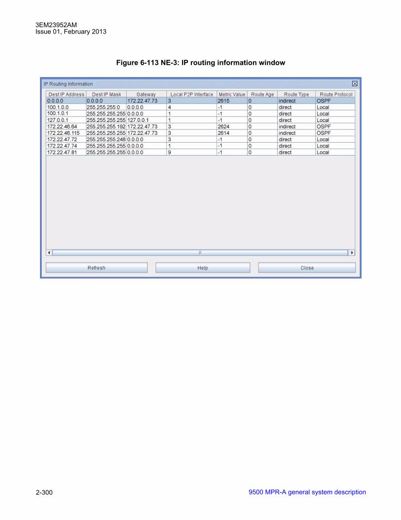
3EM23952AMIssue 01, February 2013
9500 MPR-A general system description2-300
Figure 6-113 NE-3: IP routing information window

3EM23952AMIssue 01, February 2013
9500 MPR-A general system description 2-301
NE-4
Figure 6-114 NE-4: NEtO logon window
Figure 6-115 NE-4: TMN ethernet interface provisioning

3EM23952AMIssue 01, February 2013
9500 MPR-A general system description2-302
Figure 6-116 NE-4: local configuration window
Figure 6-117 NE-4: IP static routing configuration window

3EM23952AMIssue 01, February 2013
9500 MPR-A general system description 2-303
Figure 6-118 NE-4: OSPF area configuration
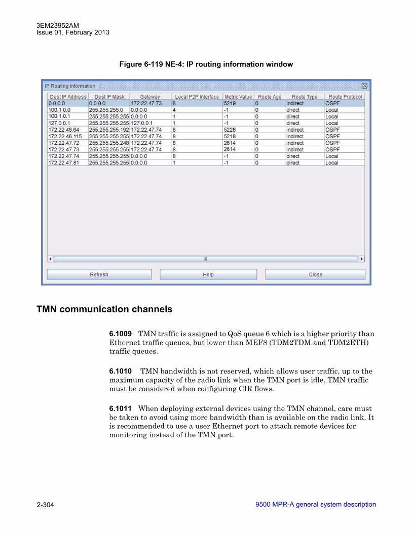
3EM23952AMIssue 01, February 2013
9500 MPR-A general system description2-304
TMN communication channels
6.1009 TMN traffic is assigned to QoS queue 6 which is a higher priority than Ethernet traffic queues, but lower than MEF8 (TDM2TDM and TDM2ETH) traffic queues.
6.1010 TMN bandwidth is not reserved, which allows user traffic, up to the maximum capacity of the radio link when the TMN port is idle. TMN traffic must be considered when configuring CIR flows.
6.1011 When deploying external devices using the TMN channel, care must be taken to avoid using more bandwidth than is available on the radio link. It is recommended to use a user Ethernet port to attach remote devices for monitoring instead of the TMN port.
Figure 6-119 NE-4: IP routing information window

3EM23952AMIssue 01, February 2013
9500 MPR-A general system description 2-305
6.1012 See the different NE TMN_RF Port scenarios. TMN routing in the 9500 MPR-A consists of a 3-port router and associated circuits in the Core-E (Control and Switching Module) plus CT screens for configuring automatic (OSPF) and manual (static) routing.
Port functions
• NE TMN_RF Port (Local NE) - TMN channel carried by Ethernet frames in the dedicated TMN port (on the front panel of the Core-E module) (this port is normally used to connect the LCT)
• Mgmt Port - Primary function TMN data channel, up to 512 kbit/s channel inside Radio frame. Secondary function- CT access
• Eth Port 4 - Primary function- provisioned Ethernet and transport Ethernet traffic. Secondary function - TMN channel carried by Ethernet frames in Ethernet tributary 4 (on the front panel of the Core-E module)
• Two TMN In-band interfaces (by using the Ethernet traffic ports)
NE TMN_RF port scenarios
• NE TMN_RF Port Belongs to Subnet 2
• NE TMN_RF Port Belongs to Subnet 1
• NE TMN_RF Port Belongs to Separate Subnet 3

3EM23952AMIssue 01, February 2013
9500 MPR-A general system description2-306
Figure 6-120 NE TMN_RF port belongs to subnet 2

3EM23952AMIssue 01, February 2013
9500 MPR-A general system description 2-307
Figure 6-121 NE TMN_RF port belongs to subnet 1

3EM23952AMIssue 01, February 2013
9500 MPR-A general system description2-308
Open shortest path first (OSPF)
• OSPF is the preferred method for routing within the radio WANs.
Figure 6-122 NE TMN_RF port belongs to separate subnet 3

3EM23952AMIssue 01, February 2013
9500 MPR-A general system description 2-309
• The 9500 MPR uses a simplified OSPF implementation. If the NE is configured in IPv6 mode, OSPFv3 is used.
• Configuration requires only an Area ID and Mask.
• Supports redundant WAN paths, allowing linear, tree, ring, mesh and other WAN topologies. If redundant paths are available, OSPF can reconfigure routes to work around a failed link.
• Dynamically assigns a routing metric to redundant paths based on route cost, where the route cost is determined by the speed of the interface used and the hop count to a destination.
• Does not perform route aggregation.
• Supports a maximum of 250 routes within a single OSPF area.
Static routing
• Usually used at radio WAN border routers to specify a default gateway to:
� use for reaching external networks when the external network does not use a supported dynamic routing protocol.
� control the exchange of dynamic route information between the radio WAN and the external network.
• Static routing only supports provisioning a single route to a given destination at any radio. Route metrics and redundant routes are not supported. This limits the useful WAN topologies to linear and tree configurations when using Static Routing.
• Maximum of 25 static route entries per radio.
� To minimize the number of static route entries required, the radio network addressing plan should allow for maximum route aggregation.
� Static routes directed out the PPP interfaces use the interface name as the route destination; rf, rptr, or (front) ppp.
Protection schemes
Protection schemes with MOD300/ODU300
6.1013 Supported Protection types:
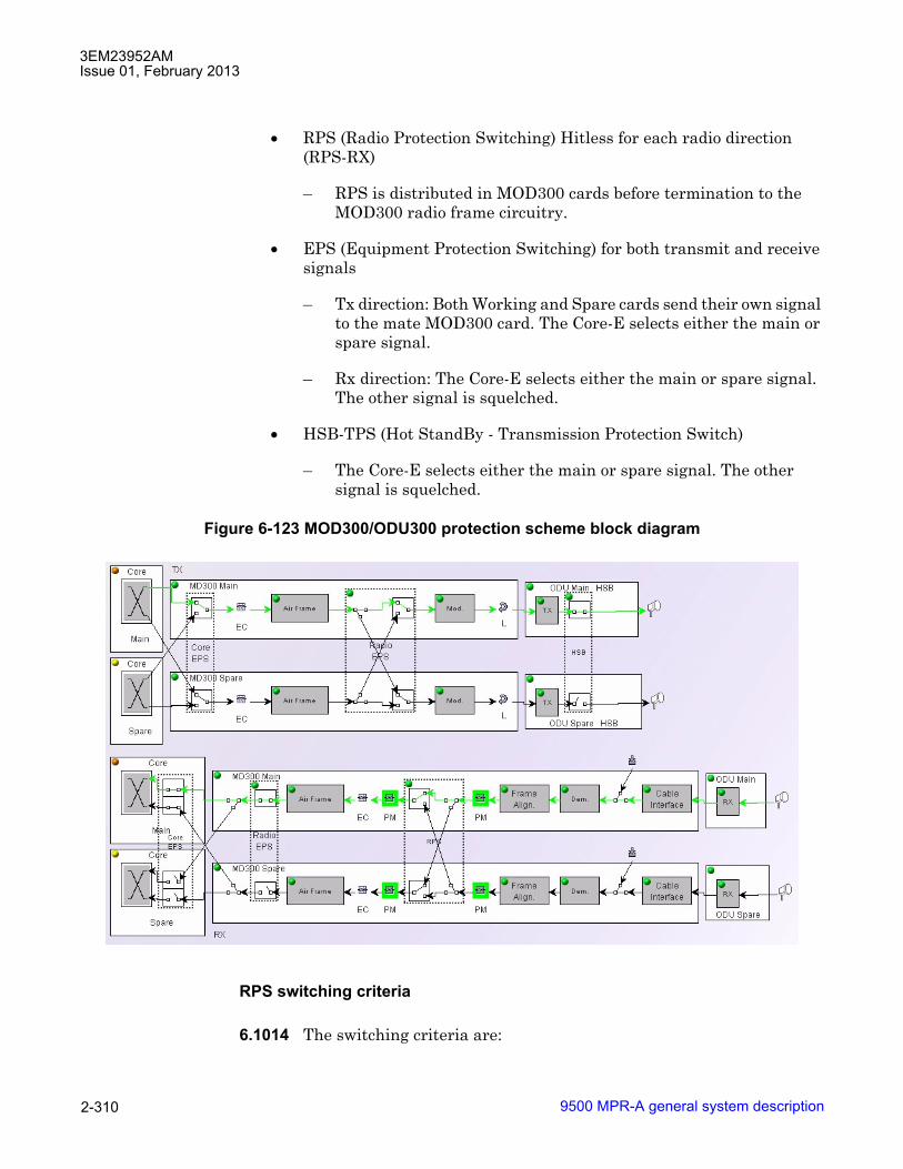
3EM23952AMIssue 01, February 2013
9500 MPR-A general system description2-310
• RPS (Radio Protection Switching) Hitless for each radio direction (RPS-RX)
� RPS is distributed in MOD300 cards before termination to the MOD300 radio frame circuitry.
• EPS (Equipment Protection Switching) for both transmit and receive signals
� Tx direction: Both Working and Spare cards send their own signal to the mate MOD300 card. The Core-E selects either the main or spare signal.
� Rx direction: The Core-E selects either the main or spare signal. The other signal is squelched.
• HSB-TPS (Hot StandBy - Transmission Protection Switch)
� The Core-E selects either the main or spare signal. The other signal is squelched.
RPS switching criteria
6.1014 The switching criteria are:
Figure 6-123 MOD300/ODU300 protection scheme block diagram

3EM23952AMIssue 01, February 2013
9500 MPR-A general system description 2-311
• SF (Signal Fail): generated from transmission and equipment alarms affecting the Rx radio section:
• Demodulation Fail
• IDU-ODU cable loss
• LOF of aggregate signal radio side
• Main and spare ODU, IDU HW failures (card fail)
• HBER (high BER)
• EW (Early Warning)
EPS switching criteria
6.1015 The switching criteria are:
• Peripheral Card Fail (switching off of the peripheral included)
• Peripheral Card Missing
• LOS of all the tributaries (of course only in case of PDH local access peripheral protection) managed via SW.
HSB switching criteria
6.1016 The switching criteria are:
• Radio Interface Peripheral Card Fail (switching off of the peripheral included)
• Radio Interface Peripheral Card Missing
• MSS-ODU cable loss
• ODU TX chain alarm (this is an OR of the following alarms: LOS at ODU input, modfail, txFail, ODU card fail).
• Incompatible Shifter alarm
• Incompatible Frequency alarm
• Incompatible Power alarm
• Incompatible Modulation Parameters alarm
• Common Loss Alarm

3EM23952AMIssue 01, February 2013
9500 MPR-A general system description2-312
Protection schemes with MPT-HL
6.1017 Supported Protection types:
• RPS (Radio Protection Switching) Hitless for each radio direction (RPS-RX)
� RPS is distributed in MPT-HL Transceivers before termination to the MPT-HL Transceiver radio frame circuitry.
• EPS (Equipment Protection Switching) for both transmit and receive signals
� Tx direction: Both Working and Spare MPT-HL Transceiver send their own signal to the mate MPT-HL Transceiver. The Core-E selects either the main or spare signal.
� Rx direction: The Core-E selects either the main or spare signal after MPT-HL Transceiver radio frame circuitry. The other signal is squelched.
• HSB-TPS (Hot StandBy - Transmission Protection Switch)
� The Core-E selects either the main or spare signal. The other signal is squelched.

3EM23952AMIssue 01, February 2013
9500 MPR-A general system description 2-313
RPS switching criteria
6.1018 The switching criteria are:
• SF (Signal Fail): generated from transmission and equipment alarms affecting the Rx radio section:
• Demodulation Fail
• MPT-HL link failure
• LOF of aggregate signal radio side
• Main and spare IDU HW failures (card fail)
• HBER (high BER)
• EW (Early Warning)
EPS switching criteria
6.1019 The switching criteria are:
Figure 6-124 MPT-HL protection scheme block diagram

3EM23952AMIssue 01, February 2013
9500 MPR-A general system description2-314
• MPT-HL Transceiver Fail (switching off of the peripheral included)
• MPT-HL Transceiver Missing
• LOS of all the tributaries (of course only in case of PDH local access peripheral protection) managed via SW.
HSB switching criteria
6.1020 The switching criteria are:
• MPT-HL Transceiver Fail (switching off of the peripheral included)
• MPT-HL Transceiver Missing
• IDU TX chain alarm (this is an OR of the following alarms: LOS at IF input, modfail, txFail, IDU card fail).
• Incompatible Shifter alarm
• Incompatible Frequency alarm
• Incompatible Power alarm
• Incompatible Modulation Parameters alarm
• Common Loss Alarm
Protection schemes with MPT-HC/XP
6.1021 To implement the 1+1 configuration an optional external module (RPS or XPIC+RPS) and optical cable may be connected from one MPT-HC/XP to the second MPT-HC/XP. In Figure 6-125 Ethernet port 2 of one MPT-HC/XP is connected to Ethernet port 2 of the second MPT-HC/XP.
NOTE: In Figure 6-125 the two MPT are connected to two different MPT Access units, but they can also be connected to the same MPT Access Unit, or to the same Core-E unit.
6.1022 The MPT-HC/XP radios can be connected to MPT Access or Core-E units. Both MPTs in a protected configuration must use the same type of port (optical or electrical). Port 2 can protect port 1, port 4 can protect port 3, and port 6 can protect port 5.

3EM23952AMIssue 01, February 2013
9500 MPR-A general system description 2-315
Supported protection types:
• RPS (Radio Protection Switching) Hitless for each radio direction
� RPS can be implemented with or without the external module and interconnection cable between the two MPT-HC/XP.
� When no external module and interconnection cable is used, the 1+1 RPS messages are exchanged in the MSS-4/MSS-8 shelf.
� When the external modules and interconnection cable is used, the 1+1 RPS messages are exchanged between the MPT-HC/XPs.
• EPS (Equipment Protection Switching) for the MPT-HC/XP
� EPS protects the MPT-HC/XP and the cables connecting it to the MSS.
• HSB-TPS (Hot StandBy - Transmission Protection Switch)
� Spare ODU module is squelched.

3EM23952AMIssue 01, February 2013
9500 MPR-A general system description2-316
RPS switching criteria
6.1023 The switching criteria are:
• SF (Signal Fail): generated from transmission and equipment alarms affecting the Rx radio section
• Rx Fail
Figure 6-125 MPT-HC/XP protection schemes

3EM23952AMIssue 01, February 2013
9500 MPR-A general system description 2-317
• Demodulation Fail
• LOF of aggregate signal radio side
• inter-MPT coupling link failure
• HBER (high BER) based on the demodulated erroneous blocks ratio
• EW (Early Warning) based on MSE
6.1024 Moreover, MPT-HC/XP supports a further embedded functionality called "Enhanced RPS". Enhanced RPS is a frame-based protection mechanism, aimed to reach a quick reaction time and increasing significantly the quality of the radio interface in the Rx side. It assumes the alignment between the 2 received radio channels and it is based on frame by frame selection of the "best" frame between the frames received from the Main and the Spare radio channel. The Enhanced RPS assumes that the "classical" RPS criteria are used to give indication about the "preferred" channel, whose frame has to be selected, when the frame-based choice between the 2 streams is not possible (e.g. due to the frame alignment error). The Enhanced RPS switching criterion depends on the presence of errors in the decoded LDPC word.
EPS switching criteria
6.1025 The switching criteria are:
• MPT Access Card Fail
• MPT Access Card Missing
• IDU-ODU Connection Failure
• ICP alarm
• LOS of all the tributaries (of course only in case of PDH local access peripheral protection) managed via SW.
• Mated MPT Access card Failure
HSB switching criteria
6.1026 The switching criteria are:
• MPT-HC/XP Access Card Fail status
• IDU-ODU Connection Failure
• ICP alarm
3EM23952AMIssue 01, February 2013
9500 MPR-A general system description2-318
• Incompatible Shifter alarm
• Incompatible Frequency alarm
• Incompatible Power alarm
• Incompatible Modulation Parameters alarm
• Mated MPT-HC/XP Access card Failure
• Inter-MPT-HC/XP coupling link failure. Where there is a cross configuration (EPS on Spare & TPS on main), HSB (TPS) will switch and align with EPS position, if there is an inter-MPR coupling link failure.
Core-E protection
6.1027 The logic of this protection is distributed in each access and radio peripheral unit. All the switching criteria coming from both the Core units, are available (via backpanel) to each peripheral in order to allow to each logic to take the same decision.
6.1028 Both the Cores (main and spare) send their signals to all the traffic peripherals.
6.1029 Core protection supports two different types of protection:
• Traffic/services protection (protection of all the transport functions with the exception of the control platform)
• Control Platform protection
6.1030 In order to provide this protection the Flash Cards on the two Core boards are kept aligned (in terms of SW and configuration data) both in case of new operations done by the management systems and in case of Flash Card replacement.
6.1031 If an optical splitter is used in Core protection configuration autonegotations need to be disabled and LOS criteria need to be disabled on involved ports. Note that usage of an optical splitter is intended to provide protection in case of Core board failure not for providing line protection on the fiber link.
NOTE: Core-E protection is not supported when an MPT-HL is connected to the main Core-E unit.

3EM23952AMIssue 01, February 2013
9500 MPR-A general system description 2-319
User ethernet interfaces protection
6.1032 In order to support User Ethernet interfaces protection using an external device, the User Ethernet ports of the Core in standby status are switched off.
6.1033 The switch on of the User Ethernet interfaces when the Core in standby status becomes active, due to operator commands or automatic switch, is done within few seconds. In case of Optical Ethernet interface, the Lambda, Link Length, Connector and Gigabit Ethernet Compliance Code information are read from the active Core.
TMN local ethernet interface protection
6.1034 In order to support TMN Local Ethernet interface protection using an external device, the relevant Ethernet port of the Core in standby status is switched off.
6.1035 The switch on of the TMN Local Ethernet interface when the Core in standby status becomes active, due to operator commands or automatic switch, is done within 5 seconds.
6.1036 In order to avoid impact on the Core, the external device used for the TMN Local Ethernet interface protection is kept separate from the one used for protection of User Ethernet interface.
6.1037 Note: When the Core-E unit is protected, it is suggested to protect the Ethernet data ports also to avoid losing of traffic after a Core switch. If the Ethernet cables are not protected, it is recommended to enable �LOS as switch criteria� and to enable �Static LAG�.
External synchronization interface protection
6.1038 The Protection of the external synchronization interface is supported. The output port on the stand-by Core is muted.
Node-timed PDH interface protection
6.1039 In case of node-timed PDH interface the protection of the NE Clock provided by Core is supported.

3EM23952AMIssue 01, February 2013
9500 MPR-A general system description2-320
Core protection restoration mode
6.1040 The restoration mode is always non revertive: the Core main becomes active as soon as it has recovered from failure or when a switch command is released.
Core-E protection switching criteria
6.1041 The switching criteria are:
• Core Card Fail
• Core Card Missing
• Control Platform operational status failure
• Flash Card realignment in progress
• Flash Card failure
6.1042 If the �Ethernet LOS Criteria� feature has been enabled the following additional switching criteria are added:
• Card Fail of SFP optical module
• Card Missing of SFP optical module
• LOS of any Electrical User Ethernet interfaces, including the LOS of the forth User Ethernet interface working as TMN Local Ethernet interface.
N.B. In case of stand-by Flash Card realignment in progress, the application SW refuses/removes a manual switch command.

3EM23952AMIssue 01, February 2013
9500 MPR-A general system description 2-321
7. Engineering specifications
7.1 This section provides basic information and specifications relating to signal interfaces, alarm interfaces, and control interfaces. Information about connection points, connector types, and pin assignments are also provided.
Rack specifications
7.2 Refer to table 7-A for standard rack specifications. Refer to table 7-B for seismic rack specifications.
Power specifications
7.3 See table 7-C for MSS-8 shelf primary power interface specifications. See table 7-D for MSS-4 shelf primary power interface specifications. See table 7-E for MSS-1 shelf primary power interface specifications. See table 7-F for 9500 MPR-A system component power requirement specifications. See table 7-G for MPT-HL shelf primary power interface specifications.
Environmental specifications
7.4 Refer to table 7-H for environmental condition specifications.
Component weights
7.5 Refer to table 7-I for engineering specifications (component weights).
Radio profiles
MPT ODU Radio Specification
7.6 For radio specification for MPT-HC/MPT-XP/9558HC (transmit power, receiver threshold, and system gain, . . . ) refer to the 9500 MPR-A MPT ODU/MPR-e Radio Specification document (PN 3EM23959AAAATQZZA).
MPT-HL Radio Specification
7.7 For radio specification for MPT-HL (transmit power, receiver threshold, and system gain, . . . ) refer to the 9500 MPR-A MPT-HL Radio Specification document (PN 3EM23960AAAATQZZA).

3EM23952AMIssue 01, February 2013
9500 MPR-A general system description2-322
ODU300 Radio Specification
7.8 For radio specification for ODU300 (transmit power, receiver threshold, and system gain, . . . ) refer to the 9500 MPR-A ODU300 Radio Specification document (PN 3EM23961AAAATQZZA).
Signal interface
7.9 System signal interfaces comply with customer interface specifications. Supported signal interfaces include the following: DS1, DS3, 10/100/1000 BaseT (electrical) Ethernet, and Gigabit (GigE optical) Ethernet SFP cable connectors.
Signal cable connections
7.10 Each P32E1DS1 DS1 card provides two 68-position SCSI connectors. Each SCSI connector supports sixteen (Tx and Rx) DS1 connections for customer DS1 cable interconnect for unprotected P32E1DS1-equipped MSS-8 shelf for a total of thirty-two DS1 connections per P32E1DS1 card.
7.11 Optional DS1 D-Connector patch panel provides four 37-position D-Sub connectors for customer DS1 cable interconnect for the P32E1DS1 equipped MSS-8 shelf. There are thirty-two (Tx and Rx) DS1 connections available on the DS1 D-Connector patch panel and feed each DS1 signal to both the main and spare P32E1DS1 cards in protected P32E1DS1 configurations.
7.12 Optional DS1 RJ-45 patch panel provides thirty-two RJ-45 connectors for customer DS1 cable interconnect for the P32E1DS1 equipped MSS-8 shelf. There are thirty-two (Tx and Rx) DS1 connections available on the DS1 RJ-45 patch panel and feed each DS1 signal to both the main and spare P32E1DS1 cards in protected P32E1DS1 configurations.
7.13 Four mini-BNC connectors on the 2-port P2E3DS3 card provide two (Tx and Rx) DS3 mini-BNC connections for customer DS3 cable interconnect for unprotected P2E3DS3-equipped MSS-8 shelf. Optional mini-BNC to BNC cables are available to provide a typical DS3 interface.
7.14 Optional DS3 Hybrid 3 dB splitters provide (Tx and Rx) DS3 BNC connections and feed each DS3 signal to both main and spare P2E3DS3 cards.
7.15 Four RJ-45 connectors on the Core-E card provides access to the four 10/100/1000 Base-T Ethernet ports for customer 10/100/1000 Base-T Ethernet interconnect.

3EM23952AMIssue 01, February 2013
9500 MPR-A general system description 2-323
7.16 One GigE optical SFP port on the Core-E card provides customer access to the GigE optical port on the Core-E card.
7.17 Four RJ-45 connectors on the P8ETH card provide access to the four 10/100/1000 Base-T Ethernet ports for customer 10/100/1000 Base-T Ethernet interconnect.
7.18 Four GigE optical SFP ports on the P8ETH card provides customer access to the four GigE optical ports on the P8ETH card. Optionally, the four GigE optical SFP ports are used to interface MPT-HL transceiver cards.
DS1 interface
7.19 Refer to table 7-J for the DS1 interface specifications. See figure 7-1 for the asynchronous DS1 format template. The template specifies the signal waveshape boundaries. DS1 waveshape at the 9500 MPR-A must fit within the template bounds. See figures 7-2, 7-3, and 7-4 for DS3 jitter characteristics.
DS3 interface
7.20 Refer to table 7-K for the DS3 interface specifications. See figure 7-5 for the asynchronous DS3 format template. The template specifies the signal waveshape boundaries. DS3 waveshape at the DSX must fit within the template bounds. See figures 7-6, 7-7, and 7-8 for DS3 jitter characteristics.
Control interface
7.21 One RJ-45 connector on the Core-E cards provide access to the NMS (MGMT) Craft port.
7.22 Optionally, Core-E 10/100/1000 BaseT Ethernet interface port 4 can be configured for TMN Ethernet interface.
7.23 Optionally, Core-E 10/100/1000 BaseT Ethernet interface ports 1 through 4 and/or Core-E GigE SFP port 5 and/or 6 can be configured to support In-band TMN VLAN traffic.

3EM23952AMIssue 01, February 2013
9500 MPR-A general system description2-324
Rack specifications
Table 7-A. Standard equipment rack specificationsITEM CHARACTERISTICS1. Description Equal-flange aluminum rack provides mounting space for shelves in
areas where zone 4 earthquake compliance is NOT required2. Physical dimensions (bays)
HeightWidthDepth
MSS-8 Stand-Alone Shelf
MPT-HL Shelf W/diplexer
MPT-HL Shelf W/One Waveguide Bracket
MPT-HL Shelf W/Two Waveguide Bracket
7 ft 0 in.20.5 in.
12 in.
13.5 in.
17 in.
22.0 in.
Table 7-B. Seismic equipment rack specificationsITEM CHARACTERISTICS1. Description Unequal-flange seismic rack provides mounting space for shelves in
areas where zone 4 earthquake compliance is required2. Physical dimensions (bays)
HeightWidthDepth
MSS-8 Stand-Alone Shelf
MPT-HL Shelf W/diplexer
MPT-HL Shelf W/One Waveguide Bracket
MPT-HL Shelf W/Two Waveguide Bracket
7 ft 0 in.22 in.
12 in.
13.5 in.
17 in.
22.0 in.
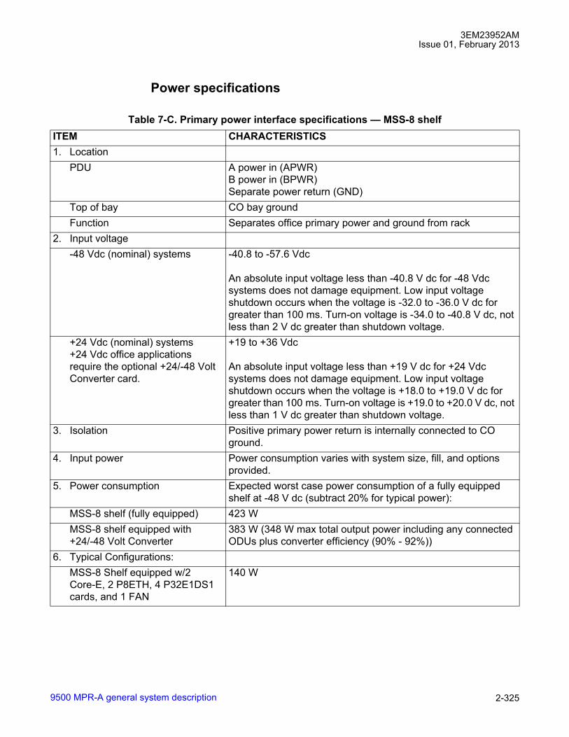
3EM23952AMIssue 01, February 2013
9500 MPR-A general system description 2-325
Power specifications
Table 7-C. Primary power interface specifications � MSS-8 shelfITEM CHARACTERISTICS1. Location
PDU A power in (APWR)B power in (BPWR)Separate power return (GND)
Top of bay CO bay groundFunction Separates office primary power and ground from rack
2. Input voltage-48 Vdc (nominal) systems -40.8 to -57.6 Vdc
An absolute input voltage less than -40.8 V dc for -48 Vdc systems does not damage equipment. Low input voltage shutdown occurs when the voltage is -32.0 to -36.0 V dc for greater than 100 ms. Turn-on voltage is -34.0 to -40.8 V dc, not less than 2 V dc greater than shutdown voltage.
+24 Vdc (nominal) systems+24 Vdc office applications require the optional +24/-48 Volt Converter card.
+19 to +36 Vdc
An absolute input voltage less than +19 V dc for +24 Vdc systems does not damage equipment. Low input voltage shutdown occurs when the voltage is +18.0 to +19.0 V dc for greater than 100 ms. Turn-on voltage is +19.0 to +20.0 V dc, not less than 1 V dc greater than shutdown voltage.
3. Isolation Positive primary power return is internally connected to CO ground.
4. Input power Power consumption varies with system size, fill, and options provided.
5. Power consumption Expected worst case power consumption of a fully equipped shelf at -48 V dc (subtract 20% for typical power):
MSS-8 shelf (fully equipped) 423 WMSS-8 shelf equipped with +24/-48 Volt Converter
383 W (348 W max total output power including any connected ODUs plus converter efficiency (90% - 92%))
6. Typical Configurations:MSS-8 Shelf equipped w/2 Core-E, 2 P8ETH, 4 P32E1DS1 cards, and 1 FAN
140 W

3EM23952AMIssue 01, February 2013
9500 MPR-A general system description2-326
MSS-8 Shelf equipped w/1 Core-E, 1 MOD300, 2 P32E1DS1 cards, 1 ODU1, and 1 FAN
121.5 W
MSS-8 Shelf equipped w/2 Core-E, 2 MOD300, 2 P32E1DS1 cards, 2 ODU1, and 1 FAN
204 W
MSS-8 Shelf equipped w/2 Core-E, 4 MOD300, 2 P32E1DS1 cards, 4 ODUs1, and 1 FAN
329 W
MSS-8 Shelf equipped w/2 Core-E, 6 MOD300, cards, 6 ODUs1, and 1 FAN
423 W
[1] ODU300 TABLE 7-C is not resident within the MSS-4/8 shelf, But it�s power is supplied through the MOD300card. Thus the ODU300 power consumption must be included with the MSS-4/8 shelf for fusing/circuit breakerconsideration. For heat dissipation calculations, the ODU300 should be excluded from MSS-4/8 shelf powerconsumption.
Table 7-D. Primary power interface specifications � MSS-4 selfITEM CHARACTERISTICS1. Location
PDU A power in (APWR)B power in (BPWR)Separate power return (GND)
Top of bay CO bay groundFunction Separates office primary power and ground from rack
2. Input voltage-48 V (nominal) systems -40.8 to -57.6 volts
An absolute input voltage less than -40.8 V dc for -48 V systems does not damage equipment. Low input voltage shutdown occurs when the voltage is -32.0 to -36.0 V dc for greater than 100 ms. Turn-on voltage is -34.0 to -40.8 V dc, not less than 2 V dc greater than shutdown voltage.
3. Isolation Positive primary power return is internally connected to CO ground.
4. Input power Power consumption varies with system size, fill, and options provided.
5. Power consumption Expected worst case power consumption of a fully equipped shelf at -48 V dc (subtract 20% for typical power):
Table 7-C. Primary power interface specifications � MSS-8 shelf (cont.)ITEM CHARACTERISTICS
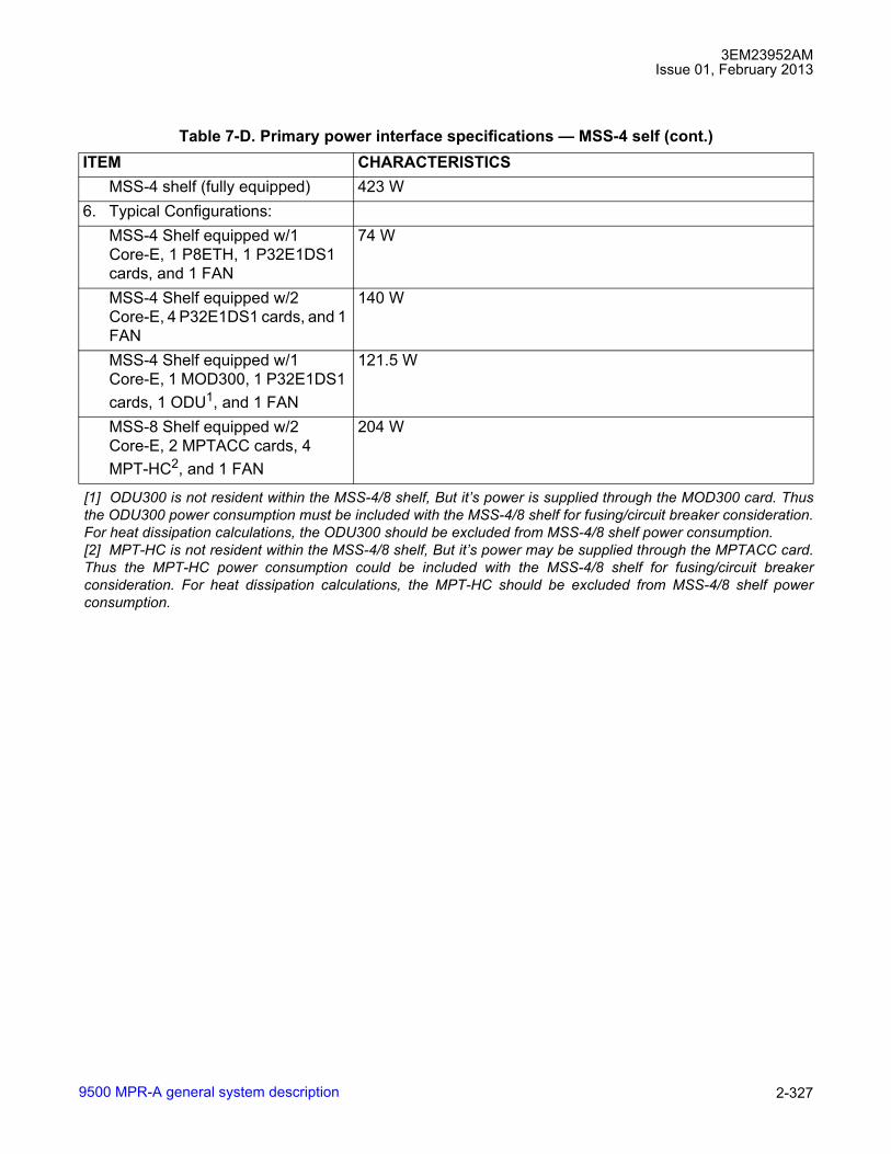
3EM23952AMIssue 01, February 2013
9500 MPR-A general system description 2-327
MSS-4 shelf (fully equipped) 423 W6. Typical Configurations:
MSS-4 Shelf equipped w/1 Core-E, 1 P8ETH, 1 P32E1DS1 cards, and 1 FAN
74 W
MSS-4 Shelf equipped w/2 Core-E, 4 P32E1DS1 cards, and 1 FAN
140 W
MSS-4 Shelf equipped w/1 Core-E, 1 MOD300, 1 P32E1DS1 cards, 1 ODU1, and 1 FAN
121.5 W
MSS-8 Shelf equipped w/2 Core-E, 2 MPTACC cards, 4 MPT-HC2, and 1 FAN
204 W
[1] ODU300 is not resident within the MSS-4/8 shelf, But it�s power is supplied through the MOD300 card. Thusthe ODU300 power consumption must be included with the MSS-4/8 shelf for fusing/circuit breaker consideration.For heat dissipation calculations, the ODU300 should be excluded from MSS-4/8 shelf power consumption.[2] MPT-HC is not resident within the MSS-4/8 shelf, But it�s power may be supplied through the MPTACC card.Thus the MPT-HC power consumption could be included with the MSS-4/8 shelf for fusing/circuit breakerconsideration. For heat dissipation calculations, the MPT-HC should be excluded from MSS-4/8 shelf powerconsumption.
Table 7-D. Primary power interface specifications � MSS-4 self (cont.)ITEM CHARACTERISTICS

3EM23952AMIssue 01, February 2013
9500 MPR-A general system description2-328
Table 7-E. Primary power interface specifications � MSS-1 shelfITEM CHARACTERISTICS1. Location
PDU A power in (APWR)B power in (BPWR)Separate power return (GND)
Top of bay CO bay groundFunction Separates office primary power and ground from rack
2. Input voltage-24, -48, -60 V (nominal) systems+24, +48, +60 V (nominal) systems
-20.0 to -72.0 volts+20.0 to +72 volts
An absolute input voltage less than -+20 V dc for +24 V systems or -20 V dc for -24 V systems does not damage equipment.
3. Isolation Positive primary power return is internally connected to CO ground.
4. Input power Power consumption varies with system size, fill, and options provided.
5. Power consumption Expected worst case power consumption of a fully equipped shelf at -48 V dc (subtract 20% for typical power):
MSS-1 shelf 41.9 W6. Typical Configurations:
MSS-1 Shelf with no PFoE supported MPT ODUs
41.9 W
MSS-1 Shelf with one PFoE1 supported MPT ODUs
[1] MPT-HC is not resident within the MSS-1 shelf, but its power may be supplied through the shelf. Thus theMPT-HC power consumption could be included with the MSS-1 shelf for fusing/circuit breaker consideration. Forheat dissipation calculations, the MPT-HC should be excluded from MSS-1 shelf power consumption.
88.9 W
MSS-1 Shelf with two PFoE1 supported MPT ODUs
135.9 W
Table 7-F. Power consumption � MSS-4/8 shelf cardsITEM MAXIMUM POWER
CONSUMPTIONTYPICAL POWERCONSUMPTION
+24/-48 Volt Converter1 35 W 28 W
AUX 10 W 9 WCore-E (CORE-E) 20 W 16 WFAN 2U Card (MSS-8) 8 W 8 WFAN 2U Card w/Alarms (MSS-8) 25 W 22 W

3EM23952AMIssue 01, February 2013
9500 MPR-A general system description 2-329
FAN 1U Card (MSS-4) 5 W 5 WMOD300 Radio Interface 23 W 21MPTACC 17 W 13.5 W
MPT-HC2 39 W 37 W
MPT-HC2 with 1+1 RPS module 40 W 38 W
MPT-HC2 with XPIC+RPS module 48 W 46 W
MPT-XP 70 W 67 WMPT-XP with 1+1 RPS module 70 W 67 WMPT-XP with XPIC+RPS module 78 W 73 W
ODU3003 45 W for ODUs < 15 GHz30 W for ODUs > 15 GHz
P2E3DS3 DS3 PDH Interface 15.5 W 9 WP8ETH Ethernet Access Switch 15 W 12 WP32E1DS1 DS1 PDH Interface 15.5 W 9 W
[1] +24/-48 Volt Converter power consumption equals 8% typical, 10% maximum, of MSS-8 shelf and connectedODUs power consumption.[2] MPT-HC is not resident within the MSS-4/8 shelf, but its power may be supplied through the MPTACC card.Thus the MPT-HC power consumption could be included with the MSS-4/8 shelf for fusing/circuit breakerconsideration. For heat dissipation calculations, the MPT-HC should be excluded from MSS-4/8 shelf powerconsumption.[3] ODU300 is not resident within the MSS-4/8 shelf, But it�s power is supplied through the MOD300 card. Thusthe ODU300 power consumption must be included with the MSS-4/8 shelf for fusing/circuit breaker consideration.For heat dissipation calculations, the ODU300 should be excluded from MSS-4/8 shelf power consumption.
Table 7-G. Primary power interface specifications � MPT-HL shelfITEM CHARACTERISTICS1. Location
PDU A power in (slot 1)B power in (slot 2)Separate power return (GND)
Top of bay CO bay groundFunction Separates office primary power and ground from rack
2. Input voltage
Table 7-F. Power consumption � MSS-4/8 shelf cards (cont.)ITEM MAXIMUM POWER
CONSUMPTIONTYPICAL POWERCONSUMPTION

3EM23952AMIssue 01, February 2013
9500 MPR-A general system description2-330
Environmental specifications
-24/48 V (nominal) systems -20.4 to -57.6 volts
An input voltage less negative than -20.4 V dc for -24/48 V systems does not damage equipment. Low input voltage shutdown occurs when the voltage is less negative than -17.0 V dc for greater than 100 ms. Turn-on voltage is -20.0 V dc or more negative.
+24/48 V (nominal) systems +20.4 to +57.6 volts
An input voltage less than +20.4 V dc for +24/48 V systems does not damage equipment. Low input voltage shutdown occurs when the voltage is +17.0 V dc or less for greater than 100 ms. Turn-on voltage is +20.0 V dc or greater.
3. Isolation Positive primary power return is isolated from CO ground by more than 100 kilohms as measured per TelcordiaTA-EOP-000295.
4. Input power Power consumption varies with system size, fill, and options provided.
5. Power consumption Expected worst case power consumption of a fully equipped shelf at -48 V dc (subtract 20% for typical power):
MPT-HL shelf (fully equipped) 280 WMPT-HL Transceiver 140 W
6. Typical Configurations:MPT-HL shelf equipped w/1 MPT-HL Transceiver
140 W
MPT-HL shelf equipped w/2 MPT-HL Transceivers
280 W
Table 7-H. Environmental condition specificationsITEM ASSEMBLY OPERATING NONOPERATING
1. Ambient temperature1 MPT-HL, MSS-8, MSS-4
-5 °C to +55 °C2
(41 °F to 131 °F)-40 °C to 70 °C(-40 °F to 158 °F)
MSS-1,MPT-HC, MPT-XP, ODU300, Power Injector
-40 °C to +65 °C(-40 °F to 149 °F)
-40 °C to 70 °C(-40 °F to 158 °F)
Table 7-G. Primary power interface specifications � MPT-HL shelf (cont.)ITEM CHARACTERISTICS

3EM23952AMIssue 01, February 2013
9500 MPR-A general system description 2-331
2. Relative humidity MPT-HL, MSS-8, MSS-4,MSS-1, Power Injector
5 to 85%3
(without condensation)0 to 95%(without condensation)
MPT-HC, MPT-XP, ODU300,
0 to 100%
3. Altitude4 MSS-8, MSS-4,MSS-1, MPT-HC, MPT-HL, MPT-XP, ODU300, Power Injector
-60 to 1800 m(-197 to 5,905 ft)
-60 to 4000 m(-197 to 13,123 ft)
4. Cooling MSS-8, MSS-4,MSS-1, MPT-HL
Forced air
5. Vibration and shock MSS-8, MSS-4,MSS-1, MPT-HC, MPT-HL, ODU300, Power Injector
Earthquake requirements
6. Duty cycle MSS-8, MSS-4,MSS-1, MPT-HC, MPT-HL, MPT-XP, ODU300, Power Injector
Continuous, unattended
[1] Room temperature is measured at a location 1.5 m (59 in.) above the floor and 400 mm (15.8 in.) in front of theequipment.[2] Short term operating ambient temperature is -5 °C to +50 °C (23 °F to 149 °F) for a period not to exceed 96consecutive hours and a total of not more than 15 days in 1 year.[3] Short term operating Relative humidity is 5 to 90% for a period not to exceed 96 consecutive hours and atotal of not more than 15 days in 1 year.
Table 7-H. Environmental condition specifications (cont.)

3EM23952AMIssue 01, February 2013
9500 MPR-A general system description2-332
Component weights
DS1 interface
[4] At installation between 1800 m to 4000 m (5905 ft to 13,123 ft) above sea level, with an ambient aisletemperature not to exceed of 30 °C (113 °F).
Table 7-I. 9500 MPR-A engineering data (component weight)COMPONENT WEIGHT (LBS)MSS-8 shelf (fully equipped) 6 kg (13.2 lb.)MSS-4 shelf (fully equipped) TBDMSS-1 shelf 2.0 kg (4.4 lb.)MSS-1c plus bracket 2.1 kg (4.5 lb.)MSS-1c fan 0.7 kg (1.6 lb.)MPT-HL shelf (fully equipped) 12.3 kg (27.0 lb.)ODU300 5.9 kg (13 lb.)MPT-HC w/embedded diplexer 6.4 kg (14.1 lb.)MPT-HC/9558HC w/external diplexer 8.9 kg (19.6 lb.)MPT-XP 10.4 kg (22.9 lb.)RPS Module 0.9 kg (2.0 lb.)XPIC+RPS 1.1 kg (2.4 lb.)RF Couplers 6 - 8 GHz 6 kg (13.2 lb.)RF Couplers 11 - 38 GHz 4.3 kg (9.5 lb.)OMT Couplers 6 - 8 GHz 6 kg (13.2 lb.)OMT Couplers 11 - 38 GHz 4 kg (8.8 lb.)OMT-C Couplers 6 GHz 12.5 kg (27.5 lb.)OMT-C Couplers 11 - 38 GHz 8.5 kg (18.7 lb.)Power Injector Box 0.8 kg (1.7 lb.)MPT Power Unit 1 kg (2.2 lb.)MPT Extended Power Unit 1.1 kg (2.4 lb.)
Table 7-J. DS1 interface specificationsITEM CHARACTERISTICS1. Location DS1 connectors on P32E1DS1 card equipped in MSS-8 shelf2. Function Couples DS1s into and out of P32E1DS1 card equipped in MSS-8 shelf3. Capacity 32 unprotected DS1s per P32E1DS1 card
32 protected DS1s per pair of P32E1DS1 cards4. Frequency 1.544 Mb/s ±32 pulse position modulation (ppm)

3EM23952AMIssue 01, February 2013
9500 MPR-A general system description 2-333
5. Line code AMI (bipolar) with B8ZS coding6. Line impedance 100 ohms ±5%, balanced7. Level Measured with all 1's signal in 3 kHz bandwidth centered
at 772 kHz into100 ohms ±5%Input @ 772 kHz +12.6 to +17.9 dBm at equal-level point plus attenuation of 0 to 655 ft of
cableOutput @ 772 kHz +12.6 to +17.9 dBm at equal-level point after attenuation of 0 to 655 ft of
cableOutput @ 1.544 MHz More than 29 dB below level at 772 kHz
8. Pulse shape:Output Complies with GR-499-CORE. Meets DS1 format template requirements
(see figure 7-1).9. Cable type Twisted-pair cable, typical 22 AWG ABAM. Complies with ANSI
T1.102-1993Maximum cable length 660 ft from defined DSX-level point
Table 7-J. DS1 interface specifications (cont.)ITEM CHARACTERISTICS
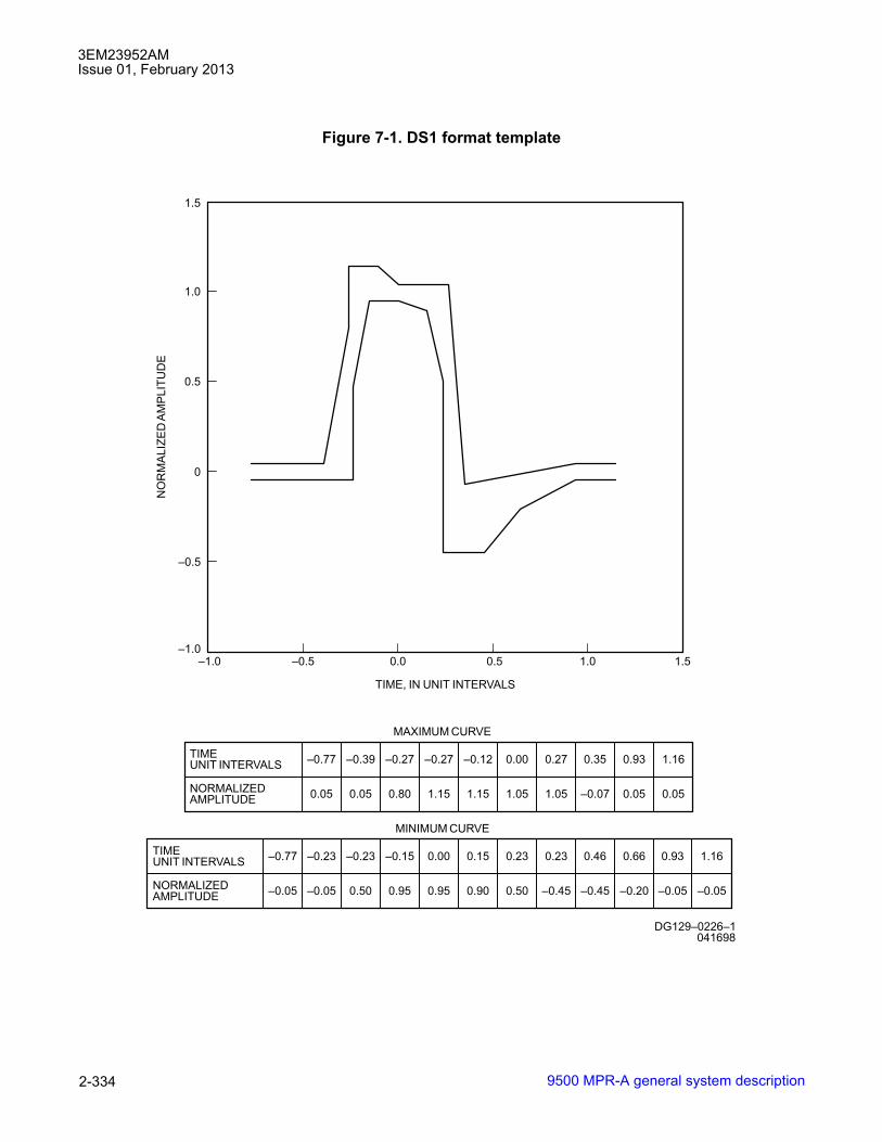
3EM23952AMIssue 01, February 2013
9500 MPR-A general system description2-334
Figure 7-1. DS1 format template
–0.77 –0.39 –0.27 –0.12 0.00 0.27 0.35 0.93 1.16
0.05 0.05 0.80 1.15 1.15 1.05 1.05 –0.07 0.05 0.05
–0.27TIMEUNIT INTERVALS
NORMALIZEDAMPLITUDE
MAXIMUM CURVE
–0.77 –0.23 –0.15 0.00 0.15 0.23 0.23 0.46 0.66
–0.05 –0.05 0.50 0.95 0.90 0.50 –0.45 –0.45 –0.20
–0.23TIMEUNIT INTERVALS
NORMALIZEDAMPLITUDE
MINIMUM CURVE
0.93 1.16
–0.05 –0.05
1.0
0.5
0
–0.5
–1.0 –0.5 0.0 0.5 1.0 1.5
TIME, IN UNIT INTERVALS
NO
RM
AL
IZE
DA
MP
LIT
UD
E
DG129–0226–1
1.5
–1.0
041698
0.95

3EM23952AMIssue 01, February 2013
9500 MPR-A general system description 2-335
Figure 7-2. DS1 input jitter accommodation
Figure 7-3. DS1 jitter transfer characteristics
ACCEPTABLERANGE
10 Hz 500 Hz 8 kHz 40 kHz
5 UI
0.1 UI
FREQUENCY
950-0208-1
DS
1IN
PU
T J
ITT
ER
(PE
AK
-TO
-PE
AK
)
071510
ACCEPTABLERANGE
10 Hz 350 Hz 15 kHz
0.1 dB
FREQUENCY 950-0209-1
DS
1R
EC
EIV
ER
JIT
TE
RT
RA
NS
FE
R F
UN
CT
ION
20 dB/DECADE
071510
2.5 kHz
40 dB/DECADE

3EM23952AMIssue 01, February 2013
9500 MPR-A general system description2-336
DS3 interface
Figure 7-4. DS1 jitter measurement filter characteristics
Table 7-K. DS3 interface specificationsITEM CHARACTERISTICS1. Location Mini-BNC connectors on the P2E3DS3 card equipped in the MSS-8 shelf2. Function Couples DS3s into and out of P2E3DS3 card3. Capacity 1 to 2 full-duplex DS3 ports per P2E3DS3 card4. Frequency 44.736 Mb/s ±20 ppm5. Line code AMI (bipolar) with B3ZS coding6. Format Asynchronous framed DS3 per ANSI T1.107-1997 standard. See
figure 7-5.DS3 C-bit parity with C-bit mode operation per ANSI Standard T1.107a (R5.0)
7. Line impedance 75 ohms +5%, unbalanced8. Level Measured with all 1's signal and 3 kHz bandwidth into 75 ohms +5%
Input @ 22 MHz -1.8 to +5.7 dBm at equal-level point less attenuation of 0 to 450 ft of cableOutput @ 44 MHz More than 20 dB below level @ 22 MHz
9. Pulse shape:Output Compliant with GR-499-CORE. Meets DS3 format template requirements
(see figure 7-5).10. Cable type 75 ohm BNC coaxial cables, 728A11. Mating connector type Mini-BNC male
ACCEPTABLERANGE
10 Hz 350 Hz 15 kHz
0.1 dB
FREQUENCY 950-0209-1
DS
1R
EC
EIV
ER
JIT
TE
RT
RA
NS
FE
R F
UN
CT
ION
20 dB/DECADE
071510
2.5 kHz
40 dB/DECADE
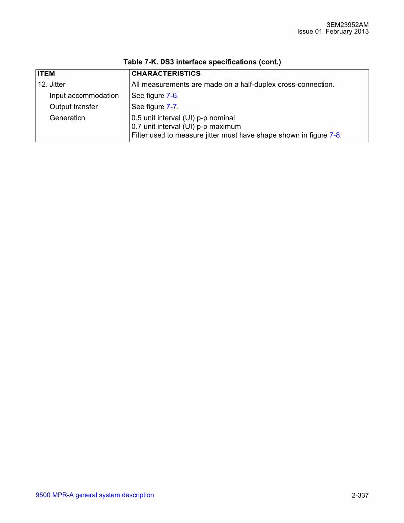
3EM23952AMIssue 01, February 2013
9500 MPR-A general system description 2-337
12. Jitter All measurements are made on a half-duplex cross-connection.Input accommodation See figure 7-6.Output transfer See figure 7-7.Generation 0.5 unit interval (UI) p-p nominal
0.7 unit interval (UI) p-p maximumFilter used to measure jitter must have shape shown in figure 7-8.
Table 7-K. DS3 interface specifications (cont.)ITEM CHARACTERISTICS

3EM23952AMIssue 01, February 2013
9500 MPR-A general system description2-338
Figure 7-5. Asynchronous DS3 format template
TIME (UNIT INTERVALS)
NO
RM
ALI
ZE
DA
MP
LIT
UD
E
671-0498-1
INVERTED PULSE SHOWN TO AID OSCILLOSCOPE TIME-BASE ADJUSTMENT
NORMALIZEDAMPLITUDE
TIMEUNIT INTERVALSCURVE
MINIMUMCURVE
071504
MAXIMUMCURVE
-1.0-0.4
-0.2
0.0
0.2
0.4
0.6
0.8
1.0
1.2
-1.5 0.0 1.0 1.50.5

3EM23952AMIssue 01, February 2013
9500 MPR-A general system description 2-339
Figure 7-6. DS3 input jitter accommodation
Figure 7-7. DS3 jitter transfer characteristics
ACCEPTABLERANGE
10 Hz 2.3 kHz 60 kHz 300 kHz
5 UI
0.1 UI
FREQUENCY671-0499-1
DS
3IN
PU
TJI
TT
ER
(PE
AK
-TO
-PE
AK
)
071504
ACCEPTABLERANGE
10 Hz 1000 Hz 15 kHz
0.1 dB
FREQUENCY 671-0500-1
DS
3R
EC
EIV
ER
JIT
TE
RT
RA
NS
FE
RF
UN
CT
ION
20 dB/DECADE
071504

3EM23952AMIssue 01, February 2013
9500 MPR-A general system description2-340
Figure 7-8. DS3 jitter measurement filter characteristics
ACCEPTABLERANGE
10 Hz 1000 Hz 15 kHz
0.1 dB
FREQUENCY 671-0500-1
DS
3R
EC
EIV
ER
JIT
TE
RT
RA
NS
FE
RF
UN
CT
ION
20 dB/DECADE
071504

UDS-100 3EM23952AMIssue 01, February 2013
9500 MPR-A unit data sheet cross-reference 3-1
Unit Data Sheets (UDSs)UDS-100 9500 MPR-A unit data sheet cross-reference
UDS-1009500 MPR-A unit data sheet cross-referenceUnit Data Sheet Cross-Reference by UDS Number
UDS NUMBER DESCRIPTION CLEI STATUS
PARTNUMBER
UDS-100 9500 MPR-A unit data sheet cross-reference N/A N/A N/AUDS-101 MSS-8 Microwave Service Switch Shelf N/A Inactive 3DB18485AA
MSS-8 Microwave Service Switch Shelf CRMLB10HRA Active 3DB18485ABUDS-102 MPT-HL Microwave Packet transport-Long
Haul ShelfN/A Active 3EM22618AB
3EM22618ACUDS-103 CSM-E Enhanced Control and Switching
ModuleCRCCAEVEAA Active 3DB18326AC
UDS-104 MOD300 Radio Interface N/A Inactive 3DB18136ACMOD300 Radio Interface N/A Inactive 3DB18136ADMOD300 Radio Interface CRG2ABVDAA Active 3DB18136AEMOD300EN Radio Interface CRG2ABWDAA Active 3DB18538AC
UDS-105 P32E1DS1 DS1 PDH Card N/A Inactive 3DB18126ADP32E1DS1 DS1 PDH Card CRG2ABUDAA Active 3DB18126AE
UDS-106 P2E3DS3 DS3 PDH Card N/A Inactive 3DB18194ABP2E3DS3 DS3 PDH Card CRG2AA9DAA Active 3DB18194AC
UDS-107 P8ETH Ethernet Access Switch Card CRCCACGJAA Active 3DB18206ACUDS-108 ODU300, L6 GHz, 252.04 MHz SEPARATION
ODU300, 5930 - 6020 MHZ, HP, TX LOW N/A Inactive 3DB23215AAODU300, 5989 - 6079 MHZ, HP, TX LOW N/A Inactive 3DB23215ABODU300, 6078 - 6168 MHZ, HP, TX LOW N/A Inactive 3DB23215ACODU300, 6182 - 6272 MHZ, HP, TX HIGH N/A Inactive 3DB23215ADODU300, 6241 - 6331 MHZ, HP, TX HIGH N/A Inactive 3DB23215AEODU300, 6330 - 6420 MHZ HP, TX HIGH N/A Inactive 3DB23215AF
UDS-108 ODU300 W/LIGHTNING SURGE SUPPRESSOR, L6 GHz, 252.04 MHz SEPARATIONODU300, 5930 - 6020 MHZ, HP, TX LOW CRMLT10HRB Active 3DB23215HAODU300, 5989 - 6079 MHZ, HP, TX LOW CRMLV10HRB Active 3DB23215HBODU300, 6078 - 6168 MHZ, HP, TX LOW CRMLX10HRB Active 3DB23215HCODU300, 6182 - 6272 MHZ, HP, TX HIGH CRMLU10HRB Active 3DB23215HDODU300, 6241 - 6331 MHZ, HP, TX HIGH CRMLW10HRB Active 3DB23215HEODU300, 6330 - 6420 MHZ HP, TX HIGH CRMLY10HRB Active 3DB23215HF

3EM23952AMIssue 01, February 2013
9500 MPR-A unit data sheet cross-reference3-2
UDS-100
UDS-108 ODU300, U6 GHz, 160 MHz SEPARATIONODU300, 6540 - 6610 MHZ, HP, TX LOW N/A Inactive 3DB23214AAODU300, 6710 - 6780 MHZ, HP, TX HIGH N/A Inactive 3DB23214ABODU300, 6590 - 6660 MHZ, HP, TX LOW N/A Inactive 3DB23214ACODU300, 6760 - 6830 MHZ, HP, TX HIGH N/A Inactive 3DB23214ADODU300, 6640 - 6710 MHZ, HP, TX LOW N/A Inactive 3DB23214AEODU300, 6800 - 6870 MHZ, HP, TX HIGH N/A Inactive 3DB23214AF
UDS-108 ODU300 W/LIGHTNING SURGE SUPPRESSOR, U6 GHz, 160 MHz SEPARATIONODU300, 6540 - 6610 MHZ, HP, TX LOW CRMLZ10HRB Active 3DB23214HAODU300, 6710 - 6780 MHZ, HP, TX HIGH CRML110HRB Active 3DB23214HBODU300, 6590 - 6660 MHZ, HP, TX LOW CRML210HRB Active 3DB23214HCODU300, 6760 - 6830 MHZ, HP, TX HIGH CRML310HRB Active 3DB21214HDODU300, 6640 - 6710 MHZ, HP, TX LOW CRML410HRB Active 3DB23214HEODU300, 6800 - 6870 MHZ, HP, TX HIGH CRML510HRB Active 3DB23214HF
UDS-108 ODU300, U6 GHz, 340 MHz SEPARATIONODU300, 6430 - 6590 MHz, HP TX LOW N/A Inactive 3DB23216AAODU300, 6770 - 6930 MHz, HP TX HIGH N/A Inactive 3DB23216ABODU300, 6515 - 6675 MHz, HP TX LOW N/A Inactive 3DB23216ACODU300, 6855 - 7015 MHz, HP TX HIGH N/A Inactive 3DB23216ADODU300, 6600 - 6760 MHz, HP TX LOW N/A Inactive 3DB23216AEODU300, 6940 - 7100 MHz, HP TX HIGH N/A Inactive 3DB23216AF
UDS-108 ODU300 W/LIGHTNING SURGE SUPPRESSOR, U6 GHz, 340 MHz SEPARATIONODU300, 6430 - 6590 MHz, HP TX LOW CRML610HRB Active 3DB23216HAODU300, 6770 - 6930 MHz, HP TX HIGH CRML710HRB Active 3DB23216HBODU300, 6515 - 6675 MHz, HP TX LOW CRML810HRB Active 3DB23216HCODU300, 6855 - 7015 MHz, HP TX HIGH CRML910HRB Active 3DB23216HDODU300, 6600 - 6760 MHz, HP TX LOW CRMMA00ARB Active 3DB23216HEODU300, 6940 - 7100 MHz, HP TX HIGH CRMMB00ARB Active 3DB23216HF
UDS-108 ODU300 W/LIGHTNING SURGE SUPPRESSOR, 7 GHz, 175 MHz SEPARATIONODU300, 7124 - 7185 MHz, HP, TX Low N/A Active 3DB23223HAODU300, 7299 - 7360 MHz, HP, TX High N/A Active 3DB23224HAODU300, 7157.5 - 7217.5 MHz, HP, TX Low N/A Active 3DB23225HAODU300, 7332.5 - 7392.5 MHz, HP, TX High N/A Active 3DB23226HAODU300, 7190 - 7250 MHz, HP, TX Low N/A Active 3DB23227HAODU300, 7365 - 7425 MHz, HP, TX High N/A Active 3DB23228HA
UDS NUMBER DESCRIPTION CLEI STATUS
PARTNUMBER

UDS-100 3EM23952AMIssue 01, February 2013
9500 MPR-A unit data sheet cross-reference 3-3
UDS-108 ODU300 W/LIGHTNING SURGE SUPPRESSOR, 7 GHz, 150 MHz SEPARATIONODU300, 7424 - 7485 MHz, HP, TX Low N/A Active 3DB23217HAODU300, 7574 - 7635 MHz, HP, TX High N/A Active 3DB23218HAODU300, 7470 - 7530 MHz, HP, TX Low N/A Active 3DB23219HAODU300, 7620 - 7680 MHz, HP, TX High N/A Active 3DB23220HAODU300, 7515 - 7575 MHz, HP, TX Low N/A Active 3DB23221HAODU300, 7665 - 7725 MHz, HP, TX High N/A Active 3DB23222HA
UDS-108 ODU300 W/LIGHTNING SURGE SUPPRESSOR, 8 GHz, 300 MHz SEPARATIONODU300, 7722.5 - 7859 MHz, HP, TX Low N/A Active 3DB23033HAODU300, 8025 - 8171 MHz, HP, TX High N/A Active 3DB23033HCODU300, 7844 - 7981 MHz, HP, TX Low N/A Active 3DB23033HBODU300, 8145 - 8287 MHz, HP, TX High N/A Active 3DB23033HD
UDS-108 ODU300 11 GHz, 590-490 MHz SEPARATIONODU300, 10675 - 10835 MHZ, TX LOW N/A Inactive 3DB23035AAODU300, 10795 - 10955 MHZ, TX LOW N/A Inactive 3DB23035ABODU300, 10915 - 11075 MHZ, TX LOW N/A Inactive 3DB23035ACODU300, 11035 - 11200 MHZ, TX LOW N/A Inactive 3DB23035ADODU300, 11200 - 11345 MHZ, TX HIGH N/A Inactive 3DB23035AEODU300, 11310 - 11465 MHZ, TX HIGH N/A Inactive 3DB23035AFODU300, 11430 - 11585 MHZ, TX HIGH N/A Inactive 3DB23035AGODU300, 11550 - 11705 MHZ, TX HIGH N/A Inactive 3DB23035AH
UDS-108 ODU300 W/LIGHTNING SURGE SUPPRESSOR 11 GHz, 590-490 MHz SEPARATIONODU300, 10675 - 10835 MHZ, TX LOW CRMMC00ARB Active 3DB23035HAODU300, 10795 - 10955 MHZ, TX LOW CRMME00ARB Active 3DB23035HBODU300, 10915 - 11075 MHZ, TX LOW CRMMG00ARB Active 3DB23035HCODU300, 11035 - 11200 MHZ, TX LOW CRMMJ00ARB Active 3DB23035HDODU300, 11200 - 11345 MHZ, TX HIGH CRMMD00ARB Active 3DB23035HEODU300, 11310 - 11465 MHZ, TX HIGH CRMMF00ARB Active 3DB23035HFODU300, 11430 - 11585 MHZ, TX HIGH CRMMH00ARB Active 3DB23035HGODU300, 11550 - 11705 MHZ, TX HIGH CRMMK00ARB Active 3DB23035HH
UDS-108 ODU300 15 GHz, 475/490 MHz SEPARATIONODU300, 14500 - 14660 MHZ, TX LOW N/A Inactive 3DB23039ACODU300, 14975 - 15135 MHZ, TX HIGH N/A Inactive 3DB23039AD
UDS NUMBER DESCRIPTION CLEI STATUS
PARTNUMBER
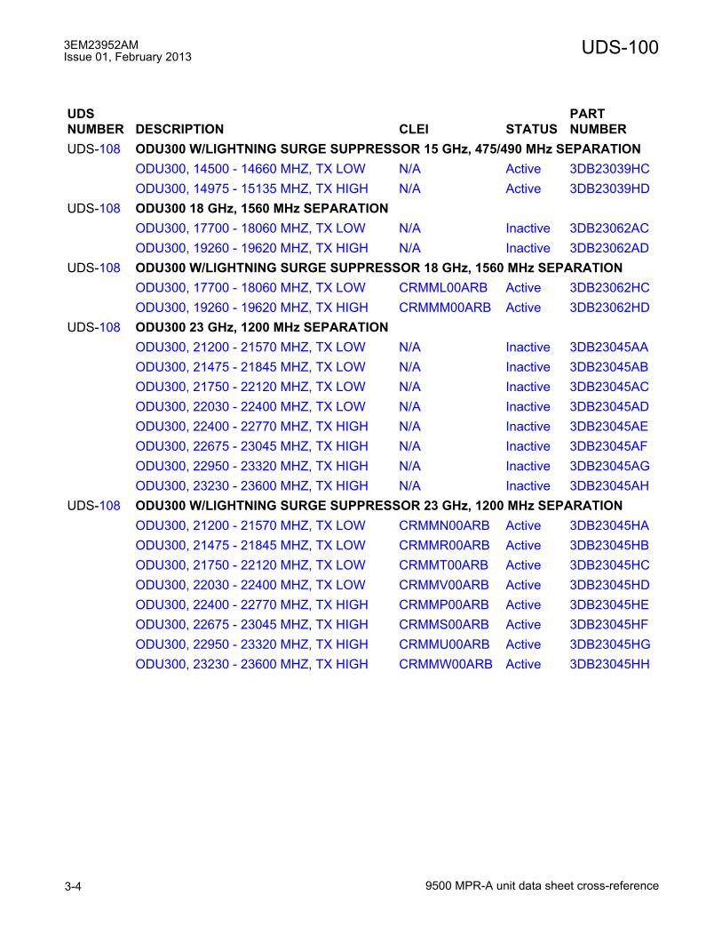
3EM23952AMIssue 01, February 2013
9500 MPR-A unit data sheet cross-reference3-4
UDS-100
UDS-108 ODU300 W/LIGHTNING SURGE SUPPRESSOR 15 GHz, 475/490 MHz SEPARATIONODU300, 14500 - 14660 MHZ, TX LOW N/A Active 3DB23039HCODU300, 14975 - 15135 MHZ, TX HIGH N/A Active 3DB23039HD
UDS-108 ODU300 18 GHz, 1560 MHz SEPARATIONODU300, 17700 - 18060 MHZ, TX LOW N/A Inactive 3DB23062ACODU300, 19260 - 19620 MHZ, TX HIGH N/A Inactive 3DB23062AD
UDS-108 ODU300 W/LIGHTNING SURGE SUPPRESSOR 18 GHz, 1560 MHz SEPARATIONODU300, 17700 - 18060 MHZ, TX LOW CRMML00ARB Active 3DB23062HCODU300, 19260 - 19620 MHZ, TX HIGH CRMMM00ARB Active 3DB23062HD
UDS-108 ODU300 23 GHz, 1200 MHz SEPARATIONODU300, 21200 - 21570 MHZ, TX LOW N/A Inactive 3DB23045AAODU300, 21475 - 21845 MHZ, TX LOW N/A Inactive 3DB23045ABODU300, 21750 - 22120 MHZ, TX LOW N/A Inactive 3DB23045ACODU300, 22030 - 22400 MHZ, TX LOW N/A Inactive 3DB23045ADODU300, 22400 - 22770 MHZ, TX HIGH N/A Inactive 3DB23045AEODU300, 22675 - 23045 MHZ, TX HIGH N/A Inactive 3DB23045AFODU300, 22950 - 23320 MHZ, TX HIGH N/A Inactive 3DB23045AGODU300, 23230 - 23600 MHZ, TX HIGH N/A Inactive 3DB23045AH
UDS-108 ODU300 W/LIGHTNING SURGE SUPPRESSOR 23 GHz, 1200 MHz SEPARATIONODU300, 21200 - 21570 MHZ, TX LOW CRMMN00ARB Active 3DB23045HAODU300, 21475 - 21845 MHZ, TX LOW CRMMR00ARB Active 3DB23045HBODU300, 21750 - 22120 MHZ, TX LOW CRMMT00ARB Active 3DB23045HCODU300, 22030 - 22400 MHZ, TX LOW CRMMV00ARB Active 3DB23045HDODU300, 22400 - 22770 MHZ, TX HIGH CRMMP00ARB Active 3DB23045HEODU300, 22675 - 23045 MHZ, TX HIGH CRMMS00ARB Active 3DB23045HFODU300, 22950 - 23320 MHZ, TX HIGH CRMMU00ARB Active 3DB23045HGODU300, 23230 - 23600 MHZ, TX HIGH CRMMW00ARB Active 3DB23045HH
UDS NUMBER DESCRIPTION CLEI STATUS
PARTNUMBER
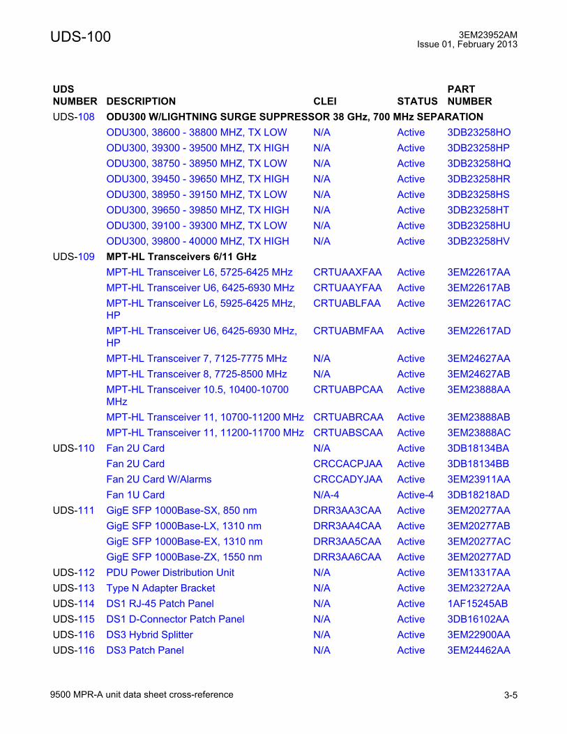
UDS-100 3EM23952AMIssue 01, February 2013
9500 MPR-A unit data sheet cross-reference 3-5
UDS-108 ODU300 W/LIGHTNING SURGE SUPPRESSOR 38 GHz, 700 MHz SEPARATIONODU300, 38600 - 38800 MHZ, TX LOW N/A Active 3DB23258HOODU300, 39300 - 39500 MHZ, TX HIGH N/A Active 3DB23258HPODU300, 38750 - 38950 MHZ, TX LOW N/A Active 3DB23258HQODU300, 39450 - 39650 MHZ, TX HIGH N/A Active 3DB23258HRODU300, 38950 - 39150 MHZ, TX LOW N/A Active 3DB23258HSODU300, 39650 - 39850 MHZ, TX HIGH N/A Active 3DB23258HTODU300, 39100 - 39300 MHZ, TX LOW N/A Active 3DB23258HUODU300, 39800 - 40000 MHZ, TX HIGH N/A Active 3DB23258HV
UDS-109 MPT-HL Transceivers 6/11 GHzMPT-HL Transceiver L6, 5725-6425 MHz CRTUAAXFAA Active 3EM22617AAMPT-HL Transceiver U6, 6425-6930 MHz CRTUAAYFAA Active 3EM22617ABMPT-HL Transceiver L6, 5925-6425 MHz, HP
CRTUABLFAA Active 3EM22617AC
MPT-HL Transceiver U6, 6425-6930 MHz, HP
CRTUABMFAA Active 3EM22617AD
MPT-HL Transceiver 7, 7125-7775 MHz N/A Active 3EM24627AAMPT-HL Transceiver 8, 7725-8500 MHz N/A Active 3EM24627ABMPT-HL Transceiver 10.5, 10400-10700 MHz
CRTUABPCAA Active 3EM23888AA
MPT-HL Transceiver 11, 10700-11200 MHz CRTUABRCAA Active 3EM23888ABMPT-HL Transceiver 11, 11200-11700 MHz CRTUABSCAA Active 3EM23888AC
UDS-110 Fan 2U Card N/A Active 3DB18134BAFan 2U Card CRCCACPJAA Active 3DB18134BBFan 2U Card W/Alarms CRCCADYJAA Active 3EM23911AAFan 1U Card N/A-4 Active-4 3DB18218AD
UDS-111 GigE SFP 1000Base-SX, 850 nm DRR3AA3CAA Active 3EM20277AAGigE SFP 1000Base-LX, 1310 nm DRR3AA4CAA Active 3EM20277ABGigE SFP 1000Base-EX, 1310 nm DRR3AA5CAA Active 3EM20277ACGigE SFP 1000Base-ZX, 1550 nm DRR3AA6CAA Active 3EM20277AD
UDS-112 PDU Power Distribution Unit N/A Active 3EM13317AAUDS-113 Type N Adapter Bracket N/A Active 3EM23272AAUDS-114 DS1 RJ-45 Patch Panel N/A Active 1AF15245ABUDS-115 DS1 D-Connector Patch Panel N/A Active 3DB16102AAUDS-116 DS3 Hybrid Splitter N/A Active 3EM22900AAUDS-116 DS3 Patch Panel N/A Active 3EM24462AA
UDS NUMBER DESCRIPTION CLEI STATUS
PARTNUMBER
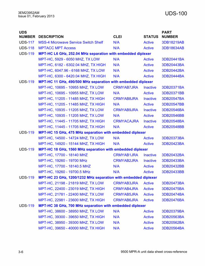
3EM23952AMIssue 01, February 2013
9500 MPR-A unit data sheet cross-reference3-6
UDS-100
UDS-117 MSS-4 Microwave Service Switch Shelf N/A Active 3DB18219ABUDS-118 MPTACC MPT Access N/A Active 3DB18634ABUDS-119 MPT-HC L6 GHz, 252.04 MHz separation with embedded diplexer
MPT-HC, 5929 - 6050 MHZ, TX LOW N/A Active 3DB20441BAMPT-HC, 6182 - 6302.04 MHZ, TX HIGH N/A Active 3DB20443BAMPT-HC, 6047.96 - 6168 MHZ, TX LOW N/A Active 3DB20442BAMPT-HC, 6300 - 6420.04 MHZ, TX HIGH N/A Active 3DB20444BA
UDS-119 MPT-HC 11 GHz, 490/500 MHz separation with embedded diplexerMPT-HC, 10695 - 10955 MHZ, TX LOW CRMYAB7JRA Inactive 3DB20371BAMPT-HC, 10695 - 10955 MHZ, TX LOW N/A Active 3DB20371BBMPT-HC, 11205 - 11485 MHZ, TX HIGH CRMYAB8JRA Inactive 3DB20547BAMPT-HC, 11205 - 11485 MHZ, TX HIGH N/A Active 3DB20547BBMPT-HC, 10935 - 11205 MHZ, TX LOW CRMYAB9JRA Inactive 3DB20546BAMPT-HC, 10935 - 11205 MHZ, TX LOW N/A Active 3DB20546BBMPT-HC, 11445 - 11705 MHZ, TX HIGH CRMYACAJRA Inactive 3DB20548BAMPT-HC, 11445 - 11705 MHZ, TX HIGH N/A Active 3DB20548BB
UDS-119 MPT-HC 15 GHz, 475 MHz separation with embedded diplexerMPT-HC, 14500 - 14724 MHZ, TX LOW N/A Active 3DB20373BAMPT-HC, 14920 - 15144 MHZ, TX HIGH N/A Active 3DB20423BA
UDS-119 MPT-HC 18 GHz, 1560 MHz separation with embedded diplexerMPT-HC, 17700 - 18140 MHZ CRMYAB1JRA Inactive 3DB20432BAMPT-HC, 19260 - 19700 MHz CRMYAB2JRA Inactive 3DB20433BAMPT-HC, 17700 - 18140.5 MHZ N/A Active 3DB20432BBMPT-HC, 19260 - 19700.5 MHz N/A Active 3DB20433BB
UDS-119 MPT-HC 23 GHz, 1200/1232 MHz separation with embedded diplexerMPT-HC, 21198 - 21819 MHZ, TX LOW CRMYAB3JRA Active 3DB20473BAMPT-HC, 22400 - 23019 MHZ, TX HIGH CRMYAB4JRA Active 3DB20475BAMPT-HC, 21781 - 22400 MHZ, TX LOW CRMYAB5JRA Active 3DB20474BAMPT-HC, 22981 - 23600 MHZ, TX HIGH CRMYAB6JRA Active 3DB20476BA
UDS-119 MPT-HC 38 GHz, 700 MHz separation with embedded diplexerMPT-HC, 38600 - 38950 MHZ, TX LOW N/A Active 3DB20379BAMPT-HC, 39300 - 39650 MHZ, TX HIGH N/A Active 3DB20563BAMPT-HC, 38950 - 39300 MHZ, TX LOW N/A Active 3DB20562BAMPT-HC, 39650 - 40000 MHZ, TX HIGH N/A Active 3DB20564BA
UDS NUMBER DESCRIPTION CLEI STATUS
PARTNUMBER
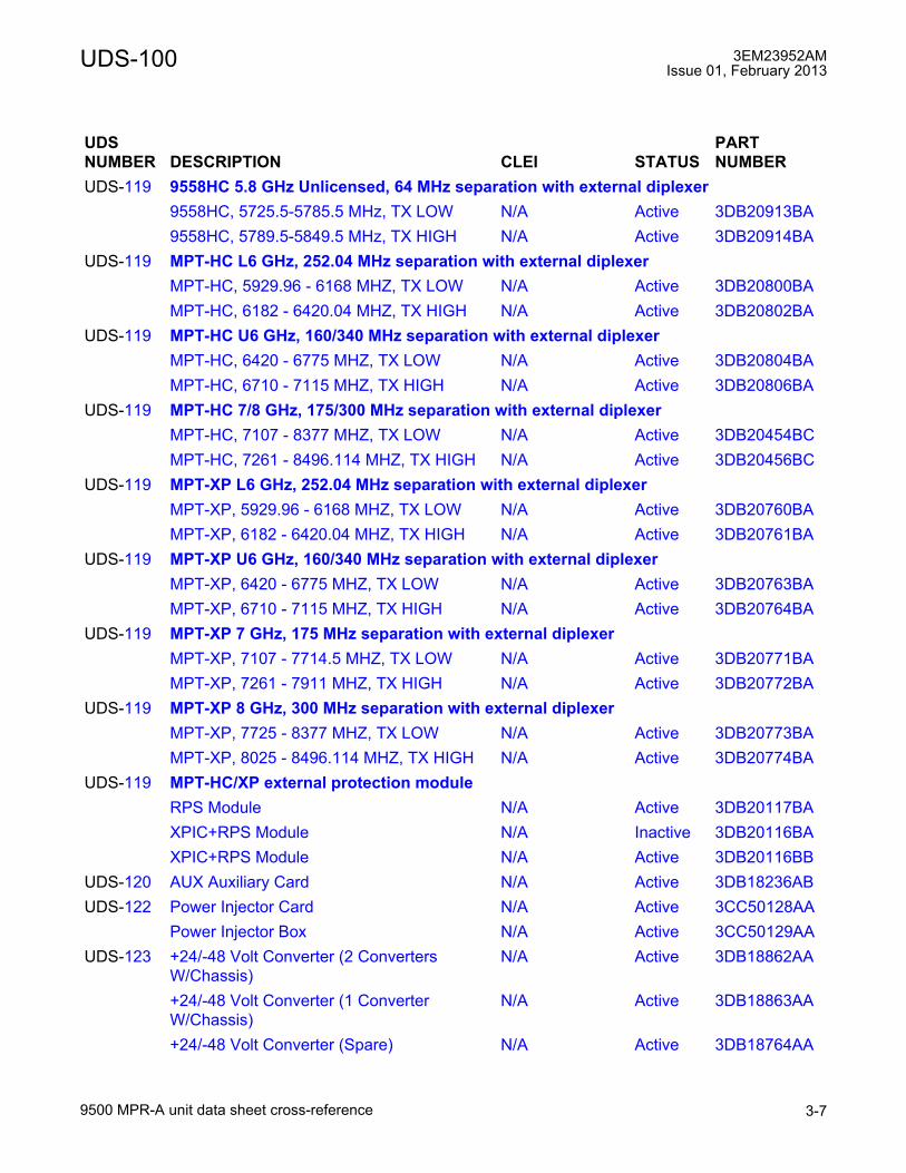
UDS-100 3EM23952AMIssue 01, February 2013
9500 MPR-A unit data sheet cross-reference 3-7
UDS-119 9558HC 5.8 GHz Unlicensed, 64 MHz separation with external diplexer9558HC, 5725.5-5785.5 MHz, TX LOW N/A Active 3DB20913BA9558HC, 5789.5-5849.5 MHz, TX HIGH N/A Active 3DB20914BA
UDS-119 MPT-HC L6 GHz, 252.04 MHz separation with external diplexerMPT-HC, 5929.96 - 6168 MHZ, TX LOW N/A Active 3DB20800BAMPT-HC, 6182 - 6420.04 MHZ, TX HIGH N/A Active 3DB20802BA
UDS-119 MPT-HC U6 GHz, 160/340 MHz separation with external diplexerMPT-HC, 6420 - 6775 MHZ, TX LOW N/A Active 3DB20804BAMPT-HC, 6710 - 7115 MHZ, TX HIGH N/A Active 3DB20806BA
UDS-119 MPT-HC 7/8 GHz, 175/300 MHz separation with external diplexerMPT-HC, 7107 - 8377 MHZ, TX LOW N/A Active 3DB20454BCMPT-HC, 7261 - 8496.114 MHZ, TX HIGH N/A Active 3DB20456BC
UDS-119 MPT-XP L6 GHz, 252.04 MHz separation with external diplexerMPT-XP, 5929.96 - 6168 MHZ, TX LOW N/A Active 3DB20760BAMPT-XP, 6182 - 6420.04 MHZ, TX HIGH N/A Active 3DB20761BA
UDS-119 MPT-XP U6 GHz, 160/340 MHz separation with external diplexerMPT-XP, 6420 - 6775 MHZ, TX LOW N/A Active 3DB20763BAMPT-XP, 6710 - 7115 MHZ, TX HIGH N/A Active 3DB20764BA
UDS-119 MPT-XP 7 GHz, 175 MHz separation with external diplexerMPT-XP, 7107 - 7714.5 MHZ, TX LOW N/A Active 3DB20771BAMPT-XP, 7261 - 7911 MHZ, TX HIGH N/A Active 3DB20772BA
UDS-119 MPT-XP 8 GHz, 300 MHz separation with external diplexerMPT-XP, 7725 - 8377 MHZ, TX LOW N/A Active 3DB20773BAMPT-XP, 8025 - 8496.114 MHZ, TX HIGH N/A Active 3DB20774BA
UDS-119 MPT-HC/XP external protection moduleRPS Module N/A Active 3DB20117BAXPIC+RPS Module N/A Inactive 3DB20116BAXPIC+RPS Module N/A Active 3DB20116BB
UDS-120 AUX Auxiliary Card N/A Active 3DB18236ABUDS-122 Power Injector Card N/A Active 3CC50128AA
Power Injector Box N/A Active 3CC50129AAUDS-123 +24/-48 Volt Converter (2 Converters
W/Chassis)N/A Active 3DB18862AA
+24/-48 Volt Converter (1 Converter W/Chassis)
N/A Active 3DB18863AA
+24/-48 Volt Converter (Spare) N/A Active 3DB18764AA
UDS NUMBER DESCRIPTION CLEI STATUS
PARTNUMBER
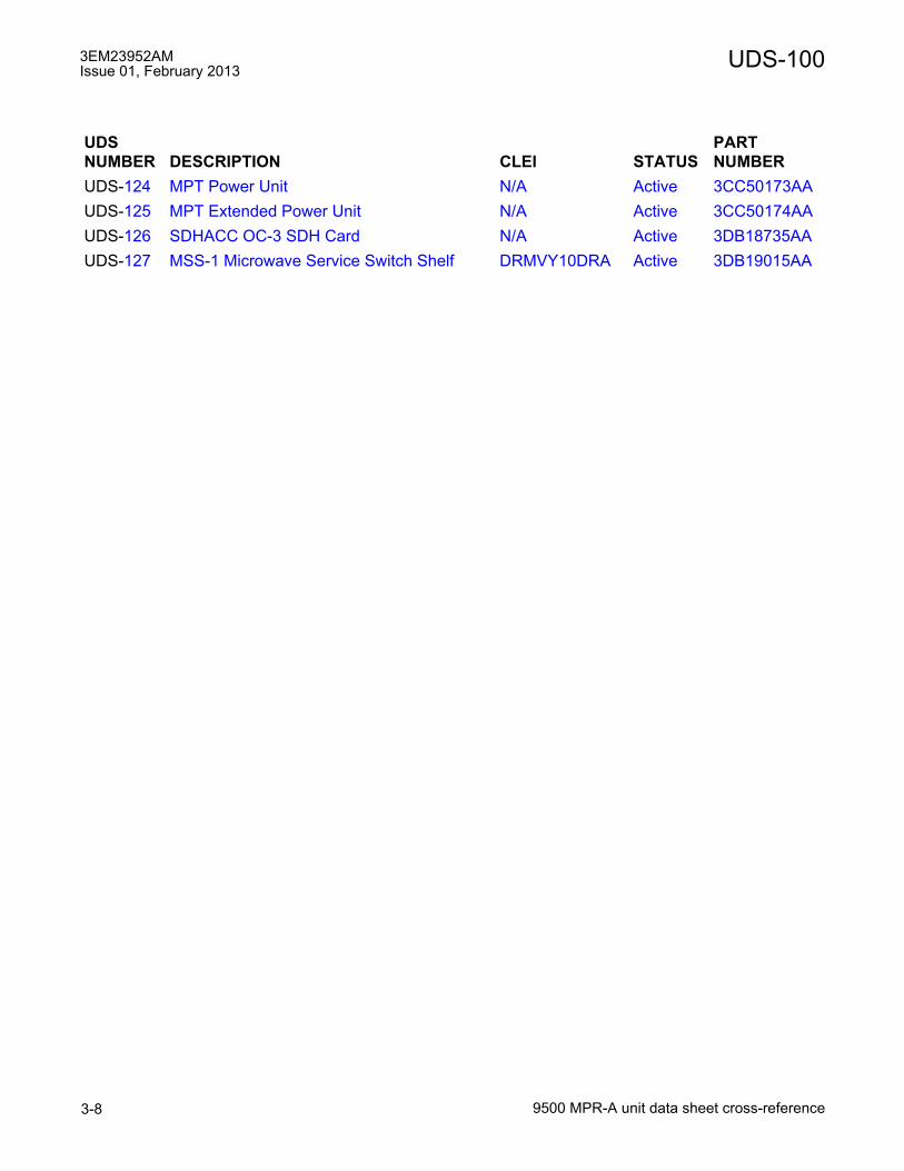
3EM23952AMIssue 01, February 2013
9500 MPR-A unit data sheet cross-reference3-8
UDS-100
UDS-124 MPT Power Unit N/A Active 3CC50173AAUDS-125 MPT Extended Power Unit N/A Active 3CC50174AAUDS-126 SDHACC OC-3 SDH Card N/A Active 3DB18735AAUDS-127 MSS-1 Microwave Service Switch Shelf DRMVY10DRA Active 3DB19015AA
UDS NUMBER DESCRIPTION CLEI STATUS
PARTNUMBER

UDS-100 3EM23952AMIssue 01, February 2013
9500 MPR-A unit data sheet cross-reference 3-9
Unit Data Sheet Cross-Reference by Part Number
PARTNUMBER DESCRIPTION CLEI STATUS
UDS NUMBER
1AF15245AB DS1 RJ-45 Patch Panel N/A Active UDS-1143CC50128AA Power Injector Card N/A Active UDS-1223CC50129AA Power Injector Box N/A Active3CC50173AA MPT Power Unit N/A Active UDS-1243DB16102AA DS1 D-Connector Patch Panel N/A Active UDS-1153DB18485AA MSS-8 Microwave Service Switch Shelf N/A Inactive UDS-1013DB18485AB MSS-8 Microwave Service Switch Shelf CRMLB10HRA Active UDS-1013DB18126AD P32E1DS1 DS1 PDH Card N/A Inactive UDS-1053DB18126AE P32E1DS1 DS1 PDH Card CRG2ABUDAA Active UDS-1053DB18134BA Fan 2U Card N/A Active UDS-1103DB18134BB Fan 2U Card CRCCACPJAA Active UDS-1103DB18136AC MOD300 Radio Interface N/A Inactive UDS-1043DB18136AD MOD300 Radio Interface N/A Inactive UDS-1043DB18136AE MOD300 Radio Interface CRG2ABVDAA Active UDS-1043DB18194AB P2E3DS3 DS3 PDH Card N/A Inactive UDS-1063DB18194AC P2E3DS3 DS3 PDH Card CRG2AA9DAA Active UDS-1063DB18206AC P8ETH Ethernet Access Switch Card CRCCACGJAA Active UDS-1073DB18209AB CSM-B Control and Switching Module N/A Active UDS-1033DB18218AD Fan 1U Card N/A-4 Active-4 UDS-1103DB18219AB MSS-4 Microwave Service Switch Shelf N/A Active UDS-1173DB18236AB AUX Auxiliary Card N/A Active UDS-1203DB18326AC CSM-E Enhanced Control and Switching
ModuleCRCCAEVEAA Active UDS-103
3DB18538AC MOD300EN Radio Interface CRG2ABWDAA Active UDS-1043DB18634AB MPTACC MPT Access N/A Active UDS-1183DB18735AA SDHACC OC-3 SDH Card N/A Active UDS-1263DB18862AA +24/-48 Volt Converter (2 Converters
W/Chassis)N/A Active UDS-123
3DB18863AA +24/-48 Volt Converter (1 Converter W/Chassis)
N/A Active
3DB18764AA +24/-48 Volt Converter (Spare) N/A Active3DB19015AA MSS-1 Microwave Service Switch Shelf DRMVY10DRA Active UDS-1273DB20116BA XPIC+RPS Module N/A Inactive UDS-1193DB20116BB XPIC+RPS Module N/A Active UDS-119

3EM23952AMIssue 01, February 2013
9500 MPR-A unit data sheet cross-reference3-10
UDS-100
3DB20117BA RPS Module N/A Active UDS-1193DB20371BA MPT-HC, 10695 - 10955 MHZ, TX LOW CRMYAB7JRA Inactive UDS-1193DB20371BB MPT-HC, 10695 - 10955 MHZ, TX LOW N/A Active UDS-1193DB20373BA MPT-HC, 14500 - 14724 MHZ, TX LOW N/A Active UDS-1193DB20379BA MPT-HC, 38600 - 38950 MHZ, TX LOW N/A Active UDS-1193DB20423BA MPT-HC, 14920 - 15144 MHZ, TX HIGH N/A Active UDS-1193DB20432BA MPT-HC, 17700 - 18140 MHZ CRMYAB1JRA Inactive UDS-1193DB20433BA MPT-HC, 19260 - 19700 MHz CRMYAB2JRA Inactive UDS-1193DB20441BA MPT-HC, 5929 - 6050 MHZ, TX LOW N/A Active UDS-1193DB20442BA MPT-HC, 6047.96 - 6168 MHZ, TX LOW N/A Active UDS-1193DB20443BA MPT-HC, 6182 - 6302.04 MHZ, TX HIGH N/A Active UDS-1193DB20444BA MPT-HC, 6300 - 6420.04 MHZ, TX HIGH N/A Active UDS-1193DB20454BC MPT-HC, 7107 - 8377 MHZ, TX LOW N/A Active UDS-1193DB20456BC MPT-HC, 7261 - 8496.114 MHZ, TX HIGH N/A Active UDS-1193DB20473BA MPT-HC, 21198 - 21819 MHZ, TX LOW CRMYAB3JRA Active UDS-1193DB20474BA MPT-HC, 21781 - 22400 MHZ, TX LOW CRMYAB5JRA Active UDS-1193DB20475BA MPT-HC, 22400 - 23019 MHZ, TX HIGH CRMYAB4JRA Active UDS-1193DB20476BA MPT-HC, 22981 - 23600 MHZ, TX HIGH CRMYAB6JRA Active UDS-1193DB20546BA MPT-HC, 10935 - 11205 MHZ, TX LOW CRMYAB9JRA Inactive UDS-1193DB20546BB MPT-HC, 10935 - 11205 MHZ, TX LOW N/A Active UDS-1193DB20547BA MPT-HC, 11205 - 11485 MHZ, TX HIGH CRMYAB8JRA Inactive UDS-1193DB20547BA MPT-HC, 11205 - 11485 MHZ, TX HIGH N/A Active UDS-1193DB20548BA MPT-HC, 11445 - 11705 MHZ, TX HIGH CRMYAB6JRA Inactive UDS-1193DB20548BB MPT-HC, 11445 - 11705 MHZ, TX HIGH N/A Active UDS-1193DB20563BA MPT-HC, 39300 - 39650 MHZ, TX HIGH N/A Active UDS-1193DB20562BA MPT-HC, 38950 - 39300 MHZ, TX LOW N/A Active UDS-1193DB20564BA MPT-HC, 39650 - 40000 MHZ, TX HIGH N/A Active UDS-1193DB20760BA MPT-XP, 5929.96 - 6168 MHZ, TX LOW N/A Active UDS-1193DB20761BA MPT-XP, 6182 - 6420.04 MHZ, TX HIGH N/A Active UDS-1193DB20763BA MPT-XP, 6420 - 6775 MHZ, TX LOW N/A Active UDS-1193DB20764BA MPT-XP, 6710 - 7115 MHZ, TX HIGH N/A Active UDS-1193DB20771BA MPT-XP, 7107 - 7714.5 MHZ, TX LOW N/A Active UDS-1193DB20772BA MPT-XP, 7261 - 7911 MHZ, TX HIGH N/A Active UDS-1193DB20773BA MPT-XP, 7725 - 8377 MHZ, TX LOW N/A Active UDS-1193DB20774BA MPT-XP, 8025 - 8496.114 MHZ, TX HIGH N/A Active UDS-119
PARTNUMBER DESCRIPTION CLEI STATUS
UDS NUMBER

UDS-100 3EM23952AMIssue 01, February 2013
9500 MPR-A unit data sheet cross-reference 3-11
3DB20800BA MPT-HC, 5929.96 - 6168 MHZ, TX LOW N/A Active UDS-1193DB20802BA MPT-HC, 6182 - 6420.04 MHZ, TX HIGH N/A Active UDS-1193DB20804BA MPT-HC, 6420 - 6775 MHZ, TX LOW N/A Active UDS-1193DB20806BA MPT-HC, 6710 - 7115 MHZ, TX HIGH N/A Active UDS-1193DB20913BA 9558HC, 5725.5-5785.5 MHz, TX LOW N/A Active UDS-1193DB20914BA 9558HC, 5789.5-5849.5 MHz, TX HIGH N/A Active UDS-119ODU300 W/LIGHTNING SURGE SUPPRESSOR, 8 GHz, 300 MHz SEPARATION UDS-1083DB23033HA ODU300, 7722.5 - 7859 MHz, HP, TX Low N/A Active3DB23033HC ODU300, 8025 - 8171 MHz, HP, TX High N/A Active3DB23033HB ODU300, 7844 - 7981 MHz, HP, TX Low N/A Active3DB23033HD ODU300, 8145 - 8287 MHz, HP, TX High N/A ActiveODU300 11 GHz, 590-490 MHz SEPARATION UDS-1083DB23035AA ODU300, 10675 - 10835 MHZ, TX LOW N/A Inactive3DB23035AB ODU300, 10795 - 10955 MHZ, TX LOW N/A Inactive3DB23035AC ODU300, 10915 - 11075 MHZ, TX LOW N/A Inactive3DB23035AD ODU300, 11035 - 11200 MHZ, TX LOW N/A Inactive3DB23035AE ODU300, 11200 - 11345 MHZ, TX HIGH N/A Inactive3DB23035AF ODU300, 11310 - 11465 MHZ, TX HIGH N/A Inactive3DB23035AG ODU300, 11430 - 11585 MHZ, TX HIGH N/A Inactive3DB23035AH ODU300, 11550 - 11705 MHZ, TX HIGH N/A InactiveODU300 W/LIGHTNING SURGE SUPPRESSOR 11 GHz, 590-490 MHz SEPARATION UDS-1083DB23035HA ODU300, 10675 - 10835 MHZ, TX LOW CRMMC00ARB Active3DB23035HB ODU300, 10795 - 10955 MHZ, TX LOW CRMME00ARB Active3DB23035HC ODU300, 10915 - 11075 MHZ, TX LOW CRMMG00ARB Active3DB23035HD ODU300, 11035 - 11200 MHZ, TX LOW CRMMJ00ARB Active3DB23035HE ODU300, 11200 - 11345 MHZ, TX HIGH CRMMD00ARB Active3DB23035HF ODU300, 11310 - 11465 MHZ, TX HIGH CRMMF00ARB Active3DB23035HG ODU300, 11430 - 11585 MHZ, TX HIGH CRMMH00ARB Active3DB23035HH ODU300, 11550 - 11705 MHZ, TX HIGH CRMMK00ARB ActiveODU300 15 GHz, 475/490 MHz SEPARATION UDS-1083DB23039AC ODU300, 14500 - 14660 MHZ, TX LOW N/A Inactive3DB23039AD ODU300, 14975 - 15135 MHZ, TX HIGH N/A InactiveODU300 W/LIGHTNING SURGE SUPPRESSOR 15 GHz, 475/490 MHz SEPARATION UDS-1083DB23039HC ODU300, 14500 - 14660 MHZ, TX LOW N/A Active3DB23039HD ODU300, 14975 - 15135 MHZ, TX HIGH N/A Active
PARTNUMBER DESCRIPTION CLEI STATUS
UDS NUMBER

3EM23952AMIssue 01, February 2013
9500 MPR-A unit data sheet cross-reference3-12
UDS-100
ODU300 23 GHz, 1200 MHz SEPARATION UDS-1083DB23045AA ODU300, 21200 - 21570 MHZ, TX LOW N/A Inactive3DB23045AB ODU300, 21475 - 21845 MHZ, TX LOW N/A Inactive3DB23045AC ODU300, 21750 - 22120 MHZ, TX LOW N/A Inactive3DB23045AD ODU300, 22030 - 22400 MHZ, TX LOW N/A Inactive3DB23045AE ODU300, 22400 - 22770 MHZ, TX HIGH N/A Inactive3DB23045AF ODU300, 22675 - 23045 MHZ, TX HIGH N/A Inactive3DB23045AG ODU300, 22950 - 23320 MHZ, TX HIGH N/A Inactive3DB23045AH ODU300, 23230 - 23600 MHZ, TX HIGH N/A InactiveODU300 W/LIGHTNING SURGE SUPPRESSOR 23 GHz, 1200 MHz SEPARATION UDS-1083DB23045HA ODU300, 21200 - 21570 MHZ, TX LOW CRMMN00ARB Active3DB23045HB ODU300, 21475 - 21845 MHZ, TX LOW CRMMR00ARB Active3DB23045HC ODU300, 21750 - 22120 MHZ, TX LOW CRMMT00ARB Active3DB23045HD ODU300, 22030 - 22400 MHZ, TX LOW CRMMV00ARB Active3DB23045HE ODU300, 22400 - 22770 MHZ, TX HIGH CRMMP00ARB Active3DB23045HF ODU300, 22675 - 23045 MHZ, TX HIGH CRMMS00ARB Active3DB23045HG ODU300, 22950 - 23320 MHZ, TX HIGH CRMMU00ARB Active3DB23045HH ODU300, 23230 - 23600 MHZ, TX HIGH CRMMW00ARB ActiveODU300 18 GHz, 1560 MHz SEPARATION UDS-1083DB23062AC ODU300, 17700 - 18060 MHZ, TX LOW N/A Inactive3DB23062AD ODU300, 19260 - 19620 MHZ, TX HIGH N/A InactiveODU300 W/LIGHTNING SURGE SUPPRESSOR 18 GHz, 1560 MHz SEPARATION UDS-1083DB23062HC ODU300, 17700 - 18060 MHZ, TX LOW CRMML00ARB Active3DB23062HD ODU300, 19260 - 19620 MHZ, TX HIGH CRMMM00ARB ActiveODU300, U6 GHz, 160 MHz SEPARATION UDS-1083DB23214AA ODU300, 6540 - 6610 MHZ, HP, TX LOW N/A Inactive3DB23214AB ODU300, 6710 - 6780 MHZ, HP, TX HIGH N/A Inactive3DB23214AC ODU300, 6590 - 6660 MHZ, HP, TX LOW N/A Inactive3DB23214AD ODU300, 6760 - 6830 MHZ, HP, TX HIGH N/A Inactive3DB23214AE ODU300, 6640 - 6710 MHZ, HP, TX LOW N/A Inactive3DB23214AF ODU300, 6800 - 6870 MHZ, HP, TX HIGH N/A Inactive
PARTNUMBER DESCRIPTION CLEI STATUS
UDS NUMBER

UDS-100 3EM23952AMIssue 01, February 2013
9500 MPR-A unit data sheet cross-reference 3-13
ODU300 W/LIGHTNING SURGE SUPPRESSOR, U6 GHz, 160 MHz SEPARATION UDS-1083DB23214HA ODU300, 6540 - 6610 MHZ, HP, TX LOW CRMLZ10HRB Active3DB23214HB ODU300, 6710 - 6780 MHZ, HP, TX HIGH CRML110HRB Active3DB23214HC ODU300, 6590 - 6660 MHZ, HP, TX LOW CRML210HRB Inactive3DB21214HD ODU300, 6760 - 6830 MHZ, HP, TX HIGH CRML310HRB Inactive3DB23214HE ODU300, 6640 - 6710 MHZ, HP, TX LOW CRML410HRB Inactive3DB23214HF ODU300, 6800 - 6870 MHZ, HP, TX HIGH CRML510HRB InactiveODU300 L6 GHz, 252.04 MHz SEPARATION UDS-1083DB23215AA ODU300, 5930 - 6020 MHZ, HP, TX LOW N/A Inactive3DB23215AB ODU300, 5989 - 6079 MHZ, HP, TX LOW N/A Inactive3DB23215AC ODU300, 6078 - 6168 MHZ, HP, TX LOW N/A Inactive3DB23215AD ODU300, 6182 - 6272 MHZ, HP, TX HIGH N/A Inactive3DB23215AE ODU300, 6241 - 6331 MHZ, HP, TX HIGH N/A Inactive3DB23215AF ODU300, 6330 - 6420 MHZ HP, TX HIGH N/A InactiveODU300 W/LIGHTNING SURGE SUPPRESSOR L6 GHz, 252.04 MHz SEPARATION UDS-1083DB23215HA ODU300, 5930 - 6020 MHZ, HP, TX LOW CRMLT10HRB Active3DB23215HB ODU300, 5989 - 6079 MHZ, HP, TX LOW CRMLV10HRB Active3DB23215HC ODU300, 6078 - 6168 MHZ, HP, TX LOW CRMLX10HRB Active3DB23215HD ODU300, 6182 - 6272 MHZ, HP, TX HIGH CRMLU10HRB Active3DB23215HE ODU300, 6241 - 6331 MHZ, HP, TX HIGH CRMLW10HRB Active3DB23215HF ODU300, 6330 - 6420 MHZ HP, TX HIGH CRMLY10HRB ActiveODU300, U6 GHz, 340 MHz SEPARATION UDS-1083DB23216AA ODU300, 6430 - 6590 MHz, HP TX LOW N/A Inactive3DB23216AB ODU300, 6770 - 6930 MHz, HP TX HIGH N/A Inactive3DB23216AC ODU300, 6515 - 6675 MHz, HP TX LOW N/A Inactive3DB23216AD ODU300, 6855 - 7015 MHz, HP TX HIGH N/A Inactive3DB23216AE ODU300, 6600 - 6760 MHz, HP TX LOW N/A Inactive3DB23216AF ODU300, 6940 - 7100 MHz, HP TX HIGH N/A InactiveODU300 W/LIGHTNING SURGE SUPPRESSOR, U6 GHz, 340 MHz SEPARATION UDS-1083DB23216HA ODU300, 6430 - 6590 MHz, HP TX LOW CRML610HRB Active3DB23216HB ODU300, 6770 - 6930 MHz, HP TX HIGH CRML710HRB Active3DB23216HC ODU300, 6515 - 6675 MHz, HP TX LOW CRML810HRB Active3DB23216HD ODU300, 6855 - 7015 MHz, HP TX HIGH CRML910HRB Active3DB23216HE ODU300, 6600 - 6760 MHz, HP TX LOW CRMMA00ARB Active3DB23216HF ODU300, 6940 - 7100 MHz, HP TX HIGH CRMMB00ARB Active
PARTNUMBER DESCRIPTION CLEI STATUS
UDS NUMBER

3EM23952AMIssue 01, February 2013
9500 MPR-A unit data sheet cross-reference3-14
UDS-100
ODU300 W/LIGHTNING SURGE SUPPRESSOR, 7 GHz, 150 MHz SEPARATION UDS-1083DB23217HA ODU300, 7424 - 7485 MHz, HP, TX Low N/A Active3DB23218HA ODU300, 7574 - 7635 MHz, HP, TX High N/A Active3DB23219HA ODU300, 7470 - 7530 MHz, HP, TX Low N/A Active3DB23220HA ODU300, 7620 - 7680 MHz, HP, TX High N/A Active3DB23221HA ODU300, 7515 - 7575 MHz, HP, TX Low N/A Active3DB23222HA ODU300, 7665 - 7725 MHz, HP, TX High N/A ActiveODU300 W/LIGHTNING SURGE SUPPRESSOR, 7 GHz, 175 MHz SEPARATION UDS-1083DB23223HA ODU300, 7124 - 7185 MHz, HP, TX Low N/A Active3DB23224HA ODU300, 7299 - 7360 MHz, HP, TX High N/A Active3DB23225HA ODU300, 7157.5 - 7217.5 MHz, HP, TX Low N/A Active3DB23226HA ODU300, 7332.5 - 7392.5 MHz, HP, TX High N/A Active3DB23227HA ODU300, 7190 - 7250 MHz, HP, TX Low N/A Active3DB23228HA ODU300, 7365 - 7425 MHz, HP, TX High N/A ActiveODU300 W/LIGHTNING SURGE SUPPRESSOR 38 GHz, 700 MHz SEPARATION UDS-1083DB23258HO ODU300, 38600 - 38800 MHZ, TX LOW N/A Active3DB23258HP ODU300, 39300 - 39500 MHZ, TX HIGH N/A Active3DB23258HQ ODU300, 38750 - 38950 MHZ, TX LOW N/A Active3DB23258HR ODU300, 39450 - 39650 MHZ, TX HIGH N/A Active3DB23258HS ODU300, 38950 - 39150 MHZ, TX LOW N/A Active3DB23258HT ODU300, 39650 - 39850 MHZ, TX HIGH N/A Active3DB23258HU ODU300, 39100 - 39300 MHZ, TX LOW N/A Active3DB23258HV ODU300, 39800 - 40000 MHZ, TX HIGH N/A Active3EM13317AA PDU Power Distribution Unit N/A Active UDS-1123EM20277AA GigE SFP 1000Base-SX, 850 nm DRR3AA3CAA Active UDS-1113EM20277AB GigE SFP 1000Base-LX, 1310 nm DRR3AA4CAA Active UDS-1113EM20277AC GigE SFP 1000Base-EX, 1310 nm DRR3AA5CAA Active UDS-1113EM20277AD GigE SFP 1000Base-ZX, 1550 nm DRR3AA6CAA Active UDS-1113EM22617AA MPT-HL Transceiver L6, 5725-6425 MHz CRTUAAXFAA Active UDS-1093EM22617AB MPT-HL Transceiver U6, 6425-6930 MHz CRTUAAYFAA Active UDS-1093EM22617AC MPT-HL Transceiver L6, 5925-6425 MHz,
HPCRTUABLFAA Active UDS-109
3EM22617AD MPT-HL Transceiver U6, 6425-6930 MHz, HP
CRTUABMFAA Active UDS-109
3EM22618AB3EM22618AC
MPT-HL Microwave Packet transport-Long Haul Shelf
N/A Active UDS-102
PARTNUMBER DESCRIPTION CLEI STATUS
UDS NUMBER
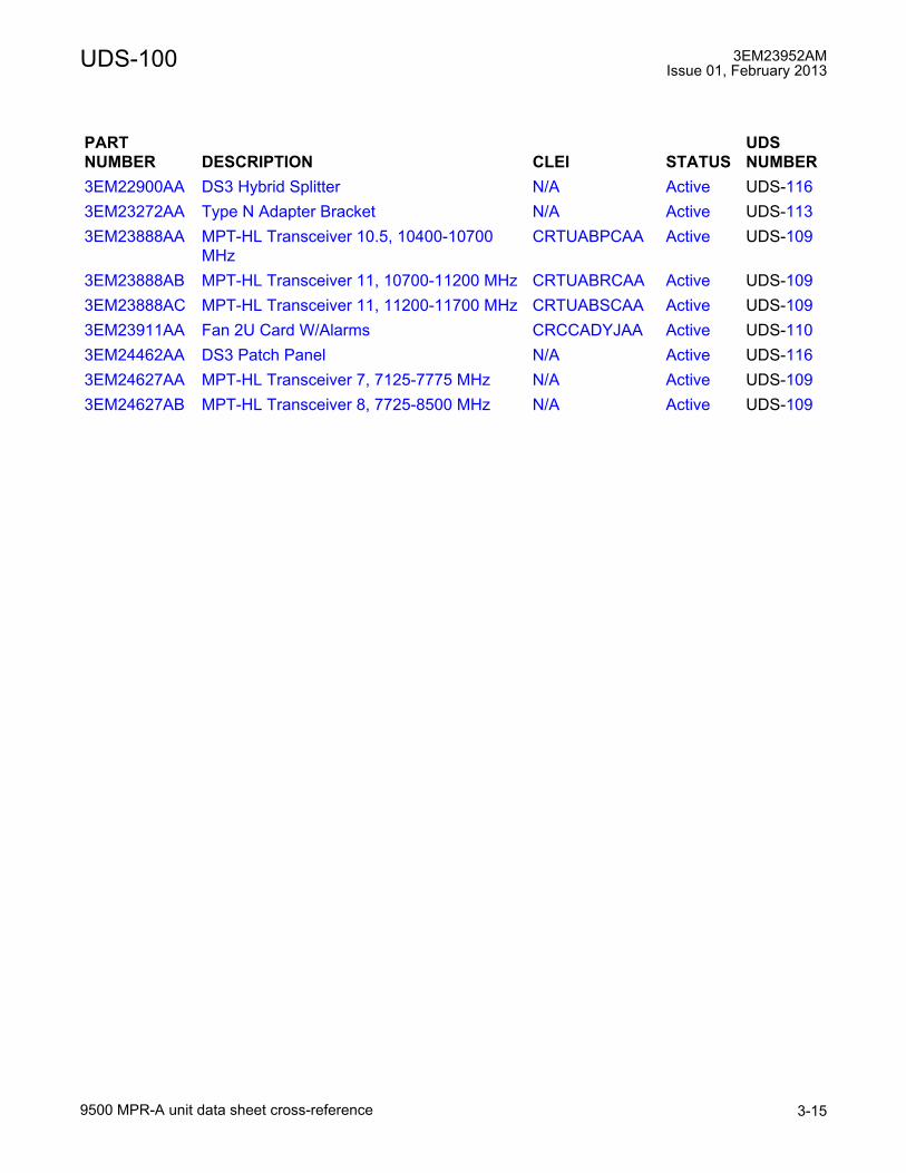
UDS-100 3EM23952AMIssue 01, February 2013
9500 MPR-A unit data sheet cross-reference 3-15
3EM22900AA DS3 Hybrid Splitter N/A Active UDS-1163EM23272AA Type N Adapter Bracket N/A Active UDS-1133EM23888AA MPT-HL Transceiver 10.5, 10400-10700
MHzCRTUABPCAA Active UDS-109
3EM23888AB MPT-HL Transceiver 11, 10700-11200 MHz CRTUABRCAA Active UDS-1093EM23888AC MPT-HL Transceiver 11, 11200-11700 MHz CRTUABSCAA Active UDS-1093EM23911AA Fan 2U Card W/Alarms CRCCADYJAA Active UDS-1103EM24462AA DS3 Patch Panel N/A Active UDS-1163EM24627AA MPT-HL Transceiver 7, 7125-7775 MHz N/A Active UDS-1093EM24627AB MPT-HL Transceiver 8, 7725-8500 MHz N/A Active UDS-109
PARTNUMBER DESCRIPTION CLEI STATUS
UDS NUMBER

3EM23952AMIssue 01, February 2013
9500 MPR-A unit data sheet cross-reference3-16
UDS-100
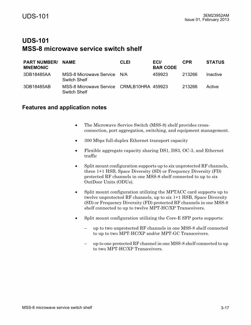
UDS-101 3EM23952AMIssue 01, February 2013
MSS-8 microwave service switch shelf 3-17
UDS-101 MSS-8 microwave service switch shelf
UDS-101MSS-8 microwave service switch shelf
Features and application notes
• The Microwave Service Switch (MSS-8) shelf provides cross-connection, port aggregation, switching, and equipment management.
• 300 Mbps full-duplex Ethernet transport capacity
• Flexible aggregate capacity sharing DS1, DS3, OC-3, and Ethernet traffic
• Split mount configuration supports up to six unprotected RF channels, three 1+1 HSB, Space Diversity (SD) or Frequency Diversity (FD) protected RF channels in one MSS-8 shelf connected to up to six OutDoor Units (ODUs).
• Split mount configuration utilizing the MPTACC card supports up to twelve unprotected RF channels, up to six 1+1 HSB, Space Diversity (SD) or Frequency Diversity (FD) protected RF channels in one MSS-8 shelf connected to up to twelve MPT-HC/XP Transceivers.
• Split mount configuration utilizing the Core-E SFP ports supports:
� up to two unprotected RF channels in one MSS-8 shelf connected to up to two MPT-HC/XP and/or MPT-GC Transceivers.
� up to one protected RF channel in one MSS-8 shelf connected to up to two MPT-HC/XP Transceivers.
PART NUMBER/MNEMONIC
NAME CLEI ECI/BAR CODE
CPR STATUS
3DB18485AA MSS-8 Microwave Service Switch Shelf
N/A 459923 213266 Inactive
3DB18485AB MSS-8 Microwave Service Switch Shelf
CRMLB10HRA 459923 213266 Active

3EM23952AMIssue 01, February 2013
MSS-8 microwave service switch shelf3-18
UDS-101
• Split mount configuration utilizing the Core-E electrical Ethernet ports supports:
� up to four unprotected RF channels in one MSS-8 shelf connected to up to four MPT-HC/XP and/or MPT-GC Transceivers.
� up to two protected RF channels in one MSS-8 shelf connected to up to four MPT-HC/XP Transceivers.
• Split mount configuration utilizing the P8ETH SFP ports support up to eighteen unprotected RF channels in one MSS-8 shelf connected to up to eighteen MPT-HC/XP Transceivers.
• All indoor mount supports up to twenty unprotected RF channels, nine 1+1 HSB, Space Diversity (SD) or Frequency Diversity (FD) protected RF channels in one MSS-8 shelf using P8ETH cards connected to up to nine Microwave Packet Transport-Long Haul (MPT-HL) shelves and the Core-E card connected to up to two MPT-HL shelves.
• Stand-alone shelf configuration
• All cards are accessed from the front side of the shelf
• Mounts in a 19-inch aluminum rack or 19-inch seismic rack. Adapter flanges available to mount in a 23-inch aluminum rack
• Provides two mounting depth options: flush mount or 5 inch projection
• Provides nine card slots. Two are dedicated for Control and Switching Modules (Core-E). Six universal slots are available for transport cards: P32E1DS1 (DS1), P2E3DS3 (DS3), SDHACC (OC-3), MOD300 (RADIO) and/or P8ETH (Ethernet). Slot 8 also supports the AUX (Auxiliary) card. One slot is dedicated for fan card.
Description
The MSS-8 self consists of a module cage and backplane which provides nine slots. Two dedicated slots for Core-E cards. Six slots are available for transport cards: P32E1DS1 (DS1), P2E3DS3 (DS3), SDHACC (OC-3), MOD300 (Radio), and/or P8ETH (Ethernet). One slot is dedicated for a required fan card. See figure 101-1 for an example of the MSS-8 shelf.
The MSS-8 shelf is 19 inches wide (17.25 inches wide without mounting flanges), 3.46 inches high (2 EIA rack increments), and 9.75 inches deep. Adapter plates are available to mount the MSS-8 shelf in 23 inch aluminum racks. See figure 101-2 for outline and shelf dimensions of the MSS-8 shelf.

UDS-101 3EM23952AMIssue 01, February 2013
MSS-8 microwave service switch shelf 3-19
Equipment complement
MSS-8 shelf slots 1 and 2 are dedicated to the Core-E card. Slots 3 through 8 are available for transport cards P32E1DS1, P2E3DS3, MPTACC, MOD300, SDHACC, and/or P8ETH. Slot 9 is dedicated for required fan card. See figure 101-3 for MSS-8 shelf slot definitions. Refer to Table 101-A for details of card equipage options.
Figure 101-1. Microwave service switch (MSS-8) shelf
Figure 101-2. MSS-8 shelf dimensions
950-0040-1
062110
MSS-8 Shelf
17.25
9.75
3.46

3EM23952AMIssue 01, February 2013
MSS-8 microwave service switch shelf3-20
UDS-101
CAUTION Possibility of service interruption. If an MPT-HL is connected to the main Core-E card, Core-E protection is not supported. A protection switch will cause communication with the MPT-HL to be lost.
Figure 101-3. MSS-8 shelf slot definitions
950-0003-3
092010
CSM-E
(Spare)
Transport Card Transport Card
Transport Card Transport Card
Transport CardTransport Card
or
Auxiliary Card
CSM-E
(Main)
Fan
92
4
6
8
1
3
5
7
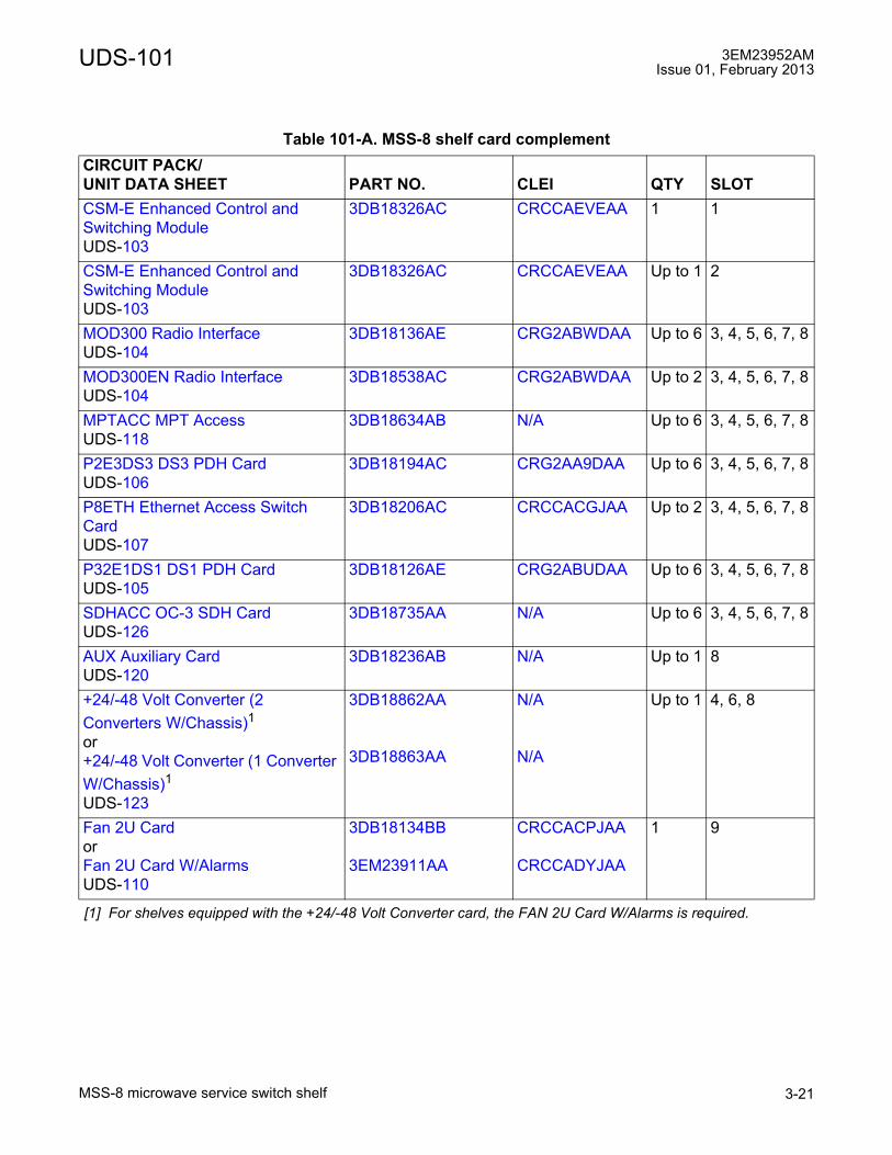
UDS-101 3EM23952AMIssue 01, February 2013
MSS-8 microwave service switch shelf 3-21
Table 101-A. MSS-8 shelf card complementCIRCUIT PACK/UNIT DATA SHEET PART NO. CLEI QTY SLOTCSM-E Enhanced Control and Switching ModuleUDS-103
3DB18326AC CRCCAEVEAA 1 1
CSM-E Enhanced Control and Switching ModuleUDS-103
3DB18326AC CRCCAEVEAA Up to 1 2
MOD300 Radio InterfaceUDS-104
3DB18136AE CRG2ABWDAA Up to 6 3, 4, 5, 6, 7, 8
MOD300EN Radio InterfaceUDS-104
3DB18538AC CRG2ABWDAA Up to 2 3, 4, 5, 6, 7, 8
MPTACC MPT AccessUDS-118
3DB18634AB N/A Up to 6 3, 4, 5, 6, 7, 8
P2E3DS3 DS3 PDH CardUDS-106
3DB18194AC CRG2AA9DAA Up to 6 3, 4, 5, 6, 7, 8
P8ETH Ethernet Access Switch CardUDS-107
3DB18206AC CRCCACGJAA Up to 2 3, 4, 5, 6, 7, 8
P32E1DS1 DS1 PDH CardUDS-105
3DB18126AE CRG2ABUDAA Up to 6 3, 4, 5, 6, 7, 8
SDHACC OC-3 SDH CardUDS-126
3DB18735AA N/A Up to 6 3, 4, 5, 6, 7, 8
AUX Auxiliary CardUDS-120
3DB18236AB N/A Up to 1 8
+24/-48 Volt Converter (2 Converters W/Chassis)1or+24/-48 Volt Converter (1 Converter W/Chassis)1UDS-123
[1] For shelves equipped with the +24/-48 Volt Converter card, the FAN 2U Card W/Alarms is required.
3DB18862AA
3DB18863AA
N/A
N/A
Up to 1 4, 6, 8
Fan 2U Card orFan 2U Card W/AlarmsUDS-110
3DB18134BB
3EM23911AA
CRCCACPJAA
CRCCADYJAA
1 9
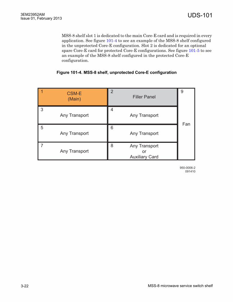
3EM23952AMIssue 01, February 2013
MSS-8 microwave service switch shelf3-22
UDS-101
MSS-8 shelf slot 1 is dedicated to the main Core-E card and is required in every application. See figure 101-4 to see an example of the MSS-8 shelf configured in the unprotected Core-E configuration. Slot 2 is dedicated for an optional spare Core-E card for protected Core-E configurations. See figure 101-5 to see an example of the MSS-8 shelf configured in the protected Core-E configuration.
Figure 101-4. MSS-8 shelf, unprotected Core-E configuration
950-0006-2
091410
Filler Panel
Any Transport Any Transport
Any Transport Any Transport
Any TransportAny Transport
or
Auxiliary Card
CSM-E
(Main)
Fan
92
4
6
8
1
3
5
7
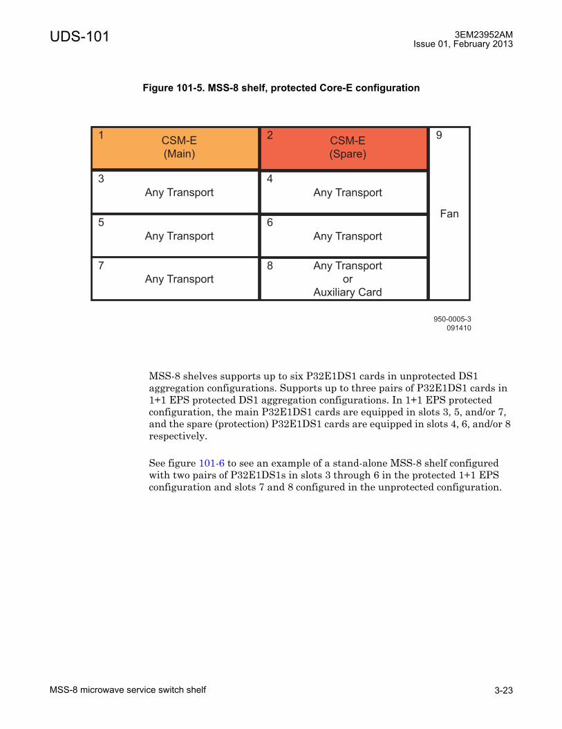
UDS-101 3EM23952AMIssue 01, February 2013
MSS-8 microwave service switch shelf 3-23
MSS-8 shelves supports up to six P32E1DS1 cards in unprotected DS1 aggregation configurations. Supports up to three pairs of P32E1DS1 cards in 1+1 EPS protected DS1 aggregation configurations. In 1+1 EPS protected configuration, the main P32E1DS1 cards are equipped in slots 3, 5, and/or 7, and the spare (protection) P32E1DS1 cards are equipped in slots 4, 6, and/or 8 respectively.
See figure 101-6 to see an example of a stand-alone MSS-8 shelf configured with two pairs of P32E1DS1s in slots 3 through 6 in the protected 1+1 EPS configuration and slots 7 and 8 configured in the unprotected configuration.
Figure 101-5. MSS-8 shelf, protected Core-E configuration
950-0005-3
091410
CSM-E
(Spare)
Any Transport Any Transport
Any Transport Any Transport
Any Transport
Any Transport
or
Auxiliary Card
CSM-E
(Main)
Fan
92
4
6
8
1
3
5
7

3EM23952AMIssue 01, February 2013
MSS-8 microwave service switch shelf3-24
UDS-101
MSS-8 shelves supports up to six P2E3DS3 cards in unprotected configurations. Supports up to three pairs of P2E3DS3 cards in 1+1 EPS protected configurations. In 1+1 EPS protected configuration, the main P2E3DS3 cards are equipped in slots 3, 5, and/or 7, and the spare (protection) P2E3DS3 cards are equipped in slots 4, 6, and/or 8 respectively.
See figure 101-7 to see an example of a stand-alone MSS-8 shelf configured with two pairs of P2E3DS3s in slots 3 through 6 in the protected 1+1 EPS configuration and slots 7 and 8 configured in the unprotected configuration.
Figure 101-6. MSS-8 stand-alone shelf, equipped with P32E1DS1 (DS1 Card)
950-0007-3
091410
CSM-E
(Spare)
P32E1DS1
(Main)
P32E1DS1
(Spare)
P32E1DS1
(Main)
P32E1DS1
(Spare)
P32E1DS1
(Unprotected)
P32E1DS1
(Unprotected)
CSM-E
(Main)
Fan
92
4
6
8
1
3
5
7

UDS-101 3EM23952AMIssue 01, February 2013
MSS-8 microwave service switch shelf 3-25
MSS-8 shelves supports up to six SDHACC cards in unprotected configurations. Supports up to three pairs of SDHACC cards in 1+1 EPS protected configurations. In 1+1 EPS protected configuration, the main SDHACC cards are equipped in slots 3, 5, and/or 7, and the spare (protection) SDHACC cards are equipped in slots 4, 6, and/or 8 respectively.
MSS-8 shelves supports up to six MOD300 cards in unprotected RF radio configurations. Supports up to three pairs of MOD300 cards in protected RF radio in 1+1 HSB, SD or FD configurations. In 1+1 HSB, SD or FD configurations, the main MOD300 cards are equipped in slots 3, 5, and/or 7, and the spare (protection) MOD300 cards are equipped in slots 4, 6, and/or 8 respectively.
See figure 101-8 to see an example of the MSS-8 shelf configured as a split mount, 1+0 drop and insert repeater in slots 7 and 8, with a pair of P32E1DS1s in slots 3 and 4 in the protected 1+1 EPS configuration, and with a pair of P2E3DS3s in slots 5 and 6 in the protected 1+1 EPS configuration.
See figure 101-9 to see an example of the MSS-8 shelf configured as a split mount, 1+1 drop and insert repeater in slots 5 through 8, with a P32E1DS1s in slot 3 in the unprotected configuration, and with a P2E3DS3 in slot 4 in the unprotected configuration.
Figure 101-7. MSS-8 stand-alone shelf, equipped with P2E3DS3 (DS3 Card)
950-0008-3
091410
CSM-E
(Spare)
P2E3DS3
(Main)
P2E3DS3
(Spare)
P2E3DS3
(Main)
P2E3DS3
(Spare)
P2E3DS3
(Unprotected)
P2E3DS3
(Unprotected)
CSM-E
(Main)
Fan
92
4
6
8
1
3
5
7

3EM23952AMIssue 01, February 2013
MSS-8 microwave service switch shelf3-26
UDS-101
Figure 101-8. MSS-8 shelf, split mount, 1+0 drop and insert repeater configuration
Figure 101-9. MSS-8 shelf, split mount, 1+1 drop and insert repeater configuration
950-0009-3
091410
CSM-E
(Spare)
P32E1DS1
(Main)
P32E1DS1
(Spare)
P2E3DS3
(Main)
P2E3DS3
(Spare)
MOD300
(Unprotected)
MOD300
(Unprotected)
CSM-E
(Main)
Fan
92
4
6
8
1
3
5
7
950-0010-3
091410
CSM-E
(Spare)
P32E1DS1
(Unprotected)
P2E3DS3
(Unprotected)
MOD300
(Main)
MOD300
(Spare)
MOD300
(Main)
MOD300
(Spare)
CSM-E
(Main)
Fan
92
4
6
8
1
3
5
7

UDS-101 3EM23952AMIssue 01, February 2013
MSS-8 microwave service switch shelf 3-27
MSS-8 shelves supports up to six MPTACC cards in unprotected configuration, up to twelve RF radio channels. Supports three pairs of MPTACC cards in protected 1+1 HSB/FD configuration, up to six protected RF radio channels. In 1+1 HSB, SD or FD configuration, the main MPTACC card is equipped in slot 3, 5, and/or 7 and the spare (protection) MPTACC card is equipped in slot 4, 6, and/or 8 respectively.
See figure 101-10 to see an example of the MSS-8 shelf configured as a split mount, unprotected Core-E, 12-way nodal junction in slots 3 through 8.
See figure 101-11 to see an example of the MSS-8 shelf configured as a protected Core-E, 1+1 protected 4-way junction in slots 5 through 8, and slots 3 and 4 configured in the unprotected DS1 configuration.
Figure 101-10. MSS-8 shelf, split mount MPT-HC/XP, 1+0 12-way nodal junction configuration
950-0046-1
030311
Filler Panel
MPT A ccess
(Main)
MPT A ccess
(Main)
MPT A ccess
(Main)
CSM-E
(Main)
Fan
92
4
6
8
1
3
5
7MPT A ccess
(Main)
MPT A ccess
(Main)
MPT A ccess
(Main)

3EM23952AMIssue 01, February 2013
MSS-8 microwave service switch shelf3-28
UDS-101
MSS-8 shelves equipped with P8ETH cards, the P8ETH is supported in slots 3 through 8. For stacked P8ETH applications, the main P8ETH card resides in slot 3, 5, and/or 7 and the spare P8ETH resides in slots 4, 6, and/or 8.
See figure 101-12 to see an example of the MSS-8 shelf configured as an all indoor mount, 1+0 4-way junction in slot 3, with a pair of P32E1DS1s in slots 5 and 6 in the protected 1+1 EPS configuration.
See figure 101-13 to see an example of the MSS-8 shelf configured as an all indoor mount, 1+1 4-way junction in slots 3 and 4, with three P32E1DS1s in slots 5 through 7 in the unprotected configuration.
Figure 101-11. MSS-8 shelf, all indoor mount, 1+1 4-way junction configuration
950-0047-1
030311
P32E1DS1
(Unprotected)
MPT A ccess
(Main)
MPT A ccess
(Spare)
CSM-E
(Main)
Fan
92
4
6
8
1
3
5
7MPT A ccess
(Main)
P32E1DS1
(Unprotected)
MPT A ccess
(Spare)
CSM-E
(Spare)

UDS-101 3EM23952AMIssue 01, February 2013
MSS-8 microwave service switch shelf 3-29
Figure 101-12. MSS-8 shelf, all indoor mount, 1+0 4-way junction configuration
Figure 101-13. MSS-8 shelf, all indoor mount, 1+1 4-way junction configuration
950-0011-3
091410
CSM-E
(Spare)
P8ETH
(Main)Filler Panel
P32E1DS1
(Main)
P32E1DS1
(Spare)
Filler Panel Filler Panel
CSM-E
(Main)
Fan
92
4
6
8
1
3
5
7
950-0012-3
091410
CSM-E
(Spare)
P8ETH
(Main)
P8ETH
(Spare)
P32E1DS1
(Unprotected)
P32E1DS1
(Unprotected)
P32E1DS1
(Unprotected) Filler Panel
CSM-E
(Main)
Fan
92
4
6
8
1
3
5
7

3EM23952AMIssue 01, February 2013
MSS-8 microwave service switch shelf3-30
UDS-101
MSS-8 shelf equipped with two P8ETH cards and four MOD300 cards support up to a 12 spoke hub. In this configuration; main P8ETH cards are equipped in slots 3 and 4 and support up to eight 1+0 spokes, and up to four main MOD300 cards are equipped in slots 5 through 8 and support up to four 1+0 spokes.
See figure 101-14 to see an example of the MSS-8 shelf configured as a 12 spoke hub using all indoor mount (P8ETH/MPT-HL).
See figure 101-15 to see an example of the MSS-8 shelf configured mixing all three radio technologies. P8ETH cards equipped in slots 3 and 4 support up to eight MPT-HL 1+0 unprotected radio channels or as shown up to four MPT-HL 1+1 protected radio channels. MPT Access cards in slots 5 and 6 support up to 4 MPT-HC/XP 1+0 unprotected radio channels, or as shown two MPT-HC/XP 1+1 protected radio channels. The MOD300 card in slot 7 supports one ODU300 1+0 radio channel. Slot 8 is shown with one 1+0 P32E1DS1 DS1 Interface with support for up to 32 DS1 signals.
Figure 101-14. MSS-8 shelf, 1+0, 12 spoke hub configuration
950-0253-1
100611
CSM-E
(Spare)
P8ETH
(Main)
P32E1DS1
(Main)
P8ETH
(Main)
P32E1DS1
(Main)
P8ETH
(Main)AUX
CSM-E
(Main)
Fan
92
4
6
8
1
3
5
7

UDS-101 3EM23952AMIssue 01, February 2013
MSS-8 microwave service switch shelf 3-31
The Core-E card in slot 1 can support the following:
� up to six MPT-HC/XP 1+0 radio channels
� up to three MPT-HC/XP 1+1 radio channels
� up to two MPT-HL 1+0 radio channels
Functional overview
MSS-8 implements functionality of grooming, routing, switching and protection, exploiting a packet oriented technology in order to meet the overall architecture.
The MSS-8 Core-E platform, with multiplexing and symmetrical cross-connect functions, can manage different radio directions (up to fourteen), with the possibility to add-drop data flows of local DS1/DS3/OC-3/Ethernet traffic. Core-E platform is based on packet technology (Ethernet Switch) with a generic serial GigE interface between Core-E and transport cards. See figure 101-16 for a functional block diagram of the MSS-8 shelf.
Figure 101-15. MSS-8 shelf, 1+0, 12 spoke hub configuration
950-0048-1
030311
P8ETH
(Main)
MPT A ccess
(Main)
MPT A ccess
(Spare)
CSM-E
(Main)
Fan
92
4
6
8
1
3
5
7MOD300
(Main)
P8ETH
(Spare)
P32E1DS1
(Main)
CSM-E
(Spare)
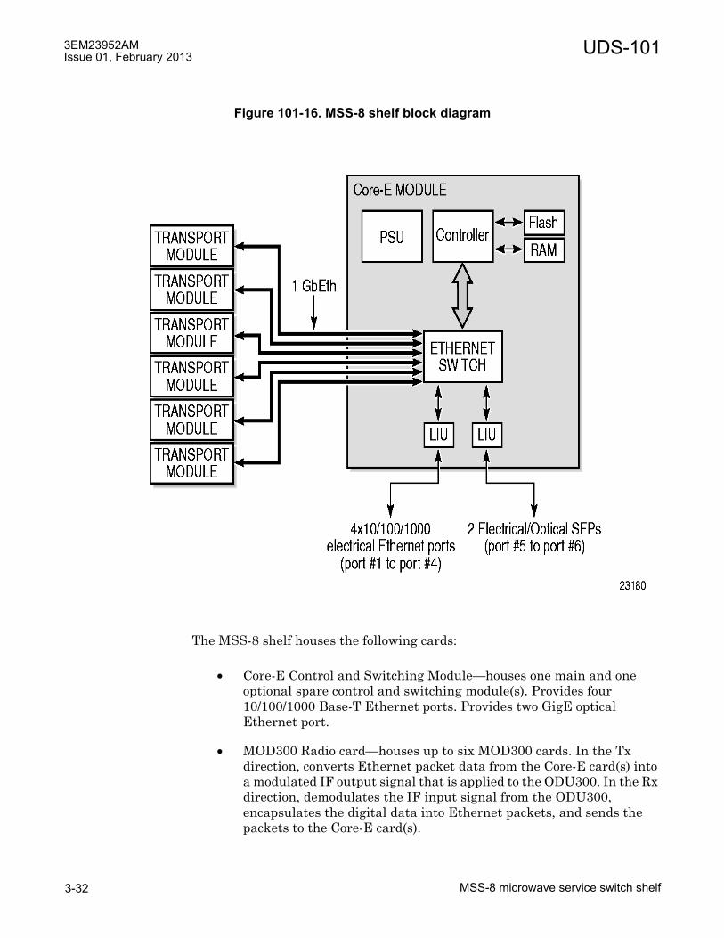
3EM23952AMIssue 01, February 2013
MSS-8 microwave service switch shelf3-32
UDS-101
The MSS-8 shelf houses the following cards:
• Core-E Control and Switching Module�houses one main and one optional spare control and switching module(s). Provides four 10/100/1000 Base-T Ethernet ports. Provides two GigE optical Ethernet port.
• MOD300 Radio card�houses up to six MOD300 cards. In the Tx direction, converts Ethernet packet data from the Core-E card(s) into a modulated IF output signal that is applied to the ODU300. In the Rx direction, demodulates the IF input signal from the ODU300, encapsulates the digital data into Ethernet packets, and sends the packets to the Core-E card(s).
Figure 101-16. MSS-8 shelf block diagram
UDS-101 3EM23952AMIssue 01, February 2013
MSS-8 microwave service switch shelf 3-33
• MPTACC MPT Access card�houses up to six MPTACC cards for MSS-8 to two MPT-HC/XP interfaces (Ethernet and power) for split mount configuration.
• P2E3DS3 DS3 PDH card�houses up to six P2E3DS3 cards for DS3 TDM traffic encapsulation/extraction into standard Ethernet packets
• P8ETH Ethernet Access Switch�houses up to six P8ETH cards for MSS-8-to-MPT-HL or MSS-8-to-MPT-HC/XP interfaces. The P8ETH card functions as a layer 2 switch, cross-connecting VLAN tagged Ethernet data to/from the addressed MPT unit. The P8ETH card provides traffic management for Core-Es for up to six directions using protected radios and up to twelve directions using unprotected radios. P8ETH cards also provide four 10/100/1000 Base-T Ethernet ports and up to four GigE optical Ethernet ports.
• P32E1DS1 DS1 PDH card�houses up to six P32E1DS1 cards for DS1 TDM traffic encapsulation/extraction into standard Ethernet packets
• SDHACC OC-3 SDH card�houses up to six SDHACC cards for OC-3 TDM traffic encapsulation/extraction into standard Ethernet packets
• The MSS-8 shelf houses one fan card resident in slot 9 on the right-hand side of the shelf and provides forced-air cooling for the shelf.
• The MSS-8 shelf houses up to one AUX card optional in slot 8 to provide up to nine station alarm inputs and eight station alarm control outputs.

3EM23952AMIssue 01, February 2013
MSS-8 microwave service switch shelf3-34
UDS-101

UDS-102 3EM23952AMIssue 01, February 2013
MPT-HL microwave packet transport-long haul shelf 3-35
UDS-102 MPT-HL microwave packet transport-long haul shelf
UDS-102MPT-HL microwave packet transport-long haul shelf
Features and application notes
• The Microwave Packet Transport-Long Haul (MPT-HL) shelf provides an all indoor solution when used in conjunction with the 9500 MPR-A MSS-1/4/8 shelf.
• The MPT-HL shelf provides support for two high-capacity, long-haul RF transmission MPT Transceivers.
• All cards are accessed from the front side of the shelf.
• Mounts in a 19-inch aluminum rack or 19-inch seismic rack. Adapter flanges available to mount in a 23-inch aluminum rack
• Provides two mounting depth options: flush mount or 5 inch projection
Description
The MPT-HL self consists of a module cage and backplane which provides two slots dedicated for two MPT Transceiver cards. See Figure 102-1 for an example of the MPT-HL shelf.
The MPT-HL shelf is 19 inches wide (17.25 inches wide without mounting flanges), 4.25 inches high (2.5 EIA rack increments), and 10.5 inches deep without diplexer and waveguide mounting brackets. Adapter plates are available to mount the MPT-HL shelf in 23 inch aluminum racks. See Figure 102-2 through Figure 102-5 for outline and shelf dimensions of the MPT-HL shelf in various configurations.
PART NUMBER/MNEMONIC
NAME CLEI ECI/BAR CODE
CPR STATUS
3EM22618AB3EM22618AC
MPT-HL Microwave Packet transport-Long Haul Shelf
N/A N/A N/A Active

3EM23952AMIssue 01, February 2013
MPT-HL microwave packet transport-long haul shelf3-36
UDS-102
Figure 102-1. Microwave packet transport-long haul (MPT-HL) shelf
Figure 102-2. MPT-HL shelf dimensions
950-0042-1
062110
MPT-HL Shelf
17.25
10.5
4.25

UDS-102 3EM23952AMIssue 01, February 2013
MPT-HL microwave packet transport-long haul shelf 3-37
Figure 102-3. MPT-HL shelf w/diplexer dimensions - top view
Figure 102-4. MPT-HL shelf w/one waveguide bracket dimensions - top view
950-0041-1
062110
17.25
13.5
950-0043-1
06211017.25
17.0

3EM23952AMIssue 01, February 2013
MPT-HL microwave packet transport-long haul shelf3-38
UDS-102
Equipment complement
MPT-HL shelf houses one or two MPT Transceiver cards. The MPT Transceiver cards can be configured either in 1+1 protection, one 1+0 unprotected, or two 1+0 unprotected radio channels.
Figure 102-5. MPT-HL shelf w/two waveguide brackets dimensions - top view
950-0044-1
062110
17.25
22.0

UDS-102 3EM23952AMIssue 01, February 2013
MPT-HL microwave packet transport-long haul shelf 3-39
Table 102-A. MPT-HL shelf card complementCIRCUIT PACK/UNIT DATA SHEET PART NO. CLEI QTY SLOTMPT-HL Transceiver L6, 5725-6425 MHzUDS-109
3EM22617AA CRTUAAXFAA 1 or 2 1, 2
MPT-HL Transceiver U6, 6425-6930 MHzUDS-109
3EM22617AB CRTUAAYFAA
MPT-HL Transceiver L6, 5925-6425 MHz, HPUDS-109
3EM22617AC CRTUABLFAA
MPT-HL Transceiver U6, 6425-6930 MHz, HPUDS-109
3EM22617AD CRTUABMFAA
MPT-HL Transceiver 7, 7125-7775 MHzUDS-109
3EM24627AA N/A
MPT-HL Transceiver 8, 7725-8500 MHzUDS-109
3EM24627AB N/A
MPT-HL Transceiver 10.5, 10400-10700 MHzUDS-109
3EM23888AA CRTUABPCAA
MPT-HL Transceiver 11, 10700-11200 MHzUDS-109
3EM23888AB CRTUABRCAA
MPT-HL Transceiver 11, 11200-11700 MHzUDS-109
3EM23888AC CRTUABSCAA

3EM23952AMIssue 01, February 2013
MPT-HL microwave packet transport-long haul shelf3-40
UDS-102

UDS-103 3EM23952AMIssue 01, February 2013
Core-E control and switching module 3-41
UDS-103 Core-E control and switching module
UDS-103Core-E control and switching module
Features and application notes
The Core-E card provides the following functions:
• Four 10/100/1000 BaseT Ethernet ports, supporting the following:
� User Ethernet ports
� MPT-HC/XP 1+0
� MPT-HC/XP 1+1
• Two GigE optical Ethernet ports, supporting the following:
� User Ethernet ports
� MPT-HC/XP 1+0
� MPT-HC/XP 1+1
� MPT-HL 1+0
• Network Management System (NMS) port
• TMN Ethernet Interface port
• MSS shelf synchronization clock reference
• External clock reference input and output
• Supports unprotected and 1+1 Core-E Equipment Protection Switch (EPS) configurations
CAUTION Possibility of service interruption. If an MPT-HL is connected to the main Core-E card, Core-E protection is not supported. A protection switch will cause communication with the MPT-HL to be lost.
• The active Core-E card manages communications � between all of the peripheral cards (P32E1DS1, P2E3DS3, MOD300, ODU300, SDHACC, MPT-HL Transceiver, and P8ETH) to provide peripheral management, NMS, equipment configuration, event reporting and logging, equipment database management and software downloads.

3EM23952AMIssue 01, February 2013
Core-E control and switching module3-42
UDS-103
• Layer 2 Ethernet Switch � performs the cross-connection between the peripheral cards and the Ethernet ports.
� The Switch shall assure to the system a complete interconnection between all cards connected into the MSS-4/8 shelf.
� The Switch shall perform address learning, standard 802.1Q management (VLAN), Layer 2 switching (MAC address, VLAN), and QOS per system (802.1P and DiffServ).
� VLAN table and Address Tables shall be required to be maintained/updated by the system for Core-E and Peripheral Switches.
• Storage of Log Files for events and alarms. Storage capacity is the most recent 500 events and 700 alarms.
Description
Purpose and function
The Control and Switching Module (Core-E) performs all supervisory functions for the 9500 MPR-A MSS and switches Ethernet packets from peripherals to radio cards. The Core-E consists of microprocessor and Ethernet switch circuits.
Microprocessor
The microprocessor consists of a 128 Mbyte system memory (SDRAM), 8 Mbyte boot memory (EEPROM), and 128 Mbyte flash memory.
Options/configurations
There are no card options. The Core-E card is required in slot 1. The Spare Core-E card resides in slot 2 when equipped.
Indicators, connectors, and control
The Control and Switch Module (Core-E) card has the following indicators, connectors, and controls.
See Figure 103-1 for Core-E card front panel indicator and connector locations.
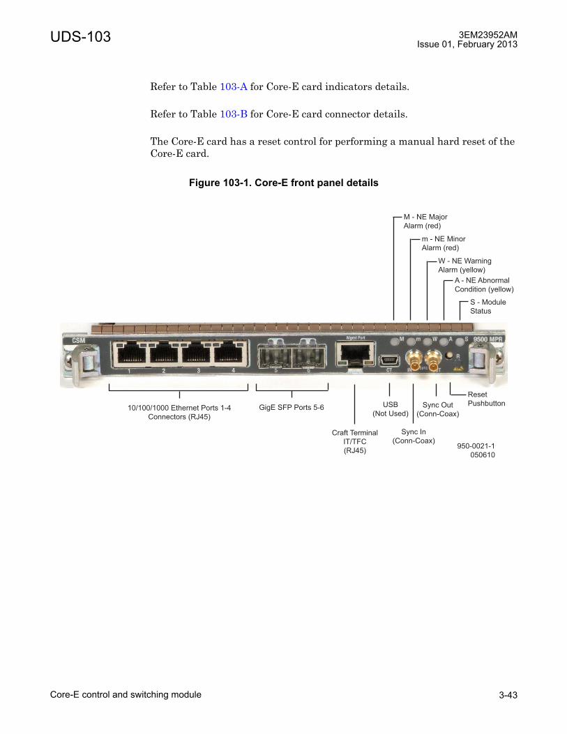
UDS-103 3EM23952AMIssue 01, February 2013
Core-E control and switching module 3-43
Refer to Table 103-A for Core-E card indicators details.
Refer to Table 103-B for Core-E card connector details.
The Core-E card has a reset control for performing a manual hard reset of the Core-E card.
Figure 103-1. Core-E front panel details
950-0021-1
050610
10/100/1000 Ethernet Ports 1-4
Connectors (RJ45)
GigE SFP Ports 5-6
Craft Terminal
IT/TFC
(RJ45)
USB
(Not Used)
Sync In
(Conn-Coax)
Sync Out
(Conn-Coax)
S - Module
Status
A - NE Abnormal
Condition (yellow)
W - NE Warning
Alarm (yellow)
m - NE Minor
Alarm (red)
M - NE Major
Alarm (red)
Reset
Pushbutton
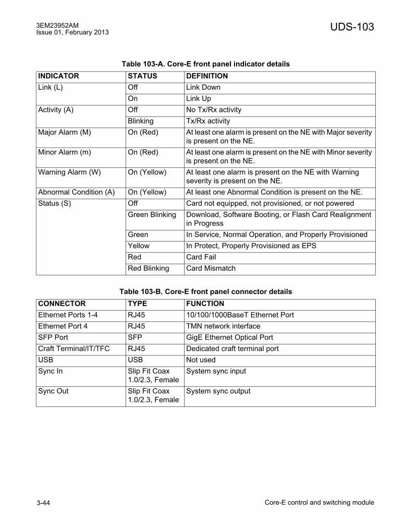
3EM23952AMIssue 01, February 2013
Core-E control and switching module3-44
UDS-103
Table 103-A. Core-E front panel indicator detailsINDICATOR STATUS DEFINITIONLink (L) Off Link Down
On Link UpActivity (A) Off No Tx/Rx activity
Blinking Tx/Rx activityMajor Alarm (M) On (Red) At least one alarm is present on the NE with Major severity
is present on the NE.Minor Alarm (m) On (Red) At least one alarm is present on the NE with Minor severity
is present on the NE.Warning Alarm (W) On (Yellow) At least one alarm is present on the NE with Warning
severity is present on the NE.Abnormal Condition (A) On (Yellow) At least one Abnormal Condition is present on the NE.Status (S) Off Card not equipped, not provisioned, or not powered
Green Blinking Download, Software Booting, or Flash Card Realignment in Progress
Green In Service, Normal Operation, and Properly ProvisionedYellow In Protect, Properly Provisioned as EPSRed Card FailRed Blinking Card Mismatch
Table 103-B. Core-E front panel connector detailsCONNECTOR TYPE FUNCTIONEthernet Ports 1-4 RJ45 10/100/1000BaseT Ethernet PortEthernet Port 4 RJ45 TMN network interfaceSFP Port SFP GigE Ethernet Optical PortCraft Terminal/IT/TFC RJ45 Dedicated craft terminal portUSB USB Not usedSync In Slip Fit Coax
1.0/2.3, FemaleSystem sync input
Sync Out Slip Fit Coax 1.0/2.3, Female
System sync output
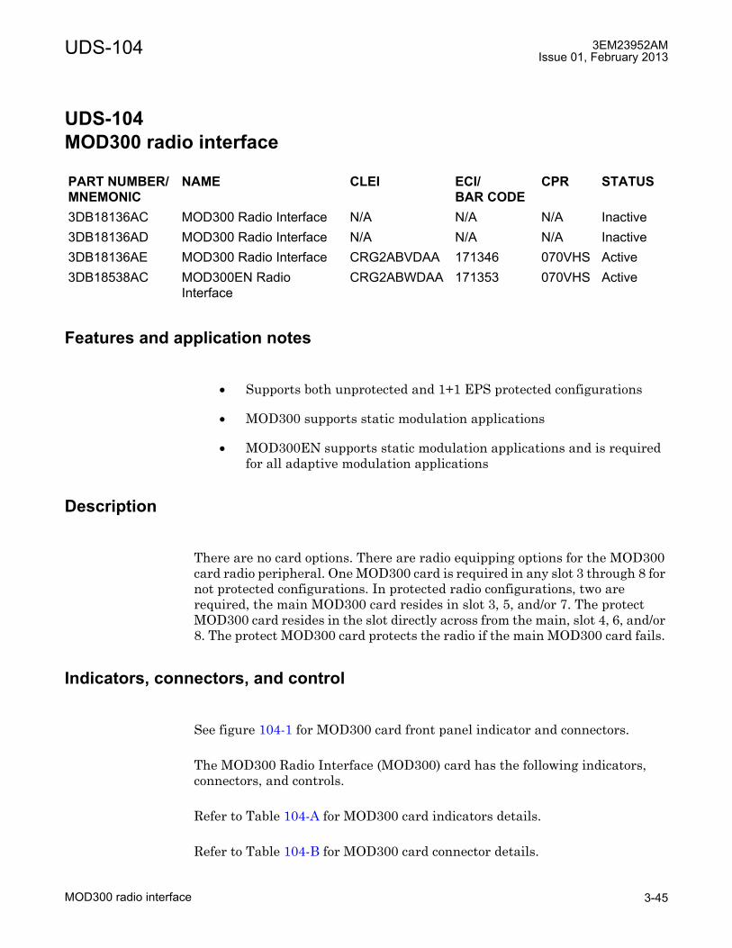
UDS-104 3EM23952AMIssue 01, February 2013
MOD300 radio interface 3-45
UDS-104 MOD300 radio interface
UDS-104MOD300 radio interface
Features and application notes
• Supports both unprotected and 1+1 EPS protected configurations
• MOD300 supports static modulation applications
• MOD300EN supports static modulation applications and is required for all adaptive modulation applications
Description
There are no card options. There are radio equipping options for the MOD300 card radio peripheral. One MOD300 card is required in any slot 3 through 8 for not protected configurations. In protected radio configurations, two are required, the main MOD300 card resides in slot 3, 5, and/or 7. The protect MOD300 card resides in the slot directly across from the main, slot 4, 6, and/or 8. The protect MOD300 card protects the radio if the main MOD300 card fails.
Indicators, connectors, and control
See figure 104-1 for MOD300 card front panel indicator and connectors.
The MOD300 Radio Interface (MOD300) card has the following indicators, connectors, and controls.
Refer to Table 104-A for MOD300 card indicators details.
Refer to Table 104-B for MOD300 card connector details.
PART NUMBER/MNEMONIC
NAME CLEI ECI/BAR CODE
CPR STATUS
3DB18136AC MOD300 Radio Interface N/A N/A N/A Inactive3DB18136AD MOD300 Radio Interface N/A N/A N/A Inactive3DB18136AE MOD300 Radio Interface CRG2ABVDAA 171346 070VHS Active3DB18538AC MOD300EN Radio
InterfaceCRG2ABWDAA 171353 070VHS Active
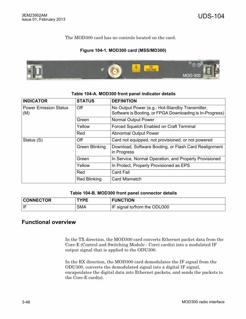
3EM23952AMIssue 01, February 2013
MOD300 radio interface3-46
UDS-104
The MOD300 card has no controls located on the card.
Functional overview
In the TX direction, the MOD300 card converts Ethernet packet data from the Core-E (Control and Switching Module - Core) card(s) into a modulated IF output signal that is applied to the ODU300.
In the RX direction, the MOD300 card demodulates the IF signal from the ODU300, converts the demodulated signal into a digital IF signal, encapsulates the digital data into Ethernet packets, and sends the packets to the Core-E card(s).
Figure 104-1. MOD300 card (MSS/MD300)
Table 104-A. MOD300 front panel indicator detailsINDICATOR STATUS DEFINITIONPower Emission Status (M)
Off No Output Power (e.g.: Hot-Standby Transmitter, Software is Booting, or FPGA Downloading is In-Progress)
Green Normal Output PowerYellow Forced Squelch Enabled on Craft TerminalRed Abnormal Output Power
Status (S) Off Card not equipped, not provisioned, or not poweredGreen Blinking Download, Software Booting, or Flash Card Realignment
in ProgressGreen In Service, Normal Operation, and Properly ProvisionedYellow In Protect, Properly Provisioned as EPSRed Card FailRed Blinking Card Mismatch
Table 104-B. MOD300 front panel connector detailsCONNECTOR TYPE FUNCTIONIF SMA IF signal to/from the ODU300

UDS-104 3EM23952AMIssue 01, February 2013
MOD300 radio interface 3-47
See figure 104-2 for a block diagram of the MOD300.
Figure 104-2. MOD300 card block diagram
Tx
Mod
Rx
Demod
MODEM
ASIC
950-0190-1
062710
MOD300 Radio Access
Air Framer
PDH/Data
Management
IDU/ODU
Communication
FPGA
Air Framer
PDH/Data
Management
IDU/ODU
Communication
EPS
Tx
RPS
Rx
Analog
Chain
DAC
DAC
IF Tx
Q
I
ADC
ADC
IF Rx
Q
I
diplexer
From Alternate
Radio Board
for RPS
From/To
Alternate Radio
Board for EPS

3EM23952AMIssue 01, February 2013
MOD300 radio interface3-48
UDS-104
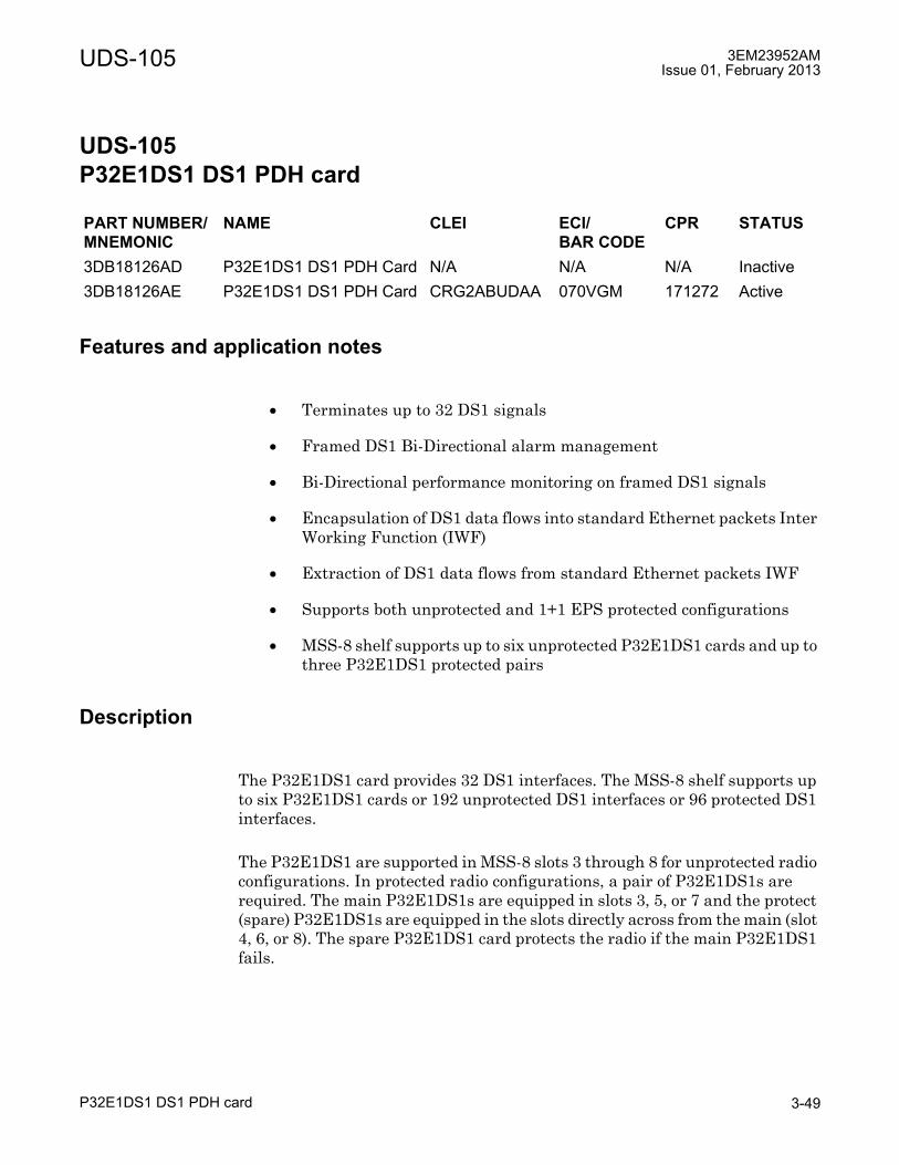
UDS-105 3EM23952AMIssue 01, February 2013
P32E1DS1 DS1 PDH card 3-49
UDS-105 P32E1DS1 DS1 PDH card
UDS-105P32E1DS1 DS1 PDH card
Features and application notes
• Terminates up to 32 DS1 signals
• Framed DS1 Bi-Directional alarm management
• Bi-Directional performance monitoring on framed DS1 signals
• Encapsulation of DS1 data flows into standard Ethernet packets Inter Working Function (IWF)
• Extraction of DS1 data flows from standard Ethernet packets IWF
• Supports both unprotected and 1+1 EPS protected configurations
• MSS-8 shelf supports up to six unprotected P32E1DS1 cards and up to three P32E1DS1 protected pairs
Description
The P32E1DS1 card provides 32 DS1 interfaces. The MSS-8 shelf supports up to six P32E1DS1 cards or 192 unprotected DS1 interfaces or 96 protected DS1 interfaces.
The P32E1DS1 are supported in MSS-8 slots 3 through 8 for unprotected radio configurations. In protected radio configurations, a pair of P32E1DS1s are required. The main P32E1DS1s are equipped in slots 3, 5, or 7 and the protect (spare) P32E1DS1s are equipped in the slots directly across from the main (slot 4, 6, or 8). The spare P32E1DS1 card protects the radio if the main P32E1DS1 fails.
PART NUMBER/MNEMONIC
NAME CLEI ECI/BAR CODE
CPR STATUS
3DB18126AD P32E1DS1 DS1 PDH Card N/A N/A N/A Inactive3DB18126AE P32E1DS1 DS1 PDH Card CRG2ABUDAA 070VGM 171272 Active

3EM23952AMIssue 01, February 2013
P32E1DS1 DS1 PDH card3-50
UDS-105
Indicators, connectors, and control
The P32E1DS1 DS1 PDH card has the following indicator and connectors:
See Figure 105-1 for P32E1DS1 DS1 PDH card front panel indicator and connectors.
Refer to Table 105-A for P32E1DS1 DS1 PDH card indicators details.
Refer to Table 105-B for P32E1DS1 DS1 PDH card connector details.
The P32E1DS1 DS1 PDH card has no controls located on the card.
Figure 105-1. P32E1DS1 DS1 card (MSS/DS1) front panel view
Table 105-A. P32E1DS1 DS1 card front panel indicator detailsINDICATOR STATUS DEFINITIONStatus (S) Off Card not equipped, not provisioned, or not powered
Green Blinking Download, Software Booting, or Flash Card Realignment in Progress
Green In Service, Normal Operation, and Properly ProvisionedYellow In Protect, Properly Provisioned as EPSRed Card FailRed Blinking Card Mismatch
Table 105-B. P32E1DS1 DS1 card front panel connector detailsCONNECTOR TYPE FUNCTIONI/O (16-1) 64 position SCSI
connectorDS1, Tx and Rx (tip and ring), interconnectDS1s number 1 through 16
I/O (32-17) 64 position SCSI connector
DS1, Tx and Rx (tip and ring), interconnectDS1s number 17 through 32
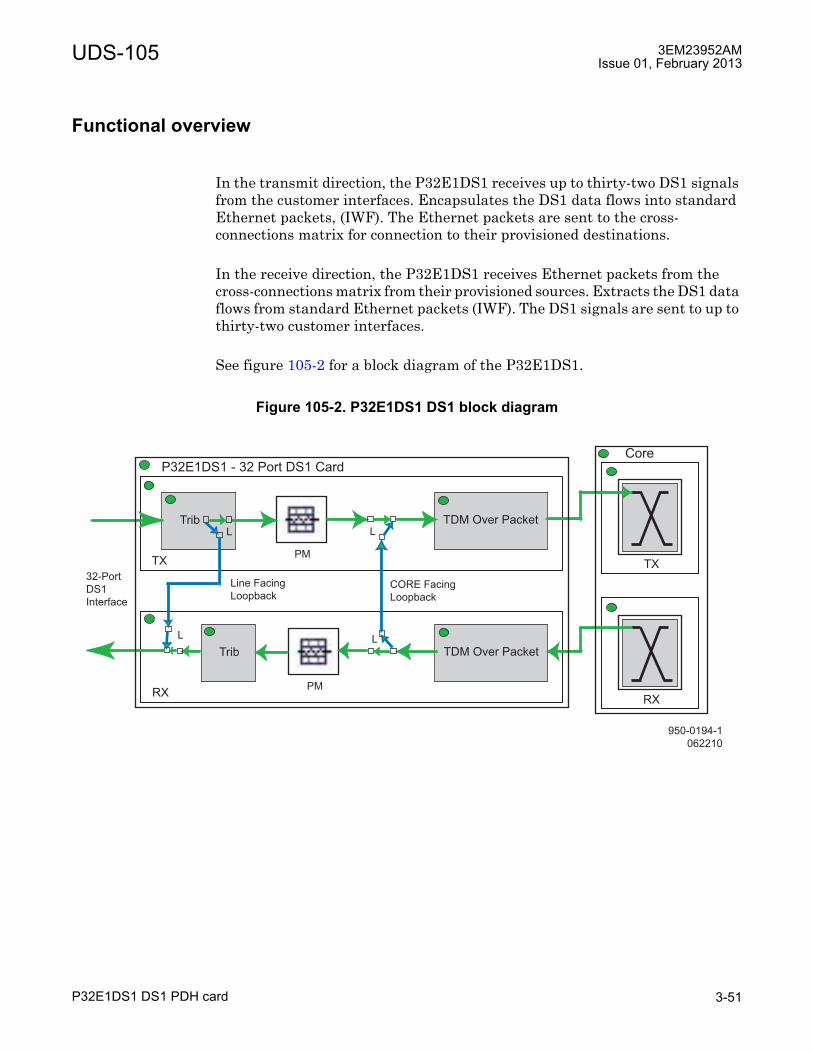
UDS-105 3EM23952AMIssue 01, February 2013
P32E1DS1 DS1 PDH card 3-51
Functional overview
In the transmit direction, the P32E1DS1 receives up to thirty-two DS1 signals from the customer interfaces. Encapsulates the DS1 data flows into standard Ethernet packets, (IWF). The Ethernet packets are sent to the cross-connections matrix for connection to their provisioned destinations.
In the receive direction, the P32E1DS1 receives Ethernet packets from the cross-connections matrix from their provisioned sources. Extracts the DS1 data flows from standard Ethernet packets (IWF). The DS1 signals are sent to up to thirty-two customer interfaces.
See figure 105-2 for a block diagram of the P32E1DS1.
Figure 105-2. P32E1DS1 DS1 block diagram
950-0194-1
062210
Trib TDM Over Packet
PM
L
TX
Trib TDM Over Packet
PM
L
RX
TX
RX
P32E1DS1 - 32 Port DS1 CardCore
L
L
CORE Facing
Loopback
32-Port
DS1
Interface
Line Facing
Loopback

3EM23952AMIssue 01, February 2013
P32E1DS1 DS1 PDH card3-52
UDS-105

UDS-106 3EM23952AMIssue 01, February 2013
P2E3DS3 DS3 PDH card 3-53
UDS-106 P2E3DS3 DS3 PDH card
UDS-106P2E3DS3 DS3 PDH card
Features and application notes
• Terminates up to two DS3 signals.
• Framed DS3 Bi-Directional alarm management
• Bi-Directional performance monitoring on framed DS3 signals
• Encapsulation of DS3 data flows into standard Ethernet packets Inter Working Function (IWF)
• Extraction of DS3 data flows from standard Ethernet packets IWF
• Supports both unprotected and 1+1 EPS protected configurations
• MSS-8 shelf supports up to six unprotected P2E3DS3 cards and up to three P2E3DS3 protected pairs
Description
The P2E3DS3 card provides 2 DS3 interfaces. The MSS-8 shelf supports up to six P2E3DS3 cards or 12 unprotected DS3 interfaces or 6 protected DS3 interfaces.
The P2E3DS3 is supported in MSS-8 slots 3 through 8 for unprotected radio configurations. In protected radio configurations, a pair of P2E3DS3s are required. The main P2E3DS3s are equipped in slots 3, 5, and/or 7 and the protect (spare) P2E3DS3s are equipped in the slots directly across from the main (slots 4, 6, and/or 8). The protect (spare) P2E3DS3 card protects the radio if the main P3E3DS3 fails.
PART NUMBER/MNEMONIC
NAME CLEI ECI/BAR CODE
CPR STATUS
3DB18194AB P2E3DS3 DS3 PDH Card N/A N/A N/A Inactive3DB18194AC P2E3DS3 DS3 PDH Card CRG2AA9DAA 167528 070SNE Active

3EM23952AMIssue 01, February 2013
P2E3DS3 DS3 PDH card3-54
UDS-106
Indicators, connectors, and control
The P2E3DS3 DS3 PDH card has the following indicator and connectors.
See Figure 106-1 for P2E3DS3 DS3 PDH card front panel indicator and connectors.
Refer to Table 106-A for P2E3DS3 DS3 PDH card indicators details.
Refer to Table 106-B for P2E3DS3 DS3 PDH card connector details.
The P2E3DS3 DS3 PDH card has no controls located on the card.
Figure 106-1. P2E3DS3 DS3 card (MSS/DS3) front panel view
Table 106-A. P2E3DS3 DS3 card front panel indicator detailsINDICATOR STATUS DEFINITIONStatus (S) Off Card not equipped, not provisioned, or not powered
Green Blinking Download, Software Booting, or Flash Card Realignment in Progress
Green In Service, Normal Operation, and Properly ProvisionedYellow In Protect, Properly Provisioned as EPSRed Card FailRed Blinking Card Mismatch
Table 106-B. P2E3DS3 DS3 card front panel connector detailsCONNECTOR TYPE FUNCTIONLINE 1 75 ohm male,
mini-BNC - Qty 2IN - DS3 Rx interconnectOUT - DS3 Tx interconnect
LINE 2 75 ohm male, mini-BNC - Qty 2
IN - DS3 Rx interconnectOUT - DS3 Tx interconnect
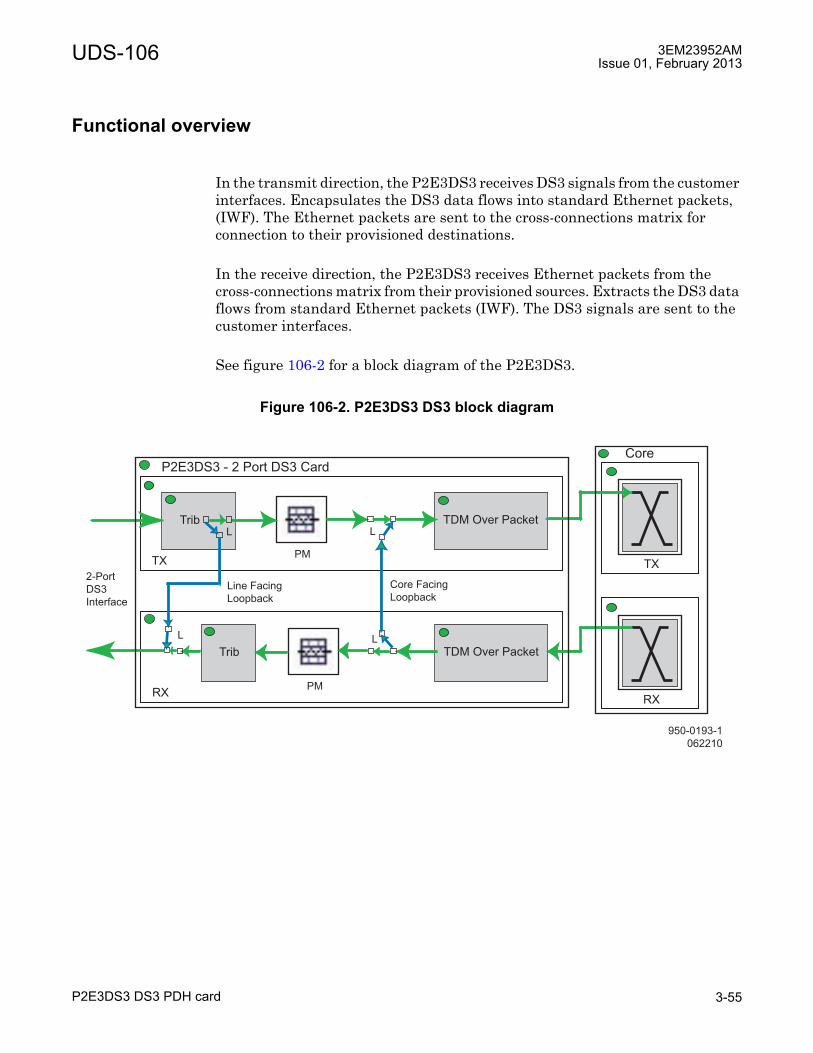
UDS-106 3EM23952AMIssue 01, February 2013
P2E3DS3 DS3 PDH card 3-55
Functional overview
In the transmit direction, the P2E3DS3 receives DS3 signals from the customer interfaces. Encapsulates the DS3 data flows into standard Ethernet packets, (IWF). The Ethernet packets are sent to the cross-connections matrix for connection to their provisioned destinations.
In the receive direction, the P2E3DS3 receives Ethernet packets from the cross-connections matrix from their provisioned sources. Extracts the DS3 data flows from standard Ethernet packets (IWF). The DS3 signals are sent to the customer interfaces.
See figure 106-2 for a block diagram of the P2E3DS3.
Figure 106-2. P2E3DS3 DS3 block diagram
950-0193-1
062210
Trib TDM Over Packet
PM
L
TX
Trib TDM Over Packet
PM
L
RX
TX
RX
P2E3DS3 - 2 Port DS3 CardCore
L
L
Core Facing
Loopback
2-Port
DS3
Interface
Line Facing
Loopback

3EM23952AMIssue 01, February 2013
P2E3DS3 DS3 PDH card3-56
UDS-106

UDS-107 3EM23952AMIssue 01, February 2013
P8ETH ethernet access switch card 3-57
UDS-107 P8ETH ethernet access switch card
UDS-107P8ETH ethernet access switch card
Features and application notes
• Terminates up to four GigE optical Ethernet SFP interfaces
• Terminates up to four 10/100/1000 10BaseT Ethernet interfaces
• Terminates up to four MPT-HL Transceiver cards
• Supports one MPT-HL L2 Radio LAG port
• Supports up to four L1 Radio LAG ports
• Terminates up to four MPT-HC/XP units
• Supports both unprotected and 1+1 EPS protected configurations with MPT-HL
• Supports unprotected configurations with MPT-HC/XP
Description
The P8ETH card provides four 10/100/1000 10BaseT Ethernet interfaces and four GigE optical Ethernet SFP interfaces. The MSS-8 shelf supports one protected pair of P8ETH cards or one unprotected P8ETH card.
The P8ETH is supported in MSS-8 slots 3 through 8 for unprotected radio configurations. In protected radio configurations, a pair of P8ETHs are required. The main P8ETH is equipped in slots 3, 5, and/or 7 and the protect (spare) P8ETH is equipped in slots 4, 6, and/or 8 directly across from the main. The protect (spare) P8ETH card protects the radio if the main P8ETH fails.
PART NUMBER/MNEMONIC
NAME CLEI ECI/BAR CODE
CPR STATUS
3DB18206AC P8ETH Ethernet Access Switch Card
CRCCACGJAA 169403 070UPD Active

3EM23952AMIssue 01, February 2013
P8ETH ethernet access switch card3-58
UDS-107
Indicators, connectors, and control
The P8ETH card has the following indicators, connectors, and controls.
See Figure 107-1 for P8ETH card front panel indicator and connector locations.
Refer to Table 107-A for P8ETH card indicators details.
Refer to Table 107-B for P8ETH card connector details.
Figure 107-1. P8ETH card (MSS/P8ETH)
Table 107-A. P8ETH front panel indicator detailsINDICATOR STATUS DEFINITIONStatus (S) Off Card not equipped, not provisioned, or not powered
Green Blinking Download, Software Booting, or Flash Card Realignment in Process
Green In-Service, Normal Operation, and Properly ProvisionedYellow In Protect, Properly Provisioned as EPSRed Card FailRed Blinking Card Mismatch
Link Off Link DownOn Link Up
Activity Off No Tx/Rx activityBlinking Tx/Rx activity
950-0102-1
091509
10/100/1000 Ethernet Ports 1-4
Connectors (RJ45)
GigE SFP Ports 5-8

UDS-107 3EM23952AMIssue 01, February 2013
P8ETH ethernet access switch card 3-59
Functional overview
The main purpose of the Ethernet Access Switch (P8ETH) module is to provide the MSS-to-MPT interface for the 9500 MPR-A all indoor configuration. The P8ETH module functions as a layer 2 switch, cross-connecting VLAN tagged Ethernet data to/from the addressed MPT. The P8ETH module provides traffic management for Core-Es for up to four directions using protected radios and up to eight directions using not-protected radios.
A secondary purpose of the P8ETH module is to provide four RJ45 10/100/1000Base-T Ethernet ports, in addition to the four Core-E Ethernet ports, and four SFP optical Ethernet ports, in addition to the Core-E SFP optical Ethernet port.
See figure 107-2 for a block diagram of the P8ETH.
Table 107-B. P8ETH front panel connector detailsCONNECTOR TYPE FUNCTIONEthernet Ports 1-4 RJ45 10/100/1000BaseT Ethernet PortSFP Ports 5-8 SFP GigE Ethernet Optical Port
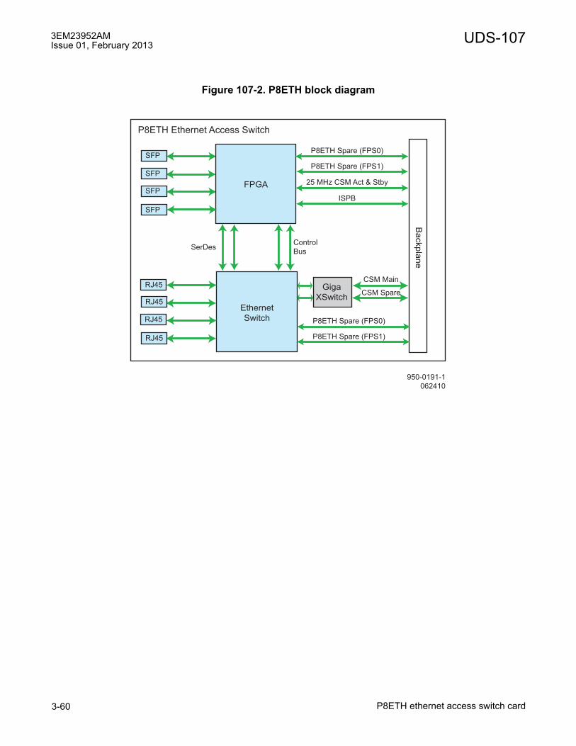
3EM23952AMIssue 01, February 2013
P8ETH ethernet access switch card3-60
UDS-107
Figure 107-2. P8ETH block diagram
950-0191-1
062410
Ethernet
Switch
P8ETH Ethernet Access Switch
Giga
XSwitch
Backpla
ne
RJ45
RJ45
RJ45
RJ45
FPGA
SFP
SFP
SFP
SFP
P8ETH Spare (FPS0)
P8ETH Spare (FPS1)
25 MHz CSM Act & Stby
Control
BusSerDes
CSM Main
ISPB
CSM Spare
P8ETH Spare (FPS0)
P8ETH Spare (FPS1)

UDS-108 3EM23952AMIssue 01, February 2013
ODU300 outdoor unit 3-61
UDS-108 ODU300 outdoor unit
UDS-108ODU300 outdoor unit
PART NUMBER/MNEMONIC
NAME CLEI ECI/BAR CODE
CPR STATUS
ODU300, L6 GHz, 252.04 MHz SEPARATION3DB23215AA ODU300, 5930 - 6020 MHZ,
HP, TX LOWN/A N/A N/A Inactive
3DB23215AD ODU300, 6182 - 6272 MHZ,HP, TX HIGH
N/A N/A N/A Inactive
3DB23215AB ODU300, 5989 - 6079 MHZ,HP, TX LOW
N/A N/A N/A Inactive
3DB23215AE ODU300, 6241 - 6331 MHZ,HP, TX HIGH
N/A N/A N/A Inactive
3DB23215AC ODU300, 6078 - 6168 MHZ,HP, TX LOW
N/A N/A N/A Inactive
3DB23215AF ODU300, 6330 - 6420 MHZ HP, TX HIGH
N/A N/A N/A Inactive
ODU300 W/LIGHTNING SURGE SUPPRESSOR1, L6 GHz, 252.04 MHz SEPARATION3DB23215HA ODU300, 5930 - 6020 MHZ,
HP, TX LOWCRMLT10HRB 461514 213567 Active
3DB23215HD ODU300, 6182 - 6272 MHZ, HP, TX HIGH
CRMLU10HRB 461515 213568 Active
3DB23215HB ODU300, 5989 - 6079 MHZ, HP, TX LOW
CRMLV10HRB 461516 213569 Active
3DB23215HE ODU300, 6241 - 6331 MHZ, HP, TX HIGH
CRMLW10HRB 461517 213570 Active
3DB23215HC ODU300, 6078 - 6168 MHZ, HP, TX LOW
CRMLX10HRB 461518 213571 Active
3DB23215HF ODU300, 6330 - 6420 MHZHP, TX HIGH
CRMLY10HRB 461519 213572 Active
ODU300, U6 GHz, 160 MHz SEPARATION3DB23214AA ODU300, 6540 - 6610 MHZ,
HP, TX LOWN/A N/A N/A Inactive
3DB23214AB ODU300, 6710 - 6780 MHZ,HP, TX HIGH
N/A N/A N/A Inactive
3DB23214AC ODU300, 6590 - 6660 MHZ,HP, TX LOW
N/A N/A N/A Inactive
3DB23214AD ODU300, 6760 - 6830 MHZ,HP, TX HIGH
N/A N/A N/A Inactive
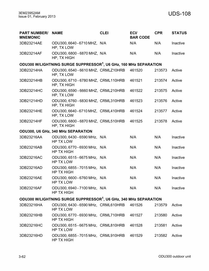
3EM23952AMIssue 01, February 2013
ODU300 outdoor unit3-62
UDS-108
3DB23214AE ODU300, 6640 - 6710 MHZ, HP, TX LOW
N/A N/A N/A Inactive
3DB23214AF ODU300, 6800 - 6870 MHZ,HP, TX HIGH
N/A N/A N/A Inactive
ODU300 W/LIGHTNING SURGE SUPPRESSOR1, U6 GHz, 160 MHz SEPARATION3DB23214HA ODU300, 6540 - 6610 MHZ,
HP, TX LOWCRMLZ10HRB 461520 213573 Active
3DB23214HB ODU300, 6710 - 6780 MHZ,HP, TX HIGH
CRML110HRB 461521 213574 Active
3DB23214HC ODU300, 6590 - 6660 MHZ,HP, TX LOW
CRML210HRB 461522 213575 Active
3DB21214HD ODU300, 6760 - 6830 MHZ,HP, TX HIGH
CRML310HRB 461523 213576 Active
3DB23214HE ODU300, 6640 - 6710 MHZ, HP, TX LOW
CRML410HRB 461524 213577 Active
3DB23214HF ODU300, 6800 - 6870 MHZ,HP, TX HIGH
CRML510HRB 461525 213578 Active
ODU300, U6 GHz, 340 MHz SEPARATION3DB23216AA ODU300, 6430 - 6590 MHz,
HP TX LOW N/A N/A N/A Inactive
3DB23216AB ODU300, 6770 - 6930 MHz, HP TX HIGH
N/A N/A N/A Inactive
3DB23216AC ODU300, 6515 - 6675 MHz, HP TX LOW
N/A N/A N/A Inactive
3DB23216AD ODU300, 6855 - 7015 MHz, HP TX HIGH
N/A N/A N/A Inactive
3DB23216AE ODU300, 6600 - 6760 MHz, HP TX LOW
N/A N/A N/A Inactive
3DB23216AF ODU300, 6940 - 7100 MHz, HP TX HIGH
N/A N/A N/A Inactive
ODU300 W/LIGHTNING SURGE SUPPRESSOR1, U6 GHz, 340 MHz SEPARATION3DB23216HA ODU300, 6430 - 6590 MHz,
HP TX LOWCRML610HRB 461526 213579 Active
3DB23216HB ODU300, 6770 - 6930 MHz, HP TX HIGH
CRML710HRB 461527 213580 Active
3DB23216HC ODU300, 6515 - 6675 MHz, HP TX LOW
CRML810HRB 461528 213581 Active
3DB23216HD ODU300, 6855 - 7015 MHz, HP TX HIGH
CRML910HRB 461529 213582 Active
PART NUMBER/MNEMONIC
NAME CLEI ECI/BAR CODE
CPR STATUS
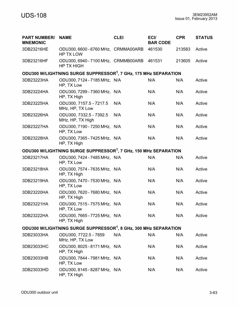
UDS-108 3EM23952AMIssue 01, February 2013
ODU300 outdoor unit 3-63
3DB23216HE ODU300, 6600 - 6760 MHz, HP TX LOW
CRMMA00ARB 461530 213583 Active
3DB23216HF ODU300, 6940 - 7100 MHz, HP TX HIGH
CRMMB00ARB 461531 213605 Active
ODU300 W/LIGHTNING SURGE SUPPRESSOR1, 7 GHz, 175 MHz SEPARATION3DB23223HA ODU300, 7124 - 7185 MHz,
HP, TX LowN/A N/A N/A Active
3DB23224HA ODU300, 7299 - 7360 MHz, HP, TX High
N/A N/A N/A Active
3DB23225HA ODU300, 7157.5 - 7217.5 MHz, HP, TX Low
N/A N/A N/A Active
3DB23226HA ODU300, 7332.5 - 7392.5 MHz, HP, TX High
N/A N/A N/A Active
3DB23227HA ODU300, 7190 - 7250 MHz, HP, TX Low
N/A N/A N/A Active
3DB23228HA ODU300, 7365 - 7425 MHz, HP, TX High
N/A N/A N/A Active
ODU300 W/LIGHTNING SURGE SUPPRESSOR1, 7 GHz, 150 MHz SEPARATION3DB23217HA ODU300, 7424 - 7485 MHz,
HP, TX LowN/A N/A N/A Active
3DB23218HA ODU300, 7574 - 7635 MHz, HP, TX High
N/A N/A N/A Active
3DB23219HA ODU300, 7470 - 7530 MHz, HP, TX Low
N/A N/A N/A Active
3DB23220HA ODU300, 7620 - 7680 MHz, HP, TX High
N/A N/A N/A Active
3DB23221HA ODU300, 7515 - 7575 MHz, HP, TX Low
N/A N/A N/A Active
3DB23222HA ODU300, 7665 - 7725 MHz, HP, TX High
N/A N/A N/A Active
ODU300 W/LIGHTNING SURGE SUPPRESSOR1, 8 GHz, 300 MHz SEPARATION3DB23033HA ODU300, 7722.5 - 7859
MHz, HP, TX LowN/A N/A N/A Active
3DB23033HC ODU300, 8025 - 8171 MHz, HP, TX High
N/A N/A N/A Active
3DB23033HB ODU300, 7844 - 7981 MHz, HP, TX Low
N/A N/A N/A Active
3DB23033HD ODU300, 8145 - 8287 MHz, HP, TX High
N/A N/A N/A Active
PART NUMBER/MNEMONIC
NAME CLEI ECI/BAR CODE
CPR STATUS

3EM23952AMIssue 01, February 2013
ODU300 outdoor unit3-64
UDS-108
ODU300 11 GHz, 590-490 MHz SEPARATION3DB23035AA ODU300, 10675 - 10835
MHZ, TX LOWN/A N/A N/A Inactive
3DB23035AE ODU300, 11200 - 11345 MHZ, TX HIGH
N/A N/A N/A Inactive
3DB23035AB ODU300, 10795 - 10955 MHZ, TX LOW
N/A N/A N/A Inactive
3DB23035AF ODU300, 11310 - 11465 MHZ, TX HIGH
N/A N/A N/A Inactive
3DB23035AC ODU300, 10915 - 11075 MHZ, TX LOW
N/A N/A N/A Inactive
3DB23035AG ODU300, 11430 - 11585 MHZ, TX HIGH
N/A N/A N/A Inactive
3DB23035AD ODU300, 11035 - 11200 MHZ, TX LOW
N/A N/A N/A Inactive
3DB23035AH ODU300, 11550 - 11705 MHZ, TX HIGH
N/A N/A N/A Inactive
ODU300 W/LIGHTNING SURGE SUPPRESSOR1 11 GHz, 590-490 MHz SEPARATION3DB23035HA ODU300, 10675 - 10835
MHZ, TX LOWCRMMC00ARB 213584 461532 Active
3DB23035HE ODU300, 11200 - 11345 MHZ, TX HIGH
CRMMD00ARB 213585 461533 Active
3DB23035HB ODU300, 10795 - 10955 MHZ, TX LOW
CRMME00ARB 461534 213586 Active
3DB23035HF ODU300, 11310 - 11465 MHZ, TX HIGH
CRMMF00ARB 461536 213587 Active
3DB23035HC ODU300, 10915 - 11075 MHZ, TX LOW
CRMMG00ARB 461537 213588 Active
3DB23035HG ODU300, 11430 - 11585 MHZ, TX HIGH
CRMMH00ARB 461539 213589 Active
3DB23035HD ODU300, 11035 - 11200 MHZ, TX LOW
CRMMJ00ARB 461540 213590 Active
3DB23035HH ODU300, 11550 - 11705 MHZ, TX HIGH
CRMMK00ARB 461541 213591 Active
ODU300 15 GHz, 475/490 MHz SEPARATION3DB23039AC ODU300, 14500 - 14660
MHZ, TX LOWN/A N/A N/A Inactive
3DB23039AD ODU300, 14975 - 15135 MHZ, TX HIGH
N/A N/A N/A Inactive
PART NUMBER/MNEMONIC
NAME CLEI ECI/BAR CODE
CPR STATUS
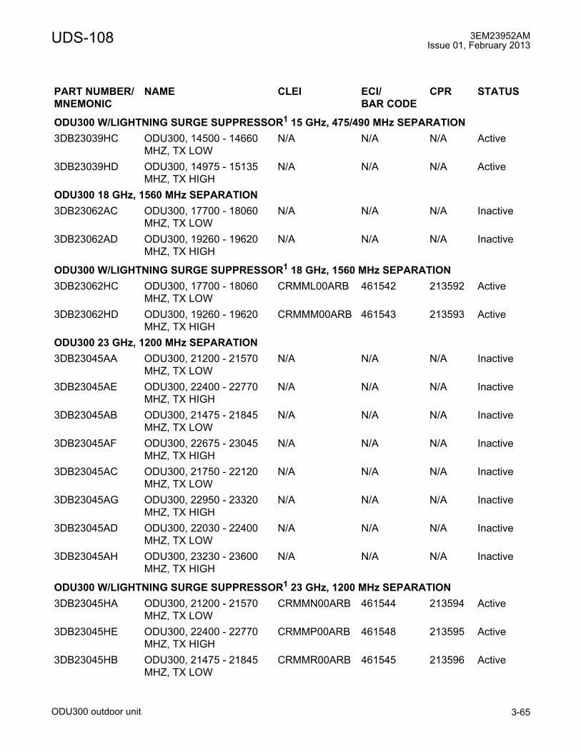
UDS-108 3EM23952AMIssue 01, February 2013
ODU300 outdoor unit 3-65
ODU300 W/LIGHTNING SURGE SUPPRESSOR1 15 GHz, 475/490 MHz SEPARATION3DB23039HC ODU300, 14500 - 14660
MHZ, TX LOWN/A N/A N/A Active
3DB23039HD ODU300, 14975 - 15135 MHZ, TX HIGH
N/A N/A N/A Active
ODU300 18 GHz, 1560 MHz SEPARATION3DB23062AC ODU300, 17700 - 18060
MHZ, TX LOWN/A N/A N/A Inactive
3DB23062AD ODU300, 19260 - 19620 MHZ, TX HIGH
N/A N/A N/A Inactive
ODU300 W/LIGHTNING SURGE SUPPRESSOR1 18 GHz, 1560 MHz SEPARATION3DB23062HC ODU300, 17700 - 18060
MHZ, TX LOW CRMML00ARB 461542 213592 Active
3DB23062HD ODU300, 19260 - 19620 MHZ, TX HIGH
CRMMM00ARB 461543 213593 Active
ODU300 23 GHz, 1200 MHz SEPARATION3DB23045AA ODU300, 21200 - 21570
MHZ, TX LOWN/A N/A N/A Inactive
3DB23045AE ODU300, 22400 - 22770 MHZ, TX HIGH
N/A N/A N/A Inactive
3DB23045AB ODU300, 21475 - 21845 MHZ, TX LOW
N/A N/A N/A Inactive
3DB23045AF ODU300, 22675 - 23045 MHZ, TX HIGH
N/A N/A N/A Inactive
3DB23045AC ODU300, 21750 - 22120 MHZ, TX LOW
N/A N/A N/A Inactive
3DB23045AG ODU300, 22950 - 23320 MHZ, TX HIGH
N/A N/A N/A Inactive
3DB23045AD ODU300, 22030 - 22400 MHZ, TX LOW
N/A N/A N/A Inactive
3DB23045AH ODU300, 23230 - 23600 MHZ, TX HIGH
N/A N/A N/A Inactive
ODU300 W/LIGHTNING SURGE SUPPRESSOR1 23 GHz, 1200 MHz SEPARATION3DB23045HA ODU300, 21200 - 21570
MHZ, TX LOWCRMMN00ARB 461544 213594 Active
3DB23045HE ODU300, 22400 - 22770 MHZ, TX HIGH
CRMMP00ARB 461548 213595 Active
3DB23045HB ODU300, 21475 - 21845 MHZ, TX LOW
CRMMR00ARB 461545 213596 Active
PART NUMBER/MNEMONIC
NAME CLEI ECI/BAR CODE
CPR STATUS

3EM23952AMIssue 01, February 2013
ODU300 outdoor unit3-66
UDS-108
Features and application notes
• Optimal for urban links
• ODU300s are band specific
• Supports static and adaptive modulation
• Support for the following channel plans: Lower 6 GHz, Upper 6 GHz, 7 GHz, 8 GHz, 11 GHz, 15 GHz, 18 GHz, and 23 GHz.
3DB23045HF ODU300, 22675 - 23045 MHZ, TX HIGH
CRMMS00ARB 461549 213597 Active
3DB23045HC ODU300, 21750 - 22120 MHZ, TX LOW
CRMMT00ARB 461546 213598 Active
3DB23045HG ODU300, 22950 - 23320 MHZ, TX HIGH
CRMMU00ARB 461550 213599 Active
3DB23045HD ODU300, 22030 - 22400 MHZ, TX LOW
CRMMV00ARB 461547 213600 Active
3DB23045HH ODU300, 23230 - 23600 MHZ, TX HIGH
CRMMW00ARB 461551 213601 Active
ODU300 W/LIGHTNING SURGE SUPPRESSOR 38 GHz, 700 MHz SEPARATION3DB23258HO ODU300, 38600 - 38800
MHZ, TX LOWN/A N/A N/A Active
3DB23258HP ODU300, 39300 - 39500 MHZ, TX HIGH
N/A N/A N/A Active
3DB23258HQ ODU300, 38750 - 38950 MHZ, TX LOW
N/A N/A N/A Active
3DB23258HR ODU300, 39450 - 39650 MHZ, TX HIGH
N/A N/A N/A Active
3DB23258HS ODU300, 38950 - 39150 MHZ, TX LOW
N/A N/A N/A Active
3DB23258HT ODU300, 39650 - 39850 MHZ, TX HIGH
N/A N/A N/A Active
3DB23258HU ODU300, 39100 - 39300 MHZ, TX LOW
N/A N/A N/A Active
3DB23258HV ODU300, 39800 - 40000 MHZ, TX HIGH
N/A N/A N/A Active
[1] ODU300�s with Lightning Surge Suppressor are supported starting with 9500 MPR-A R1.2.x and are not sup-ported by R1.0.x and R1.1.x.
PART NUMBER/MNEMONIC
NAME CLEI ECI/BAR CODE
CPR STATUS

UDS-108 3EM23952AMIssue 01, February 2013
ODU300 outdoor unit 3-67
• Channel frequency software selectable within tuning range of the ODU300
• Supports L2 Radio LAG ports:
� up to six member L2 Radio LAG per MSS-8 shelf
� up to two member L2 Radio LAG per MSS-4 shelf
• Support for the following static radio profiles:
� Supported static channel bandwidths: 10, 30, 40, and 50 MHz
� Supported static modulations: 4 QAM, 16 QAM, 32 QAM, 64 QAM, 128 QAM, and 256 QAM
• Support for the following adaptive radio profiles:
� Supported adaptive channel bandwidth: 30 MHz
� Supported adaptive modulations: 4/16 QAM, 4/16/64 QAM, 4/16/64/128 QAM and 4/16/64/128/256 QAM
• Automatic Transmit Power Control (ATPC) support
• Integrated antenna mount
• Non-Integrated antenna mount optional
• Polarization is field configurable, Vertical (standard) or horizontal (optional)
• Coaxial connection to the MSS/MOD300 card
• ODU300s available with built-in lightning surge suppressor
Description
The ODU300 is a microprocessor controlled transceiver that interfaces the MSS-4/8 shelf MOD300 card with the antenna. Transmitter circuits in the ODU300 consists of cable interface, modulator, local oscillator, up converter/mixer, power amplifier, and diplexer. Receive circuits consist of diplexer, low-noise amplifier, local oscillator, down converter/mixer, automatic gain control, and cable interface. The microprocessor manages ODU300 frequency, transmit power alarming, and performance monitoring. Power is provided by -48Vdc from the MSS to the ODU300 DC-DC converter. The ODU300 is frequency dependent.
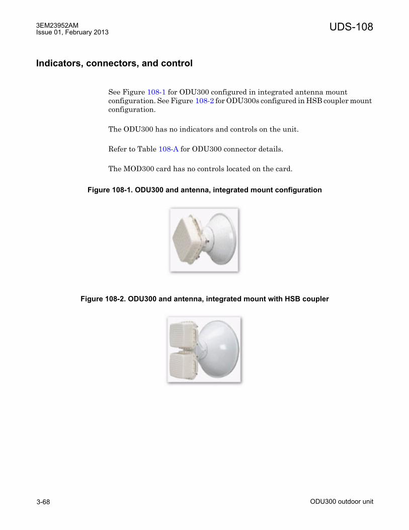
3EM23952AMIssue 01, February 2013
ODU300 outdoor unit3-68
UDS-108
Indicators, connectors, and control
See Figure 108-1 for ODU300 configured in integrated antenna mount configuration. See Figure 108-2 for ODU300s configured in HSB coupler mount configuration.
The ODU300 has no indicators and controls on the unit.
Refer to Table 108-A for ODU300 connector details.
The MOD300 card has no controls located on the card.
Figure 108-1. ODU300 and antenna, integrated mount configuration
Figure 108-2. ODU300 and antenna, integrated mount with HSB coupler

UDS-108 3EM23952AMIssue 01, February 2013
ODU300 outdoor unit 3-69
RSSI monitoring point
The ODU300 has a capped BNC female connector to access RSSI during antenna alignment.
There is a linear relationship of voltage to RSSI, as shown in the table below; an RSSI of 0.25 Vdc is equivalent to -10 dBm RSSI, and each additional 0.25 Vdc RSSI increase thereafter corresponds to a 10 dBm decrease in RSSI.
The lower the voltage the higher RSSI and better aligned the antenna is.
Waveguide flange data
Table 108-D lists the antenna port flange types used with the ODU300, plus their mating flange options and fastening hardware for remote mount installations.
UDR/PDR flanges are rectangular; UBR/PDR flanges are square.
On the ODU300, the two flange styles are:
• UDR. 6-hole or 8-hole (6/8 bolt holes depending on frequency range/waveguide type), flush-face flange with threaded, blind holes.
• UBR. 4-hole flush-face flange with threaded, blind holes.
The corresponding mating flange styles are:
• PDR. 6-hole or 8-hole flange with gasket groove and clear holes.
Table 108-A. Core-E front panel connector detailsCONNECTOR TYPE FUNCTIONAntenna Port Waveguide
InterfaceRF signal to antenna
IF Signal In Type-N Female IF signal from MOD300 cardRSSI BNC Female RSSI Monitor PortGround Stud ODU300 Grounding
Table 108-C. RSSI tableUNITS MEASUREMENTBNC (Vdc) 0.25 0.5 0.75 1.0 1.25 1.5 1.75 2.0 2.25 2.5RSSI (dBm) -10 -20 -30 -40 -50 -60 -70 -80 -90 -100
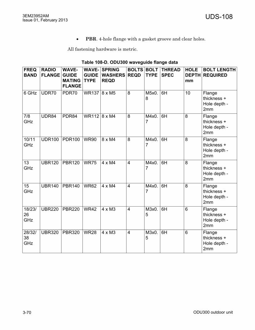
3EM23952AMIssue 01, February 2013
ODU300 outdoor unit3-70
UDS-108
• PBR. 4-hole flange with a gasket groove and clear holes.
All fastening hardware is metric.
Table 108-D. ODU300 waveguide flange dataFREQBAND
RADIOFLANGE
WAVE-GUIDEMATINGFLANGE
WAVE-GUIDETYPE
SPRINGWASHERSREQD
BOLTSREQD
BOLTTYPE
THREADSPEC
HOLEDEPTHmm
BOLT LENGTHREQUIRED
6 GHz UDR70 PDR70 WR137 8 x M5 8 M5x0.8
6H 10 Flange thickness +Hole depth - 2mm
7/8 GHz
UDR84 PDR84 WR112 8 x M4 8 M4x0.7
6H 8 Flange thickness + Hole depth - 2mm
10/11GHz
UDR100 PDR100 WR90 8 x M4 8 M4x0.7
6H 8 Flange thickness + Hole depth - 2mm
13 GHz
UBR120 PBR120 WR75 4 x M4 4 M4x0.7
6H 8 Flange thickness + Hole depth - 2mm
15 GHz
UBR140 PBR140 WR62 4 x M4 4 M4x0.7
6H 8 Flange thickness + Hole depth - 2mm
18/23/26GHz
UBR220 PBR220 WR42 4 x M3 4 M3x0.5
6H 6 Flange thickness + Hole depth - 2mm
28/32/38GHz
UBR320 PBR320 WR28 4 x M3 4 M3x0.5
6H 6 Flange thickness + Hole depth - 2mm

UDS-109 3EM23952AMIssue 01, February 2013
MPT-HL transceiver 3-71
UDS-109 MPT-HL transceiver
UDS-109MPT-HL transceiver
Features and application notes
• High-capacity, long-haul RF transmission shelf
• Supported on P8ETH cards in 1+0 and 1+1 configurations, Core-E cards in 1+0 configurations, MSS-1 SFP ports in 1+0 configurations, L1 and L2 Radio ports
• Support for the following RF configurations: Non-Standby, Hot Standby, Space Diversity, and Frequency Diversity
• Support for the following channel plans: 5.8 GHz Unlicensed, Lower 6 GHz, Upper 6 GHz, 7 GHz, 8 Ghz, 10.5 GHz, and 11 GHz
• Support for the following static radio profiles:
� Supported static channel bandwidths: 5, 10, 30, and 40 MHz
� Supported static modulations: 32 QAM, 128 QAM, and 256 QAM
PART NUMBER/MNEMONIC
NAME CLEI ECI/BAR CODE
CPR STATUS
3EM22617AA MPT-HL Transceiver L6, 5725-6425 MHz
CRTUAAXFAA 171610 070VLL Active
3EM22617AB MPT-HL Transceiver U6,6425-6930 MHz
CRTUAAYFAA 171611 070VLM Active
3EM22617AC MPT-HL Transceiver L6, 5925-6425 MHz, HP
CRTUABLFAA 173789 070XRS Active
3EM22617AD MPT-HL Transceiver U6,6425-6930 MHz, HP
CRTUABMFAA 173790 070XRS Active
3EM24627AA MPT-HL Transceiver 7,7125-7775 MHz
N/A N/A N/A Active
3EM24627AB MPT-HL Transceiver 8,7725-8500 MHz
N/A N/A N/A Active
3EM23888AA MPT-HL Transceiver 10.5,10400-10700 MHz
CRTUABPCAA 174725 070YGX Active
3EM23888AB MPT-HL Transceiver 11,10700-11200 MHz
CRTUABRCAA 174727 070YGY Active
3EM23888AC MPT-HL Transceiver 11,11200-11700 MHz
CRTUABSCAA 174728 070YGZ Active
3EM23952AMIssue 01, February 2013
MPT-HL transceiver3-72
UDS-109
• Support for the following adaptive radio profiles:
� Supported adaptive channel bandwidths: 30 MHz
� Supported adaptive modulations: 4/16/64/128/256 QAM
• Automatic Transmit Power Control (ATPC) support
• Gigabit Ethernet connection to 9500 MPR-A MSS indoor unit using standard SFPs
Description
The MPT-HL Transceiver card is a microprocessor controlled RF transceiver that interfaces the Core-E card, P8ETH card, or MSS-1 shelf MPT-HL port with the antenna. The MPT-HL Transceiver microprocessor manages transmit and receive frequencies, transmit power, alarming, and performance monitoring.
There are no MPT-HL Transceiver card options. The MPT-HL Transceiver resides in the MPT-HL shelf. Supported configurations are one or two Non-Standby (1+0) radios, Hot Standby (1+1) and Hot Standby space and frequency diversity.
Indicators, connectors, and control
The MPT-HL Transceiver card has the following indicators, connectors, and controls.
See Figure 109-1 for MPT-HL Transceiver card front panel indicator and connector locations.
Refer to Table 109-A for MPT-HL Transceiver card indicators details.
Refer to Table 109-B for MPT-HL Transceiver card connector details.
Refer to Table 109-C for MPT-HL Transceiver card control details.

UDS-109 3EM23952AMIssue 01, February 2013
MPT-HL transceiver 3-73
Figure 109-1. MPT-HL transceiver
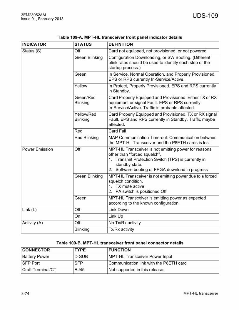
3EM23952AMIssue 01, February 2013
MPT-HL transceiver3-74
UDS-109
Table 109-A. MPT-HL transceiver front panel indicator detailsINDICATOR STATUS DEFINITIONStatus (S) Off Card not equipped, not provisioned, or not powered
Green Blinking Configuration Downloading, or SW Booting. (Different blink rates should be used to identify each step of the startup process.)
Green In Service, Normal Operation, and Properly Provisioned. EPS or RPS currently In-Service/Active.
Yellow In Protect, Properly Provisioned. EPS and RPS currently in Standby.
Green/Red Blinking
Card Properly Equipped and Provisioned. Either TX or RX equipment or signal Fault. EPS or RPS currently In-Service/Active. Traffic is probable affected.
Yellow/Red Blinking
Card Properly Equipped and Provisioned, TX or RX signal Fault, EPS and RPS currently in Standby. Traffic maybe affected.
Red Card FailRed Blinking MAP Communication Time-out: Communication between
the MPT-HL Transceiver and the P8ETH cards is lost.Power Emission Off MPT-HL Transceiver is not emitting power for reasons
other than �forced squelch�.1. Transmit Protection Switch (TPS) is currently in
standby state.2. Software booting or FPGA download in progress
Green Blinking MPT-HL Transceiver is not emitting power due to a forced squelch condition.1. TX mute active2. PA switch is positioned Off
Green MPT-HL Transceiver is emitting power as expected according to the known configuration.
Link (L) Off Link DownOn Link Up
Activity (A) Off No Tx/Rx activityBlinking Tx/Rx activity
Table 109-B. MPT-HL transceiver front panel connector detailsCONNECTOR TYPE FUNCTIONBattery Power D-SUB MPT-HL Transceiver Power InputSFP Port SFP Communication link with the P8ETH cardCraft Terminal/CT RJ45 Not supported in this release.

UDS-109 3EM23952AMIssue 01, February 2013
MPT-HL transceiver 3-75
Functional overview
In the TX direction, the MPT-HL Transceiver converts Ethernet packet data from the P8ETH (Ethernet Access Switch - EAS) card MPT-HL port into a modulated IF output signal. The modulated IF signal is converted into a RF signal which is amplified by the Power Amplifier (PA) and routed through a band-pass filter to the antenna.
In the RX direction, the MPT-HL Transceiver card amplifies the incoming RF signal. Converts the RF signal into a first IF signal. The first IF signal is then converted to a second IF signal. The second IF signal is filtered, demodulated, and converted into Ethernet packet data. The Ethernet packet data is then sent to the P8ETH card MPT-HL port.
See figure 109-2 for a block diagram of the MPT-HL Transceiver.
Table 109-C. MPT-HL transceiver front panel control detailsCONTROL POSITION FUNCTIONPA 0 Transmit OFF (TxMute)
1 Transmit ON
Figure 109-2. MPT-HL transceiver block diagram
950-0192-1
062410
MODEM
Board
SFP Tx
MPT Transceiver Card
RJ45
PSU
+/-20V
+/-60V
Bias
Board
I
Q
I2C
IF
RF
Transceiver
Board
PA
I
Q
I2C
IF
DC Voltages
Modem RF Transceiver
Rx
RF
Back
Plane Antenna
Port

3EM23952AMIssue 01, February 2013
MPT-HL transceiver3-76
UDS-109
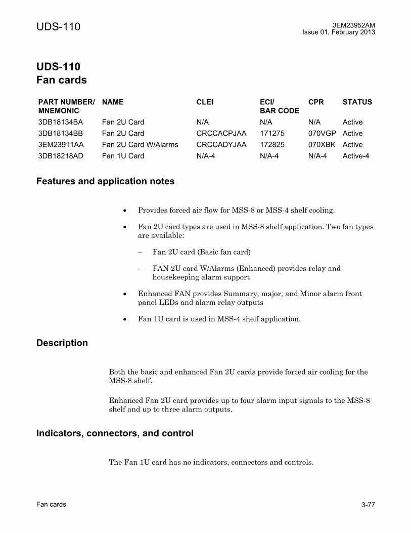
UDS-110 3EM23952AMIssue 01, February 2013
Fan cards 3-77
UDS-110 Fan cards
UDS-110Fan cards
Features and application notes
• Provides forced air flow for MSS-8 or MSS-4 shelf cooling.
• Fan 2U card types are used in MSS-8 shelf application. Two fan types are available:
� Fan 2U card (Basic fan card)
� FAN 2U card W/Alarms (Enhanced) provides relay and housekeeping alarm support
• Enhanced FAN provides Summary, major, and Minor alarm front panel LEDs and alarm relay outputs
• Fan 1U card is used in MSS-4 shelf application.
Description
Both the basic and enhanced Fan 2U cards provide forced air cooling for the MSS-8 shelf.
Enhanced Fan 2U card provides up to four alarm input signals to the MSS-8 shelf and up to three alarm outputs.
Indicators, connectors, and control
The Fan 1U card has no indicators, connectors and controls.
PART NUMBER/MNEMONIC
NAME CLEI ECI/BAR CODE
CPR STATUS
3DB18134BA Fan 2U Card N/A N/A N/A Active3DB18134BB Fan 2U Card CRCCACPJAA 171275 070VGP Active3EM23911AA Fan 2U Card W/Alarms CRCCADYJAA 172825 070XBK Active3DB18218AD Fan 1U Card N/A-4 N/A-4 N/A-4 Active-4

3EM23952AMIssue 01, February 2013
Fan cards3-78
UDS-110
The basic Fan 2U card has no indicators, connectors and controls.
See Figure 110-1 for enhanced Fan 2U card with alarms front panel indicator, controls, and connector locations.
Refer to Table 110-A for enhanced Fan 2U card indicators details.
Refer to Table 110-B for Fan 2U card connector details.
Refer to Table 110-C for Fan 2U card control details.
Alarm Cutoff and Lamp Test are not supported with R4.2.0 software.
Figure 110-1. Fan 2U card w/alarms (front view)
950-0110-1
011210

UDS-110 3EM23952AMIssue 01, February 2013
Fan cards 3-79
Table 110-A. FAN 2U w/alarms front panel indicator detailsINDICATOR STATUS DEFINITIONFan Off LED not supported in this release.Batt A Green LED not supported in this release.Batt B Green LED not supported in this release.Summary On NE summary alarm indicates either a Major or Minor
alarm.Major Red NE summary, indicates a Major alarm is present.Minor Yellows NE summary, indicates a Minor alarm is present.
Table 110-B. FAN 2U w/alarms front panel connector detailsCONNECTOR TYPE FUNCTIONExternal Alarms DSUB 15
PositionExternal Alarm Inputs and Outputs
Table 110-C. FAN 2U w/alarms front panel control detailsCONNECTOR TYPE FUNCTION
ACO/LT1
[1] ACO/LT control is not supported in R4.2.0 software.
push button Alarm cutoff
Table 110-D. Fan 2U card office alarm and control connector / cable detailPIN DEFINITION Function CONTACT NUMBER WIRE COLORAlarm Input 1 01 White/BlueAlarm Input 2 02 Blue/WhiteAlarm Input 3 11 White/OrangeAlarm Input 4 12 Orange/WhiteGround 07 White/GreenAlarm Output 1
Summary Alarm14 White/Brown
Alarm Output 1 15 Brown/WhiteAlarm Output 2
Major Alarm08 White/Slate
Alarm Output 2 10 Slate/WhiteAlarm Output 3
Minor Alarm04 Red/Blue
Alarm Output 3 05 Blue/RedNot Used 03 N/ANot Used 06 N/ANot Used 09 N/ANot Used 13 N/A
3EM23952AMIssue 01, February 2013
Fan cards3-80
UDS-110
Functional overview
Both the basic and enhanced Fan 2U cards provide forced air cooling for the MSS-8 shelf.
The Fan 1U card provide forced air cooling for the MSS-4 shelf.
Alarm output 1 (Summary Alarm) is energized for the no-alarm state, so that it generates an alarm when shelf power is lost. As a result, all outputs are open during system operation with no alarms.
The enhanced Fan 2U card Alarm Cutoff and Lamp Test are not supported with R4.2.0 software.
Output alarm electrical characteristics
Each alarm output has two pins. Depending if the alarm is present or not the two relevant pins will be in short circuit or in open circuit condition.
When the relay alarm output pins will be in short circuit condition, the alarm outputs will tolerate a 50mA max current and the max voltage between the two pins never exceed 2V. When the relay alarm output pins are in open circuit condition the alarm outputs will tolerate 60V and the max leakage current will never exceed 0.2mA.
Input alarm electrical characteristics
The inputs must be able to reveal if the relevant pin is open or short circuit with respect to GND. Table 110-E shows the alarm behavior.
The short circuit is detected with an input voltage 0V < V < 0.15V.The open circuit is detected with an input voltage 0.7V < V < 5V.The alarm inputs can tolerate �0.5 volts to +5 volts without damage.
Table 110-E. Input alarm electrical behaviorInput pin status OPEN Logical �1� Alarmed, Not Alarmed
condition depends on alarm polarity settings provisioned
GND (0V) Logical �0�
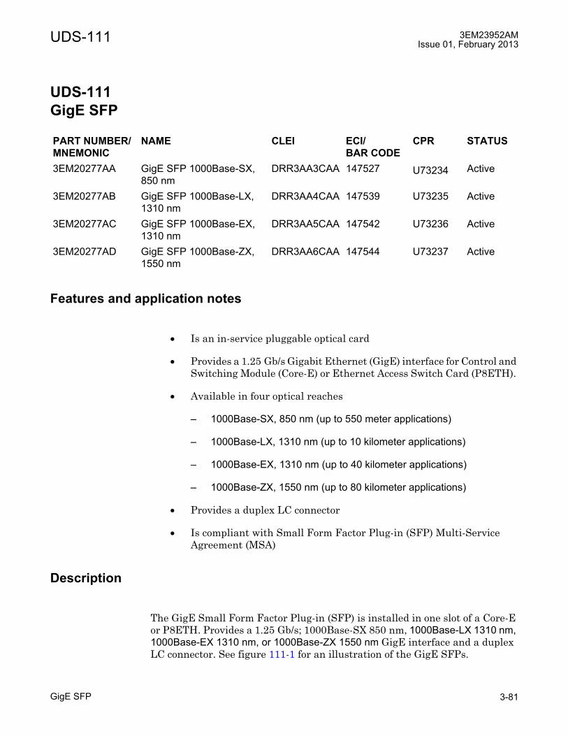
UDS-111 3EM23952AMIssue 01, February 2013
GigE SFP 3-81
UDS-111 GigE SFP
UDS-111GigE SFP
Features and application notes
• Is an in-service pluggable optical card
• Provides a 1.25 Gb/s Gigabit Ethernet (GigE) interface for Control and Switching Module (Core-E) or Ethernet Access Switch Card (P8ETH).
• Available in four optical reaches
� 1000Base-SX, 850 nm (up to 550 meter applications)
� 1000Base-LX, 1310 nm (up to 10 kilometer applications)
� 1000Base-EX, 1310 nm (up to 40 kilometer applications)
� 1000Base-ZX, 1550 nm (up to 80 kilometer applications)
• Provides a duplex LC connector
• Is compliant with Small Form Factor Plug-in (SFP) Multi-Service Agreement (MSA)
Description
The GigE Small Form Factor Plug-in (SFP) is installed in one slot of a Core-E or P8ETH. Provides a 1.25 Gb/s; 1000Base-SX 850 nm, 1000Base-LX 1310 nm, 1000Base-EX 1310 nm, or 1000Base-ZX 1550 nm GigE interface and a duplex LC connector. See figure 111-1 for an illustration of the GigE SFPs.
PART NUMBER/MNEMONIC
NAME CLEI ECI/BAR CODE
CPR STATUS
3EM20277AA GigE SFP 1000Base-SX, 850 nm
DRR3AA3CAA 147527 U73234 Active
3EM20277AB GigE SFP 1000Base-LX, 1310 nm
DRR3AA4CAA 147539 U73235 Active
3EM20277AC GigE SFP 1000Base-EX, 1310 nm
DRR3AA5CAA 147542 U73236 Active
3EM20277AD GigE SFP 1000Base-ZX, 1550 nm
DRR3AA6CAA 147544 U73237 Active
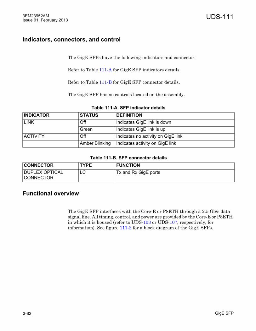
3EM23952AMIssue 01, February 2013
GigE SFP3-82
UDS-111
Indicators, connectors, and control
The GigE SFPs have the following indicators and connector.
Refer to Table 111-A for GigE SFP indicators details.
Refer to Table 111-B for GigE SFP connector details.
The GigE SFP has no controls located on the assembly.
Functional overview
The GigE SFP interfaces with the Core-E or P8ETH through a 2.5 Gb/s data signal line. All timing, control, and power are provided by the Core-E or P8ETH in which it is housed (refer to UDS-103 or UDS-107, respectively, for information). See figure 111-2 for a block diagram of the GigE SFPs.
Table 111-A. SFP indicator detailsINDICATOR STATUS DEFINITIONLINK Off Indicates GigE link is down
Green Indicates GigE link is upACTIVITY Off Indicates no activity on GigE link
Amber Blinking Indicates activity on GigE link
Table 111-B. SFP connector detailsCONNECTOR TYPE FUNCTIONDUPLEX OPTICAL CONNECTOR
LC Tx and Rx GigE ports

UDS-111 3EM23952AMIssue 01, February 2013
GigE SFP 3-83
On the transmitter side, the GigE SFPs has an automatic optical output power control circuit, a laser driver and a laser diode module. The transmitter is based on a non-cooled DFB laser. The laser safety class for the complete integrated module is class 1 according to IEC 60825. It can manage commands for TX disable and provides a TX fault alarm.
TX fault indicates a laser fault. The transmitter is not disabled when the TX fault signal is active. TX disable is an input that is used to shut down the transmitter optical output.
On the receiver side, the GigE SFPs have a PIN photo detector for light-to-electrical current conversion and a limiting amplifier. The photo-detected current is amplified by an electrical circuit that delivers two complementary data signals.
Figure 111-1. Optical SFP module
950-0001-1072009
Optical cables
Transceiver CSM SFP module
Transceiver EAS SFP module
Input
Output
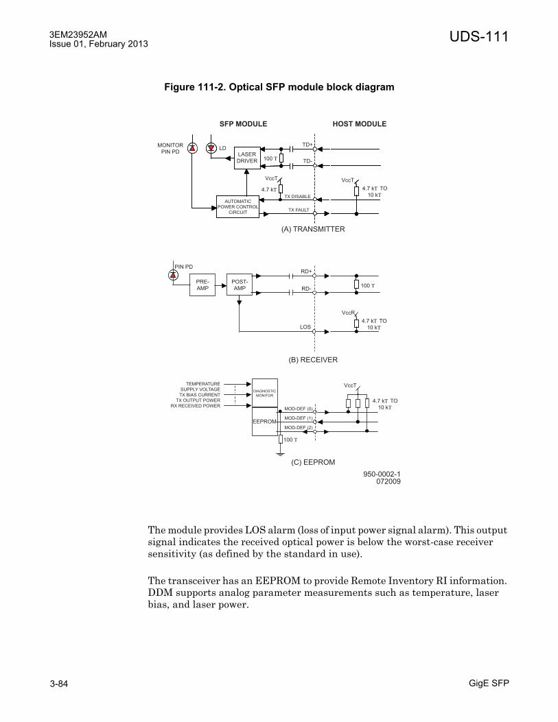
3EM23952AMIssue 01, February 2013
GigE SFP3-84
UDS-111
The module provides LOS alarm (loss of input power signal alarm). This output signal indicates the received optical power is below the worst-case receiver sensitivity (as defined by the standard in use).
The transceiver has an EEPROM to provide Remote Inventory RI information. DDM supports analog parameter measurements such as temperature, laser bias, and laser power.
Figure 111-2. Optical SFP module block diagram
950-0002-1072009
MONITOR
PIN PDLD
LASER
DRIVER
AUTOMATIC
POWER CONTROL
CIRCUIT
100
100
100
4.7 k TO
10 k
4.7 k TO
10 k
4.7 k TO
10 k
4.7 k
SFP MODULE HOST MODULE
(A) TRANSMITTER
(B) RECEIVER
(C) EEPROM
EEPROM
DIAGNOSTIC
MONITOR
TEMPERATURE
SUPPLY VOLTAGE
TX BIAS CURRENT
TX OUTPUT POWER
RX RECEIVED POWERMOD-DEF (0)
MOD-DEF (1)
MOD-DEF (2)
PIN PD
TD+
TD-
VccT VccT
VccT
VccR
TX DISABLE
TX FAULT
RD-
RD+
POST-
AMP
PRE-
AMP
LOS
UDS-112 3EM23952AMIssue 01, February 2013
Power distribution unit (PDU) 3-85
UDS-112 Power distribution unit (PDU)
UDS-112Power distribution unit (PDU)
Features and application notes
• Distributes A and B battery power that feeds MSS-8 and/or MPT-HL shelves and/or auxiliary equipment
• Provides fused protection for individual shelves and auxiliary equipment
• Floating Battery inputs to support both ±24 and ±48 VDC operation
• Optional relay card that provides eight Form-C outputs
• Mounts in a 19-inch aluminum rack or 19-inch seismic rack. Adapter flanges available to mount in a 23-inch aluminum rack
• Requires 5.25 inches (3 EIA rack increments) of open rack space
Description
The PDU provides redundant, fuse protected connections to up to six 9500 MPR-A shelves and/or auxiliary equipment. Two isolated battery input connections (A & B). Each battery input is distributed to six alarm indicating fused battery outputs (A+/A- & B+/B-) See Figure 112-1 for an isometric view of the PDU. See Figure 112-2 for a front panel view of the PDU.
PART NUMBER/MNEMONIC
NAME CLEI ECI/BAR CODE
CPR STATUS
3EM13317AA PDU Power Distribution Unit
N/A N/A N/A Active
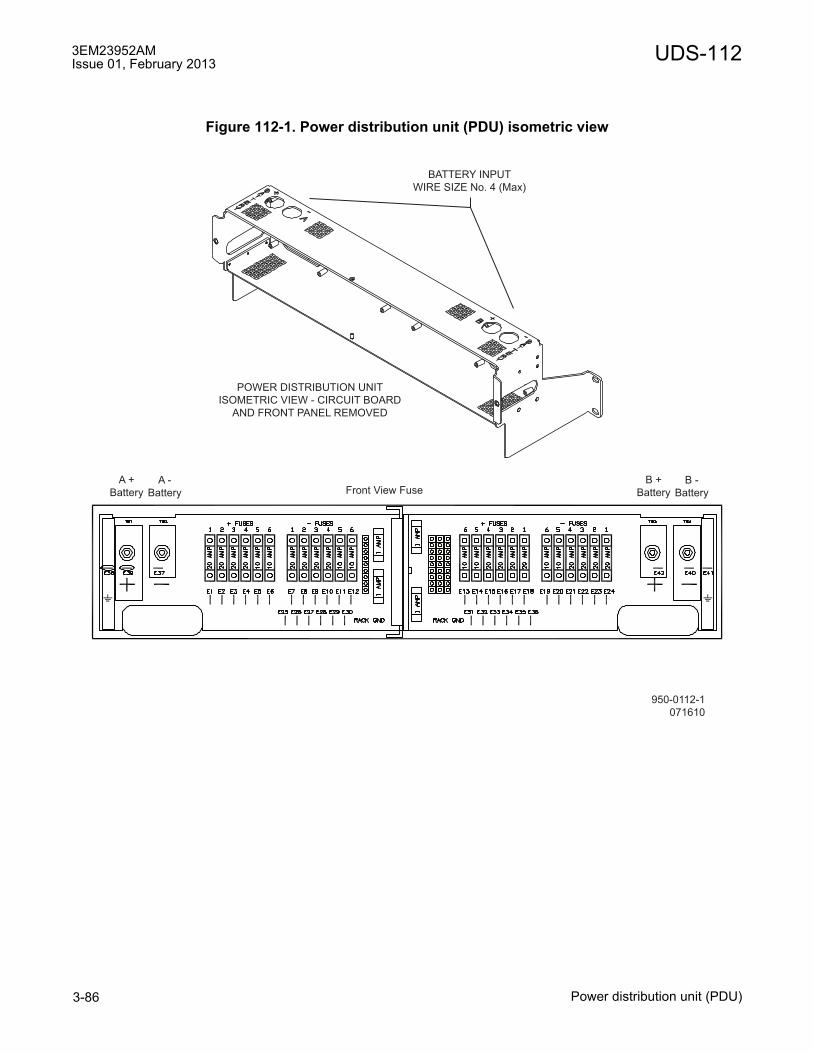
3EM23952AMIssue 01, February 2013
Power distribution unit (PDU)3-86
UDS-112
Figure 112-1. Power distribution unit (PDU) isometric view
950-0112-1
071610
Front View FuseA +
Battery
A -
Battery
B +
Battery
B -
Battery
BATTERY INPUT
WIRE SIZE No. 4 (Max)
POWER DISTRIBUTION UNIT
ISOMETRIC VIEW - CIRCUIT BOARD
AND FRONT PANEL REMOVED
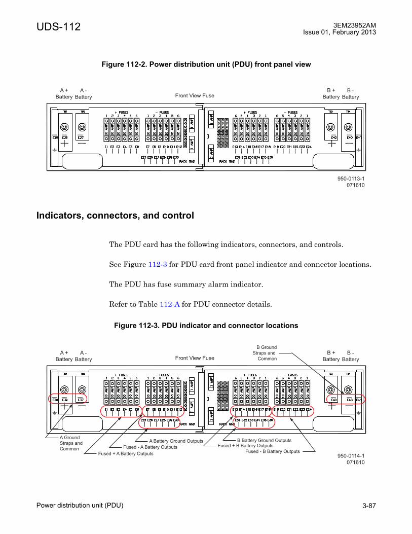
UDS-112 3EM23952AMIssue 01, February 2013
Power distribution unit (PDU) 3-87
Indicators, connectors, and control
The PDU card has the following indicators, connectors, and controls.
See Figure 112-3 for PDU card front panel indicator and connector locations.
The PDU has fuse summary alarm indicator.
Refer to Table 112-A for PDU connector details.
Figure 112-2. Power distribution unit (PDU) front panel view
Figure 112-3. PDU indicator and connector locations
950-0113-1
071610
Front View FuseA +
Battery
A -
Battery
B +
Battery
B -
Battery
950-0114-1
071610
Front View FuseA +
Battery
A -
Battery
B +
Battery
B -
Battery
Fused + A Battery Outputs
A Battery Ground Outputs
Fused - A Battery Outputs Fused + B Battery OutputsB Battery Ground Outputs
Fused - B Battery Outputs
A Ground
Straps and
Common
B Ground
Straps and
Common

3EM23952AMIssue 01, February 2013
Power distribution unit (PDU)3-88
UDS-112
Table 112-A. PDU connector detailsCONNECTOR DESIGNATOR TYPE FUNCTIONA+ TB1 One-Hole,
0.250 inch, compression lug
A Battery positive battery inputA- TB2 A Battery negative battery inputB+ TB3 B Battery positive battery inputB- TB4 B Battery negative battery inputFA1+ E1 Fused A1 battery positive outputFA2+ E2 Fused A2 battery positive outputFA3+ E3 Fused A3 battery positive outputFA4+ E4 Fused A4 battery positive outputFA5+ E5 Fused A5 battery positive outputFA6+ E6 Fused A6 battery positive outputFA1- E7 Fused A1 battery negative outputFA2- E8 Fused A2 battery negative outputFA3- E9 Fused A3 battery negative outputFA4- E10 Fused A4 battery negative outputFA5- E11 Fused A5 battery negative outputFA6- E12 Fused A6 battery negative outputFB1+ E13 Fused B1 battery positive outputFB2+ E14 Fused B2 battery positive outputFB3+ E15 Fused B3 battery positive outputFB4+ E16 Fused B4 battery positive outputFB5+ E17 Fused B5 battery positive outputFB6+ E18 Fused B6 battery positive outputFB1- E19 Fused B1 battery negative outputFB2- E20 Fused B2 battery negative outputFB3- E21 Fused B3 battery negative outputFB4- E22 Fused B4 battery negative output
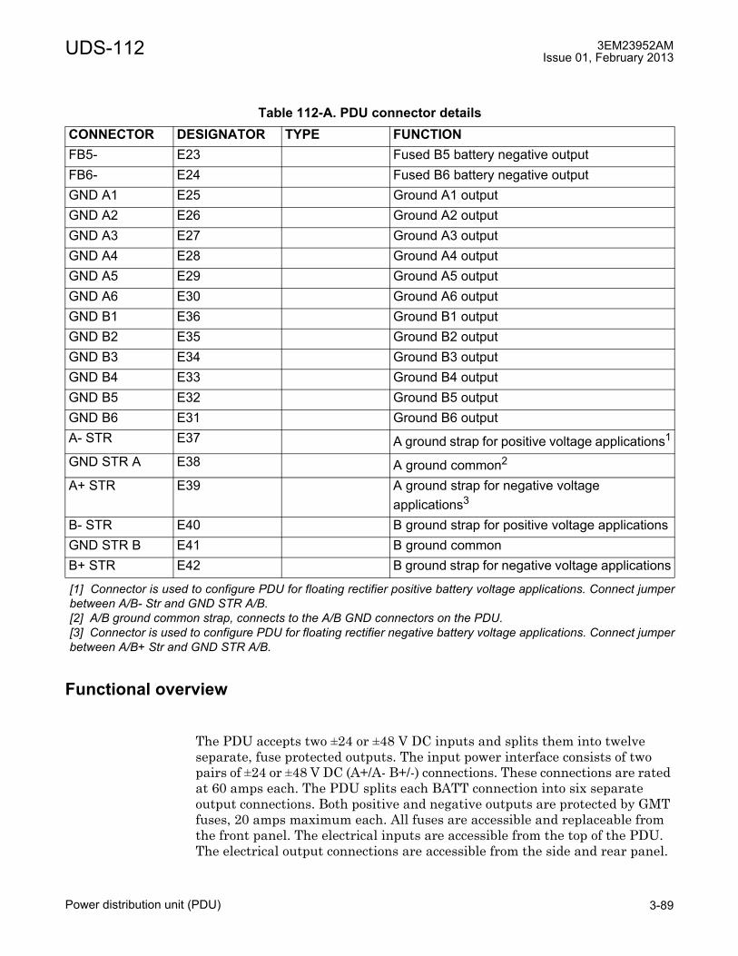
UDS-112 3EM23952AMIssue 01, February 2013
Power distribution unit (PDU) 3-89
Functional overview
The PDU accepts two ±24 or ±48 V DC inputs and splits them into twelve separate, fuse protected outputs. The input power interface consists of two pairs of ±24 or ±48 V DC (A+/A- B+/-) connections. These connections are rated at 60 amps each. The PDU splits each BATT connection into six separate output connections. Both positive and negative outputs are protected by GMT fuses, 20 amps maximum each. All fuses are accessible and replaceable from the front panel. The electrical inputs are accessible from the top of the PDU. The electrical output connections are accessible from the side and rear panel.
FB5- E23 Fused B5 battery negative outputFB6- E24 Fused B6 battery negative outputGND A1 E25 Ground A1 outputGND A2 E26 Ground A2 outputGND A3 E27 Ground A3 outputGND A4 E28 Ground A4 outputGND A5 E29 Ground A5 outputGND A6 E30 Ground A6 outputGND B1 E36 Ground B1 outputGND B2 E35 Ground B2 outputGND B3 E34 Ground B3 outputGND B4 E33 Ground B4 outputGND B5 E32 Ground B5 outputGND B6 E31 Ground B6 outputA- STR E37 A ground strap for positive voltage applications1
GND STR A E38 A ground common2
A+ STR E39 A ground strap for negative voltage applications3
B- STR E40 B ground strap for positive voltage applicationsGND STR B E41 B ground commonB+ STR E42 B ground strap for negative voltage applications
[1] Connector is used to configure PDU for floating rectifier positive battery voltage applications. Connect jumperbetween A/B- Str and GND STR A/B.[2] A/B ground common strap, connects to the A/B GND connectors on the PDU.[3] Connector is used to configure PDU for floating rectifier negative battery voltage applications. Connect jumperbetween A/B+ Str and GND STR A/B.
Table 112-A. PDU connector detailsCONNECTOR DESIGNATOR TYPE FUNCTION

3EM23952AMIssue 01, February 2013
Power distribution unit (PDU)3-90
UDS-112
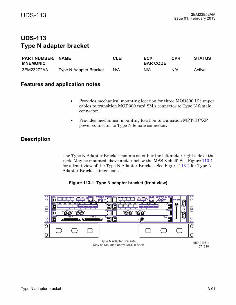
UDS-113 3EM23952AMIssue 01, February 2013
Type N adapter bracket 3-91
UDS-113 Type N adapter bracket
UDS-113Type N adapter bracket
Features and application notes
• Provides mechanical mounting location for three MOD300 IF jumper cables to transition MOD300 card SMA connector to Type N female connector.
• Provides mechanical mounting location to transition MPT-HC/XP power connector to Type N female connector.
Description
The Type N Adapter Bracket mounts on either the left and/or right side of the rack. May be mounted above and/or below the MSS-8 shelf. See Figure 113-1 for a front view of the Type N Adapter Bracket. See Figure 113-2 for Type N Adapter Bracket dimensions.
PART NUMBER/MNEMONIC
NAME CLEI ECI/BAR CODE
CPR STATUS
3EM23272AA Type N Adapter Bracket N/A N/A N/A Active
Figure 113-1. Type N adapter bracket (front view)
950-0116-1
071610
Type N Adapter Brackets
May be Mounted above MSS-8 Shelf

3EM23952AMIssue 01, February 2013
Type N adapter bracket3-92
UDS-113
Figure 113-2. Type N adapter bracket dimensions
950-0115-1
071610
1.72
6.10
1.73 1.770 1.770

UDS-114 3EM23952AMIssue 01, February 2013
DS1 RJ-45 Patch Panel 3-93
UDS-114 DS1 RJ-45 Patch Panel
UDS-114DS1 RJ-45 Patch Panel
Features and application notes
• Converts P32E1DS1 card SCSI connectors to thirty-two RJ-45 connectors.
• MSS-1 shelf support: converts MSS-1 shelf MSS/DS1 connector to sixteen RJ-45 connectors.
� Supports up to two MSS-1 shelves
� Requires one 68 pin SCSI cable per MSS-1 shelf
• Supports both protected and non-protected P32E1DS1 applications.
• Requires two 68 pin SCSI cables in non-protected DS1 configuration. Requires four 68 pin SCSI cables in protected DS1 configuration.
Description
The DS1 RJ-45 Patch Panel mounts above and/or below the MSS-1/4/8 shelf. Requires 1.5 rack increments.
Customer interconnect are thirty-two RJ-45 connectors, I/O 1 through I/O 32. Each RJ-45 connector supports one DS1 signal, 1 through 32 respectively and provides both input and output signal connections. Four 68 pin SCSI connectors interconnects the main and spare P32E1DS1 card connectors. See Figure 114-1 for a front view of the DS1 RJ-45 Patch Panel. See Figure 114-2 for a rear view of the DS1 RJ-45 Patch Panel.
PART NUMBER/MNEMONIC
NAME CLEI ECI/BAR CODE
CPR STATUS
1AF15245AB DS1 RJ-45 Patch Panel N/A N/A N/A Active

3EM23952AMIssue 01, February 2013
DS1 RJ-45 Patch Panel3-94
UDS-114
Connectors
Refer to Table 114-A for DS1 RJ-45 Patch Panel connector details for P32E1DS1 card.
Figure 114-1. DS1 RJ-45 patch panel (front view)
Figure 114-2. DS1 RJ-45 patch panel (rear view)
Table 114-A. P32E1DS1 DS1 card front panel connector detailsCONNECTOR TYPE FUNCTIONI/O (1- 32) RJ-45 DS1, Tx and Rx (tip and ring), interconnect
DS1s number 1 through 32M1 64 position SCSI
connectorDS1, Tx and Rx (tip and ring), interconnectDS1s number 1 through 16, Main
M2 64 position SCSI connector
DS1, Tx and Rx (tip and ring), interconnectDS1s number 17 through 32, Main
M3 64 position SCSI connector
DS1, Tx and Rx (tip and ring), interconnectDS1s number 1 through 16, Spare
M4 64 position SCSI connector
DS1, Tx and Rx (tip and ring), interconnectDS1s number 17 through 32, Spare
950-0117-1
071710
RJ-45 DS1 Patch Panel
Front View
950-0118-1
071710
RJ-45 DS1 Patch Panel
Rear View
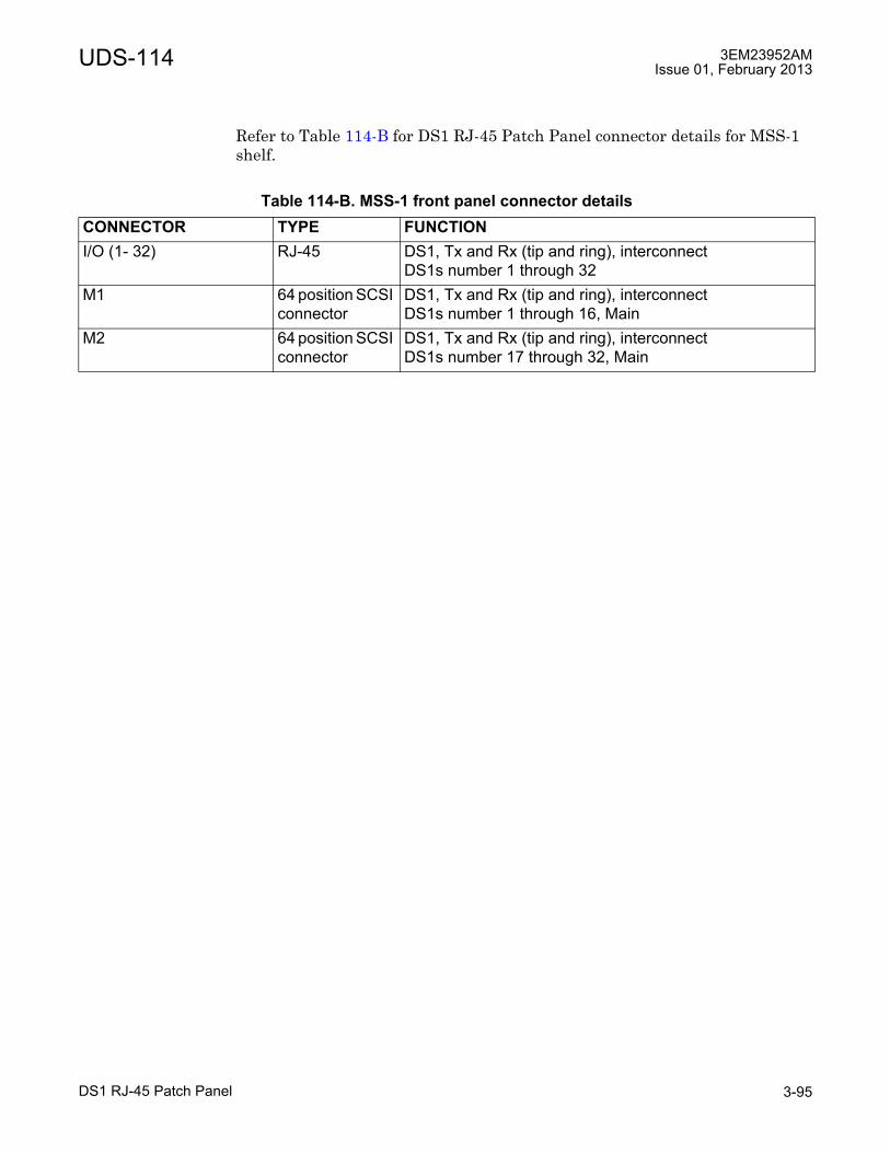
UDS-114 3EM23952AMIssue 01, February 2013
DS1 RJ-45 Patch Panel 3-95
Refer to Table 114-B for DS1 RJ-45 Patch Panel connector details for MSS-1 shelf.
Table 114-B. MSS-1 front panel connector detailsCONNECTOR TYPE FUNCTIONI/O (1- 32) RJ-45 DS1, Tx and Rx (tip and ring), interconnect
DS1s number 1 through 32M1 64 position SCSI
connectorDS1, Tx and Rx (tip and ring), interconnectDS1s number 1 through 16, Main
M2 64 position SCSI connector
DS1, Tx and Rx (tip and ring), interconnectDS1s number 17 through 32, Main

3EM23952AMIssue 01, February 2013
DS1 RJ-45 Patch Panel3-96
UDS-114

UDS-115 3EM23952AMIssue 01, February 2013
DS1/MSS-1 d-connector patch panel 3-97
UDS-115 DS1/MSS-1 d-connector patch panel
UDS-115DS1/MSS-1 d-connector patch panel
Features and application notes
• Converts P32E1DS1 card SCSI connectors to four 37 position DSUB connectors.
• MSS-1 shelf support: converts MSS-1 shelf MSS/DS1 SCSI connector to sixteen DSUB connectors.
� Supports up to two MSS-1 shelves
� Requires one 68 pin SCSI cable per MSS-1 shelf
• Supports both protected and non-protected P32E1DS1 applications.
• Requires two 68 pin SCSI cables in non-protected DS1 configuration. Requires four 68 pin SCSI cables in protected DS1 configuration.
Description
The DS1 D-Connector Patch Panel mounts above and/or below the MSS-8 shelf. Requires 1 rack increments.
Customer interconnect are the four 37 position DSUB connectors. Each 37 position DSUB connector supports eight DS1 signals. Four 68 pin SCSI connectors interconnects the main and spare P32E1DS1 card connectors. See Figure 115-1 for a front view of the DS1 D-Connector Patch Panel. See Figure 115-2 for a rear view of the DS1 D-Connector Patch Panel.
PART NUMBER/MNEMONIC
NAME CLEI ECI/BAR CODE
CPR STATUS
3DB16102AA DS1 D-Connector Patch Panel
N/A N/A N/A Active

3EM23952AMIssue 01, February 2013
DS1/MSS-1 d-connector patch panel3-98
UDS-115
Connectors
Refer to Table 115-A for DS1 D-Connector Patch Panel connector details.
Figure 115-1. DS1 RJ-45 patch panel (front view)
Figure 115-2. DS1 RJ-45 patch panel (rear view)
Table 115-A. P32E1DS1 DS1 card front panel connector detailsCONNECTOR TYPE FUNCTIONE1/DS1 - 1/8 37 position
DSUB connectorDS1, Tx and Rx (tip and ring), Customer InterconnectDS1s number 1 through 8
E1/DS1 - 9/16 37 positionDSUB connector
DS1, Tx and Rx (tip and ring), Customer InterconnectDS1s number 9 through 16
E1/DS1 - 17/24 37 positionDSUB connector
DS1, Tx and Rx (tip and ring), Customer InterconnectDS1s number 17 through 24
E1/DS1 - 25/32 37 positionDSUB connector
DS1, Tx and Rx (tip and ring), Customer InterconnectDS1s number 25 through 32
E1/DS1 - 1/16 Main 64 positionSCSI connector
DS1, Tx and Rx (tip and ring), P32E1DS1 InterconnectDS1s number 1 through 16, Main
950-0119-1
071710
37 Pin DSUB
DS1 Patch Panel
Front View
E1/DS1-17/24
E1/DS1-25/32 E1/DS1-9/16
E1/DS1-1/8
950-0120-1
071710
37 Pin DSUB
DS1 Patch Panel
Rear View
E1/DS1-1/16 EXT
E1/DS1-1/16 MAIN E1/DS1-17/32 MAIN
E1/DS1-7/32 EXT

UDS-115 3EM23952AMIssue 01, February 2013
DS1/MSS-1 d-connector patch panel 3-99
Refer to Table 115-B for MSS-1 D-Connector Patch Panel connector details.
E1/DS1 - 17/32 Main 64 positionSCSI connector
DS1, Tx and Rx (tip and ring), P32E1DS1 InterconnectDS1s number 17 through 32, Main
E1/DS1 - 1/16 Spare 64 positionSCSI connector
DS1, Tx and Rx (tip and ring), P32E1DS1 InterconnectDS1s number 1 through 16, Spare
E1/DS1 - 17/32 Spare 64 positionSCSI connector
DS1, Tx and Rx (tip and ring), P32E1DS1 InterconnectDS1s number 17 through 32, Spare
Table 115-B. MSS-1 front panel connector detailsCONNECTOR TYPE FUNCTIONE1/DS1 - 1/8 37 position
DSUB connectorDS1, Tx and Rx (tip and ring), Customer InterconnectDS1s number 1 through 8
E1/DS1 - 9/16 37 positionDSUB connector
DS1, Tx and Rx (tip and ring), Customer InterconnectDS1s number 9 through 16
E1/DS1 - 17/24 37 positionDSUB connector
DS1, Tx and Rx (tip and ring), Customer InterconnectDS1s number 17 through 24
E1/DS1 - 25/32 37 positionDSUB connector
DS1, Tx and Rx (tip and ring), Customer InterconnectDS1s number 25 through 32
E1/DS1 - 1/16 Main 64 positionSCSI connector
DS1, Tx and Rx (tip and ring), P32E1DS1 InterconnectDS1s number 1 through 16, Main
E1/DS1 - 17/32 Main 64 positionSCSI connector
DS1, Tx and Rx (tip and ring), P32E1DS1 InterconnectDS1s number 17 through 32, Main
Table 115-A. P32E1DS1 DS1 card front panel connector detailsCONNECTOR TYPE FUNCTION

3EM23952AMIssue 01, February 2013
DS1/MSS-1 d-connector patch panel3-100
UDS-115

UDS-116 3EM23952AMIssue 01, February 2013
3 dB hybrid splitter 3-101
UDS-116 3 dB hybrid splitter
UDS-1163 dB hybrid splitter
Description
External 3 dB hybrid splitter used to interconnect protected DS3 signals.
Connectors
Refer to Table 116-A for DS3 Hybrid Splitter connector details.
PART NUMBER/MNEMONIC
NAME CLEI ECI/BAR CODE
CPR STATUS
3EM22900AA DS3 Hybrid Splitter N/A N/A N/A Active
Figure 116-1. Hybrid splitter interconnect
950-0201-1
022610
Spare SideMini BNC Connectors
SLINE 2INOUT
LINE 1INOUT
9500 MPR DS3 Trib (Protected Pair)
MSS-8 ShelfMain SideMini BNC Connectors
LINE 2INOUT
LINE 1INOUT
S P2E3DS3P2E3DS3
BNC Panel Mount
Customer Connectors
Line 1
OutLine 1
InLine 2
Out
Line 2
In

3EM23952AMIssue 01, February 2013
3 dB hybrid splitter3-102
UDS-116
Table 116-A. Hybrid splitter connector detailCONNECTOR TYPE FUNCTIONCustomer Interconnect 75 ohm BNC,
Female Protected DS3 customer interconnect, input and output.
P2E3DS3 Card Interconnect
75 ohm male, mini-BNC
Protected DS3 P2E3DS3 Card interconnect, input and output.

UDS-117 3EM23952AMIssue 01, February 2013
MSS-4 microwave service switch shelf 3-103
UDS-117 MSS-4 microwave service switch shelf
UDS-117MSS-4 microwave service switch shelf
Features and application notes
• The Microwave Service Switch (MSS-4) shelf provides cross-connection, port aggregation, switching, and equipment management.
• 16Gb Packet Based Node
• 300 Mbps full-duplex Ethernet transport capacity
• Flexible aggregate capacity sharing DS1, DS3, OC-3 and Ethernet traffic
• Split mount configuration utilizing the MOD300 radio cards support up to two unprotected RF channels, one 1+1 HSB, Space Diversity (SD) or Frequency Diversity (FD) protected RF channels in one MSS-4 shelf connected to up to two ODU300s.
• Split mount configuration utilizing the MPTACC card supports up to four unprotected RF channels, up to two 1+1 HSB, Space Diversity (SD) or Frequency Diversity (FD) protected RF channels in one MSS-4 shelf connected to up to four MPT-HC/XP Transceivers.
• Split mount configuration utilizing the Core-E SFP ports supports:
� up to two unprotected RF channels in one MSS-4 shelf connected to up to two MPT-HC/XP and/or MPT-GC Transceivers
� up to one protected RF channel in one MSS-4 shelf connected to up to two MPT-HC/XP Transceivers.
PART NUMBER/MNEMONIC
NAME CLEI ECI/BAR CODE
CPR STATUS
3DB18219AB MSS-4 Microwave Service Switch Shelf
N/A N/A N/A Active
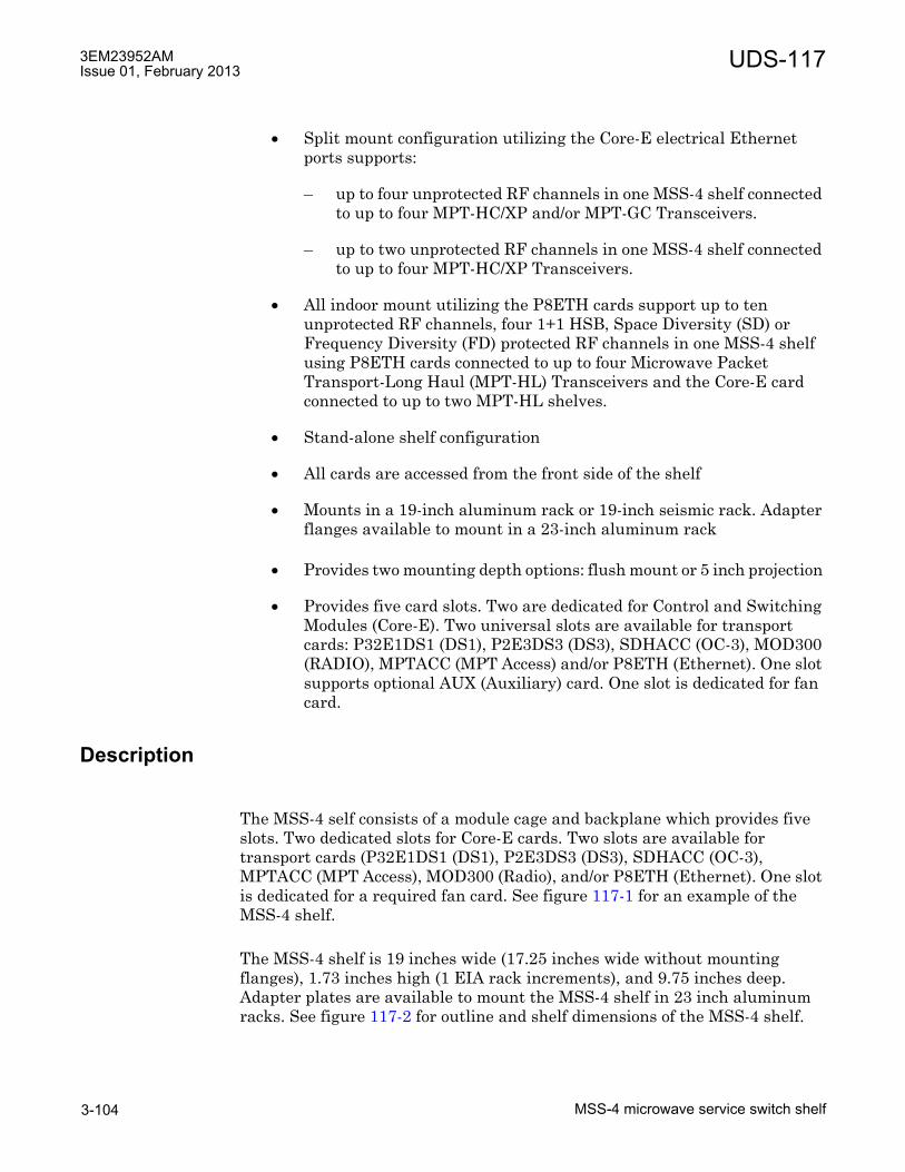
3EM23952AMIssue 01, February 2013
MSS-4 microwave service switch shelf3-104
UDS-117
• Split mount configuration utilizing the Core-E electrical Ethernet ports supports:
� up to four unprotected RF channels in one MSS-4 shelf connected to up to four MPT-HC/XP and/or MPT-GC Transceivers.
� up to two unprotected RF channels in one MSS-4 shelf connected to up to four MPT-HC/XP Transceivers.
• All indoor mount utilizing the P8ETH cards support up to ten unprotected RF channels, four 1+1 HSB, Space Diversity (SD) or Frequency Diversity (FD) protected RF channels in one MSS-4 shelf using P8ETH cards connected to up to four Microwave Packet Transport-Long Haul (MPT-HL) Transceivers and the Core-E card connected to up to two MPT-HL shelves.
• Stand-alone shelf configuration
• All cards are accessed from the front side of the shelf
• Mounts in a 19-inch aluminum rack or 19-inch seismic rack. Adapter flanges available to mount in a 23-inch aluminum rack
• Provides two mounting depth options: flush mount or 5 inch projection
• Provides five card slots. Two are dedicated for Control and Switching Modules (Core-E). Two universal slots are available for transport cards: P32E1DS1 (DS1), P2E3DS3 (DS3), SDHACC (OC-3), MOD300 (RADIO), MPTACC (MPT Access) and/or P8ETH (Ethernet). One slot supports optional AUX (Auxiliary) card. One slot is dedicated for fan card.
Description
The MSS-4 self consists of a module cage and backplane which provides five slots. Two dedicated slots for Core-E cards. Two slots are available for transport cards (P32E1DS1 (DS1), P2E3DS3 (DS3), SDHACC (OC-3), MPTACC (MPT Access), MOD300 (Radio), and/or P8ETH (Ethernet). One slot is dedicated for a required fan card. See figure 117-1 for an example of the MSS-4 shelf.
The MSS-4 shelf is 19 inches wide (17.25 inches wide without mounting flanges), 1.73 inches high (1 EIA rack increments), and 9.75 inches deep. Adapter plates are available to mount the MSS-4 shelf in 23 inch aluminum racks. See figure 117-2 for outline and shelf dimensions of the MSS-4 shelf.

UDS-117 3EM23952AMIssue 01, February 2013
MSS-4 microwave service switch shelf 3-105
D
Equipment complement
MSS-4 shelf slots 1 and 2 are dedicated to the Core-E card. Slots 3 and 4 are available for transport cards; P32E1DS1, P2E3DS3, MPTACC, MOD300, SDGACC, and/or P8ETH. Slot 4 supports optional AUX card. Slot 5 is dedicated for required fan card. See figure 117-3 for MSS-4 shelf slot definitions. Refer to Table 117-A for details of card equipage options.
Figure 117-1. Microwave service switch (MSS-4) shelf
Figure 117-2. MSS-4 shelf dimensions
950-0045-1
092110
MSS-4 Shelf
17.25
9.75
1.73
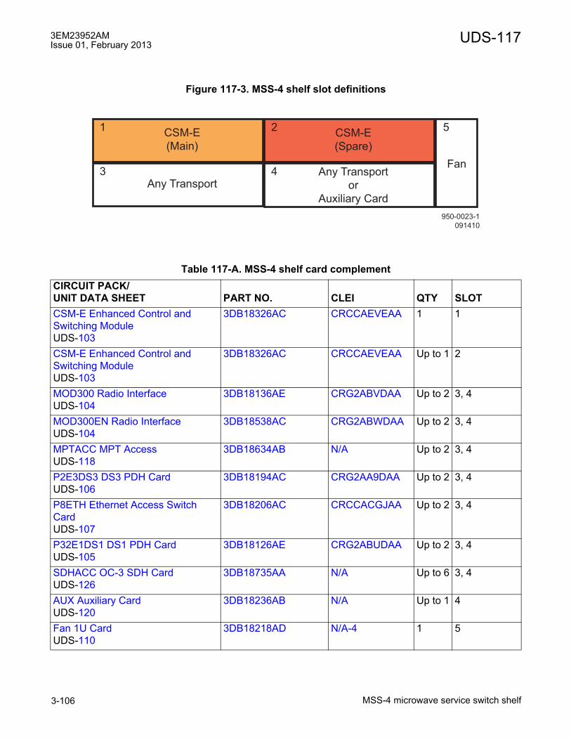
3EM23952AMIssue 01, February 2013
MSS-4 microwave service switch shelf3-106
UDS-117
Figure 117-3. MSS-4 shelf slot definitions
Table 117-A. MSS-4 shelf card complementCIRCUIT PACK/UNIT DATA SHEET PART NO. CLEI QTY SLOTCSM-E Enhanced Control and Switching ModuleUDS-103
3DB18326AC CRCCAEVEAA 1 1
CSM-E Enhanced Control and Switching ModuleUDS-103
3DB18326AC CRCCAEVEAA Up to 1 2
MOD300 Radio InterfaceUDS-104
3DB18136AE CRG2ABVDAA Up to 2 3, 4
MOD300EN Radio InterfaceUDS-104
3DB18538AC CRG2ABWDAA Up to 2 3, 4
MPTACC MPT AccessUDS-118
3DB18634AB N/A Up to 2 3, 4
P2E3DS3 DS3 PDH CardUDS-106
3DB18194AC CRG2AA9DAA Up to 2 3, 4
P8ETH Ethernet Access Switch CardUDS-107
3DB18206AC CRCCACGJAA Up to 2 3, 4
P32E1DS1 DS1 PDH CardUDS-105
3DB18126AE CRG2ABUDAA Up to 2 3, 4
SDHACC OC-3 SDH CardUDS-126
3DB18735AA N/A Up to 6 3, 4
AUX Auxiliary CardUDS-120
3DB18236AB N/A Up to 1 4
Fan 1U Card UDS-110
3DB18218AD N/A-4 1 5
950-0023-1
091410
CSM-E
(Spare)
Any TransportAny Transport
or
Auxiliary Card
CSM-E
(Main)
Fan
52
4
1
3
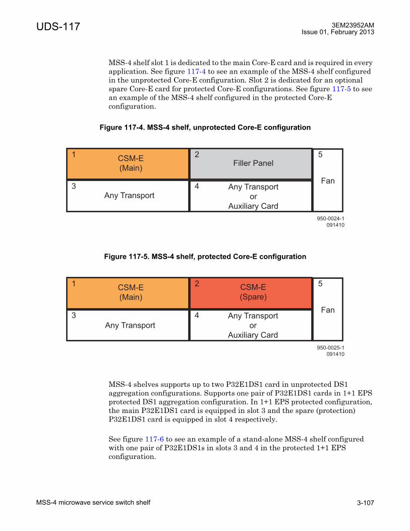
UDS-117 3EM23952AMIssue 01, February 2013
MSS-4 microwave service switch shelf 3-107
MSS-4 shelf slot 1 is dedicated to the main Core-E card and is required in every application. See figure 117-4 to see an example of the MSS-4 shelf configured in the unprotected Core-E configuration. Slot 2 is dedicated for an optional spare Core-E card for protected Core-E configurations. See figure 117-5 to see an example of the MSS-4 shelf configured in the protected Core-E configuration.
MSS-4 shelves supports up to two P32E1DS1 card in unprotected DS1 aggregation configurations. Supports one pair of P32E1DS1 cards in 1+1 EPS protected DS1 aggregation configuration. In 1+1 EPS protected configuration, the main P32E1DS1 card is equipped in slot 3 and the spare (protection) P32E1DS1 card is equipped in slot 4 respectively.
See figure 117-6 to see an example of a stand-alone MSS-4 shelf configured with one pair of P32E1DS1s in slots 3 and 4 in the protected 1+1 EPS configuration.
Figure 117-4. MSS-4 shelf, unprotected Core-E configuration
Figure 117-5. MSS-4 shelf, protected Core-E configuration
950-0024-1
091410
CSM-E
(Main)
Fan
52
4
1
3
Filler Panel
Any Transport Any Transport
or
Auxiliary Card
950-0025-1
091410
CSM-E
(Main)
Fan
52
4
1
3
CSM-E
(Spare)
Any Transport
Any Transport
or
Auxiliary Card
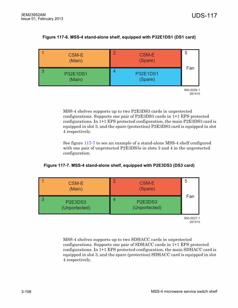
3EM23952AMIssue 01, February 2013
MSS-4 microwave service switch shelf3-108
UDS-117
MSS-4 shelves supports up to two P2E3DS3 cards in unprotected configurations. Supports one pair of P2E3DS3 cards in 1+1 EPS protected configurations. In 1+1 EPS protected configuration, the main P2E3DS3 card is equipped in slot 3, and the spare (protection) P2E3DS3 card is equipped in slot 4 respectively.
See figure 117-7 to see an example of a stand-alone MSS-4 shelf configured with one pair of unprotected P2E3DS3s in slots 3 and 4 in the unprotected configuration.
MSS-4 shelves supports up to two SDHACC cards in unprotected configurations. Supports one pair of SDHACC cards in 1+1 EPS protected configurations. In 1+1 EPS protected configuration, the main SDHACC card is equipped in slot 3, and the spare (protection) SDHACC card is equipped in slot 4 respectively.
Figure 117-6. MSS-4 stand-alone shelf, equipped with P32E1DS1 (DS1 card)
Figure 117-7. MSS-4 stand-alone shelf, equipped with P2E3DS3 (DS3 card)
950-0026-1
091410
CSM-E
(Main)
Fan
52
4
1
3
CSM-E
(Spare)
P32E1DS1
(Main)
P32E1DS1
(Spare)
950-0027-1
091510
CSM-E
(Main)
Fan
52
4
1
3
CSM-E
(Spare)
P2E3DS3
(Unportected)
P2E3DS3
(Unportected)

UDS-117 3EM23952AMIssue 01, February 2013
MSS-4 microwave service switch shelf 3-109
MSS-4 shelves supports up to two MOD300 cards in unprotected RF radio configurations. Supports one pair of MOD300 cards in protected RF radio in 1+1 HSB, SD or FD configurations. In 1+1 HSB, SD or FD configurations, the main MOD300 card is equipped in slots 3 and the spare (protection) MOD300 card is equipped in slot 4 respectively.
See figure 117-8 to see an example of the MSS-4 shelf configured as a split mount, 1+0 drop and insert repeater configuration.
See figure 117-9 to see an example of the MSS-4 shelf configured as a split mount, 1+1 terminal configuration.
Figure 117-8. MSS-4 shelf, split mount using MOD300, 1+0 drop and insert repeater configuration
Figure 117-9. MSS-4 shelf, split mount using MOD300, 1+1 terminal configuration
950-0028-2
053111
CSM-E
(Main)
Fan
52
4
1
3
CSM-E
(Spare)
MOD300
(Unprotected)
MOD300
(Unprotected)
950-0029-1
091410
CSM-E
(Main)
Fan
52
4
1
3
CSM-E
(Spare)
MOD300
(Main)
MOD300
(Spare)
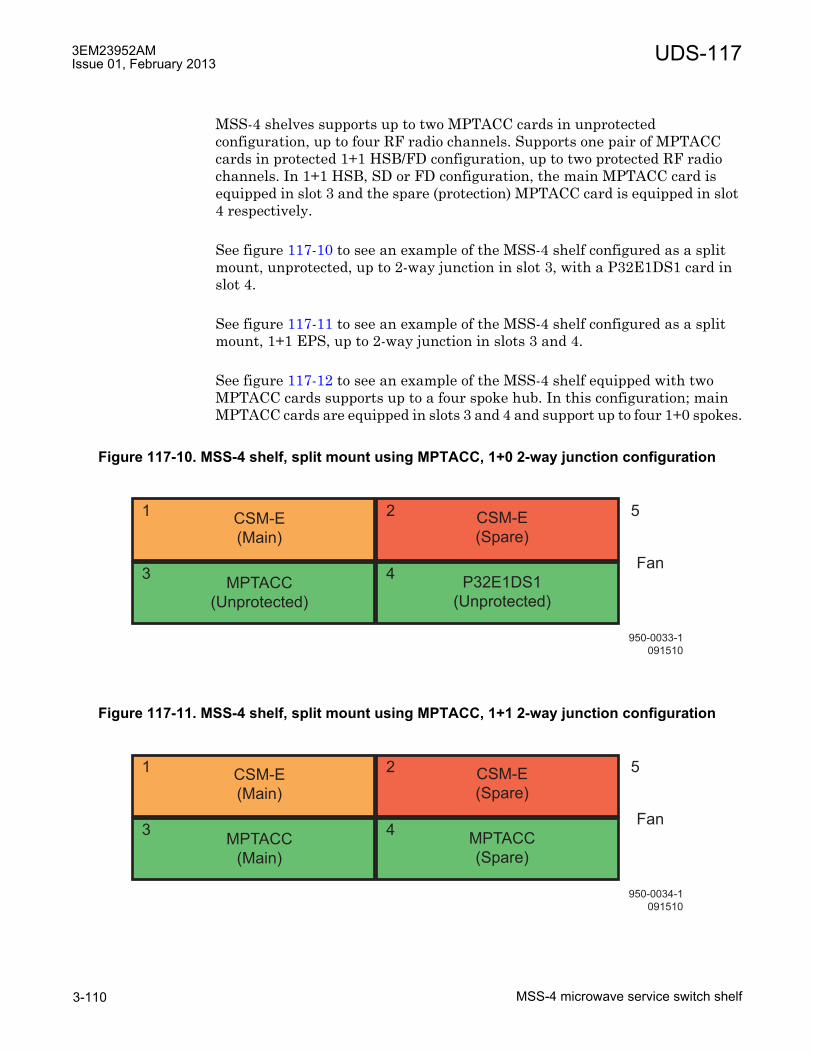
3EM23952AMIssue 01, February 2013
MSS-4 microwave service switch shelf3-110
UDS-117
MSS-4 shelves supports up to two MPTACC cards in unprotected configuration, up to four RF radio channels. Supports one pair of MPTACC cards in protected 1+1 HSB/FD configuration, up to two protected RF radio channels. In 1+1 HSB, SD or FD configuration, the main MPTACC card is equipped in slot 3 and the spare (protection) MPTACC card is equipped in slot 4 respectively.
See figure 117-10 to see an example of the MSS-4 shelf configured as a split mount, unprotected, up to 2-way junction in slot 3, with a P32E1DS1 card in slot 4.
See figure 117-11 to see an example of the MSS-4 shelf configured as a split mount, 1+1 EPS, up to 2-way junction in slots 3 and 4.
See figure 117-12 to see an example of the MSS-4 shelf equipped with two MPTACC cards supports up to a four spoke hub. In this configuration; main MPTACC cards are equipped in slots 3 and 4 and support up to four 1+0 spokes.
Figure 117-10. MSS-4 shelf, split mount using MPTACC, 1+0 2-way junction configuration
Figure 117-11. MSS-4 shelf, split mount using MPTACC, 1+1 2-way junction configuration
950-0033-1
091510
CSM-E
(Main)
Fan
52
4
1
3
CSM-E
(Spare)
MPTACC
(Unprotected)
P32E1DS1
(Unprotected)
950-0034-1
091510
CSM-E
(Main)
Fan
52
4
1
3
CSM-E
(Spare)
MPTACC
(Main)
MPTACC
(Spare)
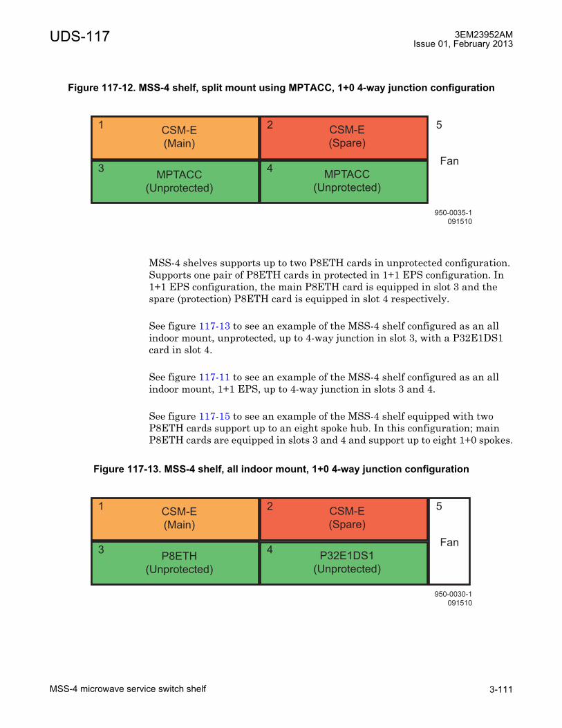
UDS-117 3EM23952AMIssue 01, February 2013
MSS-4 microwave service switch shelf 3-111
MSS-4 shelves supports up to two P8ETH cards in unprotected configuration. Supports one pair of P8ETH cards in protected in 1+1 EPS configuration. In 1+1 EPS configuration, the main P8ETH card is equipped in slot 3 and the spare (protection) P8ETH card is equipped in slot 4 respectively.
See figure 117-13 to see an example of the MSS-4 shelf configured as an all indoor mount, unprotected, up to 4-way junction in slot 3, with a P32E1DS1 card in slot 4.
See figure 117-11 to see an example of the MSS-4 shelf configured as an all indoor mount, 1+1 EPS, up to 4-way junction in slots 3 and 4.
See figure 117-15 to see an example of the MSS-4 shelf equipped with two P8ETH cards support up to an eight spoke hub. In this configuration; main P8ETH cards are equipped in slots 3 and 4 and support up to eight 1+0 spokes.
Figure 117-12. MSS-4 shelf, split mount using MPTACC, 1+0 4-way junction configuration
Figure 117-13. MSS-4 shelf, all indoor mount, 1+0 4-way junction configuration
950-0035-1
091510
CSM-E
(Main)
Fan
52
4
1
3
CSM-E
(Spare)
MPTACC
(Unprotected)
MPTACC
(Unprotected)
950-0030-1
091510
CSM-E
(Main)
Fan
52
4
1
3
CSM-E
(Spare)
P8ETH
(Unprotected)
P32E1DS1
(Unprotected)
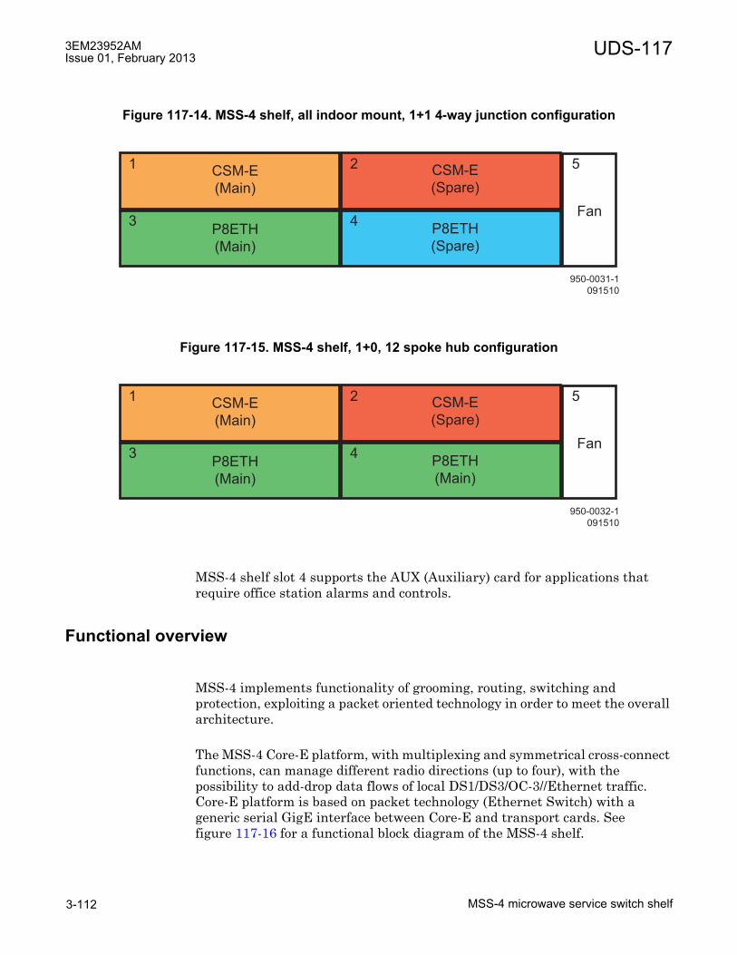
3EM23952AMIssue 01, February 2013
MSS-4 microwave service switch shelf3-112
UDS-117
MSS-4 shelf slot 4 supports the AUX (Auxiliary) card for applications that require office station alarms and controls.
Functional overview
MSS-4 implements functionality of grooming, routing, switching and protection, exploiting a packet oriented technology in order to meet the overall architecture.
The MSS-4 Core-E platform, with multiplexing and symmetrical cross-connect functions, can manage different radio directions (up to four), with the possibility to add-drop data flows of local DS1/DS3/OC-3//Ethernet traffic. Core-E platform is based on packet technology (Ethernet Switch) with a generic serial GigE interface between Core-E and transport cards. See figure 117-16 for a functional block diagram of the MSS-4 shelf.
Figure 117-14. MSS-4 shelf, all indoor mount, 1+1 4-way junction configuration
Figure 117-15. MSS-4 shelf, 1+0, 12 spoke hub configuration
950-0031-1
091510
CSM-E
(Main)
Fan
52
4
1
3
CSM-E
(Spare)
P8ETH
(Main)
P8ETH
(Spare)
950-0032-1
091510
CSM-E
(Main)
Fan
52
4
1
3
CSM-E
(Spare)
P8ETH
(Main)
P8ETH
(Main)

UDS-117 3EM23952AMIssue 01, February 2013
MSS-4 microwave service switch shelf 3-113
The MSS-4 shelf houses the following cards:
• AUX Auxiliary card�houses one optional Auxiliary card in slot 4. Auxiliary card provides six station alarm inputs and seven station alarm control outputs.
• Core-E Control and Switching Module�houses one main and one optional spare control and switching module(s). Provides four 10/100/1000 Base-T Ethernet ports. Provides two GigE optical Ethernet port.
Figure 117-16. MSS-4 shelf block diagram

3EM23952AMIssue 01, February 2013
MSS-4 microwave service switch shelf3-114
UDS-117
• MOD300 Radio card�houses up to two MOD300 cards. In the Tx direction, converts Ethernet packet data from the Core-E card card(s) into a modulated IF output signal that is applied to the ODU300. In the Rx direction, demodulates the IF input signal from the ODU300, encapsulates the digital data into Ethernet packets, and sends the packets to the Core-E card(s).
• P2E3DS3 DS3 PDH card�houses up to two P2E3DS3 cards for DS3 TDM traffic encapsulation/extraction into standard Ethernet packets
• P8ETH Ethernet Access Switch�houses up to two P8ETH cards for MSS-4-to-MPT-HL interface for all indoor configurations. The P8ETH card functions as a layer 2 switch, cross-connecting VLAN tagged Ethernet data to/from the addressed MPT-HL. The P8ETH card provides traffic management for Core-Es for up to four directions using protected radios and up to eight directions using unprotected radios. P8ETH cards also provide four 10/100/1000 Base-T Ethernet ports and up to four GigE optical Ethernet ports.
• SDHACC OC-3 SDH card�houses up to two SDHACC cards for OC-3 TDM traffic encapsulation/extraction into standard Ethernet packets
• P2E3DS3 DS3 PDH card�houses up to two P2E3DS3 cards for DS3 TDM traffic encapsulation/extraction into standard Ethernet packets
• The MSS-4 shelf houses one fan card resident in slot 5 on the right-hand side of the shelf and provides forced-air cooling for the shelf.

UDS-118 3EM23952AMIssue 01, February 2013
MPTACC MPT access card 3-115
UDS-118 MPTACC MPT access card
UDS-118MPTACC MPT access card
Features and application notes
• Provide traffic interface between Core switch and up to two MPT-HC/XP
• Simplified interconnection with MPT-HC using PFoE function (Ethernet traffic and power supply on the same cable)
• Supports both unprotected and 1+1 EPS/HSB protected configurations
• Supports one MPT-HC/XP L2 Radio LAG port
• MPT-HC/XP EPS/HSB management function
• Clock distribution function
• L2 packet based Proprietary clock algorithm
• Ethernet link quality monitor function
• Radio Link Quality notification through MPR Protection Protocol frames
• Communication with Core controller for provisioning and status report.
• Provide the power supply interface to the MPT-HC
• Lightning and surge protection for both electrical GbEth and power interfaces that are connected to MPT-HC
• Ethernet and power interface supervision
PART NUMBER/MNEMONIC
NAME CLEI ECI/BAR CODE
CPR STATUS
3DB18634AB MPTACC MPT Access N/A N/A N/A Active
3EM23952AMIssue 01, February 2013
MPTACC MPT access card3-116
UDS-118
Description
The MPTACC is an interface for one or two MPT-HC/XP. This interface is comprised of two components, Ethernet and DC power. The Ethernet interface to the MPT-HC/XP is a standard GbEth interface (electrical or optical). It sends/receives standard Ethernet packets to/from both Core-E modules. It contains the logic for the EPS Core-E protection. One or two MPT-HC/XP can be connected.
The MPTACC is supported in MSS-8 slots 3 through 8 and MSS-4 slots 3 and 4.
In unprotected radio configurations the main MPTACC card is supported in any of the supported MSS-4/8 slots, two radio channels per MPTACC card for a maximum of twelve MPTACC/MPT-HC/XP radio channels per MSS-8 shelf and four radio channels per MSS-4 shelf.
In protected radio configurations, two arrangements are available. The first arrangement utilizes one interface on a MPTACC card configured as main and the second interface as spare for a single protected radio channel. This arrangement is supported in MSS-8 slots 3 through 8 and MSS-4 slots 3 and 4. The second arrangement utilizes a main MPTACC card and a spare MPTACC card. The main MPTACCs are equipped in slots 3, 5, and/or 7 and the protect (spare) MPTACCs are equipped in the slots directly across from the main (slots 4, 6, and/or 8).
The MPTACC card can be equipped with GigE SFP as required to meet system requirements.
The MPTACC card supports one MPT-HC/XP L2 Radio LAG port.
The MPTACC card provides four GigE ports, two electrical (ports 1 and 2) and two optical SFP (ports 3 and 4). Only two GigE ports are supported simultaneously, either two electrical, two optical, or one electrical and one optical.
Either electrical port #1 or optical port #3 can be enabled and is associated with power supply port #1.
Either electrical port #2 or optical port #4 can be enabled and is associated with power supply port #2.
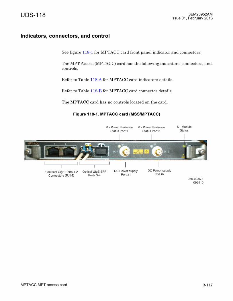
UDS-118 3EM23952AMIssue 01, February 2013
MPTACC MPT access card 3-117
Indicators, connectors, and control
See figure 118-1 for MPTACC card front panel indicator and connectors.
The MPT Access (MPTACC) card has the following indicators, connectors, and controls.
Refer to Table 118-A for MPTACC card indicators details.
Refer to Table 118-B for MPTACC card connector details.
The MPTACC card has no controls located on the card.
Figure 118-1. MPTACC card (MSS/MPTACC)
950-0036-1
092410
Electrical GigE Ports 1-2
Connectors (RJ45)
Optical GigE SFP
Ports 3-4
DC Power supply
Port #2
M - Power Emission
Status Port 1
DC Power supply
Port #1
M - Power Emission
Status Port 2
S - Module
Status
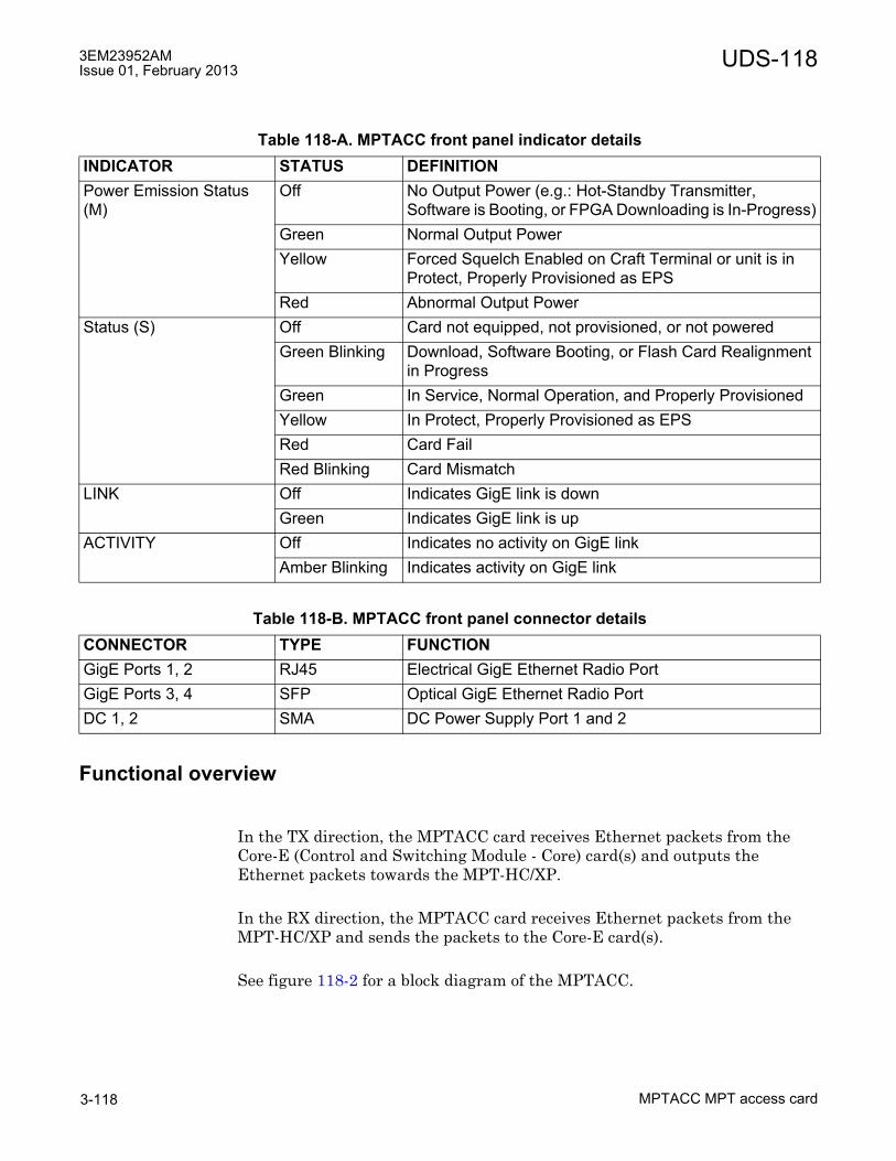
3EM23952AMIssue 01, February 2013
MPTACC MPT access card3-118
UDS-118
Functional overview
In the TX direction, the MPTACC card receives Ethernet packets from the Core-E (Control and Switching Module - Core) card(s) and outputs the Ethernet packets towards the MPT-HC/XP.
In the RX direction, the MPTACC card receives Ethernet packets from the MPT-HC/XP and sends the packets to the Core-E card(s).
See figure 118-2 for a block diagram of the MPTACC.
Table 118-A. MPTACC front panel indicator detailsINDICATOR STATUS DEFINITIONPower Emission Status (M)
Off No Output Power (e.g.: Hot-Standby Transmitter, Software is Booting, or FPGA Downloading is In-Progress)
Green Normal Output PowerYellow Forced Squelch Enabled on Craft Terminal or unit is in
Protect, Properly Provisioned as EPSRed Abnormal Output Power
Status (S) Off Card not equipped, not provisioned, or not poweredGreen Blinking Download, Software Booting, or Flash Card Realignment
in ProgressGreen In Service, Normal Operation, and Properly ProvisionedYellow In Protect, Properly Provisioned as EPSRed Card FailRed Blinking Card Mismatch
LINK Off Indicates GigE link is downGreen Indicates GigE link is up
ACTIVITY Off Indicates no activity on GigE linkAmber Blinking Indicates activity on GigE link
Table 118-B. MPTACC front panel connector detailsCONNECTOR TYPE FUNCTIONGigE Ports 1, 2 RJ45 Electrical GigE Ethernet Radio PortGigE Ports 3, 4 SFP Optical GigE Ethernet Radio PortDC 1, 2 SMA DC Power Supply Port 1 and 2

UDS-118 3EM23952AMIssue 01, February 2013
MPTACC MPT access card 3-119
Figure 118-2. MPTACC card block diagram
950-0036-1
092410
Digital
Processing

3EM23952AMIssue 01, February 2013
MPTACC MPT access card3-120
UDS-118
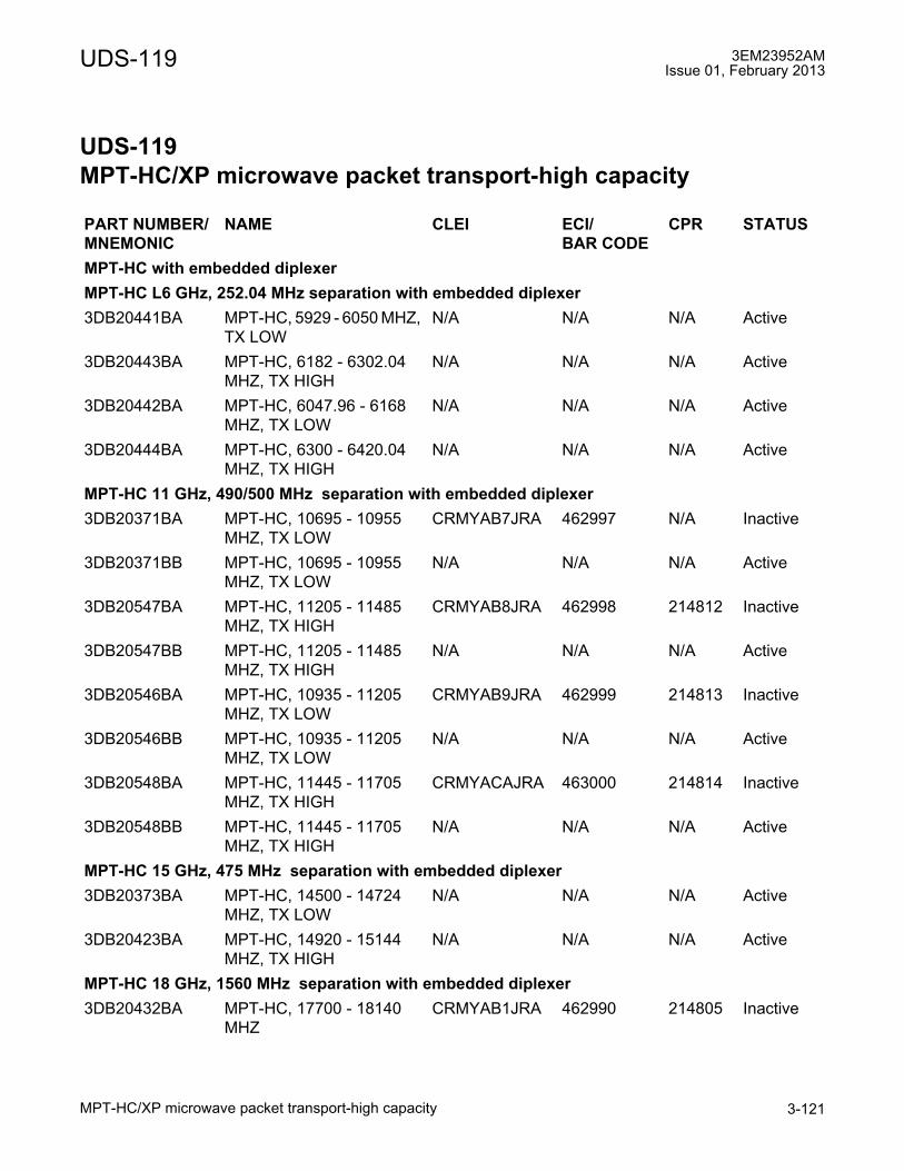
UDS-119 3EM23952AMIssue 01, February 2013
MPT-HC/XP microwave packet transport-high capacity 3-121
UDS-119 MPT-HC/XP microwave packet transport-high capacity
UDS-119MPT-HC/XP microwave packet transport-high capacity
PART NUMBER/MNEMONIC
NAME CLEI ECI/BAR CODE
CPR STATUS
MPT-HC with embedded diplexerMPT-HC L6 GHz, 252.04 MHz separation with embedded diplexer3DB20441BA MPT-HC, 5929 - 6050 MHZ,
TX LOWN/A N/A N/A Active
3DB20443BA MPT-HC, 6182 - 6302.04 MHZ, TX HIGH
N/A N/A N/A Active
3DB20442BA MPT-HC, 6047.96 - 6168 MHZ, TX LOW
N/A N/A N/A Active
3DB20444BA MPT-HC, 6300 - 6420.04 MHZ, TX HIGH
N/A N/A N/A Active
MPT-HC 11 GHz, 490/500 MHz separation with embedded diplexer3DB20371BA MPT-HC, 10695 - 10955
MHZ, TX LOWCRMYAB7JRA 462997 N/A Inactive
3DB20371BB MPT-HC, 10695 - 10955 MHZ, TX LOW
N/A N/A N/A Active
3DB20547BA MPT-HC, 11205 - 11485 MHZ, TX HIGH
CRMYAB8JRA 462998 214812 Inactive
3DB20547BB MPT-HC, 11205 - 11485 MHZ, TX HIGH
N/A N/A N/A Active
3DB20546BA MPT-HC, 10935 - 11205 MHZ, TX LOW
CRMYAB9JRA 462999 214813 Inactive
3DB20546BB MPT-HC, 10935 - 11205 MHZ, TX LOW
N/A N/A N/A Active
3DB20548BA MPT-HC, 11445 - 11705 MHZ, TX HIGH
CRMYACAJRA 463000 214814 Inactive
3DB20548BB MPT-HC, 11445 - 11705 MHZ, TX HIGH
N/A N/A N/A Active
MPT-HC 15 GHz, 475 MHz separation with embedded diplexer3DB20373BA MPT-HC, 14500 - 14724
MHZ, TX LOWN/A N/A N/A Active
3DB20423BA MPT-HC, 14920 - 15144 MHZ, TX HIGH
N/A N/A N/A Active
MPT-HC 18 GHz, 1560 MHz separation with embedded diplexer3DB20432BA MPT-HC, 17700 - 18140
MHZCRMYAB1JRA 462990 214805 Inactive

3EM23952AMIssue 01, February 2013
MPT-HC/XP microwave packet transport-high capacity3-122
UDS-119
3DB20433BA MPT-HC, 19260 - 19700 MHz
CRMYAB2JRA 462993 214807 Inactive
3DB20432BB MPT-HC, 17700 - 18140.5 MHZ
N/A N/A N/A Active
3DB20433BB MPT-HC, 19260 - 19700.5 MHz
N/A N/A N/A Active
MPT-HC 23 GHz, 1200/1232 MHz separation with embedded diplexer3DB20473BA MPT-HC, 21198 - 21819
MHZ, TX LOWCRMYAB3JRA 462991 214806 Active
3DB20475BA MPT-HC, 22400 - 23019 MHZ, TX HIGH
CRMYAB4JRA 462994 214808 Active
3DB20474BA MPT-HC, 21781 - 22400 MHZ, TX LOW
CRMYAB5JRA 462995 214809 Active
3DB20476BA MPT-HC, 22981 - 23600 MHZ, TX HIGH
CRMYAB6JRA 462996 214810 Active
MPT-HC 38 GHz, 700 MHz separation with embedded diplexer3DB20379BA MPT-HC, 38600 - 38950
MHZ, TX LOWN/A N/A N/A Active
3DB20563BA MPT-HC, 39300 - 39650 MHZ, TX HIGH
N/A N/A N/A Active
3DB20562BA MPT-HC, 38950 - 39300 MHZ, TX LOW
N/A N/A N/A Active
3DB20564BA MPT-HC, 39650 - 40000 MHZ, TX HIGH
N/A N/A N/A Active
MPT-HC with external diplexers1
9558HC 5.8 GHz Unlicensed, 64 MHz separation with external diplexer3DB20913BA 9558HC, 5725.5-5785.5
MHz, TX LOWN/A N/A N/A Active
3DB20914BA 9558HC, 5789.5-5849.5 MHz, TX HIGH
N/A N/A N/A Active
MPT-HC L6 GHz, 252.04 MHz separation with external diplexer3DB20800BA MPT-HC, 5929.96 - 6168
MHZ, TX LOWN/A N/A N/A Active
3DB20802BA MPT-HC, 6182 - 6420.04 MHZ, TX HIGH
N/A N/A N/A Active
MPT-HC U6 GHz, 160/340 MHz separation with external diplexer3DB20804BA MPT-HC, 6420 - 6775 MHZ,
TX LOWN/A N/A N/A Active
PART NUMBER/MNEMONIC
NAME CLEI ECI/BAR CODE
CPR STATUS

UDS-119 3EM23952AMIssue 01, February 2013
MPT-HC/XP microwave packet transport-high capacity 3-123
3DB20806BA MPT-HC, 6710 - 7115 MHZ, TX HIGH
N/A N/A N/A Active
MPT-HC 7/8 GHz, 175/300 MHz separation with external diplexer3DB20454BC MPT-HC, 7107 - 8377 MHZ,
TX LOWN/A N/A N/A Active
3DB20456BC MPT-HC, 7261 - 8496.114 MHZ, TX HIGH
N/A N/A N/A Active
MPT-XP with external diplexers2
MPT-XP L6 GHz, 252.04 MHz separation with external diplexer3DB20760BA MPT-XP, 5929.96 - 6168
MHZ, TX LOWN/A N/A N/A Active
3DB20761BA MPT-XP, 6182 - 6420.04 MHZ, TX HIGH
N/A N/A N/A- Active
MPT-XP U6 GHz, 160/340 MHz separation with external diplexer3DB20763BA MPT-XP, 6420 - 6775 MHZ,
TX LOWN/A N/A N/A Active
3DB20764BA MPT-XP, 6710 - 7115 MHZ, TX HIGH
N/A N/A N/A Active
MPT-XP 7 GHz, 175 MHz separation with external diplexer3DB20771BA MPT-XP, 7107 - 7714.5
MHZ, TX LOWN/A N/A N/A Active
3DB20772BA MPT-XP, 7261 - 7911 MHZ, TX HIGH
N/A N/A N/A Active
MPT-XP 8 GHz, 300 MHz separation with external diplexer3DB20773BA MPT-XP, 7725 - 8377 MHZ,
TX LOWN/A N/A N/A Active
3DB20774BA MPT-XP, 8025 - 8496.114 MHZ, TX HIGH
N/A N/A N/A Active
MPT-HC/XP external protection module3DB20117BA RPS Module N/A N/A N/A Active3DB20116BA XPIC+RPS Module N/A N/A N/A Inactive3DB20116BB XPIC+RPS Module N/A N/A N/A Active
[1] MPT-HC with external diplexer requires selecting the appropriate external diplexer.[2] MPT-XP with external diplexer requires selecting the appropriate external diplexer.
PART NUMBER/MNEMONIC
NAME CLEI ECI/BAR CODE
CPR STATUS
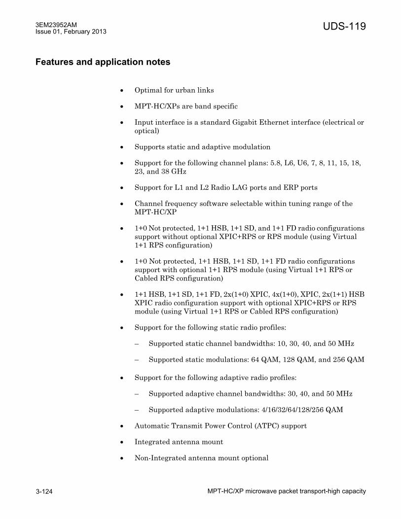
3EM23952AMIssue 01, February 2013
MPT-HC/XP microwave packet transport-high capacity3-124
UDS-119
Features and application notes
• Optimal for urban links
• MPT-HC/XPs are band specific
• Input interface is a standard Gigabit Ethernet interface (electrical or optical)
• Supports static and adaptive modulation
• Support for the following channel plans: 5.8, L6, U6, 7, 8, 11, 15, 18, 23, and 38 GHz
• Support for L1 and L2 Radio LAG ports and ERP ports
• Channel frequency software selectable within tuning range of the MPT-HC/XP
• 1+0 Not protected, 1+1 HSB, 1+1 SD, and 1+1 FD radio configurations support without optional XPIC+RPS or RPS module (using Virtual 1+1 RPS configuration)
• 1+0 Not protected, 1+1 HSB, 1+1 SD, 1+1 FD radio configurations support with optional 1+1 RPS module (using Virtual 1+1 RPS or Cabled RPS configuration)
• 1+1 HSB, 1+1 SD, 1+1 FD, 2x(1+0) XPIC, 4x(1+0), XPIC, 2x(1+1) HSB XPIC radio configuration support with optional XPIC+RPS or RPS module (using Virtual 1+1 RPS or Cabled RPS configuration)
• Support for the following static radio profiles:
� Supported static channel bandwidths: 10, 30, 40, and 50 MHz
� Supported static modulations: 64 QAM, 128 QAM, and 256 QAM
• Support for the following adaptive radio profiles:
� Supported adaptive channel bandwidths: 30, 40, and 50 MHz
� Supported adaptive modulations: 4/16/32/64/128/256 QAM
• Automatic Transmit Power Control (ATPC) support
• Integrated antenna mount
• Non-Integrated antenna mount optional
UDS-119 3EM23952AMIssue 01, February 2013
MPT-HC/XP microwave packet transport-high capacity 3-125
• Polarization is field configurable, Vertical (standard) or horizontal (optional)
• One or two cables (Power and Ethernet) are required to connect to the MPT-HC/XP. Several methods are available to interconnect the MSS-1/MSS-4/MSS-8 to the MPT-HC/XP:
� One electrical Ethernet cable connects the MPT Access unit or MSS-1 shelf PFoE ports to the MPT-HC (using the PFoE solution).
� One optical Ethernet cable (data) and one coaxial cable (power) connect the MPT Access unit or MSS-1 shelf to the MPT-HC.
� One electrical cable (data) connects the Core-E card or MSS-1 shelf ports 3 and 4 to the Power Injector Card/Box, MPT Extended Power Unit, and one electrical Ethernet cable connects to the MPT-HC (using the PFoE solution).
� One electrical or optical Ethernet cable (data) connects the Core-E card to the MPT-HC. Power is provided outside the MSS shelf (Power Injector Card/Box, MPT Power Unit, MPT Extended Power Unit, direct connection to office power).
� One optical Ethernet cable (data) connects the P8ETH card or MSS-1 shelf to the MPT-HC. Power is provided outside the MSS shelf (Power Injector Card/Box, MPT Power Unit, MPT Extended Power Unit, direct connection to office power).
� One electrical cable (data) connects the MPT Access, Core-E card, or MSS-1 shelf to the MPT Extended Power Unit, and one electrical Ethernet cable connects to the MPT-XP (using the PFoE solution).
� One electrical or optical Ethernet cable (data) connects the Core-E card to the MPT-XP. Power is provided outside the MSS shelf (MPT Extended Power Unit or direct connection to office power).
� One optical Ethernet cable (data) connects the P8ETH card to the MPT-XP. Power is provided outside the MSS shelf (MPT Extended Power Unit or direct connection to office power).
• MPT-HC/XPs include built-in lightning surge suppressor

3EM23952AMIssue 01, February 2013
MPT-HC/XP microwave packet transport-high capacity3-126
UDS-119
Description
The MPT-HC/XP is a microprocessor controlled transceiver that interfaces the MSS-1/4/8/1c shelf with the antenna. Transmitter circuits in the MPT-HC/XP consists of cable interface, modulator, local oscillator, up converter/mixer, power amplifier, and diplexer. Receive circuits consist of diplexer, low-noise amplifier, local oscillator, down converter/mixer, automatic gain control, demodulator, and cable interface. The microprocessor manages MPT-HC/XP frequency, transmit power alarming, and performance monitoring. Power is provided by -48Vdc from the MSS or external power source to the MPT-HC DC-DC converter through PFoE electrical Ethernet cable or a dedicated power supply cable. The MPT-HC/XP is frequency dependent.
Additional information for MPT-HC/XP with external diplexer
The MPT-HC/XP with external diplexer is made up of two boxes, one for diplexer system (BRANCHING) and the other for all other active functions (TRANSCEIVER) connected together to form the MPT-HC/XP. See Figure 119-1.
An O-RING present in the TRANSCEIVER box guarantees the MPT-HC/XP assembly waterproofness.
NOTE: This is a conductive O-RING and must be left dry. Do not wet it with silicon grease (silicon grease must be used only on O-ring between MPT-HC/XP and antenna).
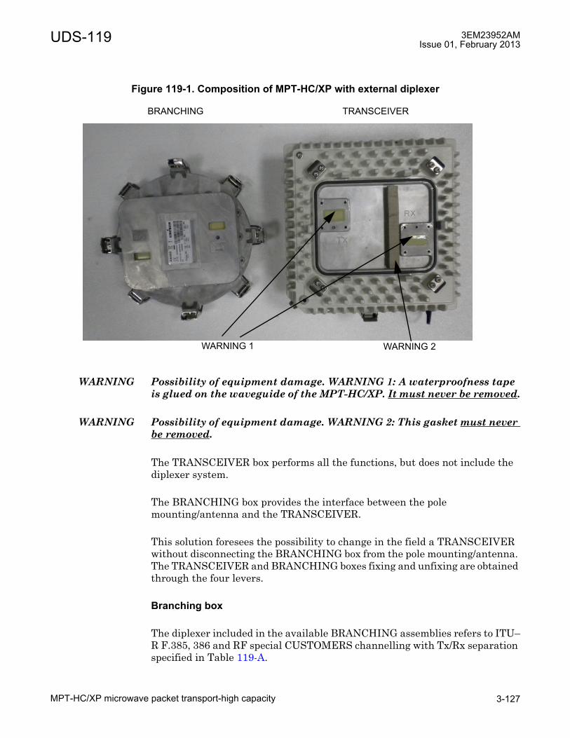
UDS-119 3EM23952AMIssue 01, February 2013
MPT-HC/XP microwave packet transport-high capacity 3-127
WARNING Possibility of equipment damage. WARNING 1: A waterproofness tape is glued on the waveguide of the MPT-HC/XP. It must never be removed.
WARNING Possibility of equipment damage. WARNING 2: This gasket must never be removed.
The TRANSCEIVER box performs all the functions, but does not include the diplexer system.
The BRANCHING box provides the interface between the pole mounting/antenna and the TRANSCEIVER.
This solution foresees the possibility to change in the field a TRANSCEIVER without disconnecting the BRANCHING box from the pole mounting/antenna. The TRANSCEIVER and BRANCHING boxes fixing and unfixing are obtained through the four levers.
Branching box
The diplexer included in the available BRANCHING assemblies refers to ITU�R F.385, 386 and RF special CUSTOMERS channelling with Tx/Rx separation specified in Table 119-A.
Figure 119-1. Composition of MPT-HC/XP with external diplexer
BRANCHING TRANSCEIVER
WARNING 1 WARNING 2
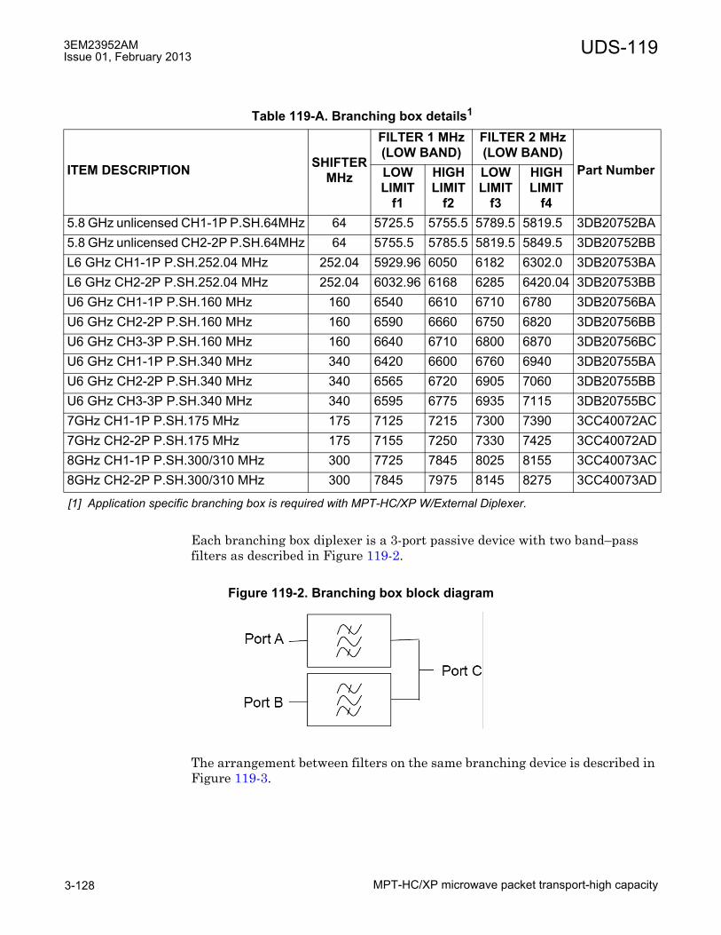
3EM23952AMIssue 01, February 2013
MPT-HC/XP microwave packet transport-high capacity3-128
UDS-119
Each branching box diplexer is a 3-port passive device with two band�pass filters as described in Figure 119-2.
The arrangement between filters on the same branching device is described in Figure 119-3.
Table 119-A. Branching box details1
[1] Application specific branching box is required with MPT-HC/XP W/External Diplexer.
ITEM DESCRIPTION SHIFTERMHz
FILTER 1 MHz(LOW BAND)
FILTER 2 MHz(LOW BAND)
Part NumberLOWLIMIT
f1
HIGHLIMIT
f2
LOWLIMIT
f3
HIGHLIMIT
f45.8 GHz unlicensed CH1-1P P.SH.64MHz 64 5725.5 5755.5 5789.5 5819.5 3DB20752BA5.8 GHz unlicensed CH2-2P P.SH.64MHz 64 5755.5 5785.5 5819.5 5849.5 3DB20752BBL6 GHz CH1-1P P.SH.252.04 MHz 252.04 5929.96 6050 6182 6302.0 3DB20753BAL6 GHz CH2-2P P.SH.252.04 MHz 252.04 6032.96 6168 6285 6420.04 3DB20753BBU6 GHz CH1-1P P.SH.160 MHz 160 6540 6610 6710 6780 3DB20756BAU6 GHz CH2-2P P.SH.160 MHz 160 6590 6660 6750 6820 3DB20756BBU6 GHz CH3-3P P.SH.160 MHz 160 6640 6710 6800 6870 3DB20756BCU6 GHz CH1-1P P.SH.340 MHz 340 6420 6600 6760 6940 3DB20755BAU6 GHz CH2-2P P.SH.340 MHz 340 6565 6720 6905 7060 3DB20755BBU6 GHz CH3-3P P.SH.340 MHz 340 6595 6775 6935 7115 3DB20755BC7GHz CH1-1P P.SH.175 MHz 175 7125 7215 7300 7390 3CC40072AC7GHz CH2-2P P.SH.175 MHz 175 7155 7250 7330 7425 3CC40072AD8GHz CH1-1P P.SH.300/310 MHz 300 7725 7845 8025 8155 3CC40073AC8GHz CH2-2P P.SH.300/310 MHz 300 7845 7975 8145 8275 3CC40073AD
Figure 119-2. Branching box block diagram

UDS-119 3EM23952AMIssue 01, February 2013
MPT-HC/XP microwave packet transport-high capacity 3-129
NOTE: f1, f2, f3 and f4 frequencies of the branching filters refer to the extreme channel frequencies and not to the cut�off frequencies of the filters.
TRANSCEIVER and BRANCHING boxes coupling
Figure 119-4 shows the TRANSCEIVER and BRANCHING boxes coupling surfaces:
• (A) BRANCHING box information label
• (B) (HIGH FREQ) and (C) (LOW FREQ) RF interfaces on BRANCHING box
• (D) (TX) and (E) (RX) RF interfaces on TRANSCEIVER box
The TRANSCEIVER and BRANCHING boxes can be coupled in two alternative ways (180°-rotated with respect to each other):
• BRANCHING box (B) (HIGH FREQ) coupled to TRANSCEIVER box�s (D) (TX)in this case the TX part of the transceiver uses the HIGH frequency range of the Shifter set by the Craft Terminal; obviously the RX part of the transceiver uses the corresponding LOW frequency range;
• BRANCHING box (C) (LOW FREQ) coupled to TRANSCEIVER box�s (D) (TX)in this case the TX part of the transceiver uses the LOW frequency range of the Shifter set by the Craft Terminal; obviously the RX part of the transceiver uses the corresponding HIGH frequency range.
Figure 119-3. Branching box band-pass detail

3EM23952AMIssue 01, February 2013
MPT-HC/XP microwave packet transport-high capacity3-130
UDS-119
NOTE: There is only one possible way to couple the BRANCHING box and the TRANSCEIVER box: the TRANSCEIVER box is keyed with a mistake-proofing pin, whose position depends on the type of transceiver (low or high band, as shown in Figure 119-4) to ensure that the association with the BRANCHING box is always correct.
Indicators, connectors, and control
See Figure 119-5 for MPT-HC/XP.
The external interfaces for embedded and external diplexer versions are listed in Table 119-B, including a description of the corresponding connectors.
The RF Interface waveguide types are listed in Table 119-C.
MPT-HC with embedded diplexer views and access points are shown in Figure 119-6.
MPT-HC/XP with external diplexer views and access points are shown in Figure 119-7.
The MPT-HC/XP has no indicators and controls on the unit.
Figure 119-4. MPT-HC/XP TRANSCEIVER and BRANCHING boxes coupling surfaces
(A) (B)
(C)
(D)
(E)Mistake-proofingHole

UDS-119 3EM23952AMIssue 01, February 2013
MPT-HC/XP microwave packet transport-high capacity 3-131
Figure 119-5. MPT-HC/XP
Table 119-B. MPT-HC with internal diplexer connector detailsREF CONNECTOR TYPE FUNCTION
11
[1] RF interface for connection to antenna or coupler. The plastic cover is removed during installation.WARNING: A waterproof tape is glued on the waveguide of the MPT-HC, it MUST never be removed.
Antenna Port WaveguideInterface
RF signal to antenna
2 Data & Power In RJ45 + R2CT Electrical Data & DC Power connection to MSS-4/MSS-83 SFP LC + Q-XCO Optical GigE Data Interface connection to MSS-4/MSS-84 RPS LC + Q-XCO Optical GigE RPS Interface connection to second MPT-HC5 XPIC Round
ProprietaryConnection to second MPT-HC in XPIC configuration.
6 RSSI LEMO RSSI Monitor PortGround Stud MPT-HC Grounding
Table 119-C. MPT-HC/XP: RF interface
FREQUENCY GHz 6 7 8 11 15 18-23 38Waveguide Type WR137 WR112 WR112 WR75 WR62 WR42 WR28

3EM23952AMIssue 01, February 2013
MPT-HC/XP microwave packet transport-high capacity3-132
UDS-119
Figure 119-6. Views of MPT-HC with embedded diplexer (6, 11-38 GHz)
REFERENCENUMBER
INTERFACE
(A) Locking hooks (4) to fix/unfix MPT-HC assembly to antenna or coupler
(1) RF interface for connection to antenna or coupler
WARNING: Possibility of equipment damage. A waterproofness tape is glued on the waveguide of the MPT-HC. It must never be removed.
(1) (A)
(A)(A)
(A)(3) (2)
MPT-HC basic
(4)
(3) (2)
MPT-HC equipped with XPIC+RPS module
(5)
(4)
(3) (2)
MPT-HC equipped with RPS module
(6)
(6) (6)

UDS-119 3EM23952AMIssue 01, February 2013
MPT-HC/XP microwave packet transport-high capacity 3-133
Figure 119-7. Views of MPT-HC/XP/9558HC with external diplexer (5.8 to 8 GHz)
REFERENCENUMBER
INTERFACE
(A) 4 locking hooks to fix/unfix branching assembly (diplexer) to transceiver(B) 4 locking hooks to fix/unfix branching assembly (diplexer) to antenna or
coupler(1) RF interface for connection to antenna or coupler
WARNING: Possibility of equipment damage. A waterproofness tape is glued on the waveguide of the MPT-HC/XP. It must never be removed.
(3) (2)
MPT-HC/XP basic
(4)
(3) (2)
MPT-HC/XP equipped with XPIC+RPS
(5)
(4)
(3) (2)
MPT-HC/XP equipped with RPS module
(1) (A)
(A)(A)
(A)
(B)(B)
(B)(B)
(6)
(6) (6)
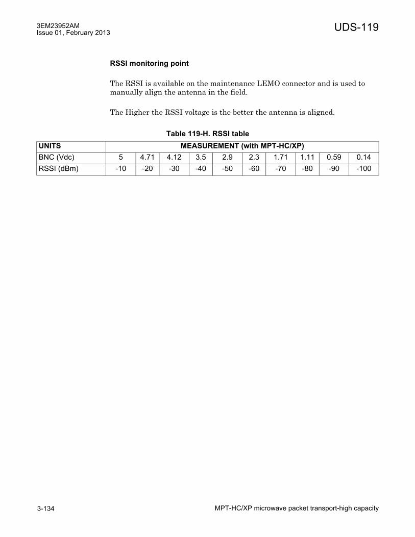
3EM23952AMIssue 01, February 2013
MPT-HC/XP microwave packet transport-high capacity3-134
UDS-119
RSSI monitoring point
The RSSI is available on the maintenance LEMO connector and is used to manually align the antenna in the field.
The Higher the RSSI voltage is the better the antenna is aligned.
Table 119-H. RSSI tableUNITS MEASUREMENT (with MPT-HC/XP)BNC (Vdc) 5 4.71 4.12 3.5 2.9 2.3 1.71 1.11 0.59 0.14RSSI (dBm) -10 -20 -30 -40 -50 -60 -70 -80 -90 -100

UDS-120 3EM23952AMIssue 01, February 2013
AUX auxiliary card 3-135
UDS-120 AUX auxiliary card
UDS-120AUX auxiliary card
Features and application notes
• Housekeeping alarm points (six station alarm inputs and seven station control outputs)
� User provisionable alarm labels
� User provisionable polarity (Active Low/Active High)
• Hardware support for EOW. EOW is not supported in 9500 MPR-A R4.2.0.
• Hardware support for two 64 Kb/s, RS422/V.11 DCE co-directional service channels. Service channels are not supported in 9500 MPR-A R4.2.0.
• One AUX card supported per MSS shelf. In the MSS-4 shelf, AUX card is supported in slot 4 only. In the MSS-8 shelf, AUX card is supported in MSS-8 shelf slot 8 only.
Description
The AUX card provides thirteen housekeeping alarm points, six station alarm inputs and seven station control outputs. Housekeeping alarm points support user provisionable alarm labels on a per alarm basis. User provisionable alarm active polarity on a per alarm basis.
Indicators, connectors, and control
The AUX card has the following indicators, connectors, and controls.
See Figure 120-1 for AUX card front panel indicator and connector locations.
PART NUMBER/MNEMONIC
NAME CLEI ECI/BAR CODE
CPR STATUS
3DB18236AB AUX Auxiliary Card N/A N/A N/A Active

3EM23952AMIssue 01, February 2013
AUX auxiliary card3-136
UDS-120
Refer to Table 120-A for AUX card indicators details.
Refer to Table 120-B for AUX card connector details.
Figure 120-1. AUX card (MSS/AUX)
Table 120-A. AUX front panel indicator detailsINDICATOR STATUS DEFINITIONStatus (S) Off Card not equipped, not provisioned, or not powered
Green Blinking Download, Software Booting, or Flash Card Realignment in Process
Green In-Service, Normal Operation, and Properly ProvisionedYellow In Protect, Properly Provisioned as EPSRed Card FailRed Blinking Card Mismatch
EOW Line Status (E) Off EOW Line Status LED is not supported in R4.2.0
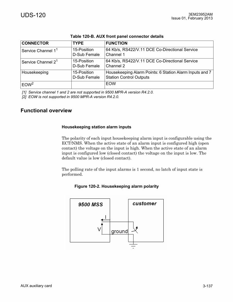
UDS-120 3EM23952AMIssue 01, February 2013
AUX auxiliary card 3-137
Functional overview
Housekeeping station alarm inputs
The polarity of each input housekeeping alarm input is configurable using the ECT/NMS. When the active state of an alarm input is configured high (open contact) the voltage on the input is high. When the active state of an alarm input is configured low (closed contact) the voltage on the input is low. The default value is low (closed contact).
The polling rate of the input alarms is 1 second, no latch of input state is performed.
Table 120-B. AUX front panel connector detailsCONNECTOR TYPE FUNCTION
Service Channel 11
[1] Service channel 1 and 2 are not supported in 9500 MPR-A version R4.2.0.
15-Position D-Sub Female
64 Kb/s, RS422/V.11 DCE Co-Directional Service Channel 1
Service Channel 21 15-Position D-Sub Female
64 Kb/s, RS422/V.11 DCE Co-Directional Service Channel 2
Housekeeping 15-Position D-Sub Female
Housekeeping Alarm Points: 6 Station Alarm Inputs and 7 Station Control Outputs
EOW2
[2] EOW is not supported in 9500 MPR-A version R4.2.0.
EOW
Figure 120-2. Housekeeping alarm polarity

3EM23952AMIssue 01, February 2013
AUX auxiliary card3-138
UDS-120
Housekeeping station alarm input electrical characteristics
Open Contact: 2V < |V|< 60 V; |I| < 0.2mA
Closed Contract: 0V < |V|< 2 V; |I| < 50mA
Though the housekeeping equipment requirement on max input voltage is 60 V, the PCB layout of peripheral must be able to manage 72 V.
By default the presence of active alarm corresponds to closed relay contact with a common wire available to the customer. By CT/NMS it is possible to change the polarity independently for each alarm (both normally closed and normally open contacts are available on the I/O connector).
When the power supply is down (and also when the power supply is on but the SW hasn't yet initialized the HW), all the relays of the outputs of the alarms/housekeeping are in the "open contact" state (HW default condition).
Output alarm electrical characteristics
Open Contact: 2V < |V|< 60 V; |I| < 0.2mA
Closed Contract: 0V < |V|< 2 V; |I| < 50mA
Though the housekeeping equipment requirement on max input voltage is 60 V, the PCB layout of peripheral must be able to manage 72 V.
Synchronous 64 Kb/s RS422/V.11 DCE co-directional
The service channel interface is DCE co-directional definition where it is possible to assume that the timing signals are equal in both the directions: the subordinate equipment (DTE) has to synchronize the output data with the unique timing signal received.
The NEs at either end of a service channel must be synchronized to the same Network Element Clock (NEC) in each MSS node.

UDS-120 3EM23952AMIssue 01, February 2013
AUX auxiliary card 3-139
Figure 120-3. 64 Kb/s service channel DCE co-directional

3EM23952AMIssue 01, February 2013
AUX auxiliary card3-140
UDS-120

UDS-122 3EM23952AMIssue 01, February 2013
Power injector 3-141
UDS-122 Power injector
UDS-122Power injector
Features and application notes
• Allows a single electrical Ethernet cable run between the MSS-1/4/8 shelf and the MPT-HC Transceiver mounting location.
• Redundant DC power inputs from -48V battery
• Low pass filtering
• Insertion of the DC voltage on two Ethernet streams to power two MPT-HCs
• Surge protection on both Ethernet output ports (K44 & K45)
• The maximum cable length is 100 m for PFoE applications. With coax cable and fiber for data, the maximum length is 300 m.
Description
The Power Injector is an indoor device designed to deliver the DC power supply to MPT-HC by using the same cable carrying the Ethernet traffic.
MPT- HC is powered through an electrical Ethernet cable from the Power Injector.
The Power Injector box/Card combines the Ethernet traffic and DC power and sends the output on one connector the Power Supply + Ethernet Traffic. This solution is called PFoE (Power Feed over Ethernet), and is proprietary.
PART NUMBER/MNEMONIC
NAME CLEI ECI/BAR CODE
CPR STATUS
3CC50128AA Power Injector Card N/A N/A N/A Active3CC50129AA Power Injector Box N/A N/A N/A Active3DB77008AC Power Injector Bracket N/A N/A N/A Active
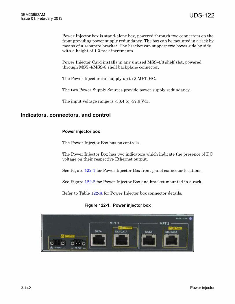
3EM23952AMIssue 01, February 2013
Power injector3-142
UDS-122
Power Injector box is stand-alone box, powered through two connectors on the front providing power supply redundancy. The box can be mounted in a rack by means of a separate bracket. The bracket can support two boxes side by side with a height of 1.3 rack increments.
Power Injector Card installs in any unused MSS-4/8 shelf slot, powered through MSS-4/MSS-8 shelf backplane connector.
The Power Injector can supply up to 2 MPT-HC.
The two Power Supply Sources provide power supply redundancy.
The input voltage range is -38.4 to -57.6 Vdc.
Indicators, connectors, and control
Power injector box
The Power Injector Box has no controls.
The Power Injector Box has two indicators which indicate the presence of DC voltage on their respective Ethernet output.
See Figure 122-1 for Power Injector Box front panel connector locations.
See Figure 122-2 for Power Injector Box and bracket mounted in a rack.
Refer to Table 122-A for Power Injector box connector details.
Figure 122-1. Power injector box
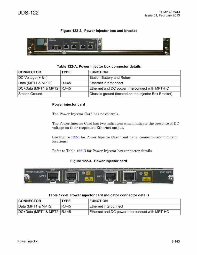
UDS-122 3EM23952AMIssue 01, February 2013
Power injector 3-143
Power injector card
The Power Injector Card has no controls.
The Power Injector Card has two indicators which indicate the presence of DC voltage on their respective Ethernet output.
See Figure 122-1 for Power Injector Card front panel connector and indicator locations.
Refer to Table 122-B for Power Injector box connector details.
Figure 122-2. Power injector box and bracket
Table 122-A. Power injector box connector detailsCONNECTOR TYPE FUNCTIONDC Voltage (+ & -) Station Battery and ReturnData (MPT1 & MPT2) RJ-45 Ethernet interconnectDC+Data (MPT1 & MPT2) RJ-45 Ethernet and DC power Interconnect with MPT-HCStation Ground Chassis ground (located on the Injector Box Bracket)
Figure 122-3. Power injector card
Table 122-B. Power injector card indicator connector detailsCONNECTOR TYPE FUNCTIONData (MPT1 & MPT2) RJ-45 Ethernet interconnectDC+Data (MPT1 & MPT2) RJ-45 Ethernet and DC power Interconnect with MPT-HC

3EM23952AMIssue 01, February 2013
Power injector3-144
UDS-122
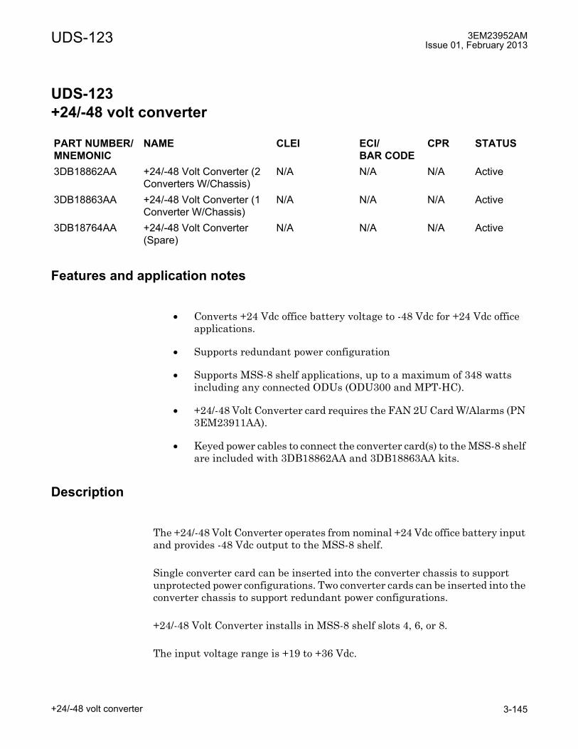
UDS-123 3EM23952AMIssue 01, February 2013
+24/-48 volt converter 3-145
UDS-123 +24/-48 volt converter
UDS-123+24/-48 volt converter
Features and application notes
• Converts +24 Vdc office battery voltage to -48 Vdc for +24 Vdc office applications.
• Supports redundant power configuration
• Supports MSS-8 shelf applications, up to a maximum of 348 watts including any connected ODUs (ODU300 and MPT-HC).
• +24/-48 Volt Converter card requires the FAN 2U Card W/Alarms (PN 3EM23911AA).
• Keyed power cables to connect the converter card(s) to the MSS-8 shelf are included with 3DB18862AA and 3DB18863AA kits.
Description
The +24/-48 Volt Converter operates from nominal +24 Vdc office battery input and provides -48 Vdc output to the MSS-8 shelf.
Single converter card can be inserted into the converter chassis to support unprotected power configurations. Two converter cards can be inserted into the converter chassis to support redundant power configurations.
+24/-48 Volt Converter installs in MSS-8 shelf slots 4, 6, or 8.
The input voltage range is +19 to +36 Vdc.
PART NUMBER/MNEMONIC
NAME CLEI ECI/BAR CODE
CPR STATUS
3DB18862AA +24/-48 Volt Converter (2 Converters W/Chassis)
N/A N/A N/A Active
3DB18863AA +24/-48 Volt Converter (1 Converter W/Chassis)
N/A N/A N/A Active
3DB18764AA +24/-48 Volt Converter (Spare)
N/A N/A N/A Active

3EM23952AMIssue 01, February 2013
+24/-48 volt converter3-146
UDS-123
Indicators, connectors, and control
See Figure 123-1 for +24/-48 Volt Converter card front panel indicator and connectors.
The +24/-48 Volt Converter card has the following indicators, connectors, and controls.
Refer to Table 123-A for +24/-48 Volt Converter card indicators details.
Refer to Table 123-B for +24/-48 Volt Converter card connector details.
The +24/-48 Volt Converter card has no controls.
Figure 123-1. +24/-48 volt converter card
950-0250-1
053111
Main Power
ConverterProtect Power
Converter
Power Converter
Outputs
Power Converter
Inputs

UDS-123 3EM23952AMIssue 01, February 2013
+24/-48 volt converter 3-147
Table 123-A. +24/-48 volt converter card indicator detailsINDICATOR STATUS DEFINITIONStatus (top) Off Card not equipped, not powered, or hardware failure has
been detected.Green Normal operation (input and output)
PSU Failure Indication (bottom)
Off Card not equipped, not powered, or no failure is detected.Red PSU Failure indication detected.
Table 123-B. +24/-48 volt converter card connector detailsCONNECTOR TYPE FUNCTION+24 Vdc Input Station Battery and Return-48 Vdc Output Ethernet interconnect

3EM23952AMIssue 01, February 2013
+24/-48 volt converter3-148
UDS-123
UDS-124 3EM23952AMIssue 01, February 2013
MPT Power Unit 3-149
UDS-124 MPT Power Unit
UDS-124MPT Power Unit
Features and application notes
• Distributes power remotely to up to four external MPT-HC ODUs with or without XPIC
• Dual battery input provided with surge protection
• Power feed to support -48V DC on the ODU side
• In rush and short circuit protection on the ODU side
• Reverse polarity protection on the -48V Power input side
• Lightning protection on the ODU side
• Hot Swap function
• Output low-pass filter
• Power ORing feeds the board from two independent battery power lines
• Up to two units can be mounted in a 19-inch aluminum rack or 19-inch seismic rack.
• To power the ODU one coaxial cable is connected to:
� MPT Power Unit (Type N Connector)
� Type N to Ethernet pair Pigtail (RJ45 of pair Pigtail is connected to RJ-45 of MPT-HC V2)
• For data transmission, optical fiber is connected to the IDU and the MPT using optical connectors.
PART NUMBER/MNEMONIC
NAME CLEI ECI/BAR CODE
CPR STATUS
3CC50173AA MPT Power Unit N/A N/A N/A Active

3EM23952AMIssue 01, February 2013
MPT Power Unit3-150
UDS-124
Description
The MPT Power Unit is designed to remotely power four external MPT ODUs through Type N-connector cables.
The size of the board is 198 x 150 mm. See Figure 124-1 for a front panel view of the MPT Power Unit. See Figure 124-2 for a top view of the box, and Figure 124-3 for a top view of the board.
Figure 124-1. MPT power unit front panel view
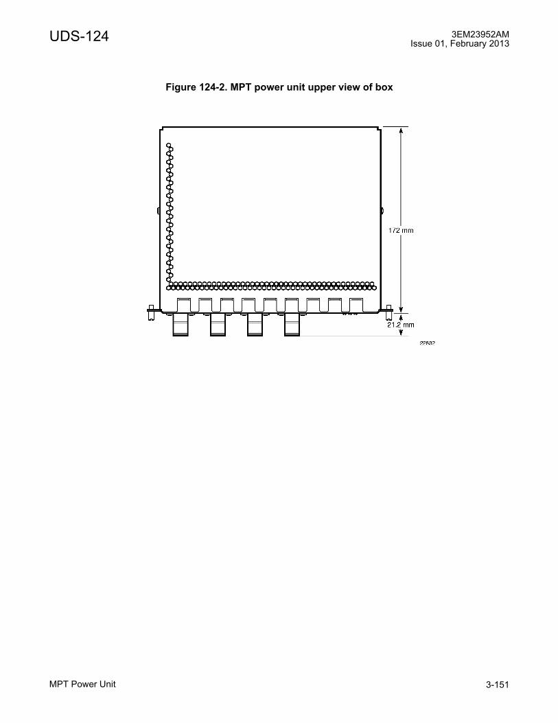
UDS-124 3EM23952AMIssue 01, February 2013
MPT Power Unit 3-151
Figure 124-2. MPT power unit upper view of box
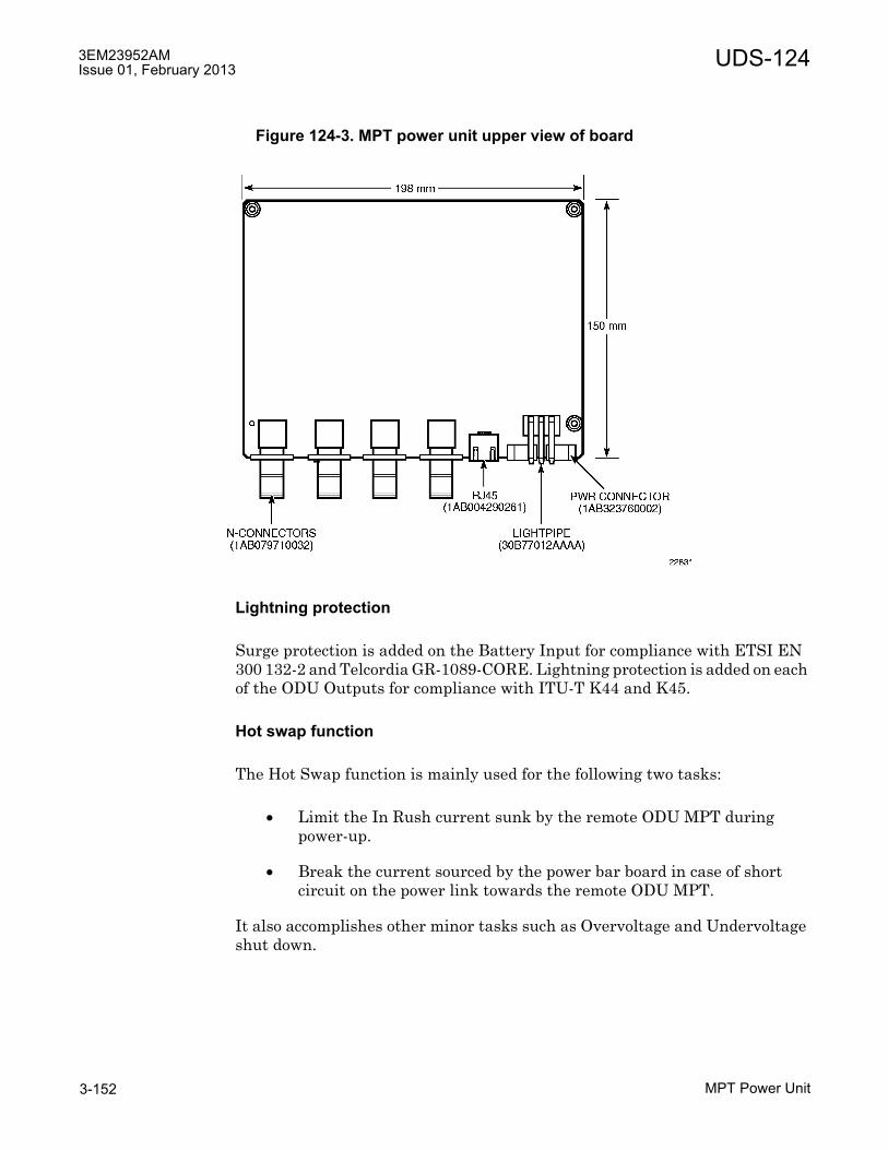
3EM23952AMIssue 01, February 2013
MPT Power Unit3-152
UDS-124
Lightning protection
Surge protection is added on the Battery Input for compliance with ETSI EN 300 132-2 and Telcordia GR-1089-CORE. Lightning protection is added on each of the ODU Outputs for compliance with ITU-T K44 and K45.
Hot swap function
The Hot Swap function is mainly used for the following two tasks:
• Limit the In Rush current sunk by the remote ODU MPT during power-up.
• Break the current sourced by the power bar board in case of short circuit on the power link towards the remote ODU MPT.
It also accomplishes other minor tasks such as Overvoltage and Undervoltage shut down.
Figure 124-3. MPT power unit upper view of board
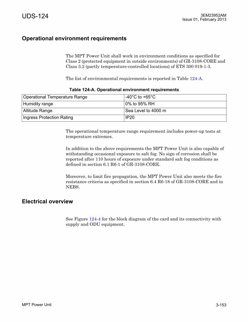
UDS-124 3EM23952AMIssue 01, February 2013
MPT Power Unit 3-153
Operational environment requirements
The MPT Power Unit shall work in environment conditions as specified for Class 2 (protected equipment in outside environments) of GR-3108-CORE and Class 3.2 (partly temperature-controlled locations) of ETS 300 019-1-3.
The list of environmental requirements is reported in Table 124-A.
The operational temperature range requirement includes power-up tests at temperature extremes.
In addition to the above requirements the MPT Power Unit is also capable of withstanding occasional exposure to salt fog. No sign of corrosion shall be reported after 110 hours of exposure under standard salt fog conditions as defined in section 6.1 R6-1 of GR-3108-CORE.
Moreover, to limit fire propagation, the MPT Power Unit also meets the fire resistance criteria as specified in section 6.4 R6-18 of GR-3108-CORE and in NEBS.
Electrical overview
See Figure 124-4 for the block diagram of the card and its connectivity with supply and ODU equipment.
Table 124-A. Operational environment requirementsOperational Temperature Range -40°C to +65°CHumidity range 0% to 95% RHAltitude Range Sea Level to 4000 mIngress Protection Rating IP20
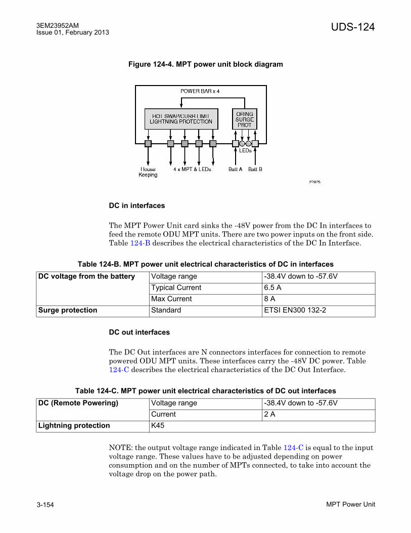
3EM23952AMIssue 01, February 2013
MPT Power Unit3-154
UDS-124
DC in interfaces
The MPT Power Unit card sinks the -48V power from the DC In interfaces to feed the remote ODU MPT units. There are two power inputs on the front side. Table 124-B describes the electrical characteristics of the DC In Interface.
DC out interfaces
The DC Out interfaces are N connectors interfaces for connection to remote powered ODU MPT units. These interfaces carry the -48V DC power. Table 124-C describes the electrical characteristics of the DC Out Interface.
NOTE: the output voltage range indicated in Table 124-C is equal to the input voltage range. These values have to be adjusted depending on power consumption and on the number of MPTs connected, to take into account the voltage drop on the power path.
Figure 124-4. MPT power unit block diagram
Table 124-B. MPT power unit electrical characteristics of DC in interfacesDC voltage from the battery Voltage range -38.4V down to -57.6V
Typical Current 6.5 AMax Current 8 A
Surge protection Standard ETSI EN300 132-2
Table 124-C. MPT power unit electrical characteristics of DC out interfacesDC (Remote Powering) Voltage range -38.4V down to -57.6V
Current 2 ALightning protection K45

UDS-124 3EM23952AMIssue 01, February 2013
MPT Power Unit 3-155
As a general consideration, considering a maximum total current of 8A, with 2A on each MPT:
• Maximum Voltage drop: 0.67 V
The minimum drop can be calculated considering only one MPT connected and thus 2A as total current consumption:
• Minimum Voltage drop: 0.44 V
Housekeeping interfaces
Housekeeping interfaces are RJ45 copper Ethernet connectors.Alarm data and common signal will be mapped.The logic for housekeeping signals is GROUND (normal operation) or TRI-STATE (fail condition).
Indicators, connectors, and control
The MPT Power Unit has the following indicators, connectors, and controls:
• 2 x Power In Connector
• 6 x Green LED
• 4 x N Connector
• 1 x RJ45 connector
Table 124-D describes the electrical connections of the DC in interfaces. Table 124-E describes the electrical connections of the DC out interfaces.Table 124-F describes the electrical characteristics of the Housekeeping Interfaces.
Table 124-D. MPT power unit electrical connections of DC in interfacesSIGNAL DESCRIPTIONPower -48VGround GND
Table 124-E. MPT power unit electrical connections of DC out interfacesPIN N-connector
Signal DescriptionCentre-tap -48V -48 V powerShield GND Ground
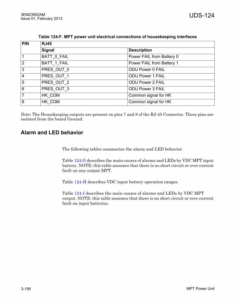
3EM23952AMIssue 01, February 2013
MPT Power Unit3-156
UDS-124
Note: The Housekeeping outputs are present on pins 7 and 8 of the RJ-45 Connector. These pins are isolated from the board Ground.
Alarm and LED behavior
The following tables summarize the alarm and LED behavior.
Table 124-G describes the main causes of alarms and LEDs by VDC MPT input battery. NOTE: this table assumes that there is no short circuit or over current fault on any output MPT.
Table 124-H describes VDC input battery operation ranges.
Table 124-I describes the main causes of alarms and LEDs by VDC MPT output. NOTE: this table assumes that there is no short circuit or over current fault on input batteries.
Table 124-F. MPT power unit electrical connections of housekeeping interfacesPIN RJ45
Signal Description1 BATT_0_FAIL Power FAIL from Battery 02 BATT_1_FAIL Power FAIL from Battery 13 PRES_OUT_0 ODU Power 0 FAIL4 PRES_OUT_1 ODU Power 1 FAIL5 PRES_OUT_2 ODU Power 2 FAIL6 PRES_OUT_3 ODU Power 3 FAIL7 HK_COM Common signal for HK8 HK_COM Common signal for HK

UDS-124 3EM23952AMIssue 01, February 2013
MPT Power Unit 3-157
Table 124-J describes DC output MPT (ODU) operation ranges.
Table 124-G. Main cases of alarms and LEDs by VDC MPT input batteryVDC Input Battery Housekeeping alarms LEDsBattery 1 Battery 2 Power
Battery 1
Power Battery 2
ODU Power [1:4]
Battery A LED
Battery B LED
ODU LED [1:4]
-38.4V < VDC < 0V -38.4V < VDC < 0V Tri state Tri state Tri state Off Off Off-38.4V < VDC < 0V -57.6V < VDC < -
38.4VTri state Ground Ground Off Green Green
-57.6V < VDC < -38.4V
-38.4V < VDC < 0V Ground Tri state Ground Green Off Green
-57.6V < VDC < -38.4V
-57.6V < VDC < -38.4V
Ground Ground Ground Green Green Green
-57.6V < VDC < -38.4V
VDC < -57.6V Ground Tri state Tri state Green Off Off
VDC < -57.6V -57.6V < VDC < -38.4V
Tri state Ground Tri state Off Green Off
VDC < -57.6V VDC < -57.6V Tri state Tri state Tri state Off Off Off
Table 124-H. VDC input battery operation rangesWorking range -57.6V < VDC < -38.4VUndervoltage -38.4V < VDC < 0VOvervoltage VDC < -57.6V

3EM23952AMIssue 01, February 2013
MPT Power Unit3-158
UDS-124
Cable length
Table 124-K provides the maximum allowed cable length without step-up for a minimum input battery voltage of -38.4 V.
Table 124-I. Main cases of alarms and LEDs by VDC MPT output (N connectors)DC output MPT (ODU) Housekeeping alarms LEDsMPT out 1
MPT out 2
MPT out 3
MPT out 4
ODU Power 1
ODU Power 2
ODU Power 3
ODU Power 4
ODU LED 1
ODU LED 2
ODU LED 3
ODU LED 4
0A < DC < 2A
0A < DC < 2A
0A < DC < 2A
0A < DC < 2A
Ground Ground Ground Ground Green Green Green Green
0A < DC < 2A
0A < DC < 2A
0A < DC < 2A
DC > 2A
Ground Ground Ground Tri state
Green Green Green Off
0A < DC < 2A
0A < DC < 2A
DC > 2A
0A < DC < 2A
Ground Ground Tri state
Ground Green Green Off Green
0A < DC < 2A
0A < DC < 2A
DC > 2A
DC > 2A
Ground Ground Tri state
Tri state
Green Green Off Off
DC > 2A
DC > 2A
DC > 2A
0A < DC < 2A
Tri state
Tri state
Tri state
Ground Off Off Off Green
DC > 2A
DC > 2A
DC > 2A
DC > 2A
Tri state
Tri state
Tri state
Tri state
Off Off Off Off
Table 124-J. DC output MPT (ODU) operation rangesWorking range 0A < DC < 2AShort circuit or over current fault DC > 2A

UDS-124 3EM23952AMIssue 01, February 2013
MPT Power Unit 3-159
Mounting rack
A bracket is provided to mount the MPT Power Unit in a 19 inch rack. The bracket provides an attachment point for grounding, located in the central strut. The same bracket can be used to mount the MPT Power Unit. See Figure 124-5.
Table 124-K. Maximum allowed cable length for MPT Power Unit Cable type Coaxial cable 1AB350440001:
Power only, Data on optical cableConfiguration Maximum lengthMPT-HC V2 300 mMPT-HC V2 with XPIC 300 mConstraint 1 Max current in Ethernet transformer < 1.8 A
Max current limit for Power Unit: 1.8 AConstraint 2 Min MPT-HC PSU input voltage > 28 V1
[1] PSU input voltage on MPT-HC/MPT-XP
Constraint 3 Data traffic only with optical cable
Figure 124-5. MPT power unit mounting bracket

3EM23952AMIssue 01, February 2013
MPT Power Unit3-160
UDS-124
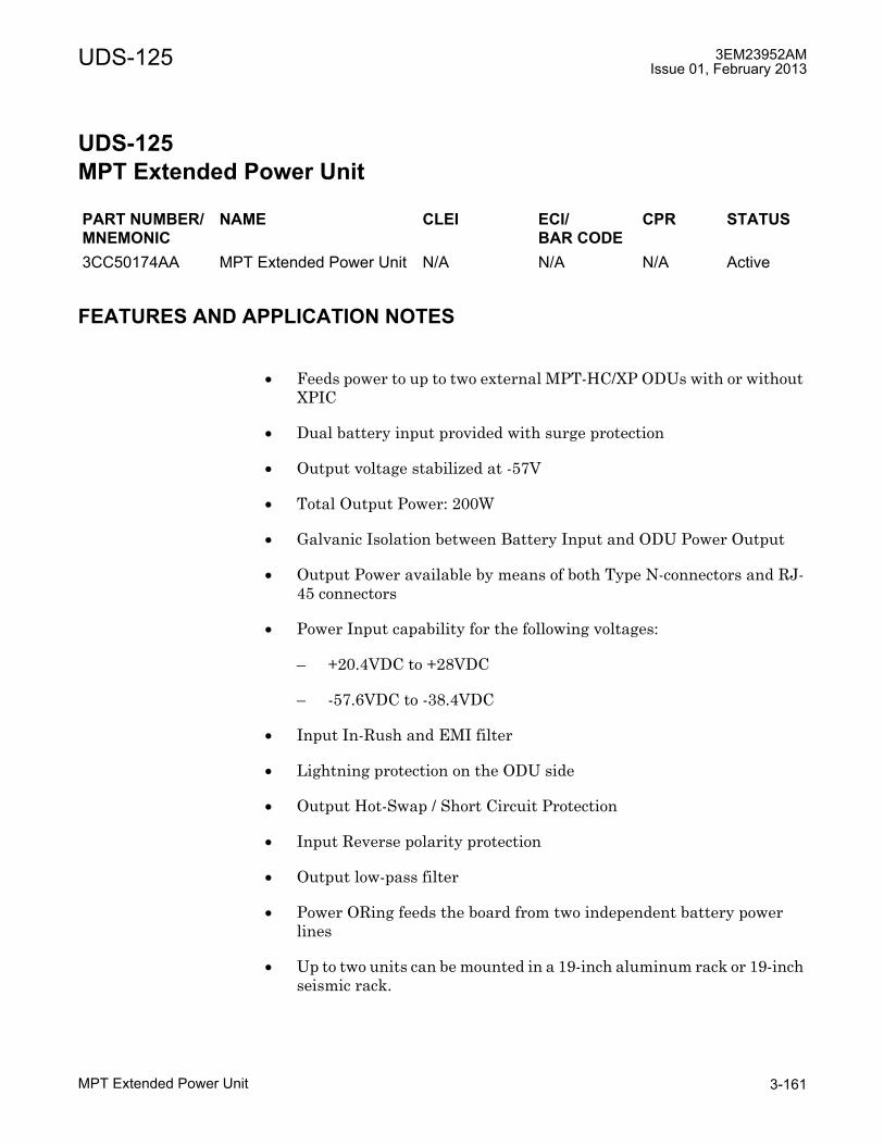
UDS-125 3EM23952AMIssue 01, February 2013
MPT Extended Power Unit 3-161
UDS-125 MPT Extended Power Unit
UDS-125MPT Extended Power Unit
FEATURES AND APPLICATION NOTES
• Feeds power to up to two external MPT-HC/XP ODUs with or without XPIC
• Dual battery input provided with surge protection
• Output voltage stabilized at -57V
• Total Output Power: 200W
• Galvanic Isolation between Battery Input and ODU Power Output
• Output Power available by means of both Type N-connectors and RJ-45 connectors
• Power Input capability for the following voltages:
� +20.4VDC to +28VDC
� -57.6VDC to -38.4VDC
• Input In-Rush and EMI filter
• Lightning protection on the ODU side
• Output Hot-Swap / Short Circuit Protection
• Input Reverse polarity protection
• Output low-pass filter
• Power ORing feeds the board from two independent battery power lines
• Up to two units can be mounted in a 19-inch aluminum rack or 19-inch seismic rack.
PART NUMBER/MNEMONIC
NAME CLEI ECI/BAR CODE
CPR STATUS
3CC50174AA MPT Extended Power Unit N/A N/A N/A Active
3EM23952AMIssue 01, February 2013
MPT Extended Power Unit3-162
UDS-125
• There are two ways to power the ODU:
1. Data on Cat5e cable:
� Ethernet cable is connected to MPT Extended Power Unit (RJ-45 connector DC ODU Data) and MPT (RJ45 connector)
2. Data on fiber:
� Power can be on an Ethernet cable with RJ-45 connectors connected to the MPT Extended Power Unit and the MPT, or
� on a coaxial cable with Type N connectors, with an Ethernet pair pigtail connected to the MPT Extended Power Unit and the MPT (the RJ-45 of the pair pigtail is connected to the MPT).
Both cases have limitations on cable length due to data on Ethernet (100 m) or to power loss in the cables (length limitation depends on MPT configuration and the cable used).
DESCRIPTION
The MPT Extended Power Unit is designed to power up to two external MPT ODUs through Type N-connector cables and RJ-45 connectors. The MPT Extended Power Unit also uses the RJ-45 connectors to establish an Ethernet data link connection between IDU and ODU.
The size of the board is 208 x 150 mm. See Figure 125-1 for a front panel view of the MPT Extended Power Unit. See Figure 125-2 for a top view of the box, and Figure 125-3 for a top view of the board.

UDS-125 3EM23952AMIssue 01, February 2013
MPT Extended Power Unit 3-163
Figure 125-1. MPT Extended Power Unit Front Panel View
Figure 125-2. MPT Extended Power Unit Upper View of Box

3EM23952AMIssue 01, February 2013
MPT Extended Power Unit3-164
UDS-125
Lightning Protection
Surge protection is added on the Battery Input for compliance with ETSI EN 300 132-2 and Telcordia GR-1089-CORE. Lightning protection is added on each of the ODU Outputs for compliance with ITU-T K44 and K45.
EMI/EMC
Radiated Emission
The MPT Extended Power Unit meets the Radiated Emission criteria as described in section 3.2.1 of GR-1089 reference Class A, and in section 8.2.3 of EN 301 489-1 reference Class B.
Figure 125-3. MPT Extended Power Unit Upper View of Board
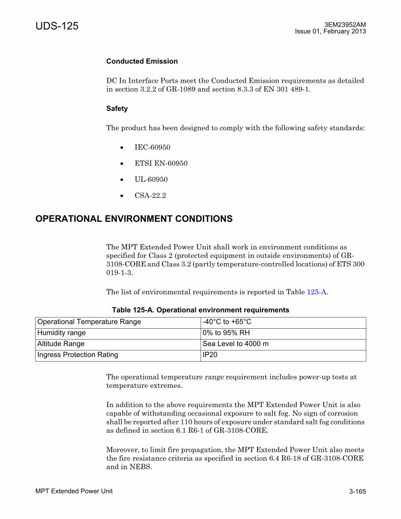
UDS-125 3EM23952AMIssue 01, February 2013
MPT Extended Power Unit 3-165
Conducted Emission
DC In Interface Ports meet the Conducted Emission requirements as detailed in section 3.2.2 of GR-1089 and section 8.3.3 of EN 301 489-1.
Safety
The product has been designed to comply with the following safety standards:
• IEC-60950
• ETSI EN-60950
• UL-60950
• CSA-22.2
OPERATIONAL ENVIRONMENT CONDITIONS
The MPT Extended Power Unit shall work in environment conditions as specified for Class 2 (protected equipment in outside environments) of GR-3108-CORE and Class 3.2 (partly temperature-controlled locations) of ETS 300 019-1-3.
The list of environmental requirements is reported in Table 125-A.
The operational temperature range requirement includes power-up tests at temperature extremes.
In addition to the above requirements the MPT Extended Power Unit is also capable of withstanding occasional exposure to salt fog. No sign of corrosion shall be reported after 110 hours of exposure under standard salt fog conditions as defined in section 6.1 R6-1 of GR-3108-CORE.
Moreover, to limit fire propagation, the MPT Extended Power Unit also meets the fire resistance criteria as specified in section 6.4 R6-18 of GR-3108-CORE and in NEBS.
Table 125-A. Operational environment requirementsOperational Temperature Range -40°C to +65°CHumidity range 0% to 95% RHAltitude Range Sea Level to 4000 mIngress Protection Rating IP20

3EM23952AMIssue 01, February 2013
MPT Extended Power Unit3-166
UDS-125
ELECTRICAL OVERVIEW
See Figure 125-4 for the block diagram of the card and its connectivity with supply, ODU and IDU equipment.
DC In interfaces
The dual battery input is provided by two DC In connectors. Table 125-B describes the electrical characteristics of the DC In Interface.
Figure 125-4. MPT Extended Power Unit Block Diagram
Table 125-B. MPT Extended Power Unit Electrical Characteristics of DC In InterfacesDC voltage from the battery Voltage range 19.2V to 57.6V
-19.2V to -57.6VMax Current 15 A
Surge protection Standard • ETSI EN300 132-2• GR-1089-CORE

UDS-125 3EM23952AMIssue 01, February 2013
MPT Extended Power Unit 3-167
DC Out interfaces
The DC Out interfaces provide the power supply to two external MPTs (ODUs). For each ODU the power is available on Type N and RJ-45 connectors. Only one output (Type N or RJ-45) must be used to power an MPT. If an RJ-45 connector is used to power an MPT, the data coming from the other RJ-45 can be added. Table 125-C describes the electrical characteristics of the DC Out Interface.
RJ-45 connectors
There are two dual-stacked RJ-45 connectors.
Table 125-D describes the electrical characteristics of the dual-stacked RJ-45 connectors.
Housekeeping interface
The housekeeping interface is a dedicated RJ-45 copper Ethernet connector. Alarm data and common signal will be mapped.The logic for housekeeping signals is GROUND (normal operation) or High Impedance (fail condition).
Table 125-E describes the electrical connections of the housekeeping interface.
Table 125-C. MPT Extended Power Unit Electrical Characteristics of DC Out InterfacesODU DC voltage Voltage range -57V
Max Current 1.8 ALightning protection • ITU-T K44
• ITU-T K45 • GR-1089-CORE
Table 125-D. MPT Extended Power Unit Electrical Characteristics of dual-stacked RJ-45 connectors
Ethernet signal Standards • 100 Base-T • 1000 Base-T
DC (remote powering) Voltage range -57VCurrent 500 mA per contact
Lightning protection ITU-T K45
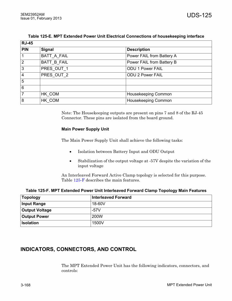
3EM23952AMIssue 01, February 2013
MPT Extended Power Unit3-168
UDS-125
Note: The Housekeeping outputs are present on pins 7 and 8 of the RJ-45 Connector. These pins are isolated from the board ground.
Main Power Supply Unit
The Main Power Supply Unit shall achieve the following tasks:
• Isolation between Battery Input and ODU Output
• Stabilization of the output voltage at -57V despite the variation of the input voltage
An Interleaved Forward Active Clamp topology is selected for this purpose. Table 125-F describes the main features.
INDICATORS, CONNECTORS, AND CONTROL
The MPT Extended Power Unit has the following indicators, connectors, and controls:
Table 125-E. MPT Extended Power Unit Electrical Connections of housekeeping interfaceRJ-45PIN Signal Description1 BATT_A_FAIL Power FAIL from Battery A2 BATT_B_FAIL Power FAIL from Battery B3 PRES_OUT_1 ODU 1 Power FAIL4 PRES_OUT_2 ODU 2 Power FAIL567 HK_COM Housekeeping Common8 HK_COM Housekeeping Common
Table 125-F. MPT Extended Power Unit Interleaved Forward Clamp Topology Main FeaturesTopology Interleaved ForwardInput Range 18-60VOutput Voltage -57VOutput Power 200WIsolation 1500V
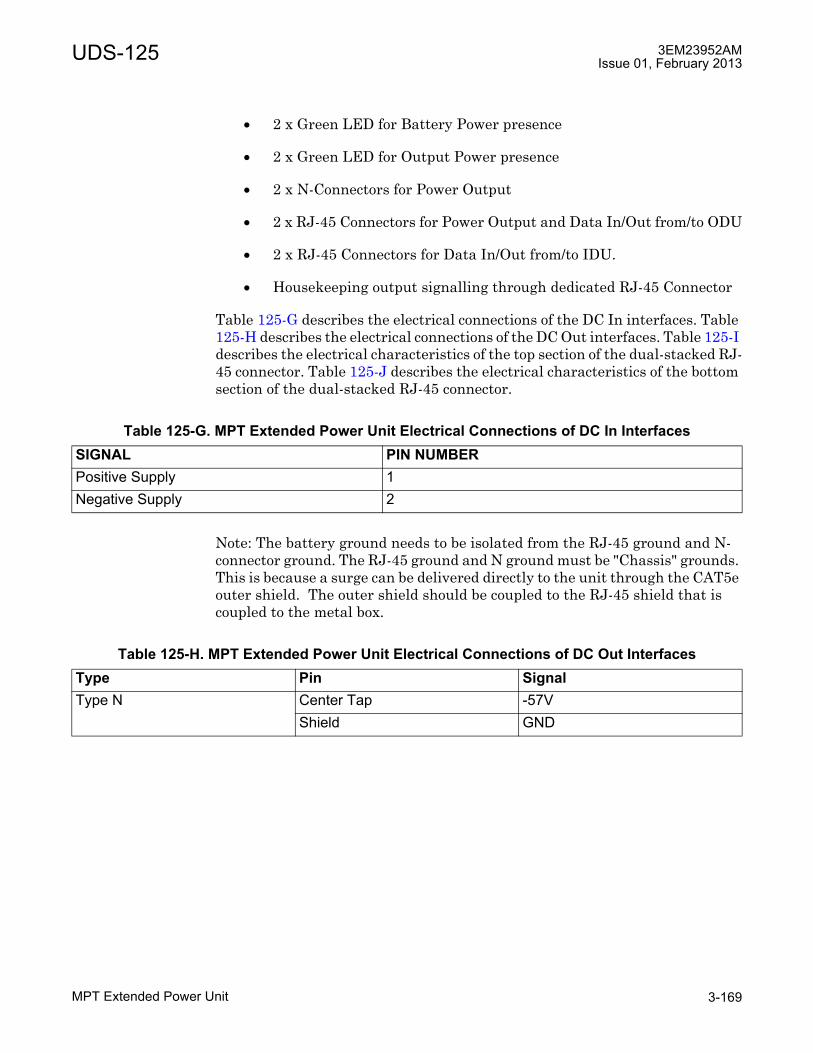
UDS-125 3EM23952AMIssue 01, February 2013
MPT Extended Power Unit 3-169
• 2 x Green LED for Battery Power presence
• 2 x Green LED for Output Power presence
• 2 x N-Connectors for Power Output
• 2 x RJ-45 Connectors for Power Output and Data In/Out from/to ODU
• 2 x RJ-45 Connectors for Data In/Out from/to IDU.
• Housekeeping output signalling through dedicated RJ-45 Connector
Table 125-G describes the electrical connections of the DC In interfaces. Table 125-H describes the electrical connections of the DC Out interfaces. Table 125-I describes the electrical characteristics of the top section of the dual-stacked RJ-45 connector. Table 125-J describes the electrical characteristics of the bottom section of the dual-stacked RJ-45 connector.
Note: The battery ground needs to be isolated from the RJ-45 ground and N-connector ground. The RJ-45 ground and N ground must be "Chassis" grounds. This is because a surge can be delivered directly to the unit through the CAT5e outer shield. The outer shield should be coupled to the RJ-45 shield that is coupled to the metal box.
Table 125-G. MPT Extended Power Unit Electrical Connections of DC In InterfacesSIGNAL PIN NUMBERPositive Supply 1Negative Supply 2
Table 125-H. MPT Extended Power Unit Electrical Connections of DC Out InterfacesType Pin SignalType N Center Tap -57V
Shield GND

3EM23952AMIssue 01, February 2013
MPT Extended Power Unit3-170
UDS-125
Note: The shield of the dual stacked RJ-45 connector must be connected to ground; this will allow the cable shielding to be included in the return current path.
ALARM AND LED BEHAVIOR
The following tables summarize the alarm and LED behavior.
Table 125-K describes the main causes of alarms and LEDs by VDC MPT input battery. Note: this table assumes that there is no short circuit or over current fault on any output MPT.
Table 125-L describes VDC input battery operation ranges.
Table 125-I. MPT Extended Power Unit Electrical Connections of top section of dual-stacked RJ-45 connector
PIN Signal Description1 TR_DP0 IDU Data pair 0 +2 TR_DN0 IDU Data pair 0 - 3 TR_DN1 IDU Data pair 1 - 4 TR_DP2 IDU Data pair 2 +5 TR_DN2 IDU Data pair 2 - 6 TR_DP1 IDU Data pair 1 +7 TR_DP3 IDU Data pair 3 +8 TR_DN3 IDU Data pair 3 -
Table 125-J. MPT Extended Power Unit Electrical Connections of bottom section of dual-stacked RJ-45 connector
PIN Signal Description1 BI_D0P Bi-directional pair 0 + & GND2 BI_D0N Bi-directional pair 0 - & GND3 BI_D1P Bi-directional pair 1 + & GND4 BI_D2P Bi-directional pair 2 + & -57V5 BI_D2N Bi-directional pair 2 - & -57V6 BI_D1N Bi-directional pair 1 - & GND7 BI_D3P Bi-directional pair 3 + & -57V8 BI_D3N Bi-directional pair 3 - & -57V

UDS-125 3EM23952AMIssue 01, February 2013
MPT Extended Power Unit 3-171
Table 125-M describes the main causes of alarms and LEDs by VDC MPT output. Note: this table assumes that there is no short circuit or over current fault on input batteries.
Table 125-N describes DC output MPT (ODU) operation ranges.
Table 125-K. Main cases of alarms and LEDs by VDC MPT input batteryVDC Input Battery Housekeeping alarms LEDsBattery 1 Battery 2 Power
Battery 1
Power Battery 2
ODU Power [1:2]
Battery A LED
Battery B LED
ODU LED [1:2]
0V < VDC < 19.2V 0V < VDC < 19.2V Tri state Tri state Tri state Off Off Off0V < VDC < 19.2V 19.2V < VDC <
57.6VTri state Ground Ground Off Green Green
19.2V < VDC < 57.6V
0V < VDC < 19.2V Ground Tri state Ground Green Off Green
19.2V < VDC < 57.6V
19.2V < VDC < -57.6V
Ground Ground Ground Green Green Green
19.2V < VDC < 57.6V
VDC < -57.6V Ground Tri state Tri state Green Off Off
VDC > -57.6V -57.6V < VDC < -38.4V
Tri state Ground Tri state Off Green Off
VDC > -57.6V VDC > -57.6V Tri state Tri state Tri state Off Off Off
Table 125-L. VDC Input Battery Operation RangesWorking range ±19.2V < VDC < 57.6VUndervoltage 0V < VDC < ±19.2VOvervoltage VDC > ±57.6V
Table 125-M. Main cases of alarms and LEDs by VDC MPT output (N/RJ-45 connectors)DC output MPT (ODU) Housekeeping alarms LEDsMPT out 1 MPT out 2 ODU Power 1 ODU Power 2 ODU LED 1 ODU LED 20A < DC < 1.75A 0A < DC < 1.75A Ground Ground Green Green0A < DC < 1.75A DC > 1.75A Ground Tri state Green OffDC > 1.75A 0A < DC < 1.75A Tri state Ground Off GreenDC > 1.75A DC > 1.75A Tri state Tri state Off Off

3EM23952AMIssue 01, February 2013
MPT Extended Power Unit3-172
UDS-125
Cable length
Table 125-O provides the maximum allowed cable length with step-up with output voltage of -53 V.
Table 125-N. DC output MPT (ODU) Operation RangesWorking range 0A < DC < 1.75AShort circuit or over current fault DC > 1.75A
Table 125-O. Maximum allowed cable length for MPT Extended Power UnitCable type Cat5E, 1AC016760006:
Power and Data on Ethernet cable
Cat5E, 1AC016760006:Power only, Data on optical cable
Coaxial cable 1AB350440001:Power only, Data on optical cable
Configuration Maximum length Maximum length Maximum lengthMPT-HC 100 m 100 m 300 mMPT-HC with XPIC 100 m 100 m 300 mMPT-XP 100 m 100 m 300 mMPT-XP with XPIC 100 m 100 m 300 mConstraint 1 Max current in Ethernet transformer < 1.8 A Max
current limit for Power Unit: 1.8 AMax current limit for Power Unit: 1.8 A
Constraint 2 Min MPT-HC PSU input voltage > 28 V, Min MPT-XP PSU input voltage >36 V1
[1] PSU input voltage on MPT-HC/MPT-XP
Constraint 3 Data traffic only with Ethernet cable
Data traffic only with optical cable

UDS-125 3EM23952AMIssue 01, February 2013
MPT Extended Power Unit 3-173
MOUNTING RACK
A bracket is provided to mount the MPT Extended Power Unit in a 19 inch rack. The bracket provides an attachment point for grounding, located in the central strut. The same bracket can be used to mount the MPT Power Unit. See Figure 125-5.
Figure 125-5. MPT Extended Power Unit mounting bracket

3EM23952AMIssue 01, February 2013
MPT Extended Power Unit3-174
UDS-125
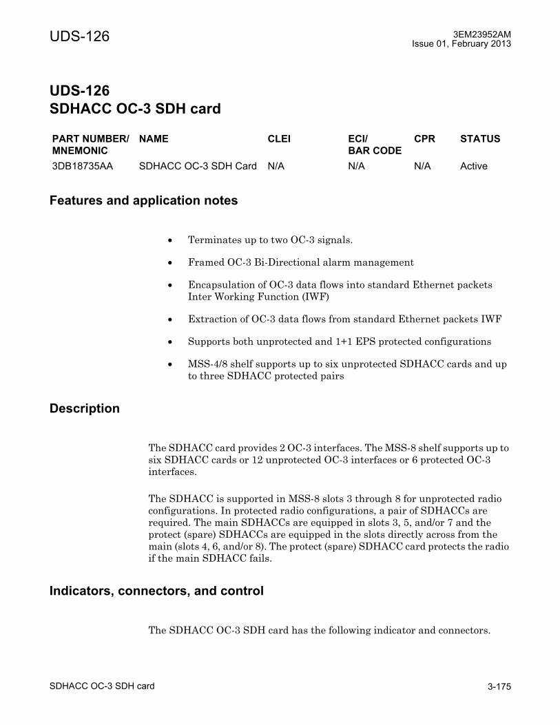
UDS-126 3EM23952AMIssue 01, February 2013
SDHACC OC-3 SDH card 3-175
UDS-126 SDHACC OC-3 SDH card
UDS-126SDHACC OC-3 SDH card
Features and application notes
• Terminates up to two OC-3 signals.
• Framed OC-3 Bi-Directional alarm management
• Encapsulation of OC-3 data flows into standard Ethernet packets Inter Working Function (IWF)
• Extraction of OC-3 data flows from standard Ethernet packets IWF
• Supports both unprotected and 1+1 EPS protected configurations
• MSS-4/8 shelf supports up to six unprotected SDHACC cards and up to three SDHACC protected pairs
Description
The SDHACC card provides 2 OC-3 interfaces. The MSS-8 shelf supports up to six SDHACC cards or 12 unprotected OC-3 interfaces or 6 protected OC-3 interfaces.
The SDHACC is supported in MSS-8 slots 3 through 8 for unprotected radio configurations. In protected radio configurations, a pair of SDHACCs are required. The main SDHACCs are equipped in slots 3, 5, and/or 7 and the protect (spare) SDHACCs are equipped in the slots directly across from the main (slots 4, 6, and/or 8). The protect (spare) SDHACC card protects the radio if the main SDHACC fails.
Indicators, connectors, and control
The SDHACC OC-3 SDH card has the following indicator and connectors.
PART NUMBER/MNEMONIC
NAME CLEI ECI/BAR CODE
CPR STATUS
3DB18735AA SDHACC OC-3 SDH Card N/A N/A N/A Active
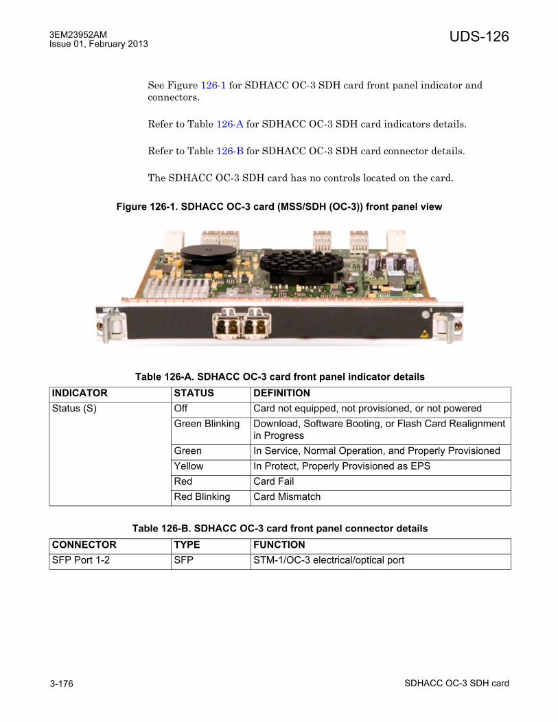
3EM23952AMIssue 01, February 2013
SDHACC OC-3 SDH card3-176
UDS-126
See Figure 126-1 for SDHACC OC-3 SDH card front panel indicator and connectors.
Refer to Table 126-A for SDHACC OC-3 SDH card indicators details.
Refer to Table 126-B for SDHACC OC-3 SDH card connector details.
The SDHACC OC-3 SDH card has no controls located on the card.
Figure 126-1. SDHACC OC-3 card (MSS/SDH (OC-3)) front panel view
Table 126-A. SDHACC OC-3 card front panel indicator detailsINDICATOR STATUS DEFINITIONStatus (S) Off Card not equipped, not provisioned, or not powered
Green Blinking Download, Software Booting, or Flash Card Realignment in Progress
Green In Service, Normal Operation, and Properly ProvisionedYellow In Protect, Properly Provisioned as EPSRed Card FailRed Blinking Card Mismatch
Table 126-B. SDHACC OC-3 card front panel connector detailsCONNECTOR TYPE FUNCTIONSFP Port 1-2 SFP STM-1/OC-3 electrical/optical port
UDS-126 3EM23952AMIssue 01, February 2013
SDHACC OC-3 SDH card 3-177
Functional overview
In the transmit direction, the SDHACC receives OC-3 signals from the customer interfaces. Encapsulates the OC-3 data flows into standard Ethernet packets, (IWF). The Ethernet packets are sent to the cross-connections matrix for connection to their provisioned destinations.
In the receive direction, the SDHACC receives Ethernet packets from the cross-connections matrix from their provisioned sources. Extracts the OC-3 data flows from standard Ethernet packets (IWF). The OC-3 signals are sent to the customer interfaces.

3EM23952AMIssue 01, February 2013
SDHACC OC-3 SDH card3-178
UDS-126
UDS-127 3EM23952AMIssue 01, February 2013
MSS-1 microwave service switch shelf 3-179
UDS-127 MSS-1 microwave service switch shelf
UDS-127MSS-1 microwave service switch shelf
Features and application notes
• The Microwave Service Switch (MSS-1) is a monoboard that provides user Ethernet, TDM, housekeeping and management interfaces.
• 16Gb Packet Based Node
• 1 Mbps full-duplex Ethernet transport capacity
• Flexible aggregate capacity sharing DS1 and Ethernet traffic
• IPv6 routing and tunneling
• Four housekeeping alarm input interfaces
• Three housekeeping alarm output interfaces (alarm LEDs)
• Split mount configuration utilizing the Core-E SFP ports supports:
� up to two unprotected RF channels in one MSS-1 shelf connected to up to two MPT-HC/XP, MPT-HL, and/or MPT-GC Transceivers.
� up to one protected RF channel in one MSS-1 shelf connected to two MPT-HC/XP Transceivers.
• Split mount configuration utilizing the Core-E electrical Ethernet ports supports:
� up to four unprotected RF channels in one MSS-1 shelf connected to up to four MPT-HC/XP and/or MPT-GC Transceivers.
� up to two protected RF channels in one MSS-1 shelf connected to two MPT-HC/XP Transceivers.
• Stand-alone shelf configuration
• Mounts in a 19-inch aluminum rack or 19-inch seismic rack. Adapter flanges available to mount in a 23-inch aluminum rack
PART NUMBER/MNEMONIC
NAME CLEI ECI/BAR CODE
CPR STATUS
3DB19015AA MSS-1 Microwave Service Switch Shelf
DRMVY10DRA N/A N/A Active

3EM23952AMIssue 01, February 2013
MSS-1 microwave service switch shelf3-180
UDS-127
• Can be mounted horizontally or vertically in a rack
• Provides two mounting options: flush mount or 5 inch projection
Description
See Figure 127-1 for an example of the MSS-1 shelf.
The MSS-1 shelf is 16.14 inches wide, 0.08 inches high, and 5.51 inches deep. See figure 127-2 for outline and shelf dimensions of the MSS-1 shelf.
Functional overview
MSS-1 implements functionality of grooming, routing, and switching, exploiting a packet oriented technology in order to meet the overall architecture.
Figure 127-1. Microwave service switch (MSS-1) shelf
Figure 127-2. MSS-1 shelf dimensions

UDS-127 3EM23952AMIssue 01, February 2013
MSS-1 microwave service switch shelf 3-181
The MSS-1 Core-E platform, with multiplexing and symmetrical cross-connect functions, can manage different radio directions (up to six), with the possibility to add-drop data flows of local DS1 traffic. The Core-E platform is based on packet technology (Ethernet Switch) with a generic serial GigE interface between the Core-E and transport cards. See Figure 127-3 for a functional block diagram of the MSS-1 shelf.
Front panel connectors
The MSS-1 provides six native Ethernet user interfaces. Using these interfaces, you can connect any radio that can be connected to a Core-E card.
Table 127-A defines the port numbering, interface type, traffic support and MPT connectivity.
Figure 127-3. MSS-1 shelf block diagram
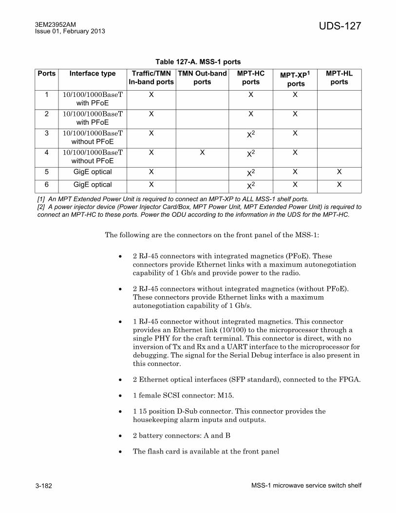
3EM23952AMIssue 01, February 2013
MSS-1 microwave service switch shelf3-182
UDS-127
The following are the connectors on the front panel of the MSS-1:
• 2 RJ-45 connectors with integrated magnetics (PFoE). These connectors provide Ethernet links with a maximum autonegotiation capability of 1 Gb/s and provide power to the radio.
• 2 RJ-45 connectors without integrated magnetics (without PFoE). These connectors provide Ethernet links with a maximum autonegotiation capability of 1 Gb/s.
• 1 RJ-45 connector without integrated magnetics. This connector provides an Ethernet link (10/100) to the microprocessor through a single PHY for the craft terminal. This connector is direct, with no inversion of Tx and Rx and a UART interface to the microprocessor for debugging. The signal for the Serial Debug interface is also present in this connector.
• 2 Ethernet optical interfaces (SFP standard), connected to the FPGA.
• 1 female SCSI connector: M15.
• 1 15 position D-Sub connector. This connector provides the housekeeping alarm inputs and outputs.
• 2 battery connectors: A and B
• The flash card is available at the front panel
Table 127-A. MSS-1 portsPorts Interface type Traffic/TMN
In-band portsTMN Out-band
portsMPT-HC
portsMPT-XP1
ports
[1] An MPT Extended Power Unit is required to connect an MPT-XP to ALL MSS-1 shelf ports.
MPT-HL ports
1 10/100/1000BaseT with PFoE
X X X
2 10/100/1000BaseT with PFoE
X X X
3 10/100/1000BaseT without PFoE
X X2
[2] A power injector device (Power Injector Card/Box, MPT Power Unit, MPT Extended Power Unit) is required toconnect an MPT-HC to these ports. Power the ODU according to the information in the UDS for the MPT-HC.
X
4 10/100/1000BaseT without PFoE
X X X2 X
5 GigE optical X X2 X X
6 GigE optical X X2 X X

UDS-127 3EM23952AMIssue 01, February 2013
MSS-1 microwave service switch shelf 3-183
Table 127-B provides the pinout information for the RJ-45 connectors.
Tables 127-C and 127-D provide the pinout information for the SCSI connector.
Table 127-B. MSS-1 pinout RJ-45 connector (NMS+Debug)PIN # Signal
1 TX_P2 TX_N3 RX_N4 Debug_TX5 Debug_Rx6 RX_P7 DTR8 GND
Table 127-C. 68 pin SCSI cable input (RCV) pinoutPAIR FROM WIRE COLOR FUNCTION1 Jx-3 White/Blue Input1 - Tip (RCV)
Jx-37 Blue/White Input1- Ring (RCV)2 Jx-5 White/Orange Input2 - Tip (RCV)
Jx-39 Orange/White Input2- Ring (RCV)3 Jx-7 White/Green Input3- Tip (RCV)
Jx-41 Green/White Input3- Ring (RCV)4 Jx-9 White/Brown Input4 - Tip (RCV)
Jx-43 Brown/White Input4- Ring (RCV)5 Jx-11 White/Slate Input5 - Tip (RCV)
Jx-45 Slate/White Input5- Ring (RCV)6 Jx-13 Red/Blue Input6 - Tip (RCV)
Jx-47 Blue/Red Input6- Ring (RCV)7 Jx-15 Red/Orange Input7 - Tip (RCV)
Jx-49 Orange/Red Input7- Ring (RCV)8 Jx-17 Red/Green Input8 - Tip (RCV)
Jx-51 Green/Red Input8- Ring (RCV)9 Jx-19 Red/Brown Input9 - Tip (RCV)
Jx-53 Brown/Red Input9- Ring (RCV)10 Jx-21 Red/Slate Input10 - Tip (RCV)
Jx-55 Slate/Red Input10- Ring (RCV)

3EM23952AMIssue 01, February 2013
MSS-1 microwave service switch shelf3-184
UDS-127
11 Jx-23 Black/Blue Input11- Tip (RCV)Jx-57 Blue/Black Input11- Ring (RCV)
12 Jx-25 Black/Orange Input12 - Tip (RCV)Jx-59 Orange/Black Input12- Ring (RCV)
13 Jx-27 Black/Green Input13 - Tip (RCV)Jx-61 Green/Black Input13- Ring (RCV)
14 Jx-29 Black/Brown Input14 - Tip (RCV)Jx-63 Brown/Black Input14- Ring (RCV)
15 Jx-31 Black/Slate Input15 - Tip (RCV)Jx-65 Slate/Black Input15- Ring (RCV)
16 Jx-33 Yellow/Blue Input16 - Tip (RCV)Jx-67 Blue/Yellow Input16- Ring (RCV)
Table 127-D. 68 pin SCSI cable output (XMT) pinoutPAIR FROM WIRE COLOR FUNCTION1 Jx-2 White/Blue Output1 - Tip (XMT)
Jx-36 Blue/White Output1- Ring (XMT)2 Jx-4 White/Orange Output2 - Tip (XMT)
Jx-38 Orange/White Output2- Ring (XMT)3 Jx-6 White/Green Output3- Tip (XMT)
Jx-40 Green/White Output3- Ring (XMT)4 Jx-8 White/Brown Output4 - Tip (XMT)
Jx-42 Brown/White Output4- Ring (XMT)5 Jx-10 White/Slate Output5 - Tip (XMT)
Jx-44 Slate/White Output5- Ring (XMT)6 Jx-12 Red/Blue Output6 - Tip (XMT)
Jx-46 Blue/Red Output6- Ring (XMT)7 Jx-14 Red/Orange Output7 - Tip (XMT)
Jx-48 Orange/Red Output7- Ring (XMT)8 Jx-16 Red/Green Output8 - Tip (XMT)
Jx-50 Green/Red Output8- Ring (XMT)9 Jx-18 Red/Brown Output9 - Tip (XMT)
Jx-52 Brown/Red Output9- Ring (XMT)
Table 127-C. 68 pin SCSI cable input (RCV) pinout (cont.)PAIR FROM WIRE COLOR FUNCTION
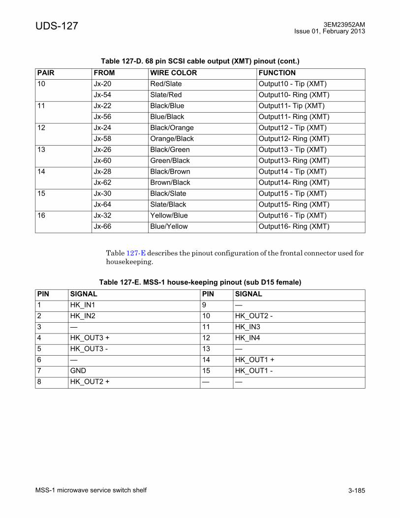
UDS-127 3EM23952AMIssue 01, February 2013
MSS-1 microwave service switch shelf 3-185
Table 127-E describes the pinout configuration of the frontal connector used for housekeeping.
10 Jx-20 Red/Slate Output10 - Tip (XMT)Jx-54 Slate/Red Output10- Ring (XMT)
11 Jx-22 Black/Blue Output11- Tip (XMT)Jx-56 Blue/Black Output11- Ring (XMT)
12 Jx-24 Black/Orange Output12 - Tip (XMT)Jx-58 Orange/Black Output12- Ring (XMT)
13 Jx-26 Black/Green Output13 - Tip (XMT)Jx-60 Green/Black Output13- Ring (XMT)
14 Jx-28 Black/Brown Output14 - Tip (XMT)Jx-62 Brown/Black Output14- Ring (XMT)
15 Jx-30 Black/Slate Output15 - Tip (XMT)Jx-64 Slate/Black Output15- Ring (XMT)
16 Jx-32 Yellow/Blue Output16 - Tip (XMT)Jx-66 Blue/Yellow Output16- Ring (XMT)
Table 127-E. MSS-1 house-keeping pinout (sub D15 female)PIN SIGNAL PIN SIGNAL1 HK_IN1 9 �2 HK_IN2 10 HK_OUT2 -3 � 11 HK_IN34 HK_OUT3 + 12 HK_IN45 HK_OUT3 - 13 �6 � 14 HK_OUT1 +7 GND 15 HK_OUT1 -8 HK_OUT2 + � �
Table 127-D. 68 pin SCSI cable output (XMT) pinout (cont.)PAIR FROM WIRE COLOR FUNCTION
3EM23952AMIssue 01, February 2013
MSS-1 microwave service switch shelf3-186
UDS-127
Alarm and LED behavior
The MSS-1 shelf provides the following functionality:
� Main Core-E card
� Main 16 port P32E1DS1 DS1 card
� Housekeeping alarm input/outputs
Core-E card alarms are reported as MSS/CORE. DS1 card alarms are reported MSS/DS1.
The Card Fail alarm indicates one or more of the following:
• lack of secondary power supply
• loss of FPGA
• loss of oscillator
• loss of -55 V DC/DC power supply
LEDs
The front panel of the MSS-1 has the following LEDs:
• Major alarm (red): at least one Major or Critical alarm is present
• Minor alarm (red): at least one Minor alarm is present
• Warning (yellow): at least one Warning alarm is present
• Abnormal (yellow): at least one Abnormal Condition is present
• Status
• 2 PFoE LEDs: on indicates that PFoE is active
Table 127-F describes the behavior of the status LED.
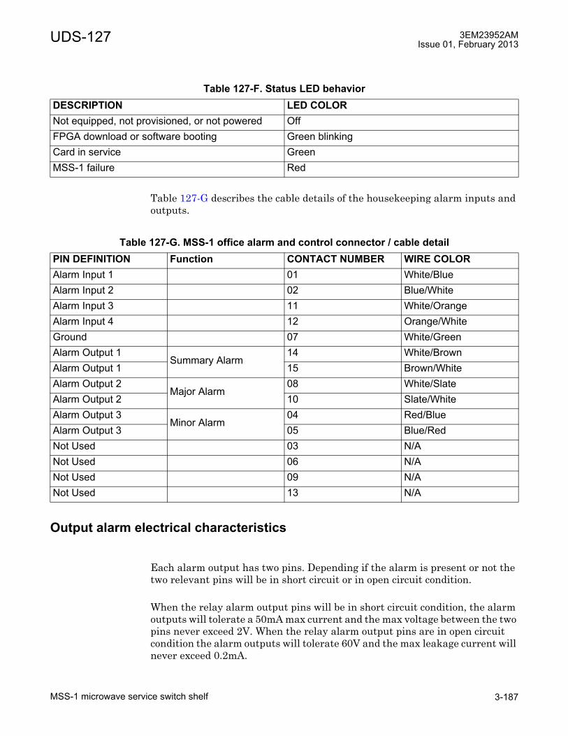
UDS-127 3EM23952AMIssue 01, February 2013
MSS-1 microwave service switch shelf 3-187
Table 127-G describes the cable details of the housekeeping alarm inputs and outputs.
Output alarm electrical characteristics
Each alarm output has two pins. Depending if the alarm is present or not the two relevant pins will be in short circuit or in open circuit condition.
When the relay alarm output pins will be in short circuit condition, the alarm outputs will tolerate a 50mA max current and the max voltage between the two pins never exceed 2V. When the relay alarm output pins are in open circuit condition the alarm outputs will tolerate 60V and the max leakage current will never exceed 0.2mA.
Table 127-F. Status LED behaviorDESCRIPTION LED COLORNot equipped, not provisioned, or not powered OffFPGA download or software booting Green blinkingCard in service GreenMSS-1 failure Red
Table 127-G. MSS-1 office alarm and control connector / cable detailPIN DEFINITION Function CONTACT NUMBER WIRE COLORAlarm Input 1 01 White/BlueAlarm Input 2 02 Blue/WhiteAlarm Input 3 11 White/OrangeAlarm Input 4 12 Orange/WhiteGround 07 White/GreenAlarm Output 1
Summary Alarm14 White/Brown
Alarm Output 1 15 Brown/WhiteAlarm Output 2
Major Alarm08 White/Slate
Alarm Output 2 10 Slate/WhiteAlarm Output 3
Minor Alarm04 Red/Blue
Alarm Output 3 05 Blue/RedNot Used 03 N/ANot Used 06 N/ANot Used 09 N/ANot Used 13 N/A
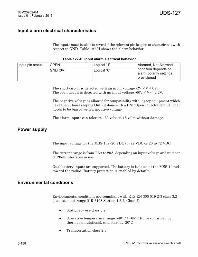
3EM23952AMIssue 01, February 2013
MSS-1 microwave service switch shelf3-188
UDS-127
Input alarm electrical characteristics
The inputs must be able to reveal if the relevant pin is open or short circuit with respect to GND. Table 127-H shows the alarm behavior.
The short circuit is detected with an input voltage -2V < V < 0V.The open circuit is detected with an input voltage -60V < V < -2.2V.
The negative voltage is allowed for compatibility with legacy equipment which have their Housekeeping Output done with a PNP Open collector circuit. That needs to be biased with a negative voltage.
The alarm inputs can tolerate �60 volts to +5 volts without damage.
Power supply
The input voltage for the MSS-1 is -20 VDC to -72 VDC or 20 to 72 VDC.
The current range is from 7.5A to 20A, depending on input voltage and number of PFoE interfaces in use.
Dual battery inputs are supported. The battery is isolated at the MSS-1 level toward the radios. Battery protection is enabled by default.
Environmental conditions
Environmental conditions are compliant with ETS EN 300 019-2-3 class 3.2 plus extended range (GR-3108 Section 1.3.2, Class 2):
• Stationary use class 3.2
• Operative temperature range: -40°C / +65°C (to be confirmed by thermal simulations), cold start at -20°C
• Transportation class 2.3
Table 127-H. Input alarm electrical behaviorInput pin status OPEN Logical �1� Alarmed, Not Alarmed
condition depends on alarm polarity settings provisioned
GND (0V) Logical �0�

UDS-127 3EM23952AMIssue 01, February 2013
MSS-1 microwave service switch shelf 3-189
• Storage class 1.2
• Cabinet degree of protection IP20
• Acoustic noise class 3.1 & 3.2

3EM23952AMIssue 01, February 2013
MSS-1 microwave service switch shelf3-190
UDS-127

3EM23952AMIssue 01, February 2013
Appendix A: Glossary A-1
Appendix A: Glossary
A
AIS - Alarm Indication Signal
AMI - Alternating Mark Inversion
ANSI - American National Standards Institute
APT - Active Problem Table
ASAP - Alarm Severity Assignment Profile
ASIC - Application Specific Integrated Circuit
ATPC - Automatic Transmit Power Control
AVC - Attribute Value Change
B
BBE - Background Block Error
BER - Bit Error Rate
BIP - Bit Interleaved Parity
C
CAS - Channel Associated Signaling
CD - Current Data
CES - Circuit Emulation Service
CESoETH - Circuit Emulation Service over Ethernet

3EM23952AMIssue 01, February 2013
Appendix A: GlossaryA-2
CESoP - Circuit Emulation Services over Packet
CFA - Carrier Failure Alarm
CFM - Connectivity Fault Management
CLA - Common Loss Alarm
Core-E - Control and Switching Module
CoS - Class of Service
CRC - Cyclic Redundancy Check
CRU - Clock Reference Unit
CSM-E - Control and Switching Module (Core-E card)
CT - Craft Terminal
D
DL - Data Link
DS - Differentiated Services
E
EAS - Ethernet Access Switch Card
ECID - ECID (Emulation IDentification) is a network unique 8-bit code identifier used along with V-Lan to identify and switch individual DS1/DS3/OC-3 lines through the Core-E.
ECT - Equipment Craft Terminal
EFC - Ethernet Flow Control
EFD - Event Forwarding Discriminator
EOW - Engineering Order Wire
EPS - Equipment Protection Switching

3EM23952AMIssue 01, February 2013
Appendix A: Glossary A-3
ERP - Ethernet Ring Protection
ES - Errored Second
ESMC - Ethernet Synchronization Message Channel
ETH - ETHernet
ETSI - European Telecommunications Standards Institute
EW - Early Warning
F
F - Framing
FAS - Frame Alignment Signal
FCS - Frame Check Sequence
FD - Frequency Diversity
FE - Fast Ethernet
FEC - Forward Error Correction
FPGA - Field Programmable Gate Array
G
GFP - Generic Frame Protocol
GNE - Gateway Network Element
H
HBER - High Bit Error Ratio
HD - History Data
HDB3 - High Density order 3 Bipolar encoding

3EM23952AMIssue 01, February 2013
Appendix A: GlossaryA-4
HET - Hetero frequency
HS - Hitless Switch
HSB - Hot Stand-By
I
IDU - InDoor Unit
IM - Information Model
IP - Internet Protocol
ISPB - Intra Shelf Parallel Switching
IWF - Interworking Function
J
JA - Jitter Attenuator
JTAG - Joint Test Action Group
JUSM - Java User-based Security Model
K
L
LAN - Local Area Network
LAPD - Link Access Procedure on D-channel
LBER - Low Bit Error Ration
LIM - Link Identifier Mismatch
LIU - Line Interface Unit
LOF - Loss Of Frame

3EM23952AMIssue 01, February 2013
Appendix A: Glossary A-5
LOS - Loss Of Signal
M
MAC - Medium Access Control
MAU - Medium Attachment Unit
MEF - Metro Ethernet Forum
MEN - Metro Ethernet Network
MIB - Management Information Base
MOD300 (MD300) - Radio (Modem) Card
MPR - Microwave Packet Radio
MPT - Microwave Packet Transport
MRTIE - Maximum Relative Time Interval Error
MSOH - Multiple Section OverHead
MSS - Microwave Service Switch
MTIE - Maximum Time Interval Error
MXC - Microwave Cross Connect
N
NE - Network Element
NEC - Network Element Clock
NEtO - Network Element Overview
NMS - Network Management System
NNI - Network Node Interface

3EM23952AMIssue 01, February 2013
Appendix A: GlossaryA-6
NRZ - Not Return to Zero
NSA - Not Service Affecting
NTP - Network Time Protocol
O
OC - ODU Controller
ODU - Outdoor Unit
OFS - Out of Frame Second
OH - OverHead
OMS - Operations Management System
OOF - Out Of Frame
OS - Operation System
OSPF - Open Short Path First
P
P2E3DS3 - Two port DS3 PDH Interface Card
P8ETH - Eight port Ethernet Access Switch Card
P32E1DS1 - Thirty-two port DS1 PDH Interface Card
PDH - Plesiochronous Digital Hierarchy
PDU - Protocol Data Unit
PLM - PayLoad Mismatch
PM - Performance Monitoring
PNU - Packet Node Unit

3EM23952AMIssue 01, February 2013
Appendix A: Glossary A-7
PPM - Part Per Million
PRBS - Pseudo Random Binary Sequence
PRS - Clock Primary Reference Source Clock
PSU - Power Supply Unit
PTU - Packet Transport Unit
Q
QoS - Quality of Service
R
R-APS - Ring Automatic Protection Switching
RAI - Remote Alarm Indication
RDI - Remote Defect Indication
REI - Remote Error Indication
RFC - Remote Frequency Control
RI - Remote Inventory
RPL - Ring Protection Link
RPS - Radio Protection Switching
RSOH - Regenerator Section Over-Head
RSL - Receive Signal Level
RTPC - Remote Transmit Power Control
RTU - Right To Use

3EM23952AMIssue 01, February 2013
Appendix A: GlossaryA-8
S
SA - Service Affecting
SD - Space Diversity
SDH - Synchronous Digital Hierarchy
SDHACC - Two port OC-3 SDH Interface Card
SerDes - Serializer / Deserializer
SES - Severely Errored Second
SF - Signal Fail
SNMP - Simple Network Management Protocol
SP - Spare
SPI - Serial Peripheral Interface
SW - Software
SWP - Software Package
Symbol Rate - The number of symbol changes (signalling events) made to the transmission medium per second using a digitally modulated signal or a line code. Also known as baud rate or modulation rate.
T
TBI - Ten Bit Interface
TCA - Threshold Crossing Alarm
TCO - Total Cost of Ownership
TD - Threshold Data
TDEV - Time Deviation
TDF - Total Discarded Frames

3EM23952AMIssue 01, February 2013
Appendix A: Glossary A-9
TDM - Time Division Multiplexed
TDM2ETH - Time Division Multiplexed To Ethernet
TDM2TDM - Time Division Multiplexed To Time Division Multiplexed
TIM - Trace Identifier Mismatch
TMN - Telecommunication Management Network
TPS - Tx Protection Switching
TRCF - Total Received Correct Frames
TRCO - Total Received Correct Octets
TRSEF - Total Received Service Errored Frames
TS - Time Slot
TSM - Transmission Systems Manager
TTF - Total Transmitted Frames
TTO - Total Transmitted Octets
TTP - Trail Termination Point
U
UAS - UnAvailable Second
UAT - UnAvailable Time
UI - Unit Interval
V
VC-n - Virtual Container - n
VLAN - Virtual Local Area Network

3EM23952AMIssue 01, February 2013
Appendix A: GlossaryA-10
W
WebEML - Web Element Manager Layer. A set of Java applications (Craft Terminal) containing NEtO and JUSM.
WK - Working
X
XPIC - Cross Polar Interference Canceller
Y
Z
ZBTSI - Zero Byte Time Slot Interchange
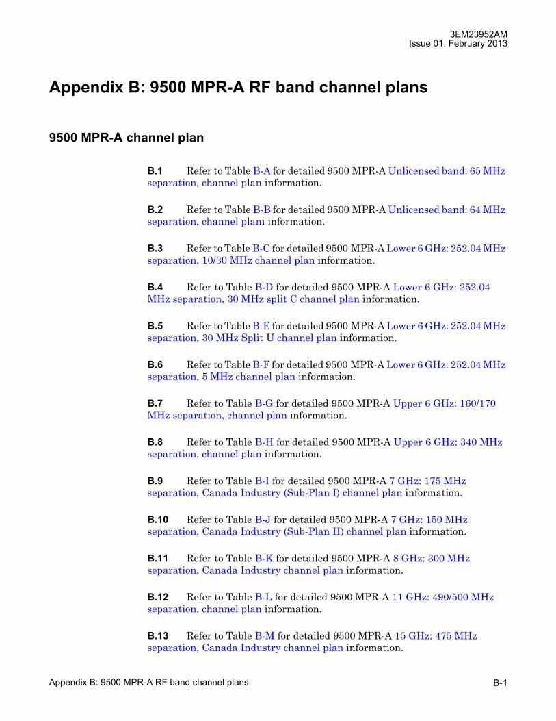
3EM23952AMIssue 01, February 2013
Appendix B: 9500 MPR-A RF band channel plans B-1
Appendix B: 9500 MPR-A RF band channel plans
9500 MPR-A channel plan
B.1 Refer to Table B-A for detailed 9500 MPR-A Unlicensed band: 65 MHz separation, channel plan information.
B.2 Refer to Table B-B for detailed 9500 MPR-A Unlicensed band: 64 MHz separation, channel plani information.
B.3 Refer to Table B-C for detailed 9500 MPR-A Lower 6 GHz: 252.04 MHz separation, 10/30 MHz channel plan information.
B.4 Refer to Table B-D for detailed 9500 MPR-A Lower 6 GHz: 252.04 MHz separation, 30 MHz split C channel plan information.
B.5 Refer to Table B-E for detailed 9500 MPR-A Lower 6 GHz: 252.04 MHz separation, 30 MHz Split U channel plan information.
B.6 Refer to Table B-F for detailed 9500 MPR-A Lower 6 GHz: 252.04 MHz separation, 5 MHz channel plan information.
B.7 Refer to Table B-G for detailed 9500 MPR-A Upper 6 GHz: 160/170 MHz separation, channel plan information.
B.8 Refer to Table B-H for detailed 9500 MPR-A Upper 6 GHz: 340 MHz separation, channel plan information.
B.9 Refer to Table B-I for detailed 9500 MPR-A 7 GHz: 175 MHz separation, Canada Industry (Sub-Plan I) channel plan information.
B.10 Refer to Table B-J for detailed 9500 MPR-A 7 GHz: 150 MHz separation, Canada Industry (Sub-Plan II) channel plan information.
B.11 Refer to Table B-K for detailed 9500 MPR-A 8 GHz: 300 MHz separation, Canada Industry channel plan information.
B.12 Refer to Table B-L for detailed 9500 MPR-A 11 GHz: 490/500 MHz separation, channel plan information.
B.13 Refer to Table B-M for detailed 9500 MPR-A 15 GHz: 475 MHz separation, Canada Industry channel plan information.
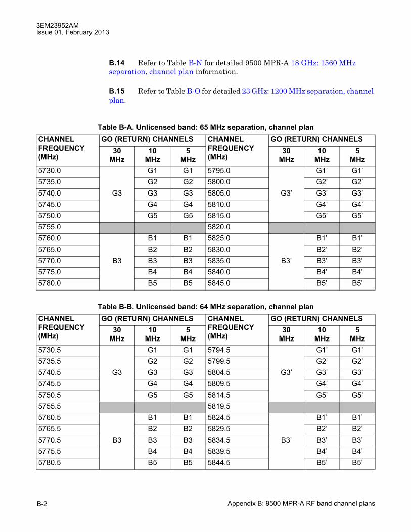
3EM23952AMIssue 01, February 2013
Appendix B: 9500 MPR-A RF band channel plansB-2
B.14 Refer to Table B-N for detailed 9500 MPR-A 18 GHz: 1560 MHz separation, channel plan information.
B.15 Refer to Table B-O for detailed 23 GHz: 1200 MHz separation, channel plan.
Table B-A. Unlicensed band: 65 MHz separation, channel planCHANNELFREQUENCY(MHz)
GO (RETURN) CHANNELS CHANNELFREQUENCY(MHz)
GO (RETURN) CHANNELS30
MHz10
MHz5
MHz30
MHz10
MHz5
MHz5730.0 G1 G1 5795.0 G1� G1�5735.0 G2 G2 5800.0 G2� G2�5740.0 G3 G3 G3 5805.0 G3� G3� G3�5745.0 G4 G4 5810.0 G4� G4�5750.0 G5 G5 5815.0 G5� G5�5755.0 5820.05760.0 B1 B1 5825.0 B1� B1�5765.0 B2 B2 5830.0 B2� B2�5770.0 B3 B3 B3 5835.0 B3� B3� B3�5775.0 B4 B4 5840.0 B4� B4�5780.0 B5 B5 5845.0 B5� B5�
Table B-B. Unlicensed band: 64 MHz separation, channel planCHANNELFREQUENCY(MHz)
GO (RETURN) CHANNELS CHANNELFREQUENCY(MHz)
GO (RETURN) CHANNELS30
MHz10
MHz5
MHz30
MHz10
MHz5
MHz5730.5 G1 G1 5794.5 G1� G1�5735.5 G2 G2 5799.5 G2� G2�5740.5 G3 G3 G3 5804.5 G3� G3� G3�5745.5 G4 G4 5809.5 G4� G4�5750.5 G5 G5 5814.5 G5� G5�5755.5 5819.55760.5 B1 B1 5824.5 B1� B1�5765.5 B2 B2 5829.5 B2� B2�5770.5 B3 B3 B3 5834.5 B3� B3� B3�5775.5 B4 B4 5839.5 B4� B4�5780.5 B5 B5 5844.5 B5� B5�

3EM23952AMIssue 01, February 2013
Appendix B: 9500 MPR-A RF band channel plans B-3
Table B-C. Lower 6 GHz: 252.04 MHz separation, 10/30 MHz channel planCHANNELFREQUENCY(MHz)
GO (RETURN) CHANNELS CHANNELFREQUENCY(MHz)
RETURN (GO) CHANNELS30
MHz10
MHz30
MHz10
MHz5935.320 L6.D1.L 6187.360 L6.D1.H5945.200 L6.B1.L L6.D2.L 6197.240 L6.B1.H L6.D2.H5955.080 L6.D3.L 6207.120 L6.D3.H5964.970 L6.D4.L 6217.010 L6.D4.H5974.850 L6.B2.L L6.D5.L 6226.890 L6.B2.H L6.D5.H5984.730 L6.D6.L 6236.770 L6.D6.H5994.620 L6.D7.L 6246.660 L6.D7.H6004.500 L6.B3.L L6.D8.L 6256.540 L6.B3.H L6.D8.H6014.380 L6.D9.L 6266.420 L6.D9.H6024.270 L6.D10.L 6276.310 L6.D10.H6034.150 L6.B4.L L6.D11.L 6286.190 L6.B4.H L6.D11.H6044.030 L6.D12.L 6296.070 L6.D12.H6053.920 L6.D13.L 6305.960 L6.D13.H6063.800 L6.B5.L L6.D14.L 6315.840 L6.B5.H L6.D14.H6073.680 L6.D15.L 6325.720 L6.D15.H6083.570 L6.D16.L 6335.610 L6.D16.H6093.450 L6.B6.L L6.D17.L 6345.490 L6.B6.H L6.D17.H6103.330 L6.D18.L 6355.370 L6.D18.H
6113.2201
[1] Alternate channels set aside for narrow band systems.
L6.D19.L 6365.2601 L6.D19.H
6123.1001 L6.B7.L L6.D20.L 6375.1401 L6.B7.H L6.D20.H
6132.9801 L6.D21.L 6385.0201 L6.D21.H
6142.8701 L6.D22.L 6394.9101 L6.D22.H
6152.7501 L6.B8.L L6.D23.L 6404.7901 L6.B8.H L6.D23.H
6162.6301 L6.D24.L 6414.6701 L6.D24.H

3EM23952AMIssue 01, February 2013
Appendix B: 9500 MPR-A RF band channel plansB-4
Table B-D. Lower 6 GHz: 252.04 MHz separation, 30 MHz split C channel planCHANNELFREQUENCY(MHz)
GO (RETURN) CHANNELS CHANNELFREQUENCY(MHz)
RETURN (GO) CHANNELS30
MHz30
MHz5937.7875 11C 6189.8275 21C5967.4375 12C 6219.4775 22C5997.0875 13C 6249.1275 23C6026.7375 14C 6278.7775 24C6056.3875 15C 6308.4275 25C6086.0375 16C 6338.0775 26C6115.6875 17C 6367.7275 27C6145.3375 18C 6397.3775 28C
Table B-E. Lower 6 GHz: 252.04 MHz separation, 30 MHz Split U channel planCHANNELFREQUENCY(MHz)
GO (RETURN) CHANNELS CHANNELFREQUENCY(MHz)
RETURN (GO) CHANNELS30
MHz30
MHz5952.6125 11U 6204.6526 21U5982.2625 12U 6234.3025 22U6011.9125 13U 6263.9525 23U6041.5625 14U 6293.6025 24U6071.2125 15U 6323.2525 25U6100.8625 16U 6352.9025 26U6130.5125 17U 6382.5525 27U6160.1625 18U 6412.2025 28U

3EM23952AMIssue 01, February 2013
Appendix B: 9500 MPR-A RF band channel plans B-5
Table B-F. Lower 6 GHz: 252.04 MHz separation, 5 MHz channel planCHANNELFREQUENCY(MHz)
GO (RETURN) CHANNELS CHANNELFREQUENCY(MHz)
RETURN (GO) CHANNELS5
MHz5
MHz6110.75 L6.E1.L 6362.79 L6.E1.H6115.69 L6.E2.L 6367.73 L6.E2.H6120.63 L6.E3.L 6372.67 L6.E3.H6125.57 L6.E4.L 6377.61 L6.E4.H6130.51 L6.E5.L 6382.55 L6.E5.H6135.45 L6.E6.L 6387.49 L6.E6.H6140.40 L6.E7.L 6392.44 L6.E7.H6145.34 L6.E8.L 6397.38 L6.E8.H6150.28 L6.E9.L 6402.32 L6.E9.H6155.22 L6.E10.L 6407.26 L6.E10.H6160.16 L6.E11.L 6412.20 L6.E11.H6165.10 L6.E12.L 6417.14 L6.E12.H
Table B-G. Upper 6 GHz: 160/170 MHz separation, channel planCHANNELFREQUENCY(MHz)
GO (RETURN) CHANNELS CHANNELFREQUENCY(MHz)
RETURN (GO) CHANNELS10
MHz5
MHz10
MHz5
MHz
65351 U6.D17.L
65452 U6.D1.L U6.E1.L 67152 U6.D1.H U6.E1.H
6550 U6.E2.L 6730 U6.E2.H
65552 U6.D2.L U6.E3.L 67252 U6.D2.H U6.E3.H
6560 U6.E4.L 6740 U6.E4.H6565 U6.D3.L U6.E5.L 6735 U6.D3.H U6.E5.H
65751 U6.D18.L
6585 U6.D4.L U6.6.L 6745 U6.D4.H U6.6.H6590 U6.E7.L 6750 U6.E7.H6595 U6.D5.L U6.E8.L 6755 U6.D5.H U6.E8.H6600 U6.E9.L 6760 U6.E9.H6605 U6.D6.L U6.E10.L 6765 U6.D6.H U6.E10.H6610 U6.E11.L 6770 U6.E11.H6615 U6.D7.L U6.E12.L 6775 U6.D7.H U6.E12.H6620 U6.E13.L 6780 U6.E13.H

3EM23952AMIssue 01, February 2013
Appendix B: 9500 MPR-A RF band channel plansB-6
6625 U6.D8.L U6.E14.L 6785 U6.D8.H U6.E14.H6630 U6.E15.L 6790 U6.E15.H6635 U6.D9.L U6.E16.L 6795 U6.D9.H U6.E16.H6640 U6.E17.L 6800 U6.E17.H6645 U6.D10.L U6.E18.L 6805 U6.D10.H U6.E18.H6650 U6.E19.L 6810 U6.E19.H6655 U6.D11.L U6.E20.L 6815 U6.D11.H U6.E20.H6660 U6.E21.L 6820 U6.E21.H6665 U6.D12.L U6.E22.L 6825 U6.D12.H U6.E22.H6670 U6.E23.L 6830 U6.E23.H6675 U6.D13.L U6.E24.L 6835 U6.D13.H U6.E24.H6680 U6.E25.L 6840 U6.E25.H6685 U6.D14.L U6.E26.L 6845 U6.D14.H U6.E26.H6690 U6.E27.L 6850 U6.E27.H6695 U6.D15.L U6.E28.L 6855 U6.D15.H U6.E28.H6700 U6.E29.L 6860 U6.E29.H6705 U6.D16.L U6.E30.L 6865 U6.D16.H U6.E30.H6710 U6.E31.L 6870 U6.E31.H
[1] Available only for emergency restoration, maintenance bypass, or other temporary fixed purposes. Such usesare authorized on a non-interference basis to other frequencies in this band.[2] Alternate channels set aside for narrow band systems.
Table B-G. Upper 6 GHz: 160/170 MHz separation, channel plan (cont.)CHANNELFREQUENCY(MHz)
GO (RETURN) CHANNELS CHANNELFREQUENCY(MHz)
RETURN (GO) CHANNELS10
MHz5
MHz10
MHz5
MHz

3EM23952AMIssue 01, February 2013
Appendix B: 9500 MPR-A RF band channel plans B-7
Table B-H. Upper 6 GHz: 340 MHz separation, channel planCHANNELFREQUENCY(MHz)
GO (RETURN) CHANNELS CHANNELFREQUENCY(MHz)
GO (RETURN) CHANNELS10
MHz10
MHz6435 C1 6775 C�16445 C2 6785 C�26455 C3 6795 C�36465 C4 6805 C�46475 C5 6815 C�56485 C6 6825 C�66495 C7 6835 C�76505 C8 6845 C�86515 C9 6855 C�96525 C10 6865 C�106535 C11 6875 C�116545 C12 6885 C�126555 C13 6895 C�136565 C14 6905 C�146575 C15 6915 C�156585 C16 6925 C�16
65951
[1] Unpaired channels
C17
66051 C18
66151 C19
66251 C20
66351 C21
66451 C22
66551 C23
66651 C24
66751 C25
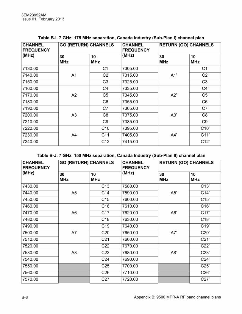
3EM23952AMIssue 01, February 2013
Appendix B: 9500 MPR-A RF band channel plansB-8
Table B-I. 7 GHz: 175 MHz separation, Canada Industry (Sub-Plan I) channel planCHANNELFREQUENCY(MHz)
GO (RETURN) CHANNELS CHANNELFREQUENCY(MHz)
RETURN (GO) CHANNELS
30MHz
10MHz
30MHz
10MHz
7130.00 C1 7305.00 C1�7140.00 A1 C2 7315.00 A1� C2�7150.00 C3 7325.00 C3�7160.00 C4 7335.00 C4�7170.00 A2 C5 7345.00 A2� C5�7180.00 C6 7355.00 C6�7190.00 C7 7365.00 C7�7200.00 A3 C8 7375.00 A3� C8�7210.00 C9 7385.00 C9�7220.00 C10 7395.00 C10�7230.00 A4 C11 7405.00 A4� C11�7240.00 C12 7415.00 C12�
Table B-J. 7 GHz: 150 MHz separation, Canada Industry (Sub-Plan II) channel planCHANNELFREQUENCY(MHz)
GO (RETURN) CHANNELS CHANNELFREQUENCY(MHz)
RETURN (GO) CHANNELS
30MHz
10MHz
30MHz
10MHz
7430.00 C13 7580.00 C13�7440.00 A5 C14 7590.00 A5� C14�7450.00 C15 7600.00 C15�7460.00 C16 7610.00 C16�7470.00 A6 C17 7620.00 A6� C17�7480.00 C18 7630.00 C18�7490.00 C19 7640.00 C19�7500.00 A7 C20 7650.00 A7� C20�7510.00 C21 7660.00 C21�7520.00 C22 7670.00 C22�7530.00 A8 C23 7680.00 A8� C23�7540.00 C24 7690.00 C24�7550.00 C25 7700.00 C25�7560.00 C26 7710.00 C26�7570.00 C27 7720.00 C27�
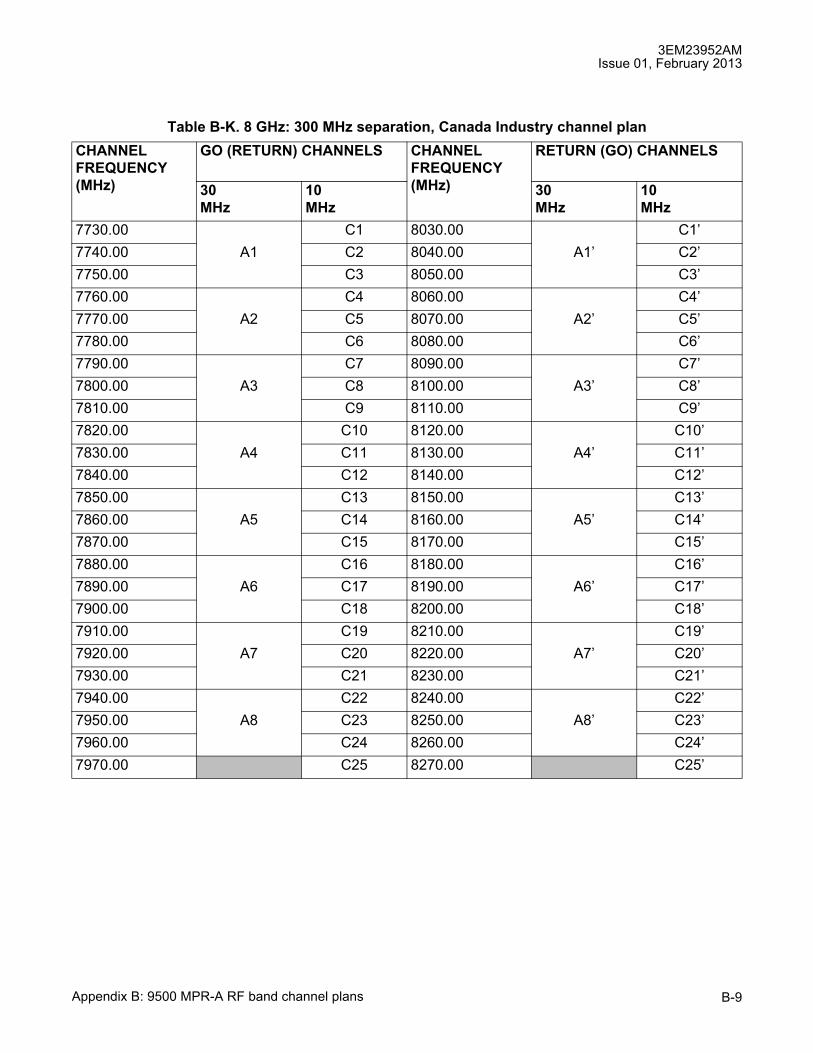
3EM23952AMIssue 01, February 2013
Appendix B: 9500 MPR-A RF band channel plans B-9
Table B-K. 8 GHz: 300 MHz separation, Canada Industry channel planCHANNELFREQUENCY(MHz)
GO (RETURN) CHANNELS CHANNELFREQUENCY(MHz)
RETURN (GO) CHANNELS
30MHz
10MHz
30MHz
10MHz
7730.00 C1 8030.00 C1�7740.00 A1 C2 8040.00 A1� C2�7750.00 C3 8050.00 C3�7760.00 C4 8060.00 C4�7770.00 A2 C5 8070.00 A2� C5�7780.00 C6 8080.00 C6�7790.00 C7 8090.00 C7�7800.00 A3 C8 8100.00 A3� C8�7810.00 C9 8110.00 C9�7820.00 C10 8120.00 C10�7830.00 A4 C11 8130.00 A4� C11�7840.00 C12 8140.00 C12�7850.00 C13 8150.00 C13�7860.00 A5 C14 8160.00 A5� C14�7870.00 C15 8170.00 C15�7880.00 C16 8180.00 C16�7890.00 A6 C17 8190.00 A6� C17�7900.00 C18 8200.00 C18�7910.00 C19 8210.00 C19�7920.00 A7 C20 8220.00 A7� C20�7930.00 C21 8230.00 C21�7940.00 C22 8240.00 C22�7950.00 A8 C23 8250.00 A8� C23�7960.00 C24 8260.00 C24�7970.00 C25 8270.00 C25�

3EM23952AMIssue 01, February 2013
Appendix B: 9500 MPR-A RF band channel plansB-10
Table B-L. 11 GHz: 490/500 MHz separation, channel planCHANNELFREQUENCY(MHz)
GO (RETURN) CHANNELS CHANNELFREQUENCY(MHz)
GO (RETURN) CHANNELS40MHz
30MHz
10MHz
40MHz
30MHz
10MHz
10705.0 1 11205.0 110715.0 B1 2 11215.0 B1 210725.0 3 11225.0 A1 310735.0 A1 4 11235.0 410745.0 5 11245.0 B2 510755.0 B2 6 11255.0 610765.0 7 11265.0 A2 710775.0 A2 8 11275.0 810785.0 9 11285.0 B3 910795.0 B3 10 11295.0 1010805.0 11 11305.0 A3 1110815.0 A3 12 11315.0 1210825.0 13 11325.0 B4 1310835.0 B4 14 11335.0 1410845.0 15 11345.0 A4 1510855.0 A4 16 11355.0 1610865.0 17 11365.0 B5 1710875.0 B5 18 11375.0 1810885.0 19 11385.0 A5 1910895.0 A5 20 11395.0 2010905.0 21 11405.0 B6 2110915.0 B6 22 11415.0 2210925.0 23 11425.0 A6 2310935.0 A6 24 11435.0 2410945.0 25 11445.0 B7 2510955.0 B7 26 11455.0 2610965.0 27 11465.0 A7 2710975.0 A7 28 11475.0 2810985.0 29 11485.0 B8 2910995.0 B8 30 11495.0 3011005.0 31 11505.0 A8 3111015.0 A8 32 11515.0 3211025.0 33 11525.0 B9 33

3EM23952AMIssue 01, February 2013
Appendix B: 9500 MPR-A RF band channel plans B-11
11035.0 B9 34 11535.0 3411045.0 35 11545.0 A9 3511055.0 A9 36 11555.0 3611065.0 37 11565.0 B10 3711075.0 B10 38 11575.0 3811085.0 39 11585.0 A10 3911095.0 A10 40 11595.0 4011105.0 41 11605.0 B11 4111115.0 B11 42 11615.0 4211125.0 43 11625.0 A11 4311135.0 A11 44 11635.0 4411145.0 45 11645.0 B12 4511155.0 B12 46 11655.0 4611165.0 47 11665.0 A12 4711175.0 A12 48 11675.0 4811185.0 B13 49 11685.0 B13 4911195.0 50 11695.0 50
Table B-L. 11 GHz: 490/500 MHz separation, channel plan (cont.)CHANNELFREQUENCY(MHz)
GO (RETURN) CHANNELS CHANNELFREQUENCY(MHz)
GO (RETURN) CHANNELS40MHz
30MHz
10MHz
40MHz
30MHz
10MHz

3EM23952AMIssue 01, February 2013
Appendix B: 9500 MPR-A RF band channel plansB-12
Table B-M. 15 GHz: 475 MHz separation, Canada Industry channel planCHANNELFREQUENCY(MHz)
GO (RETURN) CHANNELS CHANNELFREQUENCY(MHz)
GO (RETURN) CHANNELS40MHz
30MHz
20MHz1
10MHz
40MHz
30MHz
20MHz1
10MHz
14510 C1 14985 C�114520 D1 D1 14995 D1� D1�14530 C2 15005 C�214550 C3 15025 C�314560 D2 D2 15035 D2� D2�14570 C4 15045 C�414590 C5 15065 C�514600 D3 D3 15075 D3� D3�14610 C6 15085 C�614630 C7 15105 C�714640 D4 D4 15115 D4� D4�14650 C8 15125 C�814665 B21 15140 B�2114670 C9 15145 C�914675 B20 15150 B�2014680 D5 D5 15155 D5� D5�14685 B19 15160 B�1914690 C10 15165 C�1014695 B18 15170 B�1814705 B17 15180 B�1714710 C11 15185 C�1114715 B16 15190 B�1614720 D6 D6 15195 D�6 D�614725 B15 15200 B�1514730 C12 15205 C�1214735 B14 15210 B�1414745 B13 15220 B�1314750 C13 15225 C�1314755 B12 15230 B�1214760 D7 D7 15235 D�7 D714765 B11 15240 B�1114770 C14 15245 C�1414775 B10 15250 B�10

3EM23952AMIssue 01, February 2013
Appendix B: 9500 MPR-A RF band channel plans B-13
14785 B9 15260 B�914790 C15 15275 C�1514795 B8 15270 B�814800 D8 D8 15275 D�8 D�814805 B7 15280 B�714810 C16 15285 C�1614815 B6 15290 B�614825 B5 15300 B�514835 B4 15310 B�414845 B3 15320 B�314855 B2 15330 B�214865 B1 15340 B�1
[1] 20 MHz channels are currently not supported.
Table B-M. 15 GHz: 475 MHz separation, Canada Industry channel plan (cont.)CHANNELFREQUENCY(MHz)
GO (RETURN) CHANNELS CHANNELFREQUENCY(MHz)
GO (RETURN) CHANNELS40MHz
30MHz
20MHz1
10MHz
40MHz
30MHz
20MHz1
10MHz
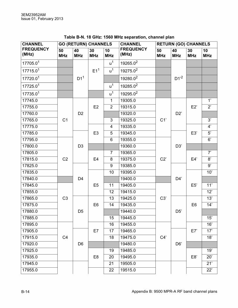
3EM23952AMIssue 01, February 2013
Appendix B: 9500 MPR-A RF band channel plansB-14
Table B-N. 18 GHz: 1560 MHz separation, channel planCHANNELFREQUENCY(MHz)
GO (RETURN) CHANNELS CHANNELFREQUENCY(MHz)
RETURN (GO) CHANNELS50MHz
40MHz
30MHz
10MHz
50MHz
40MHz
30MHz
10MHz
17705.01 u1 19265.02
17715.01 E11 u1 19275.02
17720.01 D11 19280.02 D1�2
17725.01 u1 19285.02
17735.01 u1 19295.02
17745.0 1 19305.0 1�17755.0 E2 2 19315.0 E2� 2�17760.0 D2 19320.0 D2�17765.0 C1 3 19325.0 C1� 3�17775.0 4 19335.0 4�17785.0 E3 5 19345.0 E3� 5�17795.0 6 19355.0 6�17800.0 D3 19360.0 D3�17805.0 7 19365.0 7�17815.0 C2 E4 8 19375.0 C2� E4� 8�17825.0 9 19385.0 9�17835.0 10 19395.0 10�17840.0 D4 19400.0 D4�17845.0 E5 11 19405.0 E5� 11�17855.0 12 19415.0 12�17865.0 C3 13 19425.0 C3� 13�17875.0 E6 14 19435.0 E6 14�17880.0 D5 19440.0 D5�17885.0 15 19445.0 15�17895.0 16 19455.0 16�17905.0 E7 17 19465.0 E7� 17�17915.0 C4 18 19475.0 C4� 18�17920.0 D6 19480.0 D6�17925.0 19 19485.0 19�17935.0 E8 20 19495.0 E8� 20�17945.0 21 19505.0 21�17955.0 22 19515.0 22�
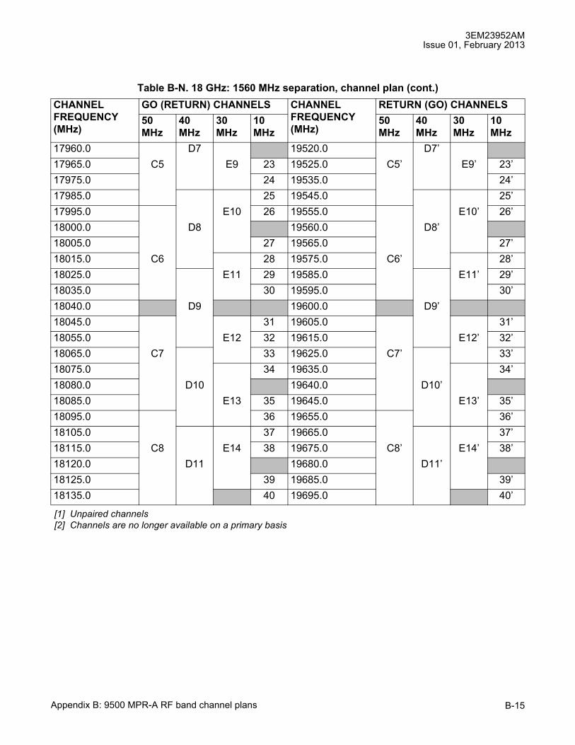
3EM23952AMIssue 01, February 2013
Appendix B: 9500 MPR-A RF band channel plans B-15
17960.0 D7 19520.0 D7�17965.0 C5 E9 23 19525.0 C5� E9� 23�17975.0 24 19535.0 24�17985.0 25 19545.0 25�17995.0 E10 26 19555.0 E10� 26�18000.0 D8 19560.0 D8�18005.0 27 19565.0 27�18015.0 C6 28 19575.0 C6� 28�18025.0 E11 29 19585.0 E11� 29�18035.0 30 19595.0 30�18040.0 D9 19600.0 D9�18045.0 31 19605.0 31�18055.0 E12 32 19615.0 E12� 32�18065.0 C7 33 19625.0 C7� 33�18075.0 34 19635.0 34�18080.0 D10 19640.0 D10�18085.0 E13 35 19645.0 E13� 35�18095.0 36 19655.0 36�18105.0 37 19665.0 37�18115.0 C8 E14 38 19675.0 C8� E14� 38�18120.0 D11 19680.0 D11�18125.0 39 19685.0 39�18135.0 40 19695.0 40�
[1] Unpaired channels[2] Channels are no longer available on a primary basis
Table B-N. 18 GHz: 1560 MHz separation, channel plan (cont.)CHANNELFREQUENCY(MHz)
GO (RETURN) CHANNELS CHANNELFREQUENCY(MHz)
RETURN (GO) CHANNELS50MHz
40MHz
30MHz
10MHz
50MHz
40MHz
30MHz
10MHz

3EM23952AMIssue 01, February 2013
Appendix B: 9500 MPR-A RF band channel plansB-16
Table B-O. 23 GHz: 1200 MHz separation, channel planCHANNELFREQUENCY(MHz)
GO (RETURN) CHANNELS CHANNELFREQUENCY(MHz)
RETURN (GO) CHANNELS50MHz
40MHz
30MHz
10MHz
50MHz
40MHz
30MHz
10MHz
21205 w 22405 w�21215 w 22415 w�21220 y 22420 y�21225 z w 22425 z� w�21235 x w 22435 x� w�21245 w 22445 w�21255 w 22455 w�21265 w 22465 w�21270 y 22470 y�21275 z w 22475 z� w�21285 x w 22485 x� w�21295 w 22495 w�21305 w 22505 w�21315 w 22515 w�21320 y 22520 y�21325 z w 22525 z� w�21335 x w 22535 x� w�21345 w 22545 w�21355 w 22555 w�21365 w 22565 w�21370 y 22570 y�21375 z w 22575 z� w�21385 x w 22585 x� w�21395 w 22595 w�21405 w 22605 w�21415 w 22615 w�21420 y 22620 y�21425 z w 22625 z� w�21435 x w 22635 x� w�21445 w 22645 w�21455 w 22655 w�21465 w 22665 w�21470 y 22670 y�

3EM23952AMIssue 01, February 2013
Appendix B: 9500 MPR-A RF band channel plans B-17
21475 z w 22675 z� w�21485 x w 22685 x� w�21495 w 22695 w�21505 w 22705 w�21515 w 22715 w�21520 y 22720 y�21525 z w 22725 z� w�21535 x w 22735 x� w�21545 w 22745 w�21555 w 22755 w�21565 w 22765 w�21570 y 22770 y�21575 z w 22775 z� w�21585 x w 22785 x� w�21595 w 22795 w�
216051 w 228051 w�
216151 w 228151 w�
216201 y 228201 y�
216251 z w 228251 z� w�
216351 x w 228351 x� w�
216451 w 228451 w�
216551 w 228551 w�
216651 w 228651 w�
216701 y 228701 y�
216751 z w 228751 z� w�
216851 x w 228851 x� w�
216951 w 228951 w�
217051 w 229051 w�
217151 w 229151 w�
217201 y 229201 y�
217251 z w 229251 z� w�
Table B-O. 23 GHz: 1200 MHz separation, channel plan (cont.)CHANNELFREQUENCY(MHz)
GO (RETURN) CHANNELS CHANNELFREQUENCY(MHz)
RETURN (GO) CHANNELS50MHz
40MHz
30MHz
10MHz
50MHz
40MHz
30MHz
10MHz
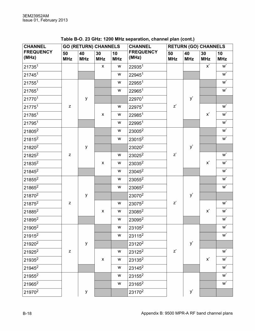
3EM23952AMIssue 01, February 2013
Appendix B: 9500 MPR-A RF band channel plansB-18
217351 x w 229351 x� w�
217451 w 229451 w�
217551 w 229551 w�
217651 w 229651 w�
217701 y 229701 y�
217751 z w 229751 z� w�
217851 x w 229851 x� w�
217951 w 229951 w�
218052 w 230052 w�
218152 w 230152 w�
218202 y 230202 y�
218252 z w 230252 z� w�
218352 x w 230352 x� w�
218452 w 230452 w�
218552 w 230552 w�
218652 w 230652 w�
218702 y 230702 y�
218752 z w 230752 z� w�
218852 x w 230852 x� w�
218952 w 230952 w�
219052 w 231052 w�
219152 w 231152 w�
219202 y 231202 y�
219252 z w 231252 z� w�
219352 x w 231352 x� w�
219452 w 231452 w�
219552 w 231552 w�
219652 w 231652 w�
219702 y 231702 y�
Table B-O. 23 GHz: 1200 MHz separation, channel plan (cont.)CHANNELFREQUENCY(MHz)
GO (RETURN) CHANNELS CHANNELFREQUENCY(MHz)
RETURN (GO) CHANNELS50MHz
40MHz
30MHz
10MHz
50MHz
40MHz
30MHz
10MHz

3EM23952AMIssue 01, February 2013
Appendix B: 9500 MPR-A RF band channel plans B-19
219752 z w 231752 z� w�
219852 x w 231852 x� w�
219952 w 231952 w�
22005 w 23205 w�22015 w 23215 w�22020 y 23220 y�22025 z w 23225 z� w�22035 x w 23235 x� w�22045 w 23245 w�22055 w 23255 w�22065 w 23265 w�22070 y 23270 y�22075 z w 23275 z� w�22085 x w 23285 x� w�22095 w 23295 w�22105 w 23305 w�22115 w 23315 w�22120 y 23320 y�22125 z w 23325 z� w�22135 x w 23335 x� w�22145 w 23345 w�22155 w 23355 w�22165 w 23365 w�22170 y 23370 y�22175 z w 23375 z� w�22185 x w 23385 x� w�22195 w 23395 w�22205 w 23405 w�22215 w 23415 w�22220 y 23420 y�22225 z w 23425 z� w�22235 x w 23435 x� w�22245 w 23445 w�
Table B-O. 23 GHz: 1200 MHz separation, channel plan (cont.)CHANNELFREQUENCY(MHz)
GO (RETURN) CHANNELS CHANNELFREQUENCY(MHz)
RETURN (GO) CHANNELS50MHz
40MHz
30MHz
10MHz
50MHz
40MHz
30MHz
10MHz
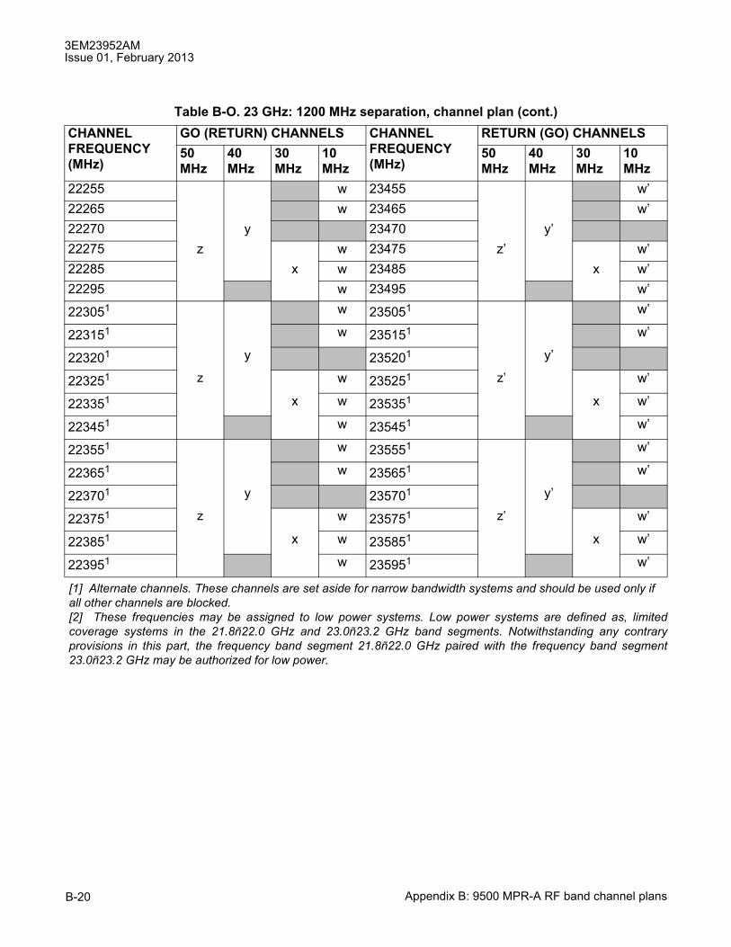
3EM23952AMIssue 01, February 2013
Appendix B: 9500 MPR-A RF band channel plansB-20
22255 w 23455 w�22265 w 23465 w�22270 y 23470 y�22275 z w 23475 z� w�22285 x w 23485 x w�22295 w 23495 w�
223051 w 235051 w�
223151 w 235151 w�
223201 y 235201 y�
223251 z w 235251 z� w�
223351 x w 235351 x w�
223451 w 235451 w�
223551 w 235551 w�
223651 w 235651 w�
223701 y 235701 y�
223751 z w 235751 z� w�
223851 x w 235851 x w�
223951 w 235951 w�
[1] Alternate channels. These channels are set aside for narrow bandwidth systems and should be used only ifall other channels are blocked.[2] These frequencies may be assigned to low power systems. Low power systems are defined as, limitedcoverage systems in the 21.8ñ22.0 GHz and 23.0ñ23.2 GHz band segments. Notwithstanding any contraryprovisions in this part, the frequency band segment 21.8ñ22.0 GHz paired with the frequency band segment23.0ñ23.2 GHz may be authorized for low power.
Table B-O. 23 GHz: 1200 MHz separation, channel plan (cont.)CHANNELFREQUENCY(MHz)
GO (RETURN) CHANNELS CHANNELFREQUENCY(MHz)
RETURN (GO) CHANNELS50MHz
40MHz
30MHz
10MHz
50MHz
40MHz
30MHz
10MHz

Customer documentation and productsupport
Customer documentationhttp://www.alcatel-lucent.com/myaccess
Product manuals and documentation updates are available at alcatel-lucent.com. If you are a new user and require access to this service, please contact your Alcatel-Lucent sales
representative.
Technical supporthttp://support.alcatel-lucent.com
Documentation [email protected]

© 2013 Alcatel-Lucent. All rights reserved.3EM23952AM Edition 01


![[XLS]admapps.defesa.ptadmapps.defesa.pt/app_docs/entidadesconvencionadas/admen... · Web view9700 9700 9700 9700 9700 9900 9560 9560 9560 9630 9500 9500 9500 9500 9500 9500 9500 9500](https://img.pdfslide.net/doc/110x75/5bf6f08e09d3f279228ce4e7/xls-web-view9700-9700-9700-9700-9700-9900-9560-9560-9560-9630-9500-9500-9500.jpg)