Embed Size (px)
Citation preview
Prestressed Concrete Structures Dr. Amlan K Sengupta and Prof. Devdas Menon
Indian Institute of Technology Madras
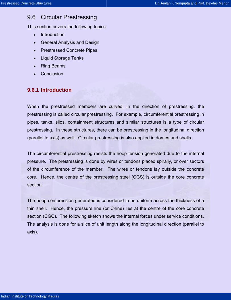
9.6 Circular Prestressing This section covers the following topics.
• Introduction
• General Analysis and Design
• Prestressed Concrete Pipes
• Liquid Storage Tanks
• Ring Beams
• Conclusion
9.6.1 Introduction
When the prestressed members are curved, in the direction of prestressing, the
prestressing is called circular prestressing. For example, circumferential prestressing in
pipes, tanks, silos, containment structures and similar structures is a type of circular
prestressing. In these structures, there can be prestressing in the longitudinal direction
(parallel to axis) as well. Circular prestressing is also applied in domes and shells.
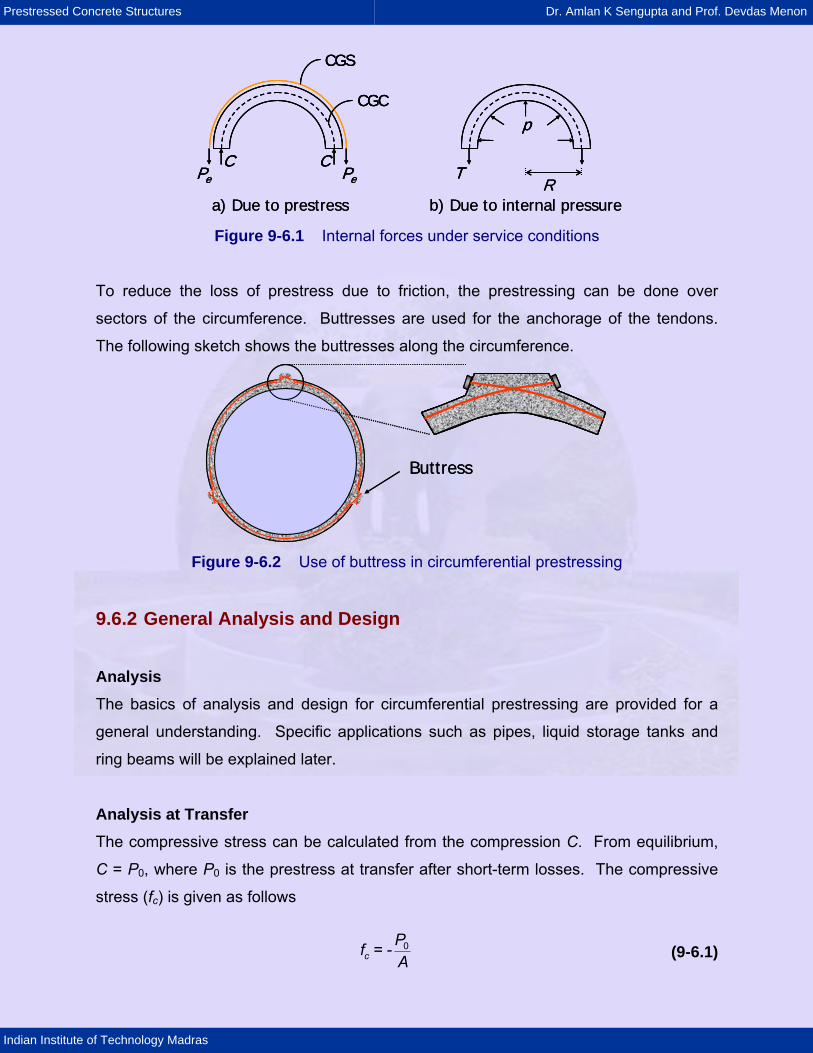
The circumferential prestressing resists the hoop tension generated due to the internal
pressure. The prestressing is done by wires or tendons placed spirally, or over sectors
of the circumference of the member. The wires or tendons lay outside the concrete
core. Hence, the centre of the prestressing steel (CGS) is outside the core concrete
section.
The hoop compression generated is considered to be uniform across the thickness of a
thin shell. Hence, the pressure line (or C-line) lies at the centre of the core concrete
section (CGC). The following sketch shows the internal forces under service conditions.
The analysis is done for a slice of unit length along the longitudinal direction (parallel to
axis).
Prestressed Concrete Structures Dr. Amlan K Sengupta and Prof. Devdas Menon
Indian Institute of Technology Madras
CPePe
C
CGC
CGS
Ra) Due to prestress b) Due to internal pressure
T
p
CPePe
C
CGC
CGS
CPePe
C
CGC
CGS
Ra) Due to prestress b) Due to internal pressure
T
p
T
p
Figure 9-6.1 Internal forces under service conditions
To reduce the loss of prestress due to friction, the prestressing can be done over
sectors of the circumference. Buttresses are used for the anchorage of the tendons.
The following sketch shows the buttresses along the circumference.
Buttress Buttress
Figure 9-6.2 Use of buttress in circumferential prestressing
9.6.2 General Analysis and Design
Analysis The basics of analysis and design for circumferential prestressing are provided for a
general understanding. Specific applications such as pipes, liquid storage tanks and
ring beams will be explained later.
Analysis at Transfer The compressive stress can be calculated from the compression C. From equilibrium,
C = P0, where P0 is the prestress at transfer after short-term losses. The compressive
stress (fc) is given as follows
cPf = -A
0 (9-6.1)
Prestressed Concrete Structures Dr. Amlan K Sengupta and Prof. Devdas Menon
Indian Institute of Technology Madras
Here,
A = area of the longitudinal section of the slice.
The permissible prestress is determined based on fc within the allowable stress at
transfer (fcc,all).
Analysis at Service Loads The tensile stress due to the internal pressure (p) can be calculated from the tension T.
From equilibrium of half of the slice, T = pR where, R is the radius of the mid-surface of
the cylinder. The resultant stress (fc) due to the effective prestress (Pe) and internal
pressure is given as follows.
ec
t
P pRf = - +A A
(9-6.2)
Here,
At = area of the transformed longitudinal section of the slice.
The value of fc should be compressive and within the allowable stress at service loads
(fcc,all). In the previous equation, since Pe = pR and At is greater than A, fc is always
negative. Thus, the concrete will be under compression. To meet the safety standards,
a factor of safety can be further introduced.
Design The internal pressure p and the radius R are given variables. It is assumed that the
prestressing steel alone carries the hoop tension due to internal pressure, that is Pe =
Apfpe = pR.
The steps of design are as follows.
1) Calculate the area of the prestressing steel from the equation Ap = pR / fpe.
2) Calculate the prestress at transfer from an estimate of the permissible initial
stress fp0 and using the equation
P0 = Ap fp0. (9-6.3)
3) Calculate the thickness of concrete shell from the following equation.
A = P0 / fcc,all (9-6.4)
Prestressed Concrete Structures Dr. Amlan K Sengupta and Prof. Devdas Menon
Indian Institute of Technology Madras
Here, fcc,all is the allowable compressive stress at transfer.
4) Calculate the resultant stress fc at the service conditions using Eqn. (9-6.2). The
value of fc should be within fcc,all, the allowable stress at service conditions.
9.6.3 Prestressed Concrete Pipes
Prestressed concrete pipes are suitable when the internal pressure is within 0.5 to 2.0
N/mm2. There are two types of prestressed concrete pipes: cylinder type and the non-
cylinder type. A cylinder type pipe has a steel cylinder core, over which the concrete is
cast and prestressed. A non-cylinder type of pipe is made of prestressed concrete only.
IS:784 - 2001 (Prestressed Concrete Pipes (Including Specials) - Specification)
provides guidelines for the design of prestressed concrete pipes with the internal
diameter ranging from 200 mm to 2500 mm. The pipes are designed to withstand the
combined effect of internal pressure and external loads. The minimum grade of
concrete in the core should be M40 for non-cylinder type pipes.
First, the core is cast either by the centrifugal method or by the vertical casting method.
In the centrifugal method the mould is subjected to spinning till the concrete is
compacted to a uniform thickness throughout the length of the pipe. In the vertical
casting method, concrete is poured in layers up to a specified height.
After adequate curing of concrete, first the longitudinal wires are prestressed (the wires
can be pre-tensioned). Subsequently, the circumferential prestressing is done by the
wire wound around the core in a helical form. The wire is wound using a counter weight
or a die. Finally a coat of concrete or rich cement mortar is applied over the wire to
prevent from corrosion.
For cylinder type pipes, first the steel cylinder is fabricated and tested. Then the
concrete is cast around it.
Prestressed Concrete Structures Dr. Amlan K Sengupta and Prof. Devdas Menon
Indian Institute of Technology Madras
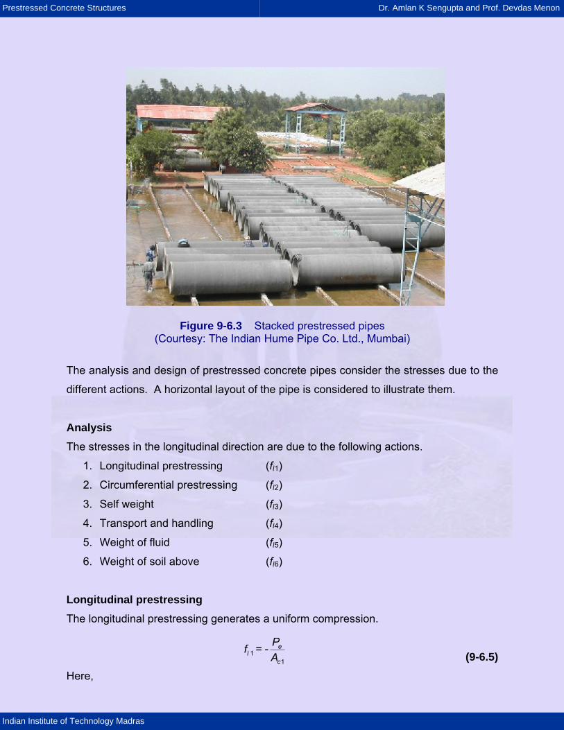
Figure 9-6.3 Stacked prestressed pipes (Courtesy: The Indian Hume Pipe Co. Ltd., Mumbai)
The analysis and design of prestressed concrete pipes consider the stresses due to the
different actions. A horizontal layout of the pipe is considered to illustrate them.
Analysis The stresses in the longitudinal direction are due to the following actions.
1. Longitudinal prestressing (fl1)
2. Circumferential prestressing (fl2)
3. Self weight (fl3)
4. Transport and handling (fl4)
5. Weight of fluid (fl5)
6. Weight of soil above (fl6)
Longitudinal prestressing The longitudinal prestressing generates a uniform compression.
l
e
c
Pf = -A1
1 (9-6.5) Here,
Prestressed Concrete Structures Dr. Amlan K Sengupta and Prof. Devdas Menon
Indian Institute of Technology Madras
Pe = effective prestress
Ac1 = area of concrete in the core.
Circumferential prestressing Due to the Poisson’s effect, the circumferential prestressing generates longitudinal
tensile stress.
le
c
Pf = ×A2 0.284 (9-6.6)
The above expression estimates the Poisson’s effect.
Self weight If the pipe is not continuously supported, then a varying longitudinal stress generates
due to the moment due to self weight (Msw).
ll
sw 3
Mf = ±Z (9-6.7)
Here,
Zl = section modulus about the centroidal axis.
Transport and handling A varying longitudinal stress generates due to the moment during transport and
handling (Mth).
ll
th
Mf = ±Z4 (9-6.8)
Weight of fluid Similar to self weight, the moment due to weight of the fluid inside (Mf) generates
varying longitudinal stress.
ll
f
Mf = ±Z5 (9-6.9)
Prestressed Concrete Structures Dr. Amlan K Sengupta and Prof. Devdas Menon
Indian Institute of Technology Madras
Weight of soil above The weight of soil above for buried pipes is modelled as an equivalent distributed load.
The expression of stress (fl6) is similar to that for the weight of fluid.
The longitudinal stresses are combined based on the following diagram.
D
fl 1 fl 2 fl 3 + fl 4 + fl 5 + fl 6
+ +
Section of pipe
D
fl 1 fl 2 fl 3 + fl 4 + fl 5 + fl 6
+ +
Section of pipe
Figure 9-6.4 Stress profiles across section
The stresses in the circumferential direction are due to the following actions.
1. Circumferential prestressing (fh1)
2. Self weight (fh2)
3. Weight of fluid (fh3)
4. Weight of soil above (fh4)
5. Live load (fh5)
6. Internal pressure (fh6)
Circumferential prestressing The compressive hoop stress (fh1) is given as follows.
s
h c
s
c
Pf = -AP= -× t
12
1
(9-6.10)
Here,
Ps = tensile force in spiral wire in unit length of pipe
Ac2 = area for longitudinal section of unit length
tc = thickness of the core.
Prestressed Concrete Structures Dr. Amlan K Sengupta and Prof. Devdas Menon
Indian Institute of Technology Madras
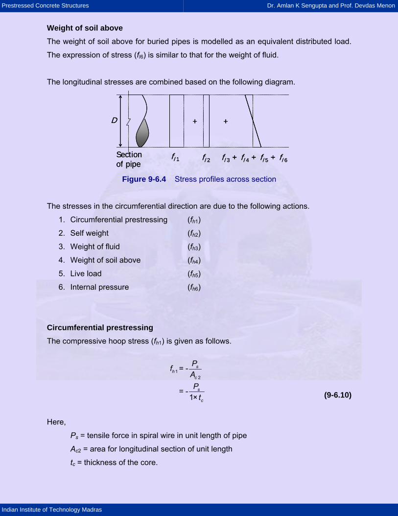
Actions 2. to 5. For each of these actions, first the vertical load per unit length (W) is calculated.
Moment (M) and thrust (T) develop across the thickness owing to distortion of the
section due to W, as shown in the following sketch.
T M
WW
T M
WW
Figure 9-6.5 Forces due to vertical load
The hoop stress at a point is calculated by the following equation.
(9-6.11)
h
h
M Tf = ± +Z A
The expressions of M and T due to W are as follows.
M = CM W R (9-6.12) T = CT W (9-6.13)
Here,
CM = moment coefficient
CT = thrust coefficient
W = vertical load per unit length
R = mean radius of pipe
A = area of longitudinal section for unit length of pipe
Zh = section modulus for hoop stress for same length
= (1/6)t2 × 1000 mm3/m
t = total thickness of core and coat
Values of CM and CT are tabulated in IS:784 - 2001.
The internal pressure is as follows.
h t
pRf =A6 (9-6.14)
Prestressed Concrete Structures Dr. Amlan K Sengupta and Prof. Devdas Menon
Indian Institute of Technology Madras
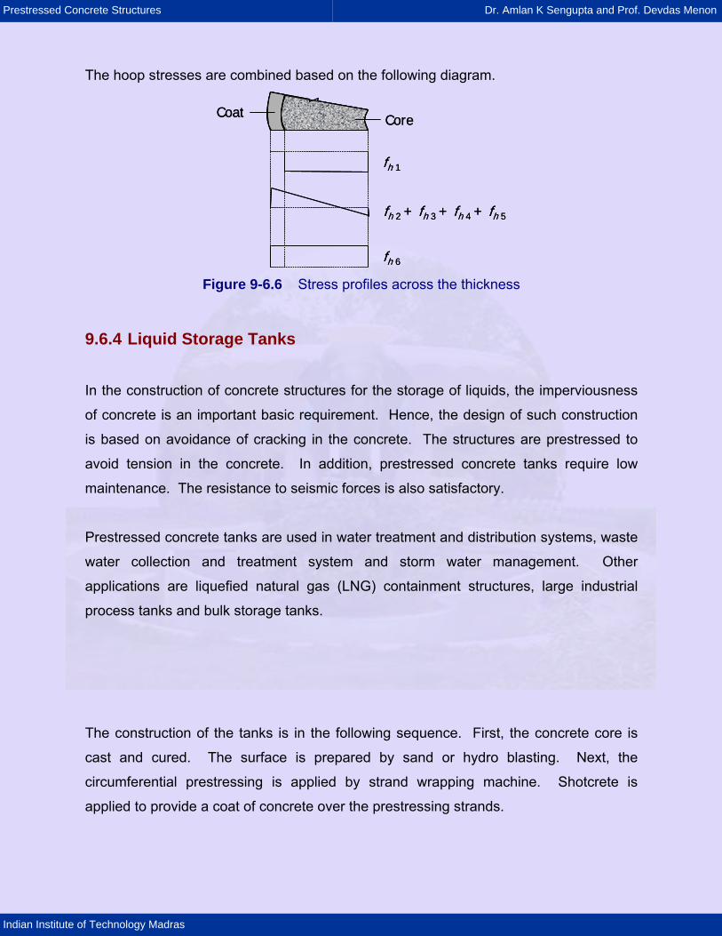
The hoop stresses are combined based on the following diagram.
fh 1
fh 2 + fh 3 + fh 4 + fh 5
fh 6
Coat Core
fh 1
fh 2 + fh 3 + fh 4 + fh 5
fh 6
Coat Core
Figure 9-6.6 Stress profiles across the thickness
9.6.4 Liquid Storage Tanks
In the construction of concrete structures for the storage of liquids, the imperviousness
of concrete is an important basic requirement. Hence, the design of such construction
is based on avoidance of cracking in the concrete. The structures are prestressed to
avoid tension in the concrete. In addition, prestressed concrete tanks require low
maintenance. The resistance to seismic forces is also satisfactory.
Prestressed concrete tanks are used in water treatment and distribution systems, waste
water collection and treatment system and storm water management. Other
applications are liquefied natural gas (LNG) containment structures, large industrial
process tanks and bulk storage tanks.
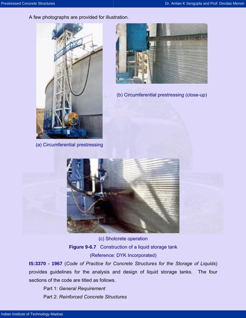
The construction of the tanks is in the following sequence. First, the concrete core is
cast and cured. The surface is prepared by sand or hydro blasting. Next, the
circumferential prestressing is applied by strand wrapping machine. Shotcrete is
applied to provide a coat of concrete over the prestressing strands.
Prestressed Concrete Structures Dr. Amlan K Sengupta and Prof. Devdas Menon
Indian Institute of Technology Madras
A few photographs are provided for illustration.
(b) Circumferential prestressing (close-up)
(a) Circumferential prestressing
(c) Shotcrete operation
Figure 9-6.7 Construction of a liquid storage tank
(Reference: DYK Incorporated)
IS:3370 - 1967 (Code of Practice for Concrete Structures for the Storage of Liquids)
provides guidelines for the analysis and design of liquid storage tanks. The four
sections of the code are titled as follows.
Part 1: General Requirement
Part 2: Reinforced Concrete Structures
Prestressed Concrete Structures Dr. Amlan K Sengupta and Prof. Devdas Menon
Indian Institute of Technology Madras
Part 3: Prestressed Concrete Structures
Part 4: Design Tables.
Analysis The analysis of liquid storage tanks can be done by IS:3370 - 1967, Part 4, or by the
finite element method. The Code provides coefficients for bending moment, shear and
hoop tension (for cylindrical tanks), which were developed from the theory of plates and
shells. In Part 4, both rectangular and cylindrical tanks are covered. Since circular
prestressing is applicable to cylindrical tanks, only this type of tank is covered in this
module.
The following types of boundary conditions are considered in the analysis of the
cylindrical wall.
a) For base: fixed or hinged
b) For top: free or hinged or framed.
The applicability of each boundary condition is explained next.
For base Fixed: When the wall is built continuous with its footing, then the base can be
considered to be fixed as the first approximation.
Hinged: If the sub grade is susceptible to settlement, then a hinged base is a
conservative assumption. Since the actual rotational restraint from the footing is
somewhere in between fixed and hinged, a hinged base can be assumed.
The base can be made sliding with appropriate polyvinyl chloride (PVC) water-stops for
liquid tightness.
For top Free: The top of the wall is considered free when there is no restraint in expansion.
Hinged: When the top is connected to the roof slab by dowels for shear transfer, the
boundary condition can be considered to be hinged.
Prestressed Concrete Structures Dr. Amlan K Sengupta and Prof. Devdas Menon
Indian Institute of Technology Madras
Framed: When the top of the wall and the roof slab are made continuous with moment
transfer, the top is considered to be framed.
The hydrostatic pressure on the wall increases linearly from the top to the bottom of the
liquid of maximum possible depth. If the vapour pressure in the free board is negligible,
then the pressure at the top is zero. Else, it is added to the pressure of the liquid
throughout the depth. The forces generated in the tank due to circumferential prestress
are opposite in nature to that due to hydrostatic pressure. If the tank is built
underground, then the earth pressure needs to be considered.
The hoop tension in the wall, generated due to a triangular hydrostatic pressure is given
as follows.
T = CT w H Ri (9-6.15)
The bending moment in the vertical direction is given as follows.
M = CM w H3 (9-6.16)
The shear at the base is given by the following expression.
V = CV w H2 (9-6.17)
In the previous equations, the notations used are as follows.
CT = coefficient for hoop tension
CM = coefficient for bending moment
CV = coefficient for shear
w = unit weight of liquid
H = height of the liquid
Ri = inner radius of the wall.
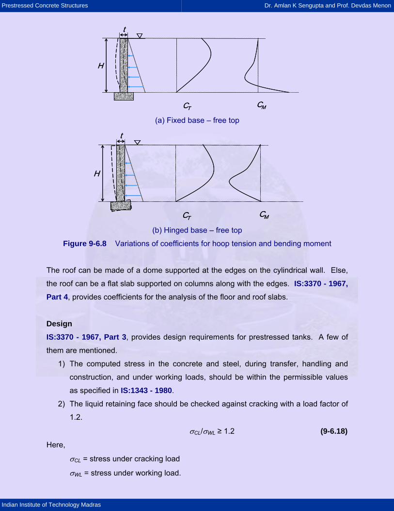
The values of the coefficients are tabulated in IS:3370 - 1967, Part 4, for various values
of H2/Dt, at different depths of the liquid. D and t represent the inner diameter and the
thickness of the wall, respectively. The typical variations of CT and CM with depth, for
two sets of boundary conditions are illustrated.
Prestressed Concrete Structures Dr. Amlan K Sengupta and Prof. Devdas Menon
Indian Institute of Technology Madras
CT CM
H
t
CT CM
H
t
(a) Fixed base – free top
CT CM
H
t
CT CM
H
t
(b) Hinged base – free top
Figure 9-6.8 Variations of coefficients for hoop tension and bending moment
The roof can be made of a dome supported at the edges on the cylindrical wall. Else,
the roof can be a flat slab supported on columns along with the edges. IS:3370 - 1967, Part 4, provides coefficients for the analysis of the floor and roof slabs.
Design IS:3370 - 1967, Part 3, provides design requirements for prestressed tanks. A few of
them are mentioned.
1) The computed stress in the concrete and steel, during transfer, handling and
construction, and under working loads, should be within the permissible values
as specified in IS:1343 - 1980.
2) The liquid retaining face should be checked against cracking with a load factor of
1.2.
σCL/σWL ≥ 1.2 (9-6.18)
Here,
σCL = stress under cracking load
σWL = stress under working load.
Prestressed Concrete Structures Dr. Amlan K Sengupta and Prof. Devdas Menon
Indian Institute of Technology Madras
Values of limiting tensile strength of concrete for estimating the cracking load are
specified in the Code.
3) The ultimate load at failure should not be less than twice the working load.
4) When the tank is full, there should be compression in the concrete at all points of
at least 0.7 N/mm2. When the tank is empty, there should not be tensile stress
greater than 1.0 N/mm2. Thus, the tank should be analysed both for the full and
empty conditions.
5) There should be provisions to allow for elastic distortion of the structure during
prestressing. Any restraint that may lead to the reduction of the prestressing
force, should be considered.
Detailing Requirements
IS:3370 - 1967, Part 3, also provides detailing requirements. The cover requirement is
as follows. The minimum cover to the prestressing wires should be 35 mm on the liquid
face. For faces away from the liquid, the cover requirements are as per IS:1343 - 1980.
Other requirements from IS:1343 - 1980 are also applicable.
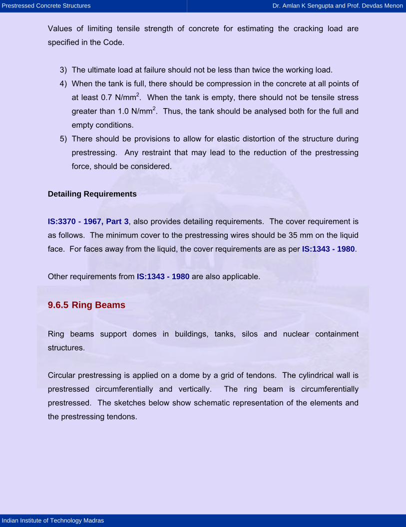
9.6.5 Ring Beams
Ring beams support domes in buildings, tanks, silos and nuclear containment
structures.
Circular prestressing is applied on a dome by a grid of tendons. The cylindrical wall is
prestressed circumferentially and vertically. The ring beam is circumferentially
prestressed. The sketches below show schematic representation of the elements and
the prestressing tendons.
Prestressed Concrete Structures Dr. Amlan K Sengupta and Prof. Devdas Menon
Indian Institute of Technology Madras
Dome
Ring beam
Cylindrical wall
Raft foundation
Dome
Ring beam
Cylindrical wall
Raft foundation Figure 9-6.9 Cross-section of a nuclear containment structure
Tendon for dome prestressing
Tendon for vertical prestressing of wall
Tendons forprestressing of ring beam
Tendons forprestressing of wall
Tendon for dome prestressing
Tendon for vertical prestressing of wall
Tendons forprestressing of ring beam
Tendons forprestressing of wall
Figure 9-6.10 Typical layout of prestressing tendons at dome and ring beam junction
Prestressed Concrete Structures Dr. Amlan K Sengupta and Prof. Devdas Menon
Indian Institute of Technology Madras
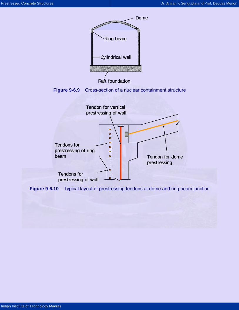
The following photo shows a prestressed nuclear containment structure.
Figure 9-6.11 Containment Structure, Kaiga Atomic Power Plant, Karnataka
(Reference: Larsen & Toubro)
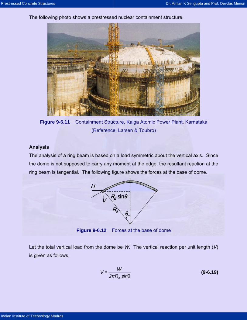
Analysis The analysis of a ring beam is based on a load symmetric about the vertical axis. Since
the dome is not supposed to carry any moment at the edge, the resultant reaction at the
ring beam is tangential. The following figure shows the forces at the base of dome.
Rd sinθ
H
V
θRd
Rd sinθ
H
V
θRd
Figure 9-6.12 Forces at the base of dome
Let the total vertical load from the dome be W. The vertical reaction per unit length (V)
is given as follows.
d
WV =2πR sinθ
(9-6.19)
Prestressed Concrete Structures Dr. Amlan K Sengupta and Prof. Devdas Menon
Indian Institute of Technology Madras
Here,
Rd = radius of the dome
θ = half of the angle subtended by the dome.
The horizontal thrust (H) is calculated from the condition of the reaction to be tangential.
The value per unit length is given as follows.
d
H =V cotθW cotθ=πR sinθ2
(9-6.20)
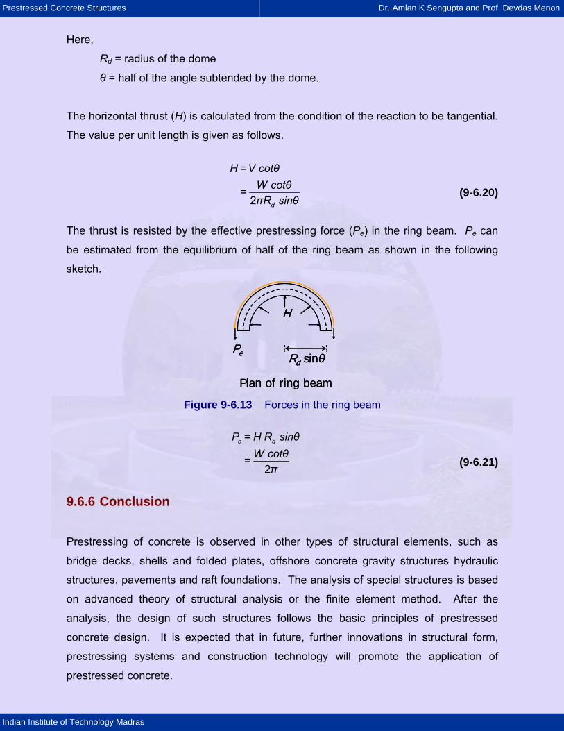
The thrust is resisted by the effective prestressing force (Pe) in the ring beam. Pe can
be estimated from the equilibrium of half of the ring beam as shown in the following
sketch.
Pe
H
Rd sinθ
Plan of ring beam
Pe
H
Rd sinθ
Plan of ring beam Figure 9-6.13 Forces in the ring beam
e dP = H R sinθ
W cotθ=π2
(9-6.21)
9.6.6 Conclusion
Prestressing of concrete is observed in other types of structural elements, such as
bridge decks, shells and folded plates, offshore concrete gravity structures hydraulic
structures, pavements and raft foundations. The analysis of special structures is based
on advanced theory of structural analysis or the finite element method. After the
analysis, the design of such structures follows the basic principles of prestressed
concrete design. It is expected that in future, further innovations in structural form,
prestressing systems and construction technology will promote the application of
prestressed concrete.
Prestressed Concrete Structures Dr. Amlan K Sengupta and Prof. Devdas Menon
Indian Institute of Technology Madras
A few photos of recent applications follows.
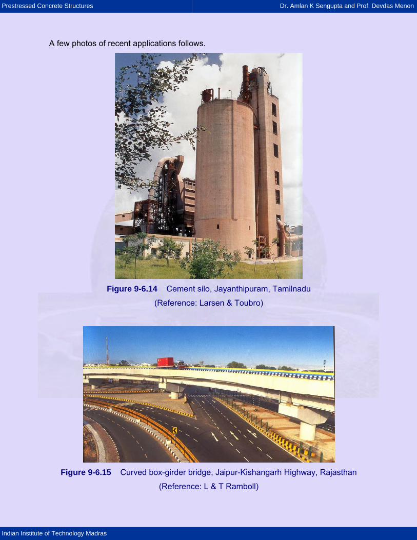
Figure 9-6.14 Cement silo, Jayanthipuram, Tamilnadu
(Reference: Larsen & Toubro)
Figure 9-6.15 Curved box-girder bridge, Jaipur-Kishangarh Highway, Rajasthan
(Reference: L & T Ramboll)
Prestressed Concrete Structures Dr. Amlan K Sengupta and Prof. Devdas Menon
Indian Institute of Technology Madras
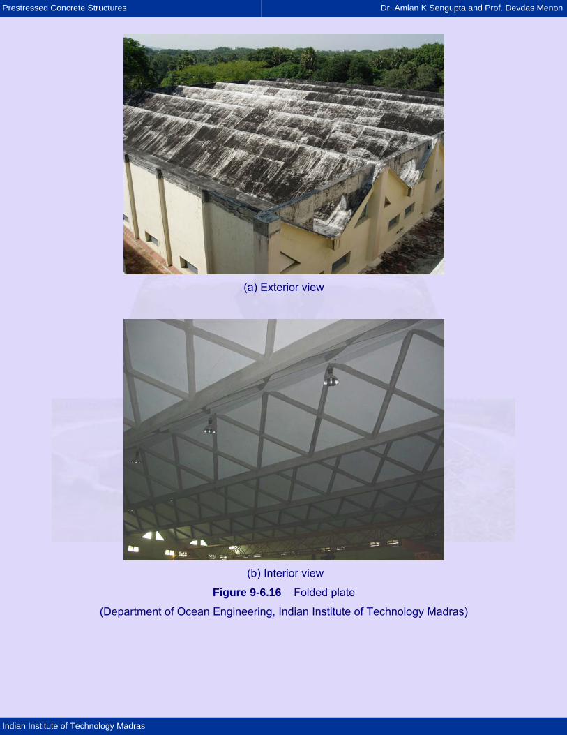
(a) Exterior view
(b) Interior view
Figure 9-6.16 Folded plate
(Department of Ocean Engineering, Indian Institute of Technology Madras)
Prestressed Concrete Structures Dr. Amlan K Sengupta and Prof. Devdas Menon
Indian Institute of Technology Madras
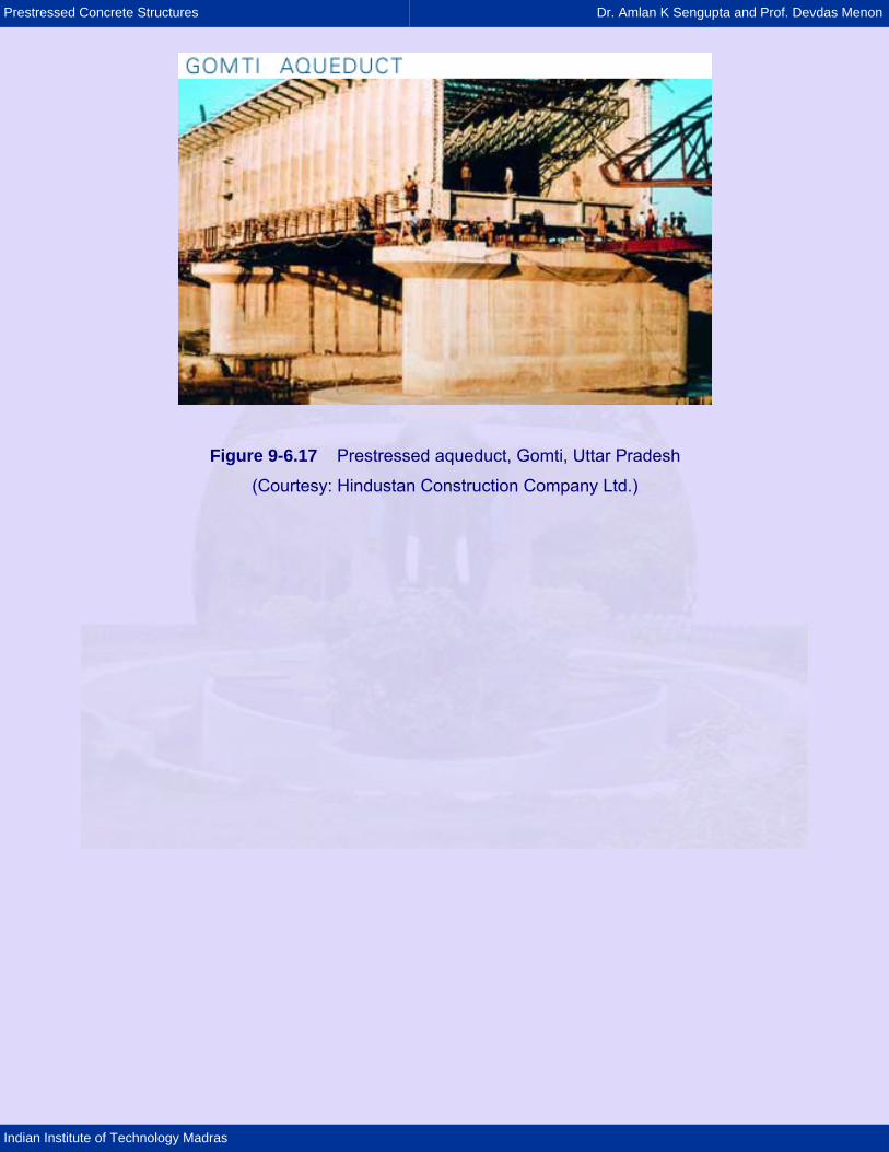
Figure 9-6.17 Prestressed aqueduct, Gomti, Uttar Pradesh
(Courtesy: Hindustan Construction Company Ltd.)