Embed Size (px)
Citation preview
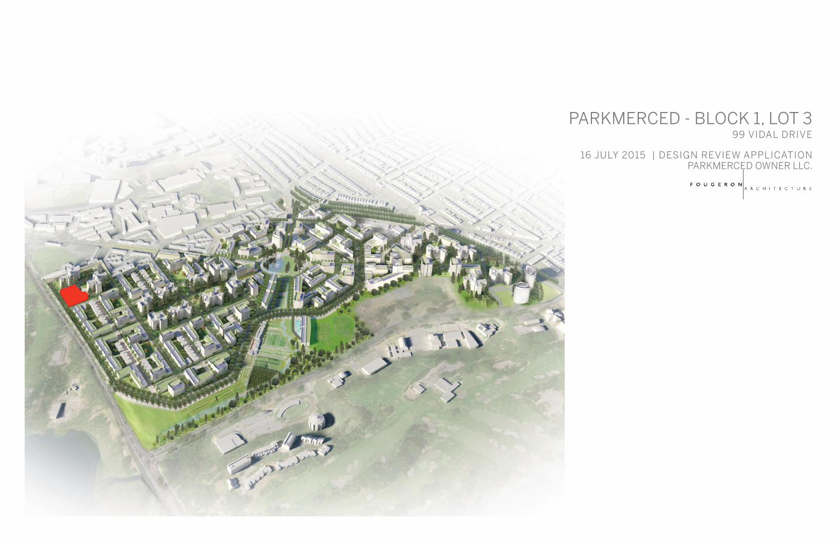
PARKMERCED - BLOCK 1, LOT 399 VIDAL DRIVE
16 JULY 2015 | DESIGN REVIEW APPLICATIONPARKMERCED OWNER LLC.
PARKMERCED BLOCK 1, LOT 3 - SAN FRANCISCO, CA 2015.07.16
PARKMERCED OWNER LLC | FOUGERON ARCHITECTURE FOUGERON ARCHITECTURE
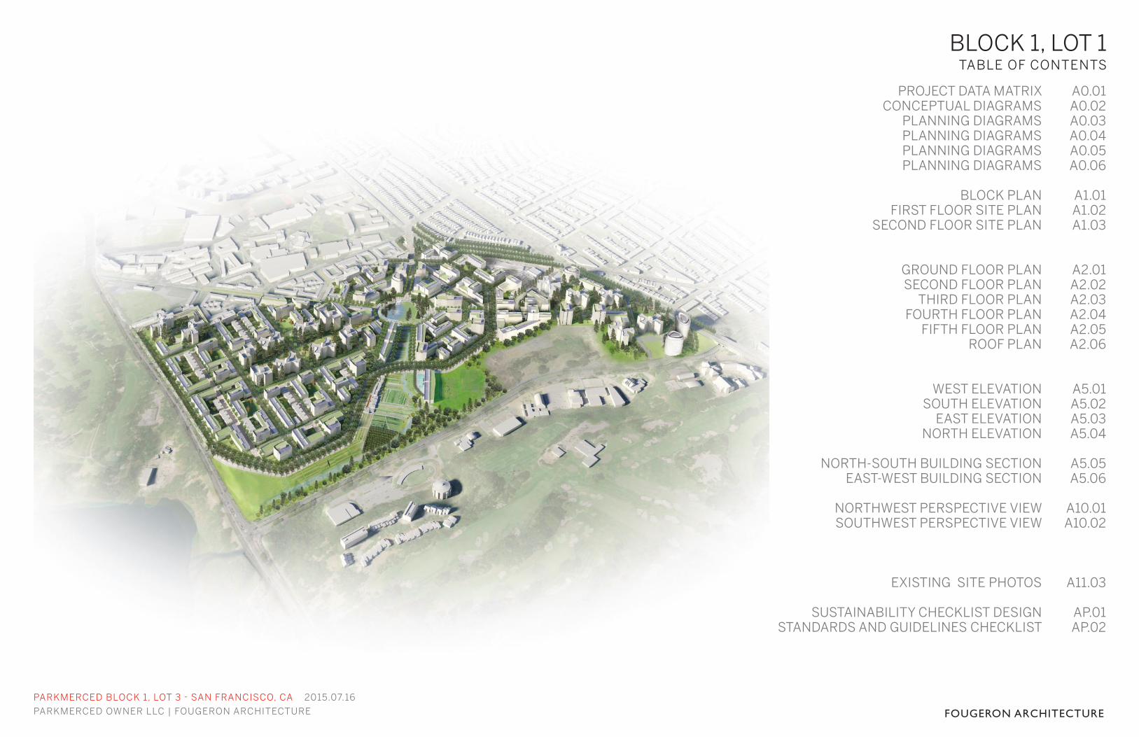
BLOCK 1, LOT 1TABLE OF CONTENTS
PROJECT DATA MATRIXCONCEPTUAL DIAGRAMS
PLANNING DIAGRAMSPLANNING DIAGRAMSPLANNING DIAGRAMSPLANNING DIAGRAMS
BLOCK PLANFIRST FLOOR SITE PLAN
SECOND FLOOR SITE PLAN
GROUND FLOOR PLANSECOND FLOOR PLAN
THIRD FLOOR PLANFOURTH FLOOR PLAN
FIFTH FLOOR PLANROOF PLAN
WEST ELEVATIONSOUTH ELEVATION
EAST ELEVATIONNORTH ELEVATION
NORTH-SOUTH BUILDING SECTIONEAST-WEST BUILDING SECTION
NORTHWEST PERSPECTIVE VIEWSOUTHWEST PERSPECTIVE VIEW
EXISTING SITE PHOTOS
SUSTAINABILITY CHECKLIST DESIGNSTANDARDS AND GUIDELINES CHECKLIST
A0.01A0.02A0.03A0.04A0.05A0.06
A1.01A1.02A1.03
A2.01A2.02A2.03A2.04A2.05A2.06
A5.01A5.02A5.03A5.04
A5.05A5.06
A10.01A10.02
A11.03
AP.01AP.02

PARKMERCED BLOCK 1, LOT 3 - SAN FRANCISCO, CA 2015.07.16
PARKMERCED OWNER LLC | FOUGERON ARCHITECTURE FOUGERON ARCHITECTUREPROJECT PROGRAM & DATA MATRIX A0.01
TOWER AND UNITS
Fougeron BuildingUnit Type STUDIO 1x1 2x2A 2x2B 3x2 3x2.5A 3x2.5B Common Lobby Fitness Net Floor Area Gross Floor Area
Level Unit Area Total UnitsRooftop 20,774
Residential 5 6 1 1 1 1 10 120 7,133 8,9074 6 3 2 11 120 13,795 15,9343 6 4 4 2 1 4 1 22 330 120 14,824 18,4872 4 3 2 9 899 120 15,479 17,464
Lobby/Resid 1 1 2 2 1 5 1 5 532 366 8,327 11,612
Total Units 22 12 11 5 2 10 2 64
Percentage of Total 34% 19% 17% 8% 3% 16% 3% 100%
TOTAL AREA 59,558 72,404
REPLACEMENT UNIT MATRIX
Unit TypeStudio n/a 314-390 n/a n/a 221x1 townhouse n/a 694 n/a n/a 21x1 688 706-729 45 57-64 102x2A 873 877-986 41 51.5-92 112x2B 1022 1031-1127 75 87-111 53x2 1192 1292 80 81 23x2.5A 1330 1400 78 86 103x2.5B 1506 1590 115 121 2
64Design Standards and Guidelines Appendix A ComplianceSITE PARKING AND TRANSPORTATION
Required Provided Required ProvidedProposed Fougeron Building Footprint *≤15,500 15,495 Bike Parking Class 1 29 32 low/32 highExisting Building Footprint N/A N/A Bike Parking Class 2 0 5LMS Footprint 11,803Existing Towers 29,557 On Street Car Share Spaces 1 1Total Block 01 Parcel Area 203,888 On-Street Loading Spaces 1 1
Lot Coverage Per Appendix A 27.9%Permitted Provided
Dedicated Open Space - - Parking Spaces NA *1 to 1 MAXUseable Open Space **3,072 11,040 Handicapped Spaces NA
Van Spaces NA
* PER REQUIREMENTS OF APPENDIX A-‐ REGULATING PLAN BLOCK 01 * NO ON SITE PARKING WILL BE PROVIDED, BUT OFF SITE PARKING WILL** NOT REQUIRED PER APPENDXIX A; 48 S.F. OF PUBLIC OPEN SPACE PER UNIT PER 03.02.03 AT COURTYARD BE PROVIDED AT NO GREATER THAN 1:1.
Net S.F. REQ'D NET S.F, PROVIDED CLOSET S.F. REQ'D CLOSET S.F. PROVIDED UNIT COUNT
PARKMERCED BLOCK 1, LOT 3 - SAN FRANCISCO, CA 2015.07.16
PARKMERCED OWNER LLC | FOUGERON ARCHITECTURE FOUGERON ARCHITECTURE
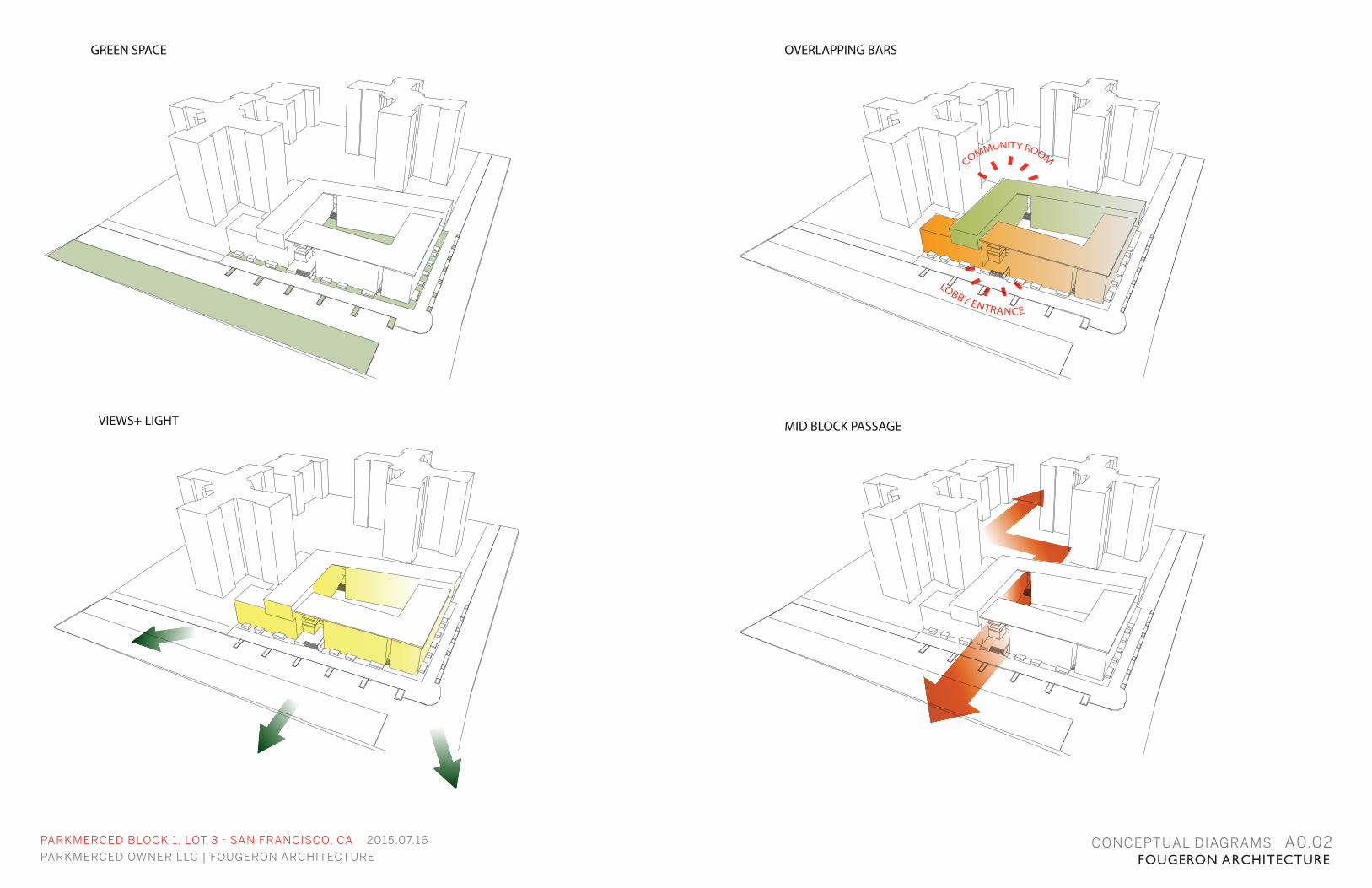
GREEN SPACE
CONCEPTUAL DIAGRAMS A0.02
VIEWS+ LIGHT
OVERLAPPING BARS
LOBBY ENTRANCE
MID BLOCK PASSAGE
PARKMERCED BLOCK 1, LOT 3 - SAN FRANCISCO, CA 2015.07.16
PARKMERCED OWNER LLC | FOUGERON ARCHITECTURE FOUGERON ARCHITECTURE
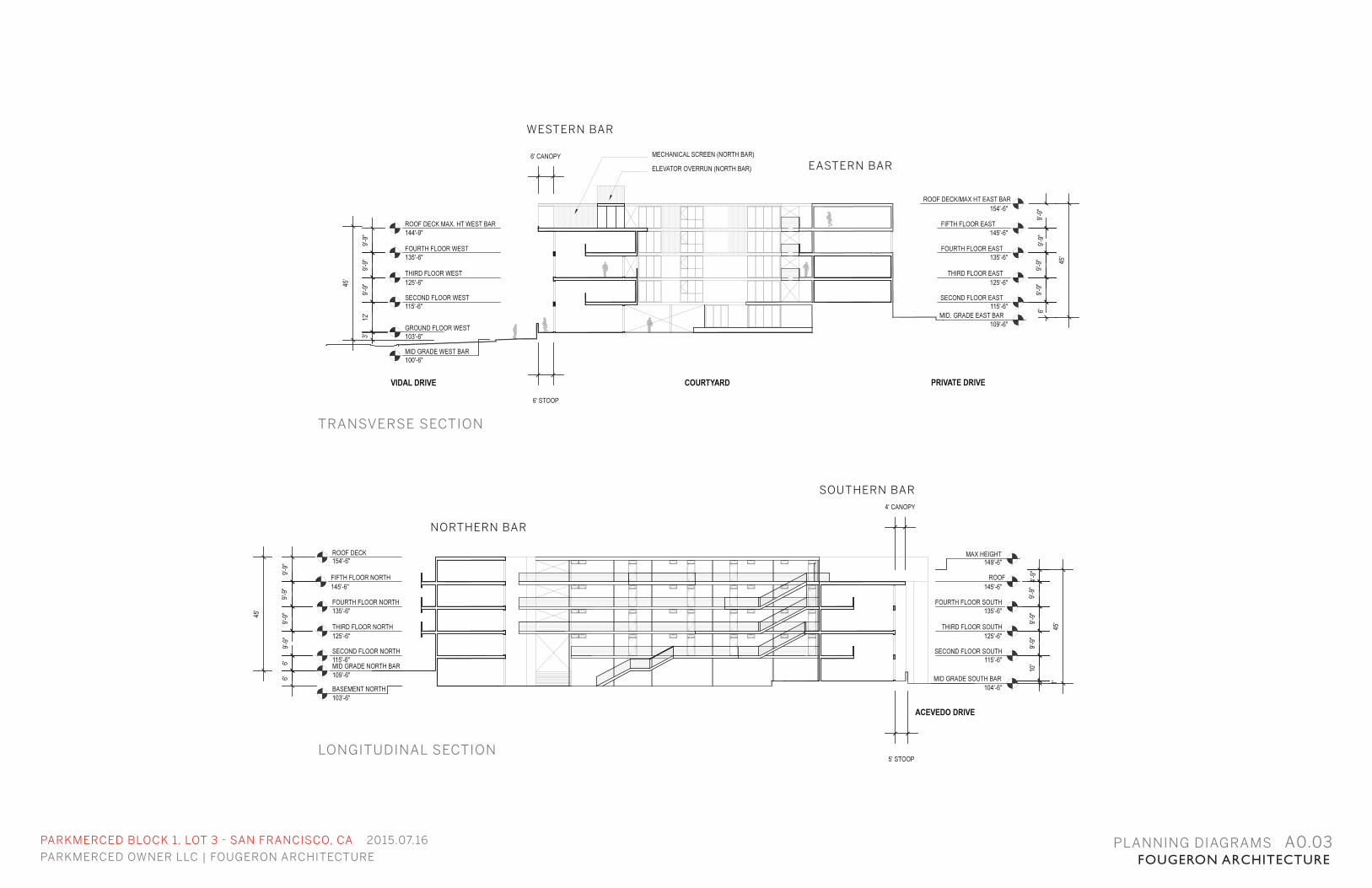
LONGITUDINAL SECTION
TRANSVERSE SECTION
WESTERN BAR
EASTERN BAR
NORTHERN BAR
SOUTHERN BAR
PLANNING DIAGRAMS A0.03
PARKMERCED BLOCK 1, LOT 3 - SAN FRANCISCO, CA 2015.07.16
PARKMERCED OWNER LLC | FOUGERON ARCHITECTURE FOUGERON ARCHITECTURE
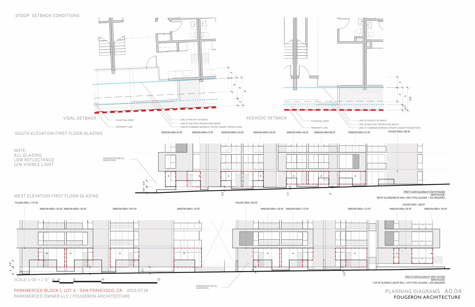
WEST ELEVATION FIRST FLOOR GLAZING
STOOP SETBACK CONDITIONS
PLANNING DIAGRAMS A0.04
ACEVEDO SETBACK
SOUTH ELEVATION FIRST FLOOR GLAZING
VIDAL SETBACK
SCALE: 1/16”= 1’-0” 0 4 8 16 32
PROPERTY LINE
PLANTING STRIP LINE OF PRIVATE SETBACK
NOTE:ALL GLAZINGLOW REFLECTANCE 12% VISIBLE LIGHT
PERFORATED METAL GUARD RAIL
PERFORATED METAL GUARD RAIL
LINE OF BALCONY PROJECTION ABOVE
LINE OF COMMON SETBACK (STOOP CANOPY PROJECTION) PROPERTY LINE
PLANTING STRIP LINE OF PRIVATE SETBACK
LINE OF BALCONY PROJECTION ABOVE
LINE OF COMMON SETBACK (STOOP CANOPY PROJECTION)
PARKMERCED BLOCK 1, LOT 3 - SAN FRANCISCO, CA 2015.07.16
PARKMERCED OWNER LLC | FOUGERON ARCHITECTURE FOUGERON ARCHITECTURE
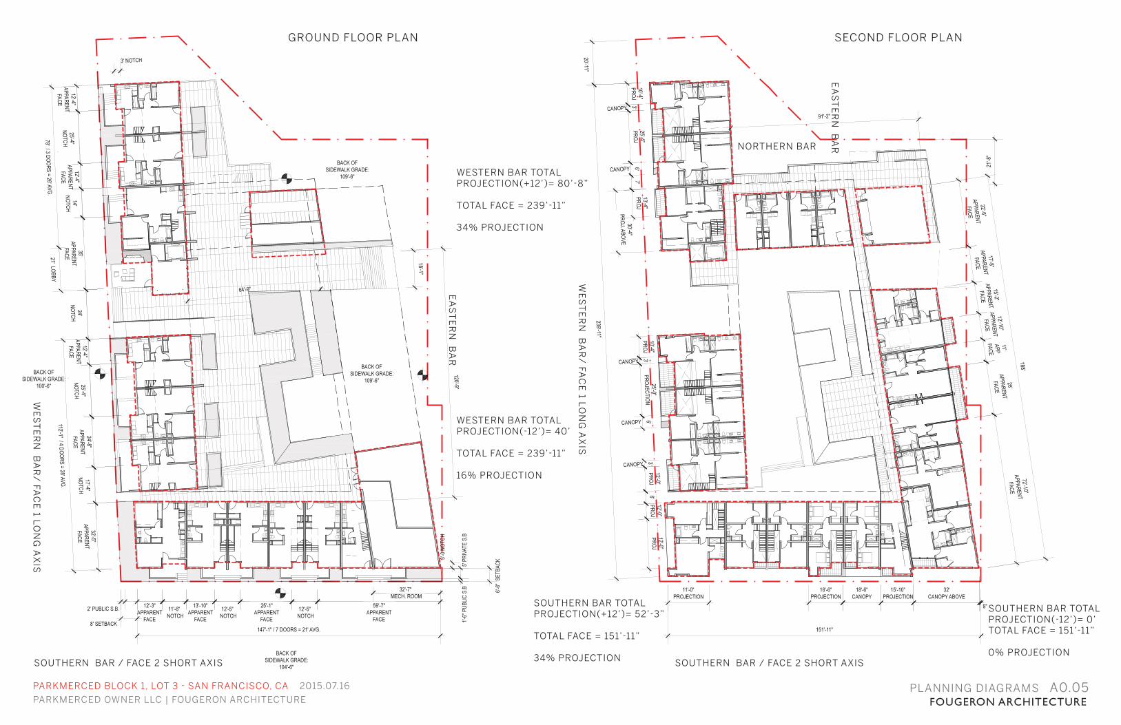
GROUND FLOOR PLAN
PLANNING DIAGRAMS A0.05
SECOND FLOOR PLAN
EA
ST
ER
N B
AR
WE
ST
ER
N B
AR
/ FA
CE
1 LO
NG
AX
IS
SOUTHERN BAR / FACE 2 SHORT AXIS
WESTERN BAR TOTAL PROJECTION(+12’)= 80’-8”
TOTAL FACE = 239’-11”
34% PROJECTION
SOUTHERN BAR / FACE 2 SHORT AXIS
WESTERN BAR TOTAL PROJECTION(-12’)= 40’
TOTAL FACE = 239’-11”
16% PROJECTION
SOUTHERN BAR TOTAL PROJECTION(+12’)= 52’-3”
TOTAL FACE = 151’-11”
34% PROJECTION
SOUTHERN BAR TOTAL PROJECTION(-12’)= 0’TOTAL FACE = 151’-11”
0% PROJECTION
NORTHERN BAR
EA
ST
ER
N B
AR
WE
ST
ER
N B
AR
/ FA
CE
1 LO
NG
AX
IS
PARKMERCED BLOCK 1, LOT 3 - SAN FRANCISCO, CA 2015.07.16
PARKMERCED OWNER LLC | FOUGERON ARCHITECTURE FOUGERON ARCHITECTUREPLANNING DIAGRAMS A0.06
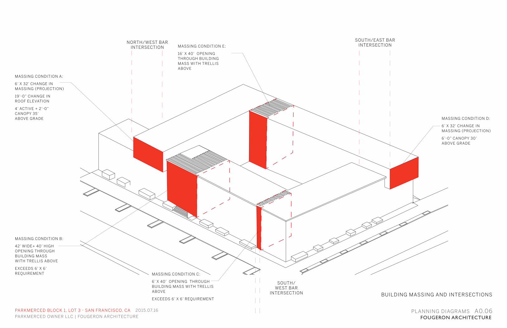
MASSING CONDITION D:
6’ X 32’ CHANGE IN MASSING (PROJECTION)
6’-0” CANOPY 30’ ABOVE GRADE
MASSING CONDITION A:
6’ X 32’ CHANGE IN MASSING (PROJECTION)
19’-0” CHANGE IN ROOF ELEVATION
4’ ACTIVE + 2’-0” CANOPY 35’ ABOVE GRADE
NORTH/WEST BAR INTERSECTION
SOUTH/EAST BAR INTERSECTION
SOUTH/WEST BAR
INTERSECTION
MASSING CONDITION E:
16’ X 40’ OPENING THROUGH BUILDING MASS WITH TRELLIS ABOVE
BUILDING MASSING AND INTERSECTIONS
MASSING CONDITION B:
42’ WIDE+ 40’ HIGH OPENING THROUGH BUILDING MASSWITH TRELLIS ABOVE
EXCEEDS 6’ X 6’REQUIREMENT MASSING CONDITION C:
6’ X 40’ OPENING THROUGH BUILDING MASS WITH TRELLISABOVE
EXCEEDS 6’ X 6’ REQUIREMENT
PARKMERCED BLOCK 1, LOT 3 - SAN FRANCISCO, CA 2015.07.16
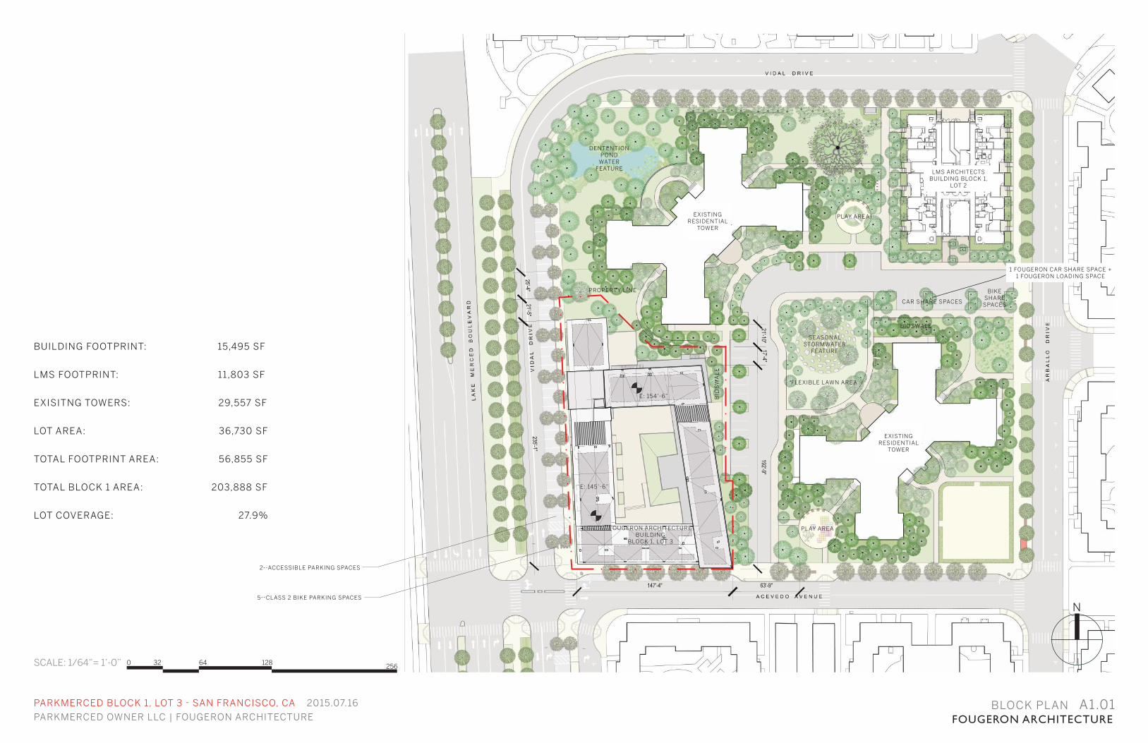
PARKMERCED OWNER LLC | FOUGERON ARCHITECTURE FOUGERON ARCHITECTUREBLOCK PLAN A1.01
N
SCALE: 1/64”= 1’-0”
N
BUILDING FOOTPRINT: 15,495 SF
LMS FOOTPRINT: 11,803 SF
EXISITNG TOWERS: 29,557 SF
LOT AREA: 36,730 SF
TOTAL FOOTPRINT AREA: 56,855 SF
TOTAL BLOCK 1 AREA: 203,888 SF
LOT COVERAGE: 27.9%
DENTENTIONPOND
WATERFEATURE
PROPERTY LINE
FOUGERON ARCHITECTURE BUILDING
BLOCK 1, LOT 3
EXISTINGRESIDENTIAL
TOWER
EXISTINGRESIDENTIAL
TOWER
LMS ARCHITECTS BUILDING BLOCK 1,
LOT 2
PLAY AREA
PLAY AREA
SEASONALSTORMWATER
FEATURE
FLEXIBLE LAWN AREA
BIOSWALE
BIO
SW
AL
E
2--ACCESSIBLE PARKING SPACES
5--CLASS 2 BIKE PARKING SPACES
CAR SHARE SPACES
BIKESHARE
SPACES
E: 154’-6”
E: 145’-6”
1 FOUGERON CAR SHARE SPACE + 1 FOUGERON LOADING SPACE
0 32 64 128 256
0 16 32 64 128
PARKMERCED BLOCK 1, LOT 3 - SAN FRANCISCO, CA 2015.07.16
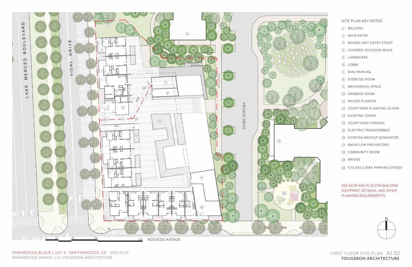
PARKMERCED OWNER LLC | FOUGERON ARCHITECTURE FOUGERON ARCHITECTUREFIRST FLOOR SITE PLAN A1.02
ACEVEDO AVENUE
SITE PLAN KEY NOTES:
BALCONY
MAIN ENTRY
RAISED UNIT ENTRY STOOP
COVERED OUTDOOR SPACE
LANDSCAPE
LOBBY
BIKE PARKING
EXERCISE ROOM
MECHANICAL SPACE
GARBAGE ROOM
RAISED PLANTER
COURTYARD PLANTING ISLAND
EXISTING TOWER
COURTYARD/TERRACE
ELECTRIC TRANSFORMER
EXISTING BACKUP GENERATOR
BACKFLOW PREVENTORS
COMMUNITY ROOM
BRIDGE
5 CLASS 2 BIKE PARKING STAGES
3
4
5
6
7
8
9
10
11
12
13
14
15
16
17
18
19
N
PR
IVA
TE
DR
IVE
15
17
PR
OP
ER
TY
LIN
E
SCALE: 1/32”= 1’-0”
SEE A0.05 AND A1.01 FOR BUILDING
FOOTPRINT, SETBACK, AND OTHER
PLANNING REQUIREMENTS.
2
1
3
17
13
7
8
16
142
6
4
11
12
9
13
10
3
20
20
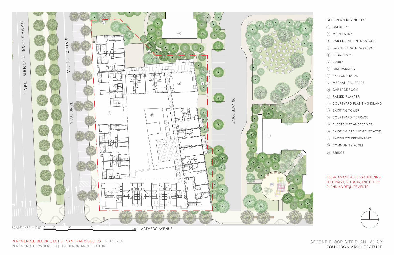
SEE A0.05 AND A1.01 FOR BUILDING
FOOTPRINT, SETBACK, AND OTHER
PLANNING REQUIREMENTS.
0 16 32 64 128
PARKMERCED BLOCK 1, LOT 3 - SAN FRANCISCO, CA 2015.07.16
PARKMERCED OWNER LLC | FOUGERON ARCHITECTURE FOUGERON ARCHITECTURESECOND FLOOR SITE PLAN A1.03
N
ACEVEDO AVENUE
VID
AL
DR
IVE
PR
IVA
TE
DR
IVE
1
4
6
12
14
18
16
17
5
15
13
NORTH TERRACE
SCALE: 1/32”= 1’-0”
PR
OP
ER
TY
LIN
E
SITE PLAN KEY NOTES:
BALCONY
MAIN ENTRY
RAISED UNIT ENTRY STOOP
COVERED OUTDOOR SPACE
LANDSCAPE
LOBBY
BIKE PARKING
EXERCISE ROOM
MECHANICAL SPACE
GARBAGE ROOM
RAISED PLANTER
COURTYARD PLANTING ISLAND
EXISTING TOWER
COURTYARD/TERRACE
ELECTRIC TRANSFORMER
EXISTING BACKUP GENERATOR
BACKFLOW PREVENTORS
COMMUNITY ROOM
BRIDGE
3
4
5
6
7
8
9
10
11
12
13
14
15
16
17
18
19
2
1
13
1
19
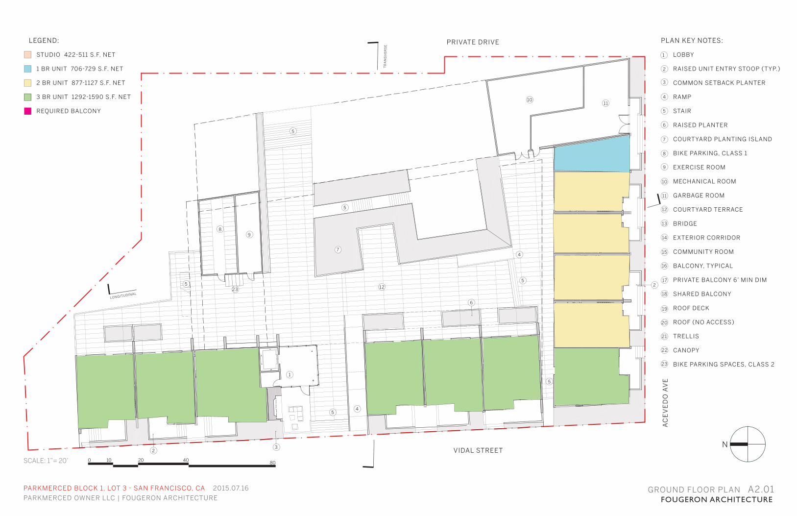
GROUND FLOOR PLAN A2.01
N
1
2
3
4
4
5
6
7
89
1011
12
5
5
5
5
5
2
LONGITUDINAL
TR
AN
SV
ER
SE
SCALE: 1”= 20’
23
LEGEND:
STUDIO 422-511 S.F. NET
1 BR UNIT 706-729 S.F. NET
2 BR UNIT 877-1127 S.F. NET
3 BR UNIT 1292-1590 S.F. NET
REQUIRED BALCONY
0 10 20 40 80
PARKMERCED BLOCK 1, LOT 3 - SAN FRANCISCO, CA 2015.07.16
PARKMERCED OWNER LLC | FOUGERON ARCHITECTURE FOUGERON ARCHITECTURE
VIDAL STREET
PRIVATE DRIVE
AC
EV
ED
O A
VE
PLAN KEY NOTES:
LOBBY
RAISED UNIT ENTRY STOOP (TYP.)
COMMON SETBACK PLANTER
RAMP
STAIR
RAISED PLANTER
COURTYARD PLANTING ISLAND
BIKE PARKING, CLASS 1
EXERCISE ROOM
MECHANICAL ROOM
GARBAGE ROOM
COURTYARD TERRACE
BRIDGE
EXTERIOR CORRIDOR
COMMUNITY ROOM
BALCONY, TYPICAL
PRIVATE BALCONY 6’ MIN DIM
SHARED BALCONY
ROOF DECK
ROOF (NO ACCESS)
TRELLIS
CANOPY
BIKE PARKING SPACES, CLASS 2
3
4
5
6
7
8
9
10
11
12
13
14
15
16
17
18
19
2
1
20
21
22
23
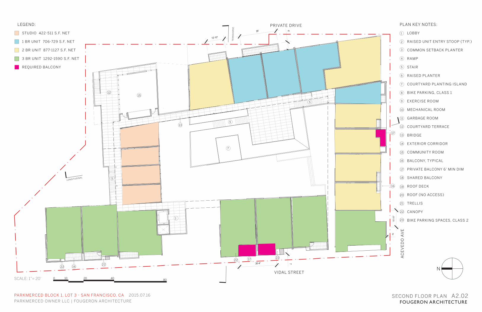
SECOND FLOOR PLAN A2.02
N
13
16
16
17
7
1
1215
5
5
5
SCALE: 1”= 20’
LONGITUDINAL
TR
AN
SV
ER
SE
LEGEND:
STUDIO 422-511 S.F. NET
1 BR UNIT 706-729 S.F. NET
2 BR UNIT 877-1127 S.F. NET
3 BR UNIT 1292-1590 S.F. NET
REQUIRED BALCONY
17
22
2222
0 10 20 40 80
PARKMERCED BLOCK 1, LOT 3 - SAN FRANCISCO, CA 2015.07.16
PARKMERCED OWNER LLC | FOUGERON ARCHITECTURE FOUGERON ARCHITECTURESECOND FLOOR PLAN A2.02
PLAN KEY NOTES:
LOBBY
RAISED UNIT ENTRY STOOP (TYP.)
COMMON SETBACK PLANTER
RAMP
STAIR
RAISED PLANTER
COURTYARD PLANTING ISLAND
BIKE PARKING, CLASS 1
EXERCISE ROOM
MECHANICAL ROOM
GARBAGE ROOM
COURTYARD TERRACE
BRIDGE
EXTERIOR CORRIDOR
COMMUNITY ROOM
BALCONY, TYPICAL
PRIVATE BALCONY 6’ MIN DIM
SHARED BALCONY
ROOF DECK
ROOF (NO ACCESS)
TRELLIS
CANOPY
BIKE PARKING SPACES, CLASS 2
3
4
5
6
7
8
9
10
11
12
13
14
15
16
17
18
19
2
1
20
21
22
23
VIDAL STREET
PRIVATE DRIVE
AC
EV
ED
O A
VE
22

THIRD FLOOR PLAN A2.03
N
18
13
1
19
14
18
16
16
17
17
5
5
SCALE: 1”= 20’
LEGEND:
STUDIO 422-511 S.F. NET
1 BR UNIT 706-729 S.F. NET
2 BR UNIT 877-1127 S.F. NET
3 BR UNIT 1292-1590 S.F. NET
REQUIRED BALCONY
0 10 20 40 80
PARKMERCED BLOCK 1, LOT 3 - SAN FRANCISCO, CA 2015.07.16
PARKMERCED OWNER LLC | FOUGERON ARCHITECTURE FOUGERON ARCHITECTURE
PLAN KEY NOTES:
LOBBY
RAISED UNIT ENTRY STOOP (TYP.)
COMMON SETBACK PLANTER
RAMP
STAIR
RAISED PLANTER
COURTYARD PLANTING ISLAND
BIKE PARKING, CLASS 1
EXERCISE ROOM
MECHANICAL ROOM
GARBAGE ROOM
COURTYARD TERRACE
BRIDGE
EXTERIOR CORRIDOR
COMMUNITY ROOM
BALCONY, TYPICAL
PRIVATE BALCONY 6’ MIN DIM
SHARED BALCONY
ROOF DECK
ROOF (NO ACCESS)
TRELLIS
CANOPY
BIKE PARKING SPACES, CLASS 2
3
4
5
6
7
8
9
10
11
12
13
14
15
16
17
18
19
2
1
20
21
22
23
VIDAL STREET
PRIVATE DRIVE
AC
EV
ED
O A
VE
2222
22
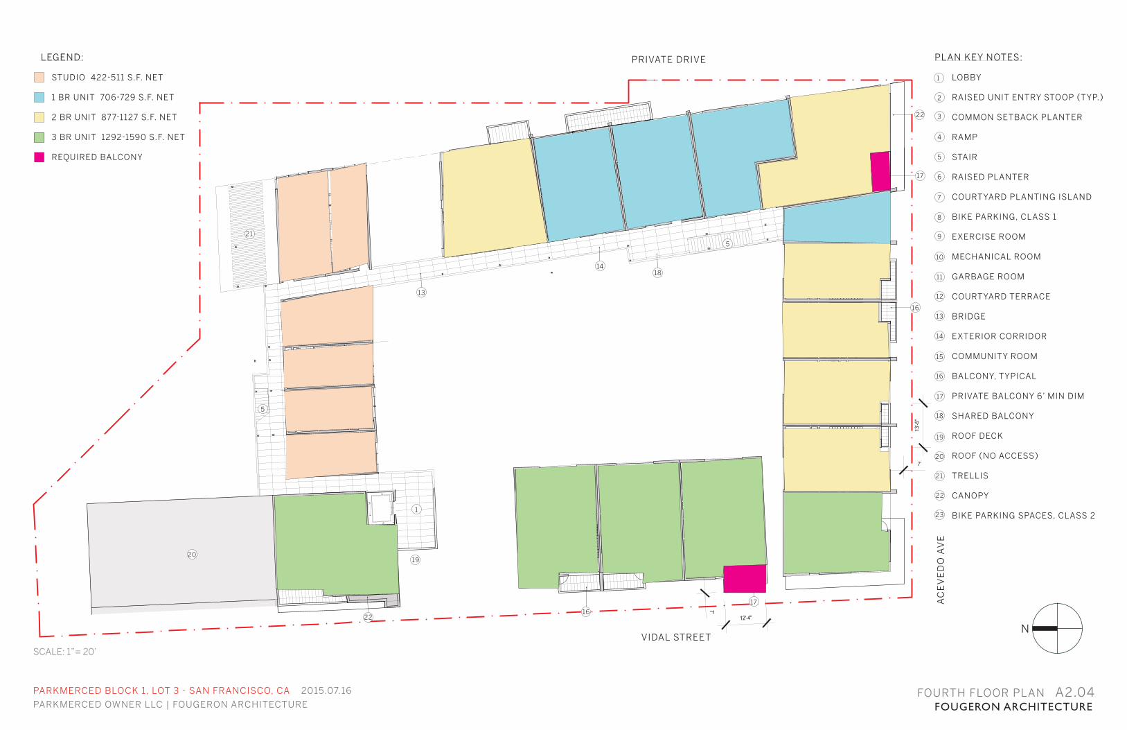
FOURTH FLOOR PLAN A2.04
N
20
17
13
1
19
1418
16
17
16
5
5
SCALE: 1”= 20’
LEGEND:
STUDIO 422-511 S.F. NET
1 BR UNIT 706-729 S.F. NET
2 BR UNIT 877-1127 S.F. NET
3 BR UNIT 1292-1590 S.F. NET
REQUIRED BALCONY
22
PARKMERCED BLOCK 1, LOT 3 - SAN FRANCISCO, CA 2015.07.16
PARKMERCED OWNER LLC | FOUGERON ARCHITECTURE FOUGERON ARCHITECTURE
PLAN KEY NOTES:
LOBBY
RAISED UNIT ENTRY STOOP (TYP.)
COMMON SETBACK PLANTER
RAMP
STAIR
RAISED PLANTER
COURTYARD PLANTING ISLAND
BIKE PARKING, CLASS 1
EXERCISE ROOM
MECHANICAL ROOM
GARBAGE ROOM
COURTYARD TERRACE
BRIDGE
EXTERIOR CORRIDOR
COMMUNITY ROOM
BALCONY, TYPICAL
PRIVATE BALCONY 6’ MIN DIM
SHARED BALCONY
ROOF DECK
ROOF (NO ACCESS)
TRELLIS
CANOPY
BIKE PARKING SPACES, CLASS 2
3
4
5
6
7
8
9
10
11
12
13
14
15
16
17
18
19
2
1
20
21
22
23
VIDAL STREET
PRIVATE DRIVE
AC
EV
ED
O A
VE
22
21
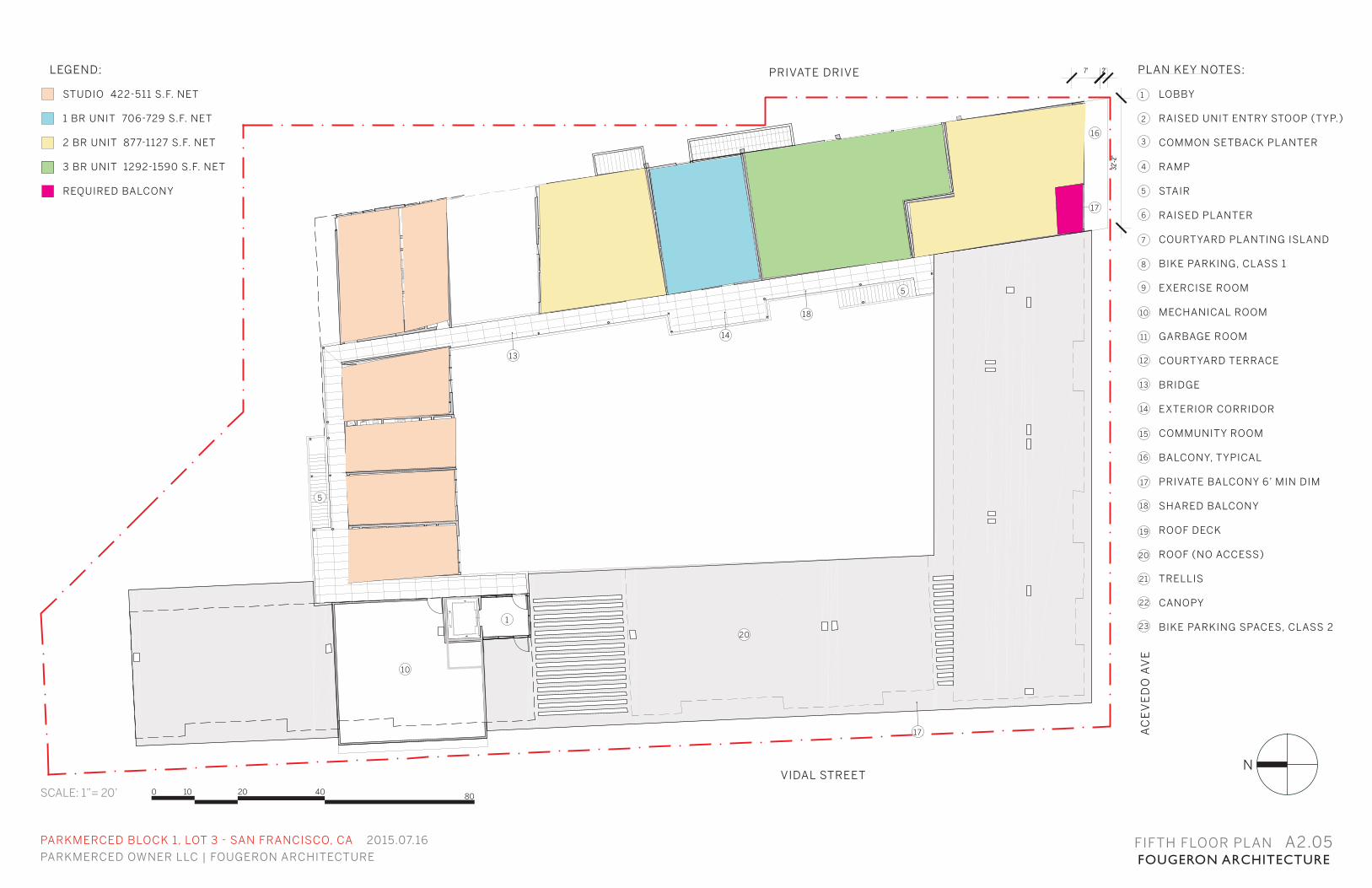
FIFTH FLOOR PLAN A2.05
N
10
17
13
1
14
18
5
5
20
SCALE: 1”= 20’
LEGEND:
STUDIO 422-511 S.F. NET
1 BR UNIT 706-729 S.F. NET
2 BR UNIT 877-1127 S.F. NET
3 BR UNIT 1292-1590 S.F. NET
REQUIRED BALCONY
17
16
0 10 20 40 80
PARKMERCED BLOCK 1, LOT 3 - SAN FRANCISCO, CA 2015.07.16
PARKMERCED OWNER LLC | FOUGERON ARCHITECTURE FOUGERON ARCHITECTURE
PLAN KEY NOTES:
LOBBY
RAISED UNIT ENTRY STOOP (TYP.)
COMMON SETBACK PLANTER
RAMP
STAIR
RAISED PLANTER
COURTYARD PLANTING ISLAND
BIKE PARKING, CLASS 1
EXERCISE ROOM
MECHANICAL ROOM
GARBAGE ROOM
COURTYARD TERRACE
BRIDGE
EXTERIOR CORRIDOR
COMMUNITY ROOM
BALCONY, TYPICAL
PRIVATE BALCONY 6’ MIN DIM
SHARED BALCONY
ROOF DECK
ROOF (NO ACCESS)
TRELLIS
CANOPY
BIKE PARKING SPACES, CLASS 2
3
4
5
6
7
8
9
10
11
12
13
14
15
16
17
18
19
2
1
20
21
22
23
VIDAL STREET
PRIVATE DRIVE
AC
EV
ED
O A
VE
21
21
21
0 10 20 40 80
PARKMERCED BLOCK 1, LOT 3 - SAN FRANCISCO, CA 2015.07.16
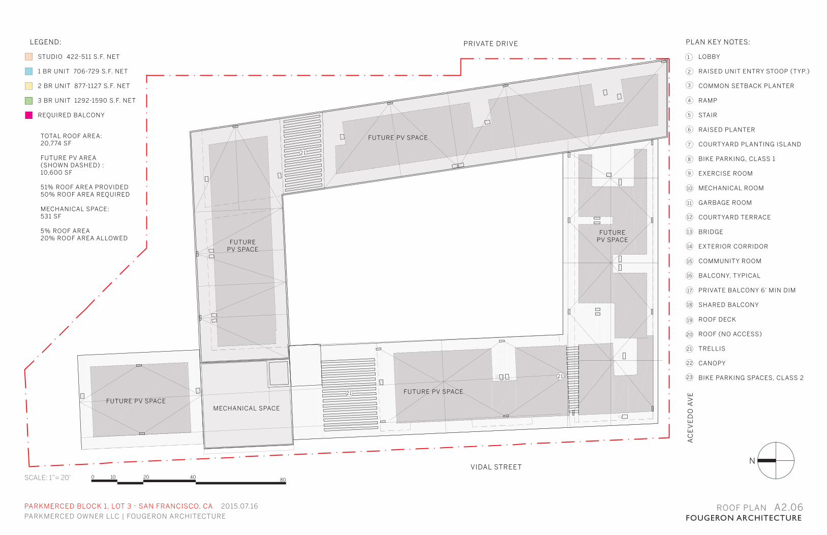
PARKMERCED OWNER LLC | FOUGERON ARCHITECTURE FOUGERON ARCHITECTUREROOF PLAN A2.06
N
TOTAL ROOF AREA:20,774 SF
FUTURE PV AREA (SHOWN DASHED) :10,600 SF
51% ROOF AREA PROVIDED50% ROOF AREA REQUIRED
MECHANICAL SPACE:531 SF
5% ROOF AREA20% ROOF AREA ALLOWED
MECHANICAL SPACE
FUTURE PV SPACE
FUTURE PV SPACE
FUTURE PV SPACE
FUTURE PV SPACE
FUTURE PV SPACE
SCALE: 1”= 20’
PLAN KEY NOTES:
LOBBY
RAISED UNIT ENTRY STOOP (TYP.)
COMMON SETBACK PLANTER
RAMP
STAIR
RAISED PLANTER
COURTYARD PLANTING ISLAND
BIKE PARKING, CLASS 1
EXERCISE ROOM
MECHANICAL ROOM
GARBAGE ROOM
COURTYARD TERRACE
BRIDGE
EXTERIOR CORRIDOR
COMMUNITY ROOM
BALCONY, TYPICAL
PRIVATE BALCONY 6’ MIN DIM
SHARED BALCONY
ROOF DECK
ROOF (NO ACCESS)
TRELLIS
CANOPY
BIKE PARKING SPACES, CLASS 2
3
4
5
6
7
8
9
10
11
12
13
14
15
16
17
18
19
2
1
20
21
22
23
VIDAL STREET
PRIVATE DRIVE
AC
EV
ED
O A
VE
LEGEND:
STUDIO 422-511 S.F. NET
1 BR UNIT 706-729 S.F. NET
2 BR UNIT 877-1127 S.F. NET
3 BR UNIT 1292-1590 S.F. NET
REQUIRED BALCONY
PARKMERCED BLOCK 1, LOT 3 - SAN FRANCISCO, CA 2015.07.16
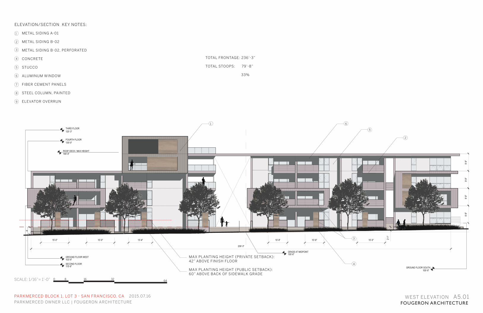
PARKMERCED OWNER LLC | FOUGERON ARCHITECTURE FOUGERON ARCHITECTUREWEST ELEVATION A5.01
SCALE: 1/16”= 1’-0”
ELEVATION/SECTION KEY NOTES:
METAL SIDING A-01
METAL SIDING B-02
METAL SIDING B-02, PERFORATED
CONCRETE
STUCCO
ALUMINUM WINDOW
FIBER CEMENT PANELS
STEEL COLUMN, PAINTED
ELEVATOR OVERRUN
3
4
5
6
7
8
2
1
9
2
1 6
5
3
4
MAX PLANTING HEIGHT (PRIVATE SETBACK):42” ABOVE FINISH FLOOR
MAX PLANTING HEIGHT (PUBLIC SETBACK):60” ABOVE BACK OF SIDEWALK GRADE
0 8 16 32 64
TOTAL FRONTAGE: 236’-3”
TOTAL STOOPS: 79’-8” 33%
PARKMERCED BLOCK 1, LOT 3 - SAN FRANCISCO, CA 2015.07.16
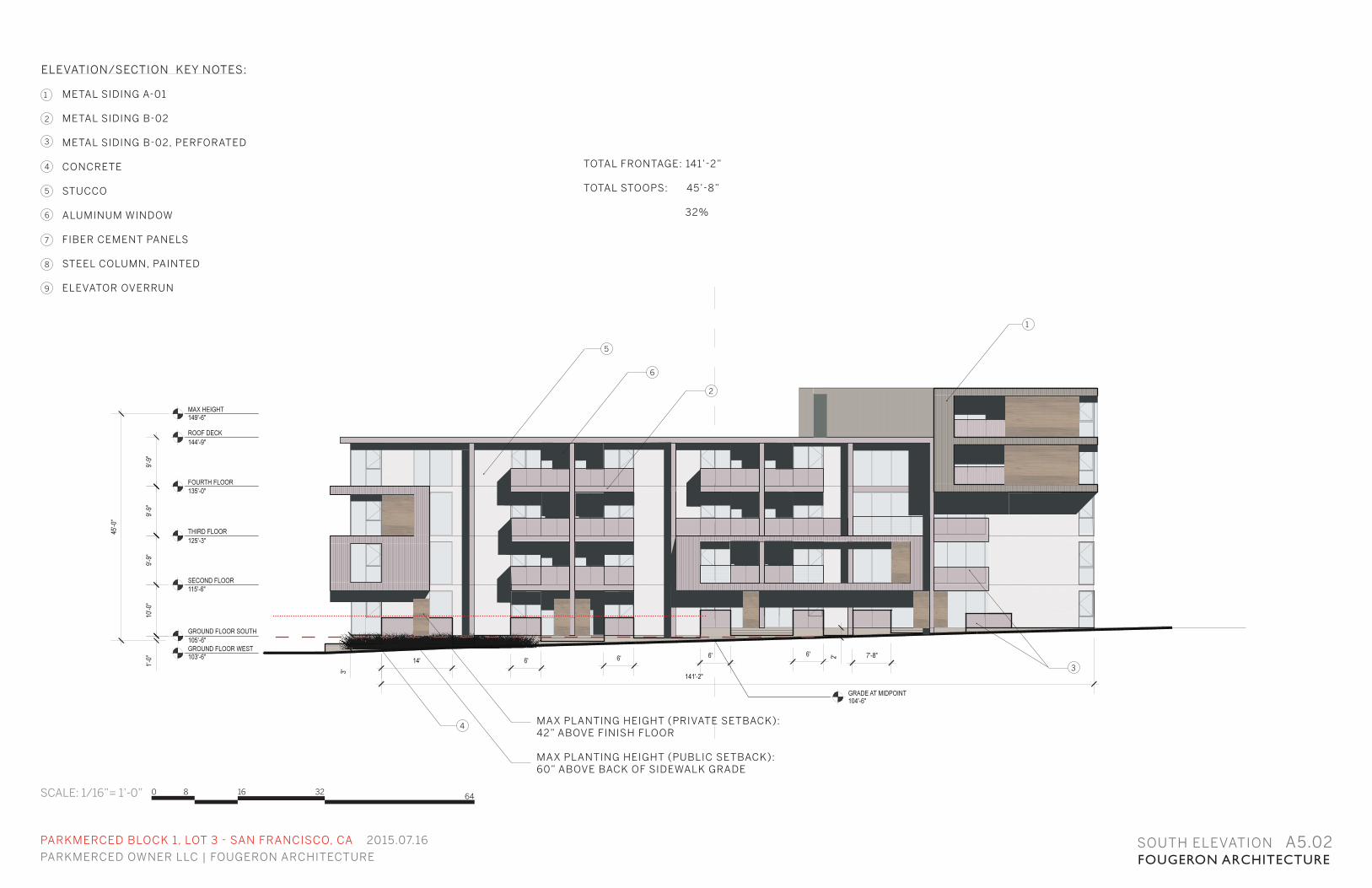
PARKMERCED OWNER LLC | FOUGERON ARCHITECTURE FOUGERON ARCHITECTURESOUTH ELEVATION A5.02
SCALE: 1/16”= 1’-0”
ELEVATION/SECTION KEY NOTES:
METAL SIDING A-01
METAL SIDING B-02
METAL SIDING B-02, PERFORATED
CONCRETE
STUCCO
ALUMINUM WINDOW
FIBER CEMENT PANELS
STEEL COLUMN, PAINTED
ELEVATOR OVERRUN
3
4
5
6
7
8
2
1
9
MAX PLANTING HEIGHT (PRIVATE SETBACK):42” ABOVE FINISH FLOOR
MAX PLANTING HEIGHT (PUBLIC SETBACK):60” ABOVE BACK OF SIDEWALK GRADE
3
4
5
6
2
1
0 8 16 32 64
TOTAL FRONTAGE: 141’-2”
TOTAL STOOPS: 45’-8” 32%
PARKMERCED BLOCK 1, LOT 3 - SAN FRANCISCO, CA 2015.07.16
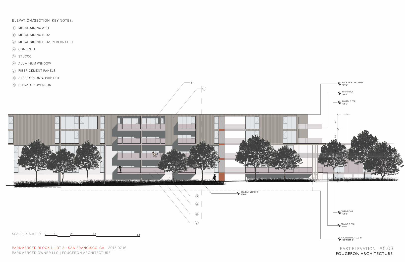
PARKMERCED OWNER LLC | FOUGERON ARCHITECTURE FOUGERON ARCHITECTUREEAST ELEVATION A5.03
SCALE: 1/16”= 1’-0”
ELEVATION/SECTION KEY NOTES:
METAL SIDING A-01
METAL SIDING B-02
METAL SIDING B-02, PERFORATED
CONCRETE
STUCCO
ALUMINUM WINDOW
FIBER CEMENT PANELS
STEEL COLUMN, PAINTED
ELEVATOR OVERRUN
3
4
5
6
7
8
2
1
9
3
4
5
6
2
1
0 8 16 32 64
PARKMERCED BLOCK 1, LOT 3 - SAN FRANCISCO, CA 2015.07.16
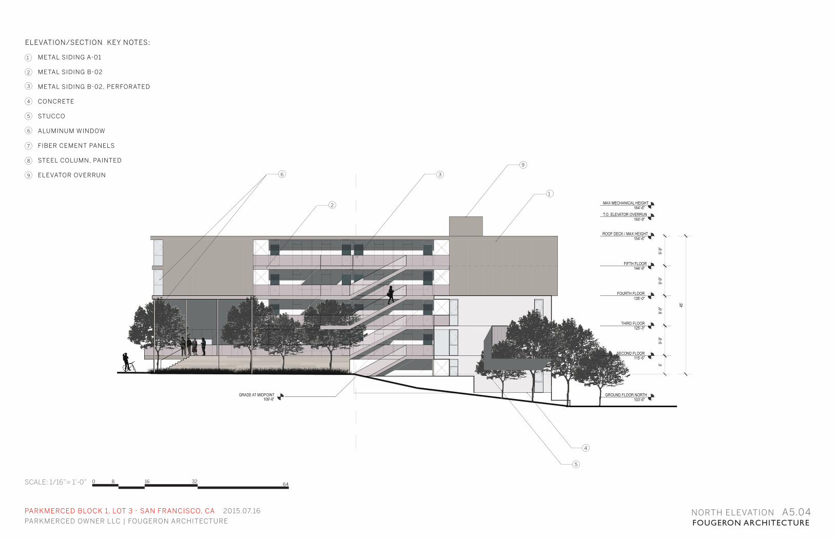
PARKMERCED OWNER LLC | FOUGERON ARCHITECTURE FOUGERON ARCHITECTURENORTH ELEVATION A5.04
SCALE: 1/16”= 1’-0”
ELEVATION/SECTION KEY NOTES:
METAL SIDING A-01
METAL SIDING B-02
METAL SIDING B-02, PERFORATED
CONCRETE
STUCCO
ALUMINUM WINDOW
FIBER CEMENT PANELS
STEEL COLUMN, PAINTED
ELEVATOR OVERRUN
3
4
5
6
7
8
2
1
9 3
4
6
1
9
0 8 16 32 64
5
2
PARKMERCED BLOCK 1, LOT 3 - SAN FRANCISCO, CA 2015.07.16
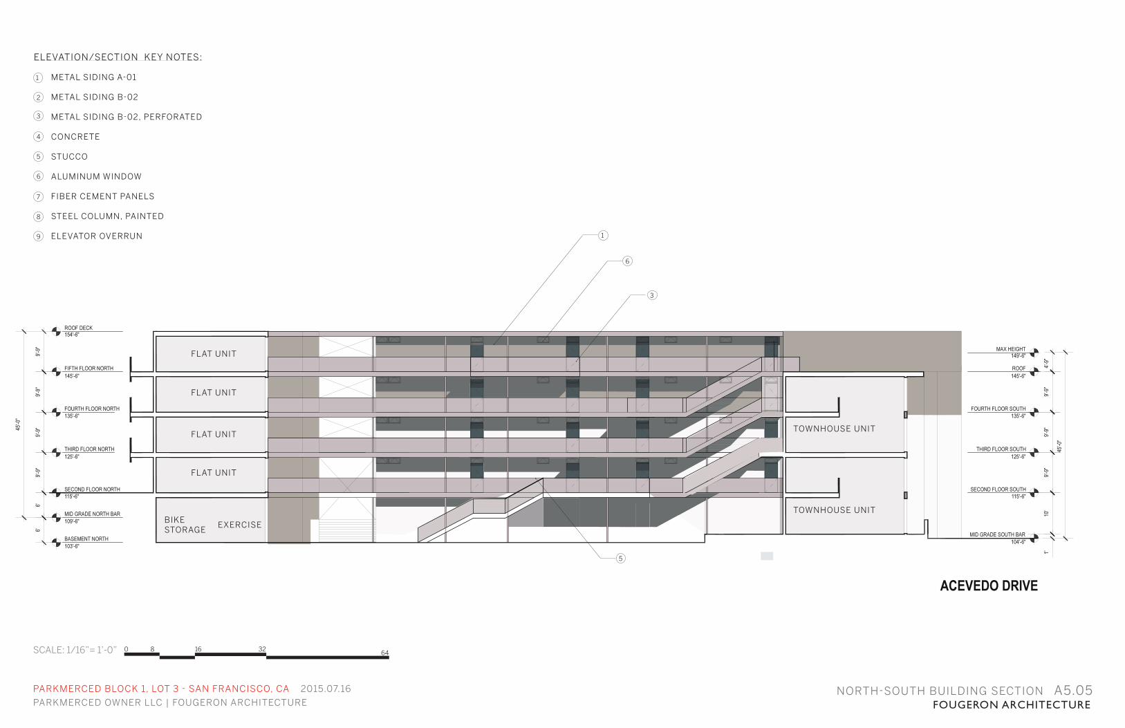
PARKMERCED OWNER LLC | FOUGERON ARCHITECTURE FOUGERON ARCHITECTURENORTH-SOUTH BUILDING SECTION A5.05
SCALE: 1/16”= 1’-0”
TOWNHOUSE UNIT
ELEVATION/SECTION KEY NOTES:
METAL SIDING A-01
METAL SIDING B-02
METAL SIDING B-02, PERFORATED
CONCRETE
STUCCO
ALUMINUM WINDOW
FIBER CEMENT PANELS
STEEL COLUMN, PAINTED
ELEVATOR OVERRUN
3
4
5
6
7
8
2
1
9
3
5
6
1
TOWNHOUSE UNIT
FLAT UNIT
FLAT UNIT
FLAT UNIT
FLAT UNIT
BIKE STORAGE
EXERCISE
0 8 16 32 64
PARKMERCED BLOCK 1, LOT 3 - SAN FRANCISCO, CA 2015.07.16
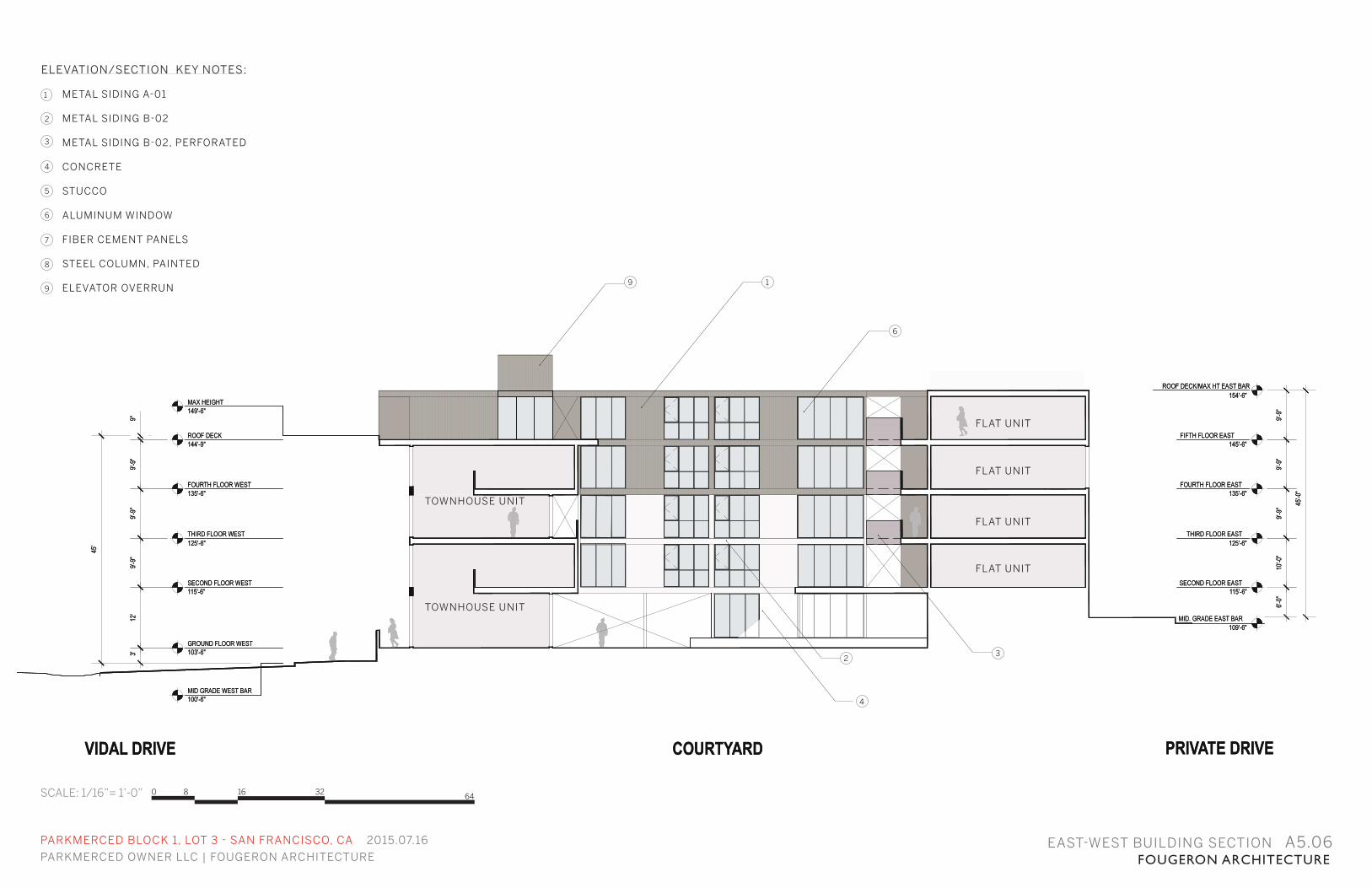
PARKMERCED OWNER LLC | FOUGERON ARCHITECTURE FOUGERON ARCHITECTUREEAST-WEST BUILDING SECTION A5.06
SCALE: 1/16”= 1’-0”
ELEVATION/SECTION KEY NOTES:
METAL SIDING A-01
METAL SIDING B-02
METAL SIDING B-02, PERFORATED
CONCRETE
STUCCO
ALUMINUM WINDOW
FIBER CEMENT PANELS
STEEL COLUMN, PAINTED
ELEVATOR OVERRUN
3
4
5
6
7
8
2
1
9
3
4
6
2
19
TOWNHOUSE UNIT
TOWNHOUSE UNIT
FLAT UNIT
FLAT UNIT
FLAT UNIT
FLAT UNIT
0 8 16 32 64
PARKMERCED BLOCK 1, LOT 3 - SAN FRANCISCO, CA 2015.07.16
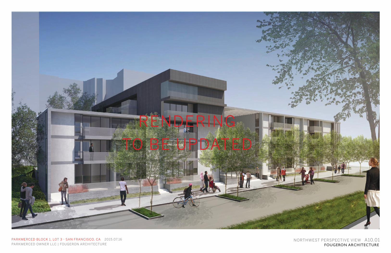
PARKMERCED OWNER LLC | FOUGERON ARCHITECTURE FOUGERON ARCHITECTURENORTHWEST PERSPECTIVE VIEW A10.01
RENDERING
TO BE UPDATED
PARKMERCED BLOCK 1, LOT 3 - SAN FRANCISCO, CA 2015.07.16
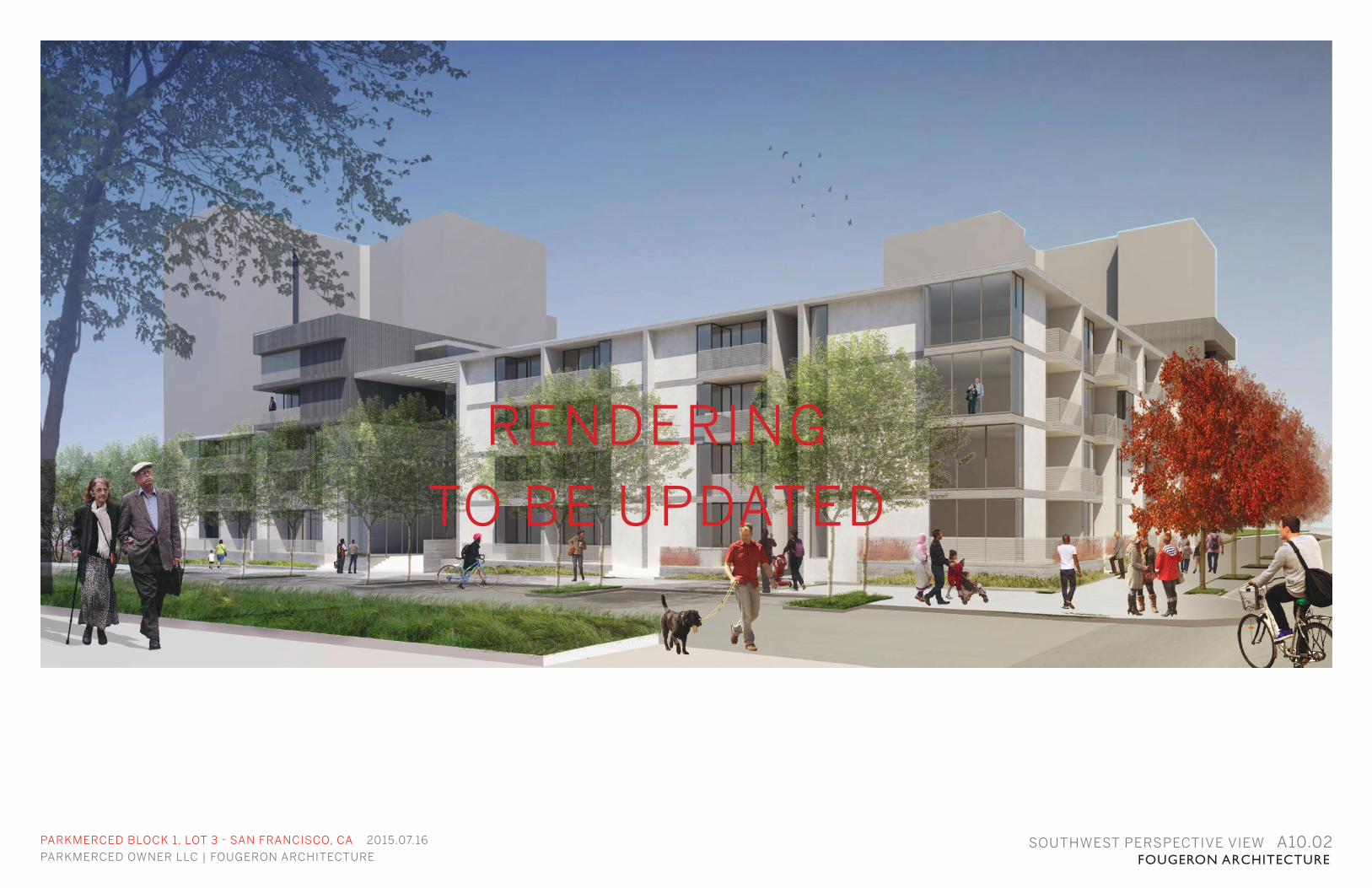
PARKMERCED OWNER LLC | FOUGERON ARCHITECTURE FOUGERON ARCHITECTURESOUTHWEST PERSPECTIVE VIEW A10.02
RENDERING
TO BE UPDATED
PARKMERCED BLOCK 1, LOT 3 - SAN FRANCISCO, CA 2015.07.16
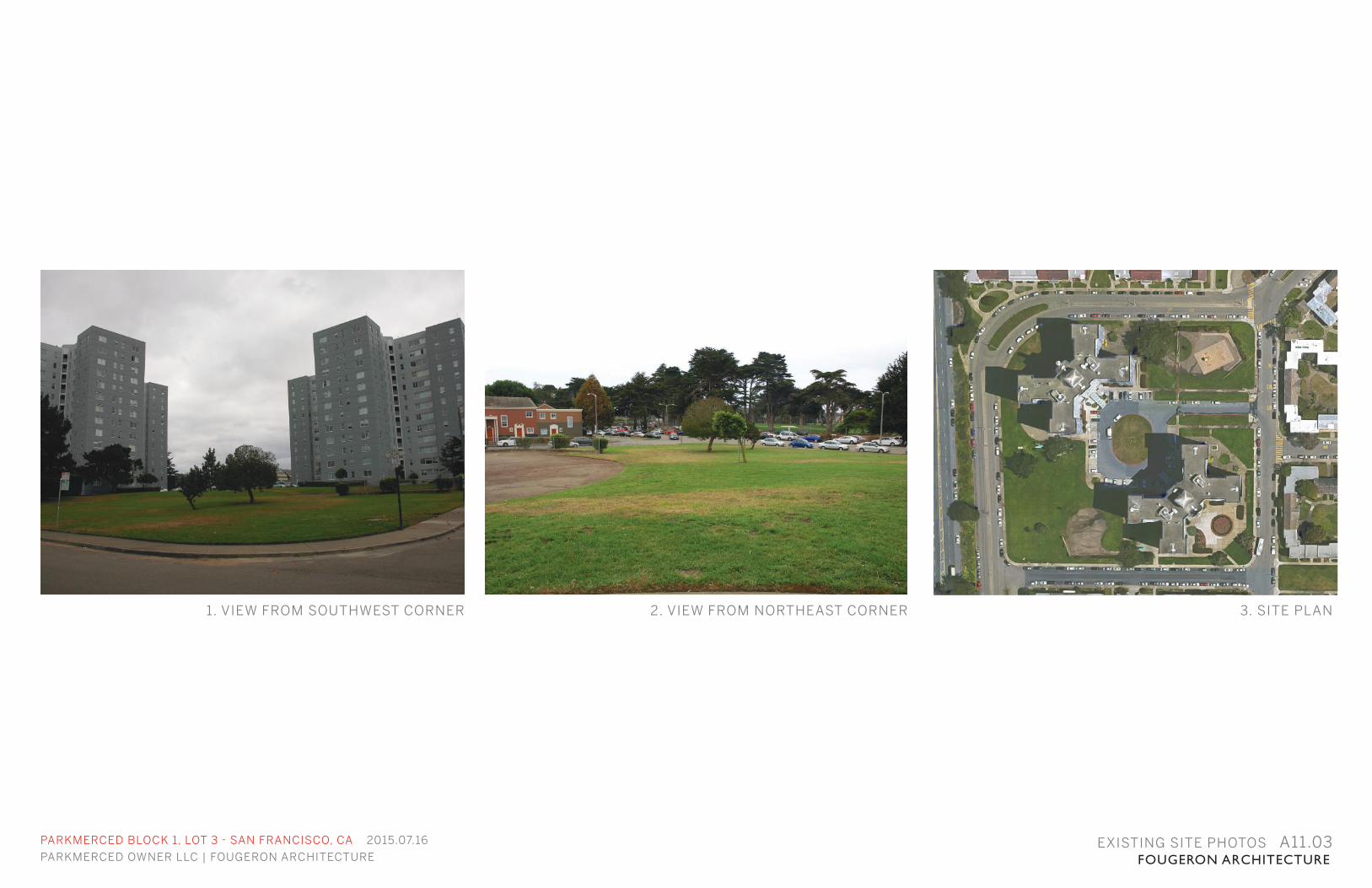
PARKMERCED OWNER LLC | FOUGERON ARCHITECTURE FOUGERON ARCHITECTUREEXISTING SITE PHOTOS A11.03
1. VIEW FROM SOUTHWEST CORNER 2. VIEW FROM NORTHEAST CORNER 3. SITE PLAN
PARKMERCED BLOCK 1, LOT 3 - SAN FRANCISCO, CA 2015.07.16
PARKMERCED OWNER LLC | FOUGERON ARCHITECTURE FOUGERON ARCHITECTURE
BLOCK 1, LOT 1APPENDIX
PARKMERCED BLOCK 1, LOT 3 - SAN FRANCISCO, CA 2015.07.16
PARKMERCED OWNER LLC | FOUGERON ARCHITECTURE FOUGERON ARCHITECTURE
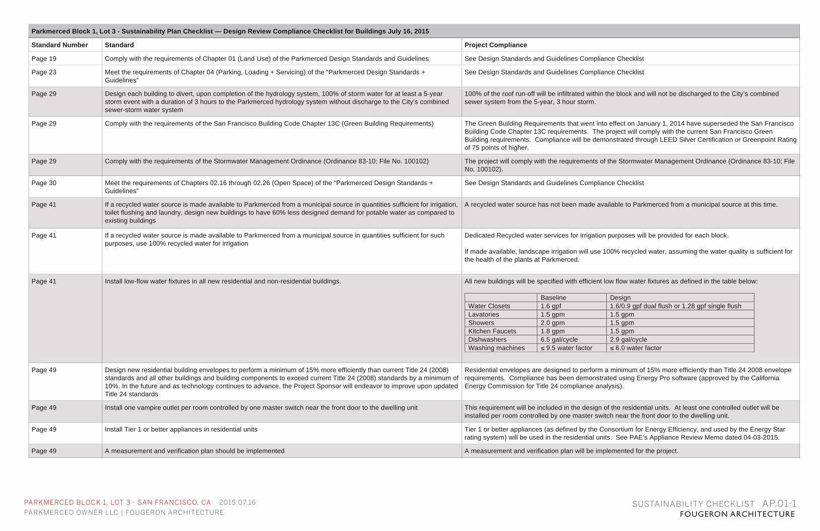
Parkmerced Block 1, Lot 3 - Sustainability Plan Checklist — Design Review Compliance Checklist for Buildings July 16, 2015
Standard Number Standard Project Compliance
Page 19 Comply with the requirements of Chapter 01 (Land Use) of the Parkmerced Design Standards and Guidelines See Design Standards and Guidelines Compliance Checklist
Page 23 Meet the requirements of Chapter 04 (Parking, Loading + Servicing) of the “Parkmerced Design Standards + Guidelines”
See Design Standards and Guidelines Compliance Checklist
Page 29 Design each building to divert, upon completion of the hydrology system, 100% of storm water for at least a 5-year storm event with a duration of 3 hours to the Parkmerced hydrology system without discharge to the City’s combined sewer-storm water system
100% of the roof run-off will be infiltrated within the block and will not be discharged to the City’s combined sewer system from the 5-year, 3 hour storm.
Page 29 Comply with the requirements of the San Francisco Building Code Chapter 13C (Green Building Requirements) The Green Building Requirements that went into effect on January 1, 2014 have superseded the San Francisco Building Code Chapter 13C requirements. The project will comply with the current San Francisco Green Building requirements. Compliance will be demonstrated through LEED Silver Certification or Greenpoint Rating of 75 points of higher.
Page 29 Comply with the requirements of the Stormwater Management Ordinance (Ordinance 83-10; File No. 100102) The project will comply with the requirements of the Stormwater Management Ordinance (Ordinance 83-10; File No. 100102).
Page 30 Meet the requirements of Chapters 02.16 through 02.26 (Open Space) of the “Parkmerced Design Standards + Guidelines”
See Design Standards and Guidelines Compliance Checklist
Page 41
If a recycled water source is made available to Parkmerced from a municipal source in quantities sufficient for irrigation, toilet flushing and laundry, design new buildings to have 60% less designed demand for potable water as compared to existing buildings
A recycled water source has not been made available to Parkmerced from a municipal source at this time.
Page 41 If a recycled water source is made available to Parkmerced from a municipal source in quantities sufficient for such purposes, use 100% recycled water for irrigation
Dedicated Recycled water services for irrigation purposes will be provided for each block. If made available, landscape irrigation will use 100% recycled water, assuming the water quality is sufficient for the health of the plants at Parkmerced.
Page 41 Install low-flow water fixtures in all new residential and non-residential buildings. All new buildings will be specified with efficient low flow water fixtures as defined in the table below:
Baseline Design Water Closets 1.6 gpf 1.6/0.9 gpf dual flush or 1.28 gpf single flush Lavatories 1.5 gpm 1.5 gpm Showers 2.0 gpm 1.5 gpm Kitchen Faucets 1.8 gpm 1.5 gpm Dishwashers 6.5 gal/cycle 2.9 gal/cycle Washing machines ≤ 9.5 water factor ≤ 6.0 water factor
Page 49 Design new residential building envelopes to perform a minimum of 15% more efficiently than current Title 24 (2008) standards and all other buildings and building components to exceed current Title 24 (2008) standards by a minimum of 10%. In the future and as technology continues to advance, the Project Sponsor will endeavor to improve upon updated Title 24 standards
Residential envelopes are designed to perform a minimum of 15% more efficiently than Title 24 2008 envelope requirements. Compliance has been demonstrated using Energy Pro software (approved by the California Energy Commission for Title 24 compliance analysis).
Page 49 Install one vampire outlet per room controlled by one master switch near the front door to the dwelling unit This requirement will be included in the design of the residential units. At least one controlled outlet will be installed per room controlled by one master switch near the front door to the dwelling unit.
Page 49 Install Tier 1 or better appliances in residential units Tier 1 or better appliances (as defined by the Consortium for Energy Efficiency, and used by the Energy Star rating system) will be used in the residential units. See PAE’s Appliance Review Memo dated 04-03-2015.
Page 49 A measurement and verification plan should be implemented A measurement and verification plan will be implemented for the project.
SUSTAINABILITY CHECKLIST AP.01-1
PARKMERCED BLOCK 1, LOT 3 - SAN FRANCISCO, CA 2015.07.16
PARKMERCED OWNER LLC | FOUGERON ARCHITECTURE FOUGERON ARCHITECTURE
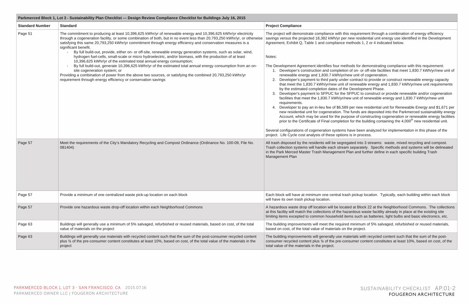
Parkmerced Block 1, Lot 3 - Sustainability Plan Checklist — Design Review Compliance Checklist for Buildings July 16, 2015
Standard Number Standard Project Compliance
Page 51 The commitment to producing at least 10,396,625 kWhr/yr of renewable energy and 10,396,625 kWhr/yr electricity through a cogeneration facility, or some combination of both, but in no event less than 20,793,250 kWhr/yr, or otherwise satisfying this same 20,793,250 kWhr/yr commitment through energy efficiency and conservation measures is a significant benefit.
- By full build-out, provide, either on- or off-site, renewable energy generation systems, such as solar, wind, hydrogen fuel-cells, small-scale or micro hydroelectric, and/or biomass, with the production of at least 10,396,625 kWhr/yr of the estimated total annual energy consumption;
- By full build-out, generate 10,396,625 kWhr/yr of the estimated total annual energy consumption from an on-site cogeneration system; or
Providing a combination of power from the above two sources, or satisfying the combined 20,793,250 kWhr/yr requirement through energy efficiency or conservation savings
The project will demonstrate compliance with this requirement through a combination of energy efficiency savings versus the projected 18,382 kWh/yr per new residential unit energy use identified in the Development Agreement, Exhibit Q, Table 1 and compliance methods 1, 2 or 4 indicated below. Notes: The Development Agreement identifies four methods for demonstrating compliance with this requirement:
1. Developer’s construction and completion of on- or off-site facilities that meet 1,830.7 kWh/yr/new unit of renewable energy and 1,830.7 kWh/yr/new unit of cogeneration.
2. Developer’s payment to third party under contract to provide or construct renewable energy capacity that meet the 1,830.7 kWh/yr/new unit of renewable energy and 1,830.7 kWh/yr/new unit requirements by the estimated completion dates of the Development Phase.
3. Developer’s payment to SFPUC for the SFPUC to construct or provide renewable and/or cogeneration facilities that meet the 1,830.7 kWh/yr/new unit of renewable energy and 1,830.7 kWh/yr/new unit requirements.
4. Developer to pay an in-lieu fee of $6,589 per new residential unit for Renewable Energy and $1,671 per new residential unit for cogeneration. The funds are deposited into the Parkmerced sustainability energy Account, which may be used for the purpose of constructing cogeneration or renewable energy facilities prior to the Certificate of Final completion for the building containing the 4,000th new residential unit.
Several configurations of cogeneration systems have been analyzed for implementation in this phase of the project. Life Cycle cost analysis of these options is in process.
Page 57 Meet the requirements of the City’s Mandatory Recycling and Compost Ordinance (Ordinance No. 100-09, File No. 081404)
All trash disposed by the residents will be segregated into 3 streams: waste, mixed recycling and compost. Trash collection systems will handle each stream separately. Specific methods and systems will be delineated in the Park Merced Master Trash Management Plan and further define in each specific building Trash Management Plan
Page 57 Provide a minimum of one centralized waste pick-up location on each block Each block will have at minimum one central trash pickup location. Typically, each building within each block will have its own trash pickup location.
Page 57 Provide one hazardous waste drop-off location within each Neighborhood Commons A hazardous waste drop off location will be located at Block 22 at the Neighborhood Commons. The collections at this facility will match the collections of the hazardous waste facitlity already in place at the existing site limiting items excepted to common household items such as batteries, light bulbs and basic electronics, etc.
Page 63 Buildings will generally use a minimum of 5% salvaged, refurbished or reused materials, based on cost, of the total value of materials on the project
The building improvements will meet the required minimum of 5% salvaged, refurbished or reused materials, based on cost, of the total value of materials on the project.
Page 63 Buildings will generally use materials with recycled content such that the sum of the post-consumer recycled content plus ½ of the pre-consumer content constitutes at least 10%, based on cost, of the total value of the materials in the project
The building improvements will generally use materials with recycled content such that the sum of the post-consumer recycled content plus ½ of the pre-consumer content constitutes at least 10%, based on cost, of the total value of the materials in the project.
SUSTAINABILITY CHECKLIST AP.01-2
PARKMERCED BLOCK 1, LOT 3 - SAN FRANCISCO, CA 2015.07.16
PARKMERCED OWNER LLC | FOUGERON ARCHITECTURE FOUGERON ARCHITECTURE
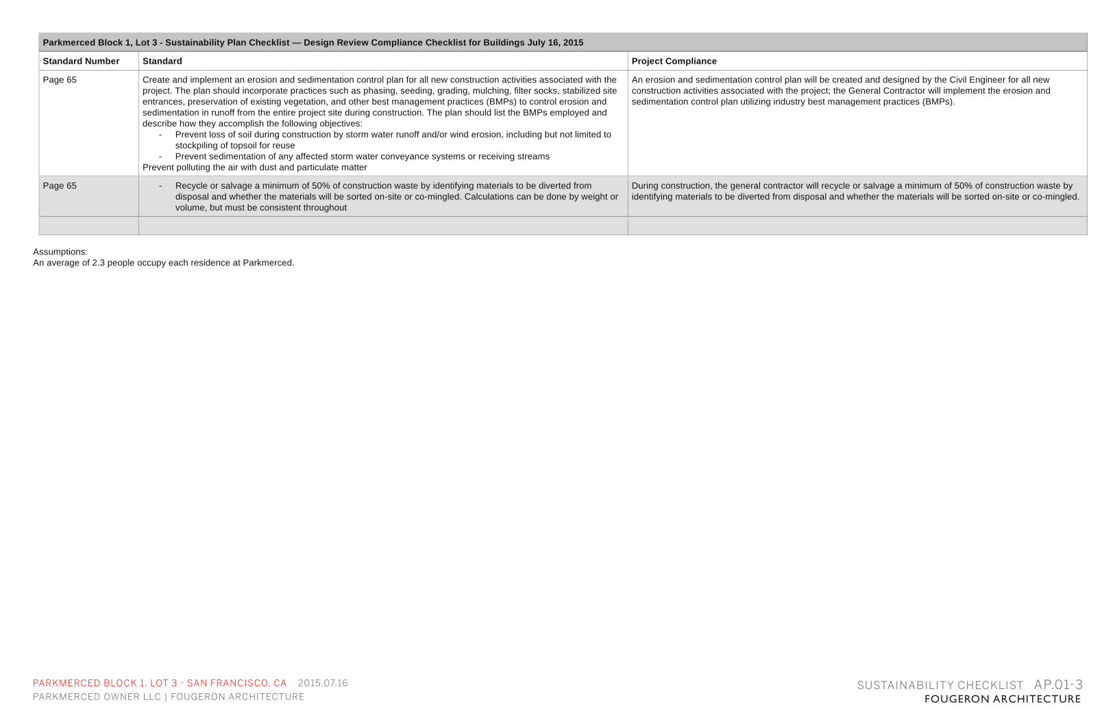
Parkmerced Block 1, Lot 3 - Sustainability Plan Checklist — Design Review Compliance Checklist for Buildings July 16, 2015
Standard Number Standard Project Compliance
Page 65 Create and implement an erosion and sedimentation control plan for all new construction activities associated with the project. The plan should incorporate practices such as phasing, seeding, grading, mulching, filter socks, stabilized site entrances, preservation of existing vegetation, and other best management practices (BMPs) to control erosion and sedimentation in runoff from the entire project site during construction. The plan should list the BMPs employed and describe how they accomplish the following objectives:
- Prevent loss of soil during construction by storm water runoff and/or wind erosion, including but not limited to stockpiling of topsoil for reuse
- Prevent sedimentation of any affected storm water conveyance systems or receiving streams Prevent polluting the air with dust and particulate matter
An erosion and sedimentation control plan will be created and designed by the Civil Engineer for all new construction activities associated with the project; the General Contractor will implement the erosion and sedimentation control plan utilizing industry best management practices (BMPs).
Page 65 - Recycle or salvage a minimum of 50% of construction waste by identifying materials to be diverted from disposal and whether the materials will be sorted on-site or co-mingled. Calculations can be done by weight or volume, but must be consistent throughout
During construction, the general contractor will recycle or salvage a minimum of 50% of construction waste by identifying materials to be diverted from disposal and whether the materials will be sorted on-site or co-mingled.
Assumptions: An average of 2.3 people occupy each residence at Parkmerced.
SUSTAINABILITY CHECKLIST AP.01-3

THIS PAGE LEFT INTENTIONALLY BLANK
PARKMERCED BLOCK 1, LOT 3 - SAN FRANCISCO, CA 2015.07.16
PARKMERCED OWNER LLC | FOUGERON ARCHITECTURE FOUGERON ARCHITECTUREDESIGN STANDARDS AND GUIDELINES CHECKLIST AP.02-1
Parkmerced Block 1, Lot 3 Design Standards and Guidelines — Design Review Compliance Checklist for Buildings July 16, 2015
Standard Number Standard Project Compliance Implementing Standards
03.01.01 Sustainability Performance
All buildings shall meet or exceed the requirements of the Parkmerced Sustainability Plan.
See sustainability Checklist
03.02.01 - 03.02.02 Lot Coverage
Lot coverage is calculated for each development block and is specifically listed in Appendix A of the Design Standards and Guidelines - Regulating Plan.
Fougeron Footprint Area= 15,495 s.f. LMS Footprint Area= 11,803 s.f. Existing Towers= 29,557 s.f. Total Footprint Area= 203,888 s.f. Lot Coverage= 27.9% per Appendix A
Percentage of lot coverage is defined as the total enclosed building footprint area divided by the total development block area. Designated public open spaces, such as Neighborhood Commons, are excluded from lot coverage calculations. Building encroachments, projections and obstructions as defined in Section 03.05 Building Controls - Setback are not included in the total enclosed building footprint area calculation. However, those portions of a pedestrian paseo that pass below occupied building area must be included in the total building footprint area. (03.02.02)
03.02.03 Usable Open Space
48 square feet of common open space or 36 square feet of private open space per unit. Both common and private open spaces must have a minimum dimension of 6 feet in any direction.
Common open space at central courtyard: 11,040 s.f. 11,040 s.f./64 units =172.5 s.f. per unit. See A1.03. First Floor Site Plan.
Courtyards and rooftop terraces shall count towards the provision of common open space. Setback areas, balconies and decks shall count towards the provision of private open space.
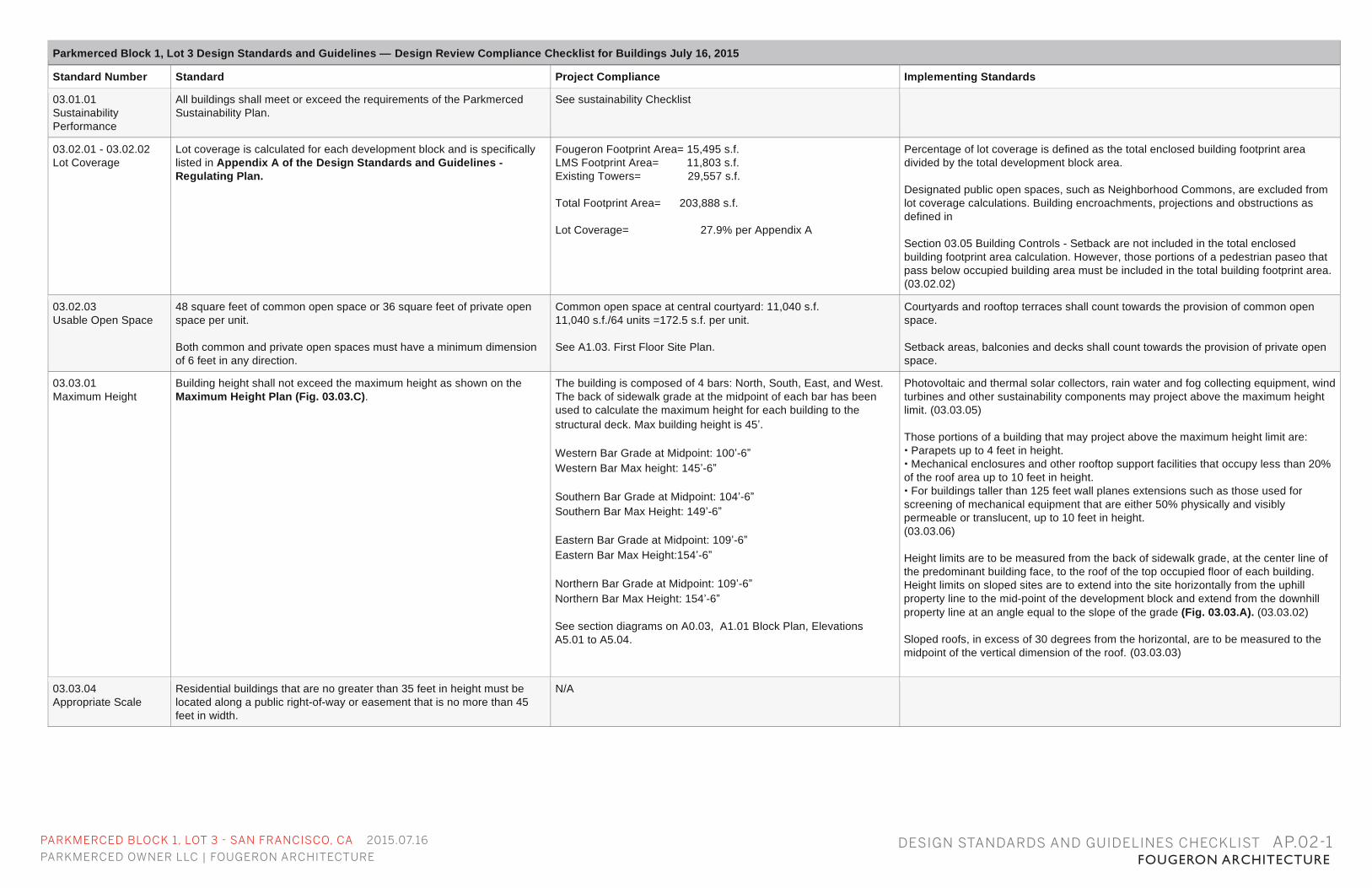
03.03.01 Maximum Height
Building height shall not exceed the maximum height as shown on the Maximum Height Plan (Fig. 03.03.C).
The building is composed of 4 bars: North, South, East, and West. The back of sidewalk grade at the midpoint of each bar has been used to calculate the maximum height for each building to the structural deck. Max building height is 45’. Western Bar Grade at Midpoint: 100’-6” Western Bar Max height: 145’-6” Southern Bar Grade at Midpoint: 104’-6” Southern Bar Max Height: 149’-6” Eastern Bar Grade at Midpoint: 109’-6” Eastern Bar Max Height:154’-6” Northern Bar Grade at Midpoint: 109’-6” Northern Bar Max Height: 154’-6” See section diagrams on A0.03, A1.01 Block Plan, Elevations A5.01 to A5.04.
Photovoltaic and thermal solar collectors, rain water and fog collecting equipment, wind turbines and other sustainability components may project above the maximum height limit. (03.03.05) Those portions of a building that may project above the maximum height limit are: • Parapets up to 4 feet in height. • Mechanical enclosures and other rooftop support facilities that occupy less than 20% of the roof area up to 10 feet in height. • For buildings taller than 125 feet wall planes extensions such as those used for screening of mechanical equipment that are either 50% physically and visibly permeable or translucent, up to 10 feet in height. (03.03.06) Height limits are to be measured from the back of sidewalk grade, at the center line of the predominant building face, to the roof of the top occupied floor of each building. Height limits on sloped sites are to extend into the site horizontally from the uphill property line to the mid-point of the development block and extend from the downhill property line at an angle equal to the slope of the grade (Fig. 03.03.A). (03.03.02) Sloped roofs, in excess of 30 degrees from the horizontal, are to be measured to the midpoint of the vertical dimension of the roof. (03.03.03)
03.03.04 Appropriate Scale
Residential buildings that are no greater than 35 feet in height must be located along a public right-of-way or easement that is no more than 45 feet in width.
N/A
PARKMERCED BLOCK 1, LOT 3 - SAN FRANCISCO, CA 2015.07.16
PARKMERCED OWNER LLC | FOUGERON ARCHITECTURE FOUGERON ARCHITECTURE
Parkmerced Block 1, Lot 3 Design Standards and Guidelines — Design Review Compliance Checklist for Buildings July 16, 2015
Standard Number Standard Project Compliance Implementing Standards
03.03.06 Projections
Those portions of a building that may project above the maximum height limit are: •Parapets up to 4 feet in height. •Mechanical enclosures and other rooftop support facilities that occupy less than 20% of the roof area up to 10 feet in height. •For buildings taller than 125 feet wall planes extensions such as those used for screening of mechanical equipment that are either 50% physically and visibly permeable or translucent, up to 10 feet in height.
Western Bar Max Parapet Height: 149’-6” Western Bar Max Mechanical Height: 155’-6” Southern Bar Max Parapet Height: 153’-6” Southern Bar max Mechanical Height: 159’-6” Eastern Bar Max Parapet Height: 158’-6” Eastern Bar Max Mechanical Height: 164’-6” Northern Bar Max Parapet Height: 158’-6” Northern Bar Max Mechanical Height: 164’-6” See Diagrams A0.03.
03.04.02 Maximum Plan Dimension
Building Height Max Plan Length Up to 35’ NA 36’ – 45’ NA 46’ – 85’ 200’ 86’ – 145’ 140’
NA. Building is 45’ tall.
03.04.03 Maximum Diagonal
Building Height Max Diagonal Up to 35’ NA 36’ – 45’ NA 46’ – 85’ NA 86’ – 145’ 170’
NA. Building is 45’ tall.
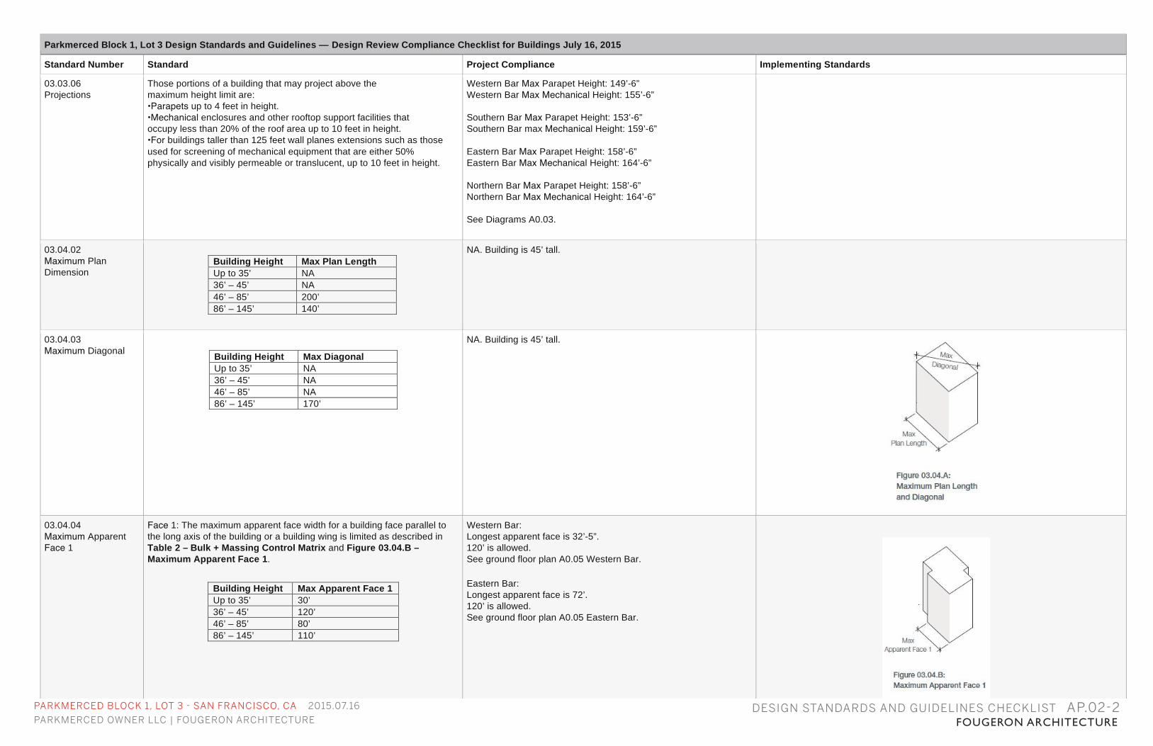
03.04.04 Maximum Apparent Face 1
Face 1: The maximum apparent face width for a building face parallel to the long axis of the building or a building wing is limited as described in Table 2 – Bulk + Massing Control Matrix and Figure 03.04.B – Maximum Apparent Face 1.
Building Height Max Apparent Face 1 Up to 35’ 30’ 36’ – 45’ 120’ 46’ – 85’ 80’ 86’ – 145’ 110’
Western Bar: Longest apparent face is 32’-5”. 120’ is allowed. See ground floor plan A0.05 Western Bar. Eastern Bar: Longest apparent face is 72’. 120’ is allowed. See ground floor plan A0.05 Eastern Bar.
DESIGN STANDARDS AND GUIDELINES CHECKLIST AP.02-2
PARKMERCED BLOCK 1, LOT 3 - SAN FRANCISCO, CA 2015.07.16
PARKMERCED OWNER LLC | FOUGERON ARCHITECTURE FOUGERON ARCHITECTURE
Parkmerced Block 1, Lot 3 Design Standards and Guidelines — Design Review Compliance Checklist for Buildings July 16, 2015
Standard Number Standard Project Compliance Implementing Standards
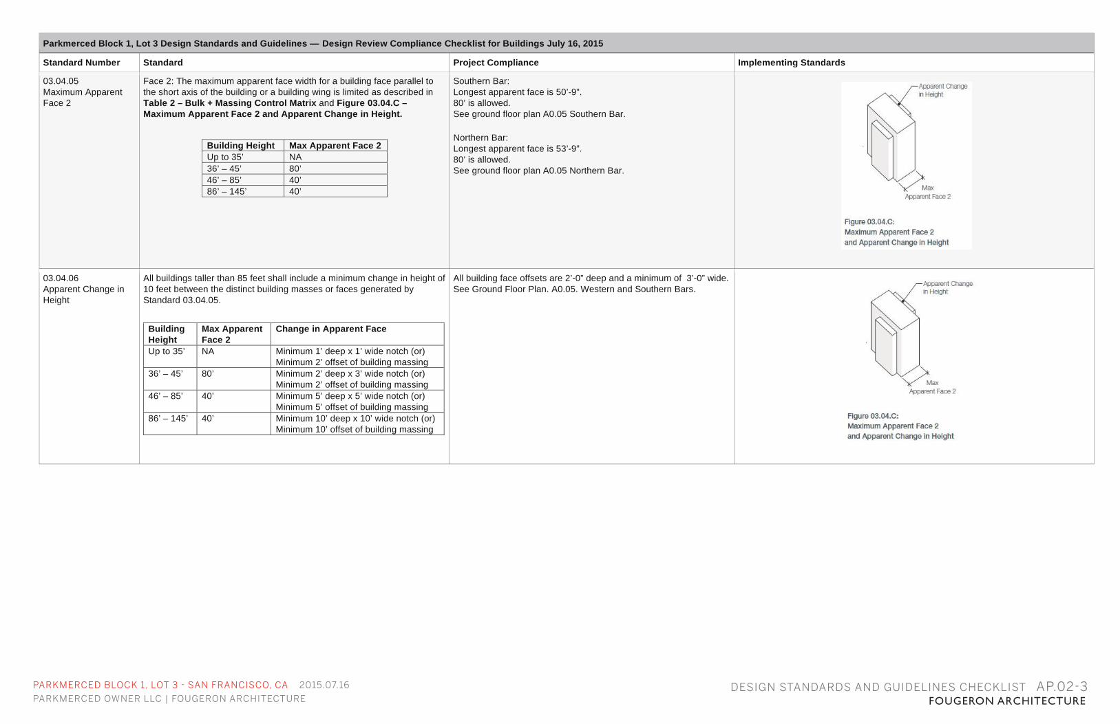
03.04.05 Maximum Apparent Face 2
Face 2: The maximum apparent face width for a building face parallel to the short axis of the building or a building wing is limited as described in Table 2 – Bulk + Massing Control Matrix and Figure 03.04.C – Maximum Apparent Face 2 and Apparent Change in Height.
Building Height Max Apparent Face 2 Up to 35’ NA 36’ – 45’ 80’ 46’ – 85’ 40’ 86’ – 145’ 40’
Southern Bar: Longest apparent face is 50’-9”. 80’ is allowed. See ground floor plan A0.05 Southern Bar. Northern Bar: Longest apparent face is 53’-9”. 80’ is allowed. See ground floor plan A0.05 Northern Bar.
03.04.06 Apparent Change in Height
All buildings taller than 85 feet shall include a minimum change in height of 10 feet between the distinct building masses or faces generated by Standard 03.04.05.
Building Height
Max Apparent Face 2
Change in Apparent Face
Up to 35’ NA Minimum 1’ deep x 1’ wide notch (or) Minimum 2’ offset of building massing
36’ – 45’ 80’ Minimum 2’ deep x 3’ wide notch (or) Minimum 2’ offset of building massing
46’ – 85’ 40’ Minimum 5’ deep x 5’ wide notch (or) Minimum 5’ offset of building massing
86’ – 145’ 40’ Minimum 10’ deep x 10’ wide notch (or) Minimum 10’ offset of building massing
All building face offsets are 2’-0” deep and a minimum of 3’-0” wide. See Ground Floor Plan. A0.05. Western and Southern Bars.
DESIGN STANDARDS AND GUIDELINES CHECKLIST AP.02-3
PARKMERCED BLOCK 1, LOT 3 - SAN FRANCISCO, CA 2015.07.16
PARKMERCED OWNER LLC | FOUGERON ARCHITECTURE FOUGERON ARCHITECTUREDESIGN STANDARDS AND GUIDELINES CHECKLIST AP.02-4
Parkmerced Block 1, Lot 3 Design Standards and Guidelines — Design Review Compliance Checklist for Buildings July 16, 2015
Standard Number Standard Project Compliance Implementing Standards
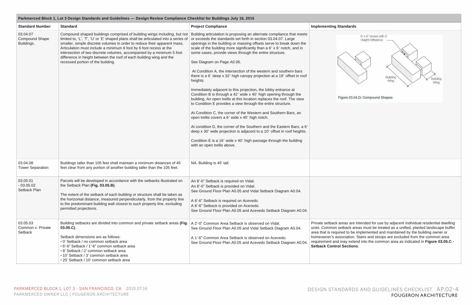
03.04.07 Compound Shape Buildings.
Compound shaped buildings comprised of building wings including, but not limited to, ‘L’, ‘T’, ‘U’ or ‘E’ shaped plans shall be articulated into a series of smaller, simple discrete volumes in order to reduce their apparent mass. Articulation must include a minimum 6 foot by 6 foot recess at the intersection of two discrete volumes, accompanied by a minimum 5 foot difference in height between the roof of each building wing and the recessed portion of the building.
Building articulation is proposing an alternate compliance that meets or exceeds the standards set forth in section 03.04.07. Large openings in the building or massing offsets serve to break down the scale of the building more significantly than a 6’ x 6’ notch, and in some cases, provide views through the entire structure. See Diagram on Page A0.06. At Condition A, the intersection of the western and southern bars there is a 6’ deep x 32’ high canopy projection at a 19’ offset in roof heights. Immediately adjacent to this projection, the lobby entrance at Condition B is through a 42’ wide x 40’ high opening through the building. An open trellis at this location replaces the roof. The view to Condition E provides a view through the entire structure. At Condition C, the corner of the Western and Southern Bars, an open trellis covers a 6’ wide x 40’ high notch. At condition D, the corner of the Southern and the Eastern Bars, a 6’ deep x 30’ wide projection is adjacent to a 10’ offset in roof heights. Condition E is a 16’ wide x 40’ high passage through the building with an open trellis above.
03.04.08 Tower Separation
Buildings taller than 105 feet shall maintain a minimum distances of 45 feet clear from any portion of another building taller than the 105 feet.
NA. Building is 45’ tall.
03.05.01 - 03.05.02 Setback Plan
Parcels will be developed in accordance with the setbacks illustrated on the Setback Plan (Fig. 03.05.B). The extent of the setback of each building or structure shall be taken as the horizontal distance, measured perpendicularly, from the property line to the predominant building wall closest to such property line, excluding permitted projections.
An 8’-0” Setback is required on Vidal. An 8’-0” Setback is provided on Vidal. See Ground Floor Plan A0.05 and Vidal Setback Diagram A0.04. A 6’-6” Setback is required on Acevedo. A 6’-6” Setback is provided on Acevedo. See Ground Floor Plan A0.05 and Acevedo Setback Diagram A0.04.
03.05.03 Common v. Private Setback
Building setbacks are divided into common and private setback areas (Fig. 03.05.C). Setback dimensions are as follows: • 0’ Setback / no common setback area • 6’-6” Setback / 1’-6” common setback area • 8’ Setback / 2’ common setback area • 10’ Setback / 3’ common setback area • 20’ Setback / 10’ common setback area
A 2’-0” Common Area Setback is observed on Vidal. See Ground Floor Plan A0.05 and Vidal Setback Diagram A0.04. A 1’-6” Common Area Setback is observed on Acevedo. See Ground Floor Plan A0.05 and Acevedo Setback Diagram A0.04.
Private setback areas are intended for use by adjacent individual residential dwelling units. Common setback areas must be treated as a unified, planted landscape buffer area that is required to be implemented and maintained by the building owner or homeowner’s association. Stairs and stoops are excluded from the common area requirement and may extend into the common area as indicated in Figure 03.05.C - Setback Control Sections.
PARKMERCED BLOCK 1, LOT 3 - SAN FRANCISCO, CA 2015.07.16
PARKMERCED OWNER LLC | FOUGERON ARCHITECTURE FOUGERON ARCHITECTUREDESIGN STANDARDS AND GUIDELINES CHECKLIST AP.02-5
Parkmerced Block 1, Lot 3 Design Standards and Guidelines — Design Review Compliance Checklist for Buildings July 16, 2015
Standard Number Standard Project Compliance Implementing Standards
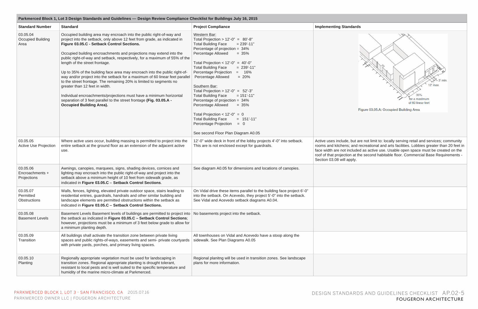
03.05.04 Occupied Building Area
Occupied building area may encroach into the public right-of-way and project into the setback, only above 12 feet from grade, as indicated in Figure 03.05.C - Setback Control Sections. Occupied building encroachments and projections may extend into the public right-of-way and setback, respectively, for a maximum of 55% of the length of the street frontage. Up to 35% of the building face area may encroach into the public right-of-way and/or project into the setback for a maximum of 60 linear feet parallel to the street frontage. The remaining 20% is limited to segments no greater than 12 feet in width. Individual encroachments/projections must have a minimum horizontal separation of 3 feet parallel to the street frontage (Fig. 03.05.A - Occupied Building Area).
Western Bar: Total Projection > 12’-0” = 80’-8” Total Building Face = 239’-11” Percentage of projection = 34% Percentage Allowed = 35% Total Projection < 12’-0” = 40’-0” Total Building Face = 239’-11” Percentage Projection = 16% Percentage Allowed = 20% Southern Bar: Total Projection > 12’-0” = 52’-3” Total Building Face = 151’-11” Percentage of projection = 34% Percentage Allowed = 35% Total Projection < 12’-0” = 0 Total Building Face = 151’-11” Percentage Projection = 0 See second Floor Plan Diagram A0.05
03.05.05 Active Use Projection
Where active uses occur, building massing is permitted to project into the entire setback at the ground floor as an extension of the adjacent active use.
12’-0” wide deck in front of the lobby projects 4’-0” into setback. This are is not enclosed except for guardrails.
Active uses include, but are not limit to: locally serving retail and services; community rooms and kitchens; and recreational and arts facilities. Lobbies greater than 20 feet in face width are not included as active use. Usable open space must be created on the roof of that projection at the second habitable floor. Commercial Base Requirements - Section 03.08 will apply.
03.05.06 Encroachments + Projections
Awnings, canopies, marquees, signs, shading devices, cornices and lighting may encroach into the public right-of-way and project into the setback above a minimum height of 10 feet from sidewalk grade, as indicated in Figure 03.05.C – Setback Control Sections.
See diagram A0.05 for dimensions and locations of canopies.
03.05.07 Permitted Obstructions
Walls, fences, lighting, elevated private outdoor space, stairs leading to residential entries, guardrails, handrails and other similar building and landscape elements are permitted obstructions within the setback as indicated in Figure 03.05.C – Setback Control Sections.
On Vidal drive these items parallel to the building face project 6’-0” into the setback. On Acevedo, they project 5’-0” into the setback. See Vidal and Acevedo setback diagrams A0.04.
03.05.08 Basement Levels
Basement Levels Basement levels of buildings are permitted to project into the setback as indicated in Figure 03.05.C – Setback Control Sections; however, projections must be a minimum of 3 feet below grade to allow for a minimum planting depth.
No basements project into the setback.
03.05.09 Transition
All buildings shall activate the transition zone between private living spaces and public rights-of-ways, easements and semi- private courtyards with private yards, porches, and primary living spaces.
All townhouses on Vidal and Acevedo have a stoop along the sidewalk. See Plan Diagrams A0.05
03.05.10 Planting
Regionally appropriate vegetation must be used for landscaping in transition zones. Regional appropriate planting is drought tolerant, resistant to local pests and is well suited to the specific temperature and humidity of the marine micro-climate at Parkmerced.
Regional planitng will be used in transition zones. See landscape plans for more information.
PARKMERCED BLOCK 1, LOT 3 - SAN FRANCISCO, CA 2015.07.16
PARKMERCED OWNER LLC | FOUGERON ARCHITECTURE FOUGERON ARCHITECTUREDESIGN STANDARDS AND GUIDELINES CHECKLIST AP.02-6
Parkmerced Block 1, Lot 3 Design Standards and Guidelines — Design Review Compliance Checklist for Buildings July 16, 2015
Standard Number Standard Project Compliance Implementing Standards
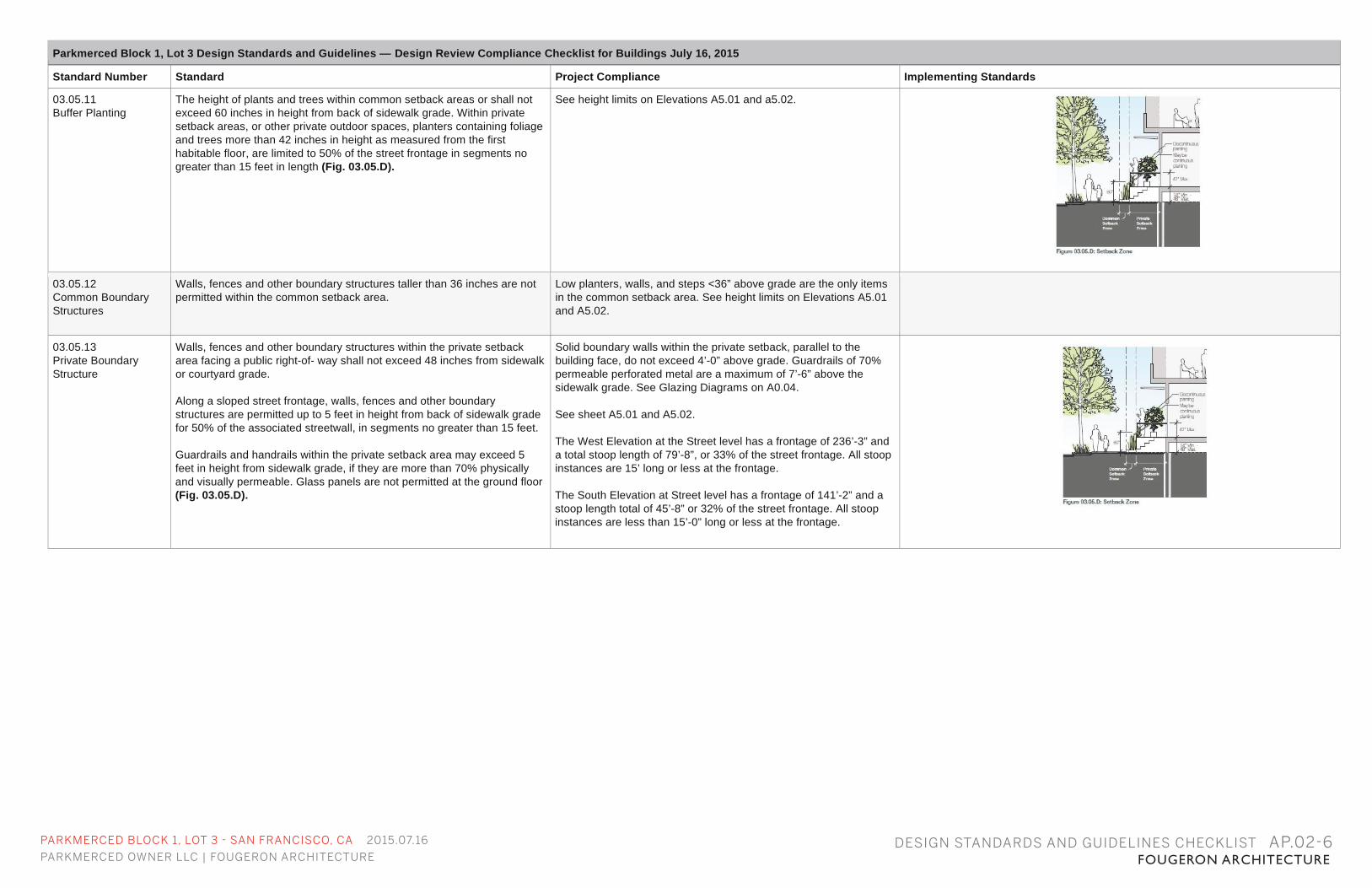
03.05.11 Buffer Planting
The height of plants and trees within common setback areas or shall not exceed 60 inches in height from back of sidewalk grade. Within private setback areas, or other private outdoor spaces, planters containing foliage and trees more than 42 inches in height as measured from the first habitable floor, are limited to 50% of the street frontage in segments no greater than 15 feet in length (Fig. 03.05.D).
See height limits on Elevations A5.01 and a5.02.
03.05.12 Common Boundary Structures
Walls, fences and other boundary structures taller than 36 inches are not permitted within the common setback area.
Low planters, walls, and steps <36” above grade are the only items in the common setback area. See height limits on Elevations A5.01 and A5.02.
03.05.13 Private Boundary Structure
Walls, fences and other boundary structures within the private setback area facing a public right-of- way shall not exceed 48 inches from sidewalk or courtyard grade. Along a sloped street frontage, walls, fences and other boundary structures are permitted up to 5 feet in height from back of sidewalk grade for 50% of the associated streetwall, in segments no greater than 15 feet. Guardrails and handrails within the private setback area may exceed 5 feet in height from sidewalk grade, if they are more than 70% physically and visually permeable. Glass panels are not permitted at the ground floor (Fig. 03.05.D).
Solid boundary walls within the private setback, parallel to the building face, do not exceed 4’-0” above grade. Guardrails of 70% permeable perforated metal are a maximum of 7’-6” above the sidewalk grade. See Glazing Diagrams on A0.04. See sheet A5.01 and A5.02. The West Elevation at the Street level has a frontage of 236’-3” and a total stoop length of 79’-8”, or 33% of the street frontage. All stoop instances are 15’ long or less at the frontage. The South Elevation at Street level has a frontage of 141’-2” and a stoop length total of 45’-8” or 32% of the street frontage. All stoop instances are less than 15’-0” long or less at the frontage.
PARKMERCED BLOCK 1, LOT 3 - SAN FRANCISCO, CA 2015.07.16
PARKMERCED OWNER LLC | FOUGERON ARCHITECTURE FOUGERON ARCHITECTURE
Parkmerced Block 1, Lot 3 Design Standards and Guidelines — Design Review Compliance Checklist for Buildings July 16, 2015
Standard Number Standard Project Compliance Implementing Standards
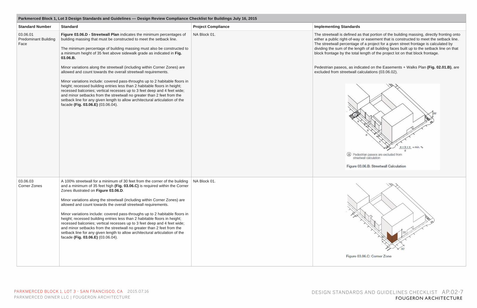
03.06.01 Predominant Building Face
Figure 03.06.D - Streetwall Plan indicates the minimum percentages of building massing that must be constructed to meet the setback line. The minimum percentage of building massing must also be constructed to a minimum height of 35 feet above sidewalk grade as indicated in Fig. 03.06.B. Minor variations along the streetwall (including within Corner Zones) are allowed and count towards the overall streetwall requirements. Minor variations include: covered pass-throughs up to 2 habitable floors in height; recessed building entries less than 2 habitable floors in height; recessed balconies; vertical recesses up to 3 feet deep and 4 feet wide; and minor setbacks from the streetwall no greater than 2 feet from the setback line for any given length to allow architectural articulation of the facade (Fig. 03.06.E) (03.06.04).
NA Block 01. The streetwall is defined as that portion of the building massing, directly fronting onto either a public right-of-way or easement that is constructed to meet the setback line. The streetwall percentage of a project for a given street frontage is calculated by dividing the sum of the length of all building faces built up to the setback line on that block frontage by the total length of the project lot on that block frontage. Pedestrian paseos, as indicated on the Easements + Walks Plan (Fig. 02.01.B), are excluded from streetwall calculations (03.06.02).
03.06.03 Corner Zones
A 100% streetwall for a minimum of 30 feet from the corner of the building and a minimum of 35 feet high (Fig. 03.06.C) is required within the Corner Zones illustrated on Figure 03.06.D. Minor variations along the streetwall (including within Corner Zones) are allowed and count towards the overall streetwall requirements. Minor variations include: covered pass-throughs up to 2 habitable floors in height; recessed building entries less than 2 habitable floors in height; recessed balconies; vertical recesses up to 3 feet deep and 4 feet wide; and minor setbacks from the streetwall no greater than 2 feet from the setback line for any given length to allow architectural articulation of the facade (Fig. 03.06.E) (03.06.04).
NA Block 01.
DESIGN STANDARDS AND GUIDELINES CHECKLIST AP.02-7
PARKMERCED BLOCK 1, LOT 3 - SAN FRANCISCO, CA 2015.07.16
PARKMERCED OWNER LLC | FOUGERON ARCHITECTURE FOUGERON ARCHITECTUREDESIGN STANDARDS AND GUIDELINES CHECKLIST AP.02-8
Parkmerced Block 1, Lot 3 Design Standards and Guidelines — Design Review Compliance Checklist for Buildings July 16, 2015
Standard Number Standard Project Compliance Implementing Standards
03.06.05 Building Base Articulation
At a minimum, all buildings must articulate the first habitable floor with a finer grain of architectural detailing to enhance the pedestrian experience. Buildings taller than 50 feet must articulate the first two habitable floors with a finer grain of architectural detailing. This may include, but is not limited to, architectural elements such as canopies, awnings, overhangs, projections, recesses, greater dimensional depth of facade elements, and material and surface change and texture (Fig. 03.06.F).
The façade is perforated with a series of notches at the ground floor, covered by balconies above. Stoops, stairs, and railings provide a finer grain of architectural detail at the ground floor. See A0.05, A5.01, and A5.02.
03.06.06 Active Ground Floors
Buildings taller than 65 feet and adjacent to Neighborhood Commons must include active ground floor uses that are visible from and oriented towards the neighborhood commons (Fig. 03.06.G). Active uses include, but are not limit to: locally serving retail and services; community rooms and kitchens; and recreational and arts facilities. Lobbies greater than 20 feet in face width are not included as active use.
NA, building is 45’ tall.
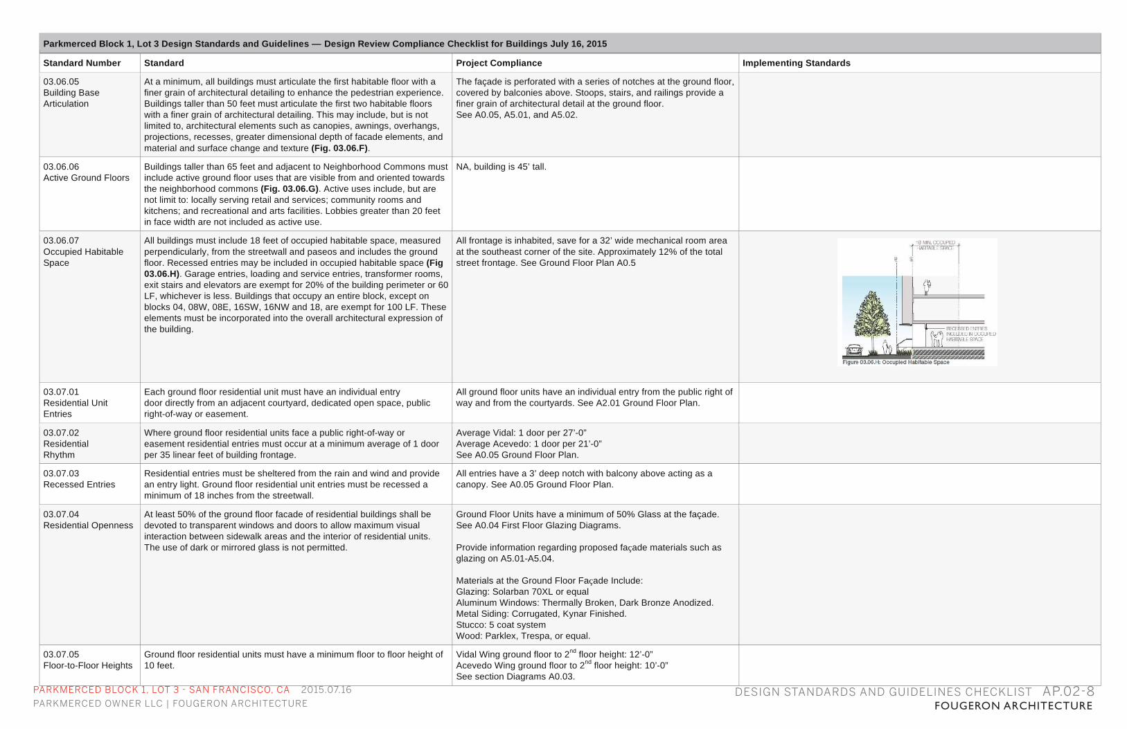
03.06.07 Occupied Habitable Space
All buildings must include 18 feet of occupied habitable space, measured perpendicularly, from the streetwall and paseos and includes the ground floor. Recessed entries may be included in occupied habitable space (Fig 03.06.H). Garage entries, loading and service entries, transformer rooms, exit stairs and elevators are exempt for 20% of the building perimeter or 60 LF, whichever is less. Buildings that occupy an entire block, except on blocks 04, 08W, 08E, 16SW, 16NW and 18, are exempt for 100 LF. These elements must be incorporated into the overall architectural expression of the building.
All frontage is inhabited, save for a 32’ wide mechanical room area at the southeast corner of the site. Approximately 12% of the total street frontage. See Ground Floor Plan A0.5
03.07.01 Residential Unit Entries
Each ground floor residential unit must have an individual entry door directly from an adjacent courtyard, dedicated open space, public right-of-way or easement.
All ground floor units have an individual entry from the public right of way and from the courtyards. See A2.01 Ground Floor Plan.
03.07.02 Residential Rhythm
Where ground floor residential units face a public right-of-way or easement residential entries must occur at a minimum average of 1 door per 35 linear feet of building frontage.
Average Vidal: 1 door per 27’-0” Average Acevedo: 1 door per 21’-0” See A0.05 Ground Floor Plan.
03.07.03 Recessed Entries
Residential entries must be sheltered from the rain and wind and provide an entry light. Ground floor residential unit entries must be recessed a minimum of 18 inches from the streetwall.
All entries have a 3’ deep notch with balcony above acting as a canopy. See A0.05 Ground Floor Plan.
03.07.04 Residential Openness
At least 50% of the ground floor facade of residential buildings shall be devoted to transparent windows and doors to allow maximum visual interaction between sidewalk areas and the interior of residential units. The use of dark or mirrored glass is not permitted.
Ground Floor Units have a minimum of 50% Glass at the façade. See A0.04 First Floor Glazing Diagrams. Provide information regarding proposed façade materials such as glazing on A5.01-A5.04. Materials at the Ground Floor Façade Include: Glazing: Solarban 70XL or equal Aluminum Windows: Thermally Broken, Dark Bronze Anodized. Metal Siding: Corrugated, Kynar Finished. Stucco: 5 coat system Wood: Parklex, Trespa, or equal.
03.07.05 Floor-to-Floor Heights
Ground floor residential units must have a minimum floor to floor height of 10 feet.
Vidal Wing ground floor to 2nd floor height: 12’-0” Acevedo Wing ground floor to 2nd floor height: 10’-0” See section Diagrams A0.03.
PARKMERCED BLOCK 1, LOT 3 - SAN FRANCISCO, CA 2015.07.16
PARKMERCED OWNER LLC | FOUGERON ARCHITECTURE FOUGERON ARCHITECTUREDESIGN STANDARDS AND GUIDELINES CHECKLIST AP.02-9
Parkmerced Block 1, Lot 3 Design Standards and Guidelines — Design Review Compliance Checklist for Buildings July 16, 2015
Standard Number Standard Project Compliance Implementing Standards
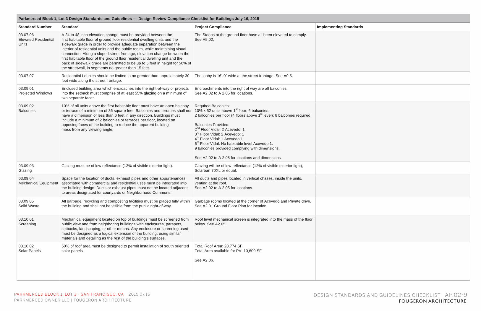
03.07.06 Elevated Residential Units
A 24 to 48 inch elevation change must be provided between the first habitable floor of ground floor residential dwelling units and the sidewalk grade in order to provide adequate separation between the interior of residential units and the public realm, while maintaining visual connection. Along a sloped street frontage, elevation change between the first habitable floor of the ground floor residential dwelling unit and the back of sidewalk grade are permitted to be up to 5 feet in height for 50% of the streetwall, in segments no greater than 15 feet.
The Stoops at the ground floor have all been elevated to comply. See A5.02.
03.07.07 Residential Lobbies should be limited to no greater than approximately 30 feet wide along the street frontage.
The lobby is 16’-0” wide at the street frontage. See A0.5.
03.09.01 Projected Windows
Enclosed building area which encroaches into the right-of-way or projects into the setback must comprise of at least 55% glazing on a minimum of two separate faces.
Encroachments into the right of way are all balconies. See A2.02 to A 2.05 for locations.
03.09.02 Balconies
10% of all units above the first habitable floor must have an open balcony or terrace of a minimum of 36 square feet. Balconies and terraces shall not have a dimension of less than 6 feet in any direction. Buildings must include a minimum of 2 balconies or terraces per floor, located on opposing faces of the building to reduce the apparent building mass from any viewing angle.
Required Balconies: 10% x 52 units above 1st floor: 6 balconies. 2 balconies per floor (4 floors above 1st level): 8 balconies required. Balconies Provided: 2nd Floor Vidal: 2 Acevedo: 1 3rd Floor Vidal: 2 Acevedo: 1 4th Floor Vidal: 1 Acevedo 1 5th Floor Vidal: No habitable level Acevedo 1. 9 balconies provided complying with dimensions. See A2.02 to A 2.05 for locations and dimensions.
03.09.03 Glazing
Glazing must be of low reflectance (12% of visible exterior light). Glazing will be of low reflectance (12% of visible exterior light), Solarban 70XL or equal.
03.09.04 Mechanical Equipment
Space for the location of ducts, exhaust pipes and other appurtenances associated with commercial and residential uses must be integrated into the building design. Ducts or exhaust pipes must not be located adjacent to areas designated for courtyards or Neighborhood Commons.
All ducts and pipes located in vertical chases, inside the units, venting at the roof. See A2.02 to A 2.05 for locations.
03.09.05 Solid Waste
All garbage, recycling and composting facilities must be placed fully within the building and shall not be visible from the public right-of-way.
Garbage rooms located at the corner of Acevedo and Private drive. See A2.01 Ground Floor Plan for location.
03.10.01 Screening
Mechanical equipment located on top of buildings must be screened from public view and from neighboring buildings with enclosures, parapets, setbacks, landscaping, or other means. Any enclosure or screening used must be designed as a logical extension of the building, using similar materials and detailing as the rest of the building’s surfaces.
Roof level mechanical screen is integrated into the mass of the floor below. See A2.05.
03.10.02 Solar Panels
50% of roof area must be designed to permit installation of south oriented solar panels.
Total Roof Area: 20,774 SF. Total Area available for PV: 10,600 SF See A2.06.
PARKMERCED BLOCK 1, LOT 3 - SAN FRANCISCO, CA 2015.07.16
PARKMERCED OWNER LLC | FOUGERON ARCHITECTURE FOUGERON ARCHITECTUREDESIGN STANDARDS AND GUIDELINES CHECKLIST AP.02-10
Parkmerced Block 1, Lot 3 Design Standards and Guidelines — Design Review Compliance Checklist for Buildings July 16, 2015
Standard Number Standard Project Compliance Implementing Standards
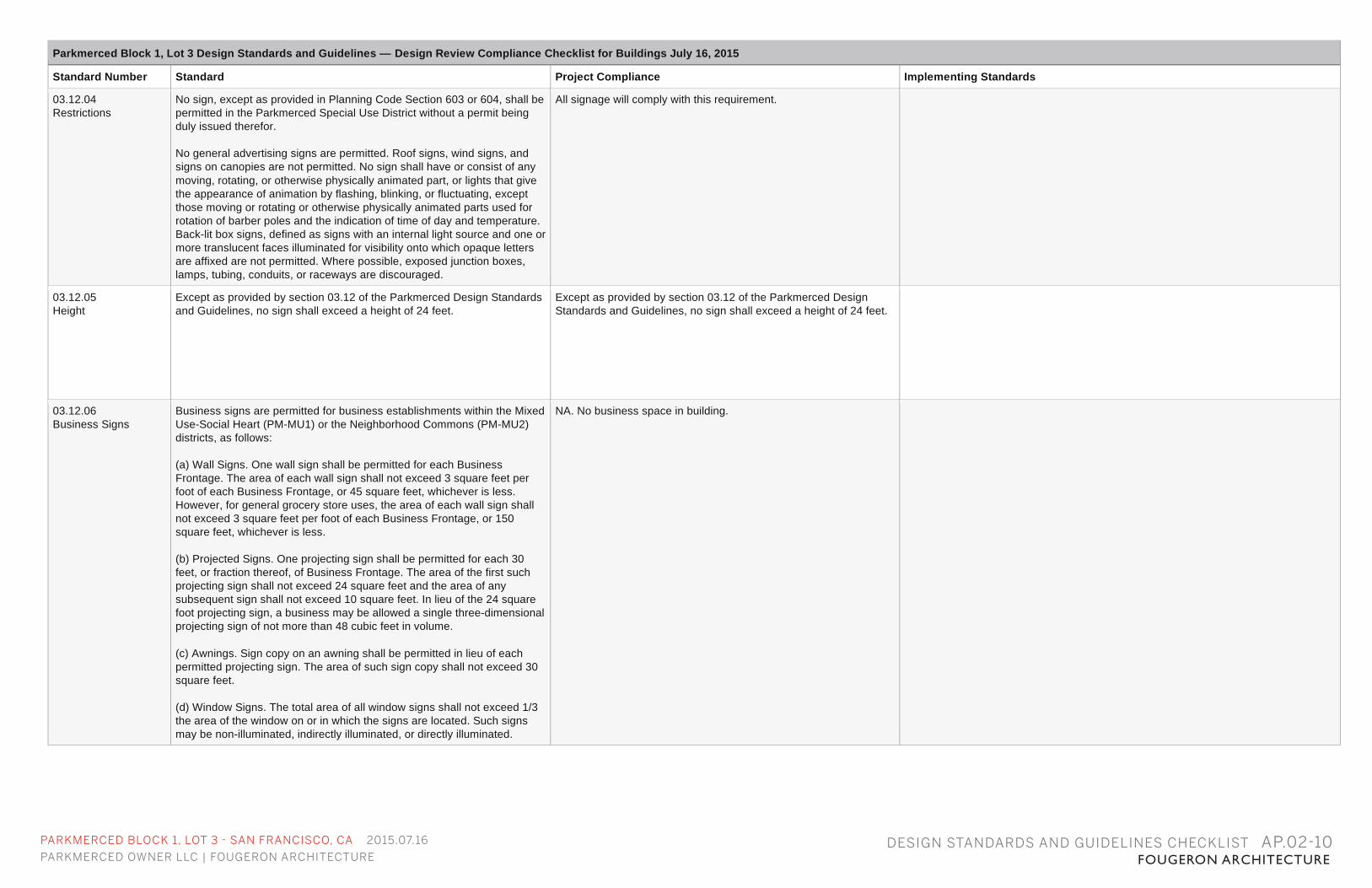
03.12.04 Restrictions
No sign, except as provided in Planning Code Section 603 or 604, shall be permitted in the Parkmerced Special Use District without a permit being duly issued therefor. No general advertising signs are permitted. Roof signs, wind signs, and signs on canopies are not permitted. No sign shall have or consist of any moving, rotating, or otherwise physically animated part, or lights that give the appearance of animation by flashing, blinking, or fluctuating, except those moving or rotating or otherwise physically animated parts used for rotation of barber poles and the indication of time of day and temperature. Back-lit box signs, defined as signs with an internal light source and one or more translucent faces illuminated for visibility onto which opaque letters are affixed are not permitted. Where possible, exposed junction boxes, lamps, tubing, conduits, or raceways are discouraged.
All signage will comply with this requirement.
03.12.05 Height
Except as provided by section 03.12 of the Parkmerced Design Standards and Guidelines, no sign shall exceed a height of 24 feet.
Except as provided by section 03.12 of the Parkmerced Design Standards and Guidelines, no sign shall exceed a height of 24 feet.
03.12.06 Business Signs
Business signs are permitted for business establishments within the Mixed Use-Social Heart (PM-MU1) or the Neighborhood Commons (PM-MU2) districts, as follows: (a) Wall Signs. One wall sign shall be permitted for each Business Frontage. The area of each wall sign shall not exceed 3 square feet per foot of each Business Frontage, or 45 square feet, whichever is less. However, for general grocery store uses, the area of each wall sign shall not exceed 3 square feet per foot of each Business Frontage, or 150 square feet, whichever is less. (b) Projected Signs. One projecting sign shall be permitted for each 30 feet, or fraction thereof, of Business Frontage. The area of the first such projecting sign shall not exceed 24 square feet and the area of any subsequent sign shall not exceed 10 square feet. In lieu of the 24 square foot projecting sign, a business may be allowed a single three-dimensional projecting sign of not more than 48 cubic feet in volume. (c) Awnings. Sign copy on an awning shall be permitted in lieu of each permitted projecting sign. The area of such sign copy shall not exceed 30 square feet. (d) Window Signs. The total area of all window signs shall not exceed 1/3 the area of the window on or in which the signs are located. Such signs may be non-illuminated, indirectly illuminated, or directly illuminated.
NA. No business space in building.
PARKMERCED BLOCK 1, LOT 3 - SAN FRANCISCO, CA 2015.07.16
PARKMERCED OWNER LLC | FOUGERON ARCHITECTURE FOUGERON ARCHITECTUREDESIGN STANDARDS AND GUIDELINES CHECKLIST AP.02-11
Parkmerced Block 1, Lot 3 Design Standards and Guidelines — Design Review Compliance Checklist for Buildings July 16, 2015
Standard Number Standard Project Compliance Implementing Standards
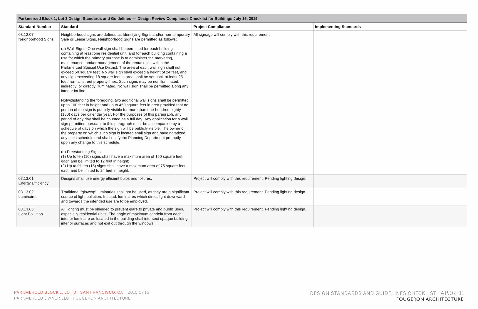
03.12.07 Neighborhood Signs
Neighborhood signs are defined as Identifying Signs and/or non-temporary Sale or Lease Signs. Neighborhood Signs are permitted as follows: (a) Wall Signs. One wall sign shall be permitted for each building containing at least one residential unit, and for each building containing a use for which the primary purpose is to administer the marketing, maintenance, and/or management of the rental units within the Parkmerced Special Use District. The area of each wall sign shall not exceed 50 square feet. No wall sign shall exceed a height of 24 feet, and any sign exceeding 18 square feet in area shall be set back at least 25 feet from all street property lines. Such signs may be nonilluminated, indirectly, or directly illuminated. No wall sign shall be permitted along any interior lot line. Notwithstanding the foregoing, two additional wall signs shall be permitted up to 100 feet in height and up to 450 square feet in area provided that no portion of the sign is publicly visible for more than one-hundred eighty (180) days per calendar year. For the purposes of this paragraph, any period of any day shall be counted as a full day. Any application for a wall sign permitted pursuant to this paragraph must be accompanied by a schedule of days on which the sign will be publicly visible. The owner of the property on which such sign is located shall sign and have notarized any such schedule and shall notify the Planning Department promptly upon any change to this schedule. (b) Freestanding Signs. (1) Up to ten (10) signs shall have a maximum area of 150 square feet each and be limited to 12 feet in height; (2) Up to fifteen (15) signs shall have a maximum area of 75 square feet each and be limited to 24 feet in height.
All signage will comply with this requirement.
03.13.01 Energy Efficiency
Designs shall use energy efficient bulbs and fixtures. Project will comply with this requirement. Pending lighting design.
03.13.02 Luminaires
Traditional “glowtop” luminaries shall not be used, as they are a significant source of light pollution. Instead, luminaires which direct light downward and towards the intended use are to be employed.
Project will comply with this requirement. Pending lighting design.
03.13.03 Light Pollution
All lighting must be shielded to prevent glare to private and public uses, especially residential units. The angle of maximum candela from each interior luminaire as located in the building shall intersect opaque building interior surfaces and not exit out through the windows.
Project will comply with this requirement. Pending lighting design.
PARKMERCED BLOCK 1, LOT 3 - SAN FRANCISCO, CA 2015.07.16
PARKMERCED OWNER LLC | FOUGERON ARCHITECTURE FOUGERON ARCHITECTUREDESIGN STANDARDS AND GUIDELINES CHECKLIST AP.02-12
Parkmerced Block 1, Lot 3 Design Standards and Guidelines — Design Review Compliance Checklist for Buildings July 16, 2015
Standard Number Standard Project Compliance Implementing Standards
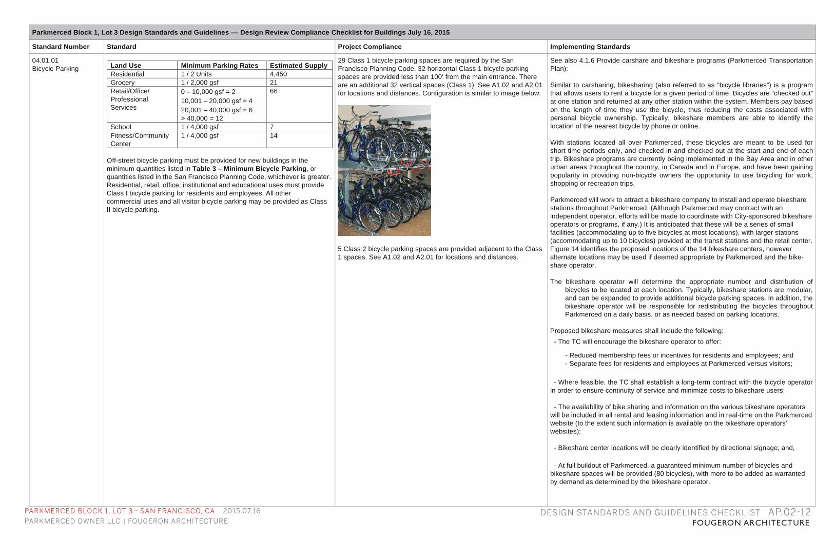
04.01.01 Bicycle Parking
Off-street bicycle parking must be provided for new buildings in the minimum quantities listed in Table 3 – Minimum Bicycle Parking, or quantities listed in the San Francisco Planning Code, whichever is greater. Residential, retail, office, institutional and educational uses must provide Class I bicycle parking for residents and employees. All other commercial uses and all visitor bicycle parking may be provided as Class II bicycle parking.
Land Use Minimum Parking Rates Estimated Supply Residential 1 / 2 Units 4,450 Grocery 1 / 2,000 gsf 21 Retail/Office/ Professional Services
0 – 10,000 gsf = 2 10,001 – 20,000 gsf = 4 20,001 – 40,000 gsf = 6 > 40,000 = 12
66
School 1 / 4,000 gsf 7 Fitness/Community Center
1 / 4,000 gsf 14
29 Class 1 bicycle parking spaces are required by the San Francisco Planning Code. 32 horizontal Class 1 bicycle parking spaces are provided less than 100’ from the main entrance. There are an additional 32 vertical spaces (Class 1). See A1.02 and A2.01 for locations and distances. Configuration is similar to image below.
5 Class 2 bicycle parking spaces are provided adjacent to the Class 1 spaces. See A1.02 and A2.01 for locations and distances.
See also 4.1.6 Provide carshare and bikeshare programs (Parkmerced Transportation Plan): Similar to carsharing, bikesharing (also referred to as “bicycle libraries”) is a program that allows users to rent a bicycle for a given period of time. Bicycles are “checked out” at one station and returned at any other station within the system. Members pay based on the length of time they use the bicycle, thus reducing the costs associated with personal bicycle ownership. Typically, bikeshare members are able to identify the location of the nearest bicycle by phone or online. With stations located all over Parkmerced, these bicycles are meant to be used for short time periods only, and checked in and checked out at the start and end of each trip. Bikeshare programs are currently being implemented in the Bay Area and in other urban areas throughout the country, in Canada and in Europe, and have been gaining popularity in providing non-bicycle owners the opportunity to use bicycling for work, shopping or recreation trips. Parkmerced will work to attract a bikeshare company to install and operate bikeshare stations throughout Parkmerced. (Although Parkmerced may contract with an independent operator, efforts will be made to coordinate with City-sponsored bikeshare operators or programs, if any.) It is anticipated that these will be a series of small facilities (accommodating up to five bicycles at most locations), with larger stations (accommodating up to 10 bicycles) provided at the transit stations and the retail center. Figure 14 identifies the proposed locations of the 14 bikeshare centers, however alternate locations may be used if deemed appropriate by Parkmerced and the bike-share operator. The bikeshare operator will determine the appropriate number and distribution of
bicycles to be located at each location. Typically, bikeshare stations are modular, and can be expanded to provide additional bicycle parking spaces. In addition, the bikeshare operator will be responsible for redistributing the bicycles throughout Parkmerced on a daily basis, or as needed based on parking locations.
Proposed bikeshare measures shall include the following:
- The TC will encourage the bikeshare operator to offer:
- Reduced membership fees or incentives for residents and employees; and - Separate fees for residents and employees at Parkmerced versus visitors;
- Where feasible, the TC shall establish a long-term contract with the bicycle operator in order to ensure continuity of service and minimize costs to bikeshare users; - The availability of bike sharing and information on the various bikeshare operators will be included in all rental and leasing information and in real-time on the Parkmerced website (to the extent such information is available on the bikeshare operators’ websites); - Bikeshare center locations will be clearly identified by directional signage; and, - At full buildout of Parkmerced, a guaranteed minimum number of bicycles and bikeshare spaces will be provided (80 bicycles), with more to be added as warranted by demand as determined by the bikeshare operator.
PARKMERCED BLOCK 1, LOT 3 - SAN FRANCISCO, CA 2015.07.16
PARKMERCED OWNER LLC | FOUGERON ARCHITECTURE FOUGERON ARCHITECTUREDESIGN STANDARDS AND GUIDELINES CHECKLIST AP.02-13
Parkmerced Block 1, Lot 3 Design Standards and Guidelines — Design Review Compliance Checklist for Buildings July 16, 2015
Standard Number Standard Project Compliance Implementing Standards
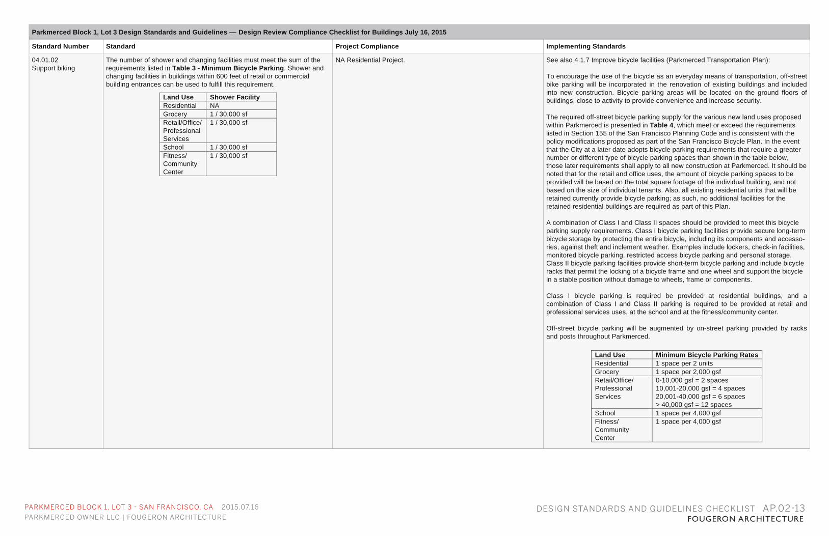
04.01.02 Support biking
The number of shower and changing facilities must meet the sum of the requirements listed in Table 3 - Minimum Bicycle Parking. Shower and changing facilities in buildings within 600 feet of retail or commercial building entrances can be used to fulfill this requirement.
Land Use Shower Facility Residential NA Grocery 1 / 30,000 sf Retail/Office/ Professional Services
1 / 30,000 sf
School 1 / 30,000 sf Fitness/ Community Center
1 / 30,000 sf
NA Residential Project. See also 4.1.7 Improve bicycle facilities (Parkmerced Transportation Plan): To encourage the use of the bicycle as an everyday means of transportation, off-street bike parking will be incorporated in the renovation of existing buildings and included into new construction. Bicycle parking areas will be located on the ground floors of buildings, close to activity to provide convenience and increase security. The required off-street bicycle parking supply for the various new land uses proposed within Parkmerced is presented in Table 4, which meet or exceed the requirements listed in Section 155 of the San Francisco Planning Code and is consistent with the policy modifications proposed as part of the San Francisco Bicycle Plan. In the event that the City at a later date adopts bicycle parking requirements that require a greater number or different type of bicycle parking spaces than shown in the table below, those later requirements shall apply to all new construction at Parkmerced. It should be noted that for the retail and office uses, the amount of bicycle parking spaces to be provided will be based on the total square footage of the individual building, and not based on the size of individual tenants. Also, all existing residential units that will be retained currently provide bicycle parking; as such, no additional facilities for the retained residential buildings are required as part of this Plan. A combination of Class I and Class II spaces should be provided to meet this bicycle parking supply requirements. Class I bicycle parking facilities provide secure long-term bicycle storage by protecting the entire bicycle, including its components and accesso-ries, against theft and inclement weather. Examples include lockers, check-in facilities, monitored bicycle parking, restricted access bicycle parking and personal storage. Class II bicycle parking facilities provide short-term bicycle parking and include bicycle racks that permit the locking of a bicycle frame and one wheel and support the bicycle in a stable position without damage to wheels, frame or components. Class I bicycle parking is required be provided at residential buildings, and a combination of Class I and Class II parking is required to be provided at retail and professional services uses, at the school and at the fitness/community center. Off-street bicycle parking will be augmented by on-street parking provided by racks and posts throughout Parkmerced.
Land Use Minimum Bicycle Parking Rates Residential 1 space per 2 units Grocery 1 space per 2,000 gsf Retail/Office/ Professional Services
0-10,000 gsf = 2 spaces 10,001-20,000 gsf = 4 spaces 20,001-40,000 gsf = 6 spaces > 40,000 gsf = 12 spaces
School 1 space per 4,000 gsf Fitness/ Community Center
1 space per 4,000 gsf
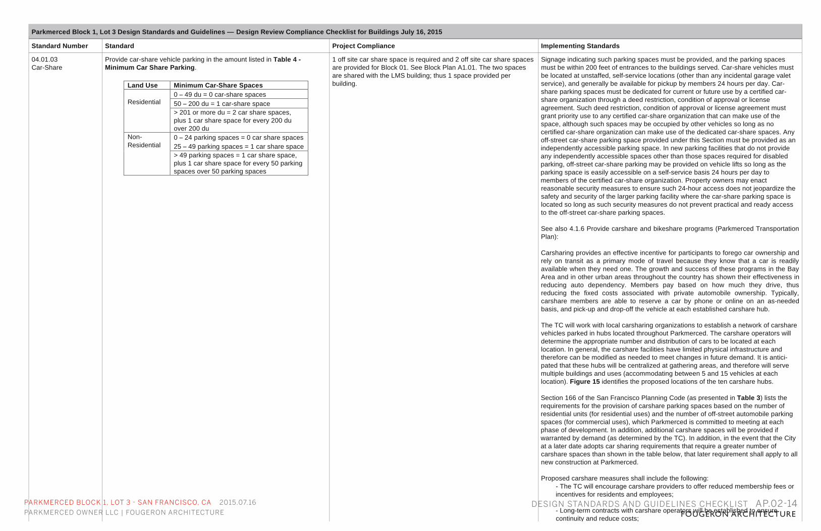
PARKMERCED BLOCK 1, LOT 3 - SAN FRANCISCO, CA 2015.07.16
PARKMERCED OWNER LLC | FOUGERON ARCHITECTURE FOUGERON ARCHITECTUREDESIGN STANDARDS AND GUIDELINES CHECKLIST AP.02-14
Parkmerced Block 1, Lot 3 Design Standards and Guidelines — Design Review Compliance Checklist for Buildings July 16, 2015
Standard Number Standard Project Compliance Implementing Standards
04.01.03 Car-Share
Provide car-share vehicle parking in the amount listed in Table 4 - Minimum Car Share Parking.
Land Use Minimum Car-Share Spaces Residential
0 – 49 du = 0 car-share spaces 50 – 200 du = 1 car-share space > 201 or more du = 2 car share spaces, plus 1 car share space for every 200 du over 200 du
Non-Residential
0 – 24 parking spaces = 0 car share spaces 25 – 49 parking spaces = 1 car share space > 49 parking spaces = 1 car share space, plus 1 car share space for every 50 parking spaces over 50 parking spaces
1 off site car share space is required and 2 off site car share spaces are provided for Block 01. See Block Plan A1.01. The two spaces are shared with the LMS building; thus 1 space provided per building.
Signage indicating such parking spaces must be provided, and the parking spaces must be within 200 feet of entrances to the buildings served. Car-share vehicles must be located at unstaffed, self-service locations (other than any incidental garage valet service), and generally be available for pickup by members 24 hours per day. Car-share parking spaces must be dedicated for current or future use by a certified car-share organization through a deed restriction, condition of approval or license agreement. Such deed restriction, condition of approval or license agreement must grant priority use to any certified car-share organization that can make use of the space, although such spaces may be occupied by other vehicles so long as no certified car-share organization can make use of the dedicated car-share spaces. Any off-street car-share parking space provided under this Section must be provided as an independently accessible parking space. In new parking facilities that do not provide any independently accessible spaces other than those spaces required for disabled parking, off-street car-share parking may be provided on vehicle lifts so long as the parking space is easily accessible on a self-service basis 24 hours per day to members of the certified car-share organization. Property owners may enact reasonable security measures to ensure such 24-hour access does not jeopardize the safety and security of the larger parking facility where the car-share parking space is located so long as such security measures do not prevent practical and ready access to the off-street car-share parking spaces. See also 4.1.6 Provide carshare and bikeshare programs (Parkmerced Transportation Plan): Carsharing provides an effective incentive for participants to forego car ownership and rely on transit as a primary mode of travel because they know that a car is readily available when they need one. The growth and success of these programs in the Bay Area and in other urban areas throughout the country has shown their effectiveness in reducing auto dependency. Members pay based on how much they drive, thus reducing the fixed costs associated with private automobile ownership. Typically, carshare members are able to reserve a car by phone or online on an as-needed basis, and pick-up and drop-off the vehicle at each established carshare hub. The TC will work with local carsharing organizations to establish a network of carshare vehicles parked in hubs located throughout Parkmerced. The carshare operators will determine the appropriate number and distribution of cars to be located at each location. In general, the carshare facilities have limited physical infrastructure and therefore can be modified as needed to meet changes in future demand. It is antici-pated that these hubs will be centralized at gathering areas, and therefore will serve multiple buildings and uses (accommodating between 5 and 15 vehicles at each location). Figure 15 identifies the proposed locations of the ten carshare hubs. Section 166 of the San Francisco Planning Code (as presented in Table 3) lists the requirements for the provision of carshare parking spaces based on the number of residential units (for residential uses) and the number of off-street automobile parking spaces (for commercial uses), which Parkmerced is committed to meeting at each phase of development. In addition, additional carshare spaces will be provided if warranted by demand (as determined by the TC). In addition, in the event that the City at a later date adopts car sharing requirements that require a greater number of carshare spaces than shown in the table below, that later requirement shall apply to all new construction at Parkmerced. Proposed carshare measures shall include the following:
- The TC will encourage carshare providers to offer reduced membership fees or incentives for residents and employees; - Long-term contracts with carshare operators will be established to ensure continuity and reduce costs; - The TC will encourage carshare providers to offer reduced fees for long-term carshare use. This would reduce the need for private vehicle ownership for

THIS PAGE LEFT INTENTIONALLY BLANK