Embed Size (px)
Citation preview

M68HCU GRIPPER
CONTROLLER SOFTWARE
A/,_ _'/3 33
by
/odd Wei-Duk Tsai
Rensselaer Polytechnic Institute
Electrical, Computer, and Systems Engineering
Troy, New York 12180-3590
May 1991
CIRSSE REPORT #90
https://ntrs.nasa.gov/search.jsp?R=19930007485 2018-07-05T10:00:53+00:00Z

(£)Copy,'ight 1991
I}V
Jodi Wei-Duk Tsai
All Rights Reserved

CONTENTS
LIST OF TABLES ................................. vi
LIST OF FIGURES ................................ vii
ACKNOWLEDGEMENT ............................. viii
ABSTRACT .................................... ix
1. Introduction ................................... 1
2. Overview ..................................... 2
2.1 MechanicalAspects ............................ 2
2.2 Software Interface ............................. 2
2.3 Hardware Interface ............................ 2
3. VxWorks Gripper Library ........................... 7
3.1 grRegWrite, grRegRead ......................... 7
3.1.1 Synopsis .............................. 7
3.1.2 Description ............................ 7
3.1.3 Return Value ........................... 7
3.1.4 Errors ............................... 9
3.1.5 See Also .............................. 9
3.2 grSrvGrab, grSrvForce, grSrvPo_ .................... 10
3.2.1 Synopsis .............................. 10
3.2.2 Description ............................ 10
3.2.3 Return Value ........................... i0
3.2.4 Errors ............................... 10
4. Firmware Software Architecture ........................ 11
4.1 Initialization ................................ 11
4.1.1 Power Up Initialization (powerUpStart) ............. 11
4.1.2 ACIA Initialization (AClAInit, ONACIA) ........... 11
4.1.3 RAM Initialization (initR.-\M) .................. 13
4.1.4 Hardware Initialization (bwInit) ................. 14
.°.
III

4.1.5 Software Initialization (swlnit) .................. 18
4.2 Comme_nd Processing (processCt_c_l) ................... 18
4.2.1 Register Model .......................... 20
4.2.2 Servo Modes (grSrvGrab. grSrvPos, grSrvForce) ........ 22
4.3 Interrupt Level (positionServo,forceServo,grabServo) .......... 24
4.3.1 Grab Servo (grabServo) ..................... 24
4.4 Critical Data ............................... 26
4.4.1 Floating Point Control Parameters ............... 26
4.4.2 Working Memory of Floating Point Routines .......... 26
4.5 EPROM .................................. 27
4.6 Control Loop ............................... 27
4.7 Command Processing Real-Time, Constraints .............. 27
4.8 Debugging ................................. 28
4.8.1 EPROM Configuration ...................... 28
4.8.2 Debug Configuration ....................... 28
5. Tutorial ..................................... 29
5.1 Initializing the Network Daemol, .................... 29
5.2 Creating the 68HCll Buffalo Monitor Window ............. 29
5.3 Constructing an Imakefi[e ........................ 31
5.4 Assembling and Downloading ...................... 31
6. Tools ....................................... 32
6.1 rDevLogin - remote device login ..................... 32
6.1.1 Synopsis .............................. 32
6.1.2 Description ............................ 32
6.2 rDevd - remote device daemon ...................... 32
6.2.1 Synopsis .............................. 32
6.2.2 Description ............................ 33
6.3 rDevCmd ................................. 33
6.4 a611floatpp ................................ 35
6.5 moto2moto ................................ 35
6.6 motooffset ................................. 36
iV

6.7 installMan ................................. 37
6.8 manc .................................... 37
6.9 xmanc ................................... 37
6.10 Public Domain Utilities .......................... 38
6.10.1 68HC11 Assembler ........................ 38
6.10.2 int2moto .............................. 38
7. Configuration Management ........................... 39
7.1 Motivation ................................. 39
7.1.1 Complicated Makefiles ...................... 39
7.1.2 Working Versions of Files .................... 39
7.2 Imake Configuration Files ........................ 40
7.2.1 Files ................................ 40
7.2.2 Caveats .............................. 47
7.2.3 Bugs ................................ 47
7.2.4 See Also .............................. 47
7.3 Imakefile .................................. 47
7.3.1 VxWorks Library ......................... 48
7.3.2 VxWorks Binary ......................... 50
7.3.3 UNIX Library ........................... 51
7.3.4 UNIX Binary ........................... 52
7.3.5 Making subdirectories with no local targets ........... 53
7.3.6 Making subdirectories with local targets ............ 53
7.3.7 Making local targets only . ................... 56
7.3.8 Custom rules and depemlencies ................. 56
8. Conclusions ................................... 60
LITERATURE CITED .............................. 61


LIST OF TABLES
2.1
3.1
3.2
4.1
4.2
4.3
4.4
4.5
4.6
4.7
4.8
4.9
4.10
4.ii
6.1
68HCll Hardware Interface ................... 3
Register Constants ........................ 8
Errors ............................... 9
Memory Map ........................... 14
Interrupt Vector Map with Buffalo monitor ........... 16
Interrupt Vector" Map with gripper controller .......... 16
Command Character Tal)[('. ................... 19
Subroutine Table ......................... 19
RS-232 Serial Port Commands .................. 20
Error Codes ............................ 20
Registers .............................. 21
State Transition Table ...................... 24
Bit Representation ........................ 25
State Transition Table in Bit Representation .......... 25
Action Table ........................... 35


LIST OF FIGURES
2.1
2.2
2.3
4.1
4.2
4.3
4.4
5.1
6.1
6.2
CIRSSE Gripper ......................... 3
Configuration ........................... 4
Schematic of Pneumatic Piston Assembly ............ 5
Software Architecture ....................... 12
Real-Time Clock Error ('aused by Interrupt Overrun ..... 18
Top Level State Transiti_m Diagram ............... 22
Grab Servo Mode State r['ransition Diagram .......... 23
Hardware Configuration ..................... 30
Network Connections ....................... 34
Software Architecture ....................... 36
vii


ACKNOWLEDGEMENT
I would like to thank my mother and fath_r for their support. I would also like to
thank Dr. Robert B. Kelley, my thesis adviser, for his guidance during the various
stages of development.
hi eQviii


ABSTRACT
This thesis discusses the development of firmware for the 68HC11 gripper controller.
A general description of the software and hardware interfaces is given. The C li-
brary interface for the gripper is then described followed by a detailed discussion
of the software architecture of the firmwate. A procedure to assemble and down-
load 68HCll programs is presented in th,_ form of a tutorial. The tools used to
implement this environment are then described. Finally, the implementation of the
configuration management scheme used t_, Inanage all CIRSSE software is presented.
ix


CHAPTER 1
Introduction
The objective of this project we_s to produce a low-cost gripper controller for CIRSSE
and attain the following design goals:
• provide an RS-232 command interface.
• implement position feedback control using potentiometers.
• implement force feedback control using strain gauges.
• allow the gripper to "grab" objects using the infrared sensors.
• minimize sampling period (maximize sampling rate) to allow maximum pos-
sible fluctuation in gripper control parameters.
In addition, software tools were cr_,ated for SunOS and VxWorks to provide
an easy to use edit-compile-download-d,'tmg environment for the development of
programs using the 68HCll EVB on a S_I1Lworkstation.

CHAPTER 2
Overview
2.1 Mechanical Aspects
The gripper is shown in Figure 2.1. The gripper has a crossfire infrared sensor
to detect the presence of an object betweet_ the fingers. Potentiometers and strain
gauges allow position and force feedback control to be implemented.
2.2 Software Interface
The top level interface through ttw gripper is through the VxWorks gripper
library on the MV135 68020 processor boards. The actual servoing is accomplished
with the 68HC11 EVB. Communication occurs between the MV135 68020 processor
boards and the 68HCll EVB via an RS232 cable. This configuration is shown in
Figure 2.2.
2.3 Hardware Interface
The CIRSSE gripper is a pneumatically controlled system shown in Figure 2.3.
The pressure is adjusted by writing an 8-bit value to port B of the 68HCll. This
port is connected to a D/A converter outside of the 68HCll evaluation board. The
D/A converter generates a signal that is amplified to control a servo valve. This
effectively controls the rate at which air enters the piston from both sides. Table 2.1
shows the port mapping.
Since the air pressure is fixed at all times, the 8-bit value at the 68HCll port
merely acts as an integral gain. A point ,,xists where the servo valve delivers air at
the same rate to both sides of the piston. The digital output value at this point is
known as Z_r,,sur,. Although the digital o_ltput value may take on the full range of

3
Gripper
crossfiresensor
strain gauges_<
infrared sensor
potentiometers
Figure 2.1" C[RSSE Gripper
fuaction 68HC11'port
position EO
force E1
crossfire sensor C bit 0
air valve' B bit '7-0
Table 2.1: 68HCll l[ardware Interface

VxWorks Host
!!
It brary,Gripper "II
t. _ a
RS-232 cable
!!Gripper Cont_'oiler Softwar_o ib
68HC 11 EVB
Figure 2.2: Configuration

5
I 68HC 11 EVB
t
[ 8bit D/A -i
air _ _
I- v&lvepiston
Figure 2.3: Schematic of l)ueumatic Piston Assembly
gripper

6
8-bit values, in practice, only very slight perturbations are needed from zj,.,3s_,., in
order to move the fingers of the gripper Io any given position or force setpoint.
The current method used to adjust the pressure is a proportional-integral-
derivative (PID) controller. All parameters may be dynamically adjusted while the
gripper controller is servoing.

CHAPTER 3
VxWorks Gripper Library
The gripper library is a standardized C library interface to the gripper controller.
This allows future changes to be made to the software in the 68HCll without
invalidating the code written at the application level.
The gripper library also isolates the application software from the real-time
constraints of the gripper protocol. This is done by providing the proper interchar-
aeter delay and the intercommand delay when sending commands to the gripper.
3.1 grRegWrite, grRegRead
3.1.1 Synopsis
.... #include <grLib.h>
int grRegWrite(inZ fd,GRREG regNo,double value)
int grRegRead(int fd,GRREG regNo,double *pValue)
3.1.2 Description
These functions read and write to software registers in the 68HCII. In all of
these functions, the argument fd is a file descriptor returned by open (2V) [Sun 88].
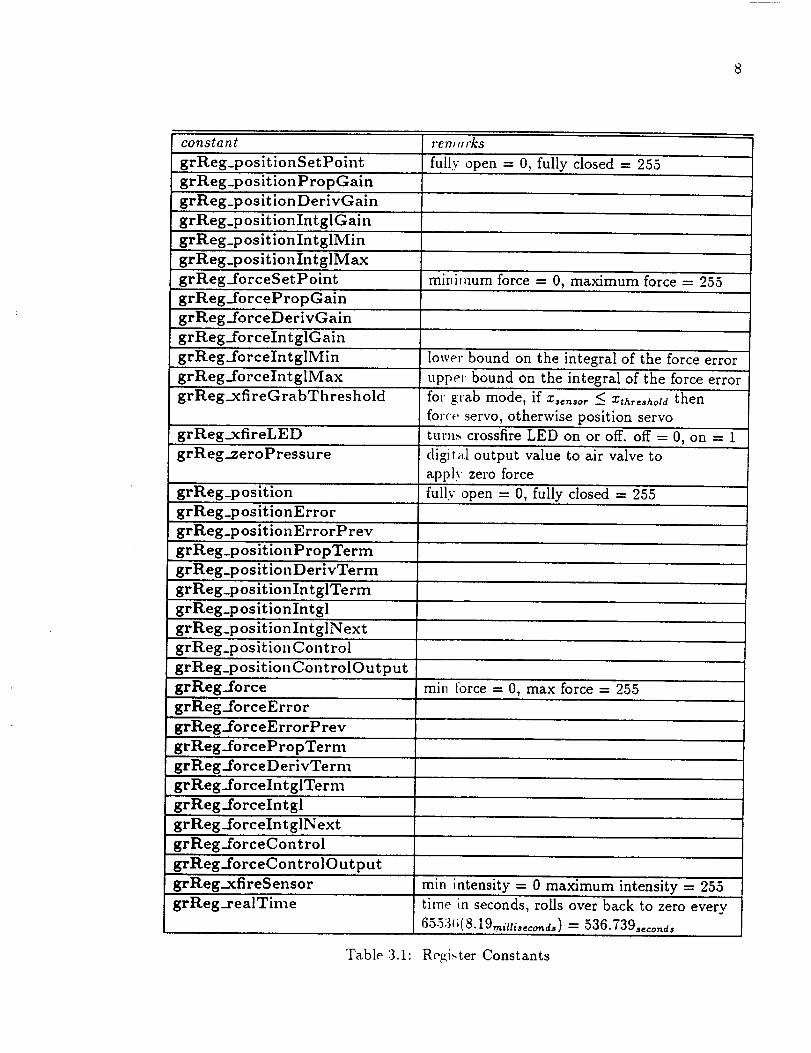
The argument regNo refers to one ,ff the constants in Table 3.1. The mathe-
matical representatioas of these registers is given in Table 4.8.
3.1.3 Return Value
These functions return 0 if the call is successful otherwise 1 is returned.
constant
grReg_positionSetPoint
grReg_positionPropGain
grReg_positionDerivGain
grReg_positionIntglGain
grReg_positionIntglMin
grReg_positionInt glMax
grReg_forceSetPoint
grReg_forcePropGain
grReg_forceDerivGain
grReg_foreeIntglGain
grReg._foreelntglMin
grReg_forceIntglMax
grReg_xfireGrabThreshold
7"enJ ¢11"_8
fully open = 0, fully closed = 255
minimum force = 0, maximum force = 255
lowe," bound on the integral of the force error
upper bound on the integral of the force error
for grab mode, if x,,_,o, < zthr,_hota then
force servo, otherwise position servo
grReg_xfireLED
grReg_zeroPressure
grReg_position
grReg_p os it ion Error
grReg_positionErrorPrev
grReg_positionPropTerm
turns crossfire LED on or of[.off = 0, on = 1
digital output value to air valve to
apply zero force
fully open = 0, fully closed = 255
grReg_positionDerivTerm
grReg_positionIntglTerm
grReg_positionIntgl
grReg_positionIntglNext
grReg_positionControl
grReg_positionControlOutput
grReg_force
grReg_forceError
grReg_forceErrorPrev
grReg_forcePropTerm
grReg_forceDerivTerm
grReg_forceInt glTerm
grReg_forceIntgl
grReg_forceIntglNext
grReg..forceControl
grReg_forceControlOutput
grReg..xfireSensor
grReg_realTime
min tbrce = 0, max force = 255
min intensity = 0 maximum intensity = 255
time in seconds, roils over back to zero every
65534_(8.19,nittis_o,_d,) = 536.739,_o,_ds
Table 3.1: Register Constants

9
constant remarks
S.grLib_VxWorks_IiNVARG An invalid argument was given when
calling the function.
S_grLib_VxWorks_INVCMD
S..grLib_VxWo rks_BAD_P,.ES P ONSE
S..grLib_VxWorks_TIMEO UT
EBADF
ENOTTY
An invalid command was given. This
indicates that garbage was sent
over the RS232 serial line,
probably a hardware fault.
The response from the 68HCll could
not be recognized because the
68HC11 EVB was not initialized
properly
There was no response from the
68HCll EVB.
ioctl(2) failed because the
stream was not associated with a
valid file descriptor.
ioctl(2) FIONREAD request
does not apply to kind of objectassociated with the file stream.
EINVAL The request or arguments to ioctl(2)were invalid.
EFAULT The Data transfer that occurred
within ioctl(2) resulted ina read or write to an address
outside of the process' address
space.
Table 3.2: Errors
3.1.4 Errors
The error codes returned are showr_ in Table 3.2.
3.1.5 See Also
In the UNIX man pages, see open (2V), close (2) [Sun 88].

10
3.2 grSrvGrab, grSrvForce, grSrvPos
3.2.1 Synopsis
#include <grLib .h>
int ErSrvGrab(ing fd)
int grSrvPos(int fd)
ing grSrvForce(ing fd)
3.2.2 Description
These functions enable various servo modes. The gripper controller software
in the 68HCll attempts to maintain the position and force set points set by the
grReg(2) commands.
In all these functions, the argument fd is a file descriptor returned by open(2V).
grSrvGrab() enables position mode or servo mode depending on whether
there is an object detected between the fingers of the gripper.
grSrvPos() enables position servo mode and attempts to maintain the posi-
tion.
grSrvForce() enables force servo mode and attempts to maintain the force
set point.
3.2.3 Return Value
These functions return 0 if the call is successful otherwise 1 is returned.
3.2.4 Errors
See Table 3.2.

CHAPTER 4
Firmware Software Architecture
The software for the gripper controller is a simple real-time executive which operates
in three different modes.
grab servo mode servos to the force set point if there is an object detected be-
tween the fingers, otherwise servos to the position set point.
position servo mode servos the gripper to maintain a position set point.
force servo mode servos the gripper to maintain a force set point.
For each section or subsection headi,lg, the relevant subroutine in the gripper
controller source code is indicated in parentheses.
4.1 Initialization
4.1.1 Power Up Initialization (powerUpStart)
Upon power up, the 68HCll EVB 1 starts executing instructions at 0xe000.
The power up startup code sets the OPTION register and TMSK2 register immedi-
ately since these must be set within 64 bus-cycles after reset [Motorola 89, p. 3-8].
After this period expires, some of the bils in these registers become read-only and
may not be set.
4.1.2 ACIA Initialization (ACIAInit, ONACIA)
ACIAInit initializes the ACIA on power up to enable communication via the
RS-232 serial port. ONACIA re-initializes the ACIA after an error.
1The 68HCll EVB uses the MC68HCllAI version of the M68ttCll family
]L

12
Host
..... | ........ _- .....
=|R5232 _ri_l.. Port *!| !
Conut_ands Error Stb.tus Codes
68HCll
Bas,_ Level
Interrupt Level
Pressure: Control
I
i
I
T
Position FeedbackL,. Gripper [[ardware
Force Feedback--J
Figure 4.1: Software Architecture

13
Note that there are two RS-232 serial ports on the M68HCll EVB. The ter-
minal port is connected to the ACIA. The other host port is connected to the SCI
on the M68HCll and is not used [Motorola 86, Figure 6-2].
4.1.3 RAM Initialization (initRAM)
The on-chip RAM space is only 256 bytes. The on-chip EEPROM space is only
512 bytes [Motorola 89, Table 1-1]. Since t he gripper controller software exceeds the
capacity of both on-chip memories, an ex't(,rnal RAM and an external EPROM are
needed.
Two methods were considered in allocating program space to the external
RAM and EPROM.
1. using the external RAM area for uniuitialized data and initialized data; using
the EPROM area for constant data. initialized data, and code.
2. using the RAM area for all code and data.
The first method uses EPROM and RAM space optimally. However, it in-
troduces complexity by requiring a separate section of memory for constant data,
initialized data, and uninitialized data.
The second method treats all code aad data the same and merely copies the
whole contents of the EPROM to the RAM" area and then executes the code residing
in RAM. The primary benefit of this method is that it is trivial to implement at the
expense of wasting some space by needlessly duplicating constant data and code.
The second method is used for this application. The firmware copies itself to
RAM after performing a few required initializations and jumps to the first routine
main in RAM. Note that all jumps and branches prior to the main routine must
use relative addressing since the program is assembled with the origin at the start
of RAM (0xc000) not EPROM (0xe000)..-\ memory map is shown in Table 4.1.

14
address description0x0000 direct RAM
0xc000 user RAM
gripper controller code gets copiedEPROM and is executed here
0xdf00 top of stack
0xe000 EPROM
initialization copies code and datato RAM
Table 4.1: Memory Map
4.1.4 Hardware Initialization (hwInit)
During hardware initialization, the following are accomplished.
• crossfire port initialization
• A/D converter register initialization
• interrupt subroutine vector initializa.tion
• real-time interrupt register initialization
• hardware diagnostics
4.1.4.1 Crossfire Port Initialization (hwInitXfire)
The crossfire LED is turned on by writing to bit 0 of the PORTC register. The
port C databus is bi-directional. Each bit in the DDRC register determines whether
the corresponding bit of the databus is either an input or output line [Motorola 89,
p. 7-20]. Thus, proper configuration of the DDRC register requires that bit 0 be
high.

15
4.1.4.2 A/D converter initializatio,a (hwInitADC/ADCInit)
The A/D converter subsystem is initialized by the ADPU and CSEL bits in
the OPTION control register. The A/D charge pump is initially disabled upon reset.
The ADPU bit must be set to one to enable the A/D charge pump [Motorola 89, p.
12-12]. The CSEL bit is set to zero for this application since additional A/D error
is caused by internal noise if the alternate' clock source for the on-chip EEPROM
charge pump is selected during A/D conv_rsion [Motorola 89, p. 12-13].
4.1.4.3 Interrupt Vector Initialization (RTISetISR)
During each of the grab, position, and force servo modes mentioned in Sec-
tion 4, a separate interrupt subroutine is used. These interrupt subroutines are set
with the RTISetISR subroutine.
4.1.4.4 Real-Time Interrupt Initialization (RTIInit)
The real-time interrupt serves three purposes.
• provides periodic activation of the s,,rvo loop to ensure a constant sampling
rate.
• allows a timer to be maintained so that the delay for grab mode can be im-
plemented.
• maintains a real-time clock to determine if the servo loop is executing within
the proper time.
l:tTIInit first sets the tick counter Io zero. The counter is incremented on
every real-time interrupt. This counter is used to calculate the real-time in seconds
and is used to schedule events in grab m_de.
Since the interrupt vector table is located from 0xffd6 to 0xfffi _, the Buffalo
monitor automatically presets the interrupt, vectors. However, these vectors merely

16
address
OxOOc4
OxOOeb
OxOOff
Oxffd6
OxfffO
Oxffff
Table 4.2:
description
Start of Buffalo JMP vector table
JMP RTIInt
End of JMP vector table
Start of Buffalo monitor vector table0x00eb
End of Buffalo monitor vector table
Interrupt Vector Map with Buffalo monitor
address
0x00c4
0x00eb
0x00ff
0xffd6
0xfff0
0xffff
Table 4.3:
description
Start of unused JMP vector table
JMP RTIInt (still initialized but not used)End of unused JhIP vector table
Start of gripper controller vector table
RTIInt
End of gripper co_ltroller vector table
Interrupt Vector Map with gripper controller
point to JMP instructions in RAM which jump to the appropriate interrupt handler.
Thus, a JMP instruction to the real-time interrupt handler must be present at the
real-time interrupt address of the Buffalo lllonitor jump table. This configuration is
shown in Table 4.2.
When the Buffalo monitor is remow_d and replaced with the gripper controller
software, the jump table in RAM is no longer necessary since the interrupt vec-
tor table located from 0xffd6 to 0xffff can be set with the appropriate vectors by
initializing the corresponding EPROM locations. The JMP instruction is still harm-
lessly initialized since the gripper controller is never aware of whether it was copied
from EPROM or downloaded via the RS-232 port. This configuration is shown in
Table 4.3.

17
The TFLG2 register is usedto cleartl_eRTIF status bit which is automatically
set at the end of every interrupt [Motorol_ 89,p. 10-12]. The RTI rate is then set
by initializing the lower two bits of the PACTL register.
When real-time interrupt initialization is complete, the interrupts are in a
disabled state. They may be turned on and off with the RTIStart and RTIStop
routines.
A real-time clock is maintained and is displayedasseconds.This parameter, t,
is one of the gripper controller software registers shown in Table 4.8. If the interrupt
handler routine does not execute in time ['or the next interrupt then the real-time
clock here will be off from the actual elaps_d time by some integer factor.
For example, if the interrupt routine takes 10ms to execute and an interrupt
occurs every 8.19ms, the next interrupt will be missed. Therefore the real-time clock
will be slowed by a factor of two. Thus, by merely observing the real-time clock and
using a wristwatch, it is possible to veri_" that real-time interrupts are not being
missed. An example of this type of error is given in Figure 4.2.
4.1.4.5 Hardware Diagnostics (hwInit, hwInitADC)
Hardware diagnostics are performed to ensure that the following features of
the M68HCll EVB are functional:
• A/D conversion
• real-time interrupts
To test the A/D subsystem, a conversion command is output to the ADCTL
register and the CCF flag is then polled to ensure that a conversion complete is
returned at approximately the correct tim_..
To test the real-time interrupt, a sul,r_mtine to set a byte in memory is installed
as an interrupt handler. Proper generati,m of interrupts is verified by checking the

18
real-time interrupts
_40.95
i I
0 10 26.38
start of interrupt routine
I
completion of interrupt routine
Figure 4.2: Real-Time Clock Error Caused by Interrupt Overrun
memory location after enabling and disabling interrupts.
4.1.5 Software Initialization (swInit)
Software initialization consists of all the run-time initialization of various con-
stants used in the controller algorithms. The two goals are to minimize the amount
of information that needs to be updated if parameters are changed and to optimize
performance by computing common sube×l_ressions beforehand.
4.2 Command Processing (processCmd)
Command processing is performed _t the non-interrupt driven level. This level
of execution performs all the command line processing through the RS-232 serial
interface.
First, the software reads a commalt,:l line from the RS-232 serial port. Each

19
offset com/_and letter
0 g
1 p
2 f
3 w
4 r
s
Table 4.4: Command Character Table
offset
0
2
4
6
8
10
process command subroutine
grSrvGrab
grSrvPos
grSrvForce
grReg'Read
grRegWrite
dispGripStat
Table 4.5: Subroutine Table
command consists of a single letter. When a command is received, the command is
parsed by searching the table of letters shown in Table 4.4.
Using the index into this table, a corresponding entry is found in the table of
subroutine addresses shown in Table 4.5. The subroutine is then invoked to execute
the command. The X register points to the current character being parsed. Upon
entry into each of the subroutines invoked, the X register points to the arguments
in the command buffer.
The commands for the gripper controller are shown in Table 4.6. The argument
register in the write register and read register commands refers to one of the
registers in Table 4.8. The regi._terValue parameter is a floating point number.
After processing each command, a line is returned to the host through the

2O
function corn.mand to 63HCll response from 68HCll
grab serve mode g errorCode
position serve mode p errorCode
force serve mode f errorCode
read register r register errorCode register Value
write register w register regi._terValue errorCode
Table 4.6:RS-232 Serial Port Commands
errorCode eT"ror
0 no error
1 invalid argument2 invalid command
Table 4.7: Error Codes
RS-232 serial port. The errorCode field contains the error status code. The mean-
ing of the errorCode field is shown in Table 4.7. There is another register Value
field returned in response to the read register command. This is a floating point
number.
4.2.1 Register Model
The register model is used to set all of the parameters for the gripper controller
primarily because the control algorithm is expected to change often. Therefore, it is
important that control parameters can be easily added or deleted from the system
without requiring any major changes to tile gripper protocol.
In addition to the PID gains, there ave additional registers representing terms
which must be computed at the end of every sample period. These terms are in-
cluded in order to assist the user in determining the correct gains to be used with
a gripper. The mathematical representations for all these registers are shown in
Table 4.8.

21
register
0
2
3
'4
5
6
'7
8
9
10
11
i213
14
I5
16
17
18
19
20
21
22
23
24
control parameter
position set point
position proportional gain
position derivative gain
position integral gain
position integral minimum
position integral maximumforce set point
force proportional gain
force derivative gain
force integral gain
force integrai minimum
force integral maximum
crossfire grab threshold
crossfire grab delay
crossfire LED
zero pressure point
position
position error
previous position error
position proportional term
position derivative term
position integral term
position integral
next position integral
position control
writable
3,as
yes
ves
),as
force proportional term
yes
ves
yes
yes
yes
'Yes
yes
yes
ves
yes
)'as
yes
no
no
no
no
no
no
no
tlo
representation
Psctpnt
Ppga!n
Pdgain
_,igain
Pimin
Pimax
f *etpnt
f pgain
f dgain
f igain
krn_n
krn_x
Xthreshold
Xdelay.o
_led
Zpre$$_re
Pert "-- p -- Psetpnt
perrprev
Ppterrn "- PpgainPerr
Pd_aln ( 73err --perrprev )
P dterrn --" ' T "
Piterrn --" PigainPi
Pi
Pinext = Pi + _(Perrprev + pert)
Pctl = Ppterm + Pdterm + PiterrnnO
25 position control output no Po_,t = min(max(p_a + zpr..._, 0), 255)
26 force no f
27 force error no fear = f - f_tp.t
28 previous force error no f.._,._,
29 no
tlO30
31
force derivative term
force integral term
force integrM
next force integral
32
33
expiration time
fp_,_., = f,_oi.f...
fdterm = l.,_°i.(I.,-,'-/.,','p,'.,,)T
fi,e.._ = f.ig.!.ktlO
tlO
tlO
34 force control no fat = fr#,-,_ +fat,,., + fiterm
35 force control output no fo_,, = min(max(f_tt, 0), 255)
36 crossfire sensor I10 X _en$o r
37 no
38
39
real time
grab state
kTk..., = k + 7(L-,-. + L r)
_ezpire
tlO| , • , . ,
tlO
40 grab mask ao
"['able 4.8: Registers

22
Start )
initialization complete
grab servo_ _ _ _grab
osition Servo Mode_
servo
(;o ")rce Servo Mode
Figure 4.3: Top Level State Transition Diagram
4.2.2 Servo Modes (grSrvGrab, grSrvPos, grSrvForce)
The grab, position, and force servo commands initiate calls to grSrvGrab,
grSrvPos, and grSrvForce respectively. All these routines initialize an interrupt
subroutine vector using RTISetISR. This creates three top level states that are
initiated by each command. The top level states for the gripper controller are shown
in Figure 4.3. The gripper controller begins in grab servo mode upon initialization.
Both positionServo and forceServo are similar in that they contain no
additional states. However, the grabServo mode contains substates.
When the gripper controller is in th¢, grab servo state, the gripper will close
whenever an object blocks the crossfire beam between the fingers. This closing can
be delayed a certain period of time. Figure 4.4 shows the different states for grab
servo mode. In both Position IVait and Position Delay states, position servoing is
performed and in the Force state, force servoing is performed.

23
Starl
/_ Position Wait
crossfire beam blocke_/_ -/ sfire beam not blocked
lcrossfire be_tm blocked
timer expired
Figure 4.4: Grab Servo Mode, State Transition Diagram

24
timer
ezpired
c,rossfiTe
blocked
yes
yes no
no
state
position wait
action
position servo
nezt state
,-qgr=b
position waitno no
no no positiondelay position servo position wait
no no force position servo position wait
no yes positionwait start timer position delay
no yes positiondelay position servo position delay
no forceforce
positionwait
force servo
positi'on servo
position servoposition delay
position wait
position wait
position waityes
yes no force position servo position wait
start timer position delayyes yes
yes yes
yes yes
position delay force servo force
force force servo force
Table 4.9: State Transition Table
4.3 Interrupt Level (positionServo,forceServo,grabServo)
The interrupt level refers to the interrupt driven software in the controller, the
interrupt handler code. This level of execution performs the servoing of the fingers.
A periodic interrupt occurs every sampling period T. T is 8.19 milliseconds.
The ADCTL register is configured so that the position, force, and crossfire
sensors are read simultaneously from ports E0, El, and E3 respectively as shown
in Figure 2.1. Conversions are performed on all three channels simultaneously by
setting the SCAN bit to zero and setting the MULT bit to one [Motorola 89, p.
12-14].
4.3.1 Grab Servo (grabServo)
Table 4.9 shows the the grab servo state table. There are two inputs which
cause all state changes. Table 4.11 is derived after substituting the bit representa-
tions in Table 4.10.
The actual implementation of the state transition table uses the first three

25
L ,,
symbol bit representation
no 0
yes iposition wait O0
position delay 01
force 10
position servo O0
force servo 01
start timer 10
Table 4.10: Bit Representation
timer crossfire
ezpired blocked
0 0
0 0
0 0
0 1
0 1
0 1
1 0
1 0"
1 0
1 1
1 1
1 1
state
.S9 ,.ut,
O0
O1
10
ooO1
io
O0
O1
10
O0
Ol
10
action nezt state
8grab
O0 O0
O0 O0
O0 O0
10 01
oo oiO1 10
O0 O0
oo " obO0 O0
10 O1
01 10
Ol lb
Table 4.11: State Transition "['able in Bit Representation

26
columns of Table 4.11 as an offset into a table which contains the action routine to
be performed and the next state.
4.4 Critical Data
There are two sets of critical data.
• the floating point control parameters written and read by the user via the
write register and read register commands
• the working memory used by the floating point routines
4.4.1 Floating Point Control Parameters
Critical data is inevitably introduced because of the use of floating point con-
trol parameters. There is no atomic instruction which can read or write 3 bytes,
the length of a floating point number. Wh_,n a critical control parameter is set, the
interrupts are masked while the floating point number is being transferred to the
register area used by the interrupt handlers. This prevents the interrupt handler
from using a partially updated floating point parameter. Fortunately, the amount
of critical code is limited to two places irt the software. Thus, masking can be per-
formed without losing any interrupts and without causing any discontinuities in the
servoing.
4.4.2 Working Memory of Floating Point Routines
Critical data also exists in the working memory of the floating point routines,
labeled floatContext in the source co&,. Since one set of floating point routines
are used for both non-interrupt and interrupt driven software, potential problems
arise if both levels of execution are using the same data.
Since the working memory only involves 6 bytes of memory which can be
copied quickly, the real-time interrupt hal lcIler sa:ves the non-interrupt level contents

27
of this memory area before calling the interrupt handler. After the interrupt handler
completes, the non-interrupt level contents is restored and execution resumes.
4.5 EPROM
The gripper controller firmware is designed to replace the Buffalo monitor
firmware at 0x6000. Testing has been simplified by avoiding the use of any pro-
gramming methods which would require the configuring of jumpers.
4.6 Control Loop
The control algorithm is essentially the same for position and force servoing.
Thus, it would have been possible to have one generic control loop subroutine.
However, this would require one of the following time consuming activities:
• indexing to each of the two control structures for each position and force
parameter.
• copying of the control structure to and from the memory area used by the
shared servo loop.
Both indexing and copying memory are time consuming activities for a large
number of registers. Indexing also complicates the code significantly. It was decided
to keep the code and data as simple and a._ fast as possible by keeping the position
and force servo loops separate at the expense of using slightly more memory for
code.
4.7 Command Processing Real-Time Constraints
There is a fundamental linfit imposed on the number of characters which may
be sent to the gripper controller in a c(.xtain period of time. Because the servo
loop must always be executed every 8.19 ms, the non-interrupt level software only

28
executesbetweenthe time the servoloop codehascompleted and the next real-time
interrupt. Since all reads from the RS-232 serial port occur at the non-interrupt
level, there is a possibility that characters may not be read if characters are sent down
too quickly. Thus, in order to guarantee that each character is read by the gripper
controller software, it is necessary to wait at least 20 ms between characters. This
will ensure that the servo loop has completely executed and that the non-interrupt
level software has read the character from the serial port.
In addition to waiting between characters, it takes a minimum of 40ms to
process a command. Thus, there must be at least a 40rns delay before any characters
are sent down to the 68HC11 following any the input of any command.
4.8 Debugging
The gripper controller can be configured for EPROM or downloading via the
RS-232 port. The latter configuration is useful for debugging the software.
4.8.1 EPROM Configuration
The software originally is located all in EPROM. When initialization begins
the initRAM subroutine copies EPROM to RAM. The source file ctl.asm contains
this code.
4.8.2 Debug Configuration
The software is downloaded into RAM at 0xc000. In this configuration,
initRAM must not be called since the software is already relocated and the
EPROM contains the Buffalo monitor. This source file is derived from ctl.asm by
deleting the bsr initRAM instruction. Th is is done automatically by the Imakefile.

CHAPTER 5
Tutorial
A set of software development tools allo_rs the programmer to perform all editing
and debugging on a Sun workstation. These' software development tools work within
emacs and X windows to create an integr;tted edit-compile-debug environment. The
procedure for editing, compiling and debugging is presented in this chapter.
The hardware configuration and the tools needed are shown in Figure 5.1.
This section assumes you are already familiar with UNIX and X windows.
5.1 Initializing the Network Daemon
Before any communication from the Sun workstation to the 68HCll EVB can
begin, a network daemon must first be prcse, nt on one of the 68020 MV135 processor
cards in the VME cage. This network daemon must be present on the same 68020
MV135 processor card that is connected to the 68HCll EVB via an RS232 serial
cable. In the following example, the 68H(' tl EVB must be connected to the lower
serial port (/tyCo/1).
The network daemon is invoked wil h the commands
rlogin vx2.ral.rpi.edu
id < /usr2/testbed/CIRSSE/ins_alled/VxWorks/bin/rDevd.o
rDevInit "/tyCo/l"
at the VxWorks prompt.
5.2 Creating the 68HCll Buffalo Monitor Window
A terminal connection to the 68HC11 Buffalo monitor is started with

3O
Sun workstation
MV135 68020 Processor Boards
/tyCo/1
/tyCo/0 ]
VME Cage
RS-232 Serial ('able
Emac$
rDevLogin
rDevCmd
Ethernet*t
Gripper Controller
ttCll EVB J
gripper
Figure 5.1: Hardwa.re Configuration

31
rDevLogin hostname
in any zterm window.
5.3 Constructing an Imakefile
An Imakefile merely lists all the targets and dependencies which need to be
generated. In this case, the [make.file is trivial and only consists of one line.
AllTarget (prog. Y)
5.4 Assembling and Downloading
The resulting program may be compiled and downloaded by issuing the fol-
lowing command.
cm.l_f prog.Y
A listing file named prog.lst is created. Lines with errors are marked with a
letter from A-Z in the first column. Here i., an example.
U 0000 7e O0 O0 main imp
0003 end
main2
0000 main
The U stands for undefined. A complete listing of all error codes is given in
the manual page [Colley 87].

CHAPTER 6
Tools
A variety of tools have been constructed to aid in developing software for the
M68HCll EVB. Thesetoolsprovidesimp]ewaysto assemble,debug,and download
programs.
6.1 rDevLogin - remote device login
6.1.1 Synopsis
rDevLogin hostname
6.1.2 Description
The rDevLogin client redirects terminal input and output to a rDevd server
at the specified hostname. The rDevLogin client attempts to open a connection at
port 8200 of hostname. Using the select(2), read(2), and write(2) system calls,
a full duplex connection is implemented [S,m 88].
6.2 rDevd - remote device daemon
The network server rDevd runs on VxWorks to create a full-duplex connection
between a socket and a serial port on the [_8020 MV135.
6.2.1 Synopsis
rDevInit deviceName
32

33
6.2.2 Description
The rDevd serverlistens on two p_lblicports and waits for incoming connec-
tions. When it acceptsa connectionon either port, rDevd providesa byte stream
between the client and the devicespecifi,.dby deviceName.
The two ports areusedin order to establishtwo independentpaths to senddata
to the tty device. Oneport, symbolically a_medTELPORT, providesa full-duplex
connection to the tty device. Another port, symbolically named CMDPORT,
provides only a sendpath to the tty device. This allows TELPORT to be usedas
an interactive terminal interface to the try devicewhile CMDPORT can be used
to sendcommandsto the tty device. Figure 6.1 showsthis arrangement.
The select(2) call is usedto look for"incomingconnectionsor data. Any input
event receivedby the rDevd serverresults in two actions.
• an accept action where a connection is estabhshed.
• a transfer action where a block of data is transferred.
The inputs detected by select(2) ate mapped into the actions in Table 6.1.
Both the socket inde.r and destination soc_'et indez columns refer to indices into an
array of file descriptors. When data to be _'_ad appears on one of the file descriptors
in the array, either an accept or transfer _lction is taken using the action column.
The array element pointed to by destin_ttion socket indez is used to store the file
descriptor of the new socket connection accepted or store the file descriptor of the
socket where data is to be written.
6.3 rDevCmd
The network client rDevCmd run,_ on SunOS to send a string to the rDevd
server. Normally a carriage return always [ollows the string unless the -n parameter
is specified.

34
Keyboard
f
rDevLogin rDevCmd
//TELPORT CMDPORT
t'Devd
RS232 Serial Port
r
MVL35 68020
Figure 6.1: Network Connections

35
socket indez action destination socket indez
TELNETLISTEN accept TELNETMSG
TELNETMSG trans f_.'r DEV
CMDLISTI_N accept CMDMSG
CMDMSG transfer DEV
DEV transfer TELNETMS'G ....
Table 6.1: A,-tion Table
The client rDevCmd uses the connect(2) system call to initiate a connection
on a socket.
6.4 a611floatpp
The utility aOllfloatpp is a preprocessor which is designed to scan its stan-
dard input for occurrences of floating poillt numbers. If a floating point number
is found and does not occur within a comment, it is expanded to its equivalent 3
byte hexadecimal representation in 68HCl1 assembler. This preprocessor is used in
conjunction with a611 to allow the use of floating point numbers in 68HCll source
code using the floating point routines in the gripper controller software.
6.5 moto2rnoto
The utility moto2moto reformats _lotorola S-records by reading in the orig-
inal S-records and outputting S-records which are no longer than a specified length.
This is needed because the S-records prochlced by the int2moto utility are too long
in length to be read by the Buffalo monitor'.
The program operates by reading in each S-record and storing each in a cell of
a linked list. Each cell of the linked list is then scanned a second time. The object
code for each cell is output until maxBytes are reached. A new S-record is started
and more object code is output until no more object code remains in the cell. This

36
cell
address
length
\
I data
I I _
I I
I I
I I
I.
cell
address
length
data
cell
address
length
,= _NI
I '
I
data
Figure 6.2: Softw,_re Architecture
linked list data structure is depicted in Figure 6.2.
Only S-records of type SO. $1, and S.q can be read by moto2moto.
6.6 motooffset
The utility motooffset offsets the base address of Motorola S-records. This
is necessary for EPROM programmers which require a base address of 0x0000 in
order to read in the S-records correctly.
For example, a program which is normally downloaded and tested in RAM
may be located at 0xc000. The S-records would normally start at 0xc000. If this

37
program is to be downloadedfi'om the EPROM, relocatable startup code must be
added to copy the program from EPRO_I to RAM. The resulting object code is
offset by -0xc000_ to make the first address0x0000so that the object code can be
downloadedproperly into the EPROM burner.
The operation of the motooffset utility is the sameasthe moto2moto utility
except that the offset in the argument list is added to each addressjust before S-
records are output from eachcell.
6.7' installMan
The Bourne shell script installMan installs a manual page in a directory
deriving the manual subdirectoryand exteI_sionfrom the section headerspecifiedin
the manual pageitself. This is a convenientway to install manual pages.
6.8 rnanc
The Bourne shell script manc merely invokes the ordinary UNIX man comm-
mand with the -M ./CIRSSE/installed/nlaa option. This provides a short and easy
way to obtain manual pages.
6.9 xmanc
The Bourne shell script xmanc set._ the MANPATH environment variable
to the ./CIRSSE/installed/man director.v and then invokes the xman command.
This provides a short and easy way to browse through manual pages in X windows.
=the two's complement of 0xc000

38
6.10 Public Domain Utilities
6.10.1 68HCll Assembler
A public domain assembler was used to translate the 68HC11 assembler source
to Iatel formatted object code [Colley 87].
6.10.2 int2moto
Since the 68HCll assembler output._ only Intel formatted object code, the
assembler output must be passed through the int2moto utility to convert it to
Motorola S-record format.

CHAPTER 7
Configuration Management
7.1 Motivation
There are two motivations for developing a configuration management scheme
for software at CIRSSE.
• Makefiles are complicated since a diverse programming environment exists.
• Version control.
7.1.1 Complicated Makefiles
The development of software at C[RSSE presents a very diverse number of
programming environments to the programmer.
For example, the gripper controller software resides on the 68HCll EVB run-
ning the Buffalo monitor. It must also communicate to the outside world through a
cable connected to a 68020 MV135 runniug VxWorks. The 68020 MV135 must also
communicate to a SPARCstation host running SunOS. Software runs on all three of
these platforms.
In addition, there are a number of compilers being considered to implement
code at CIRSSE. Some of these are Sun's cc, GNU gcc, and GNU g++.
AH this diversity complicates the construction of Makefiles. A much simpler
method of constructing Makefiles has be,,n developed.
7.1.2 Working Versions of Files
Version control is designed to make, sure that working pieces of code are not
lost while experimenting with new add ons to the code. This is accomplished by
integrating SCCS into the configuration ma.nagement scheme.
:_(.j
4O
7.2 Imake Configuration Files
In order to make the task of system maintenance as easy as possible, imake
has been used to minimize the amount of information necessary to perform all the
necessary maintenance tasks. Imake also greatly simplifies the task of specifying
rules and dependencies. Instead of designing and maintaining a separate Makefile
in each directory which may" require information such as common paths to be dupli-
cated in each Makefile, a much shorter Im_kefile is specified. This Imakefile consists
of cpp macro calls and ordinary make rules, definitions, or dependencies. The abil-
ity of macro expansion allows [makefile :,."to be several times shorter than Makefile's
by isolating all configuration management details from the application programmer.
Configuration management schemes using imake also enable code to be de-
veloped either entirely within a single directory, distributed amongst several users
or both without going through the hassle of" updating duplicated configuration man-
agement related information in each Makefile.
In this configuration management scheme, there is only one [makefile per di-
rectory. This lmakefile may be copied directly into the project directory and used
as is without any modification. This greatly reduces the amount of effort required
for maintenance of the Makefile _ in an e,_vironment where software is not only be-
ing developed in separate directories own,_d by several different users but is also
available in a project directory which is ,,s,_d for shared public access.
7.2.1 Files
There are several #inclu,le files. The #include files are separated so that
different parts of the system can be added or deleted easily as needs change or if
new softwaa'e or hardware is added to th,. system.
• Imake.rules specifies aU the generic t,des.

41
• Project.tmpl specifies all the project dependent information such as directory
specifics.
• genclass.tmpl specifies all the rules for producing container classes using the
GNU libg++ class-generation facifity.
• LaTeX.tmpl specifies all the LaTeX rules and definitions.
• UNIX.trnpl specifies all the UNIX related rules and definitions.
• VxWorks.tmpl specifies all the VxWorks related rules and definitions.
• M68HC11.tmpl specifies all the M68|[Cll related rules and definitions.
• Imake.tmpl specifies all the rules and definitions common to every Imakefile.
7.2.1.1 Imake.rules
MakeSubdirs(subdirs) is a macro to descend the directories in the subdirs
argument and extract an Imakefile and run make to create a Makefile. Make is
then invoked using the same targets passed fi'om the parent make.
addClean(targets) is a macro to _,ld the list of files specified by targets to
the list of files to be cleaned when perfornfing make clean.
manInstall(manlist) is a macro ro install man pages. The cpp C prepro-
cessor is used on these man pages betbre actually installing them. This allows
preprocessor directives such as _:include to be used to included shared text be-
tween man pages to avoid unnecessary dul,lication. The argument rnanlist is a list
of man pages, ie. manInstall(ls.man sed.lnan)
manSo(solinks,manpage) is a macro to create man pages which are sourced
to a common manual page. All example of this is the strings (3) set of UNIX
functions. The argument solin_:s is a list ot" man pages to be sourced to a common
manual page. The argument manpage is t l_e name of the sourced manual page, ie.

42
manSo(strcpy.manstrdup.man,strings.man). The appropriate sectionis determined
by the sectionfield usedin the .TH headerof the file manpage.
installFile(flags,file,dir) is a genet'i,: installation macro to invoke the install
utility with the given flags to install the file specified by file into the specified
directory dir. Note that only one file may be specified, ie. file may not be a list of
files. When using installFile, absolute paths should be avoided since these make
the Imakefile dependent on where the source tree is located.
AllTarget(targets) is a macro to cause all targets to be built. Note that
targets can be a list as well as an individual target.
LintTarget(incs,srcs) is a macro to run the lint processor on all C source
files specified by srcs. Incs is a list of a ll #include files that are necessary for
compilation. The incs argument is necessary in order for the rule to generate the
appropriate dependencies.
7.2.1.2 Project.tmpl
Project.tmpl contains all the directory specific information. This information
normally varies fl'om project to project.
The make variable PROJDII:t is the official project directory.
It is recommended that relative paths be used to reference any local configura-
tion files so that programs can be moved to and from PROJDIR without changing
any Imakefiles.
INSTALLDIR is the installation di_',:ctory used to install all programs, scripts,
and other target files.
CONFIGDIR is the corlfiguratiozt directory used to store all configuration
management related files. These are all the' files necessary to create Imakefiles.

43
7.2.1.3 UNIX.tmpl
UNL¥.trnpl contains all the UNIX specific rules.
UNIXBinTarget(target,inclist.objlist) is a macro to link a group of cc
object files specified by objlist into one executable. Explicit rules are not necessary
to compile .c files into .o files. This is tM<en care of by the implicit suffix rules in
/usr/include/make/default.mk. Inclist is a list of #include files for the C sources.
Their presence is necessary for a propel" dependency. Target is the name of the
executable file.
UNIXBinCCCTarget(target,inclist,objlist) is a macro which is the same
as UNIXBinTarget except that objlist is the name of a group of g++ object files
to be compiled into one executable.
UNIXLibTarget(target,inclist,objlist) is a macro which is the same as
UNIXBinTarget except that target is the name of a library archive (.a) instead of
an executable. The object files in obflist are combined to form the library archive
specified by target.
UNIXBinInstall(binary) is a macro to install a UNIX binary executable.
UNIXLibInstall(library) is a macro to install a UNIX library archive.
UNIXHInstall(include) is a ma(r(, to install the #include file specified by
include.
UNIXShInstall(script) is a macro to install a UNIX script.
7.2.1.4 VxWorks.tmpl
VxWorksBinTarget(target,inclist,objlist) is a macro to generate the rule
to link the list of object files specified by ob.flist and to generate the proper #include
dependencies from the #include files specilied by inclist.
VxWorksLibTarget(target,inclist,objlist) is a macro which is exactly
the same as VxWorksBinTarget. Its ptlrpose is to logically separate object files

44
used as libraries from those object files which actually use those libraries.
Note that for either VxWorksBinTarget or VxWorksLibTarget, target
must never be a file in objlist. This would create a circular dependency which would
cause make to fail. To create a single object file from a single C file just leave the
objlist argument empty.
For example, VxWorksBinTarget(singleTarget.o, singleTargetlnc.h, ),
will create single Target. o from single Ta_'v_ t. c.
VxWorksBinlnstall(binary) is _Lmacro to install the object file specified
by binary. Note that binary can only be a single file.
VxWorksLibInstall(library) is a lnacro to install the object file specified
by library. Note that library can only be a single file.
VxWorksHInstall(include) is a nlacro to install the #include file specified
by include. Note that include can only be a single file.
VxWorksShImstall(script) is a macro to install a VxWorks script.
7.2.1.5 M68HCll.tmpl
M68HCIi.tmpl contains macros, rules and definitions to generate Makefile's
for the 68HCll attached to one of the serb_[ ports on the MV135 running VxWorks.
There are several macros in M68HCll.tmyl which are used only for constructing
other macros within M68HC11.tmpl they should NOT be used any other way. These
macros are M68HCllasmToObj, M68HCllobjToX, and M68HCllXToY.
These macros are used only to construct the implicit rules necessary to generate
downloadable Motorola S-records for the 6,SHCll Buffalo monitor.
M68HCllBinInstall(XFile) is _ macro to install a Motorola S-record ob-
ject file (.X). Note that there are implicil suffix rules for generating .X files.
M68HC11Clean(base) is a ma,'ro to add base.obj, base.lst, base.X, and
base. Y to the list of targets to be cleaned. Note that base is a basename such as

45
"hello", not "hello.c'. Note that there max be more than one base in the argument,
ie. M68HCllClean(basel base2).
M68HCllWindow() is a macro to open an xterm (1) window which in-
vokes rDevLogin (1) to connect xterm (1) to the 68HCll EVB Buffalo monitor.
The window may be created with the COlmnand cmkmf Window.
M68HC11Download(baselist) is a macro to download the .Y files specified
in baselist to the 68HCll EVB. Note that ghe names in baselist should not contain
.Y. This extension is automatically added. The downloading can be accomplished
by the command cmkmf Download.
7.2.1.6 LaTeX.tmpl
LaTeX.tmpl defines the implicit sumx rules to generate a .ps or .dvi file from
a LaTeX .tex or xfig .fig file. In addition. LaTeX.tmpl defines macros.
LaTeXClean(base) is a. macro to add base.aux, base.log, and base.dvi to
the list of targets to be cleaned. Note that there may be more than one base in the
argument, ie. LaTeXClean(basel base2).
7.2.1.7 Imake.tmpl
Imake.tmpl is a file that is the wmplate for all Makefile's generated from
ImakefiIe. All Makefile's generated from imake have the following targets:
• clean - clean all targets except installed targets
• lint - run the lint processor on all (I source files
• all - generate all targets, but do not, install anything
• install - generate all targets and in._ta.ll

46
The clean target is useful when the ,,oltrce code is working and installed targets
are all that is needed. This reclaims disk space used by intermediate object files and
other unnecessary files generated during the build.
The lint target is useful for checking _ll the C source code using the lint utility.
The all target is useful for testing if things compile correctly during editing
and an installation is not desired because the code is not finished. Since the all
rule does not perform an3" install, it may fail if some of the local targets depend
on installed targets that have not yet been installed. In other words, it is not
recommended that a make all be done olt +Lwhole directory unless it is certain that
the required targets are installed.
The install target is usefi_l for performing entire rebuilds or making sure that
everything is up to date.
7.2.1.8 Directory Structure
• CIRSSE- Project directory
• CIRSSE/installed - installed files
• CIRSSE/installed/M68HCll - inst_lled 68HCll files
• ClRSSE/installed/VxWorks- instatl_.d VxWorks files
• CIRSSE/installed/UNIX - installed IrNIX files
• CIRSSE/installed/man - installed m+t.nuai pages
• CIRSSE/src/config- configuration nlanagement info
• CIRSSE/src/apps - application (obj_.ct code that calls "library functions"
• CIRSSE/src/lib- libraries
• CIRSSE/src/samples - sample Imakefiles .

47
7".2.2 Caveats
The #include path is set using the -I option. -ICIRSSE/installed/UNIX/h
is added to CPPFLAGS whenever any of" the macros in UNIX.tmpl are used and
-ICIRSSE/installed/VxWorks/h is added to CPPFLAGS whenever any of the Vx-
Works target macros in VzWorks.trnpl are used. Thus, if these macros are not used,
the proper #include path is not added.
7.2.3 Bugs
You cannot mix macros from UNLX.tmpl and VzWorks.tmpl. You must main-
tain UNIX and VxWorks source code in different directories. This bug arises because
there can only be one value of CPPFLAGS per Makefile.
7.2.4 See Also
In UNIX man pages imake (1), cpp (1), man (1), xman (1) [Sun 88,
manual pages] [X11 89, manual pages].
7.3 Imakefile
An Imakefile is merely a collection of cpp macros and make definitions and
rules which are processed by imake to create a Makefile that will generate all the
necessary commands in order to perform certain maintenance on software.
After constructing an Imakefile, it is possible to perform the following com-
mands to do different types of maintenavc_, tasks.
• cmkmf clean - clean all targets exc,,pt installed targets
• cmkmf lint - perform lint checks on all code
• cmkmf all - build all targets but don't install anything

48
• crnkmf install - build and install all targets
Note that care must be taken when using crnkmf all because some targets
may depend on other installed targets which will not be installed by cmkmf all.
This kind of build is only useful if all installed targets needed are already in place.
The easiest way to learn what macro calls to put in Imakefiles to perform
different tasks is to look at some examples. It is easiest to copy an existing [makefile
and edit it.
7.3.1 VxWorks Library
Here is an example of a simple Imok,file to create all the necessary rules and
dependencies for a VxWorks library consisting of only one object module. No .c
files appear anywhere except in the Li.,tTarget macro in the Imakefile because
make automatically checks for .c files automatically from the implicit suffix rules
in/usr/include/make/default.rnk. This ln, akefile can be found in
./src/samptes/gx Works/lib/single/lrnakcfile.
/**/# Comments prefixed by C comment delimiters like this line are
/**/# copied into the Makefile generated by imake.
* Normal comments like this do not show up in the Makefile
*/
AllTarget(sampleSLib.o sampleSLib.v)
VxWorksLibTarget(sampleSLib.o , sampleSLib.h, )
VxWorksLibInstall(sampleSLib.o)

49
VxWorksHInstall(sampleSLib.h)
VxWorksShInstall(sampleSLib.v)
LintTarget(sampleSLib.h , sampleSLib.c)
Note the comma at the end of the s_,cond argument. The third argument is
blank.
If there is more than one object ill,: in a VxWorks library then the [makefile
would look like this. This Imakefile can 1,_ found in
.Isrc/samples/Vz Works/lib/m_Htiple/lma_'efile.
/**/# Comments prefixed by C comment delimiters like this line are
/**/# copied into the Makefile generated by imake.
* Normal comments like this do not
*/
show up in the Makefile
AllTarget (sampleMLib.o sampleMLib, v)
VxWorksLibTarget(sampleMLib.o,sampleMLib.h,functions.o subroutines.o)
VxWorksLibInstall(sampleMLib.o)
VxWorksHlnstall(sampleMLib.h)
VxWorksShInstall(sampleMLib.v)
LintTarget(sampleMLib.h , functions.c subroutines.c)
Note that for VxWorksLibTarget the first argument, the library, must be
unique from any of the object fil_s in the s,_cond argument, ie. the names of the input
and output files must all be unique. This is aecessary to avoid circular dependencies.

5O
7.3.2 VxWorks Binary
The lmakefile for VxWorks binaries is no different from the Irnakefile for
VxWorks libraries. The only functional difference is that the targets are put in a
different directory during installation.
Here is an example of an [makefile to create all the necessary rules and de-
pendencies for a VxWorks binary when dealing with only one object file. No .c
files appear anywhere except in the LintTarget macro in the Imakefile because
make automatically checks for .c files automatically from the implicit suffix rules
in/usr/include/make/de]'ault.mk. This rite can be found in
./src/sarnples/Vx Works/bin/single/Imake.file
/**/# Comments prefixed by C comment delimiters like this line are
/**/# copied into the Makefile generated by imake.
/*
* Normal comments like _his do not show up in the Makefile
*/
AllTarget (sampleSBin.o sampleSBin, v)
VxWorksBinTarget(sampleSBin.o , sampleSBinConst.h sampleSBinDecl.h,
VxWorksBinInstall(sampleSBin.o)
VxWorksHInstall(sampleSBinConst.h)
VxWorksHInstall(sampleSBinDecl.h)
VxWorksShInstall(sampleSBin.v)
LintTarget(sampleSBinConst.h sampleSBinDecl.h , sampleSBin.c)
Note the comma at the end of the _,'cond argument. The third argument is

51
blank.
If there is more than one object file ill the VxWorks binary then the Imakefile
would look like this. This Imakefile can be found in
./src/samples/Vz Works/bin/rn ,dtiple/Imakefile.
/**/# Comments prefixed by C comment delimiters like this line are
/**/# copied into the Makefile generated by imake.
* Normal comments like this do not
*/
show up in the Makefile
AllTarget(sampleMBin.o sampleMBin.v)
VxWorksBinTarget(sampleMBin.o,sampleMBinConst.h sampleMBinDecl.h,main.o io.o)
YxWorksBinInstall(sampleMBin.o)
VxWorksHInstall(sampleMBinConst.h)
VxWorksHInstall(sampleMBinDecl.h)
VxWorksShInstall(sampleMBin.v)
LintTarget(sampleMBinConst.h sampleMBinDecl.h , main.c io.c)
7.3.3 UNIX Library
Here is an example of a simple b,,&efile to create all the necessary rules
and dependencies for a UNIX library, consisting of only one object module. No
.c files appear anywhere except in the Li,,tTarget macro in the [makefile because
make automatically checks for. c files art1 o,natically from the implicit suffax rules in
lust/include/make/default.ink. This file can be found in ./src/samples/UNIXflib/Imakefile
/**/# Comments prefixed by C comment delimiters like this line are

52
/**I# copied into the Makefile generated by imake.
* Normal comments like this do not show up in the Makefile
AllTarget(sampleLib.a)
UNIXLibTarget(sampleLib.a , sampleLib.h , functions.o subroutines.o)
UNIXLibInstall(sampleLib.a)
UNIXHInstall(sampleLib.h)
LintTarget(sampleLib.h , functions.c subroutines.c)
7.3.4 UNIX Binary
Here is an example of aa lmakeJil, to create all the necessary rules and
dependencies for a UNIX binat'y, consisling of only one object module. No .c
files appear anywhere except in the Li,tTarget macro in the [makefile because
make automatically checks for .c files am o,natically from the impficit suffix rules in
lust/include/make/default.ink. This file ca_ be found in ./src/samples/UNIX/bin/Imakefile
/**/# Comments prefixed by C comment delimiters like this line are
/**/# copied into the Makefile generated by imake.
* Normal comments like this do not show up in the Makefile

53
AllTarget (sample)
UNIXBinTarget(sampleBin , sampleConst.h sampleDecl.h
UNIXBinInst all (sampleBin)
UNIXHInst all (sampleConst. h)
UNIXHInst all (sampleDecl, h)
LintTarget(sampleConst.h sampleDecl.h ,
, main.o input.o output.o)
main.c input.c output.c)
7.3.5 Making subdirectories with no local targets
There may be times when there are subdirectories which themselves contain
Imakefiles which generate more targets.
Here is an example of an Imakefile that generates all targets in the subdirec-
tories. This file can be found in ./src/samples/Imakefile.
MakeSubdirs(UNIX VxWorks localTarget custom)
7.3.6 Making subdirectories with local targets
Sometimes local targets exist in a ,livectory in addition to subdirectories. In
this case all the targets in the subdirectoH_,s must be built before the targets in the
local directory are built.
Consider the following directory hi_Tarchy.
Imakefile b/
a/ sampleLocalTarget.c
a:

54
Imakefile sampleSubdirATarget .c
b:
Imakefile sampleLocalTargetB, c
Targets in directories a and b must be built before the local target sampleLo-
calTarget is built.
The [makefile to accomplish this is shown below. This file can be found in
./src/samples flocalTarget/Imakefile
MakeSubdirs(a b)
* This local target is built after
* the subdirectories a, and b are built
* The standard targets for non-leaf directories are
* clean lint all install. They cause all the
* corresponding targets in subdirectories a and b
* to be built.
* The targets clean.local neat.local lint.local
* all.local and install.local are built after the
* subdirectories are built.
*/
AllTarget (sampleLocalTarget)
UNIXBinTarget(sampleLocalTarget,,sampleLocalTarget.o)

55
UNIXBinlnstall(sampleLocalTarget)
The subdirectories beneath the loc_dYarget directory merely contain ordinary
Imakefiles which build targets normally. "['hey are shown below for completeness.
This Imakefile for subdirectory a can be tbu,td in ./src/samplesflocalTarget/a/Imakefile.
/*
* This target is built before the directory above.
* The standard targets for leaf directories are
* clean lint all and install
* Note there are no local include files so the second argument to
* UNIXBinTarget and the first argument to LintTarget are empty.
AllTarget(sampleSubdirATarget)
UNIXBinTarget(sampleSubdirATarget,,sampleSubdirATarget.o)
UNIXBinlnstall(sampleSubdirATarget)
LimtTarget(,sampleSubdirATarget.c)
This [makefile for subdirectory b can I>e found in ./src/samples/localTarget/b/[makefile.
/*
* This target is built before the directory above.
* The standard targets for leaf directories are
* clean lint all and install
56
Note there are no include files so the second argument to
UNIXBinTarget and the first argument to LintTarget are empty.
AllTarget(sampleSubdirBTarget)
UNIXBinTarget(sampleSubdirBTarget,,sampleSubdirBTarget.o)
UNIXBinInstall(sampleSubdirBTarget)
LintTarget(,sampleSubdirBTarget.c)
7.3.7 Making local targets only
When code is being developed in very targe source trees, sometimes only a local
build is desired because traversing the entire tree is too time consuming. For this
reason, there is a way to build only the loced targets in a non-leaf directory. Instead
of using the clean, lint, all, and install targets which compile all the subdirectories
and the local targets, you can use the clea,.local, lint.local, all.local, and install.local
targets to build the targets in tile local dh'ectory only.
Be very cautious when doing this sillce building things in this manner may
cause the subdirectories to be out of date with respect to the local targets. For this
reason, it is recommended that a cmkmf el, an and cmkrnf install be done after you
are finished working on a particular directory to make sure all the targets from that
node down are all up to date.
7.3.8 Custom rules and dependencies
There may be cases where none of" the predefined macros are adequate to
serve your needs. Since imake is merel)" a preprocessor to make, you are free to

57
incorporate whatever make rules and definitions you desire.
Since local targets may have a suffix of .local if the current directory is a
leaf directory, the following make variableshavebeendefined so that the standard
targets may still be defined in a consiste_Ltmanner. They are merely set to the
valuesof the standard targets, but are suffixed by .local if MakeSubdirs 0 appears
at the beginning of the bnakefile.
• CLEAN_TARGET - defined as clean or clean.local
• LINT_TARGET - defined as lint o1" lint.local
• ALL_TARGET- defined as all or all.local
• INSTALL_TARGET - defined as install or install.local
Use relative paths so that your Ima_,,file isn't dependent on where the source
tree is installed. For example, use ../progdir/neatProg instead of
/home/userdir/projdir/progdir/neatProg.
Here is an example of an Imakefile that contains custom rules and dependen-
cies. This file can be found in ./sm/sampl, s/custom/Imakefile.
* A customized Imakefile
,/
AllTarget (a b c)
a:
echo "Making target a"

58
touch a
b:
echo "Making target b"
touch b
C:
echo "Making target c"
touch c
* These make variables are defined as clean all install uninstall and
lint if the macro MakeSubdirs() is NOT used, ie. the current
directory is a leaf directory. Otherwise these make variables are
* defined as clean.local all.local install.local and uninstall.local.
*!
$(CLEAN_TARGET)::
echo "Cleaning targets"
$(ALL_TARGET)::
echo "Making special all targets"
$(INSTALL_TARGET)::
echo "Installing targets"
$ (LINT_TARGET) ::
\

59
echo "Making lint targets"
addClean(a b c)

CHAPTER 8
Conclusions
The VxWorks gripper library functions isolate the application layer from the details
of the gripper protocol so that future chaages in gripper controller parameters do
not cause invalidate large portions of code.
The gripper controller software provides a simple command interface to the
68HCll EVB and enables the gripper to either "grab" objects which come between
the fingers of the gripper or unconditionally servo at a position or force set point.
The software development environmeat enables programs to be compiled and
downloaded with one simple command. This environment can be used to maintain
the gripper controller software and serve as a basis for developing any new software
for the 68HCll EVB.
{;I}

LITERATURE CITED
[Colley 87]
[Motorola 89]
[Motorola 86]
[Sun 88]
[WRS90]
[Xll 89]
68HCI1 Cross-Assembler (Portable) Version 0.1, William C. Colley
III, I987.
M68HC11 Reference Manual, Prentice Hall, Englewood Cliffs, New
Jersey, 1989.
M68HC11EI/B Evaluation Board User's Manual, Motorola Inc.,
1986.
SunOS 4.0 Reference Man_,d, Sun Microsysterns Inc., Mountain
View, California, 1988.
Vx Works Volume 2 versions. 5.00, Wind River Systems Inc.,
Emeryville, California, 1990.
X Window System Versiou 11 Release 4, Massachusetts Institute of
Technology, 1989.
(_L