Embed Size (px)
Citation preview
l
'
A BRIEF DESCRIPTION
OF THE OPERATIONS
OF
THE SCOTTISH
SHALE OIL
INDUSTRY
SCOTTISH OILS, LTD.
53 BOTHWELL STREET, GLASGOW, C.2
12/1951
t-vsAv z oac;. ~s
A BRIEF DESCRIPTION
OF THE OPERATIONS
OF
THE SCOTTISH
SHALE OIL
INDUSTRY
SCOTTISH OILS, LTD.
53 BOTHWELL STREET, GLASGOW, C.2
121195 1
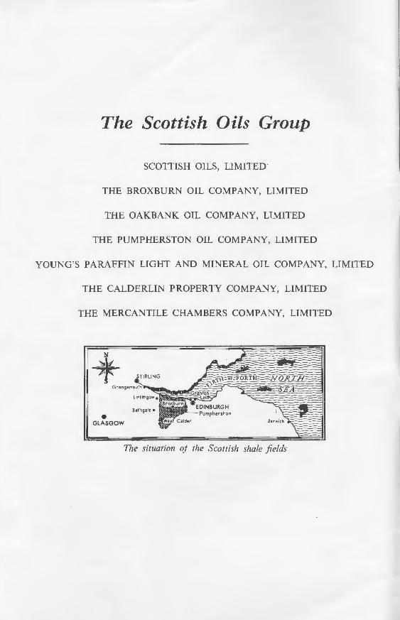
The Scottish Oils Group
SCOTTISH OILS, LIMITED
THE BROXBURN OIL COMPANY, LIMITED
THE OAKBANK OIL COMPANY, LIMITED
THE PUMPHERSTON OIL COMPANY, LIMITED
YOUNG'S PARAFFIN LIGHT AND MINERAL OIL COMPANY, LIMITED
THE CALDERLIN PROPERTY COMPANY, LIMITED
THE MERCANTILE CHAMBERS COMPANY, LIMITED
• GLASGOW
The situation oj the Scottish shale fields
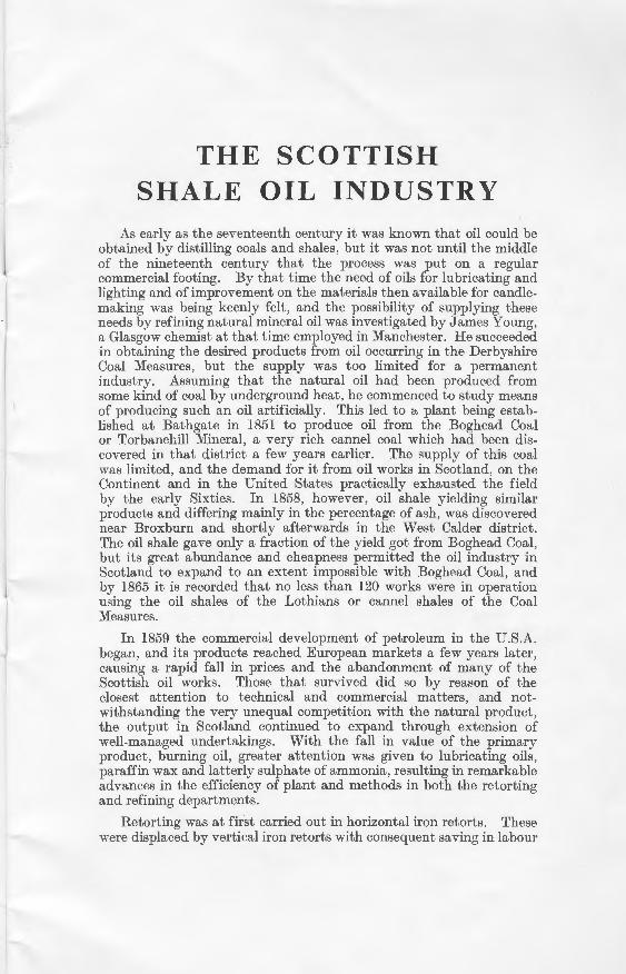
THE SCOTTISH SHALE OIL INDUSTRY
As early as the seventeenth century it was known that oil could be obtained by distilling coals and shales, but it was not until the middle of the nineteenth century that the process was put on a regular commercial footing. By that time the need of oils for lubricating and lighting and of improvement on the materials then available for candlemaking was being keenly felt, and the possibility of supplying these needs by refining natural mineral oil was investigated by James Young, a Glasgow chemist at that time employed in Manchester. He succeeded in obtaining the desired products from oil occurring in the Derbyshire Coal Measures, but the supply was too limited for a permanent industry. Assuming that the natural oil had been produced from some kind of coal by underground heat, he commenced to study means of producing such an oil artificially. This led to a, plant being established at Bathgate in 1851 to produce oil from the Boghead Coal or Torbanehill Mineral, a very rich cannel coal which had been discovered in that district a few years earlier. The sup-ply of this coal was limited, and the demand for it from oil works in Scotland, on the Continent and in the United States practically exhausted the field by the early Sixties. In 1858, however, oil shale yielding similar products and differing mainly in the percentage of ash, was discovered near Broxburn and shortly afterwards in the West Calder district. The oil shale gave only a fraction of the yield got from Boghead Coal, but its great abundance and cheapness permitted the oil industry in Scotland to expand to an extent impossible with Boghead Coal, and by 1865 it is recorded that no less than 120 works were in operation using the oil shales of the Lothians or cannel shales of the Coal Measures.
In 1859 the commercial development of petroleum in the U.S.A. began, and its products reached European markets a few years later, causing a rapid fall in prices and the abandonment of many of the Scottish oil works. Those that survived did so by reason of the closest attention to technical and commercial matters, and notwithstanding the very unequal competition with the natural product, the output in Scotland continued to expand through extension of well-managed undertakings. With the fall in value of the primary product, burning oil, greater attention was given to lubricating oils, paraffin wax and latterly sulphate of ammonia, resulting in remarkable advances in the efficiency of plant and methods in both the retorting and refining departments.
Retorting was at first carried out in horizontal iron retorts. These were displaced by vertical iron retorts with consequent saving in labour
4
and improvement in yields. Arrangements were then introduced by which the fixed carbon of the spent shale was utilised as fuel (Henderson 1873) and in the Young and Beilby retort of 1882 a great advance was made in ammonia recovery by the use of steam. In 1894 the Pumpherston retort was patented by Bryson, Jones & Fraser, in which the Young & Beilby principle was embodied in greatly improved mechanical design with a marked gain in economy and control of operation. The We>.twood Retort erected in 1941 marks the highest development attained in the design of such plant.
The output of shale reached a maximum of 3l million tons in 1913, when further development was checked by the First World War. During the war a sch< me for the joint marketing of certain products was brought into operation, and on the conclusion of the war this was extended to deal with all products. At the same time the six surviving companies were brought under one management, their ordinary shares being acquired by a new company, Scottish Oils, Ltd., whose ordinary capital in turn was subscribed by the Anglo-Persian Oil Co., Ltd., now the Anglo-Iranian Oil Co., Ltd. The economic difficulties of the subsequent period have brought about successive reductions in the scale of operations until to-day the output of shale is a little short of I i million tons per annum. This output is drawn from 11 shale mines, retorted in 4 crude oil works, and the crude products are refined in a central refinery at Pumpherston. In addition there are 2 sulphuric acid works, a candle factory and a brickwork. The technical headquarters of the industry are at Middleton Hall, Uphall, and mining and manufacturing operations are carried on in the districts of West Calder, Pumpherston, Broxburn and Winchburgh. In all nearly 4,000 men are employed.
Oil shale is dark brown to black in colour with a laminated structure which is more obvious after retorting than in its natural state. It. shows a brown streak, and rich specimens can be cut with a sharp knife giving a thin curly shaving like leather or rubber. It contains about 80% of ash, which consists mainly of silica and alumina. The oil shales of the Lothians occur in the Calciferous Sandstone Series near the base of the Carboniferous system, constituting a local development peculiar to West and Mid Lothian and adjacent portions of Fife and Lanark.
A full description of the geology of the oil shales, the method:; employed in mining, the chemistry and methods of manufacture, is contained in the Memoir of the Scottish Geological Survey on " The Oil Shales of the Lothians " (Third Edition, 1927) and "Oil Shale and Cannel Coal 1938."
December, 1951
The following pages give an account of the operations carried on at typical units, namely, at Burngrange Pit, near West Calder Station, at Westwood Crude Oil Works, near West Calder Station, and at Pumpherston Refinery, near Uphall Station.
5
BURNGRANGE PIT.
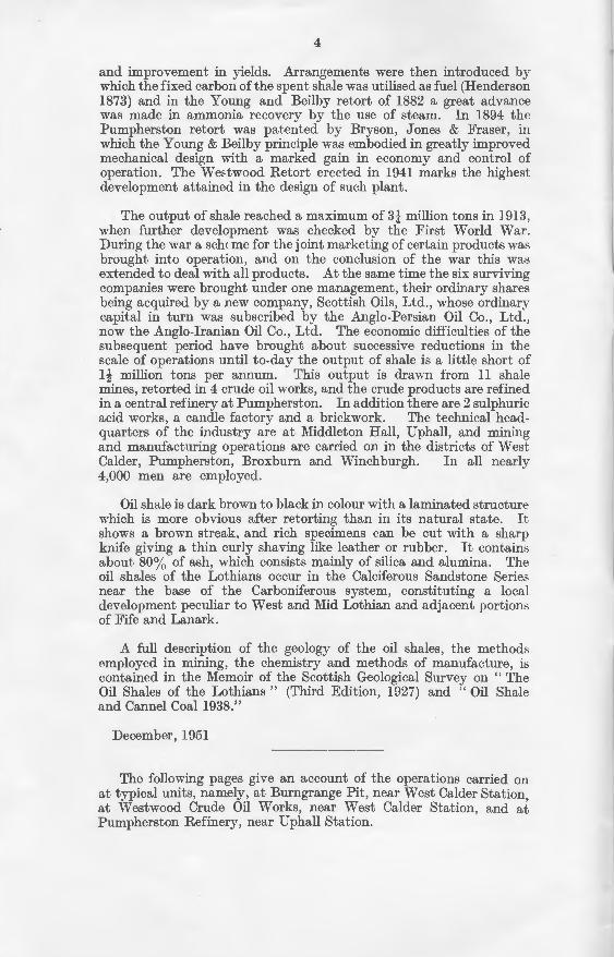
This pit is situated immediately to the South-West of West Calder, and is about 280 yards West of the petroleum bore put down in the year I9I9 by Messrs. S. Pearson & Son to a depth of 3,9IO feet. It commands an area of approximately 650 acres of the Dunnet seam of shale lying between Polbeth and Westwood Pit to the North and a large upthrow fault to the South. The seam has an average thickness of IO feet, and dips at a regular gradient of I3 degrees (I in 4.5) to the West and rises from the shaft bottom at the same inclination for about 300 yards to the East, where it flattens out and then begins to dip-thus forming an anticline.
BuRNGRANGE PITS, WEST CALDER.
The sinking of the two vertical shafts was begun in I935 and completed in I936. Each is I4 ft. in diameter and 468 feet deep, with a 9-in. lining of SOL bricks manufactured from spent shale by the company at Pumpherston. The downcast or winding shaft. (No. I) is equipped for an output of I,OOO tons per 8-hour shift. The men are also lowered and raised in this shaft, the upcast being used for winding only in case of emergency. In the winding shaft there are two single-deck cages holding two hutches in tandem and fitted with controllers which are operated through levers by the pithead and pitbottom controllers. Each hutch weighs about 6 cwts., and holds about one ton of oil shale, so that the load lifted from the pit bottom is about 52 cwts. The shaft is equipped with three It in. dia. guide ropes to each cage and two It in. dia. rubbing ropes between the cages, which are kept taut by large weights at the bottom. The winding ropes are It in. dia. steel wire flattened strand ropes attached to the cages by Martin's detaching hooks.
6
The cables carrying electric power underground and the water pipes for the pumps are fitted in the upcast shaft.
Electric power is used throughout, being supplied through an underground cable from the power station at Addiewell Works, which is about a mile distant. It is transmitted as alternating current at 3300 volts and transformed at the pit to 440 volts at 50 cycles for use above and below ground for power purposes, and llO volts for lighting.
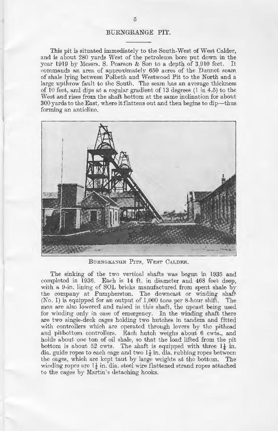
A TYPICAL ELECTRIC WINDER.
The electric winder on No. 1 shaft is designed for an output of 120 tons per hour. The maximum speed of the cage in the shaft is only 12 ft. per second, and this low speed, together with the bicylindroconical drum of 8 ft. on small diameter and 10 ft. on large diameter, keeps down the peak load in the power station. The drum is driven from the winder motor through a double helical machine-cut gear having a ratio of 10.6 to I. The winder motor is a continuously rated 170 h.p. screen-protected machine, running at 235 revs. per minute, and has connected across the stator circuit a 98 K.V.A. static condenser. The brakes on the winding drum are controlled through an oil-brake engine, with an oil pressure of 100 lbs. per sq. in. An automatic accelerating device is provided to control the speed of the winder motor during acceleration.
Automatic safety devices are so arranged that the main switch is thrown out when any of the following circumstances occurs :-
1. If enginemen's emergency button is pressed. 2. If brake is not at "on" position after a failure of supply. 3. If stator switch is not at "off" after a failure of supply. 4. If cage overwinds and operates two limit switches on pithead.
7
5. If cage overwinds and operates two switches on the " Lilly " controller.
6. If cage is overspeeding when coming near pithead, a switch on " Lilly " controller operates.
When the main switch is open, a solenoid under the control platform becomes de-energised, thereby releasing a dead weight of llO lbs., which in turn operates the oil break engine, thus automatically applying the brakes.
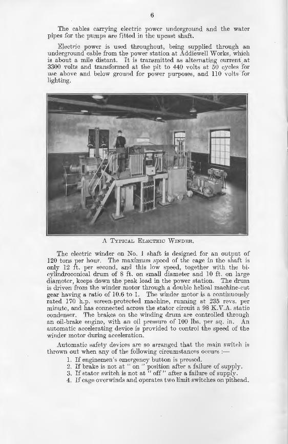
ELECTRIC DRILLING MACHINE AT WORK UNDERGROUND.
The winder on No. 2 shaft is only used in case of emergency, and an ordinary 60 h.p. double-drum haulage is installed. This winder operates single decked cages running in wooden guides.
The ventilating fan is an 84-in. dia. double inlet Sirocco fan running at 160 revs. per minute driven by a 60 h.p. motor through a Tex rope drive. At this speed the fan is capable of delivering 100,000 cubic ft. of air per minute at a 2-in. water gauge, while at 253 revs. it can deliver 150,000 cubic ft. of air per minute with a 4-in. water gauge. It is connected to No. 2 shaft (upcast) by means of a drift.
The pit bottom is 13 ft. wide and 10 ft. high for a distance of 38 ft., and thereafter 16 ft. wide and 10 ft. high to the main dook (Dipping Mine). The sides are lined with SOL bricks and the roof consists of 8 in. by 6 in. R.S. joists 2 ft. apart, with pre-case concrete blocks filling in the spaces between the girders.
8
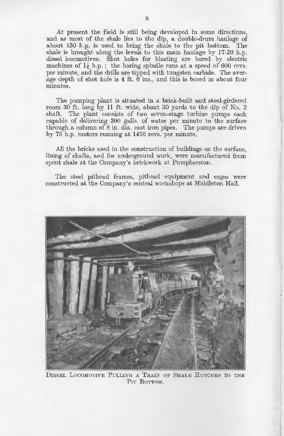
At present the field is still being developed in some directions, and as most of the shale lies to the dip, a double-drum haulage of about 150 h.p. is used to bring the shale to the pit bottom. The shale is brought along the levels to this main haulage by 17-20 h.p. diesel locomotives. Shot holes for blasting are bored by electric machines of 1! h.p. ; the boring spindle runs at a speed of 600 revs. per minute, and the drills are tipped with tungsten carbide. The average depth of shot hole is 4 ft. 6 ins., and this is bored in about four minutes.
The pumping plant is situated in a brick-built and steel-girdered room 30 ft. long by ll ft. wide, about 30 yards to the dip of No. 2 shaft. The plant consists of two seven-stage turbine pumps each capable of delivering 300 galls. of water per minute to the surface through a column of 8 in. dia. cast iron pipes. The pumps are driven by 75 h.p. motors running at 1470 revs. per minute.
All the bricks used in the construction of buildings on the surface, lining of shafts, and for underground work, were manufactured from spent shale at the Company's brickwork at Pumpherston.
The steel pithead frames, pithead equipment and cages were constructed at the Company's central workshops at Middleton Hall.
DIESEL LocoMOTIVE PuLLING A TRAIN OF SHALE HuTCHES TO THE
PIT BoTTOM.
lS,
of ~e .p. ric rs. ~r-
ur
ed 2
ch ce
m
re
9
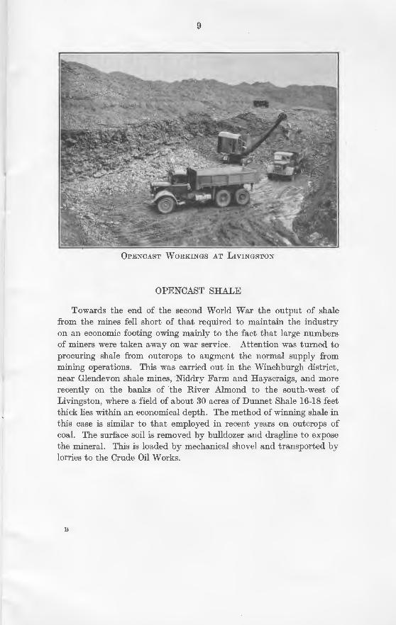
0PENCAST WORKINGS AT LIVINGSTON
OPENCAST SHALE
Towards the end of the second World War the output of shale from the mines fell short of that required to maintain the industry on an economic footing owing mainly to the fact that large numbers of miners were taken away on war service. Attention was turned to procuring shale from outcrops to augment the normal supply from mining operations. This was carried out in the Winchburgh district, near Glendevon shale mines, Niddry Farm and Hayscraigs, and more recently on the banks of the River Almond to the south-west of Livingston, where a field of about 30 acres of Dunnet Shale 16-18 feet thick lies within an economical depth. The method of winning shale in this case is similar to that employed in recent years on outcrops of coal. The surface soil is removed by bulldozer and dragline to expose the mineral. This is loaded by mechanical shovel and transported by lorries to the Crude Oil Works.
B
10
TRANSPORT OF RAW SHALE
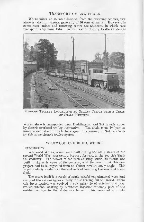
Where mines lie at some distance from the retorting centres, raw shale is taken in wagons , generally of 10 tons capacity. However, in some cases, mines and retorting centre are adjacent, in which case transport is by mine tubs. In the case of Niddry Castle Crude Oil
ELECTRIC TROLLEY LocoMOTIVE AT NmDRY CASTLE WITH A TRAIN
OF SHALE HUTCHES.
Works, shale is transported from Duddingston and Tottlywells mines by electric over-head trolley locomotive. The shale from Philpstoun mines is also taken in the latter stages of its journey to Niddry Castle by this same electric trolley system.
WESTWOOD CRUDE OIL WORKS
INTRODUCTION.
Westwood Works, which were built during the early stages of the second World War, represent a big step forward in the Scottish Shale ()il Industry. The newegt of the then existing Crude Oil Works was built in the early years of the century, with the result that this new project had to be regarded from an almost revolutionary angle. This is particularly evident in the methods of handling the raw and spent shale.
The retort itself is a result of much careful experimental work and study of the various types already in use throughout the world. From this investigation was evolved a new principle of external and controlled internal heating by air/steam injection whereby part of the residual carbon in the shale was burnt. This provided not only
'es, raw ever, in ch case .tde Oil
'RAIN
nmes stoun ~astle
f the )hale ,was new This pent
and 'rom con-the
only
ll
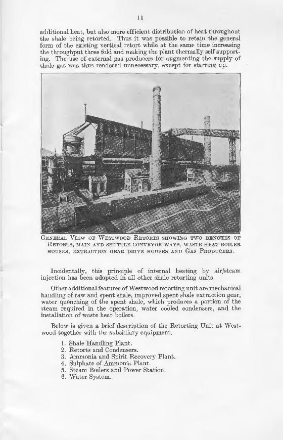
additional heat, but also more efficient distribution of heat throughout the shale being retorted. Thus it was possible to retain the general form of the existing vertical retort while at the same time increasing the throughput three fold and making the plant thermally self supporting. The use of external gas producers for augmenting the supply of shale gas was thus rendered unnecessary, except for starting up.
GENERAL VIEW OF WESTWOOD RETORTS SHOWING TWO BENCHES OF
RETORTS, MAIN AND SHUTTLE CONVEYOR WAYS, WASTE HEAT BOILER
HOUSES, EXTRACTION GEAR DRIVE HOUSES AND GAS PRODUCERS.
Incidentally, this principle of internal heating by air/steam injection has been adopted in all other shale retorting units.
Other additional features of Westwood retorting unit are mechanical handling of raw and spent shale, improved spent shale extraction gear, water quenching of the spent shale, which produces a portion of the steam required in the operation, water cooled condensers, and the installation of waste heat boilers.
Below is given a brief description of the Retorting Unit at West-wood together with the subsidiary equipment.
l . Shale Handling Plant. 2. Retorts and Condensers. 3. Ammonia and Spirit Recovery Plant. 4. Sulphate of Ammonia Plant. 5. Steam Boilers and Power Station. 6. Water System.
I2
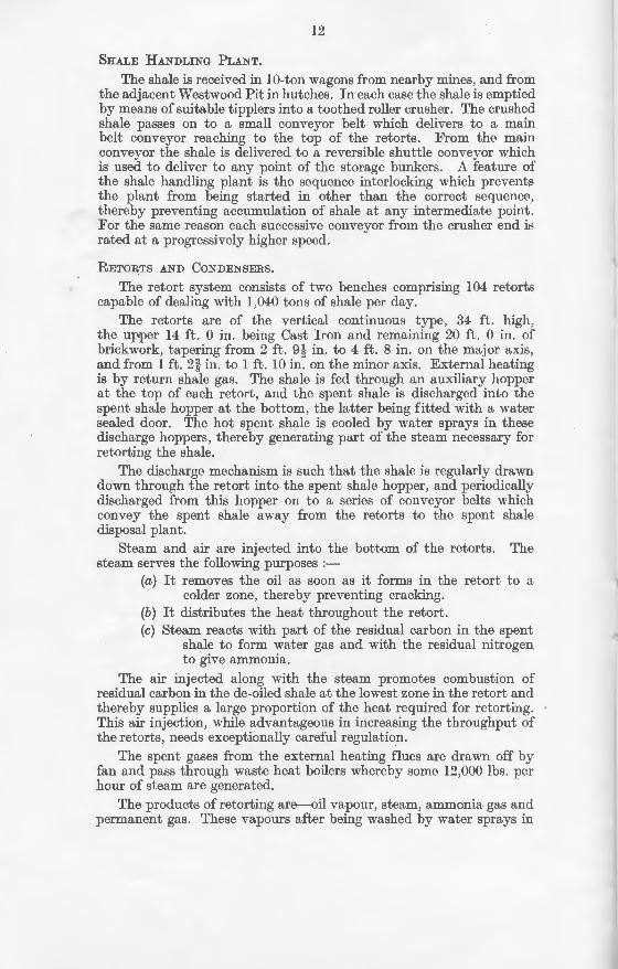
SHALE HANDLING PLANT.
The shale is received in IO-ton wagons from nearby mines, and from the adjacent Westwood Pit in hutches. In each case the shale is emptied by means of suitable tipplers into a toothed roller crusher. The crushed shale passes on to a small conveyor belt which delivers to a main belt conveyor reaching to the top of the retorts. From the main conveyor the shale is delivered to a reversible shuttle conveyor which is used to deliver to any point of the storage bunkers. A feature of the shale handling plant is the sequence interlocking which prevents the plant from being started in other than the correct sequence, thereby preventing accumulation of shale at any intermediate point. For the same reason each successive conveyor from the crusher end ir; rated at a progressively higher speed.
RETORTS AND CONDENSERS.
The retort system consists of two benches comprising I 04 retorts capable of dealing with I,040 tons of shale per day.
The retorts are of the vertical continuous type, 34 ft. high, the upper 14 ft. 0 in. being Cast Iron and remaining 20 ft. 0 in. of brickwork, tapering from 2 ft. 9-l in. to 4 ft. 8 in. on the major axis, and from I ft. 2~ in. to 1 ft. 10 in. on the minor axis. External heating is by return shale gas. The shale is fed through an auxiliary hopper at the top of each retort, and the spent shale is discharged into the spent shale hopper at the bottom, the latter being fitted with a water sealed door. The hot spent shale is cooled by water sprays in these discharge hoppers, thereby generating part of the steam necessary for retorting the shale.
The discharge mechanism is such that the shale is regularly drawn down through the retort into the spent shale hopper, and periodically discharged from this hopper on to a series of conveyor belts which convey the spent shale away from the retorts to the spent shale disposal plant.
Steam and air are injected into the bottom of the retorts. The steam serves the following purposes :-
(a) It removes the oil as soon as it forms in the retort to a colder zone, thereby preventing cracking.
(b) It distributes the heat throughout the retort. (c) Steam reacts with part of the residual carbon in the spent
shale to form water gas and with the residual nitrogen to give ammonia.
The air injected along with the steam promotes combustion of residual carbon in the de-oiled shale at the lowest zone in the retort and thereby supplies a large proportion of the heat required for retorting. This air injection, while advantageous in increasing the throughput of the retorts, needs exceptionally careful regulation.
The spent gases from the external heating flues are drawn off by fan and pass through waste heat boilers whereby some I2,000 lbs. per hour of steam are generated.
The products of retorting are-oil vapour, steam, ammonia gas and permanent gas. These vapours after being washed by water sprays in
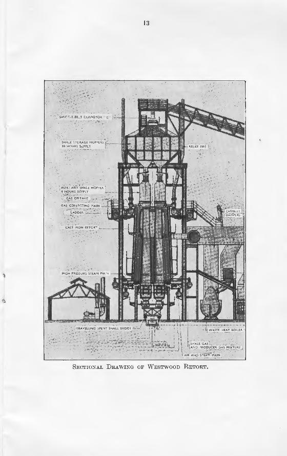
SHUT flE BELT CONVEYOR "C "
i AUXILIARY SHALE HOPPEA 1
-4 HOURS SlJPPL Y
GAS OFFTAKE
G·As C?_LLECTING MAIN r
lAODER i-
CAST IRON RETORT :..
13
•.
l SHALE CAS \ ~ ~ .,.. ~ L\ At~p PROJ?UCE,~AS MIXT~REJ
lf A IR AND STeAM MAIN
SECTIONAL DRAWING OF WESTWOOD RETORT.
14
the retort main are drawn by the exhausters through water cooled condensers where crude oil and ammonia liquor collect. The exhausters are B.T.H. machines capable of dealing with one million cubic feet of gas per hour.
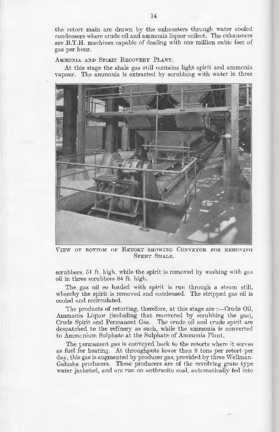
AMMONIA AND SPIRIT RECOVERY PLANT.
At this stage the shale gas still contains light spirit and ammonia vapour. The ammonia is extracted by scrubbing with water in three
VIEW OF BOTTOM OF RETORT SHOWING CONVEYOR FOR REMOVING
SPENT SHALE.
scrubbers, 51 ft. high , while the spirit is removed by washing 11·ith gas oil in three scrubbers 84ft. high.
The gas oil so loaded with spirit is run through a steam still , whereby the spirit is removed and condensed. The stripped gas oil is cooled and recirculated.
The products of retorting, therefore, at this stage are :-Crude Oil , Ammonia Liquor (including that recovered by scrubbing the gas), Crude Spirit and Permanent Gas. The crude oil and crude spirit are despatched to the refinery as such, while the ammonia is converted to Ammcnium Sulphate at the Sulphate of Ammonia Plant.
The permanent gas is conveyed back to the retorts where it serves as fuel for heating. At throughputs lower than 8 tons per retort per day, this gas is augmented by producer gas, provided by three WeHmanGalusha producers. These producers are of the revolving grate type water jacketed, and are run on anthracite coal, automatically fed into
I
Hi
the producer from a storage hopper above. Scrubbing with water gives a clean gas for use as fuel.
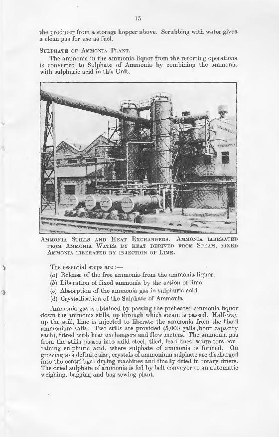
SuLPHATE oF AMMONIA PLANT.
The ammonia in the ammonia liquor from the retorting operations is converted to Sulphate of Ammonia by combining the ammonia. with sulphuric acid in this Unit.
AMMONIA S1'ILLS AND HEAT EXCHANGERS. AMMONIA LIBERATED
FROM AMMONIA WATER BY HEAT DERIVED FROM STEAM, FIXED·
AMMONIA LIBERATED BY INJECTION OF LIME.
The essential steps are :-(a) Release of the free ammonia from the ammonia liquor. (b) Liberation of fixed ammonia by the action of lime. (c) Absorption of the ammonia gas in sulphuric acid. (d) Crystallisation of the Sulphate of Ammonia.
Ammonia gas is obtained by passing the preheated ammonia liquor· down the ammonia stills, up through which steam is passed. Half-way up the still, lime is injected to liberate the ammonia from the fixed ammonium salts. Two stills are provided (5,000 galls.jhour capacity each) , fitted with heat exchangers and flow meters. The ammonia gas. from the stills passes into mild steel, tiled , lead-lined saturators containing sulphuric acid, where sulphate of ammonia is formed. On growing to a definite size, crystals of ammonium sulphate are discharged into the centrifugal drying machines and finally dried in rotary driers. The dried sulphate of ammonia is fed by belt conveyor to an automati~ weighing, bagging and bag sewing plant.
16
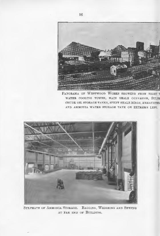
PANORAMA OF WESTWOOD WORKS SHOWING FROM RIGHT TO LEF'
WATER COOLING TOWER, MAIN SHALE CONVEYOR, SULPHATE 0
CRUDE OIL STORAGE TANKS, SPENT SHALE BINGS, EXHAUSTER HOUSE
AND AMMONIA WATER STORAGE TANK ON EXTREME LEFT.
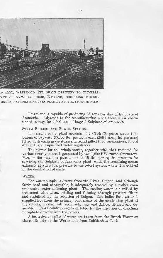
SULPHATE OF AMMONIA STORAGE. BAGGING, WEIGHING AND SEWING
AT FAR END OF BUILDING.
I
17
lHT TO LEFT, WESTWOOD PIT, SHALE DELIVERY TO CRUSHERS,
IULPHATE OF AMMONIA HOUSE, RETORTS, SCRUBBING TOWERS,
'STEH. HOUSE, NAPHTHA RECOVEH.Y PLANT, NAPHTHA STOH.AGE TANK,
EFT.
This plant is capable of producing 66 tons per day of Sulphate of Ammonia. Adjacent to the manufacturing plant there is air conditioned storage for 2,500 tons of bagged Sulphate of Ammonia.
STEAM BoiLERS AND PowER STATION.
The steam boiler plant consists of 4 Clark-Chapman water tube boilers of capacity 30,000 lbs. per hour each (200 lbs.fsq. in. pressure) fitted with chain grate stokers, integral gilled tube economisers, forced draught, and Copes feed water regulators.
The power for the whole works, together with that required for various nearby mines, is generated by two 1,800 KW. turbo alternators. Part of the steam is passed out at 15 lbs. per sq. in. pressure for servicing the Sulphate of Ammonia plant, while the remaining steam exhausts at a few lbs. pressure to the retort system where it is utilised in the distillation of shale.
WATEH..
The water supply is drawn from the River Almond, and although fairly hard and changeable, is adequately treated by a rather comprehensive water softening plant. The cooling water is clarified by treatment with alum, settling and filtering through pressure filters and stabilised by the addition of Calgon. The boiler feed water is supplied hot from the primary condensers of the condensing plant at the retorts, treated with soda ash, lime and Alfloc, filtered and deaerated. Final conditioning is effected by the injection of disodium phosphate directly into the boilers.
Alternative supplies of water are taken from the Breich 'Vater on the south side of the Works and from Cobbimhaw Loch.
18
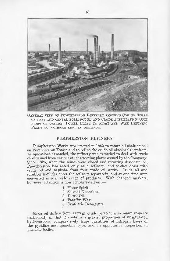
GENERAL VIEW OF PUMPHERSTON REFINERY SHOWING COKING STILLS
ON LEFT AND CENTRE FOREGROUND AND CRUDE DISTILLATION UNIT
RIGHT OF CENTRE, POWER PLANT TO RIGHT AND WAX REFINING
PLANT TO EXTREME LEFT IN DISTANCE.
PUMPHERSTON REFINERY
Pumpherston Works was erected in 1883 to retort oil shale mined on Pumpherston Estate and to refine the crude oil obtained therefrom. As operations expanded, the refinery was extended to deal with crude oil obtained from various other retorting plants owned by the Company. Since 1925, when the mines were closed and retorting discontinued, Pumpherston has acted only as a refinery, and to-day deals 11·ith crude oil and naphtha from four crude oil works. Crude oil and scrubber naphtha enter the refinery separately, and at one time were converted into a wide range of products. With changed markets, however, attention is now concentrated on :-
1. Motor Spirit. 2. Solvent Naphthas. 3. Diesel OiL 4. Paraffin Wax. 5. Synthetic Detergents.
Shale oil differs from average crude petroleum in many respects particularly in that it contains a greater proportion of unsaturated hydrocarbons, comparatively large quantities of nitrogen bases of the pyridine and quinoline type, and an appreciable proportion of phenolic bodies.
19
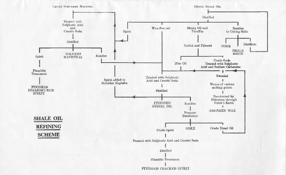
The refining of crude shale oil is achieved by :-1. Separation of the various components by distillation. 2. Purification by chemical treatment. 3. Extraction and refining of paraffin wax.
The chart (on page 31) shows diagrammatically the main processes to which the crude oil and scrubber naphtha are subjected in order to obtain the above products.
Briefly, the essential processes in refining crude oil are:-
(1) Splitting the crude oil into various fractions by distillation to coke.
(2) Extraction of wax from wax-bearing cut. (3) Acid and Soda treatment of wax-free oil and re-running
treated diesel oil. (4) Pressure distillation of the heavy residue. (5) Refining of crude wax. (6) Refining of Motor Spirit.
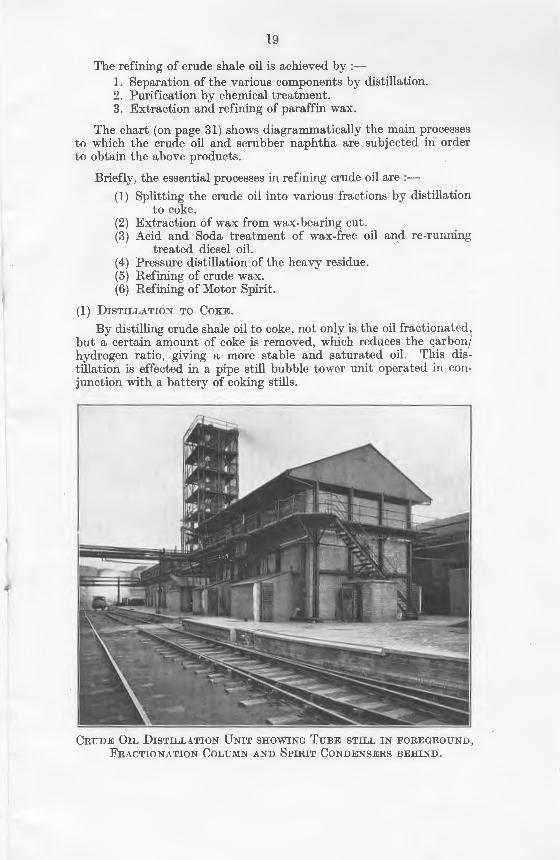
(l) DISTILLATION TO COKE.
By distilling crude shale oil to coke, not only is the oil fractionated, but a certain amount of coke is removed, which reduces the carbon/ hydrogen ratio, giving a more stable and saturated oil. This distillation is effected in a pipe still bubble tower unit operated in conjunction with a battery of coking stills.
CRUDE OIL DISTILLATION UNIT SHOWING TUBE STILL IN FOREGROUND,
1l'RACTIONATION CoLUMN AND SPIRIT CoNDENSERS BEHIND.
20
The pipe still bubble tower unit has a capacity of 160,000 g.p.d., and is of conventional design. The products from this unit are :-
Crude Spirit 6% Wax-free Cut ... 23% Wax-bearing Cut 56% Residue . . . 15%
The residue is run to coke in batch stills working semi-continuously. This coking distillation results in slight cracking, rendering 70% of the distillate available for incorporation in the wax-bearing cut. Accordingly this distillate is recycled through the crude unit.
The coke is of low ash content and contains about 5% of volatile matter. Calcination to reduce the volatile matter to less than I % results in an excellent raw material for the production of electrodes for the aluminium industry.
The overhead from the pipe still distillation of crude oil joins the scrubber naphtha recovered from the crude works retort gases. These are refined together for the production of Motor Spirit. The wax-free oil and wax-bearing cut form the basis of Diesel Oil and Wax.
(2) ExTRACTION oF WAx FROM WAx-BEARING CuT. The next step is the removal of the crude waxes from the wax
bearing press cut. This is done by filtering a blend of wax-free oil and press cut through a 500-plate filter press operating at 500 lbs.fsq. in. The process is carried out in two stages at 38"F. and 20°F. The wax/ oil mixture is cooled in double pipe heat exchangers fitted with internal scrapers, first with cold oil from the filter presses and secondly with liquid ammonia. The ammonia refrigerating system is operated by 50-ton Sterne compressors driven by ll5 H.P. motors.
The dewaxed oil is of low setting point and the crude wax contains 15% of oil.
(3) Acm AND SoDA TREATMENT oF WAx-FREE OIL. The wax-free oil and the dewaxed oil con'3titute the bulk of the
crude diesel, the remainder of the blend being made up by spirit bottoms and cracked diesel oil. This crude diesel oil, owing to the presence of phenols and pyridine bases, is unstable and requires treatment and redistillation to meet present-day specification for DERV Fuel. The treatment given is 2% of 96% acid at l00°F., and is accomplished by air agitation. The acid treated oil is neutralised by agitation with 10% caustic soda solution and then re-run in a pipe still/bubble tower unit. Overhead is taken a small quantity of spirit to correct the flash point of the diesel oil. Diesel oil is taken off as a tray cut, while the residue provides the charging stock for the cracking plant.
This diesel oil, of high cetane number and low setting point, is an excellent fuel for diesel engined road vehicles.
(4) PRESSURE DISTILLATION OF RESIDUE. The residue from the diesel distillation is still a potential source
af diesel, and by distillation under pressure, i. e. a mild cracking, yields some 70% diesel oil and 20% motor spirit. The diesel oil so
21
produced joins the crude diesel oil from the wax extraction process, while the motor spirit joins the scrubber naphtha for finishing treatment.
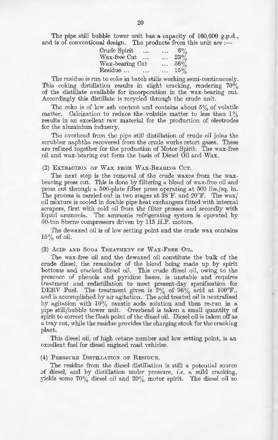
(5) REFINING OF CRUDE WAX.
The production of finished wax from crude wax entails :-(a) Acid and soda treatment to remove unstable material. (b) Sweating to remove oil and to divide the wax into grades
according to melting point. (c) Decolorising of individual waxes to definite colour specifica
tions.
AMMONIA COMPRESSORS USED FOR PROVIDING THE CooLING MEDIUM
IN THE WAx ExTRACTION PLANT.
(a) The crude wax as obtained from the filter presses contains 15% oil, and is dark in colour and unstable, due principally to this oil content. Treatment with sulphuric acid and sodium carbonate is required, and this is carried out in vertical cylindrical cone bottomed vessels with air agitation.
(b) Crude wax is a mixture of solid hydrocarbons, varying in the case of shale wax from melting point of 140° F. to 95° F., together with 15% oil. Removal of the oil and fractionation of the hydrocarbons into waxes of specified melting points are accomplished by sweating. This consists in gradually heating the solid wax, whereby oil is run offfollowed by wax of successively higher melting points. Until 1939, sweating was carried out in Henderson sweaters, but new vertical type sweaters have been designed and are in operation. These vertical
22
tube sweaters are simple in design, and have a very much greater heating surface in relation to the quantity of wax sweated than the Henderson sweaters. They are vertical cylindrical vessels, 20 ft. 6 in. high by 9 ft. 6 in. diam., with tube plates top and bottom, and have 2,300-!-in. mild steel tubes. The capacity of each sweater is 20 tons of wax and it has a heating surface of 370 sq. ft. per ton of wax sweated. Twelve of these sweaters are available.
Molten wax is pumped into the space between the tube plates. After charging, the wax is cooled by circulating cold water through the tubes and when solid, sweating is started. This is effected by gradually increasing the temperature of the water passing through the tubes until a residue of the desired melting point is obtained. The rate of heating is automatically controlled by the introduction of steam into the circulating water system, and the controller, after being set, increases the water temperature by a definite amount per hour to a given maximum and maintains it at that maximum.
First, oil comes off the sweater, and then wax of higher and higher melting point, until the re~idue in the stove is of the desired melting point.
The advantages of this sweater over the old type Henderson unit are:-
(I) Reduction in time cycle per sweating operation. (2) Reduction in steam consumption. (3) More accurate control, and therefore more regular pro
duction.
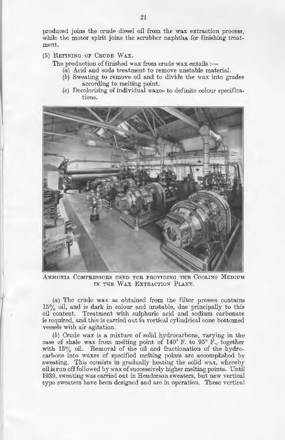
FILTER PRESSES IN WHICH THE CRUDE WAX IS EXTRACTED FROM THE
CoOLED WAX BEARING OIL.
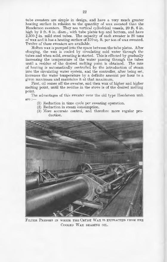
VERTICAL TuBE SwEATERS FOR DE-OILING AND SEPARATING WAx
I~ TO V ARlO US GRADES PRIOR TO DECOLORISING PROCESS.
The cmde wax having been de-oiled and sweated into waxes of definite melting point, must now be decolorised to definite colour specifications required by the market.
Decolorising is effected by passing the molten wax through a vertical column of bleaching earth enclosed in a steam jacketed mild steel cylinder. The decolorised wax is then cast into trays, and " ·hen cold removed in slabs and packed for despatch.
The bleaching earth, Floridin in this case, is regenerated by first washing out the adhering wax with solvent nahptha. Secondly, the naphtha is stripped from the earth by steam, and the earth is dischE-.rged from the filter for re-activation by heating in a rotary furnace to l000°F.
The solid wax is ready for the market or for candle making, which is carried on at the works of The Broxburn Oil Company, Limited, at Broxburn.
The wax is also used for matches, for waterproofing paper, textiles a.nd leather, for grease-proof packings for food, for electrical insulation, ancl for many other purposes.
(6) REFINING OF MoTOR SPIRIT.
The basic material for motor spirit consists of :-(a) Scrubber Naphtha received from the Crude Works. (b) The lightest portion from the pipe still distillation of (rude
oil. (c) Spirit from the cracking of oil heavier than diesel oil.
24
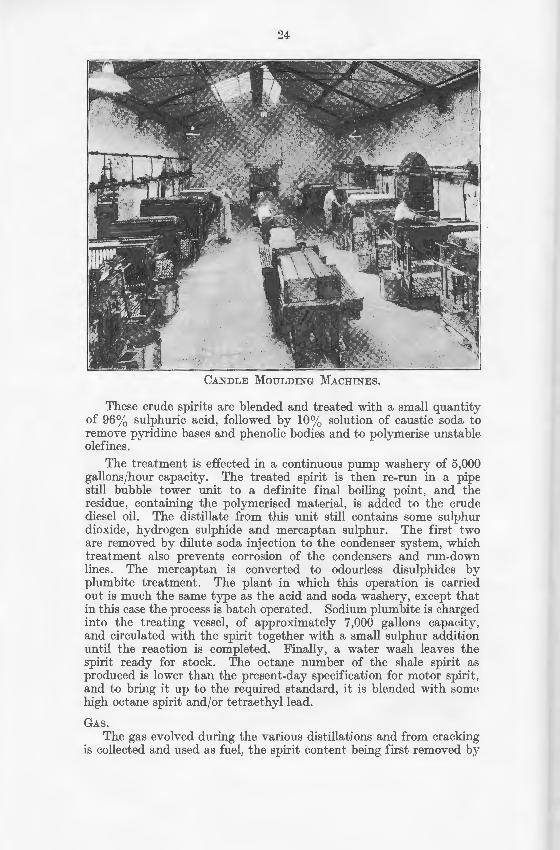
CANDLE MOULDING MACHINES.
These crude spirits are blended and treated with a small quantity of 96% sulphuric acid, followed by 10% solution of caustic soda to remove pyridine bases and phenolic bodies and to polymerise unstable olefines.
The treatment is effected in a continuous pump washery of 5,000 gallons/hour capacity. The treated spirit is then re-run in a pipe still bubble tower unit to a definite final boiling point, and the residue, containing the polymerised material, is added to the crude diesel oil. The distillate from this unit still contains some sulphur dioxide, hydrogen sulphide and mercaptan sulphur. The first two are removed by dilute soda injection to the condenser system, which treatment also prevents corrosion of the condensers and run-down lines. The mercaptan is converted to odourless disulphides by plumbite treatment. The plant in which this operation is carried out is much the same type as the acid and soda washery, except that in this case the process is batch operated. Sodium plum bite is charged into the treating vessel, of approximately 7,000 gallons capacity, and circulated with the spirit together with a small sulphur addition until the reaction is completed. Finally, a water wash leaves the spirit ready for stock. The octane number of the shale spirit as produced is lower than the present-day specification for motor spirit, and to bring it up to the required standard, it is blended with some high octane spirit and/or tetraethyllead.
GAS.
The gas evolved during the various distillations and from cracking is collected and used a.s fuel, the spirit content being first removed by
25
absorption in gas oil, and the naphtha so obtained added to the crude scrubber naphtha for refining.
Acm AND SoDA TARS.
The tars removed from shale oil by the various acid and soda treatments amount to ll/12% on crude. From the acid tar, the free sulphuric acid is recovered and used for the production of Sulphate of Ammonia, while the organic component, after settling, provides all the fuel required in the refinery with the exception of that required for steam raising.
MANUFACTURE OF AMMONIUM SuLPHATE.
Ammonium sulphate is manufactured at Pumpherston from ammonia liquor supplied by adjacent Crude Oil Works. The ammonia is liberated from the liquor in the same manner as at Westwood, i.e., by distillation with steam in a vertical still, but the method of c.oncentration and separation of ammonium sulphate is different. The steam and ammonia from the still pass into lead-lined wooden vats containing sulphuric acid recovered from the acid tar as described above. The dilute solution of ammonium sulphate so obtained is clarified and transferred to a vacuum evaporator for concentration. The crystals of ammonium sulphate which separate out are removed from the evaporator, washed free from acid and dried, first by centrifuging, and finally by hot air in an inclined rotary drier. The dry neutral ammonium sulphate is bagged for despatch.
CAUSTIC SoDA AND SuLPHURIC Acm.
Caustic soda required for refining operations is manufactured at Pumpherston by the usual method of adding milk of lime to soda ash solution. The weak caustic soda solution (10% NaOH) is concentrated to any desired strength up to 35% in double effect vacuum evaporators.
The sulphuric acid used in the crude oil works and in refining is produced at the Bathgate Works of Young's Paraffin Light & Mineral Oil Company, Limited, and the Broxburn Works of the Broxburn Oil Company, Limited, using the lead-chamber process.
POWER PLANT.
Steam is provided by nine Stirling boilers, having a total evaporative capacity of approximately 198,000 lb. per hour. These boilers can all be adapted for burning heavy fuel oil or coal as required.
The electrical installation consists of two B.T.H. 1,000 K.W., and one 1500 K.W. Allan-Peebles turbo-alternators generating at 3,300 volts, 50 cycles, and 3-phase. Pass-out steam is bled off for process work, the remainder going to surface condensers.
STORAGE AND DESPATCH OF FINISHED PRODUCTS.
The tankage for finished products alone amounts to 21,000 tons. Facilities for despatch of finished products are provided by four loading banks for (1) wax, (2) spirit, (3) heavy oil, and (4) general barrelling and packing. The last-named comprises a complete barrelling equipment, including cooperage.
26
BRICKMAKING
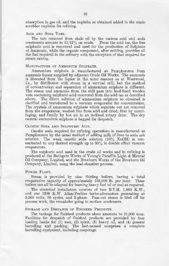
After several years of experimental work it was found possible to make an excellent building brick from spent shale. A plant is in operation at Pumpherston to carry out the manufacture of these bricks which have a crushing strength (wet) of about 3,500 lbs.fsq. in.
SPENT SHALE BRICKS BEING MOULDED PRIOR TO STEAM HARDENING.
Spent shale bricks consist essentially of pulverised spent shale mixed in a pan mill with hydrated lime and lime slurry in carefully defined proportions. This mixture is passed to a brick moulding machine and thence to steam heated ovens or autoclaves.
The steam hardening of the bricks is done by heat derived from superheated steam applied to the autoclaves for a period of 8 or !)
hours.
In addition to the standard sizes of building bricks, certain specially shaped bricks are made.
The lime used for brick manufacture is obtained as lime shell and hydrated on site, the plant for this purpose forming a major p::trt of the brick process.
Brickmaking is carried out in two separate and parallel units capable of turning out 3,000 bricks per hour each.
27
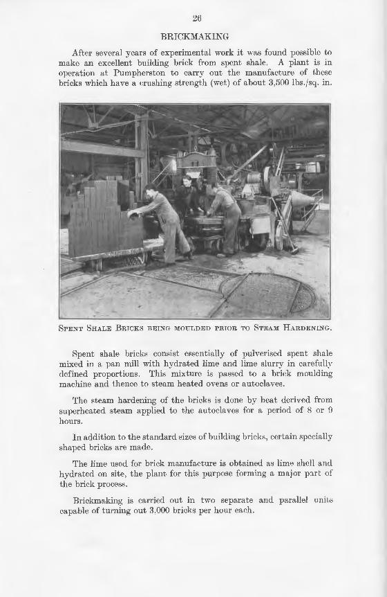
SOL BRICKS Bl~ING LOADED ON ROAD VEHICLES.
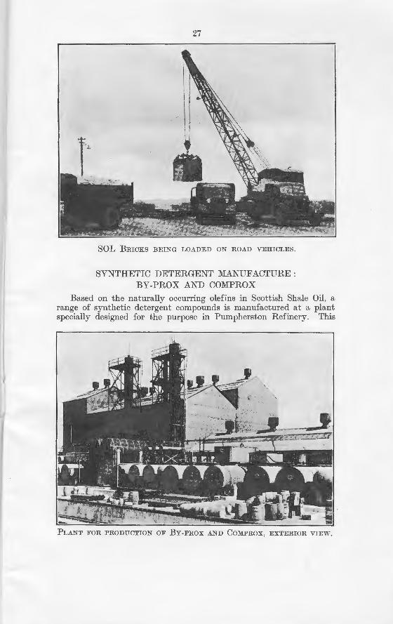
SYNTHETIC DETEH,GENT MANUFACTURE: BY-PROX AND COMPROX
Based on the naturally occurring olefins in Scottish Shale Oil, a range of synthetic detergent compounds is manufactured at a plant specially designed for the purpose in Pumpherston Refinery. This
PLANT FOR PRODUCTION OF BY-PROX AND COMPROX, EXTERIOH VIEW.
28
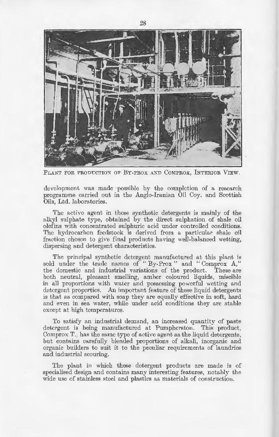
PLANT FOR PRODUCTION OF BY-PROX AND COMPROX, INTERIOR VIEW.
development was made possible by the completion of a research programme carried out in the Anglo-Iranian Oil Coy. and Scottish Oils, Ltd. laboratories.
The active agent in these synthetic detergents is mainly of the alkyl sulphate type, obtained by the direct sulphation of shale oil olefins with concentrated sulphuric acid under controlled conditions. The hydrocarbon feedstock is derived from a particular shale oil fraction chosen to give final products having well-balanced wetting, dispersing and detergent characteristics.
The principal synthetic detergent manufactured at this plant is sold under the trade names of "By-Prox" and "Comprox A," the domestic and industrial variations of the product. These are both neutral, pleasant smelling, amber coloured liquids, miscible in all proportions with water and possessing powerful wetting and detergent properties. An important feature of these liquid detergents is that as compared with soap they are equally effective in soft, hard and even in sea water, while under acid conditions they are stable except at high temperatures.
To satisfy an industrial demand, an increased quantity of paste detergent is being manufactured at Pumpherston. This product, Comprox T., has the same type of active agent as the liquid detergents, but contains carefully blended proportions of alkali, inorganic and organic builders to suit it to the peculiar requirements of laundries and industrial scouring.
The plant in which these detergent products are made is of specialised design and contains many interesting features, notably the wide use of stainless steel and plastics as materials of construction.
29
The products are despatched to all parts of Britain by road and rail, and a considerable proportion of the output is exported to Europe and to the British Commonwealth.
CENTRAL OFFICES, LABORATORIES, STORES, WORKSHOPS,
ETC.
The administration of the Scottish Shale Oil Industry is centred at Middleton Hall , Uphall, with its central offices, Laboratories, Stores, "\Vorkshops, Garages and Motor Repair Centre.
WELFARE:-
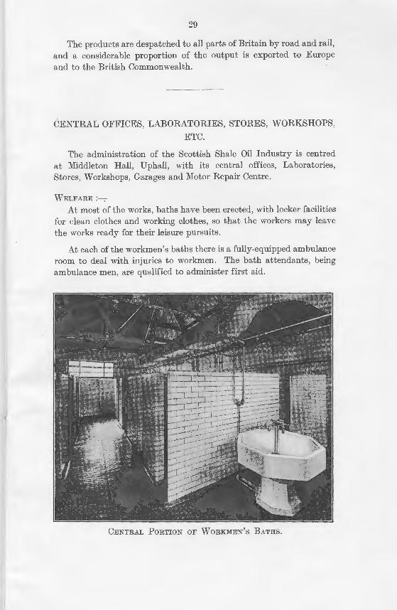
At most of the works, baths have been erected, with locker facilities for clean clothes and working clothes, so that the workers may leave the works ready for their leisure pursuits.
At each of the workmen's baths there is a fully-equipped ambulance room to deal with injuries to workmen. The bath attendants, being ambulance men, are qualified to administer first aid.
CENTRAL PoRTION oF WoRKMEN's BATHS.
30
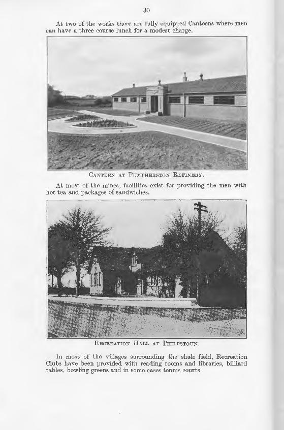
At two of the works there are fully equipped Canteens where men can have a three course lunch for a modest charge.
CANTEEN AT PUMPHERSTON REFINERY.
At most of the mines, facilities exist for providing the men with hot tea and packages of sandwiches.
RECREATION HALL AT PHILPSTOUN.
In most of the villages surrounding the shale field, Recreation Clubs have been provided with reading rooms and libraries, billiard tables, bowling greens and in some cases tennis courts.
::l 0
CRl'DE SCR I"BRER N .-\PIIT IH
Trcat~d with :::lulphuric Acid
and Caustic Soda
I Distilled
I r 1 1 . SOLVENT .
Spirit NAPHTHAS Residue
Plum bite Treatment
CRU!Jt! SI!AL~; OIL
Distilled I
I Wax-free cut Heavy Oil and Residue Spirit 1 Paraffin to Coking Stills
I r- 1 COKE r Distillate Cooled and Filtered
SHALE RESIN
----. Crude Scale
Blue Oil Treated with Sulphuric Acid and Sodium Carbonate
Spirit. added to Tre_ated with Sulphuric Scrubber Naphtha ACid and Caustic Soda
Sweated I
FINISHED STRAIGHT-RUN
SPIRIT
SHALE OIL
REFINING
SCHEME
I Dist:lled ~ I -,
FI~ISHED Residue DIESEL OIL
Pressure Distillation
Waxes. of various melting points
Decolorised by Filtration through
Fuller's Earth
FIN ISH ED WAX
----. Crude Spirit COKE Crude Diesel Oil
Treated with Sulphuric Acid and Caustic Soda
I Distilled
I Plum bite Treatment
FIXISHED CRACKED SPIRIT
, I
SOL BRICKS
HIGH STRENGTH FINE APPEARANCE
REGULAR SHAPE
FOR. HOUSING SCHEMES, FACTORIES
AND OTHER BUILDING PURPOSES
Manufactured only by
SCOTTISH 01 LS, Ll MITED at
PUMPHERSTON WORKS UPHALL
Selling Agents for SOL BRICKS
RANKIN INDUSTRIES, LTD. 19 COMMERCE STREET
GLASGOW : C.S.
Telephone: SOUth 0401
Glasgow
Telegrams : "Bricks
Glasgow"
BY..PROX WASHES £11~ CLEANER
Produced for the Scottish Housewife at Pumpherston Refinery, Midlothian by Scottish Oils Ltd who employ over 4,000 people.
Sole Distributors: Irano Products Ltd 53 Bothwell St Glasgow C2 (Associated with Scottish Oils Ltd)