Embed Size (px)
Citation preview
Aalborg Universitet
A Cell-to-Cell Battery Equalizer With Zero-Current Switching and Zero-Voltage GapBased on Quasi-Resonant LC Converter and Boost ConverterShang, Yunlong; Zhang, Chenghui; Cui, Naxin; Guerrero, Josep M.
Published in:I E E E Transactions on Power Electronics
DOI (link to publication from Publisher):10.1109/TPEL.2014.2345672
Publication date:2015
Document VersionEarly version, also known as pre-print
Link to publication from Aalborg University
Citation for published version (APA):Shang, Y., Zhang, C., Cui, N., & Guerrero, J. M. (2015). A Cell-to-Cell Battery Equalizer With Zero-CurrentSwitching and Zero-Voltage Gap Based on Quasi-Resonant LC Converter and Boost Converter. I E E ETransactions on Power Electronics, 30(7), 3731 - 3747 . DOI: 10.1109/TPEL.2014.2345672
General rightsCopyright and moral rights for the publications made accessible in the public portal are retained by the authors and/or other copyright ownersand it is a condition of accessing publications that users recognise and abide by the legal requirements associated with these rights.
? Users may download and print one copy of any publication from the public portal for the purpose of private study or research. ? You may not further distribute the material or use it for any profit-making activity or commercial gain ? You may freely distribute the URL identifying the publication in the public portal ?
Take down policyIf you believe that this document breaches copyright please contact us at [email protected] providing details, and we will remove access tothe work immediately and investigate your claim.
Downloaded from vbn.aau.dk on: april 13, 2018
1
A Cell-to-Cell Battery Equalizer With Zero-CurrentSwitching and Zero-Voltage Gap Based on
Quasi-Resonant LC Converter and Boost ConverterYunlong Shang, Student Member, IEEE, Chenghui Zhang, Member, IEEE, Naxin Cui, Member, IEEE, and Josep
M. Guerrero, Senior Member, IEEE
Abstract—In conventional equalizers, the facts of bulky sizeand high cost are widespread. Particularly, the zero switchingloss and zero-voltage gap (ZVG) between cells are difficult toimplement due to the high-frequency hard switching and thevoltage drop across power devices. To overcome these difficulties,a direct cell-to-cell battery equalizer based on quasi-resonantLC converter (QRLCC) and boost DC-DC converter (BDDC)is proposed. The QRLCC is employed to gain zero-currentswitching (ZCS), leading to a reduction of power losses. TheBDDC is employed to enhance the equalization voltage gapfor large balancing current and ZVG between cells. Moreover,through controlling the duty cycle of the BDDC, the topologycan online adaptively regulate the equalization current accordingto the voltage difference, which not only effectively preventsover-equalization but also abridges the overall balancing time.Instead of a dedicated equalizer for each cell, only one balancingconverter is employed and shared by all cells, reducing the sizeand implementation cost. Simulation and experimental resultsshow the proposed scheme exhibits outstanding balancing per-formance, and the energy conversion efficiency is higher than98%. The validity of the proposed equalizer is further verifiedby a quantitative and systematic comparison with the existingactive balancing methods.
Index Terms—Equalizers, zero-current switching, DC-DC pow-er converters, battery management systems, lithium-ion batteries,electric vehicles.
I. INTRODUCTION
DUE to high energy density, low self-discharge rate, andno memory effect, lithium-ion batteries play important
roles in high power battery applications such as electricvehicles (EVs) and hybrid electric vehicles (HEVs). However,since one single cell has limited voltage and capacity, it isrequired to construct battery packs with hundreds or thousandsof single cells connected in parallel and/or in series to meetthe power and energy requirements of EVs or HEVs [1]-[6]. For example, the power battery pack in BMW’s MINIE is composed of 5,088 single cells (48 cells in paralleland 106 cells in series) [7]. Unfortunately, series-connectedlithium-ion cells bring a key technical issue: serious imbalance
This work was supported by the National Natural Science Foundation ofChina under grant No. 61034007, No. 61273097 and No. 61104034.
Yunlong Shang, Chenghui Zhang, and Naxin Cui are with the School ofControl Science and Engineering, Shandong University, Jinan, Shandong,250061 China (Tel: +86-531-88395717; Fax: +86-531-88392906; e-mail:[email protected]; [email protected]; [email protected]).
Josep M. Guerrero is with the Department of Energy Technology, AalborgUniversity, 9220 Aalborg East, Denmark (Tel: +45-2037-8262; Fax: +45-9815-1411; e-mail: [email protected]).
between cell voltages or SOCs is generated due to manufactur-ing inconsistencies and unique performance characteristics ofindividual cells in a typical pack. Furthermore, after a numberof charge/discharge cycles, the imbalance tends to grow overtime. This reduces enormously the available capacity of thebattery pack, and even leads to premature cells degradationand safety hazards (e.g., explosion or fire, etc.) due to theovercharge or overdischarge of cells. Consequently, equaliza-tion for series-connected batteries is essential to prevent thesephenomena and to extend the life time of the battery pack.Obviously, as one key technology of battery managementsystem (BMS), the battery equalization for series-connectedlithium-ion batteries has become a research focus.
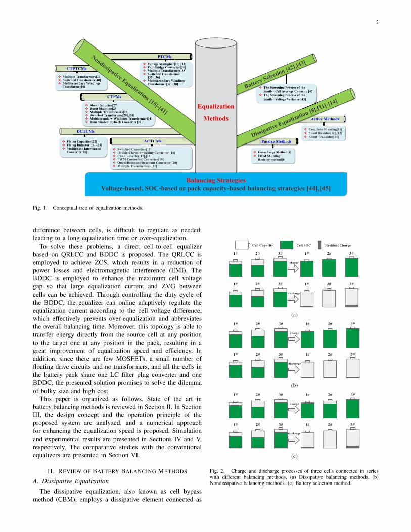
Numerous balancing methods have been proposed andwell summarized in [8]-[10]. As described in Fig. 1, theseequalization methods can be classified into three main group-s: the dissipative methods [8], [11]-[14], the nondissipativemethods [15]-[41], and battery selection method [42], [43].Furthermore, each group can be further divided into severalcategories. The tree trunk, the tree large branches, the treebranches, and the tree leaves in Fig. 1 represent the classi-fication process of the equalization methods from coarse tofine. The ground represents the balancing strategies, whichinclude the voltage-based, SOC-based, and pack capacity-based strategies [44], [45].
A review of literature shows that the conventional equalizersare not suitable for lithium-ion batteries due to the followingfacts:
1) The size of the conventional equalizers is prone to bebulky because large amounts of transformers, MOSFETs, andfloating drive circuits are necessary.
2) Lithium-ion battery offers a relatively flat open circuitvoltage (OCV) across a broad range of SOC from 20% to 80%[11], [36]. In other words, even though the SOC differencebetween cells is large, the corresponding voltage differencestill remains small. Consequently, the equalization current ofthe conventional equalizers is very small. Particularly, thepower devices would not conduct normally when the voltagedifference between cells is less than the voltage drop acrosspower devices.
3) ZVG between cells can not be achieved due to the voltagedrop across the power devices.
4) The switching loss is very high because the switches areconducted in high-frequency hard switching mode.
5) The equalization current, which depends on the voltage
This document downloaded from www.microgrids.et.aau.dk is the preprint version of the final paper:Y. Shang, C. Zhang, N. Cui, and J. M. Guerrero, "A cell-to-cell battery equalizer with zero-current switching and zero-voltage gap based on quasi-resonant LC converter and boost converter," IEEE Trans. Power Electron., 2014, IEEE Early Access.
2
v Flying Capacitor[22]v Flying Inductor[23]-[25]v Multiphase Interleaved
Converter[26]
DCTCMs
v Multiple Transformers[39]v Switched Transformer[40] v Multisecondary Windings
Transformer[41] v The Screening Process of the Similar Cell Average Capacity [42]
v The Screening Process of the Similar Voltage Variance [43]
Passive Methods
v Overcharge Method[8] v Fixed Shunting
Resistor method[8]
Active Methods
v Overcharge Method[8] v Fixed Shunting
Resistor method[8]
Passive Methods
ActiActiActiActiActiActive Methods
[42] v The Screening Process of the
Similar Voltage Variance [43]
vvvvvv The Screening Process of the v The Screening Process of the Similar Cell Average Capacity [42] Similar Cell Average Capacity
v The Screening Process of the
v Shunt Inductor[27]v Boost Shunting[28]v Multiple Transformers[29]v Switched Transformer[29],[30]v Multisecondary Windings Transformer[31]v Time Shared Flyback Converter[32]
CTPTCMs
CTPMs
v Voltage Multiplier[10],[33]v Full-Bridge Converter[34]v Multiple Transformers[35]v Switched Transformer
[35],[36] v Multisecondary Windings
Transformer[37],[38]
PTCMs
ACTCMsFlying Capacitor[22]Flying Inductor[23]-[25]Multiphase Interleaved
DCTCMs
ple Transformehed Transsecondaryformer[41]
v Time Shared Flyback Converter[32]
CTPTCMs
[10],[33]Converter[34]
formers[35]former
Windings ,[38]
[10],
ACTCMs
v Shunt Inductor[27]v Boost Shunting[28]v Multiple
Transformers[39]Transformer[40]
dary Windings r[41]
Transformers[29]v Switched Transformer[29],[30]v Multisecondary Windings Transformer[31]v Time Shared Flyback Converter[32]
CMs
CTPMs
v Voltage Multiplier[10],v Full-Bridge Converter[v Multiple Transformev Switched Transforme
[35],[36] v Multisecondary Windi
Transformer[37],[38]
Multiplier[10],
PTCMs
Equalization
Methods
v Switched Capacitor[15]v Double-Tiered Switching Capacitor [16]v Cûk Converter[17],[18]v PWM Controlled Converter[19]v Quasi-Resonant/Resonant Converter [20]v Multiple Transformers [21]
Balancing Strategies
Voltage-based, SOC-based or pack capacity-based balancing strategies [44],[45]
v Complete Shunting[11]v Shunt Resistor[12],[13]v Shunt Transistor[14]
Fig. 1. Conceptual tree of equalization methods.
difference between cells, is difficult to regulate as needed,leading to a long equalization time or over-equalization.
To solve these problems, a direct cell-to-cell equalizerbased on QRLCC and BDDC is proposed. The QRLCC isemployed to achieve ZCS, which results in a reduction ofpower losses and electromagnetic interference (EMI). TheBDDC is employed to enhance the maximum cell voltagegap so that large equalization current and ZVG betweencells can be achieved. Through controlling the duty cycle ofthe BDDC, the equalizer can online adaptively regulate theequalization current according to the cell voltage difference,which effectively prevents over-equalization and abbreviatesthe overall balancing time. Moreover, this topology is able totransfer energy directly from the source cell at any positionto the target one at any position in the pack, resulting in agreat improvement of equalization speed and efficiency. Inaddition, since there are few MOSFETs, a small number offloating drive circuits and no transformers, and all the cells inthe battery pack share one LC filter plug converter and oneBDDC, the presented solution promises to solve the dilemmaof bulky size and high cost.
This paper is organized as follows. State of the art inbattery balancing methods is reviewed in Section II. In SectionIII, the design concept and the operation principle of theproposed system are analyzed, and a numerical approachfor enhancing the equalization speed is proposed. Simulationand experimental results are presented in Sections IV and V,respectively. The comparative studies with the conventionalequalizers are presented in Section VI.
II. REVIEW OF BATTERY BALANCING METHODS
A. Dissipative Equalization
The dissipative equalization, also known as cell bypassmethod (CBM), employs a dissipative element connected as
1# 2# 3# 1# 2# 3#
charge
1# 2# 3# 1# 2# 3#
discharge
Cell Capacity Cell SOC Residual Charge
(a)
1# 2# 3# 1# 2# 3#
charge
1# 2# 3# 1# 2# 3#
discharge
(b)
1# 2# 3# 1# 2# 3#
charge
1# 2# 3# 1# 2# 3#
discharge
(c)
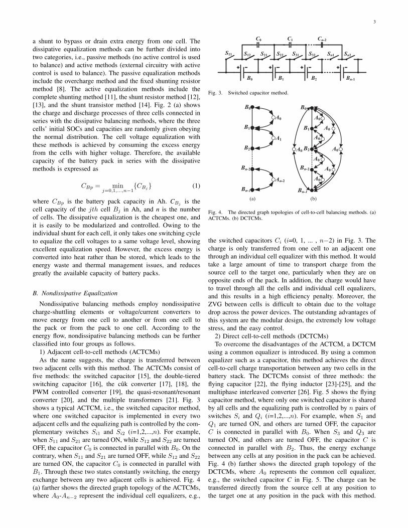
Fig. 2. Charge and discharge processes of three cells connected in serieswith different balancing methods. (a) Dissipative balancing methods. (b)Nondissipative balancing methods. (c) Battery selection method.
3
a shunt to bypass or drain extra energy from one cell. Thedissipative equalization methods can be further divided intotwo categories, i.e., passive methods (no active control is usedto balance) and active methods (external circuitry with activecontrol is used to balance). The passive equalization methodsinclude the overcharge method and the fixed shunting resistormethod [8]. The active equalization methods include thecomplete shunting method [11], the shunt resistor method [12],[13], and the shunt transistor method [14]. Fig. 2 (a) showsthe charge and discharge processes of three cells connected inseries with the dissipative balancing methods, where the threecells’ initial SOCs and capacities are randomly given obeyingthe normal distribution. The cell voltage equalization withthese methods is achieved by consuming the excess energyfrom the cells with higher voltage. Therefore, the availablecapacity of the battery pack in series with the dissipativemethods is expressed as
CBp = minj=0,1,...,n−1
CBj (1)
where CBp is the battery pack capacity in Ah. CBj is thecell capacity of the jth cell Bj in Ah, and n is the numberof cells. The dissipative equalization is the cheapest one, andit is easily to be modularized and controlled. Owing to theindividual shunt for each cell, it only takes one switching cycleto equalize the cell voltages to a same voltage level, showingexcellent equalization speed. However, the excess energy isconverted into heat rather than be stored, which leads to theenergy waste and thermal management issues, and reducesgreatly the available capacity of battery packs.
B. Nondissipative Equalization
Nondissipative balancing methods employ nondissipativecharge-shuttling elements or voltage/current converters tomove energy from one cell to another or from one cell tothe pack or from the pack to one cell. According to theenergy flow, nondissipative balancing methods can be furtherclassified into four groups as follows.
1) Adjacent cell-to-cell methods (ACTCMs)As the name suggests, the charge is transferred between
two adjacent cells with this method. The ACTCMs consist offive methods: the switched capacitor [15], the double-tieredswitching capacitor [16], the cuk converter [17], [18], thePWM controlled converter [19], the quasi-resonant/resonantconverter [20], and the multiple transformers [21]. Fig. 3shows a typical ACTCM, i.e., the switched capacitor method,where one switched capacitor is implemented in every twoadjacent cells and the equalizing path is controlled by the com-plementary switches Si1 and Si2 (i=1,2,...,n). For example,when S11 and S21 are turned ON, while S12 and S22 are turnedOFF, the capacitor C0 is connected in parallel with B0. On thecontrary, when S11 and S21 are turned OFF, while S12 and S22
are turned ON, the capacitor C0 is connected in parallel withB1. Through these two states constantly switching, the energyexchange between any two adjacent cells is achieved. Fig. 4(a) farther shows the directed graph topology of the ACTCMs,where A0-An−2 represent the individual cell equalizers, e.g.,
B0 B1 B2 Bn-1
C0 C1 Cn-2
S11 S12 S21 S22 S31 Sn1 Sn2S32
Fig. 3. Switched capacitor method.
B0
B1
B2
Bn-2
Bn-1
A0
A1
An-2
B0
B1
B2
Bn-2
A0
A0
A0
A0
A0 A0
A0
Bn-1
A0
(a) (b)
Fig. 4. The directed graph topologies of cell-to-cell balancing methods. (a)ACTCMs. (b) DCTCMs.
the switched capacitors Ci (i=0, 1, ... , n−2) in Fig. 3. Thecharge is only transferred from one cell to an adjacent onethrough an individual cell equalizer with this method. It wouldtake a large amount of time to transport charge from thesource cell to the target one, particularly when they are onopposite ends of the pack. In addition, the charge would haveto travel through all the cells and individual cell equalizers,and this results in a high efficiency penalty. Moreover, theZVG between cells is difficult to obtain due to the voltagedrop across the power devices. The outstanding advantages ofthis system are the modular design, the extremely low voltagestress, and the easy control.
2) Direct cell-to-cell methods (DCTCMs)To overcome the disadvantages of the ACTCM, a DCTCM
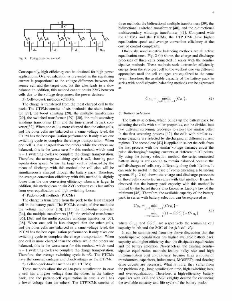
using a common equalizer is introduced. By using a commonequalizer such as a capacitor, this method achieves the directcell-to-cell charge transportation between any two cells in thebattery stack. The DCTCMs consist of three methods: theflying capacitor [22], the flying inductor [23]-[25], and themultiphase interleaved converter [26]. Fig. 5 shows the flyingcapacitor method, where only one switched capacitor is sharedby all cells and the equalizing path is controlled by n pairs ofswitches Si and Qi (i=1,2,...,n). For example, when S1 andQ1 are turned ON, and others are turned OFF, the capacitorC is connected in parallel with B0. When S3 and Q3 areturned ON, and others are turned OFF, the capacitor C isconnected in parallel with B2. Thus, the energy exchangebetween any cells at any position in the pack can be achieved.Fig. 4 (b) farther shows the directed graph topology of theDCTCMs, where A0 represents the common cell equalizer,e.g., the switched capacitor C in Fig. 5. The charge can betransferred directly from the source cell at any position tothe target one at any position in the pack with this method.
4
S1 Sn
B0 B1 B2 Bn-1
C
Q1 S2 Q2 S3 Q3 Qn
Fig. 5. Flying capacitor method.
Consequently, high efficiency can be obtained for high powerapplications. Over-equalization is prevented as the equalizingcurrent is proportional to the voltage difference between thesource cell and the target one, but this also leads to a slowbalance. In addition, this method cannot obtain ZVG betweencells due to the voltage drop across the power devices.
3) Cell-to-pack methods (CTPMs)The charge is transferred from the most charged cell to the
pack. The CTPMs consist of six methods: the shunt induc-tor [27], the boost shunting [28], the multiple transformers[29], the switched transformer [29], [30], the multisecondarywindings transformer [31], and the time shared flyback con-verter[32]. When one cell is more charged than the other cells,and the other cells are balanced in a same voltage level, theCTPM has the best equalization performance. It only takes oneswitching cycle to complete the charge transportation. Whenone cell is less charged than the others while the others arebalanced, this is the worst case for this method, which needn− 1 switching cycles to complete the charge transportation.Therefore, the average switching cycle is n/2, showing poorequalization speed. When the target cell is balanced by themean of discharge with this method, the cell also will besimultaneously charged through the battery pack. Therefore,the average conversion efficiency with this method is slightlylower than the one conversion efficiency when n is large. Inaddition, this method can obtain ZVG between cells but suffersfrom over-equalization and high switching losses.
4) Pack-to-cell methods (PTCMs)The charge is transferred from the pack to the least charged
cell in the battery pack. The PTCMs consist of five methods:the voltage multiplier [10], [33], the full-bridge converter[34], the multiple transformers [35], the switched transformer[35], [36], and the multisecondary windings transformer [37],[38]. When one cell is less charged than the other cells,and the other cells are balanced in a same voltage level, thePTCM has the best equalization performance. It only takes oneswitching cycle to complete the charge transportation. Whenone cell is more charged than the others while the others arebalanced, this is the worst case for this method, which needn− 1 switching cycles to complete the charge transportation.Therefore, the average switching cycle is n/2. The PTCMshave the same advantages and disadvantages as the CTPMs.
5) Cell-to-pack-to-cell methods (CTPTCMs)These methods allow the cell-to-pack equalization in case
a cell has a higher voltage than the others in the batterypack, and the pack-to-cell equalization in case a cell hasa lower voltage than the others. The CTPTCMs consist of
three methods: the bidirectional multiple transformers [39], thebidirectional switched transformer [40], and the bidirectionalmultisecondary windings transformer [41]. Compared withthe CTPMs and the PTCMs, the CTPTCMs have higherequalization speed and average conversion efficiency at thecost of control complexity.
Obviously, nondissipative balancing methods are all activeequalization ones. Fig. 2 (b) shows the charge and dischargeprocesses of three cells connected in series with the nondis-sipative methods. These methods seek to transfer efficientlyenergy from the strongest cell to the weakest one via differentapproaches until the cell voltages are equalized to the samelevel. Therefore, the available capacity of the battery pack inseries with nondissipative balancing methods can be expressedas
CBp = meanj=0,1,...,n−1
CBj. (2)
C. Battery Selection
The battery selection, which builds up the battery pack byselecting the cells with similar properties, can be divided intotwo different screening processes to select the similar cells.In the first screening process [42], the cells with similar av-erage capacity are selected by discharging at different currentregimes. The second one [43] is applied to select the cells fromthe first process with the similar voltage variance under thepulse discharging/charging currents at different SOC points.By using the battery selection method, the series-connectedbattery string is not enough to remain balanced because theself-discharges of cells vary differently along their lifetime. Itcan only be useful in the case of complementing a balancingsystem. Fig. 2 (c) shows the charge and discharge processesof three cells connected in series with this method. It can beobserved that the battery pack capacity with this method islimited by the barrel theory also known as Liebig’s law of theminimum [46]. Therefore, the available capacity of the batterypack in series with battery selection can be expressed as
CBp = minj=0,1,...,n−1
CrBj+
minj=0,1,...,n−1
(1− SOCj) ∗ CrBj(3)
where CrBj and SOCj are respectively the remaining cellcapacity in Ah and the SOC of the jth cell Bj .
It can be summarized from the above discussion that thenondissipative equalization has higher available battery packcapacity and higher efficiency than the dissipative equalizationand the battery selection. Nevertheless, the existing nondis-sipative equalization methods feature bulky size and highimplementation cost ubiquitously, because large amounts oftransformers, capacitors, inductances, MOSFETs, and floatingdrive circuits are necessary. What is more, they suffer fromthe problems e.g., long equalization time, high switching loss,and over-equalization. Therefore, a high-efficiency batteryequalizer with ZCS and ZVG is highly desired for enhancingthe available capacity and life cycle of the battery packs.
5
...
S1 S2 Q1 S3 Q2 S4 Q3 S5 Q4 Sn Qn-1 Qn
L
C
+
+
-
+
-
+
-
PWM0 PWM-
V
Vcb
S'1 S'2 Q'1 S'3 Q'2 S'4 Q'3 S'5 Q'4 S'n Q'n-1 Q'n
M2
M1 M3
M4
D1 D3
D4
D2
Lb Db
CbMb
DriveCircuit
DetectionCircuit
Detection
Circuit
M M
PWM+
Multi-Channel
AnalogSwitch
Switch Module 2
Switch Module 1
Boost DC-DCConverter
LC Resonant Converter
Microcontroller
B0 B1 B2 B3 Bn-1
V3V2 Vn-1V1V0
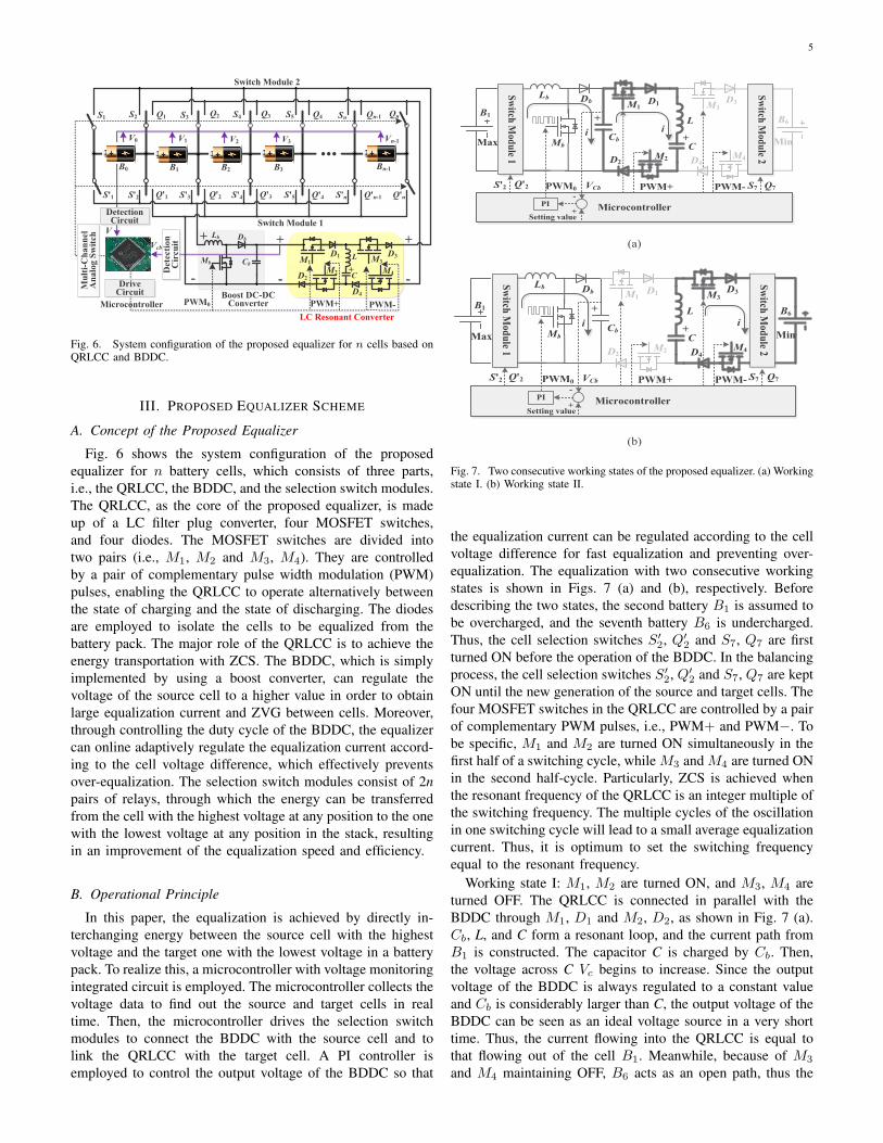
Fig. 6. System configuration of the proposed equalizer for n cells based onQRLCC and BDDC.
III. PROPOSED EQUALIZER SCHEME
A. Concept of the Proposed Equalizer
Fig. 6 shows the system configuration of the proposedequalizer for n battery cells, which consists of three parts,i.e., the QRLCC, the BDDC, and the selection switch modules.The QRLCC, as the core of the proposed equalizer, is madeup of a LC filter plug converter, four MOSFET switches,and four diodes. The MOSFET switches are divided intotwo pairs (i.e., M1, M2 and M3, M4). They are controlledby a pair of complementary pulse width modulation (PWM)pulses, enabling the QRLCC to operate alternatively betweenthe state of charging and the state of discharging. The diodesare employed to isolate the cells to be equalized from thebattery pack. The major role of the QRLCC is to achieve theenergy transportation with ZCS. The BDDC, which is simplyimplemented by using a boost converter, can regulate thevoltage of the source cell to a higher value in order to obtainlarge equalization current and ZVG between cells. Moreover,through controlling the duty cycle of the BDDC, the equalizercan online adaptively regulate the equalization current accord-ing to the cell voltage difference, which effectively preventsover-equalization. The selection switch modules consist of 2npairs of relays, through which the energy can be transferredfrom the cell with the highest voltage at any position to the onewith the lowest voltage at any position in the stack, resultingin an improvement of the equalization speed and efficiency.
B. Operational Principle
In this paper, the equalization is achieved by directly in-terchanging energy between the source cell with the highestvoltage and the target one with the lowest voltage in a batterypack. To realize this, a microcontroller with voltage monitoringintegrated circuit is employed. The microcontroller collects thevoltage data to find out the source and target cells in realtime. Then, the microcontroller drives the selection switchmodules to connect the BDDC with the source cell and tolink the QRLCC with the target cell. A PI controller isemployed to control the output voltage of the BDDC so that
Microcontroller
Max
B6
M2
M1 M3
M4
D1 D3
D4D2
L
CCb
Lb
ii+
+
PI
Switch
Module1
Setting value+
-
PWM+ PWM-
Switch
Module2
S'2 S7VCbPWM0
B1
Min
Q'2 Q7
Db
Mb
(a)
Microcontroller
M2
M1 M3
M4
D1 D3
D4D2
L
CCb
Lb
i+
+
PI
Switch
Module1
Setting value+
-
PWM+ PWM-
Switch
Module2
VCbPWM0
i
B1
Max
B6
Min
S'2 Q'2 S7 Q7
Db
Mb
(b)
Fig. 7. Two consecutive working states of the proposed equalizer. (a) Workingstate I. (b) Working state II.
the equalization current can be regulated according to the cellvoltage difference for fast equalization and preventing over-equalization. The equalization with two consecutive workingstates is shown in Figs. 7 (a) and (b), respectively. Beforedescribing the two states, the second battery B1 is assumed tobe overcharged, and the seventh battery B6 is undercharged.Thus, the cell selection switches S′
2, Q′2 and S7, Q7 are first
turned ON before the operation of the BDDC. In the balancingprocess, the cell selection switches S′
2, Q′2 and S7, Q7 are kept
ON until the new generation of the source and target cells. Thefour MOSFET switches in the QRLCC are controlled by a pairof complementary PWM pulses, i.e., PWM+ and PWM−. Tobe specific, M1 and M2 are turned ON simultaneously in thefirst half of a switching cycle, while M3 and M4 are turned ONin the second half-cycle. Particularly, ZCS is achieved whenthe resonant frequency of the QRLCC is an integer multiple ofthe switching frequency. The multiple cycles of the oscillationin one switching cycle will lead to a small average equalizationcurrent. Thus, it is optimum to set the switching frequencyequal to the resonant frequency.
Working state I: M1, M2 are turned ON, and M3, M4 areturned OFF. The QRLCC is connected in parallel with theBDDC through M1, D1 and M2, D2, as shown in Fig. 7 (a).Cb, L, and C form a resonant loop, and the current path fromB1 is constructed. The capacitor C is charged by Cb. Then,the voltage across C Vc begins to increase. Since the outputvoltage of the BDDC is always regulated to a constant valueand Cb is considerably larger than C, the output voltage of theBDDC can be seen as an ideal voltage source in a very shorttime. Thus, the current flowing into the QRLCC is equal tothat flowing out of the cell B1. Meanwhile, because of M3
and M4 maintaining OFF, B6 acts as an open path, thus the
6
MOSFETs
1&2 ON
PWM
i
iB
1
iB
6
State I State II
VC
MOSFETs
3&4 ON
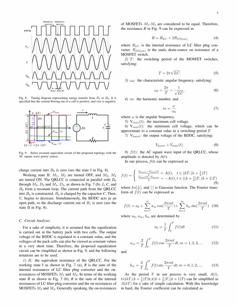
Fig. 8. Timing diagram representing energy transfer from B1 to B6. It isspecified that the current flowing out of a cell is positive, and vice is negative.
+
-
L
C +Vc
i
R
Vboost
t
f(t)
kT
Vmax t
(k+½)T (k+1)Tf(t)
Vmin t
2A
kT 2A
t
2A t ≈ 2A kT
A kT
Fig. 9. Series resonant equivalent circuit of the proposed topology with theAC square wave power source.
charge current into B6 is zero (see the state I in Fig. 8).Working state II: M1, M2 are turned OFF, and M3, M4
are turned ON. The QRLCC is connected in parallel with B6
through M3, D3 and M4, D4, as shown in Fig. 7 (b). L, C, andB6 form a resonant loop. The current path from the QRLCCinto B6 is constructed. B6 is charged by the capacitor C. Then,Vc begins to decrease. Simultaneously, the BDDC acts as anopen path, so the discharge current out of B1 is zero (see thestate II in Fig. 8).
C. Circuit Analysis
For a sake of simplicity, it is assumed that the equalizationis carried out in the battery pack with two cells. The outputvoltage of the BDDC is regulated to a constant value, and thevoltages of the pack cells can also be viewed as constant valuesin a very short time. Therefore, the proposed equalizationcircuit can be simplified as shown in Fig. 9, and the followingnotations are to be used.
1) R: the equivalent resistance of the QRLCC. For theworking state I as shown in Fig. 7 (a), R is the sum of theinternal resistances of LC filter plug converter and the on-resistances of MOSFETs M1 and M2. In terms of the workingstate II as shown in Fig. 7 (b), R is the sum of the internalresistances of LC filter plug converter and the on-resistances ofMOSFETs M3 and M4. Generally speaking, the on-resistances
of MOSFETs M1-M4 are considered to be equal. Therefore,the resistance R in Fig. 9 can be expressed as
R = RLC + 2RDS(on) (4)
where RLC is the internal resistance of LC filter plug con-verter. RDS(on) is the static drain-source on resistance of aMOSFET switch.
2) T : the switching period of the MOSFET switches,satisfying:
T = 2π√LC. (5)
3) ω0: the characteristic angular frequency, satisfying:
ω0 =2π
T=
1√LC
. (6)
4) m: the harmonic number, and
m =ω
ω0(7)
where ω is the angular frequency.5) Vmax(t): the maximum cell voltage.6) Vmin(t): the minimum cell voltage, which can be
approximate to a constant value in a switching period T.7) Vboost: the output voltage of the BDDC, satisfying:
Vboost > Vmax(t). (8)
8) f(t): the AC square wave input of the QRLCC, whoseamplitude is denoted by A(t).
In our process, f (t) can be expressed as
f(t) =
Vboost−Vmin(t)
2 = A(t), t ∈ (kT, (k + 12 )T )
Vmin(t)−Vboost
2 = −A(t), t ∈ ((k + 12 )T, (k + 1)T )
(9)where k=[ tT ], and [·] is Gaussian function. The Fourier trans-form of f(t) can be expressed as
f(t) = a0 +∞∑
m=1
am cos(2πmt
T)+
∞∑m=1
bm sin(2πmt
T) (10)
where a0, am, bm are determined by
a0 =1
T
∫ T
0
f(t)dt (11)
am =2
T
∫ T
0
f(t) cos2πmt
Tdt,m = 1, 2, 3, ... (12)
and
bm =2
T
∫ T
0
f(t) sin2πmt
Tdt,m = 0, 1, 2, .... (13)
As the period T in our process is very small, A(t),t∈(kT ,(k + 1
2 )T ))∪((k + 12 )T ,(k + 1)T ) can be simplified as
A(kT ) for a sake of simple calculation. With this knowledgein hard, the Fourier coefficient can be calculated as
7
am = 0,m = 0, 1, 2, ... (14)
bm = (1m − (−1)m)2A(kT )
mπ,m = 0, 1, 2.... (15)
After determining all coefficients of (10), the series of f (t)(kT < t < (k + 1)T , t = (k + 1
2 )T ) can be rewritten as
f(t) ≈ 4A(kT )
π(sin(ω0t) +
sin(3ω0t)
3
+sin(5ω0t)
5+ . . .).
(16)
The input AC impedance of the series resonant circuitshown in Fig. 9 can be expressed as
Z = R+ j(ωL− 1/ωC). (17)
By (16) and (17), the mth harmonic wave amplitude in theresonance current is shown as
Im =4A(kT )
mπR
√1 +Q2(m− 1
m )2
(18)
where Q is the quality factor, and
Q =ω0L
R=
1
ω0CR. (19)
With (18), one can get the maximum of Im, m∈N , i.e.,
I1 =4A(kT )
πR. (20)
It can be seen from (20) that I1 is proportional to A(kT ),while is inversely proportional to the equivalent resistance R,but has no relationship with L or C values.
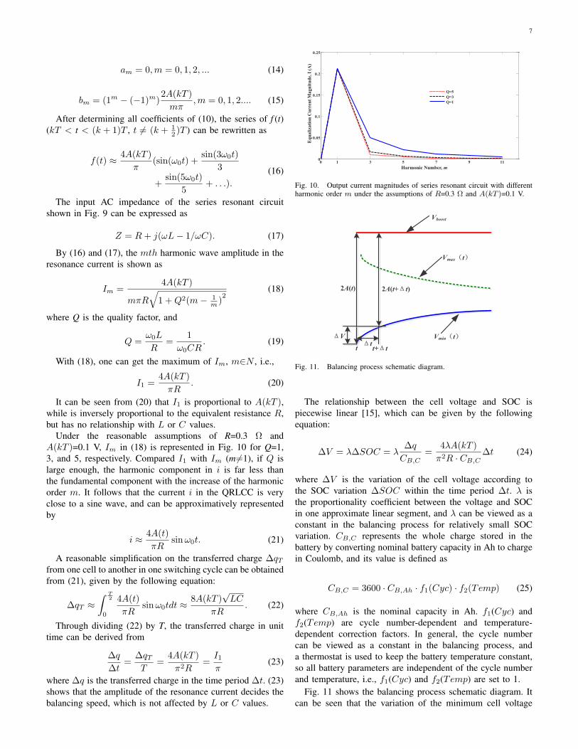
Under the reasonable assumptions of R=0.3 Ω andA(kT )=0.1 V, Im in (18) is represented in Fig. 10 for Q=1,3, and 5, respectively. Compared I1 with Im (m =1), if Q islarge enough, the harmonic component in i is far less thanthe fundamental component with the increase of the harmonicorder m. It follows that the current i in the QRLCC is veryclose to a sine wave, and can be approximatively representedby
i ≈ 4A(t)
πRsinω0t. (21)
A reasonable simplification on the transferred charge ∆qTfrom one cell to another in one switching cycle can be obtainedfrom (21), given by the following equation:
∆qT ≈∫ T
2
0
4A(t)
πRsinω0tdt ≈
8A(kT )√LC
πR. (22)
Through dividing (22) by T, the transferred charge in unittime can be derived from
∆q
∆t=
∆qTT
=4A(kT )
π2R=
I1π
(23)
where ∆q is the transferred charge in the time period ∆t. (23)shows that the amplitude of the resonance current decides thebalancing speed, which is not affected by L or C values.
0 1 3 5 7 9 110
0.05
0.1
0.15
0.2
0.25
m
I/A
Q=5
Q=3
Q=1
Harmonic Number, m
Eq
uali
zati
on
Cu
rren
t M
ag
nit
ud
e, I
(A
)
Fig. 10. Output current magnitudes of series resonant circuit with differentharmonic order m under the assumptions of R=0.3 Ω and A(kT )=0.1 V.
Vboost
Vmax t
Vmin tV
t
2A(t+ t)2A(t)
t t+ t
Fig. 11. Balancing process schematic diagram.
The relationship between the cell voltage and SOC ispiecewise linear [15], which can be given by the followingequation:
∆V = λ∆SOC = λ∆q
CB,C=
4λA(kT )
π2R · CB,C∆t (24)
where ∆V is the variation of the cell voltage according tothe SOC variation ∆SOC within the time period ∆t. λ isthe proportionality coefficient between the voltage and SOCin one approximate linear segment, and λ can be viewed as aconstant in the balancing process for relatively small SOCvariation. CB,C represents the whole charge stored in thebattery by converting nominal battery capacity in Ah to chargein Coulomb, and its value is defined as
CB,C = 3600 · CB,Ah · f1(Cyc) · f2(Temp) (25)
where CB,Ah is the nominal capacity in Ah. f1(Cyc) andf2(Temp) are cycle number-dependent and temperature-dependent correction factors. In general, the cycle numbercan be viewed as a constant in the balancing process, anda thermostat is used to keep the battery temperature constant,so all battery parameters are independent of the cycle numberand temperature, i.e., f1(Cyc) and f2(Temp) are set to 1.
Fig. 11 shows the balancing process schematic diagram. Itcan be seen that the variation of the minimum cell voltage
8
Vbat
+
-
RS,d
RL,c
CS,d
RL,d
RS,cCS,c CL,c
CL,d
Ro,d
Ro,c+
-
+
OCV=f(SOC)ibat
OCV
C0
RSelf-Discharge
Voltage-Current CharacteristicsBattery Lifetime
V1 V2
ibat
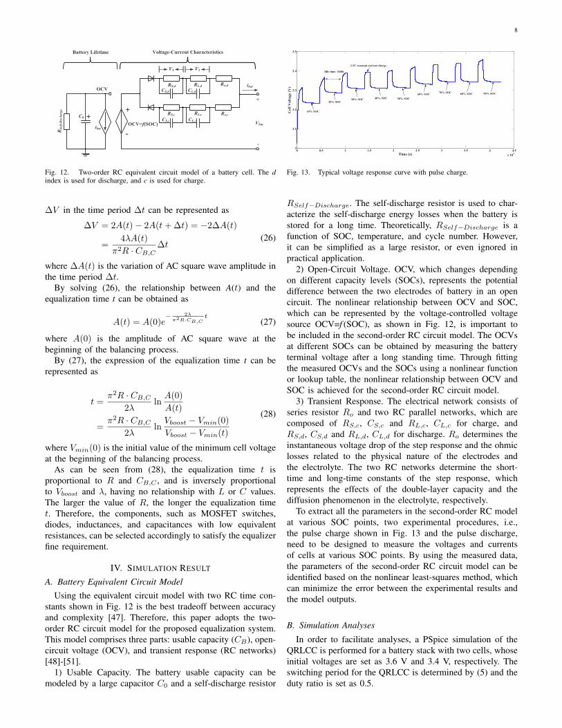
Fig. 12. Two-order RC equivalent circuit model of a battery cell. The dindex is used for discharge, and c is used for charge.
∆V in the time period ∆t can be represented as
∆V = 2A(t)− 2A(t+∆t) = −2∆A(t)
=4λA(t)
π2R · CB,C∆t
(26)
where ∆A(t) is the variation of AC square wave amplitude inthe time period ∆t.
By solving (26), the relationship between A(t) and theequalization time t can be obtained as
A(t) = A(0)e− 2λ
π2R·CB,Ct
(27)
where A(0) is the amplitude of AC square wave at thebeginning of the balancing process.
By (27), the expression of the equalization time t can berepresented as
t =π2R · CB,C
2λln
A(0)
A(t)
=π2R · CB,C
2λln
Vboost − Vmin(0)
Vboost − Vmin(t)
(28)
where Vmin(0) is the initial value of the minimum cell voltageat the beginning of the balancing process.
As can be seen from (28), the equalization time t isproportional to R and CB,C , and is inversely proportionalto Vboost and λ, having no relationship with L or C values.The larger the value of R, the longer the equalization timet. Therefore, the components, such as MOSFET switches,diodes, inductances, and capacitances with low equivalentresistances, can be selected accordingly to satisfy the equalizerfine requirement.
IV. SIMULATION RESULT
A. Battery Equivalent Circuit Model
Using the equivalent circuit model with two RC time con-stants shown in Fig. 12 is the best tradeoff between accuracyand complexity [47]. Therefore, this paper adopts the two-order RC circuit model for the proposed equalization system.This model comprises three parts: usable capacity (CB), open-circuit voltage (OCV), and transient response (RC networks)[48]-[51].
1) Usable Capacity. The battery usable capacity can bemodeled by a large capacitor C0 and a self-discharge resistor
0 0.5 1 1.5 2 2.5 3 3.5 4 4.5
x 104
3
3.1
3.2
3.3
3.4
3.5
Time (s)
Cel
l V
olt
ag
e (V
)
Idle time: 3600s
1/3C constant current charge
40% SOC
90% SOC
30% SOC20% SOC
50% SOC
60% SOC70% SOC
80% SOC
10% SOC
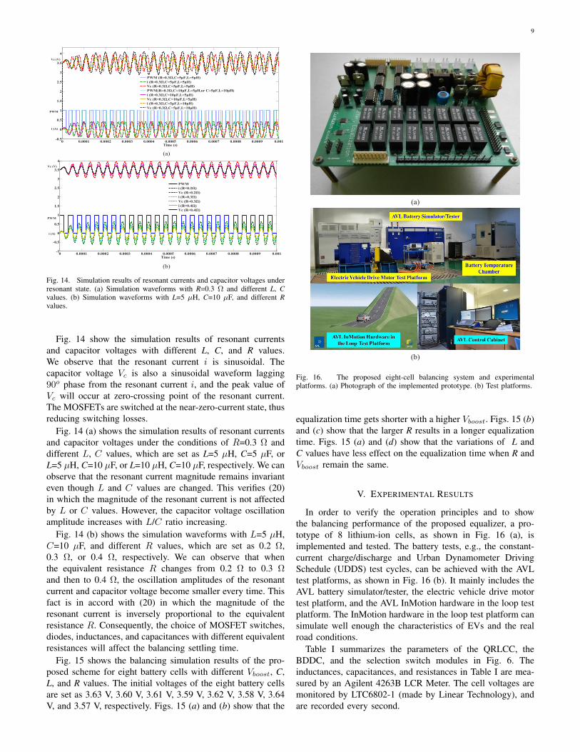
Fig. 13. Typical voltage response curve with pulse charge.
RSelf−Discharge. The self-discharge resistor is used to char-acterize the self-discharge energy losses when the battery isstored for a long time. Theoretically, RSelf−Discharge is afunction of SOC, temperature, and cycle number. However,it can be simplified as a large resistor, or even ignored inpractical application.
2) Open-Circuit Voltage. OCV, which changes dependingon different capacity levels (SOCs), represents the potentialdifference between the two electrodes of battery in an opencircuit. The nonlinear relationship between OCV and SOC,which can be represented by the voltage-controlled voltagesource OCV=f (SOC), as shown in Fig. 12, is important tobe included in the second-order RC circuit model. The OCVsat different SOCs can be obtained by measuring the batteryterminal voltage after a long standing time. Through fittingthe measured OCVs and the SOCs using a nonlinear functionor lookup table, the nonlinear relationship between OCV andSOC is achieved for the second-order RC circuit model.
3) Transient Response. The electrical network consists ofseries resistor Ro and two RC parallel networks, which arecomposed of RS,c, CS,c and RL,c, CL,c for charge, andRS,d, CS,d and RL,d, CL,d for discharge. Ro determines theinstantaneous voltage drop of the step response and the ohmiclosses related to the physical nature of the electrodes andthe electrolyte. The two RC networks determine the short-time and long-time constants of the step response, whichrepresents the effects of the double-layer capacity and thediffusion phenomenon in the electrolyte, respectively.
To extract all the parameters in the second-order RC modelat various SOC points, two experimental procedures, i.e.,the pulse charge shown in Fig. 13 and the pulse discharge,need to be designed to measure the voltages and currentsof cells at various SOC points. By using the measured data,the parameters of the second-order RC circuit model can beidentified based on the nonlinear least-squares method, whichcan minimize the error between the experimental results andthe model outputs.
B. Simulation Analyses
In order to facilitate analyses, a PSpice simulation of theQRLCC is performed for a battery stack with two cells, whoseinitial voltages are set as 3.6 V and 3.4 V, respectively. Theswitching period for the QRLCC is determined by (5) and theduty ratio is set as 0.5.
9
(a)
(b)
0 0.0001 0.0002 0.0003 0.0004 0.0005 0.0006 0.0007 0.0008 0.0009 0.001-0.5
0
0.5
1
1.5
2
2.5
3
3.5
4
Time (s)
PWM (R=0.3Ω,C=5μF,L=5μH)
i (R=0.3Ω,C=5μF,L=5μH)
Vc (R=0.3Ω,C=5μF,L=5μH)
PWM(R=0.3Ω,C=10μF,L=5μH,or C=5μF,L=10μH)
i (R=0.3Ω,C=10μF,L=5μH)
Vc (R=0.3Ω,C=10μF,L=5μH)
i (R=0.3Ω,C=5μF,L=10μH)
Vc (R=0.3Ω,C=5μF,L=10μH)
Vc (V)
PWM
i (A)
0 0.0001 0.0002 0.0003 0.0004 0.0005 0.0006 0.0007 0.0008 0.0009 0.001-1
-0.5
0
0.5
1
1.5
2
2.5
3
3.5
4
Time (s)
PWM
i (R=0.2Ω)
Vc (R=0.2Ω)
i (R=0.3Ω)
Vc (R=0.3Ω)
i (R=0.4Ω)
Vc (R=0.4Ω)
Vc (V)
i (A)
PWM
Fig. 14. Simulation results of resonant currents and capacitor voltages underresonant state. (a) Simulation waveforms with R=0.3 Ω and different L, Cvalues. (b) Simulation waveforms with L=5 µH, C=10 µF, and different Rvalues.
Fig. 14 show the simulation results of resonant currentsand capacitor voltages with different L, C, and R values.We observe that the resonant current i is sinusoidal. Thecapacitor voltage Vc is also a sinusoidal waveform lagging90o phase from the resonant current i, and the peak value ofVc will occur at zero-crossing point of the resonant current.The MOSFETs are switched at the near-zero-current state, thusreducing switching losses.
Fig. 14 (a) shows the simulation results of resonant currentsand capacitor voltages under the conditions of R=0.3 Ω anddifferent L, C values, which are set as L=5 µH, C=5 µF, orL=5 µH, C=10 µF, or L=10 µH, C=10 µF, respectively. We canobserve that the resonant current magnitude remains invarianteven though L and C values are changed. This verifies (20)in which the magnitude of the resonant current is not affectedby L or C values. However, the capacitor voltage oscillationamplitude increases with L/C ratio increasing.
Fig. 14 (b) shows the simulation waveforms with L=5 µH,C=10 µF, and different R values, which are set as 0.2 Ω,0.3 Ω, or 0.4 Ω, respectively. We can observe that whenthe equivalent resistance R changes from 0.2 Ω to 0.3 Ωand then to 0.4 Ω, the oscillation amplitudes of the resonantcurrent and capacitor voltage become smaller every time. Thisfact is in accord with (20) in which the magnitude of theresonant current is inversely proportional to the equivalentresistance R. Consequently, the choice of MOSFET switches,diodes, inductances, and capacitances with different equivalentresistances will affect the balancing settling time.
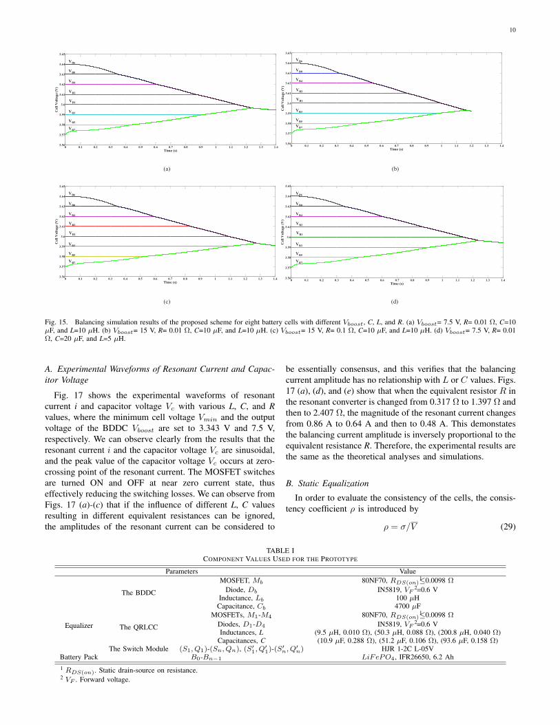
Fig. 15 shows the balancing simulation results of the pro-posed scheme for eight battery cells with different Vboost, C,L, and R values. The initial voltages of the eight battery cellsare set as 3.63 V, 3.60 V, 3.61 V, 3.59 V, 3.62 V, 3.58 V, 3.64V, and 3.57 V, respectively. Figs. 15 (a) and (b) show that the
(a)
(b)
Fig. 16. The proposed eight-cell balancing system and experimentalplatforms. (a) Photograph of the implemented prototype. (b) Test platforms.
equalization time gets shorter with a higher Vboost. Figs. 15 (b)and (c) show that the larger R results in a longer equalizationtime. Figs. 15 (a) and (d) show that the variations of L andC values have less effect on the equalization time when R andVboost remain the same.
V. EXPERIMENTAL RESULTS
In order to verify the operation principles and to showthe balancing performance of the proposed equalizer, a pro-totype of 8 lithium-ion cells, as shown in Fig. 16 (a), isimplemented and tested. The battery tests, e.g., the constant-current charge/discharge and Urban Dynamometer DrivingSchedule (UDDS) test cycles, can be achieved with the AVLtest platforms, as shown in Fig. 16 (b). It mainly includes theAVL battery simulator/tester, the electric vehicle drive motortest platform, and the AVL InMotion hardware in the loop testplatform. The InMotion hardware in the loop test platform cansimulate well enough the characteristics of EVs and the realroad conditions.
Table I summarizes the parameters of the QRLCC, theBDDC, and the selection switch modules in Fig. 6. Theinductances, capacitances, and resistances in Table I are mea-sured by an Agilent 4263B LCR Meter. The cell voltages aremonitored by LTC6802-1 (made by Linear Technology), andare recorded every second.
10
0 0.1 0.2 0.3 0.4 0.5 0.6 0.7 0.8 0.9 1 1.1 1.2 1.3 1.43.56
3.57
3.58
3.59
3.6
3.61
3.62
3.63
3.64
3.65
Time (s)
Cel
l V
olt
age
(V)
VB6
VB4
VB2
VB3
VB5
VB7
VB1
VB0
0 0.1 0.2 0.3 0.4 0.5 0.6 0.7 0.8 0.9 1 1.1 1.2 1.3 1.43.56
3.57
3.58
3.59
3.6
3.61
3.62
3.63
3.64
3.65
Time (s)
Cel
l V
olt
age
(V)
VB6
VB4
VB2
VB3
VB5
VB7
VB1
VB0
(a) (b)
0 0.1 0.2 0.3 0.4 0.5 0.6 0.7 0.8 0.9 1 1.1 1.2 1.3 1.43.56
3.57
3.58
3.59
3.6
3.61
3.62
3.63
3.64
3.65
Time (s)
Cel
l V
olt
age
(V)
VB6
VB4
VB2
VB3
VB5
VB7
VB1
VB0
0 0.1 0.2 0.3 0.4 0.5 0.6 0.7 0.8 0.9 1 1.1 1.2 1.3 1.43.56
3.57
3.58
3.59
3.6
3.61
3.62
3.63
3.64
3.65
Time (s)C
ell
Volt
age
(V)
VB6
VB4
VB2
VB3
VB5
VB7
VB1
VB0
(c) (d)
Fig. 15. Balancing simulation results of the proposed scheme for eight battery cells with different Vboost, C, L, and R. (a) Vboost= 7.5 V, R= 0.01 Ω, C=10µF, and L=10 µH. (b) Vboost= 15 V, R= 0.01 Ω, C=10 µF, and L=10 µH. (c) Vboost= 15 V, R= 0.1 Ω, C=10 µF, and L=10 µH. (d) Vboost= 7.5 V, R= 0.01Ω, C=20 µF, and L=5 µH.
A. Experimental Waveforms of Resonant Current and Capac-itor Voltage
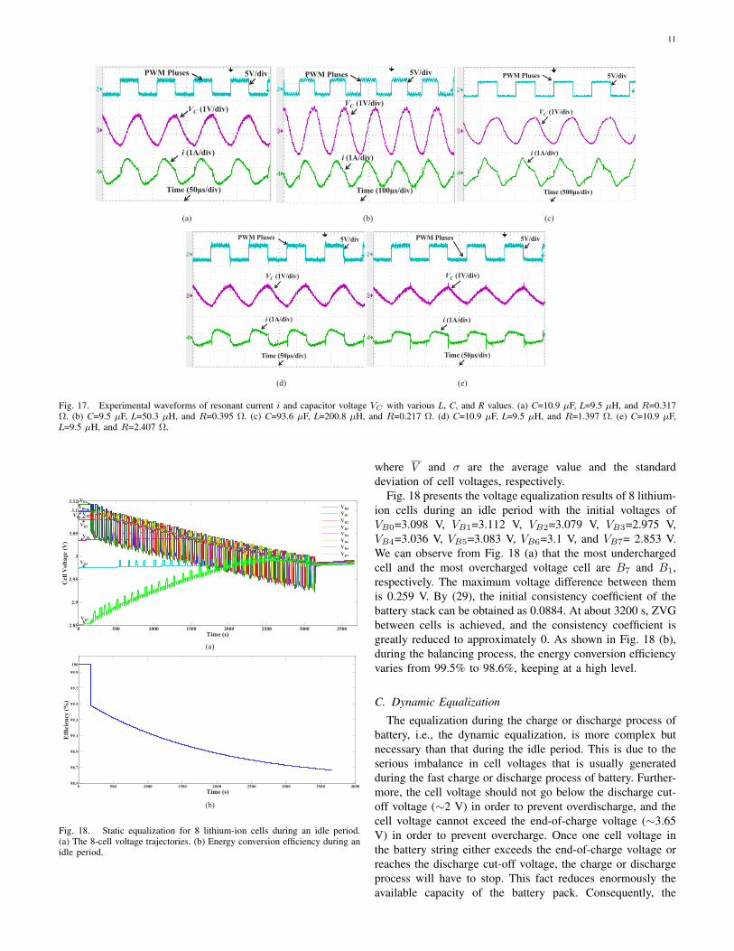
Fig. 17 shows the experimental waveforms of resonantcurrent i and capacitor voltage Vc with various L, C, and Rvalues, where the minimum cell voltage Vmin and the outputvoltage of the BDDC Vboost are set to 3.343 V and 7.5 V,respectively. We can observe clearly from the results that theresonant current i and the capacitor voltage Vc are sinusoidal,and the peak value of the capacitor voltage Vc occurs at zero-crossing point of the resonant current. The MOSFET switchesare turned ON and OFF at near zero current state, thuseffectively reducing the switching losses. We can observe fromFigs. 17 (a)-(c) that if the influence of different L, C valuesresulting in different equivalent resistances can be ignored,the amplitudes of the resonant current can be considered to
be essentially consensus, and this verifies that the balancingcurrent amplitude has no relationship with L or C values. Figs.17 (a), (d), and (e) show that when the equivalent resistor R inthe resonant converter is changed from 0.317 Ω to 1.397 Ω andthen to 2.407 Ω, the magnitude of the resonant current changesfrom 0.86 A to 0.64 A and then to 0.48 A. This demonstatesthe balancing current amplitude is inversely proportional to theequivalent resistance R. Therefore, the experimental results arethe same as the theoretical analyses and simulations.
B. Static Equalization
In order to evaluate the consistency of the cells, the consis-tency coefficient ρ is introduced by
ρ = σ/V (29)
TABLE ICOMPONENT VALUES USED FOR THE PROTOTYPE
Parameters Value
Equalizer
The BDDC
MOSFET, Mb 80NF70, RDS(on)1≤0.0098 Ω
Diode, Db IN5819, VF2=0.6 V
Inductance, Lb 100 µHCapacitance, Cb 4700 µF
The QRLCC
MOSFETs, M1-M4 80NF70, RDS(on)1≤0.0098 Ω
Diodes, D1-D4 IN5819, VF2=0.6 V
Inductances, L (9.5 µH, 0.010 Ω), (50.3 µH, 0.088 Ω), (200.8 µH, 0.040 Ω)Capacitances, C (10.9 µF, 0.288 Ω), (51.2 µF, 0.106 Ω), (93.6 µF, 0.158 Ω)
The Switch Module (S1, Q1)-(Sn, Qn), (S′1, Q
′1)-(S
′n, Q
′n) HJR 1-2C L-05V
Battery Pack B0-Bn−1 LiFePO4, IFR26650, 6.2 Ah1 RDS(on). Static drain-source on resistance.2 VF . Forward voltage.
11
PWM Pluses
VC
(1V/div)
i (1A/div)
5V/div
Time (50μs/div)
5V/div
Time (100μs/div)
VC
(1V/div)
i (1A/div)
PWM Pluses PWM Pluses 5V/div
Time (500μs/div)
VC
(1V/div)
i (1A/div)
(a) (b) (c)
PWM Pluses 5V/div
VC
(1V/div)
i (1A/div)
Time (50μs/div)
PWM Pluses 5V/div
Time (50μs/div)
VC
(1V/div)
i (1A/div)
(d) (e)
Fig. 17. Experimental waveforms of resonant current i and capacitor voltage VC with various L, C, and R values. (a) C=10.9 µF, L=9.5 µH, and R=0.317Ω. (b) C=9.5 µF, L=50.3 µH, and R=0.395 Ω. (c) C=93.6 µF, L=200.8 µH, and R=0.217 Ω. (d) C=10.9 µF, L=9.5 µH, and R=1.397 Ω. (e) C=10.9 µF,L=9.5 µH, and R=2.407 Ω.
0 500 1000 1500 2000 2500 3000 35002.85
2.9
2.95
3
3.05
3.1
3.12
Time (s)
Cell
Volt
age (
V)
VB1
VB6
VB0
VB2
VB3
VB7
VB5
VB4
B0
B1
B2
B3
B4
B5
B6
B7
VB1
VB0
VB2
VB3
VB4
VB5
VB6
VB7
(a)
(b)
0 500 1000 1500 2000 2500 3000 3500 400098.5
98.7
98.9
99.1
99.3
99.5
99.7
99.9
100
Time (s)
Eff
icie
ncy
(%
)
Fig. 18. Static equalization for 8 lithium-ion cells during an idle period.(a) The 8-cell voltage trajectories. (b) Energy conversion efficiency during anidle period.
where V and σ are the average value and the standarddeviation of cell voltages, respectively.
Fig. 18 presents the voltage equalization results of 8 lithium-ion cells during an idle period with the initial voltages ofVB0=3.098 V, VB1=3.112 V, VB2=3.079 V, VB3=2.975 V,VB4=3.036 V, VB5=3.083 V, VB6=3.1 V, and VB7= 2.853 V.We can observe from Fig. 18 (a) that the most underchargedcell and the most overcharged voltage cell are B7 and B1,respectively. The maximum voltage difference between themis 0.259 V. By (29), the initial consistency coefficient of thebattery stack can be obtained as 0.0884. At about 3200 s, ZVGbetween cells is achieved, and the consistency coefficient isgreatly reduced to approximately 0. As shown in Fig. 18 (b),during the balancing process, the energy conversion efficiencyvaries from 99.5% to 98.6%, keeping at a high level.
C. Dynamic Equalization
The equalization during the charge or discharge process ofbattery, i.e., the dynamic equalization, is more complex butnecessary than that during the idle period. This is due to theserious imbalance in cell voltages that is usually generatedduring the fast charge or discharge process of battery. Further-more, the cell voltage should not go below the discharge cut-off voltage (∼2 V) in order to prevent overdischarge, and thecell voltage cannot exceed the end-of-charge voltage (∼3.65V) in order to prevent overcharge. Once one cell voltage inthe battery string either exceeds the end-of-charge voltage orreaches the discharge cut-off voltage, the charge or dischargeprocess will have to stop. This fact reduces enormously theavailable capacity of the battery pack. Consequently, the
12
dynamic equalization performance is a significant issue needto verify.
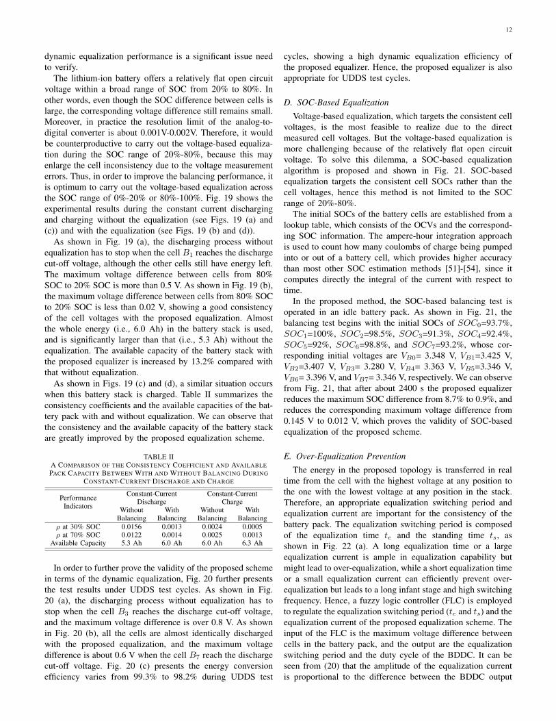
The lithium-ion battery offers a relatively flat open circuitvoltage within a broad range of SOC from 20% to 80%. Inother words, even though the SOC difference between cells islarge, the corresponding voltage difference still remains small.Moreover, in practice the resolution limit of the analog-to-digital converter is about 0.001V-0.002V. Therefore, it wouldbe counterproductive to carry out the voltage-based equaliza-tion during the SOC range of 20%-80%, because this mayenlarge the cell inconsistency due to the voltage measurementerrors. Thus, in order to improve the balancing performance, itis optimum to carry out the voltage-based equalization acrossthe SOC range of 0%-20% or 80%-100%. Fig. 19 shows theexperimental results during the constant current dischargingand charging without the equalization (see Figs. 19 (a) and(c)) and with the equalization (see Figs. 19 (b) and (d)).
As shown in Fig. 19 (a), the discharging process withoutequalization has to stop when the cell B1 reaches the dischargecut-off voltage, although the other cells still have energy left.The maximum voltage difference between cells from 80%SOC to 20% SOC is more than 0.5 V. As shown in Fig. 19 (b),the maximum voltage difference between cells from 80% SOCto 20% SOC is less than 0.02 V, showing a good consistencyof the cell voltages with the proposed equalization. Almostthe whole energy (i.e., 6.0 Ah) in the battery stack is used,and is significantly larger than that (i.e., 5.3 Ah) without theequalization. The available capacity of the battery stack withthe proposed equalizer is increased by 13.2% compared withthat without equalization.
As shown in Figs. 19 (c) and (d), a similar situation occurswhen this battery stack is charged. Table II summarizes theconsistency coefficients and the available capacities of the bat-tery pack with and without equalization. We can observe thatthe consistency and the available capacity of the battery stackare greatly improved by the proposed equalization scheme.
TABLE IIA COMPARISON OF THE CONSISTENCY COEFFICIENT AND AVAILABLEPACK CAPACITY BETWEEN WITH AND WITHOUT BALANCING DURING
CONSTANT-CURRENT DISCHARGE AND CHARGE
PerformanceIndicators
Constant-CurrentDischarge
Constant-CurrentCharge
WithoutBalancing
WithBalancing
WithoutBalancing
WithBalancing
ρ at 30% SOC 0.0156 0.0013 0.0024 0.0005ρ at 70% SOC 0.0122 0.0014 0.0025 0.0013
Available Capacity 5.3 Ah 6.0 Ah 6.0 Ah 6.3 Ah
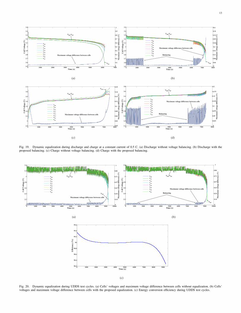
In order to further prove the validity of the proposed schemein terms of the dynamic equalization, Fig. 20 further presentsthe test results under UDDS test cycles. As shown in Fig.20 (a), the discharging process without equalization has tostop when the cell B3 reaches the discharge cut-off voltage,and the maximum voltage difference is over 0.8 V. As shownin Fig. 20 (b), all the cells are almost identically dischargedwith the proposed equalization, and the maximum voltagedifference is about 0.6 V when the cell B7 reach the dischargecut-off voltage. Fig. 20 (c) presents the energy conversionefficiency varies from 99.3% to 98.2% during UDDS test
cycles, showing a high dynamic equalization efficiency ofthe proposed equalizer. Hence, the proposed equalizer is alsoappropriate for UDDS test cycles.
D. SOC-Based Equalization
Voltage-based equalization, which targets the consistent cellvoltages, is the most feasible to realize due to the directmeasured cell voltages. But the voltage-based equalization ismore challenging because of the relatively flat open circuitvoltage. To solve this dilemma, a SOC-based equalizationalgorithm is proposed and shown in Fig. 21. SOC-basedequalization targets the consistent cell SOCs rather than thecell voltages, hence this method is not limited to the SOCrange of 20%-80%.
The initial SOCs of the battery cells are established from alookup table, which consists of the OCVs and the correspond-ing SOC information. The ampere-hour integration approachis used to count how many coulombs of charge being pumpedinto or out of a battery cell, which provides higher accuracythan most other SOC estimation methods [51]-[54], since itcomputes directly the integral of the current with respect totime.
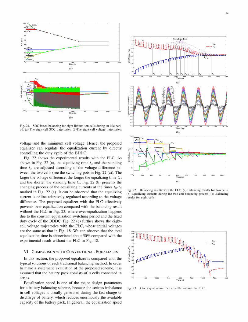
In the proposed method, the SOC-based balancing test isoperated in an idle battery pack. As shown in Fig. 21, thebalancing test begins with the initial SOCs of SOC0=93.7%,SOC1=100%, SOC2=98.5%, SOC3=91.3%, SOC4=92.4%,SOC5=92%, SOC6=98.8%, and SOC7=93.2%, whose cor-responding initial voltages are VB0= 3.348 V, VB1=3.425 V,VB2=3.407 V, VB3= 3.280 V, VB4= 3.363 V, VB5=3.346 V,VB6= 3.396 V, and VB7= 3.346 V, respectively. We can observefrom Fig. 21, that after about 2400 s the proposed equalizerreduces the maximum SOC difference from 8.7% to 0.9%, andreduces the corresponding maximum voltage difference from0.145 V to 0.012 V, which proves the validity of SOC-basedequalization of the proposed scheme.
E. Over-Equalization Prevention
The energy in the proposed topology is transferred in realtime from the cell with the highest voltage at any position tothe one with the lowest voltage at any position in the stack.Therefore, an appropriate equalization switching period andequalization current are important for the consistency of thebattery pack. The equalization switching period is composedof the equalization time te and the standing time ts, asshown in Fig. 22 (a). A long equalization time or a largeequalization current is ample in equalization capability butmight lead to over-equalization, while a short equalization timeor a small equalization current can efficiently prevent over-equalization but leads to a long infant stage and high switchingfrequency. Hence, a fuzzy logic controller (FLC) is employedto regulate the equalization switching period (te and ts) and theequalization current of the proposed equalization scheme. Theinput of the FLC is the maximum voltage difference betweencells in the battery pack, and the output are the equalizationswitching period and the duty cycle of the BDDC. It can beseen from (20) that the amplitude of the equalization currentis proportional to the difference between the BDDC output
13
0 1000 2000 3000 4000 5000 6000 70002.5
2.6
2.7
2.8
2.9
3
3.1
3.2
3.3
3.4
3.5
Time (s)
Cell
Vo
lta
ge
(V)
B0
B1
B2
B3
B4
B5
B6
B7
VB1
VB0
VB2
VB3
VB4
VB5
VB6
VB7
Maximum voltage difference between cells
VB0-VB7
Max
imu
m v
olt
age
dif
fere
nce
(V
)
0.1
0.2
0.4
0.5
1
0.3
0.6
VB1
0.7
0.8
0.9
00 1000 2000 3000 4000 5000 6000 7000 8000
2.5
2.6
2.7
2.8
2.9
3
3.1
3.2
3.3
3.4
3.5
Time (s)
Cell
Vo
lta
ge
(V)
B0
B1
B2
B3
B4
B5
B6
B7
VB1
VB0
VB2
VB3
VB4
VB5
VB6
VB7
Maximum voltage difference between cells
VB0-VB7
Max
imu
m v
olt
age
dif
fere
nce
(V
)
0.04
0.08
0.16
0.2
0.4
0.12
0.24
VB3
0.28
0.32
0.36
Balancing
0
(a) (b)
0 1000 2000 3000 4000 5000 6000 7000 80002.9
3
3.1
3.2
3.3
3.4
3.5
3.6
3.7
Time (s)
Cell
Vo
lta
ge
(V)
B0
B1
B2
B3
B4
B5
B6
B7
VB1
VB0
VB2
VB3
VB4
VB5
VB6
VB7
Maximum voltage difference between cells
VB0-VB7
Max
imu
m v
olt
age
dif
fere
nce
(V
)
0.02
0.04
0.08
0.1
0.18
0.06
0.12
VB1
0.14
0.16
0 1000 2000 3000 4000 5000 6000 7000 80002.2
2.4
2.6
2.8
3
3.2
3.4
3.6
3.8
Time (s)
Cell
Vo
lta
ge (
V)
B0
B1
B2
B3
B4
B5
B6
B7
VB1
VB0
VB2
VB3
VB4
VB5
VB6
VB7
Maximum voltage difference between cells
VB0-VB7
Max
imu
m v
olt
age d
iffe
ren
ce
(V)
0
0.025
0.075
0.1
0.2
0.05
0.125
0.15
0.175
Balancing
(c) (d)
Fig. 19. Dynamic equalization during discharge and charge at a constant current of 0.5 C. (a) Discharge without voltage balancing. (b) Discharge with theproposed balancing. (c) Charge without voltage balancing. (d) Charge with the proposed balancing.
0 1000 2000 3000 4000 5000 6000 7000 8000 9000 100002
2.2
2.4
2.6
2.8
3
3.2
3.4
Time (s)
Cell
Volt
age (
V)
B0
B1
B2
B3
B4
B5
B6
B7
VB1
VB0
VB2
VB3
VB4
VB5
VB6
VB7
Maximum voltage difference between cells
VB0-VB7
Max
imu
m v
olt
age
dif
fere
nce
(V
)
0.14
0.29
0.57
0.71
1
0.43
0.86
VB3
00 1000 2000 3000 4000 5000 6000 7000 8000 9000 10000
2
2.2
2.4
2.6
2.8
3
3.2
3.4
Time (s)
Cell
Volt
age (
V)
B0
B1
B2
B3
B4
B5
B6
B7
VB1
VB0
VB2
VB3
VB4
VB5
VB6
VB7
Maximum voltage difference between cells
VB0-VB7
Max
imu
m v
olt
age d
iffe
ren
ce (
V)
0.14
0.29
0.57
0.71
1
0.43
0.86
VB7
Balancing
0
(a) (b)
(c)
0 1000 2000 3000 4000 5000 6000 7000 8000 900098.2
98.4
98.6
98.8
99
99.2
99.4
99.6
Time (s)
Eff
icie
ncy
(%
)
Fig. 20. Dynamic equalization during UDDS test cycles. (a) Cells’ voltages and maximum voltage difference between cells without equalization. (b) Cells’voltages and maximum voltage difference between cells with the proposed equalization. (c) Energy conversion efficiency during UDDS test cycles.
14
0 500 1000 1500 2000 2500 3000 3500 400091
92
93
94
95
96
97
98
99
100
Time (s)
SO
C (
%)
SOC1
SOC2
SOC0
SOC4
SOC5
SOC3
SOC7
SOC6
(a)
0 500 1000 1500 2000 2500 3000 3500 40003.25
3.3
3.35
3.4
3.45
Time (s)
Cel
l V
olta
ge (
V)
VB1
VB2
VB0
VB4
VB5VB3
VB7
VB6
(b)
Fig. 21. SOC-based balancing for eight lithium-ion cells during an idle peri-od. (a) The eight-cell SOC trajectories. (b)The eight-cell voltage trajectories.
voltage and the minimum cell voltage. Hence, the proposedequalizer can regulate the equalization current by directlycontrolling the duty cycle of the BDDC.
Fig. 22 shows the experimental results with the FLC. Asshown in Fig. 22 (a), the equalizing time te and the standingtime ts are adjusted according to the voltage difference be-tween the two cells (see the switching pots in Fig. 22 (a)). Thelarger the voltage difference, the longer the equalizing time te,and the shorter the standing time ts. Fig. 22 (b) presents thechanging process of the equalizing currents at the times t0-t9marked in Fig. 22 (a). It can be observed that the equalizingcurrent is online adaptively regulated according to the voltagedifference. The proposed equalizer with the FLC effectivelyprevents over-equalization compared with the balancing resultwithout the FLC in Fig. 23, where over-equalization happensdue to the constant equalization switching period and the fixedduty cycle of the BDDC. Fig. 22 (c) further shows the eight-cell voltage trajectories with the FLC, whose initial voltagesare the same as that in Fig. 18. We can observe that the totalequalization time is abbreviated about 50% compared with theexperimental result without the FLC in Fig. 18.
VI. COMPARISON WITH CONVENTIONAL EQUALIZERS
In this section, the proposed equalizer is compared with thetypical solutions of each traditional balancing method. In orderto make a systematic evaluation of the proposed scheme, it isassumed that the battery pack consists of n cells connected inseries.
Equalization speed is one of the major design parametersfor a battery balancing scheme, because the serious imbalancein cell voltages is usually generated during the fast charge ordischarge of battery, which reduces enormously the availablecapacity of the battery pack. In general, the equalization speed
0 500 1000 1500 2000 2500 3000 3500 4000 4500 5000 55002.8
2.85
2.9
2.95
3
3.05
3.1
3.15
3.2
3.25
3.3
Time (s)
Cel
l V
olt
age
(V)
B0
B1
t0 t2 t4t1t3 t5 t6 t7 t8 t9
Switching Pots
te
ts
ts
te
VB0
VB1VB1
VB0
(a)
0 20 40 60 80 100 120 140 160 180 200 220 240 250-0.63
-0.53
-0.43
-0.33
-0.23
-0.13
-0.03
0.07
0.17
0.27
0.37
0.47
0.57
0.66
Time (μs)E
qu
ali
zati
on
Cu
rren
t (A
)
t0t1t2t3t4t5t6t7t8t9
Th
etr
end
of
curr
ent
(b)
0 200 400 600 800 1000 1200 1400 1600 1800 20002.85
2.9
2.95
3
3.05
3.1
3.15
Time (s)
Cel
l V
olt
age
(V)
VB2
VB0
VB5
VB6VB1
VB4
VB3
VB7
te
ts
(c)
Fig. 22. Balancing results with the FLC. (a) Balancing results for two cells.(b) Equalizing currents during the two-cell balancing process. (c) Balancingresults for eight cells.
0 1000 2000 3000 4000 5000 6000 7000 80002.6
2.65
2.7
2.75
2.8
2.85
2.9
2.95
3
3.05
3.1
3.15
3.2
3.253.28
Time (s)
Cell
Vo
lta
ge (
V)
VB0
VB1
VB0
VB1VB1
VB0
Fig. 23. Over-equalization for two cells without the FLC.
15
is determined by the maximum equalization current and theaverage switching cycle. The maximum equalization currentdecides the transferred power among the cells in one switchingcycle, and the average switching cycle to complete the chargetransportation from the source cell to the target one decidesthe equalization speed and efficiency.
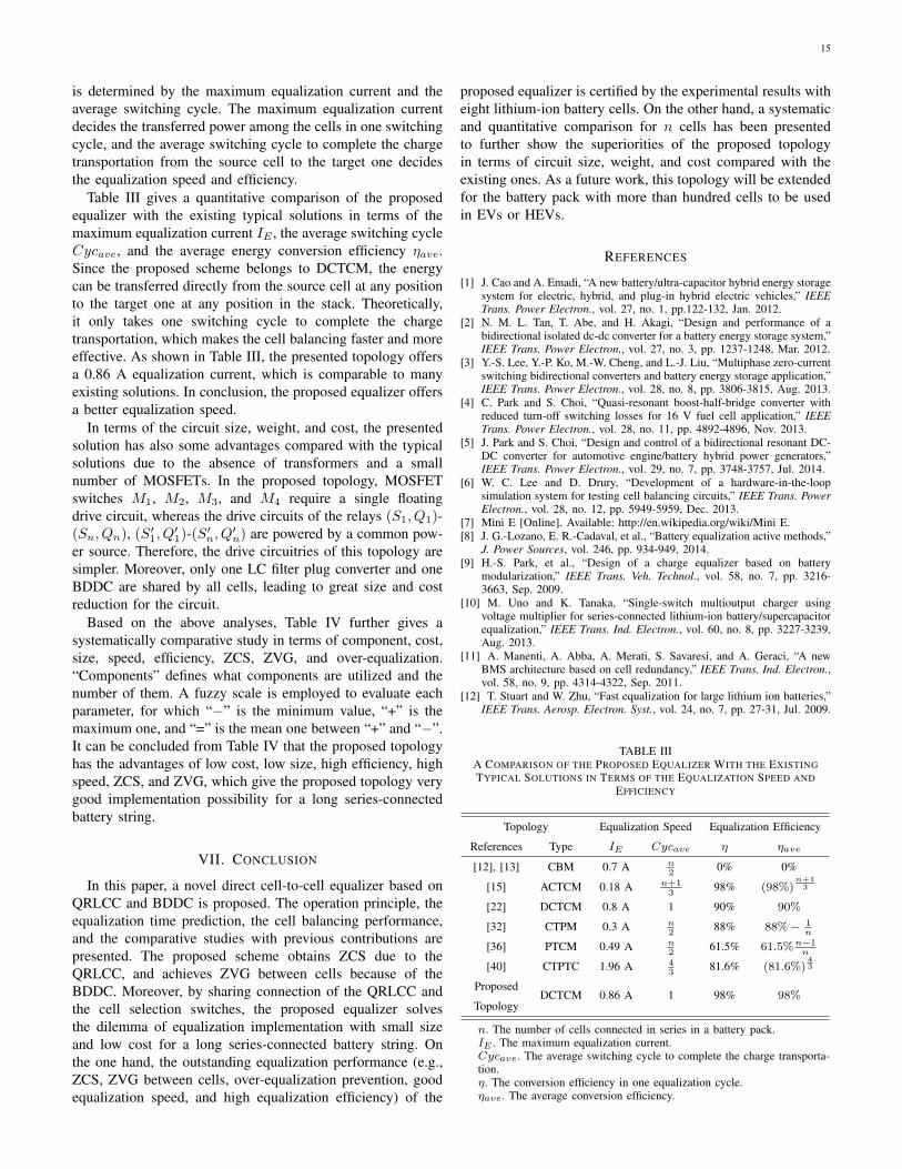
Table III gives a quantitative comparison of the proposedequalizer with the existing typical solutions in terms of themaximum equalization current IE , the average switching cycleCycave, and the average energy conversion efficiency ηave.Since the proposed scheme belongs to DCTCM, the energycan be transferred directly from the source cell at any positionto the target one at any position in the stack. Theoretically,it only takes one switching cycle to complete the chargetransportation, which makes the cell balancing faster and moreeffective. As shown in Table III, the presented topology offersa 0.86 A equalization current, which is comparable to manyexisting solutions. In conclusion, the proposed equalizer offersa better equalization speed.
In terms of the circuit size, weight, and cost, the presentedsolution has also some advantages compared with the typicalsolutions due to the absence of transformers and a smallnumber of MOSFETs. In the proposed topology, MOSFETswitches M1, M2, M3, and M4 require a single floatingdrive circuit, whereas the drive circuits of the relays (S1, Q1)-(Sn, Qn), (S′
1, Q′1)-(S
′n, Q
′n) are powered by a common pow-
er source. Therefore, the drive circuitries of this topology aresimpler. Moreover, only one LC filter plug converter and oneBDDC are shared by all cells, leading to great size and costreduction for the circuit.
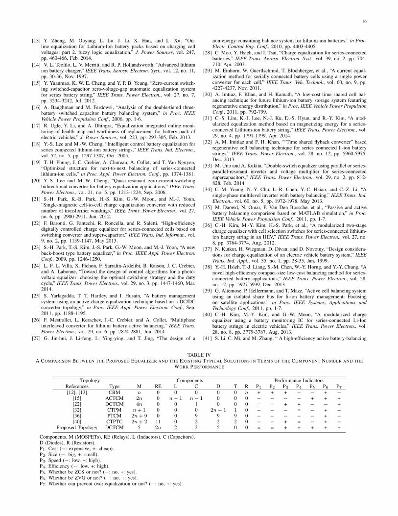
Based on the above analyses, Table IV further gives asystematically comparative study in terms of component, cost,size, speed, efficiency, ZCS, ZVG, and over-equalization.“Components” defines what components are utilized and thenumber of them. A fuzzy scale is employed to evaluate eachparameter, for which “−” is the minimum value, “+” is themaximum one, and “=” is the mean one between “+” and “−”.It can be concluded from Table IV that the proposed topologyhas the advantages of low cost, low size, high efficiency, highspeed, ZCS, and ZVG, which give the proposed topology verygood implementation possibility for a long series-connectedbattery string.
VII. CONCLUSION
In this paper, a novel direct cell-to-cell equalizer based onQRLCC and BDDC is proposed. The operation principle, theequalization time prediction, the cell balancing performance,and the comparative studies with previous contributions arepresented. The proposed scheme obtains ZCS due to theQRLCC, and achieves ZVG between cells because of theBDDC. Moreover, by sharing connection of the QRLCC andthe cell selection switches, the proposed equalizer solvesthe dilemma of equalization implementation with small sizeand low cost for a long series-connected battery string. Onthe one hand, the outstanding equalization performance (e.g.,ZCS, ZVG between cells, over-equalization prevention, goodequalization speed, and high equalization efficiency) of the
proposed equalizer is certified by the experimental results witheight lithium-ion battery cells. On the other hand, a systematicand quantitative comparison for n cells has been presentedto further show the superiorities of the proposed topologyin terms of circuit size, weight, and cost compared with theexisting ones. As a future work, this topology will be extendedfor the battery pack with more than hundred cells to be usedin EVs or HEVs.
REFERENCES
[1] J. Cao and A. Emadi, “A new battery/ultra-capacitor hybrid energy storagesystem for electric, hybrid, and plug-in hybrid electric vehicles,” IEEETrans. Power Electron., vol. 27, no. 1, pp.122-132, Jan. 2012.
[2] N. M. L. Tan, T. Abe, and H. Akagi, “Design and performance of abidirectional isolated dc-dc converter for a battery energy storage system,”IEEE Trans. Power Electron., vol. 27, no. 3, pp. 1237-1248, Mar. 2012.
[3] Y.-S. Lee, Y.-P. Ko, M.-W. Cheng, and L.-J. Liu, “Multiphase zero-currentswitching bidirectional converters and battery energy storage application,”IEEE Trans. Power Electron., vol. 28, no. 8, pp. 3806-3815, Aug. 2013.
[4] C. Park and S. Choi, “Quasi-resonant boost-half-bridge converter withreduced turn-off switching losses for 16 V fuel cell application,” IEEETrans. Power Electron., vol. 28, no. 11, pp. 4892-4896, Nov. 2013.
[5] J. Park and S. Choi, “Design and control of a bidirectional resonant DC-DC converter for automotive engine/battery hybrid power generators,”IEEE Trans. Power Electron., vol. 29, no. 7, pp. 3748-3757, Jul. 2014.
[6] W. C. Lee and D. Drury, “Development of a hardware-in-the-loopsimulation system for testing cell balancing circuits,” IEEE Trans. PowerElectron., vol. 28, no. 12, pp. 5949-5959, Dec. 2013.
[7] Mini E [Online]. Available: http://en.wikipedia.org/wiki/Mini E.[8] J. G.-Lozano, E. R.-Cadaval, et al., “Battery equalization active methods,”
J. Power Sources, vol. 246, pp. 934-949, 2014.[9] H.-S. Park, et al., “Design of a charge equalizer based on battery
modularization,” IEEE Trans. Veh. Technol., vol. 58, no. 7, pp. 3216-3663, Sep. 2009.
[10] M. Uno and K. Tanaka, “Single-switch multioutput charger usingvoltage multiplier for series-connected lithium-ion battery/supercapacitorequalization,” IEEE Trans. Ind. Electron., vol. 60, no. 8, pp. 3227-3239,Aug. 2013.
[11] A. Manenti, A. Abba, A. Merati, S. Savaresi, and A. Geraci, “A newBMS architecture based on cell redundancy,” IEEE Trans. Ind. Electron.,vol. 58, no. 9, pp. 4314-4322, Sep. 2011.
[12] T. Stuart and W. Zhu, “Fast equalization for large lithium ion batteries,”IEEE Trans. Aerosp. Electron. Syst., vol. 24, no. 7, pp. 27-31, Jul. 2009.
TABLE IIIA COMPARISON OF THE PROPOSED EQUALIZER WITH THE EXISTINGTYPICAL SOLUTIONS IN TERMS OF THE EQUALIZATION SPEED AND
EFFICIENCY
Topology Equalization Speed Equalization Efficiency
References Type IE Cycave η ηave
[12], [13] CBM 0.7 A n2
0% 0%
[15] ACTCM 0.18 A n+13
98% (98%)n+13
[22] DCTCM 0.8 A 1 90% 90%
[32] CTPM 0.3 A n2
88% 88%− 1n
[36] PTCM 0.49 A n2
61.5% 61.5%n−1n
[40] CTPTC 1.96 A 43
81.6% (81.6%)43
Proposed
TopologyDCTCM 0.86 A 1 98% 98%
n. The number of cells connected in series in a battery pack.IE . The maximum equalization current.Cycave. The average switching cycle to complete the charge transporta-tion.η. The conversion efficiency in one equalization cycle.ηave. The average conversion efficiency.
16
[13] Y. Zheng, M. Ouyang, L. Lu, J. Li, X. Han, and L. Xu, “On-line equalization for Lithium-Ion battery packs based on charging cellvoltages: part 2. fuzzy logic equalization,” J. Power Sources, vol. 247,pp. 460-466, Feb. 2014.
[14] V. L. Teofilo, L. V. Merritt, and R. P. Hollandsworth, “Advanced lithiumion battery charger,” IEEE Trans. Aerosp. Electron. Syst., vol. 12, no. 11,pp. 30-36, Nov. 1997.
[15] Y. Yuanmao, K. W. E. Cheng, and Y. P. B. Yeung, “Zero-current switch-ing switched-capacitor zero-voltage-gap automatic equalization systemfor series battery string,” IEEE Trans. Power Electron., vol. 27, no. 7,pp. 3234-3242, Jul. 2012.
[16] A. Baughman and M. Ferdowsi, “Analysis of the double-tiered three-battery switched capacitor battery balancing system,” in Proc. IEEEVehicle Power Propulsion Conf., 2006, pp. 1-6.
[17] R. Ugle, Y. Li, and A. Dhingra, “Equalization integrated online moni-toring of health map and worthiness of replacement for battery pack ofelectric vehicles,” J. Power Sources, vol. 223, pp. 293-305, Feb. 2013.
[18] Y.-S. Lee and M.-W. Cheng, “Intelligent control battery equalization forseries connected lithium-ion battery strings,” IEEE Trans. Ind. Electron.,vol. 52, no. 5, pp. 1297-1307, Oct. 2005.
[19] T. H. Phung, J. C. Crebier, A. Chureau, A. Collet, and T. Van Nguyen,“Optimized structure for next-to-next balancing of series-connectedlithium-ion cells,” in Proc. Appl. Power Electron. Conf., pp. 1374-1381.
[20] Y.-S. Lee and M.-W. Cheng, “Quasi-resonant zero-current-switchingbidirectional converter for battery equalization applications,” IEEE Trans.Power Electron., vol. 21, no. 5, pp. 1213-1224, Sep. 2006.
[21] S.-H. Park, K.-B. Park, H.-S. Kim, G.-W. Moon, and M.-J. Youn,“Single-magnetic cell-to-cell charge equalization converter with reducednumber of transformer windings,” IEEE Trans. Power Electron., vol. 27,no. 6, pp. 2900-2911, Jun. 2012.
[22] F. Baronti, G. Fantechi, R. Roncella, and R. Saletti, “High-efficiencydigitally controlled charge equalizer for series-connected cells based onswitching converter and super-capacitor,” IEEE Trans. Ind. Informat., vol.9, no. 2, pp. 1139-1147, May 2013.
[23] S.-H. Park, T.-S. Kim, J.-S. Park, G.-W. Moon, and M.-J. Yoon, “A newbuck-boost type battery equalizer,” in Proc. IEEE Appl. Power Electron.Conf., 2009, pp. 1246-1250.
[24] L. F. L. Villa, X. Pichon, F. Sarrafin-Ardelibi, B. Raison, J. C. Crebier,and A. Labonne, “Toward the design of control algorithms for a photo-voltaic equalizer: choosing the optimal switching strategy and the dutycycle,” IEEE Trans. Power Electron., vol. 29, no. 3, pp. 1447-1460, Mar.2014.
[25] S. Yarlagadda, T. T. Hartley, and I. Husain, “A battery managementsystem using an active charge equalization technique based on a DC/DCconverter topology,” in Proc. IEEE Appl. Power Electron. Conf., Sep.2011, pp. 1188-1195.
[26] F. Mestrallet, L. Kerachev, J.-C. Crebier, and A. Collet, “Multiphaseinterleaved converter for lithium battery active balancing,” IEEE Trans.Power Electron., vol. 29, no. 6, pp. 2874-2881, Jun. 2014.
[27] G. Jin-hui, J. Li-feng, L. Ying-ying, and T. Jing, “The design of a
non-energy-consuming balance system for lithium-ion batteries,” in Proc.Electr. Control Eng. Conf., 2010, pp. 4403-4405.
[28] C. Moo, Y. Hsieh, and I. Tsai, “Charge equalization for series-connectedbatteries,” IEEE Trans. Aerosp. Electron. Syst., vol. 39, no. 2, pp. 704-710, Apr. 2003.
[29] M. Einhorn, W. Guertlschmid, T. Blochberger, et al., “A current equal-ization method for serially connected battery cells using a single powerconverter for each cell,” IEEE Trans. Veh. Technol., vol. 60, no. 9, pp.4227-4237, Nov. 2011.
[30] A. Imtiaz, F. Khan, and H. Kamath, “A low-cost time shared cell bal-ancing technique for future lithium-ion battery storage system featuringregenerative energy distribution,” in Proc. IEEE Vehicle Power PropulsionConf., 2011, pp. 792-799.
[31] C.-S. Lim, K.-J. Lee, N.-J. Ku, D.-S. Hyun, and R.-Y. Kim, “A mod-ularized equalization method based on magnetizing energy for a series-connected Lithium-ion battery string,” IEEE Trans. Power Electron., vol.29, no. 4, pp. 1791-1799, Apr. 2014.
[32] A. M. Imitiaz and F. H. Khan, ““Time shared flyback converter” basedregenerative cell balancing technique for series connected li-ion batterystrings,” IEEE Trans. Power Electron., vol. 28, no. 12, pp. 5960-5975,Dec. 2013.
[33] M. Uno and A. Kukita, “Double-switch equalizer using parallel or series-parallel-resonant inverter and voltage multiplier for series-connectedsupercapacitors,” IEEE Trans. Power Electron., vol. 29, no. 2, pp. 812-828, Feb. 2014.
[34] C.-M. Young, N.-Y. Chu, L.-R. Chen, Y.-C. Hsiao, and C.-Z. Li, “Asingle-phase multilevel inverter with battery balancing,” IEEE Trans. Ind.Electron., vol. 60, no. 5, pp. 1972-1978, May 2013.
[35] M. Daowd, N. Omar, P. Van Den Bossche, et al., “Passive and activebattery balancing comparison based on MATLAB simulation,” in Proc.IEEE Vehicle Power Propulsion Conf., 2011, pp. 1-7.
[36] C.-H. Kim, M.-Y. Kim, H.-S. Park, et al., “A modularized two-stagecharge equalizer with cell selection switches for series-connected lithium-ion battery string in an HEV,” IEEE Trans. Power Electron., vol. 27, no.8, pp. 3764-3774, Aug. 2012.
[37] N. Kutkut, H. Wiegman, D. Divan, and D. Novotny, “Design considera-tions for charge equalization of an electric vehicle battery system,” IEEETrans. Ind. Appl., vol. 35, no. 1, pp. 28-35, Jan. 1999.
[38] Y.-H. Hsieh, T.-J. Liang, S.-M. Chen, W.-Y. Horng, and Y.-Y. Chung, “Anovel high-efficiency compact-size low-cost balancing method for series-connected battery applications,” IEEE Trans. Power Electron., vol. 28,no. 12, pp. 5927-5939, Dec. 2013.
[39] G. Altemose, P. Hellermann, and T. Mazz, “Active cell balancing systemusing an isolated share bus for li-ion battery management: Focusingon satellite applications,” in Proc. IEEE Systems, Applications andTechnology Conf., 2011, pp. 1-7.
[40] C.-H. Kim, M.-Y. Kim, and G.-W. Moon, “A modularized chargeequalizer using a battery monitoring IC for series-connected Li-Ionbattery strings in electric vehicles,” IEEE Trans. Power Electron., vol.28, no. 8, pp. 3779-3787, Aug. 2013.
[41] S. Li, C. Mi, and M. Zhang, “ A high-efficiency active battery-balancing
TABLE IVA COMPARISON BETWEEN THE PROPOSED EQUALIZER AND THE EXISTING TYPICAL SOLUTIONS IN TERMS OF THE COMPONENT NUMBER AND THE
WORK PERFORMANCE
Topology Components Performance IndicatorsReferences Type M RE L C D T R P1 P2 P3 P4 P5 P6 P7
[12], [13] CBM n 0 0 0 0 0 n + + + − − + −[15] ACTCM 2n 0 n− 1 n− 1 0 0 0 − − − − + + +[22] DCTCM 4n 0 0 1 0 0 0 = = + + − − +[32] CTPM n+ 1 0 0 0 2n− 1 1 0 − − − = − + −[36] PTCM 2n+ 9 0 0 9 9 9 0 − − − − − + −[40] CTPTC 2n+ 2 11 0 2 2 2 0 − − + = − + −
Proposed Topology DCTCM 5 2n 2 2 5 0 0 = = + + + + +
Components. M (MOSFETs), RE (Relays), L (Inductors), C (Capacitors),D (Diodes), R (Resistors).P1. Cost (−: expensive, +: cheap).P2. Size (−: big, +: small).P3. Speed (−: low, +: high).P4. Efficiency (−: low, +: high).P5. Whether be ZCS or not? (−: no, +: yes).P6. Whether be ZVG or not? (−: no, +: yes).P7. Whether can prevent over-equalization or not? (−: no, +: yes).
17
circuit using multiwinding transformer,” IEEE Trans. Ind. Appl., vol. 49,no. 1, pp. 198-207, Jan. 2013.
[42] J.-H. Kim, J.-W. Shin, C.-Y. Jeon, and B.-H. Cho, “Screening process ofli-ion series battery pack for improved voltage/SOC balancing,” in Proc.IEEE Power Electron. Conf., 2010, pp. 1174-1179.
[43] J.-H. Kim, J.-W. Shin, C.-Y. Jeon, and B.-H. Cho, “Stable configurationof a li-ion series battery pack based on a screening process for improvedvoltage/SOC balancing,” IEEE Trans. Power Electron., vol. 27, no. 1, pp.411-424, Jan. 2012.
[44] F. Deng and Z. Chen, “A control method for voltage balancing inmodular multilevel converters,” IEEE Trans. Power Electron., vol. 29,no. 1, pp. 66-76, Jan. 2014.
[45] Y. Zheng, M. Ouyang, L. Lu, J. Li, X. Han, and L. Xu, “On-lineequalization for lithium-ion battery packs based on charging cell voltages:part 1. equalization based on remaining charging capacity estimation,” J.Power Sources, vol. 247, pp. 676-686, Feb. 2014.
[46] Liebig’s law of the minimum [Online]. Available:http://en.wikipedia.org/wiki/Liebig’s law of the minimum.
[47] C. Min and G. R.-Mora, “Accurate electrical battery model capable ofpredicting runtime and I-V performance,” IEEE Trans. Energy Convers.,vol. 21, no. 2, pp. 504-511, Jun. 2006.
[48] M. Einhorn, F. V. Conte, C. Kral, and J. Fleig, “Comparison, selection,and parameterization of electrical battery models for automotive appli-cations,” IEEE Trans. Power Electron., vol. 28, no. 3, pp. 1429-1437,March 2013.
[49] B. Hredzak, V.G. Agelidis, and M. Jang, “A model predictive controlsystem for a hybrid battery-ultracapacitor power source,” IEEE Trans.Power Electron., vol. 29, no. 3, pp. 1469-1479, March 2014.
[50] S. Ben-Yaakov, “Behavioral average modeling and equivalent circuitsimulation of switched capacitors converters,” IEEE Trans. Power Elec-tron., vol. 27, no. 2, pp. 632-636, Feb. 2012.
[51] R. Priewasser, M. Agostinelli, C. Unterrieder, S. Marsili, and M.Huemer, “Modeling, control, and implementation of DC-DC convertersfor variable frequency operation,” IEEE Trans. Power Electron., vol. 29,no. 1, pp. 287-301, Jan. 2014.
[52] J. Kim, S. Lee, and B. H. Cho, “Complementary cooperation algorithmbased on DEKF combined with pattern recognition for SOC/capacityestimation and SOH prediction,” IEEE Trans. Power Electron., vol. 27,no. 1, pp. 436-451, Jan. 2012.
[53] J. C. Alvarez Anton, P. J. Garcia Nieto, F. J. de Cos Juez, F. SanchezLasheras, C. Blanco Viehjo, and N. Roqueni Gutierrez, “Battery state-of-charge estimator using the MARS technique,” IEEE Trans. PowerElectron., vol. 28, no. 8, pp. 3798-3805, Aug. 2013.
[54] J. C. Alvarez Anton, P. J. Garcia Nieto, C. Blanco Viejo, and J. A.Vilan Vilan, “Support vector machines used to estimate the battery stateof charge,” IEEE Trans. Power Electron., vol. 28, no. 12, pp. 5919-5926,Dec. 2013.
Yunlong Shang was born in China, in 1984. Hereceived the B.S. degree from Hefei University ofTechnology, China, in 2008. Since 2010, he hasbeen enrolled for the joint courses for master anddoctor degrees in the School of Control Scienceand Engineering, Shandong University, Shandong,China.
His current research interests include the designand control of battery management system, batteryequalization, battery modeling, and SOC estimation.
Mr. Shang is a student member of the IEEE.
Chenghui Zhang was born in China, in 1963. Hereceived the B.S. and M.S. degrees from ShandongUniversity of Technology, China, in 1985 and 1988,respectively, and the Ph.D. degree from ShandongUniversity, China, in 2001. In 1988, he joinedShandong University, where he is currently a FullProfessor with the School of Control Science andEngineering, and the director of Research Centerof Power Electronics Energy-Saving Technology &Equipment of the Chinese Education Ministry. Prof.Zhang was selected as a Changjiang Scholar of the
Education Ministry, and a Taishan Scholar of Shandong Province in 2009,respectively.
His current research interests include optimal control of engineering, powerelectronics and motor drives, and energy-saving techniques.
Dr. Zhang is a member of the IEEE.
Naxin Cui was born in China, in 1968. She receivedthe B.S. degree from Tianjin University, China, in1989, and the M.S. and Ph.D. degrees from Shan-dong University, China, in 1994 and 2005, respec-tively. In 1994, she joined Shandong University,where she is currently a Full Professor with theSchool of Control Science and Engineering.
Her current research interests include power elec-tronics, motor drives, automatic control theory andapplication, and battery energy management systemof electric vehicles.
Dr. Cui is a member of the IEEE.
Josep M. Guerrero (S’01-M’04-SM’08) receivedthe B.S. degree in telecommunications engineering,the M.S. degree in electronics engineering, and thePh.D. degree in power electronics from the TechnicalUniversity of Catalonia, Barcelona, in 1997, 2000and 2003, respectively. Since 2011, he has beena Full Professor with the Department of EnergyTechnology, Aalborg University, Denmark, where heis responsible for the Microgrid Research Program.From 2012 he is a guest Professor at the ChineseAcademy of Science and the Nanjing University
of Aeronautics and Astronautics; and from 2014 he is chair Professor inShandong University.
His research interests is oriented to different microgrid aspects, includingpower electronics, distributed energy-storage systems, hierarchical and coop-erative control, energy management systems, and optimization of microgridsand islanded minigrids. Prof. Guerrero is an Associate Editor for the IEEETransactions On Power Electronics, the IEEE Transactions On IndustrialElectronics, and the IEEE Industrial Electronics Magazine, and an Editorfor the IEEE Transactions On Smart Grid. He has been Guest Editor of theIEEE Transactions On Power Electronics Special Issues: Power Electronicsfor Wind Energy Conversion and Power Electronics for Microgrids; theIEEE Transactions On Industrial Electronics Special Sections: UninterruptiblePower Supplies systems, Renewable Energy Systems, Distributed Generationand Microgrids, and Industrial Applications and Implementation Issues of theKalman Filter; and the IEEE Transactions On Smart Grid Special Issue onSmart DC Distribution Systems. He was the chair of the Renewable EnergySystems Technical Committee of the IEEE Industrial Electronics Society. In2014 he was awarded as ISI Highly Cited Researcher.