Embed Size (px)
Citation preview
A Characterization of the BroadbandMIMO PLC Channel in Aircraft
Leyna SadamoriETH Zurich
Department of Computer ScienceUniversitätstr. 6, 8092 Zürich, Switzerland
Email: [email protected]
Stephen Dominiak, Thomas HunzikerHochschule Luzern
Technik & ArchitekturTechnikumstr. 21, 6048 Horw, Switzerland
Email: stephen.dominiak, [email protected]
Abstract—The use of Multiple Input Multiple Output (MIMO)techniques for Power Line Communications (PLC) has beenproven for the consumer market. As of 2011, MIMO is part oftwo PLC standards and products are already available for endusers. PLC for avionics on the other hand is a niche technology.Fulfilling the high demands for safety-critical components makesthe engineering of a PLC solution a challenging task. Manyaircraft systems are powered by a three-phase alternating currentsystem and already provide the necessary wiring for adoptingMIMO techniques. Our goal is to develop next generation PLCsystems for aircraft with MIMO technology.
The signal propagation on power lines is known to be complexwhich makes channel modeling a fundamental challenge in thedevelopment of PLC systems. Because of the safety-critical natureof avionics applications, the channel models need to be accurate,but more importantly, should represent the actual conditions asrealistically as possible.
We present a test bench that emulates the cabin lighting systemin an aircraft. The layout of the wire harness is designed suchthat realistic distances and complexities within the network canbe reproduced within a smaller area on the test bench. Theoriginal design has been validated with simulations by Bertuolet al. to make sure that the test bench is as close to a real scenarioas possible. The design has been modified to provide a three-phase infrastructure and thus allow MIMO communications.The test bench has been used to perform extensive channelmeasurements, on which we base our channel characterization.We evaluate the channel gain of the different channels, but alsoMIMO characteristics such as the spatial correlation, and analyzethe impact of different topological aspects such as link length ornetwork complexity.
I. INTRODUCTION
Today’s Power Line Communications (PLC) systems canbe found mostly in home networking or smart meteringapplications. This is reflected by the fact that PLC is alreadystandardized for these domains, such as the ITU-T G.9903 andG.9904 (also known as G3 and PRIME) standard for smartmetering, or the HomePlug AV2 standard for in-home multi-media applications [1]. Other domains such as the automotiveor aerospace industry also have a high potential for the useof PLC [2], [3], and still, PLC is a niche technology in thosedomains. These domains have in common that systems maybe safety-critical, which puts high demands on the reliability.Since the PLC channel is known to be a difficult one [4], [5],it makes it a challenging task to develop a system that meetsthe requirements of safety-critical systems.
A fundamental problem in PLC research is the channelcharacterization and modeling, since the signal propagationis almost as complex as for the wireless channel. Despitebeing a wired communications technology, the PLC channelis very sensitive to the environment surrounding the wires,which greatly contributes to the modeling difficulties, but moreimportantly, makes the modeling problem domain specific.Only few models for safety-critical domains, e.g., an aircraftmodel, exist, while most of the literature provides modelsfor the power grid (at different voltage levels), or in-homenetworks (c.f. [1], [5] and references therein).
A new development in PLC technology is the adoption ofMultiple Input Multiple Output (MIMO) techniques. MIMOtechniques are known as multi-antenna techniques, but canbe applied to multi-conductor PLC environments as well. Anexample of such an environment is the use of three-phasealternating current (AC), which has at least three conductorsfor the phases, and usually has another conductor as neutral.MIMO technology has already been successfully applied towireless communications such as Long Term Evolution (LTE)or IEEE 802.11n onwards [6]. The use of MIMO for PLC isled by the in-home multimedia domain with the HomePlugAlliance being the first to include this technology in theirHomePlug AV2 standard [7], [8].
We aim for adopting MIMO techniques for the use of PLCin avionics systems. In this paper we present a characterizationof the broadband MIMO channel in an aircraft. The character-ization is based on measurements taken on a test bench thatemulates a part of the cabin lighting system (CLS) within theAirbus A380 aircraft. The original test bench design has beenpresented by Bertuol et al. [9], which we have modified toprovide a three-phase infrastructure, and thus enable the useof MIMO.
II. TEST BENCH
Our test bench is designed to emulate a CLS in an aircraft.It consists of a wire network that connects a secondary powerdistribution box (SPDB) with several illumination ballast units(IBUs). The wires are aligned in isolated parallel corridors toallow for realistic lengths of the wire harness. The originaldesign has been proposed by Bertuol et al. [9], which we havemodified to provide a three-phase infrastructure.
SPDB DN1 DN2
DN3 DN4 DN5
IBU1 IBU2 IBU3 IBU4
IBU7 IBU8
IBU9 IBU10
IBU11 IBU12 IBU13 IBU14
5.9 1.0
4.0 3.2 3.3 9.0
26.6
7.8 5.3
2.2 6.3
6.75.0
2.1 6.5 5.6 5.5
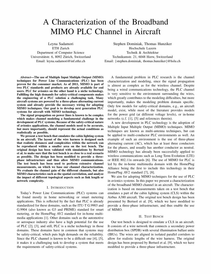
Fig. 1. Tree topology of the CLS network and individual link lengths inMeters
TABLE IDISTANCES BETWEEN IBUS AND THE SPDB IN METERS
IBU1 IBU2 IBU3 IBU4 IBU7 IBU89.9 10.1 10.2 16.0 28.8 40.7
IBU9 IBU10 IBU11 IBU12 IBU13 IBU1441.1 39.4 36.6 46.2 45.3 45.2
A. Topology
The topology is a tree-like structure as depicted in Fig. 1,with the SPDB as root, intermediary distribution nodes (DNs),and IBUs as leaves. The distances between different DNs, andalso to the IBUs have been varied to create a highly irregulartopology. Tab. I lists the distances from each IBU to the SPDB.The use of intermediary DNs allows to individually connect
and disconnect IBUs to the network and so create arbitrarytopologies from straight paths to networks with all branchesconnected. This variety of topologies allows to analyze forexample the impact of the link length (see Sec. IV-A) orthe number of branches (see Sec. IV-B) on the channelcharacteristics.
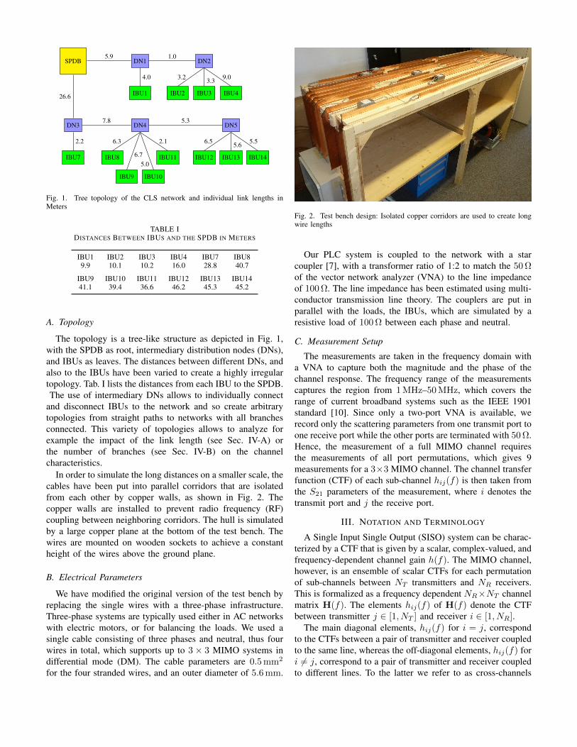
In order to simulate the long distances on a smaller scale, thecables have been put into parallel corridors that are isolatedfrom each other by copper walls, as shown in Fig. 2. Thecopper walls are installed to prevent radio frequency (RF)coupling between neighboring corridors. The hull is simulatedby a large copper plane at the bottom of the test bench. Thewires are mounted on wooden sockets to achieve a constantheight of the wires above the ground plane.
B. Electrical Parameters
We have modified the original version of the test bench byreplacing the single wires with a three-phase infrastructure.Three-phase systems are typically used either in AC networkswith electric motors, or for balancing the loads. We used asingle cable consisting of three phases and neutral, thus fourwires in total, which supports up to 3× 3 MIMO systems indifferential mode (DM). The cable parameters are 0.5 mm2
for the four stranded wires, and an outer diameter of 5.6 mm.
Fig. 2. Test bench design: Isolated copper corridors are used to create longwire lengths
Our PLC system is coupled to the network with a starcoupler [7], with a transformer ratio of 1:2 to match the 50 Ωof the vector network analyzer (VNA) to the line impedanceof 100 Ω. The line impedance has been estimated using multi-conductor transmission line theory. The couplers are put inparallel with the loads, the IBUs, which are simulated by aresistive load of 100 Ω between each phase and neutral.
C. Measurement Setup
The measurements are taken in the frequency domain witha VNA to capture both the magnitude and the phase of thechannel response. The frequency range of the measurementscaptures the region from 1 MHz–50 MHz, which covers therange of current broadband systems such as the IEEE 1901standard [10]. Since only a two-port VNA is available, werecord only the scattering parameters from one transmit port toone receive port while the other ports are terminated with 50 Ω.Hence, the measurement of a full MIMO channel requiresthe measurements of all port permutations, which gives 9measurements for a 3×3 MIMO channel. The channel transferfunction (CTF) of each sub-channel hij(f) is then taken fromthe S21 parameters of the measurement, where i denotes thetransmit port and j the receive port.
III. NOTATION AND TERMINOLOGY
A Single Input Single Output (SISO) system can be charac-terized by a CTF that is given by a scalar, complex-valued, andfrequency-dependent channel gain h(f). The MIMO channel,however, is an ensemble of scalar CTFs for each permutationof sub-channels between NT transmitters and NR receivers.This is formalized as a frequency dependent NR×NT channelmatrix H(f). The elements hij(f) of H(f) denote the CTFbetween transmitter j ∈ [1, NT ] and receiver i ∈ [1, NR].
The main diagonal elements, hij(f) for i = j, correspondto the CTFs between a pair of transmitter and receiver coupledto the same line, whereas the off-diagonal elements, hij(f) fori 6= j, correspond to a pair of transmitter and receiver coupledto different lines. To the latter we refer to as cross-channels
0 10 20 30 40 50
f [MHz]
−35
−30
−25
−20
−15
−10
−5
0|h
11|[
dB]
IBU1IBU2IBU3IBU4IBU7IBU8IBU9IBU10IBU11IBU12IBU13IBU14
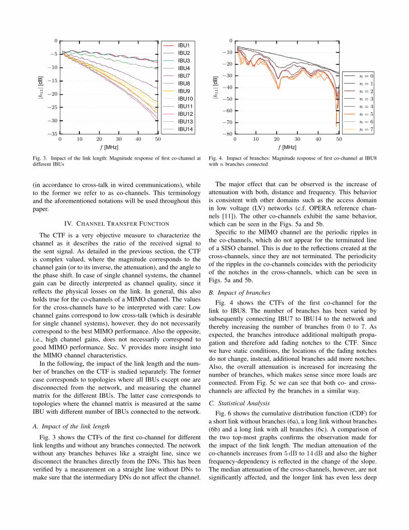
Fig. 3. Impact of the link length: Magnitude response of first co-channel atdifferent IBUs
(in accordance to cross-talk in wired communications), whileto the former we refer to as co-channels. This terminologyand the aforementioned notations will be used throughout thispaper.
IV. CHANNEL TRANSFER FUNCTION
The CTF is a very objective measure to characterize thechannel as it describes the ratio of the received signal tothe sent signal. As detailed in the previous section, the CTFis complex valued, where the magnitude corresponds to thechannel gain (or to its inverse, the attenuation), and the angle tothe phase shift. In case of single channel systems, the channelgain can be directly interpreted as channel quality, since itreflects the physical losses on the link. In general, this alsoholds true for the co-channels of a MIMO channel. The valuesfor the cross-channels have to be interpreted with care: Lowchannel gains correspond to low cross-talk (which is desirablefor single channel systems), however, they do not necessarilycorrespond to the best MIMO performance. Also the opposite,i.e., high channel gains, does not necessarily correspond togood MIMO performance. Sec. V provides more insight intothe MIMO channel characteristics.
In the following, the impact of the link length and the num-ber of branches on the CTF is studied separately. The formercase corresponds to topologies where all IBUs except one aredisconnected from the network, and measuring the channelmatrix for the different IBUs. The latter case corresponds totopologies where the channel matrix is measured at the sameIBU with different number of IBUs connected to the network.
A. Impact of the link length
Fig. 3 shows the CTFs of the first co-channel for differentlink lengths and without any branches connected. The networkwithout any branches behaves like a straight line, since wedisconnect the branches directly from the DNs. This has beenverified by a measurement on a straight line without DNs tomake sure that the intermediary DNs do not affect the channel.
0 10 20 30 40 50
f [MHz]
−80
−70
−60
−50
−40
−30
−20
−10
0
|h11|[
dB] n = 0
n = 1
n = 2
n = 3
n = 4
n = 5
n = 6
n = 7
Fig. 4. Impact of branches: Magnitude response of first co-channel at IBU8with n branches connected
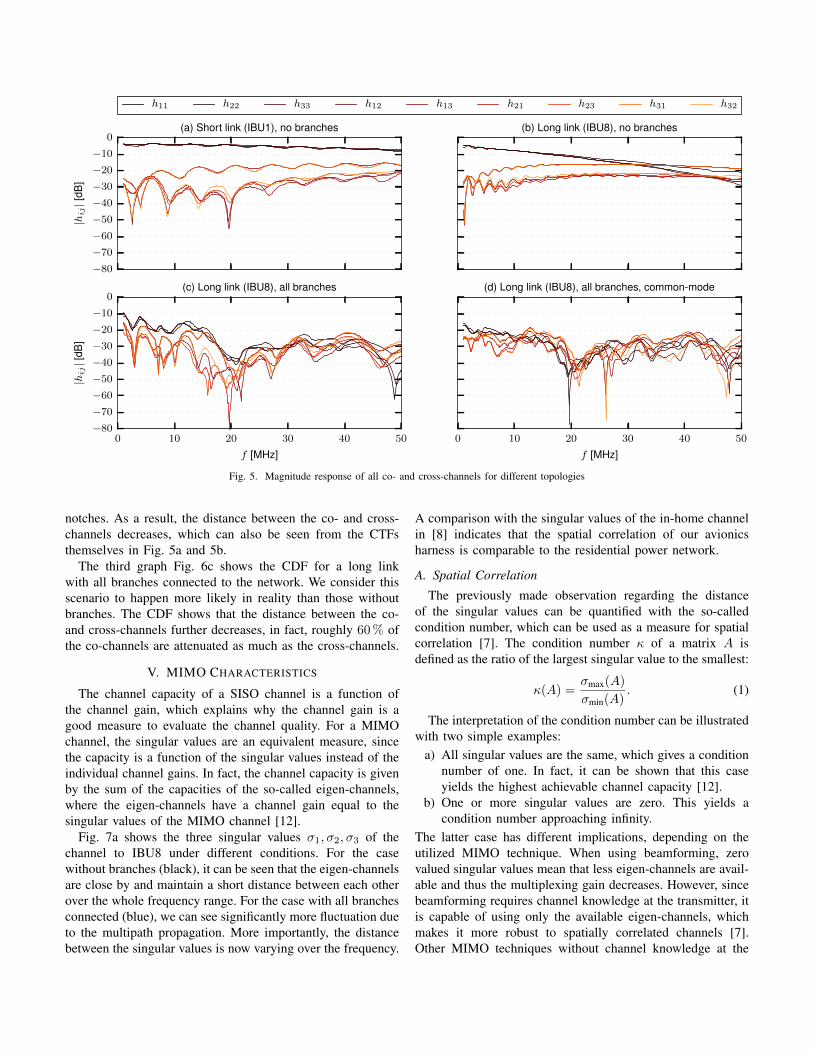
The major effect that can be observed is the increase ofattenuation with both, distance and frequency. This behavioris consistent with other domains such as the access domainin low voltage (LV) networks (c.f. OPERA reference chan-nels [11]). The other co-channels exhibit the same behavior,which can be seen in the Figs. 5a and 5b.
Specific to the MIMO channel are the periodic ripples inthe co-channels, which do not appear for the terminated lineof a SISO channel. This is due to the reflections created at thecross-channels, since they are not terminated. The periodicityof the ripples in the co-channels coincides with the periodicityof the notches in the cross-channels, which can be seen inFigs. 5a and 5b.
B. Impact of branches
Fig. 4 shows the CTFs of the first co-channel for thelink to IBU8. The number of branches has been varied bysubsequently connecting IBU7 to IBU14 to the network andthereby increasing the number of branches from 0 to 7. Asexpected, the branches introduce additional multipath propa-gation and therefore add fading notches to the CTF. Sincewe have static conditions, the locations of the fading notchesdo not change, instead, additional branches add more notches.Also, the overall attenuation is increased for increasing thenumber of branches, which makes sense since more loads areconnected. From Fig. 5c we can see that both co- and cross-channels are affected by the branches in a similar way.
C. Statistical Analysis
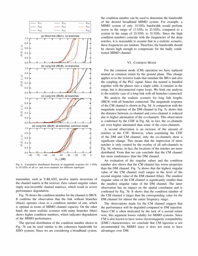
Fig. 6 shows the cumulative distribution function (CDF) fora short link without branches (6a), a long link without branches(6b) and a long link with all branches (6c). A comparison ofthe two top-most graphs confirms the observation made forthe impact of the link length. The median attenuation of theco-channels increases from 5 dB to 14 dB and also the higherfrequency-dependency is reflected in the change of the slope.The median attenuation of the cross-channels, however, are notsignificantly affected, and the longer link has even less deep
−80
−70
−60
−50
−40
−30
−20
−10
0
|hij|[
dB]
(a) Short link (IBU1), no branches (b) Long link (IBU8), no branches
0 10 20 30 40 50
f [MHz]
−80
−70
−60
−50
−40
−30
−20
−10
0
|hij|[
dB]
(c) Long link (IBU8), all branches
0 10 20 30 40 50
f [MHz]
(d) Long link (IBU8), all branches, common-mode
h11 h22 h33 h12 h13 h21 h23 h31 h32
Fig. 5. Magnitude response of all co- and cross-channels for different topologies
notches. As a result, the distance between the co- and cross-channels decreases, which can also be seen from the CTFsthemselves in Fig. 5a and 5b.
The third graph Fig. 6c shows the CDF for a long linkwith all branches connected to the network. We consider thisscenario to happen more likely in reality than those withoutbranches. The CDF shows that the distance between the co-and cross-channels further decreases, in fact, roughly 60 % ofthe co-channels are attenuated as much as the cross-channels.
V. MIMO CHARACTERISTICS
The channel capacity of a SISO channel is a function ofthe channel gain, which explains why the channel gain is agood measure to evaluate the channel quality. For a MIMOchannel, the singular values are an equivalent measure, sincethe capacity is a function of the singular values instead of theindividual channel gains. In fact, the channel capacity is givenby the sum of the capacities of the so-called eigen-channels,where the eigen-channels have a channel gain equal to thesingular values of the MIMO channel [12].
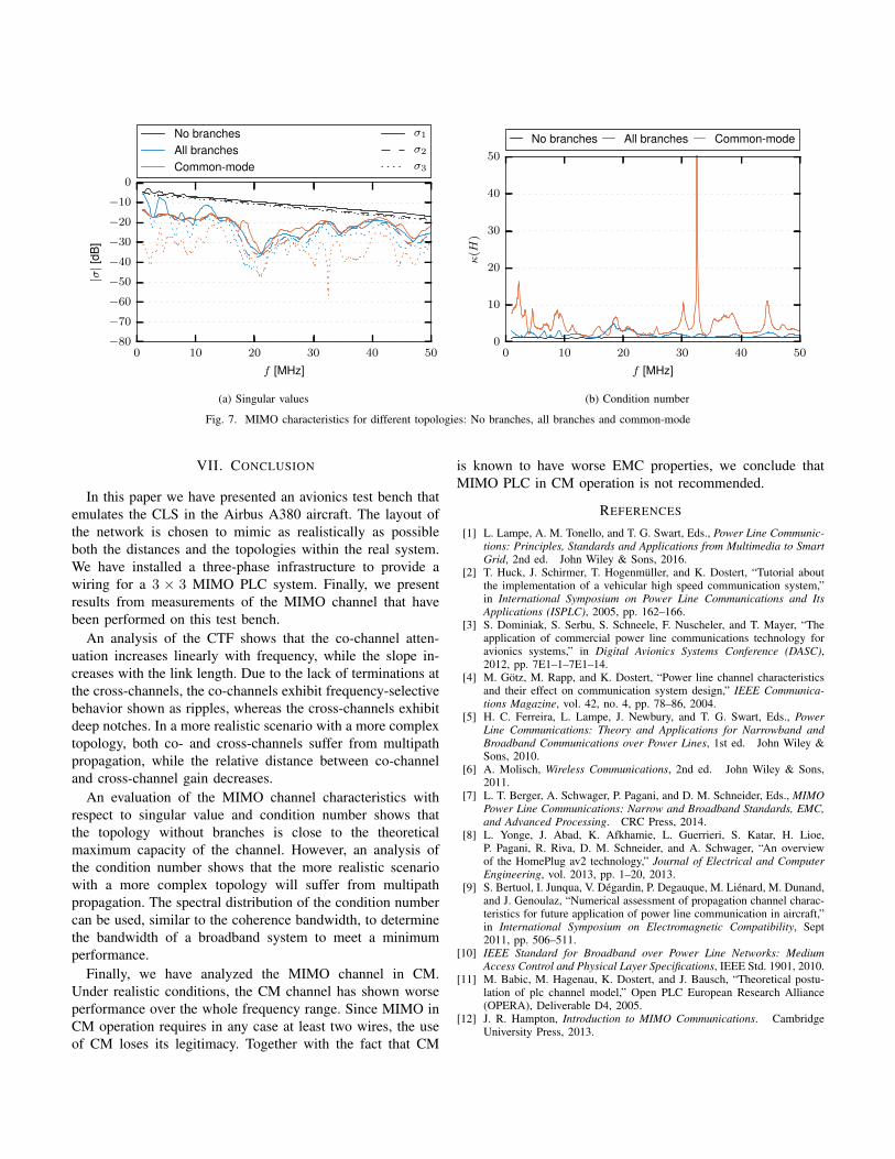
Fig. 7a shows the three singular values σ1, σ2, σ3 of thechannel to IBU8 under different conditions. For the casewithout branches (black), it can be seen that the eigen-channelsare close by and maintain a short distance between each otherover the whole frequency range. For the case with all branchesconnected (blue), we can see significantly more fluctuation dueto the multipath propagation. More importantly, the distancebetween the singular values is now varying over the frequency.
A comparison with the singular values of the in-home channelin [8] indicates that the spatial correlation of our avionicsharness is comparable to the residential power network.
A. Spatial Correlation
The previously made observation regarding the distanceof the singular values can be quantified with the so-calledcondition number, which can be used as a measure for spatialcorrelation [7]. The condition number κ of a matrix A isdefined as the ratio of the largest singular value to the smallest:
κ(A) =σmax(A)
σmin(A). (1)
The interpretation of the condition number can be illustratedwith two simple examples:
a) All singular values are the same, which gives a conditionnumber of one. In fact, it can be shown that this caseyields the highest achievable channel capacity [12].
b) One or more singular values are zero. This yields acondition number approaching infinity.
The latter case has different implications, depending on theutilized MIMO technique. When using beamforming, zerovalued singular values mean that less eigen-channels are avail-able and thus the multiplexing gain decreases. However, sincebeamforming requires channel knowledge at the transmitter, itis capable of using only the available eigen-channels, whichmakes it more robust to spatially correlated channels [7].Other MIMO techniques without channel knowledge at the
0.0
0.2
0.4
0.6
0.8
1.0
P(X≤x
)
(a) Short link (IBU1), no branches
0.0
0.2
0.4
0.6
0.8
1.0
P(X≤x
)
(b) Long link (IBU8), no branches
0.0
0.2
0.4
0.6
0.8
1.0
P(X≤x
)
(c) Long link (IBU8), all branches
−80 −70 −60 −50 −40 −30 −20 −10 0
|hij | [dB]
0.0
0.2
0.4
0.6
0.8
1.0
P(X≤x
)
(d) Long link (IBU8), all branches, common-mode
h11
h22
h33
h12
h13
h21
h23
h31
h32
Fig. 6. Cumulative distribution function of magnitude response for 1MHzto 50MHz of all co- and cross-channels for different topologies
transmitter, such as V-BLAST, involve matrix inversions ofthe channel matrix at the receiver. Zero valued singular valuesimply non-invertible channel matrices, which result in severeperformance degradation.
Fig. 7b shows the condition number for the channel to IBU8.It confirms the observation that the link without branches(black) operates close to a condition number of one, whichis optimal in terms of MIMO channel capacity. On the otherhand, the more realistic scenario with many branches (blue)shows higher condition numbers, which indicates degradationof the MIMO performance.
The spectral distribution of the condition number shown inFig. 7b can be used similar to the coherence bandwidth forSISO systems. Since we are considering a broadband system,
the condition number can be used to determine the bandwidthof the desired broadband MIMO system. For example, aMIMO system of only 10 MHz bandwidth would performworse in the range of 15 MHz to 25 MHz, compared to asystem in the range of 25 MHz to 35 MHz. Since the highcondition numbers coincide with the frequencies of the deepnotches, it is reasonable to assume that in a realistic scenario,these frequencies are random. Therefore, the bandwidth shouldbe chosen high enough to compensate for the badly condi-tioned MIMO channel.
VI. COMMON MODE
For the common mode (CM) operation we have replacedneutral as common return by the ground plane. This changeapplies to to the resistive loads that simulate the IBUs and alsothe coupling of the PLC signal. Since the neutral is bundledtogether with the phases into a single cable, it remains in thesetup, but is disconnected (open loop). We limit our analysisto the realistic case of a long link with all branches connected.
We analyze the realistic scenario for long link lengths(IBU8) with all branches connected. The magnitude responseof the CM channel is shown in Fig. 5d. A comparison with themagnitude response of the DM channel in Fig. 5c shows thatthe distance between co-channel and cross-channel is reduceddue to higher attenuation of the co-channels. This observationis confirmed by the CDF in Fig. 6d, in fact, the co-channelsare even higher attenuated than some of the cross-channels.
A second observation is an increase of the amount ofnotches in the CTF. However, when examining the CDFof the DM and CM channel, only the co-channels show asignificant change. This means that the impression of morenotches is only created by the overlay of all sub-channels inFig. 5d, whereas, in fact, the locations of the notches are moredistributed. From that we can conclude that the CM channelhas more randomness than the DM channel.
An evaluation of the singular values and the conditionnumber also shows that the CM channel has worse propertiesthan the DM channel. Fig. 7a shows that the highest singularvalue of the CM channel (red) ranges at the level of thesecond singular value of the DM channel (blue). The smallestsingular value of the CM channel is significantly smaller thanthe smallest singular value of the DM channel. The latterobservation has an impact on the spatial correlation and isconfirmed by Fig. 7b. It shows that the condition number ofthe CM channel is larger than the corresponding value for theDM channel for almost the entire frequency range.
The observations made for the CM channel suggest thatthe performance will be degraded compared to DM injection.Since CM is often motivated by the lack of a second returnwire, this argument looses validity for MIMO systems. SinceCM is also known to have worse electromagnetic compatibility(EMC) characteristics, we conclude that CM injection is notrecommended for MIMO since it does not seem to haveadvantages over DM.
0 10 20 30 40 50
f [MHz]
−80
−70
−60
−50
−40
−30
−20
−10
0
|σ|[
dB]
No branchesAll branchesCommon-mode
σ1
σ2
σ3
(a) Singular values
0 10 20 30 40 50
f [MHz]
0
10
20
30
40
50
κ(H
)
No branches All branches Common-mode
(b) Condition number
Fig. 7. MIMO characteristics for different topologies: No branches, all branches and common-mode
VII. CONCLUSION
In this paper we have presented an avionics test bench thatemulates the CLS in the Airbus A380 aircraft. The layout ofthe network is chosen to mimic as realistically as possibleboth the distances and the topologies within the real system.We have installed a three-phase infrastructure to provide awiring for a 3 × 3 MIMO PLC system. Finally, we presentresults from measurements of the MIMO channel that havebeen performed on this test bench.
An analysis of the CTF shows that the co-channel atten-uation increases linearly with frequency, while the slope in-creases with the link length. Due to the lack of terminations atthe cross-channels, the co-channels exhibit frequency-selectivebehavior shown as ripples, whereas the cross-channels exhibitdeep notches. In a more realistic scenario with a more complextopology, both co- and cross-channels suffer from multipathpropagation, while the relative distance between co-channeland cross-channel gain decreases.
An evaluation of the MIMO channel characteristics withrespect to singular value and condition number shows thatthe topology without branches is close to the theoreticalmaximum capacity of the channel. However, an analysis ofthe condition number shows that the more realistic scenariowith a more complex topology will suffer from multipathpropagation. The spectral distribution of the condition numbercan be used, similar to the coherence bandwidth, to determinethe bandwidth of a broadband system to meet a minimumperformance.
Finally, we have analyzed the MIMO channel in CM.Under realistic conditions, the CM channel has shown worseperformance over the whole frequency range. Since MIMO inCM operation requires in any case at least two wires, the useof CM loses its legitimacy. Together with the fact that CM
is known to have worse EMC properties, we conclude thatMIMO PLC in CM operation is not recommended.
REFERENCES
[1] L. Lampe, A. M. Tonello, and T. G. Swart, Eds., Power Line Communic-tions: Principles, Standards and Applications from Multimedia to SmartGrid, 2nd ed. John Wiley & Sons, 2016.
[2] T. Huck, J. Schirmer, T. Hogenmüller, and K. Dostert, “Tutorial aboutthe implementation of a vehicular high speed communication system,”in International Symposium on Power Line Communications and ItsApplications (ISPLC), 2005, pp. 162–166.
[3] S. Dominiak, S. Serbu, S. Schneele, F. Nuscheler, and T. Mayer, “Theapplication of commercial power line communications technology foravionics systems,” in Digital Avionics Systems Conference (DASC),2012, pp. 7E1–1–7E1–14.
[4] M. Götz, M. Rapp, and K. Dostert, “Power line channel characteristicsand their effect on communication system design,” IEEE Communica-tions Magazine, vol. 42, no. 4, pp. 78–86, 2004.
[5] H. C. Ferreira, L. Lampe, J. Newbury, and T. G. Swart, Eds., PowerLine Communications: Theory and Applications for Narrowband andBroadband Communications over Power Lines, 1st ed. John Wiley &Sons, 2010.
[6] A. Molisch, Wireless Communications, 2nd ed. John Wiley & Sons,2011.
[7] L. T. Berger, A. Schwager, P. Pagani, and D. M. Schneider, Eds., MIMOPower Line Communications: Narrow and Broadband Standards, EMC,and Advanced Processing. CRC Press, 2014.
[8] L. Yonge, J. Abad, K. Afkhamie, L. Guerrieri, S. Katar, H. Lioe,P. Pagani, R. Riva, D. M. Schneider, and A. Schwager, “An overviewof the HomePlug av2 technology,” Journal of Electrical and ComputerEngineering, vol. 2013, pp. 1–20, 2013.
[9] S. Bertuol, I. Junqua, V. Dégardin, P. Degauque, M. Liénard, M. Dunand,and J. Genoulaz, “Numerical assessment of propagation channel charac-teristics for future application of power line communication in aircraft,”in International Symposium on Electromagnetic Compatibility, Sept2011, pp. 506–511.
[10] IEEE Standard for Broadband over Power Line Networks: MediumAccess Control and Physical Layer Specifications, IEEE Std. 1901, 2010.
[11] M. Babic, M. Hagenau, K. Dostert, and J. Bausch, “Theoretical postu-lation of plc channel model,” Open PLC European Research Alliance(OPERA), Deliverable D4, 2005.
[12] J. R. Hampton, Introduction to MIMO Communications. CambridgeUniversity Press, 2013.