Embed Size (px)
Citation preview

A COLLISION DEFORMER FOR AUTODESK MAYA
A Thesis
by
WEI WANG
Submitted to the Office of Graduate and Professional Studies of
Texas A&M University
in partial fulfillment of the requirements for the degree of
MASTER OF SCIENCE
Chair of Committee, Tim McLaughlin
Committee Members, Ann McNamara
John Keyser
Head of Department, Tim McLaughlin
May 2015
Major Subject: Visualization
Copyright 2015 Wei Wang

ii
ABSTRACT
Believable physical interactions involving collisions between objects are
essential in motion graphics and video games. The most common approach to create
such effect is to employ dynamics simulation. However, to create a simple collision
effect, dynamics simulation is time-consuming and lacks artistic control. This paper
presents a custom deformer for creating simple collision effects in Autodesk Maya. The
deformer determines intersection between objects by performing inclusion tests for
selected vertices, and approximates the elastic behavior of the soft body in response to
collisions by applying a controllable deforming algorithm to the object surface. No
physics simulation is required in this process. The deformer supports interacting with
multiple collider objects and at the same time provides artistic control for the user to
manage the deformation. The deformer has proven successful for creating plausible
deformation of simple collision interactions in a fast, controllable manner.

iii
DEDICATION
To my parents

iv
ACKNOWLEDGEMENTS
First and foremost, I would like to offer my sincerest gratitude to my committee
chair, Prof. Tim McLaughlin for his excellent guidance. This thesis would not have been
possible without his help and encouragement. Great thanks go to my committee
members, Dr. Ann McNamara and Dr. John Keyser for their immense support and
sharing of knowledge throughout the course of this research.
Thanks also go to all the department faculty, staff and former students for
making my time at Texas A&M University an extremely rewarding experience. I have
gained much more than just knowledge in the past three years.
I also want to extend my gratitude to my Viz companions, Sean Low, Siran Liu,
Kelly Kin, Rachel Wang, Will Kung, Qiao Wang for their tremendous help and valuable
suggestions.
Finally, thanks to my parents for their constant love and support.

v
NOMENCLATURE
3D Three-Dimensional
FEM Finite Element Method
AABB Axis-Aligned Bounding Box
SDK Software Development Kit
API Application Programming Interface
MEL Maya Embedded Language
GUI Graphical User Interface
TBB Threading Building Blocks

vi
TABLE OF CONTENTS
Page
ABSTRACT .......................................................................................................................ii
DEDICATION ................................................................................................................. iii
ACKNOWLEDGEMENTS .............................................................................................. iv
NOMENCLATURE ........................................................................................................... v
TABLE OF CONTENTS .................................................................................................. vi
LIST OF FIGURES ........................................................................................................ viii
1. INTRODUCTION ...................................................................................................... 1
2. BACKGROUND ........................................................................................................ 3
2.1 Soft Body Dynamics .......................................................................................... 3
2.2 Morph Target Animation ................................................................................... 4
2.3 Deformers ........................................................................................................... 5
3. CORE ALGORITHM ................................................................................................ 8
3.1 Collision Detection ............................................................................................. 8
3.2 Collision Response ........................................................................................... 12 3.3 Artistic Control ................................................................................................. 16
3.4 Multiple Interactions ........................................................................................ 18 3.5 Post-deformation Smoothing ........................................................................... 19
4. IMPLEMENTATION .............................................................................................. 21
4.1 Implementation Environment ........................................................................... 21
4.2 The Collision Deformer Plugin ........................................................................ 22 4.3 Optimization ..................................................................................................... 29
5. RESULTS ................................................................................................................. 32
5.1 Example Applications ...................................................................................... 32 5.2 Limitations ....................................................................................................... 41

vii
6. CONCLUSION ........................................................................................................ 43
REFERENCES ................................................................................................................. 44

viii
LIST OF FIGURES
Page
Figure 1 Examples of collision interactions. (a) Snapshot from Shrek Forever After.
(2010). DreamWorks Animation. (b) Snapshot from Up. (2009). Pixar
Animation Studios ............................................................................................ 1
Figure 2 Spheres modified by Maya deformers: lattice deformer, shrink wrap
deformer and squash deformer (from left to right). ......................................... 6
Figure 3 Common types of bounding volumes (Langetepe & Zachmann, 2006) .......... 9
Figure 4 Pseudo code for an AABB intersection test ................................................... 10
Figure 5 Point-bounding box containment tests can preclude calculations for
vertices that are outside the geometry. ........................................................... 11
Figure 6 Point in polygon test: the ray originating from the white point has an odd
number of intersections with the edges of the polygon; therefore it is
inside the polygon. ......................................................................................... 12
Figure 7 Example of direct deformation ...................................................................... 14
Figure 8 Example of indirect deformation ................................................................... 15
Figure 9 The shape of the bulge effect can be manipulated using the curve control. .. 17
Figure 10 Example of multiple interactions: an elastic sphere colliding with a torus
and two spheres .............................................................................................. 18
Figure 11 Deforming process for multiple colliders ...................................................... 19
Figure 12 The smoothed position of a point is determined by the positions of the
points that are connected to it. ........................................................................ 20
Figure 13 Node connections for a collision deformer affected by two collider objects 25
Figure 14 Weight values can be interactively painted to the surface of the deforming
mesh using the Maya Paint Tool .................................................................... 26
Figure 15 AETemplates for the collision deformer node. (Left) the Maya default
template without customization (Right) custom template. ............................. 27

ix
Figure 16 Maya scene used to test the performance of the deformer. ........................... 30
Figure 17 Profiling data collected using the Maya DG Profiler..................................... 31
Figure 18 Screenshots from Sleddin’, directed by John Pettingill ................................. 33
Figure 19 The falloff curve of the bulge effect .............................................................. 33
Figure 20 (Left) rough deformation with noticeable sharp edges. (Right) final result
after smoothing. .............................................................................................. 34
Figure 21 Screenshots from animation project W A K E. (Top left) the character’s
sleeve is intersecting with the bed sheet. (Top right) Close up on the
intersection area. (Bottom left) same animation frame with the collision
deformer applied. (Bottom right) close up on the sleeve with intersection
eliminated. ...................................................................................................... 35
Figure 22 The collision deformer setup in W A K E. (Left) vertices outside the
intersecting areas were painted 0 for deformer weight. (Right) a proxy
geometry was created as the collider object. .................................................. 36
Figure 23 Nano Hunter rig. Retrieved from Digital Tutors (Digital Tutors, 2014). ...... 37
Figure 24 (Left) the deformer only affects the fleshy parts of the feet. (Right) falloff
curve of the bulge effect on the feet. .............................................................. 37
Figure 25 (Left) the original foot rig. (Right) the collision deformer flattens the
bottom of the foot as it contacts the ground, and adds a subtle bulge to the
side of the foot. ............................................................................................... 38
Figure 26 The Boris character. Retrieved from Digital Tutors (Digital Tutors, 2014). . 39
Figure 27 (Left) before collision. (Middle) a sphere is colliding with the belly.
(Right) the belly jiggles after the collider is moved away. ............................ 40
Figure 28 Multiple collider objects interacting with the character. ............................... 41
Figure 29 Open shapes cannot be used as collider objects. ........................................... 42

1
1. INTRODUCTION
Believable deformation of a soft body caused by collision interactions with other
objects is essential in motion graphics and video games. In practice, the most common
approach to create such effect is to employ soft body dynamics. As a physically based
method, soft body dynamics is capable of producing realistic collision responses for
large-scale, complex interactions.
Figure 1 Examples of collision interactions. (a) Snapshot from Shrek Forever After.
(2010). DreamWorks Animation. (Mitchell, 2010) (b) Snapshot from Up. (2009). Pixar
Animation Studios (Docter, 2009)
However, there are many scenarios where the intended collision response is
simple or subtle rather than complex, such as a baseball hit by a baseball bat, or leaving
footprints on snow-covered ground. In these cases, expensive, time-consuming physical
simulation becomes less desirable as the ease of use and flexibility to control are valued
more upon physical accuracy.

2
An ideal solution for creating simple collision response on a soft body should
meet the following requirements:
Interactive: collision response should be calculated interactively as the user moves
the objects in the scene. This method should be independent of time and allow the
user to access the animation frames in an arbitrary order.
Simulation-free: the method should be capable of creating fast and reliable collision
deformation without the need to perform time-consuming physics simulations.
Controllable: artistic control over the resulting deformation should be provided to
allow the user to achieve a particular look of the deformation.
This thesis presents a deformer-based approach to address these animation needs.
The deformer uses an efficient, parallel algorithm to check collisions and reposition the
points on the deforming mesh to eliminate penetration. The user can directly specify the
appearance of the deformation by adjusting a series of parameters provided. The
deformer supports interacting with multiple collider objects and offers an optional
smoothing function to relax the deformed mesh. The tool developed as part of this
research is integrated into Autodesk Maya as a plugin.
The remaining sections of this thesis are organized as follows. Section 2 reviews
the background of this research to provide a fundamental understanding to the reader.
Section 3 explains the core algorithm of the deformer in detail. Section 4 describes the
aspects of how the tool was implemented. Section 5 illustrates some visual results of the
research and discusses of the limitations of the approach. The conclusion of the research
is provided in the last section of the thesis.

3
2. BACKGROUND
2.1 Soft Body Dynamics
Soft body dynamics is the most common approach for creating collision effects
for deformable objects. In this method, the collision animation is achieved by applying
forces to the particles that control the shape of the soft body.
In computer graphics, many methods have been proposed to model soft bodies.
Most of these methods fall into two categories: mass-spring meshes and finite element
methods (FEM). Mass-spring systems model a deformable object as a set of point
masses connected by elastic springs governed by some variant of Hooke's law (Nealen,
Müller, Keiser, Boxerman, & Carlson, 2006). Mass-spring systems are widely used for
one or two-dimensional structures such as hair and cloth (House & David, 2000). The
finite element method is considered to be the most physically accurate approach to
simulate deformation of colliding solids, and it is relatively more complex than the
mass-spring model.
3D Animation packages usually provide dynamics toolsets for performing
simulations, such as Maya’s nDynamics and 3ds Max’s MassFX system. The user can
use a combination of rigid body, cloth, and other types of solvers to simulate the motion
and properties of deformable objects.
The advantage of physically based simulation is that the resulting interactions are
automatically realistic, as the simulation is driven by laws of physics. The animator only
needs to specify the physical parameters and initial conditions of the simulation, and

4
does not need to concern with defining the detailed motions and behavior of the
simulated objects.
The drawback of this approach is that dynamics simulation involves complex
logic to evaluate, therefore it is computationally expensive. The animator does not have
direct control over the result deformation, but instead is exposed to a series of
parameters that affects the physics simulation which generates the collision response.
Finding the right parameters requires an understanding of the underlying mechanics of
the physics simulation, and usually involves a tedious process of trial and error, as the
visual impact of changing a parameter can be difficult to predict. Because the complete
simulation needs to be recalculated each time a parameter is changed, the process of
achieving desired collision response might be time-consuming.
Unlike Animators working in scientific fields such as engineering or medical
visualization that have greater concern for the physical accuracy of the simulations,
animators for visual effects and animation are primarily concerned with controlling the
visual results. As physically based simulation must obey the physics equations to stay
realistic, it may be difficult for the artist to achieve the desired deformation that follows
a particular art style.
2.2 Morph Target Animation
An alternative approach for creating collision response is to employ morph target
animation, which is also known as blend shapes. In this method, the collision response is
achieved by gradually morphing the source shape to match a manually defined result
shape, which can be one or a linear combination of multiple targets.

5
This approach could be seen as a two-step process. The first step is to determine
a mapping between the boundaries of the source and the target shape. The mapping is
commonly one-to-one, which means the target shape and base shape should share the
same topology. The second step is to define paths for each pair of corresponding points
on the boundaries to calculate the in-between shapes.
Morph-target animation is demonstrably art-directable. The artist has direct
control over how the deformation appears, because the individual positions of the
vertices on the deforming mesh can be defined within each animation frame.
However, in contrast to physically based simulation where realistic collision
response happens automatically, the artist needs to manually animate the collision
interaction. This process may be labor-intensive because the timing and trajectory of the
objects must be carefully specified to ensure the deformation and the collision appear
simultaneously.
2.3 Deformers
In animation packages, deformers are push button functions that can be applied
to an object to modify its shape. (O'Neil, 2008). A deformer manipulates the shape of the
target geometry by performing a certain algorithm on the low-level components (such as
vertices and control points) of the geometry. The resulting deformation can be controlled
by tuning the influences of the attributes provided within the deformer.
Animation packages provide a broad range of deformers to be used in various
scenarios. Some of them can be used as modeling tools to shape objects. For example,
you can model a screw by applying a twist deformer to a cylinder. Some deformers are

6
used as animation tools more often such as the squash deformer and the cluster
deformer. There are also deformers designed for more specific tasks like cleaning up
simulation results, correcting bad animation or prototyping character rigs, just to name a
few. Figure 2 illustrates some of the native deformers in Autodesk Maya.
Figure 2 Spheres modified by Maya deformers: lattice deformer, shrink wrap deformer
and squash deformer (from left to right).
In practice, artists can apply multiple deformers to a same object to achieve the
desired result. The final deformation depends on the order that the deformers are
evaluated. Deformers are also commonly used in combination with other deformation
techniques such as skeletal animation and physically based simulations.
Although the function and underlying algorithm of a deformer vary from one to
another, most deformers have the following features in common:
High-level. A deformer alters the shape of the deforming object by applying an
algorithm to the low-level components of the object. The user does not access the
low-level components directly, but instead manages the output of the deformer

7
by adjusting high-level attributes that control the values of the variables used in
the algorithm.
Time-independent. In opposition to physically based simulations, the results
produced by deformers are usually independent of time. The deformation is
calculated individually for each animation frame and independent of frames
before and after. This means that the artist is able to adjust the deformation for a
given frame without affecting the shapes on any other frames.
Interactive. When modeling or animating objects using a deformer, artists want
to see the updated shape instantaneously as they make changes. Thus, in most
cases, it is important that the deformer can run at interactive rates. The
effectiveness of a deformer is compromised if interactive performance could not
be achieved.

8
3. CORE ALGORITHM
Collision detection and collision response are the two core components of the
deformation algorithm. Collision detection determines intersection between the soft
body and the colliders, and reports a list of penetrating points. Collision response applies
the deformation to the points on the soft body to resolve the intersection.
3.1 Collision Detection
Detection of collision between polyhedral objects is a very common problem in
3D computer graphics. One intuitive method is to check if any vertex of one object is
contained in the other one. If so, the collision happens. The process of determining
whether a point lies inside a polygon is usually known as the inclusion test, or
containment test, which has significant applications in computer graphics and physics
simulations.
The polygon models we work with usually consist of thousands of vertices.
Without applying any acceleration method, the collision detection procedure can be
highly inefficient, as the deformer has to perform intense brute force inclusion tests for
each vertex-polygon pair whenever the objects change in shape or size, or move in
space. The running time for this process can increase exponentially with each additional
object. To reduce the computational cost of these tests, our method adapts a two-phase
approach for the collision detection process.

9
3.1.1 Broad-Phase Collision Detection
The broad-phase collision detection uses bounding volumes to quickly cull away
pairs of objects that are far away from each other. A bounding volume is a simple
volume that contains one or more objects completely. The contained objects cannot
collide if their bounding volumes do not overlap. Figure 3 (Langetepe & Zachmann,
2006) illustrates some common types of bounding volumes.
Figure 3 Common types of bounding volumes (Langetepe & Zachmann, 2006)
Axis-aligned bounding boxes (AABB) are chosen as the bounding volumes for
objects. An AABB is specified by two points that describe the minimum and maximum
corners of the box. In Maya, the computational cost for constructing and updating an
AABB is low, as the world space coordinates of the maximum corner and the minimum
corner can be queried from the object.
In 3D space, two AABBs intersect only when they overlap in x, y and z.
Therefore, intersection of two AABBs can be determined by respectively comparing the

10
minimum points and the maximum points of the two AABBs along the three axes (see
Figure 4).
Figure 4 Pseudo code for an AABB intersection test
3.1.2 Narrow-Phase Collision Detection
The result of the broad-phase collision detection is a list of collider objects that
are potentially colliding with the deformable mesh. In the narrow phase, the exact result
of contact will be determined, and the points where the two objects are interpenetrating
will be found, if there is a collision.
The basic idea is to perform a containment test for each vertex in the deformable
mesh against the collider object. If the result is true, the tested vertex is inside the
collision region and needs to be moved in the next stage to resolve the collision. If all
test results are false, collision does not happen.
In practice, instead of directly running tests for all vertices, we first do a point-
AABB containment test to quickly rule out those that are outside the collider’s bounding

11
box. Implementing this step can noticeably reduce the running time especially when the
deformable object has a dense mesh.
Figure 5 Point-bounding box containment tests can preclude calculations for vertices
that are outside the geometry.
The last step of this phase is the containment test. One of the most well-known
methods for this test is the ray crossing algorithm (Hormann & Agathos, 2001). In this
method, the containment is determined by casting a ray from the tested point along any
fixed direction, and counting the number of times the ray intersects the polygon. If the
number is even, the point is outside the polygon, otherwise, the point is inside the
polygon (see Figure 6).

12
Figure 6 Point in polygon test: the ray originating from the white point has an odd
number of intersections with the edges of the polygon; therefore it is inside the polygon.
The collision detection method adopted in the deformer is an extension of the
crossing algorithm in 3D space. The intersection ray is defined using the vertex position
as the origin, and the vertex normal as the travel direction. We utilize the
AllIntersections() function provided with the mesh function set in Maya API to
determine the number of intersections between the ray and the collider object. To speed
up this operation, we specify a uniform voxel grid structure for the collider object before
the intersection routines begin. Maya can automatically determine the number of voxel
cells for the grid based on the density of the mesh, and the grid will be cached with the
mesh until the entire operation is done.
3.2 Collision Response
The task of this stage is to apply deformation to the deformable object in
response to collisions. There are two components of the deformation: direct deformation
and indirect deformation. Direct deformation suppresses the interpenetration by
deforming the soft body according to the shape of the interacting collider. This process is
spontaneous and not directed by the user. Indirect deformation adds on top of direct

13
deformation to reflect the elastic properties of the soft body. In opposition to direct
deformation, this process allows more user inputs to achieve a particular look for the
deformation.
3.2.1 Direct Deformation
Using the method explained in section 3.1, we can find the vertices of the
deforming object that are inside the collider. The direct deformation is achieved by
pushing these vertices to their closest points on the surface of the collider. This creates a
compression effect at the spot where the collision happens (see Figure 7). To find the
closest points, we make use of the MMeshIntersector class in Maya API.
The MMeshIntersector class contains methods for efficiently finding the closet
point on a mesh. Internally, when the class is initialized, the mesh intersector will
tessellate the polygon mesh and build an octree for the triangles to accelerate the
evaluation process. The octree structure will be cached for reuse, and will automatically
rebuild if the shape of the polygon mesh changes.

14
Figure 7 Example of direct deformation.
When vertices on the deformable mesh are found inside a given collider, a mesh
intersector will be initialized for that specific collider mesh, if it hasn't already been.
Then the intersector evaluates each penetrating vertex 𝑉𝑖 in a loop and finds its closest
point 𝑃𝑖 on the collider surface. Finally, the deformer updates the position of vertex 𝑉𝑖
using the following equation:
𝑃𝑖 = 𝑃𝑖 + (𝑃′𝑖 – 𝑃𝑖) ∙ 𝑤𝑖 ∙ 𝑒,
Where 𝑃′𝑖 – 𝑃𝑖 is the offset vector, 𝑤𝑖 is the weight value assigned to the vertex, and 𝑒 is
the envelope value of the deformer. In each loop, we also compute the displacement of
the vertex, which is the length of the offset vector. Thus at the end of the iterations, the
maximum displacement for direct deformation 𝑑𝑚𝑎𝑥 can be determined. This value will
be used to compute indirect deformation for the soft body.

15
3.2.2 Indirect Deformation
Direct deformation results in a compressed surface and a loss in volume. In
reality, many elastic deformable materials are highly incompressible. Indirect
deformation is applied to the deforming object to express the elastic properties of a soft
body.
Figure 8 Example of indirect deformation.
The effect of the indirect deformation is to bulge out the surface around the
newly formed region of collision (see Figure 8). Indirect deformation is applied to all the
vertices that are not directly penetrating the interacting collider. These vertices will be
pushed along their vertex normal directions by different magnitudes. The offset vector 𝑡𝑖
for repositioning a given vertex 𝑉𝑖 is defined by:
𝑡𝑖 = 𝑛𝑖 ∙ 𝑎 ∙ 𝑑𝑖

16
In this equation, 𝑛𝑖 is the vertex normal of 𝑉𝑖; 𝑎 is bulge strength, which is a user-
specified value for scaling the overall bulge effect; 𝑑𝑖 is the displacement of 𝑉𝑖. The
determination of 𝑑𝑖 will be discussed in section 3.3.
Thus the final position of vertex 𝑉𝑖 can be determined:
𝑃𝑖 = 𝑃𝑖 + 𝑡𝑖 ∙ 𝑤𝑖 ∙ 𝑒,
Where 𝑤𝑖 is the weight value assigned to vertex 𝑉𝑖, 𝑒 is the envelope value of the
deformer.
3.3 Artistic Control
It is important that the user has the flexibility to decide how the final deformation
will appear. User control of the deformer is provided in the form of attributes which
define the value of the variables in the deformation equations. This section explains how
these attributes can be used to adjust the resulting deformation.
Strength: this attribute is introduced to the offset equation to allow the user to
control the amplitude of the bulge effect.
Distance: the distance of bulge is a float number attribute that determines how
far the bulge effect can extend on the surface of the deformable mesh.
Shape Curve: this attribute is provided to the user with great flexibility for
manipulating the shape of the bulge within the bulge distance. As shown in Figure 9, the
curve is defined by a set of positions, values, and interpolation types. The horizontal axis
of the curve represents positions on the soft body relative to the bulge distance. For a
given vertex 𝑉𝑖, its relative position 𝑝𝑖 is defined by:
𝑝𝑖 = 𝑠𝑖/𝑟

17
Where 𝑠𝑖 is the distance between 𝑉𝑖 and its closest point on the collider surface, 𝑟
is the bulge distance value set by the user. The vertical axis of the curve represents the
relative bulge displacement at the given position 𝑝𝑖. For vertex 𝑉𝑖, the actual
displacement is defined by multiply the maximum displacement by this relative value:
𝑑𝑖 = 𝑓(𝑝𝑖) ∙ 𝑑𝑚𝑎𝑥
Figure 9 The shape of the bulge effect can be manipulated using the curve control.
Elasticity: this attribute defines the elastic behavior of the soft body. Options
include “elastic” and “plastic”. When set to elastic, the soft body will restore to its
original shape when the collider is moved away. When set to plastic, the deformation
will be kept on the soft body for a permanent deformation effect.
In addition to those attributes that are specific to the collision deformer, general
attributes inherited from the base class of Maya deformer are also available to the user:
Weight: the weight for a vertex is arbitrarily specified by the user to control how
much the vertex is influenced by the deformer. With the artisan-based Paint Tool in

18
Maya, the user can interactively paint weights on the deformable object to specify
various intensity values for different deform regions.
Envelope: envelope is an attribute which controls the overall influence the
deformer has on the deforming object. The attribute ranges from 0 to 1 and the value
defines the proportion of the final deformation to be added to the object.
3.4 Multiple Interactions
One of the most important features of the deformer is the support for interacting
with multiple colliders such as shown in Figure 10.
Figure 10 Example of multiple interactions: an elastic sphere colliding with a torus and
two spheres.
When dealing with only one collider object, the process is straightforward: we
first determine intersection between the soft body and the collider, and then perform the
deformation if a collision is detected. In multiple-collider situations, instead of checking

19
collisions for all collider objects at once and deforming the soft body using a union of
shapes of the intersecting colliders, we evaluate only one collider each time and deform
the soft body as needed. Then we treat the updated shape as the new deformable mesh
and repeat the same routine with the next collider. Using this method, the resulting shape
is completely independent of the order in which the colliders are evaluated, and frequent
initializations and updates of acceleration structures can be avoided. Figure 11
demonstrates the deforming process for multiple colliders.
Figure 11 Deforming process for multiple colliders
3.5 Post-deformation Smoothing
Sometimes when the deforming mesh is dense, collision interactions may result
in sharp edges inside the collision area. To solve this problem, a weighted Laplacian
Deform Soft body
Next Collider
Collider Mesh
Soft Body Mesh
Collision Detection
False
Start loop W
True

20
mesh smoothing method was added to the deformation algorithm. This method
determines the smoothed position of a point by averaging the weighted positions of the
points that are connected to it (see Figure 12).
Figure 12 The smoothed position of a point is determined by the positions of the points
that are connected to it.
For a given vertex 𝑉𝑖, the smoothed position 𝑃′𝑖 after 1 iteration is defined by:
𝑃′𝑖 = 1
∑ 𝑑𝑖𝑗𝑁𝑗=1
∑ 𝑃𝑗
𝑁
𝑗=1
𝑑𝑖𝑗
Where N is the set of neighbor vertices connected to 𝑉𝑖 , 𝑃𝑗 is the position of the j-th
neighbor 𝑉𝑗, 𝑑𝑖𝑗 is the distance between 𝑉𝑖 and 𝑉𝑗.

21
4. IMPLEMENTATION
4.1 Implementation Environment
4.1.1 Developing for Autodesk Maya
The collision deformer plugin was developed for Autodesk Maya 2015 SP2.
Autodesk Maya is an industry standard animation suite which offers a rich set of tools
for 3D content creation. The Maya Software Development Kit (SDK) contains a
powerful C++ Application Programing Interface (API) which provides access to Maya’s
internal functionality. Using the Maya API, developers can create plugins to manipulate
existing Maya objects as well as to extend Maya’s capabilities.
In addition to the C++ API, programming access is also provided through the
Maya Embedded Language (MEL) and Python. MEL is a Maya-specific scripting
language which provides access to all of the built-in Maya commands. Most actions that
can be done through Maya’s Graphical User Interface (GUI) can also be accomplished
using MEL to enhance workflow and productivity. Python is a widely used high-level
programming language that has been supported in Maya since version 8.5 (Mechtley &
Trowbridge, 2011). Using the Maya Python module, developers can execute the same
native Maya commands as they can do with MEL but at the same time take advantage of
the robust, object-oriented design and extensive libraries of Python.
4.1.2 Additional Libraries
PySide was used for building custom GUIs for the plugin. PySide is a Python
binding to the Qt library, which is a cross-platform framework for application and UI

22
development. As the Maya interface (after version 2010) is built using the Qt framework
(Autodesk, n.d.), custom widgets created with PySide can be seamlessly blended with
the Maya native interface.
Intel Threading Building Blocks (TBB) was used to parallelize the deformation
algorithm to enhance the performance of the deformer. TBB is a widely used C++
template library which comprises a rich set of components for developing software
programs that take advantage of multi-core processors (Popovici, 2008). TBB was
chosen for two reasons: 1) TBB is available on all platforms that Maya supports. 2) TBB
enables the developer to specify logical tasks instead of threads and let the library map
the tasks onto threads dynamically and efficiently (Reinders, 2007). This allows
parallelizing without having to change existing code structure too much.
4.2 The Collision Deformer Plugin
The collision deformer plugin comprises two major components: the deformer
class and an auxiliary script. The deformer class defines the core deform function as well
as methods for registering the deformer node with Maya. The auxiliary script contains
functions for initializing user controls and establishing connections for the deformer
node and its associated objects.
4.2.1 The Collision Deformer Class
The collision deformer class was implemented using C++, and it is the core of
the plugin. The class defines the deformer node which contains the algorithm explained
in Section 3. The collision deformer class derives the MPxDeformerNode class in the
Maya API. The MPxDeformerNode class is the base class for user-defined deformers.

23
By deriving this class, the deformer can inherit the benefits of Maya's internal deformer
functionality such adjusting node influence, editing membership and reordering
deformation history (Autodesk, 2010).
A deformer node in Maya is a subset of dependency node. To implement a
deformer node, the following member functions needs to be implemented:
The initialize() function: the initialize method is where the type, name and default
values of all attributes are specified.
The initializePlugin() function: this functions is called when the plugin is being
loaded. It registers the plugin’s information such as ID, type, name and commands
with Maya.
The uninitializePlugin() function: this function is similar to the initializePlugin()
function. It is called when the plugin is being unloaded from Maya.
The deform() function: this function is where the deformation takes place. It starts
with extracting data from the data block, which is a Maya object for storing data
being received by or sent from the deformer node (Autodesk, 2010). The data
includes parameters set by the user, such as strength and weights, and geometric data
of the connected objects, such as the collider meshes and bounding boxes. In the next
step, the function enters the routine of checking collisions and calculating positions
for the points. In the end, the deform() function updates the deforming mesh and
returns a signal to Maya to indicate a successful deformation, or problems that
encountered in the process.

24
4.2.2 Auxiliary Functions
The auxiliary script is a Python script containing functions for facilitating user
interactions with the deformer. It is executed when the collision deformer plugin is
loaded into Maya. The script adds push button commands to Maya’s animation menu to
allow the user to create and edit a collision deformer and formats the attribute template
for the deformer node.
4.2.2.1 Deformer Commands
In order to create a collision response, certain node connections need to be
established between the deformable object, the collision deformer node, and the
colliders. It is very cumbersome to manage the node networks manually, as the deformer
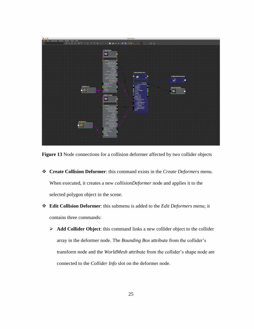
node requires input from multiple levels of the polygon objects (see Figure 13).
Therefore, a series of commands is implemented to automate the operations of applying,
editing, and removing a Collision Deformer. These commands are provided as push-
button functions in the Create Deformers menu and the Edit Deformers menu under the
Animation menu set in Maya.
25
Figure 13 Node connections for a collision deformer affected by two collider objects
Create Collision Deformer: this command exists in the Create Deformers menu.
When executed, it creates a new collisionDeformer node and applies it to the
selected polygon object in the scene.
Edit Collision Deformer: this submenu is added to the Edit Deformers menu; it
contains three commands:
Add Collider Object: this command links a new collider object to the collider
array in the deformer node. The Bounding Box attribute from the collider’s
transform node and the WorldMesh attribute from the collider’s shape node are
connected to the Collider Info slot on the deformer node.

26
Remove Collider Object: this command removes an existing collider from the
collider array by breaking all the connections established between the collider
object and the deformer node.
Paint Collision Deformer Weights Tool: this command launches the Maya
Paint Tool (see Figure 14) to allow the user to interactively specify weight values
for the vertices on the surface of the soft body.
Figure 14 Weight values can be interactively painted to the surface of the deforming
mesh using the Maya Paint Tool
4.2.2.2 Customizing the Attribute Editor Template
In addition to the menu commands, the auxiliary script also contains functions
for customizing the Attribute Editor Template (AETemplate). The Attribute Editor is a
Maya control widget that lists attributes of nodes connected to the selected object. The

27
tabs across the top of the widget allow the user to switch back and forth between nodes
to view and change the values of attributes.
An AETemplate defines how the attributes of a certain type of node appear in the
attribute editor. Maya allows customization for AETemplates for better presentation and
more intuitive control. Using MEL and PyMEL commands, developers can format the
controllers as well as embed custom components to the template.
As shown in Figure 15, the customized AETemplate for the collision deformer
organizes the attributes in four collapsible fields.
Figure 15 AETemplates for the collision deformer node. (Left) the Maya default
template without customization (Right) custom template.

28
The first section of the AETemplate consists of controls for solver-related
attributes, including combo boxes for collision solver and elasticity, and a slider for
envelope.
The Bulge section contains controls for adjusting the bulge effect of the
deformation, including sliders for the strength attribute and the distance attribute.
The Bulge Shape section houses a curve control for adjusting the falloff of the
bulge effect. The user can directly manipulate existing points or add more points to the
curve in the graph. The arrow button on the right expands the curve control in a separate
window to enable more precise control.
The Colliders section provides a custom widget for managing collider objects.
The list on the left displays the name of all colliders currently affecting the deforming
object. The buttons on the right side allow the user to add colliders, remove colliders and
launch the paint weight tool without having to reach to the Edit Collision Deformer
menu located on the top of the Maya window.
The Smooth Mesh section contains a slider for setting the number of iterations of
post-deformation smoothing.
All the other attributes are organized in the Extra Attributes section. These
attributes are inherited from the Maya deformer base class and do not affect the
deformation directly hence are hidden from the user by default.

29
4.3 Optimization
Deformers are usually designed to alter the shape of an object in a controllable
manner at interactive rates. Due to the computationally intensive nature of the deform
algorithm, optimization is essential for achieving expected performance.
4.3.1 Parallelization
Multi-core processors have become standard while the speed increases of single
cores have slowed down. Normally, a program written for sequential computation runs
on a single core, where the instructions are executed one after another. To leverage the
power of a multi-core processor, the task of a program can be decomposed into a series
of smaller tasks to run on multiple cores simultaneously. Employing parallelism could
bring significant performance improvements to a program.
Data parallelism and task parallelism are two forms of parallelization of
computation at a high level. Data parallelism involves performing the same independent
operation to multiple data elements at the same time, such as parallel image processing
algorithms that apply a filter to each pixel. Task parallelism involves executing distinct
tasks at the same time, with the number of tasks fixed, such as a program with a compute
thread and a UI thread. The deformation algorithm is a good candidate for using the data
parallelism model, as the vertices on the deforming mesh are evaluated individually and
repeatedly in loops.
There are three computational-intensive loops in the deformation routine: the
collision detection loop, the deformation loop, and the post-deformation smoothing loop.
These loops contain expensive vector operations on points such as the inclusion tests and

30
the closest point operations. The loops were rewritten using the TBB template
function tbb::parallel_for to partition the original range into subranges which run on
separate threads. The operations inside the original loops were extracted into separate
classes and adapted in a way that they can be performed on multiple vertices
simultaneously without interfering with each other.
4.3.2 Performance Improvement
The performance improvement was tested using the Maya DG Profiler to collect
the timing metrics of the deformer node in the test scene before and after parallelization.
The test scene consists of three spherical colliders, each of which has 92 vertices,
animated to deform a plane which has 2601 vertices (see Figure 16).
Figure 16 Maya scene used to test the performance of the deformer.

31
Figure 17 Profiling data collected using the Maya DG Profiler
Results (see Figure 17) show that the optimization has led to a significant
performance improvement. The deformer node runs more than 200% faster in the same
scene when parallelization is applied. The frame rate of the animation playback has been
increased from 5-8 FPS (frames per second) to 19-27 FPS.

32
5. RESULTS
5.1 Example Applications
The collision deformer is applicable in a variety of scenarios. This section
demonstrates the effectiveness of the deformer with some examples in which it has been
employed.
5.1.1 Animating Snow Deformation
Sleddin’ is an animation short created by students from the Visualization
Department at Texas A&M University. This animation features a long sequence of a boy
sledding down a towering mountain. Interactions with snow-covered ground, such as the
character making footprints and the sled leaving trails can be seen in most of the shots,
making animating the snow deformation one of the biggest challenges in production.
The effects artists went through a laborious process to simulate these effects using soft
body dynamics in Maya.
The collision deformer provides an option to define the elastic property of the
deforming object. When the value is set to “plastic,” the object will not restore to its
original shape after the collision is resolved; deformation caused by the collision will be
kept on the surface. This example describes how the deformer was used in such a
manner to replicate the footprint animation in Sleddin’ (See Figure 18).

33
Figure 18 Screenshots from Sleddin’, directed by John Pettingill
The primary effect in this shot is the dent in the snow, which can be
automatically generated when collision is detected. The secondary effect is the
accumulation of snow around the toe of the boot as the character rubs his foot on the
ground. To mimic this effect, a low-strength bulge was applied to the mesh and then
shaped with the falloff curve shown in Figure 19.
Figure 19 The falloff curve of the bulge effect

34
Figure 20 (Left) rough deformation with noticeable sharp edges. (Right) final result
after smoothing.
Figure 20 (1) illustrates the deformation result with the bulge applied. The
overall shape is believable but some sharp edges can be seen inside the circled area.
This can be corrected using the post-deformation smoothing function provided within
the deformer. The final result showing in Figure 16 (2) was achieved with 5 iterations of
smoothing.
The animation achieved in this example is very similar to the simulated results,
but the implementation process is much simpler and more straightforward in comparison
with the simulation approach adopted in Sleddin’.
5.1.2 Removing Geometry Intersections
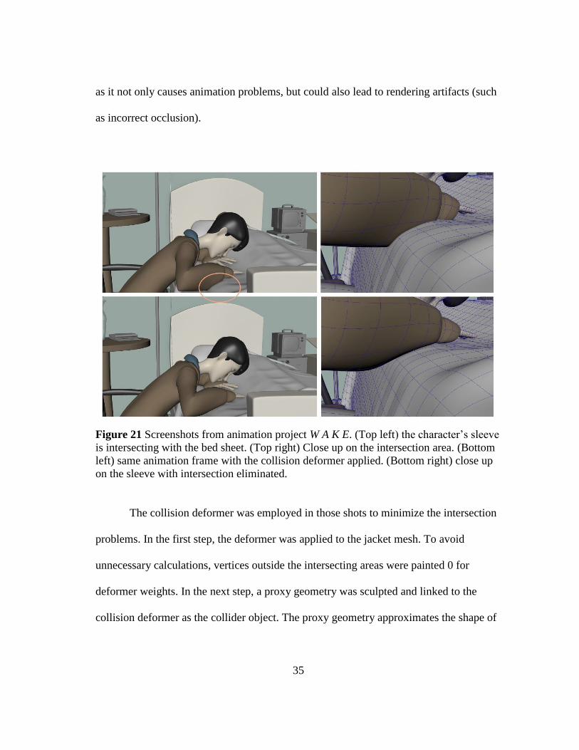
W A K E, directed by Kelly Kin, is an animated short about a boy who is coming
to terms with the fact that his sister is in a coma. There are several shots in the animation
where the main character, Dan, leans at the bedside of his sick sister. As shown in Figure
21, several areas on Dan’s sleeves are noticeably penetrating through the sheet as he
moves his arm off the bed. Geometry overlapping should be avoided as much as possible
35
as it not only causes animation problems, but could also lead to rendering artifacts (such
as incorrect occlusion).
Figure 21 Screenshots from animation project W A K E. (Top left) the character’s sleeve
is intersecting with the bed sheet. (Top right) Close up on the intersection area. (Bottom
left) same animation frame with the collision deformer applied. (Bottom right) close up
on the sleeve with intersection eliminated.
The collision deformer was employed in those shots to minimize the intersection
problems. In the first step, the deformer was applied to the jacket mesh. To avoid
unnecessary calculations, vertices outside the intersecting areas were painted 0 for
deformer weights. In the next step, a proxy geometry was sculpted and linked to the
collision deformer as the collider object. The proxy geometry approximates the shape of

36
the sheet with much lower vertex density (See Figure 22), allowing faster evaluations of
collision detection and deforming.
Figure 22 The collision deformer setup in W A K E. (Left) vertices outside the
intersecting areas were painted 0 for deformer weight. (Right) a proxy geometry was
created as the collider object.
The elasticity attribute of the deformer was set to “elastic,” thus the sleeves can
be restored to their original shapes once the arms move away from the bed.
5.1.3 Adding Squash to Foot Rig
This example demonstrates how the collision deformer could be incorporated in a
character rig to produce fast and plausible secondary deformation.

37
Figure 23 Nano Hunter rig. Retrieved from Digital Tutors (Digital Tutors, 2014).
The deformer was applied to the Nano Hunter rig (see Figure 23) to add
automatic ground detection and squash deformation to the feet. As the deformer supports
using the ground plane as a collider, no additional collider object needs to be created. As
shown in Figure 24, deformer weights were only painted on the fleshy parts of the feet.
Figure 24 (Left) the deformer only affects the fleshy parts of the feet. (Right) falloff
curve of the bulge effect on the feet.
When the foot contacts the ground plane, the deformer squashes the bottom of
the foot and adds a subtle but natural bulge to the side of the foot (see Figure 25).

38
Figure 25 (Left) the original foot rig. (Right) the collision deformer flattens the bottom
of the foot as it contacts the ground, and adds a subtle bulge to the side of the foot.

39
5.1.4 Working with Other Deformers
It is very common to apply multiple deformers to a single object to achieve
certain deformation effects. In this example, the collision deformer is used together with
the jiggle deformer to create a realistic elastic effect on a character.
The Maya jiggle deformer can produce a shaking or vibrating effect on the
surface of an object as the points on the surface move. It is often used to create effects
such as hair jiggling and stomach shaking.
Figure 26 The Boris character. Retrieved from Digital Tutors (Digital Tutors, 2014).
Boris is a character that features a chubby body (see Figure 26). When animating
a character like him, the motion of fat cannot be ignored. Using the collision deformer
and the jiggle deformer, plausible fat motion caused by collision can be added to the
body with minimum effort. The collision deformer detects contacts between the body
and the colliders and deforms the body to resolve the collision. The deformation caused

40
by the collision deformer in turn triggers the jiggle deformer to generate a shaking effect
on top of the existing deformation (see Figure 27). The whole process happens
automatically, allowing the animator to focus more on the character’s primary motions
and expressions.
Figure 27 (Left) before collision. (Middle) a sphere is colliding with the belly. (Right)
the belly jiggles after the collider is moved away.
As the collision deformer supports interacting with multiple objects, the user can
easily add more than one collider to affect the soft body (see Figure 28).

41
Figure 28 Multiple collider objects interacting with the character.
5.2 Limitations
a. One important principle in animation is the fact that an object’s volume remains
unchanged when squashed or stretched (Lasseter, 1987). Although the current collision
deformer allows the user to control the volume of the deforming object by manually
adjusting the strength and the falloff of the bulge effect, direct and automatic volume
preservation is not provided.

42
Figure 29 Open shapes cannot be used as collider objects.
b. The deformation algorithm determines collision by checking if any of the points
on the deforming mesh is inside the collider object. This method is based on the crossing
number algorithm, which requires the tested polygon to have a closed surface. The
results produced by the deformer might be unpredictable if the collider object has an
open area on the mesh. Due to this limitation, shapes such as those shown in Figure 29
cannot be directly used as collider objects. To solve this problem, the user has to either
fill the open areas or use proxy geometries for the collider objects.

43
6. CONCLUSION
The collision deformer implemented for this thesis has provided a fast and
reliable approach to create simple collision deformation on a soft body in Autodesk
Maya without performing expensive physically-based simulations. The deformer uses a
time-independent algorithm to approximate the elastic property of a soft body and at the
same time offers artistic control to the user to interactively adjust the resulting
deformation. Within the options and parameters provided within the deformer, the user
is able to adjust the elasticity, strength, bulge falloff and more of the collision effect.

44
REFERENCES
Autodesk. (2010). MPxNode Class Reference. Retrieved 10 19, 2014, from
http://download.autodesk.com/us/maya/2010help/API/class_m_px_node.html
Autodesk. (n.d.). Maya User Guide: Customizing the Interface. (Autodesk) Retrieved 10
30, 2014, from
http://help.autodesk.com/view/MAYAUL/2015/ENU/?guid=GUID-44D81B33-
2F2B-47C9-8387-48FC4E6594E8
Digital Tutors. (2014, 11 25). The Asset Library. Retrieved from Digital Tutors:
http://www.digitaltutors.com/11/assetlibrary/
Docter, P. (Director). (2009). Up [Motion Picture]. Pixar Animation Studios
Hormann, K., & Agathos, A. (2001). The Point in Polygon Problem for Arbitrary
Polygons. Computational Geometry-theory and Applications, 20(3), 131-144.
House, D., & David, B. (2000). Cloth Modeling and Animation. Natick, MA, USA: A.
K. Peters, Ltd.
Langetepe, E., & Zachmann, G. (2006). Geometric Data Structures for Computer
Graphics. A K Peters.
Lasseter, J. (1987). Principles of Traditional Animation Applied to 3D Computer
Animation. SIGGRAPH '87 Proceedings of the 14th Annual Conference on
Computer Graphics and Interactive Techniques. New York, NY, USA.

45
Mechtley, A., & Trowbridge, R. (2011). Maya Python for Games and Film: A Complete
Reference for the Maya Python and the Maya Python API. Morgan Kaufmann
Publishers.
Mitchell, M. (Director). (2010). Shrek Forever After [Motion Picture]. DreamWorks
Animation.
Nealen, A., Müller, M., Keiser, R., Boxerman, E., & Carlson, M. (2006). Physically
Based Deformable Models in Computer Graphics. Computer Graphics Forum,
25(4), 809-836.
O'Neil, R. (2008). Digital Character Development. Burlington, MA: Morgan Kaufmann
Publishers.
Popovici, T. W. (2008). Putting Intel Threading Building Blocks to Work. Proceedings
of the 1st International Workshop on Multicore Software Engineering. New
York, NY, USA.
Reinders, J. (2007). Intel Threading Building Blocks. O'Reilly Media, Inc.