Embed Size (px)
Citation preview

— MINNESOTA POWER SYSTEMS CONFERENCE
A Creative Line Differential Protection Scheme for the Hudson River Crossing Section of a 345kV
Transmission LineMike Kockott
ABB
Tuesday, November 12, 2019SAINT PAUL, MN

—
Slide 2
Co-author acknowledgement
Alex Echeverria, NYPAEric Anderson, NYPABharat Vasudevan, ABB Inc.
November 13, 2019
—
Slide 3
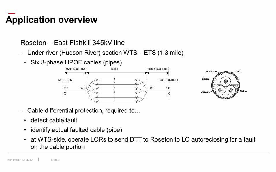
Application overview
Roseton – East Fishkill 345kV line– Under river (Hudson River) section WTS – ETS (1.3 mile)
• Six 3-phase HPOF cables (pipes)
– Cable differential protection, required to…• detect cable fault• identify actual faulted cable (pipe)• at WTS-side, operate LORs to send DTT to Roseton to LO autoreclosing for a fault
on the cable portion
November 13, 2019
overhead line overhead linecable
—
Slide 4
Application overview
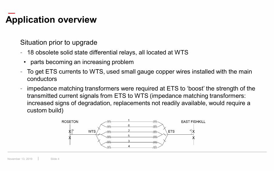
Situation prior to upgrade– 18 obsolete solid state differential relays, all located at WTS
• parts becoming an increasing problem– To get ETS currents to WTS, used small gauge copper wires installed with the main
conductors– impedance matching transformers were required at ETS to ‘boost’ the strength of the
transmitted current signals from ETS to WTS (impedance matching transformers: increased signs of degradation, replacements not readily available, would require a custom build)
November 13, 2019
—
Slide 5
Application overview
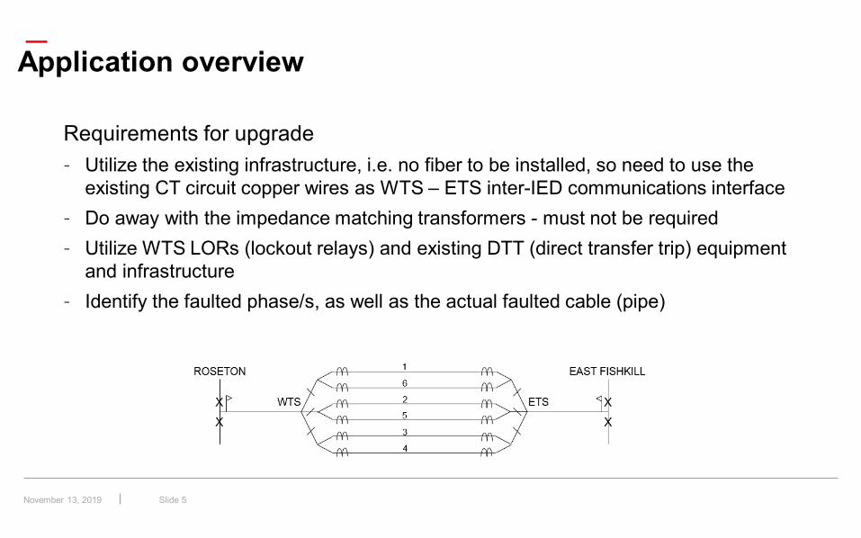
Requirements for upgrade– Utilize the existing infrastructure, i.e. no fiber to be installed, so need to use the
existing CT circuit copper wires as WTS – ETS inter-IED communications interface– Do away with the impedance matching transformers - must not be required– Utilize WTS LORs (lockout relays) and existing DTT (direct transfer trip) equipment
and infrastructure– Identify the faulted phase/s, as well as the actual faulted cable (pipe)
November 13, 2019
—
Slide 6
Application overview
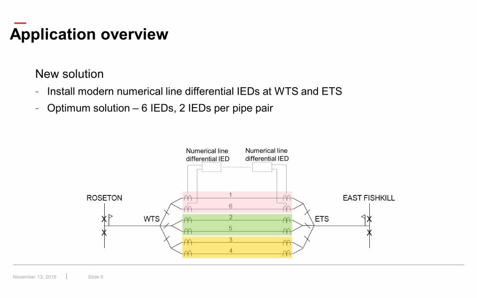
New solution– Install modern numerical line differential IEDs at WTS and ETS– Optimum solution – 6 IEDs, 2 IEDs per pipe pair
Numerical line differential IED
Numerical line differential IED
November 13, 2019
—
Slide 7
Application overview
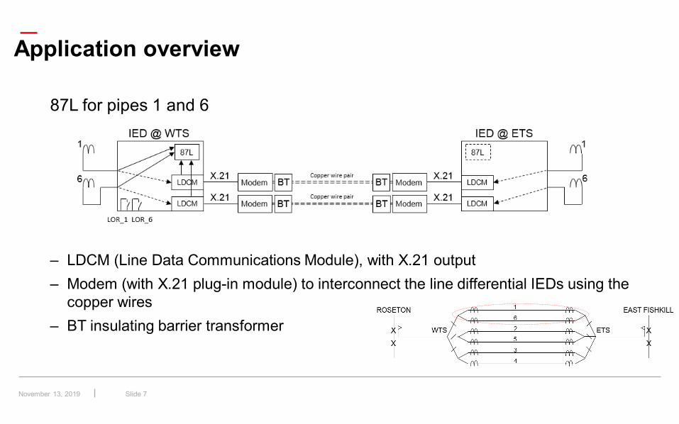
87L for pipes 1 and 6
– LDCM (Line Data Communications Module), with X.21 output– Modem (with X.21 plug-in module) to interconnect the line differential IEDs using the
copper wires– BT insulating barrier transformer
November 13, 2019
—
Slide 8
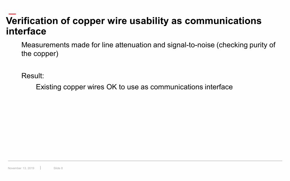
Verification of copper wire usability as communications interface
Measurements made for line attenuation and signal-to-noise (checking purity of the copper)
Result:Existing copper wires OK to use as communications interface
November 13, 2019
—
Slide 9
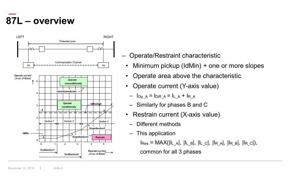
87L – overviewLEFT RIGHT
– Operate/Restraint characteristic• Minimum pickup (IdMin) + one or more slopes• Operate area above the characteristic• Operate current (Y-axis value)
– IOp_A = IDiff_A = IL_A + IR_A
– Similarly for phases B and C
• Restrain current (X-axis value)– Different methods– This application
IRes = MAX(|IL_A|, |IL_B|, |IL_C|, |IR_A|, |IR_B|, |IR_C|),common for all 3 phases
November 13, 2019
—
Slide 10
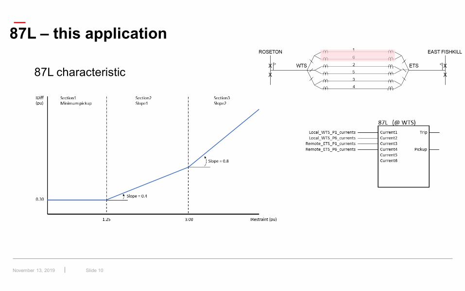
87L – this application
87L characteristic
November 13, 2019
—
Slide 11
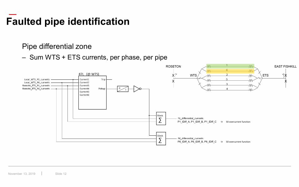
Faulted pipe identification
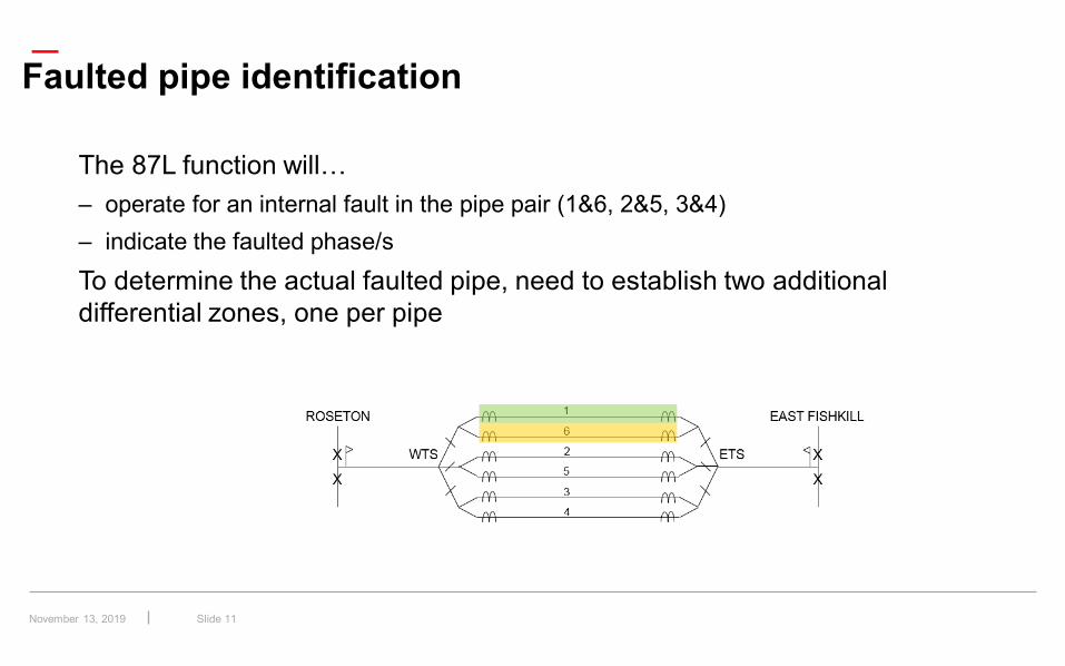
The 87L function will…– operate for an internal fault in the pipe pair (1&6, 2&5, 3&4)– indicate the faulted phase/sTo determine the actual faulted pipe, need to establish two additional differential zones, one per pipe
November 13, 2019
—
Slide 12
Pipe differential zone– Sum WTS + ETS currents, per phase, per pipe
Faulted pipe identification
P1_IDiff_A, P1_IDiff_B, P1_IDiff_C → 50 overcurrent function
P6_IDiff_A, P6_IDiff_B, P6_IDiff_C → 50 overcurrent function
November 13, 2019
—
Slide 13
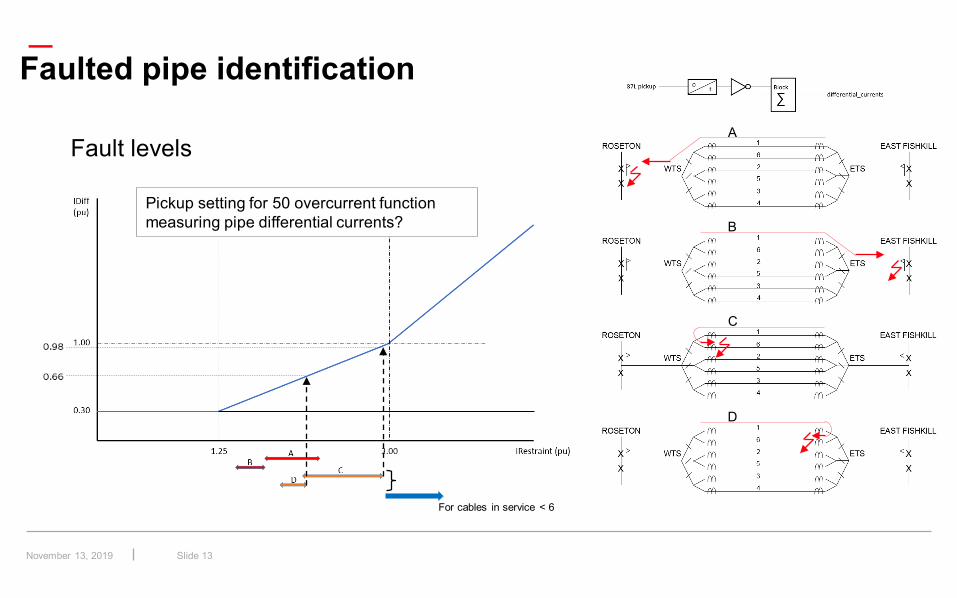
Fault levels
Faulted pipe identification
A
B
C
D
For cables in service < 6
Pickup setting for 50 overcurrent function measuring pipe differential currents?
November 13, 2019
—
Slide 14
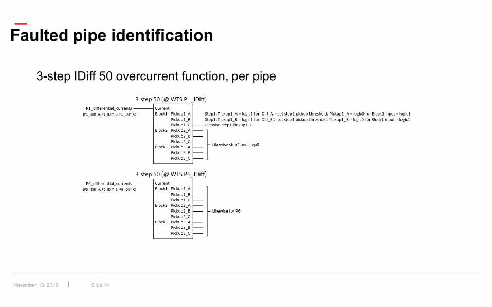
3-step IDiff 50 overcurrent function, per pipe
Faulted pipe identification
November 13, 2019
—
Slide 15
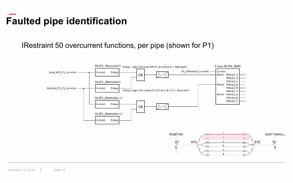
IRestraint 50 overcurrent functions, per pipe (shown for P1)
Faulted pipe identification
November 13, 2019
—
Slide 16
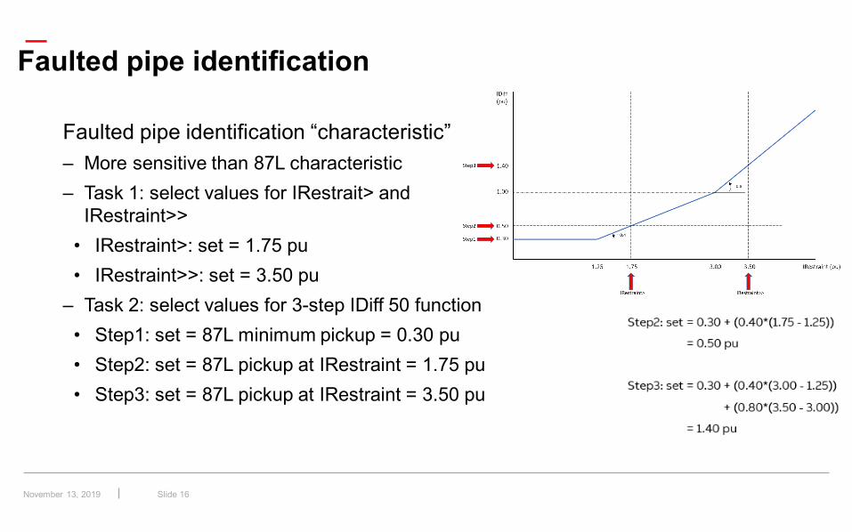
Faulted pipe identification
Faulted pipe identification “characteristic”– More sensitive than 87L characteristic– Task 1: select values for IRestrait> and
IRestraint>>• IRestraint>: set = 1.75 pu• IRestraint>>: set = 3.50 pu
– Task 2: select values for 3-step IDiff 50 function• Step1: set = 87L minimum pickup = 0.30 pu• Step2: set = 87L pickup at IRestraint = 1.75 pu• Step3: set = 87L pickup at IRestraint = 3.50 pu
November 13, 2019
—
Slide 17
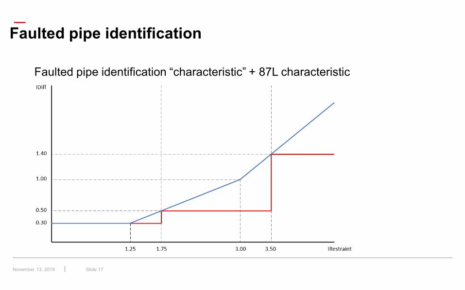
Faulted pipe identification “characteristic” + 87L characteristic
Faulted pipe identification
November 13, 2019
—
Slide 18
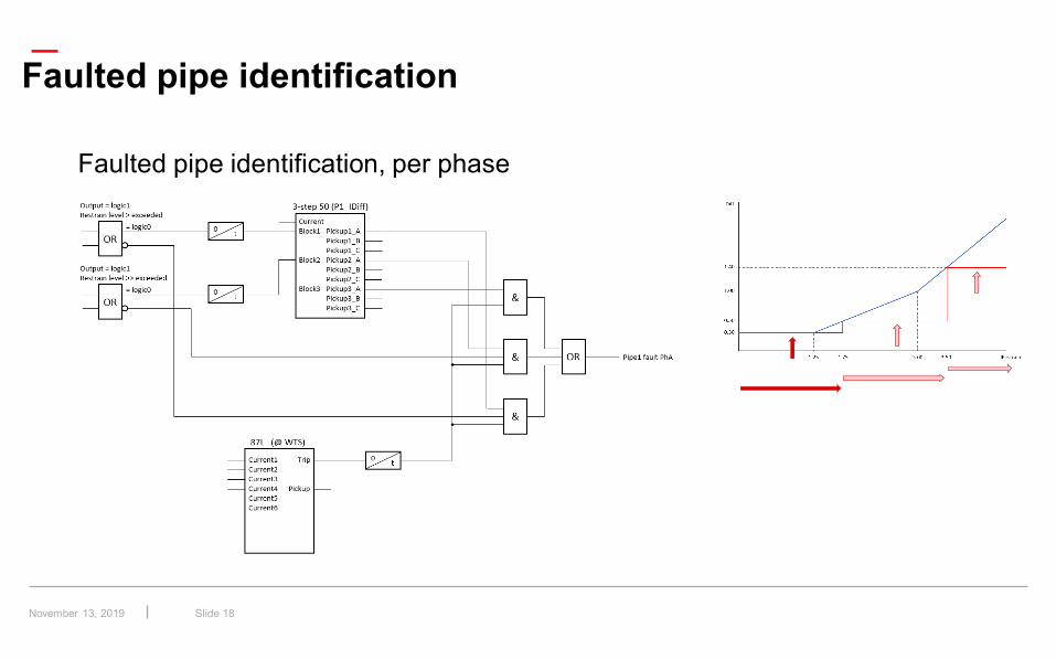
Faulted pipe identification, per phase
Faulted pipe identification
November 13, 2019
—
Slide 19
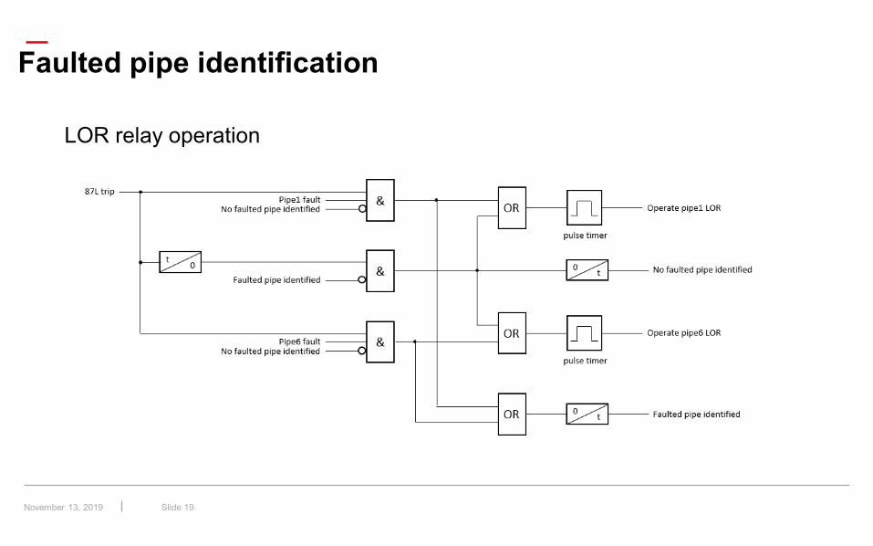
LOR relay operation
Faulted pipe identification
November 13, 2019
—
Slide 20
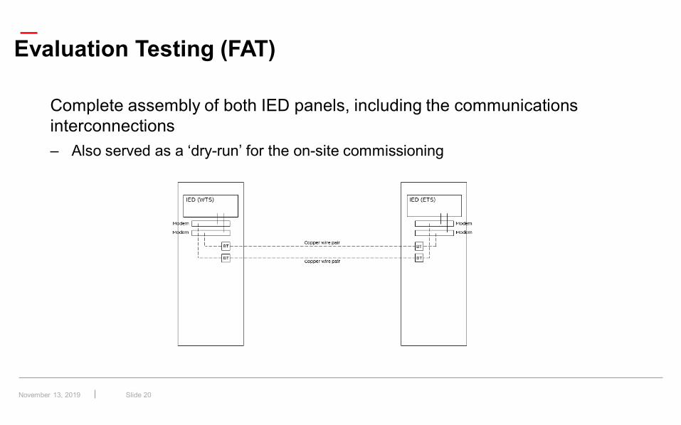
Evaluation Testing (FAT)
Complete assembly of both IED panels, including the communications interconnections– Also served as a ‘dry-run’ for the on-site commissioning
November 13, 2019
—
Slide 21
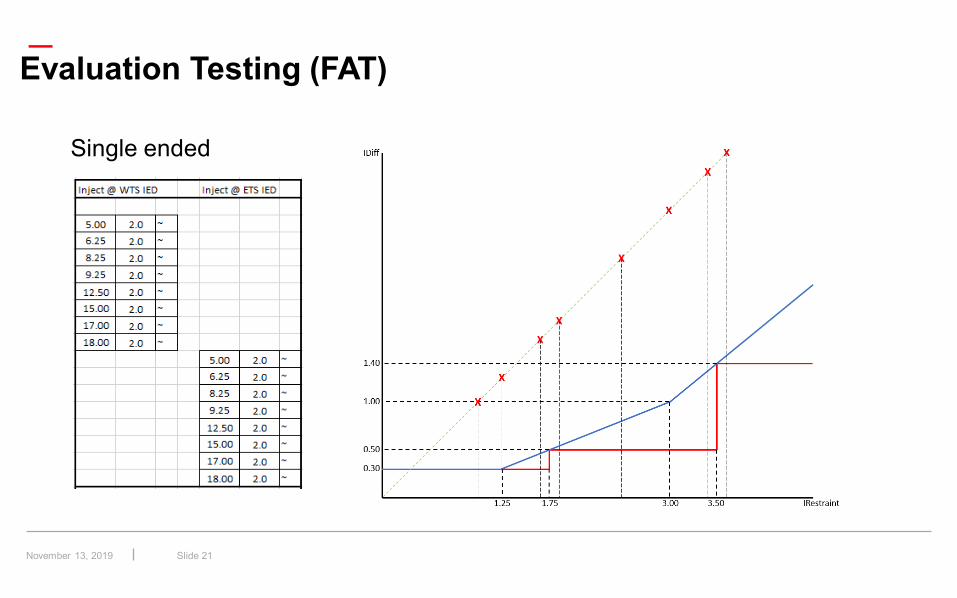
Evaluation Testing (FAT)
Single ended
November 13, 2019
—
Slide 22
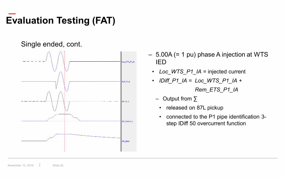
Evaluation Testing (FAT)
Single ended, cont.– 5.00A (= 1 pu) phase A injection at WTS
IED• Loc_WTS_P1_IA = injected current• IDiff_P1_IA = Loc_WTS_P1_IA +
Rem_ETS_P1_IA– Output from ∑
• released on 87L pickup• connected to the P1 pipe identification 3-
step IDiff 50 overcurrent function
November 13, 2019
—
Slide 23
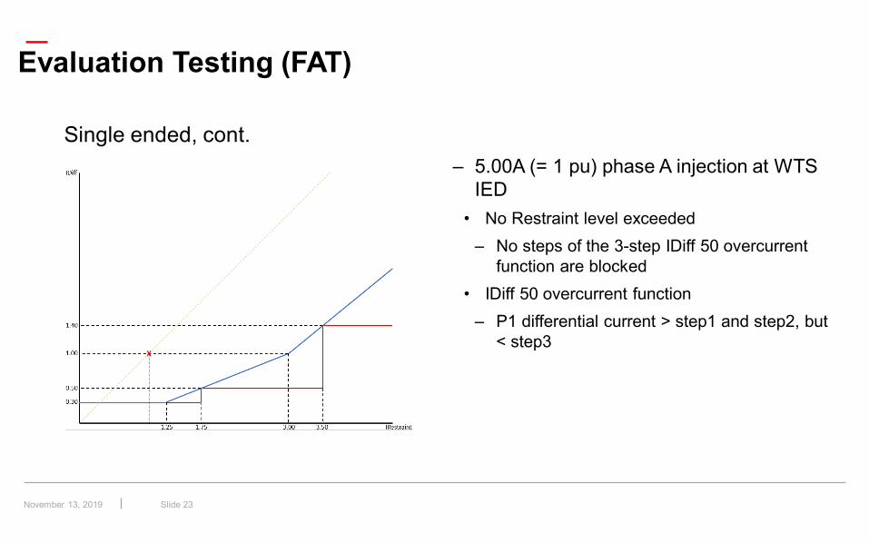
Evaluation Testing (FAT)
Single ended, cont.– 5.00A (= 1 pu) phase A injection at WTS
IED• No Restraint level exceeded
– No steps of the 3-step IDiff 50 overcurrent function are blocked
• IDiff 50 overcurrent function– P1 differential current > step1 and step2, but
< step3
November 13, 2019
—
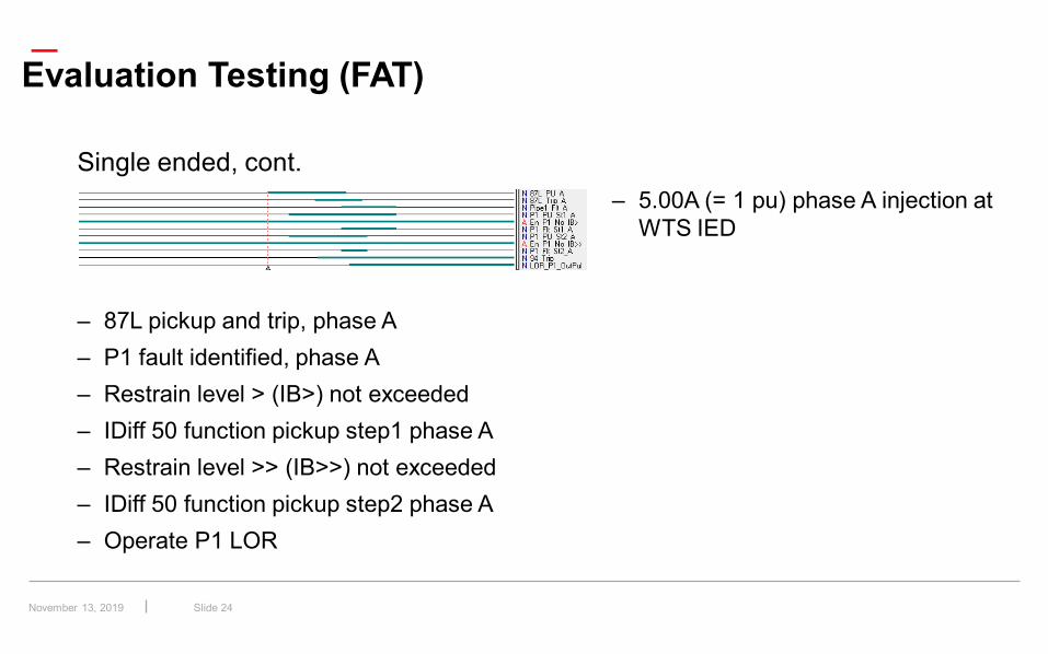
Slide 24
Evaluation Testing (FAT)
Single ended, cont.– 5.00A (= 1 pu) phase A injection at
WTS IED
– 87L pickup and trip, phase A– P1 fault identified, phase A– Restrain level > (IB>) not exceeded– IDiff 50 function pickup step1 phase A– Restrain level >> (IB>>) not exceeded– IDiff 50 function pickup step2 phase A– Operate P1 LOR
November 13, 2019
—
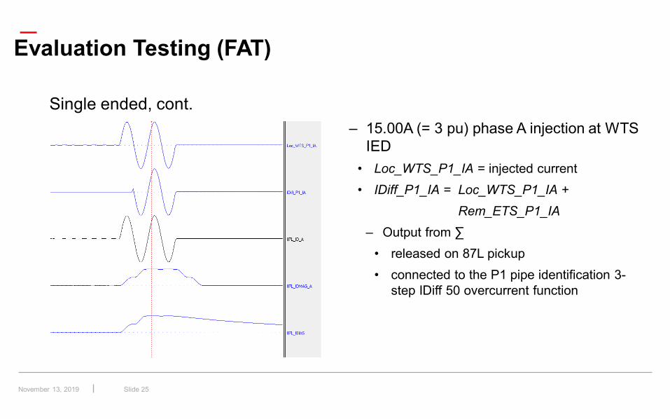
Slide 25
Evaluation Testing (FAT)
Single ended, cont.– 15.00A (= 3 pu) phase A injection at WTS
IED• Loc_WTS_P1_IA = injected current• IDiff_P1_IA = Loc_WTS_P1_IA +
Rem_ETS_P1_IA– Output from ∑
• released on 87L pickup• connected to the P1 pipe identification 3-
step IDiff 50 overcurrent function
November 13, 2019
—
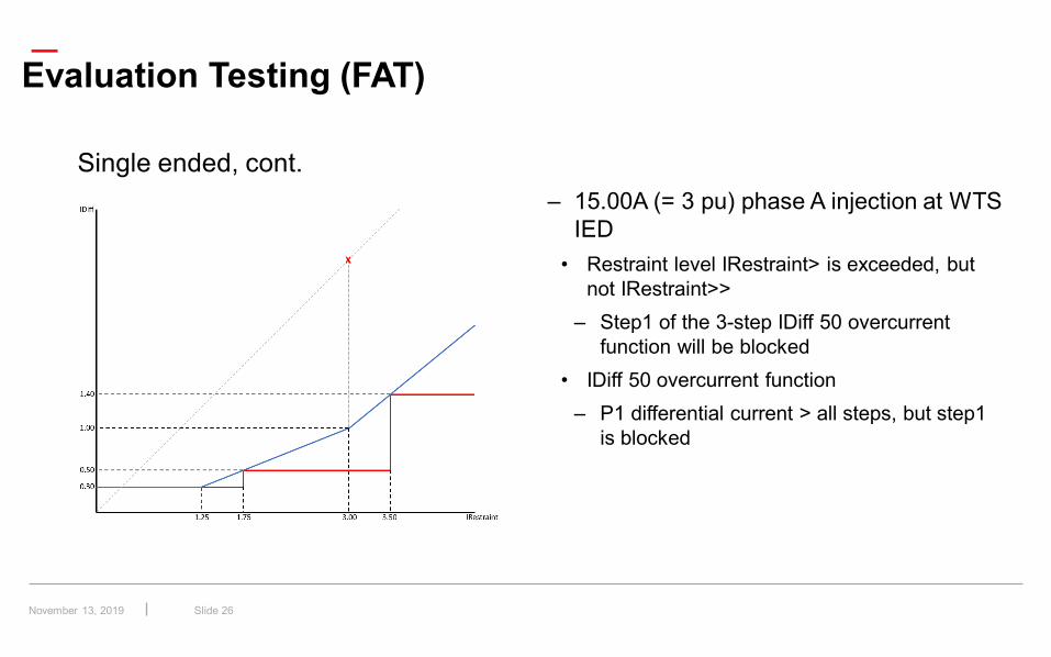
Slide 26
Evaluation Testing (FAT)
Single ended, cont.– 15.00A (= 3 pu) phase A injection at WTS
IED• Restraint level IRestraint> is exceeded, but
not IRestraint>>– Step1 of the 3-step IDiff 50 overcurrent
function will be blocked• IDiff 50 overcurrent function
– P1 differential current > all steps, but step1 is blocked
November 13, 2019
—
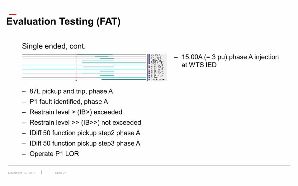
Slide 27
Evaluation Testing (FAT)
Single ended, cont.– 15.00A (= 3 pu) phase A injection
at WTS IED
– 87L pickup and trip, phase A– P1 fault identified, phase A– Restrain level > (IB>) exceeded– Restrain level >> (IB>>) not exceeded– IDiff 50 function pickup step2 phase A– IDiff 50 function pickup step3 phase A– Operate P1 LOR
November 13, 2019
—
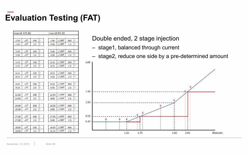
Slide 28
Evaluation Testing (FAT)
Double ended, 2 stage injection– stage1, balanced through current– stage2, reduce one side by a pre-determined amount
November 13, 2019
—
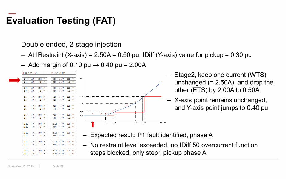
Slide 29
Evaluation Testing (FAT)
Double ended, 2 stage injection– At IRestraint (X-axis) = 2.50A = 0.50 pu, IDiff (Y-axis) value for pickup = 0.30 pu– Add margin of 0.10 pu → 0.40 pu = 2.00A
– Stage2, keep one current (WTS) unchanged (= 2.50A), and drop the other (ETS) by 2.00A to 0.50A
– X-axis point remains unchanged, and Y-axis point jumps to 0.40 pu
– Expected result: P1 fault identified, phase A– No restraint level exceeded, no IDiff 50 overcurrent function
steps blocked, only step1 pickup phase A
November 13, 2019
—
Slide 30
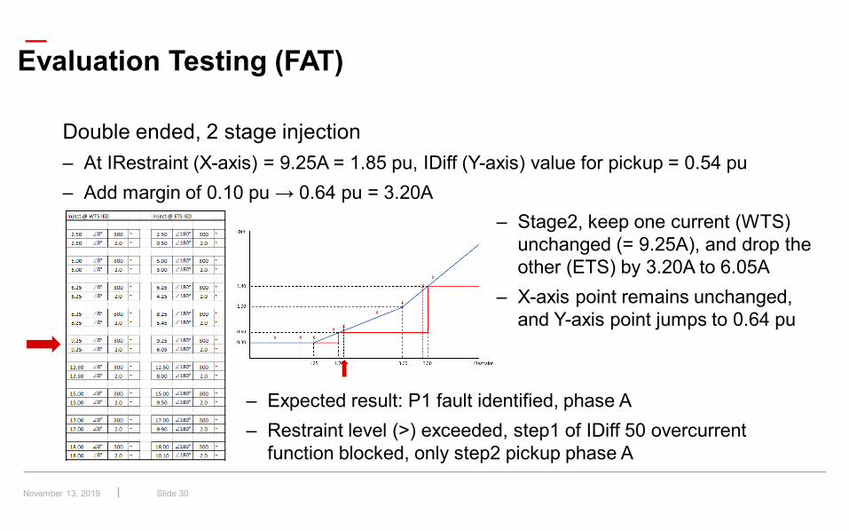
Evaluation Testing (FAT)
Double ended, 2 stage injection– At IRestraint (X-axis) = 9.25A = 1.85 pu, IDiff (Y-axis) value for pickup = 0.54 pu– Add margin of 0.10 pu → 0.64 pu = 3.20A
– Stage2, keep one current (WTS) unchanged (= 9.25A), and drop the other (ETS) by 3.20A to 6.05A
– X-axis point remains unchanged, and Y-axis point jumps to 0.64 pu
– Expected result: P1 fault identified, phase A– Restraint level (>) exceeded, step1 of IDiff 50 overcurrent
function blocked, only step2 pickup phase A
November 13, 2019
—
Slide 31
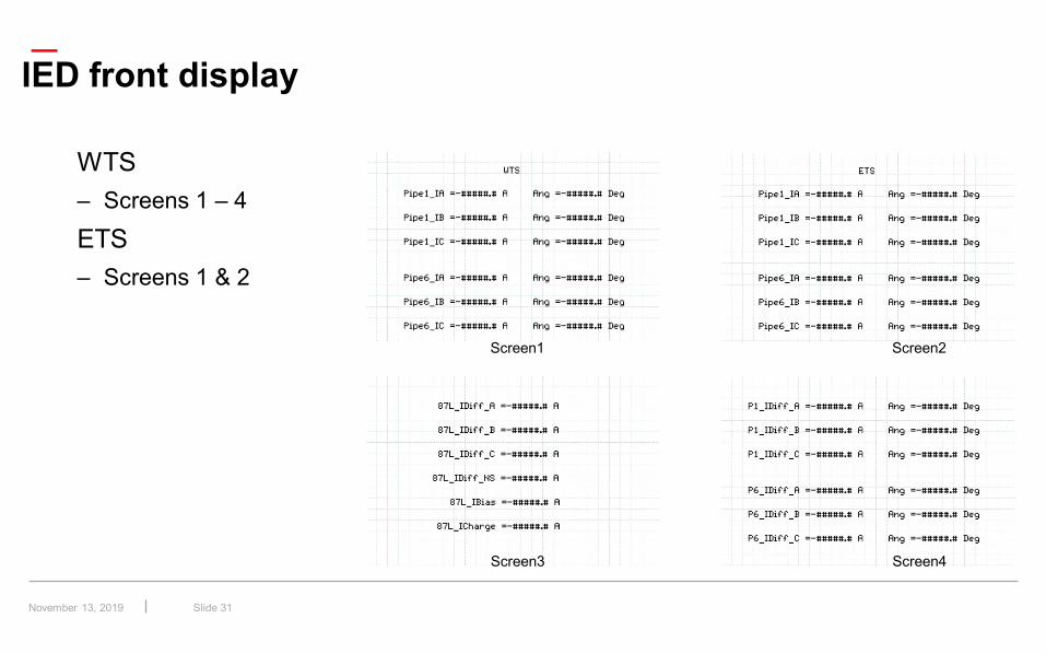
IED front display
WTS– Screens 1 – 4ETS– Screens 1 & 2
Screen1 Screen2
Screen3 Screen4
November 13, 2019
—
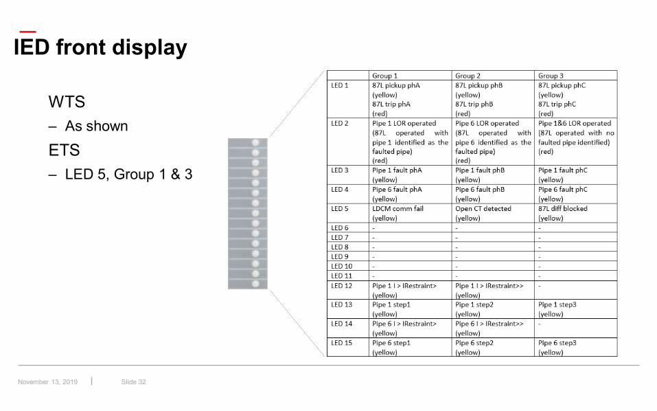
Slide 32
IED front display
WTS– As shownETS– LED 5, Group 1 & 3
November 13, 2019
—
Slide 33
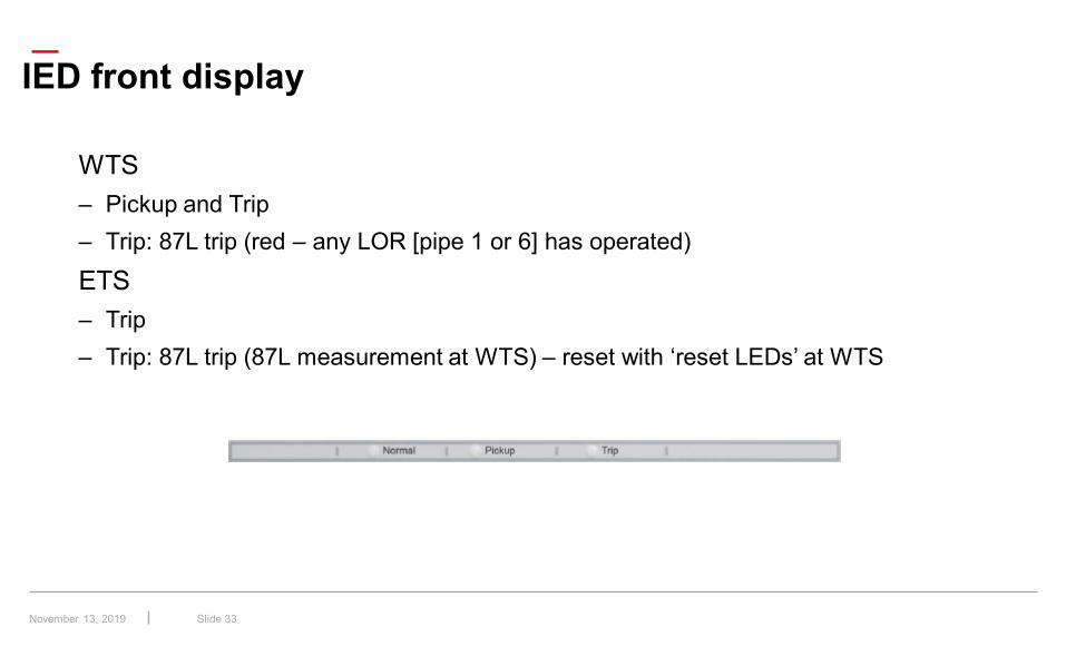
IED front display
WTS– Pickup and Trip– Trip: 87L trip (red – any LOR [pipe 1 or 6] has operated)ETS– Trip– Trip: 87L trip (87L measurement at WTS) – reset with ‘reset LEDs’ at WTS
November 13, 2019
—
Slide 34
Conclusion
FAT– Successful – expected operation for all test casesCommissioning– Put into service 12 May 2017– All equipment, including the communications, has to date performed as expected
November 13, 2019
![Transmission Line Differential Protection Based on ...discussed line differential protection based on IEC 61850. In [9] an adaptive current line differential protection scheme is proposed](https://img.pdfslide.net/doc/110x75/5e7b1116957fb414ac4ec632/transmission-line-differential-protection-based-on-discussed-line-differential.jpg)