Embed Size (px)
Citation preview
WiMAX FORUM PROPRIETARY
WiMAX Forum Proprietary Copyright © 2010 WiMAX Forum. All Rights Reserved.
WiMAX Forum® Test Procedures
WiMAX Forum® Mobile Radio Conformance Tests
WMF-T25-002-R010v04
WiMAX Forum® Approved (2010-09-07)
WiMAX Forum® Air Test Procedures WMF-T25-002-R010v04 WiMAX Forum® Mobile RCT
Page - ii
WiMAX FORUM PROPRIETARY
Copyr ight Notice, Use Restr ictions, Disclaimer , and Limitation of Liability 1
2 Copyright 2010 WiMAX Forum. All rights reserved. 3 4 The WiMAX Forum® owns the copyright in this document and reserves all rights herein. This document is available for 5 download from the WiMAX Forum and may be duplicated for internal use, provided that all copies contain all proprietary notices 6 and disclaimers included herein. Except for the foregoing, this document may not be duplicated, in whole or in part, or 7 distributed without the express written authorization of the WiMAX Forum. 8 9 Use of this document is subject to the disclaimers and limitations described below. Use of this document constitutes acceptance 10 of the following terms and conditions: 11 12 THIS DOCUMENT IS PROVIDED “AS IS” AND WITHOUT WARRANTY OF ANY KIND. TO THE GREATEST 13 EXTENT PERMITTED BY LAW, THE WiMAX FORUM DISCLAIMS ALL EXPRESS, IMPLIED AND 14 STATUTORY WARRANTIES, INCLUDING, WITHOUT LIMITATION, THE IMPLIED WARRANTIES OF TITLE, 15 NONINFRINGEMENT, MERCHANTABILITY AND FITNESS FOR A PARTICULAR PURPOSE. THE WiMAX 16 FORUM DOES NOT WARRANT THAT THIS DOCUMENT IS COMPLETE OR WITHOUT ERROR AND 17 DISCLAIMS ANY WARRANTIES TO THE CONTRARY. 18 19 Any products or services provided using technology described in or implemented in connection with this document may be 20 subject to various regulatory controls under the laws and regulations of various governments worldwide. The user is solely 21 responsible for the compliance of its products and/or services with any such laws and regulations and for obtaining any and all 22 required authorizations, permits, or licenses for its products and/or services as a result of such regulations within the applicable 23 jurisdiction. 24 25 NOTHING IN THIS DOCUMENT CREATES ANY WARRANTIES WHATSOEVER REGARDING THE 26 APPLICABILITY OR NON-APPLICABILITY OF ANY SUCH LAWS OR REGULATIONS OR THE SUITABILITY 27 OR NON-SUITABILITY OF ANY SUCH PRODUCT OR SERVICE FOR USE IN ANY JURISDICTION. 28 29 NOTHING IN THIS DOCUMENT CREATES ANY WARRANTIES WHATSOEVER REGARDING THE 30 SUITABILITY OR NON-SUITABILITY OF A PRODUCT OR A SERVICE FOR CERTIFICATION UNDER ANY 31 CERTIFICATION PROGRAM OF THE WiMAX FORUM OR ANY THIRD PARTY. 32 33 The WiMAX Forum has not investigated or made an independent determination regarding title or noninfringement of any 34 technologies that may be incorporated, described or referenced in this document. Use of this document or implementation of any 35 technologies described or referenced herein may therefore infringe undisclosed third-party patent rights or other intellectual 36 property rights. The user is solely responsible for making all assessments relating to title and noninfringement of any technology, 37 standard, or specification referenced in this document and for obtaining appropriate authorization to use such technologies, 38 technologies, standards, and specifications, including through the payment of any required license fees. 39 40 NOTHING IN THIS DOCUMENT CREATES ANY WARRANTIES OF TITLE OR NONINFRINGEMENT WITH 41 RESPECT TO ANY TECHNOLOGIES, STANDARDS OR SPECIFICATIONS REFERENCED OR INCORPORATED 42 INTO THIS DOCUMENT. 43 44 IN NO EVENT SHALL THE WiMAX FORUM OR ANY MEMBER BE LIABLE TO THE USER OR TO A THIRD 45 PARTY FOR ANY CLAIM ARISING FROM OR RELATING TO THE USE OF THIS DOCUMENT, INCLUDING, 46 WITHOUT LIMITATION, A CLAIM THAT SUCH USE INFRINGES A THIRD PARTY’S INTELLECTUAL 47 PROPERTY RIGHTS OR THAT IT FAILS TO COMPLY WITH APPLICABLE LAWS OR REGULATIONS. BY 48 USE OF THIS DOCUMENT, THE USER WAIVES ANY SUCH CLAIM AGAINST THE WiMAX FORUM AND ITS 49 MEMBERS RELATING TO THE USE OF THIS DOCUMENT. 50 51 The WiMAX Forum reserves the right to modify or amend this document without notice and in its sole discretion. The user is 52 solely responsible for determining whether this document has been superseded by a later version or a different document. 53 54 “WiMAX,” “Mobile WiMAX,” “Fixed WiMAX,” “WiMAX Forum,” “WiMAX Certified,” “WiMAX Forum 55 Certified,” the WiMAX Forum logo and the WiMAX Forum Certified logo are trademarks or registered trademarks 56 of the WiMAX Forum. All other trademarks are the property of their respective owners. 57
58
WiMAX Forum® Air Test Procedures WMF-T25-002-R010v04 WiMAX Forum® Mobile RCT
Page - iii
WiMAX FORUM PROPRIETARY
Table of Contents
1. OVERVIEW .................................................................................................................................................... 1
2. SCOPE ............................................................................................................................................................. 2
3. PURPOSE ........................................................................................................................................................ 3
4. REFERENCES ................................................................................................................................................ 4
5. DEFINITIONS AND ABBREVIATIONS .................................................................................................... 5 5.1 Definitions ..................................................................................................................................................... 5
5.2 Abbreviations ................................................................................................................................................ 6
6. MEASUREMENT SYSTEM ......................................................................................................................... 8 6.1 General requirements ..................................................................................................................................... 8 6.2 Test condition declarations ............................................................................................................................ 8
7. CONFORMANCE TESTS ........................................................................................................................... 10
8. TEST PROCEDURES .................................................................................................................................. 12 8.1 General statement for all tests ...................................................................................................................... 12
8.2 General statement for all test setups ............................................................................................................ 12
9. TEST FOR MOBILE STATION ................................................................................................................. 14 9.1 Test procedures ............................................................................................................................................ 14
9.1.1 MS-01.1: MS Receiver Maximum Tolerable Signal ............................................................................ 15 9.1.1.1 Introduction ................................................................................................................................... 15 9.1.1.2 PICS coverage and test purposes ................................................................................................... 15 9.1.1.3 Testing requirements ..................................................................................................................... 15 9.1.1.4 Test setup ...................................................................................................................................... 15 9.1.1.5 Test procedure ............................................................................................................................... 16 9.1.1.6 Compliance requirements .............................................................................................................. 16
9.1.2 MS-02.1: MS receiver preamble .......................................................................................................... 17 9.1.2.1 Introduction ................................................................................................................................... 17 9.1.2.2 PICS coverage and test purposes ................................................................................................... 17 9.1.2.3 Testing requirements ..................................................................................................................... 17 9.1.2.4 Test setup ...................................................................................................................................... 17 9.1.2.5 Test procedure ............................................................................................................................... 18
9.1.2.5.1 Decoding preamble with all defined cell IDs and all segments .................................................................. 189.1.2.5.2 Decoding preambles while more than a single BS is transmitting .............................................................. 18
9.1.2.6 Compliance requirements .............................................................................................................. 19 9.1.2.7 Uncertainties ................................................................................................................................. 22
9.1.3 MS-02.2: MS receiver preamble .......................................................................................................... 23 9.1.3.1 Introduction ................................................................................................................................... 23 9.1.3.2 PICS coverage and test purposes ................................................................................................... 23 9.1.3.3 Testing requirements ..................................................................................................................... 23 9.1.3.4 Test setup ...................................................................................................................................... 23 9.1.3.5 Test procedure ............................................................................................................................... 24
9.1.3.5.1 Decoding preamble with all defined cell IDs and all segments .................................................................. 249.1.3.5.2 Decoding preambles while more than a single BS is transmitting .............................................................. 24
WiMAX Forum® Air Test Procedures WMF-T25-002-R010v04 WiMAX Forum® Mobile RCT
Page - iv
WiMAX FORUM PROPRIETARY
9.1.3.6 Compliance requirements .............................................................................................................. 24 9.1.3.7 Uncertainties ................................................................................................................................. 24
9.1.4 MS-03.1: Reserved ............................................................................................................................... 24 9.1.5 MS-04.1: MS receiver RSSI measurements ......................................................................................... 25
9.1.5.1 Introduction ................................................................................................................................... 25 9.1.5.2 PICS coverage and test purposes ................................................................................................... 25 9.1.5.3 Testing requirements ..................................................................................................................... 26 9.1.5.4 Test setup ...................................................................................................................................... 27 9.1.5.5 Test procedure ............................................................................................................................... 27 9.1.5.6 Compliance requirements .............................................................................................................. 29
9.1.6 MS-05.1: MS receiver Physical CINR measurements ......................................................................... 30 9.1.6.1 Introduction ................................................................................................................................... 30 9.1.6.2 PICS coverage and test purposes ................................................................................................... 30 9.1.6.3 Testing requirements ..................................................................................................................... 31 9.1.6.4 Test setup ...................................................................................................................................... 32 9.1.6.5 Test procedure ............................................................................................................................... 32 9.1.6.6 Compliance requirements .............................................................................................................. 35 9.1.6.7 Uncertainties ................................................................................................................................. 36
9.1.7 MS-06.2: MS receiver pilot-based Effective CINR measurement ....................................................... 36 9.1.7.1 Introduction ................................................................................................................................... 36 9.1.7.2 PICS coverage and test purposes ................................................................................................... 37 9.1.7.3 Testing requirements ..................................................................................................................... 38 9.1.7.4 Test setup ...................................................................................................................................... 38 9.1.7.5 Test procedure ............................................................................................................................... 44 9.1.7.6 Compliance requirements .............................................................................................................. 47 9.1.7.7 Uncertainties ................................................................................................................................. 50
9.1.8 MS-07.1: MS receiver adjacent and non-adjacent channel selectivity ................................................. 51 9.1.8.1 Introduction ................................................................................................................................... 51 9.1.8.2 PICS coverage and test purposes ................................................................................................... 52 9.1.8.3 Testing requirements ..................................................................................................................... 52 9.1.8.4 Test setup ...................................................................................................................................... 52 9.1.8.5 Test procedures ............................................................................................................................. 53 9.1.8.6 Compliance requirements .............................................................................................................. 54 9.1.8.7 Uncertainties ................................................................................................................................. 54
9.1.9 MS-08.1: MS receiver maximum input signal ..................................................................................... 55 9.1.9.1 Introduction ................................................................................................................................... 55 9.1.9.2 PICS coverage and test purposes ................................................................................................... 55 9.1.9.3 Testing requirements ..................................................................................................................... 55 9.1.9.4 Test setup ...................................................................................................................................... 56 9.1.9.5 Test procedure ............................................................................................................................... 56 9.1.9.6 Compliance requirements .............................................................................................................. 57 9.1.9.7 Uncertainties ................................................................................................................................. 57
9.1.10 MS-09.1: MS receiver sensitivity ......................................................................................................... 57 9.1.10.1 Introduction ................................................................................................................................... 57 9.1.10.2 PICS coverage and test purposes ................................................................................................... 58 9.1.10.3 Testing requirements ..................................................................................................................... 58 9.1.10.4 Test setup ...................................................................................................................................... 59 9.1.10.5 Test procedure ............................................................................................................................... 59 9.1.10.6 Compliance requirements .............................................................................................................. 62
9.1.11 MS-10.1: MS Transmit and Receive HARQ ........................................................................................ 66
MS-10a.1: MS Transmit HARQ .............................................................................................................................. 66 9.1.11.1 Introduction ................................................................................................................................... 66 9.1.11.2 PICS coverage and test purposes ................................................................................................... 66 9.1.11.3 Testing requirements ..................................................................................................................... 66 9.1.11.4 Test setup ...................................................................................................................................... 68
WiMAX Forum® Air Test Procedures WMF-T25-002-R010v04 WiMAX Forum® Mobile RCT
Page - v
WiMAX FORUM PROPRIETARY
9.1.11.5 Test procedure ............................................................................................................................... 69 9.1.11.6 Compliance requirements .............................................................................................................. 70 9.1.11.7 Uncertainties ................................................................................................................................. 71
MS-10b.1: MS Receive HARQ ............................................................................................................................... 72 9.1.11.8 Introduction ................................................................................................................................... 72 9.1.11.9 PICS coverage and test purposes ................................................................................................... 72 9.1.11.10 Testing requirements ..................................................................................................................... 73 9.1.11.11 Test setup ...................................................................................................................................... 75 9.1.11.12 Test procedure ............................................................................................................................... 75 9.1.11.13 Compliance requirements .............................................................................................................. 79 9.1.11.14 Uncertainties ................................................................................................................................. 81 9.1.11.15 Appendix - finding maximum SNR for PER > 0.5 ....................................................................... 81 9.1.11.16 Appendix - finding maximum SNR for Burst Error Rate > 0.9 .................................................... 82
9.1.12 MS-11.1: MS receiver PHY support for handover ............................................................................... 83 9.1.12.1 Introduction ................................................................................................................................... 83 9.1.12.2 PICS coverage and test purposes ................................................................................................... 83 9.1.12.3 Testing requirements ..................................................................................................................... 83 9.1.12.4 Test setup ...................................................................................................................................... 84 9.1.12.5 Test procedure ............................................................................................................................... 84 9.1.12.6 Compliance requirements .............................................................................................................. 87 9.1.12.7 Uncertainties ................................................................................................................................. 88
9.1.13 MS-11.2: MS receiver PHY support for inter-FA handover ................................................................ 89 9.1.13.1 Introduction ................................................................................................................................... 89 9.1.13.2 PICS coverage and test purposes ................................................................................................... 89 9.1.13.3 Testing requirements ..................................................................................................................... 89 9.1.13.4 Test setup ...................................................................................................................................... 90 9.1.13.5 Test procedure ............................................................................................................................... 91 9.1.13.6 Compliance requirements .............................................................................................................. 93 9.1.13.7 Uncertainties ................................................................................................................................. 93
9.1.14 MS-12.1: MS Transmitter Modulation and Coding, Cyclic Prefix and Frame Duration Timing ......... 94 9.1.14.1 Introduction ................................................................................................................................... 94 9.1.14.2 PICS coverage and test purposes ................................................................................................... 94 9.1.14.3 Testing requirements ..................................................................................................................... 95 9.1.14.4 Test setup ...................................................................................................................................... 95 9.1.14.5 Test procedure ............................................................................................................................... 95 9.1.14.6 Compliance requirements .............................................................................................................. 96 9.1.14.7 Uncertainties ................................................................................................................................. 97
9.1.15 MS-13.1: MS Transmit Ranging Support ............................................................................................. 97 9.1.15.1 Introduction ................................................................................................................................... 97 9.1.15.2 PICS coverage and test purposes ................................................................................................... 99 9.1.15.3 Testing requirements ..................................................................................................................... 99 9.1.15.4 Test setup .................................................................................................................................... 100 9.1.15.5 Test procedure ............................................................................................................................. 100 9.1.15.6 Compliance requirements ............................................................................................................ 101 9.1.15.7 Uncertainties ............................................................................................................................... 102
9.1.16 MS-14.1: Reserved ............................................................................................................................. 103 9.1.17 MS-15.1: MS transmit power dynamic range and relative step accuracy .......................................... 104
9.1.17.1 Introduction ................................................................................................................................. 104 9.1.17.2 Coverage and test purposes ......................................................................................................... 104 9.1.17.3 Testing requirements ................................................................................................................... 105 9.1.17.4 Test setup .................................................................................................................................... 105 9.1.17.5 Test procedure – Dynamic range and Open loop / Closed Loop Power Step Accuracy ............. 106 9.1.17.6 Compliance requirements ............................................................................................................ 107 9.1.17.7 Uncertainties ............................................................................................................................... 108
9.1.18 MS-16.1: MS Transmit Power Control Support ................................................................................. 109
WiMAX Forum® Air Test Procedures WMF-T25-002-R010v04 WiMAX Forum® Mobile RCT
Page - vi
WiMAX FORUM PROPRIETARY
9.1.18.1 Introduction ................................................................................................................................. 109 9.1.18.2 PICS coverage and test purposes ................................................................................................. 109 9.1.18.3 Testing requirements ................................................................................................................... 109 9.1.18.4 Test setup .................................................................................................................................... 111 9.1.18.5 Test procedure ............................................................................................................................. 111 9.1.18.6 Compliance requirements ............................................................................................................ 116 9.1.18.7 Uncertainties ............................................................................................................................... 117 9.1.18.8 Miscellaneous .............................................................................................................................. 117
9.1.19 MS-17.1: MS transmitter spectral flatness ......................................................................................... 118 9.1.19.1 Introduction ................................................................................................................................. 118 9.1.19.2 PICS coverage and test purposes ................................................................................................. 118 9.1.19.3 Testing requirements ................................................................................................................... 118 9.1.19.4 Test setup .................................................................................................................................... 118 9.1.19.5 Test procedure ............................................................................................................................. 119 9.1.19.6 Compliance requirements ............................................................................................................ 120 9.1.19.7 Uncertainties ............................................................................................................................... 120
9.1.20 MS-18.1: MS transmitter relative constellation error ......................................................................... 121 9.1.20.1 Introduction ................................................................................................................................. 121 9.1.20.2 PICS coverage and test purposes ................................................................................................. 121 9.1.20.3 Testing requirements ................................................................................................................... 122 9.1.20.4 Test setup .................................................................................................................................... 123 9.1.20.5 Test procedure ............................................................................................................................. 123 9.1.20.6 Compliance requirements ............................................................................................................ 124 9.1.20.7 Uncertainties ............................................................................................................................... 124
9.1.21 MS-19.1: MS transmit synchronization .............................................................................................. 124 9.1.21.1 Introduction ................................................................................................................................. 124 9.1.21.2 PICS coverage and test purposes ................................................................................................. 124 9.1.21.3 Testing requirements ................................................................................................................... 125 9.1.21.4 Test setup .................................................................................................................................... 126 9.1.21.5 Test procedure ............................................................................................................................. 126 9.1.21.6 Compliance requirements ............................................................................................................ 126 9.1.21.7 Uncertainties ............................................................................................................................... 127
9.1.22 MS-20.1: MS transmit/receive switching gap .................................................................................... 127 9.1.22.1 Introduction ................................................................................................................................. 128 9.1.22.2 PICS coverage and test purposes ................................................................................................. 129 9.1.22.3 Testing requirements ................................................................................................................... 129 9.1.22.4 Test setup .................................................................................................................................... 129 9.1.22.5 Test procedure ............................................................................................................................. 130 9.1.22.6 Compliance requirements ............................................................................................................ 131 9.1.22.7 Uncertainties ............................................................................................................................... 132
9.1.23 MS-21.2: MS AMC receive and transmit operation ........................................................................... 132 9.1.23.1 Introduction ................................................................................................................................. 133 9.1.23.2 PICS coverage and test purposes ................................................................................................. 133 9.1.23.3 Testing requirements ................................................................................................................... 133 9.1.23.4 Test setup .................................................................................................................................... 133 9.1.23.5 Test procedure ............................................................................................................................. 135 9.1.23.6 Compliance requirements ............................................................................................................ 139 9.1.23.7 Uncertainties ............................................................................................................................... 140
9.1.24 MS-22.2: Part A, MS receiver MIMO processing .............................................................................. 140 9.1.24.1 Introduction ................................................................................................................................. 141 9.1.24.2 PICS coverage and test purposes ................................................................................................. 142 9.1.24.3 Testing requirements ................................................................................................................... 142 9.1.24.4 Test setup .................................................................................................................................... 142 9.1.24.5 Test procedure ............................................................................................................................. 145 9.1.24.6 Compliance requirements ............................................................................................................ 155 9.1.24.7 Introduction ................................................................................................................................. 156
WiMAX Forum® Air Test Procedures WMF-T25-002-R010v04 WiMAX Forum® Mobile RCT
Page - vii
WiMAX FORUM PROPRIETARY
9.1.24.8 PICS coverage and test purposes ................................................................................................. 156 9.1.24.9 Testing requirements ................................................................................................................... 157 9.1.24.10 Test setup .................................................................................................................................... 158 9.1.24.11 Test procedure ............................................................................................................................. 158 9.1.24.12 Compliance requirements ............................................................................................................ 162 9.1.24.13 Uncertainties ............................................................................................................................... 162
9.1.25 MS-23.2 MS receive Beamforming processing.................................................................................. 162 9.1.25.1 Introduction ................................................................................................................................. 163 9.1.25.2 PICS coverage and test purposes ................................................................................................. 165 9.1.25.3 Testing requirements ................................................................................................................... 165 9.1.25.4 Test setup for dedicated pilots zones ........................................................................................... 165 9.1.25.5 Frame structure and packet Sizes ................................................................................................ 167 9.1.25.6 PUSC frame parameters .............................................................................................................. 168 9.1.25.7 AMC frame parameters ............................................................................................................... 170 9.1.25.8 Receiver sensitivity test procedure for dedicated pilots zones .................................................... 171 9.1.25.9 Compliance requirements ............................................................................................................ 173 9.1.25.10 Pass/Fail verdict .......................................................................................................................... 177 9.1.25.11 Test procedure for extra receiving power in beamformed zone .................................................. 177 9.1.25.12 Pass/Fail verdict .......................................................................................................................... 178 9.1.25.13 Test requirements for PCINR reporting in dedicated pilots zone ................................................ 178 9.1.25.14 Test procedure for PCINR reporting in dedicated pilots zone .................................................... 179 9.1.25.15 Pass/Fail verdict .......................................................................................................................... 182 9.1.25.16 Test requirements for dedicated pilots in STC zone .................................................................... 182 9.1.25.17 Test procedure for dedicated pilots in STC zone ........................................................................ 182 9.1.25.18 Pass/Fail Verdict ......................................................................................................................... 182 9.1.25.19 Uncertainties ............................................................................................................................... 183
9.1.26 MS-24.2: MS transmit collaborative MIMO ...................................................................................... 183 9.1.26.1 Introduction ................................................................................................................................. 184 9.1.26.2 PICS coverage and test purposes ................................................................................................. 184 9.1.26.3 Testing requirements ................................................................................................................... 184 9.1.26.4 Test setup .................................................................................................................................... 185 9.1.26.5 Test procedures ........................................................................................................................... 185 9.1.26.6 Compliance requirements ............................................................................................................ 186 9.1.26.7 Uncertainties ............................................................................................................................... 187
9.1.27 MS-25.2: MS transmit Beamforming support .................................................................................... 187 9.1.27.1 Introduction ................................................................................................................................. 187 9.1.27.2 PICS coverage and test purposes ................................................................................................. 189 9.1.27.3 Testing requirements ................................................................................................................... 189 9.1.27.4 Test setup .................................................................................................................................... 189 9.1.27.5 Test procedure ............................................................................................................................. 190 9.1.27.6 Compliance requirements ............................................................................................................ 206 9.1.27.7 Uncertainties ............................................................................................................................... 206
10. TESTS FOR BASE STATIONS ................................................................................................................ 207 10.1 Test procedures .......................................................................................................................................... 207
10.1.1 BS-01.1: BS receiver maximum tolerable signal ............................................................................... 208 10.1.1.1 Introduction ................................................................................................................................. 208 10.1.1.2 PICS coverage and test purposes ................................................................................................. 208 10.1.1.3 Testing requirements ................................................................................................................... 208 10.1.1.4 Test setup .................................................................................................................................... 209 10.1.1.5 Test procedure ............................................................................................................................. 209 10.1.1.6 Compliance requirements ............................................................................................................ 209 10.1.1.7 Uncertainties ............................................................................................................................... 209
10.1.2 BS-02.1: Reserved .............................................................................................................................. 210 10.1.3 BS-03.1: BS Receive Ranging Support .............................................................................................. 211
WiMAX Forum® Air Test Procedures WMF-T25-002-R010v04 WiMAX Forum® Mobile RCT
Page - viii
WiMAX FORUM PROPRIETARY
10.1.3.1 Introduction ................................................................................................................................. 211 10.1.3.2 PICS coverage and test purposes ................................................................................................. 211 10.1.3.3 Testing requirements ................................................................................................................... 211 10.1.3.4 Test setup .................................................................................................................................... 212 10.1.3.5 Test procedure ............................................................................................................................. 212
10.1.3.5.1 Subtest 1: Initial Ranging ....................................................................................................................... 21310.1.3.5.2 Subtest 2: Periodic Ranging .................................................................................................................... 21310.1.3.5.3 Subtest 3: Handover Ranging ................................................................................................................. 214
10.1.3.6 Compliance requirements ............................................................................................................ 214 10.1.3.7 Uncertainties ............................................................................................................................... 215
10.1.4 BS-04.1: BS receiver adjacent and non-adjacent channel selectivity ................................................. 215 10.1.4.1 Introduction ................................................................................................................................. 215 10.1.4.2 PICS coverage and test purposes ................................................................................................. 216 10.1.4.3 Testing requirements ................................................................................................................... 216 10.1.4.4 Test setup .................................................................................................................................... 216 10.1.4.5 Test procedure ............................................................................................................................. 217 10.1.4.6 Compliance requirements ............................................................................................................ 218 10.1.4.7 Uncertainties ............................................................................................................................... 218
10.1.5 BS-05.1: BS Rx Maximum Input Level On-channel reception tolerance ......................................... 218 10.1.5.1 Introduction ................................................................................................................................. 218 10.1.5.2 PICS Coverage ............................................................................................................................ 218 10.1.5.3 Test Setup .................................................................................................................................... 219 10.1.5.4 Test procedure ............................................................................................................................. 219 10.1.5.5 Compliance Requirements .......................................................................................................... 221
10.1.6 BS-06.1: BS receiver sensitivity ......................................................................................................... 221 10.1.6.1 Introduction ................................................................................................................................. 221 10.1.6.2 Test Setup .................................................................................................................................... 222 10.1.6.3 PICS coverage and test purposes ................................................................................................. 224 10.1.6.4 Testing requirements ................................................................................................................... 224 10.1.6.5 Test procedure ............................................................................................................................. 224 10.1.6.6 Compliance requirements ............................................................................................................ 230 10.1.6.7 Uncertainties ............................................................................................................................... 231
10.1.7 BS-07.1 BS transmitter modulation and coding ................................................................................. 232 10.1.7.1 Introduction ................................................................................................................................. 232 10.1.7.2 PICS coverage and test purposes ................................................................................................. 232 10.1.7.3 Testing requirements ................................................................................................................... 233 10.1.7.4 Test setup .................................................................................................................................... 234 10.1.7.5 Test procedure ............................................................................................................................. 234 10.1.7.6 Compliance requirements ............................................................................................................ 235 10.1.7.7 Uncertainties/accuracies of the measurement system.................................................................. 236
10.1.8 BS-08.1: BS Transmitter Cyclic Prefix, Symbol Timing, and Frame Duration Timing ................... 236 10.1.8.1 Introduction ................................................................................................................................. 236 10.1.8.2 PICS coverage and test purposes ................................................................................................. 236 10.1.8.3 Testing requirements ................................................................................................................... 236 10.1.8.4 Test setup .................................................................................................................................... 236 10.1.8.5 Test procedure ............................................................................................................................. 237 10.1.8.6 Compliance requirements ............................................................................................................ 237 10.1.8.7 Uncertainties ............................................................................................................................... 238
10.1.9 BS-09.1: BS Transmit Preambles ...................................................................................................... 238 10.1.9.1 Introduction ................................................................................................................................. 238 10.1.9.2 PICS coverage and test purposes ................................................................................................. 238 10.1.9.3 Testing requirements ................................................................................................................... 239 10.1.9.4 Test setup .................................................................................................................................... 239 10.1.9.5 Test procedure ............................................................................................................................. 239 10.1.9.6 Compliance requirements ............................................................................................................ 240 10.1.9.7 Uncertainties ............................................................................................................................... 240
WiMAX Forum® Air Test Procedures WMF-T25-002-R010v04 WiMAX Forum® Mobile RCT
Page - ix
WiMAX FORUM PROPRIETARY
10.1.10 BS-10.1: BS transmitter power range ................................................................................................. 240 10.1.10.1 Introduction ................................................................................................................................. 240 10.1.10.2 PICS coverage and test purposes ................................................................................................. 241 10.1.10.3 Testing requirements ................................................................................................................... 241 10.1.10.4 Test setup .................................................................................................................................... 241 10.1.10.5 Test procedure ............................................................................................................................. 241 10.1.10.6 Compliance requirements ............................................................................................................ 242 10.1.10.7 Uncertainties ............................................................................................................................... 242
10.1.11 BS-11.1: BS transmitter spectral flatness ........................................................................................... 242 10.1.11.1 Introduction ................................................................................................................................. 242 10.1.11.2 PICS coverage and test purposes ................................................................................................. 242 10.1.11.3 Testing requirements ................................................................................................................... 243 10.1.11.4 Test setup .................................................................................................................................... 243 10.1.11.5 Test procedure ............................................................................................................................. 243 10.1.11.6 Compliance requirements ............................................................................................................ 244 10.1.11.7 Uncertainties ............................................................................................................................... 245
10.1.12 BS-12.1: BS Transmitter Relative Constellation Error ...................................................................... 245 10.1.12.1 Introduction ................................................................................................................................. 245 10.1.12.2 PICS Coverage ............................................................................................................................ 246 10.1.12.3 Test Requirements ....................................................................................................................... 246 10.1.12.4 Test Setup .................................................................................................................................... 248 10.1.12.5 Test Procedure ............................................................................................................................. 248 10.1.12.6 Compliance Requirements .......................................................................................................... 248
10.1.13 BS-13.1: BS synchronization ............................................................................................................. 249 10.1.13.1 Introduction ................................................................................................................................. 249 10.1.13.2 PICS coverage and test purposes ................................................................................................. 250 10.1.13.3 Testing requirements ................................................................................................................... 250 10.1.13.4 Test setup .................................................................................................................................... 251 10.1.13.5 Test procedure ............................................................................................................................. 252 10.1.13.6 Compliance requirements ............................................................................................................ 253 10.1.13.7 Uncertainties ............................................................................................................................... 254
10.1.14 BS-14.1: BS Receive and Transmit HARQ ........................................................................................ 254 10.1.14.1 Introduction ................................................................................................................................. 254 10.1.14.2 PICS coverage and test purposes ................................................................................................. 255 10.1.14.3 Testing requirements ................................................................................................................... 255 10.1.14.4 Test setup .................................................................................................................................... 256 10.1.14.5 Test procedure ............................................................................................................................. 256 10.1.14.6 Compliance requirements ............................................................................................................ 259 10.1.14.7 Uncertainties ............................................................................................................................... 259
10.1.15 BS-15.1: Reserved .............................................................................................................................. 259 10.1.16 BS-16.1: BS receive/transmit switching gaps .................................................................................... 260
10.1.16.1 Introduction ................................................................................................................................. 260 10.1.16.2 PICS coverage and test purposes ................................................................................................. 261 10.1.16.3 Testing requirements ................................................................................................................... 261 10.1.16.4 Test setup .................................................................................................................................... 262 10.1.16.5 Test procedure ............................................................................................................................. 262 10.1.16.6 Compliance requirements ............................................................................................................ 263 10.1.16.7 Uncertainties ............................................................................................................................... 264
10.1.17 BS-17.2: BS AMC receive and transmit operation ............................................................................ 265 10.1.17.1 Introduction ................................................................................................................................. 265 10.1.17.2 PICS coverage and test purposes ................................................................................................. 265 10.1.17.3 Testing requirements ................................................................................................................... 266 10.1.17.4 Test setup .................................................................................................................................... 266 10.1.17.5 Test procedure ............................................................................................................................. 269 10.1.17.6 Compliance requirements ............................................................................................................ 270 10.1.17.7 Uncertainties ............................................................................................................................... 272
WiMAX Forum® Air Test Procedures WMF-T25-002-R010v04 WiMAX Forum® Mobile RCT
Page - x
WiMAX FORUM PROPRIETARY
10.1.18 BS-18.2: BS receive Collaborative MIMO ........................................................................................ 273 10.1.18.1 Introduction ................................................................................................................................. 273 10.1.18.2 PICS coverage and test purposes ................................................................................................. 274 10.1.18.3 Testing requirements ................................................................................................................... 275 10.1.18.4 Test setup .................................................................................................................................... 275 10.1.18.5 Test procedure ............................................................................................................................. 275 10.1.18.6 Compliance requirements ............................................................................................................ 277 10.1.18.7 Uncertainties ............................................................................................................................... 280
10.1.19 BS-19.2: BS transmit MIMO processing ........................................................................................... 280 10.1.19.1 Introduction ................................................................................................................................. 280 10.1.19.2 PICS coverage and test purposes ................................................................................................. 281 10.1.19.3 Testing requirements ................................................................................................................... 281 10.1.19.4 Test setup .................................................................................................................................... 281 10.1.19.5 Test procedure ............................................................................................................................. 282 10.1.19.6 Compliance requirements ............................................................................................................ 287 10.1.19.7 Uncertainties ............................................................................................................................... 288
10.1.20 BS-20.2: BS transmitter Beamforming .............................................................................................. 288 10.1.20.1 Introduction ................................................................................................................................. 288 10.1.20.2 PICS coverage and test purposes ................................................................................................. 289 10.1.20.3 Testing requirements ................................................................................................................... 290 10.1.20.4 Test setup .................................................................................................................................... 290 10.1.20.5 Test procedure ............................................................................................................................. 293 10.1.20.6 Compliance requirements ............................................................................................................ 297 10.1.20.7 Uncertainties ............................................................................................................................... 298
10.1.21 BS-21.2: BS Receiver Beamforming Processing ............................................................................... 298 10.1.21.1 Introduction ................................................................................................................................. 298 10.1.21.2 PICS coverage and test purposes ................................................................................................. 298 10.1.21.3 Prerequisite tests .......................................................................................................................... 299 10.1.21.4 Test equipment and test equipment requirements ....................................................................... 299 10.1.21.5 Test Parameter Configurations .................................................................................................... 300 10.1.21.6 BS Antenna port connection ....................................................................................................... 300 10.1.21.7 Test procedure ............................................................................................................................. 300 10.1.21.8 Compliance requirements ............................................................................................................ 302 10.1.21.9 Uncertainties ............................................................................................................................... 302
APPENDIX 1. .......................................................................................................................................................... 303 A 1.1 Test Packets ............................................................................................................................................... 303
A 1.2 Receiver minimum sensitivity ................................................................................................................... 305
A 1.3 Bit Error Rate (BER) versus Packet Error Rate (PER) .............................................................................. 310 A 1.4 Qualitative tests and functional tests ......................................................................................................... 311
APPENDIX 2. .......................................................................................................................................................... 313 A 2.1 RF Center Frequency ................................................................................................................................. 313
A 2.2 MS Received Power Reference ................................................................................................................. 313
A 2.3 Downlink and uplink allocation ................................................................................................................. 314 A 2.4 Wave 1 Testing of 2-Antenna MSs............................................................................................................ 317
APPENDIX 3. .......................................................................................................................................................... 318 A 3.1 Measuring PER for MS ............................................................................................................................. 318
A 3.2 Measuring PER for BS .............................................................................................................................. 318
WiMAX Forum® Air Test Procedures WMF-T25-002-R010v04 WiMAX Forum® Mobile RCT
Page - xi
WiMAX FORUM PROPRIETARY
APPENDIX 4. .......................................................................................................................................................... 320 A 4.1 Test Channel Models ................................................................................................................................. 320
A 4.1.1 Purpose of channel modeling ............................................................................................................. 320 A 4.1.2 MIMO channels .................................................................................................................................. 320
A 4.2 Derivation of the correlation matrices ....................................................................................................... 325
A 4.3 Reference antenna configuration ............................................................................................................... 329
APPENDIX 5. .......................................................................................................................................................... 333 A 5.1 Sample Test Center Frequency .................................................................................................................. 333
APPENDIX 6. .......................................................................................................................................................... 335 A 6.1 RCTT functional requirements .................................................................................................................. 335
A 6.2 Signaling Unit (BSE) Requirements: ......................................................................................................... 336
APPENDIX 7. .......................................................................................................................................................... 337 A 7.1 Test Modes ................................................................................................................................................ 337
WiMAX Forum® Air Test Procedures WMF-T25-002-R010v04 WiMAX Forum® Mobile RCT
Page - xii
WiMAX FORUM PROPRIETARY
LIST OF FIGURES
FIGURE 1. A) GENERAL INTERFACE DIAGRAM FOR MS UUT B) GENERAL INTERFACE DIAGRAM FOR BS UUT ........................................................................................................................................................ 8
FIGURE 2. TEST SETUP FOR MS RECEIVER MAXIMUM TOLERABLE SIGNAL TEST. .............................. 15FIGURE 3. TEST SETUP FOR MS RECEIVER PREAMBLES TEST. .................................................................. 18FIGURE 4. TEST SETUP FOR MS RECEIVER PREAMBLES TEST. ................................................................... 23FIGURE 5. TEST SETUP FOR RSSI TEST. .............................................................................................................. 27FIGURE 6. TEST CONFIGURATIONS FOR THE CINR TEST .............................................................................. 32FIGURE 7. TEST SETUP FOR ECINR TEST CASE 1 (PUSC WITH NO STC,) 4 (AMC WITH DEDICATED
PILOTS) AND 5 (PUSC WITH DEDICATED PILOTS WITH NO STC) ........................................................ 38FIGURE 8. TEST SETUP FOR ECINR TEST CASE 2 (PUSC WITH MATRIX A,) 3 (PUSC WITH MATRIX B)
AND 6 (PUSC WITH DEDICATED PILOTS AND STC – MATRIX B) ......................................................... 39FIGURE 9. FRAME FORMAT FOR ECINR TEST CASES 1 (PUSC WITH NO STC), 2 (PUSC WITH MATRIX
A) AND 3 (PUSC WITH MATRIX B) N_SUBCH_PER_SEG = 10 FOR 1024 FFT, 5 FOR 512 FFT. .......... 39FIGURE 10. FRAME FORMAT FOR ECINR TEST CASE 4 (AMC WITH DEDICATED PILOTS) .................... 40FIGURE 11. FRAME FORMAT FOR ECINR TEST CASE 5 (PUSC WITH DEDICATED PILOTS AND NO
STC) N_SUBCH_PER_SEG = 10 FOR 1024 FFT, 5 FOR 512 FFT. ............................................................... 41FIGURE 12. FRAME FORMAT FOR ECINR TEST CASE 6 (PUSC WITH DEDICATED PILOTS AND STC –
MATRIX B) ........................................................................................................................................................ 42FIGURE 13. TEST SETUP FOR MS RECEIVER ADJACENT AND NON-ADJACENT CHANNEL
SELECTIVITY TEST ......................................................................................................................................... 52FIGURE 14. TEST SETUP FOR MS RECEIVER MAXIMUM INPUT SIGNAL .................................................... 56FIGURE 15. TEST SETUP FOR MS RECEIVER SENSITIVITY TEST. ................................................................. 59FIGURE 16. TEST SETUP FOR MS TRANSMIT HARQ ........................................................................................... 68FIGURE 17. TEST SETUP FOR MS RECEIVE HARQ ............................................................................................. 75FIGURE 18. TEST SETUP FOR MS RECEIVE HARQ - MULTIPLE RX ANTENNAS ........................................ 75FIGURE 19. TEST CONFIGURATIONS FOR THE CINR TEST. ........................................................................... 84FIGURE 20. TEST CONFIGURATIONS FOR THE CINR TEST. ........................................................................... 90FIGURE 21. MS TRANSMITTER MODULATION AND CODING, CYCLIC PREFIX AND FRAME
DURATION TIMING ........................................................................................................................................ 95FIGURE 22. TEST SETUP FOR MS TRANSMIT RANGING SUPPORT ............................................................... 100FIGURE 23. TEST SETUP FOR MS TRANSMIT POWER LEVEL DYNAMIC RANGE AND POWER LEVEL
CONTROL TEST. ............................................................................................................................................ 105FIGURE 24. TEST SETUP FOR MS TRANSMIT POWER CONTROL SUPPORT ................................................ 111FIGURE 25. TEST SETUP FOR MS SPECTRAL FLATNESS .............................................................................. 119FIGURE 26. TEST SETUP FOR MS RELATIVE CONSTELLATION ERROR ................................................... 123FIGURE 27. TEST SETUP FOR MS TRANSMIT SYNCHRONIZATION ........................................................... 126FIGURE 28. DEFINITION OF SSRTG AND SSTTG ............................................................................................. 129FIGURE 29. TEST SETUP FOR MS RECEIVE/TRANSMIT SWITCHING GAPS .............................................. 130FIGURE 30. TEST SETUP FOR FUNCTIONAL TRANSMIT TEST & QUALITATIVE RECEIVE TEST OF
AMC SENSITIVITY ........................................................................................................................................ 134FIGURE 31. TEST SETUP FOR ABSOLUTE AND DIFFERENTIAL CINR REPORTING TEST ...................... 134FIGURE 32. FRAME FORMAT FOR MS AMC TEST ........................................................................................... 135FIGURE 33.TEST SETUP FOR MS RECEIVER MIMO PROCESSING ............................................................... 143FIGURE 34. FRAME STRUCTURE FOR MIMO SENSITIVITY TEST ............................................................... 144FIGURE 35. PROPOSED TEST SETUP FOR BOTH MATRIX A & B ................................................................. 158FIGURE 36. BASIC TEST SETUP FOR MS RECEIVE BEAMFORMING TESTS WITH DEDICATED PILOTS
.......................................................................................................................................................................... 166FIGURE 37. TEST SETUP FOR PCINR REPORTING WITH DEDICATED PILOTS ......................................... 166FIGURE 38. TEST SET UP FOR MATRIX B WITH DEDICATED PILOT ZONES ............................................ 167FIGURE 39. FRAME STRUCTURE FOR TEST OF PUSC ZONE WITH DEDICATED PILOTS ....................... 169FIGURE 40. FRAME STRUCTURE FOR TEST OF AMC ZONE WITH DEDICATED PILOTS ........................ 171
WiMAX Forum® Air Test Procedures WMF-T25-002-R010v04 WiMAX Forum® Mobile RCT
Page - xiii
WiMAX FORUM PROPRIETARY
FIGURE 41 TEST SETUP FOR MS TRANSMIT COLLABORATIVE MIMO .................................................... 185FIGURE 42 TEST SETUP FOR MS TRANSMIT BEAMFORMING SUPPORT (MS-25.2) .................................... 190FIGURE 43 EXAMPLE FOR UPLINK FRAME STRUCTURE FOR TEST CASE #1 (MS25.2 UL FRAME
FORMAT 1) ...................................................................................................................................................... 191FIGURE 44 UPLINK FRAME STRUCTURE FOR TEST CASE #2 (MS25.2 UL FRAME FORMAT 2) ........... 192FIGURE 45 UPLINK FRAME STRUCTURE FOR TEST CASE #2 SOUNDING ZONE LOCATION (MS25.2
UL FRAME FORMAT 3) ................................................................................................................................. 197FIGURE 46 UPLINK FRAME STRUCTURE FOR TEST CASE #2 SOUNDING ZONE LOCATION (MS25.2
UL FRAME FORMAT 4) ................................................................................................................................. 197FIGURE 47 : SEQUENCE OF FRAMES FOR PERIODIC SOUNDING TEST ..................................................... 199FIGURE 48 UPLINK FRAME STRUCTURE FOR TEST CASE #3 AND TEST CASE #4 (MS25.2 UL FRAME
FORMAT 5) ...................................................................................................................................................... 201FIGURE 49 UPLINK FRAME STRUCTURE FOR TEST CASE #3 AND TEST CASE #4 (MS25.2 UL FRAME
FORMAT 6) ...................................................................................................................................................... 201FIGURE 50. TEST SETUP FOR BS RECEIVER MAXIMUM TOLERABLE SIGNAL ...................................... 209FIGURE 51. TEST SETUP FOR BS RECEIVE RANGING SUPPORT TEST ...................................................... 212FIGURE 52. TEST SETUP FOR BS RECEIVER ADJACENT AND NON-ADJACENT CHANNEL
SELECTIVITY TEST ....................................................................................................................................... 216FIGURE 53. TEST SETUP FOR BS RECEIVER MAXIMUM INPUT SIGNAL TEST. ....................................... 219FIGURE 54. TEST SETUP FOR BS RECEIVER SENSITIVITY TEST ................................................................ 223FIGURE 55. TEST SETUP FOR BS TRANSMITTER MODULATION AND CODING TEST ........................... 234FIGURE 56. TEST SETUP FOR BS TRANSMITTER CYCLIC PREFIX, SYMBOL TIMING, AND FRAME
DURATION TIMING ...................................................................................................................................... 237FIGURE 57. TEST SETUP FOR BS TRANSMIT PREAMBLES ........................................................................... 239FIGURE 58. TEST SETUP FOR BS TRANSMITTER POWER CONTROL RANGE .......................................... 241FIGURE 59. TEST SETUP FOR BS SPECTRAL FLATNESS ............................................................................... 243FIGURE 60. TEST SETUP FOR BS TRANSMITTER RELATIVE CONSTELLATION ERROR (BS-12.1) ............. 248FIGURE 61. AN EXAMPLE TEST SETUP FOR BS SYNCHRONIZATION ....................................................... 252FIGURE 62. TEST SETUP FOR BS RECEIVE AND TRANSMIT HARQ ............................................................ 256FIGURE 63. DEFINITION OF RTG AND TTG ...................................................................................................... 261FIGURE 64. TEST SETUP FOR BS RECEIVE/TRANSMIT SWITCHING GAPS ............................................... 262FIGURE 65.TEST SETUP FOR BS AMC OPERATION ........................................................................................ 266FIGURE 66. FRAME STRUCTURE WITH NORMAL MAP ................................................................................. 267FIGURE 67. FRAME STRUCTURE WITH COMPRESSED MAP ........................................................................ 268FIGURE 68 UL COLLABORATIVE MIMO TEST SETUP .................................................................................. 275FIGURE 69 PILOT PATTERN-A ............................................................................................................................ 276FIGURE 70 PILOT PATTERN-B ............................................................................................................................. 276FIGURE 71. TEST SETUP FOR BS TRANSMIT MIMO PROCESSING (STATIC CHANNEL) ....................... 281FIGURE 72. TEST CONFIGURATION FOR THE BS TRANSMITTER BEAMFORMING PROCESSING TEST
.......................................................................................................................................................................... 290FIGURE 73. TEST CONFIGURATION FOR THE BS TRANSMITTER BEAMFORMING TEST IN DL PUSC
STC ZONE ........................................................................................................................................................ 291FIGURE 74. FRAME STRUCTURE FOR THE TEST OF PUSC WITH DEDICATED PILOTS .......................... 293FIGURE 75. FRAME STRUCTURE FOR THE TEST OF AMC WITH DEDICATED PILOTS .......................... 293FIGURE 76. TEST EQUIPMENT CONFIGURATION FOR THE BS RECEIVER BEAMFORMING
PROCESSING TEST. ....................................................................................................................................... 299FIGURE 77. DEFAULT FRAME STRUCTURE WITH NORMAL MAP .............................................................. 315FIGURE 78. DEFAULT FRAME STRUCTURE WITH COMPRESSED MAP ..................................................... 316FIGURE 79. PER TAP MIMO CORRELATION MATRICES ................................................................................ 321FIGURE 80. BLOCK DIAGRAM OF CORRELATED CHANNEL COEFFICIENT GENERATION. ................. 324FIGURE 81. HIGH CORRELATION ANTENNAS CONFIGURATION ............................................................... 329FIGURE 82. MEDIUM CORRELATION ANTENNAS CONFIGURATION ........................................................ 329FIGURE 83. LOW CORRELATION ANTENNAS CONFIGURATION ................................................................ 330FIGURE 84. ANTENNA CONFIGURATION FOR DEDICATED PILOT IN STC ZONE ................................... 331
WiMAX Forum® Air Test Procedures WMF-T25-002-R010v04 WiMAX Forum® Mobile RCT
Page - xiv
WiMAX FORUM PROPRIETARY
List of Tables TABLE 2. CONDITION SUMMARY .......................................................................................................................... 9TABLE 3 RADIO CONFORMANCE TESTS ........................................................................................................... 10TABLE 4. PICS COVERAGE FOR MS01.1 .............................................................................................................. 15TABLE 5. SYSTEM PROFILE COVERAGE FOR MS-02.1 .................................................................................... 17TABLE 6. COMPLIANCE TABLE FOR MS-02.1 .................................................................................................... 19TABLE 9. PICS COVERAGE FOR MS-04.1 ............................................................................................................. 26TABLE 10. RSSI TEST POINTS AND LEVELS (SCENARIO-1) ........................................................................... 28TABLE 11. RSSI TEST POINTS AND LEVELS (SCENARIO-2) ........................................................................... 29TABLE 13. PICS COVERAGE FOR MS-05.1 ........................................................................................................... 30TABLE 14. CINR TEST RANGES ............................................................................................................................ 31TABLE 15: CINR TEST POINTS FOR PREAMBLE/PILOT-BASED PCINR ........................................................ 32TABLE 16. CINR TEST POINTS FOR PREAMBLE-BASED PCINR ..................................................................... 35TABLE 17. CINR TEST POINTS FOR PILOT-BASED PCINR .............................................................................. 35TABLE 19. TARGET BLOCK LENGTH FOR ECINR ............................................................................................. 36TABLE 20. PICS COVERAGE FOR MS-06.2 ........................................................................................................... 38TABLE 21. DL ZONE #2 CONFIGURATION .......................................................................................................... 42TABLE 22. CQICH CONFIGURATION. .................................................................................................................. 48TABLE 23. DL SUB-BURSTS TO BE TRANSMITTED BY THE BSE FOR TEST CASES 1 (PUSC WITH NO
STC,) 2 (PUSC WITH MATRIX A,) 4 (PUSC WITH DEDICATED PILOTS AND NO STC) AND 5 (AMC WITH DEDICATED PILOTS) ........................................................................................................................... 49
TABLE 24. DL SUB-BURSTS TO BE TRANSMITTED BY THE BSE FOR TEST CASE 3 (PUSC WITH MATRIX B) ........................................................................................................................................................ 49
TABLE 25. SUB-BURST SIZE AND NUMBER OF MAXIMUM FEC BLOCKS PER SUB-BURST. .................. 50TABLE 27. PICS COVERAGE FOR MS-07.1 ........................................................................................................... 52TABLE 28. PARAMETERS FOR MS RECEIVER ADJACENT-CHANNEL SELECTIVITY TEST ..................... 54TABLE 29. PARAMETERS FOR MS RECEIVER NON-ADJACENT CHANNEL SELECTIVITY TEST ........... 54TABLE 31. PICS COVERAGE FOR MS-08.1 ........................................................................................................... 55TABLE 32. PARAMETERS FOR MS RECEIVER MAXIMUM INPUT SIGNAL TEST ....................................... 56TABLE 33. PACKET ERROR RATE LIMITS (64QAM) ......................................................................................... 57TABLE 35. PICS COVERAGE FOR MS-09.1 ........................................................................................................... 58TABLE 36. SENSITIVITY OFFSET IF NEED TO ACCOUNT FOR PILOT BOOSTING .................................... 59TABLE 37. PARAMETERS FOR SINGLE-ANTENNA RECEIVER SENSITIVITY (CTC, PUSC, AWGN) ...... 60TABLE 38. PARAMETERS FOR SINGLE-ANTENNA RECEIVER SENSITIVITY (CTC, PUSC, PED-
B@3KM/H) ........................................................................................................................................................ 61TABLE 39. PARAMETERS FOR SINGLE-ANTENNA RECEIVER SENSITIVITY (CTC, PUSC, VEH-
A@60KM/H) ...................................................................................................................................................... 62TABLE 40. MAX MS SENSITIVITY LEVEL FOR 3.5 MHZ BANDWIDTH ........................................................ 62TABLE 41. MAX MS SENSITIVITY LEVEL FOR 5 MHZ BANDWIDTH ........................................................... 63TABLE 42. MAX MS SENSITIVITY LEVEL FOR 7 MHZ BANDWIDTH .......................................................... 63TABLE 43. MAX MS SENSITIVITY LEVEL FOR 8.75 MHZ BANDWIDTH ...................................................... 64TABLE 44. MAX MS SENSITIVITY LEVEL FOR 10 MHZ BANDWIDTH ........................................................ 65TABLE 46. PICS COVERAGE FOR MS-10A.1 ........................................................................................................ 66TABLE 47. SERVICE FLOW DESCRIPTION FOR MS-10A.1 ............................................................................... 68TABLE 48. NUMBER OF SYMBOLS FOR DL AND UL FOR MS-10A.1 ............................................................. 68TABLE 49. MINIMUM VALUES PER HARQ CATEGORY FOR UL HARQ ....................................................... 71TABLE 50. RECEIVER INPUT LEVEL (DBM) FOR FUNCTIONAL TESTS OF HARQ TRANSMITTER ....... 71TABLE 51. PARAMETERS FOR FUNCTIONAL TESTS AND ACCEPTANCE LIMIT ...................................... 71TABLE 53. PICS COVERAGE FOR MS-10B.1 ........................................................................................................ 72TABLE 54. SERVICE FLOW DESCRIPTION FOR MS-10B.1 ............................................................................... 74TABLE 55. NUMBER OF SYMBOLS FOR DL AND UL FOR MS-10B.1 ............................................................. 74TABLE 56. MINIMUM VALUES PER HARQ CATEGORY FOR DL HARQ ....................................................... 79TABLE 57. PARAMETERS FOR QUALITATIVE TESTS AND ACCEPTANCE LIMIT FOR MS-10B.1 .......... 80
WiMAX Forum® Air Test Procedures WMF-T25-002-R010v04 WiMAX Forum® Mobile RCT
Page - xv
WiMAX FORUM PROPRIETARY
TABLE 58. PARAMETERS FOR BUFFER SIZE TEST IN TEST SET 5 FOR MS-10B.1 .................................... 80TABLE 59. PARAMETERS FOR BUFFER SIZE TEST IN TEST SET 6 FOR MS-10B.1 ..................................... 80TABLE 60. RECEIVER INPUT LEVEL (DBM) FOR MS-10B.1 TEST ................................................................ 80TABLE 61. PARAMETERS FOR FUNCTIONAL TESTS AND ACCEPTANCE LIMIT FOR MS-10B.1 ........... 81TABLE 62. MAXIMUM DATA BYTES PER CODING RATE FOR EACH HARQ CHANNEL ......................... 81TABLE 64. PICS COVERAGE FOR MS-11.1 ........................................................................................................... 83TABLE 65. CINR TEST POINTS FOR HO CINR .................................................................................................... 85TABLE 66. CINR TEST POINTS FOR HO CINR .................................................................................................... 87TABLE 67. PICS COVERAGE FOR MS-11.2 ........................................................................................................... 89TABLE 68. CINR TEST POINTS FOR HO CINR (INTER-FA) ............................................................................... 91TABLE 69. CINR TEST POINTS FOR HO CINR (INTER-FA, PUSC REUSE 1) .................................................. 93TABLE 70. LIST OF MS TRANSMITTER MCS OPTIONS .................................................................................... 94TABLE 71. PICS COVERAGE FOR MS-12.1 ........................................................................................................... 94TABLE 72. LIST OF MS TRANSMITTER TEST CASES ....................................................................................... 96TABLE 73. LIST OF MS TRANSMITTER TEST CASES ....................................................................................... 96TABLE 75. PICS COVERAGE FOR MS-13.1 ........................................................................................................... 99TABLE 76. TEST CONDITIONS ............................................................................................................................ 101TABLE 77. MAXIMUM ALLOWED ERRORS FOR INITIAL RANGING .......................................................... 102TABLE 78. MAXIMUM ALLOWED ERRORS FOR PERIODIC RANGING ...................................................... 102TABLE 80. TX POWER REQUIREMENTS ........................................................................................................... 104TABLE 81. POWER CLASSES ............................................................................................................................... 104TABLE 82. COVERAGE FOR MS-15 .................................................................................................................... 104TABLE 83. REQUIRED ACCURACY FOR POWER LEVEL CONTROL. .......................................................... 106TABLE 84. TESTING POWER STEP FOR ACTUAL MEASUREMENTS ......................................................... 107TABLE 85. MEASURED POUT VS PIDEAL ................................................................................................................ 107TABLE 87. PICS COVERAGE FOR MS-16.1 ......................................................................................................... 109TABLE 88. TX POWER STEP ACCURACY REQUIREMENT ............................................................................ 110TABLE 89. MS TX POWER, BS_EIRP = 0DBM, PMAX STANDS FOR MS MAX TX POWER ....................... 115TABLE 90. INITIAL RANGING ............................................................................................................................. 116TABLE 91. CLOSED LOOP POWER CONTROL .................................................................................................. 117TABLE 92. OPEN LOOP POWER CONTROL ....................................................................................................... 117TABLE 94. PICS COVERAGE FOR MS-17.1 ......................................................................................................... 118TABLE 95. MS SPECTRAL FLATNESS TEST PARAMETERS .......................................................................... 119TABLE 97. RELATIVE CONSTELLATION ERROR REQUIREMENTS FOR MS ............................................. 121TABLE 98. PICS COVERAGE FOR MS-18.1 ......................................................................................................... 121TABLE 99. RCE RESULTS VS BURST TYPE AT X FREQUENCY .................................................................... 124TABLE 101. PICS COVERAGE FOR MS-19.1 ....................................................................................................... 125TABLE 102. TIMING/FREQUENCY ERRORS FOR INITIAL TRANSMISSION ............................................... 127TABLE 103. TIMING/FREQUENCY ERRORS DURING RANGING .................................................................. 127TABLE 104. TIMING/FREQUENCY ERRORS DURING NORMAL OPERATION ........................................... 127TABLE 106. PICS COVERAGE FOR MS-20.1 ....................................................................................................... 129TABLE 107. TEST PARAMETERS FOR MS RX/TX SWITCHING GAPS .......................................................... 130TABLE 108. SSTTG AND SSRTG TIMING PERFORMANCE REQUIREMENT FOR MS ................................ 132TABLE 109. RTG TIMING PERFORMANCE REQUIREMENT FOR BS ............................................................ 132TABLE 110. PER REQUIREMENTS FOR RECEPTION DURING THE LAST PACKET POSITIONS OF DL . 132TABLE 112. PICS COVERAGE FOR MS-21.2 ....................................................................................................... 133TABLE 113 BSE SENSITIVITY VALUES FOR MS FUNCTIONAL TRANSMIT TEST .................................... 136TABLE 114 MS SENSITIVITY FOR AMC IN AWGN FOR VARIOUS SYSTEM BANDWIDTHS .................. 136TABLE 115 PARAMETERS FOR MS AMC RECEIVE SENSITIVITY TEST ..................................................... 137TABLE 116. CINR TEST CONFIGURATIONS: MULTIPATH CHANNEL AND CINRΔ ................................... 138TABLE 117. CINR TEST CHANNEL CONFIGURATIONS: FIVE BANDS WITH THE HIGHEST CINR ........ 139TABLE 119. PICS COVERAGE FOR MS-22.2 ....................................................................................................... 142TABLE 120. PARAMETERS FOR MIMO RECEIVER PERFORMANCE (MATRIX-A, ONE PACKET PER
FRAME, 2 FEC BLOCKS PER PACKET) ...................................................................................................... 145TABLE 121. SENSITIVITY NUMBERS FOR 3.5 MHZ CHANNEL BANDWIDTH ........................................... 146TABLE 122. SENSITIVITY NUMBERS FOR 5 MHZ CHANNEL BANDWIDTH .............................................. 146
WiMAX Forum® Air Test Procedures WMF-T25-002-R010v04 WiMAX Forum® Mobile RCT
Page - xvi
WiMAX FORUM PROPRIETARY
TABLE 123. SENSITIVITY NUMBERS FOR 7 MHZ CHANNEL BANDWIDTH .............................................. 147TABLE 124. SENSITIVITY NUMBERS FOR 8.75 MHZ CHANNEL BANDWIDTH ......................................... 147TABLE 125. SENSITIVITY NUMBERS FOR 10 MHZ CHANNEL BANDWIDTH ............................................ 147TABLE 126. PARAMETERS FOR MIMO RECEIVER PERFORMANCE (MATRIX-B, TWO FEC BLOCKS
PER PACKET) ................................................................................................................................................. 148TABLE 127. SENSITIVITY NUMBERS FOR 3.5 MHZ CHANNEL BANDWIDTH ........................................... 149TABLE 128. SENSITIVITY NUMBERS FOR 5 MHZ CHANNEL BANDWIDTH .............................................. 149TABLE 129. SENSITIVITY NUMBERS FOR 7 MHZ CHANNEL BANDWIDTH .............................................. 150TABLE 130. SENSITIVITY NUMBERS FOR 8.75 MHZ CHANNEL BANDWIDTH ......................................... 150TABLE 131. SENSITIVITY NUMBERS FOR 10 MHZ CHANNEL BANDWIDTH ............................................ 150TABLE 132. PARAMETERS FOR MIMO RECEIVER PERFORMANCE (MATRIX-B, TWO FEC BLOCKS
PER PACKET, 4DB ANTENNA IMBALANCE) ........................................................................................... 152TABLE 133. SENSITIVITY NUMBERS FOR 3.5 MHZ CHANNEL BANDWIDTH ........................................... 152TABLE 134. SENSITIVITY NUMBERS FOR 5 MHZ CHANNEL BANDWIDTH .............................................. 152TABLE 135. SENSITIVITY NUMBERS FOR 7 MHZ CHANNEL BANDWIDTH .............................................. 153TABLE 136. SENSITIVITY NUMBERS FOR 8.75 MHZ CHANNEL BANDWIDTH ......................................... 153TABLE 137. SENSITIVITY NUMBERS FOR 10 MHZ CHANNEL BANDWIDTH ............................................ 153TABLE 138. MODE SELECTION, MCS, AND CORRESPONDING SPECTRAL EFFICIENCY ...................... 155TABLE 139. MCS LEVELS AND MIMO MODES FOR BURST-1 AND BURST-2 ............................................ 155TABLE 141. PICS COVERAGE FOR MS-22.2 DL-MIMO PCINR REPORTS ..................................................... 156TABLE 142. SNR TEST RANGES FOR MATRIX A ............................................................................................. 158TABLE 143. SNR TEST POINTS FOR PILOT-BASED PCINR (MATRIX A) ..................................................... 159TABLE 144. SNR TEST POINTS FOR PILOT-BASED PCINR (MATRIX B) ..................................................... 159TABLE 146. PICS COVERAGE FOR MS 23.2 ....................................................................................................... 165TABLE 147. MAJOR GROUP INDEX NUMBER FOR PUSC .............................................................................. 168TABLE 148. MAJOR GROUP ALLOCATIONS FOR PUSC ................................................................................. 169TABLE 149. MAJOR GROUPS FOR START OF ALLOCATION FOR PUSC ..................................................... 170TABLE 150. MAJOR GROUP INDEX NUMBER FOR AMC ............................................................................... 170TABLE 151. LENGTH AND SYMBOL OFFSET OF AMC ZONE ....................................................................... 171TABLE 152. PARAMETERS FOR TWO-ANTENNA RECEIVER SENSITIVITY WITH DEDICATED PILOTS
(CTC, AMC, AWGN) ....................................................................................................................................... 173TABLE 153. TWO-ANTENNA RECEIVER SENSITIVITY VALUES WITH DEDICATED PILOTS (CTC,
AMC, AWGN) .................................................................................................................................................. 173TABLE 154. PARAMETERS FOR TWO-ANTENNA RECEIVER SENSITIVITY WITH DEDICATED PILOTS
(CTC, PUSC, AWGN) ...................................................................................................................................... 174TABLE 155. TWO-ANTENNA RECEIVER SENSITIVITY VALUES WITH DEDICATED PILOTS(CTC,
PUSC, AWGN) ................................................................................................................................................. 174TABLE 156. PARAMETERS FOR TWO-ANTENNA RECEIVER SENSITIVITY WITH DEDICATED PILOTS
(CTC, PUSC, PED-B@3KM/H) ....................................................................................................................... 175TABLE 157. TWO-ANTENNA RECEIVER SENSITIVITY VALUES WITH DEDICATED PILOTS ............... 175TABLE 158. PARAMETERS FOR TWO-ANTENNA RECEIVER SENSITIVITY WITH DEDICATED PILOTS
(CTC, PUSC, VEH-A@60KM/H) .................................................................................................................... 176TABLE 159. TWO-ANTENNA RECEIVER SENSITIVITY VALUES WITH DEDICATED PILOTS (CTC,
PUSC, VEH-A@60KM/H) ............................................................................................................................... 176TABLE 160. PUSC SENSITIVY FOR EXTRA POWER TEST (CTC, PUSC, AWGN) ....................................... 178TABLE 161. CINR TEST POINTS FOR DEDICATED PILOTS-BASED PCINR ................................................. 179TABLE 162. MAJOR GROUPS AND MAJOR GROUP BITMAPS FOR 1024 FFT ............................................. 181TABLE 163. MAJOR GROUPS AND MAJOR GROUP BITMAPS FOR 512-FFT ............................................... 181TABLE 164. PARAMETERS FOR MIMO RECEIVER FUNCTIONALITY WITH DEDICATED PILOTS (CTC,
MATRIX B, AWGN) ....................................................................................................................................... 182TABLE 165. MIMO RECEIVER SENSITIVITY (PLUS 10 DB) WITH DEDICATED PILOTS (CTC, MATRIX
B, AWGN) ........................................................................................................................................................ 183TABLE 167 PICS COVERAGE FOR MS-24.2 ........................................................................................................ 184TABLE 168 LIST OF MS TRANSMIT TEST CASES ............................................................................................ 186TABLE 170. PICS COVERAGE FOR [MS-25.2] .................................................................................................... 189TABLE 171. SEPARABILITY PARAMETERS A .................................................................................................. 193
WiMAX Forum® Air Test Procedures WMF-T25-002-R010v04 WiMAX Forum® Mobile RCT
Page - xvii
WiMAX FORUM PROPRIETARY
TABLE 172. SEPARABILITY PARAMETERS B .................................................................................................. 193TABLE 173. SEPARABILITY PARAMETERS C .................................................................................................. 194TABLE 174. SEPARABILITY PARAMETERS D .................................................................................................. 194TABLE 175. SEPARABILITY PARAMETERS E .................................................................................................. 195TABLE 176. SEPARABILITY PARAMETERS F ................................................................................................... 196TABLE 177. SEPARABILITY PARAMETERS F ................................................................................................... 198TABLE 178. SEPARABILITY PARAMETERS G .................................................................................................. 198TABLE 179. SEPARABILITY PARAMETERS H .................................................................................................. 199TABLE 180. SEPARABILITY PARAMETERS I ................................................................................................... 200TABLE 181. SEPARABILITY PARAMETERS J ................................................................................................... 202TABLE 182. SEPARABILITY PARAMETERS K .................................................................................................. 202TABLE 183. SEPARABILITY PARAMETERS L .................................................................................................. 203TABLE 184. SEPARABILITY PARAMETERS M ................................................................................................. 203TABLE 185. SEPARABILITY PARAMETERS N .................................................................................................. 204TABLE 186. SEPARABILITY PARAMETERS O .................................................................................................. 205TABLE 187. SEPARABILITY PARAMETERS P ................................................................................................... 205TABLE 188. PICS COVERAGE FOR BS-01.1 ....................................................................................................... 208TABLE 190. PICS COVERAGE FOR BS-03.1 ....................................................................................................... 211TABLE 191. PARAMETERS FOR BS RECEIVE RANGING-SUPPORT TEST .................................................. 212TABLE 193. PICS COVERAGE FOR BS-04.1 ....................................................................................................... 216TABLE 194. PARAMETERS FOR BS RECEIVER ADJACENT CHANNEL SELECTIVITY TEST ................. 217TABLE 195. PARAMETERS FOR BS RECEIVE NON-ADJACENT CHANNEL SELECTIVITY TEST ........... 217TABLE 197. PICS COVERAGE FOR BS-05.1 ....................................................................................................... 219TABLE 198. PARAMETERS FOR BS RECEIVER MAXIMUM INPUT SIGNAL TEST ................................... 219TABLE 199. PARAMETERS FOR FUNCTIONAL TESTS AND ACCEPTANCE LIMIT .................................. 221TABLE 201. PICS COVERAGE FOR BS-06.1 BS RECEIVER SENSITIVITY .................................................... 224TABLE 202. NUMBER OF OFDM SYMBOLS IN DL AND UL. .......................................................................... 224TABLE 203. PARAMETERS FOR SINGLE-ANTENNA RECEIVER SENSITIVITY (CTC, PUSC, AWGN) .. 226TABLE 204. PARAMETERS FOR SINGLE-ANTENNA RECEIVER SENSITIVITY (CTC, PUSC, PED-
B@3KM/H) ...................................................................................................................................................... 227TABLE 205. PARAMETERS FOR SINGLE-ANTENNA RECEIVER SENSITIVITY ( CTC, PUSC, VEH-
A@60KM/H) .................................................................................................................................................... 229TABLE 206. MAX BS SENSITIVITY LEVEL FOR 3.5 MHZ BANDWIDTH .................................................... 230TABLE 207. MAX BS SENSITIVITY LEVEL FOR 5 MHZ BANDWIDTH ........................................................ 230TABLE 208. MAX BS SENSITIVITY LEVEL FOR 7 MHZ BANDWIDTH ....................................................... 230TABLE 209. MAX BS SENSITIVITY LEVEL FOR 8.75 MHZ BANDWIDTH .................................................. 231TABLE 210. MAX BS SENSITIVITY LEVEL FOR 10 MHZ BANDWIDTH ..................................................... 231TABLE 212. BS TRANSMITTER MODULATION AND CODING IN WIMAX PROFILE AND PICS ............. 232TABLE 213. PICS COVERAGE FOR BS-07.1 ....................................................................................................... 232TABLE 214. PARAMETERS FOR BS TRANSMITTER MODULATION AND CODING TEST OF CTC ......... 235TABLE 216. PICS COVERAGE FOR BS-08.1 ....................................................................................................... 236TABLE 217. USEFUL SYMBOL DURATION AND CYCLIC PREFIX DURATION .......................................... 238TABLE 219. PICS COVERAGE FOR BS-09.1 ....................................................................................................... 239TABLE 221. PICS COVERAGE FOR BS-10.1 ....................................................................................................... 241TABLE 223. PICS COVERAGE FOR BS-11.1 ....................................................................................................... 243TABLE 225. ALLOWED RELATIVE CONSTELLATION ERRORS VS. MCS ................................................... 246TABLE 226. PICS COVERAGE FOR BS-10.1 ....................................................................................................... 246TABLE 227. TEST RESULTS FOR BS-12.1 ........................................................................................................... 249TABLE 229. PICS COVERAGE FOR BS-13.1 ....................................................................................................... 250TABLE 230. TIME AND FREQUENCY ERROR UNDER SYNCHRONIZED CONDITIONS ........................... 253TABLE 231. TIME AND FREQUENCY ERROR UNDER RESYNCHRONIZATION CONDITIONS ............... 254TABLE 233. PICS COVERAGE FOR BS-14.1 ....................................................................................................... 255TABLE 234. VALUES REQUIRED IN TESTING IN EACH STEP ....................................................................... 258TABLE 236. PICS COVERAGE FOR BS-16.1 ....................................................................................................... 261TABLE 237. MSE PATTERN PARAMETERS ....................................................................................................... 262TABLE 238. TTG AND RTG TIMING PERFORMANCE REQUIREMENT FOR BS ......................................... 263
WiMAX Forum® Air Test Procedures WMF-T25-002-R010v04 WiMAX Forum® Mobile RCT
Page - xviii
WiMAX FORUM PROPRIETARY
TABLE 239. PER REQUIREMENTS FOR RECEPTION OF UL PACKETS. ....................................................... 264TABLE 240. CQICH ERROR RATE REQUIREMENTS FOR RECEPTION DURING THE FIRST SYMBOLS OF
UL. .................................................................................................................................................................... 264TABLE 242. PICS COVERAGE FOR BS-17.2 ....................................................................................................... 265TABLE 243. NUMBER OF OFDM SYMBOLS IN DL AND UL ........................................................................... 268TABLE 244. PARAMETERS FOR FUNCTIONAL TESTS AND ACCEPTANCE LIMIT .................................. 271TABLE 245. BS RECEIVER SENSITIVITY LEVEL FOR 3.5 MHZ BANDWIDTH IN AWGN CHANNEL ..... 271TABLE 246. BS RECEIVER SENSITIVITY LEVEL FOR 5 MHZ BANDWIDTH IN AWGN CHANNEL ........ 271TABLE 247. BS RECEIVER SENSITIVITY LEVEL FOR 7 MHZ BANDWIDTH IN AWGN CHANNEL ....... 271TABLE 248. BS RECEIVER SENSITIVITY LEVEL FOR 8.75 MHZ BANDWIDTH IN AWGN CHANNEL .. 272TABLE 249. BS RECEIVER SENSITIVITY LEVEL FOR 10 MHZ BANDWIDTH IN AWGN CHANNEL ..... 272TABLE 250. PARAMETERS FOR SENSITIVITY TESTS AND ACCEPTANCE LIMIT ................................... 272TABLE 252. MCS LEVEL AND CHANNEL MODELS OF MSE FOR TEST ...................................................... 273TABLE 253. TEST BURST ALLOCATION (CTC, PUSC) .................................................................................... 274TABLE 254. BASIC PARAMETERS FOR BS RECEIVE COLLABORATIVE MIMO (CTC, PUSC) ................ 274TABLE 255. PICS COVERAGE FOR BS18.2 ........................................................................................................ 274TABLE 256. MAX BS SENSITIVITY LEVEL FOR BS RECEIVE COLLABORATIVE MIMO IN BW 3.5 MHZ
.......................................................................................................................................................................... 277TABLE 257. MAX BS SENSITIVITY LEVEL FOR BS RECEIVE COLLABORATIVE MIMO IN BW 5 MHZ
.......................................................................................................................................................................... 278TABLE 258. MAX BS SENSITIVITY LEVEL FOR BS RECEIVE COLLABORATIVE MIMO IN BW 7 MHZ
.......................................................................................................................................................................... 278TABLE 259. MAX BS SENSITIVITY LEVEL FOR BS RECEIVE COLLABORATIVE MIMO IN BW 8.75 MHZ
.......................................................................................................................................................................... 279TABLE 260. MAX BS SENSITIVITY LEVEL FOR BS RECEIVE COLLABORATIVE MIMO IN BW 10 MHZ
.......................................................................................................................................................................... 279TABLE 262. PICS COVERAGE FOR BS-19.2 ....................................................................................................... 281TABLE 263 PILOT MODULATION TEST RESULTS FOR BS-19.2 .................................................................... 282TABLE 264 SENSITIVITY LEVEL FOR DL PUSC IN AWGN CHANNEL ........................................................ 283TABLE 265 PARAMETERS FOR FUNCTIONAL TESTS AND ACCEPTANCE LIMIT .................................... 284TABLE 266 FORMATTING MIMO SIGNAL TEST RESULTS FOR BS-19.2 ..................................................... 284TABLE 267. ALLOWED RELATIVE CONSTELLATION ERRORS VS. MCS ................................................... 285TABLE 268 RCE TEST RESULTS FOR MATRIX-A FOR BS-19.2 ..................................................................... 286TABLE 269 RCE TEST RESULTS FOR MATRIX –B FOR BS-19.2 .................................................................... 286TABLE 270 OUTPUT POWER TEST RESULTS FOR MATRIX-A FOR BS-19.2 ............................................... 286TABLE 271 OUTPUT POWER TEST RESULTS FOR MATRIX-B FOR BS-19.2 ............................................... 287TABLE 272. PICS COVERAGE FOR BS-20.2 ....................................................................................................... 289TABLE 273. FRAME CONFIGURATION NUMBERS OF TEST PACKETS (PDUS), AND ERROR PACKETS
FOR DIFFERENT BANDWIDTHS. MCS IS ALWAYS QPSK, WITH RATE-1/2 CTC. ............................ 292TABLE 274. SENSITIVITY LEVEL AT MS EMULATOR FOR DL PUSC IN AWGN CHANNEL ................... 296TABLE 275. PARAMETERS FOR DEDICATED PILOT IN DL PIUSC STC ZONE FUNCTIONAL TESTS
AND ACCEPTANCE LIMIT ........................................................................................................................... 296TABLE 277. PICS COVERAGE FOR BS–21.2 ....................................................................................................... 298TABLE 278. DIVERSITY GAIN ............................................................................................................................. 301TABLE 279. PARAMETERS FOR TESTS. ............................................................................................................ 302TABLE 281. PAYLOAD CHARACTERISTICS FOR TEST MESSAGES ........................................................... 303TABLE 282. PAYLOAD CHARACTERISTICS FOR TEST MESSAGES IN UPLINK TESTS FOR 512-FFT
(BANDWIDTHS OF 3.5MHZ AND 5MHZ) ................................................................................................... 303TABLE 283. PAYLOAD CHARACTERISTICS FOR TEST MESSAGES IN UPLINK TESTS FOR 1024-FFT
(BANDWIDTHS OF 7, 8.75, AND 10MHZ) ................................................................................................... 304TABLE 284. MAX MS SENSITIVITY LEVEL FOR 3.5 MHZ BANDWIDTH .................................................... 305TABLE 285. MAX MS SENSITIVITY LEVEL FOR 5 MHZ BANDWIDTH ....................................................... 305TABLE 286. MAX MS SENSITIVITY LEVEL FOR 7 MHZ BANDWIDTH ...................................................... 306TABLE 287. MAX MS SENSITIVITY LEVEL FOR 8.75 MHZ BANDWIDTH .................................................. 307TABLE 288. MAX MS SENSITIVITY LEVEL FOR 10 MHZ BANDWIDTH .................................................... 307TABLE 289. MAX BS SENSITIVITY LEVEL FOR 3.5 MHZ BANDWIDTH .................................................... 308
WiMAX Forum® Air Test Procedures WMF-T25-002-R010v04 WiMAX Forum® Mobile RCT
Page - xix
WiMAX FORUM PROPRIETARY
TABLE 290. MAX BS SENSITIVITY LEVEL FOR 5 MHZ BANDWIDTH ....................................................... 308TABLE 291. MAX BS SENSITIVITY LEVEL FOR 7 MHZ BANDWIDTH ....................................................... 309TABLE 292. MAX BS SENSITIVITY LEVEL FOR 8.75 MHZ BANDWIDTH .................................................. 309TABLE 293. MAX BS SENSITIVITY LEVEL FOR 10 MHZ BANDWIDTH ..................................................... 309TABLE 294. PARAMETERS FOR QUALITATIVE TESTS AND ACCEPTANCE LIMIT ................................ 311TABLE 295. PARAMETERS FOR FUNCTIONAL TESTS AND ACCEPTANCE LIMIT .................................. 311TABLE 296. MS RECEIVED POWER MESAUREMENT REFERENCE ............................................................. 313TABLE 297. DEFAULT FCH CONFIGURATION ................................................................................................. 314TABLE 298. DEFAULT NUMBER OF OFDM SYMBOLS IN DL AND UL SUBFRAMES ............................... 314TABLE 299. DIMENSIONS OF BURST OF INTEREST FOR DEFAULT FRAME STRUCTURE WITH
NORMAL MAP ................................................................................................................................................ 315TABLE 300. DIMENSIONS OF BURST OF INTEREST FOR DEFAULT FRAME STRUCTURE WITH
COMPRESSED MAP ....................................................................................................................................... 316TABLE 301. PDP AND SPATIAL CHANNEL MODEL PARAMETERS ............................................................. 321TABLE 302. MIMO CORRELATION PARAMETERS .......................................................................................... 323TABLE 303. PDP AND SPATIAL CHANNEL MODEL PARAMETERS FOR LARGE DELAY SPREAD ....... 325TABLE 304. RAY OFFSET ANGLES WITHIN A TAP, GIVEN FOR 1° RMS ANGLE SPREAD ..................... 325TABLE 305. PER TAP PARAMETERS FOR PED B CHANNEL USING s'β FROM TABLE 302 .................. 332TABLE 306. SAMPLE TEST CENTER FREQUENCIES ....................................................................................... 333
WiMAX Forum® Air Test Procedures WMF-T25-002-R010v04 WiMAX Forum® Mobile RCT
Page - 1
WiMAX FORUM PROPRIETARY
1. Overview This document specifies the scope, setup, procedures and conditions of Mobile Radio Conformance Testing of Mobile Stations and Base Stations to Mobile WiMAX® air interface requirements.
In order to perform the tests listed in this document, specialized test equipment and testing capabilities are required. These are outlined in Section Appendix 6.
This document specifies the scope, setup, procedures and conditions of WiMAX Forum® radio conformance testing of Mobile Stations and Base Stations to WiMAX Forum® Mobile System Profile and Mobile PICS requirements with respect to Wave 2 certification.
This document is an amendment to the base WiMAX Forum® Mobile Radio Conformance Testing [9] document and specifies the tests that are required for compliance to Wave 2 mobile certification, in addition to those specified in the base document.
WiMAX Forum® Air Test Procedures WMF-T25-002-R010v04 WiMAX Forum® Mobile RCT
Page - 2
WiMAX FORUM PROPRIETARY
2. Scope The tests included in this document cover the Radio Frequency and Physical Layer aspects of interoperability and conformance testing of Mobile Stations and Base Stations to IEEE Std 802.16-2004 [1] as amended by IEEE Std 802.16e-2005 [2] and profiled by Mobile WiMAX® System Profile [4] and PICS [7].
The tests included in this document provide the additional Wave 2 coverage of the Radio Frequency and Physical Layer aspects of interoperability and conformance testing of Mobile Stations and Base Stations to IEEE Std 802.16-2004 [1] as amended by IEEE Std 802.16e-2005 [2] and IEEE P802.16-2004/Cor2/D1 [3] and profiled by WiMAX Forum® Mobile System Profile [4] and PICS [7].
WiMAX Forum® Air Test Procedures WMF-T25-002-R010v04 WiMAX Forum® Mobile RCT
Page - 3
WiMAX FORUM PROPRIETARY
3. Purpose These radio conformance testing methodologies and specifications will be used by the WiMAX Forum® designated certification laboratories to perform the required conformance and interoperability testing to partially achieve Mobile WiMAX® certification.
WiMAX Forum® Air Test Procedures WMF-T25-002-R010v04 WiMAX Forum® Mobile RCT
Page - 4
WiMAX FORUM PROPRIETARY
4. References The following documents contain provisions, which through reference in this text, constitute provisions of the present document. References are either specific (identified by date of publication, edition number, version number, etc.) or non-specific. For a specific reference, subsequent revisions do not apply. For non-specific references, the latest versions apply.
[1] IEEE Std 802.16-2004: “IEEE Standard for Local and Metropolitan Area Networks – Part 16: Air Interface for Fixed Broadband Wireless Access Systems”
[2] IEEE P802.16e-2005: “IEEE Standard for Local and Metropolitan Area Networks Part 16: Air Interface for Fixed and Mobile Broadband Wireless Access Systems Amendment 2: Physical and Medium Access Control Layers for Combined Fixed and Mobile Operation in Licensed Bands and Corrigendum 1”
[3] IEEE P802.16-2004/Cor2/D3: Air Interface for Fixed and Mobile Broadband Wireless Access Systems Corrigendum 2
[4] WMF-T23-001-R010v09, WiMAX Forum® Mobile System Profile, WiMAX Forum® Technical Working Group
[5] Mobile WiMAX Certification Profile Recommendation v1.0.0, WiMAX, Technical Working Group
[6] MTG Mobile WiMAX System Profile Certification Wave Recommendation v1.0.0, Mobile Task Group, WiMAX Technical Working Group
[7] WMF-T24-001-R010v07, WiMAX Forum® Mobile Protocol Implementation Conformance Statement (PICS) Proforma, WiMAX Forum® Technical Working Group
[8] RECOMMENDATION ITU-R M.1225, GUIDELINES FOR EVALUATION OF RADIO TRANSMISSION, TECHNOLOGIES FOR IMT-2000, 1997
[9] WiMAX Forum® Mobile Radio Conformance Tests (MRCT) Wave 2 Amendment, v1.0.1, WiMAX Forum® Technical Working Group, (2007-07)
WiMAX Forum® Air Test Procedures WMF-T25-002-R010v04 WiMAX Forum® Mobile RCT
Page - 5
WiMAX FORUM PROPRIETARY
5. Definitions and abbreviations 5.1 Definitions For the purposes of the present document, the following terms and definitions apply:
RCT Test System (RCTT): System that connects to the UUT and which is responsible for the initiation, execution, termination and verdict assignment of the different test cases covered in this document.
Test System Controller : part of the RCTT intended to control, configure and synchronize the different instruments involved in the test setup and which is responsible for the execution the different test scripts on the UUT.
Signaling Unit: Part of the test system behaving as the UUT counterpart, intended to provide the necessary signaling (i.e., protocol) capabilities at the MAC and PHY level to trigger the necessary UUT functions for all possible test scenarios. This includes but is not limited to:
1. Connection procedures between the Test System and the UUT (burst 2. Allocations, Initial Ranging, service flow establishment, etc.) 3. Power control procedures 4. Remote configuration and reporting mechanisms 5. Invalid behaviour simulation (frequency errors, Round Trip Delay (RTD), 6. NAK signals, etc.)
Vector Signal Analyzer (VSA): part of the RCTT responsible for the advanced signal processing over the RF signal including but not limited to: time and frequency domain analysis, frequency error measurements, constellation measurements, etc.
Vector Signal Generator (VSG): part of the RCTT responsible for any additional signal generation in the test setup (for example, interferer signals)
Power Meter : part of the RCTT responsible for accurate power measurements (this element may be replaced by the VSA if enough measurement accuracy is ensured)
Reuse 1 (also noted by (1, 1, 3)): pattern implies a RF frequency usage pattern with each cluster comprising of one BS Site. Each BS Sites have three sectors and all sectors are assigned the same RF channel.
Reuse 3 (also noted by (1, 3, 3)): pattern implies a RF frequency usage pattern with each cluster comprising of one BS Site. Each BS Site having three sectors where each of the three sectors is assigned a unique RF channel.
An " arbitrary" value: is one value selected by the test operator from the set or range of values specified. The test is only performed with the one selected value unless otherwise stated in the test. The DUT shall be capable of fulfilling the requirements of the test for each value in the the set or range of values specified.
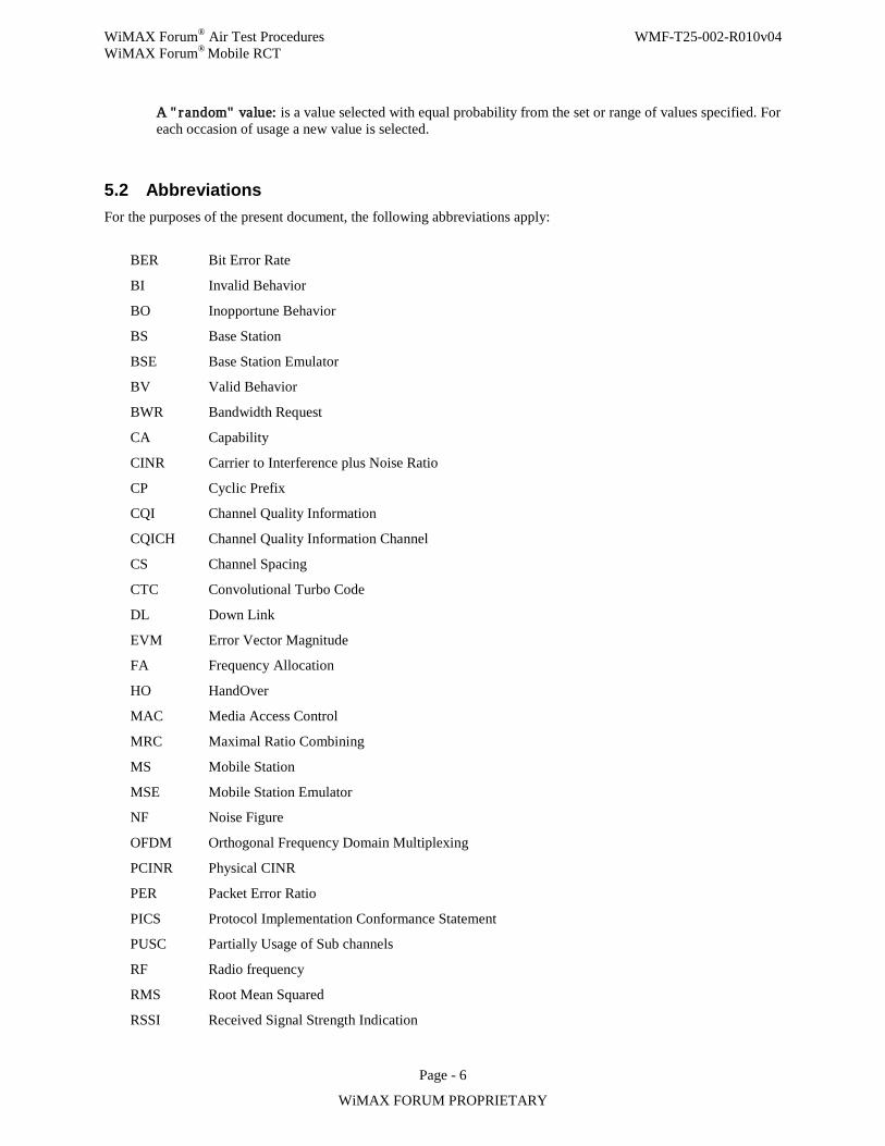
WiMAX Forum® Air Test Procedures WMF-T25-002-R010v04 WiMAX Forum® Mobile RCT
Page - 6
WiMAX FORUM PROPRIETARY
A " random" value: is a value selected with equal probability from the set or range of values specified. For each occasion of usage a new value is selected.
5.2 Abbreviations For the purposes of the present document, the following abbreviations apply:
BER Bit Error Rate
BI Invalid Behavior
BO Inopportune Behavior
BS Base Station
BSE Base Station Emulator
BV Valid Behavior
BWR Bandwidth Request
CA Capability
CINR Carrier to Interference plus Noise Ratio
CP Cyclic Prefix
CQI Channel Quality Information
CQICH Channel Quality Information Channel
CS Channel Spacing
CTC Convolutional Turbo Code
DL Down Link
EVM Error Vector Magnitude
FA Frequency Allocation
HO HandOver
MAC Media Access Control
MRC Maximal Ratio Combining
MS Mobile Station
MSE Mobile Station Emulator
NF Noise Figure
OFDM Orthogonal Frequency Domain Multiplexing
PCINR Physical CINR
PER Packet Error Ratio
PICS Protocol Implementation Conformance Statement
PUSC Partially Usage of Sub channels
RF Radio frequency
RMS Root Mean Squared
RSSI Received Signal Strength Indication
WiMAX Forum® Air Test Procedures WMF-T25-002-R010v04 WiMAX Forum® Mobile RCT
Page - 7
WiMAX FORUM PROPRIETARY
RTD Round Trip Delay
TLV Type Length Value
TP Test Purpose
TSS Test Suite Structure
UL Up Link
UUT Unit Under Test
VSA Vector Signal Analyzer
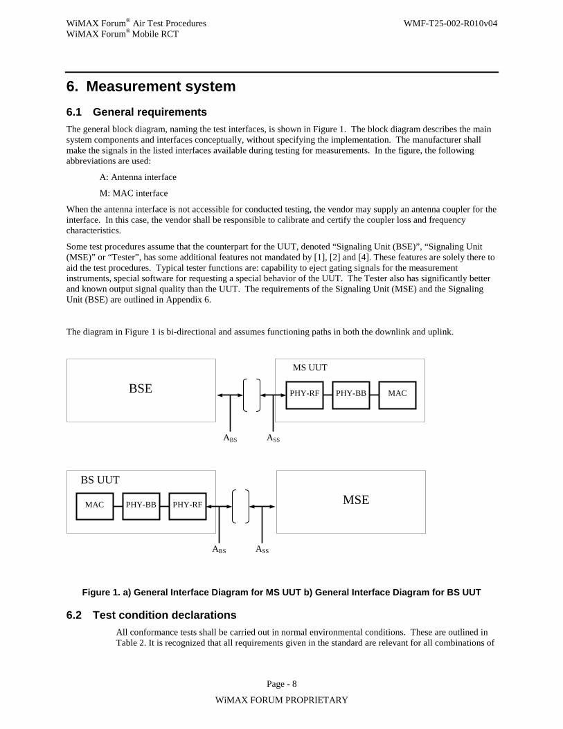
WiMAX Forum® Air Test Procedures WMF-T25-002-R010v04 WiMAX Forum® Mobile RCT
Page - 8
WiMAX FORUM PROPRIETARY
6. Measurement system 6.1 General requirements The general block diagram, naming the test interfaces, is shown in Figure 1. The block diagram describes the main system components and interfaces conceptually, without specifying the implementation. The manufacturer shall make the signals in the listed interfaces available during testing for measurements. In the figure, the following abbreviations are used:
A: Antenna interface
M: MAC interface
When the antenna interface is not accessible for conducted testing, the vendor may supply an antenna coupler for the interface. In this case, the vendor shall be responsible to calibrate and certify the coupler loss and frequency characteristics.
Some test procedures assume that the counterpart for the UUT, denoted “Signaling Unit (BSE)”, “Signaling Unit (MSE)” or “Tester”, has some additional features not mandated by [1], [2] and [4]. These features are solely there to aid the test procedures. Typical tester functions are: capability to eject gating signals for the measurement instruments, special software for requesting a special behavior of the UUT. The Tester also has significantly better and known output signal quality than the UUT. The requirements of the Signaling Unit (MSE) and the Signaling Unit (BSE) are outlined in Appendix 6.
The diagram in Figure 1 is bi-directional and assumes functioning paths in both the downlink and uplink.
Figure 1. a) General Interface Diagram for MS UUT b) General Interface Diagram for BS UUT
6.2 Test condition declarations All conformance tests shall be carried out in normal environmental conditions. These are outlined in Table 2. It is recognized that all requirements given in the standard are relevant for all combinations of
MSE MAC PHY-BB PHY-RF BS UUT
ABS ASS
PHY-RF PHY-BB MAC MS UUT
BSE
ABS ASS
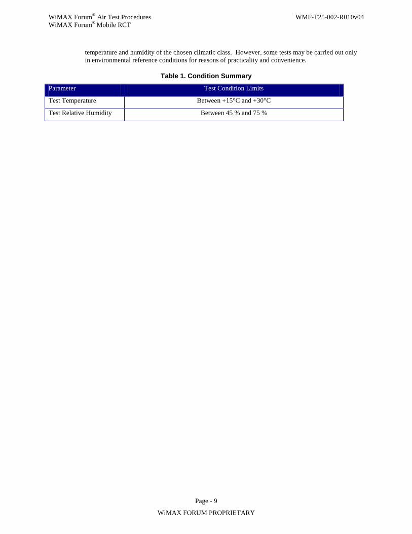
WiMAX Forum® Air Test Procedures WMF-T25-002-R010v04 WiMAX Forum® Mobile RCT
Page - 9
WiMAX FORUM PROPRIETARY
temperature and humidity of the chosen climatic class. However, some tests may be carried out only in environmental reference conditions for reasons of practicality and convenience.
Table 1. Condition Summary
Parameter Test Condition Limits
Test Temperature Between +15°C and +30°C
Test Relative Humidity Between 45 % and 75 %
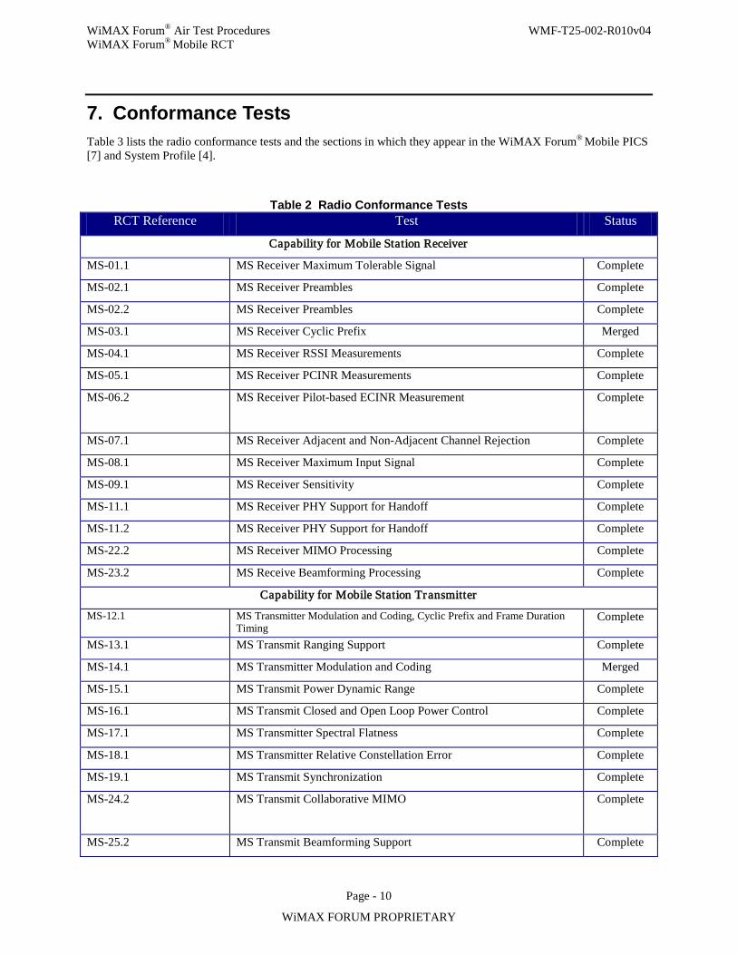
WiMAX Forum® Air Test Procedures WMF-T25-002-R010v04 WiMAX Forum® Mobile RCT
Page - 10
WiMAX FORUM PROPRIETARY
7. Conformance Tests Table 3 lists the radio conformance tests and the sections in which they appear in the WiMAX Forum® Mobile PICS [7] and System Profile [4].
Table 2 Radio Conformance Tests RCT Reference Test Status
Capability for Mobile Station Receiver
MS-01.1 MS Receiver Maximum Tolerable Signal Complete
MS-02.1 MS Receiver Preambles Complete
MS-02.2 MS Receiver Preambles Complete
MS-03.1 MS Receiver Cyclic Prefix Merged
MS-04.1 MS Receiver RSSI Measurements Complete
MS-05.1 MS Receiver PCINR Measurements Complete
MS-06.2 MS Receiver Pilot-based ECINR Measurement Complete
MS-07.1 MS Receiver Adjacent and Non-Adjacent Channel Rejection Complete
MS-08.1 MS Receiver Maximum Input Signal Complete
MS-09.1 MS Receiver Sensitivity Complete
MS-11.1 MS Receiver PHY Support for Handoff Complete
MS-11.2 MS Receiver PHY Support for Handoff Complete
MS-22.2 MS Receiver MIMO Processing Complete
MS-23.2 MS Receive Beamforming Processing Complete
Capability for Mobile Station Transmitter
MS-12.1 MS Transmitter Modulation and Coding, Cyclic Prefix and Frame Duration Timing
Complete
MS-13.1 MS Transmit Ranging Support Complete
MS-14.1 MS Transmitter Modulation and Coding Merged
MS-15.1 MS Transmit Power Dynamic Range Complete
MS-16.1 MS Transmit Closed and Open Loop Power Control Complete
MS-17.1 MS Transmitter Spectral Flatness Complete
MS-18.1 MS Transmitter Relative Constellation Error Complete
MS-19.1 MS Transmit Synchronization Complete
MS-24.2 MS Transmit Collaborative MIMO Complete
MS-25.2 MS Transmit Beamforming Support Complete
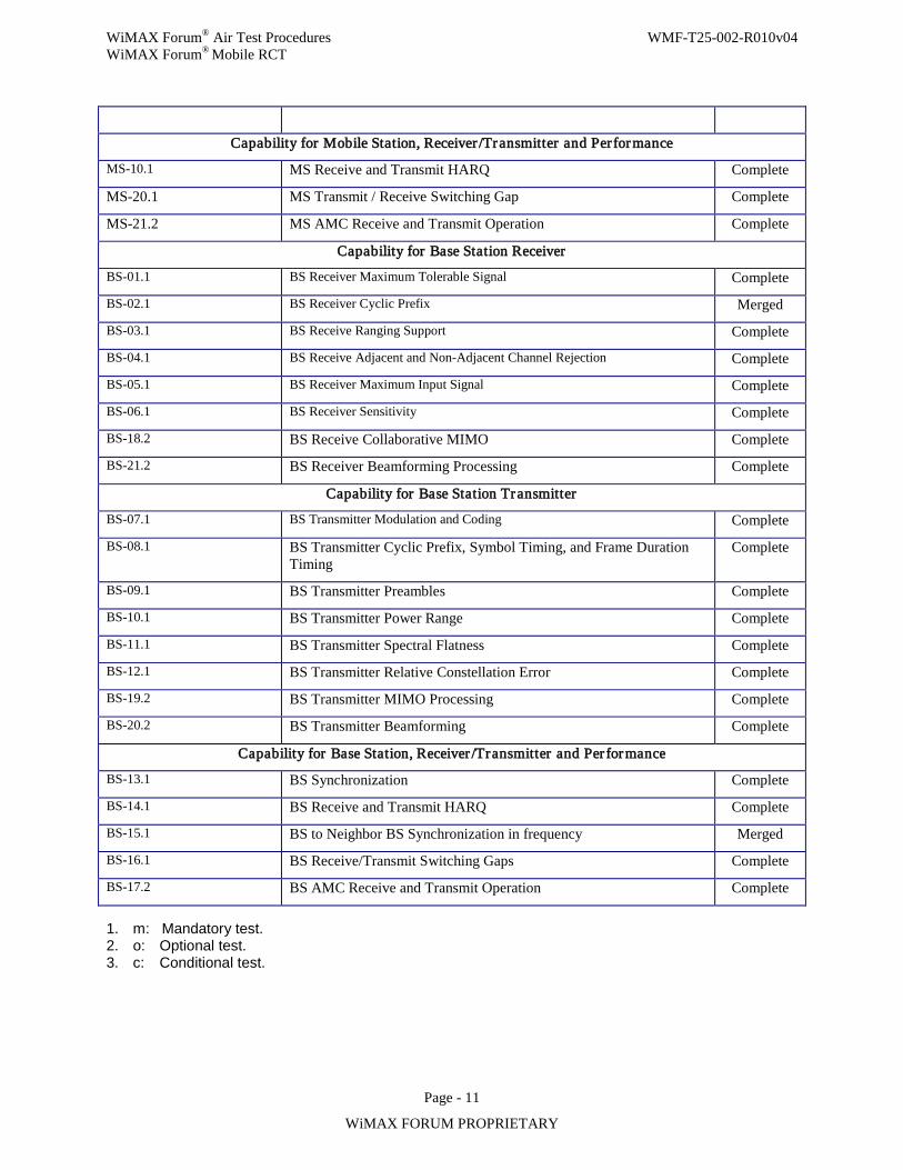
WiMAX Forum® Air Test Procedures WMF-T25-002-R010v04 WiMAX Forum® Mobile RCT
Page - 11
WiMAX FORUM PROPRIETARY
Capability for Mobile Station, Receiver /Transmitter and Per for mance
MS-10.1 MS Receive and Transmit HARQ Complete
MS-20.1 MS Transmit / Receive Switching Gap Complete
MS-21.2 MS AMC Receive and Transmit Operation Complete
Capability for Base Station Receiver
BS-01.1 BS Receiver Maximum Tolerable Signal Complete
BS-02.1 BS Receiver Cyclic Prefix Merged
BS-03.1 BS Receive Ranging Support Complete
BS-04.1 BS Receive Adjacent and Non-Adjacent Channel Rejection Complete
BS-05.1 BS Receiver Maximum Input Signal Complete
BS-06.1 BS Receiver Sensitivity Complete
BS-18.2 BS Receive Collaborative MIMO Complete
BS-21.2 BS Receiver Beamforming Processing Complete
Capability for Base Station Transmitter
BS-07.1 BS Transmitter Modulation and Coding Complete
BS-08.1 BS Transmitter Cyclic Prefix, Symbol Timing, and Frame Duration Timing
Complete
BS-09.1 BS Transmitter Preambles Complete
BS-10.1 BS Transmitter Power Range Complete
BS-11.1 BS Transmitter Spectral Flatness Complete
BS-12.1 BS Transmitter Relative Constellation Error Complete
BS-19.2 BS Transmitter MIMO Processing Complete
BS-20.2 BS Transmitter Beamforming Complete
Capability for Base Station, Receiver /Transmitter and Per formance
BS-13.1 BS Synchronization Complete
BS-14.1 BS Receive and Transmit HARQ Complete
BS-15.1 BS to Neighbor BS Synchronization in frequency Merged
BS-16.1 BS Receive/Transmit Switching Gaps Complete
BS-17.2 BS AMC Receive and Transmit Operation Complete
1. m: Mandatory test. 2. o: Optional test. 3. c: Conditional test.
WiMAX Forum® Air Test Procedures WMF-T25-002-R010v04 WiMAX Forum® Mobile RCT
Page - 12
WiMAX FORUM PROPRIETARY
8. Test Procedures
8.1 General statement for all tests
1. Test procedures are provided below for all mandatory tests. 2. In any test the losses for all RF elements will be considered and compensated for. This procedure will be
called setup calibration. 3. If used, the Packet Generator is configured accordingly to the message(s) sent, the type of modulation used
and the data packet rate specified in the test procedure. 4. The measurement uncertainty for all RF level based measurements should be added to the tolerance for
absolute power measurements. 5. With the exception of the tests that test the ranging parameter, initial ranging should be completed, prior to
a measurement being recorded. 6. The meaning of the words "receives data correctly", as stated in the test procedures, is defined in Appendix
3. 7. In the case that PER measurements is required in a test, the following guidelines shall be followed.
• For Wave 1 certification, either Ping or ACK/NACK based methods (Refer to Appendix 3) can be used based on vendor declaration. For Wave 2 certification, PER measurement shall be performed based on ACK/NACK method.
Where there is a measurement uncertainty, this shall be declared by the test facility and be traceable. The tests for which a measurement uncertainty is applicable shall have it stated in the test setup description of the test.
In order to perform this test, the UUT has to provide the necessary configuration interface to the Test Facility in order to:
1. Modify the modulation and coding rates 2. Modify UL MAP and DL MAP as needed for the corresponding tests 3. Modify any applicable HARQ parameter as needed by corresponding tests. Examples are: UCD TLV,
ACIDs scheduling, maximum number of retransmissions etc. 4. Configure the preambles on the BS UUT. 5. Modify and set ID_cell and Perm_Base.
The equipment vendor shall be responsible for providing the necessary Man to Machine Interface (MMI) to the Test Facility in order for the tests to be carried on.
[Test Lab to provide recommendation (based on their knowledge of test equipment capabilities) on uncertainty requirements for various tests some time before Wave 1 certifications so that TWG can revisit the related contents in the RCT doc.]
8.2 General statement for all test setups 1. Test setup for each test is abstract representation to execute test procedures described in each section
accordingly.
WiMAX Forum® Air Test Procedures WMF-T25-002-R010v04 WiMAX Forum® Mobile RCT
Page - 13
WiMAX FORUM PROPRIETARY
2. Test lab’s detailing of test setup can be done to make sure that the test setup supports feasible execution, provided that they are consistent with overall test procedures and measurement accuracy requirements described in each test.
3. If any item in each test setup is not needed for a specific test case, then it will not be used.
WiMAX Forum® Air Test Procedures WMF-T25-002-R010v04 WiMAX Forum® Mobile RCT
Page - 14
WiMAX FORUM PROPRIETARY
9. Test for Mobile Station 9.1 Test procedures A test code of format XX-nn.m is assigned to all tests where XX is either MS for Mobile Station or Bs for Base Station, nn is a number assigned to the test and m is 1 for Wave 1 tests and 2 for Wave 2 tests.
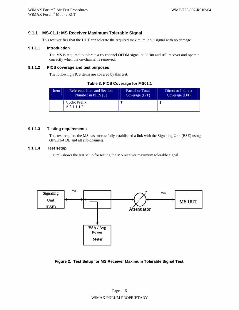
WiMAX Forum® Air Test Procedures WMF-T25-002-R010v04 WiMAX Forum® Mobile RCT
Page - 15
WiMAX FORUM PROPRIETARY
9.1.1 MS-01.1: MS Receiver Maximum Tolerable Signal This test verifies that the UUT can tolerate the required maximum input signal with no damage.
9.1.1.1 Introduction
The MS is required to tolerate a co-channel OFDM signal at 0dBm and still recover and operate correctly when the co-channel is removed.
9.1.1.2 PICS coverage and test purposes
The following PICS items are covered by this test.
Table 3. PICS Coverage for MS01.1
Item Reference Item and Section Number in PICS [6]
Partial or Total Coverage (P/T)
Direct or Indirect Coverage (D/I)
1 Cyclic Prefix A.5.1.1.1.2
T I
9.1.1.3 Testing requirements
This test requires the MS has successfully established a link with the Signaling Unit (BSE) using QPSK3/4 DL and all sub-channels.
9.1.1.4 Test setup
Figure 2shows the test setup for testing the MS receiver maximum tolerable signal.
Figure 2. Test Setup for MS Receiver Maximum Tolerable Signal Test.
Signaling
Unit
(BSE)
VSA / Avg Power
Meter
MS UUT
ABS
Attenuator
AMS
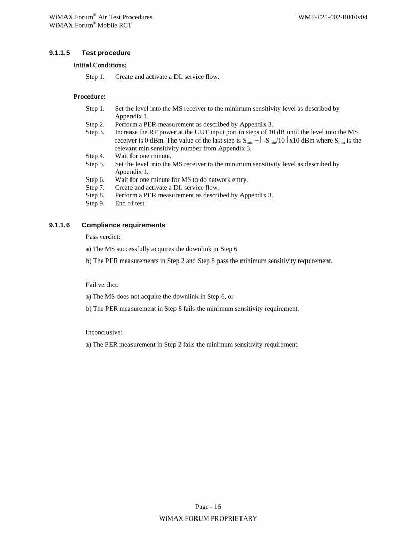
WiMAX Forum® Air Test Procedures WMF-T25-002-R010v04 WiMAX Forum® Mobile RCT
Page - 16
WiMAX FORUM PROPRIETARY
9.1.1.5 Test procedure
Initial Conditions:
Step 1. Create and activate a DL service flow.
Procedure:
Step 1. Set the level into the MS receiver to the minimum sensitivity level as described by Appendix 1.
Step 2. Perform a PER measurement as described by Appendix 3. Step 3. Increase the RF power at the UUT input port in steps of 10 dB until the level into the MS
receiver is 0 dBm. The value of the last step is Smin + -Smin/10 x10 dBm where Smin is the relevant min sensitivity number from Appendix 3.
Step 4. Wait for one minute. Step 5. Set the level into the MS receiver to the minimum sensitivity level as described by
Appendix 1. Step 6. Wait for one minute for MS to do network entry. Step 7. Create and activate a DL service flow. Step 8. Perform a PER measurement as described by Appendix 3. Step 9. End of test.
9.1.1.6 Compliance requirements
Pass verdict:
a) The MS successfully acquires the downlink in Step 6
b) The PER measurements in Step 2 and Step 8 pass the minimum sensitivity requirement.
Fail verdict:
a) The MS does not acquire the downlink in Step 6, or
b) The PER measurement in Step 8 fails the minimum sensitivity requirement.
Inconclusive:
a) The PER measurement in Step 2 fails the minimum sensitivity requirement.
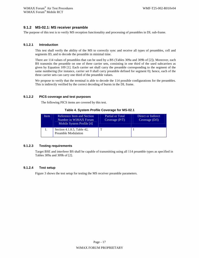
WiMAX Forum® Air Test Procedures WMF-T25-002-R010v04 WiMAX Forum® Mobile RCT
Page - 17
WiMAX FORUM PROPRIETARY
9.1.2 MS-02.1: MS receiver preamble The purpose of this test is to verify MS reception functionality and processing of preambles in DL sub-frame.
9.1.2.1 Introduction
This test shall verify the ability of the MS to correctly sync and receive all types of preambles, cell and segments ID, and to decode the preamble in minimal time.
There are 114 values of preambles that can be used by a BS (Tables 309a and 309b of [2]). Moreover, each BS transmits the preamble on one of three carrier sets, consisting in one third of the used subcarriers as given by Equation 109 [1]. Each carrier set shall carry the preamble corresponding to the segment of the same numbering (for instance, carrier set 0 shall carry preamble defined for segment 0); hence, each of the three carrier sets can carry one third of the preamble values.
We propose to verify that the terminal is able to decode the 114 possible configurations for the preambles. This is indirectly verified by the correct decoding of bursts in the DL frame.
9.1.2.2 PICS coverage and test purposes
The following PICS items are covered by this test.
Table 4. System Profile Coverage for MS-02.1
Item Reference Item and Section Number in WiMAX Forum Mobile System Profile [4]
Partial or Total Coverage (P/T)
Direct or Indirect Coverage (D/I)
1. Section 4.1.8.5, Table 42, Preamble Modulation
T I
9.1.2.3 Testing requirements
Target BSE and interferer BS shall be capable of transmitting using all 114 preamble types as specified in Tables 309a and 309b of [2].
9.1.2.4 Test setup Figure 3 shows the test setup for testing the MS receiver preamble parameters.
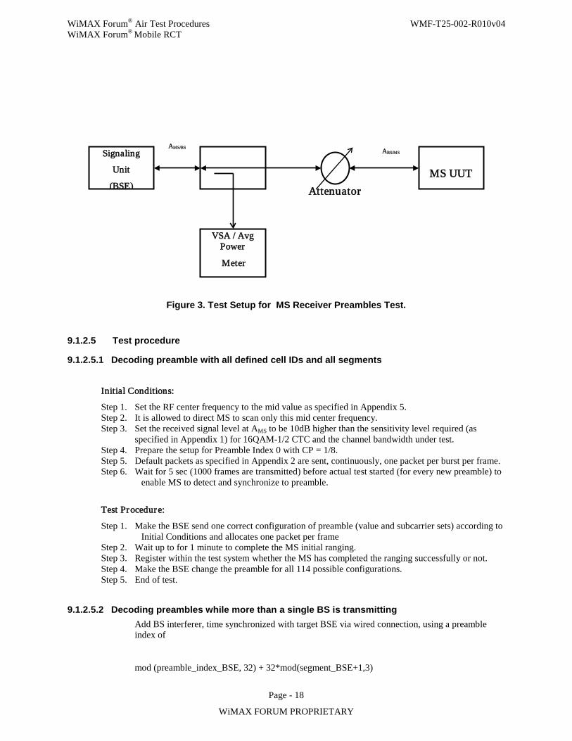
WiMAX Forum® Air Test Procedures WMF-T25-002-R010v04 WiMAX Forum® Mobile RCT
Page - 18
WiMAX FORUM PROPRIETARY
Figure 3. Test Setup for MS Receiver Preambles Test.
9.1.2.5 Test procedure
9.1.2.5.1 Decoding preamble with all defined cell IDs and all segments
Initial Conditions:
Step 1. Set the RF center frequency to the mid value as specified in Appendix 5. Step 2. It is allowed to direct MS to scan only this mid center frequency. Step 3. Set the received signal level at AMS to be 10dB higher than the sensitivity level required (as
specified in Appendix 1) for 16QAM-1/2 CTC and the channel bandwidth under test. Step 4. Prepare the setup for Preamble Index 0 with CP = 1/8. Step 5. Default packets as specified in Appendix 2 are sent, continuously, one packet per burst per frame. Step 6. Wait for 5 sec (1000 frames are transmitted) before actual test started (for every new preamble) to
enable MS to detect and synchronize to preamble.
Test Procedure:
Step 1. Make the BSE send one correct configuration of preamble (value and subcarrier sets) according to Initial Conditions and allocates one packet per frame
Step 2. Wait up to for 1 minute to complete the MS initial ranging. Step 3. Register within the test system whether the MS has completed the ranging successfully or not. Step 4. Make the BSE change the preamble for all 114 possible configurations. Step 5. End of test.
9.1.2.5.2 Decoding preambles while more than a single BS is transmitting Add BS interferer, time synchronized with target BSE via wired connection, using a preamble index of
mod (preamble_index_BSE, 32) + 32*mod(segment_BSE+1,3)
Signaling
Unit
(BSE)
VSA / Avg Power
Meter
MS UUT
AMS/BS
Attenuator
ABS/MS
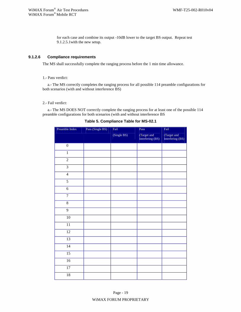
WiMAX Forum® Air Test Procedures WMF-T25-002-R010v04 WiMAX Forum® Mobile RCT
Page - 19
WiMAX FORUM PROPRIETARY
for each case and combine its output -10dB lower to the target BS output. Repeat test 9.1.2.5.1with the new setup.
9.1.2.6 Compliance requirements
The MS shall successfully complete the ranging process before the 1 min time allowance.
1.- Pass verdict:
a.- The MS correctly completes the ranging process for all possible 114 preamble configurations for both scenarios (with and without interference BS)
2.- Fail verdict:
a.- The MS DOES NOT correctly complete the ranging process for at least one of the possible 114 preamble configurations for both scenarios (with and without interference BS
Table 5. Compliance Table for MS-02.1
Preamble Index Pass (Single BS) Fail
(Single BS)
Pass
(Target and Interfering (BS)
Fail
(Target and Interfering (BS)
0
1
2
3
4
5
6
7
8
9
10
11
12
13
14
15
16
17
18

WiMAX Forum® Air Test Procedures WMF-T25-002-R010v04 WiMAX Forum® Mobile RCT
Page - 20
WiMAX FORUM PROPRIETARY
19
20
21
22
23
24
25
26
27
28
29
30
31
32
33
34
35
36
37
38
39
40
41
42
43
44
45
46
47
48
49
50
51
52
53

WiMAX Forum® Air Test Procedures WMF-T25-002-R010v04 WiMAX Forum® Mobile RCT
Page - 21
WiMAX FORUM PROPRIETARY
54
55
56
57
58
59
60
61
62
63
64
65
66
67
68
69
70
71
72
73
74
75
76
77
78
79
80
81
82
83
84
85
86
87
88
WiMAX Forum® Air Test Procedures WMF-T25-002-R010v04 WiMAX Forum® Mobile RCT
Page - 22
WiMAX FORUM PROPRIETARY
89
90
91
92
93
94
95
96
97
98
99
100
101
102
103
104
105
106
107
108
109
110
111
112
113
9.1.2.7 Uncertainties
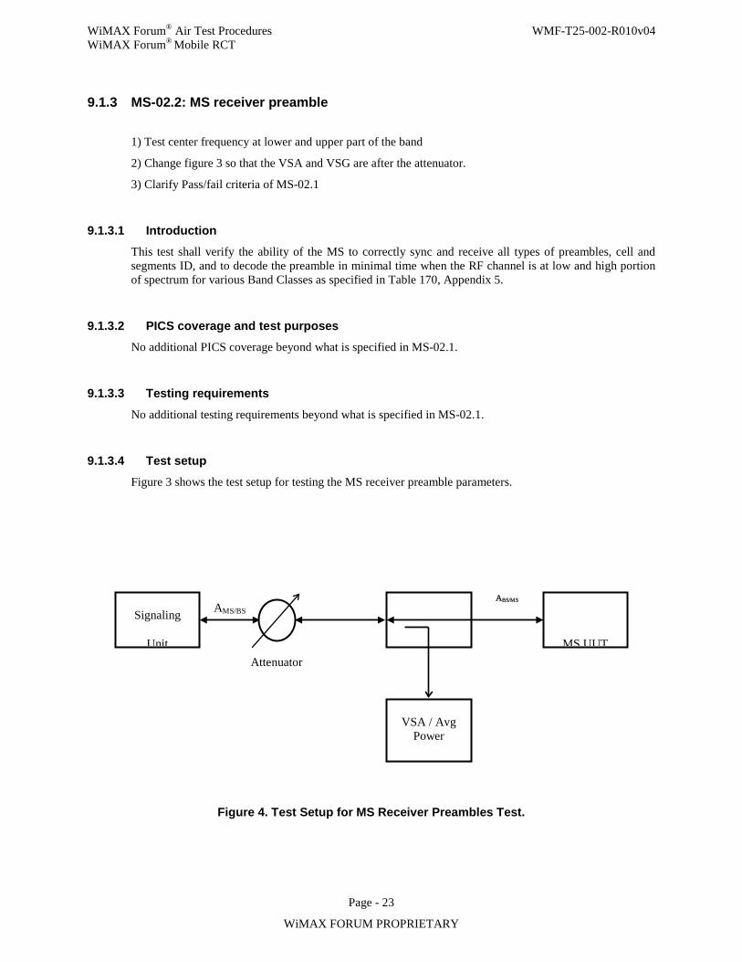
WiMAX Forum® Air Test Procedures WMF-T25-002-R010v04 WiMAX Forum® Mobile RCT
Page - 23
WiMAX FORUM PROPRIETARY
9.1.3 MS-02.2: MS receiver preamble
1) Test center frequency at lower and upper part of the band
2) Change figure 3 so that the VSA and VSG are after the attenuator.
3) Clarify Pass/fail criteria of MS-02.1
9.1.3.1 Introduction This test shall verify the ability of the MS to correctly sync and receive all types of preambles, cell and segments ID, and to decode the preamble in minimal time when the RF channel is at low and high portion of spectrum for various Band Classes as specified in Table 170, Appendix 5.
9.1.3.2 PICS coverage and test purposes No additional PICS coverage beyond what is specified in MS-02.1.
9.1.3.3 Testing requirements
No additional testing requirements beyond what is specified in MS-02.1.
9.1.3.4 Test setup Figure 3 shows the test setup for testing the MS receiver preamble parameters.
Figure 4. Test Setup for MS Receiver Preambles Test.
Signaling
Unit
MS UUT AMS/BS
Attenuator
VSA / Avg Power
ABS/MS
WiMAX Forum® Air Test Procedures WMF-T25-002-R010v04 WiMAX Forum® Mobile RCT
Page - 24
WiMAX FORUM PROPRIETARY
9.1.3.5 Test procedure
9.1.3.5.1 Decoding preamble with all defined cell IDs and all segments Repeat tests of Section 9.1.2.5.1 by modifying initial conditions to attain low and high values of RF center frequencies as specified in Appendix 5.
9.1.3.5.2 Decoding preambles while more than a single BS is transmitting Repeat tests of Section 9.1.2.5.2 by modifying initial conditions to attain low and high values of RF center frequencies as specified in Appendix 5.
9.1.3.6 Compliance requirements
The MS shall successfully complete the ranging process before the 1 min time allowance.
1.- Pass verdict:
a.- The MS correctly completes the register request process for all possible 114 preamble configurations for both scenarios (with and without interference BS). This means that BSE successfully receives REG-REQ message from MS UUT.
2.- Fail verdict:
a.- The MS DOES NOT correctly complete the register request process for at least one of the possible 114 preamble configurations for both scenarios (with and without interference BS). This means that BSE does not receive REG-REQ message from MS UUT.
9.1.3.7 Uncertainties No additional Uncertainties beyond what is specified in MS-02.1.
9.1.4 MS-03.1: Reserved
WiMAX Forum® Air Test Procedures WMF-T25-002-R010v04 WiMAX Forum® Mobile RCT
Page - 25
WiMAX FORUM PROPRIETARY
9.1.5 MS-04.1: MS receiver RSSI measurements The purpose of this test is to verify that the MS receiver, when requested by the BS to report the RSSI measurement, can meet the accuracy requirement defined in IEEE Std 802.16-2004, IEEE Std 802.16e-2005, and the Mobile System Profile. Such a requirement is expected to be satisfied for the entire RSSI range and under typical channel/interference conditions.
9.1.5.1 Introduction A BS could request the RSSI measurement from a MS via REP-REQ and the MS shall report it via REP-RSP. In the REP-RSP message, the RSSI report shall follow the TLV encoding format with a type value of 1.6 and a length of 2 bytes (one byte for the mean and one for standard deviation).
Section 8.4.11.2 (“RSSI mean and standard deviation”) of IEEE Std 802.16e-2005 specifies the quantization rule if RSSI is reported via REP-RSP messages:
“Mean and standard deviation statistics shall be reported in units of dBm and dB, respectively. To prepare such reports, statistics shall be quantized in 1 dB increments, ranging from –40 dBm (encoded 0x53) to –123 dBm (encoded 0x00). Values outside this range shall be assigned the closest extreme value within the scale.”
“The message time index is incremented every frame. The reported RSSI value shall be an estimate of the total received power of the frame preamble of the segment of the connected BS
.””
Section 8.4.11.2 of IEEE Std 802.16-2004 further states:
“The method used to estimate the RSSI of a single message is left to individual implementation, but the relative accuracy of a single signal measurement, taken from a single message, shall be + /- 2dB, with an absolute accuracy of + /-4dB. This shall be the case over the entire range of input RSSIs.”
Also during handover related RSSI reporting, a BS may request a scan report including RSSI measurement from a MS via MOB_SCN-RSP, and the MS shall transmit a MOB_SCN-REP message constructed according to the requests indicated in the MOB_SCN-RSP. A different range and quantization are specified in Section 6.3.2.3.50 (“Scanning Result Report (MOB_SCN-REP) message”) and 6.3.2.3.53 (“MS HO Request (MOB_MSHO-REQ) message”) of IEEE Std 802.16e-2005:
“The BS RSSI mean parameter indicates the Received Signal Strength measured by the MS from the particular BS. The value shall be interpreted as an unsigned byte with units of 0.25 dB, such that 0x00 is interpreted as –103.75 dBm, an MS shall be able to report values in the range –103.75 dBm to –40 dBm. The measurement shall be performed on the frame preamble and averaged over the measurement period
.”
The RSSI measurement in both cases should be the received power from only the particular BS that transmits its preamble from its associated segment.
9.1.5.2 PICS coverage and test purposes
The following PICS items are covered by this test.
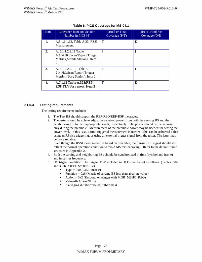
WiMAX Forum® Air Test Procedures WMF-T25-002-R010v04 WiMAX Forum® Mobile RCT
Page - 26
WiMAX FORUM PROPRIETARY
Table 6. PICS Coverage for MS-04.1
Item Reference Item and Section Number in PICS [6]
Partial or Total Coverage (P/T)
Direct or Indirect Coverage (D/I)
1. A.5.1.1.1.13, Table A.33: RSSI Measurement
T D
2. A. 5.1.1.2.2.11 Table A.104:HO/Scan/Report Trigger Metrics(Mobile Station), Item 2
P I
3. A. 5.1.2.2.2.10. Table A. 214:HO/Scan/Report Trigger Metrics (Base Station), Item 2
P I
4. A.7.1.12 Table A.328:REP-RSP TLV for repor t, Item 2
T D
9.1.5.3 Testing requirements
The testing requirements include:
1. The Test BS should support the REP-REQ/REP-RSP messages. 2. The tester should be able to adjust the received power from both the serving BS and the
neighboring BS to their appropriate levels, respectively. The power should be the average only during the preamble. Measurement of the preamble power may be needed for setting the power level. In this case, a time triggered measurement is needed. This can be achieved either using an RF rise triggering, or using an external trigger signal from the tester. The latter may be more reliable.
3. Even though the RSSI measurement is based on preamble, the transmit BS signal should still reflect the normal operation condition to avoid MS mis-behaving. Refer to the default frame structure in Appendix 2.
4. Both the serving and neighboring BSs should be synchronized in time (symbol and frame) and in carrier frequency.
5. HO trigger condition: The Trigger TLV included in DCD shall be set as follows. (Tables 358a and 358b in IEEE Std 802.16e)
Type = 0x0 (CINR metric) Function = 0x6 (Metric of serving BS less than absolute value) Action = 0x2 (Respond on trigger with MOB_MSHO_REQ) Value=0xA8 (=-20dB) Averaging duration=0x10 (=16frames)
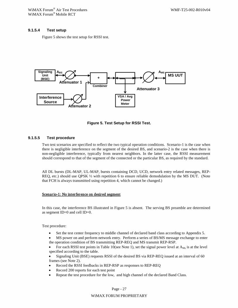
WiMAX Forum® Air Test Procedures WMF-T25-002-R010v04 WiMAX Forum® Mobile RCT
Page - 27
WiMAX FORUM PROPRIETARY
9.1.5.4 Test setup
Figure 5 shows the test setup for RSSI test.
Attenuator 2
Signaling Unit
(BSE)
VSA / Avg Power Meter
MS UUT ABS
Attenuator 1
AMS
+
Interference Source
Combiner Attenuator 3
Figure 5. Test Setup for RSSI Test.
9.1.5.5 Test procedure Two test scenarios are specified to reflect the two typical operation conditions. Scenario-1 is the case when there is negligible interference on the segment of the desired BS, and scenario-2 is the case when there is non-negligible interference, typically from nearest neighbors. In the latter case, the RSSI measurement should correspond to that of the segment of the connected or the particular BS, as required by the standard.
All DL bursts (DL-MAP, UL-MAP, bursts containing DCD, UCD, network entry related messages, REP-REQ, etc.) should use QPSK ½ with repetition 6 to ensure reliable demodulation by the MS DUT. (Note that FCH is always transmitted using repetition 4, which cannot be changed.)
Scenar io-1: No inter ference on desired segment
In this case, the interference BS illustrated in Figure 5 is absent. The serving BS preamble are determined as segment ID=0 and cell ID=0.
Test procedure:
• Set the test center frequency to middle channel of declared band class according to Appendix 5. • MS power on and perform network entry. Perform a series of BS/MS message exchange to enter the operation condition of BS transmitting REP-REQ and MS transmit REP-RSP. • For each RSSI test points in Table 10(see Note 1), set the signal power level at AMs is at the level specified according to the table. • Signaling Unit (BSE) requests RSSI of the desired BS via REP-REQ issued at an interval of 60 frames (see Note 2). • Record the RSSI feedbacks in REP-RSP as responses to REP-REQ • Record 200 reports for each test point • Repeat the test procedure for the low, and high channel of the declared Band Class.
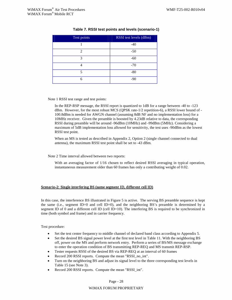
WiMAX Forum® Air Test Procedures WMF-T25-002-R010v04 WiMAX Forum® Mobile RCT
Page - 28
WiMAX FORUM PROPRIETARY
Table 7. RSSI test points and levels (scenario-1)
Test points RSSI test levels (dBm)
1 -40
2 -50
3 -60
4 -70
5 -80
6 -90
Note 1 RSSI test range and test points:
In the REP-RSP message, the RSSI report is quantized to 1dB for a range between -40 to -123 dBm. However, for the most robust MCS (QPSK rate-1/2 repetition-6), a RSSI lower bound of -100.8dBm is needed for AWGN channel (assuming 8dB NF and no implementation loss) for a 10MHz receiver. Given the preamble is boosted by 4.23dB relative to data, the corresponding RSSI during preamble will be around -96dBm (10MHz) and -99dBm (5MHz). Considering a maximum of 5dB implementation loss allowed for sensitivity, the test uses -90dBm as the lowest RSSI test point.
When an MS is tested as described in Appendix 2, Option 2 (single channel connected to dual antenna), the maximum RSSI test point shall be set to -43 dBm.
Note 2 Time interval allowed between two reports:
With an averaging factor of 1/16 chosen to reflect desired RSSI averaging in typical operation, instantaneous measurement older than 60 frames has only a contributing weight of 0.02.
Scenar io-2: Single inter fer ing BS (same segment ID, different cell ID)
In this case, the interference BS illustrated in Figure 5 is active. The serving BS preamble sequence is kept the same (i.e., segment ID=0 and cell ID=0), and the neighboring BS’s preamble is determined by a segment ID of 0 and a different cell ID (cell ID=10). The interfering BS is required to be synchronized in time (both symbol and frame) and in carrier frequency.
Test procedure:
• Set the test center frequency to middle channel of declared band class according to Appendix 5. • Set the desired BS signal power level at the first test level in Table 11. With the neighboring BS
off, power on the MS and perform network entry. Perform a series of BS/MS message exchange to enter the operation condition of BS transmitting REP-REQ and MS transmit REP-RSP.
• Tester requests RSSI of the desired BS via REP-REQ at an interval of 60 frames • Record 200 RSSI reports. Compute the mean "RSSI_no_int". • Turn on the neighboring BS and adjust its signal level to the three corresponding test levels in
Table 15 (see Note 3). • Record 200 RSSI reports. Compute the mean "RSSI_int".
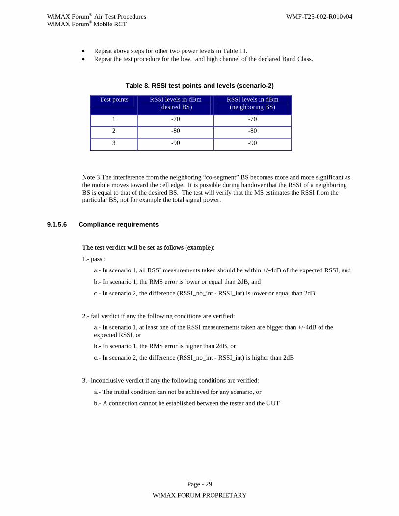
WiMAX Forum® Air Test Procedures WMF-T25-002-R010v04 WiMAX Forum® Mobile RCT
Page - 29
WiMAX FORUM PROPRIETARY
• Repeat above steps for other two power levels in Table 11. • Repeat the test procedure for the low, and high channel of the declared Band Class.
Table 8. RSSI test points and levels (scenario-2)
Test points RSSI levels in dBm (desired BS)
RSSI levels in dBm (neighboring BS)
1 -70 -70
2 -80 -80
3 -90 -90
Note 3 The interference from the neighboring “co-segment” BS becomes more and more significant as the mobile moves toward the cell edge. It is possible during handover that the RSSI of a neighboring BS is equal to that of the desired BS. The test will verify that the MS estimates the RSSI from the particular BS, not for example the total signal power.
9.1.5.6 Compliance requirements
The test verdict will be set as follows (example):
1.- pass :
a.- In scenario 1, all RSSI measurements taken should be within +/-4dB of the expected RSSI, and
b.- In scenario 1, the RMS error is lower or equal than 2dB, and
c.- In scenario 2, the difference (RSSI_no_int - RSSI_int) is lower or equal than 2dB
2.- fail verdict if any the following conditions are verified:
a.- In scenario 1, at least one of the RSSI measurements taken are bigger than +/-4dB of the expected RSSI, or
b.- In scenario 1, the RMS error is higher than 2dB, or
c.- In scenario 2, the difference (RSSI_no_int - RSSI_int) is higher than 2dB
3.- inconclusive verdict if any the following conditions are verified:
a.- The initial condition can not be achieved for any scenario, or
b.- A connection cannot be established between the tester and the UUT
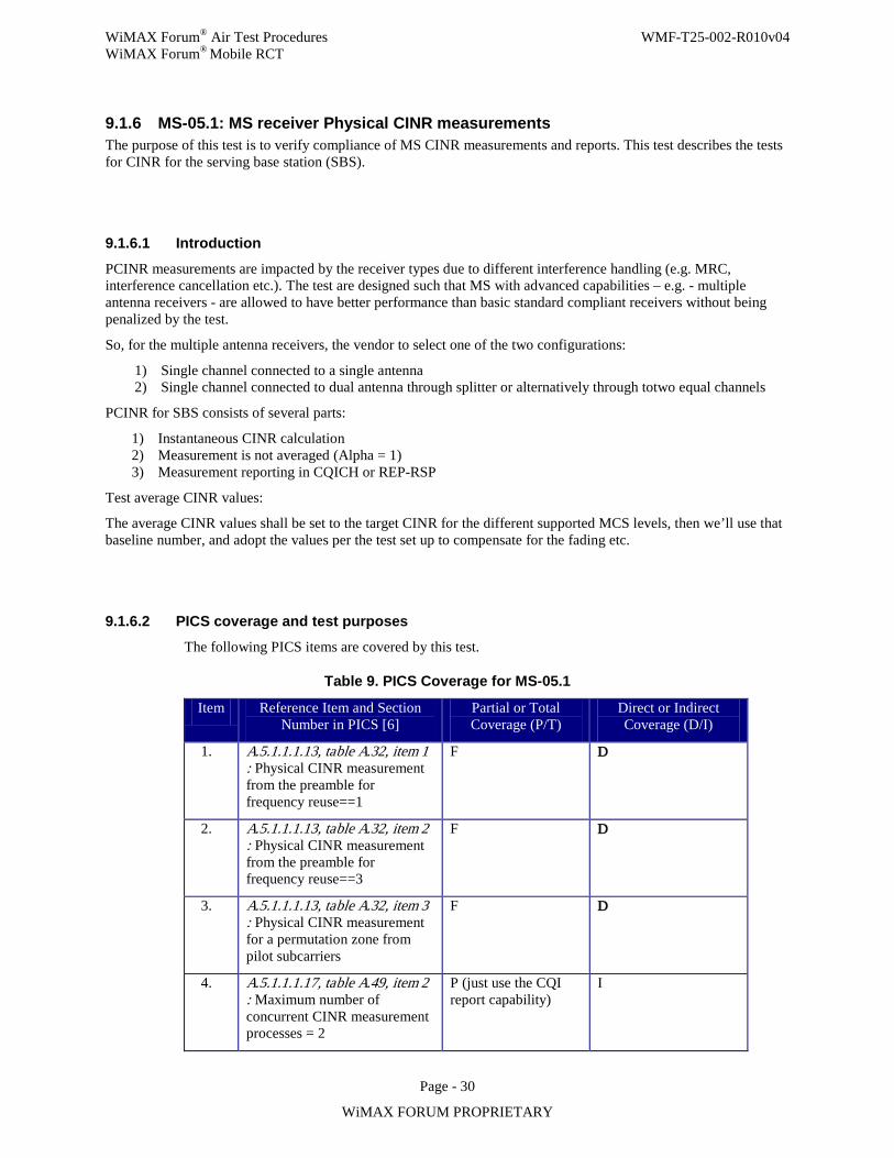
WiMAX Forum® Air Test Procedures WMF-T25-002-R010v04 WiMAX Forum® Mobile RCT
Page - 30
WiMAX FORUM PROPRIETARY
9.1.6 MS-05.1: MS receiver Physical CINR measurements The purpose of this test is to verify compliance of MS CINR measurements and reports. This test describes the tests for CINR for the serving base station (SBS).
9.1.6.1 Introduction
PCINR measurements are impacted by the receiver types due to different interference handling (e.g. MRC, interference cancellation etc.). The test are designed such that MS with advanced capabilities – e.g. - multiple antenna receivers - are allowed to have better performance than basic standard compliant receivers without being penalized by the test.
So, for the multiple antenna receivers, the vendor to select one of the two configurations:
1) Single channel connected to a single antenna 2) Single channel connected to dual antenna through splitter or alternatively through totwo equal channels
PCINR for SBS consists of several parts:
1) Instantaneous CINR calculation 2) Measurement is not averaged (Alpha = 1) 3) Measurement reporting in CQICH or REP-RSP
Test average CINR values:
The average CINR values shall be set to the target CINR for the different supported MCS levels, then we’ll use that baseline number, and adopt the values per the test set up to compensate for the fading etc.
9.1.6.2 PICS coverage and test purposes
The following PICS items are covered by this test.
Table 9. PICS Coverage for MS-05.1
Item Reference Item and Section Number in PICS [6]
Partial or Total Coverage (P/T)
Direct or Indirect Coverage (D/I)
1.
A.5.1.1.1.13, table A.32, item 1 : Physical CINR measurement from the preamble for frequency reuse==1
F D
2. A.5.1.1.1.13, table A.32, item 2 : Physical CINR measurement from the preamble for frequency reuse==3
F D
3. A.5.1.1.1.13, table A.32, item 3 : Physical CINR measurement for a permutation zone from pilot subcarriers
F D
4. A.5.1.1.1.17, table A.49, item 2 : Maximum number of concurrent CINR measurement processes = 2
P (just use the CQI report capability)
I

WiMAX Forum® Air Test Procedures WMF-T25-002-R010v04 WiMAX Forum® Mobile RCT
Page - 31
WiMAX FORUM PROPRIETARY
9.1.6.3 Testing requirements
All of the below tests require the MS to be receiving DL frames and bursts. The DL attenuation should be aligned with the specified noise and interference to generate appropriate CINR appropriate for the supported modulations (QPSK, 16-QAM, 64QAM).
Preamble PCINR: - 1. During the test the BSE shall assign a CQICH allocation with alpha = 1 to the MS and shall transmit
DL traffic to the MS in every frame. 2. Absolute accuracy is defined as D(i) = reported_dB(i) – real_dB(i) per ensemble of measurements for
a given input average CINR 3. Relative accuracy is defined as E(i) = D(i) – mean[D(i)] per ensemble of measurements for a given
input average CINR 4. Pass/Fail criterion recommendations are as follows:
Absolute CINR:
( )min
10101 10 log 10 1 [ ] 1
CINR D
dB QE mean D k dB QE−
− − − ⋅ + ≤ ≤ + +
Relative CINR:
( )Pr(| [ ] [ ] | 1 ) 70%D k mean D k dB QE− ≤ + + ≥
Where QE=0.5dB (quantization error), Dmin=30dB, Pr is empirical probability
5. PCINR accuracy of 1dB accuracy is evaluated over time: The tester collects all the MS measurement reports during the duration of the test then validate that the mean report is within the required range as above for the absolute CINR test and all reports were within 70% confidence for the relative CINR test.
6. The average CINR range is as follows with step 5 dB
Table 10. CINR test ranges
Min Max
Reuse 1 -3dB 23dB
Reuse 3 +2dB 25dB
7. Channel – test is performed for PedB 3km/h and VehA 60km/h respectively. 8. HO trigger condition:
a. The Trigger TLV included in DCD shall be set as follows. (Tables 358a and 358b in IEEE 802.16e)
b. Type = 0x0 (CINR metric) c. Function = 0x6 (Metric of serving BS less than absolute value) d. Action = 0x2 (Respond on trigger with MOB_MSHO_REQ) e. Value=0xA8 (=-20dB) f. Averaging duration=0x10 (=16frames)
Pilot CINR: - 1. to use same accuracy requirements of the preamble CINR.
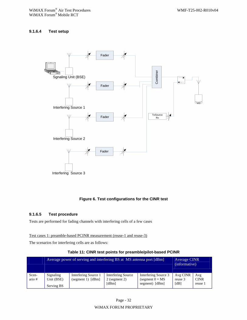
WiMAX Forum® Air Test Procedures WMF-T25-002-R010v04 WiMAX Forum® Mobile RCT
Page - 32
WiMAX FORUM PROPRIETARY
9.1.6.4 Test setup
MS
Com
bine
r
ToSourceRx
Interfering Source 2
Fader
Interfering Source 1
Fader
Sgnaling Unit (BSE)
Fader
Interfering Source 3
Fader
Figure 6. Test configurations for the CINR test
9.1.6.5 Test procedure
Tests are performed for fading channels with interfering cells of a few cases
Test cases 1: preamble-based PCINR measurement (reuse-1 and reuse-3)
The scenarios for interfering cells are as follows:
Table 11: CINR test points for preamble/pilot-based PCINR
Average power of serving and interfering BS at MS antenna port [dBm] Average CINR (informative)
Scen-ario #
Signaling Unit (BSE)
Serving BS
Interfering Source 1 (segment 1) [dBm]
Interfering Source 2 (segment 2) [dBm]
Interfering Source 3 (segment 0 = MS segment) [dBm]
Avg CINR reuse 3 [dB]
Avg CINR reuse 1
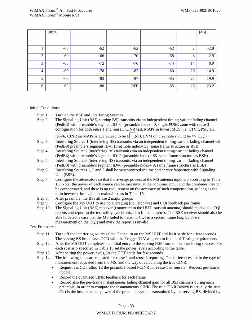
WiMAX Forum® Air Test Procedures WMF-T25-002-R010v04 WiMAX Forum® Mobile RCT
Page - 33
WiMAX FORUM PROPRIETARY
[dBm] [dB]
1 -60 -62 -62 -62 2 -2.8
2 -60 -66 -70 -68 8 2.9
3 -60 -72 -76 -74 14 8.9
4 -60 -78 -82 -80 20 14.9
5 -60 -83 -87 -85 25 19.9
6 -60 -88 OFF -85 25 23.2
Initial Conditions:
Step 1. Turn on the BSE and Interfering Sources Step 2. The Signaling Unit (BSE, serving BS) transmits via an independent timing-variant fading channel
(PedB3) with preamble’s segment ID=0 (preamble index= 0, single PUSC zone with reuse 3 configuration for both reuse 1 and reuse 3 CINR test, MAPs in lowest MCS, i.e. CTC QPSK 1/2,
rep=6, CINR on MAPs is guaranteed to be ≥2dB, EVM on preamble should be >> Dmin,) Step 3. Interfering Source 1 (interfering BS) transmits via an independent timing-variant fading channel with
(PedB3) preamble’s segment ID=1 (preamble index= 33, same frame structure as BSE) Step 4. Interfering Source2 (interfering BS) transmits via an independent timing-variant fading channel
(PedB3) with preamble’s segment ID=2 (preamble index= 65, same frame structure as BSE) Step 5. Interfering Source3 (interfering BS) transmits via an independent timing-variant fading channel
(PedB3) with preamble’s segment ID=0 (preamble index= 9, same frame structure as BSE) Step 6. Interfering Sources 1, 2 and 3 shall be synchronized in time and carrier frequency with Signaling
Unit (BSE). Step 7. Configure the attenuators so that the average powers at the MS antenna input are according to Table
15. Note: the power of each source can be measured at the combiner input and the combiner loss can be compensated, and there is no requirement on the accuracy of such compensation, as long as the ratio between the signals is maintained as in Table 15.
Step 8. After preamble, the BSs all use 2 major groups Step 9. Configure the MS UUT to use no averaging (i.e., alpha=1) and CQI feedback per frame Step 10. The Signaling Unit (BSE) receiver (connected to the UUT transmit antenna) should receive the CQI
reports and report to the test utility synchronized to frame numbers. The BSE receiver should also be able to detect a case that the MS failed to transmit CQI in a certain frame (e.g. by power measurement on the CQI) and mark the report as invalid.
Test Procedure:
Step 11. Turn off the interfering sources first. Then turn on the MS UUT and let it settle for a few seconds. The serving BS broadcasts DCD with the Trigger TLV as given in Item h of Testing requirements.
Step 12. After the MS UUT completes the initial entry to the serving BSE, turn on the interfering sources. For each scenario specified in Table 15 set the power levels according to the table.
Step 13. After setting the power levels, let the UUT settle for few seconds. Step 14. The following steps are repeated for reuse 1 and reuse 3 reporting. The differences are in the type of
measurement requested from the MS, and the way of calculating the true CINR. • Request via CQI_alloc_IE the preamble-based PCINR for reuse-1 or reuse 3. Request per-frame
update. • Record the quantized SINR feedback for each frame • Record also the per-frame instantaneous fading channel gain for all BSs channels during each
preamble, in order to compute the instantaneous CINR. The true CINR (which is actually the true C/I) is the instantaneous power of the preamble symbol transmitted by the serving BS, divided by:
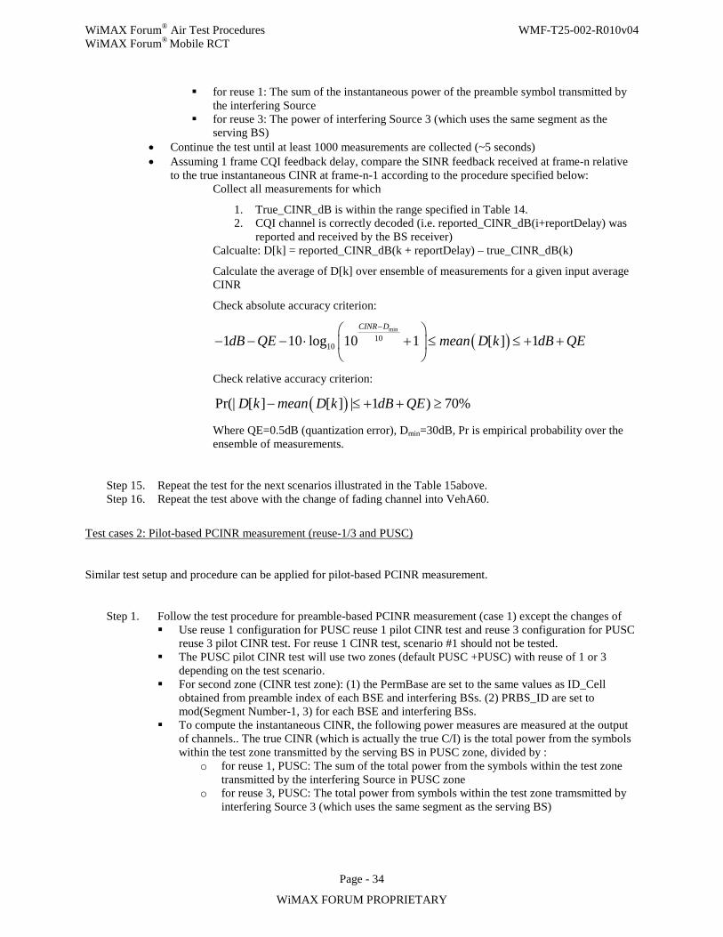
WiMAX Forum® Air Test Procedures WMF-T25-002-R010v04 WiMAX Forum® Mobile RCT
Page - 34
WiMAX FORUM PROPRIETARY
for reuse 1: The sum of the instantaneous power of the preamble symbol transmitted by the interfering Source
for reuse 3: The power of interfering Source 3 (which uses the same segment as the serving BS)
• Continue the test until at least 1000 measurements are collected (~5 seconds) • Assuming 1 frame CQI feedback delay, compare the SINR feedback received at frame-n relative
to the true instantaneous CINR at frame-n-1 according to the procedure specified below: Collect all measurements for which
1. True_CINR_dB is within the range specified in Table 14. 2. CQI channel is correctly decoded (i.e. reported_CINR_dB(i+reportDelay) was
reported and received by the BS receiver) Calcualte: D[k] = reported_CINR_dB(k + reportDelay) – true_CINR_dB(k)
Calculate the average of D[k] over ensemble of measurements for a given input average CINR
Check absolute accuracy criterion:
( )min
10101 10 log 10 1 [ ] 1
CINR D
dB QE mean D k dB QE−
− − − ⋅ + ≤ ≤ + +
Check relative accuracy criterion:
( )Pr(| [ ] [ ] | 1 ) 70%D k mean D k dB QE− ≤ + + ≥
Where QE=0.5dB (quantization error), Dmin=30dB, Pr is empirical probability over the ensemble of measurements.
Step 15. Repeat the test for the next scenarios illustrated in the Table 15above. Step 16. Repeat the test above with the change of fading channel into VehA60.
Test cases 2: Pilot-based PCINR measurement (reuse-1/3 and PUSC)
Similar test setup and procedure can be applied for pilot-based PCINR measurement.
Step 1. Follow the test procedure for preamble-based PCINR measurement (case 1) except the changes of Use reuse 1 configuration for PUSC reuse 1 pilot CINR test and reuse 3 configuration for PUSC
reuse 3 pilot CINR test. For reuse 1 CINR test, scenario #1 should not be tested. The PUSC pilot CINR test will use two zones (default PUSC +PUSC) with reuse of 1 or 3
depending on the test scenario. For second zone (CINR test zone): (1) the PermBase are set to the same values as ID_Cell
obtained from preamble index of each BSE and interfering BSs. (2) PRBS_ID are set to mod(Segment Number-1, 3) for each BSE and interfering BSs.
To compute the instantaneous CINR, the following power measures are measured at the output of channels.. The true CINR (which is actually the true C/I) is the total power from the symbols within the test zone transmitted by the serving BS in PUSC zone, divided by :
o for reuse 1, PUSC: The sum of the total power from the symbols within the test zone transmitted by the interfering Source in PUSC zone
o for reuse 3, PUSC: The total power from symbols within the test zone tramsmitted by interfering Source 3 (which uses the same segment as the serving BS)
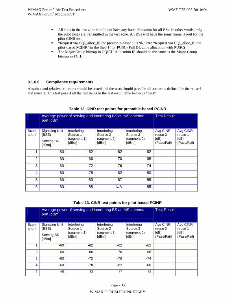
WiMAX Forum® Air Test Procedures WMF-T25-002-R010v04 WiMAX Forum® Mobile RCT
Page - 35
WiMAX FORUM PROPRIETARY
All slots in the test zone should not have any burst allocation for all BSs. In other words, only the pilot tones are transmitted in the test zone. All BSs will have the same frame layout for the pilot CINR test.
“Request via CQI_alloc_IE the preamble-based PCINR” into “Request via CQI_alloc_IE the pilot-based PCINR” in the Step 14for PUSC (Full DL zone allocation with PUSC)
The Major Group bitmap in CQICH Allocation IE should be the same as the Major Group bitmap in FCH.
9.1.6.6 Compliance requirements
Absolute and relative criterions should be tested and the tests should pass for all scenarios defined for the reuse 1 and reuse 3. This test pass if all the test items in the test result table below is “pass”.
Table 12. CINR test points for preamble-based PCINR
Average power of serving and interfering BS at MS antenna port [dBm]
Test Result
Scen-ario #
Signaling Unit (BSE)
Serving BS [dBm]
Interfering Source 1 (segment 1) [dBm]
Interfering Source 2 (segment 2) [dBm]
Interfering Source 3 (segment 0) [dBm]
Avg CINR reuse 3 [dB] (Pass/Fail)
Avg CINR reuse 1 [dB] (Pass/Fail)
1 -60 -62 -62 -62
2 -60 -66 -70 -68
3 -60 -72 -76 -74
4 -60 -78 -82 -80
5 -60 -83 -87 -85
6 -60 -88 N/A -85
Table 13. CINR test points for pilot-based PCINR
Average power of serving and interfering BS at MS antenna port [dBm]
Test Result
Scen-ario #
Signaling Unit (BSE)
Serving BS [dBm]
Interfering Source 1 (segment 1) [dBm]
Interfering Source 2 (segment 2) [dBm]
Interfering Source 3 (segment 0) [dBm]
Avg CINR reuse 3 [dB] (Pass/Fail)
Avg CINR reuse 1 [dB] (Pass/Fail)
1 -60 -62 -62 -62
2 -60 -66 -70 -68
3 -60 -72 -76 -74
4 -60 -78 -82 -80
5 -60 -83 -87 -85
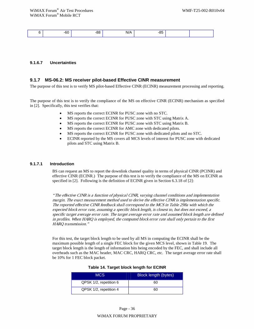
WiMAX Forum® Air Test Procedures WMF-T25-002-R010v04 WiMAX Forum® Mobile RCT
Page - 36
WiMAX FORUM PROPRIETARY
6 -60 -88 N/A -85
9.1.6.7 Uncertainties
9.1.7 MS-06.2: MS receiver pilot-based Effective CINR measurement The purpose of this test is to verify MS pilot-based Effective CINR (ECINR) measurement processing and reporting.
The purpose of this test is to verify the compliance of the MS on effective CINR (ECINR) mechanism as specified in [2]. Specifically, this test verifies that:
• MS reports the correct ECINR for PUSC zone with no STC. • MS reports the correct ECINR for PUSC zone with STC using Matrix A. • MS reports the correct ECINR for PUSC zone with STC using Matrix B. • MS reports the correct ECINR for AMC zone with dedicated pilots. • MS reports the correct ECINR for PUSC zone with dedicated pilots and no STC. • ECINR reported by the MS covers all MCS levels of interest for PUSC zone with dedicated
pilots and STC using Matrix B.
9.1.7.1 Introduction
BS can request an MS to report the downlink channel quality in terms of physical CINR (PCINR) and effective CINR (ECINR.) The purpose of this test is to verify the compliance of the MS on ECINR as specified in [2]. Following is the definition of ECINR given in Section 6.3.18 of [2]:
“The effective CINR is a function of physical CINR, varying channel conditions and implementation margin. The exact measurement method used to derive the effective CINR is implementation specific. The reported effective CINR feedback shall correspond to the MCS in Table 298a with which the expected block error rate, assuming a specific block length, is closest to, but does not exceed, a specific target average error rate. The target average error rate and assumed block length are defined in profiles. When HARQ is employed, the computed block error rate shall only pertain to the first HARQ transmission.”
For this test, the target block length to be used by all MS in computing the ECINR shall be the maximum possible length of a single FEC block for the given MCS level, shown in Table 19. The target block length is the length of information bits being encoded by the FEC, and shall include all overheads such as the MAC header, MAC CRC, HARQ CRC, etc. The target average error rate shall be 10% for 1 FEC block packet.
Table 14. Target block length for ECINR
MCS Block length (bytes)
QPSK 1/2, repetition 6 60
QPSK 1/2, repetition 4 60
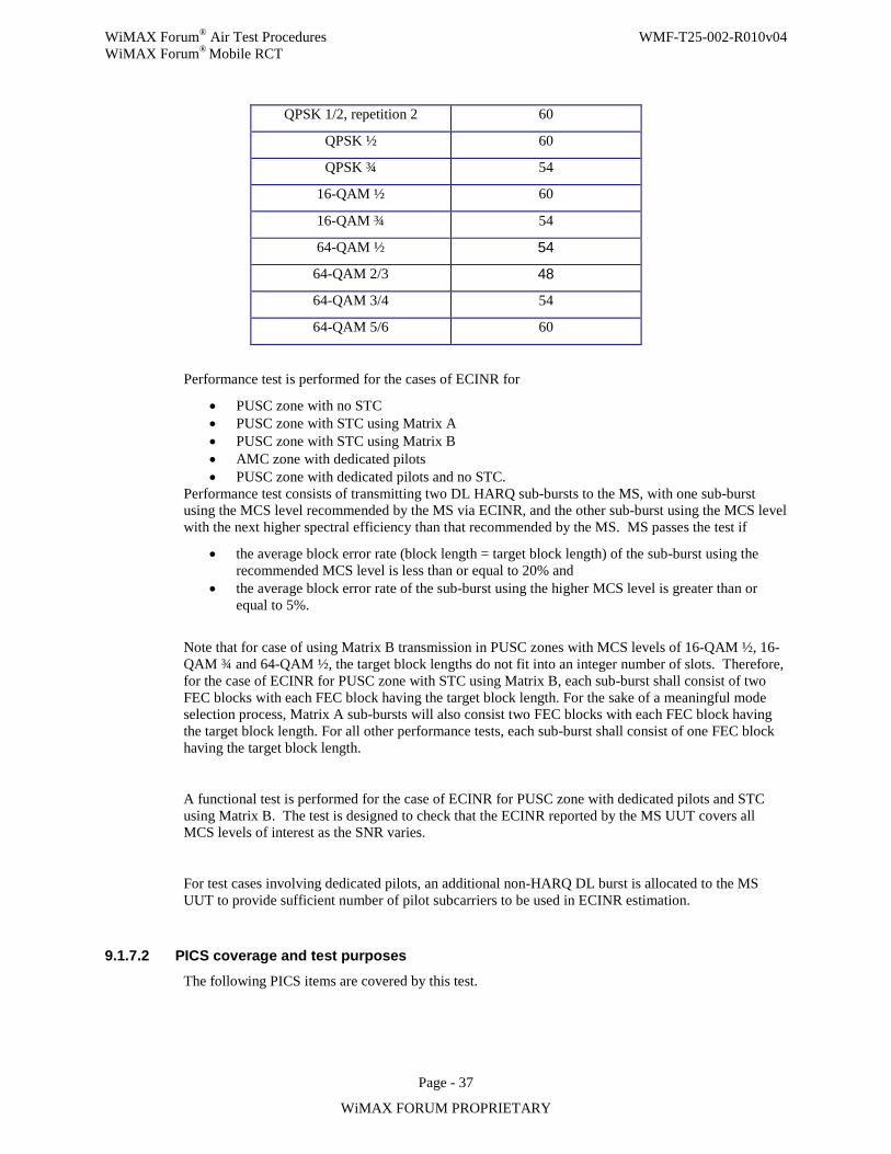
WiMAX Forum® Air Test Procedures WMF-T25-002-R010v04 WiMAX Forum® Mobile RCT
Page - 37
WiMAX FORUM PROPRIETARY
QPSK 1/2, repetition 2 60
QPSK ½ 60
QPSK ¾ 54
16-QAM ½ 60
16-QAM ¾ 54
64-QAM ½ 54
64-QAM 2/3 48
64-QAM 3/4 54
64-QAM 5/6 60
Performance test is performed for the cases of ECINR for
• PUSC zone with no STC • PUSC zone with STC using Matrix A • PUSC zone with STC using Matrix B • AMC zone with dedicated pilots • PUSC zone with dedicated pilots and no STC.
Performance test consists of transmitting two DL HARQ sub-bursts to the MS, with one sub-burst using the MCS level recommended by the MS via ECINR, and the other sub-burst using the MCS level with the next higher spectral efficiency than that recommended by the MS. MS passes the test if
• the average block error rate (block length = target block length) of the sub-burst using the recommended MCS level is less than or equal to 20% and
• the average block error rate of the sub-burst using the higher MCS level is greater than or equal to 5%.
Note that for case of using Matrix B transmission in PUSC zones with MCS levels of 16-QAM ½, 16-QAM ¾ and 64-QAM ½, the target block lengths do not fit into an integer number of slots. Therefore, for the case of ECINR for PUSC zone with STC using Matrix B, each sub-burst shall consist of two FEC blocks with each FEC block having the target block length. For the sake of a meaningful mode selection process, Matrix A sub-bursts will also consist two FEC blocks with each FEC block having the target block length. For all other performance tests, each sub-burst shall consist of one FEC block having the target block length.
A functional test is performed for the case of ECINR for PUSC zone with dedicated pilots and STC using Matrix B. The test is designed to check that the ECINR reported by the MS UUT covers all MCS levels of interest as the SNR varies.
For test cases involving dedicated pilots, an additional non-HARQ DL burst is allocated to the MS UUT to provide sufficient number of pilot subcarriers to be used in ECINR estimation.
9.1.7.2 PICS coverage and test purposes The following PICS items are covered by this test.
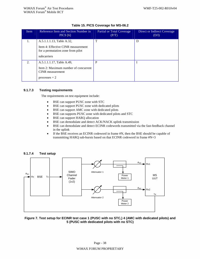
WiMAX Forum® Air Test Procedures WMF-T25-002-R010v04 WiMAX Forum® Mobile RCT
Page - 38
WiMAX FORUM PROPRIETARY
Table 15. PICS Coverage for MS-06.2
Item Reference Item and Section Number in PICS [6]
Partial or Total Coverage (P/T)
Direct or Indirect Coverage (D/I)
1. A.5.1.1.1.13, Table A.32,
Item 4: Effective CINR measurement for a permutation zone from pilot
subcarriers
T D
2. A.5.1.1.1.17, Table A.49,
Item 2: Maximum number of concurrent CINR measurement
processes = 2
P I
9.1.7.3 Testing requirements
The requirements on test equipment include:
• BSE can support PUSC zone with STC • BSE can support PUSC zone with dedicated pilots • BSE can support AMC zone with dedicated pilots • BSE can supports PUSC zone with dedicated pilots and STC • BSE can support HARQ allocation • BSE can demodulate and detect ACK/NACK uplink transmission • BSE can demodulate and detect ECINR codewords transmitted via the fast-feedback channel
in the uplink • If the BSE receives an ECINR codeword in frame #N, then the BSE should be capable of
transmitting HARQ sub-bursts based on that ECINR codeword in frame #N+3
9.1.7.4 Test setup
MSUUTBSE
SIMO Channel
Fader(1x2)
Tx
Attenuator 1
Attenuator 2
Power Meter 1
Power Meter 2
Rx1
Rx2
Tx
AMS
AMS
ABS
Rx
Figure 7. Test setup for ECINR test case 1 (PUSC with no STC,) 4 (AMC with dedicated pilots) and 5 (PUSC with dedicated pilots with no STC)
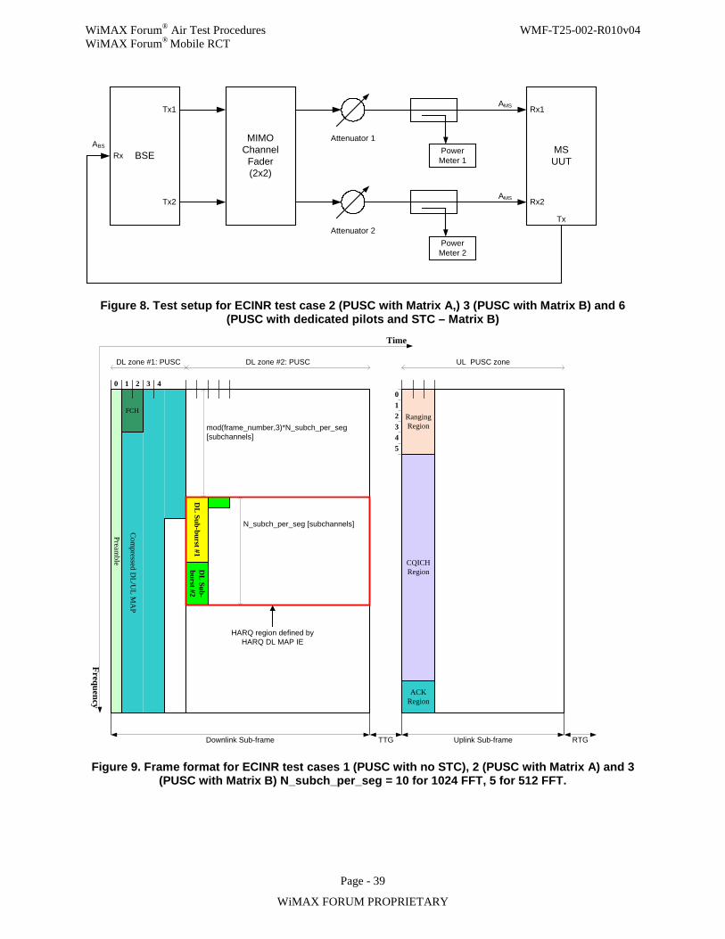
WiMAX Forum® Air Test Procedures WMF-T25-002-R010v04 WiMAX Forum® Mobile RCT
Page - 39
WiMAX FORUM PROPRIETARY
MSUUTBSE
MIMO Channel
Fader(2x2)
Tx1
Tx2
Attenuator 1
Attenuator 2
Power Meter 1
Power Meter 2
Rx1
Rx2
Tx
Rx
AMS
ABS
AMS
Figure 8. Test setup for ECINR test case 2 (PUSC with Matrix A,) 3 (PUSC with Matrix B) and 6 (PUSC with dedicated pilots and STC – Matrix B)
Com
pressed DL/U
L MA
P
Frequency
Time
0
RangingRegion
ACKRegion
CQICHRegion
Uplink Sub-frame
DL zone #1: PUSC
Downlink Sub-frame
DL zone #2: PUSC UL PUSC zone
DL
Sub-burst #1D
L Sub-
burst #2
1 3
Preamble
FCH
2 4012345
TTG RTG
mod(frame_number,3)*N_subch_per_seg[subchannels]
HARQ region defined by HARQ DL MAP IE
N_subch_per_seg [subchannels]
Figure 9. Frame format for ECINR test cases 1 (PUSC with no STC), 2 (PUSC with Matrix A) and 3 (PUSC with Matrix B) N_subch_per_seg = 10 for 1024 FFT, 5 for 512 FFT.
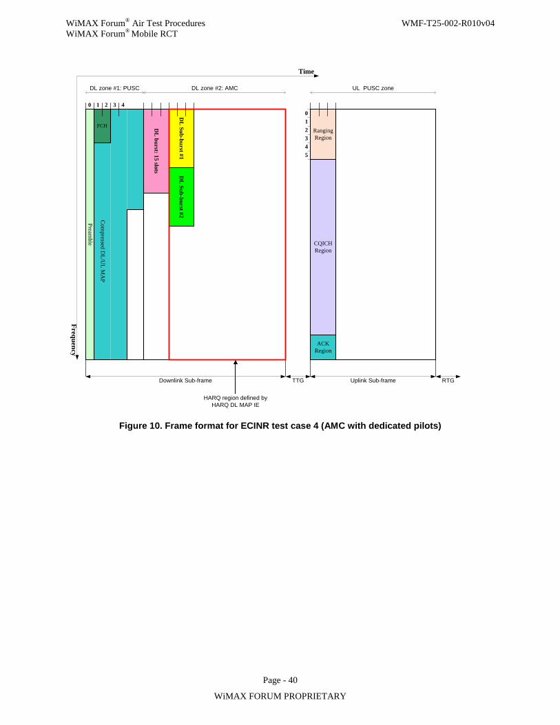
WiMAX Forum® Air Test Procedures WMF-T25-002-R010v04 WiMAX Forum® Mobile RCT
Page - 40
WiMAX FORUM PROPRIETARY
DL
burst: 15 slots
Com
pressed DL/U
L MA
P
Frequency
Time
0
RangingRegion
ACKRegion
CQICHRegion
Uplink Sub-frame
DL zone #1: PUSC
Downlink Sub-frame
DL zone #2: AMC UL PUSC zone
DL
Sub-burst #1D
L Sub-burst #2
1 3
Preamble
FCH
2 4012345
TTG RTG
HARQ region defined by HARQ DL MAP IE
Figure 10. Frame format for ECINR test case 4 (AMC with dedicated pilots)
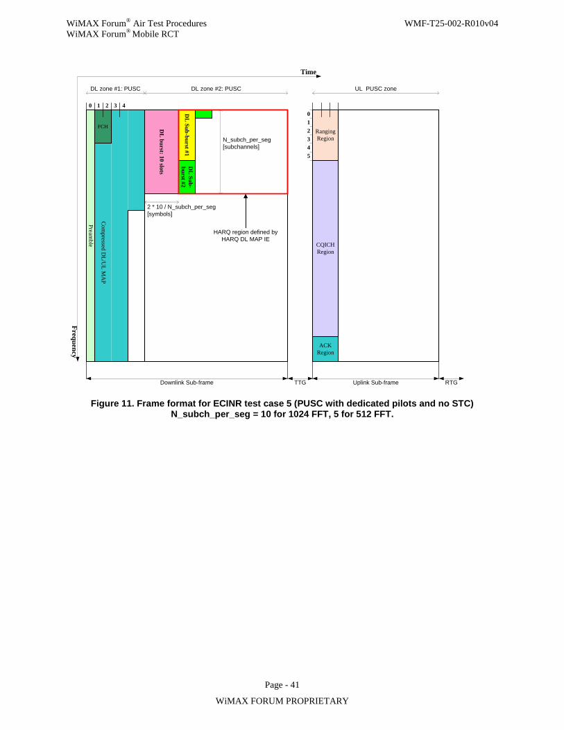
WiMAX Forum® Air Test Procedures WMF-T25-002-R010v04 WiMAX Forum® Mobile RCT
Page - 41
WiMAX FORUM PROPRIETARY
DL
burst: 10 slots
Com
pressed DL/U
L MA
P
Frequency
Time
0
RangingRegion
ACKRegion
CQICHRegion
Uplink Sub-frame
DL zone #1: PUSC
Downlink Sub-frame
DL zone #2: PUSC UL PUSC zone
DL
Sub-burst #1D
L Sub-
burst #2
1 3
Preamble
FCH
2 4012345
TTG RTG
HARQ region defined by HARQ DL MAP IE
N_subch_per_seg [subchannels]
2 * 10 / N_subch_per_seg[symbols]
Figure 11. Frame format for ECINR test case 5 (PUSC with dedicated pilots and no STC) N_subch_per_seg = 10 for 1024 FFT, 5 for 512 FFT.
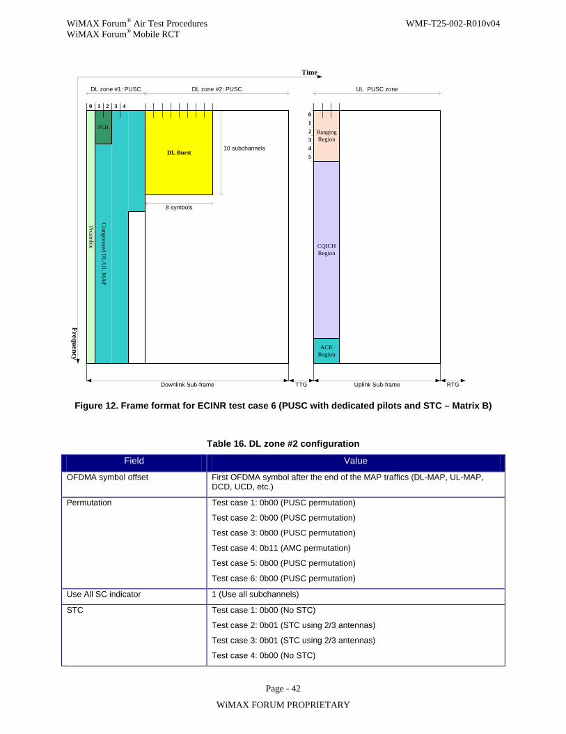
WiMAX Forum® Air Test Procedures WMF-T25-002-R010v04 WiMAX Forum® Mobile RCT
Page - 42
WiMAX FORUM PROPRIETARY
Com
pressed DL/U
L MA
P
Frequency
Time
0
RangingRegion
ACKRegion
CQICHRegion
Uplink Sub-frame
DL zone #1: PUSC
Downlink Sub-frame
DL zone #2: PUSC UL PUSC zone
DL Burst
1 3
Preamble
FCH
2 4012345
TTG RTG
10 subchannels
8 symbols
Figure 12. Frame format for ECINR test case 6 (PUSC with dedicated pilots and STC – Matrix B)
Table 16. DL zone #2 configuration
Field Value
OFDMA symbol offset First OFDMA symbol after the end of the MAP traffics (DL-MAP, UL-MAP, DCD, UCD, etc.)
Permutation Test case 1: 0b00 (PUSC permutation)
Test case 2: 0b00 (PUSC permutation)
Test case 3: 0b00 (PUSC permutation)
Test case 4: 0b11 (AMC permutation)
Test case 5: 0b00 (PUSC permutation)
Test case 6: 0b00 (PUSC permutation)
Use All SC indicator 1 (Use all subchannels)
STC Test case 1: 0b00 (No STC)
Test case 2: 0b01 (STC using 2/3 antennas)
Test case 3: 0b01 (STC using 2/3 antennas)
Test case 4: 0b00 (No STC)
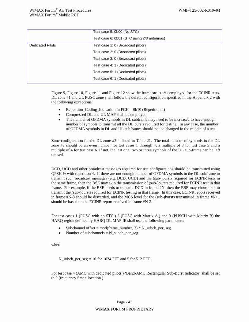
WiMAX Forum® Air Test Procedures WMF-T25-002-R010v04 WiMAX Forum® Mobile RCT
Page - 43
WiMAX FORUM PROPRIETARY
Test case 5: 0b00 (No STC)
Test case 6: 0b01 (STC using 2/3 antennas)
Dedicated Pilots Test case 1: 0 (Broadcast pilots)
Test case 2: 0 (Broadcast pilots)
Test case 3: 0 (Broadcast pilots)
Test case 4: 1 (Dedicated pilots)
Test case 5: 1 (Dedicated pilots)
Test case 6: 1 (Dedicated pilots)
Figure 9, Figure 10, Figure 11 and Figure 12 show the frame structures employed for the ECINR tests. DL zone #1 and UL PUSC zone shall follow the default configuration specified in the Appendix 2 with the following exceptions:
• Repetition_Coding_Indication in FCH = 0b10 (Repetition 4) • Compressed DL and UL MAP shall be employed • The number of OFDMA symbols in DL subframe may need to be increased to have enough
number of symbols to transmit all the DL bursts required for testing. In any case, the number of OFDMA symbols in DL and UL subframes should not be changed in the middle of a test.
Zone configuration for the DL zone #2 is listed in Table 21. The total number of symbols in the DL zone #2 should be an even number for test cases 1 through 4, a multiple of 3 for test case 5 and a multiple of 4 for test case 6. If not, the last one, two or three symbols of the DL sub-frame can be left unused.
DCD, UCD and other broadcast messages required for test configurations should be transmitted using QPSK ½ with repetition 4. If there are not enough number of OFDMA symbols in the DL subframe to transmit such broadcast messages (e.g. DCD, UCD) and the (sub-)bursts required for ECINR tests in the same frame, then the BSE may skip the transmission of (sub-)bursts required for ECINR test in that frame. For example, if the BSE needs to transmit DCD in frame #N, then the BSE may choose not to transmit the (sub-)bursts required for ECINR testing in that frame. In this case, ECINR report received in frame #N-3 should be discarded, and the MCS level for the (sub-)bursts transmitted in frame #N+1 should be based on the ECINR report received in frame #N-2.
For test cases 1 (PUSC with no STC,) 2 (PUSC with Matrix A,) and 3 (PUSCH with Matrix B) the HARQ region defined by HARQ DL MAP IE shall use the following parameters:
• Subchannel offset = mod(frame_number, 3) * N_subch_per_seg • Number of subchannels = N_subch_per_seg
where
N_subch_per_seg = 10 for 1024 FFT and 5 for 512 FFT.
For test case 4 (AMC with dedicated pilots,) ‘Band-AMC Rectangular Sub-Burst Indicator’ shall be set to 0 (frequency first allocation.)
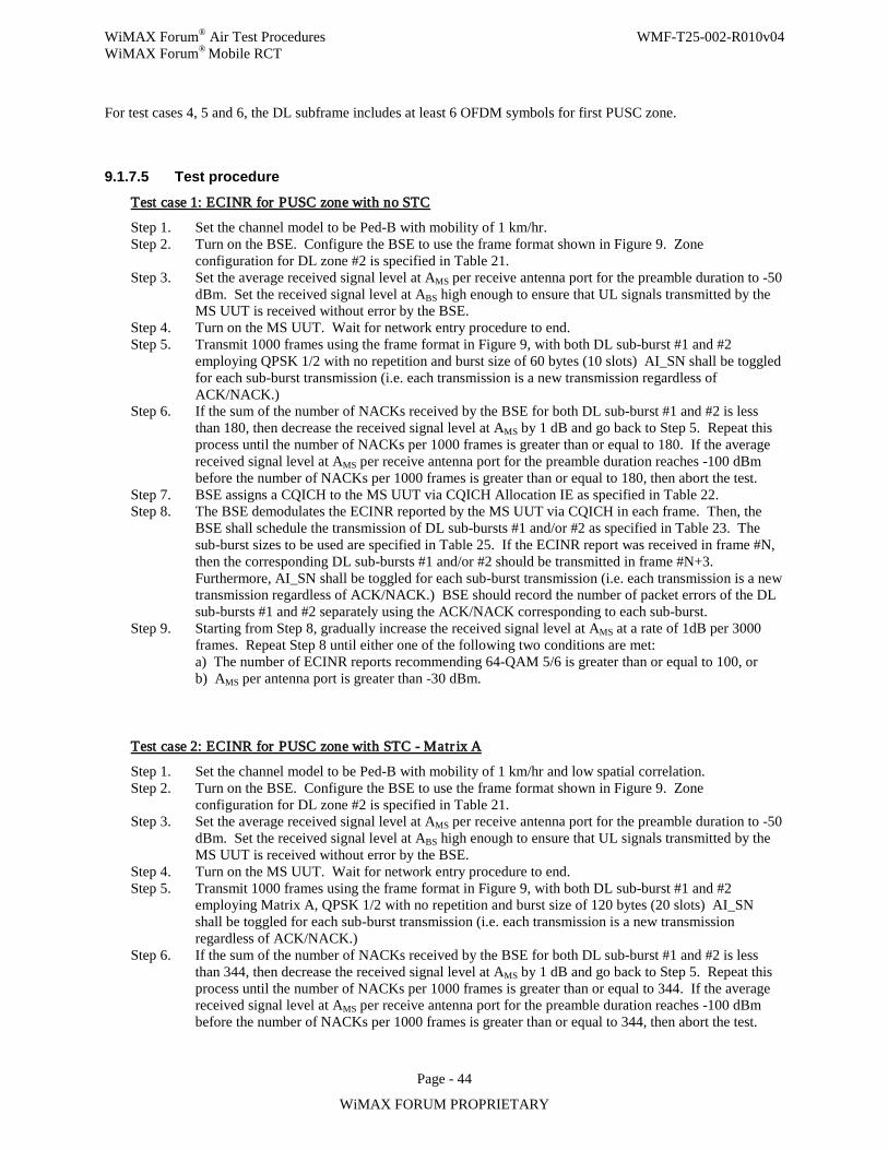
WiMAX Forum® Air Test Procedures WMF-T25-002-R010v04 WiMAX Forum® Mobile RCT
Page - 44
WiMAX FORUM PROPRIETARY
For test cases 4, 5 and 6, the DL subframe includes at least 6 OFDM symbols for first PUSC zone.
9.1.7.5 Test procedure
Test case 1: ECINR for PUSC zone with no STC
Step 1. Set the channel model to be Ped-B with mobility of 1 km/hr. Step 2. Turn on the BSE. Configure the BSE to use the frame format shown in Figure 9. Zone
configuration for DL zone #2 is specified in Table 21. Step 3. Set the average received signal level at AMS per receive antenna port for the preamble duration to -50
dBm. Set the received signal level at ABS high enough to ensure that UL signals transmitted by the MS UUT is received without error by the BSE.
Step 4. Turn on the MS UUT. Wait for network entry procedure to end. Step 5. Transmit 1000 frames using the frame format in Figure 9, with both DL sub-burst #1 and #2
employing QPSK 1/2 with no repetition and burst size of 60 bytes (10 slots) AI_SN shall be toggled for each sub-burst transmission (i.e. each transmission is a new transmission regardless of ACK/NACK.)
Step 6. If the sum of the number of NACKs received by the BSE for both DL sub-burst #1 and #2 is less than 180, then decrease the received signal level at AMS by 1 dB and go back to Step 5. Repeat this process until the number of NACKs per 1000 frames is greater than or equal to 180. If the average received signal level at AMS per receive antenna port for the preamble duration reaches -100 dBm before the number of NACKs per 1000 frames is greater than or equal to 180, then abort the test.
Step 7. BSE assigns a CQICH to the MS UUT via CQICH Allocation IE as specified in Table 22. Step 8. The BSE demodulates the ECINR reported by the MS UUT via CQICH in each frame. Then, the
BSE shall schedule the transmission of DL sub-bursts #1 and/or #2 as specified in Table 23. The sub-burst sizes to be used are specified in Table 25. If the ECINR report was received in frame #N, then the corresponding DL sub-bursts #1 and/or #2 should be transmitted in frame #N+3. Furthermore, AI_SN shall be toggled for each sub-burst transmission (i.e. each transmission is a new transmission regardless of ACK/NACK.) BSE should record the number of packet errors of the DL sub-bursts #1 and #2 separately using the ACK/NACK corresponding to each sub-burst.
Step 9. Starting from Step 8, gradually increase the received signal level at AMS at a rate of 1dB per 3000 frames. Repeat Step 8 until either one of the following two conditions are met: a) The number of ECINR reports recommending 64-QAM 5/6 is greater than or equal to 100, or b) AMS per antenna port is greater than -30 dBm.
Test case 2: ECINR for PUSC zone with STC - Matr ix A
Step 1. Set the channel model to be Ped-B with mobility of 1 km/hr and low spatial correlation. Step 2. Turn on the BSE. Configure the BSE to use the frame format shown in Figure 9. Zone
configuration for DL zone #2 is specified in Table 21. Step 3. Set the average received signal level at AMS per receive antenna port for the preamble duration to -50
dBm. Set the received signal level at ABS high enough to ensure that UL signals transmitted by the MS UUT is received without error by the BSE.
Step 4. Turn on the MS UUT. Wait for network entry procedure to end. Step 5. Transmit 1000 frames using the frame format in Figure 9, with both DL sub-burst #1 and #2
employing Matrix A, QPSK 1/2 with no repetition and burst size of 120 bytes (20 slots) AI_SN shall be toggled for each sub-burst transmission (i.e. each transmission is a new transmission regardless of ACK/NACK.)
Step 6. If the sum of the number of NACKs received by the BSE for both DL sub-burst #1 and #2 is less than 344, then decrease the received signal level at AMS by 1 dB and go back to Step 5. Repeat this process until the number of NACKs per 1000 frames is greater than or equal to 344. If the average received signal level at AMS per receive antenna port for the preamble duration reaches -100 dBm before the number of NACKs per 1000 frames is greater than or equal to 344, then abort the test.
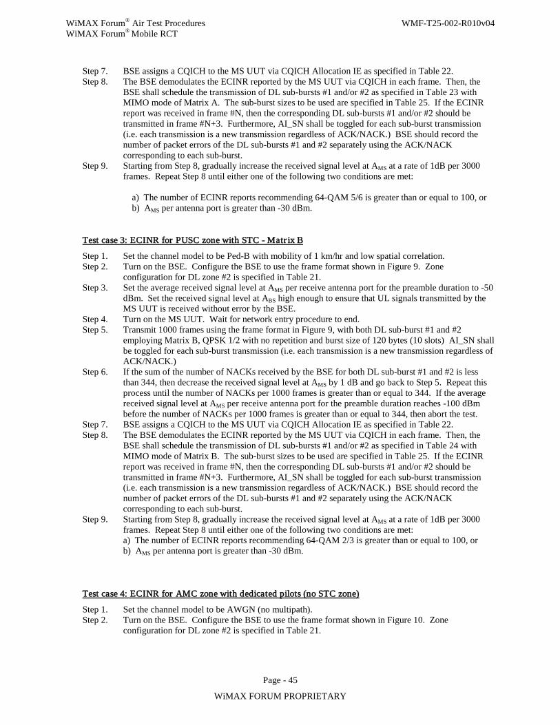
WiMAX Forum® Air Test Procedures WMF-T25-002-R010v04 WiMAX Forum® Mobile RCT
Page - 45
WiMAX FORUM PROPRIETARY
Step 7. BSE assigns a CQICH to the MS UUT via CQICH Allocation IE as specified in Table 22. Step 8. The BSE demodulates the ECINR reported by the MS UUT via CQICH in each frame. Then, the
BSE shall schedule the transmission of DL sub-bursts #1 and/or #2 as specified in Table 23 with MIMO mode of Matrix A. The sub-burst sizes to be used are specified in Table 25. If the ECINR report was received in frame #N, then the corresponding DL sub-bursts #1 and/or #2 should be transmitted in frame #N+3. Furthermore, AI_SN shall be toggled for each sub-burst transmission (i.e. each transmission is a new transmission regardless of ACK/NACK.) BSE should record the number of packet errors of the DL sub-bursts #1 and #2 separately using the ACK/NACK corresponding to each sub-burst.
Step 9. Starting from Step 8, gradually increase the received signal level at AMS at a rate of 1dB per 3000 frames. Repeat Step 8 until either one of the following two conditions are met:
a) The number of ECINR reports recommending 64-QAM 5/6 is greater than or equal to 100, or b) AMS per antenna port is greater than -30 dBm.
Test case 3: ECINR for PUSC zone with STC - Matr ix B
Step 1. Set the channel model to be Ped-B with mobility of 1 km/hr and low spatial correlation. Step 2. Turn on the BSE. Configure the BSE to use the frame format shown in Figure 9. Zone
configuration for DL zone #2 is specified in Table 21. Step 3. Set the average received signal level at AMS per receive antenna port for the preamble duration to -50
dBm. Set the received signal level at ABS high enough to ensure that UL signals transmitted by the MS UUT is received without error by the BSE.
Step 4. Turn on the MS UUT. Wait for network entry procedure to end. Step 5. Transmit 1000 frames using the frame format in Figure 9, with both DL sub-burst #1 and #2
employing Matrix B, QPSK 1/2 with no repetition and burst size of 120 bytes (10 slots) AI_SN shall be toggled for each sub-burst transmission (i.e. each transmission is a new transmission regardless of ACK/NACK.)
Step 6. If the sum of the number of NACKs received by the BSE for both DL sub-burst #1 and #2 is less than 344, then decrease the received signal level at AMS by 1 dB and go back to Step 5. Repeat this process until the number of NACKs per 1000 frames is greater than or equal to 344. If the average received signal level at AMS per receive antenna port for the preamble duration reaches -100 dBm before the number of NACKs per 1000 frames is greater than or equal to 344, then abort the test.
Step 7. BSE assigns a CQICH to the MS UUT via CQICH Allocation IE as specified in Table 22. Step 8. The BSE demodulates the ECINR reported by the MS UUT via CQICH in each frame. Then, the
BSE shall schedule the transmission of DL sub-bursts #1 and/or #2 as specified in Table 24 with MIMO mode of Matrix B. The sub-burst sizes to be used are specified in Table 25. If the ECINR report was received in frame #N, then the corresponding DL sub-bursts #1 and/or #2 should be transmitted in frame #N+3. Furthermore, AI_SN shall be toggled for each sub-burst transmission (i.e. each transmission is a new transmission regardless of ACK/NACK.) BSE should record the number of packet errors of the DL sub-bursts #1 and #2 separately using the ACK/NACK corresponding to each sub-burst.
Step 9. Starting from Step 8, gradually increase the received signal level at AMS at a rate of 1dB per 3000 frames. Repeat Step 8 until either one of the following two conditions are met: a) The number of ECINR reports recommending 64-QAM 2/3 is greater than or equal to 100, or b) AMS per antenna port is greater than -30 dBm.
Test case 4: ECINR for AMC zone with dedicated pilots (no STC zone)
Step 1. Set the channel model to be AWGN (no multipath). Step 2. Turn on the BSE. Configure the BSE to use the frame format shown in Figure 10. Zone
configuration for DL zone #2 is specified in Table 21.
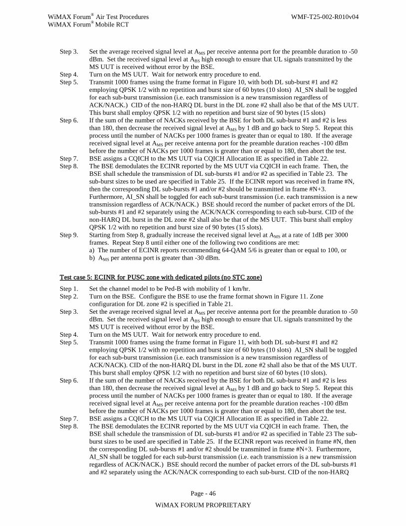
WiMAX Forum® Air Test Procedures WMF-T25-002-R010v04 WiMAX Forum® Mobile RCT
Page - 46
WiMAX FORUM PROPRIETARY
Step 3. Set the average received signal level at AMS per receive antenna port for the preamble duration to -50 dBm. Set the received signal level at ABS high enough to ensure that UL signals transmitted by the MS UUT is received without error by the BSE.
Step 4. Turn on the MS UUT. Wait for network entry procedure to end. Step 5. Transmit 1000 frames using the frame format in Figure 10, with both DL sub-burst #1 and #2
employing QPSK 1/2 with no repetition and burst size of 60 bytes (10 slots) AI_SN shall be toggled for each sub-burst transmission (i.e. each transmission is a new transmission regardless of ACK/NACK.) CID of the non-HARQ DL burst in the DL zone #2 shall also be that of the MS UUT. This burst shall employ QPSK 1/2 with no repetition and burst size of 90 bytes (15 slots)
Step 6. If the sum of the number of NACKs received by the BSE for both DL sub-burst #1 and #2 is less than 180, then decrease the received signal level at AMS by 1 dB and go back to Step 5. Repeat this process until the number of NACKs per 1000 frames is greater than or equal to 180. If the average received signal level at AMS per receive antenna port for the preamble duration reaches -100 dBm before the number of NACKs per 1000 frames is greater than or equal to 180, then abort the test.
Step 7. BSE assigns a CQICH to the MS UUT via CQICH Allocation IE as specified in Table 22. Step 8. The BSE demodulates the ECINR reported by the MS UUT via CQICH in each frame. Then, the
BSE shall schedule the transmission of DL sub-bursts #1 and/or #2 as specified in Table 23. The sub-burst sizes to be used are specified in Table 25. If the ECINR report was received in frame #N, then the corresponding DL sub-bursts #1 and/or #2 should be transmitted in frame #N+3. Furthermore, AI_SN shall be toggled for each sub-burst transmission (i.e. each transmission is a new transmission regardless of ACK/NACK.) BSE should record the number of packet errors of the DL sub-bursts #1 and #2 separately using the ACK/NACK corresponding to each sub-burst. CID of the non-HARQ DL burst in the DL zone #2 shall also be that of the MS UUT. This burst shall employ QPSK 1/2 with no repetition and burst size of 90 bytes (15 slots).
Step 9. Starting from Step 8, gradually increase the received signal level at AMS at a rate of 1dB per 3000 frames. Repeat Step 8 until either one of the following two conditions are met: a) The number of ECINR reports recommending 64-QAM 5/6 is greater than or equal to 100, or b) AMS per antenna port is greater than -30 dBm.
Test case 5: ECINR for PUSC zone with dedicated pilots (no STC zone)
Step 1. Set the channel model to be Ped-B with mobility of 1 km/hr. Step 2. Turn on the BSE. Configure the BSE to use the frame format shown in Figure 11. Zone
configuration for DL zone #2 is specified in Table 21. Step 3. Set the average received signal level at AMS per receive antenna port for the preamble duration to -50
dBm. Set the received signal level at ABS high enough to ensure that UL signals transmitted by the MS UUT is received without error by the BSE.
Step 4. Turn on the MS UUT. Wait for network entry procedure to end. Step 5. Transmit 1000 frames using the frame format in Figure 11, with both DL sub-burst #1 and #2
employing QPSK 1/2 with no repetition and burst size of 60 bytes (10 slots) AI_SN shall be toggled for each sub-burst transmission (i.e. each transmission is a new transmission regardless of ACK/NACK). CID of the non-HARQ DL burst in the DL zone #2 shall also be that of the MS UUT. This burst shall employ QPSK 1/2 with no repetition and burst size of 60 bytes (10 slots).
Step 6. If the sum of the number of NACKs received by the BSE for both DL sub-burst #1 and #2 is less than 180, then decrease the received signal level at AMS by 1 dB and go back to Step 5. Repeat this process until the number of NACKs per 1000 frames is greater than or equal to 180. If the average received signal level at AMS per receive antenna port for the preamble duration reaches -100 dBm before the number of NACKs per 1000 frames is greater than or equal to 180, then abort the test.
Step 7. BSE assigns a CQICH to the MS UUT via CQICH Allocation IE as specified in Table 22. Step 8. The BSE demodulates the ECINR reported by the MS UUT via CQICH in each frame. Then, the
BSE shall schedule the transmission of DL sub-bursts #1 and/or #2 as specified in Table 23 The sub-burst sizes to be used are specified in Table 25. If the ECINR report was received in frame #N, then the corresponding DL sub-bursts #1 and/or #2 should be transmitted in frame #N+3. Furthermore, AI_SN shall be toggled for each sub-burst transmission (i.e. each transmission is a new transmission regardless of ACK/NACK.) BSE should record the number of packet errors of the DL sub-bursts #1 and #2 separately using the ACK/NACK corresponding to each sub-burst. CID of the non-HARQ
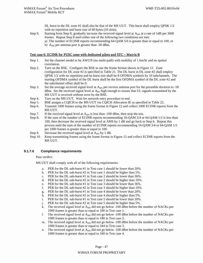
WiMAX Forum® Air Test Procedures WMF-T25-002-R010v04 WiMAX Forum® Mobile RCT
Page - 47
WiMAX FORUM PROPRIETARY
DL burst in the DL zone #2 shall also be that of the MS UUT. This burst shall employ QPSK 1/2 with no repetition and burst size of 60 bytes (10 slots).
Step 9. Starting from Step 8, gradually increase the received signal level at AMS at a rate of 1dB per 3000 frames. Repeat Step 8 until either one of the following two conditions are met: a) The number of ECINR reports recommending 64-QAM 5/6 is greater than or equal to 100, or b) AMS per antenna port is greater than -30 dBm.
Test case 6: ECINR for PUSC zone with dedicated pilots and STC – Matr ix B
Step 1. Set the channel model to be AWGN (no multi-path) with mobility of 1 km/hr and no spatial correlation.
Step 2. Turn on the BSE. Configure the BSE to use the frame format shown in Figure 12. Zone configuration for DL zone #2 is specified in Table 21. The DL burst in DL zone #2 shall employ QPSK 1/2 with no repetition and its burst size shall be 8 OFDMA symbols by 10 subchannels. The starting OFDMA symbol of the DL burst shall be the first OFDMA symbol of the DL zone #2 and the subchannel offset shall be 0.
Step 3. Set the average received signal level at AMS per receive antenna port for the preamble duration to -50 dBm. Set the received signal level at ABS high enough to ensure that UL signals transmitted by the MS UUT is received without error by the BSE.
Step 4. Turn on the MS UUT. Wait for network entry procedure to end. Step 5. BSE assigns a CQICH to the MS UUT via CQICH Allocation IE as specified in Table 22. Step 6. Transmit 1000 frames using the frame format in Figure 12 and collect 1000 ECINR reports from the
MS UUT. Step 7. If the received signal level at AMS is less than -100 dBm, then stop the test. Step 8. If the sum of the number of ECINR reports recommending 16-QAM 3/4 or 64-QAM 1/2 is less than
100, then decrease the received signal level at AMS by 1 dB and go back to Step 6. Repeat this process until the sum of the number of ECINR reports recommending 16-QAM 3/4 or 64-QAM 1/2 per 1000 frames is greater than or equal to 100.
Step 9. Decrease the received signal level at AMS by 1 dB. Step 10. Keep transmitting frames using the frame format in Figure 12 and collect ECINR reports from the
MS UUT.
9.1.7.6 Compliance requirements Pass verdict:
MS UUT shall comply with all of the following requirements:
a. PER for the DL sub-burst #1 in Test case 1 should be lower than 20%. b. PER for the DL sub-burst #2 in Test case 1 should be higher than 5%. c. PER for the DL sub-burst #1 in Test case 2 should be lower than 36%. d. PER for the DL sub-burst #2 in Test case 2 should be higher than 10%. e. PER for the DL sub-burst #1 in Test case 3 should be lower than 36%. f. PER for the DL sub-burst #2 in Test case 3 should be higher than 10%. g. PER for the DL sub-burst #1 in Test case 4 should be lower than 20%. h. PER for the DL sub-burst #2 in Test case 4 should be higher than 5%. i. PER for the DL sub-burst #1 in Test case 5 should be lower than 20%. j. PER for the DL sub-burst #2 in Test case 5 should be higher than 5%. k. The received signal level at AMS did not go below -100 dBm before the number of NACKs per
1000 frames is greater than or equal to 180 in Test case 1. l. The received signal level at AMS did not go below -100 dBm before the number of NACKs per
1000 frames is greater than or equal to 180 in Test case 2. m. The received signal level at AMS did not go below -100 dBm before the number of NACKs per
1000 frames is greater than or equal to 344 in Test case 3. n. The received signal level at AMS did not go below -100 dBm before the number of NACKs per
1000 frames is greater than or equal to 180 in Test case 4.
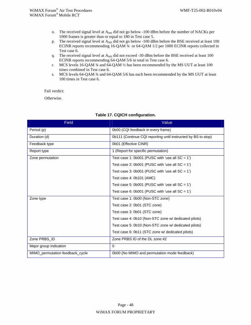
WiMAX Forum® Air Test Procedures WMF-T25-002-R010v04 WiMAX Forum® Mobile RCT
Page - 48
WiMAX FORUM PROPRIETARY
o. The received signal level at AMS did not go below -100 dBm before the number of NACKs per 1000 frames is greater than or equal to 180 in Test case 5.
p. The received signal level at AMS did not go below -100 dBm before the BSE received at least 100 ECINR reports recommending 16-QAM ¾ or 64-QAM 1/2 per 1000 ECINR reports collected in Test case 6.
q. The received signal level at AMS did not exceed -30 dBm before the BSE received at least 100 ECINR reports recommending 64-QAM 5/6 in total in Test case 6.
r. MCS levels 16-QAM ¾ and 64-QAM ½ has been recommended by the MS UUT at least 100 times combined in Test case 6.
s. MCS levels 64-QAM ¾ and 64-QAM 5/6 has each been recommended by the MS UUT at least 100 times in Test case 6.
Fail verdict:
Otherwise.
Table 17. CQICH configuration.
Field Value
Period (p) 0b00 (CQI feedback in every frame)
Duration (d) 0b111 (Continue CQI reporting until instructed by BS to stop)
Feedback type 0b01 (Effective CINR)
Report type 1 (Report for specific permutation)
Zone permutation Test case 1: 0b001 (PUSC with ‘use all SC = 1’)
Test case 2: 0b001 (PUSC with ‘use all SC = 1’)
Test case 3: 0b001 (PUSC with ‘use all SC = 1’)
Test case 4: 0b101 (AMC)
Test case 5: 0b001 (PUSC with ‘use all SC = 1’)
Test case 6: 0b001 (PUSC with ‘use all SC = 1’)
Zone type Test case 1: 0b00 (Non-STC zone)
Test case 2: 0b01 (STC zone)
Test case 3: 0b01 (STC zone)
Test case 4: 0b10 (Non-STC zone w/ dedicated pilots)
Test case 5: 0b10 (Non-STC zone w/ dedicated pilots)
Test case 6: 0b11 (STC zone w/ dedicated pilots)
Zone PRBS_ID Zone PRBS ID of the DL zone #2
Major group indication 0
MIMO_permutation feedback_cycle 0b00 (No MIMO and permutation mode feedback)
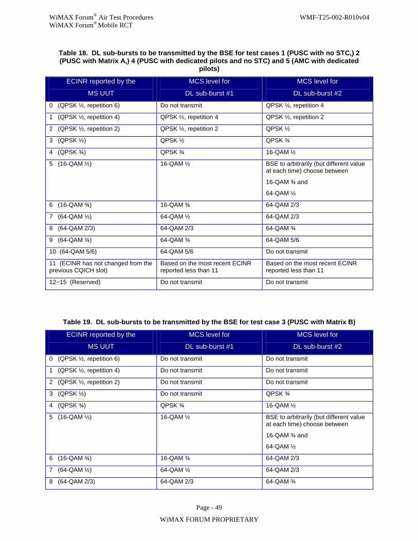
WiMAX Forum® Air Test Procedures WMF-T25-002-R010v04 WiMAX Forum® Mobile RCT
Page - 49
WiMAX FORUM PROPRIETARY
Table 18. DL sub-bursts to be transmitted by the BSE for test cases 1 (PUSC with no STC,) 2 (PUSC with Matrix A,) 4 (PUSC with dedicated pilots and no STC) and 5 (AMC with dedicated
pilots)
ECINR reported by the
MS UUT
MCS level for
DL sub-burst #1
MCS level for
DL sub-burst #2
0 (QPSK ½, repetition 6) Do not transmit QPSK ½, repetition 4
1 (QPSK ½, repetition 4) QPSK ½, repetition 4 QPSK ½, repetition 2
2 (QPSK ½, repetition 2) QPSK ½, repetition 2 QPSK ½
3 (QPSK ½) QPSK ½ QPSK ¾
4 (QPSK ¾) QPSK ¾ 16-QAM ½
5 (16-QAM ½) 16-QAM ½ BSE to arbitrarily (but different value at each time) choose between
16-QAM ¾ and
64-QAM ½
6 (16-QAM ¾) 16-QAM ¾ 64-QAM 2/3
7 (64-QAM ½) 64-QAM ½ 64-QAM 2/3
8 (64-QAM 2/3) 64-QAM 2/3 64-QAM ¾
9 (64-QAM ¾) 64-QAM ¾ 64-QAM 5/6
10 (64-QAM 5/6) 64-QAM 5/6 Do not transmit
11 (ECINR has not changed from the previous CQICH slot)
Based on the most recent ECINR reported less than 11
Based on the most recent ECINR reported less than 11
12~15 (Reserved) Do not transmit Do not transmit
Table 19. DL sub-bursts to be transmitted by the BSE for test case 3 (PUSC with Matrix B)
ECINR reported by the
MS UUT
MCS level for
DL sub-burst #1
MCS level for
DL sub-burst #2
0 (QPSK ½, repetition 6) Do not transmit Do not transmit
1 (QPSK ½, repetition 4) Do not transmit Do not transmit
2 (QPSK ½, repetition 2) Do not transmit Do not transmit
3 (QPSK ½) Do not transmit QPSK ¾
4 (QPSK ¾) QPSK ¾ 16-QAM ½
5 (16-QAM ½) 16-QAM ½ BSE to arbitrarily (but different value at each time) choose between
16-QAM ¾ and
64-QAM ½
6 (16-QAM ¾) 16-QAM ¾ 64-QAM 2/3
7 (64-QAM ½) 64-QAM ½ 64-QAM 2/3
8 (64-QAM 2/3) 64-QAM 2/3 64-QAM ¾
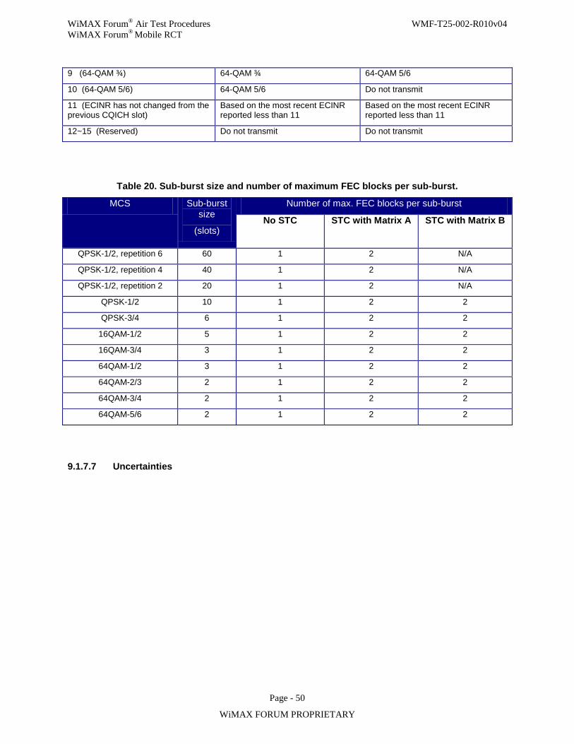
WiMAX Forum® Air Test Procedures WMF-T25-002-R010v04 WiMAX Forum® Mobile RCT
Page - 50
WiMAX FORUM PROPRIETARY
9 (64-QAM ¾) 64-QAM ¾ 64-QAM 5/6
10 (64-QAM 5/6) 64-QAM 5/6 Do not transmit
11 (ECINR has not changed from the previous CQICH slot)
Based on the most recent ECINR reported less than 11
Based on the most recent ECINR reported less than 11
12~15 (Reserved) Do not transmit Do not transmit
Table 20. Sub-burst size and number of maximum FEC blocks per sub-burst.
MCS Sub-burst size
(slots)
Number of max. FEC blocks per sub-burst
No STC
STC with Matrix A STC with Matrix B
QPSK-1/2, repetition 6 60 1 2 N/A
QPSK-1/2, repetition 4 40 1 2 N/A
QPSK-1/2, repetition 2 20 1 2 N/A
QPSK-1/2 10 1 2 2
QPSK-3/4 6 1 2 2
16QAM-1/2 5 1 2 2
16QAM-3/4 3 1 2 2
64QAM-1/2 3 1 2 2
64QAM-2/3 2 1 2 2
64QAM-3/4 2 1 2 2
64QAM-5/6 2 1 2 2
9.1.7.7 Uncertainties
WiMAX Forum® Air Test Procedures WMF-T25-002-R010v04 WiMAX Forum® Mobile RCT
Page - 51
WiMAX FORUM PROPRIETARY
9.1.8 MS-07.1: MS receiver adjacent and non-adjacent channel selectivity The purpose of this test is to verify that the MS receiver can meet the Adjacent and Non-adjacent Channel Selectivity defined in IEEE Std 802.16-2004, IEEE Std 802.16e-2005, and the Mobile System Profile.
9.1.8.1 Introduction
The adjacent and non-adjacent channel selectivity performance depends on both ACLR (Adjacent Channel Leakage power Ratio) of the interferer transmitter and the ACS (Adjacent Channel Selectivity) of the receiver. The interference experienced in a realistic environment can come from different sources depending on the type of interferers and their out-of-band emission masks, as well as the channel spacing. The standard does not specify the type of interferers, but rather just describes the test as:
“The adjacent channel selectivity and alternate channel selectivity shall be measured by setting the desired signal’s strength 3dB above the rate dependent receiver sensitivity and raising the power level of the interfering signal until the specified error rate is obtained. The power different between the interfering signal and the desired channel is the corresponding adjacent channel selectivity. The interfering signal in the adjacent channel shall be a conforming OFMDA signal, not synchronized with the signal in the channel under test. For non-adjacent channel testing the test method is identical except the interfering channel shall be any channel other than the adjacent channel or the co-channel.”
ACS is a measure of a receiver’s ability to receive a OFDMA signal at its assigned channel frequency in the presence of an adjacent channel signal at a given frequency offset from the centre frequency of the assigned channel. ACS is the ratio of the receive filter attenuation on the assigned channel frequency to the receive filter attenuation on the adjacent channel(s).
The Adjacent Channel Interference Power Ratio (ACIR) is the ratio of the total power transmitted from a source (both BS and MS) to the total interference power affecting a victim receiver, resulting from both transmitter and receiver imperfections.
When the ACLR of the interference source is much better than receiver ACS performance, the adjacent channel selectivity performance is determined by the ACS performance.
11 1ACIR
ACLR ACS
=+
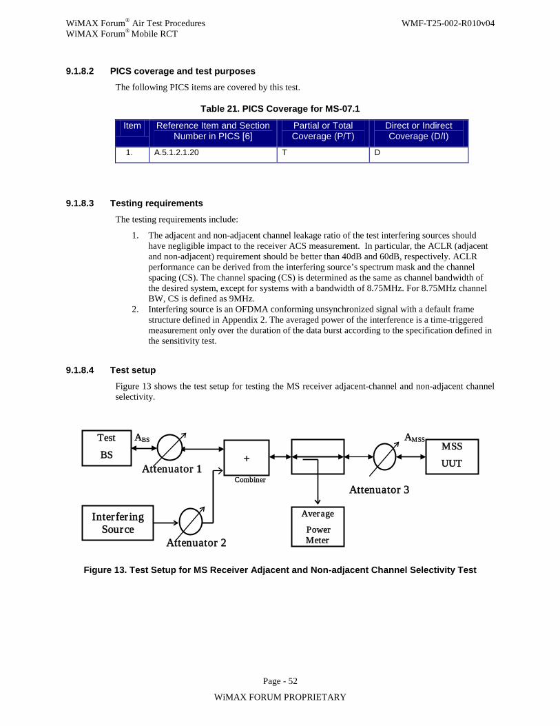
WiMAX Forum® Air Test Procedures WMF-T25-002-R010v04 WiMAX Forum® Mobile RCT
Page - 52
WiMAX FORUM PROPRIETARY
9.1.8.2 PICS coverage and test purposes
The following PICS items are covered by this test.
Table 21. PICS Coverage for MS-07.1
Item Reference Item and Section Number in PICS [6]
Partial or Total Coverage (P/T)
Direct or Indirect Coverage (D/I)
1. A.5.1.2.1.20 T D
9.1.8.3 Testing requirements
The testing requirements include:
1. The adjacent and non-adjacent channel leakage ratio of the test interfering sources should have negligible impact to the receiver ACS measurement. In particular, the ACLR (adjacent and non-adjacent) requirement should be better than 40dB and 60dB, respectively. ACLR performance can be derived from the interfering source’s spectrum mask and the channel spacing (CS). The channel spacing (CS) is determined as the same as channel bandwidth of the desired system, except for systems with a bandwidth of 8.75MHz. For 8.75MHz channel BW, CS is defined as 9MHz.
2. Interfering source is an OFDMA conforming unsynchronized signal with a default frame structure defined in Appendix 2. The averaged power of the interference is a time-triggered measurement only over the duration of the data burst according to the specification defined in the sensitivity test.
9.1.8.4 Test setup
Figure 13 shows the test setup for testing the MS receiver adjacent-channel and non-adjacent channel selectivity.
Figure 13. Test Setup for MS Receiver Adjacent and Non-adjacent Channel Selectivity Test
Attenuator 2
Test
BS
Average
Power Meter
MSS
UUT
ABS
Attenuator 1
AMSS
+
Inter fer ing Source
Combiner Attenuator 3
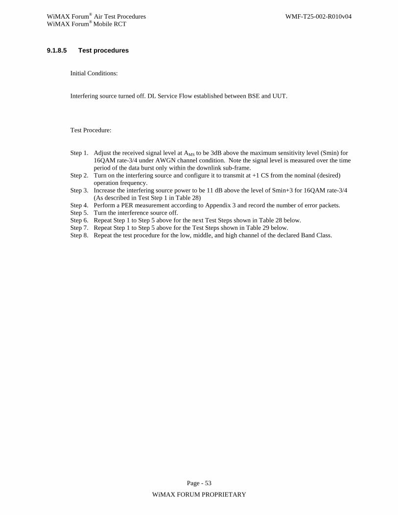
WiMAX Forum® Air Test Procedures WMF-T25-002-R010v04 WiMAX Forum® Mobile RCT
Page - 53
WiMAX FORUM PROPRIETARY
9.1.8.5 Test procedures
Initial Conditions:
Interfering source turned off. DL Service Flow established between BSE and UUT.
Test Procedure:
Step 1. Adjust the received signal level at AMS to be 3dB above the maximum sensitivity level (Smin) for 16QAM rate-3/4 under AWGN channel condition. Note the signal level is measured over the time period of the data burst only within the downlink sub-frame.
Step 2. Turn on the interfering source and configure it to transmit at +1 CS from the nominal (desired) operation frequency.
Step 3. Increase the interfering source power to be 11 dB above the level of Smin+3 for 16QAM rate-3/4 (As described in Test Step 1 in Table 28)
Step 4. Perform a PER measurement according to Appendix 3 and record the number of error packets. Step 5. Turn the interference source off. Step 6. Repeat Step 1 to Step 5 above for the next Test Steps shown in Table 28 below. Step 7. Repeat Step 1 to Step 5 above for the Test Steps shown in Table 29 below. Step 8. Repeat the test procedure for the low, middle, and high channel of the declared Band Class.
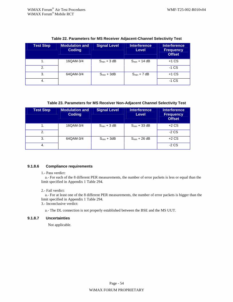
WiMAX Forum® Air Test Procedures WMF-T25-002-R010v04 WiMAX Forum® Mobile RCT
Page - 54
WiMAX FORUM PROPRIETARY
Table 22. Parameters for MS Receiver Adjacent-Channel Selectivity Test
Test Step Modulation and Coding
Signal Level Interference Level
Interference Frequency
Offset
1. 16QAM-3/4 Smin + 3 dB Smin + 14 dB +1 CS
2. -1 CS
3. 64QAM-3/4 Smin + 3dB Smin + 7 dB +1 CS
4. -1 CS
Table 23. Parameters for MS Receiver Non-Adjacent Channel Selectivity Test
Test Step Modulation and Coding
Signal Level Interference Level
Interference Frequency
Offset
1. 16QAM-3/4 Smin + 3 dB Smin + 33 dB +2 CS
2. -2 CS
3. 64QAM-3/4 Smin + 3dB Smin + 26 dB +2 CS
4. -2 CS
9.1.8.6 Compliance requirements 1.- Pass verdict: a.- For each of the 8 different PER measurements, the number of error packets is less or equal than the limit specified in Appendix 1 Table 294. 2.- Fail verdict: a.- For at least one of the 8 different PER measurements, the number of error packets is bigger than the limit specified in Appendix 1 Table 294. 3.- Inconclusive verdict:
a.- The DL connection is not properly established between the BSE and the MS UUT.
9.1.8.7 Uncertainties
Not applicable.
WiMAX Forum® Air Test Procedures WMF-T25-002-R010v04 WiMAX Forum® Mobile RCT
Page - 55
WiMAX FORUM PROPRIETARY
9.1.9 MS-08.1: MS receiver maximum input signal The purpose of this test is to verify MS is capable of decoding an on-channel input signal with maximum required power.
9.1.9.1 Introduction
Mobile WiMAX® System Profile and IEEE Std 802.16e-2005 [Section 8.4.13.3.1] requires the MS receiver shall be capable of decoding a maximum on-channel signal of -30dBm. This is verified by measuring the packet error rates at least robust modulation and coding, and verifying that packet error rate is lower than the defined limits.
9.1.9.2 PICS coverage and test purposes
The following PICS items are covered by this test. This test is applicable to all MS as a mandatory requirement.
Table 24. PICS Coverage for MS-08.1
Item Reference Item and Section Number in PICS [6]
Partial or Total Coverage (P/T)
Direct or Indirect Coverage (D/I)
1. Item 1 section A5.1.1.1.19 T D
9.1.9.3 Testing requirements
This test requires the test system to be generating DL bursts as defined below. The MS UUT is to set up a downlink connection with the test system at receive signal level of -30dBm, and measure packet error rate for 64QAM DL modulation with packet lengths as specified in Appendix 1.
The test shall be performed with:
a) 5ms frame b) a cyclic prefix of Tb/8 c) a modulation and coding of 64QAM d) one packet per burst per frame e) number of packets as defined in Table 32. f) channel bandwidth selected according to declared Band Class.
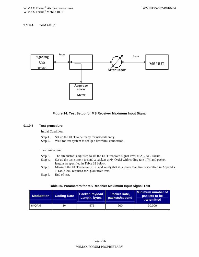
WiMAX Forum® Air Test Procedures WMF-T25-002-R010v04 WiMAX Forum® Mobile RCT
Page - 56
WiMAX FORUM PROPRIETARY
9.1.9.4 Test setup
Figure 14. Test Setup for MS Receiver Maximum Input Signal
9.1.9.5 Test procedure Initial Condition:
Step 1. Set up the UUT to be ready for network entry. Step 2. Wait for test system to set up a downlink connection.
Test Procedure:
Step 3. The attenuator is adjusted to set the UUT received signal level at AMS to -30dBm. Step 4. Set up the test system to send n packets at 64 QAM with coding rate of ¾ and packet
lengths as specified in Table 32 below. Step 5. Measure the UUT receiver PER, and verify that it is lower than limits specified in Appendix
1 Table 294 required for Qualitative tests Step 6. End of test.
Table 25. Parameters for MS Receiver Maximum Input Signal Test
Modulation Coding Rate Packet Payload Length, bytes
Packet Rate, packets/second
Minimum number of packets to be transmitted
64QAM 3/4 576 200 30,000
Signaling
Unit
(BSE)
Avgerage Power
Meter
MS UUT
AMS/BS
Attenuator
ABS/MS
WiMAX Forum® Air Test Procedures WMF-T25-002-R010v04 WiMAX Forum® Mobile RCT
Page - 57
WiMAX FORUM PROPRIETARY
9.1.9.6 Compliance requirements
1- Pass verdict:
a- The number of error packets is less or equal than the limit specified in Appendix 1 Table 294.
2- Fail verdict:
a- The number of error packets is bigger than the limit specified in Appendix 1 Table 294.
3- Inconclusive verdict:
a- The DL connection is not properly established between the BSE and the MS UUT in Step 2.
Table 26. Packet Error Rate limits (64QAM)
Packet Length, bytes Threshold PER Number of packets sent N
Maximum number of error packets M
576+38 0.49% 30,000 147
576+10 0.47% 30,000 141
9.1.9.7 Uncertainties
1. Not applicable.
9.1.10 MS-09.1: MS receiver sensitivity The purpose of the test is to verify that the receiver is compliant to the sensitivity requirements as specified in the PICS document and the mobile profile. The requirements are for various MCS levels and the test channel conditions include both AWGN and fading.
9.1.10.1 Introduction In order to be compliant to the receiver sensitivity requirement, the receiver is required to achieve a Packet Error Rate (PER) equal to or better than a certain target level when the received signal is set at the sensitivity level.
The PER, rather than the Bit Error Rate (BER), is calculated over a large number of frames to verify that the performance is better than or equal to the target PER. For AWGN channels, the target PER is converted from the packet size and the standard requirement of BER=1e-6, assuming independent error event after decoding (Appendix 1). For fading channels, the target PER is 10%, which is assumed to be near the target PER of a first HARQ transmission.
Two options of test mechanisms can be used for this test:
1. ACK/NACK mechanism (mandatory for wave-2): The packets are allocated in HARQ DL MAP IE with assigned ACK channel for MS UUT to feed back either ACK or NACK for each of the data packets (bursts) transmitted in the previous frame. The ACK/NACK feedback mechanism is the same as used in HARQ operation, even though the Test BS will not re-transmit in the case of receiving a NACK. Each packet transmitted in a frame is a new packet (i.e., AI_SN toggles at each frame). The downlink allocation information for each
WiMAX Forum® Air Test Procedures WMF-T25-002-R010v04 WiMAX Forum® Mobile RCT
Page - 58
WiMAX FORUM PROPRIETARY
packet (burst) is conveyed in HARQ DL MAP IE and the receiver feeds back ACK/NACK in the assigned ACK channels within the specified HARQ ACK region.
2. Ping mechanism (optional for wave-1): The Signaling Unit (BS emulator) uses the Ping command to send some payload bits to the MS UUT at an interval of 5ms (one frame). The MS will send the payload back if it is decoded successfully.
The packet size for AWGN, including all headers and CRC, is chosen to be 540 bytes. However for fading test, the packet length is chosen to be, after encoding, a single FEC block with a maximum data size allowed by the CTC subchannel concatenation rule, i.e., 60/54/48 bytes depending on the particular MCS level. The actual number of payload bits for the two test mechanism is:
1. ACK/NACK mechanism: Each data packet consists of a 6-byte generic MAC header at the beginning and a 2-byte CRC-16 at the end, leaving the remaining as payload bits. Random payload bits are used. The CRC is calculated based on MAC header and the payload.
2. Ping mechanism (optional for wave-1): The header size in a Ping message is 28 bytes with 8 bytes of ICMP control message. In addition to the 28 bytes header in each Ping message, there will be a 6-byte generic MAC header at the beginning and a 4-byte CRC-32 at the end. The Ping payload data length can be variable from 0 to 65535 bytes. So, for AWGN test case, the ping payload is 540-28-10=502 bytes and for fading test case, the ping payload will be 22/16/10 bytes, corresponding to PDU sizes of 60/54/48 bytes respectively. Random payload bits are used. The CRC is calculated based on MAC header and the payload.
One (1) packet (burst) is allocated in a data PUSC/AMC zone after the first PUSC zone for control message (MAP and DCD). The data zone extends to the end of the DL sub-frame. The allocation starts from slot 1+mod(n, Nsch) where n is the frame index and Nsch is the number of slots in the frequency domain (e.g., 15 in 512-point FFT PUSC). The rest of slots in the data zone (before and after the allocated burst) can use random QPSK symbols. Corresponding to those slots, BSE should use a different CID in the MAP meesage. The per-subcarrier transmit power level of the rest of the data zone is kept the same as the per-subcarrier of the data burst so that the signal power measured for the entire data zone is the same as that in the allocation to the MS UUT.
9.1.10.2 PICS coverage and test purposes
The following PICS items are covered by this test.
Table 27. PICS Coverage for MS-09.1
Item Reference Item and Section Number in PICS [6]
Partial or Total Coverage (P/T)
Direct or Indirect Coverage (D/I)
1. A.5.1.1.1.17 P D
9.1.10.3 Testing requirements The input signal level, averaged only over the data zone, needs to be set at the appropriate levels, which may requires a time-triggered measurement. Moreover, the power level should be the average over data subcarriers only. If this cannot be achieved, which means that the boosted pilots are also included in the power density adjustment, the 2.5 dB (16/9) pilot boosting should be taken into account. The input power level should be set as the sensitivity level given in the PICS tables plus an offset computed as 10log10[(N_data+N_pilot*16/9)/(N_data+N_pilot)] (given in Table 36):
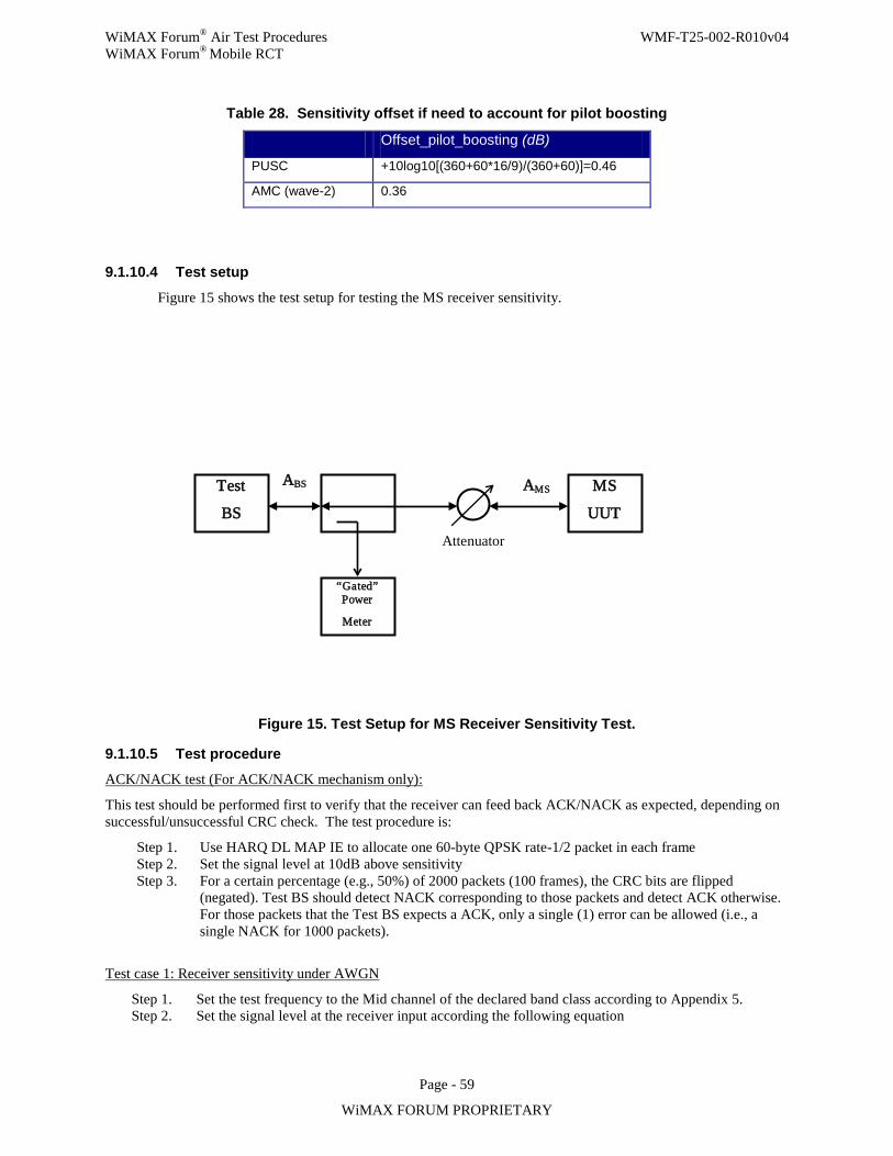
WiMAX Forum® Air Test Procedures WMF-T25-002-R010v04 WiMAX Forum® Mobile RCT
Page - 59
WiMAX FORUM PROPRIETARY
Table 28. Sensitivity offset if need to account for pilot boosting
Offset_pilot_boosting (dB)
PUSC +10log10[(360+60*16/9)/(360+60)]=0.46
AMC (wave-2) 0.36
9.1.10.4 Test setup
Figure 15 shows the test setup for testing the MS receiver sensitivity.
Figure 15. Test Setup for MS Receiver Sensitivity Test.
9.1.10.5 Test procedure ACK/NACK test (For ACK/NACK mechanism only):
This test should be performed first to verify that the receiver can feed back ACK/NACK as expected, depending on successful/unsuccessful CRC check. The test procedure is:
Step 1. Use HARQ DL MAP IE to allocate one 60-byte QPSK rate-1/2 packet in each frame Step 2. Set the signal level at 10dB above sensitivity Step 3. For a certain percentage (e.g., 50%) of 2000 packets (100 frames), the CRC bits are flipped
(negated). Test BS should detect NACK corresponding to those packets and detect ACK otherwise. For those packets that the Test BS expects a ACK, only a single (1) error can be allowed (i.e., a single NACK for 1000 packets).
Test case 1: Receiver sensitivity under AWGN
Step 1. Set the test frequency to the Mid channel of the declared band class according to Appendix 5. Step 2. Set the signal level at the receiver input according the following equation
Test
BS
“Gated” Power
Meter
MS
UUT
ABS
Attenuator
AMS
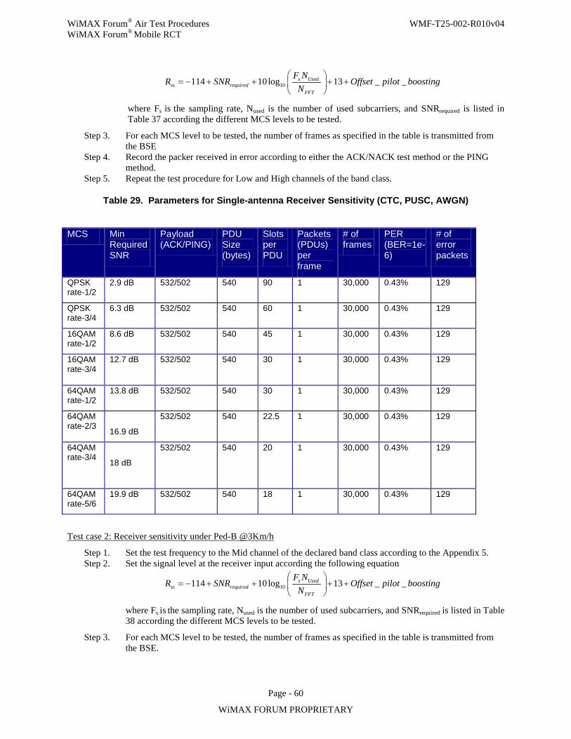
WiMAX Forum® Air Test Procedures WMF-T25-002-R010v04 WiMAX Forum® Mobile RCT
Page - 60
WiMAX FORUM PROPRIETARY
10114 10log 13 _ _s Usedss required
FFT
F NR SNR Offset pilot boosting
N
= − + + + +
where Fs is the sampling rate, Nused is the number of used subcarriers, and SNRrequired is listed in Table 37 according the different MCS levels to be tested.
Step 3. For each MCS level to be tested, the number of frames as specified in the table is transmitted from the BSE
Step 4. Record the packer received in error according to either the ACK/NACK test method or the PING method.
Step 5. Repeat the test procedure for Low and High channels of the band class.
Table 29. Parameters for Single-antenna Receiver Sensitivity (CTC, PUSC, AWGN)
MCS Min Required SNR
Payload (ACK/PING)
PDU Size (bytes)
Slots per PDU
Packets (PDUs) per frame
# of frames
PER (BER=1e-6)
# of error packets
QPSK rate-1/2
2.9 dB 532/502 540 90 1 30,000 0.43% 129
QPSK rate-3/4
6.3 dB 532/502 540 60 1 30,000 0.43% 129
16QAM rate-1/2
8.6 dB 532/502 540 45 1 30,000 0.43% 129
16QAM rate-3/4
12.7 dB
532/502 540 30 1 30,000 0.43% 129
64QAM rate-1/2
13.8 dB 532/502 540 30 1 30,000 0.43% 129
64QAM rate-2/3
16.9 dB
532/502 540 22.5 1 30,000 0.43% 129
64QAM rate-3/4
18 dB
532/502 540 20 1 30,000 0.43% 129
64QAM rate-5/6
19.9 dB 532/502 540 18 1 30,000 0.43% 129
Test case 2: Receiver sensitivity under Ped-B @3Km/h
Step 1. Set the test frequency to the Mid channel of the declared band class according to the Appendix 5. Step 2. Set the signal level at the receiver input according the following equation
10114 10log 13 _ _s Usedss required
FFT
F NR SNR Offset pilot boosting
N
= − + + + +
where Fs is the sampling rate, Nused is the number of used subcarriers, and SNRrequired is listed in Table 38 according the different MCS levels to be tested.
Step 3. For each MCS level to be tested, the number of frames as specified in the table is transmitted from the BSE.
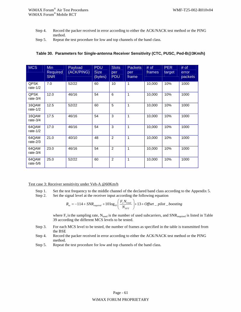
WiMAX Forum® Air Test Procedures WMF-T25-002-R010v04 WiMAX Forum® Mobile RCT
Page - 61
WiMAX FORUM PROPRIETARY
Step 4. Record the packer received in error according to either the ACK/NACK test method or the PING method.
Step 5. Repeat the test procedure for low and top channels of the band class.
Table 30. Parameters for Single-antenna Receiver Sensitivity (CTC, PUSC, Ped-B@3Km/h)
MCS Min Required SNR
Payload (ACK/PING)
PDU Size (bytes)
Slots per PDU
Packets per frame
# of frames
PER target
# of error packets
QPSK rate-1/2
7.0 52/22 60 10 1 10,000 10% 1000
QPSK rate-3/4
12.0 46/16 54 6 1 10,000 10% 1000
16QAM rate-1/2
12.5 52/22 60 5 1 10,000 10% 1000
16QAM rate-3/4
17.5 46/16 54 3 1 10,000 10% 1000
64QAM rate-1/2
17.0 46/16 54 3 1 10,000 10% 1000
64QAM rate-2/3
21.0 40/10 48 2 1 10,000 10% 1000
64QAM rate-3/4
23.0 46/16 54 2 1 10,000 10% 1000
64QAM rate-5/6
25.0 52/22 60 2 1 10,000 10% 1000
Test case 3: Receiver sensitivity under Veh-A @60Km/h
Step 1. Set the test frequency to the middle channel of the declared band class according to the Appendix 5. Step 2. Set the signal level at the receiver input according the following equation
10114 10log 13 _ _s Usedss required
FFT
F NR SNR Offset pilot boosting
N
= − + + + +
where Fs is the sampling rate, Nused is the number of used subcarriers, and SNRrequired is listed in Table 39 according the different MCS levels to be tested.
Step 3. For each MCS level to be tested, the number of frames as specified in the table is transmitted from the BSE
Step 4. Record the packer received in error according to either the ACK/NACK test method or the PING method.
Step 5. Repeat the test procedure for low and top channels of the band class.
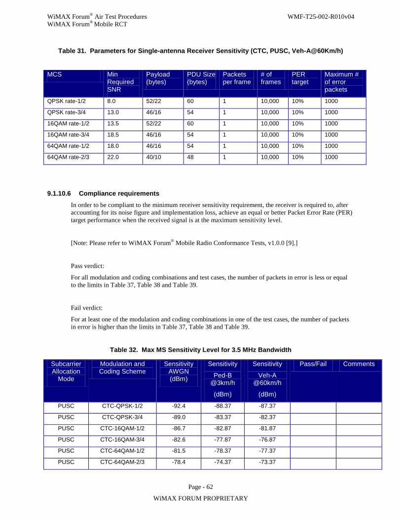
WiMAX Forum® Air Test Procedures WMF-T25-002-R010v04 WiMAX Forum® Mobile RCT
Page - 62
WiMAX FORUM PROPRIETARY
Table 31. Parameters for Single-antenna Receiver Sensitivity (CTC, PUSC, Veh-A@60Km/h)
MCS Min Required SNR
Payload (bytes)
PDU Size (bytes)
Packets per frame
# of frames
PER target
Maximum # of error packets
QPSK rate-1/2 8.0 52/22 60 1 10,000 10% 1000
QPSK rate-3/4 13.0 46/16 54 1 10,000 10% 1000
16QAM rate-1/2 13.5 52/22 60 1 10,000 10% 1000
16QAM rate-3/4 18.5 46/16 54 1 10,000 10% 1000
64QAM rate-1/2 18.0 46/16 54 1 10,000 10% 1000
64QAM rate-2/3 22.0 40/10 48 1 10,000 10% 1000
9.1.10.6 Compliance requirements
In order to be compliant to the minimum receiver sensitivity requirement, the receiver is required to, after accounting for its noise figure and implementation loss, achieve an equal or better Packet Error Rate (PER) target performance when the received signal is at the maximum sensitivity level.
[Note: Please refer to WiMAX Forum® Mobile Radio Conformance Tests, v1.0.0 [9].]
Pass verdict:
For all modulation and coding combinations and test cases, the number of packets in error is less or equal to the limits in Table 37, Table 38 and Table 39.
Fail verdict:
For at least one of the modulation and coding combinations in one of the test cases, the number of packets in error is higher than the limits in Table 37, Table 38 and Table 39.
Table 32. Max MS Sensitivity Level for 3.5 MHz Bandwidth
Subcarrier Allocation
Mode
Modulation and Coding Scheme
Sensitivity AWGN (dBm)
Sensitivity
Ped-B @3km/h
(dBm)
Sensitivity
Veh-A @60km/h
(dBm)
Pass/Fail Comments
PUSC CTC-QPSK-1/2 -92.4 -88.37 -87.37
PUSC CTC-QPSK-3/4 -89.0 -83.37 -82.37
PUSC CTC-16QAM-1/2 -86.7 -82.87 -81.87
PUSC CTC-16QAM-3/4 -82.6 -77.87 -76.87
PUSC CTC-64QAM-1/2 -81.5 -78.37 -77.37
PUSC CTC-64QAM-2/3 -78.4 -74.37 -73.37
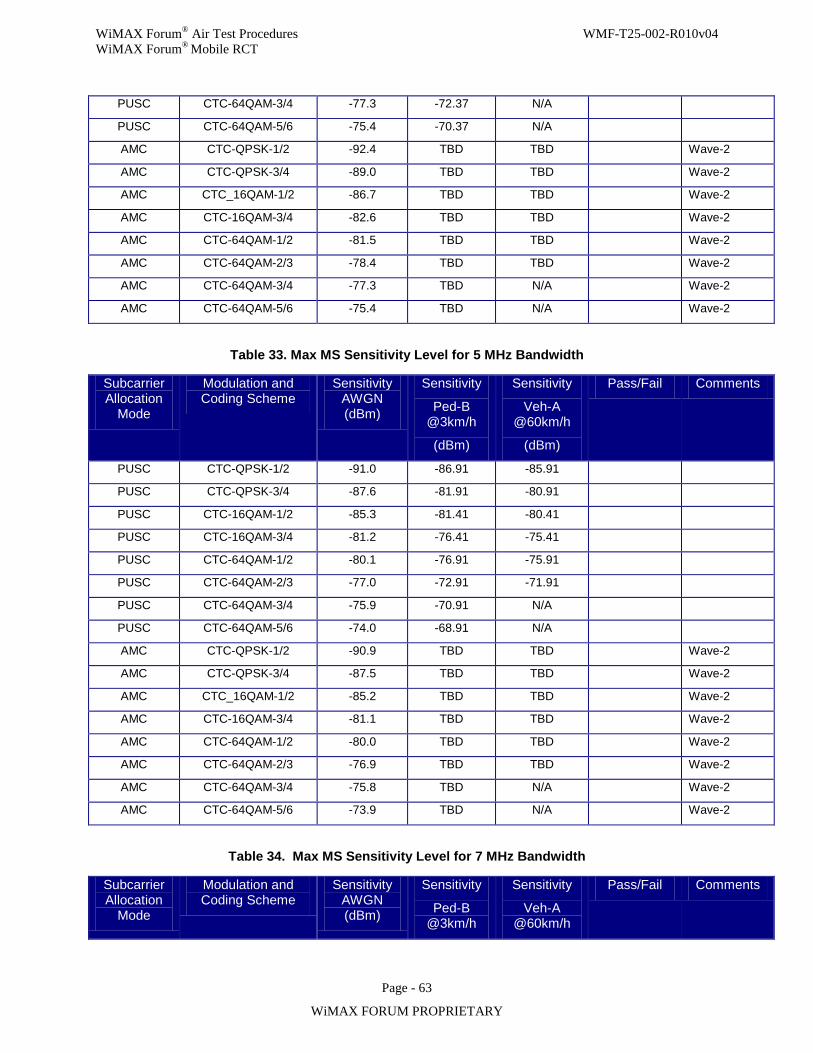
WiMAX Forum® Air Test Procedures WMF-T25-002-R010v04 WiMAX Forum® Mobile RCT
Page - 63
WiMAX FORUM PROPRIETARY
PUSC CTC-64QAM-3/4 -77.3 -72.37 N/A
PUSC CTC-64QAM-5/6 -75.4 -70.37 N/A
AMC CTC-QPSK-1/2 -92.4 TBD TBD Wave-2
AMC CTC-QPSK-3/4 -89.0 TBD TBD Wave-2
AMC CTC_16QAM-1/2 -86.7 TBD TBD Wave-2
AMC CTC-16QAM-3/4 -82.6 TBD TBD Wave-2
AMC CTC-64QAM-1/2 -81.5 TBD TBD Wave-2
AMC CTC-64QAM-2/3 -78.4 TBD TBD Wave-2
AMC CTC-64QAM-3/4 -77.3 TBD N/A Wave-2
AMC CTC-64QAM-5/6 -75.4 TBD N/A Wave-2
Table 33. Max MS Sensitivity Level for 5 MHz Bandwidth
Subcarrier Allocation
Mode
Modulation and Coding Scheme
Sensitivity AWGN (dBm)
Sensitivity
Ped-B @3km/h
(dBm)
Sensitivity
Veh-A @60km/h
(dBm)
Pass/Fail Comments
PUSC CTC-QPSK-1/2 -91.0 -86.91 -85.91
PUSC CTC-QPSK-3/4 -87.6 -81.91 -80.91
PUSC CTC-16QAM-1/2 -85.3 -81.41 -80.41
PUSC CTC-16QAM-3/4 -81.2 -76.41 -75.41
PUSC CTC-64QAM-1/2 -80.1 -76.91 -75.91
PUSC CTC-64QAM-2/3 -77.0 -72.91 -71.91
PUSC CTC-64QAM-3/4 -75.9 -70.91 N/A
PUSC CTC-64QAM-5/6 -74.0 -68.91 N/A
AMC CTC-QPSK-1/2 -90.9 TBD TBD Wave-2
AMC CTC-QPSK-3/4 -87.5 TBD TBD Wave-2
AMC CTC_16QAM-1/2 -85.2 TBD TBD Wave-2
AMC CTC-16QAM-3/4 -81.1 TBD TBD Wave-2
AMC CTC-64QAM-1/2 -80.0 TBD TBD Wave-2
AMC CTC-64QAM-2/3 -76.9 TBD TBD Wave-2
AMC CTC-64QAM-3/4 -75.8 TBD N/A Wave-2
AMC CTC-64QAM-5/6 -73.9 TBD N/A Wave-2
Table 34. Max MS Sensitivity Level for 7 MHz Bandwidth
Subcarrier Allocation
Mode
Modulation and Coding Scheme
Sensitivity AWGN (dBm)
Sensitivity
Ped-B @3km/h
Sensitivity
Veh-A @60km/h
Pass/Fail Comments
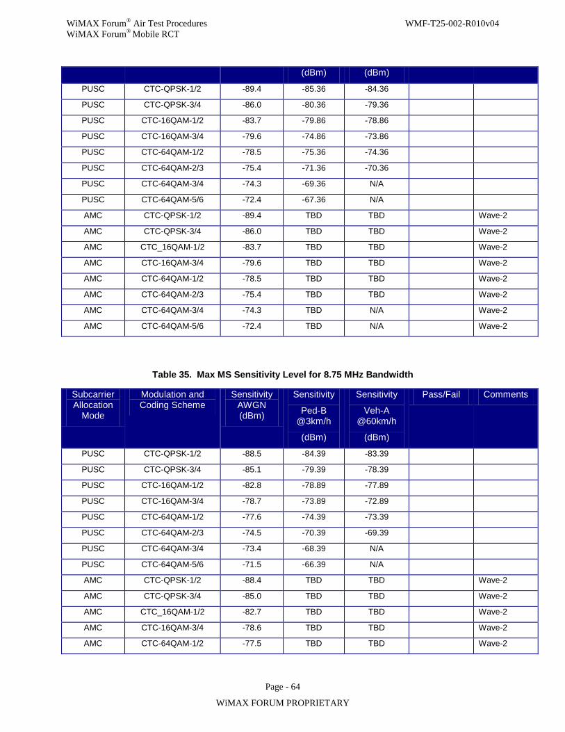
WiMAX Forum® Air Test Procedures WMF-T25-002-R010v04 WiMAX Forum® Mobile RCT
Page - 64
WiMAX FORUM PROPRIETARY
(dBm) (dBm)
PUSC CTC-QPSK-1/2 -89.4 -85.36 -84.36
PUSC CTC-QPSK-3/4 -86.0 -80.36 -79.36
PUSC CTC-16QAM-1/2 -83.7 -79.86 -78.86
PUSC CTC-16QAM-3/4 -79.6 -74.86 -73.86
PUSC CTC-64QAM-1/2 -78.5 -75.36 -74.36
PUSC CTC-64QAM-2/3 -75.4 -71.36 -70.36
PUSC CTC-64QAM-3/4 -74.3 -69.36 N/A
PUSC CTC-64QAM-5/6 -72.4 -67.36 N/A
AMC CTC-QPSK-1/2 -89.4 TBD TBD Wave-2
AMC CTC-QPSK-3/4 -86.0 TBD TBD Wave-2
AMC CTC_16QAM-1/2 -83.7 TBD TBD Wave-2
AMC CTC-16QAM-3/4 -79.6 TBD TBD Wave-2
AMC CTC-64QAM-1/2 -78.5 TBD TBD Wave-2
AMC CTC-64QAM-2/3 -75.4 TBD TBD Wave-2
AMC CTC-64QAM-3/4 -74.3 TBD N/A Wave-2
AMC CTC-64QAM-5/6 -72.4 TBD N/A Wave-2
Table 35. Max MS Sensitivity Level for 8.75 MHz Bandwidth
Subcarrier Allocation
Mode
Modulation and Coding Scheme
Sensitivity AWGN (dBm)
Sensitivity
Ped-B @3km/h
(dBm)
Sensitivity
Veh-A @60km/h
(dBm)
Pass/Fail Comments
PUSC CTC-QPSK-1/2 -88.5 -84.39 -83.39
PUSC CTC-QPSK-3/4 -85.1 -79.39 -78.39
PUSC CTC-16QAM-1/2 -82.8 -78.89 -77.89
PUSC CTC-16QAM-3/4 -78.7 -73.89 -72.89
PUSC CTC-64QAM-1/2 -77.6 -74.39 -73.39
PUSC CTC-64QAM-2/3 -74.5 -70.39 -69.39
PUSC CTC-64QAM-3/4 -73.4 -68.39 N/A
PUSC CTC-64QAM-5/6 -71.5 -66.39 N/A
AMC CTC-QPSK-1/2 -88.4 TBD TBD Wave-2
AMC CTC-QPSK-3/4 -85.0 TBD TBD Wave-2
AMC CTC_16QAM-1/2 -82.7 TBD TBD Wave-2
AMC CTC-16QAM-3/4 -78.6 TBD TBD Wave-2
AMC CTC-64QAM-1/2 -77.5 TBD TBD Wave-2
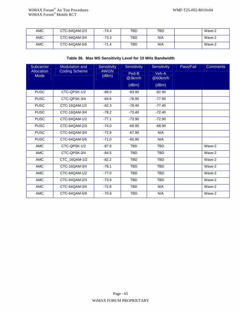
WiMAX Forum® Air Test Procedures WMF-T25-002-R010v04 WiMAX Forum® Mobile RCT
Page - 65
WiMAX FORUM PROPRIETARY
AMC CTC-64QAM-2/3 -74.4 TBD TBD Wave-2
AMC CTC-64QAM-3/4 -73.3 TBD N/A Wave-2
AMC CTC-64QAM-5/6 -71.4 TBD N/A Wave-2
Table 36. Max MS Sensitivity Level for 10 MHz Bandwidth
Subcarrier Allocation
Mode
Modulation and Coding Scheme
Sensitivity AWGN (dBm)
Sensitivity
Ped-B @3km/h
(dBm)
Sensitivity
Veh-A @60km/h
(dBm)
Pass/Fail Comments
PUSC CTC-QPSK-1/2 -88.0 -83.90 -82.90
PUSC CTC-QPSK-3/4 -84.6 -78.90 -77.90
PUSC CTC-16QAM-1/2 -82.3 -78.40 -77.40
PUSC CTC-16QAM-3/4 -78.2 -73.40 -72.40
PUSC CTC-64QAM-1/2 -77.1 -73.90 -72.90
PUSC CTC-64QAM-2/3 -74.0 -69.90 -68.90
PUSC CTC-64QAM-3/4 -72.9 -67.90 N/A
PUSC CTC-64QAM-5/6 -71.0 -65.90 N/A
AMC CTC-QPSK-1/2 -87.9 TBD TBD Wave-2
AMC CTC-QPSK-3/4 -84.5 TBD TBD Wave-2
AMC CTC_16QAM-1/2 -82.2 TBD TBD Wave-2
AMC CTC-16QAM-3/4 -78.1 TBD TBD Wave-2
AMC CTC-64QAM-1/2 -77.0 TBD TBD Wave-2
AMC CTC-64QAM-2/3 -73.9 TBD TBD Wave-2
AMC CTC-64QAM-3/4 -72.8 TBD N/A Wave-2
AMC CTC-64QAM-5/6 -70.9 TBD N/A Wave-2
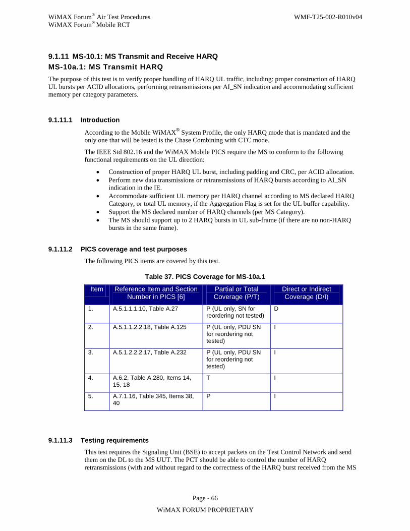
WiMAX Forum® Air Test Procedures WMF-T25-002-R010v04 WiMAX Forum® Mobile RCT
Page - 66
WiMAX FORUM PROPRIETARY
9.1.11 MS-10.1: MS Transmit and Receive HARQ MS-10a.1: MS Transmit HARQ The purpose of this test is to verify proper handling of HARQ UL traffic, including: proper construction of HARQ UL bursts per ACID allocations, performing retransmissions per AI_SN indication and accommodating sufficient memory per category parameters.
9.1.11.1 Introduction
According to the Mobile WiMAX® System Profile, the only HARQ mode that is mandated and the only one that will be tested is the Chase Combining with CTC mode.
The IEEE Std 802.16 and the WiMAX Mobile PICS require the MS to conform to the following functional requirements on the UL direction:
• Construction of proper HARQ UL burst, including padding and CRC, per ACID allocation. • Perform new data transmissions or retransmissions of HARQ bursts according to AI_SN
indication in the IE. • Accommodate sufficient UL memory per HARQ channel according to MS declared HARQ
Category, or total UL memory, if the Aggregation Flag is set for the UL buffer capability. • Support the MS declared number of HARQ channels (per MS Category). • The MS should support up to 2 HARQ bursts in UL sub-frame (if there are no non-HARQ
bursts in the same frame).
9.1.11.2 PICS coverage and test purposes
The following PICS items are covered by this test.
Table 37. PICS Coverage for MS-10a.1
Item Reference Item and Section Number in PICS [6]
Partial or Total Coverage (P/T)
Direct or Indirect Coverage (D/I)
1. A.5.1.1.1.10, Table A.27 P (UL only, SN for reordering not tested)
D
2. A.5.1.1.2.2.18, Table A.125 P (UL only, PDU SN for reordering not tested)
I
3. A.5.1.2.2.2.17, Table A.232 P (UL only, PDU SN for reordering not tested)
I
4. A.6.2, Table A.280, Items 14, 15, 18
T I
5. A.7.1.16, Table 345, Items 38, 40
P I
9.1.11.3 Testing requirements This test requires the Signaling Unit (BSE) to accept packets on the Test Control Network and send them on the DL to the MS UUT. The PCT should be able to control the number of HARQ retransmissions (with and without regard to the correctness of the HARQ burst received from the MS
WiMAX Forum® Air Test Procedures WMF-T25-002-R010v04 WiMAX Forum® Mobile RCT
Page - 67
WiMAX FORUM PROPRIETARY
UUT), the repetition code of each burst, and the UIUC for all UL allocations (to control the MCS used for each burst).
The Signaling Unit (BSE) should also be able to forward packets received from the MS UUT to the PCT for inspection. Moreover, the Signaling Unit (BSE) should be capable of forwarding all management messages received from the MS UUT, for inspection by the PCT.
Some control of the Signaling Unit (BSE)’s scheduling is required (See details in Section 9.1.11.5).
The Signaling Unit (BSE) shall support category 4 HARQ UL (receive) buffer and support the aggregate capability when receiving HARQ UL bursts sent by the MS UUT.
The Signaling Unit (BSE) shall be able to verify that burst retransmissions by the MS UUT are identical to the original transmission of the same burst. (The signaling Unit may use HARQ combining or any other method for this purpose.)
The RCTT shall control the Signaling Unit (BSE)’s transmit power and the power with which the Signaling Unit (BSE) instructs the MS UUT to transmit.
The Signaling Unit (BSE) shall be configured to comply with the appropriate band class for the MS UUT, and will be configured to use a single zone in the UL or DL during this test. The DL/UL ratio should be set according to Table 48.
Unless otherwise indicated in the test procedure, the MAPs sent by the Signaling Unit (BSE) should be sent with the following MCS and repetition factor: QPSK-1/2, repetition factor = 4. Also, unless otherwise indicated in the test procedure, the Signaling Unit (BSE) shall not include HARQ feedback (ACKs and NACKs) in the MAPs.
The test requires that the PCT have packet generator and analyzer capabilities.
If not otherwise mentioned in the test procedure, the packet generator will output packets at a rate of 100 packets per second. These packets will be ICMP-echo-request packets, with random data for payload, sent to the MS UUT through the Signaling Unit (BSE)’s DL connection. The MS UUT shall reply to these packets with ICMP-echo-reply sent back to the packet analyzer, through the UL connection to the Signaling Unit (BSE). The packet analyzer shall be able to verify that the data received is identical to the data sent according to the Identifier and Sequence Number fields in the ICMP-echo-request and ICMP-echo-reply messages.
Also, an attenuator should be used to control the received power at the MS UUT.
The MS UUT shall support an IP stack (over the WiMAX stack) which includes the IP and ICMP protocols. It shall reply with ICMP-echo-reply to all ICMP-echo-request messages. The minimum rate in which the MS UUT is required to reply to ICMP-echo-request messages is 200 packets per second.
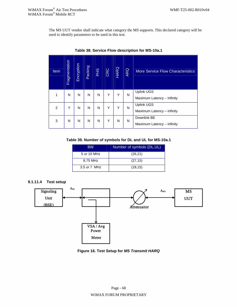
WiMAX Forum® Air Test Procedures WMF-T25-002-R010v04 WiMAX Forum® Mobile RCT
Page - 68
WiMAX FORUM PROPRIETARY
The MS UUT vendor shall indicate what category the MS supports. This declared category will be used to identify parameters to be used in this test.
Table 38. Service Flow description for MS-10a.1
Item Fr
agm
enta
tion
Encr
yptio
n
Pack
ing
PHS
CR
C
HAR
Q
ARQ
More Service Flow Characteristics
1 N N N N Y Y N Uplink UGS
Maximum Latency – Infinity
2 Y N N N Y Y N Uplink UGS
Maximum Latency – Infinity
3 N N N N Y N N Downlink BE
Maximum Latency – Infinity
Table 39. Number of symbols for DL and UL for MS-10a.1
BW Number of symbols (DL,UL)
5 or 10 MHz (26,21)
8.75 MHz (27,15)
3.5 or 7 MHz (18,15)
9.1.11.4 Test setup
Figure 16. Test Setup for MS Transmit HARQ
Signaling
Unit
(BSE)
VSA / Avg Power
Meter
MS
UUT ABS
Attenuator
AMS
WiMAX Forum® Air Test Procedures WMF-T25-002-R010v04 WiMAX Forum® Mobile RCT
Page - 69
WiMAX FORUM PROPRIETARY
9.1.11.5 Test procedure
Initial Conditions:
Step 1. Create and activate a DL service flow, per Item 3 in Table 47, using a BS-initiates DSA-REQ, and wait for the transaction to succeed. The MCS used for the DL SF is 64QAM-5/6.
Step 2. Set the received signal level at AMS and at ABS to the limit specified in Table 50. (10dB higher than sensitivity level set in standard and TWG System Profile) and no higher than 10dB below maximum transmit power. Preferably, use the closed loop power control mechanism, controlled by the Signaling Unit (BSE) to achieve the proper transmit power of the MS UUT.
[Test Set 1: The following steps ver ify that the MS UUT constructs proper HARQ UL bur sts. They also ver ify that the MS UUT suppor ts the declared number of HARQ UL channels and per forms retransmissions per AI_SN. The MS UUT’s conformance to buffer size per channel is also ver ified:]
Initial Conditions:
Step 1. Verify that the initial conditions of the entire test (first paragraph of this section) are met. Step 2. Create and activate an UL service flow, per Item 2 in Table 47, using a BS-initiated DSA-
REQ, and wait for the transaction to succeed.
Test Procedure:
Step 1. Configure the Signaling Unit (BSE) so that it schedules a different ACID in each frame, in a round-robin manner (i.e., retransmissions occur only after n frames, where n is the number of UL HARQ channels). Each ACID allocation is limited to the minimum between the buffer size per channel, according to Table 49 and the needed allocation to transmit a single packet per burst. In any case, the number of byte allocated per UL sub-frame shall not exceed “Maximum MAC data byte per UL sub-frame”, as reported by the MS UUT in the SBC-REQ message or the available capacity of the UL sub-frame.
Step 2. Configure the Signaling Unit (BSE) so that it schedules 2 transmissions per HARQ UL burst (first transmission toggles AI_SN and in the next transmission AI_SN stays the same, regardless of the success of the first transmission).
Step 3. Configure the Signaling Unit (BSE) to forward only the second transmission of each received burst to the MAC layer (even if the first transmission was successful).
Step 4. Packet generator generates the packet number and size as specified in Table 51. A new packet is generated as soon as the packet analyzer detects that a packet has been successfully received by the BS. At the beginning of the test 2×M packets are generated, were M is defined in Table 51. This creates a sort of “window” of 2×M packets and ensures that no more than 2×M packets are queued in the system,
.
Step 5. Repeat for all MCSs and all packet sizes (per Table 51).
[Test Set 2: The following steps ver ify that the MS UUT suppor ts the declared number of HARQ UL bur sts per UL sub-frame:]
Initial Conditions:
Step 1. Verify that the initial conditions of the entire test (first paragraph of this section) are met. Step 2. Create and activate n UL service flows, per Item 1 in Table 47, using a BS-initiated DSA-
REQ, and wait for the transactions to succeed. n is the maximum number of HARQ bursts
WiMAX Forum® Air Test Procedures WMF-T25-002-R010v04 WiMAX Forum® Mobile RCT
Page - 70
WiMAX FORUM PROPRIETARY
in UL sub-frame, as per declared category and Table 49 (currently, n = 2 for all categories). DSA-REQs shall indicate that each SF is mapped to a different ACID.
Test Procedure:
Step 1. Set maximum number of HARQ transmissions to 1 (no retransmissions). Step 2. Configure Signaling Unit (BSE) to allocate every 4 frames n 300-byte UL grants with MCS
= 16QAM-3/4. Step 3. Packet generator generates n 288-byte packets every 4 frames (n x 50 packets per second),
one for each SF. Send the number of packets specified in Table 51 for 288-byte packet, per SF.
Step 4. If the declared capability for HARQ UL buffer is with a cleared Aggregation Flag, end test.
[Test Set 3: The following steps ver ify that the MS UUT conforms to the declared total buffer size when the Aggregation Flag is set:]
Initial Conditions:
Step 1. Verify that the initial conditions of the entire test (first paragraph of this section) are met. Step 2. Create and activate an UL service flow using a BS-initiated DSA-REQ, per Item 2 in Table
47, and wait for the transactions to succeed.
Test Procedure:
Step 1. Configure the Signaling Unit (BSE) so that it schedules 2 transmissions per HARQ UL burst (first transmission toggles AI_SN and in the next transmission AI_SN stays the same).
Step 2. Configure the Signaling Unit (BSE) to allocate to ACID 1 the minimum number of bytes between Maximum MAC data bytes per UL sub-frame and ½ of the total number of data bytes according to buffer capability (per coding rate and declared category) in each even frame and to allocate to ACID 2 the minimum number of bytes between Maximum MAC data bytes per UL sub-frame and ½ of the total number of data bytes according to buffer capability (per coding rate and declared category) in each odd frame. Allocations should use 16QAM-3/4 as MCS.
Step 3. Packet generator generates 576-byte packets. Number of packets as specified in Table 51. A new packet is generated as soon as the packet analyzer detects that a packet has been successfully received by the BS. At the beginning of the test 2×M packets are generated, were M is defined in Table 51. This creates a sort of “window” of 2×M packets and ensures that no more than 2×M packets are queued in the system,
Step 4. End of test.
9.1.11.6 Compliance requirements
Pass Verdict
1. For Test Set 1, the number of packets per MCS and packet size combination, not received by the Signaling Unit (BSE) is less than the limit set in Table 51, and
2. For Test Set 2, the number of packets per SF not received by the Signaling Unit (BSE) is less than the limit set in Table 51, and
3. For Test Set 3, if relevant, the number of packets not received by the Signaling Unit (BSE) is less than the limit set in Table 51.
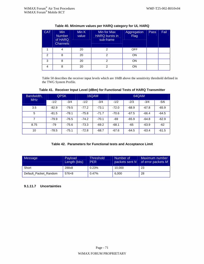
WiMAX Forum® Air Test Procedures WMF-T25-002-R010v04 WiMAX Forum® Mobile RCT
Page - 71
WiMAX FORUM PROPRIETARY
Table 40. Minimum values per HARQ category for UL HARQ
CAT Min Number of HARQ Channels
Min K value
Min for Max HARQ bursts in
sub-frame
Aggregation Flag
Pass Fail
1 4 20 2 OFF
2 8 20 2 ON
3 8 20 2 ON
4 8 20 2 ON
Table 50 describes the receiver input levels which are 10dB above the sensitivity threshold defined in the TWG System Profile.
Table 41. Receiver Input Level (dBm) for Functional Tests of HARQ Transmitter
Bandwidth, MHz
QPSK 16QAM 64QAM
-1/2 -3/4 -1/2 -3/4 -1/2 -2/3 -3/4 -5/6
3.5 -82.9 -79.5 -77.2 -73.1 -72.0 -68.9 -67.8 -65.9
5 -81.5 -78.1 -75.8 -71.7 -70.6 -67.5 -66.4 -64.5
7 -79.9 -76.5 -74.2 -70.1 -69 -65.9 -64.8 -62.9
8.75 -79 -75.6 -73.3 -69.2 -68.1 -65 -63.9 -62
10 -78.5 -75.1 -72.8 -68.7 -67.6 -64.5 -63.4 -61.5
Table 42. Parameters for Functional tests and Acceptance Limit
Message Payload Length (bits)
Threshold PER
Number of packets sent N
Maximum number of error packets M
Short 288x8 0.23% 10,000 23
Default_Packet_Random 576×8 0.47% 6,000 28
9.1.11.7 Uncertainties
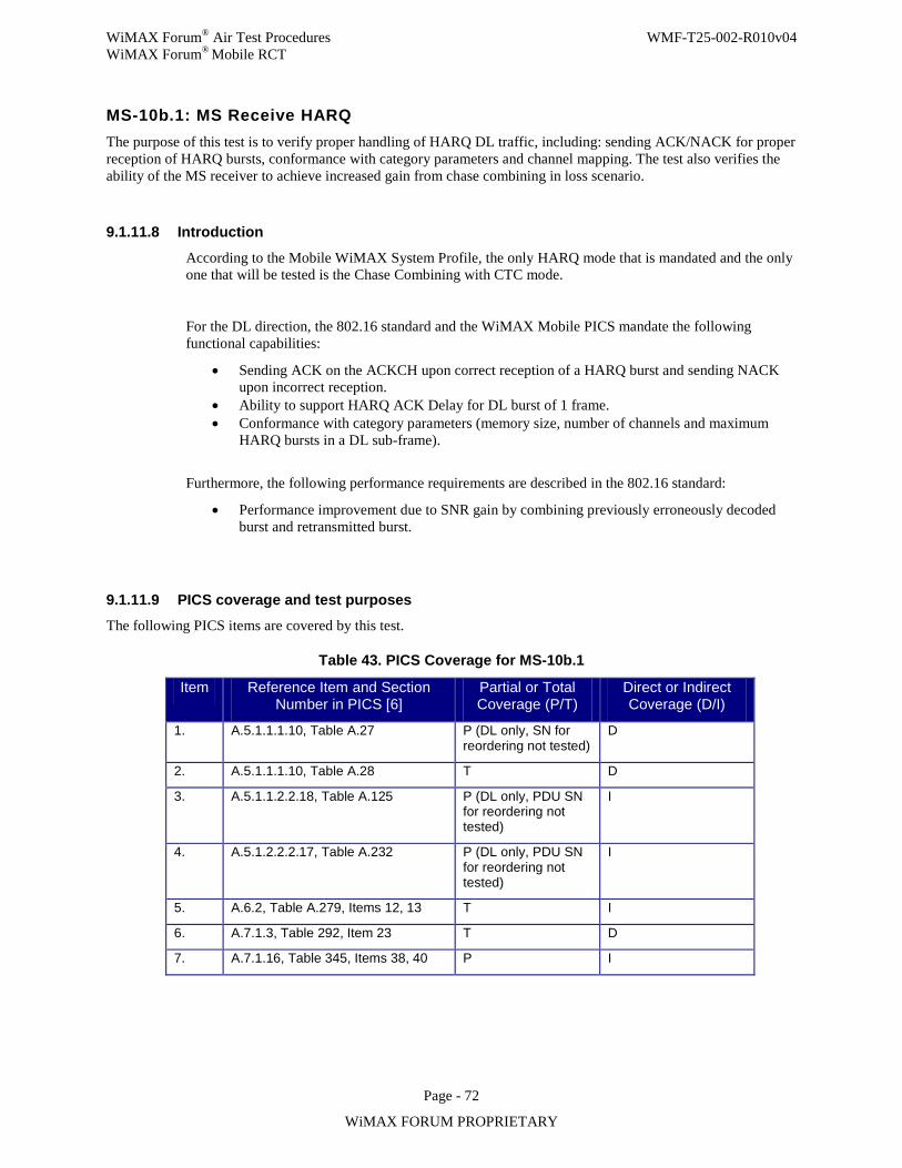
WiMAX Forum® Air Test Procedures WMF-T25-002-R010v04 WiMAX Forum® Mobile RCT
Page - 72
WiMAX FORUM PROPRIETARY
MS-10b.1: MS Receive HARQ The purpose of this test is to verify proper handling of HARQ DL traffic, including: sending ACK/NACK for proper reception of HARQ bursts, conformance with category parameters and channel mapping. The test also verifies the ability of the MS receiver to achieve increased gain from chase combining in loss scenario.
9.1.11.8 Introduction
According to the Mobile WiMAX System Profile, the only HARQ mode that is mandated and the only one that will be tested is the Chase Combining with CTC mode.
For the DL direction, the 802.16 standard and the WiMAX Mobile PICS mandate the following functional capabilities:
• Sending ACK on the ACKCH upon correct reception of a HARQ burst and sending NACK upon incorrect reception.
• Ability to support HARQ ACK Delay for DL burst of 1 frame. • Conformance with category parameters (memory size, number of channels and maximum
HARQ bursts in a DL sub-frame).
Furthermore, the following performance requirements are described in the 802.16 standard:
• Performance improvement due to SNR gain by combining previously erroneously decoded burst and retransmitted burst.
9.1.11.9 PICS coverage and test purposes The following PICS items are covered by this test.
Table 43. PICS Coverage for MS-10b.1
Item Reference Item and Section Number in PICS [6]
Partial or Total Coverage (P/T)
Direct or Indirect Coverage (D/I)
1. A.5.1.1.1.10, Table A.27 P (DL only, SN for reordering not tested)
D
2. A.5.1.1.1.10, Table A.28 T D
3. A.5.1.1.2.2.18, Table A.125 P (DL only, PDU SN for reordering not tested)
I
4. A.5.1.2.2.2.17, Table A.232 P (DL only, PDU SN for reordering not tested)
I
5. A.6.2, Table A.279, Items 12, 13 T I
6. A.7.1.3, Table 292, Item 23 T D
7. A.7.1.16, Table 345, Items 38, 40 P I
WiMAX Forum® Air Test Procedures WMF-T25-002-R010v04 WiMAX Forum® Mobile RCT
Page - 73
WiMAX FORUM PROPRIETARY
9.1.11.10 Testing requirements
This test requires the Signaling Unit (BSE) to accept packets on the Test Control Network and send them on the DL to the MS UUT. The PCT should be able to control the number of HARQ retransmissions (with and without regard to the ACK/NACK received from the MS UUT), the repetition of each burst, and the DIUC for all DL allocations (to control the MCS used for each burst).
The Signaling Unit (BSE) should also be able to forward packets received from the MS UUT to the PCT for inspection. Moreover, the Signaling Unit (BSE) should be capable of counting or forwarding ACKs and NACKs received from the MS UUT, and all management messages received from the MS UUT, for inspection by the PCT.
The Signaling Unit (BSE) should be capable of transmitting a HARQ burst with modified CRC (e.g., CRC bar). Also, some control of the Signaling Unit (BSE)’s scheduling is required (See details in section 9.1.11.13).
The Signaling Unit (BSE) shall be configured to comply with the appropriate band class for the MS UUT, and will be configured to use a single zone in the UL or DL during this test. The DL/UL ratio should be set according to Table 55.
Unless otherwise indicated in the test procedure, the MAPs sent by the Signaling Unit (BSE) should be sent with the following MCS and repetition factor: QPSK-1/2, repetition factor = 4.
The test requires that the PCT have packet generator and analyzer capabilities.
If not otherwise mentioned in the test procedure, the packet generator will output packets at a rate of 100 packets per second. These packets will be ICMP-echo-request packets (packet sizes are calculated to make the burst sizes according to Table 27), with random data for payload, sent to the MS UUT through the Signaling Unit (BSE)’s DL connection. The MS UUT shall reply to these packets with ICMP-echo-reply sent back to the packet analyzer, through the UL connection to the Signaling Unit (BSE). The packet analyzer shall be able to verify that the data received is identical to the data sent according to the Identifier and Sequence Number fields in the ICMP-echo-request and ICMP-echo-reply messages.
A signal generator, capable of generating white Gaussian noise signal that will be combined with the Signaling Unit (BSE) output, to generate AWGN channel, is needed for this test, to test the combining performance. Also, an attenuator should be used to control the received power at the MS UUT, circulators to separate the DL and UL channels and a combiner.
The MS UUT shall support an IP stack (over the WiMAX stack) which includes the IP and ICMP protocols. It shall reply with ICMP-echo-reply to all ICMP-echo-request messages. The minimum rate in which the MS UUT is required to reply to ICMP-echo-request messages is 200 packets per second.
The MS UUT vendor shall indicate what category the MS supports. This declared category will be used to identify parameters to be used in this test. For Category 1, the vendor will declare whether the aggregation flag for the DL buffer capability is set or cleared.
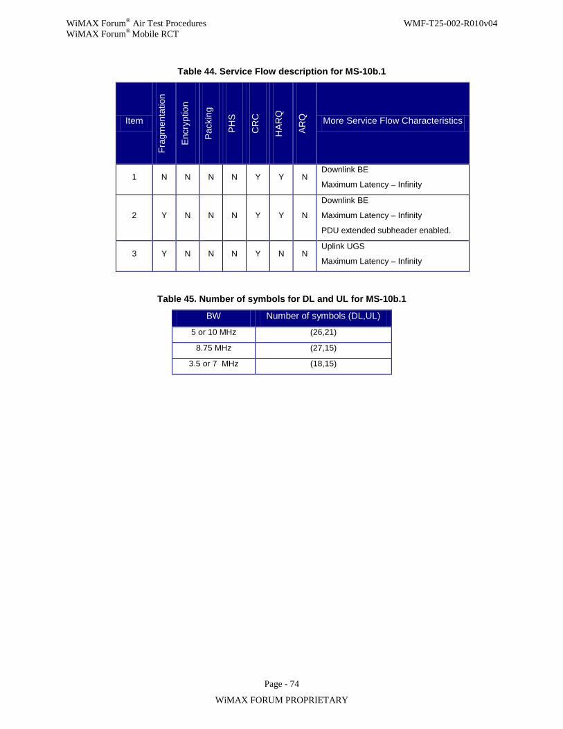
WiMAX Forum® Air Test Procedures WMF-T25-002-R010v04 WiMAX Forum® Mobile RCT
Page - 74
WiMAX FORUM PROPRIETARY
Table 44. Service Flow description for MS-10b.1
Item
Frag
men
tatio
n
Encr
yptio
n
Pack
ing
PHS
CR
C
HAR
Q
ARQ
More Service Flow Characteristics
1 N N N N Y Y N Downlink BE
Maximum Latency – Infinity
2 Y N N N Y Y N
Downlink BE
Maximum Latency – Infinity
PDU extended subheader enabled.
3 Y N N N Y N N Uplink UGS
Maximum Latency – Infinity
Table 45. Number of symbols for DL and UL for MS-10b.1
BW Number of symbols (DL,UL)
5 or 10 MHz (26,21)
8.75 MHz (27,15)
3.5 or 7 MHz (18,15)
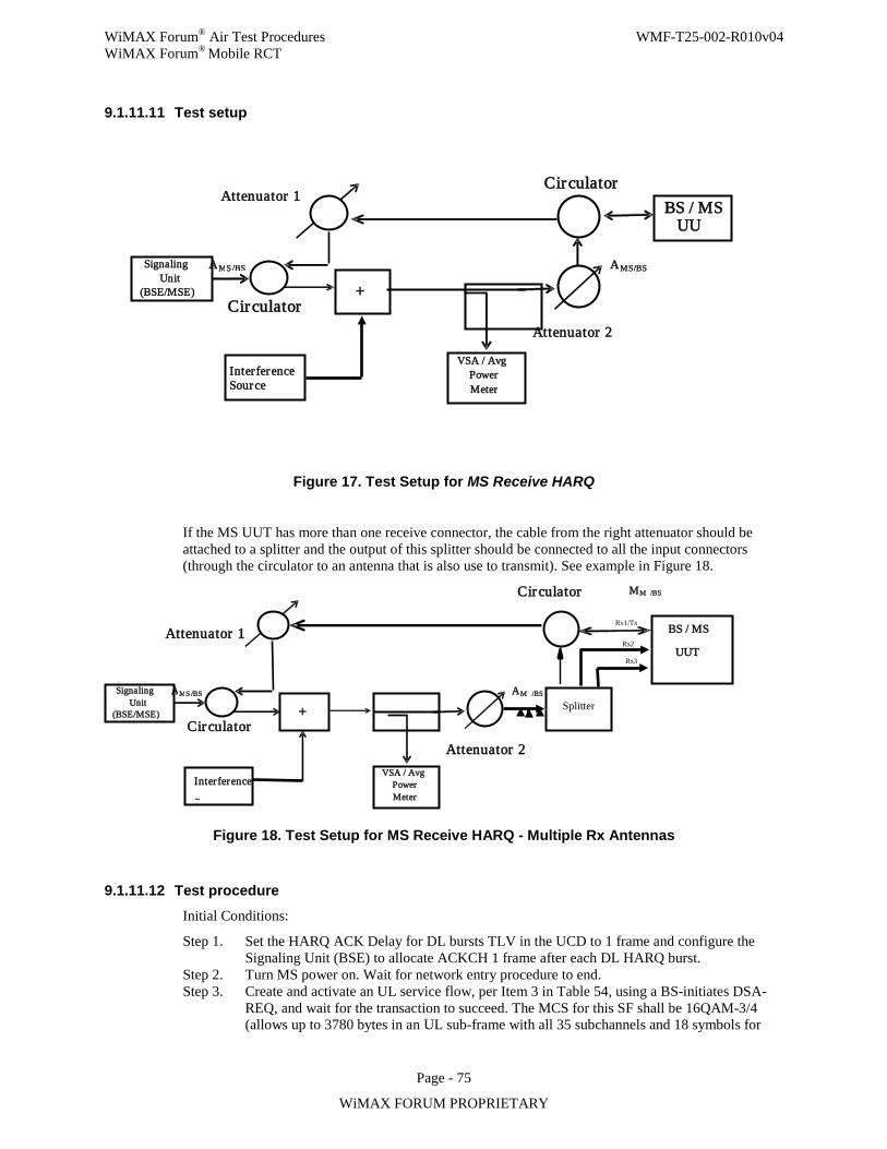
WiMAX Forum® Air Test Procedures WMF-T25-002-R010v04 WiMAX Forum® Mobile RCT
Page - 75
WiMAX FORUM PROPRIETARY
9.1.11.11 Test setup
Figure 17. Test Setup for MS Receive HARQ
If the MS UUT has more than one receive connector, the cable from the right attenuator should be attached to a splitter and the output of this splitter should be connected to all the input connectors (through the circulator to an antenna that is also use to transmit). See example in Figure 18.
Figure 18. Test Setup for MS Receive HARQ - Multiple Rx Antennas
9.1.11.12 Test procedure Initial Conditions:
Step 1. Set the HARQ ACK Delay for DL bursts TLV in the UCD to 1 frame and configure the Signaling Unit (BSE) to allocate ACKCH 1 frame after each DL HARQ burst.
Step 2. Turn MS power on. Wait for network entry procedure to end. Step 3. Create and activate an UL service flow, per Item 3 in Table 54, using a BS-initiates DSA-
REQ, and wait for the transaction to succeed. The MCS for this SF shall be 16QAM-3/4 (allows up to 3780 bytes in an UL sub-frame with all 35 subchannels and 18 symbols for
M M /BS
Signaling Unit
(BSE/MSE)
VSA / Avg Power Meter
BS / MS
UUT
A M S /BS
Attenuator 1
A M /BS
Attenuator 2
Circulator
Circulator
Splitter
Rx1/Tx
Rx2
Rx3
Interference
S
+
Signaling Unit
(BSE/MSE)
VSA / Avg Power
Meter
BS / MS UU
A M S /BS
Attenuator 1
A MS /BS
Attenuator 2
Circulator
Circulator
Interference Source
+
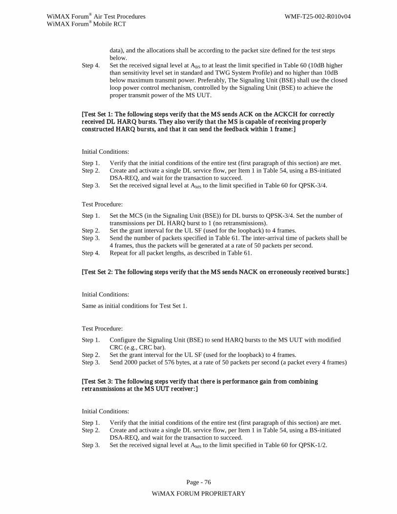
WiMAX Forum® Air Test Procedures WMF-T25-002-R010v04 WiMAX Forum® Mobile RCT
Page - 76
WiMAX FORUM PROPRIETARY
data), and the allocations shall be according to the packet size defined for the test steps below.
Step 4. Set the received signal level at ABS to at least the limit specified in Table 60 (10dB higher than sensitivity level set in standard and TWG System Profile) and no higher than 10dB below maximum transmit power. Preferably, The Signaling Unit (BSE) shall use the closed loop power control mechanism, controlled by the Signaling Unit (BSE) to achieve the proper transmit power of the MS UUT.
[Test Set 1: The following steps ver ify that the MS sends ACK on the ACKCH for correctly received DL HARQ bur sts. They also ver ify that the MS is capable of receiving proper ly constructed HARQ bursts, and that it can send the feedback within 1 frame:]
Initial Conditions:
Step 1. Verify that the initial conditions of the entire test (first paragraph of this section) are met. Step 2. Create and activate a single DL service flow, per Item 1 in Table 54, using a BS-initiated
DSA-REQ, and wait for the transaction to succeed. Step 3. Set the received signal level at AMS to the limit specified in Table 60 for QPSK-3/4.
Test Procedure:
Step 1. Set the MCS (in the Signaling Unit (BSE)) for DL bursts to QPSK-3/4. Set the number of transmissions per DL HARQ burst to 1 (no retransmissions).
Step 2. Set the grant interval for the UL SF (used for the loopback) to 4 frames. Step 3. Send the number of packets specified in Table 61. The inter-arrival time of packets shall be
4 frames, thus the packets will be generated at a rate of 50 packets per second. Step 4. Repeat for all packet lengths, as described in Table 61.
[Test Set 2: The following steps ver ify that the MS sends NACK on er roneously received bursts:]
Initial Conditions:
Same as initial conditions for Test Set 1.
Test Procedure:
Step 1. Configure the Signaling Unit (BSE) to send HARQ bursts to the MS UUT with modified CRC (e.g., CRC bar).
Step 2. Set the grant interval for the UL SF (used for the loopback) to 4 frames. Step 3. Send 2000 packet of 576 bytes, at a rate of 50 packets per second (a packet every 4 frames)
[Test Set 3: The following steps ver ify that there is per formance gain from combining retransmissions at the MS UUT receiver :]
Initial Conditions:
Step 1. Verify that the initial conditions of the entire test (first paragraph of this section) are met. Step 2. Create and activate a single DL service flow, per Item 1 in Table 54, using a BS-initiated
DSA-REQ, and wait for the transaction to succeed. Step 3. Set the received signal level at AMS to the limit specified in Table 60 for QPSK-1/2.
WiMAX Forum® Air Test Procedures WMF-T25-002-R010v04 WiMAX Forum® Mobile RCT
Page - 77
WiMAX FORUM PROPRIETARY
Test Procedure:
Step 1. Set the MCS (in the Signaling Unit (BSE)) for DL bursts to QPSK-1/2. Step 2. Configure the PCT to generate 240-bytes packets. Step 3. Find the minimum AWGN signal level (and thus, the maximum received SNR at the MS
UUT) for which PER > 0.5. Mark this SNR as MCSSNR n , where MCS is the modulation and coding scheme used (e.g., 16QAM-3/4) and n is the number of bytes in the packet. This SNR should be found with at least 0.5dB resolution and for a DL SF with HARQ enabled but with no retransmissions. (See Section 9.1.11.17 for a suggestion for an algorithm that may be used to find this SNR.)
Step 4. Set the maximum number of transmissions per DL HARQ burst to 2 (1 retransmission). Step 5. Set the grant interval for the UL SF (used for the loopback) to 2 frames and set the grant
size to accommodate the packets sent on the DL. Step 6. Send the number of packets specified in Table 57. The inter arrival time of packets shall be
2 frames, thus the packets will be generated at a rate of 100 packets per second. Step 7. Repeat for 64QAM-5/6.
[Test Set 4: The following steps ver ify that the MS UUT suppor ts maximum number of HARQ DL bur sts in sub-frame in accordance with declared category:]
Initial Conditions:
Step 1. Verify that the initial conditions of the entire test (first paragraph of this section) are met. Step 2. Create and activate n DL service flows, per Item 1 in Table 54, using a BS-initiated DSA-
REQ, and wait for the transactions to succeed. n is the maximum number of HARQ bursts in DL sub-frame, as per the declared category. DSA-REQs shall indicate that each SF is mapped to a different ACID. MCS for these DL bursts shall be 16QAM-3/4.
Step 3. Set the received signal level at AMS to the limit specified in Table 60 for 16QAM-3/4.
Test Procedure:
Step 1. Set maximum number of HARQ transmissions to 1 (no retransmissions). Step 2. Set the UL grant interval to 4 frames and the grant size to n x 300 bytes. Step 3. Packet generator generates n 288-byte packets every 4 frames (n x 50 packets per second),
one for each SF. Send the number of packets specified in Table 61 for 288-byte packet, per SF.
[Test Set 5: The following steps ver ify that the MS UUT suppor ts number of DL HARQ channels per declared category and suppor ts the declared memory for DL HARQ, if the Aggregation Flag is cleared:]
Initial Conditions:
Step 1. Verify that the initial conditions of the entire test (first paragraph of this section) are met. Step 2. Create and activate a DL service flow, per Item 2 in Table 54, using a BS-initiated DSA-
REQ, and wait for the transactions to succeed. Step 3. Set the received signal level at AMS to the limit specified in Table 60 for 16QAM-3/4.
Test Procedure:
Step 1. Set maximum number of HARQ transmissions to 1 (no retransmissions). Step 2. Configure the Signaling Unit (BSE) so that it schedules a different ACID in each frame, in a
round-robin manner (i.e., retransmissions occur only after n frames, where n is the number of DL HARQ channels). Each ACID allocation is limited to the minimum among buffer size
WiMAX Forum® Air Test Procedures WMF-T25-002-R010v04 WiMAX Forum® Mobile RCT
Page - 78
WiMAX FORUM PROPRIETARY
per channel, Maximum MAC data per DL sub-frame and maximum available data allocation size per DL sub-frame.
Step 3. Set the UL grant interval to 2 frames and the grant size to 1500 bytes. Step 4. Find the minimum AWGN signal level (and thus, the maximum received SNR at the MS
UUT) for which Burst Error Rate > 0.9. Mark this SNR as 2SNR . This SNR should be found with at least 0.5dB resolution and for a DL SF with HARQ enabled but with no retransmissions. (See Section 9.1.11.18 for a suggestion of an algorithm that may be used to find this SNR.)
Step 5. Set maximum number of HARQ transmissions to 4 (3 retransmissions). Step 6. Set the received signal level at AMS to the limit specified in Table 60. Configure the signal
generator to transmit AWGN signal so that SNR at AMS is 2SNR found in Step 4of Test Set 5.
Step 7. Packet generator generates packets of the size as in Step 2 of Test Set 5 (that is, the minimum among buffer size per channel, Maximum MAC data per DL sub-frame, and maximum available data allocation size per DL sub-frame) and packet number ‘N’ as specified in Table 58. A new packet is generated as soon as the packet analyzer detects that a packet has been successfully received by the MS. At the beginning of the test 2×M packets are generated, were M is defined in Table 58. This creates a sort of “window” of 2×M packets and ensures that no more than 2×M packets are queued in the system,
Step 8. If the Aggregation Flag is cleared for the declared category, end test.
[Test Set 6: The following steps ver ify that the MS UUT suppor ts the declared memory for DL HARQ, if the Aggregation Flag is set:]
Initial Conditions:
Step 1. Verify that the initial conditions of the entire test (first paragraph of this section) are met. Step 2. Create and activate a single DL service flow, per Item 2 in Table 54, using a BS-initiated
DSA-REQ, and wait for the transaction to succeed. Step 3. Set the received signal level at AMS to the limit specified in Table 60 for 16QAM-3/4.
Test Procedure
Step 1. Set maximum number of HARQ transmissions to 1 (no retransmissions). Step 2. Configure Signaling Unit (BSE) to use 16QAM-3/4. Step 3. Set the UL grant interval to 2 frames and the grant size to the minimum between ½ of the
total number of data bytes according to the DL HARQ buffer capability and Maximum MAC data bytes per DL sub-frame.
Step 4. Configure the Signaling Unit (BSE) to allocate to ACID 1 the minimum number of bytes among Maximum MAC data bytes per DL sub-frame, ½ of the total number of data bytes according to buffer capability (per coding rate and declared category), and maximum available data allocation size per DL sub-frame in each even frame and to allocate to ACID 2 the same number of bytes in each odd frame.
Step 5. Find the minimum AWGN signal level (and thus, the maximum received SNR at the MS UUT) for which Burst Error Rate > 0.9. Mark this SNR as 3SNR . This SNR should be found with at least 0.5dB resolution and for a DL SF with HARQ enabled but with no retransmissions. (See Section 9.1.11.18 for a suggestion of an algorithm that may be used to find this SNR.)
Step 6. Set the received signal level at AMS to the limit specified in Table 60. Configure the signal generator to transmit AWGN signal so that SNR at AMS is 3SNR found in Step 5 of Test Set 6.
Step 7. Set maximum number of HARQ transmissions to 4 (3 retransmission).
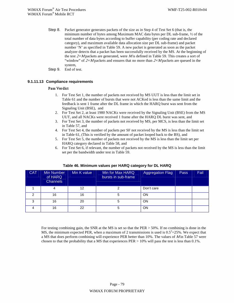
WiMAX Forum® Air Test Procedures WMF-T25-002-R010v04 WiMAX Forum® Mobile RCT
Page - 79
WiMAX FORUM PROPRIETARY
Step 8. Packet generator generates packets of the size as in Step 4 of Test Set 6 (that is, the minimum number of bytes among Maximum MAC data bytes per DL sub-frame, ½ of the total number of data bytes according to buffer capability (per coding rate and declared category), and maximum available data allocation size per DL sub-frame) and packet number ‘N’ as specified in Table 59. A new packet is generated as soon as the packet analyzer detects that a packet has been successfully received by the MS. At the beginning of the test 2×M packets are generated, were M is defined in Table 59. This creates a sort of “window” of 2×M packets and ensures that no more than 2×M packets are queued in the system,
Step 9. End of test.
9.1.11.13 Compliance requirements
Pass Verdict
1. For Test Set 1, the number of packets not received by MS UUT is less than the limit set in Table 61 and the number of bursts that were not ACKed is less than the same limit and the feedback is sent 1 frame after the DL frame in which the HARQ burst was sent from the Signaling Unit (BSE), and
2. For Test Set 2, at least 1980 NACKs were received by the Signaling Unit (BSE) from the MS UUT, and all NACKs were received 1 frame after the HARQ DL burst was sent, and
3. For Test Set 3, the number of packets not received by MS, per MCS, is less than the limit set in Table 57, and
4. For Test Set 4, the number of packets per SF not received by the MS is less than the limit set in Table 61, (This is verified by the amount of packet looped back to the BS), and
5. For Test Set 5, the number of packets not received by the MS is less than the limit set per HARQ category declared in Table 58, and
6. For Test Set 6, if relevant, the number of packets not received by the MS is less than the limit set per the bandwidth under test in Table 59.
Table 46. Minimum values per HARQ category for DL HARQ
CAT Min Number of HARQ Channels
Min K value Min for Max HARQ bursts in sub-frame
Aggregation Flag Pass Fail
1 4 12 2 Don’t care
2 16 16 5 ON
3 16 20 5 ON
4 16 22 5 ON
For testing combining gain, the SNR at the MS is set so that the PER > 50%. If no combining is done in the MS, the minimum expected PER, when a maximum of 2 transmissions is used is 0.52=25%. We expect that a MS that does perform combining will experience PER better than 10%. The values of M in Table 57 were chosen to that the probability that a MS that experiences PER > 10% will pass the test is less than 0.1%.
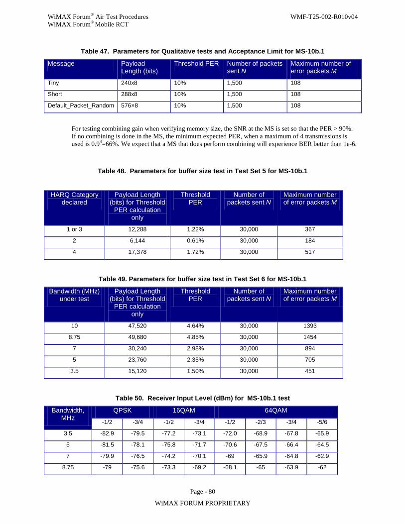
WiMAX Forum® Air Test Procedures WMF-T25-002-R010v04 WiMAX Forum® Mobile RCT
Page - 80
WiMAX FORUM PROPRIETARY
Table 47. Parameters for Qualitative tests and Acceptance Limit for MS-10b.1
Message Payload Length (bits)
Threshold PER Number of packets sent N
Maximum number of error packets M
Tiny 240x8 10% 1,500 108
Short 288x8 10% 1,500 108
Default_Packet_Random 576×8 10% 1,500 108
For testing combining gain when verifying memory size, the SNR at the MS is set so that the PER > 90%. If no combining is done in the MS, the minimum expected PER, when a maximum of 4 transmissions is used is 0.94=66%. We expect that a MS that does perform combining will experience BER better than 1e-6.
Table 48. Parameters for buffer size test in Test Set 5 for MS-10b.1
HARQ Category declared
Payload Length (bits) for Threshold
PER calculation only
Threshold PER
Number of packets sent N
Maximum number of error packets M
1 or 3 12,288 1.22% 30,000 367
2 6,144 0.61% 30,000 184
4 17,378 1.72% 30,000 517
Table 49. Parameters for buffer size test in Test Set 6 for MS-10b.1
Bandwidth (MHz) under test
Payload Length (bits) for Threshold
PER calculation only
Threshold PER
Number of packets sent N
Maximum number of error packets M
10 47,520 4.64% 30,000 1393
8.75 49,680 4.85% 30,000 1454
7 30,240 2.98% 30,000 894
5 23,760 2.35% 30,000 705
3.5 15,120 1.50% 30,000 451
Table 50. Receiver Input Level (dBm) for MS-10b.1 test
Bandwidth, MHz
QPSK 16QAM 64QAM
-1/2 -3/4 -1/2 -3/4 -1/2 -2/3 -3/4 -5/6
3.5 -82.9 -79.5 -77.2 -73.1 -72.0 -68.9 -67.8 -65.9
5 -81.5 -78.1 -75.8 -71.7 -70.6 -67.5 -66.4 -64.5
7 -79.9 -76.5 -74.2 -70.1 -69 -65.9 -64.8 -62.9
8.75 -79 -75.6 -73.3 -69.2 -68.1 -65 -63.9 -62
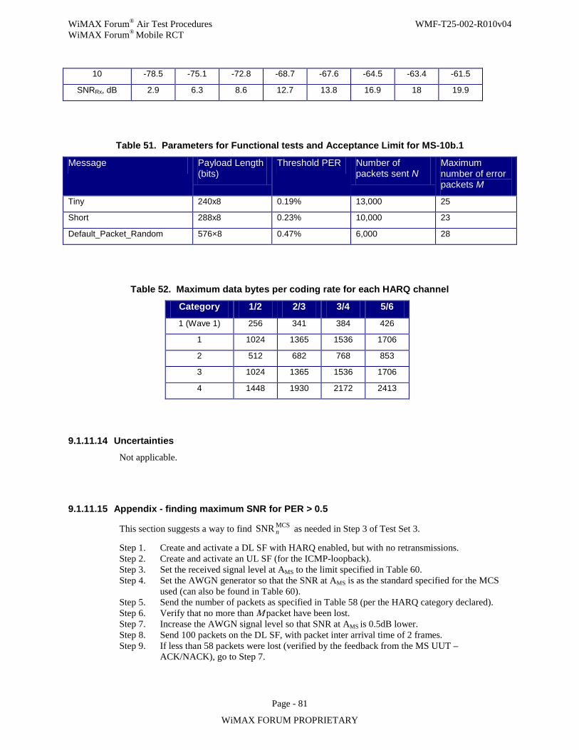
WiMAX Forum® Air Test Procedures WMF-T25-002-R010v04 WiMAX Forum® Mobile RCT
Page - 81
WiMAX FORUM PROPRIETARY
10 -78.5 -75.1 -72.8 -68.7 -67.6 -64.5 -63.4 -61.5
SNRRx, dB 2.9 6.3 8.6 12.7 13.8 16.9 18 19.9
Table 51. Parameters for Functional tests and Acceptance Limit for MS-10b.1
Message Payload Length (bits)
Threshold PER Number of packets sent N
Maximum number of error packets M
Tiny 240x8 0.19% 13,000 25
Short 288x8 0.23% 10,000 23
Default_Packet_Random 576×8 0.47% 6,000 28
Table 52. Maximum data bytes per coding rate for each HARQ channel
Category 1/2 2/3 3/4 5/6
1 (Wave 1) 256 341 384 426
1 1024 1365 1536 1706
2 512 682 768 853
3 1024 1365 1536 1706
4 1448 1930 2172 2413
9.1.11.14 Uncertainties
Not applicable.
9.1.11.15 Appendix - finding maximum SNR for PER > 0.5
This section suggests a way to find MCSSNR n as needed in Step 3 of Test Set 3.
Step 1. Create and activate a DL SF with HARQ enabled, but with no retransmissions. Step 2. Create and activate an UL SF (for the ICMP-loopback). Step 3. Set the received signal level at AMS to the limit specified in Table 60. Step 4. Set the AWGN generator so that the SNR at AMS is as the standard specified for the MCS
used (can also be found in Table 60). Step 5. Send the number of packets as specified in Table 58 (per the HARQ category declared). Step 6. Verify that no more than M packet have been lost. Step 7. Increase the AWGN signal level so that SNR at AMS is 0.5dB lower. Step 8. Send 100 packets on the DL SF, with packet inter arrival time of 2 frames. Step 9. If less than 58 packets were lost (verified by the feedback from the MS UUT –
ACK/NACK), go to Step 7.
WiMAX Forum® Air Test Procedures WMF-T25-002-R010v04 WiMAX Forum® Mobile RCT
Page - 82
WiMAX FORUM PROPRIETARY
Step 10. If 58 packet or more were lost (verified by the number of NACKs), mark the SNR as MCSSNR n for the number of byte of the sent packets and the used MCS.
9.1.11.16 Appendix - finding maximum SNR for Burst Error Rate > 0.9
Step 1. Set the received signal level at AMS to the limit specified in Table 60. Step 2. Set the AWGN generator so that the SNR at AMS is as the standard specified for the MCS
used (can also be found in Table 60). Step 3. Send the number of packets as specified in Table 59 (per the bandwidth under test). Step 4. Verify that no more than M packet have been lost. Step 5. Increase the AWGN signal level so that SNR at AMS is 0.5dB lower. Step 6. Send enough packets on the DL SF, so that 100 bursts will be transmitter on the DL. Step 7. If less than 95 of the bursts were lost (verified by the feedback from the MS UUT –
ACK/NACK), go to Step 5. Step 8. If 95 of the bursts or more were lost, stop (verified by the number of NACKs).
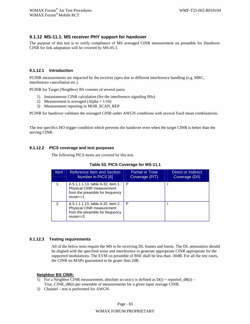
WiMAX Forum® Air Test Procedures WMF-T25-002-R010v04 WiMAX Forum® Mobile RCT
Page - 83
WiMAX FORUM PROPRIETARY
9.1.12 MS-11.1: MS receiver PHY support for handover The purpose of this test is to verify compliance of MS averaged CINR measurement on preamble for Handover. CINR for link adaptation will be covered by MS-05.1.
9.1.12.1 Introduction
PCINR measurements are impacted by the receiver types due to different interference handling (e.g. MRC, interference cancellation etc.).
PCINR for Target (Neighbor) BS consists of several parts:
1) Instantaneous CINR calculation (for the interference signaling BSs) 2) Measurement is averaged (Alpha = 1/16) 3) Measurement reporting in MOB_SCAN_REP
PCINR for handover validates the averaged CINR under AWGN conditions with several fixed mean combinations.
The test specifics HO trigger condition which prevents the handover even when the target CINR is better than the serving CINR.
9.1.12.2 PICS coverage and test purposes The following PICS items are covered by this test.
Table 53. PICS Coverage for MS-11.1
Item Reference Item and Section Number in PICS [6]
Partial or Total Coverage (P/T)
Direct or Indirect Coverage (D/I)
1. A.5.1.1.1.13, table A.32, item 1 : Physical CINR measurement from the preamble for frequency reuse==1
P I
2. A.5.1.1.1.13, table A.32, item 2 : Physical CINR measurement from the preamble for frequency reuse==3
P I
9.1.12.3 Testing requirements
All of the below tests require the MS to be receiving DL frames and bursts. The DL attenuation should be aligned with the specified noise and interference to generate appropriate CINR appropriate for the supported modulations. The EVM on preamble of BSE shall be less than -30dB. For all the test cases, the CINR on MAPs guaranteed to be grater than 2dB.
Neighbor BS CINR: 1) For a Neighbor CINR measurement, absolute accuracy is defined as D(i) = reported_dB(i) –
True_CINR_dB(i) per ensemble of measurements for a given input average CINR. 2) Channel – test is performed for AWGN.
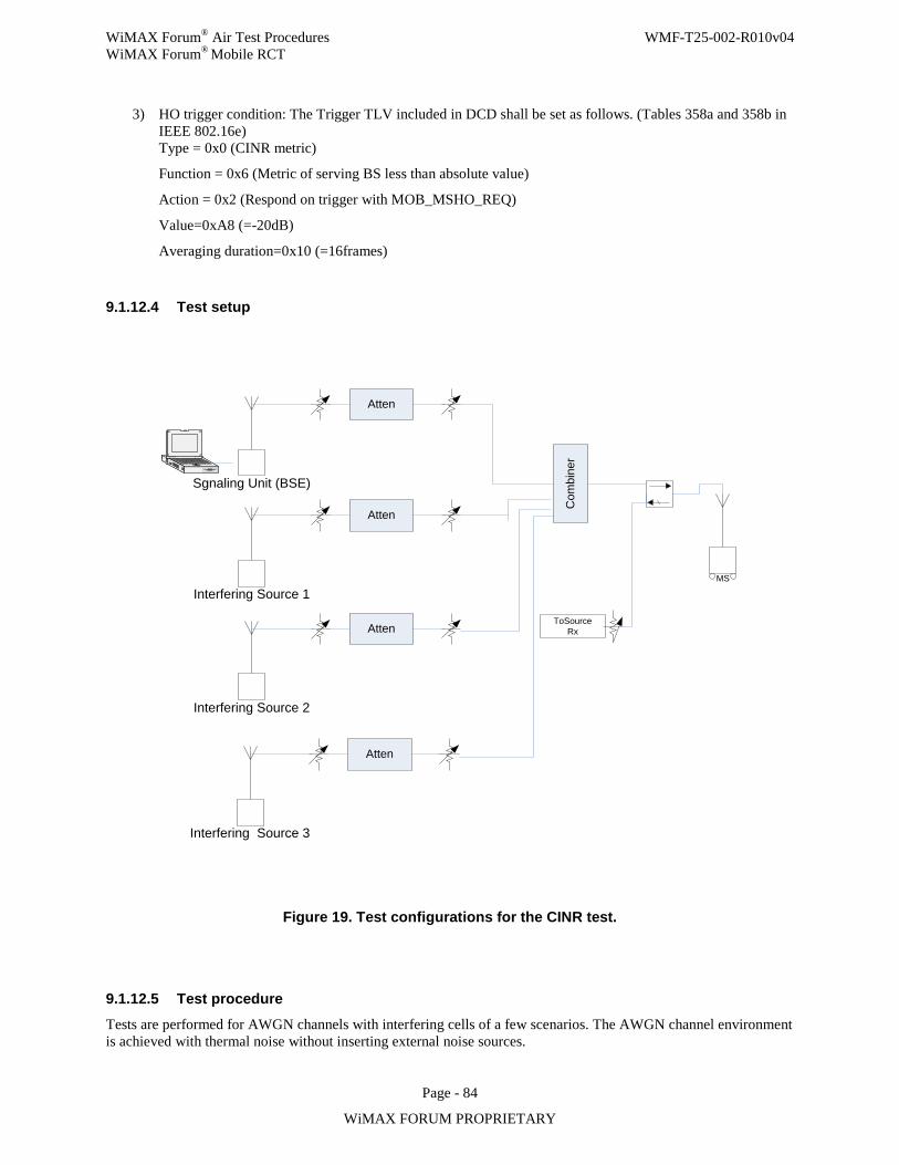
WiMAX Forum® Air Test Procedures WMF-T25-002-R010v04 WiMAX Forum® Mobile RCT
Page - 84
WiMAX FORUM PROPRIETARY
3) HO trigger condition: The Trigger TLV included in DCD shall be set as follows. (Tables 358a and 358b in IEEE 802.16e) Type = 0x0 (CINR metric)
Function = 0x6 (Metric of serving BS less than absolute value)
Action = 0x2 (Respond on trigger with MOB_MSHO_REQ)
Value=0xA8 (=-20dB)
Averaging duration=0x10 (=16frames)
9.1.12.4 Test setup
MSC
ombi
ner
ToSourceRx
Interfering Source 2
Atten
Interfering Source 1
Atten
Sgnaling Unit (BSE)
Atten
Interfering Source 3
Atten
Figure 19. Test configurations for the CINR test.
9.1.12.5 Test procedure Tests are performed for AWGN channels with interfering cells of a few scenarios. The AWGN channel environment is achieved with thermal noise without inserting external noise sources.
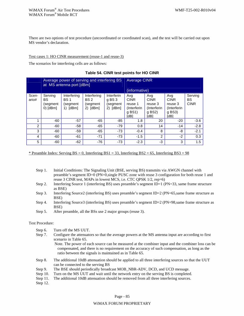
WiMAX Forum® Air Test Procedures WMF-T25-002-R010v04 WiMAX Forum® Mobile RCT
Page - 85
WiMAX FORUM PROPRIETARY
There are two options of test procedure (uncoordinated or coordinated scan), and the test will be carried out upon MS vendor’s declaration.
Test cases 1: HO CINR measurement (reuse-1 and reuse-3)
The scenarios for interfering cells are as follows:
Table 54. CINR test points for HO CINR
Average power of serving and interfering BS at MS antenna port [dBm]
Average CINR
(informative) Scen-ario#
Serving BS (segment 0) [dBm]
Interfering BS 1 (segment 1) [dBm]
Interfering BS 2 (segment 2) [dBm]
Interfering BS 3 (segment 2) [dBm]
Avg CINR reuse 1 (Interfering BS1) [dB]
Avg CINR reuse 3 (Interfering BS2) [dB]
Avg CINR reuse 3 (Interfering BS3) [dB]
Serving BS CINR
1 -60 -57 -65 -85 1.8 20 -20 -3.6 2 -60 -58 -65 -79 0.8 14 -14 -2.8 3 -60 -59 -65 -73 -0.4 8 -8 -2.1 4 -60 -61 -71 -73 -1.5 2 -2 0.3 5 -60 -62 -76 -73 -2.3 -3 3 1.5
* Preamble Index: Serving BS = 0, Interfering BS1 = 33, Interfering BS2 = 65, Interfering BS3 = 98
Step 1. Initial Conditions: The Signaling Unit (BSE, serving BS) transmits via AWGN channel with preamble’s segment ID=0 (PN=0,single PUSC zone with reuse 3 configuration for both reuse 1 and reuse 3 CINR test, MAPs in lowest MCS, i.e. CTC QPSK 1/2, rep=6)
Step 2. Interfering Source 1 (interfering BS) uses preamble’s segment ID=1 (PN=33, same frame structure as BSE)
Step 3. Interfering Source2 (interfering BS) uses preamble’s segment ID=2 (PN=65,same frame structure as BSE)
Step 4. Interfering Source3 (interfering BS) uses preamble’s segment ID=2 (PN=98,same frame structure as BSE)
Step 5. After preamble, all the BSs use 2 major groups (reuse 3).
Test Procedure:
Step 6. Turn off the MS UUT. Step 7. Configure the attenuators so that the average powers at the MS antenna input are according to first
scenario in Table 65. Note. The power of each source can be measured at the combiner input and the combiner loss can be
compensated, and there is no requirement on the accuracy of such compensation, as long as the ratio between the signals is maintained as in Table 65.
Step 8. The additional 10dB attenuation should be applied to all three interfering sources so that the UUT can be connected to the serving BS
Step 9. The BSE should periodically broadcast MOB_NBR-ADV, DCD, and UCD message. Step 10. Turn on the MS UUT and wait until the network entry on the serving BS is completed. Step 11. The additional 10dB attenuation should be removed from all three interfering sources. Step 12.
WiMAX Forum® Air Test Procedures WMF-T25-002-R010v04 WiMAX Forum® Mobile RCT
Page - 86
WiMAX FORUM PROPRIETARY
Option 1: The BSE shall assign an Unsolicited MOB_SCN-RSP to the MS with Scan_Duration = 0, Report Mode = periodic report, and report period = 50. The BSE may transmit DL traffic to the MS in every frame.
Option 2: Set the DCD Trigger TLV as follows. (16-2004/Cor2/D3 table 358a)
type:function:action = 0b01 (RSSI metric):101(Metric of serving BS greater than
absolute value):011(On trigger) = 0x6b
trigger value: 0x00 (RSSI=-103.75dBm)
trigger averaging duration: 0x0A (10 frames)
The MS UUT shall generate a MOB_SCN-REQ filled with the proper values required to measure intra-FA neighbor BS CINR. The Scan_Duration should be less than or equal to 15 frames.
The BSE shall assign a MOB_SCN-RSP as a response to the MOB_SCN-REQ
with the Scan_Duration which is equal to the value that MS requested, Interleaving
interval of “50 Scan Duration” frames, Report mode = periodic report, and Report
period = 50 frames. The Report metric shall be BS CINR mean. The BSE may
transmit DL traffic to the MS in every frame.
Step 13. MS UUT shall measure the CINR value for the Interfering Source 1 and 2 and use averaging parameter (i.e., alpha=1/16) according to the received DCD message.
Step 14. MS UUT shall respond with MOB_SCN-REP containing the CINR measurement of Interfering BS 1 for reuse 1 and Interfering BS 2 for reuse 3 to the BSE.
Step 15. The Signaling Unit (BSE) receiver (connected to the UUT transmit antenna) should receive the Neighbor CINR reports. The BSE receiver should also be able to detect a case that the MS failed to transmit MOB_SCN-REP in a certain frame (e.g. by checking the message CRC) and mark the report as invalid.
Step 16. The BSE should record the correctly reported measurement results from the received MOB_SCN-REP until the BSE received 200 MOB_SCN-REP measurement reports.
Step 17. Evaluate the accuracy of the reported Neighbor CINR feedback according to the procedure specified below:
• Calculate: D[k] = reported_CINR_dB(k) – true_CINR_dB The True_CINR_dB is the value in the Table 65as an informative column.
The true CINR (which is actually the true C/I) is the instantaneous power of the preamble symbol transmitted by the serving BS, divided by:
For reuse 1: The sum of the instantaneous power of the preamble symbol transmitted by the interfering Source
For reuse 3: The power of interfering Source 3 (which uses the same segment as the serving BS)
• Calculate a record the average of D[k] over ensemble of measurements for the given scenario. Step 18. Fill the evaluation result of the Step 17in the relevant column of the Table 66. Step 19. Go to the Step 6and repeat the test for the next scenarios in the Table 65above.
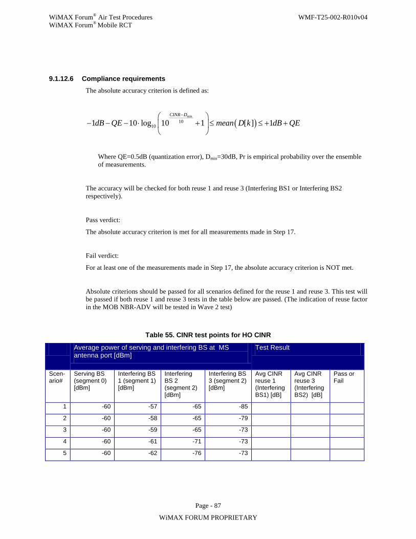
WiMAX Forum® Air Test Procedures WMF-T25-002-R010v04 WiMAX Forum® Mobile RCT
Page - 87
WiMAX FORUM PROPRIETARY
9.1.12.6 Compliance requirements The absolute accuracy criterion is defined as:
( )min
10101 10 log 10 1 [ ] 1
CINR D
dB QE mean D k dB QE−
− − − ⋅ + ≤ ≤ + +
Where QE=0.5dB (quantization error), Dmin=30dB, Pr is empirical probability over the ensemble of measurements.
The accuracy will be checked for both reuse 1 and reuse 3 (Interfering BS1 or Interfering BS2 respectively).
Pass verdict:
The absolute accuracy criterion is met for all measurements made in Step 17.
Fail verdict:
For at least one of the measurements made in Step 17, the absolute accuracy criterion is NOT met.
Absolute criterions should be passed for all scenarios defined for the reuse 1 and reuse 3. This test will be passed if both reuse 1 and reuse 3 tests in the table below are passed. (The indication of reuse factor in the MOB NBR-ADV will be tested in Wave 2 test)
Table 55. CINR test points for HO CINR
Average power of serving and interfering BS at MS antenna port [dBm]
Test Result
Scen-ario#
Serving BS (segment 0) [dBm]
Interfering BS 1 (segment 1) [dBm]
Interfering BS 2 (segment 2) [dBm]
Interfering BS 3 (segment 2) [dBm]
Avg CINR reuse 1 (Interfering BS1) [dB]
Avg CINR reuse 3 (Interfering BS2) [dB]
Pass or Fail
1 -60 -57 -65 -85
2 -60 -58 -65 -79
3 -60 -59 -65 -73
4 -60 -61 -71 -73
5 -60 -62 -76 -73

WiMAX Forum® Air Test Procedures WMF-T25-002-R010v04 WiMAX Forum® Mobile RCT
Page - 88
WiMAX FORUM PROPRIETARY
9.1.12.7 Uncertainties
Not applicable.
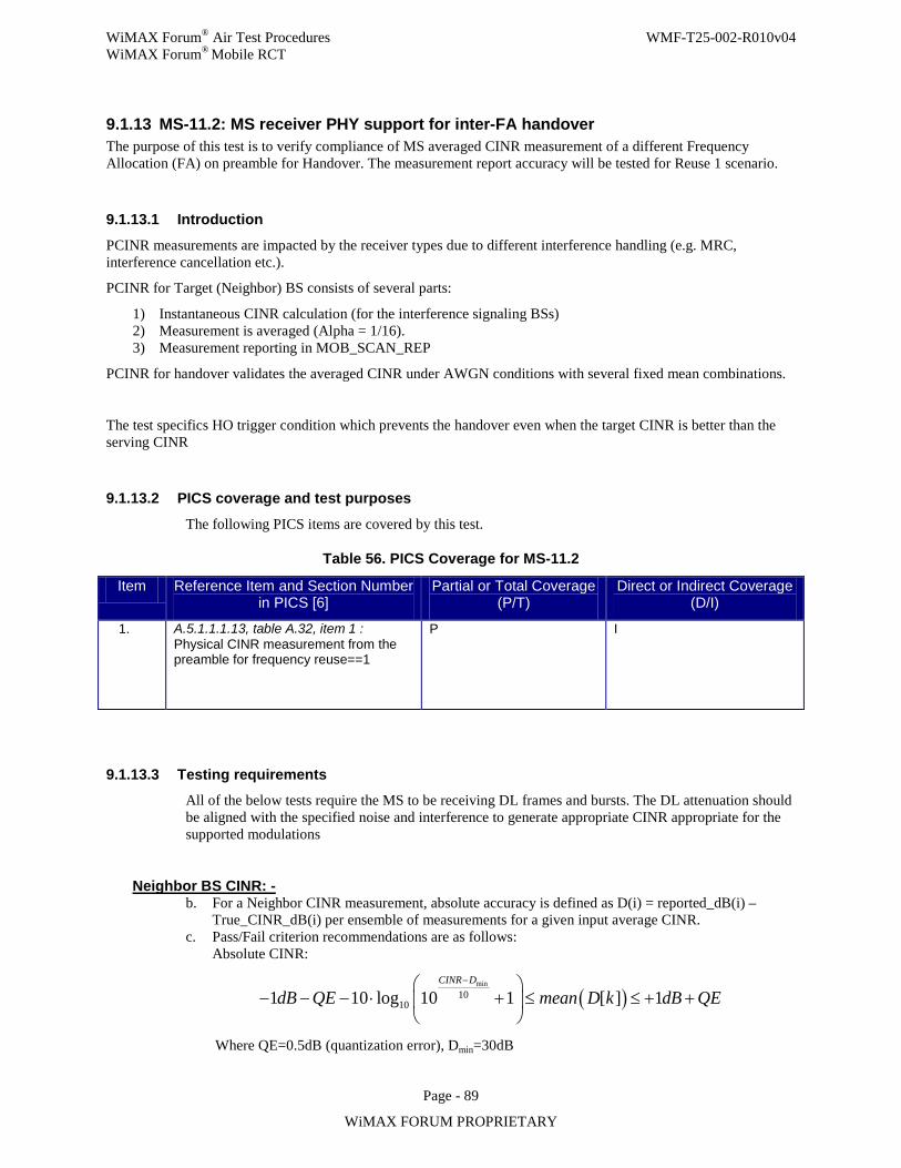
WiMAX Forum® Air Test Procedures WMF-T25-002-R010v04 WiMAX Forum® Mobile RCT
Page - 89
WiMAX FORUM PROPRIETARY
9.1.13 MS-11.2: MS receiver PHY support for inter-FA handover The purpose of this test is to verify compliance of MS averaged CINR measurement of a different Frequency Allocation (FA) on preamble for Handover. The measurement report accuracy will be tested for Reuse 1 scenario.
9.1.13.1 Introduction
PCINR measurements are impacted by the receiver types due to different interference handling (e.g. MRC, interference cancellation etc.).
PCINR for Target (Neighbor) BS consists of several parts:
1) Instantaneous CINR calculation (for the interference signaling BSs) 2) Measurement is averaged (Alpha = 1/16). 3) Measurement reporting in MOB_SCAN_REP
PCINR for handover validates the averaged CINR under AWGN conditions with several fixed mean combinations.
The test specifics HO trigger condition which prevents the handover even when the target CINR is better than the serving CINR
9.1.13.2 PICS coverage and test purposes
The following PICS items are covered by this test.
Table 56. PICS Coverage for MS-11.2
Item Reference Item and Section Number in PICS [6]
Partial or Total Coverage (P/T)
Direct or Indirect Coverage (D/I)
1. A.5.1.1.1.13, table A.32, item 1 : Physical CINR measurement from the preamble for frequency reuse==1
P I
9.1.13.3 Testing requirements All of the below tests require the MS to be receiving DL frames and bursts. The DL attenuation should be aligned with the specified noise and interference to generate appropriate CINR appropriate for the supported modulations
Neighbor BS CINR: - b. For a Neighbor CINR measurement, absolute accuracy is defined as D(i) = reported_dB(i) –
True_CINR_dB(i) per ensemble of measurements for a given input average CINR. c. Pass/Fail criterion recommendations are as follows:
Absolute CINR:
( )min
10101 10 log 10 1 [ ] 1
CINR D
dB QE mean D k dB QE−
− − − ⋅ + ≤ ≤ + +
Where QE=0.5dB (quantization error), Dmin=30dB
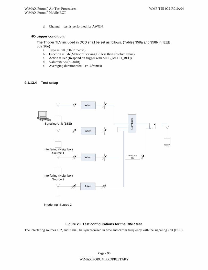
WiMAX Forum® Air Test Procedures WMF-T25-002-R010v04 WiMAX Forum® Mobile RCT
Page - 90
WiMAX FORUM PROPRIETARY
d. Channel – test is performed for AWGN.
HO trigger condition:
The Trigger TLV included in DCD shall be set as follows. (Tables 358a and 358b in IEEE 802.16e)
a. Type = 0x0 (CINR metric) b. Function = 0x6 (Metric of serving BS less than absolute value) c. Action = 0x2 (Respond on trigger with MOB_MSHO_REQ) d. Value=0xA8 (=-20dB) e. Averaging duration=0x10 (=16frames)
9.1.13.4 Test setup
MS
Com
bine
r
ToSourceRx
Interfering (Neighbor) Source 2
Atten
Interfering (Neighbor) Source 1
Atten
Sgnaling Unit (BSE)
Atten
Interfering Source 3
Atten
Figure 20. Test configurations for the CINR test.
The interfering sources 1, 2, and 3 shall be synchronized in time and carrier frequency with the signaling unit (BSE).
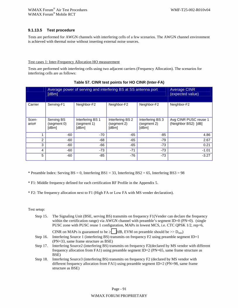
WiMAX Forum® Air Test Procedures WMF-T25-002-R010v04 WiMAX Forum® Mobile RCT
Page - 91
WiMAX FORUM PROPRIETARY
9.1.13.5 Test procedure
Tests are performed for AWGN channels with interfering cells of a few scenarios. The AWGN channel environment is achieved with thermal noise without inserting external noise sources.
Test cases 1: Inter-Frequency Allocation HO measurement
Tests are performed with interfering cells using two adjacent carriers (Frequency Allocation). The scenarios for interfering cells are as follows:
Table 57. CINR test points for HO CINR (Inter-FA)
Average power of serving and interfering BS at SS antenna port [dBm]
Average CINR (expected value)
Carrier Serving-F1 Neighbor-F2 Neighbor-F2 Neighbor-F2 Neighbor-F2
Scen-ario#
Serving BS (segment 0) [dBm]
Interfering BS 1 (segment 1) [dBm]
Interfering BS 2 (segment 2) [dBm]
Interfering BS 3 (segment 2) [dBm]
Avg CINR PUSC reuse 1 (Neighbor BS2) [dB]
1 -60 -70 -65 -85 4.86 2 -60 -68 -65 -79 2.67 3 -60 -66 -65 -73 0.21 4 -60 -73 -71 -73 -1.01 5 -60 -85 -76 -73 -3.27
* Preamble Index: Serving BS = 0, Interfering BS1 = 33, Interfering BS2 = 65, Interfering BS3 = 98
* F1: Middle frequency defined for each certification RF Profile in the Appendix 5.
* F2: The frequency allocation next to F1 (High FA or Low FA with MS vender declaration).
Test setup:
Step 15. The Signaling Unit (BSE, serving BS) transmits on frequency F1(Vender can declare the frequency within the certification range) via AWGN channel with preamble’s segment ID=0 (PN=0). (single PUSC zone with PUSC reuse 1 configuration, MAPs in lowest MCS, i.e. CTC QPSK 1/2, rep=6,
CINR on MAPs is guaranteed to be ≥2dB, EVM on preamble should be >> Dmin) Step 16. Interfering Source 1 (interfering BS) transmits on frequency F2 using preamble segment ID=1
(PN=33, same frame structure as BSE) Step 17. Interfering Source2 (interfering BS) transmits on frequency F2(declared by MS vendor with different
frequency allocation from FA1) using preamble segment ID=2 (PN=65, same frame structure as BSE)
Step 18. Interfering Source3 (interfering BS) transmits on frequency F2 (declared by MS vendor with different frequency allocation from FA1) using preamble segment ID=2 (PN=98, same frame structure as BSE)
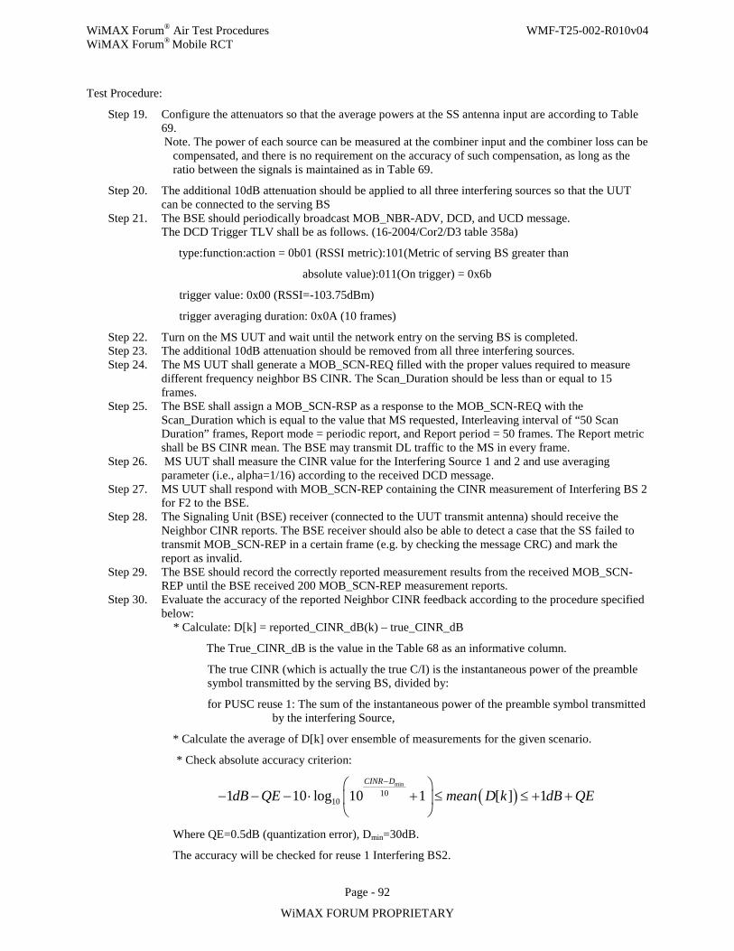
WiMAX Forum® Air Test Procedures WMF-T25-002-R010v04 WiMAX Forum® Mobile RCT
Page - 92
WiMAX FORUM PROPRIETARY
Test Procedure:
Step 19. Configure the attenuators so that the average powers at the SS antenna input are according to Table 69. Note. The power of each source can be measured at the combiner input and the combiner loss can be
compensated, and there is no requirement on the accuracy of such compensation, as long as the ratio between the signals is maintained as in Table 69.
Step 20. The additional 10dB attenuation should be applied to all three interfering sources so that the UUT can be connected to the serving BS
Step 21. The BSE should periodically broadcast MOB_NBR-ADV, DCD, and UCD message. The DCD Trigger TLV shall be as follows. (16-2004/Cor2/D3 table 358a)
type:function:action = 0b01 (RSSI metric):101(Metric of serving BS greater than
absolute value):011(On trigger) = 0x6b
trigger value: 0x00 (RSSI=-103.75dBm)
trigger averaging duration: 0x0A (10 frames)
Step 22. Turn on the MS UUT and wait until the network entry on the serving BS is completed. Step 23. The additional 10dB attenuation should be removed from all three interfering sources. Step 24. The MS UUT shall generate a MOB_SCN-REQ filled with the proper values required to measure
different frequency neighbor BS CINR. The Scan_Duration should be less than or equal to 15 frames.
Step 25. The BSE shall assign a MOB_SCN-RSP as a response to the MOB_SCN-REQ with the Scan_Duration which is equal to the value that MS requested, Interleaving interval of “50 Scan Duration” frames, Report mode = periodic report, and Report period = 50 frames. The Report metric shall be BS CINR mean. The BSE may transmit DL traffic to the MS in every frame.
Step 26. MS UUT shall measure the CINR value for the Interfering Source 1 and 2 and use averaging parameter (i.e., alpha=1/16) according to the received DCD message.
Step 27. MS UUT shall respond with MOB_SCN-REP containing the CINR measurement of Interfering BS 2 for F2 to the BSE.
Step 28. The Signaling Unit (BSE) receiver (connected to the UUT transmit antenna) should receive the Neighbor CINR reports. The BSE receiver should also be able to detect a case that the SS failed to transmit MOB_SCN-REP in a certain frame (e.g. by checking the message CRC) and mark the report as invalid.
Step 29. The BSE should record the correctly reported measurement results from the received MOB_SCN-REP until the BSE received 200 MOB_SCN-REP measurement reports.
Step 30. Evaluate the accuracy of the reported Neighbor CINR feedback according to the procedure specified below:
* Calculate: D[k] = reported_CINR_dB(k) – true_CINR_dB
The True_CINR_dB is the value in the Table 68 as an informative column.
The true CINR (which is actually the true C/I) is the instantaneous power of the preamble symbol transmitted by the serving BS, divided by:
for PUSC reuse 1: The sum of the instantaneous power of the preamble symbol transmitted by the interfering Source,
* Calculate the average of D[k] over ensemble of measurements for the given scenario.
* Check absolute accuracy criterion:
( )min
10101 10 log 10 1 [ ] 1
CINR D
dB QE mean D k dB QE−
− − − ⋅ + ≤ ≤ + +
Where QE=0.5dB (quantization error), Dmin=30dB.
The accuracy will be checked for reuse 1 Interfering BS2.
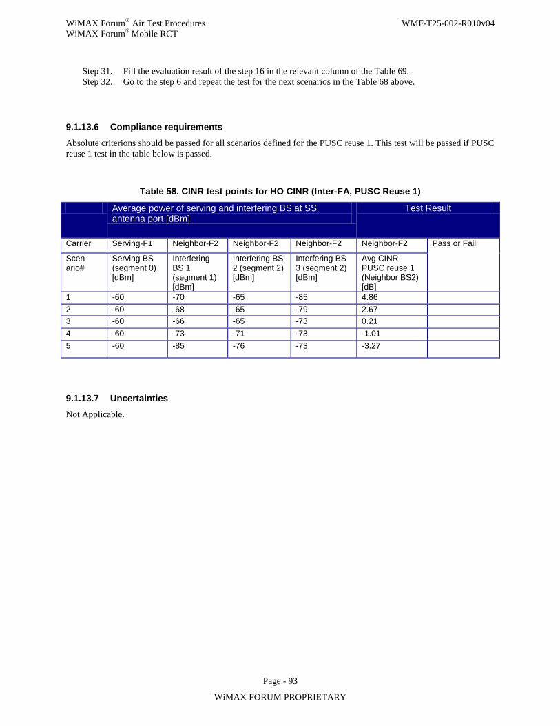
WiMAX Forum® Air Test Procedures WMF-T25-002-R010v04 WiMAX Forum® Mobile RCT
Page - 93
WiMAX FORUM PROPRIETARY
Step 31. Fill the evaluation result of the step 16 in the relevant column of the Table 69. Step 32. Go to the step 6 and repeat the test for the next scenarios in the Table 68 above.
9.1.13.6 Compliance requirements
Absolute criterions should be passed for all scenarios defined for the PUSC reuse 1. This test will be passed if PUSC reuse 1 test in the table below is passed.
Table 58. CINR test points for HO CINR (Inter-FA, PUSC Reuse 1)
Average power of serving and interfering BS at SS antenna port [dBm]
Test Result
Carrier Serving-F1 Neighbor-F2 Neighbor-F2 Neighbor-F2 Neighbor-F2 Pass or Fail
Scen-ario#
Serving BS (segment 0) [dBm]
Interfering BS 1 (segment 1) [dBm]
Interfering BS 2 (segment 2) [dBm]
Interfering BS 3 (segment 2) [dBm]
Avg CINR PUSC reuse 1 (Neighbor BS2) [dB]
1 -60 -70 -65 -85 4.86 2 -60 -68 -65 -79 2.67 3 -60 -66 -65 -73 0.21 4 -60 -73 -71 -73 -1.01 5 -60 -85 -76 -73 -3.27
9.1.13.7 Uncertainties
Not Applicable.
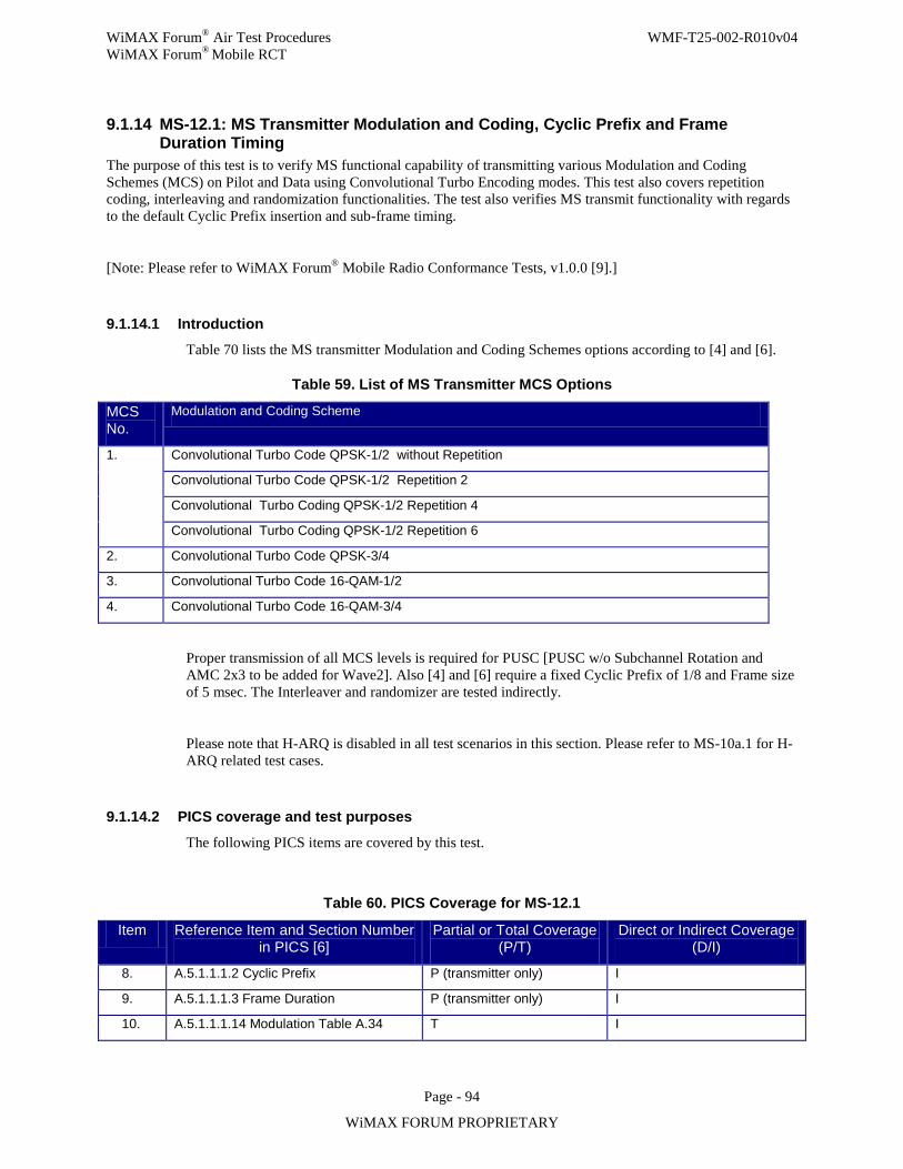
WiMAX Forum® Air Test Procedures WMF-T25-002-R010v04 WiMAX Forum® Mobile RCT
Page - 94
WiMAX FORUM PROPRIETARY
9.1.14 MS-12.1: MS Transmitter Modulation and Coding, Cyclic Prefix and Frame Duration Timing
The purpose of this test is to verify MS functional capability of transmitting various Modulation and Coding Schemes (MCS) on Pilot and Data using Convolutional Turbo Encoding modes. This test also covers repetition coding, interleaving and randomization functionalities. The test also verifies MS transmit functionality with regards to the default Cyclic Prefix insertion and sub-frame timing.
[Note: Please refer to WiMAX Forum® Mobile Radio Conformance Tests, v1.0.0 [9].]
9.1.14.1 Introduction Table 70 lists the MS transmitter Modulation and Coding Schemes options according to [4] and [6].
Table 59. List of MS Transmitter MCS Options
Proper transmission of all MCS levels is required for PUSC [PUSC w/o Subchannel Rotation and AMC 2x3 to be added for Wave2]. Also [4] and [6] require a fixed Cyclic Prefix of 1/8 and Frame size of 5 msec. The Interleaver and randomizer are tested indirectly.
Please note that H-ARQ is disabled in all test scenarios in this section. Please refer to MS-10a.1 for H-ARQ related test cases.
9.1.14.2 PICS coverage and test purposes
The following PICS items are covered by this test.
Table 60. PICS Coverage for MS-12.1
Item Reference Item and Section Number in PICS [6]
Partial or Total Coverage (P/T)
Direct or Indirect Coverage (D/I)
8. A.5.1.1.1.2 Cyclic Prefix P (transmitter only) I
9. A.5.1.1.1.3 Frame Duration P (transmitter only) I
10. A.5.1.1.1.14 Modulation Table A.34 T I
MCS No.
Modulation and Coding Scheme
1. Convolutional Turbo Code QPSK-1/2 without Repetition
Convolutional Turbo Code QPSK-1/2 Repetition 2
Convolutional Turbo Coding QPSK-1/2 Repetition 4
Convolutional Turbo Coding QPSK-1/2 Repetition 6
2. Convolutional Turbo Code QPSK-3/4
3. Convolutional Turbo Code 16-QAM-1/2
4. Convolutional Turbo Code 16-QAM-3/4
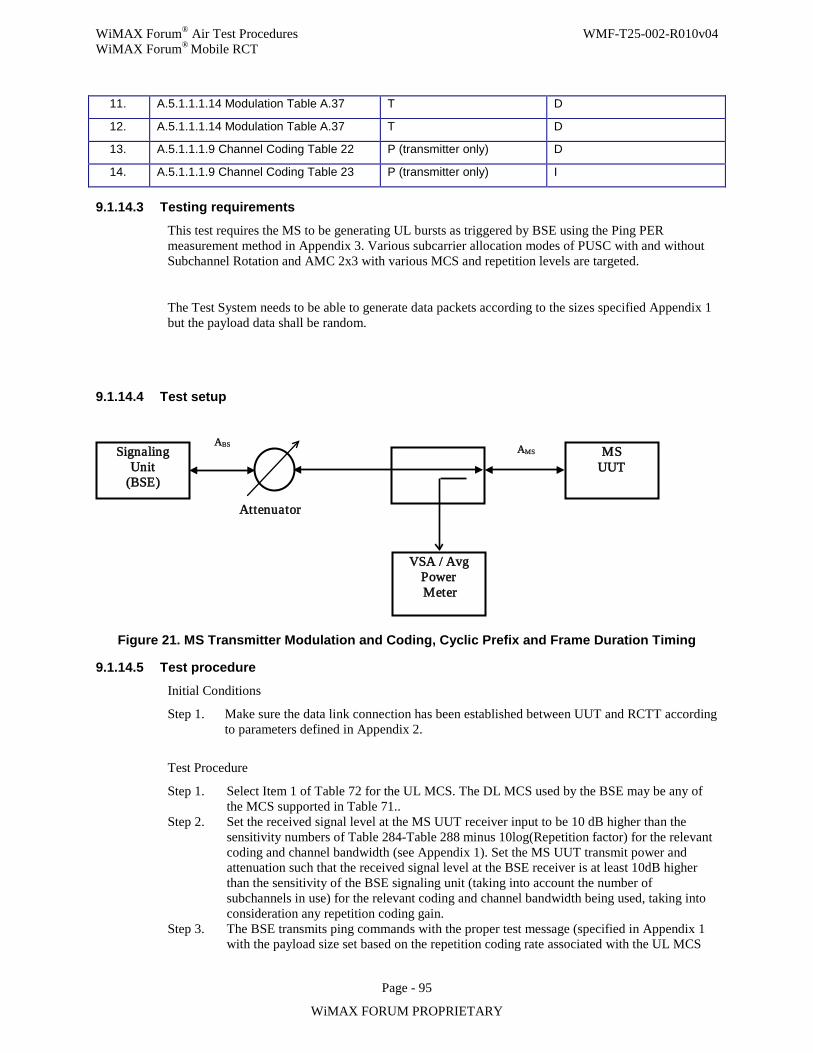
WiMAX Forum® Air Test Procedures WMF-T25-002-R010v04 WiMAX Forum® Mobile RCT
Page - 95
WiMAX FORUM PROPRIETARY
11. A.5.1.1.1.14 Modulation Table A.37 T D
12. A.5.1.1.1.14 Modulation Table A.37 T D
13. A.5.1.1.1.9 Channel Coding Table 22 P (transmitter only) D
14. A.5.1.1.1.9 Channel Coding Table 23 P (transmitter only) I
9.1.14.3 Testing requirements
This test requires the MS to be generating UL bursts as triggered by BSE using the Ping PER measurement method in Appendix 3. Various subcarrier allocation modes of PUSC with and without Subchannel Rotation and AMC 2x3 with various MCS and repetition levels are targeted.
The Test System needs to be able to generate data packets according to the sizes specified Appendix 1 but the payload data shall be random.
9.1.14.4 Test setup
Figure 21. MS Transmitter Modulation and Coding, Cyclic Prefix and Frame Duration Timing
9.1.14.5 Test procedure
Initial Conditions
Step 1. Make sure the data link connection has been established between UUT and RCTT according to parameters defined in Appendix 2.
Test Procedure
Step 1. Select Item 1 of Table 72 for the UL MCS. The DL MCS used by the BSE may be any of the MCS supported in Table 71..
Step 2. Set the received signal level at the MS UUT receiver input to be 10 dB higher than the sensitivity numbers of Table 284-Table 288 minus 10log(Repetition factor) for the relevant coding and channel bandwidth (see Appendix 1). Set the MS UUT transmit power and attenuation such that the received signal level at the BSE receiver is at least 10dB higher than the sensitivity of the BSE signaling unit (taking into account the number of subchannels in use) for the relevant coding and channel bandwidth being used, taking into consideration any repetition coding gain.
Step 3. The BSE transmits ping commands with the proper test message (specified in Appendix 1 with the payload size set based on the repetition coding rate associated with the UL MCS
Signaling Unit
(BSE)
VSA / Avg Power Meter
MS UUT
Attenuator
AMS ABS
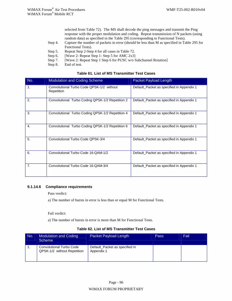
WiMAX Forum® Air Test Procedures WMF-T25-002-R010v04 WiMAX Forum® Mobile RCT
Page - 96
WiMAX FORUM PROPRIETARY
selected from Table 72). The MS shall decode the ping messages and transmit the Ping response with the proper modulation and coding. Repeat transmission of N packets (using random data) as specified in the Table 295 (corresponding to Functional Tests).
Step 4. Capture the number of packets in error (should be less than M as specified in Table 295 for Functional Tests).
Step 5. Repeat Step 2-Step 4 for all cases in Table 72. Step 6. [Wave 2: Repeat Step 1- Step 5 for AMC 2x3] Step 7. [Wave 2: Repeat Step 1 Step 6 for PUSC w/o Subchannel Rotation] Step 8. End of test.
Table 61. List of MS Transmitter Test Cases
9.1.14.6 Compliance requirements
Pass verdict:
a) The number of bursts in error is less than or equal M for Functional Tests.
Fail verdict:
a) The number of bursts in error is more than M for Functional Tests.
Table 62. List of MS Transmitter Test Cases
No. Modulation and Coding Scheme Packet Payload Length
1. Convolutional Turbo Code QPSK-1/2 without Repetition
Default_Packet as specified in Appendix 1
2. Convolutional Turbo Coding QPSK-1/2 Repetition 2 Default_Packet as specified in Appendix 1
3. Convolutional Turbo Coding QPSK-1/2 Repetition 4 Default_Packet as specified in Appendix 1
4. Convolutional Turbo Coding QPSK-1/2 Repetition 6 Default_Packet as specified in Appendix 1
5. Convolutional Turbo Code QPSK-3/4 Default_Packet as specified in Appendix 1
6. Convolutional Turbo Code 16-QAM-1/2 Default_Packet as specified in Appendix 1
7. Convolutional Turbo Code 16-QAM-3/4 Default_Packet as specified in Appendix 1
No. Modulation and Coding Scheme
Packet Payload Length Pass Fail
1. Convolutional Turbo Code QPSK-1/2 without Repetition
Default_Packet as specified in Appendix 1
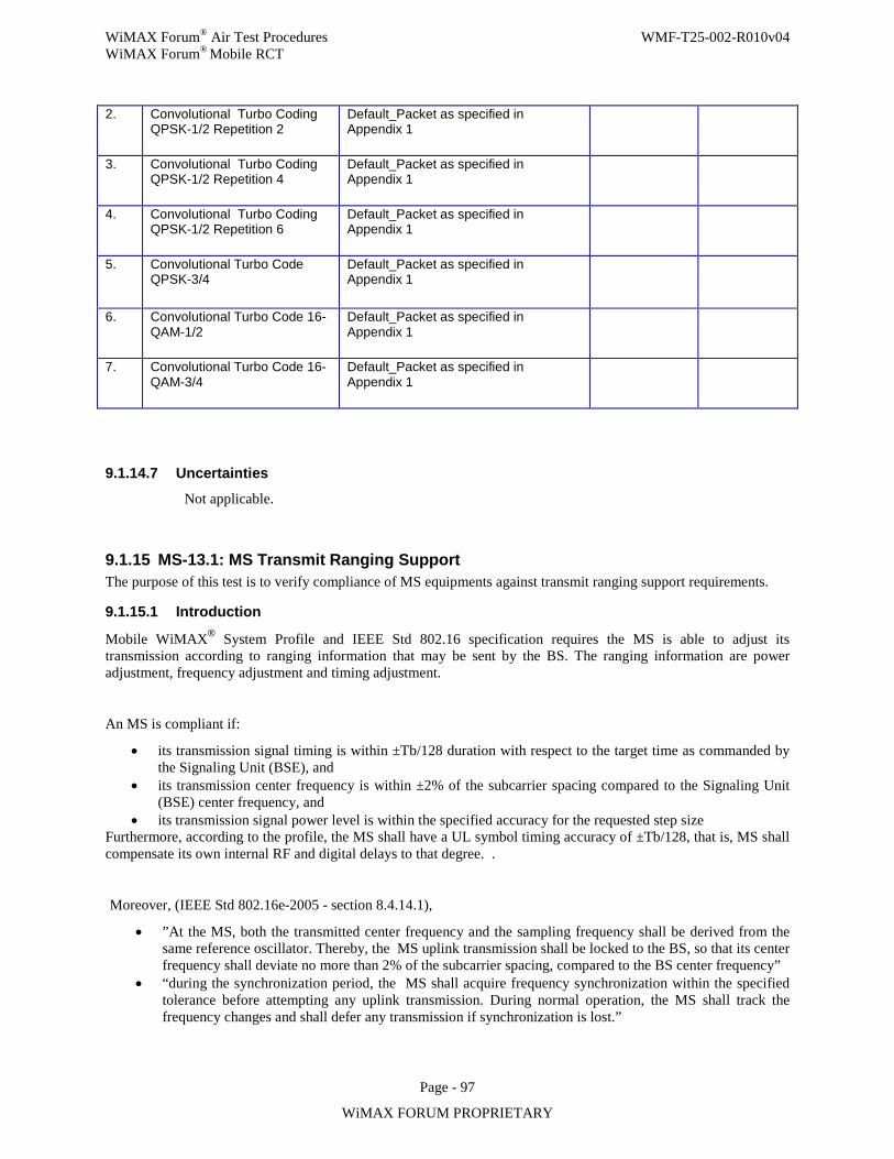
WiMAX Forum® Air Test Procedures WMF-T25-002-R010v04 WiMAX Forum® Mobile RCT
Page - 97
WiMAX FORUM PROPRIETARY
9.1.14.7 Uncertainties
Not applicable.
9.1.15 MS-13.1: MS Transmit Ranging Support The purpose of this test is to verify compliance of MS equipments against transmit ranging support requirements.
9.1.15.1 Introduction
Mobile WiMAX® System Profile and IEEE Std 802.16 specification requires the MS is able to adjust its transmission according to ranging information that may be sent by the BS. The ranging information are power adjustment, frequency adjustment and timing adjustment.
An MS is compliant if:
• its transmission signal timing is within ±Tb/128 duration with respect to the target time as commanded by the Signaling Unit (BSE), and
• its transmission center frequency is within ±2% of the subcarrier spacing compared to the Signaling Unit (BSE) center frequency, and
• its transmission signal power level is within the specified accuracy for the requested step size Furthermore, according to the profile, the MS shall have a UL symbol timing accuracy of ±Tb/128, that is, MS shall compensate its own internal RF and digital delays to that degree. .
Moreover, (IEEE Std 802.16e-2005 - section 8.4.14.1),
• ”At the MS, both the transmitted center frequency and the sampling frequency shall be derived from the same reference oscillator. Thereby, the MS uplink transmission shall be locked to the BS, so that its center frequency shall deviate no more than 2% of the subcarrier spacing, compared to the BS center frequency”
• “during the synchronization period, the MS shall acquire frequency synchronization within the specified tolerance before attempting any uplink transmission. During normal operation, the MS shall track the frequency changes and shall defer any transmission if synchronization is lost.”
2. Convolutional Turbo Coding QPSK-1/2 Repetition 2
Default_Packet as specified in Appendix 1
3. Convolutional Turbo Coding QPSK-1/2 Repetition 4
Default_Packet as specified in Appendix 1
4. Convolutional Turbo Coding QPSK-1/2 Repetition 6
Default_Packet as specified in Appendix 1
5. Convolutional Turbo Code QPSK-3/4
Default_Packet as specified in Appendix 1
6. Convolutional Turbo Code 16-QAM-1/2
Default_Packet as specified in Appendix 1
7. Convolutional Turbo Code 16-QAM-3/4
Default_Packet as specified in Appendix 1
WiMAX Forum® Air Test Procedures WMF-T25-002-R010v04 WiMAX Forum® Mobile RCT
Page - 98
WiMAX FORUM PROPRIETARY
Since the accuracy that the MS should have when it applies the frequency corrections sent by the Signaling Unit (BSE) is not defined, this will not be tested and the Signaling Unit (BSE) will not send any frequency correction.
The power control mechanisms included in the ranging process are not addressed in this test, but they are part of the specific power control test.
There are two types of ranging codes mandated by the Mobile WiMAX® System Profile:
• 2 symbols long (for Initial Ranging and HO ranging) • 1 symbol long (for Periodic Ranging and BWR).
Ranging requirements are validated in two sub-tests:
• Subtest A: by verifying the initial phase of the network entry is passed by the MS though the MS was un-ranged initially (by emulation).
• Subtest B: by verifying further phases during which MS is in Periodic Ranging are successful though MS get unranged (by emulation). This additional phases follow previous one described in Subtest A and hence assumes the MS has succeeded Initial Ranging and entered the Periodic Ranging phase.
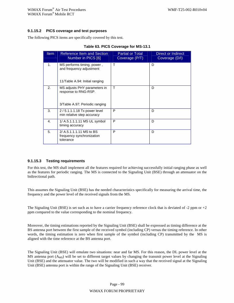
WiMAX Forum® Air Test Procedures WMF-T25-002-R010v04 WiMAX Forum® Mobile RCT
Page - 99
WiMAX FORUM PROPRIETARY
9.1.15.2 PICS coverage and test purposes
The following PICS items are specifically covered by this test.
Table 63. PICS Coverage for MS-13.1
Item Reference Item and Section Number in PICS [6]
Partial or Total Coverage (P/T)
Direct or Indirect Coverage (D/I)
1. MS performs timing, power , and frequency adjustment
11/Table A.94: Initial ranging
T D
2. MS adjusts PHY parameters in response to RNG-RSP.
3/Table A.97: Periodic ranging
T D
3. 2 / 5.1.1.1.18 Tx power level min relative step accuracy
P D
4. 1/ A.5.1.1.1.11 MS UL symbol timing accuracy
P D
5. 2/ A.5.1.1.1.11 MS to BS frequency synchronization tolerance
P D
9.1.15.3 Testing requirements
For this test, the MS shall implement all the features required for achieving successfully initial ranging phase as well as the features for periodic ranging. The MS is connected to the Signaling Unit (BSE) through an attenuator on the bidirectional path.
This assumes the Signaling Unit (BSE) has the needed characteristics specifically for measuring the arrival time, the frequency and the power level of the received signals from the MS.
The Signaling Unit (BSE) is set such as to have a carrier frequency reference clock that is deviated of -2 ppm or +2 ppm compared to the value corresponding to the nominal frequency.
Moreover, the timing estimations reported by the Signaling Unit (BSE) shall be expressed as timing difference at the BS antenna port between the first sample of the received symbol (including CP) versus the timing reference. In other words, the timing estimation is zero when first sample of the symbol (including CP) transmitted by the MS is aligned with the time reference at the BS antenna port.
The Signaling Unit (BSE) will emulate two situations: near and far MS. For this reason, the DL power level at the MS antenna port (AMS) will be set to different target values by changing the transmit power level at the Signaling Unit (BSE) and the attenuator value. The two will be modified in such a way that the received signal at the Signaling Unit (BSE) antenna port is within the range of the Signaling Unit (BSE) receiver.
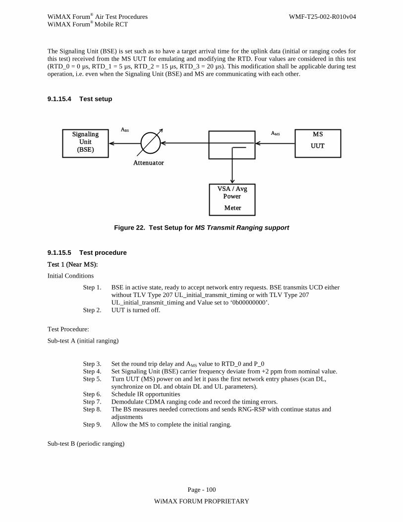
WiMAX Forum® Air Test Procedures WMF-T25-002-R010v04 WiMAX Forum® Mobile RCT
Page - 100
WiMAX FORUM PROPRIETARY
The Signaling Unit (BSE) is set such as to have a target arrival time for the uplink data (initial or ranging codes for this test) received from the MS UUT for emulating and modifying the RTD. Four values are considered in this test (RTD_0 = 0 µs, RTD_1 = 5 µs, RTD_2 = 15 µs, RTD_3 = 20 µs). This modification shall be applicable during test operation, i.e. even when the Signaling Unit (BSE) and MS are communicating with each other.
9.1.15.4 Test setup
Figure 22. Test Setup for MS Transmit Ranging support
9.1.15.5 Test procedure
Test 1 (Near MS):
Initial Conditions
Step 1. BSE in active state, ready to accept network entry requests. BSE transmits UCD either without TLV Type 207 UL_initial_transmit_timing or with TLV Type 207 UL_initial_transmit_timing and Value set to ‘0b00000000’.
Step 2. UUT is turned off.
Test Procedure:
Sub-test A (initial ranging)
Step 3. Set the round trip delay and AMS value to RTD_0 and P_0 Step 4. Set Signaling Unit (BSE) carrier frequency deviate from +2 ppm from nominal value. Step 5. Turn UUT (MS) power on and let it pass the first network entry phases (scan DL,
synchronize on DL and obtain DL and UL parameters). Step 6. Schedule IR opportunities Step 7. Demodulate CDMA ranging code and record the timing errors. Step 8. The BS measures needed corrections and sends RNG-RSP with continue status and
adjustments Step 9. Allow the MS to complete the initial ranging.
Sub-test B (periodic ranging)
Signaling Unit
(BSE)
VSA / Avg Power
Meter
MS UUT
Attenuator
AMS ABS
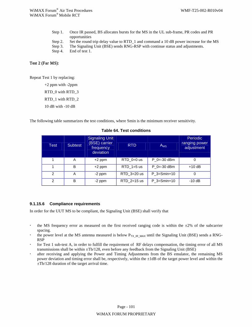
WiMAX Forum® Air Test Procedures WMF-T25-002-R010v04 WiMAX Forum® Mobile RCT
Page - 101
WiMAX FORUM PROPRIETARY
Step 1. Once IR passed, BS allocates bursts for the MS in the UL sub-frame, PR codes and PR opportunities
Step 2. Set the round trip delay value to RTD_1 and command a 10 dB power increase for the MS Step 3. The Signaling Unit (BSE) sends RNG-RSP with continue status and adjustments. Step 4. End of test 1.
Test 2 (Far MS):
Repeat Test 1 by replacing:
+2 ppm with -2ppm
RTD_0 with RTD_3
RTD_1 with RTD_2
10 dB with -10 dB
The following table summarizes the test conditions, where Smin is the minimum receiver sensitivity.
Table 64. Test conditions
Test Subtest
Signaling Unit (BSE) carrier
frequency deviation
RTD AMS
Periodic ranging power
adjustment
1 A +2 ppm RTD_0=0 us P_0=-30 dBm 0
1 B +2 ppm RTD_1=5 us P_0=-30 dBm +10 dB
2 A -2 ppm RTD_3=20 us P_3=Smin+10 0
2 B -2 ppm RTD_2=15 us P_3=Smin+10 -10 dB
9.1.15.6 Compliance requirements In order for the UUT MS to be compliant, the Signaling Unit (BSE) shall verify that
the MS frequency error as measured on the first received ranging code is within the ±2% of the subcarrier spacing.
the power level at the MS antenna measured is below PTX_IR_MAX until the Signaling Unit (BSE) sends a RNG-RSP
for Test 1 sub-test A, in order to fulfill the requirement of RF delays compensation, the timing error of all MS transmissions shall be within ±Tb/128, even before any feedback from the Signaling Unit (BSE)
after receiving and applying the Power and Timing Adjustments from the BS emulator, the remaining MS power deviation and timing error shall be, respectively, within the ±1dB of the target power level and within the ±Tb/128 duration of the target arrival time.
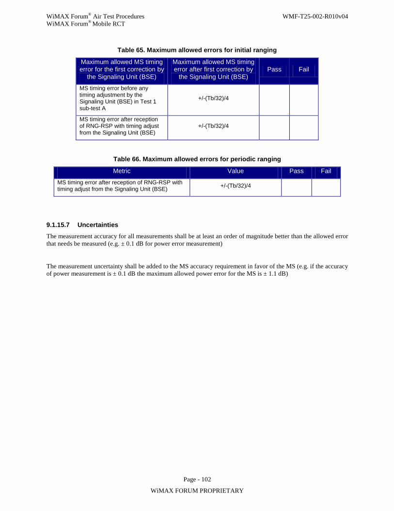
WiMAX Forum® Air Test Procedures WMF-T25-002-R010v04 WiMAX Forum® Mobile RCT
Page - 102
WiMAX FORUM PROPRIETARY
Table 65. Maximum allowed errors for initial ranging
Maximum allowed MS timing error for the first correction by
the Signaling Unit (BSE)
Maximum allowed MS timing error after first correction by
the Signaling Unit (BSE) Pass Fail
MS timing error before any timing adjustment by the Signaling Unit (BSE) in Test 1 sub-test A
+/-(Tb/32)/4
MS timing error after reception of RNG-RSP with timing adjust from the Signaling Unit (BSE)
+/-(Tb/32)/4
Table 66. Maximum allowed errors for periodic ranging
Metric Value Pass Fail
MS timing error after reception of RNG-RSP with timing adjust from the Signaling Unit (BSE) +/-(Tb/32)/4
9.1.15.7 Uncertainties
The measurement accuracy for all measurements shall be at least an order of magnitude better than the allowed error that needs be measured (e.g. ± 0.1 dB for power error measurement)
The measurement uncertainty shall be added to the MS accuracy requirement in favor of the MS (e.g. if the accuracy of power measurement is ± 0.1 dB the maximum allowed power error for the MS is ± 1.1 dB)
WiMAX Forum® Air Test Procedures WMF-T25-002-R010v04 WiMAX Forum® Mobile RCT
Page - 103
WiMAX FORUM PROPRIETARY
9.1.16 MS-14.1: Reserved
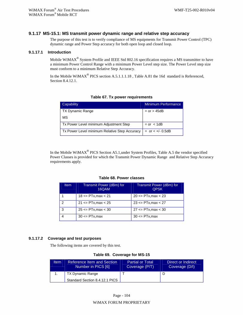
WiMAX Forum® Air Test Procedures WMF-T25-002-R010v04 WiMAX Forum® Mobile RCT
Page - 104
WiMAX FORUM PROPRIETARY
9.1.17 MS-15.1: MS transmit power dynamic range and relative step accuracy The purpose of this test is to verify compliance of MS equipments for Transmit Power Control (TPC) dynamic range and Power Step accuracy for both open loop and closed loop.
9.1.17.1 Introduction
Mobile WiMAX® System Profile and IEEE Std 802.16 specification requires a MS transmitter to have a minimum Power Control Range with a minimum Power Level step size. The Power Level step size must conform to a minimum Relative Step Accuracy.
In the Mobile WiMAX® PICS section A.5.1.1.1.18 , Table A.81 the 16d standard is Referenced, Section 8.4.12.1.
Table 67. Tx power requirements
Capability Minimum Performance
TX Dynamic Range
MS
= or > 45dB
Tx Power Level minimum Adjustment Step = or < 1dB
Tx Power Level minimum Relative Step Accuracy = or < +/- 0.5dB
In the Mobile WiMAX® PICS Section A5.1,under System Profiles, Table A.5 the vendor specified Power Classes is provided for which the Transmit Power Dynamic Range and Relative Step Accuracy requirements apply.
Table 68. Power classes
Item Transmit Power (dBm) for 16QAM
Transmit Power (dBm) for QPSK
1 18 <= PTx,max < 21 20 <= PTx,max < 23
2 21 <= PTx,max < 25 23 <= PTx,max < 27
3 25 <= PTx,max < 30 27 <= PTx,max < 30
4 30 <= PTx,max 30 <= PTx,max
9.1.17.2 Coverage and test purposes
The following items are covered by this test.
Table 69. Coverage for MS-15
Item Reference Item and Section Number in PICS [6]
Partial or Total Coverage (P/T)
Direct or Indirect Coverage (D/I)
1. TX Dynamic Range
Standard Section 8.4.12.1 PICS
T D
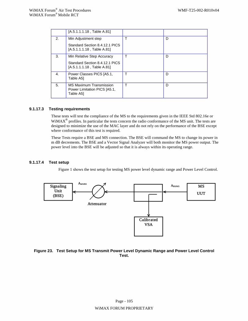
WiMAX Forum® Air Test Procedures WMF-T25-002-R010v04 WiMAX Forum® Mobile RCT
Page - 105
WiMAX FORUM PROPRIETARY
[A.5.1.1.1.18 , Table A.81]
2. Min Adjustment step
Standard Section 8.4.12.1 PICS [A.5.1.1.1.18 , Table A.81]
T D
3. Min Relative Step Accuracy
Standard Section 8.4.12.1 PICS [A.5.1.1.1.18 , Table A.81]
T D
4. Power Classes PICS [A5.1, Table A5]
T D
5. MS Maximum Transmission Power Limitation PICS [A5.1, Table A5]
T D
9.1.17.3 Testing requirements
These tests will test the compliance of the MS to the requirements given in the IEEE Std 802.16e or WiMAX® profiles. In particular the tests concern the radio conformance of the MS unit. The tests are designed to minimize the use of the MAC layer and do not rely on the performance of the BSE except where conformance of this test is required.
These Tests require a BSE and MS connection. The BSE will command the MS to change its power in m dB decrements. The BSE and a Vector Signal Analyzer will both monitor the MS power output. The power level into the BSE will be adjusted so that it is always within its operating range.
9.1.17.4 Test setup
Figure 1 shows the test setup for testing MS power level dynamic range and Power Level Control.
Figure 23. Test Setup for MS Transmit Power Level Dynamic Range and Power Level Control Test.
Signaling Unit
(BSE)
Calibrated VSA
MS UUT
Attenuator
ABS/MS AMS/BS
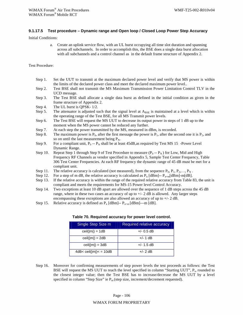
WiMAX Forum® Air Test Procedures WMF-T25-002-R010v04 WiMAX Forum® Mobile RCT
Page - 106
WiMAX FORUM PROPRIETARY
9.1.17.5 Test procedure – Dynamic range and Open loop / Closed Loop Power Step Accuracy
Initial Conditions:
a. Create an uplink service flow, with an UL burst occupying all time slot duration and spanning across all subchannels. In order to accomplish this, the BSE does a single data burst allocation with all subchannels and a control channel as in the default frame structure of Appendix 2.
Test Procedure:
Step 1. Set the UUT to transmit at the maximum declared power level and verify that MS power is within the limits of the declared power class and meet the declared maximum power level..
Step 2. Test BSE shall not transmit the MS Maximum Transmission Power Limitation Control TLV in the UCD message.
Step 3. The Test BSE shall allocate a single data burst as defined in the initial condition as given in the frame structure of Appendix 2.
Step 4. The UL burst is QPSK- 1/2. Step 5. The attenuator is adjusted such that the signal level at ABSE is maintained at a level which is within
the operating range of the Test BSE, for all MS Transmit power levels. Step 6. The Test BSE will request the MS UUT to decrease its output power in steps of 1 dB up to the
moment when the MS power cannot be reduced any further. Step 7. At each step the power transmitted by the MS, measured in dBm, is recorded. Step 8. The maximum power is P0, after the first message the power is P1, after the second one it is P2, and
so on until the last measurement being PN. Step 9. For a compliant unit, P0 -- PN shall be at least 45dB,as required by Test MS 15 -Power Level
Dynamic Range. Step 10. Repeat Step 1 through Step 9 of Test Procedure to measure (P0 -- PN ) for Low, Mid and High
Frequency RF Channels as vendor specified in Appendix 5, Sample Test Center Frequency, Table 306 Test Center Frequencies. At each RF frequency the dynamic range of 45 dB must be met for a compliant unit.
Step 11. The relative accuracy is calculated (not measured), from the sequence P0, P1, P2,…, PN . Step 12. For a step of m dB, the relative accuracy is calculated as Pn [dBm]-- Pn+m[dBm]-m[dB]. Step 13. If the relative accuracy is within the range of the required relative accuracy from Table 83, the unit is
compliant and meets the requirements for MS-15 Power level Control Accuracy. Step 14. Two exceptions at least 10 dB apart are allowed over the sequence of 1 dB steps across the 45 dB
range, where in these two cases an accuracy of up to +/- 2 dB is allowed. Any larger steps encompassing these exceptions are also allowed an accuracy of up to +/- 2 dB.
Step 15. Relative accuracy is defined as Pn [dBm]-- Pn+m [dBm]—m [dB].
Table 70. Required accuracy for power level control.
Single Step Size m Required relative accuracy
ceil(|m|) = 1dB +/- 0.5 dB
ceil(|m|) = 2dB +/- 1 dB
ceil(|m|) = 3dB +/- 1.5 dB
4dB< ceil(|m|)< = 10dB +/- 2 dB
Step 16. Moreover for confirming measurements of step power levels the test proceeds as follows: the Test BSE will request the MS UUT to reach the level specified in column “Starting UUT”, Ps, rounded to the closest integer value; then the Test BSE has to increase/decrease the MS UUT by a level specified in column “Step Size” ie Pm (step size, increment/decrement requested).
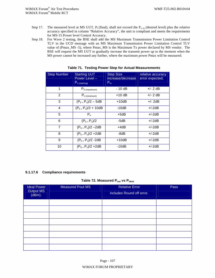
WiMAX Forum® Air Test Procedures WMF-T25-002-R010v04 WiMAX Forum® Mobile RCT
Page - 107
WiMAX FORUM PROPRIETARY
Step 17. The measured level at MS UUT, Pf (final), shall not exceed the Ps+m (desired level) plus the relative accuracy specified in column “Relative Accuracy”, the unit is compliant and meets the requirements for MS-15 Power level Control Accuracy.
Step 18. For Wave 2 testing, the BSE shall add the MS Maximum Transmission Power Limitation Control TLV in the UCD message with an MS Maximum Transmission Power Limitation Control TLV value of (Pmax_MS -5), where Pmax_MS is the Maximum Tx power declared by MS vendor. The BSE will request the MS UUT to gradually increase the transmit power up to the moment when the MS power cannot be increased any further, where the maximum power Pmax will be measured.
Table 71. Testing Power Step for Actual Measurements
Step Number Starting UUT Power Level – Ps (starting)
Step Size increase/decrease Pm
relative accuracy error expected;
1 P0 (maximum) - 10 dB +/- 2 dB
2 Pn (minimum) +10 dB +/- 2 dB
3 (P0 + Pn)/2 – 5dB +10dB +/- 2dB
4 (P0 + Pn)/2 + 10dB -10dB +/-2dB
5 Pn +5dB +/-2dB
6 (P0 + Pn)/2 -5dB +/-2dB
7 (P0 + Pn)/2 –2dB +4dB +/-2dB
8 (P0 + Pn)/2 +2dB -8dB +/-2dB
9 (P0 + Pn)/2 -2dB +10dB +/-2dB
10 (P0 + Pn)/2 +2dB -10dB +/-2dB
9.1.17.6 Compliance requirements
Table 72. Measured Pout vs Pideal
Ideal Power Output MS
(dBm).
Measured Pout MS Relative Error
includes Round off error.
Pass
WiMAX Forum® Air Test Procedures WMF-T25-002-R010v04 WiMAX Forum® Mobile RCT
Page - 108
WiMAX FORUM PROPRIETARY
Pass verdicts:
For Step 1: For a compliant unit, MS maximum Tx power shall comply with declared power class per Table 81and the maximum declared power level by vendor.
For Step 9: For a compliant unit, P0 -- PN shall be at least 45 dB
For Step 10: For a compliant unit , P0 -- PN shall be at least 45 dB
For Step 13: If the relative accuracy is within the range of the required relative accuracy from Table 83, the unit is compliant and meets the requirements for MS-15 Power level Control Accuracy.
For Step 17: The measured level at MS UUT, Pf (final), shall not exceed the Ps+m (desired level) plus the relative accuracy specified in column “Relative Accuracy”, the unit is compliant and meets the requirements for MS-15 Power level Control Accuracy.
For Step 18: The measured level at MS UUT, Pmax, shall not exceed Pmax_UCD_TLV + 2dB, the unit is compliant and meets the requirements for MS-15 Maximum Transmission Power Control. Here, Pmax_UCD_TLV is the MS Maximum Power Limitation value specified in the UCD TLV and 2dB is the accuracy margin.
Fail verdicts:
For Step 9: For a Failed unit, P0 -- PN shall be less than 45 dB.
For Step 10: For a Failed unit, P0 -- PN shall be less than 45 dB.
For Step 13: If the relative accuracy exceeds the range of the required relative accuracy from Table 83, the unit fails.
For Step 17: If the measured level at MS UUT, Pf (final), exceeds the Ps+m (desired level) plus the relative accuracy specified in column “Relative Accuracy”, the unit fails.
For Step 18: If the measured level at MS UUT, Pmax, exceeds Pmax_UCD_TLV + 2dB, the unit fails.
9.1.17.7 Uncertainties
VSA – Vector Signal Analyzer and BSE accuracy must be accounted for. Numerical Rounding Off of power levels must also be accounted for and included in the Relative accuracy numbers.
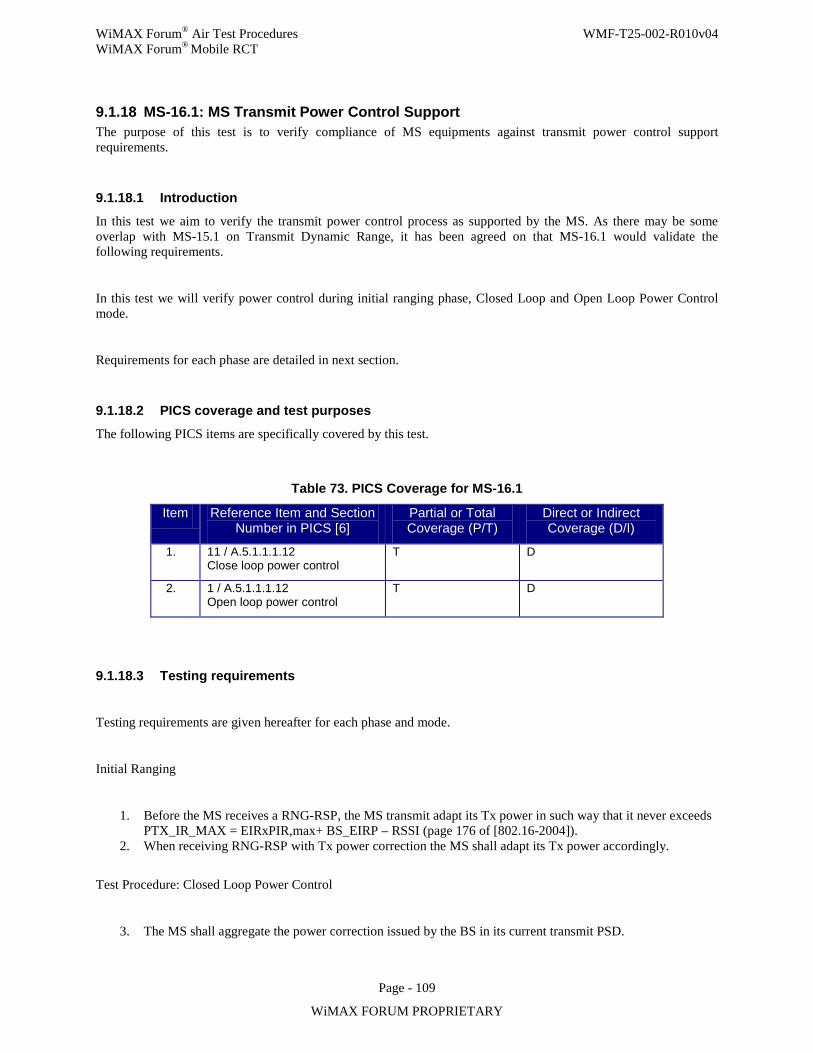
WiMAX Forum® Air Test Procedures WMF-T25-002-R010v04 WiMAX Forum® Mobile RCT
Page - 109
WiMAX FORUM PROPRIETARY
9.1.18 MS-16.1: MS Transmit Power Control Support The purpose of this test is to verify compliance of MS equipments against transmit power control support requirements.
9.1.18.1 Introduction
In this test we aim to verify the transmit power control process as supported by the MS. As there may be some overlap with MS-15.1 on Transmit Dynamic Range, it has been agreed on that MS-16.1 would validate the following requirements.
In this test we will verify power control during initial ranging phase, Closed Loop and Open Loop Power Control mode.
Requirements for each phase are detailed in next section.
9.1.18.2 PICS coverage and test purposes
The following PICS items are specifically covered by this test.
Table 73. PICS Coverage for MS-16.1
Item Reference Item and Section Number in PICS [6]
Partial or Total Coverage (P/T)
Direct or Indirect Coverage (D/I)
1. 11 / A.5.1.1.1.12 Close loop power control
T D
2. 1 / A.5.1.1.1.12 Open loop power control
T D
9.1.18.3 Testing requirements
Testing requirements are given hereafter for each phase and mode.
Initial Ranging
1. Before the MS receives a RNG-RSP, the MS transmit adapt its Tx power in such way that it never exceeds PTX_IR_MAX = EIRxPIR,max+ BS_EIRP – RSSI (page 176 of [802.16-2004]).
2. When receiving RNG-RSP with Tx power correction the MS shall adapt its Tx power accordingly.
Test Procedure: Closed Loop Power Control
3. The MS shall aggregate the power correction issued by the BS in its current transmit PSD.
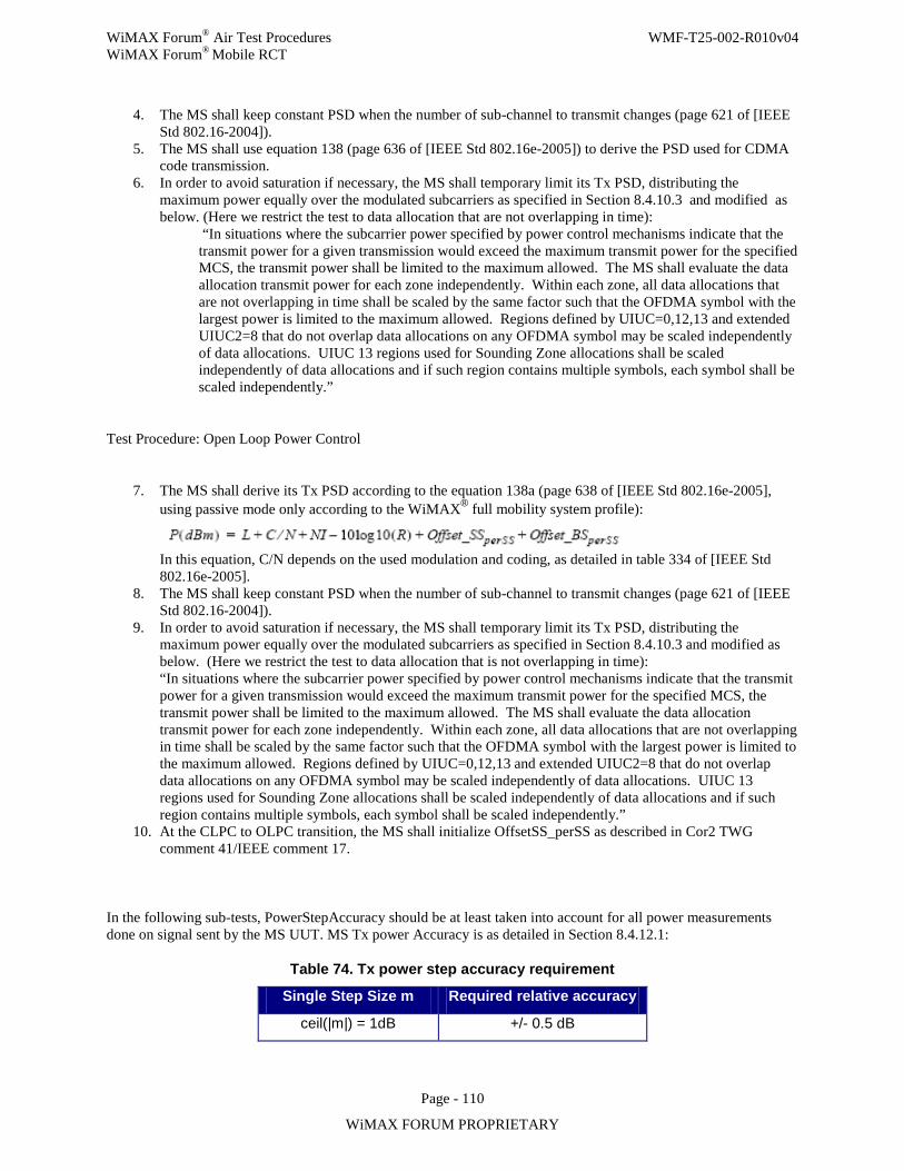
WiMAX Forum® Air Test Procedures WMF-T25-002-R010v04 WiMAX Forum® Mobile RCT
Page - 110
WiMAX FORUM PROPRIETARY
4. The MS shall keep constant PSD when the number of sub-channel to transmit changes (page 621 of [IEEE Std 802.16-2004]).
5. The MS shall use equation 138 (page 636 of [IEEE Std 802.16e-2005]) to derive the PSD used for CDMA code transmission.
6. In order to avoid saturation if necessary, the MS shall temporary limit its Tx PSD, distributing the maximum power equally over the modulated subcarriers as specified in Section 8.4.10.3 and modified as below. (Here we restrict the test to data allocation that are not overlapping in time):
“In situations where the subcarrier power specified by power control mechanisms indicate that the transmit power for a given transmission would exceed the maximum transmit power for the specified MCS, the transmit power shall be limited to the maximum allowed. The MS shall evaluate the data allocation transmit power for each zone independently. Within each zone, all data allocations that are not overlapping in time shall be scaled by the same factor such that the OFDMA symbol with the largest power is limited to the maximum allowed. Regions defined by UIUC=0,12,13 and extended UIUC2=8 that do not overlap data allocations on any OFDMA symbol may be scaled independently of data allocations. UIUC 13 regions used for Sounding Zone allocations shall be scaled independently of data allocations and if such region contains multiple symbols, each symbol shall be scaled independently.”
Test Procedure: Open Loop Power Control
7. The MS shall derive its Tx PSD according to the equation 138a (page 638 of [IEEE Std 802.16e-2005], using passive mode only according to the WiMAX® full mobility system profile):
In this equation, C/N depends on the used modulation and coding, as detailed in table 334 of [IEEE Std 802.16e-2005].
8. The MS shall keep constant PSD when the number of sub-channel to transmit changes (page 621 of [IEEE Std 802.16-2004]).
9. In order to avoid saturation if necessary, the MS shall temporary limit its Tx PSD, distributing the maximum power equally over the modulated subcarriers as specified in Section 8.4.10.3 and modified as below. (Here we restrict the test to data allocation that is not overlapping in time): “In situations where the subcarrier power specified by power control mechanisms indicate that the transmit power for a given transmission would exceed the maximum transmit power for the specified MCS, the transmit power shall be limited to the maximum allowed. The MS shall evaluate the data allocation transmit power for each zone independently. Within each zone, all data allocations that are not overlapping in time shall be scaled by the same factor such that the OFDMA symbol with the largest power is limited to the maximum allowed. Regions defined by UIUC=0,12,13 and extended UIUC2=8 that do not overlap data allocations on any OFDMA symbol may be scaled independently of data allocations. UIUC 13 regions used for Sounding Zone allocations shall be scaled independently of data allocations and if such region contains multiple symbols, each symbol shall be scaled independently.”
10. At the CLPC to OLPC transition, the MS shall initialize OffsetSS_perSS as described in Cor2 TWG comment 41/IEEE comment 17.
In the following sub-tests, PowerStepAccuracy should be at least taken into account for all power measurements done on signal sent by the MS UUT. MS Tx power Accuracy is as detailed in Section 8.4.12.1:
Table 74. Tx power step accuracy requirement
Single Step Size m Required relative accuracy
ceil(|m|) = 1dB +/- 0.5 dB
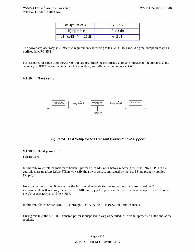
WiMAX Forum® Air Test Procedures WMF-T25-002-R010v04 WiMAX Forum® Mobile RCT
Page - 111
WiMAX FORUM PROPRIETARY
ceil(|m|) = 2dB +/- 1 dB
ceil(|m|) = 3dB +/- 1.5 dB
4dB< ceil(|m|)< = 10dB +/- 2 dB
The power step accuracy shall meet the requirements according to test MRC-15.1 including the exception cases as outlined in MRC-15.1
Furthermore, for Open Loop Power Control sub-test, these measurements shall take into account required absolute accuracy on RSSI measurement which is respectively +/-4 dB according to test MS-04.
9.1.18.4 Test setup
Signalling Unit (BSE) Attenuator
Directional Coupler Attenuator MS UUT
CalibratedVSA
MBS ABS MSSASS
Figure 24. Test Setup for MS Transmit Power Control support
9.1.18.5 Test procedure
Sub-test IR0
In this test, we check the maximum transmit power of the MS-UUT before receiving the first RNG-RSP is in the authorized range (Step 1.Step 6Then we verify the power corrections issued by the test-BS are properly applied (Step 8).
Note that in Step 1.Step 6 we assume the MS should estimate its maximum transmit power based on RSSI measurements with accuracy better than +/-4dB, and apply this power in the Tx with an accuracy of +/-2dB, so that the global accuracy should be +/-6dB.
In this test, allocation for RNG-REQ through CDMA_Alloc_IE is PUSC on 2 sub-channels.
During this test, the MS-UUT transmit power is supposed to vary as detailed in Table 89 (presented at the end of the section).
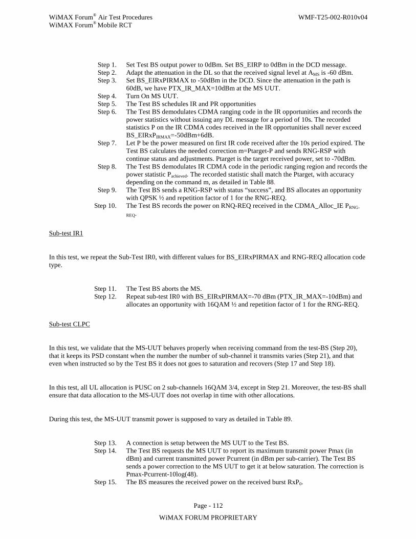
WiMAX Forum® Air Test Procedures WMF-T25-002-R010v04 WiMAX Forum® Mobile RCT
Page - 112
WiMAX FORUM PROPRIETARY
Step 1. Set Test BS output power to 0dBm. Set BS_EIRP to 0dBm in the DCD message. Step 2. Adapt the attenuation in the DL so that the received signal level at AMS is -60 dBm. Step 3. Set BS_EIRxPIRMAX to -50dBm in the DCD. Since the attenuation in the path is
60dB, we have PTX_IR_MAX=10dBm at the MS UUT. Step 4. Turn On MS UUT. Step 5. The Test BS schedules IR and PR opportunities Step 6. The Test BS demodulates CDMA ranging code in the IR opportunities and records the
power statistics without issuing any DL message for a period of 10s. The recorded statistics P on the IR CDMA codes received in the IR opportunities shall never exceed BS_EIRxPIRMAX=-50dBm+6dB.
Step 7. Let P be the power measured on first IR code received after the 10s period expired. The Test BS calculates the needed correction m=Ptarget-P and sends RNG-RSP with continue status and adjustments. Ptarget is the target received power, set to -70dBm.
Step 8. The Test BS demodulates IR CDMA code in the periodic ranging region and records the power statistic Pachieved. The recorded statistic shall match the Ptarget, with accuracy depending on the command m, as detailed in Table 88.
Step 9. The Test BS sends a RNG-RSP with status “success”, and BS allocates an opportunity with QPSK ½ and repetition factor of 1 for the RNG-REQ.
Step 10. The Test BS records the power on RNQ-REQ received in the CDMA_Alloc_IE PRNG-
REQ.
Sub-test IR1
In this test, we repeat the Sub-Test IR0, with different values for BS_EIRxPIRMAX and RNG-REQ allocation code type.
Step 11. The Test BS aborts the MS. Step 12. Repeat sub-test IR0 with BS_EIRxPIRMAX=-70 dBm (PTX_IR_MAX=-10dBm) and
allocates an opportunity with 16QAM ½ and repetition factor of 1 for the RNG-REQ.
Sub-test CLPC
In this test, we validate that the MS-UUT behaves properly when receiving command from the test-BS (Step 20), that it keeps its PSD constant when the number the number of sub-channel it transmits varies (Step 21), and that even when instructed so by the Test BS it does not goes to saturation and recovers (Step 17 and Step 18).
In this test, all UL allocation is PUSC on 2 sub-channels 16QAM 3/4, except in Step 21. Moreover, the test-BS shall ensure that data allocation to the MS-UUT does not overlap in time with other allocations.
During this test, the MS-UUT transmit power is supposed to vary as detailed in Table 89.
Step 13. A connection is setup between the MS UUT to the Test BS. Step 14. The Test BS requests the MS UUT to report its maximum transmit power Pmax (in
dBm) and current transmitted power Pcurrent (in dBm per sub-carrier). The Test BS sends a power correction to the MS UUT to get it at below saturation. The correction is Pmax-Pcurrent-10log(48).
Step 15. The BS measures the received power on the received burst RxP0.
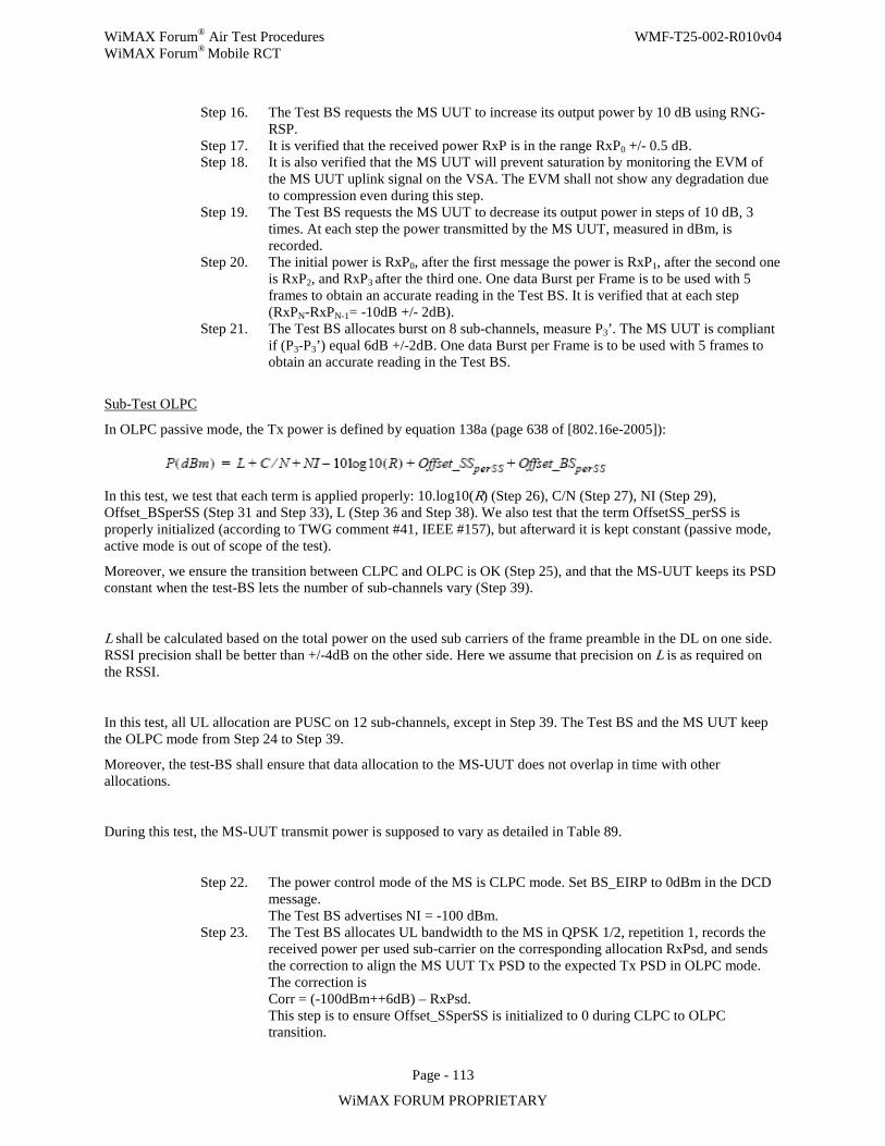
WiMAX Forum® Air Test Procedures WMF-T25-002-R010v04 WiMAX Forum® Mobile RCT
Page - 113
WiMAX FORUM PROPRIETARY
Step 16. The Test BS requests the MS UUT to increase its output power by 10 dB using RNG-RSP.
Step 17. It is verified that the received power RxP is in the range RxP0 +/- 0.5 dB. Step 18. It is also verified that the MS UUT will prevent saturation by monitoring the EVM of
the MS UUT uplink signal on the VSA. The EVM shall not show any degradation due to compression even during this step.
Step 19. The Test BS requests the MS UUT to decrease its output power in steps of 10 dB, 3 times. At each step the power transmitted by the MS UUT, measured in dBm, is recorded.
Step 20. The initial power is RxP0, after the first message the power is RxP1, after the second one is RxP2, and RxP3 after the third one. One data Burst per Frame is to be used with 5 frames to obtain an accurate reading in the Test BS. It is verified that at each step (RxPN-RxPN-1= -10dB +/- 2dB).
Step 21. The Test BS allocates burst on 8 sub-channels, measure P3’. The MS UUT is compliant if (P3-P3’) equal 6dB +/-2dB. One data Burst per Frame is to be used with 5 frames to obtain an accurate reading in the Test BS.
Sub-Test OLPC
In OLPC passive mode, the Tx power is defined by equation 138a (page 638 of [802.16e-2005]):
In this test, we test that each term is applied properly: 10.log10(R) (Step 26), C/N (Step 27), NI (Step 29), Offset_BSperSS (Step 31 and Step 33), L (Step 36 and Step 38). We also test that the term OffsetSS_perSS is properly initialized (according to TWG comment #41, IEEE #157), but afterward it is kept constant (passive mode, active mode is out of scope of the test).
Moreover, we ensure the transition between CLPC and OLPC is OK (Step 25), and that the MS-UUT keeps its PSD constant when the test-BS lets the number of sub-channels vary (Step 39).
L shall be calculated based on the total power on the used sub carriers of the frame preamble in the DL on one side. RSSI precision shall be better than +/-4dB on the other side. Here we assume that precision on L is as required on the RSSI.
In this test, all UL allocation are PUSC on 12 sub-channels, except in Step 39. The Test BS and the MS UUT keep the OLPC mode from Step 24 to Step 39.
Moreover, the test-BS shall ensure that data allocation to the MS-UUT does not overlap in time with other allocations.
During this test, the MS-UUT transmit power is supposed to vary as detailed in Table 89.
Step 22. The power control mode of the MS is CLPC mode. Set BS_EIRP to 0dBm in the DCD message. The Test BS advertises NI = -100 dBm.
Step 23. The Test BS allocates UL bandwidth to the MS in QPSK 1/2, repetition 1, records the received power per used sub-carrier on the corresponding allocation RxPsd, and sends the correction to align the MS UUT Tx PSD to the expected Tx PSD in OLPC mode. The correction is Corr = (-100dBm++6dB) – RxPsd. This step is to ensure Offset_SSperSS is initialized to 0 during CLPC to OLPC transition.
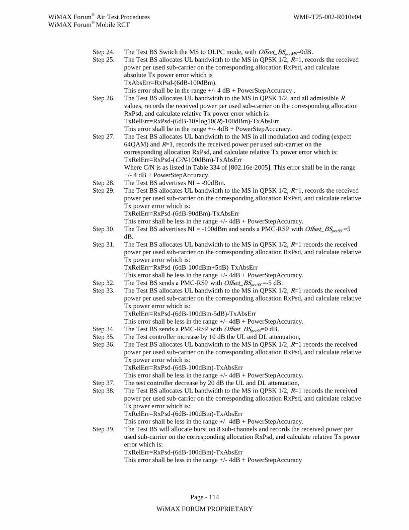
WiMAX Forum® Air Test Procedures WMF-T25-002-R010v04 WiMAX Forum® Mobile RCT
Page - 114
WiMAX FORUM PROPRIETARY
Step 24. The Test BS Switch the MS to OLPC mode, with Offset_BSperMS=0dB. Step 25. The Test BS allocates UL bandwidth to the MS in QPSK 1/2, R=1, records the received
power per used sub-carrier on the corresponding allocation RxPsd, and calculate absolute Tx power error which is TxAbsErr=RxPsd-(6dB-100dBm). This error shall be in the range +/- 4 dB + PowerStepAccuracy .
Step 26. The Test BS allocates UL bandwidth to the MS in QPSK 1/2, and all admissible R values, records the received power per used sub-carrier on the corresponding allocation RxPsd, and calculate relative Tx power error which is: TxRelErr=RxPsd-(6dB-10×log10(R)-100dBm)-TxAbsErr This error shall be in the range +/- 4dB + PowerStepAccuracy.
Step 27. The Test BS allocates UL bandwidth to the MS in all modulation and coding (expect 64QAM) and R=1, records the received power per used sub-carrier on the corresponding allocation RxPsd, and calculate relative Tx power error which is: TxRelErr=RxPsd-(C/N-100dBm)-TxAbsErr Where C/N is as listed in Table 334 of [802.16e-2005]. This error shall be in the range +/- 4 dB + PowerStepAccuracy.
Step 28. The Test BS advertises NI = -90dBm. Step 29. The Test BS allocates UL bandwidth to the MS in QPSK 1/2, R=1, records the received
power per used sub-carrier on the corresponding allocation RxPsd, and calculate relative Tx power error which is: TxRelErr=RxPsd-(6dB-90dBm)-TxAbsErr This error shall be less in the range +/- 4dB + PowerStepAccuracy.
Step 30. The Test BS advertises NI = -100dBm and sends a PMC-RSP with Offset_BSperSS =5 dB.
Step 31. The Test BS allocates UL bandwidth to the MS in QPSK 1/2, R=1 records the received power per used sub-carrier on the corresponding allocation RxPsd, and calculate relative Tx power error which is: TxRelErr=RxPsd-(6dB-100dBm+5dB)-TxAbsErr This error shall be less in the range +/- 4dB + PowerStepAccuracy.
Step 32. The Test BS sends a PMC-RSP with Offset_BSperSS =-5 dB. Step 33. The Test BS allocates UL bandwidth to the MS in QPSK 1/2, R=1 records the received
power per used sub-carrier on the corresponding allocation RxPsd, and calculate relative Tx power error which is: TxRelErr=RxPsd-(6dB-100dBm-5dB)-TxAbsErr This error shall be less in the range +/- 4dB + PowerStepAccuracy.
Step 34. The Test BS sends a PMC-RSP with Offset_BSperSS=0 dB. Step 35. The Test controller increase by 10 dB the UL and DL attenuation, Step 36. The Test BS allocates UL bandwidth to the MS in QPSK 1/2, R=1 records the received
power per used sub-carrier on the corresponding allocation RxPsd, and calculate relative Tx power error which is: TxRelErr=RxPsd-(6dB-100dBm)-TxAbsErr This error shall be less in the range +/- 4dB + PowerStepAccuracy.
Step 37. The test controller decrease by 20 dB the UL and DL attenuation, Step 38. The Test BS allocates UL bandwidth to the MS in QPSK 1/2, R=1 records the received
power per used sub-carrier on the corresponding allocation RxPsd, and calculate relative Tx power error which is: TxRelErr=RxPsd-(6dB-100dBm)-TxAbsErr This error shall be less in the range +/- 4dB + PowerStepAccuracy.
Step 39. The Test BS will allocate burst on 8 sub-channels and records the received power per used sub-carrier on the corresponding allocation RxPsd, and calculate relative Tx power error which is: TxRelErr=RxPsd-(6dB-100dBm)-TxAbsErr This error shall be less in the range +/- 4dB + PowerStepAccuracy
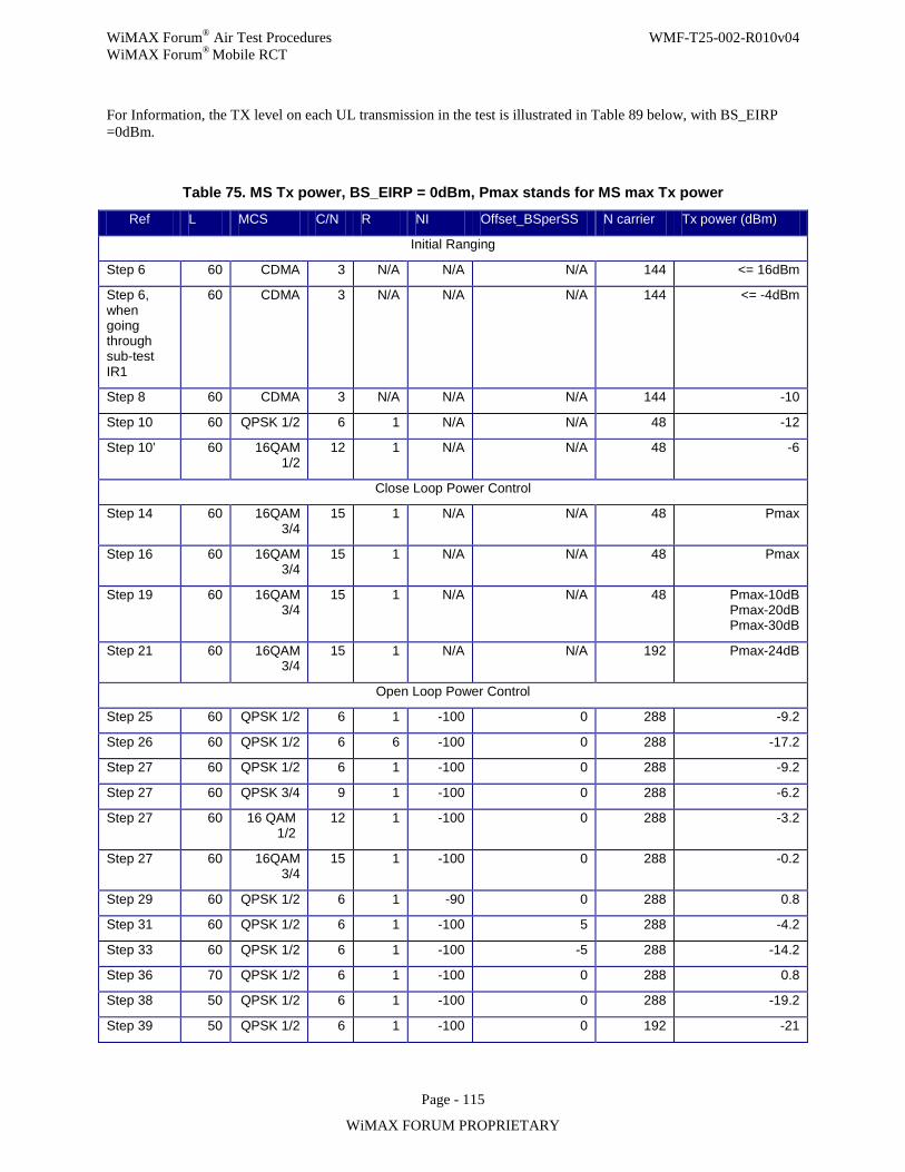
WiMAX Forum® Air Test Procedures WMF-T25-002-R010v04 WiMAX Forum® Mobile RCT
Page - 115
WiMAX FORUM PROPRIETARY
For Information, the TX level on each UL transmission in the test is illustrated in Table 89 below, with BS_EIRP =0dBm.
Table 75. MS Tx power, BS_EIRP = 0dBm, Pmax stands for MS max Tx power
Ref L MCS C/N R NI Offset_BSperSS N carrier Tx power (dBm)
Initial Ranging
Step 6 60 CDMA 3 N/A N/A N/A 144 <= 16dBm
Step 6, when going through sub-test IR1
60 CDMA 3 N/A N/A N/A 144 <= -4dBm
Step 8 60 CDMA 3 N/A N/A N/A 144 -10
Step 10 60 QPSK 1/2 6 1 N/A N/A 48 -12
Step 10’ 60 16QAM 1/2
12 1 N/A N/A 48 -6
Close Loop Power Control
Step 14 60 16QAM 3/4
15 1 N/A N/A 48 Pmax
Step 16 60 16QAM 3/4
15 1 N/A N/A 48 Pmax
Step 19 60 16QAM 3/4
15 1 N/A N/A 48 Pmax-10dB Pmax-20dB Pmax-30dB
Step 21 60 16QAM 3/4
15 1 N/A N/A 192 Pmax-24dB
Open Loop Power Control
Step 25 60 QPSK 1/2 6 1 -100 0 288 -9.2
Step 26 60 QPSK 1/2 6 6 -100 0 288 -17.2
Step 27 60 QPSK 1/2 6 1 -100 0 288 -9.2
Step 27 60 QPSK 3/4 9 1 -100 0 288 -6.2
Step 27 60 16 QAM 1/2
12 1 -100 0 288 -3.2
Step 27 60 16QAM 3/4
15 1 -100 0 288 -0.2
Step 29 60 QPSK 1/2 6 1 -90 0 288 0.8
Step 31 60 QPSK 1/2 6 1 -100 5 288 -4.2
Step 33 60 QPSK 1/2 6 1 -100 -5 288 -14.2
Step 36 70 QPSK 1/2 6 1 -100 0 288 0.8
Step 38 50 QPSK 1/2 6 1 -100 0 288 -19.2
Step 39 50 QPSK 1/2 6 1 -100 0 192 -21
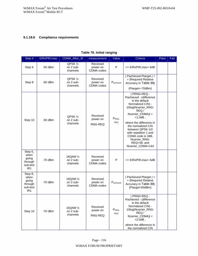
WiMAX Forum® Air Test Procedures WMF-T25-002-R010v04 WiMAX Forum® Mobile RCT
Page - 116
WiMAX FORUM PROPRIETARY
9.1.18.6 Compliance requirements
Table 76. Initial ranging
Step # EIRxPIR,max CDMA_Alloc_IE measurement Value Criteria Pass Fail
Step 6 -50 dBm QPSK ½ on 2 sub-channels
Received power on
CDMA codes P <= EIRxPIR,max+ 6dB
Step 8 -50 dBm QPSK ½ on 2 sub-channels
Received power on
CDMA codes Pachieved
| Pachieved-Ptarget | < = |Required Relative
Accuracy in Table 88|
(Ptarget=-70dBm)
Step 10 -50 dBm QPSK ½ on 2 sub-channels
Received power on
RNG-REQ
PRNG-
REQ
| PRNG-REQ -Pachieved - (difference
in the default Normalized C/N) -
10log(Ncarrier_RNG-REQ /
Ncarrier_CDMA)| < =1.0dB ,
where the difference in the normalized C/N between QPSK-1/2 with repetition 1 and CDMA code is 3dB,
Ncarrier_RNG-REQ=48, and
Ncarrier_CDMA=144
Step 6, when going
through sub-test
IR1
-70 dBm 16QAM ½ on 2 sub-channels
Received power on
CDMA codes P <= EIRxPIR,max+ 6dB
Step 8, when going
through sub-test
IR1
-70 dBm 16QAM ½ on 2 sub-channels
Received power on
CDMA codes Pachieved
| Pachieved-Ptarget | < = |Required Relative
Accuracy in Table 88| (Ptarget=50dBm)
Step 10 -70 dBm 16QAM ½ on 2 sub-channels
Received power on
RNG-REQ
PRNG-
REQ
| PRNG-REQ -Pachieved - (difference
in the default Normalized C/N) -
10log(Ncarrier_RNG-REQ /
Ncarrier_CDMA)| < =2.0dB ,
where the difference in the normalized C/N
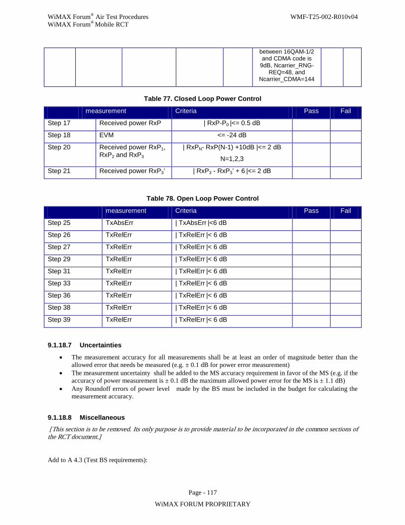
WiMAX Forum® Air Test Procedures WMF-T25-002-R010v04 WiMAX Forum® Mobile RCT
Page - 117
WiMAX FORUM PROPRIETARY
between 16QAM-1/2 and CDMA code is
9dB, Ncarrier_RNG-REQ=48, and
Ncarrier_CDMA=144
Table 77. Closed Loop Power Control
measurement Criteria Pass Fail
Step 17 Received power RxP | RxP-P0 |<= 0.5 dB
Step 18 EVM <= -24 dB
Step 20 Received power RxP1, RxP2 and RxP3
| RxPN- RxP(N-1) +10dB |<= 2 dB
N=1,2,3
Step 21 Received power RxP3’ | RxP3 - RxP3’ + 6 |<= 2 dB
Table 78. Open Loop Power Control
measurement Criteria Pass Fail
Step 25 TxAbsErr | TxAbsErr |<6 dB
Step 26 TxRelErr | TxRelErr |< 6 dB
Step 27 TxRelErr | TxRelErr |< 6 dB
Step 29 TxRelErr | TxRelErr |< 6 dB
Step 31 TxRelErr | TxRelErr |< 6 dB
Step 33 TxRelErr | TxRelErr |< 6 dB
Step 36 TxRelErr | TxRelErr |< 6 dB
Step 38 TxRelErr | TxRelErr |< 6 dB
Step 39 TxRelErr | TxRelErr |< 6 dB
9.1.18.7 Uncertainties
• The measurement accuracy for all measurements shall be at least an order of magnitude better than the allowed error that needs be measured (e.g. ± 0.1 dB for power error measurement)
• The measurement uncertainty shall be added to the MS accuracy requirement in favor of the MS (e.g. if the accuracy of power measurement is ± 0.1 dB the maximum allowed power error for the MS is ± 1.1 dB)
• Any Roundoff errors of power level made by the BS must be included in the budget for calculating the measurement accuracy.
9.1.18.8 Miscellaneous
[This section is to be removed. Its only purpose is to provide material to be incorporated in the common sections of the RCT document.]
Add to A 4.3 (Test BS requirements):
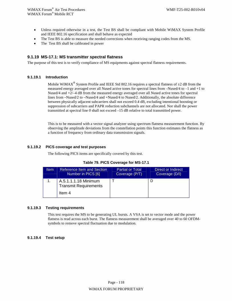
WiMAX Forum® Air Test Procedures WMF-T25-002-R010v04 WiMAX Forum® Mobile RCT
Page - 118
WiMAX FORUM PROPRIETARY
• Unless required otherwise in a test, the Test BS shall be compliant with Mobile WiMAX System Profile and IEEE 802.16 specification and shall behave as expected
• The Test BS is able to measure the needed corrections when receiving ranging codes from the MS. • The Test BS shall be calibrated in power
9.1.19 MS-17.1: MS transmitter spectral flatness The purpose of this test is to verify compliance of MS equipments against spectral flatness requirements.
9.1.19.1 Introduction
Mobile WiMAX® System Profile and IEEE Std 802.16 requires a spectral flatness of ±2 dB from the measured energy averaged over all Nused active tones for spectral lines from –Nused/4 to –1 and +1 to Nused/4 and +2/–4 dB from the measured energy averaged over all Nused active tones for spectral lines from –Nused/2 to –Nused/4 and +Nused/4 to Nused/2. Additionally, the absolute difference between physically adjacent subcarriers shall not exceed 0.4 dB, excluding intentional boosting or suppression of subcarriers and PAPR reduction subchannels are not allocated. Nor shall the power transmitted at spectral line 0 shall not exceed –15 dB relative to total transmitted power.
This is to be measured with a vector signal analyzer using spectrum flatness measurement function. By observing the amplitude deviations from the constellation points this function estimates the flatness as a function of frequency from ordinary data transmission signals.
9.1.19.2 PICS coverage and test purposes
The following PICS items are specifically covered by this test.
Table 79. PICS Coverage for MS-17.1
Item Reference Item and Section Number in PICS [6]
Partial or Total Coverage (P/T)
Direct or Indirect Coverage (D/I)
1. A.5.1.1.1.18 Minimum Transmit Requirements
Item 4
T D
9.1.19.3 Testing requirements
This test requires the MS to be generating UL bursts. A VSA is set to vector mode and the power flatness is read across each burst. The flatness measurement shall be averaged over 40 to 60 OFDM-symbols to remove spectral fluctuation due to modulation.
9.1.19.4 Test setup
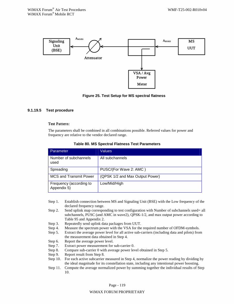
WiMAX Forum® Air Test Procedures WMF-T25-002-R010v04 WiMAX Forum® Mobile RCT
Page - 119
WiMAX FORUM PROPRIETARY
Figure 25. Test Setup for MS spectral flatness
9.1.19.5 Test procedure
Test Pattern:
The parameters shall be combined in all combinations possible. Referred values for power and frequency are relative to the vendor declared range.
Table 80. MS Spectral Flatness Test Parameters
Parameter Values
Number of subchannels used
All subchannels
Spreading PUSC/(For Wave 2: AMC )
MCS and Transmit Power (QPSK 1/2 and Max Output Power)
Frequency (according to Appendix 5)
Low/Mid/High
Step 1. Establish connection between MS and Signaling Unit (BSE) with the Low frequency of the declared frequency range.
Step 2. Send uplink map corresponding to test configuration with Number of subchannels used= all subchannels, PUSC (and AMC in wave2), QPSK-1/2, and max output power according to Table 95 and Appendix 2.
Step 3. Repeatedly send uplink data packages from UUT. Step 4. Measure the spectrum power with the VSA for the required number of OFDM-symbols. Step 5. Extract the average power level for all active sub-carriers (including data and pilots) from
the measurement data obtained in Step 4. Step 6. Report the average power level. Step 7. Extract power measurement for sub-carrier 0. Step 8. Compare sub-carrier 0 with average power level obtained in Step 5. Step 9. Report result from Step 8. Step 10. For each active subcarrier measured in Step 4, normalize the power reading by dividing by
the ideal magnitude for its constellation state, including any intentional power boosting. Step 11. Compute the average normalized power by summing together the individual results of Step
10.
Signaling Unit
(BSE)
VSA / Avg Power
Meter
MS UUT
Attenuator
ABS/MS AMS/BS
WiMAX Forum® Air Test Procedures WMF-T25-002-R010v04 WiMAX Forum® Mobile RCT
Page - 120
WiMAX FORUM PROPRIETARY
Step 12. Using the results from Step 10, record minimum power reading and maximum power reading for outer subcarrier (–Nused/2 to –Nused/4 and +Nused/4 to Nused/2) for all active sub-carriers.
Step 13. Compare the values from Step 12 with average power level obtained in Step 11. Step 14. Report result from Step 13. Step 15. Using the results from Step 10, record minimum power reading and maximum power
reading for inner sub-carriers (–Nused/4 to –1 and +1 to Nused/4) for all active sub-carriers from the measurement data obtained in Step 4.
Step 16. Compare the values from Step 15 with average normalized power level obtained in Step 5. Step 17. Report result from Step 16. Step 18. Compare amplitudes within the measurement data obtained in Step 4 for all active sub-
carriers which are physically adjacent and including pilots but excluding all non-allocated sub-channels. Comparison shall be made after normalization to ideal constellation state and compensation for intentional power boosting.
Step 19. Report neighbor sub-carrier deviation. Step 20. Repeat Step 1- Step 19for Mid and High channel of declared frequency range. Step 21. End of test.
9.1.19.6 Compliance requirements Pass verdict:
a) The leakage power transmitted at spectral line 0 does not exceed –15 dB relative to the corresponding total transmitted power for all specified combinations of test parameters.
b) All active inner sub-carriers shall be within ±2 dB of the corresponding average power level for all active sub-carriers power for all specified combinations of test parameters.
c) All active outer sub-carriers shall be within +2/–4 dB of the corresponding average power level for all active sub-carriers power for all specified combinations of test parameters.
d) The maximum neighbor sub-carrier deviation for all specified combinations of test parameters is equal to or below 0.4 dB for all active sub-carriers.
Fail verdict:
a) The leakage power transmitted at spectral line 0 exceeds –15 dB relative to the corresponding total transmitted power for any specified combination of test parameters.
b) Any active inner sub-carrier exceeds ±2 dB of the corresponding average power level for all active sub-carriers power for any specified combination of test parameters.
c) Any active outer sub-carriers exceed +2/–4 dB of the corresponding average power level for all active sub-carriers power for any specified combination of test parameters.
d) The maximum neighbor sub-carrier deviation for any specified combinations of test parameters exceeds 0.4 dB for any active sub-carriers.
9.1.19.7 Uncertainties
The maximum flatness measurement uncertainty for individual sub-carriers is 0.05 dB relative to the average channel power.
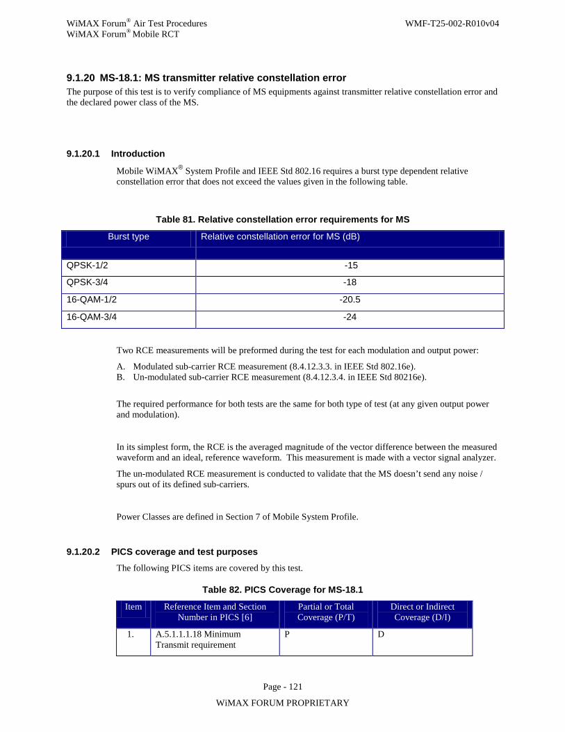
WiMAX Forum® Air Test Procedures WMF-T25-002-R010v04 WiMAX Forum® Mobile RCT
Page - 121
WiMAX FORUM PROPRIETARY
9.1.20 MS-18.1: MS transmitter relative constellation error The purpose of this test is to verify compliance of MS equipments against transmitter relative constellation error and the declared power class of the MS.
9.1.20.1 Introduction
Mobile WiMAX® System Profile and IEEE Std 802.16 requires a burst type dependent relative constellation error that does not exceed the values given in the following table.
Table 81. Relative constellation error requirements for MS Burst type Relative constellation error for MS (dB)
QPSK-1/2 -15
QPSK-3/4 -18
16-QAM-1/2 -20.5
16-QAM-3/4 -24
Two RCE measurements will be preformed during the test for each modulation and output power:
A. Modulated sub-carrier RCE measurement (8.4.12.3.3. in IEEE Std 802.16e). B. Un-modulated sub-carrier RCE measurement (8.4.12.3.4. in IEEE Std 80216e).
The required performance for both tests are the same for both type of test (at any given output power and modulation).
In its simplest form, the RCE is the averaged magnitude of the vector difference between the measured waveform and an ideal, reference waveform. This measurement is made with a vector signal analyzer.
The un-modulated RCE measurement is conducted to validate that the MS doesn’t send any noise / spurs out of its defined sub-carriers.
Power Classes are defined in Section 7 of Mobile System Profile.
9.1.20.2 PICS coverage and test purposes
The following PICS items are covered by this test.
Table 82. PICS Coverage for MS-18.1
Item Reference Item and Section Number in PICS [6]
Partial or Total Coverage (P/T)
Direct or Indirect Coverage (D/I)
1. A.5.1.1.1.18 Minimum Transmit requirement
P D
WiMAX Forum® Air Test Procedures WMF-T25-002-R010v04 WiMAX Forum® Mobile RCT
Page - 122
WiMAX FORUM PROPRIETARY
9.1.20.3 Testing requirements This test requires the MS to be generating UL bursts.
The test case will be repeated for the UUT transmitting at the declared Maximum and Minimum power. Please note that the minimum power declared by the vendor will not be higher than Maximum-45dB as per IEEE Std 802.16e.
The Vector Signal Analyzer (VSA) should be configured as follows:
Demodulation: OFDMA
FFT Size: 512 (For 3.5 and 5 MHz bandwidth) or 1024 (for 7/8.75/10 MHz bandwidth)
Center Frequency: Depends on profile, DUT
Channel Bandwidth: Depends on profile, DUT
Cyclic Prefix: 1/8
UL subcarrier allocation: PUSC
Number of OFDMA UL/DL symbols: Refer to the default frame structure setting of Appendix 2.
No. of Subchanels: FFT 512 – 4, 17; FFT 1024 – 8, 35
The IEEE Std 802.16-e in 8.4.12.3.2 recommends for RCE measurements the use of ¼ of the subchannels.
Number of frames for averaging: 10
Pilot Phase Tracking: ON
Pilot Timing Tracking: ON
Pilot Amplitude Tracking: ON
Channel Estimation: data+pilot
IDCell: 31
PermBase: 31
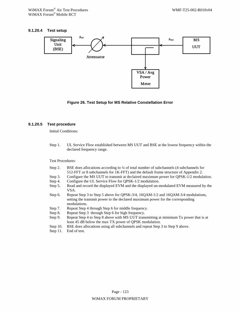
WiMAX Forum® Air Test Procedures WMF-T25-002-R010v04 WiMAX Forum® Mobile RCT
Page - 123
WiMAX FORUM PROPRIETARY
9.1.20.4 Test setup
Figure 26. Test Setup for MS Relative Constellation Error
9.1.20.5 Test procedure
Initial Conditions:
Step 1. UL Service Flow established between MS UUT and BSE at the lowest frequency within the declared frequency range.
Test Procedures:
Step 2. BSE does allocations according to ¼ of total number of subchannels (4 subchannels for 512-FFT or 8 subchannels for 1K-FFT) and the default frame structure of Appendix 2.
Step 3. Configure the MS UUT to transmit at declaired maximum power for QPSK-1/2 modulation. Step 4. Configure the UL Service Flow for QPSK-1/2 modulation. Step 5. Read and record the displayed EVM and the displayed un-modulated EVM measured by the
VSA. Step 6. Repeat Step 3 to Step 5 above for QPSK-3/4, 16QAM-1/2 and 16QAM-3/4 modulations,
setting the transmit power to the declared maximum power for the corresponding modulations.
Step 7. Repeat Step 4 through Step 6 for middle frequency. Step 8. Repeat Step 3 through Step 6 for high frequency. Step 9. Repeat Step 4 to Step 8 above with MS UUT transmitting at minimum Tx power that is at
least 45 dB below the max TX power of QPSK modulation. Step 10. BSE does allocations using all subchannels and repeat Step 3 to Step 9 above. Step 11. End of test.
Signaling Unit
(BSE)
VSA / Avg Power
Meter
MS UUT
Attenuator
AMS ABS
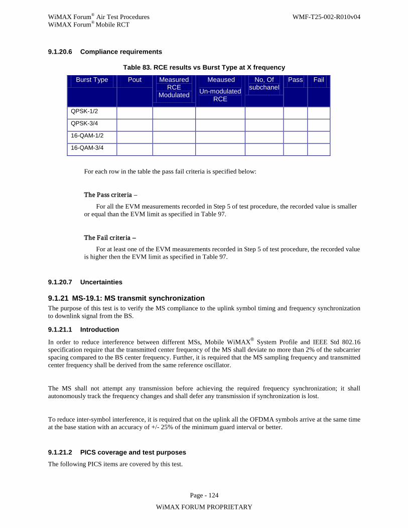
WiMAX Forum® Air Test Procedures WMF-T25-002-R010v04 WiMAX Forum® Mobile RCT
Page - 124
WiMAX FORUM PROPRIETARY
9.1.20.6 Compliance requirements
Table 83. RCE results vs Burst Type at X frequency
Burst Type Pout Measured RCE
Modulated
Meaused
Un-modulated RCE
No, Of subchanel
Pass Fail
QPSK-1/2
QPSK-3/4
16-QAM-1/2
16-QAM-3/4
For each row in the table the pass fail criteria is specified below:
The Pass cr iter ia –
For all the EVM measurements recorded in Step 5 of test procedure, the recorded value is smaller or equal than the EVM limit as specified in Table 97.
The Fail cr iter ia –
For at least one of the EVM measurements recorded in Step 5 of test procedure, the recorded value is higher then the EVM limit as specified in Table 97.
9.1.20.7 Uncertainties
9.1.21 MS-19.1: MS transmit synchronization The purpose of this test is to verify the MS compliance to the uplink symbol timing and frequency synchronization to downlink signal from the BS.
9.1.21.1 Introduction
In order to reduce interference between different MSs, Mobile WiMAX® System Profile and IEEE Std 802.16 specification require that the transmitted center frequency of the MS shall deviate no more than 2% of the subcarrier spacing compared to the BS center frequency. Further, it is required that the MS sampling frequency and transmitted center frequency shall be derived from the same reference oscillator.
The MS shall not attempt any transmission before achieving the required frequency synchronization; it shall autonomously track the frequency changes and shall defer any transmission if synchronization is lost.
To reduce inter-symbol interference, it is required that on the uplink all the OFDMA symbols arrive at the same time at the base station with an accuracy of +/- 25% of the minimum guard interval or better.
9.1.21.2 PICS coverage and test purposes
The following PICS items are covered by this test.
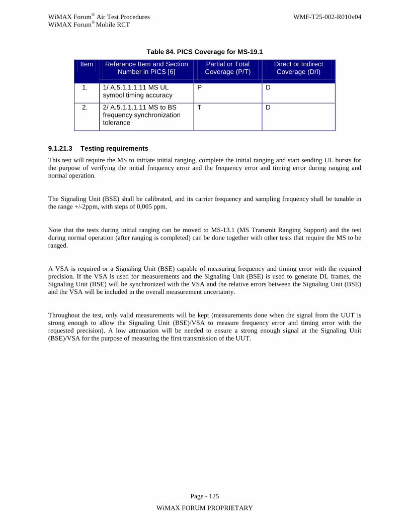
WiMAX Forum® Air Test Procedures WMF-T25-002-R010v04 WiMAX Forum® Mobile RCT
Page - 125
WiMAX FORUM PROPRIETARY
Table 84. PICS Coverage for MS-19.1
Item Reference Item and Section Number in PICS [6]
Partial or Total Coverage (P/T)
Direct or Indirect Coverage (D/I)
1. 1/ A.5.1.1.1.11 MS UL symbol timing accuracy
P D
2. 2/ A.5.1.1.1.11 MS to BS frequency synchronization tolerance
T D
9.1.21.3 Testing requirements
This test will require the MS to initiate initial ranging, complete the initial ranging and start sending UL bursts for the purpose of verifying the initial frequency error and the frequency error and timing error during ranging and normal operation.
The Signaling Unit (BSE) shall be calibrated, and its carrier frequency and sampling frequency shall be tunable in the range +/-2ppm, with steps of 0,005 ppm.
Note that the tests during initial ranging can be moved to MS-13.1 (MS Transmit Ranging Support) and the test during normal operation (after ranging is completed) can be done together with other tests that require the MS to be ranged.
A VSA is required or a Signaling Unit (BSE) capable of measuring frequency and timing error with the required precision. If the VSA is used for measurements and the Signaling Unit (BSE) is used to generate DL frames, the Signaling Unit (BSE) will be synchronized with the VSA and the relative errors between the Signaling Unit (BSE) and the VSA will be included in the overall measurement uncertainty.
Throughout the test, only valid measurements will be kept (measurements done when the signal from the UUT is strong enough to allow the Signaling Unit (BSE)/VSA to measure frequency error and timing error with the requested precision). A low attenuation will be needed to ensure a strong enough signal at the Signaling Unit (BSE)/VSA for the purpose of measuring the first transmission of the UUT.
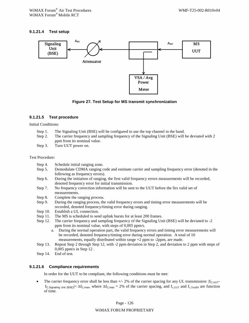
WiMAX Forum® Air Test Procedures WMF-T25-002-R010v04 WiMAX Forum® Mobile RCT
Page - 126
WiMAX FORUM PROPRIETARY
9.1.21.4 Test setup
Figure 27. Test Setup for MS transmit synchronization
9.1.21.5 Test procedure
Initial Conditions:
Step 1. The Signaling Unit (BSE) will be configured to use the top channel in the band. Step 2. The carrier frequency and sampling frequency of the Signaling Unit (BSE) will be deviated with 2
ppm from its nominal value. Step 3. Turn UUT power on.
Test Procedure:
Step 4. Schedule initial ranging zone. Step 5. Demodulate CDMA ranging code and estimate carrier and sampling frequency error (denoted in the
following as frequency errors). Step 6. During the initiation of ranging, the first valid frequency errors measurements will be recorded,
denoted frequency error for initial transmission. Step 7. No frequency correction information will be sent to the UUT before the firs valid set of
measurements. Step 8. Complete the ranging process. Step 9. During the ranging process, the valid frequency errors and timing error measurements will be
recorded, denoted frequency/timing error during ranging. Step 10. Establish a UL connection. Step 11. The MS is scheduled to send uplink bursts for at least 200 frames. Step 12. The carrier frequency and sampling frequency of the Signaling Unit (BSE) will be deviated to -2
ppm from its nominal value, with steps of 0,005 ppm/s. a. During the normal operation part, the valid frequency errors and timing error measurements will
be recorded, denoted frequency/timing error during normal operation. A total of 10 measurements, equally distributed within range +2 ppm to -2ppm, are made.
Step 13. Repeat Step 2 through Step 12, with -2 ppm deviation in Step 2, and deviation to 2 ppm with steps of 0,005 ppm/s in Step 12 .
Step 14. End of test.
9.1.21.6 Compliance requirements
In order for the UUT to be compliant, the following conditions must be met:
• The carrier frequency error shall be less than +/- 2% of the carrier spacing for any UL transmission: |fC,UUT- fC,Signaling Unit (BSE)|< ∆fC,max, where ∆fC,max = 2% of the carrier spacing, and fc,UUT and fc,TestBS are function of time.
Signaling Unit
(BSE)
VSA / Avg Power
Meter
MS UUT
Attenuator
AMS ABS
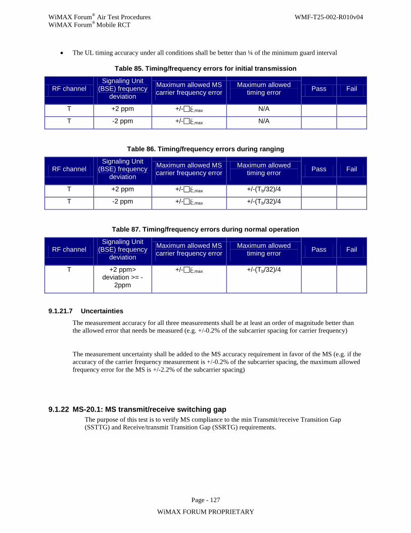
WiMAX Forum® Air Test Procedures WMF-T25-002-R010v04 WiMAX Forum® Mobile RCT
Page - 127
WiMAX FORUM PROPRIETARY
• The UL timing accuracy under all conditions shall be better than ¼ of the minimum guard interval
Table 85. Timing/frequency errors for initial transmission
RF channel Signaling Unit
(BSE) frequency deviation
Maximum allowed MS carrier frequency error
Maximum allowed timing error Pass Fail
T +2 ppm +/-fC,max N/A
T -2 ppm +/-fC,max N/A
Table 86. Timing/frequency errors during ranging
RF channel Signaling Unit
(BSE) frequency deviation
Maximum allowed MS carrier frequency error
Maximum allowed timing error Pass Fail
T +2 ppm +/-fC,max +/-(Tb/32)/4
T -2 ppm +/-fC,max +/-(Tb/32)/4
Table 87. Timing/frequency errors during normal operation
RF channel Signaling Unit
(BSE) frequency deviation
Maximum allowed MS carrier frequency error
Maximum allowed timing error Pass Fail
T +2 ppm> deviation >= -
2ppm
+/-fC,max +/-(Tb/32)/4
9.1.21.7 Uncertainties
The measurement accuracy for all three measurements shall be at least an order of magnitude better than the allowed error that needs be measured (e.g. +/-0.2% of the subcarrier spacing for carrier frequency)
The measurement uncertainty shall be added to the MS accuracy requirement in favor of the MS (e.g. if the accuracy of the carrier frequency measurement is +/-0.2% of the subcarrier spacing, the maximum allowed frequency error for the MS is +/-2.2% of the subcarrier spacing)
9.1.22 MS-20.1: MS transmit/receive switching gap The purpose of this test is to verify MS compliance to the min Transmit/receive Transition Gap (SSTTG) and Receive/transmit Transition Gap (SSRTG) requirements.
WiMAX Forum® Air Test Procedures WMF-T25-002-R010v04 WiMAX Forum® Mobile RCT
Page - 128
WiMAX FORUM PROPRIETARY
9.1.22.1 Introduction
This test shall make certain that the MS can perform switching between receive and transmit states quick enough to meet the PICS requirements. In order to perform these measurements the start and end of the two switching events must be defined.
For testing purposes the SSRTG is defined as the time between end of the last sample of the last OFDM-symbol of the DL and the start of the first sample of the first OFDM-symbol of the UL frame, see Figure 28.
For testing purposes the SSTTG is defined as the time between end of the last sample of the last OFDM-symbol of the UL and the start of the first sample of the preamble of the following DL frame. The SSTTG will be actually bounded by the RTG in practical operation since TTG and RTG are fixed values in the WiMAX® profile and the TTG portion accommodates the RTD(round-trip-delay), which is always positive value in practice, as well as the SSRTG.
To be certain that the UUT can perform the switching it is not sufficient to measure that an RF-signal is present at these positions of the MAC-frame, the UUT also need to have some level of performance at these points. In order to ensure this both downlink and uplink traffic must be tested. When testing SSRTG performance, the Signaling Unit (BSE) shall command the MS to send and receive data at fixed positions in the MAC-frame, the pattern to be repeated continuously for the duration of test. PER shall be measured on a PDU positioned as late as possible in the DL frame and Relative Constellation Error shall be measured on the first symbol of the UL frame averaged over 100 bursts.
The SSTTG shall be tested with the same approach. The Signaling Unit (BSE) shall command the MS to send and receive data at fixed positions in the MAC-frame, the pattern to be repeated continuously for the duration of test. Relative Constellation Error shall be measured on the last symbol of the UL frame averaged over 100 bursts and PER shall be measured on a PDU positioned as early as possible in the DL frame.
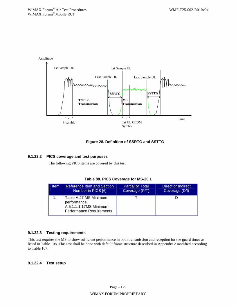
WiMAX Forum® Air Test Procedures WMF-T25-002-R010v04 WiMAX Forum® Mobile RCT
Page - 129
WiMAX FORUM PROPRIETARY
Time
1st Sample DL 1st Sample UL
Last Sample DL Last Sample UL
Test BS Transmission
Preamble
MS Transmission
1st UL OFDM Symbol
SSRTG SSTTG
Amplitude
Figure 28. Definition of SSRTG and SSTTG
9.1.22.2 PICS coverage and test purposes The following PICS items are covered by this test.
Table 88. PICS Coverage for MS-20.1
Item Reference Item and Section Number in PICS [6]
Partial or Total Coverage (P/T)
Direct or Indirect Coverage (D/I)
1. Table A.47 MS Minimum performance, A.5.1.1.1.17MS Minimum Performance Requirements
T D
9.1.22.3 Testing requirements
This test requires the MS to show sufficient performance in both transmission and reception for the guard times as listed in Table 108. This test shall be done with default frame structure described in Appendix 2 modified according to Table 107.
9.1.22.4 Test setup
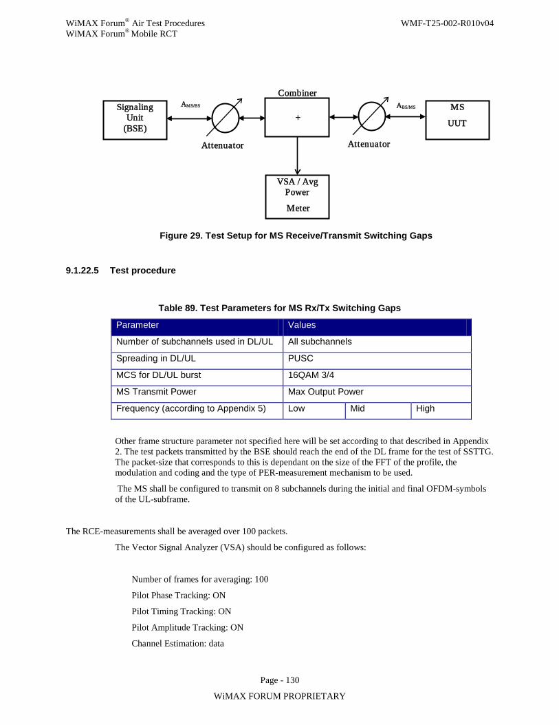
WiMAX Forum® Air Test Procedures WMF-T25-002-R010v04 WiMAX Forum® Mobile RCT
Page - 130
WiMAX FORUM PROPRIETARY
Figure 29. Test Setup for MS Receive/Transmit Switching Gaps
9.1.22.5 Test procedure
Table 89. Test Parameters for MS Rx/Tx Switching Gaps
Parameter Values
Number of subchannels used in DL/UL All subchannels
Spreading in DL/UL PUSC
MCS for DL/UL burst 16QAM 3/4
MS Transmit Power Max Output Power
Frequency (according to Appendix 5) Low Mid High
Other frame structure parameter not specified here will be set according to that described in Appendix 2. The test packets transmitted by the BSE should reach the end of the DL frame for the test of SSTTG. The packet-size that corresponds to this is dependant on the size of the FFT of the profile, the modulation and coding and the type of PER-measurement mechanism to be used.
The MS shall be configured to transmit on 8 subchannels during the initial and final OFDM-symbols of the UL-subframe.
The RCE-measurements shall be averaged over 100 packets.
The Vector Signal Analyzer (VSA) should be configured as follows:
Number of frames for averaging: 100
Pilot Phase Tracking: ON
Pilot Timing Tracking: ON
Pilot Amplitude Tracking: ON
Channel Estimation: data
Signaling Unit
(BSE)
MS
UUT
Attenuator
ABS/MS AMS/BS
VSA / Avg Power
Meter
Combiner +
Attenuator
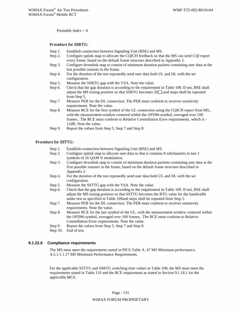
WiMAX Forum® Air Test Procedures WMF-T25-002-R010v04 WiMAX Forum® Mobile RCT
Page - 131
WiMAX FORUM PROPRIETARY
Premable Index = 4
Procedure for SSRTG:
Step 1. Establish connection between Signaling Unit (BSE) and MS. Step 2. Configure uplink map to allocate the CQICH feedback so that the MS can send CQI report
every frame, based on the default frame structure described in Appendix 2. Step 3. Configure downlink map to consist of minimum duration packets containing user data at the
last possible instants in the frame. Step 4. For the duration of the test repeatedly send user data both UL and DL with the set
configuration. Step 5. Measure the SSRTG gap with the VSA. Note the value. Step 6. Check that the gap duration is according to the requirement in Table 108. If not, BSE shall
adjust the MS timing position so that SSRTG becomes 50s and steps shall be repeated from Step 5.
Step 7. Measure PER for the DL connection. The PER must conform to receiver sensitivity requirements. Note the value.
Step 8. Measure RCE for the first symbol of the UL connection using the CQICH report from MS., with the measurement-window centered within the OFDM-symbol, averaged over 100 frames.. The RCE must conform to Relative Constellation Error requirements, which is -12dB. Note the value.
Step 9. Report the values from Step 5, Step 7 and Step 8. Procedure for SSTTG:
Step 1. Establish connection between Signaling Unit (BSE) and MS. Step 2. Configure uplink map to allocate user data so that it contains 8 subchannels in last 3
symbols of 16 QAM ¾ modulation. Step 3. Configure downlink map to consist of minimum duration packets containing user data at the
first possible instants in the frame, based on the default frame structure described in Appendix 2.
Step 4. For the duration of the test repeatedly send user data both UL and DL with the set configuration.
Step 5. Measure the SSTTG gap with the VSA. Note the value. Step 6. Check that the gap duration is according to the requirement in Table 109. If not, BSE shall
adjust the MS timing position so that SSTTG becomes the RTG value for the bandwidth under test as specified in Table 109and steps shall be repeated from Step 5.
Step 7. Measure PER for the DL connection. The PER must conform to receiver sensitivity requirements. Note the value.
Step 8. Measure RCE for the last symbol of the UL, with the measurement-window centered within the OFDM-symbol, averaged over 100 frames.. The RCE must conform to Relative Constellation Error requirements. Note the value.
Step 9. Report the values from Step 5, Step 7 and Step 8. Step 10. End of test.
9.1.22.6 Compliance requirements
The MS must meet the requirements stated in PICS Table A. 47 MS Minimum performance, A.5.1.1.1.17 MS Minimum Performance Requirements.
For the applicable SSTTG and SSRTG switching time values in Table 108, the MS must meet the requirements stated in Table 110 and the RCE requirement as stated in Section 9.1.18.1 for the applicable MCS.
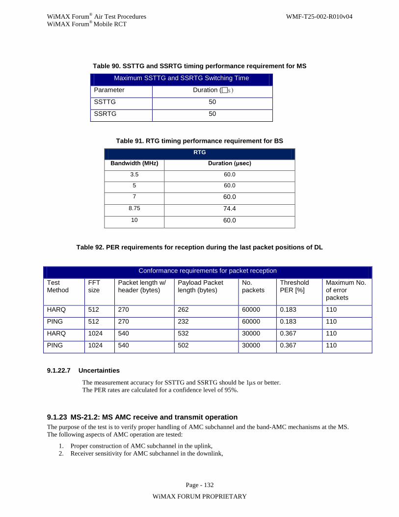
WiMAX Forum® Air Test Procedures WMF-T25-002-R010v04 WiMAX Forum® Mobile RCT
Page - 132
WiMAX FORUM PROPRIETARY
Table 90. SSTTG and SSRTG timing performance requirement for MS
Maximum SSTTG and SSRTG Switching Time
Parameter Duration (s )
SSTTG 50
SSRTG 50
Table 91. RTG timing performance requirement for BS RTG
Bandwidth (MHz) Duration (μsec)
3.5 60.0 5 60.0 7 60.0
8.75 74.4 10 60.0
Table 92. PER requirements for reception during the last packet positions of DL
Conformance requirements for packet reception
Test Method
FFT size
Packet length w/ header (bytes)
Payload Packet length (bytes)
No. packets
Threshold PER [%]
Maximum No. of error packets
HARQ 512 270 262 60000 0.183 110
PING 512 270 232 60000 0.183 110
HARQ 1024 540 532 30000 0.367 110
PING 1024 540 502 30000 0.367 110
9.1.22.7 Uncertainties
The measurement accuracy for SSTTG and SSRTG should be 1µs or better. The PER rates are calculated for a confidence level of 95%.
9.1.23 MS-21.2: MS AMC receive and transmit operation The purpose of the test is to verify proper handling of AMC subchannel and the band-AMC mechanisms at the MS. The following aspects of AMC operation are tested:
1. Proper construction of AMC subchannel in the uplink, 2. Receiver sensitivity for AMC subchannel in the downlink,
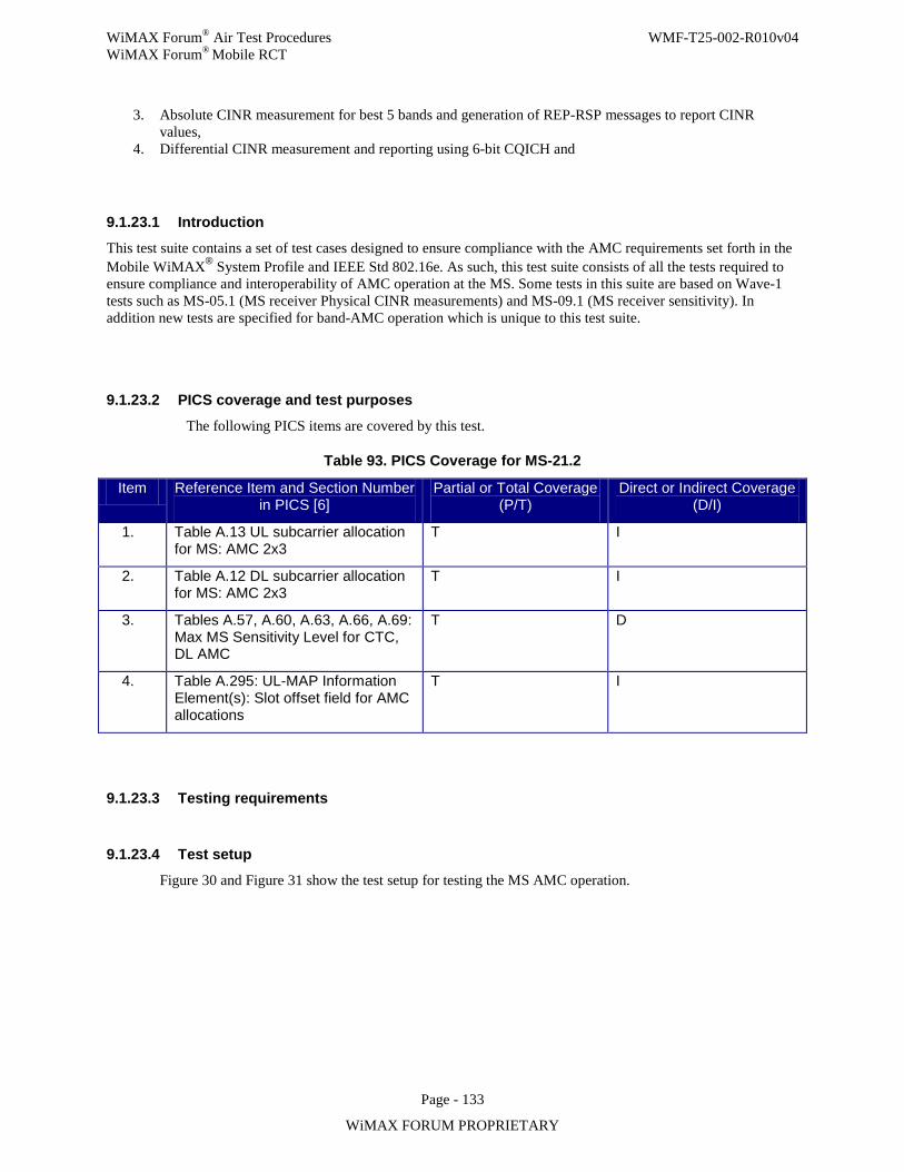
WiMAX Forum® Air Test Procedures WMF-T25-002-R010v04 WiMAX Forum® Mobile RCT
Page - 133
WiMAX FORUM PROPRIETARY
3. Absolute CINR measurement for best 5 bands and generation of REP-RSP messages to report CINR values,
4. Differential CINR measurement and reporting using 6-bit CQICH and
9.1.23.1 Introduction
This test suite contains a set of test cases designed to ensure compliance with the AMC requirements set forth in the Mobile WiMAX® System Profile and IEEE Std 802.16e. As such, this test suite consists of all the tests required to ensure compliance and interoperability of AMC operation at the MS. Some tests in this suite are based on Wave-1 tests such as MS-05.1 (MS receiver Physical CINR measurements) and MS-09.1 (MS receiver sensitivity). In addition new tests are specified for band-AMC operation which is unique to this test suite.
9.1.23.2 PICS coverage and test purposes
The following PICS items are covered by this test.
Table 93. PICS Coverage for MS-21.2
Item Reference Item and Section Number in PICS [6]
Partial or Total Coverage (P/T)
Direct or Indirect Coverage (D/I)
1. Table A.13 UL subcarrier allocation for MS: AMC 2x3
T I
2. Table A.12 DL subcarrier allocation for MS: AMC 2x3
T I
3. Tables A.57, A.60, A.63, A.66, A.69: Max MS Sensitivity Level for CTC, DL AMC
T D
4. Table A.295: UL-MAP Information Element(s): Slot offset field for AMC allocations
T I
9.1.23.3 Testing requirements
9.1.23.4 Test setup
Figure 30 and Figure 31 show the test setup for testing the MS AMC operation.
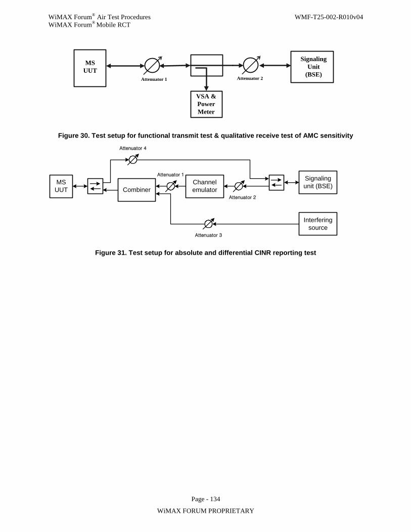
WiMAX Forum® Air Test Procedures WMF-T25-002-R010v04 WiMAX Forum® Mobile RCT
Page - 134
WiMAX FORUM PROPRIETARY
MS UUT
Signaling Unit
(BSE)Attenuator 2Attenuator 1
VSA & Power Meter
Figure 30. Test setup for functional transmit test & qualitative receive test of AMC sensitivity
MS UUT Combiner
Channel emulator
Signaling unit (BSE)
Interfering source
Attenuator 1
Attenuator 2
Attenuator 3
Attenuator 4
Figure 31. Test setup for absolute and differential CINR reporting test
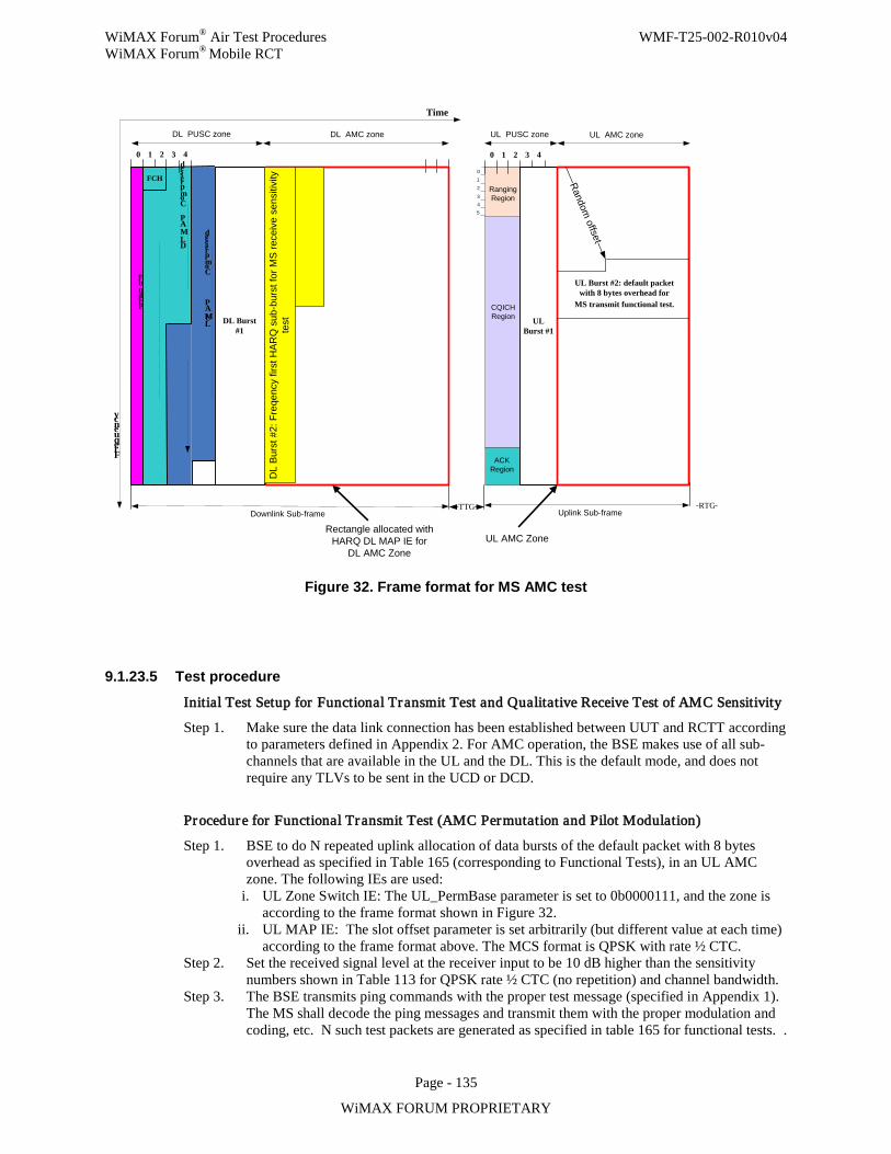
WiMAX Forum® Air Test Procedures WMF-T25-002-R010v04 WiMAX Forum® Mobile RCT
Page - 135
WiMAX FORUM PROPRIETARY
Preamble
Frequency
Compressed
DL MAP
Time
0 1 2 3
012
3Ranging Region
ACK Region
CQICHRegion
Uplink Sub-frame
DL PUSC zone
TTG RTG
4 0 1 2 3 4
45
Downlink Sub-frame
Compressed
UL MAP
Rectangle allocated with HARQ DL MAP IE for
DL AMC ZoneUL AMC Zone
FCH
DL AMC zone UL PUSC zone UL AMC zone
DL Burst #1
UL Burst #1
Random offset
DL
Bur
st #
2: F
reqe
ncy
first
HA
RQ
sub
-bur
st fo
r MS
rece
ive
sens
itivi
ty
test
UL Burst #2: default packet with 8 bytes overhead for
MS transmit functional test.
Figure 32. Frame format for MS AMC test
9.1.23.5 Test procedure
Initial Test Setup for Functional Transmit Test and Qualitative Receive Test of AMC Sensitivity
Step 1. Make sure the data link connection has been established between UUT and RCTT according to parameters defined in Appendix 2. For AMC operation, the BSE makes use of all sub-channels that are available in the UL and the DL. This is the default mode, and does not require any TLVs to be sent in the UCD or DCD.
Procedure for Functional Transmit Test (AMC Permutation and Pilot Modulation)
Step 1. BSE to do N repeated uplink allocation of data bursts of the default packet with 8 bytes overhead as specified in Table 165 (corresponding to Functional Tests), in an UL AMC zone. The following IEs are used:
i. UL Zone Switch IE: The UL_PermBase parameter is set to 0b0000111, and the zone is according to the frame format shown in Figure 32.
ii. UL MAP IE: The slot offset parameter is set arbitrarily (but different value at each time) according to the frame format above. The MCS format is QPSK with rate ½ CTC.
Step 2. Set the received signal level at the receiver input to be 10 dB higher than the sensitivity numbers shown in Table 113 for QPSK rate ½ CTC (no repetition) and channel bandwidth.
Step 3. The BSE transmits ping commands with the proper test message (specified in Appendix 1). The MS shall decode the ping messages and transmit them with the proper modulation and coding, etc. N such test packets are generated as specified in table 165 for functional tests. .
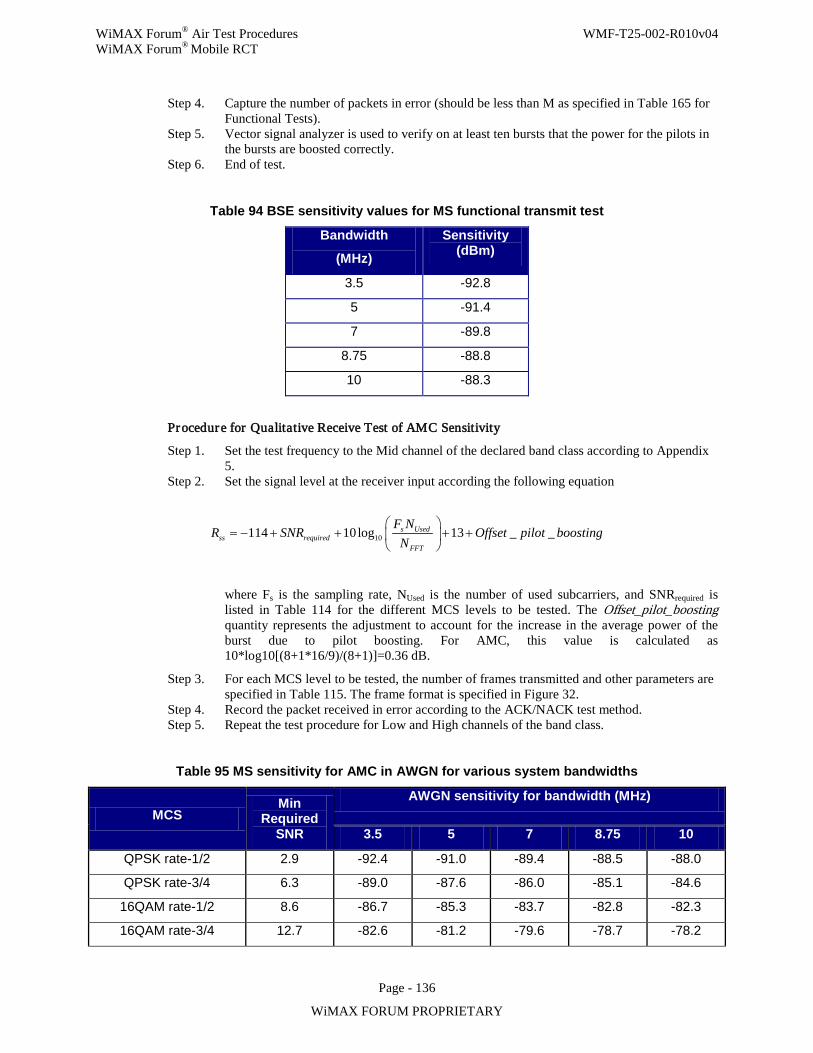
WiMAX Forum® Air Test Procedures WMF-T25-002-R010v04 WiMAX Forum® Mobile RCT
Page - 136
WiMAX FORUM PROPRIETARY
Step 4. Capture the number of packets in error (should be less than M as specified in Table 165 for Functional Tests).
Step 5. Vector signal analyzer is used to verify on at least ten bursts that the power for the pilots in the bursts are boosted correctly.
Step 6. End of test.
Table 94 BSE sensitivity values for MS functional transmit test
Bandwidth
(MHz)
Sensitivity (dBm)
3.5 -92.8
5 -91.4
7 -89.8
8.75 -88.8
10 -88.3
Procedure for Qualitative Receive Test of AMC Sensitivity
Step 1. Set the test frequency to the Mid channel of the declared band class according to Appendix 5.
Step 2. Set the signal level at the receiver input according the following equation
10114 10log 13 _ _s Usedss required
FFT
F NR SNR Offset pilot boosting
N
= − + + + +
where Fs is the sampling rate, NUsed is the number of used subcarriers, and SNRrequired is listed in Table 114 for the different MCS levels to be tested. The Offset_pilot_boosting quantity represents the adjustment to account for the increase in the average power of the burst due to pilot boosting. For AMC, this value is calculated as 10*log10[(8+1*16/9)/(8+1)]=0.36 dB.
Step 3. For each MCS level to be tested, the number of frames transmitted and other parameters are specified in Table 115. The frame format is specified in Figure 32.
Step 4. Record the packet received in error according to the ACK/NACK test method. Step 5. Repeat the test procedure for Low and High channels of the band class.
Table 95 MS sensitivity for AMC in AWGN for various system bandwidths
MCS Min
Required SNR
AWGN sensitivity for bandwidth (MHz)
3.5 5 7 8.75 10
QPSK rate-1/2 2.9 -92.4 -91.0 -89.4 -88.5 -88.0
QPSK rate-3/4 6.3 -89.0 -87.6 -86.0 -85.1 -84.6
16QAM rate-1/2 8.6 -86.7 -85.3 -83.7 -82.8 -82.3
16QAM rate-3/4 12.7 -82.6 -81.2 -79.6 -78.7 -78.2
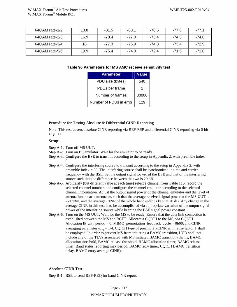
WiMAX Forum® Air Test Procedures WMF-T25-002-R010v04 WiMAX Forum® Mobile RCT
Page - 137
WiMAX FORUM PROPRIETARY
64QAM rate-1/2 13.8 -81.5 -80.1 -78.5 -77.6 -77.1
64QAM rate-2/3 16.9 -78.4 -77.0 -75.4 -74.5 -74.0
64QAM rate-3/4 18 -77.3 -75.9 -74.3 -73.4 -72.9
64QAM rate-5/6 19.9 -75.4 -74.0 -72.4 -71.5 -71.0
Table 96 Parameters for MS AMC receive sensitivity test
Parameter Value
PDU size (bytes) 540
PDUs per frame 1
Number of frames 30000
Number of PDUs in error 129
Procedure for Testing Absolute & Differential CINR Repor ting
Note: This test covers absolute CINR reporting via REP-RSP and differential CINR reporting via 6-bit CQICH.
Setup:
Step A-1. Turn off MS UUT. Step A-2. Turn on BS emulator. Wait for the emulator to be ready. Step A-3. Configure the BSE to transmit according to the setup in Appendix 2, with preamble index =
0. Step A-4. Configure the interfering source to transmit according to the setup in Appendix 2, with
preamble index = 33. The interfering source shall be synchronized in time and carrier frequency with the BSE. Set the output signal power of the BSE and that of the interfering source such that the difference between the two is 20 dB.
Step A-5. Arbitrarily (but different value at each time) select a channel from Table 116, record the selected channel number, and configure the channel emulator according to the selected channel information. Adjust the output signal power of the channel emulator and the level of attenuation at each attenuator, such that the average received signal power at the MS UUT is -60 dBm, and the average CINR of the whole bandwidth is kept at 20 dB. Any change in the average CINR in this test is to be accomplished via appropriate variation of the output signal power of the interfering source while keeping the BSE signal power constant.
Step A-6. Turn on the MS UUT. Wait for the MS to be ready. Ensure that the data link connection is established between the MS and RCTT. Allocate a CQICH to the MS, via CQICH Allocation IE with period = 0, MIMO_permutation_feedback_cycle = 0b00, and CINR averaging parameter αavg = 1/4. CQICH type of preamble PCINR with reuse factor 1 shall be employed. In order to prevent MS from initiating a BAMC transition, UCD shall not include any of the TLVs associated with MS initiated BAMC transition (that is, BAMC allocation threshold, BAMC release threshold, BAMC allocation timer, BAMC release timer, Band status reporting max period, BAMC retry timer, CQICH BAMC transition delay, BAMC entry average CINR).
Absolute CINR Test:
Step B-1. BSE to send REP-REQ for band CINR report.
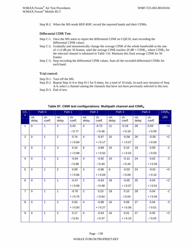
WiMAX Forum® Air Test Procedures WMF-T25-002-R010v04 WiMAX Forum® Mobile RCT
Page - 138
WiMAX FORUM PROPRIETARY
Step B-2. When the MS sends REP-RSP, record the reported bands and their CINRs.
Differential CINR Test:
Step C-1. Once the MS starts to report the differential CINR on CQICH, start recording the differential CINR values.
Step C-2. Gradually and monotonically change the average CINR of the whole bandwidth at the rate of ±1.0 dB per 50 frames, until the average CINR reaches 20 dB + CINRΔ, where CINRΔ for the selected channel is tabulated in Table 116. Maintain this final average CINR for 50 frames.
Step C-3. Stop recording the differential CINR values. Sum all the recorded differential CINRs for each band.
Tr ial control:
Step D-1. Turn off the MS. Step D-2. Repeat Step A-4 to Step D-1 for 9 times, for a total of 10 trials. In each new iteration of Step
A-4, select a channel among the channels that have not been previously selected in this test. Step D-3. End of test.
Table 97. CINR test configurations: Multipath channel and CINRΔ
Ch. #
Path 0 Path 1 Path 2 Path 3 Path 4 CINRΔ
(dB) rel. delay
ch. coeff.
rel. delay
ch. coeff.
rel. delay
ch. coeff.
rel. delay
ch. coeff.
rel. delay
ch. coeff.
1 0 1 2 0.43
- i 0.77
4 -0.72
- i 0.48
11 -0.19
- i 0.18
28 0.03
- i 0.09
+3
2 0 1 2 0.74
+ i 0.84
4 -0.97
+ i 0.17
10 -0.08
+ i 0.07
26 -0.05
- i 0.09
+2
3 0 1 3 0.16
+ i 0.98
6 -0.89
+ i 0.52
10 0.10
+ i 0.02
18 0.09
- i 0.03
-2
4 0 1 2 -0.04
- i 0.88
4 -0.92
- i 0.40
15 -0.12
- i 0.43
24 0.02
+ i 0.04
-3
5 0 1 2 0.09
+ i 0.86
4 -0.96
+ i 0.64
6 -0.03
- i 0.09
24 -0.01
- i 0.10
+3
6 0 1 1 -0.47
+ i 0.99
2 -0.63
- i 0.48
18 -0.05
+ i 0.07
25 0.04
+ i 0.01
+2
7 0 1 1 -0.76
+ i 0.75
2 0.23
- i 0.64
18 0.10
- i 0.04
28 0.04
+ i 0.04
-2
8 0 1 2 0.55
+ i 0.93
4 -0.88
+ i 0.27
16 0.08
+ i 0.06
27 0.04
- i 0.01
-3
9 0 1 2 0.17
- i 0.91
4 -0.63
- i 0.37
24 0.01
+ i 0.10
27 0.05
- i 0.02
+3
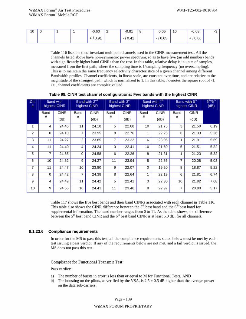
WiMAX Forum® Air Test Procedures WMF-T25-002-R010v04 WiMAX Forum® Mobile RCT
Page - 139
WiMAX FORUM PROPRIETARY
10 0 1 1 -0.60
+ i 0.91
2 -0.81
- i 0.41
8 0.05
- i 0.05
10 -0.08
+ i 0.06
-3
Table 116 lists the time-invariant multipath channels used in the CINR measurement test. All the channels listed above have non-symmetric power spectrum, so as to have five (an odd number) bands with significantly higher band CINRs than the rest. In this table, relative delay is in units of samples, measured from the first path, where the sampling time is 1/sampling frequency (no oversampling). This is to maintain the same frequency selectivity characteristics of a given channel among different Bandwidth profiles. Channel coefficients, in linear scale, are constant over time, and are relative to the magnitude of the strongest path, which is normalized to 1. In this table, i denotes the square root of -1, i.e., channel coefficients are complex valued.
Table 98. CINR test channel configurations: Five bands with the highest CINR
Ch. #
Band with highest CINR
Band with 2nd highest CINR
Band with 3rd highest CINR
Band with 4th highest CINR
Band with 5th highest CINR
5th/6th (dB)
Band #
CINR
(dB)
Band #
CINR
(dB)
Band #
CINR
(dB)
Band #
CINR
(dB)
Band #
CINR
(dB)
1 4 24.46 11 24.18 5 22.68 10 21.75 3 21.50 6.19
2 0 24.10 7 23.95 8 22.76 1 22.25 6 21.33 5.26
3 11 24.27 2 23.85 7 23.22 6 23.06 1 21.91 5.69
4 11 24.40 4 24.24 3 22.41 10 21.60 5 21.51 5.32
5 7 24.65 0 24.58 6 22.26 8 21.81 1 21.23 5.32
6 10 24.62 9 24.27 11 23.94 8 22.86 7 20.08 5.03
7 11 24.47 10 23.80 9 22.07 0 19.20 8 18.87 5.22
8 0 24.42 7 24.38 8 22.64 1 22.19 6 21.81 6.74
9 4 24.49 11 24.42 5 22.41 3 22.30 10 21.82 7.68
10 9 24.55 10 24.41 11 23.46 8 22.92 7 20.80 5.17
Table 117 shows the five best bands and their band CINRs associated with each channel in Table 116. This table also shows the CINR difference between the 5th best band and the 6th best band for supplemental information. The band number ranges from 0 to 11. As the table shows, the difference between the 5th best band CINR and the 6th best band CINR is at least 5.0 dB, for all channels.
9.1.23.6 Compliance requirements
In order for the MS to pass this test, all the compliance requirements stated below must be met by each test issuing a pass verdict. If any of the requirements below are not met, and a fail verdict is issued, the MS does not pass this test.
Compliance for Functional Transmit Test:
Pass verdict:
a) The number of bursts in error is less than or equal to M for Functional Tests, AND b) The boosting on the pilots, as verified by the VSA, is 2.5 ± 0.5 dB higher than the average power
on the data sub-carriers.
WiMAX Forum® Air Test Procedures WMF-T25-002-R010v04 WiMAX Forum® Mobile RCT
Page - 140
WiMAX FORUM PROPRIETARY
Fail verdict:
a) The number of bursts in error is more than M for Functional Tests OR b) The boosting on the pilots is not 2.5 ± 0.5 dB higher than the average power on the data sub-
carriers.
Compliance for Receive Sensitivity Test:
In order to be compliant to the minimum receiver sensitivity requirement, the receiver is required to, after accounting for its noise figure and implementation loss, achieve an equal or better Packet Error Rate (PER) target performance when the received signal is at the maximum sensitivity level.
Pass verdict:
For all modulation and coding combinations and test cases, the number of packets in error is less than or equal to the value specified in Table 115.
Fail verdict:
For at least one of the modulation and coding combinations in one of the test cases, the number of packets in error is higher than the limits in Table 115.
Compliance for Absolute & Differential CINR Repor ting Test:
Pass verdict: All of the following conditions are satisfied.
- Condition 1 (MS functionalities): The MS UUT sends REP-RSP within 100 frames of REP-REQ transmission assuming that the BSE allocates uplink BW every frame, and starts sending differential CINR report on the next frame after REP-RSP.
- Condition 2 (Best band selection): For all trials, the five reported bands correspond to the highest CINR bands. The order in which the 5 best bands are reported in REP-RSP is not tested.
- Condition 3 (Absolute CINR): For at least 70% of the 50 reported absolute CINRs (5 best band CINRs per trial × 10 trials), the difference between the reported CINR and the actual CINR is within the ±3 dB range.
- Condition 4 (Differential CINR): At least 70% of the 50 summed differential CINRs for each band (5 summed CINRs per trial × 10 trials) are in the range of CINRΔ ± 3 dB.
Fail verdict: Otherwise.
9.1.23.7 Uncertainties
9.1.24 MS-22.2: Part A, MS receiver MIMO processing The purpose of this test is to verify MS compliance to reception of MIMO signal. It includes testing related to Matrix A, Matrix B, and Mode Selection. This test will cover testing of all IO-MIMO related features to MS such as CINR processing in MIMO mode and Fast DL measurement feedback w/ more than one Rx antenna.
The purpose of the test is to verify that the MS receiver can support the MIMO features as specified in the PICS document and the Mobile System Profile. The MIMO functionalities to be verified for MS receivers include the demodulation and decoding performance for matrix A and B MIMO transmission for common pilots at various MCS levels and under various channel conditions, and the MS capabilities to recommend the correct MIMO mode
WiMAX Forum® Air Test Procedures WMF-T25-002-R010v04 WiMAX Forum® Mobile RCT
Page - 141
WiMAX FORUM PROPRIETARY
to BS (switching between matrix A and B) under various channel conditions. In addition, PCINR measurements for MIMO modes at the MS are tested for common pilots.
9.1.24.1 Introduction
In the mobile profile, the MS is required to be able to support the two MIMO transmission modes (i.e., matrix-A and B) in an STC zone under PUSC permutation. In particular, the MS MIMO support includes the capability of demodulating and decoding both matrix-A and B formats with a certain performance, and the capability of link adaptation support in the form of ECINR reporting and MIMO mode selection.
MIMO matrix-A and matrix-B demodulation:
To verify that the MS receiver can demodulate and decode the MIMO transmission with a certain performance, the MS is required to achieve a Block Error Rate (BLER) equal to or better than the target of 10% at a received signal level that is specific to the MCS level and the fading channel conditions. The fading channel conditions include a combination of several power delay profiles (i.e., Ped-B @ 3kmph, Veh-A @ 60kmph, and a modified Veh-A @ 120kmph with the last path moving to 10us) and spatial correlations (low, medium, and high as defined in Appendix 4). Additional test cases are also included to test the receiver performance under receive antenna imbalance.
The PER is computed from the number of NACKs sent from the MS UUT via the ACK channel that is assigned by the BSE. In each frame, one packet is sent from the BSE and the MS UUT will feed back in the next frame either ACK or NACK for each packet. The downlink burst and uplink ACK channel allocation information is conveyed in HARQ DL MAP IE. Unlike the normal HARQ operation, the BSE will not re-transmit a packet in the case of receiving a NACK. The packet transmitted in each frame is a new packet (i.e., “AI_SN” field toggles at each frame). The details of STC zone location, burst allocation size and position, and packet size will be described in the test setup section.
MIMO mode selection between matrix-A and matrix-B:
In order for the BS to use the MIMO format that best suits the downlink channel condition, the MS is required to be able to feed back trustworthy information that includes PCINR/ECINR, as well as matrix-A/B mode recommendation.
As the standard states in section 6.3.18: “The reported effective CINR feedback shall correspond to the MCS in Table 298a with which the expected block error rate, assuming a specific block length, is closest to, but does not exceed, a specific target average error rate. The target average error rate and assumed block length are defined in profiles.” It is reasonable to follow the same concept to define the MIMO selection reporting requirement for MS, i.e., the MS should provide the MIMO mode recommendation that corresponds to the highest spectral efficiency while still meeting the target block error rate. The spectral efficiency here is derived from both the MCS levels and the MIMO mode. It is also necessary to specify the block length for which the target BLER is defined. Since the block size and target BLER were not defined in either the system profile or the PICS document, in the test, the block length is assumed to be the maximal FEC block length allowed for different MCS (i.e., 60/54/48 bytes) and the target BLER is 10%.
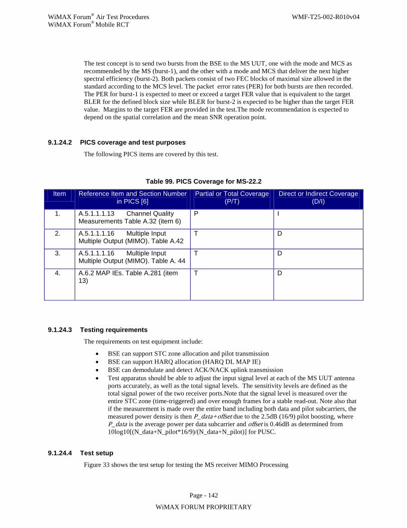
WiMAX Forum® Air Test Procedures WMF-T25-002-R010v04 WiMAX Forum® Mobile RCT
Page - 142
WiMAX FORUM PROPRIETARY
The test concept is to send two bursts from the BSE to the MS UUT, one with the mode and MCS as recommended by the MS (burst-1), and the other with a mode and MCS that deliver the next higher spectral efficiency (burst-2). Both packets consist of two FEC blocks of maximal size allowed in the standard according to the MCS level. The packet error rates (PER) for both bursts are then recorded. The PER for burst-1 is expected to meet or exceed a target FER value that is equivalent to the target BLER for the defined block size while BLER for burst-2 is expected to be higher than the target FER value. Margins to the target FER are provided in the test.The mode recommendation is expected to depend on the spatial correlation and the mean SNR operation point.
9.1.24.2 PICS coverage and test purposes
The following PICS items are covered by this test.
Table 99. PICS Coverage for MS-22.2
Item Reference Item and Section Number in PICS [6]
Partial or Total Coverage (P/T)
Direct or Indirect Coverage (D/I)
1. A.5.1.1.1.13 Channel Quality Measurements Table A.32 (item 6)
P I
2. A.5.1.1.1.16 Multiple Input Multiple Output (MIMO). Table A.42
T D
3. A.5.1.1.1.16 Multiple Input Multiple Output (MIMO). Table A. 44
T D
4. A.6.2 MAP IEs. Table A.281 (item 13)
T D
9.1.24.3 Testing requirements
The requirements on test equipment include:
• BSE can support STC zone allocation and pilot transmission • BSE can support HARQ allocation (HARQ DL MAP IE) • BSE can demodulate and detect ACK/NACK uplink transmission • Test apparatus should be able to adjust the input signal level at each of the MS UUT antenna
ports accurately, as well as the total signal levels. The sensitivity levels are defined as the total signal power of the two receiver ports.Note that the signal level is measured over the entire STC zone (time-triggered) and over enough frames for a stable read-out. Note also that if the measurement is made over the entire band including both data and pilot subcarriers, the measured power density is then P_data+offset due to the 2.5dB (16/9) pilot boosting, where P_data is the average power per data subcarrier and offset is 0.46dB as determined from 10log10[(N_data+N_pilot*16/9)/(N_data+N_pilot)] for PUSC.
9.1.24.4 Test setup
Figure 33 shows the test setup for testing the MS receiver MIMO Processing
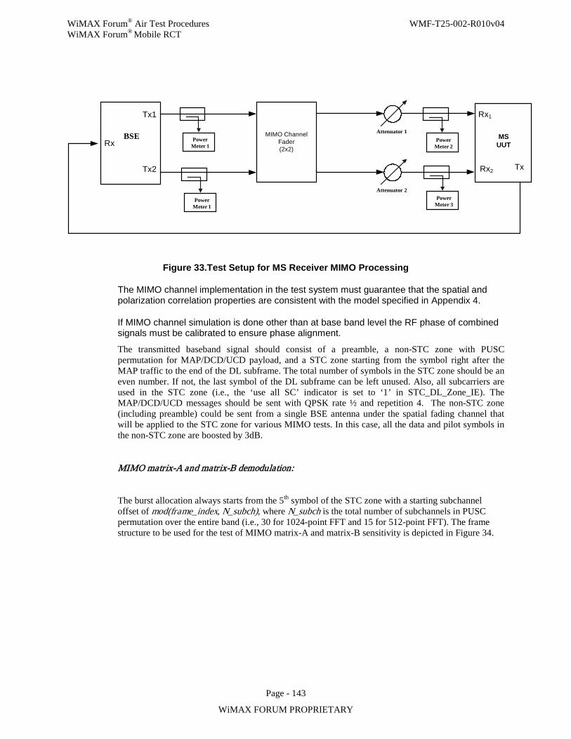
WiMAX Forum® Air Test Procedures WMF-T25-002-R010v04 WiMAX Forum® Mobile RCT
Page - 143
WiMAX FORUM PROPRIETARY
Attenuator 2
MIMO Channel Fader(2x2)
Attenuator 1
Rx1
Rx2 Tx
Tx1
Rx
Power Meter 1
Power Meter 3
Power Meter 2
BSE MSUUT
Power Meter 1
Tx2
Figure 33.Test Setup for MS Receiver MIMO Processing
The MIMO channel implementation in the test system must guarantee that the spatial and polarization correlation properties are consistent with the model specified in Appendix 4.
If MIMO channel simulation is done other than at base band level the RF phase of combined signals must be calibrated to ensure phase alignment. The transmitted baseband signal should consist of a preamble, a non-STC zone with PUSC permutation for MAP/DCD/UCD payload, and a STC zone starting from the symbol right after the MAP traffic to the end of the DL subframe. The total number of symbols in the STC zone should be an even number. If not, the last symbol of the DL subframe can be left unused. Also, all subcarriers are used in the STC zone (i.e., the ‘use all SC’ indicator is set to ‘1’ in STC_DL_Zone_IE). The MAP/DCD/UCD messages should be sent with QPSK rate ½ and repetition 4. The non-STC zone (including preamble) could be sent from a single BSE antenna under the spatial fading channel that will be applied to the STC zone for various MIMO tests. In this case, all the data and pilot symbols in the non-STC zone are boosted by 3dB.
MIMO matrix-A and matrix-B demodulation:
The burst allocation always starts from the 5th symbol of the STC zone with a starting subchannel offset of mod(frame_index, N_subch), where N_subch is the total number of subchannels in PUSC permutation over the entire band (i.e., 30 for 1024-point FFT and 15 for 512-point FFT). The frame structure to be used for the test of MIMO matrix-A and matrix-B sensitivity is depicted in Figure 34.
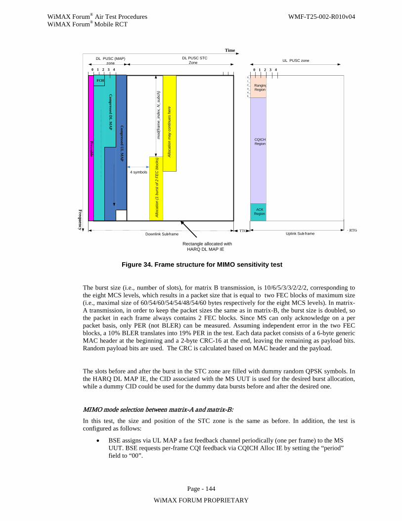
WiMAX Forum® Air Test Procedures WMF-T25-002-R010v04 WiMAX Forum® Mobile RCT
Page - 144
WiMAX FORUM PROPRIETARY
Preamble
Frequency
Com
pressed DL
MA
P
Time
0 1 2 3
012
3Ranging Region
ACK Region
CQICHRegion
Uplink Sub- frame
DL PUSC (MAP) zone
TTG RTG
4 0 1 2 3 4
45
Downlink Sub- frame
Com
pressed UL
MA
P
Rectangle allocated with HARQ DL MAP IE
FCH
DL PUSC STC Zone UL PUSC zone
4 symbols
mod
(fram
e_in
dex,
N_s
ubch
)A
lloca
tion
(1 b
urst
of 2
FE
C b
lock
s)
Allo
catio
n m
ay c
ontin
ues
here
Figure 34. Frame structure for MIMO sensitivity test
The burst size (i.e., number of slots), for matrix B transmission, is 10/6/5/3/3/2/2/2, corresponding to the eight MCS levels, which results in a packet size that is equal to two FEC blocks of maximum size (i.e., maximal size of 60/54/60/54/54/48/54/60 bytes respectively for the eight MCS levels). In matrix-A transmission, in order to keep the packet sizes the same as in matrix-B, the burst size is doubled, so the packet in each frame always contains 2 FEC blocks. Since MS can only acknowledge on a per packet basis, only PER (not BLER) can be measured. Assuming independent error in the two FEC blocks, a 10% BLER translates into 19% PER in the test. Each data packet consists of a 6-byte generic MAC header at the beginning and a 2-byte CRC-16 at the end, leaving the remaining as payload bits. Random payload bits are used. The CRC is calculated based on MAC header and the payload.
The slots before and after the burst in the STC zone are filled with dummy random QPSK symbols. In the HARQ DL MAP IE, the CID associated with the MS UUT is used for the desired burst allocation, while a dummy CID could be used for the dummy data bursts before and after the desired one.
MIMO mode selection between matrix-A and matrix-B: In this test, the size and position of the STC zone is the same as before. In addition, the test is configured as follows:
• BSE assigns via UL MAP a fast feedback channel periodically (one per frame) to the MS UUT. BSE requests per-frame CQI feedback via CQICH Alloc IE by setting the “period” field to “00”.
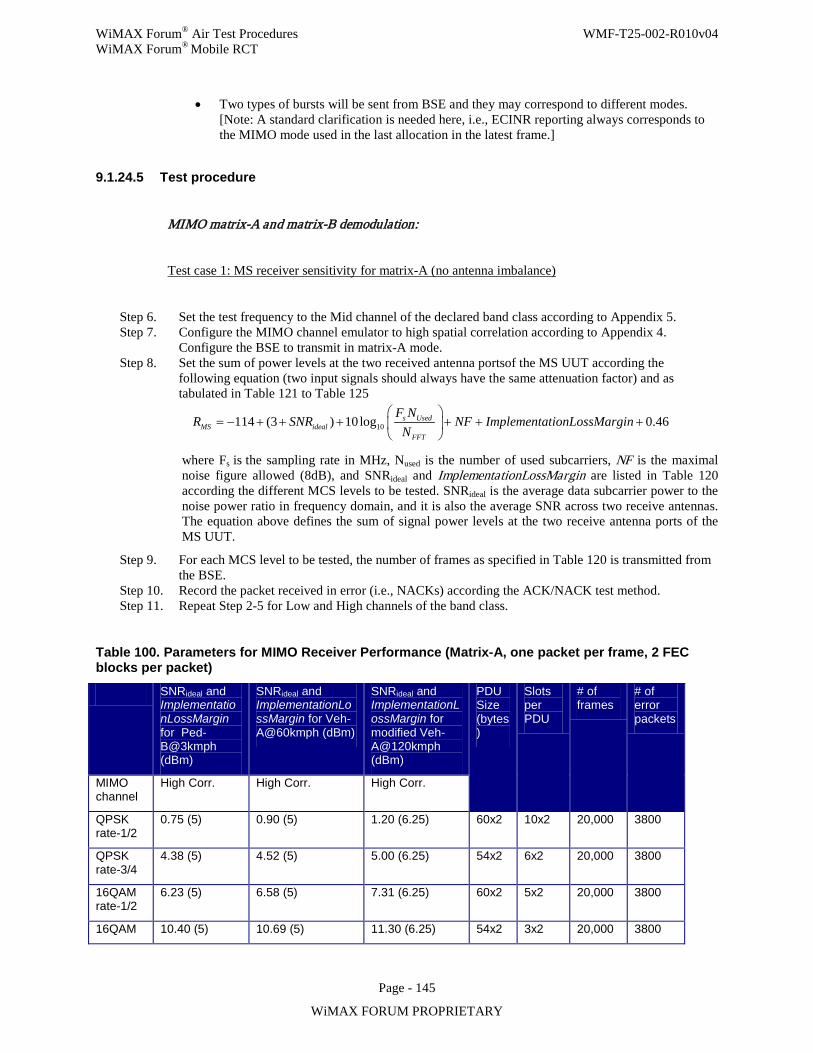
WiMAX Forum® Air Test Procedures WMF-T25-002-R010v04 WiMAX Forum® Mobile RCT
Page - 145
WiMAX FORUM PROPRIETARY
• Two types of bursts will be sent from BSE and they may correspond to different modes. [Note: A standard clarification is needed here, i.e., ECINR reporting always corresponds to the MIMO mode used in the last allocation in the latest frame.]
9.1.24.5 Test procedure
MIMO matrix-A and matrix-B demodulation:
Test case 1: MS receiver sensitivity for matrix-A (no antenna imbalance)
Step 6. Set the test frequency to the Mid channel of the declared band class according to Appendix 5. Step 7. Configure the MIMO channel emulator to high spatial correlation according to Appendix 4.
Configure the BSE to transmit in matrix-A mode. Step 8. Set the sum of power levels at the two received antenna portsof the MS UUT according the
following equation (two input signals should always have the same attenuation factor) and as tabulated in Table 121 to Table 125
10114 (3 ) 10log 0.46s UsedMS ideal
FFT
F NR SNR NF ImplementationLossMargin
N
= − + + + + + +
where Fs is the sampling rate in MHz, Nused is the number of used subcarriers, NF is the maximal noise figure allowed (8dB), and SNRideal and ImplementationLossMargin are listed in Table 120 according the different MCS levels to be tested. SNRideal is the average data subcarrier power to the noise power ratio in frequency domain, and it is also the average SNR across two receive antennas. The equation above defines the sum of signal power levels at the two receive antenna ports of the MS UUT.
Step 9. For each MCS level to be tested, the number of frames as specified in Table 120 is transmitted from the BSE.
Step 10. Record the packet received in error (i.e., NACKs) according the ACK/NACK test method. Step 11. Repeat Step 2-5 for Low and High channels of the band class.
Table 100. Parameters for MIMO Receiver Performance (Matrix-A, one packet per frame, 2 FEC blocks per packet)
SNRideal and ImplementationLossMargin for Ped-B@3kmph (dBm)
SNRideal and ImplementationLossMargin for Veh-A@60kmph (dBm)
SNRideal and ImplementationLossMargin for modified Veh-A@120kmph (dBm)
PDU Size (bytes)
Slots per PDU
# of frames
# of error packets
MIMO channel
High Corr. High Corr. High Corr.
QPSK rate-1/2
0.75 (5) 0.90 (5) 1.20 (6.25) 60x2 10x2 20,000 3800
QPSK rate-3/4
4.38 (5) 4.52 (5) 5.00 (6.25) 54x2 6x2 20,000 3800
16QAM rate-1/2
6.23 (5) 6.58 (5) 7.31 (6.25) 60x2 5x2 20,000 3800
16QAM 10.40 (5) 10.69 (5) 11.30 (6.25) 54x2 3x2 20,000 3800
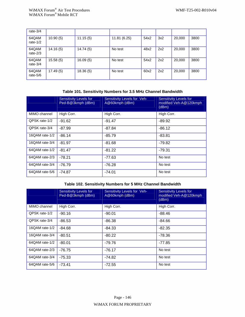
WiMAX Forum® Air Test Procedures WMF-T25-002-R010v04 WiMAX Forum® Mobile RCT
Page - 146
WiMAX FORUM PROPRIETARY
rate-3/4
64QAM rate-1/2
10.90 (5) 11.15 (5) 11.81 (6.25) 54x2 3x2 20,000 3800
64QAM rate-2/3
14.16 (5) 14.74 (5) No test 48x2 2x2 20,000 3800
64QAM rate-3/4
15.58 (5) 16.09 (5) No test 54x2 2x2 20,000 3800
64QAM rate-5/6
17.49 (5) 18.36 (5) No test 60x2 2x2 20,000 3800
Table 101. Sensitivity Numbers for 3.5 MHz Channel Bandwidth
Sensitivity Levels for Ped-B@3kmph (dBm)
Sensitivity Levels for Veh-A@60kmph (dBm)
Sensitivity Levels for modified Veh-A@120kmph (dBm)
MIMO channel High Corr. High Corr. High Corr.
QPSK rate-1/2 -91.62 -91.47 -89.92
QPSK rate-3/4 -87.99 -87.84 -86.12
16QAM rate-1/2 -86.14 -85.79 -83.81
16QAM rate-3/4 -81.97 -81.68 -79.82
64QAM rate-1/2 -81.47 -81.22 -79.31
64QAM rate-2/3 -78.21 -77.63 No test
64QAM rate-3/4 -76.79 -76.28 No test
64QAM rate-5/6 -74.87 -74.01 No test
Table 102. Sensitivity Numbers for 5 MHz Channel Bandwidth
Sensitivity Levels for Ped-B@3kmph (dBm)
Sensitivity Levels for Veh-A@60kmph (dBm)
Sensitivity Levels for modified Veh-A@120kmph (dBm)
MIMO channel High Corr. High Corr. High Corr.
QPSK rate-1/2 -90.16 -90.01 -88.46
QPSK rate-3/4 -86.53 -86.38 -84.66
16QAM rate-1/2 -84.68 -84.33 -82.35
16QAM rate-3/4 -80.51 -80.22 -78.36
64QAM rate-1/2 -80.01 -79.76 -77.85
64QAM rate-2/3 -76.75 -76.17 No test
64QAM rate-3/4 -75.33 -74.82 No test
64QAM rate-5/6 -73.41 -72.55 No test
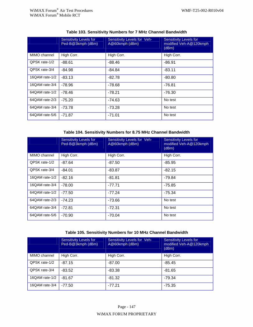
WiMAX Forum® Air Test Procedures WMF-T25-002-R010v04 WiMAX Forum® Mobile RCT
Page - 147
WiMAX FORUM PROPRIETARY
Table 103. Sensitivity Numbers for 7 MHz Channel Bandwidth
Sensitivity Levels for Ped-B@3kmph (dBm)
Sensitivity Levels for Veh-A@60kmph (dBm)
Sensitivity Levels for modified Veh-A@120kmph (dBm)
MIMO channel High Corr. High Corr. High Corr.
QPSK rate-1/2 -88.61 -88.46 -86.91
QPSK rate-3/4 -84.98 -84.84 -83.11
16QAM rate-1/2 -83.13 -82.78 -80.80
16QAM rate-3/4 -78.96 -78.68 -76.81
64QAM rate-1/2 -78.46 -78.21 -76.30
64QAM rate-2/3 -75.20 -74.63 No test
64QAM rate-3/4 -73.78 -73.28 No test
64QAM rate-5/6 -71.87 -71.01 No test
Table 104. Sensitivity Numbers for 8.75 MHz Channel Bandwidth
Sensitivity Levels for Ped-B@3kmph (dBm)
Sensitivity Levels for Veh-A@60kmph (dBm)
Sensitivity Levels for modified Veh-A@120kmph (dBm)
MIMO channel High Corr. High Corr. High Corr.
QPSK rate-1/2 -87.64 -87.50 -85.95
QPSK rate-3/4 -84.01 -83.87 -82.15
16QAM rate-1/2 -82.16 -81.81 -79.84
16QAM rate-3/4 -78.00 -77.71 -75.85
64QAM rate-1/2 -77.50 -77.24 -75.34
64QAM rate-2/3 -74.23 -73.66 No test
64QAM rate-3/4 -72.81 -72.31 No test
64QAM rate-5/6 -70.90 -70.04 No test
Table 105. Sensitivity Numbers for 10 MHz Channel Bandwidth
Sensitivity Levels for Ped-B@3kmph (dBm)
Sensitivity Levels for Veh-A@60kmph (dBm)
Sensitivity Levels for modified Veh-A@120kmph (dBm)
MIMO channel High Corr. High Corr. High Corr.
QPSK rate-1/2 -87.15 -87.00 -85.45
QPSK rate-3/4 -83.52 -83.38 -81.65
16QAM rate-1/2 -81.67 -81.32 -79.34
16QAM rate-3/4 -77.50 -77.21 -75.35
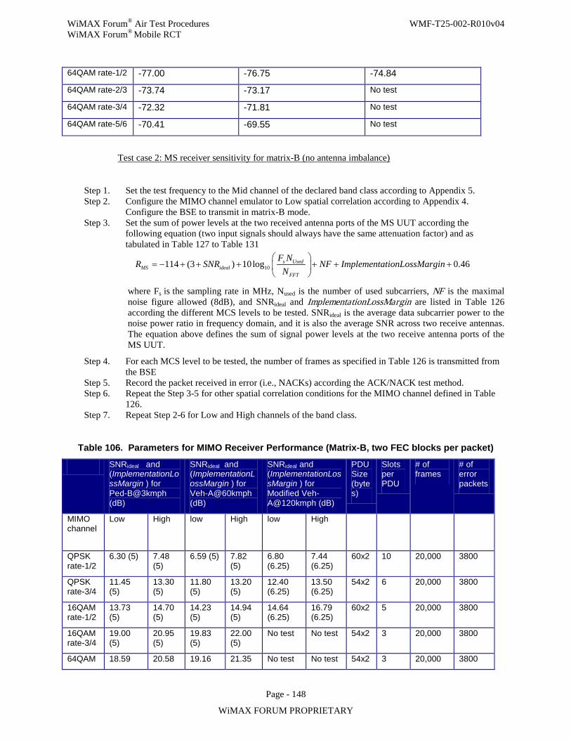
WiMAX Forum® Air Test Procedures WMF-T25-002-R010v04 WiMAX Forum® Mobile RCT
Page - 148
WiMAX FORUM PROPRIETARY
64QAM rate-1/2 -77.00 -76.75 -74.84
64QAM rate-2/3 -73.74 -73.17 No test
64QAM rate-3/4 -72.32 -71.81 No test
64QAM rate-5/6 -70.41 -69.55 No test
Test case 2: MS receiver sensitivity for matrix-B (no antenna imbalance)
Step 1. Set the test frequency to the Mid channel of the declared band class according to Appendix 5. Step 2. Configure the MIMO channel emulator to Low spatial correlation according to Appendix 4.
Configure the BSE to transmit in matrix-B mode. Step 3. Set the sum of power levels at the two received antenna ports of the MS UUT according the
following equation (two input signals should always have the same attenuation factor) and as tabulated in Table 127 to Table 131
10114 (3 ) 10log 0.46s UsedMS ideal
FFT
F NR SNR NF ImplementationLossMargin
N
= − + + + + + +
where Fs is the sampling rate in MHz, Nused is the number of used subcarriers, NF is the maximal noise figure allowed (8dB), and SNRideal and ImplementationLossMargin are listed in Table 126 according the different MCS levels to be tested. SNRideal is the average data subcarrier power to the noise power ratio in frequency domain, and it is also the average SNR across two receive antennas. The equation above defines the sum of signal power levels at the two receive antenna ports of the MS UUT.
Step 4. For each MCS level to be tested, the number of frames as specified in Table 126 is transmitted from the BSE
Step 5. Record the packet received in error (i.e., NACKs) according the ACK/NACK test method. Step 6. Repeat the Step 3-5 for other spatial correlation conditions for the MIMO channel defined in Table
126. Step 7. Repeat Step 2-6 for Low and High channels of the band class.
Table 106. Parameters for MIMO Receiver Performance (Matrix-B, two FEC blocks per packet)
SNRideal and (ImplementationLossMargin ) for Ped-B@3kmph (dB)
SNRideal and (ImplementationLossMargin ) for Veh-A@60kmph (dB)
SNRideal and (ImplementationLossMargin ) for Modified Veh-A@120kmph (dB)
PDU Size (bytes)
Slots per PDU
# of frames
# of error packets
MIMO channel
Low High low High low High
QPSK rate-1/2
6.30 (5) 7.48 (5)
6.59 (5) 7.82 (5)
6.80 (6.25)
7.44 (6.25)
60x2 10 20,000 3800
QPSK rate-3/4
11.45 (5)
13.30 (5)
11.80 (5)
13.20 (5)
12.40 (6.25)
13.50 (6.25)
54x2 6 20,000 3800
16QAM rate-1/2
13.73 (5)
14.70 (5)
14.23 (5)
14.94 (5)
14.64 (6.25)
16.79 (6.25)
60x2 5 20,000 3800
16QAM rate-3/4
19.00 (5)
20.95 (5)
19.83 (5)
22.00 (5)
No test No test 54x2 3 20,000 3800
64QAM 18.59 20.58 19.16 21.35 No test No test 54x2 3 20,000 3800
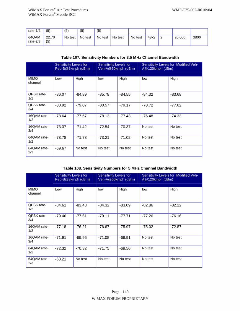
WiMAX Forum® Air Test Procedures WMF-T25-002-R010v04 WiMAX Forum® Mobile RCT
Page - 149
WiMAX FORUM PROPRIETARY
rate-1/2 (5) (5) (5) (5)
64QAM rate-2/3
22.70 (5)
No test No test No test No test No test 48x2 2 20,000 3800
Table 107. Sensitivity Numbers for 3.5 MHz Channel Bandwidth
Sensitivity Levels for Ped-B@3kmph (dBm)
Sensitivity Levels for Veh-A@60kmph (dBm)
Sensitivity Levels for Modified Veh-A@120kmph (dBm)
MIMO channel
Low High low High low High
QPSK rate-1/2
-86.07 -84.89 -85.78 -84.55 -84.32 -83.68
QPSK rate-3/4
-80.92 -79.07 -80.57 -79.17 -78.72 -77.62
16QAM rate-1/2
-78.64 -77.67 -78.13 -77.43 -76.48 -74.33
16QAM rate-3/4
-73.37 -71.42 -72.54 -70.37 No test No test
64QAM rate-1/2
-73.78 -71.78 -73.21 -71.02 No test No test
64QAM rate-2/3
-69.67 No test No test No test No test No test
Table 108. Sensitivity Numbers for 5 MHz Channel Bandwidth
Sensitivity Levels for Ped-B@3kmph (dBm)
Sensitivity Levels for Veh-A@60kmph (dBm)
Sensitivity Levels for Modified Veh-A@120kmph (dBm)
MIMO channel
Low High low High low High
QPSK rate-1/2
-84.61 -83.43 -84.32 -83.09 -82.86 -82.22
QPSK rate-3/4
-79.46 -77.61 -79.11 -77.71 -77.26 -76.16
16QAM rate-1/2
-77.18 -76.21 -76.67 -75.97 -75.02 -72.87
16QAM rate-3/4
-71.91 -69.96 -71.08 -68.91 No test No test
64QAM rate-1/2
-72.32 -70.32 -71.75 -69.56 No test No test
64QAM rate-2/3
-68.21 No test No test No test No test No test
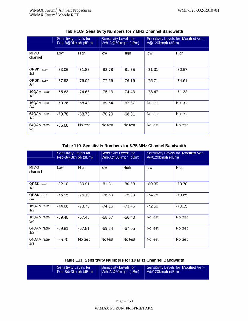
WiMAX Forum® Air Test Procedures WMF-T25-002-R010v04 WiMAX Forum® Mobile RCT
Page - 150
WiMAX FORUM PROPRIETARY
Table 109. Sensitivity Numbers for 7 MHz Channel Bandwidth
Sensitivity Levels for Ped-B@3kmph (dBm)
Sensitivity Levels for Veh-A@60kmph (dBm)
Sensitivity Levels for Modified Veh-A@120kmph (dBm)
MIMO channel
Low High low High low High
QPSK rate-1/2
-83.06 -81.88 -82.78 -81.55 -81.31 -80.67
QPSK rate-3/4
-77.92 -76.06 -77.56 -76.16 -75.71 -74.61
16QAM rate-1/2
-75.63 -74.66 -75.13 -74.43 -73.47 -71.32
16QAM rate-3/4
-70.36 -68.42 -69.54 -67.37 No test No test
64QAM rate-1/2
-70.78 -68.78 -70.20 -68.01 No test No test
64QAM rate-2/3
-66.66 No test No test No test No test No test
Table 110. Sensitivity Numbers for 8.75 MHz Channel Bandwidth
Sensitivity Levels for Ped-B@3kmph (dBm)
Sensitivity Levels for Veh-A@60kmph (dBm)
Sensitivity Levels for Modified Veh-A@120kmph (dBm)
MIMO channel
Low High low High low High
QPSK rate-1/2
-82.10 -80.91 -81.81 -80.58 -80.35 -79.70
QPSK rate-3/4
-76.95 -75.10 -76.60 -75.20 -74.75 -73.65
16QAM rate-1/2
-74.66 -73.70 -74.16 -73.46 -72.50 -70.35
16QAM rate-3/4
-69.40 -67.45 -68.57 -66.40 No test No test
64QAM rate-1/2
-69.81 -67.81 -69.24 -67.05 No test No test
64QAM rate-2/3
-65.70 No test No test No test No test No test
Table 111. Sensitivity Numbers for 10 MHz Channel Bandwidth
Sensitivity Levels for Ped-B@3kmph (dBm)
Sensitivity Levels for Veh-A@60kmph (dBm)
Sensitivity Levels for Modified Veh-A@120kmph (dBm)
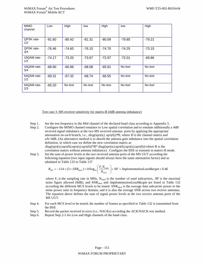
WiMAX Forum® Air Test Procedures WMF-T25-002-R010v04 WiMAX Forum® Mobile RCT
Page - 151
WiMAX FORUM PROPRIETARY
MIMO channel
Low High low High low High
QPSK rate-1/2
-81.60 -80.42 -81.31 -80.09 -79.85 -79.21
QPSK rate-3/4
-76.46 -74.60 -76.10 -74.70 -74.25 -73.15
16QAM rate-1/2
-74.17 -73.20 -73.67 -72.97 -72.01 -69.86
16QAM rate-3/4
-68.90 -66.96 -68.08 -65.91 No test No test
64QAM rate-1/2
-69.31 -67.32 -68.74 -66.55 No test No test
64QAM rate-2/3
-65.20 No test No test No test No test No test
Test case 3: MS receiver sensitivity for matrix-B (4dB antenna imbalance)
Step 1. Set the test frequency to the Mid channel of the declared band class according to Appendix 5. Step 2. Configure the MIMO channel emulator to Low spatial correlation and to emulate additionally a 4dB
received signal imbalance at the two MS received antenna ports by applying the appropriate attenuation on each branch, i.e., diag(sqrt(a), sqrt(b))*H, where H is the channel matrix and a/b=4dB. (An alternative method is to absorb the antenna gain imbalance into the spatial correlation definition, in which case we define the new correlation matrix as diag(sqrt(a),sqrt(b),sqrt(a),sqrt(b))*R* diag(sqrt(a),sqrt(b),sqrt(a),sqrt(b)) where R is the correlation matrix without antenna imbalance) . Configure the BSE to transmit in matrix-B mode.
Step 3. Set the sum of power levels at the two received antenna ports of the MS UUT according the following equation (two input signals should always have the same attenuation factor) and as tabulated in Table 133 to Table 137
10114 (3 ) 10log 0.46s UsedMS ideal
FFT
F NR SNR NF ImplementationLossMargin
N
= − + + + + + +
where Fs is the sampling rate in MHz, Nused is the number of used subcarriers, NF is the maximal noise figure allowed (8dB), and SNRideal and ImplementationLossMargin are listed in Table 132 according the different MCS levels to be tested. SNRideal is the average data subcarrier power to the noise power ratio in frequency domain, and it is also the average SNR across two receive antennas. The equation above defines the sum of signal power levels at the two receive antenna ports of the MS UUT.
Step 4. For each MCS level to be tested, the number of frames as specified in Table 132 is transmitted from the BSE
Step 5. Record the packet received in error (i.e., NACKs) according the ACK/NACK test method. Step 6. Repeat Step 2-5 for Low and High channels of the band class.
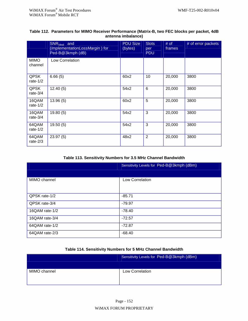
WiMAX Forum® Air Test Procedures WMF-T25-002-R010v04 WiMAX Forum® Mobile RCT
Page - 152
WiMAX FORUM PROPRIETARY
Table 112. Parameters for MIMO Receiver Performance (Matrix-B, two FEC blocks per packet, 4dB antenna imbalance)
SNRideal and (ImplementationLossMargin ) for Ped-B@3kmph (dB)
PDU Size (bytes)
Slots per PDU
# of frames
# of error packets
MIMO channel
Low Correlation
QPSK rate-1/2
6.66 (5) 60x2 10 20,000 3800
QPSK rate-3/4
12.40 (5) 54x2 6 20,000 3800
16QAM rate-1/2
13.96 (5) 60x2 5 20,000 3800
16QAM rate-3/4
19.80 (5) 54x2 3 20,000 3800
64QAM rate-1/2
19.50 (5) 54x2 3 20,000 3800
64QAM rate-2/3
23.97 (5) 48x2 2 20,000 3800
Table 113. Sensitivity Numbers for 3.5 MHz Channel Bandwidth
Sensitivity Levels for Ped-B@3kmph (dBm)
MIMO channel Low Correlation
QPSK rate-1/2 -85.71
QPSK rate-3/4 -79.97
16QAM rate-1/2 -78.40
16QAM rate-3/4 -72.57
64QAM rate-1/2 -72.87
64QAM rate-2/3 -68.40
Table 114. Sensitivity Numbers for 5 MHz Channel Bandwidth
Sensitivity Levels for Ped-B@3kmph (dBm)
MIMO channel Low Correlation
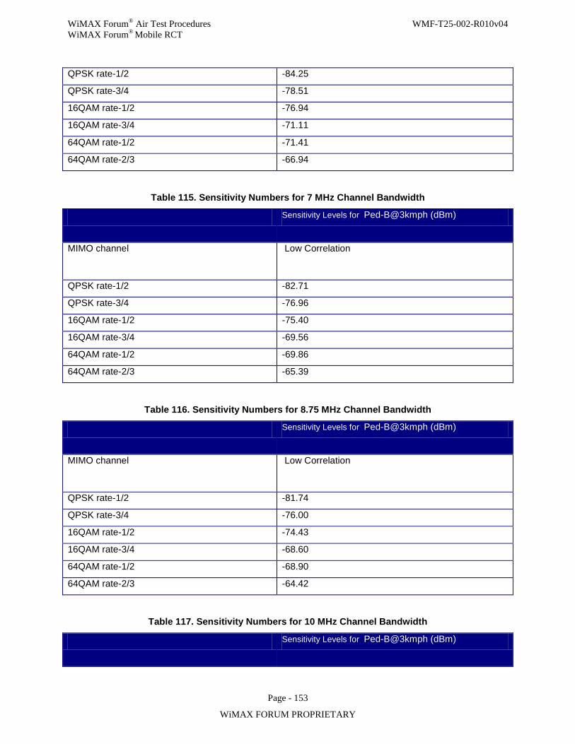
WiMAX Forum® Air Test Procedures WMF-T25-002-R010v04 WiMAX Forum® Mobile RCT
Page - 153
WiMAX FORUM PROPRIETARY
QPSK rate-1/2 -84.25
QPSK rate-3/4 -78.51
16QAM rate-1/2 -76.94
16QAM rate-3/4 -71.11
64QAM rate-1/2 -71.41
64QAM rate-2/3 -66.94
Table 115. Sensitivity Numbers for 7 MHz Channel Bandwidth
Sensitivity Levels for Ped-B@3kmph (dBm)
MIMO channel Low Correlation
QPSK rate-1/2 -82.71
QPSK rate-3/4 -76.96
16QAM rate-1/2 -75.40
16QAM rate-3/4 -69.56
64QAM rate-1/2 -69.86
64QAM rate-2/3 -65.39
Table 116. Sensitivity Numbers for 8.75 MHz Channel Bandwidth
Sensitivity Levels for Ped-B@3kmph (dBm)
MIMO channel Low Correlation
QPSK rate-1/2 -81.74
QPSK rate-3/4 -76.00
16QAM rate-1/2 -74.43
16QAM rate-3/4 -68.60
64QAM rate-1/2 -68.90
64QAM rate-2/3 -64.42
Table 117. Sensitivity Numbers for 10 MHz Channel Bandwidth
Sensitivity Levels for Ped-B@3kmph (dBm)
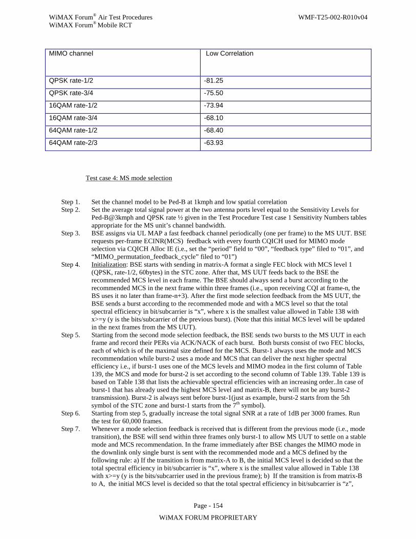
WiMAX Forum® Air Test Procedures WMF-T25-002-R010v04 WiMAX Forum® Mobile RCT
Page - 154
WiMAX FORUM PROPRIETARY
MIMO channel Low Correlation
QPSK rate-1/2 -81.25
QPSK rate-3/4 -75.50
16QAM rate-1/2 -73.94
16QAM rate-3/4 -68.10
64QAM rate-1/2 -68.40
64QAM rate-2/3 -63.93
Test case 4: MS mode selection
Step 1. Set the channel model to be Ped-B at 1kmph and low spatial correlation Step 2. Set the average total signal power at the two antenna ports level equal to the Sensitivity Levels for
Ped-B@3kmph and QPSK rate ½ given in the Test Procedure Test case 1 Sensitivity Numbers tables appropriate for the MS unit’s channel bandwidth.
Step 3. BSE assigns via UL MAP a fast feedback channel periodically (one per frame) to the MS UUT. BSE requests per-frame ECINR(MCS) feedback with every fourth CQICH used for MIMO mode selection via CQICH Alloc IE (i.e., set the “period” field to “00”, “feedback type” filed to “01”, and “MIMO_permutation_feedback_cycle” filed to “01”)
Step 4. Initialization: BSE starts with sending in matrix-A format a single FEC block with MCS level 1 (QPSK, rate-1/2, 60bytes) in the STC zone. After that, MS UUT feeds back to the BSE the recommended MCS level in each frame. The BSE should always send a burst according to the recommended MCS in the next frame within three frames (i.e., upon receiving CQI at frame-n, the BS uses it no later than frame-n+3). After the first mode selection feedback from the MS UUT, the BSE sends a burst according to the recommended mode and with a MCS level so that the total spectral efficiency in bit/subcarrier is “x”, where x is the smallest value allowed in Table 138 with x>=y (y is the bits/subcarrier of the previous burst). (Note that this initial MCS level will be updated in the next frames from the MS UUT).
Step 5. Starting from the second mode selection feedback, the BSE sends two bursts to the MS UUT in each frame and record their PERs via ACK/NACK of each burst. Both bursts consist of two FEC blocks, each of which is of the maximal size defined for the MCS. Burst-1 always uses the mode and MCS recommendation while burst-2 uses a mode and MCS that can deliver the next higher spectral efficiency i.e., if burst-1 uses one of the MCS levels and MIMO modea in the first column of Table 139, the MCS and mode for burst-2 is set according to the second column of Table 139. Table 139 is based on Table 138 that lists the achievable spectral efficiencies with an increasing order..In case of burst-1 that has already used the highest MCS level and matrix-B, there will not be any burst-2 transmission). Burst-2 is always sent before burst-1(just as example, burst-2 starts from the 5th symbol of the STC zone and burst-1 starts from the 7th symbol).
Step 6. Starting from step 5, gradually increase the total signal SNR at a rate of 1dB per 3000 frames. Run the test for 60,000 frames.
Step 7. Whenever a mode selection feedback is received that is different from the previous mode (i.e., mode transition), the BSE will send within three frames only burst-1 to allow MS UUT to settle on a stable mode and MCS recommendation. In the frame immediately after BSE changes the MIMO mode in the downlink only single burst is sent with the recommended mode and a MCS defined by the following rule: a) If the transition is from matrix-A to B, the initial MCS level is decided so that the total spectral efficiency in bit/subcarrier is “x”, where x is the smallest value allowed in Table 138 with x>=y (y is the bits/subcarrier used in the previous frame); b) If the transition is from matrix-B to A, the initial MCS level is decided so that the total spectral efficiency in bit/subcarrier is “z”,
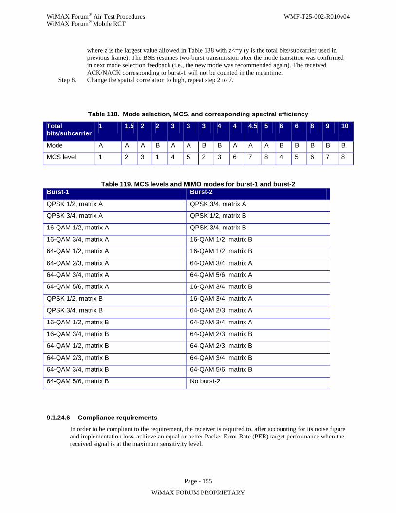
WiMAX Forum® Air Test Procedures WMF-T25-002-R010v04 WiMAX Forum® Mobile RCT
Page - 155
WiMAX FORUM PROPRIETARY
where z is the largest value allowed in Table 138 with z<=y (y is the total bits/subcarrier used in previous frame). The BSE resumes two-burst transmission after the mode transition was confirmed in next mode selection feedback (i.e., the new mode was recommended again). The received ACK/NACK corresponding to burst-1 will not be counted in the meantime.
Step 8. Change the spatial correlation to high, repeat step 2 to 7.
Table 118. Mode selection, MCS, and corresponding spectral efficiency
Total bits/subcarrier
1 1.5 2 2 3 3 3 4 4 4.5 5 6 6 8 9 10
Mode A A A B A A B B A A A B B B B B MCS level 1 2 3 1 4 5 2 3 6 7 8 4 5 6 7 8
Table 119. MCS levels and MIMO modes for burst-1 and burst-2 Burst-1 Burst-2
QPSK 1/2, matrix A QPSK 3/4, matrix A
QPSK 3/4, matrix A QPSK 1/2, matrix B
16-QAM 1/2, matrix A QPSK 3/4, matrix B
16-QAM 3/4, matrix A 16-QAM 1/2, matrix B
64-QAM 1/2, matrix A 16-QAM 1/2, matrix B
64-QAM 2/3, matrix A 64-QAM 3/4, matrix A
64-QAM 3/4, matrix A 64-QAM 5/6, matrix A
64-QAM 5/6, matrix A 16-QAM 3/4, matrix B
QPSK 1/2, matrix B 16-QAM 3/4, matrix A
QPSK 3/4, matrix B 64-QAM 2/3, matrix A
16-QAM 1/2, matrix B 64-QAM 3/4, matrix A
16-QAM 3/4, matrix B 64-QAM 2/3, matrix B
64-QAM 1/2, matrix B 64-QAM 2/3, matrix B
64-QAM 2/3, matrix B 64-QAM 3/4, matrix B
64-QAM 3/4, matrix B 64-QAM 5/6, matrix B
64-QAM 5/6, matrix B No burst-2
9.1.24.6 Compliance requirements
In order to be compliant to the requirement, the receiver is required to, after accounting for its noise figure and implementation loss, achieve an equal or better Packet Error Rate (PER) target performance when the received signal is at the maximum sensitivity level.
WiMAX Forum® Air Test Procedures WMF-T25-002-R010v04 WiMAX Forum® Mobile RCT
Page - 156
WiMAX FORUM PROPRIETARY
Pass verdict:
For all modulation and coding combinations in test case 1, 2 and 3, the number of packets in error is less or equal to the limits in Table 120, Table 126, and Table 132 respectively. In the mode selection test, the recorded PER for burst-1 must not exceed the target PER of 36% (Assuming a target BLER of 10% and a positive margin of 10% allowed. The PER for the two-block packet is then 1-(1-0.2)^2=36%). At the same time, the PER for burst-2 must be worse than the target PER of 9.75% (Assuming a target BLER of 10% and a negative margin of 5% allowed. The PER for a two-block burst is then 1-(1-0.05)^2=9.75%).
Fail verdict:
For at least one of the modulation and coding combinations in test case 1, 2 and 3, the number of packets in error is higher than the limits in Table 120, Table 126, and Table 132 respectively, or the MS fails the mode selection test.
MS-22.2: Par t B, MS receiver Physical CINR measurements for DL-MIMO The purpose of this test is to verify compliance of MS CINR measurements and reports for DL-MIMO in PUSC permutation. This text describes the method and the test for this case.
9.1.24.7 Introduction
PCINR measurements are impacted by the receiver types due to different possible implementations of the DL-MIMO receiver at the MS side. The tests are designed such that MS with advanced capabilities are allowed to have better performance than basic standard compliant receivers without being penalized by the test. Channels under test are chosen carefully so that for variety of receiver implementations, including ZF, MMSE and ML receivers the reference PCINR metric results in the same value. Additional implementation margin is included to the compliance requirement to accommodate various other receiver types not explicitly covered by the reference PCINR equations used in this RCT. Currently, the standard defines two possible methods for MIMO operation in DL PUSC -STC zone which are:
1. Matrix A – Alamouti scheme 2. Matrix B – Spatial multiplexing.
Matrix A transmission is used for achieving spatial diversity while Matrix B transmission is used to maximize transmission rate by transmitting two symbols from two different antennas. Therefore, upon BS command the MS is supposed to receive transmissions in one of the two possible MIMO modes. In this sub-test the ability of the MS-UUT to compute post-processing PCINR (i.e., after performing combining) from DL-PUSC broadcast pilots is examined using pre-defined mechanism. This mechanism is based on section 8.4.5.4.10.1 in the standard that specifies the methods for preparing feedback through CQI_CH_Alloc_IE for STC/MIMO zones. We note here that the frame structure, burst size and CQI reports are the same in the above tests (this refers to sensitivity and MIMO mode selection in MS22.2).
9.1.24.8 PICS coverage and test purposes
The following PICS items are covered by this test.
Table 120. PICS Coverage for MS-22.2 DL-MIMO PCINR reports
Item Reference Item and Section Number Partial or Total Coverage Direct or Indirect Coverage
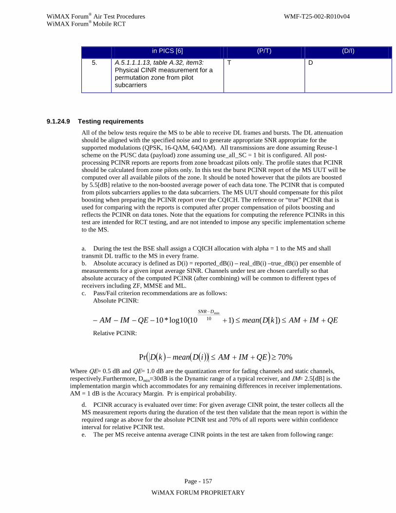
WiMAX Forum® Air Test Procedures WMF-T25-002-R010v04 WiMAX Forum® Mobile RCT
Page - 157
WiMAX FORUM PROPRIETARY
in PICS [6] (P/T) (D/I)
5. A.5.1.1.1.13, table A.32, item3: Physical CINR measurement for a permutation zone from pilot subcarriers
T D
9.1.24.9 Testing requirements All of the below tests require the MS to be able to receive DL frames and bursts. The DL attenuation should be aligned with the specified noise and to generate appropriate SNR appropriate for the supported modulations (QPSK, 16-QAM, 64QAM). All transmissions are done assuming Reuse-1 scheme on the PUSC data (payload) zone assuming use_all_SC = 1 bit is configured. All post-processing PCINR reports are reports from zone broadcast pilots only. The profile states that PCINR should be calculated from zone pilots only. In this test the burst PCINR report of the MS UUT will be computed over all available pilots of the zone. It should be noted however that the pilots are boosted by 5.5[dB] relative to the non-boosted average power of each data tone. The PCINR that is computed from pilots subcarriers applies to the data subcarriers. The MS UUT should compensate for this pilot boosting when preparing the PCINR report over the CQICH. The reference or “true” PCINR that is used for comparing with the reports is computed after proper compensation of pilots boosting and reflects the PCINR on data tones. Note that the equations for computing the reference PCINRs in this test are intended for RCT testing, and are not intended to impose any specific implementation scheme to the MS.
a. During the test the BSE shall assign a CQICH allocation with alpha = 1 to the MS and shall transmit DL traffic to the MS in every frame. b. Absolute accuracy is defined as D(i) = reported_dB(i) – real_dB(i) –true_dB(i) per ensemble of measurements for a given input average SINR. Channels under test are chosen carefully so that absolute accuracy of the computed PCINR (after combining) will be common to different types of receivers including ZF, MMSE and ML. c. Pass/Fail criterion recommendations are as follows: Absolute PCINR:
QEIMAMkDmeanQEIMAMDSNR
++≤≤+−−−−−
])[()110(10log*10 10min
Relative PCINR:
( ) ( )( )( ) %70Pr ≥++≤− QEIMAMiDmeankD
Where QE= 0.5 dB and QE= 1.0 dB are the quantization error for fading channels and static channels, respectively.Furthermore, Dmin=30dB is the Dynamic range of a typical receiver, and IM= 2.5[dB] is the implementation margin which accommodates for any remaining differences in receiver implementations. AM = 1 dB is the Accuracy Margin. Pr is empirical probability.
d. PCINR accuracy is evaluated over time: For given average CINR point, the tester collects all the MS measurement reports during the duration of the test then validate that the mean report is within the required range as above for the absolute PCINR test and 70% of all reports were within confidence interval for relative PCINR test. e. The per MS receive antenna average CINR points in the test are taken from following range:
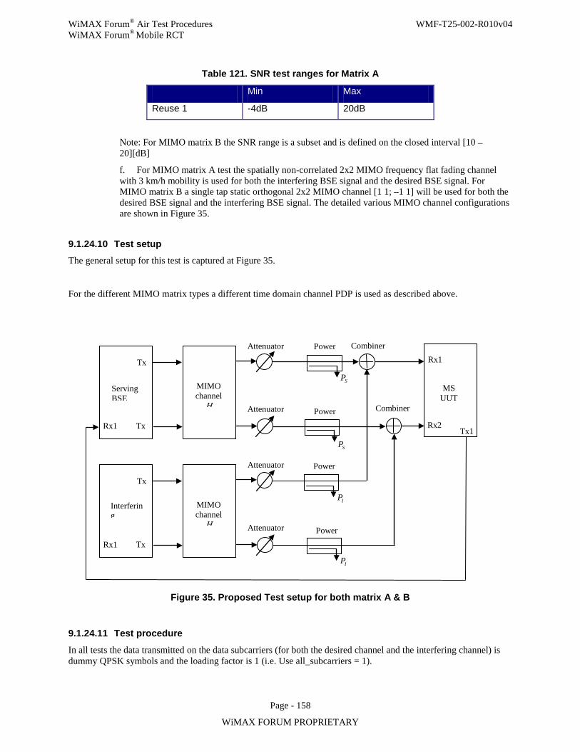
WiMAX Forum® Air Test Procedures WMF-T25-002-R010v04 WiMAX Forum® Mobile RCT
Page - 158
WiMAX FORUM PROPRIETARY
Table 121. SNR test ranges for Matrix A
Min Max
Reuse 1 -4dB 20dB
Note: For MIMO matrix B the SNR range is a subset and is defined on the closed interval [10 – 20][dB]
f. For MIMO matrix A test the spatially non-correlated 2x2 MIMO frequency flat fading channel with 3 km/h mobility is used for both the interfering BSE signal and the desired BSE signal. For MIMO matrix B a single tap static orthogonal 2x2 MIMO channel [1 1; –1 1] will be used for both the desired BSE signal and the interfering BSE signal. The detailed various MIMO channel configurations are shown in Figure 35.
9.1.24.10 Test setup The general setup for this test is captured at Figure 35.
For the different MIMO matrix types a different time domain channel PDP is used as described above.
Figure 35. Proposed Test setup for both matrix A & B
9.1.24.11 Test procedure
In all tests the data transmitted on the data subcarriers (for both the desired channel and the interfering channel) is dummy QPSK symbols and the loading factor is 1 (i.e. Use all_subcarriers = 1).
IP
SP
SP
Tx
Tx
Rx1
Rx1
Rx2
Serving BSE
MS UUT
MIMO channel
H
Attenuator
Attenuator
Combiner
Combiner
Power
Tx
Tx
Rx1
MIMO channel
H
Attenuator
Attenuator
Interfering
Tx1
Power
Power
Power
IP
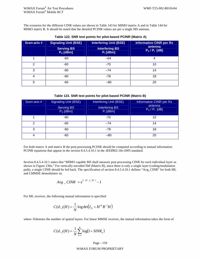
WiMAX Forum® Air Test Procedures WMF-T25-002-R010v04 WiMAX Forum® Mobile RCT
Page - 159
WiMAX FORUM PROPRIETARY
The scenarios for the different CINR values are shown in Table 143 for MIMO matrix A and in Table 144 for MIMO matrix B. It should be noted that the detailed PCINR values are per a single MS antenna.
Table 122. SNR test points for pilot-based PCINR (Matrix A)
Scen-ario # Signaling Unit (BSE)
Serving BS PS [dBm]
Interfering Unit (BSE)
Interfering BS PI [dBm]
Informative CINR per Rx antenna
PS / PI [dB]
1 -60 –64 4
2 -60 -70 10
3 -60 –74 14
4 -60 -78 18
5 -60 –80 20
Table 123. SNR test points for pilot-based PCINR (Matrix B)
Scen-ario # Signaling Unit (BSE)
Serving BS PS [dBm]
Interfering Unit (BSE)
Interfering BS PI [dBm]
Informative CINR per Rx antenna
PS / PI [dB]
1 -60 -70 10
2 -60 –74 14
3 -60 -78 18
4 -60 –80 20
For both matrix A and matrix B the post-processing PCINR should be computed according to mutual information PCINR equations that appear in the section 8.4.5.4.10.1 in the IEEE802.16e-2005 standard.
Section 8.4.5.4.10.1 states that “MIMO capable MS shall measure post processing CINR for each individual layer as shown in Figure 230a.” For vertically encoded SM (Matrix B), since there is only a single layer (coding/modulation path), a single CINR should be fed back. The specification of section 8.4.5.4.10.1 defines “Avg_CINR” for both ML and LMMSE demodulator as:
For ML receiver, the following mutual information is specified
where N denotes the number of spatial layers. For linear MMSE receiver, the mutual information takes the form of
1_ ),( −= HydCeCINRAvg
( )HRHIN
HydC HN
1detlog1),( −+=
( )∑=
+=N
nnSINR
NHydC
11log1),(
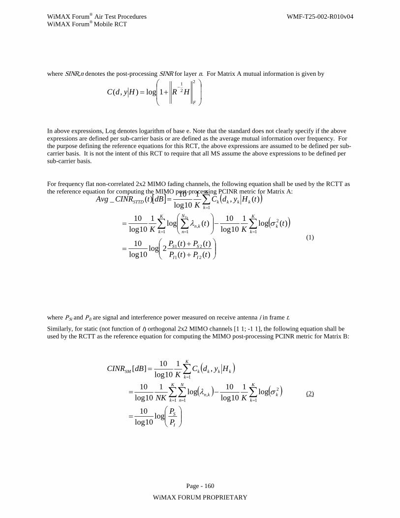
WiMAX Forum® Air Test Procedures WMF-T25-002-R010v04 WiMAX Forum® Mobile RCT
Page - 160
WiMAX FORUM PROPRIETARY
where SINR,n denotes the post-processing SINR for layer n. For Matrix A mutual information is given by
In above expressions, Log denotes logarithm of base e. Note that the standard does not clearly specify if the above expressions are defined per sub-carrier basis or are defined as the average mutual information over frequency. For the purpose defining the reference equations for this RCT, the above expressions are assumed to be defined per sub-carrier basis. It is not the intent of this RCT to require that all MS assume the above expressions to be defined per sub-carrier basis.
For frequency flat non-correlated 2x2 MIMO fading channels, the following equation shall be used by the RCTT as the reference equation for computing the MIMO post-processing PCINR metric for Matrix A:
(1)
where PSi and PIi are signal and interference power measured on receive antenna i in frame t.
Similarly, for static (not function of t) orthogonal 2x2 MIMO channels [1 1; -1 1], the following equation shall be used by the RCTT as the reference equation for computing the MIMO post-processing PCINR metric for Matrix B:
(2)
+=
−2
21
1log),(F
HRHydC
[ ] ( )
( )
++
=
−
=
=
∑∑ ∑
∑
== =
=
)()()()(2log
10log10
)(log110log
10)(log110log
10
)(,110log
10)(_
21
21
1
2
1 1,
1
tPtPtPtP
tK
tK
tHydCK
dBtCINRAvg
II
SS
K
kk
K
k
N
nkn
K
kkkkkSTTD
Tx
σλ
( )
( ) ( )
=
−=
=
∑∑∑
∑
== =
=
I
S
K
kk
K
k
N
nkn
K
kkkkkSM
PP
KNK
HydCK
dBCINR
log10log
10
log110log
10log110log
10
,110log
10][
1
2
1 1,
1
σλ
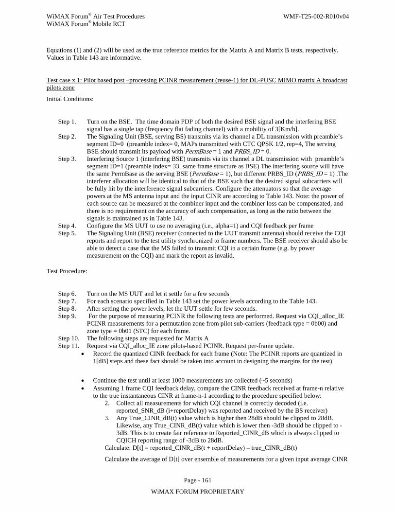
WiMAX Forum® Air Test Procedures WMF-T25-002-R010v04 WiMAX Forum® Mobile RCT
Page - 161
WiMAX FORUM PROPRIETARY
Equations (1) and (2) will be used as the true reference metrics for the Matrix A and Matrix B tests, respectively. Values in Table 143 are informative.
Test case x.1: Pilot based post –processing PCINR measurement (reuse-1) for DL-PUSC MIMO matrix A broadcast pilots zone
Initial Conditions:
Step 1. Turn on the BSE. The time domain PDP of both the desired BSE signal and the interfering BSE signal has a single tap (frequency flat fading channel) with a mobility of 3[Km/h].
Step 2. The Signaling Unit (BSE, serving BS) transmits via its channel a DL transmission with preamble’s segment ID=0 (preamble index= 0, MAPs transmitted with CTC QPSK 1/2, rep=4, The serving BSE should transmit its payload with PermBase = 1 and PRBS_ID = 0.
Step 3. Interfering Source 1 (interfering BSE) transmits via its channel a DL transmission with preamble’s segment ID=1 (preamble index= 33, same frame structure as BSE) The interfering source will have the same PermBase as the serving BSE (PermBase = 1), but different PRBS_ID (PRBS_ID = 1) .The interferer allocation will be identical to that of the BSE such that the desired signal subcarriers will be fully hit by the interference signal subcarriers. Configure the attenuators so that the average powers at the MS antenna input and the input CINR are according to Table 143. Note: the power of each source can be measured at the combiner input and the combiner loss can be compensated, and there is no requirement on the accuracy of such compensation, as long as the ratio between the signals is maintained as in Table 143.
Step 4. Configure the MS UUT to use no averaging (i.e., alpha=1) and CQI feedback per frame Step 5. The Signaling Unit (BSE) receiver (connected to the UUT transmit antenna) should receive the CQI
reports and report to the test utility synchronized to frame numbers. The BSE receiver should also be able to detect a case that the MS failed to transmit CQI in a certain frame (e.g. by power measurement on the CQI) and mark the report as invalid.
Test Procedure:
Step 6. Turn on the MS UUT and let it settle for a few seconds Step 7. For each scenario specified in Table 143 set the power levels according to the Table 143. Step 8. After setting the power levels, let the UUT settle for few seconds. Step 9. For the purpose of measuring PCINR the following tests are performed. Request via CQI_alloc_IE
PCINR measurements for a permutation zone from pilot sub-carriers (feedback type = 0b00) and zone type = 0b01 (STC) for each frame.
Step 10. The following steps are requested for Matrix A Step 11. Request via CQI_alloc_IE zone pilots-based PCINR. Request per-frame update.
• Record the quantized CINR feedback for each frame (Note: The PCINR reports are quantized in 1[dB] steps and these fact should be taken into account in designing the margins for the test)
• Continue the test until at least 1000 measurements are collected (~5 seconds) • Assuming 1 frame CQI feedback delay, compare the CINR feedback received at frame-n relative
to the true instantaneous CINR at frame-n-1 according to the procedure specified below: 2. Collect all measurements for which CQI channel is correctly decoded (i.e.
reported_SNR_dB (i+reportDelay) was reported and received by the BS receiver) 3. Any True_CINR_dB(t) value which is higher then 28dB should be clipped to 28dB.
Likewise, any True_CINR_dB(t) value which is lower then -3dB should be clipped to -3dB. This is to create fair reference to Reported_CINR_dB which is always clipped to CQICH reporting range of -3dB to 28dB.
Calculate: D[t] = reported_CINR_dB(t + reportDelay) – true_CINR_dB(t)
Calculate the average of D[t] over ensemble of measurements for a given input average CINR
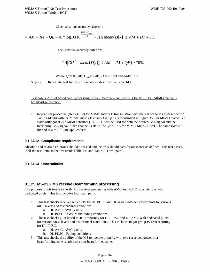
WiMAX Forum® Air Test Procedures WMF-T25-002-R010v04 WiMAX Forum® Mobile RCT
Page - 162
WiMAX FORUM PROPRIETARY
Check absolute accuracy criterion:
QEIMAMkDmeanQEIMAMDSNR
++≤≤+−−−−−
])[()110(10log*10 10min
Check relative accuracy criterion:
( ) ( )( )( ) %70Pr ≥++≤− QEIMAMiDmeankD
Where QE= 0.5 dB, Dmin=30dB, IM= 2.5 dB and AM=1 dB.
Step 12. Repeat the test for the next scenarios described in Table 143.
Test case x.2: Pilot based post –processing PCINR measurement (reuse-1) for DL-PUSC MIMO matrix B broadcast pilots zone.
1. Repeat test procedure (steps 1- 12) for MIMO matrix B transmission with the test scenarios as described in Table 144 and with the MIMO matrix B channel setup as demonstrated in Figure 35. For MIMO matrix B a static orthogonal 2x2 MIMO channel [1 1; –1 1] will be used for both the desired BSE signal and the interfering BSE signal. Since channel is static, the QE= 1 dB for MIMO Matrix B test. The same IM= 2.5 dB and AM = 1 dB are applied here.
9.1.24.12 Compliance requirements
Absolute and relative criterions should be tested and the tests should pass for all scenarios defined. This test passes if all the test items in the test result Table 143 and Table 144 are “pass”.
9.1.24.13 Uncertainties
9.1.25 MS-23.2 MS receive Beamforming processing The purpose of this test is to verify MS receiver processing with AMC and PUSC transmissions with dedicated pilots. This test includes four main parts:
1. This test checks receiver sensitivity for DL PUSC and DL AMC with dedicated pilots for various MCS levels and test channel conditions
a. DL AMC: AWGN only b. DL PUSC: AWGN and fading conditions
2. This test checks pilot based PCINR reporting for DL PUSC and DL AMC with dedicated pilots for various MCS levels and test channel conditions. This includes major group PCINR reporting for DL PUSC.
a. DL AMC: AWGN only b. DL PUSC: Fading conditions
3. This test checks the ability of the MS to operate properly with extra received power in a beamforming zone relative to a non-beamformed zone.
WiMAX Forum® Air Test Procedures WMF-T25-002-R010v04 WiMAX Forum® Mobile RCT
Page - 163
WiMAX FORUM PROPRIETARY
4. Finally, this test also addresses MS operation in DL-PUSC STC zone with dedicated pilots and matrix B.
9.1.25.1 Introduction
A MS receiver has to be tested for correct processing of bursts configured for beamforming (i.e., in zones with dedicated pilots) as transmitted from the BS, either in an AMC or PUSC zone. This processing includes receiver sensitivity and items associated with it, namely, PCINR estimation based on dedicated pilots and major group PCINR report when in a PUSC zone.
The test setup includes a single BSE that transmits DL data to the MS UUT which has two receive antennas. The transmitted data is received via both antennas (i.e., SIMO case) by means of combining the data from the two antennas (e.g. MRRC).
The four main test sections are described below:
Receiver Sensitivity with dedicated pilots:
The first test deals with receiver sensitivity in beamforming (dedicated pilots) zone. For the receiver sensitivity tests, the transmitting signal is not required to be beamformed since the main difference between this test and other non-beamformed test cases is the use of dedicated pilots. Hence, a BSE with single antenna and a MS receiver with two antennas are sufficient for the tests as shown in the test set up section below. To be compliant to receiver sensitivity requirements, the MS UUT receiver is required to achieve a PER/BER equal or better than a specific target level at specified channel conditions. For fading channels the target PER is 10% and for AWGN channels the target BER is 10-5.
For beamforming in an AMC zone, allocations should be made with a time-first subchannel allocation using the HARQ_DL_MAP_IE() with the “rectangular sub-burst indicator” set. For beamforming in a DL-PUSC zone, the basic allocation unit in the frequency domain is a single major group. For receiver sensitivity tests, each MS (unless otherwise stated) is allocated only a single slot by one or more major groups. Finally, it was decided not to check antenna imbalance issues in this test and these (typically) small imbalances can be considered as part of the receiver’s implementation loss1
.
Accommodation of extra received power due to beamforming:
In the second part of the test, accommodation of additional received power due to beamforming by the MS is verified. For this test, the BSE is required to be capable of emulating a BS transmitter with 4 antennas as well as transmitting both beamformed and non-beamformed zones in one DL subframe. Note that actual beamforming is not required and the BSE transmission is still with a single antenna, however the transmit power of the beamformed zone must be boosted as appropriate for the (emulated) number of transmit antennas.
In order to emulate BF gain at the receiver, the BSE must either internally boost just the beamformed zone, or be connected to an external amplifier which can provide gain to just the beamformed zone. In this later case, an external control circuit is required to synchronize the BF power boosting to the BF zone. 1 Additionally, this issue will be tested in MS MIMO sensitivity test.
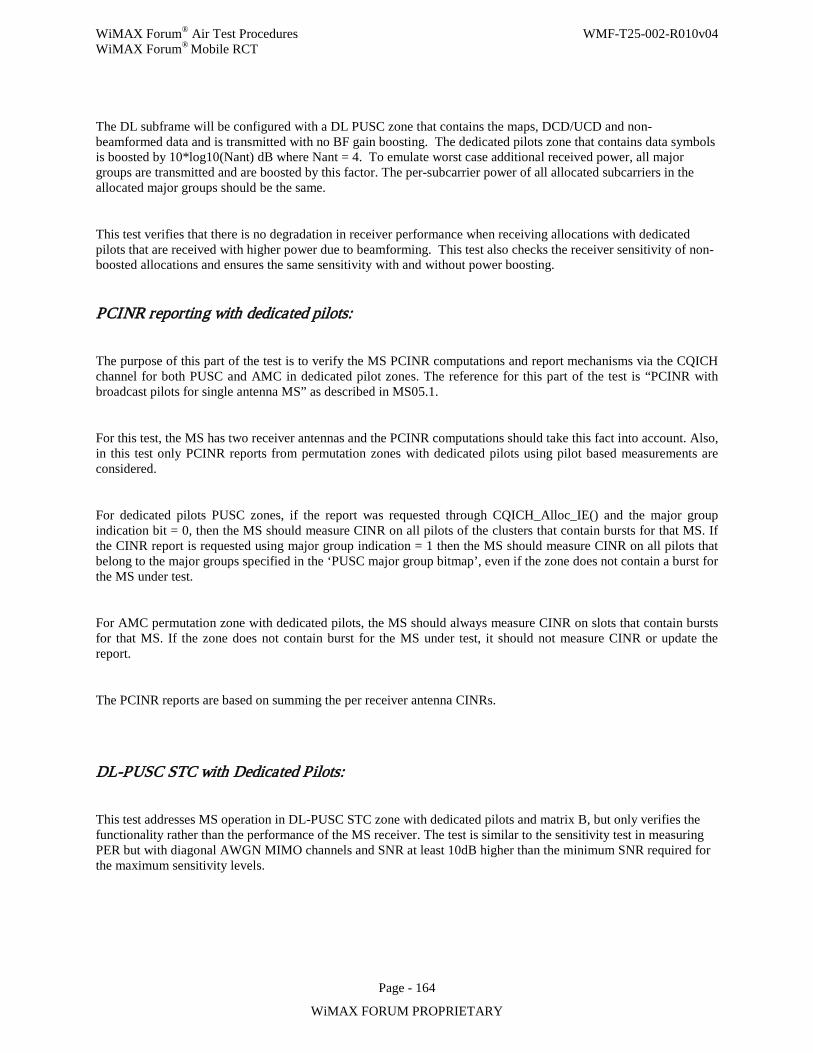
WiMAX Forum® Air Test Procedures WMF-T25-002-R010v04 WiMAX Forum® Mobile RCT
Page - 164
WiMAX FORUM PROPRIETARY
The DL subframe will be configured with a DL PUSC zone that contains the maps, DCD/UCD and non-beamformed data and is transmitted with no BF gain boosting. The dedicated pilots zone that contains data symbols is boosted by 10*log10(Nant) dB where Nant = 4. To emulate worst case additional received power, all major groups are transmitted and are boosted by this factor. The per-subcarrier power of all allocated subcarriers in the allocated major groups should be the same.
This test verifies that there is no degradation in receiver performance when receiving allocations with dedicated pilots that are received with higher power due to beamforming. This test also checks the receiver sensitivity of non-boosted allocations and ensures the same sensitivity with and without power boosting.
PCINR reporting with dedicated pilots:
The purpose of this part of the test is to verify the MS PCINR computations and report mechanisms via the CQICH channel for both PUSC and AMC in dedicated pilot zones. The reference for this part of the test is “PCINR with broadcast pilots for single antenna MS” as described in MS05.1.
For this test, the MS has two receiver antennas and the PCINR computations should take this fact into account. Also, in this test only PCINR reports from permutation zones with dedicated pilots using pilot based measurements are considered.
For dedicated pilots PUSC zones, if the report was requested through CQICH_Alloc_IE() and the major group indication bit = 0, then the MS should measure CINR on all pilots of the clusters that contain bursts for that MS. If the CINR report is requested using major group indication = 1 then the MS should measure CINR on all pilots that belong to the major groups specified in the ‘PUSC major group bitmap’, even if the zone does not contain a burst for the MS under test.
For AMC permutation zone with dedicated pilots, the MS should always measure CINR on slots that contain bursts for that MS. If the zone does not contain burst for the MS under test, it should not measure CINR or update the report.
The PCINR reports are based on summing the per receiver antenna CINRs.
DL-PUSC STC with Dedicated Pilots:
This test addresses MS operation in DL-PUSC STC zone with dedicated pilots and matrix B, but only verifies the functionality rather than the performance of the MS receiver. The test is similar to the sensitivity test in measuring PER but with diagonal AWGN MIMO channels and SNR at least 10dB higher than the minimum SNR required for the maximum sensitivity levels.
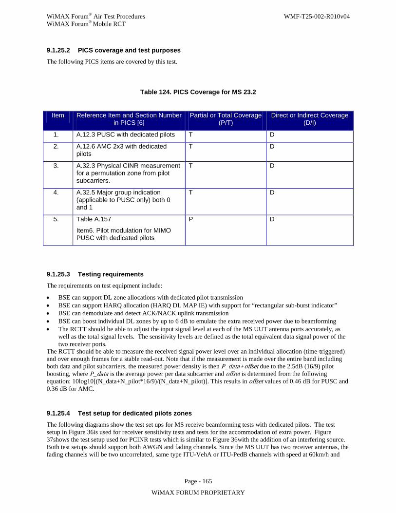
WiMAX Forum® Air Test Procedures WMF-T25-002-R010v04 WiMAX Forum® Mobile RCT
Page - 165
WiMAX FORUM PROPRIETARY
9.1.25.2 PICS coverage and test purposes
The following PICS items are covered by this test.
Table 124. PICS Coverage for MS 23.2
Item Reference Item and Section Number in PICS [6]
Partial or Total Coverage (P/T)
Direct or Indirect Coverage (D/I)
1. A.12.3 PUSC with dedicated pilots T D
2. A.12.6 AMC 2x3 with dedicated pilots
T D
3. A.32.3 Physical CINR measurement for a permutation zone from pilot subcarriers.
T D
4. A.32.5 Major group indication (applicable to PUSC only) both 0 and 1
T D
5. Table A.157
Item6. Pilot modulation for MIMO PUSC with dedicated pilots
P D
9.1.25.3 Testing requirements
The requirements on test equipment include:
• BSE can support DL zone allocations with dedicated pilot transmission • BSE can support HARQ allocation (HARQ DL MAP IE) with support for “rectangular sub-burst indicator” • BSE can demodulate and detect ACK/NACK uplink transmission • BSE can boost individual DL zones by up to 6 dB to emulate the extra received power due to beamforming • The RCTT should be able to adjust the input signal level at each of the MS UUT antenna ports accurately, as
well as the total signal levels. The sensitivity levels are defined as the total equivalent data signal power of the two receiver ports.
The RCTT should be able to measure the received signal power level over an individual allocation (time-triggered) and over enough frames for a stable read-out. Note that if the measurement is made over the entire band including both data and pilot subcarriers, the measured power density is then P_data+offset due to the 2.5dB (16/9) pilot boosting, where P_data is the average power per data subcarrier and offset is determined from the following equation: 10log10[(N_data+N_pilot*16/9)/(N_data+N_pilot)]. This results in offset values of 0.46 dB for PUSC and 0.36 dB for AMC.
9.1.25.4 Test setup for dedicated pilots zones
The following diagrams show the test set ups for MS receive beamforming tests with dedicated pilots. The test setup in Figure 36is used for receiver sensitivity tests and tests for the accommodation of extra power. Figure 37shows the test setup used for PCINR tests which is similar to Figure 36with the addition of an interfering source. Both test setups should support both AWGN and fading channels. Since the MS UUT has two receiver antennas, the fading channels will be two uncorrelated, same type ITU-VehA or ITU-PedB channels with speed at 60km/h and
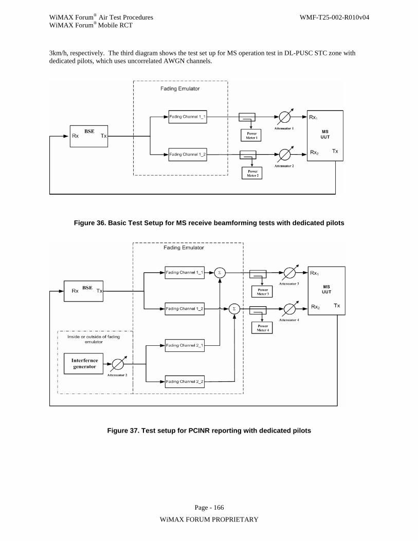
WiMAX Forum® Air Test Procedures WMF-T25-002-R010v04 WiMAX Forum® Mobile RCT
Page - 166
WiMAX FORUM PROPRIETARY
3km/h, respectively. The third diagram shows the test set up for MS operation test in DL-PUSC STC zone with dedicated pilots, which uses uncorrelated AWGN channels.
Figure 36. Basic Test Setup for MS receive beamforming tests with dedicated pilots
Figure 37. Test setup for PCINR reporting with dedicated pilots
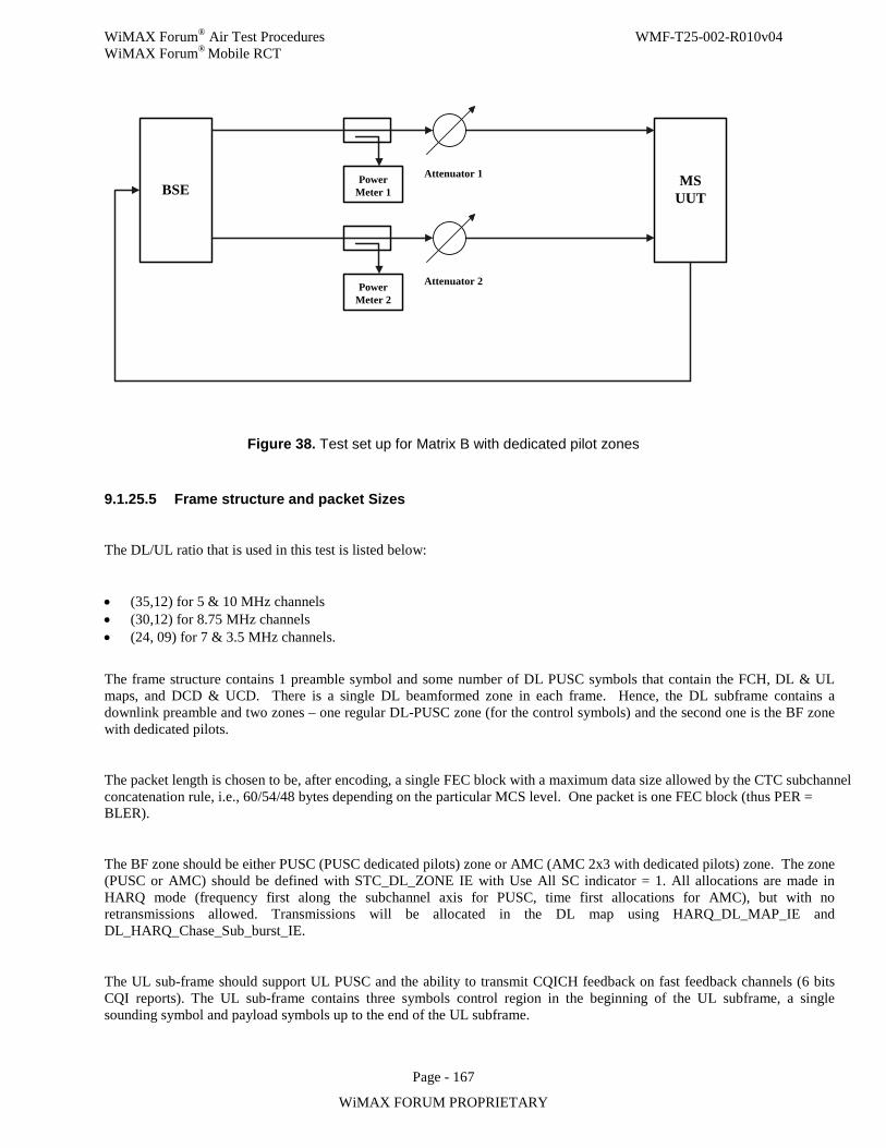
WiMAX Forum® Air Test Procedures WMF-T25-002-R010v04 WiMAX Forum® Mobile RCT
Page - 167
WiMAX FORUM PROPRIETARY
BSE MSUUT
Power Meter 1
Attenuator 1
Power Meter 2
Attenuator 2
Figure 38. Test set up for Matrix B with dedicated pilot zones
9.1.25.5 Frame structure and packet Sizes
The DL/UL ratio that is used in this test is listed below:
• (35,12) for 5 & 10 MHz channels • (30,12) for 8.75 MHz channels • (24, 09) for 7 & 3.5 MHz channels.
The frame structure contains 1 preamble symbol and some number of DL PUSC symbols that contain the FCH, DL & UL maps, and DCD & UCD. There is a single DL beamformed zone in each frame. Hence, the DL subframe contains a downlink preamble and two zones – one regular DL-PUSC zone (for the control symbols) and the second one is the BF zone with dedicated pilots.
The packet length is chosen to be, after encoding, a single FEC block with a maximum data size allowed by the CTC subchannel concatenation rule, i.e., 60/54/48 bytes depending on the particular MCS level. One packet is one FEC block (thus PER = BLER).
The BF zone should be either PUSC (PUSC dedicated pilots) zone or AMC (AMC 2x3 with dedicated pilots) zone. The zone (PUSC or AMC) should be defined with STC_DL_ZONE IE with Use All SC indicator = 1. All allocations are made in HARQ mode (frequency first along the subchannel axis for PUSC, time first allocations for AMC), but with no retransmissions allowed. Transmissions will be allocated in the DL map using HARQ_DL_MAP_IE and DL_HARQ_Chase_Sub_burst_IE.
The UL sub-frame should support UL PUSC and the ability to transmit CQICH feedback on fast feedback channels (6 bits CQI reports). The UL sub-frame contains three symbols control region in the beginning of the UL subframe, a single sounding symbol and payload symbols up to the end of the UL subframe.
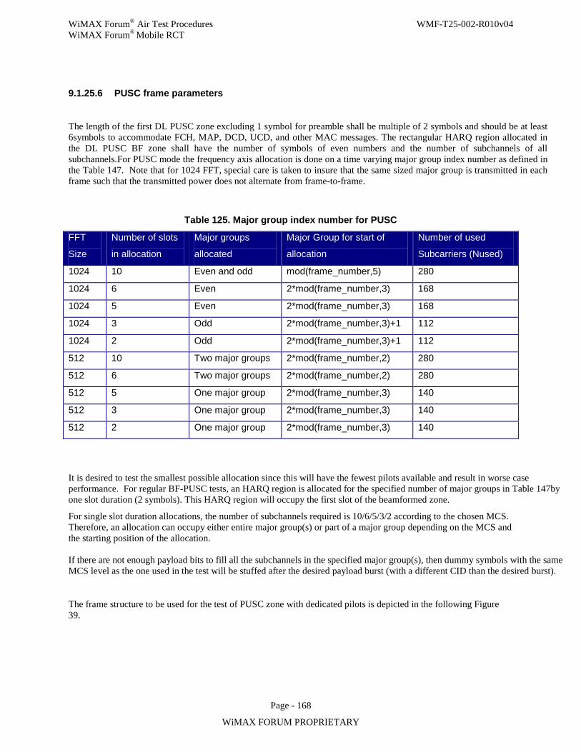
WiMAX Forum® Air Test Procedures WMF-T25-002-R010v04 WiMAX Forum® Mobile RCT
Page - 168
WiMAX FORUM PROPRIETARY
9.1.25.6 PUSC frame parameters
The length of the first DL PUSC zone excluding 1 symbol for preamble shall be multiple of 2 symbols and should be at least 6symbols to accommodate FCH, MAP, DCD, UCD, and other MAC messages. The rectangular HARQ region allocated in the DL PUSC BF zone shall have the number of symbols of even numbers and the number of subchannels of all subchannels.For PUSC mode the frequency axis allocation is done on a time varying major group index number as defined in the Table 147. Note that for 1024 FFT, special care is taken to insure that the same sized major group is transmitted in each frame such that the transmitted power does not alternate from frame-to-frame.
Table 125. Major group index number for PUSC
FFT
Size
Number of slots
in allocation
Major groups
allocated
Major Group for start of
allocation
Number of used
Subcarriers (Nused)
1024 10 Even and odd mod(frame_number,5) 280
1024 6 Even 2*mod(frame_number,3) 168
1024 5 Even 2*mod(frame_number,3) 168
1024 3 Odd 2*mod(frame_number,3)+1 112
1024 2 Odd 2*mod(frame_number,3)+1 112
512 10 Two major groups 2*mod(frame_number,2) 280
512 6 Two major groups 2*mod(frame_number,2) 280
512 5 One major group 2*mod(frame_number,3) 140
512 3 One major group 2*mod(frame_number,3) 140
512 2 One major group 2*mod(frame_number,3) 140
It is desired to test the smallest possible allocation since this will have the fewest pilots available and result in worse case performance. For regular BF-PUSC tests, an HARQ region is allocated for the specified number of major groups in Table 147by one slot duration (2 symbols). This HARQ region will occupy the first slot of the beamformed zone.
For single slot duration allocations, the number of subchannels required is 10/6/5/3/2 according to the chosen MCS. Therefore, an allocation can occupy either entire major group(s) or part of a major group depending on the MCS and the starting position of the allocation. If there are not enough payload bits to fill all the subchannels in the specified major group(s), then dummy symbols with the same MCS level as the one used in the test will be stuffed after the desired payload burst (with a different CID than the desired burst).
The frame structure to be used for the test of PUSC zone with dedicated pilots is depicted in the following Figure 39.
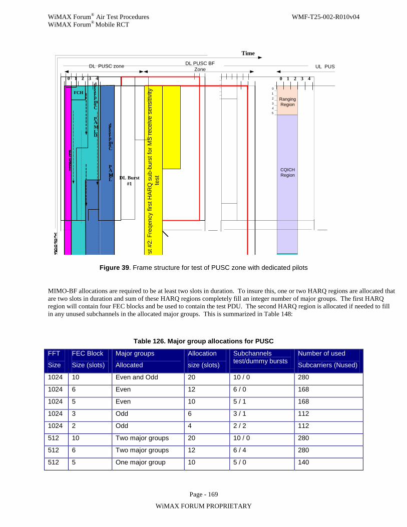
WiMAX Forum® Air Test Procedures WMF-T25-002-R010v04 WiMAX Forum® Mobile RCT
Page - 169
WiMAX FORUM PROPRIETARY
Preamble
Frequency
Compressed
DL MAP
Time
0 1 2 3
012
3Ranging Region
ACK Region
CQICHRegion
DL PUSC zone
TTG
4 0 1 2 3 4
45
Compressed
UL MAP
FCH
DL PUSC BF Zone UL PUSC zone
DL Burst #1
DL
Burs
t #2:
Fre
qenc
y fir
st H
ARQ
sub
-bur
st fo
r MS
rece
ive
sens
itivi
ty
test
Figure 39. Frame structure for test of PUSC zone with dedicated pilots
MIMO-BF allocations are required to be at least two slots in duration. To insure this, one or two HARQ regions are allocated that are two slots in duration and sum of these HARQ regions completely fill an integer number of major groups. The first HARQ region will contain four FEC blocks and be used to contain the test PDU. The second HARQ region is allocated if needed to fill in any unused subchannels in the allocated major groups. This is summarized in Table 148:
Table 126. Major group allocations for PUSC
FFT
Size
FEC Block
Size (slots)
Major groups
Allocated
Allocation
size (slots)
Subchannels test/dummy bursts
Number of used
Subcarriers (Nused)
1024 10 Even and Odd 20 10 / 0 280
1024 6 Even 12 6 / 0 168
1024 5 Even 10 5 / 1 168
1024 3 Odd 6 3 / 1 112
1024 2 Odd 4 2 / 2 112
512 10 Two major groups 20 10 / 0 280
512 6 Two major groups 12 6 / 4 280
512 5 One major group 10 5 / 0 140
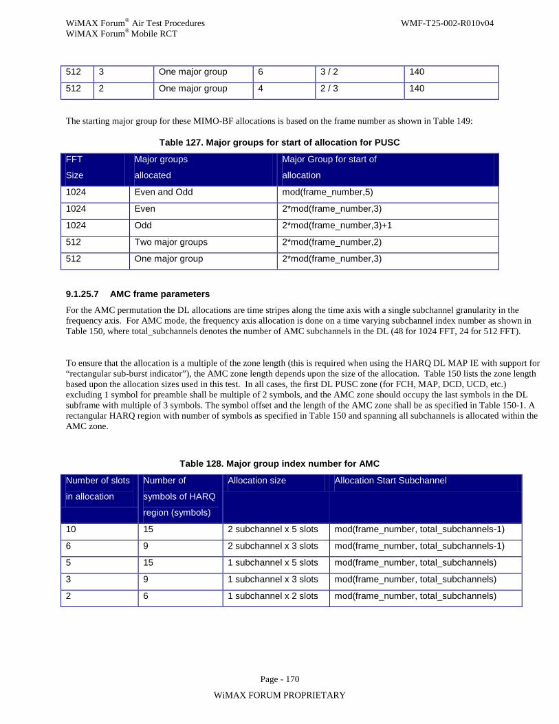
WiMAX Forum® Air Test Procedures WMF-T25-002-R010v04 WiMAX Forum® Mobile RCT
Page - 170
WiMAX FORUM PROPRIETARY
512 3 One major group 6 3 / 2 140
512 2 One major group 4 2 / 3 140
The starting major group for these MIMO-BF allocations is based on the frame number as shown in Table 149:
Table 127. Major groups for start of allocation for PUSC
FFT
Size
Major groups
allocated
Major Group for start of
allocation
1024 Even and Odd mod(frame_number,5)
1024 Even 2*mod(frame_number,3)
1024 Odd 2*mod(frame_number,3)+1
512 Two major groups 2*mod(frame_number,2)
512 One major group 2*mod(frame_number,3)
9.1.25.7 AMC frame parameters
For the AMC permutation the DL allocations are time stripes along the time axis with a single subchannel granularity in the frequency axis. For AMC mode, the frequency axis allocation is done on a time varying subchannel index number as shown in Table 150, where total_subchannels denotes the number of AMC subchannels in the DL (48 for 1024 FFT, 24 for 512 FFT).
To ensure that the allocation is a multiple of the zone length (this is required when using the HARQ DL MAP IE with support for “rectangular sub-burst indicator”), the AMC zone length depends upon the size of the allocation. Table 150 lists the zone length based upon the allocation sizes used in this test. In all cases, the first DL PUSC zone (for FCH, MAP, DCD, UCD, etc.) excluding 1 symbol for preamble shall be multiple of 2 symbols, and the AMC zone should occupy the last symbols in the DL subframe with multiple of 3 symbols. The symbol offset and the length of the AMC zone shall be as specified in Table 150-1. A rectangular HARQ region with number of symbols as specified in Table 150 and spanning all subchannels is allocated within the AMC zone.
Table 128. Major group index number for AMC
Number of slots
in allocation
Number of
symbols of HARQ
region (symbols)
Allocation size Allocation Start Subchannel
10 15 2 subchannel x 5 slots mod(frame_number, total_subchannels-1)
6 9 2 subchannel x 3 slots mod(frame_number, total_subchannels-1)
5 15 1 subchannel x 5 slots mod(frame_number, total_subchannels)
3 9 1 subchannel x 3 slots mod(frame_number, total_subchannels)
2 6 1 subchannel x 2 slots mod(frame_number, total_subchannels)
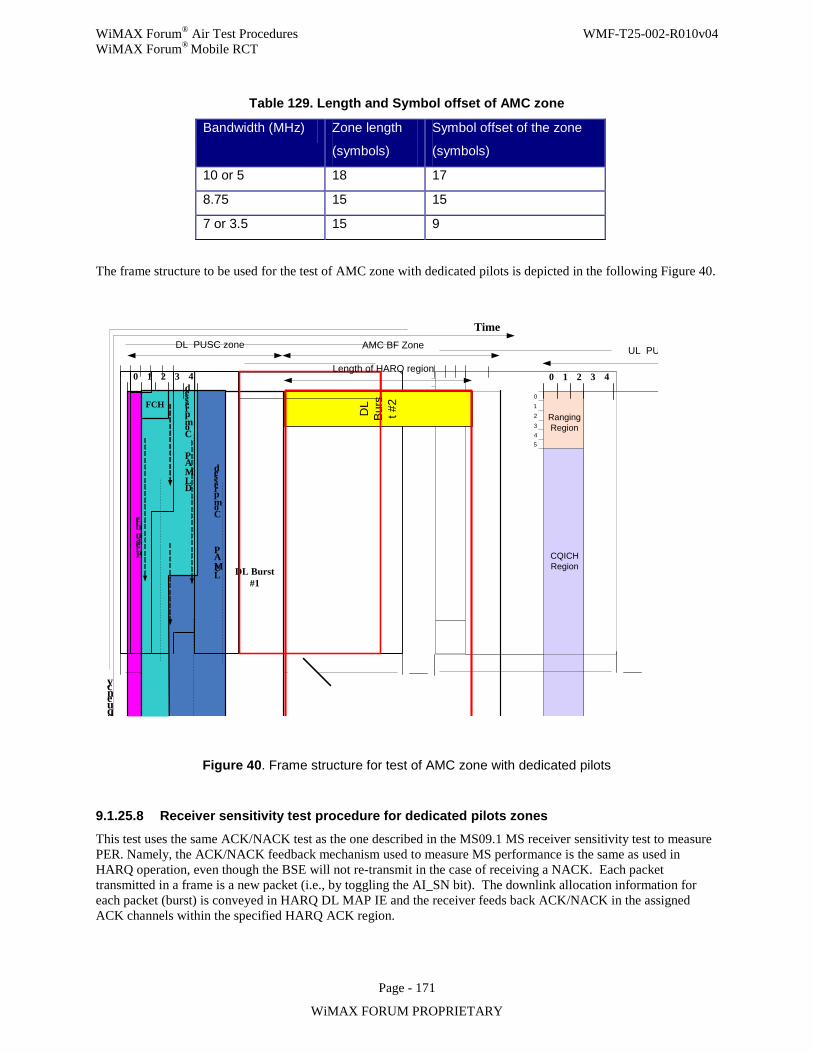
WiMAX Forum® Air Test Procedures WMF-T25-002-R010v04 WiMAX Forum® Mobile RCT
Page - 171
WiMAX FORUM PROPRIETARY
Table 129. Length and Symbol offset of AMC zone
Bandwidth (MHz) Zone length
(symbols)
Symbol offset of the zone
(symbols)
10 or 5 18 17
8.75 15 15
7 or 3.5 15 9
The frame structure to be used for the test of AMC zone with dedicated pilots is depicted in the following Figure 40.
Preamble
Frequency
Compressed
DL MAP
Time
0 1 2 3
012
3Ranging Region
ACK Region
CQICHRegion
DL PUSC zone
4 0 1 2 3 4
45
Compressed
UL MAP
FCH
AMC BF Zone UL PUSC zone
DL Burst #1
DL
Bur
st #
2
Length of HARQ region
Figure 40. Frame structure for test of AMC zone with dedicated pilots
9.1.25.8 Receiver sensitivity test procedure for dedicated pilots zones This test uses the same ACK/NACK test as the one described in the MS09.1 MS receiver sensitivity test to measure PER. Namely, the ACK/NACK feedback mechanism used to measure MS performance is the same as used in HARQ operation, even though the BSE will not re-transmit in the case of receiving a NACK. Each packet transmitted in a frame is a new packet (i.e., by toggling the AI_SN bit). The downlink allocation information for each packet (burst) is conveyed in HARQ DL MAP IE and the receiver feeds back ACK/NACK in the assigned ACK channels within the specified HARQ ACK region.
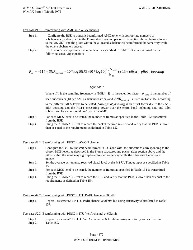
WiMAX Forum® Air Test Procedures WMF-T25-002-R010v04 WiMAX Forum® Mobile RCT
Page - 172
WiMAX FORUM PROPRIETARY
Test case #1.1: Beamforming with AMC in AWGN channel
Step 1. Configure the BSE to transmit beamformed AMC zone with appropriate numbers of subchannels (as described in the Frame structures and packet sizes section above) being allocated to the MS UUT and the pilots within the allocated subchannels beamformed the same way while the other subchannels unused.
Step 2. Set the receiver’s per-antenna input level as specified in Table 153 which is based on the following sensitivity equation:
boostingpilotoffsetNNF
RSNRRfft
usedsrequiredss __13)(10log*10)(10log*10114 +++−+−=
Equation 1
Where sF is the sampling frequency in [MHz], R is the repetition factor, usedN is the number of
used subcarriers (18 per AMC subchannel stripe) and requiredSNR is listed in Table 152 according to the different MCS levels to be tested. Offset_pilot_boosting is an offset factor due to the 2.5dB pilot boosting and the RCTT measuring power over the entire band including data and pilot subcarriers. Its value should be 0.36dB for AMC.
Step 3. For each MCS level to be tested, the number of frames as specified in the Table 152 transmitted from the BSE.
Step 4. Using the ACK/NACK test to record the packet received in error and verify that the PER is lower than or equal to the requirements as defined in Table 152.
Test case #2.1: Beamforming with PUSC in AWGN channel
Step 1. Configure the BSE to transmit beamformed PUSC zone with the allocations corresponding to the chosen MCS levels as described in the Frame structures and packet sizes section above and the pilots within the same major group beamformed same way while the other subchannels are unused.
Step 2. Set the average per-antenna received signal level at the MS UUT input input as specified in Table 155.
Step 3. For each MCS level to be tested, the number of frames as specified in Table 154 is transmitted from the BSE.
Step 4. Using the ACK/NACK test to record the PER and verify that the PER is lower than or equal to the requirements as defined in Table 154.
Test case #2.2: Beamforming with PUSC in ITU PedB channel at 3km/h
Step 1. Repeat Test case #2.1 in ITU PedB channel at 3km/h but using sensitivity values listed inTable 157.
Test case #2.3: Beamforming with PUSC in ITU VehA channel at 60km/h
Step 1. Repeat Test case #2.1 in ITU VehA channel at 60km/h but using sensitivity values listed in Step 2. Table 159.
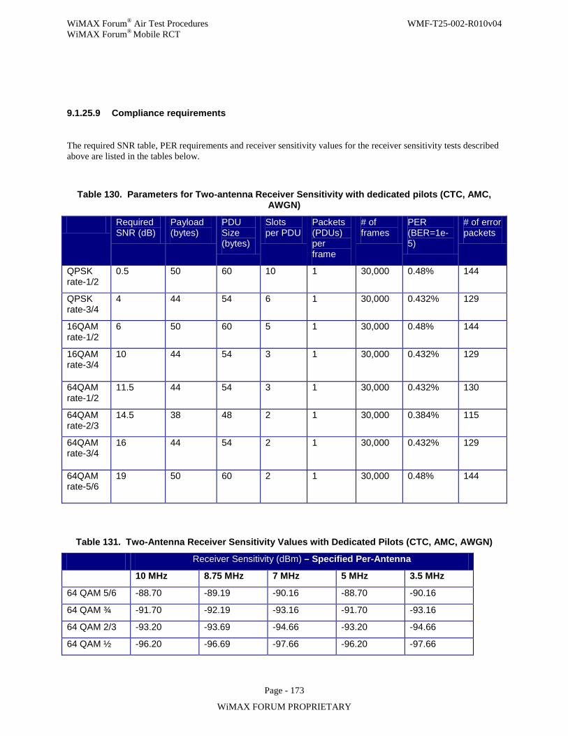
WiMAX Forum® Air Test Procedures WMF-T25-002-R010v04 WiMAX Forum® Mobile RCT
Page - 173
WiMAX FORUM PROPRIETARY
9.1.25.9 Compliance requirements
The required SNR table, PER requirements and receiver sensitivity values for the receiver sensitivity tests described above are listed in the tables below.
Table 130. Parameters for Two-antenna Receiver Sensitivity with dedicated pilots (CTC, AMC, AWGN)
Required SNR (dB)
Payload (bytes)
PDU Size (bytes)
Slots per PDU
Packets (PDUs) per frame
# of frames
PER (BER=1e-5)
# of error packets
QPSK rate-1/2
0.5 50 60 10 1 30,000 0.48% 144
QPSK rate-3/4
4 44 54 6 1 30,000 0.432% 129
16QAM rate-1/2
6 50 60 5 1 30,000 0.48% 144
16QAM rate-3/4
10
44 54 3 1 30,000 0.432% 129
64QAM rate-1/2
11.5 44 54 3 1 30,000 0.432% 130
64QAM rate-2/3
14.5 38 48 2 1 30,000 0.384% 115
64QAM rate-3/4
16
44 54 2 1 30,000 0.432% 129
64QAM rate-5/6
19
50 60 2 1 30,000 0.48% 144
Table 131. Two-Antenna Receiver Sensitivity Values with Dedicated Pilots (CTC, AMC, AWGN)
Receiver Sensitivity (dBm) – Specified Per-Antenna
10 MHz 8.75 MHz 7 MHz 5 MHz 3.5 MHz
64 QAM 5/6 -88.70 -89.19 -90.16 -88.70 -90.16
64 QAM ¾ -91.70 -92.19 -93.16 -91.70 -93.16
64 QAM 2/3 -93.20 -93.69 -94.66 -93.20 -94.66
64 QAM ½ -96.20 -96.69 -97.66 -96.20 -97.66
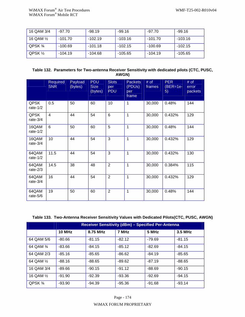
WiMAX Forum® Air Test Procedures WMF-T25-002-R010v04 WiMAX Forum® Mobile RCT
Page - 174
WiMAX FORUM PROPRIETARY
16 QAM 3/4 -97.70 -98.19 -99.16 -97.70 -99.16
16 QAM ½ -101.70 -102.19 -103.16 -101.70 -103.16
QPSK ¾ -100.69 -101.18 -102.15 -100.69 -102.15
QPSK ½ -104.19 -104.68 -105.65 -104.19 -105.65
Table 132. Parameters for Two-antenna Receiver Sensitivity with dedicated pilots (CTC, PUSC, AWGN)
Required SNR
Payload (bytes)
PDU Size (bytes)
Slots per PDU
Packets (PDUs) per frame
# of frames
PER (BER=1e-5)
# of error packets
QPSK rate-1/2
0.5 50 60 10 1 30,000 0.48% 144
QPSK rate-3/4
4 44 54 6 1 30,000 0.432% 129
16QAM rate-1/2
6 50 60 5 1 30,000 0.48% 144
16QAM rate-3/4
10
44 54 3 1 30,000 0.432% 129
64QAM rate-1/2
11.5 44 54 3 1 30,000 0.432% 130
64QAM rate-2/3
14.5 38 48 2 1 30,000 0.384% 115
64QAM rate-3/4
16
44 54 2 1 30,000 0.432% 129
64QAM rate-5/6
19 50 60 2 1 30,000 0.48% 144
Table 133. Two-Antenna Receiver Sensitivity Values with Dedicated Pilots(CTC, PUSC, AWGN)
Receiver Sensitivity (dBm) – Specified Per-Antenna
10 MHz 8.75 MHz 7 MHz 5 MHz 3.5 MHz
64 QAM 5/6 -80.66 -81.15 -82.12 -79.69 -81.15
64 QAM ¾ -83.66 -84.15 -85.12 -82.69 -84.15
64 QAM 2/3 -85.16 -85.65 -86.62 -84.19 -85.65
64 QAM ½ -88.16 -88.65 -89.62 -87.19 -88.65
16 QAM 3/4 -89.66 -90.15 -91.12 -88.69 -90.15
16 QAM ½ -91.90 -92.39 -93.36 -92.69 -94.15
QPSK ¾ -93.90 -94.39 -95.36 -91.68 -93.14

WiMAX Forum® Air Test Procedures WMF-T25-002-R010v04 WiMAX Forum® Mobile RCT
Page - 175
WiMAX FORUM PROPRIETARY
QPSK ½ -95.18 -95.67 -96.64 -95.18 -96.64
Note that the 512 FFT sensitivity numbers may be different than the corresponding 1024 FFT values due to a different number of used subcarriers.
Table 134. Parameters for Two-antenna Receiver Sensitivity with dedicated pilots (CTC, PUSC, Ped-B@3Km/h)
Required SNR
Payload (bytes)
PDU Size (bytes)
Slots per PDU
Packets per frame
# of frames
PER target
# of error packets
QPSK rate-1/2
2.5 50 60 10 1 10,000 10% 1000
QPSK rate-3/4
6 44 54 6 1 10,000 10% 1000
16QAM rate-1/2
7.5 50 60 5 1 10,000 10% 1000
16QAM rate-3/4
12 44 54 3 1 10,000 10% 1000
64QAM rate-1/2
12.5 44 54 3 1 10,000 10% 1000
64QAM rate-2/3
16 38 48 2 1 10,000 10% 1000
64QAM rate-3/4
17.5 44 54 2 1 10,000 10% 1000
64QAM rate-5/6
20 50 60 2 1 10,000 10% 1000
Table 135. Two-Antenna Receiver Sensitivity Values with Dedicated Pilots
(CTC, PUSC, Ped-B@3Km/h)
Receiver Sensitivity (dBm) – Specified Per-Antenna
10 MHz 8.75 MHz 7 MHz 5 MHz 3.5 MHz
64 QAM 5/6 -79.66 -80.15 -81.12 -78.69 -80.15
64 QAM ¾ -82.16 -82.65 -83.62 -81.19 -82.65
64 QAM 2/3 -83.66 -84.15 -85.12 -82.69 -84.15
64 QAM ½ -87.16 -87.65 -88.62 -86.19 -87.65
16 QAM 3/4 -87.66 -88.15 -89.12 -86.69 -88.15
16 QAM ½ -90.40 -90.89 -91.86 -91.19 -92.65
QPSK ¾ -91.90 -92.39 -93.36 -89.68 -91.14
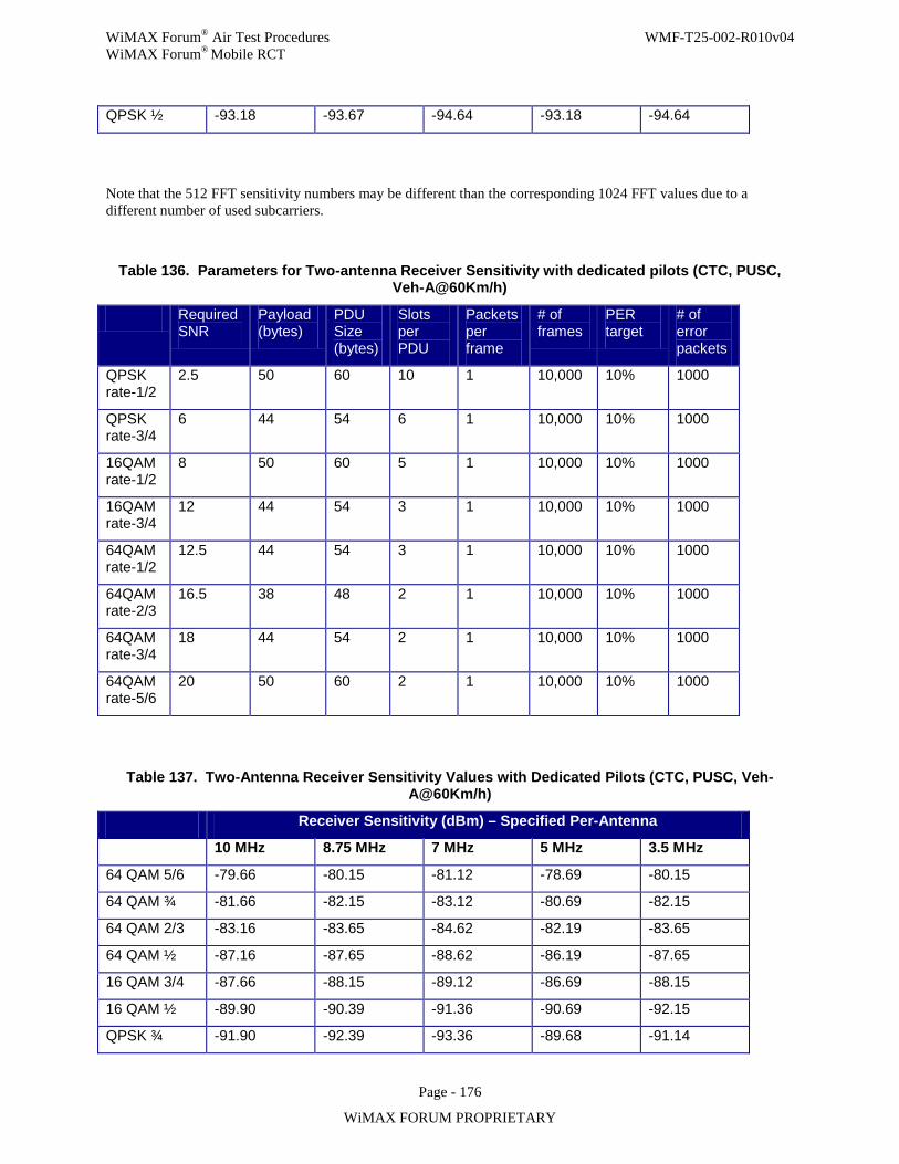
WiMAX Forum® Air Test Procedures WMF-T25-002-R010v04 WiMAX Forum® Mobile RCT
Page - 176
WiMAX FORUM PROPRIETARY
QPSK ½ -93.18 -93.67 -94.64 -93.18 -94.64
Note that the 512 FFT sensitivity numbers may be different than the corresponding 1024 FFT values due to a different number of used subcarriers.
Table 136. Parameters for Two-antenna Receiver Sensitivity with dedicated pilots (CTC, PUSC, Veh-A@60Km/h)
Required SNR
Payload (bytes)
PDU Size (bytes)
Slots per PDU
Packets per frame
# of frames
PER target
# of error packets
QPSK rate-1/2
2.5 50 60 10 1 10,000 10% 1000
QPSK rate-3/4
6 44 54 6 1 10,000 10% 1000
16QAM rate-1/2
8 50 60 5 1 10,000 10% 1000
16QAM rate-3/4
12 44 54 3 1 10,000 10% 1000
64QAM rate-1/2
12.5 44 54 3 1 10,000 10% 1000
64QAM rate-2/3
16.5 38 48 2 1 10,000 10% 1000
64QAM rate-3/4
18 44 54 2 1 10,000 10% 1000
64QAM rate-5/6
20 50 60 2 1 10,000 10% 1000
Table 137. Two-Antenna Receiver Sensitivity Values with Dedicated Pilots (CTC, PUSC, Veh-A@60Km/h)
Receiver Sensitivity (dBm) – Specified Per-Antenna
10 MHz 8.75 MHz 7 MHz 5 MHz 3.5 MHz
64 QAM 5/6 -79.66 -80.15 -81.12 -78.69 -80.15
64 QAM ¾ -81.66 -82.15 -83.12 -80.69 -82.15
64 QAM 2/3 -83.16 -83.65 -84.62 -82.19 -83.65
64 QAM ½ -87.16 -87.65 -88.62 -86.19 -87.65
16 QAM 3/4 -87.66 -88.15 -89.12 -86.69 -88.15
16 QAM ½ -89.90 -90.39 -91.36 -90.69 -92.15
QPSK ¾ -91.90 -92.39 -93.36 -89.68 -91.14
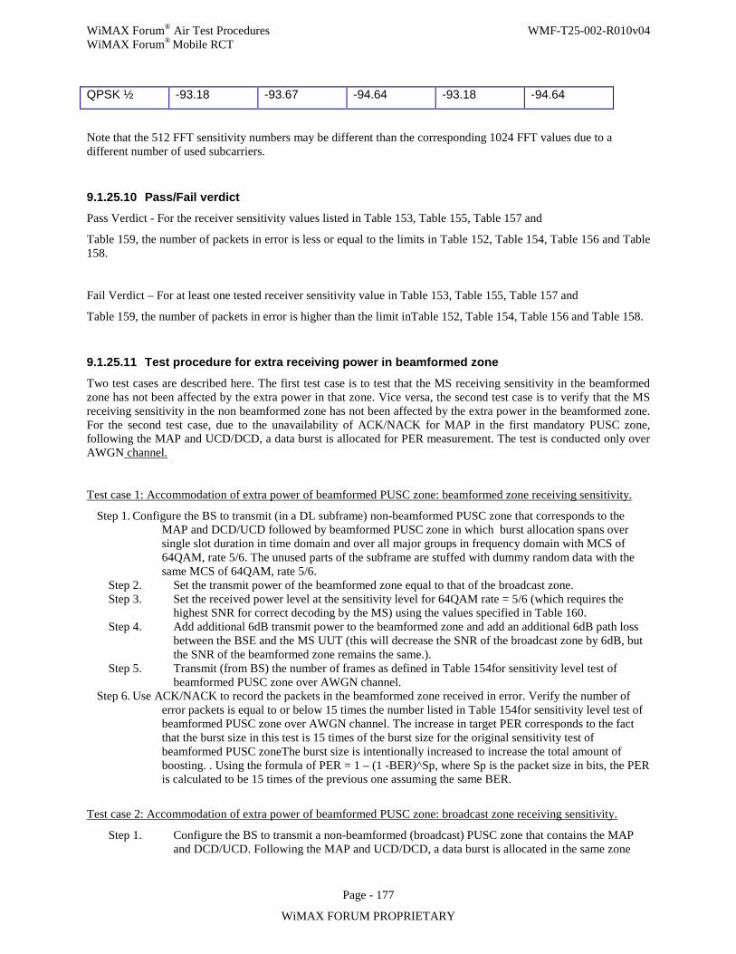
WiMAX Forum® Air Test Procedures WMF-T25-002-R010v04 WiMAX Forum® Mobile RCT
Page - 177
WiMAX FORUM PROPRIETARY
QPSK ½ -93.18 -93.67 -94.64 -93.18 -94.64
Note that the 512 FFT sensitivity numbers may be different than the corresponding 1024 FFT values due to a different number of used subcarriers.
9.1.25.10 Pass/Fail verdict Pass Verdict - For the receiver sensitivity values listed in Table 153, Table 155, Table 157 and
Table 159, the number of packets in error is less or equal to the limits in Table 152, Table 154, Table 156 and Table 158.
Fail Verdict – For at least one tested receiver sensitivity value in Table 153, Table 155, Table 157 and
Table 159, the number of packets in error is higher than the limit inTable 152, Table 154, Table 156 and Table 158.
9.1.25.11 Test procedure for extra receiving power in beamformed zone
Two test cases are described here. The first test case is to test that the MS receiving sensitivity in the beamformed zone has not been affected by the extra power in that zone. Vice versa, the second test case is to verify that the MS receiving sensitivity in the non beamformed zone has not been affected by the extra power in the beamformed zone. For the second test case, due to the unavailability of ACK/NACK for MAP in the first mandatory PUSC zone, following the MAP and UCD/DCD, a data burst is allocated for PER measurement. The test is conducted only over AWGN channel.
Test case 1: Accommodation of extra power of beamformed PUSC zone: beamformed zone receiving sensitivity.
Step 1. Configure the BS to transmit (in a DL subframe) non-beamformed PUSC zone that corresponds to the MAP and DCD/UCD followed by beamformed PUSC zone in which burst allocation spans over single slot duration in time domain and over all major groups in frequency domain with MCS of 64QAM, rate 5/6. The unused parts of the subframe are stuffed with dummy random data with the same MCS of 64QAM, rate 5/6.
Step 2. Set the transmit power of the beamformed zone equal to that of the broadcast zone. Step 3. Set the received power level at the sensitivity level for 64QAM rate = 5/6 (which requires the
highest SNR for correct decoding by the MS) using the values specified in Table 160. Step 4. Add additional 6dB transmit power to the beamformed zone and add an additional 6dB path loss
between the BSE and the MS UUT (this will decrease the SNR of the broadcast zone by 6dB, but the SNR of the beamformed zone remains the same.).
Step 5. Transmit (from BS) the number of frames as defined in Table 154for sensitivity level test of beamformed PUSC zone over AWGN channel.
Step 6. Use ACK/NACK to record the packets in the beamformed zone received in error. Verify the number of error packets is equal to or below 15 times the number listed in Table 154for sensitivity level test of beamformed PUSC zone over AWGN channel. The increase in target PER corresponds to the fact that the burst size in this test is 15 times of the burst size for the original sensitivity test of beamformed PUSC zoneThe burst size is intentionally increased to increase the total amount of boosting. . Using the formula of PER = 1 – (1 -BER)^Sp, where Sp is the packet size in bits, the PER is calculated to be 15 times of the previous one assuming the same BER.
Test case 2: Accommodation of extra power of beamformed PUSC zone: broadcast zone receiving sensitivity.
Step 1. Configure the BS to transmit a non-beamformed (broadcast) PUSC zone that contains the MAP and DCD/UCD. Following the MAP and UCD/DCD, a data burst is allocated in the same zone
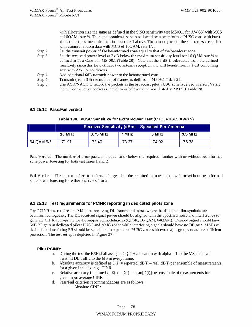
WiMAX Forum® Air Test Procedures WMF-T25-002-R010v04 WiMAX Forum® Mobile RCT
Page - 178
WiMAX FORUM PROPRIETARY
with allocation size the same as defined in the SISO sensitivity test MS09.1 for AWGN with MCS of 16QAM, rate ½. Then, the broadcast zone is followed by a beamformed PUSC zone with burst allocations the same as defined in Test case 1 above. The unused parts of the subframes are stuffed with dummy random data with MCS of 16QAM, rate 1/2.
Step 2. Set the transmit power of the beamformed zone equal to that of the broadcast zone. Step 3. Set the received power level at 3 dB below the maximum sensitivity level for 16 QAM rate ½ as
defined in Test Case 1 in MS-09.1 (Table 28). Note that the 3 dB is subtracted from the defined sensitivity since this tests utilizes two antenna reception and will benefit from a 3 dB combining gain with AWGN conditions.
Step 4. Add additional 6dB transmit power to the beamformed zone. Step 5. Transmit (from BS) the number of frames as defined in MS09.1 Table 28. Step 6. Use ACK/NACK to record the packets in the broadcast pilot PUSC zone received in error. Verify
the number of error packets is equal to or below the number listed in MS09.1 Table 28.
9.1.25.12 Pass/Fail verdict
Table 138. PUSC Sensitivy for Extra Power Test (CTC, PUSC, AWGN)
Receiver Sensitivity (dBm) – Specified Per-Antenna
10 MHz 8.75 MHz 7 MHz 5 MHz 3.5 MHz
64 QAM 5/6 -71.91 -72.40 -73.37 -74.92 -76.38
Pass Verdict – The number of error packets is equal to or below the required number with or without beamformed zone power boosting for both test cases 1 and 2.
Fail Verdict – The number of error packets is larger than the required number either with or without beamformed zone power boosting for either test cases 1 or 2.
9.1.25.13 Test requirements for PCINR reporting in dedicated pilots zone
The PCINR test requires the MS to be receiving DL frames and bursts where the data and pilot symbols are beamformed together. The DL received signal power should be aligned with the specified noise and interference to generate CINR appropriate for the supported modulations (QPSK, 16-QAM, 64QAM). Desired signal should have 6dB BF gain in dedicated pilots PUSC and AMC zones while interfering signals should have no BF gain. MAPs of desired and interfering BS should be scheduled in segmented PUSC zone with two major groups to assure sufficient protection. The test set up is depicted in Figure 37.
Pilot PCINR: a. During the test the BSE shall assign a CQICH allocation with alpha = 1 to the MS and shall
transmit DL traffic to the MS in every frame. b. Absolute accuracy is defined as D(i) = reported_dB(i) – real_dB(i) per ensemble of measurements
for a given input average CINR c. Relative accuracy is defined as E(i) = D(i) – mean[D(i)] per ensemble of measurements for a
given input average CINR d. Pass/Fail criterion recommendations are as follows:
i. Absolute CINR:
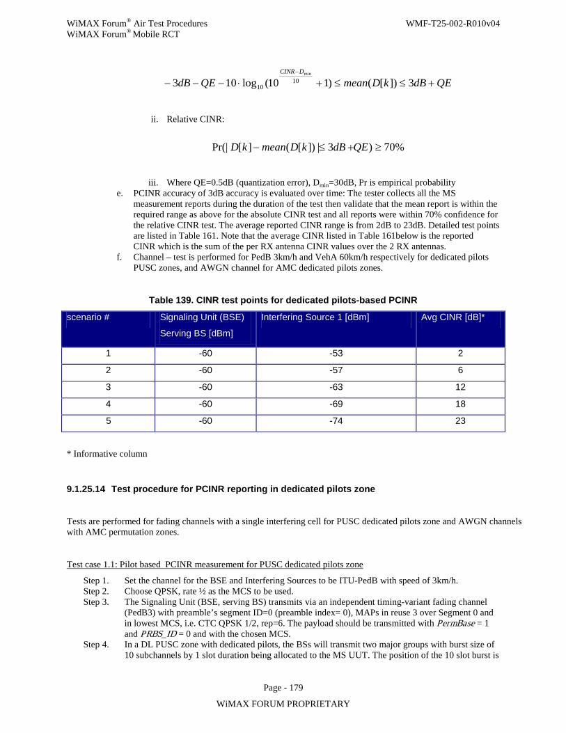
WiMAX Forum® Air Test Procedures WMF-T25-002-R010v04 WiMAX Forum® Mobile RCT
Page - 179
WiMAX FORUM PROPRIETARY
QEdBkDmeanQEdBDCINR
+≤≤+⋅−−−−
3])[()110(log103 1010
min
ii. Relative CINR:
%70)3|])[(][Pr(| ≥+≤− QEdBkDmeankD
iii. Where QE=0.5dB (quantization error), Dmin=30dB, Pr is empirical probability e. PCINR accuracy of 3dB accuracy is evaluated over time: The tester collects all the MS
measurement reports during the duration of the test then validate that the mean report is within the required range as above for the absolute CINR test and all reports were within 70% confidence for the relative CINR test. The average reported CINR range is from 2dB to 23dB. Detailed test points are listed in Table 161. Note that the average CINR listed in Table 161below is the reported CINR which is the sum of the per RX antenna CINR values over the 2 RX antennas.
f. Channel – test is performed for PedB 3km/h and VehA 60km/h respectively for dedicated pilots PUSC zones, and AWGN channel for AMC dedicated pilots zones.
Table 139. CINR test points for dedicated pilots-based PCINR
scenario # Signaling Unit (BSE)
Serving BS [dBm]
Interfering Source 1 [dBm] Avg CINR [dB]*
1 -60 -53 2
2 -60 -57 6
3 -60 -63 12
4 -60 -69 18
5 -60 -74 23
* Informative column
9.1.25.14 Test procedure for PCINR reporting in dedicated pilots zone
Tests are performed for fading channels with a single interfering cell for PUSC dedicated pilots zone and AWGN channels with AMC permutation zones.
Test case 1.1: Pilot based PCINR measurement for PUSC dedicated pilots zone
Step 1. Set the channel for the BSE and Interfering Sources to be ITU-PedB with speed of 3km/h. Step 2. Choose QPSK, rate ½ as the MCS to be used. Step 3. The Signaling Unit (BSE, serving BS) transmits via an independent timing-variant fading channel
(PedB3) with preamble’s segment ID=0 (preamble index= 0), MAPs in reuse 3 over Segment 0 and in lowest MCS, i.e. CTC QPSK 1/2, rep=6. The payload should be transmitted with PermBase = 1 and PRBS_ID = 0 and with the chosen MCS.
Step 4. In a DL PUSC zone with dedicated pilots, the BSs will transmit two major groups with burst size of 10 subchannels by 1 slot duration being allocated to the MS UUT. The position of the 10 slot burst is
WiMAX Forum® Air Test Procedures WMF-T25-002-R010v04 WiMAX Forum® Mobile RCT
Page - 180
WiMAX FORUM PROPRIETARY
randomized across frames according to the procedure specified in 9.1.25.6 on PUSC frame parameters. The rest of the subchannels are unoccupied.
Step 5. Interfering Source 1 (interfering BS) transmits via an independent timing-variant fading channel with (PedB3) preamble’s segment ID=1 (preamble index= 33, same frame structure as BSE), MAPs in reuse 3 over Segment 1 and in lowest MCS, i.e. CTC QPSK 1/2, rep=6. The payload of the interfering source will have the same PermBase as the serving BS (PermBase = 1), but different PRBS_ID (PRBS_ID = 1) and with the same MCS as the desired signal. The interferer allocation will be identical to that of the BSE such that the desired signal subcarriers will be fully hit by the interference signal subcarriers.
Step 6. The Interfering source shall be synchronized in time and carrier frequency with Signaling Unit (BSE).
Step 7. Set the average powers at the MS antenna input according to the first test point listed in Table 161. Note: the power of each source can be measured at the combiner input and the combiner loss can be compensated, and there is no requirement on the accuracy of such compensation, as long as the ratio between the signals is maintained as in Table 161.
Step 8. Turn on the MS UUT and let it settle for a few seconds.Configure the MS UUT to use no averaging (i.e., alpha=1) and CQI feedback per frame
Step 9. The Signaling Unit (BSE) receiver (connected to the UUT transmit antenna) should receive the CQI reports and report to the test utility synchronized to frame numbers. The BSE receiver should also be able to detect a case that the MS failed to transmit CQI in a certain frame (e.g. by power measurement on the CQI) and mark the report as invalid.
Step 10. For each scenario specified in Table 161set the power levels according to the Table 161. After setting the power levels, let the UUT settle for few seconds such that all the gain control loops converged.
Step 11. For the purpose of measuring PCINR, the following steps are performed. Request via CQI_alloc_IE dedicated pilots PCINR measurement. Request per-frame update.Additionally, set zone_type = 0b10, Zone_permutation = 0b001 and major group indication = 0. This test is performed on two major groups and all PCINR computations are done based on these major group allocated clusters alone.
• Record the quantized CINR feedback for each frame • Record also the per-frame instantaneous fading channel gain for the all BSE and interferer, in
order to compute the instantaneous CINR. The true CINR (which is actually the true C/I) is calculated from per antenna values and for each antenna is the sum of the instantaneous receive power of the pilot symbols transmitted by the serving BS, divided by:
: The sum of the instantaneous recieve power of the pilot symbols transmitted by the interfering source. The two values calculated per antenna are summed to provide the true CINR value.
• Continue the test until at least 1000 measurements are collected (~5 seconds) • Assuming 1 frame CQI feedback delay, compare the CINR feedback received at frame-n relative
to the true instantaneous CINR at frame-n-1 according to the procedure specified below: 1. Collect all measurements for which the CQI channel is correctly decoded (i.e.
reported_CINR_dB(i+reportDelay) was reported and received by the BS receiver)
2. Clip the true_CINR_dB(k) to -3dB whenever it is lower then -3dB. Clip the true_CINR_dB(k) to 28dB whenever it is higher then 28dB.
3. Calculate: D[k] = reported_CINR_dB(k + reportDelay) – true_CINR_dB(k) 4. Calculate the average of D[k] over ensemble of measurements for a given input
average CINR 5. Check absolute accuracy criterion:
QEdBkDmeanQEdBDCINR
+≤≤+⋅−−−−
3])[()110(log103 1010
min
6. Check relative accuracy criterion:
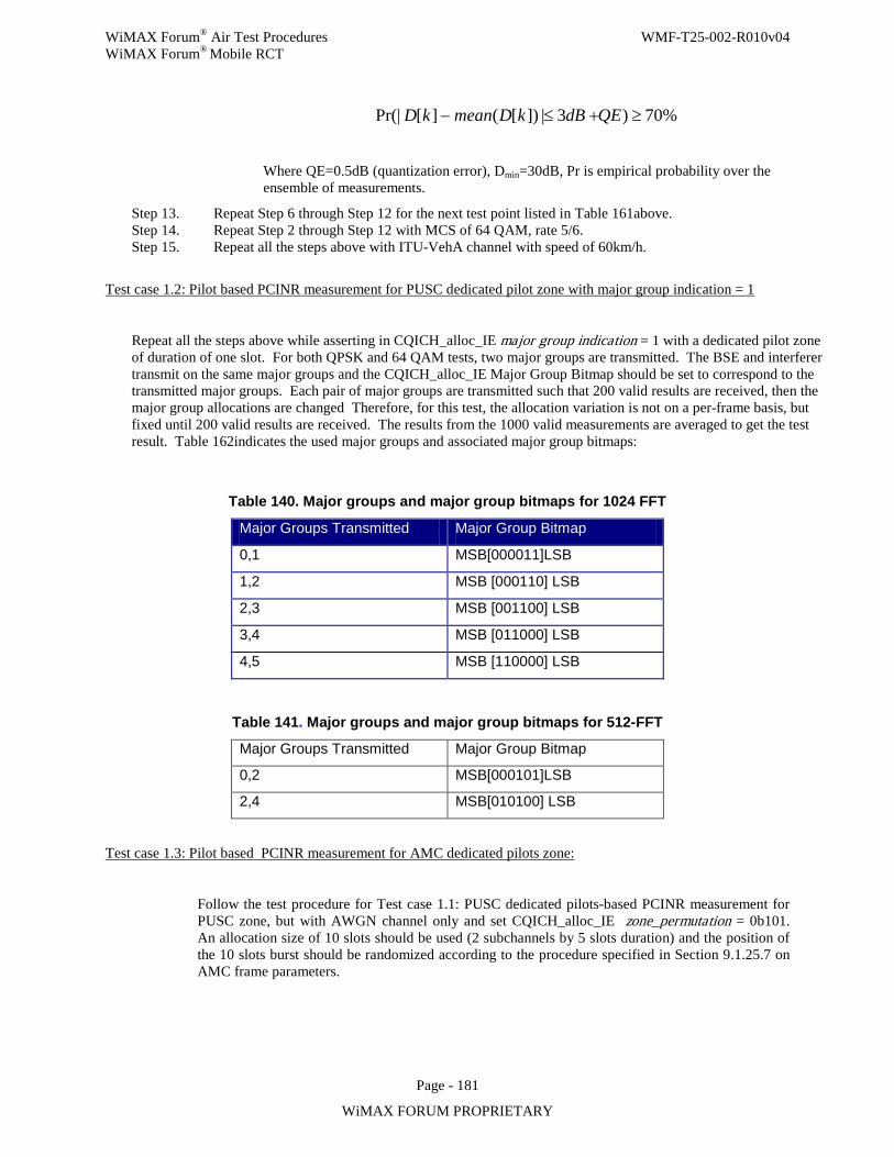
WiMAX Forum® Air Test Procedures WMF-T25-002-R010v04 WiMAX Forum® Mobile RCT
Page - 181
WiMAX FORUM PROPRIETARY
%70)3|])[(][Pr(| ≥+≤− QEdBkDmeankD
Where QE=0.5dB (quantization error), Dmin=30dB, Pr is empirical probability over the ensemble of measurements.
Step 13. Repeat Step 6 through Step 12 for the next test point listed in Table 161above. Step 14. Repeat Step 2 through Step 12 with MCS of 64 QAM, rate 5/6. Step 15. Repeat all the steps above with ITU-VehA channel with speed of 60km/h.
Test case 1.2: Pilot based PCINR measurement for PUSC dedicated pilot zone with major group indication = 1
Repeat all the steps above while asserting in CQICH_alloc_IE major group indication = 1 with a dedicated pilot zone of duration of one slot. For both QPSK and 64 QAM tests, two major groups are transmitted. The BSE and interferer transmit on the same major groups and the CQICH_alloc_IE Major Group Bitmap should be set to correspond to the transmitted major groups. Each pair of major groups are transmitted such that 200 valid results are received, then the major group allocations are changed Therefore, for this test, the allocation variation is not on a per-frame basis, but fixed until 200 valid results are received. The results from the 1000 valid measurements are averaged to get the test result. Table 162indicates the used major groups and associated major group bitmaps:
Table 140. Major groups and major group bitmaps for 1024 FFT
Major Groups Transmitted Major Group Bitmap
0,1 MSB[000011]LSB
1,2 MSB [000110] LSB
2,3 MSB [001100] LSB
3,4 MSB [011000] LSB
4,5 MSB [110000] LSB
Table 141. Major groups and major group bitmaps for 512-FFT
Major Groups Transmitted Major Group Bitmap
0,2 MSB[000101]LSB
2,4 MSB[010100] LSB
Test case 1.3: Pilot based PCINR measurement for AMC dedicated pilots zone:
Follow the test procedure for Test case 1.1: PUSC dedicated pilots-based PCINR measurement for PUSC zone, but with AWGN channel only and set CQICH_alloc_IE zone_permutation = 0b101. An allocation size of 10 slots should be used (2 subchannels by 5 slots duration) and the position of the 10 slots burst should be randomized according to the procedure specified in Section 9.1.25.7 on AMC frame parameters.
WiMAX Forum® Air Test Procedures WMF-T25-002-R010v04 WiMAX Forum® Mobile RCT
Page - 182
WiMAX FORUM PROPRIETARY
9.1.25.15 Pass/Fail verdict
Pass Verdict – For all the test points in Table 161, the ensemble PCINR measurements meet both the absolute and the relative accuracy requirements as defined in the test procedures.
Fail Verdict – For any one of the test points in Table 161, the ensemble PCINR measurements did not meet either the absolute or the relative accuracy requirements as defined in the test procedures.
9.1.25.16 Test requirements for dedicated pilots in STC zone
The set up for this test is depicted in Figure 38. Diagonal 2x2 AWGN channels are used for the test. As specified in the PUSC Frame Structure section, the minimal allocation duration is 4 symbols, which provides the minimal time interval for the MS to estimate (channel) parameters. Since the purpose of this test is to verify the functionality of the MS receiver beamforming processing in STC zone with dedicated pilots, allocations with minimal symbol duration should be used for the test. As this test is not a performance test, the input power levels are set according to the values listed in Table 165, which are 10dB higher than the minimum required SNR derived from the corresponding maximum sensitivity levels.
Since a Diagonal AWGN channel will be used for this test, the first zone including preamble, FCH, DL-MAP, and UL-MAP shall be transmitted from both Tx antennas of the BSE.
9.1.25.17 Test procedure for dedicated pilots in STC zone Test case 1: Receiver operation of dedicated pilot in STC zone with dedicated pilots.
Step 1. Configure the BSE to transmit beamformed STC zone with the appropriate number of subchannels for the test MCS level (e.g., 10 subchannels for QPSK, rate ½) and 4 symbols duration.
Step 2. Set the receiver’s input level according to Table 165for the MCS level and band class being tested. Step 3. Transmit the number of frames for the test MCS level as listed in Table 164. Step 4. Use the ACK/NACK test to record the packet received in error and verify that the PER is lower
than or equal to the requirements as defined in Table 164. Step 5. Repeat above steps for all the MCS levels listed in Table 164.
9.1.25.18 Pass/Fail Verdict
Pass Verdict - For the receiver sensitivity values listed in Table 165, the number of packets in error is less or equal to the limits in Table 164.
Fail Verdict – For at least one tested receiver sensitivity value in Table 165, the number of packets in error is higher than the limit in Table 164.
Table 142. Parameters for MIMO Receiver Functionality with dedicated pilots (CTC, Matrix B, AWGN)
Required PDU Size
Slots per Packets (PDUs)
# of PER # of error
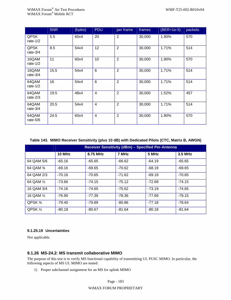
WiMAX Forum® Air Test Procedures WMF-T25-002-R010v04 WiMAX Forum® Mobile RCT
Page - 183
WiMAX FORUM PROPRIETARY
SNR (bytes) PDU per frame frames (BER=1e-5) packets
QPSK rate-1/2
5.5 60x4 20 2 30,000 1.90% 570
QPSK rate-3/4
8.5 54x4 12 2 30,000 1.71% 514
16QAM rate-1/2
11 60x4 10 2 30,000 1.90% 570
16QAM rate-3/4
15.5 54x4 6 2 30,000 1.71% 514
64QAM rate-1/2
16 54x4 6 2 30,000 1.71% 514
64QAM rate-2/3
19.5 48x4 4 2 30,000 1.52% 457
64QAM rate-3/4
20.5 54x4 4 2 30,000 1.71% 514
64QAM rate-5/6
24.5 60x4 4 2 30,000 1.90% 570
Table 143. MIMO Receiver Sensitivity (plus 10 dB) with Dedicated Pilots (CTC, Matrix B, AWGN)
Receiver Sensitivity (dBm) – Specified Per-Antenna
10 MHz 8.75 MHz 7 MHz 5 MHz 3.5 MHz
64 QAM 5/6 -65.16 -65.65 -66.62 -64.19 -65.65
64 QAM ¾ -69.16 -69.65 -70.62 -68.19 -69.65
64 QAM 2/3 -70.16 -70.65 -71.62 -69.19 -70.65
64 QAM ½ -73.66 -74.15 -75.12 -72.69 -74.15
16 QAM 3/4 -74.16 -74.65 -75.62 -73.19 -74.65
16 QAM ½ -76.90 -77.39 -78.36 -77.69 -79.15
QPSK ¾ -79.40 -79.89 -80.86 -77.18 -78.64
QPSK ½ -80.18 -80.67 -81.64 -80.18 -81.64
9.1.25.19 Uncertainties
Not applicable.
9.1.26 MS-24.2: MS transmit collaborative MIMO The purpose of this test is to verify MS functional capability of transmitting UL PUSC MIMO. In particular, the following aspects of MS UL MIMO are tested:
1) Proper subchannel assignment for an MS for uplink MIMO
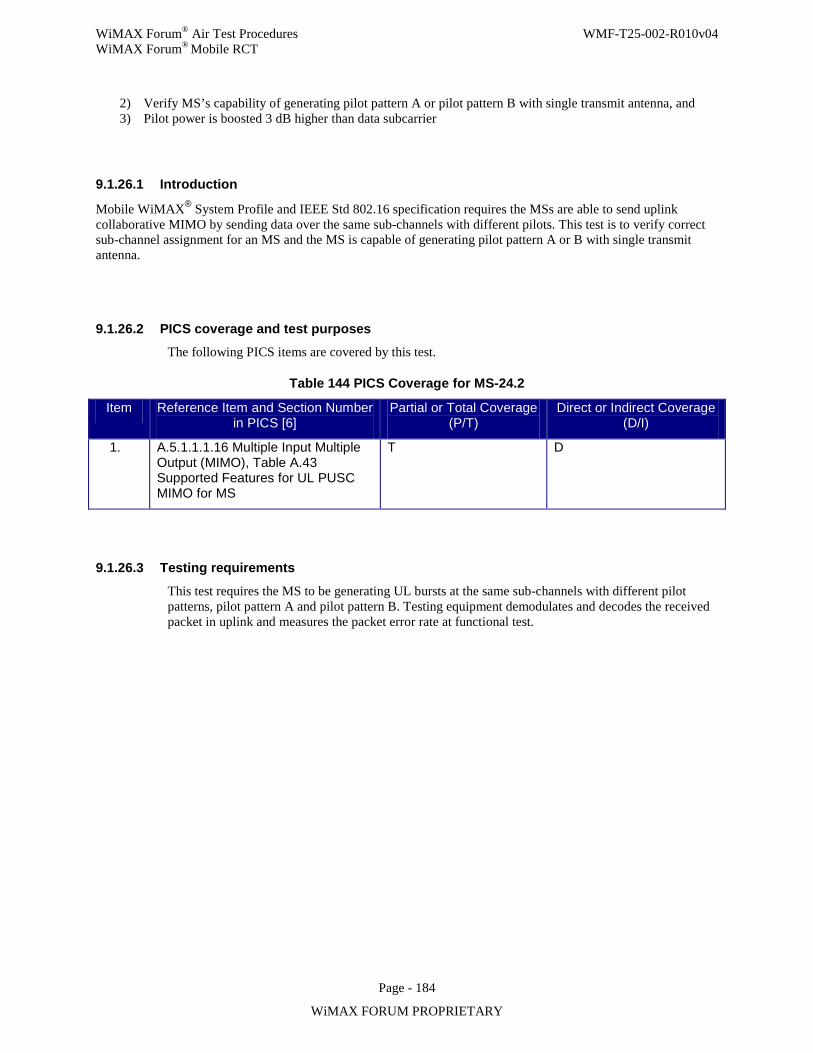
WiMAX Forum® Air Test Procedures WMF-T25-002-R010v04 WiMAX Forum® Mobile RCT
Page - 184
WiMAX FORUM PROPRIETARY
2) Verify MS’s capability of generating pilot pattern A or pilot pattern B with single transmit antenna, and 3) Pilot power is boosted 3 dB higher than data subcarrier
9.1.26.1 Introduction
Mobile WiMAX® System Profile and IEEE Std 802.16 specification requires the MSs are able to send uplink collaborative MIMO by sending data over the same sub-channels with different pilots. This test is to verify correct sub-channel assignment for an MS and the MS is capable of generating pilot pattern A or B with single transmit antenna.
9.1.26.2 PICS coverage and test purposes The following PICS items are covered by this test.
Table 144 PICS Coverage for MS-24.2
Item Reference Item and Section Number in PICS [6]
Partial or Total Coverage (P/T)
Direct or Indirect Coverage (D/I)
1. A.5.1.1.1.16 Multiple Input Multiple Output (MIMO), Table A.43 Supported Features for UL PUSC MIMO for MS
T D
9.1.26.3 Testing requirements
This test requires the MS to be generating UL bursts at the same sub-channels with different pilot patterns, pilot pattern A and pilot pattern B. Testing equipment demodulates and decodes the received packet in uplink and measures the packet error rate at functional test.
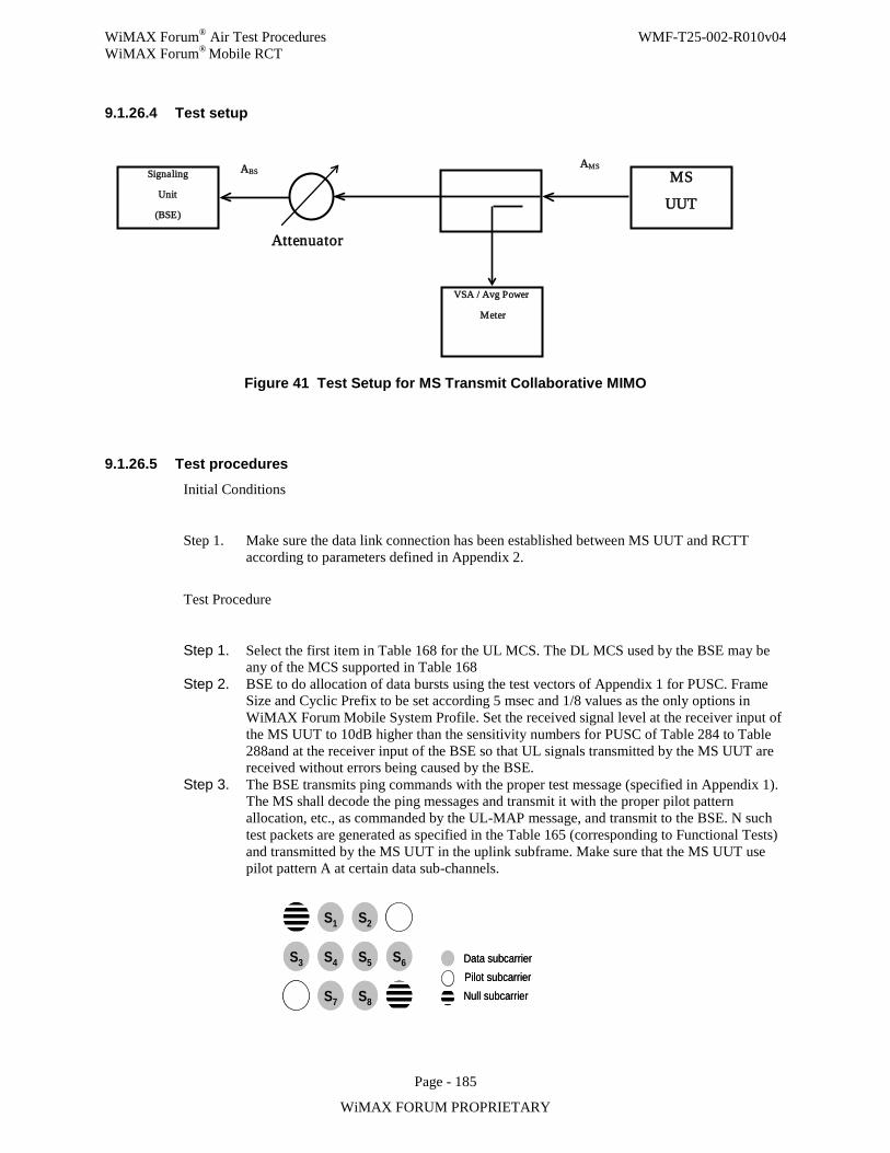
WiMAX Forum® Air Test Procedures WMF-T25-002-R010v04 WiMAX Forum® Mobile RCT
Page - 185
WiMAX FORUM PROPRIETARY
9.1.26.4 Test setup
Figure 41 Test Setup for MS Transmit Collaborative MIMO
9.1.26.5 Test procedures
Initial Conditions
Step 1. Make sure the data link connection has been established between MS UUT and RCTT according to parameters defined in Appendix 2.
Test Procedure
Step 1. Select the first item in Table 168 for the UL MCS. The DL MCS used by the BSE may be any of the MCS supported in Table 168
Step 2. BSE to do allocation of data bursts using the test vectors of Appendix 1 for PUSC. Frame Size and Cyclic Prefix to be set according 5 msec and 1/8 values as the only options in WiMAX Forum Mobile System Profile. Set the received signal level at the receiver input of the MS UUT to 10dB higher than the sensitivity numbers for PUSC of Table 284 to Table 288and at the receiver input of the BSE so that UL signals transmitted by the MS UUT are received without errors being caused by the BSE.
Step 3. The BSE transmits ping commands with the proper test message (specified in Appendix 1). The MS shall decode the ping messages and transmit it with the proper pilot pattern allocation, etc., as commanded by the UL-MAP message, and transmit to the BSE. N such test packets are generated as specified in the Table 165 (corresponding to Functional Tests) and transmitted by the MS UUT in the uplink subframe. Make sure that the MS UUT use pilot pattern A at certain data sub-channels.
S1 S2
S3 S4 S5 S6
S7 S8
Data subcarrierPilot subcarrierNull subcarrier
S1 S2
S3 S4 S5 S6
S7 S8
Data subcarrierPilot subcarrierNull subcarrier
Signaling Unit
(BSE)
VSA / Avg Power Meter
MS
UUT Attenuator
AMS ABS
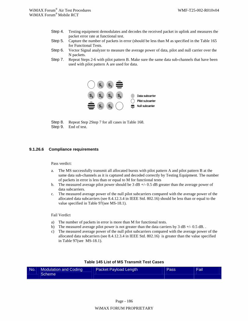
WiMAX Forum® Air Test Procedures WMF-T25-002-R010v04 WiMAX Forum® Mobile RCT
Page - 186
WiMAX FORUM PROPRIETARY
Step 4. Testing equipment demodulates and decodes the received packet in uplink and measures the packet error rate at functional test.
Step 5. Capture the number of packets in error (should be less than M as specified in the Table 165 for Functional Tests.
Step 6. Vector Signal analyzer to measure the average power of data, pilot and null carrier over the N packets.
Step 7. Repeat Steps 2-6 with pilot pattern B. Make sure the same data sub-channels that have been used with pilot pattern A are used for data.
S1 S2
S3 S4 S5 S6
S7 S8
Data subcarrierPilot subcarrierNull subcarrier
S1 S2
S3 S4 S5 S6
S7 S8
Data subcarrierPilot subcarrierNull subcarrier
Step 8. Repeat Step 2Step 7 for all cases in Table 168. Step 9. End of test.
9.1.26.6 Compliance requirements
Pass verdict:
a. The MS successfully transmit all allocated bursts with pilot pattern A and pilot pattern B at the same data sub-channels as it is captured and decoded correctly by Testing Equipment. The number of packets in error is less than or equal to M for functional tests
b. The measured average pilot power should be 3 dB +/- 0.5 dB greater than the average power of data subcarriers.
c. The measured average power of the null pilot subcarriers compared with the average power of the allocated data subcarriers (see 8.4.12.3.4 in IEEE Std. 802.16) should be less than or equal to the value specified in Table 97(see MS-18.1).
Fail Verdict
a) The number of packets in error is more than M for functional tests. b) The measured average pilot power is not greater than the data carriers by 3 dB +/- 0.5 dB. . c) The measured average power of the null pilot subcarriers compared with the average power of the
allocated data subcarriers (see 8.4.12.3.4 in IEEE Std. 802.16) is greater than the value specified in Table 97(see MS-18.1).
Table 145 List of MS Transmit Test Cases
No. Modulation and Coding Scheme
Packet Payload Length Pass Fail
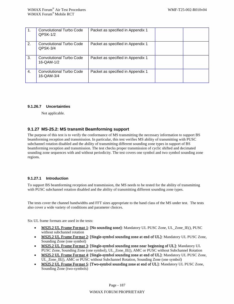
WiMAX Forum® Air Test Procedures WMF-T25-002-R010v04 WiMAX Forum® Mobile RCT
Page - 187
WiMAX FORUM PROPRIETARY
9.1.26.7 Uncertainties
Not applicable.
9.1.27 MS-25.2: MS transmit Beamforming support The purpose of this test is to verify the conformance of MS transmitting the necessary information to support BS beamforming reception and transmission. In particular, this test verifies MS ability of transmitting with PUSC subchannel rotation disabled and the ability of transmitting different sounding zone types in support of BS beamforming reception and transmission. The test checks proper transmission of cyclic shifted and decimated sounding zone sequences with and without periodicity. The test covers one symbol and two symbol sounding zone regions.
9.1.27.1 Introduction To support BS beamforming reception and transmission, the MS needs to be tested for the ability of transmitting with PUSC subchannel rotation disabled and the ability of transmitting different sounding zone types.
The tests cover the channel bandwidths and FFT sizes appropriate to the band class of the MS under test. The tests also cover a wide variety of conditions and parameter choices.
Six UL frame formats are used in the tests:
• MS25.2 UL Frame Format 1: [No sounding zone]: Mandatory UL PUSC Zone, UL_Zone_IE(), PUSC without subchannel rotation
• MS25.2 UL Frame Format 2: [Single-symbol sounding zone at end of UL]: Mandatory UL PUSC Zone, Sounding Zone (one symbol)
• MS25.2 UL Frame Format 3: [Single-symbol sounding zone near beginning of UL]: Mandatory UL PUSC Zone, Sounding Zone (one symbol), UL_Zone_IE(), AMC or PUSC without Subchannel Rotation
• MS25.2 UL Frame Format 4: [Single-symbol sounding zone at end of UL]: Mandatory UL PUSC Zone, UL_Zone_IE(), AMC or PUSC without Subchannel Rotation, Sounding Zone (one symbol)
• MS25.2 UL Frame Format 5: [Two-symbol sounding zone at end of UL]: Mandatory UL PUSC Zone, Sounding Zone (two-symbols)
1. Convolutional Turbo Code QPSK-1/2
Packet as specified in Appendix 1
2. Convolutional Turbo Code QPSK-3/4
Packet as specified in Appendix 1
3. Convolutional Turbo Code 16-QAM-1/2
Packet as specified in Appendix 1
4. Convolutional Turbo Code 16-QAM-3/4
Packet as specified in Appendix 1
WiMAX Forum® Air Test Procedures WMF-T25-002-R010v04 WiMAX Forum® Mobile RCT
Page - 188
WiMAX FORUM PROPRIETARY
• MS25.2 UL Frame Format 6: [Two-symbol sounding zone near beginning of UL]: Mandatory UL PUSC Zone, Sounding Zone (two-symbols), UL_Zone_IE(), one of AMC, PUSC, PUSC without Subchannel Rotation.
The frame structure for the test shall have following DL/UL ratios;
For one symbol sounding zone;
• (31, 16) for 5 & 10 MHz channels • (29, 13) for 8.75 MHz channel • (23, 10) for 3.5 & 7 MHz channel
For two symbols sounding zone;
• (27, 20) for 5 & 10 MHz channels • (25, 17) for 8.75 MHz channel • (19, 14) for 3.5 & 7 MHz channel
The following outline shows the organization of the tests and which frame format is being used in the tests. .
Test Case #1 – Verify UL PUSC Subchannel Rotation on and off (MS25.2 UL Frame Format 1)
Test Case #2 – Single-Symbol Sounding Zone Tests
• Non periodic tests for testing proper waveform generation o Cyclic Shift Separability (MS25.2 UL Frame Format 2)
Normal allocation mode – full band sounding Normal allocation mode – partial band sounding Band-AMC allocation mode
o Decimation Separability (MS25.2 UL Frame Format 2) Normal allocation mode – full band sounding Normal allocation mode – partial band sounding Band-AMC allocation mode
o Sounding Zone Location and SZ Shift value Test - cyclic shift separability and decimation separability (MS25.2 UL Frame Format 3 and MS25.2 UL Frame Format 4)
• Periodicity tests for validating periodic sounding capability (MS25.2 UL Frame Format 4) o Sounding with Cyclic Shift Separability o Sounding with Decimation Separability
Test Case #3 – Two-Symbol Sounding Zone Tests for validating two-symbol sounding zones.
• Non-periodic tests o Cyclic time shift index parameter (MS25.2 UL Frame Format 5) o Max cyclic shift index (MS25.2 UL Frame Format 6) o Decimation value (MS25.2 UL Frame Format 5) o Decimation offset (MS25.2 UL Frame Format 6)
• Periodicity tests (MS25.2 UL Frame Format 5) Test Case #4 – Relative Constellation Error for Sounding Symbols (MS25.2 UL Frame Format 5)
Throughout these tests, the parameters / variables of the sounding signaling are generally listed in terms of their mathematical values rather than the binary (or decimal equivalent) field values signaled in the relevant IEs. Refer to
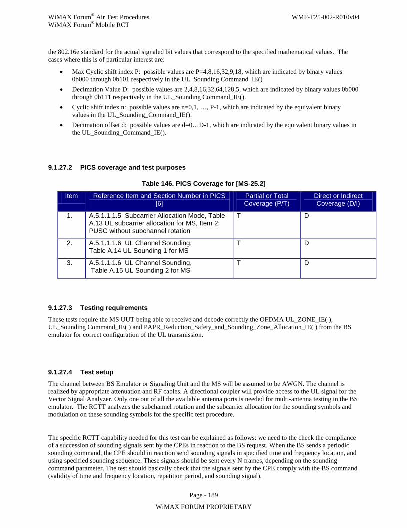
WiMAX Forum® Air Test Procedures WMF-T25-002-R010v04 WiMAX Forum® Mobile RCT
Page - 189
WiMAX FORUM PROPRIETARY
the 802.16e standard for the actual signaled bit values that correspond to the specified mathematical values. The cases where this is of particular interest are:
• Max Cyclic shift index P: possible values are P=4,8,16,32,9,18, which are indicated by binary values 0b000 through 0b101 respectively in the UL_Sounding Command_IE()
• Decimation Value D: possible values are 2,4,8,16,32,64,128,5, which are indicated by binary values 0b000 through 0b111 respectively in the UL_Sounding Command_IE().
• Cyclic shift index n: possible values are n=0,1, …, P-1, which are indicated by the equivalent binary values in the UL_Sounding_Command_IE().
• Decimation offset d: possible values are d=0…D-1, which are indicated by the equivalent binary values in the UL_Sounding_Command_IE().
9.1.27.2 PICS coverage and test purposes
Table 146. PICS Coverage for [MS-25.2]
Item Reference Item and Section Number in PICS [6]
Partial or Total Coverage (P/T)
Direct or Indirect Coverage (D/I)
1. A.5.1.1.1.5 Subcarrier Allocation Mode, Table A.13 UL subcarrier allocation for MS, Item 2: PUSC without subchannel rotation
T D
2. A.5.1.1.1.6 UL Channel Sounding, Table A.14 UL Sounding 1 for MS
T D
3. A.5.1.1.1.6 UL Channel Sounding, Table A.15 UL Sounding 2 for MS
T D
9.1.27.3 Testing requirements
These tests require the MS UUT being able to receive and decode correctly the OFDMA UL_ZONE_IE( ), UL_Sounding Command_IE( ) and PAPR_Reduction_Safety_and_Sounding_Zone_Allocation_IE( ) from the BS emulator for correct configuration of the UL transmission.
9.1.27.4 Test setup
The channel between BS Emulator or Signaling Unit and the MS will be assumed to be AWGN. The channel is realized by appropriate attenuation and RF cables. A directional coupler will provide access to the UL signal for the Vector Signal Analyzer. Only one out of all the available antenna ports is needed for multi-antenna testing in the BS emulator. The RCTT analyzes the subchannel rotation and the subcarrier allocation for the sounding symbols and modulation on these sounding symbols for the specific test procedure.
The specific RCTT capability needed for this test can be explained as follows: we need to the check the compliance of a succession of sounding signals sent by the CPEs in reaction to the BS request. When the BS sends a periodic sounding command, the CPE should in reaction send sounding signals in specified time and frequency location, and using specified sounding sequence. These signals should be sent every N frames, depending on the sounding command parameter. The test should basically check that the signals sent by the CPE comply with the BS command (validity of time and frequency location, repetition period, and sounding signal).
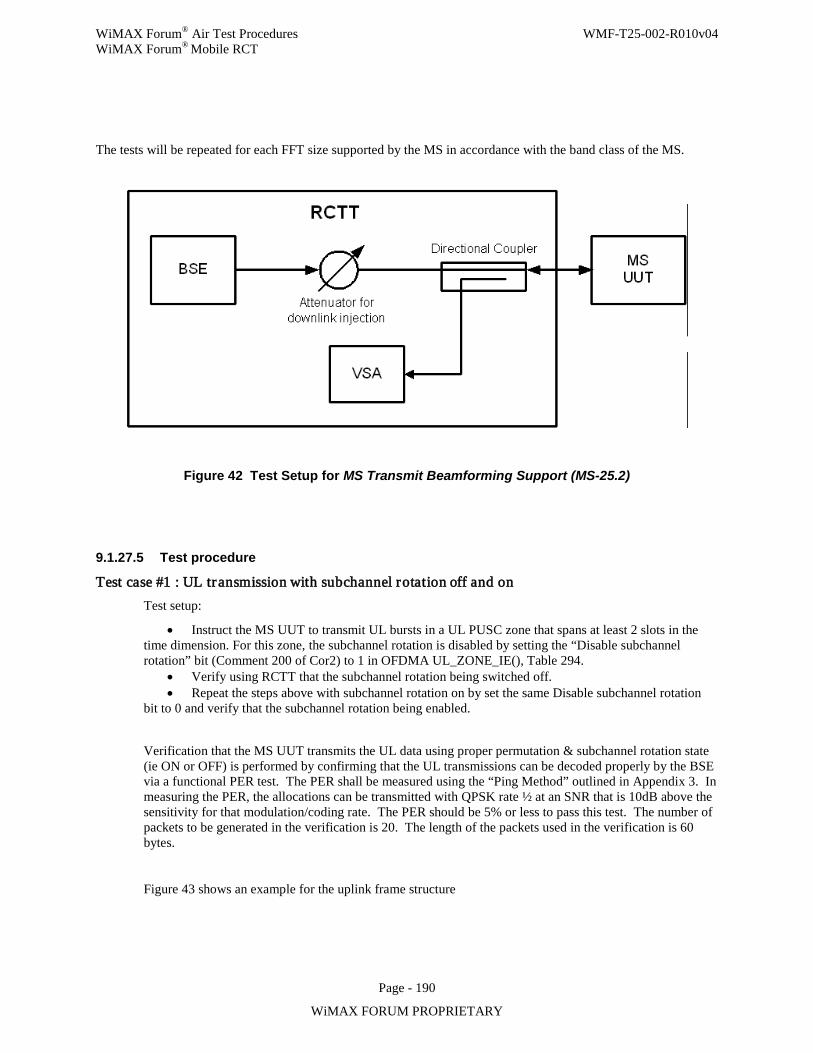
WiMAX Forum® Air Test Procedures WMF-T25-002-R010v04 WiMAX Forum® Mobile RCT
Page - 190
WiMAX FORUM PROPRIETARY
The tests will be repeated for each FFT size supported by the MS in accordance with the band class of the MS.
Figure 42 Test Setup for MS Transmit Beamforming Support (MS-25.2)
9.1.27.5 Test procedure
Test case #1 : UL transmission with subchannel rotation off and on Test setup:
• Instruct the MS UUT to transmit UL bursts in a UL PUSC zone that spans at least 2 slots in the time dimension. For this zone, the subchannel rotation is disabled by setting the “Disable subchannel rotation” bit (Comment 200 of Cor2) to 1 in OFDMA UL_ZONE_IE(), Table 294.
• Verify using RCTT that the subchannel rotation being switched off. • Repeat the steps above with subchannel rotation on by set the same Disable subchannel rotation
bit to 0 and verify that the subchannel rotation being enabled.
Verification that the MS UUT transmits the UL data using proper permutation & subchannel rotation state (ie ON or OFF) is performed by confirming that the UL transmissions can be decoded properly by the BSE via a functional PER test. The PER shall be measured using the “Ping Method” outlined in Appendix 3. In measuring the PER, the allocations can be transmitted with QPSK rate ½ at an SNR that is 10dB above the sensitivity for that modulation/coding rate. The PER should be 5% or less to pass this test. The number of packets to be generated in the verification is 20. The length of the packets used in the verification is 60 bytes.
Figure 43 shows an example for the uplink frame structure
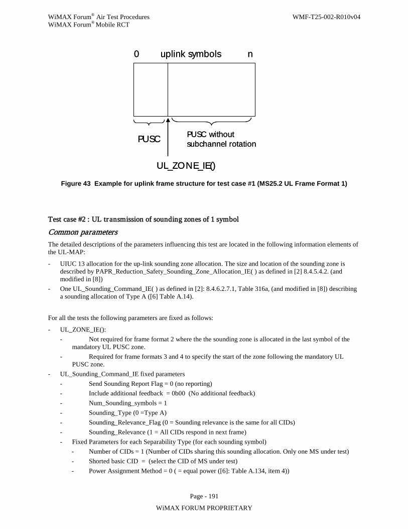
WiMAX Forum® Air Test Procedures WMF-T25-002-R010v04 WiMAX Forum® Mobile RCT
Page - 191
WiMAX FORUM PROPRIETARY
0 nuplink symbols
PUSC PUSC withoutsubchannel rotation
UL_ZONE_IE()
0 nuplink symbols
PUSC PUSC withoutsubchannel rotation
UL_ZONE_IE()
Figure 43 Example for uplink frame structure for test case #1 (MS25.2 UL Frame Format 1)
Test case #2 : UL transmission of sounding zones of 1 symbol
Common parameters The detailed descriptions of the parameters influencing this test are located in the following information elements of the UL-MAP:
- UIUC 13 allocation for the up-link sounding zone allocation. The size and location of the sounding zone is described by PAPR_Reduction_Safety_Sounding_Zone_Allocation_IE( ) as defined in [2] 8.4.5.4.2. (and modified in [8])
- One UL_Sounding_Command_IE( ) as defined in [2]: 8.4.6.2.7.1, Table 316a, (and modified in [8]) describing a sounding allocation of Type A ([6] Table A.14).
For all the tests the following parameters are fixed as follows:
- UL_ZONE_IE(): - Not required for frame format 2 where the the sounding zone is allocated in the last symbol of the
mandatory UL PUSC zone. - Required for frame formats 3 and 4 to specify the start of the zone following the mandatory UL
PUSC zone. - UL_Sounding_Command_IE fixed parameters
- Send Sounding Report Flag = 0 (no reporting) - Include additional feedback = 0b00 (No additional feedback) - Num_Sounding_symbols = 1 - Sounding_Type (0 =Type A) - Sounding_Relevance_Flag (0 = Sounding relevance is the same for all CIDs) - Sounding_Relevance (1 = All CIDs respond in next frame) - Fixed Parameters for each Separability Type (for each sounding symbol)
- Number of CIDs = 1 (Number of CIDs sharing this sounding allocation. Only one MS under test) - Shorted basic CID = (select the CID of MS under test) - Power Assignment Method = 0 ( = equal power ([6]: Table A.134, item 4))
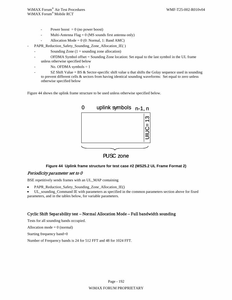
WiMAX Forum® Air Test Procedures WMF-T25-002-R010v04 WiMAX Forum® Mobile RCT
Page - 192
WiMAX FORUM PROPRIETARY
- Power boost = 0 (no power boost) - Multi-Antenna Flag = 0 (MS sounds first antenna only) - Allocation Mode = 0 (0: Normal, 1: Band AMC)
- PAPR_Reduction_Safety_Sounding_Zone_Allocation_IE( ) - Sounding Zone (1 = sounding zone allocation) - OFDMA Symbol offset = Sounding Zone location: Set equal to the last symbol in the UL frame
unless otherwise specified below - No. OFDMA symbols = 1 - SZ Shift Value = BS & Sector-specific shift value u that shifts the Golay sequence used in sounding
to prevent different cells & sectors from having identical sounding waveforms: Set equal to zero unless otherwise specified below
Figure 44 shows the uplink frame structure to be used unless otherwise specified below.
PUSC zone
0 nuplink symbols n-1,
UIU
C=
13
PUSC zone
0 nuplink symbols n-1,
UIU
C=
13
Figure 44 Uplink frame structure for test case #2 (MS25.2 UL Frame Format 2)
Periodicity parameter set to 0 BSE repetitively sends frames with an UL_MAP containing
• PAPR_Reduction_Safety_Sounding_Zone_Allocation_IE() • UL_sounding_Command IE with parameters as specified in the common parameters section above for fixed parameters, and in the tables below, for variable parameters.
Cyclic Shift Separability test – Normal Allocation Mode – Full bandwidth sounding Tests for all sounding bands occupied.
Allocation mode = 0 (normal)
Starting frequency band=0
Number of Frequency bands is 24 for 512 FFT and 48 for 1024 FFT.
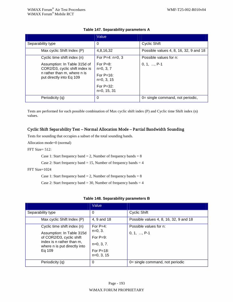
WiMAX Forum® Air Test Procedures WMF-T25-002-R010v04 WiMAX Forum® Mobile RCT
Page - 193
WiMAX FORUM PROPRIETARY
Table 147. Separability parameters A
Value
Separability type 0 Cyclic Shift
Max cyclic Shift Index (P) 4,8,16,32 Possible values 4, 8, 16, 32, 9 and 18
Cyclic time shift index (n)
Assumption: In Table 315d of COR2/D3, cyclic shift index is n rather than m, where n is put directly into Eq 109
For P=4: n=0, 3
For P=8: n=0, 3, 7
For P=16: n=0, 3, 15
For P=32: n=0, 15, 31
Possible values for n:
0, 1, ..., P-1
Periodicity (q) 0 0= single command, not periodic,
Tests are performed for each possible combination of Max cyclic shift index (P) and Cyclic time Shift index (n) values.
Cyclic Shift Separability Test – Normal Allocation Mode – Par tial Bandwidth Sounding Tests for sounding that occupies a subset of the total sounding bands.
Allocation mode=0 (normal)
FFT Size= 512:
Case 1: Start frequency band = 2, Number of frequency bands = 8
Case 2: Start frequency band = 15, Number of frequency bands = 4
FFT Size=1024
Case 1: Start frequency band = 2, Number of frequency bands = 8
Case 2: Start frequency band = 30, Number of frequency bands = 4
Table 148. Separability parameters B
Value
Separability type 0 Cyclic Shift
Max cyclic Shift Index (P) 4, 9 and 18 Possible values 4, 8, 16, 32, 9 and 18
Cyclic time shift index (n)
Assumption: In Table 315d of COR2/D3, cyclic shift index is n rather than m, where n is put directly into Eq 109
For P=4: n=0, 3.
For P=9:
n=0, 3, 7.
For P=18: n=0, 3, 15
Possible values for n:
0, 1, ..., P-1
Periodicity (q) 0 0= single command, not periodic
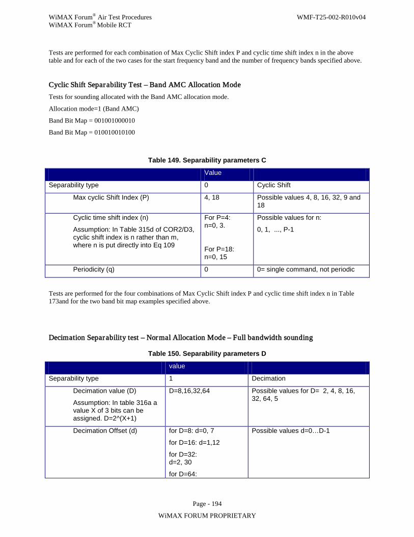
WiMAX Forum® Air Test Procedures WMF-T25-002-R010v04 WiMAX Forum® Mobile RCT
Page - 194
WiMAX FORUM PROPRIETARY
Tests are performed for each combination of Max Cyclic Shift index P and cyclic time shift index n in the above table and for each of the two cases for the start frequency band and the number of frequency bands specified above.
Cyclic Shift Separability Test – Band AMC Allocation Mode Tests for sounding allocated with the Band AMC allocation mode.
Allocation mode=1 (Band AMC)
Band Bit Map = 001001000010
Band Bit Map = 010010010100
Table 149. Separability parameters C
Value
Separability type 0 Cyclic Shift
Max cyclic Shift Index (P) 4, 18 Possible values 4, 8, 16, 32, 9 and 18
Cyclic time shift index (n)
Assumption: In Table 315d of COR2/D3, cyclic shift index is n rather than m, where n is put directly into Eq 109
For P=4: n=0, 3.
For P=18: n=0, 15
Possible values for n:
0, 1, ..., P-1
Periodicity (q) 0 0= single command, not periodic
Tests are performed for the four combinations of Max Cyclic Shift index P and cyclic time shift index n in Table 173and for the two band bit map examples specified above.
Decimation Separability test – Normal Allocation Mode – Full bandwidth sounding
Table 150. Separability parameters D
value
Separability type 1 Decimation
Decimation value (D)
Assumption: In table 316a a value X of 3 bits can be assigned. D=2^(X+1)
D=8,16,32,64 Possible values for D= 2, 4, 8, 16, 32, 64, 5
Decimation Offset (d) for D=8: d=0, 7
for D=16: d=1,12
for D=32: d=2, 30
for D=64:
Possible values d=0…D-1
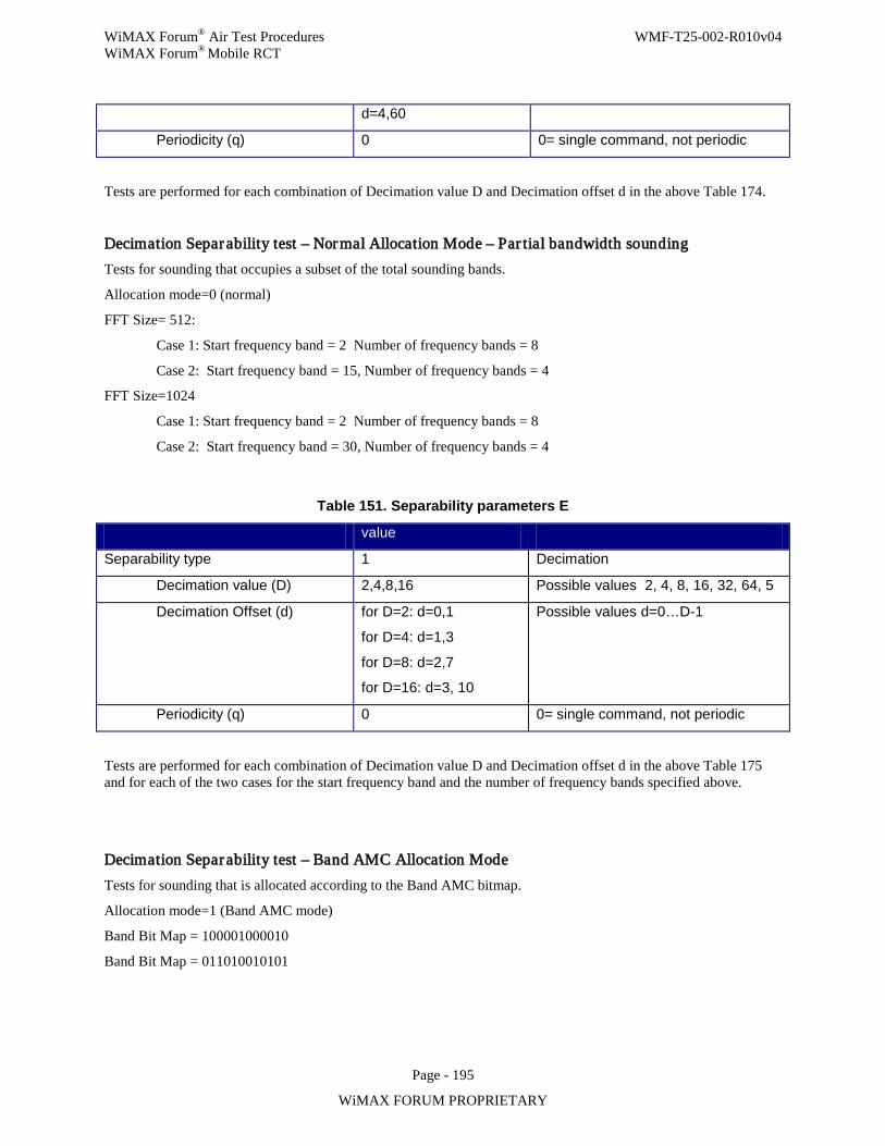
WiMAX Forum® Air Test Procedures WMF-T25-002-R010v04 WiMAX Forum® Mobile RCT
Page - 195
WiMAX FORUM PROPRIETARY
d=4,60
Periodicity (q) 0 0= single command, not periodic
Tests are performed for each combination of Decimation value D and Decimation offset d in the above Table 174.
Decimation Separability test – Normal Allocation Mode – Par tial bandwidth sounding Tests for sounding that occupies a subset of the total sounding bands.
Allocation mode=0 (normal)
FFT Size= 512:
Case 1: Start frequency band = 2 Number of frequency bands = 8
Case 2: Start frequency band = 15, Number of frequency bands = 4
FFT Size=1024
Case 1: Start frequency band = 2 Number of frequency bands = 8
Case 2: Start frequency band = 30, Number of frequency bands = 4
Table 151. Separability parameters E
value
Separability type 1 Decimation
Decimation value (D) 2,4,8,16 Possible values 2, 4, 8, 16, 32, 64, 5
Decimation Offset (d) for D=2: d=0,1
for D=4: d=1,3
for D=8: d=2,7
for D=16: d=3, 10
Possible values d=0…D-1
Periodicity (q) 0 0= single command, not periodic
Tests are performed for each combination of Decimation value D and Decimation offset d in the above Table 175 and for each of the two cases for the start frequency band and the number of frequency bands specified above.
Decimation Separability test – Band AMC Allocation Mode Tests for sounding that is allocated according to the Band AMC bitmap.
Allocation mode=1 (Band AMC mode)
Band Bit Map = 100001000010
Band Bit Map = 011010010101
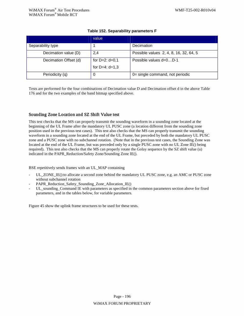
WiMAX Forum® Air Test Procedures WMF-T25-002-R010v04 WiMAX Forum® Mobile RCT
Page - 196
WiMAX FORUM PROPRIETARY
Table 152. Separability parameters F
value
Separability type 1 Decimation
Decimation value (D) 2,4 Possible values 2, 4, 8, 16, 32, 64, 5
Decimation Offset (d) for D=2: d=0,1
for D=4: d=1,3
Possible values d=0…D-1
Periodicity (q) 0 0= single command, not periodic
Tests are performed for the four combinations of Decimation value D and Decimation offset d in the above Table 176 and for the two examples of the band bitmap specified above.
Sounding Zone Location and SZ Shift Value test This test checks that the MS can properly transmit the sounding waveform in a sounding zone located at the beginning of the UL Frame after the mandatory UL PUSC zone (a location different from the sounding zone position used in the previous test cases). This test also checks that the MS can properly transmit the sounding waveform in a sounding zone located at the end of the UL Frame, but preceded by both the mandatory UL PUSC zone and a PUSC zone with no subchannel rotation. (Note that in the previous test cases, the Sounding Zone was located at the end of the UL Frame, but was preceded only by a single PUSC zone with no UL Zone IE() being required). This test also checks that the MS can properly rotate the Golay sequence by the SZ shift value (u) indicated in the PAPR_Reduction/Safety Zone/Sounding Zone IE().
BSE repetitively sends frames with an UL_MAP containing
- UL_ZONE_IE():to allocate a second zone behind the mandatory UL PUSC zone, e.g. an AMC or PUSC zone without subchannel rotation
- PAPR_Reduction_Safety_Sounding_Zone_Allocation_IE() - UL_sounding_Command IE with parameters as specified in the common parameters section above for fixed
parameters, and in the tables below, for variable parameters.
Figure 45 show the uplink frame structures to be used for these tests.
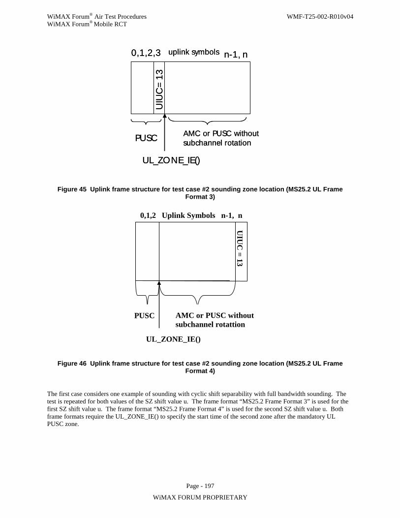
WiMAX Forum® Air Test Procedures WMF-T25-002-R010v04 WiMAX Forum® Mobile RCT
Page - 197
WiMAX FORUM PROPRIETARY
PUSC
0,1,2,3 nn-1,
UIU
C=
13
AMC or PUSC withoutsubchannel rotation
uplink symbols
UL_ZONE_IE()
PUSC
0,1,2,3 nn-1,
UIU
C=
13
AMC or PUSC withoutsubchannel rotation
uplink symbols
UL_ZONE_IE()
Figure 45 Uplink frame structure for test case #2 sounding zone location (MS25.2 UL Frame Format 3)
PUSC
UIU
C = 13
UL_ZONE_IE()
AMC or PUSC without subchannel rotattion
0,1,2 Uplink Symbols n-1, n
Figure 46 Uplink frame structure for test case #2 sounding zone location (MS25.2 UL Frame Format 4)
The first case considers one example of sounding with cyclic shift separability with full bandwidth sounding. The test is repeated for both values of the SZ shift value u. The frame format “MS25.2 Frame Format 3” is used for the first SZ shift value u. The frame format “MS25.2 Frame Format 4” is used for the second SZ shift value u. Both frame formats require the UL_ZONE_IE() to specify the start time of the second zone after the mandatory UL PUSC zone.
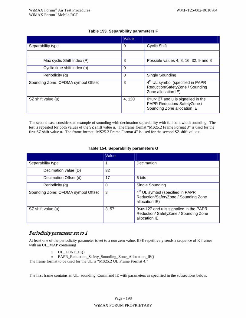
WiMAX Forum® Air Test Procedures WMF-T25-002-R010v04 WiMAX Forum® Mobile RCT
Page - 198
WiMAX FORUM PROPRIETARY
Table 153. Separability parameters F
Value
Separability type 0 Cyclic Shift
Max cyclic Shift Index (P) 8 Possible values 4, 8, 16, 32, 9 and 8
Cyclic time shift index (n) 0
Periodicity (q) 0 Single Sounding
Sounding Zone: OFDMA symbol Offset 3 4th UL symbol (specified in PAPR Reduction/SafetyZone / Sounding Zone allocation IE)
SZ shift value (u) 4, 120 0≤u≤127 and u is signalled in the PAPR Reduction/ SafetyZone / Sounding Zone allocation IE
The second case considers an example of sounding with decimation separability with full bandwidth sounding. The test is repeated for both values of the SZ shift value u. The frame format “MS25.2 Frame Format 3” is used for the first SZ shift value u. The frame format “MS25.2 Frame Format 4” is used for the second SZ shift value u.
Table 154. Separability parameters G
Value
Separability type 1 Decimation
Decimation value (D) 32
Decimation Offset (d) 17 6 bits
Periodicity (q) 0 Single Sounding
Sounding Zone: OFDMA symbol Offset 3 4th UL symbol (specified in PAPR Reduction/SafetyZone / Sounding Zone allocation IE)
SZ shift value (u) 3, 57 0≤u≤127 and u is signalled in the PAPR Reduction/ SafetyZone / Sounding Zone allocation IE
Periodicity parameter set to 1 At least one of the periodicity parameter is set to a non zero value. BSE repetitively sends a sequence of K frames with an UL_MAP containing
o UL_ZONE_IE() o PAPR_Reduction_Safety_Sounding_Zone_Allocation_IE()
The frame format to be used for the UL is “MS25.2 UL Frame Format 4.”
The first frame contains an UL_sounding_Command IE with parameters as specified in the subsections below.
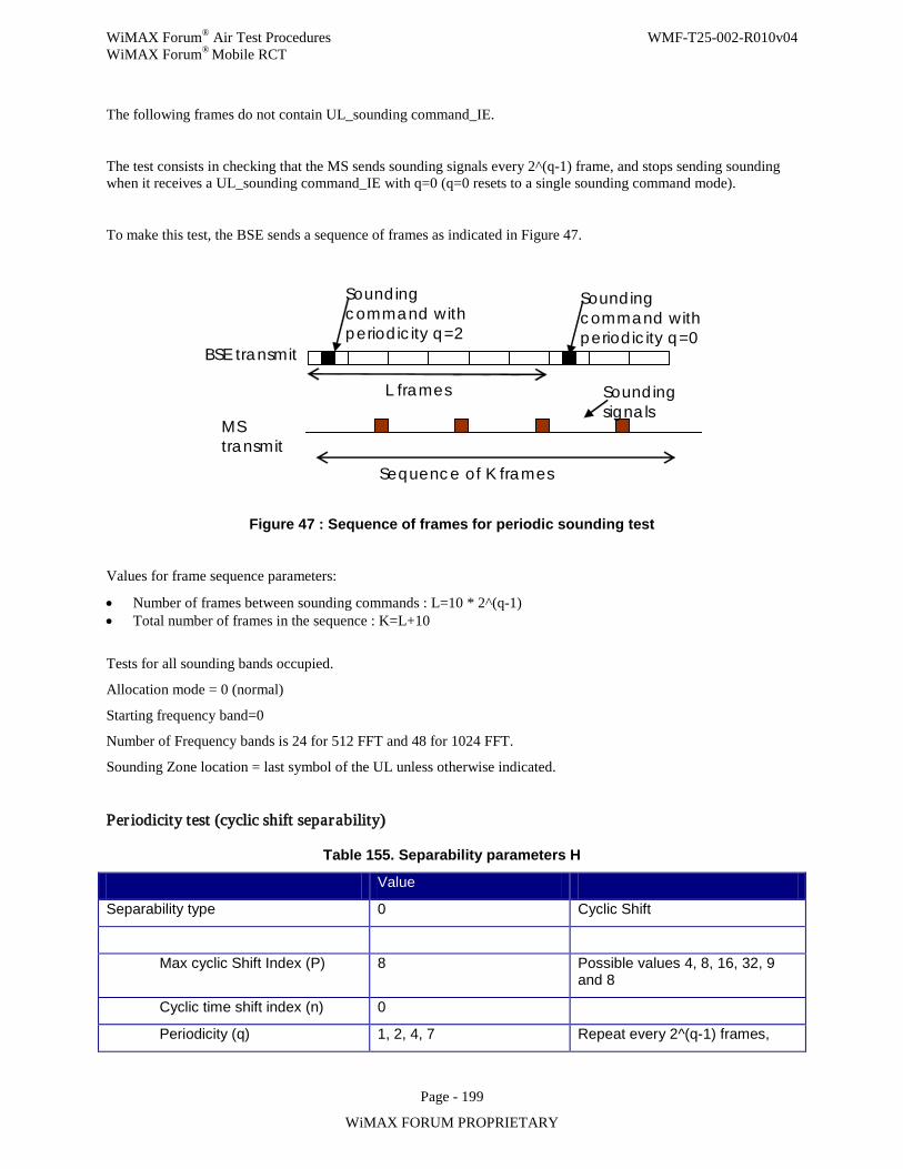
WiMAX Forum® Air Test Procedures WMF-T25-002-R010v04 WiMAX Forum® Mobile RCT
Page - 199
WiMAX FORUM PROPRIETARY
The following frames do not contain UL_sounding command_IE.
The test consists in checking that the MS sends sounding signals every 2^(q-1) frame, and stops sending sounding when it receives a UL_sounding command_IE with q=0 (q=0 resets to a single sounding command mode).
To make this test, the BSE sends a sequence of frames as indicated in Figure 47.
MS transmit
BSE transmit
Sounding command with periodicity q=2
Sounding command with periodicity q=0
Sounding signals
Sequence of K frames
L frames
Figure 47 : Sequence of frames for periodic sounding test
Values for frame sequence parameters:
• Number of frames between sounding commands : L=10 * 2^(q-1) • Total number of frames in the sequence : K=L+10
Tests for all sounding bands occupied.
Allocation mode = 0 (normal)
Starting frequency band=0
Number of Frequency bands is 24 for 512 FFT and 48 for 1024 FFT.
Sounding Zone location = last symbol of the UL unless otherwise indicated.
Per iodicity test (cyclic shift separability)
Table 155. Separability parameters H
Value
Separability type 0 Cyclic Shift
Max cyclic Shift Index (P) 8 Possible values 4, 8, 16, 32, 9 and 8
Cyclic time shift index (n) 0
Periodicity (q) 1, 2, 4, 7 Repeat every 2^(q-1) frames,
WiMAX Forum® Air Test Procedures WMF-T25-002-R010v04 WiMAX Forum® Mobile RCT
Page - 200
WiMAX FORUM PROPRIETARY
q=1… 7
Tests are performed for each Periodicity parameter listed in the Table 179 above.
Per iodicity test (decimation separability)
Table 156. Separability parameters I
Value
Separability type 1 Decimation
Decimation value (D) 16
Decimation Offset (d) 5 6 bits
Periodicity (q) 1, 2, 4, 7 Repeat every 2^(q-1) frames, q=1… 7
Tests are performed for each Periodicity parameter listed in the Table 180 above.
Test case #3 : UL transmission of sounding zones of 2 symbols
Common parameters
- UL_ZONE_IE( ): not required in “MS25.2 UL Frame format 5,” because the sounding zone is allocated in the last symbol of the mandatory UL PUSC zone. Required in “MS25.2 UL Frame Format 6” to specify the end of the SZ and the start of the next zone.
- PAPR_Reduction_Safety_Sounding_Zone_Allocation_IE( ) - OFDMA Symbol offset = Sounding Zone location: Set equal to one symbol before the last symbol
(n-1) in the UL frame unless otherwise specified. - No. OFDMA symbols = 2 - SZ Shift Value = BS & Sector – specific shift value u that shifts the Golay sequence used in
sounding: Set equal to all zeros unless otherwise specified below. - UL_Sounding_Command_IE parameters
- Send Sounding Report Flag = 0 (no reporting) - Include additional feedback = 0b00 (No additional feedback) - Num_Sounding_symbols = 2 Parameters for sounding symbol 1:
- Separability Type = 0 (cyclic shift, occupy all subcarriers in the assigned band) - Sounding symbol index = 0 - Starting Frequency Band = 0 - Number of frequency bands = 48 (value valid for 1024 FFT)
Parameters for sounding symbol 2:
- Separability Type = 1 (decimating, occupy decimated subcarriers) - Sounding symbol index = 1
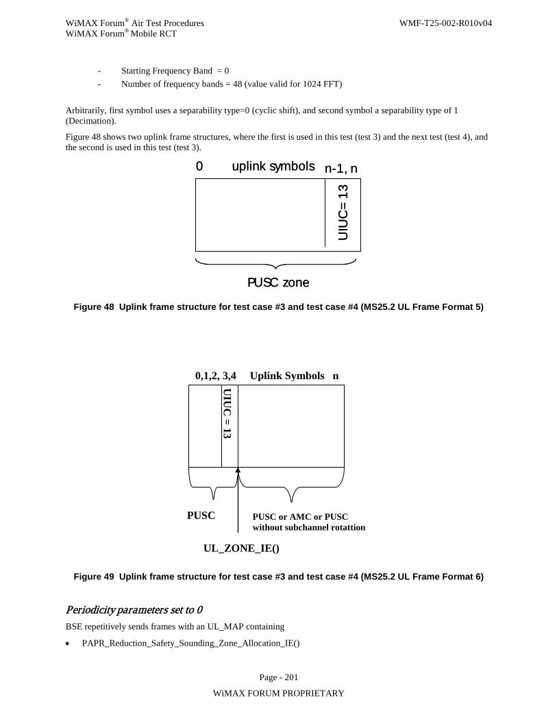
WiMAX Forum® Air Test Procedures WMF-T25-002-R010v04 WiMAX Forum® Mobile RCT
Page - 201
WiMAX FORUM PROPRIETARY
- Starting Frequency Band = 0 - Number of frequency bands = 48 (value valid for 1024 FFT)
Arbitrarily, first symbol uses a separability type=0 (cyclic shift), and second symbol a separability type of 1 (Decimation).
Figure 48 shows two uplink frame structures, where the first is used in this test (test 3) and the next test (test 4), and the second is used in this test (test 3).
PUSC zone
0 nuplink symbols n-1,
UIU
C=
13
PUSC zone
0 nuplink symbols n-1,
UIU
C=
13
Figure 48 Uplink frame structure for test case #3 and test case #4 (MS25.2 UL Frame Format 5)
PUSC
UIU
C = 13
UL_ZONE_IE()
0,1,2, 3,4 Uplink Symbols n
PUSC or AMC or PUSC without subchannel rotattion
Figure 49 Uplink frame structure for test case #3 and test case #4 (MS25.2 UL Frame Format 6)
Periodicity parameters set to 0 BSE repetitively sends frames with an UL_MAP containing
• PAPR_Reduction_Safety_Sounding_Zone_Allocation_IE()
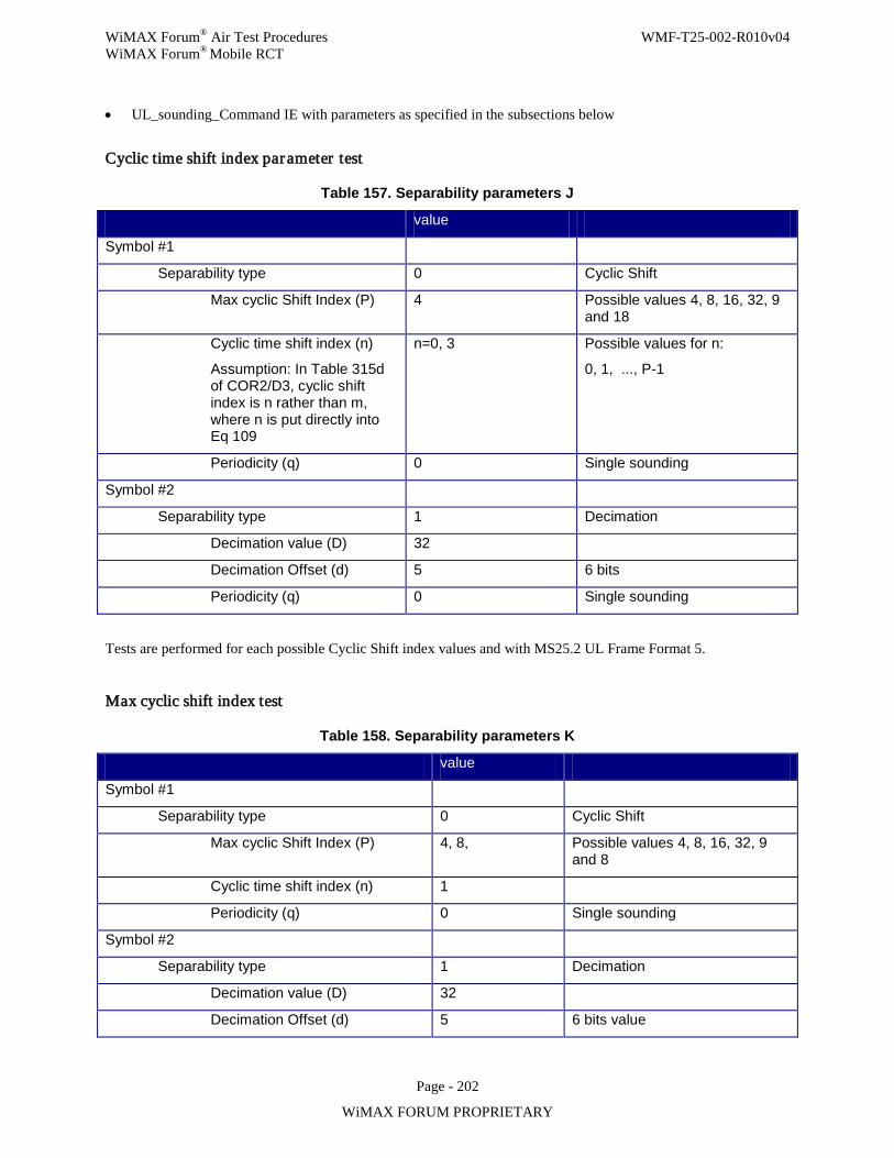
WiMAX Forum® Air Test Procedures WMF-T25-002-R010v04 WiMAX Forum® Mobile RCT
Page - 202
WiMAX FORUM PROPRIETARY
• UL_sounding_Command IE with parameters as specified in the subsections below
Cyclic time shift index parameter test
Table 157. Separability parameters J
value
Symbol #1
Separability type 0 Cyclic Shift
Max cyclic Shift Index (P) 4 Possible values 4, 8, 16, 32, 9 and 18
Cyclic time shift index (n)
Assumption: In Table 315d of COR2/D3, cyclic shift index is n rather than m, where n is put directly into Eq 109
n=0, 3 Possible values for n:
0, 1, ..., P-1
Periodicity (q) 0 Single sounding
Symbol #2
Separability type 1 Decimation
Decimation value (D) 32
Decimation Offset (d) 5 6 bits
Periodicity (q) 0 Single sounding
Tests are performed for each possible Cyclic Shift index values and with MS25.2 UL Frame Format 5.
Max cyclic shift index test
Table 158. Separability parameters K
value
Symbol #1
Separability type 0 Cyclic Shift
Max cyclic Shift Index (P) 4, 8, Possible values 4, 8, 16, 32, 9 and 8
Cyclic time shift index (n) 1
Periodicity (q) 0 Single sounding
Symbol #2
Separability type 1 Decimation
Decimation value (D) 32
Decimation Offset (d) 5 6 bits value
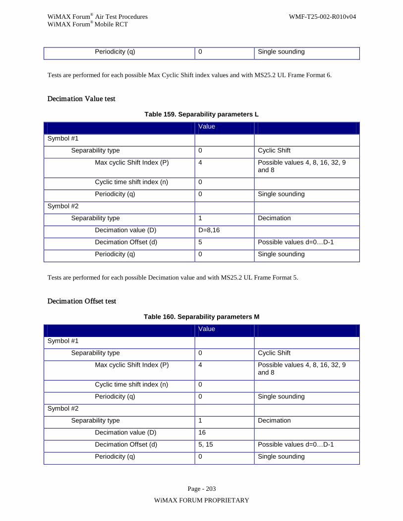
WiMAX Forum® Air Test Procedures WMF-T25-002-R010v04 WiMAX Forum® Mobile RCT
Page - 203
WiMAX FORUM PROPRIETARY
Periodicity (q) 0 Single sounding
Tests are performed for each possible Max Cyclic Shift index values and with MS25.2 UL Frame Format 6.
Decimation Value test
Table 159. Separability parameters L
Value
Symbol #1
Separability type 0 Cyclic Shift
Max cyclic Shift Index (P) 4 Possible values 4, 8, 16, 32, 9 and 8
Cyclic time shift index (n) 0
Periodicity (q) 0 Single sounding
Symbol #2
Separability type 1 Decimation
Decimation value (D) D=8,16
Decimation Offset (d) 5 Possible values d=0…D-1
Periodicity (q) 0 Single sounding
Tests are performed for each possible Decimation value and with MS25.2 UL Frame Format 5.
Decimation Offset test
Table 160. Separability parameters M
Value
Symbol #1
Separability type 0 Cyclic Shift
Max cyclic Shift Index (P) 4 Possible values 4, 8, 16, 32, 9 and 8
Cyclic time shift index (n) 0
Periodicity (q) 0 Single sounding
Symbol #2
Separability type 1 Decimation
Decimation value (D) 16
Decimation Offset (d) 5, 15 Possible values d=0…D-1
Periodicity (q) 0 Single sounding
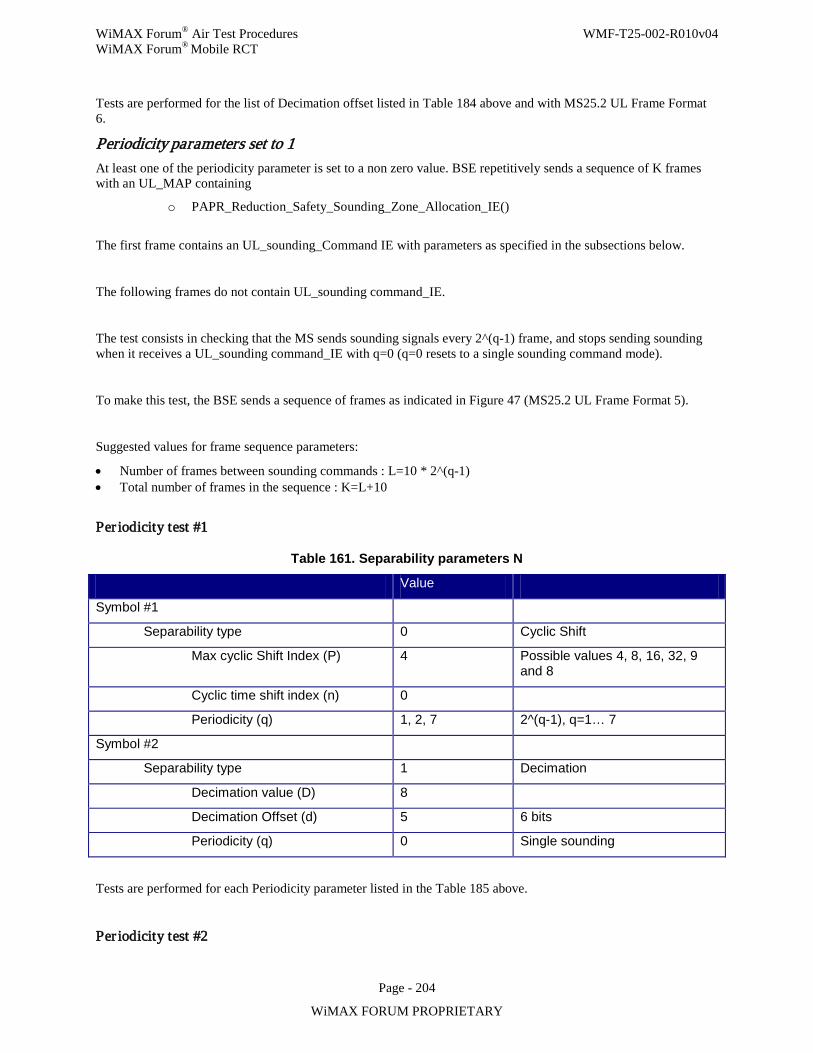
WiMAX Forum® Air Test Procedures WMF-T25-002-R010v04 WiMAX Forum® Mobile RCT
Page - 204
WiMAX FORUM PROPRIETARY
Tests are performed for the list of Decimation offset listed in Table 184 above and with MS25.2 UL Frame Format 6.
Periodicity parameters set to 1 At least one of the periodicity parameter is set to a non zero value. BSE repetitively sends a sequence of K frames with an UL_MAP containing
o PAPR_Reduction_Safety_Sounding_Zone_Allocation_IE()
The first frame contains an UL_sounding_Command IE with parameters as specified in the subsections below.
The following frames do not contain UL_sounding command_IE.
The test consists in checking that the MS sends sounding signals every 2^(q-1) frame, and stops sending sounding when it receives a UL_sounding command_IE with q=0 (q=0 resets to a single sounding command mode).
To make this test, the BSE sends a sequence of frames as indicated in Figure 47 (MS25.2 UL Frame Format 5).
Suggested values for frame sequence parameters:
• Number of frames between sounding commands : L=10 * 2^(q-1) • Total number of frames in the sequence : K=L+10
Per iodicity test #1
Table 161. Separability parameters N
Value
Symbol #1
Separability type 0 Cyclic Shift
Max cyclic Shift Index (P) 4 Possible values 4, 8, 16, 32, 9 and 8
Cyclic time shift index (n) 0
Periodicity (q) 1, 2, 7 2^(q-1), q=1… 7
Symbol #2
Separability type 1 Decimation
Decimation value (D) 8
Decimation Offset (d) 5 6 bits
Periodicity (q) 0 Single sounding
Tests are performed for each Periodicity parameter listed in the Table 185 above.
Per iodicity test #2
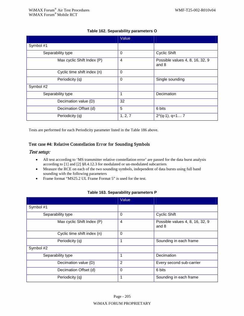
WiMAX Forum® Air Test Procedures WMF-T25-002-R010v04 WiMAX Forum® Mobile RCT
Page - 205
WiMAX FORUM PROPRIETARY
Table 162. Separability parameters O
Value
Symbol #1
Separability type 0 Cyclic Shift
Max cyclic Shift Index (P) 4 Possible values 4, 8, 16, 32, 9 and 8
Cyclic time shift index (n) 0
Periodicity (q) 0 Single sounding
Symbol #2
Separability type 1 Decimation
Decimation value (D) 32
Decimation Offset (d) 5 6 bits
Periodicity (q) 1, 2, 7 2^(q-1), q=1… 7
Tests are performed for each Periodicity parameter listed in the Table 186 above.
Test case #4: Relative Constellation Er ror for Sounding Symbols
Test setup: • All test according to ‘MS transmitter relative constellation error’ are passed for the data burst analysis
according to [1] and [2] §8.4.12.3 for modulated or un-modulated subcarriers • Measure the RCE on each of the two sounding symbols, independent of data bursts using full band
sounding with the following parameters • Frame format “MS25.2 UL Frame Format 5” is used for the test.
Table 163. Separability parameters P
Value
Symbol #1
Separability type 0 Cyclic Shift
Max cyclic Shift Index (P) 4 Possible values 4, 8, 16, 32, 9 and 8
Cyclic time shift index (n) 0
Periodicity (q) 1 Sounding in each frame
Symbol #2
Separability type 1 Decimation
Decimation value (D) 2 Every second sub-carrier
Decimation Offset (d) 0 6 bits
Periodicity (q) 1 Sounding in each frame
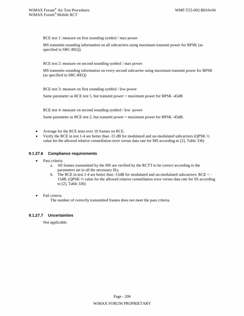
WiMAX Forum® Air Test Procedures WMF-T25-002-R010v04 WiMAX Forum® Mobile RCT
Page - 206
WiMAX FORUM PROPRIETARY
RCE test 1: measure on first sounding symbol / max power
MS transmits sounding information on all subcarriers using maximum transmit power for BPSK (as specified in SBC-REQ)
RCE test 2: measure on second sounding symbol / max power
MS transmits sounding information on every second subcarrier using maximum transmit power for BPSK (as specified in SBC-REQ)
RCE test 3: measure on first sounding symbol / low power
Same parameter as RCE test 1, but transmit power = maximum power for BPSK -45dB
RCE test 4: measure on second sounding symbol / low power
Same parameter as RCE test 2, but transmit power = maximum power for BPSK -45dB.
• Average for the RCE tests over 10 frames on RCE. • Verify the RCE in test 1-4 are better than -15 dB for modulated and un-modulated subcarriers (QPSK ½
value for the allowed relative constellation error versus data rate for MS according to [2], Table 336)
9.1.27.6 Compliance requirements
• Pass criteria a. All frames transmitted by the MS are verified by the RCTT to be correct according to the
parameters set in all the necessary IEs, b. The RCE in test 1-4 are better than -15dB for modulated and un-modulated subcarriers: RCE < -
15dB. (QPSK ½ value for the allowed relative constellation error versus data rate for SS according to [2], Table 336)
• Fail criteria The number of correctly transmitted frames does not meet the pass criteria.
9.1.27.7 Uncertainties
Not applicable.
WiMAX Forum® Air Test Procedures WMF-T25-002-R010v04 WiMAX Forum® Mobile RCT
Page - 207
WiMAX FORUM PROPRIETARY
10. Tests for Base Stations 10.1 Test procedures A test code of format XX-nn.m is assigned to all tests where XX is either MS for Mobile Station or Bs for Base Station, nn is a number assigned to the test and m is 1 for Wave 1 tests and 2 for Wave 2 tests.
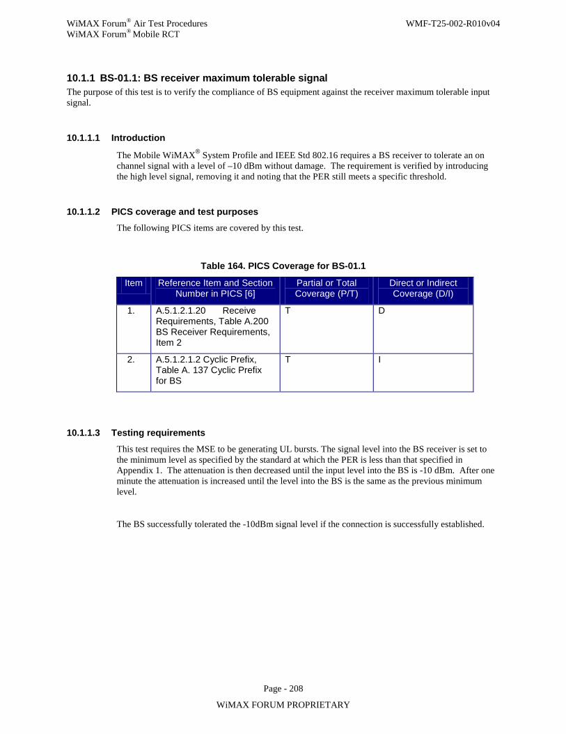
WiMAX Forum® Air Test Procedures WMF-T25-002-R010v04 WiMAX Forum® Mobile RCT
Page - 208
WiMAX FORUM PROPRIETARY
10.1.1 BS-01.1: BS receiver maximum tolerable signal The purpose of this test is to verify the compliance of BS equipment against the receiver maximum tolerable input signal.
10.1.1.1 Introduction
The Mobile WiMAX® System Profile and IEEE Std 802.16 requires a BS receiver to tolerate an on channel signal with a level of –10 dBm without damage. The requirement is verified by introducing the high level signal, removing it and noting that the PER still meets a specific threshold.
10.1.1.2 PICS coverage and test purposes The following PICS items are covered by this test.
Table 164. PICS Coverage for BS-01.1
Item Reference Item and Section Number in PICS [6]
Partial or Total Coverage (P/T)
Direct or Indirect Coverage (D/I)
1. A.5.1.2.1.20 Receive Requirements, Table A.200 BS Receiver Requirements, Item 2
T D
2. A.5.1.2.1.2 Cyclic Prefix, Table A. 137 Cyclic Prefix for BS
T I
10.1.1.3 Testing requirements
This test requires the MSE to be generating UL bursts. The signal level into the BS receiver is set to the minimum level as specified by the standard at which the PER is less than that specified in Appendix 1. The attenuation is then decreased until the input level into the BS is -10 dBm. After one minute the attenuation is increased until the level into the BS is the same as the previous minimum level.
The BS successfully tolerated the -10dBm signal level if the connection is successfully established.
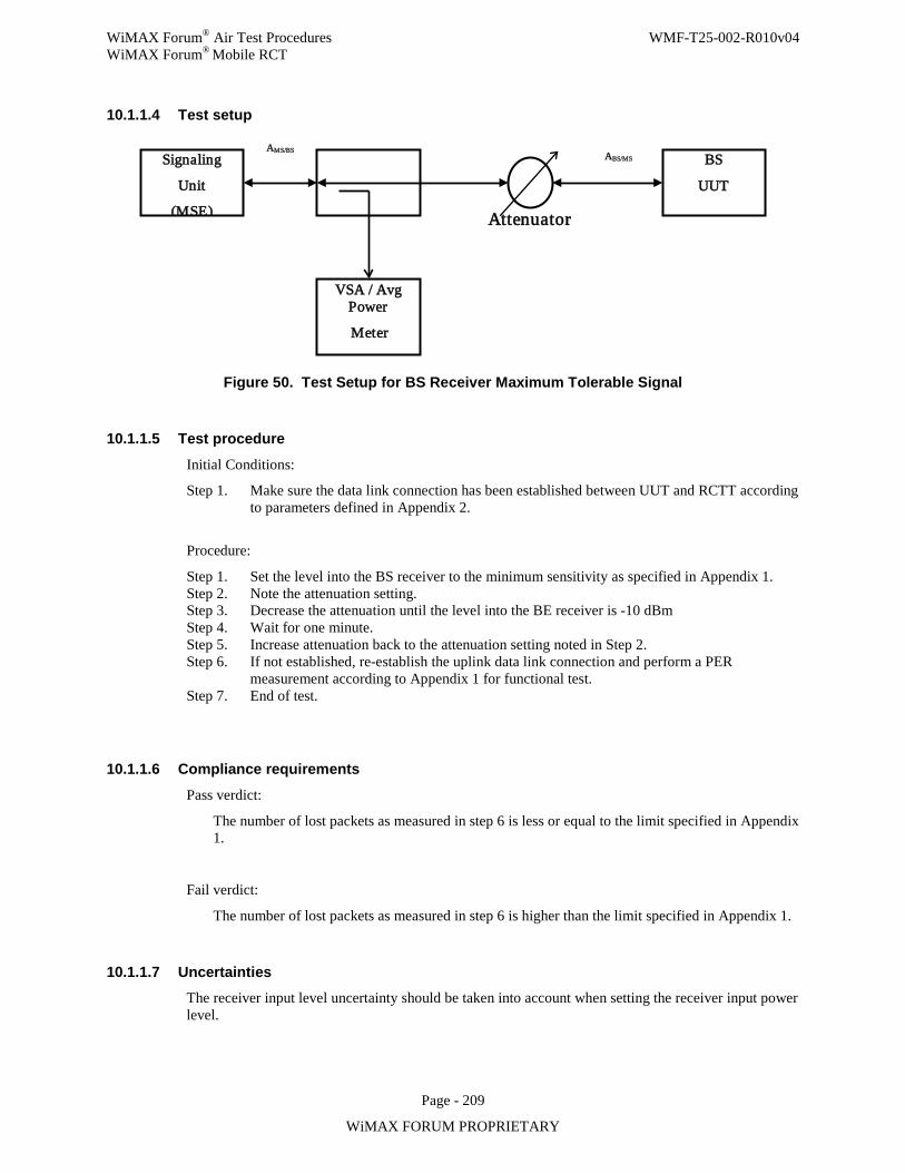
WiMAX Forum® Air Test Procedures WMF-T25-002-R010v04 WiMAX Forum® Mobile RCT
Page - 209
WiMAX FORUM PROPRIETARY
10.1.1.4 Test setup
Figure 50. Test Setup for BS Receiver Maximum Tolerable Signal
10.1.1.5 Test procedure
Initial Conditions:
Step 1. Make sure the data link connection has been established between UUT and RCTT according to parameters defined in Appendix 2.
Procedure:
Step 1. Set the level into the BS receiver to the minimum sensitivity as specified in Appendix 1. Step 2. Note the attenuation setting. Step 3. Decrease the attenuation until the level into the BE receiver is -10 dBm Step 4. Wait for one minute. Step 5. Increase attenuation back to the attenuation setting noted in Step 2. Step 6. If not established, re-establish the uplink data link connection and perform a PER
measurement according to Appendix 1 for functional test. Step 7. End of test.
10.1.1.6 Compliance requirements
Pass verdict:
The number of lost packets as measured in step 6 is less or equal to the limit specified in Appendix 1.
Fail verdict:
The number of lost packets as measured in step 6 is higher than the limit specified in Appendix 1.
10.1.1.7 Uncertainties The receiver input level uncertainty should be taken into account when setting the receiver input power level.
Signaling
Unit
(MSE)
VSA / Avg Power
Meter
BS
UUT
AMS/BS
Attenuator
ABS/MS
WiMAX Forum® Air Test Procedures WMF-T25-002-R010v04 WiMAX Forum® Mobile RCT
Page - 210
WiMAX FORUM PROPRIETARY
10.1.2 BS-02.1: Reserved
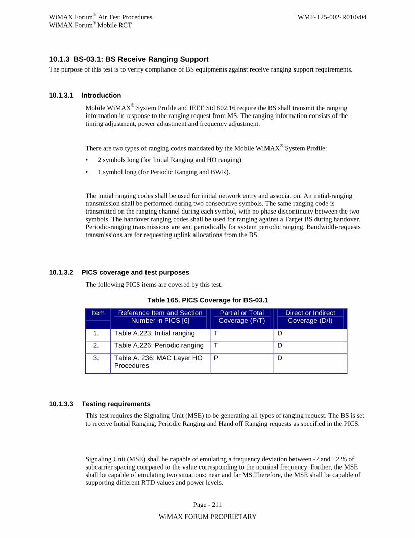
WiMAX Forum® Air Test Procedures WMF-T25-002-R010v04 WiMAX Forum® Mobile RCT
Page - 211
WiMAX FORUM PROPRIETARY
10.1.3 BS-03.1: BS Receive Ranging Support The purpose of this test is to verify compliance of BS equipments against receive ranging support requirements.
10.1.3.1 Introduction
Mobile WiMAX® System Profile and IEEE Std 802.16 require the BS shall transmit the ranging information in response to the ranging request from MS. The ranging information consists of the timing adjustment, power adjustment and frequency adjustment.
There are two types of ranging codes mandated by the Mobile WiMAX® System Profile:
• 2 symbols long (for Initial Ranging and HO ranging)
• 1 symbol long (for Periodic Ranging and BWR).
The initial ranging codes shall be used for initial network entry and association. An initial-ranging transmission shall be performed during two consecutive symbols. The same ranging code is transmitted on the ranging channel during each symbol, with no phase discontinuity between the two symbols. The handover ranging codes shall be used for ranging against a Target BS during handover. Periodic-ranging transmissions are sent periodically for system periodic ranging. Bandwidth-requests transmissions are for requesting uplink allocations from the BS.
10.1.3.2 PICS coverage and test purposes
The following PICS items are covered by this test.
Table 165. PICS Coverage for BS-03.1
Item Reference Item and Section Number in PICS [6]
Partial or Total Coverage (P/T)
Direct or Indirect Coverage (D/I)
1. Table A.223: Initial ranging T D
2. Table A.226: Periodic ranging T D
3. Table A. 236: MAC Layer HO Procedures
P D
10.1.3.3 Testing requirements This test requires the Signaling Unit (MSE) to be generating all types of ranging request. The BS is set to receive Initial Ranging, Periodic Ranging and Hand off Ranging requests as specified in the PICS.
Signaling Unit (MSE) shall be capable of emulating a frequency deviation between -2 and +2 % of subcarrier spacing compared to the value corresponding to the nominal frequency. Further, the MSE shall be capable of emulating two situations: near and far MS.Therefore, the MSE shall be capable of supporting different RTD values and power levels.
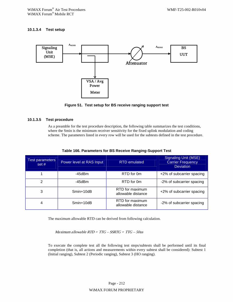
WiMAX Forum® Air Test Procedures WMF-T25-002-R010v04 WiMAX Forum® Mobile RCT
Page - 212
WiMAX FORUM PROPRIETARY
10.1.3.4 Test setup
Figure 51. Test setup for BS receive ranging support test
10.1.3.5 Test procedure As a preamble for the test procedure description, the following table summarizes the test conditions, where the Smin is the minimum receiver sensitivity for the fixed uplink modulation and coding scheme. The parameters listed in every row will be used for the subtests defined in the test procedure.
Table 166. Parameters for BS Receive Ranging-Support Test
Test parameters set # Power level at RAS Input RTD emulated
Signaling Unit (MSE) Carrier Frequency
Deviation
1 -45dBm RTD for 0m +2% of subcarrier spacing
2 -45dBm RTD for 0m -2% of subcarrier spacing
3 Smin+10dB RTD for maximum allowable distance +2% of subcarrier spacing
4 Smin+10dB RTD for maximum allowable distance -2% of subcarrier spacing
The maximum allowable RTD can be derived from following calculation.
Maximum allowable RTD = TTG – SSRTG = TTG – 50us
To execute the complete test all the following test steps/subtests shall be performed until its final completion (that is, all actions and measurements within every subtest shall be considered): Subtest 1 (Initial ranging), Subtest 2 (Periodic ranging), Subtest 3 (HO ranging).
Signaling Unit
(MSE)
VSA / Avg Power
Meter
BS
UUT
AMS/BS
Attenuator
ABS/MS
WiMAX Forum® Air Test Procedures WMF-T25-002-R010v04 WiMAX Forum® Mobile RCT
Page - 213
WiMAX FORUM PROPRIETARY
10.1.3.5.1 Subtest 1: Initial Ranging This subtest comprises the execution of the following generic subtest employing one specific parameter set previously listed in Table 191. In order to consider completely executed the subtest it is necessary to complete the execution of the generic subtest 4 times, each time using one of the 4 parameters set of the referred table.
Generic subtest procedure (to be execute using the parameter set #i described in Table 191— i varies from 1 to 4)
Initial conditions
The BS UUT and the signaling unit (MSE) are ready to initiate initial ranging, but the signaling unit has still not send any initial ranging CDMA code. The BS UUT is then awaiting the first transmission of initial ranging CDMA code from the signaling unit (MSE).
Generic subtest steps
Step 1. The signaling unit (MSE) send a initial ranging CDMA code, using the parameter set #i listed in Table 191.
Step 2. The BS UUT receives the initial ranging CDMA code and send to the signaling unit (MSE) the proper corrections.
Step 3. The signaling unit (MSE) receives such corrections and sends another initial ranging CDMA code with the corrections transmitted by BS UUT.
Step 4. Capture timing correction included in the RNG-RSP message. Step 5. Repeat Step 2 through Step 4 until MSE receive RNG-RSP message with Success Indicator. Step 6. End of generic subtest
10.1.3.5.2 Subtest 2: Periodic Ranging This subtest comprises the execution of the following generic subtest employing one specific parameter set previously listed in Table 191.
Generic subtest procedure
Initial conditions
The initial network entry including initial ranging has been completed and starting from a situation where the MSE enters into periodic ranging process.
Generic subtest steps
Step 1. The BS UUT receives the periodic ranging CDMA code and sends to the signaling unit (MSE) the proper corrections.
Step 2. The signaling unit (MSE) receives such corrections and stores for further processing the time offset correction.
Step 3. The signaling unit adopts the corrections sent by the BS UUT and sends a second periodic ranging CDMA code accordingly with these corrections.
Step 4. The BS UUT receives the new periodic ranging CDMA code and sends to the signaling unit (MSE) the new proper corrections.
Step 5. Capture timing correction included in the RNG-RSP message.
WiMAX Forum® Air Test Procedures WMF-T25-002-R010v04 WiMAX Forum® Mobile RCT
Page - 214
WiMAX FORUM PROPRIETARY
Step 6. Repeat Step 2 through Step 5 until MSE receive RNG-RSP message with Success Indicator.
Step 7. End of generic subtest
10.1.3.5.3 Subtest 3: Handover Ranging This subtest comprises the execution of the following generic subtest employing one specific parameter set previously listed in Table 191. In order to consider completely executed the subtest it is necessary to complete the execution of the generic subtest 4 times, each time using one of the 4 parameters set of the referred table.
Generic subtest procedure (to be execute using the parameter set #i described in Table 191— i varies from 1 to 4)
Initial conditions
The BS UUT and the signaling unit (MSE) are ready to perform HO process (HO ranging), but the signaling unit has still not send any HO ranging CDMA code. The BS UUT is then awaiting the first transmission of HO ranging CDMA code from the signaling unit (MSE). The internal state of the signaling unit will emulate the initiation of a HO process just for the purposes of this subtest.
Generic subtest steps
Step 1. The signaling unit (MSE) sends a HO CDMA code, using the parameter set #i listed in Table 191.
Step 2. The BS UUT receives the HO CDMA code and sends to the signaling unit (MSE) the proper corrections.
Step 3. The signaling unit (MSE) receives such corrections and sends another HO CDMA code with the corrections transmitted by BS UUT.
Step 4. Capture timing correction included in the RNG-RSP message. Step 5. Repeat Step 2 through Step 4 until MSE receive RNG-RSP message with
Success Indicator. Step 6. End of generic subtest.
10.1.3.6 Compliance requirements
Pass criteria
The test verdict is Pass if:
Timing correction included in the RNG-RSP message at the time of success indicator or right before that is within -/+CP/8 for all of the three subtests.
Fail criteria
The test verdict is Fail if:
Timing correction included in the RNG-RSP message at the time of success indicator or right before that is either smaller than –CP/8 or larger than +CP/8 for any of the three subtests.
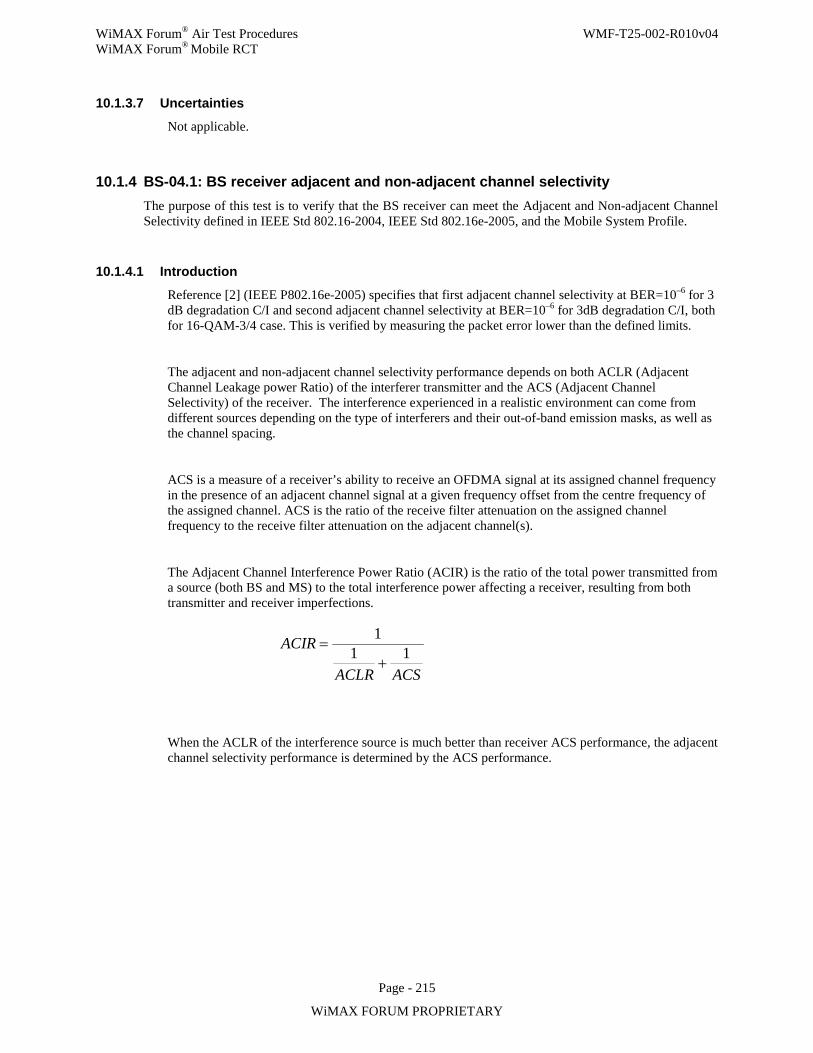
WiMAX Forum® Air Test Procedures WMF-T25-002-R010v04 WiMAX Forum® Mobile RCT
Page - 215
WiMAX FORUM PROPRIETARY
10.1.3.7 Uncertainties
Not applicable.
10.1.4 BS-04.1: BS receiver adjacent and non-adjacent channel selectivity The purpose of this test is to verify that the BS receiver can meet the Adjacent and Non-adjacent Channel Selectivity defined in IEEE Std 802.16-2004, IEEE Std 802.16e-2005, and the Mobile System Profile.
10.1.4.1 Introduction
Reference [2] (IEEE P802.16e-2005) specifies that first adjacent channel selectivity at BER=10–6 for 3 dB degradation C/I and second adjacent channel selectivity at BER=10–6 for 3dB degradation C/I, both for 16-QAM-3/4 case. This is verified by measuring the packet error lower than the defined limits.
The adjacent and non-adjacent channel selectivity performance depends on both ACLR (Adjacent Channel Leakage power Ratio) of the interferer transmitter and the ACS (Adjacent Channel Selectivity) of the receiver. The interference experienced in a realistic environment can come from different sources depending on the type of interferers and their out-of-band emission masks, as well as the channel spacing.
ACS is a measure of a receiver’s ability to receive an OFDMA signal at its assigned channel frequency in the presence of an adjacent channel signal at a given frequency offset from the centre frequency of the assigned channel. ACS is the ratio of the receive filter attenuation on the assigned channel frequency to the receive filter attenuation on the adjacent channel(s).
The Adjacent Channel Interference Power Ratio (ACIR) is the ratio of the total power transmitted from a source (both BS and MS) to the total interference power affecting a receiver, resulting from both transmitter and receiver imperfections.
When the ACLR of the interference source is much better than receiver ACS performance, the adjacent channel selectivity performance is determined by the ACS performance.
11 1ACIR
ACLR ACS
=+
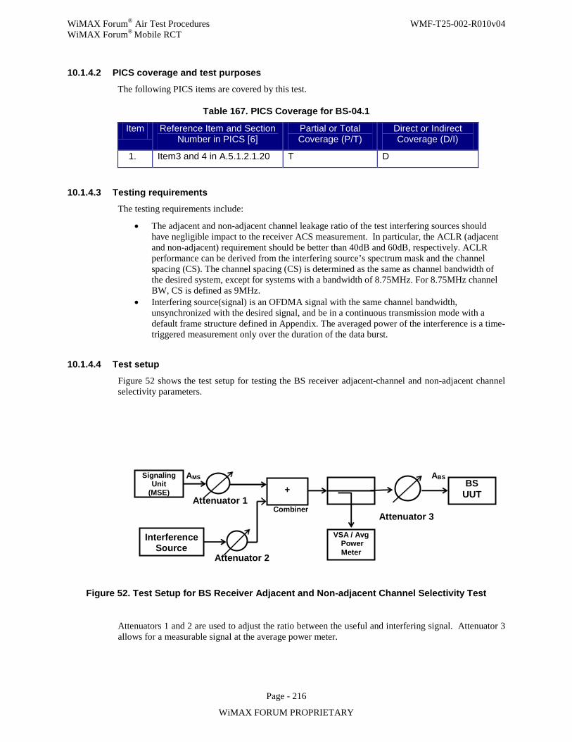
WiMAX Forum® Air Test Procedures WMF-T25-002-R010v04 WiMAX Forum® Mobile RCT
Page - 216
WiMAX FORUM PROPRIETARY
10.1.4.2 PICS coverage and test purposes
The following PICS items are covered by this test.
Table 167. PICS Coverage for BS-04.1
Item Reference Item and Section Number in PICS [6]
Partial or Total Coverage (P/T)
Direct or Indirect Coverage (D/I)
1. Item3 and 4 in A.5.1.2.1.20 T D
10.1.4.3 Testing requirements The testing requirements include:
• The adjacent and non-adjacent channel leakage ratio of the test interfering sources should have negligible impact to the receiver ACS measurement. In particular, the ACLR (adjacent and non-adjacent) requirement should be better than 40dB and 60dB, respectively. ACLR performance can be derived from the interfering source’s spectrum mask and the channel spacing (CS). The channel spacing (CS) is determined as the same as channel bandwidth of the desired system, except for systems with a bandwidth of 8.75MHz. For 8.75MHz channel BW, CS is defined as 9MHz.
• Interfering source(signal) is an OFDMA signal with the same channel bandwidth, unsynchronized with the desired signal, and be in a continuous transmission mode with a default frame structure defined in Appendix. The averaged power of the interference is a time-triggered measurement only over the duration of the data burst.
10.1.4.4 Test setup
Figure 52 shows the test setup for testing the BS receiver adjacent-channel and non-adjacent channel selectivity parameters.
Attenuator 2
Signaling Unit
(MSE)
VSA / Avg Power Meter
BS UUT
AMS
Attenuator 1
ABS
+
Interference Source
Combiner Attenuator 3
Figure 52. Test Setup for BS Receiver Adjacent and Non-adjacent Channel Selectivity Test
Attenuators 1 and 2 are used to adjust the ratio between the useful and interfering signal. Attenuator 3 allows for a measurable signal at the average power meter.
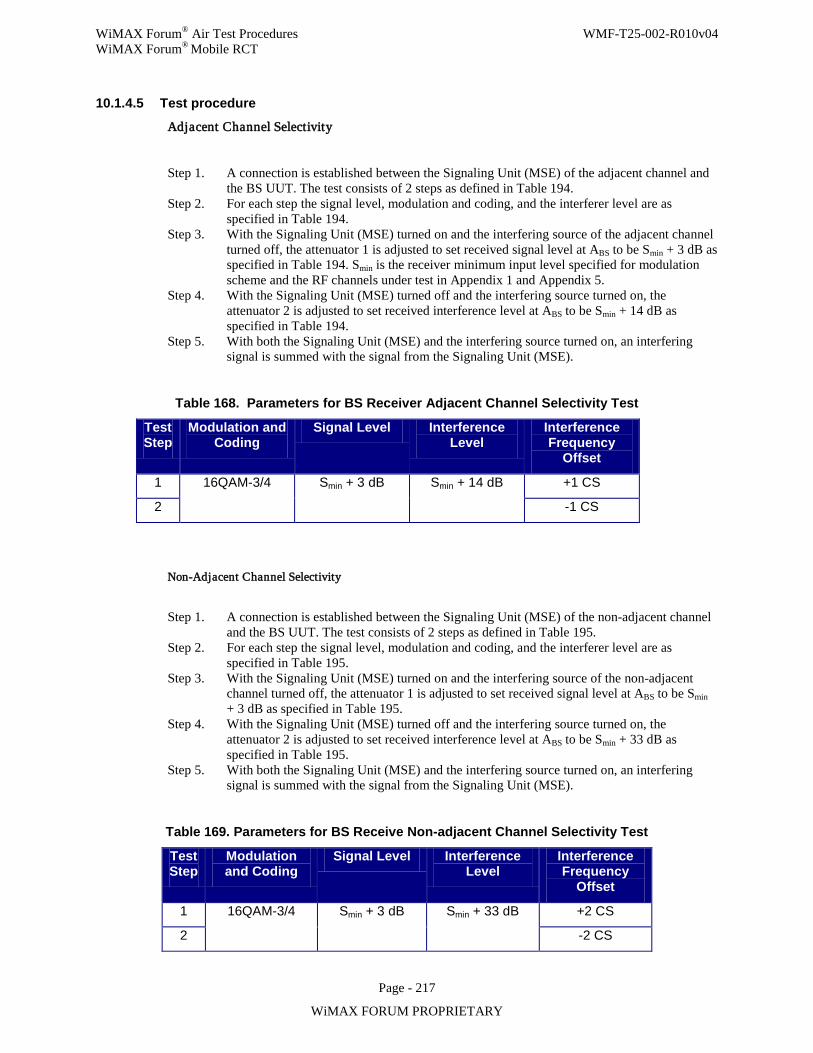
WiMAX Forum® Air Test Procedures WMF-T25-002-R010v04 WiMAX Forum® Mobile RCT
Page - 217
WiMAX FORUM PROPRIETARY
10.1.4.5 Test procedure
Adjacent Channel Selectivity
Step 1. A connection is established between the Signaling Unit (MSE) of the adjacent channel and the BS UUT. The test consists of 2 steps as defined in Table 194.
Step 2. For each step the signal level, modulation and coding, and the interferer level are as specified in Table 194.
Step 3. With the Signaling Unit (MSE) turned on and the interfering source of the adjacent channel turned off, the attenuator 1 is adjusted to set received signal level at ABS to be Smin + 3 dB as specified in Table 194. Smin is the receiver minimum input level specified for modulation scheme and the RF channels under test in Appendix 1 and Appendix 5.
Step 4. With the Signaling Unit (MSE) turned off and the interfering source turned on, the attenuator 2 is adjusted to set received interference level at ABS to be Smin + 14 dB as specified in Table 194.
Step 5. With both the Signaling Unit (MSE) and the interfering source turned on, an interfering signal is summed with the signal from the Signaling Unit (MSE).
Table 168. Parameters for BS Receiver Adjacent Channel Selectivity Test
Test Step
Modulation and Coding
Signal Level Interference Level
Interference Frequency
Offset
1 16QAM-3/4 Smin + 3 dB Smin + 14 dB +1 CS
2 -1 CS
Non-Adjacent Channel Selectivity
Step 1. A connection is established between the Signaling Unit (MSE) of the non-adjacent channel and the BS UUT. The test consists of 2 steps as defined in Table 195.
Step 2. For each step the signal level, modulation and coding, and the interferer level are as specified in Table 195.
Step 3. With the Signaling Unit (MSE) turned on and the interfering source of the non-adjacent channel turned off, the attenuator 1 is adjusted to set received signal level at ABS to be Smin + 3 dB as specified in Table 195.
Step 4. With the Signaling Unit (MSE) turned off and the interfering source turned on, the attenuator 2 is adjusted to set received interference level at ABS to be Smin + 33 dB as specified in Table 195.
Step 5. With both the Signaling Unit (MSE) and the interfering source turned on, an interfering signal is summed with the signal from the Signaling Unit (MSE).
Table 169. Parameters for BS Receive Non-adjacent Channel Selectivity Test
Test Step
Modulation and Coding
Signal Level Interference Level
Interference Frequency
Offset
1 16QAM-3/4 Smin + 3 dB Smin + 33 dB +2 CS
2 -2 CS
WiMAX Forum® Air Test Procedures WMF-T25-002-R010v04 WiMAX Forum® Mobile RCT
Page - 218
WiMAX FORUM PROPRIETARY
10.1.4.6 Compliance requirements
Adjacent Channel Selectivity
Pass Criteria:
The number of lost packets during all PER measurements is less or equal to the limit specified in Appendix 1 for Qualitative tests.
Fail Criteria:
The number of lost packets during all PER measurements is bigger than the limit specified in Appendix 1 for Qualitative tests.
Non-Adjacent Channel Selectivity
Pass Criteria:
The number of lost packets during all PER measurements is less or equal to the limit specified in Appendix 1 for Qualitative tests.
Fail Criteria:
The number of lost packets during all PER measurements is bigger than the limit specified in Appendix 1 for Qualitative tests.
10.1.4.7 Uncertainties
Not applicable.
10.1.5 BS-05.1: BS Rx Maximum Input Level On-channel reception tolerance The purpose of this test is to test a BS receiver capability of decoding an on-channel input signal of maximum required power level.
10.1.5.1 Introduction
Mobile WiMAX® System Profile and IEEE Std 802.16e-2005 [section 8.4.13.3.2] specifies that BS receiver shall be capable of decoding a maximum on-channel signal of -45 dBm. This is verified by measuring the packet error rates which are lower than defined limits at least robust modulation and coding.
10.1.5.2 PICS Coverage
The following PICS items are covered by this test
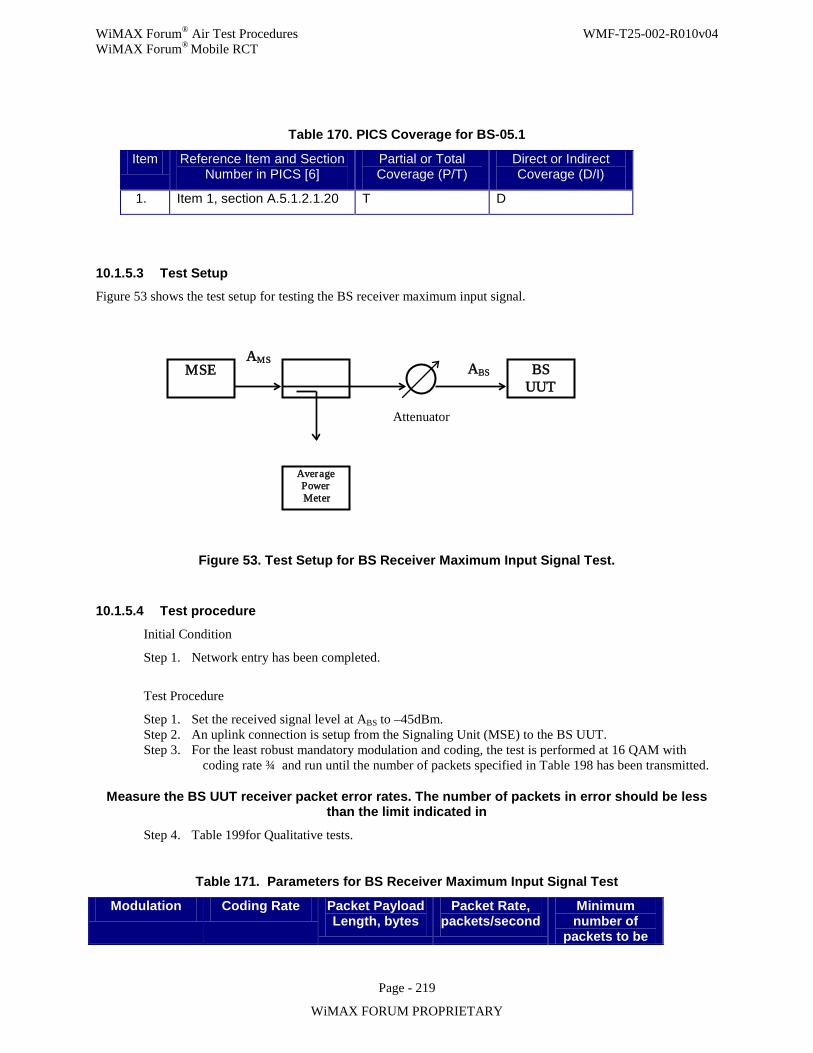
WiMAX Forum® Air Test Procedures WMF-T25-002-R010v04 WiMAX Forum® Mobile RCT
Page - 219
WiMAX FORUM PROPRIETARY
Table 170. PICS Coverage for BS-05.1
Item Reference Item and Section Number in PICS [6]
Partial or Total Coverage (P/T)
Direct or Indirect Coverage (D/I)
1. Item 1, section A.5.1.2.1.20 T D
10.1.5.3 Test Setup Figure 53 shows the test setup for testing the BS receiver maximum input signal.
Figure 53. Test Setup for BS Receiver Maximum Input Signal Test.
10.1.5.4 Test procedure
Initial Condition
Step 1. Network entry has been completed.
Test Procedure
Step 1. Set the received signal level at ABS to –45dBm. Step 2. An uplink connection is setup from the Signaling Unit (MSE) to the BS UUT. Step 3. For the least robust mandatory modulation and coding, the test is performed at 16 QAM with
coding rate ¾ and run until the number of packets specified in Table 198 has been transmitted.
Measure the BS UUT receiver packet error rates. The number of packets in error should be less than the limit indicated in
Step 4. Table 199for Qualitative tests.
Table 171. Parameters for BS Receiver Maximum Input Signal Test
Modulation Coding Rate Packet Payload Length, bytes
Packet Rate, packets/second
Minimum number of
packets to be
MSE
Average Power Meter
BS UUT
AMS
Attenuator
ABS
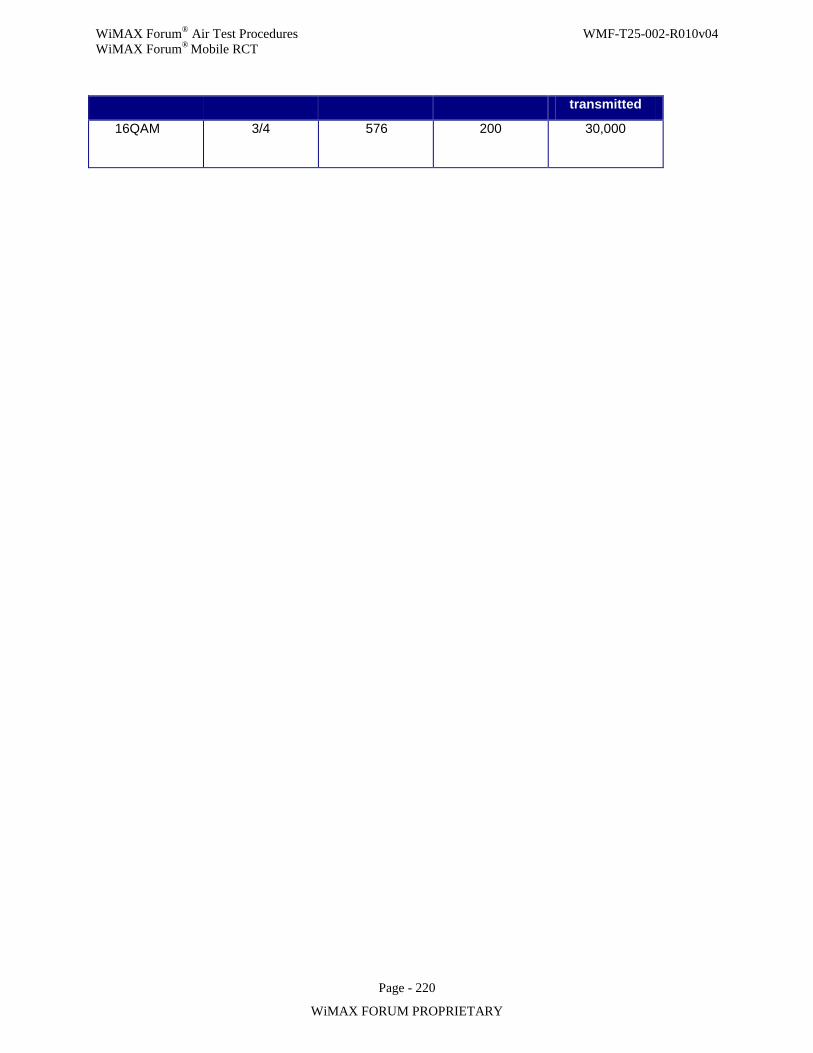
WiMAX Forum® Air Test Procedures WMF-T25-002-R010v04 WiMAX Forum® Mobile RCT
Page - 220
WiMAX FORUM PROPRIETARY
transmitted
16QAM 3/4 576
200
30,000
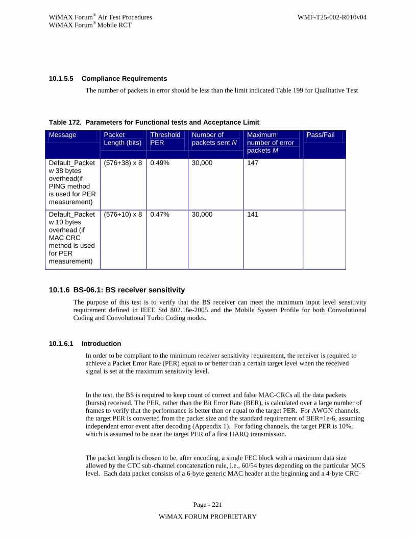
WiMAX Forum® Air Test Procedures WMF-T25-002-R010v04 WiMAX Forum® Mobile RCT
Page - 221
WiMAX FORUM PROPRIETARY
10.1.5.5 Compliance Requirements The number of packets in error should be less than the limit indicated Table 199 for Qualitative Test
Table 172. Parameters for Functional tests and Acceptance Limit
Message Packet Length (bits)
Threshold PER
Number of packets sent N
Maximum number of error packets M
Pass/Fail
Default_Packet w 38 bytes overhead(if PING method is used for PER measurement)
(576+38) x 8 0.49% 30,000 147
Default_Packet w 10 bytes overhead (if MAC CRC method is used for PER measurement)
(576+10) x 8 0.47% 30,000 141
10.1.6 BS-06.1: BS receiver sensitivity The purpose of this test is to verify that the BS receiver can meet the minimum input level sensitivity requirement defined in IEEE Std 802.16e-2005 and the Mobile System Profile for both Convolutional Coding and Convolutional Turbo Coding modes.
10.1.6.1 Introduction
In order to be compliant to the minimum receiver sensitivity requirement, the receiver is required to achieve a Packet Error Rate (PER) equal to or better than a certain target level when the received signal is set at the maximum sensitivity level.
In the test, the BS is required to keep count of correct and false MAC-CRCs all the data packets (bursts) received. The PER, rather than the Bit Error Rate (BER), is calculated over a large number of frames to verify that the performance is better than or equal to the target PER. For AWGN channels, the target PER is converted from the packet size and the standard requirement of BER=1e-6, assuming independent error event after decoding (Appendix 1). For fading channels, the target PER is 10%, which is assumed to be near the target PER of a first HARQ transmission.
The packet length is chosen to be, after encoding, a single FEC block with a maximum data size allowed by the CTC sub-channel concatenation rule, i.e., 60/54 bytes depending on the particular MCS level. Each data packet consists of a 6-byte generic MAC header at the beginning and a 4-byte CRC-
WiMAX Forum® Air Test Procedures WMF-T25-002-R010v04 WiMAX Forum® Mobile RCT
Page - 222
WiMAX FORUM PROPRIETARY
32 at the end, leaving the remaining as payload bits. Random payload bits are used. The CRC is calculated based on MAC header and the payload.
IEEE Std 802.16e-2005 specifies that the BER measured after the FEC shall be less than 10–6 at the
power levels given by 10 10114 10log ( ) 10log s Usedss Rx
FFT
F NR SNR R ImpLoss NF
N
= − + − + + +
Where
SNRRx is the receiver SNR for different levels of coding rate and modulation,
R is the repetition factor, as described in Section 8.4.9,
FS is the sampling frequency in MHz as defined in Section 8.4.2.4,
ImpLoss is the implementation loss, which includes non-ideal receiver effects such as channel estimation errors, tracking errors, quantization errors, and phase noise. The assumed value is 5 dB.
NF is the receiver noise figure, referenced to the antenna port. The assumed value is 8 dB.
The specification further defines that the minimum input levels are measured as follows:
— Using the defined standardized message packet formats.
— Using an AWGN channel.
The test verifies that the BS under test will conform to the minimum performance requirement set forth in the standard, i.e., under maximum implementation loss of 5 dB and maximal noise figure of 8dB, i.e.,
10 10114 10log ( ) 10log 13s Usedss Rx
FFT
F NR SNR R
N
= − + − + +
IEEE Std 802.16e-2005 only gives the receiver SNR table (table 338) for a tail-biting convolutional code (CC). According to the Mobile System Profile, CC is mandatory only for FCH, and CTC is used in all other transmissions. Therefore, the receiver SNR table defined in the Mobile System Profile will be used for CTC reception testing Note: the values there are for 60/54/48 bytes only.
In addition to AWGN the test is performed for fading channels Ped B and Veh A.
10.1.6.2 Test Setup
Figure 54 shows the test setup for testing the BS receiver sensitivity. Power should be measured and averaged only during the symbol times where data are allocated and exist.
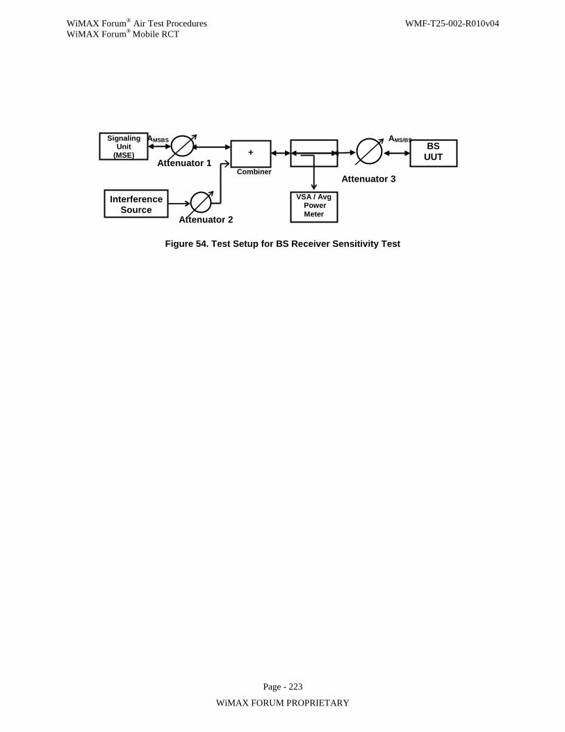
WiMAX Forum® Air Test Procedures WMF-T25-002-R010v04 WiMAX Forum® Mobile RCT
Page - 223
WiMAX FORUM PROPRIETARY
Attenuator 2
Signaling Unit
(MSE)
VSA / Avg Power Meter
BS UUT
AMSBS
Attenuator 1
AMS/BS
+
Interference Source
Combiner Attenuator 3
Figure 54. Test Setup for BS Receiver Sensitivity Test
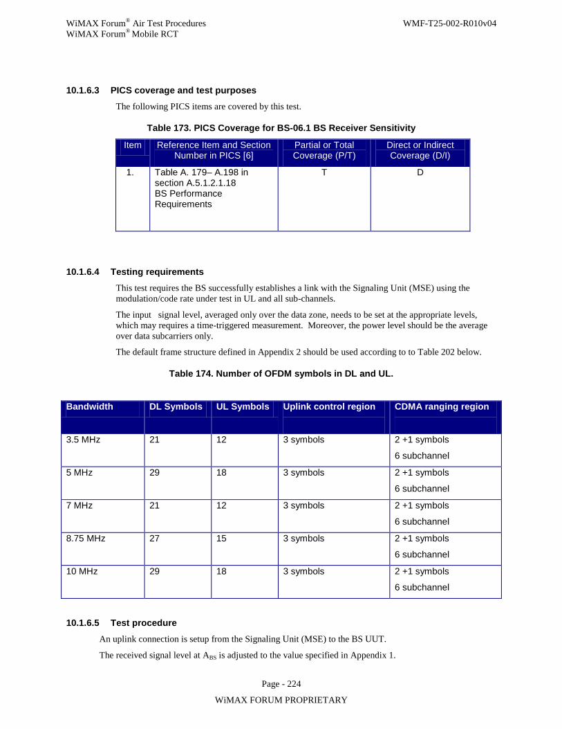
WiMAX Forum® Air Test Procedures WMF-T25-002-R010v04 WiMAX Forum® Mobile RCT
Page - 224
WiMAX FORUM PROPRIETARY
10.1.6.3 PICS coverage and test purposes
The following PICS items are covered by this test.
Table 173. PICS Coverage for BS-06.1 BS Receiver Sensitivity
Item Reference Item and Section Number in PICS [6]
Partial or Total Coverage (P/T)
Direct or Indirect Coverage (D/I)
1. Table A. 179– A.198 in section A.5.1.2.1.18 BS Performance Requirements
T D
10.1.6.4 Testing requirements
This test requires the BS successfully establishes a link with the Signaling Unit (MSE) using the modulation/code rate under test in UL and all sub-channels.
The input signal level, averaged only over the data zone, needs to be set at the appropriate levels, which may requires a time-triggered measurement. Moreover, the power level should be the average over data subcarriers only.
The default frame structure defined in Appendix 2 should be used according to to Table 202 below.
Table 174. Number of OFDM symbols in DL and UL.
Bandwidth DL Symbols UL Symbols Uplink control region
CDMA ranging region
3.5 MHz 21 12 3 symbols 2 +1 symbols
6 subchannel
5 MHz 29 18 3 symbols 2 +1 symbols
6 subchannel
7 MHz 21 12 3 symbols 2 +1 symbols
6 subchannel
8.75 MHz 27 15 3 symbols 2 +1 symbols
6 subchannel
10 MHz 29 18 3 symbols 2 +1 symbols
6 subchannel
10.1.6.5 Test procedure
An uplink connection is setup from the Signaling Unit (MSE) to the BS UUT.
The received signal level at ABS is adjusted to the value specified in Appendix 1.
WiMAX Forum® Air Test Procedures WMF-T25-002-R010v04 WiMAX Forum® Mobile RCT
Page - 225
WiMAX FORUM PROPRIETARY
Test packets are generated such that there is at least one packet per frame with the test configuration;
No fragmentation.
No header suppression.
No SDU packing.
No ARQ.
No encryption.
CRC enabled
The received signal level at ABS is adjusted to the limit specified in Table 201.
For each modulation and coding the test is performed for all configurations described in Table 15. The number of packets in error should be less than the limit indicated in Appendix 1 for Qualitative tests.
MAC-CRC test:
This test should be performed first to verify that the receiver can correctly count MAC-CRC depending on successful/unsuccessful check. The test procedure is:
• Use allocate one 60-byte QPSK rate-1/2 packet in each frame • Set the signal level at 10dB above sensitivity • For a certain percentage (e.g., 50%) of 2000 packets, the CRC bits are flipped (negated). BS UUT
should report counter values corresponding to the number of false and correct packets sent. For those packets that the MSE expects a CRC pass, only a single (1) error can be allowed (i.e., a single CRC fail for 1000 packets)
Test case 1: Receiver sensitivity under AWGN
The received signal level at the receiver input is adjusted to the maximum sensitivity level specified in Table A. 179– A.198 in section A.5.1.2.1.18 BS Performance Requirements of the Mobile WiMAX PICS for the relevant coding and channel bandwidth (see also Appendix 1) plus the boosting offset. The values are the same if derived from the “required SNR” column of Table 203 and the equation:
10 10114 10log ( ) 10log 13s Usedss Rx
FFT
F NR SNR R
N
= − + − + +
where Fs is the sampling rate and Nused is the number of used subcarriers.
For each modulation and coding, the test is performed for the different packet according to Table 203 and run until the number of frames specified in the table has been transmitted. The number of packets in error should be less than the limit indicated in the last column of the table.
For each MCS below the test is evaluated at 95% confidence level
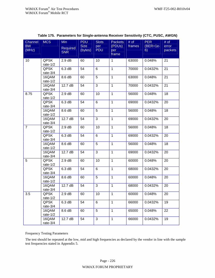
WiMAX Forum® Air Test Procedures WMF-T25-002-R010v04 WiMAX Forum® Mobile RCT
Page - 226
WiMAX FORUM PROPRIETARY
Table 175. Parameters for Single-antenna Receiver Sensitivity (CTC, PUSC, AWGN)
Channel BW (MHz)
MCS Min
Required SNR
PDU Size (bytes)
Slots per PDU
Packets (PDUs) per frame
# of frames
PER (BER=1e-6)
# of error packets
10 QPSK rate-1/2
2.9 dB 60 10 1 63000 0.048% 21
QPSK rate-3/4
6.3 dB 54 6 1 70000 0.0432% 21
16QAM rate-1/2
8.6 dB 60 5 1 63000 0.048% 21
16QAM rate-3/4
12.7 dB
54 3 1 70000 0.0432% 21
8.75 QPSK rate-1/2
2.9 dB 60 10 1 56000 0.048% 18
QPSK rate-3/4
6.3 dB 54 6 1 69000 0.0432% 20
16QAM rate-1/2
8.6 dB 60 5 1 56000 0.048% 18
16QAM rate-3/4
12.7 dB
54 3 1 69000 0.0432% 20
7 QPSK rate-1/2
2.9 dB 60 10 1 56000 0.048% 18
QPSK rate-3/4
6.3 dB 54 6 1 69000 0.0432% 20
16QAM rate-1/2
8.6 dB 60 5 1 56000 0.048% 18
16QAM rate-3/4
12.7 dB
54 3 1 69000 0.0432% 20
5 QPSK rate-1/2
2.9 dB 60 10 1 60000 0.048% 20
QPSK rate-3/4
6.3 dB 54 6 1 68000 0.0432% 20
16QAM rate-1/2
8.6 dB 60 5 1 60000 0.048% 20
16QAM rate-3/4
12.7 dB
54 3 1 68000 0.0432% 20
3.5 QPSK rate-1/2
2.9 dB 60 10 1 60000 0.048% 20
QPSK rate-3/4
6.3 dB 54 6 1 66000 0.0432% 19
16QAM rate-1/2
8.6 dB 60 5 1 65000 0.048% 22
16QAM rate-3/4
12.7 dB
54 3 1 66000 0.0432% 19
Frequency Testing Parameters
The test should be repeated at the low, mid and high frequencies as declared by the vendor in line with the sample test frequencies stated in Appendix 5.
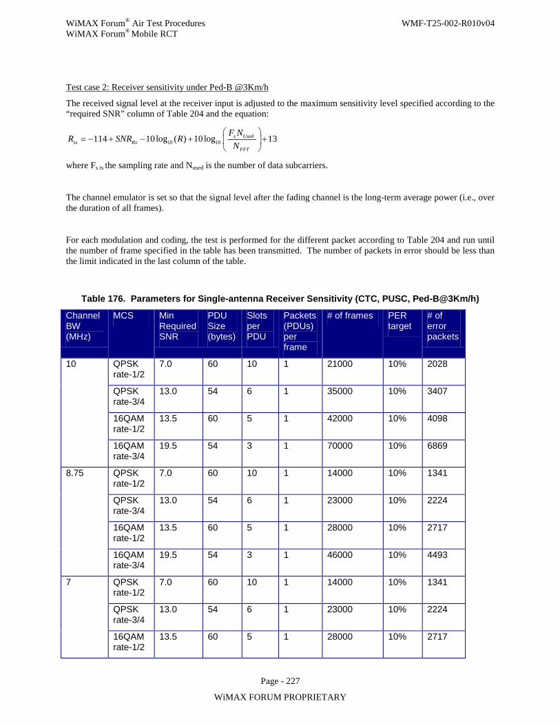
WiMAX Forum® Air Test Procedures WMF-T25-002-R010v04 WiMAX Forum® Mobile RCT
Page - 227
WiMAX FORUM PROPRIETARY
Test case 2: Receiver sensitivity under Ped-B @3Km/h
The received signal level at the receiver input is adjusted to the maximum sensitivity level specified according to the “required SNR” column of Table 204 and the equation:
10 10114 10log ( ) 10log 13s Usedss Rx
FFT
F NR SNR R
N
= − + − + +
where Fs is the sampling rate and Nused is the number of data subcarriers.
The channel emulator is set so that the signal level after the fading channel is the long-term average power (i.e., over the duration of all frames).
For each modulation and coding, the test is performed for the different packet according to Table 204 and run until the number of frame specified in the table has been transmitted. The number of packets in error should be less than the limit indicated in the last column of the table.
Table 176. Parameters for Single-antenna Receiver Sensitivity (CTC, PUSC, Ped-B@3Km/h)
Channel BW (MHz)
MCS Min Required SNR
PDU Size (bytes)
Slots per PDU
Packets (PDUs) per frame
# of frames PER target
# of error packets
10 QPSK rate-1/2
7.0 60 10 1 21000 10% 2028
QPSK rate-3/4
13.0 54 6 1 35000 10% 3407
16QAM rate-1/2
13.5 60 5 1 42000 10% 4098
16QAM rate-3/4
19.5 54 3 1 70000 10% 6869
8.75 QPSK rate-1/2
7.0 60 10 1 14000 10% 1341
QPSK rate-3/4
13.0 54 6 1 23000 10% 2224
16QAM rate-1/2
13.5 60 5 1 28000 10% 2717
16QAM rate-3/4
19.5 54 3 1 46000 10% 4493
7 QPSK rate-1/2
7.0 60 10 1 14000 10% 1341
QPSK rate-3/4
13.0 54 6 1 23000 10% 2224
16QAM rate-1/2
13.5 60 5 1 28000 10% 2717
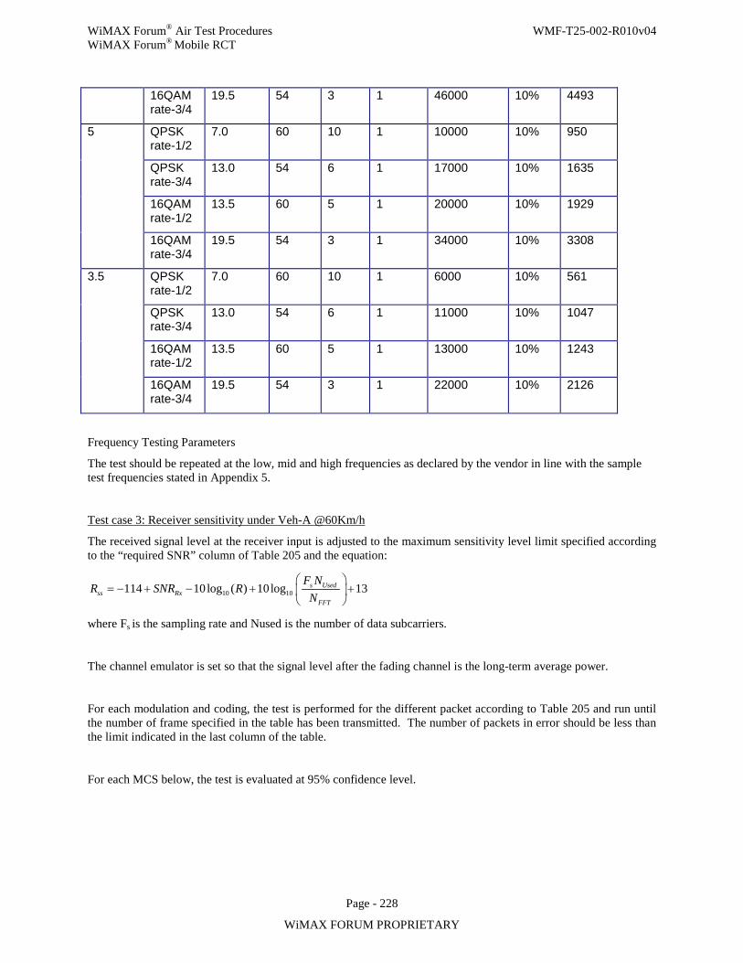
WiMAX Forum® Air Test Procedures WMF-T25-002-R010v04 WiMAX Forum® Mobile RCT
Page - 228
WiMAX FORUM PROPRIETARY
16QAM rate-3/4
19.5 54 3 1 46000 10% 4493
5 QPSK rate-1/2
7.0 60 10 1 10000 10% 950
QPSK rate-3/4
13.0 54 6 1 17000 10% 1635
16QAM rate-1/2
13.5 60 5 1 20000 10% 1929
16QAM rate-3/4
19.5 54 3 1 34000 10% 3308
3.5 QPSK rate-1/2
7.0 60 10 1 6000 10% 561
QPSK rate-3/4
13.0 54 6 1 11000 10% 1047
16QAM rate-1/2
13.5 60 5 1 13000 10% 1243
16QAM rate-3/4
19.5 54 3 1 22000 10% 2126
Frequency Testing Parameters
The test should be repeated at the low, mid and high frequencies as declared by the vendor in line with the sample test frequencies stated in Appendix 5.
Test case 3: Receiver sensitivity under Veh-A @60Km/h
The received signal level at the receiver input is adjusted to the maximum sensitivity level limit specified according to the “required SNR” column of Table 205 and the equation:
10 10114 10log ( ) 10log 13s Usedss Rx
FFT
F NR SNR R
N
= − + − + +
where Fs is the sampling rate and Nused is the number of data subcarriers.
The channel emulator is set so that the signal level after the fading channel is the long-term average power.
For each modulation and coding, the test is performed for the different packet according to Table 205 and run until the number of frame specified in the table has been transmitted. The number of packets in error should be less than the limit indicated in the last column of the table.
For each MCS below, the test is evaluated at 95% confidence level.
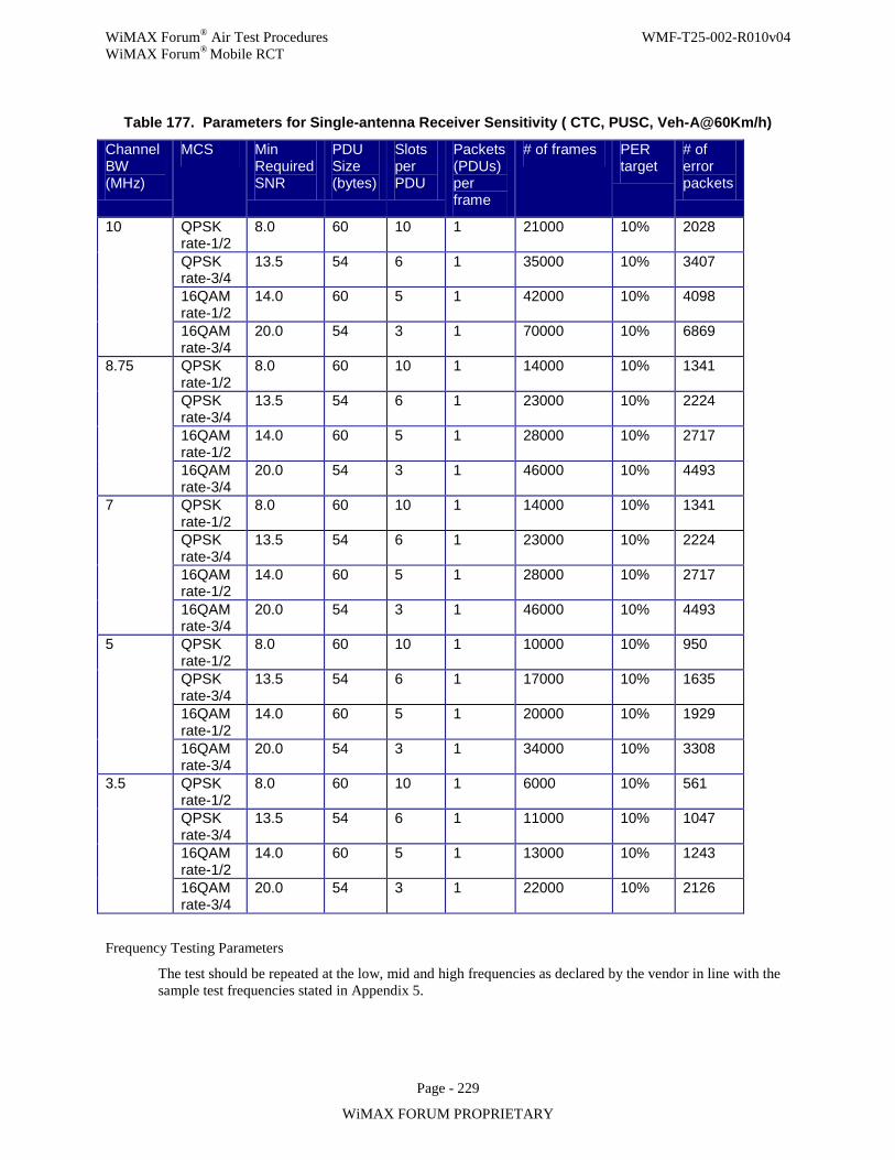
WiMAX Forum® Air Test Procedures WMF-T25-002-R010v04 WiMAX Forum® Mobile RCT
Page - 229
WiMAX FORUM PROPRIETARY
Table 177. Parameters for Single-antenna Receiver Sensitivity ( CTC, PUSC, Veh-A@60Km/h)
Channel BW (MHz)
MCS Min Required SNR
PDU Size (bytes)
Slots per PDU
Packets (PDUs) per frame
# of frames PER target
# of error packets
10 QPSK rate-1/2
8.0 60 10 1 21000 10% 2028
QPSK rate-3/4
13.5 54 6 1 35000 10% 3407
16QAM rate-1/2
14.0 60 5 1 42000 10% 4098
16QAM rate-3/4
20.0 54 3 1 70000 10% 6869
8.75 QPSK rate-1/2
8.0 60 10 1 14000 10% 1341
QPSK rate-3/4
13.5 54 6 1 23000 10% 2224
16QAM rate-1/2
14.0 60 5 1 28000 10% 2717
16QAM rate-3/4
20.0 54 3 1 46000 10% 4493
7 QPSK rate-1/2
8.0 60 10 1 14000 10% 1341
QPSK rate-3/4
13.5 54 6 1 23000 10% 2224
16QAM rate-1/2
14.0 60 5 1 28000 10% 2717
16QAM rate-3/4
20.0 54 3 1 46000 10% 4493
5 QPSK rate-1/2
8.0 60 10 1 10000 10% 950
QPSK rate-3/4
13.5 54 6 1 17000 10% 1635
16QAM rate-1/2
14.0 60 5 1 20000 10% 1929
16QAM rate-3/4
20.0 54 3 1 34000 10% 3308
3.5 QPSK rate-1/2
8.0 60 10 1 6000 10% 561
QPSK rate-3/4
13.5 54 6 1 11000 10% 1047
16QAM rate-1/2
14.0 60 5 1 13000 10% 1243
16QAM rate-3/4
20.0 54 3 1 22000 10% 2126
Frequency Testing Parameters
The test should be repeated at the low, mid and high frequencies as declared by the vendor in line with the sample test frequencies stated in Appendix 5.
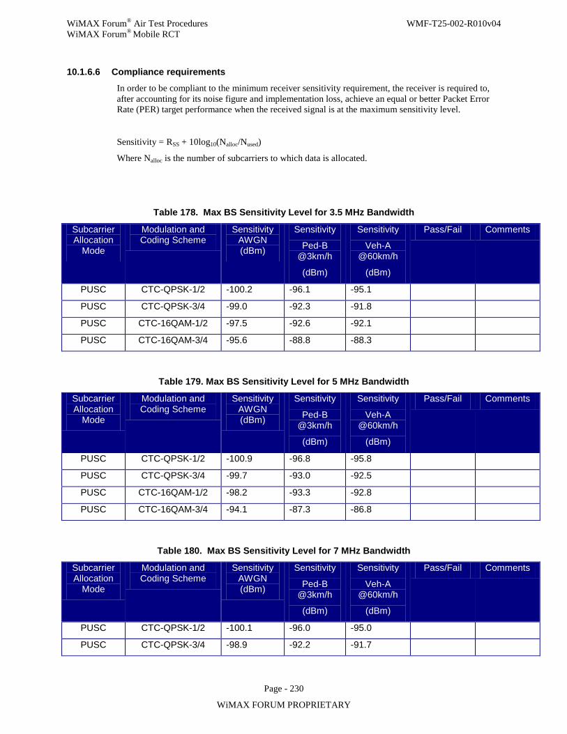
WiMAX Forum® Air Test Procedures WMF-T25-002-R010v04 WiMAX Forum® Mobile RCT
Page - 230
WiMAX FORUM PROPRIETARY
10.1.6.6 Compliance requirements
In order to be compliant to the minimum receiver sensitivity requirement, the receiver is required to, after accounting for its noise figure and implementation loss, achieve an equal or better Packet Error Rate (PER) target performance when the received signal is at the maximum sensitivity level.
Sensitivity = RSS + 10log10(Nalloc/Nused)
Where Nalloc is the number of subcarriers to which data is allocated.
Table 178. Max BS Sensitivity Level for 3.5 MHz Bandwidth
Subcarrier Allocation
Mode
Modulation and Coding Scheme
Sensitivity AWGN (dBm)
Sensitivity
Ped-B @3km/h
(dBm)
Sensitivity
Veh-A @60km/h
(dBm)
Pass/Fail Comments
PUSC CTC-QPSK-1/2 -100.2 -96.1 -95.1
PUSC CTC-QPSK-3/4 -99.0 -92.3 -91.8
PUSC CTC-16QAM-1/2 -97.5 -92.6 -92.1
PUSC CTC-16QAM-3/4 -95.6 -88.8 -88.3
Table 179. Max BS Sensitivity Level for 5 MHz Bandwidth
Subcarrier Allocation
Mode
Modulation and Coding Scheme
Sensitivity AWGN (dBm)
Sensitivity
Ped-B @3km/h
(dBm)
Sensitivity
Veh-A @60km/h
(dBm)
Pass/Fail Comments
PUSC CTC-QPSK-1/2 -100.9 -96.8 -95.8
PUSC CTC-QPSK-3/4 -99.7 -93.0 -92.5
PUSC CTC-16QAM-1/2 -98.2 -93.3 -92.8
PUSC CTC-16QAM-3/4 -94.1 -87.3 -86.8
Table 180. Max BS Sensitivity Level for 7 MHz Bandwidth
Subcarrier Allocation
Mode
Modulation and Coding Scheme
Sensitivity AWGN (dBm)
Sensitivity
Ped-B @3km/h
(dBm)
Sensitivity
Veh-A @60km/h
(dBm)
Pass/Fail Comments
PUSC CTC-QPSK-1/2 -100.1 -96.0 -95.0
PUSC CTC-QPSK-3/4 -98.9 -92.2 -91.7
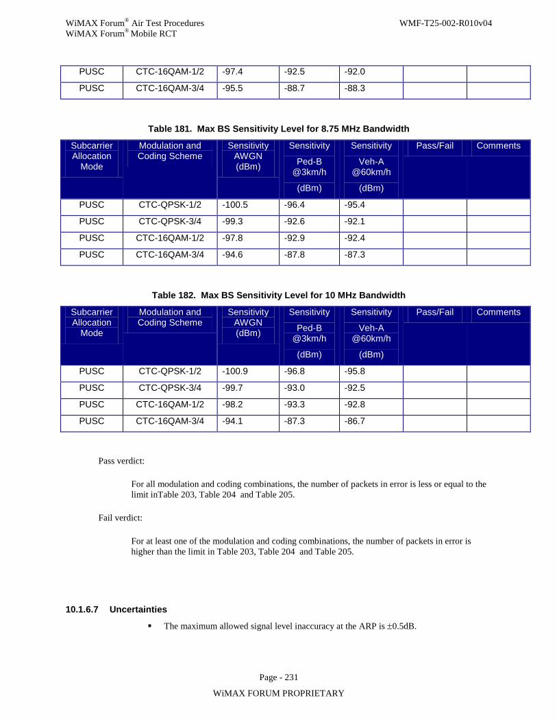
WiMAX Forum® Air Test Procedures WMF-T25-002-R010v04 WiMAX Forum® Mobile RCT
Page - 231
WiMAX FORUM PROPRIETARY
PUSC CTC-16QAM-1/2 -97.4 -92.5 -92.0
PUSC CTC-16QAM-3/4 -95.5 -88.7 -88.3
Table 181. Max BS Sensitivity Level for 8.75 MHz Bandwidth
Subcarrier Allocation
Mode
Modulation and Coding Scheme
Sensitivity AWGN (dBm)
Sensitivity
Ped-B @3km/h
(dBm)
Sensitivity
Veh-A @60km/h
(dBm)
Pass/Fail Comments
PUSC CTC-QPSK-1/2 -100.5 -96.4 -95.4
PUSC CTC-QPSK-3/4 -99.3 -92.6 -92.1
PUSC CTC-16QAM-1/2 -97.8 -92.9 -92.4
PUSC CTC-16QAM-3/4 -94.6 -87.8 -87.3
Table 182. Max BS Sensitivity Level for 10 MHz Bandwidth
Subcarrier Allocation
Mode
Modulation and Coding Scheme
Sensitivity AWGN (dBm)
Sensitivity
Ped-B @3km/h
(dBm)
Sensitivity
Veh-A @60km/h
(dBm)
Pass/Fail Comments
PUSC CTC-QPSK-1/2 -100.9 -96.8 -95.8
PUSC CTC-QPSK-3/4 -99.7 -93.0 -92.5
PUSC CTC-16QAM-1/2 -98.2 -93.3 -92.8
PUSC CTC-16QAM-3/4 -94.1 -87.3 -86.7
Pass verdict:
For all modulation and coding combinations, the number of packets in error is less or equal to the limit inTable 203, Table 204 and Table 205.
Fail verdict:
For at least one of the modulation and coding combinations, the number of packets in error is higher than the limit in Table 203, Table 204 and Table 205.
10.1.6.7 Uncertainties
The maximum allowed signal level inaccuracy at the ARP is ±0.5dB.
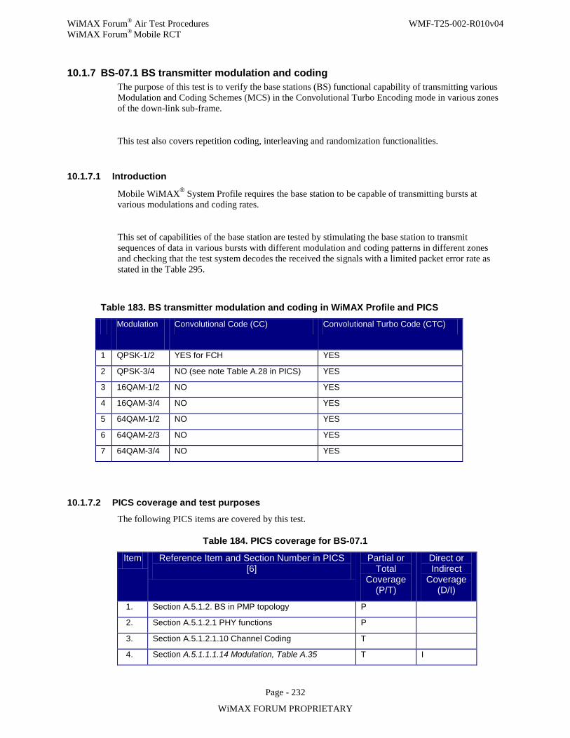
WiMAX Forum® Air Test Procedures WMF-T25-002-R010v04 WiMAX Forum® Mobile RCT
Page - 232
WiMAX FORUM PROPRIETARY
10.1.7 BS-07.1 BS transmitter modulation and coding The purpose of this test is to verify the base stations (BS) functional capability of transmitting various Modulation and Coding Schemes (MCS) in the Convolutional Turbo Encoding mode in various zones of the down-link sub-frame.
This test also covers repetition coding, interleaving and randomization functionalities.
10.1.7.1 Introduction
Mobile WiMAX® System Profile requires the base station to be capable of transmitting bursts at various modulations and coding rates.
This set of capabilities of the base station are tested by stimulating the base station to transmit sequences of data in various bursts with different modulation and coding patterns in different zones and checking that the test system decodes the received the signals with a limited packet error rate as stated in the Table 295.
Table 183. BS transmitter modulation and coding in WiMAX Profile and PICS
Modulation
Convolutional Code (CC) Convolutional Turbo Code (CTC)
1 QPSK-1/2 YES for FCH YES
2 QPSK-3/4 NO (see note Table A.28 in PICS) YES
3 16QAM-1/2 NO YES
4 16QAM-3/4 NO YES
5 64QAM-1/2 NO YES
6 64QAM-2/3 NO YES
7 64QAM-3/4 NO YES
10.1.7.2 PICS coverage and test purposes
The following PICS items are covered by this test.
Table 184. PICS coverage for BS-07.1
Item Reference Item and Section Number in PICS [6]
Partial or Total
Coverage (P/T)
Direct or Indirect
Coverage (D/I)
1. Section A.5.1.2. BS in PMP topology P
2. Section A.5.1.2.1 PHY functions P
3. Section A.5.1.2.1.10 Channel Coding T
4. Section A.5.1.1.1.14 Modulation, Table A.35 T I
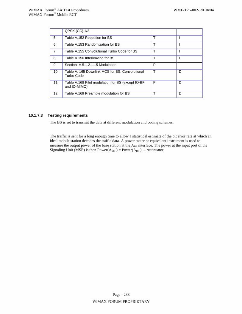
WiMAX Forum® Air Test Procedures WMF-T25-002-R010v04 WiMAX Forum® Mobile RCT
Page - 233
WiMAX FORUM PROPRIETARY
QPSK (CC) 1/2
5. Table A.152 Repetition for BS T I
6. Table A.153 Randomization for BS T I
7. Table A.155 Convolutional Turbo Code for BS T I
8. Table A.156 Interleaving for BS T I
9. Section A.5.1.2.1.15 Modulation P
10. Table A. 165 Downlink MCS for BS, Convolutional Turbo Code
T D
11. Table A.168 Pilot modulation for BS (except IO-BF and IO-MIMO)
P D
12. Table A.169 Preamble modulation for BS T D
10.1.7.3 Testing requirements
The BS is set to transmit the data at different modulation and coding schemes.
The traffic is sent for a long enough time to allow a statistical estimate of the bit error rate at which an ideal mobile station decodes the traffic data. A power meter or equivalent instrument is used to measure the output power of the base station at the ABS interface. The power at the input port of the Signaling Unit (MSE) is then Power(AMS ) = Power(ABS ) – Attenuator.
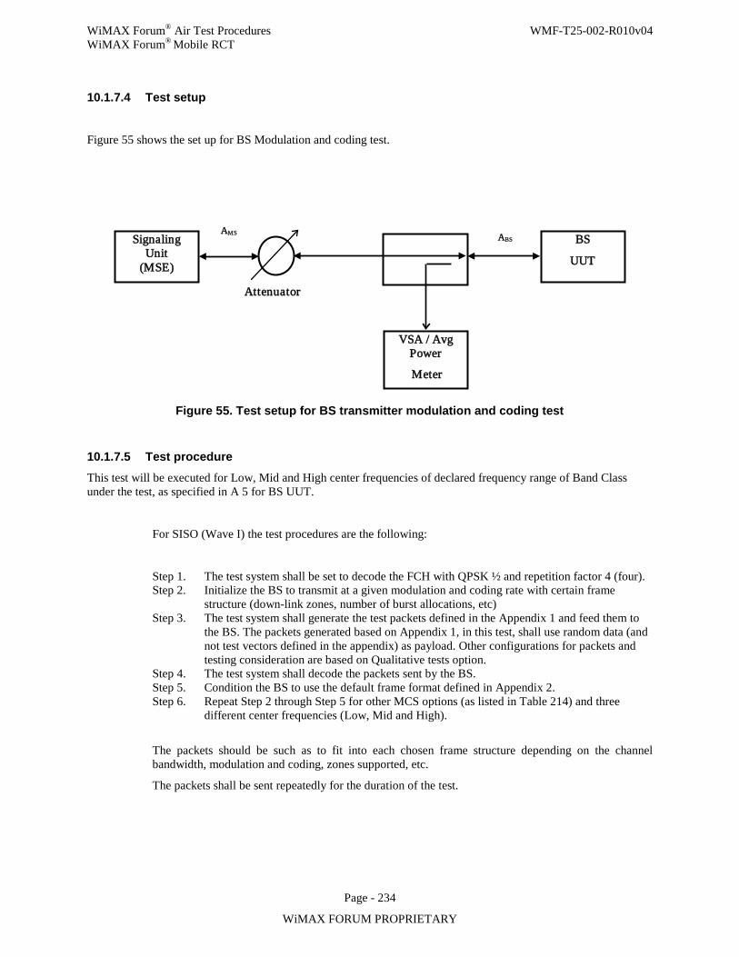
WiMAX Forum® Air Test Procedures WMF-T25-002-R010v04 WiMAX Forum® Mobile RCT
Page - 234
WiMAX FORUM PROPRIETARY
10.1.7.4 Test setup
Figure 55 shows the set up for BS Modulation and coding test.
Figure 55. Test setup for BS transmitter modulation and coding test
10.1.7.5 Test procedure This test will be executed for Low, Mid and High center frequencies of declared frequency range of Band Class under the test, as specified in A 5 for BS UUT.
For SISO (Wave I) the test procedures are the following:
Step 1. The test system shall be set to decode the FCH with QPSK ½ and repetition factor 4 (four). Step 2. Initialize the BS to transmit at a given modulation and coding rate with certain frame
structure (down-link zones, number of burst allocations, etc) Step 3. The test system shall generate the test packets defined in the Appendix 1 and feed them to
the BS. The packets generated based on Appendix 1, in this test, shall use random data (and not test vectors defined in the appendix) as payload. Other configurations for packets and testing consideration are based on Qualitative tests option.
Step 4. The test system shall decode the packets sent by the BS. Step 5. Condition the BS to use the default frame format defined in Appendix 2. Step 6. Repeat Step 2 through Step 5 for other MCS options (as listed in Table 214) and three
different center frequencies (Low, Mid and High).
The packets should be such as to fit into each chosen frame structure depending on the channel bandwidth, modulation and coding, zones supported, etc.
The packets shall be sent repeatedly for the duration of the test.
Signaling Unit
(MSE)
VSA / Avg Power
Meter
BS
UUT
Attenuator
ABS AMS
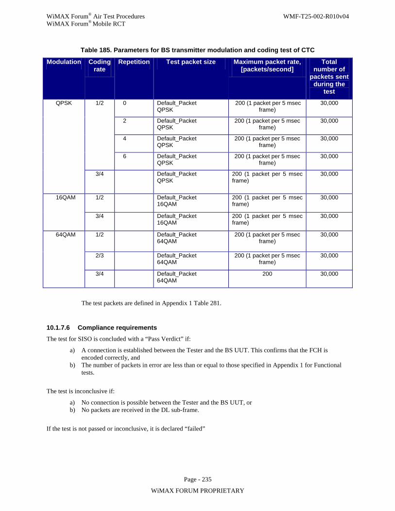
WiMAX Forum® Air Test Procedures WMF-T25-002-R010v04 WiMAX Forum® Mobile RCT
Page - 235
WiMAX FORUM PROPRIETARY
Table 185. Parameters for BS transmitter modulation and coding test of CTC
Modulation Coding rate
Repetition Test packet size Maximum packet rate, [packets/second]
Total number of
packets sent during the
test
QPSK 1/2 0 Default_Packet QPSK
200 (1 packet per 5 msec frame)
30,000
2 Default_Packet QPSK
200 (1 packet per 5 msec frame)
30,000
4 Default_Packet QPSK
200 (1 packet per 5 msec frame)
30,000
6 Default_Packet QPSK
200 (1 packet per 5 msec frame)
30,000
3/4 Default_Packet QPSK
200 (1 packet per 5 msec frame)
30,000
16QAM 1/2 Default_Packet 16QAM
200 (1 packet per 5 msec frame)
30,000
3/4 Default_Packet 16QAM
200 (1 packet per 5 msec frame)
30,000
64QAM 1/2 Default_Packet 64QAM
200 (1 packet per 5 msec frame)
30,000
2/3 Default_Packet 64QAM
200 (1 packet per 5 msec frame)
30,000
3/4 Default_Packet 64QAM
200 30,000
The test packets are defined in Appendix 1 Table 281.
10.1.7.6 Compliance requirements The test for SISO is concluded with a “Pass Verdict” if:
a) A connection is established between the Tester and the BS UUT. This confirms that the FCH is encoded correctly, and
b) The number of packets in error are less than or equal to those specified in Appendix 1 for Functional tests.
The test is inconclusive if:
a) No connection is possible between the Tester and the BS UUT, or b) No packets are received in the DL sub-frame.
If the test is not passed or inconclusive, it is declared “failed”
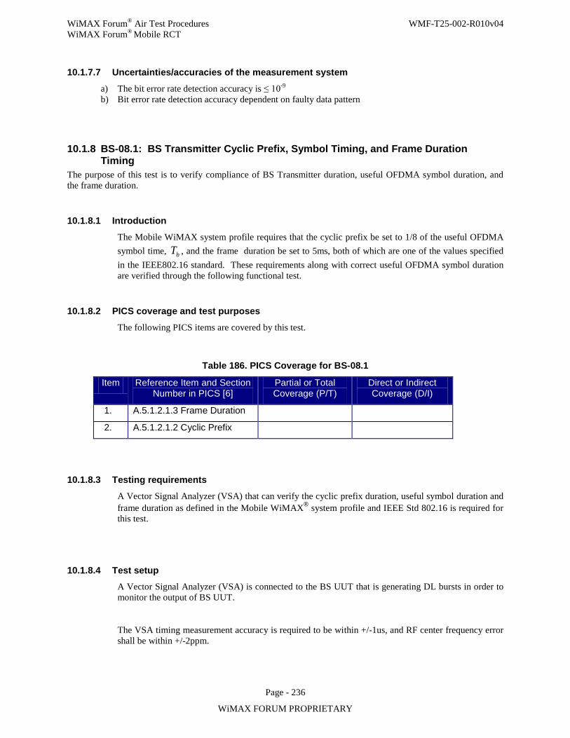
WiMAX Forum® Air Test Procedures WMF-T25-002-R010v04 WiMAX Forum® Mobile RCT
Page - 236
WiMAX FORUM PROPRIETARY
10.1.7.7 Uncertainties/accuracies of the measurement system
a) The bit error rate detection accuracy is ≤ 10-9 b) Bit error rate detection accuracy dependent on faulty data pattern
10.1.8 BS-08.1: BS Transmitter Cyclic Prefix, Symbol Timing, and Frame Duration Timing
The purpose of this test is to verify compliance of BS Transmitter duration, useful OFDMA symbol duration, and the frame duration.
10.1.8.1 Introduction
The Mobile WiMAX system profile requires that the cyclic prefix be set to 1/8 of the useful OFDMA symbol time, bT , and the frame duration be set to 5ms, both of which are one of the values specified in the IEEE802.16 standard. These requirements along with correct useful OFDMA symbol duration are verified through the following functional test.
10.1.8.2 PICS coverage and test purposes
The following PICS items are covered by this test.
Table 186. PICS Coverage for BS-08.1
Item Reference Item and Section Number in PICS [6]
Partial or Total Coverage (P/T)
Direct or Indirect Coverage (D/I)
1. A.5.1.2.1.3 Frame Duration
2. A.5.1.2.1.2 Cyclic Prefix
10.1.8.3 Testing requirements
A Vector Signal Analyzer (VSA) that can verify the cyclic prefix duration, useful symbol duration and frame duration as defined in the Mobile WiMAX® system profile and IEEE Std 802.16 is required for this test.
10.1.8.4 Test setup A Vector Signal Analyzer (VSA) is connected to the BS UUT that is generating DL bursts in order to monitor the output of BS UUT.
The VSA timing measurement accuracy is required to be within +/-1us, and RF center frequency error shall be within +/-2ppm.
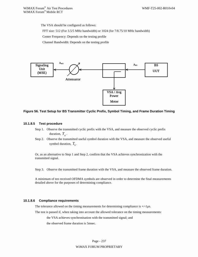
WiMAX Forum® Air Test Procedures WMF-T25-002-R010v04 WiMAX Forum® Mobile RCT
Page - 237
WiMAX FORUM PROPRIETARY
The VSA should be configured as follows:
FFT size: 512 (For 3.5/5 MHz bandwidth) or 1024 (for 7/8.75/10 MHz bandwidth)
Center Frequency: Depends on the testing profile
Channel Bandwidth: Depends on the testing profile
Figure 56. Test Setup for BS Transmitter Cyclic Prefix, Symbol Timing, and Frame Duration Timing
10.1.8.5 Test procedure Step 1. Observe the transmitted cyclic prefix with the VSA, and measure the observed cyclic prefix
duration, gT . Step 2. Observe the transmitted useful symbol duration with the VSA, and measure the observed useful
symbol duration, bT .
Or, as an alternative to Step 1 and Step 2, confirm that the VSA achieves synchronization with the transmitted signal.
Step 3. Observe the transmitted frame duration with the VSA, and measure the observed frame duration.
A minimum of ten received OFDMA symbols are observed in order to determine the final measurements detailed above for the purposes of determining compliance.
10.1.8.6 Compliance requirements
The tolerance allowed on the timing measurements for determining compliance is +/-1µs.
The test is passed if, when taking into account the allowed tolerance on the timing measurements:
the VSA achieves synchronisation with the transmitted signal; and
the observed frame duration is 5msec.
Signaling Unit
(MSE)
VSA / Avg Power
Meter
BS
UUT
Attenuator
ABS AMS
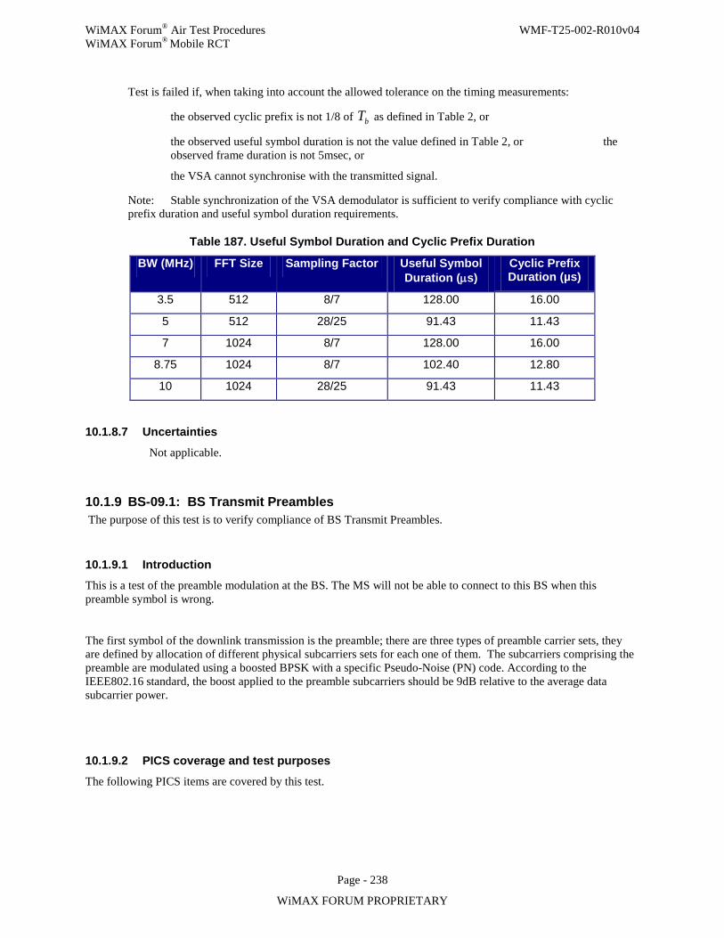
WiMAX Forum® Air Test Procedures WMF-T25-002-R010v04 WiMAX Forum® Mobile RCT
Page - 238
WiMAX FORUM PROPRIETARY
Test is failed if, when taking into account the allowed tolerance on the timing measurements:
the observed cyclic prefix is not 1/8 of bT as defined in Table 2, or
the observed useful symbol duration is not the value defined in Table 2, or the observed frame duration is not 5msec, or
the VSA cannot synchronise with the transmitted signal.
Note: Stable synchronization of the VSA demodulator is sufficient to verify compliance with cyclic prefix duration and useful symbol duration requirements.
Table 187. Useful Symbol Duration and Cyclic Prefix Duration
BW (MHz) FFT Size Sampling Factor Useful Symbol Duration (µs)
Cyclic Prefix Duration (µs)
3.5 512 8/7 128.00 16.00
5 512 28/25 91.43 11.43
7 1024 8/7 128.00 16.00
8.75 1024 8/7 102.40 12.80
10 1024 28/25 91.43 11.43
10.1.8.7 Uncertainties
Not applicable.
10.1.9 BS-09.1: BS Transmit Preambles The purpose of this test is to verify compliance of BS Transmit Preambles.
10.1.9.1 Introduction
This is a test of the preamble modulation at the BS. The MS will not be able to connect to this BS when this preamble symbol is wrong.
The first symbol of the downlink transmission is the preamble; there are three types of preamble carrier sets, they are defined by allocation of different physical subcarriers sets for each one of them. The subcarriers comprising the preamble are modulated using a boosted BPSK with a specific Pseudo-Noise (PN) code. According to the IEEE802.16 standard, the boost applied to the preamble subcarriers should be 9dB relative to the average data subcarrier power.
10.1.9.2 PICS coverage and test purposes
The following PICS items are covered by this test.
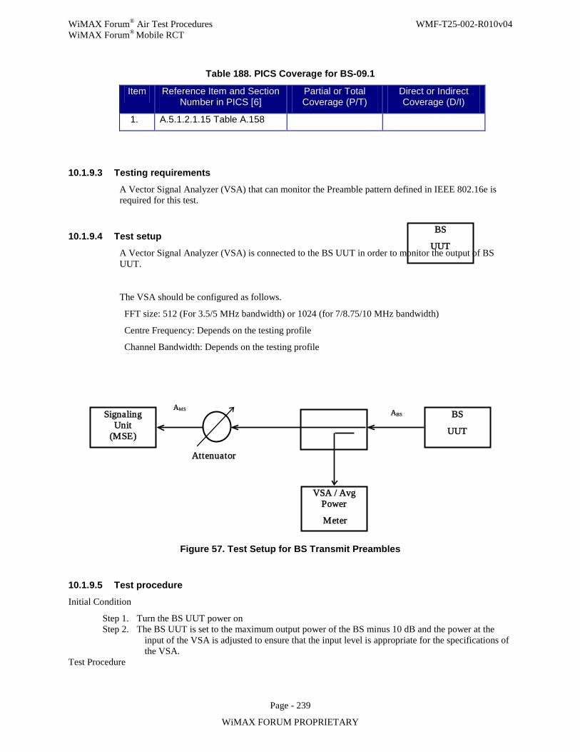
WiMAX Forum® Air Test Procedures WMF-T25-002-R010v04 WiMAX Forum® Mobile RCT
Page - 239
WiMAX FORUM PROPRIETARY
Table 188. PICS Coverage for BS-09.1
Item Reference Item and Section Number in PICS [6]
Partial or Total Coverage (P/T)
Direct or Indirect Coverage (D/I)
1. A.5.1.2.1.15 Table A.158
10.1.9.3 Testing requirements
A Vector Signal Analyzer (VSA) that can monitor the Preamble pattern defined in IEEE 802.16e is required for this test.
10.1.9.4 Test setup
A Vector Signal Analyzer (VSA) is connected to the BS UUT in order to monitor the output of BS UUT.
The VSA should be configured as follows.
FFT size: 512 (For 3.5/5 MHz bandwidth) or 1024 (for 7/8.75/10 MHz bandwidth)
Centre Frequency: Depends on the testing profile
Channel Bandwidth: Depends on the testing profile
Figure 57. Test Setup for BS Transmit Preambles
10.1.9.5 Test procedure
Initial Condition
Step 1. Turn the BS UUT power on Step 2. The BS UUT is set to the maximum output power of the BS minus 10 dB and the power at the
input of the VSA is adjusted to ensure that the input level is appropriate for the specifications of the VSA.
Test Procedure
Signaling Unit
(MSE)
VSA / Avg Power
Meter
BS
UUT
Attenuator
ABS AMS
BS
UUT
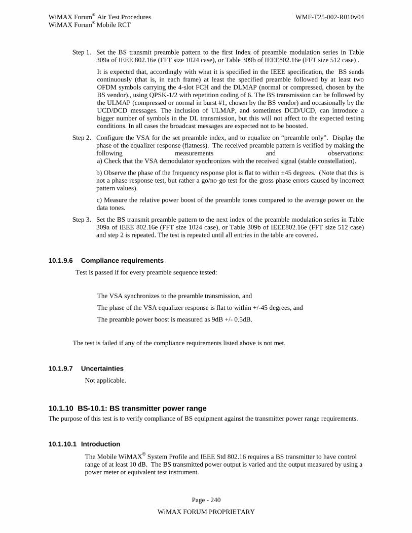
WiMAX Forum® Air Test Procedures WMF-T25-002-R010v04 WiMAX Forum® Mobile RCT
Page - 240
WiMAX FORUM PROPRIETARY
Step 1. Set the BS transmit preamble pattern to the first Index of preamble modulation series in Table 309a of IEEE 802.16e (FFT size 1024 case), or Table 309b of IEEE802.16e (FFT size 512 case) .
It is expected that, accordingly with what it is specified in the IEEE specification, the BS sends continuously (that is, in each frame) at least the specified preamble followed by at least two OFDM symbols carrying the 4-slot FCH and the DLMAP (normal or compressed, chosen by the BS vendor)., using QPSK-1/2 with repetition coding of 6. The BS transmission can be followed by the ULMAP (compressed or normal in burst #1, chosen by the BS vendor) and occasionally by the UCD/DCD messages. The inclusion of ULMAP, and sometimes DCD/UCD, can introduce a bigger number of symbols in the DL transmission, but this will not affect to the expected testing conditions. In all cases the broadcast messages are expected not to be boosted.
Step 2. Configure the VSA for the set preamble index, and to equalize on “preamble only”. Display the phase of the equalizer response (flatness). The received preamble pattern is verified by making the following measurements and observations: a) Check that the VSA demodulator synchronizes with the received signal (stable constellation).
b) Observe the phase of the frequency response plot is flat to within ±45 degrees. (Note that this is not a phase response test, but rather a go/no-go test for the gross phase errors caused by incorrect pattern values).
c) Measure the relative power boost of the preamble tones compared to the average power on the data tones.
Step 3. Set the BS transmit preamble pattern to the next index of the preamble modulation series in Table 309a of IEEE 802.16e (FFT size 1024 case), or Table 309b of IEEE802.16e (FFT size 512 case) and step 2 is repeated. The test is repeated until all entries in the table are covered.
10.1.9.6 Compliance requirements
Test is passed if for every preamble sequence tested:
The VSA synchronizes to the preamble transmission, and
The phase of the VSA equalizer response is flat to within +/-45 degrees, and
The preamble power boost is measured as 9dB +/- 0.5dB.
The test is failed if any of the compliance requirements listed above is not met.
10.1.9.7 Uncertainties
Not applicable.
10.1.10 BS-10.1: BS transmitter power range The purpose of this test is to verify compliance of BS equipment against the transmitter power range requirements.
10.1.10.1 Introduction
The Mobile WiMAX® System Profile and IEEE Std 802.16 requires a BS transmitter to have control range of at least 10 dB. The BS transmitted power output is varied and the output measured by using a power meter or equivalent test instrument.
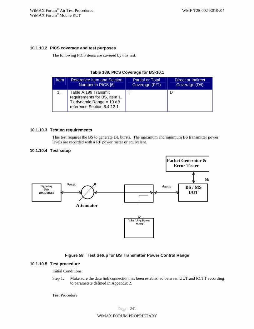
WiMAX Forum® Air Test Procedures WMF-T25-002-R010v04 WiMAX Forum® Mobile RCT
Page - 241
WiMAX FORUM PROPRIETARY
10.1.10.2 PICS coverage and test purposes The following PICS items are covered by this test.
Table 189. PICS Coverage for BS-10.1
Item Reference Item and Section Number in PICS [6]
Partial or Total Coverage (P/T)
Direct or Indirect Coverage (D/I)
1. Table A.199 Transmit requirements for BS, Item 1. Tx dynamic Range = 10 dB reference Section 8.4.12.1
T D
10.1.10.3 Testing requirements
This test requires the BS to generate DL bursts. The maximum and minimum BS transmitter power levels are recorded with a RF power meter or equivalent.
10.1.10.4 Test setup
Signaling Unit
(BSE/MSE)
Packet Generator & Error Tester
VSA / Avg Power M eter
BS / MS UUT
Attenuator
A BS/MS M B
A MS/BS
Figure 58. Test Setup for BS Transmitter Power Control Range
10.1.10.5 Test procedure
Initial Conditions:
Step 1. Make sure the data link connection has been established between UUT and RCTT according to parameters defined in Appendix 2.
Test Procedure
WiMAX Forum® Air Test Procedures WMF-T25-002-R010v04 WiMAX Forum® Mobile RCT
Page - 242
WiMAX FORUM PROPRIETARY
The test should be executed at the Low, Mid and High frequencies as declared by the vendor in line with the sample test frequencies stated in Appendix 5.
Step 1. Set the BS UUT to its maximum transmitter power output. Step 2. The maximum output power of the BS UUT is recorded. Step 3. Set the BS UUT to its minimum transmitter power output. Step 4. The minimum output power of the BS UUT is recorded. Step 5. End of test.
10.1.10.6 Compliance requirements
Pass Verdict:
The difference between maximum and minimum power is greater or equal to 10dB.
Fail Verdict:
The difference between maximum and minimum power is less than 10dB.
10.1.10.7 Uncertainties
The power measurement uncertainty declared by the test facility shall be taken into account when the pass or fail verdict is decided.
10.1.11 BS-11.1: BS transmitter spectral flatness The purpose of this test is to verify compliance of BS equipments against spectral flatness requirements.
10.1.11.1 Introduction
Mobile WiMAX® System Profile and IEEE Std 802.16 requires a spectral flatness of ±2 dB from the measured energy averaged over all Nused active tones for spectral lines from –Nused/4 to –1 and +1 to Nused/4 and +2/–4 dB from the measured energy averaged over all Nused active tones for spectral lines from –Nused/2 to –Nused/4 and +Nused/4 to Nused/2. Additionally, the absolute difference between adjacent subcarriers shall not exceed 0.4 dB, excluding intentional boosting or suppression of subcarriers. PAPR reduction subchannels are not allocated. Further, the power transmitted at spectral line 0 shall not exceed –15 dB relative to total transmitted power.
This is to be measured with a vector signal analyzer using spectrum flatness measurement function. By observing the amplitude deviations from the constellation points this function estimates the flatness as a function of frequency from ordinary data transmission signals.
10.1.11.2 PICS coverage and test purposes
The following PICS items are specifically covered by this test.
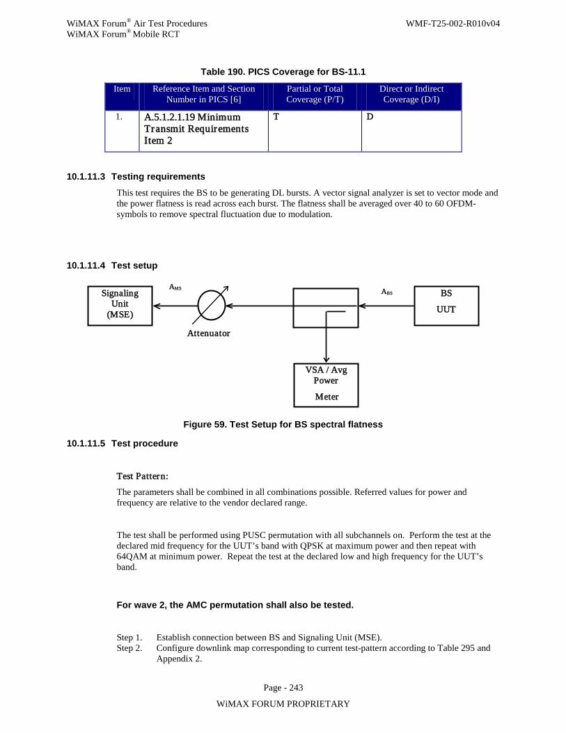
WiMAX Forum® Air Test Procedures WMF-T25-002-R010v04 WiMAX Forum® Mobile RCT
Page - 243
WiMAX FORUM PROPRIETARY
Table 190. PICS Coverage for BS-11.1
Item Reference Item and Section Number in PICS [6]
Partial or Total Coverage (P/T)
Direct or Indirect Coverage (D/I)
1. A.5.1.2.1.19 Minimum Transmit Requirements Item 2
T D
10.1.11.3 Testing requirements
This test requires the BS to be generating DL bursts. A vector signal analyzer is set to vector mode and the power flatness is read across each burst. The flatness shall be averaged over 40 to 60 OFDM-symbols to remove spectral fluctuation due to modulation.
10.1.11.4 Test setup
Figure 59. Test Setup for BS spectral flatness
10.1.11.5 Test procedure
Test Pattern:
The parameters shall be combined in all combinations possible. Referred values for power and frequency are relative to the vendor declared range.
The test shall be performed using PUSC permutation with all subchannels on. Perform the test at the declared mid frequency for the UUT’s band with QPSK at maximum power and then repeat with 64QAM at minimum power. Repeat the test at the declared low and high frequency for the UUT’s band.
For wave 2, the AMC permutation shall also be tested.
Step 1. Establish connection between BS and Signaling Unit (MSE). Step 2. Configure downlink map corresponding to current test-pattern according to Table 295 and
Appendix 2.
Signaling Unit
(MSE)
VSA / Avg Power
Meter
BS
UUT
Attenuator
ABS AMS
WiMAX Forum® Air Test Procedures WMF-T25-002-R010v04 WiMAX Forum® Mobile RCT
Page - 244
WiMAX FORUM PROPRIETARY
Step 3. Repeatedly send downlink data packages from UUT Step 4. Measure the spectrum power with the VSA for the required number of OFDM-symbols. Step 5. Extract the average power level for all active sub-carriers (including data and pilots) from
the measurement data obtained in Step 4. Step 6. Report the average power level. Step 7. Extract power measurement for sub-carrier 0. Step 8. Compare sub-carrier 0 with average power level obtained in Step 5. Step 9. Report result from Step 8. Step 10. For each active subcarrier measured in step 4, normalize the power reading by dividing by
the ideal magnitude for its constellation state, including any intentional power boosting. Step 11. Compute the average normalized power by summing together the individual results of Step
10. Step 12. Using the results from Step 10, record minimum power reading and maximum power
reading for outer (–Nused/2 to –Nused/4 and +Nused/4 to Nused/2) for all active sub-carriers.
Step 13. Compare the values from Step 12with average power level obtained in Step 11. Step 14. Report result from Step 13. Step 15. Using the results from Step 10, record minimum power reading and maximum power
reading for inner (–Nused/4 to –1 and +1 to Nused/4) for all active sub-carriers.
Step 16. Compare the values from Step 15with average normalized power level obtained in Step 11. Step 17. Report result from Step 16. Step 18. Compare amplitudes within the measurement data obtained in Step 4 for all sub-carriers
with neighboring sub-carriers including pilots. Comparison shall be made after normalization to ideal constellation state and compensation for intentional power boosting.
Step 19. Report neighbor sub-carrier deviation. Step 20. Repeat Step 2 through Step 19for all applicable Test Patterns Step 21. Repeat Step 1 through Step 20 for Low, Mid and High channel of declared frequency range. Step 22. End of test.
10.1.11.6 Compliance requirements
Pass verdict:
a) The leakage power transmitted at spectral line 0 does not exceed –15 dB relative to the corresponding total transmitted power for all specified combinations of test parameters.
b) All active inner sub-carriers shall be within ±2 dB of the corresponding average power level for all active sub-carriers power for all specified combinations of test parameters.
c) All active outer sub-carriers shall be within +2/–4 dB of the corresponding average power level for all active sub-carriers power for all specified combinations of test parameters.
d) The maximum neighbor sub-carrier deviation for all specified combinations of test parameters is equal to or below 0.4dB for all active sub-carriers.
Fail verdict:
a) The leakage power transmitted at spectral line 0 exceeds –15 dB relative to the corresponding total transmitted power for any specified combination of test parameters.
b) Any active inner sub-carriers exceed ±2 dB of the corresponding average power level for all active sub-carriers power for any specified combination of test parameters.
c) Any active outer sub-carriers exceed +2/–4 dB of the corresponding average power level for all active sub-carriers power for any specified combination of test parameters.
d) The maximum neighbor sub-carrier deviation for any specified combinations of test parameters exceeds 0.4dB for any active sub-carriers.
WiMAX Forum® Air Test Procedures WMF-T25-002-R010v04 WiMAX Forum® Mobile RCT
Page - 245
WiMAX FORUM PROPRIETARY
10.1.11.7 Uncertainties
The maximum flatness measurement uncertainty for individual sub-carriers is 0.05 dB relative to the average channel power.
10.1.12 BS-12.1: BS Transmitter Relative Constellation Error The purpose of this test is to verify BS conformance to transmitter relative constellation error fidelity requirements as required by the IEEE Std 802.16e-2005 and the TWG profile requirements.
10.1.12.1 Introduction The Standard [1] dictates that all measurements will be referenced to the RF antenna connector (i.e., at PA output without antenna). To ensure that Receiver’s SNR will be degraded by no more than 0.5 dB due to transmitter’s SNR, the relative constellation RMS error, averaged over subcarriers, OFDMA frames and packets, shall not exceed the values listed in Table 1. Since the DL sub-frame may contain several different zones, the pilot level may shift when transitioning from zone to zone. The test may be performed on any permutation zone. In order to verify the receiver’s SNR, the EVM test contains actually a receiver in which after PA output the signal is demodulated and the SNR is measured according to the following steps:
1. The BS transmits the required signal.
2. The preamble is located, i.e. initial coarse frame synchronization is performed.
3. From the preamble timing and frequency estimation is performed.
4. The timing offset is compensated as estimated.
5. The received signal shall be de-rotated according to the estimated frequency offset.
6. The VSA should use all available transmitted pilots, preamble subcarriers and data subcarriers for channel
estimation purposes.
7. Each sub-carrier value is divided by the corresponding channel estimate value.
8. For each sub-carrier value (i.e, data + pilot sub-carriers) we should find the closest constellation point and make a
decision subcarriers.
9. Compute the RMS errors averaged over all data sub-carriers in the packet.
This error is computed using the following formula (per equation 149 in IEEE 2005 std).
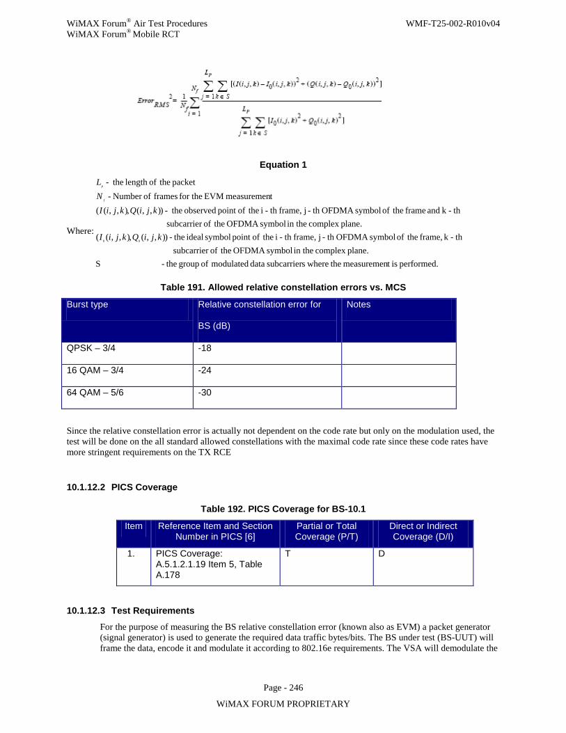
WiMAX Forum® Air Test Procedures WMF-T25-002-R010v04 WiMAX Forum® Mobile RCT
Page - 246
WiMAX FORUM PROPRIETARY
Equation 1
Where:
performed. ist measuremen the wheressubcarrier data modulated of group the- Splane.complex in the symbol OFDMA theof subcarrier
th -k frame, theof symbol OFDMAth -j frame,th -i theofpoint symbol ideal the- )),,(,),,((plane.complex in the symbol OFDMA theof subcarrier
th -k and frame theof symbol OFDMAth -j frame,th -i theofpoint observed the- )),,(,),,((tmeasuremen EVM for the frames ofNumber -
packet theoflength the-
00kjiQkjiI
kjiQkjiINL
f
p
Table 191. Allowed relative constellation errors vs. MCS
Burst type Relative constellation error for
BS (dB)
Notes
QPSK – 3/4 -18
16 QAM – 3/4 -24
64 QAM – 5/6 -30
Since the relative constellation error is actually not dependent on the code rate but only on the modulation used, the test will be done on the all standard allowed constellations with the maximal code rate since these code rates have more stringent requirements on the TX RCE
10.1.12.2 PICS Coverage
Table 192. PICS Coverage for BS-10.1
Item Reference Item and Section Number in PICS [6]
Partial or Total Coverage (P/T)
Direct or Indirect Coverage (D/I)
1. PICS Coverage: A.5.1.2.1.19 Item 5, Table A.178
T D
10.1.12.3 Test Requirements
For the purpose of measuring the BS relative constellation error (known also as EVM) a packet generator (signal generator) is used to generate the required data traffic bytes/bits. The BS under test (BS-UUT) will frame the data, encode it and modulate it according to 802.16e requirements. The VSA will demodulate the
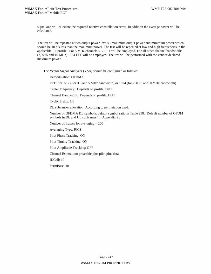
WiMAX Forum® Air Test Procedures WMF-T25-002-R010v04 WiMAX Forum® Mobile RCT
Page - 247
WiMAX FORUM PROPRIETARY
signal and will calculate the required relative constellation error.. In addition the average power will be calculated.
The test will be repeated at two output power levels - maximum output power and minimum power which should be 10 dB less than the maximum power. The test will be repeated at low and high frequencies in the applicable RF profile. For 5 MHz channels 512 FFT will be employed. For all other channel bandwidths (7, 8.75 and 10 MHz) 1024 FFT will be employed. The test will be performed with the vendor declared maximum power.
The Vector Signal Analyzer (VSA) should be configured as follows:
Demodulation: OFDMA
FFT Size: 512 (For 3.5 and 5 MHz bandwidth) or 1024 (for 7, 8.75 and10 MHz bandwidth)
Center Frequency: Depends on profile, DUT
Channel Bandwidth: Depends on profile, DUT
Cyclic Prefix: 1/8
DL subcarrier allocation: According to permutation used.
Number of OFDMA DL symbols: default symbol ratio in Table 298. ‘Default number of OFDM symbols in DL and UL subframes’ in Appendix 2..
Number of frames for averaging = 200
Averaging Type: RMS
Pilot Phase Tracking: ON
Pilot Timing Tracking: ON
Pilot Amplitude Tracking: OFF
Channel Estimation: preamble plus pilot plus data
IDCell: 10
PermBase: 10
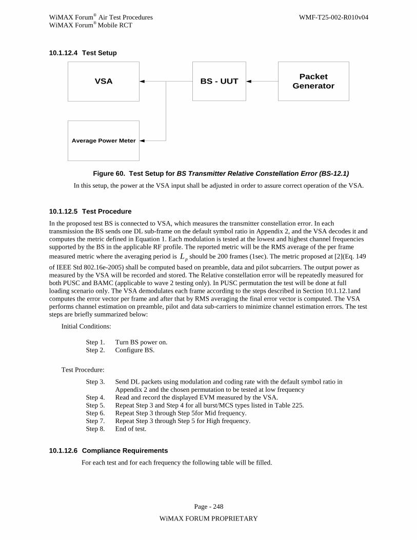
WiMAX Forum® Air Test Procedures WMF-T25-002-R010v04 WiMAX Forum® Mobile RCT
Page - 248
WiMAX FORUM PROPRIETARY
10.1.12.4 Test Setup
BS - UUTVSA
Average Power Meter
PacketGenerator
Figure 60. Test Setup for BS Transmitter Relative Constellation Error (BS-12.1)
In this setup, the power at the VSA input shall be adjusted in order to assure correct operation of the VSA.
10.1.12.5 Test Procedure
In the proposed test BS is connected to VSA, which measures the transmitter constellation error. In each transmission the BS sends one DL sub-frame on the default symbol ratio in Appendix 2, and the VSA decodes it and computes the metric defined in Equation 1. Each modulation is tested at the lowest and highest channel frequencies supported by the BS in the applicable RF profile. The reported metric will be the RMS average of the per frame measured metric where the averaging period is pL should be 200 frames (1sec). The metric proposed at [2](Eq. 149 of IEEE Std 802.16e-2005) shall be computed based on preamble, data and pilot subcarriers. The output power as measured by the VSA will be recorded and stored. The Relative constellation error will be repeatedly measured for both PUSC and BAMC (applicable to wave 2 testing only). In PUSC permutation the test will be done at full loading scenario only. The VSA demodulates each frame according to the steps described in Section 10.1.12.1and computes the error vector per frame and after that by RMS averaging the final error vector is computed. The VSA performs channel estimation on preamble, pilot and data sub-carriers to minimize channel estimation errors. The test steps are briefly summarized below:
Initial Conditions:
Step 1. Turn BS power on. Step 2. Configure BS.
Test Procedure:
Step 3. Send DL packets using modulation and coding rate with the default symbol ratio in Appendix 2 and the chosen permutation to be tested at low frequency
Step 4. Read and record the displayed EVM measured by the VSA. Step 5. Repeat Step 3 and Step 4 for all burst/MCS types listed in Table 225. Step 6. Repeat Step 3 through Step 5for Mid frequency. Step 7. Repeat Step 3 through Step 5 for High frequency. Step 8. End of test.
10.1.12.6 Compliance Requirements
For each test and for each frequency the following table will be filled.
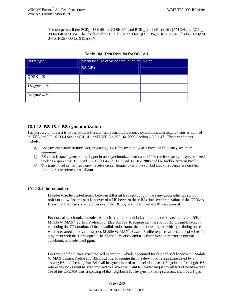
WiMAX Forum® Air Test Procedures WMF-T25-002-R010v04 WiMAX Forum® Mobile RCT
Page - 249
WiMAX FORUM PROPRIETARY
The test passes if the RCE< -18.0 dB for QPSK 3/4, and RCE <-24.0 dB for 16-QAM 3/4 and RCE < -30 for 64QAM 3/4. The test fails if the RCE> -18.0 dB for QPSK 3/4, or RCE >-24.0 dB for 16-QAM 3/4 or RCE>-30 for 64QAM ¾.
Table 193. Test Results for BS-12.1
Burst type Measured Relative constellation err
BS (dB)
Notes
QPSK – ¾
16 QAM – ¾
64 QAM – ¾
10.1.13 BS-13.1: BS synchronization The purpose of this test is to verify the BS under test meets the frequency synchronization requirements as defined in IEEE Std 802.16-2004 Section 8.4.14.1 and IEEE Std 802.16e-2005 Section 6.3.2.3.47. These conditions include:
a) BS synchronization in time, slot, frequency, TX reference timing accuracy and frequency accuracy requirements.
b) BS clock frequency error is +/-2 ppm in non-synchronized work and +/-1% carrier spacing in synchronized work as required by IEEE Std 802.16-2004 and IEEE Std 802.16e-2005 and the Mobile System Profile.
c) The transmitted center frequency, receive center frequency and the symbol clock frequency are derived from the same reference oscillator.
10.1.13.1 Introduction
In order to reduce interference between different BSs operating in the same geographic area and in order to allow fast and soft handover of a MS between these BSs time synchronization of the OFDMA frame and frequency synchronization of the RF signals of the involved BSs is required.
For normal synchronized mode - which is required to minimize interference between different BSs - Mobile WiMAX® System Profile and IEEE Std 802.16 require that the start of the preamble symbol, excluding the CP duration, of the downlink radio frame shall be time aligned with 1pps timing pulse when measured at the antenna port. Mobile WiMAX® System Profile requires an accuracy of ±1 us for alignment with the 1 pps signal. The allowed BS clock and RF center frequency error in normal synchronized mode is ±2 ppm.
For time and frequency synchronized operation - which is required for fast and soft handovers - Mobile WiMAX System Profile and IEEE Std 802.16 require that the downlink frames transmitted by a serving BS and the neighbor BS shall be synchronized to a level of at least 1/8 cyclic prefix length. BS reference clocks shall be synchronized to a level that yield RF center frequency offsets of no more than 1% of the OFDMA carrier spacing of the neighbor BS. The synchronizing reference shall be a 1 pps
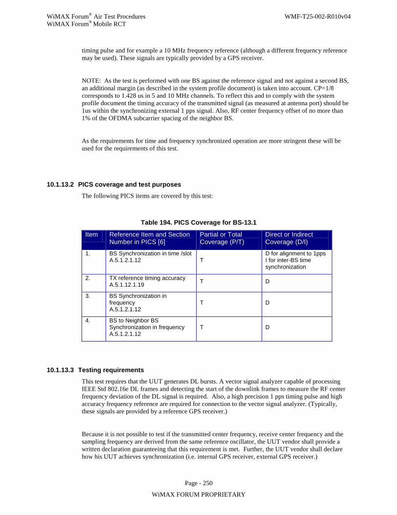
WiMAX Forum® Air Test Procedures WMF-T25-002-R010v04 WiMAX Forum® Mobile RCT
Page - 250
WiMAX FORUM PROPRIETARY
timing pulse and for example a 10 MHz frequency reference (although a different frequency reference may be used). These signals are typically provided by a GPS receiver.
NOTE: As the test is performed with one BS against the reference signal and not against a second BS, an additional margin (as described in the system profile document) is taken into account. CP=1/8 corresponds to 1.428 us in 5 and 10 MHz channels. To reflect this and to comply with the system profile document the timing accuracy of the transmitted signal (as measured at antenna port) should be 1us within the synchronizing external 1 pps signal. Also, RF center frequency offset of no more than 1% of the OFDMA subcarrier spacing of the neighbor BS.
As the requirements for time and frequency synchronized operation are more stringent these will be used for the requirements of this test.
10.1.13.2 PICS coverage and test purposes The following PICS items are covered by this test:
Table 194. PICS Coverage for BS-13.1
Item Reference Item and Section Number in PICS [6]
Partial or Total Coverage (P/T)
Direct or Indirect Coverage (D/I)
1. BS Synchronization in time /slot A.5.1.2.1.12 T
D for alignment to 1pps I for inter-BS time synchronization
2. TX reference timing accuracy A.5.1.12.1.19 T D
3. BS Synchronization in frequency A.5.1.2.1.12
T D
4. BS to Neighbor BS Synchronization in frequency A.5.1.2.1.12
T D
10.1.13.3 Testing requirements
This test requires that the UUT generates DL bursts. A vector signal analyzer capable of processing IEEE Std 802.16e DL frames and detecting the start of the downlink frames to measure the RF center frequency deviation of the DL signal is required. Also, a high precision 1 pps timing pulse and high accuracy frequency reference are required for connection to the vector signal analyzer. (Typically, these signals are provided by a reference GPS receiver.)
Because it is not possible to test if the transmitted center frequency, receive center frequency and the sampling frequency are derived from the same reference oscillator, the UUT vendor shall provide a written declaration guaranteeing that this requirement is met. Further, the UUT vendor shall declare how his UUT achieves synchronization (i.e. internal GPS receiver, external GPS receiver.)
WiMAX Forum® Air Test Procedures WMF-T25-002-R010v04 WiMAX Forum® Mobile RCT
Page - 251
WiMAX FORUM PROPRIETARY
10.1.13.4 Test setup The test setup below is considered as one possible solution for the synchronization measurement. The BS UUT and the VSA should be connected to highly accurate clock sources as demonstrated in Figure 1 when testing frequency requirement under synchronized conditions. The clock source for the UUT - the UUT GPS receiver - can be external equipment or can be integrated in the UUT. In the latter case, a GPS antenna is connected to the UUT to feed the internal GPS receiver. At the BS, the top transmit frequency will be tested
In case of more than one transmit antenna connector the test shall be performed on one randomly selected transmit antenna connector. For a case of transmit delay diversity the measurement will be done on the output port of the non-delayed antenna element.
All tests shall be conducted using the frame configuration given in appendix 2 and shall be performed at all supported/declared channel bandwidths for the DUT. The MCS shall be 16QAM1/2.
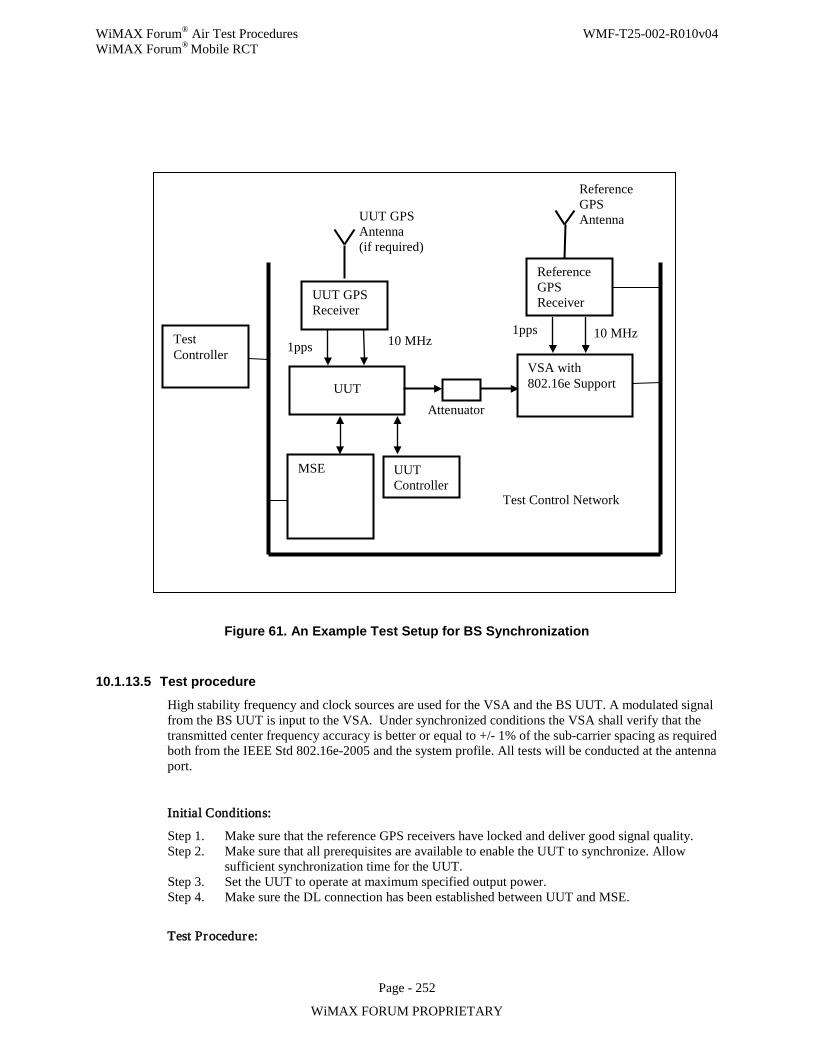
WiMAX Forum® Air Test Procedures WMF-T25-002-R010v04 WiMAX Forum® Mobile RCT
Page - 252
WiMAX FORUM PROPRIETARY
Figure 61. An Example Test Setup for BS Synchronization
10.1.13.5 Test procedure
High stability frequency and clock sources are used for the VSA and the BS UUT. A modulated signal from the BS UUT is input to the VSA. Under synchronized conditions the VSA shall verify that the transmitted center frequency accuracy is better or equal to +/- 1% of the sub-carrier spacing as required both from the IEEE Std 802.16e-2005 and the system profile. All tests will be conducted at the antenna port.
Initial Conditions:
Step 1. Make sure that the reference GPS receivers have locked and deliver good signal quality. Step 2. Make sure that all prerequisites are available to enable the UUT to synchronize. Allow
sufficient synchronization time for the UUT. Step 3. Set the UUT to operate at maximum specified output power. Step 4. Make sure the DL connection has been established between UUT and MSE.
Test Procedure:
Test Controller
MSE
UUT VSA with 802.16e Support
Reference GPS Receiver
UUT Controller
1pps 10 MHz
Test Control Network
Reference GPS Antenna UUT GPS
Antenna (if required)
UUT GPS Receiver
10 MHz 1pps
Attenuator
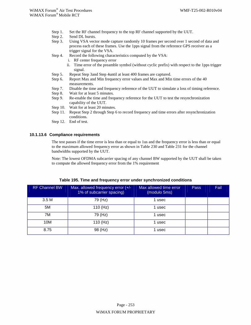
WiMAX Forum® Air Test Procedures WMF-T25-002-R010v04 WiMAX Forum® Mobile RCT
Page - 253
WiMAX FORUM PROPRIETARY
Step 1. Set the RF channel frequency to the top RF channel supported by the UUT. Step 2. Send DL bursts. Step 3. Using VSA vector mode capture randomly 10 frames per second over 1 second of data and
process each of these frames. Use the 1pps signal from the reference GPS receiver as a trigger signal for the VSA.
Step 4. Record the following characteristics computed by the VSA: i. RF center frequency error
ii. Time error of the preamble symbol (without cyclic prefix) with respect to the 1pps trigger signal.
Step 5. Repeat Step 3and Step 4until at least 400 frames are captured. Step 6. Report Max and Min frequency error values and Max and Min time errors of the 40
measurements. Step 7. Disable the time and frequency reference of the UUT to simulate a loss of timing reference. Step 8. Wait for at least 5 minutes. Step 9. Re-enable the time and frequency reference for the UUT to test the resynchronization
capability of the UUT. Step 10. Wait for at least 20 minutes. Step 11. Repeat Step 2 through Step 6 to record frequency and time errors after resynchronization
conditions. Step 12. End of test.
10.1.13.6 Compliance requirements
The test passes if the time error is less than or equal to 1us and the frequency error is less than or equal to the maximum allowed frequency error as shown in Table 230 and Table 231 for the channel bandwidths supported by the UUT.
Note: The lowest OFDMA subcarrier spacing of any channel BW supported by the UUT shall be taken to compute the allowed frequency error from the 1% requirement
Table 195. Time and frequency error under synchronized conditions
RF Channel BW Max. allowed frequency error (+/- 1% of subcarrier spacing)
Max allowed time error (modulo 5ms)
Pass Fail
3.5 M 79 (Hz) 1 usec
5M 110 (Hz) 1 usec
7M 79 (Hz) 1 usec
10M 110 (Hz) 1 usec
8.75 98 (Hz) 1 usec
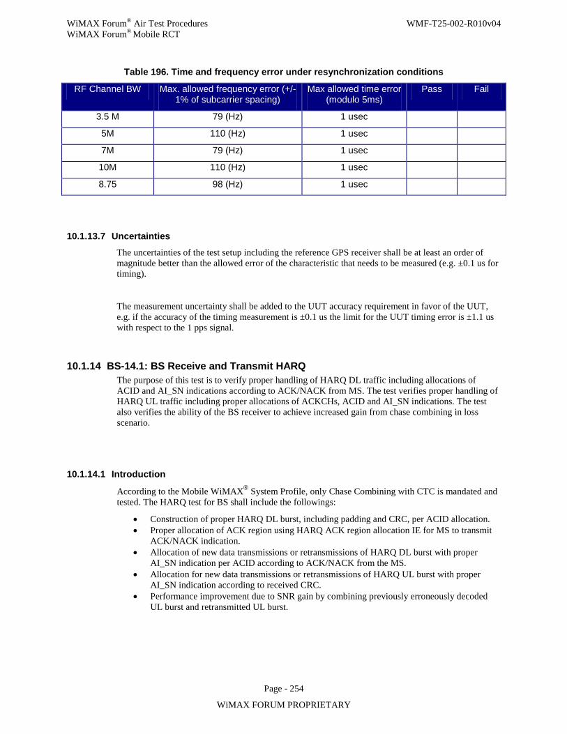
WiMAX Forum® Air Test Procedures WMF-T25-002-R010v04 WiMAX Forum® Mobile RCT
Page - 254
WiMAX FORUM PROPRIETARY
Table 196. Time and frequency error under resynchronization conditions
RF Channel BW Max. allowed frequency error (+/- 1% of subcarrier spacing)
Max allowed time error (modulo 5ms)
Pass Fail
3.5 M 79 (Hz) 1 usec
5M 110 (Hz) 1 usec
7M 79 (Hz) 1 usec
10M 110 (Hz) 1 usec
8.75 98 (Hz) 1 usec
10.1.13.7 Uncertainties
The uncertainties of the test setup including the reference GPS receiver shall be at least an order of magnitude better than the allowed error of the characteristic that needs to be measured (e.g. ±0.1 us for timing).
The measurement uncertainty shall be added to the UUT accuracy requirement in favor of the UUT, e.g. if the accuracy of the timing measurement is ±0.1 us the limit for the UUT timing error is ±1.1 us with respect to the 1 pps signal.
10.1.14 BS-14.1: BS Receive and Transmit HARQ The purpose of this test is to verify proper handling of HARQ DL traffic including allocations of ACID and AI_SN indications according to ACK/NACK from MS. The test verifies proper handling of HARQ UL traffic including proper allocations of ACKCHs, ACID and AI_SN indications. The test also verifies the ability of the BS receiver to achieve increased gain from chase combining in loss scenario.
10.1.14.1 Introduction
According to the Mobile WiMAX® System Profile, only Chase Combining with CTC is mandated and tested. The HARQ test for BS shall include the followings:
• Construction of proper HARQ DL burst, including padding and CRC, per ACID allocation. • Proper allocation of ACK region using HARQ ACK region allocation IE for MS to transmit
ACK/NACK indication. • Allocation of new data transmissions or retransmissions of HARQ DL burst with proper
AI_SN indication per ACID according to ACK/NACK from the MS. • Allocation for new data transmissions or retransmissions of HARQ UL burst with proper
AI_SN indication according to received CRC. • Performance improvement due to SNR gain by combining previously erroneously decoded
UL burst and retransmitted UL burst.
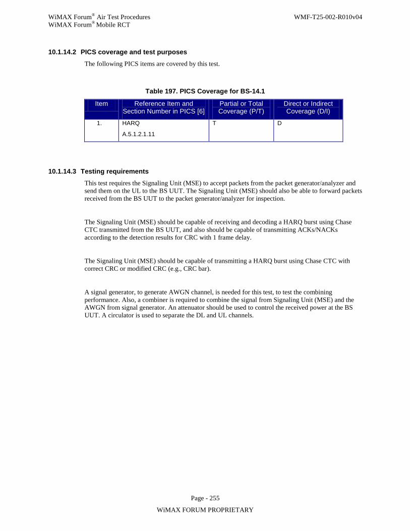
WiMAX Forum® Air Test Procedures WMF-T25-002-R010v04 WiMAX Forum® Mobile RCT
Page - 255
WiMAX FORUM PROPRIETARY
10.1.14.2 PICS coverage and test purposes
The following PICS items are covered by this test.
Table 197. PICS Coverage for BS-14.1
Item Reference Item and Section Number in PICS [6]
Partial or Total Coverage (P/T)
Direct or Indirect Coverage (D/I)
1. HARQ
A.5.1.2.1.11
T D
10.1.14.3 Testing requirements
This test requires the Signaling Unit (MSE) to accept packets from the packet generator/analyzer and send them on the UL to the BS UUT. The Signaling Unit (MSE) should also be able to forward packets received from the BS UUT to the packet generator/analyzer for inspection.
The Signaling Unit (MSE) should be capable of receiving and decoding a HARQ burst using Chase CTC transmitted from the BS UUT, and also should be capable of transmitting ACKs/NACKs according to the detection results for CRC with 1 frame delay.
The Signaling Unit (MSE) should be capable of transmitting a HARQ burst using Chase CTC with correct CRC or modified CRC (e.g., CRC bar).
A signal generator, to generate AWGN channel, is needed for this test, to test the combining performance. Also, a combiner is required to combine the signal from Signaling Unit (MSE) and the AWGN from signal generator. An attenuator should be used to control the received power at the BS UUT. A circulator is used to separate the DL and UL channels.
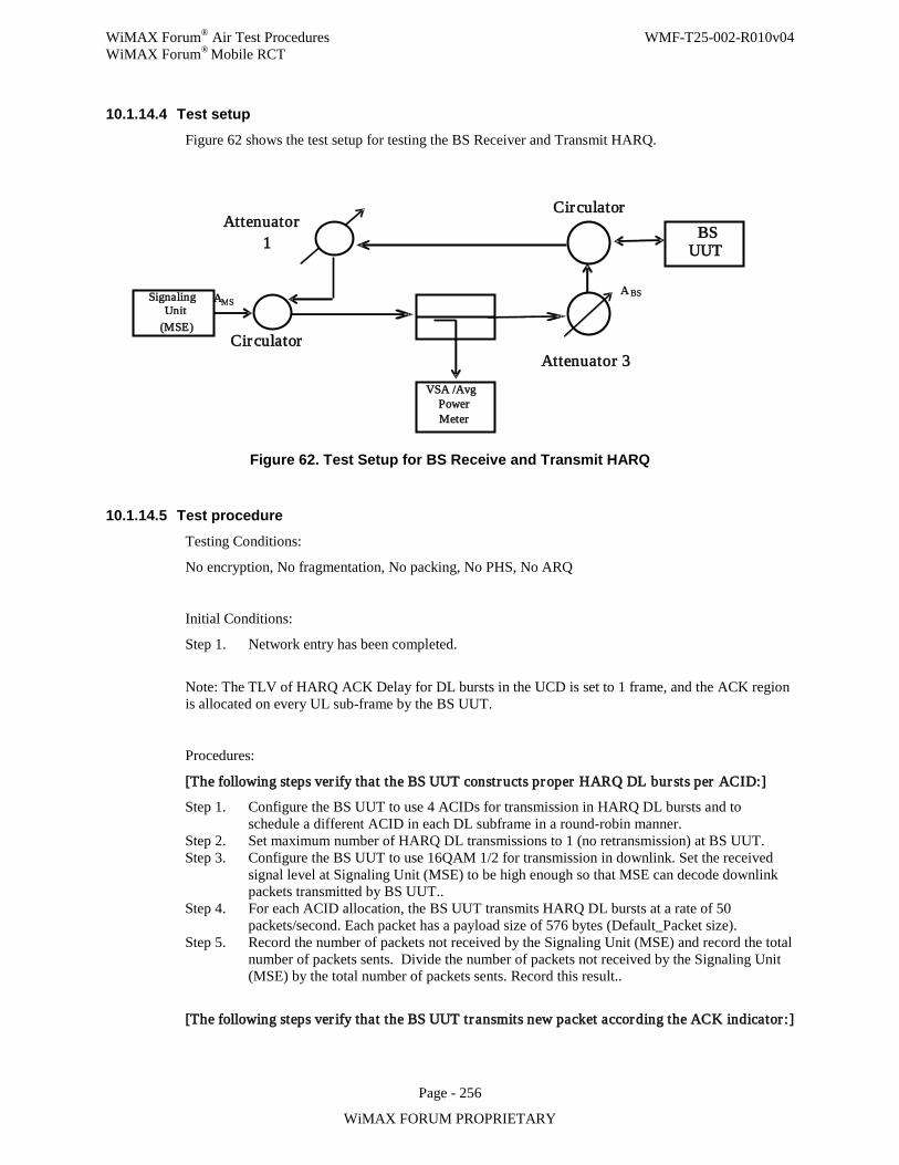
WiMAX Forum® Air Test Procedures WMF-T25-002-R010v04 WiMAX Forum® Mobile RCT
Page - 256
WiMAX FORUM PROPRIETARY
10.1.14.4 Test setup
Figure 62 shows the test setup for testing the BS Receiver and Transmit HARQ.
Figure 62. Test Setup for BS Receive and Transmit HARQ
10.1.14.5 Test procedure
Testing Conditions:
No encryption, No fragmentation, No packing, No PHS, No ARQ
Initial Conditions:
Step 1. Network entry has been completed.
Note: The TLV of HARQ ACK Delay for DL bursts in the UCD is set to 1 frame, and the ACK region is allocated on every UL sub-frame by the BS UUT.
Procedures:
[The following steps ver ify that the BS UUT constructs proper HARQ DL bursts per ACID:]
Step 1. Configure the BS UUT to use 4 ACIDs for transmission in HARQ DL bursts and to schedule a different ACID in each DL subframe in a round-robin manner.
Step 2. Set maximum number of HARQ DL transmissions to 1 (no retransmission) at BS UUT. Step 3. Configure the BS UUT to use 16QAM 1/2 for transmission in downlink. Set the received
signal level at Signaling Unit (MSE) to be high enough so that MSE can decode downlink packets transmitted by BS UUT..
Step 4. For each ACID allocation, the BS UUT transmits HARQ DL bursts at a rate of 50 packets/second. Each packet has a payload size of 576 bytes (Default_Packet size).
Step 5. Record the number of packets not received by the Signaling Unit (MSE) and record the total number of packets sents. Divide the number of packets not received by the Signaling Unit (MSE) by the total number of packets sents. Record this result..
[The following steps ver ify that the BS UUT transmits new packet according the ACK indicator :]
Signaling Unit
(MSE)
VSA /Avg Power
Meter
BS UUT
A M S
Attenuator 1
A BS
Attenuator 3
Circulator
Circulator
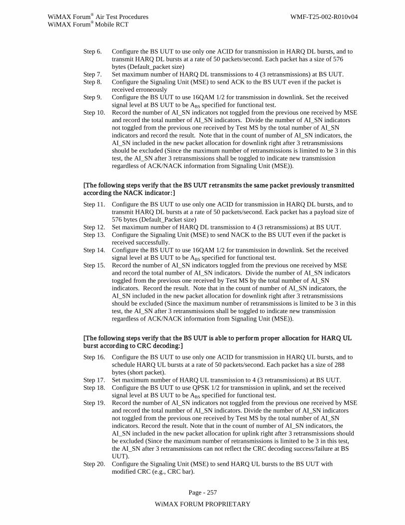
WiMAX Forum® Air Test Procedures WMF-T25-002-R010v04 WiMAX Forum® Mobile RCT
Page - 257
WiMAX FORUM PROPRIETARY
Step 6. Configure the BS UUT to use only one ACID for transmission in HARQ DL bursts, and to transmit HARQ DL bursts at a rate of 50 packets/second. Each packet has a size of 576 bytes (Default_packet size)
Step 7. Set maximum number of HARQ DL transmissions to 4 (3 retransmissions) at BS UUT. Step 8. Configure the Signaling Unit (MSE) to send ACK to the BS UUT even if the packet is
received erroneously Step 9. Configure the BS UUT to use 16QAM 1/2 for transmission in downlink. Set the received
signal level at BS UUT to be ABS specified for functional test. Step 10. Record the number of AI_SN indicators not toggled from the previous one received by MSE
and record the total number of AI_SN indicators. Divide the number of AI_SN indicators not toggled from the previous one received by Test MS by the total number of AI_SN indicators and record the result. Note that in the count of number of AI_SN indicators, the AI_SN included in the new packet allocation for downlink right after 3 retransmissions should be excluded (Since the maximum number of retransmissions is limited to be 3 in this test, the AI_SN after 3 retransmissions shall be toggled to indicate new transmission regardless of ACK/NACK information from Signaling Unit (MSE)).
[The following steps ver ify that the BS UUT retransmits the same packet previously transmitted according the NACK indicator :]
Step 11. Configure the BS UUT to use only one ACID for transmission in HARQ DL bursts, and to transmit HARQ DL bursts at a rate of 50 packets/second. Eack packet has a payload size of 576 bytes (Default_Packet size)
Step 12. Set maximum number of HARQ DL transmission to 4 (3 retransmissions) at BS UUT. Step 13. Configure the Signaling Unit (MSE) to send NACK to the BS UUT even if the packet is
received successfully. Step 14. Configure the BS UUT to use 16QAM 1/2 for transmission in downlink. Set the received
signal level at BS UUT to be ABS specified for functional test. Step 15. Record the number of AI_SN indicators toggled from the previous one received by MSE
and record the total number of AI_SN indicators. Divide the number of AI_SN indicators toggled from the previous one received by Test MS by the total number of AI_SN indicators. Record the result. Note that in the count of number of AI_SN indicators, the AI_SN included in the new packet allocation for downlink right after 3 retransmissions should be excluded (Since the maximum number of retransmissions is limited to be 3 in this test, the AI_SN after 3 retransmissions shall be toggled to indicate new transmission regardless of ACK/NACK information from Signaling Unit (MSE)).
[The following steps ver ify that the BS UUT is able to per form proper allocation for HARQ UL burst according to CRC decoding:]
Step 16. Configure the BS UUT to use only one ACID for transmission in HARQ UL bursts, and to schedule HARQ UL bursts at a rate of 50 packets/second. Each packet has a size of 288 bytes (short packet).
Step 17. Set maximum number of HARQ UL transmission to 4 (3 retransmissions) at BS UUT. Step 18. Configure the BS UUT to use QPSK 1/2 for transmission in uplink, and set the received
signal level at BS UUT to be ABS specified for functional test. Step 19. Record the number of AI_SN indicators not toggled from the previous one received by MSE
and record the total number of AI_SN indicators. Divide the number of AI_SN indicators not toggled from the previous one received by Test MS by the total number of AI_SN indicators. Record the result. Note that in the count of number of AI_SN indicators, the AI_SN included in the new packet allocation for uplink right after 3 retransmissions should be excluded (Since the maximum number of retransmissions is limited to be 3 in this test, the AI_SN after 3 retransmissions can not reflect the CRC decoding success/failure at BS UUT).
Step 20. Configure the Signaling Unit (MSE) to send HARQ UL bursts to the BS UUT with modified CRC (e.g., CRC bar).
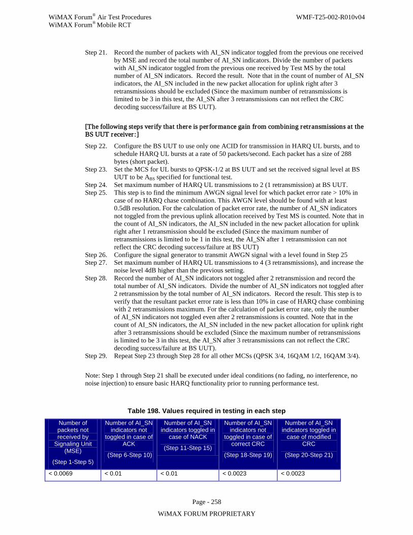
WiMAX Forum® Air Test Procedures WMF-T25-002-R010v04 WiMAX Forum® Mobile RCT
Page - 258
WiMAX FORUM PROPRIETARY
Step 21. Record the number of packets with AI_SN indicator toggled from the previous one received by MSE and record the total number of AI_SN indicators. Divide the number of packets with AI_SN indicator toggled from the previous one received by Test MS by the total number of AI_SN indicators. Record the result. Note that in the count of number of AI_SN indicators, the AI_SN included in the new packet allocation for uplink right after 3 retransmissions should be excluded (Since the maximum number of retransmissions is limited to be 3 in this test, the AI_SN after 3 retransmissions can not reflect the CRC decoding success/failure at BS UUT).
[The following steps ver ify that there is per formance gain from combining retransmissions at the BS UUT receiver :]
Step 22. Configure the BS UUT to use only one ACID for transmission in HARQ UL bursts, and to schedule HARQ UL bursts at a rate of 50 packets/second. Each packet has a size of 288 bytes (short packet).
Step 23. Set the MCS for UL bursts to QPSK-1/2 at BS UUT and set the received signal level at BS UUT to be ABS specified for functional test.
Step 24. Set maximum number of HARQ UL transmissions to 2 (1 retransmission) at BS UUT. Step 25. This step is to find the minimum AWGN signal level for which packet error rate > 10% in
case of no HARQ chase combination. This AWGN level should be found with at least 0.5dB resolution. For the calculation of packet error rate, the number of AI_SN indicators not toggled from the previous uplink allocation received by Test MS is counted. Note that in the count of AI_SN indicators, the AI_SN included in the new packet allocation for uplink right after 1 retransmission should be excluded (Since the maximum number of retransmissions is limited to be 1 in this test, the AI_SN after 1 retransmission can not reflect the CRC decoding success/failure at BS UUT)
Step 26. Configure the signal generator to transmit AWGN signal with a level found in Step 25 Step 27. Set maximum number of HARQ UL transmissions to 4 (3 retransmissions), and increase the
noise level 4dB higher than the previous setting. Step 28. Record the number of AI_SN indicators not toggled after 2 retransmission and record the
total number of AI_SN indicators. Divide the number of AI_SN indicators not toggled after 2 retransmission by the total number of AI_SN indicators. Record the result. This step is to verify that the resultant packet error rate is less than 10% in case of HARQ chase combining with 2 retransmissions maximum. For the calculation of packet error rate, only the number of AI_SN indicators not toggled even after 2 retransmissions is counted. Note that in the count of AI_SN indicators, the AI_SN included in the new packet allocation for uplink right after 3 retransmissions should be excluded (Since the maximum number of retransmissions is limited to be 3 in this test, the AI_SN after 3 retransmissions can not reflect the CRC decoding success/failure at BS UUT).
Step 29. Repeat Step 23 through Step 28 for all other MCSs (QPSK 3/4, 16QAM 1/2, 16QAM 3/4).
Note: Step 1 through Step 21 shall be executed under ideal conditions (no fading, no interference, no noise injection) to ensure basic HARQ functionality prior to running performance test.
Table 198. Values required in testing in each step
Number of packets not received by
Signaling Unit (MSE)
(Step 1-Step 5)
Number of AI_SN indicators not
toggled in case of ACK
(Step 6-Step 10)
Number of AI_SN indicators toggled in
case of NACK
(Step 11-Step 15)
Number of AI_SN indicators not
toggled in case of correct CRC
(Step 18-Step 19)
Number of AI_SN indicators toggled in
case of modified CRC
(Step 20-Step 21)
< 0.0069 < 0.01 < 0.01 < 0.0023 < 0.0023
WiMAX Forum® Air Test Procedures WMF-T25-002-R010v04 WiMAX Forum® Mobile RCT
Page - 259
WiMAX FORUM PROPRIETARY
10.1.14.6 Compliance requirements Pass Criteria:
1. The result recorded in step 5 is less than the limit set in table 157 for number of packets not received by the MSE. AND
2. The result recorded in step 10 is less than the limit set in table 157 for number of AI_SN indicators not toggled in case of ACK. AND
3. The result recorded in step 15 is less than the limit set in table 157 for number of AI_SN indicators toggled in case of NAK. AND
4. The result recorded in step 19 is less than the limit set in table 157 for number of AI_SN indicators not toggled in case of correct CRC. AND
5. The result recorded in step 21 is less than the limit set in table 157 for the number of AI_SN indicators toggled in case of modified CRC. AND
6. The result recoreded in step 28 is less than 10% for number of AI_SN indicators not toggled after 2 retransmissions.
Fail Criteria:
1.The result recorded in step 5 is not less than the limit set in table 157 for number of packets not received by the MSE. OR
2.The result recorded in step 10 is not less than the limit set in table 157 for number of AI_SN indicators not toggled in case of ACK. OR
3.The result recorded in step 15 is not less than the limit set in table 157 for number of AI_SN indicators toggled in case of NAK. OR
4.The result recorded in step 19 is not less than the limit set in table 157 for the number of AI_SN indicators not toggled in case of correct CRC. OR
5.The result recoreded in step 21 is not less the limit set in table 157 for number of AI_SN indicators toggled in case of modified CRC. OR
6.The result recoreded in step 28 is not less than 10% for number of AI_SN indicators not toggled after 2 retransmissions.
10.1.14.7 Uncertainties
Not applicable.
10.1.15 BS-15.1: Reserved
WiMAX Forum® Air Test Procedures WMF-T25-002-R010v04 WiMAX Forum® Mobile RCT
Page - 260
WiMAX FORUM PROPRIETARY
10.1.16 BS-16.1: BS receive/transmit switching gaps The purpose of this test is to verify BS compliance to the min Transmit/receive Transition Gap (TTG) and Receive/transmit Transition Gap (RTG) requirements.
10.1.16.1 Introduction
This test shall make certain that the BS can perform switching between receive and transmit states quick enough to meet the PICS requirements. In order to perform these measurements the start and end of the two switching events must be defined.
For testing purposes the TTG is defined as the time between end of the last sample of the last OFDM-symbol of the DL and the start of the first sample of the first OFDM-symbol of the UL frame, see Figure 63.
For testing purposes the RTG is defined as the time between end of the last sample of the last OFDM-symbol of the UL and the start of the first sample of the preamble of the following DL frame.
To be certain that the UUT can perform the switching it is not sufficient to measure that an RF-signal is present at these positions of the MAC-frame, the UUT also need to have some level of performance at these points. In order to ensure this both downlink and uplink traffic must be tested.
When testing RTG performance, the BS shall set up the test-MS to send and receive data at fixed positions in the MAC-frame, the pattern to be repeated continuously for the duration of test. PER shall be measured on a burst prolonged as long as to reach the end of UL frame and Relative Constellation Error shall be measured on the first symbol of the DL frame averaged over 100 bursts.
The TTG shall be tested with the same approach. The BS shall command the test-MS to send and receive data at fixed positions in the MAC-frame, the pattern to be repeated continuously for the duration of test. Relative Constellation Error shall be measured on the last symbol of the DL frame averaged over 100 bursts and error rate shall be measured on a first 3 symbols in the UL frame. Note that the first 3 symbols in the UL frame are allocated for ranging channels, CQICHs and ACKCHs for default frame structure in Appendix 2.
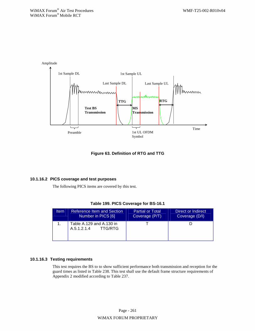
WiMAX Forum® Air Test Procedures WMF-T25-002-R010v04 WiMAX Forum® Mobile RCT
Page - 261
WiMAX FORUM PROPRIETARY
Time
1st Sample DL 1st Sample UL
Last Sample DL Last Sample UL
Test BS Transmission
Preamble
MS Transmission
1st UL OFDM Symbol
TTG RTG
Amplitude
Figure 63. Definition of RTG and TTG
10.1.16.2 PICS coverage and test purposes
The following PICS items are covered by this test.
Table 199. PICS Coverage for BS-16.1
Item Reference Item and Section Number in PICS [6]
Partial or Total Coverage (P/T)
Direct or Indirect Coverage (D/I)
1. Table A.129 and A.130 in A.5.1.2.1.4 TTG/RTG
T D
10.1.16.3 Testing requirements
This test requires the BS to to show sufficient performance both transmission and reception for the guard times as listed in Table 238. This test shall use the default frame structure requirements of Appendix 2 modified according to Table 237.
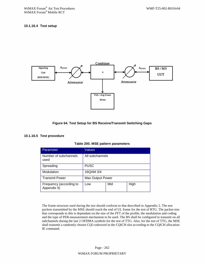
WiMAX Forum® Air Test Procedures WMF-T25-002-R010v04 WiMAX Forum® Mobile RCT
Page - 262
WiMAX FORUM PROPRIETARY
10.1.16.4 Test setup
Figure 64. Test Setup for BS Receive/Transmit Switching Gaps
10.1.16.5 Test procedure
Table 200. MSE pattern parameters
Parameter Values
Number of subchannels used
All subchannels
Spreading PUSC
Modulation 16QAM 3/4
Transmit Power Max Output Power
Frequency (according to Appendix 5)
Low Mid High
The frame-structure used during the test should conform to that described in Appendix 2. The test packets transmitted by the MSE should reach the end of UL frame for the test of RTG. The packet-size that corresponds to this is dependant on the size of the FFT of the profile, the modulation and coding and the type of PER-measurement mechanism to be used. The BS shall be configured to transmit on all subchannels during the last 2 OFDMA symbols for the test of TTG. Also, for the test of TTG, the MSE shall transmit a randomly chosen CQI codeword in the CQICH slot according to the CQICH allocation IE command.
Signaling Unit
(BSE/MSE) BS / MS
UUT Attenuator
ABS/MS AMS/BS
VSA / Avg Power Meter
Combiner +
Attenuator
WiMAX Forum® Air Test Procedures WMF-T25-002-R010v04 WiMAX Forum® Mobile RCT
Page - 263
WiMAX FORUM PROPRIETARY
The RCE-measurements shall be averaged over 100 packets.
Procedure for RTG:
Step 1. Establish connection between BS and Signaling Unit (MSE). Step 2. Configure downlink map to allocate bursts which fill up whole downlink subframe. These
bursts can have arbitrary CIDs other than the CID for UUT. This helps VSA to estimate channel in measuring the RCE on preamble.
Step 3. Configure uplink map to accommodate the UL packet specified in Table 239. Step 4. For the duration of the test repeatedly send user data both UL and DL with the set
configuration. Step 5. Measure the RTG gap with the VSA. Note the value. Step 6. Check that the gap duration is according to the requirement in Table 236. If not, adjust the
Signaling Unit (MSE) timing position and repeat from 5. Step 7. Measure PER for the UL connection. The PER must conform to receiver sensitivity
requirements. Note the value. Note that the RCE requirement for preamble is not specified in the IEEE Std or Mobile WiMAX® System Profile document. Therefore, in this test the RCE requirement value for QPSK 3/4 will also be used for preamble.
Step 8. Measure RCE for the preamble of the DL connection with the measurement-window centered within the OFDM-symbol. The value shall be averaged over 100 frames.. The RCE must conform to Relative Constellation Error requirements. Note the value.
Step 9. Report the values from Step 5-Step 8.
Procedure for TTG:
Step 1. Establish connection between BS and Signaling Unit (MSE). Step 2. Configure uplink map to allocate fast feedback channel in the first 3 symbols of UL frame
as described in Appendix 2. Step 3. Configure downlink map to contain user data in all sub-channels using 64 QAM ¾ at the
last 2 symbols in the DL frame. Step 4. For the duration of the test repeatedly send user data both UL and DL with the set
configuration. Step 5. Measure the error rate of detecting the codeword in the CQICH transmitted by MSE. The
error rate should be less than 1% at the same received power level for sensitivity test described in Appendix 2. Note the value.
Step 6. Check that the gap duration is according to the requirement in Table 236. If not, adjust the Signaling Unit (MSE) timing position and repeat from Step 5.
Step 7. Measure PER for the UL connection. The PER must conform to receiver sensitivity requirements. Note the value.
Step 8. Measure RCE for the last symbol of the DL frame with the measurement-window centered within the OFDM-symbol. The value shall be averaged over 100 frames. The RCE must conform to Relative Constellation Error requirements. Note the value.
Step 9. Report the values from Step 5-Step 8. Step 10. End of test.
10.1.16.6 Compliance requirements
For the applicable TTG and RTG settings in Table 238, the BS must meet the PER requirements stated Table 239 and the RCE requirement as stated in Table 149 in Section 10.1.12.1
Table 201. TTG and RTG timing performance requirement for BS
Maximum TTG and RTG Switching Time per Channel Band-Width
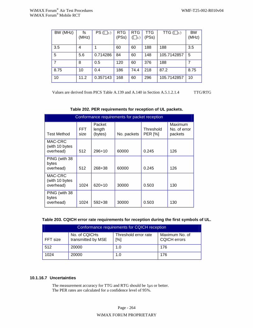
WiMAX Forum® Air Test Procedures WMF-T25-002-R010v04 WiMAX Forum® Mobile RCT
Page - 264
WiMAX FORUM PROPRIETARY
BW (MHz)
fs (MHz)
PS (s ) RTG (PSs)
RTG (s )
TTG (PSs)
TTG (s ) BW (MHz)
3.5 4 1 60 60 188 188 3.5
5 5.6 0.714286 84 60 148 105.7142857 5
7 8 0.5 120 60 376 188 7
8.75 10 0.4 186 74.4 218 87.2 8.75
10 11.2 0.357143 168 60 296 105.7142857 10
Values are derived from PICS Table A.139 and A.140 in Section A.5.1.2.1.4 TTG/RTG
Table 202. PER requirements for reception of UL packets.
Conformance requirements for packet reception
Test Method FFT size
Packet length (bytes) No. packets
Threshold PER [%]
Maximum No. of error packets
MAC-CRC (with 10 bytes overhead) 512 296+10 60000 0.245 126
PING (with 38 bytes overhead) 512 268+38 60000 0.245 126
MAC-CRC (with 10 bytes overhead) 1024 620+10 30000 0.503 130
PING (with 38 bytes overhead) 1024 592+38 30000 0.503 130
Table 203. CQICH error rate requirements for reception during the first symbols of UL.
Conformance requirements for CQICH reception
FFT size No. of CQICHs transmitted by MSE
Threshold error rate [%]
Maximum No. of CQICH errors
512 20000 1.0 176
1024 20000 1.0 176
10.1.16.7 Uncertainties
The measurement accuracy for TTG and RTG should be 1µs or better. The PER rates are calculated for a confidence level of 95%.
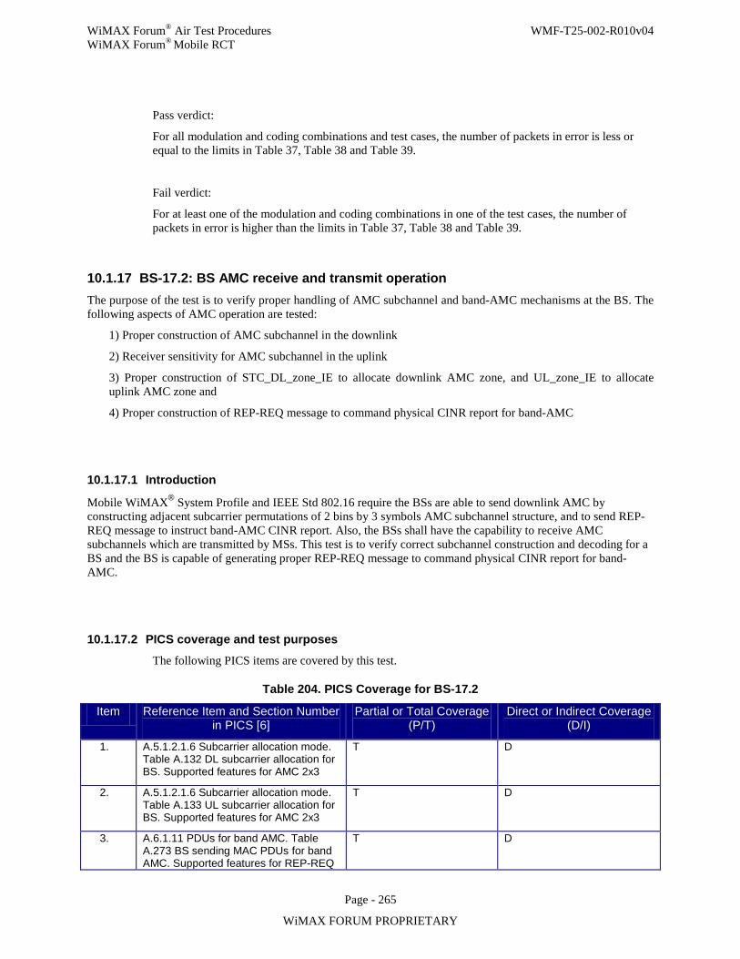
WiMAX Forum® Air Test Procedures WMF-T25-002-R010v04 WiMAX Forum® Mobile RCT
Page - 265
WiMAX FORUM PROPRIETARY
Pass verdict:
For all modulation and coding combinations and test cases, the number of packets in error is less or equal to the limits in Table 37, Table 38 and Table 39.
Fail verdict:
For at least one of the modulation and coding combinations in one of the test cases, the number of packets in error is higher than the limits in Table 37, Table 38 and Table 39.
10.1.17 BS-17.2: BS AMC receive and transmit operation The purpose of the test is to verify proper handling of AMC subchannel and band-AMC mechanisms at the BS. The following aspects of AMC operation are tested:
1) Proper construction of AMC subchannel in the downlink
2) Receiver sensitivity for AMC subchannel in the uplink
3) Proper construction of STC_DL_zone_IE to allocate downlink AMC zone, and UL_zone_IE to allocate uplink AMC zone and
4) Proper construction of REP-REQ message to command physical CINR report for band-AMC
10.1.17.1 Introduction
Mobile WiMAX® System Profile and IEEE Std 802.16 require the BSs are able to send downlink AMC by constructing adjacent subcarrier permutations of 2 bins by 3 symbols AMC subchannel structure, and to send REP-REQ message to instruct band-AMC CINR report. Also, the BSs shall have the capability to receive AMC subchannels which are transmitted by MSs. This test is to verify correct subchannel construction and decoding for a BS and the BS is capable of generating proper REP-REQ message to command physical CINR report for band-AMC.
10.1.17.2 PICS coverage and test purposes
The following PICS items are covered by this test.
Table 204. PICS Coverage for BS-17.2
Item Reference Item and Section Number in PICS [6]
Partial or Total Coverage (P/T)
Direct or Indirect Coverage (D/I)
1. A.5.1.2.1.6 Subcarrier allocation mode. Table A.132 DL subcarrier allocation for BS. Supported features for AMC 2x3
T D
2. A.5.1.2.1.6 Subcarrier allocation mode. Table A.133 UL subcarrier allocation for BS. Supported features for AMC 2x3
T D
3. A.6.1.11 PDUs for band AMC. Table A.273 BS sending MAC PDUs for band AMC. Supported features for REP-REQ
T D
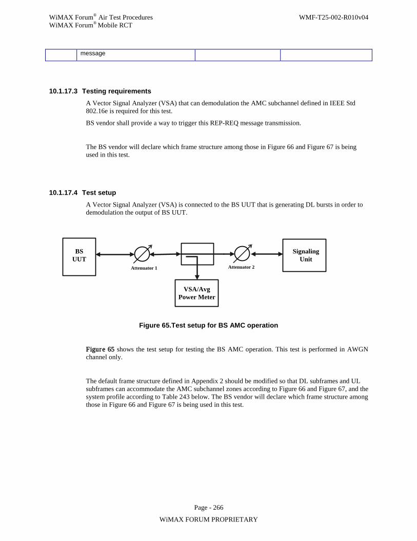
WiMAX Forum® Air Test Procedures WMF-T25-002-R010v04 WiMAX Forum® Mobile RCT
Page - 266
WiMAX FORUM PROPRIETARY
message
10.1.17.3 Testing requirements
A Vector Signal Analyzer (VSA) that can demodulation the AMC subchannel defined in IEEE Std 802.16e is required for this test.
BS vendor shall provide a way to trigger this REP-REQ message transmission.
The BS vendor will declare which frame structure among those in Figure 66 and Figure 67 is being used in this test.
10.1.17.4 Test setup
A Vector Signal Analyzer (VSA) is connected to the BS UUT that is generating DL bursts in order to demodulation the output of BS UUT.
BS UUT
Signaling Unit
Attenuator 2Attenuator 1
VSA/Avg Power Meter
Figure 65.Test setup for BS AMC operation
Figure 65 shows the test setup for testing the BS AMC operation. This test is performed in AWGN channel only.
The default frame structure defined in Appendix 2 should be modified so that DL subframes and UL subframes can accommodate the AMC subchannel zones according to Figure 66 and Figure 67, and the system profile according to Table 243 below. The BS vendor will declare which frame structure among those in Figure 66 and Figure 67 is being used in this test.
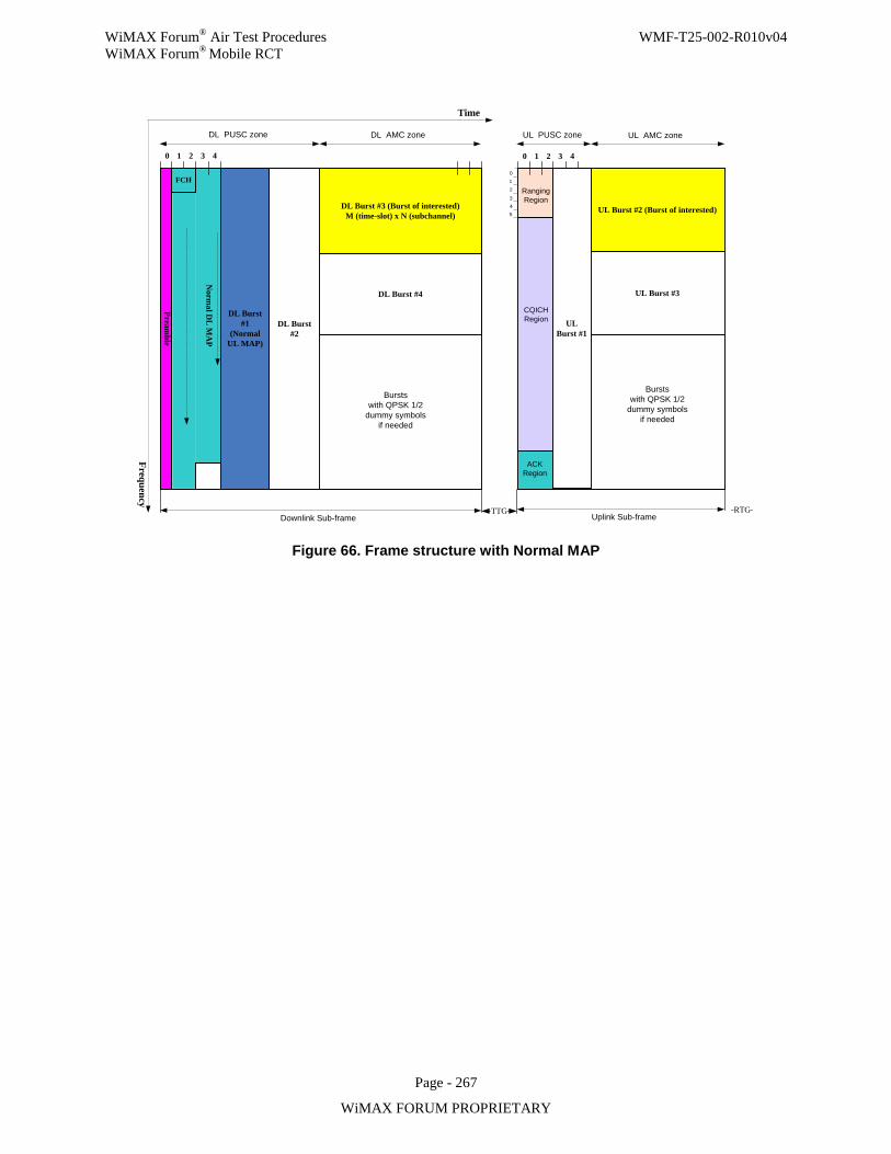
WiMAX Forum® Air Test Procedures WMF-T25-002-R010v04 WiMAX Forum® Mobile RCT
Page - 267
WiMAX FORUM PROPRIETARY
Preamble
Frequency
Norm
al DL
MA
P
DL Burst #1
(Normal UL MAP)
DL Burst #3 (Burst of interested)M (time-slot) x N (subchannel)
0 1 2 3
012
3Ranging Region
ACK Region
CQICHRegion
Uplink Sub-frameTTG RTG
4
DL Burst #4
0 1 2 3 4
45
Downlink Sub-frame
UL Burst #2 (Burst of interested)
UL Burst #3
Bursts with QPSK 1/2
dummy symbols if needed
Bursts with QPSK 1/2
dummy symbols if needed
FCH
Time
DL PUSC zone DL AMC zone UL PUSC zone UL AMC zone
DL Burst #2
UL Burst #1
Figure 66. Frame structure with Normal MAP
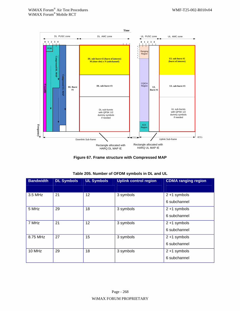
WiMAX Forum® Air Test Procedures WMF-T25-002-R010v04 WiMAX Forum® Mobile RCT
Page - 268
WiMAX FORUM PROPRIETARY
Preamble
Frequency
Com
pressed DL
MA
P
Time
0 1 2 3
012
3Ranging Region
ACK Region
CQICHRegion
Uplink Sub-frame
DL PUSC zone
TTG RTG
4 0 1 2 3 4
45
Downlink Sub-frame
Com
pressed UL
MA
P
UL sub-bursts with QPSK 1/2
dummy symbols if needed
Rectangle allocated with HARQ DL MAP IE
Rectangle allocated with HARQ UL MAP IE
FCH
DL AMC zone UL PUSC zone UL AMC zone
UL sub-burst #2 (burst of interest)
UL sub-burst #3DL Burst #1
UL Burst #1
DL sub-burst #2 (burst of interest)M (time-slot) x N (subchannel)
DL sub-burst #3
DL sub-bursts with QPSK 1/2
dummy symbols if needed
Figure 67. Frame structure with Compressed MAP
Table 205. Number of OFDM symbols in DL and UL
Bandwidth DL Symbols UL Symbols Uplink control region
CDMA ranging region
3.5 MHz 21 12 3 symbols 2 +1 symbols
6 subchannel
5 MHz 29 18 3 symbols 2 +1 symbols
6 subchannel
7 MHz 21 12 3 symbols 2 +1 symbols
6 subchannel
8.75 MHz 27 15 3 symbols 2 +1 symbols
6 subchannel
10 MHz 29 18 3 symbols 2 +1 symbols
6 subchannel
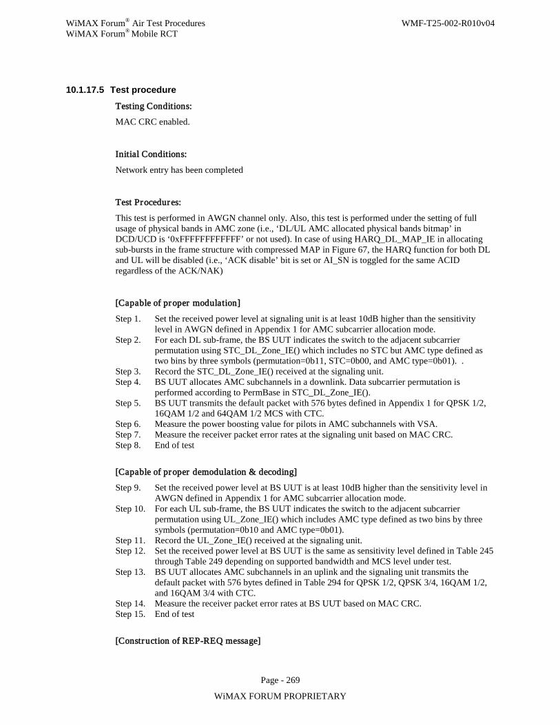
WiMAX Forum® Air Test Procedures WMF-T25-002-R010v04 WiMAX Forum® Mobile RCT
Page - 269
WiMAX FORUM PROPRIETARY
10.1.17.5 Test procedure
Testing Conditions:
MAC CRC enabled.
Initial Conditions:
Network entry has been completed
Test Procedures:
This test is performed in AWGN channel only. Also, this test is performed under the setting of full usage of physical bands in AMC zone (i.e., ‘DL/UL AMC allocated physical bands bitmap’ in DCD/UCD is ‘0xFFFFFFFFFFFF’ or not used). In case of using HARQ_DL_MAP_IE in allocating sub-bursts in the frame structure with compressed MAP in Figure 67, the HARQ function for both DL and UL will be disabled (i.e., ‘ACK disable’ bit is set or AI_SN is toggled for the same ACID regardless of the ACK/NAK)
[Capable of proper modulation]
Step 1. Set the received power level at signaling unit is at least 10dB higher than the sensitivity level in AWGN defined in Appendix 1 for AMC subcarrier allocation mode.
Step 2. For each DL sub-frame, the BS UUT indicates the switch to the adjacent subcarrier permutation using STC_DL_Zone_IE() which includes no STC but AMC type defined as two bins by three symbols (permutation=0b11, STC=0b00, and AMC type=0b01). .
Step 3. Record the STC_DL_Zone_IE() received at the signaling unit. Step 4. BS UUT allocates AMC subchannels in a downlink. Data subcarrier permutation is
performed according to PermBase in STC_DL_Zone_IE(). Step 5. BS UUT transmits the default packet with 576 bytes defined in Appendix 1 for QPSK 1/2,
16QAM 1/2 and 64QAM 1/2 MCS with CTC. Step 6. Measure the power boosting value for pilots in AMC subchannels with VSA. Step 7. Measure the receiver packet error rates at the signaling unit based on MAC CRC. Step 8. End of test
[Capable of proper demodulation & decoding]
Step 9. Set the received power level at BS UUT is at least 10dB higher than the sensitivity level in AWGN defined in Appendix 1 for AMC subcarrier allocation mode.
Step 10. For each UL sub-frame, the BS UUT indicates the switch to the adjacent subcarrier permutation using UL_Zone_IE() which includes AMC type defined as two bins by three symbols (permutation=0b10 and AMC type=0b01).
Step 11. Record the UL_Zone_IE() received at the signaling unit. Step 12. Set the received power level at BS UUT is the same as sensitivity level defined in Table 245
through Table 249 depending on supported bandwidth and MCS level under test. Step 13. BS UUT allocates AMC subchannels in an uplink and the signaling unit transmits the
default packet with 576 bytes defined in Table 294 for QPSK 1/2, QPSK 3/4, 16QAM 1/2, and 16QAM 3/4 with CTC.
Step 14. Measure the receiver packet error rates at BS UUT based on MAC CRC. Step 15. End of test
[Construction of REP-REQ message]
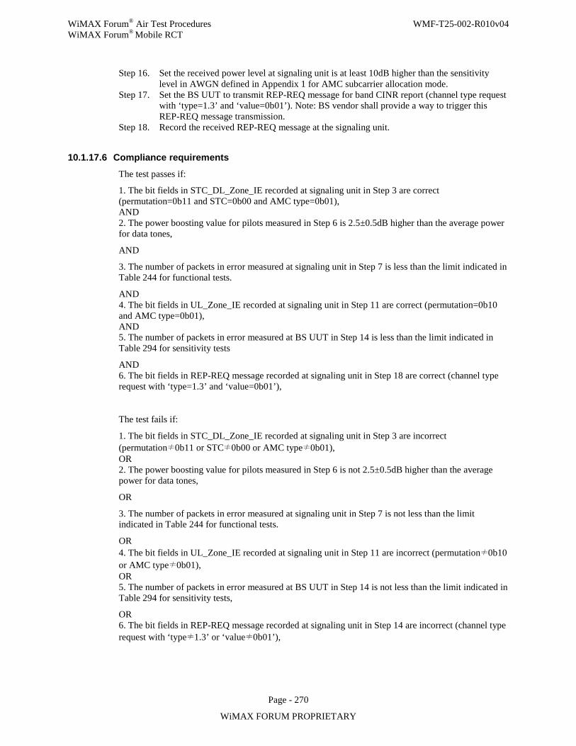
WiMAX Forum® Air Test Procedures WMF-T25-002-R010v04 WiMAX Forum® Mobile RCT
Page - 270
WiMAX FORUM PROPRIETARY
Step 16. Set the received power level at signaling unit is at least 10dB higher than the sensitivity level in AWGN defined in Appendix 1 for AMC subcarrier allocation mode.
Step 17. Set the BS UUT to transmit REP-REQ message for band CINR report (channel type request with ‘type=1.3’ and ‘value=0b01’). Note: BS vendor shall provide a way to trigger this REP-REQ message transmission.
Step 18. Record the received REP-REQ message at the signaling unit.
10.1.17.6 Compliance requirements
The test passes if:
1. The bit fields in STC_DL_Zone_IE recorded at signaling unit in Step 3 are correct (permutation=0b11 and STC=0b00 and AMC type=0b01), AND 2. The power boosting value for pilots measured in Step 6 is 2.5±0.5dB higher than the average power for data tones,
AND
3. The number of packets in error measured at signaling unit in Step 7 is less than the limit indicated in Table 244 for functional tests.
AND 4. The bit fields in UL_Zone_IE recorded at signaling unit in Step 11 are correct (permutation=0b10 and AMC type=0b01), AND 5. The number of packets in error measured at BS UUT in Step 14 is less than the limit indicated in Table 294 for sensitivity tests
AND 6. The bit fields in REP-REQ message recorded at signaling unit in Step 18 are correct (channel type request with ‘type=1.3’ and ‘value=0b01’),
The test fails if:
1. The bit fields in STC_DL_Zone_IE recorded at signaling unit in Step 3 are incorrect (permutation≠0b11 or STC≠0b00 or AMC type≠0b01), OR 2. The power boosting value for pilots measured in Step 6 is not 2.5±0.5dB higher than the average power for data tones,
OR
3. The number of packets in error measured at signaling unit in Step 7 is not less than the limit indicated in Table 244 for functional tests.
OR 4. The bit fields in UL_Zone_IE recorded at signaling unit in Step 11 are incorrect (permutation≠0b10 or AMC type≠0b01), OR 5. The number of packets in error measured at BS UUT in Step 14 is not less than the limit indicated in Table 294 for sensitivity tests,
OR 6. The bit fields in REP-REQ message recorded at signaling unit in Step 14 are incorrect (channel type request with ‘type≠1.3’ or ‘value≠0b01’),
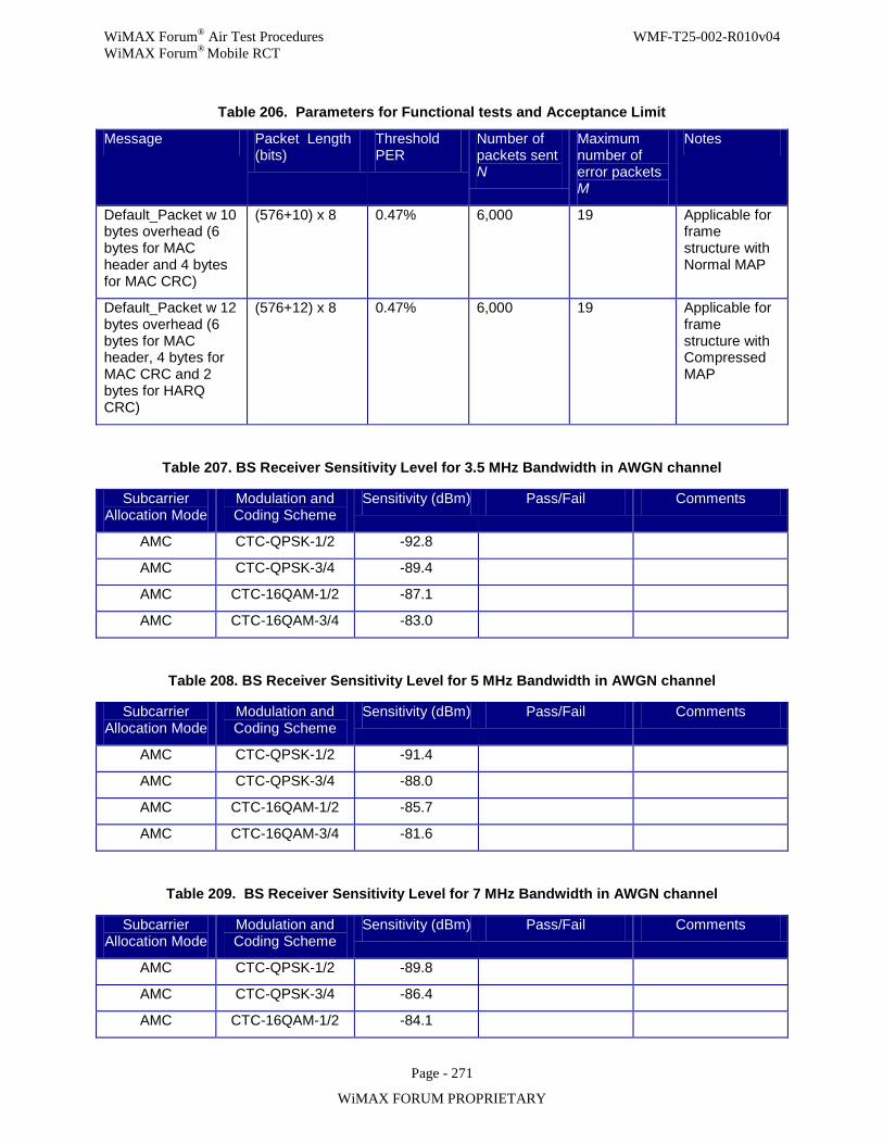
WiMAX Forum® Air Test Procedures WMF-T25-002-R010v04 WiMAX Forum® Mobile RCT
Page - 271
WiMAX FORUM PROPRIETARY
Table 206. Parameters for Functional tests and Acceptance Limit
Message Packet Length (bits)
Threshold PER
Number of packets sent N
Maximum number of error packets M
Notes
Default_Packet w 10 bytes overhead (6 bytes for MAC header and 4 bytes for MAC CRC)
(576+10) x 8 0.47% 6,000 19 Applicable for frame structure with Normal MAP
Default_Packet w 12 bytes overhead (6 bytes for MAC header, 4 bytes for MAC CRC and 2 bytes for HARQ CRC)
(576+12) x 8 0.47% 6,000 19 Applicable for frame structure with Compressed MAP
Table 207. BS Receiver Sensitivity Level for 3.5 MHz Bandwidth in AWGN channel
Subcarrier Allocation Mode
Modulation and Coding Scheme
Sensitivity (dBm) Pass/Fail Comments
AMC CTC-QPSK-1/2 -92.8
AMC CTC-QPSK-3/4 -89.4
AMC CTC-16QAM-1/2 -87.1
AMC CTC-16QAM-3/4 -83.0
Table 208. BS Receiver Sensitivity Level for 5 MHz Bandwidth in AWGN channel
Subcarrier Allocation Mode
Modulation and Coding Scheme
Sensitivity (dBm) Pass/Fail Comments
AMC CTC-QPSK-1/2 -91.4
AMC CTC-QPSK-3/4 -88.0
AMC CTC-16QAM-1/2 -85.7
AMC CTC-16QAM-3/4 -81.6
Table 209. BS Receiver Sensitivity Level for 7 MHz Bandwidth in AWGN channel
Subcarrier Allocation Mode
Modulation and Coding Scheme
Sensitivity (dBm) Pass/Fail Comments
AMC CTC-QPSK-1/2 -89.8
AMC CTC-QPSK-3/4 -86.4
AMC CTC-16QAM-1/2 -84.1
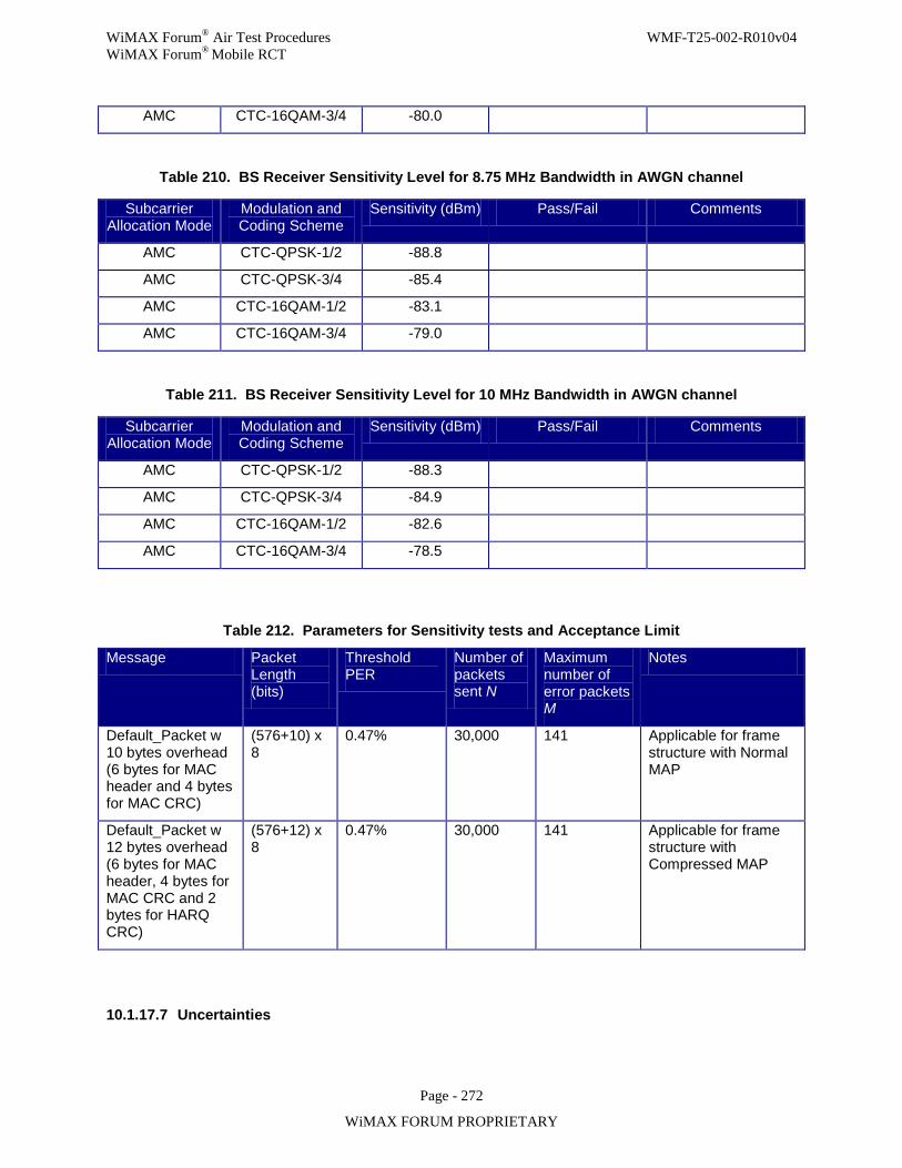
WiMAX Forum® Air Test Procedures WMF-T25-002-R010v04 WiMAX Forum® Mobile RCT
Page - 272
WiMAX FORUM PROPRIETARY
AMC CTC-16QAM-3/4 -80.0
Table 210. BS Receiver Sensitivity Level for 8.75 MHz Bandwidth in AWGN channel
Subcarrier Allocation Mode
Modulation and Coding Scheme
Sensitivity (dBm) Pass/Fail Comments
AMC CTC-QPSK-1/2 -88.8
AMC CTC-QPSK-3/4 -85.4
AMC CTC-16QAM-1/2 -83.1
AMC CTC-16QAM-3/4 -79.0
Table 211. BS Receiver Sensitivity Level for 10 MHz Bandwidth in AWGN channel
Subcarrier Allocation Mode
Modulation and Coding Scheme
Sensitivity (dBm) Pass/Fail Comments
AMC CTC-QPSK-1/2 -88.3
AMC CTC-QPSK-3/4 -84.9
AMC CTC-16QAM-1/2 -82.6
AMC CTC-16QAM-3/4 -78.5
Table 212. Parameters for Sensitivity tests and Acceptance Limit
Message Packet Length (bits)
Threshold PER
Number of packets sent N
Maximum number of error packets M
Notes
Default_Packet w 10 bytes overhead (6 bytes for MAC header and 4 bytes for MAC CRC)
(576+10) x 8
0.47% 30,000 141 Applicable for frame structure with Normal MAP
Default_Packet w 12 bytes overhead (6 bytes for MAC header, 4 bytes for MAC CRC and 2 bytes for HARQ CRC)
(576+12) x 8
0.47% 30,000 141 Applicable for frame structure with Compressed MAP
10.1.17.7 Uncertainties
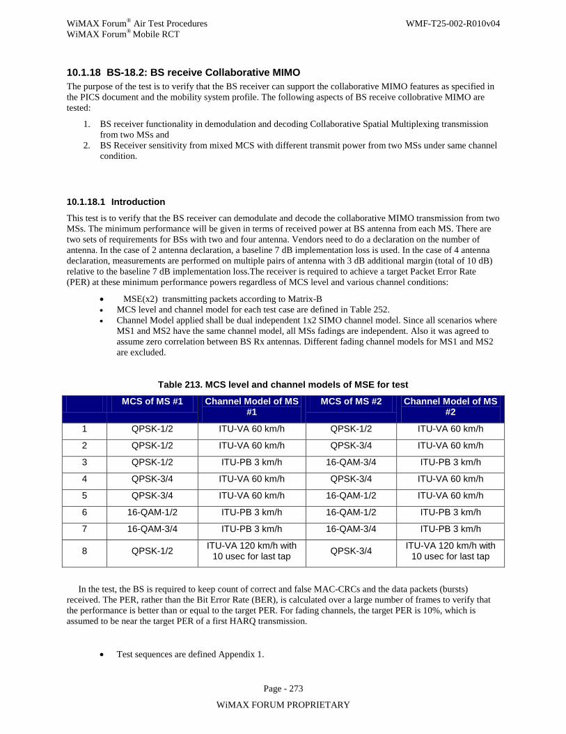
WiMAX Forum® Air Test Procedures WMF-T25-002-R010v04 WiMAX Forum® Mobile RCT
Page - 273
WiMAX FORUM PROPRIETARY
10.1.18 BS-18.2: BS receive Collaborative MIMO The purpose of the test is to verify that the BS receiver can support the collaborative MIMO features as specified in the PICS document and the mobility system profile. The following aspects of BS receive collobrative MIMO are tested:
1. BS receiver functionality in demodulation and decoding Collaborative Spatial Multiplexing transmission from two MSs and
2. BS Receiver sensitivity from mixed MCS with different transmit power from two MSs under same channel condition.
10.1.18.1 Introduction
This test is to verify that the BS receiver can demodulate and decode the collaborative MIMO transmission from two MSs. The minimum performance will be given in terms of received power at BS antenna from each MS. There are two sets of requirements for BSs with two and four antenna. Vendors need to do a declaration on the number of antenna. In the case of 2 antenna declaration, a baseline 7 dB implementation loss is used. In the case of 4 antenna declaration, measurements are performed on multiple pairs of antenna with 3 dB additional margin (total of 10 dB) relative to the baseline 7 dB implementation loss.The receiver is required to achieve a target Packet Error Rate (PER) at these minimum performance powers regardless of MCS level and various channel conditions:
• MSE(x2) transmitting packets according to Matrix-B • MCS level and channel model for each test case are defined in Table 252. • Channel Model applied shall be dual independent 1x2 SIMO channel model. Since all scenarios where
MS1 and MS2 have the same channel model, all MSs fadings are independent. Also it was agreed to assume zero correlation between BS Rx antennas. Different fading channel models for MS1 and MS2 are excluded.
Table 213. MCS level and channel models of MSE for test
MCS of MS #1 Channel Model of MS #1
MCS of MS #2 Channel Model of MS #2
1 QPSK-1/2 ITU-VA 60 km/h QPSK-1/2 ITU-VA 60 km/h
2 QPSK-1/2 ITU-VA 60 km/h QPSK-3/4 ITU-VA 60 km/h
3 QPSK-1/2 ITU-PB 3 km/h 16-QAM-3/4 ITU-PB 3 km/h
4 QPSK-3/4 ITU-VA 60 km/h QPSK-3/4 ITU-VA 60 km/h
5 QPSK-3/4 ITU-VA 60 km/h 16-QAM-1/2 ITU-VA 60 km/h
6 16-QAM-1/2 ITU-PB 3 km/h 16-QAM-1/2 ITU-PB 3 km/h
7 16-QAM-3/4 ITU-PB 3 km/h 16-QAM-3/4 ITU-PB 3 km/h
8 QPSK-1/2 ITU-VA 120 km/h with 10 usec for last tap QPSK-3/4 ITU-VA 120 km/h with
10 usec for last tap
In the test, the BS is required to keep count of correct and false MAC-CRCs and the data packets (bursts) received. The PER, rather than the Bit Error Rate (BER), is calculated over a large number of frames to verify that the performance is better than or equal to the target PER. For fading channels, the target PER is 10%, which is assumed to be near the target PER of a first HARQ transmission.
• Test sequences are defined Appendix 1.
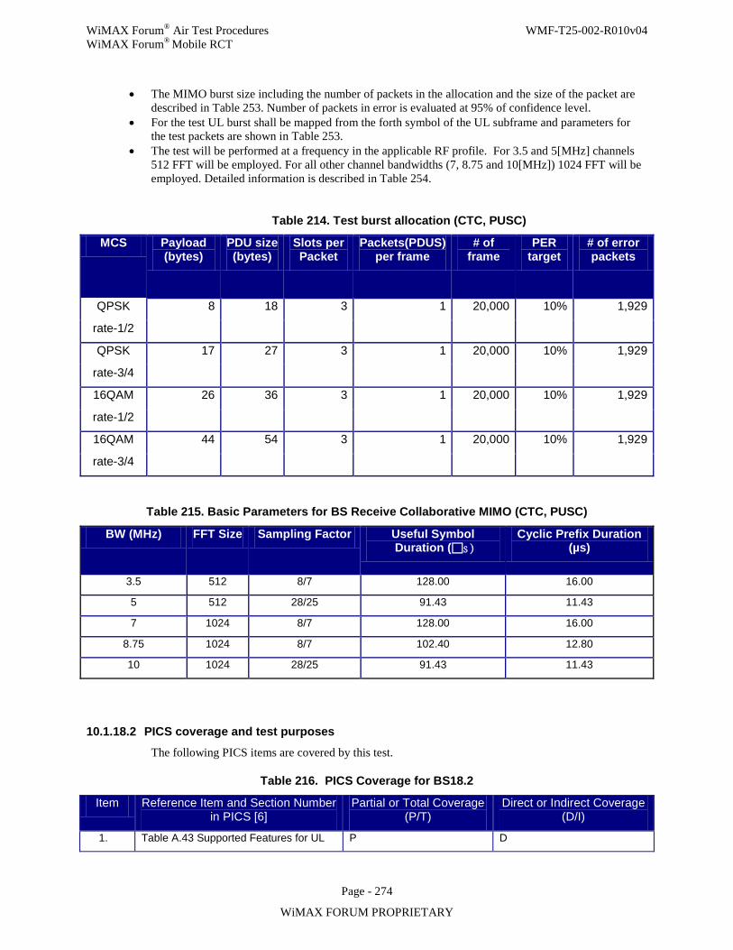
WiMAX Forum® Air Test Procedures WMF-T25-002-R010v04 WiMAX Forum® Mobile RCT
Page - 274
WiMAX FORUM PROPRIETARY
• The MIMO burst size including the number of packets in the allocation and the size of the packet are described in Table 253. Number of packets in error is evaluated at 95% of confidence level.
• For the test UL burst shall be mapped from the forth symbol of the UL subframe and parameters for the test packets are shown in Table 253.
• The test will be performed at a frequency in the applicable RF profile. For 3.5 and 5[MHz] channels 512 FFT will be employed. For all other channel bandwidths (7, 8.75 and 10[MHz]) 1024 FFT will be employed. Detailed information is described in Table 254.
Table 214. Test burst allocation (CTC, PUSC)
MCS Payload (bytes)
PDU size (bytes)
Slots per Packet
Packets(PDUS) per frame
# of frame
PER target
# of error packets
QPSK 8 18 3 1 20,000 10% 1,929
rate-1/2
QPSK 17 27 3 1 20,000 10% 1,929
rate-3/4
16QAM 26 36 3 1 20,000 10% 1,929
rate-1/2
16QAM 44 54 3 1 20,000 10% 1,929
rate-3/4
Table 215. Basic Parameters for BS Receive Collaborative MIMO (CTC, PUSC)
BW (MHz) FFT Size Sampling Factor Useful Symbol Duration (s )
Cyclic Prefix Duration (µs)
3.5 512 8/7 128.00 16.00
5 512 28/25 91.43 11.43
7 1024 8/7 128.00 16.00
8.75 1024 8/7 102.40 12.80
10 1024 28/25 91.43 11.43
10.1.18.2 PICS coverage and test purposes
The following PICS items are covered by this test.
Table 216. PICS Coverage for BS18.2
Item Reference Item and Section Number in PICS [6]
Partial or Total Coverage (P/T)
Direct or Indirect Coverage (D/I)
1. Table A.43 Supported Features for UL P D
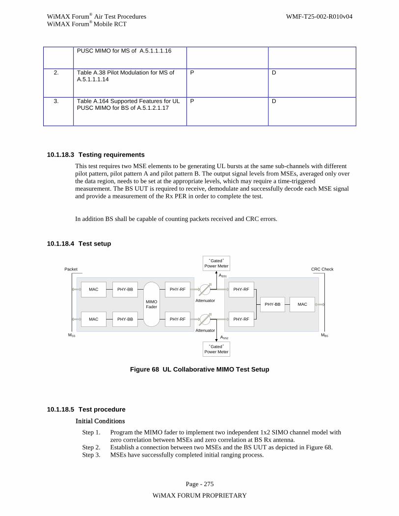
WiMAX Forum® Air Test Procedures WMF-T25-002-R010v04 WiMAX Forum® Mobile RCT
Page - 275
WiMAX FORUM PROPRIETARY
PUSC MIMO for MS of A.5.1.1.1.16
2. Table A.38 Pilot Modulation for MS of A.5.1.1.1.14
P D
3. Table A.164 Supported Features for UL PUSC MIMO for BS of A.5.1.2.1.17
P D
10.1.18.3 Testing requirements This test requires two MSE elements to be generating UL bursts at the same sub-channels with different pilot pattern, pilot pattern A and pilot pattern B. The output signal levels from MSEs, averaged only over the data region, needs to be set at the appropriate levels, which may require a time-triggered measurement. The BS UUT is required to receive, demodulate and successfully decode each MSE signal and provide a measurement of the Rx PER in order to complete the test.
In addition BS shall be capable of counting packets received and CRC errors.
10.1.18.4 Test setup
Attenuator
AttenuatorMSS MBSASS2
MAC PHY-BB PHY-RF
MAC PHY-BB PHY-RF
PHY-RF
PHY-RF
PHY-BB MAC
“Gated” Power Meter
“Gated” Power Meter
ASS1
Packet CRC Check
MIMOFader
Figure 68 UL Collaborative MIMO Test Setup
10.1.18.5 Test procedure
Initial Conditions
Step 1. Program the MIMO fader to implement two independent 1x2 SIMO channel model with zero correlation between MSEs and zero correlation at BS Rx antenna.
Step 2. Establish a connection between two MSEs and the BS UUT as depicted in Figure 68. Step 3. MSEs have successfully completed initial ranging process.
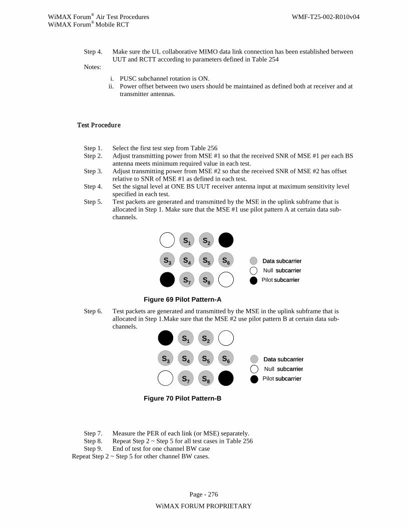
WiMAX Forum® Air Test Procedures WMF-T25-002-R010v04 WiMAX Forum® Mobile RCT
Page - 276
WiMAX FORUM PROPRIETARY
Step 4. Make sure the UL collaborative MIMO data link connection has been established between UUT and RCTT according to parameters defined in Table 254
Notes:
i. PUSC subchannel rotation is ON. ii. Power offset between two users should be maintained as defined both at receiver and at
transmitter antennas.
Test Procedure
Step 1. Select the first test step from Table 256 Step 2. Adjust transmitting power from MSE #1 so that the received SNR of MSE #1 per each BS
antenna meets minimum required value in each test. Step 3. Adjust transmitting power from MSE #2 so that the received SNR of MSE #2 has offset
relative to SNR of MSE #1 as defined in each test. Step 4. Set the signal level at ONE BS UUT receiver antenna input at maximum sensitivity level
specified in each test. Step 5. Test packets are generated and transmitted by the MSE in the uplink subframe that is
allocated in Step 1. Make sure that the MSE #1 use pilot pattern A at certain data sub-channels.
S 1 S 2
S 3 S 4 S 5 S 6
S 7 S 8
Data subcarrier subcarrier
subcarrier
S 1 S 2
S 3 S 4 S 5 S 6
S 7 S 8
Data subcarrier subcarrier
subcarrier Null Pilot
Figure 69 Pilot Pattern-A
Step 6. Test packets are generated and transmitted by the MSE in the uplink subframe that is allocated in Step 1.Make sure that the MSE #2 use pilot pattern B at certain data sub-channels.
S 1 S 2
S 3 S 4 S 5 S 6
S 7 S 8
Data subcarrier subcarrier
subcarrier
S 1 S 2
S 3 S 4 S 5 S 6
S 7 S 8
Data subcarrier subcarrier
subcarrier Pilot Null
Figure 70 Pilot Pattern-B
Step 7. Measure the PER of each link (or MSE) separately. Step 8. Repeat Step 2 ~ Step 5 for all test cases in Table 256 Step 9. End of test for one channel BW case
Repeat Step 2 ~ Step 5 for other channel BW cases.
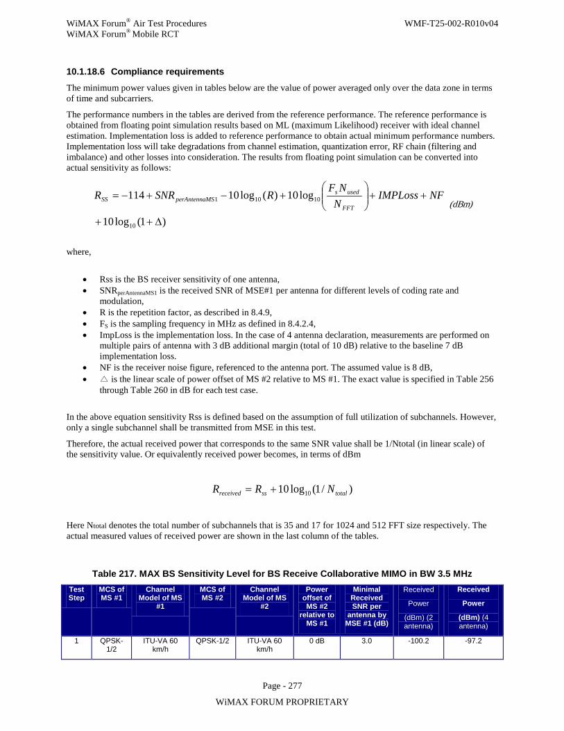
WiMAX Forum® Air Test Procedures WMF-T25-002-R010v04 WiMAX Forum® Mobile RCT
Page - 277
WiMAX FORUM PROPRIETARY
10.1.18.6 Compliance requirements
The minimum power values given in tables below are the value of power averaged only over the data zone in terms of time and subcarriers.
The performance numbers in the tables are derived from the reference performance. The reference performance is obtained from floating point simulation results based on ML (maximum Likelihood) receiver with ideal channel estimation. Implementation loss is added to reference performance to obtain actual minimum performance numbers. Implementation loss will take degradations from channel estimation, quantization error, RF chain (filtering and imbalance) and other losses into consideration. The results from floating point simulation can be converted into actual sensitivity as follows:
)1(log10
log10)(log10114
10
10101
∆++
++
+−+−= NFIMPLoss
NNF
RSNRRFFT
usedsMSperAntennaSS (dBm)
where,
• Rss is the BS receiver sensitivity of one antenna, • SNRperAntennaMS1 is the received SNR of MSE#1 per antenna for different levels of coding rate and
modulation, • R is the repetition factor, as described in 8.4.9, • FS is the sampling frequency in MHz as defined in 8.4.2.4, • ImpLoss is the implementation loss. In the case of 4 antenna declaration, measurements are performed on
multiple pairs of antenna with 3 dB additional margin (total of 10 dB) relative to the baseline 7 dB implementation loss.
• NF is the receiver noise figure, referenced to the antenna port. The assumed value is 8 dB, • is the linear scale of power offset of MS #2 relative to MS #1. The exact value is specified in Table 256
through Table 260 in dB for each test case.
In the above equation sensitivity Rss is defined based on the assumption of full utilization of subchannels. However, only a single subchannel shall be transmitted from MSE in this test.
Therefore, the actual received power that corresponds to the same SNR value shall be 1/Ntotal (in linear scale) of the sensitivity value. Or equivalently received power becomes, in terms of dBm
)/1(log10 10 totalssreceived NRR +=
Here Ntotal denotes the total number of subchannels that is 35 and 17 for 1024 and 512 FFT size respectively. The actual measured values of received power are shown in the last column of the tables.
Table 217. MAX BS Sensitivity Level for BS Receive Collaborative MIMO in BW 3.5 MHz Test Step
MCS of MS #1
Channel Model of MS
#1
MCS of MS #2
Channel Model of MS
#2
Power offset of MS #2
relative to MS #1
Minimal Received SNR per
antenna by MSE #1 (dB)
Received
Power
(dBm) (2 antenna)
Received
Power
(dBm) (4 antenna)
1 QPSK-1/2
ITU-VA 60 km/h
QPSK-1/2 ITU-VA 60 km/h
0 dB 3.0 -100.2 -97.2
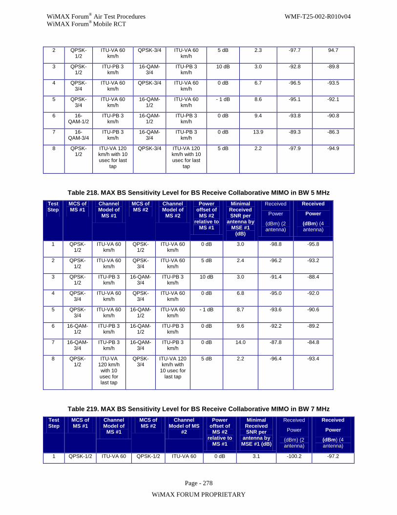
WiMAX Forum® Air Test Procedures WMF-T25-002-R010v04 WiMAX Forum® Mobile RCT
Page - 278
WiMAX FORUM PROPRIETARY
2 QPSK-1/2
ITU-VA 60 km/h
QPSK-3/4 ITU-VA 60 km/h
5 dB 2.3 -97.7 94.7
3 QPSK-1/2
ITU-PB 3 km/h
16-QAM-3/4
ITU-PB 3 km/h
10 dB 3.0 -92.8 -89.8
4 QPSK-3/4
ITU-VA 60 km/h
QPSK-3/4 ITU-VA 60 km/h
0 dB 6.7 -96.5 -93.5
5 QPSK-3/4
ITU-VA 60 km/h
16-QAM-1/2
ITU-VA 60 km/h
- 1 dB 8.6 -95.1 -92.1
6 16-QAM-1/2
ITU-PB 3 km/h
16-QAM-1/2
ITU-PB 3 km/h
0 dB 9.4 -93.8 -90.8
7 16-QAM-3/4
ITU-PB 3 km/h
16-QAM-3/4
ITU-PB 3 km/h
0 dB 13.9 -89.3 -86.3
8 QPSK-1/2
ITU-VA 120 km/h with 10 usec for last
tap
QPSK-3/4 ITU-VA 120 km/h with 10 usec for last
tap
5 dB 2.2 -97.9 -94.9
Table 218. MAX BS Sensitivity Level for BS Receive Collaborative MIMO in BW 5 MHz Test Step
MCS of MS #1
Channel Model of
MS #1
MCS of MS #2
Channel Model of
MS #2
Power offset of MS #2
relative to MS #1
Minimal Received SNR per
antenna by MSE #1
(dB)
Received
Power
(dBm) (2 antenna)
Received
Power
(dBm) (4 antenna)
1 QPSK-1/2
ITU-VA 60 km/h
QPSK-1/2
ITU-VA 60 km/h
0 dB 3.0 -98.8 -95.8
2 QPSK-1/2
ITU-VA 60 km/h
QPSK-3/4
ITU-VA 60 km/h
5 dB 2.4 -96.2 -93.2
3 QPSK-1/2
ITU-PB 3 km/h
16-QAM-3/4
ITU-PB 3 km/h
10 dB 3.0 -91.4 -88.4
4 QPSK-3/4
ITU-VA 60 km/h
QPSK-3/4
ITU-VA 60 km/h
0 dB 6.8 -95.0 -92.0
5 QPSK-3/4
ITU-VA 60 km/h
16-QAM-1/2
ITU-VA 60 km/h
- 1 dB 8.7 -93.6 -90.6
6 16-QAM-1/2
ITU-PB 3 km/h
16-QAM-1/2
ITU-PB 3 km/h
0 dB 9.6 -92.2 -89.2
7 16-QAM-3/4
ITU-PB 3 km/h
16-QAM-3/4
ITU-PB 3 km/h
0 dB 14.0 -87.8 -84.8
8 QPSK-1/2
ITU-VA 120 km/h with 10 usec for last tap
QPSK-3/4
ITU-VA 120 km/h with
10 usec for last tap
5 dB 2.2 -96.4 -93.4
Table 219. MAX BS Sensitivity Level for BS Receive Collaborative MIMO in BW 7 MHz Test Step
MCS of MS #1
Channel Model of
MS #1
MCS of MS #2
Channel Model of MS
#2
Power offset of MS #2
relative to MS #1
Minimal Received SNR per
antenna by MSE #1 (dB)
Received
Power
(dBm) (2 antenna)
Received
Power
(dBm) (4 antenna)
1 QPSK-1/2 ITU-VA 60 QPSK-1/2 ITU-VA 60 0 dB 3.1 -100.2 -97.2
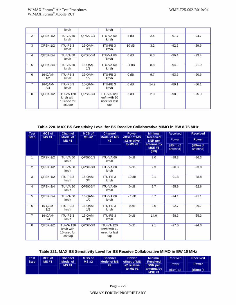
WiMAX Forum® Air Test Procedures WMF-T25-002-R010v04 WiMAX Forum® Mobile RCT
Page - 279
WiMAX FORUM PROPRIETARY
km/h km/h
2 QPSK-1/2 ITU-VA 60 km/h
QPSK-3/4 ITU-VA 60 km/h
5 dB 2.4 -97.7 -94.7
3 QPSK-1/2 ITU-PB 3 km/h
16-QAM-3/4
ITU-PB 3 km/h
10 dB 3.2 -92.6 -89.6
4 QPSK-3/4 ITU-VA 60 km/h
QPSK-3/4 ITU-VA 60 km/h
0 dB 6.8 -96.4 -93.4
5 QPSK-3/4 ITU-VA 60 km/h
16-QAM-1/2
ITU-VA 60 km/h
- 1 dB 8.8 -94.9 -91.9
6 16-QAM-1/2
ITU-PB 3 km/h
16-QAM-1/2
ITU-PB 3 km/h
0 dB 9.7 -93.6 -90.6
7 16-QAM-3/4
ITU-PB 3 km/h
16-QAM-3/4
ITU-PB 3 km/h
0 dB 14.2 -89.1 -86.1
8 QPSK-1/2 ITU-VA 120 km/h with
10 usec for last tap
QPSK-3/4 ITU-VA 120 km/h with 10 usec for last
tap
5 dB 2.0 -98.0 -95.0
Table 220. MAX BS Sensitivity Level for BS Receive Collaborative MIMO in BW 8.75 MHz Test Step
MCS of MS #1
Channel Model of
MS #1
MCS of MS #2
Channel Model of MS
#2
Power offset of MS #2 relative to MS #1
Minimal Received SNR per
antenna by MSE #1
(dB)
Received
Power
(dBm) (2 antenna)
Received
Power
(dBm) (4 antenna)
1 QPSK-1/2 ITU-VA 60 km/h
QPSK-1/2 ITU-VA 60 km/h
0 dB 3.0 -99.3 -96.3
2 QPSK-1/2 ITU-VA 60 km/h
QPSK-3/4 ITU-VA 60 km/h
5 dB 2.3 -96.8 -93.8
3 QPSK-1/2 ITU-PB 3 km/h
16-QAM-3/4
ITU-PB 3 km/h
10 dB 3.1 -91.8 -88.8
4 QPSK-3/4 ITU-VA 60 km/h
QPSK-3/4 ITU-VA 60 km/h
0 dB 6.7 -95.6 -92.6
5 QPSK-3/4 ITU-VA 60 km/h
16-QAM-1/2
ITU-VA 60 km/h
- 1 dB 8.7 -94.1 -91.1
6 16-QAM-1/2
ITU-PB 3 km/h
16-QAM-1/2
ITU-PB 3 km/h
0 dB 9.6 -92.7 -89.7
7 16-QAM-3/4
ITU-PB 3 km/h
16-QAM-3/4
ITU-PB 3 km/h
0 dB 14.0 -88.3 -85.3
8 QPSK-1/2 ITU-VA 120 km/h with
10 usec for last tap
QPSK-3/4 ITU-VA 120 km/h with 10 usec for last
tap
5 dB 2.1 -97.0 -94.0
Table 221. MAX BS Sensitivity Level for BS Receive Collaborative MIMO in BW 10 MHz Test Step
MCS of MS #1
Channel Model of
MS #1
MCS of MS #2
Channel Model of MS
#2
Power offset of MS #2 relative to MS #1
Minimal Received SNR per
antenna by MSE #1
Received
Power
(dBm) (2
Received
Power
(dBm) (4

WiMAX Forum® Air Test Procedures WMF-T25-002-R010v04 WiMAX Forum® Mobile RCT
Page - 280
WiMAX FORUM PROPRIETARY
(dB) antenna) antenna)
1 QPSK-1/2 ITU-VA 60 km/h
QPSK-1/2 ITU-VA 60 km/h
0 dB 3.1 -98.7 -95.7
2 QPSK-1/2 ITU-VA 60 km/h
QPSK-3/4 ITU-VA 60 km/h
5 dB 2.4 -96.2 -93.2
3 QPSK-1/2 ITU-PB 3 km/h
16-QAM-3/4
ITU-PB 3 km/h
10 dB 3.0 -91.4 -88.4
4 QPSK-3/4 ITU-VA 60 km/h
QPSK-3/4 ITU-VA 60 km/h
0 dB 6.8 -95.0 -92.0
5 QPSK-3/4 ITU-VA 60 km/h
16-QAM-1/2
ITU-VA 60 km/h
- 1 dB 8.8 -93.5 -90.5
6 16-QAM-1/2
ITU-PB 3 km/h
16-QAM-1/2
ITU-PB 3 km/h
0 dB 9.5 -92.3 -89.3
7 16-QAM-3/4
ITU-PB 3 km/h
16-QAM-3/4
ITU-PB 3 km/h
0 dB 14.0 -87.8 -84.8
8 QPSK-1/2 ITU-VA 120 km/h with
10 usec for last tap
QPSK-3/4 ITU-VA 120 km/h with 10 usec for last
tap
5 dB 2.1 -96.5 -93.5
Pass Verdict: when
a) PER measured for both MSEs in the test procedures can meet the PER requirement of 10%.
Fail Verdict: when
a) BS can’t be configured to receive packets transmitted from MSEs in UL subframe with UL MIMO enabled.
b) Either MSE fail to meet the PER requirement of 10%.
10.1.18.7 Uncertainties
The maximum allowed signal level inaccuracy at the ABS is +/- 0.5 dB.
10.1.19 BS-19.2: BS transmit MIMO processing
The purpose of the test is to verify that the BS transmitter can support the MIMO features as specified in the PICS document and the Mobile System Profile. In particular, this test verifies BS MIMO transmit functionality including pilot formatting for both Matrix-A and Matrix-B and per-chain EVM performance.
10.1.19.1 Introduction
This test is to verify that the BS transmitter can support both Matrix-A and Matrix-B operation. The minimum performance will be given in terms of relative constellation error per transmit chain and output power imbalances
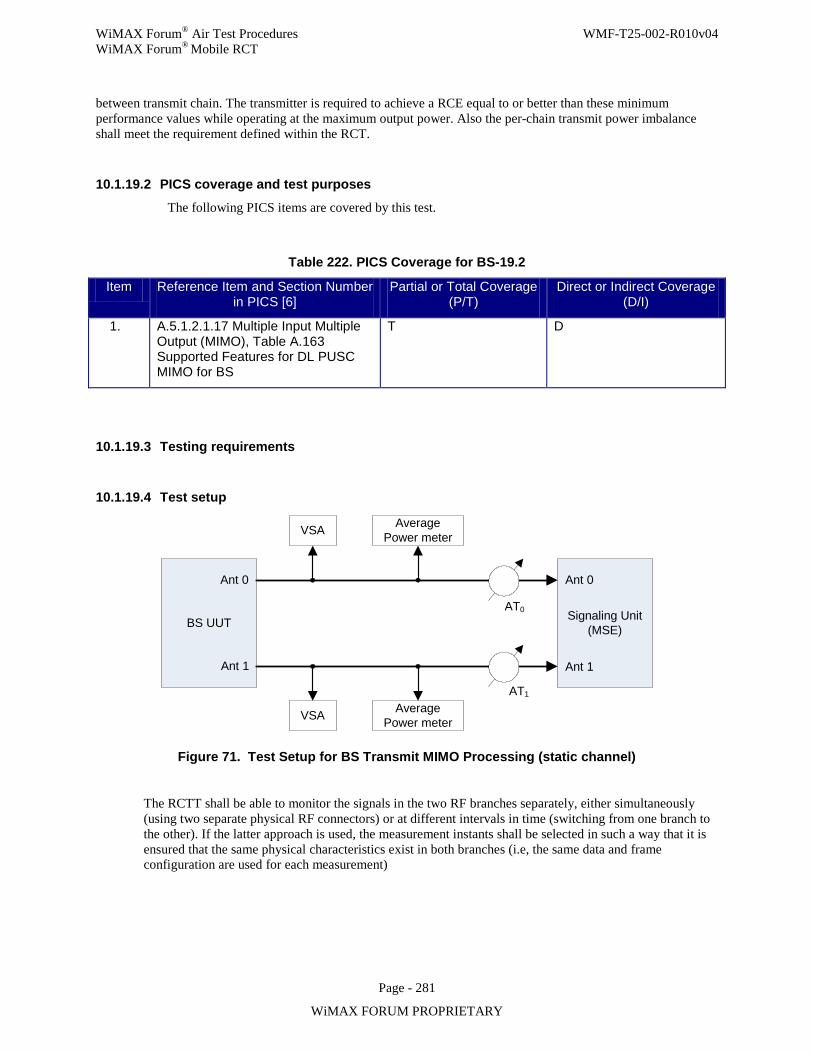
WiMAX Forum® Air Test Procedures WMF-T25-002-R010v04 WiMAX Forum® Mobile RCT
Page - 281
WiMAX FORUM PROPRIETARY
between transmit chain. The transmitter is required to achieve a RCE equal to or better than these minimum performance values while operating at the maximum output power. Also the per-chain transmit power imbalance shall meet the requirement defined within the RCT.
10.1.19.2 PICS coverage and test purposes
The following PICS items are covered by this test.
Table 222. PICS Coverage for BS-19.2
Item Reference Item and Section Number in PICS [6]
Partial or Total Coverage (P/T)
Direct or Indirect Coverage (D/I)
1. A.5.1.2.1.17 Multiple Input Multiple Output (MIMO), Table A.163 Supported Features for DL PUSC MIMO for BS
T D
10.1.19.3 Testing requirements
10.1.19.4 Test setup
BS UUT
Ant 0
Ant 1
Signaling Unit (MSE)
Ant 0
Ant 1
AT0
AT1
VSA AveragePower meter
VSA AveragePower meter
Figure 71. Test Setup for BS Transmit MIMO Processing (static channel)
The RCTT shall be able to monitor the signals in the two RF branches separately, either simultaneously (using two separate physical RF connectors) or at different intervals in time (switching from one branch to the other). If the latter approach is used, the measurement instants shall be selected in such a way that it is ensured that the same physical characteristics exist in both branches (i.e, the same data and frame configuration are used for each measurement)
WiMAX Forum® Air Test Procedures WMF-T25-002-R010v04 WiMAX Forum® Mobile RCT
Page - 282
WiMAX FORUM PROPRIETARY
10.1.19.5 Test procedure
Initial Conditions:
Step 2. Make sure the data link connection has been established between BS UUT and testing equipment
Test #1 – Pilot modulation for MIMO transmission (Functional Test)
In the proposed test, a downlink connection is established between the BS UUT and the testing equipment, which measures the power level at pilot subcarriers and data subcarriers. In each transmission the BS UUT sends one DL sub-frame on the maximum DL sub-frame size allowed by the profile.
The testing equipment shall report the average power for pilot subcarriers and data subcarriers in DL PUSC STC zone with Matrix-A and Matrix-B.
The testing equipment performs channel estimation both on pilots and data sub-carriers to minimize channel estimation errors.
A single MCS is sufficient to show that the BS UUT is modulating pilots in the DL PUSC STC zone properly. As such, this portion of the test requires only QPSK ¾ to be tested.
This test requires the test setup in Figure 71.
The test steps are briefly summarized below:
Step 9. Configure BS UUT to transmit MIMO signal with Matrix-A. Step 10. BS UUT sends DL packets in DL PUSC STC zone using QPSK 3/4 with the maximal DL
sub-frame size at middle frequency that BS UUT supports. Step 11. Testing equipment reads and records the average power level at pilot subcarriers, data
subcarriers and null subcarriers (punctured pilot subcarriers) respectively in DL PUSC STC zone. The averaging will be done over 200 frames.
Step 12. Configure BS UUT to transmit MIMO signal with Matrix-B and repeat Step 10 and Step 11.
Step 13. End of test.
Test Results #1 – Pilot modulation for MIMO transmission
For each test the following table will be filled.
Table 223 Pilot Modulation Test Results for BS-19.2
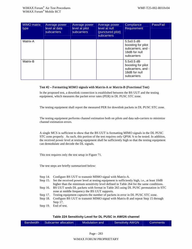
WiMAX Forum® Air Test Procedures WMF-T25-002-R010v04 WiMAX Forum® Mobile RCT
Page - 283
WiMAX FORUM PROPRIETARY
MIMO matrix type
Average power level at data subcarriers
Average power level at pilot subcarriers
Average power level at null (punctured pilot) subcarriers
Compliance Requirement
Pass/Fail
Matrix-A 5.5±0.5 dB boosting for pilot subcarriers, and -18dB for null subcarriers
Matrix-B 5.5±0.5 dB boosting for pilot subcarriers, and -18dB for null subcarriers
Test #2 – Formatting MIMO signals with Matr ix-A or Matr ix-B (Functional Test)
In the proposed test, a downlink connection is established between the BS UUT and the testing equipment, which measures the packet error rates (PER) in DL PUSC STC zone.
The testing equipment shall report the measured PER for downlink packets in DL PUSC STC zone.
The testing equipment performs channel estimation both on pilots and data sub-carriers to minimize channel estimation errors.
A single MCS is sufficient to show that the BS UUT is formatting MIMO signals in the DL PUSC STC zone properly. As such, this portion of the test requires only QPSK ¾ to be tested. In addition, the received power level at testing equipment shall be sufficiently high so that the testing equipment can demodulate and decode the DL signals.
This test requires only the test setup in Figure 71.
The test steps are briefly summarized below:
Step 14. Configure BS UUT to transmit MIMO signal with Matrix-A. Step 15. Set the received power level at testing equipment is sufficiently high, i.e., at least 10dB
higher than the minimum sensitivity level defined in Table 264 for the same conditions. Step 16. BS UUT sends DL packets with format in Table 265 using DL PUSC permutation in STC
zone at middle frequency the BS UUT supports. Step 17. Testing equipment captures the number of packets in error in DL PUSC STC zone. Step 18. Configure BS UUT to transmit MIMO signal with Matrix-B and repeat Step 15 through
Step 17. Step 19. End of test.
Table 224 Sensitivity Level for DL PUSC in AWGN channel
Bandwidth Subcarrier allocation Modulation and Sensitivity AWGN Comments
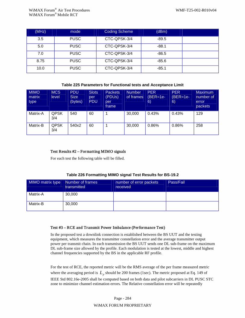
WiMAX Forum® Air Test Procedures WMF-T25-002-R010v04 WiMAX Forum® Mobile RCT
Page - 284
WiMAX FORUM PROPRIETARY
(MHz) mode Coding Scheme (dBm)
3.5 PUSC CTC-QPSK-3/4 -89.5
5.0 PUSC CTC-QPSK-3/4 -88.1
7.0 PUSC CTC-QPSK-3/4 -86.5
8.75 PUSC CTC-QPSK-3/4 -85.6
10.0 PUSC CTC-QPSK-3/4 -85.1
Table 225 Parameters for Functional tests and Acceptance Limit
MIMO matrix type
MCS level
PDU Size (bytes)
Slots per PDU
Packets (PDUs) per frame
Number of frames
PER (BER=1e-6)
PER (BER=1e-6)
Maximum number of error packets
Matrix-A QPSK 3/4
540 60 1 30,000 0.43% 0.43% 129
Matrix-B QPSK 3/4
540x2 60 1 30,000 0.86% 0.86% 258
Test Results #2 – Formatting MIMO signals
For each test the following table will be filled.
Table 226 Formatting MIMO signal Test Results for BS-19.2
MIMO matrix type Number of frames transmitted
number of error packets received
Pass/Fail
Matrix-A 30,000
Matrix-B 30,000
Test #3 – RCE and Transmit Power Imbalance (Per formance Test)
In the proposed test a downlink connection is established between the BS UUT and the testing equipment, which measures the transmitter constellation error and the average transmitter output power per transmit chain. In each transmission the BS UUT sends one DL sub-frame on the maximum DL sub-frame size allowed by the profile. Each modulation is tested at the lowest, middle and highest channel frequencies supported by the BS in the applicable RF profile.
For the test of RCE, the reported metric will be the RMS average of the per frame measured metric where the averaging period is pL should be 200 frames (1sec). The metric proposed at Eq. 149 of IEEE Std 802.16e-2005 shall be computed based on both data and pilot subcarriers in DL PUSC STC zone to minimize channel estimation errors. The Relative constellation error will be repeatedly
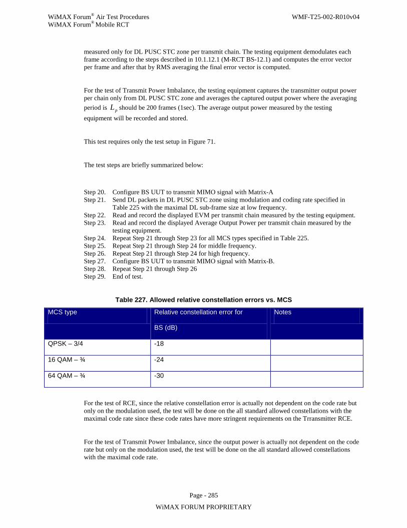
WiMAX Forum® Air Test Procedures WMF-T25-002-R010v04 WiMAX Forum® Mobile RCT
Page - 285
WiMAX FORUM PROPRIETARY
measured only for DL PUSC STC zone per transmit chain. The testing equipment demodulates each frame according to the steps described in 10.1.12.1 (M-RCT BS-12.1) and computes the error vector per frame and after that by RMS averaging the final error vector is computed.
For the test of Transmit Power Imbalance, the testing equipment captures the transmitter output power per chain only from DL PUSC STC zone and averages the captured output power where the averaging period is pL should be 200 frames (1sec). The average output power measured by the testing equipment will be recorded and stored.
This test requires only the test setup in Figure 71.
The test steps are briefly summarized below:
Step 20. Configure BS UUT to transmit MIMO signal with Matrix-A Step 21. Send DL packets in DL PUSC STC zone using modulation and coding rate specified in
Table 225 with the maximal DL sub-frame size at low frequency. Step 22. Read and record the displayed EVM per transmit chain measured by the testing equipment. Step 23. Read and record the displayed Average Output Power per transmit chain measured by the
testing equipment. Step 24. Repeat Step 21 through Step 23 for all MCS types specified in Table 225. Step 25. Repeat Step 21 through Step 24 for middle frequency. Step 26. Repeat Step 21 through Step 24 for high frequency. Step 27. Configure BS UUT to transmit MIMO signal with Matrix-B. Step 28. Repeat Step 21 through Step 26 Step 29. End of test.
Table 227. Allowed relative constellation errors vs. MCS
MCS type Relative constellation error for
BS (dB)
Notes
QPSK – 3/4 -18
16 QAM – ¾ -24
64 QAM – ¾ -30
For the test of RCE, since the relative constellation error is actually not dependent on the code rate but only on the modulation used, the test will be done on the all standard allowed constellations with the maximal code rate since these code rates have more stringent requirements on the Trransmitter RCE.
For the test of Transmit Power Imbalance, since the output power is actually not dependent on the code rate but only on the modulation used, the test will be done on the all standard allowed constellations with the maximal code rate.
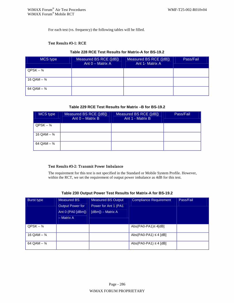
WiMAX Forum® Air Test Procedures WMF-T25-002-R010v04 WiMAX Forum® Mobile RCT
Page - 286
WiMAX FORUM PROPRIETARY
For each test (vs. frequency) the following tables will be filled.
Test Results #3-1: RCE
Table 228 RCE Test Results for Matrix-A for BS-19.2
MCS type Measured BS RCE ([dB]) Ant 0 – Matrix A
Measured BS RCE ([dB]) Ant 1- Matrix A
Pass/Fail
QPSK – ¾
16 QAM – ¾
64 QAM – ¾
Table 229 RCE Test Results for Matrix –B for BS-19.2
MCS type Measured BS RCE ([dB]) Ant 0 – Matrix B
Measured BS RCE ([dB]) Ant 1 - Matrix B
Pass/Fail
QPSK – ¾
16 QAM – ¾
64 QAM – ¾
Test Results #3-2: Transmit Power Imbalance
The requirement for this test is not specified in the Standard or Mobile System Profile. However, within the RCT, we set the requirement of output power imbalance as 4dB for this test.
Table 230 Output Power Test Results for Matrix-A for BS-19.2
Burst type Measured BS
Output Power for
Ant 0 (PA0 [dBm])
– Matrix A
Measured BS Output
Power for Ant 1 (PA1
[dBm]) – Matrix A
Compliance Requirement Pass/Fail
QPSK – ¾ Abs(PA0-PA1)≤ 4[dB]
16 QAM – ¾ Abs(PA0-PA1) ≤ 4 [dB]
64 QAM – ¾ Abs(PA0-PA1) ≤ 4 [dB]
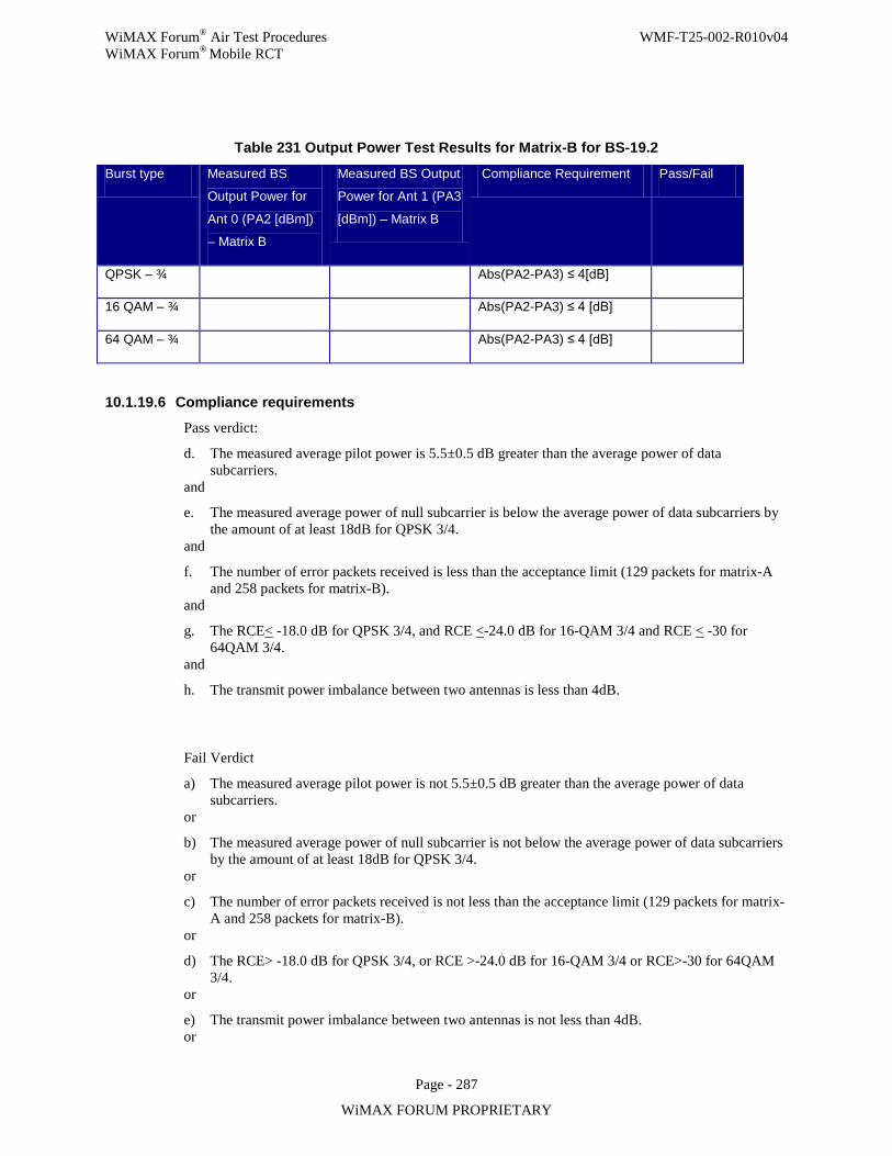
WiMAX Forum® Air Test Procedures WMF-T25-002-R010v04 WiMAX Forum® Mobile RCT
Page - 287
WiMAX FORUM PROPRIETARY
Table 231 Output Power Test Results for Matrix-B for BS-19.2
Burst type Measured BS
Output Power for
Ant 0 (PA2 [dBm])
– Matrix B
Measured BS Output
Power for Ant 1 (PA3
[dBm]) – Matrix B
Compliance Requirement Pass/Fail
QPSK – ¾ Abs(PA2-PA3) ≤ 4[dB]
16 QAM – ¾ Abs(PA2-PA3) ≤ 4 [dB]
64 QAM – ¾ Abs(PA2-PA3) ≤ 4 [dB]
10.1.19.6 Compliance requirements
Pass verdict:
d. The measured average pilot power is 5.5±0.5 dB greater than the average power of data subcarriers.
and
e. The measured average power of null subcarrier is below the average power of data subcarriers by the amount of at least 18dB for QPSK 3/4.
and
f. The number of error packets received is less than the acceptance limit (129 packets for matrix-A and 258 packets for matrix-B).
and
g. The RCE< -18.0 dB for QPSK 3/4, and RCE <-24.0 dB for 16-QAM 3/4 and RCE < -30 for 64QAM 3/4.
and
h. The transmit power imbalance between two antennas is less than 4dB.
Fail Verdict
a) The measured average pilot power is not 5.5±0.5 dB greater than the average power of data subcarriers.
or
b) The measured average power of null subcarrier is not below the average power of data subcarriers by the amount of at least 18dB for QPSK 3/4.
or
c) The number of error packets received is not less than the acceptance limit (129 packets for matrix-A and 258 packets for matrix-B).
or
d) The RCE> -18.0 dB for QPSK 3/4, or RCE >-24.0 dB for 16-QAM 3/4 or RCE>-30 for 64QAM 3/4.
or
e) The transmit power imbalance between two antennas is not less than 4dB. or
WiMAX Forum® Air Test Procedures WMF-T25-002-R010v04 WiMAX Forum® Mobile RCT
Page - 288
WiMAX FORUM PROPRIETARY
10.1.19.7 Uncertainties
Not applicable.
10.1.20 BS-20.2: BS transmitter Beamforming
The purpose of this test is to verify the BS transmitter beamforming functionality which includes PUSC with dedicated pilots and AMC 2×3 with dedicated pilots. This test also includes verifications of BS transmitter beamforming performance and proper handling of UL channel sounding.
Assuming that a given BS complies with all single-antenna transmit requirements, then this test, in particular, covers the following items:
1. The BS does not transmit pilots in the region not allocated for downlink bursts when using PUSC with dedicated pilots and AMC with dedicated pilots.
2. The BS allocates downlink bursts spanning over a major group for PUSC with dedicated pilots.
3. The transmitted pilot signals are beamformed in the same manner as data.
4. The BS correctly constructs the STC DL zone IE (DIUC=15 & extended DIUC=0x01) in the DL MAP message, the sounding zone IE (UIUC=13) and the UL sounding command IE (UIUC=11 & extended UIUC=0x04) in UL MAP message.
In the case that the BS supports IO-BF AND IO-MIMO then the following tests shall be conducted: 5. The BS does not transmit pilots in the region not allocated for downlink bursts when using PUSC with
dedicated pilots in the DL STC zone,
6. Functional test for proper construction of signals in Matrix-A or Matrix-B format with dedicated pilots in the DL PUSC STC zone.
10.1.20.1 Introduction
The capability of “beamforming” is described in the IEEE Std 802.16 under the name of AAS (Advanced Antenna Systems). In the WiMAX® PICS the “beamforming features” are grouped under the heading of IO-BF.
The radio transmission in “beamforming” is asymmetric in the sense that the downlink and uplink operations are different but complementary. The base station performs the beamforming of the radio signal and the mobile station sends sounding signals that assist the base station in estimating the downlink channel characteristics. The implementation of the beamforming algorithms is not part of the standards and therefore also not part of the certification testing.
This test also addresses BS that supports IO-BF AND IO-MIMO by conducting simplified functional tests on the operation of DL PUSC STC zone with dedicated pilots.
The test setup is described with eight antennas. The same test rack may be used to test a BS having between two and eight antenna ports (NA).
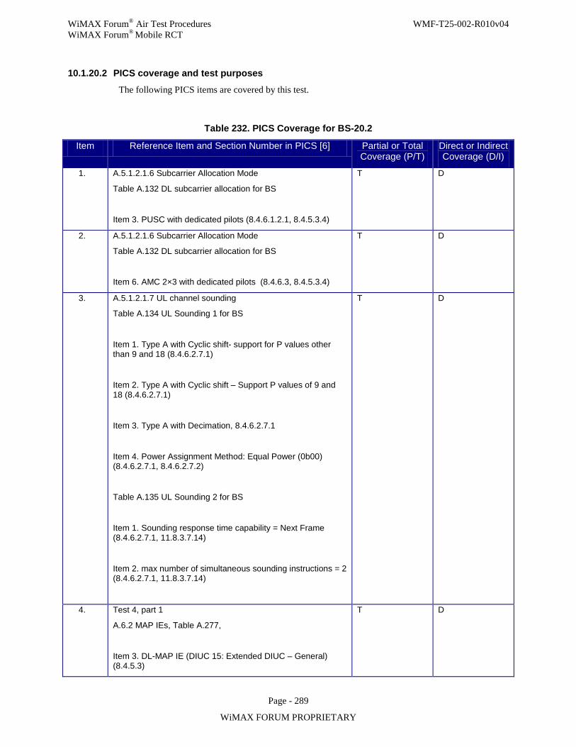
WiMAX Forum® Air Test Procedures WMF-T25-002-R010v04 WiMAX Forum® Mobile RCT
Page - 289
WiMAX FORUM PROPRIETARY
10.1.20.2 PICS coverage and test purposes
The following PICS items are covered by this test.
Table 232. PICS Coverage for BS-20.2
Item Reference Item and Section Number in PICS [6] Partial or Total Coverage (P/T)
Direct or Indirect Coverage (D/I)
1. A.5.1.2.1.6 Subcarrier Allocation Mode
Table A.132 DL subcarrier allocation for BS
Item 3. PUSC with dedicated pilots (8.4.6.1.2.1, 8.4.5.3.4)
T D
2. A.5.1.2.1.6 Subcarrier Allocation Mode
Table A.132 DL subcarrier allocation for BS
Item 6. AMC 2×3 with dedicated pilots (8.4.6.3, 8.4.5.3.4)
T D
3. A.5.1.2.1.7 UL channel sounding
Table A.134 UL Sounding 1 for BS
Item 1. Type A with Cyclic shift- support for P values other than 9 and 18 (8.4.6.2.7.1)
Item 2. Type A with Cyclic shift – Support P values of 9 and 18 (8.4.6.2.7.1)
Item 3. Type A with Decimation, 8.4.6.2.7.1
Item 4. Power Assignment Method: Equal Power (0b00) (8.4.6.2.7.1, 8.4.6.2.7.2)
Table A.135 UL Sounding 2 for BS
Item 1. Sounding response time capability = Next Frame (8.4.6.2.7.1, 11.8.3.7.14)
Item 2. max number of simultaneous sounding instructions = 2 (8.4.6.2.7.1, 11.8.3.7.14)
T D
4. Test 4, part 1
A.6.2 MAP IEs, Table A.277,
Item 3. DL-MAP IE (DIUC 15: Extended DIUC – General) (8.4.5.3)
T D
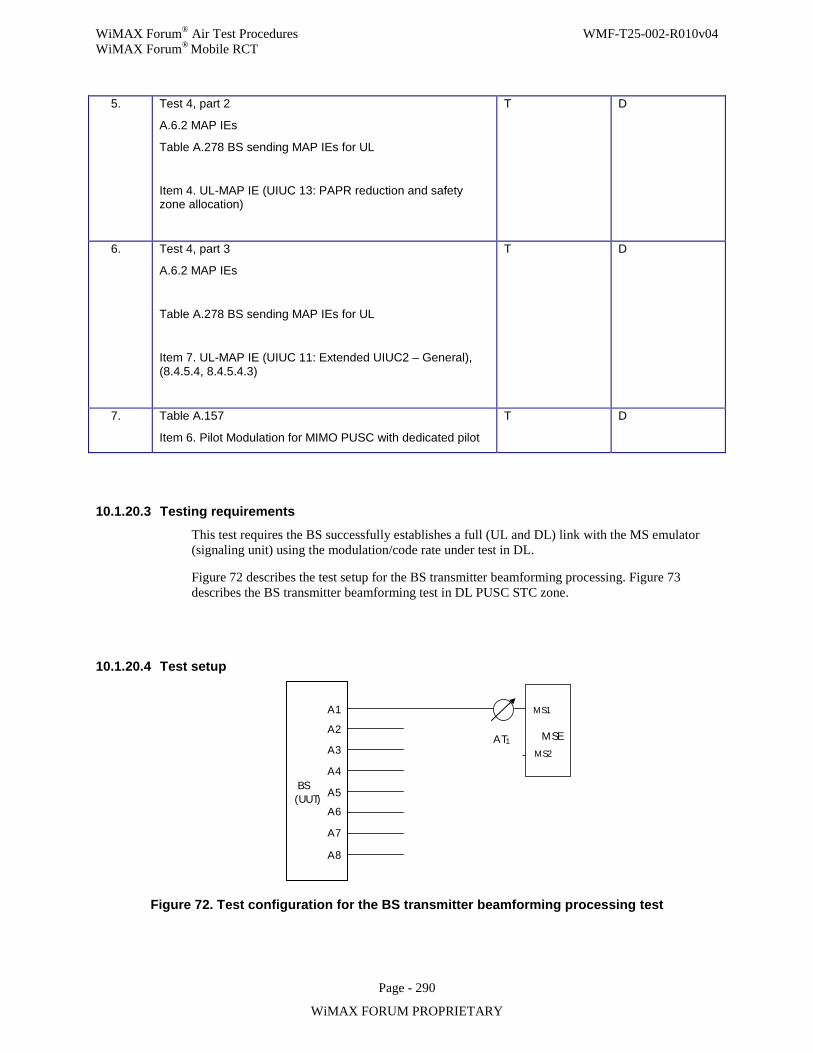
WiMAX Forum® Air Test Procedures WMF-T25-002-R010v04 WiMAX Forum® Mobile RCT
Page - 290
WiMAX FORUM PROPRIETARY
5. Test 4, part 2
A.6.2 MAP IEs
Table A.278 BS sending MAP IEs for UL
Item 4. UL-MAP IE (UIUC 13: PAPR reduction and safety zone allocation)
T D
6. Test 4, part 3
A.6.2 MAP IEs
Table A.278 BS sending MAP IEs for UL
Item 7. UL-MAP IE (UIUC 11: Extended UIUC2 – General), (8.4.5.4, 8.4.5.4.3)
T D
7. Table A.157
Item 6. Pilot Modulation for MIMO PUSC with dedicated pilot
T D
10.1.20.3 Testing requirements
This test requires the BS successfully establishes a full (UL and DL) link with the MS emulator (signaling unit) using the modulation/code rate under test in DL.
Figure 72 describes the test setup for the BS transmitter beamforming processing. Figure 73 describes the BS transmitter beamforming test in DL PUSC STC zone.
10.1.20.4 Test setup
BS (UUT)
A1 A2
A3
A4
A5 A6
A7
A8
MSE
MS1
MS2 AT1
Figure 72. Test configuration for the BS transmitter beamforming processing test
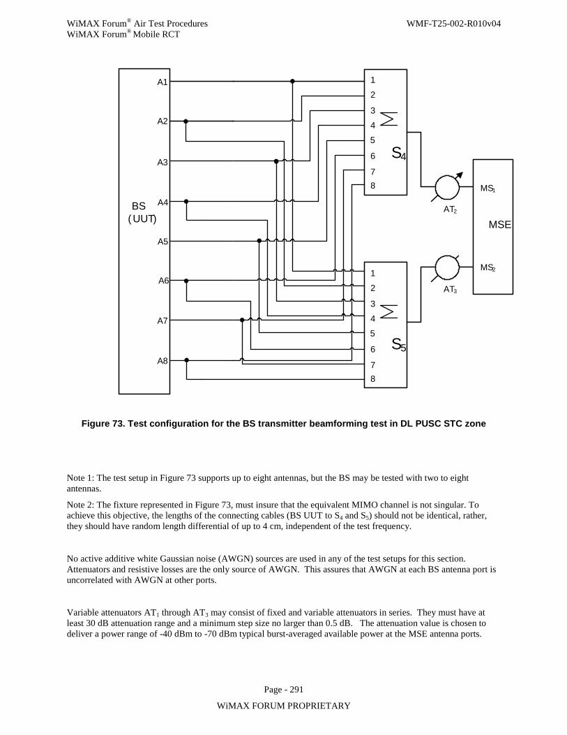
WiMAX Forum® Air Test Procedures WMF-T25-002-R010v04 WiMAX Forum® Mobile RCT
Page - 291
WiMAX FORUM PROPRIETARY
BS (UUT)
AT2
A1
S4
1
3
5
7
MSE
MS1
A2
A3
A4
A5
A6
A7
A8
2
4
6
8
MS2
S5
1
3
5
7
2
4
6
8
AT3
Figure 73. Test configuration for the BS transmitter beamforming test in DL PUSC STC zone
Note 1: The test setup in Figure 73 supports up to eight antennas, but the BS may be tested with two to eight antennas.
Note 2: The fixture represented in Figure 73, must insure that the equivalent MIMO channel is not singular. To achieve this objective, the lengths of the connecting cables (BS UUT to S4 and S5) should not be identical, rather, they should have random length differential of up to 4 cm, independent of the test frequency.
No active additive white Gaussian noise (AWGN) sources are used in any of the test setups for this section. Attenuators and resistive losses are the only source of AWGN. This assures that AWGN at each BS antenna port is uncorrelated with AWGN at other ports.
Variable attenuators AT1 through AT3 may consist of fixed and variable attenuators in series. They must have at least 30 dB attenuation range and a minimum step size no larger than 0.5 dB. The attenuation value is chosen to deliver a power range of -40 dBm to -70 dBm typical burst-averaged available power at the MSE antenna ports.
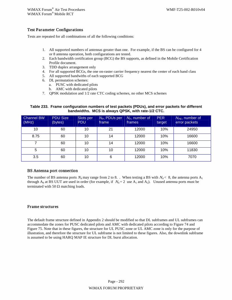
WiMAX Forum® Air Test Procedures WMF-T25-002-R010v04 WiMAX Forum® Mobile RCT
Page - 292
WiMAX FORUM PROPRIETARY
Test Parameter Configurations Tests are repeated for all combinations of all the following conditions:
1. All supported numbers of antennas greater than one. For example, if the BS can be configured for 4 or 8 antenna operation, both configurations are tested.
2. Each bandwidth certification group (BCG) the BS supports, as defined in the Mobile Certification Profile document.
3. TDD duplex arrangement only 4. For all supported BCGs, the one on-raster carrier frequency nearest the center of each band class 5. All supported bandwiths of each supported BCG 6. DL permutation schemes:
a. PUSC with dedicated pilots b. AMC with dedicated pilots
7. QPSK modulation and 1/2 rate CTC coding schemes, no other MCS schemes
Table 233. Frame configuration numbers of test packets (PDUs), and error packets for different bandwidths. MCS is always QPSK, with rate-1/2 CTC.
Channel BW (MHz)
PDU Size (bytes)
Slots per PDU
NP, PDUs per frame
NF, number of frames
PER target
NPE, number of error packets
10 60 10 21 12000 10% 24950
8.75 60 10 14 12000 10% 16600
7 60 10 14 12000 10% 16600
5 60 10 10 12000 10% 11830
3.5 60 10 6 12000 10% 7070
BS Antenna port connection The number of BS antenna ports NA may range from 2 to 8. . When testing a BS with NA < 8, the antenna ports A1 through A8 at BS UUT are used in order (for example, if NA = 2 use A1 and A2). Unused antenna ports must be terminated with 50 Ω matching loads.
Frame structures
The default frame structure defined in Appendix 2 should be modified so that DL subframes and UL subframes can accommodate the zones for PUSC dedicated pilots and AMC with dedicated pilots according to Figure 74 and Figure 75. Note that in these figures, the structure for UL PUSC zone or UL AMC zone is only for the purpose of illustration, and therefore the structure for UL subframe is not limited to these figures. Also, the downlink subframe is assumed to be using HARQ MAP IE structure for DL burst allocation.
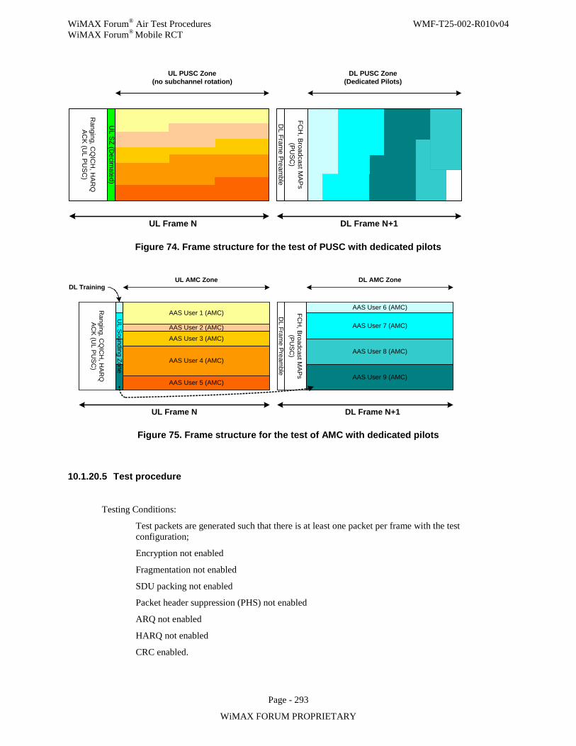
WiMAX Forum® Air Test Procedures WMF-T25-002-R010v04 WiMAX Forum® Mobile RCT
Page - 293
WiMAX FORUM PROPRIETARY
DL Fram
e Preamble
FCH
, Broadcast MAPs
(PUSC
)
Ranging, C
QIC
H, H
ARQ
AC
K (UL PU
SC
)
UL Frame N
DL PUSC Zone (Dedicated Pilots)
DL Frame N+1
UL PUSC Zone(no subchannel rotation)
UL SZ (D
ecimated)
Figure 74. Frame structure for the test of PUSC with dedicated pilots
DL Fram
e Preamble
FCH
, Broadcast MAPs
(PUSC
)
AAS User 6 (AMC)
AAS User 7 (AMC)
AAS User 8 (AMC)
AAS User 9 (AMC)
Ranging, C
QIC
H, H
ARQ
AC
K (UL PU
SC
)
AAS User 1 (AMC)
AAS User 2 (AMC)
AAS User 3 (AMC)
AAS User 4 (AMC)
AAS User 5 (AMC)
UL Frame N DL Frame N+1
UL AMC Zone DL AMC Zone
UL Sounding Zone
DL Training
Figure 75. Frame structure for the test of AMC with dedicated pilots
10.1.20.5 Test procedure
Testing Conditions:
Test packets are generated such that there is at least one packet per frame with the test configuration;
Encryption not enabled
Fragmentation not enabled
SDU packing not enabled
Packet header suppression (PHS) not enabled
ARQ not enabled
HARQ not enabled
CRC enabled.
WiMAX Forum® Air Test Procedures WMF-T25-002-R010v04 WiMAX Forum® Mobile RCT
Page - 294
WiMAX FORUM PROPRIETARY
Initial Conditions:
Step 1. Network entry has been completed.
Setting and Test Procedure:
Test 1
The following steps verify that the BS UUT does not transmit pilots in the region not allocated for downlink bursts when using PUSC with dedicated pilots and AMC with dedicated pilots.
This test is performed for test setup configuration specified in Figure 72.
Step 1. Set the Attenuator AT1 as minimum attenuation. Step 2. Program the BS UUT and the MS emulator (signaling unit) for a downlink and uplink
transmission with the permutation (PUSC with dedicated pilots, and AMC with dedicated pilots) under test.
Step 3. For each permutation, the test is performed for 96 bytes packet for 10 repeated frames. The modulation is set QPSK and the channel coding is Convolutional Turbo Code rate 1/2.
Step 4. For each packet sent, the VSA verifies that the pilots are not transmitted in the region not allocated for downlink bursts. This means that the average power for pilot locations in the region not allocated for downlink burst shall be lower than 15dB (since the RCE requirement for QPSK 1/2 is -15dB) compared with average power for the allocated data subcarriers. Note that in case of PUSC with dedicated pilots, all the pilots within a major group are beamformed together until the end of burst allocation in time axis. Therefore, in this case the pilot positions outside of burst allocation in time axis and outside of allocated major group shall be considered in calculation of average power for pilot locations in the region not allocated for downlink burst.
Test 2
The following steps verify that the BS UUT beamforms pilots spanning over a major group that contains the burst for PUSC with dedicated pilots.
This test is performed for test setup configuration specified in Figure 72.
Step 5. Set the Attenuator AT1 as minimum attenuation. Step 6. Program the BS UUT for a downlink with the permutation of PUSC with dedicated pilots on
any of major groups. Step 7. The test is performed for 96 bytes packet for 10 repeated frames. The modulation is set
QPSK and the channel coding is Convolutional Turbo Code rate 1/2. Step 8. For each packet sent, the VSA verifies that all the pilots are beamformed in the major group
that contains the downlink burst. This means that the average power for pilot locations in the major group shall be 2.5dB±0.5dB higher than the average power for allocated data subcarriers. Note that the pilots outside of burst allocation in time axis are not transmitted, and therefore, only the pilots within the major group until the end of burst allocation shall be considered in calculation of average power for pilot locations in the major group.
Test 3
The following steps verify that the BS UUT correctly constructs the STC_DL_zone_IE (DIUC=15 & extended DIUC=0x01), the PAPR_Reduction_Safety_Sounding_Zone_Allocation_IE (UIUC=13) and the UL_Sounding_Command_IE (UIUC=11 & extended UIUC=0x04) correctly.
WiMAX Forum® Air Test Procedures WMF-T25-002-R010v04 WiMAX Forum® Mobile RCT
Page - 295
WiMAX FORUM PROPRIETARY
This test is performed for test setup configuration specified in Figure 72.
Step 9. Set the Attenuator AT1 as minimum attenuation. Step 10. Program the BS UUT and the MS emulator (signaling unit) for a downlink and uplink
transmission with the permutation (PUSC with dedicated pilots, and AMC with dedicated pilots) under test.
Step 11. For each permutation, the test is performed for 96 bytes packet for 10 repeated frames. The modulation is set QPSK and the channel coding is Convolutional Turbo Code rate 1/2.
Step 12. For each packet sent, the MS emulator (signaling unit) verifies that the STC_DL_zone_IE (UIUC=15 & extended DIUC=0x01) in DL MAP message is valid for each permutation (i.e., the field of ‘Dedicated Pilot’ shall be set to be 1).
Step 13. If the MS emulator (signaling unit) receives the PAPR_Reduction_Safety_Sounding_Zone_Allocation_IE (UIUC=13) in UL MAP message, it verifies that the sounding zone IE is valid (i.e., the field of ‘sounding zone’ shall be set to be 1).
Step 14. If the MS emulator (signaling unit) receives the UL_Sounding_Command_IE (UIUC=11 & extended UIUC=0x04) in UL MAP message, it verifies that the UL sounding command IE is valid.
Test 4
The following steps verify that the BS UUT does not transmit pilots in the region not allocated for downlink bursts when using PUSC with dedicated pilots in the DL STC zone.
This test is performed for test setup configuration specified in Figure 73. Repeat the test sequence for Matrix-A and Matrix-B in DL PUSC STC zone, both with dedicated pilots.
Step 15. Set the Attenuators AT2 and AT3 as minimum attenuation. Step 16. Program the BS UUT and the MS emulator (signaling unit) for a downlink transmission
with PUSC with dedicated pilots in DL STC zone. Step 17. The test is performed for 96 bytes packets for 10 repeated frames. The modulation is set
QPSK and the channel coding is Convolutional Turbo Code rate 1/2. Step 18. For each packet sent, the VSA verifies that the pilots are not transmitted in the region not
allocated for downlink bursts. This means that the average power for pilot locations in the region not allocated for downlink burst shall be lower than 15dB (since the RCE requirement for QPSK 1/2 is -15dB) compared with average power for the allocated data subcarriers. Note that in case of PUSC with dedicated pilots, all the pilots within a major group are beamformed together until the end of burst allocation in time axis. Therefore, in this case the pilot positions outside of burst allocation in time axis and outside of allocated major group shall be considered in calculation of average power for pilot locations in the region not allocated for downlink burst.
Test 5
The following steps verify the proper construction of signals in Matrix-A or Matrix-B format with dedicated pilots in the DL PUSC STC zone.
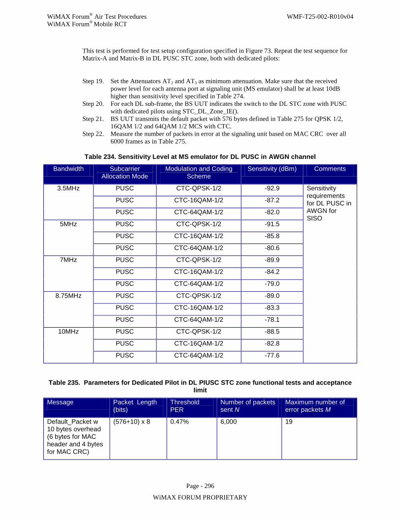
WiMAX Forum® Air Test Procedures WMF-T25-002-R010v04 WiMAX Forum® Mobile RCT
Page - 296
WiMAX FORUM PROPRIETARY
This test is performed for test setup configuration specified in Figure 73. Repeat the test sequence for Matrix-A and Matrix-B in DL PUSC STC zone, both with dedicated pilots:
Step 19. Set the Attenuators AT2 and AT3 as minimum attenuation. Make sure that the received power level for each antenna port at signaling unit (MS emulator) shall be at least 10dB higher than sensitivity level specified in Table 274.
Step 20. For each DL sub-frame, the BS UUT indicates the switch to the DL STC zone with PUSC with dedicated pilots using STC_DL_Zone_IE().
Step 21. BS UUT transmits the default packet with 576 bytes defined in Table 275 for QPSK 1/2, 16QAM 1/2 and 64QAM 1/2 MCS with CTC.
Step 22. Measure the number of packets in error at the signaling unit based on MAC CRC over all 6000 frames as in Table 275.
Table 234. Sensitivity Level at MS emulator for DL PUSC in AWGN channel
Bandwidth Subcarrier Allocation Mode
Modulation and Coding Scheme
Sensitivity (dBm) Comments
3.5MHz PUSC CTC-QPSK-1/2 -92.9 Sensitivity requirements for DL PUSC in AWGN for SISO
PUSC CTC-16QAM-1/2 -87.2
PUSC CTC-64QAM-1/2 -82.0
5MHz PUSC CTC-QPSK-1/2 -91.5
PUSC CTC-16QAM-1/2 -85.8
PUSC CTC-64QAM-1/2 -80.6
7MHz PUSC CTC-QPSK-1/2 -89.9
PUSC CTC-16QAM-1/2 -84.2
PUSC CTC-64QAM-1/2 -79.0
8.75MHz PUSC CTC-QPSK-1/2 -89.0
PUSC CTC-16QAM-1/2 -83.3
PUSC CTC-64QAM-1/2 -78.1
10MHz PUSC CTC-QPSK-1/2 -88.5
PUSC CTC-16QAM-1/2 -82.8
PUSC CTC-64QAM-1/2 -77.6
Table 235. Parameters for Dedicated Pilot in DL PIUSC STC zone functional tests and acceptance limit
Message Packet Length (bits)
Threshold PER
Number of packets sent N
Maximum number of error packets M
Default_Packet w 10 bytes overhead (6 bytes for MAC header and 4 bytes for MAC CRC)
(576+10) x 8 0.47% 6,000 19
WiMAX Forum® Air Test Procedures WMF-T25-002-R010v04 WiMAX Forum® Mobile RCT
Page - 297
WiMAX FORUM PROPRIETARY
10.1.20.6 Compliance requirements
The test passes if:
The pilots are not transmitted in the region not allocated for downlink bursts in Step 4, and The pilots are beamformed over a major group that contains the downlink burst span over set by BS UUT in Step 8,
and
The STC_DL_zone_IE (UIUC=15 & extended DIUC=0x01) in DL MAP message is valid for each permutation in Step 12,
and
The sounding zone IE (UIUC=13) is valid in Step 13,
and
The UL sounding command IE is valid in Step 14,
In the case that the BS supports IO-BF AND IO-MIMO,
The pilots are not transmitted in any major group not allocated for downlink bursts in Step 18,
and
The number of packets in error measured in Step 22 is less than the limit specified in Table 275.
The test fails if:
The pilots are transmitted in the region not allocated for downlink bursts in Step 4, or The pilots are not beamformed over a major group that contains the downlink burst set by BS UUT in Step 8,
or The STC_DL_zone_IE (UIUC=15 & extended DIUC=0x01) in DL MAP message is not valid for each permutation in Step 12,
or
The sounding zone IE (UIUC=13) is not valid in Step 13,
or The UL sounding command IE is not valid in Step 14,
In the case that the BS supports IO-BF and IO-MIMO
The pilots are transmitted in any major group not allocated for downlink bursts in Step 18,
or
The number of packets in error measured in Step 22 is not less than the limit specified in Table 275.
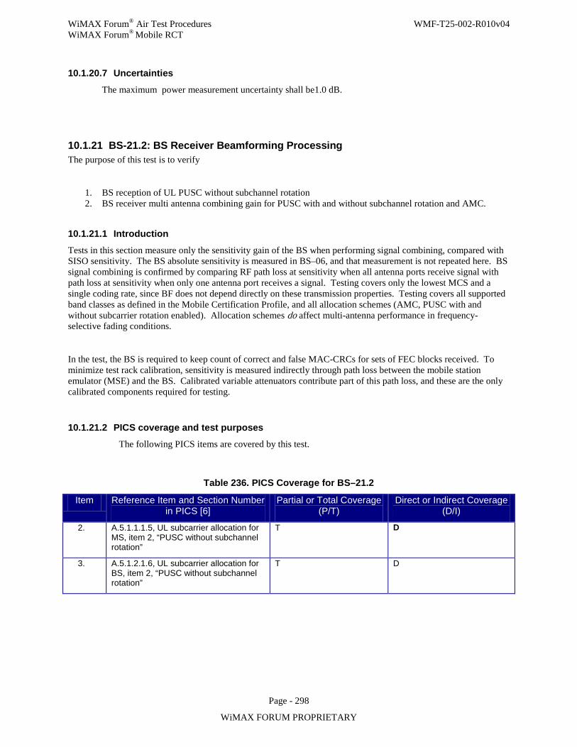
WiMAX Forum® Air Test Procedures WMF-T25-002-R010v04 WiMAX Forum® Mobile RCT
Page - 298
WiMAX FORUM PROPRIETARY
10.1.20.7 Uncertainties
The maximum power measurement uncertainty shall be1.0 dB.
10.1.21 BS-21.2: BS Receiver Beamforming Processing The purpose of this test is to verify
1. BS reception of UL PUSC without subchannel rotation 2. BS receiver multi antenna combining gain for PUSC with and without subchannel rotation and AMC.
10.1.21.1 Introduction
Tests in this section measure only the sensitivity gain of the BS when performing signal combining, compared with SISO sensitivity. The BS absolute sensitivity is measured in BS–06, and that measurement is not repeated here. BS signal combining is confirmed by comparing RF path loss at sensitivity when all antenna ports receive signal with path loss at sensitivity when only one antenna port receives a signal. Testing covers only the lowest MCS and a single coding rate, since BF does not depend directly on these transmission properties. Testing covers all supported band classes as defined in the Mobile Certification Profile, and all allocation schemes (AMC, PUSC with and without subcarrier rotation enabled). Allocation schemes do affect multi-antenna performance in frequency-selective fading conditions.
In the test, the BS is required to keep count of correct and false MAC-CRCs for sets of FEC blocks received. To minimize test rack calibration, sensitivity is measured indirectly through path loss between the mobile station emulator (MSE) and the BS. Calibrated variable attenuators contribute part of this path loss, and these are the only calibrated components required for testing.
10.1.21.2 PICS coverage and test purposes
The following PICS items are covered by this test.
Table 236. PICS Coverage for BS–21.2
Item Reference Item and Section Number in PICS [6]
Partial or Total Coverage (P/T)
Direct or Indirect Coverage (D/I)
2. A.5.1.1.1.5, UL subcarrier allocation for MS, item 2, “PUSC without subchannel rotation”
T D
3. A.5.1.2.1.6, UL subcarrier allocation for BS, item 2, “PUSC without subchannel rotation”
T D
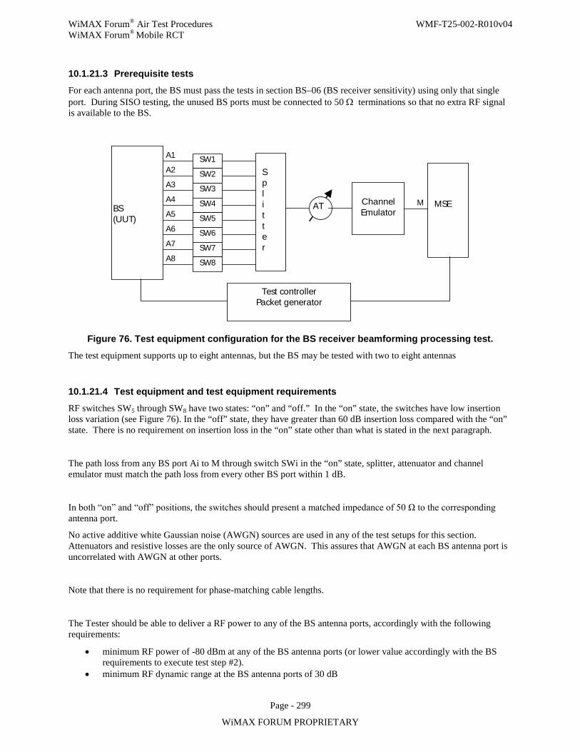
WiMAX Forum® Air Test Procedures WMF-T25-002-R010v04 WiMAX Forum® Mobile RCT
Page - 299
WiMAX FORUM PROPRIETARY
10.1.21.3 Prerequisite tests
For each antenna port, the BS must pass the tests in section BS–06 (BS receiver sensitivity) using only that single port. During SISO testing, the unused BS ports must be connected to 50 Ω terminations so that no extra RF signal is available to the BS.
BS (UUT)
A1
A2
A3
A4
A5
A6
A7
A8
SW1
SW2
SW3
SW4
SW5
SW6
SW7
SW8
S p l i t t e r
AT
Channel Emulator
MSE
Test controller Packet generator
M
Figure 76. Test equipment configuration for the BS receiver beamforming processing test.
The test equipment supports up to eight antennas, but the BS may be tested with two to eight antennas
10.1.21.4 Test equipment and test equipment requirements
RF switches SW5 through SW8 have two states: “on” and “off.” In the “on” state, the switches have low insertion loss variation (see Figure 76). In the “off” state, they have greater than 60 dB insertion loss compared with the “on” state. There is no requirement on insertion loss in the “on” state other than what is stated in the next paragraph.
The path loss from any BS port Ai to M through switch SWi in the “on” state, splitter, attenuator and channel emulator must match the path loss from every other BS port within 1 dB.
In both “on” and “off” positions, the switches should present a matched impedance of 50 Ω to the corresponding antenna port.
No active additive white Gaussian noise (AWGN) sources are used in any of the test setups for this section. Attenuators and resistive losses are the only source of AWGN. This assures that AWGN at each BS antenna port is uncorrelated with AWGN at other ports.
Note that there is no requirement for phase-matching cable lengths.
The Tester should be able to deliver a RF power to any of the BS antenna ports, accordingly with the following requirements:
• minimum RF power of -80 dBm at any of the BS antenna ports (or lower value accordingly with the BS requirements to execute test step #2).
• minimum RF dynamic range at the BS antenna ports of 30 dB
WiMAX Forum® Air Test Procedures WMF-T25-002-R010v04 WiMAX Forum® Mobile RCT
Page - 300
WiMAX FORUM PROPRIETARY
• minimum RF step size at the at the BS antenna ports of 0.5 dB
10.1.21.5 Test Parameter Configurations
Tests are repeated for all combinations of all the following conditions:
1. All supported numbers of antennas greater than one. For example, if the BS can be configured for 4 or 8 antenna operation, both configurations are tested.
2. Each bandwidth certification group (BCG) the BS supports, as defined in the Mobile Certification Profile document.
3. TDD duplex arrangement only 4. For all supported BCGs, the one on-channel-raster carrier frequency nearest the center of each band class 5. All supported bandwidths of each supported BCG 6. UL permutation schemes:
a. PUSC with subcarrier rotation enabled b. PUSC with subcarrier rotation disabled c. AMC
7. QPSK modulation and 1/2 rate CTC coding schemes, no other MCS schemes 8. AWGN channel model (no Doppler spreading), Pedestrian-B channel model (3 km/hr Doppler spreading),
and Vehicular-A channel model (60 km/hr Doppler spreading)
10.1.21.6 BS Antenna port connection
The number of BS antenna ports NA may range from 2 to 8. BS antenna ports connect to switches SW1 through SW8. When testing a BS with NA < 8, the connections SW1 through SW8are used in order. Unused test ports are terminated with 50 Ω match loads.
10.1.21.7 Test procedure
The test in this section is repeated for all supported bandclasses. Within each bandclass, the tests are repeated with the BS configured to use UL allocation schemes AMC, PUSC with and without subcarrier rotation enabled, for the channel conditions described above.
Configure test equipment as shown in Figure 76 or as in the alternate configuration described at the end of Section 10.1.21.4.
Configure the BS, MSE and test equipment:
• Use only QPSK, rate-1/2 CTC MCS for the UL data • Up to two uplink zones shall be used: a first PUSC zone for control regions and UL PUSC data (when
testing PUSC), and a second zone for AMC data (when testing AMC); This second zone will be configured for AMC, while the first zone will be configured for PUSC, either with or without subchannel rotation.
• Configure for a stream of UL subframes, using the parameters from Table 279. In all cases the data consist of 60-byte PDUs, allocated as 10 slots/PDU. Each UL subframe uses 3 control symbols.
• HARQ off • BW-dependent test parameters as given in Table 279.
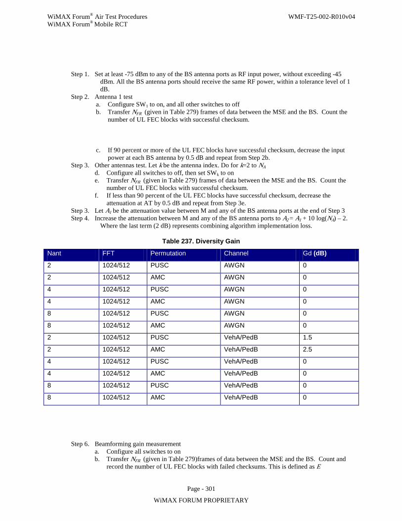
WiMAX Forum® Air Test Procedures WMF-T25-002-R010v04 WiMAX Forum® Mobile RCT
Page - 301
WiMAX FORUM PROPRIETARY
Step 1. Set at least -75 dBm to any of the BS antenna ports as RF input power, without exceeding -45 dBm. All the BS antenna ports should receive the same RF power, within a tolerance level of 1 dB.
Step 2. Antenna 1 test a. Configure SW1 to on, and all other switches to off b. Transfer NFR (given in Table 279) frames of data between the MSE and the BS. Count the
number of UL FEC blocks with successful checksum.
c. If 90 percent or more of the UL FEC blocks have successful checksum, decrease the input power at each BS antenna by 0.5 dB and repeat from Step 2b.
Step 3. Other antennas test. Let k be the antenna index. Do for k=2 to NA d. Configure all switches to off, then set SWk to on e. Transfer NFR (given in Table 279) frames of data between the MSE and the BS. Count the
number of UL FEC blocks with successful checksum. f. If less than 90 percent of the UL FEC blocks have successful checksum, decrease the
attenuation at AT by 0.5 dB and repeat from Step 3e. Step 3. Let A1 be the attenuation value between M and any of the BS antenna ports at the end of Step 3 Step 4. Increase the attenuation between M and any of the BS antenna ports to A2 = A1 + 10 log(NA) – 2.
Where the last term (2 dB) represents combining algorithm implementation loss.
Table 237. Diversity Gain
Nant FFT Permutation Channel Gd (dB)
2 1024/512 PUSC AWGN 0
2 1024/512 AMC AWGN 0
4 1024/512 PUSC AWGN 0
4 1024/512 AMC AWGN 0
8 1024/512 PUSC AWGN 0
8 1024/512 AMC AWGN 0
2 1024/512 PUSC VehA/PedB 1.5
2 1024/512 AMC VehA/PedB 2.5
4 1024/512 PUSC VehA/PedB 0
4 1024/512 AMC VehA/PedB 0
8 1024/512 PUSC VehA/PedB 0
8 1024/512 AMC VehA/PedB 0
Step 6. Beamforming gain measurement a. Configure all switches to on b. Transfer NFR (given in Table 279)frames of data between the MSE and the BS. Count and
record the number of UL FEC blocks with failed checksums. This is defined as E
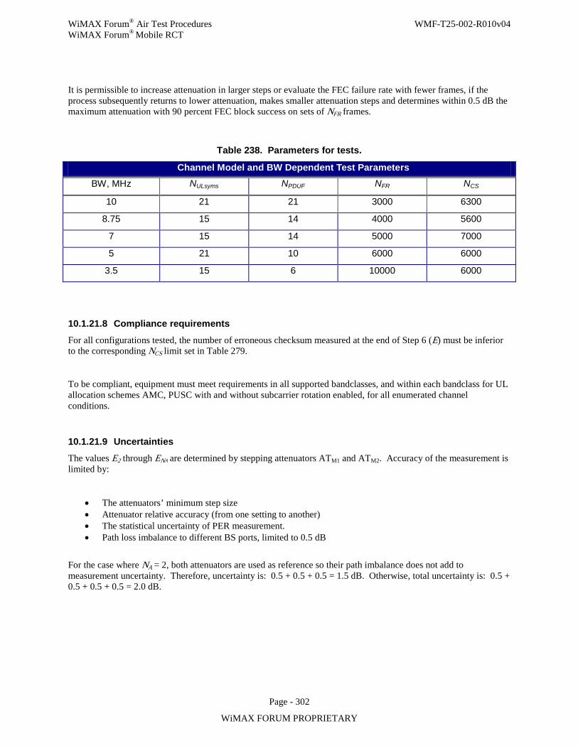
WiMAX Forum® Air Test Procedures WMF-T25-002-R010v04 WiMAX Forum® Mobile RCT
Page - 302
WiMAX FORUM PROPRIETARY
It is permissible to increase attenuation in larger steps or evaluate the FEC failure rate with fewer frames, if the process subsequently returns to lower attenuation, makes smaller attenuation steps and determines within 0.5 dB the maximum attenuation with 90 percent FEC block success on sets of NFR frames.
Table 238. Parameters for tests.
Channel Model and BW Dependent Test Parameters BW, MHz NULsyms NPDUF NFR NCS
10 21 21 3000 6300
8.75 15 14 4000 5600
7 15 14 5000 7000
5 21 10 6000 6000
3.5 15 6 10000 6000
10.1.21.8 Compliance requirements
For all configurations tested, the number of erroneous checksum measured at the end of Step 6 (E) must be inferior to the corresponding NCS limit set in Table 279.
To be compliant, equipment must meet requirements in all supported bandclasses, and within each bandclass for UL allocation schemes AMC, PUSC with and without subcarrier rotation enabled, for all enumerated channel conditions.
10.1.21.9 Uncertainties
The values E2 through ENA are determined by stepping attenuators ATM1 and ATM2. Accuracy of the measurement is limited by:
• The attenuators’ minimum step size • Attenuator relative accuracy (from one setting to another) • The statistical uncertainty of PER measurement. • Path loss imbalance to different BS ports, limited to 0.5 dB
For the case where NA = 2, both attenuators are used as reference so their path imbalance does not add to measurement uncertainty. Therefore, uncertainty is: 0.5 + 0.5 + 0.5 = 1.5 dB. Otherwise, total uncertainty is: 0.5 + 0.5 + 0.5 + 0.5 = 2.0 dB.
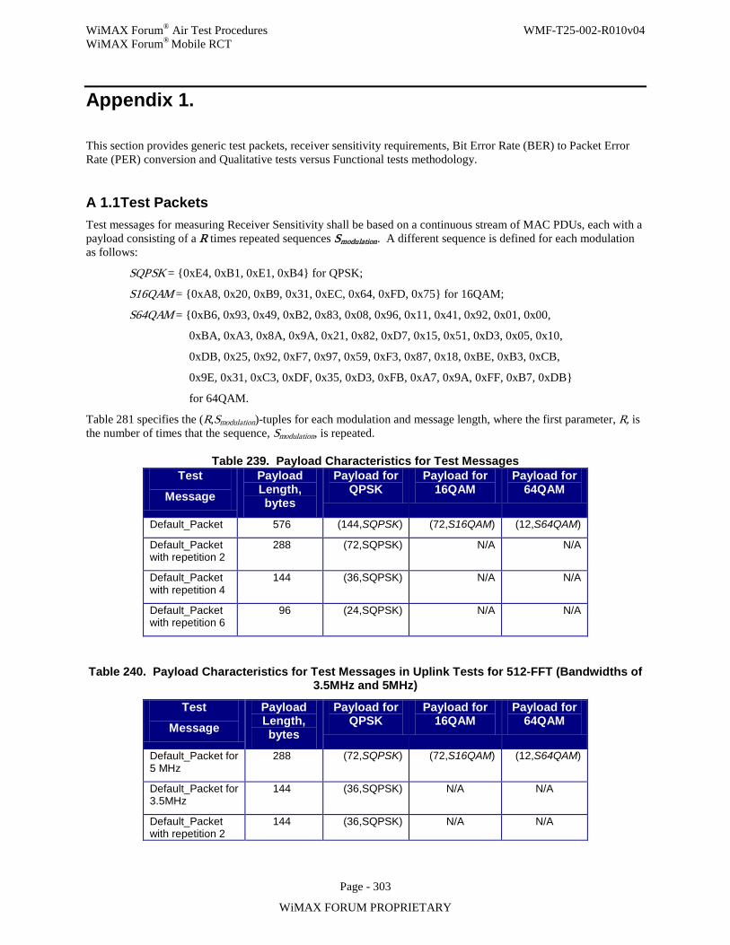
WiMAX Forum® Air Test Procedures WMF-T25-002-R010v04 WiMAX Forum® Mobile RCT
Page - 303
WiMAX FORUM PROPRIETARY
Appendix 1.
This section provides generic test packets, receiver sensitivity requirements, Bit Error Rate (BER) to Packet Error Rate (PER) conversion and Qualitative tests versus Functional tests methodology.
A 1.1 Test Packets Test messages for measuring Receiver Sensitivity shall be based on a continuous stream of MAC PDUs, each with a payload consisting of a R times repeated sequences Smodulation. A different sequence is defined for each modulation as follows:
SQPSK = 0xE4, 0xB1, 0xE1, 0xB4 for QPSK;
S16QAM = 0xA8, 0x20, 0xB9, 0x31, 0xEC, 0x64, 0xFD, 0x75 for 16QAM;
S64QAM = 0xB6, 0x93, 0x49, 0xB2, 0x83, 0x08, 0x96, 0x11, 0x41, 0x92, 0x01, 0x00,
0xBA, 0xA3, 0x8A, 0x9A, 0x21, 0x82, 0xD7, 0x15, 0x51, 0xD3, 0x05, 0x10,
0xDB, 0x25, 0x92, 0xF7, 0x97, 0x59, 0xF3, 0x87, 0x18, 0xBE, 0xB3, 0xCB,
0x9E, 0x31, 0xC3, 0xDF, 0x35, 0xD3, 0xFB, 0xA7, 0x9A, 0xFF, 0xB7, 0xDB
for 64QAM.
Table 281 specifies the (R,Smodulation)-tuples for each modulation and message length, where the first parameter, R, is the number of times that the sequence, Smodulation, is repeated.
Table 239. Payload Characteristics for Test Messages Test
Message
Payload Length, bytes
Payload for QPSK
Payload for 16QAM
Payload for 64QAM
Default_Packet 576 (144,SQPSK) (72,S16QAM) (12,S64QAM)
Default_Packet with repetition 2
288 (72,SQPSK) N/A N/A
Default_Packet with repetition 4
144 (36,SQPSK) N/A N/A
Default_Packet with repetition 6
96 (24,SQPSK) N/A N/A
Table 240. Payload Characteristics for Test Messages in Uplink Tests for 512-FFT (Bandwidths of 3.5MHz and 5MHz)
Test
Message
Payload Length, bytes
Payload for QPSK
Payload for 16QAM
Payload for 64QAM
Default_Packet for 5 MHz
288 (72,SQPSK) (72,S16QAM) (12,S64QAM)
Default_Packet for 3.5MHz
144 (36,SQPSK) N/A N/A
Default_Packet with repetition 2
144 (36,SQPSK) N/A N/A
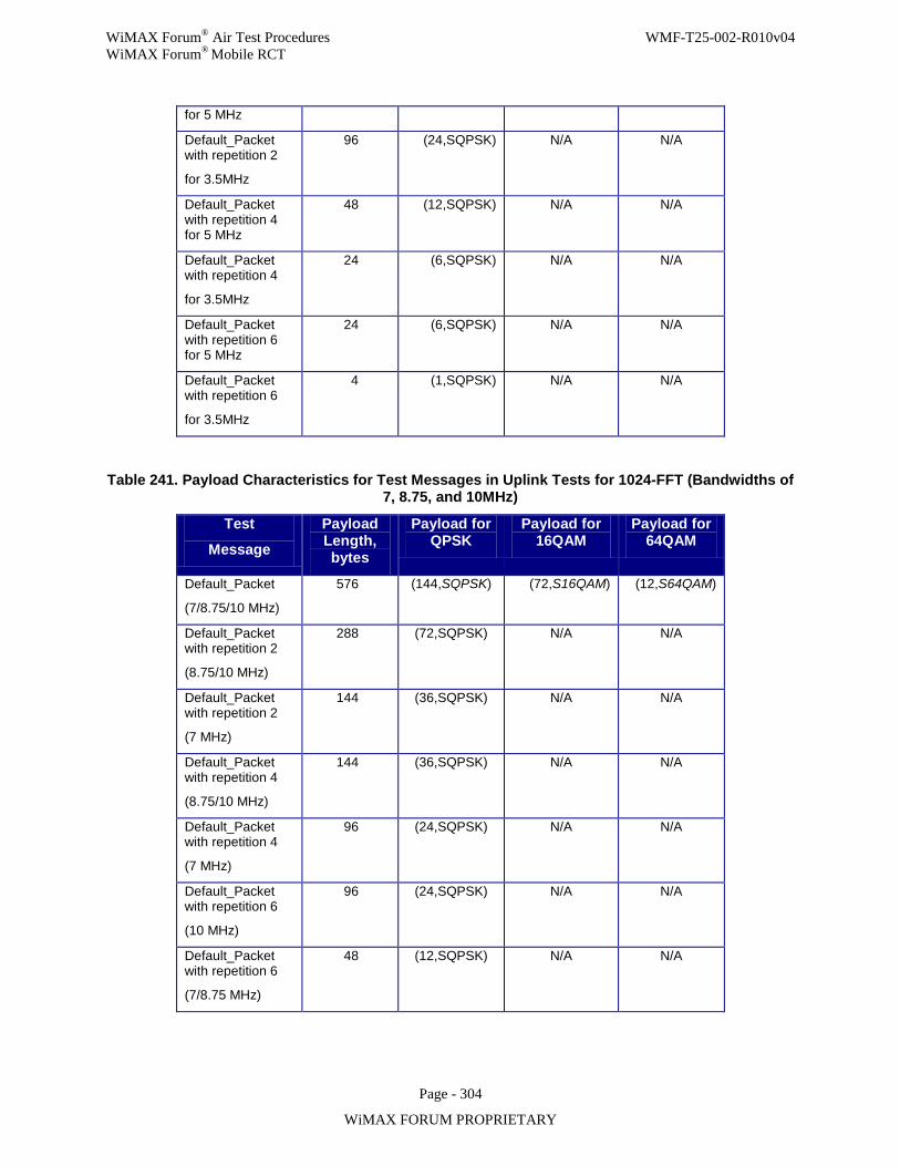
WiMAX Forum® Air Test Procedures WMF-T25-002-R010v04 WiMAX Forum® Mobile RCT
Page - 304
WiMAX FORUM PROPRIETARY
for 5 MHz
Default_Packet with repetition 2
for 3.5MHz
96 (24,SQPSK) N/A N/A
Default_Packet with repetition 4 for 5 MHz
48 (12,SQPSK) N/A N/A
Default_Packet with repetition 4
for 3.5MHz
24 (6,SQPSK) N/A N/A
Default_Packet with repetition 6 for 5 MHz
24 (6,SQPSK) N/A N/A
Default_Packet with repetition 6
for 3.5MHz
4 (1,SQPSK) N/A N/A
Table 241. Payload Characteristics for Test Messages in Uplink Tests for 1024-FFT (Bandwidths of 7, 8.75, and 10MHz)
Test
Message
Payload Length, bytes
Payload for QPSK
Payload for 16QAM
Payload for 64QAM
Default_Packet
(7/8.75/10 MHz)
576 (144,SQPSK) (72,S16QAM) (12,S64QAM)
Default_Packet with repetition 2
(8.75/10 MHz)
288 (72,SQPSK) N/A N/A
Default_Packet with repetition 2
(7 MHz)
144 (36,SQPSK) N/A N/A
Default_Packet with repetition 4
(8.75/10 MHz)
144 (36,SQPSK) N/A N/A
Default_Packet with repetition 4
(7 MHz)
96 (24,SQPSK) N/A N/A
Default_Packet with repetition 6
(10 MHz)
96 (24,SQPSK) N/A N/A
Default_Packet with repetition 6
(7/8.75 MHz)
48 (12,SQPSK) N/A N/A
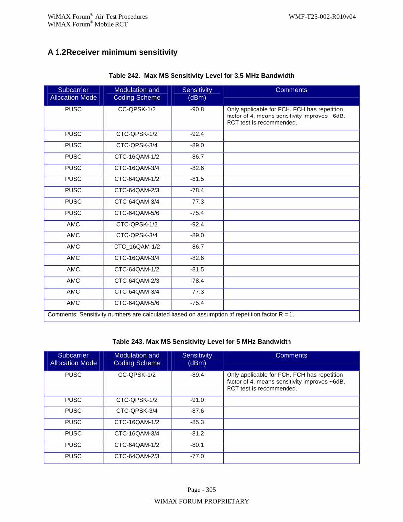
WiMAX Forum® Air Test Procedures WMF-T25-002-R010v04 WiMAX Forum® Mobile RCT
Page - 305
WiMAX FORUM PROPRIETARY
A 1.2 Receiver minimum sensitivity
Table 242. Max MS Sensitivity Level for 3.5 MHz Bandwidth
Subcarrier Allocation Mode
Modulation and Coding Scheme
Sensitivity (dBm)
Comments
PUSC CC-QPSK-1/2 -90.8
Only applicable for FCH. FCH has repetition factor of 4, means sensitivity improves ~6dB. RCT test is recommended.
PUSC CTC-QPSK-1/2 -92.4
PUSC CTC-QPSK-3/4 -89.0
PUSC CTC-16QAM-1/2 -86.7
PUSC CTC-16QAM-3/4 -82.6
PUSC CTC-64QAM-1/2 -81.5
PUSC CTC-64QAM-2/3 -78.4
PUSC CTC-64QAM-3/4 -77.3
PUSC CTC-64QAM-5/6 -75.4
AMC CTC-QPSK-1/2 -92.4
AMC CTC-QPSK-3/4 -89.0
AMC CTC_16QAM-1/2 -86.7
AMC CTC-16QAM-3/4 -82.6
AMC CTC-64QAM-1/2 -81.5
AMC CTC-64QAM-2/3 -78.4
AMC CTC-64QAM-3/4 -77.3
AMC CTC-64QAM-5/6 -75.4
Comments: Sensitivity numbers are calculated based on assumption of repetition factor R = 1.
Table 243. Max MS Sensitivity Level for 5 MHz Bandwidth
Subcarrier Allocation Mode
Modulation and Coding Scheme
Sensitivity (dBm)
Comments
PUSC CC-QPSK-1/2 -89.4 Only applicable for FCH. FCH has repetition factor of 4, means sensitivity improves ~6dB. RCT test is recommended.
PUSC CTC-QPSK-1/2 -91.0
PUSC CTC-QPSK-3/4 -87.6
PUSC CTC-16QAM-1/2 -85.3
PUSC CTC-16QAM-3/4 -81.2
PUSC CTC-64QAM-1/2 -80.1
PUSC CTC-64QAM-2/3 -77.0
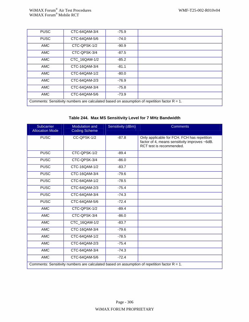
WiMAX Forum® Air Test Procedures WMF-T25-002-R010v04 WiMAX Forum® Mobile RCT
Page - 306
WiMAX FORUM PROPRIETARY
PUSC CTC-64QAM-3/4 -75.9
PUSC CTC-64QAM-5/6 -74.0
AMC CTC-QPSK-1/2 -90.9
AMC CTC-QPSK-3/4 -87.5
AMC CTC_16QAM-1/2 -85.2
AMC CTC-16QAM-3/4 -81.1
AMC CTC-64QAM-1/2 -80.0
AMC CTC-64QAM-2/3 -76.9
AMC CTC-64QAM-3/4 -75.8
AMC CTC-64QAM-5/6 -73.9
Comments: Sensitivity numbers are calculated based on assumption of repetition factor R = 1.
Table 244. Max MS Sensitivity Level for 7 MHz Bandwidth
Subcarrier Allocation Mode
Modulation and Coding Scheme
Sensitivity (dBm) Comments
PUSC CC-QPSK-1/2 -87.8 Only applicable for FCH. FCH has repetition factor of 4, means sensitivity improves ~6dB. RCT test is recommended.
PUSC CTC-QPSK-1/2 -89.4
PUSC CTC-QPSK-3/4 -86.0
PUSC CTC-16QAM-1/2 -83.7
PUSC CTC-16QAM-3/4 -79.6
PUSC CTC-64QAM-1/2 -78.5
PUSC CTC-64QAM-2/3 -75.4
PUSC CTC-64QAM-3/4 -74.3
PUSC CTC-64QAM-5/6 -72.4
AMC CTC-QPSK-1/2 -89.4
AMC CTC-QPSK-3/4 -86.0
AMC CTC_16QAM-1/2 -83.7
AMC CTC-16QAM-3/4 -79.6
AMC CTC-64QAM-1/2 -78.5
AMC CTC-64QAM-2/3 -75.4
AMC CTC-64QAM-3/4 -74.3
AMC CTC-64QAM-5/6 -72.4
Comments: Sensitivity numbers are calculated based on assumption of repetition factor R = 1.
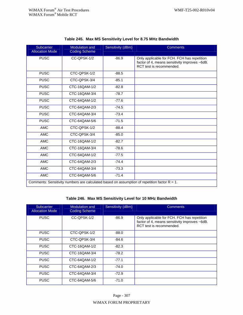
WiMAX Forum® Air Test Procedures WMF-T25-002-R010v04 WiMAX Forum® Mobile RCT
Page - 307
WiMAX FORUM PROPRIETARY
Table 245. Max MS Sensitivity Level for 8.75 MHz Bandwidth
Subcarrier Allocation Mode
Modulation and Coding Scheme
Sensitivity (dBm) Comments
PUSC CC-QPSK-1/2 -86.9 Only applicable for FCH. FCH has repetition factor of 4, means sensitivity improves ~6dB. RCT test is recommended.
PUSC CTC-QPSK-1/2 -88.5
PUSC CTC-QPSK-3/4 -85.1
PUSC CTC-16QAM-1/2 -82.8
PUSC CTC-16QAM-3/4 -78.7
PUSC CTC-64QAM-1/2 -77.6
PUSC CTC-64QAM-2/3 -74.5
PUSC CTC-64QAM-3/4 -73.4
PUSC CTC-64QAM-5/6 -71.5
AMC CTC-QPSK-1/2 -88.4
AMC CTC-QPSK-3/4 -85.0
AMC CTC-16QAM-1/2 -82.7
AMC CTC-16QAM-3/4 -78.6
AMC CTC-64QAM-1/2 -77.5
AMC CTC-64QAM-2/3 -74.4
AMC CTC-64QAM-3/4 -73.3
AMC CTC-64QAM-5/6 -71.4
Comments: Sensitivity numbers are calculated based on assumption of repetition factor R = 1.
Table 246. Max MS Sensitivity Level for 10 MHz Bandwidth
Subcarrier Allocation Mode
Modulation and Coding Scheme
Sensitivity (dBm) Comments
PUSC CC-QPSK-1/2 -86.9 Only applicable for FCH. FCH has repetition factor of 4, means sensitivity improves ~6dB. RCT test is recommended.
PUSC CTC-QPSK-1/2 -88.0
PUSC CTC-QPSK-3/4 -84.6
PUSC CTC-16QAM-1/2 -82.3
PUSC CTC-16QAM-3/4 -78.2
PUSC CTC-64QAM-1/2 -77.1
PUSC CTC-64QAM-2/3 -74.0
PUSC CTC-64QAM-3/4 -72.9
PUSC CTC-64QAM-5/6 -71.0
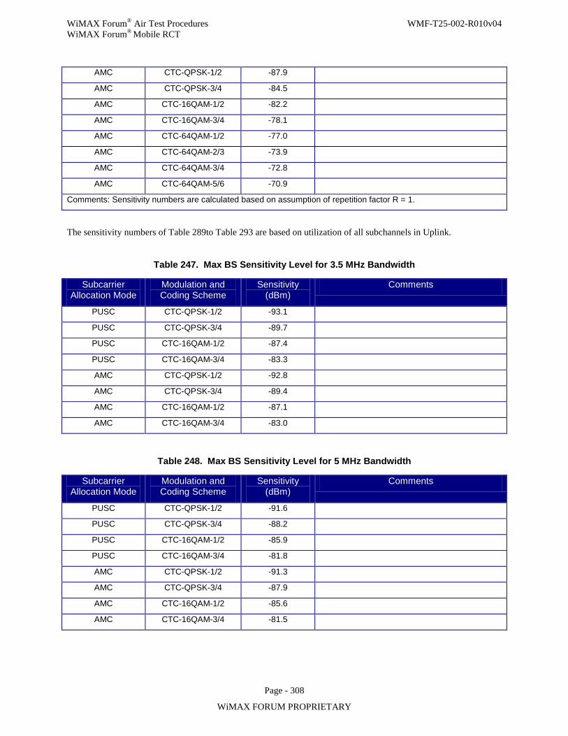
WiMAX Forum® Air Test Procedures WMF-T25-002-R010v04 WiMAX Forum® Mobile RCT
Page - 308
WiMAX FORUM PROPRIETARY
AMC CTC-QPSK-1/2 -87.9
AMC CTC-QPSK-3/4 -84.5
AMC CTC-16QAM-1/2 -82.2
AMC CTC-16QAM-3/4 -78.1
AMC CTC-64QAM-1/2 -77.0
AMC CTC-64QAM-2/3 -73.9
AMC CTC-64QAM-3/4 -72.8
AMC CTC-64QAM-5/6 -70.9
Comments: Sensitivity numbers are calculated based on assumption of repetition factor R = 1.
The sensitivity numbers of Table 289to Table 293 are based on utilization of all subchannels in Uplink.
Table 247. Max BS Sensitivity Level for 3.5 MHz Bandwidth
Subcarrier Allocation Mode
Modulation and Coding Scheme
Sensitivity (dBm)
Comments
PUSC CTC-QPSK-1/2 -93.1
PUSC CTC-QPSK-3/4 -89.7
PUSC CTC-16QAM-1/2 -87.4
PUSC CTC-16QAM-3/4 -83.3
AMC CTC-QPSK-1/2 -92.8
AMC CTC-QPSK-3/4 -89.4
AMC CTC-16QAM-1/2 -87.1
AMC CTC-16QAM-3/4 -83.0
Table 248. Max BS Sensitivity Level for 5 MHz Bandwidth
Subcarrier Allocation Mode
Modulation and Coding Scheme
Sensitivity (dBm)
Comments
PUSC CTC-QPSK-1/2 -91.6
PUSC CTC-QPSK-3/4 -88.2
PUSC CTC-16QAM-1/2 -85.9
PUSC CTC-16QAM-3/4 -81.8
AMC CTC-QPSK-1/2 -91.3
AMC CTC-QPSK-3/4 -87.9
AMC CTC-16QAM-1/2 -85.6
AMC CTC-16QAM-3/4 -81.5
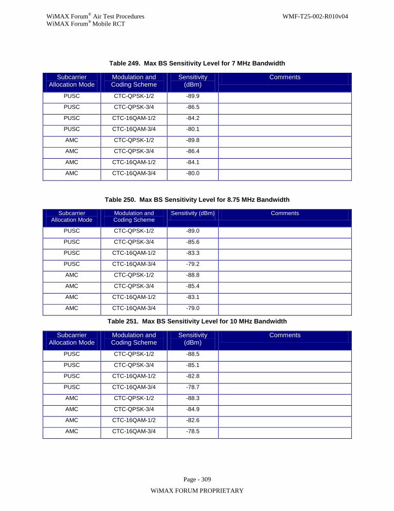
WiMAX Forum® Air Test Procedures WMF-T25-002-R010v04 WiMAX Forum® Mobile RCT
Page - 309
WiMAX FORUM PROPRIETARY
Table 249. Max BS Sensitivity Level for 7 MHz Bandwidth
Subcarrier Allocation Mode
Modulation and Coding Scheme
Sensitivity (dBm)
Comments
PUSC CTC-QPSK-1/2 -89.9
PUSC CTC-QPSK-3/4 -86.5
PUSC CTC-16QAM-1/2 -84.2
PUSC CTC-16QAM-3/4 -80.1
AMC CTC-QPSK-1/2 -89.8
AMC CTC-QPSK-3/4 -86.4
AMC CTC-16QAM-1/2 -84.1
AMC CTC-16QAM-3/4 -80.0
Table 250. Max BS Sensitivity Level for 8.75 MHz Bandwidth
Subcarrier Allocation Mode
Modulation and Coding Scheme
Sensitivity (dBm) Comments
PUSC CTC-QPSK-1/2 -89.0
PUSC CTC-QPSK-3/4 -85.6
PUSC CTC-16QAM-1/2 -83.3
PUSC CTC-16QAM-3/4 -79.2
AMC CTC-QPSK-1/2 -88.8
AMC CTC-QPSK-3/4 -85.4
AMC CTC-16QAM-1/2 -83.1
AMC CTC-16QAM-3/4 -79.0
Table 251. Max BS Sensitivity Level for 10 MHz Bandwidth
Subcarrier Allocation Mode
Modulation and Coding Scheme
Sensitivity (dBm)
Comments
PUSC CTC-QPSK-1/2 -88.5
PUSC CTC-QPSK-3/4 -85.1
PUSC CTC-16QAM-1/2 -82.8
PUSC CTC-16QAM-3/4 -78.7
AMC CTC-QPSK-1/2 -88.3
AMC CTC-QPSK-3/4 -84.9
AMC CTC-16QAM-1/2 -82.6
AMC CTC-16QAM-3/4 -78.5
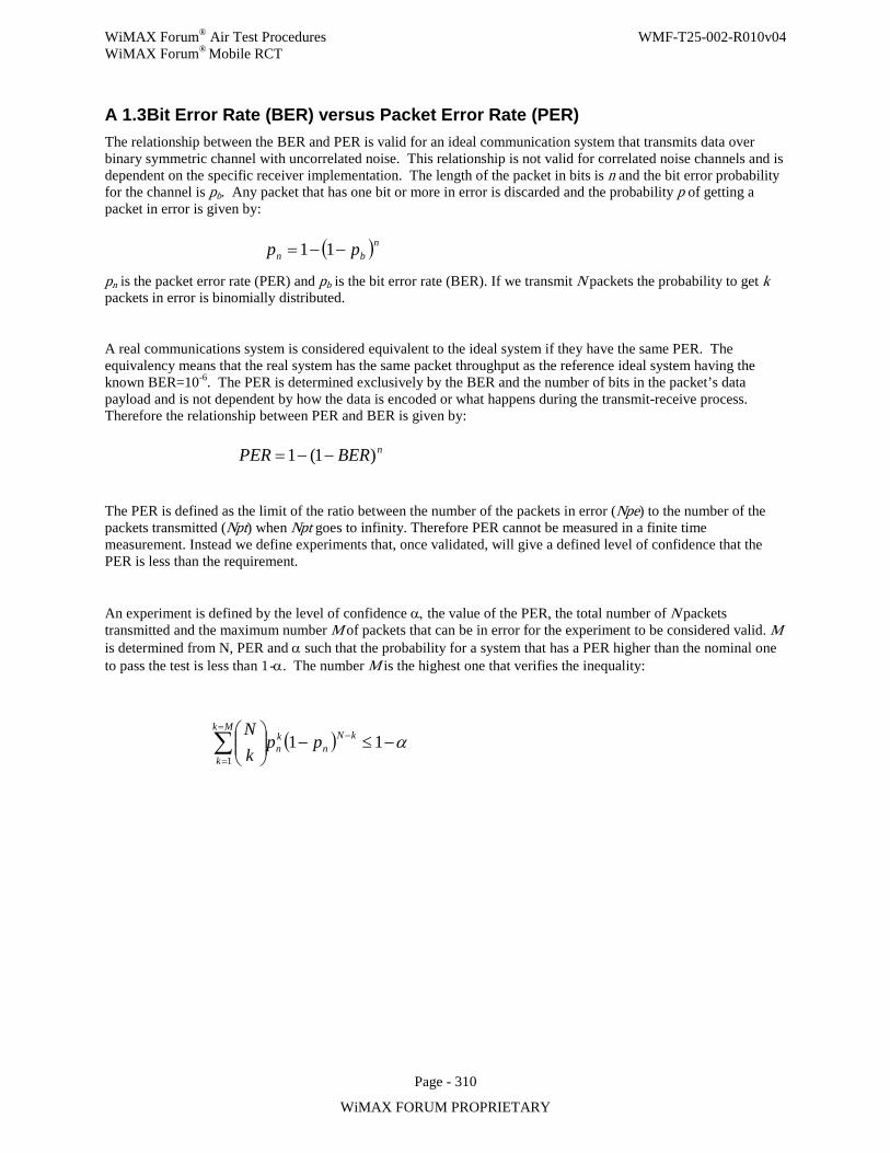
WiMAX Forum® Air Test Procedures WMF-T25-002-R010v04 WiMAX Forum® Mobile RCT
Page - 310
WiMAX FORUM PROPRIETARY
A 1.3 Bit Error Rate (BER) versus Packet Error Rate (PER) The relationship between the BER and PER is valid for an ideal communication system that transmits data over binary symmetric channel with uncorrelated noise. This relationship is not valid for correlated noise channels and is dependent on the specific receiver implementation. The length of the packet in bits is n and the bit error probability for the channel is pb. Any packet that has one bit or more in error is discarded and the probability p of getting a packet in error is given by:
( )nbn pp −−= 11
pn is the packet error rate (PER) and pb is the bit error rate (BER). If we transmit N packets the probability to get k packets in error is binomially distributed.
A real communications system is considered equivalent to the ideal system if they have the same PER. The equivalency means that the real system has the same packet throughput as the reference ideal system having the known BER=10-6. The PER is determined exclusively by the BER and the number of bits in the packet’s data payload and is not dependent by how the data is encoded or what happens during the transmit-receive process. Therefore the relationship between PER and BER is given by:
nBERPER )1(1 −−=
The PER is defined as the limit of the ratio between the number of the packets in error (Npe) to the number of the packets transmitted (Npt) when Npt goes to infinity. Therefore PER cannot be measured in a finite time measurement. Instead we define experiments that, once validated, will give a defined level of confidence that the PER is less than the requirement.
An experiment is defined by the level of confidence α, the value of the PER, the total number of N packets transmitted and the maximum number M of packets that can be in error for the experiment to be considered valid. M is determined from N, PER and α such that the probability for a system that has a PER higher than the nominal one to pass the test is less than 1-α. The number M is the highest one that verifies the inequality:
( ) α−≤−
−=
=∑ 11
1
kNn
kn
Mk
kpp
kN
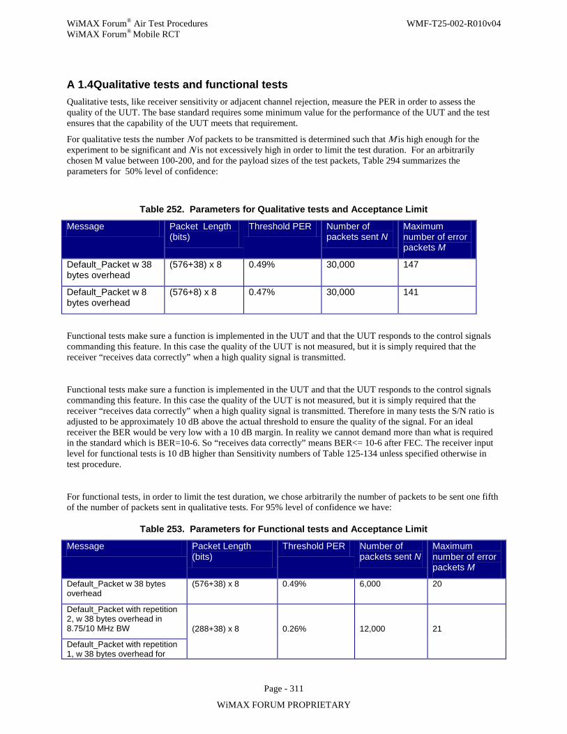
WiMAX Forum® Air Test Procedures WMF-T25-002-R010v04 WiMAX Forum® Mobile RCT
Page - 311
WiMAX FORUM PROPRIETARY
A 1.4 Qualitative tests and functional tests Qualitative tests, like receiver sensitivity or adjacent channel rejection, measure the PER in order to assess the quality of the UUT. The base standard requires some minimum value for the performance of the UUT and the test ensures that the capability of the UUT meets that requirement.
For qualitative tests the number N of packets to be transmitted is determined such that M is high enough for the experiment to be significant and N is not excessively high in order to limit the test duration. For an arbitrarily chosen M value between 100-200, and for the payload sizes of the test packets, Table 294 summarizes the parameters for 50% level of confidence:
Table 252. Parameters for Qualitative tests and Acceptance Limit
Message Packet Length (bits)
Threshold PER Number of packets sent N
Maximum number of error packets M
Default_Packet w 38 bytes overhead
(576+38) x 8 0.49% 30,000 147
Default_Packet w 8 bytes overhead
(576+8) x 8 0.47% 30,000 141
Functional tests make sure a function is implemented in the UUT and that the UUT responds to the control signals commanding this feature. In this case the quality of the UUT is not measured, but it is simply required that the receiver “receives data correctly” when a high quality signal is transmitted.
Functional tests make sure a function is implemented in the UUT and that the UUT responds to the control signals commanding this feature. In this case the quality of the UUT is not measured, but it is simply required that the receiver “receives data correctly” when a high quality signal is transmitted. Therefore in many tests the S/N ratio is adjusted to be approximately 10 dB above the actual threshold to ensure the quality of the signal. For an ideal receiver the BER would be very low with a 10 dB margin. In reality we cannot demand more than what is required in the standard which is BER=10-6. So “receives data correctly” means BER<= 10-6 after FEC. The receiver input level for functional tests is 10 dB higher than Sensitivity numbers of Table 125-134 unless specified otherwise in test procedure.
For functional tests, in order to limit the test duration, we chose arbitrarily the number of packets to be sent one fifth of the number of packets sent in qualitative tests. For 95% level of confidence we have:
Table 253. Parameters for Functional tests and Acceptance Limit
Message Packet Length (bits)
Threshold PER Number of packets sent N
Maximum number of error packets M
Default_Packet w 38 bytes overhead
(576+38) x 8 0.49% 6,000 20
Default_Packet with repetition 2, w 38 bytes overhead in 8.75/10 MHz BW (288+38) x 8 0.26% 12,000 21
Default_Packet with repetition 1, w 38 bytes overhead for
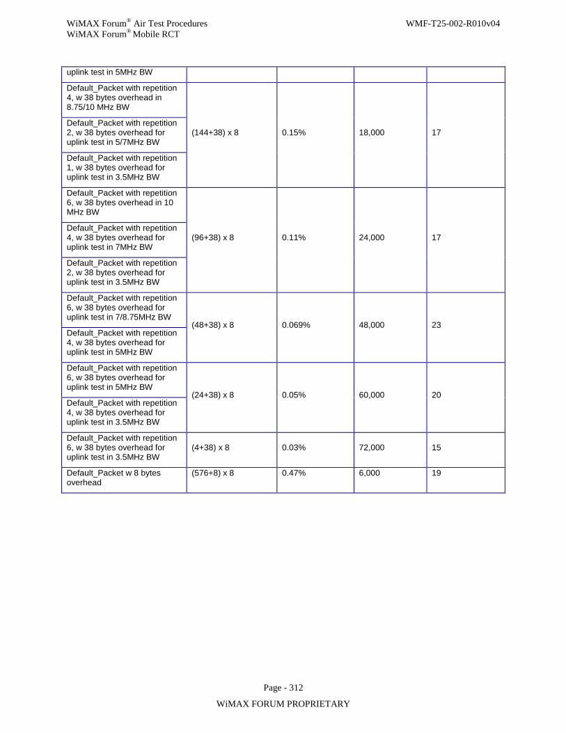
WiMAX Forum® Air Test Procedures WMF-T25-002-R010v04 WiMAX Forum® Mobile RCT
Page - 312
WiMAX FORUM PROPRIETARY
uplink test in 5MHz BW
Default_Packet with repetition 4, w 38 bytes overhead in 8.75/10 MHz BW
(144+38) x 8 0.15% 18,000 17 Default_Packet with repetition 2, w 38 bytes overhead for uplink test in 5/7MHz BW
Default_Packet with repetition 1, w 38 bytes overhead for uplink test in 3.5MHz BW
Default_Packet with repetition 6, w 38 bytes overhead in 10 MHz BW
(96+38) x 8 0.11% 24,000 17 Default_Packet with repetition 4, w 38 bytes overhead for uplink test in 7MHz BW
Default_Packet with repetition 2, w 38 bytes overhead for uplink test in 3.5MHz BW
Default_Packet with repetition 6, w 38 bytes overhead for uplink test in 7/8.75MHz BW
(48+38) x 8 0.069% 48,000 23 Default_Packet with repetition 4, w 38 bytes overhead for uplink test in 5MHz BW
Default_Packet with repetition 6, w 38 bytes overhead for uplink test in 5MHz BW
(24+38) x 8 0.05% 60,000 20 Default_Packet with repetition 4, w 38 bytes overhead for uplink test in 3.5MHz BW
Default_Packet with repetition 6, w 38 bytes overhead for uplink test in 3.5MHz BW
(4+38) x 8 0.03% 72,000 15
Default_Packet w 8 bytes overhead
(576+8) x 8 0.47% 6,000 19
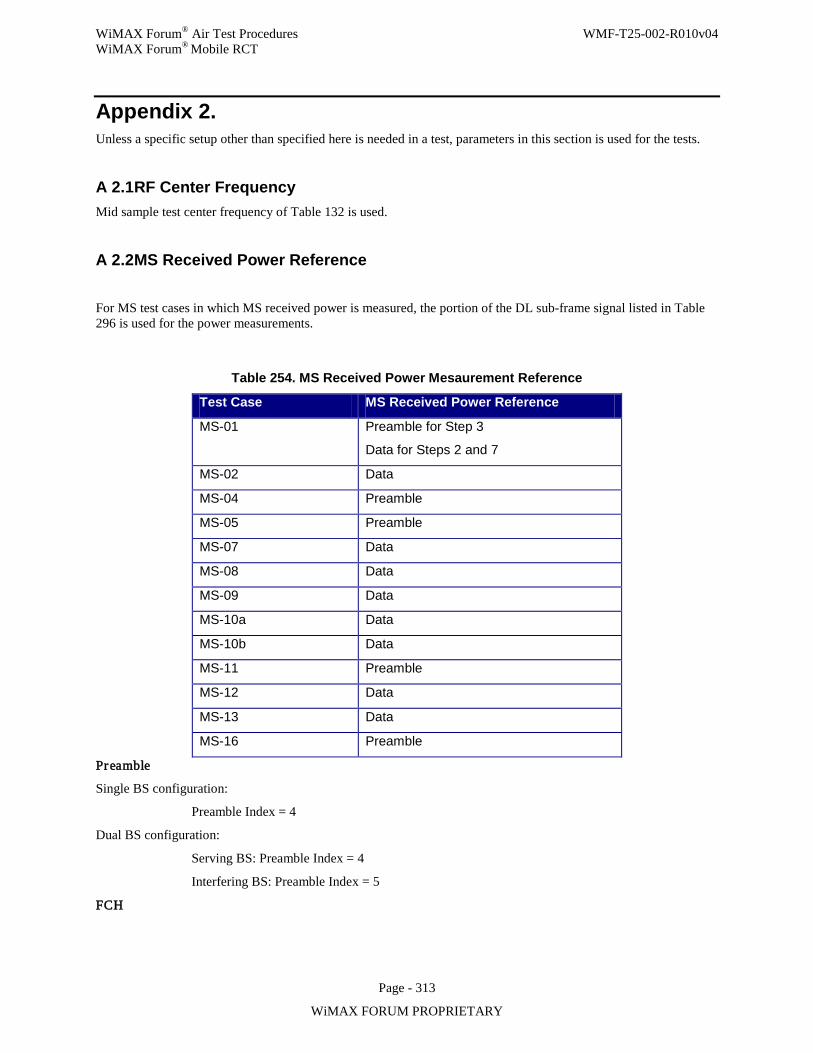
WiMAX Forum® Air Test Procedures WMF-T25-002-R010v04 WiMAX Forum® Mobile RCT
Page - 313
WiMAX FORUM PROPRIETARY
Appendix 2. Unless a specific setup other than specified here is needed in a test, parameters in this section is used for the tests.
A 2.1 RF Center Frequency Mid sample test center frequency of Table 132 is used.
A 2.2 MS Received Power Reference
For MS test cases in which MS received power is measured, the portion of the DL sub-frame signal listed in Table 296 is used for the power measurements.
Table 254. MS Received Power Mesaurement Reference
Test Case MS Received Power Reference
MS-01 Preamble for Step 3
Data for Steps 2 and 7
MS-02 Data
MS-04 Preamble
MS-05 Preamble
MS-07 Data
MS-08 Data
MS-09 Data
MS-10a Data
MS-10b Data
MS-11 Preamble
MS-12 Data
MS-13 Data
MS-16 Preamble
Preamble
Single BS configuration:
Preamble Index = 4
Dual BS configuration:
Serving BS: Preamble Index = 4
Interfering BS: Preamble Index = 5
FCH

WiMAX Forum® Air Test Procedures WMF-T25-002-R010v04 WiMAX Forum® Mobile RCT
Page - 314
WiMAX FORUM PROPRIETARY
Table 255. Default FCH configuration
Field Value
Used Subchannel Bitmap 0b111111
Repetition_Coding_Indication 0b11
Coding_Indication 0b010
A 2.3 Downlink and uplink allocation Network Entry
Unless otherwise specified, the MS or MSE shall complete initial network entry.
BW Requests
The MSE shall initiate UL allocations by sending bandwidth requests to the BS UUT.
Frame structure
• FFT Size: 512 for 3.5 and 5 MHz and 1024 for 7, 8.75 and 10 MHz BW • Cyclic Prefix is 1/8. • Regular DL/UL MAP IE to be used. • Downlink frame contains a number of symbols in DL and UL subframes given in theTable 298. • In the UL subframe, the control region covers 3 symbols. In this control region, the CDMA region is
composed of one ranging subchannel, with one Initial Ranging region and one Periodic Ranging region. The remaining slots of the control region are used if needed for fast feedback and/or HARQ-ACK.
Table 256. Default number of OFDM symbols in DL and UL subframes
Bandwidth DL Symbols UL Symbols Uplink control region
CDMA ranging region
3.5 MHz 21 12 3 symbols 2 +1 symbols
6 subchannel
5 MHz 29 18 3 symbols 2 +1 symbols
6 subchannel
7 MHz 21 12 3 symbols 2 +1 symbols
6 subchannel
8.75 MHz 27 15 3 symbols 2 +1 symbols
6 subchannel
10 MHz 29 18 3 symbols 2 +1 symbols
6 subchannel
• For DL sub-frame in MS test, a data PUSC/AMC zone starts from a new symbol after 1st PUSC zone for MAP and DCD, until the end of DL sub-frame
• For UL sub-frame in BS test, the data zone starts from the 4th symbol (after control message region) to the end
• In DL sub-frame, desired burst(s) has CID to the UUT, and the rest of the data zone can have random QPSK symbols. In DL-MAP, these slots will be associated with a different CID
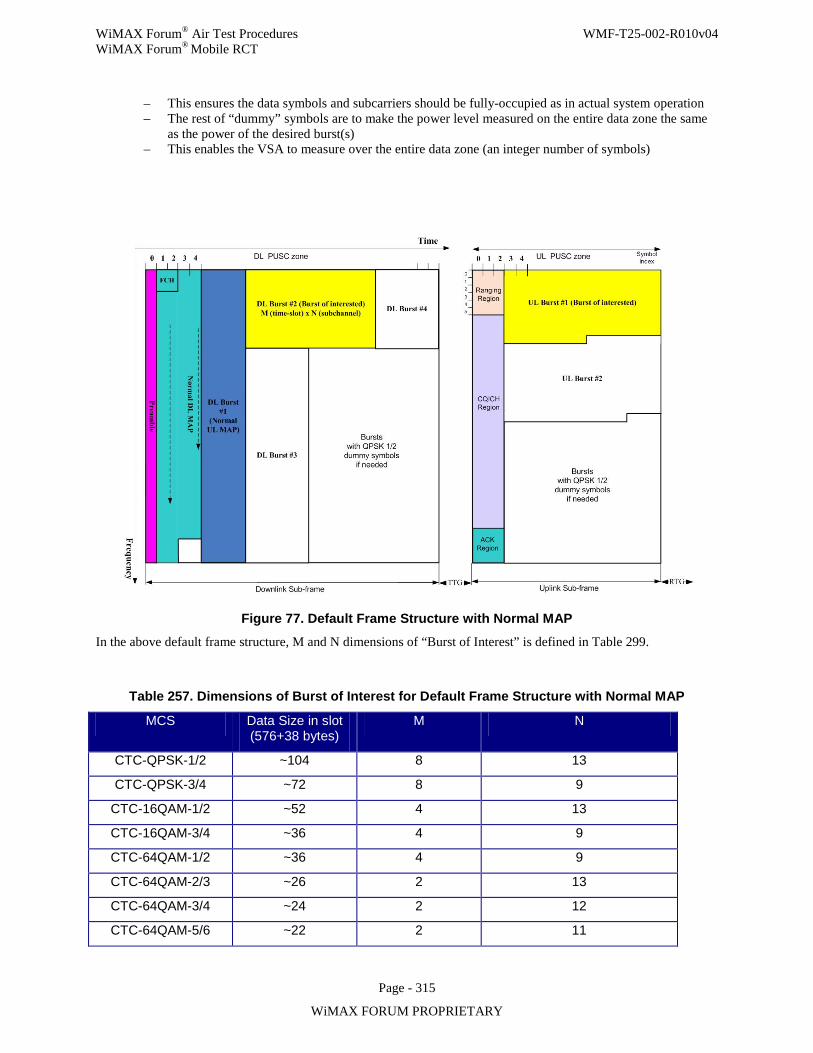
WiMAX Forum® Air Test Procedures WMF-T25-002-R010v04 WiMAX Forum® Mobile RCT
Page - 315
WiMAX FORUM PROPRIETARY
– This ensures the data symbols and subcarriers should be fully-occupied as in actual system operation – The rest of “dummy” symbols are to make the power level measured on the entire data zone the same
as the power of the desired burst(s) – This enables the VSA to measure over the entire data zone (an integer number of symbols)
Figure 77. Default Frame Structure with Normal MAP
In the above default frame structure, M and N dimensions of “Burst of Interest” is defined in Table 299.
Table 257. Dimensions of Burst of Interest for Default Frame Structure with Normal MAP
MCS Data Size in slot (576+38 bytes)
M N
CTC-QPSK-1/2 ~104 8 13
CTC-QPSK-3/4 ~72 8 9
CTC-16QAM-1/2 ~52 4 13
CTC-16QAM-3/4 ~36 4 9
CTC-64QAM-1/2 ~36 4 9
CTC-64QAM-2/3 ~26 2 13
CTC-64QAM-3/4 ~24 2 12
CTC-64QAM-5/6 ~22 2 11
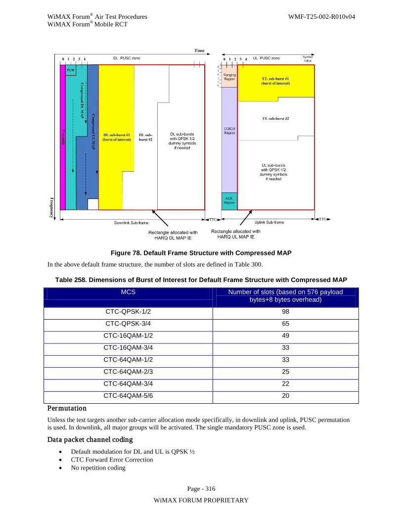
WiMAX Forum® Air Test Procedures WMF-T25-002-R010v04 WiMAX Forum® Mobile RCT
Page - 316
WiMAX FORUM PROPRIETARY
Figure 78. Default Frame Structure with Compressed MAP In the above default frame structure, the number of slots are defined in Table 300.
Table 258. Dimensions of Burst of Interest for Default Frame Structure with Compressed MAP
MCS Number of slots (based on 576 payload bytes+8 bytes overhead)
CTC-QPSK-1/2 98
CTC-QPSK-3/4 65
CTC-16QAM-1/2 49
CTC-16QAM-3/4 33
CTC-64QAM-1/2 33
CTC-64QAM-2/3 25
CTC-64QAM-3/4 22
CTC-64QAM-5/6 20
Permutation Unless the test targets another sub-carrier allocation mode specifically, in downlink and uplink, PUSC permutation is used. In downlink, all major groups will be activated. The single mandatory PUSC zone is used.
Data packet channel coding • Default modulation for DL and UL is QPSK ½ • CTC Forward Error Correction • No repetition coding
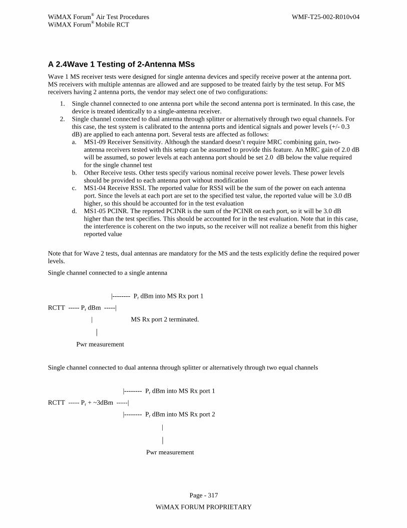
WiMAX Forum® Air Test Procedures WMF-T25-002-R010v04 WiMAX Forum® Mobile RCT
Page - 317
WiMAX FORUM PROPRIETARY
A 2.4 Wave 1 Testing of 2-Antenna MSs Wave 1 MS receiver tests were designed for single antenna devices and specify receive power at the antenna port. MS receivers with multiple antennas are allowed and are supposed to be treated fairly by the test setup. For MS receivers having 2 antenna ports, the vendor may select one of two configurations:
1. Single channel connected to one antenna port while the second antenna port is terminated. In this case, the device is treated identically to a single-antenna receiver.
2. Single channel connected to dual antenna through splitter or alternatively through two equal channels. For this case, the test system is calibrated to the antenna ports and identical signals and power levels (+/- 0.3 dB) are applied to each antenna port. Several tests are affected as follows: a. MS1-09 Receiver Sensitivity. Although the standard doesn’t require MRC combining gain, two-
antenna receivers tested with this setup can be assumed to provide this feature. An MRC gain of 2.0 dB will be assumed, so power levels at each antenna port should be set 2.0 dB below the value required for the single channel test
b. Other Receive tests. Other tests specify various nominal receive power levels. These power levels should be provided to each antenna port without modification
c. MS1-04 Receive RSSI. The reported value for RSSI will be the sum of the power on each antenna port. Since the levels at each port are set to the specified test value, the reported value will be 3.0 dB higher, so this should be accounted for in the test evaluation
d. MS1-05 PCINR. The reported PCINR is the sum of the PCINR on each port, so it will be 3.0 dB higher than the test specifies. This should be accounted for in the test evaluation. Note that in this case, the interference is coherent on the two inputs, so the receiver will not realize a benefit from this higher reported value
Note that for Wave 2 tests, dual antennas are mandatory for the MS and the tests explicitly define the required power levels.
Single channel connected to a single antenna
|-------- Pr dBm into MS Rx port 1 RCTT ----- Pr dBm -----| | MS Rx port 2 terminated. | Pwr measurement
Single channel connected to dual antenna through splitter or alternatively through two equal channels
|-------- Pr dBm into MS Rx port 1 RCTT ----- Pr + ~3dBm -----| |-------- Pr dBm into MS Rx port 2 |
| Pwr measurement
WiMAX Forum® Air Test Procedures WMF-T25-002-R010v04 WiMAX Forum® Mobile RCT
Page - 318
WiMAX FORUM PROPRIETARY
Appendix 3. A 3.1 Measuring PER for MS Measur ing PER using Ping Method
For the PER measurement, the Signaling Unit (BS emulator) uses the Ping command to send some payload to the MS UUT at an interval of 5ms (one frame). The MS will send the payload back if it is decoded successfully. Hence, a packet error rate (PER) can be measured. PER, rather than Bit Error Rate (BER), is calculated over a large number of frames to verify that the performance is better than or equal to the target PER. The header size in a Ping message is 28 bytes with 8 bytes of ICMP control message. In addition to the 28 bytes header in each Ping message, there will be a 6 byte generic MAC header at the beginning and a 4-byte CRC-32 at the end.
The burst is allocated in a data PUSC/AMC zone after the first PUSC zone for control message (MAP and DCD) The data zone extends to the end of the DL sub frame. The allocation starts from slot 1+mod(n, Nsch) where n is the frame index and Nsch is the number of slots in the frequency domain (e.g., 15 in 512 point FFT PUSC). The rest of slots in the data zone (before and after the allocated burst) can use random QPSK symbols. Corresponding to those slots, BSE should use a different CID in the MAP message. The per subcarrier transmit power level of the rest of the data zone is kept the same as the per subcarrier of the data burst so that the signal power measured for the entire data zone is the same as that in the allocation to the MS UUT.
Measur ing PER using ACK/NACK Method For the PER measurement, the Signaling Unit (BS emulator) uses the ACK/NACK command to send 1 HARQ packet to the MS UUT at an interval of 5ms (one frame). The BS emulator should set the Maximum Number of HARQ retransmissions to 0 (no retransmissions), and that the DL HARQ ACK Delay should be set to 1 frame. In addition, the BS emulator should allocate a feedback region at each frame that follows the frame with DL HARQ bursts.
The MS, per packet, will send a reported ACK if it is decoded successfully and Nack otherwise. Hence, a packet error rate (PER) can be measured by counting the number of NACK message. PER, rather than Bit Error Rate (BER), is calculated over a large number of frames to verify that the performance is better than or equal to the target PER.
The HARQ packets are allocated in a data PUSC/AMC zone after the first PUSC zone for control message (MAP and DCD) The data zone extends to the end of the DL sub frame. The allocation starts from slot 1+mod(n, Nsch) where n is the frame index and Nsch is the number of slots in the frequency domain (e.g., 15 in 512 point FFT PUSC). The rest of slots in the data zone (before and after the allocated burst) can use random QPSK symbols. Corresponding to those slots, BSE should use a different CID in the MAP message. The per subcarrier transmit power level of the rest of the data zone is kept the same as the per subcarrier of the data burst so that the signal power measured for the entire data zone is the same as that in the allocation to the MS UUT.
A 3.2 Measuring PER for BS
Measur ing PER using MAC CRC Method For the PER measurement in the uplink, the Signaling Unit (MS emulator) always inserts MAC CRC at the end of each packet to transmit. The BS UUT calculates and shows the PER based on its received packets by checking the MAC CRC. Hence, a packet error rate can be measured. Packet error rate (PER), rather than Bit Error Rate (BER), is calculated over a large number of frames to verify that the performance is better than or equal to the target PER. The overhead for the MAC CRC method is 10 bytes including 6 byte generic MAC header at the beginning and a 4-byte CRC-32 at the end.
WiMAX Forum® Air Test Procedures WMF-T25-002-R010v04 WiMAX Forum® Mobile RCT
Page - 319
WiMAX FORUM PROPRIETARY
Measur ing PER using Ping Method For the PER measurement, the Signaling Unit (MS emulator) uses the Ping command to send some payload to the BS UUT at an interval of 5ms (one frame). The BS will send the payload back if it is decoded successfully. Hence, a packet error rate can be measured. Packet error rate (PER), rather than Bit Error Rate (BER), is calculated over a large number of frames to verify that the performance is better than or equal to the target PER. The header size in a Ping message is 28 bytes with 8 bytes of ICMP control message. In addition to the 28 bytes header in each Ping message, there will be a 6 byte generic MAC header at the beginning and a 4-byte CRC-32 at the end.
WiMAX Forum® Air Test Procedures WMF-T25-002-R010v04 WiMAX Forum® Mobile RCT
Page - 320
WiMAX FORUM PROPRIETARY
Appendix 4. This section provides testing channel models for SISO and MIMO/BF.
A 4.1 Test Channel Models A 4.1.1 Purpose of channel modeling
The purpose of channel modeling in RCT is to provide a realistic and standard setting for the performance testing of mobile fading environment. In particular, the setting covers the frequency-time variation characteristics of both SISO and MIMO systems.
SISO channels
SISO channel character ization
SISO channel models Compliance to the following three channel models as specified in [7] is required.
• AWGN • ITU Pedestrian B 3 km/h • ITU Vehicular A 60 km/h
Model descr iption Refer to [7].
Channel parameters Refer to [7].
A 4.1.2 MIMO channels
Introduction
Mobile WiMAX® RCT requires the use of MIMO channel models. ITU models (Ped-B & Veh-A: 6-tap TDL) were chosen for SISO RCT test. This model was extended to 2x2 MIMO channel models with the definition of a per-tap spatial correlation. Three levels of channel correlation have been defined, to serve as three options for the RCTs. Note that the content of this appendix is relevant to downlink.
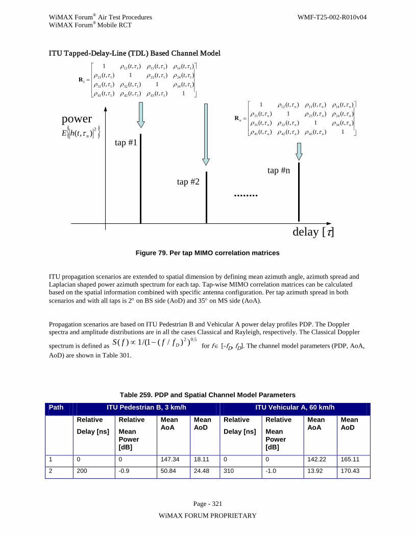
WiMAX Forum® Air Test Procedures WMF-T25-002-R010v04 WiMAX Forum® Mobile RCT
Page - 321
WiMAX FORUM PROPRIETARY
ITU Tapped-Delay-Line (TDL) Based Channel Model
delay [τ]
power 2),( nthE τ
tap #1
tap #2tap #n
=
1),(),(),(),(1),(),(),(),(1),(),(),(),(1
143142141
134132131
124123121
114113112
1
τρτρτρτρτρτρτρτρτρτρτρτρ
tttttttttttt
R
=
1),(),(),(),(1),(),(),(),(1),(),(),(),(1
434241
343231
242321
141312
nnn
nnn
nnn
nnn
n
tttttttttttt
τρτρτρτρτρτρτρτρτρτρτρτρ
R
Figure 79. Per tap MIMO correlation matrices
ITU propagation scenarios are extended to spatial dimension by defining mean azimuth angle, azimuth spread and Laplacian shaped power azimuth spectrum for each tap. Tap-wise MIMO correlation matrices can be calculated based on the spatial information combined with specific antenna configuration. Per tap azimuth spread in both scenarios and with all taps is 2° on BS side (AoD) and 35° on MS side (AoA).
Propagation scenarios are based on ITU Pedestrian B and Vehicular A power delay profiles PDP. The Doppler spectra and amplitude distributions are in all the cases Classical and Rayleigh, respectively. The Classical Doppler
spectrum is defined as 5.02 ))/(1/(1)( DfffS −∝ for f ∈ [-fD, fD]. The channel model parameters (PDP, AoA,
AoD) are shown in Table 301.
Table 259. PDP and Spatial Channel Model Parameters
Path ITU Pedestrian B, 3 km/h ITU Vehicular A, 60 km/h
Relative
Delay [ns]
Relative
Mean Power [dB]
Mean AoA
Mean AoD
Relative
Delay [ns]
Relative
Mean Power [dB]
Mean AoA
Mean AoD
1 0 0 147.34 18.11 0 0 142.22 165.11
2 200 -0.9 50.84 24.48 310 -1.0 13.92 170.43
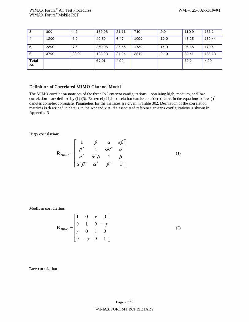
WiMAX Forum® Air Test Procedures WMF-T25-002-R010v04 WiMAX Forum® Mobile RCT
Page - 322
WiMAX FORUM PROPRIETARY
3 800 -4.9 139.08 21.11 710 -9.0 110.94 182.2
4 1200 -8.0 49.50 6.47 1090 -10.0 45.25 162.44
5 2300 -7.8 260.03 23.85 1730 -15.0 98.38 170.6
6 3700 -23.9 128.93 24.24 2510 -20.0 50.41 155.68
Total AS
67.91 4.99 69.9 4.99
Definition of Correlated MIMO Channel Model The MIMO correlation matrices of the three 2x2 antenna configurations – obtaining high, medium, and low correlation – are defined by (1)-(3). Extremely high correlation can be considered later. In the equations below (.)* denotes complex conjugate. Parameters for the matrices are given in Table 302. Derivation of the correlation matrices is described in details in the Appendix A, the associated reference antenna configurations is shown in Appendix B
High cor relation:
=
11
11
****
**
**
βαβαββααααββ
αβαβ
MIMOR (1)
Medium cor relation:
−
−=
100010
010001
γγ
γγ
MIMOR (2)
Low cor relation:
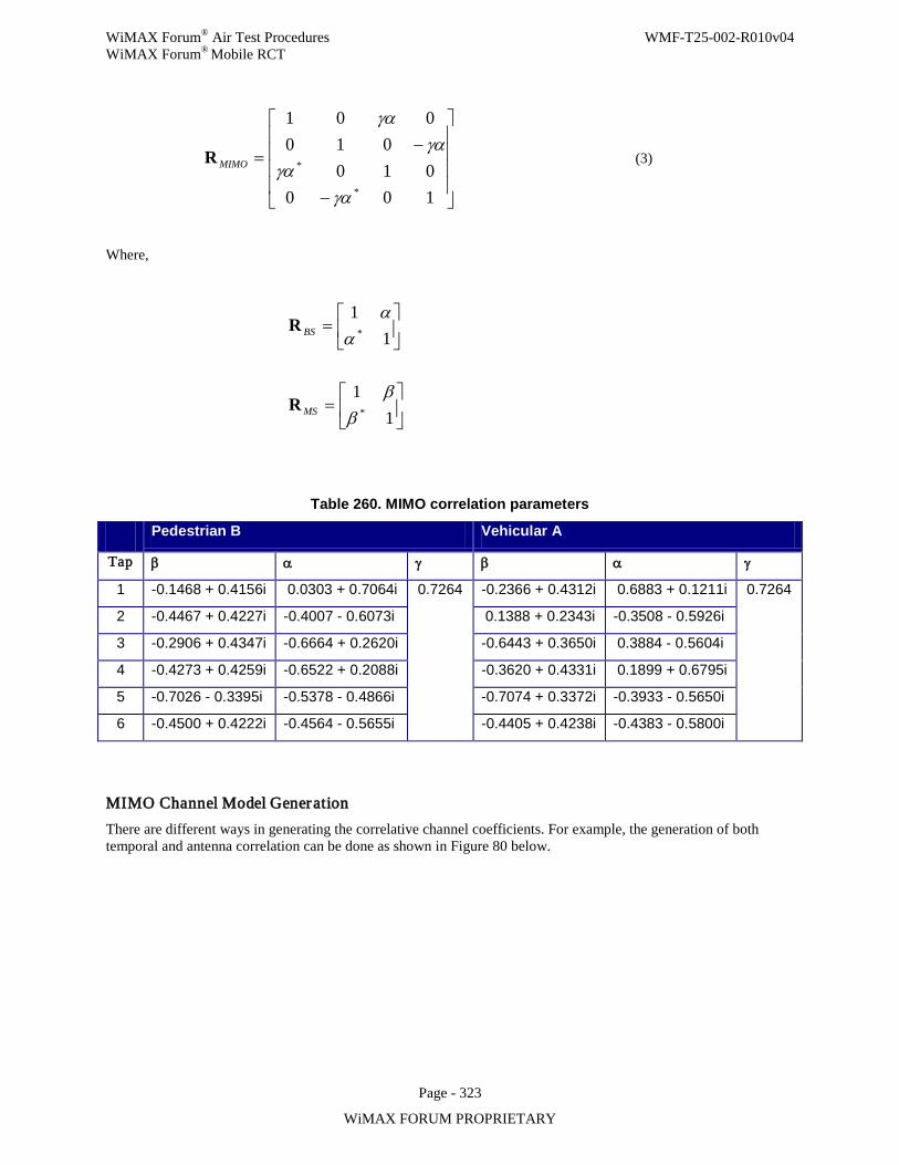
WiMAX Forum® Air Test Procedures WMF-T25-002-R010v04 WiMAX Forum® Mobile RCT
Page - 323
WiMAX FORUM PROPRIETARY
−
−=
100010
010001
*
*
γαγα
γαγα
MIMOR (3)
Where,
Table 260. MIMO correlation parameters
Pedestrian B Vehicular A
Tap β α γ β α γ
1 -0.1468 + 0.4156i 0.0303 + 0.7064i 0.7264 -0.2366 + 0.4312i 0.6883 + 0.1211i 0.7264
2 -0.4467 + 0.4227i -0.4007 - 0.6073i 0.1388 + 0.2343i -0.3508 - 0.5926i
3 -0.2906 + 0.4347i -0.6664 + 0.2620i -0.6443 + 0.3650i 0.3884 - 0.5604i
4 -0.4273 + 0.4259i -0.6522 + 0.2088i -0.3620 + 0.4331i 0.1899 + 0.6795i
5 -0.7026 - 0.3395i -0.5378 - 0.4866i -0.7074 + 0.3372i -0.3933 - 0.5650i
6 -0.4500 + 0.4222i -0.4564 - 0.5655i -0.4405 + 0.4238i -0.4383 - 0.5800i
MIMO Channel Model Generation There are different ways in generating the correlative channel coefficients. For example, the generation of both temporal and antenna correlation can be done as shown in Figure 80 below.
=
11
*αα
BSR
=
11
*ββ
MSR
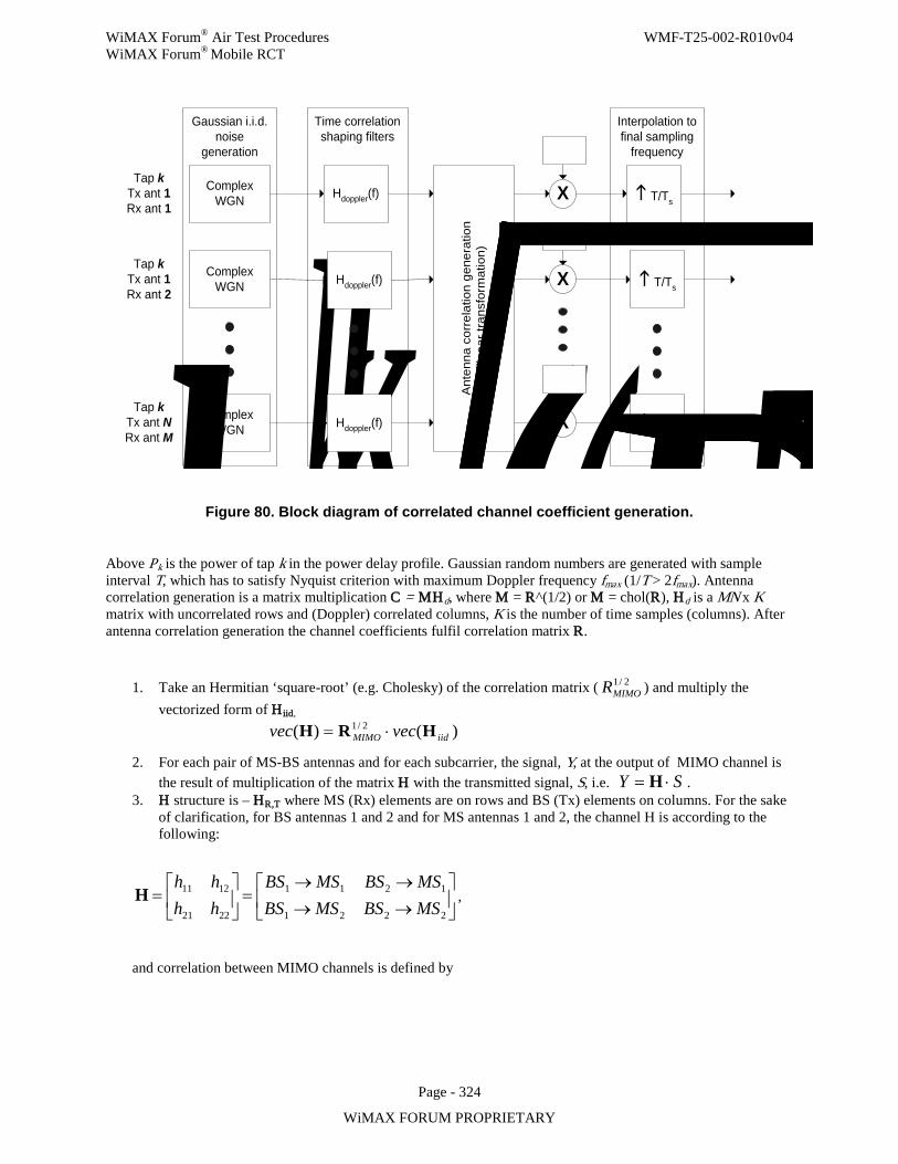
WiMAX Forum® Air Test Procedures WMF-T25-002-R010v04 WiMAX Forum® Mobile RCT
Page - 324
WiMAX FORUM PROPRIETARY
Interpolation tofinal sampling
frequency
Gaussian i.i.d.noise
generation
Time correlationshaping filters
Tap kTx ant 1Rx ant 1
ComplexWGN Hdoppler(f)
ComplexWGN
ComplexWGN
Tap kTx ant 1Rx ant 2
Tap kTx ant NRx ant M
Ant
enna
cor
rela
tion
gene
ratio
n(li
near
tran
sfor
mat
ion)
X
X
X( Thk ( Thk ( Thk T/Ts
T/Ts
T/Ts
Hdoppler(f)
Hdoppler(f) PPP
Figure 80. Block diagram of correlated channel coefficient generation.
Above Pk is the power of tap k in the power delay profile. Gaussian random numbers are generated with sample interval T, which has to satisfy Nyquist criterion with maximum Doppler frequency fmax (1/T > 2fmax). Antenna correlation generation is a matrix multiplication C = MHd, where M = R^(1/2) or M = chol(R), Hd is a MN x K matrix with uncorrelated rows and (Doppler) correlated columns, K is the number of time samples (columns). After antenna correlation generation the channel coefficients fulfil correlation matrix R.
1. Take an Hermitian ‘square-root’ (e.g. Cholesky) of the correlation matrix ( 2/1MIMOR ) and multiply the
vectorized form of Hiid,
)()( 2/1iidMIMO vecvec HRH ⋅=
2. For each pair of MS-BS antennas and for each subcarrier, the signal, Y, at the output of MIMO channel is the result of multiplication of the matrix H with the transmitted signal, S, i.e. SY ⋅= H .
3. H structure is – HR,T where MS (Rx) elements are on rows and BS (Tx) elements on columns. For the sake of clarification, for BS antennas 1 and 2 and for MS antennas 1 and 2, the channel H is according to the following:
→→→→
=
=
2221
1211
2221
1211
MSBSMSBSMSBSMSBS
hhhh
H ,
and correlation between MIMO channels is defined by
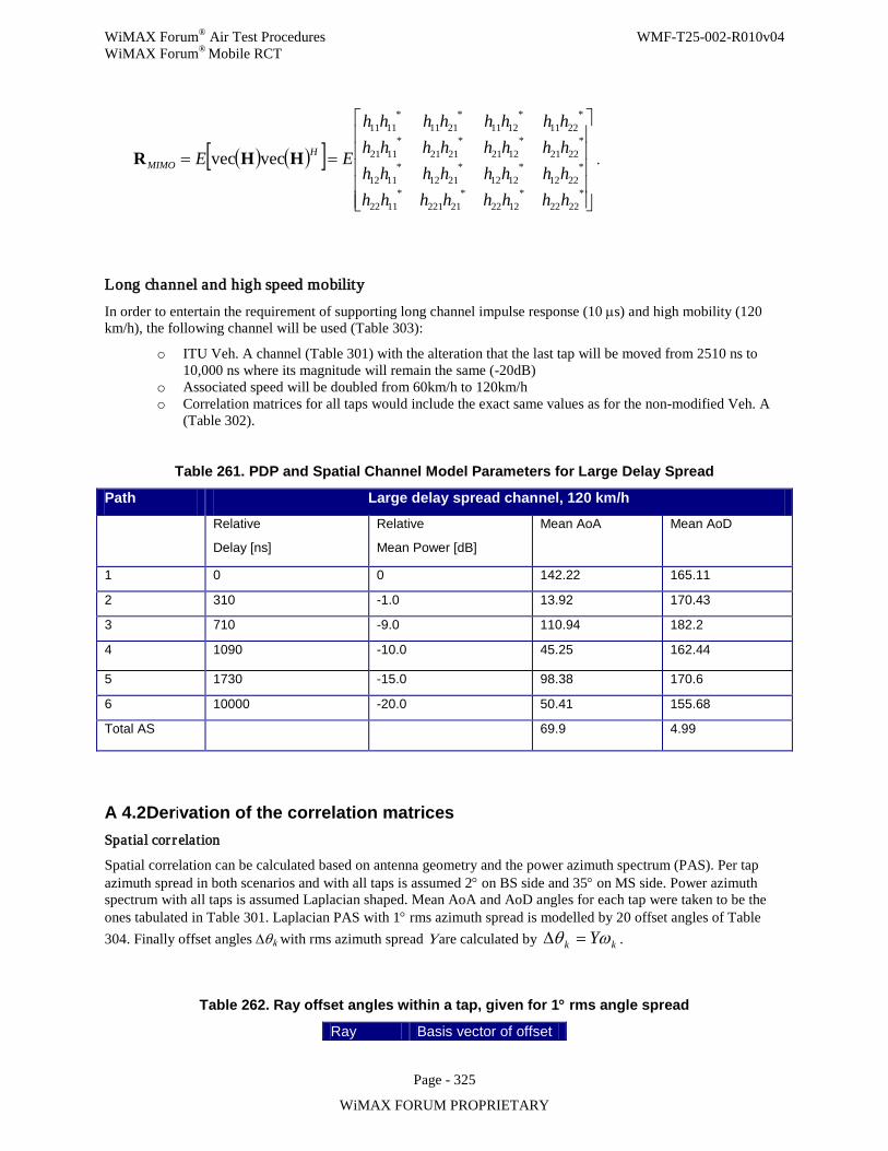
WiMAX Forum® Air Test Procedures WMF-T25-002-R010v04 WiMAX Forum® Mobile RCT
Page - 325
WiMAX FORUM PROPRIETARY
( ) ( )[ ]
==
*2222
*1222
*21221
*1122
*2212
*1212
*2112
*1112
*2221
*1221
*2121
*1121
*2211
*1211
*2111
*1111
vecvec
hhhhhhhhhhhhhhhhhhhhhhhhhhhhhhhh
EE HMIMO HHR .
Long channel and high speed mobility
In order to entertain the requirement of supporting long channel impulse response (10 µs) and high mobility (120 km/h), the following channel will be used (Table 303):
o ITU Veh. A channel (Table 301) with the alteration that the last tap will be moved from 2510 ns to 10,000 ns where its magnitude will remain the same (-20dB)
o Associated speed will be doubled from 60km/h to 120km/h o Correlation matrices for all taps would include the exact same values as for the non-modified Veh. A
(Table 302).
Table 261. PDP and Spatial Channel Model Parameters for Large Delay Spread
Path Large delay spread channel, 120 km/h
Relative
Delay [ns]
Relative
Mean Power [dB]
Mean AoA Mean AoD
1 0 0 142.22 165.11
2 310 -1.0 13.92 170.43
3 710 -9.0 110.94 182.2
4 1090 -10.0 45.25 162.44
5 1730 -15.0 98.38 170.6
6 10000 -20.0 50.41 155.68
Total AS 69.9 4.99
A 4.2 Derivation of the correlation matrices Spatial cor relation
Spatial correlation can be calculated based on antenna geometry and the power azimuth spectrum (PAS). Per tap azimuth spread in both scenarios and with all taps is assumed 2° on BS side and 35° on MS side. Power azimuth spectrum with all taps is assumed Laplacian shaped. Mean AoA and AoD angles for each tap were taken to be the ones tabulated in Table 301. Laplacian PAS with 1° rms azimuth spread is modelled by 20 offset angles of Table 304. Finally offset angles ∆θk with rms azimuth spread Y are calculated by kk Yωθ =∆ .
Table 262. Ray offset angles within a tap, given for 1° rms angle spread
Ray Basis vector of offset
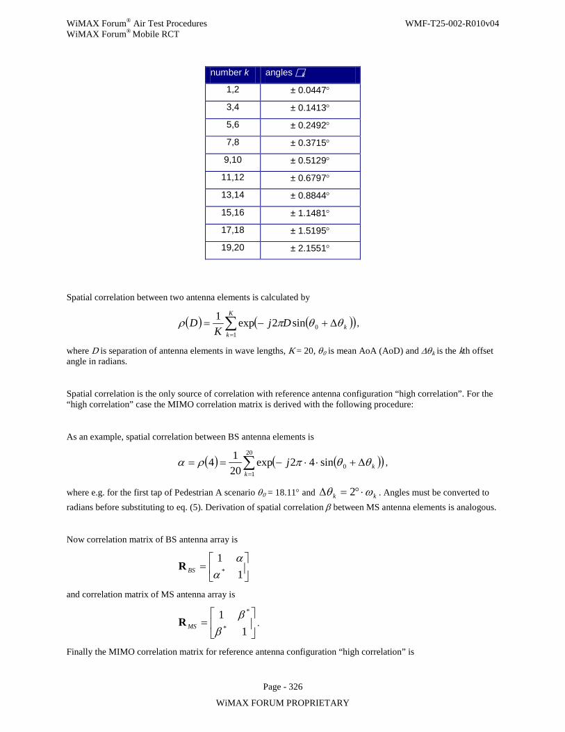
WiMAX Forum® Air Test Procedures WMF-T25-002-R010v04 WiMAX Forum® Mobile RCT
Page - 326
WiMAX FORUM PROPRIETARY
number k angles k
1,2 ± 0.0447°
3,4 ± 0.1413°
5,6 ± 0.2492°
7,8 ± 0.3715°
9,10 ± 0.5129°
11,12 ± 0.6797°
13,14 ± 0.8844°
15,16 ± 1.1481°
17,18 ± 1.5195°
19,20 ± 2.1551°
Spatial correlation between two antenna elements is calculated by
( ) ( )( )∑=
∆+−=K
kkDj
KD
10sin2exp1 θθπρ ,
where D is separation of antenna elements in wave lengths, K = 20, θ0 is mean AoA (AoD) and ∆θk is the kth offset angle in radians.
Spatial correlation is the only source of correlation with reference antenna configuration “high correlation”. For the “high correlation” case the MIMO correlation matrix is derived with the following procedure:
As an example, spatial correlation between BS antenna elements is
( ) ( )( )∑=
∆+⋅⋅−==20
10sin42exp
2014
kkj θθπρα ,
where e.g. for the first tap of Pedestrian A scenario θ0 = 18.11° and kk ωθ ⋅°=∆ 2 . Angles must be converted to radians before substituting to eq. (5). Derivation of spatial correlation β between MS antenna elements is analogous.
Now correlation matrix of BS antenna array is
=
11
*αα
BSR
and correlation matrix of MS antenna array is
=
11
*
*
ββ
MSR .
Finally the MIMO correlation matrix for reference antenna configuration “high correlation” is
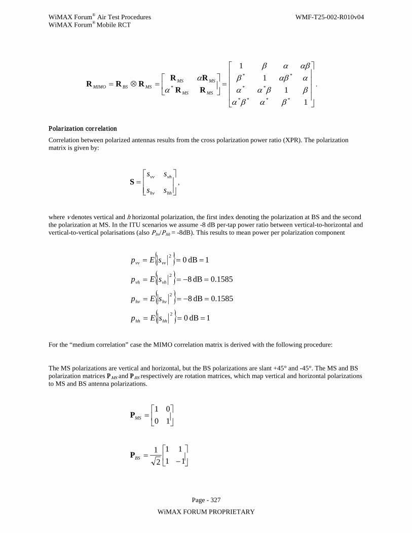
WiMAX Forum® Air Test Procedures WMF-T25-002-R010v04 WiMAX Forum® Mobile RCT
Page - 327
WiMAX FORUM PROPRIETARY
=
=⊗=
11
11
****
**
**
*
βαβαββααααββ
αβαβ
αα
MSMS
MSMSMSBSMIMO RR
RRRRR .
Polar ization cor relation
Correlation between polarized antennas results from the cross polarization power ratio (XPR). The polarization matrix is given by:
=
hhhv
vhvv
ss
ssS ,
where v denotes vertical and h horizontal polarization, the first index denoting the polarization at BS and the second the polarization at MS. In the ITU scenarios we assume -8 dB per-tap power ratio between vertical-to-horizontal and vertical-to-vertical polarisations (also Phv/Phh = -8dB). This results to mean power per polarization component
1dB 0
0.1585dB 8
1585.0dB 8
1dB 0
2
2
2
2
===
=−==
=−==
===
hhhh
hvhv
vhvh
vvvv
sEp
sEp
sEp
sEp
For the “medium correlation” case the MIMO correlation matrix is derived with the following procedure:
The MS polarizations are vertical and horizontal, but the BS polarizations are slant +45° and -45°. The MS and BS polarization matrices PMS and PBS respectively are rotation matrices, which map vertical and horizontal polarizations to MS and BS antenna polarizations.
=
1001
MSP
−
=11
112
1BSP
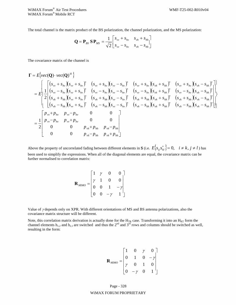
WiMAX Forum® Air Test Procedures WMF-T25-002-R010v04 WiMAX Forum® Mobile RCT
Page - 328
WiMAX FORUM PROPRIETARY
The total channel is the matrix product of the BS polarization, the channel polarization, and the MS polarization:
−−++
==hhvhhvvv
hhvhhvvvMSBS ssss
ssss2
1PSPQ
The covariance matrix of the channel is
( )( ) ( )( ) ( )( ) ( )( )( )( ) ( )( ) ( )( ) ( )( )( )( ) ( )( ) ( )( ) ( )( )( )( ) ( )( ) ( )( ) ( )( )
+−−+
+−−+
=
−−+−−−+−−+++−+++−−+−−−+−−+++−+++
=
⋅=
∗∗∗∗
∗∗∗∗
∗∗∗∗
∗∗∗∗
hhvhhhvh
hhvhhhvh
hvvvhvvv
hvvvhvvv
hhvhhhvhhhvhhhvhhvvvhhvhhvvvhhvh
hhvhhhvhhhvhhhvhhvvvhhvhhvvvhhvh
hhvhhvvvhhvhhvvvhvvvhvvvhvvvhvvv
hhvhhvvvhhvhhvvvhvvvhvvvhvvvhvvv
H
pppppppp
pppppppp
ssssssssssssssssssssssssssssssssssssssssssssssssssssssssssssssss
E
vecvecE
0000
0000
21
21
)()( QQΓ
Above the property of uncorrelated fading between different elements in S (i.e. ljkissE klij ≠≠=∗ ,,0 ) has been used to simplify the expressions. When all of the diagonal elements are equal, the covariance matrix can be further normalised to correlation matrix:
−−
=
100100
001001
γγ
γγ
MIMOR
Value of γ depends only on XPR. With different orientations of MS and BS antenna polarizations, also the covariance matrix structure will be different.
Note, this correlation matrix derivation is actually done for the HTR case. Transforming it into an HRT form the channel elements h1,2 and h2,1 are switched and thus the 2nd and 3rd rows and columns should be switched as well, resulting in the form:
−
−=
100010
010001
γγ
γγ
MIMOR
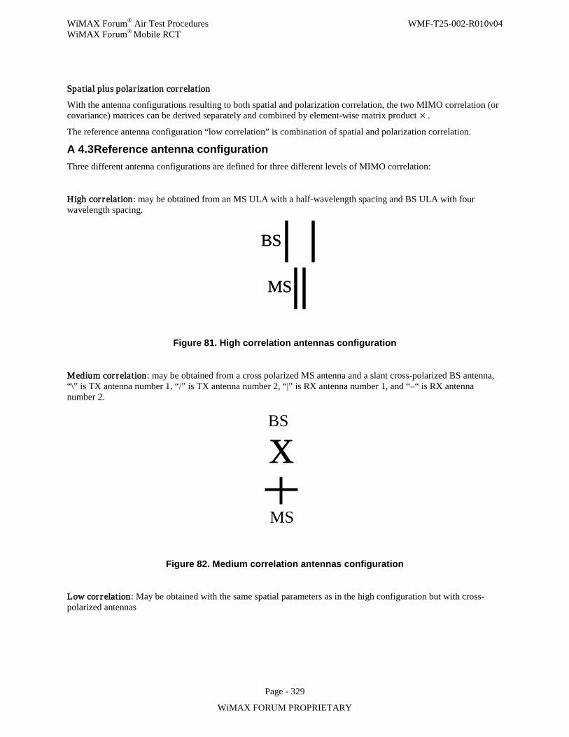
WiMAX Forum® Air Test Procedures WMF-T25-002-R010v04 WiMAX Forum® Mobile RCT
Page - 329
WiMAX FORUM PROPRIETARY
Spatial plus polar ization cor relation
With the antenna configurations resulting to both spatial and polarization correlation, the two MIMO correlation (or covariance) matrices can be derived separately and combined by element-wise matrix product × .
The reference antenna configuration “low correlation” is combination of spatial and polarization correlation.
A 4.3 Reference antenna configuration Three different antenna configurations are defined for three different levels of MIMO correlation:
High cor relation: may be obtained from an MS ULA with a half-wavelength spacing and BS ULA with four wavelength spacing.
BS
MS
BS
MS
Figure 81. High correlation antennas configuration
Medium cor relation: may be obtained from a cross polarized MS antenna and a slant cross-polarized BS antenna, “\” is TX antenna number 1, “/” is TX antenna number 2, “|” is RX antenna number 1, and “–“ is RX antenna number 2.
Figure 82. Medium correlation antennas configuration
Low cor relation: May be obtained with the same spatial parameters as in the high configuration but with cross-polarized antennas
BS
MS
x
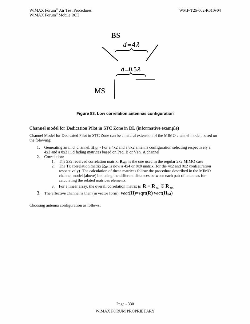
WiMAX Forum® Air Test Procedures WMF-T25-002-R010v04 WiMAX Forum® Mobile RCT
Page - 330
WiMAX FORUM PROPRIETARY
λ4=d
λ5.0=d
BS
MS
λ4=d
λ5.0=d
BS
MS
Figure 83. Low correlation antennas configuration
Channel model for Dedication Pilot in STC Zone in DL (informative example) Channel Model for Dedicated Pilot in STC Zone can be a natural extension of the MIMO channel model, based on the folowing:
1. Generating an i.i.d. channel, Hiid - For a 4x2 and a 8x2 antenna configuration selecting respectively a 4x2 and a 8x2 i.i.d fading matrices based on Ped. B or Veh. A channel
2. Correlation: 1. The 2x2 received correlation matrix, RMS, is the one used in the regular 2x2 MIMO case 2. The Tx correlation matrix RBS is now a 4x4 or 8x8 matrix (for the 4x2 and 8x2 configuration
respectively). The calculation of these matrices follow the procedure described in the MIMO channel model (above) but using the different distances between each pair of antennas for calculating the related matrices elements.
3. For a linear array, the overall correlation matrix is MSBS RRR ⊗=
3. The effective channel is then (in vector form): vect(H)=sqrt(R)∙vect(Hiid)
Choosing antenna configuration as follows:
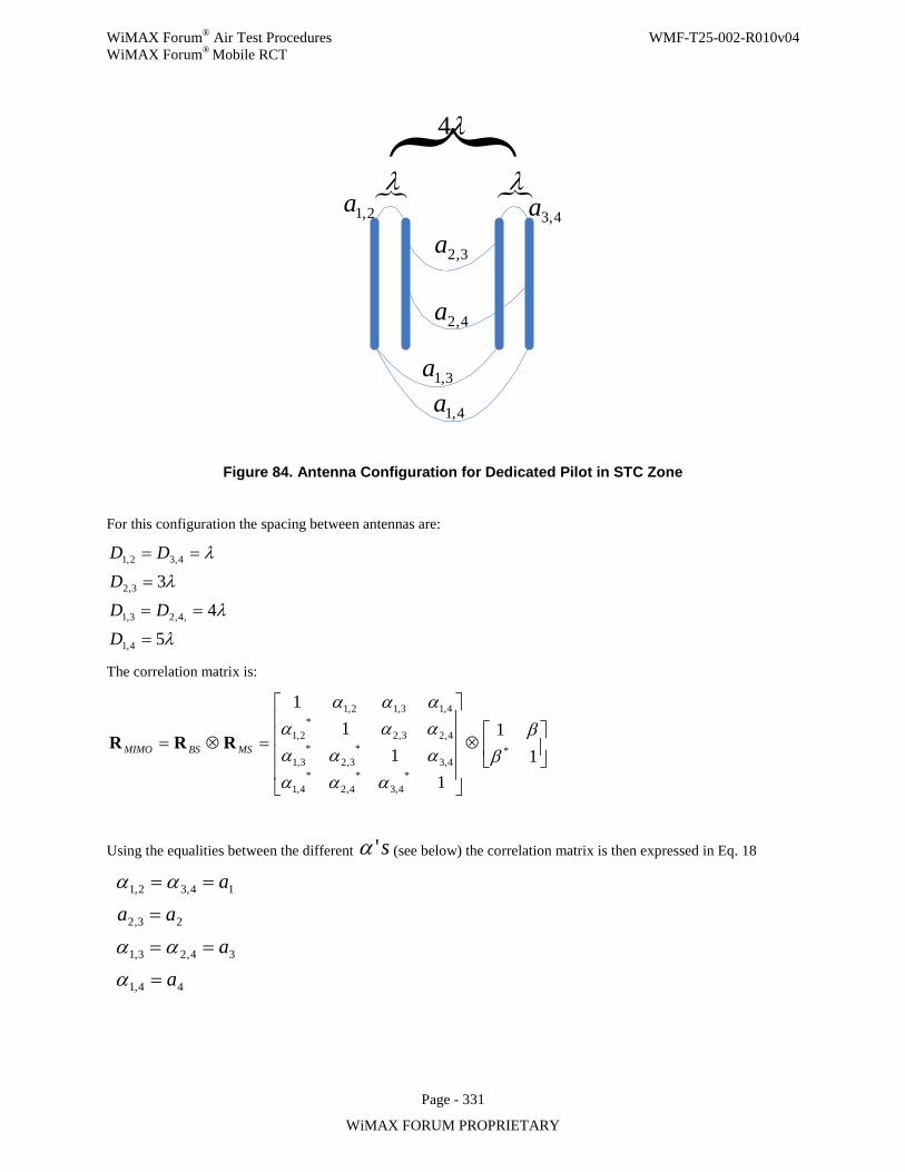
WiMAX Forum® Air Test Procedures WMF-T25-002-R010v04 WiMAX Forum® Mobile RCT
Page - 331
WiMAX FORUM PROPRIETARY
λλ
λ4
3,1a
3,2a
4,1a
4,3a2,1a
4,2a
Figure 84. Antenna Configuration for Dedicated Pilot in STC Zone
For this configuration the spacing between antennas are:
λ
λ
λ
λ
54
3
4,1
,4,23,1
3,2
4,32,1
=
==
=
==
DDD
DDD
The correlation matrix is:
⊗
=⊗=1
1
11
11
*
*4,3
*4,2
*4,1
4,3*
3,2*
3,1
4,23,2*
2,1
4,13,12,1
ββ
αααααααααααα
MSBSMIMO RRR
Using the equalities between the different s'α (see below) the correlation matrix is then expressed in Eq. 18
44,1
34,23,1
23,2
14,32,1
aa
aaa
=
==
=
==
α
αα
αα
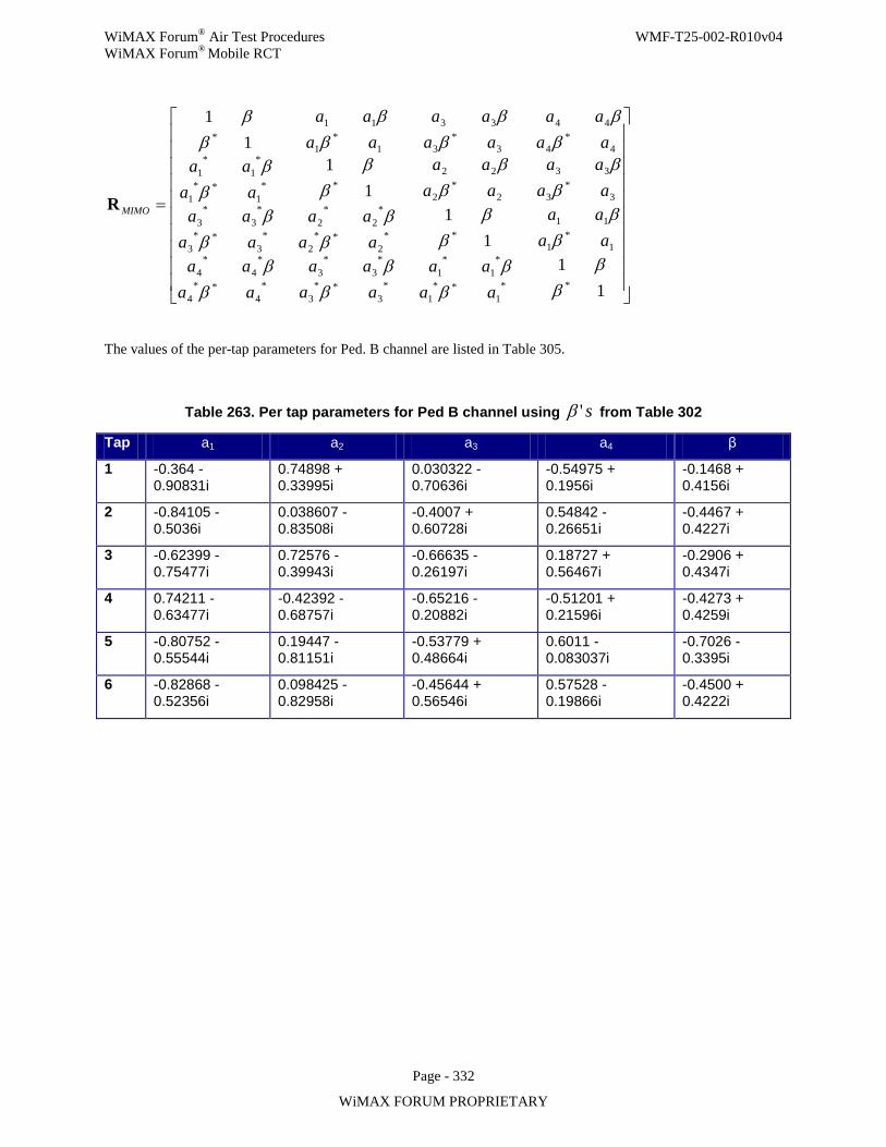
WiMAX Forum® Air Test Procedures WMF-T25-002-R010v04 WiMAX Forum® Mobile RCT
Page - 332
WiMAX FORUM PROPRIETARY
=
11
11
11
11
**1
**1
*1
*1
*3
**3
*3
*3
*4
**4
*4
*4
1*
1
11**
2**
2
*2
*2
*3
**3
*3
*3
3*
3
33
2*
2
22**
1**
1
*1
*1
4*
4
44
3*
3
33
1*
1
11*
ββ
ββ
ββ
ββ
ββ
ββ
ββ
ββ
ββ
ββ
ββ
ββ
ββ
ββ
ββ
ββ
aaaa
aaaa
aaaa
aaaa
aaaa
aaaa
aaaa
aaaa
aaaa
aaaa
aaaa
aaaa
MIMOR
The values of the per-tap parameters for Ped. B channel are listed in Table 305.
Table 263. Per tap parameters for Ped B channel using s'β from Table 302
Tap a1 a2 a3 a4 β
1 -0.364 - 0.90831i
0.74898 + 0.33995i
0.030322 - 0.70636i
-0.54975 + 0.1956i
-0.1468 + 0.4156i
2 -0.84105 - 0.5036i
0.038607 - 0.83508i
-0.4007 + 0.60728i
0.54842 - 0.26651i
-0.4467 + 0.4227i
3 -0.62399 - 0.75477i
0.72576 - 0.39943i
-0.66635 - 0.26197i
0.18727 + 0.56467i
-0.2906 + 0.4347i
4 0.74211 - 0.63477i
-0.42392 - 0.68757i
-0.65216 - 0.20882i
-0.51201 + 0.21596i
-0.4273 + 0.4259i
5 -0.80752 - 0.55544i
0.19447 - 0.81151i
-0.53779 + 0.48664i
0.6011 - 0.083037i
-0.7026 - 0.3395i
6 -0.82868 - 0.52356i
0.098425 - 0.82958i
-0.45644 + 0.56546i
0.57528 - 0.19866i
-0.4500 + 0.4222i
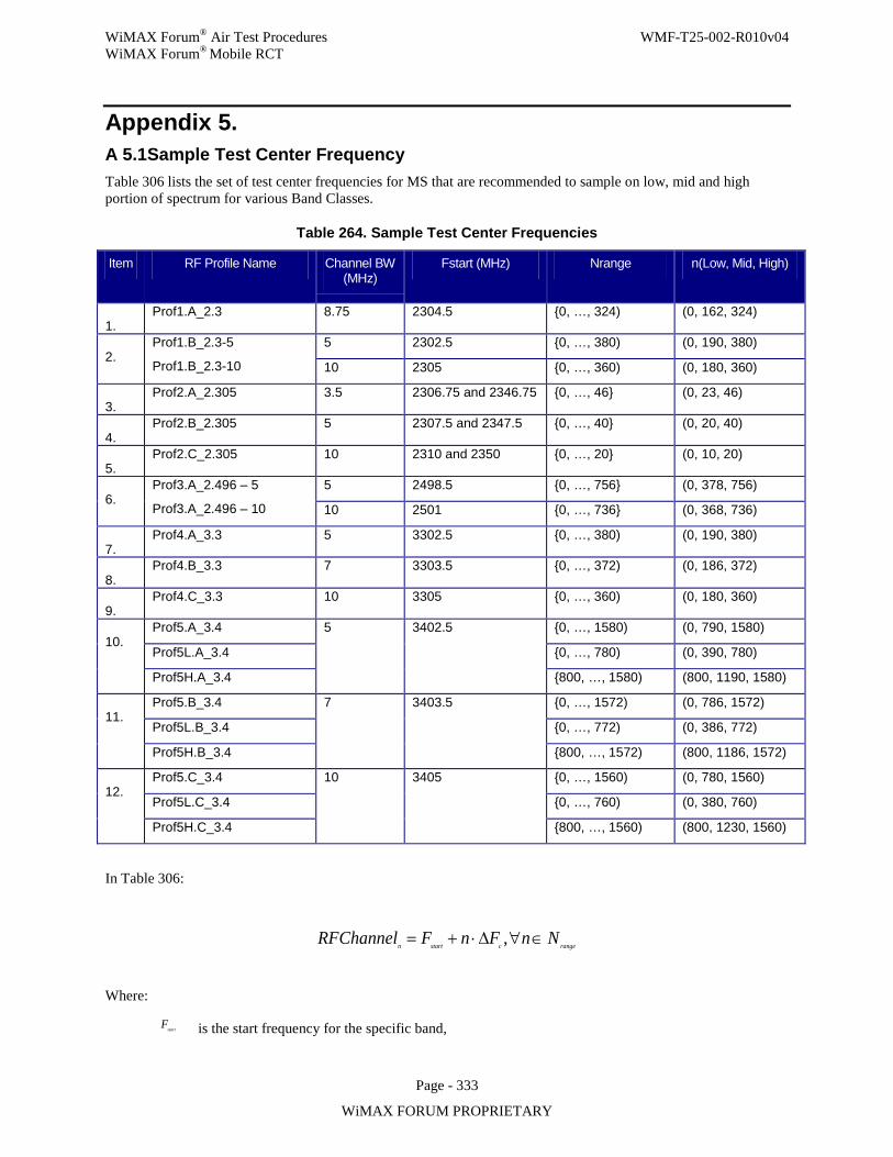
WiMAX Forum® Air Test Procedures WMF-T25-002-R010v04 WiMAX Forum® Mobile RCT
Page - 333
WiMAX FORUM PROPRIETARY
Appendix 5. A 5.1 Sample Test Center Frequency Table 306 lists the set of test center frequencies for MS that are recommended to sample on low, mid and high portion of spectrum for various Band Classes.
Table 264. Sample Test Center Frequencies
Item RF Profile Name Channel BW (MHz)
Fstart (MHz) Nrange n(Low, Mid, High)
1. Prof1.A_2.3 8.75 2304.5 0, …, 324) (0, 162, 324)
2. Prof1.B_2.3-5
Prof1.B_2.3-10
5 2302.5 0, …, 380) (0, 190, 380)
10 2305 0, …, 360) (0, 180, 360)
3. Prof2.A_2.305 3.5 2306.75 and 2346.75 0, …, 46 (0, 23, 46)
4. Prof2.B_2.305 5 2307.5 and 2347.5 0, …, 40 (0, 20, 40)
5. Prof2.C_2.305 10 2310 and 2350 0, …, 20 (0, 10, 20)
6. Prof3.A_2.496 – 5
Prof3.A_2.496 – 10
5 2498.5 0, …, 756 (0, 378, 756)
10 2501 0, …, 736 (0, 368, 736)
7. Prof4.A_3.3 5 3302.5 0, …, 380) (0, 190, 380)
8. Prof4.B_3.3 7 3303.5 0, …, 372) (0, 186, 372)
9. Prof4.C_3.3 10 3305 0, …, 360) (0, 180, 360)
10. Prof5.A_3.4 5 3402.5 0, …, 1580) (0, 790, 1580)
Prof5L.A_3.4 0, …, 780) (0, 390, 780)
Prof5H.A_3.4 800, …, 1580) (800, 1190, 1580)
11. Prof5.B_3.4 7 3403.5 0, …, 1572) (0, 786, 1572)
Prof5L.B_3.4 0, …, 772) (0, 386, 772)
Prof5H.B_3.4 800, …, 1572) (800, 1186, 1572)
12. Prof5.C_3.4 10 3405 0, …, 1560) (0, 780, 1560)
Prof5L.C_3.4 0, …, 760) (0, 380, 760)
Prof5H.C_3.4 800, …, 1560) (800, 1230, 1560)
In Table 306:
rangecstartnNnFnFChannelRF ∈∀∆⋅+= ,
Where:
startF is the start frequency for the specific band,
WiMAX Forum® Air Test Procedures WMF-T25-002-R010v04 WiMAX Forum® Mobile RCT
Page - 334
WiMAX FORUM PROPRIETARY
cF∆ is the center frequency step,
rangeN is the range values for the n parameter
To put back all the RF profile columns from PICS so that the Equations are well defined.
For BS, the low, mid and high center frequencies shall be identified according to the vendor’s declared range and includes the first, last and a center frequency that is at the average of low and high up to a frequency step size of 250 KHz quantization.
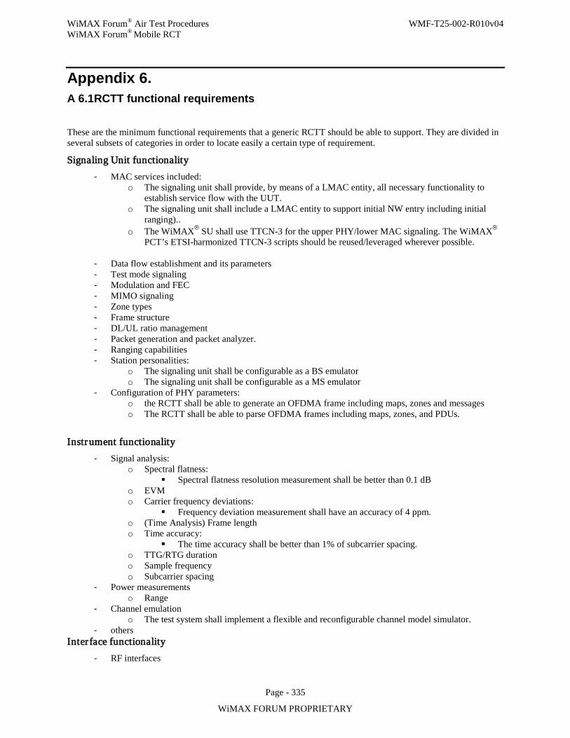
WiMAX Forum® Air Test Procedures WMF-T25-002-R010v04 WiMAX Forum® Mobile RCT
Page - 335
WiMAX FORUM PROPRIETARY
Appendix 6. A 6.1 RCTT functional requirements
These are the minimum functional requirements that a generic RCTT should be able to support. They are divided in several subsets of categories in order to locate easily a certain type of requirement.
Signaling Unit functionality - MAC services included:
o The signaling unit shall provide, by means of a LMAC entity, all necessary functionality to establish service flow with the UUT.
o The signaling unit shall include a LMAC entity to support initial NW entry including initial ranging)..
o The WiMAX® SU shall use TTCN-3 for the upper PHY/lower MAC signaling. The WiMAX® PCT’s ETSI-harmonized TTCN-3 scripts should be reused/leveraged wherever possible.
- Data flow establishment and its parameters - Test mode signaling - Modulation and FEC - MIMO signaling - Zone types - Frame structure - DL/UL ratio management - Packet generation and packet analyzer. - Ranging capabilities - Station personalities:
o The signaling unit shall be configurable as a BS emulator o The signaling unit shall be configurable as a MS emulator
- Configuration of PHY parameters: o the RCTT shall be able to generate an OFDMA frame including maps, zones and messages o The RCTT shall be able to parse OFDMA frames including maps, zones, and PDUs.
Instrument functionality - Signal analysis:
o Spectral flatness: Spectral flatness resolution measurement shall be better than 0.1 dB
o EVM o Carrier frequency deviations:
Frequency deviation measurement shall have an accuracy of 4 ppm. o (Time Analysis) Frame length o Time accuracy:
The time accuracy shall be better than 1% of subcarrier spacing. o TTG/RTG duration o Sample frequency o Subcarrier spacing
- Power measurements o Range
- Channel emulation o The test system shall implement a flexible and reconfigurable channel model simulator.
- others Interface functionality
- RF interfaces
WiMAX Forum® Air Test Procedures WMF-T25-002-R010v04 WiMAX Forum® Mobile RCT
Page - 336
WiMAX FORUM PROPRIETARY
- Sync and trigger signals: o GPIO's (general purpose input/output) shall be used for external control and synchronization of
the RCTT. o
- Log functionality - Connectivity with other external devices
A 6.2 Signaling Unit (BSE) Requirements: • The Signaling Unit (BSE) shall be capable to shift its carrier frequency and sampling frequency (hence the
carrier frequency and sampling frequency) in the range [-2 .. 2] ppm with respect to the nominal value with an accuracy better than 0.1 ppm.
• Unless required otherwise in a test, the Signaling Unit (BSE) shall be compliant with Mobile WiMAX® System Profile and IEEE Std 802.16 and shall behave as expected.
• The Signalling Unit (BSE) shall behave as required for every test. This means that it is required that the SU shall provide the necessary functionality to behave like if it is a compliant implementation with Mobile WiMAX® System Profile and IEEE Std 802.16 and at the same time it shall provide the specific not (necessarily) compliant functionality that it is required by every test.
• The Signalling Unit (BSE) shall be calibrated in power, time and frequency.
WiMAX Forum® Air Test Procedures WMF-T25-002-R010v04 WiMAX Forum® Mobile RCT
Page - 337
WiMAX FORUM PROPRIETARY
Appendix 7. A 7.1 Test Modes TBD