Embed Size (px)
Citation preview

A High Intensity Positron Source Based on a
Superconducting Electron Linac
Terry Grimm, Chase Boulware,
Mayir Mamtimin, James McCarter, Valeriia Starovoitova
Niowave, Inc.
Lansing MI
NP SBIR/STTR Exchange Meeting, Gaithersburg MD
August 2016

Commercial Uses of
Superconducting Electron Linacs
Free Electron Lasers
High
Power
X-Ray
Sources
Radioisotope Production
High
Flux
Neutron
Sources
2

Turnkey Linac Subsystems [1]
3
Cryomodules
Superconducting cavities
in specialized geometries

Turnkey Linac Subsystems [2]
4
Commercial 4 K refrigerators(rugged piston-based systems,
100 W cryogenic capacity)
Industrial Accelerator Controls(Programmable Logic Controllers with
PC interface)
Solid-state and tetrode
RF amplifiers(up to 60 kW)

Project Overview
5
• Applications of high-intensity positron sources
• nuclear physics
• materials science
• Positron Production System Design
• 10 MeV Superconducting RF Electron Linac
• High-power Beam Target Designs
• Positron Capture and Transport Magnets
• Hardware Construction
• Experimental Results with Beam Target

6
Niowave, Inc.
o Terry Grimm, Chase Boulware, Mayir Mamtimin,
James McCarter, and Valeriia Starovoitova
IAC
o Dan Dale and Tony Forest
JLab
o Joe Grames, Matt Poelker, and Mike Spata
LANL
o Stuart Maloy, Eric Olivas, and Keith Woloshun
Project Team

7
Positrons for Nuclear Physics
• Polarized positron collisions are
an important program component
at proposed next-generation
lepton-ion colliders (JLEIC at
JLab and eRHIC at BNL)
• lepton polarization asymmetry in neutral current deep inelastic scattering
• charged current deep inelastic scattering and charm production
• physics beyond the standard model
• Transfer of polarization from a low-energy highly
polarized electron beam has been demonstrated
(PEPPo)

8
Positrons for Non-Destructive
Testing of Materials [1]
e+
Positrons thermalize before annihilation with an
electron, often becoming stuck in lattice defects.

9
Positrons for Non-Destructive
Testing of Materials [2]
e+
γ
γ
Gamma-ray emission from annihilation will come
preferentially from the defect sites, locating them.

10
Positron Production
Conceptual Design
10 MeV, 100 kW
Superconducting Electron
Linac
flowing liquid
metal target
positron-electron
pair production
positron
separation and
capture
solenoid
magnets
flow

10 MeV Accelerator with
Positron Target
Electron Source
– 350 MHz, 100 kV normal-conducting resonant cavity
– integrated, gated thermionic cathode
10 MV superconducting cryomodule
– 3-cell, 350 MHz niobium resonator
– thermal and magnetic shields 11

10 MeV Linac in Tunnel
12
System currently being
commissioned for
sterilization and cargo
scanning demonstrations.

Positrons are created in a two-step
process
• Electrons emit Bremsstrahlung
photons
Positron Conversion Process [1]
13
γ
e-
e-
Bremsstrahlung (braking radiation)
energy depends on:
• incident electron energy
• directness of collision with
target nucleus0 1 2 3 4 5 6 7 8 9 10
photon energy (MeV)
1011
1010
109
ph
oto
n f
lux
(p
er c
m2s
in 1
00
keV
bin
)
10 MeV beam

Positrons are created in a two-step
process
• Electrons emit Bremsstrahlung
photons
• Photons create e+/e- pairs
Positron Conversion Process [2]
γ10 MeV beam
14
e-
e-
e-
e+Pair production happens near a second
target atom to conserve momentum and
energy.

15
Positron System Schematic
LBE Converter
Capture Solenoid
Separation
Dipole
Positron Solenoids
Electron Dump
Positron Target
e-
e-
e+
• The e+ beamline is designed to be dispersion free at positron target location, so
that different energy positrons arrive at the same point
• 0.2 Tesla solenoid collects ~20% of e+ produced at converter
• ~4x10⁻⁴ e+ leave the capture solenoid per incident 10 MeV e- on the converter
Converter Solenoid

16
Liquid Metal Target with
Natural Circulation
• Density differential
between hot and
cold leg drives
flow
• Heat input from
beam goes into hot
leg
• Heat exchanger
removes heat at
reservoir on top
• Lead-bismuth eutectic
– Low melting point: 124°C
– High boiling point: 1670 °C
– Z = 82, 83
~1 m

17
Liquid Metal Target with
Mechanical Pumping
Mechanical pumps can also be used with lead-bismuth eutectic to
increase and control the flow rate.
More flow allows for better cooling of the target, and handling of
more beam power.
Spinning impeller provides
liquid metal flow.
18
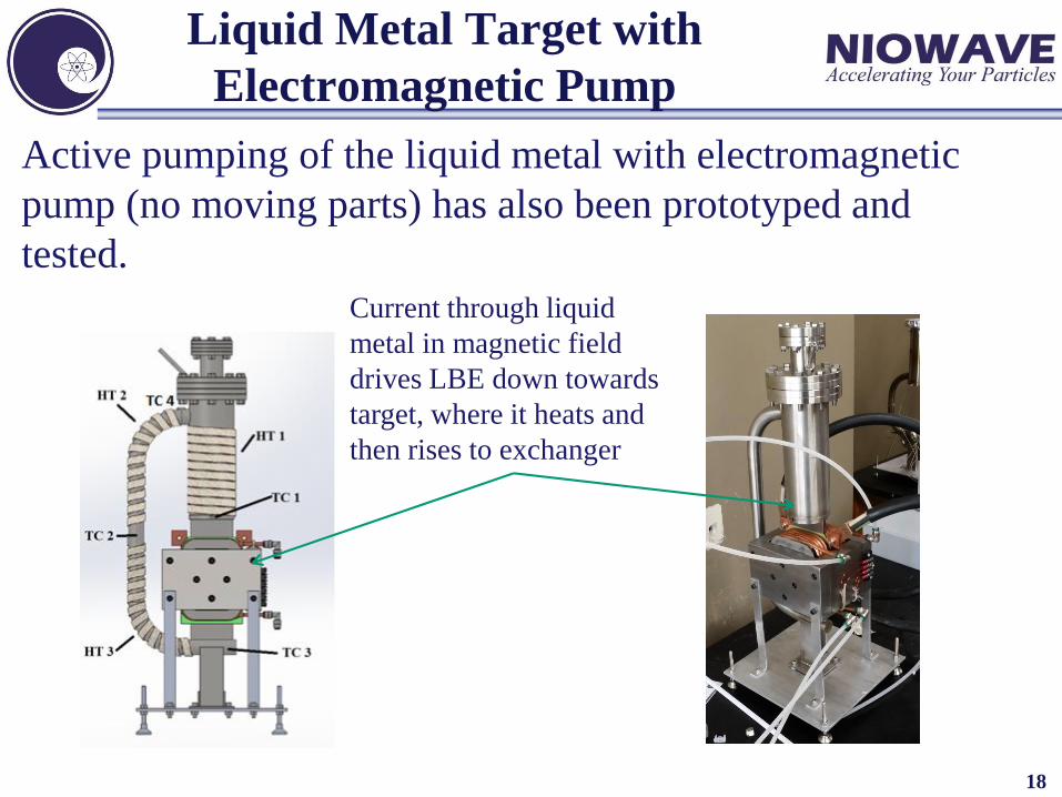
Active pumping of the liquid metal with electromagnetic
pump (no moving parts) has also been prototyped and
tested.
Current through liquid
metal in magnetic field
drives LBE down towards
target, where it heats and
then rises to exchanger
Liquid Metal Target with
Electromagnetic Pump

19
Liquid Metal Target Design
Input electron beam passes through:
• 0.25 mm SS
• 2 mm LBE, chosen for highest rate of production of e+
using 10 MeV e- (~2x10⁻³ e+/e-)
• 0.25 mm SS
Stainless Steel
Thin layer of lead-bismuth eutectic
Input (e-)Output (e-,e+,γ)

Momentum of e+ and e- after
Converter
• Positron and electron momenta distributions
using 10 MeV beam (simulated by IAC)
– Peak of e- at ~7 MeV
– Peak of e+ at ~2 MeV
20

21
System Power Handling
Part Description Percent of Power Deposited
LBE Converter 52 %
Beampipe (water cooled) 27 %
Solenoids (water cooled) 20 %
Leaving System 1 %
Coupled with analysis by LANL, this indicates that the natural circulation
liquid metal converter can handle up to 10 kW of incident beam power.
Total power deposited into various beamline components by e- and
γ as a percent of input beam power of 10 MeV e- beam

22
Radiation Detectors for
Positron Production
Radiation from the beam is monitored at two locations
• ionization chamber along the beam axis
• NaI detector near the target to record annihilation
gammas
Dump
e+ Target
Ionization chamber
NaI detector

23
Positron System Hardware
Liquid Metal
Converter
Capture Solenoid
Separation
Dipole
Positron Solenoids
Electron Dump
Positron Target
Converter
Solenoid

24
Converter-Only Testing
Completed testing a simplified target region, a bare beampipe with
the LBE target
• Temperature along beamline pipe, for power deposition
• Collected current at dump, for e- transmission through LBE
• X-ray detection, for radiation doses
Dump
Target

25
Test Results – Charge Transport
• Used MCNPX to simulate charge transport of electrons through the
liquid metal target to a beam dump with no magnetic focusing
• Two beam tests were run with the accelerator and converter-only
setup, giving reasonable agreement with the simulation
10-3
10-4
10-5
10-6
10-7
2 3 4 5 6
Fra
ctio
n o
f E
lect
rons
Beam Energy (MeV)
Electron transport from to beam dump (after liquid metal target)
Simulation
February Exp
Aug Exp

26
Test Results – Radiation Spectrum
The NaI detector was able to clearly resolve the positron
annihilation peak even without magnetic capture (this
spectrum includes positrons generated all along the beamline).
511 keV

27
Project Summary
• A robust, industrial positron source is needed for
both nuclear physics and materials science
applications
• This SBIR project has developed and built a
positron production system
• 10 MeV superconducting electron accelerator
• high-power liquid metal target
• magnetic capture and separation systems
• Full testing with high-energy beam and positron
detection planned for late 2016