Embed Size (px)
Citation preview
d O(ý,7 A.U.W.E. Tech. Note 636/79661'.3t 0c, CT____________
8~3.385 CopyN.
A Mý-ATHEMATICALM~ODEL' OF WATER ENTRY~~~~)~~~ _ _ _ _ _ _ _ _ _ _ _ _
-00~0
z
ADMIRALTY UNDERWATER WEAPONS ESTABLISHMENT
W PORTLAND
5 BEST AVAILABLE COPY
3CD
~.UKI UNCLASSIFIEID/UNLIMITED,- f
-i . ~ - . . - ~ -- -. ,.~
q"'
UNCLASSIFIED/UNLIMITED (iii)
UDC No 681.3.06: AUWE Technical Note No 636/79532.582.8: October 1979623.565.6
t
A MATHEMATICAL MODEL OF WATER ENTRY. (U/U)
by
A M Mackey
iC9
.--
•,' @® Controller HM4SO London 1979 U2CQASIFIEDULILMITED
(iv) UVCLASSIVIMD/UNLIMITED
CONTENTSPage No
Duplicate Front Cover ... ... ... ... ... W.. ..
(ii) Blank
Title Page ... ... ... ... ... ... ... ... ... (iii)
Contents ... ... ... ... ... (iv)
Distribution (Detachable) ... ... ... ... ... (v)(vi) Blank
SPrercis ... .. ... ... ... . .. ... ... ... 1
Conclusions ... ... ... ... .. .. . ... ... 1
2 Blank
Introduction ... . ... . ... ... 3
The Mathematical Model ... . ......... ... 3-12
The Experimental Measurements ... ... .... 12
Model Validation ... ... ... ... ... ... 12-13
Acknowledgements ....... ... 13
References ... ... 13-14
Appendix: FORTRAN listing of the water entry simulation ... 15-3738 Blank
Document Control Sheet ... ... ... ... ... ... ... 39~40 Blank
Abstract Cards (Detachable) ... ... ... ... ... ... 4i
ILLUSTRATIONS
Figure
1 The phases of water entry.
A typical light weight torpedo.
l'3 A typical air delivery parachute system.
4 hA body segment.
5 The geometry of water entry.
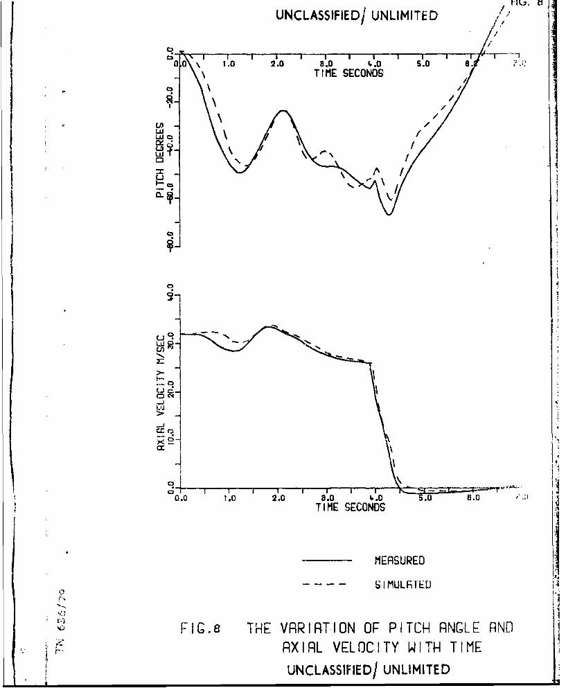
6 The variation of pitch angle and axial velocity with time.
7 I
f I I TI H IT it
UNCLASSIFIED/UNLIMITED
j UNCLASSIFIED/UNLIMITED 1.
A MATHEMATICAL MODEL OF WATER ENTRY. (U/U)
PR5C IS
1. A computer simulation of the water entry of an axisymmetric body with orwithout a cruciform tail and with or without a parachute delivery system isdescribed. The predictions of the simulation are shown to agree with experi-
mental observations of water entry motion. The Fortran program which implementsthis model is listed.A! CONCLUSIONS
2. Over the range of impact velocities (20 to 40 m/sec) which were experi-mentally investigated using a full scale dummy torpedo, the simulation gavereasonable agreement with the measured water entry behaviour. In addition alimited comparison at higher impact velocities indicated that the possibility
of applying the simulation to a wider range of entry velocities was promising.
3. The principal areas in which future work could be carried out are inimproving the model of the splash, the cavity and the interaction of both thebody and the parachute with the cavity flow field particularly at low Froudenumbers.
"Aciotcs on/y_I1%~ibut ic/_____ 02
Sal I and/or, t , 3special
" ~UNCLASSIFIED/UTNLIMITED
UNCLASSIFIED/UNLIMITED 3.
INTRODUCTION.
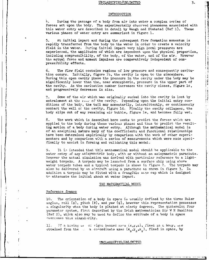
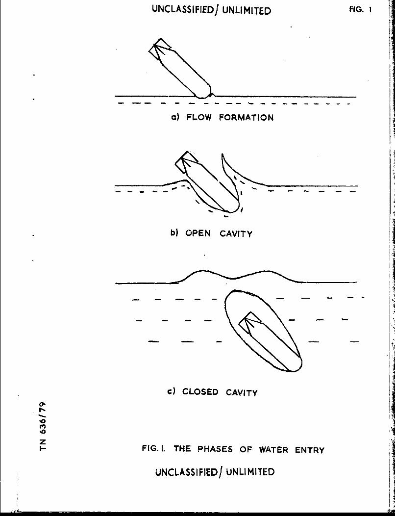
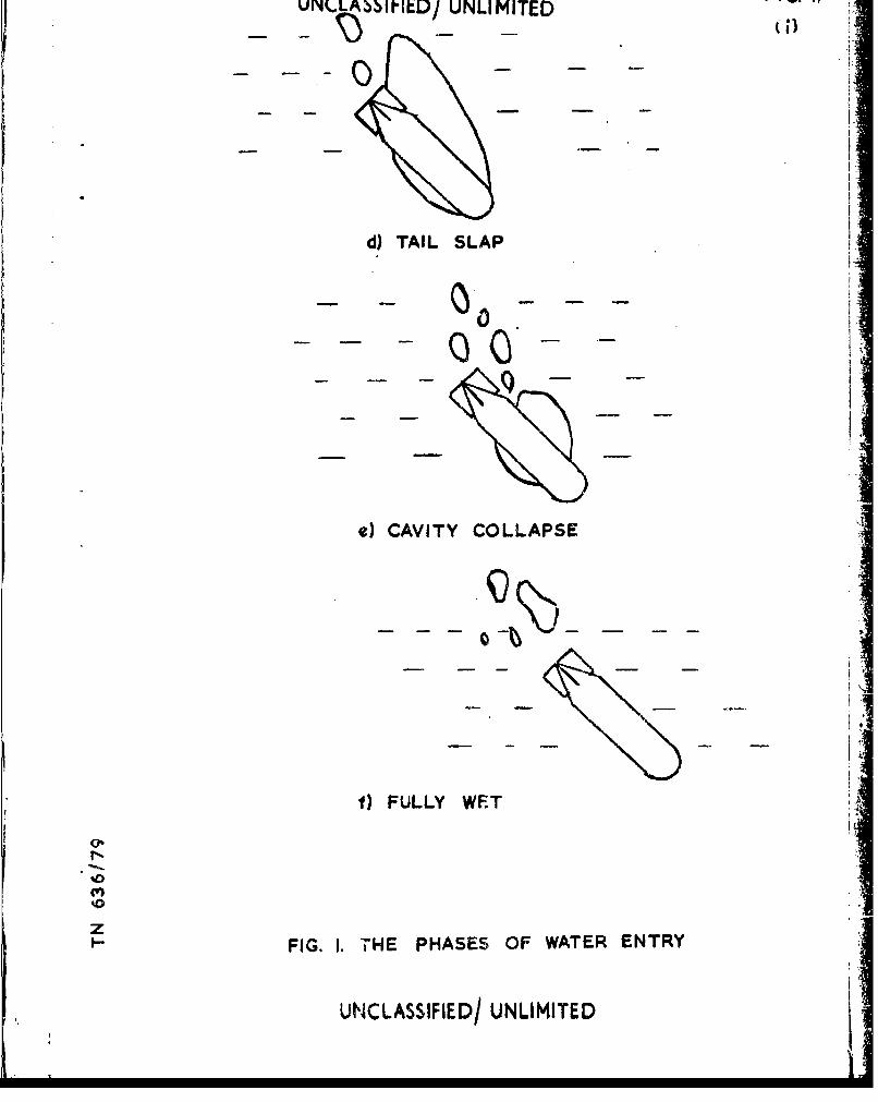
4. During the passage of a body from air into water a complex series offorces act upon the body. The experimentally observed phenomena associated withthis water entry are described in detail by Waugh and Stubstad (Ref 1). Thesevarious phases of water entry are summarised in figure 1.
5. At initial impact and during the subsequent flow formation momentum israpidly transferred from the body to the water in order to create a velocityfield in the water. During initial impact very high local pressures areexperienced, the amplitudes of which are dependent upon the physical properties,
including compressibility, of the body, of the water, and of the air. Howeverthe actual force and moment impulses are comparatively independent of com--pressibility effects.
6. The flow field contains regions of low pressure and consequently cavita-tion occurs. Initially, figure lb, the cavity is open to the atmosphere.During this open cavity phase the pressure in the cavity under the body may besignificantly lower than the, near atmospheric, pressure in the upper part of
the cavity. As the cavitation number increases the cavity closes, figure lc,and progressively decreases in size.
7. Some of the air which was originally sucked into the cavity is lost byentrainment at the rrof the cavity. Depending upon the initial entry con-
ditions of the body, the tail may momentarily, intermittently, or continuouslycontact the wall of the cavity, figure id. Finally the cavity collapses, thebody slips out of any remaining air bubble, figure le, and becomes fully wet. !
8. The work which is described here seeks to predict the forces which areapplied to the body during these various phases and' thus to predict the result-ing motion of a body during water entry. Although the mathematical model isof an analytical nature many of the coefficients and functional relationshipshave been determined empirically by comparison vith the work of other experi-menters and by comparison with a series of measurements which were made speci-fically to assist in forming and validating this model.
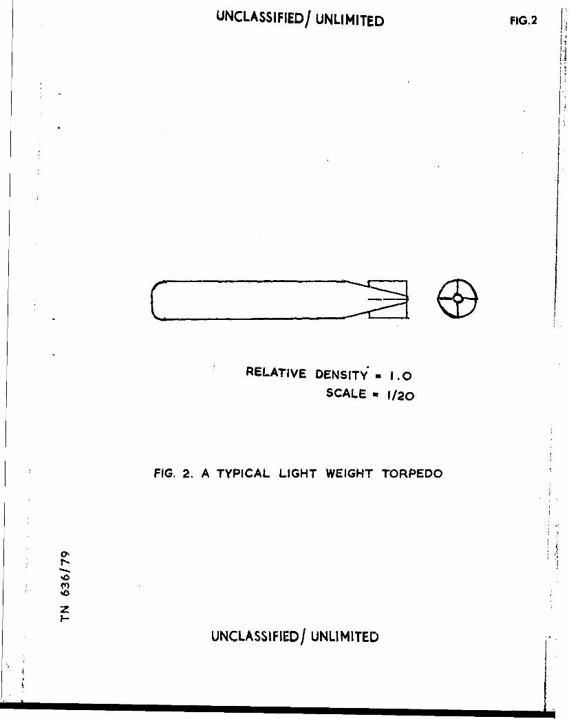
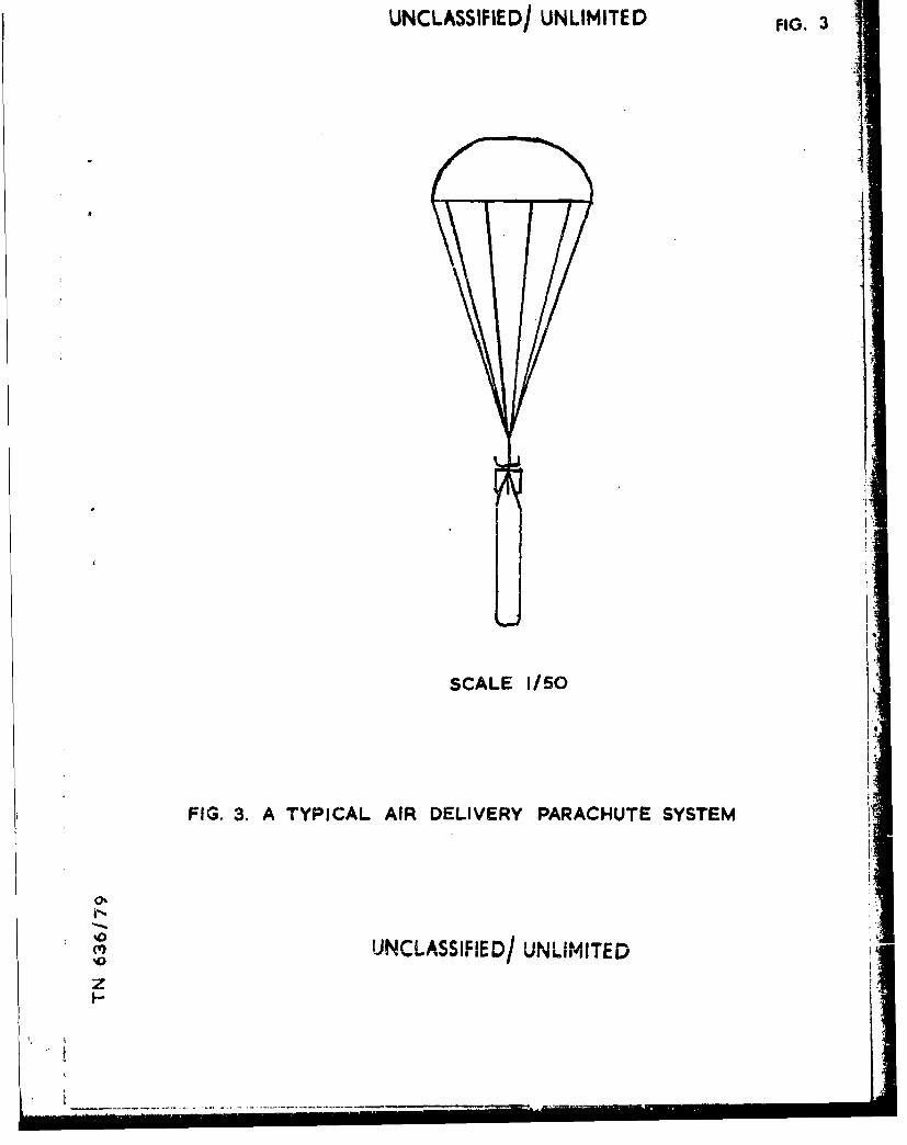
9. It is intended that this mathematical model should be applicable to thewater entry of any axisymmetric body, with or without an axisymmetric parachute.However the actual simulation was derived with particular reference to a light-weight torpedo. A torpedo may be launched from a surface ship using abovewater torpedo tubes and a typical torpedo is shown in figure 2. The torpedo mayalso be delivered by an aircraft using a parachute as shown in figure 3. Inaddition a torpedo may be fitted with a frangible ncse cap which is designedtn attenuate the initial shock at water impact.
THE MATHEMATICAL MODEL
Reference frames
10. The orientation of a body in space is usually defined by the three Eulerangles, roll (4), pitch (e), and yaw (i), however this representation possessesa singularity when the body is pitched at ninety degrees. The quaternion fourparameter system, first described by the Irish mathematician Sir W B Hamilton(Ref 2), which also may be used to define the attitude of a body in spacenvercomes this singularity.
11. Tf a moving ze or rigut handed axes (x,y,z), fixed in a boay, ýieobtained from the m co-ordinate axes (xsysxs), fixed in space, by
UNCLASSIFIED/UNLIMITED
4. UNCLASSIFIED/UNLIMITED
rotating the space frame of reference through the angle p about the unitvector (ass6,Ys) then the quaternion parameters, e, describing the orienta-
tion of the body axes relative to the space axes are defined as:-
e = cos520 2
el ysiinin i
e sin2 - s 2
eC - CCs 2n -2 (1) 2
e3 Ys sin n
It Pay be seen that :-
Ze =1 (2)
I pa terms of the three Euler angles the quaternion pa-ameters are given
+e C i OS e 32 Ce e--2e e se sin +ie2 2 2 2 2
e 0 1 Cos sin 2 ½in2 2 2 2
2 Li 2 2
Iz3(3)
S Tie t,":.- rxnrat ion matrix, Thich relates the body fr f reference toLg,• pac c ora of reýfeorenc e, i s:
_ 2 ;e2- e_e 2 2ele2_ 2eoe3 2e e +2ee0o~l e 2 3-e2 03 o 2 1 3
31 -, +o. 220e12+e2_3 2 1
•e~eo •..].2 2_ 2e3 2eol 24
2c .e_.-2e eO 2eoel+2e e3 e e el 2+e 3
1)4 1'hct(, rmino.logy.
L Y z _
UNCLASSIFIED/UNLIMITED 5.
will be used for convenience. In the space frame of reference the unit vectorX is the body x axis, the unit vector Y is the body y axis and the unit vectorZ is the body z axis.
The equations of motion
15. The origin of the body fixed axes is chosen so that the x axis is the axisof symmetry of the body and so that the co-ordinates of the position of the
centre of gravity are (O,yg,zg). If the body, of mass m, axial moment ofinertia Ix and transverse moment of inertia ly, is moving with linear velocity(u,v,w) and angular velocity (p,q,r) under the influence of external forces
(Fx,Fy,Fz) and moments (Lx,Ly,Lz) in a gravitational field g then the equationsof motion are:-
m + -r + wq + yg(pq - 1) + zg(pr +4)- gX 3 ) =
m ( - + ur - yg(r 2 + p2) + zg(qr - 3 gY3 ) -
m uq + (e + yg(rq + ) - Zg(P2 + q2) gZ 3 ) = F7 (6)
+ m * uq + vp~ - zg(4ý - wp+ ur) + g(zgY 3 g3 =y + (Ix - Iy) rp + m zg (=L vr + wq - gX3 = Ly
Izf + (Iy - Ix) pq + m yg (vr A - wq + gX3) = Lz
The geometry of water entry
16. In order to predict the external forces and moments applied to the bodyit is first necessary to determine which parts of the body are in contact withwater.
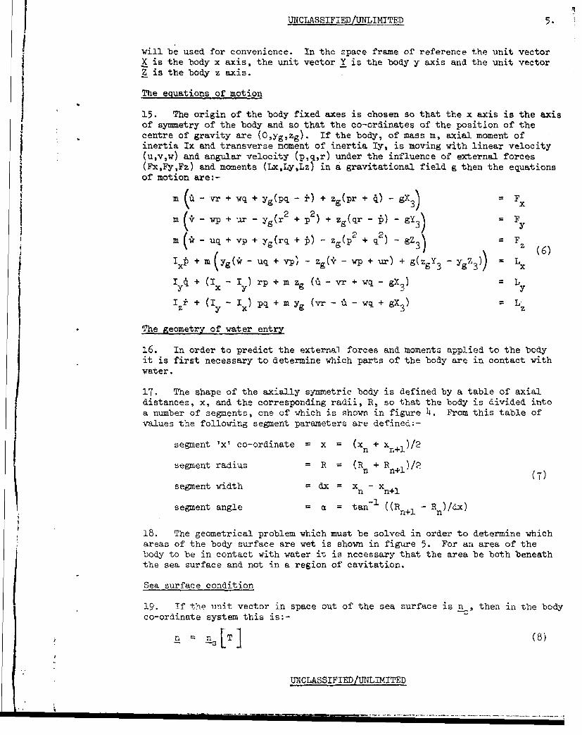
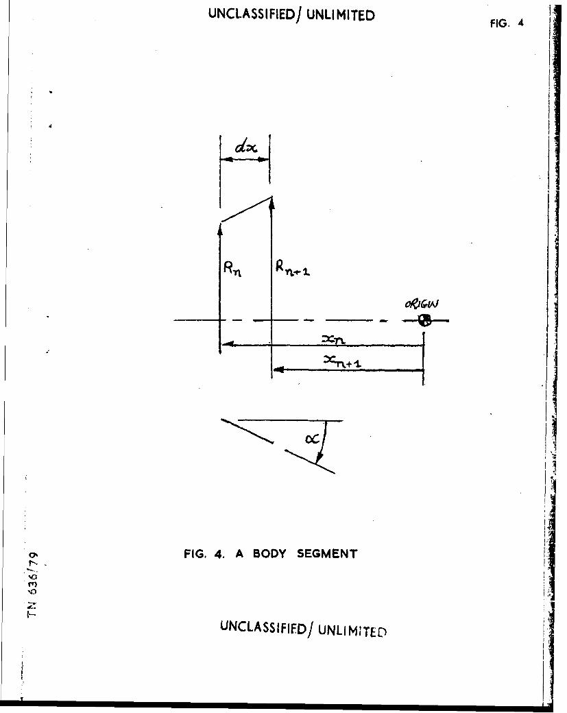
17. The shape of the axially symmetric body is defined by a table of axialdistances, x, and the corresponding radii, R, so that the body is divided intoa number of segments, one of which is shown in figure h. From this table ofvalues the following segment parameters are defined:-
segment 'x' co-ordinate = x = (xn + xn+l)/2
segment radius = R = (Rn + R n+l)/?n n+2.(7)
segment width = dx = xn - xn+1
segment angle a = tan-' ((R - R )/dx)n+l n
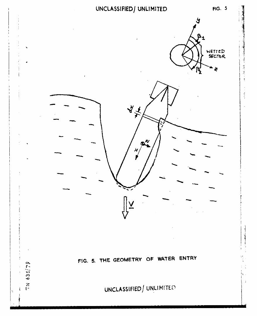
18. The geometrical problem which must be solved in order to determine whichareas of the body surface are wet is shown in figure 5. For an area of thebody to be in contact with water it is necessary that the area be both beneaththe sea surface and not in a region of cavitation.
Sea surface condition
19. Tf the unit vector in space out of the sea surface is n , then in the body
co-ordinate system this is;-
UNCLASSIFIED/UNLIMITED
J 6. UNCLASSIFIED/UNLIMITED
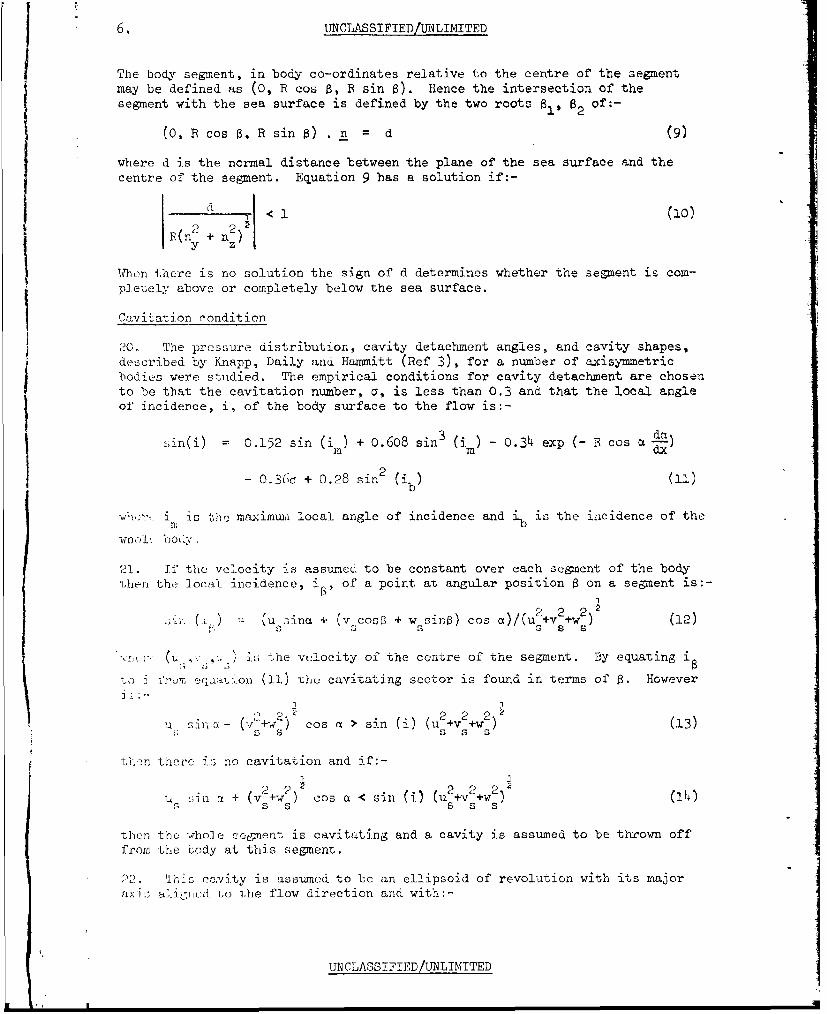
The body segment, in body co-ordinates relative to the centre of the segmentmay be defined as (0, R cos 8, R sin 8). Hence the intersection of thesegment with the sea surface is defined by the two roots 81, 82 of:-
(0, R cos 8, R sin s) . n = d (9)
where d is the normal distance between the plane of the sea surface and thecentre of the segment. Equation 9 has a solution if:-
ga2 j< 1 (10)12 R(n y+ nZ)
IWhen there is no solution the sign of d determines whether the segment is com-pletely above or completely below the sea surface.
Cavitation condition
20. The pressure distribution, cavity detachment angles, and cavity shapes,
described by Knapp, Daily and Hammitt (Ref 3), for a number of axisymmetricbodies were studied. The empirical conditions for cavity detachment are chosento be that the cavitation number, a, is less than 0.3 and that the local angleof incidence, i, of the body surface to the flow is:-
sin(i) = 0.152 sin (i ) + 0.608 sin3 (is) - 0.34 exp (- R cos akdM m dx
- 0.36a + 0.28 sin2 (4 ) (I-,)
WCi*e is 0 the maximun local angle of incidence and ib is the incidence of the
21. If the velocity is assumed to be constant over each segment of the bodyithen the local incidence, i, of a point at angular position 8 on a segment is:-0',
(•i. . u.ina + (vcosoý + w sin•) Cos a)/(u¼+v2 +w22 (12)S S sS s
E.hf(U ,v-*.< is the velocity of the centre of the segment. By equating i
to I.., eqeaation (11) the cavitating sector is found in terms of 0. HoweverJ I
U Sin sa- ( 2)cos a > sin (i) (u 2 +v2 +w2 ) (13)
then there is no cavitation and if:-
U3 sin a + (v 2-+w) Cos a < sin W) (u2+2+wV 21)+)s s s s s
trhen the whole sotenent is eavitating and a cavity is assumed to be thrown offfrom the Lody at this segment.
22. This ca1vity is assumed to be an ellipsoid of revolution with its majoraxi-s aligned to the flow direction and with:-
UNCLASSIFIED/UNLIMITED
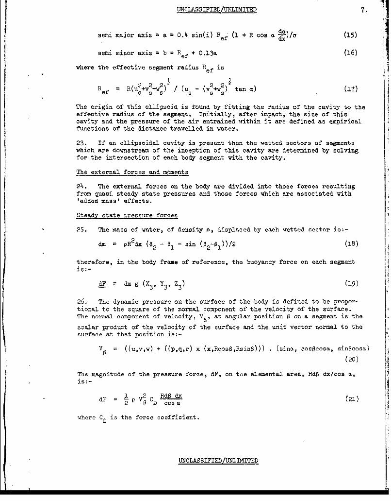
UNCLASSIFIED/UNLIMITED 7. 1semi major axis = a 0 O.4 sin(i)Re% (1 + R cos c 1)/a (15)
ef dx:
semi minor axis = b = Ref + 0.13a (16)
where the effective segment radius R is
2 u2+vw2 2Ref = R(u s +vwS) I(us- (v2 +w2) s tan a) (17)
The origin of this ellipsoid is found by fitting the radius of the cavity to theeffective radius of the segment. Initially, after impact, the size of thiscavity and the pressure of the air entrained within it are defined as empiricalfunctions of the distance travelled in water.
23. If an ellipsoidal cavity is present then the wetted sectors of segmentswhich are downstream of the inception of this cavity are determined by solvingfor the intersection of each body segment with the cavity.
The external forces and moments
24. The external forces on the body are divided into those forces resultingfrom quasi steady state pressures and those forces which are associated with'added mass' effects.
Steady state .ress'ire forces
25. The mass of water, of density p, displaced by each wetted sector is:-
dm = pR2 dx ( - S1 - sin (a2-B1))/2 (18)
therefore, in the body frame of reference, the buoyancy force on each segmentis:-
dF = dm g (X, Y3' Z3) (19)
26. The dynamic pressure on the surface of the body is defined to be propor-tional to the square of the normal component of the velocity of the surface.The normal component of velocity, V,, at angular position 8 on a segment is the
scalar product of the velocity of the surface and the unit vector normal to thesurface at that position ie:-
V = ((u,v,w) + ((p,q,r) x (x,RcosS,Rsin8))) . (sina, cosacosa, sin~cosa)
(20)
The magnitude of the pressure force, dF, on tae elemental area, RdB dx/cos a,
is:-
dF = ) 2 RdSd (21)2 a VCD Cosa
whcr Ci s the force coefficient.•D
UNCLASSIFIED/UNLIMITED
8. UiNCLASSIFIED/UNLIMITED
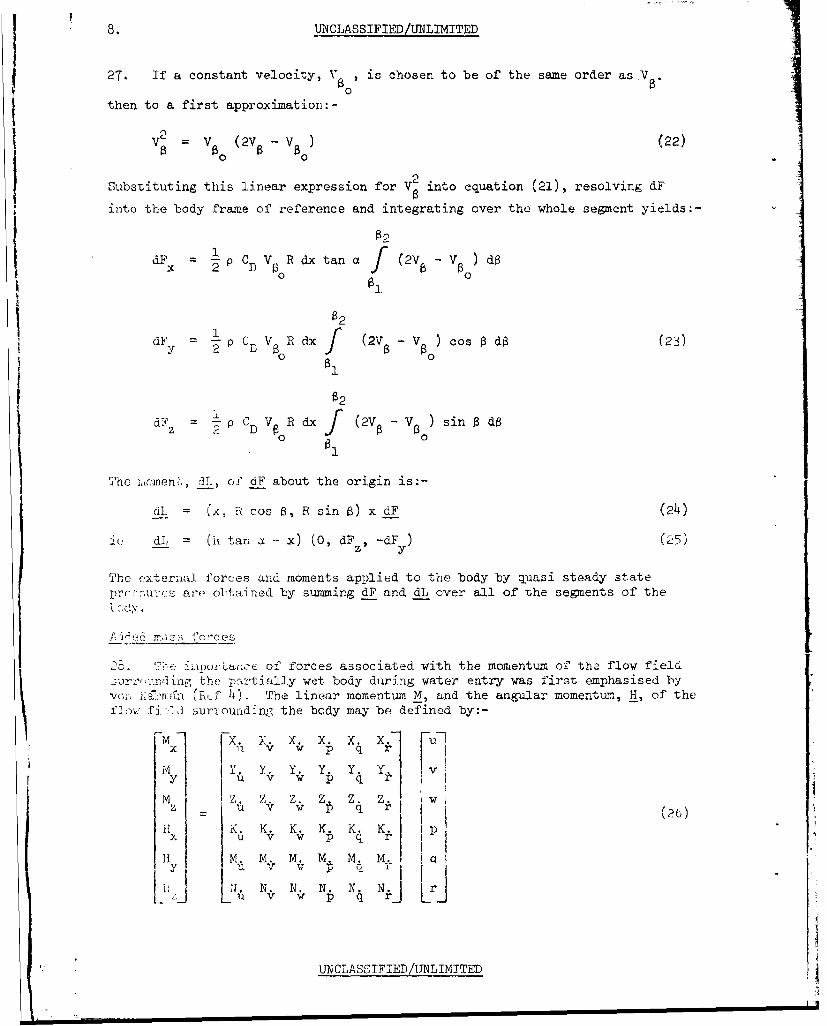
27. If a constant velocity, V, is chosen to be of the same order as V
then to a first approximation:-I 2
V V0 (2V8 ) ao22)
Substituting this linear expression for V into equation (21), resolving d
into the body frame of reference and integrating over the whole segment yields:-
82
dFx -2p CD VR dx tan a (2V V dB
$2I 6I18
a2
dFz p C V R dx (2V 8 - ) sin d8
The iaomeni, jL, of dF about the origin is:-
dL (x, R cos 8, R sin B) x dF (24)
Jt: dL (Ox tan a - x) (0, dFz, -dF ) (25)
The external forces and moments applied to the body by quasi steady statepc:2:",- s aro obtained by summing dP and dL over all of the segments of the
1 -i rr~mc' of forces associated with the momentum of the flow field. 1rr-,unng the partially wet body during water entry was first emphasised byV i: .Zmran (h~f 4). The linear momentum M, and the angular momentum, H, of theflow fi -1i surrounding the body may be defined by:-
- X. X. x. x. x. X. ui Y. Y, Y. Y . Y. Y Iy 11 v w q
= v W p q r 1 (26)ji K. K. K. K. K. K.i Ip
x u v W p q r
1. N. N. N. N. N_ S_ W p :J _ _L
UNCLASSTFIED/[mLIMTTED
UNCLASSIFIEDjjUNIMITED 9.
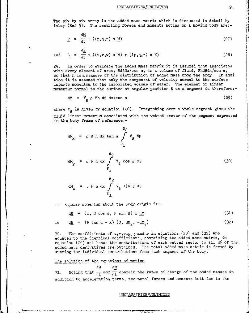
The six by six array is the added mass matrix which is discussed in detail byImlay (Ref 5). The resulting forces and moments acting on a moving body are:-
dMF = - + ((p,q,r) xM) (27)
dHand L = t- + ((u,v,w) x M) + ((p,q,r) x H) (28)
29. in order to evaluate the added mass matrix it is assumed that associatedwith every element of area, Rdgdx/cos a, is a volume of fluid, Rhd~dx/cos a,so that h is ameasure of the distribution of added mass upon the body. In addi-tion it is assumed that only the component of velocity normal to the surfaceimparts momentum to the associated volume of water. The element of linearmomentum normal to the surface at angular position 8 on a segment is therefore:-
dM = V p Rh d$ dx/cos a (29)
where V is given by equatio-. (20). Integrating over a whole segment gives the
fluid linear momentum associated with the wetted sector of the segment expressedin the body frame of reference:-
02
dM p R h dx tan a f V8 d$
81
a2
dM =p R h dx f V acos do (30)Y
02
dMz p R h dx Va sin 8 do
%,ngular momentum about the body origin is:-
dH = %x, R cos 0, R sin $) x dM (31)
ie dH = (R tan a - x) (0, dM , -dMy) (32)
30. The coefficients of u,v,w,p.; and r in equations (30) and (32) areequated to the identical coefficients, comprising the added mass matrix, inequation (26) and hence the contributions of each wetted sector to all 36 of theadded mass derivatives are obtained. The total added mass matrix is formed bysumming the individual cont2ibutions from each segment of the body.
The solution of the equations of motion
31. Noting that T and--t contain the rates of change of the added masses in
addition to acceleration terms, the total forces and moments both due to the
UNCLASSIFIED/UNLIMITED
.................L ...........
10. UNCLASSIFIED/UTMITED
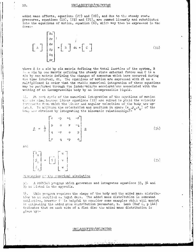
added mass effects, equations (27) and (28), and due to thm steady statepressures, equations (19), (23) and (25), are summed linearly and substitutedinto the equations of motion, equation (6), which may then be expressed in theformi: -
du
dv
LA] dP t L ] (33)dq
Ldr
where A is a six by six matrix defining the total inertias of the system, Ba Six by one matrix defining the steady state external forces and C is a
six by one matrix defining the changes of momentum which have occurred duringthe time interval, dt. The equations of motion are expressed with dt as a
multiplicand in numerical integration of these equations
may oc performed through the indetc'minate accelerations associated with thewetting of an incompressible body by an incompressible liquid.
At ealh cycle of the numerical integration of the equations of moTdionttlinear equations (33) are solved to yielId the v "locity
Tc~.½,!enta fom which the <-in-ar and angular velocities of the body are up-
>...t•.. I-n aJdition The orientation and position in space (x ,y oz) of theoc, are obta ined by integrating the kinematic relationships:-
Fo -P -q -r]
14j2L P Ei r q
' 2 1 e
-- q . - r 0 P -
r q -p 0
I'-o
LW L . 5L I
D csi-on r-,'te-..eia s-imualation
3;. A 'OCTRAi progrrrn which generates and integrates equations 33, 34 and3ý5 i; listed in the appendix,
S1i. This p;'ogram require3 the shape of the body and the added mass distribu-
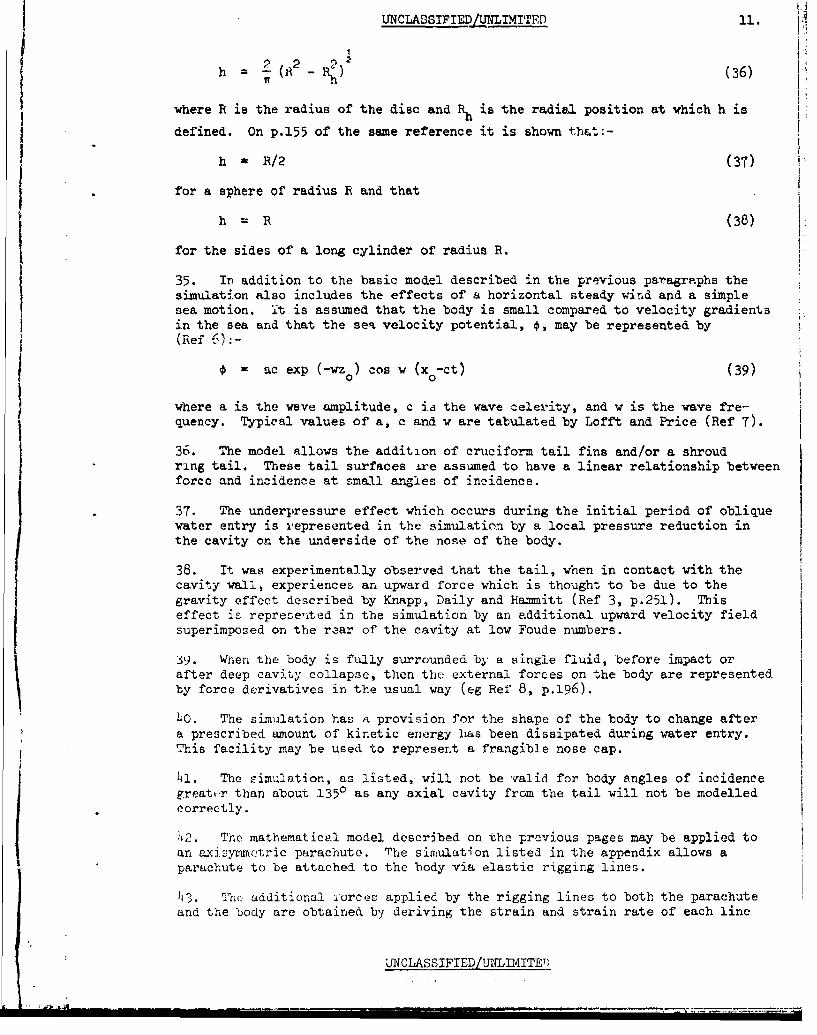
tior, to Lc supplied ab input data. The added mass distribution is somewhatsuuoct ive, however i- is helpful to consider some examples "hich will assistin c2ý,i~mating the added mnss nistribution parameter, h. Lamb (Ref 6, p !44)indicates that on each side of a flat disc the added mass distribution isgiven by:-
D-N CLASSIFIED/UNLIMITED
UNCLASSIFIEDLUNLIMITED 11.
"2 R2 R22iih it - (36)
where R is the radius of the disc and Rh is the radial position at which h is
defined. On p.155 of the same reference it is shown that:-
a R/2 (37)
for a sphere of radius R and that
h = R (38)
for the sides of a long cylinder of radius R.
35. In addition to the basic model described in the previous paragraphs thesimulation also includes the effects of a horizontal steady wind and a simplesea motion. it is assumed that the body is small compared to velocity gradientsin the sea and that the sea velocity potential, 4, may be represented by(Ref 6);-
ac exp (-wzo) cos W (xo-ct) (39)
where a is the wave amplitude, c is the wave celerity, and w is the wave fre-quency. Typical values of a, c and v are tabulated by Lofft and Price (Ref 7).
36. The model allows the addition of cruciform tail fins and/or a shroudring tail. These tail surfaces ire assumed to have a linear relationship betweenforce and incidence at small angles of incidence.
37. The underpressure effect which occurs during the initial period of obliquewater entry is represented in the simulation by a local pressure reduction inthe cavity on the underside of the nose of the body.
38. It was experimentally observed that the tail, when in contact with thecavity wall, experiences an upward force which is thought to be due to thegravity effect described by Knapp, Daily and Hammitt (Ref 3, p.251). Thiseffect is represe'xted in the simulation by an additional upward velocity fieldsuperimposed on the rear of the cavity at low Foude numbers.
39. When the body is fully surrounded by a single fluid, before impact orafter deep cavity collapse, then the external forces on the body are representedby force derivatives in the usual way (eg Ref 8, p.196 ).
4O. The simulation has a provision for the shape of the body to change aftera prescribed amount of kinetic energy has been dissipated during water entry.This facility may be used to represent a frangible nose cap.
41. The simulation, as listed, will not be valid for body angles of incidencegreate.r than about 1350 as any axial cavity from the tail will not be modelledcorrectly.
42. The mathematical model described on the previous pages may be applied toan axisymmotric parachute. The simulation listed in the appendix allows aparachute to be attached to the body via elastic rigging lines.
43. oho additional rorces applied by the rigging lines to both the parachuteand the body are obtained by deriving the strain and strain rate of each line
UNCLASSIFIED/UNLIM4ITEB
12. UNCLASSIFIED/UNLIMITED
from the known position and velocity of the body relative to the parachute.The equations of motion of the body and of the parachute are then evaluatedindependently.
44. In the previous paragraphs the principles of the water entry simulationwere described. The reader who wishes to explore the detailed implementationof these principles may do 3o by studying the appendix.
THE EXPERIMENTAL MEASUREMENTS
45. The difficulties associated with scaling water entry behaviour are dis-cussed by Knapp, Daily and Hammitt (Ref 3, p.5 4 8 ). In view of the manyuncertainties associated with extrapolating small scale model measurementsup to full, scale the experimental measurements required to improve and vali-date the mathematical model were carried out at full scale.
46. An instrumentation system, designed to record the motion of the body
and described by Coman (Ref 9), was fully contained within the dummy torpedoand comprised, three rate gyroscopes to measure the angular velocity vector,three accelerometers to measure the linear acceleration vector, and a solidstate digital recorder. The trajectory of the body was obtained by integratingthe recorded angular velocity and linear acceleration as described by Coman(Ref 10). The sensor signals were also recorded for a ten second period
before release and this data was filtered to provide the attitude of the bodyat release for the initial conditions of the attitude integration. Theinitial conditions for the velocity integration were measured optically.
4r. In order to isolate the influence of the parachute and determine thecharacteristics of the body alone the first set of measurements were carriedout by projecting the dunmy torpedo alone,without any parachute, into the sea.A second series of measurements were then made with parachutes, the torpedoand parachute'being released from a helicopter. It was interesting to notethat by commencing with the buoyant dummy torpedo, assumed stationary, on thesea surface at the end of a drop and then integrating the measured motion back-wards through water entry and through the flight in air it was possible todetermine the velocity of the delivery aircraft and that this value agreedwithin 1 m/sec with the optically measured aircraft velocity.
MODEL VALIDATION
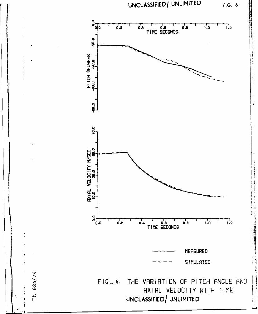
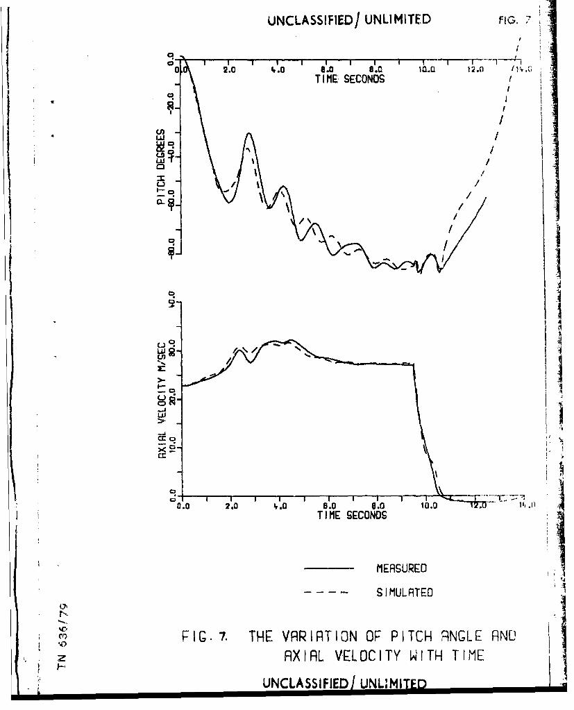
46.Some typical results of the experimental measurements along with theprocictions of the simulation are shown in figures 6, 7 and 8. The body'srditch angle, 6, in degrees and axial component of velocity, u, in metres perzecond are both plotted against time in these figures.
49. Figure 6 shows the water entry behaviour of the bare torpedo projectedinto a calm sea at approximately 30 m/sec, at a trajectory angle of 200 belowthe horizontal, and with zero incidence to this trajectory. Water impactoccurs at approximately 0.3 seconds and during the initial phases of waterentry a nose down rate of turn is imparted to the body by the reduced pressureregion under the nose. At approximately 0.6 seconds the tail hits the top ofthe cavity, in this region the simulation diverges a little from the measure-ments however this particular tail slapping behaviour was found to be notexperimentally repeatable in detail.
50. In the drops described in figures 7 and 8 the torpedo was fitted with aparachute. In figure 7 a conical ribbon parachute of approximately 2 metresflying diameter fitted with 7.0 metres long rigging lines was employed, the
UNCLASSIFIED/UNLIMITED
UNCLASSIFIED/UNLIMITED 13.
torpedo was released at a height of 225 metres above sea level, water impactoccurred approximately 9.5 seconds after release, and the pitch angle at impactis almost vertical. In figure 8 a ringshot parachute of 2 metres flying dia-meter fitted with 3.5 metres long rigging lines was used, the torpedo wasreleased at a height of 60 metres, water impact occurred approximately 4 secondsafter release and the pitch angle at impact is about 55 degrees,
51. In figures 7 and 8 and, indeed, in all of the parachute drops which weremade it was found that the simulation predicted higher frequencies of oscilla-tion of the body in air then were observed. It was not possible to offer asatisfactory explanation for this inaccuracy of the simulation.
52. All of the measurements which were carried out in support of the mathe-matical model described in this note were at impact velocities of between 20and 40 m/sec, however a limited amount of work was carried out to compare thesimulation with the 150 m/sec entry velocity full scale measurements describedby Waugh and Stubstad (Ref 1, chap 5). At this higher impact velocity it isto be expected that the influence of the underpressure effect will be reduced.Head shapes 'a', 'g', 'I' and 'n' were simulated and good agreement with thewater entry whip (Ref 1, fig 5.9) and with the zero cavitation number dragcoefficient (Ref 1, fig 5.11) were obtained indicating that this simulation maybe applicable to a wide range of impact velocities.
ACKNOWLEDGEMENTS
53. Grateful acknowledgement is made to the staff of AUWE, Helston, and ofAMTE, Glen Fruin, who assisted in carrying out the measurements.
REFERENCES
Reference
1. J G Waugh and G W Stubstad. "Hydroballistics Modeling"Naval Undersea Centre, San Diego, California.
2. Sir W R Hamilton. "Elements of Quaternions"Longmans, Green and Co, London.
3. R T Knapp, J W Daily and F G Hamxitt. "Cavitation"McGraw-Hill, New York. I'
4. T von Karman. "The impact on seaplane floats during landing"NACA Tech Note 321 (1929).
5. F H Imlay. "The complete expressions for 'added mass' of a rigid bodymoving in an ideal fluid" •
DTMB Report No 1528 (1961).
6. Sir H Lamb. "Hydrodynamics"Sixth edition, Cambridge University Press.
7. R F Lofft and W G Price. "Ocean wave statistics frequency of occurrence
of sea states"AEW Technical Memo No 19/73.
8. F S Burt. "New contributions to hydroballistics"Advances in Hydroscience Vol 1 - 1964, Academic Press, New York.
UNCLASSTFIED/UNLIMTTED
14. UNCLASSIFIED/UNLIMI2ED
Rerfronce
9. A Coman. "A description .,)f a robust digital recording system"AUWE Tech Note 584/78.
10. A Coman. "Missile trajectory reconstruction using internalinstrumentation"AUWE Tech Note 468/72.
.- -- .. . • - ' b':O T l'. ,
O R ' .C.' , ; ... . G I -Ai ,ISA 7I1(0N S
.fCSTTDT]M' T
APPENDIX 15. zj
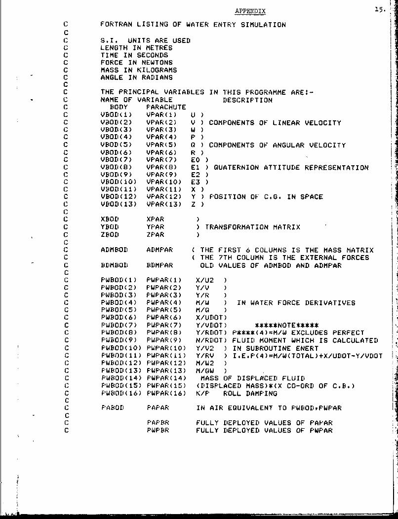
(2 FORTRAN LISTING OF WATER ENTRY SIMULATIONCC.1 S.I. UNITS ARE USED
C LENGTH IN METRESC TIME IN SECONDSC FORCE IN NEWTONS
C MASS IN KILOGRAMSC ANGLE IN RADIANSCC THE PRINCIPAL VARIABLES IN THIS PROGRAMME ARE:-C NAME OF VARIABLE DESCRIPTIONC BODY PARACHUTEC VBOD(1) VPAR(1) U )C VBOD(2) VPAR(2) V ) COMPONENTS OF LINEAR VELOCITYC VBOD(3) VPAR(3) W )C VBOD(4) VPAR(4) P )C VBOD(5) VPAR(5) 0 ) COMPONENTS OF ANGULAR VELOCITYC VBOD(6) VFAR(6) R )C VBOD(7) VPAR(7) EO )C VBOD(8) VPAR(8) El ) QUATERNION ATTITUDE REPRESENTATIONC VBOD(9) VPAR(9) E2 )C VBOD(IO) VPAR(lO) E3 )C VBOD(11) VPAR(11) X )C VBOD(12) VPAR(12) Y ) POSITION OF C.G. IN SPACEC VBOD(13) VPAR(13) Z )C
C XBOD XPAR )C YBOD YPAR ) TRANSFORMATION MATRIXC ZBOD ZPAR )C
C ADMBOD ADMPAR ( THE FIRST 6 COLUMNS IS THE MASS MATRIXC ( THE 7TH COLUMN IS THE EXTERNAL FORCESC BDMBOD BDMPAR OLD VALUES OF ADMBOD AND ADMPARCC PWBOD(1) PWFAR(I) X/U2 )C PWBOD (2) PWFAR (2) Y/VC F'WBOD(3) WF'PAR(3) Y/RC F'WBOD(4) F'WPAR(4) M/W ) IN WATER FORCE DERIVATIVESC PWBOD(5) F'WPAR(5) M/QC PWBOD(6) PWPAR(6) X/UDOT)C FWBOD(7) PWPAR(7) Y/VDOT) * NOTE**C PWBOD(8) FWPAR(8) Y/RDOT) P****(4)=M/W EXCLUDES PERFECTC FWBOD(9) FWPAR(9) N/RDOT) FLUID MOMENT WHICH IS CALCULATEDC F'WBOD(1O) PWPAR(1O) Y/V2 ) IN SUBROUTINE ENERTC PWBOD(11) FWPAR(i1) Y/RV ) I.E.P(4)=M/W(TOTAL)+X/UDOT-Y/VDOTC FPWBOD(12) FWFAR(12) M/W2C PWBOD(13) PWPAR(13) M/QW )C PWBOD(14) FWPAR(14) MASS OF DISPLACED FLUIDC PWBOD(15) PWPAR(15) (DISPLACED MASS)*(X CO-ORD OF C.B.)C FWBOD(16) FWPAR(16) K/P ROLL DAMPINGC ;(11 F'ABOD PAFAAR IN AIR EQUIVALENT TO FWBODFWPAR
C* PAPBR FULLY DEPLOYED VALUES OF PAPAR
C PWPBR FULLY DEPLOYED VALUES OF PWPAR
-
lb.
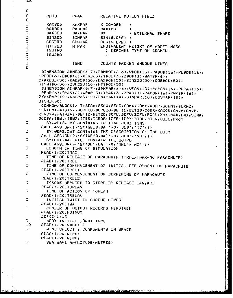
Co1 Rf4Ol RPAR RELATIVE MOTION FIELDCo XAXBOD XAXPAR X CO-OR'SC1 RALIBOD RAEIPAR RADILUSC1 DAXBOD DAXPAR fix ) EXTEAýNAL SHAPEo SINBOD SINPAR SIN(SLOPE))Co COSBOE' COSPAR COS(SLOPE) )o HTTBOD HTPAR EQUIVALENT HEIGHT OF ADDED MASS(o ISbJ1BO) DEFINES TYPE OF' SEGMENTCo ISW2BO
C, ISHE' COUNTS BROK~EN SHROUD LINES
DIMENSION ArBE(p)BIBr(y)VOI1)FAOI1)FW~l1)1RBOD ( 6) , 5505< 6) , X'OE'( 3) YBOD(3) ZE4OD( 3) WATER(6)p2XAXBOD(S0)tRAiBDD'(S0) tE'AX(ODl(SO),SINFOEI(5O),COSBcIs(so),3ISWIB'O(50)YISW2B0(50) ,HTTBODl(50)DIMENSION ADiMF*AR(617)9,SDMP'AR(6t6)IVP'AR(13),P'AFAR(16),PFWPAR(16),1RPAR(6) vDPAR(6) sXPAR'(3) YPAR(3) vZPAR(3) ,PAPER( 16),rPWFPBR(16),P2XAXFPARUO0),RAEIPAR(10o),DAxF'AR(Io),SINp'AR(lo),cosp'AR(Ilo,31SHD(30)COMMON/E'LOCN1/ TrSEAASEAW9SEACPCOMXCOMYWDIEPSURMyPSURMz,1 SOTEMI ATSYSZ PSURECGJ E'URECGP SET 15' BET2D~tC3OJRP XAXOR, CAVA ,CAVB,2SL4VYVZIATVZVYBET1CBNET2CBOF'UBOFVBOJFWF'CAVXAXRADEIAXSINA,SCOSA, ISW1 ISW2. ITES, ICROSP IDEP9 IE'RYt,EOE'U, BOEV,SJYODWPFROT
o SY:#WEIB.DAT CONTAINS INITIAL CODiITIONSCALL ASSIGN(l1,'S'rIWjEIB.f'AT' *0. 'OLDI', tiC', a)
C SY:WEPB.DAT CONTAINS THE DESCRIPTION OF THE BODY -
CALL ASSIGN(2. 'SY:WEPFB.DAT' .0. 'OLEi" 'NC', 1)0 SY:OjUT.DAT" WILL. CONTAIN THE OUTPUT
CALL ASSIGN(3,'SY:#OUT.EIAr',o,'NEbJ','No',:)o1 LENGTH IN TIME OF SIMULATION
REAEI( 120)TMAXo1 TIME OF RELEASE OF PARACHUTE (TREL>TMAXtNO PARACHUTE)
REAE'(1.20)TRELC TIME OF COMMENCEMENT OF INITIAL. DEPLOYMENT OF PARACHUTE
REA'( 1920 )TREL1G TIME OF COMMENCEMENT OF EIEREEFING OF PARACHUTE
READ 1i20)TREL2'TORQUE APPLIED TO STORE BY RELEASE LANYARD
REAM (I 20)TORLANC, TIME OF' ACTION OF TORLAN
READ(1. 20) TRELANC INITIAL TWIST IN SHROUD LINES
READ'( 1,20) TWAC, NUMBER OF OUTPUT RECORDS REQUIRED
RLADi(l1 20)POINUM
C BOD:Y INITIAL CONDITIONS10 REAE'(1.20)VBOD(I)C WINE' VELOCITY COMPONENTS IN SPACE
READlp 20)WINt'XREAD( 1.20 )WINEIY
C SEA WAVE AMPLITUDE(EMETRES)
17. -"
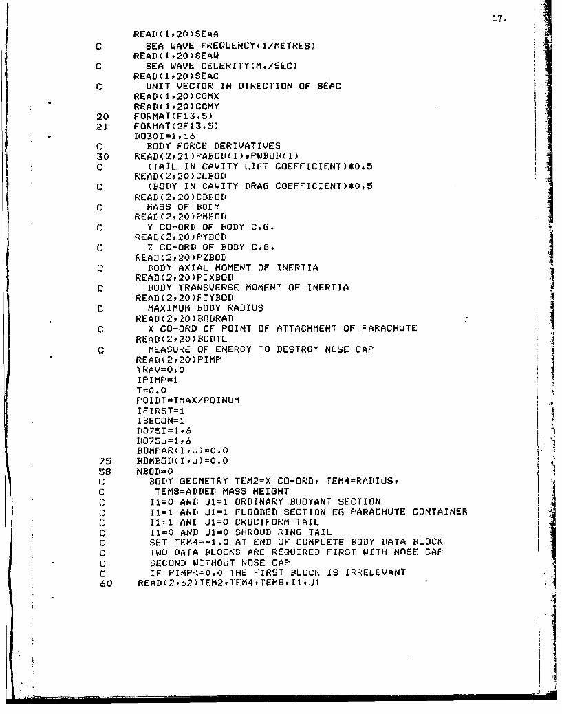
READ(1,20)SEAA 17.
C SEA WAVE FREQUENCY(I/METRES)READ ( I, 20 ) SEAW
C SEA WAVE CELERITY(M./SEC)REA' ( 1, 20 ) SEAC
C UNIT VECTOR IN DIRECTION OF SEACREAD(1,20)COMXREAEI( 1 ,20)COMY
20 FORMAT(Fi3.5)21 FORMAT(2F13.5)
L'030I=lt16C BODY FORCE DERIVATIVES30 READ(2,21)PFABO'( I ), PWBOE'( I)C (TAIL IN CAVITY LIFT COEFFICIENT)(0.5
READE(2,20)CLBOE'
C (BODY IN CAVITY DRAG COEFFICIENT)*0.5REALD( v2, 20) CDBOD
C MASS OF BODYREAD (2v 20) PMBOD
C Y CO-ORE OF BODY C.G.READs(2,20)PYBOD
C Z CO-ORD OF BODY C.6,READ ( 2,20) FPZBOEi
C BODY AXIAL MOMENT OF INERTIAREAD(2,20)PIXBOED
C BODY TRANSVERSE MOMENT OF INERTIAREAD(220 )F'IYBODl
C MAXIMUM BOriY RADIUS
REA[i(2,20)BODRAEIC X CO-ORE' OF POINT OF ATTACHMENT OF' PARACHUTE
READ(2,20 )EIOEITLC MEASURE OF ENERGY TO DESTROY NOSE CAP
READ (2 20) PIMPTRAV=00IIFIPIMP1=T=O.0FO ILiT=TMAX/F' I NUMIFIRST=IISECON=1D075IP ,6D075J=1,6 .BDMPAR(IvJ)=0.O
75 BEIMBOD( I IJh)=O.0a.S NBOD=O
C BODY GEOMETRY TEM2=X CO-ORD, TEM4=RADIUS,C TEMB=ADEEIED MASS HEIGHT
1 11=0 AND Jl=l ORDINARY BUOYANT SECTIONC I1=1 ANE' J1=1 FLOODED SECTION EG PARACHUTE CONTAINER
I I1=1 ANDI J1=0 CRUCIFORM TAILC I1=0 ANT' J1=0 SHROUD' RING TAIL(.? SET TEM4=-1.0 AT ENE' OF COMPLETE BODY DATA BLOCKC TWO DATA BLOCKS ARE REQUIRED FIRST WITH NOSE CAP( SECOND WITHOUT NOSE CAP( IF PIMFP.'=O.O THE FIRST BLOCK IS IRRELEVANT60 REAII(2,62)TEM2,T'EM4tTEMBI11JX
I. :1,I
62 FORMAT(3F13,5P2I2)IF(TEM4.LT.-0. 1)GOTO200IF( Ii.NE4.I .OR.,J1.NE*J)00T06?TEMS=TEM1 -TEM2TEM6=TEM4-TEM3TEM7=SGRT (TEMS*.1'E. MS+T'EM6*TEt16)IF( (TEMS/TEM-/ .G1 .0.002)G0T065TEMZ=O. 002*ABS( TEM6)TEM7=SQRT (TEM5*CTEMS+TEM6*TEM6)
65 NBOE'=NBODl+1XAXBOD( NBOD)=( TEM1+-TEM2 )/2. 0RADBOD(CNBOD ) = TEM3+TEM4 )/2.0HTTBODUNBOEO=(TEM8+TEM9)/2.0E'AXBOD(CNOD ) =TEM5SINBOD(CNBOD )=TEM6/TEM7COSBOD C NBOD )=TEMS/TEM7ISW1BO(NBOD)=I1ISW2BO( NBOD)=J1
67 1=11
TEM1=TEM2 LTC'EM3=TEM4T EM 9=1'E MBGOTO60
6000 ISECON=0C PARACHUTE INITIAL CONDITIONS
VPAR( 1)=VBOD( 1)VPAR (2) =VBOD ( 2) +BODTL.*VbODr (6)VF'AR (3) =VBOD (3) -BODiTL*VBOD (5)E'060501=4, 10
605n' VPAR'( I)=VBOD( I)VPAR (11 ) =VBOD ( i1) +ý.)ODTL*XBOD (1)VPAR(ý 12 ) =VBOD (12) +BODTL*XBOD (2)VP'AR( 13) =YBOD C 13)+BODITL*XF4Ol( 3)
uSY:*WEPF¾DAT CONTAINS THE DESCRIPTION,, OF THE PARACHUTECALL ASSIGN(4y'SY:4WEPF¾D.AT',0,'OLDl'','NCý',1)
C' NUMBER OF SHROUD LINESREAD (4 950) NSHD
50 FORMA'f(12)C OR-SIONAL STIFFNESS OF SHRýOUDi LINE SYSTEM
READ(4f 20)TWISTLENGTH OF EACH SHROUD LINE
R'E'AD (4 v 20 ) T LFLC TE AR ST R IP YIE LD LO0A D
READ(4. 20) TLFTC TEAR STRIP EXPIRED LENGTH + TL-FL
r'tAD (4P20) TLFTL.C TEAR STRIP BREAKING LOAD
READi(4, 20) TLF'FCTLF'Ar TL-FB TL.FCy TLFP* DESCRIBE SHROUDI LINE STRESS/STRAIN
C, CHARACTERISTIC SEE 7000READ(4920)TLF'AA
READ (4920) TLF*CREAD (4 9 20) TLFC I
---- V.., - -. I 7)' q-' - ijt
19.
j C IN WATER VALUE OF TLFCREAD(4920)TLCWET
C IN WATER VALUE OF TLFPREAD(4p20)TLFWET
C SHROUD LINE BIREAK(ING LOADREAD(492O)TLFBR
c RATE OF DEPLOYMENT PARAMETERREAD(4p20)SE'LPARD02030I=1 ,16
C PARACHUTE FORCE DERIVATIVES* 2030 REAE'(4p21)F'AF*BR( ) PWF*BR( I)
(1 PARACHUTE ADDED MASS HEIGHTREAEI(4v20)HTPARIC PARACHUTE PARTIALLY WET DRAG COEFFICIENT*0.SREAE'1(4 p20)CDFAR
c MASS OF PARACHUTEREAI'(4v20)PMFPAR
C PARACHUTE AXIAL MOMENT OF INERTIAI READ(4p20)PIXPARC PARACHUTE TRANSVERSE MOMENT OF INERTIA
READ(4v20)PIYPARCl MAXIMUM RADIUS OF FULLY DEPLOYED PARACHUTE
READ (4v20)PFIRRADC X CO-ORE' OF POINT OF ATTACHMENT OF SHROUD LINES TO CANOPYI READ(4y20)FARTL
(.1 RADIUS OF PARACHUTE AT RELEASE AS FRACTION OF FEBRRADREAE'(4 20) SCLMIN
C RADIUS OF DROGUE AS FRACTION OF PE4RRADREAD(4r20)SCLMAX
C RADIUS OF REEFEDI PARACHUTE AS FRACTION OF' PBRRADREAD(4v2O)SCL2NPA R=0
(1C FULLY DEPLOYED PARACHUTE GEOMETRY TEMi=X CO-ORti, TEM3=RALIIUSREAt'(4v2002)TEMlvTEM3
2000 READ(4, 2002)TEM2, TEM42002 FORMAT(2F13.5)
IF(TEM4.LT.-0*1 )G0T02060TEM5=TEM1 -TEM2TEM6=TEM4-TEM3TEM7=SGRT (TEM5*TEM5+TEM6*TEM6)IF((TEM5/TEM7).GT.0.002)0OTO2005TEM5=0. 002*ABS( TEM6)TEM7=SGRT (TEM5*TEMS+TEM6*TEM6)
2005 NF'AR=NFPAR+lXAXPAR (NF'AR )=( TEM1+TEM2 )/2.0RADPFAR(NPAR)=(TEM3+TEM4)/2#0E'AXPAR (NF'AR) =TEM5SINF'AR NF'AR )=TEM6/TEM7COSF'AR (NF'AR )=TEM5/TEM7TEMI =TEM2TEM3=TEM4GOT02000
* 2060 SHIIANG=6.283185/FLOAT(NSHD)D02065I1=1rNSHD
2065 ISHDCI)0O
20.
SCLFAR=SCLM IN
f'T=0.0GOT06005
C FROM 200 TO 1500 IS FORCES ON BODYCl TEST FOR PRESENCE OF NOSE OAFP200 IF(IPIMP.EQ,0)G0T0202
IF(CTRAV*YEL2.*LT .PIMP) G0T0202I P1MP= 0I ~GO TO5S
202 1102051=1,,6D0205J=197AEIMF'AR( I v)=0.0
2.05 A'MBcOP(IJ)=0.0CALL XYZ (VEODqXBOE" YI4cOD, ZBOt')I ~CALL SEA(WATERXBOEI,YBOrIPzBOEIVBODI(11),VBOZKZ12),vBOEI(13))5
C DEPTH OF EXTREMITIES OF BODYDEP=SURECG-XAXEIOD (1)*FURECGTEM2=SuRECG-xAXBorI(CNEW!') *DURECGDEPME= (DEF+TEM2 ) /2.0
TEM7=EOEIRAli*SOTEM1r EM3=rE'E- TE M?TEM4=TEM2-TEM7TEMi =FEF'+TEM7+BODRADTEM 2 =TEM2+ TEM? +BOD [RAI,
C1 FIRST ESTIMATE OF TrIME INCREMENTDT=BODRAD/SORT (VBOD (I)*vBOD (1) +VBOD(2) *VE4OD(2) +VBOD (3) *VBc~'(3)I Di $ STGT.0. 02 )D[T=0.021FE2'EME.Gt37.O.0)00T0208
G RELATIVE MOTION FIELD IN AIRR[4oD,(a ) mVEOt'( 1 ) -WINDX*Xf:0ti( 1 ) -WINf')KXBOE'(2)RB4OD((2) =YFOD (2 )-WINDX*Y? OD (I) -WINDY*YbOD( i2)RBODl(3) =V[4DD(3) -W INDX*ZE:Or'(CI)_W INFYj*ZBOEI (2)RI3OD(4)=--9.81*XB30F(3)RRBOZS) =-9.al*YBODC(3)RBO'( 6)=-9, 1*ZBOD(3)CALL HYrPRO ( ADMEiOlF, P#fOD VBOIh RBODl)TECT * LT. TRELAN) AMEIOEI(5 '7)=ADiMBoD( 5,7) +TORLANIF(T'FM1,GT.0.0.OR.TEM2.GT.0.0)GOTO21O
o1 BODY IS FULLY IN AIRPICAV=10 1000.0TRAV=0.0I IM~0GOT0400
208 IIM~iRELATIVE MOTION FIELD IN WATER
210 RBOD (I) '=BODC0)-WATER1()*XBOD(I) )-WATER(2) *XFOD (2) -WATER (3) *XBOD (3)R'BODl(2)=vBOrD(2)-WATER(1)*YBOD(1 )-WATCR(2)ZYBi~fl'(2)-WATERC3)*Y[4ODi(3)RBOD'(3)=VBOE'(3)-WATER( 1)ZO( 1) -WATER (24ZEL,(2-WATER (3) *ZE40D (3)fkBODl(4)=WATER(4)*XBODC1l)+WATER(5)*XEBOr'(2)+(WATER(6)-9.81)*XBOtI(3)RBODI(S)=WATER(4)*YBoD(1l)+WATER(5)*YBODi(2)+(WATER(6)-9.S1 )*YBOEU(3)RBOI,(6)=WATER(4)*2E40D(1)+WAT'ER(5)*ZBODi(2)+(WATER(6)-9,81)ZZBOII(3)
c OBTAIN CAVITATION NUMBERV2W2i=RFODl(2)*R'BOEi(2)+RBOFl(3)*RBODI(3)VEL 2=V2W2+RBOE'(l1)*R[4OD( 1)F'AMBU 0100, 0*WDEP
21..
IF(F'CAV.EQ.O.0)G0T0216PCAV=PAME4-TRAV*300#*0/E'ODRAE'IF(FCAV.LT.0.0)PCAV=0#0FPAMB£= PAMB1-FCA V
216 CAV=PIAMEI/(515*0*VEL2)I IF(TEM3.LT.O.OOR.TEM4.LT.0.0)G0T0240C BODY IS FULLY IMMERSED IN WATER
IF(CAY.LT*0.3)00T0250IC THERE IS NO CAVITYI ~~~CALL HYDRO (ADMbOI',PWBOD9,VE4OD, REOD)
* TRAV=9999#0PCAV=0.0GOT0400
c BODY IS PARTIALY WET240 DT=DT/5.0250 ICROS=1
UP 0 =GR(V2W2/VEL2 Aro) rMoi'Ao~iai~r
IF( IIM.EcU,0.ORP'CAVEQl.0.0)GOTO256C TRAV=DISTANCE TRAVELLED' AFTER IMPACT
TEM8=VEIOD (11) -TORXI ~TEM9=VBODi( 12) -TORYTEM1O=VBOD( 13)-TORZTRAV=SQRT*(TEM8*TEM8+TEM9*TEM?+TEM10*TEM10)I C CALCULATE UNTIERPRESSURE
256 DUNPE=101000.0*(1,0-(0,2-0.07*Xz4OEI(3))*TRAV/BOEDRAtI)C, CALCULATE FORCES ANti ADDED MASSES FOR EACH BODY SEGMENT
Dio1500J=1 NBODITES=OXAX=XAXBOD(J)RAD=RADBOI ( J)EDAX=DAXBOD (J)SINA=SINEBOD(J)COSA=COSPOD (J)Iswl=ISWIBo(J)ISW2=ISW2BO(J)P'ROT=VBOD(4)
BODV=REOD (2) +XAX* VBOEI(6)BODW=RE4ori(3)-XAX*VBOI' (5)IF(IUF.,EG.0.OR.XAX.GT.CGOUFP)60T01110 I
(1 UPWARD VELOCITY ON REAR OF CAVITY
IF(TEM1 .GT.1.0)TEM1=1.0BO DV =BOD + TEM I *UPVE LBoriw=BoEiw+TEM1 *UF'WEL
:1110 BOFU=BOlDU*SINABOFV=BODV*COSA-RAD*VBOD(6)*SINABOFW=BODW*COSA+RAD*VBOI( 5) *SINACALL. DEPTHIF( IDRY.EG. 1)GOT015OO
C SET UP IMPACT POSITION
IIM=lTORX=VBOII(11)TORY=VBODiC12)TORZ=VI'0D( 13)
c IF ICROSti AXIAL ELLIPSOID CAVITY NOT FORMEDC IF ICROStO AXIAL ELLIPSOID CAVITY EXISTS,1120 IF(ICROS.EQ.O)GOTO11?O
IF( ISW2.EGO. )GOTO11SOC TEST SEGMENT FOR CAVITATIONC BETIC TO BET2C WILL BCE THE WETTED SECTOR OF THE SEUiMENT1130 TEM7=BO1'V*BODV+8(ODW*BODW4
U2V 2W 2 =TEM 7 + 801W *801UlF(PCAV.GT*.0 4 )00T01132P'AMB=10100 0* (W1'EF-XAX*RBOI'(4) /9.81)I1132 CAVSEG=P'AMB/(515.0*U2V2W2)IF(CAVSEG.GT. 1 0)GOTO11SOIF(CAVSEG.LT40..001 )CAVSEGO.4001T'EM6=SORT (U2V2W2)TEM2Y=SORT (TEM7)TEM1"COSA*TEM27TEM4= (I5OF7U+TEM ) /TEMaIF'(SINMAX.LT. TEM4)SINMAX=TEM4
IF(J.EG. 1)J11lC' CALCULATE INCIDENCE CONDITION FOR CAVITATION
TEM2t3=RADI*(SINBOII(J1)*COSA-cosBorD(J1)*SINA)T'EM2B=TEM26*(COSOLI(JZ)+CO$A)/(EIAXBODi(J1)+DIAX)T'EM2=0, 25*TRAV/RAD
IF*(TEM2,GT.O.76)TEM2ZO,76TEM2=TEM2*(0C.2+0.S*SINMAX*SINV.AX)CONINCtT'EM2*SINMAX-0434*EXP,(-TEM28)-O,36*CAVSEG+042SZTEM?/U2V2ýW2TEM2=CONINC*TEM6IF'UEBOFU+TEM1¾*GT.TEM2)GOTO1140
Cl SEGMENT IS ALL DRYC1 CALCULATE GEOMETRY OF AXIAL CAVITY IF PRESENT
I EM 2 =TEM 27 /T EM6TEM3=ABS (BODlU) /TEM61 EM4=TEM3-ABS (TEM2*SINA/COSA)lF'(TE'M4.LE.0.O)GOTO1400T EM1= RAE'/TIE M4CAVA=O0.4*SINMAX*(1.0+TEM2S)*TEM1/CAVSEG1 ~CAVB=TEMl+0. 13*CAVATEM9--1.?5*TEM1+O.09*TRAVIF> TEM9#LT.CAVB)CAVB=TEM9:cs=oIF( (CAVA+CAVA) .LT.TRAV)GOTO113SCAVA;0. 84*TRAVCAVC=O.21*TRAVI05=1
11 35 IF(CAYA.L.E.O#0)GOTO1400C FIr CAVITY TO NOSE
1LM4=TEM1/CAVBCXORWCAVA*SC4RT (1 , -TEM4*TEMA)'E:M4=:TE:M4*CAYA*CAVA/CAVB :TEM5=CXOR/SQRT (CXOR*CXOR+TEMA*TEM4)
2 3
TEM4=TEM2*COSA+ABS( TEM3*SINA)IF( TEM5*LE *TEM4 )GOTO1400CAVY =-EBOD[V /T EM6CAVZ -- EOrIW / T Et6j ~ ~CGOR=CXOR-XAX CV
ICROS=O
* C UPWARD VELOCITY ON REAR OF~ CAVITYCGOUP =-CGORCAVUF-CAVA
UF&VEL=-TEM6*(0. O05*RI(ot'(5)+STGN(0,025,RE~OD(5)))UFPWEL=-TEM6*(0.005*RIBOD(6)+SIGN(0.025,RB~QD(6)))IF~(AiS(XBOD(3)).LT.O.96)GOTO1400UFPVEL=TEM6*SIGN(0.025,YFBOE'(6))
C1EMN140ATALYWTB CVTTO CONDITION
TEM2=SGRT ( I* 0-TEM2TEM2)
TE:M4=ATAN2(TEM2, TEM3)EBETlC=TEM4--TEM114ET2C=3,1416-TEM4-TEMIGOTO01200
(1 SEGMENT IS COMPLETELY WET BY CAVITATION CONDITION1150 £BET1C=0*0
BET2C=6 2831ITES1lGOT0 1200
c TEST FOR INTERSECTION WITH CAVITY:1170 TEM1=CGOR+XAX
TEM8~=CAVAIF(1TEM1.GT.0.0.OR.ICSEQ.0)G0T01175TEM8=CAVC
11. 7 5 TEM1=TEM1/TEM8TEM1=TEM1*TEMIIF(TEM1 .GE. 1 O)GOTQ1180CAVR=CAViB*SQRT (1, 0-TEMI)CAkOD=AtBS (XAXOR-XAX) *SQVYVZTEM1= CA VR+R ADIF(CAVD.GE.TEM1 )GOT01180TEMI=CAVR-RADlIF'(CAVD,.LE.TEM1 )G0T01400
IF(CAVED.LE.TEM1 )B0T01180TEMI=(CAVDi*cAVE'+RAE'*RAr'-CAVR*CAVR )/ (2. 0*CAVl*rADi)TEM2ý-SQRT (1.*0-TEM1*TEM1)TEM3=AT*AN2 (TEM2, TEMI)F4ET1 C=ATVZVY+TEM3I4ET2C=ATVZVY--TEM3
24i.
GOTO 1.200:1180 IF(1SU2.EQ*0)GOTO11SQf ICROS1l
SINMAXtSQRT (V2W2/YEL2)GOTO 1130
1200 CALL rORCES(AriMBODipRBorI.HTTBODI(J) ,CLBODPCLIBOED)IF(ICROS.EQ.1.ANDI.ICS.EQ.0)GOTO1O00
:1400 IF(IDEP*.EO. 1 OR.E'UNFE.LT.0+,0.R,18W2.EQ.0)GOTO1500C UNDERPRCSSURE FORCE
TEM4=DUNP'E*DAX*RADTEM1=TEM4*(COS(BET1E')-COS(BET2E'))TEli2=TEM4*'(SIN(BET2Di)-SIN(EET1Di))I TEMJ=XAX-RAD*SINA/COSAADiMBOfI(2v?)=At'MB~ODl(2v?)+TEM2ADMBOEI(3, 7)=ADM'OD (3,? )+TEM1ADiMBOD(5, 7)=ADiME'ODi(5,?)-TEM3*TEM1AE'MBOEI(6t?)=AEIMI400(6,?)+TEM3*TEM2
1500 CONTINUE400 IF(ISECON.EO.1)50T051500C UP TO 4500 IS FORCES, ON PARACHUTE
CALL XYZ(VP'ARPX'ARPYP'ARPZPAR)CALL SEA( WATER PXPARYPFARPZP*ARPVPAR( 11),VPAR(12)toVPAR( 13))
C1 DEPTH OF EXTREMITIES OF PARACHUTEDEP=SURECO-XAXP'AR 1) *DURECGTEM2::-SURECG-XAXP'AR (NPAR) *DURECGI ~~T EM? PA RNAD *SQ TEMTEiM1I4'EP+TE:M?T EM 1 3 =11PF'-TIEli?TEm1I4=TEM2-TEM?DEPME( PE1+ TEM14) /2.0IE(LiEPME#GT~u*0)60TO3210
C RELATIVE MOTION FIELD IN AIRRP'AR( 1)=VP'AR( 1)-WINDX*XP'AR(l1)-WINDY*XFPAR(2)RPAR (2) =VPAR (2) -W I NLX*YPAR (1) -W INriY*YFAR (2)RP'AR'3) =VPAR (3) -WINDX*ZP'AR (1) -WINDIY*ZFPAR (2)RP*AR(4)=--9.S1*XPAR(3)RP*AR( Sfl"-9.31*YP*AR(3)RPAR(6) =-9.81 *ZPAR (3)CALL HYDIROe(AriMP'AR PAF'AR VP'AR RPAR)IF(TEM1 .LT.0.O)G0T03400
C PARACHUTE COULD BE WETC RELATIVE MOTION FIELD IN WATER3-210 RPAR(1 )=4WrnK(1) -WATER (I) *XPAR (1) -WATER(2) *XPAR (2) -WATER(<3)*XFPAR (3)
RF'A R( 2)= VFAR (2) -WA TER ( 1 ) * Y PAlR 1 ) -WA TER (2) *Y PAR (2) -Wt'. Z-,R'(3 )*YPAR (3 )RPAR (Z)VPAR (3)-WATER (1I) *zFAR (1 )-WATER (2)*ZPAR (2)-WATER (3) *ZPAR (3)RPA R (4) =WAT E R(4 )*XPAR(I) + WA T ER (5) *XPAR (2) +(WA TErk(6) -9.8 1 )*XFAR (3)RPAR k5) =WATER (4) *YPAR (1) +WATER (5) *YPAR (2) +(WATER (6) -9. 81 )*YPAR (3)RFAR (6)h--WATER (4) *ZPAR ( 1 ) +WATER'(5) *ZPAFU(2) +(WATER (6) --?. 81 ) *ZPAR (3)I F (TE M13, GT*0. 0.4A NDsT EMi14,50T# 04 o.ANr'.CAV.OT,0*3)Q0T03240
C PARACHUTE COULD BE PART WETC SE'T LIP TEST FOR INTERSECTION WITH CAVITY FROM BODY
I FC I CRf4OS.EQ, 4 0)00T*03220IEF(CAV.LT.0 4 001)CAV=0.001(.AVA=2,. 0*BOLIRADI/CAVCAYE4=E400RAD+0, 13*CAVA
25.,3220 TEM1TIORX-VE4OE(11)
TEM2=TORY-VBOD( 12)TEM3=TORZ-YVBOt'(13)TEM1S=TEM1*XPAR(i )+TEM2*XPAR(2)+TEM3*XPAR(3)IF(TEM1S.EG.O.0)G0T03230TEM4=YDOD(11)-YPAR(11)TEM5=vBari(12)-YPAP(12)TEM6YEICD(13)-YPAR(13)TEM16-TEM4*XP'AR(i i+TEM5*XFAR(2)+TEM6*XPIAR(3)
TEM17=-TEM16/TEM1 SIF(TEM17.LE.O.0)G0T03230TEM18=SGRT(CTEM1*TECV1+TEM2*TEM2+TEM3*TEM3)TEM1=TEM4+TEM1*T*E.;-1?TEM2=TEMS+TEM2*TEM17
TEM3=TEM6+TEM3ZTEM17CAYY=TEM1*YPAR(1)tTEM2*YPAR(2)+TEM3*YP'AR(3)CAVZ=TEMIlýZP'AR(1 )+TEM2*ZPAR(2)+TEM3*ZF'AR(3)CAVEi=SORT (CAVY*CtVY+CAVZ*CAVZ)TEM1=1 .0-TEM17*TEM118/CAYATEM1=TEM1*TEM1
IF(TEM1 .GE. 1 0)G0T03230CAVR=CAYE*SORT (1.0-TEN 1)I ~ ~T EM 1=CAV R +PARR ADIF(CAYEI.GE.TEMX )G0T03230T EM 1 CAYR -PARRADII ~IF (CAVEI.LE*TEM1 )00T03225ATUZVYt=ATAN2(CCAVZtC 1.Y)I CAV= 1G0T03250
3225 IF'(E'EPME.GT.0#O)CALL HYliRO(AiMFPARF'AP*ARVP'ARRPAR)G0T03400
'3230 ICAV=OIF(TEM13,LT.04.OOR.TEM14.L-T,0.0)G0T03250
C PARACHUTE IS FULLY WET3240 CAiLL HYLIRO(CADiMPAR , PWPAR, VPAR, RPAR)
00T034003250 IF(DEPME.GT.0.0)CALL HYIeRO(ADMF'AR.PFAP'ARVPARvR'PAR)C1 CALCULATE FORCES AND ADDED MASSES ON EACH SEGMENT
lD04.500j1lyNPARITES=0XAX=XAXP*AR C )RADiSCLPAR*RADPFAR ( J)DAX"SCLPAR*DAXPAR (J)SINA"=S.'NPAR (J)COSA=COSP'AR(J)
SW 1=1ISW2= 1E4ODU--RPAR 1)LIOFU=BOt'U*SINATEMI =XAX*COSA-RAI'*S INALOFV=RF'AR(2 )*COSA+VP'AR (6)*TEM1EIOFW=RFAR (3) *COSA-VF'AR C 5) TEMiCALL DiEPTHIF(IDRY.EQ. 1)GOTO4SOC)1V ClCAV.EQ.0oo)Go0O4350
21DA
TEM1=CAVR+RAE'IF(CAVDi,GE.TEM1 )GOTO43SOTEMI=CAVR'-RAE'IF(CAVEI.LE*TEM1 )GOTO4SOOTEM1=-TEM1IF(CAVE'.LE. TEMi )G0T04350TEM1= (CAVD*CAVDi+RAEI*RAl'-CAVR*CAVR ) /(2. 0*CAVE'*RAD)T'EM2=SORT( 1 0-TEM1*TEM1)TEM3=ATAN2(TEM2tTEM1)BET1C =A TV ZVYV+ TEM 3BET2C=ATVZVY-TEM3G0T04400A
C ALL WET BY CAVITY INTERSECTION4350 BET1CO,0.
EiET2C=6, 2831ITES~1
4400 CALL FORCES(AE'MP'ARRPARPHTF'AR,0.0,CDIPAR)TLFC=TLCWETT L FF' =T L F'WET
4500 CONTINUEC CALCULATE FORCES IN SHROUD LINESC FIRST OBTAIN BODy fO PARACHUTE TRANSFORMATION MATRIX3400 S1=XBOI'(1)*XP'AR(1)+XBODI(2)*XPAR(2)+XBODl(3)*XPAR(3)
S2=YBOI(l) *XPIAR( 1) +YE4or(2) *XF'AR (2 )+YBOE' (3) *XPAR(3)S3=zDor ( 1 )*XPAR (1 )+zBOr'(2)*XPAR(2) +zBOD 3)*XPAR(3)S4=XE'OD (1) *YP'AR (1 )+XBOE' (2) *YPAR(2) +XEIOE(3) ZYPAR (3)S5=YB'wO(1) *YPIAR (1) +YBoE'(2) *YPAR (2 )+YBODa(3) *YPAR (3 )S6=ZBODI(1) *Y'AR (1) +ZBOD (2) *YPAR (2 )+ZBOD(3) *YAR (3 )s7=XBori(1)*ZPIAR(i)+XBoEi(2)*zPAR(2)+XBOEI(3)*ZPAR(3)SS=YBOE'(1 )*ZPAR (I1)+YBOD (2) *ZPAR (2) +YBOD (3) *ZPAR (3)S9?=ZBOD(I1) *ZPAR ( I1) +ZFOEI(2) *ZPAR (2 ) +ZBOD (3 ) *ZPAR (3)
C RELATIVE VELOCITY AND' POSITION OF BODY W.R#T., PARACHUTETEMl=VBOD(2) +VE4OD(6)*BoE'TL1*EM2=VBOE'(3) -VBOD( 5) *BODTLBOE'U=VBýDODi(1)*S1+TEM1*S2+TEM2*53BODIV=VBODi(1)*S4+TEM1*S5+TEM2*56BI3OW=VBODi(l1)*S7+TEM1*SB+TEM2*59TEM1=VBOD(11 )-VPAR(11)TEM2=VBOD( 12) -VPAR( 12)TEM3=VBOD( 13) -VPAR( 13)TLX=TEM1*XF'AR'1D+TEM2*XF'AR(2)+TEM3*XPAR(3)+BODiTL*S1TL.Y=TEM1*YP'AR(1)+TEM2*YP'AR(2)+TEM3*YPAR(3)+BODTL*S4TLZ=TEM1*ZFIAR( 1)+TEM2*ZF'AR(2)+TEM3*ZPAR(3)+BODiTL*S7
C CALCULATE AND SUM TENSIONS IN SHROUD LINES'7000 TPX=0.0
TP'Y=0.OTP'Z=0#OT EM 12 =- SHE'AN6DOYSOOI=1 ,NSHEeTEMi 2=TEM12+SHDlANGIF'(ISHE'(I) *EO, 1)GOTOZ4SO
C1 EXTENSION OF LINETE~11=TLX--PARTLTEM6=PARfkAD*COS (TEM 12)T EM 2 =TL. -1 E M6
27.
TEM7=F'ARRAD*SIN (TEM1l2)I TEM3=TLZ-TEM7TEM4=SGRT (TEMI*TEM1+TEM2*i*EM2+TEM3*TEM3)TEM5=TEM4-TLFLIF(TEM5*LE.O.0)GOTO75OO
C RATE OF EXTENSION OF LINE1'EM8=BODU-(VPAR( 1)+VPAR(5)*TEM7-VF'AR(6)*TEM6)TEM9=EIODV-(VPAR(2)+VPAR(6)*PARTL-YPAR(4)*TEM7)TEMIO=EBODW-'(VF'AR(3)+YPAR(4)*TEM6-VPAR(5)*PARTL)TEMI=TEMI/TEM4TEM2=TEM2/TEM4TEM3=TEMZ/TEM4
C TENSION IN LINETEM4= (TEMO*TEM14TEM9*TEM2+TEMIO*TEM3 ) TLFCTEM8= CTLFA+TLFB*TEM5) *TEM5TEM9=1'EMS*TLFFIF(CTEM4*,GT *TEM9) TEM4=TEiI9IF(TEM4#LT.-TEM9)TEM4=-TEM9T*EM8= TEM8+TEM4IF'(TEM8.GT.TLFBR) ISHII(I)=1TF'X=TF'X+TEMS*TEMIT F Y= TFY +TE M8* T EM2
TF'Z=TF'Z+TEM18*TEM3GOT07500I
(1 AT LEAST ONE SHROUD LINE IS B~ROKENE107455J= ,NSHII
7455 ITEM=ITEM+ISHU(J)
7500 CONTINUE
C TEAR STRIP BEHAVIOURTEM I =SORT C TFX*TF'X+TFPY*TF'Y+TFPZ*TP'Z)IF(TEM1 ,LToTLFT)GOTO7600
IF( TLFL. GT.*TLFTL ) GT07530G lEAR STRIP YIELDS
GOT 070007530 IF(TEM1 .L.T.TLFF)G0T07600(1 P'ARACHUTE HAS BROK~EN FREE FROM BODY7550 TREL=10000.0
ISECON=1GOT05500
G TORSIONAL TORQUE7600 TEM2=TWA
IF(TEM2.GT. 3.0)TEM2=3.0IF (TEM2#LT#.-3.0)TEM2=-340TEMI=TEM1 *TEM2*TWIST*SCLF'AR*SCLF'AR i
C ADD~ SHROUD LINE FORCES TO PARACHUTE AND BDOLYADMFAR(197)=ADMF'AR(lp7)+lP'XAriMFPAR( 2,7)=ADMF'AR(2p7)+TF'Y
At'MFAR(3p 7) =ADMPAR(3 v7) +TFZADMFAR(4, 7)=A!IMF'AR(4v7)+TEMlA LIM PAR (5p 7) =ADMPAR (5 v7) -TF'Z*'TLX+TF'X*TLZADMPAR(6, 7) =ArIMF'AR(6 v7) +TF'Y*T'LX-TF'X*TLYT BX=-TF'X*S 1-TFPY*S4-TFPZ*i37
T By = -T FX* 62-T F Y * S5- T'Z * S 81 BZ=-TF'X*83-TFPY*S6-TF'Z*S9ADMBOD(l1 7)=AEIMEOD(1v7)+TE4XAriMBOD(2, 7) =ADMEIOI( 2,7) +TBYADME4Ot'(397) =AlMBOE'(37~7) +TEZAEIMEUOD( 4,7)=AEIMBE4D(4,7) -TEM1*SlADiMBoDi(5,7)=AriMBtOE(5',;')-TE4Z*BODTL-TEMl*S2AE'MBE400(6,7) =ADIME4OD(6,7) +TE4Y*BE4TL-TEM1*S3CALL ENERT (AriMIBOr, BDMBOD, RBOE, VBOII, liBOlI, XBOEI , TOt' ,ZBOEI ,F'M(OI,t
IF'YE4OE pFZBOD, F'IXBOi4O'F'iyBorD, riT)CALL. ENERT (ADiMF'AR, BDMF'AR ,RF'AR ,VF'AR, DP'AR, XF'AR, YF'ARPZFAR, F'MF'AR,
10,0q0.0,F'IXFARF'IYPARqrDT)CALL DERIV (ADM4Ot,p VBOll BD P 101,XIO1I YB400,ZE400 v LIT)CALL rERIV(ArDMF'ARVFPARDPEFARiXF'ARYF'ARZF'ARPtiT)
G P'ARACHUTE DEP'LOYMENTSCLF'AR=SCLF'AR+SDILF'AR*(RF'AR( 1)-AF(S(RFPAR(2) )-AE'S(RFPAR(3)) )*EDTTWA=TWA+(VE4OD(4)-VF'AR(4) )*DTI F (SCLP'AR 4 OT 4SCLMAX )SCLF'AR=SCLMAXIF(SCLP'AR.LT.SCLMIN)SCLFPAR=SCLMINIF (SCLOLDiE.EQ*SCLMAX.ANDI* SCLF'AR.EQ .SCLMAX )GOTOS700
60 05 TEM2=SCLF'AR*SCLFARD1061001=1916P A PAR ( I ) =PAPB R ( I) *T EM 2
6100 FWF'AR ( I ) =FWF'DR ( I ) *TEM2S CL0LDI= Sc LPFAR;AR RA 0= SCL F'AR *: PB4RRAt'GoO 15700
(1 BOD0Y ALONJE5500 k"ALL. E.NERT (AtiMi~OD bMEIBOr, R'BOD , VP.EIOD, t'BOt'XBiOt',YE4Ot' ,Z~'0D, FMBOD~v
1 FYB4011 F'ZE'Or, F' IXE~IOD F'I YEOIQD, T)IF'( FIRST.E0,O)GOT055OS
(1 FIRST PASS THROUGH Pr,%'OGRAMME TO SET UP B[DME40 ETC*IFIR'ST=0C,0T05705
5 0O5 CALL DiERIV(ArMEIO0rVBOE,DlBODYXEUDYBlODYZ14ODrgT)C INCREMENT TIME3700 T=T+riTC, CHE'CK. PARACHUTE STATUS
IF'(T.GT.TREL.ANL'.ISECDN.EQ.1)GOTO6000IF (1 T .GThEL ) SCL.MAX=SCL2IF (I T.GTTREL.2) SCLMAX=1 40IF (1.LT.F'OIT)G0T0200
C ~OUTPUT A~ REECORTDC THE WRITE STATEMENTS AND NEED TO CALL EULER SHOULD BE
VJARIE1:' AS REQUIRED5705 POIT=T+POIDT
CALL EtJL.ER%(TEMI1,TEM2,TEM39XiBOrYBoDtzEýior)IF( ISECOIE0. 1 )G0T05900CALL EUL.EfR(TEM4rTEM5,TEM6,XF'ARfYF'ARZF'AR)WRITF'(3, 199)T, vi400( 1)PVF'AR(1) TEM2,TEM5, VEIOr'( 1) ,v140i( 12) VE401( 13)wRXi,(7,199)T*,v14or(i),VF'AR(I),TEM2,T'EM~,VBE4OI(11),VEBOr(12),VBODI(13)GOl 05950
'59 00 WRITE ( 3 y19 9) T V O D( I ) v 0. 0 9T EM2,90 o0 PV BO D(11) vVEBODI( 12 ) 9VBOr( 13 )WF I TE ( 7 v199 ) T fV4O r( I) #0. 0,vTEM2 P0 s0 V BOD (11 ) PVBODI( 12 ) v V bO,( 13 )
199 FORMAT(F9.44,F1043)
29. [f
59750 IF(T.LT'.TMAX)GOTO200C RUN COMPLETE
WRITE(3t199)-1,0PO0,0.0.0,0,0,0,O,0,0.O,0400STO0FEND'SUBROUTINE XYZ(VPXFYFZ)
C GENERATES THE TRANSFORMATION MATRIX X'YpZ FROM GUATERNIONS* DIMENSION V(13hPXG3)PY(3)PZ(3)
X(1) =1.0-2. 0*(Y(9 )*V( 9) V10)*V10) )X(2)=2.0*(V(10)*Y(7)+Y(8)*V(9))X(3)=2.0*(V(8)*V(10)-V(7)*V(9))Y(1)=2. 0*( V(8) *V(9)-V( 7)*V10) )Y(2) =1, 0-2. 0*( V(8) *Y(8) V10)*V10) )Y(3)=2.0*(V(7)*V(8)+V(9)*V(10))Z(1 )=2.0*(V(7)*V(9)+Y(8)*V( 10))Z(2)=2.0*(V(9.*Y( 10)-V(7)*Y(8))Z(3) =1, 0-2. 0*( Y( ) *V(8) +V(9) *V( 9) )RETURNI
SUBROUTINE SEA(WyviYPZPXP'OSPYP'OSPZPOS)C MOTION AND GEOMETRY OF THE SEA
DIMENSION W(6) ,X(3) PY(3) ,Z(3)COMMON/BLOCKI/ TtSEAASEAWSEACCOMXCOMYWDIEFPSURMYSURMZv1SQTEM1,ATSYSZSURECGEaURECGBET1EIBET2'ipCGORXAXORCAVA'qCAVBP2SQYYVZATVZVYPBETZCBET2CBOFUBOFVwtBOFWPFCAVPXAXPRADPDAXvSINA'SCOSA vISW1,PISW29 ITES PICROS 9IE'EP, IERY PBODUP BOIV rBOE'Wp,PROTANG=SEAW* ( XPOS*COMX+YPOS*COMY-SEAC*T)S=SIN(ANG)C=COS(ANG)Z E X F=SEA A *SIF( ZPOS.OT.ZEXP')ZEXP*ZP'OS3E=EXF'(-SEAW*ZEXP')AZ= SE AA*SE AC *SEA WA2=A1 *SEAC*SEAW
C SEA MOTION AT XPOSPYPOSYZPOSU=-A1*E*SW( 1)=U*COMXW(2)=U*COMYW(3)=-AI*E*CUt' 0T =A 2 *E *CW(4)=:UE;OT*COMXw(5)1:UEiOT*COMYW(6)=-A2*E*SWDEP=10 * 0+ZPOS-SEAA*E*S
c SEA SURFACE GEOMETRYEl U'X=SE A A*S EAW*CA1=SQRT( 1 0+EIZE'X*t'ZLiX)A2='ZE'X/A1XN=A2*COMXYN=A2*COMYZN=-1 .0/AlSURMY=XN*Y(1)+YN*Y(2)+ZN*Y(3) LSURMZ=XN*Z(1)+YN*Z(2)+ZN*Z(3)T'EM1=5UR MY *S U RMY+ S URM Z *SURM ZIF(TEM1 LT. 0. 00001)TEM1O.,00001
30.
SOTEM1=SGRT(TEM1)
ATSYSZ=ATAN2 (SURMYPSURMZ)SURECG=ZN* (SEAA*S-ZF'OS)E;URECG=XN*X( 1)+YN*X(2)+ZN*X(3)RETURNENDESUBROUTINE HYDRO(AvPyvR)
C FULLY IMMERSED FORCES AND ADDED MASSESDIMENSION F'(16)tA(6i7hyV(13) ,R(6)LJ=ADS(R(1) )U2=R'( 1)*UUP,=V(4)*UULWU*V(5)LJR=~U*V(6)UV=U*R(2)UW=U*R(3)VWAB=SC4RT(R(2)*R'(2)+R(3)*R(3))V2=R(2)*VWABW2=R(3)*VWAB0A2=V(5)*VWABRA2=V(6 )*VWaABIC FORCESA(1 ,7)4F(1)*U2+P*(14)*R(4)A(2,7 )=F (3 )*UR+.P(2) *UV+PI(10) *V2+Pl(11)*RA2+F' ( 4 )*R (5)A(3,7)=-P'(3)*UQ+F'(2)*UW+P'(10)*W2-F'(11)*0A2+P(14)*R(6)A (4 v7) =F'(16) *UP'
A(57)=F,15) *R(6)+P(4 )*UW+PI(5)*UG+I( 12 )*W2+F'( 13 )*A2A (6,7)=,( 15)*R(5)-P,(4)*UV+PI(5)*UR-PI(12)*V2+P'(13)*RA2
c ADDED MASSESA(19,1)=P(6)IA (2,2) =F'(7)A (2,6)=F' (8)A (3p3) =F' (7)A (3v5) = - P(8)A (SS) = P (9)A (6v6) = P(9)RETURNENDLSUBROUTINE DEPTH
CALCULATES THE INTERSECTION OF A SEGMENT WITH THE SEA SURFACE(, E4ET1D TO FET2L' IS THE INTERSECTION SECTOR,
COMMON/?LOCKI/ TiEASAPECCMPOMPIE'SRYSRZ1SOT'EM1I ATSYSZ ,SURECO' DURECG ,BETID' rBET2Dv CGORP XAXORY CA VACAYBP2SOYYVZATVZVYBET1CBET2CBOFUE4OFVBOFWP'CAYXAXRADDEAXSINA,3COSArISW1,r1SW2,PITES, ICROSj,IDEPILIDRYE40L'U r EOE',Vp B1(WPROT
IDRYO0SURE =5U RE C G -XAX *BUR EC 6SURE =SURE / SOTEM 1IF(SURE4LEoRADI)60T0120
RETURN1.20 IF(SURE.LE.-RAD)60T0500
SURE =SURE /RAE'TEM1=SORT( 1 0-SURE*SUR'E)
31.
TEM2=ATAN2(SUREP TEMI)
BETI D=TEM2-ATSYSZBET2ri=3, 1416-TEM2-ATSYSZTEM1=(BET 1D+BET2D)/2. 0TEM2=COS (TEMI )*SURMY+SIN (TEM ) *SURMZ
IF(TEM2.LT*0.0)RETURNTE ML =BET1 IDBET 1D=FET2DBET 21= TEM 1RETURN
!30 r1 RY= 1I RETURNENDSUBROUTINE FORCES(AFRPHTYCLIFTPCt'RAG)
c FORCES AND ADDIED MASSES FOR EACH WET SECTORI DIMENSION A(697)PR(6)COMMON/EtLOCK1/ TSEAASEAWSEACPCOMXtCOMYWDEF'PSURMYPSURMZP
IS(OTEý'M1 ATSYSZSURECc3,DURECGPBET1ID.BET2DtCGORXAXORPCAVAPCAVBP2SaYYVZATVZVYBETlCBET2CBOFUBOFVBOFWPFFCAVXAXRAIIIIAXOSINAP3COSA, ISW1 ,ISW2,ITES, ICROS.ILIEP, ILIRYBOEDUPBODVIBODIWPF'ROT
C2 SORT OUT ACTUAL WETTED SECTOR FROM DEPTH AND CAVITATION DATAISEG=OIF( ItEP*EQ*I1)GOTO300IF(ITES*EQ.0)GOT0205BET 1C=BEETIDBE I 2C=BET 2DGOT0300
205 TEM2=SCALE(BET2EI-BET1D)TEM3=SCALE (BETIC-BET lD)TEM4=SCALE( BET2C-BET ill)
220o IF(TEM4.LT.TEM3)G0T0240IF(TEM3#GT .TEM2)RETURNBET 1C=TEMZ+BET11DIF(TEM4*GT. TEM2)G0T0230
225 BET2C=TEM4+BET1IrGOT0300
230 I4ET2C=TEM2+BETlDGOT0300
240 BETIC=E4ET11iIF( TEM4, GT. TEM2) G0T0230IF(TEM3.GT, TEM2)G0T02.2;5BET2C= TEM4 +BET 1 LI SEG= 1BET3C=TEM3+BET1 DBET4C=TEM2+BETIDE
c CALCULATE FORCES AND ADDED MASSES300 BET1C=SCALE(BETIC)
BET2C=SCALE(BET2C)IF(EiET2C.LT.BETIC)BET2C=BEIT2C+6,263185SINE41=SIN(BETIC)SINB2=SIN(BET2C)I COSBI=COS(BETIC)C05142=COS(L4E'2C)IF(ISW1,EQ.1,AND,1ISW2,ER,0)GOT0500
C, AI TO FI INTEGRALS USED FOR FORCES AND MASSES
AI=BET2C-BET1"C
EI=SINB2-SINSI1CI=CCSBl-COSB2TEM3=(SIN(BET2C+BET2C)-SIN(BET1C+EIET1C) )/4 .0TEM4=AI/2.0TEM7=SIN(TEM4)IF(AI.GT.3, 142)TEM?=1 40iII T EM4 +TEN 3EI=(SINB2*SINBi2-SINB1*SINB1 )/2.0FI=TEM4-TEtI3TEMi =RADEI*AXI ~TEM2= 1030. C*TEMJ.TEM3=ABS (COSA)
TEM5=COSA/TEM3TEMH6 =RAE'* SI NA-XAX *Co SATEM7=TEM2*HT*TEM7TEMS=TEM?*TEM4TEM9=TEMB*SI NATEM1O=TEMS*COSATEMi11TEMS*TEM6T Em12= TEM? * TEMT EMH13= T EM 12 *Co SAI l~~~EN14=T EM 12 * TE MTEN 1 5TEN? *T E16*T E M / TEN 3
C ~ADDIED MASSESA(191L)=A( 1,1)+TEN9*AIA(l,2)=A(1?2)+TEMI.O*BIA( 1 ,3)=A(l1 3)4TEN1O*CIA( ,5 )=A(it b) +TEN1 1*01A(1,6)=A(1,6)-TEN11*E(IA(2v2)=A(2p2)+T'EM13*'ilA(2,'3p=A(2f-,3)+TEN13*EIA(2,5)=A(2r5)+TEMi4*EIA(2,6)=A(2,6)-TErM14*DIA(3,3)=A(3v3){TEtI13*FIA(395)=A(3i5)+TEN1I4*FIA(5,S)zA(5,5)+TEM1S*FIA(5,6):'~A(S,6)-TEM15*EIA(6y6)=A(6r6)+TEM15*DITE:M8-(BEIT1C+BET2C)*0. STEKM7rCOS (TEMS)T EM,8-S=SI N ( T ENS )TEMY/::EOFU+.0,25-* ( BOFV* (COSBI'+COSB2+TEM?+TEM ) +EOFW*1 ($INiII+14SINB2+TEMS+I'EN8))T*EM8" C1DRAG * T E2*ABS(TEM?)TEM9=TEM8*TEM5T'EMiO=E'OFU*AI +EOPV*FI +BOFW*CITEM1P4::OF'U*E4ItOFV*DiI+BOFW*EITEMi2=BOFU*CI+E4OFV*EI+E4OFW*FIIF( ISW2.EQ.0)00T0350
C2 NON LINEAR FORCE"DAFlXLTEMB*TEM4*('TEM1O+T'EMiO-T*EM7*AI)J:AV-Y=TE'M9*(TE'M11+iTEM11I-TEN?*BI )DAF'Z=;TEM9* (TEM12+-TEM12ý-TEM?*CI )
33.
1F(ISWl .EO 1 )00T0400C BUOYANCY FORCE
TEM11=0.5*TEM2*RAEI*(AI-SIN(AIA))E'AF'X=EAFX-R( 4) *TEMl 1EiAFY=t'AFY-R(5)*TEM1 1E'AFZ=DAFZ-R( 6) *TEM1 1GOT0400
C1 LINEAR FORCE350 TEMZ=CL IFT*TEM2*SQRT (BOEiU*BOEIU+(ODYV*EIODV+BODiW*EODW)
TEMS=TEMZ*TEMS* E'AFX=TEMZ*TEM4*TEMl 0
DAFY=TEMB*TEM 1tAFZ=TEMS*TEM12
400 A(1,7)=A(107)-EAFXA(2v7)=A(2p7)-DAFYA(3,7)cA(3t7)-EIAFZTEM14=TEM6/COSAA(5p7)=A(597)-EIAFZ*TEM14A(6p7)=A(6v7)+E'AFY*TEM14GOT0900
C CRUCIFORM TAIL500 TEM6=1O3O. 0*EIAX
TEM 10=TEM6*CL IFT*SQRT (BODiU*BODIU+BOEIV*BOE'V+E(OEW*E(OEIW)TEM1=RAEI*RADl*0. STEM2=T-0#S-FLOAT(IFIX(T))TEM3=TEM1*0.01TEM4=0 .3/RAE'TEMS=0. 4/RAE'Yl1= -RAE'
Y2= RAE'Z 1= -RAEIZ 2 =RAE'IF(SINB1*SINE42*GE.0,0)60T0520TEMS=RADi*(SINB1*COSB2-COSBl*SINE(2)/(SINB1-SINB2)IF(SINB1 .GT*.0.)GOTOS1OY1=TEM5G0T0540
5710 Y2=TEM5GOT0540
`5 2 0 IF'((SINB1+SINB2).GT*O40)G0T0530IF( (BET*2C-BET1C) ,GT,3.14159)GOTOS4OGOT0700
1530 IF(C05B14 GT*COSB2)GOTO700540 AI=Y2-Y1
141=AI*(Y2+Y1 )/2.0CI=(Y2*Y2*Y2-Y1*Y1*Y1 )/3.0TEM7=TEM6*HT*AI/ (RAEi+RAE')TEM8=TEM7*XAX
C1 ADDEDE MASSES AND' FORCES 'HORIZONTAL FIN'A(393)=A(3v3)+TEM?*AIA(3v4)=A(3v4)+TEM?*BIA(395)=A(3t5)-TEMB*AIA(4 ,4 hA(4p4)+TEM7*CIA(495)=A(4t5)-TEM8*BIA(5vS)=A(5sS)+TEM8*XAX*AI
E'AFZ=TEM1O* (BODW*~AI+F'ROT*BI)A(3p7)=A(3p7)-E'AFZA(4,?)=A(4,7)-TEM1O*(BEIOW*f41+PROT*CI)IF(ABS(BI).LT.TEM3)A(497)=A(4v7)+
1(SIGN(TEM4,TEM2)-FPROT)*AliS(DiAFZ)*TEM1A(5t7)=A(5# 7)+XAX*LIAFZ
700 IF(COSE'1*C0552.GE,0.0)GOTO?20TEMS=RADi*(SINB2*COSB1-COSB2*SINB1 )/(COSB1-COSB2)IF(COSB24GT4040)GT0T10Z1=TEM5GL'T0740
71o Z2=TEN5GOT0740
720 IF((COSB1+COSB2).GT,0.0)GOTOI73OIF((BET2C-BET1C).GT.3.14159)60T0740GOT0900
,)30 IF(S1M52+GT.SINB1 )GOTO900740 AI=Z2--Z1
BI=AI*(Z2':+Zl)/2.0CI=(12*Z2*Z2-Z1*Zl*Zl)/3,0TEM?=TEM6*HT*AI/ (RADI+RADI)TEMS=TEMY*XAX
CADDED MASSES AND FORCES 'VERTICAL FIN'A(2t2)=A(2p2)+TEMY*AIA(294)=A(294)-TEM7*BIA(296)=A(2p6)+TEM8*AIA(4y4)=A(4v4)+TEM7*CIA(4p6)=A(4y6)-TEMS*BSIA(6,6)a=A(6,c,)+TEM8*XAX*AItiAFYWTEM10*(SODIV*AI-PIROT*BI)I
A(4,Y7PA(4,7)+TEM1O*(BODiV*BI-F'ROT*CI)
ZF(AECS(FI) ,LT.TEM3)A(4,7)=A(4,7)+1(SIGN(TEM5,TEM2)-PFROT)*ABS(DIAFY)*TEMIIA(69?)=A(6p0)-XAX*DiAFY
900 IF(ISEG*EQ4O)RETURN1BETI1C= SET 3£BET2C=BET4CISEG-=00010300EN DjSUB4ROUTINE ENERT ( A9B 9 R 9V P 1IYX PYYvZ vPMIvPYP9PZ v PIX vFI YvDT)
C FORCES DUE TO GRAVITATIONAL AND INERTIAL SOURCES BUTG EXCLUDING TERMS CONTAINING DU/DTiI'V/DTv...... DR/E'T
DIMENSION V(13) ,X(3) ,Y(3) ,Z(3) ,D(6) ,S(6) YR(6) PA(6u7) ,B(6v6)F2=V(4)*:V(4)PGY=(4)*V(5)P'R=V(4)*Y(6)02=V(5)*V(5)R2=V(6)*Y(6)OR=Y(5)*V(6)UQ=V( 1)*V(5))UR=V(6)*V( 1)VP=V(4)*V(2)VR=V(2)*V(6)
35.4
WF'uV(3)*Y(4)WO=V(3)*V(5)
YM=F'M*FPY xX3=X( 3) *981Y3=Y(3) *9481Z3=Z(3)*9o81
C MOTION FORCESA (1 7) =A (1 7) -PM* (WG-YR+P'Y*POL+PZ*PR-X3)A (2 r7)-A (2,v7) -PM* (UR-Wr.-P'Y* (R2+P2) +Pz*QR-Y3)A (3,97)=A (3,p7) -PM* (yP-UQ+P'Y*GR-PZW(P2+02) -Z3)A(4,7)=A(4,7)-ZM*(WP'-UR+Y3)-YM*(VP'-UQ-Z3)A(5,7)=A(5,7)-(PIX-PIly)*PR-ZM*(WQ-VR-X3)A(6,7)=A(6,7)-(PIY-PIX)*PQL-YM*(YR-WQ+X3)
o ADDfED MASS EQUALITIESA(2tl1)=A( 1,2)A(3v1)=A(1 .3)A(3,2)inA(2,3)A(3p6)=-A(2.5)A(4p2)=A(2u4)A(4r3)=A(3p4)A(5p1)=A(195)A(5v2)=A(2p5)A(593)=A(3p5)A(5u4)=A(4v5)A(6. )=A(1 .6)A(6v2)-A(296)A(6p3)=A(3p6)A(6v4)=A(496)A(6.5)=A(596)5(1 )=R(4)+X3 -
S(2)=R(5)+Y3S(3)=R(6)+Z311031=4p6S(I )Q, 0
3 R(I)=V(I) ITEM1=A( 11) +A(2. 2) +A(3. 3)TEM2=B( 1,1)+B(2,.2)+B(3v3)IF(TEM1 .GE.TEM2)GOTOA
C SHEDDING MASS1101001=1P6110100J=lP,6
100 A(IJ)=4( I.J)+0.2*(A(IJ)-B(I.J) )4 11051=196
(C ADDED MASS FORCESA(1,7)=A(1,7)-R(I)*(A(3,I)*R(5)-A(2,I)*R(6) )+A(i1I)*S'.I)A(2,?)=A(2,7)-R(I)*('A(1,1)*R(6)-A(3,I)*R(4) )+A(2,I)*S(I)A(3.7)=A(397)-R(I )*(A(2,I)*R(4)-A(1 ,I )*R(5) )+A(3, I)*S(I)A(497)=A(497)-R(I )*(A(3.I)*R(2)-A(2 I )*R(3)+A(6 I )*R(5)1-'A(5pI )*R(6) )+A(4,I )*S(I)A(5,7)=A(5,7)-R(I)*(A(1,I)*R(3)-A(3,I)*R(1 )+A(4v1 )*R(6)1-A(6pI)*R(4) )+A(59I)*S(I)A(6,7)=A(6,7)-R(I)*(A(2,I)*RC1 )-A(,Il)*R(2)+A(S, I)*R(4)
) - 36. 1--A(4vI)*R(S) )+A(6pI)*S(I)
IF(TEM1 .LT.TEM2)GOTO1OG RATE OF CHANGE OF MASS
Ei(J)=D(J)-RC I)*CA(JplI)-B(J# I))C OLD ADDED MASSES
10 DCJuI)=A(JPI)C TOTAL MASS MATRIX
AC 1,1)=A(1,1) +F'MA(luS)=AClv5)+ZMAC I. 6)=A( 1,6) -YMA C292)=A(2p 2)+P'MAC2t4)=A(2p4)-ZM
AC3 ,3)=A(3p 3)+P~MI ~AC 3 4 )=A( 3v4 )+YMAC4,2)=AC4,2)-ZMAC 4.3)=AC4p3 )+YMA(494)=A(4p4 )+PIXI ~ACS.5)=A(S, 5)+P'IYA(5tl1)=A(5 1 )+ZMAC6. 1)=A(6, 1)-YMA C6,6) =A (6,6) +F' IY
C ADJUST TIME INCREMENT TO SUIT NATURE OF MOTIONTEM1=ABSCD1(1)/A(1,1))tABS(D(2)/AC2,2))+Ai;S(DC(3)/A(3,3))1+50.O*(ABS(DC(4)/AC4s4) )+AE4SCD(5)/A(5,5) )+flBSCD(6)/A(6.6)))
C SET DT=0 FOR IMPULSIVE VELOCITY CHANGEIFCTEMi .GT. 1 0)1DT=0.0TEM1=AFS(A(1,7)/A(1,1))+ABS(A(2.7)/'A(2.2))+AFS(AC3,7)/AC3,3))1+50.0*(ABS(A(4s7)/AC4.4) )+ABS(A(S.?/)/A(S.S) )+ADS(A(6,7)/A(6.6)))TEM10405SQRTTEMI
C REDUCE DT IF ACCELERATION IS LARGE
IF(DiT.GT.TEM1 )DT=TEM1RETURNENDSUBROUTINE DiERIV( A .VEi. Xvyg 2EIT)
C. SOLVE AND INTEGRATE THE EQ~UATIONS OF MOTIONDIMENSION A(6,7),V(13fltrIC6).X(3).YC3) .Z(3hE'IVC6)'05 1,-1 v6
C EVALUATE HALF' TOTAL EXTERNAL. FORCE IMPULSE5 A(I,7)=0.5*(ACEK/)*E'T+11CI))
SOLVE EQUATIONS OF MOTION BY FORCING THE LOWER L.H. OF Ic THE MASS MATRIX TO ZERO AND THE DIAGONAL TO UNITY
D020J=1 .5TEM=A(J,J)Do1OK=J, K
10 A(J,t<) =ACJuK)/TEM1=J+1D1020L=I,6D'020K=I97
20 ACL, K)=ACL.K) -ACLi J)*A(J, K)DVC6)=AC6v7)/A(6,6)E'V(5)=A(5y7)-A(5y6)*DV(6)E'V(4)=A(4.7)-A(4.6)*DIV(6)-A(4,5)*EIVCS)DIV(3)=A(3,?)-A(3,6)*DiV(6)--AC395)*DIVC5)-A(3.-4)*E1V(4)E'V(2)=A(2,?)-AC2,6)*EIV(6)-A(2#5)*DiVCS)-A(2.4)*DlV(4)-A(293)*DIV(3)
EIY( 1)=A(1 uY)-A ( l6)*['V(6)-A( 1 5)*t'V(5)-A( 1,4)*DIV(4)-A(1 v3)*EIV(3)-1A(1 v2)*D)V(2)1105850I=1P6
C INCREMENT VELOCITIES BY HALF TOTAL INCREMENT5850 V(I)=Y(I)+DV(I)
iT 2 Ti T *0. 5o INCREMENT GUATERNIONS
V(7)=V(7)-(V(8)*Y(4)+V(9)*V(5)+V(10)*V(6))*DIT2V(8)=V(8)+(V(7)*V(4)-V(iCO*V(5)+V(9)*V(6))*DiT2V(9)=V(9)+(V(10)*V(4)+V(7)*V(5)-v(B)*V(6))*DIT2V(10)=V(10)-(V(9)*V(4)-V(8)*V(5)-Y(7)*V(6))*DIT2V11) =Y(11) +( X( )*V(1) +Y( 1) *V( 2)+Z( 1) *V(3) )*DT
V(12)=V(12)+(X(2)WV(1)+Y(2)*V(2)+Z(2)*V(3))*IJTV13) =V( 13)+( X(3) *V 1) +Y(3 )*V( 2) +2(3) *Y(3) ) *ET
[D05860I=lP6C INCREMENT VELOCITIES BY REMAINING HALF INCREMENT5860 V(I)=V(I)+iVUI)
t105870I=7vl10o1 NORMALISE GUATERNIONS5870 V(I)=V(I)*TEM
RETURNENDPFUNCTION SCALE(X)
o MAKE ANGLE X IN RANGE 0 TO 2*PI10 IF(X.GE*0.0)GOTO2O
X=X+6 .283185
GOT010
20 IF(X.LT.6.283185)GOTO3OGOTO20
30 SCALE=XRETURN
SUBROUTINE EULER(SPTPFPXPYPZ)Ao EXTRACT ROLL(F)rFPITCH(T)PAZIMUTH(S) IN DEGREES FROM THEC TRANSFORMATION MATRIX
DIMENSION X(3)p)Y(3)PZ(3)T1=X(3)*X(3)T2=0.0IF(T1 .LT. 1 0)T2=SORT( 1.0-Ti)T=-57*3*ATAN2(Xc3 ,T2)F=5'7.3*ATAN2(Y(3)YZ(3))S-5743*ATAN2(X(2)vX(1))RE TURNENDP
-zc
UNCLASSIFIED] UNLIMITED FIG. 1
C3) FLOW FORMATION
b) OPEN CAVITY
c) CLOSED CAVITY
zA
FIG. 1. THE PHASES OF WATER ENTRY
UNCLASSIFIEDJ UNLIMITED
UN(..ASSIFIED/ UNLIMITED
d) TAIL SLAP
e) CAVITY COLLAPSE
f) FULLY WET
o'0'0
FIG. I. THE PHASES OF WATER ENTRY
UNCLASSIFIED/ UNLIMITED
UNCLASSIFIEDJ UNLIMITED FIG.2
RELATiVE DENSITY' 1.0SCALE , 1/20
FIG. 2. A TYPICAL LIGHT WEIGHT TORPEDO
z UUNCLASSIFIED,/UNLIMITED.,
UNCLASSIFIED/ UNLIMITED FIG. 3
* I
SCALE 1/50
FIG. 3. A TYPICAL AIR DELIVERY PARACHUTE SYSTEM
UNCLASSIFIED/ UNLIMITED
II
UNCLASSIFIEDJ UNLIMITED FIG. 4 I
I
FIG. 4. A BODY SEGMENT
'0
-. UNCLASSIFIED/ UNLIMITED
I i
UNCLASSIFIED] UNLIMITED FIG.5
WETTE
FIG.S. HE GOMERY F WAER NTR
UNCLSSIFED] N.LIIT±
J NCLASSIFIED/ UNLIMITED 11G. 6
0.2 0.6 0.8 1.0 t.:|. ~TIMHE- SECONDS.
Cc0
8-
Cc
0.0 0.2 0.4 0.6 O.8 1.0 1.2TIME SECONDS
MEASURED
SIMULATED
FIG.. 6. THE VRRIRTION OF PITCH RNCLE PND
RXIRL VELOCITY WITH T,'1E
UNCLASSIFIED/ UNLIMITEDt~1A
UNCLASSIFIED! UNLIMITED FIG. 7
02.0 .0 8.a 10.0 12.0TIME-SECONDS
I !
L-
cr
22 10.0 2.0 I..0 8.0 8.0 10.0
TIME SECONDS
MEASURED
SIMULATED
I FIG. 7. THE VARIATION OF PITCH RNGLE NU
z AXIAL VELOCITY WITH TIME
UNCLASSIFIED] UNLUMITED
UNCLASSIFIED/ UNLIMITED
00 \ 1.0 2.0 a. a ~ . 5*0 8
Jd "
Lo
o IN
V..
Lij~
CC
c----
o
- ~MERSURED iS I MURIEL)I
C,.q
MJ ,
FIG,e T H VRRIRTION OF PITCH RNC-LE R NORXIRL VELOCITY WITH TIME
UNCLASSIFIED/ UNLIMITED
DOCUMENT CONTROL SHEET
Overall security classification of sheet ... ............................................................
(As far as possible this sheet should contain only unclassified information. 1f ;s is necessary to enterclassified information, the box concerned must be marked to indicate the classification e| (R),(C) or (S))
1. DRIC Reference (if known) 2. Originator's Raferenca 3. Agency Reference 4. Report Security
fe eAUWE Tech Note 636/79 Clasification
Acc No 6o..o UNCLASSIFIED/Ai e•UU UNLIaMTD
5. Originator's Code 6. Originator (Corporate Author) Name and Location01 2500n) Admiralty Underwater Weapons Establishment012SO I Portland, Dorset, UK
Sa.Sponsoring Agency's 6a.Sponsoring Agency (Contract Authority) Name and LocationCode (if known)
7. TitleA Mathematical Model of Water Entry. (U/U)
7a.Title in Foreign Language (in the came of translations)
7b.Presented at (for conference papere),Titla, place and data of confera.nce
8. Author l.Surname, initial 9•a.Author 2 9b.Authors 3, 4... 10. Date. pp. ref.
Mackey A M Oct 79 55 10
11. Contract C~umber 12. Period 13. Project 14, Other References
15. Distribution statement
15. Descriptors (or keywords)
Abstract A computer simulation of the water entry of an axisymmetric body with orwithout a cruciform tail and with or without a parachute delivery systemis described. The predictions of the simulation are shown to agree withexperimental observations of water entry motion. The FORTRAN programwhich implements this model is listed.
UNCLASSIFIED/UNLIMITED 41.
~8C1ru 4)
(- ri 4) Or-4 - ** 0) O
C) 0 to~o~+ 4) -P4 V3)~I~-4
E.4 r-4 +2r4 4 rd' 0 H)~
k ~ 0 *,-Ir0 4 04 0 0 4-1 0 0
+1 4) -H 5
:9 O'r4 m)~P op a4 0
00 0 42 CH0Ci4r -r1 ., 04 0 *dl H
+ 42 .42P $I -, - -i- -
0 00 ,r 0
CH't 0 i r3 %0k1%o*r 0 A
0 0 TO43r (a -p
420 040Q o
00
e C --L -4 r 0d0 t-c
a\ n r.j ON 0
C)100 09 a g 0 g A
00 F4 0944+3~
.~4 2 , ).r
0~0 00)0))0 4 44
4)42)
CA4)C 'd 140~ 4)I- Od- Er 0 00 rn
04A
r-4 F4-
$4 0 ri 0 $4 0 4)
H) H- (+ 4)
:3 *rz O1) -F C4
0 4) 0 a) 0 4) P4
k rrq H 0 4-4 VM.. 0r4;01 l
to00- ()4dN ,C1 1 . .,14 ~ 4 ) ca t.r
__ _ _ _ __ _ _ _ W0R4)j
I'D NCLASSIFr" 5 9 .9 %0 VF1 ~ )H c 40 H 1 r i i. 40 0