Embed Size (px)
Citation preview
JOURNAL OF MICROELECTROMECHANICAL SYSTEMS, VOL. 12, NO. 1, FEBRUARY 2003 21
A Pendulous Oscillating Gyroscopic AccelerometerFabricated Using Deep-Reactive Ion Etching
Todd J. Kaiser, Member, IEEE,and Mark G. Allen, Member, IEEE
Abstract—A silicon pendulous oscillating gyroscopic ac-celerometer (POGA) was fabricated using deep-reactive ionetching (DRIE) and silicon wafer bonding technologies. A POGAis the micromachining-compatible analog of the pendulous inte-grating gyroscopic accelerometer (PIGA), which is the basis of themost sensitive accelerometers demonstrated to date. Gyroscopicaccelerometers rely on the principle of rebalancing an accelera-tion-sensing pendulous mass by means of an induced gyroscopictorque. The accelerometer is composed of three individual layersthat are assembled into the final instrument. The top layer useswafer bonding of an oxidized wafer to a handling wafer to createa silicon-on-oxide wafer pair, in which the oxide layer provideselectrical isolation between the mechanical members and thehandling layer. The middle layer is a two-gimbal torsionally-sup-ported silicon structure and is in turn supported by an underlyingdrive/sense layer. The micromachined POGA operated accordingto gyroscopic accelerometer principles, having better than mil-ligram resolution and dynamic ranges in excess of 1 g (open loop)and approximately 12 mg (closed loop). [888]
Index Terms—Accelerometer, deep-reactive ion etching (DRIE),inertial instruments, wafer bonding.
I. INTRODUCTION
T HE pendulous oscillating gyroscopic accelerometer(POGA) is the oscillatory analog of the pendulous
integrating gyro accelerometer (PIGA), the most accuratestrategic-grade accelerometer to date [1]. Instead of rotatingmembers as in the PIGA, the members of the three orthogonalaxis system in the POGA oscillate [2]. The interaction of theoscillations of the inner and outer members provides a dc torqueto the middle member to rebalance a pendulous seismic mass.Because the members oscillate rather than rotate, significantdesign and manufacturing simplifications are possible. Theoscillatory nature of the POGA makes it amenable to layeredfabrication, which is achievable using micromachining tech-nologies [3]. The operation of the POGA is easiest understoodif the operation of the PIGA is first reviewed. The PIGA is thesuperposition of two instruments, a pendulous accelerometerand a single-degree-of-freedom gyroscope. The accelerometeris used to sense the accelerations and the gyroscope is used tomaintain the proof mass at the null position through closed-loopoperation.
Manuscript received June 17, 2002; revised August 29, 2002. Subject EditorE. Obermeier.
T. J. Kaiser was with the School of Electrical and Computer Engineering,Georgia Institute of Technology, Atlanta, GA 30332-0269 USA. He is now withthe Department of Electrical and Computer Engineering, Montana State Univer-sity, Bozeman, MT 59717-3780 USA (e-mail: [email protected]).
M. G. Allen is with the School of Electrical and Computer Engineering,Georgia Institute of Technology, Atlanta, GA 30332-0269 USA.
Digital Object Identifier 10.1109/JMEMS.2002.807476
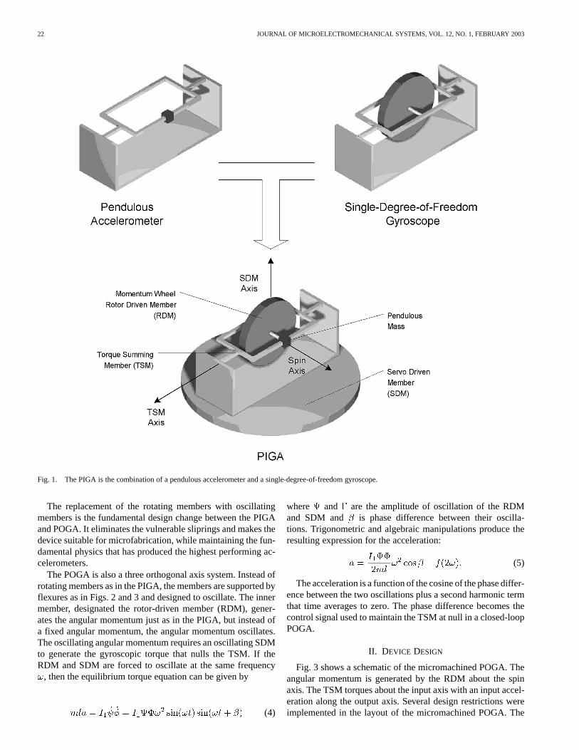
Adding a proof mass to a symmetric gimbal can form a pen-dulous accelerometer (see Fig. 1). An input acceleration willcreate a torque on the gimbal proportional to the mass (), thedisplacement of the mass from the axis of rotation or momentarm ( ) and the input acceleration (). This torque is defined asthependulous torque :
(1)
Mounting a spinning momentum wheel on a gimbal perpen-dicular to the wheel axis forms a single-degree-of-freedom gy-roscope. Rotation of the gyroscope about an axis perpendicularto both the spin axis of the wheel and the gimbal axis will createagyroscopic torque on the gimbal proportional to the angularmomentum of the wheel () and the rotation rate of the gyro-scope ( ) [4]–[6]:
(2)
When the functionalities of the two instruments are super-imposed, the gimbal of the accelerometer and the gimbal of thesingle-degree-of-freedom gyroscope become the same member.The pendulous torque and the gyroscopic torque are mechani-cally summed on this member, which is known as thetorquesumming member(TSM). The momentum wheel or rotor is usu-ally positioned such that the spin axis is aligned with the pendu-lous mass as in Fig. 1. In order to generate a gyroscopic torqueto balance the torque generated by the acceleration of the pendu-lous mass, the gyroscope is mounted on an additional memberthat is able to rotate under the influence of an external servo-motor. This member is called theservo driven member(SDM).In closed-loop operation of the PIGA, the SDM is rotated suchthat the gyroscopic and pendulous torques cancel. Setting thependulous torque equal to the gyroscopic torque creates an equi-librium torque equation given by
(3)
where is the moment of inertia of the rotor about the spinaxis, is the angular velocity of the rotor about the spin axisand is the angular velocity of the servo driven member aboutits axis.
In order to null a constant input acceleration, such as the ac-celeration due to Earth’s gravity, a constant rotation of the SDMis required, which is a potential disadvantage of the PIGA ap-proach. The electrical signals must pass through sliprings to ex-cite the inner components. These sliprings can eventually be-come failure modes, due to the wear caused by the continuousrotation of the SDM.
1057-7157/03$17.00 © 2003 IEEE
22 JOURNAL OF MICROELECTROMECHANICAL SYSTEMS, VOL. 12, NO. 1, FEBRUARY 2003
Fig. 1. The PIGA is the combination of a pendulous accelerometer and a single-degree-of-freedom gyroscope.
The replacement of the rotating members with oscillatingmembers is the fundamental design change between the PIGAand POGA. It eliminates the vulnerable sliprings and makes thedevice suitable for microfabrication, while maintaining the fun-damental physics that has produced the highest performing ac-celerometers.
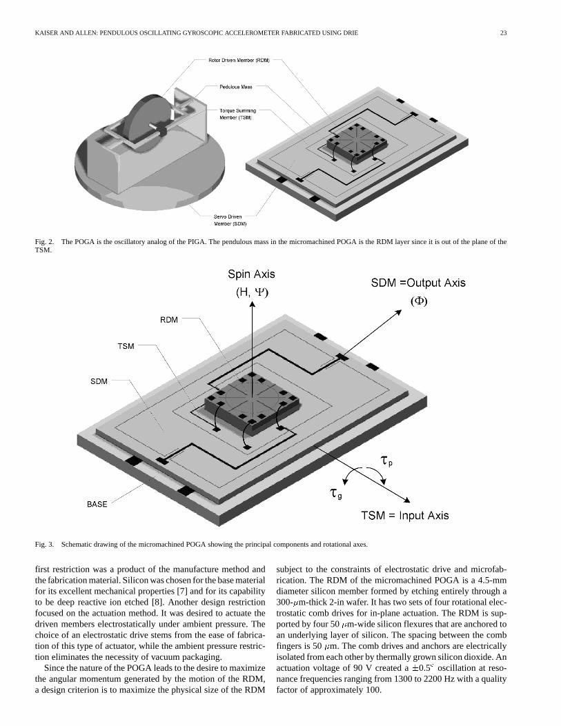
The POGA is also a three orthogonal axis system. Instead ofrotating members as in the PIGA, the members are supported byflexures as in Figs. 2 and 3 and designed to oscillate. The innermember, designated the rotor-driven member (RDM), gener-ates the angular momentum just as in the PIGA, but instead ofa fixed angular momentum, the angular momentum oscillates.The oscillating angular momentum requires an oscillating SDMto generate the gyroscopic torque that nulls the TSM. If theRDM and SDM are forced to oscillate at the same frequency
, then the equilibrium torque equation can be given by
(4)
where and are the amplitude of oscillation of the RDMand SDM and is phase difference between their oscilla-tions. Trigonometric and algebraic manipulations produce theresulting expression for the acceleration:
(5)
The acceleration is a function of the cosine of the phase differ-ence between the two oscillations plus a second harmonic termthat time averages to zero. The phase difference becomes thecontrol signal used to maintain the TSM at null in a closed-loopPOGA.
II. DEVICE DESIGN
Fig. 3 shows a schematic of the micromachined POGA. Theangular momentum is generated by the RDM about the spinaxis. The TSM torques about the input axis with an input accel-eration along the output axis. Several design restrictions wereimplemented in the layout of the micromachined POGA. The
KAISER AND ALLEN: PENDULOUS OSCILLATING GYROSCOPIC ACCELEROMETER FABRICATED USING DRIE 23
Fig. 2. The POGA is the oscillatory analog of the PIGA. The pendulous mass in the micromachined POGA is the RDM layer since it is out of the plane of theTSM.
Fig. 3. Schematic drawing of the micromachined POGA showing the principal components and rotational axes.
first restriction was a product of the manufacture method andthe fabrication material. Silicon was chosen for the base materialfor its excellent mechanical properties [7] and for its capabilityto be deep reactive ion etched [8]. Another design restrictionfocused on the actuation method. It was desired to actuate thedriven members electrostatically under ambient pressure. Thechoice of an electrostatic drive stems from the ease of fabrica-tion of this type of actuator, while the ambient pressure restric-tion eliminates the necessity of vacuum packaging.
Since the nature of the POGA leads to the desire to maximizethe angular momentum generated by the motion of the RDM,a design criterion is to maximize the physical size of the RDM
subject to the constraints of electrostatic drive and microfab-rication. The RDM of the micromachined POGA is a 4.5-mmdiameter silicon member formed by etching entirely through a300- m-thick 2-in wafer. It has two sets of four rotational elec-trostatic comb drives for in-plane actuation. The RDM is sup-ported by four 50 m-wide silicon flexures that are anchored toan underlying layer of silicon. The spacing between the combfingers is 50 m. The comb drives and anchors are electricallyisolated from each other by thermally grown silicon dioxide. Anactuation voltage of 90 V created a0.5 oscillation at reso-nance frequencies ranging from 1300 to 2200 Hz with a qualityfactor of approximately 100.
24 JOURNAL OF MICROELECTROMECHANICAL SYSTEMS, VOL. 12, NO. 1, FEBRUARY 2003
The TSM and the SDM are silicon members etched from thesame two-inch silicon wafer as a single unit. The TSM is insetwithin the SDM. The TSM flexures are 50m wide and 1 mmlong connecting the TSM to the SDM. The SDM flexure di-mensions are varied to match the SDM resonant frequency tothe RDM resonant frequency. These flexures attach the SDM toa frame that is mounted to a supporting base. The SDM has 100
m holes perforating the silicon structure to reduce the squeezefilm damping between the SDM and the supporting glass base.The TSM requires damping to reduce the vibration sensitivityof the TSM, so no perforations are necessary. The backside ofthe SDM and TSM are etched to create the necessary gap toallow motion of these members. This gap was varied between 10and 50 m. Smaller gaps required less drive voltages but allowsmaller mechanical motion. The front side has electrical con-duits patterned on the surface separated from the substrate by alayer of silicon dioxide.
The SDM/TSM assembly is mounted on a base that provideselectrodes for actuation and sensing of the mechanical mem-bers. The drive electrodes for the SDM are positioned near theedge of the member to increase the torque generated. The SDMsensing electrodes are positioned just inside the drive electrodes.The TSM 2 mm 5 mm sensing electrodes are placed underthe TSM at the edge of the member to maximize sensitivity torotations. They have a 50-m gap that results in a 2 pf capac-itance. Both sensor systems use differential capacitor readoutelectronics to monitor the position of the SDM and TSM. Aground plane is serpentined between the electrodes to reducecrosstalk between the capacitors.
III. FABRICATION
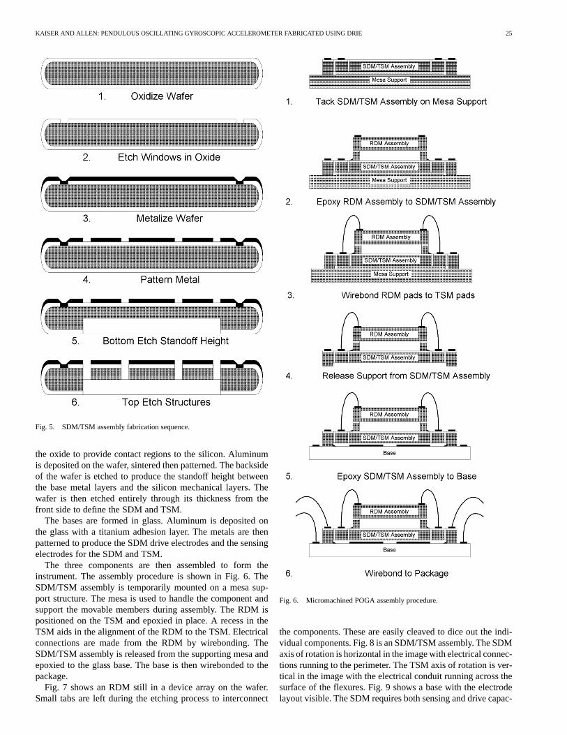
The micromachined POGA is fabricated in three separateassemblies, the RDM, the SDM/TSM assembly and the base.The RDM and SDM/TSM assembly were etched out of siliconwafers in a Plasma Therm inductively coupled plasma reactiveion etcher (ICP-RIE). Characterization and discussion of theprocedure can be found elsewhere [8]. The base is formed inglass with patterned metal electrodes on the surface.
The RDM fabrication sequence is shown in Fig. 4. A 2-inp-type silicon wafer is oxidized to produce a 1m layer ofoxide surrounding the wafer. The oxidized wafer is bonded toanother nonoxidized wafer using standard techniques [9]. Thebonded wafers are now electrically isolated by the oxide layerbetween them. The bonded wafers are then oxidized again. Thetop wafer is then patterned and etched down to the buried oxidelayer defining the RDM, its flexures and its radial comb drives.The wafer combination is then etched from the backside to re-lease the RDM mechanical structure, yet retain the anchors forthe flexures and comb drive. The oxide is then removed from theexterior surfaces and aluminum is patterned on the comb driveanchors by using a shadow mask.
The shadow masks were also produced using the ICP. Holeswere etched through silicon wafers to produce the masks. Whenthe mask is aligned to the wafer, aluminum was allowed to de-posit on the component only in the required areas. The shadowmasks were produced for both device-level metallization andwafer-level metallization.
Fig. 4. RDM fabrication sequence.
The fabrication sequence of the SDM/TSM assembly isshown in Fig. 5. A p-type 2-in silicon wafer is oxidized toproduce a one micron layer of oxide. Windows are etched in
KAISER AND ALLEN: PENDULOUS OSCILLATING GYROSCOPIC ACCELEROMETER FABRICATED USING DRIE 25
Fig. 5. SDM/TSM assembly fabrication sequence.
the oxide to provide contact regions to the silicon. Aluminumis deposited on the wafer, sintered then patterned. The backsideof the wafer is etched to produce the standoff height betweenthe base metal layers and the silicon mechanical layers. Thewafer is then etched entirely through its thickness from thefront side to define the SDM and TSM.
The bases are formed in glass. Aluminum is deposited onthe glass with a titanium adhesion layer. The metals are thenpatterned to produce the SDM drive electrodes and the sensingelectrodes for the SDM and TSM.
The three components are then assembled to form theinstrument. The assembly procedure is shown in Fig. 6. TheSDM/TSM assembly is temporarily mounted on a mesa sup-port structure. The mesa is used to handle the component andsupport the movable members during assembly. The RDM ispositioned on the TSM and epoxied in place. A recess in theTSM aids in the alignment of the RDM to the TSM. Electricalconnections are made from the RDM by wirebonding. TheSDM/TSM assembly is released from the supporting mesa andepoxied to the glass base. The base is then wirebonded to thepackage.
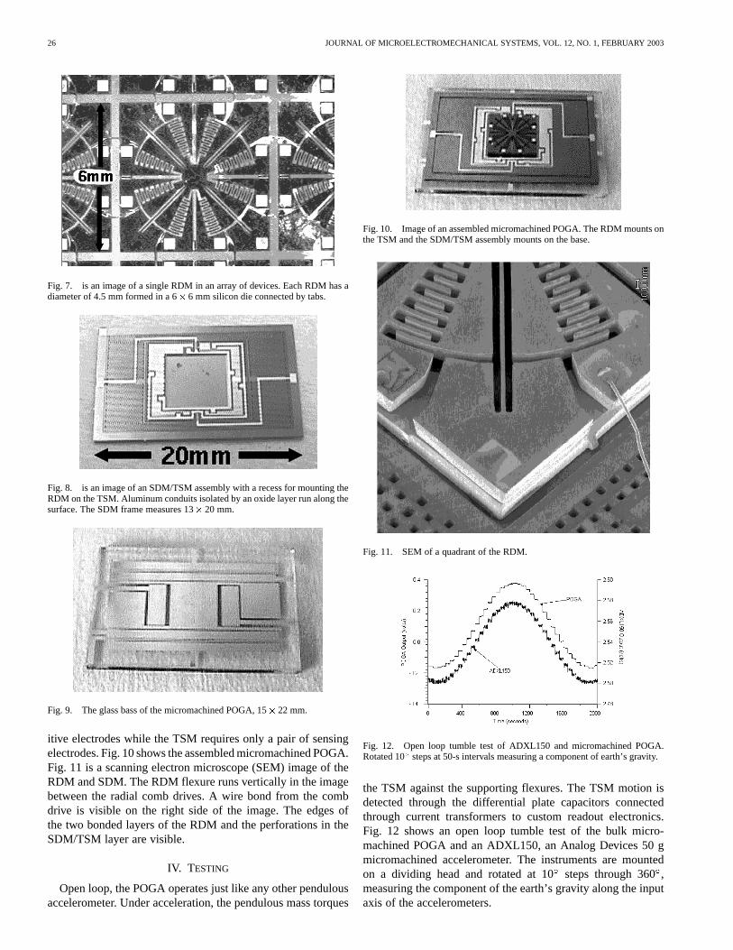
Fig. 7 shows an RDM still in a device array on the wafer.Small tabs are left during the etching process to interconnect
Fig. 6. Micromachined POGA assembly procedure.
the components. These are easily cleaved to dice out the indi-vidual components. Fig. 8 is an SDM/TSM assembly. The SDMaxis of rotation is horizontal in the image with electrical connec-tions running to the perimeter. The TSM axis of rotation is ver-tical in the image with the electrical conduit running across thesurface of the flexures. Fig. 9 shows a base with the electrodelayout visible. The SDM requires both sensing and drive capac-
26 JOURNAL OF MICROELECTROMECHANICAL SYSTEMS, VOL. 12, NO. 1, FEBRUARY 2003
Fig. 7. is an image of a single RDM in an array of devices. Each RDM has adiameter of 4.5 mm formed in a 6� 6 mm silicon die connected by tabs.
Fig. 8. is an image of an SDM/TSM assembly with a recess for mounting theRDM on the TSM. Aluminum conduits isolated by an oxide layer run along thesurface. The SDM frame measures 13� 20 mm.
Fig. 9. The glass bass of the micromachined POGA, 15� 22 mm.
itive electrodes while the TSM requires only a pair of sensingelectrodes. Fig. 10 shows the assembled micromachined POGA.Fig. 11 is a scanning electron microscope (SEM) image of theRDM and SDM. The RDM flexure runs vertically in the imagebetween the radial comb drives. A wire bond from the combdrive is visible on the right side of the image. The edges ofthe two bonded layers of the RDM and the perforations in theSDM/TSM layer are visible.
IV. TESTING
Open loop, the POGA operates just like any other pendulousaccelerometer. Under acceleration, the pendulous mass torques
Fig. 10. Image of an assembled micromachined POGA. The RDM mounts onthe TSM and the SDM/TSM assembly mounts on the base.
Fig. 11. SEM of a quadrant of the RDM.
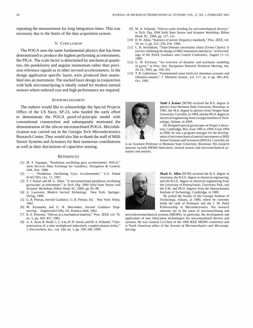
Fig. 12. Open loop tumble test of ADXL150 and micromachined POGA.Rotated 10 steps at 50-s intervals measuring a component of earth’s gravity.
the TSM against the supporting flexures. The TSM motion isdetected through the differential plate capacitors connectedthrough current transformers to custom readout electronics.Fig. 12 shows an open loop tumble test of the bulk micro-machined POGA and an ADXL150, an Analog Devices 50 gmicromachined accelerometer. The instruments are mountedon a dividing head and rotated at 10steps through 360,measuring the component of the earth’s gravity along the inputaxis of the accelerometers.
KAISER AND ALLEN: PENDULOUS OSCILLATING GYROSCOPIC ACCELEROMETER FABRICATED USING DRIE 27
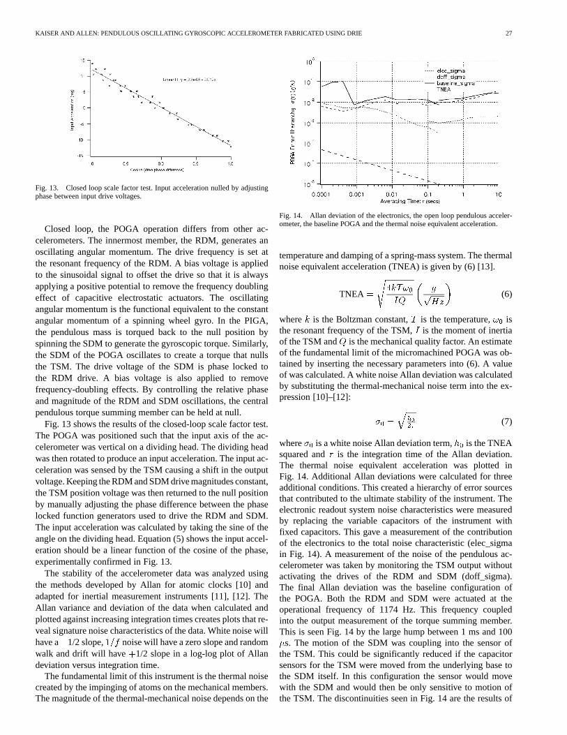
Fig. 13. Closed loop scale factor test. Input acceleration nulled by adjustingphase between input drive voltages.
Closed loop, the POGA operation differs from other ac-celerometers. The innermost member, the RDM, generates anoscillating angular momentum. The drive frequency is set atthe resonant frequency of the RDM. A bias voltage is appliedto the sinusoidal signal to offset the drive so that it is alwaysapplying a positive potential to remove the frequency doublingeffect of capacitive electrostatic actuators. The oscillatingangular momentum is the functional equivalent to the constantangular momentum of a spinning wheel gyro. In the PIGA,the pendulous mass is torqued back to the null position byspinning the SDM to generate the gyroscopic torque. Similarly,the SDM of the POGA oscillates to create a torque that nullsthe TSM. The drive voltage of the SDM is phase locked tothe RDM drive. A bias voltage is also applied to removefrequency-doubling effects. By controlling the relative phaseand magnitude of the RDM and SDM oscillations, the centralpendulous torque summing member can be held at null.
Fig. 13 shows the results of the closed-loop scale factor test.The POGA was positioned such that the input axis of the ac-celerometer was vertical on a dividing head. The dividing headwas then rotated to produce an input acceleration. The input ac-celeration was sensed by the TSM causing a shift in the outputvoltage. Keeping the RDM and SDM drive magnitudes constant,the TSM position voltage was then returned to the null positionby manually adjusting the phase difference between the phaselocked function generators used to drive the RDM and SDM.The input acceleration was calculated by taking the sine of theangle on the dividing head. Equation (5) shows the input accel-eration should be a linear function of the cosine of the phase,experimentally confirmed in Fig. 13.
The stability of the accelerometer data was analyzed usingthe methods developed by Allan for atomic clocks [10] andadapted for inertial measurement instruments [11], [12]. TheAllan variance and deviation of the data when calculated andplotted against increasing integration times creates plots that re-veal signature noise characteristics of the data. White noise willhave a 1/2 slope, noise will have a zero slope and randomwalk and drift will have 1/2 slope in a log-log plot of Allandeviation versus integration time.
The fundamental limit of this instrument is the thermal noisecreated by the impinging of atoms on the mechanical members.The magnitude of the thermal-mechanical noise depends on the
Fig. 14. Allan deviation of the electronics, the open loop pendulous acceler-ometer, the baseline POGA and the thermal noise equivalent acceleration.
temperature and damping of a spring-mass system. The thermalnoise equivalent acceleration (TNEA) is given by (6) [13].
TNEA (6)
where is the Boltzman constant, is the temperature, isthe resonant frequency of the TSM,is the moment of inertiaof the TSM and is the mechanical quality factor. An estimateof the fundamental limit of the micromachined POGA was ob-tained by inserting the necessary parameters into (6). A valueof was calculated. A white noise Allan deviation was calculatedby substituting the thermal-mechanical noise term into the ex-pression [10]–[12]:
(7)
where is a white noise Allan deviation term, is the TNEAsquared and is the integration time of the Allan deviation.The thermal noise equivalent acceleration was plotted inFig. 14. Additional Allan deviations were calculated for threeadditional conditions. This created a hierarchy of error sourcesthat contributed to the ultimate stability of the instrument. Theelectronic readout system noise characteristics were measuredby replacing the variable capacitors of the instrument withfixed capacitors. This gave a measurement of the contributionof the electronics to the total noise characteristic (elec_sigmain Fig. 14). A measurement of the noise of the pendulous ac-celerometer was taken by monitoring the TSM output withoutactivating the drives of the RDM and SDM (doff_sigma).The final Allan deviation was the baseline configuration ofthe POGA. Both the RDM and SDM were actuated at theoperational frequency of 1174 Hz. This frequency coupledinto the output measurement of the torque summing member.This is seen Fig. 14 by the large hump between 1 ms and 100
s. The motion of the SDM was coupling into the sensor ofthe TSM. This could be significantly reduced if the capacitorsensors for the TSM were moved from the underlying base tothe SDM itself. In this configuration the sensor would movewith the SDM and would then be only sensitive to motion ofthe TSM. The discontinuities seen in Fig. 14 are the results of
28 JOURNAL OF MICROELECTROMECHANICAL SYSTEMS, VOL. 12, NO. 1, FEBRUARY 2003
repeating the measurement for long integration times. This wasnecessary due to the limits of the data acquisition system.
V. CONCLUSION
The POGA uses the same fundamental physics that has beendemonstrated to produce the highest performing accelerometer,the PIGA. The scale factor is determined by mechanical quanti-ties, the pendulosity and angular momentum rather than preci-sion reference signals as in other servoed accelerometers. In thedesign application specific layers were produced then assem-bled into an instrument. The stacked layer design in conjunctionwith bulk micromachjning is ideally suited for modern inertialsensors where reduced cost and high performance are required.
ACKNOWLEDGMENT
The authors would like to acknowledge the Special ProjectsOffice of the US Navy, SP-23, who funded the early effortto demonstrate the POGA proof-of-principle model withconventional construction and subsequently motivated thedemonstration of the silicon micromachined POGA. Microfab-rication was carried out in the Georgia Tech MicroelectronicsResearch Center. They would also like to thank the staff of MilliSensor Systems and Actuators for their numerous contributionsas well as their discussions of capacitive sensing.
REFERENCES
[1] M. S. Sapuppo, “Pendulous oscillating gyro accelerometer: POGA,”Joint Services Data Exchange for Guidance, Navigation & Control,24th, Nov. 1998.
[2] , “Pendulous Oscillating Gyro Accelerometer,” U.S. Patent#5 457 993, Oct. 17, 1997.
[3] T. J. Kaiser and M. G. Allen, “A micromachined pendulous oscillatinggyroscopic accelerometer,” inTech. Dig. 2000 Solid State Sensor andActuator Workshop, Hilton Head, SC, 2000, pp. 85–88.
[4] A. Lawrence, Modern Inertial Technology. New York: Springer-Verlag, 1998.
[5] G. R. Pitman,Inertial Guidance, G. R. Pitman, Ed. New York: Wiley,1962.
[6] M. Fernandez and G. R. Macomber,Inertial Guidance Engi-neering. Englewood Cliffs, NJ: Prentice-Hall, 1962.
[7] K. E. Petersen, “Silicon as a mechanical material,”Proc. IEEE, vol. 70,no. 5, pp. 420–457, 1982.
[8] A. A. Ayon, R. Braff, C. C. Lin, H. H. Sawin, and M. A. Schmidt, “Char-acterization of a time multiplexed inductively coupled plasma etcher,”J. Electrochem. Soc., vol. 146, no. 1, pp. 339–349, 1999.
[9] M. A. Schmidt, “Silicon wafer bonding for micromechanical devices,”in Tech. Dig. 1994 Solid State Sensor and Actuator Workshop, HiltonHead, SC, 1994, pp. 127–131.
[10] D. W. Allan, “Statistics of atomic frequency standards,”Proc. IEEE, vol.54, no. 2, pp. 221–230, Feb. 1966.
[11] C. R. Kochakian, “Time-Domain uncertainty charts (Green Charts): Atool for validating the design of IMU/instrument interfaces,” in Proceed-ings of the AIAA Guidance and Control Conference, August 11–13,1980.
[12] G. W. Erickson, “An overview of dynamic and stochastic modelingof gyros,” in Proc. Inst. Navigation National Technical Meeting, Jan.20–22, 1993, pp. 339–351.
[13] T. B. Gabrielson, “Fundamental noise limits for miniature acoustic andvibration sensors,”J. Vibration Acoust., vol. 117, no. 4, pp. 405–410,Oct. 1995.
Todd J. Kaiser (M’00) received the B.S. degree inphysics from Montana State University, Bozeman, in1981, the M.S. degree in physics from Oregon StateUniversity, Corvallis, in 1984, and the Ph.D. degree inelectrical engineering from Georgia Institute of Tech-nology, Atlanta, in 2000.
He designed optical gyroscopes at Draper Labora-tory, Cambridge, MA, from 1985 to 1994. From 1994to 2000, he was a program manager for the develop-ment of micromechanical inertial instruments at MilliSensor Systems and Actuators (MSSA). Currently, he
is an Assistant Professor at Montana State University, Bozeman. His researchinterests include MEMS fabrication, inertial sensors and micromechanical ac-tuators and sensors.
Mark G. Allen (M’89) received the B.A. degree inchemistry, the B.S.E. degree in chemical engineering,and the B.S.E. degree in electrical engineering fromthe University of Pennsylvania, University Park, andthe S.M. and Ph.D. degrees from the MassachusettsInstitute of Technology, Cambridge, in 1989.
He joined the faculty of the Georgia Institute ofTechnology, Atlanta, in 1989, where he currentlyholds the rank of Professor and the J. M. PettitProfessorship in Microelectronics. His researchinterests are in the areas of micromachining and
microelectromechanical systems (MEMS); in particular, the development andapplication of new fabrication technologies for micromachined devices andsystems. He was General Co-Chair of the 1996 IEEE MEMS conference andis North American editor of theJournal of Micromechanics and Microengi-neering.