Embed Size (px)
Citation preview
ACTIV
ITY REPO
RT 2016
Facility Status087
A Scanning Laue X-ray Diffraction Microscope
T he combined benefits resulting from the devel-opment of highly efficient X-ray focusing optics,
fast area-detector technology and ever more brilliant X-ray beam sources at synchrotron facilities have added nanometric spatial resolution never before achieved to the centennial but powerful technique of X-ray diffraction.
Incremental progress towards ever smaller and bright-er X-ray beams combined with increasing sophistica-tion of computer algorithms to process more compli-cated and larger datasets have rendered synchrotron microfocus and nanofocus techniques attractive to characterize diverse samples.
X-ray diffraction with a monochromatic beam is commonly used to characterize both epitaxial and polycrystalline thin films and multilayers. Here the X-ray beam impinges on the sample at a grazing angle to maximize the thin-film signal with respect to the substrate; the precise position and shape of the reflections are recorded. Shifts in the position of the reflections can be linked to a macroscopic strain or dif-ferences in chemical composition, whereas the study of reflection shapes can provide useful information about the thin film such as the thickness, crystallite size, microscopic strain and defect type and density.
Polychromatic X-ray diffraction, better known as Laue diffraction discovered by Max von Laue in 1912, uses
a polychromatic incident beam to collect Laue pat-terns from a crystalline sample. With this technique, the Bragg condition is satisfied simultaneously for multiple reflections, without the need to rotate the crystal. Laue diffraction has therefore the potential to be a quicker alternative to the monochromatic X-ray diffraction method, but the wavelength information for each reflection is generally lost making the inter-pretation of the intensities difficult. Laue diffraction was therefore used in laboratories solely to deter-mine the orientation of a crystal before its mount-ing on a diffractometer for monochromatic X-ray study. In the 1990s the method found applications at synchrotron facilities along two directions. First, by resolving the problem of wavelength-dependent intensity corrections and calibrating the wavelength distribution among the reflections, Laue diffraction was found to be a viable alternative to monochro-matic single-crystal diffraction to solve the structure of large molecules.1,2 As data collection is rapid, it has been used in time-resolved studies to solve the struc-ture of ephemeral macromolecular configurations.3,4 Second, Laue diffraction was used in combination with X-ray focusing optics to map rapidly the crystal orientation and strain in polycrystalline materials.5-7 This technique is called X-ray Laue microdiffraction or microLaue diffraction as the size of the X-ray beam is about 1 μm or less. A small X-ray beam means not only that small samples, such as a mineral inclusion inside a highly heterogeneous rock specimen, can
Fig. 1: Detailed layout of XND endstation (called FORMOSA – FOcus X-ray for MicrO-Structure Analysis) and its functionalities.
ACTIV
ITY REPO
RT 2016
Facility Status
088
be investigated, but also that the spatial distribution of microstructural characteristics such as crystallite orientation and strain in a polycrystalline sample, can be mapped, when the technique is used in a scanning mode (the sample is raster-scanned under the micro/nano beam and diffraction is collected at each step). Synchrotron X-ray nano- or microdiffraction techniques thus complement other imaging techniques such as scan-ning electron microscopy (SEM), transmission electron microscopy (TEM), Raman micro-spectroscopy, X-ray microscopy, X-ray microfluorescence imaging, luminescence microscopy, atomic-force microscopy (AFM) and scanning tunneling microscopy (STM) and typically provide information that is more difficult to obtain from other characterization tools.
Over the past two decades, scanning X-ray Laue diffraction method has become more powerful; many synchrotron facilities established their own dedicated micro/nano-Laue diffraction beamlines, beginning with BL 34-ID-E of APS (1999) through BL 12.3.2 of ALS ( 2001), VESPERS of CLS (2007), BM32 of ESRF (2010) to TPS 21A (2016). Based on a new design of a small-emittance storage ring and a state-of-the-art two-stage focus-ing design of a beamline, the TPS 21A X-ray nanodiffraction (XND) deliv-ered the smallest focusing size, ~90 nm, in the field and greatest photon flux ~3 x 10¹¹ s-1 at 10 keV. Combined with a specially designed fast area X-ray detector, the rate of Laue pattern images of XND can easily attain up to 10~25 Hz depending on the specimen. This advance made Laue X-ray diffraction become a structural microscope. XND combined with on-line SEM for quick sample positioning and tetra-probe stages for diverse measurements cover electrical, optical and surface properties to provide complementary information other than X-ray. Figure 1 shows the design of the XND endstation.
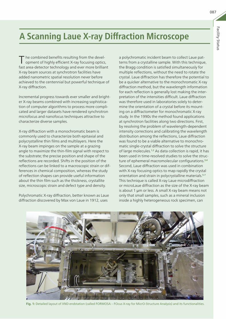
From a Laue diffraction microscope, a user could obtain the 2D and 3D (incorporated with a high-Z metal wire scanning across the surface of a sample during each scan point) distribution of structural information including phase, orientation, strain or stress and density of dislocations after an area scan with fine steps. For example, a scanning area 10 x 10 μm2 with step 100 nm results in 10,201 patterns of shape like the top of Fig. 2. Without dedicated analysis software such as XMAS (X-ray Micro-diffraction Analysis Software) developed by Nobumichi Tamura from ALS, a user would have been unable to extract that information mentioned above.
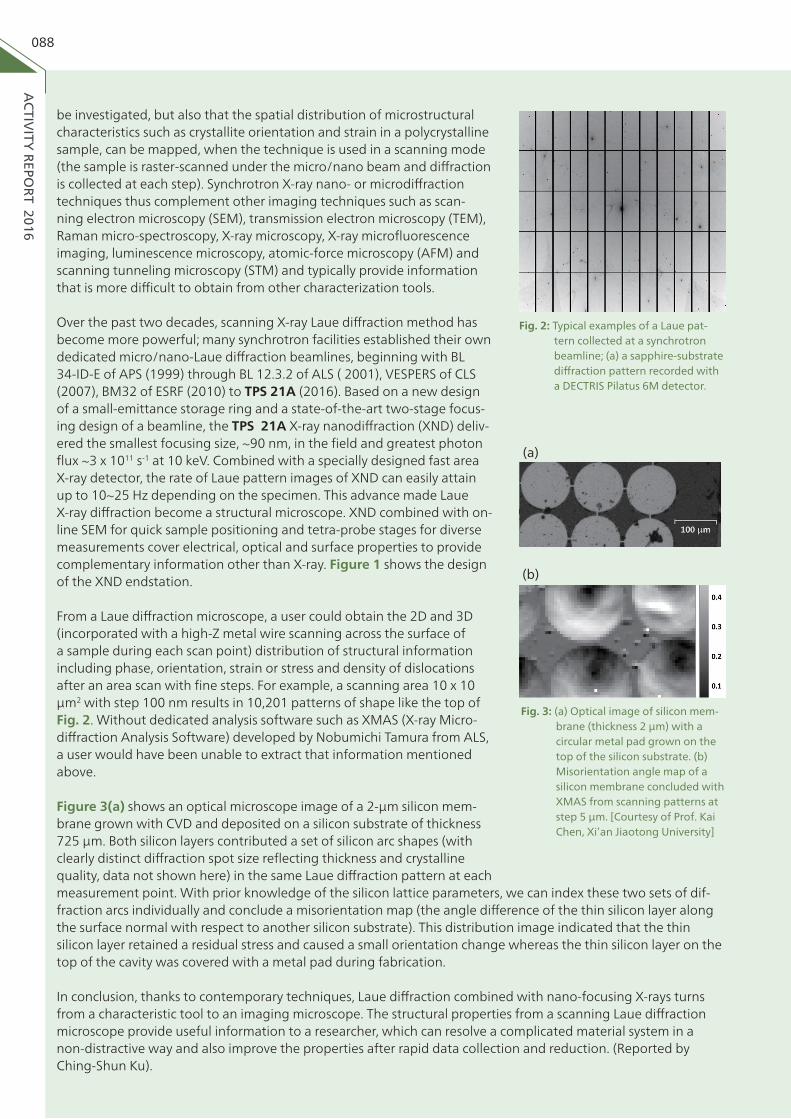
Figure 3(a) shows an optical microscope image of a 2-μm silicon mem-brane grown with CVD and deposited on a silicon substrate of thickness 725 μm. Both silicon layers contributed a set of silicon arc shapes (with clearly distinct diffraction spot size reflecting thickness and crystalline quality, data not shown here) in the same Laue diffraction pattern at each
Fig. 3: (a) Optical image of silicon mem-brane (thickness 2 μm) with a circular metal pad grown on the top of the silicon substrate. (b) Misorientation angle map of a silicon membrane concluded with XMAS from scanning patterns at step 5 μm. [Courtesy of Prof. Kai Chen, Xi’an Jiaotong University]
Fig. 2: Typical examples of a Laue pat-tern collected at a synchrotron beamline; (a) a sapphire-substrate diffraction pattern recorded with a DECTRIS Pilatus 6M detector.
(a)
(b)
measurement point. With prior knowledge of the silicon lattice parameters, we can index these two sets of dif-fraction arcs individually and conclude a misorientation map (the angle difference of the thin silicon layer along the surface normal with respect to another silicon substrate). This distribution image indicated that the thin silicon layer retained a residual stress and caused a small orientation change whereas the thin silicon layer on the top of the cavity was covered with a metal pad during fabrication.
In conclusion, thanks to contemporary techniques, Laue diffraction combined with nano-focusing X-rays turns from a characteristic tool to an imaging microscope. The structural properties from a scanning Laue diffraction microscope provide useful information to a researcher, which can resolve a complicated material system in a non-distractive way and also improve the properties after rapid data collection and reduction. (Reported by Ching-Shun Ku).
ACTIV
ITY REPO
RT 2016
Facility Status089
| References |1. Z. Ren, and K. Moffat, J. Appl. Cryst. 28(5), 461
(1995).2. Z. Ren, D. Bourgeois, J. R. Helliwell, K. Moffat, V.
Srajer, and B. L. Stoddard, J. Synch. Rad. 6(4), 891 (1999).
3. U. K. Genick, G. E. Borgstahl, K. Ng, Z. Ren, C. Prad-ervand, P. M. Burke, V. Šrajer, T.-Y. Teng, W. Schil-dkamp, D. E. McRee, K. Moffat, and D. F. Getzoff,
Science 275(5305), 1471 (1997).4. K. Moffat, Nat. Struc. Mole. Bio. 5, 641 (1998).5. P. C. Wang, G. S. Cargill III, I. C. Noyan, and C. K. Hu,
Appl. Phys. Lett. 72(11), 1296 (1998).6. J. S. Chung, N. Tamura, G. E. Ice, B. C. Larson, and J.
D. Budai, MRS Proc. 563, 169 (1999). 7. N. Tamura, B. C. Valek, R. Spolenak, A. A. MacDow-
ell, R. S. Celestre, H. A. Padmore, and J. R. Patel, MRS Proc. 612, D8 (2000).
X-ray Pump-Probe Technique
A n understanding of structural dynamics at a molecular lev-
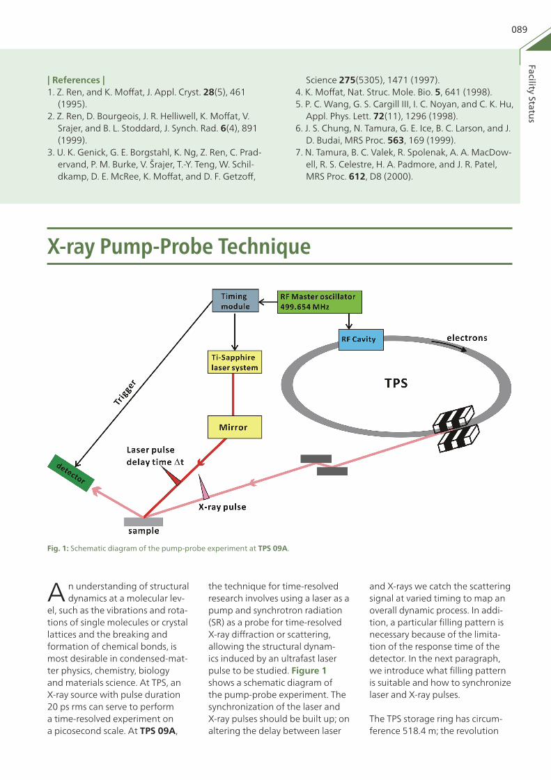
el, such as the vibrations and rota-tions of single molecules or crystal lattices and the breaking and formation of chemical bonds, is most desirable in condensed-mat-ter physics, chemistry, biology and materials science. At TPS, an X-ray source with pulse duration 20 ps rms can serve to perform a time-resolved experiment on a picosecond scale. At TPS 09A,
Fig. 1: Schematic diagram of the pump-probe experiment at TPS 09A.
the technique for time-resolved research involves using a laser as a pump and synchrotron radiation (SR) as a probe for time-resolved X-ray diffraction or scattering, allowing the structural dynam-ics induced by an ultrafast laser pulse to be studied. Figure 1 shows a schematic diagram of the pump-probe experiment. The synchronization of the laser and X-ray pulses should be built up; on altering the delay between laser
and X-rays we catch the scattering signal at varied timing to map an overall dynamic process. In addi-tion, a particular filling pattern is necessary because of the limita-tion of the response time of the detector. In the next paragraph, we introduce what filling pattern is suitable and how to synchronize laser and X-ray pulses.
The TPS storage ring has circum-ference 518.4 m; the revolution