Embed Size (px)
Citation preview

A. Seshappa Asst Prof VCE Engineering Drawing
1
MECHANICAL ENGINEERING
Seshappa Asst Prof VCE | MECHANICAL ENGINEERING
1
Engineering Drawing
A. Seshappa Asst Prof VCE Engineering Drawing
2
MECHANICAL ENGINEERING
Seshappa Asst Prof VCE | MECHANICAL ENGINEERING
2
CONTENTS
I Introduction To Engineering Drawing
1 Introduction 1-9
2 Lettering & Dimensioning 9-10
3 Geometric constructions 10-15
4 Conic sections 15- 21
7 Important Questions 21
8 Previous paper questions 22
II Projection of Points and Straight Lines
1 Introduction and Projection of points 23-24
2 Projection of Straight lines 25-34
3 Important questions & Previous Paper Questions 35
III Projection of Planes and Solids
1 Introduction 36-38
2 Simple Problems 39-44
3 important and previous paper questions 45
4 Projection of solids-introduction 46-50
5 Problems 50-56
6 Previous paper questions 56
IV Isometric axes, lines ,planes and Solids
1 Introduction 57
2 Terminology and simple problems 58
3 Isometric view of Solids 59-63
4 Isometric view of Frustums 63
A. Seshappa Asst Prof VCE Engineering Drawing
3
MECHANICAL ENGINEERING
Seshappa Asst Prof VCE | MECHANICAL ENGINEERING
3
5 Isometric view of Composite solids 63
6 Problems 64-70
7 Previous paper questions 71
V Orthographic projection
1 Introduction 72-75
2 Problems 75-81
3 Previous paper questions 82-85
A. Seshappa Asst Prof VCE Engineering Drawing
4
MECHANICAL ENGINEERING
Seshappa Asst Prof VCE | MECHANICAL ENGINEERING
4
UNIT – 1 INTRODUCTION TO ENGINEERING DRAWING
Engineering drawing is a two dimensional representation of three dimensional objects. In general, it
provides necessary information about the shape, size, surface quality, material, manufacturing
process, etc., of the object. It is the graphic language from which a trained person can visualize
objects.
Drawing Instruments and aids:
The Instruments and other aids used in drafting work are listed below:
Drawing board
Set squares
French curves
Templates
Mini drafter
Instrument box
Protractor
Set of scales
Drawing sheets
Pencils
Drawing Board:
Until recently drawing boards used are made of well seasoned softwood of about 25 mm thick with a
working edge for T-square. Nowadays mini-drafters are used instead of T-squares which can be fixed
on any board. The standard size of board depends on the size of drawing sheet size required.
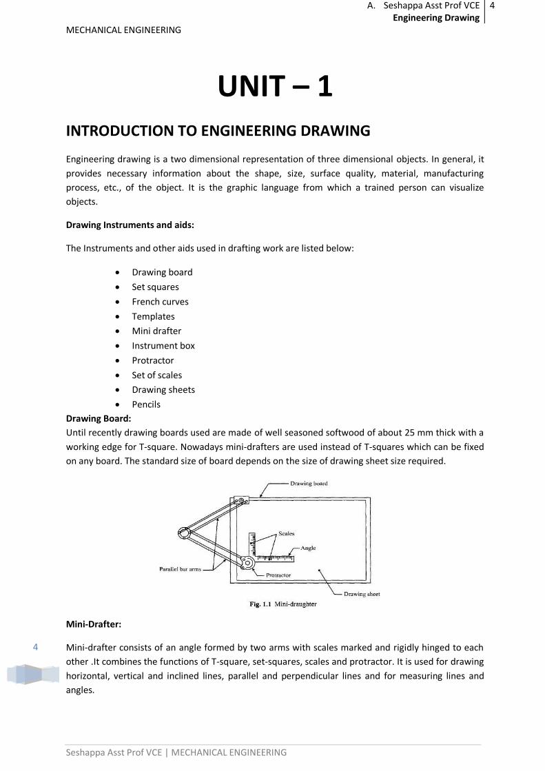
Mini-Drafter:
Mini-drafter consists of an angle formed by two arms with scales marked and rigidly hinged to each
other .It combines the functions of T-square, set-squares, scales and protractor. It is used for drawing
horizontal, vertical and inclined lines, parallel and perpendicular lines and for measuring lines and
angles.
A. Seshappa Asst Prof VCE Engineering Drawing
5
MECHANICAL ENGINEERING
Seshappa Asst Prof VCE | MECHANICAL ENGINEERING
5
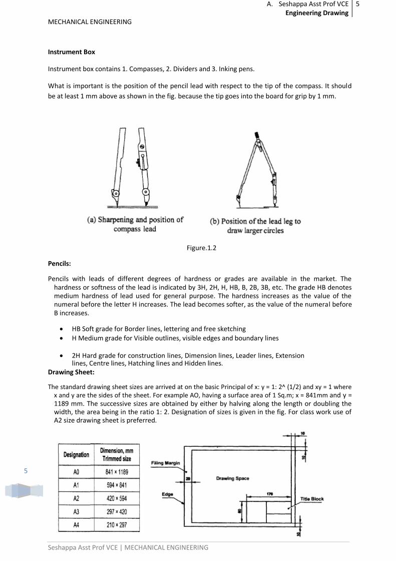
Instrument Box
Instrument box contains 1. Compasses, 2. Dividers and 3. Inking pens.
What is important is the position of the pencil lead with respect to the tip of the compass. It should
be at least 1 mm above as shown in the fig. because the tip goes into the board for grip by 1 mm.
Figure.1.2
Pencils:
Pencils with leads of different degrees of hardness or grades are available in the market. The hardness or softness of the lead is indicated by 3H, 2H, H, HB, B, 2B, 3B, etc. The grade HB denotes medium hardness of lead used for general purpose. The hardness increases as the value of the numeral before the letter H increases. The lead becomes softer, as the value of the numeral before B increases.
HB Soft grade for Border lines, lettering and free sketching
H Medium grade for Visible outlines, visible edges and boundary lines
2H Hard grade for construction lines, Dimension lines, Leader lines, Extension lines, Centre lines, Hatching lines and Hidden lines.
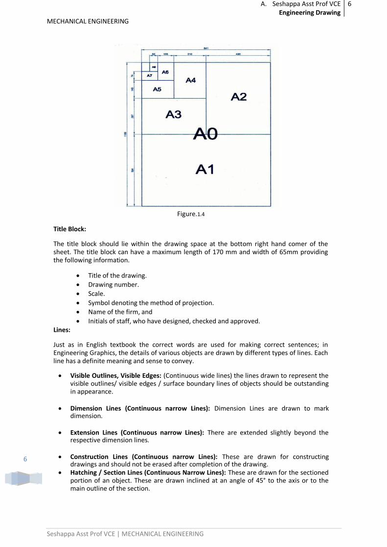
Drawing Sheet:
The standard drawing sheet sizes are arrived at on the basic Principal of x: y = 1: 2^ (1/2) and xy = 1 where x and y are the sides of the sheet. For example AO, having a surface area of 1 Sq.m; x = 841mm and y = 1189 mm. The successive sizes are obtained by either by halving along the length or doubling the width, the area being in the ratio 1: 2. Designation of sizes is given in the fig. For class work use of A2 size drawing sheet is preferred.
A. Seshappa Asst Prof VCE Engineering Drawing
6
MECHANICAL ENGINEERING
Seshappa Asst Prof VCE | MECHANICAL ENGINEERING
6
Figure.1.4
Title Block:
The title block should lie within the drawing space at the bottom right hand comer of the sheet. The title block can have a maximum length of 170 mm and width of 65mm providing the following information.
Title of the drawing.
Drawing number.
Scale.
Symbol denoting the method of projection.
Name of the firm, and
Initials of staff, who have designed, checked and approved. Lines:
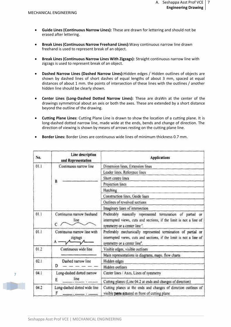
Just as in English textbook the correct words are used for making correct sentences; in Engineering Graphics, the details of various objects are drawn by different types of lines. Each line has a definite meaning and sense to convey.
Visible Outlines, Visible Edges: (Continuous wide lines) the lines drawn to represent the visible outlines/ visible edges / surface boundary lines of objects should be outstanding in appearance.
Dimension Lines (Continuous narrow Lines): Dimension Lines are drawn to mark dimension.
Extension Lines (Continuous narrow Lines): There are extended slightly beyond the respective dimension lines.
Construction Lines (Continuous narrow Lines): These are drawn for constructing drawings and should not be erased after completion of the drawing.
Hatching / Section Lines (Continuous Narrow Lines): These are drawn for the sectioned portion of an object. These are drawn inclined at an angle of 45° to the axis or to the main outline of the section.
A. Seshappa Asst Prof VCE Engineering Drawing
7
MECHANICAL ENGINEERING
Seshappa Asst Prof VCE | MECHANICAL ENGINEERING
7
Guide Lines (Continuous Narrow Lines): These are drawn for lettering and should not be erased after lettering.
Break Lines (Continuous Narrow Freehand Lines):Wavy continuous narrow line drawn freehand is used to represent break of an object.
Break Lines (Continuous Narrow Lines With Zigzags): Straight continuous narrow line with zigzags is used to represent break of an object.
Dashed Narrow Lines (Dashed Narrow Lines):Hidden edges / Hidden outlines of objects are shown by dashed lines of short dashes of equal lengths of about 3 mm, spaced at equal distances of about 1 mm. the points of intersection of these lines with the outlines / another hidden line should be clearly shown.
Center Lines (Long-Dashed Dotted Narrow Lines): These are draWn at the center of the drawings symmetrical about an axis or both the axes. These are extended by a short distance beyond the outline of the drawing.
Cutting Plane Lines: Cutting Plane Line is drawn to show the location of a cutting plane. It is long-dashed dotted narrow line, made wide at the ends, bends and change of direction. The direction of viewing is shown by means of arrows resting on the cutting plane line.
Border Lines: Border Lines are continuous wide lines of minimum thickness 0.7 mm.
Table.1.2
A. Seshappa Asst Prof VCE Engineering Drawing
8
MECHANICAL ENGINEERING
Seshappa Asst Prof VCE | MECHANICAL ENGINEERING
8
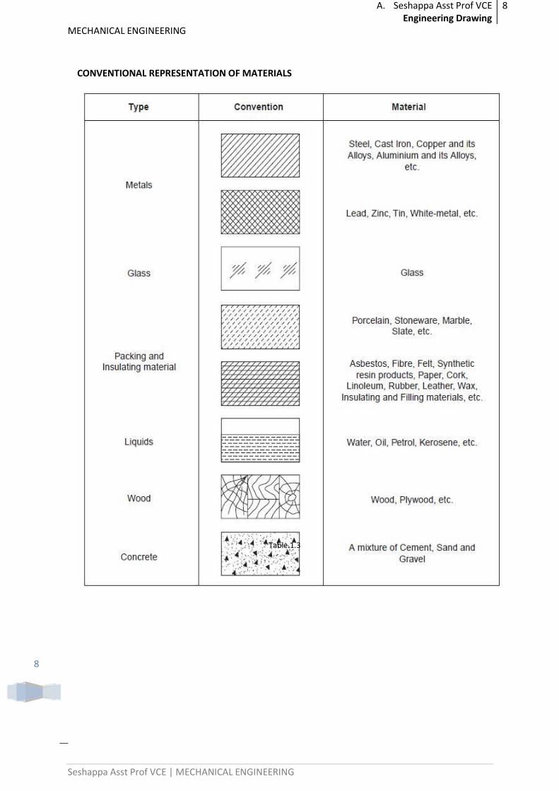
CONVENTIONAL REPRESENTATION OF MATERIALS
Table.1.3
A. Seshappa Asst Prof VCE Engineering Drawing
9
MECHANICAL ENGINEERING
Seshappa Asst Prof VCE | MECHANICAL ENGINEERING
9
LETTERING
Lettering is defined as writing of titles, sub-titles, dimensions, etc., on a drawing.
Importance of Lettering:
To undertake production work of an engineering component as per the drawing, the size and other details are indicated on the drawing. This is done in the form of notes and dimensions. Main Features of Lettering are legibility, uniformity and rapidity of execution. Use of drawing instruments for lettering consumes more time. Lettering should be done freehand with speed. Practice accompanied by continuous efforts would improve the lettering skill and style. Poor lettering mars the appearance of an otherwise good drawing.
Size of Letters:
Size of Letters is measured by the height h of the CAPITAL letters as well as numerals.
Standard heights for CAPITAL letters and numerals recommended by BIS are given below: 1.8, 2.5, 3.5, 5, 6, 10, 14 and 20 mm
Note: Size of the letters may be selected based upon the size of drawing.
Guide Lines:
In order to obtain correct and uniform height of letters and numerals, guide lines are drawn, using 2H pencil with light pressure. HB grade conical end pencil is used for lettering. The following are some of the guide lines for lettering
Drawing numbers, title block and letters denoting cutting planes, sections are written in 10 mm size.
Drawing title is written in 7 mm size. Hatching, sub-titles, materials, dimensions, notes, etc., are written in 3.5 mm size. Space between lines = 3/4 h
Space between words may be equal to the width of alphabet M or 3/5 h.
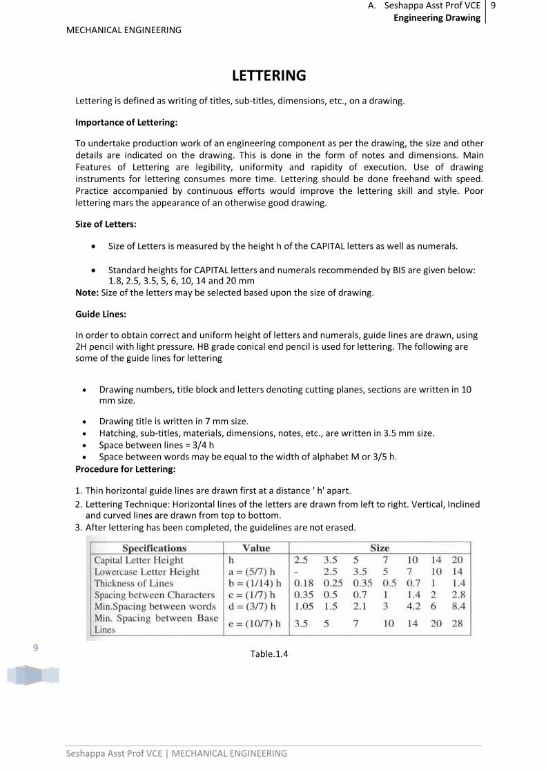
Procedure for Lettering:
1. Thin horizontal guide lines are drawn first at a distance ' h' apart. 2. Lettering Technique: Horizontal lines of the letters are drawn from left to right. Vertical, Inclined
and curved lines are drawn from top to bottom. 3. After lettering has been completed, the guidelines are not erased.
Table.1.4
A. Seshappa Asst Prof VCE Engineering Drawing
10
MECHANICAL ENGINEERING
Seshappa Asst Prof VCE | MECHANICAL ENGINEERING
10
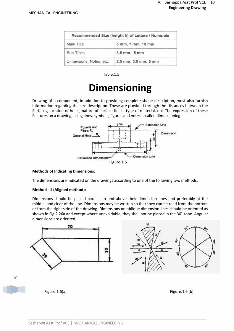
Table.1.5
Dimensioning Drawing of a component, in addition to providing complete shape description, must also furnish Information regarding the size description. These are provided through the distances between the Surfaces, location of holes, nature of surface finish, type of material, etc. The expression of these Features on a drawing, using lines, symbols, figures and notes is called dimensioning.
Figure.1.5
Methods of Indicating Dimensions:
The dimensions are indicated on the drawings according to one of the following two methods.
Method - 1 (Aligned method):
Dimensions should be placed parallel to and above their dimension lines and preferably at the middle, and clear of the line. Dimensions may be written so that they can be read from the bottom or from the right side of the drawing. Dimensions on oblique dimension lines should be oriented as shown in Fig.2.26a and except where unavoidable, they shall not be placed in the 30° zone. Angular dimensions are oriented.
Figure.1.6(a) Figure.1.6 (b)
A. Seshappa Asst Prof VCE Engineering Drawing
11
MECHANICAL ENGINEERING
Seshappa Asst Prof VCE | MECHANICAL ENGINEERING
11
Method - 2 (Uni-directional):
Dimensions should be indicated so that they can be read from the bottom of the drawing only. Non-horizontal dimension lines are interrupted, preferably in the middle for insertion of the dimension. Note: Horizontal dimensional lines are not broken to place the dimension in both cases.
Figure.1.7
GEOMETRICAL CONSTRUCTIONS
Introduction:
Engineering drawing consists of a number of geometrical constructions. A few methods are illustrated here without mathematical proofs.
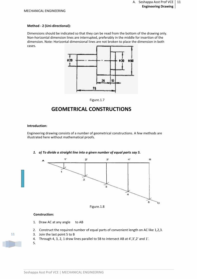
1. a) To divide a straight line into a given number of equal parts say 5.
Figure.1.8
Construction:
1. Draw AC at any angle to AB
2. Construct the required number of equal parts of convenient length on AC like 1,2,3. 3. Join the last point 5 to B 4. Through 4, 3, 2, 1 draw lines parallel to 5B to intersect AB at 4',3',2' and 1'. 5.
A. Seshappa Asst Prof VCE Engineering Drawing
12
MECHANICAL ENGINEERING
Seshappa Asst Prof VCE | MECHANICAL ENGINEERING
12
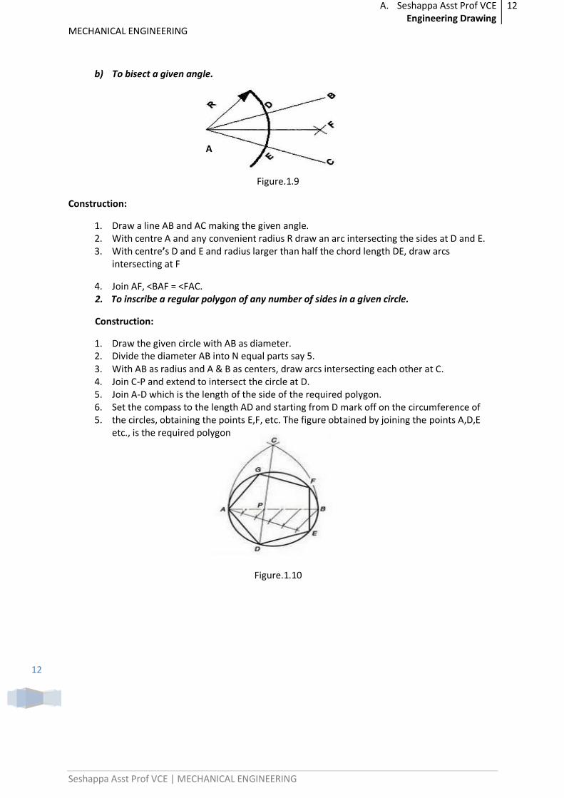
b) To bisect a given angle.
A
Figure.1.9
Construction:
1. Draw a line AB and AC making the given angle. 2. With centre A and any convenient radius R draw an arc intersecting the sides at D and E. 3. With centre’s D and E and radius larger than half the chord length DE, draw arcs
intersecting at F
4. Join AF, <BAF = <FAC. 2. To inscribe a regular polygon of any number of sides in a given circle.
Construction:
1. Draw the given circle with AB as diameter. 2. Divide the diameter AB into N equal parts say 5. 3. With AB as radius and A & B as centers, draw arcs intersecting each other at C. 4. Join C-P and extend to intersect the circle at D. 5. Join A-D which is the length of the side of the required polygon. 6. Set the compass to the length AD and starting from D mark off on the circumference of 5. the circles, obtaining the points E,F, etc. The figure obtained by joining the points A,D,E
etc., is the required polygon
Figure.1.10
A. Seshappa Asst Prof VCE Engineering Drawing
13
MECHANICAL ENGINEERING
Seshappa Asst Prof VCE | MECHANICAL ENGINEERING
13
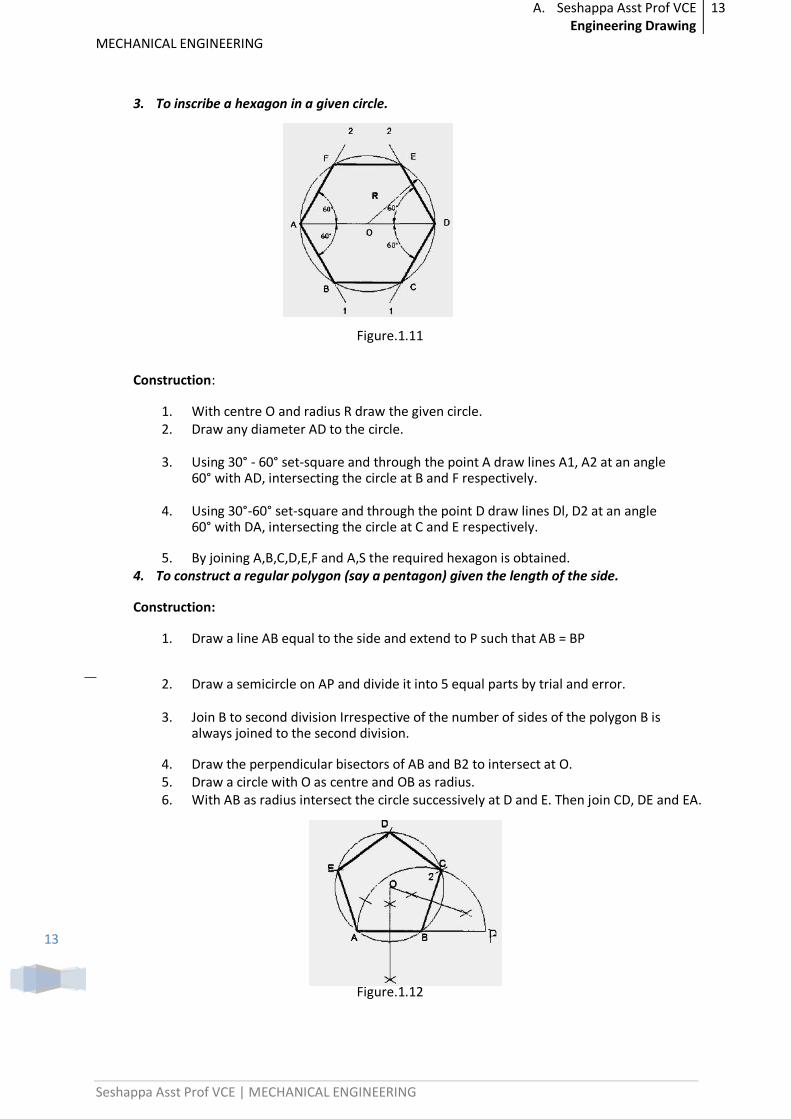
3. To inscribe a hexagon in a given circle.
Figure.1.11
Construction:
1. With centre O and radius R draw the given circle. 2. Draw any diameter AD to the circle.
3. Using 30° - 60° set-square and through the point A draw lines A1, A2 at an angle 60° with AD, intersecting the circle at B and F respectively.
4. Using 30°-60° set-square and through the point D draw lines Dl, D2 at an angle 60° with DA, intersecting the circle at C and E respectively.
5. By joining A,B,C,D,E,F and A,S the required hexagon is obtained. 4. To construct a regular polygon (say a pentagon) given the length of the side.
Construction:
1. Draw a line AB equal to the side and extend to P such that AB = BP
2. Draw a semicircle on AP and divide it into 5 equal parts by trial and error.
3. Join B to second division Irrespective of the number of sides of the polygon B is always joined to the second division.
4. Draw the perpendicular bisectors of AB and B2 to intersect at O. 5. Draw a circle with O as centre and OB as radius. 6. With AB as radius intersect the circle successively at D and E. Then join CD, DE and EA.
Figure.1.12
A. Seshappa Asst Prof VCE Engineering Drawing
14
MECHANICAL ENGINEERING
Seshappa Asst Prof VCE | MECHANICAL ENGINEERING
14
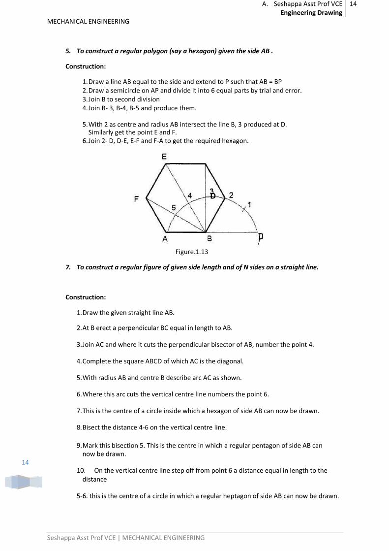
5. To construct a regular polygon (say a hexagon) given the side AB .
Construction:
1. Draw a line AB equal to the side and extend to P such that AB = BP 2. Draw a semicircle on AP and divide it into 6 equal parts by trial and error. 3. Join B to second division 4. Join B- 3, B-4, B-5 and produce them.
5. With 2 as centre and radius AB intersect the line B, 3 produced at D. Similarly get the point E and F.
6. Join 2- D, D-E, E-F and F-A to get the required hexagon.
D
Figure.1.13
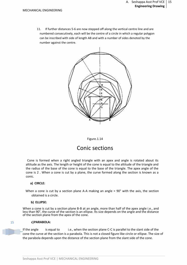
7. To construct a regular figure of given side length and of N sides on a straight line.
Construction:
1. Draw the given straight line AB.
2. At B erect a perpendicular BC equal in length to AB.
3. Join AC and where it cuts the perpendicular bisector of AB, number the point 4.
4. Complete the square ABCD of which AC is the diagonal.
5. With radius AB and centre B describe arc AC as shown.
6. Where this arc cuts the vertical centre line numbers the point 6.
7. This is the centre of a circle inside which a hexagon of side AB can now be drawn.
8. Bisect the distance 4-6 on the vertical centre line.
9. Mark this bisection 5. This is the centre in which a regular pentagon of side AB can now be drawn.
10. On the vertical centre line step off from point 6 a distance equal in length to the distance
5-6. this is the centre of a circle in which a regular heptagon of side AB can now be drawn.
A. Seshappa Asst Prof VCE Engineering Drawing
15
MECHANICAL ENGINEERING
Seshappa Asst Prof VCE | MECHANICAL ENGINEERING
15
11. If further distances 5-6 are now stepped off along the vertical centre line and are
numbered consecutively, each will be the centre of a circle in which a regular polygon
can be inscribed with side of length AB and with a number of sides denoted by the
number against the centre.
Figure.1.14
Conic sections
Cone is formed when a right angled triangle with an apex and angle is rotated about its altitude as the axis. The length or height of the cone is equal to the altitude of the triangle and the radius of the base of the cone is equal to the base of the triangle. The apex angle of the cone is 2 . When a cone is cut by a plane, the curve formed along the section is known as a conic.
When a cone is cut by a section plane A-A making an angle = 90° with the axis, the section
obtained is a circle.
When a cone is cut by a section plane B-B at an angle, more than half of the apex angle i.e., and less than 90°, the curve of the section is an ellipse. Its size depends on the angle and the distance of the section plane from the apex of the cone.
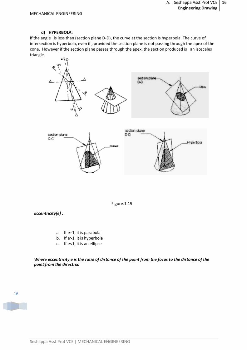
c) PARABOLA:
If the angle is equal to i.e., when the section plane C-C is parallel to the slant side of the cone the curve at the section is a parabola. This is not a closed figure like circle or ellipse. The size of the parabola depends upon the distance of the section plane from the slant side of the cone.
a) CIRCLE:
b) ELLIPSE:
A. Seshappa Asst Prof VCE Engineering Drawing
16
MECHANICAL ENGINEERING
Seshappa Asst Prof VCE | MECHANICAL ENGINEERING
16
d) HYPERBOLA: If the angle is less than (section plane D-D), the curve at the section is hyperbola. The curve of intersection is hyperbola, even if , provided the section plane is not passing through the apex of the cone. However if the section plane passes through the apex, the section produced is an isosceles triangle.
Figure.1.15
Eccentricity(e) :
a. If e=1, it is parabola b. If e>1, it is hyperbola c. If e<1, it is an ellipse
Where eccentricity e is the ratio of distance of the point from the focus to the distance of the point from the directrix.
A. Seshappa Asst Prof VCE Engineering Drawing
17
MECHANICAL ENGINEERING
Seshappa Asst Prof VCE | MECHANICAL ENGINEERING
17
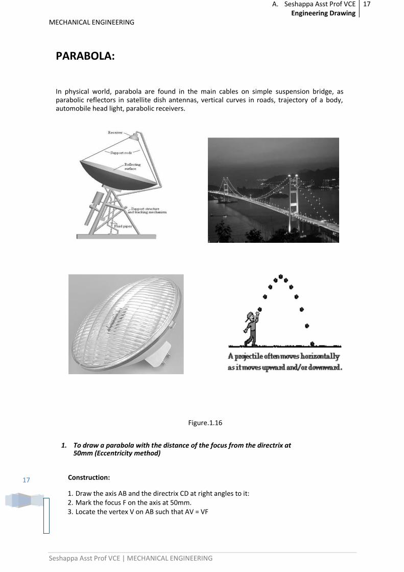
PARABOLA:
In physical world, parabola are found in the main cables on simple suspension bridge, as parabolic reflectors in satellite dish antennas, vertical curves in roads, trajectory of a body, automobile head light, parabolic receivers.
Figure.1.16
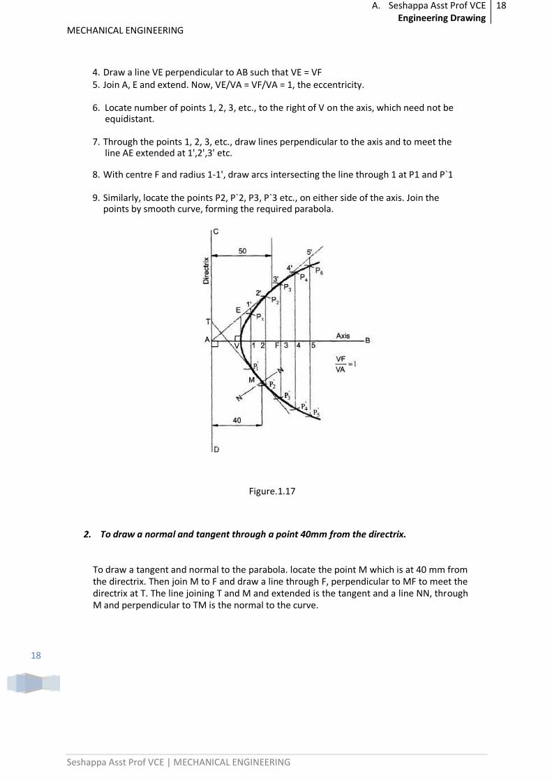
1. To draw a parabola with the distance of the focus from the directrix at 50mm (Eccentricity method)
Construction:
1. Draw the axis AB and the directrix CD at right angles to it: 2. Mark the focus F on the axis at 50mm. 3. Locate the vertex V on AB such that AV = VF
A. Seshappa Asst Prof VCE Engineering Drawing
18
MECHANICAL ENGINEERING
Seshappa Asst Prof VCE | MECHANICAL ENGINEERING
18
4. Draw a line VE perpendicular to AB such that VE = VF 5. Join A, E and extend. Now, VE/VA = VF/VA = 1, the eccentricity.
6. Locate number of points 1, 2, 3, etc., to the right of V on the axis, which need not be equidistant.
7. Through the points 1, 2, 3, etc., draw lines perpendicular to the axis and to meet the line AE extended at 1',2',3' etc.
8. With centre F and radius 1-1', draw arcs intersecting the line through 1 at P1 and P`1
9. Similarly, locate the points P2, P`2, P3, P`3 etc., on either side of the axis. Join the points by smooth curve, forming the required parabola.
Figure.1.17
2. To draw a normal and tangent through a point 40mm from the directrix.
To draw a tangent and normal to the parabola. locate the point M which is at 40 mm from the directrix. Then join M to F and draw a line through F, perpendicular to MF to meet the directrix at T. The line joining T and M and extended is the tangent and a line NN, through M and perpendicular to TM is the normal to the curve.
A. Seshappa Asst Prof VCE Engineering Drawing
19
MECHANICAL ENGINEERING
Seshappa Asst Prof VCE | MECHANICAL ENGINEERING
19
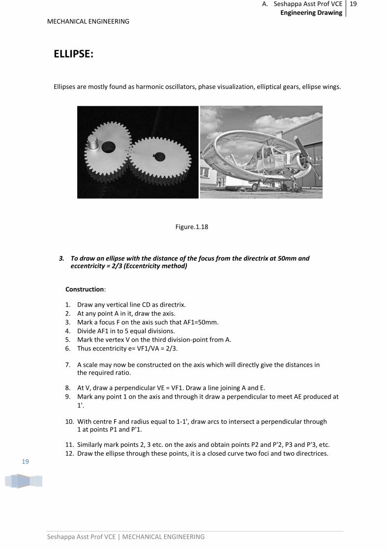
ELLIPSE:
Ellipses are mostly found as harmonic oscillators, phase visualization, elliptical gears, ellipse wings.
Figure.1.18
3. To draw an ellipse with the distance of the focus from the directrix at 50mm and eccentricity = 2/3 (Eccentricity method)
Construction:
1. Draw any vertical line CD as directrix. 2. At any point A in it, draw the axis. 3. Mark a focus F on the axis such that AF1=50mm. 4. Divide AF1 in to 5 equal divisions. 5. Mark the vertex V on the third division-point from A. 6. Thus eccentricity e= VF1/VA = 2/3.
7. A scale may now be constructed on the axis which will directly give the distances in the required ratio.
8. At V, draw a perpendicular VE = VF1. Draw a line joining A and E. 9. Mark any point 1 on the axis and through it draw a perpendicular to meet AE produced at
1'.
10. With centre F and radius equal to 1-1', draw arcs to intersect a perpendicular through 1 at points P1 and P'1.
11. Similarly mark points 2, 3 etc. on the axis and obtain points P2 and P'2, P3 and P'3, etc. 12. Draw the ellipse through these points, it is a closed curve two foci and two directrices.
A. Seshappa Asst Prof VCE Engineering Drawing
20
MECHANICAL ENGINEERING
Seshappa Asst Prof VCE | MECHANICAL ENGINEERING
20
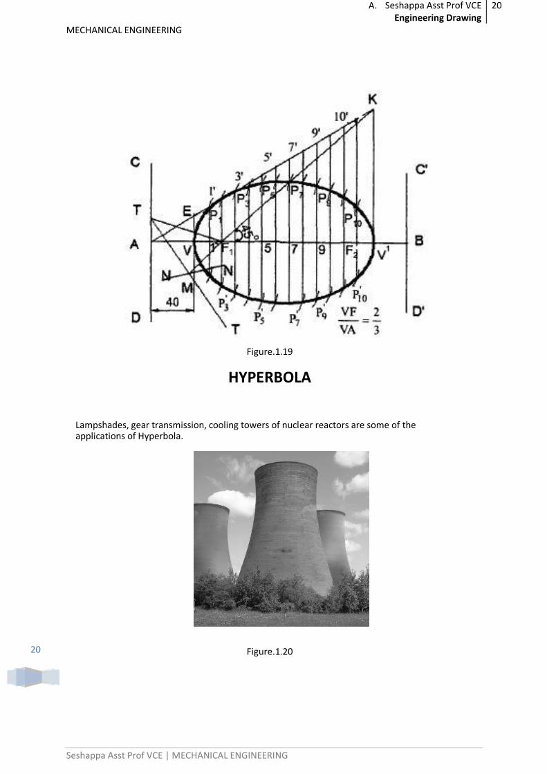
Figure.1.19
HYPERBOLA
Lampshades, gear transmission, cooling towers of nuclear reactors are some of the applications of Hyperbola.
Figure.1.20
A. Seshappa Asst Prof VCE Engineering Drawing
21
MECHANICAL ENGINEERING
Seshappa Asst Prof VCE | MECHANICAL ENGINEERING
21
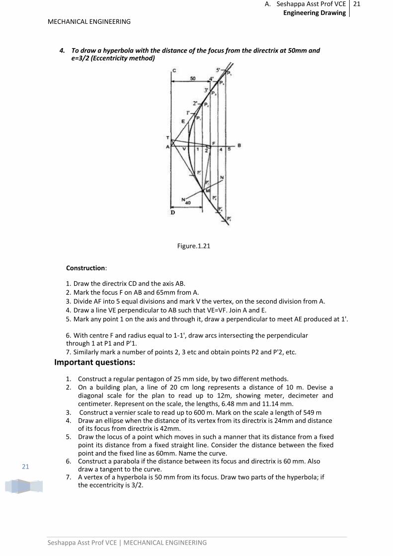
4. To draw a hyperbola with the distance of the focus from the directrix at 50mm and e=3/2 (Eccentricity method)
Figure.1.21
Construction:
1. Draw the directrix CD and the axis AB. 2. Mark the focus F on AB and 65mm from A. 3. Divide AF into 5 equal divisions and mark V the vertex, on the second division from A. 4. Draw a line VE perpendicular to AB such that VE=VF. Join A and E. 5. Mark any point 1 on the axis and through it, draw a perpendicular to meet AE produced at 1'.
6. With centre F and radius equal to 1-1', draw arcs intersecting the perpendicular through 1 at P1 and P'1. 7. Similarly mark a number of points 2, 3 etc and obtain points P2 and P'2, etc.
Important questions:
1. Construct a regular pentagon of 25 mm side, by two different methods. 2. On a building plan, a line of 20 cm long represents a distance of 10 m. Devise a
diagonal scale for the plan to read up to 12m, showing meter, decimeter and centimeter. Represent on the scale, the lengths, 6.48 mm and 11.14 mm.
3. Construct a vernier scale to read up to 600 m. Mark on the scale a length of 549 m 4. Draw an ellipse when the distance of its vertex from its directrix is 24mm and distance
of its focus from directrix is 42mm. 5. Draw the locus of a point which moves in such a manner that its distance from a fixed
point its distance from a fixed straight line. Consider the distance between the fixed point and the fixed line as 60mm. Name the curve.
6. Construct a parabola if the distance between its focus and directrix is 60 mm. Also draw a tangent to the curve.
7. A vertex of a hyperbola is 50 mm from its focus. Draw two parts of the hyperbola; if the eccentricity is 3/2.
A. Seshappa Asst Prof VCE Engineering Drawing
22
MECHANICAL ENGINEERING
Seshappa Asst Prof VCE | MECHANICAL ENGINEERING
22
8. The focus of a hyperbola is 60mm from its directrix. Draw the curve when eccentricity is 5/3.Draw a tangent and a normal to the curve at appoint distant 45mm from the directrix.
Previous Paper Questions:
1.
a) The actual length of 500m is represented by a line of 15 cm on a drawing. Construct a vernier scale to read upto 600 m. Mark on the scale a length of 549 m.
b) Two fixed points A and B are 100mm apart. Trace the complete path of a point P moving in the Same plane as that of A and B in such a way that, the sum of its distances from A and B is always the same and equal to 125 mm
2.
A coin of 40mm diameter rolls over a horizontal table without slipping. A point on the circumference of the coin in contact with the table surface in the beginning and after one complete revolution. Draw the path traced by the point. Draw a tangent and normal at a point 25 mm from the table.
3.
a) A rectangular field of 0.54 hectare is represented on a map by a rectangle of
3cm×2cm .Draw the diagonal scale to read up to 1 meter and long enough to
measure up to 600m.Mark a length of 425m. b) Draw a parabola when the distance between focus and directrix is 50mm.
Draw a tangent and normal at a point distant 70mm from the directrix. 4.
a) The actual length of 300m is represented by a line of 10cm on a drawing. Draw a vernier scale to read up to 500m. Mark on it a length of 367m.
b) Draw an epi cycloid generated by a rolling circle of 60 mm diameter for one
complete revolution. The radius of directing circle is 100mm.Draw a tangent
and a normal to the curve at 150mm from the center of the directing circle.
5.
a) The vertex of a hyperbola is 5cms from directrix. Draw the curve if the eccentricity is 3/2. Draw the normal and tangent at a point 50mm from axis.
b) A circle of 30mm diameter rolls on the concave side of generating circle of
radius 30mm. Draw the path traced by a point on the generating circle for one
complete revolution
.. ..
A. Seshappa Asst Prof VCE Engineering Drawing
23
MECHANICAL ENGINEERING
Seshappa Asst Prof VCE | MECHANICAL ENGINEERING
23
UNIT – 2
PROJECTION OF POINTS AND STRAIGHT LINES
Introduction
What is point?
An element which has no dimensions, it can be situated in the following positions with respect to principal planes of the projections.
Point situated above H.P and in front of V.P.
Point situated above H.P and behind V.P
Point situated below H.P and behind V.P.
Point situated below H.P and in front of V.P.
Point situated on H.P and in front of V.P.
Point situated above H.P and on V.P.
Point situated on H.P and behind V.P.
Point situated below H.P and on V.P.
Point situated on both H.P and V.P.
Conventional Representation:
Actual Position of a point designated by capitals i.e. A, B, C, D …
Front view of a point is designated by small letters with dashes i.e. a’, b’, c’, d’….
Top view of a point is designated by only small letters i.e. a, b, c, d ….
Side view of a point is designated by small letters with double dashes i.e. a”, b”, c”, d”... The Intersection of reference planes is a line known as reference line denoted by x-y and the line
connecting the front and top view is known as projection line; it is always perpendicular to the
principal axis (x-y line).
A. Seshappa Asst Prof VCE Engineering Drawing
24
MECHANICAL ENGINEERING
Seshappa Asst Prof VCE | MECHANICAL ENGINEERING
24
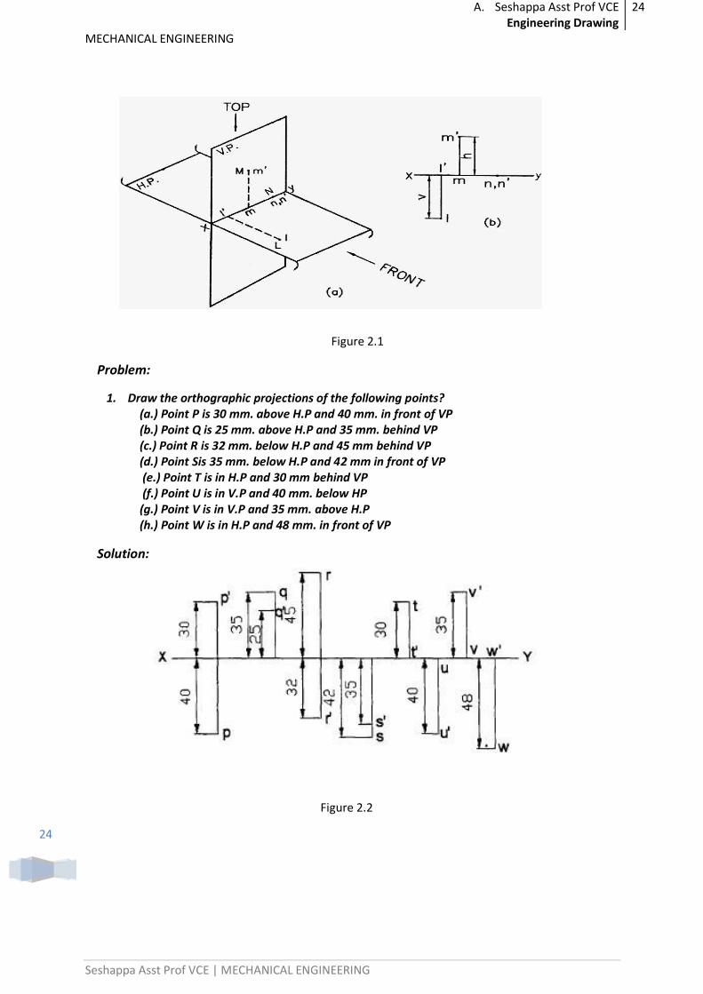
Figure 2.1
Problem:
1. Draw the orthographic projections of the following points? (a.) Point P is 30 mm. above H.P and 40 mm. in front of VP (b.) Point Q is 25 mm. above H.P and 35 mm. behind VP (c.) Point R is 32 mm. below H.P and 45 mm behind VP (d.) Point Sis 35 mm. below H.P and 42 mm in front of VP (e.) Point T is in H.P and 30 mm behind VP (f.) Point U is in V.P and 40 mm. below HP (g.) Point V is in V.P and 35 mm. above H.P (h.) Point W is in H.P and 48 mm. in front of VP
Solution:
Figure 2.2
A. Seshappa Asst Prof VCE Engineering Drawing
25
MECHANICAL ENGINEERING
Seshappa Asst Prof VCE | MECHANICAL ENGINEERING
25
PROJECTION OF STAIGHT LINES
Introduction
What is Line?
A Shortest distance between two points and the actual length of the line is known as True Length denoted by TL.
Orientation of Straight Lines
1. Line parallel to both H.P and V.P
2. Line perpendicular to H.P and parallel to V.P
3. Line perpendicular to V.P and parallel to H.P
4. Line inclined to H.P and parallel to V.P
5. Line inclined to V.P and parallel to H.P
6. Line situated in H.P
7. Line situated in V.P
8. Line situated in both H.P and V.P
9. Line inclined to both the reference planes.
1. Line inclined to both H.P and V.P front view angle and top view angle = 90 deg
2. Line inclined to both H.P and V.P front view angle and top view angle = 90 deg
Problems
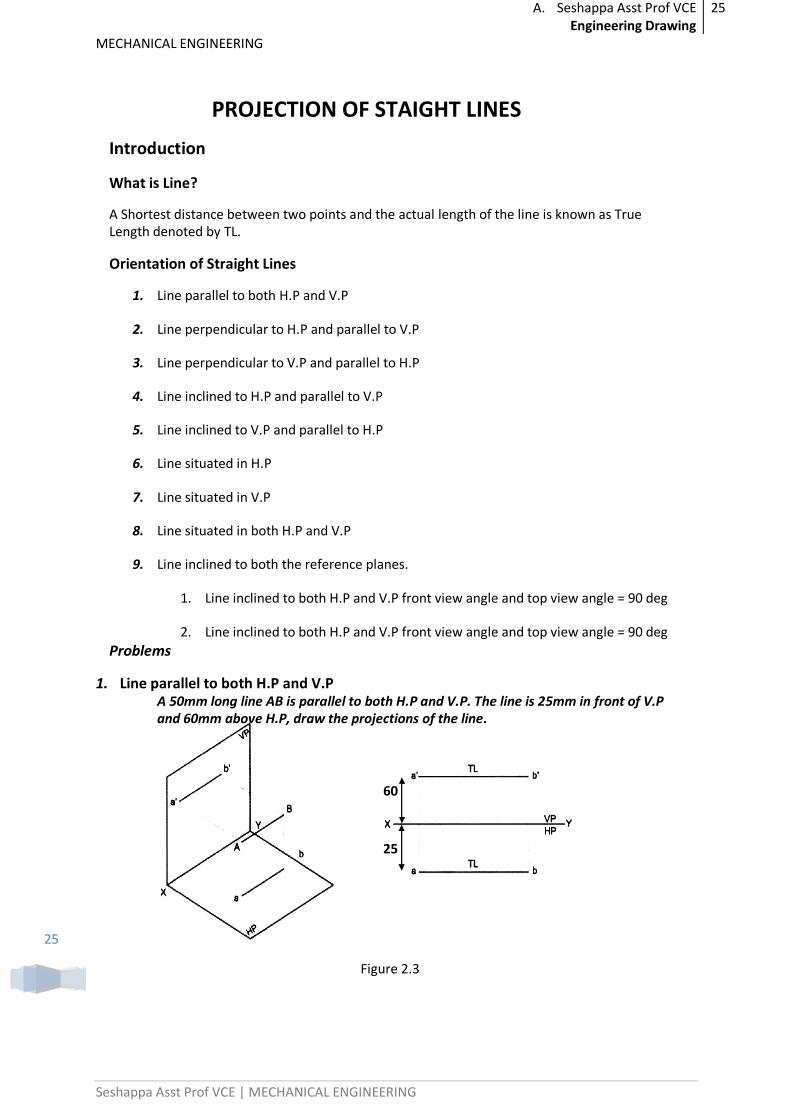
1. Line parallel to both H.P and V.P A 50mm long line AB is parallel to both H.P and V.P. The line is 25mm in front of V.P and 60mm above H.P, draw the projections of the line.
60
25
Figure 2.3
A. Seshappa Asst Prof VCE Engineering Drawing
26
MECHANICAL ENGINEERING
Seshappa Asst Prof VCE | MECHANICAL ENGINEERING
26
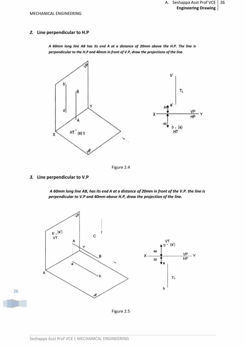
2. Line perpendicular to H.P
A 60mm long line AB has its end A at a distance of 20mm above the H.P. The line is
perpendicular to the H.P and 40mm in front of V.P, draw the projections of the line.
20
40
Figure 2.4
3. Line perpendicular to V.P
A 60mm long line AB, has its end A at a distance of 20mm in front of the V.P. the line is
perpendicular to V.P and 40mm above H.P, draw the projection of the line.
40
20
Figure 2.5
A. Seshappa Asst Prof VCE Engineering Drawing
27
MECHANICAL ENGINEERING
Seshappa Asst Prof VCE | MECHANICAL ENGINEERING
27
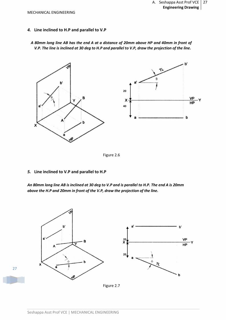
4. Line inclined to H.P and parallel to V.P
A 80mm long line AB has the end A at a distance of 20mm above HP and 40mm in front of
V.P. The line is inclined at 30 deg to H.P and parallel to V.P, draw the projection of the line.
20
40
Figure 2.6
5. Line inclined to V.P and parallel to H.P
An 80mm long line AB is inclined at 30 deg to V.P and is parallel to H.P. The end A is 20mm
above the H.P and 20mm in front of the V.P, draw the projection of the line.
20
20
Figure 2.7
A. Seshappa Asst Prof VCE Engineering Drawing
28
MECHANICAL ENGINEERING
Seshappa Asst Prof VCE | MECHANICAL ENGINEERING
28
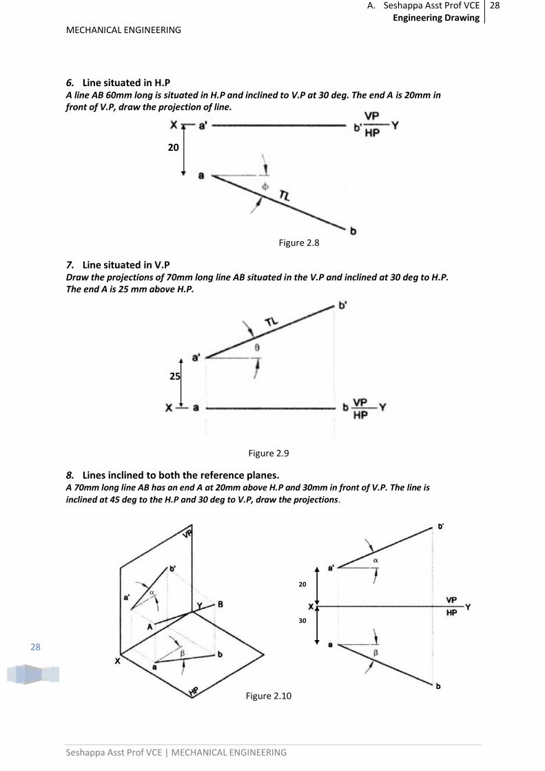
6. Line situated in H.P A line AB 60mm long is situated in H.P and inclined to V.P at 30 deg. The end A is 20mm in front of V.P, draw the projection of line.
20
Figure 2.8
7. Line situated in V.P Draw the projections of 70mm long line AB situated in the V.P and inclined at 30 deg to H.P. The end A is 25 mm above H.P.
25
Figure 2.9
8. Lines inclined to both the reference planes. A 70mm long line AB has an end A at 20mm above H.P and 30mm in front of V.P. The line is
inclined at 45 deg to the H.P and 30 deg to V.P, draw the projections.
20
30
Figure 2.10
A. Seshappa Asst Prof VCE Engineering Drawing
29
MECHANICAL ENGINEERING
Seshappa Asst Prof VCE | MECHANICAL ENGINEERING
29
Important Questions and Previous Paper Problems:
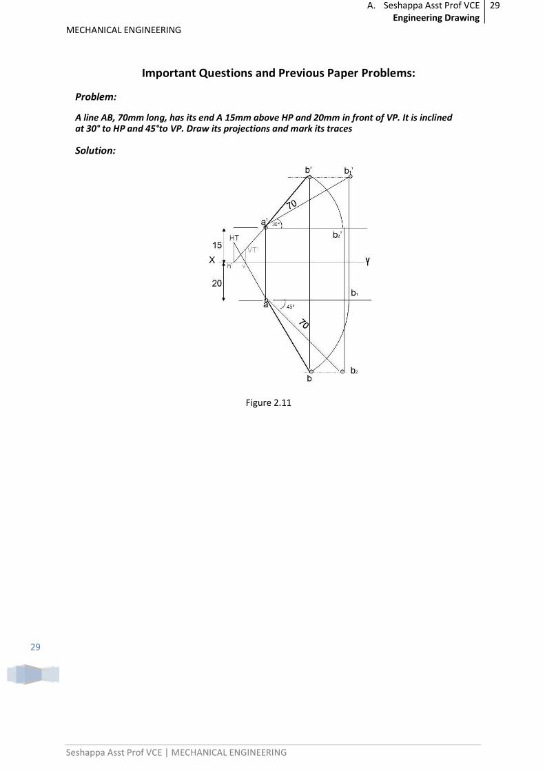
Problem:
A line AB, 70mm long, has its end A 15mm above HP and 20mm in front of VP. It is inclined at 30° to HP and 45°to VP. Draw its projections and mark its traces
Solution:
Figure 2.11
A. Seshappa Asst Prof VCE Engineering Drawing
30
MECHANICAL ENGINEERING
Seshappa Asst Prof VCE | MECHANICAL ENGINEERING
30
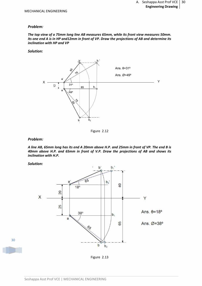
Problem:
The top view of a 75mm long line AB measures 65mm, while its front view measures 50mm. Its one end A is in HP and12mm in front of VP. Draw the projections of AB and determine its inclination with HP and VP
Solution:
Figure 2.12
Problem:
A line AB, 65mm long has its end A 20mm above H.P. and 25mm in front of VP. The end B is 40mm above H.P. and 65mm in front of V.P. Draw the projections of AB and shows its inclination with H.P.
Solution:
Figure 2.13
A. Seshappa Asst Prof VCE Engineering Drawing
31
MECHANICAL ENGINEERING
Seshappa Asst Prof VCE | MECHANICAL ENGINEERING
31
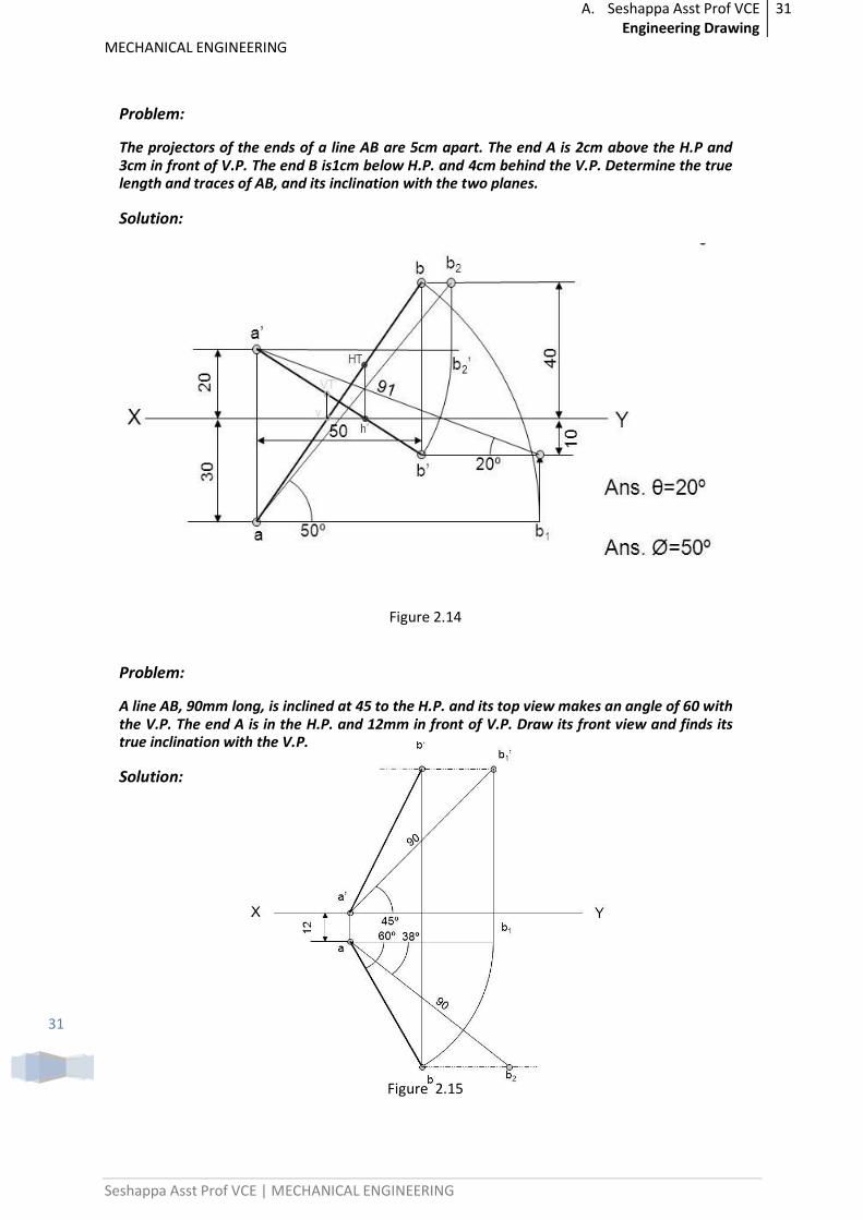
Problem:
The projectors of the ends of a line AB are 5cm apart. The end A is 2cm above the H.P and 3cm in front of V.P. The end B is1cm below H.P. and 4cm behind the V.P. Determine the true length and traces of AB, and its inclination with the two planes.
Solution:
Figure 2.14
Problem:
A line AB, 90mm long, is inclined at 45 to the H.P. and its top view makes an angle of 60 with the V.P. The end A is in the H.P. and 12mm in front of V.P. Draw its front view and finds its true inclination with the V.P.
Solution:
Figure 2.15
A. Seshappa Asst Prof VCE Engineering Drawing
32
MECHANICAL ENGINEERING
Seshappa Asst Prof VCE | MECHANICAL ENGINEERING
32
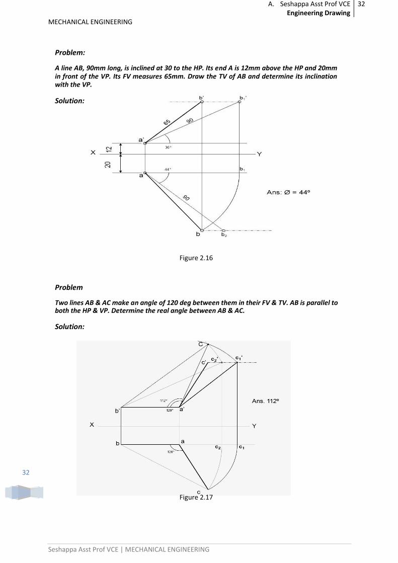
Problem:
A line AB, 90mm long, is inclined at 30 to the HP. Its end A is 12mm above the HP and 20mm in front of the VP. Its FV measures 65mm. Draw the TV of AB and determine its inclination with the VP.
Solution:
Figure 2.16
Problem
Two lines AB & AC make an angle of 120 deg between them in their FV & TV. AB is parallel to both the HP & VP. Determine the real angle between AB & AC.
Solution:
Figure 2.17
A. Seshappa Asst Prof VCE Engineering Drawing
33
MECHANICAL ENGINEERING
Seshappa Asst Prof VCE | MECHANICAL ENGINEERING
33
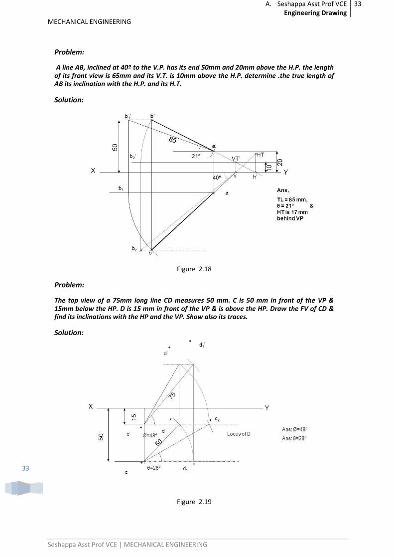
Problem:
A line AB, inclined at 40º to the V.P. has its end 50mm and 20mm above the H.P. the length of its front view is 65mm and its V.T. is 10mm above the H.P. determine .the true length of AB its inclination with the H.P. and its H.T.
Solution:
Figure 2.18
Problem:
The top view of a 75mm long line CD measures 50 mm. C is 50 mm in front of the VP & 15mm below the HP. D is 15 mm in front of the VP & is above the HP. Draw the FV of CD & find its inclinations with the HP and the VP. Show also its traces.
Solution:
Figure 2.19
A. Seshappa Asst Prof VCE Engineering Drawing
34
MECHANICAL ENGINEERING
Seshappa Asst Prof VCE | MECHANICAL ENGINEERING
34
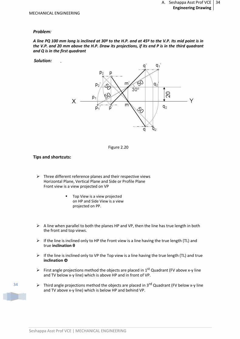
Problem:
A line PQ 100 mm long is inclined at 30º to the H.P. and at 45º to the V.P. Its mid point is in the V.P. and 20 mm above the H.P. Draw its projections, if its end P is in the third quadrant and Q is in the first quadrant
Solution:
Figure 2.20
Tips and shortcuts:
Three different reference planes and their respective views Horizontal Plane, Vertical Plane and Side or Profile Plane Front view is a view projected on VP
Top View is a view projected on HP and Side View is a view projected on PP.
A line when parallel to both the planes HP and VP, then the line has true length in both the front and top views.
If the line is inclined only to HP the Front view is a line having the true length (TL) and true inclination θ
If the line is inclined only to VP the Top view is a line having the true length (TL) and true inclination Φ
First angle projections method the objects are placed in 1st Quadrant (FV above x-y line and TV below x-y line) which is above HP and in front of VP.
Third angle projections method the objects are placed in 3rd Quadrant (FV below x-y line and TV above x-y line) which is below HP and behind VP.
A. Seshappa Asst Prof VCE Engineering Drawing
35
MECHANICAL ENGINEERING
Seshappa Asst Prof VCE | MECHANICAL ENGINEERING
35
Important Questions
(1) A line PS 65mm has its end P 15mm above the HP and 15mm in front of the VP. It is inclined at 55 deg to the HP and 35 deg to the VP. Draw its projections.
(2) A line CD, inclined at 25deg to the HP, measures 80mm in top view. The end C is in the first quadrant and 25mm and 15mm from the HP and the VP respectively. The end D is at equal distance from the both the reference planes. Draw the projections, fine true length and true inclination with the VP.
(3) A straight line ST has its end S, 10mm in front of the VP and nearer to it. The mid-point M line is 50mm in front of the VP and 40mm above HP. The front and top view measure 90mm and 120mm respectively. Draw the projection of the line. Also find its true length and true inclinations with the HP and VP.
(4) A line PQ has its end P, 10mm above the HP and 20mm in front of the VP. The end Q is 85mm in front of the VP. The front view of the line measures 75mm. the distance between the end projectors is 50mm. Draw the projections of the line and find its true length and its true inclinations with the VP and HP.
(5) A line PF, 65mm has its end P, 15mm above the HP and 15mm in front of the VP. It is inclined at 55deg to the VP. Draw its projections.
Previous Paper Questions: (1) A line CD 60mm long has its end ‘C’ in both H.P and V.P. It is inclined at 300to H.P and
450 to V.P. Draw the projections. (2) A point C is 40mm below H.P and 20mm behind V.P, another points D and E are 60mm
above H.P and in front of V.P, 90mm below H.P and 45mm in front of V.P respectively. Draw the projections of all points on same reference line.
(3) The end P of a straight line PQ is 20 mm above the H.P. and 30 mm in front of V.P. The end Q is 15 mm below the H.P. and 45mm behind the V.P. If the end projectors are 50 mm apart, Draw the projection of PQ and determine the true length, traces and inclination with the reference planes.
(4) The front view of line inclined at 300to V.P is 65mm long. Draw the projections of a line, when it is parallel to and 40mm above H.P. and one end being 20mm in front of V.P.
(5) A line PQ, 64 mm long has one of its extremities 20 mm in front VP and the other 50 mm above HP. The line is inclined at 400 to HP and 250 to VP. Draw its top and front view.
(6) The projection of a line AB has 350 inclinations in top view and 400 inclination in the front view with an elevation length of 60 mm. If the end A is 10 mm below HP and B is 12 mm behind VP, Draw the projections and locate the traces keeping the line in the third quadrant.
(7) Line PQ has 72 mm length in the front view and 66 mm length in the top view. The end P is 48 mm below HP and 40 mm behind VP, while the end Q is 12 mm below HP. Draw the projection of the line, locate the traces and determine the true length and inclinations of the line with the reference planes.
.. ..
A. Seshappa Asst Prof VCE Engineering Drawing
36
MECHANICAL ENGINEERING
Seshappa Asst Prof VCE | MECHANICAL ENGINEERING
36
UNIT-3
PROJECTION OF PLANES
Introduction :
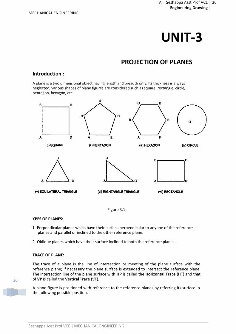
A plane is a two dimensional object having length and breadth only. Its thickness is always neglected; various shapes of plane figures are considered such as square, rectangle, circle, pentagon, hexagon, etc
Figure 3.1
YPES OF PLANES:
1. Perpendicular planes which have their surface perpendicular to anyone of the reference planes and parallel or inclined to the other reference plane.
2. Oblique planes which have their surface inclined to both the reference planes.
TRACE OF PLANE:
The trace of a plane is the line of intersection or meeting of the plane surface with the reference plane; if necessary the plane surface is extended to intersect the reference plane. The intersection line of the plane surface with HP is called the Horizontal Trace (HT) and that of VP is called the Vertical Trace (VT).
A plane figure is positioned with reference to the reference planes by referring its surface in the following possible position.
A. Seshappa Asst Prof VCE Engineering Drawing
37
MECHANICAL ENGINEERING
Seshappa Asst Prof VCE | MECHANICAL ENGINEERING
37
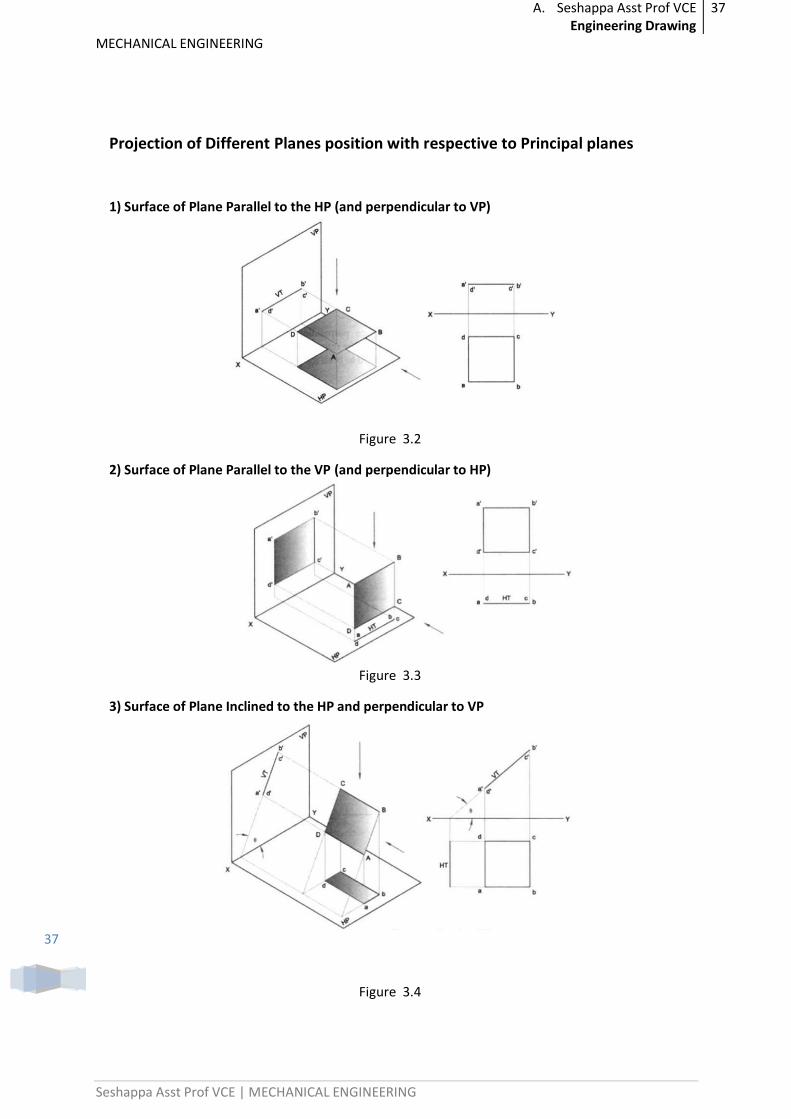
Projection of Different Planes position with respective to Principal planes
1) Surface of Plane Parallel to the HP (and perpendicular to VP)
Figure 3.2
2) Surface of Plane Parallel to the VP (and perpendicular to HP)
Figure 3.3
3) Surface of Plane Inclined to the HP and perpendicular to VP
Figure 3.4
A. Seshappa Asst Prof VCE Engineering Drawing
38
MECHANICAL ENGINEERING
Seshappa Asst Prof VCE | MECHANICAL ENGINEERING
38
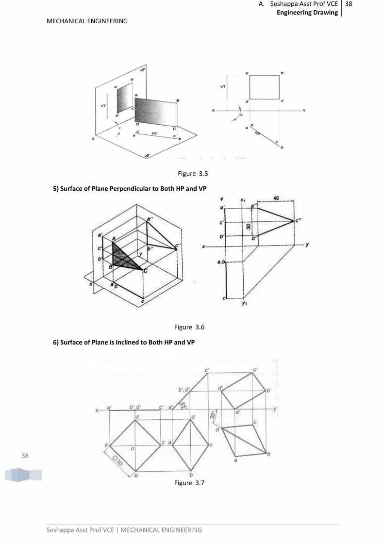
Figure 3.5
5) Surface of Plane Perpendicular to Both HP and VP
Figure 3.6
6) Surface of Plane is Inclined to Both HP and VP
Figure 3.7
A. Seshappa Asst Prof VCE Engineering Drawing
39
MECHANICAL ENGINEERING
Seshappa Asst Prof VCE | MECHANICAL ENGINEERING
39
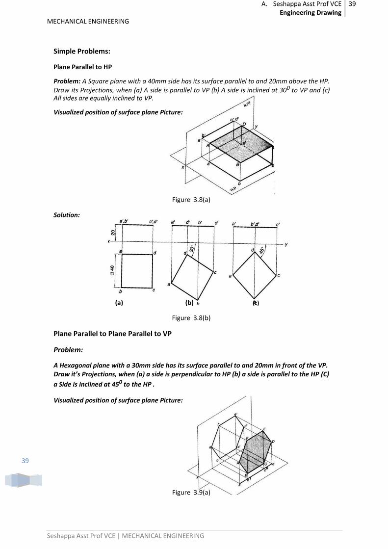
Simple Problems:
Plane Parallel to HP
Problem: A Square plane with a 40mm side has its surface parallel to and 20mm above the HP. Draw its Projections, when (a) A side is parallel to VP (b) A side is inclined at 300 to VP and (c) All sides are equally inclined to VP.
Visualized position of surface plane Picture:
Figure 3.8(a)
Solution:
(a) (b) (c)
Figure 3.8(b)
Plane Parallel to Plane Parallel to VP
Problem:
A Hexagonal plane with a 30mm side has its surface parallel to and 20mm in front of the VP. Draw it’s Projections, when (a) a side is perpendicular to HP (b) a side is parallel to the HP (C)
a Side is inclined at 450 to the HP .
Visualized position of surface plane Picture:
Figure 3.9(a)
A. Seshappa Asst Prof VCE Engineering Drawing
40
MECHANICAL ENGINEERING
Seshappa Asst Prof VCE | MECHANICAL ENGINEERING
40
Solution:
(a) (b) (c)
Figure 3.9(b)
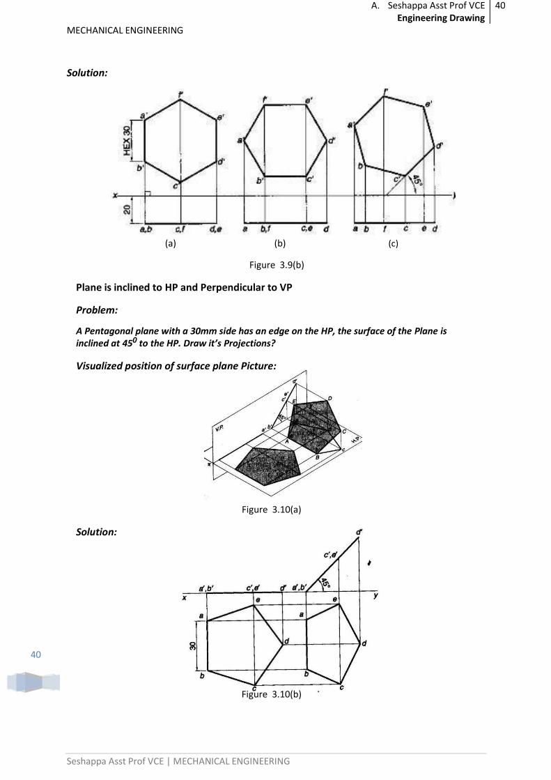
Plane is inclined to HP and Perpendicular to VP
Problem:
A Pentagonal plane with a 30mm side has an edge on the HP, the surface of the Plane is inclined at 450 to the HP. Draw it’s Projections?
Visualized position of surface plane Picture:
Figure 3.10(a)
Solution:
Figure 3.10(b)
A. Seshappa Asst Prof VCE Engineering Drawing
41
MECHANICAL ENGINEERING
Seshappa Asst Prof VCE | MECHANICAL ENGINEERING
41
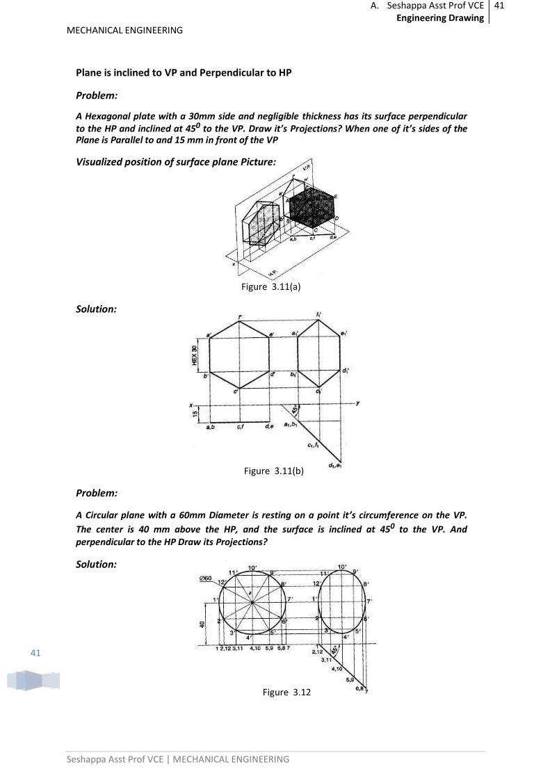
Plane is inclined to VP and Perpendicular to HP
Problem:
A Hexagonal plate with a 30mm side and negligible thickness has its surface perpendicular to the HP and inclined at 450 to the VP. Draw it’s Projections? When one of it’s sides of the Plane is Parallel to and 15 mm in front of the VP
Visualized position of surface plane Picture:
Figure 3.11(a)
Solution:
Figure 3.11(b)
Problem:
A Circular plane with a 60mm Diameter is resting on a point it’s circumference on the VP.
The center is 40 mm above the HP, and the surface is inclined at 450 to the VP. And perpendicular to the HP Draw its Projections?
Solution:
Figure 3.12
A. Seshappa Asst Prof VCE Engineering Drawing
42
MECHANICAL ENGINEERING
Seshappa Asst Prof VCE | MECHANICAL ENGINEERING
42
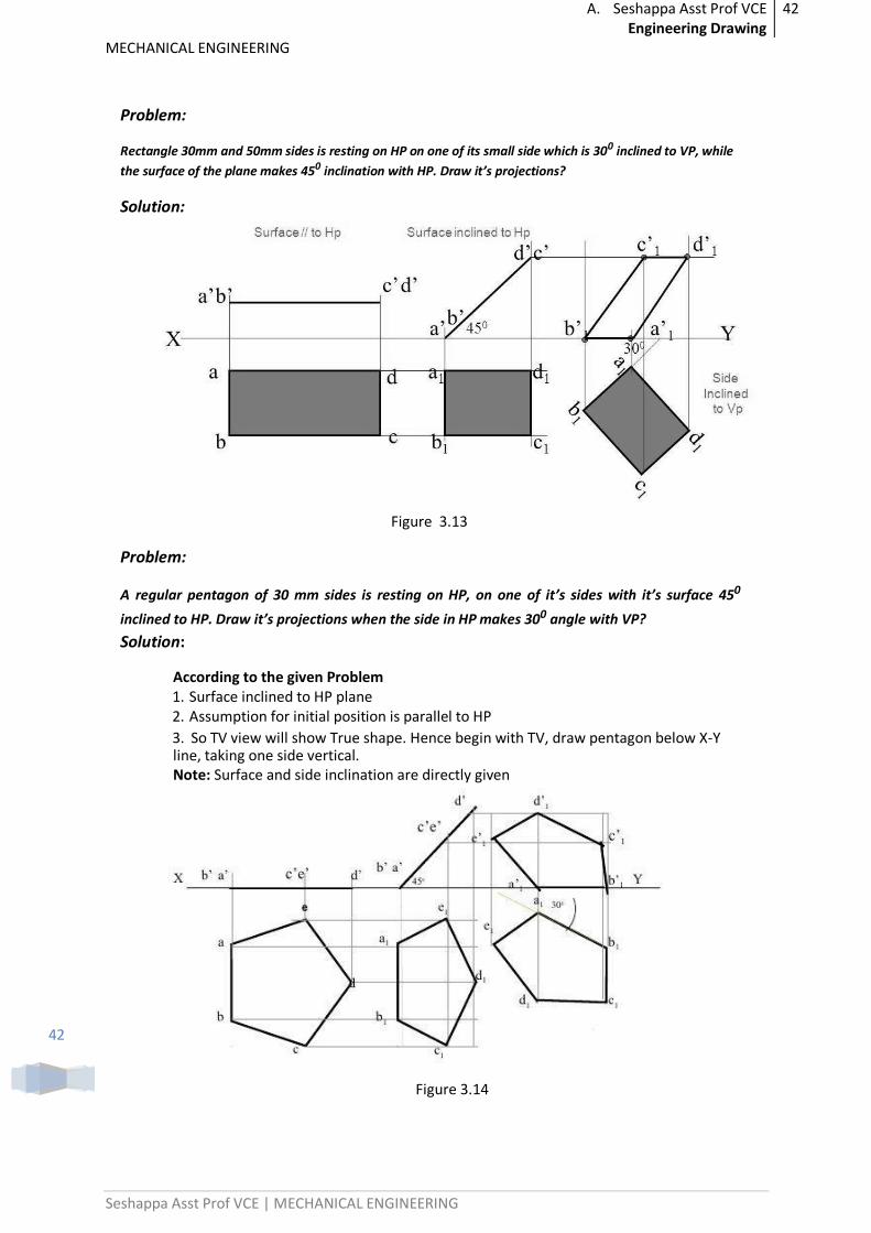
Problem:
Rectangle 30mm and 50mm sides is resting on HP on one of its small side which is 300 inclined to VP, while
the surface of the plane makes 450 inclination with HP. Draw it’s projections?
Solution:
Figure 3.13
Problem:
A regular pentagon of 30 mm sides is resting on HP, on one of it’s sides with it’s surface 450
inclined to HP. Draw it’s projections when the side in HP makes 300 angle with VP?
Solution:
According to the given Problem 1. Surface inclined to HP plane 2. Assumption for initial position is parallel to HP 3. So TV view will show True shape. Hence begin with TV, draw pentagon below X-Y line, taking one side vertical. Note: Surface and side inclination are directly given
Figure 3.14
A. Seshappa Asst Prof VCE Engineering Drawing
43
MECHANICAL ENGINEERING
Seshappa Asst Prof VCE | MECHANICAL ENGINEERING
43
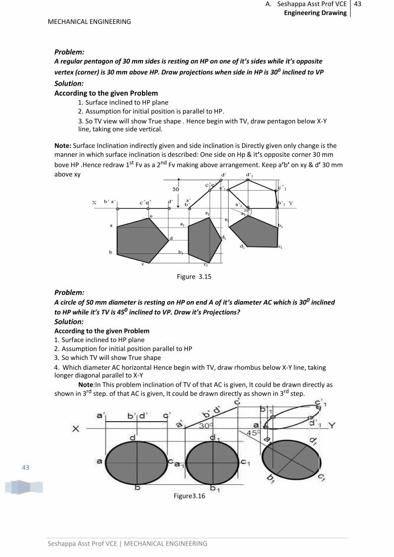
Problem: A regular pentagon of 30 mm sides is resting on HP on one of it’s sides while it’s opposite
vertex (corner) is 30 mm above HP. Draw projections when side in HP is 300 inclined to VP
Solution: According to the given Problem
1. Surface inclined to HP plane 2. Assumption for initial position is parallel to HP. 3. So TV view will show True shape . Hence begin with TV, draw pentagon below X-Y line, taking one side vertical.
Note: Surface Inclination indirectly given and side inclination is Directly given only change is the manner in which surface inclination is described: One side on Hp & it’s opposite corner 30 mm
bove HP .Hence redraw 1st Fv as a 2nd Fv making above arrangement. Keep a’b’ on xy & d’ 30 mm
above xy
Figure 3.15
Problem: A circle of 50 mm diameter is resting on HP on end A of it’s diameter AC which is 300 inclined
to HP while it’s TV is 450 inclined to VP. Draw it’s Projections?
Solution: According to the given Problem 1. Surface inclined to HP plane 2. Assumption for initial position parallel to HP 3. So which TV will show True shape 4. Which diameter AC horizontal Hence begin with TV, draw rhombus below X-Y line, taking longer diagonal parallel to X-Y
Note:In This problem inclination of TV of that AC is given, It could be drawn directly as shown in 3rd step. of that AC is given, It could be drawn directly as shown in 3rd step.
Figure3.16
A. Seshappa Asst Prof VCE Engineering Drawing
44
MECHANICAL ENGINEERING
Seshappa Asst Prof VCE | MECHANICAL ENGINEERING
44
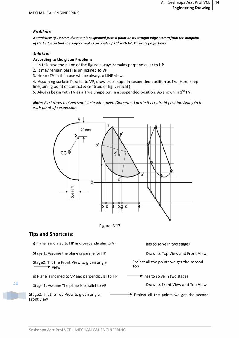
Problem:
A semicircle of 100 mm diameter is suspended from a point on its straight edge 30 mm from the midpoint
of that edge so that the surface makes an angle of 450 with VP. Draw its projections.
Solution: According to the given Problem: 1. In this case the plane of the figure always remains perpendicular to HP 2. It may remain parallel or inclined to VP 3. Hence TV in this case will be always a LINE view. 4. Assuming surface Parallel to VP, draw true shape in suspended position as FV. (Here keep line joining point of contact & centroid of fig. vertical )
5. Always begin with FV as a True Shape but in a suspended position. AS shown in 1st FV.
Note: First draw a given semicircle with given Diameter, Locate its centroid position And join it with point of suspension.
Figure 3.17
Tips and Shortcuts:
i) Plane is inclined to HP and perpendicular to VP
has to solve in two stages
Stage 1: Assume the plane is parallel to HP Draw its Top View and Front View
Stage2: Tilt the Front View to given angle view
Project all the points we get the second Top
ii) Plane is inclined to VP and perpendicular to HP has to solve in two stages
Stage 1: Assume The plane is parallel to VP Draw its Front View and Top View
Stage2: Tilt the Top View to given angle Front view
Project all the points we get the second
A. Seshappa Asst Prof VCE Engineering Drawing
45
MECHANICAL ENGINEERING
Seshappa Asst Prof VCE | MECHANICAL ENGINEERING
45
Important Questions:
1. A pentagon of sides 30mm rests on the ground on one of its corners with the sides containing the corners being equally inclined to the ground. The side opposite to the corner on which it rests is inclined at 30 degrees to the VP and is parallel to the HP. The surface of the pentagon makes 10 degrees with the ground. Draw the top and front views of the pentagon.
2. A regular pentagon of 30mm side is resting on one of its edges on HP which is inclined at 45degrees to VP. Its surface is inclined at 30 degrees to HP. Draw its projections.
Previous Paper Questions:
1. Draw the projections of a regular hexagon of 25mm side, having one of its sides in the H.P. and inclined at 60 degrees to the V.P., and its surface making an angle of 45 degrees with H.P.
2. A thin circular plate of 40mm diameter having its plane vertical and inclined at 400 to V.P. Its center is 30mm above H.P. and 35mm in front of V.P. Draw the projections.

A. Seshappa Asst Prof VCE Engineering Drawing
46
MECHANICAL ENGINEERING
Seshappa Asst Prof VCE | MECHANICAL ENGINEERING
46
PROJECTION OF SOLIDS
Introduction:
A solid has three dimensions, the length, breadth and thickness or height. A solid may be represented by orthographic views, the number of which depends on the type of solid and its orientation with respect to the planes of projection. solids are classified into two major groups. (i) Polyhedral, and (ii) Solids of revolution
POLYHEDRAL
A polyhedral is defined as a solid bounded by plane surfaces called faces. They are:
(i)Regular polyhedral (ii) Prisms and (iii) Pyramids
Regular Polyhedral
A polyhedron is said to be regular if its surfaces are regular polygons. The following are some of the regular polyhedral.
SOLIDS
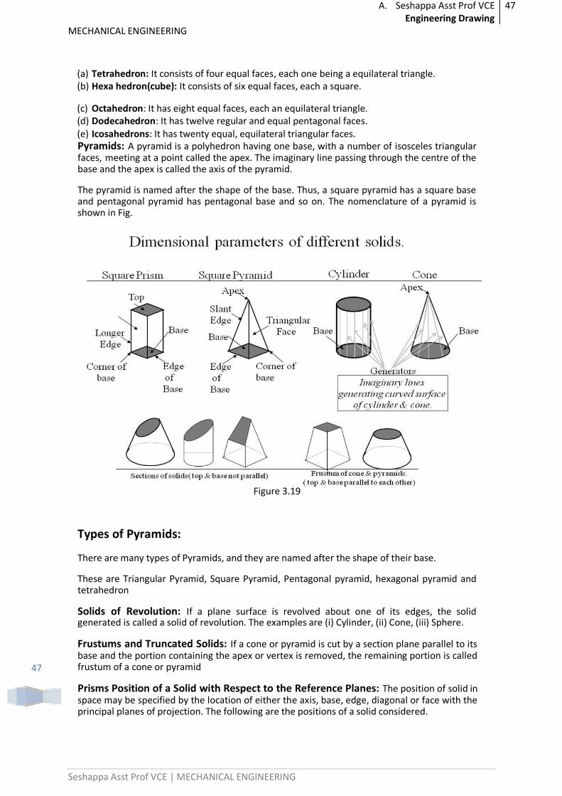
Prisms: A prism is a polyhedron having two equal ends called the bases parallel to each other. The two bases are joined by faces, which are rectangular in shape. The imaginary line passing through the centers of the bases is called the axis of the prism.
A prism is named after the shape of its base. For example, a prism with square base is called a square prism, the one with a pentagonal base is called a pentagonal prism, and so on (Fig) The nomenclature of the prism is given in Fig.
Figure 3.18
A. Seshappa Asst Prof VCE Engineering Drawing
47
MECHANICAL ENGINEERING
Seshappa Asst Prof VCE | MECHANICAL ENGINEERING
47
(a) Tetrahedron: It consists of four equal faces, each one being a equilateral triangle. (b) Hexa hedron(cube): It consists of six equal faces, each a square.
(c) Octahedron: It has eight equal faces, each an equilateral triangle. (d) Dodecahedron: It has twelve regular and equal pentagonal faces. (e) Icosahedrons: It has twenty equal, equilateral triangular faces. Pyramids: A pyramid is a polyhedron having one base, with a number of isosceles triangular faces, meeting at a point called the apex. The imaginary line passing through the centre of the base and the apex is called the axis of the pyramid.
The pyramid is named after the shape of the base. Thus, a square pyramid has a square base and pentagonal pyramid has pentagonal base and so on. The nomenclature of a pyramid is shown in Fig.
Figure 3.19
Types of Pyramids:
There are many types of Pyramids, and they are named after the shape of their base.
These are Triangular Pyramid, Square Pyramid, Pentagonal pyramid, hexagonal pyramid and tetrahedron
Solids of Revolution: If a plane surface is revolved about one of its edges, the solid generated is called a solid of revolution. The examples are (i) Cylinder, (ii) Cone, (iii) Sphere.
Frustums and Truncated Solids: If a cone or pyramid is cut by a section plane parallel to its base and the portion containing the apex or vertex is removed, the remaining portion is called frustum of a cone or pyramid
Prisms Position of a Solid with Respect to the Reference Planes: The position of solid in space may be specified by the location of either the axis, base, edge, diagonal or face with the principal planes of projection. The following are the positions of a solid considered.
A. Seshappa Asst Prof VCE Engineering Drawing
48
MECHANICAL ENGINEERING
Seshappa Asst Prof VCE | MECHANICAL ENGINEERING
48
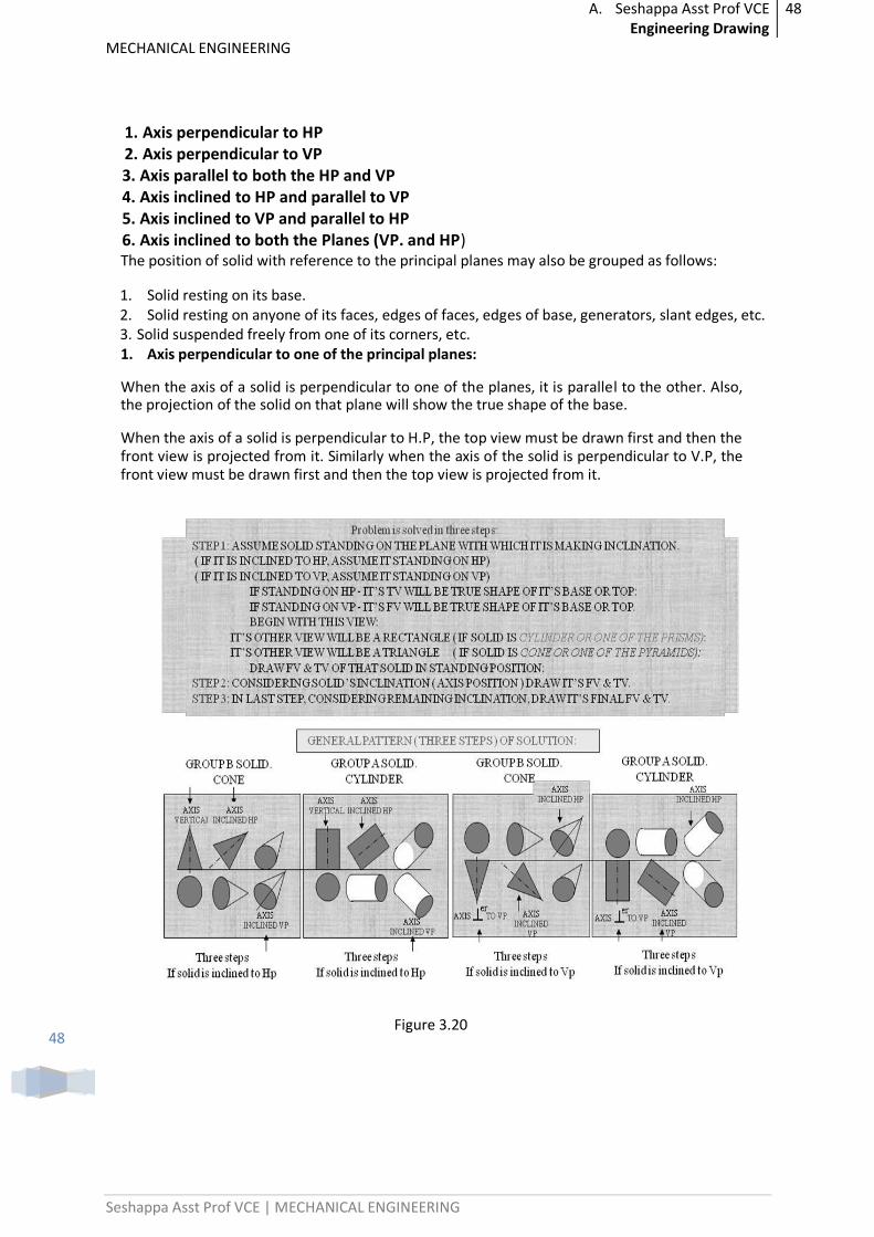
1. Axis perpendicular to HP 2. Axis perpendicular to VP 3. Axis parallel to both the HP and VP 4. Axis inclined to HP and parallel to VP 5. Axis inclined to VP and parallel to HP 6. Axis inclined to both the Planes (VP. and HP) The position of solid with reference to the principal planes may also be grouped as follows:
1. Solid resting on its base. 2. Solid resting on anyone of its faces, edges of faces, edges of base, generators, slant edges, etc. 3. Solid suspended freely from one of its corners, etc. 1. Axis perpendicular to one of the principal planes:
When the axis of a solid is perpendicular to one of the planes, it is parallel to the other. Also, the projection of the solid on that plane will show the true shape of the base.
When the axis of a solid is perpendicular to H.P, the top view must be drawn first and then the front view is projected from it. Similarly when the axis of the solid is perpendicular to V.P, the front view must be drawn first and then the top view is projected from it.
Figure 3.20
A. Seshappa Asst Prof VCE Engineering Drawing
49
MECHANICAL ENGINEERING
Seshappa Asst Prof VCE | MECHANICAL ENGINEERING
49
Simple Problems:
When the axis of solid is perpendicular to one of the planes, it is parallel to the other. Also, the projection of the solid on that plane will show the true shape of the base. When the axis of a solid is perpendicular to H.P, the top view must be drawn first and then the front view is projected from it. Similarly when the axis of the solid is perpendicular to V.P, the front view must be drawn first and then the top view is projected from it.
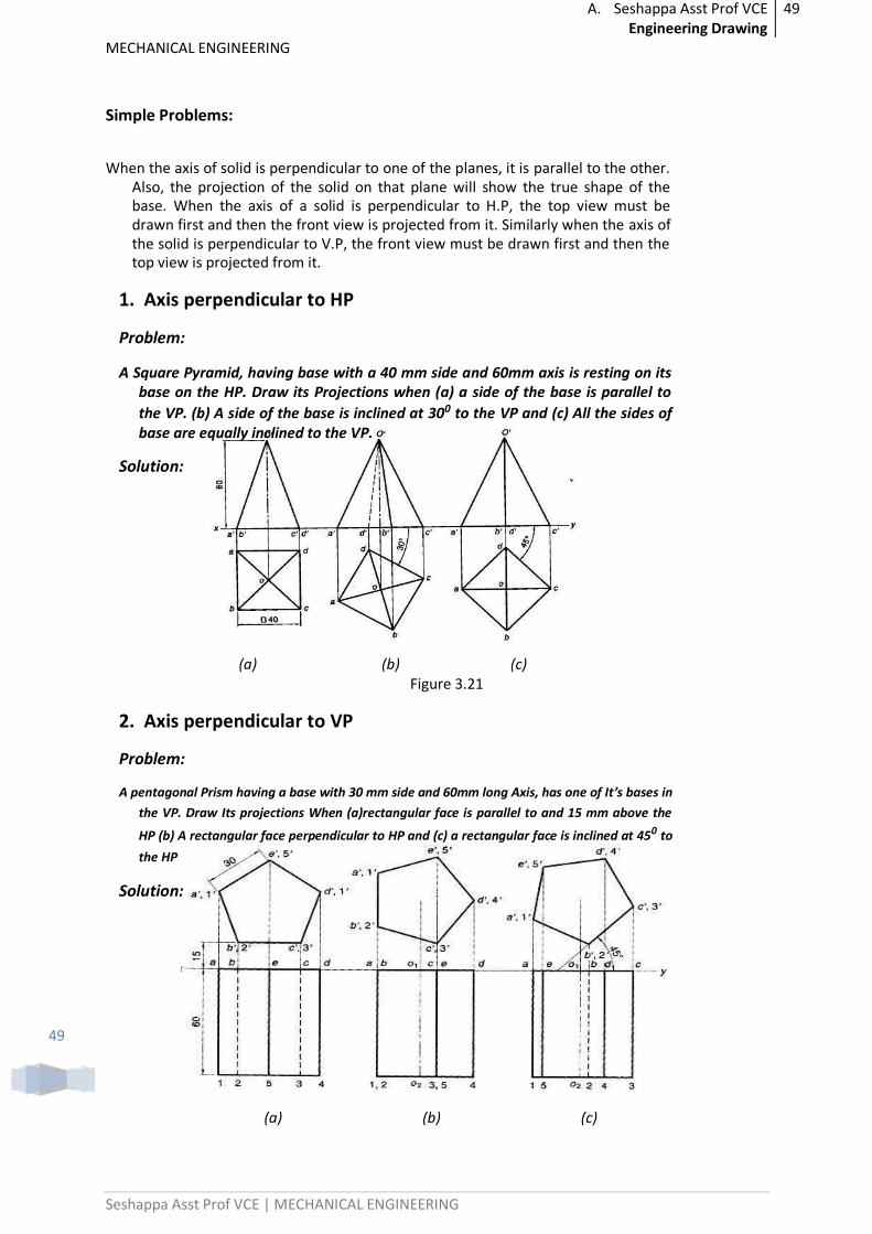
1. Axis perpendicular to HP
Problem:
A Square Pyramid, having base with a 40 mm side and 60mm axis is resting on its base on the HP. Draw its Projections when (a) a side of the base is parallel to
the VP. (b) A side of the base is inclined at 300 to the VP and (c) All the sides of base are equally inclined to the VP.
Solution:
(a) (b) (c) Figure 3.21
2. Axis perpendicular to VP
Problem:
A pentagonal Prism having a base with 30 mm side and 60mm long Axis, has one of It’s bases in
the VP. Draw Its projections When (a)rectangular face is parallel to and 15 mm above the
HP (b) A rectangular face perpendicular to HP and (c) a rectangular face is inclined at 450 to
the HP
Solution:
(a) (b) (c)
A. Seshappa Asst Prof VCE Engineering Drawing
50
MECHANICAL ENGINEERING
Seshappa Asst Prof VCE | MECHANICAL ENGINEERING
50
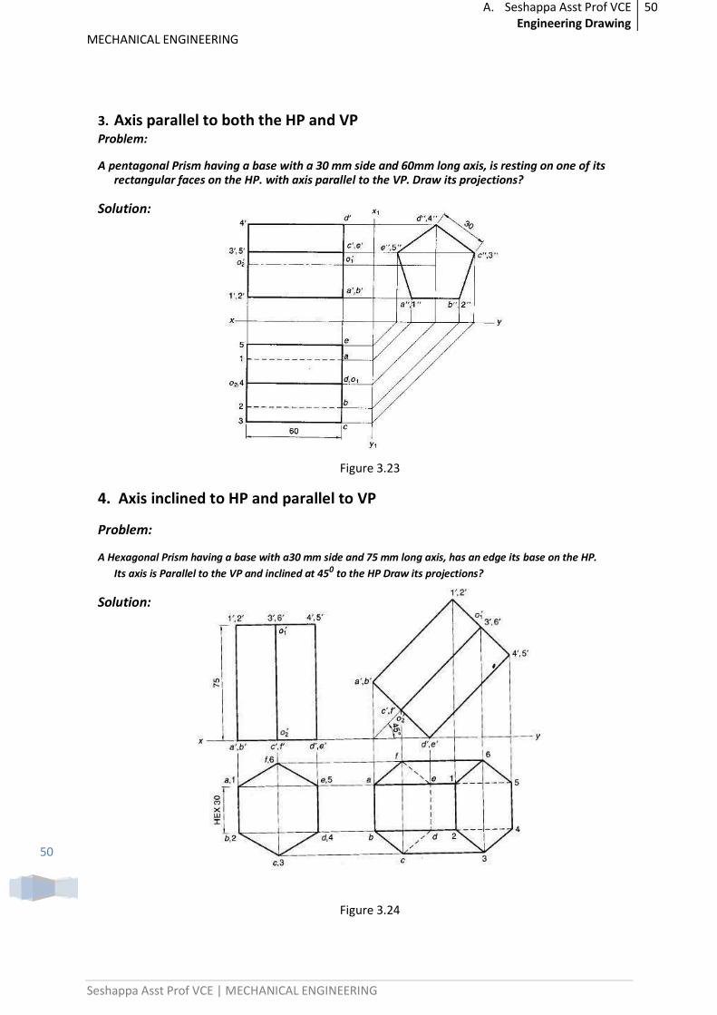
3. Axis parallel to both the HP and VP Problem:
A pentagonal Prism having a base with a 30 mm side and 60mm long axis, is resting on one of its rectangular faces on the HP. with axis parallel to the VP. Draw its projections?
Solution:
Figure 3.23
4. Axis inclined to HP and parallel to VP
Problem:
A Hexagonal Prism having a base with a30 mm side and 75 mm long axis, has an edge its base on the HP.
Its axis is Parallel to the VP and inclined at 450 to the HP Draw its projections?
Solution:
Figure 3.24
A. Seshappa Asst Prof VCE Engineering Drawing
51
MECHANICAL ENGINEERING
Seshappa Asst Prof VCE | MECHANICAL ENGINEERING
51
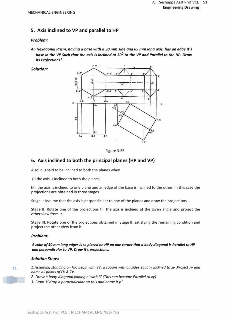
5. Axis inclined to VP and parallel to HP
Problem:
An Hexagonal Prism, having a base with a 30 mm side and 65 mm long axis, has an edge it’s
base in the VP Such that the axis is inclined at 300 to the VP and Parallel to the HP. Draw its Projections?
Solution:
Figure 3.25
6. Axis inclined to both the principal planes (HP and VP)
A solid is said to be inclined to both the planes when
(i) the axis is inclined to both the planes,
(ii) the axis is inclined to one plane and an edge of the base is inclined to the other. In this case the projections are obtained in three stages.
Stage I: Assume that the axis is perpendicular to one of the planes and draw the projections.
Stage II: Rotate one of the projections till the axis is inclined at the given angle and project the other view from it.
Stage III: Rotate one of the projections obtained in Stage II, satisfying the remaining condition and project the other view from it.
Problem:
A cube of 50 mm long edges is so placed on HP on one corner that a body diagonal is Parallel to HP and perpendicular to VP. Draw it’s projections.
Solution Steps:
1. Assuming standing on HP, begin with TV, a square with all sides equally inclined to xy .Project Fv and name all points of FV & TV. 2. Draw a body-diagonal joining c’ with 3’ (This can become Parallel to xy) 3. From 1’ drop a perpendicular on this and name it p’
A. Seshappa Asst Prof VCE Engineering Drawing
52
MECHANICAL ENGINEERING
Seshappa Asst Prof VCE | MECHANICAL ENGINEERING
52
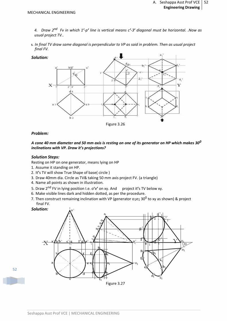
4. Draw 2nd Fv in which 1’-p’ line is vertical means c’-3’ diagonal must be horizontal. .Now as usual project TV..
5. In final TV draw same diagonal is perpendicular to VP as said in problem. Then as usual project final FV.
Solution:
Figure 3.26
Problem:
A cone 40 mm diameter and 50 mm axis is resting on one of its generator on HP which makes 300 inclinations with VP. Draw it’s projections?
Solution Steps: Resting on HP on one generator, means lying on HP 1. Assume it standing on HP. 2. It’s TV will show True Shape of base( circle ) 3. Draw 40mm dia. Circle as TV& taking 50 mm axis project FV. (a triangle) 4. Name all points as shown in illustration.
5. Draw 2nd FV in lying position I.e. o’e’ on xy. And project it’s TV below xy. 6. Make visible lines dark and hidden dotted, as per the procedure. 7. Then construct remaining inclination with VP (generator o1e1 300 to xy as shown) & project
final FV.
Solution:
Figure 3.27
A. Seshappa Asst Prof VCE Engineering Drawing
53
MECHANICAL ENGINEERING
Seshappa Asst Prof VCE | MECHANICAL ENGINEERING
53
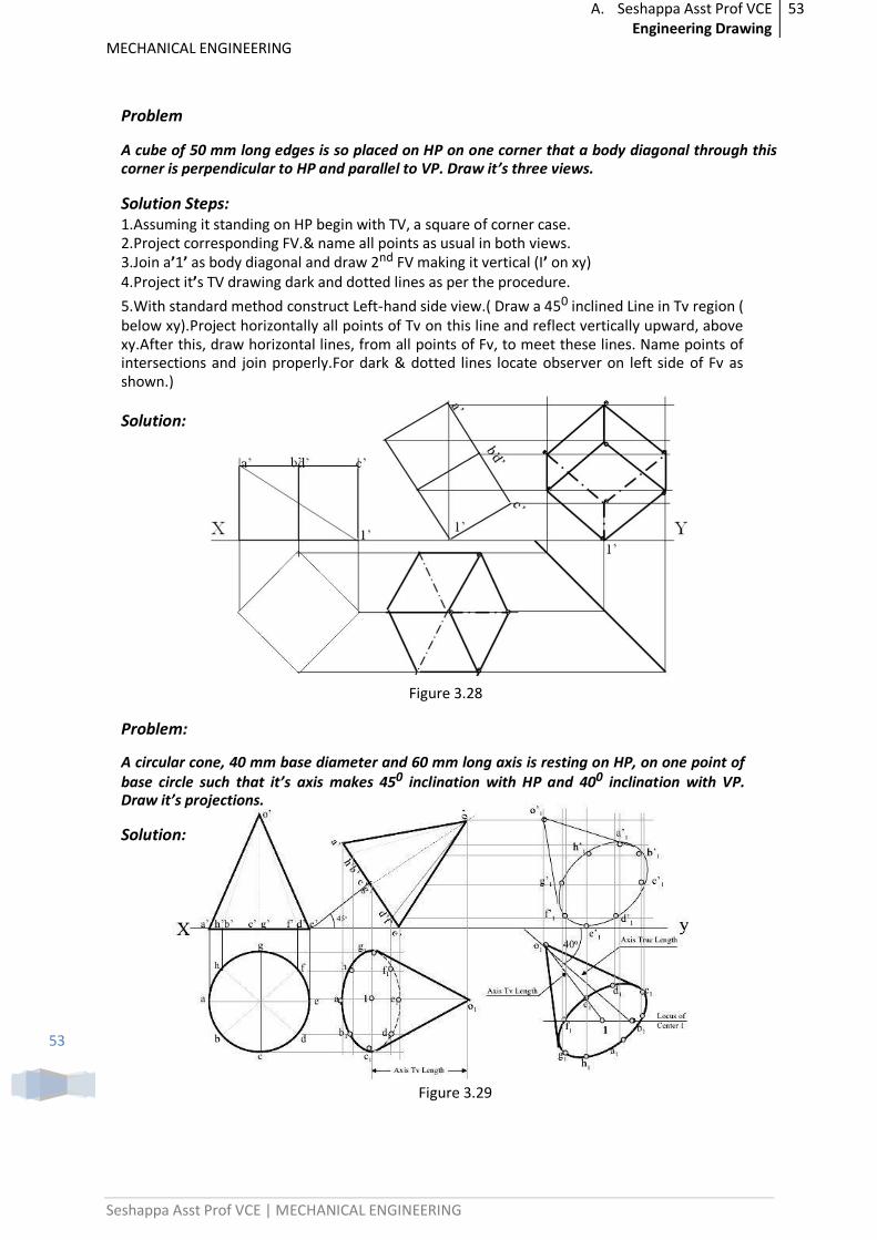
Problem
A cube of 50 mm long edges is so placed on HP on one corner that a body diagonal through this corner is perpendicular to HP and parallel to VP. Draw it’s three views.
Solution Steps: 1.Assuming it standing on HP begin with TV, a square of corner case. 2.Project corresponding FV.& name all points as usual in both views. 3.Join a’1’ as body diagonal and draw 2nd FV making it vertical (I’ on xy) 4.Project it’s TV drawing dark and dotted lines as per the procedure. 5.With standard method construct Left-hand side view.( Draw a 450 inclined Line in Tv region ( below xy).Project horizontally all points of Tv on this line and reflect vertically upward, above xy.After this, draw horizontal lines, from all points of Fv, to meet these lines. Name points of intersections and join properly.For dark & dotted lines locate observer on left side of Fv as shown.)
Solution:
Figure 3.28
Problem:
A circular cone, 40 mm base diameter and 60 mm long axis is resting on HP, on one point of base circle such that it’s axis makes 450 inclination with HP and 400 inclination with VP. Draw it’s projections.
Solution:
Figure 3.29
A. Seshappa Asst Prof VCE Engineering Drawing
54
MECHANICAL ENGINEERING
Seshappa Asst Prof VCE | MECHANICAL ENGINEERING
54
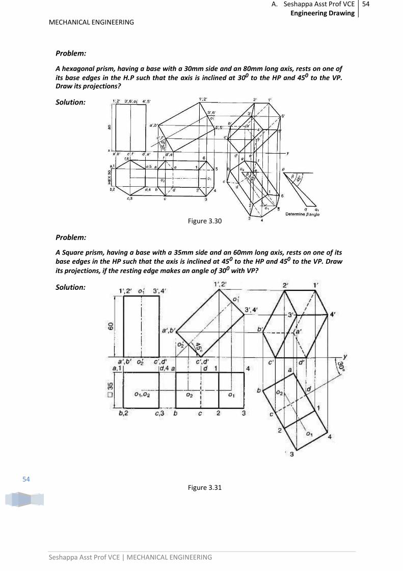
Problem:
A hexagonal prism, having a base with a 30mm side and an 80mm long axis, rests on one of its base edges in the H.P such that the axis is inclined at 300 to the HP and 450 to the VP. Draw its projections?
Solution:
Figure 3.30
Problem:
A Square prism, having a base with a 35mm side and an 60mm long axis, rests on one of its base edges in the HP such that the axis is inclined at 450 to the HP and 450 to the VP. Draw its projections, if the resting edge makes an angle of 300 with VP?
Solution:
Figure 3.31
A. Seshappa Asst Prof VCE Engineering Drawing
55
MECHANICAL ENGINEERING
Seshappa Asst Prof VCE | MECHANICAL ENGINEERING
55
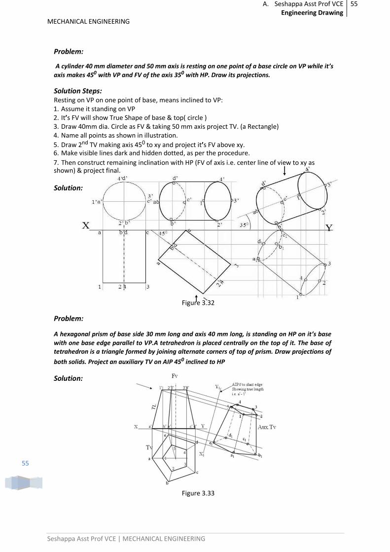
Problem:
A cylinder 40 mm diameter and 50 mm axis is resting on one point of a base circle on VP while it’s
axis makes 450 with VP and FV of the axis 350 with HP. Draw its projections.
Solution Steps: Resting on VP on one point of base, means inclined to VP: 1. Assume it standing on VP 2. It’s FV will show True Shape of base & top( circle ) 3. Draw 40mm dia. Circle as FV & taking 50 mm axis project TV. (a Rectangle) 4. Name all points as shown in illustration.
5. Draw 2nd TV making axis 450 to xy and project it’s FV above xy. 6. Make visible lines dark and hidden dotted, as per the procedure. 7. Then construct remaining inclination with HP (FV of axis i.e. center line of view to xy as shown) & project final.
Solution:
Figure 3.32
Problem:
A hexagonal prism of base side 30 mm long and axis 40 mm long, is standing on HP on it’s base
with one base edge parallel to VP.A tetrahedron is placed centrally on the top of it. The base of
tetrahedron is a triangle formed by joining alternate corners of top of prism. Draw projections of
both solids. Project an auxiliary TV on AIP 450 inclined to HP
Solution:
Figure 3.33
A. Seshappa Asst Prof VCE Engineering Drawing
56
MECHANICAL ENGINEERING
Seshappa Asst Prof VCE | MECHANICAL ENGINEERING
56
1. Axis inclined to HP and Parallel to VP have to solve in two stages Stage(i) assume axis perpendicular to HP then draw Top and Front view
Stage(ii) Tilt the Front view according to given angle. Then project all the points will get Final Top view
2 Axis inclined to VP and Parallel to HP have to solve in two stages Stage(i) assume axis perpendicular to VP then draw front and Top view
Stage(ii) Tilt the Top view according to given angle. Then project all the points will get Final Front view
Previous paper questions and Important Problems:
1. A cone of base diameter 40 mm and axis height 60 mm rests on the ground on a point of its base circle such that the axis of the cone is inclined at 400 to the HP and 300 to the VP. Draw its front and top views. 2. A hexagonal prism of base of side 40 mm and axis length 80 mm rests on one of its base
edges on the HP. The end containing that edge is inclined at 300 to the HP and the axis is parallel to VP. It is cut by a plane perpendicular to the VP and parallel to the HP. The cutting plane bisects the axis. Draw its front and the sectional top views. 3. A square pyramid of base side 30 mm and altitude 50 mm lies on one of its triangular
faces on the HP with its axis parallel to the VP. It is cut by a vertical plane inclined at 300 to the VP and meeting the axis at 40 mm from the vertex measured in the plan. Draw the top view, sectional front view and the true shape of the section. 4. A cone, diameter of base 50 mm and axis 65 mm long. is lying on the HP. on one of its generators with the axis parallel to the VP. It is cut by a horizontal Section plane 12mm above the ground. Draw its front view and sectional top view. 5. Draw the projections of a hexagonal pyramid of side of base 30mm and axis 60mm long resting on one of its base edges in HP with its axis inclined at 300 to HP. and the top view of axis
is 450 to VP. 6. A square prism having a base with a 40mm side and a 60 mm long axis rests on its base on HP. such that one of the vertical faces makes an angle of 30 degrees with VP. A section plane perpendicular to the VP. Inclined at 45 degrees to the HP. and passing through the axis at a point 20 mm from its top end cuts the prism. Draw its front view, sectional top view. 7. A hexagonal prism, side of base 35mm and height 75mm is resting on one of its corners on HP. with a longer edge containing that corner inclined at 60 degrees to the HP. and rectangular face parallel to the VP. A horizontal section plane cuts the prism into two halves. Draw the sectional top view of the cut prism and front view.
8. Draw the projections of a pentagonal prism, base 25 mm side and axis 50 mm long resting on one of its rectangular faces on HP, with the axis inclined at 45 degrees to VP.
.. ..
A. Seshappa Asst Prof VCE Engineering Drawing
57
MECHANICAL ENGINEERING
Seshappa Asst Prof VCE | MECHANICAL ENGINEERING
57
UNIT – 4
ISOMETRIC AXES, LINES, PLANES AND SOLIDS
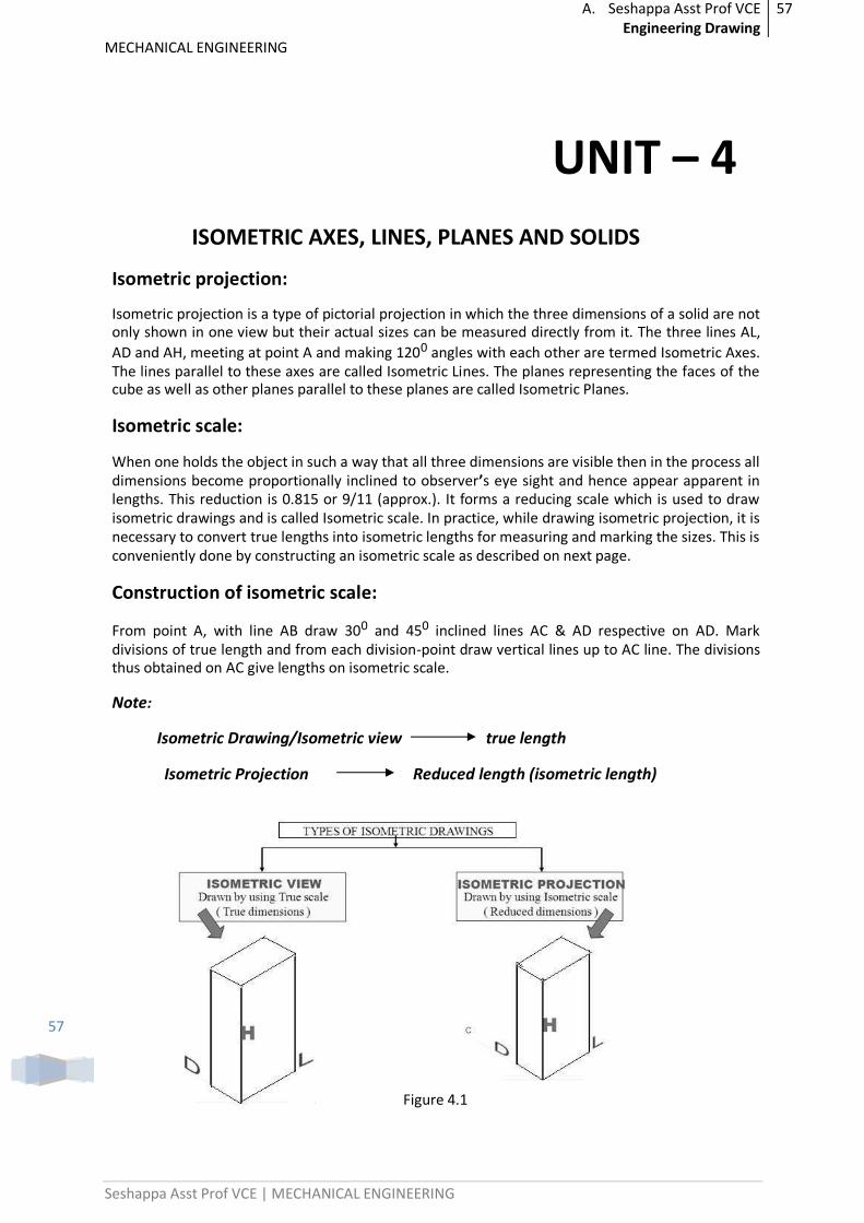
Isometric projection:
Isometric projection is a type of pictorial projection in which the three dimensions of a solid are not only shown in one view but their actual sizes can be measured directly from it. The three lines AL,
AD and AH, meeting at point A and making 1200 angles with each other are termed Isometric Axes. The lines parallel to these axes are called Isometric Lines. The planes representing the faces of the cube as well as other planes parallel to these planes are called Isometric Planes.
Isometric scale:
When one holds the object in such a way that all three dimensions are visible then in the process all dimensions become proportionally inclined to observer’s eye sight and hence appear apparent in lengths. This reduction is 0.815 or 9/11 (approx.). It forms a reducing scale which is used to draw isometric drawings and is called Isometric scale. In practice, while drawing isometric projection, it is necessary to convert true lengths into isometric lengths for measuring and marking the sizes. This is conveniently done by constructing an isometric scale as described on next page.
Construction of isometric scale:
From point A, with line AB draw 300 and 450 inclined lines AC & AD respective on AD. Mark divisions of true length and from each division-point draw vertical lines up to AC line. The divisions thus obtained on AC give lengths on isometric scale.
Note:
Isometric Drawing/Isometric view true length
Isometric Projection Reduced length (isometric length)
Figure 4.1
A. Seshappa Asst Prof VCE Engineering Drawing
58
MECHANICAL ENGINEERING
Seshappa Asst Prof VCE | MECHANICAL ENGINEERING
58
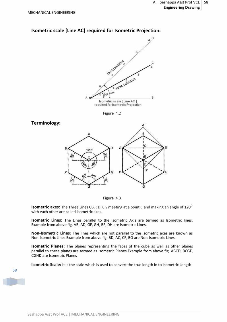
Isometric scale [Line AC] required for Isometric Projection:
Figure 4.2
Terminology:
Figure 4.3
Isometric axes: The Three Lines CB, CD, CG meeting at a point C and making an angle of 1200 with each other are called Isometric axes.
Isometric Lines: The Lines parallel to the Isometric Axis are termed as Isometric lines. Example from above fig. AB, AD, GF, GH, BF, DH are Isometric Lines.
Non-Isometric Lines: The lines which are not parallel to the isometric axes are known as Non-Isometric Lines Example from above fig. BD, AC, CF, BG are Non-Isometric Lines.
Isometric Planes: The planes representing the faces of the cube as well as other planes parallel to these planes are termed as Isometric Planes Example from above fig. ABCD, BCGF, CGHD are Isometric Planes
Isometric Scale: It is the scale which is used to convert the true length in to Isometric Length
A. Seshappa Asst Prof VCE Engineering Drawing
59
MECHANICAL ENGINEERING
Seshappa Asst Prof VCE | MECHANICAL ENGINEERING
59
Isometric views of planes:
Simple Problems:
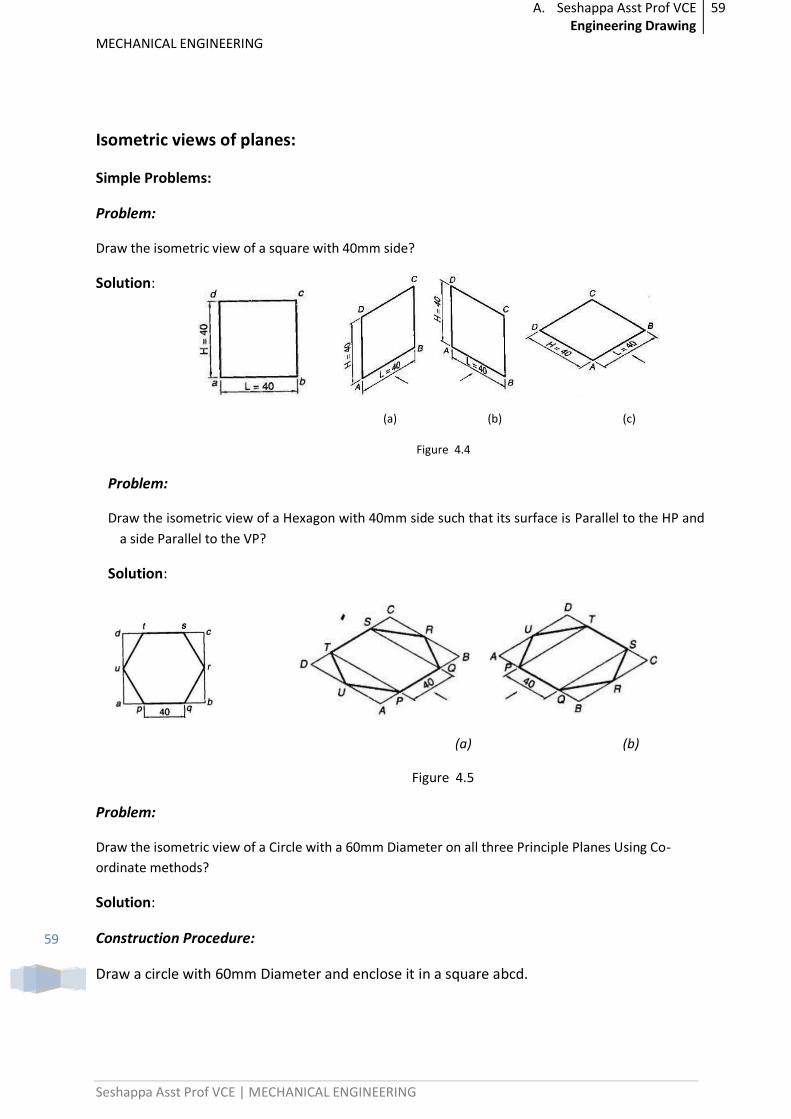
Problem:
Draw the isometric view of a square with 40mm side?
Solution:
(a) (b) (c)
Figure 4.4
Problem:
Draw the isometric view of a Hexagon with 40mm side such that its surface is Parallel to the HP and
a side Parallel to the VP?
Solution:
(a) (b)
Figure 4.5
Problem:
Draw the isometric view of a Circle with a 60mm Diameter on all three Principle Planes Using Co-
ordinate methods?
Solution:
Construction Procedure:
Draw a circle with 60mm Diameter and enclose it in a square abcd.
A. Seshappa Asst Prof VCE Engineering Drawing
60
MECHANICAL ENGINEERING
Seshappa Asst Prof VCE | MECHANICAL ENGINEERING
60
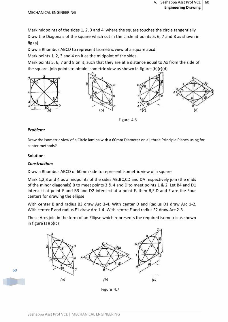
Mark midpoints of the sides 1, 2, 3 and 4, where the square touches the circle tangentially
Draw the Diagonals of the square which cut in the circle at points 5, 6, 7 and 8 as shown in
fig (a).
Draw a Rhombus ABCD to represent Isometric view of a square abcd.
Mark points 1, 2, 3 and 4 on it as the midpoint of the sides.
Mark points 5, 6, 7 and 8 on it, such that they are at a distance equal to Ax from the side of
the square .join points to obtain isometric view as shown in figures(b)(c)(d)
(a) (b) (c) (d)
Figure 4.6
Problem:
Draw the isometric view of a Circle lamina with a 60mm Diameter on all three Principle Planes using for
center methods?
Solution:
Construction:
Draw a Rhombus ABCD of 60mm side to represent isometric view of a square
Mark 1,2,3 and 4 as a midpoints of the sides AB,BC,CD and DA respectively join (the ends of the minor diagonals) B to meet points 3 & 4 and D to meet points 1 & 2. Let B4 and D1 intersect at point E and B3 and D2 intersect at a point F. then B,E,D and F are the Four centers for drawing the ellipse
With center B and radius B3 draw Arc 3-4. With center D and Radius D1 draw Arc 1-2. With center E and radius E1 draw Arc 1-4. With centre F and radius F2 draw Arc 2-3.
These Arcs join in the form of an Ellipse which represents the required isometric as shown in figure (a)(b)(c)
(a) (b) (c)
Figure 4.7
A. Seshappa Asst Prof VCE Engineering Drawing
61
MECHANICAL ENGINEERING
Seshappa Asst Prof VCE | MECHANICAL ENGINEERING
61
Isometric views of solids
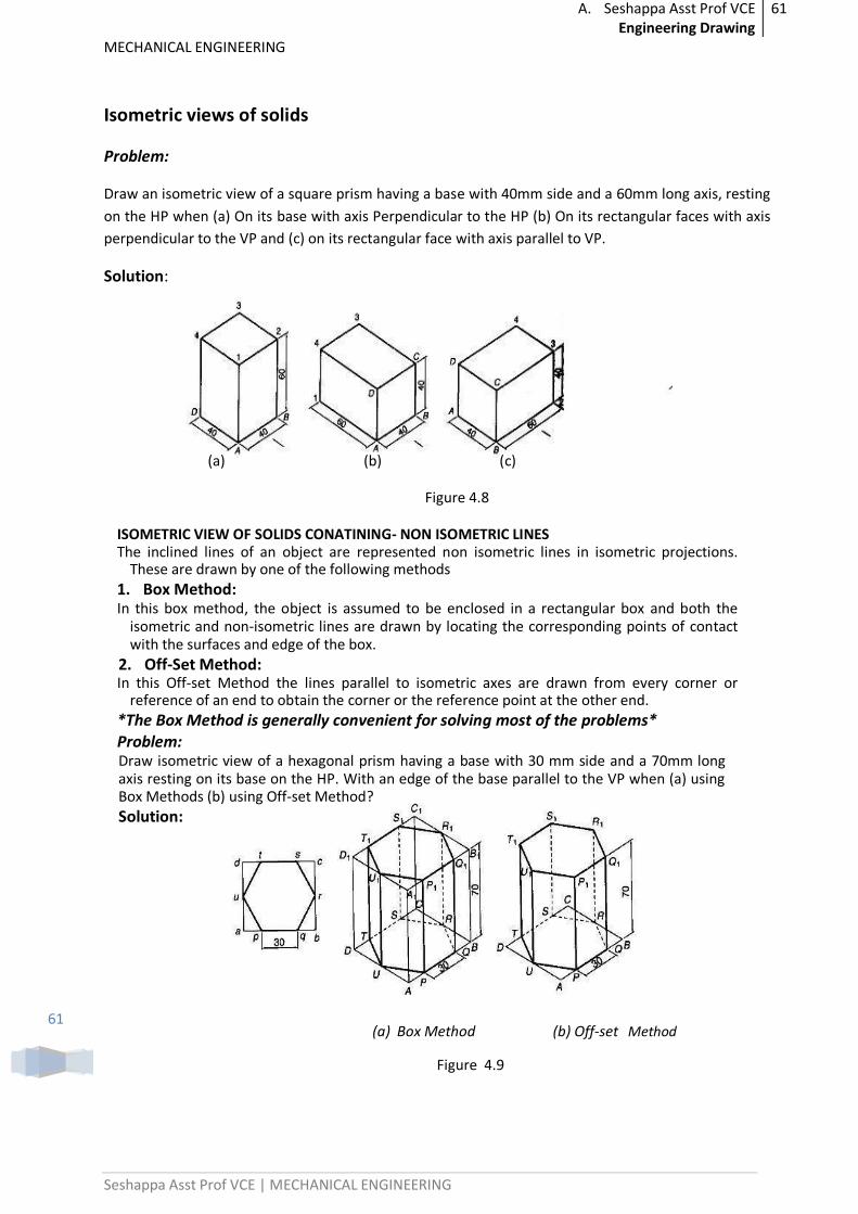
Problem:
Draw an isometric view of a square prism having a base with 40mm side and a 60mm long axis, resting
on the HP when (a) On its base with axis Perpendicular to the HP (b) On its rectangular faces with axis
perpendicular to the VP and (c) on its rectangular face with axis parallel to VP.
Solution:
(a) (b) (c)
Figure 4.8
ISOMETRIC VIEW OF SOLIDS CONATINING- NON ISOMETRIC LINES The inclined lines of an object are represented non isometric lines in isometric projections.
These are drawn by one of the following methods
1. Box Method: In this box method, the object is assumed to be enclosed in a rectangular box and both the
isometric and non-isometric lines are drawn by locating the corresponding points of contact with the surfaces and edge of the box.
2. Off-Set Method: In this Off-set Method the lines parallel to isometric axes are drawn from every corner or
reference of an end to obtain the corner or the reference point at the other end.
*The Box Method is generally convenient for solving most of the problems* Problem: Draw isometric view of a hexagonal prism having a base with 30 mm side and a 70mm long axis resting on its base on the HP. With an edge of the base parallel to the VP when (a) using Box Methods (b) using Off-set Method?
Solution:
(a) Box Method (b) Off-set Method
Figure 4.9
A. Seshappa Asst Prof VCE Engineering Drawing
62
MECHANICAL ENGINEERING
Seshappa Asst Prof VCE | MECHANICAL ENGINEERING
62
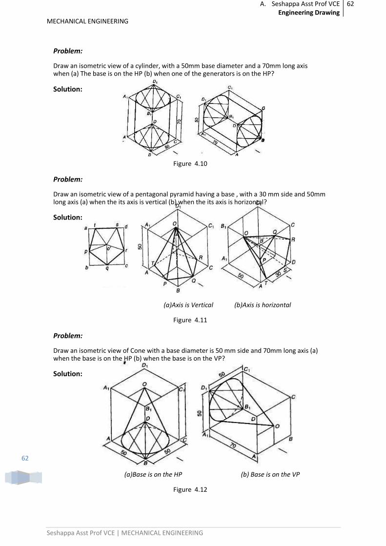
Problem:
Draw an isometric view of a cylinder, with a 50mm base diameter and a 70mm long axis when (a) The base is on the HP (b) when one of the generators is on the HP?
Solution:
Figure 4.10
Problem:
Draw an isometric view of a pentagonal pyramid having a base , with a 30 mm side and 50mm long axis (a) when the its axis is vertical (b) when the its axis is horizontal?
Solution:
(a)Axis is Vertical (b)Axis is horizontal
Figure 4.11
Problem:
Draw an isometric view of Cone with a base diameter is 50 mm side and 70mm long axis (a) when the base is on the HP (b) when the base is on the VP?
Solution:
(a)Base is on the HP (b) Base is on the VP
Figure 4.12
A. Seshappa Asst Prof VCE Engineering Drawing
63
MECHANICAL ENGINEERING
Seshappa Asst Prof VCE | MECHANICAL ENGINEERING
63
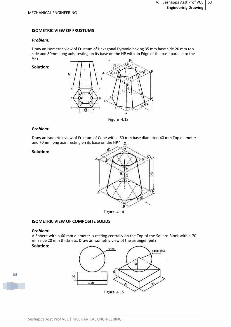
ISOMETRIC VIEW OF FRUSTUMS
Problem:
Draw an isometric view of Frustum of Hexagonal Pyramid having 35 mm base side 20 mm top side and 80mm long axis, resting on its base on the HP with an Edge of the base parallel to the VP?
Solution:
Figure 4.13
Problem:
Draw an isometric view of Frustum of Cone with a 60 mm base diameter, 40 mm Top diameter and 70mm long axis, resting on its base on the HP?
Solution:
Figure 4.14
ISOMETRIC VIEW OF COMPOSITE SOLIDS
Problem: A Sphere with a 60 mm diameter is resting centrally on the Top of the Square Block with a 70 mm side 20 mm thickness. Draw an isometric view of the arrangement?
Solution:
Figure 4.15
A. Seshappa Asst Prof VCE Engineering Drawing
64
MECHANICAL ENGINEERING
Seshappa Asst Prof VCE | MECHANICAL ENGINEERING
64
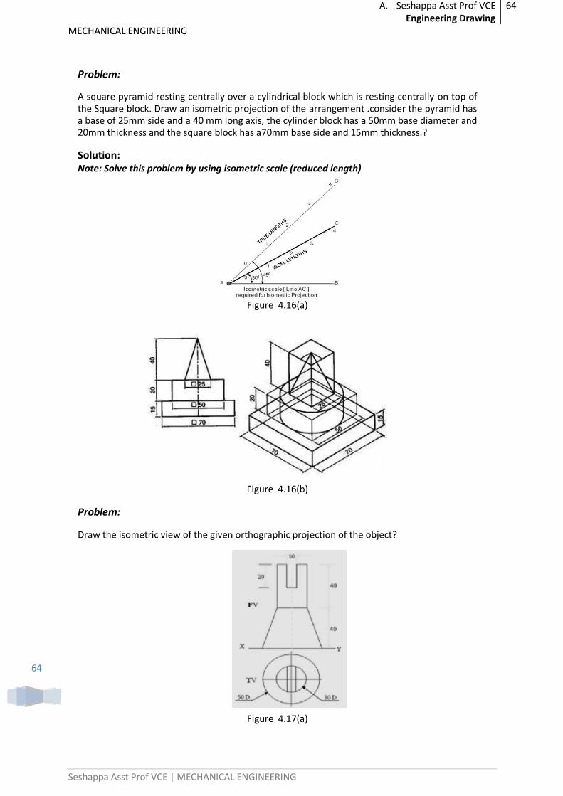
Problem:
A square pyramid resting centrally over a cylindrical block which is resting centrally on top of the Square block. Draw an isometric projection of the arrangement .consider the pyramid has a base of 25mm side and a 40 mm long axis, the cylinder block has a 50mm base diameter and 20mm thickness and the square block has a70mm base side and 15mm thickness.?
Solution: Note: Solve this problem by using isometric scale (reduced length)
Figure 4.16(a)
Figure 4.16(b)
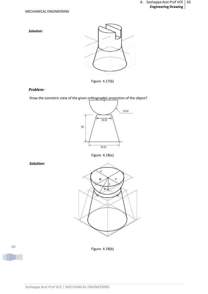
Problem:
Draw the isometric view of the given orthographic projection of the object?
Figure 4.17(a)
A. Seshappa Asst Prof VCE Engineering Drawing
65
MECHANICAL ENGINEERING
Seshappa Asst Prof VCE | MECHANICAL ENGINEERING
65
Solution:
Figure 4.17(b)
Problem:
Draw the isometric view of the given orthographic projection of the object?
Figure 4.18(a)
Solution:
Figure 4.18(b)
A. Seshappa Asst Prof VCE Engineering Drawing
66
MECHANICAL ENGINEERING
Seshappa Asst Prof VCE | MECHANICAL ENGINEERING
66
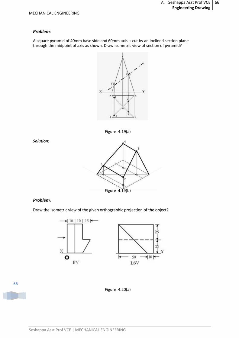
Problem:
A square pyramid of 40mm base side and 60mm axis is cut by an inclined section plane through the midpoint of axis as shown. Draw isometric view of section of pyramid?
Figure 4.19(a)
Solution:
Figure 4.19(b)
Problem:
Draw the isometric view of the given orthographic projection of the object?
Figure 4.20(a)
A. Seshappa Asst Prof VCE Engineering Drawing
67
MECHANICAL ENGINEERING
Seshappa Asst Prof VCE | MECHANICAL ENGINEERING
67
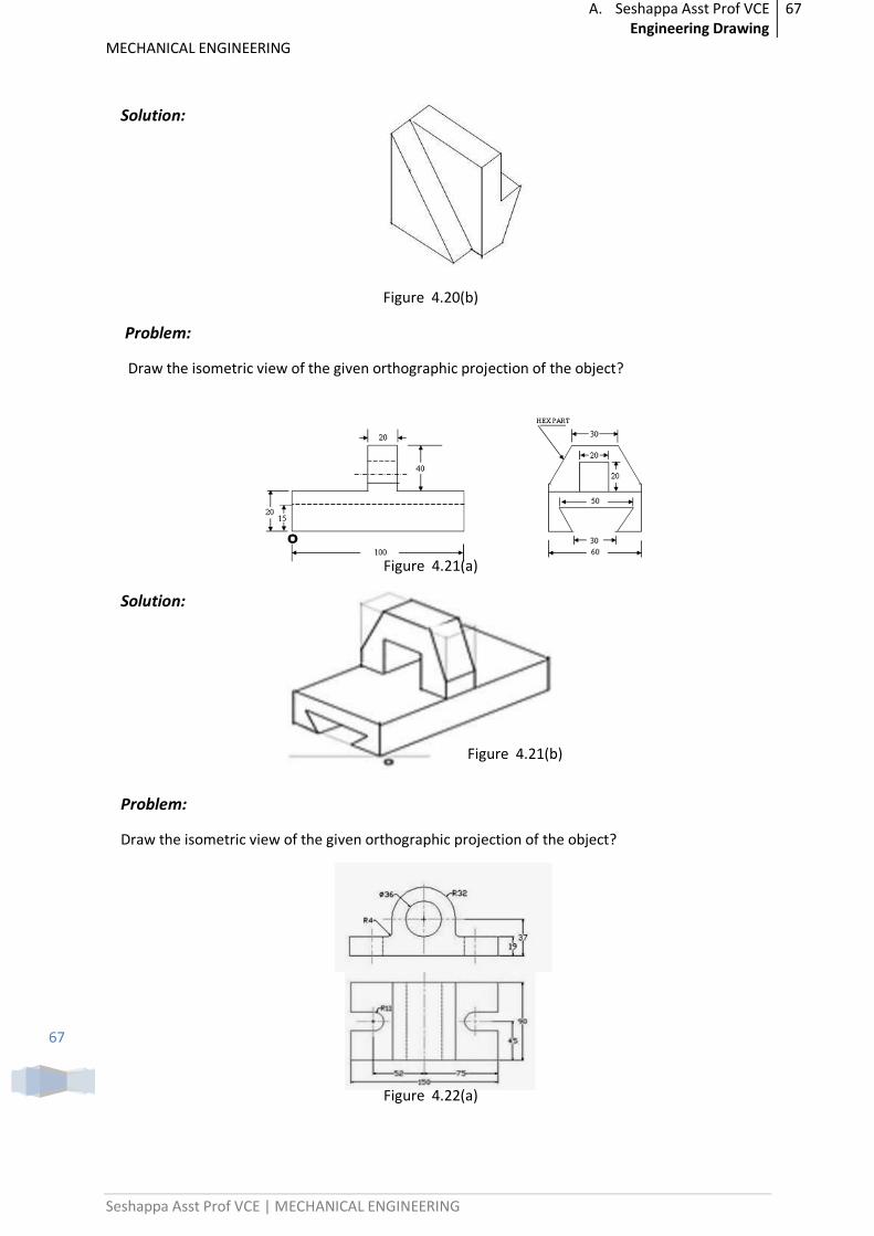
Solution:
Figure 4.20(b)
Problem:
Draw the isometric view of the given orthographic projection of the object?
Figure 4.21(a)
Solution:
Figure 4.21(b)
Problem:
Draw the isometric view of the given orthographic projection of the object?
Figure 4.22(a)
A. Seshappa Asst Prof VCE Engineering Drawing
68
MECHANICAL ENGINEERING
Seshappa Asst Prof VCE | MECHANICAL ENGINEERING
68
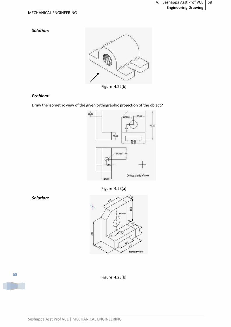
Solution:
Figure 4.22(b)
Problem:
Draw the isometric view of the given orthographic projection of the object?
Figure 4.23(a)
Solution:
Figure 4.23(b)
A. Seshappa Asst Prof VCE Engineering Drawing
69
MECHANICAL ENGINEERING
Seshappa Asst Prof VCE | MECHANICAL ENGINEERING
69
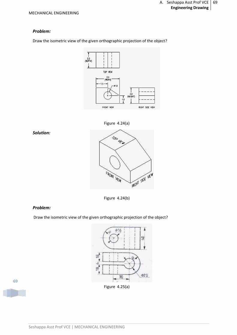
Problem:
Draw the isometric view of the given orthographic projection of the object?
Figure 4.24(a)
Solution:
Figure 4.24(b)
Problem:
Draw the isometric view of the given orthographic projection of the object?
Figure 4.25(a)
A. Seshappa Asst Prof VCE Engineering Drawing
70
MECHANICAL ENGINEERING
Seshappa Asst Prof VCE | MECHANICAL ENGINEERING
70
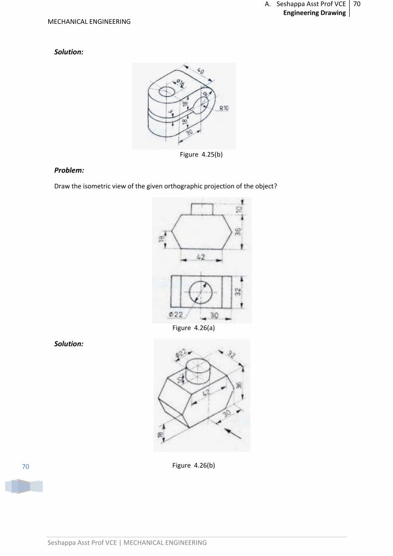
Solution:
Figure 4.25(b)
Problem:
Draw the isometric view of the given orthographic projection of the object?
Figure 4.26(a)
Solution:
Figure 4.26(b)
A. Seshappa Asst Prof VCE Engineering Drawing
71
MECHANICAL ENGINEERING
Seshappa Asst Prof VCE | MECHANICAL ENGINEERING
71
Previous Paper Questions:
1. A cylindrical block of base,60 mm diameter and height 90 mm, standing on the HP, with its axis perpendicular to the HP. Draw its isometric view.
2. Draw an isometric view of a hexagonal prism having a base with 25mm side and 65 mm long axis which is lying on its face in the HP, with axis parallel to both HP and VP.
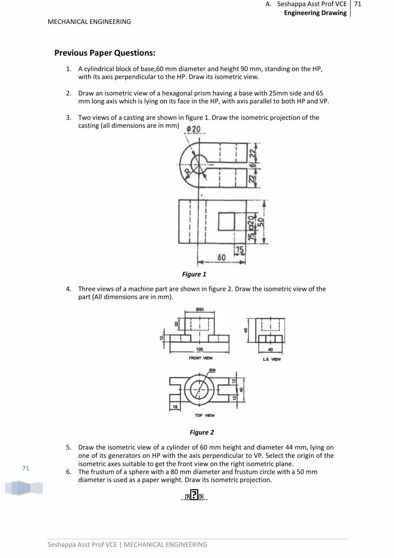
3. Two views of a casting are shown in figure 1. Draw the isometric projection of the casting (all dimensions are in mm)
Figure 1
4. Three views of a machine part are shown in figure 2. Draw the isometric view of the part (All dimensions are in mm).
Figure 2
5. Draw the isometric view of a cylinder of 60 mm height and diameter 44 mm, lying on one of its generators on HP with the axis perpendicular to VP. Select the origin of the isometric axes suitable to get the front view on the right isometric plane.
6. The frustum of a sphere with a 80 mm diameter and frustum circle with a 50 mm diameter is used as a paper weight. Draw its isometric projection.
.. ..
A. Seshappa Asst Prof VCE Engineering Drawing
72
MECHANICAL ENGINEERING
Seshappa Asst Prof VCE | MECHANICAL ENGINEERING
72
UNIT-5
ORTHOGRAPHIC PROJECTION
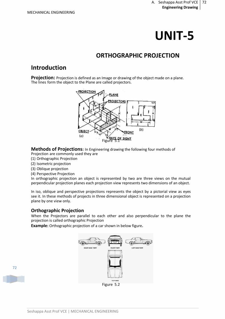
Introduction
Projection: Projection is defined as an Image or drawing of the object made on a plane. The lines form the object to the Plane are called projectors.
Figure 5.1
Methods of Projections: In Engineering drawing the following four methods of Projection are commonly used they are (1) Orthographic Projection (2) Isometric projection (3) Oblique projection (4) Perspective Projection In orthographic projection an object is represented by two are three views on the mutual perpendicular projection planes each projection view represents two dimensions of an object.
In iso, oblique and perspective projections represents the object by a pictorial view as eyes see it. In these methods of projects in three dimensional object is represented on a projection plane by one view only.
Orthographic Projection When the Projectors are parallel to each other and also perpendicular to the plane the projection is called orthographic Projection
Example: Orthographic projection of a car shown in below figure.
Figure 5.2
A. Seshappa Asst Prof VCE Engineering Drawing
73
MECHANICAL ENGINEERING
Seshappa Asst Prof VCE | MECHANICAL ENGINEERING
73
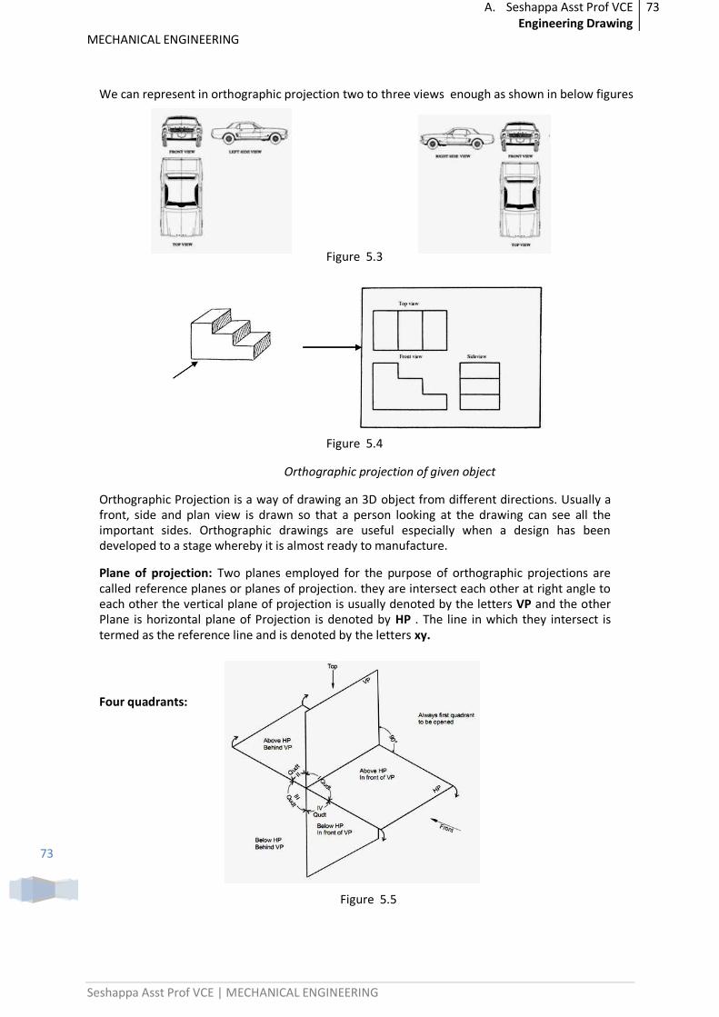
We can represent in orthographic projection two to three views enough as shown in below figures
Figure 5.3
Figure 5.4
Orthographic projection of given object
Orthographic Projection is a way of drawing an 3D object from different directions. Usually a front, side and plan view is drawn so that a person looking at the drawing can see all the important sides. Orthographic drawings are useful especially when a design has been developed to a stage whereby it is almost ready to manufacture.
Plane of projection: Two planes employed for the purpose of orthographic projections are called reference planes or planes of projection. they are intersect each other at right angle to each other the vertical plane of projection is usually denoted by the letters VP and the other Plane is horizontal plane of Projection is denoted by HP . The line in which they intersect is termed as the reference line and is denoted by the letters xy.
Four quadrants:
Figure 5.5
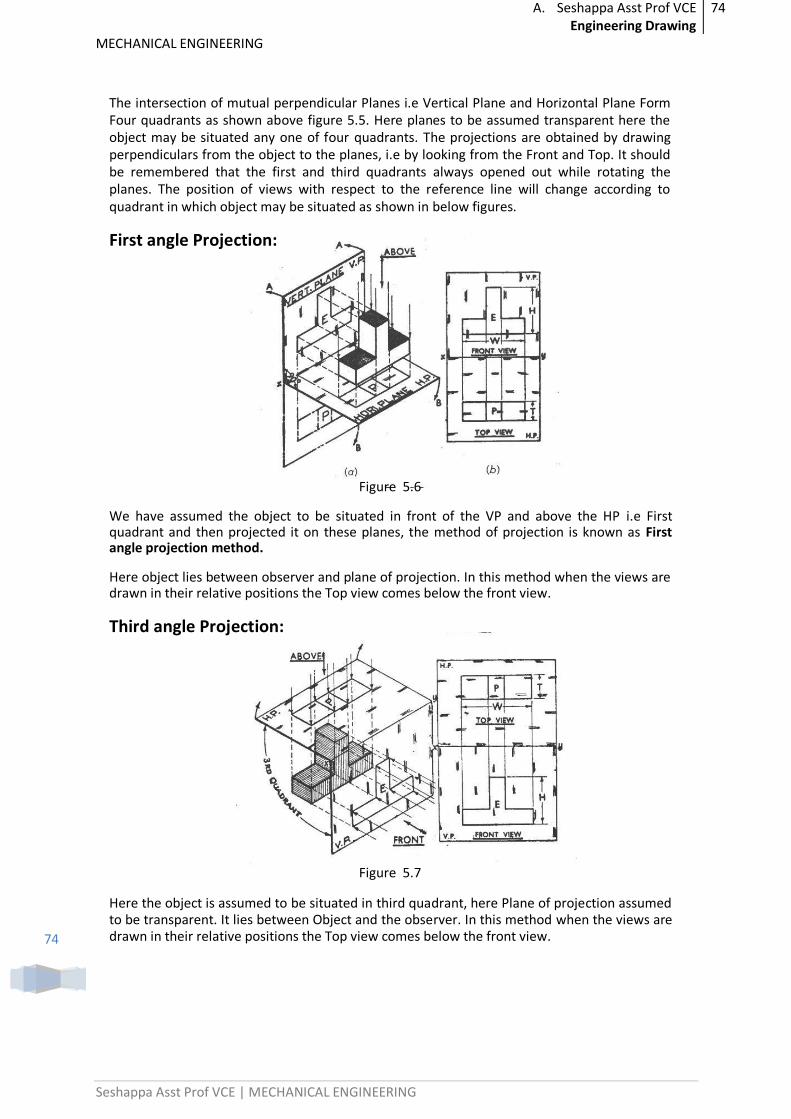
A. Seshappa Asst Prof VCE Engineering Drawing
74
MECHANICAL ENGINEERING
Seshappa Asst Prof VCE | MECHANICAL ENGINEERING
74
The intersection of mutual perpendicular Planes i.e Vertical Plane and Horizontal Plane Form Four quadrants as shown above figure 5.5. Here planes to be assumed transparent here the object may be situated any one of four quadrants. The projections are obtained by drawing perpendiculars from the object to the planes, i.e by looking from the Front and Top. It should be remembered that the first and third quadrants always opened out while rotating the planes. The position of views with respect to the reference line will change according to quadrant in which object may be situated as shown in below figures.
First angle Projection:
Figure 5.6
We have assumed the object to be situated in front of the VP and above the HP i.e First quadrant and then projected it on these planes, the method of projection is known as First angle projection method.
Here object lies between observer and plane of projection. In this method when the views are drawn in their relative positions the Top view comes below the front view.
Third angle Projection:
Figure 5.7
Here the object is assumed to be situated in third quadrant, here Plane of projection assumed to be transparent. It lies between Object and the observer. In this method when the views are drawn in their relative positions the Top view comes below the front view.
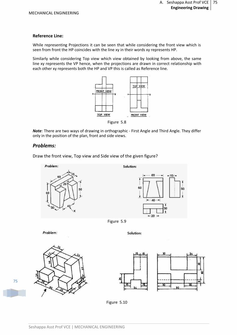
A. Seshappa Asst Prof VCE Engineering Drawing
75
MECHANICAL ENGINEERING
Seshappa Asst Prof VCE | MECHANICAL ENGINEERING
75
Reference Line:
While representing Projections it can be seen that while considering the front view which is seen from front the HP coincides with the line xy in their words xy represents HP.
Similarly while considering Top view which view obtained by looking from above, the same line xy represents the VP hence, when the projections are drawn in correct relationship with each other xy represents both the HP and VP this is called as Reference line.
Figure 5.8
Note: There are two ways of drawing in orthographic - First Angle and Third Angle. They differ only in the position of the plan, front and side views.
Problems:
Draw the front view, Top view and Side view of the given figure?
Figure 5.9
Figure 5.10
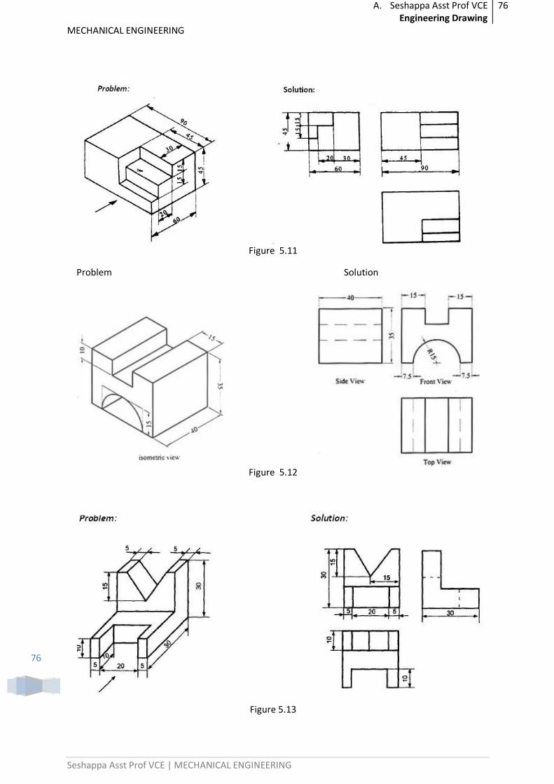
A. Seshappa Asst Prof VCE Engineering Drawing
76
MECHANICAL ENGINEERING
Seshappa Asst Prof VCE | MECHANICAL ENGINEERING
76
Figure 5.11
Problem Solution
Figure 5.12
Figure 5.13
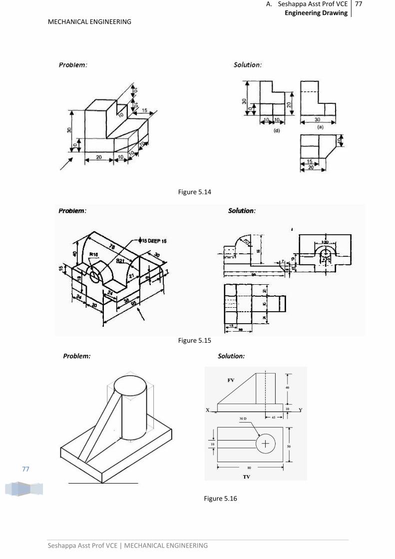
A. Seshappa Asst Prof VCE Engineering Drawing
77
MECHANICAL ENGINEERING
Seshappa Asst Prof VCE | MECHANICAL ENGINEERING
77
Figure 5.14
Figure 5.15
Problem: Solution:
Figure 5.16
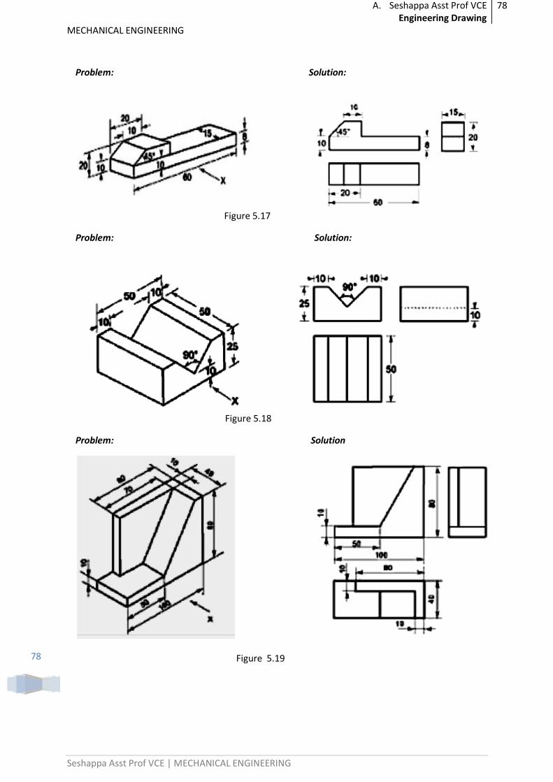
A. Seshappa Asst Prof VCE Engineering Drawing
78
MECHANICAL ENGINEERING
Seshappa Asst Prof VCE | MECHANICAL ENGINEERING
78
Problem: Solution:
Figure 5.17
Problem: Solution:
Figure 5.18
Problem: Solution
Figure 5.19
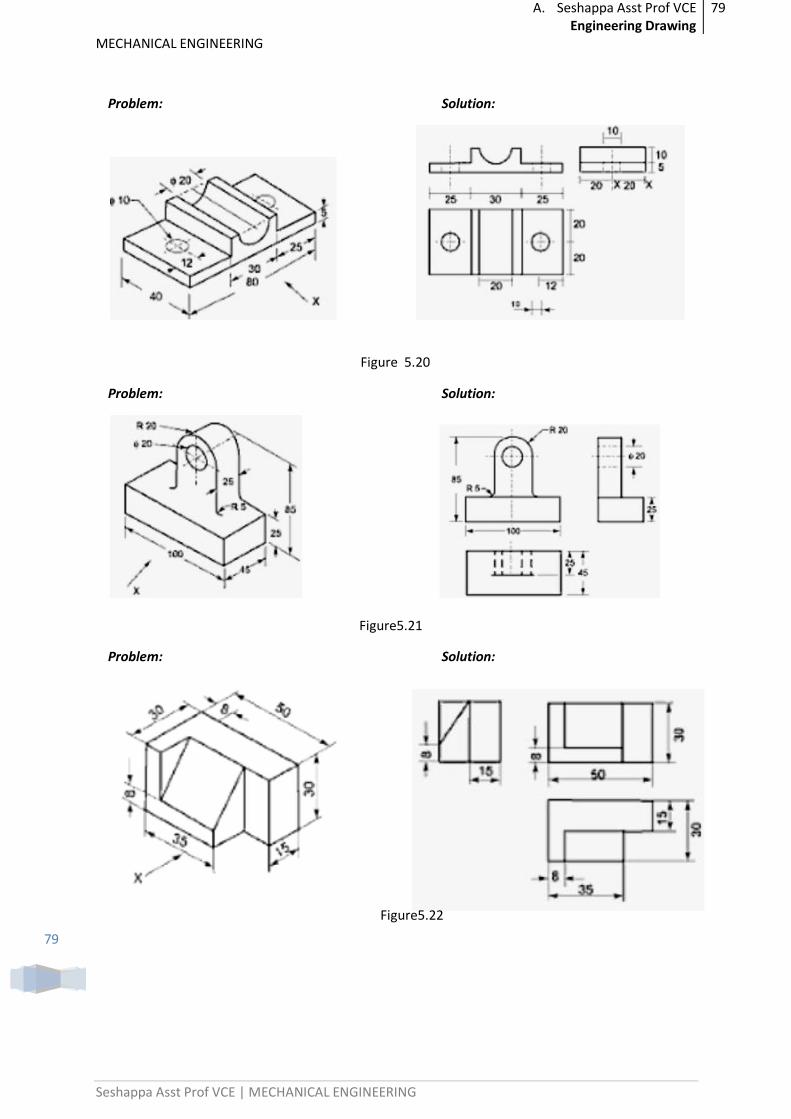
A. Seshappa Asst Prof VCE Engineering Drawing
79
MECHANICAL ENGINEERING
Seshappa Asst Prof VCE | MECHANICAL ENGINEERING
79
Problem: Solution:
Figure 5.20
Problem: Solution:
Figure5.21
Problem: Solution:
Figure5.22
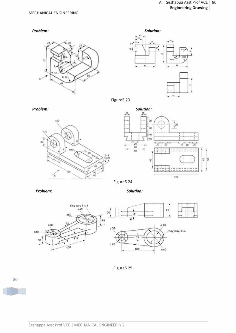
A. Seshappa Asst Prof VCE Engineering Drawing
80
MECHANICAL ENGINEERING
Seshappa Asst Prof VCE | MECHANICAL ENGINEERING
80
Problem: Solution:
Figure5.23
Problem: Solution:
Figure5.24
Problem: Solution:
Figure5.25
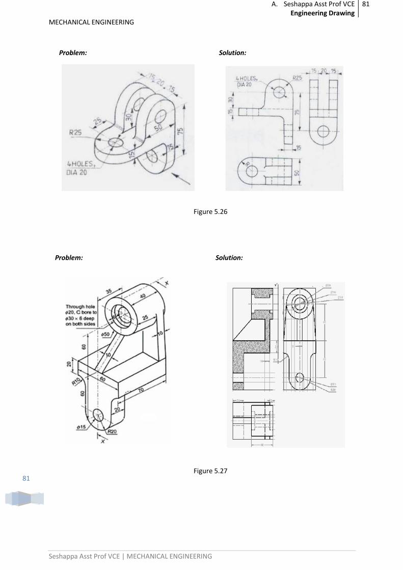
A. Seshappa Asst Prof VCE Engineering Drawing
81
MECHANICAL ENGINEERING
Seshappa Asst Prof VCE | MECHANICAL ENGINEERING
81
Problem: Solution:
Figure 5.26
Problem: Solution:
Figure 5.27
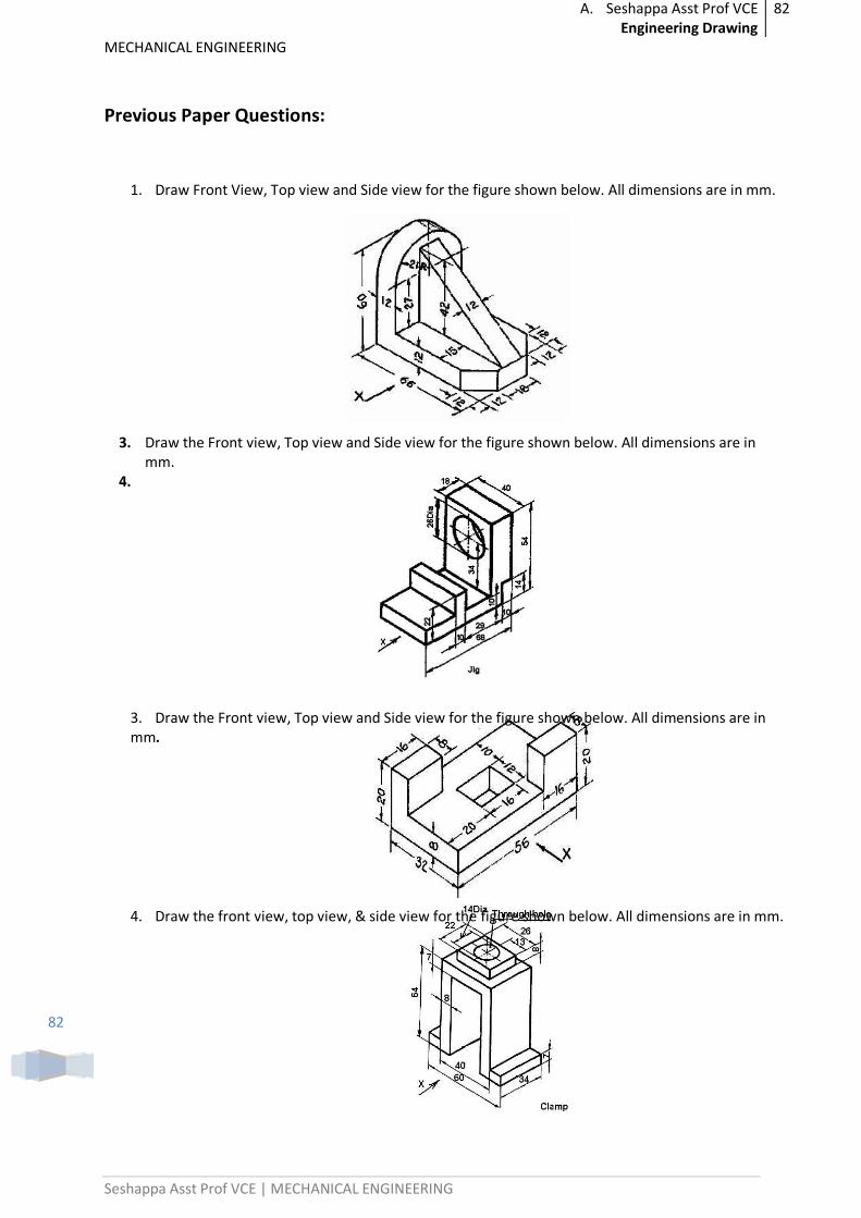
A. Seshappa Asst Prof VCE Engineering Drawing
82
MECHANICAL ENGINEERING
Seshappa Asst Prof VCE | MECHANICAL ENGINEERING
82
Previous Paper Questions:
1. Draw Front View, Top view and Side view for the figure shown below. All dimensions are in mm.
3. Draw the Front view, Top view and Side view for the figure shown below. All dimensions are in mm.
4.
3. Draw the Front view, Top view and Side view for the figure shown below. All dimensions are in mm.
4. Draw the front view, top view, & side view for the figure shown below. All dimensions are in mm.
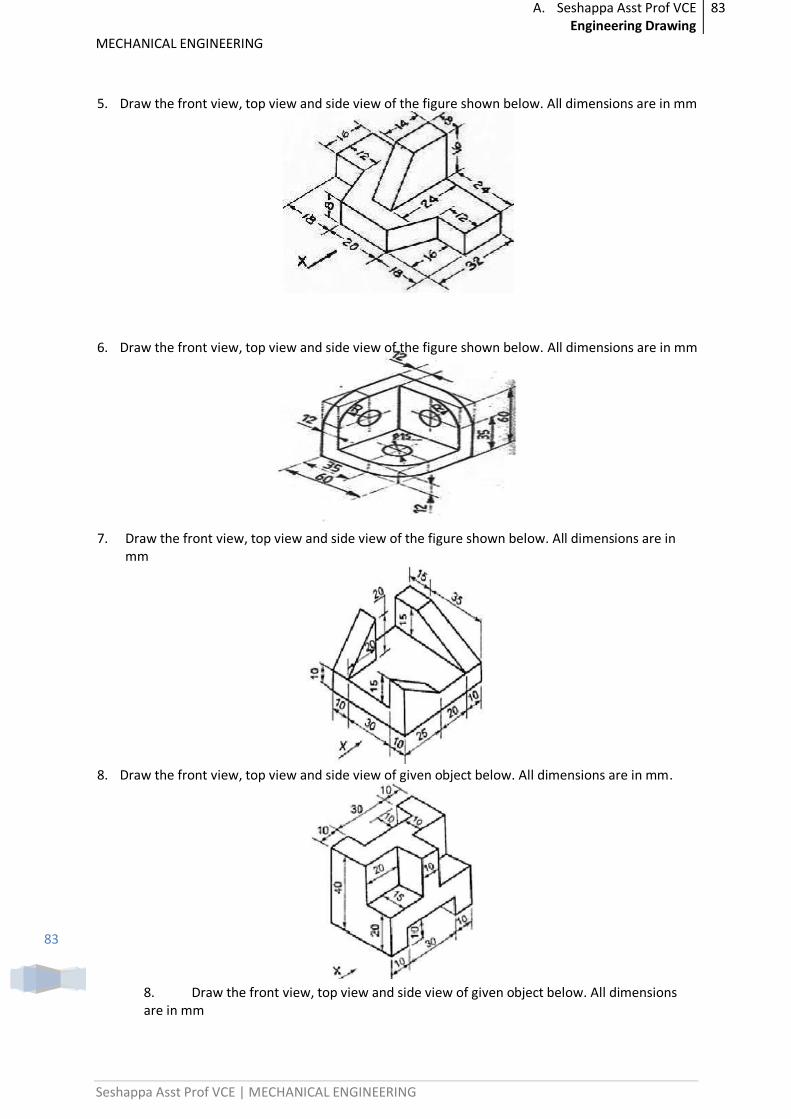
A. Seshappa Asst Prof VCE Engineering Drawing
83
MECHANICAL ENGINEERING
Seshappa Asst Prof VCE | MECHANICAL ENGINEERING
83
5. Draw the front view, top view and side view of the figure shown below. All dimensions are in mm
6. Draw the front view, top view and side view of the figure shown below. All dimensions are in mm
7. Draw the front view, top view and side view of the figure shown below. All dimensions are in mm
8. Draw the front view, top view and side view of given object below. All dimensions are in mm.
8. Draw the front view, top view and side view of given object below. All dimensions are in mm
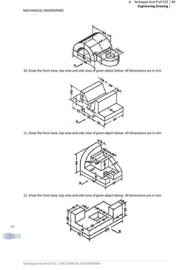
A. Seshappa Asst Prof VCE Engineering Drawing
84
MECHANICAL ENGINEERING
Seshappa Asst Prof VCE | MECHANICAL ENGINEERING
84
10. Draw the front view, top view and side view of given object below. All dimensions are in mm
11. Draw the front view, top view and side view of given object below. All dimensions are in mm
12. Draw the front view, top view and side view of given object below. All dimensions are in mm
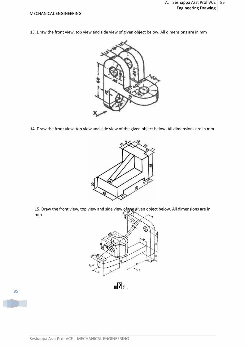
A. Seshappa Asst Prof VCE Engineering Drawing
85
MECHANICAL ENGINEERING
Seshappa Asst Prof VCE | MECHANICAL ENGINEERING
85
13. Draw the front view, top view and side view of given object below. All dimensions are in mm
14. Draw the front view, top view and side view of the given object below. All dimensions are in mm
15. Draw the front view, top view and side view of the given object below. All dimensions are in mm
.. ..