Embed Size (px)
Citation preview
786310-1
A simple method for measuring crosstalk in stereoscopic displays
Michael A. Weissmana, Andrew J. Woodsb
a TrueVision Systems, Inc., 114 E Haley Street, Santa Barbara, CA 93101, USA b Centre for Marine Science & Technology, Curtin University, GPO Box 1987, Perth 6845 Australia
ABSTRACT
Crosstalk (also known as “ghosting”, “leakage”, or “extinction”), a vitally important concept in stereoscopic 3D displays, has not been clearly defined or measured in the stereoscopic literature (Woods[3]). In this paper, a mathematical definition is proposed which uses a “physical” approach. This derivation leads to a clear definition of left-view or right-view crosstalk and shows that 1), when the display’s black level is not zero, it must be subtracted out and 2), when the source intensities are equal, crosstalk can be measured using observed intensities totally within the respective view. Next, a simple method of measuring crosstalk is presented, one that relies on only viewing a test chart on the display. No electronic or optical instruments are needed. Results of the use of the chart are presented, as well as optical measurements, which did not agree well with chart results. The main reason for the discrepancy is the difficulty of measuring very low light levels. With wide distribution, this tool can lead to the collection of useful performance information about 3D displays and, therefore, to the production of the best stereoscopic displays.
Keywords: crosstalk, extinction, ghosting, stereoscopic displays, 3D displays
1. INTRODUCTION
Maintaining low crosstalk in a stereoscopic display system – that is, reducing, or extinguishing if possible, the amount of “wrong” image in each eye (also known as “ghosting” or “leakage”) – is critically important for comfortable and high-quality 3D viewing. A moderate amount can cause eyestrain; a large amount will prevent fusing the 3D scene. However, when evaluating a stereoscopic display, it is often difficult to measure the amount of crosstalk in the display:
Due to complexity of the system,
Due to lack of measurements,
Due to the reluctance of manufacturers to release data,
Due to difficulty of making the measurement.
Furthermore, we find in the stereoscopic literature (Woods[3]) that there is much ambiguity and confusion about both the descriptive and mathematical definitions of this important concept. One objective of the current work is to model the stereoscopic image-making process and to come up with a clear mathematical definition.
A second objective is to propose a simple method of measuring the crosstalk fraction and extinction ratio that relies on viewing test patterns on the display without the need for electronic or optical instruments. Our hope is that this tool can be distributed widely and will lead to the collection of consistent information about 3D displays, and therefore, to the production of the best stereoscopic displays possible.
In this paper, we focus on a mathematical definition of crosstalk. As discussed by Woods[3], mathematical definitions of “crosstalk”, “ghosting”, “leakage”, and “extinction ratio” are quite varied within the stereoscopic literature. Sometimes, when characterizing “white-to-black” crosstalk†, a simple ratio of the ghost image (the crosstalk contribution) to the white image in the same eye is used[7]; sometimes this ratio is taken against the white image as seen in the opposite view[8][9]. Sometimes it is taken against the source image rather than the output, observed image[10]. Sometimes the
[email protected]; www.truevisionsys.com † A white image is leaked across to a black image.
Michael A. Weissman, Andrew J. Woods, “A simple method for measuring crosstalk in stereoscopic displays” in Proceedings of SPIE Stereoscopic Displays and Applications XXII, Vol. 7863, 786310 (2011).
Downloaded from: www.AndrewWoods3D.com
Copyright 2011 Society of Photo-Optical Instrumentation Engineers. One print or electronic copy can be made for personal use only. Systematic reproduction and distribution, duplication of any material in this paper for a fee or for commercial purposes, or modification of the content of the paper are prohibited. DOI: 10.1117/12.877021 http://dx.doi.org/10.1117/12.877021
786310-2
black level is subtracted out[11][12][13][14][15][16][17]; sometimes not[7][8][9][10]. In order to confirm which formulation is most appropriate, a “physical” model of crosstalk is developed in the next section.
2. DEFINING CROSSTALK
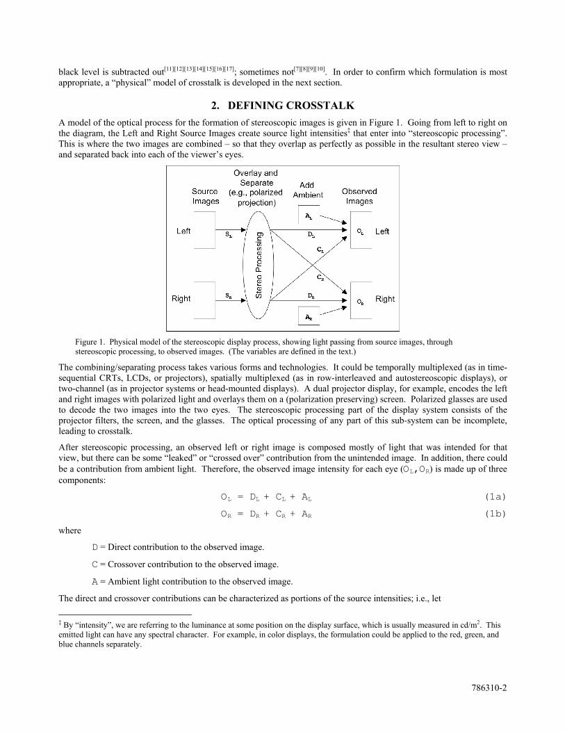
A model of the optical process for the formation of stereoscopic images is given in Figure 1. Going from left to right on the diagram, the Left and Right Source Images create source light intensities‡ that enter into “stereoscopic processing”. This is where the two images are combined – so that they overlap as perfectly as possible in the resultant stereo view – and separated back into each of the viewer’s eyes.
Figure 1. Physical model of the stereoscopic display process, showing light passing from source images, through stereoscopic processing, to observed images. (The variables are defined in the text.)
The combining/separating process takes various forms and technologies. It could be temporally multiplexed (as in time-sequential CRTs, LCDs, or projectors), spatially multiplexed (as in row-interleaved and autostereoscopic displays), or two-channel (as in projector systems or head-mounted displays). A dual projector display, for example, encodes the left and right images with polarized light and overlays them on a (polarization preserving) screen. Polarized glasses are used to decode the two images into the two eyes. The stereoscopic processing part of the display system consists of the projector filters, the screen, and the glasses. The optical processing of any part of this sub-system can be incomplete, leading to crosstalk.
After stereoscopic processing, an observed left or right image is composed mostly of light that was intended for that view, but there can be some “leaked” or “crossed over” contribution from the unintended image. In addition, there could be a contribution from ambient light. Therefore, the observed image intensity for each eye (OL,OR) is made up of three components:
OL = DL + CL + AL (1a)
OR = DR + CR + AR (1b)
where
D = Direct contribution to the observed image.
C = Crossover contribution to the observed image.
A = Ambient light contribution to the observed image.
The direct and crossover contributions can be characterized as portions of the source intensities; i.e., let
‡ By “intensity”, we are referring to the luminance at some position on the display surface, which is usually measured in cd/m2. This emitted light can have any spectral character. For example, in color displays, the formulation could be applied to the red, green, and blue channels separately.
786310-3
τL = DL/SL , τR = DR/SR (2a,b)
χRL = CL/SR , χLR = CR/SL (3a,b)
where SL,SR = left and right source image intensities. These fractions can be called
“transmittance” (τL and τR), the fraction of source image that is intended for each eye, and
“crosstalk” (χRL and χLR), the fraction of source image that crosses over or leaks, forming the “ghost” image.
Note the subscript notation “RL” and “LR”. “RL” is used to represent the crosstalk from Right Image to Left Image, and vice-versa. This clarifies which crosstalk contribution is being referred to. Both crosstalk and transmittance are simply fractional quantities, not constants. Since the formation of images on stereoscopic displays is sometimes nonlinear, these quantities can be functions of the source intensity levels (as in time-sequential liquid-crystal displays
[15][16][17]).
Equations 3 provide a simple, basic, definition of crosstalk: the leaked intensity in one view as a fraction of the source intensity of the other view. Unfortunately, it is often impossible to measure these quantities. The source intensity must be measured before stereo processing; on some displays, such as those with a lenticular or polarizing film, this cannot be done. In addition, the observed intensities (of Equation 1) are the sum of three contributions. Even if we reduce the ambient light to zero, the observed light is the sum of direct and crossed-over light. There are two measured quantities and four unknowns. Theoretically, we could “turn off”, say, the left view and measure only a direct contribution in the right and a crossover contribution in the left. However, in most displays, when black images are presented to the display, the resulting light output is not zero. Thus, the direct contribution in the left and the crossover contribution in the right have not been eliminated.
The light level of a black image (i.e., zero “signal”) is called the black level (BL) of the display. LCDs, in particular, have a relatively high BL, which can be comparable to the crossover contribution. Even for displays having very low intrinsic BL, such as CRTs, plasmas, and OLEDs, there can still be a significant BL if their contrast and/or brightness levels are not adjusted properly.
The conclusion is that a formulation is required that subtracts out any influence of the black level. In addition, it should use quantities measured after stereo processing and, if possible, in only one view. This is presented in the next section.
3. MEASURING CROSSTALK
In most stereoscopic 3D displays, the maximum ghosting§ occurs when one view has maximum signal level, or a “white” image, and the other has minimum signal level, or a “black” image. This is commonly called white-to-black crosstalk and is the most common way to characterize crosstalk in 3D displays.
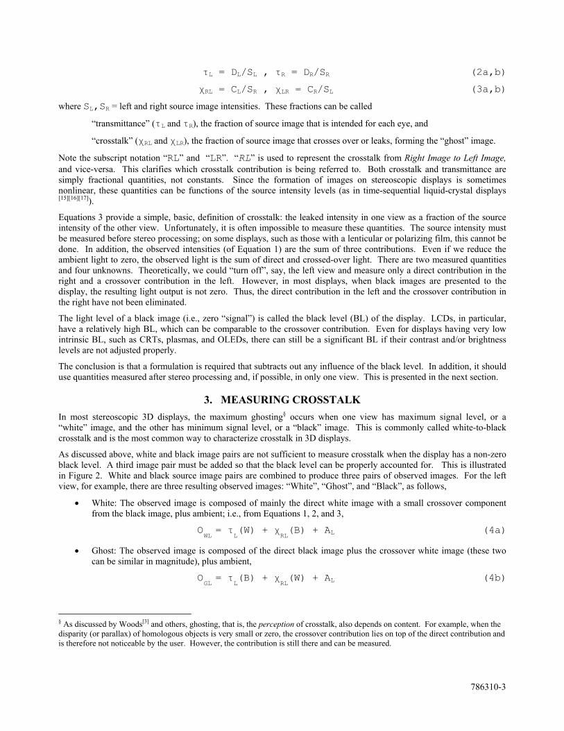
As discussed above, white and black image pairs are not sufficient to measure crosstalk when the display has a non-zero black level. A third image pair must be added so that the black level can be properly accounted for. This is illustrated in Figure 2. White and black source image pairs are combined to produce three pairs of observed images. For the left view, for example, there are three resulting observed images: “White”, “Ghost”, and “Black”, as follows,
White: The observed image is composed of mainly the direct white image with a small crossover component from the black image, plus ambient; i.e., from Equations 1, 2, and 3,
OWL = τ
L(W) + χ
RL(B) + AL (4a)
Ghost: The observed image is composed of the direct black image plus the crossover white image (these two can be similar in magnitude), plus ambient,
OGL = τ
L(B) + χ
RL(W) + AL (4b)
§ As discussed by Woods[3] and others, ghosting, that is, the perception of crosstalk, also depends on content. For example, when the disparity (or parallax) of homologous objects is very small or zero, the crossover contribution lies on top of the direct contribution and is therefore not noticeable by the user. However, the contribution is still there and can be measured.
786310-4
Black: The observed image is composed of the direct black image plus the crossover black image, plus ambient,
OBL = τ
L(B) + χ
RL(B) + AL (4c)
Figure 2. Two white and black Source Images combine to form six Observed Images: “White”, “Ghost”, and “Black” for each view. (Variables are defined in the text.)
where W is the light intensity coming from the white source image and B is the intensity of the black source image. Even though the black image comes from the minimum signal level (e.g., “zero gray-level”), it will not necessarily be zero, because of the black level of the display.
Subtracting Equation 4c from 4a and Equation 4c from 4b, leads to, respectively,
OWL – O
BL = τ
L(W – B) (5a)
OGL – O
BL = χ
RL(W – B) (5b)
And in turn,
χRL = τL(OGL – OBL)/(OWL – OBL). (6a)
A similar derivation follows for the right view,
χLR = τR(OGR – OBR)/(OWR – OBR). (6b)
This result is convenient because all the quantities are measured on the “same side”. However, these equations are not convenient because they still require the transmittance factors, which could be difficult to measure. Therefore, the final step is to define an “observed” crosstalk as
OCTRL = χRL/τL = (OGL – OBL)/(OWL – OBL) (7a)
OCTLR = χLR/τR = (OGR – OBR)/(OWR – OBR). (7b)
This parameter has been called “System Crosstalk” by Huang[11] and is used by many authors[13][14][15][16][17]. We refer to it here as “observed crosstalk” to emphasize that it uses quantities measured in the observed images and to distinguish it from the crosstalk fraction defined by Equations 3. We suggest the previous crosstalk fraction, χ, be called “intrinsic” crosstalk because it is defined by the source of the crossover contribution. As seen in Equations 7, the difference between observed and intrinsic crosstalk is the transmittance.
Authors will sometimes use the term “extinction ratio” when referring to crosstalk[3]. The Extinction Ratio is the inverse of the crosstalk fraction. That is,
ERRL = 1/OCTRL = (OWL - OBL)/(OGL - OBL) (8a)
786310-5
ERLR = 1/OCTLR = (OWR - OBR)/(OGR - OBR) (8b)
For example, good values for OCT and ER in a stereo display are 1% and 100:1, respectively.
4. RELATING OBSERVED CROSSTALK TO GRAY-LEVELS
Within computers and digital video systems, the “gray-level” is the numerical representation of the brightness of a pixel, usually in the range [0,255]. This is the “signal” that is sent to the display. For legacy reasons that we will not discuss here, the display response, that is, the intensity displayed for a given gray-level, is nonlinear. According to the sRGB color standard (the default for most computers), this nonlinear “transfer curve” from gray-levels (G) to intensity (O) is
O/OMAX = (G/GMAX)/12.92 , for G/GMAX < 0.04045 (9a)
O/OMAX = ((G/GMAX)+0.055)/(1+0.055))^2.4 , for G/GMAX >= 0.04045 (9b)
where OMAX and GMAX are the maximum intensity and gray-level values, respectively. [4]
This curve is usually approximated as “Gamma 2.2”, or
O/OMAX = (G/GMAX)^2.2 , for 0 =< G/GMAX =< 1 (10)
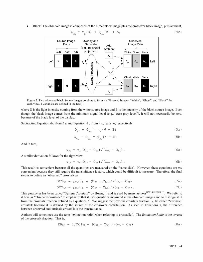
Gamma 2.2 is actually not a good approximation for the low intensity range where crosstalk exists. This is demonstrated in Figure 3. Although these two formulas track well over most of the 0 to 1 range, below about 6% of maximum intensity they diverge. In the range of typical ghost intensities, around 1%, the two curves differ by 40% to 60%.
(a) (b)
Figure 3. Comparing sRGB to Gamma 2.2: a) linear plot, b) log-log plot. X-axis: scaled gray-level (G/GMAX), Y-axis: scaled intensity (O/OMAX).
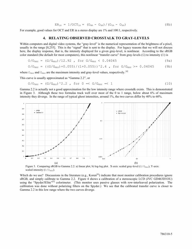
Which do we use? Discussions in the literature (e.g., Koren[6]) indicate that most monitor calibration procedures ignore sRGB, and simply calibrate to Gamma 2.2. Figure 4 shows a calibration of a stereoscopic LCD (JVC GD463D1OU) using the “Spyder3Elite”[5] colorimeter. (This monitor uses passive glasses with row-interleaved polarization. The calibration was done without polarizing filters on the Spyder.) We see that the calibrated transfer curve is closer to Gamma 2.2 in this low range where the two curves diverge.
786310-6
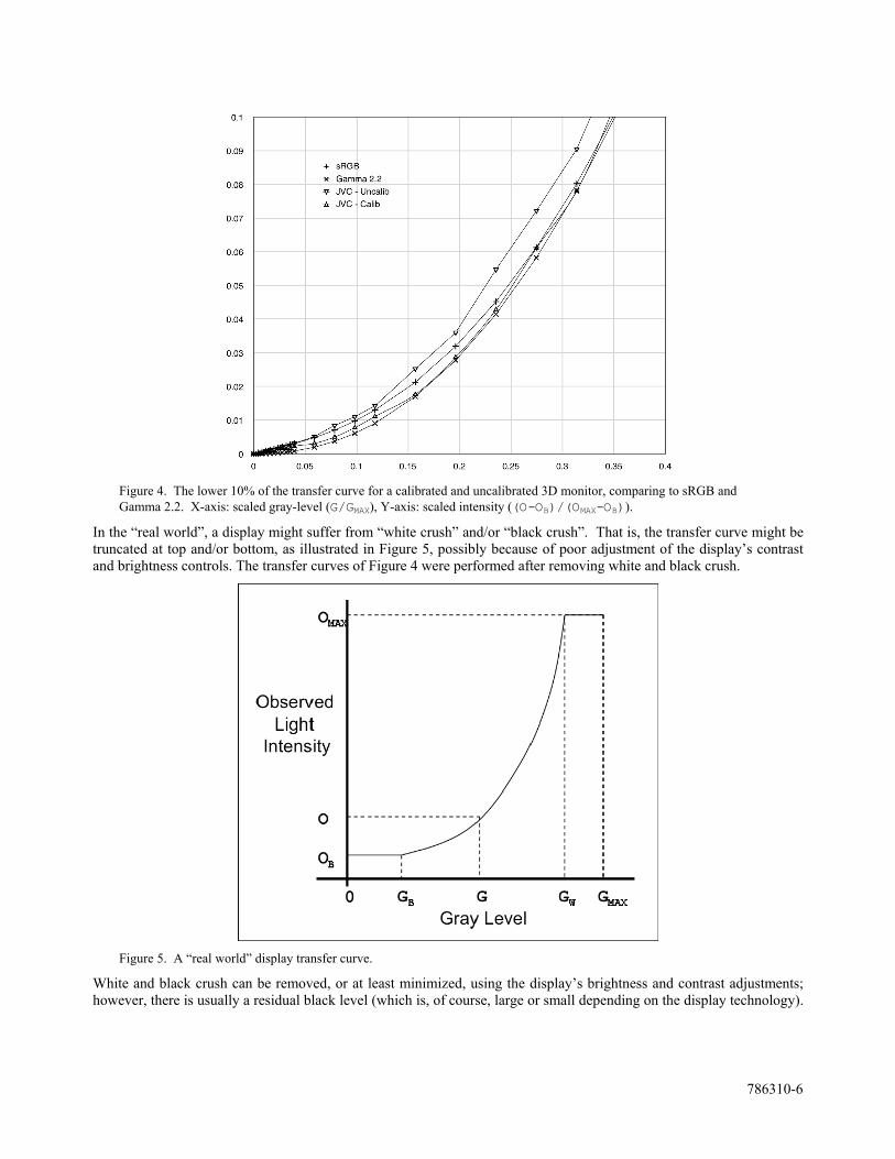
Figure 4. The lower 10% of the transfer curve for a calibrated and uncalibrated 3D monitor, comparing to sRGB and Gamma 2.2. X-axis: scaled gray-level (G/GMAX), Y-axis: scaled intensity ((O-OB)/(OMAX-OB)).
In the “real world”, a display might suffer from “white crush” and/or “black crush”. That is, the transfer curve might be truncated at top and/or bottom, as illustrated in Figure 5, possibly because of poor adjustment of the display’s contrast and brightness controls. The transfer curves of Figure 4 were performed after removing white and black crush.
Figure 5. A “real world” display transfer curve.
White and black crush can be removed, or at least minimized, using the display’s brightness and contrast adjustments; however, there is usually a residual black level (which is, of course, large or small depending on the display technology).
786310-7
This acts as a “pedestal” or bias on which the signal rides. Thus, assuming that Gamma 2.2 is our best estimate for the transfer curve, Equation 10 is modified to read
(O – OB)/(OMAX – OB) = (G/GMAX)^2.2 (11)
where OB is now the black level of the display, the output intensity for a zero gray-level image. The left-hand side of this equation is “scaled” intensity. This is what is used in Figure 4.
This leads to equations for observed crosstalk in terms of gray-levels:
OCTRL = (OGL - OBL)/(OWL - OBL) = (GGL/GMAX)^2.2 (12a)
OCTLR = (OGR - OBR)/(OWR - OBR) = (GGR/GMAX)^2.2 (12b)
That is, if we can estimate the crosstalk intensities in terms of gray-levels, we can actually measure the crosstalk fraction. Note that this result is based on the following assumptions:
1. White and black crush have been eliminated.
2. The display has been calibrated to Gamma 2.2.
3. This calibration is valid after stereo processing.
5. THE TEST CHART
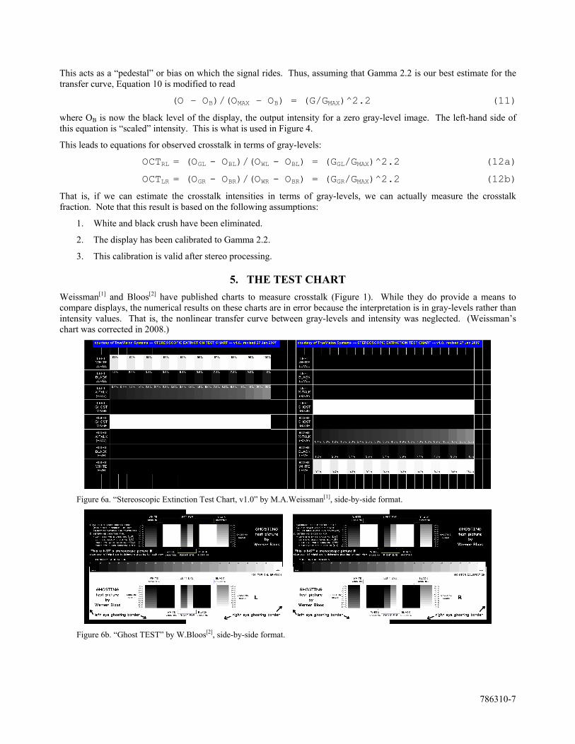
Weissman[1] and Bloos[2] have published charts to measure crosstalk (Figure 1). While they do provide a means to compare displays, the numerical results on these charts are in error because the interpretation is in gray-levels rather than intensity values. That is, the nonlinear transfer curve between gray-levels and intensity was neglected. (Weissman’s chart was corrected in 2008.)
Figure 6a. “Stereoscopic Extinction Test Chart, v1.0” by M.A.Weissman[1], side-by-side format.
Figure 6b. “Ghost TEST” by W.Bloos[2], side-by-side format.
786310-8
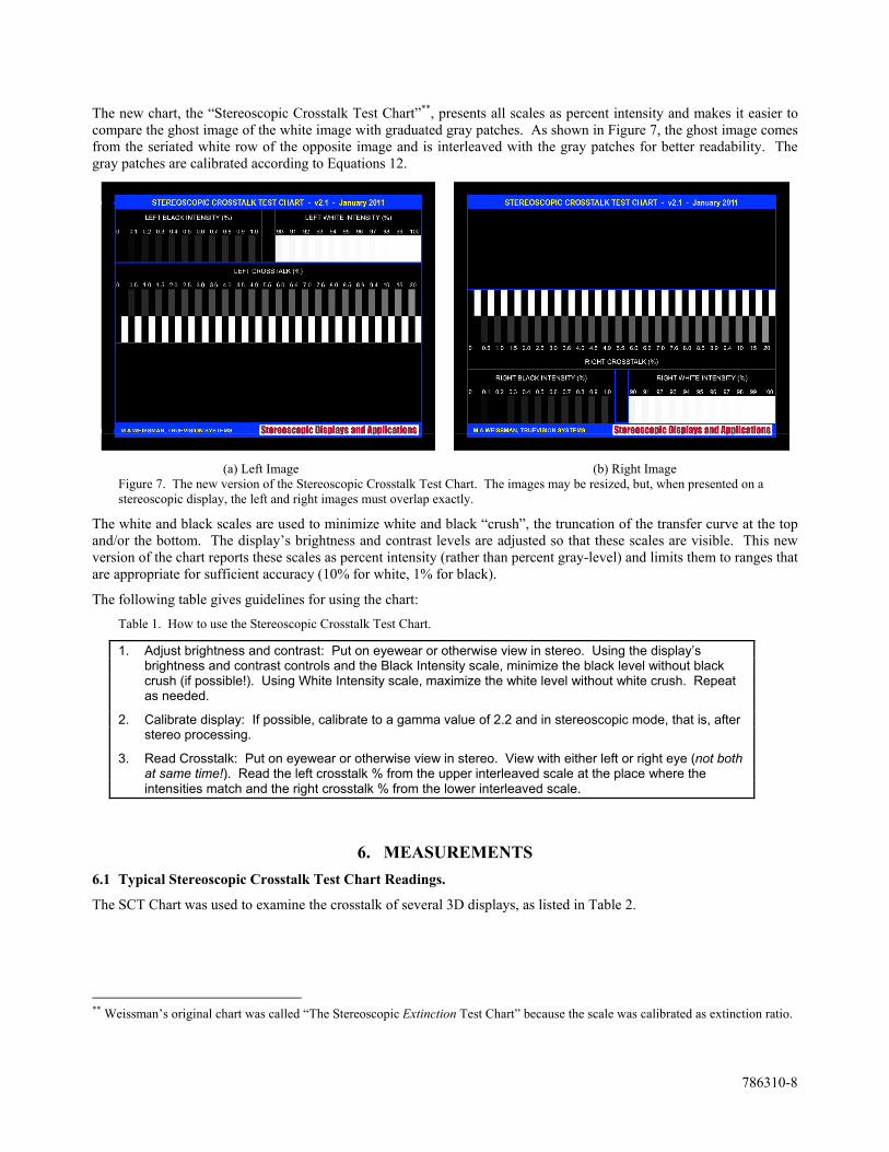
The new chart, the “Stereoscopic Crosstalk Test Chart”**, presents all scales as percent intensity and makes it easier to compare the ghost image of the white image with graduated gray patches. As shown in Figure 7, the ghost image comes from the seriated white row of the opposite image and is interleaved with the gray patches for better readability. The gray patches are calibrated according to Equations 12.
(a) Left Image (b) Right Image Figure 7. The new version of the Stereoscopic Crosstalk Test Chart. The images may be resized, but, when presented on a stereoscopic display, the left and right images must overlap exactly.
The white and black scales are used to minimize white and black “crush”, the truncation of the transfer curve at the top and/or the bottom. The display’s brightness and contrast levels are adjusted so that these scales are visible. This new version of the chart reports these scales as percent intensity (rather than percent gray-level) and limits them to ranges that are appropriate for sufficient accuracy (10% for white, 1% for black).
The following table gives guidelines for using the chart:
Table 1. How to use the Stereoscopic Crosstalk Test Chart.
1. Adjust brightness and contrast: Put on eyewear or otherwise view in stereo. Using the display’s brightness and contrast controls and the Black Intensity scale, minimize the black level without black crush (if possible!). Using White Intensity scale, maximize the white level without white crush. Repeat as needed.
2. Calibrate display: If possible, calibrate to a gamma value of 2.2 and in stereoscopic mode, that is, after stereo processing.
3. Read Crosstalk: Put on eyewear or otherwise view in stereo. View with either left or right eye (not both at same time!). Read the left crosstalk % from the upper interleaved scale at the place where the intensities match and the right crosstalk % from the lower interleaved scale.
6. MEASUREMENTS
6.1 Typical Stereoscopic Crosstalk Test Chart Readings.
The SCT Chart was used to examine the crosstalk of several 3D displays, as listed in Table 2.
** Weissman’s original chart was called “The Stereoscopic Extinction Test Chart” because the scale was calibrated as extinction ratio.
786310-9
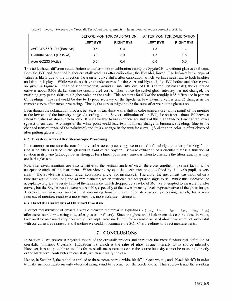
Table 2. Typical Stereoscopic Crosstalk Test Chart measurements. The numeric values are percent crosstalk.
BEFORE MONITOR CALIBRATION AFTER MONITOR CALIBRATION
LEFT EYE RIGHT EYE LEFT EYE RIGHT EYE
JVC GD463D1OU (Passive) 0.6 0.4 1.3 1.4
Hyundai S465D (Passive) 3.0 3.3 1.3 1.5
Acer GD235 (Active) 0.3 0.4 0.6 0.6
This table shows different results before and after monitor calibration (using the Spyder3Elite without glasses or filters). Both the JVC and Acer had higher crosstalk readings after calibration; the Hyundai, lower. The before/after change of values is likely due to the direction the transfer curve shifts after calibration, which we have seen lead to both brighter and darker displays. While we do not have transfer curves for the Acer and Hyundai, the JVC before and after curves are given in Figure 6. It can be seen there that, around an intensity level of 0.01 (on the vertical scale), the calibrated curve is about 0.003 darker than the uncalibrated curve. Thus, since the scaled ghost intensity has not changed, the matching gray patch shifts to a higher value on the scale. This accounts for 0.3 of the roughly 0.85 difference in percent CT readings. The rest could be due to 1) poor accuracy of the Spyder at low intensity values and 2) changes in the transfer curves after stereo processing. That is, the curves might not be the same after we put the glasses on.
Even though the polarization process, per se, is linear, there was a shift in color temperature (white point) of the monitor at the low end of the intensity range. According to the Spyder calibration of the JVC, the shift was about 5% between intensity values of about 16% to 38%. It is reasonable to assume there are shifts of this magnitude or larger at the lower (ghost) intensities. A change of the white point could lead to a nonlinear change in luminance readings (due to the changed transmittance of the polarizers) and thus a change in the transfer curve. (A change in color is often observed after putting glasses on.)
6.2 Transfer Curves After Stereoscopic Processing
In an attempt to measure the transfer curve after stereo processing, we mounted left and right circular polarizing filters (the same filters as used in the glasses) in front of the Spyder. Because extinction of a circular filter is a function of rotation in its plane (although not as strong as for a linear polarizer), care was taken to orientate the filters exactly as they are in the glasses.
Row-interleaved monitors are also sensitive to the vertical angle of view; therefore, another important factor is the acceptance angle of the instrument. When viewing by eye, the acceptance angle, defined by the eye’s pupil, is very small. The Spyder has a much larger acceptance angle (not measured). Therefore, the instrument was mounted on a tube that was 278 mm long and 44 mm diameter, which restricted the acceptance angle to 9. While this improved the acceptance angle, it severely limited the luminance, which dropped by a factor of 39. We attempted to measure transfer curves, but the Spyder results were not reliable, especially at the lower intensity levels representative of the ghost image. Therefore, we were not successful at measuring transfer curves after stereoscopic processing, which, for a row-interleaved monitor, requires a more sensitive, more accurate instrument.
6.3 Direct Measurements of Observed Crosstalk
A direct measurement of crosstalk would measure the terms in Equations 7 (OGL, OBL, OWL, OGR, OBR, OWR) after stereoscopic processing (i.e., after glasses or filters). Since the ghost and black intensities can be close in value, they must be measured very accurately. Attempts were made, but, for reasons discussed above, we were not successful with our current equipment, and therefore we could not compare the SCT Chart readings to direct measurements.
7. CONCLUSIONS
In Section 2, we present a physical model of the crosstalk process and introduce the most fundamental definition of crosstalk, “Intrinsic Crosstalk” (Equations 3), which is the ratio of ghost image intensity to its source intensity. However, it is not possible to use this for crosstalk measurements when the source intensity cannot be measured directly or the black level contributes to crosstalk, which is usually the case.
Hence, in Section 3, the model is applied to three stereo pairs (“white-black”, “black-white”, and “black-black”) in order to make measurements on only observed images and to subtract out the black levels. This approach and the resulting
786310-10
definition of a crosstalk fraction (Equations 7) agree with other authors[11][13][14][15][16][17]. This definition has been called “System Crosstalk” by Huang et al[11] ; however, here we call it “Observed Crosstalk” in order to draw a clear distinction between it and “Intrinsic Crosstalk”. The former uses observed intensities; the latter uses source intensities.
This formulation does not assume the crosstalk fractions or the transmittances are constants; it does, however, assume that 1) the source intensities are “white” and “black” (maximum and minimum image intensities) and 2) the left and right source intensities of image pairs are equal. Both of these restrictions can be lifted within this model. Indeed, the model can be used to study arbitrary source intensities, as in “gray-to-gray” crosstalk[15][16][17]. These topics will be basis for future work.
In Section 4, we consider the relation between observed image intensities and the means of creating images in electronic displays: gray-levels. We show that, even though sRGB (Equations 9) is the standard for computer graphics, displays are generally calibrated to the Gamma 2.2 transfer curve (Equation 10) - assuming that white and black crush are also eliminated. Based on these assumptions, Observed Crosstalk can be direct related to gray-levels, as shown in Equations 12.
Thus, it is possible to create a chart in which ghost images are compared to gray patches calibrated to crosstalk percentages. Such a chart, the “Stereoscopic Crosstalk Test Chart”, is presented in Section 5. The SCT Chart also has white and black scales to be used to minimize white and black crush. This chart will be available soon for general distribution via the Stereoscopic Displays and Applications Conference website (www.stereoscopic.org). In the future, additional versions will be added for color measurements and different formats. Producing the chart as an application will also be considered.
In Section 6, we present some results from attempts to validate the readings of the SCT Chart. First, to illustrate the use of the chart, readings are given before and after monitor calibration (using the Spyder3Elite[5] colorimeter). There can be significant differences, mainly due to the shift of transfer curve after calibration and the change of white and black levels.
Then we attempted to measure the transfer curve of a row-interleaved monitor after stereoscopic processing, that is, with the polarizing filters (as found in the glasses) in front of the colorimeter. However, this was not successful, because of the reduction of light into the Spyder and the apparatus needed to control the acceptance angle of the device. In short, a much more sensitive instrument is needed for this measurement.
Determination of the transfer curve after stereoscopic processing is very important. In general, when monitors are calibrated to, say, the Gamma 2.2 standard, it is done “with the glasses off”, i.e., before (complete) stereoscopic processing. Thus, if there is any nonlinearity in the system, it is likely the “glasses on” images are not calibrated to the same curve.
Some display systems are known to be nonlinear. For example, time-sequential LCDs have been shown to be nonlinear in its crosstalk characteristics[15][16][17]. That is, the crosstalk percentages are a function of the source intensities. It is likely the transmittance is also a function of source intensity, and therefore a calibration curve “before glasses” will be different from one “after glasses”. In the current study using a row-interleaved monitor, we found indications that the white point could be shifting significantly in the same intensity range as ghost intensities. This means the color channels (R, G, and B) might not be calibrated the same in this region and that the display is not following a standard transfer curve. This is an important area for future research.
Our conclusion from these preliminary measurements is that it could be rare to find a 3D display that is calibrated (post-stereo processing!) to Gamma 2.2 in these low intensity ranges, even after calibration with a colorimeter. Yet, the crosstalk values on the SCT Chart are based on this transfer curve. Are the numbers on the chart still useful?
(The values on the SCT Chart also depend on having no white and black crush. This criterion is easier to achieve, using the contrast and brightness controls of the display.)
Although we could not confirm the accuracy of the crosstalk values given by the SCT Chart, we feel that the numbers are still useful. The numbers on the chart give us a “snapshot” of the system. Yes, they might change if the monitor is calibrated to a gamma of 2.2, but the uncalibrated display might be preferred. The readings from chart can be used as a measure of crosstalk for those conditions. (In this case, we would still recommend minimizing white and black crush, as in the guidelines of Table 1, to maintain consistency.)
786310-11
Whether the display is calibrated or uncalibrated, the SCT Chart indicates the “strength” of the crosstalk component of the image as compared to the maximum image intensity. That is, it is a measure of the influence of the ghost image compared to the intended image, which is, after all, viewed with the same transfer curve, whatever it is. The readings from the SCT Chart express this measure as if the transfer curve were Gamma 2.2.
In addition, the chart can always be used in a comparative way. Comparing monitors, changing display parameters, trying different glasses, comparing viewing positions and angles, etc., are all common needs when working with a stereoscopic display system. The chart provides a simple way to do this. If there are special requirements, such as determining the crosstalk at the top of the screen, the chart may be resized and repositioned; however, it is important to keep the two views matched in size and in perfect alignment.
The difficulty we had using a low-end colorimeter (the Spyder) verifies the premise we put forward in the introduction: that measurements of crosstalk are difficult and generally not accessible to users. The SCT Chart alleviates these issues and provides a means to achieve better consistence and performance of stereoscopic 3D displays.
REFERENCES
[1] M. A. Weissman, “A simple measurement of extinction ratio” presented at Stereoscopic Displays and Applications XVIII, San Jose (2007).
[2] W. Bloos, “Ghosting test - standard method for determining ghost image,” Stereo Forum, online, dated 5 June 2008. http://www.stereoforum.org/viewtopic.php?f=16&t=53.
[3] A. J. Woods, “How are Crosstalk and Ghosting Defined in the Stereoscopic Literature” in Proc. SPIE Stereoscopic Displays and Applications XXII (in press), Burlingame, 7863, (2011).
[4] Wikipedia, http://en.wikipedia.org/wiki/SRGB_color_space [5] DataColor AG, http://spyder.datacolor.com/product-mc-s3elite.php [6] N. Koren, http://www.normankoren.com/makingfineprints1A.html [7] Woods, A. J., Harris, C. R., “Comparing levels of crosstalk with red/cyan, blue/yellow, and green/magenta anaglyph
3D glasses” in Proc. SPIE Stereoscopic Displays and Applications XXI, 7253, 0Q1-0Q12 (2010). [8] Chu, Y.-M., Chien, K.-W., Shieh, H.-P. D., Chang, J.-M., Hu, A., and Yang, V., “3D Mobile Display Based on Dual
Directional Lightguides” in 4th International Display Manufacturing Conference, Taipei, Taiwan, 799-801 (2005). [9] Hong, H.-K., Jang, J.-W., Lee, D.-G., Lim, M.-J., Shin, H.-H., “Analysis of angular dependence of 3-D technology
using polarized eyeglasses,” in Journal of the SID, 18(1), 8-12 (2010). [10] Huang, K.-C., Tsai, C.-H., Lee, K., Hsueh, W.-J., “Measurement of Contrast Ratios for 3D Display” in Proc. SPIE
Input/Output and Imaging Technologies II, 4080, 78-86 (2000). [11] Huang, K.-C., Lee, K., Lin, H.-Y., “Crosstalk issue in stereo/autostereoscopic display” in Proc. Int. Display
Manufacturing Conference, 2–18 (2009). [12] Pala, S., Stevens, R., Surman, P., “Optical crosstalk and visual comfort of a stereoscopic display used in a real-time
application” in Proc. SPIE Stereoscopic Displays and Virtual Reality Systems XIV, 6490, 111-1112 (2007). [13] Liou, J.-C., Lee, K., Tseng, F.-G., Huang, J.-F., Yen, W.-T., Hsu, W.-L., “Shutter Glasses Stereo LCD with a
Dynamic Backlight” in Proc. SPIE Stereoscopic Displays and Applications XX, 7237, 72370X (2009). [14] Boher, P., Leroux, T., Bignon, T., Collomb-Patton, V., “Multispectral polarization viewing angle analysis of circular
polarized stereoscopic 3D displays” in Proc. SPIE Stereoscopic Displays and Applications XXI, 7253, 0R1-0R12 (2010).
[15] S.-M. Jung, et al, “Improvement of 3-D Crosstalk with Over-Driving Method for the Active Retarder 3-D Displays” in SID Digest 2010, Seattle, 1264-1267 (2010).
[16] S. Shestak, et al, “Measuring of Gray-to-Gray Crosstalk in a LCD Based Time-Sequential Stereoscopic Display” in SID Digest 2010, Seattle, 132-135 (2010).
[17] C.-C. Pan, et al, “Cross-Talk Evaluation of Shutter-Type Stereoscopic 3D Display” in SID Digest 2010, Seattle, 128-131 (2010).