Embed Size (px)
Citation preview
A Transformation Based Algorithm for Ternary
Reversible Logic Synthesis using Universally Controlled
Ternary Gates
Erik Curtis, Marek Perkowski
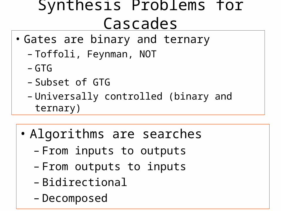
Synthesis Problems for Cascades
• Gates are binary and ternary– Toffoli, Feynman, NOT– GTG– Subset of GTG– Universally controlled (binary and ternary)
• Algorithms are searches– From inputs to outputs– From outputs to inputs– Bidirectional– Decomposed
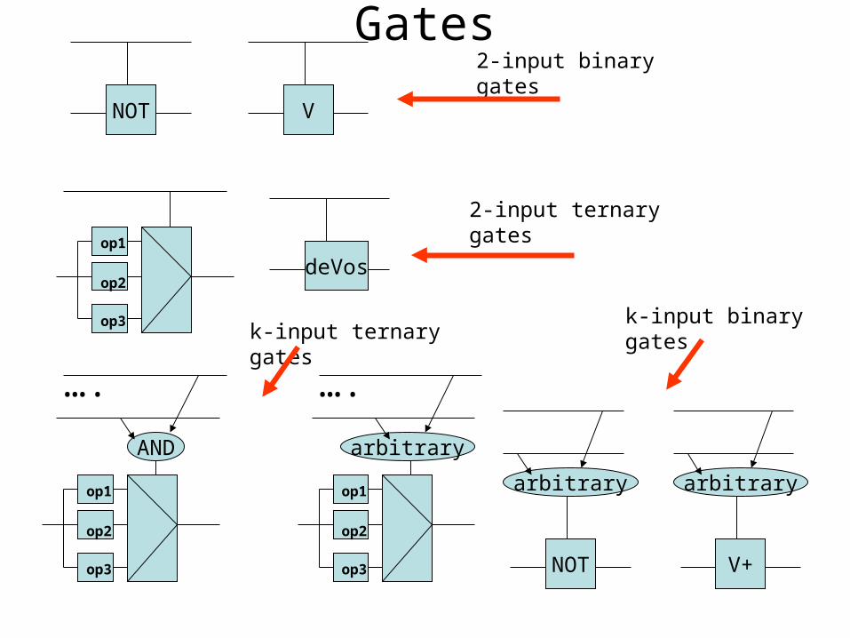
Gates
NOT V
2-input binary gates
2-input ternary gates
op1
op2
op3
deVos
op1
op2
op3
AND
….
op1
op2
op3
arbitrary
….
NOT
arbitrary
V+
arbitrary
k-input ternary gatesk-input binary gates
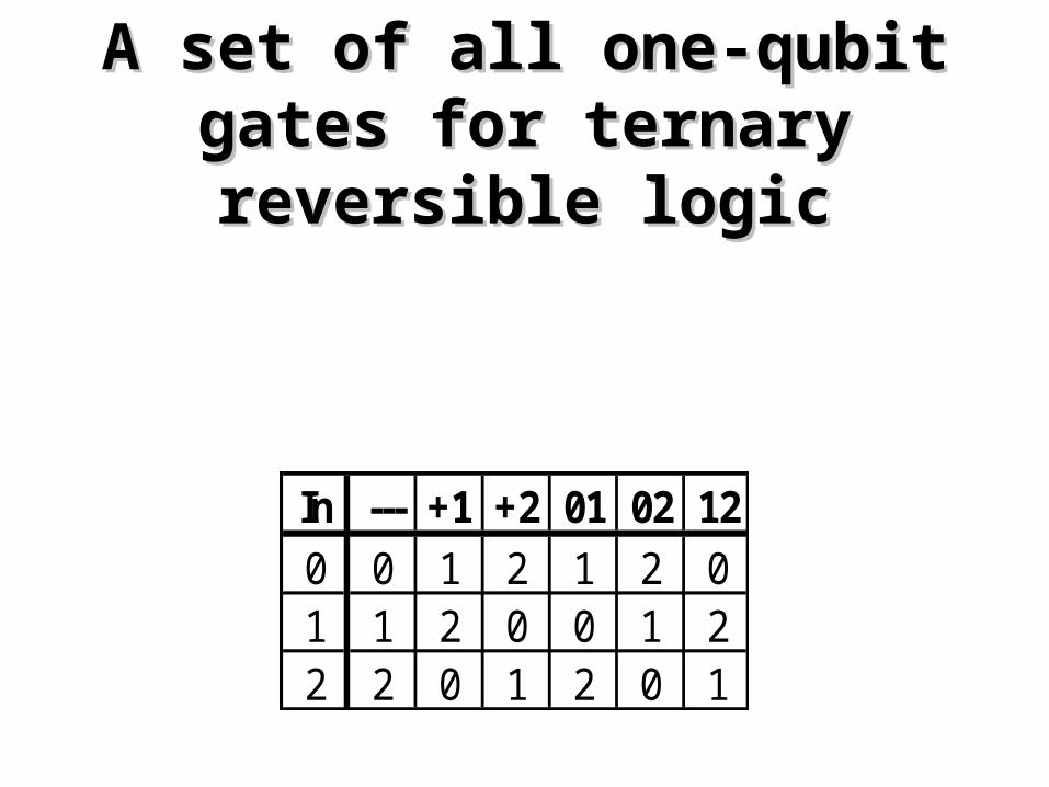
In --- +1 +2 01 02 120 0 1 2 1 2 01 1 2 0 0 1 22 2 0 1 2 0 1
A set of all one-qubit gates for A set of all one-qubit gates for ternary reversible logicternary reversible logic
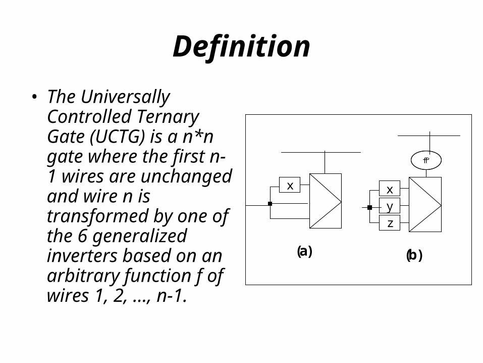
Definition
• The Universally Controlled Ternary Gate (UCTG) is a n*n gate where the first n-1 wires are unchanged and wire n is transformed by one of the 6 generalized inverters based on an arbitrary function f of wires 1, 2, …, n-1.
x
zyx
f
(a) (b)
f ‘
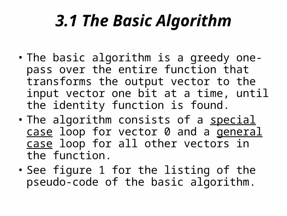
3.1 The Basic Algorithm
• The basic algorithm is a greedy one-pass over the entire function that transforms the output vector to the input vector one bit at a time, until the identity function is found.
• The algorithm consists of a special case loop for vector 0 and a general case loop for all other vectors in the function.
• See figure 1 for the listing of the pseudo-code of the basic algorithm.
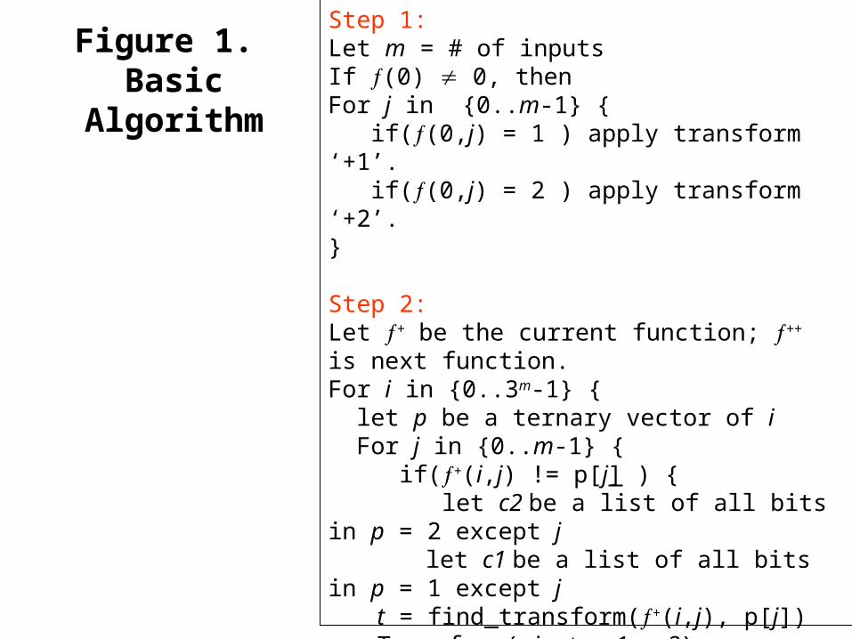
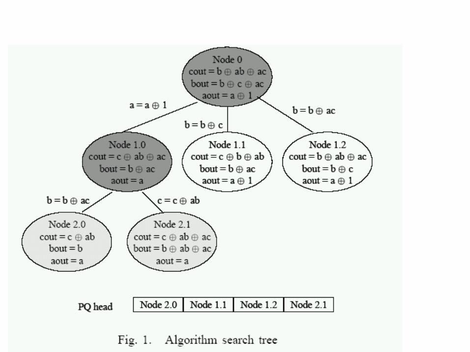
Figure 1. Basic Algorithm
Step 1:Let m = # of inputsIf (0) 0, then For j in {0..m-1} { if((0,j) = 1 ) apply transform ‘+1’. if((0,j) = 2 ) apply transform ‘+2’.}
Step 2:Let + be the current function; ++ is next function.For i in {0..3m-1} { let p be a ternary vector of i For j in {0..m-1} { if(+(i,j) != p[j] ) { let c2 be a list of all bits in p = 2 except j let c1 be a list of all bits in p = 1 except j t = find_transform(+(i,j), p[j]) Transform( j, t, c1, c2) } }}
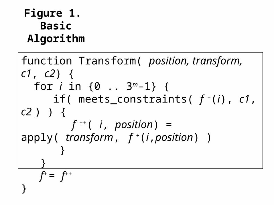
Figure 1. Basic Algorithm
function Transform( position, transform, c1, c2) { for i in {0 .. 3m-1} { if( meets_constraints( f +(i), c1, c2 ) ) { f ++( i, position) = apply( transform, f +
(i,position) ) } } f+ = f++
}
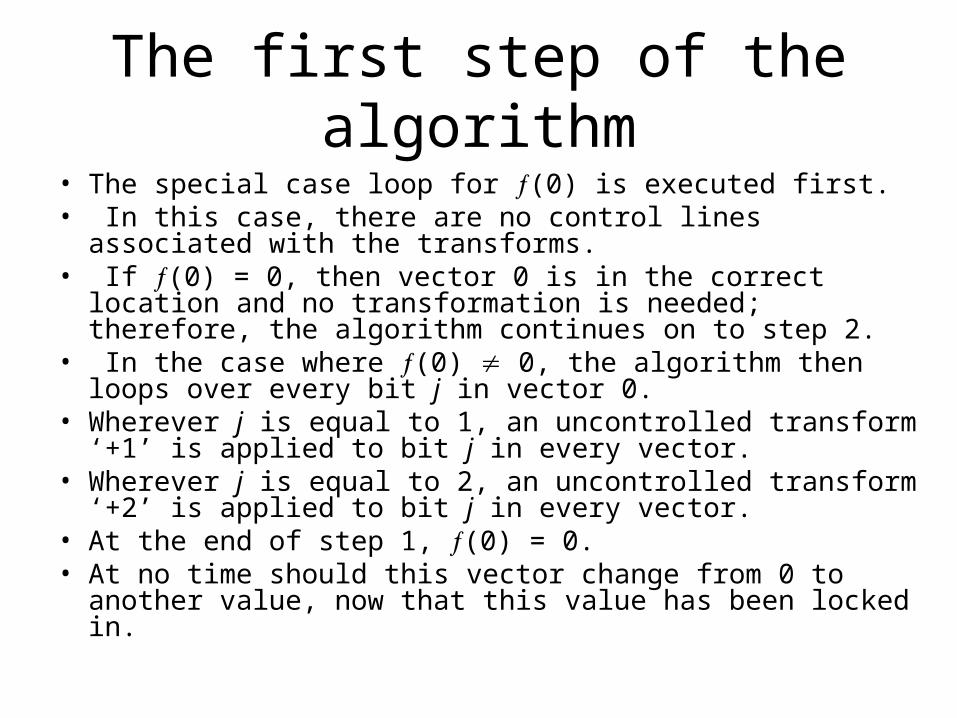
The first step of the algorithm
• The special case loop for (0) is executed first. • In this case, there are no control lines associated with the
transforms. • If (0) = 0, then vector 0 is in the correct location and no
transformation is needed; therefore, the algorithm continues on to step 2.
• In the case where (0) 0, the algorithm then loops over every bit j in vector 0.
• Wherever j is equal to 1, an uncontrolled transform ‘+1’ is applied to bit j in every vector.
• Wherever j is equal to 2, an uncontrolled transform ‘+2’ is applied to bit j in every vector.
• At the end of step 1, (0) = 0. • At no time should this vector change from 0 to another
value, now that this value has been locked in.
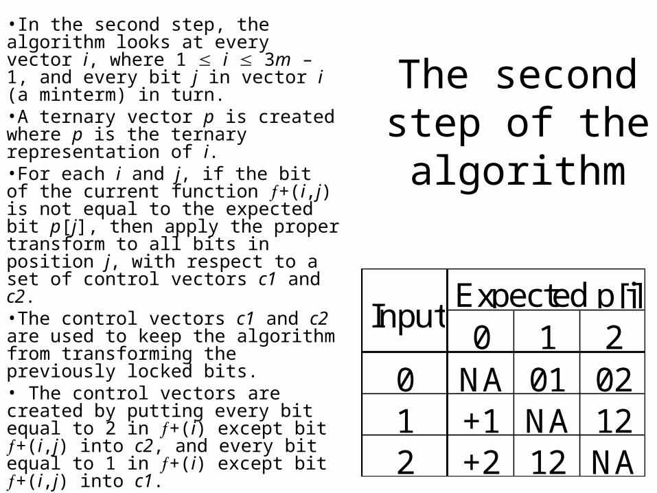
The second step of the algorithm
0 1 20 NA 01 021 +1 NA 122 +2 12 NA
Expected p[j]Input
•In the second step, the algorithm looks at every vector i, where 1 i 3m – 1, and every bit j in vector i (a minterm) in turn. •A ternary vector p is created where p is the ternary representation of i. •For each i and j, if the bit of the current function +(i,j) is not equal to the expected bit p[j], then apply the proper transform to all bits in position j, with respect to a set of control vectors c1 and c2. •The control vectors c1 and c2 are used to keep the algorithm from transforming the previously locked bits. • The control vectors are created by putting every bit equal to 2 in +(i) except bit +(i,j) into c2, and every bit equal to 1 in +(i) except bit +(i,j) into c1. •Table 2 shows the logic table for transform selection.
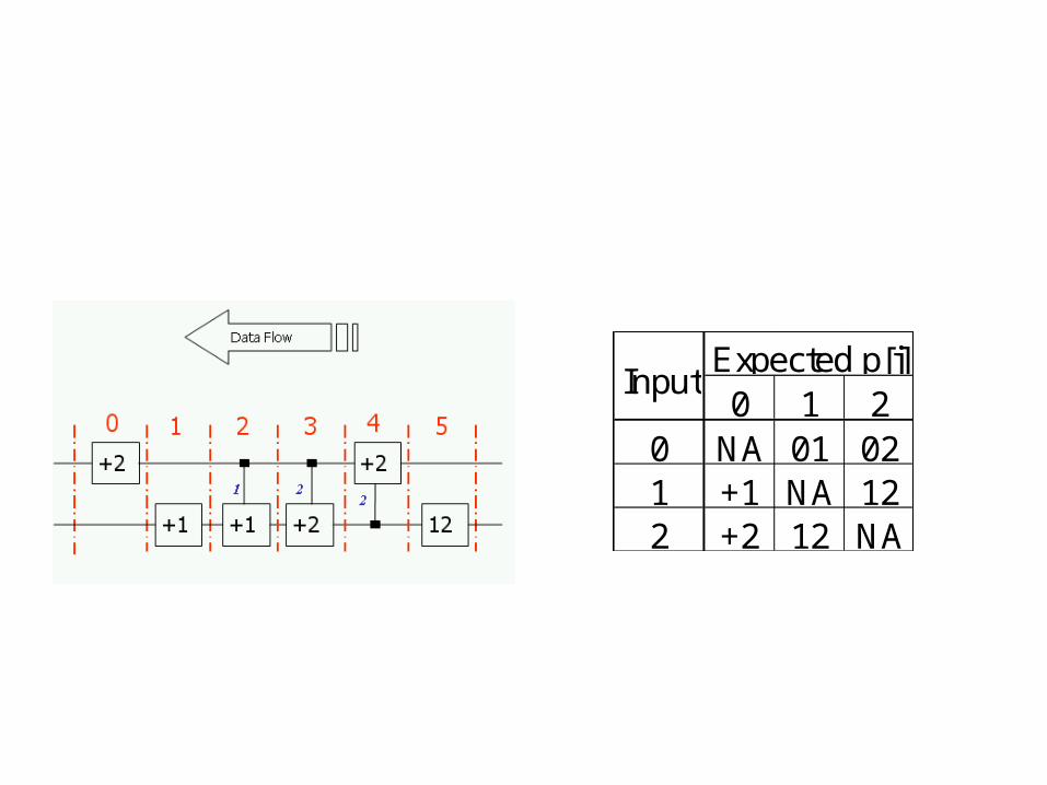
0 1 20 NA 01 021 +1 NA 122 +2 12 NA
Expected p[j]Input
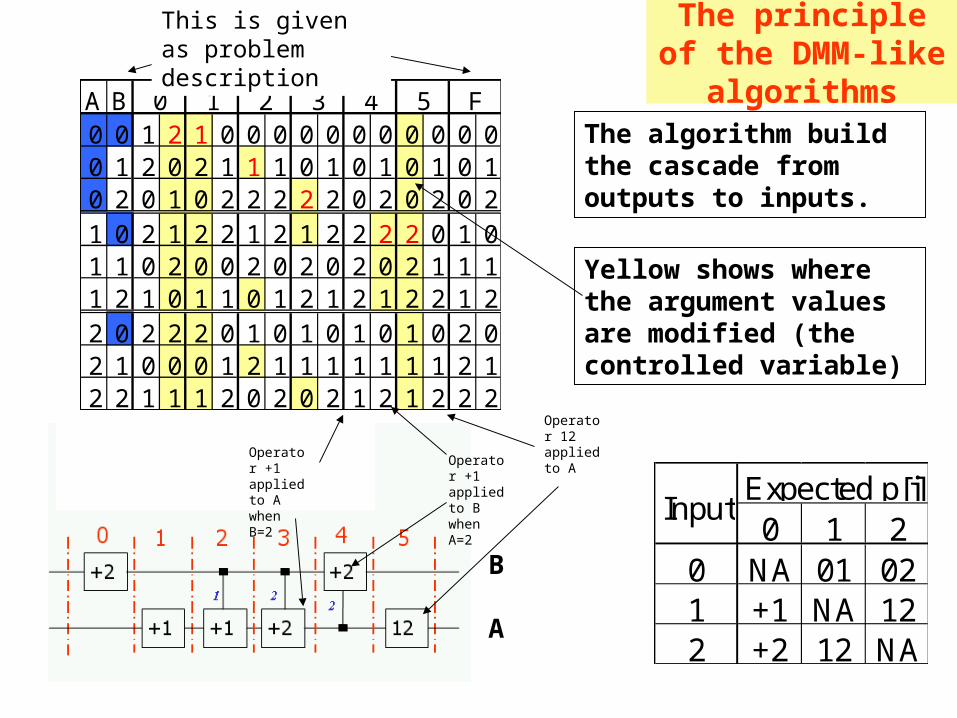
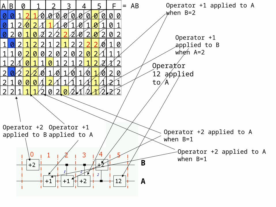
The principle of the DMM-like algorithmsA B
0 0 1 2 1 0 0 0 0 0 0 0 0 0 0 00 1 2 0 2 1 1 1 0 1 0 1 0 1 0 10 2 0 1 0 2 2 2 2 2 0 2 0 2 0 21 0 2 1 2 2 1 2 1 2 2 2 2 0 1 01 1 0 2 0 0 2 0 2 0 2 0 2 1 1 11 2 1 0 1 1 0 1 2 1 2 1 2 2 1 22 0 2 2 2 0 1 0 1 0 1 0 1 0 2 02 1 0 0 0 1 2 1 1 1 1 1 1 1 2 12 2 1 1 1 2 0 2 0 2 1 2 1 2 2 2
4 5 F0 1 2 3
A
B
The algorithm build the cascade from outputs to inputs.
This is given as problem description
0 1 20 NA 01 021 +1 NA 122 +2 12 NA
Expected p[j]Input
Operator 12 applied to A
Operator +1 applied to B when A=2
Operator +1 applied to A when B=2
Yellow shows where the argument values are modified (the controlled variable)
A B0 0 1 2 1 0 0 0 0 0 0 0 0 0 0 00 1 2 0 2 1 1 1 0 1 0 1 0 1 0 10 2 0 1 0 2 2 2 2 2 0 2 0 2 0 21 0 2 1 2 2 1 2 1 2 2 2 2 0 1 01 1 0 2 0 0 2 0 2 0 2 0 2 1 1 11 2 1 0 1 1 0 1 2 1 2 1 2 2 1 22 0 2 2 2 0 1 0 1 0 1 0 1 0 2 02 1 0 0 0 1 2 1 1 1 1 1 1 1 2 12 2 1 1 1 2 0 2 0 2 1 2 1 2 2 2
4 5 F0 1 2 3
A
B
Operator 12 applied to A
Operator +1 applied to B when A=2
Operator +1 applied to A when B=2
Operator +2 applied to A when B=1
Operator +2 applied to A when B=1
Operator +2 applied to B
Operator +1 applied to A
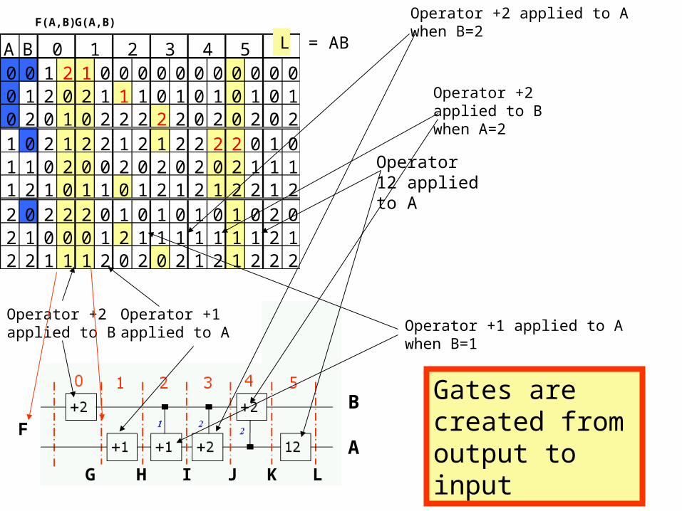
= AB

A B0 0 1 2 1 0 0 0 0 0 0 0 0 0 0 00 1 2 0 2 1 1 1 0 1 0 1 0 1 0 10 2 0 1 0 2 2 2 2 2 0 2 0 2 0 21 0 2 1 2 2 1 2 1 2 2 2 2 0 1 01 1 0 2 0 0 2 0 2 0 2 0 2 1 1 11 2 1 0 1 1 0 1 2 1 2 1 2 2 1 22 0 2 2 2 0 1 0 1 0 1 0 1 0 2 02 1 0 0 0 1 2 1 1 1 1 1 1 1 2 12 2 1 1 1 2 0 2 0 2 1 2 1 2 2 2
4 5 F0 1 2 3
A
B
Operator 12 applied to A
Operator +1 applied to B when A=2
Operator +1 applied to A when B=2
Operator +2 applied to A when B=1
Operator +2 applied to A when B=1
Operator +2 applied to B
Operator +1 applied to A
= AB
A B0 0 1 2 1 0 0 0 0 0 0 0 0 0 0 00 1 2 0 2 1 1 1 0 1 0 1 0 1 0 10 2 0 1 0 2 2 2 2 2 0 2 0 2 0 21 0 2 1 2 2 1 2 1 2 2 2 2 0 1 01 1 0 2 0 0 2 0 2 0 2 0 2 1 1 11 2 1 0 1 1 0 1 2 1 2 1 2 2 1 22 0 2 2 2 0 1 0 1 0 1 0 1 0 2 02 1 0 0 0 1 2 1 1 1 1 1 1 1 2 12 2 1 1 1 2 0 2 0 2 1 2 1 2 2 2
4 5 F0 1 2 3
A
B
Operator 12 applied to A
Operator +2 applied to B when A=2
Operator +2 applied to A when B=2
Operator +1 applied to A when B=1Operator +2 applied to B
Operator +1 applied to A
= ABF(A,B) G(A,B)
F
G
Gates are created from output to input
H I J K L
L
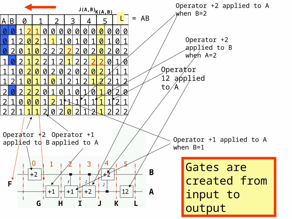
A B0 0 1 2 1 0 0 0 0 0 0 0 0 0 0 00 1 2 0 2 1 1 1 0 1 0 1 0 1 0 10 2 0 1 0 2 2 2 2 2 0 2 0 2 0 21 0 2 1 2 2 1 2 1 2 2 2 2 0 1 01 1 0 2 0 0 2 0 2 0 2 0 2 1 1 11 2 1 0 1 1 0 1 2 1 2 1 2 2 1 22 0 2 2 2 0 1 0 1 0 1 0 1 0 2 02 1 0 0 0 1 2 1 1 1 1 1 1 1 2 12 2 1 1 1 2 0 2 0 2 1 2 1 2 2 2
4 5 F0 1 2 3
A
B
Operator 12 applied to A
Operator +2 applied to B when A=2
Operator +2 applied to A when B=2
Operator +1 applied to A when B=1Operator +2 applied to B
Operator +1 applied to A
= ABK(A,B)J(A,B)
F
G
Gates are created from input to output
H I J K L
L
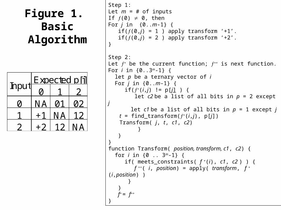
Figure 1. Basic Algorithm
0 1 20 NA 01 021 +1 NA 122 +2 12 NA
Expected p[j]Input
Step 1:Let m = # of inputsIf (0) 0, then For j in {0..m-1} { if((0,j) = 1 ) apply transform ‘+1’. if((0,j) = 2 ) apply transform ‘+2’.}
Step 2:Let + be the current function; ++ is next function.For i in {0..3m-1} { let p be a ternary vector of i For j in {0..m-1} { if(+(i,j) != p[j] ) { let c2 be a list of all bits in p = 2 except j let c1 be a list of all bits in p = 1 except j t = find_transform(+(i,j), p[j]) Transform( j, t, c1, c2) } }}function Transform( position, transform, c1, c2) { for i in {0 .. 3m-1} { if( meets_constraints( f +(i), c1, c2 ) ) { f ++( i, position) = apply( transform, f +(i,position) ) } } f+ = f++
}
A B0 0 1 2 1 0 0 0 0 0 0 0 0 0 0 00 1 2 0 2 1 1 1 0 1 0 1 0 1 0 10 2 0 1 0 2 2 2 2 2 0 2 0 2 0 21 0 2 1 2 2 1 2 1 2 2 2 2 0 1 01 1 0 2 0 0 2 0 2 0 2 0 2 1 1 11 2 1 0 1 1 0 1 2 1 2 1 2 2 1 22 0 2 2 2 0 1 0 1 0 1 0 1 0 2 02 1 0 0 0 1 2 1 1 1 1 1 1 1 2 12 2 1 1 1 2 0 2 0 2 1 2 1 2 2 2
4 5 F0 1 2 3
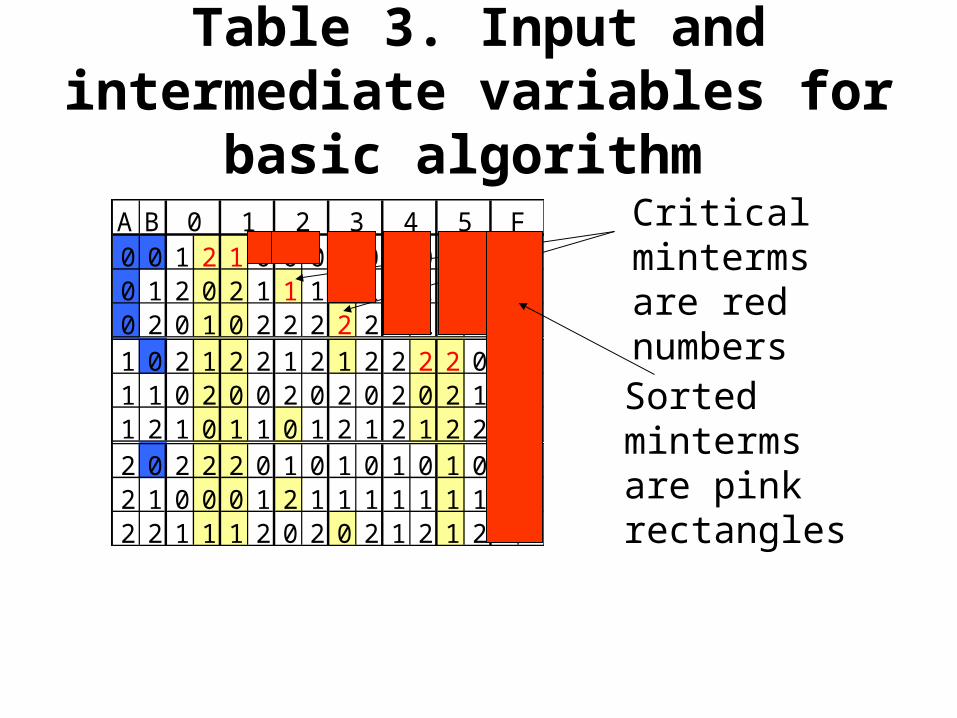
Table 3. Input and intermediate variables for basic algorithm
Critical minterms are red numbers
Sorted minterms are pink rectangles
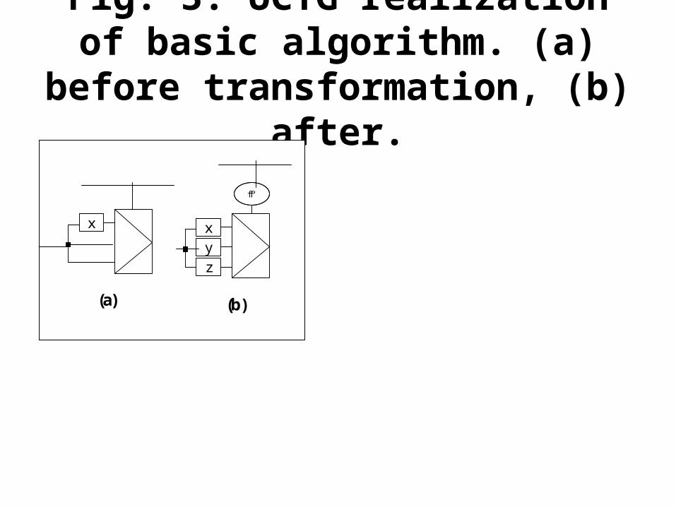
Fig. 3. UCTG realization of basic algorithm. (a) before
transformation, (b) after.
x
zyx
f
(a) (b)
f ‘
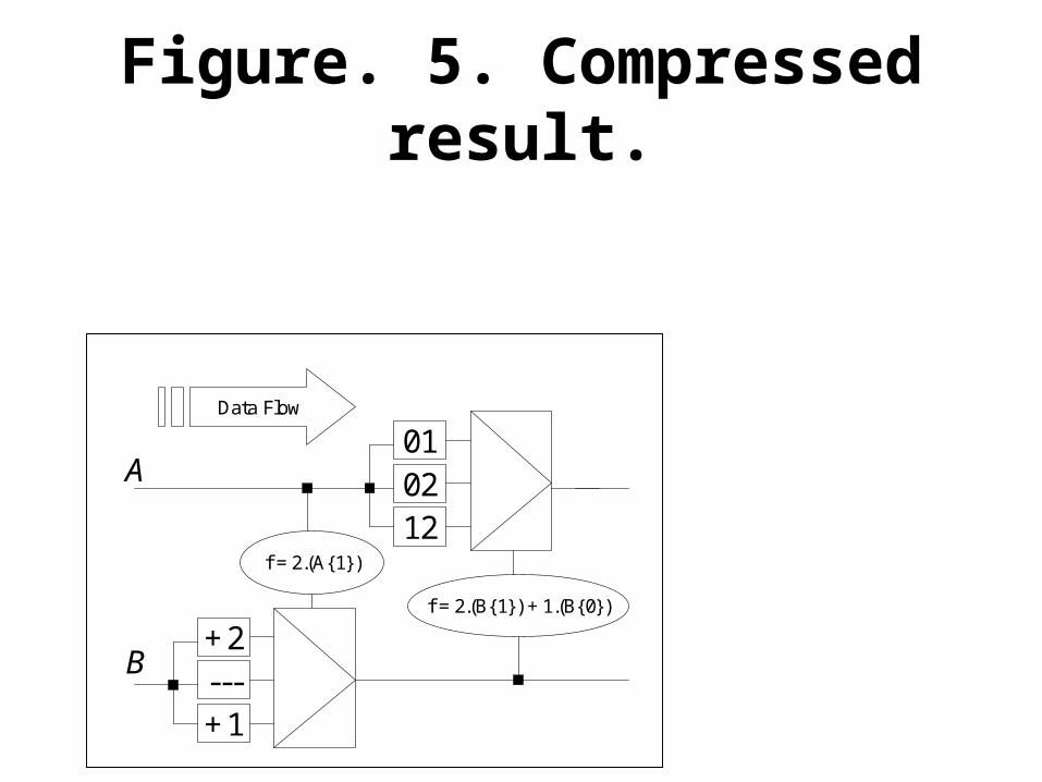
Figure. 5. Compressed result.
Data Flow
+1---+2
120201
f = 2.(A{1})
f = 2.(B{1}) + 1.(B{0})
B
A
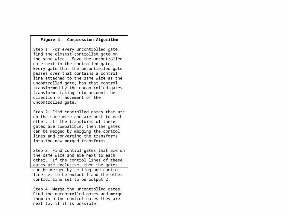
Figure 4. Compression Algorithm
Step 1: For every uncontrolled gate, find the closest controlled gate on the same wire. Move the uncontrolled gate next to the controlled gate. Every gate that the uncontrolled gate passes over that contains a control line attached to the same wire as the uncontrolled gate, has that control transformed by the uncontrolled gates transform, taking into account the direction of movement of the uncontrolled gate.
Step 2: Find controlled gates that are on the same wire and are next to each other. If the transforms of these gates are compatible, then the gates can be merged by merging the control lines and converting the transforms into the new merged transforms.
Step 3: Find control gates that are on the same wire and are next to each other. If the control lines of these gates are exclusive, then the gates can be merged by setting one control line set to be output 1 and the other control line set to be output 2.
Step 4: Merge the uncontrolled gates. Find the uncontrolled gates and merge them into the control gates they are next to, if it is possible.
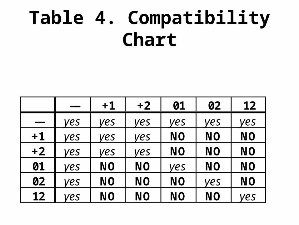
Table 4. Compatibility Chart
--- +1 +2 01 02 12--- yes yes yes yes yes yes+1 yes yes yes NO NO NO+2 yes yes yes NO NO NO01 yes NO NO yes NO NO02 yes NO NO NO yes NO12 yes NO NO NO NO yes
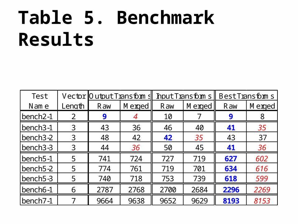
Raw Merged Raw Merged Raw Mergedbench2-1 2 9 4 10 7 9 8
bench3-1 3 43 36 46 40 41 35bench3-2 3 48 42 42 35 43 37bench3-3 3 44 36 50 45 41 36
bench5-1 5 741 724 727 719 627 602bench5-2 5 774 761 719 701 634 616bench5-3 5 740 718 753 739 618 599
bench6-1 6 2787 2768 2700 2684 2296 2269
bench7-1 7 9664 9638 9652 9629 8193 8153
Best TransformsOutput TransformsVector Length
Test Name
Input Transforms
Table 5. Benchmark Results

Abhinav Agarwal – DATE 2004
• Claims to have the best results of all so far.• Many points uncertain• We have to dig deeper to see if there is really
any value there that we do not know.• We used Reed Muller earlier but differently. • Is PPRM better than FPRM, may be because of
efficient realization on a computer.
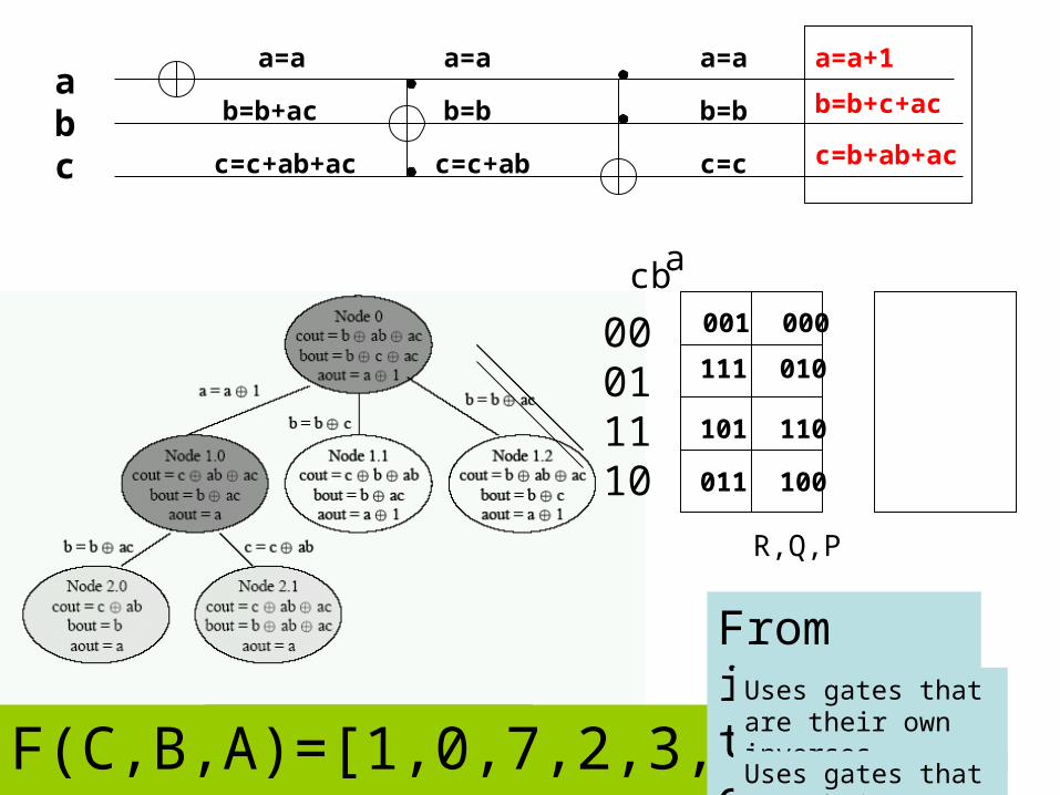
F(C,B,A)=[1,0,7,2,3,4,5,6]
ab c
00 01 11 10
001 000
111 010
011 100
101 110
R,Q,P
c=b+ab+ac
b=b+c+ac
a=a+1a=a
b=b+ac
c=c+ab+ac
a=a
b=b
c=c+ab
a=a
b=b
c=c
acb
From inputs to outputs Uses gates that are
their own inverses
Uses gates that are their own inverses


![Ternary Logic Gates and Ternary SRAM Cell ….pdf · According to blueprint of Weste & Harris in [4] for design of a binary SRAM, a ternary SRAM is constructed similarly. A ternary](https://img.pdfslide.net/doc/110x75/5a8290bb7f8b9aa24f8e2227/ternary-logic-gates-and-ternary-sram-cell-pdfaccording-to-blueprint-of-weste.jpg)

![ISSN: 2014-2846 · fàcilment la segona arrel» [Perkowski 1989: 99]. La llengua de Venècia era força comuna a la Repْblica de Ragusa. Finalment Perkowski [1989: 99] no troba en](https://img.pdfslide.net/doc/110x75/60a9491456bd9e08b94c91db/issn-2014-fcilment-la-segona-arrel-perkowski-1989-99-la-llengua-de-vencia.jpg)