Embed Size (px)
Citation preview

BK130/36
USER’S MANUAL
AC DIELECTRIC TEST SET 600 SERIES
Model Number BK130/36
VERSION 6.0
Phenix Technologies, Inc.
75 Speicher Drive Accident, Maryland 21520
Copyright © Phenix Technologies, Inc. Rev 6/12/2017
BK130/36
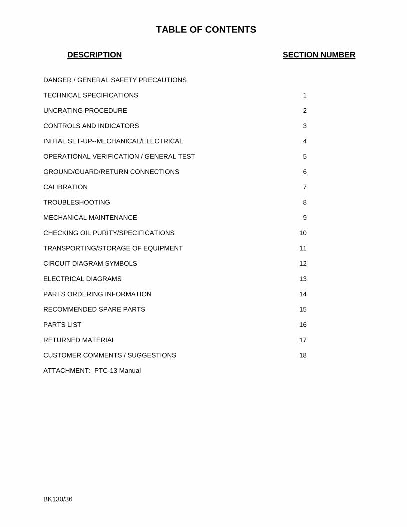
TABLE OF CONTENTS
DESCRIPTION SECTION NUMBER DANGER / GENERAL SAFETY PRECAUTIONS TECHNICAL SPECIFICATIONS 1 UNCRATING PROCEDURE 2 CONTROLS AND INDICATORS 3 INITIAL SET-UP--MECHANICAL/ELECTRICAL 4 OPERATIONAL VERIFICATION / GENERAL TEST 5 GROUND/GUARD/RETURN CONNECTIONS 6 CALIBRATION 7 TROUBLESHOOTING 8 MECHANICAL MAINTENANCE 9 CHECKING OIL PURITY/SPECIFICATIONS 10 TRANSPORTING/STORAGE OF EQUIPMENT 11 CIRCUIT DIAGRAM SYMBOLS 12 ELECTRICAL DIAGRAMS 13 PARTS ORDERING INFORMATION 14 RECOMMENDED SPARE PARTS 15 PARTS LIST 16 RETURNED MATERIAL 17 CUSTOMER COMMENTS / SUGGESTIONS 18 ATTACHMENT: PTC-13 Manual
BK130/36
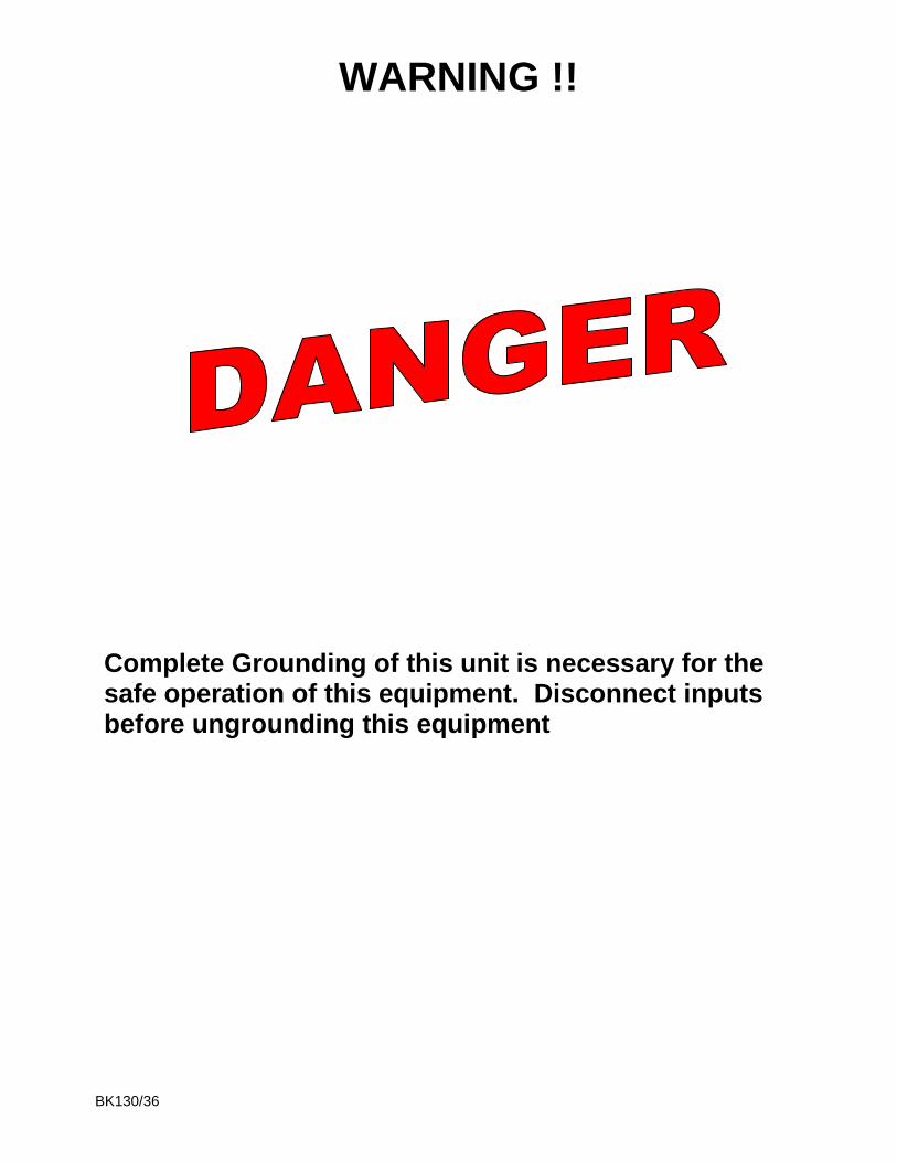
WARNING !!
Complete Grounding of this unit is necessary for the safe operation of this equipment. Disconnect inputs before ungrounding this equipment
BK130/36
GENERAL SAFETY PRECAUTIONS
HIGH VOLTAGE
This equipment is capable of providing POTENTIALLY LETHAL VOLTAGES! Improper operation or test practices may result in injury or death to the operator or surrounding personnel. The operation of High Voltage test equipment should only be performed by personnel familiar with HIGH VOLTAGE testing and safety procedures. The operator of this equipment must be aware of all hazards associated with High Voltage testing. The operator is responsible for himself and others in close proximity of the testing area. Some General Safety Practices for working with High Voltage Test Equipment have been listed below for your reference.
Become familiar with your instrument before performing an actual test
Know your work area, check that all circuits are de-energized and locked out.
Never work alone; always work with another qualified worker.
Mark off entire work area with barriers and warning tape.
Make all personnel aware of your testing activities.
Be aware of dangerous conditions that may arise from energizing a test specimen.
Never modify test equipment, modifications to equipment could introduce an unknown hazard or hinder a designed-in safety feature.
DO NOT operate damaged equipment. Remove power, and do not use the equipment until safe operation can be verified by service-trained personnel.
Phenix Technologies, Inc. assumes no liability for unsafe or improper use of test equipment.

BK130/36
1-1
SECTION 1: TECHNICAL SPECIFICATIONS Input 110 -120 volts, single phase 50 / 60 Hz, 30 amperes OR 208- 240 volts, single phase 50 / 60 Hz, 15 Amperes (Refer to Serial Tag for voltage and current designation) Output Rating 0-36 kilovolts, 180 milliamperes 0-130 kilovolts, 50 milliamperes Duty Cycle – Capacitive Loading 5 minutes ON/15 minutes OFF @ 50 mA /180 mA 1 hour ON/1 hour OFF @ 33.3 mA /120 mA Continuous @ 25 mA /90 mA Type of Cooling ONAN (Oil / Air Natural Convection) Operating Ambient Temperature 10 – 40 degrees C Output Termination 2” Polished Ball – 36 kV 3” x 12” High Voltage Spinning – 130 kV Metering - Digital Output Voltmeter: 3 ½ Digit LCD, Accuracy ±(0.8% of reading + .2% of range) Output Currentmeter: 3 ½ Digit LCD, Accuracy ±(0.8% of reading+ .2% of range). 4 Ranges: 0-200µA, 2mA, 20mA, 200mA Sizes and Weights Control/Regulator Section: 21.25” (540mm) W x 16.75" (426mm) Dx 13.75" (350mm) H; 120V - 45 lbs. (20.4 kg), 220 V – 50 lbs (22.7 Kg) High Voltage Section: 16" (406mm) W x 16" (406mm) D; X 30” (762mm) H; 178 lbs. (80.7 kg) Additional Equipment Cart : 22.5” (572mm) W x 29.25”(743mm) D x 50”(1270mm) H; 61 lbs. (27.7 kg) Cables: 20 lbs. (9.1 kg) Total Unit Weight: 120V - 304 lbs. (137.9 kg), 220V – 309 lbs. (140.2 Kg)

BK130/36
2-1
SECTION 2: UNCRATING PROCEDURE 1. Exercise care in removing shipping materials so as not to damage unit. 2. Perform visual inspection to determine if unit was damaged during shipment. If there are any signs of physical damage (such as dents, scratches, oil leaks), contact the factory before proceeding.
BK130/36
3-1
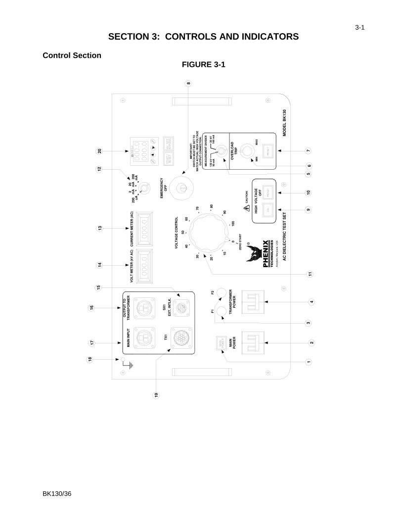
SECTION 3: CONTROLS AND INDICATORS Control Section
FIGURE 3-1
!
!
TECHNOLOGIES
PHENIX
BK130/36
3-2
CONTROLS AND INDICATORS
Descriptions are keyed to Figure 3-1. 1. Main Power Indicator. 2. Main Power Circuit Breaker. Interrupts all power into set. 3. F1 (120V) F1,2 (220V) - Control Power Fuse/Fuses. 4. Transformer Power Circuit Breaker - Interrupts power to HV Transformer. Breaker must
be on to activate High Voltage.
5. Measurement Divider Switch - Selects proper overload and voltmeter circuitry for the H.V. output terminal being used. Match switch setting to output being used on HV transformer.
6. Overload Trip - Use for presetting desired Overcurrent trip setting. Range
approximately 10-110% of rated current. 7. Reset - Will light when Overcurrent trip setting is exceeded. Push to reset. Lamp must be
extinguished for H.V.ON. 8. Emergency Off – Push down to stop test immediately. Button must be pulled up to activate High
Voltage Output. 9. High Voltage On Switch and Indicator Lamp - Turns on H.V. when Ready indicator is illuminated. 10. High Voltage Off Switch and Indicator Lamp - Turns H.V. off, indicator shows when all conditions
are met to turn H.V.ON. (External Interlock closed, Reset Lamp off, Emergency Off Button pulled up, Voltage Control at Zero).
11. Voltage Control - Adjusts Output Voltage and must be set at zero to turn High Voltage on. 12. Currentmeter Range Selector. 13. Output Currentmeter. 14. Output Voltmeter. 15. SX1 External Interlock - Provides for user connection of external interlock or auxiliary safety control
device such as Emergency Off Switch, Gate Switch, Footswitch, Dead man Switch, etc. Included plug has shorting jumper installed to complete circuit. Jumper must be removed and cable connected to user supplied device by user if desired to use this provision. Only non-energized switch or dry relay contact devices may be used. This is a series 120VAC circuit that must remain closed for High Voltage to be activated.
16. Output to Transformer - High Voltage Transformer power connection. 17. Main Input – Main input cable connects here. 18. Ground Terminal. 19. TX1 – Signal/ Metering cable between H.V. Unit and controls connects here. 20. Test Cell Timer. Press START/RESET to start the timer after test voltage has been reached. Press
START/RESET again to reset timer to the original setting. Press HV OFF BYPASS to allow high voltage to remain on after the timer has expired. Test time can be set using the buttons on the face of the timer.

BK130/36
3-3
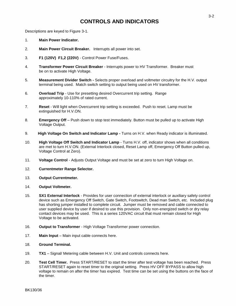
CONTROLS AND INDICATORS
FIGURE 3-2
BK130/36
3-4
CONTROLS AND INDICATORS
High Voltage Section Descriptions are keyed to Figure 3-2. 1. Power Connector – Power Cable from Output to Transformer connector, connects here. 2. High Voltage Unit Ground Point - A Ground cable from facility ground or earth ground must be
connected here. 3. Guard Binding Post (GRD) - Currents associated with this connection bypass the current meter
(meter bypass connection). SEE SECTION: 6--GROUND-GUARD-RETURN CONNECTIONS for more information on these connections (Page 6 – 1).
4. Ground Binding Post with Jumper Clip (GND) - This binding post is connected to ground. When
the Jumper Clip is tied from Ground to Return (RTN), any leakage currents from High Voltage to Ground will also be measured by the Current Meter. When the test specimen is grounded or has any sort of ground reference, the Jumper Clip must be connected from Ground to Return. When the Jumper Clip is tied from Ground to Guard (GRD), any stray leakage currents associated with Ground or Guard will bypass the Current Meter and will not be measured. The test specimen must be totally isolated from ground and free of ground references to use the Jumper Clip in this position.
Note: The Jumper Clip must always be connected from Ground to either Return or Guard as desired or dictated by the test set up.
5. Return Binding Post (RTN) - Low potential side of test specimen connects here. This connection
routes current through the Current Meter circuit (metered connection point). 6. TX1 Connector - Signal /Metering cable connects from here to TX1 on Control / Regulator section. 7. 36 kV TAP - For 0 – 36 kV output at 0 – 180 mA, this connection must be used and measurement
divider switch on controls must be set to 36 kV/180 mA position. 8. 130 kV Tap - For 0 – 130 kV output at 0 – 50 mA, this output connection is used and measurement
divider switch on controls must be set to 130 kV / 50 mA.
BK130/36
4-1
SECTION 4: INITIAL SET-UP—MECHANICAL / ELECTRICAL 1. Set up Bucket Truck or object under test. If testing a Bucket Truck, it is recommended to place outriggers
and tires on insulating pads.
2. The area to be used for the test must provide sufficient mechanical and electrical clearances. The
approximate weight of each section is available from the nameplates or the Specification Page. 3. If the unit is to be operated indoors, be sure the floor will be strong enough to support the unit.
If outdoor operation is to be used, the site for the base must be capable of supporting the unit without any settling that would tilt the assembly. 4. Position the High Voltage Transformer Tank and Control Unit as necessary for operation. 5. Clean entire High Voltage Unit so as to remove all traces of any surface contamination. The cleaner should
be nothing stronger than ordinary household cleaner. Cleaning should also include the High Voltage Electrodes.
CAUTION: When setting up the Bucket Truck, ensure that there are no overhead safety hazards such as live power lines.
BK130/36
4-2
INITIAL SET-UP--ELECTRICAL
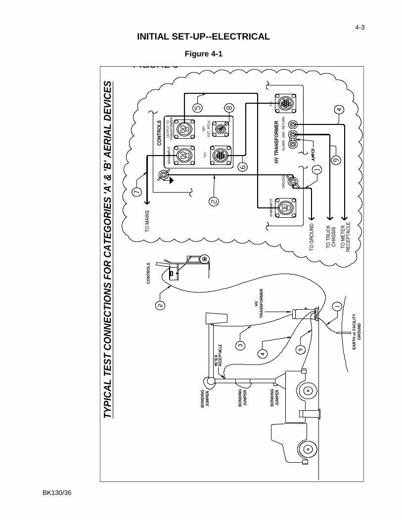
The following are examples of basic setups for performing various tests using the PHENIX test set. Refer to the A92.2 standard (Included in optional accessory package) for test parameters and for more detailed information. Connections for testing Categories A & B Aerial Devices
(Refer to Figure4-1):
1. Connect the ground stud on the high voltage transformer to a good earth ground using the supplied lead.
2. Connect the ground stud on the high voltage transformer to the ground stud on the control cabinet
using the supplied lead.
3. Connect the HV (130kV) output terminal on top of the high voltage transformer to the bucket of the truck under test using a piece of wire (Included in the optional accessory package). Verify that all metal in the bucket is bonded together and connected to the high voltage lead using bus wire or clip leads (Included in the optional accessory package). Make sure that the tap selector switch on the front panel is in the 130kV position.
4. Connect the RETURN terminal at the base of the high voltage transformer to the meter receptacle on
the boom using a coaxial lead (Included in the optional accessory package).
5. Connect the power connector on the high voltage transformer to the mating connector on the control cabinet using the supplied cable.
6. Connect the control/metering connector on the high voltage transformer to the mating connector on
the control cabinet using the supplied cable.
7. Connect input power cable to controls. Do not connect to power source until setup is complete.
8. This connector has a jumper installed that can be removed to connect an external safety switch (Included in the optional accessory package).
9. Connect the GND terminal at the base of the high voltage transformer to the chassis of the truck.
NOTE: Other jumpers to bypass chassis insulators, pivot points, knuckles, joints etc. are usually required.
WARNING: Ground the output of the High Voltage Transformer until set-up is complete! Be sure the Main Power Circuit Breaker is in the OFF position before proceeding. This equipment should only be operated by personnel familiar with High Voltage Testing and Safety Procedures.
BK130/36
4-3
INITIAL SET-UP--ELECTRICAL
Figure 4-1
TY
PIC
AL
TE
ST
CO
NN
EC
TIO
NS
FO
R C
AT
EG
OR
IES
'A
' &
'B
' A
ER
IAL
DE
VIC
ES
BO
ND
ING
JU
MP
ER
BO
ND
ING
JU
MP
ER
BO
ND
ING
JU
MP
ER
EA
RT
H o
r F
AC
ILIT
Y
GR
OU
ND
HV
TR
AN
SF
OR
ME
R
CO
NT
RO
LS
BK130/36
4-4
INITIAL SET-UP--ELECTRICAL
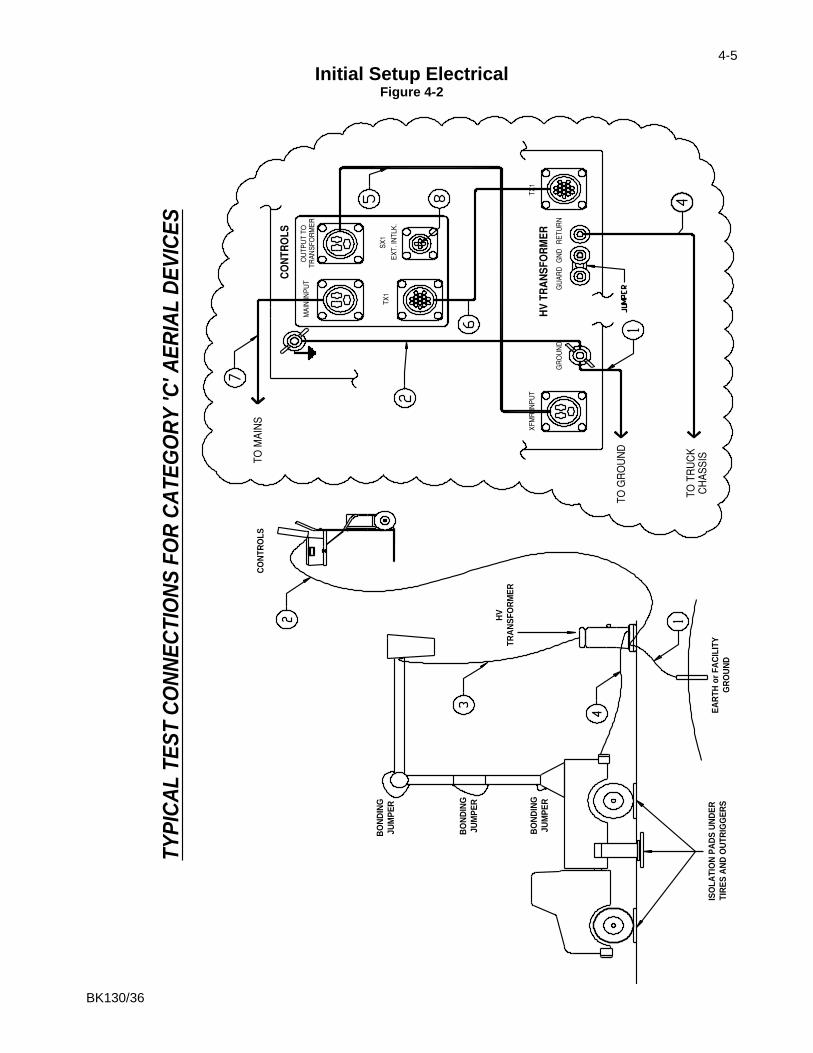
Connections for testing Category C Aerial Devices (REFER TO FIGURE 4-2)
1. Connect the ground stud on the high voltage transformer to a good earth ground using the supplied lead.
2. Connect the ground stud on the high voltage transformer to the ground stud on the control cabinet
using the supplied lead.
3. Connect the HV (130kV) output terminal on top of the high voltage transformer to the bucket of the truck under test using a piece of wire (Included in the optional accessory package). Verify that all metal in the bucket is bonded together and connected to the high voltage lead using bus wire or clip leads (Included in the optional accessory package). Make sure that the tap selector switch on the front panel is in the 130kV position.
4. Connect the RETURN terminal at the base of the high voltage transformer to the chassis of the truck
using the supplied lead.
5. Connect the power connector on the high voltage transformer to the mating connector on the control cabinet using the supplied cable.
6. Connect the control/metering connector on the high voltage transformer to the mating connector on
the control cabinet using the supplied cable.
7. Connect input power cable to controls. Do not connect to power source until setup is complete.
8. This connector has a jumper installed that can be removed to connect an external safety switch (Included in the optional accessory package).
NOTES:
Other jumpers to bypass chassis insulators, pivot points, knuckles, joints, etc. are usually required.
Truck must be isolated from ground for testing (Isolation pads included in optional accessory package).
BK130/36
4-5
Initial Setup Electrical Figure 4-2
TY
PIC
AL
TE
ST
CO
NN
EC
TIO
NS
FO
R C
AT
EG
OR
Y 'C
' AE
RIA
L D
EV
ICE
S
BO
ND
ING
JU
MP
ER
BO
ND
ING
JU
MP
ER
BO
ND
ING
JU
MP
ER
EA
RT
H o
r F
AC
ILIT
Y
GR
OU
ND
HV
TR
AN
SF
OR
ME
R
CO
NT
RO
LS
ISO
LA
TIO
N P
AD
S U
ND
ER
TIR
ES
AN
D O
UT
RIG
GE
RS

BK130/36
4-6
INITIAL SET-UP--ELECTRICAL
Connections For Testing Chassis Insulators On Aerial Devices (Refer To Figure 4-3)
1. Connect the ground stud on the high voltage transformer to a good earth ground using the supplied lead.
2. Connect the ground stud on the high voltage transformer to the ground stud on the control cabinet
using the supplied lead.
3. Connect the HV (130kV) output terminal on top of the high voltage transformer to the top (bucket) end of the chassis insulator under test using a piece of wire (Included in the optional accessory package). Other insulators or joints in the current return path must be bypassed using jumpers. Make sure that the tap selector switch on the front panel is in the 130kV position.
4. Connect the RETURN terminal at the base of the high voltage transformer to the chassis of the truck
using the supplied lead.
5. Connect the power connector on the high voltage transformer to the mating connector on the control cabinet using the supplied cable.
6. Connect the control/metering connector on the high voltage transformer to the mating connector on
the control cabinet using the supplied cable.
7. Connect input power cable to controls. Do not connect to power source until setup is complete.
8. This connector has a jumper installed that can be removed to connect an external safety switch (Included in the optional accessory package).
NOTES:
Other jumpers to bypass chassis insulators, pivot points, knuckles, joints, etc. are usually required.
Truck must be isolated from ground for testing (Isolation pads included in optional accessory package).

BK130/36
4-7
INITIAL SETUP ELECTRICAL (Figure 4-3)
TY
PIC
AL
TE
ST
CO
NN
EC
TIO
NS
FO
R C
HA
SS
IS I
NS
UL
AT
OR
S
EA
RT
H o
r F
AC
ILIT
Y
GR
OU
ND
HV
TR
AN
SF
OR
ME
R
CO
NT
RO
LS
ISO
LA
TIO
N P
AD
S U
ND
ER
TIR
ES
AN
D O
UT
RIG
GE
RS
CO
NT
RO
LS
CO
NT
RO
LS
BK130/36
5-1
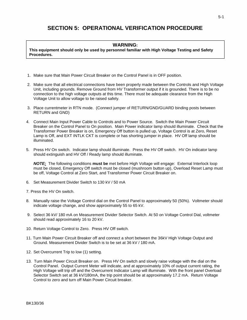
SECTION 5: OPERATIONAL VERIFICATION PROCEDURE
1. Make sure that Main Power Circuit Breaker on the Control Panel is in OFF position. 2. Make sure that all electrical connections have been properly made between the Controls and High Voltage
Unit, including grounds. Remove Ground from HV Transformer output if it is grounded. There is to be no connection to the high voltage outputs at this time. There must be adequate clearance from the High Voltage Unit to allow voltage to be raised safely.
3. Place currentmeter in RTN mode. (Connect jumper of RETURN/GND/GUARD binding posts between
RETURN and GND) 4. Connect Main Input Power Cable to Controls and to Power Source. Switch the Main Power Circuit
Breaker on the Control Panel to On position. Main Power indicator lamp should illuminate. Check that the Transformer Power Breaker is on, Emergency Off button is pulled up, Voltage Control is at Zero, Reset Lamp is Off, and EXT INTLK CKT is complete or has shorting jumper in place. HV Off lamp should be illuminated.
5. Press HV On switch. Indicator lamp should illuminate. Press the HV Off switch. HV On indicator lamp
should extinguish and HV Off / Ready lamp should illuminate. NOTE: The following conditions must be met before High Voltage will engage: External Interlock loop must be closed, Emergency Off switch must be closed (mushroom button up), Overload Reset Lamp must be off, Voltage Control at Zero Start, and Transformer Power Circuit Breaker on.
6. Set Measurement Divider Switch to 130 kV / 50 mA 7. Press the HV On switch. 8. Manually raise the Voltage Control dial on the Control Panel to approximately 50 (50%). Voltmeter should
indicate voltage change, and show approximately 55 to 65 kV. 9. Select 36 kV/ 180 mA on Measurement Divider Selector Switch. At 50 on Voltage Control Dial, voltmeter
should read approximately 16 to 20 kV. 10. Return Voltage Control to Zero. Press HV Off switch. 11. Turn Main Power Circuit Breaker off and connect a short between the 36kV High Voltage Output and
Ground. Measurement Divider Switch is to be set at 36 kV / 180 mA. 12. Set Overcurrent Trip to low (1) setting. 13. Turn Main Power Circuit Breaker on. Press HV On switch and slowly raise voltage with the dial on the
Control Panel. Output Current Meter will indicate, and at approximately 10% of output current rating, the High Voltage will trip off and the Overcurrent Indicator Lamp will illuminate. With the front panel Overload Selector Switch set at 36 kV/180mA, the trip point should be at approximately 17.2 mA. Return Voltage Control to zero and turn off Main Power Circuit breaker.
WARNING:
This equipment should only be used by personnel familiar with High Voltage Testing and Safety Procedures.
BK130/36
5-2
OPERATIONAL VERIFICATION PROCEDURE 14. Move short from 36 kV output to 130 kV output and ground. Set Measurement Divider Switch to 36 kV /
180 mA. Repeat step 13. Unit should trip off at approximately 4.6 mA. NOTE: Do not attempt to check 110% level of current trip under shorted output conditions. Rated output currents are only available through a capacitive load of sufficient value. Shorted current values should never exceed 50% of rated currents for the High Voltage Tap being used. If desired to test at 110% of current rating, the 36kV/180mA tap must be connected to a High Voltage Capacitor of approximately 15 to 20 nanofarads rated at 36 kVAC or higher. 15. Turn Off Main Power Circuit Breaker on Controls. END OF OPERATIONAL VERIFICATION TEST!
BK130/36
5-3
GENERAL TEST PROCEDURE 1. Make sure that Main Power Circuit Breaker on the Control Panel is in the OFF position. 2. Make sure that all electrical connections have been properly and securely made, and that the test
specimen is properly connected to the High Voltage Transformer (refer to Initial Set-up Procedures). Make sure the Guard / Ground / Return Jumper Clip is set properly for test being performed. Make sure all personnel are clear of danger and test area is clearly marked.
3. Connect Input Cable to Controls and to Power Source. Switch the Main Power Circuit Breaker on the
Control Panel to the ON position. 4. Set Measurement Divider switch to the position that matches the High Voltage output being used. 5. Set Overload Trip dial to desired trip-out level.
(NOTE: In setting this device, it is important to take into account the capacitive current that the sample under test will require. Set the dial to a high enough value to preclude false failure indications. If this value is not known, it is recommended that the dial be left in a higher setting.)
6. Press the HV On switch.
(NOTE: The following conditions must be met before High Voltage will engage: Security Circuit Loop must be closed, Emergency Off Switch must be closed (mushroom button up), Overload Reset Lamp must be off, Voltage Control at Zero Start, Transformer Power Circuit Breaker ON, and Ready lamp illuminated.)
7. Raise the manual Voltage Control knob on the Control Panel until desired test voltage level is
reached. Keep voltage at desired level for required duration. Record data if desired. 8. After completion of the test, manually return the Output Voltage to zero or its lowest level via the Voltage
Control knob. 9. Press HV Off momentary switch. 10. If during the test a failure should occur or if the Overcurrent Trip setting is exceeded, the High Voltage will
automatically shut off. In order to regain High Voltage, the Reset pushbutton must be pressed and Voltage Control knob returned to Zero.
BK130/36
6-1
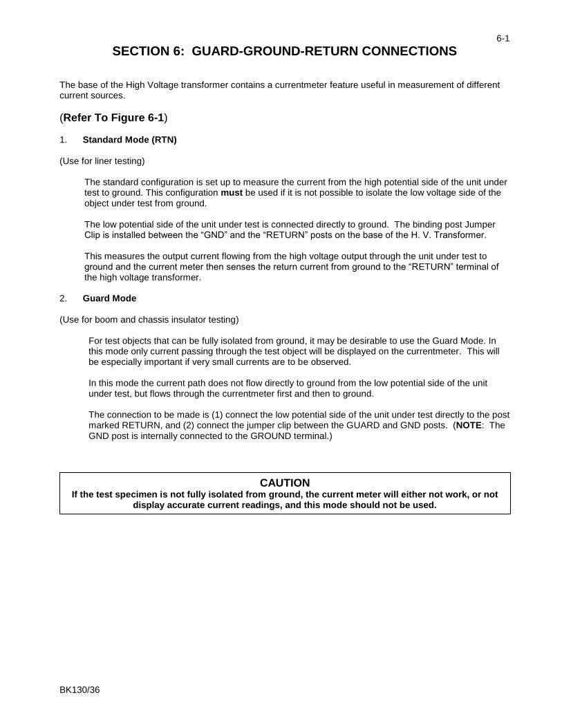
SECTION 6: GUARD-GROUND-RETURN CONNECTIONS The base of the High Voltage transformer contains a currentmeter feature useful in measurement of different current sources.
(Refer To Figure 6-1) 1. Standard Mode (RTN) (Use for liner testing)
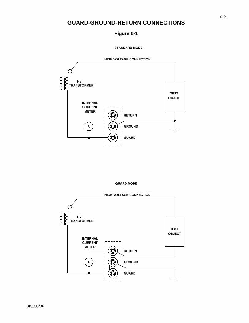
The standard configuration is set up to measure the current from the high potential side of the unit under test to ground. This configuration must be used if it is not possible to isolate the low voltage side of the object under test from ground. The low potential side of the unit under test is connected directly to ground. The binding post Jumper Clip is installed between the “GND” and the “RETURN” posts on the base of the H. V. Transformer. This measures the output current flowing from the high voltage output through the unit under test to ground and the current meter then senses the return current from ground to the “RETURN” terminal of the high voltage transformer.
2. Guard Mode (Use for boom and chassis insulator testing)
For test objects that can be fully isolated from ground, it may be desirable to use the Guard Mode. In this mode only current passing through the test object will be displayed on the currentmeter. This will be especially important if very small currents are to be observed. In this mode the current path does not flow directly to ground from the low potential side of the unit under test, but flows through the currentmeter first and then to ground. The connection to be made is (1) connect the low potential side of the unit under test directly to the post marked RETURN, and (2) connect the jumper clip between the GUARD and GND posts. (NOTE: The GND post is internally connected to the GROUND terminal.)
CAUTION If the test specimen is not fully isolated from ground, the current meter will either not work, or not
display accurate current readings, and this mode should not be used.
BK130/36
6-2
GUARD-GROUND-RETURN CONNECTIONS
Figure 6-1

BK130/36
7-1
SECTION 7: CALIBRATION
All calibrations have been done at the factory. Periodic calibration of the output voltmeter and output currentmeter should be done annually. NOTE: Refer to Electrical Diagram Section for schematics pertaining to the model number of your test set. Locating the Calibration Adjustments The calibration points are shown in the following diagram.
1. Output Voltmeter
Connect a precision high voltage voltmeter across the output to ground on 36 kV output, with Measurement Divider switch set to 36 kV. Raise the output to approximately 80% of the output rating. Adjust the reading on the panel meter (M2) by means of potentiometer R17 to a corresponding reading. Repeat procedure with precision high voltage voltmeter connected between the 130 kV output and ground with the Measurement Divider switch set to 130 kV. Adjust R19 to match precision voltmeter at 80% of output rating.
2. Output Currentmeter
It is necessary to connect adequately rated High Voltage loads (isolated from ground) to the high voltage unit that will allow each full range current to be drawn at approximately 15% or higher output voltage. This allows sufficient resolution to adjust current levels. All ranges can be calibrated from 36 kV output.
Place Binding Post Configuration in GUARD MODE. (Jumper clip is installed between “GRD” and “GND” posts.) Connect a precision ammeter between the low potential side of the appropriate high voltage load and the “RTN” post. Select the 200 uA meter range. Raise the output to approximately 80% of the range rating. Adjust the reading on the panel meter (M1) by means of potentiometer R78 to a corresponding reading. Repeat for 2 mA, 20 mA and 200 mA ranges adjusting R80, R82 and R84, respectively. (High Voltage load will need to change when changing range).
NOTE: An optional method is to use current injection between RTN and GND (Guard Mode). Do not turn High Voltage on for this method!
R19 130 kV
VM
R17 36 kV VM
R113 VOLT
OFFSET
R84
200mA CM
R82 20mA CM
R80 2mA CM
R78 200µA
CM
R77 CURRENT OFFSET
R87
RANGE OVLD
R72 110% OVLD
R69 10%
OVLD
CAUTION:
Calibration should only be done by persons familiar with High Voltage testing and safety procedures.
BK130/36
7-2
CALIBRATION
3. Overcurrent
This calibration should not need adjustment (factory adjusted). If the Overcurrent Circuit is out of calibration, perform the following steps. To recalibrate the Overcurrent Circuit with the High Voltage Unit it will be necessary to connect a 15 – 20 nanofarad capacitor rated at 36 kVAC or higher to the 36 kV / 180 mA output of the High Voltage Unit. If the capacitor is isolated from ground at the low potential end, the low potential end can be connected to the RTN post. The Guard Post Jumper may be connected to GRD (Guard Mode). If the low potential end of the capacitor is grounded, the Ground Post Jumper must be connected to RTN post.
a. Set front panel Measurement Divider switch to 36 kV/180mA. When current trip dial is set to
minimum (1) current trip level should be approx. 18mA. When dial is set to maximum (11) trip level should be approx. 198mA.
b. Set the Overload Trip potentiometer (R15) on the front panel to "1" and the Current Range
switch to 200 mA.
c. Turn on HV On and adjust the output current slowly until 10% of rated current is displayed on the current meter (18 mA).
d. Adjust potentiometer R69 until the Reset lamp illuminates and high voltage is shut off.
e. Set the Overcurrent Trip potentiometer (R15) on the front panel to "11."
f. Turn on HV On and adjust the output current slowly until 110% of rated current is
displayed on meter.
g. Adjust potentiometer R72 until the Reset Lamp illuminates and high voltage is shut off.
h. Repeat steps "b" through "g" if necessary until both settings are calibrated. 4. Range Overcurrent:
R87 sets an overcurrent for the ranges and should be set to trip at approximately 112% of full range current on medium range setting with current trip potentiometer set at “11.”
5. Voltage offset adjustment (R113): The voltage offset should be done with the voltage output lead connected to board ground. This typically can be done by connecting the output to the guard terminal. Once connected, the offset should be adjusted until the output meter reads nearest to zero. This offset adjustment should be done before adjustments to the voltage ranges are made. Test point T10 may also be used to make this adjustment.
6. Current offset adjustment (R77):
The current offset should be done with the current input connected to board ground. This typically can be done by placing a jumper from the guard to the return terminal. Once jumped, the offset should be adjusted until the output meter reads nearest to zero. This offset adjustment should be done before adjustments to the current ranges are made. Test point T37 may also be used to make this adjustment.

BK130/36
8-1
SECTION 8: TROUBLESHOOTING
General If the controls do not operate properly after having been used according to the instructions, the following hints may help.
Check main facility input power to the test set.
Check all control and switch settings.
Check indicating lamps. (Spare lamps are available through Phenix Technologies.)
Check Fuse F1/F1, F2
Check operation of main power circuit breaker (CB1). Main Power lamp should be on.
Check Transformer Power circuit breaker.
Check all plug connections, internal and external, on the test set.
Specific Problems 1. High voltage cannot be turned on?
Emergency off has been pressed – pull switch button up. External interlock is open (SX1). Voltage Control dial is not in zero start position. Protection circuit (Overload Trip) is not Reset. Transformer Power circuit breaker is off or faulty. Faulty HV On or Off switch. Faulty relay contacts.
2. Voltage control inoperable?
Transformer Power circuit breaker faulty. Problem with power cable between Controls and High Voltage Unit. High voltage is not on (K1 or K3 not energized or see number 1 above). Faulty regulator “T1.” Faulty step-up transformer in high voltage unit (T3001).
3. Overload Trip inoperable?
Improper sensitivity (adjust Current Trip (R15) on front panel). Defective U13. Check the +15 volts DC and -15 volts DC regulator (U16, U17). Check LP4 (RESET) and relay K7 on PCB 1387.

BK130/36
8-2
TROUBLESHOOTING
Specific Problems (Cont’d) 4. Currentmeter inoperable?
Binding post jumper clip installed between ground and guard with a grounded test object. Connection between currentmeter and high voltage test specimen return connected improperly. Meter damaged Faulty, TX1 interconnect cable. Damaged or inoperative range switch or wiring. Faulty Circuit on PCB1387.
5. Voltmeter inoperable?
Faulty TX1 interconnect cable. Meter damaged No high voltage present at output bushing. Damaged or inoperative Measurement Divider Switch. Faulty circuit on PCB1387.
6. No output voltage from high voltage section?
Defective metering circuit. No input to voltage regulator section, possible problems with K1 or K3, regulator (T1), or with
Transformer Power circuit breaker. Internal connection broken. High voltage winding of T2 short circuited. Refer also to 1 and 2.
BK130/36
9-1
SECTION 9: MECHANICAL MAINTENANCE
General No solution or chemical stronger than an ordinary household cleaner should be applied to the cabinet area of this unit. Care must be used when cleaning console panel. Abrasives may remove printing and descriptive titles. When cleaning, always have unit disconnected from power source. Never attempt to clean inside the unit as the cleaning solution may cause damage to the electronic components.
High Voltage Transformer 1. Surface All surfaces are finished with heavy duty paints and will provide adequate protection against the elements in normal use. It is recommended that the finish be wiped down with nothing stronger than ordinary household cleaner for longer life and also for proper electrical operation of the unit. Also inspect all fabrication joints for oil leakage. If a leak is found, retighten bolts to 5 ft. lbs. 3. Control Box / Regulator Section At least once every year, the control assembly should be removed for inspection of the regulator assembly and other parts. If dust and dirt are present, cleaning with a dry brush and air hose should be sufficient. Inspect the voltage regulator contact surfaces for any signs of burning or wear. The brushes are the carbon type and are constructed to provide a 1/8" wide contact point. If they are worn down so as to be nearing (approximately) 1/32" at the wider part of the brush, they should be replaced. The only other mechanical maintenance needed on the control box is that it be kept clean. 4. Transformer Oil Maintenance At time intervals, ranging from six months to one year, the oil purity (see next page) should be checked in the high voltage transformer to verify its reliability. If the transformer is subject to adverse weather conditions or an oil leak develops, the oil purity should be checked regularly.
BK130/36
10-1
SECTION 10: CHECKING OIL PURITY
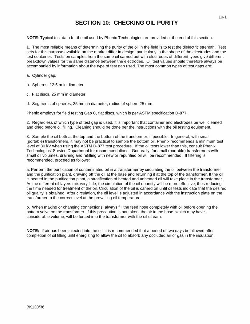
NOTE: Typical test data for the oil used by Phenix Technologies are provided at the end of this section. 1. The most reliable means of determining the purity of the oil in the field is to test the dielectric strength. Test sets for this purpose available on the market differ in design, particularly in the shape of the electrodes and the test container. Tests on samples from the same oil carried out with electrodes of different types give different breakdown values for the same distance between the electrodes. Oil test values should therefore always be accompanied by information about the type of test gap used. The most common types of test gaps are: a. Cylinder gap. b. Spheres, 12.5 m in diameter. c. Flat discs, 25 mm in diameter. d. Segments of spheres, 35 mm in diameter, radius of sphere 25 mm. Phenix employs for field testing Gap C, flat discs, which is per ASTM specification D-877. 2. Regardless of which type of test gap is used, it is important that container and electrodes be well cleaned and dried before oil filling. Cleaning should be done per the instructions with the oil testing equipment. 3. Sample the oil both at the top and the bottom of the transformer, if possible. In general, with small (portable) transformers, it may not be practical to sample the bottom oil. Phenix recommends a minimum test level of 30 kV when using the ASTM D-877 test procedure. If the oil tests lower than this, consult Phenix Technologies’ Service Department for recommendations. Generally, for small (portable) transformers with small oil volumes, draining and refilling with new or repurified oil will be recommended. If filtering is recommended, proceed as follows: a. Perform the purification of contaminated oil in a transformer by circulating the oil between the transformer and the purification plant, drawing off the oil at the base and returning it at the top of the transformer. If the oil is heated in the purification plant, a stratification of heated and unheated oil will take place in the transformer. As the different oil layers mix very little, the circulation of the oil quantity will be more effective, thus reducing the time needed for treatment of the oil. Circulation of the oil is carried on until oil tests indicate that the desired oil quality is obtained. After circulation, the oil level is adjusted in accordance with the instruction plate on the transformer to the correct level at the prevailing oil temperature. b. When making or changing connections, always fill the feed hose completely with oil before opening the bottom valve on the transformer. If this precaution is not taken, the air in the hose, which may have considerable volume, will be forced into the transformer with the oil stream. NOTE: If air has been injected into the oil, it is recommended that a period of two days be allowed after completion of oil filling until energizing to allow the oil to absorb any occluded air or gas in the insulation.
BK130/36
10-2
CHECKING OIL PURITY
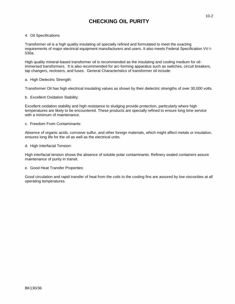
4. Oil Specifications Transformer oil is a high quality insulating oil specially refined and formulated to meet the exacting requirements of major electrical equipment manufacturers and users. It also meets Federal Specification VV-I-530a. High quality mineral-based transformer oil is recommended as the insulating and cooling medium for oil-immersed transformers. It is also recommended for arc-forming apparatus such as switches, circuit breakers, tap changers, reclosers, and fuses. General Characteristics of transformer oil include: a. High Dielectric Strength: Transformer Oil has high electrical insulating values as shown by their dielectric strengths of over 30,000 volts. b. Excellent Oxidation Stability: Excellent oxidation stability and high resistance to sludging provide protection, particularly where high temperatures are likely to be encountered. These products are specially refined to ensure long time service with a minimum of maintenance. c. Freedom From Contaminants: Absence of organic acids, corrosive sulfur, and other foreign materials, which might affect metals or insulation, ensures long life for the oil as well as the electrical units. d. High Interfacial Tension: High interfacial tension shows the absence of soluble polar contaminants. Refinery sealed containers assure maintenance of purity in transit. e. Good Heat Transfer Properties: Good circulation and rapid transfer of heat from the coils to the cooling fins are assured by low viscosities at all operating temperatures.

BK130/36
10-3
CHECKING OIL PURITY
Typical Test Data for Transformer Oil
TEST METHOD UNITS SPECIFICATION
Moisture ASTM D1533 Mg/kg 35 max
Color ASTM D1500 ASTM 0.5 max
DDF (Power Factor) @100ºC ASTM D924 0.3 max 0.3 max
Breakdown voltage (2mm gap) ASTM D1816 kV 35 min
Inhibitor Content ASTM D2668 %w/w 0.30 max
Interfacial tension ASTM D971 dynes/cm 40 min
Density @15ºC ASTM D1298 g/ml 0.91 max
Viscosity @ 100ºC ASTM D445 cSt 3.0 max
Viscosity @ 40ºC ASTM D445 cSt 12.0 max
Viscosity @ 0ºC ASTM D445 cSt 76.0 max
Refractive Index ASTM 1218 Units
Carbon N% ASTM D2140 %
Carbon A% ASTM D2140 %
Carbon P% ASTM D2140 %
Corrosive Sulfur ASTM D1275B Noncorrosive
PCBs – Detection Unit 1 mg/kg ASTM D4059 mg/kg Not Detected
Flash Point ASTM D92 0ºC 145 min

BK130/36
11-1
SECTION 11: TRANSPORTING / STORAGEOF EQUIPMENT In some instances there is a requirement for transporting the equipment from one location to another for on-site field testing. If such conditions prevail, the following precautions should be adhered to. 1. Control Box / Regulator Section Anchor sufficiently to prevent movement during shipment and covered with a canvas or other protective covering to prevent damage during transport. 2. Interconnect Cables Cover the connectors, both male and female ends, to prevent foreign matter from entering. 3. High Voltage Transformer Anchor sufficiently to prevent movement during transport and covered with a canvas or other protective covering to prevent damages during transport. Prior to operation, all insulating materials and bushings should be cleaned. Protective caps should be in place on connectors. 4. Optional cover for the transformer is available as an accessory. See part list (p. 16-2) for the part number.
STORAGE OF EQUIPMENT If the equipment will be stored for a prolonged period, the following precautions are recommended. 1. The equipment should be covered and kept in a warm, dry environment (95% maximum humidity, 5 to 50 degrees C). 2. If the high voltage transformer is to be stored outdoors, it should be completely covered to prevent damage from environmental conditions. 3. In no case should the control box be stored outdoors (unless previously specified in the original purchase agreement).
4. Prior to placing the equipment back into operation, all aspects of the maintenance schedule should be strictly adhered to.
BK130/36
12-1
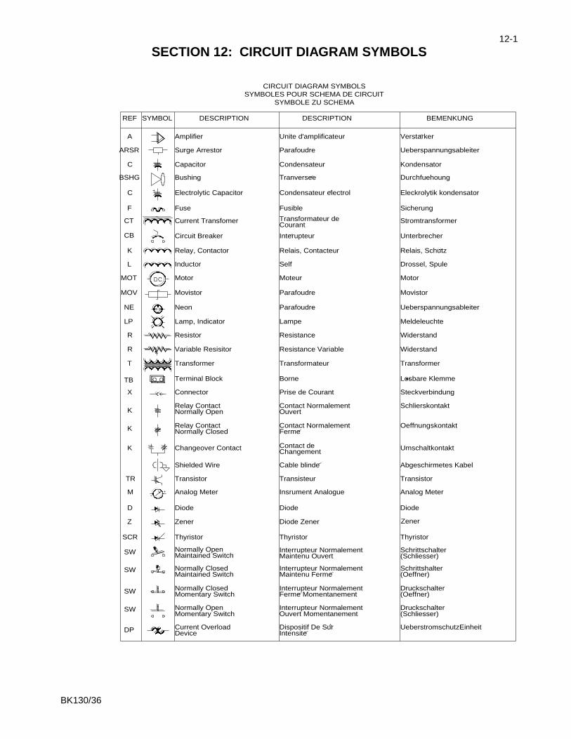
SECTION 12: CIRCUIT DIAGRAM SYMBOLS
Dispositif De Sur
Interrupteur Normalement
Interrupteur Normalement
Maintenu Ouvert
Interrupteur NormalementMaintenu Ferme
Ouvert Momentanement
Ferme MomentanementInterrupteur Normalement
DESCRIPTION
Condensateur
Unite d'amplificateur
Relais, Contacteur
Transformateur
Condensateur electrol
Transformateur de
Resistance Variable
Prise de Courant
Contact Normalement
Contact Normalement
Changement
Insrument Analogue
Diode Zener
Cable blinde
T Transformer
DeviceCurrent Overload
Momentary SwitchNormally Open
Momentary SwitchNormally Closed
Normally ClosedMaintained Switch
Maintained Switch
Normally Closed
Normally Open
Normally Open
Thyristor
Zener
Diode
Analog Meter
Shielded Wire
Transistor
Changeover Contact
Relay Contact
Relay Contact
Connector
Terminal Block
DP
SW
SW
SW
SW
SCR
Z
D
TR
M
K
K
K
TB
X
Intensite
Diode
Transisteur
Thyristor
Borne
Ouvert
Ferme
Contact de
SYMBOLE ZU SCHEMA
SYMBOLES POUR SCHEMA DE CIRCUIT
CIRCUIT DIAGRAM SYMBOLS
Variable Resisitor
Resistor
Lamp, Indicator
Neon
Movistor
Motor
Inductor
Relay, Contactor
Circuit Breaker
Current Transfomer
Fuse
Electrolytic Capacitor
Bushing
Capacitor
Surge Arrestor
Amplifier
BSHG
LP
R
R
NE
MOV
MOT
CB
K
L
CT
F
C
SYMBOL
ARSR
C
REF
A
Tranversee
Parafoudre
Moteur
Parafoudre
Lampe
Resistance
Courant
Fusible
Interupteur
Self
DESCRIPTION
Parafoudre
Transformer
Oeffnungskontakt
Abgeschirmetes Kabel
UeberstromschutzEinheit
Schrittschalter
Druckschalter
(Schliesser)
Schrittshalter(Oeffner)
(Schliesser)
(Oeffner)Druckschalter
Analog Meter
Transistor
Thyristor
Diode
Zener
Losbare Klemme
Steckverbindung
Schlierskontakt
Umschaltkontakt
BEMENKUNG
Ueberspannungsableiter
Ueberspannungsableiter
Eleckrolytik kondensator
Stromtransformer
Durchfuehoung
Widerstand
Movistor
Meldeleuchte
Widerstand
Motor
Sicherung
Drossel, Spule
Relais, Schutz
Unterbrecher
Kondensator
Verstarker

BK130/36
13-1
SECTION 13: ELECTRICAL DIAGRAMS
Drawing Number Description
9602130- 120 V BK130/36 Electrical Schematic
9602132- 220-240 V BK130/36 Electrical Schematic

BK130/36
14-1
SECTION 14: PARTS ORDERING INFORMATION Replacement parts are available from Phenix Technologies, Inc. Changes to Phenix Technologies' products are sometimes made to accommodate improved components as they become available, and to give you the benefit of the latest technical improvements developed in our Engineering Department. It is, therefore, important when ordering parts to include the serial number of the unit as well as the part number of the replacement part. When your purchase order is received at our office, a representative of Phenix Technologies will contact you to confirm the current price of the part being ordered. If a part you order has been replaced with a new or improved part, an Applications Engineer will contact you concerning any change in part number. Send orders for replacement parts to:
Service Department Phenix Technologies, Inc.
75 Speicher Drive Accident, Maryland 21520
Ph: 1 (301) 746-8118 Fax: 1 (301) 895-5570
E-mail: [email protected]
BK130/36
15-1
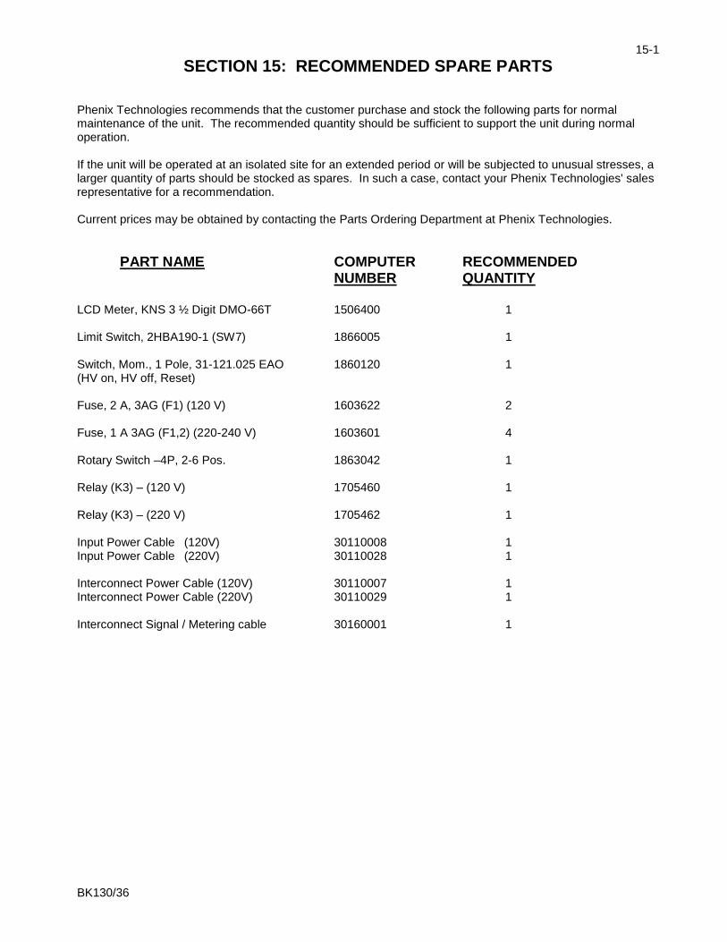
SECTION 15: RECOMMENDED SPARE PARTS Phenix Technologies recommends that the customer purchase and stock the following parts for normal maintenance of the unit. The recommended quantity should be sufficient to support the unit during normal operation. If the unit will be operated at an isolated site for an extended period or will be subjected to unusual stresses, a larger quantity of parts should be stocked as spares. In such a case, contact your Phenix Technologies' sales representative for a recommendation. Current prices may be obtained by contacting the Parts Ordering Department at Phenix Technologies.
PART NAME COMPUTER RECOMMENDED NUMBER QUANTITY LCD Meter, KNS 3 ½ Digit DMO-66T 1506400 1 Limit Switch, 2HBA190-1 (SW7) 1866005 1 Switch, Mom., 1 Pole, 31-121.025 EAO 1860120 1 (HV on, HV off, Reset) Fuse, 2 A, 3AG (F1) (120 V) 1603622 2 Fuse, 1 A 3AG (F1,2) (220-240 V) 1603601 4 Rotary Switch –4P, 2-6 Pos. 1863042 1 Relay (K3) – (120 V) 1705460 1 Relay (K3) – (220 V) 1705462 1 Input Power Cable (120V) 30110008 1 Input Power Cable (220V) 30110028 1 Interconnect Power Cable (120V) 30110007 1 Interconnect Power Cable (220V) 30110029 1 Interconnect Signal / Metering cable 30160001 1
BK130/36
16-1
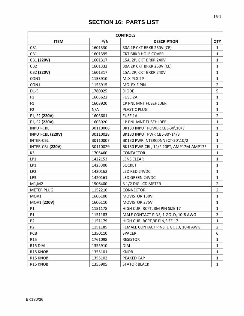
SECTION 16: PARTS LIST
CONTROLS
ITEM P/N DESCRIPTION QTY
CB1 1601330 30A 1P CKT BRKR 250V (CE) 1
CB1 1601395 CKT BRKR HOLE COVER 1
CB1 (220V) 1601317 15A, 2P, CKT BRKR 240V 1
CB2 1601332 30A 2P CKT BRKR 250V (CE) 1
CB2 (220V) 1601317 15A, 2P, CKT BRKR 240V 1
CON1 1153910 MLX PLG 2P 1
CON1 1153915 MOLEX F PIN 2
D1-5 1780025 DIODE 5
F1 1603622 FUSE 2A 1
F1 1603920 1P PNL MNT FUSEHLDER 1
F2 N/A PLASTIC PLUG 1
F1, F2 (220V) 1603601 FUSE 1A 2
F1, F2 (220V) 1603920 1P PNL MNT FUSEHLDER 1
INPUT-CBL 30110008 BK130 INPUT POWER CBL-30',10/3 1
INPUT-CBL (220V) 30110028 BK130 INPUT PWR CBL-30'-14/3 1
INTER-CBL 30110007 BK130 PWR INTERC0NNECT-20',10/2 1
INTER-CBL (220V) 30110029 BK130 PWR CBL, 14/2 20FT, AMP17M-AMP17F 1
K3 1705460 CONTACTOR 1
LP1 1422153 LENS CLEAR 1
LP1 1423300 SOCKET 1
LP2 1420162 LED RED 24VDC 1
LP3 1420161 LED GREEN 24VDC 1
M1,M2 1506400 3 1/2 DIG LCD METER 2
METER PLUG 1152210 CONNECTOR 2
MOV1 1606100 MOVISTOR 130V 1
MOV1 (220V) 1606110 MOVISTOR 275V 1
P1 1151178 HIGH CUR. RCPT. 3M PIN SIZE 17 1
P1 1151183 MALE CONTACT PINS, 1 GOLD, 10-8 AWG 3
P2 1151179 HIGH CUR. RCPT,3F PIN,SIZE 17 1
P2 1151185 FEMALE CONTACT PINS, 1 GOLD, 10-8 AWG 2
PCB 1350110 SPACER 6
R15 1761098 RESISTOR 1
R15 DIAL 1355910 DIAL 1
R15 KNOB 1355101 KNOB 1
R15 KNOB 1355102 PEAKED CAP 1
R15 KNOB 1355905 STATOR BLACK 1

BK130/36
16-2
PARTS LIST
CONTROLS
ITEM P/N DESCRIPTION QTY
R16 1720201 RESISTOR 4
R17 1720800 RESISTOR 1
SW10 1860265 LATCHING 2 POLE SWITCH 1
SW10, LP1, LP4 1420163 LED WHITE 24VDC 3
SW10,11 1422153 LENS CLEAR 2
SW11 1860260 LATCHING 1 POLE SWITCH 1
SW2/LP2 1422150 LENS RED 1
SW2-4,LP2-4 1860120 MOM. 1POLE SWITCH 3
SW3/LP3 1422151 LENS, GREEN 1
SW4/LP4 1422148 LENS, BLUE 1
SW5 1863049 ROTARY SW 3P 2-4 POS-S 1
SW5,9 1355310 KNOB 2
SW7 1866005 SW,ROLLER,20A 1
SW8 1860900 KEY SWITCH 1
SW8 1862905 CONTACT BLOCK 1
SW9 1863048 ROTARY SW 4P 2-3 POS-S 1
SX1 1151152 AMP CHS RCPT., 4F PIN, SIZE 11 1
SX1 1151162 AMP 4M PIN CBL PLUG, SIZE 11 1
SX1 1151174 CONTACT PINS, 24-20 AWG, FEMALE 2
SX1 1151176 CONTACT PINS, SOLDER, MALE 2
SX1 1151186 CBL CLAMP, SIZE 11 SMALL 1
T1 1890231 STACO 1510 VARIAC 1
T1 (220V) 1890234 1520 VARIABLE, STACO 1
T2 1896017 50 VA CTRL. TRANS., SINGL. SEC. WINDING 1
TMR1 1480120 PANEL MOUNT DIGITAL TIMER 1
TX1 1151158 AMP CHS RCPT.,16M PIN, SIZE 17 1
TX1 1151170 CONTACT PINS, 24-20 AWG, MALE 10
TX1 30160001 20' ST-ST 6PR SHL'D CABLE ASSY 1
30080018 GRN/YEL 10 AWG GND CBL-20'-RING LUGS 2
30080010 RTN CBL-LG RED TST LEAD-20' PLIER 1
31138800 PCB1388: METER PROTECTION BD 2
31138701 PCB1387: BK130 CNTRLS & METERING 1
BK130/36
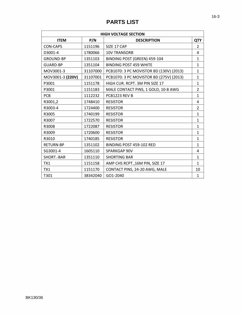
16-3
PARTS LIST
HIGH VOLTAGE SECTION
ITEM P/N DESCRIPTION QTY
CON-CAPS 1151196 SIZE 17 CAP 2
D3001-4 1780066 10V TRANSORB 4
GROUND-BP 1351103 BINDING POST (GREEN) 459-104 1
GUARD-BP 1351104 BINDING POST 459 WHITE 1
MOV3001-3 31107000 PCB1070: 3 PC MOVISTOR BD (130V) (2013) 1
MOV3001-3 (220V) 31107001 PCB1070: 3 PC MOVISTOR BD (275V) (2013) 1
P3001 1151178 HIGH CUR. RCPT. 3M PIN SIZE 17 1
P3001 1151183 MALE CONTACT PINS, 1 GOLD, 10-8 AWG 2
PCB 1112232 PCB1223 REV B 1
R3001,2 1748410 RESISTOR 4
R3003-4 1724400 RESISTOR 2
R3005 1740199 RESISTOR 1
R3007 1722570 RESISTOR 1
R3008 1722087 RESISTOR 1
R3009 1720600 RESISTOR 1
R3010 1740185 RESISTOR 1
RETURN-BP 1351102 BINDING POST 459-102 RED 1
SG3001-4 1605110 SPARKGAP 90V 4
SHORT.-BAR 1351110 SHORTING BAR 1
TX1 1151158 AMP CHS RCPT.,16M PIN, SIZE 17 1
TX1 1151170 CONTACT PINS, 24-20 AWG, MALE 10
T301 38342040 GO1-2040 1

BK130/36
17-1
SECTION 17: RETURNED MATERIAL If for any reason it should become necessary to return this equipment to the factory, the Service Department of Phenix Technologies, Inc. must be given the following information:
Name Plate Information Model Number Serial Number
Reason for Return Cause of Defect
If Phenix Technologies, Inc. deems return of the part appropriate; it will then issue an "Authorization for Return." If return is not deemed advisable, other inspection arrangements will be made. NOTE: Material received at this plant without the proper authorization shall be held as "Customer's Property" with no service until such time as the proper steps have been taken. Your cooperation is requested in order to ensure prompt service.

BK130/36
18-1
SECTION 18: CUSTOMER COMMENTS/SUGGESTIONS
Phenix Technologies made significant efforts to ensure that the materials in this Operator’s Manual are correct. If there are concerns or comments as you have used this information, Phenix Technologies appreciates any feedback. Unit Serial Number.
Sect Page(s) Comment
Please return to Phenix Technologies, Engineering Department, 75 Speicher Drive, Accident, MD 21520 USA. Phone: (301) 746-8118, Fax (301) 895-5570 or E-mail [email protected]