Embed Size (px)
Citation preview
Accurate Geolocation of Apollo 17 ALSEP Instruments
I. Haase (1), P. Gläser (1), J. Oberst (1,2), and M. S. Robinson (3) (1) Technical University of Berlin, Berlin, Germany, (2) German Aerospace Center (DLR), Germany, (3) Arizona State
University, Tempe, AZ, USA ([email protected] / Fax: +49-30-314-219 73)
Abstract
Accurate coordinates of the Apollo Lunar Surface
Experiment Package (ALSEP) instruments were
determined by an integrated analysis of Apollo 17
surface photography and Lunar Reconnaissance
Orbiter Camera (LROC) images. Angular measure-
ments made in the surface images were fitted to an
LROC Narrow Angle Camera (NAC) orthoimage
(0.25 m pixel scale) by least-squares techniques. We
obtained camera and ALSEP instrument positions
with respect to the lunar fixed Mean Earth/Polar Axis
(ME) reference system. Coordinate accuracies were
assessed to be within one LROC NAC pixel.
1. Introduction
On 12 December 1972, during their first Extra Vehi-
cular Activity (EVA), the Apollo 17 astronauts
deployed the ALSEP [1] ~190 m west of the lunar
module (LM) Challenger. Approximate positions of
the scientific instruments are known from maps based
on surface photography and astronaut records (Figure
1). To provide an improved cartographic framework
of the ALSEP site, we determined precise coordinates
of the ALSEP components using historic surface
photography in connection with high-resolution,
orbital images provided by the Lunar Reconnaissance
Orbiter (LRO) mission. This work supports analysis of
existing in-situ observations recorded by the ALSEP
instruments, e.g. seismic measurements made by the
four Geophones (Geo1-Geo4) of the Lunar Seismic
Profiling Experiment (LSPE).
Apollo Surface Imagery For photogrammetric
analyses and documentation purposes, the astronauts
recorded three panoramic image sequences at the
ALSEP station (triangles in Figure 1) using calibrated
Hasselblad cameras. Single frames of these
panoramas, capturing surface features from different
perspectives, were used to derive angular directions
from the different camera positions to the ALSEP
hardware, respectively (Figures 2 and 3).
Figure 1: Planimetric Map of the ALSEP Area (source: [1])
LROC NAC Orthoimage In August, 2011, for a
period of 28 days, LRO was maneuvered from its
nominal 50±15 km polar orbit to a low-periapsis
orbit. This allowed the on-board camera system
LROC [2] to obtain images from altitudes as low as 22
km above the lunar sphere [3]. During that month the
LROC NAC acquired a high resolution image
(M168000580) of the Apollo 17 landing site. The
pixel size in across-track direction is 0.27 m/pxl and
0.56 m/pxl in along-track (non-square pixels are due
to limitations in exposure time). By means of an
LROC NAC derived high-resolution Digital Terrain
Model (DTM) of that area [4], the image was
orthorectified and sampled to 0.25 m/pxl. The most
accurate estimate of coordinates of the ALSEP's
central station (CS) given by [5] were used to control
the orthoimage to the ME-frame. Coordinates of key
features, which were identified in the Hasselblad as
well as the orbital image, were derived from the
orthoimage and served as reference points in a
network adjustment.
EPSC AbstractsVol. 7 EPSC2012-74 2012European Planetary Science Congress 2012c© Author(s) 2012
EPSCEuropean Planetary Science Congress
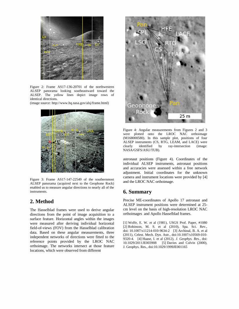
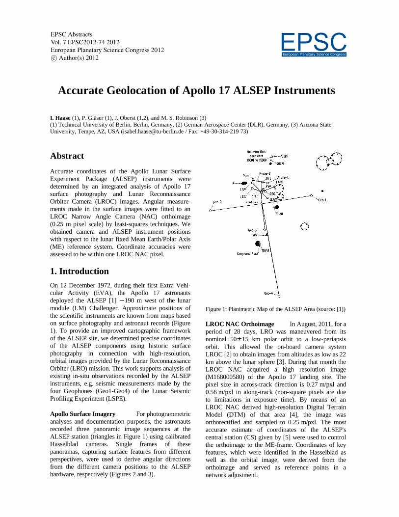
Figure 2: Frame AS17-136-20701 of the northwestern ALSEP panorama looking southeastward toward the
ALSEP. The yellow lines depict image rows of identical directions.
(image source: http://www.hq.nasa.gov/alsj/frame.html)
Figure 3: Frame AS17-147-22549 of the southernmost ALSEP panorama (acquired next to the Geophone Rock)
enabled us to measure angular directions to nearly all of the instruments.
2. Method
The Hasselblad frames were used to derive angular
directions from the point of image acquisition to a
surface feature. Horizontal angles within the images
were measured after deriving individual horizontal
field-of-views (FOV) from the Hasselblad calibration
data. Based on these angular measurements, three
independent networks of directions were fitted to the
reference points provided by the LROC NAC
orthoimage. The networks intersect at those feature
locations, which were observed from different
Figure 4: Angular measurements from Figures 2 and 3 were plotted onto the LROC NAC orthoimage
(M168000580). In this sample plot, positions of four ALSEP instruments (CS, RTG, LEAM, and LACE) were
clearly identified by ray-intersection (image: NASA/GSFS/ASU/TUB).
astronaut positions (Figure 4). Coordinates of the
individual ALSEP instruments, astronaut positions
and accuracies were assessed within a free network
adjustment. Initial coordinates for the unknown
camera and instrument locations were provided by [4]
and the LROC NAC orthoimage.
6. Summary
Precise ME-coordinates of Apollo 17 astronaut and
ALSEP instrument positions were determined at 25-
cm level on the basis of high-resolution LROC NAC
orthoimages and Apollo Hasselblad frames.
[1] Wolfe, E. W. et al (1981), USGS Prof. Paper, #1080 [2] Robinson, M. S. et al (2010), Spa. Sci. Rev.,
doi: 10.1007/s11214-010-9634-2 [3] Archinal, B. A. et al (2011), Celest. Mech. Dyn. Astr., doi:10.1007/s10569-010-
9320-4. [4] Haase, I. et al (2012), J. Geophys. Res., doi: 10.1029/2011JE003908 [5] Davies and Colvin (2000),
J. Geophys. Res., doi:10.1029/1999JE001165