Embed Size (px)
Citation preview

Single Channel Time-Reversal Acoustics: a Comparisonbetween Time Reversal and Phase Conjugation
M.Fink, A. Derode, A. Tourin, J. De Rosny
Laboratoire Ondes et Acoustique, ESPCI, 10 rue Vauquelin, 75005, Paris, France
The objective of this paper is to show that time-reversal invariance can be exploited in acoustics to accurately control wavepropagation through random propagating media as well as through chaotic reverberant cavities. To illustrate these concepts,several experiments are presented. They show that chaotic dynamics reduces the number of transducers needed to insure anaccurate time-reversal experiment to a one channel experiment. Comparisons with phase conjugated experiments will show thatthis effect is typical of broadband time-reversed acoustics and is not observed in monochromatic phase conjugation.
INTRODUCTION
Taking advantage of time reversal symmetry of thewave equation, the concept of time reversal cavity(TRC) and time reversal mirror (TRM) has beendeveloped and several devices have been built whichillustrated the efficiency of this concept [1,2]. In sucha device, an acoustic source, located inside a losslessmedium, radiates a brief transient pulse that propagatesand is distorted by the medium. If the acoustic fieldcan be measured on every point of a closed surfacesurrounding the medium (acoustic retina), andretransmitted through the medium in a time-reversedchronology, then the wave will travel back to itssource and recover its original shape. Note that itrequires both time reversal invariance and spatialreciprocity to reconstruct the exact time-reversed wavein the whole volume by means of a two-dimensionaltime-reversal operation. From an experimental point ofview a TRC consists of a two-dimensionalpiezoelectric transducer array that samples thewavefield over a closed surface. An array pitch of theorder of /2 where is the smallest wavelength of thepressure field is needed to insure the recording of allthe information on the wavefield. Each transducer isconnected to its own electronic circuitry that consistsof a receiving amplifier, an A/D converter, a storagememory and a programmable transmitter able tosynthesize a time-reversed version of the stored signal.In practice, TRCs are difficult to realize and the TRoperation is usually performed on a limited angulararea, thus limiting reversal and focusing quality. ATRM consists typically of some hundred elements, ortime-reversal channels. Here we want to show thatthrough random multiply scattering medium, a one
transducer time reversal mirror is sufficient to refocusthe wavefield at the source. The multiple scatteringprocesses allow to redirect one part of the initial wavetowards the one channel TRM, that normally miss thetransducer. After the time-reversal operation, thewhole multiply scattering medium behaves as acoherent focusing source, with a large angular aperturefor enhanced resolution. The same kind ofimprovement may be obtained for waves propagatingin highly reverberant media such as closed cavities orwaveguides. Multiple reflections along the mediumboundaries significantly increase the apparent apertureof the TRM and a set of experiments conducted inchaotic cavities will be presented. It will be shown alsothat, for a reflecting cavity with chaotic boundaries, aone channel time reversal mirror is sufficient to ensureoptimal focusing.
THE CHAOTIC CAVITY
Here, we discussed of waves confined in closedreflecting cavities such as elastic waves propagating ina silicon wafer. With such boundary conditions, noinformation can escape from the system and areverberant acoustic field is created. If, moreover, thecavity shows ergodic and mixing properties andnegligible absorption, one may hope to collect allinformation at only one point. C. Draeger [3]et al haveshown experimentally and theoretically that in thisparticular case a time-reversal can be obtained usingonly one TR channel operating in a closed cavity. Thefield is measured at one point over a long period oftime and the time-reversed signal is re-emittted at thesame position
The experiment is 2D and has been carriedout by using elastic surface waves propagating alongmonocrystalline silicon wafer whose shape is a D-shape stadium. This geometry is chosen to avoidquasi-periodic orbits. Silicon was selected for its weakabsorption. The elastic waves which propagate in sucha plate are Lamb waves. The source is isotropic andconsidered point-like because the cone tip is muchsmaller than the central wavelength. A heterodynelaser interferometer measures the displacement field asa function of time at different points on the cavity.
The experiment is a two step-process asdescribed above: In the first step, one of thetransducers, located at point A, transmits a shortomnidirectional signal of duration 0.5 µs into thewafer. Another transducer, located at B, observes avery long chaotic signal, that results from multiplereflections of the incident pulse along the edges of thecavity, and which continue for more than 50milliseconds corresponding to some hundredreflections along the boundaries. Then, a portion of 2milliseconds of the signal is selected, time-reversedand re-emitted by point B. As the time reversed waveis a flexural wave that induces vertical displacementsof the silicon surface, it can be observed using theoptical interferometer that scan the surface aroundpoint A.
One observes both an impressive timerecompression at point A and a refocusing of the time-reversed wave around the origin, with a focal spotwhose radial dimension is equal to half the wavelengthof the flexural wave. Using reflections at theboundaries, the time-reversed wave field convergestowards the origin from all directions and gives acircular spot, like the one that could be obtained with aclosed time reversal cavity covered with transducers.The 2 millisecond time-reversed waveform is the timesequence needed to focus exactly on point A.
The success of this time-reversal experimentis particularly interesting with respect to two aspects.Firstly, it proves again the feasibility of time-reversalin wave systems with chaotic ray dynamics.Paradoxically, in the case of one-channel time-reversal, chaotic dynamics is not only harmless butalso even useful, as it guarantees ergodicity andmixing. Secondly, using a source of vanishingaperture, we obtain an almost perfect focusing quality.The procedure approaches the performance of a closedTRC, which has an aperture of 360°. Hence, a one-point time-reversal in a chaotic cavity produces betterresults than a TRM in an open system. Usingreflections at the edge, focusing quality is not aperturelimited, and in addition, the time-reversed collapsingwavefront approaches the focal spot from alldirections.
This interesting result emphasizes the great interest oftime-reversal experiments, compared to phaseconjugated experiments. In phase conjugation, oneonly work with monochromatic waves and not withbroadband pulses. For example, if one work only atfrequency n one cannot refocus a wave on point A.An omnidirectional transducer, located at any positionB, working in monochromatic mode, send a divergingwave in the cavity that have no any reason to refocuson point A. The refocusing process works only withbroadband pulses, with a large number of eigenmodesin the transducer bandwidth. Here, the averagingprocess that gives a good estimate of the spatialcorrelation function of the elastic field is obtained bysumming over “pseudo-realizations” whichcorresponds to the different modes in the same cavity.This come from the fact that in a chaotic cavity, wemay assume a statistical decorrelation of the differenteigenmodes. As the number of eigenmodes availablein the transducer bandwidth increases, the refocusingquality becomes better and the focal spot patternbecomes closed to the ideal Bessel function. Hence,the signal to noise level should increase as the square-root of the number of modes in the transducerbandwidth.
A similar result has also been observed in thetime-reversal experiment conducted in open multiplyscattering medium. A clear refocusing has beenobtained with only a single array element. Thefocusing process works with broadband pulses( thetransducer center frequency is 3.5 MHz with a 50 %bandwidth at - 6dB ). For each individual frequencythere is no focusing and the estimate of the spatialcorrelation is very noisy. However, for a largebandwidth, if we have statistical decorrelation of thewavefields for different frequencies, the time-reversedfield is self-averaging.
REFERENCES
1. Fink, M., Prada, C., Wu, F,. and Cassereau, D, IEEEUltrasonics Symposium Proceedings, Montreal , Vol 1, pp681-686, (1989)2. Fink, M., IEEE Trans. Ultrason. Ferroelec. Freq. Contr,39 (5) 555-566 (1992)3. C. Draeger, M. Fink, Phys. Rev. Lett, 79, 407 (1997)
4. E. Abraham, “Title of Chapter,” in Elastodynamics,edited by J. J. Thomson, Publisher City: PublisherName, 1998, pp. 400-410.
Time Reversal Mirrors in Noisy Environments
D. R. Dowling, K. G. Sabra, and S. R. Khosla
Department of Mechanical Engineering, University of Michigan, Ann Arbor, Michigan 48105, USA
The robust spatial and temporal focusing properties of time-reversal mirrors (TRMs) are limited or lost when the environment is not reciprocal, acoustic absorption losses are prevalent, the receiving aperture is too small, or noise contaminates the received signal. This talk presents theoretical performance results for TRMs deployed in noisy environments. The theory formally accounts for the characteristics of the source, the signal, the TRM, and the environment in terms of two signal to noise ratios: one for the field received by the TRM and one for the field produced by the TRM in the vicinity of the source location. The theoretical results are simplified to an algebraic relationship when the noise field is isotropic, spatially-uncorrelated, and spectrally-uniform in the signal's bandwidth; and a power constraint limits the amplitude of the TRM's broadcast. In this case, the TRM-produced signal-to-noise ratio at the source is directly related to the TRM-received signal-to-noise ratio, the number of TRM elements, the time-bandwidth product of the TRM-received signal, and the energy broadcast by the source and TRM elements. Predictions of the theory are illustrated through narrow- and broad-band propagation calculations for free-space and underwater sound-channel environments.
INTRODUCTION
Active acoustic time reversal is the process of recording the signal from a remote source, and then replaying the signal in a time-reversed fashion to retro-direct the replayed sound back to the remote source to form a retrofocus. This process, and various other active and passive extensions of it, have an innate elegance and allure [1,2] that provide exciting possibilities for technical advancements in the areas of biomedical ultrasound, active and passive sonar, nondestructive evaluation, and even manufacturing quality control monitoring. Active acoustic time reversal may be implemented with an array of reciprocal transducers commonly referred to as a time-reversal mirror (TRM). The performance of a TRM – as determined by the size, longevity, and field amplitude of its retrofocus – is limited by: i) a lack of reciprocity and absorption during propagation between the source and the array, ii ) insufficient array aperture, and iii ) noise in the acoustic environment. This paper addresses the final limitation and presents theoretical and computational results from for time reversal of narrowband [3] and broadband signals in noisy environments. Noise influences TRM performance twice because the array both listens and transmits. While the TRA is listening, noise can corrupt the signal received from the remote source. The extent of this corruption is
characterized by the received signal-to-noise ratio SNRr. When the array produces its time-reversed transmission, it unintentionally broadcasts the noise it heard during its listening interval along with the signal. Hence, at the intended retrofocus location, there are two noise components: the array-broadcast noise and the ambient noise. The ability of a TRM to reject both noise components is characterized by SNRf, the focal-zone signal-to-noise ratio of the TRM-broadcast sound field in the vicinity of the original source at the expected time of the retrofocus. The results presented here can be used to predict SNRf in terms of SNRr, the characteristics of the signal, the characteristics of the TRM, and the characteristics of the acoustic medium.
FORMAL DEVELOPMENT
Research on acoustic time-reversal techniques goes back several decades [4]. More recent mathematical formulations [5,6] of time reversal involve complex conjugation of the Fourier transform of the received signal. Here, the TRM is formulated in the time domain as an array of N monopole transducers (i = 1, N) located at
&
r i that both receive and transmit. Thus, the time-dependent acoustic pressure, P, at a field point
&
r f that includes noise and the TRA's
transmission is:
P(&
r f , t) = g(&
r f ,t;&
r i , ′ t ) A w(&
r i,Tc − ′ t ) + n(&
r i,Tc − ′ t )[ ]−∞
+∞∫i=1
N
∑ d ′ t + n(&
r f , t) (1)
where g(&
r f , t f ;&
r o ,t o) is the time-dependent Green's
function linking spatial-temporal coordinates (&
r o, to )
with (&
r f , t f ) , w(&
r i , t) is the signal recorded by the
TRM elements, A is the electrical amplification between the array's reception and its time-reversed broadcast (here A has units of length), n(
&
r ,t ) is the zero-mean noise field, and Tc is the requisite time delay for causality. In practice, the value of A may be determined in situ by the TRM operator but it will always be limited by the broadcast capabilities of the TRA's transducers. In order to evaluate the noise rejection performance of a TRM, the two signal-to-noise ratios mentioned above must be defined. Here we set:
SNRr = w2(
&
r i ,t)dt−∞+∞∫
i=1
N
∑ n2 (&
r i , t) dt−∞+∞∫
i=1
N
∑ (2)
and use a correlation with a delayed and time reversed version of the original signal s(t) to define:
SNRf (&
r f ) =s(Tc − t)Psignal(−∞
+∞∫ &
r f , t)dt[ ]2
s(Tc − t)ntotal(−∞+∞∫ &
r f , t)dt[ ]2 (3)
where the angle brackets define an ensemble average.
RESULTS WITH A SIMPLE NOISE
FIELD
Evaluation of the formal results requires specification of the noise field and the array amplification factor. Here, a simple noise field is considered – a stationary homogeneous flat-spectrum band-limited zero-mean random field that is uncorrelated between array elements and between the source and array locations. Although idealized, this noise field allows the general formulae to be reduced to mere algebraic expressions. Moreover, it should provide gage performance results for actual TRM systems. Here, an average broadcast power constraint for the TRM elements is used to determine A in terms of the received-signal and noise amplitudes. The final performance result appears as an approximate algebraic relationship between SNRr and SNRf:
SNRf (&
r s) = 2NBTrSNRr 1+ΠsTs
NΠeTr
1+ SNRr
SNRr
(4)
where
&
r s is the remote source location, B is the bandwidth containing 99% of the signal energy, Tr is
the time necessary to receive 99% of the signal energy, Ts is the time necessary to broadcast 99% of the signal energy, Πs is the broadcast power of the original source, and Πe is the broadcast power of a single TRM element. The relationship (4) is approximate because several factors of 0.99 have been rounded up to unity. The final result (4) includes all of the fundamental parameters that influence TRM retrofocusing in a noisy environment. It can be used for parameter studies that determine performance curves of SNRf vs. SNRr without recourse to propagation calculations provided reliable estimates for Tr are available. This final result allows TRM performance to be grouped into loud and quiet array parameter ranges depending on the ratio: ΠsTs/NΠeTr. These parameter ranges will be illustrated during the presentation. However, the most important parametric dependence is the occurrence of Tr, not Ts, in the time-bandwidth product in the numerator of (4). Thus, multipath propagation, which tends to increase signal pulse duration, is actually exploited by a TRM for noise reduction. This parametric dependence may be very important for TRM-based underwater communication and other active sonar applications since Tr/Ts may be of order 102 or greater.
ACKNOWLEDGEMENTS
This research is sponsored by the Ocean Acoustics Program of the United States Office of Naval Research.
REFERENCES
1. M. Fink "Time-Reversed Acoustics," Physics Today 50, No. 3, 34-40 (1997).
2. M. Fink "Time-Reversed Acoustics," Scientific American 281, No. 5, 91-97 (1999).
3. S. R. Khosla and D. R. Dowling "Time-reversing array retrofocusing in noisy environments," J. Acoust. Soc. Am. 109, 538-546 (2001).
4. A. Parvulescu "Matched-signal (MESS) processing by the ocean," J. Acoust. Soc. Am. 98, 943-960 (1995).
5. M. Fink, C. Prada, F. Wu, and D. Cassereau "Self focusing in inhomogeneous media with time reversal mirrors," Proc. IEEE Ultrason. Symp., 681-686 (1989).
6. D. R. Jackson and D. R. Dowling "Phase-conjugation in underwater acoustics," J. Acoust. Soc. Am. 89, 171-181 (1991).
Detection and Imaging in Complex Media
with the D.O.R.T. Method.C. PRADA.
Laboratoire Ondes et Acoustique, ESPCI, Université Paris 7, U.M.R. 7587, 10 rue Vauquelin, 75005 Paris, France
In most fields of acoustics, arrays of transmitters and arrays of receivers become available. With such arrays, a great amount ofdata can be collected and the general problem is to extract the relevant information to detect (or to form an image of) ascattering object. The D.O.R.T. method is a new approach to active detection and focusing of acoustic waves using arrays oftransmitters and receivers. This method was derived from the theoretical analysis of iterative time reversal mirrors. It consistsessentially in the construction of the invariants the time reversal process. After explaining the principle of the D.O.R.T. methodapplications of this technique will be discussed.
THE D.O.R.T. METHODLarge arrays of transducers are becoming
common tool for ultrasonic detection and imaging.With such arrays, a great amount of scattering data canbe collected and the general problem is to extract therelevant information from these data to detect or toform an image. The decomposition of the time reversaloperator (D.O.R.T.) method[1,2] is a detection techniquethat applies to pulse echo data acquired with arrays oftransducers. It is a tool to sort the data through anappropriate analysis of the inter-element impulseresponses of all elements of the arrays. The D.O.R.T.method was derived from the theoretical analysis oftime reversal mirrors and relies on the matrixformalism used to describe a transmit-receive process.
Decomposition of the transfer matrixA transmit receive process performed in a timeinvariant medium, from array n°1 of M transmitters toan array n°2 of L receivers, is described in a generalmanner by a transfer matrix. Indeed, such arraysinsonifying a given medium can be considered as alinear and time invariant LxM input-output system. Itis characterized by the inter-element impulse responsesklm(t). The LxM transfer matrix K()=[Klm()] iscalculated by Fourier transform of the responses klm(t).This complex matrix can be written as the product ofthree matrices as follows
K() = U() S() tV*(), (1)where S() is a real diagonal matrix of singularvalues, U() and V() are unitary matrices and the *means complex conjugate. One singular value isrelated to the ratio of received energy to transmittedenergy in the following way: If column n°i of V()(singular vector n°i) is used as a transmit vector thenthe receive vector is K()Vi() = Si()Ui() and theratio between transmitted energy and received energy
is Si()2. In particular, the singular vector V1(ω) is thetransmit vector that produces the most energeticreceived vector.The physical meaning of this singular valuedecomposition can be illuminated through the analysisof the time reversal process.
Invariants of the time reversal operatorThe iterative time reversal process has been widelydescribed[1,2,7,8]for a single array of transducers usedfor both transmit and receive mode. In fact even if thereceive array is different from the transmit array, thetime reversal process can be considered as a ‘thoughtexperiment’[3]. Because of reciprocity, the transfermatrix from array n°2 to array n°1 is the matrix tK().Thus, the time reversal operator can be defined in ageneral manner as tK*()K(). This formulation is aneasy generalization of the time reversal operatorK*()K() introduced in most papers for a singletransmit-receive array. The eigenvalues of tK*()K()are the squares of the singular values of K() and itseigenvectors are the columns of V(). In consequence,the singular vectors are the invariants of the iterativetime reversal process.For “Rayleigh” type scatterers, the general result thatwas shown is that the number of non-zero singularvalues is equal to the number of resolved scatterers[3].Furthermore if the scatterers have distinct ‘apparent’reflectivities and are ideally resolved, there is a one toone correspondence between the scatterers and thesingular vectors. Each vector corresponds to theresponse of one scatterer to the array.In fact, the assumption of spherical diffusion is onlytrue for a pointlike contrast of compressibility. Arecent study[4] showed that in general four eigenvaluesof the time reversal operator are associated to eachscatterer. However for hard material, three eigenvaluesare much smaller than the dominant one and the
multiple eigenstates have not been observed in theexperiments that are mentionned in the following.Finally, the D.O.R.T. method consists in themeasurement of the inter element impulse responsesklm(t) and the singular value decomposition of thetransfer matrix. The detection is obtained by theanalysis of the singular values of the transfer matrix.Then the eigenvectors can be used for two differentpurposes: (1) selective focusing which requiresprogrammable generators can be achieved byexperimental backpropagation of the eigenvectors(2) localization and imaging which requires a model ofthe propagating medium can be obtained by numericalbackpropagation of the eigenvectorsDifferent applications of the D.O.R.T. method are nowsummarized.
APPLICATIONS
Selective focusing.The iterative time reversal process was applied toselect the brightest point of an extended scatterer. Insome situations, the object under investigation is suchthat the convergence of the iterative time reversalprocess is very slow. At each iteration, due to theconvolution by the response of the transducers, thesignals get longer and longer. This may lead toundesirable interferences with other earlier or laterechoes. As the eigenvector of highest eigenvalue is thelimit of an iterative time reversal process, this leadingeigenvector can be used to focus directly on thebrightest point of the scatterer. Furthermore in thepresence of several scatterers, the transmission of eachsingular vector of the transfer matrix allows to focusselectively on each of the scatterer without anyassumption on the propagating medium[1,2].
Flaw detection in solids.When the pulse echo detection is performed in an
unknown inhomogeneous media, classical focusingtechniques can no more be applied. In non destructiveevaluation of solids, water is often used as a couplingfluid. The sound speed fluctuations between the probeand the flaw are then very large and classical focusingtechniques require accurate knowledge of the probeand sample geometry. For the D.O.R.T. method only arough knowledge off the geometry is required toadapted time windowing to the zone of interest.Excellent detection was obtained in inspection ofsamples with high speckle noise level like titaniumalloy. The detection at 5 MHz of a 0.4mm defect at140mm depth in Ti6-4 alloy was achieved with goodsignal to noise ratio.[5] 15dB signal to noise ratio
images were obtained by numerical backpropagationof the first eigenvector.
Detection and separation of Lamb modes.The D.O.R.T. method was also applied to thecharacterization of Lamb waves circumnavigating inan air filled cylindrical shell[6]. For a steel shell of20mm diameter and 0.6mm thickness at centralfrequency 3 MHz, the three pseudo Lamb waves A0,A1 and S0 were separated, each of these Lamb wavewas shown to be an invariant of the time reversalprocess. The dispersion curves of these waves werededuced from the localization of their radiation points.The eigenvalues of the time reversal operator providedthe resonance frequencies of the shell associated to A1and S0 modes. This type of analysis is now applied toflaw detection in tubes.
High resolution in wave guide.In a wave-guide, the pulse echo response of a scattereris generally complex because of multiple path troughthe guide. However, like in time reversalexperiments[7,8], the D.O.R.T. method takes advantageof the multiple path to increase the virtual aperture ofan array. The detection of two scatterers in a waterwave guide, the separation of their impulse responsefunctions and the selective focusing on each of themwere obtained with a resolution ten times thinner thanthe theoretical free space resolution. The maineigenvector was also used to optimize a simple modelof the guide allowing good quality of imaging bynumerical backpropagation of the eigenvectors[9]. Themethod is now studied towards applications tounderwater acoustics.
References1. C. Prada and M. Fink, Wave Motion 20, 151-163
(1994).2. C. Prada, S. Manneville, D. Spoliansky, and M. Fink,
J.Acoust.Soc.Am. 99, 2067-2076 (1996).3. C. Prada, M. Tanter and M. Fink in Proc. IEEE
Ultrasonic Symp., (1997)4. D. H. Chambers, A.K. Gautesen J.Acoust.Soc.Am. 109,
2616-2624 (2001)5. E. Kerbrat, C. Prada, D. Cassereau, R.K. Ing and M.
Fink in Proc IEEE Ultrasonic Symp., 779-783 (2000).6. C. Prada and M. Fink, J.Acoust Soc.Am. 104, 801-807
(1998).7. P. Roux, B. Roman, M. Fink, Appl. Phys. Lett.,70 (14),
1811-1813, (1997).8. W.S. Hodgkiss et al. J.Acoust.Soc.Am., 105 (3), 1597-
1604, (1999).9. N. Mordant, C. Prada, and M. Fink, J.Acoust.Soc.Am
105 (5) (1999).
Nonlinear Parametrically Conjugate Ultrasound Beams
A. Brysev
Wave Research Center of the General Physics Institute RAS38 Vavilov Str., 119991 Moscow, GSP-1, Russia. e-mail: [email protected]; [email protected]
Main results concerning experiments with nonlinear parametrically conjugate ultrasound beams are reviewed. The results havebeen obtained in Wave Research Center of the General Physics Institute, Moscow, Russia and also in cooperation with theUniversity of Texas at Austin, USA and with the Institute of Electronics and Microelectronics Nord, Lille, France. Design andoperation of the overthreshold parametric amplifier with conjugating element made of magnetostrictive ceramics are explained.The amplifier’s possibilities to generate high intense conjugate ultrasound beams are demonstrated. Special attention is paid tothe nonlinear effects in such beams propagating in homogeneous and inhomogeneous media. Automatic focusing and self-targeting of conjugate ultrasonic beams are presented. The current problems and prospects of parametric wave conjugation innonlinear acoustic and applications are discussed.
INTRODUCTION
The last decade was marked by intensivedevelopment of time reversing [1] and phaseconjugation methods [2,3] for acoustic waves. Themain advantages of both approaches are thecompensation of phase aberrations as well as self-targeting of acoustic energy onto scattering objectssurrounded by phase inhomogeneous medium. Thesefeatures give unique possibilities for scientificinvestigations, NDE, technology and medicaldiagnostics and therapy. At the same time significantprogress in nonlinear acoustic imaging and ultrasoundhyperthermia and lithotrity stimulates an interest to thehigh-intensity and, as a consequence, nonlinearconjugate acoustic waves. On this way two mainproblems should be studied. The first, how to generatehigh-intensity conjugate ultrasound beams and thesecond, how the acoustic nonlinearity will influence onthe quality of phase conjugation in homogeneous andespecially in inhomogeneous media?
OVERTHRESHOULD PARAMETRICAMPLIFIER AS A TOOL FOR
GENERATION OF CONJUGATE HIGHINTENSE ULTRASOUND BEAMS
One of the most effective solutions of the firstproblem is connected with the parametric method ofultrasound phase conjugation (PC) proposed by Prof.F. Bunkin et al. [4]. Especially successfully this fruitfulidea was realized in the overthreshould phonon-magnon interaction taking place in specialmagnetostrictive ceramics pumping by externalalternating magnetic field [2]. In these conditions notonly phase conjugation in real time exist, but also a
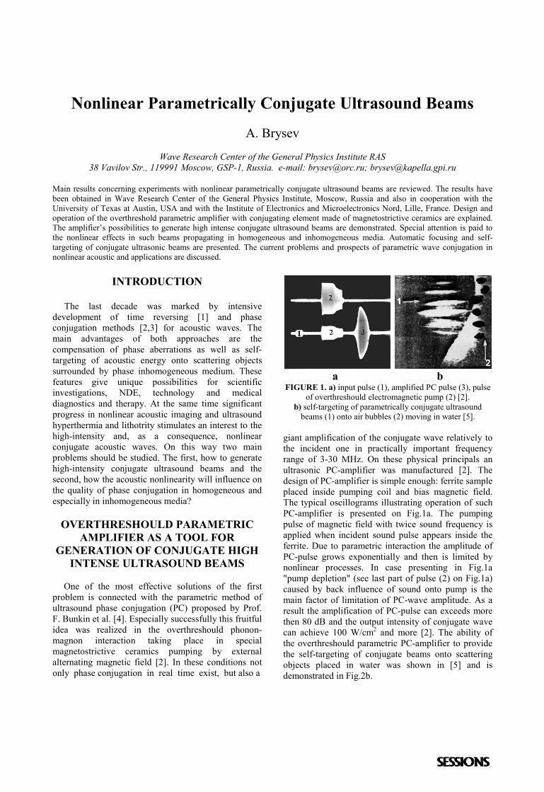
a b
FIGURE 1. a) input pulse (1), amplified PC pulse (3), pulseof overthreshould electromagnetic pump (2) [2].
b) self-targeting of parametrically conjugate ultrasoundbeams (1) onto air bubbles (2) moving in water [5].
giant amplification of the conjugate wave relatively tothe incident one in practically important frequencyrange of 3-30 MHz. On these physical principals anultrasonic PC-amplifier was manufactured [2]. Thedesign of PC-amplifier is simple enough: ferrite sampleplaced inside pumping coil and bias magnetic field.The typical oscillograms illustrating operation of suchPC-amplifier is presented on Fig.1a. The pumpingpulse of magnetic field with twice sound frequency isapplied when incident sound pulse appears inside theferrite. Due to parametric interaction the amplitude ofPC-pulse grows exponentially and then is limited bynonlinear processes. In case presenting in Fig.1a"pump depletion" (see last part of pulse (2) on Fig.1a)caused by back influence of sound onto pump is themain factor of limitation of PC-wave amplitude. As aresult the amplification of PC-pulse can exceeds morethen 80 dB and the output intensity of conjugate wavecan achieve 100 W/cm2 and more [2]. The ability ofthe overthreshould parametric PC-amplifier to providethe self-targeting of conjugate beams onto scatteringobjects placed in water was shown in [5] and isdemonstrated in Fig.2b.
NONLINEAR PARAMETRICALLYCONJUGATE ULTRASOUND BEAMS
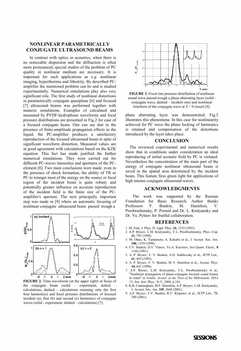
In contrast with optics in acoustics, when there isno noticeable dispersion and the diffraction is oftenmore pronounced, special studies of the problem of PCquality in nonlinear medium are necessary. It isimportant for such applications as e.g. nonlinearimaging, hyperthermia and lithotrity. By described PC-amplifier the mentioned problem can be and is studiedexperimentally. Numerical simulations play also verysignificant role. The first study of nonlinear distortionsin parametrically conjugate quasiplane [6] and focused[7] ultrasound beams was performed together withnumeric simulations. Examples of calculated andmeasured by PVDF-hydrophone waveforms and focalpressure distributions are presented in Fig.2 for case ofa focused conjugate beam. One can see that in thepresence of finite-amplitude propagation effects in theliquid, the PC-amplifier produces a satisfactoryreproduction of the focused ultrasound beam in spite ofsignificant waveform distortion. Measured values arein good agreement with calculations based on the KZKequation. This fact has made justified the furthernumerical simulations. They were carried out fordifferent PC-waves intensities and apertures of the PC-element [8]. Two main conclusions were made: even inthe presence of shock formation, the ability of TR orPC to retarget most of the energy on the source or focalregion of the incident beam is quite robust; andpotentially greater influence on accurate reproductionof the incident field is the finite size of the PC-amplifier's aperture. The next principally importantstep was made in [9] where an automatic focusing ofnonlinear conjugate ultrasound beam passed trough a
FIGURE 2. Time waveforms (at the upper right) at focus ofthe conjugate beam (solid – experiment, dotted –calculations, dashed – calculations retaining only the firstfour harmonics) and focal pressure distributions of focusedincident (a), first (b) and second (c) harmonics of conjugatewaves (solid - experiment, dashed – calculations) [7].
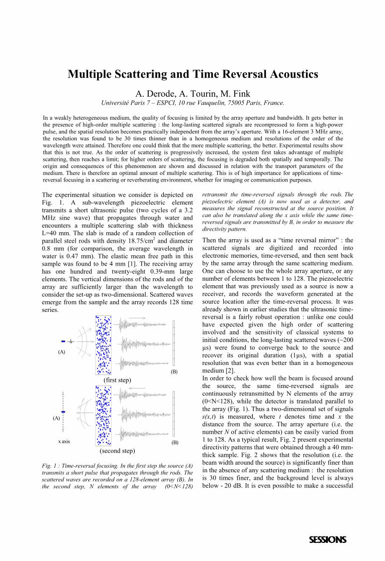
FIGURE 3. Focal rms pressure distribution of nonlinearsound wave passed trough a phase aberrating layer (solid -
conjugate wave, dashed – incident one) and nonlineartimeform of the conjugate wave at X = 0 (inset) [9].
phase aberrating layer was demonstrated. Fig.3illustrates this phenomena. In this case for nonlinearityachieved for PC wave the phase locking of harmonicsis retained and compensation of the distortionsintroduced by the layer takes place.
CONCLUSION The reviewed experimental and numerical resultsshow that in conditions under consideration an idealreproducing of initial acoustic field by PC is violated.Nevertheless the concentration of the main part of theenergy of conjugate nonlinear ultrasound beam issaved in the spatial area determined by the incidentbeam. This feature fires green light for applications ofhigh intense conjugate ultrasound waves.
ACKNOWLEDGMENTSThe work was supported by the Russian
Foundation for Basic Research. Author thanksProfessors F. Bunkin, M. Hamilton, V.Preobrazhensky, P. Pernod and Dr. L. Krutyansky andDr. Yu. Pylnov for fruitful collaboration.
REFERENCES1. M. Fink, J. Phys. D: Appl. Phys. 26, 1333 (1993).2. A.P. Brysev, L.M. Krutyansky, V.L. Preobrazhensky, Phys.–Usp.
41, 793 (1998)3. M. Ohno, K. Yamamoto, A. Kokubo et al., J. Acoust. Soc. Am.
106, 1339 (1999).4. F.V. Bunkin, D.V. Vlasov, Yu.A. Kravtsov, Sov.Quant. Electr., 8
1144 (1981).5. A. P. Brysev, F. V. Bunkin, A.D. Stakhovsky et al., JETP Lett.,
61, 465 (1995).6. A. P. Brysev, F. V. Bunkin, M. F. Hamilton et al., Acoust. Phys.
44, 641 (1998).7. A.P. Brysev, L.M. Krutyansky, V.L. Preobrazhensky et al.,
"Nonlinear propagation of phase-conjugate focused sound beamsin water" in Nonlin. Acoust. at the Turn of the Millennium: ISNA15, Am. Inst. Phys., N-Y, 2000, p.183.
8. K.B. Cunningham, M.F. Hamilton, A.P. Brysev, L.M. Krutyansky,J. Acoust. Soc. Am. 109, 2668 (2001).
9. A.P. Brysev, F.V. Bunkin, R.V. Klopotov et al., JETP Lett., 73,389 (2001).
Multiple Scattering and Time Reversal AcousticsA. Derode, A. Tourin, M. Fink
Université Paris 7 – ESPCI, 10 rue Vauquelin, 75005 Paris, France.
In a weakly heterogeneous medium, the quality of focusing is limited by the array aperture and bandwidth. It gets better inthe presence of high-order multiple scattering : the long-lasting scattered signals are recompressed to form a high-powerpulse, and the spatial resolution becomes practically independent from the array’s aperture. With a 16-element 3 MHz array,the resolution was found to be 30 times thinner than in a homogeneous medium and resolutions of the order of thewavelength were attained. Therefore one could think that the more multiple scattering, the better. Experimental results showthat this is not true. As the order of scattering is progressively increased, the system first takes advantage of multiplescattering, then reaches a limit; for higher orders of scattering, the focusing is degraded both spatially and temporally. Theorigin and consequences of this phenomenon are shown and discussed in relation with the transport parameters of themedium. There is therefore an optimal amount of multiple scattering. This is of high importance for applications of time-reversal focusing in a scattering or reverberating environment, whether for imaging or communication purposes.
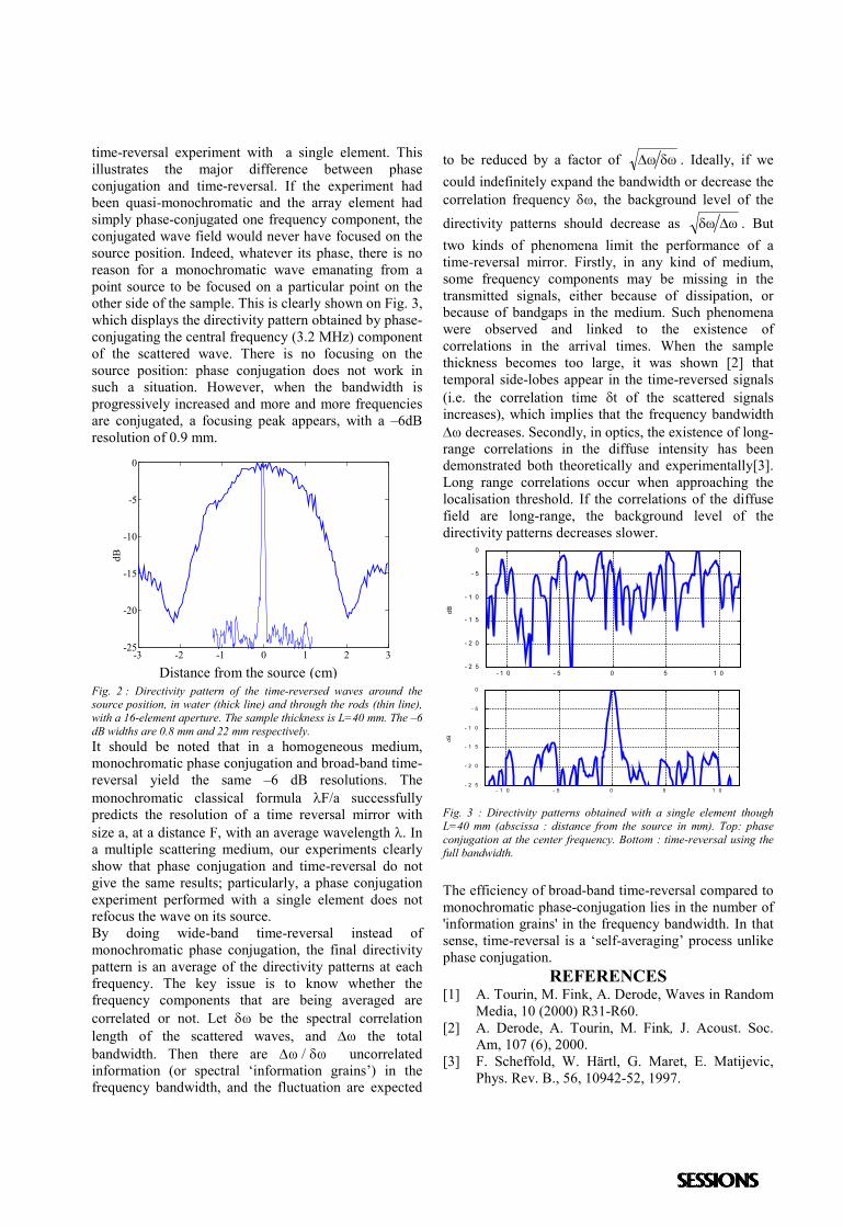
The experimental situation we consider is depicted onFig. 1. A sub-wavelength piezoelectric elementtransmits a short ultrasonic pulse (two cycles of a 3.2MHz sine wave) that propagates through water andencounters a multiple scattering slab with thicknessL=40 mm. The slab is made of a random collection ofparallel steel rods with density 18.75/cm2 and diameter0.8 mm (for comparison, the average wavelength inwater is 0.47 mm). The elastic mean free path in thissample was found to be 4 mm [1]. The receiving arrayhas one hundred and twenty-eight 0.39-mm largeelements. The vertical dimensions of the rods and of thearray are sufficiently larger than the wavelength toconsider the set-up as two-dimensional. Scattered wavesemerge from the sample and the array records 128 timeseries.
(B)
(A)
(first step)
(B)x axis
(A)
(second step)
Fig. 1 : Time-reversal focusing. In the first step the source (A)transmits a short pulse that propagates through the rods. Thescattered waves are recorded on a 128-element array (B). Inthe second step, N elements of the array (0<N<128)
retransmit the time-reversed signals through the rods. Thepiezoelectric element (A) is now used as a detector, andmeasures the signal reconstructed at the source position. Itcan also be translated along the x axis while the same time-reversed signals are transmitted by B, in order to measure thedirectivity pattern.
Then the array is used as a “time reversal mirror” : thescattered signals are digitized and recorded intoelectronic memories, time-reversed, and then sent backby the same array through the same scattering medium.One can choose to use the whole array aperture, or anynumber of elements between 1 to 128. The piezoelectricelement that was previously used as a source is now areceiver, and records the waveform generated at thesource location after the time-reversal process. It wasalready shown in earlier studies that the ultrasonic time-reversal is a fairly robust operation : unlike one couldhave expected given the high order of scatteringinvolved and the sensitivity of classical systems toinitial conditions, the long-lasting scattered waves (~200µs) were found to converge back to the source andrecover its original duration (1µs), with a spatialresolution that was even better than in a homogeneousmedium [2].In order to check how well the beam is focused aroundthe source, the same time-reversed signals arecontinuously retransmitted by N elements of the array(0<N<128), while the detector is translated parallel tothe array (Fig. 1). Thus a two-dimensional set of signalss(x,t) is measured, where t denotes time and x thedistance from the source. The array aperture (i.e. thenumber N of active elements) can be easily varied from1 to 128. As a typical result, Fig. 2 present experimentaldirectivity patterns that were obtained through a 40 mm-thick sample. Fig. 2 shows that the resolution (i.e. thebeam width around the source) is significantly finer thanin the absence of any scattering medium : the resolutionis 30 times finer, and the background level is alwaysbelow - 20 dB. It is even possible to make a successful
time-reversal experiment with a single element. Thisillustrates the major difference between phaseconjugation and time-reversal. If the experiment hadbeen quasi-monochromatic and the array element hadsimply phase-conjugated one frequency component, theconjugated wave field would never have focused on thesource position. Indeed, whatever its phase, there is noreason for a monochromatic wave emanating from apoint source to be focused on a particular point on theother side of the sample. This is clearly shown on Fig. 3,which displays the directivity pattern obtained by phase-conjugating the central frequency (3.2 MHz) componentof the scattered wave. There is no focusing on thesource position: phase conjugation does not work insuch a situation. However, when the bandwidth isprogressively increased and more and more frequenciesare conjugated, a focusing peak appears, with a –6dBresolution of 0.9 mm.
-3 -2 -1 0 1 2 3-25
-20
-15
-10
-5
0
Distance from the source (mm)
dB
Fig. 2 : Directivity pattern of the time-reversed waves around thesource position, in water (thick line) and through the rods (thin line),with a 16-element aperture. The sample thickness is L=40 mm. The –6dB widths are 0.8 mm and 22 mm respectively.It should be noted that in a homogeneous medium,monochromatic phase conjugation and broad-band time-reversal yield the same –6 dB resolutions. Themonochromatic classical formula F/a successfullypredicts the resolution of a time reversal mirror withsize a, at a distance F, with an average wavelength . Ina multiple scattering medium, our experiments clearlyshow that phase conjugation and time-reversal do notgive the same results; particularly, a phase conjugationexperiment performed with a single element does notrefocus the wave on its source.By doing wide-band time-reversal instead ofmonochromatic phase conjugation, the final directivitypattern is an average of the directivity patterns at eachfrequency. The key issue is to know whether thefrequency components that are being averaged arecorrelated or not. Let be the spectral correlationlength of the scattered waves, and the totalbandwidth. Then there are uncorrelatedinformation (or spectral ‘information grains’) in thefrequency bandwidth, and the fluctuation are expected
to be reduced by a factor of . Ideally, if wecould indefinitely expand the bandwidth or decrease thecorrelation frequency , the background level of thedirectivity patterns should decrease as . Buttwo kinds of phenomena limit the performance of atime-reversal mirror. Firstly, in any kind of medium,some frequency components may be missing in thetransmitted signals, either because of dissipation, orbecause of bandgaps in the medium. Such phenomenawere observed and linked to the existence ofcorrelations in the arrival times. When the samplethickness becomes too large, it was shown [2] thattemporal side-lobes appear in the time-reversed signals(i.e. the correlation time t of the scattered signalsincreases), which implies that the frequency bandwidth decreases. Secondly, in optics, the existence of long-range correlations in the diffuse intensity has beendemonstrated both theoretically and experimentally[3].Long range correlations occur when approaching thelocalisation threshold. If the correlations of the diffusefield are long-range, the background level of thedirectivity patterns decreases slower.
- 1 0 - 5 0 5 1 0- 2 5
- 2 0
- 1 5
- 1 0
- 5
0
dB
- 1 0 - 5 0 5 1 0- 2 5
- 2 0
- 1 5
- 1 0
- 5
0
dB
Fig. 3 : Directivity patterns obtained with a single element thoughL=40 mm (abscissa : distance from the source in mm). Top: phaseconjugation at the center frequency. Bottom : time-reversal using thefull bandwidth.
The efficiency of broad-band time-reversal compared tomonochromatic phase-conjugation lies in the number of'information grains' in the frequency bandwidth. In thatsense, time-reversal is a ‘self-averaging’ process unlikephase conjugation.
REFERENCES[1] A. Tourin, M. Fink, A. Derode, Waves in Random
Media, 10 (2000) R31-R60.[2] A. Derode, A. Tourin, M. Fink, J. Acoust. Soc.
Am, 107 (6), 2000.[3] F. Scheffold, W. Härtl, G. Maret, E. Matijevic,
Phys. Rev. B., 56, 10942-52, 1997.
Distance from the source (cm)
Retro-focusing of phase conjugate acoustic beams in nonlinear inhomogeneous media
V.Preobrazhensky(1,2), P.Pernod(1)
1) IEMN DOAE EC-Lille Electronique Acoustique, CNRS/UMR 8520 Cite Scientifique BP69,
59652 V.d’Ascq, France 2) Wave Research Center GPI, Russian Academy of Sciences,
38 Vavilova str., 117942 Moscow, Russia.
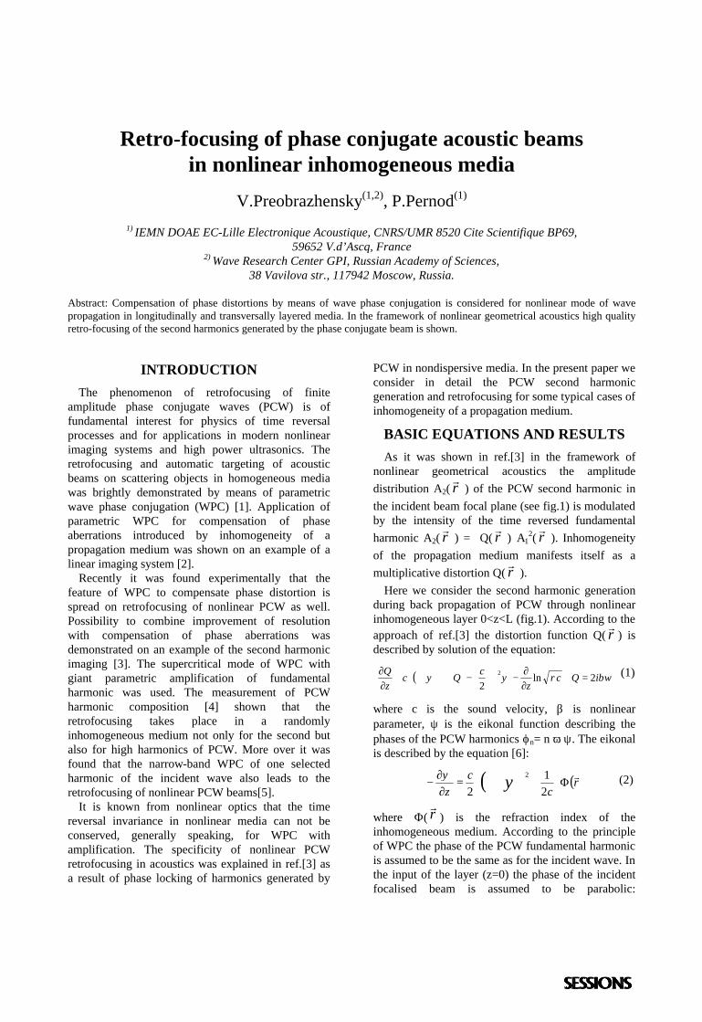
Abstract: Compensation of phase distortions by means of wave phase conjugation is considered for nonlinear mode of wave propagation in longitudinally and transversally layered media. In the framework of nonlinear geometrical acoustics high quality retro-focusing of the second harmonics generated by the phase conjugate beam is shown.
INTRODUCTION The phenomenon of retrofocusing of finite
amplitude phase conjugate waves (PCW) is of fundamental interest for physics of time reversal processes and for applications in modern nonlinear imaging systems and high power ultrasonics. The retrofocusing and automatic targeting of acoustic beams on scattering objects in homogeneous media was brightly demonstrated by means of parametric wave phase conjugation (WPC) [1]. Application of parametric WPC for compensation of phase aberrations introduced by inhomogeneity of a propagation medium was shown on an example of a linear imaging system [2].
Recently it was found experimentally that the feature of WPC to compensate phase distortion is spread on retrofocusing of nonlinear PCW as well. Possibility to combine improvement of resolution with compensation of phase aberrations was demonstrated on an example of the second harmonic imaging [3]. The supercritical mode of WPC with giant parametric amplification of fundamental harmonic was used. The measurement of PCW harmonic composition [4] shown that the retrofocusing takes place in a randomly inhomogeneous medium not only for the second but also for high harmonics of PCW. More over it was found that the narrow-band WPC of one selected harmonic of the incident wave also leads to the retrofocusing of nonlinear PCW beams[5].
It is known from nonlinear optics that the time reversal invariance in nonlinear media can not be conserved, generally speaking, for WPC with amplification. The specificity of nonlinear PCW retrofocusing in acoustics was explained in ref.[3] as a result of phase locking of harmonics generated by
PCW in nondispersive media. In the present paper we consider in detail the PCW second harmonic generation and retrofocusing for some typical cases of inhomogeneity of a propagation medium.
BASIC EQUATIONS AND RESULTS As it was shown in ref.[3] in the framework of
nonlinear geometrical acoustics the amplitude distribution A2( ⊥r
r) of the PCW second harmonic in
the incident beam focal plane (see fig.1) is modulated by the intensity of the time reversed fundamental harmonic A2( ⊥r
r) = Q( ⊥r
r) A1
2( ⊥rr
). Inhomogeneity of the propagation medium manifests itself as a multiplicative distortion Q( ⊥r
r).
Here we consider the second harmonic generation during back propagation of PCW through nonlinear inhomogeneous layer 0<z<L (fig.1). According to the approach of ref.[3] the distortion function Q( rr ) is described by solution of the equation:
( ) βωρψψ iQcz
cQczQ 2ln
22 =⋅
∂∂
−−∇⋅∇⋅+∂∂
∇⊥⊥⊥ (1)
where c is the sound velocity, β is nonlinear parameter, ψ is the eikonal function describing the phases of the PCW harmonics ϕn= n ω ψ. The eikonal is described by the equation [6]:
( ) ( )rc
cz
rΦ⋅+⊥⋅=
∂∂
− ∇ 21
22ψψ (2)
where Φ( rr ) is the refraction index of the inhomogeneous medium. According to the principle of WPC the phase of the PCW fundamental harmonic is assumed to be the same as for the incident wave. In the input of the layer (z=0) the phase of the incident focalised beam is assumed to be parabolic:
ψ = f0 r⊥2/2c. For longitudinally layered structure
Φ=Φ(z) the solution of the system (1),(2) with boundary condition Q( ⊥r
r,z=L) =0 is independent on
⊥rr
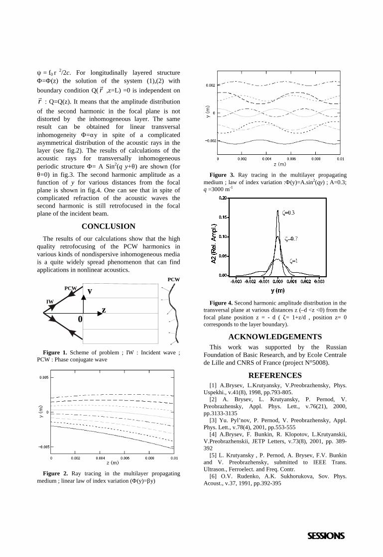
: Q=Q(z). It means that the amplitude distribution of the second harmonic in the focal plane is not distorted by the inhomogeneous layer. The same result can be obtained for linear transversal inhomogeneity Φ=αy in spite of a complicated asymmetrical distribution of the acoustic rays in the layer (see fig.2). The results of calculations of the acoustic rays for transversally inhomogeneous periodic structure Φ= A Sin2(q y+θ) are shown (for θ=0) in fig.3. The second harmonic amplitude as a function of y for various distances from the focal plane is shown in fig.4. One can see that in spite of complicated refraction of the acoustic waves the second harmonic is still retrofocused in the focal plane of the incident beam.
CONCLUSION The results of our calculations show that the high
quality retrofocusing of the PCW harmonics in various kinds of nondispersive inhomogeneous media is a quite widely spread phenomenon that can find applications in nonlinear acoustics.
y P C W
P C W
I W z
0
Figure 1. Scheme of problem ; IW : Incident wave ;
PCW : Phase conjugate wave
Figure 2. Ray tracing in the multilayer propagating
medium ; linear law of index variation (Φ(y)=βy)
Figure 3. Ray tracing in the multilayer propagating
medium ; law of index variation :Φ(y)=A.sin2(qy) ; A=0.3; q =3000 m-1
Figure 4. Second harmonic amplitude distribution in the
transversal plane at various distances z (–d <z <0) from the focal plane position z = - d ( ζ= 1+z/d , position z= 0 corresponds to the layer boundary).
ACKNOWLEDGEMENTS This work was supported by the Russian
Foundation of Basic Research, and by Ecole Centrale de Lille and CNRS of France (project N°5008).
REFERENCES [1] A.Brysev, L.Krutyansky, V.Preobrazhensky, Phys.
Uspekhi., v.41(8), 1998, pp.793-805. [2] A. Brysev, L. Krutyansky, P. Pernod, V.
Preobrazhensky, Appl. Phys. Lett., v.76(21), 2000, pp.3133-3135
[3] Yu. Pyl’nov, P. Pernod, V. Preobrazhensky, Appl. Phys. Lett., v.78(4), 2001, pp.553-555
[4] A.Brysev, F. Bunkin, R. Klopotov, L.Krutyanskii, V.Preobrazhenskii, JETP Letters, v.73(8), 2001, pp. 389-392
[5] L. Krutyansky , P. Pernod, A. Brysev, F.V. Bunkin and V. Preobrazhensky, submitted to IEEE Trans. Ultrason., Ferroelect. and Freq. Contr.
[6] O.V. Rudenko, A.K. Sukhorukova, Sov. Phys. Acoust., v.37, 1991, pp.392-395
Below Diffraction Limits with an Acoustic Sink : the IdealTime Reversal Experiment
J. De Rosny and M. Fink
Laboratoire Ondes et Acoustique, ESPCI, 10 rue Vauquelin, 75005, Paris, France
Time-reversal has successfully demonstrated the ability to focus acoustic waves. However the minimal focal spot dimensionis always larger than half the wavelength, which is in agreement with diffraction limit. We will show that this behaviour isrelated to the presence of a diverging wave that is always created after the convergent wave collapse at the focus.In a time reversal experiment, by replacing the initial source by its time reversed image, we may eliminated this divergingwave. Such a process allows to create an acoustic sink which absorbs the converging wave. We present the first experimentaldemonstration of an acoustic sink and we observe focal spot smaller than 1/14 the wavelength.
INTRODUCTION
In the past years, taking advantage of the time-reversalinvariance of the acoustic propagation, time reversalmirrors has been developed that create time reversedwaves for ultrasonic transient fields propagatingthrough complex media [1]. A wave radiated by asource is recorded by an array of emitting/receivingelements, time-reversed and then re-transmitted backinto the medium. The re-transmitted signal back-propagates and refocuses exactly on the source.However in agreement with diffraction limits, even ifthe source is point-like, the time-reversed waverefocuses on a spot size that cannot be smaller thanhalf wavelength. This apparent failure of the time-reversed operation is usually interpreted as the loss ofevanescent waves during the propagation over somewavelengths. By using a time-reversal interpretation ofthis phenomenon, we show that the diffraction limitcan be overcome if an acoustic sink, which absorbs allincoming energy during the time-reversed step,replaces the source. This sink is nothing else than thetime reversed image of the source. Here we report thefirst experimental result obtained with an acoustic sinkand we observe focal spot size of less than 1/14wavelength.
THE ACOUSTIC SINK
To test the time reversal invariance of the acousticwave equation in a non dissipative medium requiresintroducing a "mirror" of the time variable. In an"image world", such a mirror exists by taking a motionpicture of the wave propagation and then running thefilm backward. In the "real world", reverse timevariable means to generate experimentally a back-
propagated field from a forward propagation. Thanksto Huygens principle, the mirror of the time variablecan be replaced by a time reversal operation conductedonly on a closed surface that surrounds the initialsource location. This active surface is covered withreversible transducers (that act both as microphonesand loudspeakers).. In a first step, a punctual sourceemits a pulsed field that is measured by thetransducers. In a second step, the recorded field istime-reversed and then retransmitted back into themedium. In practice, a closed time reversal mirror(TRM) is difficult to realize and, to limit the number oftransducers, the time reversal operation is usuallyperformed on a limited angular area. Nevertheless, thenumber of transducers needed could be dramaticallydecrease if a large part of the time reversal mirror isreplaced by reflecting boundaries that redirect theincident wave towards the TRM aperture. Therefore,after several reflections on the boundaries, the entirefield generated by the source reaches the time reversalmirror. In some extreme configuration, such as closedreflecting cavities with ergodic and mixing properties,all the information coming from a point like source canbe collected at only one point. Therefore the timereversal operation can be conducted using only onepoint like transducer located inside a closed cavity.The first time-reversal experiments in such aconfiguration were carried out in 1997 by C. Draegeret al [2] with chaotic silicon plates cavities andrefocusing of the time reversed wave on focal spot ofhalf wavelength size were observed. Here we want toextend this experiment beyond the diffraction limits.The size of the time-reversed focal spot is usuallyinterpreted in terms of diffraction limits: In the firststep the point like source radiates a field whoseangular spectrum contains both propagating waves and
evanescent waves. The evanescent wave componentsare lost after propagation over some wavelengths. Inthe second step, the time-reversed field retransmittedby the TRM does not any more contain evanescentwaves and thus the wave focuses on a spot whosedimension is of the order of half wavelength. In termof a time reversal interpretation, the apparent failure ofthe time-reversed operation can also be understood inthe following way: The second step described above isnot strictly the time-reversal of the first step. Indeed,when the converging time-reversed wave collapses atthe origin, a diverging wave of opposite sign follows.This wave has not time-reversed image in the forwardpropagation. Indeed, a “complete” time reversal wouldconsist of only a converging wave. This interpretationis closely related to the diffraction’s one. Indeed, evenif both converging and diverging spherical wavesshow a strong singularity at the origin, the interferenceof these two waves implies that the field remains finitefor all time at the focus. The spatial distributioninduced by this superposition is nothing else than theclassical diffraction spot.This interpretation in terms of converging anddiverging waves leads an intuitive way to obtain a“complete” time reversal: the initial source that wasinjecting some energy during the first step must bereplaced by a sink that will absorb all arriving energyduring the second step. How to realise such an acousticsink? The diverging wave will be cancelled if one isable to create from the focus, where is the initialsource, a diverging wave which interfere destructivelywhich the diverging wave coming from the TRM.Such an operation, allows the evanescent waves to bereintroduced at the source location. Thus we are nolonger limited by diffraction and we would observe thetime reversed singularity of the forward step.
To realise experimentally such an acoustic sink, weuse a slightly different experimental set-up that the oneused by C. Draeger et al, in order to be able to recordevanescent waves. The cavity is a transparent glassplate whose shape is a D-shape stadium. Elastic waves,which propagate in such a plate, are Lamb waves. Thegeometry is chosen to avoid quasi-periodic orbits andto obtain quasi-isotropic focusing. A brass conecoupled to a longitudinal transducer generates the fieldat one point of the cavity. The dimension of the contactzone is less than 100 m. In the original experiment, asecond identical transducer is used as TRM. Here, thesame transducer is used both to generate the forwardfield and the time-reversed field. The central frequencyof the transducer is 500 kHz and the Lamb waves havea mean wavelength of 4mm. A heterodyne laserinterferometer records the field time dependence. Theoptical beam that scans the field has a lateraldimension of 6 m. As we want to observe elastic
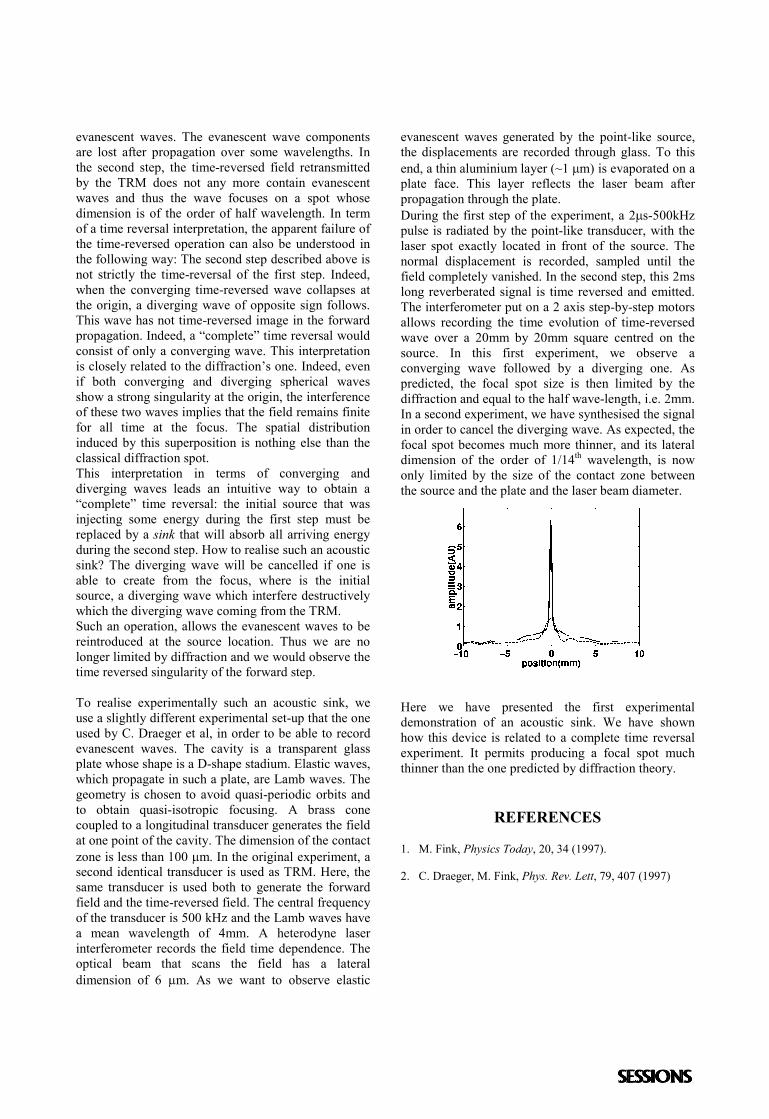
evanescent waves generated by the point-like source,the displacements are recorded through glass. To thisend, a thin aluminium layer (~1 m) is evaporated on aplate face. This layer reflects the laser beam afterpropagation through the plate.During the first step of the experiment, a 2s-500kHzpulse is radiated by the point-like transducer, with thelaser spot exactly located in front of the source. Thenormal displacement is recorded, sampled until thefield completely vanished. In the second step, this 2mslong reverberated signal is time reversed and emitted.The interferometer put on a 2 axis step-by-step motorsallows recording the time evolution of time-reversedwave over a 20mm by 20mm square centred on thesource. In this first experiment, we observe aconverging wave followed by a diverging one. Aspredicted, the focal spot size is then limited by thediffraction and equal to the half wave-length, i.e. 2mm.In a second experiment, we have synthesised the signalin order to cancel the diverging wave. As expected, thefocal spot becomes much more thinner, and its lateraldimension of the order of 1/14th wavelength, is nowonly limited by the size of the contact zone betweenthe source and the plate and the laser beam diameter.
Here we have presented the first experimentaldemonstration of an acoustic sink. We have shownhow this device is related to a complete time reversalexperiment. It permits producing a focal spot muchthinner than the one predicted by diffraction theory.
REFERENCES
1. M. Fink, Physics Today, 20, 34 (1997).
2. C. Draeger, M. Fink, Phys. Rev. Lett, 79, 407 (1997)
Comparison between time reversal and spatio temporalinverse filter in absorbing and non-absorbing media:
application to focusing through a human skull
M. Tanter , J.-F. Aubry, J.-L. Thomas, and M. Fink
Laboratoire Ondes et Acoustique, ESPCI, 10 rue Vauquelin, 75005 Paris, France.
Ultrasonic imaging systems capabilities are strongly dependent on the focusing quality of the ultrasonic beam. In thecase of brain imaging, the skull strongly degrades the ultrasonic focusing pattern by introducing strong phase andamplitude aberrations of the wavefront. In previous works, this degradation of the beam focus had been partiallycorrected by coupling the time reversal focusing process to an amplitude compensation of the emission signals. In thatcase, the optimal focus was reproduced down to -20 dB, but the sidelobes level remained at about -25 dB. Thistechnique is here compared to another focusing technique recently developed in our laboratory, called spatio-temporalinverse filter. Thanks to this method, based on the inversion of the propagation operator at each frequency within thebandwidth of our transducers, experimental focusing through the skull is now comparable to the optimal focusing inhomogeneous medium. Those two methods not only differ theoretically, but also suffer differently from all theexperimental limits, such as the limited bandwidth of the transducers or the limited aperture of the arrays. Comparingthe results obtained with both techniques in water and through a human skull clearly highlights advantages anddrawbacks of each method.
INTRODUCTION
Focusing is classically obtained by the assumption ofconstant sound speed in the medium and hence theapplication of a cylindrical time delay law on theelements of a transducer array in order to compensatefor the time-of-flight differences between elements.This classical focusing is unfortunately stronglydegraded for a heterogeneous medium. Aberrationscorrections techniques are currently developed forabdominal parts and consists to introducecompensating time delays on each single element ofthe emitting array. These techniques are based on theassumption that the aberrating medium can bemodeled as a very thin layer located close to the array(“phase screen assumption”).When focusing through the skull, the heterogeneitiesof the bone in terms of sound speed, density andabsorption are two much important and we haveshown in previous work that the aberrations induced insuch an extreme case on the ultrasonic beam can nomore be modeled by a simple “phase screen”. Wedeveloped two different techniques overcoming thelimitations of the “phase screen” assumption : time
reversal combined with amplitude compensation [1]and more recently the spatio temporal inverse filtertechnique [2,3]. In the monochromatic case, the use ofinverse filtering was also proposed by R. Seip and E.Ebbini for medical applications [4].
1
m
j
N
1
N
hmj(t)
100mm
64m
m
Array of transducers Set of controlpoints
water
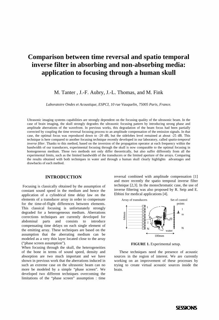
FIGURE 1. Experimental setup.
These techniques need the presence of acousticsources in the region of interest. We are currentlyworking on an improvement of these processes bytrying to create virtual acoustic sources inside thebrain.
SPATIO TEMPORAL INVERSE FILTER
The whole process is fully described in [2,3].Basically, a half human skull is placed between anarray of transducers and a set of N control points(hydrophones) placed in the focal plane (Figure 1). Foreach couple (control point m, transducer j), we definethe impulse response hmj(t), which corresponds to thesignal received on the mth control point after atemporal Dirac function is applied on the jth transducerof the array. This response includes all the propagationeffects through the considered medium as well as theacousto-electric responses of the two elements and areacquired experimentally. Let ej(t), 1≤j≤J, being theinput signal on the jth transducer. As thetransformations are supposed linear and invariantunder a time shift, the output signal fm(t), 1≤m≤M,received on the mth control point is given
by: ∑=
⊗=J
jjmjm tethtf
1
)()()( , 1≤m≤M. A temporal
Fourier transform leads in the matrix formalism to:F(ω)=H(ω)E(ω). A pseudo-inversion is realizedleading to a noise-filtered approximation H-1(ω) of theinverse matrix H-1(ω). This is performed at eachfrequency within the bandwidth of the transducer andthe final signal to emit on the array of transducers isobtained after going back to the time domain byinverse Fourier transform.
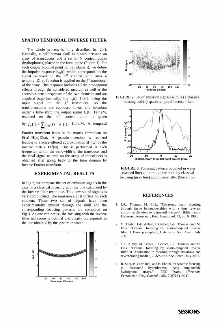
EXPERIMENTAL RESULTS
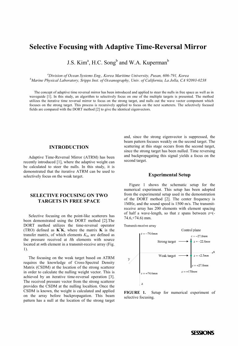
In Fig.2, we compare the set of emission signals in thecase of a classical focusing with the one calculated bythe inverse filter technique. This new set of signals isvery complicated. The emission signal differs on eachelement. These two set of signals have beenexperimentally emitted through the skull and thecorresponding focusing patterns are compared onFig.3. As one can notice, the focusing with the inversefilter technique is optimal and clearly corresponds tothe one obtained by the system in water.
-25
-20
-15
-10
-5
0
Tranducer Element
Tim
e (µ
s)
20 40 60 80 100 120
0
5
10
15
20
-25
-20
-15
-10
-5
0
Tranducer Element
Tim
e (µ
s)
20 40 60 80 100 120
0
5
10
15
20
FIGURE 2. Set of emission signals with (a) a classicalfocusing and (b) spatio temporal inverse filter.
-20 -10 0 10 20-35
-30
-25
-20
-15
-10
-5
0
Distance from the initial point source (mm)
Pre
ssu
re (
µs)
FIGURE 3. Focusing patterns obtained in water(dashed line) and through the skull by classical
focusing (gray line) and inverse filter (black line).
REFERENCES
1. J.-L. Thomas, M. Fink, “Ultrasonic beam focusingthrough tissue inhomogeneities with a time reversalmirror: application to transskull therapy”, IEEE Trans.Ultrason., Ferroelect., Freq. Contr., vol. 43, no. 6, 1996.
2. M. Tanter, J.-F. Aubry, J. Gerber, J.-L. Thomas, and M.Fink. “Optimal focusing by spatio-temporal inversefilter. I. Basic principles”, J. Acoustic. Soc. Amer., July2001.
3. J.-F. Aubry, M. Tanter, J. Gerber, J.-L. Thomas, and M.Fink. “Optimal focusing by spatio-temporal inversefilter. II. Application to focusing through absorbing andreverberating media”, J. Acoustic. Soc. Amer., July 2001.
4. R. Seip, P. VanBaren, and E. Ebbini, ‘‘Dynamic focusingin ultrasound hyperthermia using implantablehydrophone arrays,’’ IEEE Trans. Ultra-son.Ferroelectr. Freq. Control 41(5), 706713 (1994).
Selective Focusing with Adaptive Time-Reversal Mirror
J.S. Kima, H.C. Songb and W.A. Kupermanb
aDivision of Ocean Systems Eng., Korea Maritime University, Pusan, 606-791, KoreabMarine Physical Laboratory, Sripps Inst. of Oceanography, Univ. of California, La Jolla, CA 92093-0238
The concept of adaptive time reversal mirror has been introduced and applied to steer the nulls in free space as well as inwaveguide [1]. In this study, an algorithm to selectively focus on one of the multiple targets is presented. The methodutilizes the iterative time reversal mirror to focus on the strong target, and nulls out the wave vector component whichfocuses on the strong target. This process is recursively applied to focus on the next scatterers. The selectively focusedfields are compared with the DORT method [2] to give the identical eigenvectors.
INTRODUCTION
Adaptive Time-Reversal Mirror (ATRM) has beenrecently introduced [1], where the adaptive weight canbe calculated to steer the nulls. In this study, it isdemonstrated that the iterative ATRM can be used toselectively focus on the weak target.
SELECTIVE FOCUSING ON TWOTARGETS IN FREE SPACE
Selective focusing on the point-like scatterers hasbeen demonstrated using the DORT method [2].TheDORT method utilizes the time-reversal operator(TRO) defined as K*K, where the matrix K is thetransfer matrix, of which elements Klm are defined asthe pressure received at lth elements with sourcelocated at mth element in a transmit-receive array (Fig.1).
The focusing on the weak target based on ATRMrequires the knowledge of Cross-Spectral DensityMatrix (CSDM) at the location of the strong scattererin order to calculate the nulling weight vector. This isachieved by an iterative time-reversal operation [3].The received pressure vector from the strong scattererprovides the CSDM at the nulling localtion. Once theCSDM is known, the weight is calculated and appliedon the array before backpropagation. This beampattern has a null at the location of the strong target
and, since the strong eigenvector is suppressed, thebeam pattern focuses weakly on the second target. Thescattering at this stage occurs from the second target,since the strong target has been nulled. Time reversingand backpropagating this signal yields a focus on thesecond target.
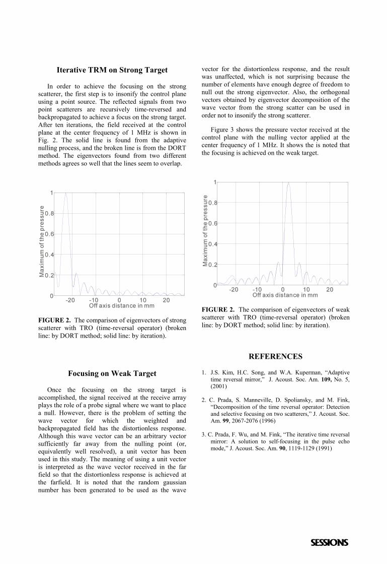
Experimental Setup
Figure 1 shows the schematic setup for thenumerical experiment. This setup has been adoptedfrom the experimental setup used in the demonstrationof the DORT method [2]. The center frequency is1MHz, and the sound speed is 1500 m/s. The transmit-receive array has 200 elements with element spacingof half a wave-length, so that z spans between z=(-74.6,+74.6) mm.
FIGURE 1. Setup for numerical experiment ofselective focusing.
Iterative TRM on Strong Target
In order to achieve the focusing on the strongscatterer, the first step is to insonify the control planeusing a point source. The reflected signals from twopoint scatterers are recursively time-reversed andbackpropagated to achieve a focus on the strong target.After ten iterations, the field received at the controlplane at the center frequency of 1 MHz is shown inFig. 2. The solid line is found from the adaptivenulling process, and the broken line is from the DORTmethod. The eigenvectors found from two differentmethods agrees so well that the lines seem to overlap.
FIGURE 2. The comparison of eigenvectors of strongscatterer with TRO (time-reversal operator) (brokenline: by DORT method; solid line: by iteration).
Focusing on Weak Target
Once the focusing on the strong target isaccomplished, the signal received at the receive arrayplays the role of a probe signal where we want to placea null. However, there is the problem of setting thewave vector for which the weighted andbackpropagated field has the distortionless response.Although this wave vector can be an arbitrary vectorsufficiently far away from the nulling point (or,equivalently well resolved), a unit vector has beenused in this study. The meaning of using a unit vectoris interpreted as the wave vector received in the farfield so that the distortionless response is achieved atthe farfield. It is noted that the random gaussiannumber has been generated to be used as the wave
vector for the distortionless response, and the resultwas unaffected, which is not surprising because thenumber of elements have enough degree of freedom tonull out the strong eigenvector. Also, the orthogonalvectors obtained by eigenvector decomposition of thewave vector from the strong scatter can be used inorder not to insonify the strong scatterer.
Figure 3 shows the pressure vector received at thecontrol plane with the nulling vector applied at thecenter frequency of 1 MHz. It shows the is noted thatthe focusing is achieved on the weak target.
FIGURE 2. The comparison of eigenvectors of weakscatterer with TRO (time-reversal operator) (brokenline: by DORT method; solid line: by iteration).
REFERENCES
1. J.S. Kim, H.C. Song, and W.A. Kuperman, “Adaptivetime reversal mirror,” J. Acoust. Soc. Am. 109, No. 5,(2001)
2. C. Prada, S. Manneville, D. Spoliansky, and M. Fink,“Decomposition of the time reversal operator: Detectionand selective focusing on two scatterers,” J. Acoust. Soc.Am. 99, 2067-2076 (1996)
3. C. Prada, F. Wu, and M. Fink, “The iterative time reversalmirror: A solution to self-focusing in the pulse echomode,” J. Acoust. Soc. Am. 90, 1119-1129 (1991)
Simultaneous Characterization of Velocity and TemperatureProfiles Using Time-Reversal
J. Carlsona,c, G. Bouchetb, and A. Maurela
aEISLAB, Luleå University of Technology, SE-971 87 Luleå, SwedenbInstitut de Mécanique des Fluides, UMR CNRS 7507, 2 rue Boussingault, 67000 Strasbourg, FrancecLaboratoire Ondes et Acoustique, UMR CNRS 7587, ESPCI - 10 rue Vauquelin, 75005 Paris, France
We present an acoustical method, based on time reversal, for simultaneous determination of temperature and velocity profiles. Thisis an extension of results previously presented in [1]. The method is numerically validated in a case of free convection; the acousticpropagation is obtained from calculations of ray propagation. The ray theory approximation, used to solve the inverse problem, isdiscussed.
PRINCIPLEIn the limit where the frequency of the sound wave
is very large compared to the typical frequencies of theproblem, an Hamiltonian system can be derived from thewave equation for sound ray propagation [2].
In a fluid at rest with uniform temperature T0, the rela-tion ω0 = c0k describes a straight ray propagation. Witha fluid flowing with velocity u(r) in a non-uniform tem-perature field with a thermal fluctuation of magnitude T ,the pulsation is expressed as ω(r,k) = c(T )k+u(r) ·k,where c(T ) = c0(1+αT), is the sound speed as a func-tion of temperature, and α is the thermal expansion coef-ficient. The wave equations then become:
drdt = c0(1+αT )k
k +udkdt =−c0αk∇ T − (k · ∇ )u−k∧ (∇ ∧u)
(1)
In section Numerical Experiment we integrate thissystem to determine the ray trajectories. For small val-ues of u/c0 and αT , we can simplify (1). In this case, twomain effects of the flow on the sound ray can be isolated,with v = ∂tr = vn:
1) the fluid motion and temperature inhomogeneity re-sult in a local modification of the sound speed:
v = c0(1+αT )+u ·k
k, (2)
2) the flow vorticity and the thermal gradients locallymodify the direction of the wave propagation:
dndt
=−c0α∇ T +(∇ ∧u)∧n (3)
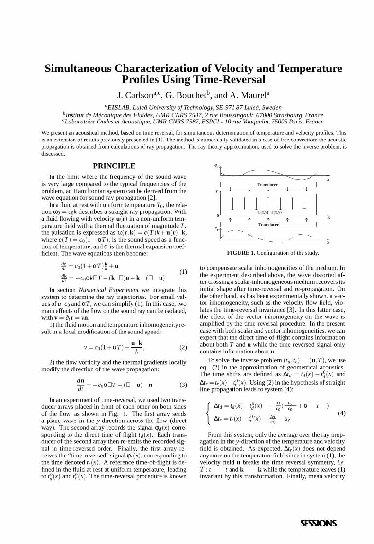
In an experiment of time-reversal, we used two trans-ducer arrays placed in front of each other on both sidesof the flow, as shown in Fig. 1. The first array sendsa plane wave in the y-direction across the flow (directway). The second array records the signal φd(x) corre-sponding to the direct time of flight td(x). Each trans-ducer of the second array then re-emits the recorded sig-nal in time-reversed order. Finally, the first array re-ceives the “time-reversed” signal φr(x), corresponding tothe time denoted tr(x). A reference time-of-flight is de-fined in the fluid at rest at uniform temperature, leadingto t0
d (x) and t0r (x). The time-reversal procedure is known
Transducer
Transducer
φd
φr
x
x
y
xU(x,y); T(x,y)
0
FIGURE 1. Configuration of the study.
to compensate scalar inhomogeneities of the medium. Inthe experiment described above, the wave distorted af-ter crossing a scalar-inhomogeneous medium recovers itsinitial shape after time-reversal and re-propagation. Onthe other hand, as has been experimentally shown, a vec-tor inhomogeneity, such as the velocity flow field, vio-lates the time-reversal invariance [3]. In this latter case,the effect of the vector inhomogeneity on the wave isamplified by the time reversal procedure. In the presentcase with both scalar and vector inhomogeneities, we canexpect that the direct time-of-flight contains informationabout both T and u while the time-reversed signal onlycontains information about u.
To solve the inverse problem (td , tr)→ (u,T ), we useeq. (2) in the approximation of geometrical acoustics.The time shifts are defined as ∆td = td(x)− t0
d (x) and∆tr = tr(x)− t0
r (x). Using (2) in the hypothesis of straightline propagation leads to system (4):
∆td = td(x)− t0d(x)∼−
Hc0(<uy>
c0+α < T >)
∆tr = tr(x)− t0r (x)∼
2Hc2
0< uy >
(4)
From this system, only the average over the ray prop-agation in the y-direction of the temperature and velocityfield is obtained. As expected, ∆tr(x) does not dependanymore on the temperature field since in system (1), thevelocity field u breaks the time reversal symmetry, i.e.T : t →−t and k→−k while the temperature leaves (1)invariant by this transformation. Finally, mean velocity
and temperature profiles can be written:
< uy > (x) =−
c20
2H ∆tr(x)
< T > (x) = c0αH (∆tr(x)
2 −∆td(x))(5)
NUMERICAL EXPERIMENTWe consider a flow induced by buoyancy effect be-
tween two vertical walls of length H (y-direction) differ-entially heated (∆T between the two walls at x = 0 andx = L). In this configuration, a horizontal temperaturegradient appears in the x-direction between the walls.This temperature gradient is responsible for the devel-opment of a convection roll. For details about this, thereader is referred to [4].
The field variables can be made dimensionless bychoosing units of length, temperature and velocity: H,∆T and c0. We take U =
√
κν/L for the characteristicvelocity of the flow (used in Ma = U/c0). The dimen-sionless temperature is written as θ and X refers to thedimensionless form of X . The system (1) now takes theform:
drdt = (1+MaT θ)k
k +Maudkdt =−MaT k∇θ −Ma((k · ∇ )u−k∧ (∇ ∧ u)
(6)
We integrated the system numerically using a fourth-order Runge-Kutta scheme with adaptive step size. Theinitial conditions at t = 0 were: r = (x(i),0) with x(i) =ia/N and k = (0,1). The N ray trajectories were inte-grated until y = 1 and we denote x f (i) and kf(i) the po-sition and the wave vector at y = 1. The direct time-offlight between y = 0 and 1 is denoted td(i). The time-of-flight at zero flow is equal to 1. The back propa-gation was integrated using the following initial condi-tions at t(i) = ta− t f (i), where ta is an arbitrary constantsuch that t(i) > 0: r = (x f (i),1) and k = −kf(i). Theseconditions correspond to the transformation T of time-reversal. Here, t0
b = ta.
0 0.250
1
y
x
(a)
0 0.250
1
y
x
(b)
0 0.250
1
y
x
(c)
−0.8
−0.6
−0.4
−0.2
0
0.2
0.4
0.6
0.8
1
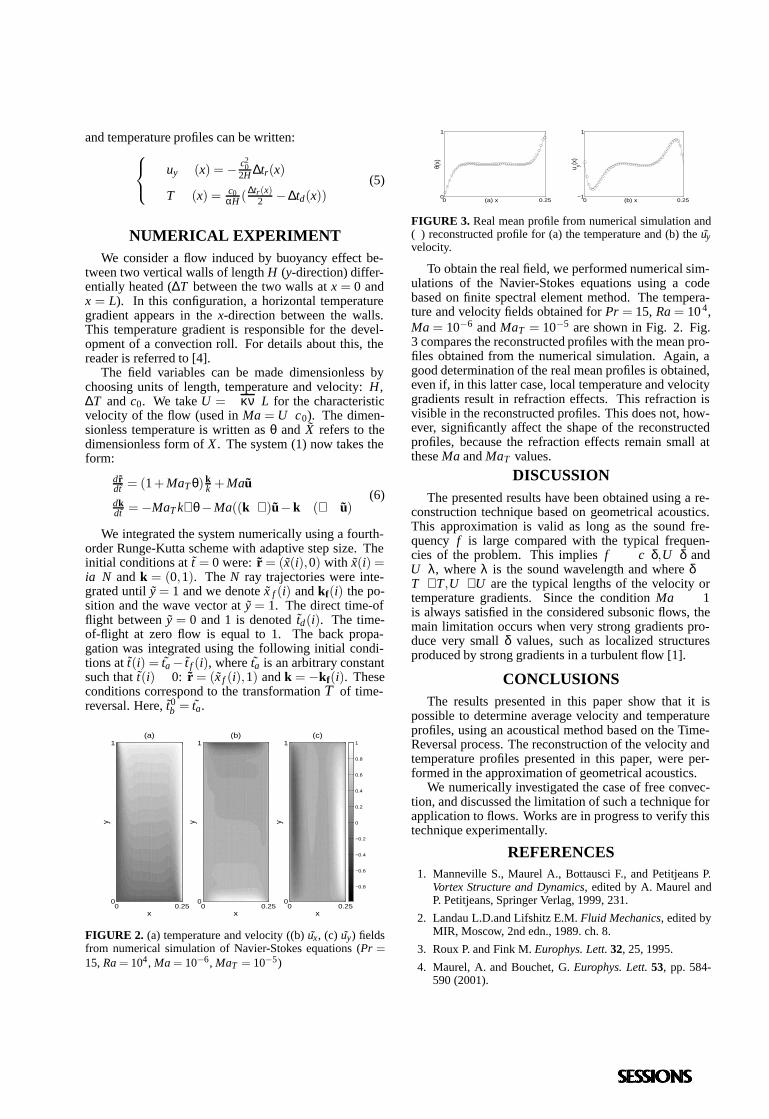
FIGURE 2. (a) temperature and velocity ((b) ux, (c) uy) fieldsfrom numerical simulation of Navier-Stokes equations (Pr =15, Ra = 104, Ma = 10−6, MaT = 10−5)
0 0.250
1
θ(x)
(a) x 0 0.25−1
1
u y(x)
(b) x
FIGURE 3. Real mean profile from numerical simulation and() reconstructed profile for (a) the temperature and (b) the uyvelocity.
To obtain the real field, we performed numerical sim-ulations of the Navier-Stokes equations using a codebased on finite spectral element method. The tempera-ture and velocity fields obtained for Pr = 15, Ra = 10 4,Ma = 10−6 and MaT = 10−5 are shown in Fig. 2. Fig.3 compares the reconstructed profiles with the mean pro-files obtained from the numerical simulation. Again, agood determination of the real mean profiles is obtained,even if, in this latter case, local temperature and velocitygradients result in refraction effects. This refraction isvisible in the reconstructed profiles. This does not, how-ever, significantly affect the shape of the reconstructedprofiles, because the refraction effects remain small atthese Ma and MaT values.
DISCUSSIONThe presented results have been obtained using a re-
construction technique based on geometrical acoustics.This approximation is valid as long as the sound fre-quency f is large compared with the typical frequen-cies of the problem. This implies f >> c/δ,U/δ andU/λ, where λ is the sound wavelength and where δ∼T/∇ T,U/∇ U are the typical lengths of the velocity ortemperature gradients. Since the condition Ma << 1is always satisfied in the considered subsonic flows, themain limitation occurs when very strong gradients pro-duce very small δ values, such as localized structuresproduced by strong gradients in a turbulent flow [1].
CONCLUSIONSThe results presented in this paper show that it is
possible to determine average velocity and temperatureprofiles, using an acoustical method based on the Time-Reversal process. The reconstruction of the velocity andtemperature profiles presented in this paper, were per-formed in the approximation of geometrical acoustics.
We numerically investigated the case of free convec-tion, and discussed the limitation of such a technique forapplication to flows. Works are in progress to verify thistechnique experimentally.
REFERENCES1. Manneville S., Maurel A., Bottausci F., and Petitjeans P.
Vortex Structure and Dynamics, edited by A. Maurel andP. Petitjeans, Springer Verlag, 1999, 231.
2. Landau L.D.and Lifshitz E.M. Fluid Mechanics, edited byMIR, Moscow, 2nd edn., 1989. ch. 8.
3. Roux P. and Fink M. Europhys. Lett. 32, 25, 1995.
4. Maurel, A. and Bouchet, G. Europhys. Lett. 53, pp. 584-590 (2001).
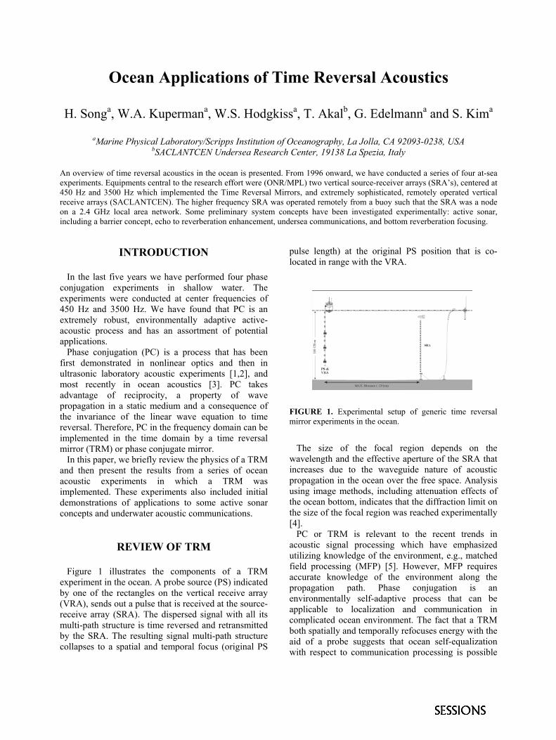
Ocean Applications of Time Reversal Acoustics
H. Songa, W.A. Kupermana, W.S. Hodgkissa, T. Akalb, G. Edelmanna and S. Kima
aMarine Physical Laboratory/Scripps Institution of Oceanography, La Jolla, CA 92093-0238, USA
bSACLANTCEN Undersea Research Center, 19138 La Spezia, Italy
An overview of time reversal acoustics in the ocean is presented. From 1996 onward, we have conducted a series of four at-sea experiments. Equipments central to the research effort were (ONR/MPL) two vertical source-receiver arrays (SRA’s), centered at 450 Hz and 3500 Hz which implemented the Time Reversal Mirrors, and extremely sophisticated, remotely operated vertical receive arrays (SACLANTCEN). The higher frequency SRA was operated remotely from a buoy such that the SRA was a node on a 2.4 GHz local area network. Some preliminary system concepts have been investigated experimentally: active sonar, including a barrier concept, echo to reverberation enhancement, undersea communications, and bottom reverberation focusing.
INTRODUCTION
In the last five years we have performed four phase conjugation experiments in shallow water. The experiments were conducted at center frequencies of 450 Hz and 3500 Hz. We have found that PC is an extremely robust, environmentally adaptive active-acoustic process and has an assortment of potential applications. Phase conjugation (PC) is a process that has been first demonstrated in nonlinear optics and then in ultrasonic laboratory acoustic experiments [1,2], and most recently in ocean acoustics [3]. PC takes advantage of reciprocity, a property of wave propagation in a static medium and a consequence of the invariance of the linear wave equation to time reversal. Therefore, PC in the frequency domain can be implemented in the time domain by a time reversal mirror (TRM) or phase conjugate mirror. In this paper, we briefly review the physics of a TRM and then present the results from a series of ocean acoustic experiments in which a TRM was implemented. These experiments also included initial demonstrations of applications to some active sonar concepts and underwater acoustic communications.
REVIEW OF TRM
Figure 1 illustrates the components of a TRM experiment in the ocean. A probe source (PS) indicated by one of the rectangles on the vertical receive array (VRA), sends out a pulse that is received at the source-receive array (SRA). The dispersed signal with all its multi-path structure is time reversed and retransmitted by the SRA. The resulting signal multi-path structure collapses to a spatial and temporal focus (original PS
pulse length) at the original PS position that is co-located in range with the VRA.
FIGURE 1. Experimental setup of generic time reversal mirror experiments in the ocean.
The size of the focal region depends on the wavelength and the effective aperture of the SRA that increases due to the waveguide nature of acoustic propagation in the ocean over the free space. Analysis using image methods, including attenuation effects of the ocean bottom, indicates that the diffraction limit on the size of the focal region was reached experimentally [4]. PC or TRM is relevant to the recent trends in acoustic signal processing which have emphasized utilizing knowledge of the environment, e.g., matched field processing (MFP) [5]. However, MFP requires accurate knowledge of the environment along the propagation path. Phase conjugation is an environmentally self-adaptive process that can be applicable to localization and communication in complicated ocean environment. The fact that a TRM both spatially and temporally refocuses energy with the aid of a probe suggests that ocean self-equalization with respect to communication processing is possible
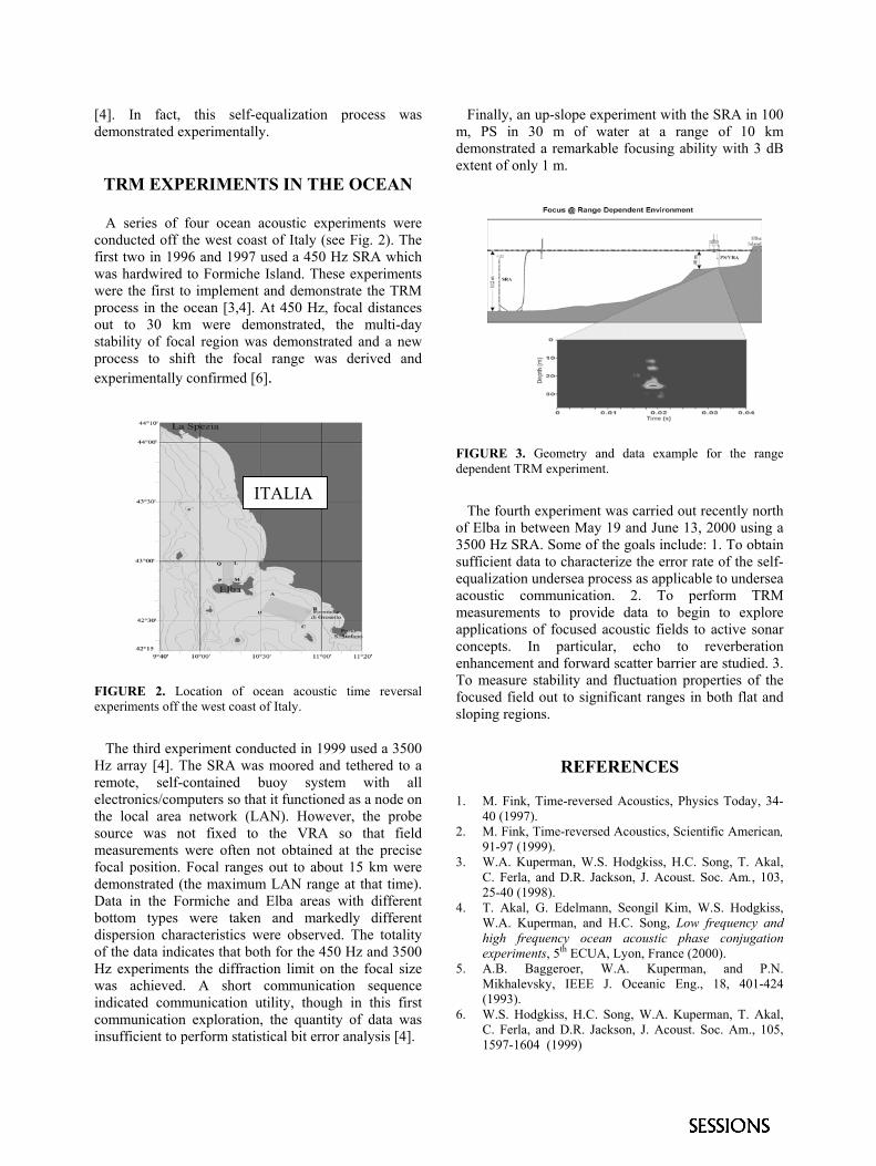
[4]. In fact, this self-equalization process was demonstrated experimentally.
TRM EXPERIMENTS IN THE OCEAN
A series of four ocean acoustic experiments were conducted off the west coast of Italy (see Fig. 2). The first two in 1996 and 1997 used a 450 Hz SRA which was hardwired to Formiche Island. These experiments were the first to implement and demonstrate the TRM process in the ocean [3,4]. At 450 Hz, focal distances out to 30 km were demonstrated, the multi-day stability of focal region was demonstrated and a new process to shift the focal range was derived and experimentally confirmed [6].
FIGURE 2. Location of ocean acoustic time reversal experiments off the west coast of Italy.
The third experiment conducted in 1999 used a 3500 Hz array [4]. The SRA was moored and tethered to a remote, self-contained buoy system with all electronics/computers so that it functioned as a node on the local area network (LAN). However, the probe source was not fixed to the VRA so that field measurements were often not obtained at the precise focal position. Focal ranges out to about 15 km were demonstrated (the maximum LAN range at that time). Data in the Formiche and Elba areas with different bottom types were taken and markedly different dispersion characteristics were observed. The totality of the data indicates that both for the 450 Hz and 3500 Hz experiments the diffraction limit on the focal size was achieved. A short communication sequence indicated communication utility, though in this first communication exploration, the quantity of data was insufficient to perform statistical bit error analysis [4].
Finally, an up-slope experiment with the SRA in 100 m, PS in 30 m of water at a range of 10 km demonstrated a remarkable focusing ability with 3 dB extent of only 1 m.
FIGURE 3. Geometry and data example for the range dependent TRM experiment.
ITALIA The fourth experiment was carried out recently north of Elba in between May 19 and June 13, 2000 using a 3500 Hz SRA. Some of the goals include: 1. To obtain sufficient data to characterize the error rate of the self-equalization undersea process as applicable to undersea acoustic communication. 2. To perform TRM measurements to provide data to begin to explore applications of focused acoustic fields to active sonar concepts. In particular, echo to reverberation enhancement and forward scatter barrier are studied. 3. To measure stability and fluctuation properties of the focused field out to significant ranges in both flat and sloping regions.
REFERENCES
1. M. Fink, Time-reversed Acoustics, Physics Today, 34-40 (1997).
2. M. Fink, Time-reversed Acoustics, Scientific American, 91-97 (1999).
3. W.A. Kuperman, W.S. Hodgkiss, H.C. Song, T. Akal, C. Ferla, and D.R. Jackson, J. Acoust. Soc. Am., 103, 25-40 (1998).
4. T. Akal, G. Edelmann, Seongil Kim, W.S. Hodgkiss, W.A. Kuperman, and H.C. Song, Low frequency and high frequency ocean acoustic phase conjugation experiments, 5th ECUA, Lyon, France (2000).
5. A.B. Baggeroer, W.A. Kuperman, and P.N. Mikhalevsky, IEEE J. Oceanic Eng., 18, 401-424 (1993).
6. W.S. Hodgkiss, H.C. Song, W.A. Kuperman, T. Akal, C. Ferla, and D.R. Jackson, J. Acoust. Soc. Am., 105, 1597-1604 (1999)
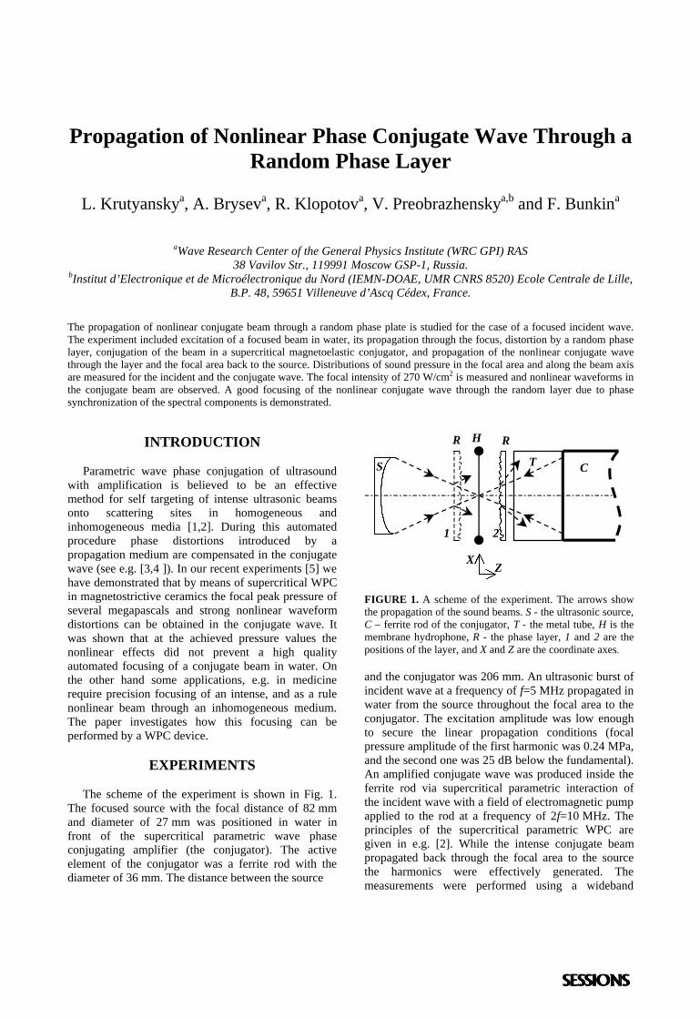
Propagation of Nonlinear Phase Conjugate Wave Through aRandom Phase Layer
L. Krutyanskya, A. Bryseva, R. Klopotova, V. Preobrazhenskya,b and F. Bunkina
aWave Research Center of the General Physics Institute (WRC GPI) RAS38 Vavilov Str., 119991 Moscow GSP-1, Russia.
bInstitut d’Electronique et de Microélectronique du Nord (IEMN-DOAE, UMR CNRS 8520) Ecole Centrale de Lille,B.P. 48, 59651 Villeneuve d’Ascq Cédex, France.
The propagation of nonlinear conjugate beam through a random phase plate is studied for the case of a focused incident wave.The experiment included excitation of a focused beam in water, its propagation through the focus, distortion by a random phaselayer, conjugation of the beam in a supercritical magnetoelastic conjugator, and propagation of the nonlinear conjugate wavethrough the layer and the focal area back to the source. Distributions of sound pressure in the focal area and along the beam axisare measured for the incident and the conjugate wave. The focal intensity of 270 W/cm2 is measured and nonlinear waveforms inthe conjugate beam are observed. A good focusing of the nonlinear conjugate wave through the random layer due to phasesynchronization of the spectral components is demonstrated.
INTRODUCTION
Parametric wave phase conjugation of ultrasoundwith amplification is believed to be an effectivemethod for self targeting of intense ultrasonic beamsonto scattering sites in homogeneous andinhomogeneous media [1,2]. During this automatedprocedure phase distortions introduced by apropagation medium are compensated in the conjugatewave (see e.g. [3,4 ]). In our recent experiments [5] wehave demonstrated that by means of supercritical WPCin magnetostrictive ceramics the focal peak pressure ofseveral megapascals and strong nonlinear waveformdistortions can be obtained in the conjugate wave. Itwas shown that at the achieved pressure values thenonlinear effects did not prevent a high qualityautomated focusing of a conjugate beam in water. Onthe other hand some applications, e.g. in medicinerequire precision focusing of an intense, and as a rulenonlinear beam through an inhomogeneous medium.The paper investigates how this focusing can beperformed by a WPC device.
EXPERIMENTS
The scheme of the experiment is shown in Fig. 1.The focused source with the focal distance of 82 mmand diameter of 27 mm was positioned in water infront of the supercritical parametric wave phaseconjugating amplifier (the conjugator). The activeelement of the conjugator was a ferrite rod with thediameter of 36 mm. The distance between the source
FIGURE 1. A scheme of the experiment. The arrows showthe propagation of the sound beams. S - the ultrasonic source,C – ferrite rod of the conjugator, T - the metal tube, H is themembrane hydrophone, R - the phase layer, 1 and 2 are thepositions of the layer, and X and Z are the coordinate axes.
and the conjugator was 206 mm. An ultrasonic burst ofincident wave at a frequency of f=5 MHz propagated inwater from the source throughout the focal area to theconjugator. The excitation amplitude was low enoughto secure the linear propagation conditions (focalpressure amplitude of the first harmonic was 0.24 MPa,and the second one was 25 dB below the fundamental).An amplified conjugate wave was produced inside theferrite rod via supercritical parametric interaction ofthe incident wave with a field of electromagnetic pumpapplied to the rod at a frequency of 2f=10 MHz. Theprinciples of the supercritical parametric WPC aregiven in e.g. [2]. While the intense conjugate beampropagated back through the focal area to the sourcethe harmonics were effectively generated. Themeasurements were performed using a wideband
H
XZ
R R
T CS
1 2
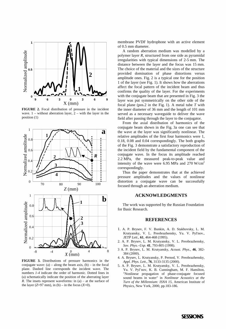
FIGURE 2. Focal distribution of pressure in the incidentwave. 1 – without aberration layer, 2 – with the layer in theposition (1)
FIGURE 3. Distributions of pressure harmonics in theconjugate wave: (a) – along the beam axis, (b) – in the focalplane. Dashed line corresponds the incident wave. Thenumbers 1-4 indicate the order of harmonic. Dotted lines in(a) schematically indicate the position of the aberrating layerR. The insets represent waveforms: in (a) – at the surface ofthe layer (Z=97 mm), in (b) – in the focus (X=0).
membrane PVDF hydrophone with an active elementof 0.5 mm diameter. A random aberration medium was modelled by apolymer layer R, structured from one side as pyramidalirregularities with typical dimensions of 2-5 mm. Thedistance between the layer and the focus was 15 mm.The choice of the material and the sizes of the structureprovided domination of phase distortions versusamplitude ones. Fig. 2 is a typical one for the position1 of the layer (see Fig. 1). It shows how the aberrationsaffect the focal pattern of the incident beam and thusconfirms the quality of the layer. For the experimentswith the conjugate beam that are presented in Fig. 3 thelayer was put symmetrically on the other side of thefocal plane (pos.2 in the Fig. 1). A metal tube T withthe inner diameter of 36 mm and the length of 101 mmserved as a necessary waveguide to deliver the wavefield after passing through the layer to the conjugator. From the axial distribution of harmonics of theconjugate beam shown in the Fig. 3a one can see thatthe wave at the layer was significantly nonlinear. Therelative amplitudes of the first four harmonics were 1,0.18, 0.08 and 0.04 correspondingly. The both graphsof the Fig. 3 demonstrate a satisfactory reproduction ofthe incident field by the fundamental component of theconjugate wave. In the focus its amplitude reached2.2 MPa, the measured peak-to-peak value andintensity of the wave were 6.95 MPa and 270 W/cm2
correspondingly. Thus the paper demonstrates that at the achievedpressure amplitudes and the values of nonlineardistortion a conjugate wave can be successfullyfocused through an aberration medium.
ACKNOWLEDGMENTS
The work was supported by the Russian Foundationfor Basic Research.
REFERENCES
1. A. P. Brysev, F. V. Bunkin, A. D. Stakhovsky, L. M.Krutyansky, V. L. Preobrazhensky, Yu. V. Pyl'nov.,JETP Lett., 61, 464-468 (1995).
2. A. P. Brysev, L. M. Krutyansky, V. L. Preobrazhensky,Sov. Phys.–Usp. 41, 793-805 (1998).
3 A. P. Brysev, L. M. Krutyansky, Acoust. Phys., 46, 382-384 (2000).
4. A. Brysev, L. Krutyansky, P. Pernod, V. Preobrazhensky,Appl. Phys. Lett., 76, 3133-3135 (2000).
5. A. P. Brysev, L. M. Krutyansky, V. L. Preobrazhensky,Yu. V. Pyl’nov, K. B. Cunningham, M. F. Hamilton,"Nonlinear propagation of phase-conjugate focusedsound beams in water" in Nonlinear Acoustics at theTurn of the Millennium: ISNA 15, American Institute ofPhysics, New York, 2000, pp.183-186.
9 6 3 0 3 6 90
0.5
1
Nor
mal
ized
am
plitu
de
X (mm)
2
1
70 80 90 100
0.2
0.4
0.6
0.8
1
0
1
2
3
4
R
a
Nor
mal
ized
am
plitu
de
Z (mm)
-8 -4 4 80
0.2
0.4
0.6
0.8
1
0
1
23
4
X (mm)
Nor
mal
ized
am
plitu
de
b
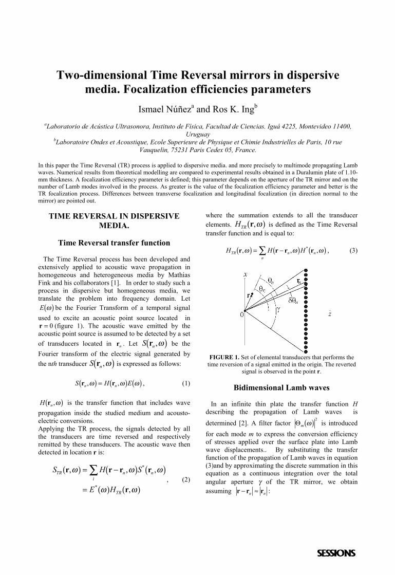
Two-dimensional Time Reversal mirrors in dispersivemedia. Focalization efficiencies parameters
Ismael Núñeza and Ros K. Ingb
aLaboratorio de Acústica Ultrasonora, Instituto de Física, Facultad de Ciencias. Iguá 4225, Montevideo 11400,Uruguay
bLaboratoire Ondes et Acoustique, Ecole Superieure de Physique et Chimie Industrielles de Paris, 10 rueVauquelin, 75231 Paris Cedex 05, France.
In this paper the Time Reversal (TR) process is applied to dispersive media. and more precisely to multimode propagating Lambwaves. Numerical results from theoretical modelling are compared to experimental results obtained in a Duralumin plate of 1.10-mm thickness. A focalization efficiency parameter is defined; this parameter depends on the aperture of the TR mirror and on thenumber of Lamb modes involved in the process. As greater is the value of the focalization efficiency parameter and better is theTR focalization process. Differences between transverse focalization and longitudinal focalization (in direction normal to themirror) are pointed out.
TIME REVERSAL IN DISPERSIVEMEDIA.
Time Reversal transfer function
The Time Reversal process has been developed andextensively applied to acoustic wave propagation inhomogeneous and heterogeneous media by MathiasFink and his collaborators [1]. In order to study such aprocess in dispersive but homogeneous media, wetranslate the problem into frequency domain. LetE ωb g be the Fourier Transform of a temporal signalused to excite an acoustic point source located inr = 0 (figure 1). The acoustic wave emitted by theacoustic point source is assumed to be detected by a setof transducers located in rn . Let S nr ,ωb g be theFourier transform of the electric signal generated bythe nth transducer S nr ,ωb g is expressed as follows:
S H En nr r, ,ω ω ωb g b g b g= , (1)
H nr ,ωb g is the transfer function that includes wavepropagation inside the studied medium and acousto-electric conversions.Applying the TR process, the signals detected by allthe transducers are time reversed and respectivelyremitted by these transducers. The acoustic wave thendetected in location r is:
S H S
E H
TR n ni
TR
r r r r
r
, , ,
,
*
*
ω ω ω
ω ω
a f b g b ga f a f
= −
=
∑, (2)
where the summation extends to all the transducerelements. HTR r,ωa f is defined as the Time Reversaltransfer function and is equal to:
H H HTR n nn
r r r r, , ,*ω ω ωb g b g b g= −∑ , (3)
FIGURE 1. Set of elemental transducers that performs thetime reversion of a signal emitted in the origin. The reverted
signal is observed in the point r.
Bidimensional Lamb waves
In an infinite thin plate the transfer function Hdescribing the propagation of Lamb waves is
determined [2]. A filter factor Θm ωb g 2 is introducedfor each mode m to express the conversion efficiencyof stresses applied over the surface plate into Lambwave displacements.. By substituting the transferfunction of the propagation of Lamb waves in equation(3)and by approximating the discrete summation in thisequation as a continuous integration over the totalangular aperture γ of the TR mirror, we obtainassuming r r r− ≈n n :
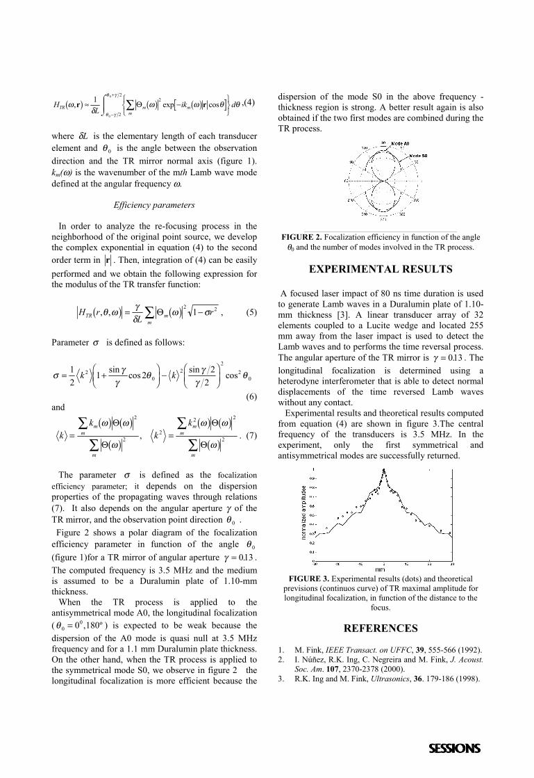
HL
ik dTR m mm
ωδ
ω ω θ θθ γ
θ γ
, exp cosr rb g b g b g≈ −RST
UVWXZY ∑
−
+1 2
2
2
0
0
Θ ,(4)
where δL is the elementary length of each transducerelement and θ 0 is the angle between the observationdirection and the TR mirror normal axis (figure 1).km(ω) is the wavenumber of the mth Lamb wave modedefined at the angular frequency ω.
Efficiency parameters
In order to analyze the re-focusing process in theneighborhood of the original point source, we developthe complex exponential in equation (4) to the secondorder term in r . Then, integration of (4) can be easilyperformed and we obtain the following expression forthe modulus of the TR transfer function:
H rL
rTR mm
, ,θ ω γδ
ω σb g b g= −∑ Θ2 21 , (5)
Parameter σ is defined as follows:
σ γγ
θ γγ
θ= +FHG
IKJ −FHG
IKJ
12
1 2 22
20
22
20k ksin cos sin cos
(6)and
kk
kkm
m
m
mm
m
= =∑
∑∑
∑
ω ω
ω
ω ω
ω
b g b gb g
b g b gb g
Θ
Θ
Θ
Θ
2
22
2 2
2, . (7)
The parameter σ is defined as the focalizationefficiency parameter; it depends on the dispersionproperties of the propagating waves through relations(7). It also depends on the angular aperture γ of theTR mirror, and the observation point direction θ 0 . Figure 2 shows a polar diagram of the focalizationefficiency parameter in function of the angle θ 0
(figure 1)for a TR mirror of angular aperture γ = 013. .The computed frequency is 3.5 MHz and the mediumis assumed to be a Duralumin plate of 1.10-mmthickness. When the TR process is applied to theantisymmetrical mode A0, the longitudinal focalization(θ 0
00 180= , º ) is expected to be weak because thedispersion of the A0 mode is quasi null at 3.5 MHzfrequency and for a 1.1 mm Duralumin plate thickness.On the other hand, when the TR process is applied tothe symmetrical mode S0, we observe in figure 2 thelongitudinal focalization is more efficient because the
dispersion of the mode S0 in the above frequency -thickness region is strong. A better result again is alsoobtained if the two first modes are combined during theTR process.
FIGURE 2. Focalization efficiency in function of the angleθ0 and the number of modes involved in the TR process.
EXPERIMENTAL RESULTS
A focused laser impact of 80 ns time duration is usedto generate Lamb waves in a Duralumin plate of 1.10-mm thickness [3]. A linear transducer array of 32elements coupled to a Lucite wedge and located 255mm away from the laser impact is used to detect theLamb waves and to performs the time reversal process.The angular aperture of the TR mirror is γ = 013. . Thelongitudinal focalization is determined using aheterodyne interferometer that is able to detect normaldisplacements of the time reversed Lamb waveswithout any contact. Experimental results and theoretical results computedfrom equation (4) are shown in figure 3.The centralfrequency of the transducers is 3.5 MHz. In theexperiment, only the first symmetrical andantisymmetrical modes are successfully returned.
FIGURE 3. Experimental results (dots) and theoreticalprevisions (continuos curve) of TR maximal amplitude forlongitudinal focalization, in function of the distance to the
focus.
REFERENCES
1. M. Fink, IEEE Transact. on UFFC, 39, 555-566 (1992).2. I. Núñez, R.K. Ing, C. Negreira and M. Fink, J. Acoust.
Soc. Am. 107, 2370-2378 (2000).3. R.K. Ing and M. Fink, Ultrasonics, 36. 179-186 (1998).
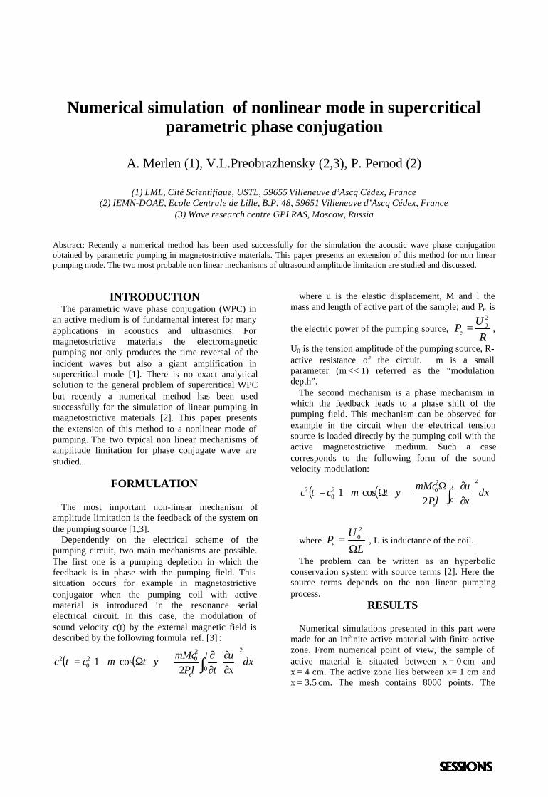
Numerical simulation of nonlinear mode in supercriticalparametric phase conjugation
A. Merlen (1), V.L.Preobrazhensky (2,3), P. Pernod (2)
(1) LML, Cité Scientifique, USTL, 59655 Villeneuve d’Ascq Cédex, France(2) IEMN-DOAE, Ecole Centrale de Lille, B.P. 48, 59651 Villeneuve d’Ascq Cédex, France
(3) Wave research centre GPI RAS, Moscow, Russia
Abstract: Recently a numerical method has been used successfully for the simulation the acoustic wave phase conjugationobtained by parametric pumping in magnetostrictive materials. This paper presents an extension of this method for non linearpumping mode. The two most probable non linear mechanisms of ultrasound amplitude limitation are studied and discussed.
INTRODUCTIONThe parametric wave phase conjugation (WPC) in
an active medium is of fundamental interest for manyapplications in acoustics and ultrasonics. Formagnetostrictive materials the electromagneticpumping not only produces the time reversal of theincident waves but also a giant amplification insupercritical mode [1]. There is no exact analyticalsolution to the general problem of supercritical WPCbut recently a numerical method has been usedsuccessfully for the simulation of linear pumping inmagnetostrictive materials [2]. This paper presentsthe extension of this method to a nonlinear mode ofpumping. The two typical non linear mechanisms ofamplitude limitation for phase conjugate wave arestudied.
FORMULATION
The most important non-linear mechanism ofamplitude limitation is the feedback of the system onthe pumping source [1,3].
Dependently on the electrical scheme of thepumping circuit, two main mechanisms are possible.The first one is a pumping depletion in which thefeedback is in phase with the pumping field. Thissituation occurs for example in magnetostrictiveconjugator when the pumping coil with activematerial is introduced in the resonance serialelectrical circuit. In this case, the modulation ofsound velocity c(t) by the external magnetic field isdescribed by the following formula ref. [3] :
( ) ( )
∂∂
∂∂++Ω+= ∫
l
e
dxxu
tlPmMctmctc
0
2202
02
2cos1 ψ
where u is the elastic displacement, M and l themass and length of active part of the sample; and Pe is
the electric power of the pumping source, R
UPe
20= ,
U0 is the tension amplitude of the pumping source, R-active resistance of the circuit. m is a smallparameter (m << 1) referred as the “modulationdepth”.
The second mechanism is a phase mechanism inwhich the feedback leads to a phase shift of thepumping field. This mechanism can be observed forexample in the circuit when the electrical tensionsource is loaded directly by the pumping coil with theactive magnetostrictive medium. Such a casecorresponds to the following form of the soundvelocity modulation:
( ) ( )
∂∂Ω++Ω+= ∫
l
e
dxxu
lPmMctmctc
0
2202
02
2cos1 ψ
where L
UPe Ω=
20 , L is inductance of the coil.
The problem can be written as an hyperbolicconservation system with source terms [2]. Here thesource terms depends on the non linear pumpingprocess.
RESULTS
Numerical simulations presented in this part weremade for an infinite active material with finite activezone. From numerical point of view, the sample ofactive material is situated between x = 0 cm andx = 4 cm. The active zone lies between x = 1 cm andx = 3.5 cm. The mesh contains 8000 points. The
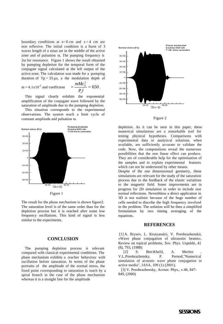
boundary conditions at x = 0 cm and x = 4 cm arenon reflexive. The initial condition is a burst of 3waves length of a sinus set in the middle of the activezone and of pulsation ω. The pumping frequency is2ω for resonance. Figure 1 shows the result obtainedby pumping depletion for the temporal form of theconjugate signal calculated at the left output of theactive zone. The calculation was made for a pumpingduration of Tp = 35 µs, a the modulation depth of
m = 4.1x10⁻² and coefficient 65020 ==ℵ
lPmMc
e
.
This signal clearly exhibits the exponentialamplification of the conjugate wave followed by thesaturation of amplitude due to the pumping depletion.
This situation corresponds to the experimentalobservations. The system reach a limit cycle ofconstant amplitude and pulsation ω.
Figure 1
The result for the phase mechanism is shown figure2.The saturation level is of the same order than for thedepletion process but it is reached after some lowfrequency oscillations. This kind of signal is lesssimilar to the experiments.
CONCLUSION
The pumping depletion process is relevantcompared with classical experimental conditions. Thephase mechanism exhibits a reacher behaviour withoscillation before saturation. In terms of the phaseportraits of the amplitude of the normal stress, thefixed point corresponding to saturation is reach by aspiral branch in the case of the phase mechanismwhereas it is a straight line for the amplitude
Figure 2
depletion. As it can be seen in this paper, thesenumerical simulations are a remarkable tool fortesting physical hypotheses. Comparisons withexperimental data or analytical solutions, whenavailable, are sufficiently accurate to validate thecode. Now, the computations reveal the numerouspossibilities that the non linear effect can produce.They are of considerable help for the optimisation ofthe samples and to explain experimental featureswhich can not be understood by other means.Despite of the one dimensionnal geometry, thesesimulations are relevant for the study of the saturationprocess due to the feedback of the elastic variationsto the magnetic field. Some improvments are inprogress for 2D simulation in order to include nonnormal reflections. Neverthless a direct application in3D is not realistic because of the huge number ofcells needed to discribe the high frequency involvedin the problem. The solution will be then a simplifiedformulation by two timing averaging of theequations.
REFERENCES
[1] A. Brysev, L. Krutyanskii, V. Preobrazhenskii,«Wave phase conjugation of ultrasonic beams»,Review on topical problems, Sov. Phys. Uspekhi, 41(8), 793, (1988)
[2] S. Ben-Khelil, A. Merlen ,V.L.Preobrazhensky, P. Pernod,"Numericalsimulation of acoustic wave phase conjugation inactive media", JASA, 109 (1) (2001). [3] V. Preobrazhensky, Acoust. Phys., v.46, 847-849, (2000)
Time(s)2E-05 4E-05
-3E+06
-2E+06
-1E+06
0
1E+06
2E+06
3E+06
Norma l stre ss (P a )Pumping de pletionGa mma =6 5 0 s/mT=3 5 mic ro s econdes
Time(s)2E-05 4E-05
-4E+06
-3E+06
-2E+06
-1E+06
0
1E+06
2E+06
3E+06
4E+06
Norma l stres s (P a )P ha se me cha nismG a mma =6 5 0 s/mT =35 micro se conde s
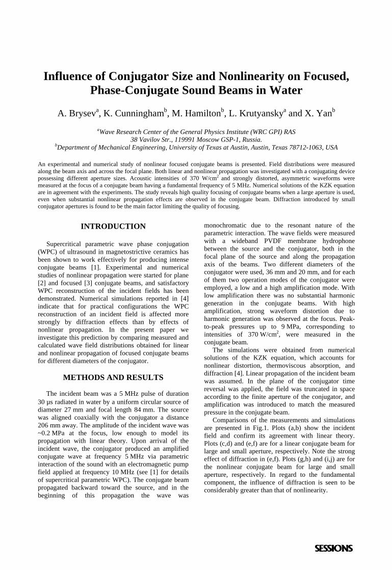
Influence of Conjugator Size and Nonlinearity on Focused,Phase-Conjugate Sound Beams in Water
A. Bryseva, K. Cunninghamb, M. Hamiltonb, L. Krutyanskya and X. Yanb
aWave Research Center of the General Physics Institute (WRC GPI) RAS38 Vavilov Str., 119991 Moscow GSP-1, Russia.
bDepartment of Mechanical Engineering, University of Texas at Austin, Austin, Texas 78712-1063, USA
An experimental and numerical study of nonlinear focused conjugate beams is presented. Field distributions were measuredalong the beam axis and across the focal plane. Both linear and nonlinear propagation was investigated with a conjugating devicepossessing different aperture sizes. Acoustic intensities of 370 W/cm2 and strongly distorted, asymmetric waveforms weremeasured at the focus of a conjugate beam having a fundamental frequency of 5 MHz. Numerical solutions of the KZK equationare in agreement with the experiments. The study reveals high quality focusing of conjugate beams when a large aperture is used,even when substantial nonlinear propagation effects are observed in the conjugate beam. Diffraction introduced by smallconjugator apertures is found to be the main factor limiting the quality of focusing.
INTRODUCTION
Supercritical parametric wave phase conjugation(WPC) of ultrasound in magnetostrictive ceramics hasbeen shown to work effectively for producing intenseconjugate beams [1]. Experimental and numericalstudies of nonlinear propagation were started for plane[2] and focused [3] conjugate beams, and satisfactoryWPC reconstruction of the incident fields has beendemonstrated. Numerical simulations reported in [4]indicate that for practical configurations the WPCreconstruction of an incident field is affected morestrongly by diffraction effects than by effects ofnonlinear propagation. In the present paper weinvestigate this prediction by comparing measured andcalculated wave field distributions obtained for linearand nonlinear propagation of focused conjugate beamsfor different diameters of the conjugator.
METHODS AND RESULTS
The incident beam was a 5 MHz pulse of duration30 µs radiated in water by a uniform circular source ofdiameter 27 mm and focal length 84 mm. The sourcewas aligned coaxially with the conjugator a distance206 mm away. The amplitude of the incident wave was~0.2 MPa at the focus, low enough to model itspropagation with linear theory. Upon arrival of theincident wave, the conjugator produced an amplifiedconjugate wave at frequency 5 MHz via parametricinteraction of the sound with an electromagnetic pumpfield applied at frequency 10 MHz (see [1] for detailsof supercritical parametric WPC). The conjugate beampropagated backward toward the source, and in thebeginning of this propagation the wave was
monochromatic due to the resonant nature of theparametric interaction. The wave fields were measuredwith a wideband PVDF membrane hydrophonebetween the source and the conjugator, both in thefocal plane of the source and along the propagationaxis of the beams. Two different diameters of theconjugator were used, 36 mm and 20 mm, and for eachof them two operation modes of the conjugator wereemployed, a low and a high amplification mode. Withlow amplification there was no substantial harmonicgeneration in the conjugate beams. With highamplification, strong waveform distortion due toharmonic generation was observed at the focus. Peak-to-peak pressures up to 9 MPa, corresponding tointensities of 370 W/cm2, were measured in theconjugate beam. The simulations were obtained from numericalsolutions of the KZK equation, which accounts fornonlinear distortion, thermoviscous absorption, anddiffraction [4]. Linear propagation of the incident beamwas assumed. In the plane of the conjugator timereversal was applied, the field was truncated in spaceaccording to the finite aperture of the conjugator, andamplification was introduced to match the measuredpressure in the conjugate beam. Comparisons of the measurements and simulationsare presented in Fig.1. Plots (a,b) show the incidentfield and confirm its agreement with linear theory.Plots (c,d) and (e,f) are for a linear conjugate beam forlarge and small aperture, respectively. Note the strongeffect of diffraction in (e,f). Plots (g,h) and (i,j) are forthe nonlinear conjugate beam for large and smallaperture, respectively. In regard to the fundamentalcomponent, the influence of diffraction is seen to beconsiderably greater than that of nonlinearity.
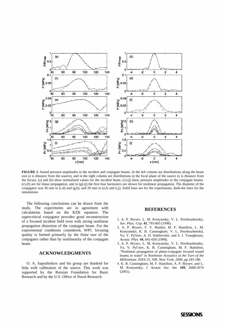
FIGURE 1. Sound pressure amplitudes in the incident and conjugate beams. In the left column are distributions along the beamaxis (z is distance from the source), and in the right column are distributions in the focal plane of the source (x is distance fromthe focus). (a) and (b) show normalized values for the incident beam. (c)-(j) show pressure amplitudes in the conjugate beams.(c)-(f) are for linear propagation, and in (g)-(j) the first four harmonics are shown for nonlinear propagation. The diameter of theconjugator was 36 mm in (c,d) and (g,h), and 20 mm in (e,f) and (i,j). Solid lines are for the experiments, dash-dot lines for thesimulations
The following conclusions can be drawn from thestudy. The experiments are in agreement withcalculations based on the KZK equation. Thesupercritical conjugator provides good reconstructionof a focused incident field even with strong nonlinearpropagation distortion of the conjugate beam. For theexperimental conditions considered, WPC focusingquality is limited primarily by the finite size of theconjugator rather than by nonlinearity of the conjugatebeam.
ACKNOWLEDGMENTS
O. A. Sapozhnikov and his group are thanked forhelp with calibration of the source. This work wassupported by the Russian Foundation for BasicResearch and by the U.S. Office of Naval Research.
REFERENCES
1. A. P. Brysev, L. M. Krutyansky, V. L. Preobrazhensky,Sov. Phys.–Usp. 41, 793-805 (1998).
2. A. P. Brysev, F. V. Bunkin, M. F. Hamilton, L. M.Krutyanskii, K. B. Cunningham, V. L. Preobrazhenskii,Yu. V. Pyl'nov, A. D. Stakhovskii, and S. J. Younghouse,Acoust. Phys. 44, 641-650 (1998).
3. A. P. Brysev, L. M. Krutyansky, V. L. Preobrazhensky,Yu. V. Pyl’nov, K. B. Cunningham, M. F. Hamilton,"Nonlinear propagation of phase-conjugate focused soundbeams in water" in Nonlinear Acoustics at the Turn of theMillennium: ISNA 15, AIP, New York, 2000, pp.183-186.
4. K. B. Cunningham, M. F. Hamilton, A. P. Brysev, and L.M. Krutyansky, J. Acoust. Soc. Am. 109, 2668-2674(2001).
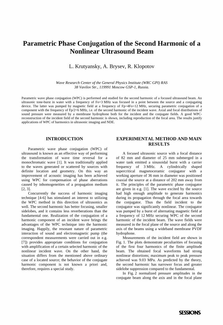
Parametric Phase Conjugation of the Second Harmonic of aNonlinear Ultrasound Beam
L. Krutyansky, A. Brysev, R. Klopotov
Wave Research Center of the General Physics Institute (WRC GPI) RAS38 Vavilov Str., 119991 Moscow GSP-1, Russia.
Parametric wave phase conjugation (WPC) is performed and studied for the second harmonic of a focused ultrasound beam. Anultrasonic tone-burst in water with a frequency of Fo=3 MHz was focused in a point between the source and a conjugatingdevice. The latter was pumped by magnetic field at a frequency of Fp=4Fo=12 MHz, securing parametric conjugation of acomponent with the frequency of Fp/2=6 MHz, i.e. of the second harmonic of the incident wave. Axial and focal distributions ofsound pressure were measured by a membrane hydrophone both for the incident and the conjugate fields. A good WPC-reconstruction of the incident field of the second harmonic is shown, including reproduction of the focal area. The results justifyapplications of WPC of harmonics in ultrasonic imaging and NDE.
INTRODUCTION
Parametric wave phase conjugation (WPC) ofultrasound is known as an effective way of performingthe transformation of wave time reversal for amonochromatic wave [1]. It was traditionally appliedto the waves generated or scattered by sources withdefinite location and geometry. On this way animprovement of acoustic imaging has been achievedusing WPC for compensation of phase aberrationscaused by inhomogeneities of a propagation medium[2, 3].
Concurrently the success of harmonic imagingtechnique [4-6] has stimulated an interest to utilizingthe WPC method in this direction of ultrasonics aswell. The second harmonic has better focusing, smallersidelobes, and it contains less reverberations than thefundamental one. Realization of the conjugation of aharmonic component of an incident wave brings theadvantages of the WPC technique into the harmonicimaging. Happily, the resonant nature of parametricinteraction of sound and electromagnetic pump (thecorrespondent measurements were carried out in e.g.[7]) provides appropriate conditions for conjugationwith amplification of a certain selected harmonic of thenonlinear incident wave. On the other hand, thesituation differs from the mentioned above ordinarycase of a located source; the behavior of the conjugateharmonic component is not known a priori and,therefore, requires a special study.
EXPERIMENTAL METHOD AND MAINRESULTS
A focused ultrasonic source with a focal distanceof 82 mm and diameter of 25 mm submerged in awater tank emitted a sinusoidal burst with a carrierfrequency of 3 MHz. A cylindrically shapedsupercritical magnetoceramic conjugator with aworking aperture of 36 mm in diameter was positionedcoaxial the source at a distance of 202 mm away fromit. The principles of the parametric phase conjugatorare given in e.g. [1]. The wave excited by the sourcehad high enough amplitude to generate harmonicsduring its propagation through the focal area towardsthe conjugator. Thus the field incident to theconjugator was significantly nonlinear. The conjugatorwas pumped by a burst of alternating magnetic field ata frequency of 12 MHz securing WPC of the secondharmonic of the incident beam. The wave fields weremeasured in the focal plane of the source and along theaxis of the beams using a wideband membrane PVDFhydrophone.
Measurements of the incident field are shown inFig. 1. The plots demonstrate peculiarities of focusingof the first four harmonics of the finite amplitudebeam. The obtained focal waveforms had strongnonlinear distortions; maximum peak to peak pressureachieved was 9.03 MPa. As predicted by the theory,the second harmonic has narrower focus and greatersidelobe suppression compared to the fundamental.
In Fig. 2 normalized pressure amplitudes in theconjugate beam along the axis and in the focal plane
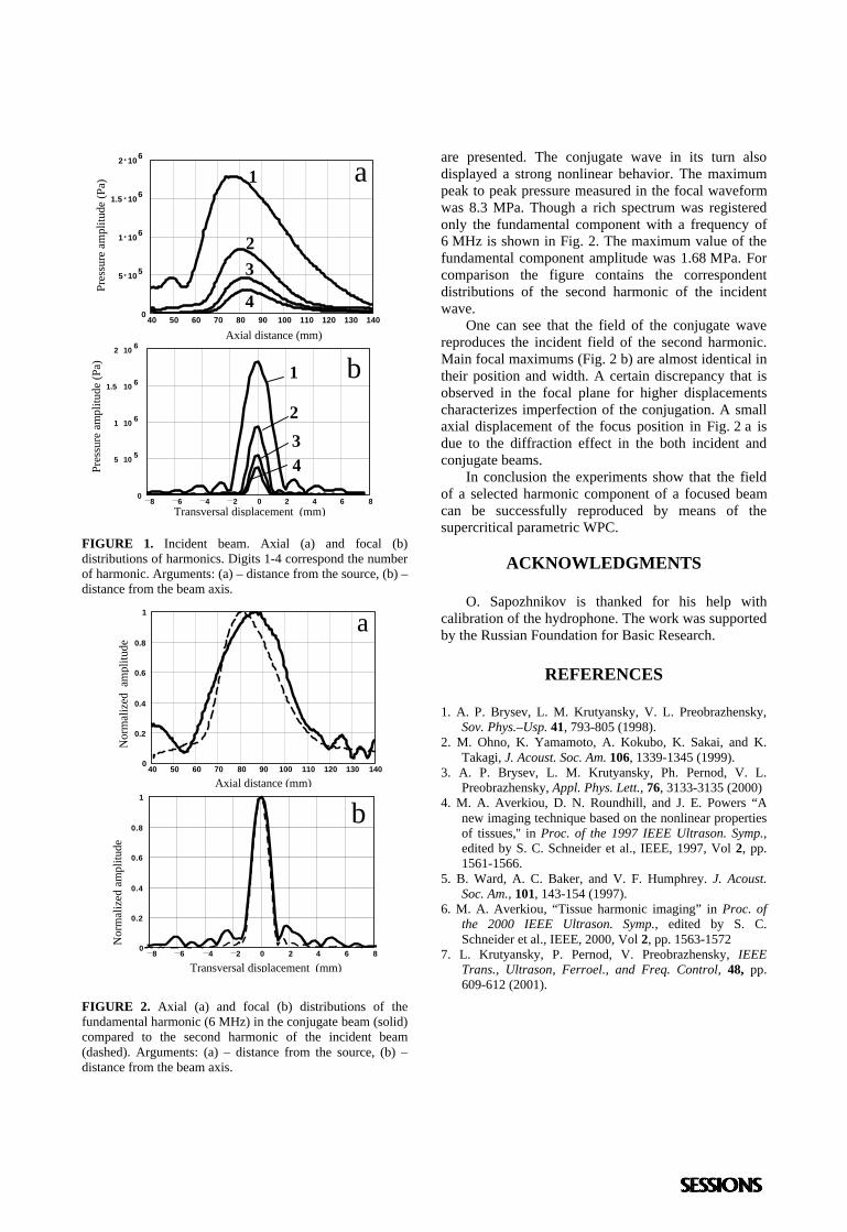
FIGURE 1. Incident beam. Axial (a) and focal (b)distributions of harmonics. Digits 1-4 correspond the numberof harmonic. Arguments: (a) – distance from the source, (b) –distance from the beam axis.
FIGURE 2. Axial (a) and focal (b) distributions of thefundamental harmonic (6 MHz) in the conjugate beam (solid)compared to the second harmonic of the incident beam(dashed). Arguments: (a) – distance from the source, (b) –distance from the beam axis.
are presented. The conjugate wave in its turn alsodisplayed a strong nonlinear behavior. The maximumpeak to peak pressure measured in the focal waveformwas 8.3 MPa. Though a rich spectrum was registeredonly the fundamental component with a frequency of6 MHz is shown in Fig. 2. The maximum value of thefundamental component amplitude was 1.68 MPa. Forcomparison the figure contains the correspondentdistributions of the second harmonic of the incidentwave.
One can see that the field of the conjugate wavereproduces the incident field of the second harmonic.Main focal maximums (Fig. 2 b) are almost identical intheir position and width. A certain discrepancy that isobserved in the focal plane for higher displacementscharacterizes imperfection of the conjugation. A smallaxial displacement of the focus position in Fig. 2 a isdue to the diffraction effect in the both incident andconjugate beams.
In conclusion the experiments show that the fieldof a selected harmonic component of a focused beamcan be successfully reproduced by means of thesupercritical parametric WPC.
ACKNOWLEDGMENTS
O. Sapozhnikov is thanked for his help withcalibration of the hydrophone. The work was supportedby the Russian Foundation for Basic Research.
REFERENCES
1. A. P. Brysev, L. M. Krutyansky, V. L. Preobrazhensky,Sov. Phys.–Usp. 41, 793-805 (1998).
2. M. Ohno, K. Yamamoto, A. Kokubo, K. Sakai, and K.Takagi, J. Acoust. Soc. Am. 106, 1339-1345 (1999).
3. A. P. Brysev, L. M. Krutyansky, Ph. Pernod, V. L.Preobrazhensky, Appl. Phys. Lett., 76, 3133-3135 (2000)
4. M. A. Averkiou, D. N. Roundhill, and J. E. Powers “Anew imaging technique based on the nonlinear propertiesof tissues,'' in Proc. of the 1997 IEEE Ultrason. Symp.,edited by S. C. Schneider et al., IEEE, 1997, Vol 2, pp.1561-1566.
5. B. Ward, A. C. Baker, and V. F. Humphrey. J. Acoust.Soc. Am., 101, 143-154 (1997).
6. M. A. Averkiou, “Tissue harmonic imaging” in Proc. ofthe 2000 IEEE Ultrason. Symp., edited by S. C.Schneider et al., IEEE, 2000, Vol 2, pp. 1563-1572
7. L. Krutyansky, P. Pernod, V. Preobrazhensky, IEEETrans., Ultrason, Ferroel., and Freq. Control, 48, pp.609-612 (2001).
40 50 60 70 80 90 100 110 120 130 1400
5 105
1 106
1.5 106
2 106
1
23
4
Axial distance (mm)
Pres
sure
am
plitu
de (P
a) a
Transversal displacement (mm)8 6 4 2 0 2 4 6 8
0
0.2
0.4
0.6
0.8
1
Nor
mal
ized
am
plitu
de
b
8 6 4 2 0 2 4 6 80
5 105
1 106
1.5 106
2 106
Transversal displacement (mm)
Pres
sure
am
plitu
de (P
a) 1
234
b
40 50 60 70 80 90 100 110 120 130 1400
0.2
0.4
0.6
0.8
1
Nor
mal
ized
am
plitu
de
Axial distance (mm)
a