Embed Size (px)
Citation preview
ICSV21, Beijing, China, 13-17 July 2014 1
The 21st International Congress on Sound and Vibration
13-17 July, 2014, Beijing/China
ACTIVE VIBRATION CONTROL OF GEAR TRANSMISSION SYSTEM
Yinong Li, Feng Zheng, Ziqiang Li, Ling Zheng and Qinzhong Ding
State Key Laboratory of Mechanical Transmission, Chongqing University, Chongqing,
China 400044
e-mail: [email protected]
In this paper, an active control structure used piezoelectric stack actuator is built to suppress
vibration due to internal incentive in gear transmission. Because the gear system is time-
variant and unknown, an offline modeling technique is unable to tracking the changes in the
secondary path, an adaptive filter algorithm used online secondary path modeling method is
proposed to the active vibration control. In order to realize the algorithm, a C-MEX S
function is used to build an FxLMS (Filtered-x least mean square) algorithm block in
Simulink. Besides, reference signal estimation and secondary path modeling are critical
components for the proposed control system. Therefore, an adaptive cascaded notch filter
technology is used to extract the reference signal from the gear vibration. An adaptive LMS
filter is also used to identify the secondary path by online experiment, effective secondary
path transfer function is obtained at the same time avoid mutual interference between the
secondary path identification and controller. Finally, the custom FxLMS block is downloaded
to dSPACE as controller and a series of experimental studies are carried out. Experiment
results show that the performance of the proposed piezoelectric stack actuator controlled by
FxLMS to suppress the vibration is obvious, about 13dB-21dB of gearbox vibration is
attenuated at different fundamental gear mesh frequency.
1. Introduction
Gear system is an essential transmission device in all kinds of mechanical systems. In the
working process, Gear system will generate error excitation what will cause vibration, because of
the influence caused by the manufacturing and assembly errors, the time-varying mesh stiffness,
meshing impact and other factors. The vibration of the gear system not only can generate noise and
lead to the instability of the transmission system, but also can accelerate fatigue damage of the
transmission system and make it failure, resulting in serious consequences.
Reducing the vibration and noise of gear has very important engineering significance for
decreasing the risk of gear box fault and improving the working condition. In 1994, Montague et.
al1
applied two piezoelectric chips as the actuators mounted onto one shaft in a gearbox system to
control the meshing vibration of gear and reduction in gear mesh vibration up to 75% was reported.
In 1999, Rebbechi et.al2
applied an approach similar to that mentioned above to isolate the vibration
transmitting between the gear shaft and housing, different in the usage of a pair of magnetostrictive
actuators and an adaptive digital controller. The proposed system was able to simultaneously deal
with the responses of the first three gear mesh harmonics. In 2000, Chen and Brennan3
developed an
active vibration control scheme that uses three magnetostrictive actuators mounted directly onto one
21st International Congress on Sound and Vibration (ICSV21), Beijing, China, 13-17 July 2014
ICSV21, Beijing, China, 13-17 July 2014 2
of the gears. With this arrangement, the controller can produce circumferential forces that suppress
steady-state torsional vibrations. WU4 applied digital signal processor, combined with analysis
theory and filter reference signal least mean square (Filter - x least - mean - square, FxLMS)
algorithm, and designed a hybrid controller to reduce the vibration of gear system. In 2005, LI5
proposed a new method of gear vibration active control based on reference signal delay least mean
square value (Delayed-x Least- mean - square, DLMS) algorithm, and carried out a large number of
experiments.
Brennan6 compared the performances of different actuators used for active vibration control
by experiments. The piezoelectric stack actuator devices with broad effective frequency range, low
power consumption, large output force, compact structure and other advantages, is more suitable for
gear meshing vibration active control which requires small displacement and large output force.
FxLMS algorithm as an adaptive filtering algorithmic proposed by WIDROW7 and BURGESS
8,
respectively in the study of the adaptive control and the active noise control, is currently the most
widely used in active vibration control. In this paper, piezoelectric stack actuator will be applied to
active meshing vibration control of gear and the FxLMS algorithm will be used to control the
output of the piezoelectric stack actuator. Through the output displacement of the piezoelectric
stack actuator controlling the transverse vibration of the shaft of gear, the purpose of controlling the
vibration of gear transmission system will be achieved. In this process, the synthesis reference
signal is extracted from the gear meshing vibration signal based on an adaptive cascade notch filter
technology, in addition, secondary path contains a piezoelectric stack actuator is online identified
using LMS adaptive filter, so that the secondary path model can real-time track the changes of
characteristic of the secondary path.
2. Control algorithm
FxLMS algorithm with its simple form and strong stability, becomes the most widely used
adaptive filtering algorithm9. In this paper, we use this algorithm to control the output of the
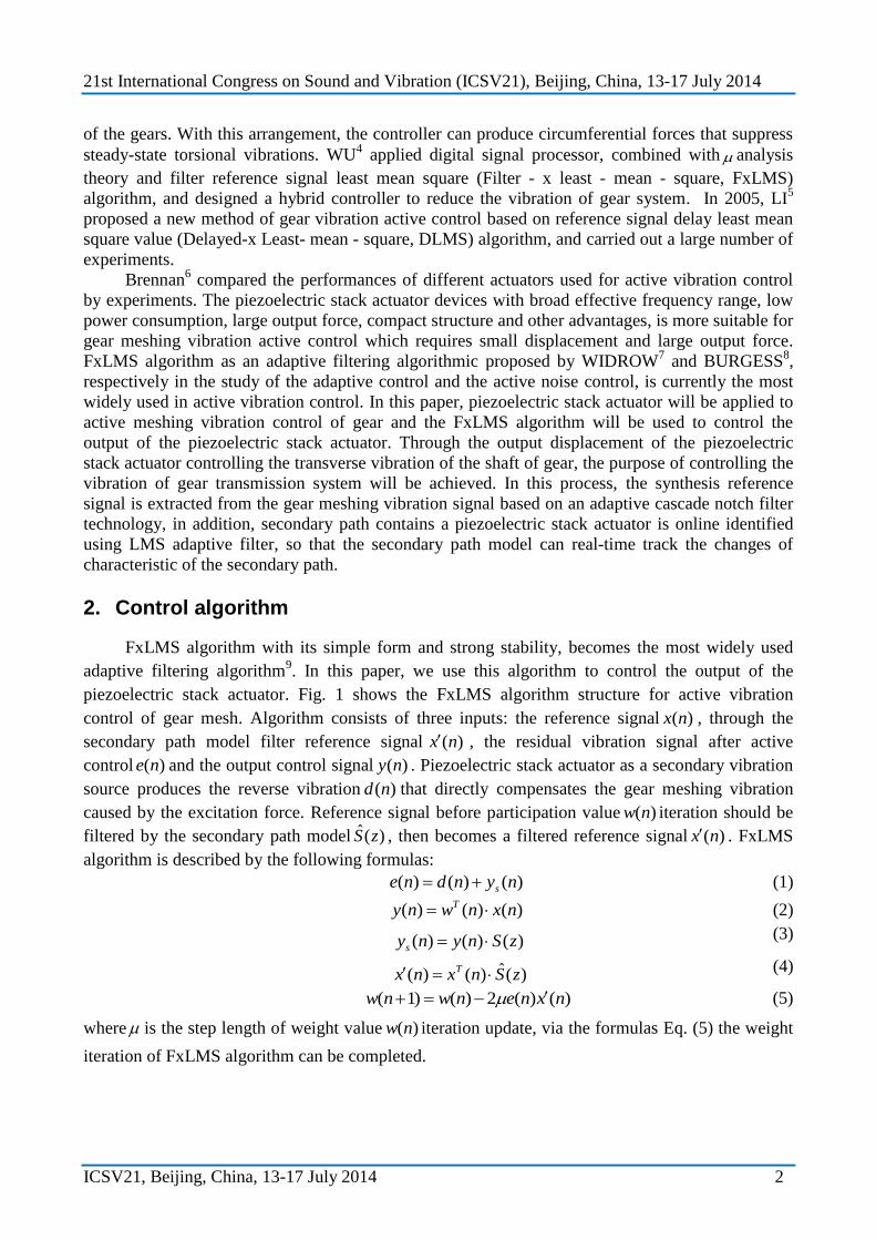
piezoelectric stack actuator. Fig. 1 shows the FxLMS algorithm structure for active vibration
control of gear mesh. Algorithm consists of three inputs: the reference signal )(nx , through the
secondary path model filter reference signal )(nx , the residual vibration signal after active
control )(ne and the output control signal )(ny . Piezoelectric stack actuator as a secondary vibration
source produces the reverse vibration )(nd that directly compensates the gear meshing vibration
caused by the excitation force. Reference signal before participation value )(nw iteration should be
filtered by the secondary path model )(ˆ zS , then becomes a filtered reference signal )(nx . FxLMS
algorithm is described by the following formulas:
)()()( nyndne s (1)
)()()( nxnwny T (2)
)()()( zSnynys (3)
)(ˆ)()( zSnxnx T (4)
)()(2)()1( nxnenwnw (5)
where is the step length of weight value )(nw iteration update, via the formulas Eq. (5) the weight
iteration of FxLMS algorithm can be completed.
21st International Congress on Sound and Vibration (ICSV21), Beijing, China, 13-17 July 2014
ICSV21, Beijing, China, 13-17 July 2014 3
Figure 1. Block diagram of the FxLMS algorithm
Reference signal x(n) is the vibration signal expected to be eliminated from gear system, the
accuracy of the reference signal directly affects the control output. In this paper, we used the real-
time frequency estimator and the waveform generator to acquire the reference signal that is needed
by the adaptive controller. Besides, we designed a kind of frequency estimator using an adaptive
cascaded notch filter. Compared with the traditional frequency estimation technology, the appliance
has a higher estimation accuracy and faster convergence speed10
. Fig. 2 is the diagram of theory of
the frequency estimation with adaptive cascaded notch filter. The adaptive cascaded notch filter is
consisted of two order notch filters whose number is P, the center frequency of each notch filter is
the sinusoidal signal frequency containing in the input signal.
1
1( )N z1( )e n( )d n
1( )kN z( )ke n
1( )pN z( )pe n
the kth order Figure 2. Diagram of cascade adaptive notch filter for frequency estimation
3. Secondary path online modeling
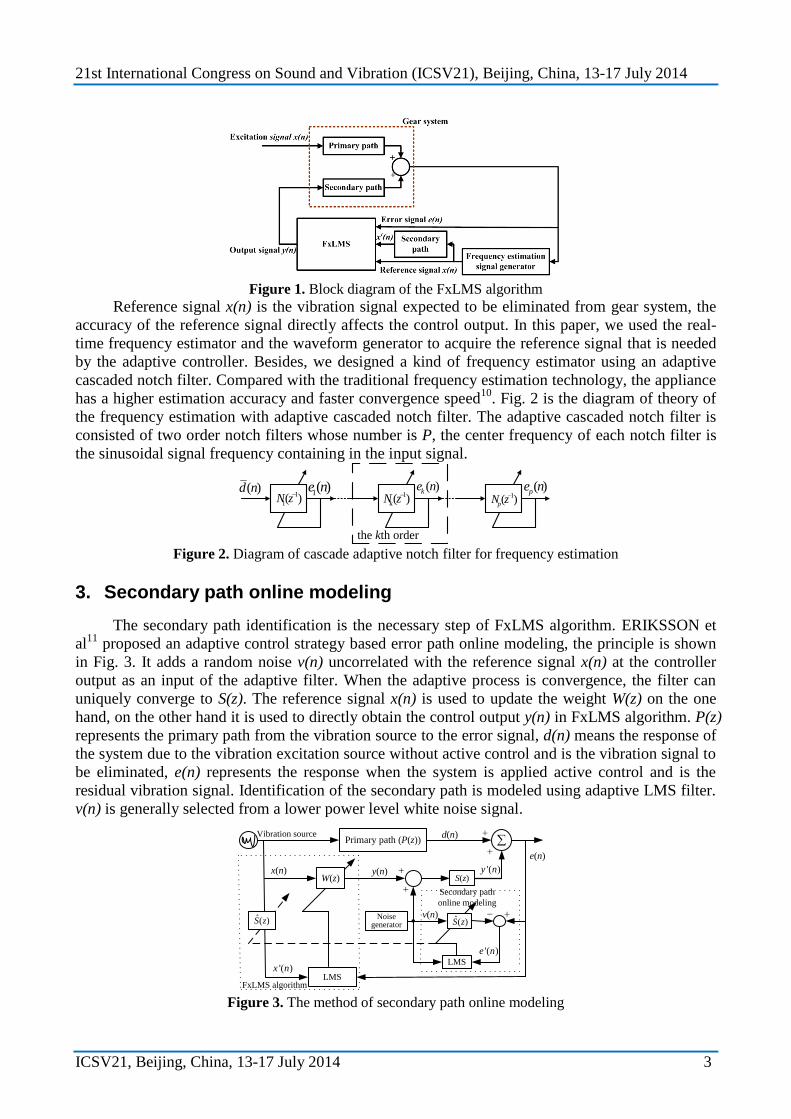
The secondary path identification is the necessary step of FxLMS algorithm. ERIKSSON et
al11
proposed an adaptive control strategy based error path online modeling, the principle is shown
in Fig. 3. It adds a random noise v(n) uncorrelated with the reference signal x(n) at the controller
output as an input of the adaptive filter. When the adaptive process is convergence, the filter can
uniquely converge to S(z). The reference signal x(n) is used to update the weight W(z) on the one
hand, on the other hand it is used to directly obtain the control output y(n) in FxLMS algorithm. P(z)
represents the primary path from the vibration source to the error signal, d(n) means the response of
the system due to the vibration excitation source without active control and is the vibration signal to
be eliminated, e(n) represents the response when the system is applied active control and is the
residual vibration signal. Identification of the secondary path is modeled using adaptive LMS filter.
v(n) is generally selected from a lower power level white noise signal.
S(z)
LMS
W(z)
Primary path (P(z))
e(n)
y(n)x(n)
Noise generator
LMS
)(ˆ zS
d(n)
'( )x n
)(ˆ zS
FxLMS algorithm
Secondary path
online modeling
Vibration source
'( )e n
v(n)
'( )y n
Figure 3. The method of secondary path online modeling
21st International Congress on Sound and Vibration (ICSV21), Beijing, China, 13-17 July 2014
ICSV21, Beijing, China, 13-17 July 2014 4
4. Active vibration control experiment
A gear transmission system is designed in this paper consisting of a pair of spur gears based
on the transverse vibration suppressing ideas.
4.1Control structure
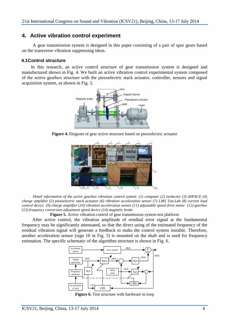
In this research, an active control structure of gear transmission system is designed and
manufactured shown in Fig. 4. We built an active vibration control experimental system composed
of the active gearbox structure with the piezoelectric stack actuator, controller, sensors and signal
acquisition system, as shown in Fig. 5.
Figure 4. Diagram of gear active structure based on piezoelectric actuator
Detail information of the active gearbox vibration control system: (1) computer (2) torductor (3) dSPACE (4)
charge amplifier (5) piezoelectric stack actuator (6) vibration acceleration sensor (7) LMS Test.Lab (8) current load
control device (9) charge amplifier (10) vibration acceleration sensor (11) adjustable speed drive motor (12) gearbox
(13) frequency conversion adjustment speed device (14) magnetic brake
Figure 5. Active vibration control of gear transmission system test platform
After active control, the vibration amplitude of residual error signal at the fundamental
frequency may be significantly attenuated, so that the direct using of the estimated frequency of the
residual vibration signal will generate a feedback to make the control system instable. Therefore,
another acceleration sensor (sign 10 in Fig. 5) is mounted on the shaft and is used for frequency
estimation. The specific schematic of the algorithm structure is shown in Fig. 6.
S(z)
LMS
W(z)
Gear system
y'(n)y(n)x(n)
White
noise
LMS
)(ˆ zS
d(n)
'( )x n
Frequency
estimator
Signal
generator
)(ˆ zS
v(n)
Acceleration
of axis
e(n)
Excitation
source
Figure 6. Test structure with hardware in loop
21st International Congress on Sound and Vibration (ICSV21), Beijing, China, 13-17 July 2014
ICSV21, Beijing, China, 13-17 July 2014 5
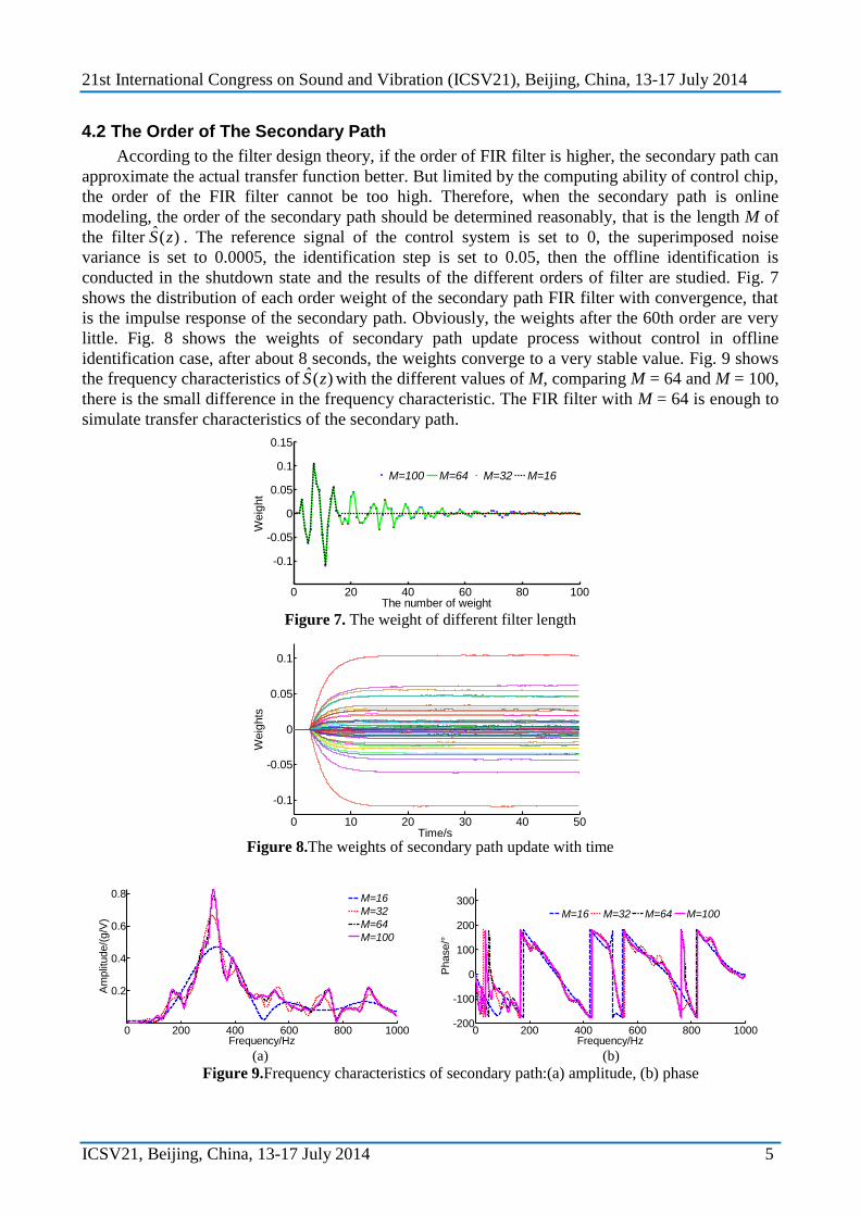
4.2 The Order of The Secondary Path
According to the filter design theory, if the order of FIR filter is higher, the secondary path can
approximate the actual transfer function better. But limited by the computing ability of control chip,
the order of the FIR filter cannot be too high. Therefore, when the secondary path is online
modeling, the order of the secondary path should be determined reasonably, that is the length M of
the filter )(ˆ zS . The reference signal of the control system is set to 0, the superimposed noise
variance is set to 0.0005, the identification step is set to 0.05, then the offline identification is
conducted in the shutdown state and the results of the different orders of filter are studied. Fig. 7
shows the distribution of each order weight of the secondary path FIR filter with convergence, that
is the impulse response of the secondary path. Obviously, the weights after the 60th order are very
little. Fig. 8 shows the weights of secondary path update process without control in offline
identification case, after about 8 seconds, the weights converge to a very stable value. Fig. 9 shows
the frequency characteristics of )(ˆ zS with the different values of M, comparing M = 64 and M = 100,
there is the small difference in the frequency characteristic. The FIR filter with M = 64 is enough to
simulate transfer characteristics of the secondary path.
0 20 40 60 80 100
-0.1
-0.05
0
0.05
0.1
0.15
The number of weight
Weig
ht
M=100 M=64 M=32 M=16
Figure 7. The weight of different filter length
0 10 20 30 40 50
-0.1
-0.05
0
0.05
0.1
Time/s
Weig
hts
Figure 8.The weights of secondary path update with time
0 200 400 600 800 1000
0.2
0.4
0.6
0.8
Frequency/Hz
Am
plit
ude/(
g/V
)
M=16
M=32
M=64
M=100
0 200 400 600 800 1000-200
-100
0
100
200
300
Frequency/Hz
Phase/°
M=16 M=32 M=64 M=100
(a) (b)
Figure 9.Frequency characteristics of secondary path:(a) amplitude, (b) phase
21st International Congress on Sound and Vibration (ICSV21), Beijing, China, 13-17 July 2014
ICSV21, Beijing, China, 13-17 July 2014 6
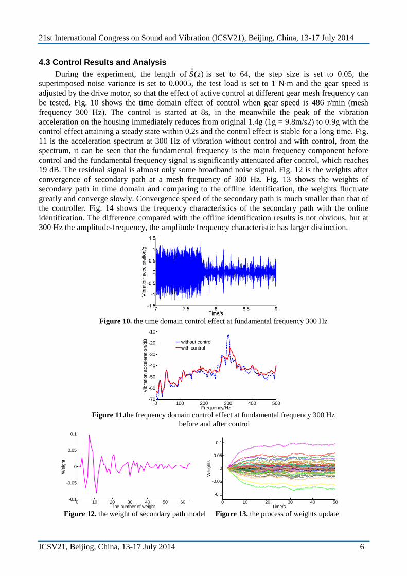
4.3 Control Results and Analysis
During the experiment, the length of )(ˆ zS is set to 64, the step size is set to 0.05, the
superimposed noise variance is set to 0.0005, the test load is set to 1 Nm and the gear speed is
adjusted by the drive motor, so that the effect of active control at different gear mesh frequency can
be tested. Fig. 10 shows the time domain effect of control when gear speed is 486 r/min (mesh
frequency 300 Hz). The control is started at 8s, in the meanwhile the peak of the vibration
acceleration on the housing immediately reduces from original 1.4g (1g = 9.8m/s2) to 0.9g with the
control effect attaining a steady state within 0.2s and the control effect is stable for a long time. Fig.
11 is the acceleration spectrum at 300 Hz of vibration without control and with control, from the
spectrum, it can be seen that the fundamental frequency is the main frequency component before
control and the fundamental frequency signal is significantly attenuated after control, which reaches
19 dB. The residual signal is almost only some broadband noise signal. Fig. 12 is the weights after
convergence of secondary path at a mesh frequency of 300 Hz. Fig. 13 shows the weights of
secondary path in time domain and comparing to the offline identification, the weights fluctuate
greatly and converge slowly. Convergence speed of the secondary path is much smaller than that of
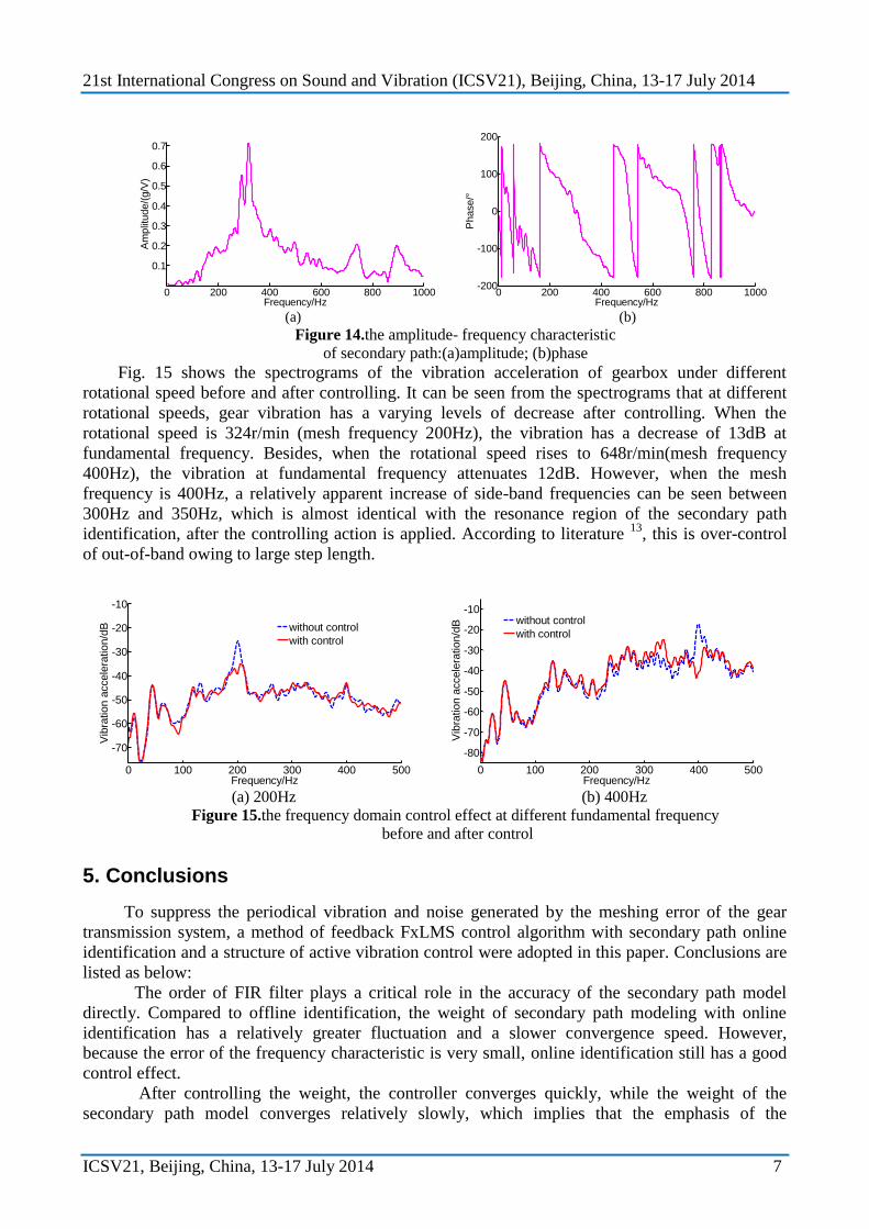
the controller. Fig. 14 shows the frequency characteristics of the secondary path with the online
identification. The difference compared with the offline identification results is not obvious, but at
300 Hz the amplitude-frequency, the amplitude frequency characteristic has larger distinction.
Figure 10. the time domain control effect at fundamental frequency 300 Hz
0 100 200 300 400 500-70
-60
-50
-40
-30
-20
-10
Frequency/Hz
Vib
ration a
ccele
ration/d
B
without control
with control
Figure 11.the frequency domain control effect at fundamental frequency 300 Hz
before and after control
0 10 20 30 40 50 60-0.1
-0.05
0
0.05
0.1
The number of weight
Weig
ht
0 10 20 30 40 50
-0.1
-0.05
0
0.05
0.1
Time/s
Weig
hts
Figure 12. the weight of secondary path model Figure 13. the process of weights update
21st International Congress on Sound and Vibration (ICSV21), Beijing, China, 13-17 July 2014
ICSV21, Beijing, China, 13-17 July 2014 7
0 200 400 600 800 1000
0.1
0.2
0.3
0.4
0.5
0.6
0.7
Frequency/Hz
Am
plit
ude/(
g/V
)
0 200 400 600 800 1000-200
-100
0
100
200
Frequency/Hz
Phase/°
(a) (b)
Figure 14.the amplitude- frequency characteristic
of secondary path:(a)amplitude; (b)phase
Fig. 15 shows the spectrograms of the vibration acceleration of gearbox under different
rotational speed before and after controlling. It can be seen from the spectrograms that at different
rotational speeds, gear vibration has a varying levels of decrease after controlling. When the
rotational speed is 324r/min (mesh frequency 200Hz), the vibration has a decrease of 13dB at
fundamental frequency. Besides, when the rotational speed rises to 648r/min(mesh frequency
400Hz), the vibration at fundamental frequency attenuates 12dB. However, when the mesh
frequency is 400Hz, a relatively apparent increase of side-band frequencies can be seen between
300Hz and 350Hz, which is almost identical with the resonance region of the secondary path
identification, after the controlling action is applied. According to literature 13
, this is over-control
of out-of-band owing to large step length.
0 100 200 300 400 500
-70
-60
-50
-40
-30
-20
-10
Frequency/Hz
Vib
ration a
ccele
ration/d
B
without control
with control
0 100 200 300 400 500
-80
-70
-60
-50
-40
-30
-20
-10
Frequency/Hz
Vib
ration a
ccele
ration/d
B
without control
with control
(a) 200Hz (b) 400Hz
Figure 15.the frequency domain control effect at different fundamental frequency
before and after control
5. Conclusions
To suppress the periodical vibration and noise generated by the meshing error of the gear
transmission system, a method of feedback FxLMS control algorithm with secondary path online
identification and a structure of active vibration control were adopted in this paper. Conclusions are
listed as below:
The order of FIR filter plays a critical role in the accuracy of the secondary path model
directly. Compared to offline identification, the weight of secondary path modeling with online
identification has a relatively greater fluctuation and a slower convergence speed. However,
because the error of the frequency characteristic is very small, online identification still has a good
control effect.
After controlling the weight, the controller converges quickly, while the weight of the
secondary path model converges relatively slowly, which implies that the emphasis of the
21st International Congress on Sound and Vibration (ICSV21), Beijing, China, 13-17 July 2014
ICSV21, Beijing, China, 13-17 July 2014 8
subsequent work should be put on how to improve the algorithm to quicken the convergence speed
of the secondary path.
(3) The vibration acceleration evoked by the superposing noise of online identification cannot
be offset, which leads to increase of vibration acceleration of some frequency bands but does not
have a big influence on the effect of control.
(4) When adopting the FxLMS algorithm with online secondary path identification at
different rotational speeds, the vibration accelerations at fundamental frequency are almost
suppressed, which accords with the theoretical results perfectly. The attenuation can respectively be
13dB, 19dB and 21dB when the mesh frequencies are 200Hz, 300Hz and 400Hz.
(5) When the fundamental frequency is 400Hz, some sideband frequencies of vibration
signals have some increase due to the over control of out-of-band caused by oversize convergence
step length.
Acknowledgements
This research is supported by the National Natural Science Foundation of China (Grant No. 50875270),
Foundation of state key laboratory of Mechanical Transmission (Grant No. SKLMT-ZZKT- 032).
REFERENCES
1 Montague G T, Kascak A F, Palazzolo A, et al, Feed-forward control of gear mesh vibration
using piezoelectric actuators, NASA Technique Memorandum 106366, (1994). 2 B. Rebbechi, C. Howard, C. Hansen, Active control of gearbox vibration, Proceedings of the
Active Control of Sound and Vibration Conference, Fort Lauderdale, 295-304, (1999). 3 Chen M H, Brennan M J, Active control of gear vibration using specially configured sensors
and actuators, Smart Materials and Structures, 9, 342-350, (2000). 4 Jian-Da Wu, Jia-Hong Lin, Implementation of an active vibration controller for gear-set shaft
using -analysis, Journal of Sound and Vibration, 281 (3-5), 1037-1055, (2005) 5 Li M F, Lim T C, Shepard W S, Experimental active vibration control of gear mesh
harmonics in a power recirculation gearbox system using a piezoelectric stack actuator, Smart
Materials and Structures, 14(5), 917–927, (2005) 6 M J Brennan, J Garcia-Bonito, S J Elliott, Experimental investigation of different actuator
technologies for active vibration control, Smart Materials and Structures, 8(1), 145–153,
(1999) 7 Widrow B, Shur D, Shaffer S, On adaptive inverse control, Proc.15th Asilomar Conf, Sata
Clara CA, 185-189, (1981). 8 Burgess J C, Active Adaptive Sound Control in a Duct: A Computer Simulation, The Journal
of the Acoustical Society of America, 70(3), 715–726, (1981) 9 Bernard Widrow, Samuel D. Stearns, Adaptive signal processing, China Machine Press,
Beijing, (2008) 10 Chu Zhao-Bi, Zhang Chong-Wei, Feng Xiao-Ying, Adaptive notch filter-based frequency
and amplitude estimation, Acta Automatica Sinica, 1(36), 60-66, (2010)(in Chinese) 11 Eriksson L J, Alile M A, Use of random noise for online transducer estimate in an adaptive
active attenuation systems, J. Acoust. Soc. Amer., 85(2), 797-802, (1989).