Embed Size (px)
DESCRIPTION
adp INFINTY 2008
Citation preview
7/21/2019 adp INFINTY 2008
http://slidepdf.com/reader/full/adp-infinty-2008 1/149ADP-1
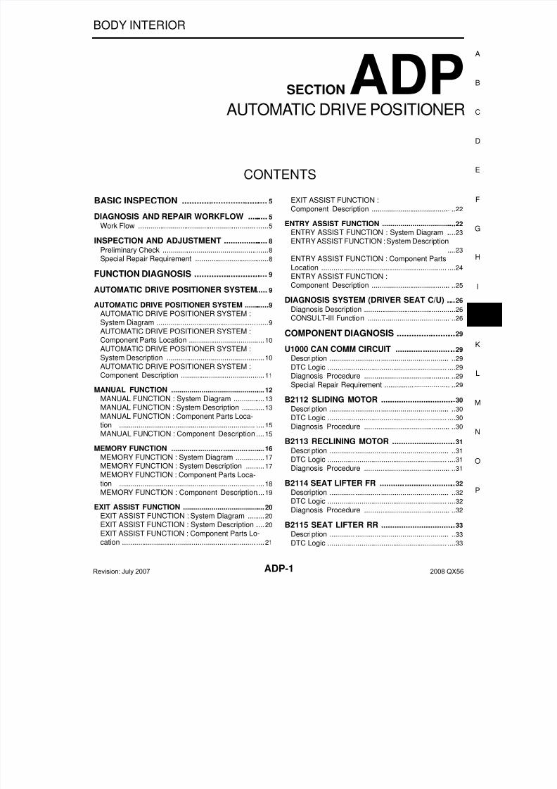
BODY INTERIOR
SECTIONADP
A
CONTENTS
AUTOMATIC DRIVE POSITIONER
BASIC INSPECTION .................................... 5
DIAGNOSIS AND REPAIR WORKFLOW .......... 5
Work Flow .................................................................5
INSPECTION AND ADJUSTMENT ..................... 8
Preliminary Check .....................................................8
Special Repair Requirement .....................................8
FUNCTION DIAGNOSIS ............................... 9
AUTOMATIC DRIVE POSITIONER SYSTEM..... 9
AUTOMATIC DRIVE POSITIONER SYSTEM .............9
AUTOMATIC DRIVE POSITIONER SYSTEM :System Diagram ........................................................9
AUTOMATIC DRIVE POSITIONER SYSTEM :Component Parts Location ......................................10
AUTOMATIC DRIVE POSITIONER SYSTEM :System Description .................................................10
AUTOMATIC DRIVE POSITIONER SYSTEM :Component Description ..........................................11
MANUAL FUNCTION ................................................12
MANUAL FUNCTION : System Diagram ................13
MANUAL FUNCTION : System Description ............13
MANUAL FUNCTION : Component Parts Loca-tion ..........................................................................15
MANUAL FUNCTION : Component Description ....15
MEMORY FUNCTION ...............................................16MEMORY FUNCTION : System Diagram ...............17
MEMORY FUNCTION : System Description ..........17
MEMORY FUNCTION : Component Parts Loca-tion ..........................................................................18
MEMORY FUNCTION : Component Description....19
EXIT ASSIST FUNCTION ..........................................20
EXIT ASSIST FUNCTION : System Diagram .........20
EXIT ASSIST FUNCTION : System Description .....20
EXIT ASSIST FUNCTION : Component Parts Lo-cation .......................................................................21
EXIT ASSIST FUNCTION :
Component Description ..........................................22
ENTRY ASSIST FUNCTION ......................................22ENTRY ASSIST FUNCTION : System Diagram .....23
ENTRY ASSIST FUNCTION : System Description
....23
ENTRY ASSIST FUNCTION : Component Parts
Location ...................................................................24
ENTRY ASSIST FUNCTION :
Component Description ..........................................25
DIAGNOSIS SYSTEM (DRIVER SEAT C/U) ....26
Diagnosis Description ..............................................26
CONSULT-III Function ............................................26
COMPONENT DIAGNOSIS .........................29
U1000 CAN COMM CIRCUIT ...........................29
Description ...............................................................29
DTC Logic ................................................................29
Diagnosis Procedure ..............................................29
Special Repair Requirement ....................................29
B2112 SLIDING MOTOR ..................................30
Description ...............................................................30
DTC Logic ................................................................30
Diagnosis Procedure ..............................................30
B2113 RECLINING MOTOR .............................31
Description ...............................................................31
DTC Logic ................................................................31
Diagnosis Procedure ..............................................31
B2114 SEAT LIFTER FR ..................................32
Description ...............................................................32
DTC Logic ................................................................32
Diagnosis Procedure ..............................................32
B2115 SEAT LIFTER RR ..................................33
Description ...............................................................33
DTC Logic ................................................................33
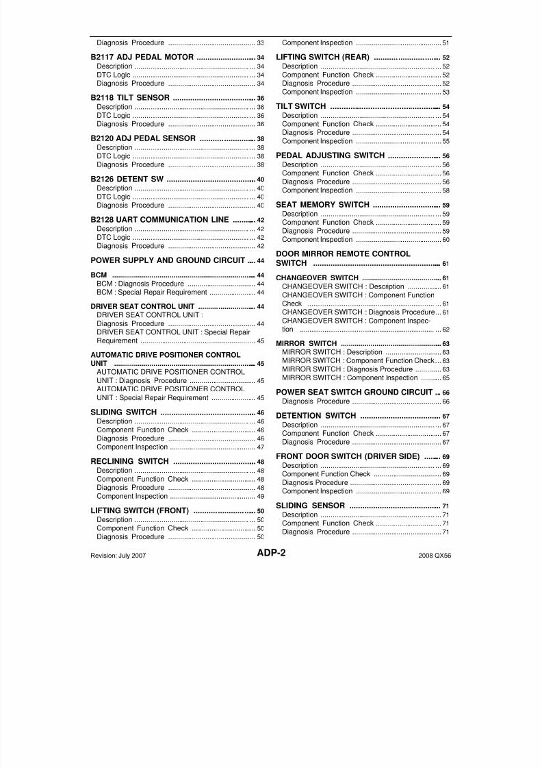
Revision: July 2007 2008 QX56
7/21/2019 adp INFINTY 2008
http://slidepdf.com/reader/full/adp-infinty-2008 2/149ADP-2
Diagnosis Procedure ............................................. 33
B2117 ADJ PEDAL MOTOR ............................. 34
Description .............................................................. 34
DTC Logic ............................................................... 34
Diagnosis Procedure ............................................. 34
B2118 TILT SENSOR ........................................ 36
Description .............................................................. 36DTC Logic ............................................................... 36
Diagnosis Procedure ............................................. 36
B2120 ADJ PEDAL SENSOR ........................... 38
Description .............................................................. 38
DTC Logic ............................................................... 38
Diagnosis Procedure ............................................. 38
B2126 DETENT SW ........................................... 40
Description .............................................................. 40
DTC Logic ............................................................... 40
Diagnosis Procedure ............................................. 40
B2128 UART COMMUNICATION LINE ............ 42
Description .............................................................. 42
DTC Logic ............................................................... 42
Diagnosis Procedure ............................................. 42
POWER SUPPLY AND GROUND CIRCUIT ..... 44
BCM ........................................................................... 44
BCM : Diagnosis Procedure ................................... 44
BCM : Special Repair Requirement ........................ 44
DRIVER SEAT CONTROL UNIT .............................. 44
DRIVER SEAT CONTROL UNIT :
Diagnosis Procedure ............................................. 44DRIVER SEAT CONTROL UNIT : Special RepairRequirement ........................................................... 45
AUTOMATIC DRIVE POSITIONER CONTROLUNIT .......................................................................... 45
AUTOMATIC DRIVE POSITIONER CONTROL
UNIT : Diagnosis Procedure .................................. 45
AUTOMATIC DRIVE POSITIONER CONTROL
UNIT : Special Repair Requirement ....................... 45
SLIDING SWITCH .............................................. 46
Description .............................................................. 46
Component Function Check ................................. 46
Diagnosis Procedure ............................................. 46
Component Inspection ............................................ 47
RECLINING SWITCH ........................................ 48
Description .............................................................. 48
Component Function Check ................................. 48
Diagnosis Procedure ............................................. 48
Component Inspection ............................................ 49
LIFTING SWITCH (FRONT) .............................. 50
Description .............................................................. 50
Component Function Check ................................. 50
Diagnosis Procedure ............................................. 50
Component Inspection ............................................ 51
LIFTING SWITCH (REAR) ................................ 52
Description .............................................................. 52
Component Function Check .................................. 52
Diagnosis Procedure .............................................. 52
Component Inspection ............................................ 53
TILT SWITCH .................................................... 54Description .............................................................. 54
Component Function Check .................................. 54
Diagnosis Procedure .............................................. 54
Component Inspection ............................................ 55
PEDAL ADJUSTING SWITCH .......................... 56
Description .............................................................. 56
Component Function Check .................................. 56
Diagnosis Procedure .............................................. 56
Component Inspection ............................................ 58
SEAT MEMORY SWITCH ................................. 59
Description .............................................................. 59
Component Function Check .................................. 59
Diagnosis Procedure .............................................. 59
Component Inspection ............................................ 60
DOOR MIRROR REMOTE CONTROLSWITCH ............................................................. 61
CHANGEOVER SWITCH .......................................... 61
CHANGEOVER SWITCH : Description .................. 61
CHANGEOVER SWITCH : Component FunctionCheck ...................................................................... 61
CHANGEOVER SWITCH : Diagnosis Procedure ... 61
CHANGEOVER SWITCH : Component Inspec-
tion .......................................................................... 62
MIRROR SWITCH ..................................................... 63
MIRROR SWITCH : Description ............................. 63
MIRROR SWITCH : Component Function Check ... 63
MIRROR SWITCH : Diagnosis Procedure .............. 63
MIRROR SWITCH : Component Inspection ........... 65
POWER SEAT SWITCH GROUND CIRCUIT ... 66
Diagnosis Procedure .............................................. 66
DETENTION SWITCH ....................................... 67
Description .............................................................. 67
Component Function Check .................................. 67Diagnosis Procedure .............................................. 67
FRONT DOOR SWITCH (DRIVER SIDE) ......... 69
Description .............................................................. 69
Component Function Check ................................... 69
Diagnosis Procedure ............................................... 69
Component Inspection ............................................ 69
SLIDING SENSOR ............................................ 71
Description .............................................................. 71
Component Function Check .................................. 71
Diagnosis Procedure .............................................. 71
Revision: July 2007 2008 QX56
7/21/2019 adp INFINTY 2008
http://slidepdf.com/reader/full/adp-infinty-2008 3/149ADP-3
A
RECLINING SENSOR ........................................73
Description ..............................................................73
Component Function Check ..................................73
Diagnosis Procedure ..............................................73
LIFTING SENSOR (FRONT) ..............................75
Description ..............................................................75
Component Function Check ..................................75
Diagnosis Procedure ..............................................75
LIFTING SENSOR (REAR) ................................77
Description ..............................................................77
Component Function Check ..................................77
Diagnosis Procedure ..............................................77
TILT SENSOR ....................................................79
Description ..............................................................79
Component Function Check ..................................79
Diagnosis Procedure ..............................................79
PEDAL ADJUSTING SENSOR ..........................81
Description ..............................................................81Component Function Check ..................................81
Diagnosis Procedure ..............................................81
MIRROR SENSOR .............................................83
DRIVER SIDE ............................................................83
DRIVER SIDE : Description ....................................83
DRIVER SIDE : Component Function Check ........83
DRIVER SIDE : Diagnosis Procedure ....................83
PASSENGER SIDE ...................................................85
PASSENGER SIDE : Description ...........................85
PASSENGER SIDE :
Component Function Check ..................................85PASSENGER SIDE : Diagnosis Procedure ...........85
SLIDING MOTOR ...............................................87
Description ..............................................................87
Component Function Check ..................................87
Diagnosis Procedure ..............................................87
RECLINING MOTOR ..........................................89
Description ..............................................................89
Component Function Check ..................................89
Diagnosis Procedure ..............................................89
LIFTING MOTOR (FRONT) ................................91
Description ..............................................................91
Component Function Check ..................................91
Diagnosis Procedure ..............................................91
LIFTING MOTOR (REAR) ..................................93
Description ..............................................................93
Component Function Check ..................................93
Diagnosis Procedure ..............................................93
TILT MOTOR ......................................................95
Description ..............................................................95
Component Function Check ..................................95
Diagnosis Procedure ..............................................95
PEDAL ADJUSTING MOTOR ..........................97
Description ...............................................................97
Component Function Check ..................................97
Diagnosis Procedure ..............................................97
DOOR MIRROR MOTOR ..................................99
Description ...............................................................99
Component Function Check ....................................99
Diagnosis Procedure ...............................................99Component Inspection ...........................................101
SEAT MEMORY INDICATOR LAMP .............. 102
Description .............................................................102
Component Function Check ................................102
Diagnosis Procedure ............................................102
Component Inspection ...........................................103
ECU DIAGNOSIS ....................................... 104
DRIVER SEAT CONTROL UNIT .................... 104
Reference Value ....................................................104
Wiring Diagram ......................................................109Fail Safe ................................................................122
DTC Index .............................................................123
AUTOMATIC DRIVE POSITIONER CON-TROL UNIT ...................................................... 124
Reference Value ....................................................124
Wiring Diagram ......................................................127
BCM (BODY CONTROL MODULE) ............... 141
Reference Value ....................................................141
Wiring Diagram ......................................................141
DTC Inspection Priority Chart .............................141
DTC Index .............................................................141
SYMPTOM DIAGNOSIS ............................ 142
ADP SYSTEM SYMPTOMS ............................ 142
Symptom Table .....................................................142
NORMAL OPERATING CONDITION ............. 144
Description .............................................................144
PRECAUTION ............................................ 145
PRECAUTIONS ............................................... 145
Precaution for Supplemental Restraint System
(SRS) "AIR BAG" and "SEAT BELT PRE-TEN-SIONER" ...............................................................145
Precaution for Work ...............................................145
ON-VEHICLE MAINTENANCE .................. 146
PRE-INSPECTION FOR DIAGNOSTIC .......... 146
Basic Inspection ....................................................146
PREPARATION ......................................... 148
PREPARATION ............................................... 148
Special Service Tool ..............................................148
Commercial Service Tool ......................................148
Revision: July 2007 2008 QX56

7/21/2019 adp INFINTY 2008
http://slidepdf.com/reader/full/adp-infinty-2008 4/149ADP-4
REMOVAL AND INSTALLATION ..............149 AUTOMATIC DRIVE POSITIONER .................149
Removal and Installation ....................................... 149
Revision: July 2007 2008 QX56
7/21/2019 adp INFINTY 2008
http://slidepdf.com/reader/full/adp-infinty-2008 5/149
DIAGNOSIS AND REPAIR WORKFLOW
ADP-5
< BASIC INSPECTION >
A
BASIC INSPECTIONDIAGNOSIS AND REPAIR WORKFLOW
Work Flow INFOID:0000000001735407
WORK FLOW
DETAILED FLOW
ALKIA0538GB
Revision: July 2007 2008 QX56
7/21/2019 adp INFINTY 2008
http://slidepdf.com/reader/full/adp-infinty-2008 6/149ADP-6
< BASIC INSPECTION >
DIAGNOSIS AND REPAIR WORKFLOW
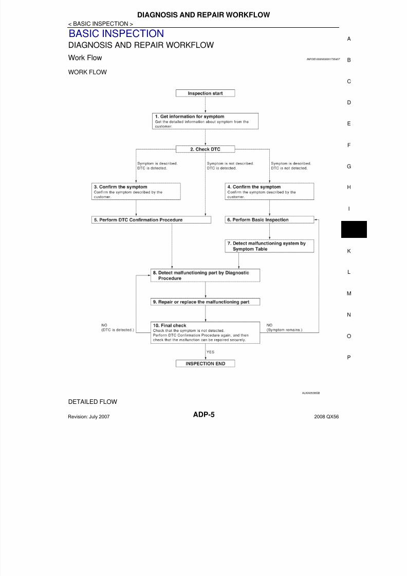
1. GET INFORMATION FOR SYMPTOM
Get the detailed information from the customer about the symptom (the condition and the environment whenthe incident/malfunction occurred).
>> GO TO 2
2. CHECK DTC WITH AUTOMATIC DRIVE POSITIONER SYSTEM
Check “Self Diagnostic Result” with CONSULT-III.Refer to ADP-123, "DTC Index".
Is any symptom described and any DTC is displayed?
Symptom is described, DTC is displayed.>>GO TO 3Symptom is not described, DTC is displayed.>>GO TO 7Symptom is described, DTC is not displayed.>>GO TO 4
3. CONFIRM THE SYMPTOM
Try to confirm the symptom described by the customer.
>> GO TO 7
4. CONFIRM THE SYMPTOMTry to confirm the symptom described by the customer.
>> GO TO 5
5. CHECK NORMAL OPERATING CONDITION
Check normal operating condition. Refer to ADP-144, "Description".
Is the incident normal operation?
YES >> INSPECTION ENDNO >> GO TO 6
6. PERFORM BASIC INSPECTION
Isolate the malfunctioning point with the basic inspection. Refer to ADP-8, "Preliminary Check".
>> GO TO 8
7. PERFORM DTC CONFIRMATION PROCEDURE
Perform the confirmation procedure for the detected DTC.
Is the DTC displayed?
YES >> GO TO 9NO >> Check intermittent incident. Refer to GI-38, "Intermittent Incident".
8. PERFORM COMPONENT FUNCTION CHECK
Perform the component function check for the isolated malfunctioning point.
>> GO TO 9
9. DETECT MALFUNCTIONING PART BY DIAGNOSTIC PROCEDURE
Isolate the malfunctioning point by performing the diagnosis procedure relevant to the symptom during thecomponent diagnosis.
>> GO TO 10
10. REPAIR OR REPLACE
Repair or replace the malfunctioning part.
Revision: July 2007 2008 QX56

7/21/2019 adp INFINTY 2008
http://slidepdf.com/reader/full/adp-infinty-2008 7/149
DIAGNOSIS AND REPAIR WORKFLOW
ADP-7
< BASIC INSPECTION >
A
>> GO TO 11
11. FINAL CHECK
Perform the DTC confirmation procedure (if DTC is detected) or component function check (if no DTC isdetected) again, and then check that the malfunction can be repaired securely.
Are all malfunctions corrected?
YES >> INSPECTION ENDSymptom is detected.>> GO TO 4DTC is detected.>> GO TO 7
Revision: July 2007 2008 QX56
7/21/2019 adp INFINTY 2008
http://slidepdf.com/reader/full/adp-infinty-2008 8/149ADP-8
< BASIC INSPECTION >
INSPECTION AND ADJUSTMENT
INSPECTION AND ADJUSTMENT
Preliminary Check INFOID:0000000001735408
1. FOREIGN OBJECTS
Check the following:• objects on or behind the seats that could cause binding
• objects under the seats that may be interfering with the seat’s moving parts• objects under pedals that may interfere with movement
Are there any foreign objects that could be causing interference?
YES >> Remove objects.NO >> GO TO 2
2. WIRING CONNECTIONS
1. Disconnect harness connectors.2. Check terminals for damage or loose connections.3. Reconnect harness connectors.
Are any connectors damaged or loose?
YES >> Repair or replace damaged parts.
NO >> GO TO 33. POWER AND GROUND
Check power supply and ground circuits for control unit. Refer to ADP-44, "DRIVER SEAT CONTROL UNIT :Diagnosis Procedure".
Is the inspection result normal?
YES >> Refer to ADP-123, "DTC Index".NO >> Repair or replace as necessary.
Special Repair Requirement INFOID:0000000001735409
Refer to Owner’s Manual for Automatic Drive Positioner system operating instructions.
Revision: July 2007 2008 QX56
7/21/2019 adp INFINTY 2008
http://slidepdf.com/reader/full/adp-infinty-2008 9/149
AUTOMATIC DRIVE POSITIONER SYSTEM
ADP-9
< FUNCTION DIAGNOSIS >
A
FUNCTION DIAGNOSISAUTOMATIC DRIVE POSITIONER SYSTEMAUTOMATIC DRIVE POSITIONER SYSTEM
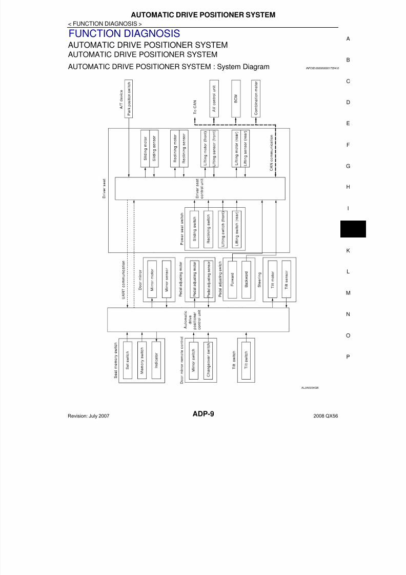
AUTOMATIC DRIVE POSITIONER SYSTEM : System Diagram INFOID:0000000001735410
ALJIA0234GB
Revision: July 2007 2008 QX56
7/21/2019 adp INFINTY 2008
http://slidepdf.com/reader/full/adp-infinty-2008 10/149ADP-10
< FUNCTION DIAGNOSIS >
AUTOMATIC DRIVE POSITIONER SYSTEM
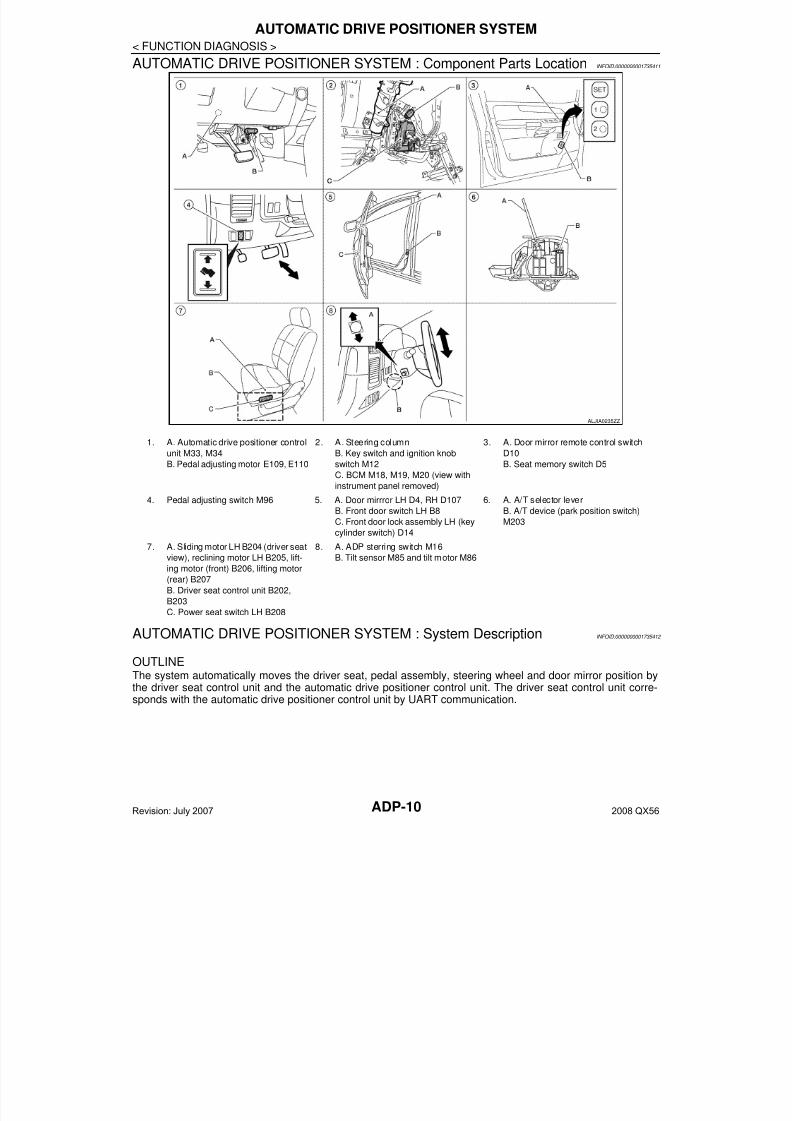
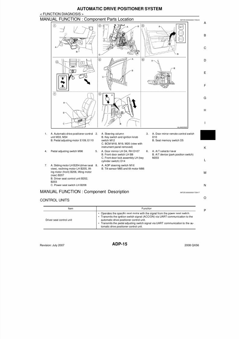
AUTOMATIC DRIVE POSITIONER SYSTEM : Component Parts Location INFOID:0000000001735411
AUTOMATIC DRIVE POSITIONER SYSTEM : System Description INFOID:0000000001735412
OUTLINEThe system automatically moves the driver seat, pedal assembly, steering wheel and door mirror position bythe driver seat control unit and the automatic drive positioner control unit. The driver seat control unit corre-sponds with the automatic drive positioner control unit by UART communication.
ALJIA0235ZZ
1. A. Automatic drive positioner control
unit M33, M34
B. Pedal adjusting motor E109, E110
2. A. Steering column
B. Key switch and ignition knob
switch M12
C. BCM M18, M19, M20 (view withinstrument panel removed)
3. A. Door mirror remote control switch
D10
B. Seat memory switch D5
4. Pedal adjusting switch M96 5. A. Door mirrror LH D4, RH D107
B. Front door switch LH B8
C. Front door lock assembly LH (key
cylinder switch) D14
6. A. A/T selector lever
B. A/T device (park position switch)
M203
7. A. Sliding motor LH B204 (driver seat
view), reclining motor LH B205, lift-
ing motor (front) B206, lifting motor
(rear) B207
B. Driver seat control unit B202,
B203
C. Power seat switch LH B208
8. A. ADP sterring switch M16
B. Tilt sensor M85 and tilt motor M86
Revision: July 2007 2008 QX56
7/21/2019 adp INFINTY 2008
http://slidepdf.com/reader/full/adp-infinty-2008 11/149
AUTOMATIC DRIVE POSITIONER SYSTEM
ADP-11
< FUNCTION DIAGNOSIS >
A
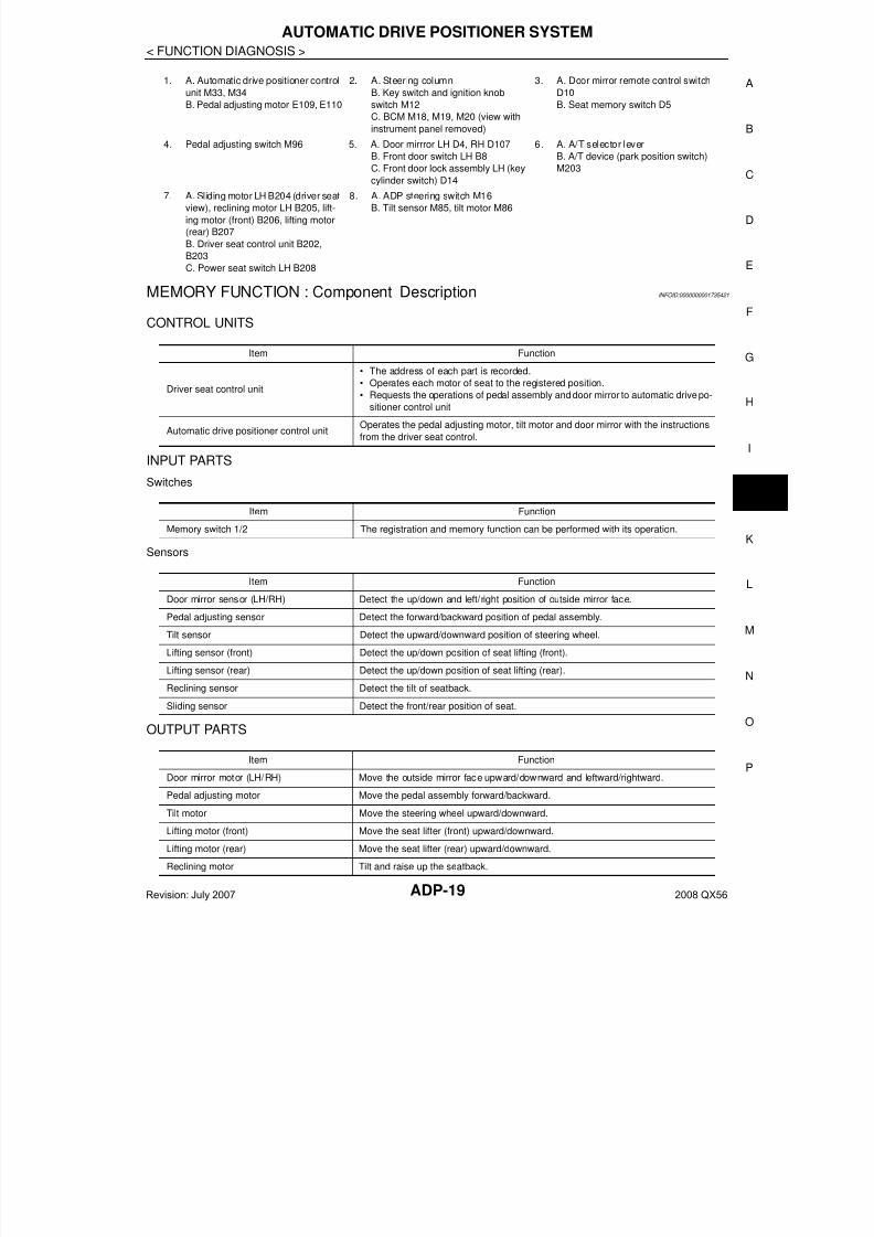
AUTOMATIC DRIVE POSITIONER SYSTEM : Component Description INFOID:0000000001735413
CONTROL UNITS
INPUT PARTS
Switches
Function Description
Manual function
The driving position (seat, pedal assembly, steering wheel and door mirror position)
can be adjusted by using the power seat switch, pedal adjusting switch, ADP steering
switch or door mirror remote control switch.
Memory functionThe seat, pedal assembly and outside mirror move to the stored driving position by
pressing seat memory switch (1 or 2).
Entry/Exit assist functionExit On exit, the seat moves backward and the steering wheel moves upward.
EntryOn entry, the seat and steering wheel return from exiting position to the previous driv-
ing position.
Item Function
Driver seat control unit
• Main unit of automatic drive positioner system
• It is connected to the CAN.
• It communicates with the automatic drive positioner control unit via UART com-
munication.
Automatic drive positioner control unit
• It communicates with the driver seat control unit via UART communication.
• Perform various controls with the instructions of driver seat control unit.
• Perform the controls of the pedal adjusting, steering wheel, door mirror and the
seat memory switch.
BCM
Transmit the following status to the driver seat control unit via CAN communication.
• Front door LH: OPEN/CLOSE
• Ignition switch position: ACC/ON
• Door lock: UNLOCK (with Intelligent Key or remote keyless entry request switch
operation)
• Key ID
• Key switch: Insert/Pull out Intelligent Key
• Starter: CRANKING/OTHER
Combination meter
Transmit the vehicle speed signal to the driver seat control unit via CAN communi-
cation.
AV control unit The setting change of auto drive positioner system can be performed on the display.
A/T device (park position switch) Transmit the shift position signal (P range) to the driver seat control unit.
Item Function
Key switch and ignition knob switch The key switch is installed to detect the key inserted/removed status.
Front door switch LH Detect front door (driver side) open/close status.
A/T device (park position switch) Detect the P range position of A/T selector lever.
Set switch The registration and system setting can be performed with its operation.
Seat memory switch 1/2 The registration and operation can be performed with its operation.
Power seat switch
The following switch is installed.
• Reclining switch
• Lifting switch (front)
• Lifting switch (rear)
• Sliding switch
The specific parts can be operated with the operation of each switch.
Pedal adjusting switch
The following switch is installed.
• Pedal forward
• Pedal backward
The specific parts can be operated with the operation of each switch.
Revision: July 2007 2008 QX56
7/21/2019 adp INFINTY 2008
http://slidepdf.com/reader/full/adp-infinty-2008 12/149ADP-12
< FUNCTION DIAGNOSIS >
AUTOMATIC DRIVE POSITIONER SYSTEM
Sensors
OUTPUT PARTS
MANUAL FUNCTION
ADP steering switch
The following switch is installed.
• Steering wheel UP
• Steering wheel down
The specific parts can be operated with the operation of each switch.
Door mirror remote control switch
The following switch is installed.
• Mirror switch
• Changeover switch
The specific parts can be operated with the operation of each switch.
Item Function
Item Function
Door mirror sensor (LH/RH) Detect the up/down and left /right posit ion of outside mirror face.
Pedal adjusting sensor Detect the forward/backward position of pedal assembly.
Tilt sensor Detect the upward/downward position of the steering wheel.
Lifting sensor (front) Detect the up/down position of seat lifting (front).
Lifting sensor (rear) Detect the up/down position of seat lifting (rear).
Reclining sensor Detect the tilt of seatback.
Sliding sensor Detect the front/rear position of seat.
Item Function
Door mirror motor (LH/RH) Move the outside mirror face upward/downward and leftward/rightward.
Pedal adjusting motor Move the pedal assembly forward/backward.
Tilt motor Move the steering wheel upward/downward.
Lifting motor (front) Move the seat lifting (front) upward/downward.
Lifting motor (rear) Move the seat lifting (rear) upward/downward.
Reclining motor Tilt and raise up the seatback.
Sliding motor Slide the seat forward/backward.
Seat memory indicator Illuminates or flashes according to the registration/operation status.
Revision: July 2007 2008 QX56

7/21/2019 adp INFINTY 2008
http://slidepdf.com/reader/full/adp-infinty-2008 13/149
AUTOMATIC DRIVE POSITIONER SYSTEM
ADP-13
< FUNCTION DIAGNOSIS >
A
MANUAL FUNCTION : System Diagram INFOID:0000000001735414
MANUAL FUNCTION : System Description INFOID:0000000001735415
OUTLINEThe driving position (seat, pedal assembly, steering wheel and door mirror position) can be adjusted manuallywith power seat switch, pedal adjusting switch, ADP steering switch and door mirror remote control switch.
OPERATION PROCEDURE1. Turn ignition switch ON.2. Operate power seat switch, pedal adjusting switch, ADP steering switch or door mirror remote control
switch.3. The driver seat, pedal assembly, steering wheel or door mirror operates according to the operation of
each switch.
DETAIL FLOW
Seat
Adjustable pedals
ALJIA0236GB
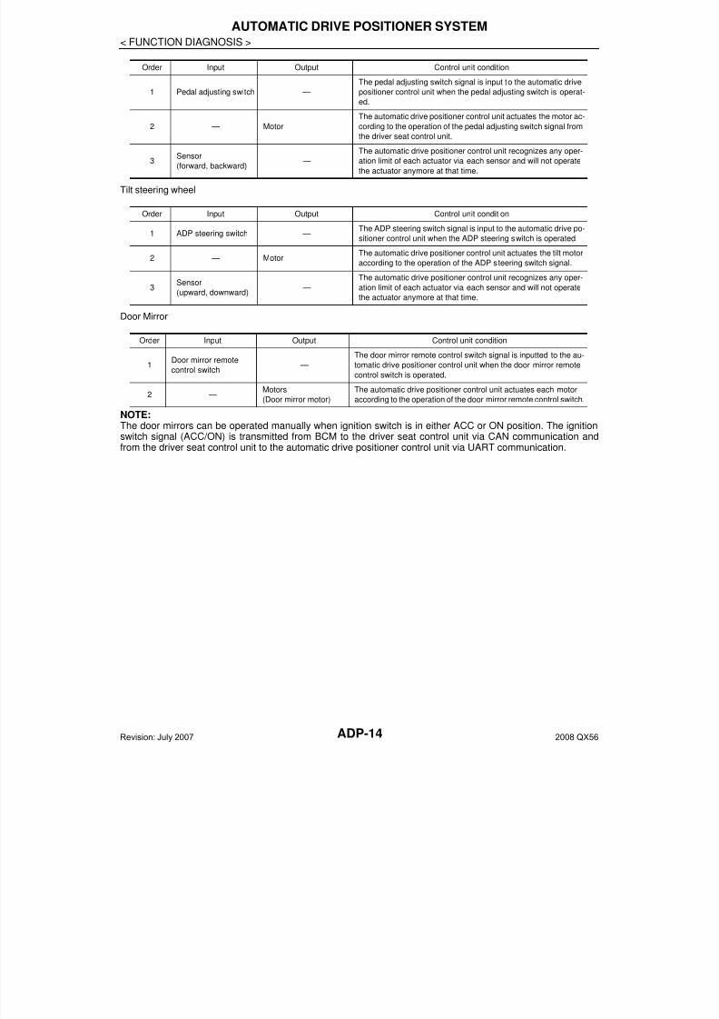
Order Input Output Control unit condition
1
Power seat switch
(sliding, lifting, reclin-
ing)
—The power seat switch signal is inputted to the driver seat control
unit when the power seat switch is operated.
2 —
Motors
(sliding, lifting, reclin-
ing)
The driver seat control unit outputs signals to each motor accord-
ing to the power seat switch input signal.
Revision: July 2007 2008 QX56
7/21/2019 adp INFINTY 2008
http://slidepdf.com/reader/full/adp-infinty-2008 14/149ADP-14
< FUNCTION DIAGNOSIS >
AUTOMATIC DRIVE POSITIONER SYSTEM
Tilt steering wheel
Door Mirror
NOTE:The door mirrors can be operated manually when ignition switch is in either ACC or ON position. The ignitionswitch signal (ACC/ON) is transmitted from BCM to the driver seat control unit via CAN communication andfrom the driver seat control unit to the automatic drive positioner control unit via UART communication.
Order Input Output Control unit condition
1 Pedal adjusting switch —
The pedal adjusting switch signal is input to the automatic drive
positioner control unit when the pedal adjusting switch is operat-
ed.
2 — Motor
The automatic drive positioner control unit actuates the motor ac-
cording to the operation of the pedal adjusting switch signal from
the driver seat control unit.
3Sensor
(forward, backward) —
The automatic drive positioner control unit recognizes any oper-
ation limit of each actuator via each sensor and will not operate
the actuator anymore at that time.
Order Input Output Control unit condition
1 ADP steering switch —The ADP steering switch signal is input to the automatic drive po-
sitioner control unit when the ADP steering switch is operated.
2 — MotorThe automatic drive positioner control unit actuates the tilt motor
according to the operation of the ADP steering switch signal.
3
Sensor
(upward, downward) —
The automatic drive positioner control unit recognizes any oper-
ation limit of each actuator via each sensor and will not operatethe actuator anymore at that time.
Order Input Output Control unit condition
1Door mirror remote
control switch —
The door mirror remote control switch signal is inputted to the au-
tomatic drive positioner control unit when the door mirror remote
control switch is operated.
2 —Motors
(Door mirror motor)
The automatic drive positioner control unit actuates each motor
according to the operation of the door mirror remote control switch.
Revision: July 2007 2008 QX56
7/21/2019 adp INFINTY 2008
http://slidepdf.com/reader/full/adp-infinty-2008 15/149
AUTOMATIC DRIVE POSITIONER SYSTEM
ADP-15
< FUNCTION DIAGNOSIS >
A
MANUAL FUNCTION : Component Parts Location INFOID:0000000001735416
MANUAL FUNCTION : Component Description INFOID:0000000001735417
CONTROL UNITS
ALJIA0235ZZ
1. A. Automatic drive positioner control
unit M33, M34
B. Pedal adjusting motor E109, E110
2. A. Steering column
B. Key switch and ignition knob
switch M12
C. BCM M18, M19, M20 (view withinstrument panel removed)
3. A. Door mirror remote control switch
D10
B. Seat memory switch D5
4. Pedal adjusting switch M96 5. A. Door mirrror LH D4, RH D107
B. Front door switch LH B8
C. Front door lock assembly LH (key
cylinder switch) D14
6. A. A/T selector lever
B. A/T device (park position switch)
M203
7. A. Sliding motor LH B204 (driver seat
view), reclining motor LH B205, lift-
ing motor (front) B206, lifting motor
(rear) B207
B. Driver seat control unit B202,
B203
C. Power seat switch LH B208
8. A. ADP steering switch M16
B. Tilt sensor M85 and tilt motor M86
Item Function
Driver seat control unit
• Operates the specific seat motor with the signal from the power seat switch.
• Transmits the ignition switch signal (ACC/ON) via UART communication to the
automatic drive positioner control unit.
• Transmits the pedal adjusting switch signal via UART communication to the au-
tomatic drive positioner control unit.
Revision: July 2007 2008 QX56
7/21/2019 adp INFINTY 2008
http://slidepdf.com/reader/full/adp-infinty-2008 16/149ADP-16
< FUNCTION DIAGNOSIS >
AUTOMATIC DRIVE POSITIONER SYSTEM
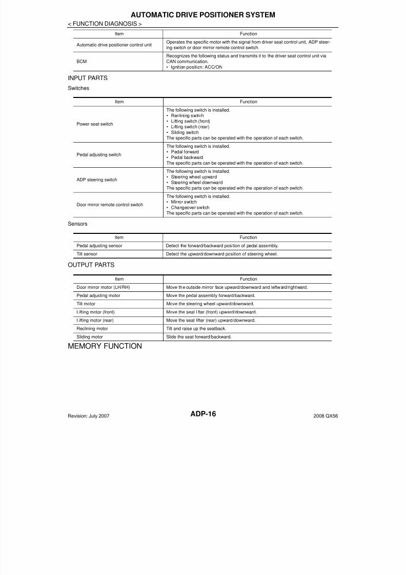
INPUT PARTS
Switches
Sensors
OUTPUT PARTS
MEMORY FUNCTION
Automatic drive positioner control unitOperates the specific motor with the signal from driver seat control unit, ADP steer-
ing switch or door mirror remote control switch.
BCM
Recognizes the following status and transmits it to the driver seat control unit via
CAN communication.
• Ignition position: ACC/ON
Item Function
Item Function
Power seat switch
The following switch is installed.
• Reclining switch
• Lifting switch (front)
• Lifting switch (rear)
• Sliding switch
The specific parts can be operated with the operation of each switch.
Pedal adjusting switch
The following switch is installed.
• Pedal forward
• Pedal backward
The specific parts can be operated with the operation of each switch.
ADP steering switch
The following switch is installed.
• Steering wheel upward
• Steering wheel downward
The specific parts can be operated with the operation of each switch.
Door mirror remote control switch
The following switch is installed.
• Mirror switch
• Changeover switch
The specific parts can be operated with the operation of each switch.
Item Function
Pedal adjusting sensor Detect the forward/backward position of pedal assembly.
Tilt sensor Detect the upward/downward position of steering wheel.
Item Function
Door mirror motor (LH/RH) Move the outside mirror face upward/downward and leftward/rightward.
Pedal adjusting motor Move the pedal assembly forward/backward.
Tilt motor Move the steering wheel upward/downward.
Lifting motor (front) Move the seat lifter (front) upward/downward.
Lifting motor (rear) Move the seat lifter (rear) upward/downward.
Reclining motor Tilt and raise up the seatback.
Sliding motor Slide the seat forward/backward.
Revision: July 2007 2008 QX56

7/21/2019 adp INFINTY 2008
http://slidepdf.com/reader/full/adp-infinty-2008 17/149
AUTOMATIC DRIVE POSITIONER SYSTEM
ADP-17
< FUNCTION DIAGNOSIS >
A
MEMORY FUNCTION : System Diagram INFOID:0000000001735418
MEMORY FUNCTION : System Description INFOID:0000000001735419
OUTLINEThe driver seat control unit can store the optimum driving positions (seat, pedal assembly, steering wheel anddoor mirror position) for 2 people. If the front seat position is changed, one-touch (pressing desired memoryswitch for more than 0.5 second) operation allows changing to the other driving position.NOTE:Further information for the memory storage procedure. Refer to Owner’s Manual.
OPERATION PROCEDURE1. Turn ignition switch ON2. Press desired memory switch for more than 0.5 second.3. Front seat LH, pedal assembly, steering wheel and door mirror will move to the memorized position.
OPERATION CONDITIONSatisfy all of the following items. The memory function is not performed if these items are not satisfied.
DETAIL FLOW
ALJIA0237GB
Item Request status
Ignition position ON
Switch inputs
• Power seat switch
• Pedal adjusting switch
• ADP steering switch
• Door mirror control switch
• Set switch
• Seat memory switch
OFF
(Not operated)
A/T selector lever P position
Revision: July 2007 2008 QX56
7/21/2019 adp INFINTY 2008
http://slidepdf.com/reader/full/adp-infinty-2008 18/149ADP-18
< FUNCTION DIAGNOSIS >
AUTOMATIC DRIVE POSITIONER SYSTEM
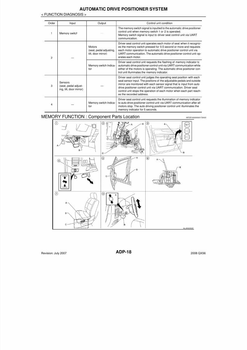
MEMORY FUNCTION : Component Parts Location INFOID:0000000001735420
Order Input Output Control unit condition
1 Memory switch —
The memory switch signal is inputted to the automatic drive positioner
control unit when memory switch 1 or 2 is operated.
Memory switch signal is input to driver seat control unit via UART
communication.
2 —
Motors
(seat, pedal adjusting,tilt, door mirror)
Driver seat control unit operates each motor of seat when it recogniz-
es the memory switch pressed for 0.5 second or more and requests
each motor operation to automatic drive positioner control unit viaUART communication. The automatic drive positioner control unit op-
erates each motor.
Memory switch Indica-
tor
Driver seat control unit requests the flashing of memory indicator to
automatic drive positioner control unit via UART communication while
either of the motors is operating. The automatic drive positioner con-
trol unit illuminates the memory indicator.
3
Sensors
(seat, pedal adjust-
ing, tilt, door mirror)
—
Driver seat control unit judges the operating seat position with each
seat sensor input. The positions of the adjustable pedals and outside
mirror are monitored with each sensor signal that is input from auto
drive positioner control unit via UART communication. Driver seat
control unit stops the operation of each motor when each part reach-
es the recorded address.
4 —Memory switch Indica-
tor
Driver seat control unit requests the illumination of memory indicatorto auto drive positioner control unit via UART communication after all
motors stop. The auto driving positioner control unit illuminates the
memory indicator for 5 seconds.
ALJIA0235ZZ
Revision: July 2007 2008 QX56
7/21/2019 adp INFINTY 2008
http://slidepdf.com/reader/full/adp-infinty-2008 19/149
AUTOMATIC DRIVE POSITIONER SYSTEM
ADP-19
< FUNCTION DIAGNOSIS >
A
MEMORY FUNCTION : Component Description INFOID:0000000001735421
CONTROL UNITS
INPUT PARTS
Switches
Sensors
OUTPUT PARTS
1. A. Automatic drive positioner control
unit M33, M34
B. Pedal adjusting motor E109, E110
2. A. Steering column
B. Key switch and ignition knob
switch M12
C. BCM M18, M19, M20 (view with
instrument panel removed)
3. A. Door mirror remote control switch
D10
B. Seat memory switch D5
4. Pedal adjusting switch M96 5. A. Door mirrror LH D4, RH D107
B. Front door switch LH B8
C. Front door lock assembly LH (key
cylinder switch) D14
6. A. A/T selector lever
B. A/T device (park position switch)
M203
7. A. Sliding motor LH B204 (driver seat
view), reclining motor LH B205, lift-
ing motor (front) B206, lifting motor
(rear) B207
B. Driver seat control unit B202,
B203
C. Power seat switch LH B208
8. A. ADP steering switch M16
B. Tilt sensor M85, tilt motor M86
Item Function
Driver seat control unit
• The address of each part is recorded.
• Operates each motor of seat to the registered position.
• Requests the operations of pedal assembly and door mirror to automatic drive po-
sitioner control unit
Automatic drive positioner control unitOperates the pedal adjusting motor, tilt motor and door mirror with the instructions
from the driver seat control.
Item Function
Memory switch 1/2 The registration and memory function can be performed with its operation.
Item Function
Door mirror sensor (LH/RH) Detect the up/down and left/right position of outside mirror face.
Pedal adjusting sensor Detect the forward/backward position of pedal assembly.
Tilt sensor Detect the upward/downward position of steering wheel.
Lifting sensor (front) Detect the up/down position of seat lifting (front).
Lifting sensor (rear) Detect the up/down position of seat lifting (rear).
Reclining sensor Detect the tilt of seatback.
Sliding sensor Detect the front/rear position of seat.
Item Function
Door mirror motor (LH/RH) Move the outside mirror face upward/downward and leftward/rightward.
Pedal adjusting motor Move the pedal assembly forward/backward.
Tilt motor Move the steering wheel upward/downward.
Lifting motor (front) Move the seat lifter (front) upward/downward.
Lifting motor (rear) Move the seat lifter (rear) upward/downward.
Reclining motor Tilt and raise up the seatback.
Revision: July 2007 2008 QX56
7/21/2019 adp INFINTY 2008
http://slidepdf.com/reader/full/adp-infinty-2008 20/149ADP-20
< FUNCTION DIAGNOSIS >
AUTOMATIC DRIVE POSITIONER SYSTEM
EXIT ASSIST FUNCTION
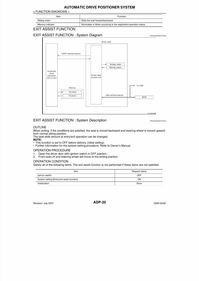
EXIT ASSIST FUNCTION : System Diagram INFOID:0000000001735422
EXIT ASSIST FUNCTION : System Description INFOID:0000000001735423
OUTLINEWhen exiting, if the conditions are satisfied, the seat is moved backward and steering wheel is moved upward-from normal sitting position.The seat slide amount at entry/exit operation can be changed.NOTE:• This function is set to OFF before delivery (initial setting).• Further information for the system setting procedure. Refer to Owner’s Manual.
OPERATION PROCEDURE1. Open the driver door with ignition switch in OFF position.2. Front seat LH and steering wheel will move to the exiting position.
OPERATION CONDITIONSatisfy all of the following items. The exit assist function is not performed if these items are not satisfied.
Sliding motor Slide the seat forward/backward.
Memory indicator Illuminates or blinks according to the registration/operation status.
Item Function
ALJIA0238GB
Item Request status
Ignition switch OFF
System setting [Entry/exit assist function] ON
Initialization Done
Revision: July 2007 2008 QX56

7/21/2019 adp INFINTY 2008
http://slidepdf.com/reader/full/adp-infinty-2008 21/149
AUTOMATIC DRIVE POSITIONER SYSTEM
ADP-21
< FUNCTION DIAGNOSIS >
A
DETAIL FLOW
EXIT ASSIST FUNCTION : Component Parts Location INFOID:0000000001735424
Switch inputs
• Power seat switch
• Pedal adjusting switch
• ADP steering switch
• Door mirror remote control switch
• Set switch
• Seat memory switch
OFF
(Not operated)
A/T selector lever P position
Item Request status
Order Input Output Control unit condition
1 Front door switch LH —Driver seat control unit receives front door switch LH signal (open)
from BCM via CAN communication.
2 —Motors (seat sliding,
tilt)
Driver seat control unit operates the seat sliding motor, which recog-
nizes that the front door LH is opened with ignition switch OFF. Driv-
er seat control unit then requests the operation of the tilt motor to the
automatic drive positioner control unit via UART communication.
The automatic drive positioner control unit operates the motor for a
constant amount.
ALJIA0235ZZ
Revision: July 2007 2008 QX56
7/21/2019 adp INFINTY 2008
http://slidepdf.com/reader/full/adp-infinty-2008 22/149ADP-22
< FUNCTION DIAGNOSIS >
AUTOMATIC DRIVE POSITIONER SYSTEM
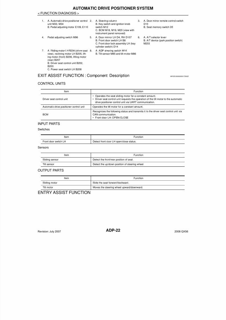
EXIT ASSIST FUNCTION : Component Description INFOID:0000000001735425
CONTROL UNITS
INPUT PARTS
Switches
Sensors
OUTPUT PARTS
ENTRY ASSIST FUNCTION
1. A. Automatic drive positioner control
unit M33, M34
B. Pedal adjusting motor E109, E110
2. A. Steering column
B. Key switch and ignition knob
switch M12
C. BCM M18, M19, M20 (view with
instrument panel removed)
3. A. Door mirror remote control switch
D10
B. Seat memory switch D5
4. Pedal adjusting switch M96 5. A. Door mirrror LH D4, RH D107
B. Front door switch LH B8
C. Front door lock assembly LH (key
cylinder switch) D14
6. A. A/T selector lever
B. A/T device (park position switch)
M203
7. A. Sliding motor LH B204 (driver seat
view), reclining motor LH B205, lift-
ing motor (front) B206, lifting motor
(rear) B207
B. Driver seat control unit B202,
B203
C. Power seat switch LH B208
8. A. ADP steering switch M16
B. Tilt sensor M85 and tilt motor M86
Item Function
Driver seat control unit
• Operates the seat sliding motor for a constant amount.
• Driver seat control unit requests the operation of the tilt motor to the automatic
drive positioner control unit via UART communication.
Automatic drive positioner control unit Operates the tilt motor for a constant amount.
BCM
Recognizes the following status and transmits it to the driver seat control unit via
CAN communication.
• Front door LH: OPEN/CLOSE
Item Function
Front door switch LH Detect front door LH open/close status.
Item Function
Sliding sensor Detect the front/rear position of seat.
Tilt sensor Detect the up/down position of steering wheel.
Item Function
Sliding motor Slide the seat forward/backward.
Tilt motor Moves the steering wheel upward/downward.
Revision: July 2007 2008 QX56
7/21/2019 adp INFINTY 2008
http://slidepdf.com/reader/full/adp-infinty-2008 23/149
AUTOMATIC DRIVE POSITIONER SYSTEM
ADP-23
< FUNCTION DIAGNOSIS >
A
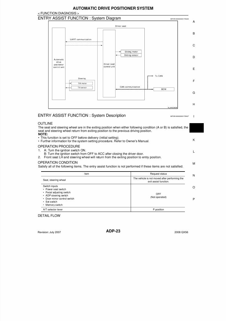
ENTRY ASSIST FUNCTION : System Diagram INFOID:0000000001735426
ENTRY ASSIST FUNCTION : System Description INFOID:0000000001735427
OUTLINEThe seat and steering wheel are in the exiting position when either following condition (A or B) is satisfied, theseat and steering wheel return from exiting position to the previous driving position.NOTE:• This function is set to OFF before delivery (initial setting).• Further information for the system setting procedure. Refer to Owner’s Manual.
OPERATION PROCEDURE1. A: Turn the ignition switch ON.
B: Turn the ignition switch from OFF to ACC after closing the driver door.2. Front seat LH and steering wheel will return from the exiting position to entry position.
OPERATION CONDITIONSatisfy all of the following items. The entry assist function is not performed if these items are not satisfied.
DETAIL FLOW
ALJIA0238GB
Item Request status
Seat, steering wheelThe vehicle is not moved after performing the
exit assist function.
Switch inputs
• Power seat switch
• Pedal adjusting switch
• ADP steering switch
• Door mirror control switch
• Set switch
• Memory switch
OFF
(Not operated)
A/T selector lever P position
Revision: July 2007 2008 QX56
7/21/2019 adp INFINTY 2008
http://slidepdf.com/reader/full/adp-infinty-2008 24/149ADP-24
< FUNCTION DIAGNOSIS >
AUTOMATIC DRIVE POSITIONER SYSTEM
ENTRY ASSIST FUNCTION : Component Parts Location INFOID:0000000001735428
Order Input Output Control unit condition
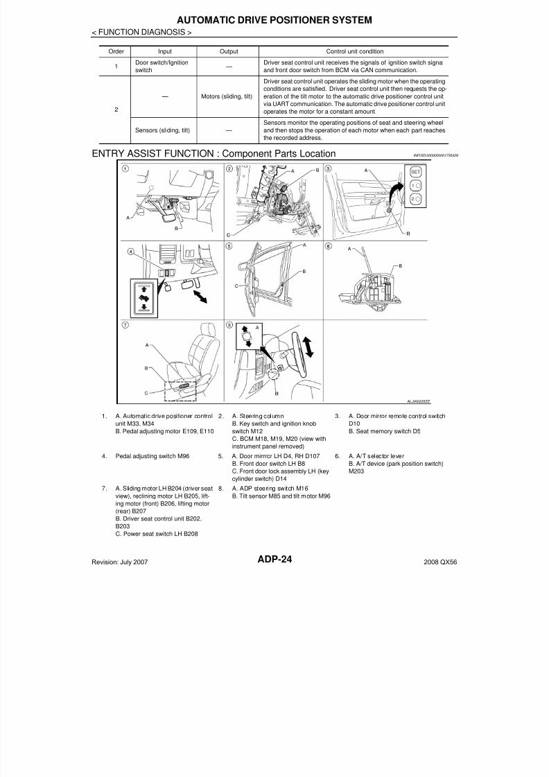
1Door switch/Ignition
switch —
Driver seat control unit receives the signals of ignition switch signal
and front door switch from BCM via CAN communication.
2
— Motors (sliding, tilt)
Driver seat control unit operates the sliding motor when the operating
conditions are satisfied. Driver seat control unit then requests the op-
eration of the tilt motor to the automatic drive positioner control unit
via UART communication. The automatic drive positioner control unit
operates the motor for a constant amount.
Sensors (sliding, tilt) —
Sensors monitor the operating positions of seat and steering wheel
and then stops the operation of each motor when each part reaches
the recorded address.
ALJIA0235ZZ
1. A. Automatic drive positioner control
unit M33, M34
B. Pedal adjusting motor E109, E110
2. A. Steering column
B. Key switch and ignition knob
switch M12
C. BCM M18, M19, M20 (view withinstrument panel removed)
3. A. Door mirror remote control switch
D10
B. Seat memory switch D5
4. Pedal adjusting switch M96 5. A. Door mirrror LH D4, RH D107
B. Front door switch LH B8
C. Front door lock assembly LH (key
cylinder switch) D14
6. A. A/T selector lever
B. A/T device (park position switch)
M203
7. A. Sliding motor LH B204 (driver seat
view), reclining motor LH B205, lift-
ing motor (front) B206, lifting motor
(rear) B207
B. Driver seat control unit B202,
B203
C. Power seat switch LH B208
8. A. ADP steering switch M16
B. Tilt sensor M85 and tilt motor M96
Revision: July 2007 2008 QX56

7/21/2019 adp INFINTY 2008
http://slidepdf.com/reader/full/adp-infinty-2008 25/149
AUTOMATIC DRIVE POSITIONER SYSTEM
ADP-25
< FUNCTION DIAGNOSIS >
A
ENTRY ASSIST FUNCTION : Component Description INFOID:0000000001735429
CONTROL UNITS
INPUT PARTS
Switches
Sensors
OUTPUT PARTS
Item Function
Driver seat control unit
According to the ignition signal and front door switch LH signal from BCM,
• Operates the seat sliding motor for a constant amount.
• Driver seat control unit then requests the operation of the tilt motor to the auto-matic drive positioner control unit via UART communication.
Automatic drive positioner control unit Operates the tilt motor for a constant amount.
BCM
Recognizes the following status and transmits it to the driver seat control unit via
CAN communication.
• Front door LH: OPEN/CLOSE
• Ignition switch position: ACC/ON
Item Function
Front door switch LH Detect front door LH open/close status.
Item Function
Sliding sensor Detect the front/rear position of seat.
Tilt sensor Detect the up/down position of steering wheel.
Item Function
Sliding motor Slide the seat forward/backward.
Tilt motor Moves the steering wheel upward/downward.
Revision: July 2007 2008 QX56
7/21/2019 adp INFINTY 2008
http://slidepdf.com/reader/full/adp-infinty-2008 26/149ADP-26
< FUNCTION DIAGNOSIS >
DIAGNOSIS SYSTEM (DRIVER SEAT C/U)
DIAGNOSIS SYSTEM (DRIVER SEAT C/U)
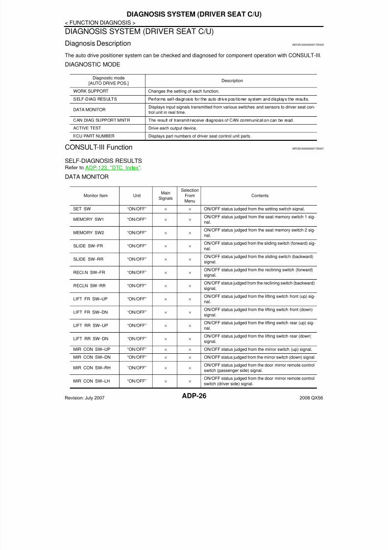
Diagnosis Description INFOID:0000000001735430
The auto drive positioner system can be checked and diagnosed for component operation with CONSULT-III.
DIAGNOSTIC MODE
CONSULT-III Function INFOID:0000000001735431
SELF-DIAGNOSIS RESULTSRefer to ADP-123, "DTC Index".
DATA MONITOR
Diagnostic mode[AUTO DRIVE POS.]
Description
WORK SUPPORT Changes the setting of each function.
SELF-DIAG RESULTS Performs self-diagnosis for the auto drive positioner system and displays the results.
DATA MONITORDisplays input signals transmitted from various switches and sensors to driver seat con-
trol unit in real time.
CAN DIAG SUPPORT MNTR The result of transmit/receive diagnosis of CAN communication can be read.
ACTIVE TEST Drive each output device.
ECU PART NUMBER Displays part numbers of driver seat control unit parts.
Monitor Item UnitMain
Signals
Selection
From
Menu
Contents
SET SW “ON/OFF” × × ON/OFF status judged from the setting switch signal.
MEMORY SW1 “ON/OFF” × ×ON/OFF status judged from the seat memory switch 1 sig-
nal.
MEMORY SW2 “ON/OFF” × ×
ON/OFF status judged from the seat memory switch 2 sig-
nal.
SLIDE SW–FR “ON/OFF” × ×ON/OFF status judged from the sliding switch (forward) sig-
nal.
SLIDE SW–RR “ON/OFF” × ×ON/OFF status judged from the sliding switch (backward)
signal.
RECLN SW–FR “ON/OFF” × ×ON/OFF status judged from the reclining switch (forward)
signal.
RECLN SW–RR “ON/OFF” × ×ON/OFF status judged from the reclining switch (backward)
signal.
LIFT FR SW–UP “ON/OFF” × ×ON/OFF status judged from the lifting switch front (up) sig-
nal.
LIFT FR SW–DN “ON/OFF” × ×
ON/OFF status judged from the lifting switch front (down)
signal.
LIFT RR SW–UP “ON/OFF” × ×ON/OFF status judged from the lifting switch rear (up) sig-
nal.
LIFT RR SW–DN “ON/OFF” × ×ON/OFF status judged from the lifting switch rear (down)
signal.
MIR CON SW–UP “ON/OFF” × × ON/OFF status judged from the mirror switch (up) signal.
MIR CON SW–DN “ON/OFF” × × ON/OFF status judged from the mirror switch (down) signal.
MIR CON SW–RH “ON/OFF” × ×ON/OFF status judged from the door mirror remote control
switch (passenger side) signal.
MIR CON SW–LH “ON/OFF” × ×ON/OFF status judged from the door mirror remote control
switch (driver side) signal.
Revision: July 2007 2008 QX56
7/21/2019 adp INFINTY 2008
http://slidepdf.com/reader/full/adp-infinty-2008 27/149
DIAGNOSIS SYSTEM (DRIVER SEAT C/U)
ADP-27
< FUNCTION DIAGNOSIS >
A
ACTIVE TESTCAUTION:
When driving vehicle, do not perform active test.
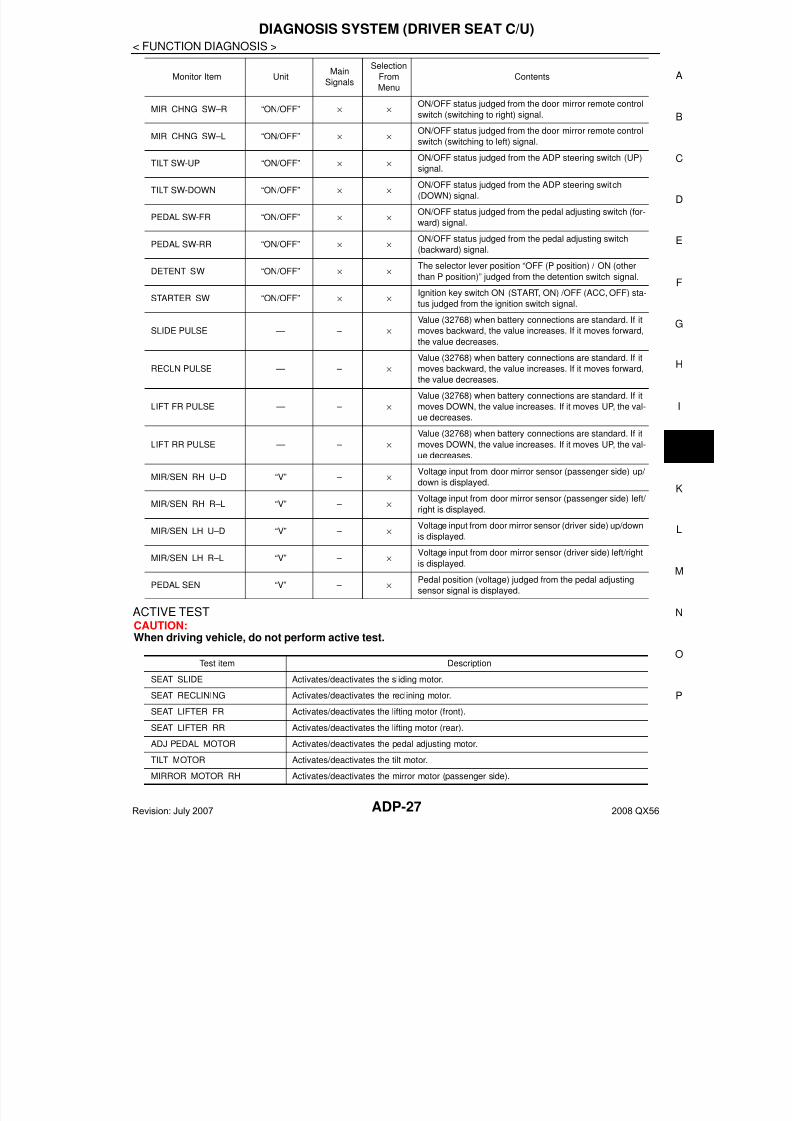
MIR CHNG SW–R “ON/OFF” × ×ON/OFF status judged from the door mirror remote control
switch (switching to right) signal.
MIR CHNG SW–L “ON/OFF” × ×ON/OFF status judged from the door mirror remote control
switch (switching to left) signal.
TILT SW-UP “ON/OFF” × × ON/OFF status judged from the ADP steering switch (UP)signal.
TILT SW-DOWN “ON/OFF” × ×ON/OFF status judged from the ADP steering switch
(DOWN) signal.
PEDAL SW-FR “ON/OFF” × ×ON/OFF status judged from the pedal adjusting switch (for-
ward) signal.
PEDAL SW-RR “ON/OFF” × ×ON/OFF status judged from the pedal adjusting switch
(backward) signal.
DETENT SW “ON/OFF” × ×The selector lever position “OFF (P position) / ON (other
than P position)” judged from the detention switch signal.
STARTER SW “ON/OFF” × ×Ignition key switch ON (START, ON) /OFF (ACC, OFF) sta-
tus judged from the ignition switch signal.
SLIDE PULSE — – ×
Value (32768) when battery connections are standard. If itmoves backward, the value increases. If it moves forward,
the value decreases.
RECLN PULSE — – ×
Value (32768) when battery connections are standard. If it
moves backward, the value increases. If it moves forward,
the value decreases.
LIFT FR PULSE — – ×
Value (32768) when battery connections are standard. If it
moves DOWN, the value increases. If it moves UP, the val-
ue decreases.
LIFT RR PULSE — – ×
Value (32768) when battery connections are standard. If it
moves DOWN, the value increases. If it moves UP, the val-
ue decreases.
MIR/SEN RH U–D “V” – ×
Voltage input from door mirror sensor (passenger side) up/
down is displayed.
MIR/SEN RH R–L “V” – ×Voltage input from door mirror sensor (passenger side) left/
right is displayed.
MIR/SEN LH U–D “V” – ×Voltage input from door mirror sensor (driver side) up/down
is displayed.
MIR/SEN LH R–L “V” – ×Voltage input from door mirror sensor (driver side) left/right
is displayed.
PEDAL SEN “V” – ×Pedal position (voltage) judged from the pedal adjusting
sensor signal is displayed.
Monitor Item UnitMain
Signals
Selection
From
Menu
Contents
Test item Description
SEAT SLIDE Activates/deactivates the sliding motor.
SEAT RECLINING Activates/deactivates the reclining motor.
SEAT LIFTER FR Activates/deactivates the lifting motor (front).
SEAT LIFTER RR Activates/deactivates the lifting motor (rear).
ADJ PEDAL MOTOR Activates/deactivates the pedal adjusting motor.
TILT MOTOR Activates/deactivates the tilt motor.
MIRROR MOTOR RH Activates/deactivates the mirror motor (passenger side).
Revision: July 2007 2008 QX56
7/21/2019 adp INFINTY 2008
http://slidepdf.com/reader/full/adp-infinty-2008 28/149ADP-28
< FUNCTION DIAGNOSIS >
DIAGNOSIS SYSTEM (DRIVER SEAT C/U)
WORK SUPPORT
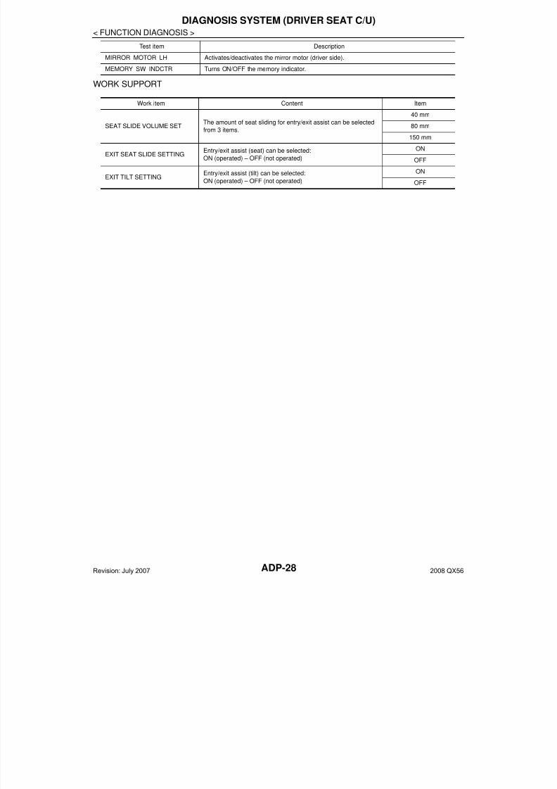
MIRROR MOTOR LH Activates/deactivates the mirror motor (driver side).
MEMORY SW INDCTR Turns ON/OFF the memory indicator.
Test item Description
Work item Content Item
SEAT SLIDE VOLUME SETThe amount of seat sliding for entry/exit assist can be selected
from 3 items.
40 mm
80 mm
150 mm
EXIT SEAT SLIDE SETTINGEntry/exit assist (seat) can be selected:
ON (operated) – OFF (not operated)
ON
OFF
EXIT TILT SETTINGEntry/exit assist (tilt) can be selected:
ON (operated) – OFF (not operated)
ON
OFF
Revision: July 2007 2008 QX56
7/21/2019 adp INFINTY 2008
http://slidepdf.com/reader/full/adp-infinty-2008 29/149
U1000 CAN COMM CIRCUIT
ADP-29
< COMPONENT DIAGNOSIS >
A
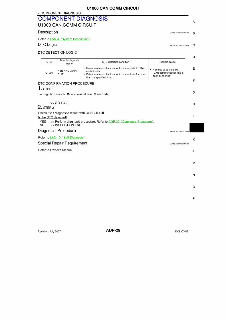
COMPONENT DIAGNOSISU1000 CAN COMM CIRCUIT
Description INFOID:0000000001735433
Refer to LAN-4, "System Description".
DTC Logic INFOID:0000000001735434
DTC DETECTION LOGIC
DTC CONFIRMATION PROCEDURE
1. STEP 1
Turn ignition switch ON and wait at least 3 seconds.
>> GO TO 2
2. STEP 2
Check “Self diagnostic result” with CONSULT-III.
Is the DTC detected?
YES >> Perform diagnosis procedure. Refer to ADP-29, "Diagnosis Procedure".NO >> INSPECTION END
Diagnosis Procedure INFOID:0000000001735435
Refer to LAN-10, "Self-Diagnosis".
Special Repair Requirement INFOID:0000000001735436
Refer to Owner’s Manual.
DTCTrouble diagnosis
nameDTC detecting condition Possible cause
U1000CAN COMM CIR-
CUIT
• Driver seat control unit cannot communicate to other
control units.
• Driver seat control unit cannot communicate for more
than the specified time.
• Harness or connectors
(CAN communication line is
open or shorted)
Revision: July 2007 2008 QX56

7/21/2019 adp INFINTY 2008
http://slidepdf.com/reader/full/adp-infinty-2008 30/149ADP-30
< COMPONENT DIAGNOSIS >
B2112 SLIDING MOTOR
B2112 SLIDING MOTOR
Description INFOID:0000000001735437
• The seat sliding motor is installed to the seat cushion frame.• The seat sliding motor is installed with the driver seat control unit.• Slides the seat frontward/rearward by changing the rotation direction of sliding motor.
DTC Logic INFOID:0000000001735438
DTC DETECTION LOGIC
DTC CONFIRMATION PROCEDURE
1. STEP 1
Turn ignition switch ON.
>> GO TO 2
2. STEP 2
Check “Self diagnostic result” with CONSULT-III.
Is the DTC detected?
YES >> Perform diagnosis procedure. Refer to ADP-30, "Diagnosis Procedure".NO >> INSPECTION END
NOTE:First perform diagnosis for B2126 if B2126 is detected. Refer to ADP-40, "Diagnosis Procedure".
Diagnosis Procedure INFOID:0000000001735439
1. PERFORM DTC CONFIRMATION PROCEDURE
1. Turn ignition switch ON.2. Check “Self diagnostic result” with CONSULT-III.3. Erase the DTC.4. Perform DTC confirmation procedure. Refer to ADP-30, "DTC Logic".
Is the DTC displayed again?
YES >> GO TO 2NO >> Check intermittent incident. Refer to GI-38, "Intermittent Incident".
2. CHECK COMPONENTS
Refer to ADP-71, "Component Function Check" and ADP-87, "Component Function Check".
>> INSPECTION END
DTC No.Trouble diagnosis
nameDTC detecting condition Possible cause
B2112 SEAT SLIDE
The driver seat control unit detects the output of slid-
ing motor output terminal for 0.1 second or more
even if the sliding switch is not input.
• Driver seat control unit
Revision: July 2007 2008 QX56
7/21/2019 adp INFINTY 2008
http://slidepdf.com/reader/full/adp-infinty-2008 31/149
B2113 RECLINING MOTOR
ADP-31
< COMPONENT DIAGNOSIS >
A
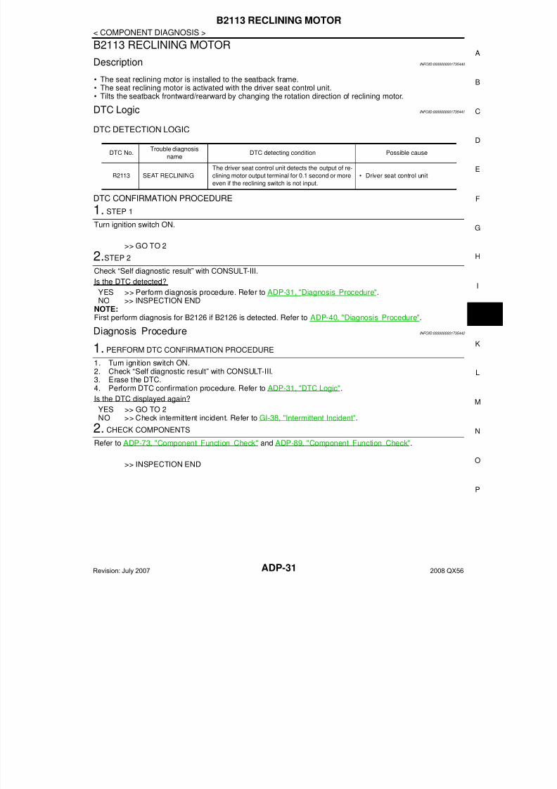
B2113 RECLINING MOTOR
Description INFOID:0000000001735440
• The seat reclining motor is installed to the seatback frame.• The seat reclining motor is activated with the driver seat control unit.• Tilts the seatback frontward/rearward by changing the rotation direction of reclining motor.
DTC Logic INFOID:0000000001735441
DTC DETECTION LOGIC
DTC CONFIRMATION PROCEDURE
1. STEP 1
Turn ignition switch ON.
>> GO TO 2
2.STEP 2
Check “Self diagnostic result” with CONSULT-III.
Is the DTC detected?
YES >> Perform diagnosis procedure. Refer to ADP-31, "Diagnosis Procedure".NO >> INSPECTION END
NOTE:First perform diagnosis for B2126 if B2126 is detected. Refer to ADP-40, "Diagnosis Procedure".
Diagnosis Procedure INFOID:0000000001735442
1. PERFORM DTC CONFIRMATION PROCEDURE
1. Turn ignition switch ON.2. Check “Self diagnostic result” with CONSULT-III.3. Erase the DTC.4. Perform DTC confirmation procedure. Refer to ADP-31, "DTC Logic".
Is the DTC displayed again?
YES >> GO TO 2NO >> Check intermittent incident. Refer to GI-38, "Intermittent Incident".
2. CHECK COMPONENTS
Refer to ADP-73, "Component Function Check" and ADP-89, "Component Function Check".
>> INSPECTION END
DTC No.Trouble diagnosis
nameDTC detecting condition Possible cause
B2113 SEAT RECLINING
The driver seat control unit detects the output of re-
clining motor output terminal for 0.1 second or more
even if the reclining switch is not input.
• Driver seat control unit
Revision: July 2007 2008 QX56
7/21/2019 adp INFINTY 2008
http://slidepdf.com/reader/full/adp-infinty-2008 32/149ADP-32
< COMPONENT DIAGNOSIS >
B2114 SEAT LIFTER FR
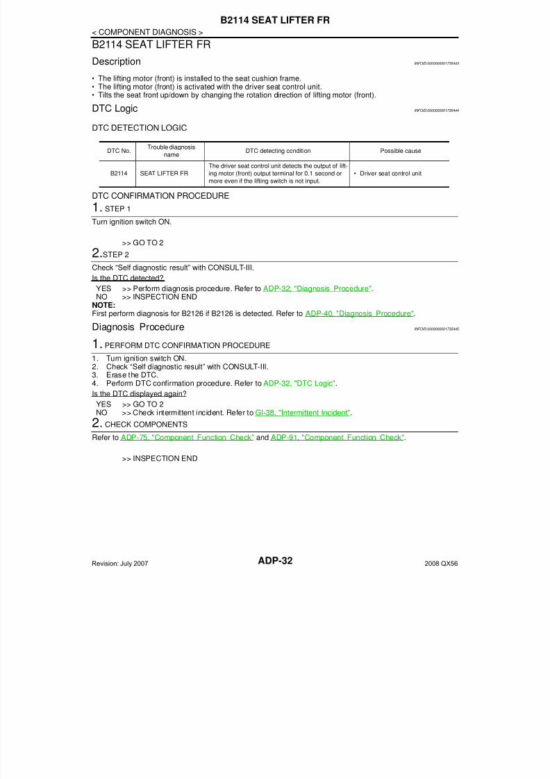
B2114 SEAT LIFTER FR
Description INFOID:0000000001735443
• The lifting motor (front) is installed to the seat cushion frame.• The lifting motor (front) is activated with the driver seat control unit.• Tilts the seat front up/down by changing the rotation direction of lifting motor (front).
DTC Logic INFOID:0000000001735444
DTC DETECTION LOGIC
DTC CONFIRMATION PROCEDURE
1. STEP 1
Turn ignition switch ON.
>> GO TO 2
2.STEP 2
Check “Self diagnostic result” with CONSULT-III.
Is the DTC detected?
YES >> Perform diagnosis procedure. Refer to ADP-32, "Diagnosis Procedure".NO >> INSPECTION END
NOTE:First perform diagnosis for B2126 if B2126 is detected. Refer to ADP-40, "Diagnosis Procedure".
Diagnosis Procedure INFOID:0000000001735445
1. PERFORM DTC CONFIRMATION PROCEDURE
1. Turn ignition switch ON.2. Check “Self diagnostic result” with CONSULT-III.3. Erase the DTC.4. Perform DTC confirmation procedure. Refer to ADP-32, "DTC Logic".
Is the DTC displayed again?
YES >> GO TO 2NO >> Check intermittent incident. Refer to GI-38, "Intermittent Incident".
2. CHECK COMPONENTS
Refer to ADP-75, "Component Function Check" and ADP-91, "Component Function Check".
>> INSPECTION END
DTC No.Trouble diagnosis
nameDTC detecting condition Possible cause
B2114 SEAT LIFTER FR
The driver seat control unit detects the output of lift-
ing motor (front) output terminal for 0.1 second or
more even if the lifting switch is not input.
• Driver seat control unit
Revision: July 2007 2008 QX56
7/21/2019 adp INFINTY 2008
http://slidepdf.com/reader/full/adp-infinty-2008 33/149
B2115 SEAT LIFTER RR
ADP-33
< COMPONENT DIAGNOSIS >
A
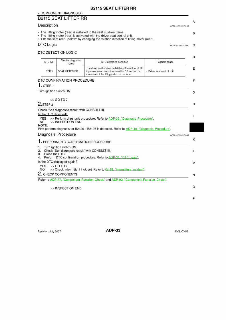
B2115 SEAT LIFTER RR
Description INFOID:0000000001735446
• The lifting motor (rear) is installed to the seat cushion frame.• The lifting motor (rear) is activated with the driver seat control unit.• Tilts the seat rear up/down by changing the rotation direction of lifting motor (rear).
DTC Logic INFOID:0000000001735447
DTC DETECTION LOGIC
DTC CONFIRMATION PROCEDURE
1. STEP 1
Turn ignition switch ON.
>> GO TO 2
2.STEP 2
Check “Self diagnostic result” with CONSULT-III.
Is the DTC detected?
YES >> Perform diagnosis procedure. Refer to ADP-33, "Diagnosis Procedure".NO >> INSPECTION END
NOTE:First perform diagnosis for B2126 if B2126 is detected. Refer to ADP-40, "Diagnosis Procedure".
Diagnosis Procedure INFOID:0000000001735448
1. PERFORM DTC CONFIRMATION PROCEDURE
1. Turn ignition switch ON.2. Check “Self diagnostic result” with CONSULT-III.3. Erase the DTC.4. Perform DTC confirmation procedure. Refer to ADP-33, "DTC Logic".
Is the DTC displayed again?
YES >> GO TO 2NO >> Check intermittent incident. Refer to GI-38, "Intermittent Incident".
2. CHECK COMPONENTS
Refer to ADP-77, "Component Function Check" and ADP-93, "Component Function Check".
>> INSPECTION END
DTC No.Trouble diagnosis
nameDTC detecting condition Possible cause
B2115 SEAT LIFTER RR
The driver seat control unit detects the output of lift-
ing motor (rear) output terminal for 0.1 second or
more even if the lifting switch is not input.
• Driver seat control unit
Revision: July 2007 2008 QX56
7/21/2019 adp INFINTY 2008
http://slidepdf.com/reader/full/adp-infinty-2008 34/149ADP-34
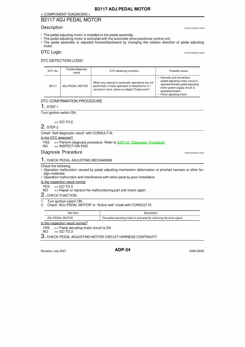
< COMPONENT DIAGNOSIS >
B2117 ADJ PEDAL MOTOR
B2117 ADJ PEDAL MOTOR
Description INFOID:0000000001735449
• The pedal adjusting motor is installed to the pedal assembly.• The pedal adjusting motor is activated with the automatic drive positioner control unit.• The pedal assembly is adjusted forward/backward by changing the rotation direction of pedal adjusting
motor.
DTC Logic INFOID:0000000001735450
DTC DETECTION LOGIC
DTC CONFIRMATION PROCEDURE
1. STEP 1
Turn ignition switch ON.
>> GO TO 2
2. STEP 2
Check “Self diagnostic result” with CONSULT-III.
Is the DTC detected?
YES >> Perform diagnosis procedure. Refer to ADP-34, "Diagnosis Procedure".
NO >> INSPECTION ENDDiagnosis Procedure INFOID:0000000001735451
1. CHECK PEDAL ADJUSTING MECHANISM
Check the following.• Operation malfunction caused by pedal adjusting mechanism deformation or pinched harness or other for-
eign materials• Operation malfunction and interference with other parts by poor installation
Is the inspection result normal
YES >> GO TO 2NO >> Repair or replace the malfunctioning part and check again.
2. CHECK FUNCTION1. Turn ignition switch ON.2. Check “ADJ PEDAL MOTOR” in "Active test" mode with CONSULT-III.
Is the inspection result normal?
YES >> Pedal adjusting motor circuit is OK.NO >> GO TO 3
3. CHECK PEDAL ADJUSTING MOTOR CIRCUIT HARNESS CONTINUITY
DTC No.Trouble diagnosis
nameDTC detecting condition Possible cause
B2117 ADJ PEDAL MOTOR
When any manual or automatic operations are not
performed, if motor operation is detected for 0.1
second or more, status is judged "Output error".
• Harness and connectors
(pedal adjusting motor circuit is
opened/shorted, pedal adjusting
motor power supply circuit is
opened/shorted.)
• Pedal adjusting motor
Test item Description
ADJ PEDAL MOTOR The pedal adjusting motor is activated by receiving the drive signal.
Revision: July 2007 2008 QX56
7/21/2019 adp INFINTY 2008
http://slidepdf.com/reader/full/adp-infinty-2008 35/149
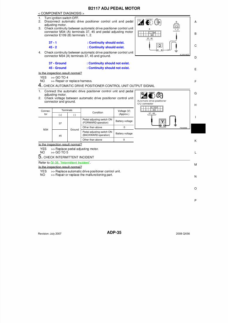
B2117 ADJ PEDAL MOTOR
ADP-35
< COMPONENT DIAGNOSIS >
A
1. Turn ignition switch OFF.2. Disconnect automatic drive positioner control unit and pedal
adjusting motor.3. Check continuity between automatic drive positioner control unit
connector M34 (A) terminals 37, 45 and pedal adjusting motorconnector E109 (B) terminals 1, 2.
4. Check continuity between automatic drive positioner control unitconnector M34 (A) terminals 37, 45 and ground.
Is the inspection result normal?
YES >> GO TO 4NO >> Repair or replace harness.
4. CHECK AUTOMATIC DRIVE POSITIONER CONTROL UNIT OUTPUT SIGNAL
1. Connect the automatic drive positioner control unit and pedaladjusting motor.
2. Check voltage between automatic drive positioner control unitconnector and ground.
Is the inspection result normal?
YES >> Replace pedal adjusting motor.NO >> GO TO 5
5. CHECK INTERMITTENT INCIDENT
Refer to GI-38, "Intermittent Incident".
Is the inspection result normal?
YES >> Replace automatic drive positioner control unit.NO >> Repair or replace the malfunctioning part.
37 - 1 : Continuity should exist.
45 - 2 : Continuity should exist.
37 - Ground : Continuity should not exist.
45 - Ground : Continuity should not exist.
ALJIA0195ZZ
Connec-
tor
TerminalsCondition
Voltage (V)
(Approx.)(+) (-)
M34
37
Ground
Pedal adjusting switch ON
(FORWARD operation)Battery voltage
Other than above 0
45
Pedal adjusting switch ON
(BACKWARD operation)Battery voltage
Other than above 0
PIIA4806E
Revision: July 2007 2008 QX56
7/21/2019 adp INFINTY 2008
http://slidepdf.com/reader/full/adp-infinty-2008 36/149ADP-36
< COMPONENT DIAGNOSIS >
B2118 TILT SENSOR
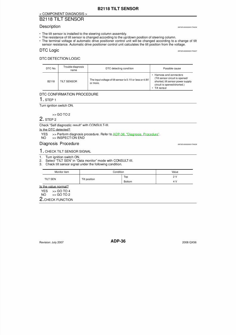
B2118 TILT SENSOR
Description INFOID:0000000001754036
• The tilt sensor is installed to the steering column assembly.• The resistance of tilt sensor is changed according to the up/down position of steering column.• The terminal voltage of automatic drive positioner control unit will be changed according to a change of tilt
sensor resistance. Automatic drive positioner control unit calculates the tilt position from the voltage.
DTC Logic INFOID:0000000001754037
DTC DETECTION LOGIC
DTC CONFIRMATION PROCEDURE1. STEP 1
Turn ignition switch ON.
>> GO TO 2
2. STEP 2
Check “Self diagnostic result” with CONSULT-III.
Is the DTC detected?
YES >> Perform diagnosis procedure. Refer to ADP-36, "Diagnosis Procedure".NO >> INSPECTION END
Diagnosis Procedure INFOID:0000000001754038
1. CHECK TILT SENSOR SIGNAL
1. Turn ignition switch ON.2. Select “TILT SEN” in “Data monitor” mode with CONSULT-III.3. Check tilt sensor signal under the following condition.
Is the value normal?
YES >> GO TO 4NO >> GO TO 2
2.CHECK FUNCTION
DTC No.Trouble diagnosis
nameDTC detecting condition Possible cause
B2118 TILT SENSORThe input voltage of tilt sensor is 0.1V or less or 4.9V
or more.
• Harness and connectors
(Tilt sensor circuit is opened/
shorted, tilt sensor power supply
circuit is opened/shorted.)
• Tilt sensor
Monitor item Condition Value
TILT SEN Tilt positionTop 2 V
Bottom 4 V
Revision: July 2007 2008 QX56
7/21/2019 adp INFINTY 2008
http://slidepdf.com/reader/full/adp-infinty-2008 37/149
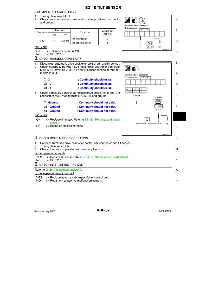
B2118 TILT SENSOR
ADP-37
< COMPONENT DIAGNOSIS >
A
1. Turn ignition switch OFF.2. Check voltage between automatic drive positioner connector
and ground.
OK or NG
OK >> Tilt sensor circuit is OK.NG >> GO TO 3
3. CHECK HARNESS CONTINUITY
1. Disconnect automatic drive positioner control unit and tilt sensor.2. Check continuity between automatic drive positioner connector
M33, M34 terminals 7, 33, 41 and tilt sensor connector M85 ter-minals 2, 3, 4.
3. Check continuity between automatic drive positioner control unitconnectors M33, M34 terminals 7, 33, 41 and ground.
OK or NG
OK >> Replace tilt motor. Refer to ST-18, "Removal and Instal-
lation".NG >> Repair or replace harness.
4. CHECK DOOR MIRROR OPERATION
1. Connect automatic drive positioner control unit connector and tilt sensor.2. Turn ignition switch ON.3. Check door mirror operation with memory function.
Is the operation normal?
YES >> Replace tilt sensor. Refer to ST-18, "Removal and Installation".NO >> GO TO 5
5. CHECK INTERMITTENT INCIDENTRefer to GI-38, "Intermittent Incident".
Is the inspection result normal?
YES >> Replace automatic drive positioner control unit.NO >> Repair or replace the malfunctioning part.
ConnectorTerminals
ConditionVoltage (V)
(Approx.)(+) (-)
M33 7 Ground
Tilt top position 2
Tilt bottom position 4
LIIA0485E
7 - 3 : Continuity should exist.
33 - 2 : Continuity should exist.
41 - 4 : Continuity should exist.
7 - Ground : Continuity should not exist.
33 - Ground : Continuity should not exist.
41 - Ground : Continuity should not exist.
LIIA1432E
Revision: July 2007 2008 QX56
7/21/2019 adp INFINTY 2008
http://slidepdf.com/reader/full/adp-infinty-2008 38/149ADP-38
< COMPONENT DIAGNOSIS >
B2120 ADJ PEDAL SENSOR
B2120 ADJ PEDAL SENSOR
Description INFOID:0000000001735452
• The pedal adjusting sensor is installed in the pedal assembly.• The resistance of pedal adjusting sensor is changed according to the forward/backward position of pedal
assembly.• The terminal voltage of automatic drive positioner control unit will be changed according to a change of
pedal adjusting sensor resistance. Automatic drive positioner control unit calculates the pedal assemblyposition from the voltage.
DTC Logic INFOID:0000000001735453
DTC DETECTION LOGIC
DTC CONFIRMATION PROCEDURE
1. STEP 1
Turn ignition switch ON.
>> GO TO 2
2. STEP 2
Check “Self diagnostic result” with CONSULT-III.
Is the DTC is detected?
YES >> Perform diagnosis procedure. Refer to ADP-38, "Diagnosis Procedure".NO >> INSPECTION END
Diagnosis Procedure INFOID:0000000001735454
1. CHECK PEDAL ADJUSTING SENSOR SIGNAL
1. Turn ignition switch ON.2. Select “PEDAL SEN” in “Data monitor” mode with CONSULT-III.3. Check the pedal adjusting sensor signal under the following condition.
Is the value normal?
YES >> Pedal adjusting circuit is OK.NO >> GO TO 2
2. CHECK PEDAL ADJUSTING SENSOR CIRCUIT HARNESS CONTINUITY
DTC No.Trouble diagnosis
nameDTC detecting condition Possible cause
B2120 ADJ PEDAL SENSORThe input voltage of pedal adjusting sensor is 0.5V
or less or 4.5V or higher, for 0.5 seconds or more.
• Harness and connectors
(Pedal adjusting sensor circuit is
opened/shorted, pedal adjusting
sensor power supply circuit is
opened/shorted.)• Pedal adjusting sensor
Monitor item Condition Value
PEDAL SEN Pedal position
Forward 0.5V
Backward 4.5V
Revision: July 2007 2008 QX56
7/21/2019 adp INFINTY 2008
http://slidepdf.com/reader/full/adp-infinty-2008 39/149
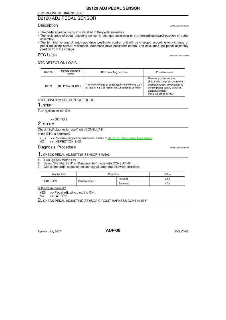
B2120 ADJ PEDAL SENSOR
ADP-39
< COMPONENT DIAGNOSIS >
A
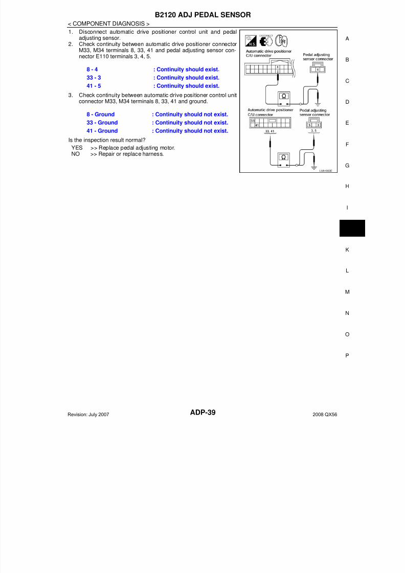
1. Disconnect automatic drive positioner control unit and pedaladjusting sensor.
2. Check continuity between automatic drive positioner connectorM33, M34 terminals 8, 33, 41 and pedal adjusting sensor con-nector E110 terminals 3, 4, 5.
3. Check continuity between automatic drive positioner control unitconnector M33, M34 terminals 8, 33, 41 and ground.
Is the inspection result normal?
YES >> Replace pedal adjusting motor.NO >> Repair or replace harness.
8 - 4 : Continuity should exist.
33 - 3 : Continuity should exist.
41 - 5 : Continuity should exist.
8 - Ground : Continuity should not exist.
33 - Ground : Continuity should not exist.
41 - Ground : Continuity should not exist.
LIIA1003E
Revision: July 2007 2008 QX56
7/21/2019 adp INFINTY 2008
http://slidepdf.com/reader/full/adp-infinty-2008 40/149ADP-40
< COMPONENT DIAGNOSIS >
B2126 DETENT SW
B2126 DETENT SW
Description INFOID:0000000001735455
• Park position switch is installed on A/T device. It is turned OFF when the A/T selector lever is in P position.• The driver seat control unit judges that the A/T selector lever is in P position if continuity does not exist in this
circuit.
DTC Logic INFOID:0000000001735456
DTC DETECTION LOGIC
DTC CONFIRMATION PROCEDURE1. STEP 1
Drive the vehicle at 7±4km/h or more.
>> GO TO 2
2. STEP 2
Check “Self diagnostic result” with CONSULT-III.
Is the DTC detected?
YES >> Perform diagnosis procedure. Refer to ADP-40, "Diagnosis Procedure".NO >> INSPECTION END
Diagnosis Procedure INFOID:0000000001735457
1. CHECK DTC
Check “Self diagnostic result” for BCM with CONSULT-lll.
Are other DTCs detected?
YES >> Check The DTC.NO >> GO TO 2
2. CHECK DETENTION SWITCH SIGNAL
1. Turn ignition switch ON.2. Select “DETENT SW” in “Data Monitor” mode with CONSULT-lll.3. Check detention switch signal under the following condition.
Is the status normal?
YES >> A/T device (park position switch) circuit is OK.NO >> GO TO 3
3. CHECK A/T DEVICE (PARK POSITION SWITCH) HARNESS
DTC No.Trouble diagnosis
nameDTC detecting condition Possible cause
B2126 DETENT SWA/T selector lever is in P position and the vehicle
speed of 7±4km/h is detected.
• Harness and connectors
(Park position switch circuit is
opened/shorted.)
• Park position switch
• Combination meter
(CAN communication )
Monitor item Condition Status
DETENT SW A/T selector leverP position OFF
Other than above ON
Revision: July 2007 2008 QX56
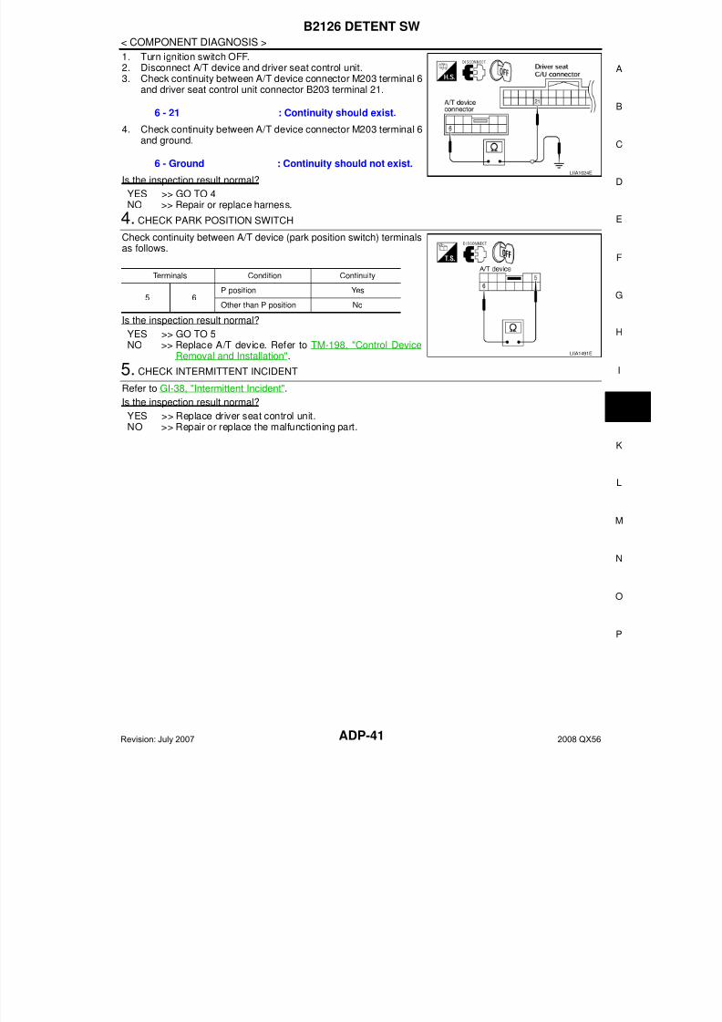
7/21/2019 adp INFINTY 2008
http://slidepdf.com/reader/full/adp-infinty-2008 41/149
B2126 DETENT SW
ADP-41
< COMPONENT DIAGNOSIS >
A
1. Turn ignition switch OFF.2. Disconnect A/T device and driver seat control unit.3. Check continuity between A/T device connector M203 terminal 6
and driver seat control unit connector B203 terminal 21.
4. Check continuity between A/T device connector M203 terminal 6
and ground.
Is the inspection result normal?
YES >> GO TO 4NO >> Repair or replace harness.
4. CHECK PARK POSITION SWITCH
Check continuity between A/T device (park position switch) terminalsas follows.
Is the inspection result normal?
YES >> GO TO 5NO >> Replace A/T device. Refer to TM-198, "Control Device
Removal and Installation".
5. CHECK INTERMITTENT INCIDENT
Refer to GI-38, "Intermittent Incident".
Is the inspection result normal?
YES >> Replace driver seat control unit.NO >> Repair or replace the malfunctioning part.
6 - 21 : Continuity should exist.
6 - Ground : Continuity should not exist.LIIA1024E
Terminals Condition Continuity
5 6P position Yes
Other than P position No
LIIA1491E
Revision: July 2007 2008 QX56

7/21/2019 adp INFINTY 2008
http://slidepdf.com/reader/full/adp-infinty-2008 42/149ADP-42
< COMPONENT DIAGNOSIS >
B2128 UART COMMUNICATION LINE
B2128 UART COMMUNICATION LINE
Description INFOID:0000000001735458
Driver seat control unit performs UART communication with the automatic drive positioner control unit using 2communication lines, TX and RX line. Driver seat control unit receives the operation signals of pedal adjustingswitch, door mirror remote control switch, set switch and memory switch and the position signals of adjustablepedal sensor and door mirror sensor from the automatic drive positioner control unit and transmits the opera-
tion request signal.
DTC Logic INFOID:0000000001735459
DTC DETECTION LOGIC
DTC CONFIRMATION PROCEDURE
1. STEP 1
Turn ignition switch ON.
>> GO TO 2
2. STEP 2
Operate pedal adjusting switch for more than 2 seconds.
>> GO TO 3
3. PROCEDURE 3
Check “Self diagnostic result” with CONSULT-III.
Is the DTC detected?
YES >> Perform diagnosis procedure. Refer to ADP-42, "Diagnosis Procedure".NO >> INSPECTION END
Diagnosis Procedure INFOID:0000000001735460
1. CHECK UART COMMUNICATION LINE CONTINUITY
1. Turn ignition switch OFF.2. Disconnect driver seat control unit and automatic drive posi-
tioner control unit.3. Check continuity between driver seat control unit harness con-
nector and automatic drive positioner control unit harness con-nector.
4. Check continuity between driver seat control unit harness connector and ground.
DTC No. Trouble diagnosis name DTC detecting condition Possible cause
B2128 UART COMM
The communication between driver seat control unit
and automatic drive positioner control unit is interrupt-
ed for a period of time.
• UART communication line
(UART communication line is
open or shorted)
• Driver seat control unit
• Automatic drive positioner
control unit
Driver seat control
unit connectorTerminal
Automatic drive positioner
control unit connectorTerminal Continuity
B2021
M3310
Yes17 26
PIIA4598E
Revision: July 2007 2008 QX56
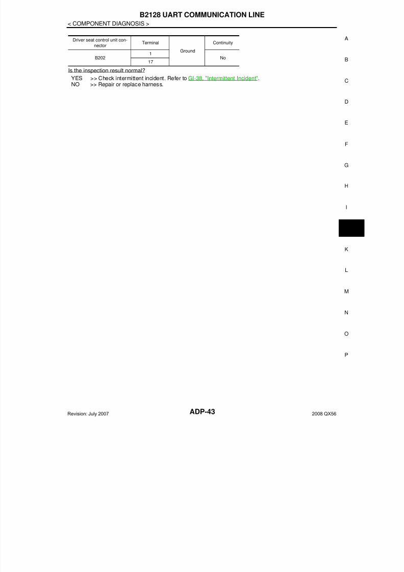
7/21/2019 adp INFINTY 2008
http://slidepdf.com/reader/full/adp-infinty-2008 43/149
B2128 UART COMMUNICATION LINE
ADP-43
< COMPONENT DIAGNOSIS >
A
Is the inspection result normal?
YES >> Check intermittent incident. Refer to GI-38, "Intermittent Incident".NO >> Repair or replace harness.
Driver seat control unit con-
nectorTerminal
Ground
Continuity
B2021
No17
Revision: July 2007 2008 QX56

7/21/2019 adp INFINTY 2008
http://slidepdf.com/reader/full/adp-infinty-2008 44/149ADP-44
< COMPONENT DIAGNOSIS >
POWER SUPPLY AND GROUND CIRCUIT
POWER SUPPLY AND GROUND CIRCUITBCM
BCM : Diagnosis Procedure INFOID:0000000001735461
Refer to BCS-30, "Diagnosis Procedure".
BCM : Special Repair Requirement INFOID:0000000001735462
1. REQUIRED WORK WHEN REPLACING BCM
Initialize control unit. Refer to CONSULT-III Operation Manual.
>> Work end.
DRIVER SEAT CONTROL UNIT
DRIVER SEAT CONTROL UNIT : Diagnosis Procedure INFOID:0000000001735463
NOTE:Do not disconnect the battery negative terminal and the driver seat control unit connector until DTC is con-firmed with CONSULT-III.
1. CHECK POWER SUPPLY CIRCUIT
1. Turn ignition switch OFF.2. Check voltage between driver seat control unit harness connec-
tor and ground.
Is the inspection result normal?
YES >> GO TO 2.NO >> Check the following.
• Repair or replace harness between driver seat control unit and fuse block (J/B).• Circuit breaker.
2. CHECK GROUND CIRCUIT
Check continuity between the driver seat control unit harness con-nector and ground.
Is the inspection result normal?
YES >> Driver seat control unit power supply and ground circuitare OK.
NO >> Repair or replace harness.
Terminals
Power
sourceCondition
Voltage (V)
(Approx.)
(+)
(–)Driver seat
control unit
connector
Terminal
B202 6
Ground
START
power sup-ply
Ignition
switchSTART Battery
voltage
B203
33 Battery
power sup-
ply
Ignition
switch
OFF40
LIIA1897E
Driver seat control unit
connectorTerminal
Ground
Continuity
B202 32Yes
B203 48
PIIA4542E
Revision: July 2007 2008 QX56
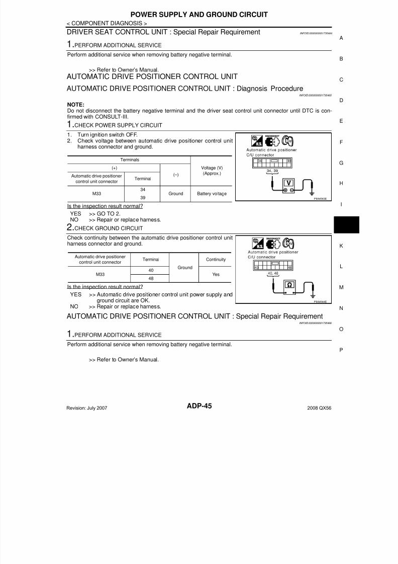
7/21/2019 adp INFINTY 2008
http://slidepdf.com/reader/full/adp-infinty-2008 45/149
POWER SUPPLY AND GROUND CIRCUIT
ADP-45
< COMPONENT DIAGNOSIS >
A
DRIVER SEAT CONTROL UNIT : Special Repair Requirement INFOID:0000000001735464
1.PERFORM ADDITIONAL SERVICE
Perform additional service when removing battery negative terminal.
>> Refer to Owner’s Manual.
AUTOMATIC DRIVE POSITIONER CONTROL UNITAUTOMATIC DRIVE POSITIONER CONTROL UNIT : Diagnosis Procedure
INFOID:0000000001735465
NOTE:Do not disconnect the battery negative terminal and the driver seat control unit connector until DTC is con-firmed with CONSULT-III.
1.CHECK POWER SUPPLY CIRCUIT
1. Turn ignition switch OFF.2. Check voltage between automatic drive positioner control unit
harness connector and ground.
Is the inspection result normal?
YES >> GO TO 2.NO >> Repair or replace harness.
2.CHECK GROUND CIRCUIT
Check continuity between the automatic drive positioner control unitharness connector and ground.
Is the inspection result normal?
YES >> Automatic drive positioner control unit power supply andground circuit are OK.
NO >> Repair or replace harness.
AUTOMATIC DRIVE POSITIONER CONTROL UNIT : Special Repair RequirementINFOID:0000000001735466
1.PERFORM ADDITIONAL SERVICE
Perform additional service when removing battery negative terminal.
>> Refer to Owner’s Manual.
Terminals
Voltage (V)
(Approx.)
(+)
(–)Automatic drive positioner
control unit connectorTerminal
M3334
Ground Battery voltage39 PIIA4543E
Automatic drive positioner
control unit connectorTerminal
Ground
Continuity
M3340
Yes48
PIIA4544E
Revision: July 2007 2008 QX56
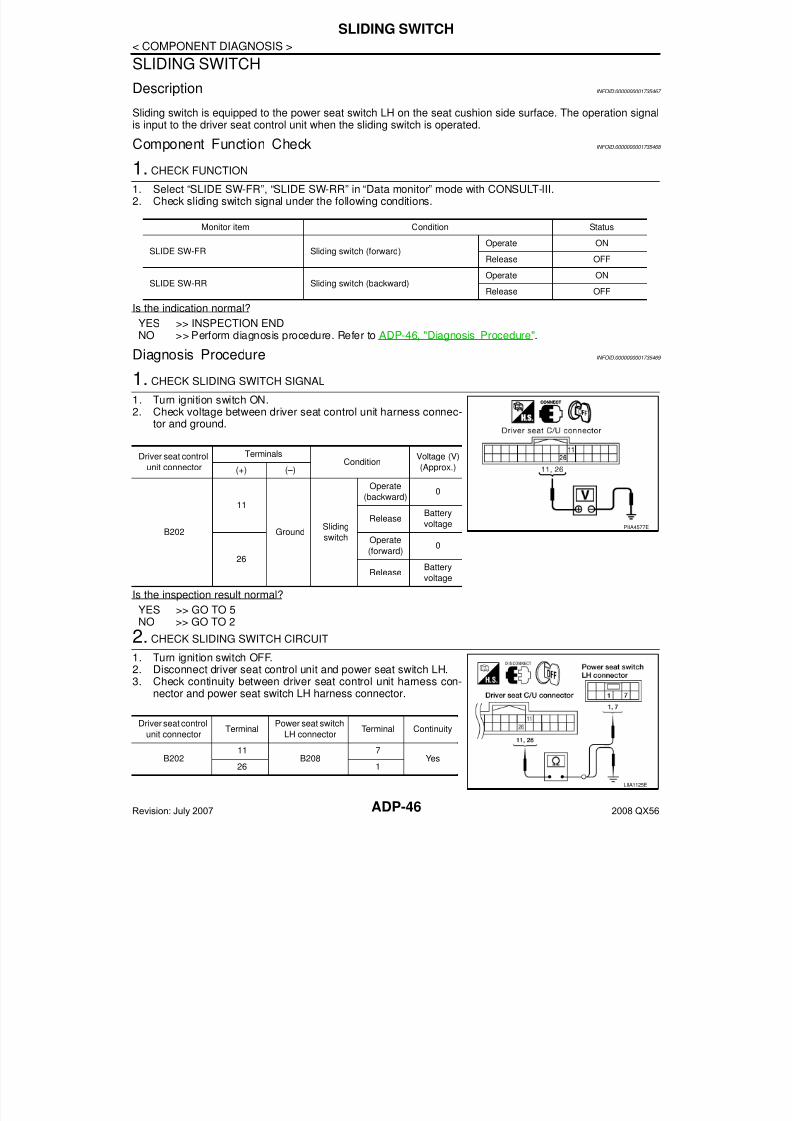
7/21/2019 adp INFINTY 2008
http://slidepdf.com/reader/full/adp-infinty-2008 46/149ADP-46
< COMPONENT DIAGNOSIS >
SLIDING SWITCH
SLIDING SWITCH
Description INFOID:0000000001735467
Sliding switch is equipped to the power seat switch LH on the seat cushion side surface. The operation signalis input to the driver seat control unit when the sliding switch is operated.
Component Function Check INFOID:0000000001735468
1. CHECK FUNCTION
1. Select “SLIDE SW-FR”, “SLIDE SW-RR” in “Data monitor” mode with CONSULT-III.2. Check sliding switch signal under the following conditions.
Is the indication normal?
YES >> INSPECTION ENDNO >> Perform diagnosis procedure. Refer to ADP-46, "Diagnosis Procedure".
Diagnosis Procedure INFOID:0000000001735469
1. CHECK SLIDING SWITCH SIGNAL
1. Turn ignition switch ON.2. Check voltage between driver seat control unit harness connec-
tor and ground.
Is the inspection result normal?
YES >> GO TO 5NO >> GO TO 2
2. CHECK SLIDING SWITCH CIRCUIT
1. Turn ignition switch OFF.2. Disconnect driver seat control unit and power seat switch LH.3. Check continuity between driver seat control unit harness con-
nector and power seat switch LH harness connector.
Monitor item Condition Status
SLIDE SW-FR Sliding switch (forward)Operate ON
Release OFF
SLIDE SW-RR Sliding switch (backward)Operate ON
Release OFF
Driver seat control
unit connector
TerminalsCondition
Voltage (V)
(Approx.)(+) (–)
B202
11
GroundSliding
switch
Operate
(backward)0
ReleaseBattery
voltage
26
Operate
(forward)0
ReleaseBattery
voltage
PIIA4577E
Driver seat control
unit connectorTerminal
Power seat switch
LH connectorTerminal Continuity
B20211
B2087
Yes26 1
LIIA1125E
Revision: July 2007 2008 QX56
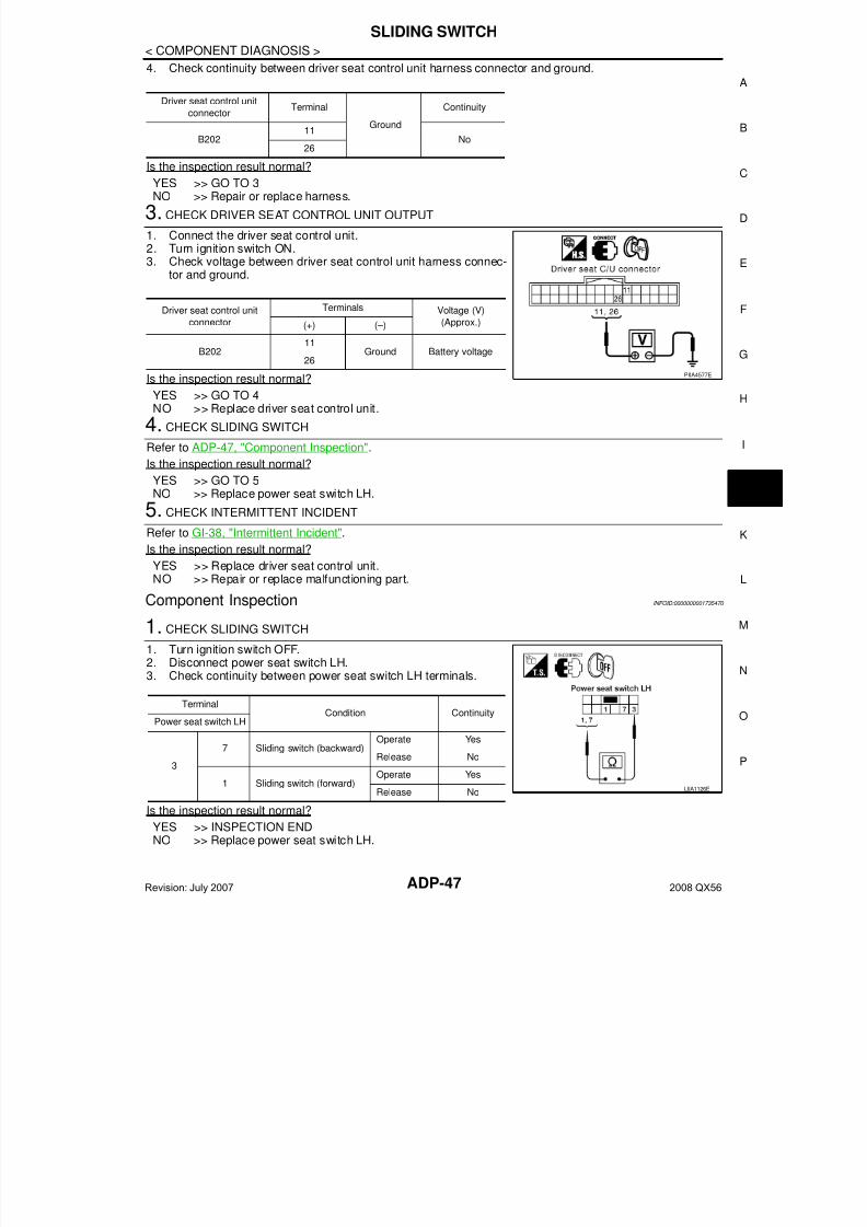
7/21/2019 adp INFINTY 2008
http://slidepdf.com/reader/full/adp-infinty-2008 47/149
SLIDING SWITCH
ADP-47
< COMPONENT DIAGNOSIS >
A
4. Check continuity between driver seat control unit harness connector and ground.
Is the inspection result normal?
YES >> GO TO 3NO >> Repair or replace harness.
3. CHECK DRIVER SEAT CONTROL UNIT OUTPUT
1. Connect the driver seat control unit.2. Turn ignition switch ON.3. Check voltage between driver seat control unit harness connec-
tor and ground.
Is the inspection result normal?
YES >> GO TO 4NO >> Replace driver seat control unit.
4. CHECK SLIDING SWITCH
Refer to ADP-47, "Component Inspection".
Is the inspection result normal?
YES >> GO TO 5NO >> Replace power seat switch LH.
5. CHECK INTERMITTENT INCIDENT
Refer to GI-38, "Intermittent Incident".
Is the inspection result normal?
YES >> Replace driver seat control unit.NO >> Repair or replace malfunctioning part.
Component Inspection INFOID:0000000001735470
1. CHECK SLIDING SWITCH
1. Turn ignition switch OFF.2. Disconnect power seat switch LH.3. Check continuity between power seat switch LH terminals.
Is the inspection result normal?
YES >> INSPECTION ENDNO >> Replace power seat switch LH.
Driver seat control unit
connectorTerminal
Ground
Continuity
B20211
No26
Driver seat control unit
connector
Terminals Voltage (V)
(Approx.)(+) (–)
B202 11 Ground Battery voltage26
PIIA4577E
TerminalCondition Continuity
Power seat switch LH
3
7 Sliding switch (backward)Operate Yes
Release No
1 Sliding switch (forward)Operate Yes
Release No LIIA1126E
Revision: July 2007 2008 QX56
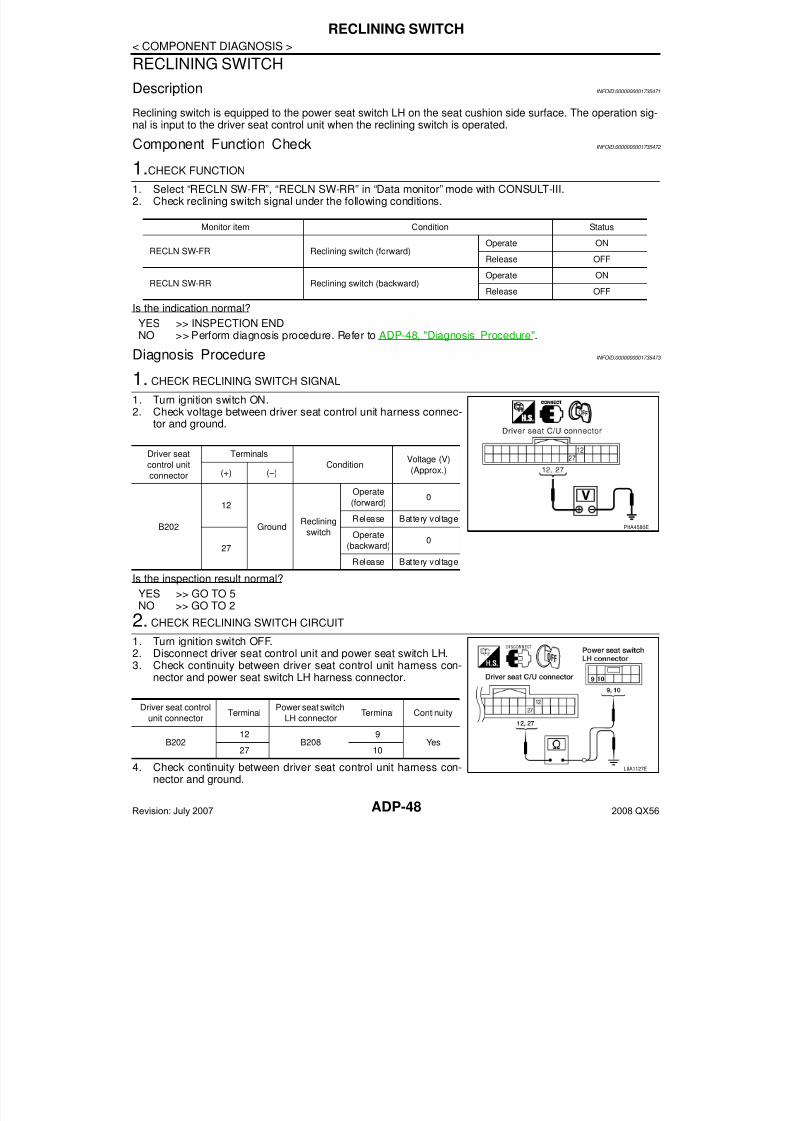
7/21/2019 adp INFINTY 2008
http://slidepdf.com/reader/full/adp-infinty-2008 48/149ADP-48
< COMPONENT DIAGNOSIS >
RECLINING SWITCH
RECLINING SWITCH
Description INFOID:0000000001735471
Reclining switch is equipped to the power seat switch LH on the seat cushion side surface. The operation sig-nal is input to the driver seat control unit when the reclining switch is operated.
Component Function Check INFOID:0000000001735472
1.CHECK FUNCTION
1. Select “RECLN SW-FR”, “RECLN SW-RR” in “Data monitor” mode with CONSULT-III.2. Check reclining switch signal under the following conditions.
Is the indication normal?
YES >> INSPECTION ENDNO >> Perform diagnosis procedure. Refer to ADP-48, "Diagnosis Procedure".
Diagnosis Procedure INFOID:0000000001735473
1. CHECK RECLINING SWITCH SIGNAL
1. Turn ignition switch ON.2. Check voltage between driver seat control unit harness connec-
tor and ground.
Is the inspection result normal?
YES >> GO TO 5NO >> GO TO 2
2. CHECK RECLINING SWITCH CIRCUIT
1. Turn ignition switch OFF.2. Disconnect driver seat control unit and power seat switch LH.3. Check continuity between driver seat control unit harness con-
nector and power seat switch LH harness connector.
4. Check continuity between driver seat control unit harness con-nector and ground.
Monitor item Condition Status
RECLN SW-FR Reclining switch (forward)Operate ON
Release OFF
RECLN SW-RR Reclining switch (backward)Operate ON
Release OFF
Driver seat
control unit
connector
Terminals
ConditionVoltage (V)
(Approx.)(+) (–)
B202
12
GroundReclining
switch
Operate
(forward)0
Release Battery voltage
27
Operate
(backward)0
Release Battery voltage
PIIA4580E
Driver seat control
unit connectorTerminal
Power seat switch
LH connectorTerminal Continuity
B20212
B2089
Yes27 10
LIIA1127E
Revision: July 2007 2008 QX56

7/21/2019 adp INFINTY 2008
http://slidepdf.com/reader/full/adp-infinty-2008 49/149
RECLINING SWITCH
ADP-49
< COMPONENT DIAGNOSIS >
A
Is the inspection result normal?
YES >> GO TO 3NO >> Repair or replace harness.
3. CHECK DRIVER SEAT CONTROL UNIT OUTPUT
1. Connect the driver seat control unit connector.2. Turn ignition switch ON.3. Check voltage between driver seat control unit harness connec-
tor and ground.
Is the inspection result normal?
YES >> GO TO 4NO >> Replace driver seat control unit.
4. CHECK RECLINING SWITCH
Refer to ADP-49, "Component Inspection".
Is the inspection result normal?
YES >> GO TO 5NO >> Replace power seat switch LH.
5. CHECK INTERMITTENT INCIDENT
Refer to GI-38, "Intermittent Incident".
Is the inspection result normal?
YES >> Replace driver seat control unit.NO >> Repair or replace the malfunctioning part.
Component Inspection INFOID:0000000001735474
1. CHECK RECLINING SWITCH
1. Turn ignition switch OFF.2. Disconnect power seat switch LH.3. Check continuity between power seat switch LH terminals.
Is the inspection result normal?
YES >> INSPECTION ENDNO >> Replace power seat switch LH.
Driver seat control unit
connectorTerminal
Ground
Continuity
B20212
No27
Driver seat control
unit connector
Terminals Voltage (V)
(Approx.)(+) (–)
B20212
Ground Battery voltage27
PIIA4580E
Terminals
Condition ContinuityPower seat switch LH
3
9Reclining switch
(backward)
Operate Yes
Release No
10Reclining switch
(forward)
Operate Yes
Release No LIIA1128E
Revision: July 2007 2008 QX56
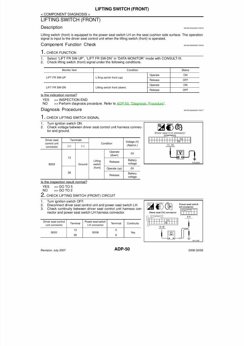
7/21/2019 adp INFINTY 2008
http://slidepdf.com/reader/full/adp-infinty-2008 50/149ADP-50
< COMPONENT DIAGNOSIS >
LIFTING SWITCH (FRONT)
LIFTING SWITCH (FRONT)
Description INFOID:0000000001735475
Lifting switch (front) is equipped to the power seat switch LH on the seat cushion side surface. The operationsignal is input to the driver seat control unit when the lifting switch (front) is operated.
Component Function Check INFOID:0000000001735476
1. CHECK FUNCTION
1. Select “LIFT FR SW-UP”, “LIFT FR SW-DN” in “DATA MONITOR” mode with CONSULT-III.2. Check lifting switch (front) signal under the following conditions.
Is the indication normal?
YES >> INSPECTION ENDNO >> Perform diagnosis procedure. Refer to ADP-50, "Diagnosis Procedure".
Diagnosis Procedure INFOID:0000000001735477
1. CHECK LIFTING SWITCH SIGNAL
1. Turn ignition switch ON.2. Check voltage between driver seat control unit harness connec-
tor and ground.
Is the inspection result normal?
YES >> GO TO 5NO >> GO TO 2
2. CHECK LIFTING SWITCH (FRONT) CIRCUIT1. Turn ignition switch OFF.2. Disconnect driver seat control unit and power seat switch LH.3. Check continuity between driver seat control unit harness con-
nector and power seat switch LH harness connector.
Monitor item Condition Status
LIFT FR SW-UP Lifting switch front (up)Operate ON
Release OFF
LIFT FR SW-DN Lifting switch front (down)Operate ON
Release OFF
Driver seat
control unit
connector
Terminals
ConditionVoltage (V)
(Approx.)(+) (–)
B202
13
Ground
Lifting
switch
(front)
Operate
(down)0V
ReleaseBattery
voltage
28
Operate (up) 0V
ReleaseBattery
voltage
PIIA4583E
Driver seat control
unit connectorTerminal
Power seat switch
LH connectorTerminal Continuity
B20213
B2085
Yes28 6
LIIA1129E
Revision: July 2007 2008 QX56
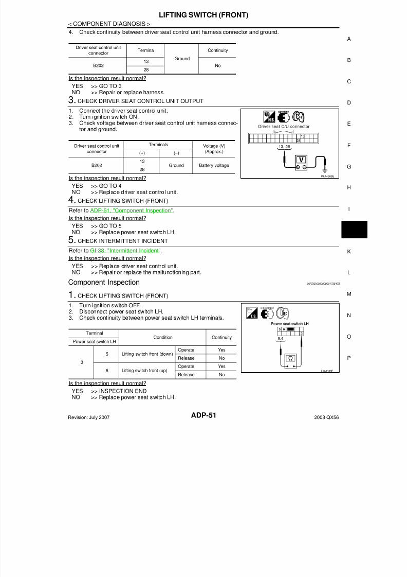
7/21/2019 adp INFINTY 2008
http://slidepdf.com/reader/full/adp-infinty-2008 51/149
LIFTING SWITCH (FRONT)
ADP-51
< COMPONENT DIAGNOSIS >
A
4. Check continuity between driver seat control unit harness connector and ground.
Is the inspection result normal?
YES >> GO TO 3NO >> Repair or replace harness.
3. CHECK DRIVER SEAT CONTROL UNIT OUTPUT
1. Connect the driver seat control unit.2. Turn ignition switch ON.3. Check voltage between driver seat control unit harness connec-
tor and ground.
Is the inspection result normal?
YES >> GO TO 4NO >> Replace driver seat control unit.
4. CHECK LIFTING SWITCH (FRONT)
Refer to ADP-51, "Component Inspection".
Is the inspection result normal?
YES >> GO TO 5NO >> Replace power seat switch LH.
5. CHECK INTERMITTENT INCIDENT
Refer to GI-38, "Intermittent Incident".
Is the inspection result normal?
YES >> Replace driver seat control unit.NO >> Repair or replace the malfunctioning part.
Component Inspection INFOID:0000000001735478
1. CHECK LIFTING SWITCH (FRONT)
1. Turn ignition switch OFF.2. Disconnect power seat switch LH.3. Check continuity between power seat switch LH terminals.
Is the inspection result normal?
YES >> INSPECTION ENDNO >> Replace power seat switch LH.
Driver seat control unit
connectorTerminal
Ground
Continuity
B20213
No28
Driver seat control unit
connector
Terminals Voltage (V)
(Approx.)(+) (–)
B202 13 Ground Battery voltage28
PIIA4583E
TerminalCondition Continuity
Power seat switch LH
3
5 Lifting switch front (down)Operate Yes
Release No
6 Lifting switch front (up)Operate Yes
Release NoLIIA1130E
Revision: July 2007 2008 QX56
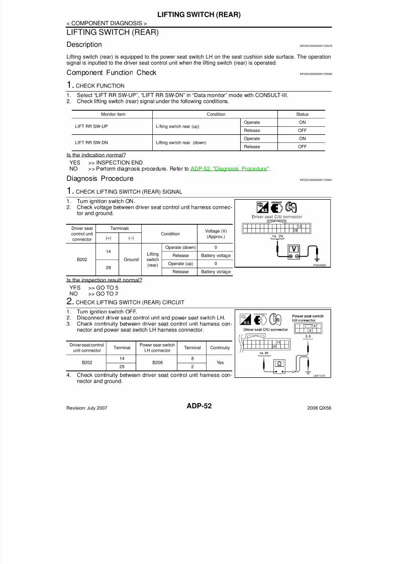
7/21/2019 adp INFINTY 2008
http://slidepdf.com/reader/full/adp-infinty-2008 52/149ADP-52
< COMPONENT DIAGNOSIS >
LIFTING SWITCH (REAR)
LIFTING SWITCH (REAR)
Description INFOID:0000000001735479
Lifting switch (rear) is equipped to the power seat switch LH on the seat cushion side surface. The operationsignal is inputted to the driver seat control unit when the lifting switch (rear) is operated.
Component Function Check INFOID:0000000001735480
1. CHECK FUNCTION
1. Select “LIFT RR SW-UP”, “LIFT RR SW-DN” in “Data monitor” mode with CONSULT-III.2. Check lifting switch (rear) signal under the following conditions.
Is the indication normal?
YES >> INSPECTION ENDNO >> Perform diagnosis procedure. Refer to ADP-52, "Diagnosis Procedure".
Diagnosis Procedure INFOID:0000000001735481
1. CHECK LIFTING SWITCH (REAR) SIGNAL
1. Turn ignition switch ON.2. Check voltage between driver seat control unit harness connec-
tor and ground.
Is the inspection result normal?
YES >> GO TO 5NO >> GO TO 2
2. CHECK LIFTING SWITCH (REAR) CIRCUIT
1. Turn ignition switch OFF.
2. Disconnect driver seat control unit and power seat switch LH.3. Check continuity between driver seat control unit harness con-nector and power seat switch LH harness connector.
4. Check continuity between driver seat control unit harness con-nector and ground.
Monitor item Condition Status
LIFT RR SW-UP Lifting switch rear (up)Operate ON
Release OFF
LIFT RR SW-DN Lifting switch rear (down)Operate ON
Release OFF
Driver seat
control unit
connector
Terminals
ConditionVoltage (V)
(Approx.)(+) (–)
B202
14
Ground
Lifting
switch
(rear)
Operate (down) 0
Release Battery voltage
29Operate (up) 0
Release Battery voltage
PIIA4586E
Driver seat control
unit connectorTerminal
Power sear switch
LH connectorTerminal Continuity
B20214
B2088
Yes29 2
LIIA1131E
Revision: July 2007 2008 QX56
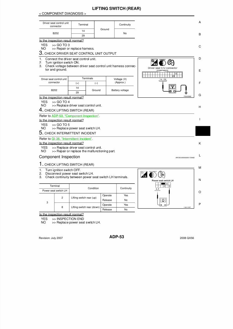
7/21/2019 adp INFINTY 2008
http://slidepdf.com/reader/full/adp-infinty-2008 53/149
LIFTING SWITCH (REAR)
ADP-53
< COMPONENT DIAGNOSIS >
A
Is the inspection result normal?
YES >> GO TO 3NO >> Repair or replace harness.
3. CHECK DRIVER SEAT CONTROL UNIT OUTPUT
1. Connect the driver seat control unit.2. Turn ignition switch ON.3. Check voltage between driver seat control unit harness connec-
tor and ground.
Is the inspection result normal?
YES >> GO TO 4NO >> Replace driver seat control unit.
4. CHECK LIFTING SWITCH (REAR)
Refer to ADP-53, "Component Inspection".
Is the inspection result normal?
YES >> GO TO 5NO >> Replace power seat switch LH.
5. CHECK INTERMITTENT INCIDENT
Refer to GI-38, "Intermittent Incident".Is the inspection result normal?
YES >> Replace driver seat control unit.NO >> Repair or replace the malfunctioning part.
Component Inspection INFOID:0000000001735482
1. CHECK LIFTING SWITCH (REAR)
1. Turn ignition switch OFF.2. Disconnect power seat switch LH.3. Check continuity between power seat switch LH terminals.
Is the inspection result normal?
YES >> INSPECTION ENDNO >> Replace power seat switch LH.
Driver seat control unit
connectorTerminal
Ground
Continuity
B20214
No29
Driver seat control unit
connector
Terminals Voltage (V)
(Approx.)(+) (–)
B20214
Ground Battery voltage
29PIIA4586E
Terminal Condition ContinuityPower seat switch LH
3
2 Lifting switch rear (up)Operate Yes
Release No
8 Lifting switch rear (down)Operate Yes
Release NoLIIA1132E
Revision: July 2007 2008 QX56

7/21/2019 adp INFINTY 2008
http://slidepdf.com/reader/full/adp-infinty-2008 54/149ADP-54
< COMPONENT DIAGNOSIS >
TILT SWITCH
TILT SWITCH
Description INFOID:0000000001754039
ADP steering switch is equipped to the steering column. The operation signal is input to the automatic drivepositioner control unit when the ADP steering switch is operated.
Component Function Check INFOID:0000000001754040
1.CHECK FUNCTION
1. Select “TILT SW-UP”, “TILT SW-DN” in “Data monitor” mode with CONSULT-III.2. Check tilt switch signal under the following conditions.
Is the indication normal?
YES >> INSPECTION ENDNO >> Perform diagnosis procedure. Refer to ADP-54, "Diagnosis Procedure".
Diagnosis Procedure INFOID:0000000001754041
1. CHECK ADP STEERING SWITCH SIGNAL
1. Turn ignition switch OFF.2. Check voltage between automatic drive positioner control unit
connector and ground.
Is the inspection result normal?
YES >> GO TO 4NO >> GO TO 2
2. CHECK ADP STEERING SWITCH HARNESS CONTINUITY
1. Disconnect automatic drive positioner control unit connectorand ADP steering switch.
2. Check continuity between automatic drive positioner control unitconnector M33 terminals 1, 17 and ADP steering switch connec-tor M16 terminals 2, 3.
3. Check continuity between automatic drive positioner control unitconnector M33 terminals 1, 17 and ground.
Monitor item Condition Status
TILT SW-UP Tilt switch (up)Operate ON
Release OFF
TILT SW-DN Tilt switch (down)Operate ON
Release OFF
ConnectorTerminals
ConditionVoltage (V)
(Approx.)(+) (-)
M33
1
Ground
ADP steering switch ON (UP
operation)0
Other than above 5
17
ADP steering switch ON
(DOWN operation)0
Other than above 5
LIIA0491E
1 - 2 : Continuity should exist.
17 - 3 : Continuity should exist.
LIIA1434E
Revision: July 2007 2008 QX56
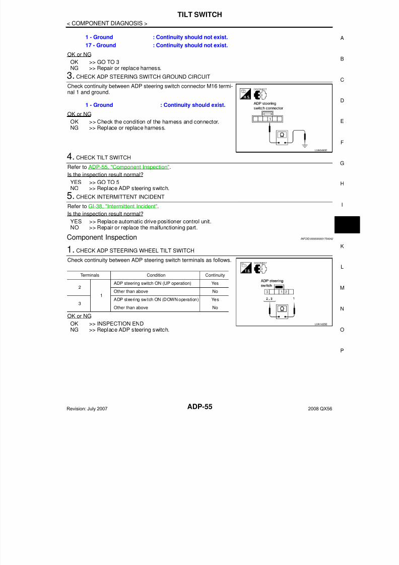
7/21/2019 adp INFINTY 2008
http://slidepdf.com/reader/full/adp-infinty-2008 55/149
TILT SWITCH
ADP-55
< COMPONENT DIAGNOSIS >
A
OK or NG
OK >> GO TO 3NG >> Repair or replace harness.
3. CHECK ADP STEERING SWITCH GROUND CIRCUIT
Check continuity between ADP steering switch connector M16 termi-nal 1 and ground.
OK or NG
OK >> Check the condition of the harness and connector.NG >> Replace or replace harness.
4. CHECK TILT SWITCHRefer to ADP-55, "Component Inspection".
Is the inspection result normal?
YES >> GO TO 5NO >> Replace ADP steering switch.
5. CHECK INTERMITTENT INCIDENT
Refer to GI-38, "Intermittent Incident".
Is the inspection result normal?
YES >> Replace automatic drive positioner control unit.NO >> Repair or replace the malfunctioning part.
Component Inspection INFOID:0000000001754042
1. CHECK ADP STEERING WHEEL TILT SWITCH
Check continuity between ADP steering switch terminals as follows.
OK or NG
OK >> INSPECTION ENDNG >> Replace ADP steering switch.
1 - Ground : Continuity should not exist.
17 - Ground : Continuity should not exist.
1 - Ground : Continuity should exist.
LIIA0490E
Terminals Condition Continuity
2
1
ADP steering switch ON (UP operation) Yes
Other than above No
3ADP steering switch ON (DOWN operation) Yes
Other than above No
LIIA1435E
Revision: July 2007 2008 QX56
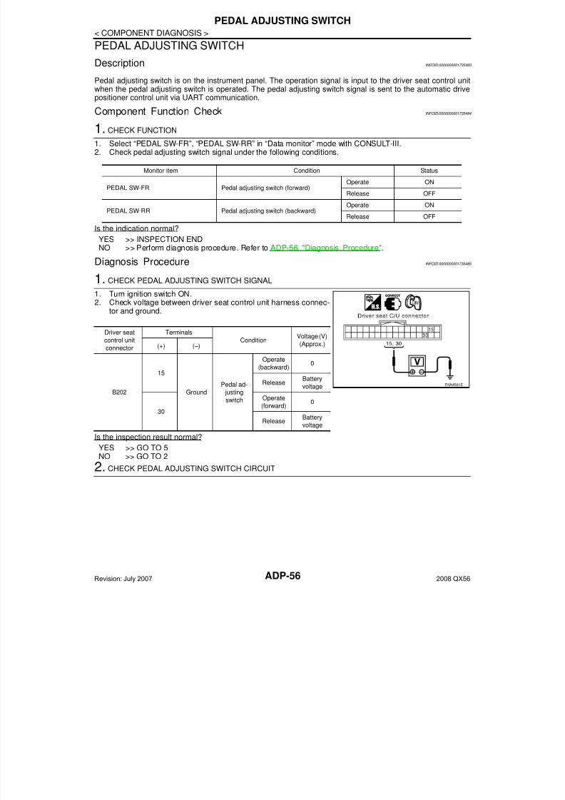
7/21/2019 adp INFINTY 2008
http://slidepdf.com/reader/full/adp-infinty-2008 56/149ADP-56
< COMPONENT DIAGNOSIS >
PEDAL ADJUSTING SWITCH
PEDAL ADJUSTING SWITCH
Description INFOID:0000000001735483
Pedal adjusting switch is on the instrument panel. The operation signal is input to the driver seat control unitwhen the pedal adjusting switch is operated. The pedal adjusting switch signal is sent to the automatic drivepositioner control unit via UART communication.
Component Function Check INFOID:0000000001735484
1. CHECK FUNCTION
1. Select “PEDAL SW-FR”, “PEDAL SW-RR” in “Data monitor” mode with CONSULT-III.2. Check pedal adjusting switch signal under the following conditions.
Is the indication normal?
YES >> INSPECTION ENDNO >> Perform diagnosis procedure. Refer to ADP-56, "Diagnosis Procedure".
Diagnosis Procedure INFOID:0000000001735485
1. CHECK PEDAL ADJUSTING SWITCH SIGNAL
1. Turn ignition switch ON.2. Check voltage between driver seat control unit harness connec-
tor and ground.
Is the inspection result normal?
YES >> GO TO 5NO >> GO TO 2
2. CHECK PEDAL ADJUSTING SWITCH CIRCUIT
Monitor item Condition Status
PEDAL SW-FR Pedal adjusting switch (forward)Operate ON
Release OFF
PEDAL SW-RR Pedal adjusting switch (backward)Operate ON
Release OFF
Driver seat
control unitconnector
Terminals
ConditionVoltage (V)
(Approx.)(+) (–)
B202
15
Ground
Pedal ad-
justing
switch
Operate
(backward)0
ReleaseBattery
voltage
30
Operate
(forward)0
ReleaseBattery
voltage
PIIA4591E
Revision: July 2007 2008 QX56
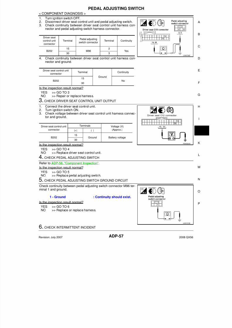
7/21/2019 adp INFINTY 2008
http://slidepdf.com/reader/full/adp-infinty-2008 57/149
PEDAL ADJUSTING SWITCH
ADP-57
< COMPONENT DIAGNOSIS >
A
1. Turn ignition switch OFF.2. Disconnect driver seat control unit and pedal adjusting switch.3. Check continuity between driver seat control unit harness con-
nector and pedal adjusting switch harness connector.
4. Check continuity between driver seat control unit harness con-nector and ground.
Is the inspection result normal?
YES >> GO TO 3NO >> Repair or replace harness.
3. CHECK DRIVER SEAT CONTROL UNIT OUTPUT
1. Connect the driver seat control unit.2. Turn ignition switch ON.3. Check voltage between driver seat control unit harness connec-
tor and ground.
Is the inspection result normal?
YES >> GO TO 4NO >> Replace driver seat control unit.
4. CHECK PEDAL ADJUSTING SWITCH
Refer to ADP-58, "Component Inspection".
Is the inspection result normal?
YES >> GO TO 5NO >> Replace pedal adjusting switch.
5. CHECK PEDAL ADJUSTING SWITCH GROUND CIRCUIT
Check continuity between pedal adjusting switch connector M96 ter-minal 1 and ground.
Is the inspection result normal?
YES >> GO TO 6NO >> Replace or replace harness.
6. CHECK INTERMITTENT INCIDENT
Driver seat
control unit
connector
TerminalPedal adjusting
switch connectorTerminal Continuity
B20215
M962
Yes30 3
Driver seat control unit
connectorTerminal
Ground
Continuity
B20215
No30
LIIA0726E
Driver seat control unit
connector
Terminals Voltage (V)
(Approx.)(+) (–)
B20215
Ground Battery voltage30
PIIA4591E
1 - Ground : Continuity should exist.
LIIA1015E
Revision: July 2007 2008 QX56

7/21/2019 adp INFINTY 2008
http://slidepdf.com/reader/full/adp-infinty-2008 58/149ADP-58
< COMPONENT DIAGNOSIS >
PEDAL ADJUSTING SWITCH
Refer to GI-38, "Intermittent Incident".
Is the inspection result normal?
YES >> Replace automatic drive positioner control unit.NO >> Repair or replace the malfunctioning part.
Component Inspection INFOID:0000000001735486
1.CHECK PEDAL ADJUSTING SWITCH
1. Turn ignition switch OFF.2. Disconnect pedal adjusting switch.3. Check continuity between pedal adjusting switch terminals.
Is the inspection result normal?
YES >> INSPECTION ENDNO >> Replace pedal adjusting switch.
TerminalCondition Continuity
Pedal adjusting switch
1
2Pedal adjusting switch
(forward)
Operate Yes
Release No
3Pedal adjusting switch
(backward)
Operate Yes
Release NoLIIA1014E
Revision: July 2007 2008 QX56

7/21/2019 adp INFINTY 2008
http://slidepdf.com/reader/full/adp-infinty-2008 59/149
SEAT MEMORY SWITCH
ADP-59
< COMPONENT DIAGNOSIS >
A
SEAT MEMORY SWITCH
Description INFOID:0000000001735487
Memory switch is equipped on the seat memory switch installed to the front door LH trim. The operation signalis input to the automatic drive positioner control unit when the memory switch is operated.
Component Function Check INFOID:0000000001735488
1. CHECK FUNCTION
1. Select “MEMORY SW 1”, “MEMORY SW 2”, "SET SW" in “Data monitor” mode with CONSULT-III.2. Check seat memory switch signal under the following conditions.
Is the indication normal?
YES >> INSPECTION ENDNO >> Perform diagnosis procedure. Refer to ADP-59, "Diagnosis Procedure".
Diagnosis Procedure INFOID:0000000001735489
1. CHECK MEMORY SWITCH CIRCUIT
1. Turn ignition switch OFF.2. Disconnect automatic drive positioner control unit and seat
memory switch.3. Check continuity between automatic drive positioner control unit
harness connector and seat memory switch harness connector.
4. Check continuity between automatic drive positioner control unit harness connector and ground.
Is the inspection result normal?
YES >> GO TO 2NO >> Repair or replace harness.
2. CHECK MEMORY SWITCH GROUND CIRCUIT
Monitor item Condition Status
MEMORY SW1 Memory switch 1Push ON
Release OFF
MEMORY SW2 Memory switch 2Push ON
Release OFF
SET SW Set switch
Push ON
Release OFF
Automatic drive
positioner control
unit connector
TerminalSeat memory
switch connectorTerminal Continuity
M33
9
D5
1
Yes24 3
25 2
Automatic drive positioner
control unit connector Terminal
Ground
Continuity
M33
9
No24
25
PIIA4576E
Revision: July 2007 2008 QX56
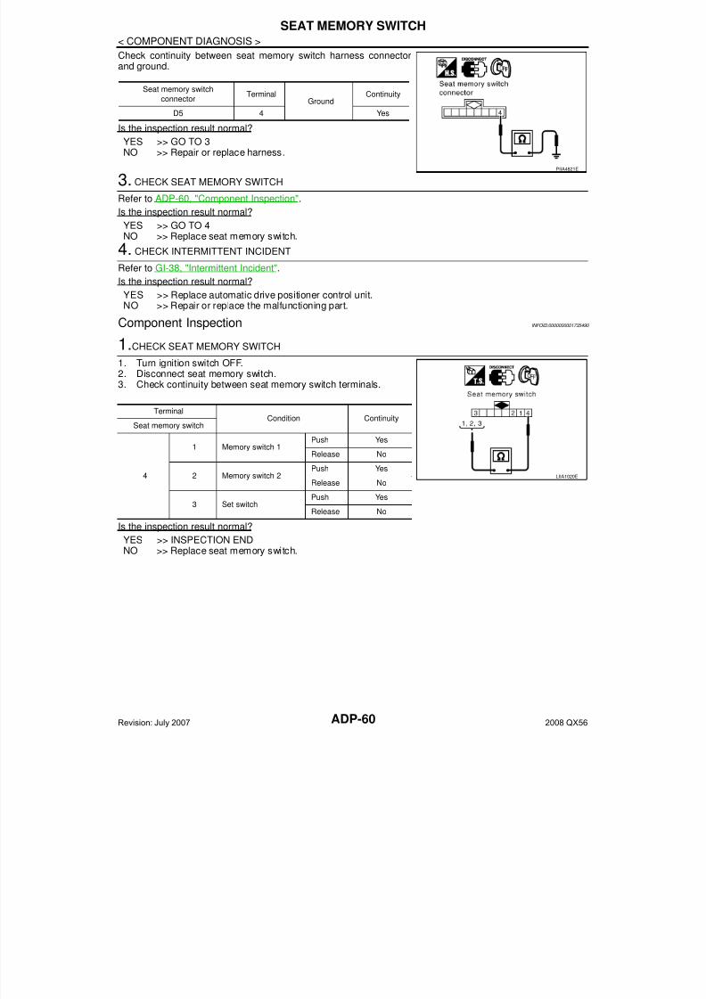
7/21/2019 adp INFINTY 2008
http://slidepdf.com/reader/full/adp-infinty-2008 60/149ADP-60
< COMPONENT DIAGNOSIS >
SEAT MEMORY SWITCH
Check continuity between seat memory switch harness connectorand ground.
Is the inspection result normal?
YES >> GO TO 3NO >> Repair or replace harness.
3. CHECK SEAT MEMORY SWITCH
Refer to ADP-60, "Component Inspection".
Is the inspection result normal?
YES >> GO TO 4NO >> Replace seat memory switch.
4. CHECK INTERMITTENT INCIDENT
Refer to GI-38, "Intermittent Incident".
Is the inspection result normal?YES >> Replace automatic drive positioner control unit.NO >> Repair or replace the malfunctioning part.
Component Inspection INFOID:0000000001735490
1.CHECK SEAT MEMORY SWITCH
1. Turn ignition switch OFF.2. Disconnect seat memory switch.3. Check continuity between seat memory switch terminals.
Is the inspection result normal?
YES >> INSPECTION ENDNO >> Replace seat memory switch.
Seat memory switch
connectorTerminal
GroundContinuity
D5 4 Yes
PIIA4821E
TerminalCondition Continuity
Seat memory switch
4
1 Memory switch 1Push Yes
Release No
2 Memory switch 2Push Yes
Release No
3 Set switchPush Yes
Release No
LIIA1020E
Revision: July 2007 2008 QX56
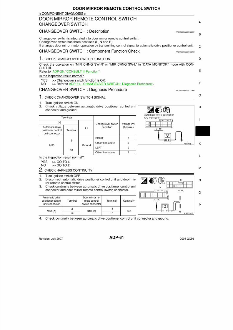
7/21/2019 adp INFINTY 2008
http://slidepdf.com/reader/full/adp-infinty-2008 61/149
DOOR MIRROR REMOTE CONTROL SWITCH
ADP-61
< COMPONENT DIAGNOSIS >
A
DOOR MIRROR REMOTE CONTROL SWITCHCHANGEOVER SWITCH
CHANGEOVER SWITCH : Description INFOID:0000000001735491
Changeover switch is integrated into door mirror remote control switch.Changeover switch has three positions (L, N and R).
It changes door mirror motor operation by transmitting control signal to automatic drive positioner control unit.CHANGEOVER SWITCH : Component Function Check INFOID:0000000001735492
1. CHECK CHANGEOVER SWITCH FUNCTION
Check the operation on “MIR CHNG SW-R” or “MIR CHNG SW-L” in “DATA MONITOR” mode with CON-SULT-III.Refer to ADP-26, "CONSULT-III Function".
Is the inspection result normal?
YES >> Changeover switch function is OK.NO >> Refer to ADP-61, "CHANGEOVER SWITCH : Diagnosis Procedure".
CHANGEOVER SWITCH : Diagnosis Procedure INFOID:0000000001735493
1. CHECK CHANGEOVER SWITCH SIGNAL
1. Turn ignition switch ON.2. Check voltage between automatic drive positioner control unit
connector and ground.
Is the inspection result normal?
YES >> GO TO 6NO >> GO TO 2
2. CHECK HARNESS CONTINUITY
1. Turn ignition switch OFF.2. Disconnect automatic drive positioner control unit and door mir-
ror remote control switch.
3. Check continuity between automatic drive positioner control unitconnector and door mirror remote control switch connector.
4. Check continuity between automatic drive positioner control unit connector and ground.
Terminals
Change over switch
condition
Voltage (V)
(Approx.)
(+)
(-)Automatic drive
positioner control
unit connector
Terminal
M33
2
Ground
RIGHT 0
Other than above 5
18LEFT 0
Other than above 5
PIIA4767E
Automatic drive
positioner control
unit connector
Terminal
Door mirror re-
mote control
switch connector
Terminal Continuity
M33 (A)2
D10 (B)11
Yes18 10 ALJIA0201ZZ
Revision: July 2007 2008 QX56
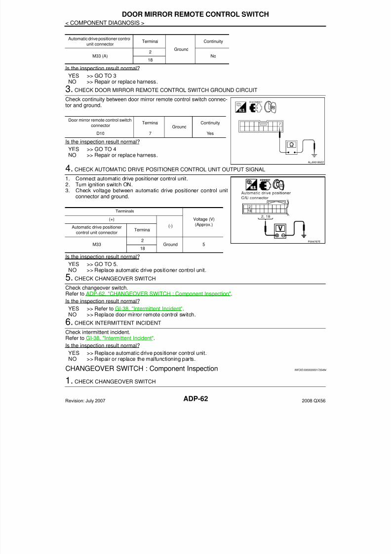
7/21/2019 adp INFINTY 2008
http://slidepdf.com/reader/full/adp-infinty-2008 62/149ADP-62
< COMPONENT DIAGNOSIS >
DOOR MIRROR REMOTE CONTROL SWITCH
Is the inspection result normal?
YES >> GO TO 3NO >> Repair or replace harness.
3. CHECK DOOR MIRROR REMOTE CONTROL SWITCH GROUND CIRCUIT
Check continuity between door mirror remote control switch connec-tor and ground.
Is the inspection result normal?
YES >> GO TO 4
NO >> Repair or replace harness.
4. CHECK AUTOMATIC DRIVE POSITIONER CONTROL UNIT OUTPUT SIGNAL
1. Connect automatic drive positioner control unit.2. Turn ignition switch ON.3. Check voltage between automatic drive positioner control unit
connector and ground.
Is the inspection result normal?
YES >> GO TO 5.NO >> Replace automatic drive positioner control unit.
5. CHECK CHANGEOVER SWITCH
Check changeover switch.Refer to ADP-62, "CHANGEOVER SWITCH : Component Inspection".
Is the inspection result normal?
YES >> Refer to GI-38, "Intermittent Incident".
NO >> Replace door mirror remote control switch.
6. CHECK INTERMITTENT INCIDENT
Check intermittent incident.Refer to GI-38, "Intermittent Incident".
Is the inspection result normal?
YES >> Replace automatic drive positioner control unit.NO >> Repair or replace the malfunctioning parts.
CHANGEOVER SWITCH : Component Inspection INFOID:0000000001735494
1. CHECK CHANGEOVER SWITCH
Automatic drive positioner control
unit connectorTerminal
Ground
Continuity
M33 (A)2
No18
Door mirror remote control switch
connectorTerminal
GroundContinuity
D10 7 Yes
ALJIA0189ZZ
Terminals
Voltage (V)
(Approx.)
(+)
(-)Automatic drive positioner
control unit connectorTerminal
M332
Ground 518
PIIA4767E
Revision: July 2007 2008 QX56
7/21/2019 adp INFINTY 2008
http://slidepdf.com/reader/full/adp-infinty-2008 63/149
DOOR MIRROR REMOTE CONTROL SWITCH
ADP-63
< COMPONENT DIAGNOSIS >
A
Check door mirror remote control switch.
Is the inspection result normal?
YES >> INSPECTION ENDNO >> Replace door mirror remote control switch.
MIRROR SWITCH
MIRROR SWITCH : Description INFOID:0000000001735495
It operates angle of the door mirror face.It transmits mirror face adjust operation to automatic drive positioner control unit.
MIRROR SWITCH : Component Function Check INFOID:0000000001735496
1. CHECK MIRROR SWITCH FUNCTION
Check the operation on “MIR CON SW–UP/DN” and “MIR CON SW–RH/LH” in “DATA MONITOR” modewith CONSULT-III.Refer to ADP-26, "CONSULT-III Function".
Is the inspection result normal?
YES >> Mirror switch function is OK.NO >> Refer to ADP-63, "MIRROR SWITCH : Diagnosis Procedure".
MIRROR SWITCH : Diagnosis Procedure INFOID:0000000001735497
1. CHECK MIRROR SWITCH FUNCTION
1. Turn ignition switch ON.2. Check voltage between automatic drive positioner control unit
connector and ground.
Is the inspection result normal?
YES >> GO TO 6NO >> GO TO 2
2. CHECK HARNESS CONTINUITY
Terminal Change over switch
conditionContinuity
Door mirror remote control switch
10
7
LEFT Yes
Other than above No
11 RIGHT Yes
Other than above No
ALJIA0190ZZ
Terminals
Mirror switch
Condition
Voltage (V)
(Approx.)
(+)
(–)Automatic drive
positioner control
unit connector
Terminal
M33
3
Ground
UP 0
Other than above 5
4LEFT 0
Other than above 5
19DOWN 0
Other than above 5
20RIGHT 0
Other than above 5
PIIA4771E
Revision: July 2007 2008 QX56

7/21/2019 adp INFINTY 2008
http://slidepdf.com/reader/full/adp-infinty-2008 64/149ADP-64
< COMPONENT DIAGNOSIS >
DOOR MIRROR REMOTE CONTROL SWITCH
1. Turn ignition switch OFF.2. Disconnect automatic drive positioner control unit and door mir-
ror remote control switch.3. Check continuity between automatic drive positioner control unit
connector and door mirror remote control switch connector.
4. Check continuity between automatic drive positioner control unit connector and ground.
Is the inspection result normal?
YES >> GO TO 3NO >> Repair or replace harness.
3. CHECK DOOR MIRROR REMOTE CONTROL SWITCH GROUND CIRCUIT
Check continuity between door mirror remote control switch connec-tor and ground.
Is the inspection result normal?
YES >> GO TO 4NO >> Repair or replace harness.
4. CHECK AUTOMATIC DRIVE POSITIONER CONTROL UNIT OUTPUT SIGNAL
1. Connect automatic drive positioner control unit.2. Turn ignition switch ON.3. Check voltage between automatic drive positioner control unit
and ground.
Is the inspection result normal?
Automatic drive
positioner control
unit connector
Terminal
Door mirror remote
control switch con-
nector
Terminal Continuity
M33 (A)
3
D10 (B)
15
Yes4 13
19 12
20 4
Automatic drive positioner
control unit connectorTerminal
Ground
Continuity
M33 (A)
3
No4
19
20
ALJIA0191ZZ
Door mirror remote control
switch connector Terminal Ground Continuity
D10 7 Yes
ALJIA0189ZZ
Terminals
Voltage (V)
(Approx.)
(+)
(-)Automatic drive positioner
control unit connectorTerminal
M33
3
Ground 54
19
20
PIIA4771E
Revision: July 2007 2008 QX56
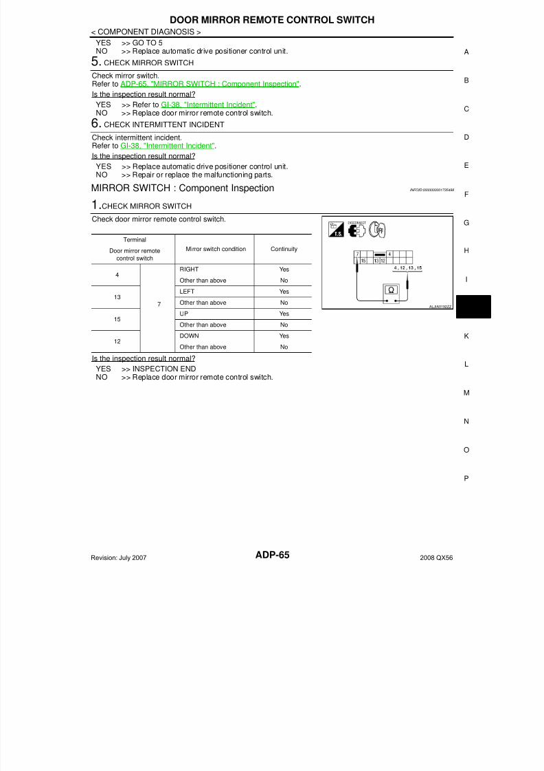
7/21/2019 adp INFINTY 2008
http://slidepdf.com/reader/full/adp-infinty-2008 65/149
DOOR MIRROR REMOTE CONTROL SWITCH
ADP-65
< COMPONENT DIAGNOSIS >
A
YES >> GO TO 5NO >> Replace automatic drive positioner control unit.
5. CHECK MIRROR SWITCH
Check mirror switch.Refer to ADP-65, "MIRROR SWITCH : Component Inspection".
Is the inspection result normal?
YES >> Refer to GI-38, "Intermittent Incident".NO >> Replace door mirror remote control switch.
6. CHECK INTERMITTENT INCIDENT
Check intermittent incident.Refer to GI-38, "Intermittent Incident".
Is the inspection result normal?
YES >> Replace automatic drive positioner control unit.NO >> Repair or replace the malfunctioning parts.
MIRROR SWITCH : Component Inspection INFOID:0000000001735498
1.CHECK MIRROR SWITCH
Check door mirror remote control switch.
Is the inspection result normal?
YES >> INSPECTION ENDNO >> Replace door mirror remote control switch.
Terminal
Mirror switch condition ContinuityDoor mirror remote
control switch
4
7
RIGHT Yes
Other than above No
13LEFT Yes
Other than above No
15UP Yes
Other than above No
12DOWN Yes
Other than above No
ALJIA0192ZZ
Revision: July 2007 2008 QX56
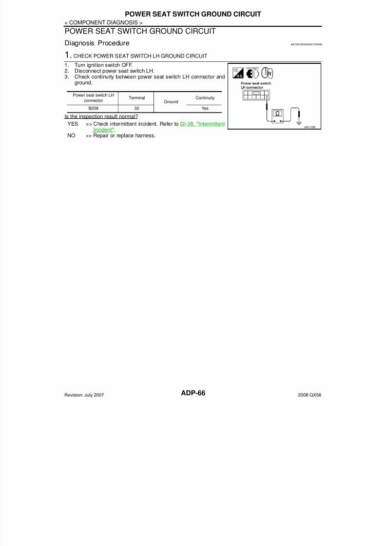
7/21/2019 adp INFINTY 2008
http://slidepdf.com/reader/full/adp-infinty-2008 66/149ADP-66
< COMPONENT DIAGNOSIS >
POWER SEAT SWITCH GROUND CIRCUIT
POWER SEAT SWITCH GROUND CIRCUIT
Diagnosis Procedure INFOID:0000000001735499
1. CHECK POWER SEAT SWITCH LH GROUND CIRCUIT
1. Turn ignition switch OFF.2. Disconnect power seat switch LH.
3. Check continuity between power seat switch LH connector andground.
Is the inspection result normal?
YES >> Check intermittent incident. Refer to GI-38, "IntermittentIncident".
NO >> Repair or replace harness.
Power seat switch LH
connectorTerminal
GroundContinuity
B208 32 Yes
LIIA1133E
Revision: July 2007 2008 QX56
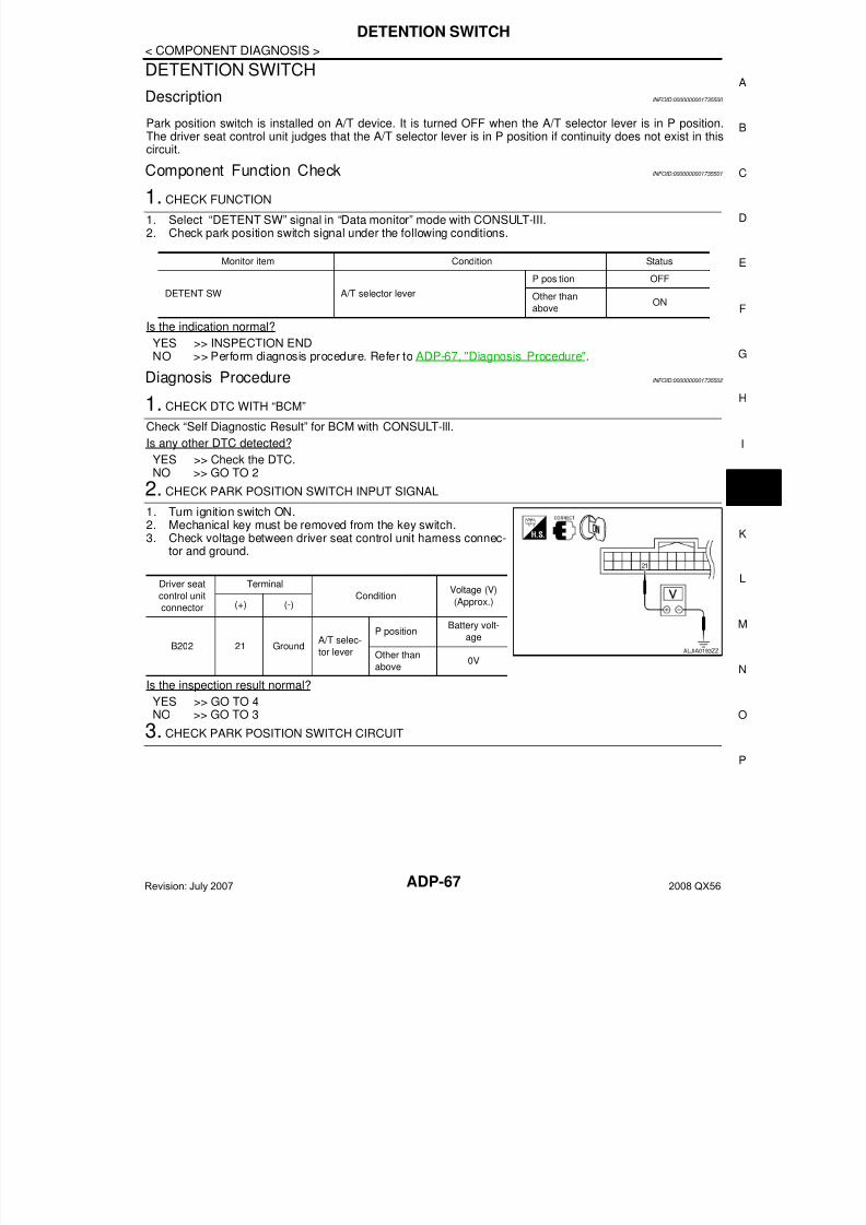
7/21/2019 adp INFINTY 2008
http://slidepdf.com/reader/full/adp-infinty-2008 67/149
DETENTION SWITCH
ADP-67
< COMPONENT DIAGNOSIS >
A
DETENTION SWITCH
Description INFOID:0000000001735500
Park position switch is installed on A/T device. It is turned OFF when the A/T selector lever is in P position.The driver seat control unit judges that the A/T selector lever is in P position if continuity does not exist in thiscircuit.
Component Function Check INFOID:0000000001735501
1. CHECK FUNCTION
1. Select “DETENT SW” signal in “Data monitor” mode with CONSULT-III.2. Check park position switch signal under the following conditions.
Is the indication normal?
YES >> INSPECTION ENDNO >> Perform diagnosis procedure. Refer to ADP-67, "Diagnosis Procedure".
Diagnosis Procedure INFOID:0000000001735502
1. CHECK DTC WITH “BCM”
Check “Self Diagnostic Result” for BCM with CONSULT-lll.
Is any other DTC detected?
YES >> Check the DTC.NO >> GO TO 2
2. CHECK PARK POSITION SWITCH INPUT SIGNAL
1. Turn ignition switch ON.2. Mechanical key must be removed from the key switch.3. Check voltage between driver seat control unit harness connec-
tor and ground.
Is the inspection result normal?
YES >> GO TO 4NO >> GO TO 3
3. CHECK PARK POSITION SWITCH CIRCUIT
Monitor item Condition Status
DETENT SW A/T selector lever
P position OFF
Other than
aboveON
Driver seat
control unit
connector
Terminal
ConditionVoltage (V)
(Approx.)(+) (-)
B202 21 GroundA/T selec-
tor lever
P positionBattery volt-
age
Other than
above0V
ALJIA0193ZZ
Revision: July 2007 2008 QX56
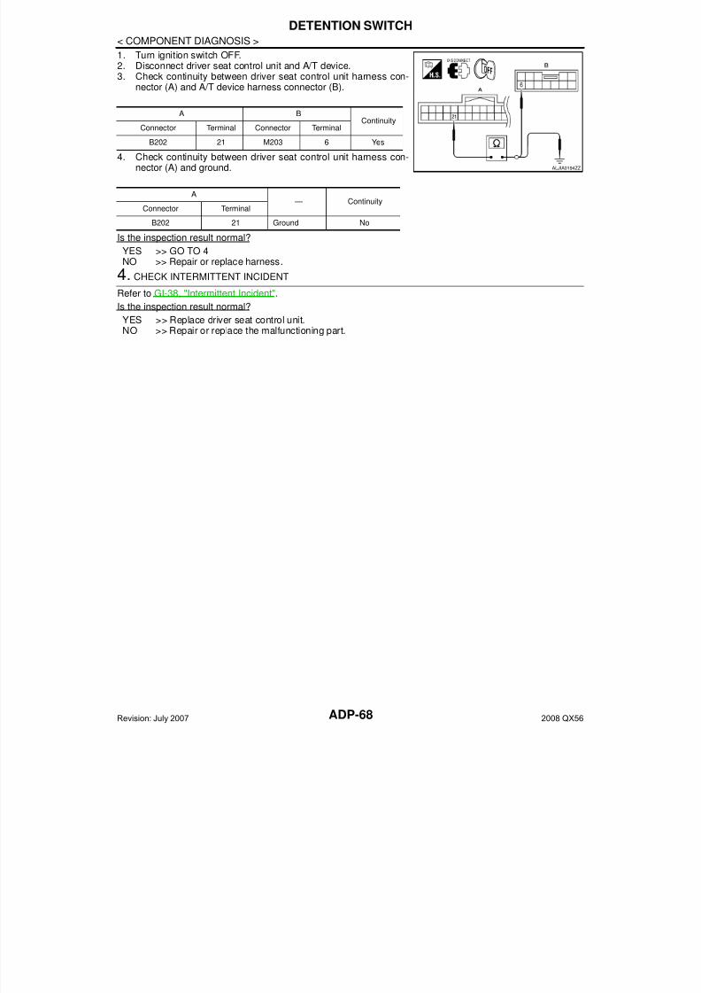
7/21/2019 adp INFINTY 2008
http://slidepdf.com/reader/full/adp-infinty-2008 68/149ADP-68
< COMPONENT DIAGNOSIS >
DETENTION SWITCH
1. Turn ignition switch OFF.2. Disconnect driver seat control unit and A/T device.3. Check continuity between driver seat control unit harness con-
nector (A) and A/T device harness connector (B).
4. Check continuity between driver seat control unit harness con-nector (A) and ground.
Is the inspection result normal?
YES >> GO TO 4NO >> Repair or replace harness.
4. CHECK INTERMITTENT INCIDENTRefer to GI-38, "Intermittent Incident".
Is the inspection result normal?
YES >> Replace driver seat control unit.NO >> Repair or replace the malfunctioning part.
A BContinuity
Connector Terminal Connector Terminal
B202 21 M203 6 Yes
A — Continuity
Connector Terminal
B202 21 Ground No
ALJIA0194ZZ
Revision: July 2007 2008 QX56
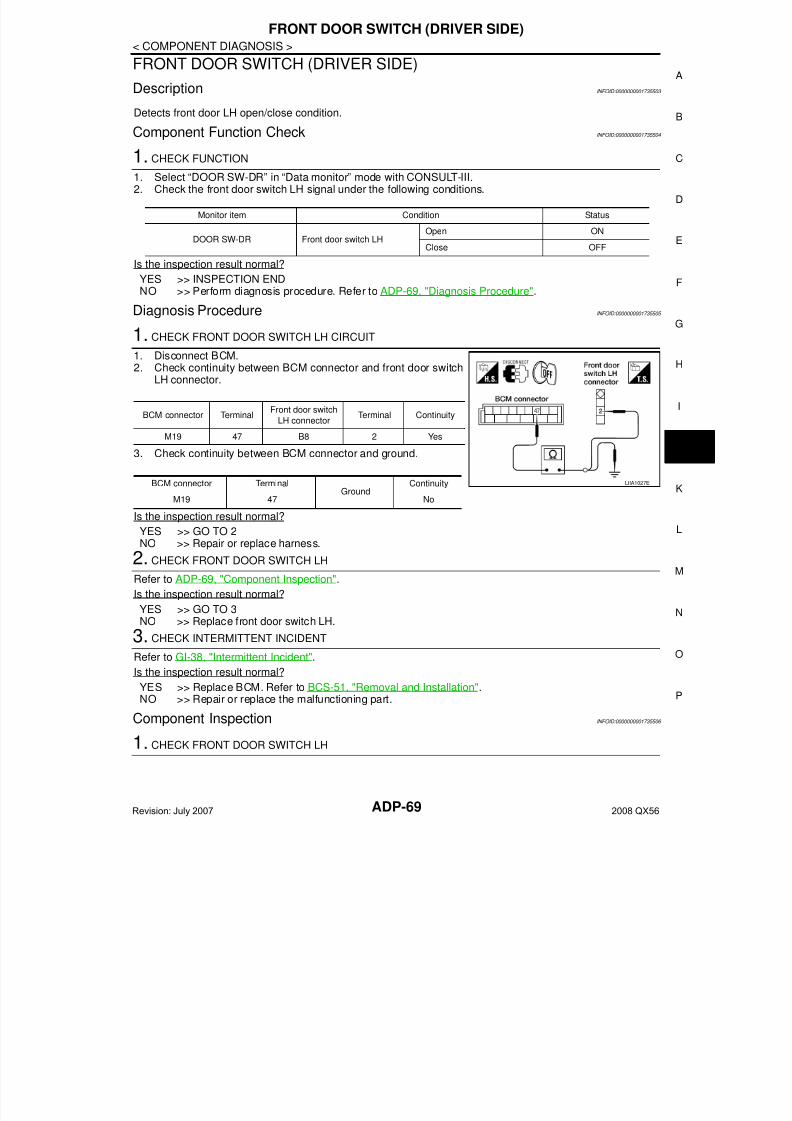
7/21/2019 adp INFINTY 2008
http://slidepdf.com/reader/full/adp-infinty-2008 69/149
FRONT DOOR SWITCH (DRIVER SIDE)
ADP-69
< COMPONENT DIAGNOSIS >
A
FRONT DOOR SWITCH (DRIVER SIDE)
Description INFOID:0000000001735503
Detects front door LH open/close condition.
Component Function Check INFOID:0000000001735504
1. CHECK FUNCTION
1. Select “DOOR SW-DR” in “Data monitor” mode with CONSULT-III.2. Check the front door switch LH signal under the following conditions.
Is the inspection result normal?
YES >> INSPECTION ENDNO >> Perform diagnosis procedure. Refer to ADP-69, "Diagnosis Procedure".
Diagnosis Procedure INFOID:0000000001735505
1. CHECK FRONT DOOR SWITCH LH CIRCUIT
1. Disconnect BCM.2. Check continuity between BCM connector and front door switch
LH connector.
3. Check continuity between BCM connector and ground.
Is the inspection result normal?
YES >> GO TO 2NO >> Repair or replace harness.
2. CHECK FRONT DOOR SWITCH LH
Refer to ADP-69, "Component Inspection".
Is the inspection result normal?
YES >> GO TO 3NO >> Replace front door switch LH.
3. CHECK INTERMITTENT INCIDENT
Refer to GI-38, "Intermittent Incident".
Is the inspection result normal?
YES >> Replace BCM. Refer to BCS-51, "Removal and Installation".NO >> Repair or replace the malfunctioning part.
Component Inspection INFOID:0000000001735506
1. CHECK FRONT DOOR SWITCH LH
Monitor item Condition Status
DOOR SW-DR Front door switch LHOpen ON
Close OFF
BCM connector TerminalFront door switch
LH connectorTerminal Continuity
M19 47 B8 2 Yes
BCM connector TerminalGround
Continuity
M19 47 No
LIIA1027E
Revision: July 2007 2008 QX56
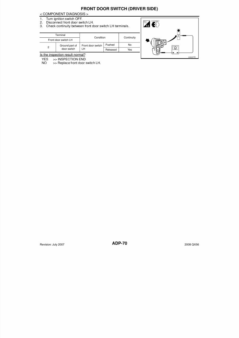
7/21/2019 adp INFINTY 2008
http://slidepdf.com/reader/full/adp-infinty-2008 70/149ADP-70
< COMPONENT DIAGNOSIS >
FRONT DOOR SWITCH (DRIVER SIDE)
1. Turn ignition switch OFF.2. Disconnect front door switch LH.3. Check continuity between front door switch LH terminals.
Is the inspection result normal?
YES >> INSPECTION ENDNO >> Replace front door switch LH.
TerminalCondition Continuity
Front door switch LH
2
Ground part of
door switch
Front door switch
LH
Pushed No
Released Yes
LIIA2377E
Revision: July 2007 2008 QX56
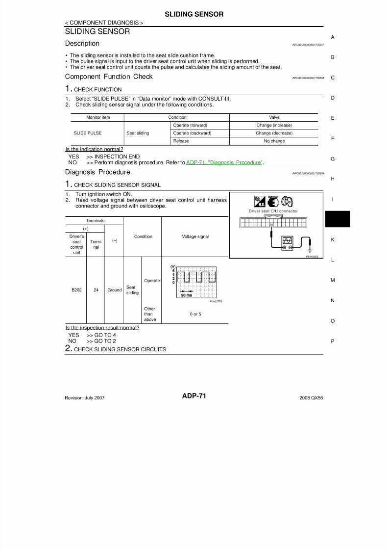
7/21/2019 adp INFINTY 2008
http://slidepdf.com/reader/full/adp-infinty-2008 71/149
SLIDING SENSOR
ADP-71
< COMPONENT DIAGNOSIS >
A
SLIDING SENSOR
Description INFOID:0000000001735507
• The sliding sensor is installed to the seat slide cushion frame.• The pulse signal is input to the driver seat control unit when sliding is performed.• The driver seat control unit counts the pulse and calculates the sliding amount of the seat.
Component Function Check INFOID:0000000001735508
1. CHECK FUNCTION
1. Select “SLIDE PULSE” in “Data monitor” mode with CONSULT-III.2. Check sliding sensor signal under the following conditions.
Is the indication normal?
YES >> INSPECTION ENDNO >> Perform diagnosis procedure. Refer to ADP-71, "Diagnosis Procedure".
Diagnosis Procedure INFOID:0000000001735509
1. CHECK SLIDING SENSOR SIGNAL
1. Turn ignition switch ON.2. Read voltage signal between driver seat control unit harness
connector and ground with osiloscope.
Is the inspection result normal?
YES >> GO TO 4NO >> GO TO 2
2. CHECK SLIDING SENSOR CIRCUITS
Monitor item Condition Valve
SLIDE PULSE Seat sliding
Operate (forward) Change (increase)
Operate (backward) Change (decrease)
Release No change
Terminals
Condition Voltage signal
(+)
(–)Driver’s
seat
control
unit
Termi-
nal
B202 24 GroundSeat
sliding
Operate
Other
than
above
0 or 5
PIIA4556E
PIIA3277E
Revision: July 2007 2008 QX56

7/21/2019 adp INFINTY 2008
http://slidepdf.com/reader/full/adp-infinty-2008 72/149ADP-72
< COMPONENT DIAGNOSIS >
SLIDING SENSOR
1. Turn ignition switch OFF.2. Disconnect driver seat control unit and sliding motor LH.3. Check continuity between driver seat control unit harness con-
nector and sliding motor LH harness connector.
4. Check continuity between driver seat control unit harness connector and ground.
Is the inspection result normal?
YES >> GO TO 3NO >> Repair or replace harness.
3. CHECK SEAT OPERATION
1. Connect driver seat control unit and sliding motor LH.2. Check seat operation (except sliding operation) with memory function.
Is the inspection result normal?
YES >> Replace sliding motor LH. (Built in seat slide cushion frame).NO >> Replace driver seat control unit.
4. CHECK INTERMITTENT INCIDENT
Refer to GI-38, "Intermittent Incident".
Is the inspection result normal?YES >> Replace driver seat control unit.NO >> Repair or replace the malfunctioning part.
Driver seat control
unit connectorTerminal
Sliding motor
LH connectorTerminal Continuity
B20216
B2043
Yes24 2
31 1
Driver seat control unit
connectorTerminal
Ground
Continuity
B202
16
No24
31
LIIA0706E
Revision: July 2007 2008 QX56

7/21/2019 adp INFINTY 2008
http://slidepdf.com/reader/full/adp-infinty-2008 73/149
RECLINING SENSOR
ADP-73
< COMPONENT DIAGNOSIS >
A
RECLINING SENSOR
Description INFOID:0000000001735510
• The reclining motor is installed to the seatback frame.• The pulse signal is inputted to the driver seat control unit when the reclining is operated.• The driver seat control unit counts the pulse and calculates the reclining amount of the seat.
Component Function Check INFOID:0000000001735511
1. CHECK FUNCTION
1. Select “RECLN PULSE” in “Data monitor” mode with CONSULT-III.2. Check reclining sensor signal under the following conditions.
Is the indication normal?
YES >> INSPECTION ENDNO >> Perform diagnosis procedure. Refer to ADP-73, "Diagnosis Procedure".
Diagnosis Procedure INFOID:0000000001735512
1. CHECK RECLINING SENSOR SIGNAL
1. Turn ignition switch ON.2. Read voltage signal between driver seat control unit harness
connector and ground with oscilloscope.
Is the inspection result normal?
YES >> GO TO 4NO >> GO TO 2
2. CHECK RECLINING SENSOR CIRCUIT
Monitor item Condition Value
RECLN PULSE Seat reclining
Operate (forward) Change (increase)
Operate (backward) Change (decrease)
Release No change
Terminals
Condition Voltage signal
(+)
(–)Driverseat con-
trol unit
Termi-
nal
B202 9 Ground
Seat
reclin-
ing
Operate
Other
than
above
0 or 5
PIIA4559E
SIIA0692J
Revision: July 2007 2008 QX56
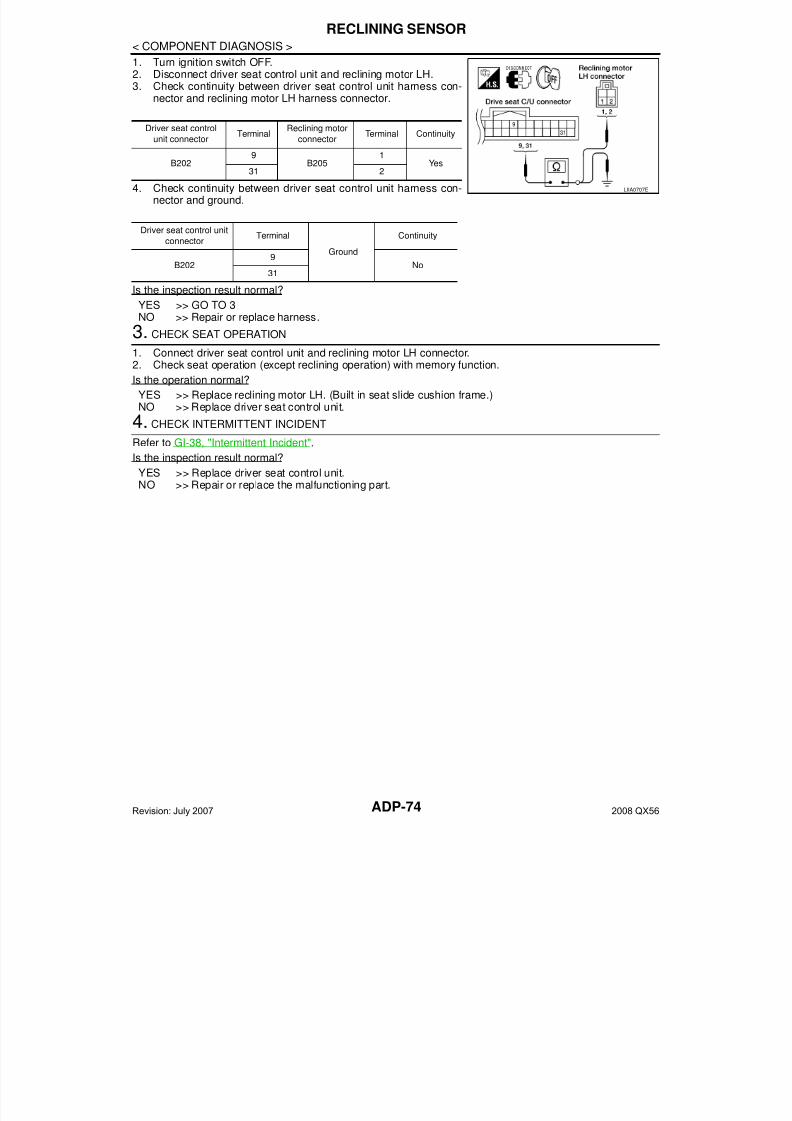
7/21/2019 adp INFINTY 2008
http://slidepdf.com/reader/full/adp-infinty-2008 74/149ADP-74
< COMPONENT DIAGNOSIS >
RECLINING SENSOR
1. Turn ignition switch OFF.2. Disconnect driver seat control unit and reclining motor LH.3. Check continuity between driver seat control unit harness con-
nector and reclining motor LH harness connector.
4. Check continuity between driver seat control unit harness con-nector and ground.
Is the inspection result normal?
YES >> GO TO 3
NO >> Repair or replace harness.3. CHECK SEAT OPERATION
1. Connect driver seat control unit and reclining motor LH connector.2. Check seat operation (except reclining operation) with memory function.
Is the operation normal?
YES >> Replace reclining motor LH. (Built in seat slide cushion frame.)NO >> Replace driver seat control unit.
4. CHECK INTERMITTENT INCIDENT
Refer to GI-38, "Intermittent Incident".
Is the inspection result normal?
YES >> Replace driver seat control unit.NO >> Repair or replace the malfunctioning part.
Driver seat control
unit connectorTerminal
Reclining motor
connectorTerminal Continuity
B202 9 B205 1 Yes31 2
Driver seat control unit
connectorTerminal
Ground
Continuity
B2029
No31
LIIA0707E
Revision: July 2007 2008 QX56
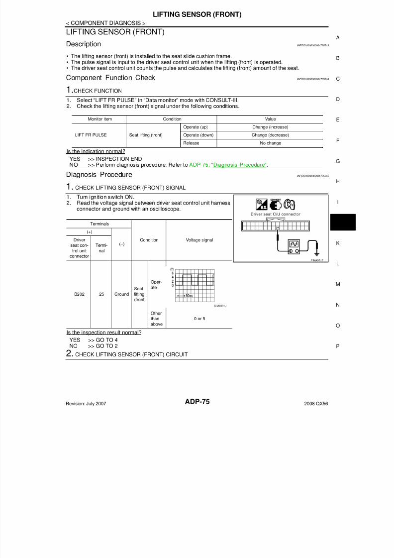
7/21/2019 adp INFINTY 2008
http://slidepdf.com/reader/full/adp-infinty-2008 75/149
LIFTING SENSOR (FRONT)
ADP-75
< COMPONENT DIAGNOSIS >
A
LIFTING SENSOR (FRONT)
Description INFOID:0000000001735513
• The lifting sensor (front) is installed to the seat slide cushion frame.• The pulse signal is input to the driver seat control unit when the lifting (front) is operated.• The driver seat control unit counts the pulse and calculates the lifting (front) amount of the seat.
Component Function Check INFOID:0000000001735514
1.CHECK FUNCTION
1. Select “LIFT FR PULSE” in “Data monitor” mode with CONSULT-III.2. Check the lifting sensor (front) signal under the following conditions.
Is the indication normal?
YES >> INSPECTION ENDNO >> Perform diagnosis procedure. Refer to ADP-75, "Diagnosis Procedure".
Diagnosis Procedure INFOID:0000000001735515
1. CHECK LIFTING SENSOR (FRONT) SIGNAL
1. Turn ignition switch ON.2. Read the voltage signal between driver seat control unit harness
connector and ground with an oscilloscope.
Is the inspection result normal?
YES >> GO TO 4NO >> GO TO 2
2. CHECK LIFTING SENSOR (FRONT) CIRCUIT
Monitor item Condition Value
LIFT FR PULSE Seat lifting (front)
Operate (up) Change (increase)
Operate (down) Change (decrease)
Release No change
Terminals
Condition Voltage signal
(+)
(–)Driver
seat con-
trol unit
connector
Termi-
nal
B202 25 Ground
Seat
lifting
(front)
Oper-
ate
Other
than
above
0 or 5
PIIA4561E
SIIA0691J
Revision: July 2007 2008 QX56
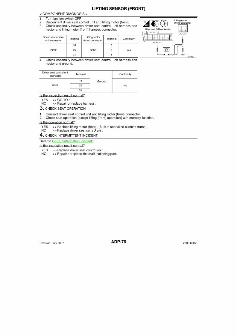
7/21/2019 adp INFINTY 2008
http://slidepdf.com/reader/full/adp-infinty-2008 76/149ADP-76
< COMPONENT DIAGNOSIS >
LIFTING SENSOR (FRONT)
1. Turn ignition switch OFF.2. Disconnect driver seat control unit and lifting motor (front).3. Check continuity between driver seat control unit harness con-
nector and lifting motor (front) harness connector.
4. Check continuity between driver seat control unit harness con-nector and ground.
Is the inspection result normal?YES >> GO TO 3NO >> Repair or replace harness.
3. CHECK SEAT OPERATION
1. Connect driver seat control unit and lifting motor (front) connector.2. Check seat operation [except lifting (front) operation] with memory function.
Is the operation normal?
YES >> Replace lifting motor (front). (Built in seat slide cushion frame.)NO >> Replace driver seat control unit.
4. CHECK INTERMITTENT INCIDENT
Refer to GI-38, "Intermittent Incident".
Is the inspection result normal?
YES >> Replace driver seat control unit.NO >> Repair or replace the malfunctioning part.
Driver seat control
unit connectorTerminal
Lifting motor
(front) connectorTerminal Continuity
B202
16
B206
3
Yes25 2
31 1
Driver seat control unit
connectorTerminal
Ground
Continuity
B202
16
No25
31
LIIA0708E
Revision: July 2007 2008 QX56
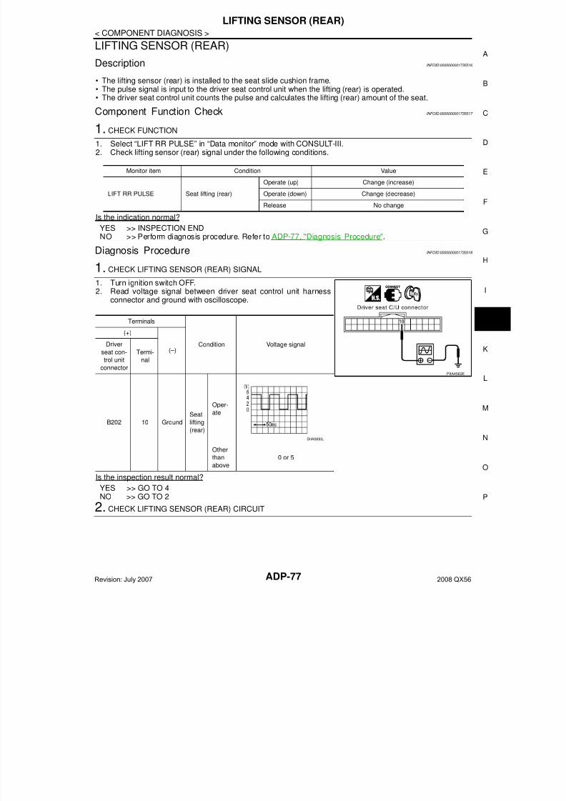
7/21/2019 adp INFINTY 2008
http://slidepdf.com/reader/full/adp-infinty-2008 77/149
LIFTING SENSOR (REAR)
ADP-77
< COMPONENT DIAGNOSIS >
A
LIFTING SENSOR (REAR)
Description INFOID:0000000001735516
• The lifting sensor (rear) is installed to the seat slide cushion frame.• The pulse signal is input to the driver seat control unit when the lifting (rear) is operated.• The driver seat control unit counts the pulse and calculates the lifting (rear) amount of the seat.
Component Function Check INFOID:0000000001735517
1. CHECK FUNCTION
1. Select “LIFT RR PULSE” in “Data monitor” mode with CONSULT-III.2. Check lifting sensor (rear) signal under the following conditions.
Is the indication normal?
YES >> INSPECTION ENDNO >> Perform diagnosis procedure. Refer to ADP-77, "Diagnosis Procedure".
Diagnosis Procedure INFOID:0000000001735518
1. CHECK LIFTING SENSOR (REAR) SIGNAL
1. Turn ignition switch OFF.2. Read voltage signal between driver seat control unit harness
connector and ground with oscilloscope.
Is the inspection result normal?
YES >> GO TO 4NO >> GO TO 2
2. CHECK LIFTING SENSOR (REAR) CIRCUIT
Monitor item Condition Value
LIFT RR PULSE Seat lifting (rear)
Operate (up) Change (increase)
Operate (down) Change (decrease)
Release No change
Terminals
Condition Voltage signal
(+)
(–)Driver
seat con-
trol unit
connector
Termi-
nal
B202 10 Ground
Seat
lifting
(rear)
Oper-
ate
Other
than
above
0 or 5
PIIA4563E
SIIA0693J
Revision: July 2007 2008 QX56
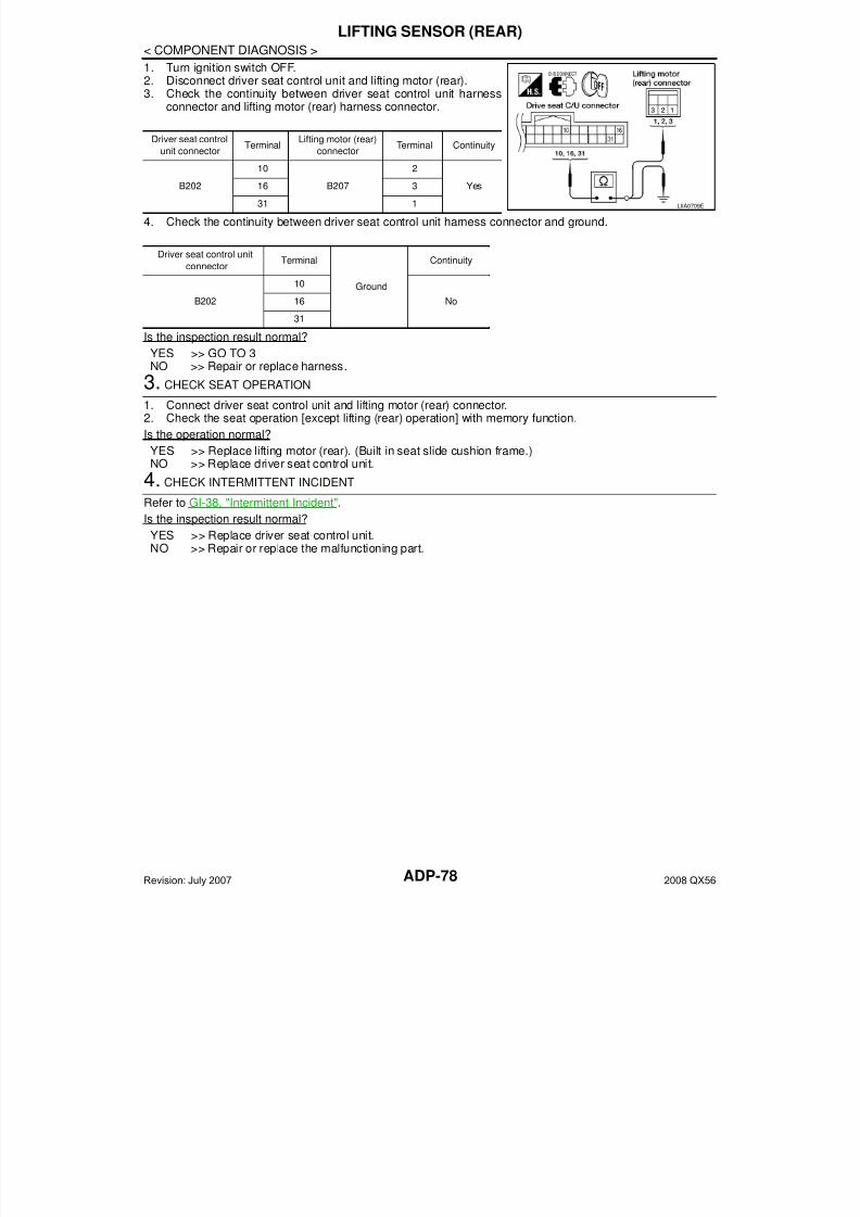
7/21/2019 adp INFINTY 2008
http://slidepdf.com/reader/full/adp-infinty-2008 78/149ADP-78
< COMPONENT DIAGNOSIS >
LIFTING SENSOR (REAR)
1. Turn ignition switch OFF.2. Disconnect driver seat control unit and lifting motor (rear).3. Check the continuity between driver seat control unit harness
connector and lifting motor (rear) harness connector.
4. Check the continuity between driver seat control unit harness connector and ground.
Is the inspection result normal?
YES >> GO TO 3NO >> Repair or replace harness.
3. CHECK SEAT OPERATION
1. Connect driver seat control unit and lifting motor (rear) connector.2. Check the seat operation [except lifting (rear) operation] with memory function.
Is the operation normal?
YES >> Replace lifting motor (rear). (Built in seat slide cushion frame.)NO >> Replace driver seat control unit.
4. CHECK INTERMITTENT INCIDENT
Refer to GI-38, "Intermittent Incident".
Is the inspection result normal?YES >> Replace driver seat control unit.NO >> Repair or replace the malfunctioning part.
Driver seat control
unit connectorTerminal
Lifting motor (rear)
connectorTerminal Continuity
B20210
B2072
Yes16 3
31 1
Driver seat control unit
connectorTerminal
Ground
Continuity
B202
10
No16
31
LIIA0709E
Revision: July 2007 2008 QX56
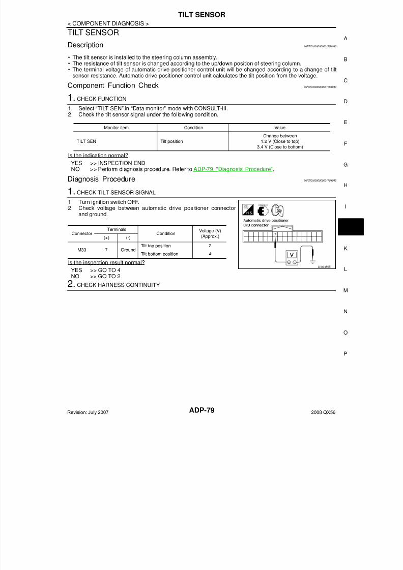
7/21/2019 adp INFINTY 2008
http://slidepdf.com/reader/full/adp-infinty-2008 79/149
TILT SENSOR
ADP-79
< COMPONENT DIAGNOSIS >
A
TILT SENSOR
Description INFOID:0000000001754043
• The tilt sensor is installed to the steering column assembly.• The resistance of tilt sensor is changed according to the up/down position of steering column.• The terminal voltage of automatic drive positioner control unit will be changed according to a change of tilt
sensor resistance. Automatic drive positioner control unit calculates the tilt position from the voltage.
Component Function Check INFOID:0000000001754044
1. CHECK FUNCTION
1. Select “TILT SEN” in “Data monitor” mode with CONSULT-III.2. Check the tilt sensor signal under the following condition.
Is the indication normal?
YES >> INSPECTION ENDNO >> Perform diagnosis procedure. Refer to ADP-79, "Diagnosis Procedure".
Diagnosis Procedure INFOID:0000000001754045
1. CHECK TILT SENSOR SIGNAL
1. Turn ignition switch OFF.2. Check voltage between automatic drive positioner connector
and ground.
Is the inspection result normal?
YES >> GO TO 4NO >> GO TO 2
2. CHECK HARNESS CONTINUITY
Monitor item Condition Value
TILT SEN Tilt position
Change between
1.2 V (Close to top)
3.4 V (Close to bottom)
ConnectorTerminals
ConditionVoltage (V)
(Approx.)(+) (-)
M33 7 GroundTilt top position 2
Tilt bottom position 4
LIIA0485E
Revision: July 2007 2008 QX56
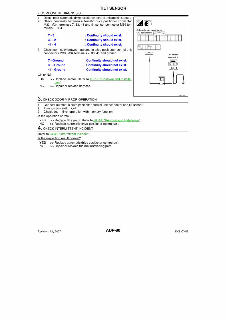
7/21/2019 adp INFINTY 2008
http://slidepdf.com/reader/full/adp-infinty-2008 80/149ADP-80
< COMPONENT DIAGNOSIS >
TILT SENSOR
1. Disconnect automatic drive positioner control unit and tilt sensor.2. Check continuity between automatic drive positioner connector
M33, M34 terminals 7, 33, 41 and tilt sensor connector M69 ter-minals 2, 3, 4.
3. Check continuity between automatic drive positioner control unitconnectors M33, M34 terminals 7, 33, 41 and ground.
OK or NG
OK >> Replace motor. Refer to ST-18, "Removal and Installa-tion".
NG >> Repair or replace harness.
3. CHECK DOOR MIRROR OPERATION
1. Connect automatic drive positioner control unit connector and tilt sensor.2. Turn ignition switch ON.3. Check door mirror operation with memory function.
Is the operation normal?
YES >> Replace tilt sensor. Refer to ST-18, "Removal and Installation".NO >> Replace automatic drive positioner control unit.
4. CHECK INTERMITTENT INCIDENT
Refer to GI-38, "Intermittent Incident".
Is the inspection result normal?
YES >> Replace automatic drive positioner control unit.NO >> Repair or replace the malfunctioning part.
7 - 3 : Continuity should exist.
33 - 2 : Continuity should exist.
41 - 4 : Continuity should exist.
7 - Ground : Continuity should not exist.
33 - Ground : Continuity should not exist.
41 - Ground : Continuity should not exist.
LIIA1432E
Revision: July 2007 2008 QX56
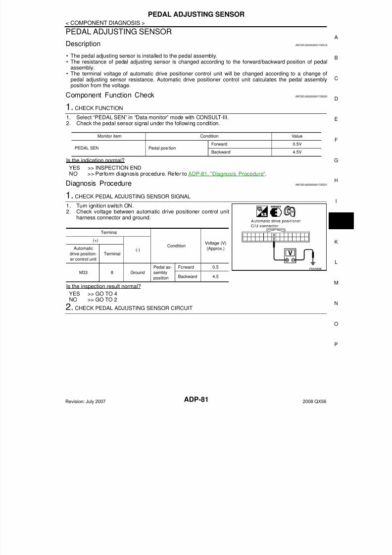
7/21/2019 adp INFINTY 2008
http://slidepdf.com/reader/full/adp-infinty-2008 81/149
PEDAL ADJUSTING SENSOR
ADP-81
< COMPONENT DIAGNOSIS >
A
PEDAL ADJUSTING SENSOR
Description INFOID:0000000001735519
• The pedal adjusting sensor is installed to the pedal assembly.• The resistance of pedal adjusting sensor is changed according to the forward/backward position of pedal
assembly.• The terminal voltage of automatic drive positioner control unit will be changed according to a change of
pedal adjusting sensor resistance. Automatic drive positioner control unit calculates the pedal assemblyposition from the voltage.
Component Function Check INFOID:0000000001735520
1. CHECK FUNCTION
1. Select “PEDAL SEN” in “Data monitor” mode with CONSULT-III.2. Check the pedal sensor signal under the following condition.
Is the indication normal?
YES >> INSPECTION ENDNO >> Perform diagnosis procedure. Refer to ADP-81, "Diagnosis Procedure".
Diagnosis Procedure INFOID:0000000001735521
1. CHECK PEDAL ADJUSTING SENSOR SIGNAL
1. Turn ignition switch ON.2. Check voltage between automatic drive positioner control unit
harness connector and ground.
Is the inspection result normal?
YES >> GO TO 4NO >> GO TO 2
2. CHECK PEDAL ADJUSTING SENSOR CIRCUIT
Monitor item Condition Value
PEDAL SEN Pedal positionForward 0.5V
Backward 4.5V
Terminal
ConditionVoltage (V)
(Approx.)
(+)
(-)Automatic
drive position-
er control unit
Terminal
M33 8 Ground
Pedal as-
sembly
position
Forward 0.5
Backward 4.5
PIIA4569E
Revision: July 2007 2008 QX56
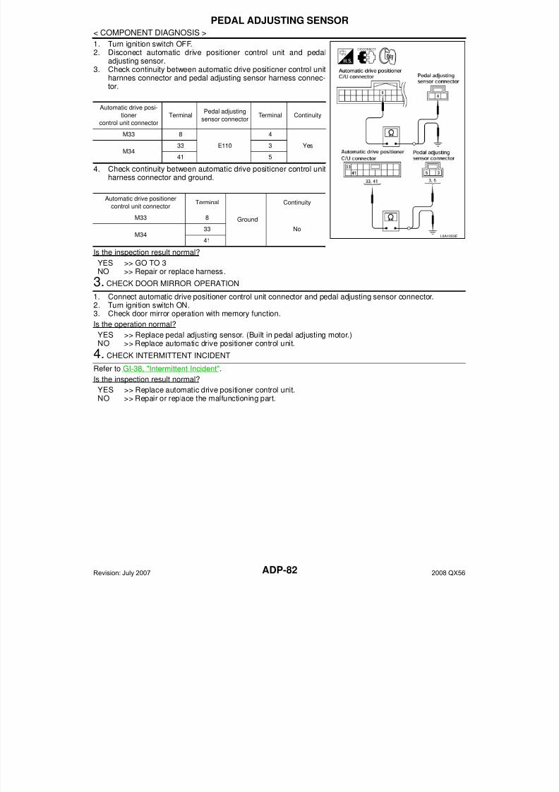
7/21/2019 adp INFINTY 2008
http://slidepdf.com/reader/full/adp-infinty-2008 82/149ADP-82
< COMPONENT DIAGNOSIS >
PEDAL ADJUSTING SENSOR
1. Turn ignition switch OFF.2. Disconect automatic drive positioner control unit and pedal
adjusting sensor.3. Check continuity between automatic drive positioner control unit
harnnes connector and pedal adjusting sensor harness connec-tor.
4. Check continuity between automatic drive positioner control unitharness connector and ground.
Is the inspection result normal?
YES >> GO TO 3NO >> Repair or replace harness.
3. CHECK DOOR MIRROR OPERATION
1. Connect automatic drive positioner control unit connector and pedal adjusting sensor connector.2. Turn ignition switch ON.3. Check door mirror operation with memory function.
Is the operation normal?
YES >> Replace pedal adjusting sensor. (Built in pedal adjusting motor.)NO >> Replace automatic drive positioner control unit.
4. CHECK INTERMITTENT INCIDENT
Refer to GI-38, "Intermittent Incident".
Is the inspection result normal?
YES >> Replace automatic drive positioner control unit.NO >> Repair or replace the malfunctioning part.
Automatic drive posi-
tioner
control unit connector
Terminal Pedal adjustingsensor connector
Terminal Continuity
M33 8
E110
4
YesM34
33 3
41 5
Automatic drive positioner
control unit connectorTerminal
Ground
Continuity
M33 8
NoM34
33
41LIIA1003E
Revision: July 2007 2008 QX56
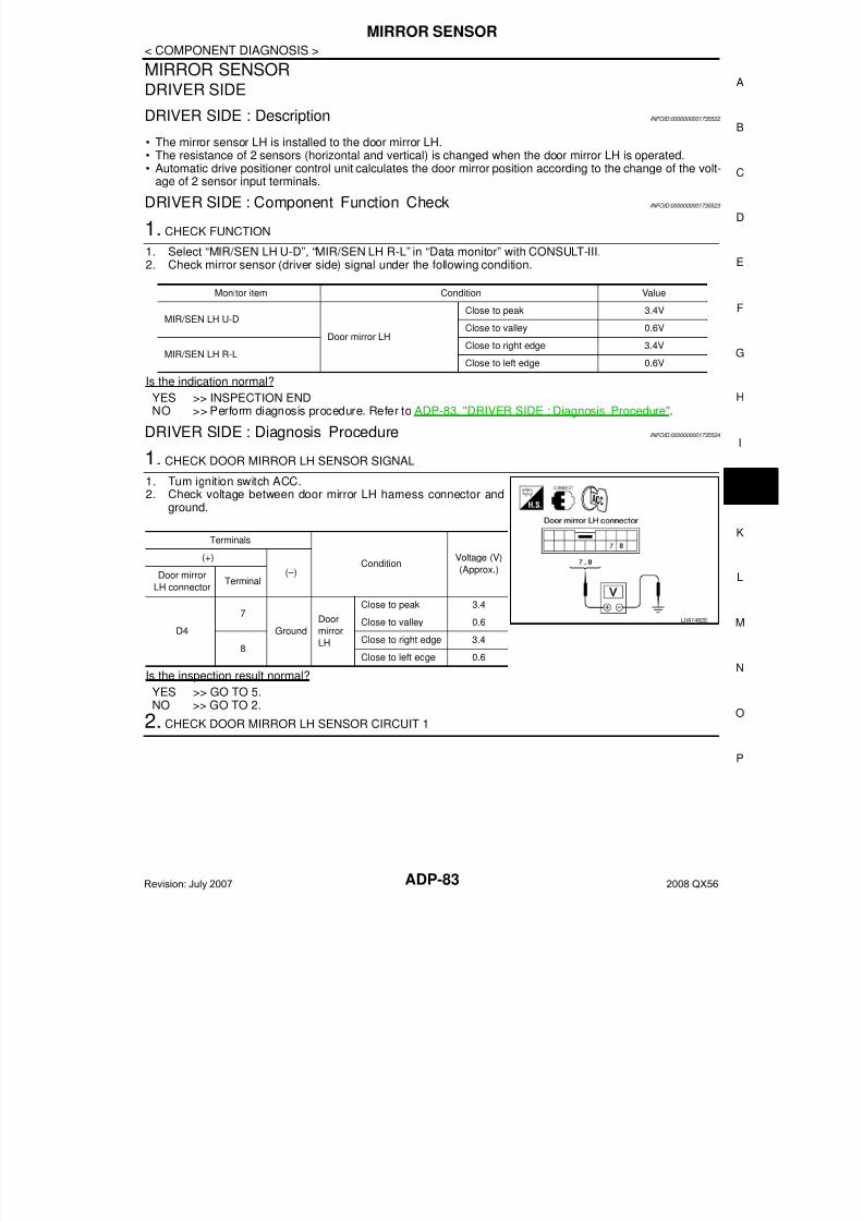
7/21/2019 adp INFINTY 2008
http://slidepdf.com/reader/full/adp-infinty-2008 83/149
MIRROR SENSOR
ADP-83
< COMPONENT DIAGNOSIS >
A
MIRROR SENSORDRIVER SIDE
DRIVER SIDE : Description INFOID:0000000001735522
• The mirror sensor LH is installed to the door mirror LH.• The resistance of 2 sensors (horizontal and vertical) is changed when the door mirror LH is operated.
• Automatic drive positioner control unit calculates the door mirror position according to the change of the volt-age of 2 sensor input terminals.
DRIVER SIDE : Component Function Check INFOID:0000000001735523
1. CHECK FUNCTION
1. Select “MIR/SEN LH U-D”, “MIR/SEN LH R-L” in “Data monitor” with CONSULT-III.2. Check mirror sensor (driver side) signal under the following condition.
Is the indication normal?
YES >> INSPECTION ENDNO >> Perform diagnosis procedure. Refer to ADP-83, "DRIVER SIDE : Diagnosis Procedure".
DRIVER SIDE : Diagnosis Procedure INFOID:0000000001735524
1. CHECK DOOR MIRROR LH SENSOR SIGNAL
1. Turn ignition switch ACC.2. Check voltage between door mirror LH harness connector and
ground.
Is the inspection result normal?
YES >> GO TO 5.NO >> GO TO 2.
2. CHECK DOOR MIRROR LH SENSOR CIRCUIT 1
Monitor item Condition Value
MIR/SEN LH U-D
Door mirror LH
Close to peak 3.4V
Close to valley 0.6V
MIR/SEN LH R-L Close to right edge 3.4V
Close to left edge 0.6V
Terminals
ConditionVoltage (V)
(Approx.)
(+)
(–)Door mirror
LH connectorTerminal
D4
7
Ground
Door
mirror
LH
Close to peak 3.4
Close to valley 0.6
8Close to right edge 3.4
Close to left edge 0.6
LIIA1482E
Revision: July 2007 2008 QX56
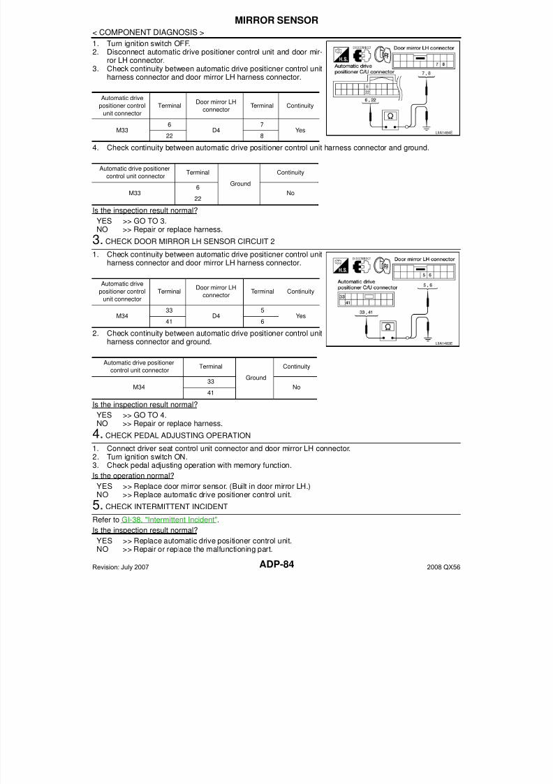
7/21/2019 adp INFINTY 2008
http://slidepdf.com/reader/full/adp-infinty-2008 84/149ADP-84
< COMPONENT DIAGNOSIS >
MIRROR SENSOR
1. Turn ignition switch OFF.2. Disconnect automatic drive positioner control unit and door mir-
ror LH connector.3. Check continuity between automatic drive positioner control unit
harness connector and door mirror LH harness connector.
4. Check continuity between automatic drive positioner control unit harness connector and ground.
Is the inspection result normal?
YES >> GO TO 3.NO >> Repair or replace harness.
3. CHECK DOOR MIRROR LH SENSOR CIRCUIT 2
1. Check continuity between automatic drive positioner control unitharness connector and door mirror LH harness connector.
2. Check continuity between automatic drive positioner control unitharness connector and ground.
Is the inspection result normal?
YES >> GO TO 4.NO >> Repair or replace harness.
4. CHECK PEDAL ADJUSTING OPERATION
1. Connect driver seat control unit connector and door mirror LH connector.2. Turn ignition switch ON.3. Check pedal adjusting operation with memory function.
Is the operation normal?
YES >> Replace door mirror sensor. (Built in door mirror LH.)NO >> Replace automatic drive positioner control unit.
5. CHECK INTERMITTENT INCIDENT
Refer to GI-38, "Intermittent Incident".
Is the inspection result normal?
YES >> Replace automatic drive positioner control unit.NO >> Repair or replace the malfunctioning part.
Automatic drive
positioner control
unit connector
TerminalDoor mirror LH
connector
Terminal Continuity
M336
D47
Yes22 8
Automatic drive positioner
control unit connectorTerminal
Ground
Continuity
M336
No22
LIIA1484E
Automatic drive
positioner control
unit connector
TerminalDoor mirror LH
connectorTerminal Continuity
M3433
D45
Yes41 6
Automatic drive positioner
control unit connectorTerminal
Ground
Continuity
M3433
No41
LIIA1483E
Revision: July 2007 2008 QX56

7/21/2019 adp INFINTY 2008
http://slidepdf.com/reader/full/adp-infinty-2008 85/149
MIRROR SENSOR
ADP-85
< COMPONENT DIAGNOSIS >
A
PASSENGER SIDE
PASSENGER SIDE : Description INFOID:0000000001735525
• The mirror sensor RH is installed to the door mirror RH.• The resistance of 2 sensors (horizontal and vertical) is changed when the door mirror RH is operated.• Automatic drive positioner control unit calculates the door mirror position according to the change of the volt-
age of 2 sensor input terminals.
PASSENGER SIDE : Component Function Check INFOID:0000000001735526
1.CHECK FUNCTION
1. Select “MIR/SEN RH U-D”, “MIR/SEN RH R-L” in “Data monitor” with CONSULT-III.2. Check the mirror sensor RH signal under the following conditions.
Is the indication normal?
YES >> INSPECTION ENDNO >> Perform diagnosis procedure. Refer to ADP-85, "PASSENGER SIDE : Diagnosis Procedure".
PASSENGER SIDE : Diagnosis Procedure INFOID:0000000001735527
1. CHECK DOOR MIRROR RH SENSOR SIGNAL
1. Turn ignition switch ACC.2. Check voltage between door mirror RH harness connector and
ground.
Is the inspection result normal?
YES >> GO TO 5
NO >> GO TO 22. CHECK DOOR MIRROR RH SENSOR HARNESS CONTINUITY
Monitor item Condition Value
MIR/SEN RH U-D
Door mirror RH
Close to peak 3.4V
Close to valley 0.6V
MIR/SEN RH R-LClose to right edge 3.4V
Close to left edge 0.6V
Terminals
ConditionVoltage (V)
(Approx.)
(+)
(–)Door mirror
RH con-
nector
Terminal
D107
7
GroundDoor mirror
RH
Close to peak 3.4
Close to valley 0.6
8Close to right edge 3.4
Close to left edge 0.6
LIIA1485E
Revision: July 2007 2008 QX56

7/21/2019 adp INFINTY 2008
http://slidepdf.com/reader/full/adp-infinty-2008 86/149ADP-86
< COMPONENT DIAGNOSIS >
MIRROR SENSOR
1. Turn ignition switch OFF.2. Disconnect automatic drive positioner control unit and door mir-
ror RH.3. Check continuity between automatic drive positioner control unit
harness connector and door mirror RH harness connector.
4. Check continuity between automatic drive positioner control unit harness connector and ground.
Is the inspection result normal?
YES >> GO TO 3NO >> Repair or replace harness.
3.CHECK DOOR MIRROR RH SENSOR POWER SUPPLY CIRCUIT
1. Check continuity between automatic drive positioner control unitharness connector and door mirror RH harness connector.
2. Check continuity between automatic drive positioner control unitharness connector and ground.
Is the inspection result normal?
YES >> GO TO 4NO >> Repair or replace harness.
4.CHECK PEDAL ADJUSTING OPERATION
1. Connect driver seat control unit connector and door mirror RH connector.2. Turn ignition switch ON.3. Check pedal adjusting operation with memory function.
Is the operation normal?
YES >> Replace door mirror sensor. (Built in door mirror RH.)NO >> Replace automatic drive positioner control unit.
5.CHECK INTERMITTENT INCIDENT
Refer to GI-38, "Intermittent Incident".
Is the inspection result normal?
YES >> Replace automatic drive positioner control unit.NO >> Repair or replace the malfunctioning part.
Automatic drive posi-
tioner control unit
connector
TerminalDoor mirror RH
connector
Terminal Continuity
M335
D1077
Yes21 8
Automatic drive positioner
control unit connectorTerminal
Ground
Continuity
M335
No21
LIIA1473E
Automatic drive posi-
tioner control unit
connector
TerminalDoor mirror RH
connectorTerminal Continuity
M3433
D1075
Yes41 6
Automatic drive positioner
control unit connectorTerminal
Ground
Continuity
M3433
No41
LIIA1486E
Revision: July 2007 2008 QX56

7/21/2019 adp INFINTY 2008
http://slidepdf.com/reader/full/adp-infinty-2008 87/149
SLIDING MOTOR
ADP-87
< COMPONENT DIAGNOSIS >
A
SLIDING MOTOR
Description INFOID:0000000001735528
• The sliding motor LH is installed to the seat cushion frame.• The sliding motor LH is installed with the driver seat control unit.• The seat is slid forward/backward by changing the rotation direction of sliding motor LH.
Component Function Check INFOID:0000000001735529
1. CHECK FUNCTION
1. Select “SEAT SLIDE” in “Active test” mode with CONSULT-III.2. Check the sliding motor LH operation.
Is the operation of relevant parts normal?
YES >> INSPECTION ENDNO >> Perform diagnosis procedure. Refer to ADP-87, "Diagnosis Procedure".
Diagnosis Procedure INFOID:0000000001735530
1. CHECK SLIDING MOTOR LH POWER SUPPLY
1. Turn the ignition switch ACC.2. Perform “Active test” (“SEAT SLIDE”) with CONSULT-lll3. Check voltage between driver seat control unit harness connec-
tor and ground.
Is the inspection result normal?
YES >> Replace sliding motor LH. (Built in seat slide cushion frame.)NO >> GO TO 2
2. CHECK SLIDING MOTOR LH CIRCUIT
Test Item Description
SEAT SLIDE
OFF
Seat sliding
Stop
FR Forward
RR Backward
Terminal
Test ItemVoltage (V)
(Approx.)
(+)
(-)Driver seat
control unit
connector
Terminal
B203
35
GroundSEAT
SLIDE
OFF 0
FR (forward) Battery voltage
RR (backward) 0
42
OFF 0
FR (forward) 0
RR (backward) Battery voltage
PIIA4801E
Revision: July 2007 2008 QX56
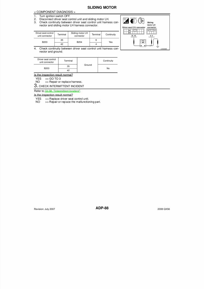
7/21/2019 adp INFINTY 2008
http://slidepdf.com/reader/full/adp-infinty-2008 88/149

7/21/2019 adp INFINTY 2008
http://slidepdf.com/reader/full/adp-infinty-2008 89/149
RECLINING MOTOR
ADP-89
< COMPONENT DIAGNOSIS >
A
RECLINING MOTOR
Description INFOID:0000000001735531
• The reclining motor LH is installed to the seat back frame.• The reclining motor LH is activated with the driver seat control unit.• The seatback is reclined forward/backward by changing the rotation direction of reclining motor LH.
Component Function Check INFOID:0000000001735532
1. CHECK FUNCTION
1. Select “SEAT RECLINING” in “Active test” mode with CONSULT-III.2. Check the reclining motor LH operation.
Is the operation of relevant parts normal?
YES >> INSPECTION ENDNO >> Perform diagnosis procedure. Refer to ADP-89, "Diagnosis Procedure".
Diagnosis Procedure INFOID:0000000001735533
1. CHECK RECLINING MOTOR LH POWER SUPPLY
1. Turn the ignition switch ACC.2. Perform “Active test” (“SEAT RECLINING”) with CONSULT-lll3. Check voltage between driver seat control unit harness connec-
tor and ground.
Is the inspection result normal?
YES >> Replace reclining motor LH. (Built in seat back frame.)NO >> GO TO 2
2. CHECK RECLINING MOTOR LH CIRCUIT
Test Item Description
SEAT RECLINING
OFF
Seat reclining
Stop
FR Forward
RR Backward
Terminal
Test ItemVoltage (V)
(Approx.)
(+)
(-)Driver
seat con-
trol unit
connector
Terminal
B203
36
GroundSEAT RE-
CLINING
OFF 0
FR (forward) Battery voltage
RR (backward) 0
44
OFF 0
FR (forward) 0
RR (backward) Battery voltage
PIIA4802E
Revision: July 2007 2008 QX56

7/21/2019 adp INFINTY 2008
http://slidepdf.com/reader/full/adp-infinty-2008 90/149ADP-90
< COMPONENT DIAGNOSIS >
RECLINING MOTOR
1. Turn ignition switch OFF.2. Disconnect driver seat control unit connector and recling motor
LH.3. Check continuity between driver seat control unit harness con-
nector and reclining motor harness connector.
4. Check continuity between driver seat control unit harness con-nector and ground.
Is the inspection result normal?
YES >> GO TO 3NO >> Repair or replace harness.
3. CHECK INTERMITTENT INCIDENT
Refer to GI-38, "Intermittent Incident".
Is the inspection result normal?
YES >> Replace driver seat control unit.NO >> Repair or replace the malfunctioning part.
Driver seat control
unit connectorTerminal
Reclining motor LH
connectorTerminal Continuity
B20336
B2054
Yes44 3
Driver seat control unit
connectorTerminal
Ground
Continuity
B20336
No44
LIIA0697E
Revision: July 2007 2008 QX56
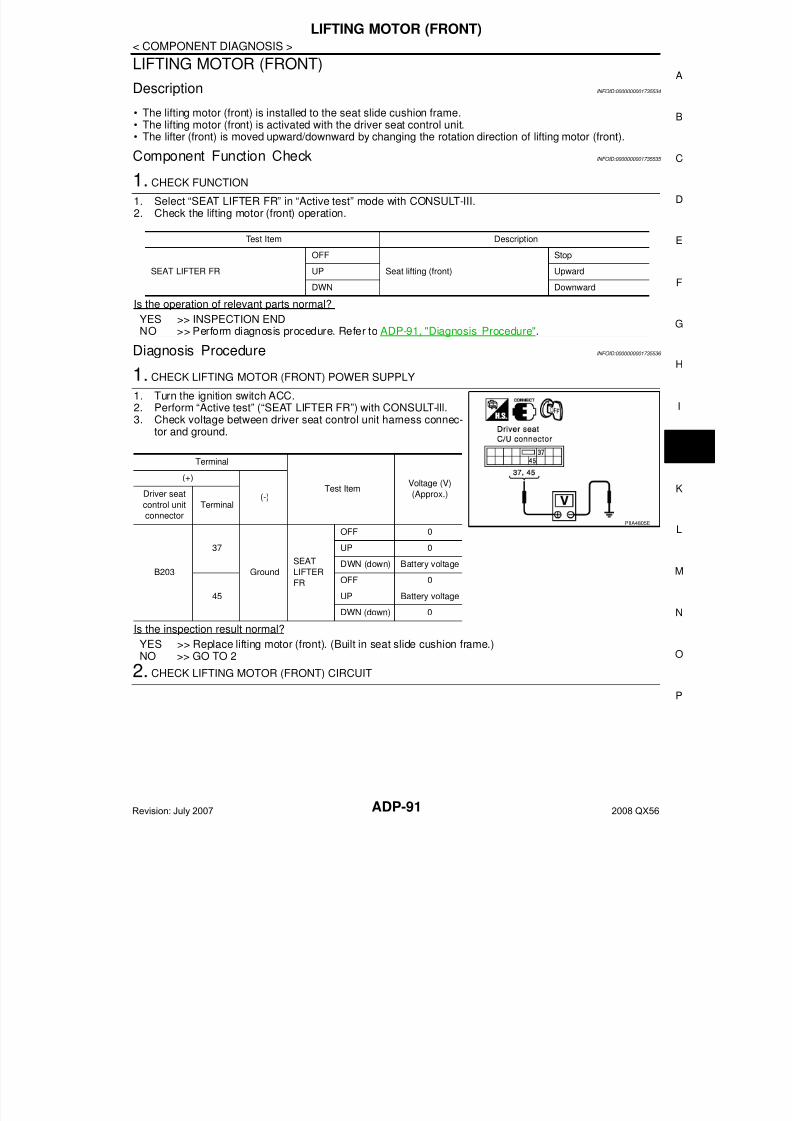
7/21/2019 adp INFINTY 2008
http://slidepdf.com/reader/full/adp-infinty-2008 91/149
LIFTING MOTOR (FRONT)
ADP-91
< COMPONENT DIAGNOSIS >
A
LIFTING MOTOR (FRONT)
Description INFOID:0000000001735534
• The lifting motor (front) is installed to the seat slide cushion frame.• The lifting motor (front) is activated with the driver seat control unit.• The lifter (front) is moved upward/downward by changing the rotation direction of lifting motor (front).
Component Function Check INFOID:0000000001735535
1. CHECK FUNCTION
1. Select “SEAT LIFTER FR” in “Active test” mode with CONSULT-III.2. Check the lifting motor (front) operation.
Is the operation of relevant parts normal?
YES >> INSPECTION ENDNO >> Perform diagnosis procedure. Refer to ADP-91, "Diagnosis Procedure".
Diagnosis Procedure INFOID:0000000001735536
1. CHECK LIFTING MOTOR (FRONT) POWER SUPPLY
1. Turn the ignition switch ACC.2. Perform “Active test” (“SEAT LIFTER FR”) with CONSULT-lll.3. Check voltage between driver seat control unit harness connec-
tor and ground.
Is the inspection result normal?
YES >> Replace lifting motor (front). (Built in seat slide cushion frame.)NO >> GO TO 2
2. CHECK LIFTING MOTOR (FRONT) CIRCUIT
Test Item Description
SEAT LIFTER FR
OFF
Seat lifting (front)
Stop
UP Upward
DWN Downward
Terminal
Test ItemVoltage (V)
(Approx.)
(+)
(-)Driver seat
control unit
connector
Terminal
B203
37
Ground
SEAT
LIFTER
FR
OFF 0
UP 0
DWN (down) Battery voltage
45
OFF 0
UP Battery voltage
DWN (down) 0
PIIA4805E
Revision: July 2007 2008 QX56
7/21/2019 adp INFINTY 2008
http://slidepdf.com/reader/full/adp-infinty-2008 92/149ADP-92
< COMPONENT DIAGNOSIS >
LIFTING MOTOR (FRONT)
1. Turn ignition switch OFF.2. Disconnect driver seat control unit and lifting motor (front) con-
nectors.3. Check continuity between driver seat control unit harness con-
nector and lifting motor (front) harness connector.
4. Check continuity between driver seat control unit harness con-nector and ground.
Is the inspection result normal?
YES >> GO TO 3NO >> Repair or replace harness.
3. CHECK INTERMITTENT INCIDENT
Refer to GI-38, "Intermittent Incident".
Is the inspection result normal?
YES >> Replace driver seat control unit.NO >> Repair or replace the malfunctioning part.
Driver seat control
unit connectorTerminal
Lifting motor (front)
connectorTerminal Continuity
B20337
B2066
Yes45 4
Driver seat control unit
connectorTerminal
Ground
Continuity
B20337
No45
LIIA0698E
Revision: July 2007 2008 QX56
7/21/2019 adp INFINTY 2008
http://slidepdf.com/reader/full/adp-infinty-2008 93/149
7/21/2019 adp INFINTY 2008
http://slidepdf.com/reader/full/adp-infinty-2008 94/149ADP-94
< COMPONENT DIAGNOSIS >
LIFTING MOTOR (REAR)
1. Disconnect driver seat control unit connector and lifting motor(rear).
2. Check continuity between driver seat control unit harness con-nector and lifting motor (rear) harness connector.
3. Check continuity between driver seat control unit harness con-nector and ground.
Is the inspection result normal?
YES >> GO TO 3
NO >> Repair or replace harness.3. CHECK INTERMITTENT INCIDENT
Refer to GI-38, "Intermittent Incident".
Is the inspection result normal?
YES >> Replace driver seat control unit.NO >> Repair or replace the malfunctioning part.
Driver seat control
unit connectorTerminal
Lifting motor (rear)
connectorTerminal Continuity
B203 38 B207 6 Yes39 4
Driver seat control unit
connectorTerminal
Ground
Continuity
B20338
No39
LIIA0699E
Revision: July 2007 2008 QX56
7/21/2019 adp INFINTY 2008
http://slidepdf.com/reader/full/adp-infinty-2008 95/149
TILT MOTOR
ADP-95
< COMPONENT DIAGNOSIS >
A
TILT MOTOR
Description INFOID:0000000001754046
• The tilt motor is installed to the steering column assembly.• The tilt motor is activated with the automatic drive positioner control unit.• The steering column is tilted upward/downward by changing the rotation direction of tilt motor.
Component Function Check INFOID:0000000001754047
1.CHECK FUNCTION
1. Select “TILT MOTOR” in “Active test” mode with CONSULT-III.2. Check the tilt motor operation.
Is the operation of relevant parts normal?
YES >> INSPECTION ENDNO >> Perform diagnosis procedure. Refer to ADP-95, "Diagnosis Procedure".
Diagnosis Procedure INFOID:0000000001754048
1. CHECK TILT MOTOR HARNESS CONTINUITY
1. Turn ignition switch OFF.2. Disconnect automatic drive positioner control unit and tilt motor.3. Check continuity between automatic drive positioner control unit
connector M34 terminals 35, 42 and tilt motor connector M86terminals 1, 5.
4. Check continuity between automatic drive positioner control unitconnector M34 terminals 35, 42 and ground.
OK or NG
OK >> GO TO 2NG >> Repair or replace harness.
2. CHECK AUTOMATIC DRIVE POSITIONER CONTROL UNIT OUTPUT SIGNAL
1. Connect the automatic drive positioner control unit connectorand tilt motor.
2. Check voltage between automatic drive positioner control unitconnector and ground.
Test item Description
TILT MOTOR
OFF
Steering tilt
Stop
UP Upward
DWN Downward
35 - 1 : Continuity should exist.
42 - 5 : Continuity should exist.
35 - Ground : Continuity should not exist.
42 - Ground : Continuity should not exist.
LIIA1431E
LIIA0482E
Revision: July 2007 2008 QX56
7/21/2019 adp INFINTY 2008
http://slidepdf.com/reader/full/adp-infinty-2008 96/149ADP-96
< COMPONENT DIAGNOSIS >
TILT MOTOR
OK or NG
OK >> Replace tilt motor. Refer to ST-18, "Removal and Installation".NG >> GO TO 3
3. CHECK INTERMITTENT INCIDENT
Refer to GI-38, "Intermittent Incident".
Is the inspection result normal?
YES >> Replace automatic drive positioner control unit.NO >> Repair or replace the malfunctioning part.
ConnectorTerminals
ConditionVoltage (V)
(Approx.)(+) (-)
M34
35
Ground
ADP steering switch ON
(UP operation)Battery voltage
Other than above 0
42
ADP steering switch ON
(DOWN operation) Battery voltage
Other than above 0
Revision: July 2007 2008 QX56
7/21/2019 adp INFINTY 2008
http://slidepdf.com/reader/full/adp-infinty-2008 97/149
PEDAL ADJUSTING MOTOR
ADP-97
< COMPONENT DIAGNOSIS >
A
PEDAL ADJUSTING MOTOR
Description INFOID:0000000001735540
• The pedal adjusting motor is installed to the pedal assembly.• The pedal adjusting motor is activated with the automatic drive positioner control unit.• The pedal assembly is adjusted forward/backward by changing the rotation direction of pedal adjusting
motor.
Component Function Check INFOID:0000000001735541
1. CHECK FUNCTION
1. Select “ADJ PEDAL MOTOR” in “Active test” mode with CONSULT-III.2. Check the pedal adjusting motor operation.
Is the operation of relevant parts normal?YES >> INSPECTION ENDNO >> Perform diagnosis procedure. Refer to ADP-97, "Diagnosis Procedure".
Diagnosis Procedure INFOID:0000000001735542
1. CHECK PEDAL ADJUSTING MOTOR POWER SUPPLY
1. Turn the ignition switch OFF.2. Perform “Active test” (“ADJ PEDAL MOTOR”) with CONSULT-lll.3. Check voltage between automatic drive positioner control unit
harness connector and ground.
Is the inspection result normal?
YES >> Replace pedal adjusting motor.NO >> GO TO 2
2. CHECK PEDAL ADJUSTING MOTOR CIRCUIT
Test item Description
ADJ PEDAL MOTOR
OFF
Pedal adjusting motor
Stop
FR Forward
RR Backward
Terminal
Test Item
Voltage
(V)
(Approx.)
(+)
(-)
Automatic
drive posi-
tioner con-
trol unit
connector
Terminal
M34
37
GroundADJ PED-
AL MOTOR
OFF 0
RR (backward) 0
FR (forward)Battery
voltage
45
OFF 0
RR (backward)Battery
voltage
FR (forward) 0
PIIA4806E
Revision: July 2007 2008 QX56
7/21/2019 adp INFINTY 2008
http://slidepdf.com/reader/full/adp-infinty-2008 98/149ADP-98
< COMPONENT DIAGNOSIS >
PEDAL ADJUSTING MOTOR
1. Disconnect automatic drive positioner control unit and pedaladjusting motor.
2. Check continuity between automatic drive positioner control unitharness connector and pedal adjusting motor harness connec-tor.
3. Check continuity between automatic drive positioner control unit harness connector and ground.
Is the inspection result normal?
YES >> GO TO 3NO >> Repair or replace harness.
3. CHECK INTERMITTENT INCIDENT
Refer to GI-38, "Intermittent Incident".
Is the inspection result normal?
YES >> Replace automatic drive positioner control unit.NO >> Repair or replace the malfunctioning part.
Automatic drive
positioner control
unit connector
TerminalPedal adjusting
motor connector
Terminal Continuity
M34 (A)37
E109 (B)1
Yes45 2
Automatic drive positioner
control unit connectorTerminal
Ground
Continuity
M34 (A)37
No45
ALJIA0195ZZ
Revision: July 2007 2008 QX56
7/21/2019 adp INFINTY 2008
http://slidepdf.com/reader/full/adp-infinty-2008 99/149
DOOR MIRROR MOTOR
ADP-99
< COMPONENT DIAGNOSIS >
A
DOOR MIRROR MOTOR
Description INFOID:0000000001735543
It makes mirror face operate from side to side and up and down with the electric power that automatic drivepositioner control unit supplies.
Component Function Check INFOID:0000000001735544
1. CHECK DOOR MIRROR MOTOR FUNCTION
Check the operation with “MIRROR MOTOR RH” and “MIRROR MOTOR LH” in “ACTIVE TEST” mode withCONSULT-IIIRefer to ADP-26, "CONSULT-III Function".
Is the inspection result normal?
YES >> Door mirror motor function is OK.NO >> Refer to ADP-99, "Diagnosis Procedure".
Diagnosis Procedure INFOID:0000000001735545
1. CHECK DOOR MIRROR MOTOR INPUT SIGNAL
1. Turn ignition switch ON.2. Check voltage between door mirror connector and ground.
Is the inspection result normal?
YES >> Refer to ADP-101, "Component Inspection".NO >> GO TO 2
2. CHECK HARNESS CONTINUITY
1. Turn ignition switch OFF.2. Disconnect automatic drive positioner control unit connector and
door mirror.3. Check continuity between automatic drive positioner control unit
connector and door mirror connector.Door mirror LH
Terminals
Door mirror re-
mote control
switch condition
Voltage (V)
(Approx.)
(+)
(–)Door mirror
connectorTerminal
D4 (LH)
D107 (RH)
1
Ground
UP Battery voltage
Other than above 0
2LEFT Battery voltage
Other than above 0
3DOWN / RIGHT Battery voltage
Other than above 0
ALJIA0196ZZ
Automatic drive
positioner control
unit connector
TerminalDoor mirror LH
connectorTerminal Continuity
M33
16
D4
3
Yes31 1
32 2
LIIA1880E
Revision: July 2007 2008 QX56
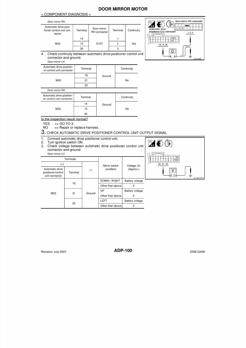
7/21/2019 adp INFINTY 2008
http://slidepdf.com/reader/full/adp-infinty-2008 100/149ADP-100
< COMPONENT DIAGNOSIS >
DOOR MIRROR MOTOR
Door mirror RH
4. Check continuity between automatic drive positioner control unitconnector and ground.Door mirror LH
Door mirror RH
Is the inspection result normal?
YES >> GO TO 3NO >> Repair or replace harness.
3. CHECK AUTOMATIC DRIVE POSITIONER CONTROL UNIT OUTPUT SIGNAL
1. Connect automatic drive positioner control unit.2. Turn ignition switch ON.3. Check voltage between automatic drive positioner control unit
connector and ground.Door mirror LH
Automatic drive posi-
tioner control unit con-
nector
TerminalDoor mirror
RH connectorTerminal Continuity
M33
14
D107
1
Yes15 2
30 3
Automatic drive position-
er control unit connectorTerminal
Ground
Continuity
M33
16
No31
32
Automatic drive position-
er control unit connectorTerminal
Ground
Continuity
M33
14
No15
30
LIIA1888E
Terminals
Mirror switch
condition
Voltage (V)
(Approx.)
(+)
(-)Automatic drive
positioner control
unit connector
Terminal
M33
16
Ground
DOWN / RIGHT Battery voltage
Other than above 0
31UP Battery voltage
Other than above 0
32LEFT Battery voltage
Other than above 0
ALJIA0197ZZ
Revision: July 2007 2008 QX56
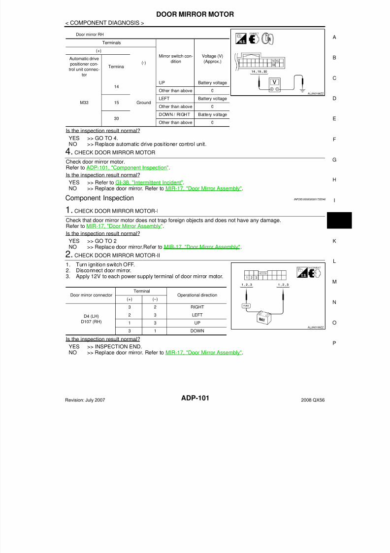
7/21/2019 adp INFINTY 2008
http://slidepdf.com/reader/full/adp-infinty-2008 101/149
DOOR MIRROR MOTOR
ADP-101
< COMPONENT DIAGNOSIS >
A
Door mirror RH
Is the inspection result normal?
YES >> GO TO 4.NO >> Replace automatic drive positioner control unit.
4. CHECK DOOR MIRROR MOTOR
Check door mirror motor.Refer to ADP-101, "Component Inspection".
Is the inspection result normal?
YES >> Refer to GI-38, "Intermittent Incident".NO >> Replace door mirror. Refer to MIR-17, "Door Mirror Assembly".
Component Inspection INFOID:0000000001735546
1. CHECK DOOR MIRROR MOTOR-I
Check that door mirror motor does not trap foreign objects and does not have any damage.Refer to MIR-17, "Door Mirror Assembly".
Is the inspection result normal?YES >> GO TO 2NO >> Replace door mirror.Refer to MIR-17, "Door Mirror Assembly".
2. CHECK DOOR MIRROR MOTOR-II
1. Turn ignition switch OFF.2. Disconnect door mirror.3. Apply 12V to each power supply terminal of door mirror motor.
Is the inspection result normal?
YES >> INSPECTION END.NO >> Replace door mirror. Refer to MIR-17, "Door Mirror Assembly".
Terminals
Mirror switch con-
dition
Voltage (V)
(Approx.)
(+)
(-)Automatic drive
positioner con-
trol unit connec-
tor
Terminal
M33
14
Ground
UP Battery voltage
Other than above 0
15LEFT Battery voltage
Other than above 0
30DOWN / RIGHT Battery voltage
Other than above 0
ALJIA0198ZZ
Door mirror connectorTerminal
Operational direction(+) (–)
D4 (LH)
D107 (RH)
3 2 RIGHT
2 3 LEFT
1 3 UP
3 1 DOWNALJIA0199ZZ
Revision: July 2007 2008 QX56

7/21/2019 adp INFINTY 2008
http://slidepdf.com/reader/full/adp-infinty-2008 102/149ADP-102
< COMPONENT DIAGNOSIS >
SEAT MEMORY INDICATOR LAMP
SEAT MEMORY INDICATOR LAMP
Description INFOID:0000000001735547
• Memory switch is equipped on the seat memory switch installed to the driver side door trim. The operationsignal is inputted to the automatic drive positioner control unit when the memory switch is operated.
• The status of automatic drive positioner system can be checked according to the illuminating/flashing status.
Component Function Check INFOID:0000000001735548
1. CHECK FUNCTION
1. Select “MEMORY SW INDCTR” in “Active test” mode with CONSULT-III.2. Check the memory indicator operation.
Is the operation of relevant parts normal?
YES >> INSPECTION ENDNO >> Perform diagnosis procedure. Refer to ADP-102, "Diagnosis Procedure".
Diagnosis Procedure INFOID:0000000001735549
1. CHECK SEAT MEMORY INDICATOR CIRCUIT
1. Turn ignition switch OFF.2. Disconnect automatic drive positioner control unit and seat
memory switch.3. Check continuity between automatic drive positioner control unit
harness connector and seat memory switch harness connector.
4. Check continuity between automatic drive positioner control unit harness connector and ground.
Is the inspection result normal?YES >> GO TO 2NO >> Repair or replace harness.
2. CHECK MEMORY INDICATOR POWER SUPPLY
Test item Description
MEMORY SW INDCTR
OFF
Memory switch indicator
OFF
ON-1 Indicator 1: ON
ON-2 Indicator 2: ON
Automatic drivepositioner control
unit connector
Terminal Seat memory switchconnector
Terminal Continuity
M3312
D56
Yes13 7
Automatic drive position-
er connectorTerminal
Ground
Continuity
M3312
No13
LIIA1022E
Revision: July 2007 2008 QX56
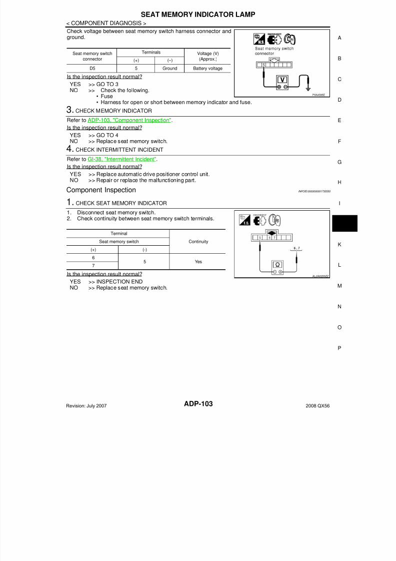
7/21/2019 adp INFINTY 2008
http://slidepdf.com/reader/full/adp-infinty-2008 103/149
SEAT MEMORY INDICATOR LAMP
ADP-103
< COMPONENT DIAGNOSIS >
A
Check voltage between seat memory switch harness connector andground.
Is the inspection result normal?YES >> GO TO 3NO >> Check the following.
• Fuse• Harness for open or short between memory indicator and fuse.
3. CHECK MEMORY INDICATOR
Refer to ADP-103, "Component Inspection".
Is the inspection result normal?
YES >> GO TO 4NO >> Replace seat memory switch.
4. CHECK INTERMITTENT INCIDENT
Refer to GI-38, "Intermittent Incident".Is the inspection result normal?
YES >> Replace automatic drive positioner control unit.NO >> Repair or replace the malfunctioning part.
Component Inspection INFOID:0000000001735550
1. CHECK SEAT MEMORY INDICATOR
1. Disconnect seat memory switch.2. Check continuity between seat memory switch terminals.
Is the inspection result normal?
YES >> INSPECTION ENDNO >> Replace seat memory switch.
Seat memory switch
connector
Terminals Voltage (V)
(Approx.)(+) (–)
D5 5 Ground Battery voltage
PIIA4595E
Terminal
ContinuitySeat memory switch
(+) (-)
65 Yes
7
ALJIA0200ZZ
Revision: July 2007 2008 QX56
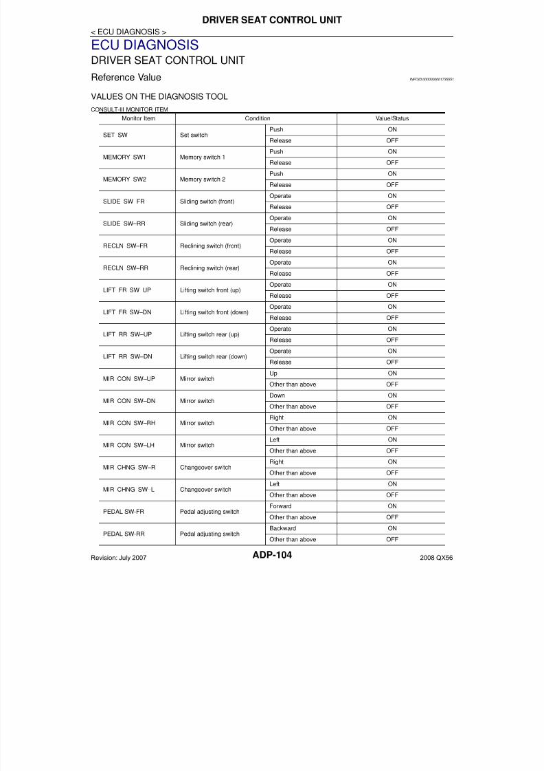
7/21/2019 adp INFINTY 2008
http://slidepdf.com/reader/full/adp-infinty-2008 104/149ADP-104
< ECU DIAGNOSIS >
DRIVER SEAT CONTROL UNIT
ECU DIAGNOSISDRIVER SEAT CONTROL UNIT
Reference Value INFOID:0000000001735551
VALUES ON THE DIAGNOSIS TOOL
CONSULT-III MONITOR ITEMMonitor Item Condition Value/Status
SET SW Set switchPush ON
Release OFF
MEMORY SW1 Memory switch 1Push ON
Release OFF
MEMORY SW2 Memory switch 2Push ON
Release OFF
SLIDE SW–FR Sliding switch (front)Operate ON
Release OFF
SLIDE SW–RR Sliding switch (rear) Operate ON
Release OFF
RECLN SW–FR Reclining switch (front)Operate ON
Release OFF
RECLN SW–RR Reclining switch (rear)Operate ON
Release OFF
LIFT FR SW–UP Lifting switch front (up)Operate ON
Release OFF
LIFT FR SW–DN Lifting switch front (down)Operate ON
Release OFF
LIFT RR SW–UP Lifting switch rear (up)Operate ON
Release OFF
LIFT RR SW–DN Lifting switch rear (down)Operate ON
Release OFF
MIR CON SW–UP Mirror switchUp ON
Other than above OFF
MIR CON SW–DN Mirror switchDown ON
Other than above OFF
MIR CON SW–RH Mirror switchRight ON
Other than above OFF
MIR CON SW–LH Mirror switchLeft ON
Other than above OFF
MIR CHNG SW–R Changeover switchRight ON
Other than above OFF
MIR CHNG SW–L Changeover switchLeft ON
Other than above OFF
PEDAL SW-FR Pedal adjusting switchForward ON
Other than above OFF
PEDAL SW-RR Pedal adjusting switchBackward ON
Other than above OFF
Revision: July 2007 2008 QX56
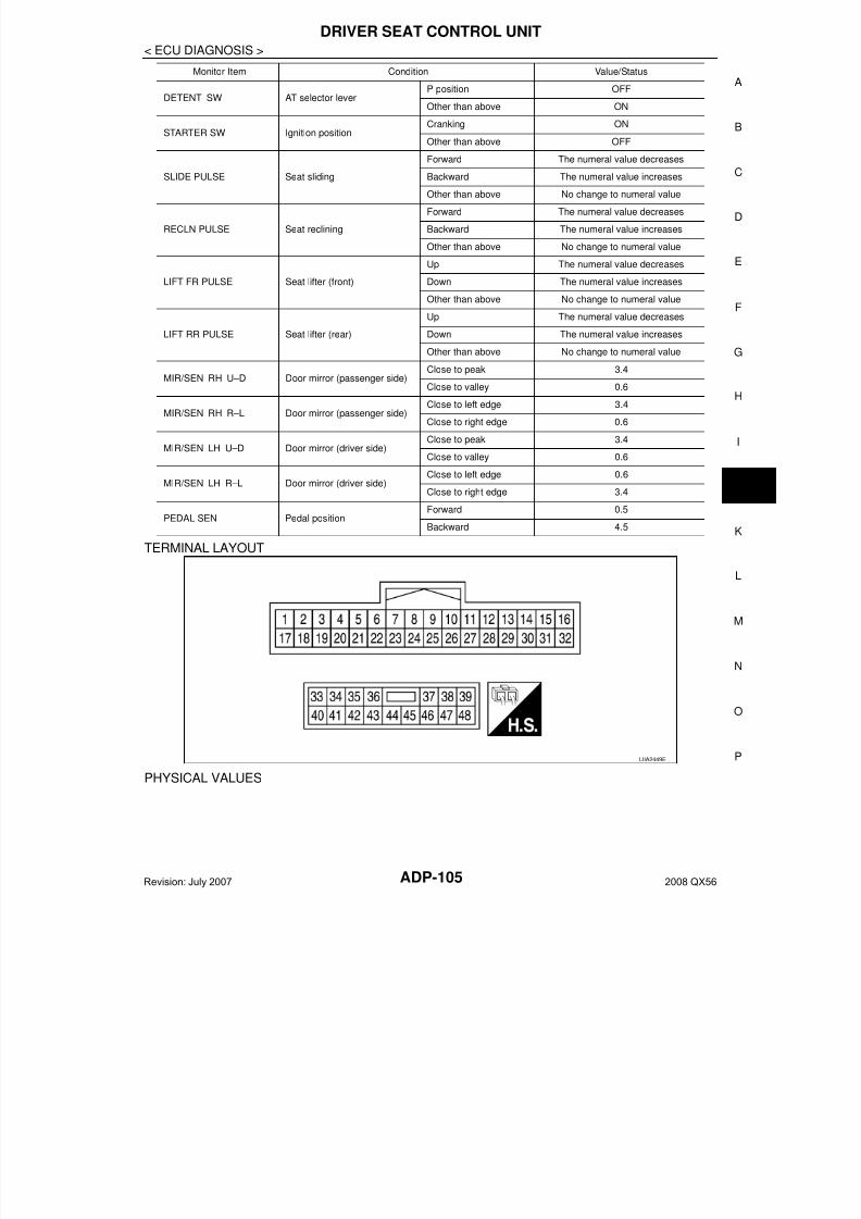
7/21/2019 adp INFINTY 2008
http://slidepdf.com/reader/full/adp-infinty-2008 105/149
DRIVER SEAT CONTROL UNIT
ADP-105
< ECU DIAGNOSIS >
A
TERMINAL LAYOUT
PHYSICAL VALUES
DETENT SW AT selector leverP position OFF
Other than above ON
STARTER SW Ignition positionCranking ON
Other than above OFF
SLIDE PULSE Seat sliding
Forward The numeral value decreases
Backward The numeral value increases
Other than above No change to numeral value
RECLN PULSE Seat reclining
Forward The numeral value decreases
Backward The numeral value increases
Other than above No change to numeral value
LIFT FR PULSE Seat lifter (front)
Up The numeral value decreases
Down The numeral value increases
Other than above No change to numeral value
LIFT RR PULSE Seat lifter (rear)
Up The numeral value decreases
Down The numeral value increases
Other than above No change to numeral value
MIR/SEN RH U–D Door mirror (passenger side)Close to peak 3.4
Close to valley 0.6
MIR/SEN RH R–L Door mirror (passenger side)Close to left edge 3.4
Close to right edge 0.6
MIR/SEN LH U–D Door mirror (driver side)Close to peak 3.4
Close to valley 0.6
MIR/SEN LH R–L Door mirror (driver side)Close to left edge 0.6
Close to right edge 3.4
PEDAL SEN Pedal position
Forward 0.5
Backward 4.5
Monitor Item Condition Value/Status
LIIA2449E
Revision: July 2007 2008 QX56
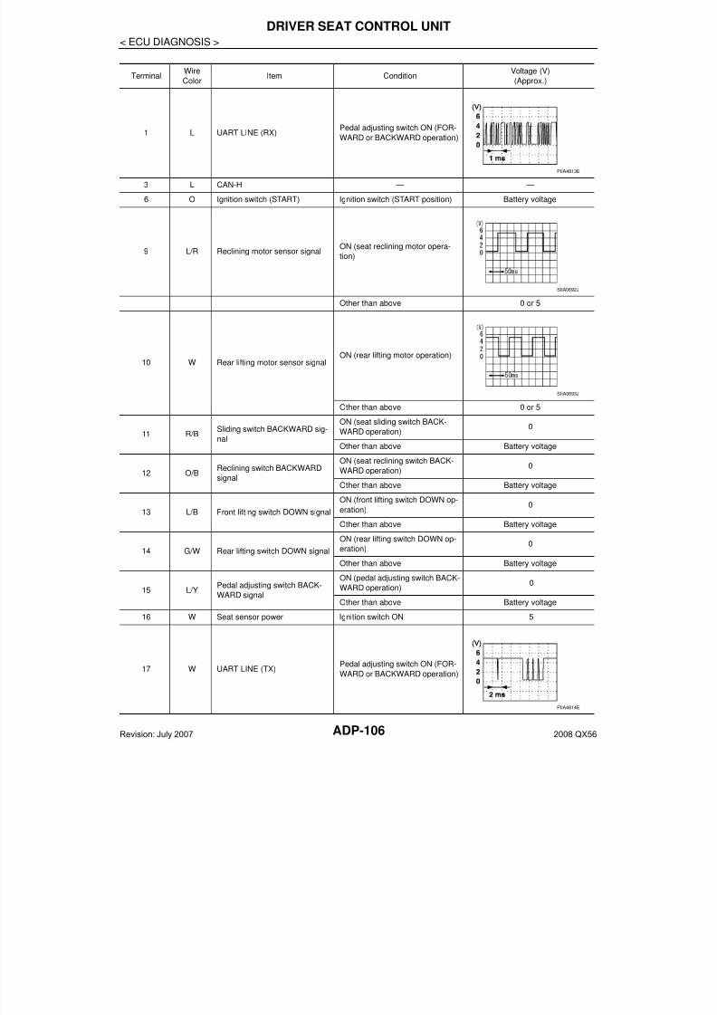
7/21/2019 adp INFINTY 2008
http://slidepdf.com/reader/full/adp-infinty-2008 106/149ADP-106
< ECU DIAGNOSIS >
DRIVER SEAT CONTROL UNIT
TerminalWire
ColorItem Condition
Voltage (V)
(Approx.)
1 L UART LINE (RX)Pedal adjusting switch ON (FOR-
WARD or BACKWARD operation)
3 L CAN-H — —
6 O Ignition switch (START) Ignition switch (START position) Battery voltage
9 L/R Reclining motor sensor signalON (seat reclining motor opera-
tion)
Other than above 0 or 5
10 W Rear lifting motor sensor signalON (rear lifting motor operation)
Other than above 0 or 5
11 R/B Sliding switch BACKWARD sig-nal
ON (seat sliding switch BACK-
WARD operation)0
Other than above Battery voltage
12 O/BReclining switch BACKWARD
signal
ON (seat reclining switch BACK-
WARD operation)0
Other than above Battery voltage
13 L/B Front lifting switch DOWN signal
ON (front lifting switch DOWN op-
eration)0
Other than above Battery voltage
14 G/W Rear lifting switch DOWN signal
ON (rear lifting switch DOWN op-
eration)0
Other than above Battery voltage
15 L/YPedal adjusting switch BACK-
WARD signal
ON (pedal adjusting switch BACK-WARD operation)
0
Other than above Battery voltage
16 W Seat sensor power Ignition switch ON 5
17 W UART LINE (TX)Pedal adjusting switch ON (FOR-
WARD or BACKWARD operation)
PIIA4813E
SIIA0692J
SIIA0693J
PIIA4814E
Revision: July 2007 2008 QX56
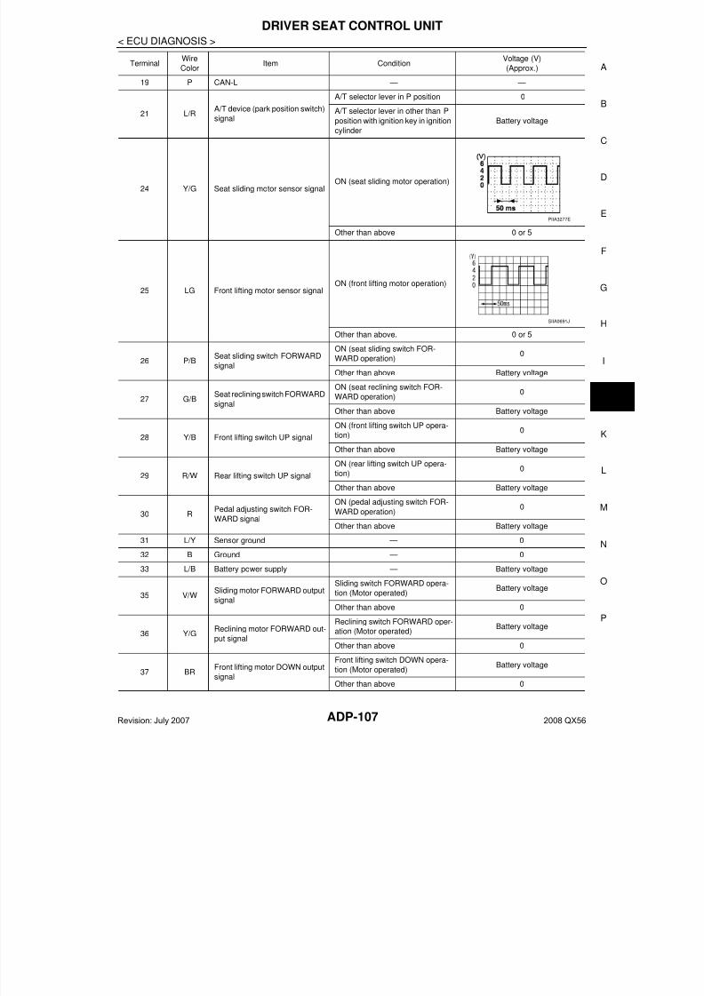
7/21/2019 adp INFINTY 2008
http://slidepdf.com/reader/full/adp-infinty-2008 107/149
DRIVER SEAT CONTROL UNIT
ADP-107
< ECU DIAGNOSIS >
A
19 P CAN-L — —
21 L/RA/T device (park position switch)
signal
A/T selector lever in P position 0
A/T selector lever in other than P
position with ignition key in ignition
cylinder
Battery voltage
24 Y/G Seat sliding motor sensor signalON (seat sliding motor operation)
Other than above 0 or 5
25 LG Front lifting motor sensor signalON (front lifting motor operation)
Other than above. 0 or 5
26 P/BSeat sliding switch FORWARD
signal
ON (seat sliding switch FOR-
WARD operation)0
Other than above Battery voltage
27 G/BSeat reclining switch FORWARD
signal
ON (seat reclining switch FOR-
WARD operation)0
Other than above Battery voltage
28 Y/B Front lifting switch UP signal
ON (front lifting switch UP opera-tion)
0
Other than above Battery voltage
29 R/W Rear lifting switch UP signal
ON (rear lifting switch UP opera-
tion)0
Other than above Battery voltage
30 RPedal adjusting switch FOR-
WARD signal
ON (pedal adjusting switch FOR-
WARD operation)0
Other than above Battery voltage
31 L/Y Sensor ground — 0
32 B Ground — 0
33 L/B Battery power supply — Battery voltage
35 V/WSliding motor FORWARD output
signal
Sliding switch FORWARD opera-
tion (Motor operated)Battery voltage
Other than above 0
36 Y/GReclining motor FORWARD out-
put signal
Reclining switch FORWARD oper-
ation (Motor operated)Battery voltage
Other than above 0
37 BRFront lifting motor DOWN output
signal
Front lifting switch DOWN opera-
tion (Motor operated)Battery voltage
Other than above 0
TerminalWire
ColorItem Condition
Voltage (V)
(Approx.)
PIIA3277E
SIIA0691J
Revision: July 2007 2008 QX56
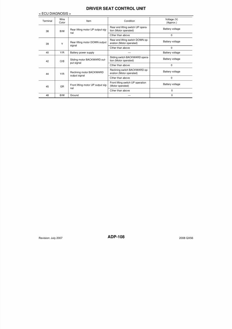
7/21/2019 adp INFINTY 2008
http://slidepdf.com/reader/full/adp-infinty-2008 108/149ADP-108
< ECU DIAGNOSIS >
DRIVER SEAT CONTROL UNIT
38 B/WRear lifting motor UP output sig-
nal
Rear end lifting switch UP opera-
tion (Motor operated)Battery voltage
Other than above 0
39 YRear lifting motor DOWN output
signal
Rear end lifting switch DOWN op-
eration (Motor operated)Battery voltage
Other than above 0
40 Y/R Battery power supply — Battery voltage
42 O/BSliding motor BACKWARD out-
put signal
Sliding switch BACKWARD opera-
tion (Motor operated)Battery voltage
Other than above 0
44 Y/RReclining motor BACKWARD
output signal
Reclining switch BACKWARD op-
eration (Motor operated)Battery voltage
Other than above 0
45 GRFront lifting motor UP output sig-
nal
Front lifting switch UP operation
(Motor operated)Battery voltage
Other than above 0
48 B/W Ground — 0
TerminalWire
ColorItem Condition
Voltage (V)
(Approx.)
Revision: July 2007 2008 QX56
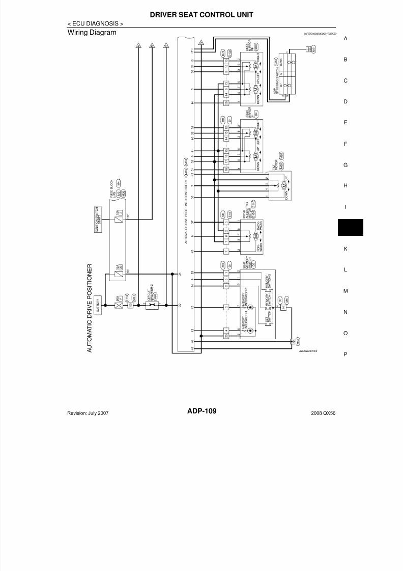
7/21/2019 adp INFINTY 2008
http://slidepdf.com/reader/full/adp-infinty-2008 109/149
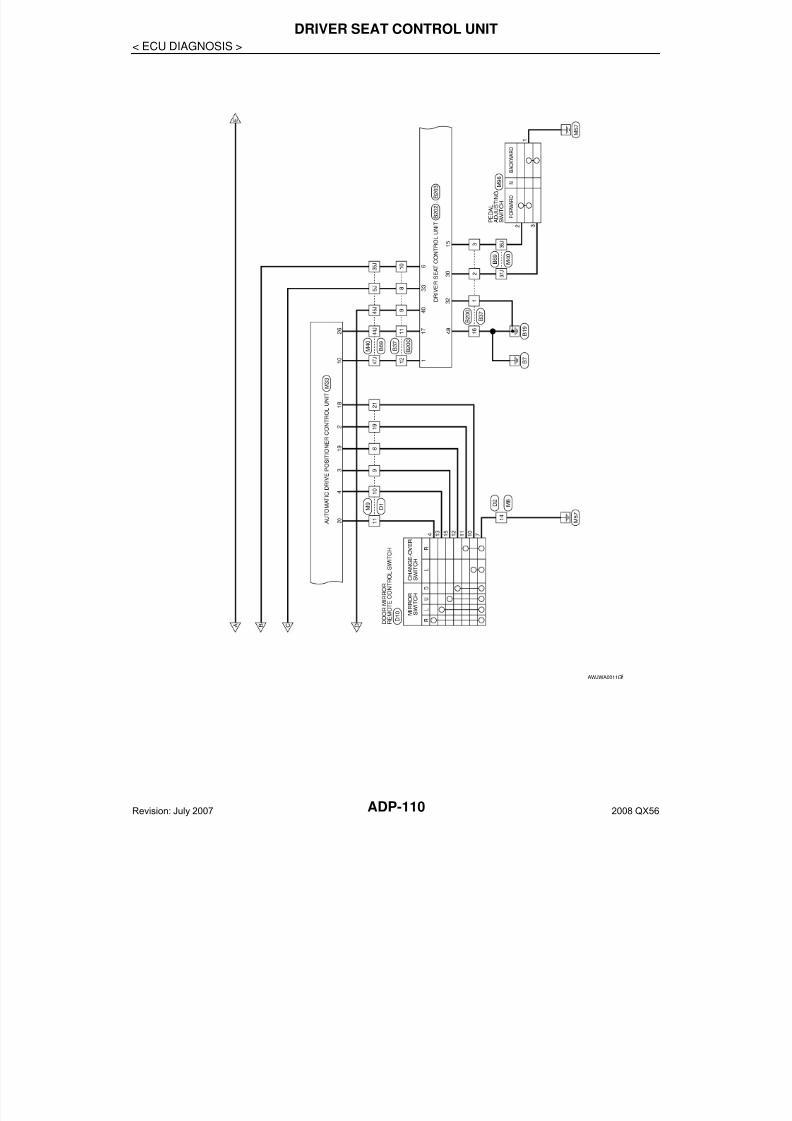
7/21/2019 adp INFINTY 2008
http://slidepdf.com/reader/full/adp-infinty-2008 110/149ADP-110
< ECU DIAGNOSIS >
DRIVER SEAT CONTROL UNIT
AWJWA0011G
Revision: July 2007 2008 QX56
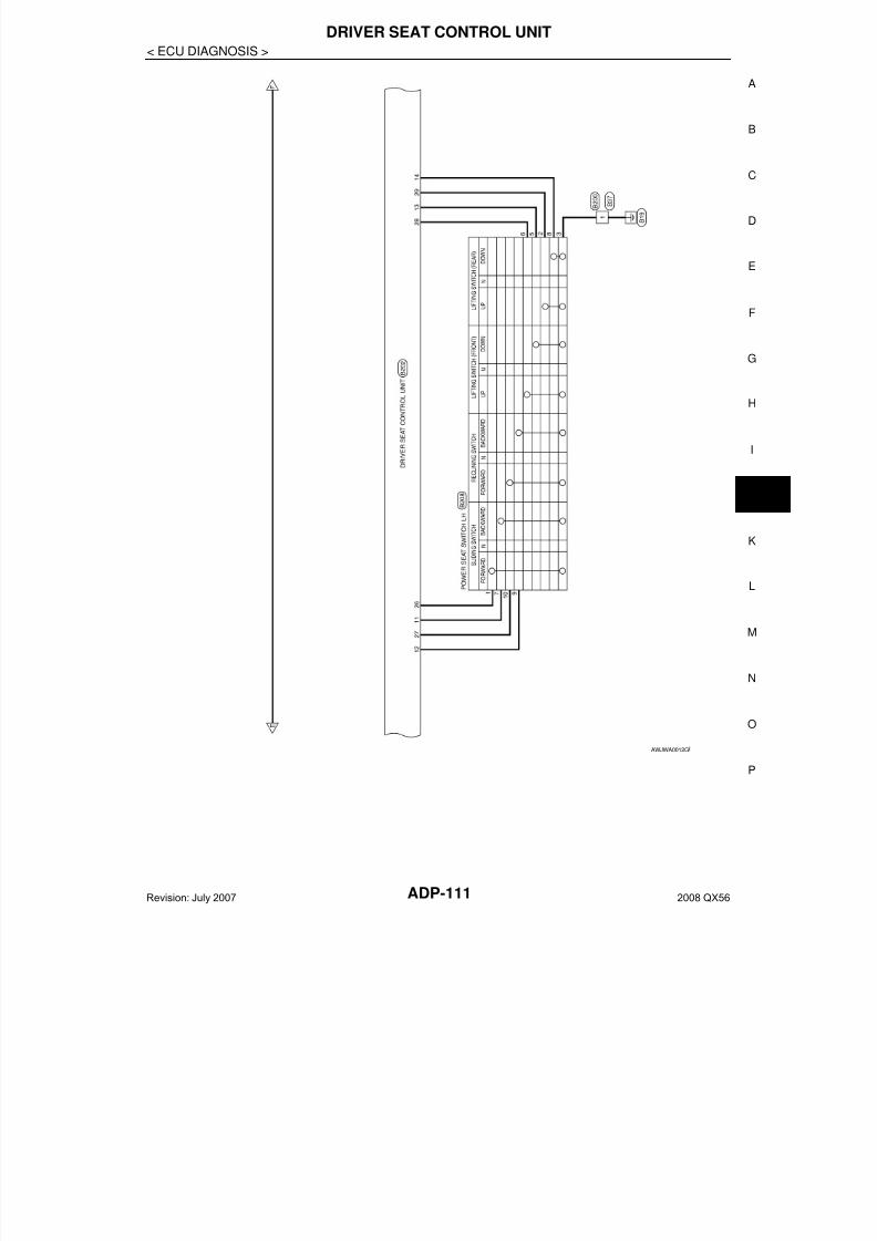
7/21/2019 adp INFINTY 2008
http://slidepdf.com/reader/full/adp-infinty-2008 111/149

7/21/2019 adp INFINTY 2008
http://slidepdf.com/reader/full/adp-infinty-2008 112/149ADP-112
< ECU DIAGNOSIS >
DRIVER SEAT CONTROL UNIT
AWJWA0013G
Revision: July 2007 2008 QX56
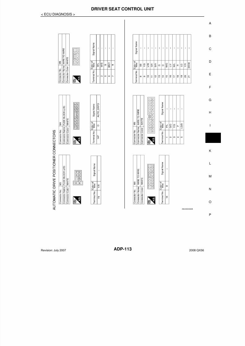
7/21/2019 adp INFINTY 2008
http://slidepdf.com/reader/full/adp-infinty-2008 113/149
DRIVER SEAT CONTROL UNIT
ADP-113
< ECU DIAGNOSIS >
A
AWJIA0039GB
Revision: July 2007 2008 QX56

7/21/2019 adp INFINTY 2008
http://slidepdf.com/reader/full/adp-infinty-2008 114/149ADP-114
< ECU DIAGNOSIS >
DRIVER SEAT CONTROL UNIT
AWJIA0040GB
Revision: July 2007 2008 QX56
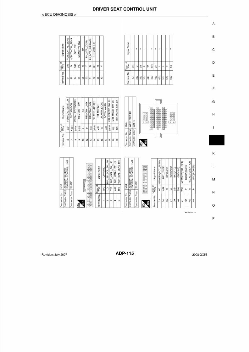
7/21/2019 adp INFINTY 2008
http://slidepdf.com/reader/full/adp-infinty-2008 115/149
DRIVER SEAT CONTROL UNIT
ADP-115
< ECU DIAGNOSIS >
A
AWJIA0041GB
Revision: July 2007 2008 QX56
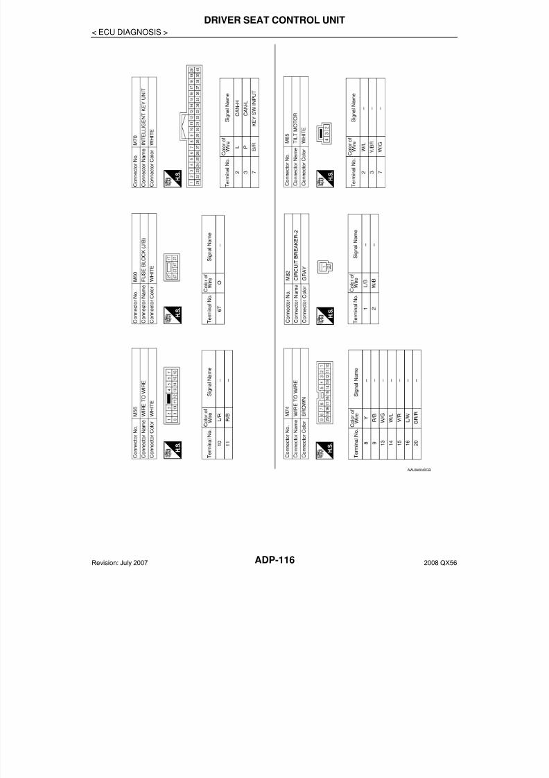
7/21/2019 adp INFINTY 2008
http://slidepdf.com/reader/full/adp-infinty-2008 116/149ADP-116
< ECU DIAGNOSIS >
DRIVER SEAT CONTROL UNIT
AWJIA0042GB
Revision: July 2007 2008 QX56
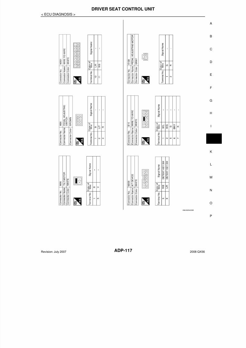
7/21/2019 adp INFINTY 2008
http://slidepdf.com/reader/full/adp-infinty-2008 117/149
DRIVER SEAT CONTROL UNIT
ADP-117
< ECU DIAGNOSIS >
A
AWJIA0043GB
Revision: July 2007 2008 QX56
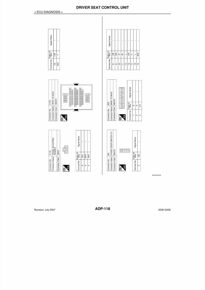
7/21/2019 adp INFINTY 2008
http://slidepdf.com/reader/full/adp-infinty-2008 118/149ADP-118
< ECU DIAGNOSIS >
DRIVER SEAT CONTROL UNIT
AWJIA0044GB
Revision: July 2007 2008 QX56
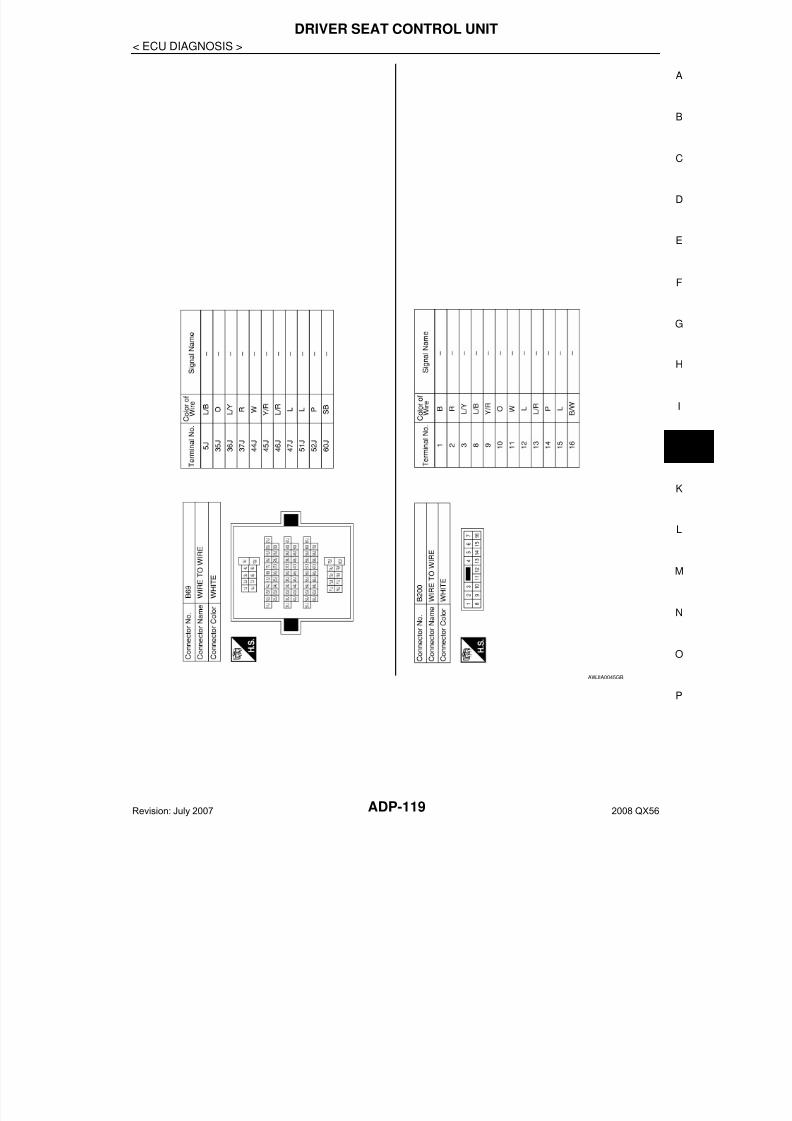
7/21/2019 adp INFINTY 2008
http://slidepdf.com/reader/full/adp-infinty-2008 119/149
DRIVER SEAT CONTROL UNIT
ADP-119
< ECU DIAGNOSIS >
A
AWJIA0045GB
Revision: July 2007 2008 QX56

7/21/2019 adp INFINTY 2008
http://slidepdf.com/reader/full/adp-infinty-2008 120/149ADP-120
< ECU DIAGNOSIS >
DRIVER SEAT CONTROL UNIT
AWJIA0046GB
Revision: July 2007 2008 QX56
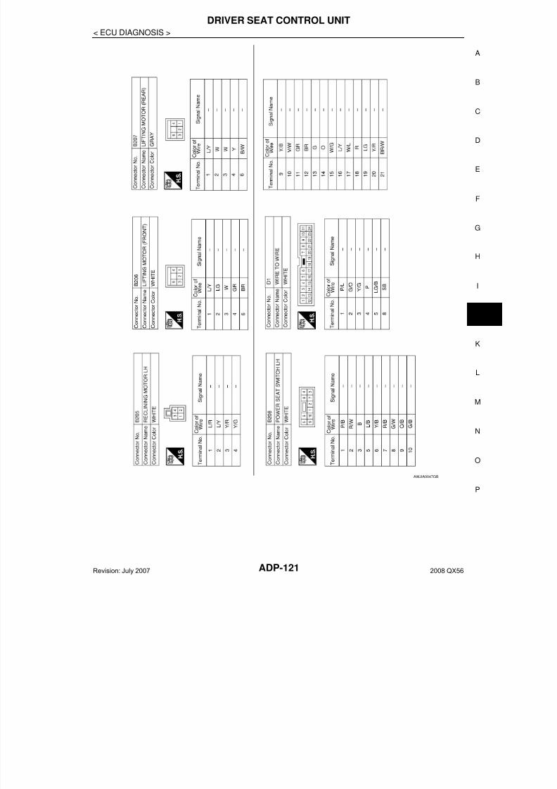
7/21/2019 adp INFINTY 2008
http://slidepdf.com/reader/full/adp-infinty-2008 121/149
DRIVER SEAT CONTROL UNIT
ADP-121
< ECU DIAGNOSIS >
A
AWJIA0047GB
Revision: July 2007 2008 QX56

7/21/2019 adp INFINTY 2008
http://slidepdf.com/reader/full/adp-infinty-2008 122/149ADP-122
< ECU DIAGNOSIS >
DRIVER SEAT CONTROL UNIT
Fail Safe INFOID:0000000001735553
The fail-safe mode may be activated if the following symptoms are observed.
FAIL-SAFE MODEWhen any manual and automatic operations are not performed, if any motor operations of front seat LH orpedals are detected for T2 or more, status is judged “Output error”.
AWJIA0048GB
Revision: July 2007 2008 QX56
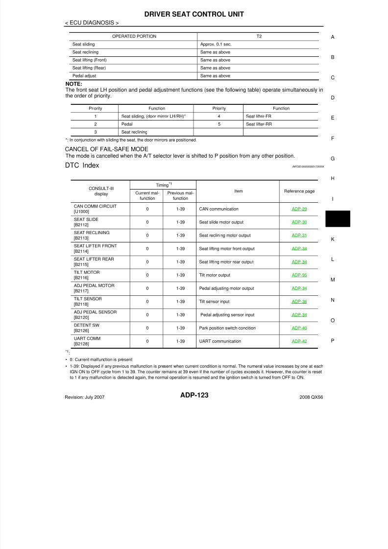
7/21/2019 adp INFINTY 2008
http://slidepdf.com/reader/full/adp-infinty-2008 123/149
DRIVER SEAT CONTROL UNIT
ADP-123
< ECU DIAGNOSIS >
A
NOTE:The front seat LH position and pedal adjustment functions (see the following table) operate simultaneously inthe order of priority.
*: In conjunction with sliding the seat, the door mirrors are positioned.
CANCEL OF FAIL-SAFE MODE
The mode is cancelled when the A/T selector lever is shifted to P position from any other position.
DTC Index INFOID:0000000001735554
*1:
• 0: Current malfunction is present
• 1-39: Displayed if any previous malfunction is present when current condition is normal. The numeral value increases by one at each
IGN ON to OFF cycle from 1 to 39. The counter remains at 39 even if the number of cycles exceeds it. However, the counter is reset
to 1 if any malfunction is detected again, the normal operation is resumed and the ignition switch is turned from OFF to ON.
OPERATED PORTION T2
Seat sliding Approx. 0.1 sec.
Seat reclining Same as above
Seat lifting (Front) Same as above
Seat lifting (Rear) Same as above
Pedal adjust Same as above
Priority Function Priority Function
1 Seat sliding, (door mirror LH/RH)* 4 Seat lifter-FR
2 Pedal 5 Seat lifter-RR
3 Seat reclining
CONSULT-III
display
Timing*1
Item Reference pageCurrent mal-
function
Previous mal-
function
CAN COMM CIRCUIT
[U1000]0 1-39 CAN communication ADP-29
SEAT SLIDE
[B2112]0 1-39 Seat slide motor output ADP-30
SEAT RECLINING[B2113]
0 1-39 Seat reclining motor output ADP-31
SEAT LIFTER FRONT
[B2114]0 1-39 Seat lifting motor front output ADP-34
SEAT LIFTER REAR
[B2115]0 1-39 Seat lifting motor rear output ADP-34
TILT MOTOR
[B2116]0 1-39 Tilt motor output ADP-95
ADJ PEDAL MOTOR
[B2117]0 1-39 Pedal adjusting motor output ADP-34
TILT SENSOR
[B2118]0 1-39 Tilt sensor input ADP-36
ADJ PEDAL SENSOR[B2120]
0 1-39 Pedal adjusting sensor input ADP-34
DETENT SW
[B2126]0 1-39 Park position switch condition ADP-40
UART COMM
[B2128]0 1-39 UART communication ADP-42
Revision: July 2007 2008 QX56
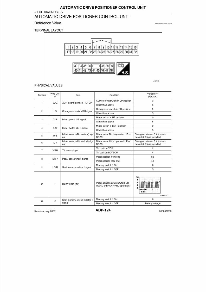
7/21/2019 adp INFINTY 2008
http://slidepdf.com/reader/full/adp-infinty-2008 124/149ADP-124
< ECU DIAGNOSIS >
AUTOMATIC DRIVE POSITIONER CONTROL UNIT
AUTOMATIC DRIVE POSITIONER CONTROL UNIT
Reference Value INFOID:0000000001735555
TERMINAL LAYOUT
PHYSICAL VALUES
LIIA2449E
TerminalWire Col-
orItem Condition
Voltage (V)
(Approx.)
1 W/G ADP steering switch TILT UPADP steering switch in UP position 0
Other than above 5
2 LG Changeover switch RH signalChangeover switch in RH position 0
Other than above 5
3 Y/B Mirror switch UP signalMirror switch in UP position 0
Other than above 5
4 V/W Mirror switch LEFT signalMirror switch in LEFT position 0
Other than above 5
5 R/BMirror sensor (RH vertical) sig-
nal
Mirror motor RH is operated UP or
DOWN
Changes between 3.4 (close to
peak) 0.6 (close to valley)
6 L/YMirror sensor (LH vertical) sig-
nal
Mirror motor LH is operated UP or
DOWN
Changes between 3.4 (close to
peak) 0.6 (close to valley)
7 Y/BR Tilt sensor inputTilt position TOP 2
Tilt position BOTTOM 4
8 BR/Y Pedal sensor input signalPedal position front end 0.5
Pedal position rear end 4.5
9 LG/B Seat memory switch 1 signal Memory switch 1 ON 0
Memory switch 1 OFF 5
10 L UART LINE (TX)Pedal adjusting switch ON (FOR-
WARD or BACKWARD operation)
12 PSeat memory switch indictor 1
signal
Memory switch 1 ON 0
Memory switch 1 OFF Battery voltage
PIIA4813E
Revision: July 2007 2008 QX56
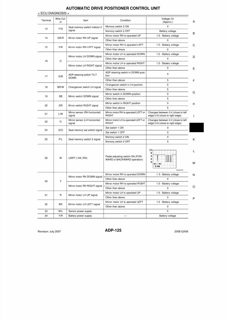
7/21/2019 adp INFINTY 2008
http://slidepdf.com/reader/full/adp-infinty-2008 125/149
AUTOMATIC DRIVE POSITIONER CONTROL UNIT
ADP-125
< ECU DIAGNOSIS >
A
13 Y/GSeat memory switch indictor 2
signal
Memory switch 2 ON 0
Memory switch 2 OFF Battery voltage
14 GR/R Mirror motor RH UP signalMirror motor RH is operated UP 1.5 - Battery voltage
Other than above 0
15 V/R Mirror motor RH LEFT signal Mirror motor RH is operated LEFT 1.5 - Battery voltage
Other than above 0
16 O
Mirror motor LH DOWN signalMirror motor LH is operated DOWN 1.5 - Battery voltage
Other than above 0
Mirror motor LH RIGHT signalMirror motor LH is operated RIGHT 1.5 - Battery voltage
Other than above 0
17 G/BADP steering switch TILT
DOWN
ADP steering switch in DOWN posi-
tion0
Other than above 5
18 BR/W Changeover switch LH signalChangeover switch in LH position 0
Other than above 5
19 SB Mirror switch DOWN signalMirror switch in DOWN position 0
Other than above 5
20 GR Mirror switch RIGHT signalMirror switch in RIGHT position 0
Other than above 5
21 L/WMirror sensor (RH horizontal)
signal
Mirror motor RH is operated LEFT or
RIGHT
Changes between 3.4 (close to left
edge) 0.6 (close to right edge)
22 GMirror sensor (LH horizontal)
signal
Mirror motor LH is operated LEFT or
RIGHT
Changes between 3.4 (close to left
edge) 0.6 (close to right edge)
24 G/O Seat memory set switch signalSet switch 1 ON 0
Set switch 1 OFF 5
25 P/L Seat memory switch 2 signalMemory switch 2 ON 0
Memory switch 2 OFF 5
26 W UART LINE (RX)Pedal adjusting switch ON (FOR-
WARD or BACKWARD operation)
30 Y
Mirror motor RH DOWN signalMirror motor RH is operated DOWN 1.5 - Battery voltage
Other than above 0
Mirror motor RH RIGHT signalMirror motor RH is operated RIGHT 1.5 - Battery voltage
Other than above 0
31 R Mirror motor LH UP signalMirror motor LH is operated UP 1.5 - Battery voltage
Other than above 0
32 BR Mirror motor LH LEFT signalMirror motor LH is operated LEFT 1.5 - Battery voltage
Other than above 0
33 W/L Sensor power supply — 5
34 Y/R Battery power supply — Battery voltage
TerminalWire Col-
orItem Condition
Voltage (V)
(Approx.)
PIIA4814E
Revision: July 2007 2008 QX56
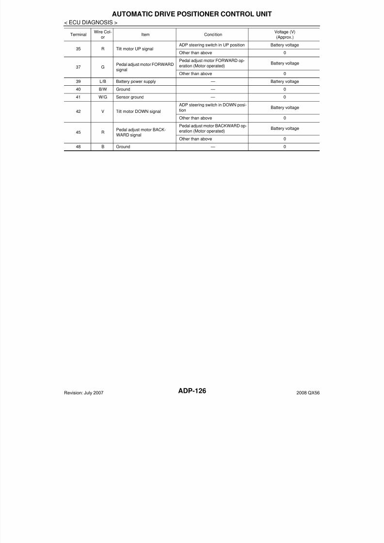
7/21/2019 adp INFINTY 2008
http://slidepdf.com/reader/full/adp-infinty-2008 126/149ADP-126
< ECU DIAGNOSIS >
AUTOMATIC DRIVE POSITIONER CONTROL UNIT
35 R Tilt motor UP signalADP steering switch in UP position Battery voltage
Other than above 0
37 GPedal adjust motor FORWARD
signal
Pedal adjust motor FORWARD op-
eration (Motor operated)Battery voltage
Other than above 0
39 L/B Battery power supply — Battery voltage
40 B/W Ground — 0
41 W/G Sensor ground — 0
42 V Tilt motor DOWN signal
ADP steering switch in DOWN posi-
tionBattery voltage
Other than above 0
45 RPedal adjust motor BACK-
WARD signal
Pedal adjust motor BACKWARD op-
eration (Motor operated)Battery voltage
Other than above 0
48 B Ground — 0
TerminalWire Col-
orItem Condition
Voltage (V)
(Approx.)
Revision: July 2007 2008 QX56
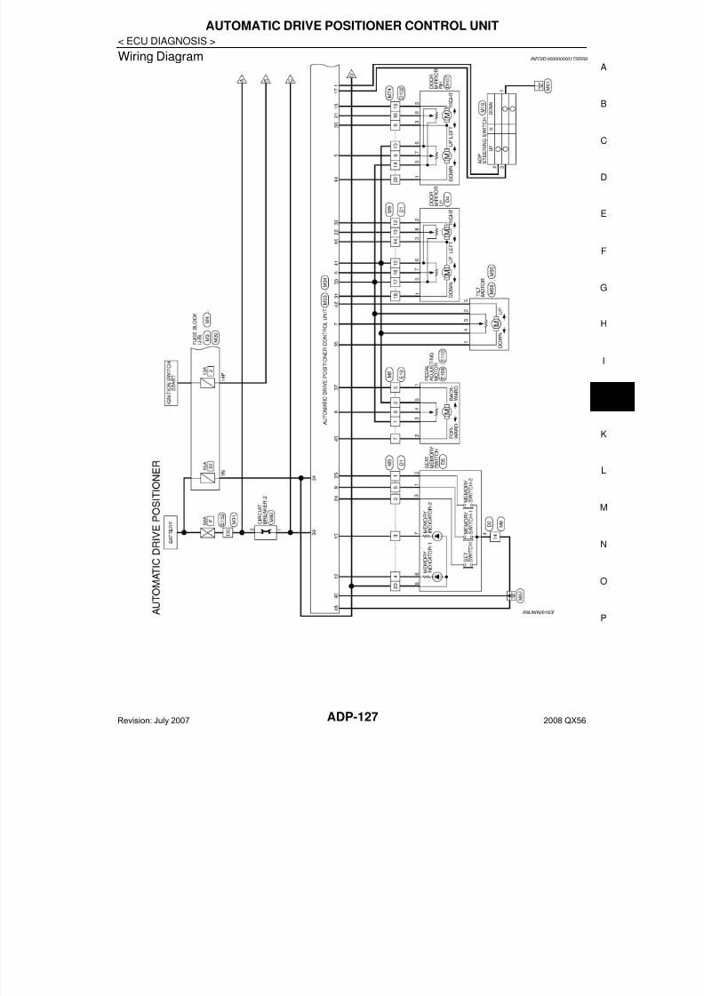
7/21/2019 adp INFINTY 2008
http://slidepdf.com/reader/full/adp-infinty-2008 127/149
AUTOMATIC DRIVE POSITIONER CONTROL UNIT
ADP-127
< ECU DIAGNOSIS >
A
Wiring Diagram INFOID:0000000001735556
AWJWA0010G
Revision: July 2007 2008 QX56
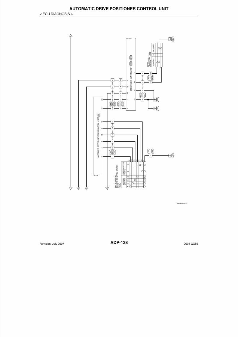
7/21/2019 adp INFINTY 2008
http://slidepdf.com/reader/full/adp-infinty-2008 128/149ADP-128
< ECU DIAGNOSIS >
AUTOMATIC DRIVE POSITIONER CONTROL UNIT
AWJWA0011G
Revision: July 2007 2008 QX56
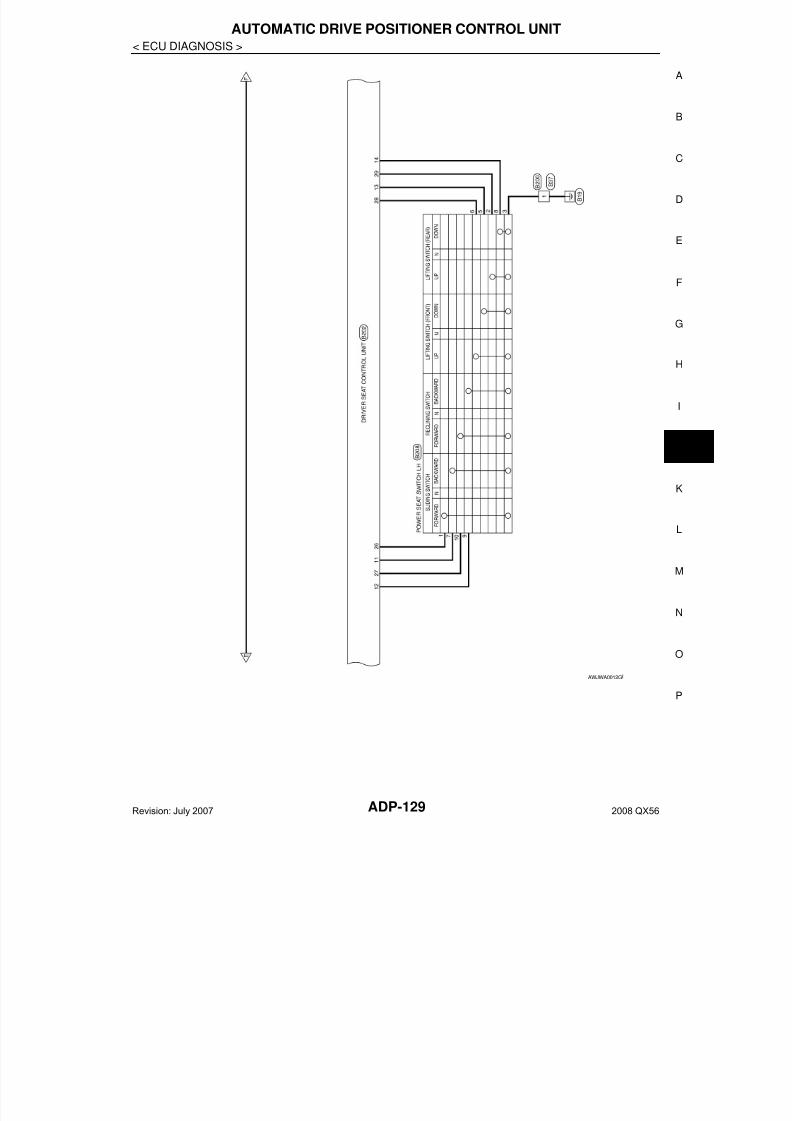
7/21/2019 adp INFINTY 2008
http://slidepdf.com/reader/full/adp-infinty-2008 129/149
AUTOMATIC DRIVE POSITIONER CONTROL UNIT
ADP-129
< ECU DIAGNOSIS >
A
AWJWA0012G
Revision: July 2007 2008 QX56
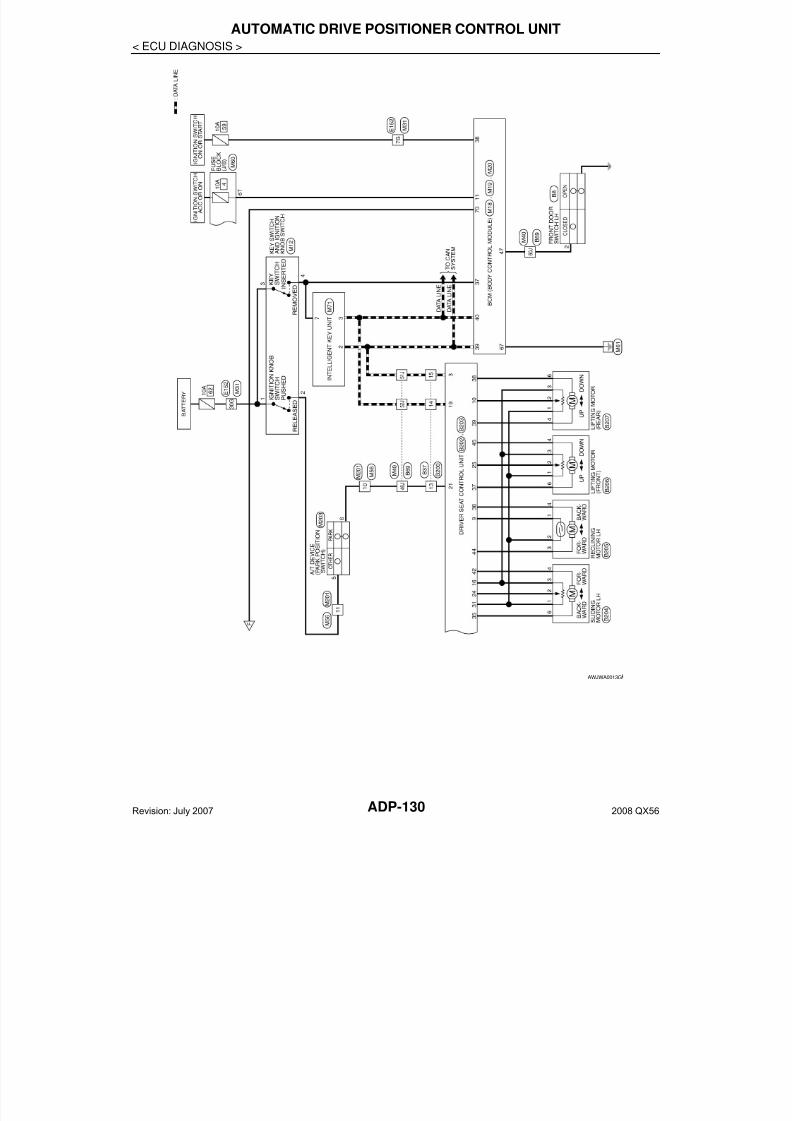
7/21/2019 adp INFINTY 2008
http://slidepdf.com/reader/full/adp-infinty-2008 130/149ADP-130
< ECU DIAGNOSIS >
AUTOMATIC DRIVE POSITIONER CONTROL UNIT
AWJWA0013G
Revision: July 2007 2008 QX56
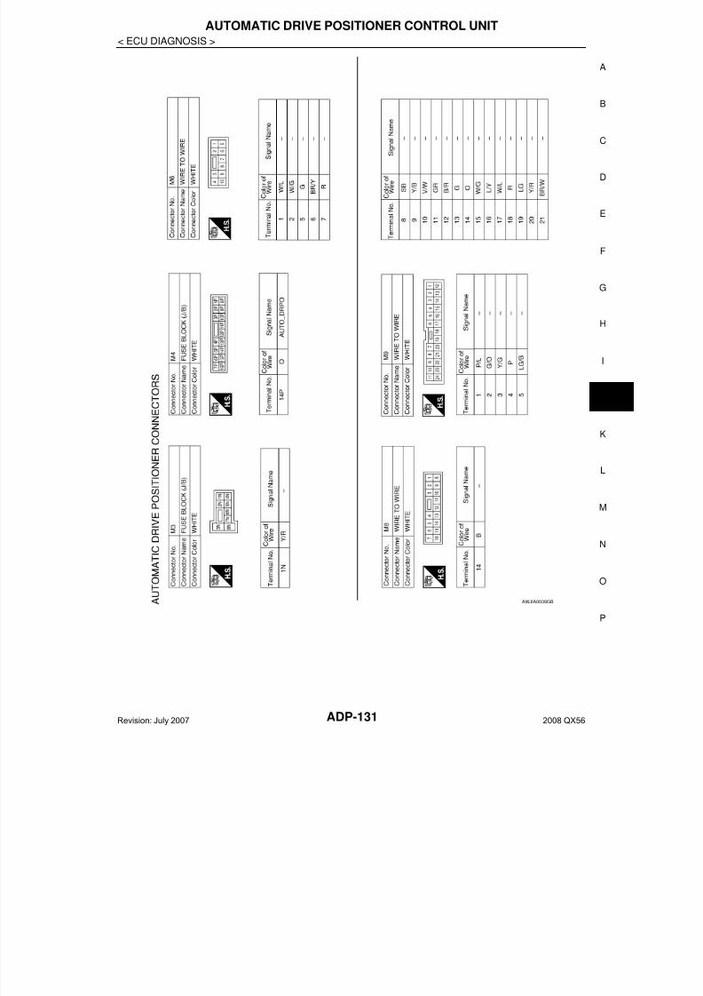
7/21/2019 adp INFINTY 2008
http://slidepdf.com/reader/full/adp-infinty-2008 131/149

7/21/2019 adp INFINTY 2008
http://slidepdf.com/reader/full/adp-infinty-2008 132/149ADP-132
< ECU DIAGNOSIS >
AUTOMATIC DRIVE POSITIONER CONTROL UNIT
AWJIA0040GB
Revision: July 2007 2008 QX56
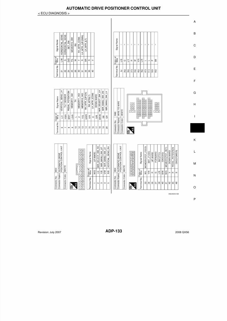
7/21/2019 adp INFINTY 2008
http://slidepdf.com/reader/full/adp-infinty-2008 133/149
AUTOMATIC DRIVE POSITIONER CONTROL UNIT
ADP-133
< ECU DIAGNOSIS >
A
AWJIA0041GB
Revision: July 2007 2008 QX56
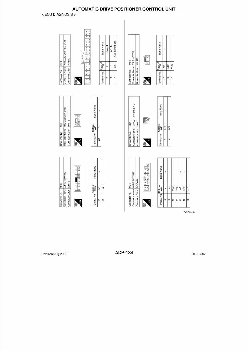
7/21/2019 adp INFINTY 2008
http://slidepdf.com/reader/full/adp-infinty-2008 134/149ADP-134
< ECU DIAGNOSIS >
AUTOMATIC DRIVE POSITIONER CONTROL UNIT
AWJIA0042GB
Revision: July 2007 2008 QX56
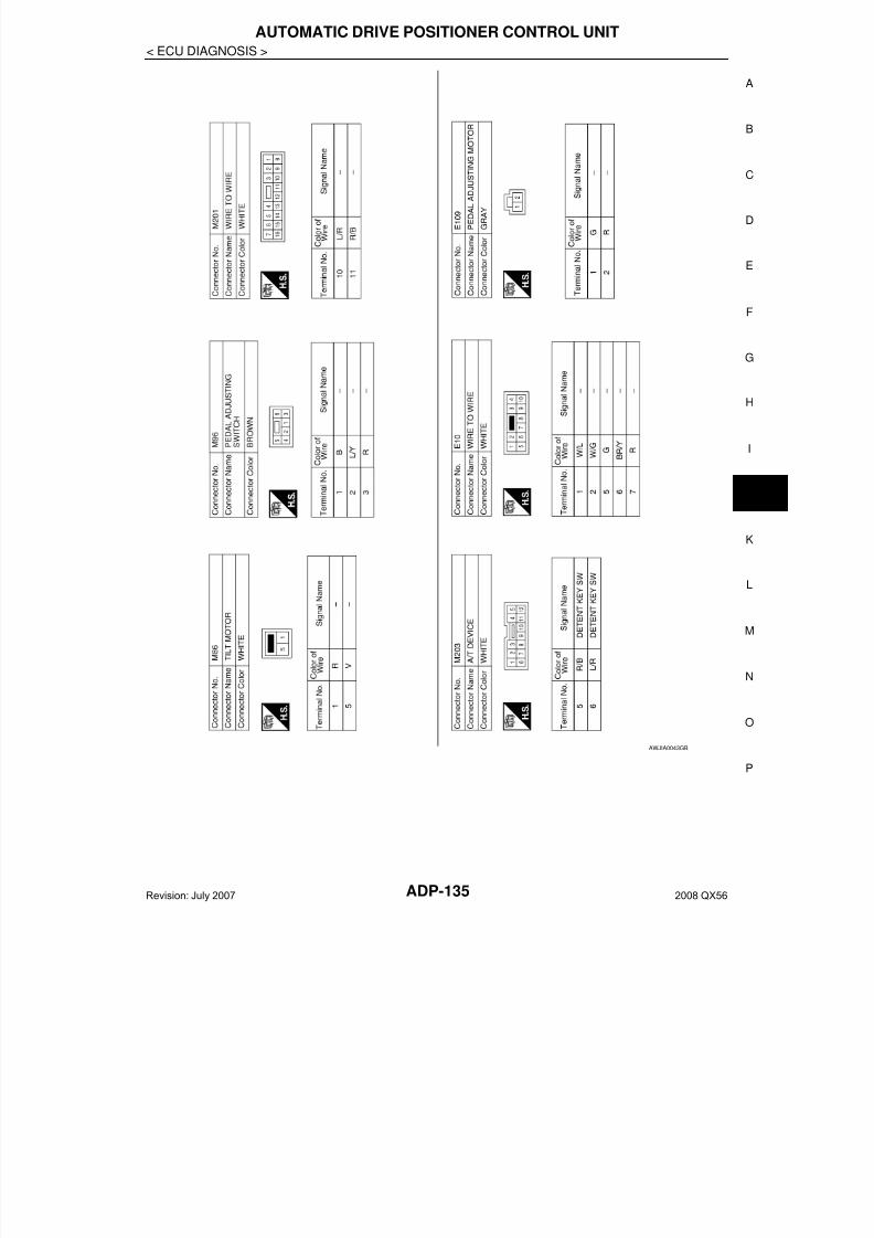
7/21/2019 adp INFINTY 2008
http://slidepdf.com/reader/full/adp-infinty-2008 135/149
AUTOMATIC DRIVE POSITIONER CONTROL UNIT
ADP-135
< ECU DIAGNOSIS >
A
AWJIA0043GB
Revision: July 2007 2008 QX56
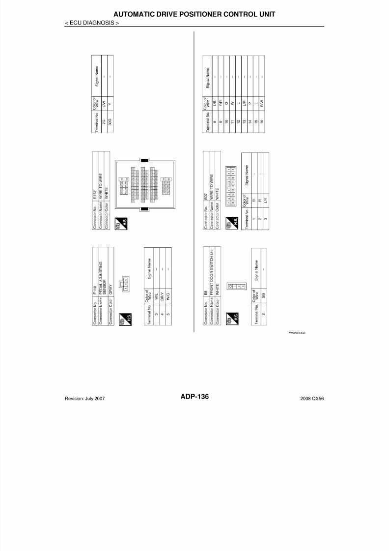
7/21/2019 adp INFINTY 2008
http://slidepdf.com/reader/full/adp-infinty-2008 136/149
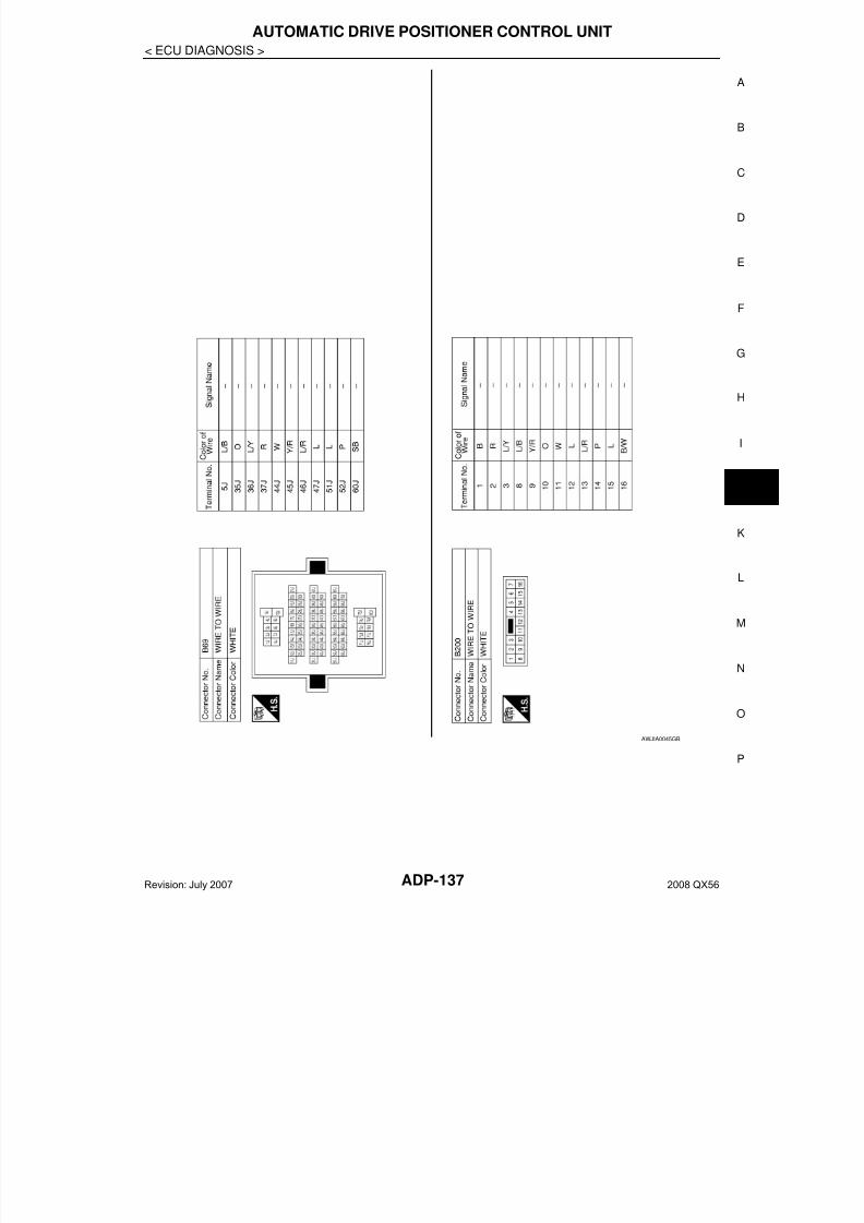
7/21/2019 adp INFINTY 2008
http://slidepdf.com/reader/full/adp-infinty-2008 137/149
AUTOMATIC DRIVE POSITIONER CONTROL UNIT
ADP-137
< ECU DIAGNOSIS >
A
AWJIA0045GB
Revision: July 2007 2008 QX56
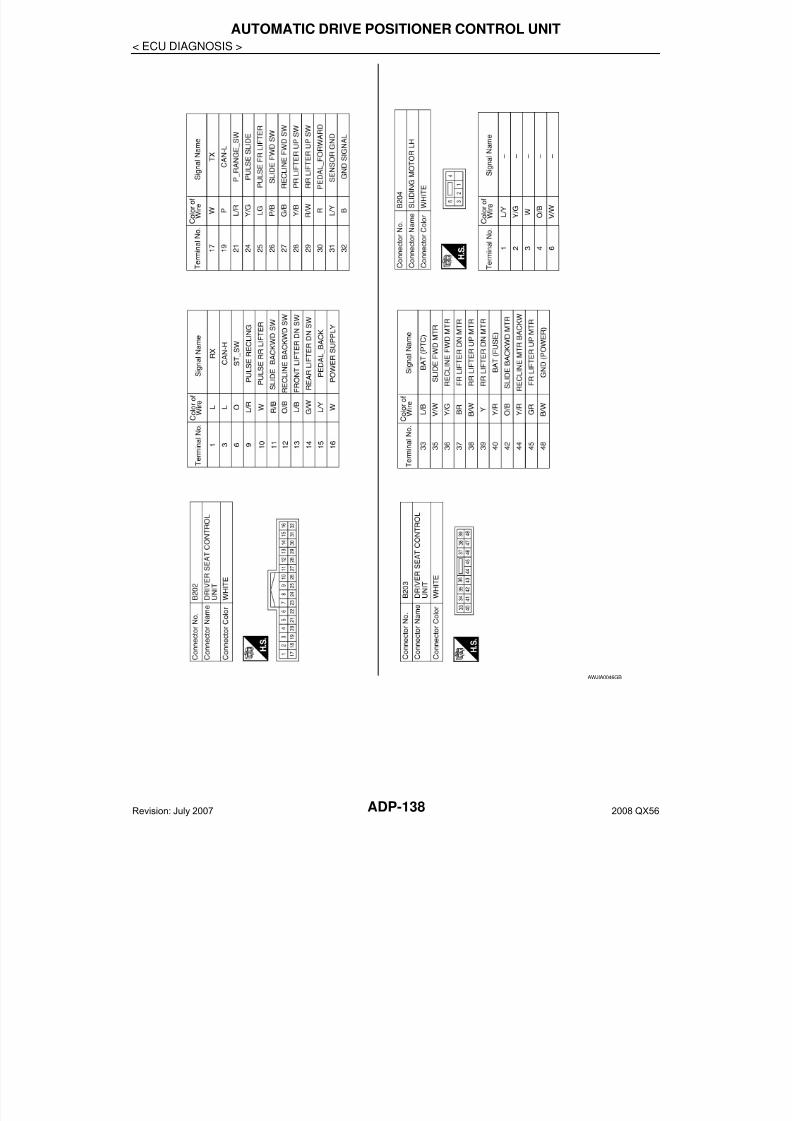
7/21/2019 adp INFINTY 2008
http://slidepdf.com/reader/full/adp-infinty-2008 138/149ADP-138
< ECU DIAGNOSIS >
AUTOMATIC DRIVE POSITIONER CONTROL UNIT
AWJIA0046GB
Revision: July 2007 2008 QX56

7/21/2019 adp INFINTY 2008
http://slidepdf.com/reader/full/adp-infinty-2008 139/149
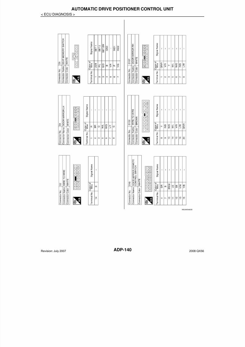
7/21/2019 adp INFINTY 2008
http://slidepdf.com/reader/full/adp-infinty-2008 140/149ADP-140
< ECU DIAGNOSIS >
AUTOMATIC DRIVE POSITIONER CONTROL UNIT
AWJIA0048GB
Revision: July 2007 2008 QX56
7/21/2019 adp INFINTY 2008
http://slidepdf.com/reader/full/adp-infinty-2008 141/149
BCM (BODY CONTROL MODULE)
ADP-141
< ECU DIAGNOSIS >
A
BCM (BODY CONTROL MODULE)
Reference Value INFOID:0000000001735557
VALUES ON THE DIAGNOSIS TOOL
CONSULT-III MONITOR ITEM
TERMINAL LAYOUTFor terminal layout information, refer to BCS-38, "Terminal Layout".
PHYSICAL VALUESFor physical value information, refer to BCS-38, "Physical Values".
Wiring Diagram INFOID:0000000001735558
For wiring information, refer to BCS-44, "Wiring Diagram".
DTC Inspection Priority Chart INFOID:0000000001735559
For DTC priority information, refer to BCS-47, "DTC Inspection Priority Chart".
DTC Index INFOID:0000000001735560
For DTC information, refer to BCS-48, "DTC Index".
Monitor Item Condition Value/Status
DOOR SW-DRFront door LH closed Off
Front door LH opened On
Revision: July 2007 2008 QX56
7/21/2019 adp INFINTY 2008
http://slidepdf.com/reader/full/adp-infinty-2008 142/149ADP-142
< SYMPTOM DIAGNOSIS >
ADP SYSTEM SYMPTOMS
SYMPTOM DIAGNOSISADP SYSTEM SYMPTOMS
Symptom Table INFOID:0000000001735561
NOTE: Always perform the “Basic Inspection” before performing diagnosis in the following table. Refer to ADP-5,
"Work Flow".
SYMPTOM 1
SYMPTOM 2
SYMPTOM 3
Symptom Diagnosis procedureReference
page
Manual functions (for specific part) do
not operate
Sliding operation Check sliding switch. ADP-46
Reclining operation Check reclining switch. ADP-48
Lifting operation (front) Check lifting switch (front). ADP-50
Lifting operation (rear) Check lifting switch (rear). ADP-52
Pedal operation1. Check pedal adjusting switch. ADP-56
2. Check pedal adjusting sensor. ADP-81
Steering wheel tilt operation Check ADP steering switch ADP-54
Door mirror operation1. Changeover switch. ADP-61
2. Mirror switch ADP-63
All parts of seatCheck power seat switch ground cir-
cuit.ADP-66
Symptom Diagnosis procedureReference
page
Memory functions (for specific part) do
not operate
Sliding operation Check sliding sensor. ADP-71
Reclining operation Check reclining sensor. ADP-73
Lifting operation (front) Check lifting sensor (front). ADP-75
Lifting operation (rear) Check lifting sensor (rear). ADP-77
Pedal operation Check pedal adjusting sensor. ADP-81
Steering wheel tilt operation Check tilt sensor ADP-79
Door mirror operation Check door mirror sensor.
Driver side:
ADP-83
Passenger
side:
ADP-85
Symptom Diagnosis procedureReference
page
Memory functions and manual func-
tions (for specific part) do not operate
Sliding operation Check sliding motor. ADP-87
Reclining operation Check reclining motor. ADP-89
Lifting operation (front) Check lifting motor (front). ADP-91
Lifting operation (rear) Check lifting motor (rear). ADP-93
Pedal operation Check pedal adjusting motor. ADP-97
Steering wheel operation Check ti lt motor ADP-95
Door mirror operation Check door mirror motor. ADP-99
Revision: July 2007 2008 QX56
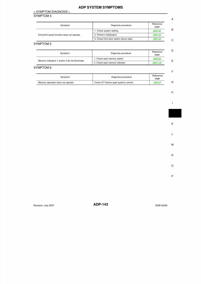
7/21/2019 adp INFINTY 2008
http://slidepdf.com/reader/full/adp-infinty-2008 143/149
ADP SYSTEM SYMPTOMS
ADP-143
< SYMPTOM DIAGNOSIS >
A
SYMPTOM 4
SYMPTOM 5
SYMPTOM 6
Symptom Diagnosis procedureReference
page
Entry/Exit assist function does not operate.
1. Check system setting. ADP-20
2. Perform initialization. ADP-22
3. Check front door switch (driver side). ADP-69
Symptom Diagnosis procedureReference
page
Memory indicators 1 and/or 2 do not illuminate.1. Check seat memory switch. ADP-59
2. Check seat memory indicator. ADP-102
Symptom Diagnosis procedureReference
page
Memory operation does not operate. Check A/T device (park position switch). ADP-67
Revision: July 2007 2008 QX56

7/21/2019 adp INFINTY 2008
http://slidepdf.com/reader/full/adp-infinty-2008 144/149ADP-144
< SYMPTOM DIAGNOSIS >
NORMAL OPERATING CONDITION
NORMAL OPERATING CONDITION
Description INFOID:0000000001735562
The following symptoms are normal operations, and they do not indicate a malfunction.
Symptom Cause Action to take Reference page
Entry/Exit assist function does
not operate.
No initialization has been performed. Perform initialization. ADP-20Entry/exit assist function is disabled.
NOTE:The entry/exit assist function is disabled
before delivery (initial setting).
Change the settings. ADP-23
Entry assist function does not op-
erate.
Manual operation with power seat switch
was performed after exit assist function
excution.
Perform the memory
function.ADP-23
Memory function, entry/exit as-
sist function or Intelligent Key in-
terlock function does not
operate.
The operating conditions are not fulfilled.Fulfill the operation
conditions.
Memory function:
ADP-17
Exit assist function:
ADP-20
Entry assist function:
ADP-23
Intelligent Key interlock
function: ADP-10
Revision: July 2007 2008 QX56

7/21/2019 adp INFINTY 2008
http://slidepdf.com/reader/full/adp-infinty-2008 145/149
PRECAUTIONS
ADP-145
< PRECAUTION >
A
PRECAUTIONPRECAUTIONS
Precaution for Supplemental Restraint System (SRS) "AIR BAG" and "SEAT BELTPRE-TENSIONER" INFOID:0000000001537293
The Supplemental Restraint System such as “AIR BAG” and “SEAT BELT PRE-TENSIONER”, used alongwith a front seat belt, helps to reduce the risk or severity of injury to the driver and front passenger for certaintypes of collision. This system includes seat belt switch inputs and dual stage front air bag modules. The SRSsystem uses the seat belt switches to determine the front air bag deployment, and may only deploy one frontair bag, depending on the severity of a collision and whether the front occupants are belted or unbelted.Information necessary to service the system safely is included in the SR and SB section of this Service Man-ual.
WARNING: To avoid rendering the SRS inoperative, which could increase the risk of personal injury or death in
the event of a collision which would result in air bag inflation, all maintenance must be performed byan authorized NISSAN/INFINITI dealer.
• Improper maintenance, including incorrect removal and installation of the SRS, can lead to personalinjury caused by unintentional activation of the system. For removal of Spiral Cable and Air Bag
Module, see the SR section.• Do not use electrical test equipment on any circuit related to the SRS unless instructed to in thisService Manual. SRS wiring harnesses can be identified by yellow and/or orange harnesses or har-ness connectors.
Precaution for Work INFOID:0000000001537294
• When removing or disassembling each component, be careful not to damage or deform it. If a componentmay be subject to interference, be sure to protect it with a shop cloth.
• When removing (disengaging) components with a screwdriver or similar tool, be sure to wrap the componentwith a shop cloth or vinyl tape to protect it.
• Protect the removed parts with a shop cloth and keep them.• Replace a deformed or damaged clip.• If a part is specified as a non-reusable part, always replace it with new one.
• Be sure to tighten bolts and nuts securely to the specified torque.• After re-installation is completed, be sure to check that each part works normally.• Follow the steps below to clean components.- Water soluble foul: Dip a soft cloth into lukewarm water, and wring the water out of the cloth to wipe the
fouled area.Then rub with a soft and dry cloth.
- Oily foul: Dip a soft cloth into lukewarm water with mild detergent (concentration: within 2 to 3%), and wipethe fouled area.Then dip a cloth into fresh water, and wring the water out of the cloth to wipe the detergent off. Then rub witha soft and dry cloth.
• Do not use organic solvent such as thinner, benzene, alcohol, or gasoline.• For genuine leather seats, use a genuine leather seat cleaner.
Revision: July 2007 2008 QX56
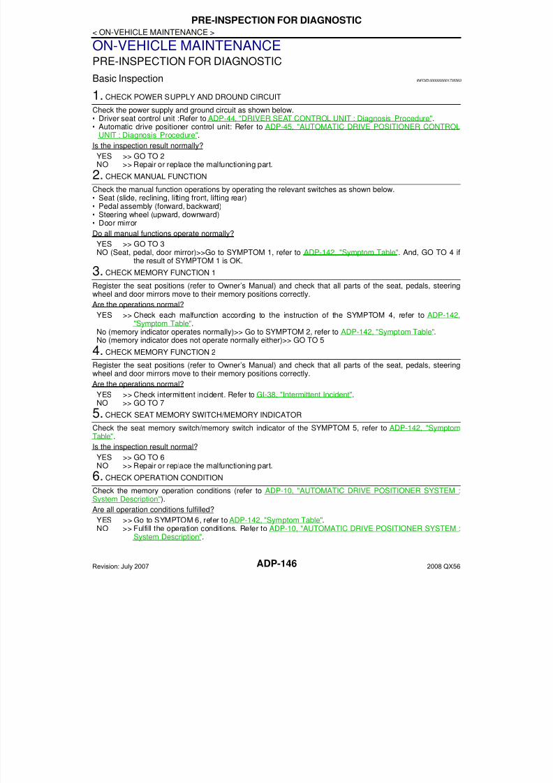
7/21/2019 adp INFINTY 2008
http://slidepdf.com/reader/full/adp-infinty-2008 146/149ADP-146
< ON-VEHICLE MAINTENANCE >
PRE-INSPECTION FOR DIAGNOSTIC
ON-VEHICLE MAINTENANCEPRE-INSPECTION FOR DIAGNOSTIC
Basic Inspection INFOID:0000000001735563
1. CHECK POWER SUPPLY AND DROUND CIRCUIT
Check the power supply and ground circuit as shown below.• Driver seat control unit :Refer to ADP-44, "DRIVER SEAT CONTROL UNIT : Diagnosis Procedure".• Automatic drive positioner control unit: Refer to ADP-45, "AUTOMATIC DRIVE POSITIONER CONTROL
UNIT : Diagnosis Procedure".
Is the inspection result normally?
YES >> GO TO 2NO >> Repair or replace the malfunctioning part.
2. CHECK MANUAL FUNCTION
Check the manual function operations by operating the relevant switches as shown below.• Seat (slide, reclining, lifting front, lifting rear)• Pedal assembly (forward, backward)• Steering wheel (upward, downward)
• Door mirrorDo all manual functions operate normally?
YES >> GO TO 3NO (Seat, pedal, door mirror)>>Go to SYMPTOM 1, refer to ADP-142, "Symptom Table". And, GO TO 4 if
the result of SYMPTOM 1 is OK.
3. CHECK MEMORY FUNCTION 1
Register the seat positions (refer to Owner’s Manual) and check that all parts of the seat, pedals, steeringwheel and door mirrors move to their memory positions correctly.
Are the operations normal?
YES >> Check each malfunction according to the instruction of the SYMPTOM 4, refer to ADP-142,"Symptom Table".
No (memory indicator operates normally)>> Go to SYMPTOM 2, refer to ADP-142, "Symptom Table".No (memory indicator does not operate normally either)>> GO TO 5
4. CHECK MEMORY FUNCTION 2
Register the seat positions (refer to Owner’s Manual) and check that all parts of the seat, pedals, steeringwheel and door mirrors move to their memory positions correctly.
Are the operations normal?
YES >> Check intermittent incident. Refer to GI-38, "Intermittent Incident".NO >> GO TO 7
5. CHECK SEAT MEMORY SWITCH/MEMORY INDICATOR
Check the seat memory switch/memory switch indicator of the SYMPTOM 5, refer to ADP-142, "SymptomTable".
Is the inspection result normal?
YES >> GO TO 6NO >> Repair or replace the malfunctioning part.
6. CHECK OPERATION CONDITION
Check the memory operation conditions (refer to ADP-10, "AUTOMATIC DRIVE POSITIONER SYSTEM :System Description").
Are all operation conditions fulfilled?
YES >> Go to SYMPTOM 6, refer to ADP-142, "Symptom Table".NO >> Fulfill the operation conditions. Refer to ADP-10, "AUTOMATIC DRIVE POSITIONER SYSTEM :
System Description".
Revision: July 2007 2008 QX56
7/21/2019 adp INFINTY 2008
http://slidepdf.com/reader/full/adp-infinty-2008 147/149
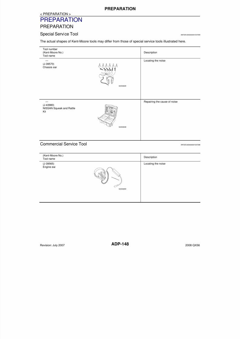
7/21/2019 adp INFINTY 2008
http://slidepdf.com/reader/full/adp-infinty-2008 148/149ADP-148
< PREPARATION >
PREPARATION
PREPARATIONPREPARATION
Special Service Tool INFOID:0000000001537295
The actual shapes of Kent-Moore tools may differ from those of special service tools illustrated here.
Commercial Service Tool INFOID:0000000001537296
Tool number
(Kent-Moore No.)
Tool name
Description
—
(J-39570)
Chassis ear
Locating the noise
—
(J-43980)
NISSAN Squeak and Rattle
Kit
Repairing the cause of noise
SIIA0993E
SIIA0994E
(Kent-Moore No.)
Tool nameDescription
(J-39565)
Engine ear
Locating the noise
SIIA0995E
Revision: July 2007 2008 QX56
7/21/2019 adp INFINTY 2008
http://slidepdf.com/reader/full/adp-infinty-2008 149/149