Embed Size (px)
Citation preview
Proceedings Venice 2014, Fifth International Symposium on Energy from Biomass and Waste San Servolo, Venice, Italy; 17 - 20 November 2014 2014 by CISA Publisher, Italy
Advanced gasification, gas cleaning and product gas utilization
M.T. VAN ‘T HOFF* and H.J.W. KÖNEMANN* *Royal Dahlman; Dahlman Renewable Technology BV, Maassluis, The Netherlands.
Corresponding author: [email protected], +31 (0)10-599 1111
SUMMARY:
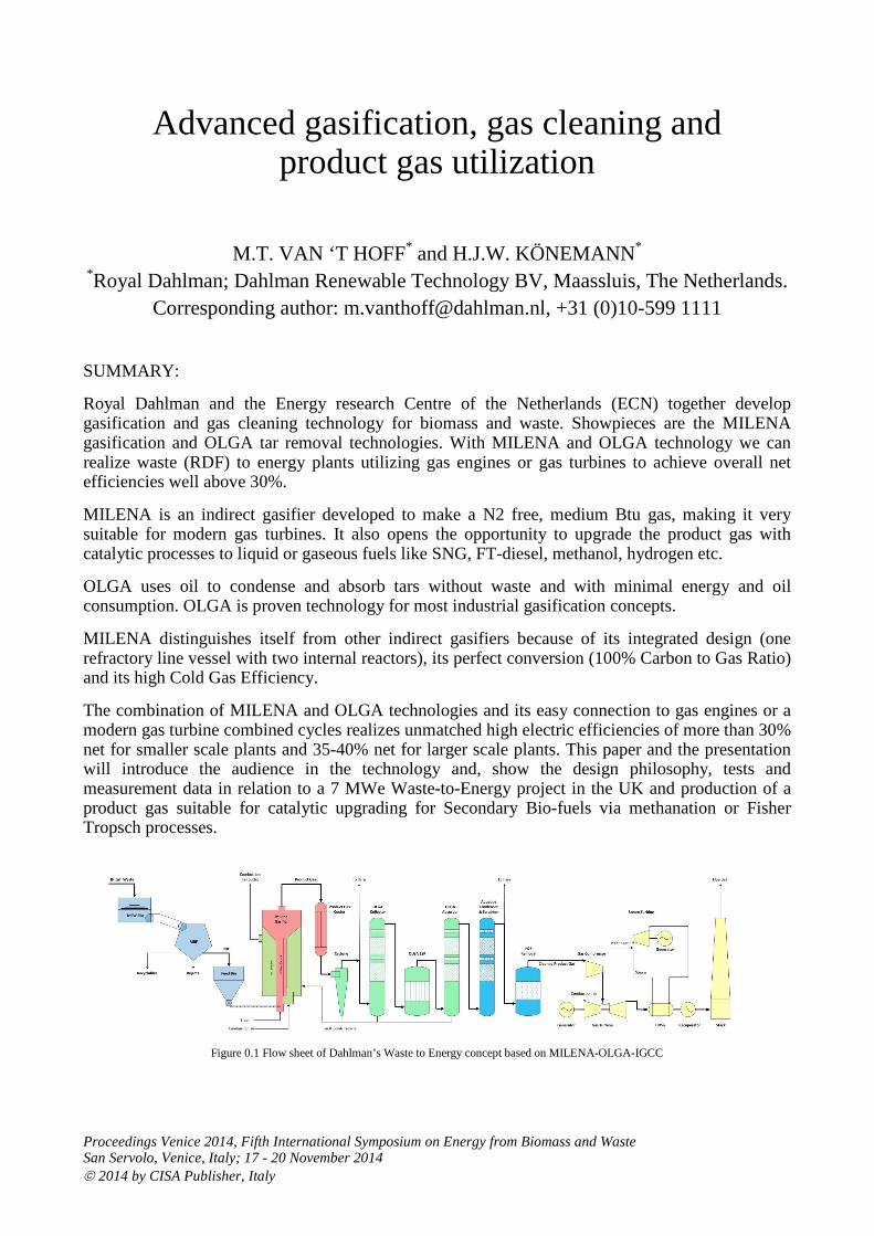
Royal Dahlman and the Energy research Centre of the Netherlands (ECN) together develop gasification and gas cleaning technology for biomass and waste. Showpieces are the MILENA gasification and OLGA tar removal technologies. With MILENA and OLGA technology we can realize waste (RDF) to energy plants utilizing gas engines or gas turbines to achieve overall net efficiencies well above 30%.
MILENA is an indirect gasifier developed to make a N2 free, medium Btu gas, making it very suitable for modern gas turbines. It also opens the opportunity to upgrade the product gas with catalytic processes to liquid or gaseous fuels like SNG, FT-diesel, methanol, hydrogen etc.
OLGA uses oil to condense and absorb tars without waste and with minimal energy and oil consumption. OLGA is proven technology for most industrial gasification concepts.
MILENA distinguishes itself from other indirect gasifiers because of its integrated design (one refractory line vessel with two internal reactors), its perfect conversion (100% Carbon to Gas Ratio) and its high Cold Gas Efficiency.
The combination of MILENA and OLGA technologies and its easy connection to gas engines or a modern gas turbine combined cycles realizes unmatched high electric efficiencies of more than 30% net for smaller scale plants and 35-40% net for larger scale plants. This paper and the presentation will introduce the audience in the technology and, show the design philosophy, tests and measurement data in relation to a 7 MWe Waste-to-Energy project in the UK and production of a product gas suitable for catalytic upgrading for Secondary Bio-fuels via methanation or Fisher Tropsch processes.
Figure 0.1 Flow sheet of Dahlman’s Waste to Energy concept based on MILENA-OLGA-IGCC

Venice 2014, Fifth International Symposium on Energy from Biomass and Waste
1. INTRODUCTION
Renewable energy, energy efficiency and energy independence are hot topics nowadays. Biomass is a renewable energy source with large potential. Biomass is generally considered as one of the most important renewable energy sources and the only 100% renewable carbon source! Besides the biomass, waste could also be an important renewable energy source. Land filling of waste will progressively be reduced in many regions for the benefit of recycling and energy production. As waste is partly fossil (plastics) and partly biogenic (e.g. wood, paper, leather, cotton), utilizing waste not only solves our waste related problems; it also (partially) contributes to our renewable energy mix. Mass incineration of waste however, is unpopular because of the emissions and low energy efficiency. Alternative gasification of biomass and waste opens the full potential of this valuable renewable carbon source. Combustion is still used more nowadays but gasification has more potential. Once the product gas is cleaned, it can be used in efficient combined cycle power stations. Moreover, the product gas can also be converted into gaseous and liquid fuels such as SNG, hydrogen or Fisher Tropsch Diesel. Royal Dahlman has a long and strong relationship with the Energy research Centre of The Netherlands (ECN) in gasification. 12 years ago we started our cooperation with the development of the OLGA tar removal technology. The MILENA gasifier technology is launched onto the market. We believe that an integrated MILENA-OLGA system is the most efficient and flexible biomass and/or waste to energy system available. This paper, the poster and oral presentation will give you background to the MILENA-OLGA technology, its advanced utilization options and the experience and test results so far.

Venice 2014, Fifth International Symposium on Energy from Biomass and Waste
2. PRINCIPLE OF BIOMASS & WASTE GASIFICATION Gasification can be defined as the thermal conversion of carbon rich feedstocks into a syngas or product gas. 2.1 Syngas vs. Product Gas Syngas mainly contains hydrogen, carbon monoxide and also carbon dioxide and water. It is normally produced by entrained flow gasifiers in which either a pulverized solid or a liquid fuel / slurry is gasified with oxygen in co-current flow at temperatures of 1300–1500°C. Temperatures are this high in order to convert coal efficiently. Coal is very suitable for entrained flow gasification, biomass or waste is not. Biomass and waste cannot economically be grinded to the fine pulverized solid needed by this type of gasification. Biomass and waste can be shredded to chips (e.g. wood) or a fluff (e.g. RDF) which is the ideal fuel of a fluidized bed. Fluidized bed biomass and waste gasifiers are operated at a lower temperature in the range of 700–900°C. Temperatures can be this low because biomass and waste are more reactive than coal. At these temperature a product gas is produced which contains syngas as well as hydrocarbons such as methane. Figure 2.1 Direct gasification vs indirect gasification
2.2 Direct vs. Indirect gasification In a “direct” gasifier biomass or waste fuel is fed to the gasifier reactor together with an under stoichiometric amount of oxygen (for gasification at 700 – 900°C air is mostly applied, for high temperature gasification pure oxygen is needed). Part of the fuel combusts, supplying the heat needed for driving the endothermic gasification of the remaining fuel. The heat could also be provided by an external source, hence without adding oxygen to the gasifier. In the absence of oxygen this thermal conversion process is not called gasification but pyrolysis. In this paper the pyrolysis process which produces a char of tar/oil stream at a temperature around 400–500°C will not be discussed, the topic is pyrolysis that delivers a product gas at a temperature in the range of 700–900°C. Pyrolysis is an endothermic process; it needs an energy source to maintain the temperature level. This energy source can be various. It could be an external energy source like electricity, natural gas and/or recycled product gas as well as any remaining unconverted fuel. Processes that use a close coupled combustion reactor which supplies the energy for the pyrolysis reactor are called indirect gasifiers. Here gasification is the combination of the separated pyrolysis and combustion processes. Energy is available in different forms and qualities. The most economical system produces a high quality energy (electricity, methane, diesel) using a low quality fuel. In our indirect gasifier we use the unconverted fraction of the biomass or waste (the waste of the waste) to supply the energy for the pyrolysis reactor.
fuel
gas
air
gasifier
fuel + air (λ~0.3) ���� gas
fuel
gas
air
flue gas
fuel
energy pyrolysis combustion
Combustion: fuel + air (λ >1) ���� flue gas +heat Pyrolysis: fuel + heat ���� gas + char

Venice 2014, Fifth International Symposium on Energy from Biomass and Waste
2.3 Raw product gas Both direct and indirect gasifiers produce a raw product gas which needs cleaning and upgrading before it can be utilized efficiently in advanced processes. The difference is the energy concentration of the product gas. Product gas formed by a direct air blown gasifier is diluted by the nitrogen present in air (79%). An indirect gasification or pyrolysis system produces a gas that is not diluted by nitrogen and therewith it has a 2 to 2½ times higher Lower Heating Value (LHV). The solution for direct gasifiers in order to generate a gas with a similar heating value is to use a mixture of oxygen and steam instead of air. This solution will require additional investment in and energy consumption of an Air Separation Unit (ASU). In addition, ASU’s are known to hamper availability of (coal) IGCC’s. All product gasses diluted or non diluted will have to be cleaned and conditioned prior to utilization in gas engines, gas turbines or catalytic conversion processes. The production of tar is seen as the Achilles heel of this process. Tar removal is an important subject discussed in this paper. 3. THE MILENA GASIFIER MILENA is an indirect fluidized bed gasifier, coupling a CFB type pyrolysis reactor with a BFB type combustion reactor. The special feature of MILENA is that both reactors are integrated in one vessel, minimizing heat loss and optimizing the heat transfer between the beds. 3.1 MILENA principle Solid fuel (biomass/waste) enters the system in the central riser (red). Some steam or air is also injected into the riser to fluidize the hot sand in which the fuel is fed. Using the energy of the hot sand biomass reacts into three basic products.
• Solid (char)
• Condensables (tars)
• Product Gas (mainly H2, CO, CH4, C2H2, C2H4, CO2, & H2O)
The product gas, sand and char flow upwards through the riser into the settling chamber. In this settling chamber the majority of the solids (sand, ash & char) are separated from the product gas. Raw product gas (containing gaseous tars) is flowing to downstream equipment. The solids collected in the settling chamber flow, under the influence of gravity, to the combustion chamber (green). In this combustion chamber the char fraction burns, heating up the sand after which the hot sand flows back to the Figure 3.1 MILENA gasifier riser completing the cycle.

Venice 2014, Fifth International Symposium on Energy from Biomass and Waste
3.2 MILENA process description The main advantage of the MILENA process is that the unconverted fraction of the waste or biomass in the pyrolysis reactor is used as fuel for the combustor. The combustor has a separate flue gas exhaust so that the product gas is not diluted with the combustion flue gasses (N2, CO2 and H2O). Furthermore, the combustion reactor operates with an over stoichiometric amount of oxygen, optimizing the combustion reactions, resulting in full carbon conversion. Summarized: � Full carbon conversion; 100% carbon to gas ratio
(95% to product gas and 5% to flue gas) � Carbon free ash, safer ash discharge and reduction in waste � High cold gas efficiency (transfer of fuel LHV into LHV product gas) >80% energy transfer to
tar free product gas, 5-15% higher than direct air blown gasifiers � No dilution of the product gas; N2 free gas suitable for green gas (SNG, CH4) production and
other catalytic upgrading processes � High product gas energy density 16 to 22 MJ/Nm3.
Suitable for a gas turbine combined cycle (IGCC)
Figure 3.2 Simplified PFD MILENA gasifier with auxiliary equipment making a MILENA package
The separate flue gas exhaust may be presented as one of MILENA’s main advantages; it also has the disadvantage of an extra exhaust. MILENA’s flue gas must be treated to comply with environmental legislations. The flue gas is cooled and solid particulates (ashes) are removed by an efficient dust filter. Extra treatment steps (adsorption, NOx reduction) may be necessary depending on the composition of the biomass/waste fuel and the local emission regulations. The product gas of MILENA is also cooled, after which coarse dust is removed by a cyclone. This dust is a mixture of ashes and combustible char which is recycled to MILENA’s combustor reactor. The primary product gas and flue cooler produces high quality heat which is utilized in the plant (e.g. by the steam turbine in an IGCC).
Venice 2014, Fifth International Symposium on Energy from Biomass and Waste
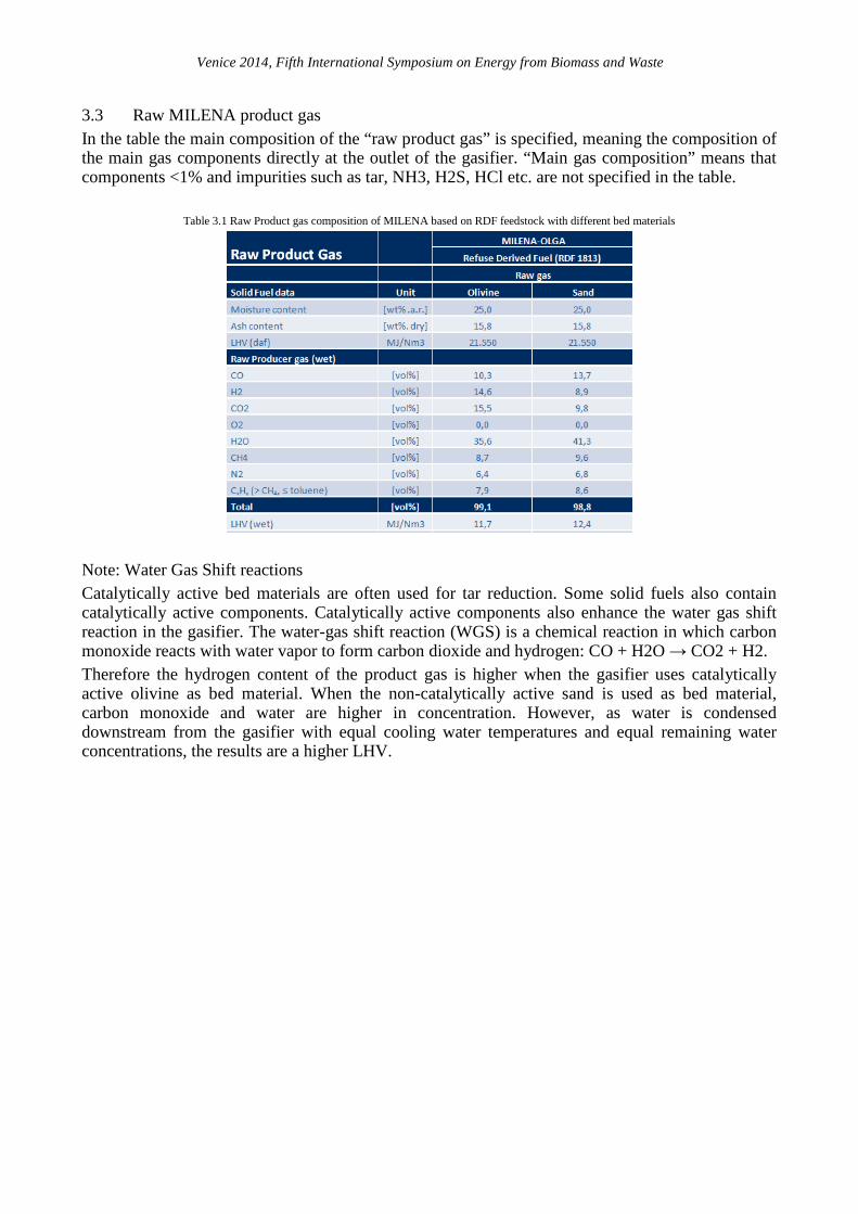
3.3 Raw MILENA product gas In the table the main composition of the “raw product gas” is specified, meaning the composition of the main gas components directly at the outlet of the gasifier. “Main gas composition” means that components <1% and impurities such as tar, NH3, H2S, HCl etc. are not specified in the table.
Table 3.1 Raw Product gas composition of MILENA based on RDF feedstock with different bed materials
Note: Water Gas Shift reactions Catalytically active bed materials are often used for tar reduction. Some solid fuels also contain catalytically active components. Catalytically active components also enhance the water gas shift reaction in the gasifier. The water-gas shift reaction (WGS) is a chemical reaction in which carbon monoxide reacts with water vapor to form carbon dioxide and hydrogen: CO + H2O → CO2 + H2. Therefore the hydrogen content of the product gas is higher when the gasifier uses catalytically active olivine as bed material. When the non-catalytically active sand is used as bed material, carbon monoxide and water are higher in concentration. However, as water is condensed downstream from the gasifier with equal cooling water temperatures and equal remaining water concentrations, the results are a higher LHV.
Venice 2014, Fifth International Symposium on Energy from Biomass and Waste
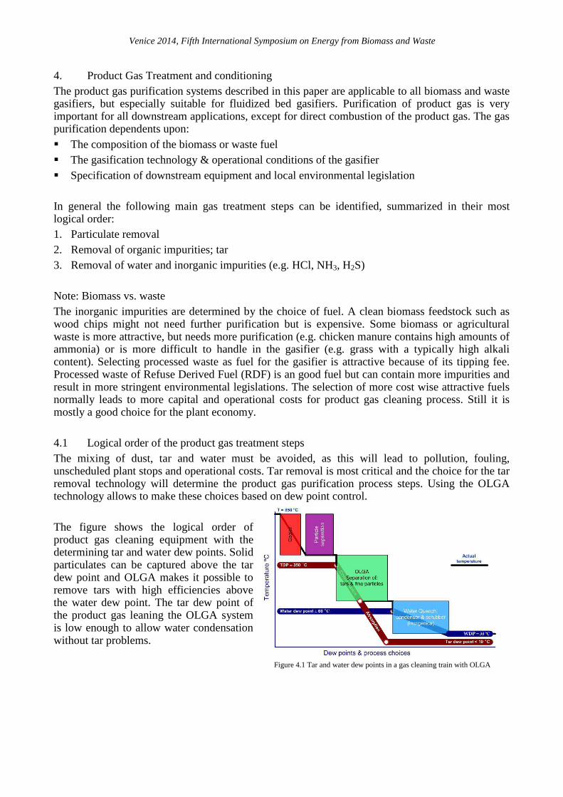
4. Product Gas Treatment and conditioning The product gas purification systems described in this paper are applicable to all biomass and waste gasifiers, but especially suitable for fluidized bed gasifiers. Purification of product gas is very important for all downstream applications, except for direct combustion of the product gas. The gas purification dependents upon: � The composition of the biomass or waste fuel � The gasification technology & operational conditions of the gasifier � Specification of downstream equipment and local environmental legislation In general the following main gas treatment steps can be identified, summarized in their most logical order: 1. Particulate removal 2. Removal of organic impurities; tar 3. Removal of water and inorganic impurities (e.g. HCl, NH3, H2S) Note: Biomass vs. waste The inorganic impurities are determined by the choice of fuel. A clean biomass feedstock such as wood chips might not need further purification but is expensive. Some biomass or agricultural waste is more attractive, but needs more purification (e.g. chicken manure contains high amounts of ammonia) or is more difficult to handle in the gasifier (e.g. grass with a typically high alkali content). Selecting processed waste as fuel for the gasifier is attractive because of its tipping fee. Processed waste of Refuse Derived Fuel (RDF) is an good fuel but can contain more impurities and result in more stringent environmental legislations. The selection of more cost wise attractive fuels normally leads to more capital and operational costs for product gas cleaning process. Still it is mostly a good choice for the plant economy. 4.1 Logical order of the product gas treatment steps The mixing of dust, tar and water must be avoided, as this will lead to pollution, fouling, unscheduled plant stops and operational costs. Tar removal is most critical and the choice for the tar removal technology will determine the product gas purification process steps. Using the OLGA technology allows to make these choices based on dew point control. The figure shows the logical order of product gas cleaning equipment with the determining tar and water dew points. Solid particulates can be captured above the tar dew point and OLGA makes it possible to remove tars with high efficiencies above the water dew point. The tar dew point of the product gas leaning the OLGA system is low enough to allow water condensation without tar problems.
Figure 4.1 Tar and water dew points in a gas cleaning train with OLGA

Venice 2014, Fifth International Symposium on Energy from Biomass and Waste
4.2 Removal of dust Dust can be removed effectively by filtration, also at temperatures above the tar dew point (450 – 500 °C). However hot gas filters are expensive and vulnerable. Tar fouling of the filter material can still be an issue in plant upsets and complicate start-up and shut-down procedures. Therefore a cyclone is chosen to remove the bulk of the dust and let the remaining fine dust particulates be removed by OLGA. 4.3 Removal of tars Tar is the Achilles heel for biomass and waste gasification. Tar problems are the main cause of failing gasification initiatives. The pictures below represent some of the known tar problems, from left to right: plugging of a water scrubber grid with heavy tars, a plugged gas engine inter cooler and fouling of naphthalene (a lighter tar) on a gas engine control valve. Tar is formed in the gasifier and comprises a wide spectrum of organic compounds, generally consisting of several aromatic rings. Simplified, tars can be distinguished in heavy tars and light tars. Heavy tars already condense out as the gas temperature drops below 350-450°C (depending on the gasifier type) and cause major fouling, efficiency loss and unscheduled plant stops. The tar dew point, i.e. the temperature at which tars start to condense, is a critical factor. Light tars such as phenol or naphthalene have less influence on the tar dew point, but are none less problematic. Light tars, especially phenol chemically pollute bleed water of downstream condensers and aqueous scrubbers. Naphthalene is important as it is known to crystallize at the inlet of gas engines causing high maintenance costs. In its research ECN tried almost every available tar removal system after which it was concluded that a new approach was necessary. From this research the OLGA technology was born. OLGA is an acronym for oil – gas scrubber. An oil is used to clean the gas. The scrubbing oil is re-used and tars are recycled; energy is kept in the process and a tar waste stream is avoided.
Figure 4.2 Pictures of Tars in a engine control valve (Naphthalene crystals), plugged intercooler and a water scrubber grid
Venice 2014, Fifth International Symposium on Energy from Biomass and Waste
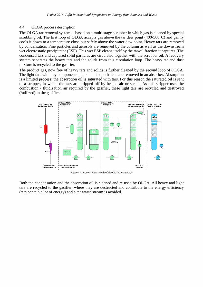
4.4 OLGA process description The OLGA tar removal system is based on a multi stage scrubber in which gas is cleaned by special scrubbing oil. The first loop of OLGA accepts gas above the tar dew point (400-500°C) and gently cools it down to a temperature close but safely above the water dew point. Heavy tars are removed by condensation. Fine particles and aerosols are removed by the column as well as the downstream wet electrostatic precipitator (ESP). This wet ESP cleans itself by the tar/oil fraction it captures. The condensed tars and captured solid particles are circulated together with the scrubber oil. A recovery system separates the heavy tars and the solids from this circulation loop. The heavy tar and dust mixture is recycled to the gasifier. The product gas, now free of heavy tars and solids is further cleaned by the second loop of OLGA. The light tars with key components phenol and naphthalene are removed in an absorber. Absorption is a limited process; the absorption oil is saturated with tars. For this reason the saturated oil is sent to a stripper, in which the tars are stripped off by heated air or steam. As this stripper uses the combustion / fluidization air required by the gasifier, these light tars are recycled and destroyed (/utilized) in the gasifier.
Figure 4.4 Process Flow sketch of the OLGA technology
Both the condensation and the absorption oil is cleaned and re-used by OLGA. All heavy and light tars are recycled to the gasifier, where they are destructed and contribute to the energy efficiency (tars contain a lot of energy) and a tar waste stream is avoided.

Venice 2014, Fifth International Symposium on Energy from Biomass and Waste
4.5 OLGA performance The measurements below represent the average of many tar measurements on a commercial CHP system which include an air blown CFB gasifier, OLGA tar removal and a Caterpillar gas engine.
Table: 4.1 OLGA results of our Portugal plant measured by Third Party
Parameter Unit Raw Gas
Downstream
OLGA Efficiency
Total tar mg/Nm³ (dry) 17106 171 99,0%
Total tar excl. BTX mg/Nm³ (dry) 16040 63 99,6%
Total tar excl. BTX & unknowns mg/Nm³ (dry) 10349 9 99,9%
Naphthalene (key-component) mg/Nm³ (dry) 2822 < 2,5 > 99,9%
Phenol (key-component) mg/Nm³ (dry) 386 < 2,5 > 99,9%
Tar dewpoint ° C > 350 < 15
° F > 660 < 59
Tar aerosols (incl. dust) mg/Nm³ (dry) -- 10
OLGA performance downstream a commercial air blown CFB gasifier
Benzene is not considered a tar by definition. Next to some traces of light tars the only tar that remains in considerable quantities is toluene (almost 90% of the known tars). Toluene is a high energy carrier and considered good fuel for an engine or turbine. In the summarizing table below we have given efficiencies for all tars, tars excluding benzene, toluene and xylene (BTX) and unknowns belonging to that group. The photos below show the start-up of OLGA; raw gas combusted in the flare upstream OLGA (left), opening the valve to OLGA (middle) and finally closing the first valve (right). Combusting clean product gas without dust and tars shows a bright blue flame.
Figure 4.5 Flame change from dirty gas flare to cleaned gas flare after OLGA

Venice 2014, Fifth International Symposium on Energy from Biomass and Waste
4.6 Water condensation and removal of inorganic components Product gas contains a lot of water (30-50% by volume). For all most all applications this water must be removed. Downstream OLGA water removal by a classic condensing water scrubber is possible without tar related problems. In the water scrubber the intense contact with water also removes the most important inorganic impurities: � HCl is easily removed by water at high efficiencies � NH3 is also removed by water, when the NH3 concentration is much higher than the strong acid
(e.g. HCl) concentration, the efficiency of NH3 removal can be optimized by dosing additional acid
� H2S is also removed partly but not with high efficiencies, H2S needs the presence of caustic, but that is undesirable because of the presence of large quantities of CO2
Biomass and waste normally does not contain enough sulfur to justify processes as Selexol and Rectisol. Absorption beds can also polish out other impurities if necessity. 4.7 Resulting clean MILENA-OLGA Product Gas The main product gas composition after the product gas treatment train does not change much. It is seen as one of the main advantages of OLGA that the gas composition is not changed. Thermal or catalytically tar crackers inevitably also convert methane to extra hydrogen and carbon monoxide, which is an disadvantage for the application of gas engines (derating, more thermal NOx), gas turbines (more thermal NOx) and certainly for SNG or green gas production where methane is the end product. The significant change is the water removal. A condensing water scrubber will remove water to a level of approximately 6% by volume. The product gas is concentrated boosting the product gas energy density to approximately 20 MJ/Nm3.
Table 4.2 Cleaned Product gas composition of MILENA-OLGA based on RDF feedstock with different bed materials
Venice 2014, Fifth International Symposium on Energy from Biomass and Waste
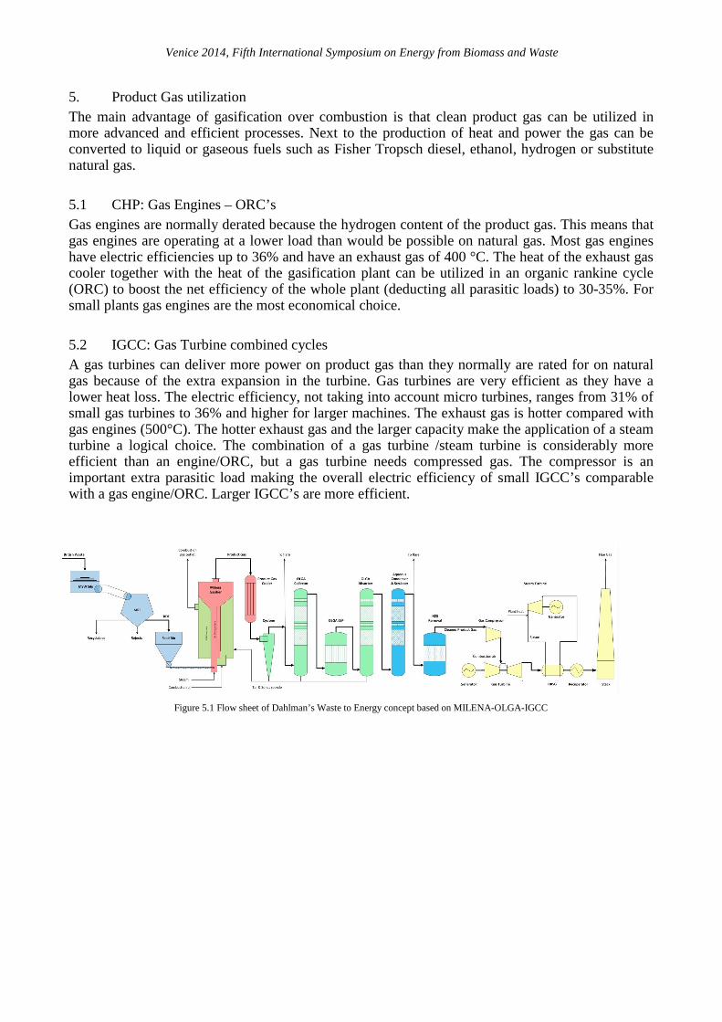
5. Product Gas utilization The main advantage of gasification over combustion is that clean product gas can be utilized in more advanced and efficient processes. Next to the production of heat and power the gas can be converted to liquid or gaseous fuels such as Fisher Tropsch diesel, ethanol, hydrogen or substitute natural gas. 5.1 CHP: Gas Engines – ORC’s Gas engines are normally derated because the hydrogen content of the product gas. This means that gas engines are operating at a lower load than would be possible on natural gas. Most gas engines have electric efficiencies up to 36% and have an exhaust gas of 400 °C. The heat of the exhaust gas cooler together with the heat of the gasification plant can be utilized in an organic rankine cycle (ORC) to boost the net efficiency of the whole plant (deducting all parasitic loads) to 30-35%. For small plants gas engines are the most economical choice. 5.2 IGCC: Gas Turbine combined cycles A gas turbines can deliver more power on product gas than they normally are rated for on natural gas because of the extra expansion in the turbine. Gas turbines are very efficient as they have a lower heat loss. The electric efficiency, not taking into account micro turbines, ranges from 31% of small gas turbines to 36% and higher for larger machines. The exhaust gas is hotter compared with gas engines (500°C). The hotter exhaust gas and the larger capacity make the application of a steam turbine a logical choice. The combination of a gas turbine /steam turbine is considerably more efficient than an engine/ORC, but a gas turbine needs compressed gas. The compressor is an important extra parasitic load making the overall electric efficiency of small IGCC’s comparable with a gas engine/ORC. Larger IGCC’s are more efficient.
Figure 5.1 Flow sheet of Dahlman’s Waste to Energy concept based on MILENA-OLGA-IGCC

Venice 2014, Fifth International Symposium on Energy from Biomass and Waste
5.3 Overall plant efficiencies to heat and power Below we give typical net efficiencies comparing gas utilization in gas engines gas turbines. Where the first red and blue bars shows the combined heat and power efficiency (assuming heat is sold) and the blue only bars show the efficiency when the heat is converted to additional electricity by a combined cycle. In all cases the plants parasitic loads (both heat and electricity) are deducted from the produced heat and power. The produced power by the gas turbine is relatively low as the product gas needs to be compressed causing a high parasitic load. A gas turbine has a considerable lower loss than an engine. This results in a higher heat output. That heat is converted into additional electricity. A steam turbine has a considerably higher efficiency than an organic rankine cycle.
Figure 5.2 Typical MILENA-OLGA CHP-IGCC efficiencies
All cases also deliver useable but lower quality heat. This lower quality heat could be used for residential heating, absorption chillers or fuel drying. Dahlman is selected by the British Energy Technologies Institute as one of three alternative technologies to design the most efficient waste to energy technology possible. www.eti.co.uk
Figure 5.3 Overview of the MILENA-OLGA IGCC plant
Venice 2014, Fifth International Symposium on Energy from Biomass and Waste
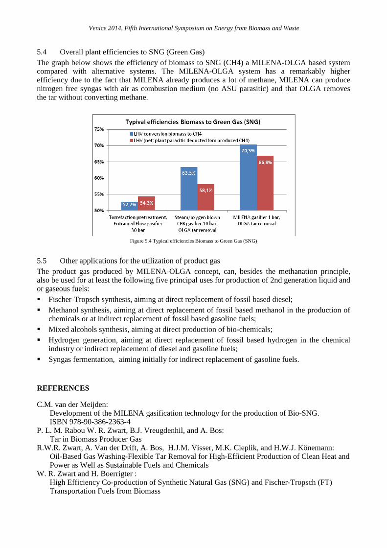
5.4 Overall plant efficiencies to SNG (Green Gas) The graph below shows the efficiency of biomass to SNG (CH4) a MILENA-OLGA based system compared with alternative systems. The MILENA-OLGA system has a remarkably higher efficiency due to the fact that MILENA already produces a lot of methane, MILENA can produce nitrogen free syngas with air as combustion medium (no ASU parasitic) and that OLGA removes the tar without converting methane.
Figure 5.4 Typical efficiencies Biomass to Green Gas (SNG)
5.5 Other applications for the utilization of product gas The product gas produced by MILENA-OLGA concept, can, besides the methanation principle, also be used for at least the following five principal uses for production of 2nd generation liquid and or gaseous fuels: � Fischer-Tropsch synthesis, aiming at direct replacement of fossil based diesel; � Methanol synthesis, aiming at direct replacement of fossil based methanol in the production of
chemicals or at indirect replacement of fossil based gasoline fuels; � Mixed alcohols synthesis, aiming at direct production of bio-chemicals; � Hydrogen generation, aiming at direct replacement of fossil based hydrogen in the chemical
industry or indirect replacement of diesel and gasoline fuels; � Syngas fermentation, aiming initially for indirect replacement of gasoline fuels.
REFERENCES
C.M. van der Meijden: Development of the MILENA gasification technology for the production of Bio-SNG. ISBN 978-90-386-2363-4
P. L. M. Rabou W. R. Zwart, B.J. Vreugdenhil, and A. Bos: Tar in Biomass Producer Gas
R.W.R. Zwart, A. Van der Drift, A. Bos, H.J.M. Visser, M.K. Cieplik, and H.W.J. Könemann: Oil-Based Gas Washing-Flexible Tar Removal for High-Efficient Production of Clean Heat and Power as Well as Sustainable Fuels and Chemicals
W. R. Zwart and H. Boerrigter : High Efficiency Co-production of Synthetic Natural Gas (SNG) and Fischer-Tropsch (FT) Transportation Fuels from Biomass