Embed Size (px)
Citation preview
Advanced Lab Course in EECS I
CS Module (300221-A)
Lecture Notes Fall 2003
Jurgen Schonwalder
December 16, 2003
School of Engineering and Science
International University Bremen
Preface
The computer science module of the advanced EECS laboratory provides and introduction to theconstruction of complex software systems (software engineering). These lecture notes assume thatthe reader is familiar with an object oriented programming language such as C++ or Java.
This lecture notes are derived from a lecture taught at the University of Osnabruck. Some intro-ductionary example were taken from a lecture on fault tolerant systems taught at the TechnicalUniversity Braunschweig. Some parts of the chapters on process models and quality assuranceare taken from lecture notes from introductionary lectures on software engineering taught by Prof.Dr. G. Snelting, Prof. Dr. A. Zeller, Dr. M. Huhn and Dr. A. Zundorf at the Technical UniversityBraunschweig.
Thanks to all students who helped to improve these notes. Special thanks to Elmar Ludwig whoprovided lots of constructive feedback during my time at the University of Osnabruck.
Jurgen Schonwalder


Contents
1 Introduction 11.1 Terminology. . . . . . . . . . . . . . . . . . . . . . . . . . . . . . . . . . . . . . 11.2 Software Crisis . . . . . . . . . . . . . . . . . . . . . . . . . . . . . . . . . . . . 2
1.2.1 Common Problems. . . . . . . . . . . . . . . . . . . . . . . . . . . . . . 21.2.2 Prominent Failures and Catastrophes. . . . . . . . . . . . . . . . . . . . . 3
2 Process Models 52.1 Code and Fix . . . . . . . . . . . . . . . . . . . . . . . . . . . . . . . . . . . . . 52.2 Waterfall Model. . . . . . . . . . . . . . . . . . . . . . . . . . . . . . . . . . . . 6
2.2.1 Planning Phase. . . . . . . . . . . . . . . . . . . . . . . . . . . . . . . . 82.2.2 Definition Phase. . . . . . . . . . . . . . . . . . . . . . . . . . . . . . . 82.2.3 Design Phase. . . . . . . . . . . . . . . . . . . . . . . . . . . . . . . . . 92.2.4 Implementation Phase. . . . . . . . . . . . . . . . . . . . . . . . . . . . 92.2.5 Installation Phase. . . . . . . . . . . . . . . . . . . . . . . . . . . . . . . 92.2.6 Maintenance Phase. . . . . . . . . . . . . . . . . . . . . . . . . . . . . . 10
2.3 V Model . . . . . . . . . . . . . . . . . . . . . . . . . . . . . . . . . . . . . . . . 102.4 Prototyping . . . . . . . . . . . . . . . . . . . . . . . . . . . . . . . . . . . . . . 112.5 Spiral Model . . . . . . . . . . . . . . . . . . . . . . . . . . . . . . . . . . . . . 112.6 Transformational Model . . . . . . . . . . . . . . . . . . . . . . . . . . . . . . . 122.7 Extreme Programming (XP). . . . . . . . . . . . . . . . . . . . . . . . . . . . . 122.8 Capability Maturity Model (CMM). . . . . . . . . . . . . . . . . . . . . . . . . . 15
3 Unified Modeling Language (UML) 173.1 Notices . . . . . . . . . . . . . . . . . . . . . . . . . . . . . . . . . . . . . . . . 173.2 Class Diagrams. . . . . . . . . . . . . . . . . . . . . . . . . . . . . . . . . . . . 18
3.2.1 Classes. . . . . . . . . . . . . . . . . . . . . . . . . . . . . . . . . . . . 183.2.2 Visibility . . . . . . . . . . . . . . . . . . . . . . . . . . . . . . . . . . . 193.2.3 Scopes . . . . . . . . . . . . . . . . . . . . . . . . . . . . . . . . . . . . 193.2.4 Generalization and Specialization. . . . . . . . . . . . . . . . . . . . . . 203.2.5 Abstractness. . . . . . . . . . . . . . . . . . . . . . . . . . . . . . . . . 213.2.6 Aggregation and Composition. . . . . . . . . . . . . . . . . . . . . . . . 213.2.7 Associations . . . . . . . . . . . . . . . . . . . . . . . . . . . . . . . . . 223.2.8 Interfaces and Realizations. . . . . . . . . . . . . . . . . . . . . . . . . . 243.2.9 Dependencies. . . . . . . . . . . . . . . . . . . . . . . . . . . . . . . . . 253.2.10 Objects. . . . . . . . . . . . . . . . . . . . . . . . . . . . . . . . . . . . 25
3.3 Sequence Diagrams. . . . . . . . . . . . . . . . . . . . . . . . . . . . . . . . . . 273.4 Collaboration Diagrams. . . . . . . . . . . . . . . . . . . . . . . . . . . . . . . . 283.5 Statchart Diagrams. . . . . . . . . . . . . . . . . . . . . . . . . . . . . . . . . . 29

CONTENTS
3.6 Activity Diagrams. . . . . . . . . . . . . . . . . . . . . . . . . . . . . . . . . . . 313.7 Use-Case Diagrams. . . . . . . . . . . . . . . . . . . . . . . . . . . . . . . . . . 323.8 Elevator Example. . . . . . . . . . . . . . . . . . . . . . . . . . . . . . . . . . . 35
4 Design Pattern 394.1 Iterator. . . . . . . . . . . . . . . . . . . . . . . . . . . . . . . . . . . . . . . . .424.2 Composite. . . . . . . . . . . . . . . . . . . . . . . . . . . . . . . . . . . . . . . 454.3 Observer. . . . . . . . . . . . . . . . . . . . . . . . . . . . . . . . . . . . . . . . 474.4 Strategy. . . . . . . . . . . . . . . . . . . . . . . . . . . . . . . . . . . . . . . . 534.5 Model View Controller . . . . . . . . . . . . . . . . . . . . . . . . . . . . . . . . 544.6 Anti Pattern: Creeping Featuritis. . . . . . . . . . . . . . . . . . . . . . . . . . . 544.7 Anti Pattern: Design By Committee. . . . . . . . . . . . . . . . . . . . . . . . . 54
5 Quality Assurance 575.1 Typical Software Errors. . . . . . . . . . . . . . . . . . . . . . . . . . . . . . . . 575.2 Program Inspections. . . . . . . . . . . . . . . . . . . . . . . . . . . . . . . . . 575.3 Verification . . . . . . . . . . . . . . . . . . . . . . . . . . . . . . . . . . . . . . 585.4 Testing. . . . . . . . . . . . . . . . . . . . . . . . . . . . . . . . . . . . . . . . .60
5.4.1 Functional Testing. . . . . . . . . . . . . . . . . . . . . . . . . . . . . . 615.4.2 Control-Flow Testing. . . . . . . . . . . . . . . . . . . . . . . . . . . . . 635.4.3 Mutation Testing. . . . . . . . . . . . . . . . . . . . . . . . . . . . . . . 655.4.4 Regression Testing. . . . . . . . . . . . . . . . . . . . . . . . . . . . . . 66
5.5 Software Metrics . . . . . . . . . . . . . . . . . . . . . . . . . . . . . . . . . . . 665.5.1 Fan-in / Fan-out. . . . . . . . . . . . . . . . . . . . . . . . . . . . . . . . 675.5.2 Lines of Code (LOC) / Non-Commented Source Statements (NCSS). . . . 675.5.3 Length of identifiers. . . . . . . . . . . . . . . . . . . . . . . . . . . . . 675.5.4 Fog Index. . . . . . . . . . . . . . . . . . . . . . . . . . . . . . . . . . . 675.5.5 Cyclomatic Complexity . . . . . . . . . . . . . . . . . . . . . . . . . . . 685.5.6 Halstead Metrics. . . . . . . . . . . . . . . . . . . . . . . . . . . . . . . 685.5.7 Object-oriented Metrics. . . . . . . . . . . . . . . . . . . . . . . . . . . 705.5.8 Bad Smelling Code. . . . . . . . . . . . . . . . . . . . . . . . . . . . . . 70
5.6 Visualization . . . . . . . . . . . . . . . . . . . . . . . . . . . . . . . . . . . . . 71
6 Tools 736.1 Program Construction. . . . . . . . . . . . . . . . . . . . . . . . . . . . . . . . . 73
6.1.1 make . . . . . . . . . . . . . . . . . . . . . . . . . . . . . . . . . . . . . 736.1.2 mfg . . . . . . . . . . . . . . . . . . . . . . . . . . . . . . . . . . . . . . 766.1.3 autoconf andautomake . . . . . . . . . . . . . . . . . . . . . . . . . 786.1.4 autoproject . . . . . . . . . . . . . . . . . . . . . . . . . . . . . . . 79
6.2 Differences between Files. . . . . . . . . . . . . . . . . . . . . . . . . . . . . . . 796.2.1 diff . . . . . . . . . . . . . . . . . . . . . . . . . . . . . . . . . . . . . 796.2.2 patch . . . . . . . . . . . . . . . . . . . . . . . . . . . . . . . . . . . . 80
6.3 Version Management. . . . . . . . . . . . . . . . . . . . . . . . . . . . . . . . . 816.3.1 Revision Control System (RCS). . . . . . . . . . . . . . . . . . . . . . . 816.3.2 Concurrent Versions System (CVS). . . . . . . . . . . . . . . . . . . . . 82
6.4 Execution Tracer. . . . . . . . . . . . . . . . . . . . . . . . . . . . . . . . . . . 836.4.1 Tracing System Calls and Signals (strace). . . . . . . . . . . . . . . . . . 836.4.2 Tracing Library Calls (ltrace). . . . . . . . . . . . . . . . . . . . . . . . 83
CONTENTS
6.4.3 Data Display Debugger (ddd). . . . . . . . . . . . . . . . . . . . . . . . 836.4.4 GNU Visual Debugger (gvd). . . . . . . . . . . . . . . . . . . . . . . . . 836.4.5 Memory Debugging Libraries (dmalloc). . . . . . . . . . . . . . . . . . . 846.4.6 Profiler (gprof) . . . . . . . . . . . . . . . . . . . . . . . . . . . . . . . . 84
7 Ergonomic Aspects 877.1 Dialog Types . . . . . . . . . . . . . . . . . . . . . . . . . . . . . . . . . . . . . 887.2 Dialog Requirements. . . . . . . . . . . . . . . . . . . . . . . . . . . . . . . . . 88
7.2.1 Suitability for the Task. . . . . . . . . . . . . . . . . . . . . . . . . . . . 887.2.2 Self Descriptiveness. . . . . . . . . . . . . . . . . . . . . . . . . . . . . 887.2.3 Controllability . . . . . . . . . . . . . . . . . . . . . . . . . . . . . . . . 887.2.4 Conformity with User Expectations. . . . . . . . . . . . . . . . . . . . . 897.2.5 Error Tolerance. . . . . . . . . . . . . . . . . . . . . . . . . . . . . . . . 897.2.6 Suitability for Individualisation . . . . . . . . . . . . . . . . . . . . . . . 897.2.7 Suitability for Learning. . . . . . . . . . . . . . . . . . . . . . . . . . . . 89
8 Empirical Laws 918.1 Requirements Phase. . . . . . . . . . . . . . . . . . . . . . . . . . . . . . . . . . 918.2 System design and specification. . . . . . . . . . . . . . . . . . . . . . . . . . . 928.3 System construction and composition. . . . . . . . . . . . . . . . . . . . . . . . 928.4 Validation and static verification. . . . . . . . . . . . . . . . . . . . . . . . . . . 938.5 Testing and dynamic verification. . . . . . . . . . . . . . . . . . . . . . . . . . . 938.6 System manufacturing, distribution and installation. . . . . . . . . . . . . . . . . 948.7 System administration, evolution and maintenance. . . . . . . . . . . . . . . . . 948.8 Project management and business analysis. . . . . . . . . . . . . . . . . . . . . . 948.9 User skills, motivation, and satisfaction. . . . . . . . . . . . . . . . . . . . . . . 958.10 Technology, architecture, and industry capabilities. . . . . . . . . . . . . . . . . . 958.11 Measurements, experiments, and empirical research. . . . . . . . . . . . . . . . . 96
A Questions 97A.1 Introduction . . . . . . . . . . . . . . . . . . . . . . . . . . . . . . . . . . . . . . 97A.2 Process Models. . . . . . . . . . . . . . . . . . . . . . . . . . . . . . . . . . . . 97A.3 Unified Modeling Language. . . . . . . . . . . . . . . . . . . . . . . . . . . . . 97A.4 Design Pattern. . . . . . . . . . . . . . . . . . . . . . . . . . . . . . . . . . . . . 98A.5 Quality Assurance. . . . . . . . . . . . . . . . . . . . . . . . . . . . . . . . . . . 98A.6 Tools. . . . . . . . . . . . . . . . . . . . . . . . . . . . . . . . . . . . . . . . . .99A.7 Ergonomic Aspects. . . . . . . . . . . . . . . . . . . . . . . . . . . . . . . . . . 99

Chapter 1
Introduction
This document is mainly about software engineering. Software engineering is an application ori-ented field of computer science which somehow bridges the more fundamental computer scienceresearch areas programming languages and formal methods with more business oriented researchfields.
The heart of software engineering is the development of models, methods and tools for the con-trolled development, operation and maintenance of large software systems.
1.1 Terminology
Some important properties of software [1]:
• Software is an immaterial product.Software is not material and cannot be seen or touched. It is therefore much more difficult todetermine whether the documentation of a program matches the executable implementation.
• Software does not age.Software does not change. A program always behaves the same for a given set of input. Thereare no physical processes that cause software to age and hence there is (in principle) no needfor maintenance to replace pieces that do not work anymore.
• Software is not constrained by physical laws.There are no physical laws which constrain what a program can do (except that some classesof problems can’t be solved). A software developer therefore has many degrees of freedomwhen designing a new piece of software.
• Software is easy to change.Well structured and modular software systems enable developers to realize changes easilyand quickly.
• Software systems age.At first glance, this seems to be a contradiction to a previous statement. While it is true thatan isolated piece of software does not change its behavior over time (it always produces thesame correct/incorrect results), it is important to understand that the environment in whichthis piece of software is executed typically changes over time (and sometimes pretty fast).Hence, complex software systems tend to age.
1
2 CHAPTER 1. INTRODUCTION
• Software is difficult to measure.The quality of software is difficult to define and hard to quantify. Exact measurement toolswhich can identify for example the number of errors in a software product do not exist andcan not be build for the general case.
Some definitions of the term software engineering (sometimes also called software technology):
• The goal oriented construction and the systematic usage of principles, methods and tools forthe group-wise development and application of complex software systems. Goal orientedimplies the recognition of factors such as costs, time and quality [1].
• The systematic approach to the development, operation, maintenance, and requirement ofsoftware. (ANSI/IEEE Standard Glossary of Software Engineering Terminology, 1983)
• Software engineering = multi-person construction of multi-version software. (Parnas, 1987)
• The application of a systematic, disciplined, quantifiable approach to the development, op-eration, and maintenance of software; that is, the application of engineering to software.(ANSI/IEEE Standard Glossary of Software Engineering Terminology, 1990)
1.2 Software Crisis
The first very complex commercial software systems were developed during the late 1960s. Duringthat period, it was observed that the known processes, methods and tools for producing softwarecould not be applied successfully to very big development projects. Many projects failed and thislead to the introduction of the termsoftware crisis. The current situation is still not very goodaccording to some empirical research done by Laprie (1999):
• Slighly more than a third of all software projects are finished successfully such that the cus-tomer and the software company are happy with the result.
• One third of the software projects produces products or services that in large parts do notfulfill the requirements of the customers.
• Slightly less than a third of all software projects end without delivering a product or serviceto the customer.
1.2.1 Common Problems
• Size and complexity of software systems
SAP R/3, a widely used enterprise resource planning software, consists of approximately7.000.000 lines of code (written in the high level language Abab or C++), approximately100.000 function calls, approximately 20.000 functions, approximately 14.000 function blocksand approximately 17.000 menus. SAP employs at its main site in Walldorf (Germany) aloneseveral thousand developers.
1.2. SOFTWARE CRISIS 3
• Integration requirements
Almost all software systems today must be able to interact with other technical systems orother software systems to exchange data within a more complex workflow. This is highlightedby marketing terms such as business to business (B2B) or business to customer (B2C) com-munication. Other examples from everyday life are automobiles which increasingly dependon the correct functioning of embedded software systems that interact with the mechanicalparts of an automobile.
• Quality requirements
According to studies by Cusumano from the MIT Sloan School of Management, 1000 linesof source code contained about7 − 20 defects in 1977. In 1994, the number of defects in1000 lines of source code was reduced to0.05 − 0.2 defects. The defect rate was thereforedrastically reduced by a factor of 100 in 15 years. However, even a defect rate of one defectper 1000 lines of code is not really acceptable and comparable to other technologies. Forexample, a technical system which is used to transport humans has to have a defect rate lessthan10−7.
• Flexibility requirements
Software systems have to be design with flexibility in mind. There are two reasons for this:First, product requirements and the components used by a software system will change in thelater phases of the software lifetime. Second, the methods and tools used to construct thesoftware will change during the software lifecycle.
• Portability and internationalization requirements
Application software has a lifetime of about 10-15 years. Given today’s speed of develop-ment, application software has to survive approximately 1-2 major changes of the underlyingsystem software and approximately 3-4 changes of the underlying hardware architecture.
The globalization and the trend towards standard software implies that many variants of agiven piece of software must be created and maintained (support for special hardware plat-forms, localization and support for various character sets, language adaptations in the userinterface, support for diverging laws and regulations in various countries and regions).
• Organizational requirements
Sofware projects usually do not fail because of technical problems. Instead, communicationproblems (between customer and developer or between developers), lack of education, highfluctuation of developers or simply bad project management are often the real reasons behindsoftware project failures.
1.2.2 Prominent Failures and Catastrophes
• Many computer programs developed in the last century stored years as two digit decimalnumbers (e.g., 73 stands for 1973). With the transition from the year 1999 to the year 2000,many problems serious software failures were expected since computations such as 00-73(instead of 2000-1973) lead to unexpected results. This so called year-2000-problem (orshort Y2K problem) lead to huge costs since many old and (sometimes very old) programshad to be tested and sometimes needed fixes.
4 CHAPTER 1. INTRODUCTION
• Instability of widely used office software and the presence of a large number of security holesin widely used software products.
• The loss of the Mars-Climate-Orbiters in September 1999 was caused by incompatible soft-ware modules. NASA asked two companies to develop software components for the naviga-tion system. One company used the metric system while the other used the British / UnitedStates system. The usage of different metric systems was known and conversions were writ-ten in almost all interfaces between these components. However, during the approach toMars, an interaction between the components without the necessary conversion caused theorbiter to come to close to Mars and it got lost.
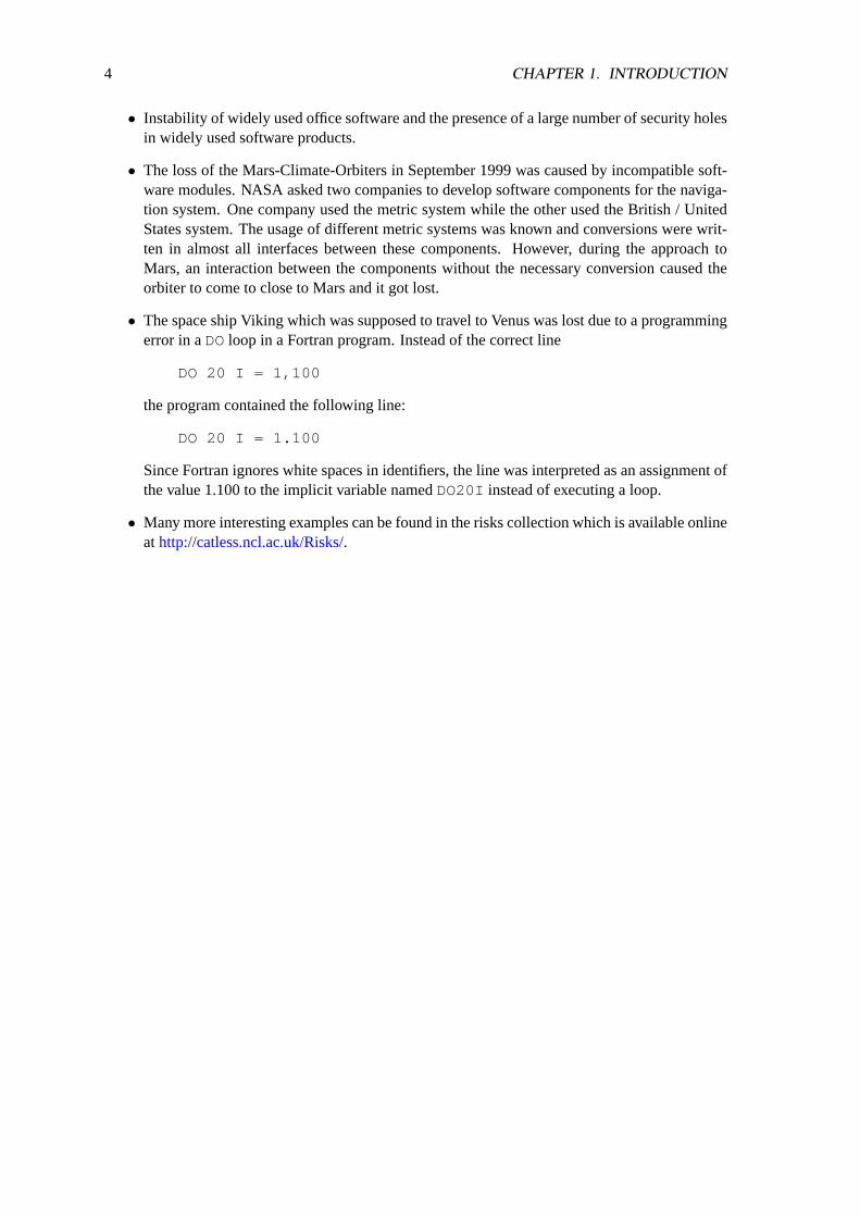
• The space ship Viking which was supposed to travel to Venus was lost due to a programmingerror in aDOloop in a Fortran program. Instead of the correct line
DO 20 I = 1,100
the program contained the following line:
DO 20 I = 1.100
Since Fortran ignores white spaces in identifiers, the line was interpreted as an assignment ofthe value 1.100 to the implicit variable namedDO20I instead of executing a loop.
• Many more interesting examples can be found in the risks collection which is available onlineathttp://catless.ncl.ac.uk/Risks/.

Chapter 2
Process Models
The systematic development of software requires rules to organize the development process andto make the process repeatable. Aprocess modeldefines the organizational framework for thedevelopment and maintenance of software. Process models define the activities that have to becarried out, the order of these activities, who will be involved in these activities, the results producedand how the quality of these results can be assessed.
• The various activities defined by a process model will be carried out by persons who act incertainroles.
• The results produced by carrying out activities are called artifacts. An artifact is an artificialfact produced by human imagination.
• Format and structure of the artifacts are determined by templates.
• A process model defines responsibilities and competencies.
• A process model defines rules, methods and tools that are to be used during the developmentand maintenance of software.
Many process models have been suggested and tested over the years and there is no single processmodel that works best for all projects. It is therefore crucial that every organization develops itsown models (typically variations of the well-known process models) and chooses the right modelfor a given project and development team.
2.1 Code and Fix
The simplest process model is the code-and-fix approach, where every developer implements func-tions without following any process model. The implemented software components are tested usingan ad-hoc approach.
This model is probably well known by students since this is the model typically used to solveprogramming exercises. This process model is indeed suitable for small projects. However, thisapproach fails for bigger projects where multiple people construct software together and wheresoftware needs to be maintained for a long period of time.
5

6 CHAPTER 2. PROCESS MODELS
TestImproveExtend
Implement
Figure 2.1: Code-and-fix process model
Assessment:
+ Suitable for single person projects which can be realized in some weeks and in cases wherethe developer and the user are the same person.
- The maintainability of the software is reduced with increasing size.
- Error probability when the software is maintained.
- Missing documentation often leads to a situation where only the developer understand theinternals of the software, which causes problems if this developer leaves the organization orin periods of illness.
- Tests and improvements are often not sufficient.
- The resulting software often does not address the requirements of the customers (except incases where the developer is also the customer).
⇒ Larger projects can not be implemented using the code-and-fix approach.
2.2 Waterfall Model
The Waterfall Model is the classic model for a structured software development approach. It ap-pears in the literature in many different variations. The name suggests that the development ofsoftware happens in multiple phases and that a new phase only starts if the previous phase has beencompleted. Of course, a very strict waterfall model, where it is impossible to go back to previousphases, is not very suitable. Hence there is a mechanism to go back to previous phases if there is aneed for doing so.

2.2. WATERFALL MODEL 7
Requirements
Design Document
Source code, Documentation,
Object Programm, Test Protocol
Installation Protocol
Planning Phase
Definition Phase
ImplementationPhase
Installation Phase
Design Phase
Maintenance Phase
Feasability Study
Figure 2.2: Waterfall process model
Remarks:
• Fundamental model with many variants.
• Some variants have additional phases (for example, the implementation phase might be splitinto an implementation phase and an integration phase).
• Every phase has to be fully completed and it is not allowed to skip any phases.
• Every phase ends with the creation of a document which describes the results produced bythat phase.
• Oriented on the top-down development approach.
• Possibility to go back to previous phases if fundamental flaws or inconsistencies are detected.
Assessment:
+ Easy to understand process model.

8 CHAPTER 2. PROCESS MODELS
+ Separation of the “what” from the “how.”
- Customers only participate in the definition phase.
- High costs if the specification does not correctly describe the customer expectations.
- Fixed process model: It is sometimes useful to skip some phases or to realize some phasesnot in strictly sequential order.
- Focusses on the development aspects; Criteria such as extensibility and adaptability are notwell recognized.
2.2.1 Planning Phase
The planning phase of a new software product includes the following activities:
• Selection of the product based on trend studies, market analysis, research results, customersurveys, pre-developments
• Product evaluation based on a market analysis and the defined main product requirement andthe expected performance and quality measures.
• Feasibility study (overall feasibility of the project, available resources, alternatives, evalua-tion of organizational preconditions).
The result of this phase is afeasibility studyconsisting of the following artefacts:
• Requirements document
• Glossary
• Project calculation
• Project plan
2.2.2 Definition Phase
During the definition phase of a software project, the detailed requirements will be defined.
• Investigation of the detailed requirements.
• Analysis and documentation of the requirements.
• Modeling, Simulation, Animation.
The result of the definition phase is a textual description of the requirements in form of arequire-ments document.
- The requirements document explainswhat the product will do and with which quality mea-sures. It does not definehowthe product does it.
- The requirements document should be easy to understand and it should be non-ambiguousfor both groups, the customers and the developers.
- The requirements document should be consistent and complete.

2.2. WATERFALL MODEL 9
2.2.3 Design Phase
The design phase (also called programming-in-the-large) includes the following activities:
• Definition of the software architecture (division of the system into system components).
• Determination of boundary conditions and applicability definitions.
• Specification of the system components.
The result of this phase is theproduct designwhich consists of the software architecture and thespecification of the system components.
2.2.4 Implementation Phase
The implementation phase (also called programming-in-the-small) includes the following activities:
• Selection of data structures and algorithms.
• Introduction of additional software layers for structuring the program.
• Documentation of the selected solutions and the design decisions.
• Definition of the time or memory complexity or other boundary conditions.
• Coding in a suitable programming language.
• Test or verification of the program.
The result of the implementation phase is the source code (inclusive any integrated documentation),the executable program, the definition of test cases and a test protocol.
2.2.5 Installation Phase
The installation phase is concerned with the installation of the product on customer sites. Theinstallation phase is typically organized in multiple steps:
• During the first step, the product is delivered to selected customers which report experiencesand observed errors (beta test).
• Once the versions under beta test run stable and without any remaining frequently observederrors, the product is delivered to all customers.
The installation typically ends in a test. A formal protocol is made which documents that thesystem is working according to the requirements fixed in the contract between the customer and thesoftware company.
10 CHAPTER 2. PROCESS MODELS
2.2.6 Maintenance Phase
The activities during the maintenance phase can be categorized as follows:
• Stabilization and corrections
• Optimizations and performance improvements
• Adaptations and extensions
The maintenance costs often exceed the development costs by a factor of 2-4. It is therefore impor-tant to consider the maintainability of the software product throughout the development process.
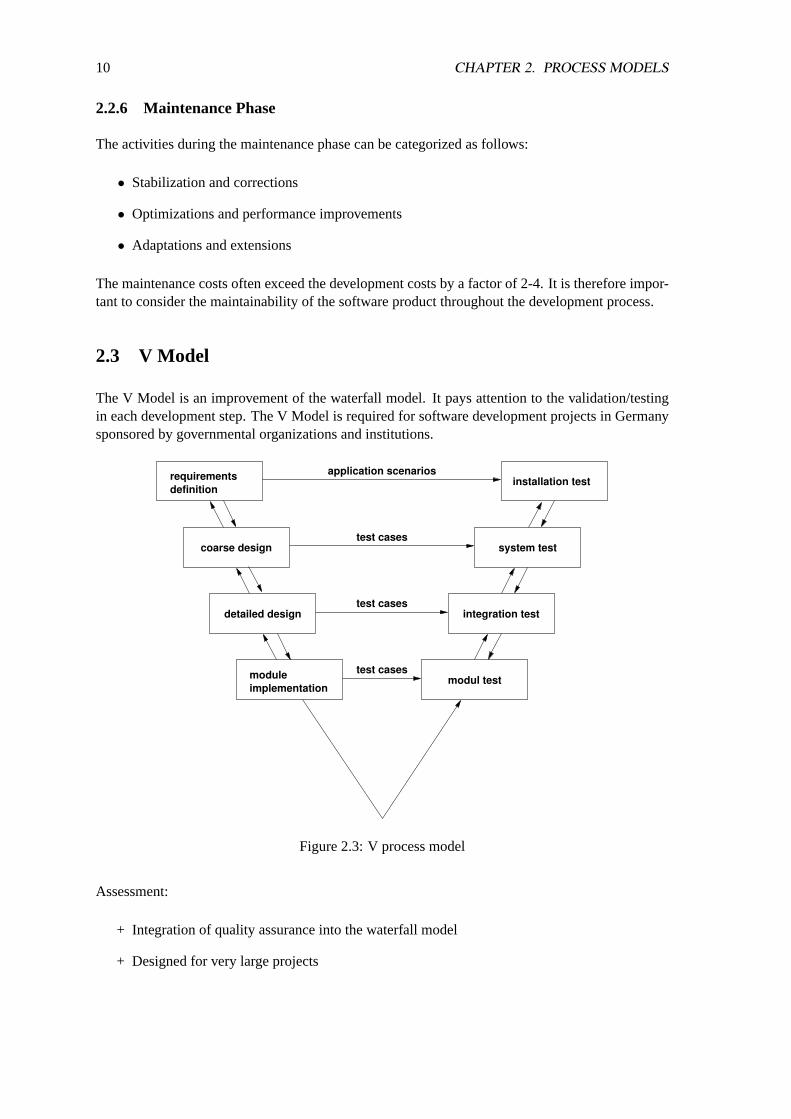
2.3 V Model
The V Model is an improvement of the waterfall model. It pays attention to the validation/testingin each development step. The V Model is required for software development projects in Germanysponsored by governmental organizations and institutions.
requirementsdefinition
module
detailed designtest cases
test cases
test cases
application scenariosinstallation test
system test
integration test
modul testimplementation
coarse design
Figure 2.3: V process model
Assessment:
+ Integration of quality assurance into the waterfall model
+ Designed for very large projects
2.4. PROTOTYPING 11
- Significant overhead for small and medium size projects
- Strict phases that must be passed sequentially
- Limited support by tools
2.4 Prototyping
The prototyping approach tries to gain early in the process valuable feedback from users/customersby developing prototypes of the system with reduced functionality, performance and quality.
• A demonstration prototypeis mainly used to acquire customers. Demonstration prototypesare often developed using program generators or high-level script languages.
• A horizontal prototypeimplements specific layer(s) of a layered software system (e.g., theuser interface). The selected layer(s) are implemented with a high degree of completeness.
• A vertical prototypeimplements a small subset of the functionality of the whole system. Theselected subset is implemented in all layers of a layered software system.
• A pilot systemis a prototype which forms the kernel of the final product. A pilot system is notused for evaluation or demonstration purposes. A pilot system can help to prepare customersfor the integration of the final software into the organization.
Assessment:
+ Customers receive relatively quickly a prototype system for experimentation.
+ Experiences with the prototype and requests for changes can be integrated early into thedesign which usually reduces the costs.
- There is a risk to fall back into the code-and-fix model.
- There is a risk to turn the prototype into the final product, which might maintenance veryexpensive since a prototype is typically not cleanly designed.
2.5 Spiral Model
The Spiral-Model is an evolutionary Model. In the first iteration, core components are identified,designed and implemented. More less important components are added in subsequent iterations.
• It is necessary to anticipate future extension while specifying and designing the core compo-nents.
• The software architecture must be open for extensions.
• It should be checked during each iteration whether existing components can be reused or ifstandard software can be used.

12 CHAPTER 2. PROCESS MODELS
The following steps are executed for every sub-projects and every iteration:
1. Requirements definition
2. Evaluation of alternatives and risks
3. Design, implementation and test of the component according to a suitable process model
4. Evaluation and preparation for the next iteration
Assessment:
+ Risk minimization in all phases and sub-projects.
+ Components can be developed using the process model most suitable for the component.
+ Ongoing evaluation and correction of the results achieved in the development process.
+ Supports and enhances reuse of existing components.
- High management overhead.
- With many iterations, there is a risk to loose the separation of the phases.
2.6 Transformational Model
The Transformational Model assumes a formal specification which is developed early in the designprocess. A series of transformations are then used to transform the specification into an executableprogram without changing the semantics contained in the formal specification. Design decisionscan be made to optimize transformations in order to improve non-functional aspects of the finalprogram.
Assessment:
+ High degree of automation
+ If the specification is correct and the transformations are correct, then the resulting imple-mentation will also be correct.
- Practically used in special application domains (e.g., code generation from state-charts, im-plementation of communication protocols).
- Requires highly skilled persons and is mostly used only in small projects.
2.7 Extreme Programming (XP)
Extreme Programming (XP) was proposed in the late 1990s as an alternative to the traditionalprocess models which are relatively static and which offer only little flexibility [2]. Extreme pro-gramming is an approach for mainly small projects (10-15 developers). It is based on twelve socalled practices:
2.7. EXTREME PROGRAMMING (XP) 13
1. Small Releases
• XP uses a highly iterative development process with a release cycle of 1-3 months.
• A release consists of several iterations. An iteration has a duration of 1-3 weeks.
• Iterations are organized in work packages of 1-3 days.
• The customer can determine derivations from his requirements and request correctionsat the end of each iteration.
2. Planning Game
• Customers describe new functions to be realized in the next iteration in form of a “userstory” and assign priorities to them.
• Developers estimate the costs for the realization of each story.
• The customer finally decides which story is being implemented in the next iteration.
• Sometimes it is necessary to repeat the planning game until a realistic plan for the nextiteration has been developed.
3. Tests-Driven Development
• Automated testing is a central concept of XP.
• Developers write test cases for their classes, packages and modules (unit tests).
• Customers develop test cases for every story (functional tests).
• Note: Developers write unit test cases before they start to implement the unit (class orpackage or module).
4. System Metaphor
• A system metaphor is used to convey the fundamental idea behind the software archi-tecture. The metaphor is known by customers and developers and is typically takenfrom the everyday world.
• The system metaphor replaces the document describing the software architecture andhelps to simplify the communication between developers and customers.
• An example is the desktop metaphor for graphical user interfaces where the screen isorganized like a real desktop.
5. Simple Designs
• Developer always choose the simplest solution that could possibly work.
• Requirements can chance quickly. This implies that for example features that increasegenerality might be obsolete in a few days.
• If it turns out later that a more generic solution is favorable, then the software is refac-tored.
6. Refactoring
• Refactoring serves to streamline and simplify the design without changing the semantics(e.g., elimination of duplicated redundant source code).
• Refactoring achieves improved readability and maintainability of the source code.

14 CHAPTER 2. PROCESS MODELS
• The availability of an encompassing test suite allows to check with a high probabilitythat no errors were introduced during the refactoring process.
• The source code should to a high degree be self explanatory so that no other documen-tation is needed to understand the system.
7. Pair Programming
• Programmers always work in pairs in front of a single computer.
• One of the two programmer usually writes new code. The other programmer inspectsthe new to determine whether the new code contains logical errors, whether it fits to thesystem metaphor or whether more tests are needed.
• The pairs of programmers working together change over time. This increases the ex-change of knowledge of various aspects of the software system.
• According to some studies, programming in pairs moderately increases costs but resultsin much more readable source code which has fewer bugs.
8. Collective Code Ownership
• The source code is owned collectively by all developers in the project. This implies thata developer can improve the source code or test cases in all parts of the projects withouthaving to consult other developers first.
9. Continuous Integration
• Newly developed or modified source code is continuously integrated into the centralsource code archive (at least once per work day).
• All tests must be passed successfully after the integration.
10. 40 Hour Week
• Pair programming is very productive and requires a high degree of concentration forboth partners.
• Programmers should therefore have regular working times in the order of 40 hours perweek.
11. Customer Integration
• Due to a lack of a software specification, there will be many questions raised during thedevelopment process which the customer has to answer.
• It is therefore desirable to have a customer representative available for the developersduring the whole process. In the ideal case, the customer representative move his workplace temporarily to the organization developing the software.
12. Coding Standards
• All developers write code which is consistent with previously agreed coding standards.
• The use of common coding standards ensures that source code is consistently formattedand that it can be easily understood and changed.
Assessment:
2.8. CAPABILITY MATURITY MODEL (CMM) 15
+ Simple process model which works well for small software projects.
+ Customer demands have direct influence on the development process.
+ Increases the happiness and motivation of the developers.
- Lack of an explicit specifications makes it difficult to integrate new developers into the teamlater.
- The implementation of the extreme programming process model is not too well documentedand experiences with it are still being obtained.
- The concept of a system metaphor is rather vague.
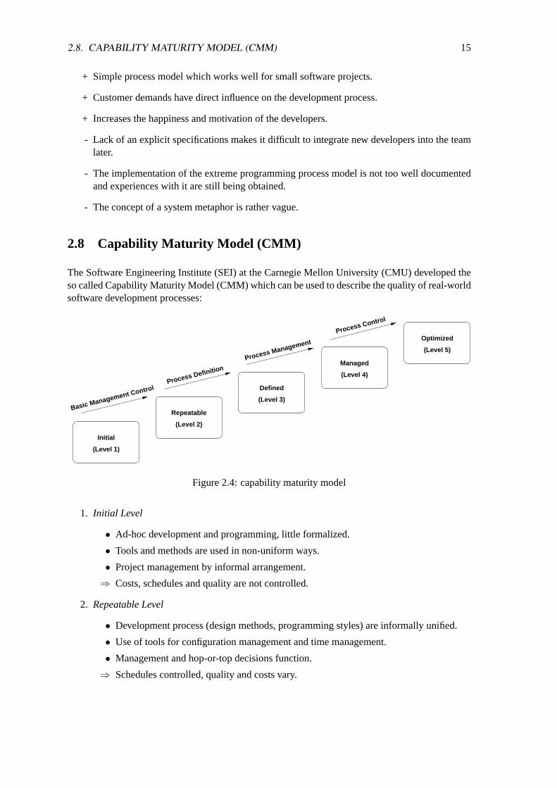
2.8 Capability Maturity Model (CMM)
The Software Engineering Institute (SEI) at the Carnegie Mellon University (CMU) developed theso called Capability Maturity Model (CMM) which can be used to describe the quality of real-worldsoftware development processes:
(Level 1)
Initial
(Level 2)
Repeatable
(Level 3)
Defined
(Level 4)
Managed
(Level 5)
Optimized
Basic Management ControlProcess Definition
Process Management
Process Control
Figure 2.4: capability maturity model
1. Initial Level
• Ad-hoc development and programming, little formalized.
• Tools and methods are used in non-uniform ways.
• Project management by informal arrangement.
⇒ Costs, schedules and quality are not controlled.
2. Repeatable Level
• Development process (design methods, programming styles) are informally unified.
• Use of tools for configuration management and time management.
• Management and hop-or-top decisions function.
⇒ Schedules controlled, quality and costs vary.
16 CHAPTER 2. PROCESS MODELS
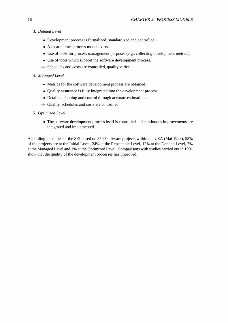
3. Defined Level
• Development process is formalized, standardized and controlled.
• A clear defines process model exists.
• Use of tools for process management purposes (e.g., collecting development metrics).
• Use of tools which support the software development process.
⇒ Schedules and costs are controlled, quality varies.
4. Managed Level
• Metrics for the software development process are obtained.
• Quality assurance is fully integrated into the development process.
• Detailed planning and control through accurate estimations.
⇒ Quality, schedules and costs are controlled.
5. Optimized Level
• The software development process itself is controlled and continuous improvements areintegrated and implemented.
According to studies of the SEI based on 3500 software projects within the USA (Mai 1998), 58%of the projects are at the Initial Level, 24% at the Repeatable Level, 12% at the Defined Level, 2%at the Managed Level and 1% at the Optimized Level. Comparisons with studies carried out in 1991show that the quality of the development processes has improved.

Chapter 3
Unified Modeling Language (UML)
The Unified Modeling Language [3, 11] is a graphical language for blueprints of software systems.UML can be used to model, specify, visualize and document artefacts of a software system. Itis an object-oriented visual modeling language which is not bound to a concrete implementationlanguage.
UML provides several different diagram types. The most commonly used diagrams are discussedin the following sections. Note that this discussion is not complete in all details and it is thusrecommended to look into the UML specification or specific text books for further details whenneeded.
In general, UML diagrams should be focussed on a certain aspect and irrelevant details should beavoided. This rule of thumb increases the readability of the diagrams and thus their usefulness.
Although UML is a rather young graphical modeling language, there are already several versionsthat differ in some of the details. The examples in this script were originally written based onversion 1.3 of the UML but should not be consistent with version 1.4 of the UML.
3.1 Notices
The simplest graphical element is the notice which can be used in all UML diagram types. Figure3.1shows how a notice is represented.
This is a simple notice.
Figure 3.1: Notice UML diagram element
Notices contain some additional text and can be put anywhere. They serve the same purposes ascomments in programming languages. And like comments in programming languages, they shouldbe used wisely (do not use notices to explain the obvious).
17
18 CHAPTER 3. UNIFIED MODELING LANGUAGE (UML)
3.2 Class Diagrams
Class diagrams are the most widely known UML diagram type. They document the structuralproperties and relationships of classes in an object-oriented model. A class is the definition of theattributes, the operations and the semantics of a set of similar objects (instances). All instances of aclass conform to the class definition.
3.2.1 Classes
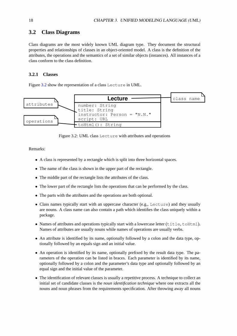
Figure3.2show the representation of a classLecture in UML.
Lecture number: String title: String instructor: Person = "N.N." script: URL toHtml(): String
attributes
operations
class name
Figure 3.2: UML classLecture with attributes and operations
Remarks:
• A class is represented by a rectangle which is split into three horizontal spaces.
• The name of the class is shown in the upper part of the rectangle.
• The middle part of the rectangle lists the attributes of the class.
• The lower part of the rectangle lists the operations that can be performed by the class.
• The parts with the attributes and the operations are both optional.
• Class names typically start with an uppercase character (e.g.,Lecture ) and they usuallyare nouns. A class name can also contain a path which identifies the class uniquely within apackage.
• Names of attributes and operations typically start with a lowercase letter (title , toHtml ).Names of attributes are usually nouns while names of operations are usually verbs.
• An attribute is identified by its name, optionally followed by a colon and the data type, op-tionally followed by an equals sign and an initial value.
• An operation is identified by its name, optionally prefixed by the result data type. The pa-rameters of the operation can be listed in braces. Each parameter is identified by its name,optionally followed by a colon and the parameter’s data type and optionally followed by anequal sign and the initial value of the parameter.
• The identification of relevant classes is usually a repetitive process. A technique to collect aninitial set of candidate classes is thenoun identification techniquewhere one extracts all thenouns and noun phrases from the requirements specification. After throwing away all nouns
3.2. CLASS DIAGRAMS 19
that are not relevant, one usually ends up with a set of things that need to be modelled. It isin particular important to identify
– physical things or things from reality (e.g., lectures, persons, rooms)
– roles (e.g., instructor, student, registrar),
– events (e.g., enrollment, subscription), and
– interactions (e.g., meetings).
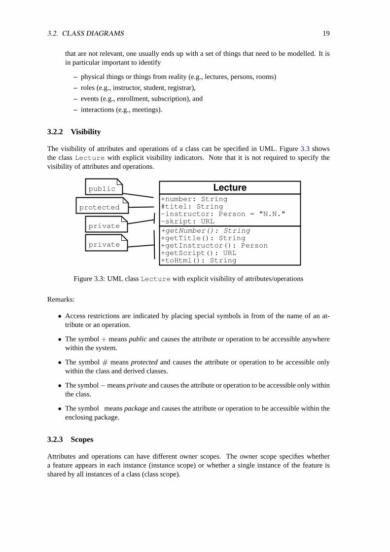
3.2.2 Visibility
The visibility of attributes and operations of a class can be specified in UML. Figure3.3 showsthe classLecture with explicit visibility indicators. Note that it is not required to specify thevisibility of attributes and operations.
Lecture+number: String#titel: String-instructor: Person = "N.N."-skript: URL+getNumber(): String+getTitle(): String+getInstructor(): Person+getScript(): URL+toHtml(): String
public
protected
private
private
Figure 3.3: UML classLecture with explicit visibility of attributes/operations
Remarks:
• Access restrictions are indicated by placing special symbols in from of the name of an at-tribute or an operation.
• The symbol+ meanspublic and causes the attribute or operation to be accessible anywherewithin the system.
• The symbol# meansprotectedand causes the attribute or operation to be accessible onlywithin the class and derived classes.
• The symbol−meansprivateand causes the attribute or operation to be accessible only withinthe class.
• The symbol meanspackageand causes the attribute or operation to be accessible within theenclosing package.
3.2.3 Scopes
Attributes and operations can have different owner scopes. The owner scope specifies whethera feature appears in each instance (instance scope) or whether a single instance of the feature isshared by all instances of a class (class scope).

20 CHAPTER 3. UNIFIED MODELING LANGUAGE (UML)
Lecture+number: String#titel: String-instructor: Person = "N.N."-skript: URL-total: Unsigned = 0+getNumber(): String+getTitle(): String+getInstructor(): Person+getScript(): URL+toHtml(): String+getTotal(): Unsigned
class attribute
class operation
Figure 3.4: UML classLecture width class attributes and class operations
Remarks:
• Attributes, which only exist once for all instances of a class, are identified by underlining theattribute name.
• Operations, which only exist once for all instances of a class, are identified by underliningthe operation name.
3.2.4 Generalization and Specialization
Generalizations and specializations are very fundamental abstraction principles. Generalization isthe process of describing specific elements in terms of a more general concept. Specialization isthe process of deriving more specific elements from a more general concept. The more specificelement often adds specific attributes and operations to the more general element. Note that thespecific element should always behave like the more general element.
Figure 3.5: UML classCourse as a generalization of the classesLecture , Lab andSeminar .
Remarks:
3.2. CLASS DIAGRAMS 21
• Generalizations / Specializations are represented by arrows with an empty head. The head ofthe array points to the more general class.
• An object of a specialized class can replace an object of the more general class in everycontext in which an object of the more general class is expected.
• A simple test whether objectu of classU is a specialization of an objectg of the classG isto ask whetheru is-aG (is-a relationship).
• Generalization and specialization is typically supported by means of inheritance in object-oriented programming languages. Note that inheritance is an implementation technique.Sometimes it is useful to implement generalizations/specializations with other techniquessuch as composition (for example to avoid a too strong coupling between classes).
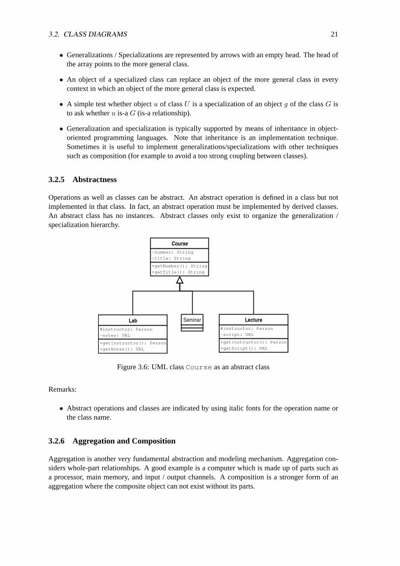
3.2.5 Abstractness
Operations as well as classes can be abstract. An abstract operation is defined in a class but notimplemented in that class. In fact, an abstract operation must be implemented by derived classes.An abstract class has no instances. Abstract classes only exist to organize the generalization /specialization hierarchy.
Figure 3.6: UML classCourse as an abstract class
Remarks:
• Abstract operations and classes are indicated by using italic fonts for the operation name orthe class name.
3.2.6 Aggregation and Composition
Aggregation is another very fundamental abstraction and modeling mechanism. Aggregation con-siders whole-part relationships. A good example is a computer which is made up of parts such asa processor, main memory, and input / output channels. A composition is a stronger form of anaggregation where the composite object can not exist without its parts.

22 CHAPTER 3. UNIFIED MODELING LANGUAGE (UML)
Figure 3.7: UML classCourseCatalog as an aggregation ofCourse s
Remarks:
• Aggregations are represented by lines that end in an empty diamond. The diamond points tothe aggregate object.
• Compositions are represented like aggregations except that the diamond is filled to indicate acomposition.
• A typical example for a composition is a chess board which consists of a number of fields.The chess board obviously cannot exist without the fields.
3.2.7 Associations
Associations are the most generic mechanism to represent relationships between classes. General-izations / specializations and aggregations / compositions are specific associations.
Figure 3.8: UML classPerson and associationsteaches andworks for
Remarks:
3.2. CLASS DIAGRAMS 23
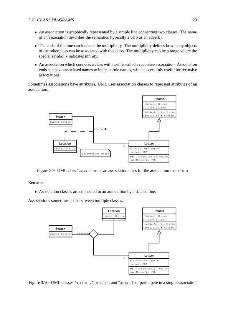
• An association is graphically represented by a simple line connecting two classes. The nameof an association describes the semantics (typically a verb or an adverb).
• The ends of the line can indicate the multiplicity. The multiplicity defines how many objectsof the other class can be associated with this class. The multiplicity can be a range where thespecial symbol∗ indicates infinity.
• An association which connects a class with itself is called a recursive association. Associationends can have associated names to indicate role names, which is certainly useful for recursiveassociations.
Sometimes associations have attributes. UML uses association classes to represent attributes of anassociation.
Figure 3.9: UML classLocation as an association class for the associationteaches
Remarks:
• Association classes are connected to an association by a dashed line.
Associations sometimes exist between multiple classes.
Figure 3.10: UML classesPerson , Lecture andLocation participate in a single association
24 CHAPTER 3. UNIFIED MODELING LANGUAGE (UML)
Remarks:
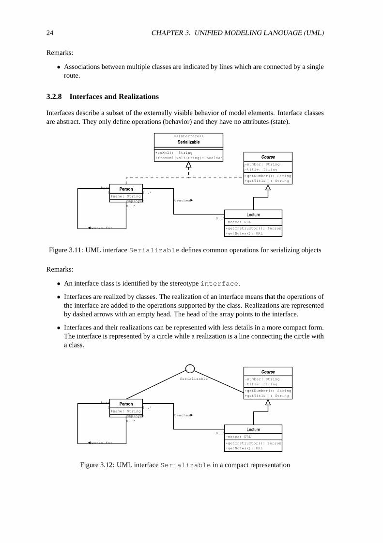
• Associations between multiple classes are indicated by lines which are connected by a singleroute.
3.2.8 Interfaces and Realizations
Interfaces describe a subset of the externally visible behavior of model elements. Interface classesare abstract. They only define operations (behavior) and they have no attributes (state).
Figure 3.11: UML interfaceSerializable defines common operations for serializing objects
Remarks:
• An interface class is identified by the stereotypeinterface .
• Interfaces are realized by classes. The realization of an interface means that the operations ofthe interface are added to the operations supported by the class. Realizations are representedby dashed arrows with an empty head. The head of the array points to the interface.
• Interfaces and their realizations can be represented with less details in a more compact form.The interface is represented by a circle while a realization is a line connecting the circle witha class.
Figure 3.12: UML interfaceSerializable in a compact representation

3.2. CLASS DIAGRAMS 25
3.2.9 Dependencies
A dependency is a relationship between two model elements which indicates that a change in theindependent element might cause changes in the dependent element. Dependencies are concernedwith model elements and not with instances of model elements.
Remarks:
• Dependencies are represented by dashed arrows pointing from the depending element to theelement it depends on.
• Dependencies are frequently created by introducing classes which depend on some otherclasses or interfaces. A chance of classes or interfaces can cause changes in dependentclasses. Note that dependencies between classes and interfaces are typically not spelled outexplicitly.
3.2.10 Objects
Objects are concrete instances of classes. Object diagrams represent a snapshot of a system ata given point in time. Figure3.13 shows a concrete instantiation of the classesPerson andLecture and the associationteaches .
Figure 3.13: UML object diagram for the classesLecture andPerson
Remarks:
• Objects are represented by rectangles.
• The name of the object is shown in the upper part of the rectangle. The name is underlined todistinguish objects from classes.
• Object names typically start with a lowercase letter. The indication of the class name, sepa-rated from the object name by a colon, is optional.
• The values contained in the object’s attributes can be shown in the bottom half of the rectan-gle. For each relevant attribute, a line of the formname = value is added.

26 CHAPTER 3. UNIFIED MODELING LANGUAGE (UML)
The diagram shown in Figure3.13can be displayed in a more compact way by omitting the detailsas shown in Figure3.14.
Figure 3.14: UML compact object diagram for the classesLecture andPerson
It is also possible to use so called multi-objects for sets of objects of the same type as shown inFigure3.15.
Figure 3.15: UML multi-object diagram for the classesLecture andPerson
3.3. SEQUENCE DIAGRAMS 27
3.3 Sequence Diagrams
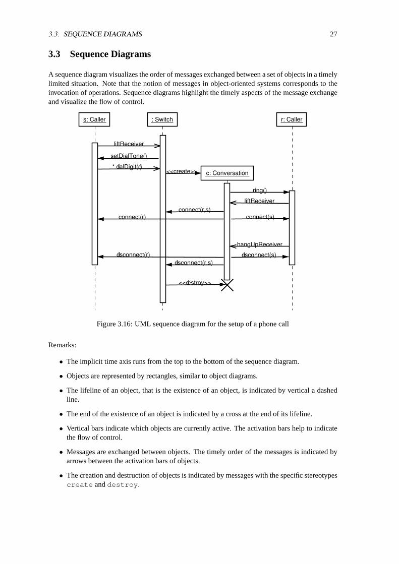
A sequence diagram visualizes the order of messages exchanged between a set of objects in a timelylimited situation. Note that the notion of messages in object-oriented systems corresponds to theinvocation of operations. Sequence diagrams highlight the timely aspects of the message exchangeand visualize the flow of control.
s: Caller : Switch r: Caller
c: Conversation
liftReceiver
setDialTone()
* dialDigit(d)<<create>>
ring()
liftReceiver
connect(s)connect(r,s)
hangUpReceiver
disconnect(r,s)disconnect(s)
<<destroy>>
disconnect(r)
connect(r)
Figure 3.16: UML sequence diagram for the setup of a phone call
Remarks:
• The implicit time axis runs from the top to the bottom of the sequence diagram.
• Objects are represented by rectangles, similar to object diagrams.
• The lifeline of an object, that is the existence of an object, is indicated by vertical a dashedline.
• The end of the existence of an object is indicated by a cross at the end of its lifeline.
• Vertical bars indicate which objects are currently active. The activation bars help to indicatethe flow of control.
• Messages are exchanged between objects. The timely order of the messages is indicated byarrows between the activation bars of objects.
• The creation and destruction of objects is indicated by messages with the specific stereotypescreate anddestroy .
28 CHAPTER 3. UNIFIED MODELING LANGUAGE (UML)
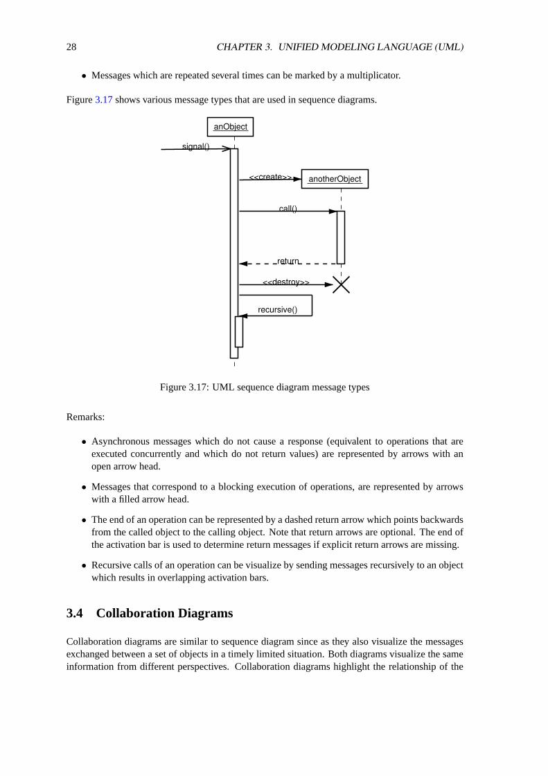
• Messages which are repeated several times can be marked by a multiplicator.
Figure3.17shows various message types that are used in sequence diagrams.
call()
<<create>>
<<destroy>>
return
signal()
recursive()
anotherObject
anObject
Figure 3.17: UML sequence diagram message types
Remarks:
• Asynchronous messages which do not cause a response (equivalent to operations that areexecuted concurrently and which do not return values) are represented by arrows with anopen arrow head.
• Messages that correspond to a blocking execution of operations, are represented by arrowswith a filled arrow head.
• The end of an operation can be represented by a dashed return arrow which points backwardsfrom the called object to the calling object. Note that return arrows are optional. The end ofthe activation bar is used to determine return messages if explicit return arrows are missing.
• Recursive calls of an operation can be visualize by sending messages recursively to an objectwhich results in overlapping activation bars.
3.4 Collaboration Diagrams
Collaboration diagrams are similar to sequence diagram since as they also visualize the messagesexchanged between a set of objects in a timely limited situation. Both diagrams visualize the sameinformation from different perspectives. Collaboration diagrams highlight the relationship of the

3.5. STATCHART DIAGRAMS 29
objects involved and their topography. The ordering aspect is or secondary importance in collabo-ration diagrams.
s: Caller
: Switch
r: Caller
c: Conversation
1: liftReceiver2: *dialDigit(d)
2.1: <<create>>2.2: <<destroy>>
2.1.1: ring()2.1.4: connect()2.1.6: disconnect()
2.1.2: connect()2.1.7: disconnect()
2.1.1.1: liftReceiver2.1.4.1: hangUpReceiver
2.1.3: connect()2.1.5: disconnect()
1.1: setDialTone()
Figure 3.18: UML collaboration diagram for the setup of a phone call
Remarks:
• The timely ordering of messages is indicated by means of a hierarchical numbering scheme.
• The name of a message typically indicates the operation that is called on the receiving object.Parameter are optionally indicated in parenthesis.
• Sequence diagrams can be transformed into collaboration diagrams and vice versa.
• The focus of both diagram types and thus the number of details displayed is however oftendifferent.
3.5 Statchart Diagrams
Statechart diagrams are used to visualize state machines. States are represented by named roundedrectangles. Possible transitions between states are represented by arrows. States can be complexand might be described by other internal statechart diagrams. The example shown in Figure3.19describes a state machine of a simple air conditioning system.

30 CHAPTER 3. UNIFIED MODELING LANGUAGE (UML)
idle
cooling heating
tooCold
atTemp
tooHot
atTemp
tooHot
tooCold
powerOn powerOff
Figure 3.19: UML statechart diagram for a simple air conditioning system
Remarks:
• The initial state is indicated by a filled circle. The final state is in indicated by a filled circlesurrounded by another circle.
• Arrows indicating transitions can be labelled with the events that cause the transition.
3.6. ACTIVITY DIAGRAMS 31
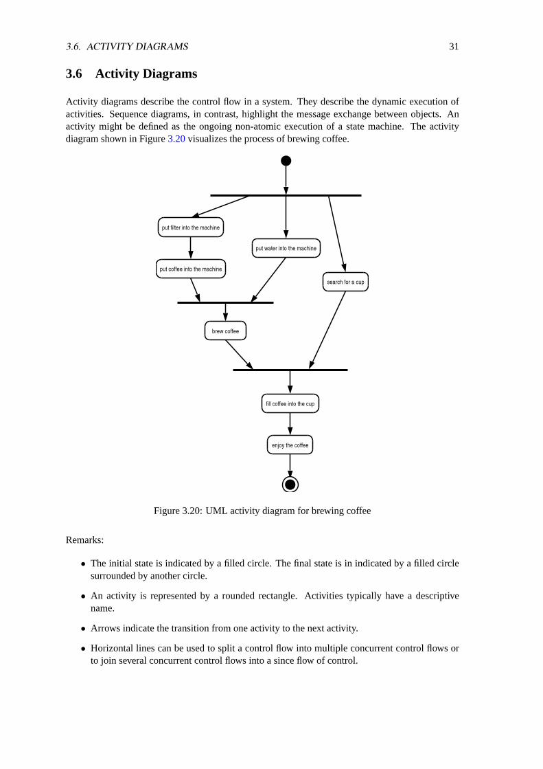
3.6 Activity Diagrams
Activity diagrams describe the control flow in a system. They describe the dynamic execution ofactivities. Sequence diagrams, in contrast, highlight the message exchange between objects. Anactivity might be defined as the ongoing non-atomic execution of a state machine. The activitydiagram shown in Figure3.20visualizes the process of brewing coffee.
Figure 3.20: UML activity diagram for brewing coffee
Remarks:
• The initial state is indicated by a filled circle. The final state is in indicated by a filled circlesurrounded by another circle.
• An activity is represented by a rounded rectangle. Activities typically have a descriptivename.
• Arrows indicate the transition from one activity to the next activity.
• Horizontal lines can be used to split a control flow into multiple concurrent control flows orto join several concurrent control flows into a since flow of control.
32 CHAPTER 3. UNIFIED MODELING LANGUAGE (UML)
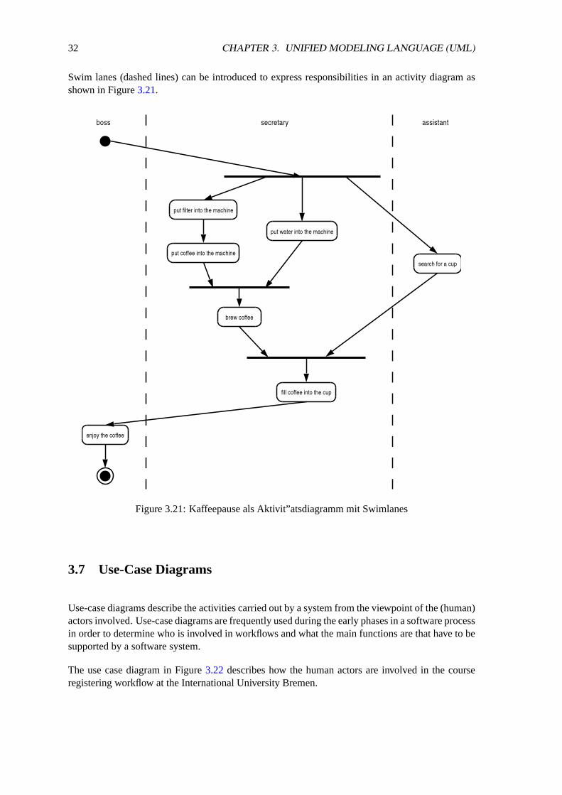
Swim lanes (dashed lines) can be introduced to express responsibilities in an activity diagram asshown in Figure3.21.
Figure 3.21: Kaffeepause als Aktivit”atsdiagramm mit Swimlanes
3.7 Use-Case Diagrams
Use-case diagrams describe the activities carried out by a system from the viewpoint of the (human)actors involved. Use-case diagrams are frequently used during the early phases in a software processin order to determine who is involved in workflows and what the main functions are that have to besupported by a software system.
The use case diagram in Figure3.22 describes how the human actors are involved in the courseregistering workflow at the International University Bremen.

3.7. USE-CASE DIAGRAMS 33
Figure 3.22: UML use-case diagram for course registrations
The example shown in Figure3.23describes how credit card transactions are supported by a creditcard software system.
Figure 3.23: UML use-case diagram for a credit card system

34 CHAPTER 3. UNIFIED MODELING LANGUAGE (UML)
Remarks:
• An use-case of a software system is represented by a named ellipse. The name is a shortdescription of the use-case.
• Actors are represented by labelled persons. The label usually identifies the role of an actor.
• A use-case is always started by an actor.
• The known elements to represent associations can be used in a use-case diagram in case thisis useful to understand the use-cases.
• System boundaries are shown by a rectangle.

3.8. ELEVATOR EXAMPLE 35
3.8 Elevator Example
The following example discusses the control logic of a hypothetic elevator:
• The building hasm floors.
• Within the elevator, there arem buttons for the various floors.
• On the lowest floor, there is a single button labelledup .
• On the highest floor, there is a single button labelleddown.
• All other floors have one button labelledup and one button labelleddown.
• The buttons are highlighted by the control logic according to the button that was pressed andas long as the elevator has not reached the requested floor.
• The elevator only moves if necessary.
• The control logic has to open the door once the requested floor has been reached and it musttry to close the door again after some time.
• The door of the elevator remains closed as long as the elevator is not used.
The usual first step is to clarify the interactions between the outside world and the control logicwithin the elevator by defining use-cases. Figure3.24shows a use-case diagram for the elevatordescribed above.
Figure 3.24: UML use-case diagram for the elevator example
The next step is the design of a class diagram which captures the structural aspects of the elevatorcontrol logic. One possible approach is to use the noun identification technique. A possible classdiagram solution is shown in Figure3.25.
36 CHAPTER 3. UNIFIED MODELING LANGUAGE (UML)
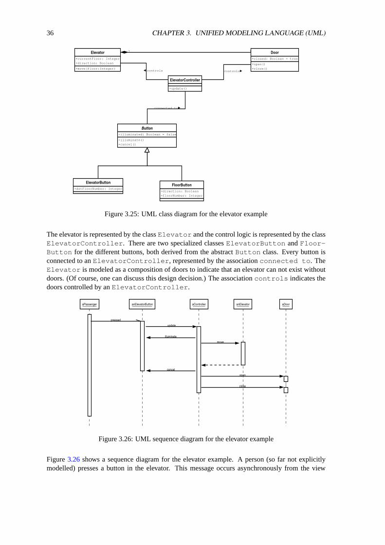
Figure 3.25: UML class diagram for the elevator example
The elevator is represented by the classElevator and the control logic is represented by the classElevatorController . There are two specialized classesElevatorButton andFloor-Button for the different buttons, both derived from the abstractButton class. Every button isconnected to anElevatorController , represented by the associationconnected to . TheElevator is modeled as a composition of doors to indicate that an elevator can not exist withoutdoors. (Of course, one can discuss this design decision.) The associationcontrols indicates thedoors controlled by anElevatorController .
Figure 3.26: UML sequence diagram for the elevator example
Figure3.26 shows a sequence diagram for the elevator example. A person (so far not explicitlymodelled) presses a button in the elevator. This message occurs asynchronously from the view
3.8. ELEVATOR EXAMPLE 37
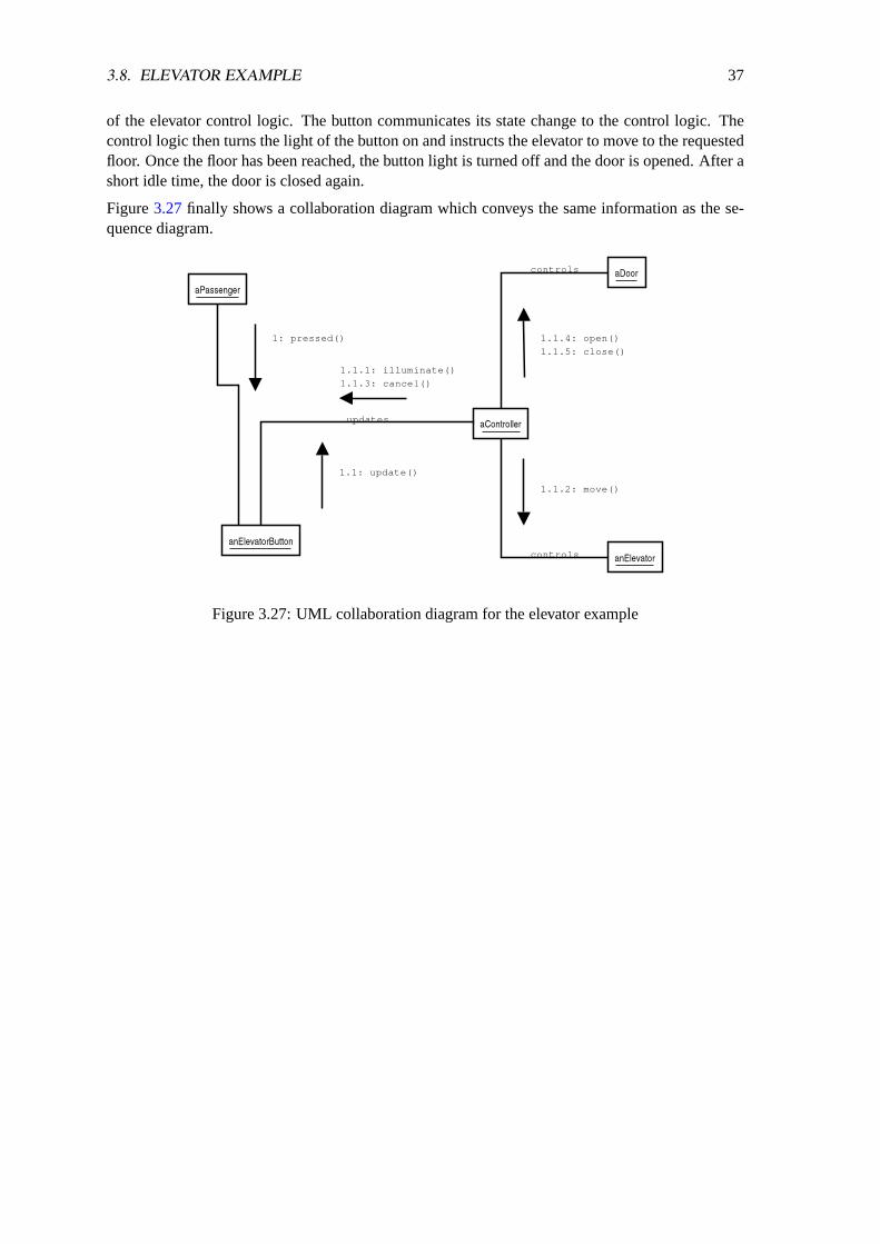
of the elevator control logic. The button communicates its state change to the control logic. Thecontrol logic then turns the light of the button on and instructs the elevator to move to the requestedfloor. Once the floor has been reached, the button light is turned off and the door is opened. After ashort idle time, the door is closed again.
Figure3.27finally shows a collaboration diagram which conveys the same information as the se-quence diagram.
Figure 3.27: UML collaboration diagram for the elevator example

38 CHAPTER 3. UNIFIED MODELING LANGUAGE (UML)
Chapter 4
Design Pattern
During the design of (object oriented) software systems, often many similar design problems haveto be solved. Experienced software designers usually reuse design solutions which have alreadybeen used elsewhere. Sometimes, known solutions are refined and generalized.
Design pattern try to capture the knowledge about good design solutions for given design problemsby capturing the expertise of software design experts and making it easily accessible to other de-signers. Design pattern thus increases the reuse of software designs. (Note that this is all aboutreuse of design and not about reuse of code.) Design pattern allow software designers to value de-sign alternatives and to avoid solutions which impact the reusability and extensibility of a softwaresystem.
Software patterns first became popular with the wide acceptance of the book Design Patterns: Ele-ments of Reusable Object-Oriented Software [7] by Erich Gamma, Richard Helm, Ralph Johnson,and John Vlissides (frequently referred to as the Gang of Four or just GoF). The term pattern goesback to writings of the architect Christopher Alexander who wrote several book in the 1970s relatedurban planning and building architecture. He defined the term pattern as follows:
”Each pattern describes a problem which occurs over and over again in our environ-ment, and then describes the core of the solution to that problem, in such a way that youcan use this solution a million times over, without ever doing it the same way twice”
A software design pattern has according to [7] four essential elements:
1. Name of the design pattern
2. Problem description
3. Solution description
4. Consequences of applying the design pattern
Design pattern can be categorized:
1. Design pattern which are concerned with the creation of objects (creational design pattern).
39

40 CHAPTER 4. DESIGN PATTERN
2. Design pattern which are concerned with the structural aspects of the organization of classesand objects (structural design pattern).
3. Design pattern which are concerned with the interaction between objects and the distributionof functionality among objects (behavioral design pattern).
This classification was introduced by the GoF and many other different classifications have beendeveloped since the publication of their design pattern book.
Design pattern are documented using a template which has a fixed number of elements. This formaldocumentation requirement was suggested by the GoF in order build up a catalog of design patternwhich can be browsed to select design pattern which apply for a concrete project [7].
• Name:The name and the classification of the pattern. A good name is very important since thenames of the design pattern will become part of the vocabulary used by software designers.
• Intent:A short statement what a design pattern does and which design problem it solves.
• Synonyms:Other well-known names for a design pattern.
• Motivation:Description of a scenario which illustrates the design problem and how the pattern solves thedesign problem. The scenario will help the reader to understand the more abstract descriptionof the pattern that follows.
• Applicability:A discussion in which situations a pattern can be used successfully, which advantages theapplication of the pattern has and how to recognize situations where a pattern is applicable.
• Structure:A graphical representation of the structure of a pattern in form of a class diagram.
• Participants:Description of the elements (classes and objects that participate in a design pattern and theirresponsibilities.
• Collaborations:Explanation how the participants collaborate to carry out their responsibilities.
• Consequences:Discussion how a pattern supports its objectives and the trade-offs that result from using apattern.
• Implementation:Discussion of implementation alternatives and pitfalls. This can include implementation lan-guage specific issues as well as discussions of performance trade-offs.
• Sample Code:Code fragments that illustrate how a pattern might be implemented in programming lan-guages such as C++, Java, or Smalltalk.
41
• Known Uses:Examples of the pattern found in real systems.
• Related Patterns:Pointers to related design pattern.
Design pattern increase the reuse of good and proven solutions and they improve the overall qual-ity of a software design. The goal is to make software designs flexible and extensible since therequirements will change during the lifetime of a piece of software (design for change).
To achieve flexible and extensible software designs, it is necessary to introduce suitable abstrac-tions and mechanisms to control the dependencies between objects and software components. Twoimportant ingredients are:
• Program to an interface and not to an implementation.
• Prefer composition of objects over inheritance.
There are some other concepts that are pretty much related to design pattern:
• Anti-Pattern describe how to reach a bad solution for a given design problem. A good anti-pattern describes why the bad solution first looks attractive, why the solution is actually badand which design pattern could be used instead.
• Idioms are compared to real design pattern relatively simple pattern which are usually specificto a certain implementation language. There is a soft boundary between design pattern andidioms.
• Architectural patterns are pattern for complex software architectures at a very high abstractionlevel. Again, there is soft boundary between design pattern and architectural pattern.
42 CHAPTER 4. DESIGN PATTERN
4.1 Iterator
Intent
Provide an object which traverses some aggregate structure, abstracting away assumptions aboutthe implementation of that structure.
Synonyms
Cursor
Motivation
It is often required to access the elements of an aggregate object (aggregate) without making theinternal structure of the aggregate visible. This pattern allows the software developer to providealternate ways to iterate over the elements of an aggregate and to change the implementation of theaggregate without affecting places where the aggregate is being used.
Applicability
• The Iterator patten can be used to iterate over the elements of an aggregate without uncoveringthe internal structure of the aggregate.
• The Iterator pattern can be used to iterate over an aggregate in different ways.
• The Iterator pattern can be used to provide a uniform interface for iterating over differentaggregates (polymorphic iteration).
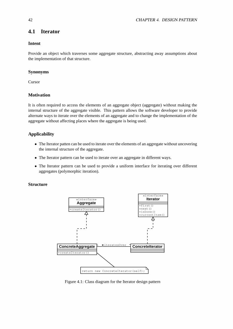
Structure
«interface»Aggregate
+createIterator()
«interface»Iterator
+first()+next()+isDone()+currentItem()
ConcreteAggregate
+createIterator()
ConcreteIteratoriteratesOver1 *
return new ConcreteIterator(self);
Figure 4.1: Class diagram for the Iterator design pattern
4.1. ITERATOR 43
Participants
• An Iterator defines the interface for iterating over a set of elements and for accessing theelements
• A ConcreteIteratorimplements the Iterator interface and keeps track of the current positionwithin the aggregate.
• An Aggregatedefines the interface for the construction of an Iterator.
• A ConcreteAggregateimplements the interface for the construction of a suitable iterator.
Collaborations
• A ConcreteIterator knows the current element within the aggregate and is able to determinethe following object.
Consequences
• It is possible to realize multiple iterators which can be used to iterate over the elements of anaggregate in different orders.
• Iterators usually simplify the interface of an aggregate.
• Iterators allow for multiple active iterations since every iterator maintains its own state.
Implementation
• Internal Iteratorsperform a certain operation automatically on all the elements of an ag-gregate. External Iteratorsrequire that the user of the Iterator requests the next elementexplicitly. External Iterators are more flexible since they allow for example to compare twoaggregates. Internal Iterators are, however, sometimes useful since they implement the com-plete iteration logic internally and are usually more efficient. Internal Iterators are usuallyused in programming languages supporting closures and continuations.
• It is possible to realize the iteration algorithm either within the iterator or within the aggregate.In the later case, an iterator is often called a cursor. The implementation of the iterationalgorithm in the iterator has to advantage that different algorithms can be realized quite easilyand the disadvantage that the iterator has to have knowledge about the internal structure ofthe aggregate. A cursor allows to minimize the required knowledge of the iterator about thestructure of the aggregate.
• Robust iterators ensure that changes in the aggregate do not cause indeterministic behavior.
• It can be useful to provide additional operations for iterators. For example, aPrevious()operation might be useful for ordered aggregates.
• A NullIterator is a degenerated Iterator which is always done, that is the operationisDone is always true.
44 CHAPTER 4. DESIGN PATTERN
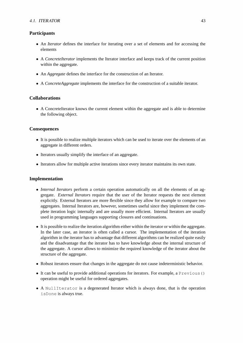
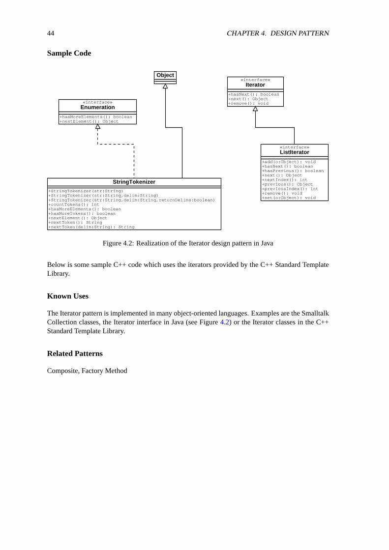
Sample Code
«interface»Iterator
+hasNext(): boolean+next(): Object+remove(): void«interface»
Enumeration
+hasMoreElements(): boolean+nextElement(): Object
StringTokenizer
+StringTokenizer(str:String)+StringTokenizer(str:String,delim:String)+StringTokenizer(str:String,delim:String,returnDelims:boolean)+countTokens(): int+hasMoreElements(): boolean+hasMoreTokens(): boolean+nextElement(): Object+nextToken(): String+nextToken(delim:String): String
«interface»ListIterator
+add(o:Object): void+hasNext(): boolean+hasPrevious(): boolean+next(): Object+nextIndex(): int+previous(): Object+previousIndex(): int+remove(): void+set(o:Object): void
Object
Figure 4.2: Realization of the Iterator design pattern in Java
Below is some sample C++ code which uses the iterators provided by the C++ Standard TemplateLibrary.
Known Uses
The Iterator pattern is implemented in many object-oriented languages. Examples are the SmalltalkCollection classes, the Iterator interface in Java (see Figure4.2) or the Iterator classes in the C++Standard Template Library.
Related Patterns
Composite, Factory Method

4.2. COMPOSITE 45
4.2 Composite
Intent
The Composite design pattern allows a client object to treat both single components and collectionsof components in a is-part-of hierarchy identically.
Motivation
Graphical editors usually support a fixed number of primitive graphic objects. Users can groupthese objects to create composite objects. A possible implementation approach is the definition ofclasses for primitive and composite objects.
The downside of this approach is that the program has to make distinctions between primitives andcomposite objects, even though the user treats all objects the same (e.g., draw, move, delete). TheComposite design pattern solves this problem by introducing an abstract class from which primitiveand composite objects are derived.
Applicability
• The Composite pattern can be used to represent is-part-of relationships.
• The Composite pattern cab be used if users treat composite objects and primitive objects inthe same way without having to know the differences.
Structure
«interface»Component
+operation()+add(Component)+remove(Component)+getChild(int)
Leaf
+operation()
Composite
+operation()+add(Component)+remove(Component)+getChild(int)
for all g in children { g.operation()}
contains
Figure 4.3: Class diagram for the Composite design pattern
Participants
• TheComponentdefines an interface for objects in the composition, and interface to access theelements and optionally an interface to access the contained object. TheComponentinterfacedefines the common standard behavior.

46 CHAPTER 4. DESIGN PATTERN
• A Leafobject represents a primitive element of the composition which does not contain otherobjects. It defines the behavior of primitive objects in the composition.
• A Compositerepresents the composite elements in the composition which can contain otherobjects. TheCompositeclass maintains references to the objects contained in the compositeand realizes the operations for accessing the contained objects.
Collaborations
Programs interact with the elements of a composition by using the Component interface. Leafobjects usually implement an operation directly. Composite objects usually implement an operationby forwarding the operation to all contained objects. In some cases, it might be necessary to do someadditional computations before or after the operation has been forwarded.
Consequences
• The patter defines a whole-part hierarchy consisting of primitive and composite objects.Primitive objects can be contained in composite objects which can them-self can be con-tained in other composite objects.
• Programs use the objects without having to know the distinction between primitive and com-pound objects.
• New primitive and composite objects can be created very easily.
• It is not possible, the restrict the object which can be contained in a composite object to asubset.
Implementation
See homeworks...
Sample Code
See homeworks...
Known Uses
The Composite design pattern is used in many graphical user interfaces. Another known usage arecompilers which represent the parse tree as a composite.
Related Patterns
Iterator

4.3. OBSERVER 47
4.3 Observer
Intent
TheObserverdesign pattern defines a 1:n relationship between object with the purpose to propagatestate changes of an object to all dependent objects so that the dependent objects can updated theirstate.
Synonyms
Dependents, Publish-Subscribe
Motivation
It is often required to maintain the consistency of cooperating objects. It furthermore seems usefulin many cases to decouple the classes so that new dependent objects can be introduced withouthaving to change existing objects. The Observer pattern introduces the concepts of a subject and anobserver. A subject can have multiple observer which have to be notified about state changes of thesubject so that they can synchronize their own state.
Applicability
• The Observer pattern can be used when changes of the state of an object can cause changesin other objects.
• The Observer pattern can be used is an object should be capable to notify other objects with-out making assumptions about the type of objects that need to be notified.
Structure
Figure 4.4: Class diagram for the Observer design pattern
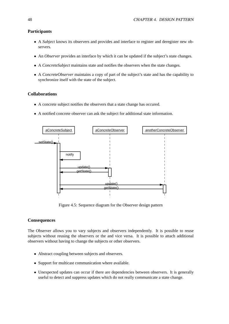
48 CHAPTER 4. DESIGN PATTERN
Participants
• A Subjectknows its observers and provides and interface to register and deregister new ob-servers.
• An Observerprovides an interface by which it can be updated if the subject’s state changes.
• A ConcreteSubjectmaintains state and notifies the observers when the state changes.
• A ConcreteObservermaintains a copy of part of the subject’s state and has the capability tosynchronize itself with the state of the subject.
Collaborations
• A concrete subject notifies the observers that a state change has occured.
• A notified concrete observer can ask the subject for additional state information.
aConcreteSubject aConcreteObserver anotherConcreteObserver
notify
update()getState()
update()getState()
setState()
Figure 4.5: Sequence diagram for the Observer design pattern
Consequences
The Observer allows you to vary subjects and observers independently. It is possible to reusesubjects without reusing the observers or the and vice versa. It is possible to attach additionalobservers without having to change the subjects or other observers.
• Abstract coupling between subjects and observers.
• Support for multicast communication where available.
• Unexpected updates can occur if there are dependencies between observers. It is generallyuseful to detect and suppress updates which do not really communicate a state change.

4.3. OBSERVER 49
Implementation
• In a straight-forward approach, subjects can simply keep internally references to their ob-servers. However, this approach might not be very efficient if there are many subjects andrelatively few observers. An alternate approach might be to realize the relationship betweensubjects and observers by using an associative hash table, which usually reduces memoryusage for the price of slightly increased costs for lookups.
• It is sometimes useful to allow observers that can depend on many subjects. In such cases, itis necessary to pass the subject as a parameter of theupdate operation.
• There are at least two fundamentally different approaches to generate notifications:
1. The operation which changes the state of the subject notifies all observers about thestate change. This advantage of this approach is that observers are not involved in thepropagation of the state changes. The disadvantage is that this approach can lead tomany little state change propagations.
2. An instance outside of the subjects is responsible to initiate the notification of observersat suitable points during the computation. This approach allows to propagate multiplestate changes as a single state change. The disadvantage is that no notifications will begenerated if the instance outside of the subject does not ask for notifications.
• Deleting subjects subjects can cause invalid references in the observer objects. One solutionis to notify observer objects that a subject is being deleted and the ensure that observers havederegistered before the subject is actually destroyed.
• It is necessary to ensure that a subject has a consistent state before notifying the observers.
• The notification might optionally pass information to the observers. In the first extreme case,no information will be passed and the observers have to retrieve the information they need(pull model). In the other extreme case, all information is passed to the observers regardlesswhether the observers need this information (push model).
• The efficiency of notifications can be improved by allowing subjects to specify which notifi-cations they are interested in during the registration.
• If the dependencies between subjects and observers are very complex, then it might be neces-sary to introduce a special object which maintains the dependencies and implements a specialstrategy for notifying observers.
Sample Code
Figure 4.6 shows the realization of the Observer pattern in the Java class packages. The JavaObserver interface defines an abstract Observer interface. The subject interface is definied by theclass Observable. Concrete subjects must be derived from the class Observable.
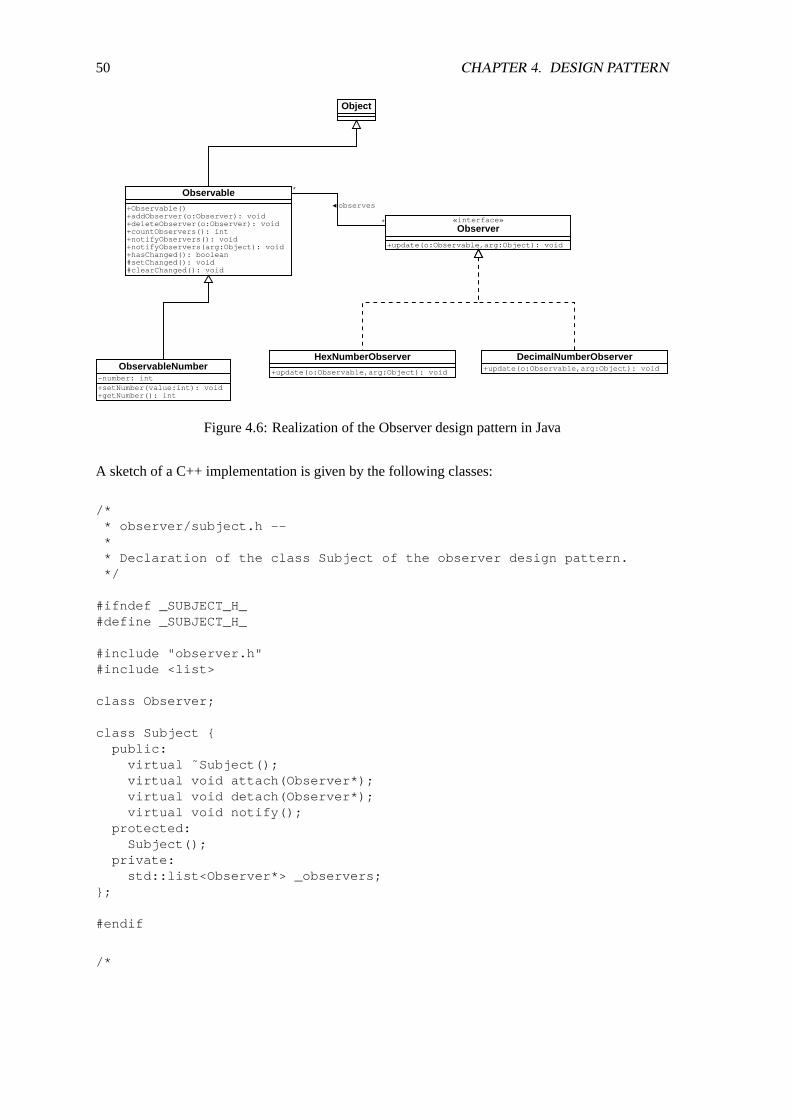
50 CHAPTER 4. DESIGN PATTERN
Observable
+Observable()+addObserver(o:Observer): void+deleteObserver(o:Observer): void+countObservers(): int+notifyObservers(): void+notifyObservers(arg:Object): void+hasChanged(): boolean#setChanged(): void#clearChanged(): void
«interface»Observer
+update(o:Observable,arg:Object): void
Object
observes
*
*
ObservableNumber-number: int+setNumber(value:int): void+getNumber(): int
HexNumberObserver
+update(o:Observable,arg:Object): void
DecimalNumberObserver+update(o:Observable,arg:Object): void
Figure 4.6: Realization of the Observer design pattern in Java
A sketch of a C++ implementation is given by the following classes:
/** observer/subject.h --** Declaration of the class Subject of the observer design pattern.*/
#ifndef _SUBJECT_H_#define _SUBJECT_H_
#include "observer.h"#include <list>
class Observer;
class Subject {public:
virtual ˜Subject();virtual void attach(Observer*);virtual void detach(Observer*);virtual void notify();
protected:Subject();
private:std::list<Observer*> _observers;
};
#endif
/*
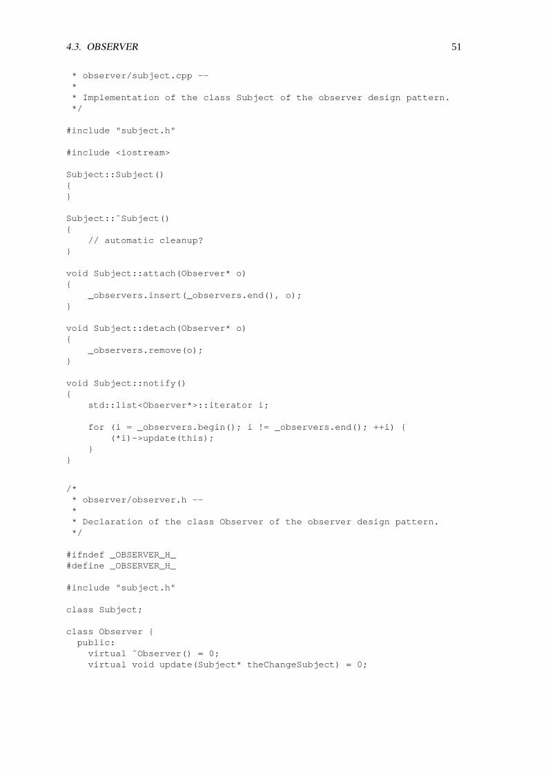
4.3. OBSERVER 51
* observer/subject.cpp --** Implementation of the class Subject of the observer design pattern.*/
#include "subject.h"
#include <iostream>
Subject::Subject(){}
Subject::˜Subject(){
// automatic cleanup?}
void Subject::attach(Observer* o){
_observers.insert(_observers.end(), o);}
void Subject::detach(Observer* o){
_observers.remove(o);}
void Subject::notify(){
std::list<Observer*>::iterator i;
for (i = _observers.begin(); i != _observers.end(); ++i) {(*i)->update(this);
}}
/** observer/observer.h --** Declaration of the class Observer of the observer design pattern.*/
#ifndef _OBSERVER_H_#define _OBSERVER_H_
#include "subject.h"
class Subject;
class Observer {public:
virtual ˜Observer() = 0;virtual void update(Subject* theChangeSubject) = 0;
52 CHAPTER 4. DESIGN PATTERN
protected:Observer(Subject *s);
protected:Subject *_subject;
};
#endif
/** observer/observer.cpp --** Implementation of the class Observer of the observer design pattern.*/
#include "observer.h"
Observer::Observer(Subject *s){
_subject = s;_subject->attach(this);
}
Observer::˜Observer(){
_subject->detach(this);}
Known Uses
The Observer pattern is part of the classic Model/View/Controller design pattern which was in-vented as part of the Smalltalk environment and is used extensively for graphical user interfaces bymany class libraries. The model corresponds to the Subject and it supports multiple Views display-ing model. The views thus are the observers of the model.
Related Patterns
Command, Iterator
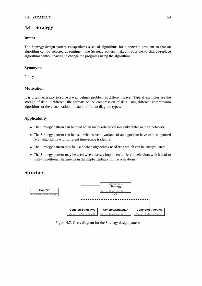
4.4. STRATEGY 53
4.4 Strategy
Intent
The Strategydesign pattern encapsulates a set of algorithms for a concrete problem so that analgorithm can be selected at runtime. The Strategy pattern makes it possible to change/replacealgorithms without having to change the programs using the algorithms.
Synonyms
Policy
Motivation
It is often necessary to solve a well defines problem in different ways. Typical examples are thestorage of data in different file formats or the compression of data using different compressionalgorithms or the visualization of data in different diagram types.
Applicability
• The Strategy pattern can be used when many related classes only differ in their behavior.
• The Strategy pattern can be used when several variants of an algorithm have to be supported(e.g., algorithms with different time-space tradeoffs).
• The Strategy pattern may be used when algorithms need data which can be encapsulated.
• The Strategy pattern may be used when classes implement different behaviors which lead tomany conditional statements in the implementation of the operations.
Structure
Context
+ContextInterface()
«interface»Strategy
+AlgorithmInterface()
ConcreteStrategyA
+AlgorithmInterface()
ConcreteStrategyA
+AlgorithmInterface()
ConcreteStrategyA
+AlgorithmInterface()
Figure 4.7: Class diagram for the Strategy design pattern
54 CHAPTER 4. DESIGN PATTERN
4.5 Model View Controller
The Model View Controller (MVC) design pattern supports the display of some data (e.g., a spread-sheet) in several views while maintaining the integrity of the representations. The MVC was de-veloped during the work on the Smalltalk graphical user interface. The MVC pattern uses theobserver pattern to notify views of any chances within the model. The controller is responsible tohandle interaction with the user. User interactions always result in changes of the model which willpotentially lead to changes in the views attached to the model.
Controller can be replaced to support different interaction styles. The strategy design pattern is usedto implement support for multiple controllers.
4.6 Anti Pattern: Creeping Featuritis
• Problem: You want to satisfy your customers. You want to do the best possible job you canwith your product, and thus win fame and fortune for yourself.
• Forces: Programmers have big egos. Customers don’t always know what they want. Pro-grammers often miss the distinction between what’s needed and what’s ”neat”.
• Anti-Solution: You get all of the programmers and designers together in a big room (akaDesignByCommittee) and everybody adds into the product what they want. This processfeeds off itself and everyone starts adding new features as the process continues.
• Discussion:CreepingFeaturitis can begin, or continue at any stage in the software develop-ment process. It’s most common in the Analysis stage, where it results in either an unendingAnalysis stage (see AnalysisParalysis) or in an unrealistically ambitious specification. In thedesign phase CreepingFeaturitis is characterized by adding more bells and whistles than werecalled for in the Analysis, or by trying to abstract everything before anything is ever madeconcrete. In the coding stage, it is characterized by coding that never ends as programmerscontinue to add ”one more feature”.
4.7 Anti Pattern: Design By Committee
• Problem: Given a political environment in which no one person has enough clout to presenta design for a system and get it approved, how do you get a design done?
• Forces:Often, a problem can be clearly identified for which no existing solution fits well. Forinstance, the DOD figured out in the mid-late ’70s that the existing programming languagesthat were being used for big military projects just didn’t cut it. FORTRAN, JOVIAL andCOBOL were not going to allow programmers to write the programs necessary to build thingslike SDI – they didn’t provide large-scale programming support, encapsulation, or a host ofother things that language designers had decided that were needed. However, no one had theforce of personality or knowledge to drive through a single, consistent solution. There wasno Alan Kay or Grace Hopper to provide a vision. So they:
• Solution: Put together a big committee to solve the problem. Let them battle it out amongstthemselves and finally take whatever comes out the end.

4.7. ANTI PATTERN: DESIGN BY COMMITTEE 55
• Discussion: The problem with DesignByCommittee is that everyone on the committee hastheir own vision of the final product. They each fight to get their $0.02 added in to the finalversion. Since there is no unifying vision, what results is a mish-mash of features in whicheverybody gets their share put in. By the way, this story relates how Ada came about.

56 CHAPTER 4. DESIGN PATTERN

Chapter 5
Quality Assurance
In order to achieve and maintain a certain degree of software quality, it is necessary to implementquality assurance procedures. The search for errors is in general a “destructive” process and it ismost effective if the search is not carried out by the developers themself. However, it is crucial thatall quality assurance activities put the quality of the product into the foreground and not the qualityor skills of the developers.
5.1 Typical Software Errors
• Computational Errors: A software component computes the wrong function (e.g., use ofwrong variables, constants or operators).
• Interface Errors: Syntactic or semantic inconsistencies between the caller of an interface(function) and the interface (function) itself.
• Control-Flow Errors: Execution of the wrong path in a program (e.g., exchange of statements,wrong conditions in loop and conditional statements). A very frequent class of errors are socalled “off-by-one” errors where loops are executed one iteration too much or too less.
• Initialization Errors: Wrong or missing initialization of variables.
• Data-Flow Errors: Illegal access of variables or data structures (e.g., out-of-bound accessto arrays, assignment to the wrong variable, pointer errors, memory allocation and releaseerrors).
5.2 Program Inspections
A program inspectionis a formal review process in which the source code of a program is readby other persons to find problems. The following rules should be followed when using programinspections:
• The inspection is initiated by the author(s) of a software module, typically when the author(s)finalize the work on the software module.
57
58 CHAPTER 5. QUALITY ASSURANCE
• The program is reviewed by several reviewers. Every reviewer focusses on a specific aspectand documents his conclusions.
• The reviewers discuss and document the detected errors in a joint meeting which is lead by aspecially trained moderator. It is not allowed to discuss solutions during this meeting.
• The result is a formal inspection protocol which identifies and classifies the detected prob-lems. The inspection protocols may also be used as input for statistics about error types anderror frequencies which might be used to improve the development process. Note again thatthis information should not be used to judge the quality of the developers since there aretypically many other factors to consider which are outside of the recorded statistics.
• The authors receives the inspection protocol and revises the software component to addressthe reported issues.
• The moderator then either releases the software module or rejects it and moves it back to theauthor(s) for further quality enhancements.
The project plan has to include time for inspections. Furthermore, it is necessary that inspectionresults are treated as sensitive material. In particular, inspection results may not be used to evaluatedevelopers and project managers and visitors are not allowed to participate in inspections.
According to some empirical studies, the time investment for program inspections is about 15-20%of the overall development time and the inspections uncover 60-70% of the errors in the inspecteddocuments. The estimated gain is 20% during the development phases and 30% during the mainte-nance phase. These numbers indicate that program inspections are a very powerful mechanism toenhance the software quality.
A Reviewis a variation of a program inspection. A review does not follow a formal procedure andthere is only an informal review protocol. Reviews are almost as effective as program inspections.The acceptance of reviews by the developers is usually higher since no formal inspection protocolsare written. However, since no information is recorded, there is no way to obtain the data needed tocontinually optimize the development process.
A Walk-throughis a form of a review where the authors performs a step-by-step presentation of thesoftware module and reviewers ask ad-hoc questions.
5.3 Verification
One approach to assure that a program conforms to the specification is to verify the program. Thereare different levels of correctness that program verifications can prove:
• Partial correctnessis a formal prove that a program produces correct results for legal inputs.
• Terminationis a formal prove that a program terminates for legal input values.
• Total Correctnessis a formal prove that a program is partially correct and terminates.
For procedural programming languages, it is possible to verify programs by defining assertions foreach program statement. This approach can be best illustrated by looking at an example.
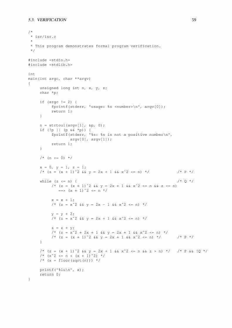
5.3. VERIFICATION 59
/** isr/isr.c** This program demonstrates formal program verification.*/
#include <stdio.h>#include <stdlib.h>
intmain(int argc, char **argv){
unsigned long int n, x, y, z;char *p;
if (argc != 2) {fprintf(stderr, "usage: %s <number>\n", argv[0]);return 1;
}
n = strtoul(argv[1], &p, 0);if (!p || (p && *p)) {
fprintf(stderr, "%s: %s is not a positive number\n",argv[0], argv[1]);
return 1;}
/* (n >= 0) */
x = 0, y = 1, z = 1;/* (z = (x + 1)ˆ2 && y = 2x + 1 && xˆ2 <= n) */ /* P */
while (z <= n) { /* Q *//* (z = (x + 1)ˆ2 && y = 2x + 1 && xˆ2 <= n && z <= n)
==> (x + 1)ˆ2 <= n */
x = x + 1;/* (z = xˆ2 && y = 2x - 1 && xˆ2 <= n) */
y = y + 2;/* (z = xˆ2 && y = 2x + 1 && xˆ2 <= n) */
z = z + y;/* (z = xˆ2 + 2x + 1 && y = 2x + 1 && xˆ2 <= n) *//* (z = (x + 1)ˆ2 && y = 2x + 1 && xˆ2 <= n) */ /* P */
}
/* (z = (x + 1)ˆ2 && y = 2x + 1 && xˆ2 <= n && z > n) */ /* P && !Q *//* (xˆ2 <= n < (x + 1)ˆ2) *//* (x = floor(sqrt(n))) */
printf("%lu\n", x);return 0;
}
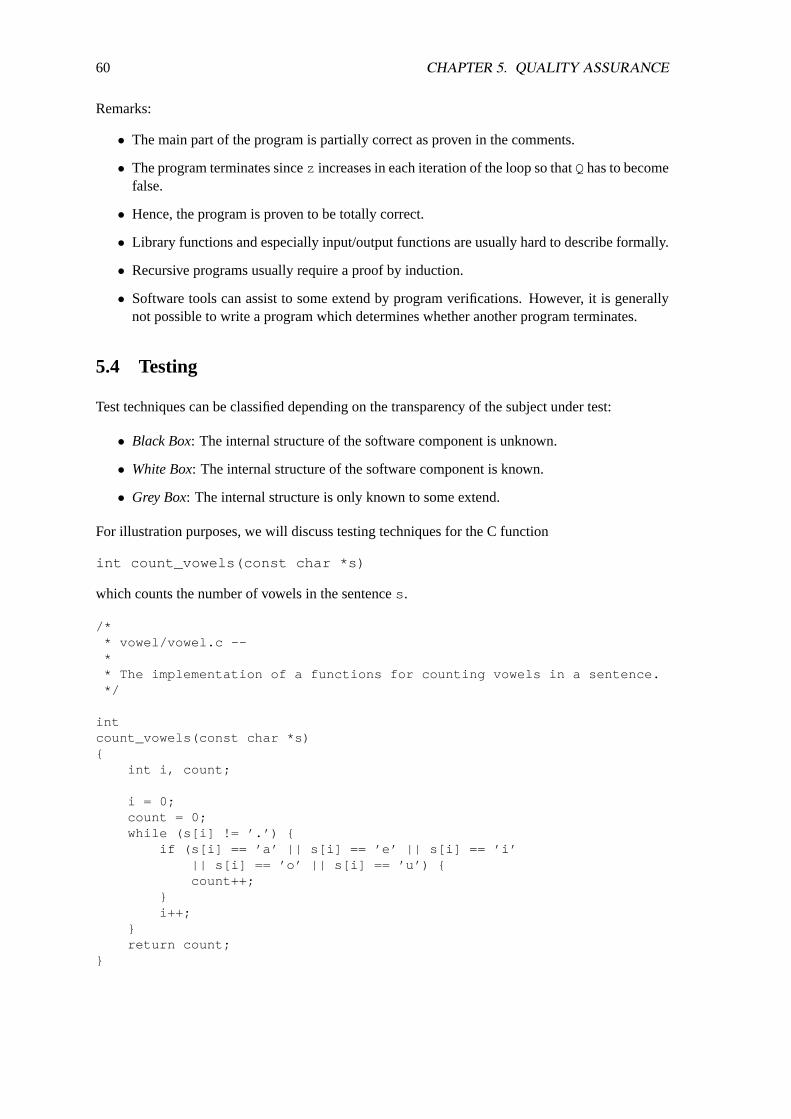
60 CHAPTER 5. QUALITY ASSURANCE
Remarks:
• The main part of the program is partially correct as proven in the comments.
• The program terminates sincez increases in each iteration of the loop so thatQhas to becomefalse.
• Hence, the program is proven to be totally correct.
• Library functions and especially input/output functions are usually hard to describe formally.
• Recursive programs usually require a proof by induction.
• Software tools can assist to some extend by program verifications. However, it is generallynot possible to write a program which determines whether another program terminates.
5.4 Testing
Test techniques can be classified depending on the transparency of the subject under test:
• Black Box: The internal structure of the software component is unknown.
• White Box: The internal structure of the software component is known.
• Grey Box: The internal structure is only known to some extend.
For illustration purposes, we will discuss testing techniques for the C function
int count_vowels(const char *s)
which counts the number of vowels in the sentences .
/** vowel/vowel.c --** The implementation of a functions for counting vowels in a sentence.*/
intcount_vowels(const char *s){
int i, count;
i = 0;count = 0;while (s[i] != ’.’) {
if (s[i] == ’a’ || s[i] == ’e’ || s[i] == ’i’|| s[i] == ’o’ || s[i] == ’u’) {count++;
}i++;
}return count;
}
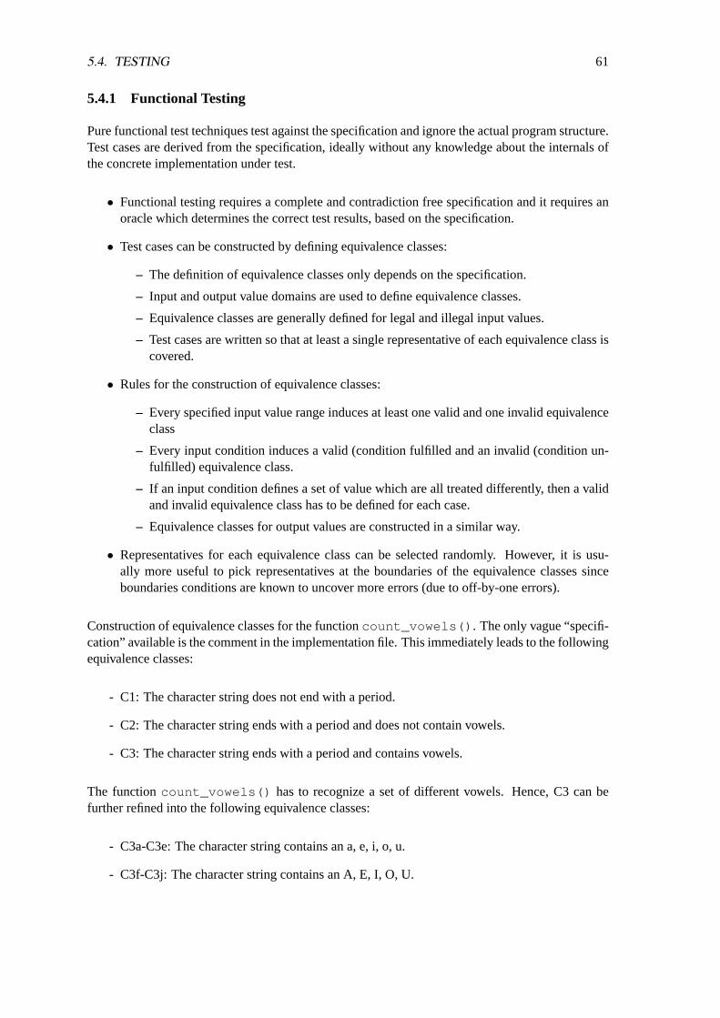
5.4. TESTING 61
5.4.1 Functional Testing
Pure functional test techniques test against the specification and ignore the actual program structure.Test cases are derived from the specification, ideally without any knowledge about the internals ofthe concrete implementation under test.
• Functional testing requires a complete and contradiction free specification and it requires anoracle which determines the correct test results, based on the specification.
• Test cases can be constructed by defining equivalence classes:
– The definition of equivalence classes only depends on the specification.
– Input and output value domains are used to define equivalence classes.
– Equivalence classes are generally defined for legal and illegal input values.
– Test cases are written so that at least a single representative of each equivalence class iscovered.
• Rules for the construction of equivalence classes:
– Every specified input value range induces at least one valid and one invalid equivalenceclass
– Every input condition induces a valid (condition fulfilled and an invalid (condition un-fulfilled) equivalence class.
– If an input condition defines a set of value which are all treated differently, then a validand invalid equivalence class has to be defined for each case.
– Equivalence classes for output values are constructed in a similar way.
• Representatives for each equivalence class can be selected randomly. However, it is usu-ally more useful to pick representatives at the boundaries of the equivalence classes sinceboundaries conditions are known to uncover more errors (due to off-by-one errors).
Construction of equivalence classes for the functioncount_vowels() . The only vague “specifi-cation” available is the comment in the implementation file. This immediately leads to the followingequivalence classes:
- C1: The character string does not end with a period.
- C2: The character string ends with a period and does not contain vowels.
- C3: The character string ends with a period and contains vowels.
The functioncount_vowels() has to recognize a set of different vowels. Hence, C3 can befurther refined into the following equivalence classes:
- C3a-C3e: The character string contains an a, e, i, o, u.
- C3f-C3j: The character string contains an A, E, I, O, U.

62 CHAPTER 5. QUALITY ASSURANCE
Looking at the output produced bycount_vowels() , two additional equivalence classes can bedefined:
- C4: The character string contains multiple identical vowels.
- C5: The character string contains multiple but different vowels.
It is now possible to select representatives and to construct test cases which cover all equivalenceclasses. An implementation of test cases using thecheck C unit test framework looks as follows:
/** vowel/check-vowel.c --** Unit test suite for the count_vowel() function. Note that some test* cases might cause access to uninitalized memory.*/
#include <stdlib.h>#include <check.h>#include "vowel.h"
static const char *v1 = "X";static const char *v2 = "a";static const char *v3 = ".";static const char *v4 = "XAaEeIiOoUuA.";static const char *v5 = NULL;
START_TEST(vowel_class1){
fail_unless(0 == count_vowels(v1), NULL);}END_TEST
START_TEST(vowel_class2){
fail_unless(0 == count_vowels(v2), NULL);}END_TEST
START_TEST(vowel_class3){
fail_unless(0 == count_vowels(v3), NULL);}END_TEST
START_TEST(vowel_class4){
fail_unless(11 == count_vowels(v4), NULL);}END_TEST
START_TEST(vowel_class5){

5.4. TESTING 63
fail_unless(0 == count_vowels(v5), NULL);}END_TEST
static Suite*vowel_suite(void){
Suite *s = suite_create("vowel_suite");TCase *vowel_core = tcase_create("vowel_core");suite_add_tcase(s, vowel_core);tcase_add_test(vowel_core, vowel_class1);tcase_add_test(vowel_core, vowel_class2);tcase_add_test(vowel_core, vowel_class3);tcase_add_test(vowel_core, vowel_class4);tcase_add_test(vowel_core, vowel_class5);return s;
}
intmain(void){
int n;
Suite *s = vowel_suite();SRunner *sr = srunner_create(s);srunner_run_all(sr, CK_NORMAL);n = srunner_ntests_failed(sr);srunner_free(sr);suite_free(s);
return (n == 0) ? EXIT_SUCCESS : EXIT_FAILURE;}
Running the test cases shows thatcount_vowels() has some errors and the implementationneeds to be fixed. Of course, the specification ofcount_vowels() is already vague and as suchone can debate the meaning of the term correct in this case.
Note that the automated execution of test cases using unit test frameworks allows to execute testsefficiently after changing the source code.
5.4.2 Control-Flow Testing
Control-flow testingis based on an analysis of some structural elements of a given implementation(statements, branches, conditions and paths). A common requirement is that all the structural ele-ments of a certain kind must be covered by the set of test cases. Hence, control-flow based testingallows primarily to judge the quality of the set of test cases. Control-flow testing is less used toconstruct test cases (unless it is known that the criteria for the set of test cases is one of coveragecriterias discussed below.)
To understand control-flow testing, it is best to construct and inspect the control-flow graph of aprogram:
• Nodes represent statements and conditions of a control structure.
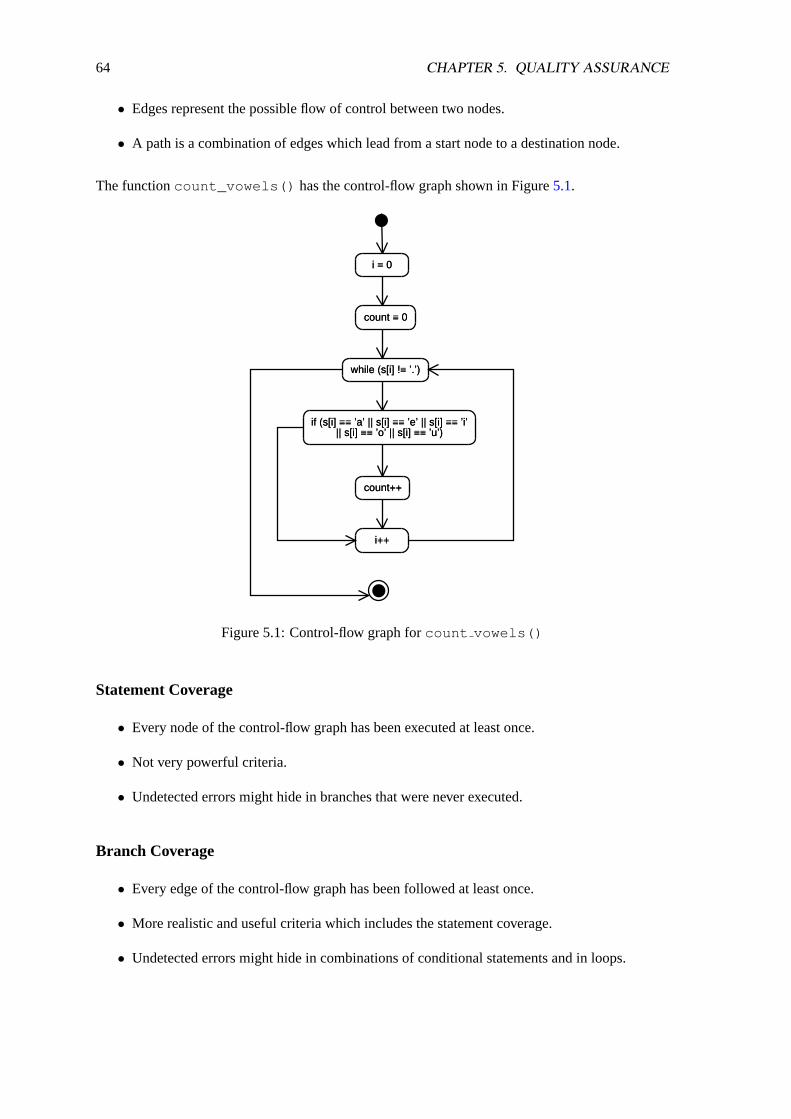
64 CHAPTER 5. QUALITY ASSURANCE
• Edges represent the possible flow of control between two nodes.
• A path is a combination of edges which lead from a start node to a destination node.
The functioncount_vowels() has the control-flow graph shown in Figure5.1.
i = 0
count = 0
while (s[i] != ’.’)
if (s[i] == ’a’ || s[i] == ’e’ || s[i] == ’i’|| s[i] == ’o’ || s[i] == ’u’)
count++
i++
Figure 5.1: Control-flow graph forcount vowels()
Statement Coverage
• Every node of the control-flow graph has been executed at least once.
• Not very powerful criteria.
• Undetected errors might hide in branches that were never executed.
Branch Coverage
• Every edge of the control-flow graph has been followed at least once.
• More realistic and useful criteria which includes the statement coverage.
• Undetected errors might hide in combinations of conditional statements and in loops.

5.4. TESTING 65
Condition Coverage
• Every condition has to evaluate at least once tofalse and at least once totrue .
• Atomic condition coverage requires that every primitive conditions has to evaluate at leastonce tofalse and at least once totrue . Note that atomic condition coverage does notimply statement coverage.
• Multiple-condition coverage requires that every condition (primitive and compound condi-tions) has to evaluate at least once tofalse and at least once totrue .
• Multiple-condition coverage is a good compromise and implies branch coverage in combina-tion with statement coverage.
Path Coverage
• Every path in the control-flow graph has been executed at least once.
• The path coverage is a theoretic criterion since there is usually an unbounded number ofpossible paths due to loops. Still, path coverage is important for comparisons since it is thestrongest criterion.
• Even path coverage does not detect all possible errors.
5.4.3 Mutation Testing
Mutation testingis based on the idea to make random small changes to the source code of a programwhich leads to a set of so called mutants. The mutants are then used to execute the test cases andit is observed how many mutants are detected by the test cases. Mutation testing is thus anotherapproach to determine the quality of a set of test cases.
• In the ideal case, a set of test cases should detect all mutants.
• Mutants can be generated automatically by special compilers so that the quality of test casescan be determined automatically.
Programs that generate mutants usually only introduce “simple” errors under the assumption that“more complex” errors are usually constructed out of simple errors. The following is a typical listof errors that are introduced while creating mutants:
• computational errors:
– Change of arithmetic operators
– Removal of arithmetic expressions
– Change of constants
• interface errors:
– Change and swapping of function call parameters
66 CHAPTER 5. QUALITY ASSURANCE
– Replacement of function calls with other function calls
• control flow errors:
– Replacement of logical expressions withtrue or false
– Change of logical and relational operators
– Replacement of function calls with other function calls
– Removal of statements
– Introduction of statements that halt the computation
• initialization errors:
– Change of constants
– Removal of initialization statements
• data flow errors:
– Exchange of variables in a specific scope
– Change of index computations
Automatically generated mutants that are not detected by the test suite must be checked manu-ally since it is possible that the changes (e.g., the exchange of some statements) did not affect thecorrectness of the program.
5.4.4 Regression Testing
Regression testingis used to ensure that changes did not break any test cases that were passedcorrectly before. Regression testing is especially important when multiple revisions of a piece ofsoftware have to be maintained for a longer period of time. Regression testing is usually performedbefore a new release is shipped to customers.
In the ideal case, the set of test cases should increase over time. In particular, it is highly desirableto write a new test case for each bug report before actually fixing the bug. In other words, a bugreport can be considered to document a bug in the test suite itself. By applying this simple updaterule and the consequent usage of regression tests, it is possible to increase the quality of a softwareproduct significantly over time.
5.5 Software Metrics
It is often required to better understand the properties of software systems by analyzing the sourcecode and computing some software metrics. The true value of software metrics becomes visibleby comparing metrics from different projects or the same set of metrics at different stages in thedevelopment process. In other words, the real value of software metrics are often comparativerelative metrics rather than single-point metrics from single-point measurements.
The key problem with software metrics is that the most important factors such as maintainability,robustness, portability, and user friendliness cannot be measured directly. Instead, metrics are oftendefined which are easier to measure but which are only indications for the really interesting quality

5.5. SOFTWARE METRICS 67
aspects of software systems. Software metrics are therefore always a subject of interpretation andthere is also the risk that software developers influence the metrics to achieve a good metric withoutreally improving the overall quality of a software system.
Software metrics can be divided intro two classes:
• Static metricsare computed by an analysis of artefacts which have been produced during thedevelopment process (design diagrams, source code, documentation).
• Dynamic metricsare computed by executing programs with some special instrumentation.
Commonly used software metrics are discussed below.
5.5.1 Fan-in / Fan-out
The number of functions which call a given function (fan-in) or the number of functions that arecalled by a given function (fan-out). A high fan-in of a function is an indication that the functionforms a critical component of a software system and that changes to this function might have sig-nificant implications to the overall system. A high fan-out of a function is an indication that thefunction has a complex control logic.
5.5.2 Lines of Code (LOC) / Non-Commented Source Statements (NCSS)
A large program contains in principle more errors than a small program. Hence, the size of aprogram usually measured in lines of code is often used as a metric. However, it is crucial torealize that this metric is rather fuzzy since there are many factors that influence the overall sizeof the source code, such as the language used, the skills of the developers, the documentation andcomments included in the source code, and so forth. Since comments and empty lines are usuallynot interesting for obtaining a measure of the source code complexity, it is common to count theNon-Commented Source Statements (NCSS). But the source code size remains a rather simple andfuzzy metric.
5.5.3 Length of identifiers
This metric is defined as the average length of identifiers. The idea behind this metric is thatprograms with short identifiers are in general harder to understand. Of course, programs that usevery long identifiers are also sometimes very difficult to read. So instead of looking at the averagelength, it is more useful to look at the whole distribution and to take into account how modernlanguages handle name spaces.
5.5.4 Fog Index
The Fog Index is a metric computed over the average length of words and the average number ofwords in sentences of a document and indicates how hard it is to read a document.
1. Find the average number of words used per sentence.

68 CHAPTER 5. QUALITY ASSURANCE
2. Calculate the percentage of words that are three syllables or more. Do not count propernames. Do not count verbs that make three syllables or adding -es or -ed.
3. Add these two figures. Example: if the average number of words per sentence was was 15,and the percentage of words three syllables or more was 12%, the sum be 27.
4. Multiply that sum by 0.4. The resulting number is the Fog Index, a rough measure of howmany words of schooling it would take to understand what you have written. In the example,multiplying 27 by 0.4 equals a Fog Index of 10.8. The Bible, Shakespeare, Mark Twain,and TV Guide all have Fog Indexes of about 6. Time, Newsweek, and the Wall St. Journalaverage about 11.
5.5.5 Cyclomatic Complexity
The cyclomatic complexity was introduced by McCabe and it is also often referred to as McCabemetric. The cyclomatic complexity is based on the structure of control flow graphs. The cyclo-matic numberV (G) of a control flow graphG with e edges,n nodes andp connections to othercomponents (procedures, modules) is given by:
V (G) = e− n + 2p
For the control flow graph of Figure5.1, we gete = 9, n = 8 and p = 1. The cyclomaticcomplexity thus isV (G) = 9 − 8 + 2 · 1 = 3. The cyclomatic complexity metric is an indicationof the complexity of the control flow and functions with a high cyclomatic complexity are typicallyconsidered to contain a higher number of errors.
Some rules of thumb:
• Simple programs withV (G) < 10 usually do not cause any serious problems.
• Programs withV (G) in the range[11−20] have moderate complexity and pose an acceptablerisk for errors.
• Programs withV (G) in the range[21− 50] are complex programs with a high risk for errors.
• Programs withV (G) > 50 are so complex that they can not really be tested and thus have avery high risk or errors.
The cyclomatic complexity is rather simple to compute and certainly more useful than the numberof lines of source code. However, some programming constructs are rather simplified (e.g., thecomplexity of conditions) and a number of proposals can be found in the literature to improve thecyclomatic complexity metric.
5.5.6 Halstead Metrics
The fundamental idea behind Halstead Metrics is to reduce a program to the number of operandsand operators that appear in the source code. An operator is any symbol or keyword which identifiesan action. Operands are all symbols which represent data (e.g., variables, constants, jump labels).
The Halstead Metrics are defined by using the following core definitions:
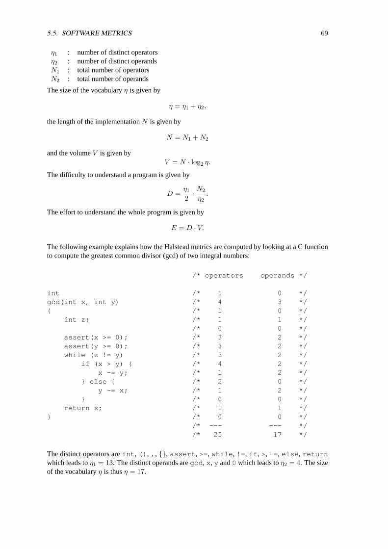
5.5. SOFTWARE METRICS 69
η1 : number of distinct operatorsη2 : number of distinct operandsN1 : total number of operatorsN2 : total number of operands
The size of the vocabularyη is given by
η = η1 + η2,
the length of the implementationN is given by
N = N1 + N2
and the volumeV is given byV = N · log2 η.
The difficulty to understand a program is given by
D =η1
2· N2
η2.
The effort to understand the whole program is given by
E = D · V.
The following example explains how the Halstead metrics are computed by looking at a C functionto compute the greatest common divisor (gcd) of two integral numbers:
/* operators operands */
int /* 1 0 */gcd(int x, int y) /* 4 3 */{ /* 1 0 */
int z; /* 1 1 *//* 0 0 */
assert(x >= 0); /* 3 2 */assert(y >= 0); /* 3 2 */while (z != y) /* 3 2 */
if (x > y) { /* 4 2 */x -= y; /* 1 2 */
} else { /* 2 0 */y -= x; /* 1 2 */
} /* 0 0 */return x; /* 1 1 */
} /* 0 0 *//* --- --- *//* 25 17 */
The distinct operators areint , () , , , {}, assert , >=, while , != , if , >, -= , else , returnwhich leads toη1 = 13. The distinct operands aregcd , x , y and0 which leads toη2 = 4. The sizeof the vocabularyη is thusη = 17.
70 CHAPTER 5. QUALITY ASSURANCE
The total number of operators isN1 = 25 and the total number of operands isN2 = 17. The lengthof the implementationN is thusN = 42.
The binary volumeV of the program isV = n· = log2η = 42 · log217 ≈ 172 bits. The difficultyto understand the source code isD = η1
2 · N2η2
= 132 · 17
4 = 27.625 and the effortE to understandthe function isE = D · V ≈ 27.625 · 172 = 4751.5.
Halstead metrics are relatively simple to compute and they are good indicators for the complexity ofa program. However, it is important to specify for each language precisely how the various languageconstructs are classified as operators and operands in order to compare Halstead metrics.
5.5.7 Object-oriented Metrics
There are many additional metrics that are specific to object-oriented programming. The mostimportant metrics are:
• Depth of Inheritance Tree (DIT): Measures the structure of the inheritance graph. Very deepinheritance graphs are usually hard to understand and maintain.
• Weighted number of Methods per Class (WMC): Measures the average number of methodsper class. Weighting factors are used to distinguish simple accessor methods from morecomplex methods.
• Number of Children of a Class (NOC): Measures the number of classes derived directly froma given class. A high value increases the likelihood that the class has only a few errors left.
• Number of Overwritten Methods (NOM): Measures how often a method is overwritten. If anumber is often overwritten very often, then this might be an indicator that the implementedsemantics were not well chosen.
5.5.8 Bad Smelling Code
A very different approach to measure the quality of source code is to rely on the opinion of experi-enced developers. Experts can often quickly determine whether some source code is good or bad,even if they can not spontaneously explain why (bad smelling code). There are several indicatorsfor bad smelling source code:
• Duplicated source code
• Very long or very complex methods / functions
• Classes with too many / too little instance variables
• Classes with too much / too little source code
• Strikingly similar derived classes
• Emptycatch statements
• Use of variables for multiple purposes
• Deep nesting of conditional statements
• ...

5.6. VISUALIZATION 71
5.6 Visualization
Several software metrics are often visualized together by using Kiviat graphs. Kiviat graphs exploitthe experimenter’s ability to recognize patterns, and hence to immediately detect the presence ofsome problem or plausible causes for it which would otherwise be hard to discover. The choice ofthe quantities to be reported on the axes is completely arbitrary. The larger a “good” quantity, andthe smaller a “bad” quantity the better. Thus the Kiviat graph of a good system will be a star likepicture, and our eye can easily perceive the ”distance” between any pattern and a perfect star.
Despite the visualization of basic metrics, there is a growing research area where people workon visualization techniques for complex software systems. Find more about this by searching for“software visualization” on the Web.

72 CHAPTER 5. QUALITY ASSURANCE
Chapter 6
Tools
Efficient software development requires knowledge of software development tools which help toincrease productivity and software quality. Some selected tools which are especially useful duringthe later phases of a software development project are described in this chapter. More informationcan be found in [12].
6.1 Program Construction
During the design and implementation of a software system, it is often required to produce rathercomplex artefacts (software, documentation) which consists of several smaller components. Thereare typically dependencies between the components so that changes to one component requireschanges to reconstruction of other components. Program construction tools operate on a descriptionof such dependencies and can be used to automatically update depending artefacts, thus relievingthe software designer/developer from the task to maintain integrity manually.
6.1.1 make
Software systems usually consist of many components and there are usually many dependenciesbetween the various components. For example, a program might consist of a set of header files anda set of implementation files which are then compiled into a set of object files which are then linkedinto libraries and finally one or more executable programs.
The dependencies between the components can be described by a dependency graph. AMakefileis a textual description of a dependency graph which includes the definition of commands that areused to construct components. The programmake reads such aMakefile and constructs aninternal dependency graph. It then checks whether there are any depending files (targets) that areolder the files they depend on (prerequisites). If such outdated files are found, commands areexecuted to bring the targets up to date.
A Makefile contains five kinds of things:
1. An explicit rulesays when and how to remake one or more files, called the rule’s targets. Itlists the other files that the targets depend on, called theprerequisitesof the target, and mayalso give commands to use to create or update the targets.
73
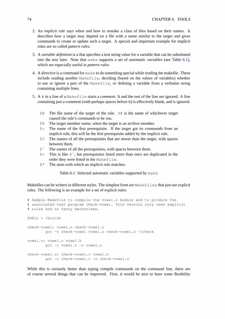
74 CHAPTER 6. TOOLS
2. An implicit rule says when and how to remake a class of files based on their names. Itdescribes how a target may depend on a file with a name similar to the target and givescommands to create or update such a target. A special and important example for implicitrules are so calledpattern rules.
3. A variable definitionis a that specifies a text string value for a variable that can be substitutedinto the text later. Note thatmake supports a set ofautomatic variables(see Table6.1),which are especially useful inpattern rules.
4. A directiveis a command formake to do something special while reading the makefile. Theseinclude reading anotherMakefile , deciding (based on the values of variables) whetherto use or ignore a part of theMakefile , or defining a variable from a verbatim stringcontaining multiple lines.
5. A # in a line of aMakefile starts acomment. It and the rest of the line are ignored. A linecontaining just a comment (with perhaps spaces before it) is effectively blank, and is ignored.
$@ The file name of the target of the rule.$@is the name of whichever targetcaused the rule’s commands to be run.
$% The target member name, when the target is an archive member.$< The name of the first prerequisite. If the target got its commands from an
implicit rule, this will be the first prerequisite added by the implicit rule.$? The names of all the prerequisites that are newer than the target, with spaces
between them.$ˆ The names of all the prerequisites, with spaces between them.$+ This is like $ˆ , but prerequisites listed more than once are duplicated in the
order they were listed in theMakefile .$* The stem with which an implicit rule matches.
Table 6.1: Selected automatic variables supported bymake
Makefiles can be written in different styles. The simplest form areMakefiles that just use explicitrules. The following is an example for a set of explicit rules:
# Sample Makefile to compile the vowel.o module and to produce the# associated test program check-vowel. This version only uses explicit# rules and no fancy mechanisms.
SHELL = /bin/sh
check-vowel: vowel.o check-vowel.ogcc -o check-vowel vowel.o check-vowel.o -lcheck
vowel.o: vowel.c vowel.hgcc -c vowel.c -o vowel.o
check-vowel.o: check-vowel.c vowel.hgcc -c check-vowel.c -o check-vowel.o
While this is certainly better than typing compile commands on the command line, there areof course several things that can be improved. First, it would be nice to have some flexibility
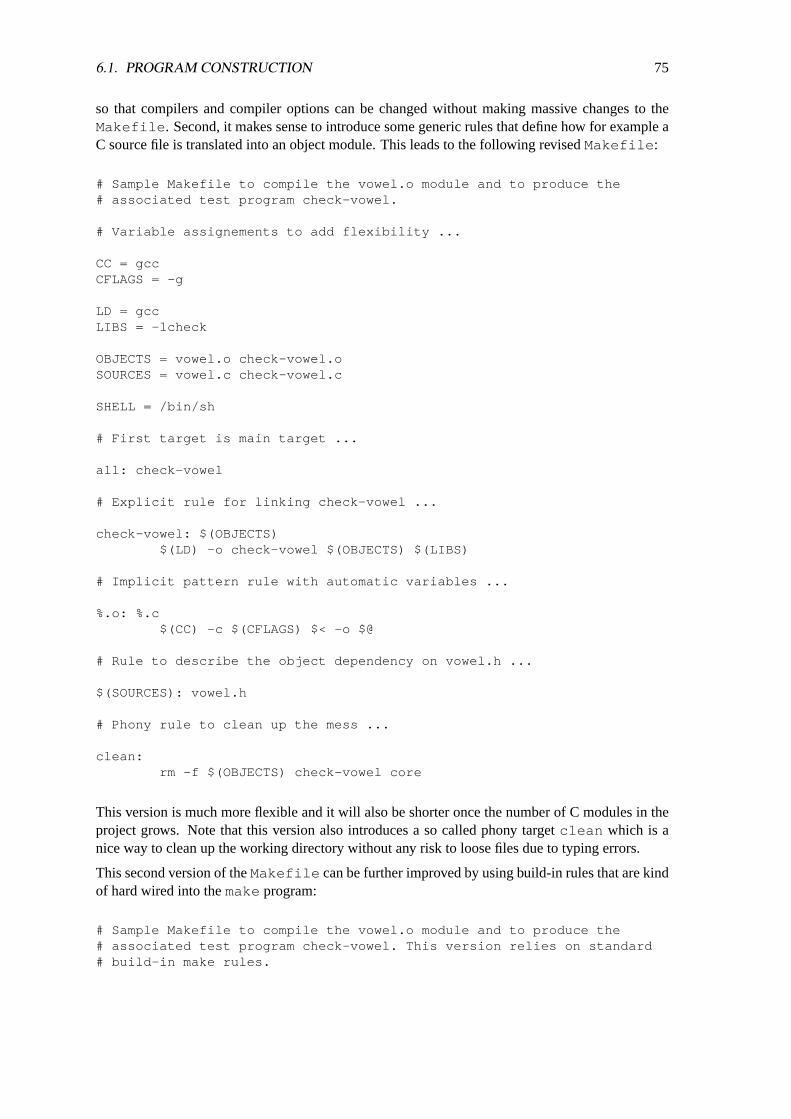
6.1. PROGRAM CONSTRUCTION 75
so that compilers and compiler options can be changed without making massive changes to theMakefile . Second, it makes sense to introduce some generic rules that define how for example aC source file is translated into an object module. This leads to the following revisedMakefile :
# Sample Makefile to compile the vowel.o module and to produce the# associated test program check-vowel.
# Variable assignements to add flexibility ...
CC = gccCFLAGS = -g
LD = gccLIBS = -lcheck
OBJECTS = vowel.o check-vowel.oSOURCES = vowel.c check-vowel.c
SHELL = /bin/sh
# First target is main target ...
all: check-vowel
# Explicit rule for linking check-vowel ...
check-vowel: $(OBJECTS)$(LD) -o check-vowel $(OBJECTS) $(LIBS)
# Implicit pattern rule with automatic variables ...
%.o: %.c$(CC) -c $(CFLAGS) $< -o $@
# Rule to describe the object dependency on vowel.h ...
$(SOURCES): vowel.h
# Phony rule to clean up the mess ...
clean:rm -f $(OBJECTS) check-vowel core
This version is much more flexible and it will also be shorter once the number of C modules in theproject grows. Note that this version also introduces a so called phony targetclean which is anice way to clean up the working directory without any risk to loose files due to typing errors.
This second version of theMakefile can be further improved by using build-in rules that are kindof hard wired into themake program:
# Sample Makefile to compile the vowel.o module and to produce the# associated test program check-vowel. This version relies on standard# build-in make rules.
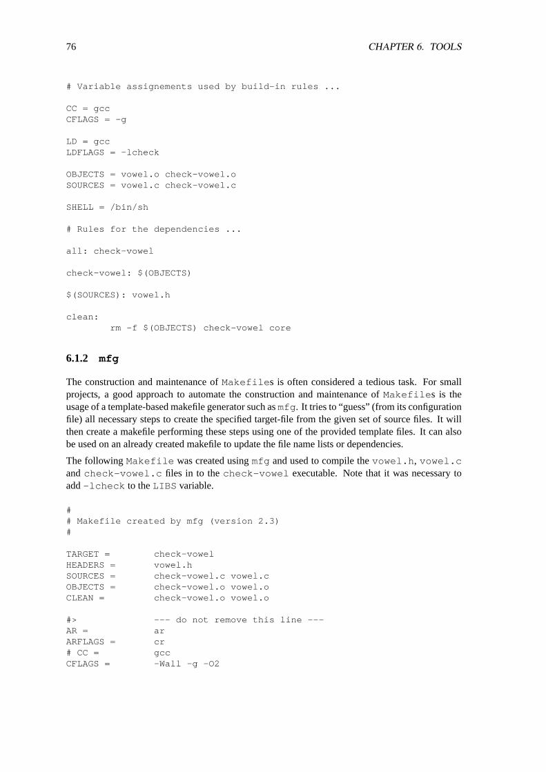
76 CHAPTER 6. TOOLS
# Variable assignements used by build-in rules ...
CC = gccCFLAGS = -g
LD = gccLDFLAGS = -lcheck
OBJECTS = vowel.o check-vowel.oSOURCES = vowel.c check-vowel.c
SHELL = /bin/sh
# Rules for the dependencies ...
all: check-vowel
check-vowel: $(OBJECTS)
$(SOURCES): vowel.h
clean:rm -f $(OBJECTS) check-vowel core
6.1.2 mfg
The construction and maintenance ofMakefile s is often considered a tedious task. For smallprojects, a good approach to automate the construction and maintenance ofMakefile s is theusage of a template-based makefile generator such asmfg . It tries to “guess” (from its configurationfile) all necessary steps to create the specified target-file from the given set of source files. It willthen create a makefile performing these steps using one of the provided template files. It can alsobe used on an already created makefile to update the file name lists or dependencies.
The followingMakefile was created usingmfg and used to compile thevowel.h , vowel.candcheck-vowel.c files in to thecheck-vowel executable. Note that it was necessary toadd-lcheck to theLIBS variable.
## Makefile created by mfg (version 2.3)#
TARGET = check-vowelHEADERS = vowel.hSOURCES = check-vowel.c vowel.cOBJECTS = check-vowel.o vowel.oCLEAN = check-vowel.o vowel.o
#> --- do not remove this line ---AR = arARFLAGS = cr# CC = gccCFLAGS = -Wall -g -O2
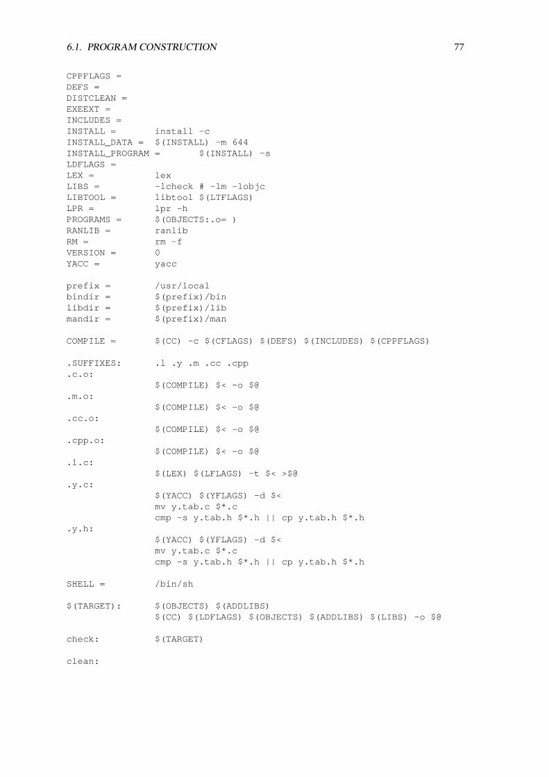
6.1. PROGRAM CONSTRUCTION 77
CPPFLAGS =DEFS =DISTCLEAN =EXEEXT =INCLUDES =INSTALL = install -cINSTALL_DATA = $(INSTALL) -m 644INSTALL_PROGRAM = $(INSTALL) -sLDFLAGS =LEX = lexLIBS = -lcheck # -lm -lobjcLIBTOOL = libtool $(LTFLAGS)LPR = lpr -hPROGRAMS = $(OBJECTS:.o= )RANLIB = ranlibRM = rm -fVERSION = 0YACC = yacc
prefix = /usr/localbindir = $(prefix)/binlibdir = $(prefix)/libmandir = $(prefix)/man
COMPILE = $(CC) -c $(CFLAGS) $(DEFS) $(INCLUDES) $(CPPFLAGS)
.SUFFIXES: .l .y .m .cc .cpp
.c.o:$(COMPILE) $< -o $@
.m.o:$(COMPILE) $< -o $@
.cc.o:$(COMPILE) $< -o $@
.cpp.o:$(COMPILE) $< -o $@
.l.c:$(LEX) $(LFLAGS) -t $< >$@
.y.c:$(YACC) $(YFLAGS) -d $<mv y.tab.c $*.ccmp -s y.tab.h $*.h || cp y.tab.h $*.h
.y.h:$(YACC) $(YFLAGS) -d $<mv y.tab.c $*.ccmp -s y.tab.h $*.h || cp y.tab.h $*.h
SHELL = /bin/sh
$(TARGET): $(OBJECTS) $(ADDLIBS)$(CC) $(LDFLAGS) $(OBJECTS) $(ADDLIBS) $(LIBS) -o $@
check: $(TARGET)
clean:
78 CHAPTER 6. TOOLS
$(RM) $(CLEAN) $(TARGET) $(TARGET)$(EXEEXT) core
distclean: clean$(RM) $(DISTCLEAN)
print:$(LPR) $(HEADERS) $(SOURCES)
install: $(TARGET)$(INSTALL) -d $(bindir)$(INSTALL_PROGRAM) $(TARGET)$(EXEEXT) $(bindir)
uninstall:$(RM) $(bindir)/$(TARGET)$(EXEEXT)
#> --- do not remove this line ---
Force_Update:
check-vowel.o: check-vowel.c vowel.h
vowel.o: vowel.c
6.1.3 autoconf and automake
Once a project has reached a state where multiple platforms have to be supported, it is often nec-essary to have some platform specific code which is compiled conditionally (for example to addmissing library functions or to replace broken library functions). A common approach to addressthese problems is to test the target platforms for any broken or missing functions or definitions andto select compilation options accordingly. This raises the question, how such tests can be written ina portable and reusable way.
Theautoconf program can be used to generate so calledconfigure scripts from templates. Aproject’s main template is stored in a file either calledconfigure.ac or configure.in . Thisfile usually calls a set of macros (written in the languagem4) which implement common tests.
The execution of aconfigure script finally leads to the construction of a specificMakefilefrom a templateMakefile (usually calledMakefile.in ) and a set of C preprocessor directivesthat are either listed in theMakefile or in a special header file calledconfig.h .
The usage ofautoconf alone requires to write theMakefile.in template manually. Theautomake program can be used in situation where the writing and maintenance of such templateMakefile s is problematic. This often happens when shared libraries or dynamic loadable librarieshave to be build on various platforms. Theautomake program reads a file calledMakefile.amwhich contains a very terse description of the various source files and the final targets and pro-duces a templateMakefile.in that can be used together with aconfigure script generatedby autoconf .
To continue the example, a sampleconfigure.in and a sampleMakefile.am are shownbelow for thecheck-vowel example. Note that the usage ofautoconf andautomake is kindof overkill for such small projects but a big help for larger projects.
dnl Configure.in template for autoconf which is used to produce a
6.2. DIFFERENCES BETWEEN FILES 79
dnl configure script.
AC_INIT(vowel.h)AM_INIT_AUTOMAKE(check-vowel, 1.0)AC_PROG_CCAC_OUTPUT(Makefile)
# Makefile.am template for producing a Makefile.in.
bin_PROGRAMS = check-vowel
check_vowel_SOURCES = vowel.h vowel.c check-vowel.ccheck_vowel_LDADD = -lcheck
6.1.4 autoproject
The sources of a software project are typically accompanied with a set of files that describe theproject. There are typically some standard files that need to be present. In order to make thecreation of a new project easy, one can use theautoproject package. The idea is that youexecuteautoproject just once when a new project is started.autoproject asks for thename of the new program (unless it is given on the command line), a program description and otherdata. It then creates a subdirectory and populates it with a C program with command line parsing,a simple manual page and texinfo page, and other standard files. The package is intended to followthe GNU programming standards. It usesautoconf to configure itself, andautomake to createtheMakefile .
6.2 Differences between Files
Almost all artefacts (e.g., source code, documentation) of a real-world software project undergomany changes during the lifetime of the project. It is thus important to be able to identify thechanges and to store and integrate such changes in an efficient way.
6.2.1 diff
Thediff program compares two input files line by line and outputs a script which describes thechanges that need to be made to the first file in order to turn it into the second file. There are differentoutput formats. The classicdiff output format is a script which can be fed into theed editor. Thisis seldom used today since there are newer formats which are more human readable and whichprovide information about the context of the change. The probably most widely used format todayis the unified context diff format which basically identifies lines that need to be added/removed byprefixing lines with either the+ or the- character. Lines that are unchanges are prefixed by a spacecharacter.
Below is a unified context diff for the changes from the firstMakefile to the thirdMakefilefor check-vowel shown above.
--- Makefile.v1 2003-11-03 14:34:18.000000000 +0100+++ Makefile.v3 2003-11-03 21:44:08.000000000 +0100

80 CHAPTER 6. TOOLS
@@ -1,14 +1,27 @@# Sample Makefile to compile the vowel.o module and to produce the
-# associated test program check-vowel. This version only uses explicit-# rules and no fancy mechanisms.+# associated test program check-vowel. This version relies on standard+# build-in make rules.++# Variable assignements used by build-in rules ...++CC = gcc+CFLAGS = -g++LD = gcc+LDFLAGS = -lcheck++OBJECTS = vowel.o check-vowel.o+SOURCES = vowel.c check-vowel.c
SHELL = /bin/sh
-check-vowel: vowel.o check-vowel.o-gcc -o check-vowel vowel.o check-vowel.o -lcheck+# Rules for the dependencies ...++all: check-vowel++check-vowel: $(OBJECTS)
-vowel.o: vowel.c vowel.h-gcc -c vowel.c -o vowel.o+$(SOURCES): vowel.h
-check-vowel.o: check-vowel.c vowel.h-gcc -c check-vowel.c -o check-vowel.o+clean:+ rm -f $(OBJECTS) check-vowel core
6.2.2 patch
Thepatch program is used to integrate so called patch files (such as unified context diffs) into aset of files. With context diffs, and to a lesser extent with normal diffs, patch can detect when theline numbers mentioned in the patch are incorrect, and attempts to find the correct place to applyeach hunk of the patch. As a first guess, it takes the line number mentioned for the hunk, plus orminus any offset used in applying the previous hunk. If that is not the correct place, patch scansboth forwards and backwards for a set of lines matching the context given in the hunk. First patchlooks for a place where all lines of the context match. If no such place is found, and it is a contextdiff, and the maximum fuzz factor is set to 1 or more, then another scan takes place ignoring thefirst and last line of context. If that fails, and the maximum fuzz factor is set to 2 or more, the firsttwo and last two lines of context are ignored, and another scan is made. (The default maximumfuzz factor is 2.) If patch cannot find a place to install that hunk of the patch, it puts the hunk out toa reject file.
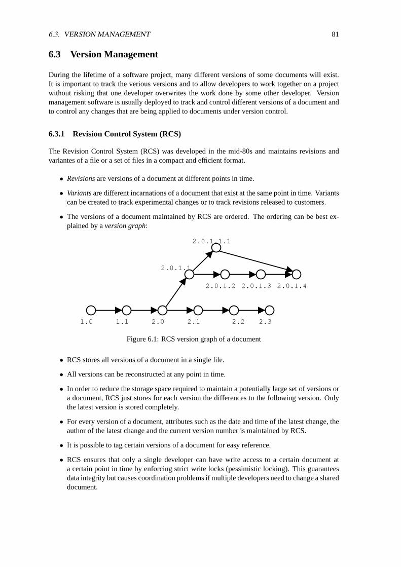
6.3. VERSION MANAGEMENT 81
6.3 Version Management
During the lifetime of a software project, many different versions of some documents will exist.It is important to track the verious versions and to allow developers to work together on a projectwithout risking that one developer overwrites the work done by some other developer. Versionmanagement software is usually deployed to track and control different versions of a document andto control any changes that are being applied to documents under version control.
6.3.1 Revision Control System (RCS)
The Revision Control System (RCS) was developed in the mid-80s and maintains revisions andvariantes of a file or a set of files in a compact and efficient format.
• Revisionsare versions of a document at different points in time.
• Variantsare different incarnations of a document that exist at the same point in time. Variantscan be created to track experimental changes or to track revisions released to customers.
• The versions of a document maintained by RCS are ordered. The ordering can be best ex-plained by aversion graph:
1.0 1.1 2.0 2.1 2.2 2.3
2.0.1.1
2.0.1.2 2.0.1.3 2.0.1.4
2.0.1.1.1
Figure 6.1: RCS version graph of a document
• RCS stores all versions of a document in a single file.
• All versions can be reconstructed at any point in time.
• In order to reduce the storage space required to maintain a potentially large set of versions ora document, RCS just stores for each version the differences to the following version. Onlythe latest version is stored completely.
• For every version of a document, attributes such as the date and time of the latest change, theauthor of the latest change and the current version number is maintained by RCS.
• It is possible to tag certain versions of a document for easy reference.
• RCS ensures that only a single developer can have write access to a certain document ata certain point in time by enforcing strict write locks (pessimistic locking). This guaranteesdata integrity but causes coordination problems if multiple developers need to change a shareddocument.

82 CHAPTER 6. TOOLS
The most important RCS commands are shown in Table6.2.
Command Description
co Retrieve a revision from an RCS file and store it into the corre-sponding working file.
ci Stores a new revisions into an RCS file.rcsdiff Compute a (context) diff for two revisions of a file.rcsmerge Integrate variants into the current working files.rlog Print information about RCS files.
Table 6.2: Most important RCS commands
6.3.2 Concurrent Versions System (CVS)
The Concurrent Versions System (CVS) supports the versioning of complete directory trees. Inparticular, CVS allows to add and remove files.
Figure 6.2: CVS Konfigurationen
A cut through the revisions of several documents is called aconfiguration. The revisions of a singledocument are controlled by using RCS. Configurations can be tagged so that it is easy to refer tothem.
Developers can create multiple local copies of the same configuration and work on those localcopies independently. Once changes are committed to the CVS repository, a check is performedto ensure that (a) the local copies are current with respect to the latest version in the developmentbranch and (b) that no unresolved conflicts exist (optimistic approach).
The most important CVS commands are shown in Table6.3.

6.4. EXECUTION TRACER 83
Command Description
cvs checkout Create a local copy of a CVS module.cvs commit Commit changes to the CVS repository.cvs add Add a new file to the CVS repository.cvs remove Remove a file from the CVS repository.cvs update Merge any updates from the CVS repository into the local copy.cvs diff Compute a diff between a CVS version and the local copy.cvs tag Tag a configuration in the CVS repository.
Table 6.3: Most important CVS commands
6.4 Execution Tracer
It is sometimes useful to find out quickly what a program is doing or if it is doing something at all.Being able to do this is especially important for programs where no source code is available and thedocumentation is rather incomplete.
6.4.1 Tracing System Calls and Signals (strace)
Thestrace utility executes programs and intercepts and records the system calls which are calledby a process and the signals which are received by a process. It is a very useful diagnostic, instruc-tional, and debugging tool which is available for almost all Unix systems.
6.4.2 Tracing Library Calls (ltrace)
The ltrace utility intercepts and records the dynamic library calls which are called by the ex-ecuted process and the signals which are received by that process. Theltrace utility can alsointercept and print the system calls executed by the program. In fact,ltrace functionality formsa superset of the functionality provided bystrace . However,ltrace does only run on selectedUnix systems.
6.4.3 Data Display Debugger (ddd)
Some more comfort is provided by graphical debuggers. Most of them are basically graphical userinterfaces build around a real debugger such asgdb for C/C++ or jdb for Java. A good exampleis the Data Display Debuggerddd which is able to visualize complex data structures.
6.4.4 GNU Visual Debugger (gvd)
Another visualizing debugger isgvd which is actually written in the programming language Ada.It is like ddd basically a graphical frontend for the debuggergdb .
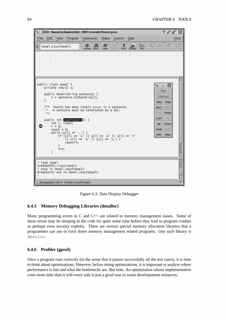
84 CHAPTER 6. TOOLS
Figure 6.3: Data Display Debugger
6.4.5 Memory Debugging Libraries (dmalloc)
Many programming errors in C and C++ are related to memory management issues. Some ofthese errors may be sleeping in the code for quite some time before they lead to program crashesor perhaps even security exploits. There are several special memory allocation libraries that aprogrammer can use to track down memory management related programs. One such library isdmalloc .
6.4.6 Profiler (gprof)
Once a program runs correctly (in the sense that it passes successfully all the test cases), it is timeto think about optimizations. However, before doing optimizations, it is important to analyze whereperformance is lost and what the bottlenecks are. But note: An optimization whose implementationcosts more time than it will every safe is just a good way to waste developement resources.

6.4. EXECUTION TRACER 85
In order to figure out which parts of a program have a big influence of the overall performance, itis necessary to make some measurements. Many C compilers have a special option (usually-pg )which can be used to compile profiling instrumentation into object files. During the execution of aprogram which was compiled with profiling enabled, execution statistics will be collected.

86 CHAPTER 6. TOOLS

Chapter 7
Ergonomic Aspects
Ergonomics are concerned with the study of the design and arrangement of equipment so that peo-ple will interact with the equipment in a healthy, comfortable, and efficient manner. As related tocomputer equipment, ergonomics is concerned with such factors as the physical design of the key-board, screens, and related hardware, and the manner in which people interact with these hardwaredevices. Ergonomics also play a role in the design of software systems, especially at the boundarybetween the machine and the human user (human/machine interface). Another frequently used termfor this is human computer interaction (HCI).
Human computer interaction is a rather young interdisciplinary field of research which touchesseveral research areas:
• Cognitive Psychology: perception, learning, reasoning, problem solving
• Physiology: sensors, motion, body
• Industrial Psychology: work organization, education, user participation, work security, eval-uation
• Ergonomics: design and arrangement of equipment, formation of rooms, light
• Software Engineering: systematic, disciplined, quantifiable approach to the development,operation, and maintenance of software
• Human Computer Interaction: help systems, tutorial systems, menus and forms, commandinterfaces, direct manipulation interfaces, hypertext and hyper-media, visualization, interac-tion with forms, dialog control
A good interface between a software system and a human user typically requires that the softwaresystem creates and maintains an explicituser modelwhich is used to guide the interaction with aparticular user. It is often sufficient to distinguish only a few broad user groups:
• novices, beginners
• casual users, infrequent users
• experts, frequent users, sophisticated users
87
88 CHAPTER 7. ERGONOMIC ASPECTS
7.1 Dialog Types
• A primary dialogis a dialog which exists until a certain task (e.g., editing of a UML diagram)has been completed.
• A secondary dialogis a dialog with a shorter lifetime which displays information about acertain subtask or which requests information needed to complete a certain subtask (e.g., afile selection dialog).
• A modal dialogforces the user to complete the modal dialog before the rest of applicationcan be used.
• A non-modal dialogallows the user to execute some other functions and to return to thenon-modal dialog at a later point in time.
• It is generally preferable to limit the use of modal dialogs since they drastically reduce theflexibility of the user. This is especially true for modal dialogs which not only prevent theusage of other function of the same program, but also prevent the usage of other programs.
• Function-oriented user interfacesare build around the principle that a user first selects a func-tion which is then applied to a set of objects. Function-oriented interfaces are typically foundin command line interfaces (e.g.,rm *.[ch] ) but also exist in graphical user interfaces(e.g., selection of tools to modify elements in a graphics editor).
• Object-oriented user interfacesare build around the principle that a user first selects a set ofobjects and then applies a function to the set of selected objects where the object defines theprecise interpretation of the function for this particular object type. Object-oriented interfacesare the foundation of most direct manipulation desktop interfaces.
7.2 Dialog Requirements
The European ISO standard 9241-10 [9] defines general requirements for the design of dialogs.
7.2.1 Suitability for the Task
A dialog is suitable for the task if the dialog helps the user to complete his task in an effective andefficient manner.
7.2.2 Self Descriptiveness
A dialog is self descriptive if every single dialog step can immediately be understood by the userbased on the information displayed by the system or if there is a mechanism to obtain any additionalexplanatory information on request of the user.
7.2.3 Controllability
A dialog is controllable if the user can start the dialog and influence the direction and speed of thedialog at any point in time until the task has been completed.
7.2. DIALOG REQUIREMENTS 89
7.2.4 Conformity with User Expectations
A dialog is conforming with user expectations if it is consistent and complies to the characteristicsof the human user, that is his knowledge of the task, his education and expertise and generallyaccepted conventions).
7.2.5 Error Tolerance
A dialog is fault tolerant if a task can be completed with error-nous inputs with minimal overheadfor corrections by the human user.
7.2.6 Suitability for Individualisation
A dialog is suitable for individualisation if the system allows to adapt the interaction style to aparticular task and the specific capabilities and preferences of the user.
7.2.7 Suitability for Learning
A dialog is suitable for learning if it helps and guides the novice user to learn about other perhapsmore efficient or effective ways to use an application.

90 CHAPTER 7. ERGONOMIC ASPECTS

Chapter 8
Empirical Laws
This chapter is purely about the empirical aspects of software engineering and systems design. Itis heavily based on the handbook of software and systems engineering written by A. Endres andD. Rombach, published in 2003 [6]. The authors have collect a number of classic observations,empirical laws and their theories:
• Observationsare facts or just subjective impressions.
• Repeated observations usually result inlaws. Laws are therefore generalizations from onesituation to another telling us how things occur (but not why).
• A theoryexplains empirically discovered laws and our observations. Theories may exist firstand they may predict laws and observations.
• A potential law which has not yet been adequately confirmed by observations is called ahypothesis.
The following sections summarize the laws and hypothesis for the various phases in a software life-cycle and the different activities that are carried out in these phases. For a more detailed discussion,see the original publication [6].
8.1 Requirements Phase
Law 1 Requirement deficiencies are the prime source of project failures. (Glass’ law, 1998)
Law 2 Errors are most frequent during the requirements and design activities and are the moreexpensive the later they are removed. (Boehm’s first law, 1975)
Law 3 Prototyping (significantly) reduces requirement and design errors, especially for user inter-faces. (Boehm’s second law)
Law 4 The value of a model depends on the view taken, but none is best for all purposes. (Davis’law, 1990)
Hypothesis 1Object model reduces communication problems between analysts and users. (Booch’sfirst hypothesis, 1991)
91

92 CHAPTER 8. EMPIRICAL LAWS
8.2 System design and specification
Law 5 Good designs require deep application domain knowledge. (Curtis law, 1988)
Law 6 Hierarchical structures reduce complexity. (Simon’s law, 1962)
Law 7 A structure is stable if cohesion is strong and coupling is low. (Constantine’s law, 1974)
Law 8 Only what is hidden can be changed without risk. (Parnas’ law, 1972)
Law 9 Separation of concerns leads to standard architectures. (Denert’s law, 1991)
Law 10 Screen pointing-time is a function of distance and width. (Fitts-Shneiderman law, 1954)
Hypothesis 2Object-oriented designs reduce errors and encourage reuse. (Booch’s second hy-pothesis)
Hypothesis 3Formal methods significantly reduce design errors, or eliminate them early. (Bauer-Zemanek hypothesis, 1968/1982)
Hypothesis 4Reusing designs through patterns yields faster and better maintenance. (Gamma’shypothesis, 1995)
8.3 System construction and composition
Law 11 What applies to small systems does not apply to large ones. (DeRemer’s law, 1975)
Law 12 Productivity and reliability depends on the length of a program’s text, independent of lan-guage level used. (Corbato’s law, 1969)
Law 13 Well-structured programs have fewer errors and are easier to maintain. (Dijkstra-Mills-Wirth law, 1969/1971)
Law 14 The larger and more decentralized an organization, the more likely it is that it has reusepotential. (Lanergan’s law, 1979/1984)
Law 15 Software reuse reduces cycle time and increases productivity and quality. (McIlroy’s law,1968)
Law 16 A system reflects the organizational structure that built it. (Conway’s law, 1968)
Hypothesis 5Object-oriented programming reduces errors and encourages reuse. (Dahl-Goldberghypothesis, 1967/1989)
Hypothesis 6Agile programming methods reduce the impact of requirement changes. (Beck-Fowlerhypothesis, 1999/2001)
Hypothesis 7Commercial off-the-shelf (COTS) based software does not eliminate the key develop-ment risks. (Basili-Boehm, 2001)

8.4. VALIDATION AND STATIC VERIFICATION 93
8.4 Validation and static verification
Law 17 Inspections significantly increase productivity, quality, and project stability. (Fagan’s law,1976)
Law 18 Effectiveness of inspections is fairly independent of its organizational form. (Porter-Vottalaw, 1997)
Law 19 Perspective–based inspections are (highly) effective and efficient. (Basili’s law, 1996)
Law 20 A combination of different validation and verification methods outperforms any singlemethod alone. (Hetzel-Myers law, 1976/1978)
Hypothesis 8Quality entails productivity. (Mills-Jones, 1983/1996)
Hypothesis 9Error prevention is better than error removal. (Mays’ hypothesis)
Hypothesis 10Proving of programs solves the problems of correctness, documentation, and com-patibility. (Hoare’s hypothesis, 1969)
8.5 Testing and dynamic verification
Law 21 Online debugging is more efficient than off-line debugging. (Sackman’s first law, 1968)
Law 22 Testing can show the presence but not the absence of errors. (Dijkstra’s law, 1970)
Law 23 A developer is unsuited to test his or her code. (Weinberg’s law, 1971)
Law 24 Approximately 80 percent of the defects come from 20 percent of modules. (Pareto-Zipf-type laws, 1897)
Law 25 Performance testing benefits significantly from system-level benchmarks. (Gray-Serlinlaw)
Law 26 Usability is quantifiable (Nielson-Norman law)
Hypothesis 11Partition testing is more effective than random testing. (Gutjahr’s hypothesis, 1999)
Hypothesis 12The adequacy of a coverage criteria can only be intuitively defined. (Weyuker’shypothesis, 1988)
Hypothesis 13The test suite to verify an arithmetic path expression can be determined. (Endres-Glatthaar hypothesis, 1978)
Hypothesis 14Suspicion-based testing can be more effective than most other approaches. (Ham-let’s hypothesis, 1990)

94 CHAPTER 8. EMPIRICAL LAWS
8.6 System manufacturing, distribution and installation
Conjecture 1 For commercial off-the-shelf products, costs and risks of manufacturing can ap-proach those of development.
Conjecture 2 Distribution ends where the customer wants it to end.
Conjecture 3 Prevention of software piracy by technical means is almost impossible.
Conjecture 4 Installability must be designed in.
8.7 System administration, evolution and maintenance
Law 27 A system that is used will be changed. (Lehman’s first law, 1980)
The original version of the law actually reads as follows: “A system must be continually adaptedelse it becomes progressively less satisfactory in use.”
Law 28 An evolving system increases its complexity unless work is done to reduce it. (Lehman’ssecond law, 1980)
Law 29 System evolution is determined by a feedback process. (Lehman’s third law, 1980)
Law 30 Smaller changes have a higher error density than larger ones. (Basili-Moller law)
Hypothesis 15Complexity metrics are good predictors of post-release reliability and maintainabil-ity. (McCabe’s hypothesis, 1976)
Hypothesis 16Object-oriented programs are difficult to maintain. (Wilde’s hypothesis, 1993)
Conjecture 5 The larger the system, the greater the administration effort that is needed.
Conjecture 6 Any system can be tuned.
8.8 Project management and business analysis
Law 31 Individual developer performance varies considerably. (Sackmann’s second law, 1968)
Law 32 A multitude of factors influence developer productivity. (Nelson-Jones law, 1966/2000)
Law 33 Development effort is a (non-linear) function of product size. (Boehm’s third law, 1981)
Law 34 Most cost estimates tend to be too low. (DeMarco-Glass law, 1982/1998)

8.9. USER SKILLS, MOTIVATION, AND SATISFACTION 95
Law 35 Mature processes and personal discipline enhance planning, increase productivity, andreduce errors. (Humphrey’s law, 1989)
Law 36 Adding manpower to a late project makes it later. (Brooks’ law, 1975)
Law 37 Products replace services through productivity gains. (Baumol’s disease, 2001)
Hypothesis 17Project risks can be resolved or mitigated by addressing them early. (Boehm’shypothesis, 1988)
8.9 User skills, motivation, and satisfaction
Law 38 Humans receive most information through the visual system and store it in a spatiallyorganized memory. (Kupfmuller’s law, 1971)
Law 39 Humans tend to structure what they see to form cohesive patterns. (Gestalt law, 1923)
Law 40 Short-term memory is limited to7± 2 chunks of information. (Miller’s law, 1956)
Law 41 Multi-modal information is easier to remember than single mode. (Krause’s law, 2000)
Law 42 The more knowledge that is available, the more effort has to be spent on the processes touse it. (Librarian’s law, 2000)
Law 43 It takes 5000 hours to turn a novice into an expert. (Apprentice’s law, 1993).
Law 44 Human needs and desires are strictly prioritized. (Maslow-Herzberg law, 1954/1966)
Hypothesis 18Motivation requires integration and participation. (McGregor’s hypothesis, 1960)
Hypothesis 19Group behavior depends on the level of attention given. (Hawthone effect, 1974)
Hypothesis 20One unsatisfied customer can hurt more than two satisfied customers can help.(Marketer’s hypothesis)
8.10 Technology, architecture, and industry capabilities
Law 45 The price/performance of processors is halved every 18 months. (Moore’s law, 1965)
Law 46 The capacity of magnetic devices increases by a factor of ten every decade. (Hoagland’slaw, 1993)
Law 47 Wireless bandwidth doubles every 2.5 years. (Cooper’s law, 2001)
96 CHAPTER 8. EMPIRICAL LAWS
Law 48 Architecture wins over technology. (Morris-Ferguson law, 1993)
Law 49 The value of a network increases with the square of its users. (Metcalfe’s law, 1973)
Hypothesis 21A sound architecture significantly reduces development and maintenance costs. (Shaw-Garlan hypothesis, 1996)
Hypothesis 22In spite disk capacity increases, data access can be kept efficient. (Bayer’s hypoth-esis, 1972)
Hypothesis 23Databases can be independent of devices and applications. (Codd’s hypothesis,1970)
Hypothesis 24Conceptual integrity is the result of a consistent mental model. (Engelbart’s hy-pothesis, 1968)
8.11 Measurements, experiments, and empirical research
Law 50 The probability that a hypothesis is true increases the more unlikely the new event is thatconfirms this hypothesis. (Bayes’ theorem)
Hypothesis 25Measurements require both goals and models. (Basili-Rombach hypothesis, 1988/1994)
Conjecture 7 Human-based methods can only be studied empirically.
Conjecture 8 Process improvements require action-based feedback.
Conjecture 9 Learning is best accelerated by a combination of controlled experiments and casestudies.
Conjecture 10Measurements are always based on actually used models rather than on desiredones.
Conjecture 11Empirical results are transferable only if abstracted and packaged with context.
Conjecture 12Empirically based models mature from understanding to explaining and predictingcapability.
Appendix A
Questions
A.1 Introduction
1. Name some properties of software and explain how software differs from other technicalproducts.
2. Define the term Software Engineering.
3. What is the software crisis? What are the problems that lead to the software crisis?
4. What is a fault tolerant system? Explain the difference between a fault and a failure.
5. Discuss the term software quality. How can you measure the quality of a software product?
A.2 Process Models
1. What is the Capability Maturity Model (CMM) and for which purpose can it be used?
2. Explain the main difference between the waterfall model and the V model.
3. Describe the difference between a horizontal prototype and a vertical prototype and betweena demonstration prototype and a pilot system.
4. Name the techniques of the extreme programming process model.
5. Which process model would you choose for developing software that maintains a catalog ofa library with a web-based loan function?
A.3 Unified Modeling Language
1. Name at least five diagram types used by the Unified Modeling Language.
2. What is the difference between structural diagrams and behavioral diagrams?
3. How is the visibility of attributes and operations identified in UML class diagrams?
97
98 APPENDIX A. QUESTIONS
4. Explain the concepts generalization, specialization, aggregation and composition. How arethese concepts represented in UML class diagrams?
5. What is a recursive association? Give an example for a recursive association.
6. Explain the term multiplicity using some examples.
7. What are association classes?
8. Draw a class diagram and an object diagram for a simple library.
9. Draw a sequence diagram for filling the gasoline tank of a car.
10. What is a collaboration diagram? What is its relationship to a sequence diagram?
11. Describe the process of making a pizza in an activity diagram. Which activities can be carriedout concurrently? What are swimlanes and can they be used in this example?
12. What are component diagrams and distribution diagrams?
A.4 Design Pattern
1. Explain what design patterns are and in which form they are usually written down.
2. Describe the composite design pattern.
3. What is an observer? Sketch the observer principle in form of a UML class diagram. Do youknow realizations of the observer design pattern?
4. What is the purpose of the strategy design pattern? Where can it be used?
5. Explain the chain of responsibility design pattern.?
6. Explain the model view controller design pattern. How is the model view controller patternrelated to other patterns?
A.5 Quality Assurance
1. Name typical classes of software errors.
2. What is a program inspection?
3. Explain the difference between black box and white box testing.
4. What is a functional testing? How are equivalence classes used?
5. Use a simple example to explain the concept of a control flow graph.
6. Explain the terms statement coverage, branch coverage, condition coverage, and path cover-age. What is the relationship between these coverage criterias?
7. What is the purpose of a regression test?

A.6. TOOLS 99
8. Explain the difference between static and dynamic software metrics.
9. How is the fan-in and the fan-out of a function defined?
10. What is the basis for the definition of the cyclomatic complexity?
11. Which constructs are analyzed in order to compute the Halstead metrics?
12. Name a few indicators for “bad smelling code.”
A.6 Tools
1. Name a few tools that can be used during the implementation of a software system.
2. What is the purpose of make and how does make determine which commands need to beexecuted in which order?
3. What is version management in software engineering and why is it important?
4. What is the relationship between RCS and CVS? What is a revision, a variant and a configu-ration?
5. What are the main differences between RCS and CVS.
6. What are unit tests and unit test frameworks?
7. What is the purpose of an integrated development environment? What are the advantagesand are there any disadvantages?
A.7 Ergonomic Aspects
1. What is a user model and how are user models used to improve the ergonomic aspects of userinterfaces?
2. What is a modal dialog and when should modal dialogs be used?
3. Explain the difference between a primary dialog and a secondary dialog.
4. Illustrate the difference between a function-oriented and an object-oriented user interface.
5. Name some rules for the design of ergonomic user interfaces.
6. What is an event-loop? Why are event-loops central to graphical user interfaces?
7. Explain what the term composition means in the context of the appearance of a graphicaluser interface.

100 APPENDIX A. QUESTIONS

Bibliography
[1] H. Balzert.Lehrbuch der Software-Technik. Spektrum, Akademischer Verlag, 2 edition, 2000.
[2] K. Beck.Extreme Programming Explained: Embrace Change. Addison-Wesley, 1999.
[3] G. Booch, J. Rumbaugh, and I. Jacobsen.The Unified Modeling Language User Guide.Addison Wesley, 1998.
[4] F. P. Brooks.The Mythical Man-Month. Addison Wesley, 1975.
[5] T. DeMarco.Der Termin. Hanser Verlag, 1998.
[6] A. Endres and D. Rombach.A Handbook of Software and Systems Engineering. Addison-Wesley, 2003.
[7] E. Gamma, R. Helm, R. Johnson, and J. Vlissides.Design Patterns: Elements of ReusableObject-Oriented Software. Addison Wesley, 1995.
[8] G. J. Myers.The Art of Software Testing. John Wiley & Sons, 1979.
[9] W. Schneider. Ergonomische Anforderungen fur Burotatigkeiten mit Bildschirmgeraten –Grundsatze der Dialoggestaltung (Kommentar zu DIN EN ISO 9241-10). Beuth Verlag, 1998.
[10] I. Sommerville.Software Engineering. Addison Wesley, 2001.
[11] P. Stevens and R. Pooley.UML - Softwareentwicklung mit Objekten und Komponenten.Addison Wesley, 2000.
[12] A. Zeller and J. Krinke.Programmierwerkzeuge. dpunkt, 2000.
101