Embed Size (px)
Citation preview

Advanced SiC MOSFETs for High Power Applications
L. Stevanovic, A. Bolotnikov, E. Kaminski, R. Beaupre, S. Kennerly, D. Lilienfeld, J. Alvarado, T. Johnson, A. Gowda, D. Esler, S. Arthur, P. Losee, Y. Sui, Z. Stum, J. McMahon, J. Glaser, J. Nasadoski GE Global Research, Niskayuna, NY 25 Jan, 2013 Presented at CFES 2012-2013 Annual Conference

Device Performance

Presented at RPI CFES, 25 Jan, 2013 3
MOSFET Stability at High Temperature Threshold voltage drift at 150°C, after -20 V on the gate

Presented at RPI CFES, 25 Jan, 2013 4
GE12N15 GE12N20
30% reduction
in $/A
Improved Temp. and Current Rating Higher Temperature Higher Current

Presented at RPI CFES, 25 Jan, 2013 5
Avalanche Ruggedness: UIS
-2
0
2
4
6
8
10
12
0
500
1000
1500
2000
0 100 200 300 400 500
I (A
)
V (
V)
Time (us)
Ea=1.33J
Voltage
Current
Superior to silicon 900V/23A Si CoolMOSTM (Ea = 1.9J)
GE’s 1200V/20A SiC MOSFET (Ea > 1J)
>8X active area difference
Reduced variability through process optimization
Ea (J)
Fre
qu
en
cy
2011 2012
LSL

Presented at RPI CFES, 25 Jan, 2013 6
Short-Circuit Capability
• Fault detection improves system safety and uptime
• Short-circuit test capability established • 960V results show tsc between 3.5 and 4us. At lower voltages,
tsc increases sufficient for majority of applications
• Short-circuit test results:
Vds = 960V Id_pk = 190A Vgs: -10V, +20V

Presented at RPI CFES, 25 Jan, 2013 7
SiC MOSFET Body Diode
Cont. test started mid-2012
Assembled a rack with six Buck-Boost converters (total of 24 MOSFETs) for testing of body diode’s long term stability.
Vsd recorded periodically during test
Buck-Boost : 200 kHz 600V, 6 kW
- Diode conducts only 5% of time (250ns out of 5uS). Tj = ~100°C
- No failures after 4500 hrs
- Diode Vsd stable (< 4% increase)

GRC Fab Manufacturing Readiness - MRL7

Presented at RPI CFES, 25 Jan, 2013 9
GRC SiC Pilot Production Line Installed and Validated Dedicated Toolset in 2011-12
Metal Deposition Asher
Polyimide coat/
develop
Solvent Bench Caros,
HF Acid Bench
RTA
Rinser Dryer
Implant Activation
ICP Etch Al Etch
Acid Bench
Resist coat/
develop

Presented at RPI CFES, 25 Jan, 2013 10
50A 15A
1A 0.25A
6A
D=3”
D=2.375”
D=4”
Product Introduction Timeline
MRL 4 Produce
In Lab
Environment
MRL 5-6 Produce in
Relevant
Environment
MRL 7 Produce in
Representative
Environment
MRL 8 Pilot Line
Demo’d,
Start LRIP
TRL 5 Breadboard
in Rep
Environment
TRL 7 Prototype
in Operating
Environment
TRL 8 System
Qual.
TRL 9 Mission
Proven
4Q’10 4Q’11 4Q’12 4Q’09
TRL 6 Prototype
in Representative
Environment
TRL: Tech Readiness Level
MRL: Mfg Readiness Level
Product
launch:
3Q2013

Device Reliability

Presented at RPI CFES, 25 Jan, 2013 12
Probability - Weibull
Time (hours)
Un
reli
ab
ilit
y,
F(
t)
1.E-3 10001.E-2 1.E-1 1 10 1001
5
10
50
90
99Probability-Weibull
JR13 FastRR re-ox; 0.4Ch; 4.2E13\37.5V 200CWeibull-2PMLE SRM MED FMF=34/S=13
Data PointsSusp Points
JR13 FastRR re-ox; 0.4Ch; 4.2E13\39.5V 175CWeibull-2PMLE SRM MED FMF=43/S=4
Data PointsSusp Points
JR13 FastRR re-ox; 0.4Ch; 4.2E13\39.5V 200CWeibull-2PMLE SRM MED FMF=42/S=6
Data PointsSusp Points
JR13 FastRR re-ox; 0.4Ch; 4.2E13\39.5V 225CWeibull-2PMLE SRM MED FMF=46/S=1
Data PointsSusp Points
JR13 FastRR re-ox; 0.4Ch; 4.2E13\41V 200CWeibull-2PMLE SRM MED FMF=50/S=0
Data Points
Rich BeaupreGE12/25/20128:23:07 AM
Time=0
failures
Intrinsics,
wearout
Extrinsic failures, bottom
of bathtub curve (FITs)
On-wafer MOSFET Reliability Testing Accelerated stress testing: gate field and temperature

Presented at RPI CFES, 25 Jan, 2013 13
DD063 JR13
Time (hours)
Cu
mu
lati
ve
% F
ailu
res
10 1.E+9100 1000 10000 100000 1000000 1.E+7 1.E+81
5
10
50
90
99
Lifetime Model Developed using full MOSFETs
Accelerated stress parameters: • Gate voltage • Junction temperature
Use conditions:
• 20V @ 175C
Extrinsics censored Design exceeds 100 year goal
η = exp (0 + 1E + 2 11605/T) 0 = 17.65 1 = -3.47 cm/MV 2 = 0.68 eV
Use Conditions

Presented at RPI CFES, 25 Jan, 2013 14
ReliaSoft Weibull++ 7 - www.ReliaSoft.com
F/S Timeline
Time, (t)
0.000 1250.000250.000 500.000 750.000 1000.000
FS Timeline
Suspension
1/17/20138:27:21 PM
Gate Reliability (HTGB) Assessment: Good w2w repeatability MOSFET intrinsic lifetime far
better than 106 hours goal Estimated random failure rate
< 10 FITs @ 20V/150⁰C Ongoing Qual. efforts (per AEC-Q101)
HTRB at 175C, 960 & 1200V: 0/80 failures after 1,000 hrs
Temp cycling (-55 to +200⁰C): 0/77 failures after 1,000 cycles
• Moisture Sensitivity Level: MSL-2
Reliability and Qualification Summary

Device Packaging and Applications

Presented at RPI CFES, 25 Jan, 2013 16
Large parasitic inductance causes high switching losses, electrical stresses
Wirebonds limit number of chips per module, max operating temperature
Inefficient thermal management
Traditional Design GE's Solution
Ultra-low parasitic inductance (5nH) enables faster switching
Power Overlay simplifies paralleling of many small devices; higher temp. limit
Integrated heatsink with superior thermal performance
High Performance Power Module
Presented at RPI CFES, 25 Jan, 2013 17
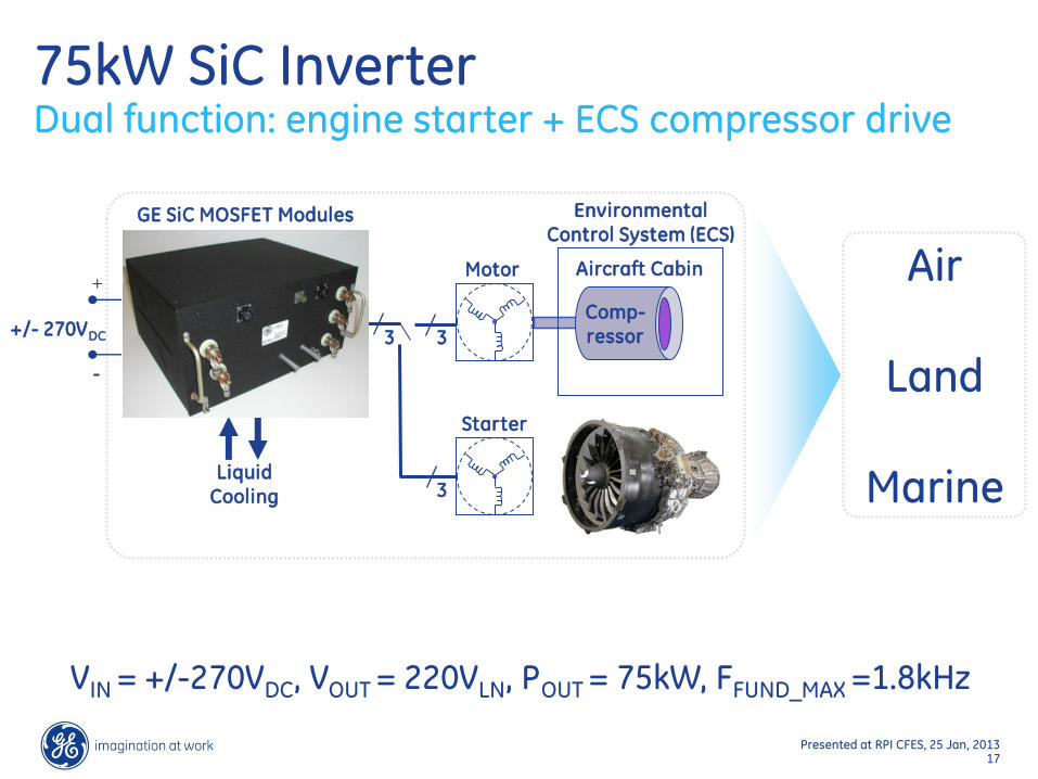
VIN = +/-270VDC, VOUT = 220VLN, POUT = 75kW, FFUND_MAX =1.8kHz
Motor
Comp-ressor +/- 270VDC
+
-
3
Liquid Cooling
Aircraft Cabin
Environmental Control System (ECS)
3
3
Starter
GE SiC MOSFET Modules
Air
Land
Marine
75kW SiC Inverter Dual function: engine starter + ECS compressor drive

Presented at RPI CFES, 25 Jan, 2013 18
75kW SiC Inverter - Efficiency Results

Presented at RPI CFES, 25 Jan, 2013 19
Summary of GE SiC Development Realizing the full benefit of SiC power electronics