Embed Size (px)
Citation preview
Advisory US Department of Transportation CircularFederal Aviation Administration
Subject Installation of Electronic Display Date U 17 2011 AC No 231311-lC
in Part 23 Airplanes Initiated by ACE-100
This advisory circular (AC) provides guidance for showing compliance with certain requirements of Title 14 Code of Federal Regulations (CFR) part 23 as well as general guidance for the design installation- integration and approval of electronic flight deck displays components and systems installed in part 23 category airplanes The guidance provided in this document is directed to airplane and avionics manufacturers modifiers and operators of part 23 category airplanes middotApplicants for a technical standard order (TSO) should consider following the guidance in this AC when the TSO requirements do not provide sufficient guidance The main purpose of this revision of the AC is providing the guidance for the requirements in the turbojet rulemaking and some general updating due to lessons learned and advance and emerging technologies
~Earl Lawrence Manager Small Airplane Directorate Aircraft Certification Service
11172011 AC 231311-1C
TABLE OF CONTENTS Section Page
10 Purpose1 20 Cancellation 1 30 Related Regulations and Documents 1 40 Background 8 50 Scope8 60 AcronymsDefinitions9 70 Display Description 17 80 Flight Displays 17 90 Powerplant Displays 25 100 Electronic Displays for Navigation Information 27 110 Aircraft Flight Manual (AFM)28 120 Electronic Checklist and Charts28 130 General Human Factors Consideraations for Design of Electronic Displays28 140 Location and Configuration of Displays31 150 Pilot Field-of-View Considerations 32 160 Luminance36 170 Symbology and Format36 180 Annunciation43 190 Lag Time and Data Update 44 200 Controls45 210 Test Functions45 220 Color Standardization 45 230 General Installation Requirements48 240 Aircraft Electrical Power Source 48 250 Safety Assessments50 260 Software and Hardware Development Assurance 51 270 Environmental Conditions 52 280 Electromagnetic Protection52 290 Electromagnetic Interference 53 300 Implosion Protection53 310 Configuration Management by Electronic Identification Guidance53
iii (and iv)
11172011 AC 231311-1C
10 Purpose This advisory circular (AC) provides guidance for showing compliance with certain requirements of Title 14 Code of Federal Regulations (CFR) part 23 as well as general guidance for the design installation integration and approval of electronic flight deck displays components and systems installed in part 23 category airplanes The guidance provided in this document is directed to airplane and avionics manufacturers modifiers and operators of part 23 category airplanes Applicants for a technical standard order (TSO) should consider following the guidance in this AC when the TSO requirements do not provide sufficient guidance The main purpose of this revision of the AC is providing the guidance for the requirements in the turbojet rulemaking from Amendment 23-62 and some general updating due to lessons learned and advance and emerging technologies
11 This AC provides an acceptable means but not the only means of showing compliance with 14 CFR applicable to installing electronic displays in part 23 airplanes The applicant remains responsible for regulatory compliance and should work closely with their geographic Aircraft Certification Office (ACO) to ensure regulatory compliance This material is neither mandatory nor regulatory in nature and does not constitute a regulation You may follow an alternate FAA-approved method Mandatory words such as ldquomustrdquo apply only to those who seek to show compliance to a specific rule by use of a method prescribed in this AC without deviation
20 Cancellation AC 231311-1B Change 1 ldquoInstallation of Electronic Display Instrument Systems in part 23 Airplanesrdquo dated February 17 2009 is cancelled
30 Related Regulations and Documents Some of the following related documents in this section may not be referenced in this AC but they provide additional information or guidance for electronic displays Please check for the most recent revision of the documents listed
31 Regulatory Sections These acceptable means of compliance refer to the applicable sections of 14 CFR part 23 For airplanes certificated under Civil Air Regulations (CAR) 3 we show the corresponding paragraphs of the former CAR in parenthesis
Table 1 - Regulatory Sections
sect 23771 (3381) Pilot compartment sect 23773 (3382) Pilot compartment view sect 23777 (3384) Cockpit controls sect 231301 (3651 and 3652) Equipment Function and installation sect 231303 (3655(a)) Flight and navigation instruments sect 231305 (3655(b)) Powerplant instruments sect 231308 High-intensity Radiated Fields (HIRF)
Protection sect 231309 Equipment systems and installations sect 231311 Electronic display instrument systems sect 231321 (3661 and 3662) Arrangement and visibility sect 231322 Warning caution and advisory lights sect 231323 (3663) Airspeed indicating system
1
11172011 AC 231311-1C
sect 231326 Pitot heat indication systems sect 231329 Automatic pilot system sect 231331 (3668) Instruments using a power source sect 231335 (3669) Flight director systems sect 231337 (3671 3672 3673 3674 and 3675)
Powerplant instruments installation
sect 231351 (3681 3682 3685 and 3686) Electrical Systems and Equipment General
sect 231353 (3683) Storage battery design and installation sect 231357 (3690 3691 and 3692) Circuit protective devices sect 231359 Electrical system fire protection sect 231361 (3688) Master switch arrangement sect 231365 (3693) Electric cables and equipment sect 231367 (3694 and 3695) Switches sect 231381 (3696 and 3697) Instrument lights sect 231431 (3721) Electronic equipment sect 231501 (3735 and 3737) Operating Limitations and Information General sect 231523 Minimum flight crew sect 231525 (3750) Kinds of operation sect 231529 Instructions for Continued Airworthiness sect 231541 (3755) Markings and Placards General sect 231543 (3756) Instrument markings General sect 231545 (3757) Airspeed indicator sect 231549 (3759) Powerplant and auxiliary power unit instruments sect 231551 (3760) Oil quantity indicator sect 231553 (3761) Fuel quantity indicator sect 231555 (3762) Control markings sect 231559 (3772) Operating limitations placard sect 231581 (3777) Airplane Flight Manual and Approved Manual
Material General
sect 231583 (3761 and 3778) Operating limitations sect 231585 Operating procedures sect 91205 Powered civil aircraft with standard category
US airworthiness certificates Instrument and equipment requirements
sect 121305 Flight and navigational equipment sect 135149 Equipment requirements General
2
11172011 AC 231311-1C
sect 135159 Equipment requirements Carrying passengers under Visual Flight Rules (VFR) at night or under VFR over-the-top conditions
sect 135163 Equipment requirements Aircraft carrying passengers under Instrument Flight Rules (IFR)
32 Advisory Circulars and Related Documents You may access the latest version of the ACs notices orders and policy statements on the FAA website wwwfaagov
Table 2 - Advisory Circulars and Related Documents
AC 20-88A Guidelines on the Marking of Aircraft Powerplant Instruments (Displays)
AC 20-115B RTCA Inc RTCADO-178B AC 20-136A Protection of Aircraft ElectricalElectronic Systems Against the
Indirect Effects of Lightning AC 20-138B Airworthiness Approval of Positioning and Navigation Systems AC 20-140A Guidelines for Design Approval of Aircraft Data Link
Communication Systems Supporting Air Traffic Services (ATS) AC 20-149 Safety and Interoperability Requirements for Initial Domestic
Flight Information Service - Broadcast AC 20-152 RTCA Inc Document RTCADO-254 Design Assurance
Guidance for Airborne Electronic Hardware AC 20-153A Acceptance of Aeronautical Data Processes and Associated
Navigation Databases
AC 20-155 SAE Documents to Support Aircraft Lightning Protection Certification
AC 20-158 The Certification of Aircraft Electrical and Electronic Systems for Operation in the High-Intensity Radiated Fields (HIRF) Environment
AC 20-167 Airworthiness Approval of Enhanced Vision System Synthetic Vision System Combined Vision System and Enhanced Flight Vision System Equipment
3
11172011 AC 231311-1C
AC 20-170 Integrated Modular Avionics Development Verification Integration and Approval Using RTCADO-297 and Technical Standard Order C153
AC 21-16F RTCA Document DO-160 versions D E and F ldquoEnvironmental Conditions and Test Procedures for Airborne Equipment
AC 23-8C Flight Test Guide for Certification of Part 23 Airplanes AC 23-15A Small Airplane Certification Compliance Program AC 23-17C Systems and Equipment Guide for Certification of Part 23
Airplanes AC 23-18 Installation of Terrain Awareness and Warning System (TAWS)
Approved for Part 23 Airplanes AC 23-22 Guidance for Approved Model List (AML) Supplemental Type
Certificate (STC) Approval of Part 23 Airplane Avionics Installations
AC 23-23 Standardization Guide for Integrated Cockpits in Part 23 Airplanes
AC 231309-1E System Safety Analysis and Assessment for Part 23 Airplanes AC 25-11A Electronic Flight Deck Displays AC 90-106 Enhanced Flight Vision Systems AC 91-75 Attitude Indicator AC 91-78 Use of Class 1 or Class 2 Electronic Flight Bag (EFB) AC 120-64 Operational Use and Modification of Electronic Checklists AC 120-76A Guidelines for the Certification Airworthiness and Operational
Approval of Electronic Flight Bag Computing Devices Order 811049 Software Approval Guidelines dated June 3 2003 Order 8110105 Simple and Complex Electronic Hardware Approval Guidance PS-ACE100-2001-004 Guidance for Reviewing Certification Plans to Address Human
Factors for Certification of Part 23 Small Airplanes
33 Technical Standard Orders (TSO) You may access the TSOs on the FAA website wwwfaagov The following is a list of the FAA TSOs that are referenced in this AC For a complete list of TSOs that are related to this AC see AC 20-110L ldquoIndex of Aviation Technical Standards Ordersrdquo or the web site for the most current list
a TSO-C63c Airborne Weather and Ground Mapping Pulsed Radars
b TSO-C113 Airborne Multipurpose Electronic Displays
c TSO-C153 Integrated Modular Avionics Hardware Elements
d TSO-C157 Aircraft Flight Information Services-Broadcast (FIS-B) Data Link Systems and Equipment
4
11172011 AC 231311-1C
e TSO-C165 Electronic Map Display Equipment for Graphical Depiction of Aircraft Position
34 Industry Documents You may obtain copies of current editions of the following publications
341 RTCA Documents The following RTCA documents are available from RTCA Inc 1828 L Street NW Suite 805 Washington DC 20036-4001 or at their website at wwwrtcaorg
a RTCADO-160G Environmental Conditions and Test Procedures for Airborne Equipment
b RTCADO-178B Software Considerations in Airborne Systems and Equipment Certification
c RTCADO-187 Minimum Operational Performance Standards for Airborne Area Navigation Equipment Using Multi-Sensor Inputs
d RTCADO-200A Standards for Processing Aeronautical Data
e RTCADO-201A Standards for Aeronautical Information
f RTCADO-254 Design Assurance Guidance for Airborne Electronic Hardware
g RTCADO-257A Minimum Operational Performance Standards for the Depiction of Navigation Information on Electronic Maps
h RTCADO-267A Minimum Aviation System Performance Standards (MASPS) for Flight Information Services-Broadcast (FIS-B) Data Link
i RTCADO-297 Integrated Modular Avionics (IMA) Development Guidance and Certification Considerations
j RTCADO-313 Certification Guidance for Installation of Non-Essential Non-Required Aircraft Cabin Systems and Equipment
k RTCADO-315A Minimum Aviation Performance Standards (MASPS) for Enhanced Vision Systems Synthetic Vision Systems Combined Vision Systems and Enhanced Flight Vision Systems
342 Society of Automotive Engineers (SAE) Inc The following Society of Automotive Engineers (SAE) Inc documents are available from SAE 400 Commonwealth Drive Warrendale PA 15096-0001 or from their website at wwwsaeorg
5
11172011 AC 231311-1C
a ARP 268G Location and Actuation of Flight Deck Controls for Transport Aircraft
b ARP 450D Flight Deck Visual Audible and Tactile Signals
c ARP 926B FaultFailure Analysis Procedure
d AIR 1093A Numeral Letter and Symbol Dimensions for Aircraft Instrument Displays
e ARP 1161A Crew Station LightingmdashCommercial Aircraft
f ARP 1782A Photometric and Colorimetric Measurement Procedures for Airborne Direct View CRT [Cathode Ray Tube] Displays
g ARP 1834A FaultFailure Analysis for Digital Systems and Equipment
h ARP 1874 Design Objectives for CRT Displays for Part 25 (Transport) Aircraft
i ARP 4032A Human Engineering Considerations in the Application of Color to Electronic Aircraft Displays
j ARP 4033 Pilot System Integration
k ARP 4067 Design Objectives for CRT Displays for Part 23 Aircraft
l ARP 4101 Flight Deck Layout and Facilities
m ARP 4102 Flight Deck Panels Controls and Displays
n ARP 41027 Electronic Displays
o ARP 4103 Flight Deck Lighting for Commercial Transport Aircraft
p ARP 4105B Abbreviations and Acronyms for Use on the Flight Deck
q ARP 4155A Human Interface Design Methodology for Integrated Display Symbology
r ARP 4256A Design Objectives for Liquid Crystal Displays for Part 25 (Transport) Aircraft
s ARP 4260A Photometric and Colorimetric Measurement Procedures for Airborne Electronic Flat Panel Displays
6
11172011 AC 231311-1C
t ARP 4754 Certification Considerations for Highly Integrated or Complex Aircraft Systems
u ARP 4761 Guidelines and Methods for Conducting the Safety Assessment Process on Civil Airborne Systems and Equipment
v ARP 5287 Optical Measurement Procedures for Airborne Head-Up Display (HUD)
w ARP 5288 Transport Category Airplane Head Up Display (HUD) Systems
x ARP 5289 Electronic Aeronautical Symbols
y ARP 5364 Human Factor Considerations in the Design of Multifunction Display Systems for Civil Aircraft
z ARP 5365 Human Interface Criteria for Cockpit Display of Traffic Information
aa ARP 5430 Human Interface Criteria for Vertical Situation Awareness Displays
bb ARP 5677 Human Engineering Considerations for Cockpit Integration of EnhancedSynthetic Vision Systems
cc AS 5703 Minimum Performance Standard for Enhanced Vision System
dd AS 8034A Minimum Performance Standard for Airborne Multipurpose Electronic Displays
ee AS 8055 Minimum Performance Standard for Airborne Head Up Display (HUD)
343 General Aviation Manufacturers Association (GAMA) The following documents are available from the GAMA 1400 K St NW Suite 801 Washington DC 2005 or from their website at wwwgamaaeroindustry-standards
a General Aviation Manufacturers Association (GAMA) Publication No 10 Recommended Practices and Guidelines for Part 23 CockpitFlight Deck Design
b General Aviation Manufacturers Association (GAMA) Publication No 12 Recommended Practices and Guidelines for an Integrated CockpitFlightdeck in a 14 CFR Part 23 Certificated Airplane
7
11172011 AC 231311-1C
40 Background
a Amendment 23-41 effective November 26 1990 established airworthiness standards in sect 231311 for installing electronic display instrument systems in normal utility acrobatic and commuter category airplanes The first electronic displays developed were direct replacements for the conventional electromechanical components with later designs providing more extensive information integration Before Amendment 23-41 most electronic display instrument systems were approved by special condition for installation in part 23 airplanes Amendment 23-49 effective March 11 1996 further amended part 23 to harmonize 14 CFR with the Joint Aviation Requirements (JAR) Section 231311 Amendment 23-49 removed redundant requirements and clarified which secondary instruments are required including the visibility requirements for those instruments
b Amendment 23-62 made several changes that affect the installation of electronic displays Guidance relative to electronic displays of those sections is also included in this AC The significant changes were
(1) Clarified requirements for trend information and appropriate sensory cues
(2) Incorporated equivalent visual displays of the instrument markings on electronic displays
(3) Allowed an applicant to take credit for reversionary or secondary flight displays on a multi-function flight display (MFD) that provides a secondary means of primary flight information (PFI)
(4) Revised some redundancy requirements to be only applicable for IFR operations
(5) Accommodated new technology for magnetic direction indicator
(6) Updated the terminology for system safety assessment
(7) Revised requirements for instruments using power source(s) and
(8) Revised requirements for storage battery backup times
50 Scope This AC is generally applicable only to an applicant seeking issuance of certain type certificates These include a type certificate (TC) an amended type certificate (ATC) or a supplemental type certificate (STC) for the approval of a new type design or a change in the type design This AC does not completely address Synthetic Vision Systems (SVS) or Enhanced Vision Systems (EVS) and Head-Up Displays (HUD) Contact the Small Airplane Directorate if there are any conflicts with other guidance and this AC The Small Airplane Directorate will coordinate and resolve the conflicts among the points of contact of the other documents
8
11172011 AC 231311-1C
60 AcronymsDefinitions
61 Acronyms
a AC Advisory Circular
b ACO Aircraft Certification Office
c ADC Air Data Computer
d ADI Attitude Direction Indicator
e ADDS Aviation Digital Data Service
f AFM Airplane Flight Manual
g AFMS Airplane Flight Manual Supplement
h AHRS Attitude Heading Reference System
i ARD Aerospace Research Document
j ARP Aerospace Recommended Practice
k AS Aerospace Standard
l ASTC Amended Supplemental Type Certificate
m ATC Amended Type Certificate
n CAR Civil Air Regulations
o CDI Course Deviation Indicator
p CFR Code of Federal Regulations
q CIP Current Icing Potential
r CL Center Line
s CRT Cathode-Ray Tubes
t DN Down
u EADI Electronic Attitude Direction Indicator
9
11172011 AC 231311-1C
v EHSI Electronic Horizontal Situation Indicator
w EICAS Engine Indication and Crew Alert System
x ELOS Equivalent Level of Safety
y EVS Enhanced Vision Systems
z FAA Federal Aviation Administration
aa FD Flight Director
bb FHA Functional Hazard Assessment
cc FLS Field-Loadable Software
dd FMEA Failure Modes and Effects Analysis
ee FOV Field-Of-View
ff GPS Global Positioning System
gg HIRF High Intensity Radiated Fields
hh HUD Head-Up Display
ii HSI Horizontal Situation Indicators
jj ICAO International Civil Aviation Organization
kk IFR Instrument Flight Rules
ll ILS Instrument Landing System
mm IMA Integrated Modular Avionics
nn IMC Instrument Meteorological Conditions
oo JAR Joint Aviation Requirements
pp LCD Liquid Crystal Displays
qq LED Light Emitting Diodes
rr LT Left
10
11172011 AC 231311-1C
ss METAR ICAO Routine Aviation Weather Report
tt MFD Multifunction Flight Display
uu ND Navigation Display
vv NOM Nominal
ww PFD Primary Flight Display
xx PFI Primary Flight Information
yy POH Pilots Operating Handbook
zz RAIM Receiver Autonomous Integrity Monitoring (used with GPS)
aaa RT Right
bbb SAE Society of Automotive Engineers
ccc STC Supplemental Type Certificate
ddd SVS Synthetic Vision Systems
eee TAS Traffic Advisory System
fff TAWS Terrain Awareness Warning System
ggg TFR Temporary Flight Restrictions
hhh TC Type Certificate
iii TCAS Traffic Alert and Collision Avoidance System
jjj TSO Technical Standard Order
kkk UL Underwriterrsquos Laboratories
lll VOR Very High Frequency Omni-Directional Range
mmm VFR Visual Flight Rules
nnn VMC Visual Meteorological Conditions
ooo VFE Maximum flap extended speed
11
11172011 AC 231311-1C
ppp VMO Maximum operating limit speed
qqq VNE Never-exceed speed
rrr VNO Maximum structural cruising speed
sss VS0 The stalling speed or the minimum steady flight speed in the landing configuration
ttt VS1 The stalling speed or the minimum steady flight speed obtained in a specific configuration
uuu WAAS Wide Area Augmentation System
62 Definitions This section contains definitions for terms in this document
a Accuracy A degree of conformance between the estimated or measured value and the true value
b Adverse Operating Condition A set of environmental or operational circumstances applicable to the airplane combined with a failure or other emergency situation that results in a significant increase in normal flight crew workload
c Component Any self-contained part combination of parts subassemblies or units that perform a distinct function necessary to the operation of the system
d Continued Safe Flight and Landing This phrase means the airplane can continue controlled flight and landing possibly using emergency procedures without requiring exceptional pilot skill or strength On landing some airplane damage may occur as a result of a Failure Condition
e Conventional A system is considered ldquoConventionalrdquo if its function the technological means to implement its function and its intended use are all the same as or closely similar to that of previously approved systems that are commonly used The systems that have established an adequate service history and the means of compliance for approval are generally accepted as Conventional
f Critical Usually a function whose loss would prevent the continued safe flight and landing of the airplane
Note The term ldquocritical functionrdquo is associated with a catastrophic failure condition Newer documents may not refer specifically to the term ldquocritical functionrdquo
g Criticality Indication of the hazard level associated with a function hardware software etc considering abnormal behavior (of this function hardware software etc) alone in
12
11172011 AC 231311-1C
combination or in combination with external events Criticality is a failure classification that could be no safety effect minor major hazardous and catastrophic See AC 231309-1E for more guidance
h Design-Eye Box A three-dimensional volume of space surrounding the design eye reference point that designers and evaluators use to determine the acceptability of display and control locations
i Design-Eye Reference Point A single reference point in space selected by the designer where the midpoint between the pilotrsquos eyes is assumed to be located when the pilot is properly seated at the pilotrsquos station
j Development Assurance All those planned and systematic actions used to substantiate to an adequate level of confidence that errors in requirements design and implementation have been identified and corrected such that the system satisfies the applicable certification basis
k Enhanced Vision System An electronic means to provide a display of the forward external scene topography (the natural or manmade features of a place or region especially in a way to show their relative positions and elevation) through the use of imaging sensors such as a forward looking infrared millimeter wave radiometry millimeter wave radar low light level image intensifying
l Equipment Essential to Safe Operation Equipment installed to comply with the applicable certification requirements of 14 CFR part 23 or operational requirements of 14 CFR parts 91 and 135
m Error An omitted or incorrect action by a pilot or maintenance person or a mistake in requirements design or implementation
n Failure An occurrence that affects the operation of a component part or element such that it can no longer function as intended (this includes both loss of function and malfunction
o Failure Condition A condition affecting either the airplane or its occupants or both either direct or consequential caused or contributed to by one or more failures or errors considering flight phase and relevant adverse operational or environmental conditions or external events Failure conditions may be classified according to their severity See AC 231309-1E for more information on definitions of failure conditions
p Field-of-View The angular extent of the display that can be seen by either pilot with the pilot seated at the pilotrsquos station See section 15 for more information on the field-of view
q Fix A generic name for a geographical position A fix may also be referred to as a waypoint intersection reporting point etc
13
11172011 AC 231311-1C
r Flight Plan Refers to any sequence of fixes that are interconnected by the desired path Flight plans may range from the simplest that include only the aircraftrsquos present position the active waypoint and the desired path between them to more complicated plans that include departure and destination airports with multiple intermediate fixes
s Function The lowest defined level of a specific action of a system equipment and pilot performance aboard the airplane that by itself provides a complete recognizable operational capability (for example an airplane heading is a function) One or more systems may contain a specific function or one system may contain multiple functions
t Functional Hazard Assessment A systematic comprehensive examination of airplane and system functions to identify potential minor major hazardous and catastrophic failure conditions that may arise as a result of a malfunction or a failure to function
u Hardware An object that has physical being Generally refers to circuit cards power supplies etc
v Hazard Any condition that compromises the overall safety of the airplane or that significantly reduces the ability of the pilot to cope with adverse operating conditions
w Head-Up Display A transparent optical display system located level with and between the pilot and the forward windscreen The HUD displays a combination of control performance navigation and command information superimposed on the external field of view It includes the display element sensors computers and power supplies indications and controls It is integrated with airborne attitude air data and navigation systems and as a display of command information is considered a component of the flight guidance system
x Independent A component part element or system that is not relying on some other component part element or system for accomplishing its function This design concept ensures that the failure of one item does not cause a failure of another item For redundancy each means of accomplishing the same function need not necessarily be identical
y Indicator A means for displaying information of a parameter More than one indicator could be depicted on one display For example a primary flight display may have indicators for attitude altitude airspeed heading and navigation
z Instrument An electrical or mechanical measurement device In sect 231311 it is defined as Devices physically contained in one unit and devices composed of two or more physically separate units or components connected together (One example is a remote indicating gyroscopic direction indicator that includes a magnetic sensing element a gyroscopic unit an amplifier and an indicator connected together)
aa Map Orientation Refers to the rule that determines the directional relation of the map to the upper part of the display depiction Using a north-up rule the north side of the map would be toward the top of the display and the south side of the map would be at the bottom Using
14
11172011 AC 231311-1C
a desired path-up rule the map would be oriented so the desired path would be vertical on the map and pointing straight up toward the top of the display
bb Map Range The geographic extent of the map region (for example the distance covered by the map representation in either the vertical or horizontal direction)
cc Malfunction Failure of a system subsystem unit or part to operate in the normal or usual manner A condition whereby the operation is outside specified limits
dd Multi-Function Display Any physical display unit other than the PFD used to present various information on which the layout may be reconfigured
ee Navigation The process of planning tracking and controlling the course of an airplane from one place to another
ff Navigation Display The display or suite of instruments by which navigation data is presented to the pilot
gg Navigation Information Information that aids the flightcrew in determining the aircraftrsquos location in a given environment (for example on flight plans VORs GPSs features on the airport surface including taxiway signage etc)
hh Primary As used for instruments it is defined in sect 231311(c) as the ldquodisplay of a parameter that is located in the instrument panel such that the pilot looks at it first when wanting to view that parameterrdquo
ii Primary Flight Display (PFD) A single physical unit that always provides the primary display of all the following altitude airspeed aircraft heading (direction) and attitude located directly in front of the pilot in a fixed layout in accordance with sect 231321 It may provide other information pertinent to guidance and fundamental control of flight of the airplane such as critical engine parameters
jj Primary Flight Information (PFI) A PFI refers to those functions or parameters required by the airworthiness and operational rules such as airspeed altitude attitude and heading (direction) that are on the PFD
kk Primary Function (PF) This definition is applicable in the case when there is more than one function available for same function A function that is installed to comply with the applicable regulations for the required function and one that provides the most pertinent controls or information instantly and directly to the pilot For example the PFD is a single physical unit that always provides the primary display and it complies with the requirements of all the following altitude airspeed aircraft heading (direction) and attitude This PFD is located directly in front of the pilot and used instantly and first by the pilot A standby (additional) PFD that is intended to be used in the event of failure of the PFD is an example of a secondary system
15
11172011 AC 231311-1C
ll Primary Navigation Where the pilot looks first for a display of navigation information such as on an HSI or CDI It displays vertical and lateral deviation and it may have the digital distance indication tofrom the selected fix
mm Redundancy The presence of more than one independent means for accomplishing a given function Each means of accomplishing the function need not necessarily be identical
nn Reversionary Display A secondary means to provide information initially presented on the PFD or MFD by the transfer of information to an alternate display
oo Scale The relative proportion of the linear dimensions of objects on a display to the dimensions of the corresponding objects and distances being represented (for example 1 inch = 100 nautical miles)
pp Secondary Display A means to present information on another display A display that can be used for backup or secondary purposes such as in the event of a failure of another display
qq Standby Instrument A dedicated instrument that is always available that presents primary flight information
rr Supplemental Function A function that is not required or intended to meet all the airworthiness and operational requirements It is usually installed for additional situational awareness
ss System A combination of components parts and elements that is interconnected to perform one or more functions
tt Synthetic Vision System A computer-generated image of the external scene topography from the perspective of the flight deck that is derived from aircraft attitude high precision navigation solution and database of terrain obstacles and relevant cultural features
Note ldquoTopographyrdquo defined as maps or charts of natural and man-made features of a place or region especially in a way to show their relative positions and elevations as applicable whenever deemed appropriate and practicable
uu Track The projection on the earthrsquos surface of the path of an aircraft the direction of which is usually expressed in degrees from north (true magnetic or grid) A track is the actual flight path of an aircraft over the surface of the earth
Note For more definitions related to safety assessments refer to AC 231309-1E for the appropriate definitions
vv Warning A clear and unambiguous indication to the pilot of a failure that requires immediate corrective action An inherent characteristic of the airplane or a device that will give
16
11172011 AC 231311-1C
clearly distinguishable indications of malfunction or misleading information may provide this warning
70 Display Description The following paragraphs give a brief description of an electronic display They do not cover all the capabilities and details of these displays or the information presented on them
71 General Electronic displays have replaced many of the traditional electromechanical and analog instruments These displays also augment andor combine the functionality of conventional systems such as radios and navigational systems The major display technologies now used are multicolor CRTs LCDs electro luminescence plasma and LEDs The initial electronic displays mimicked the traditional mechanical and electromechanical flight and powerplant instruments The colors symbols and formats on these initial electronic displays are similar to those on traditional conventional instruments Modern electronic displays provide integration and formats that often differ from traditional instruments
72 Display Configuration Electronic displays may be installed in several configurations A basic electronic display may provide only one flight or powerplant parameter while more sophisticated systems integrate many parameters on one electronic display One of the major design goals for these systems is eliminating separate conventional gauges instruments and annunciators Recent installations show a trend toward a higher degree of integration For example an integrated primary flight display provides several parameters such as attitude heading (direction) airspeed and altitude Integration of various systems should include analysis to ensure that complexity and workload are compatible with general aviation pilots capabilities For more guidance on IMA that implement TSO authorized hardware elements see TSO-C153 and AC 20shy170
80 Flight Displays
81 Instrument Requirements
a Sections 231303 231305 231311 and 231321 with the applicable operating rules (14 CFR parts 91 121 and 135) incorporate flight and powerplant instrument requirements for part 23 airplanes The navigation equipment requirements are given in operational rules specified in sectsect 91205 121303 121305 121307 135143 135149 135159 135161 and 135165 Display requirements for navigation information are dependent on the navigation system installed in the aircraft Instruments and equipment required for flights under parts 91 121 and 135 may be affected by the electronic display installation These instruments and equipment include gyroscopic bank and pitch gyroscopic direction gyroscopic rate-of-turn slip-skid instruments and other required communication and navigational equipment
b There have been applications to install equipment such as flight and navigation displays as non-required These applications request approval for these installations as situation awareness (SA) only It is not acceptable to label a display as ldquoSA-Onlyrdquo and assume that its failure condition is acceptable Installing displays that provide PFI that are more compelling than
17
11172011 AC 231311-1C
the required primary PFI displays but they do not meet the appropriate operational and airworthiness requirements and labeling them as ldquoSupplementalrdquo or ldquoSA-Only is not acceptable Section 136 provides more guidance
c The basis for certification has been that the equipment should perform its intended function and not present a hazard Instruments that aid situation awareness should be certified under the part 23 requirements including sect 231301 and sect 231309 These displays could provide hazardous misleading information PFI is essential for safe operation An instrument that provides PFI should meet the minimum standards of applicable TSOs or an equivalent standard It also should meet the guidance in AC 231309-1E AC 23-17C and the guidance in this AC
82 Primary Flight Information (PFI) PFI refers to those functions or parameters that are required by the airworthiness and operational rules such as airspeed altitude attitude and heading (direction) It may provide other information pertinent to guidance and fundamental control of flight such as critical engine parameters Attitude airspeed altitude and heading (direction) are the PFI required in sect 231311(a)(3) and (5) and they must be arranged according to sect 231321 in the ldquobasic Trdquo arrangement Direction should be heading with track presented if available as a selectable option The horizon reference line on the PFD should be at least 325 inches wide in straight and level flight for integrated displays This recommendation is not intended to prevent replacement of mechanical instruments with an electronic display of a similar horizon reference line When the true horizon is no longer on the display the artificial horizon line should provide a distinctive demarcation between sky and ground (or the background) Display of PFI on reversionary or standby displays should be arranged in the basic T-configuration but it is not required The standby instrument or displays of PFI location should meet the FOV guidance criteria in section 15
821 Acceptable Methods for Compliance with sect 231311(b) There are three acceptable methods for meeting the attitude requirements which is considered information essential for continued safe flight and landing Compliance can be accomplished by using dedicated standby instruments dual PFDs or reversionary displays that present primary flight information Electronic display systems without dedicated standby instruments should have at least two independent displays able to provide PFI to the pilot These displays should be powered such that any single failure of the power generation and distribution systems cannot remove the display of PFI from both displays Section 231311(b) in Amendment 23-62 states ldquoThe electronic display indicators including their systems and installations and considering other airplane systems must be designed so that one display of information essential for continued safe flight and landing will be available within one second to the crew by a single pilot action or by automatic means for continued safe operation after any single failure or probable combination of failuresrdquo
83 Standby Instruments The purpose of standby instruments or another independent PFD is to ensure that PFI is available to the pilot during all phases of flight and during system failures Individual indicators should be a minimum of 2 inches in diameter or if combined a minimum diameter of 3 inches (or equivalent) displayed
831 Dual PFDs Electronic display systems with dual PFDs should incorporate dual independently powered sensors that provide primary flight parameters such as AHRS with
18
11172011 AC 231311-1C
comparators and dual ADC Dual PFDs with dual AHRSs and ADCs which include checking and are powered by multiple power sources and distribution systems are significantly more reliable than presently certified mechanical systems
832 PFD and Autopilot with an AHRS For normal operation when using a single AHRS to drive the PFD and the autopilot simultaneously the installation must mitigate hazardous or catastrophic system level failures An example configuration supporting proper mitigation would include all of the following
a A dedicated standby attitude instrument within the primary maximum FOV or independent reversionary attitude display
b An AHRS with appropriate comparator or monitor of equivalent performance
c Appropriate system warningcaution annunciation associated with an AHRS malfunction
d If an aircraft is equipped with multiple AHRS it may be acceptable when one AHRS fails to drive both the autopilot and the PFD from a single AHRS as long as an AHRS independent attitude display (required for some aircraft classes) is located in the primary maximum field of view The failure must be annunciated to the pilot and the pilot must be able to select the non-failed AHRS For aircraft that do not have an independent attitude indicator when one AHRS fails the autopilot should be manually or automatically disengaged The autopilot may be reengaged if appropriate mitigation is available (for example see a through c above) The AFM or supplemental AFM should contain the appropriate procedures applicable to the equipment installed See section 110 for additional guidance AC 231309-1E guidance should be considered for these configurations
e Displays not meeting FOV guidance criteria may require additional human factors airworthiness evaluation by the certification authority See section 15 for additional guidance
84 Reversionary Flight Displays Instead of Standby Instruments or Dual PFDs
841 General Requirements
a Reversionary flight displays provide a secondary means to provide PFI through alternate display formats on another PFD or MFD by the transfer of information to an alternate display or by some other means The function of an MFD system is to provide the pilot access to various data or combinations of data used to fly the aircraft to navigate to communicate andor to manage aircraft systems The MFD would also present PFI as needed to ensure continuity of operations 14 CFR part 23 sect 231311(b) Amendment 23-62 states the electronic display indicators including their systems and installations and considering other airplane systems must be designed so that one display of information essential for continued safe flight and landing will be available within one second to the crew by a single pilot action or by automatic means for continued
19
11172011 AC 231311-1C
safe operation after any single failure or probable combination of failures To meet the requirements of sect 231311(b) a full-time standby display another independent PFD or an independent reversionary attitude display must be installed Reversionary modes could be automatically and manually selected or only manually selected
b Reversionary configurations are significantly more reliable than presently certified mechanical systems and the skills required while flying in reversionary mode are identical with those used when flying in primary mode Traditional external standby flight instruments (either electronic or mechanical) offer potential safety problems associated with delay in pilot reaction The pilot may delay a decision to transition to standby instruments and to transition to partial panel techniques as opposed to the simple action the pilot would take to switch displays A nearly identical format on the reversionary display of all PFI that is also shown on the PFD provides a significant safety enhancement over standby instruments This is especially true when the size location arrangement and information provided by the standby instruments are significantly different from those on the PFD
c Reversionary display modes should provide consistent display formats to the PFD The reversionary flight information should be presented by an independent source and display to prevent complete loss of PFI due to a single failure The reversionary configuration should have two independent displays that incorporate dual-independently powered AHRS and dual ADC subsystems that provide PFIs The reversionary system response time should provide flight critical information on the MFD in less than one second after a single pilot action or an automatic operation
d A reversionary configuration should have a single pilot action that would force both the PFD and MFD displays into reversionary mode operation However the PFI should be presented in similar format and sufficient size in the reversionary mode as it is in normal mode to allow the pilot to enhance the control of the airplane This reversionary configuration should provide backup information essential to continued safe flight and landing with an intuitive control that allows instant simultaneous access to reversionary mode on both the PFD and MFD displays The single pilot action should be easily recognized readily accessible and have the control within the pilotrsquos primary optimum field of view An acceptable method for the single pilot action is the red color andor lighted red ldquohalordquo ring that announces its position on the panel at all times
842 Reversionary Methods
a One method is to have an automatic reversionary display with a single pilot action that would force both the PFD and MFD displays into reversionary mode operation If PFI on another display is not provided provide automatic switching to ensure PFI is available to the pilot Automatic reversion must provide a complete display of PFI on the remaining display within one second if a fault is detected
b Most possible faults should be covered by this automatic reversionary capability Only a total loss of the display may not be reliably detected automatically but such a failure condition would be obvious to the pilot Faults that result in automatic switching should be extensive enough to ensure PFI availability meets the requirements of sect 231309 If such a
20
11172011 AC 231311-1C
malfunction occurs a single pilot action should provide a full display of the essential information on the remaining display within one second All modes sources frequencies flight plan data etc should be similar as they were on the PFD before the failure
c Another reversionary method would include a means to access the reversionary mode manually through a single pilot action Manual activation of the reversionary mode on the MFD through single action by the pilot is acceptable when procedures to activate the PFI on the MFD are accomplished before entering critical phases of flight The PFI would be presented continuously on the reversionary display during critical phases of flight (for example takeoff landing and missed or final approach)
85 Display of Attitude For flights under IFR conditions in part 91 and part 135 operations and under VFR at night for part 135 operations attitude information is required The loss of all attitude information or the presentation of misleading attitude information could result in a catastrophic failure condition where the pilot could not continue safe flight and landing of the airplane It is recommended that the display of attitude follows the guidelines (below) that are also in GAMA Publication 12
a The pitch ladder should be caged to the center of the display
b At pitch attitudes when the true horizon line would not normally be displayed some sky or ground should be indicated on the PFD pitch display (minimum 38 inches and maximum of 115 percent of the display) and the horizon line should indicate off-scale
c With the airplane symbol on the horizon line the range of visible pitch attitude should be at least + 25 to -15 degrees but not to exceed a total pitch range of 50 degrees
d Bank angle presentations should use a roll pointer however roll pointers and sky-pointers should not be mixed in the same flight deckcockpit
e Roll scale indices should be placed at 10 20 30 60 and 90 degrees An index may also be placed at 45 degrees
86 Display of Direction (Heading or Track)
861 General
a The loss of direction (heading or track) information could result in reduced capability of the pilot to cope with adverse operating conditions The orientation of any secondary navigation display is optional (for example Track-up North-up Heading-Up) For flights under IFR conditions a stabilized heading indicator must provide the primary display of the direction parameter A magnetic direction indicator or track may provide the reversionary display of direction
21
11172011 AC 231311-1C
b The heading display should provide a clear and unmistakable display of aircraft symbol and heading HSI should provide a clear and unmistakable display of aircraft position heading and track (an option if available) relative to the desired coursetrack Section 17 contains more guidance on symbology Direction should be heading when track is presented if available as a selectable option with the data source clearly indicated On the primary display the heading scale should have a mode that presents at least 120 degrees of arc Other display formats may be acceptable and have been previously approved but they need to be evaluated from a human factor perspective
862 Hazardous Misleading Heading Information
a The FHA for the failure effects of hazardous misleading heading information from an AHRS is clarified in AC 23-17C This policy is specifically about the application of AC 231309-1E for an airplane with the certification basis of Amendments 23-41 or later This clarification is limited to installations approved for operation in IMC under IFR For operations limited to VFR a misleading heading indication is not considered hazardous
b Develop an FHA and the related safety assessments for the specific airplane type and configuration since there can be many combinations of failures various mitigating factors and other functions available to a pilot These many factors affect the criticality of the heading indication therefore use a safety assessment process from AC 231309-1E to classify the failure conditions for misleading heading information
c A hazardously misleading heading is usually when the accuracy error is greater than 10 degrees on the primary heading instrument and it is an undetected error The safety assessment process should consider appropriate mitigating factors For Class I part 23 airplanes the failure condition for misleading hazardous heading is usually considered major
87 Display of Altitude Airspeed and Magnetic Compass Information The original requirements of CAR 3 were adopted and later recodified into part 23 sect 231303 paragraphs (a) (b) and (c) At that time pneumatically driven displays provided airspeed and altitude functions Since then the FAA envisioned airspeed altitude and magnetic compass information would remain available to the pilot with the loss of the airplanes primary electrical power For electronic displays sect 231311(a)(3) requires the primary display of attitude airspeed and altitude to be uninhibited in any normal mode of operation Section 231311(a)(5) as amended by Amendment 23-62 requires an independent magnetic direction indicator and either an independent secondary mechanical altimeter airspeed indicator and attitude instrument or electronic display parameters for the altitude airspeed and attitude that are independent from the airplanes primary electrical power system Primary altitude or airspeed displays that require electrical power are acceptable if means are provided for their continued operation upon loss of the airplanersquos primary electrical power or if pneumatically driven instruments are available for the pilotrsquos use A standby or reversionary integrated display of altitude attitude and airspeed instead of individual electronic display indicators for airspeed altitude and attitude is acceptable under one condition The condition is that the standby or reversionary integrated display and the primary display are powered such that at least one integrated display with attitude altitude and airspeed is available after failure of any power source or distribution path
22
11172011 AC 231311-1C
88 Accuracy of the Magnetic Heading System
881 General
a The operating rules such as part 91 and part 135 specify the minimum required equipment that must be installed in part 23 airplanes based on the operation such as VFR or IFR Under VFR operation part 91 sect 91205 requires a magnetic direction indicator (that is normally intended to be a compass) for heading information Under IFR operation part 91 sect 91205 requires a gyroscopically stabilized heading system Section 231303(c) Amendment 23-62 amended the requirement from ldquoA direction indicator (non-stabilized magnetic compass)rdquo to ldquoA magnetic direction indicatorrdquo As new technology becomes more affordable for part 23 airplanes many electronic flight instrument systems will use magnetically stabilized direction indicators (or electric compass systems) to measure and indicate the airplane heading to provide better performance
b The general airworthiness requirements in part 23 sect 231301 and sect 231525 determine the flight instrument and equipment accuracy requirements for part 23 airplanes Part 23 does not prescribe specific accuracy requirements for magnetic gyroscopically stabilized heading systems Specific accuracy requirements for avionics may be found in the related TSO and as acceptable means of compliance to sect 231301 in ACs notices or policy statementsletters
882 Magnetic Non-Stabilized Direction Indicator A magnetic non-stabilized direction indicator that is required by sect 231303 should have an accuracy of 10 degrees or have a correction card placard (reference sect 231327) or a back-up gyroscopic direction indicator provided the indicator is accurate better than 10 degrees If the sole purpose of the gyroscopic direction indicator is for backing up the magnetic non-stabilized direction indicator then the accuracy of presentation of headings can also be to 10 degrees However if a gyroscopic direction indicator is installed to meet the IFR operating rules then the installation requirements are defined by sect 231301
883 Magnetic Gyroscopically Stabilized Direction Indicator As installed final accuracy for a magnetic gyroscopically stabilized direction indicator of plusmn4 degrees on the ground or plusmn6 degrees in normal level flight on any heading would meet the requirements of part 23 sect 231301 This accuracy applies after compensation It should include cumulative errors in all combinations due to several factors These consist of the equipment itself the current flow in any item of electrical equipment and its associated wiring the movement of any part (for example controls or undercarriage) and the proximity of any item of equipment containing magnetic material to the magnetic sensor
884 Comparator Monitor
a For systems installations that include two magnetic gyroscopically stabilized heading systems and a comparator that monitors the differences between the headings of the two
23
11172011 AC 231311-1C
systems the comparator trip point set as follows would meet the requirements of part 23 sect 231301
(1) 6 degrees in stabilized level flight
(2) 6 degrees plus one half of the bank angle or
(3) 12 degrees with a bank angle greater than 6 degrees
(4) The alert function can be disabled at a bank angle greater than 20 degrees
(5) An alert is provided if the condition exceeds 60 seconds but it allows two minutes for a turn error as stated in the TSO
b The 6-degree trip point during level flight allows a heading error of as much as 12 degrees on one of the systems This would comprise one system at the 6 degrees in-flight tolerance limit while the other system presumably with some malfunction could have an error of 12 degrees in the same direction before the comparator monitor alert is tripped
89 Rate-of-Turn Instrument
a Under sectsect 91205 and 135159 a rate-of-turn instrument is not required if a third attitude instrument usable through flight attitudes of 360 degrees of pitch-and-roll is installed following the instrument requirements prescribed in sect 121305(j) If required place the rate-of-turn indicator near the heading indicator
b A second approved attitude indicator may substitute for the rate-of-turn instrument AC 91-75 Attitude Indicator provides one method This AC is applicable to part 23 certificated airplanes (or airplanes certificated under earlier equivalent regulations) that weigh less than 12500 pounds and are operated under part 91 The second approved attitude indicator must be powered by an independent power source from the primary attitude indicator This can be accomplished by using independent standby instruments another independent PFD or independent reversionary attitude display Most of the installations with electronic displays that meet the requirements of sect 231311 and this AC should comply with AC 91-75
810 Slip-Skid Instrument The slip-skid information is required by sectsect 91205(d)(4) and 135159(b) as applicable The FAA suggests locating the slip-skid display directly below or near the rate-of-turn instrument if installed or under or within the primary attitude display
811 Vertical Speed Indicator If provided present the vertical speed indicator to the right or directly below the altitude indicator with a scale appropriate to the performance of the aircraft
24
11172011 AC 231311-1C
90 Powerplant Displays
91 General
a This section defines a means of presenting powerplant performance and condition information about the airplanes operation It also provides guidelines about when these functions should be displayed to the pilot In general there have been two methods used to accomplish this These methods include (1) display raw engine parameters to the pilot for interpretation or (2) collect powerplant data and have an automatic monitoring system interpret and report the powerplant condition to the pilot Use the following evaluation criteria when considering the installation of electronic powerplant displays
b There is a need to evaluate each airframe engine and airframeengine interface with the operational characteristics of these systems to determine the primary powerplant parameter requirements For this evaluation and as used in this section a primary powerplant parameter is needed to start the engine and to set and monitor engine power within powerplant limitations Appropriate procedures for operation of an integrated electronic powerplant display system should be in the AFM
c For multiengine airplanes a failure or malfunction affecting the display or accuracy of any propulsion system parameter for one engine should not cause the loss of display or accuracy of any parameter for the remaining engine(s) If multiple propulsion parameters are integrated on one display and the display fails it is acceptable to provide a secondary propulsion parameter display
92 Loss of Critical Powerplant Information
a No single failure malfunction or probable combination of failures should result in either the loss of critical powerplant information or an erroneous display of powerplant parameters that would jeopardize continued safe flight and landing of the airplane Usually for engines that do not generally rely on the pilot to prevent exceeding their limits in normal operations or engines such as with electronic engine controls featuring engine limit protection the loss of powerplant displays should not cause immediate jeopardy to continued safe flight and landing
b A secondary display providing powerplant parameters for cases of loss of a primary powerplant display may be used provided it is located so the pilot can adequately view the powerplant parameters
c Throttle or power lever position may be used in place of lost powerplant display parameters This would apply if throttle position or power lever position provides a positive indication of the powerplant power level required to maintain safe flight to a landing and if the throttle has a means to preclude exceeding powerplant operating limits
25
11172011 AC 231311-1C
93 Powerplant Information
a Presentation of primary powerplant parameters continuously when they are required unless the monitor provides an adequate alert of the function Also provide a manual select option for the pilot to present the information A parameter defined as primary for engine start but not for other normal engine operation may only have to be presented continuously during engine start
b Before and upon reaching or exceeding any operating limit the display should present the required powerplant parameters without pilot action Timely alerts for each phase of flight should be provided when any operating limit is reached or exceeded for the required powerplant parameter The alerts should be in a form that enables the pilot to identify and carry out the necessary and appropriate actions The required powerplant information should be presented continuously during a critical takeoff and landing phase of flight to minimize pilot distraction until an established rate of climb or minimum altitude is achieved
c Displays that provide multiple powerplant parameters should be designed such that any parameter display or alert will not suppress another display or alert that also requires immediate crew awareness necessary to conduct safe operation of the aircraft and engine(s) Alerts that could cause subsequent activation of other displays or alerts should be presented in a manner and form to ensure appropriate identification and prioritization of all significant hazards and required crew actions See section 18 for more guidance on annunciation
94 Digital Reading Alphanumeric Displays
a Digital reading alphanumeric displays are most valuable when integrated with an analog display by adding a precise quantitative indication to complement an analog displays qualitative indication Proper integration should include a means for pilots to clearly associate the analog and digital indications (eg via close proximity) Digital reading alphanumeric powerplant displays formats should not be used in place of analog formats to indicate values of engine parameters where trend or rate-of-change information is important for safety or when the pilot needs to monitor parameters with a quick glance Digital reading alphanumeric displays limit the pilots ability to assess trend information and result in reduced crew awareness Digital reading alphanumeric displays are also limited in their ability to allow the pilot to easily compare parameters from multiple engines or to check the general proximity of differing parameters against their individual limits While these shortcomings can be compensated for with more design provisions use digital reading alphanumeric displays with caution and carefully evaluate each airframe engine and airframeengine integration
b Section 231311(a)(6) Amendment 23-62 requires sensory cues that provide a quick glance sense of rate and where appropriate trend information to the parameter being displayed to the pilot Section 231311(a)(7) requires incorporated equivalent visual displays of the instrument markings required by sectsect 231541 through 231553 or visual displays that alert the pilot to abnormal operational values or approaches to established limitation values for each parameter required to be displayed by this part
26
11172011 AC 231311-1C
c An ELOS will be necessary for digital -reading alphanumeric only displays that are not associated with any scale tape or pointer It may be difficult for pilots to determine the margin relative to targets or limits or compare between parameters To comply with sect 231311(a)(7) a scale dial or tape will be needed to accomplish the intended pilot task In order to demonstrate an equivalency a human factor andor pilot evaluations will be needed that will consider the following factors These are subject to evaluation on a case-by-case basis
(1) The visibility and relative location of the indicated parameter should be reviewed including appropriate conditions of lighting and instrument panel vibration
(2) The ability to assess necessary trend or rate-of-change information quickly including when this information may be needed during in-flight engine restarts
(3) The ability to assess how close the indicated parameter is relative to a limit
(4) The value to the crew of quickly and accurately comparing engine-to-engine data for multiengine aircraft
(5) Engine design features or characteristics that would forewarn the crew before the parameter reaches the operating limit (for example redline)
(6) The use of color in accordance with sect 231549 to indicate the state of operation a green indication would indicate normal operation a yellow indication would indicate operation in a takeoff or precautionary range and a red indication would indicate operation outside of the safe operating limits
95 Marking of Powerplant Parameters Mark powerplant parameters on electronic displays in accordance with sect 231549 AC 20-88A provides alternate methods of marking electronic powerplant displays Alternate methods of marking the displays may be performed However the FAA may evaluate these markings on a case-by-case basis depending on each airframe engine integration and appropriate human factors considerations Alternate markings that do not comply with the requirements of sect 231549 require an ELOS
100 Electronic Displays for Navigation Information
101 Guidance Information Navigation information used by the pilot for steering commands and to monitor deviation from a navigation path should be in the pilots primary FOV Warnings and cautions should also be in the primary FOV For more guidance on FOV see section 15 and Table 3 of this AC
102 Display Integration
a Navigation guidance information may be integrated with the PFDs Common examples include HSIs that combine inputs from a directional gyro with a course deviation
27
11172011 AC 231311-1C
indicator or an FD integrated with the ADI Additionally information from more than one navigation source may be displayed separately or simultaneously
b If information from more than one navigation source can be presented the selected source should be continuously indicated to the pilot If multiple sources can be presented simultaneously the display should indicate unambiguously what information is provided by each source and which one has been selected for guidance Some airplanes are equipped with an autopilot andor FD coupled to the lateral and vertical guidance system On these airplanes the input to the autopilot andor FD should coincide with the navigation source selected on the PFD or primary navigational display
103 Reversionary Navigation Displays Reversionary requirements for navigation display information depend on the rules under which the aircraft is operated and the hazards associated with the loss of or misleading information from the display The integration of non-navigation information (for example traffic weather or flight parameters) may affect the hazards associated with the loss of or misleading information from the display In these cases the applicant should perform a system safety assessment following AC 231309-1E For more guidance on safety assessments see AC 231309-1E and section 26 of this AC for more guidance
104 Navigation Database For area navigation equipment the navigation database is an essential component of the equipment Guidelines for the navigation database can be found in RTCADO-200A See AC 20-138 and AC 20-153 for more guidance and information
110 Aircraft Flight Manual (AFM) For equipment required for IFR approval the AFM or supplemental AFM should contain the limitations and the operating and emergency procedures applicable to the equipment installed Installations limited to VFR use only may require an AFM or supplemental AFM depending on the complexity of the installation and the need to identify necessary limitation and operating procedures AC 23-8C contains more policy and guidance on AFMs
120 Electronic Checklist and Charts Policy and guidance on electronic checklist and charts on electronic displays are contained in AC 23-8C AC 91-78 AC 120-64 and AC 120-76A
130 General Human Factors Considerations for Design of Electronic Displays
131 General Electronic displays can provide many innovative display flexibilities and features that were not possible with traditional displays Technology improvements in display design and integration can enhance pilot performance and improve situation awareness when innovations are designed using sound processes and appropriate design criteria that account for human performance The applicant should ensure that human performance considerations are adequately addressed throughout the design process Early FAA involvement and an effective working relationship between the FAA and the applicant will aid in the timely identification and resolution of human factors related issues The FAA encourages the applicant to develop human performance considerations including evaluation plans and present them to the FAA early in the certification process
28
11172011 AC 231311-1C
132 Human Factors for Certification of the Part 23 Small Airplanes Policy statement number PS-ACE100-2001-004 provides guidance for human factor certification plan or the human factor components of a general certification plan when one is submitted as part of a TC STC or ATC project The application of this guidance will ensure that human factors issues are adequately considered and addressed throughout the certification program
133 CockpitFlight Deck Design GAMA Publication No 10 The purpose of GAMA Publication No 10 is to provide manufacturers of small aircraft and systems with human factors recommendations for the design of cockpitsflight decks and their associated equipment This publication was developed as a cooperative effort between the FAA and industry
134 SAEs and RTCAs Recommended Practices and Standards Evaluation of the electronic display system should consider airworthiness regulations recommended practices and standards from industry documents as listed in section 3 of this AC
135 Human Factors Compliance Considerations
a The applicant should identify all human factors related regulations that apply to the installation and operation of the display system or component being certified The applicant should document how the system or component complies with each of these regulations A partial list of relevant regulations is contained in policy statement PS-ACE100-2001-004 The FAA and the applicant should develop and agree on a plan to describe how the applicant intends to show compliance with the relevant regulations It should contain enough detail to assure that human factors compliance considerations have been adequately addressed The test plan should also allow enough time to accomplish all necessary testing agreed to by the applicant and the FAA
b The applicant should assure the following
(1) The intended use of the system does not require any exceptional skill or generate any unreasonable workload for the pilot
(2) The use of the display does not require unreasonable training requirements to adequately show that the pilot can understand and properly operate the system in all operational environments
(3) The design characteristics of the display system should support error avoidance and management (detection recovery etc)
(4) The display system is integrated and is consistent or compatible with other cockpit controls and displays and it creates no more burden on the pilot regarding the new display system or operation of other systems
(5) If a failure occurs it does not prevent the pilot from safely operating the airplane
29
11172011 AC 231311-1C
c Manufacturers should provide design rationale for their decisions regarding new or unique features in a display Evaluation should be conducted to collect data in support of the new or unique features to assure they have no unsafe or misleading design characteristics The design teams including pilots should concur with the conclusion found with the data collected
d The applicant should conduct display evaluations with several human factors and pilots representatives whom are intended users of the system For systems that contain new or unique features a greater number of evaluators should be considered Allow a reasonable amount of training time to learn all required features of the display system The evaluators should be familiar with the guidance contained in this AC before the evaluation Evaluators should also be familiar with human factors display regulations guidance standards and recommendations contained under sections 3
136 Intended Function One of the regulations applicable to displays is sect 231301 As part of showing compliance with sect 231301 the display system must be of a type and design appropriate to its intended function when used by representative general aviation pilots An AFM AFMS or Pilotrsquos Guide may be used to describe the intended function
1361 Demonstrate Compliance To show compliance with sect 231301 an applicant must show that the design is appropriate for its intended function The applicantrsquos statement of intended function should be specific and detailed enough for the certification authority to evaluate the intended function(s) and to evaluate whether the associated pilot tasks (if any) can be adequately achieved This is important for systems with a pilot interface component as the certification authority should evaluate the intended function from the pilotrsquos perspective as well as from a systems perspective There are several safety concerns including the concern that the pilot could rely on a display that does not meet minimum safety standards For example applicants should elaborate on a statement that a new display system is intended to ldquoenhance situation awarenessrdquo since a wide variety of different displays from terrain awareness vertical profile and even the primary flight displays enhance situation awareness in different ways Applicants should provide a greater level of detail to identify the specific aspect(s) of situation awareness that are to be enhanced and show how the design supports those aspects Similarly the terms ldquosupplementalrdquo ldquonon-essentialrdquo ldquosecondaryrdquo etc in isolation would not be acceptable as statements of intended function While the statement of intended function must be submitted by the applicant the certification authority will make the final determination of compliance to the rule specifically on the acceptability of the proposed intended function
1362 Intended Function(s) and Associated Task(s)
a List the intended function(s) and associated task(s) for the major pilot interfaces focusing on new or unique features that affect the pilot interface A system may have multiple intended functions provided each function is documented and all information depicted or indicated to the pilot supports one or more of the documented intended functions See PS-ACE100shy2001-004 paragraph 2a Intended Function for more guidance
b You may use the following information to evaluate whether the statement of intended function and associated task is sufficiently specific and detailed
30
11172011 AC 231311-1C
(1) Does each feature and function include a statement of the intended function Is there a description of the task associated with this featurefunction
(2) What assessments decisions or actions are required from the pilot for these intended functions
(3) What other information is required for use with these intended functions (for example other cockpit systems) assumed to be used in combination with the system
(4) Is the operational environment in which these intended functions are to be used adequately described (for example VFR IFR phase of flight etc)
1363 Method(s) of Compliance The method(s) of compliance should be adequate to enable the certification authority to determine the following
a Is the system providing sufficient and appropriate information to support the intended functions and to achieve the associated tasks
b Is the level of detail accuracy integrity reliability timeliness and update rate of the information matched appropriately to the task associated with the intended function
c Does the use of the system impair the pilotrsquos ability to use other systems or do other tasks
d Does the system or the use of the system impair the safe operation or the intended function of other systems or equipment
1364 Labeling All displays and controls whose function is not obvious should be labeled and identified by function or operating limitations or any combination The assumptions andor limitations should be adequately documented in the AFM AFM Supplement andor Pilot Operating Manual (as negotiated with the ACO) This applies to the manufacturer of the equipment and not to the installer The installer is required to verify the intended function and to make any placards or flight manual limitations according to subpart G of part 23 that the installed equipment makes necessary
140 Location and Configuration of Displays
141 Display Usability Displays should be located such that the pilot(s) can monitor them with minimal head and eye movement between displays Flight information should be legible accurate easily interpreted sufficiently free of visual cutoff (viewing angle) parallax and distortion for the pilot to correctly interpret it
142 Basic T Configuration The basic T-configuration should be used for airplanes certificated under sect 231321 Amendment 23-14 or a later amendment The basic T-configuration
31
11172011 AC 231311-1C
is defined as an arrangement where the airspeed and altitude data are centered respectively directly to the left and right of the attitude data with the direction data located directly below the attitude data
143 Deviations from the Basic T Configuration
a Deviations from the basic T-configuration have been approved for individual instrument arrangements if the droop angle (angle below the sect 231321(d) position) is 15 degrees or less or if the elevated angle is 10 degrees or less These angles are measured from a horizontal reference line that passes through the center of the attitude reference data with lines passing through the center of the airspeed and altitude data
b Unique displays or arrangements for attitude altitude airspeed and navigation data integration of combinations of these functions or rearrangement of them from the basic T-configuration may be approved when an equivalent level of safety and a human factors evaluation are provided This evaluation should consider the different types of airplane operations as defined by sect 231559(b) Coordination with the Small Airplane Directorate is required Deviations beyond these limits may be approved for individual flight instruments through a human factors evaluation and display installation evaluation considering the following items
(1) The display arrangement and its alignment to the normal line of the pilots vision
(2) The cockpit view
(3) The integration of other functions within the displays
(4) The data presented format symbology etc within the display and
(5) The ease of manipulating controls associated with the displays
150 Pilot Field-of-View Considerations
151 General
a This guidance is specifically intended to address the visibility and placement of information used by the pilot Past practice has typically involved FAA flight test pilots working with applicants to conduct qualitative assessments of the proposed equipment locations This is intended primarily for new aircraft development programs but it could also be used for extensive modifications to existing cockpits Part 23 rules do not require the applicant to establish a cockpit design eye reference point from which to measure viewing distances and angular displacement to various cockpit equipments However we recommend you facilitate quantitative assessments of equipment locations for new instrument panel designs These evaluations typically involve the pilotrsquos subjective assessment of the applicantrsquos cockpit to ensure it meets the intent of sect 231321(a) which states the pilot should be able to use all the required instruments with ldquominimum head and eye movementrdquo
32
11172011 AC 231311-1C
b Many other factors need to be considered when determining the acceptability of displayed information in the cockpit These factors can include the following
(1) Readability
(2) Clutter
(3) Pilot scan pattern
(4) Pilot workload
(5) Parallax
(6) Frequency of use and criticality
(7) Attention-getting
(8) Out-the-window correlation
(9) Pilot disorientation and
(10) Illumination and glare
152 Primary Field-of-View Primary optimum FOV is based on the vertical and horizontal visual fields from the design eye reference point that can be accommodated with eye rotation only With the normal line-of-sight established at 15 degrees below the horizontal plane the values for the vertical and horizontal (relative to normal line-of-sight forward of the aircraft) are +-15 degrees as shown in figure 1 This area is normally reserved for primary flight information and high priority alerts Table 3 also provides examples of information recommended for inclusion in this visual field In most applications critical information that is considered to be essential for safe flight with warning or cautionary information that requires immediate pilot action or awareness should be placed in the primary FOV
153 Primary Maximum Field-of-View Primary maximum FOV is based on the vertical and horizontal visual fields from the design eye reference point that can be accommodated with eye rotation and minimal head rotation These values are +-35 degrees horizontal and +40 degrees up and -20 degrees down vertical as shown in figure 1 These areas are normally used for important and frequently used information A pilotrsquos visual scan and head rotation is minimized when information is placed in this area Placement of information in this area also reduces the potential for spatial disorientation Table 3 provides examples of information recommended for inclusion in this visual field
33
Optimum
Hori
NOM
Vertical Field
Optimum
Horizontal
11172011 AC 231311-1C
Figure 1 Primary Field-of-View
154 Recommended Location for Displaying Information Table 3 contains the recommended location for displaying information intended for new panel layout with integrated electronic displays however these guidelines should be followed for other installations as practicable Deviations beyond these limits may be approved for individual flight instruments depending on the combination of factors listed in section 151 These deviations need a display installation evaluation It may not be practicable for retrofit installations with new electronic displays such as with ATC STC and field approvals to comply with the values in the table This is due to limitations in the systems and incompatible technologies between the aircraft and the system being added In such cases for any given item the angular deviations should not increase from what was originally found to be acceptable and the display characteristics should be at least as good as the original display For retrofit installations it may be acceptable for installations to fall outside the recommended data in table 3 These deviations may need an evaluation by the certification authority Factors to consider during this evaluation include the distinguishing ability attention-getting quality readability etc The FOV angles should be applied for installation approvals where a design eye reference point exists For installation approvals where no design eye reference point is defined the linear panel distances from center in table 3 should be used
34
11172011 AC 231311-1C
Table 3 ndash Field-of-View
Data Recommended Field-of-View FOV Degree from Pilot View Centerline (Note 1)
Approx Distance (inches) From Reference Center Line (Note 1)
PFI ndash Basic T ndash Electronic or Mechanical 4 (Note 2) 2 (Note 2) Navigation Course Error Data (HSI CDI FD)
15 8
Autopilot and Flight Director Modes 15 8 Navigation Source Annunciation 15 (Note 3) 8 (Note 3) System Warnings and Cautions-Including Failure Annunciation
15 (Note 4) 8 (Note 4)
Required Powerplant 35 21 Advisories Annunciations 35 21
Standby Instruments 35 (Note 5) 21 (Note 5) Reversionary Display for PFI 35 21
Note 1 The FOV angles and approximate distance from center reference line based on a viewing distance of 30 inches from the panel are defined as acceptable angles and distance to each data source from the center of basic T or pilot view centerline Distances are measured center-to-center of the display in question and measured horizontally Vertical placement in the panel can be from just below the basic T to the glare shield
Note 2 Display PFI as close to the center of reference as possible
Note 3 The navigation source annunciation should be on or near the affected display and should appear on the same side of the basic T as the affected display The guidelines for the proximity to the affected display depend on the size color and distinguishing characteristics of the source annunciation
Note 4 Warnings and cautions annunciations should be within 15 degrees Some annunciations may be acceptable within 35 degrees if they are associated with a unique aural tone or a master warningcaution annunciations that is within 15 degrees and with a pilot evaluation If an aural tone is used it should be readily distinguishable from all other cockpit sounds and provide unambiguous information to direct the pilotrsquos attention to a visual indication of the condition
Note 5 Install the standby instruments as close as practicable to the PFI
35
11172011 AC 231311-1C
160 Luminance
161 Visual Performance All displayed information such as symbols graphics and alphanumeric characters should be clearly differentiated from one another and legible under all ambient illumination conditions TSO-C113 and SAE documents Aerospace Standard (AS) 8034 and ARPs 1668B 4067 and 4256 may be used as guidelines for evaluating the visual performance parameters of the electronic displays relative to viewing photo colorimetric luminance characteristics etc These conditions range from the night environment to direct sunlight through any window with the operational brightness at the luminance expected at the displayrsquos useful endshyof-life state The end-of-life luminance level represents the expected value of the display brightness or minimum acceptable output that is established by the manufacturer The display luminance should sufficiently provide a comfortable level of viewing with rapid adaptation when transitioning from looking outside the cockpit
162 Luminance Level The luminance level of some displays will gradually diminish over the life of the unit As part of the continued airworthiness requirements of sect 231529 consider establishing an operational in-flight evaluation or maintenance evaluation to determine the minimum luminance level appropriate for the type of display flight deck location method of format symbology color used etc Although automatic luminance control compensation is not required incorporating such a system may decrease pilot workload Regardless of whether an automatic luminance control is incorporated provide a manual luminance control that is not adversely affected by failure of any automatic luminance control Luminance control should not result in some information disappearing while other information remains visible
170 Symbology and Format
171 Symbol Attributes To minimize confusion or misinterpretation symbols should be easy to discern consistent within the cockpit and learned with minimal training Symbols should be positioned with sufficient accuracy to avoid interpretation errors or significantly increase interpretation time Symbols should not have shapes colors or other attributes that are ambiguous or could be confused with the meaning of similar symbols Symbols that represent physical objects (for example navigational aids and traffic) should not be misleading as to the objectrsquos physical characteristics (including position size envelope and orientation) Electronic displays in the cockpit should use symbology consistent with their intended function Clearly define and appropriately classify the function of symbology for the pilot The shape dynamics and other symbol characteristics representing the same function on more than one display on the same flight deck should be consistent Different symbols among different displays for the same functions may be acceptable only if it can be clearly shown that the pilot can quickly and consistently recognize interpret and respond correctly without incurring excessive pilot workload For example to indicate bank angle on the attitude displays in the cockpit the type of pointer ground (fix) or sky (moveable) should be similar for ease of interpretation and to minimize confusion
172 Symbol Standards Symbols should be based on established industry standards The symbols in the following SAE documents have been found to be acceptable for compliance to the regulations SAE ARP 41027 ARP 5289 and SAE ARP 5288 For example the use of flashing letters such as an ldquoXrdquo should be consistent One benefit of symbol standards versus other
36
11172011 AC 231311-1C
information formats is the compact encoding of information which minimizes clutter However the symbolic encoding of information should remain simple enough for pilots to learn and recall
173 Clutter Powerful formats are possible with an electronic display system but excessive information on a limited display size can result in clutter and reduce the efficiency of the pilot cues The density of information on the display should be compatible with the pilots ability to recognize essential information and to minimize misinterpretation Symbols and markings that are displayed during specific phases of flight may be removed at other times to reduce clutter Establish an information prioritization scheme to ensure the clear presentation of essential information Clutter should be a major consideration during the reversionary or compacted modes When combining essential information on a display after another display or unit fails the display format should not be confusing and the information should still be usable including unusual attitude If clutter is anticipated provide a means to manually remove the clutter (decluttering) Automatic decluttering such as during specific phases of flight or during certain alerts may also be appropriate
174 Unusual Attitude and Automatic Declutter of the PFD
a All primary attitude displays should provide an immediately discernible attitude recognition capability that fosters a safe and effective unusual attitude recovery capability The display should provide sufficient cues to enable the pilot to maintain full-time attitude awareness and to minimize potential for spatial disorientation The display should support the initiation of recovery from unusual attitudes within 1 second with a minimum correct response rate of 95 percent Additional information included on primary flight reference display(s) should not interfere with maintaining attitude awareness recovering from an unusual attitude or the interpretation of any PFI
b The PFD may require an automatic declutter function during unusual attitudes Unusual attitudes generally exceed 70 degrees of bank or +-30 degrees of pitch but may vary with airplane performance The approved configuration (whether basic-T configuration or a new configuration) should be preserved Basic navigation information on the primary navigation display does not need to be decluttered Flight guidance displayed to assist in unusual attitude recovery should be red and point to the correct direction for proper recovery SVS information on the display may need to be removed if the attitude source is no longer available See AC 20-167 for additional guidance on removing SVS information
Note Not applicable to aerobatic category airplanes
175 Digital Read-Out Alphanumeric-Only Display of Airspeed and Altitude Digital read-out presentation of airspeed and altitude should convey to the pilot a quick-glance sense of rate and trend information For airspeed and altitude digital read-out alphanumeric displays may not be adequate on the primary display or on the standby instruments but it is acceptable on a display used as supplementary information If the applicant proposes a digital read-out alphanumeric display they should show that the pilot response is equal to or better than the response with analog data (symbology) using a human factors evaluation
37
11172011 AC 231311-1C
176 Round Dial and Moving Scale Display The display of a round dial moving pointer with a digital read-out is acceptable To accommodate a larger operating range on a linear tape adopt a moving scale display with the present value on a digital readout Since the moving scale display typically does not provide any inherent visual cue of the relationship of present value to low or high airspeed limits quick-glance awareness cues may be needed
177 Low-Speed and High-Speed Awareness Cues (Linear Tape Displays)
a Airspeed displays with fixed pointers and moving scales should provide appropriate low-speed and high-speed awareness cues Conventional mechanical airspeed indicators for part 23 airplanes include simple green and white speed arcs that when combined with a moving pointer provide pilots with adequate low-speed awareness Airspeed displays incorporating fixed pointers and moving scales require more cues than conventional indicators to compensate for their deficiencies For part 23 airplanes prominent green and white arcs provide the pilot with speed cues but not enough to be considered equivalent Therefore low-speed awareness cues are necessary for part 23 airplanes
b The low-speed awareness cues should include a red arc starting at VSO and extending down toward zero airspeed During takeoff the red arc indication of low speed should not be displayed The applicant may choose an optional yellow band from VS1 down to VSO The applicant may choose a single conservative stall speed value to account for various weight and flap configurations (reference sect 231545(a)(4)) For most part 23 airplanes a fixed value at gross weight and full flaps is acceptable since this has been an adequate safety standard for mechanical gauges Incorporate a red arc or red barber pole extending from VNE or VMO upward to the end of the airspeed tape
Note The red arc below the stall speed is intended for low speed awareness only and is not intended to limit flight operation
1771 VNE Airplanes The applicant should show compliance with sectsect 231311(a)(6) and 231545 (paragraphs (a) through (d)) and incorporate the following speed awareness cues for VNE airplanes as shown in figure 2
a Incorporate red band from VSO to 0 (or minimum number)
b Incorporate red band from VNE to the top of the airspeed tape
38
11172011 AC 231311-1C
c Yellow band is optional in the low speed range from VSO to VS1 Use of the yellow band is discouraged (due to clutter) for twin-engine airplanes that incorporate a red and blue line in accordance with sect 231545 for one-engine-inoperative speeds
Red
Yellow
Green
Blank or optional yellow arc
Red
VNE
VNO
VFE
VS1
VSO
Figure 2 Low-Speed and High Speed Awareness for VNE Airplanes
39
D D
D
11172011 AC 231311-1C
1772 VMO Airplanes The applicant should show compliance with sectsect 231311(a)(6) and 231545 (paragraphs (a) through (d)) and incorporate the following speed awareness cues for VMO airplanes as shown in figure 3
a Incorporate red band from VSO to 0 (or minimum number)
b Incorporate red band from VMO to the top of the airspeed tape
c The green arc for normal operations is not required but it may be used if previously approved
d The yellow band is optional in the low speed range from VSO to VS1
Note On commuter category VMO
airplanes bugs should be provided for setting V1 and V2 This is a blank
area represented by a black arc
Red
Black
VFE
VS1
Blank or optional yellow arc
VSO
Red
Figure 3 Low-Speed and High Speed Awareness for VMO Airplanes
40
11172011 AC 231311-1C
1773 Primary Flight Display
a Low-speed awareness is an important PFD display function Stalls remain in the top five causes of fatal accidents for all types of part 23 airplanes so it makes sense to use the expanded display capability of new part 23 electronic PFDs to address low-speed awareness more effectively
b Newer part 23 airplanes are required to also have a stall warning that sounds at 5-10 percent above stall This was the best that could be afforded with existing technology Unfortunately most stalls occur in VMC and the pilot probably is not looking at the airspeed indicator when the airplane is slowing to a stall
c With electronic displays designers are not constrained to simply reproducing the old round-dial type displays The displays can have features that were not possible on conventional instruments Applicants should consider using the display capabilities to direct the pilotrsquos attention away from looking out the window or fixating on flight or navigation displays such as the FD or HSI One example the applicants might consider is flashing a large red ldquoSTALLrdquo in the center of the PFD and MFD These should be large enough to direct the pilotrsquos attention using peripheral vision Another example is to display an AOA or AOA-like display above the airplane symbol (or equivalent) essentially showing the stall margin Pilots prefer an AOA scheme so they can see their stall margin diminishing and take corrective action based on a trend
178 Linear Tape Altimeter Displays
a Linear tape altimeter displays should include enhancements denoting standard 500- and 1000-foot increments These displays should convey unambiguously at a glance the present altitude Combining altimeter scale length and markings therefore should be enough to allow sufficient resolution for precise manual altitude tracking in level flight They should also have enough scale length and markings to reinforce the pilotrsquos sense of altitude The scale length should also allow sufficient look-ahead room to adequately predict and accomplish level off Pilot evaluations have shown that in addition to the appropriate altitude markings commensurate with aircraft performance an altitude reference bug is recommended to provide acceptable cues
b Display a trend indicator unless a Vertical Speed Indicator is located adjacent and to the right of the altimeter A six-second altitude-trend indicator is typical but other trend values may be more appropriate depending on the airplane performance and altitude tape scaling
179 Standardization Guide for Integrated Cockpits in Part 23 Airplanes GAMA Publication No 12 ldquoRecommended Practices and Guidelines for an Integrated FlightdeckCockpit in a 14 CFR part 23 (or equivalent) Certificated Airplanerdquo is an acceptable means for showing compliance with applicable requirements for electronic displays in part 23 airplanes AC 23-23 or GAMA Publication No 12 and this AC should not conflict with one another GAMA Publication No 12 provides more specifics in certain areas for standardization for pilot transitions from various cockpits These specifics are acceptable but they do not cover all the issues for the installation of
41
11172011 AC 231311-1C
electronic displays One significant benefit of AC 23-23 to standardization between cockpit designs is that it should improve pilot performance (that is reduce pilot errors tasks performance times etc) when transitioning between different aircraft systems
1710 Alternative Formats Alternative formats or arrangements to those described above should have an adequate human factors evaluation completed to show that pilot response is timely and accurate to at least the level of the existing conventional displays Human factors criteria should be defined as part of the design process Because displays are a function of the specific cockpit layout and configuration human factors evidence needs to be provided during certification Specific human factors evaluations and studies that have been performed may support the configuration of displays and their location in the cockpit Validating these evaluationsstudies on each airplane during the certification process is an alternative
1711 Integration of Display Parameters Integration of several display parameters into one common display provides distinct benefits but it raises some certification issues New approaches presenting data and commands to the pilot are encouraged To overcome the issues that may occur as a result of this integration present the data and commands in a simple format to alleviate any increase in pilot workload The overall goal is to meet or exceed the existing cockpit performance levels currently in operational use while maintaining pilot workload at acceptable levels
1712 Overlays
a If overlays are provided the display format should allow the pilot to overlay weather or other graphics relevant to the flight path on one display without ambiguity Each new graphic should be evaluated both individually and with allowed combinations of other weather terrain and navigation symbology to guard against confusing the pilot or cluttering the screen When overlaying two or more functions using the same or similar color to convey different information is not recommended If the same or similar colors are required then retain the meaning of the different information Patterning bordering or blanking may be used to clearly depict the different sets of data
b If there are multiple depictions such as inset inlays or overlayed depictions the orientation (for example heading up track up North up etc) should be the same for each depiction This does not apply to other systems where the pilot and copilot may select different presentations of the same information and are used exclusively by that pilot For more information see TSO-165
c The ability to perform overlays is one of the greatest strengths of an electronic display but it also creates the potential to produce cluttered or misleading information Therefore the number of overlays should not cause the information displayed to become unusable through cluttering or obscuration Combinations of multiple data presentations should not cause conflicting interpretation of the symbology or icons
1713 Scaling Symbol attributes that use scaling and dynamics should be appropriate for the performance level of the airplane Conflicting range scaling should not occur Provide map range
42
11172011 AC 231311-1C
Always display the range scale for the primary navigation display in the same location on that manufacturerrsquos product
180 Annunciation
181 General The electronic display system should provide the pilot with visibly discernible annunciators that will indicate the system operating modes The visual annunciators should be distinctive under all normal lighting conditions Under night lighting with the display average brightness at the lowest usable level for prolonged flight visual annunciators should be usable Consistently locate annunciations in a specific area of the electronic display to ensure proper interpretation by the pilot Using the display selection control position as annunciation is acceptable only under certain conditions For the flight director it is acceptable if the control position is appropriately labeled to indicate the function The control position should be in direct view of the pilot and it should be obvious under all lighting conditions When a failure occurs or when using reversionary modes an annunciation of abnormal system status must be provided in accordance with sect 231311(a)(7) The display is not to provide any misleading information Evaluate annunciations that require pilot action to determine if the required actions could be accomplished in a timely manner without exceptional pilot skill A failure of any PFI sensor input to the PFD should be appropriately annunciated on the PFD
182 Multiple System Configurations Where multiple system configurations and more than one sensor input are available for source selection the switching configuration by annunciation or by selector switch position should be readily visible readable and should not be misleading to the pilot using the system Labels for mode and source selection annunciators should be compatible throughout the cockpit To ensure the pilot can properly interpret the system status cautionary annunciation methods should be consistent when numerous interface-switching configurations are possible
183 Alerting Messages Alerting messages should differentiate between normal and abnormal indications Abnormal indications should be clear and unmistakable using techniques such as different shapes sizes colors flashing boxing outlining etc Provide individual alerts for each function essential for safe operation
184 Visual Crew Alerting and Display Prioritization Due to the ability to display information from several sources on an integrated display a prioritization scheme ensures the continuous availability of essential information to the pilot Prioritization of warnings and caution alerts such as TAWS Predictive Windshear System (PWS) TCAS and Reactive Windshear System (RWS) have been established for small airplane applications and are shown in AC 23-18 Crew alerting information systems require appropriate prioritization of warning caution or advisory information This prioritization includes both visual and aural alerts Layering the new information over an existing moving map display or an existing weather display as a result of an automatic pop-up capability is a common technique Annunciation of any system level warning caution and advisory alert should be compatible with the alert schematic Prioritize systems information displayed on the MFD to allow ready access to critical information Less critical
43
11172011 AC 231311-1C
information may be less accessible Provide a means for the pilot to select higher priority information as needed with a single entry on the MFD control panel or keypad
185 Visual Alerts for Warnings Visual alerts for warnings that require immediate pilot action should be annunciated with an aural warning Terrain traffic and weather are typically displayed in a layered format on the ND although weather and terrain cannot be displayed at the same time in many current designs A threat should trigger an automatic pop-up and the appropriate display on the ND as well as the appropriate aural alert Subsequent alerts of a higher priority may override the visual display but the active aural alert should finish before another aural alert of equal or less urgency begins However active alerts should be interrupted by alerts from higher urgency levels if the delay to annunciate the higher-priority alert impacts the timely response of the pilot(s) When multiple alerts exist in the same category (for example multiple warning alerts) a means for the pilot to determine the most recent or most urgent should be provided Other MFD functions such as checklists synoptic and expanded systems information should only be shown when selected by the crew or displayed by phase of flight
186 Supplementary Monitoring of System Status through Independent Sensors Electronic displays may present system parameters such as engine instruments that can serve as supplementary information to the certified aircraft systems This information may use sensors that are completely independent from the originally approved sensors When supplementary information is presented using independent sensors the presentation cannot interfere or conflict with the primary information The electronic display should clearly annunciate andor display any exceedance to the pilot in the appropriate color following sectsect 231322 and 231549 The AFMS andor the Pilot Operating Handbook must clearly identify the relationship and procedures associated with those annunciations
190 Lag Time and Data Update
a The display of information essential to the safety of flight should be thoroughly responsive and accurate to the operational requirements Electronic display system delay effects of essential information including attitude airspeed altitude heading and specific propulsion parameters should not degrade the pilots ability to control the airplane Any lag introduced by the display system should be consistent with the airplane control task associated with that parameter Update rates of data on displays should be fast enough so that required symbol motion is free from objectionable lag or stepping
b SAE ARPs provide recommended lag times for display of the format and primary flight data and minimum rates for data updates to meet symbol motion A 50-60 Hz refresh rate is typically enough to remove traces of visible flicker on the display Frequencies above 55 Hz for stroke symbology or non-interlaced raster and 3060 Hz for interlace raster are generally satisfactory Some map information may be judged as adequate for enroute navigation displays with update rates of at least 1 Hz depending on the specific aircraft Update other critical data such as attitude heading or air data symbology at a rate of at least 15 Hz depending on the airplane
44
11172011 AC 231311-1C
200 Controls
a Display controls should be clearly visible labeled and usable by the pilot with the least practicable deviation from the normal position and from the line of vision when the pilot is looking forward along the flight path Controls should have an appropriate amount of tactile feel (for example detents friction stops or damping etc) so they can be changed without undue concentration which minimizes the potential for inadvertent changes Design controls for the pilot to be intuitive that is so the pilot can rapidly accurately identify and select all of the functions of the display control The controls should be identified easily and located in all lighting conditions allow differentiation of one control from another and have feedback through the system appropriate for the function being controlled
b Soft controls and cursor control devices development assurance levels should be commensurate with the level of criticality of the airplane system they will control Redundant methods of controlling the system may lessen the criticality required of the display control The final display response to control input should be fast enough to prevent undue concentration being required when the pilot sets values or display parameters The applicant should show by test andor demonstration in representative motion environment(s) (for example turbulence) that the display control is acceptable for controlling all functions that the pilot may access during these conditions
210 Test Functions The electronic display should incorporate a pilot selectable or automatic test mode such as built in testers that exercise the system to a depth appropriate to the system design Include this function even if the system failure analysis is not dependent on such a mode or if display test is also a maintenance function The test mode (or a sub mode) should display warning flags in their proper locations Exercise alerting and annunciation functions that are necessary to alert the pilot of unsafe conditions It is acceptable to incorporate the display test with a centralized cockpit light test switch to have the display test function disabled when airborne The test mode may provide a convenient means to display the software configuration
220 Color Standardization
221 General Color is considered an enhancement for understanding the display information that leads to performance improvement Select color to minimize display interpretation errors A proliferation of color sets can ultimately reduce safety rather than increase it Using contrast between basic colors provides a better differentiation of display elements than arbitrarily using colors near to each other in the color table Before defining the color standard for a specific display establish a consistent color philosophy throughout the display The FAA does not intend to limit electronic displays to the below listed colors although these have been shown to work well The following section depicts colors found acceptable for compliance with sect 231322 and other recommended colors as related to their functional meaning for electronic display systems Deviations may be approved with acceptable justification The use of the colors red and yellow for other than warnings and cautions is discouraged See TSO-C113 and TSO-C63 for additional guidance
45
11172011 AC 231311-1C
222 Color for Display Features Color code display features should be as indicated in the table below
Table 4 ndash Color for Display Features
Warnings Red Flight envelope and system limits Red Cautions abnormal sources AmberYellow Earth TanBrown Scales and associated figures White Engaged modes flight guidance Green Sky CyanBlue ILS deviation pointer Magenta Flight director bar MagentaGreen Pilot selectable references (bugs) Magenta
223 Color Sets One of the following color sets should be used as indicated in the table below
Table 5 ndash Color Sets
Color Set 1 Color Set 2
Fixed reference symbols that is lubber lines
White Yellow1
Current data values White Green Armed modes White Cyan Selected data values Green Cyan Selected heading Magenta2 Cyan Active routeflight plan Magenta White
1 The extensive use of the color yellow for other than cautionabnormal information is discouraged
2 In color set 1 magenta is associated with those analog parameters that constitute fly to or keep centered type information
46
11172011 AC 231311-1C
224 Color for Depiction of Weather Precipitation and Turbulence The depiction of weather precipitation and turbulence should be coded as indicated in the table below
Table 6 ndash Color for Depiction of Weather Precipitation and Turbulence
Precipitation 0-1 mmhr Black
1-4 mmhr Green
4-12 mmhr AmberYellow
12-50 mmhr Red
Above 50 mmhr Red or Magenta Turbulence mmhr White or Magenta Icing mmhr Light Blue
Note A background color (neutral color) will enhance display presentation
225 Color Deviation When the color assignments deviate from the above color set the applicant should ensure the chosen color assignments are not susceptible to confusion of symbol meaning and increased workload Where appropriate color assignment should be consistent with other color displays in the panel Luminance and color differences should not be confusing or ambiguous under any operating ambient illumination conditions The specific colors should be consistent with change in brightness on the displays over the full range of ambient light conditions Under high and low levels of lighting color degradation should not prevent the pilot from properly interpreting display information Where precipitation is integrated with other information the precipitation colors can be presented at half intensity Service experience has shown that this provides enhanced presentation and reduced ambiguity Warnings should be at full intensity
226 Enhancement Color is an enhancement for understanding the display information that leads to performance improvement but it should not be the sole means of discrimination of critical information Use symbols or letters as well as color to further enhance the effectiveness of the display Use of color alone has been shown to be less effective than when used with distinct symbol (object graphic or letter) Color degradation should be obvious and should not preclude the pilot from interpreting the remaining display information Displays should remain legible stable and unambiguous when operating in a degraded mode
227 Color for Warnings and Cautions For warnings and cautions sect 231322 provides specific requirements for assigning red and amber for visual annunciations Use red as the warning annunciation for emergency operating conditions when immediate pilot recognition is required and
47
11172011 AC 231311-1C
immediate correction or compensatory action may be required Use amber for the cautionary annunciation for abnormal operating conditions when immediate pilot awareness is required and subsequent pilot action may be required Use white or another unique color for advisory annunciations of operating conditions that require pilot awareness and possibly action Use green for indication of safe operating conditions
228 Airplane Flight Manual Include a complete list of warnings cautions and annunciation messages in the AFM supplemental AFM and placards If the manufacturers Pilot Operating Guide is found adequate and acceptable it may be referenced in the AFM or supplemental AFM as a means to satisfy this requirement
229 Color for Aviation Routine Weather For electronic color graphic display of aviation routine weather to surface meteorological data see TSO-C157 and AC 20-149 for guidance
230 General Installation Requirements The TCSTCATCASTC applicant must show that the installed electronic display system configuration (including hardware and software) meets the appropriate airplane certification basis This demonstration must include applicable TSO-C113 and functional TSO(s) or equivalent functional performance interoperability aircraft-level and system-level safety assessments environmental qualification system integration test flight test software assurance hardware assurance and other certification activities (as required to show compliance to the regulations) TCSTCATCASTC applicants may use TSO data to support airworthiness assessments if they show that the TSO requirements apply to the installation
240 Aircraft Electrical Power Source
241 Electrical Power Install each electronic display instrument system so that it receives electrical power from a bus that provides the necessary reliability according to the sect 231309 safety assessment without jeopardizing other essential or critical electrical loads connected to that bus The applicant should provide a means to indicate when adequate power is available for proper operation of the instrument
242 Power Interruptions Use techniques that reduce the momentary power interruptions or design the equipment so momentary power interruptions will not adversely affect the availability or integrity of essential information required for continued safe flight and landing The category selected from RTCADO-160 for momentary power interruptions should be appropriate for the intended use RTCADO-160 provides information that may be used for an acceptable means of qualifying display equipment such that they perform their intended function when subjected to anomalous input power Large electrical loads required to restart an engine (for example turboprops and small jets) should not affect the availability or integrity of essential information required for continued safe flight and landing
243 Independent Power Source
a Each reversionary or standby display providing primary flight information should be powered from a power source independent of the source for the primary display It should function independently from the power source of the primary display such as a second alternator or battery
48
11172011 AC 231311-1C
b Section 231331(c) Amendment 23-62 requires for certification of IFR operations and for the heading altitude airspeed and attitude there must be at least
(1) Two independent sources of power (not driven by the same engine on multiengine airplanes) and a manual or an automatic means to select each power source or
(2) A separate display of parameters for heading altitude airspeed and attitude that has a power source independent from the airplanes primary electrical power system
c Section 231353(h) Amendment 23-62 requires in the event of a complete loss of the primary electrical power generating system the battery must be capable of providing electrical power to those loads that are essential to continued safe flight and landing for
(1) At least 30 minutes for airplanes that are certificated with a maximum altitude of 25000 feet or less and
(2) At least 60 minutes for airplanes that are certificated with a maximum altitude over 25000 feet
Note The time period includes the time to recognize the loss of generated power and to take appropriate load shedding action
d The airplanes primary electrical power includes the airplanes electrical generating system and the airplanes starter battery when only one battery is installed The starter battery is not considered an acceptable standby power source unless a proper state of charge is monitored and displayed to the pilot The aircraft battery used for starting may satisfy the requirements of sect 231353(h) provided its adequacy is shown through a system safety analysis under sect 231309 In this case an ELOS may be required AC 23-17C provides more guidance
e The intent of this guidance may be met by a power generation and distribution architecture with multiple power sources and multiple distribution paths The paths must be designed such that any single failure of a power generation or distribution component does not adversely affect the primary reversionary or standby displays It does not need independent power generation sources for the primary and reversionary or standby displays for single engine airplanes if there is a different dedicated source
f For single engine airplanes where the engine drives the power generation devices the engine is not considered to be a single power source for this guidance For example a single-engine airplane with two engine driven alternators one powering a PFD and the other powering a reversionary PFD is considered to meet this guidance However this does not exempt the applicant from the sect 231353(h) requirements
49
11172011 AC 231311-1C
250 Safety Assessments
251 Regulations Before and After Amendment 23-41 Part 23 regulations issued before Amendment 23-41 were based on single-fault or fail-safe concepts A single failure would cause the loss of only one primary instrument function Only mechanical or electromechanical instruments that function independently of the primary parameter display were envisioned that is flight and powerplant instruments were isolated and independent Sometimes several other instrument functions (indication of the function display or indicator) are housed in a common case Since electronic displays permit presentation of several parameters on one display a failure in the electronic display may affect more than one required parameter Section 231309 Amendment 23-41 and later allowed approval of more advanced and complex systems Amendment 23-41 and later also incorporated sect 231311 into part 23 which provides the standards for electronic displays
252 Common-Mode Failures Section 231311(b) states that the electronic display indicators including their systems and installations and considering other airplane systems must be designed so that one display of information essential for continued safe flight and landing will be available within one second to the crew by a single pilot action or by automatic means for continued safe operation after any single failure or probable combination of failures In general without considering specific characteristics of an airplane design information essential to continued safe flight and landing that should be considered are attitude airspeed altitude warnings and any applicable propulsion parameter(s) Common-mode failures should be addressed See AC 231309-1E for more guidance
253 Safety Analysis
a AC 231309-1E describes safety assessment methods for identifying and classifying each failure condition and choosing the method(s) of safety assessment Certification of electronic display systems may involve new and complex technology that may not use traditional service-proven design concepts In this case technically qualified judgment can be enhanced when a quantitative analysis is included in the safety assessment whether or not a quantitative analysis is required by sect 231309
b The use of electronic displays allows a higher degree of integration than was practical with previous electromechanical instruments Evaluating failure states and determining display function criticality in highly integrated systems may be complex Safety assessment determination should refer to the display function and include all causes that could affect the displays of that function not only the display equipment
c Installing electronic systems in cockpits creates complex functional interrelationships between the pilots and the display and control systems The FHA identifies the failure conditions for all display functions analyzes the effects on the aircraft and pilot and assigns the corresponding criticality classification (no safety effect minor major hazardous catastrophic) It also considers both loss of functions malfunctions and situations that provide misleading information
50
11172011 AC 231311-1C
d A pilot initiated preflight test may be used to reduce failure exposure times associated with the safety analysis required under sect 231309 If the pilot is required to test a system before each flight assume for the safety analysis the pilot will accomplish this test at least once a day providing the preflight test is conveniently and acceptably implemented
260 Software and Hardware Development Assurance
261 General Applicants must show compliance with sect 231309 regardless of the intended function of the display system The equipment should be designed to the appropriate software and hardware development assurance level(s) based on the intended function and application of the equipment including the aircraft class in which it is to be installed (see AC 231309-1E Figure 2) The appropriate development assurance level(s) are determined by an analysis of the failure modes of the equipment and a categorization of the effects of the failure on the operation of the aircraft For the analysis for displays a failure is defined as either a loss of function or the output of misleading information Flight guidance information must meet the appropriate design assurance levels required for that function
262 Software Guidance
2621 General AC 20-115B addresses how RTCADO-178B provides an acceptable means for showing that software complies with pertinent airworthiness requirements All software used in electronic displays systems should be developed to the guidance of RTCADO-178B Software Considerations in Airborne Systems and Equipment Certification dated December 1 1992 or another acceptable means of compliance as agreed to between the applicant and the appropriate FAA ACO
2622 Software Levels Determine all software levels by appropriate safety assessments (see AC 231309-1E Figure 2) and any more requirements such as those specified by functional TSOs
2623 Field-Loadable Software (FLS) Many electronic displays systems use FLS as part of the TCATCSTCASTC installation FLS is software that can be loaded without removal of the equipment from the aircraft installation FLS might also include software loaded into a line replaceable unit (LRU) or hardware element at a repair station or shop FLS can refer to either executable code or data When obtaining certification approval for use of the FLS capability refer to the guidance in Order 811049 and AC 20-170
263 Electronic Hardware Guidance If the electronic display system contains electronic devices whose functions cannot feasibly be evaluated by test andor analysis the electronic devices should comply with AC 23-1309-1E 8110105 CHG 1 and AC 20-152 which addresses how to use RTCADO-254 These documents provide acceptable means for showing that complex hardware complies with the pertinent airworthiness requirements Determine the hardware levels for all hardware by the appropriate safety assessments (see AC 231309-1E Figure 2) and any more requirements such as those specified by functional TSOs
51
11172011 AC 231311-1C
270 Environmental Conditions
271 General The equipment environmental limits established by the manufacturer should be compatible with the operating environment of the airplane Evaluation of the equipment installation should consider factors such as the maximum operating altitude of the airplane and whether the equipment is located within a temperature and pressure-controlled area Applicable methods for testing the performance characteristics of equipment for specified environmental conditions are provided in RTCADO-160F Either test or analysis or both ensures the compatibility between the operational environment and the environmental equipment category of the laboratory tests
272 Temperature Electronic systems reliability is strongly related to the temperature of the solid-state components in the system Component temperatures are dependent on internal thermal design and external cooling In evaluating the temperature environment consider the additional heat generated by the equipment especially in a location where airflow is restricted To determine if adequate cooling is provided the evaluation should make maximum use of previous data from comparable installations thus limiting ground or flight tests to those installations that cannot be verified conveniently by other means When the equipment-operating environment cannot be verified from previous experience or from an evaluation of temperature values in that equipment location a cooling test should be conducted
273 Attitude Information It is recommended that attitude information continue to be presented for a minimum of 30 to 60 minutes after the in-flight loss of cooling for the primary instrument when operating in the normal operating environment (temperaturealtitude) If proper performance of the flight instrument function(s) is adversely affected due to in-flight loss of cooling such failure conditions should be annunciated The applicant should consider automatic over-temperature shutdown of the system a failure condition The subsequent pilot actions should be documented in the AFM or on placards These actions may include procedures to allow possible recovery of a system that has an over-temperature shutdown condition
274 Annunciation Annunciation of in-flight loss of cooling or fan monitors may not be required if it is shown by a safety analysis or test demonstration that a hazardous or catastrophic failure condition does not occur The safety analysis should consider the reliability of the fans redundancies of the functions reversionary features (such as the ability to transfer critical functions) the annunciation of over-temperature and its response time and the availability of other flight instrumentation In some systems cooling fans may only be installed to extend the life of the components and not to prevent a failure condition or shutdown of the equipment These types of installations do not require fan monitors or temperature sensors If the cooling fans are needed to prevent a hazardous or catastrophic failure condition install fan monitors or another method to determine the status of the cooling fan during preflight checks
280 Electromagnetic Protection Current trends indicate increasing reliance on electrical and electronic systems for safe operations For systems that perform flight propulsion navigation and instrumentation functions consider electromagnetic effects AC 20-136A AC 20-155 AC 20-158 AC 231309-1E and AC 23-17C provide more guidance for lightning and HIRF protection
52
11172011 AC 231311-1C
290 Electromagnetic Interference The electronic display instrument system should not be the source of detrimental conducted or radiated interference Conducted or radiated interference from other equipment or systems installed in the airplane should not adversely affect the displays
300 Implosion Protection Design and construct the display unit to prevent implosion when the unit is operating over the range of normal and abnormal operating environments in the airplane When a display unit has a component containing lower pressure than the ambient atmospheric pressure and it is susceptible to implosion no incapacitation of the pilot or adjacent equipment should result if an implosion occurs Test the display unit for the most severe environmental conditions of pressure and temperature levels Also test for variations in both normal and abnormal operating conditions (including overpressure and decompression) as specified by RTCADO-160F Similarity of a particular display to a unit already tested may be used to comply with this requirement
310 Configuration Management by Electronic Identification Guidance Configuration management may be necessary because the system may contain many hardware elements and functional software components with multiple approved configurations Identification of software components field-loaded into hardware elements may be implemented by electronic means Section 21607 requires equipment with a TSO to be permanently and legibly marked with specific information Compliance with sect 21607 may be shown when an electronic identification query system stored in non-volatile memory provides the required information This approach is commonly referred to as an ldquoelectronic TSO nameplaterdquo The electronic identification system must be verifiable on board the aircraft when the aircraft is on the ground at any geographic location The system must provide the specific information required by sect 21607 for all applicable functional TSOs being integrated All hardware elements that support a functional TSO must have a physical TSO nameplate Even when electronic identification (that is electronic nameplate) is used a physical TSO nameplate must be included on supporting hardware elements See AC 20-170 for more guidance
53
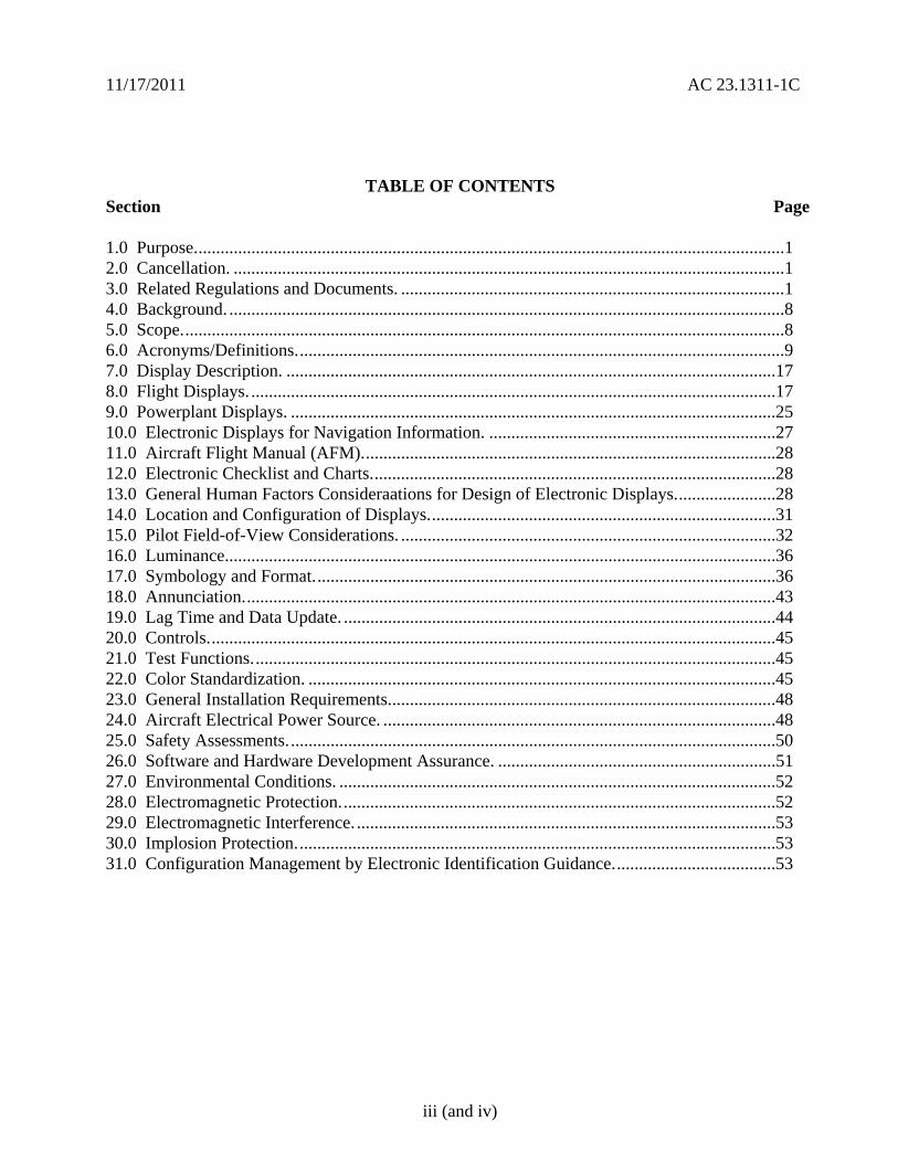
11172011 AC 231311-1C
TABLE OF CONTENTS Section Page
10 Purpose1 20 Cancellation 1 30 Related Regulations and Documents 1 40 Background 8 50 Scope8 60 AcronymsDefinitions9 70 Display Description 17 80 Flight Displays 17 90 Powerplant Displays 25 100 Electronic Displays for Navigation Information 27 110 Aircraft Flight Manual (AFM)28 120 Electronic Checklist and Charts28 130 General Human Factors Consideraations for Design of Electronic Displays28 140 Location and Configuration of Displays31 150 Pilot Field-of-View Considerations 32 160 Luminance36 170 Symbology and Format36 180 Annunciation43 190 Lag Time and Data Update 44 200 Controls45 210 Test Functions45 220 Color Standardization 45 230 General Installation Requirements48 240 Aircraft Electrical Power Source 48 250 Safety Assessments50 260 Software and Hardware Development Assurance 51 270 Environmental Conditions 52 280 Electromagnetic Protection52 290 Electromagnetic Interference 53 300 Implosion Protection53 310 Configuration Management by Electronic Identification Guidance53
iii (and iv)
11172011 AC 231311-1C
10 Purpose This advisory circular (AC) provides guidance for showing compliance with certain requirements of Title 14 Code of Federal Regulations (CFR) part 23 as well as general guidance for the design installation integration and approval of electronic flight deck displays components and systems installed in part 23 category airplanes The guidance provided in this document is directed to airplane and avionics manufacturers modifiers and operators of part 23 category airplanes Applicants for a technical standard order (TSO) should consider following the guidance in this AC when the TSO requirements do not provide sufficient guidance The main purpose of this revision of the AC is providing the guidance for the requirements in the turbojet rulemaking from Amendment 23-62 and some general updating due to lessons learned and advance and emerging technologies
11 This AC provides an acceptable means but not the only means of showing compliance with 14 CFR applicable to installing electronic displays in part 23 airplanes The applicant remains responsible for regulatory compliance and should work closely with their geographic Aircraft Certification Office (ACO) to ensure regulatory compliance This material is neither mandatory nor regulatory in nature and does not constitute a regulation You may follow an alternate FAA-approved method Mandatory words such as ldquomustrdquo apply only to those who seek to show compliance to a specific rule by use of a method prescribed in this AC without deviation
20 Cancellation AC 231311-1B Change 1 ldquoInstallation of Electronic Display Instrument Systems in part 23 Airplanesrdquo dated February 17 2009 is cancelled
30 Related Regulations and Documents Some of the following related documents in this section may not be referenced in this AC but they provide additional information or guidance for electronic displays Please check for the most recent revision of the documents listed
31 Regulatory Sections These acceptable means of compliance refer to the applicable sections of 14 CFR part 23 For airplanes certificated under Civil Air Regulations (CAR) 3 we show the corresponding paragraphs of the former CAR in parenthesis
Table 1 - Regulatory Sections
sect 23771 (3381) Pilot compartment sect 23773 (3382) Pilot compartment view sect 23777 (3384) Cockpit controls sect 231301 (3651 and 3652) Equipment Function and installation sect 231303 (3655(a)) Flight and navigation instruments sect 231305 (3655(b)) Powerplant instruments sect 231308 High-intensity Radiated Fields (HIRF)
Protection sect 231309 Equipment systems and installations sect 231311 Electronic display instrument systems sect 231321 (3661 and 3662) Arrangement and visibility sect 231322 Warning caution and advisory lights sect 231323 (3663) Airspeed indicating system
1
11172011 AC 231311-1C
sect 231326 Pitot heat indication systems sect 231329 Automatic pilot system sect 231331 (3668) Instruments using a power source sect 231335 (3669) Flight director systems sect 231337 (3671 3672 3673 3674 and 3675)
Powerplant instruments installation
sect 231351 (3681 3682 3685 and 3686) Electrical Systems and Equipment General
sect 231353 (3683) Storage battery design and installation sect 231357 (3690 3691 and 3692) Circuit protective devices sect 231359 Electrical system fire protection sect 231361 (3688) Master switch arrangement sect 231365 (3693) Electric cables and equipment sect 231367 (3694 and 3695) Switches sect 231381 (3696 and 3697) Instrument lights sect 231431 (3721) Electronic equipment sect 231501 (3735 and 3737) Operating Limitations and Information General sect 231523 Minimum flight crew sect 231525 (3750) Kinds of operation sect 231529 Instructions for Continued Airworthiness sect 231541 (3755) Markings and Placards General sect 231543 (3756) Instrument markings General sect 231545 (3757) Airspeed indicator sect 231549 (3759) Powerplant and auxiliary power unit instruments sect 231551 (3760) Oil quantity indicator sect 231553 (3761) Fuel quantity indicator sect 231555 (3762) Control markings sect 231559 (3772) Operating limitations placard sect 231581 (3777) Airplane Flight Manual and Approved Manual
Material General
sect 231583 (3761 and 3778) Operating limitations sect 231585 Operating procedures sect 91205 Powered civil aircraft with standard category
US airworthiness certificates Instrument and equipment requirements
sect 121305 Flight and navigational equipment sect 135149 Equipment requirements General
2
11172011 AC 231311-1C
sect 135159 Equipment requirements Carrying passengers under Visual Flight Rules (VFR) at night or under VFR over-the-top conditions
sect 135163 Equipment requirements Aircraft carrying passengers under Instrument Flight Rules (IFR)
32 Advisory Circulars and Related Documents You may access the latest version of the ACs notices orders and policy statements on the FAA website wwwfaagov
Table 2 - Advisory Circulars and Related Documents
AC 20-88A Guidelines on the Marking of Aircraft Powerplant Instruments (Displays)
AC 20-115B RTCA Inc RTCADO-178B AC 20-136A Protection of Aircraft ElectricalElectronic Systems Against the
Indirect Effects of Lightning AC 20-138B Airworthiness Approval of Positioning and Navigation Systems AC 20-140A Guidelines for Design Approval of Aircraft Data Link
Communication Systems Supporting Air Traffic Services (ATS) AC 20-149 Safety and Interoperability Requirements for Initial Domestic
Flight Information Service - Broadcast AC 20-152 RTCA Inc Document RTCADO-254 Design Assurance
Guidance for Airborne Electronic Hardware AC 20-153A Acceptance of Aeronautical Data Processes and Associated
Navigation Databases
AC 20-155 SAE Documents to Support Aircraft Lightning Protection Certification
AC 20-158 The Certification of Aircraft Electrical and Electronic Systems for Operation in the High-Intensity Radiated Fields (HIRF) Environment
AC 20-167 Airworthiness Approval of Enhanced Vision System Synthetic Vision System Combined Vision System and Enhanced Flight Vision System Equipment
3
11172011 AC 231311-1C
AC 20-170 Integrated Modular Avionics Development Verification Integration and Approval Using RTCADO-297 and Technical Standard Order C153
AC 21-16F RTCA Document DO-160 versions D E and F ldquoEnvironmental Conditions and Test Procedures for Airborne Equipment
AC 23-8C Flight Test Guide for Certification of Part 23 Airplanes AC 23-15A Small Airplane Certification Compliance Program AC 23-17C Systems and Equipment Guide for Certification of Part 23
Airplanes AC 23-18 Installation of Terrain Awareness and Warning System (TAWS)
Approved for Part 23 Airplanes AC 23-22 Guidance for Approved Model List (AML) Supplemental Type
Certificate (STC) Approval of Part 23 Airplane Avionics Installations
AC 23-23 Standardization Guide for Integrated Cockpits in Part 23 Airplanes
AC 231309-1E System Safety Analysis and Assessment for Part 23 Airplanes AC 25-11A Electronic Flight Deck Displays AC 90-106 Enhanced Flight Vision Systems AC 91-75 Attitude Indicator AC 91-78 Use of Class 1 or Class 2 Electronic Flight Bag (EFB) AC 120-64 Operational Use and Modification of Electronic Checklists AC 120-76A Guidelines for the Certification Airworthiness and Operational
Approval of Electronic Flight Bag Computing Devices Order 811049 Software Approval Guidelines dated June 3 2003 Order 8110105 Simple and Complex Electronic Hardware Approval Guidance PS-ACE100-2001-004 Guidance for Reviewing Certification Plans to Address Human
Factors for Certification of Part 23 Small Airplanes
33 Technical Standard Orders (TSO) You may access the TSOs on the FAA website wwwfaagov The following is a list of the FAA TSOs that are referenced in this AC For a complete list of TSOs that are related to this AC see AC 20-110L ldquoIndex of Aviation Technical Standards Ordersrdquo or the web site for the most current list
a TSO-C63c Airborne Weather and Ground Mapping Pulsed Radars
b TSO-C113 Airborne Multipurpose Electronic Displays
c TSO-C153 Integrated Modular Avionics Hardware Elements
d TSO-C157 Aircraft Flight Information Services-Broadcast (FIS-B) Data Link Systems and Equipment
4
11172011 AC 231311-1C
e TSO-C165 Electronic Map Display Equipment for Graphical Depiction of Aircraft Position
34 Industry Documents You may obtain copies of current editions of the following publications
341 RTCA Documents The following RTCA documents are available from RTCA Inc 1828 L Street NW Suite 805 Washington DC 20036-4001 or at their website at wwwrtcaorg
a RTCADO-160G Environmental Conditions and Test Procedures for Airborne Equipment
b RTCADO-178B Software Considerations in Airborne Systems and Equipment Certification
c RTCADO-187 Minimum Operational Performance Standards for Airborne Area Navigation Equipment Using Multi-Sensor Inputs
d RTCADO-200A Standards for Processing Aeronautical Data
e RTCADO-201A Standards for Aeronautical Information
f RTCADO-254 Design Assurance Guidance for Airborne Electronic Hardware
g RTCADO-257A Minimum Operational Performance Standards for the Depiction of Navigation Information on Electronic Maps
h RTCADO-267A Minimum Aviation System Performance Standards (MASPS) for Flight Information Services-Broadcast (FIS-B) Data Link
i RTCADO-297 Integrated Modular Avionics (IMA) Development Guidance and Certification Considerations
j RTCADO-313 Certification Guidance for Installation of Non-Essential Non-Required Aircraft Cabin Systems and Equipment
k RTCADO-315A Minimum Aviation Performance Standards (MASPS) for Enhanced Vision Systems Synthetic Vision Systems Combined Vision Systems and Enhanced Flight Vision Systems
342 Society of Automotive Engineers (SAE) Inc The following Society of Automotive Engineers (SAE) Inc documents are available from SAE 400 Commonwealth Drive Warrendale PA 15096-0001 or from their website at wwwsaeorg
5
11172011 AC 231311-1C
a ARP 268G Location and Actuation of Flight Deck Controls for Transport Aircraft
b ARP 450D Flight Deck Visual Audible and Tactile Signals
c ARP 926B FaultFailure Analysis Procedure
d AIR 1093A Numeral Letter and Symbol Dimensions for Aircraft Instrument Displays
e ARP 1161A Crew Station LightingmdashCommercial Aircraft
f ARP 1782A Photometric and Colorimetric Measurement Procedures for Airborne Direct View CRT [Cathode Ray Tube] Displays
g ARP 1834A FaultFailure Analysis for Digital Systems and Equipment
h ARP 1874 Design Objectives for CRT Displays for Part 25 (Transport) Aircraft
i ARP 4032A Human Engineering Considerations in the Application of Color to Electronic Aircraft Displays
j ARP 4033 Pilot System Integration
k ARP 4067 Design Objectives for CRT Displays for Part 23 Aircraft
l ARP 4101 Flight Deck Layout and Facilities
m ARP 4102 Flight Deck Panels Controls and Displays
n ARP 41027 Electronic Displays
o ARP 4103 Flight Deck Lighting for Commercial Transport Aircraft
p ARP 4105B Abbreviations and Acronyms for Use on the Flight Deck
q ARP 4155A Human Interface Design Methodology for Integrated Display Symbology
r ARP 4256A Design Objectives for Liquid Crystal Displays for Part 25 (Transport) Aircraft
s ARP 4260A Photometric and Colorimetric Measurement Procedures for Airborne Electronic Flat Panel Displays
6
11172011 AC 231311-1C
t ARP 4754 Certification Considerations for Highly Integrated or Complex Aircraft Systems
u ARP 4761 Guidelines and Methods for Conducting the Safety Assessment Process on Civil Airborne Systems and Equipment
v ARP 5287 Optical Measurement Procedures for Airborne Head-Up Display (HUD)
w ARP 5288 Transport Category Airplane Head Up Display (HUD) Systems
x ARP 5289 Electronic Aeronautical Symbols
y ARP 5364 Human Factor Considerations in the Design of Multifunction Display Systems for Civil Aircraft
z ARP 5365 Human Interface Criteria for Cockpit Display of Traffic Information
aa ARP 5430 Human Interface Criteria for Vertical Situation Awareness Displays
bb ARP 5677 Human Engineering Considerations for Cockpit Integration of EnhancedSynthetic Vision Systems
cc AS 5703 Minimum Performance Standard for Enhanced Vision System
dd AS 8034A Minimum Performance Standard for Airborne Multipurpose Electronic Displays
ee AS 8055 Minimum Performance Standard for Airborne Head Up Display (HUD)
343 General Aviation Manufacturers Association (GAMA) The following documents are available from the GAMA 1400 K St NW Suite 801 Washington DC 2005 or from their website at wwwgamaaeroindustry-standards
a General Aviation Manufacturers Association (GAMA) Publication No 10 Recommended Practices and Guidelines for Part 23 CockpitFlight Deck Design
b General Aviation Manufacturers Association (GAMA) Publication No 12 Recommended Practices and Guidelines for an Integrated CockpitFlightdeck in a 14 CFR Part 23 Certificated Airplane
7
11172011 AC 231311-1C
40 Background
a Amendment 23-41 effective November 26 1990 established airworthiness standards in sect 231311 for installing electronic display instrument systems in normal utility acrobatic and commuter category airplanes The first electronic displays developed were direct replacements for the conventional electromechanical components with later designs providing more extensive information integration Before Amendment 23-41 most electronic display instrument systems were approved by special condition for installation in part 23 airplanes Amendment 23-49 effective March 11 1996 further amended part 23 to harmonize 14 CFR with the Joint Aviation Requirements (JAR) Section 231311 Amendment 23-49 removed redundant requirements and clarified which secondary instruments are required including the visibility requirements for those instruments
b Amendment 23-62 made several changes that affect the installation of electronic displays Guidance relative to electronic displays of those sections is also included in this AC The significant changes were
(1) Clarified requirements for trend information and appropriate sensory cues
(2) Incorporated equivalent visual displays of the instrument markings on electronic displays
(3) Allowed an applicant to take credit for reversionary or secondary flight displays on a multi-function flight display (MFD) that provides a secondary means of primary flight information (PFI)
(4) Revised some redundancy requirements to be only applicable for IFR operations
(5) Accommodated new technology for magnetic direction indicator
(6) Updated the terminology for system safety assessment
(7) Revised requirements for instruments using power source(s) and
(8) Revised requirements for storage battery backup times
50 Scope This AC is generally applicable only to an applicant seeking issuance of certain type certificates These include a type certificate (TC) an amended type certificate (ATC) or a supplemental type certificate (STC) for the approval of a new type design or a change in the type design This AC does not completely address Synthetic Vision Systems (SVS) or Enhanced Vision Systems (EVS) and Head-Up Displays (HUD) Contact the Small Airplane Directorate if there are any conflicts with other guidance and this AC The Small Airplane Directorate will coordinate and resolve the conflicts among the points of contact of the other documents
8
11172011 AC 231311-1C
60 AcronymsDefinitions
61 Acronyms
a AC Advisory Circular
b ACO Aircraft Certification Office
c ADC Air Data Computer
d ADI Attitude Direction Indicator
e ADDS Aviation Digital Data Service
f AFM Airplane Flight Manual
g AFMS Airplane Flight Manual Supplement
h AHRS Attitude Heading Reference System
i ARD Aerospace Research Document
j ARP Aerospace Recommended Practice
k AS Aerospace Standard
l ASTC Amended Supplemental Type Certificate
m ATC Amended Type Certificate
n CAR Civil Air Regulations
o CDI Course Deviation Indicator
p CFR Code of Federal Regulations
q CIP Current Icing Potential
r CL Center Line
s CRT Cathode-Ray Tubes
t DN Down
u EADI Electronic Attitude Direction Indicator
9
11172011 AC 231311-1C
v EHSI Electronic Horizontal Situation Indicator
w EICAS Engine Indication and Crew Alert System
x ELOS Equivalent Level of Safety
y EVS Enhanced Vision Systems
z FAA Federal Aviation Administration
aa FD Flight Director
bb FHA Functional Hazard Assessment
cc FLS Field-Loadable Software
dd FMEA Failure Modes and Effects Analysis
ee FOV Field-Of-View
ff GPS Global Positioning System
gg HIRF High Intensity Radiated Fields
hh HUD Head-Up Display
ii HSI Horizontal Situation Indicators
jj ICAO International Civil Aviation Organization
kk IFR Instrument Flight Rules
ll ILS Instrument Landing System
mm IMA Integrated Modular Avionics
nn IMC Instrument Meteorological Conditions
oo JAR Joint Aviation Requirements
pp LCD Liquid Crystal Displays
qq LED Light Emitting Diodes
rr LT Left
10
11172011 AC 231311-1C
ss METAR ICAO Routine Aviation Weather Report
tt MFD Multifunction Flight Display
uu ND Navigation Display
vv NOM Nominal
ww PFD Primary Flight Display
xx PFI Primary Flight Information
yy POH Pilots Operating Handbook
zz RAIM Receiver Autonomous Integrity Monitoring (used with GPS)
aaa RT Right
bbb SAE Society of Automotive Engineers
ccc STC Supplemental Type Certificate
ddd SVS Synthetic Vision Systems
eee TAS Traffic Advisory System
fff TAWS Terrain Awareness Warning System
ggg TFR Temporary Flight Restrictions
hhh TC Type Certificate
iii TCAS Traffic Alert and Collision Avoidance System
jjj TSO Technical Standard Order
kkk UL Underwriterrsquos Laboratories
lll VOR Very High Frequency Omni-Directional Range
mmm VFR Visual Flight Rules
nnn VMC Visual Meteorological Conditions
ooo VFE Maximum flap extended speed
11
11172011 AC 231311-1C
ppp VMO Maximum operating limit speed
qqq VNE Never-exceed speed
rrr VNO Maximum structural cruising speed
sss VS0 The stalling speed or the minimum steady flight speed in the landing configuration
ttt VS1 The stalling speed or the minimum steady flight speed obtained in a specific configuration
uuu WAAS Wide Area Augmentation System
62 Definitions This section contains definitions for terms in this document
a Accuracy A degree of conformance between the estimated or measured value and the true value
b Adverse Operating Condition A set of environmental or operational circumstances applicable to the airplane combined with a failure or other emergency situation that results in a significant increase in normal flight crew workload
c Component Any self-contained part combination of parts subassemblies or units that perform a distinct function necessary to the operation of the system
d Continued Safe Flight and Landing This phrase means the airplane can continue controlled flight and landing possibly using emergency procedures without requiring exceptional pilot skill or strength On landing some airplane damage may occur as a result of a Failure Condition
e Conventional A system is considered ldquoConventionalrdquo if its function the technological means to implement its function and its intended use are all the same as or closely similar to that of previously approved systems that are commonly used The systems that have established an adequate service history and the means of compliance for approval are generally accepted as Conventional
f Critical Usually a function whose loss would prevent the continued safe flight and landing of the airplane
Note The term ldquocritical functionrdquo is associated with a catastrophic failure condition Newer documents may not refer specifically to the term ldquocritical functionrdquo
g Criticality Indication of the hazard level associated with a function hardware software etc considering abnormal behavior (of this function hardware software etc) alone in
12
11172011 AC 231311-1C
combination or in combination with external events Criticality is a failure classification that could be no safety effect minor major hazardous and catastrophic See AC 231309-1E for more guidance
h Design-Eye Box A three-dimensional volume of space surrounding the design eye reference point that designers and evaluators use to determine the acceptability of display and control locations
i Design-Eye Reference Point A single reference point in space selected by the designer where the midpoint between the pilotrsquos eyes is assumed to be located when the pilot is properly seated at the pilotrsquos station
j Development Assurance All those planned and systematic actions used to substantiate to an adequate level of confidence that errors in requirements design and implementation have been identified and corrected such that the system satisfies the applicable certification basis
k Enhanced Vision System An electronic means to provide a display of the forward external scene topography (the natural or manmade features of a place or region especially in a way to show their relative positions and elevation) through the use of imaging sensors such as a forward looking infrared millimeter wave radiometry millimeter wave radar low light level image intensifying
l Equipment Essential to Safe Operation Equipment installed to comply with the applicable certification requirements of 14 CFR part 23 or operational requirements of 14 CFR parts 91 and 135
m Error An omitted or incorrect action by a pilot or maintenance person or a mistake in requirements design or implementation
n Failure An occurrence that affects the operation of a component part or element such that it can no longer function as intended (this includes both loss of function and malfunction
o Failure Condition A condition affecting either the airplane or its occupants or both either direct or consequential caused or contributed to by one or more failures or errors considering flight phase and relevant adverse operational or environmental conditions or external events Failure conditions may be classified according to their severity See AC 231309-1E for more information on definitions of failure conditions
p Field-of-View The angular extent of the display that can be seen by either pilot with the pilot seated at the pilotrsquos station See section 15 for more information on the field-of view
q Fix A generic name for a geographical position A fix may also be referred to as a waypoint intersection reporting point etc
13
11172011 AC 231311-1C
r Flight Plan Refers to any sequence of fixes that are interconnected by the desired path Flight plans may range from the simplest that include only the aircraftrsquos present position the active waypoint and the desired path between them to more complicated plans that include departure and destination airports with multiple intermediate fixes
s Function The lowest defined level of a specific action of a system equipment and pilot performance aboard the airplane that by itself provides a complete recognizable operational capability (for example an airplane heading is a function) One or more systems may contain a specific function or one system may contain multiple functions
t Functional Hazard Assessment A systematic comprehensive examination of airplane and system functions to identify potential minor major hazardous and catastrophic failure conditions that may arise as a result of a malfunction or a failure to function
u Hardware An object that has physical being Generally refers to circuit cards power supplies etc
v Hazard Any condition that compromises the overall safety of the airplane or that significantly reduces the ability of the pilot to cope with adverse operating conditions
w Head-Up Display A transparent optical display system located level with and between the pilot and the forward windscreen The HUD displays a combination of control performance navigation and command information superimposed on the external field of view It includes the display element sensors computers and power supplies indications and controls It is integrated with airborne attitude air data and navigation systems and as a display of command information is considered a component of the flight guidance system
x Independent A component part element or system that is not relying on some other component part element or system for accomplishing its function This design concept ensures that the failure of one item does not cause a failure of another item For redundancy each means of accomplishing the same function need not necessarily be identical
y Indicator A means for displaying information of a parameter More than one indicator could be depicted on one display For example a primary flight display may have indicators for attitude altitude airspeed heading and navigation
z Instrument An electrical or mechanical measurement device In sect 231311 it is defined as Devices physically contained in one unit and devices composed of two or more physically separate units or components connected together (One example is a remote indicating gyroscopic direction indicator that includes a magnetic sensing element a gyroscopic unit an amplifier and an indicator connected together)
aa Map Orientation Refers to the rule that determines the directional relation of the map to the upper part of the display depiction Using a north-up rule the north side of the map would be toward the top of the display and the south side of the map would be at the bottom Using
14
11172011 AC 231311-1C
a desired path-up rule the map would be oriented so the desired path would be vertical on the map and pointing straight up toward the top of the display
bb Map Range The geographic extent of the map region (for example the distance covered by the map representation in either the vertical or horizontal direction)
cc Malfunction Failure of a system subsystem unit or part to operate in the normal or usual manner A condition whereby the operation is outside specified limits
dd Multi-Function Display Any physical display unit other than the PFD used to present various information on which the layout may be reconfigured
ee Navigation The process of planning tracking and controlling the course of an airplane from one place to another
ff Navigation Display The display or suite of instruments by which navigation data is presented to the pilot
gg Navigation Information Information that aids the flightcrew in determining the aircraftrsquos location in a given environment (for example on flight plans VORs GPSs features on the airport surface including taxiway signage etc)
hh Primary As used for instruments it is defined in sect 231311(c) as the ldquodisplay of a parameter that is located in the instrument panel such that the pilot looks at it first when wanting to view that parameterrdquo
ii Primary Flight Display (PFD) A single physical unit that always provides the primary display of all the following altitude airspeed aircraft heading (direction) and attitude located directly in front of the pilot in a fixed layout in accordance with sect 231321 It may provide other information pertinent to guidance and fundamental control of flight of the airplane such as critical engine parameters
jj Primary Flight Information (PFI) A PFI refers to those functions or parameters required by the airworthiness and operational rules such as airspeed altitude attitude and heading (direction) that are on the PFD
kk Primary Function (PF) This definition is applicable in the case when there is more than one function available for same function A function that is installed to comply with the applicable regulations for the required function and one that provides the most pertinent controls or information instantly and directly to the pilot For example the PFD is a single physical unit that always provides the primary display and it complies with the requirements of all the following altitude airspeed aircraft heading (direction) and attitude This PFD is located directly in front of the pilot and used instantly and first by the pilot A standby (additional) PFD that is intended to be used in the event of failure of the PFD is an example of a secondary system
15
11172011 AC 231311-1C
ll Primary Navigation Where the pilot looks first for a display of navigation information such as on an HSI or CDI It displays vertical and lateral deviation and it may have the digital distance indication tofrom the selected fix
mm Redundancy The presence of more than one independent means for accomplishing a given function Each means of accomplishing the function need not necessarily be identical
nn Reversionary Display A secondary means to provide information initially presented on the PFD or MFD by the transfer of information to an alternate display
oo Scale The relative proportion of the linear dimensions of objects on a display to the dimensions of the corresponding objects and distances being represented (for example 1 inch = 100 nautical miles)
pp Secondary Display A means to present information on another display A display that can be used for backup or secondary purposes such as in the event of a failure of another display
qq Standby Instrument A dedicated instrument that is always available that presents primary flight information
rr Supplemental Function A function that is not required or intended to meet all the airworthiness and operational requirements It is usually installed for additional situational awareness
ss System A combination of components parts and elements that is interconnected to perform one or more functions
tt Synthetic Vision System A computer-generated image of the external scene topography from the perspective of the flight deck that is derived from aircraft attitude high precision navigation solution and database of terrain obstacles and relevant cultural features
Note ldquoTopographyrdquo defined as maps or charts of natural and man-made features of a place or region especially in a way to show their relative positions and elevations as applicable whenever deemed appropriate and practicable
uu Track The projection on the earthrsquos surface of the path of an aircraft the direction of which is usually expressed in degrees from north (true magnetic or grid) A track is the actual flight path of an aircraft over the surface of the earth
Note For more definitions related to safety assessments refer to AC 231309-1E for the appropriate definitions
vv Warning A clear and unambiguous indication to the pilot of a failure that requires immediate corrective action An inherent characteristic of the airplane or a device that will give
16
11172011 AC 231311-1C
clearly distinguishable indications of malfunction or misleading information may provide this warning
70 Display Description The following paragraphs give a brief description of an electronic display They do not cover all the capabilities and details of these displays or the information presented on them
71 General Electronic displays have replaced many of the traditional electromechanical and analog instruments These displays also augment andor combine the functionality of conventional systems such as radios and navigational systems The major display technologies now used are multicolor CRTs LCDs electro luminescence plasma and LEDs The initial electronic displays mimicked the traditional mechanical and electromechanical flight and powerplant instruments The colors symbols and formats on these initial electronic displays are similar to those on traditional conventional instruments Modern electronic displays provide integration and formats that often differ from traditional instruments
72 Display Configuration Electronic displays may be installed in several configurations A basic electronic display may provide only one flight or powerplant parameter while more sophisticated systems integrate many parameters on one electronic display One of the major design goals for these systems is eliminating separate conventional gauges instruments and annunciators Recent installations show a trend toward a higher degree of integration For example an integrated primary flight display provides several parameters such as attitude heading (direction) airspeed and altitude Integration of various systems should include analysis to ensure that complexity and workload are compatible with general aviation pilots capabilities For more guidance on IMA that implement TSO authorized hardware elements see TSO-C153 and AC 20shy170
80 Flight Displays
81 Instrument Requirements
a Sections 231303 231305 231311 and 231321 with the applicable operating rules (14 CFR parts 91 121 and 135) incorporate flight and powerplant instrument requirements for part 23 airplanes The navigation equipment requirements are given in operational rules specified in sectsect 91205 121303 121305 121307 135143 135149 135159 135161 and 135165 Display requirements for navigation information are dependent on the navigation system installed in the aircraft Instruments and equipment required for flights under parts 91 121 and 135 may be affected by the electronic display installation These instruments and equipment include gyroscopic bank and pitch gyroscopic direction gyroscopic rate-of-turn slip-skid instruments and other required communication and navigational equipment
b There have been applications to install equipment such as flight and navigation displays as non-required These applications request approval for these installations as situation awareness (SA) only It is not acceptable to label a display as ldquoSA-Onlyrdquo and assume that its failure condition is acceptable Installing displays that provide PFI that are more compelling than
17
11172011 AC 231311-1C
the required primary PFI displays but they do not meet the appropriate operational and airworthiness requirements and labeling them as ldquoSupplementalrdquo or ldquoSA-Only is not acceptable Section 136 provides more guidance
c The basis for certification has been that the equipment should perform its intended function and not present a hazard Instruments that aid situation awareness should be certified under the part 23 requirements including sect 231301 and sect 231309 These displays could provide hazardous misleading information PFI is essential for safe operation An instrument that provides PFI should meet the minimum standards of applicable TSOs or an equivalent standard It also should meet the guidance in AC 231309-1E AC 23-17C and the guidance in this AC
82 Primary Flight Information (PFI) PFI refers to those functions or parameters that are required by the airworthiness and operational rules such as airspeed altitude attitude and heading (direction) It may provide other information pertinent to guidance and fundamental control of flight such as critical engine parameters Attitude airspeed altitude and heading (direction) are the PFI required in sect 231311(a)(3) and (5) and they must be arranged according to sect 231321 in the ldquobasic Trdquo arrangement Direction should be heading with track presented if available as a selectable option The horizon reference line on the PFD should be at least 325 inches wide in straight and level flight for integrated displays This recommendation is not intended to prevent replacement of mechanical instruments with an electronic display of a similar horizon reference line When the true horizon is no longer on the display the artificial horizon line should provide a distinctive demarcation between sky and ground (or the background) Display of PFI on reversionary or standby displays should be arranged in the basic T-configuration but it is not required The standby instrument or displays of PFI location should meet the FOV guidance criteria in section 15
821 Acceptable Methods for Compliance with sect 231311(b) There are three acceptable methods for meeting the attitude requirements which is considered information essential for continued safe flight and landing Compliance can be accomplished by using dedicated standby instruments dual PFDs or reversionary displays that present primary flight information Electronic display systems without dedicated standby instruments should have at least two independent displays able to provide PFI to the pilot These displays should be powered such that any single failure of the power generation and distribution systems cannot remove the display of PFI from both displays Section 231311(b) in Amendment 23-62 states ldquoThe electronic display indicators including their systems and installations and considering other airplane systems must be designed so that one display of information essential for continued safe flight and landing will be available within one second to the crew by a single pilot action or by automatic means for continued safe operation after any single failure or probable combination of failuresrdquo
83 Standby Instruments The purpose of standby instruments or another independent PFD is to ensure that PFI is available to the pilot during all phases of flight and during system failures Individual indicators should be a minimum of 2 inches in diameter or if combined a minimum diameter of 3 inches (or equivalent) displayed
831 Dual PFDs Electronic display systems with dual PFDs should incorporate dual independently powered sensors that provide primary flight parameters such as AHRS with
18
11172011 AC 231311-1C
comparators and dual ADC Dual PFDs with dual AHRSs and ADCs which include checking and are powered by multiple power sources and distribution systems are significantly more reliable than presently certified mechanical systems
832 PFD and Autopilot with an AHRS For normal operation when using a single AHRS to drive the PFD and the autopilot simultaneously the installation must mitigate hazardous or catastrophic system level failures An example configuration supporting proper mitigation would include all of the following
a A dedicated standby attitude instrument within the primary maximum FOV or independent reversionary attitude display
b An AHRS with appropriate comparator or monitor of equivalent performance
c Appropriate system warningcaution annunciation associated with an AHRS malfunction
d If an aircraft is equipped with multiple AHRS it may be acceptable when one AHRS fails to drive both the autopilot and the PFD from a single AHRS as long as an AHRS independent attitude display (required for some aircraft classes) is located in the primary maximum field of view The failure must be annunciated to the pilot and the pilot must be able to select the non-failed AHRS For aircraft that do not have an independent attitude indicator when one AHRS fails the autopilot should be manually or automatically disengaged The autopilot may be reengaged if appropriate mitigation is available (for example see a through c above) The AFM or supplemental AFM should contain the appropriate procedures applicable to the equipment installed See section 110 for additional guidance AC 231309-1E guidance should be considered for these configurations
e Displays not meeting FOV guidance criteria may require additional human factors airworthiness evaluation by the certification authority See section 15 for additional guidance
84 Reversionary Flight Displays Instead of Standby Instruments or Dual PFDs
841 General Requirements
a Reversionary flight displays provide a secondary means to provide PFI through alternate display formats on another PFD or MFD by the transfer of information to an alternate display or by some other means The function of an MFD system is to provide the pilot access to various data or combinations of data used to fly the aircraft to navigate to communicate andor to manage aircraft systems The MFD would also present PFI as needed to ensure continuity of operations 14 CFR part 23 sect 231311(b) Amendment 23-62 states the electronic display indicators including their systems and installations and considering other airplane systems must be designed so that one display of information essential for continued safe flight and landing will be available within one second to the crew by a single pilot action or by automatic means for continued
19
11172011 AC 231311-1C
safe operation after any single failure or probable combination of failures To meet the requirements of sect 231311(b) a full-time standby display another independent PFD or an independent reversionary attitude display must be installed Reversionary modes could be automatically and manually selected or only manually selected
b Reversionary configurations are significantly more reliable than presently certified mechanical systems and the skills required while flying in reversionary mode are identical with those used when flying in primary mode Traditional external standby flight instruments (either electronic or mechanical) offer potential safety problems associated with delay in pilot reaction The pilot may delay a decision to transition to standby instruments and to transition to partial panel techniques as opposed to the simple action the pilot would take to switch displays A nearly identical format on the reversionary display of all PFI that is also shown on the PFD provides a significant safety enhancement over standby instruments This is especially true when the size location arrangement and information provided by the standby instruments are significantly different from those on the PFD
c Reversionary display modes should provide consistent display formats to the PFD The reversionary flight information should be presented by an independent source and display to prevent complete loss of PFI due to a single failure The reversionary configuration should have two independent displays that incorporate dual-independently powered AHRS and dual ADC subsystems that provide PFIs The reversionary system response time should provide flight critical information on the MFD in less than one second after a single pilot action or an automatic operation
d A reversionary configuration should have a single pilot action that would force both the PFD and MFD displays into reversionary mode operation However the PFI should be presented in similar format and sufficient size in the reversionary mode as it is in normal mode to allow the pilot to enhance the control of the airplane This reversionary configuration should provide backup information essential to continued safe flight and landing with an intuitive control that allows instant simultaneous access to reversionary mode on both the PFD and MFD displays The single pilot action should be easily recognized readily accessible and have the control within the pilotrsquos primary optimum field of view An acceptable method for the single pilot action is the red color andor lighted red ldquohalordquo ring that announces its position on the panel at all times
842 Reversionary Methods
a One method is to have an automatic reversionary display with a single pilot action that would force both the PFD and MFD displays into reversionary mode operation If PFI on another display is not provided provide automatic switching to ensure PFI is available to the pilot Automatic reversion must provide a complete display of PFI on the remaining display within one second if a fault is detected
b Most possible faults should be covered by this automatic reversionary capability Only a total loss of the display may not be reliably detected automatically but such a failure condition would be obvious to the pilot Faults that result in automatic switching should be extensive enough to ensure PFI availability meets the requirements of sect 231309 If such a
20
11172011 AC 231311-1C
malfunction occurs a single pilot action should provide a full display of the essential information on the remaining display within one second All modes sources frequencies flight plan data etc should be similar as they were on the PFD before the failure
c Another reversionary method would include a means to access the reversionary mode manually through a single pilot action Manual activation of the reversionary mode on the MFD through single action by the pilot is acceptable when procedures to activate the PFI on the MFD are accomplished before entering critical phases of flight The PFI would be presented continuously on the reversionary display during critical phases of flight (for example takeoff landing and missed or final approach)
85 Display of Attitude For flights under IFR conditions in part 91 and part 135 operations and under VFR at night for part 135 operations attitude information is required The loss of all attitude information or the presentation of misleading attitude information could result in a catastrophic failure condition where the pilot could not continue safe flight and landing of the airplane It is recommended that the display of attitude follows the guidelines (below) that are also in GAMA Publication 12
a The pitch ladder should be caged to the center of the display
b At pitch attitudes when the true horizon line would not normally be displayed some sky or ground should be indicated on the PFD pitch display (minimum 38 inches and maximum of 115 percent of the display) and the horizon line should indicate off-scale
c With the airplane symbol on the horizon line the range of visible pitch attitude should be at least + 25 to -15 degrees but not to exceed a total pitch range of 50 degrees
d Bank angle presentations should use a roll pointer however roll pointers and sky-pointers should not be mixed in the same flight deckcockpit
e Roll scale indices should be placed at 10 20 30 60 and 90 degrees An index may also be placed at 45 degrees
86 Display of Direction (Heading or Track)
861 General
a The loss of direction (heading or track) information could result in reduced capability of the pilot to cope with adverse operating conditions The orientation of any secondary navigation display is optional (for example Track-up North-up Heading-Up) For flights under IFR conditions a stabilized heading indicator must provide the primary display of the direction parameter A magnetic direction indicator or track may provide the reversionary display of direction
21
11172011 AC 231311-1C
b The heading display should provide a clear and unmistakable display of aircraft symbol and heading HSI should provide a clear and unmistakable display of aircraft position heading and track (an option if available) relative to the desired coursetrack Section 17 contains more guidance on symbology Direction should be heading when track is presented if available as a selectable option with the data source clearly indicated On the primary display the heading scale should have a mode that presents at least 120 degrees of arc Other display formats may be acceptable and have been previously approved but they need to be evaluated from a human factor perspective
862 Hazardous Misleading Heading Information
a The FHA for the failure effects of hazardous misleading heading information from an AHRS is clarified in AC 23-17C This policy is specifically about the application of AC 231309-1E for an airplane with the certification basis of Amendments 23-41 or later This clarification is limited to installations approved for operation in IMC under IFR For operations limited to VFR a misleading heading indication is not considered hazardous
b Develop an FHA and the related safety assessments for the specific airplane type and configuration since there can be many combinations of failures various mitigating factors and other functions available to a pilot These many factors affect the criticality of the heading indication therefore use a safety assessment process from AC 231309-1E to classify the failure conditions for misleading heading information
c A hazardously misleading heading is usually when the accuracy error is greater than 10 degrees on the primary heading instrument and it is an undetected error The safety assessment process should consider appropriate mitigating factors For Class I part 23 airplanes the failure condition for misleading hazardous heading is usually considered major
87 Display of Altitude Airspeed and Magnetic Compass Information The original requirements of CAR 3 were adopted and later recodified into part 23 sect 231303 paragraphs (a) (b) and (c) At that time pneumatically driven displays provided airspeed and altitude functions Since then the FAA envisioned airspeed altitude and magnetic compass information would remain available to the pilot with the loss of the airplanes primary electrical power For electronic displays sect 231311(a)(3) requires the primary display of attitude airspeed and altitude to be uninhibited in any normal mode of operation Section 231311(a)(5) as amended by Amendment 23-62 requires an independent magnetic direction indicator and either an independent secondary mechanical altimeter airspeed indicator and attitude instrument or electronic display parameters for the altitude airspeed and attitude that are independent from the airplanes primary electrical power system Primary altitude or airspeed displays that require electrical power are acceptable if means are provided for their continued operation upon loss of the airplanersquos primary electrical power or if pneumatically driven instruments are available for the pilotrsquos use A standby or reversionary integrated display of altitude attitude and airspeed instead of individual electronic display indicators for airspeed altitude and attitude is acceptable under one condition The condition is that the standby or reversionary integrated display and the primary display are powered such that at least one integrated display with attitude altitude and airspeed is available after failure of any power source or distribution path
22
11172011 AC 231311-1C
88 Accuracy of the Magnetic Heading System
881 General
a The operating rules such as part 91 and part 135 specify the minimum required equipment that must be installed in part 23 airplanes based on the operation such as VFR or IFR Under VFR operation part 91 sect 91205 requires a magnetic direction indicator (that is normally intended to be a compass) for heading information Under IFR operation part 91 sect 91205 requires a gyroscopically stabilized heading system Section 231303(c) Amendment 23-62 amended the requirement from ldquoA direction indicator (non-stabilized magnetic compass)rdquo to ldquoA magnetic direction indicatorrdquo As new technology becomes more affordable for part 23 airplanes many electronic flight instrument systems will use magnetically stabilized direction indicators (or electric compass systems) to measure and indicate the airplane heading to provide better performance
b The general airworthiness requirements in part 23 sect 231301 and sect 231525 determine the flight instrument and equipment accuracy requirements for part 23 airplanes Part 23 does not prescribe specific accuracy requirements for magnetic gyroscopically stabilized heading systems Specific accuracy requirements for avionics may be found in the related TSO and as acceptable means of compliance to sect 231301 in ACs notices or policy statementsletters
882 Magnetic Non-Stabilized Direction Indicator A magnetic non-stabilized direction indicator that is required by sect 231303 should have an accuracy of 10 degrees or have a correction card placard (reference sect 231327) or a back-up gyroscopic direction indicator provided the indicator is accurate better than 10 degrees If the sole purpose of the gyroscopic direction indicator is for backing up the magnetic non-stabilized direction indicator then the accuracy of presentation of headings can also be to 10 degrees However if a gyroscopic direction indicator is installed to meet the IFR operating rules then the installation requirements are defined by sect 231301
883 Magnetic Gyroscopically Stabilized Direction Indicator As installed final accuracy for a magnetic gyroscopically stabilized direction indicator of plusmn4 degrees on the ground or plusmn6 degrees in normal level flight on any heading would meet the requirements of part 23 sect 231301 This accuracy applies after compensation It should include cumulative errors in all combinations due to several factors These consist of the equipment itself the current flow in any item of electrical equipment and its associated wiring the movement of any part (for example controls or undercarriage) and the proximity of any item of equipment containing magnetic material to the magnetic sensor
884 Comparator Monitor
a For systems installations that include two magnetic gyroscopically stabilized heading systems and a comparator that monitors the differences between the headings of the two
23
11172011 AC 231311-1C
systems the comparator trip point set as follows would meet the requirements of part 23 sect 231301
(1) 6 degrees in stabilized level flight
(2) 6 degrees plus one half of the bank angle or
(3) 12 degrees with a bank angle greater than 6 degrees
(4) The alert function can be disabled at a bank angle greater than 20 degrees
(5) An alert is provided if the condition exceeds 60 seconds but it allows two minutes for a turn error as stated in the TSO
b The 6-degree trip point during level flight allows a heading error of as much as 12 degrees on one of the systems This would comprise one system at the 6 degrees in-flight tolerance limit while the other system presumably with some malfunction could have an error of 12 degrees in the same direction before the comparator monitor alert is tripped
89 Rate-of-Turn Instrument
a Under sectsect 91205 and 135159 a rate-of-turn instrument is not required if a third attitude instrument usable through flight attitudes of 360 degrees of pitch-and-roll is installed following the instrument requirements prescribed in sect 121305(j) If required place the rate-of-turn indicator near the heading indicator
b A second approved attitude indicator may substitute for the rate-of-turn instrument AC 91-75 Attitude Indicator provides one method This AC is applicable to part 23 certificated airplanes (or airplanes certificated under earlier equivalent regulations) that weigh less than 12500 pounds and are operated under part 91 The second approved attitude indicator must be powered by an independent power source from the primary attitude indicator This can be accomplished by using independent standby instruments another independent PFD or independent reversionary attitude display Most of the installations with electronic displays that meet the requirements of sect 231311 and this AC should comply with AC 91-75
810 Slip-Skid Instrument The slip-skid information is required by sectsect 91205(d)(4) and 135159(b) as applicable The FAA suggests locating the slip-skid display directly below or near the rate-of-turn instrument if installed or under or within the primary attitude display
811 Vertical Speed Indicator If provided present the vertical speed indicator to the right or directly below the altitude indicator with a scale appropriate to the performance of the aircraft
24
11172011 AC 231311-1C
90 Powerplant Displays
91 General
a This section defines a means of presenting powerplant performance and condition information about the airplanes operation It also provides guidelines about when these functions should be displayed to the pilot In general there have been two methods used to accomplish this These methods include (1) display raw engine parameters to the pilot for interpretation or (2) collect powerplant data and have an automatic monitoring system interpret and report the powerplant condition to the pilot Use the following evaluation criteria when considering the installation of electronic powerplant displays
b There is a need to evaluate each airframe engine and airframeengine interface with the operational characteristics of these systems to determine the primary powerplant parameter requirements For this evaluation and as used in this section a primary powerplant parameter is needed to start the engine and to set and monitor engine power within powerplant limitations Appropriate procedures for operation of an integrated electronic powerplant display system should be in the AFM
c For multiengine airplanes a failure or malfunction affecting the display or accuracy of any propulsion system parameter for one engine should not cause the loss of display or accuracy of any parameter for the remaining engine(s) If multiple propulsion parameters are integrated on one display and the display fails it is acceptable to provide a secondary propulsion parameter display
92 Loss of Critical Powerplant Information
a No single failure malfunction or probable combination of failures should result in either the loss of critical powerplant information or an erroneous display of powerplant parameters that would jeopardize continued safe flight and landing of the airplane Usually for engines that do not generally rely on the pilot to prevent exceeding their limits in normal operations or engines such as with electronic engine controls featuring engine limit protection the loss of powerplant displays should not cause immediate jeopardy to continued safe flight and landing
b A secondary display providing powerplant parameters for cases of loss of a primary powerplant display may be used provided it is located so the pilot can adequately view the powerplant parameters
c Throttle or power lever position may be used in place of lost powerplant display parameters This would apply if throttle position or power lever position provides a positive indication of the powerplant power level required to maintain safe flight to a landing and if the throttle has a means to preclude exceeding powerplant operating limits
25
11172011 AC 231311-1C
93 Powerplant Information
a Presentation of primary powerplant parameters continuously when they are required unless the monitor provides an adequate alert of the function Also provide a manual select option for the pilot to present the information A parameter defined as primary for engine start but not for other normal engine operation may only have to be presented continuously during engine start
b Before and upon reaching or exceeding any operating limit the display should present the required powerplant parameters without pilot action Timely alerts for each phase of flight should be provided when any operating limit is reached or exceeded for the required powerplant parameter The alerts should be in a form that enables the pilot to identify and carry out the necessary and appropriate actions The required powerplant information should be presented continuously during a critical takeoff and landing phase of flight to minimize pilot distraction until an established rate of climb or minimum altitude is achieved
c Displays that provide multiple powerplant parameters should be designed such that any parameter display or alert will not suppress another display or alert that also requires immediate crew awareness necessary to conduct safe operation of the aircraft and engine(s) Alerts that could cause subsequent activation of other displays or alerts should be presented in a manner and form to ensure appropriate identification and prioritization of all significant hazards and required crew actions See section 18 for more guidance on annunciation
94 Digital Reading Alphanumeric Displays
a Digital reading alphanumeric displays are most valuable when integrated with an analog display by adding a precise quantitative indication to complement an analog displays qualitative indication Proper integration should include a means for pilots to clearly associate the analog and digital indications (eg via close proximity) Digital reading alphanumeric powerplant displays formats should not be used in place of analog formats to indicate values of engine parameters where trend or rate-of-change information is important for safety or when the pilot needs to monitor parameters with a quick glance Digital reading alphanumeric displays limit the pilots ability to assess trend information and result in reduced crew awareness Digital reading alphanumeric displays are also limited in their ability to allow the pilot to easily compare parameters from multiple engines or to check the general proximity of differing parameters against their individual limits While these shortcomings can be compensated for with more design provisions use digital reading alphanumeric displays with caution and carefully evaluate each airframe engine and airframeengine integration
b Section 231311(a)(6) Amendment 23-62 requires sensory cues that provide a quick glance sense of rate and where appropriate trend information to the parameter being displayed to the pilot Section 231311(a)(7) requires incorporated equivalent visual displays of the instrument markings required by sectsect 231541 through 231553 or visual displays that alert the pilot to abnormal operational values or approaches to established limitation values for each parameter required to be displayed by this part
26
11172011 AC 231311-1C
c An ELOS will be necessary for digital -reading alphanumeric only displays that are not associated with any scale tape or pointer It may be difficult for pilots to determine the margin relative to targets or limits or compare between parameters To comply with sect 231311(a)(7) a scale dial or tape will be needed to accomplish the intended pilot task In order to demonstrate an equivalency a human factor andor pilot evaluations will be needed that will consider the following factors These are subject to evaluation on a case-by-case basis
(1) The visibility and relative location of the indicated parameter should be reviewed including appropriate conditions of lighting and instrument panel vibration
(2) The ability to assess necessary trend or rate-of-change information quickly including when this information may be needed during in-flight engine restarts
(3) The ability to assess how close the indicated parameter is relative to a limit
(4) The value to the crew of quickly and accurately comparing engine-to-engine data for multiengine aircraft
(5) Engine design features or characteristics that would forewarn the crew before the parameter reaches the operating limit (for example redline)
(6) The use of color in accordance with sect 231549 to indicate the state of operation a green indication would indicate normal operation a yellow indication would indicate operation in a takeoff or precautionary range and a red indication would indicate operation outside of the safe operating limits
95 Marking of Powerplant Parameters Mark powerplant parameters on electronic displays in accordance with sect 231549 AC 20-88A provides alternate methods of marking electronic powerplant displays Alternate methods of marking the displays may be performed However the FAA may evaluate these markings on a case-by-case basis depending on each airframe engine integration and appropriate human factors considerations Alternate markings that do not comply with the requirements of sect 231549 require an ELOS
100 Electronic Displays for Navigation Information
101 Guidance Information Navigation information used by the pilot for steering commands and to monitor deviation from a navigation path should be in the pilots primary FOV Warnings and cautions should also be in the primary FOV For more guidance on FOV see section 15 and Table 3 of this AC
102 Display Integration
a Navigation guidance information may be integrated with the PFDs Common examples include HSIs that combine inputs from a directional gyro with a course deviation
27
11172011 AC 231311-1C
indicator or an FD integrated with the ADI Additionally information from more than one navigation source may be displayed separately or simultaneously
b If information from more than one navigation source can be presented the selected source should be continuously indicated to the pilot If multiple sources can be presented simultaneously the display should indicate unambiguously what information is provided by each source and which one has been selected for guidance Some airplanes are equipped with an autopilot andor FD coupled to the lateral and vertical guidance system On these airplanes the input to the autopilot andor FD should coincide with the navigation source selected on the PFD or primary navigational display
103 Reversionary Navigation Displays Reversionary requirements for navigation display information depend on the rules under which the aircraft is operated and the hazards associated with the loss of or misleading information from the display The integration of non-navigation information (for example traffic weather or flight parameters) may affect the hazards associated with the loss of or misleading information from the display In these cases the applicant should perform a system safety assessment following AC 231309-1E For more guidance on safety assessments see AC 231309-1E and section 26 of this AC for more guidance
104 Navigation Database For area navigation equipment the navigation database is an essential component of the equipment Guidelines for the navigation database can be found in RTCADO-200A See AC 20-138 and AC 20-153 for more guidance and information
110 Aircraft Flight Manual (AFM) For equipment required for IFR approval the AFM or supplemental AFM should contain the limitations and the operating and emergency procedures applicable to the equipment installed Installations limited to VFR use only may require an AFM or supplemental AFM depending on the complexity of the installation and the need to identify necessary limitation and operating procedures AC 23-8C contains more policy and guidance on AFMs
120 Electronic Checklist and Charts Policy and guidance on electronic checklist and charts on electronic displays are contained in AC 23-8C AC 91-78 AC 120-64 and AC 120-76A
130 General Human Factors Considerations for Design of Electronic Displays
131 General Electronic displays can provide many innovative display flexibilities and features that were not possible with traditional displays Technology improvements in display design and integration can enhance pilot performance and improve situation awareness when innovations are designed using sound processes and appropriate design criteria that account for human performance The applicant should ensure that human performance considerations are adequately addressed throughout the design process Early FAA involvement and an effective working relationship between the FAA and the applicant will aid in the timely identification and resolution of human factors related issues The FAA encourages the applicant to develop human performance considerations including evaluation plans and present them to the FAA early in the certification process
28
11172011 AC 231311-1C
132 Human Factors for Certification of the Part 23 Small Airplanes Policy statement number PS-ACE100-2001-004 provides guidance for human factor certification plan or the human factor components of a general certification plan when one is submitted as part of a TC STC or ATC project The application of this guidance will ensure that human factors issues are adequately considered and addressed throughout the certification program
133 CockpitFlight Deck Design GAMA Publication No 10 The purpose of GAMA Publication No 10 is to provide manufacturers of small aircraft and systems with human factors recommendations for the design of cockpitsflight decks and their associated equipment This publication was developed as a cooperative effort between the FAA and industry
134 SAEs and RTCAs Recommended Practices and Standards Evaluation of the electronic display system should consider airworthiness regulations recommended practices and standards from industry documents as listed in section 3 of this AC
135 Human Factors Compliance Considerations
a The applicant should identify all human factors related regulations that apply to the installation and operation of the display system or component being certified The applicant should document how the system or component complies with each of these regulations A partial list of relevant regulations is contained in policy statement PS-ACE100-2001-004 The FAA and the applicant should develop and agree on a plan to describe how the applicant intends to show compliance with the relevant regulations It should contain enough detail to assure that human factors compliance considerations have been adequately addressed The test plan should also allow enough time to accomplish all necessary testing agreed to by the applicant and the FAA
b The applicant should assure the following
(1) The intended use of the system does not require any exceptional skill or generate any unreasonable workload for the pilot
(2) The use of the display does not require unreasonable training requirements to adequately show that the pilot can understand and properly operate the system in all operational environments
(3) The design characteristics of the display system should support error avoidance and management (detection recovery etc)
(4) The display system is integrated and is consistent or compatible with other cockpit controls and displays and it creates no more burden on the pilot regarding the new display system or operation of other systems
(5) If a failure occurs it does not prevent the pilot from safely operating the airplane
29
11172011 AC 231311-1C
c Manufacturers should provide design rationale for their decisions regarding new or unique features in a display Evaluation should be conducted to collect data in support of the new or unique features to assure they have no unsafe or misleading design characteristics The design teams including pilots should concur with the conclusion found with the data collected
d The applicant should conduct display evaluations with several human factors and pilots representatives whom are intended users of the system For systems that contain new or unique features a greater number of evaluators should be considered Allow a reasonable amount of training time to learn all required features of the display system The evaluators should be familiar with the guidance contained in this AC before the evaluation Evaluators should also be familiar with human factors display regulations guidance standards and recommendations contained under sections 3
136 Intended Function One of the regulations applicable to displays is sect 231301 As part of showing compliance with sect 231301 the display system must be of a type and design appropriate to its intended function when used by representative general aviation pilots An AFM AFMS or Pilotrsquos Guide may be used to describe the intended function
1361 Demonstrate Compliance To show compliance with sect 231301 an applicant must show that the design is appropriate for its intended function The applicantrsquos statement of intended function should be specific and detailed enough for the certification authority to evaluate the intended function(s) and to evaluate whether the associated pilot tasks (if any) can be adequately achieved This is important for systems with a pilot interface component as the certification authority should evaluate the intended function from the pilotrsquos perspective as well as from a systems perspective There are several safety concerns including the concern that the pilot could rely on a display that does not meet minimum safety standards For example applicants should elaborate on a statement that a new display system is intended to ldquoenhance situation awarenessrdquo since a wide variety of different displays from terrain awareness vertical profile and even the primary flight displays enhance situation awareness in different ways Applicants should provide a greater level of detail to identify the specific aspect(s) of situation awareness that are to be enhanced and show how the design supports those aspects Similarly the terms ldquosupplementalrdquo ldquonon-essentialrdquo ldquosecondaryrdquo etc in isolation would not be acceptable as statements of intended function While the statement of intended function must be submitted by the applicant the certification authority will make the final determination of compliance to the rule specifically on the acceptability of the proposed intended function
1362 Intended Function(s) and Associated Task(s)
a List the intended function(s) and associated task(s) for the major pilot interfaces focusing on new or unique features that affect the pilot interface A system may have multiple intended functions provided each function is documented and all information depicted or indicated to the pilot supports one or more of the documented intended functions See PS-ACE100shy2001-004 paragraph 2a Intended Function for more guidance
b You may use the following information to evaluate whether the statement of intended function and associated task is sufficiently specific and detailed
30
11172011 AC 231311-1C
(1) Does each feature and function include a statement of the intended function Is there a description of the task associated with this featurefunction
(2) What assessments decisions or actions are required from the pilot for these intended functions
(3) What other information is required for use with these intended functions (for example other cockpit systems) assumed to be used in combination with the system
(4) Is the operational environment in which these intended functions are to be used adequately described (for example VFR IFR phase of flight etc)
1363 Method(s) of Compliance The method(s) of compliance should be adequate to enable the certification authority to determine the following
a Is the system providing sufficient and appropriate information to support the intended functions and to achieve the associated tasks
b Is the level of detail accuracy integrity reliability timeliness and update rate of the information matched appropriately to the task associated with the intended function
c Does the use of the system impair the pilotrsquos ability to use other systems or do other tasks
d Does the system or the use of the system impair the safe operation or the intended function of other systems or equipment
1364 Labeling All displays and controls whose function is not obvious should be labeled and identified by function or operating limitations or any combination The assumptions andor limitations should be adequately documented in the AFM AFM Supplement andor Pilot Operating Manual (as negotiated with the ACO) This applies to the manufacturer of the equipment and not to the installer The installer is required to verify the intended function and to make any placards or flight manual limitations according to subpart G of part 23 that the installed equipment makes necessary
140 Location and Configuration of Displays
141 Display Usability Displays should be located such that the pilot(s) can monitor them with minimal head and eye movement between displays Flight information should be legible accurate easily interpreted sufficiently free of visual cutoff (viewing angle) parallax and distortion for the pilot to correctly interpret it
142 Basic T Configuration The basic T-configuration should be used for airplanes certificated under sect 231321 Amendment 23-14 or a later amendment The basic T-configuration
31
11172011 AC 231311-1C
is defined as an arrangement where the airspeed and altitude data are centered respectively directly to the left and right of the attitude data with the direction data located directly below the attitude data
143 Deviations from the Basic T Configuration
a Deviations from the basic T-configuration have been approved for individual instrument arrangements if the droop angle (angle below the sect 231321(d) position) is 15 degrees or less or if the elevated angle is 10 degrees or less These angles are measured from a horizontal reference line that passes through the center of the attitude reference data with lines passing through the center of the airspeed and altitude data
b Unique displays or arrangements for attitude altitude airspeed and navigation data integration of combinations of these functions or rearrangement of them from the basic T-configuration may be approved when an equivalent level of safety and a human factors evaluation are provided This evaluation should consider the different types of airplane operations as defined by sect 231559(b) Coordination with the Small Airplane Directorate is required Deviations beyond these limits may be approved for individual flight instruments through a human factors evaluation and display installation evaluation considering the following items
(1) The display arrangement and its alignment to the normal line of the pilots vision
(2) The cockpit view
(3) The integration of other functions within the displays
(4) The data presented format symbology etc within the display and
(5) The ease of manipulating controls associated with the displays
150 Pilot Field-of-View Considerations
151 General
a This guidance is specifically intended to address the visibility and placement of information used by the pilot Past practice has typically involved FAA flight test pilots working with applicants to conduct qualitative assessments of the proposed equipment locations This is intended primarily for new aircraft development programs but it could also be used for extensive modifications to existing cockpits Part 23 rules do not require the applicant to establish a cockpit design eye reference point from which to measure viewing distances and angular displacement to various cockpit equipments However we recommend you facilitate quantitative assessments of equipment locations for new instrument panel designs These evaluations typically involve the pilotrsquos subjective assessment of the applicantrsquos cockpit to ensure it meets the intent of sect 231321(a) which states the pilot should be able to use all the required instruments with ldquominimum head and eye movementrdquo
32
11172011 AC 231311-1C
b Many other factors need to be considered when determining the acceptability of displayed information in the cockpit These factors can include the following
(1) Readability
(2) Clutter
(3) Pilot scan pattern
(4) Pilot workload
(5) Parallax
(6) Frequency of use and criticality
(7) Attention-getting
(8) Out-the-window correlation
(9) Pilot disorientation and
(10) Illumination and glare
152 Primary Field-of-View Primary optimum FOV is based on the vertical and horizontal visual fields from the design eye reference point that can be accommodated with eye rotation only With the normal line-of-sight established at 15 degrees below the horizontal plane the values for the vertical and horizontal (relative to normal line-of-sight forward of the aircraft) are +-15 degrees as shown in figure 1 This area is normally reserved for primary flight information and high priority alerts Table 3 also provides examples of information recommended for inclusion in this visual field In most applications critical information that is considered to be essential for safe flight with warning or cautionary information that requires immediate pilot action or awareness should be placed in the primary FOV
153 Primary Maximum Field-of-View Primary maximum FOV is based on the vertical and horizontal visual fields from the design eye reference point that can be accommodated with eye rotation and minimal head rotation These values are +-35 degrees horizontal and +40 degrees up and -20 degrees down vertical as shown in figure 1 These areas are normally used for important and frequently used information A pilotrsquos visual scan and head rotation is minimized when information is placed in this area Placement of information in this area also reduces the potential for spatial disorientation Table 3 provides examples of information recommended for inclusion in this visual field
33
Optimum
Hori
NOM
Vertical Field
Optimum
Horizontal
11172011 AC 231311-1C
Figure 1 Primary Field-of-View
154 Recommended Location for Displaying Information Table 3 contains the recommended location for displaying information intended for new panel layout with integrated electronic displays however these guidelines should be followed for other installations as practicable Deviations beyond these limits may be approved for individual flight instruments depending on the combination of factors listed in section 151 These deviations need a display installation evaluation It may not be practicable for retrofit installations with new electronic displays such as with ATC STC and field approvals to comply with the values in the table This is due to limitations in the systems and incompatible technologies between the aircraft and the system being added In such cases for any given item the angular deviations should not increase from what was originally found to be acceptable and the display characteristics should be at least as good as the original display For retrofit installations it may be acceptable for installations to fall outside the recommended data in table 3 These deviations may need an evaluation by the certification authority Factors to consider during this evaluation include the distinguishing ability attention-getting quality readability etc The FOV angles should be applied for installation approvals where a design eye reference point exists For installation approvals where no design eye reference point is defined the linear panel distances from center in table 3 should be used
34
11172011 AC 231311-1C
Table 3 ndash Field-of-View
Data Recommended Field-of-View FOV Degree from Pilot View Centerline (Note 1)
Approx Distance (inches) From Reference Center Line (Note 1)
PFI ndash Basic T ndash Electronic or Mechanical 4 (Note 2) 2 (Note 2) Navigation Course Error Data (HSI CDI FD)
15 8
Autopilot and Flight Director Modes 15 8 Navigation Source Annunciation 15 (Note 3) 8 (Note 3) System Warnings and Cautions-Including Failure Annunciation
15 (Note 4) 8 (Note 4)
Required Powerplant 35 21 Advisories Annunciations 35 21
Standby Instruments 35 (Note 5) 21 (Note 5) Reversionary Display for PFI 35 21
Note 1 The FOV angles and approximate distance from center reference line based on a viewing distance of 30 inches from the panel are defined as acceptable angles and distance to each data source from the center of basic T or pilot view centerline Distances are measured center-to-center of the display in question and measured horizontally Vertical placement in the panel can be from just below the basic T to the glare shield
Note 2 Display PFI as close to the center of reference as possible
Note 3 The navigation source annunciation should be on or near the affected display and should appear on the same side of the basic T as the affected display The guidelines for the proximity to the affected display depend on the size color and distinguishing characteristics of the source annunciation
Note 4 Warnings and cautions annunciations should be within 15 degrees Some annunciations may be acceptable within 35 degrees if they are associated with a unique aural tone or a master warningcaution annunciations that is within 15 degrees and with a pilot evaluation If an aural tone is used it should be readily distinguishable from all other cockpit sounds and provide unambiguous information to direct the pilotrsquos attention to a visual indication of the condition
Note 5 Install the standby instruments as close as practicable to the PFI
35
11172011 AC 231311-1C
160 Luminance
161 Visual Performance All displayed information such as symbols graphics and alphanumeric characters should be clearly differentiated from one another and legible under all ambient illumination conditions TSO-C113 and SAE documents Aerospace Standard (AS) 8034 and ARPs 1668B 4067 and 4256 may be used as guidelines for evaluating the visual performance parameters of the electronic displays relative to viewing photo colorimetric luminance characteristics etc These conditions range from the night environment to direct sunlight through any window with the operational brightness at the luminance expected at the displayrsquos useful endshyof-life state The end-of-life luminance level represents the expected value of the display brightness or minimum acceptable output that is established by the manufacturer The display luminance should sufficiently provide a comfortable level of viewing with rapid adaptation when transitioning from looking outside the cockpit
162 Luminance Level The luminance level of some displays will gradually diminish over the life of the unit As part of the continued airworthiness requirements of sect 231529 consider establishing an operational in-flight evaluation or maintenance evaluation to determine the minimum luminance level appropriate for the type of display flight deck location method of format symbology color used etc Although automatic luminance control compensation is not required incorporating such a system may decrease pilot workload Regardless of whether an automatic luminance control is incorporated provide a manual luminance control that is not adversely affected by failure of any automatic luminance control Luminance control should not result in some information disappearing while other information remains visible
170 Symbology and Format
171 Symbol Attributes To minimize confusion or misinterpretation symbols should be easy to discern consistent within the cockpit and learned with minimal training Symbols should be positioned with sufficient accuracy to avoid interpretation errors or significantly increase interpretation time Symbols should not have shapes colors or other attributes that are ambiguous or could be confused with the meaning of similar symbols Symbols that represent physical objects (for example navigational aids and traffic) should not be misleading as to the objectrsquos physical characteristics (including position size envelope and orientation) Electronic displays in the cockpit should use symbology consistent with their intended function Clearly define and appropriately classify the function of symbology for the pilot The shape dynamics and other symbol characteristics representing the same function on more than one display on the same flight deck should be consistent Different symbols among different displays for the same functions may be acceptable only if it can be clearly shown that the pilot can quickly and consistently recognize interpret and respond correctly without incurring excessive pilot workload For example to indicate bank angle on the attitude displays in the cockpit the type of pointer ground (fix) or sky (moveable) should be similar for ease of interpretation and to minimize confusion
172 Symbol Standards Symbols should be based on established industry standards The symbols in the following SAE documents have been found to be acceptable for compliance to the regulations SAE ARP 41027 ARP 5289 and SAE ARP 5288 For example the use of flashing letters such as an ldquoXrdquo should be consistent One benefit of symbol standards versus other
36
11172011 AC 231311-1C
information formats is the compact encoding of information which minimizes clutter However the symbolic encoding of information should remain simple enough for pilots to learn and recall
173 Clutter Powerful formats are possible with an electronic display system but excessive information on a limited display size can result in clutter and reduce the efficiency of the pilot cues The density of information on the display should be compatible with the pilots ability to recognize essential information and to minimize misinterpretation Symbols and markings that are displayed during specific phases of flight may be removed at other times to reduce clutter Establish an information prioritization scheme to ensure the clear presentation of essential information Clutter should be a major consideration during the reversionary or compacted modes When combining essential information on a display after another display or unit fails the display format should not be confusing and the information should still be usable including unusual attitude If clutter is anticipated provide a means to manually remove the clutter (decluttering) Automatic decluttering such as during specific phases of flight or during certain alerts may also be appropriate
174 Unusual Attitude and Automatic Declutter of the PFD
a All primary attitude displays should provide an immediately discernible attitude recognition capability that fosters a safe and effective unusual attitude recovery capability The display should provide sufficient cues to enable the pilot to maintain full-time attitude awareness and to minimize potential for spatial disorientation The display should support the initiation of recovery from unusual attitudes within 1 second with a minimum correct response rate of 95 percent Additional information included on primary flight reference display(s) should not interfere with maintaining attitude awareness recovering from an unusual attitude or the interpretation of any PFI
b The PFD may require an automatic declutter function during unusual attitudes Unusual attitudes generally exceed 70 degrees of bank or +-30 degrees of pitch but may vary with airplane performance The approved configuration (whether basic-T configuration or a new configuration) should be preserved Basic navigation information on the primary navigation display does not need to be decluttered Flight guidance displayed to assist in unusual attitude recovery should be red and point to the correct direction for proper recovery SVS information on the display may need to be removed if the attitude source is no longer available See AC 20-167 for additional guidance on removing SVS information
Note Not applicable to aerobatic category airplanes
175 Digital Read-Out Alphanumeric-Only Display of Airspeed and Altitude Digital read-out presentation of airspeed and altitude should convey to the pilot a quick-glance sense of rate and trend information For airspeed and altitude digital read-out alphanumeric displays may not be adequate on the primary display or on the standby instruments but it is acceptable on a display used as supplementary information If the applicant proposes a digital read-out alphanumeric display they should show that the pilot response is equal to or better than the response with analog data (symbology) using a human factors evaluation
37
11172011 AC 231311-1C
176 Round Dial and Moving Scale Display The display of a round dial moving pointer with a digital read-out is acceptable To accommodate a larger operating range on a linear tape adopt a moving scale display with the present value on a digital readout Since the moving scale display typically does not provide any inherent visual cue of the relationship of present value to low or high airspeed limits quick-glance awareness cues may be needed
177 Low-Speed and High-Speed Awareness Cues (Linear Tape Displays)
a Airspeed displays with fixed pointers and moving scales should provide appropriate low-speed and high-speed awareness cues Conventional mechanical airspeed indicators for part 23 airplanes include simple green and white speed arcs that when combined with a moving pointer provide pilots with adequate low-speed awareness Airspeed displays incorporating fixed pointers and moving scales require more cues than conventional indicators to compensate for their deficiencies For part 23 airplanes prominent green and white arcs provide the pilot with speed cues but not enough to be considered equivalent Therefore low-speed awareness cues are necessary for part 23 airplanes
b The low-speed awareness cues should include a red arc starting at VSO and extending down toward zero airspeed During takeoff the red arc indication of low speed should not be displayed The applicant may choose an optional yellow band from VS1 down to VSO The applicant may choose a single conservative stall speed value to account for various weight and flap configurations (reference sect 231545(a)(4)) For most part 23 airplanes a fixed value at gross weight and full flaps is acceptable since this has been an adequate safety standard for mechanical gauges Incorporate a red arc or red barber pole extending from VNE or VMO upward to the end of the airspeed tape
Note The red arc below the stall speed is intended for low speed awareness only and is not intended to limit flight operation
1771 VNE Airplanes The applicant should show compliance with sectsect 231311(a)(6) and 231545 (paragraphs (a) through (d)) and incorporate the following speed awareness cues for VNE airplanes as shown in figure 2
a Incorporate red band from VSO to 0 (or minimum number)
b Incorporate red band from VNE to the top of the airspeed tape
38
11172011 AC 231311-1C
c Yellow band is optional in the low speed range from VSO to VS1 Use of the yellow band is discouraged (due to clutter) for twin-engine airplanes that incorporate a red and blue line in accordance with sect 231545 for one-engine-inoperative speeds
Red
Yellow
Green
Blank or optional yellow arc
Red
VNE
VNO
VFE
VS1
VSO
Figure 2 Low-Speed and High Speed Awareness for VNE Airplanes
39
D D
D
11172011 AC 231311-1C
1772 VMO Airplanes The applicant should show compliance with sectsect 231311(a)(6) and 231545 (paragraphs (a) through (d)) and incorporate the following speed awareness cues for VMO airplanes as shown in figure 3
a Incorporate red band from VSO to 0 (or minimum number)
b Incorporate red band from VMO to the top of the airspeed tape
c The green arc for normal operations is not required but it may be used if previously approved
d The yellow band is optional in the low speed range from VSO to VS1
Note On commuter category VMO
airplanes bugs should be provided for setting V1 and V2 This is a blank
area represented by a black arc
Red
Black
VFE
VS1
Blank or optional yellow arc
VSO
Red
Figure 3 Low-Speed and High Speed Awareness for VMO Airplanes
40
11172011 AC 231311-1C
1773 Primary Flight Display
a Low-speed awareness is an important PFD display function Stalls remain in the top five causes of fatal accidents for all types of part 23 airplanes so it makes sense to use the expanded display capability of new part 23 electronic PFDs to address low-speed awareness more effectively
b Newer part 23 airplanes are required to also have a stall warning that sounds at 5-10 percent above stall This was the best that could be afforded with existing technology Unfortunately most stalls occur in VMC and the pilot probably is not looking at the airspeed indicator when the airplane is slowing to a stall
c With electronic displays designers are not constrained to simply reproducing the old round-dial type displays The displays can have features that were not possible on conventional instruments Applicants should consider using the display capabilities to direct the pilotrsquos attention away from looking out the window or fixating on flight or navigation displays such as the FD or HSI One example the applicants might consider is flashing a large red ldquoSTALLrdquo in the center of the PFD and MFD These should be large enough to direct the pilotrsquos attention using peripheral vision Another example is to display an AOA or AOA-like display above the airplane symbol (or equivalent) essentially showing the stall margin Pilots prefer an AOA scheme so they can see their stall margin diminishing and take corrective action based on a trend
178 Linear Tape Altimeter Displays
a Linear tape altimeter displays should include enhancements denoting standard 500- and 1000-foot increments These displays should convey unambiguously at a glance the present altitude Combining altimeter scale length and markings therefore should be enough to allow sufficient resolution for precise manual altitude tracking in level flight They should also have enough scale length and markings to reinforce the pilotrsquos sense of altitude The scale length should also allow sufficient look-ahead room to adequately predict and accomplish level off Pilot evaluations have shown that in addition to the appropriate altitude markings commensurate with aircraft performance an altitude reference bug is recommended to provide acceptable cues
b Display a trend indicator unless a Vertical Speed Indicator is located adjacent and to the right of the altimeter A six-second altitude-trend indicator is typical but other trend values may be more appropriate depending on the airplane performance and altitude tape scaling
179 Standardization Guide for Integrated Cockpits in Part 23 Airplanes GAMA Publication No 12 ldquoRecommended Practices and Guidelines for an Integrated FlightdeckCockpit in a 14 CFR part 23 (or equivalent) Certificated Airplanerdquo is an acceptable means for showing compliance with applicable requirements for electronic displays in part 23 airplanes AC 23-23 or GAMA Publication No 12 and this AC should not conflict with one another GAMA Publication No 12 provides more specifics in certain areas for standardization for pilot transitions from various cockpits These specifics are acceptable but they do not cover all the issues for the installation of
41
11172011 AC 231311-1C
electronic displays One significant benefit of AC 23-23 to standardization between cockpit designs is that it should improve pilot performance (that is reduce pilot errors tasks performance times etc) when transitioning between different aircraft systems
1710 Alternative Formats Alternative formats or arrangements to those described above should have an adequate human factors evaluation completed to show that pilot response is timely and accurate to at least the level of the existing conventional displays Human factors criteria should be defined as part of the design process Because displays are a function of the specific cockpit layout and configuration human factors evidence needs to be provided during certification Specific human factors evaluations and studies that have been performed may support the configuration of displays and their location in the cockpit Validating these evaluationsstudies on each airplane during the certification process is an alternative
1711 Integration of Display Parameters Integration of several display parameters into one common display provides distinct benefits but it raises some certification issues New approaches presenting data and commands to the pilot are encouraged To overcome the issues that may occur as a result of this integration present the data and commands in a simple format to alleviate any increase in pilot workload The overall goal is to meet or exceed the existing cockpit performance levels currently in operational use while maintaining pilot workload at acceptable levels
1712 Overlays
a If overlays are provided the display format should allow the pilot to overlay weather or other graphics relevant to the flight path on one display without ambiguity Each new graphic should be evaluated both individually and with allowed combinations of other weather terrain and navigation symbology to guard against confusing the pilot or cluttering the screen When overlaying two or more functions using the same or similar color to convey different information is not recommended If the same or similar colors are required then retain the meaning of the different information Patterning bordering or blanking may be used to clearly depict the different sets of data
b If there are multiple depictions such as inset inlays or overlayed depictions the orientation (for example heading up track up North up etc) should be the same for each depiction This does not apply to other systems where the pilot and copilot may select different presentations of the same information and are used exclusively by that pilot For more information see TSO-165
c The ability to perform overlays is one of the greatest strengths of an electronic display but it also creates the potential to produce cluttered or misleading information Therefore the number of overlays should not cause the information displayed to become unusable through cluttering or obscuration Combinations of multiple data presentations should not cause conflicting interpretation of the symbology or icons
1713 Scaling Symbol attributes that use scaling and dynamics should be appropriate for the performance level of the airplane Conflicting range scaling should not occur Provide map range
42
11172011 AC 231311-1C
Always display the range scale for the primary navigation display in the same location on that manufacturerrsquos product
180 Annunciation
181 General The electronic display system should provide the pilot with visibly discernible annunciators that will indicate the system operating modes The visual annunciators should be distinctive under all normal lighting conditions Under night lighting with the display average brightness at the lowest usable level for prolonged flight visual annunciators should be usable Consistently locate annunciations in a specific area of the electronic display to ensure proper interpretation by the pilot Using the display selection control position as annunciation is acceptable only under certain conditions For the flight director it is acceptable if the control position is appropriately labeled to indicate the function The control position should be in direct view of the pilot and it should be obvious under all lighting conditions When a failure occurs or when using reversionary modes an annunciation of abnormal system status must be provided in accordance with sect 231311(a)(7) The display is not to provide any misleading information Evaluate annunciations that require pilot action to determine if the required actions could be accomplished in a timely manner without exceptional pilot skill A failure of any PFI sensor input to the PFD should be appropriately annunciated on the PFD
182 Multiple System Configurations Where multiple system configurations and more than one sensor input are available for source selection the switching configuration by annunciation or by selector switch position should be readily visible readable and should not be misleading to the pilot using the system Labels for mode and source selection annunciators should be compatible throughout the cockpit To ensure the pilot can properly interpret the system status cautionary annunciation methods should be consistent when numerous interface-switching configurations are possible
183 Alerting Messages Alerting messages should differentiate between normal and abnormal indications Abnormal indications should be clear and unmistakable using techniques such as different shapes sizes colors flashing boxing outlining etc Provide individual alerts for each function essential for safe operation
184 Visual Crew Alerting and Display Prioritization Due to the ability to display information from several sources on an integrated display a prioritization scheme ensures the continuous availability of essential information to the pilot Prioritization of warnings and caution alerts such as TAWS Predictive Windshear System (PWS) TCAS and Reactive Windshear System (RWS) have been established for small airplane applications and are shown in AC 23-18 Crew alerting information systems require appropriate prioritization of warning caution or advisory information This prioritization includes both visual and aural alerts Layering the new information over an existing moving map display or an existing weather display as a result of an automatic pop-up capability is a common technique Annunciation of any system level warning caution and advisory alert should be compatible with the alert schematic Prioritize systems information displayed on the MFD to allow ready access to critical information Less critical
43
11172011 AC 231311-1C
information may be less accessible Provide a means for the pilot to select higher priority information as needed with a single entry on the MFD control panel or keypad
185 Visual Alerts for Warnings Visual alerts for warnings that require immediate pilot action should be annunciated with an aural warning Terrain traffic and weather are typically displayed in a layered format on the ND although weather and terrain cannot be displayed at the same time in many current designs A threat should trigger an automatic pop-up and the appropriate display on the ND as well as the appropriate aural alert Subsequent alerts of a higher priority may override the visual display but the active aural alert should finish before another aural alert of equal or less urgency begins However active alerts should be interrupted by alerts from higher urgency levels if the delay to annunciate the higher-priority alert impacts the timely response of the pilot(s) When multiple alerts exist in the same category (for example multiple warning alerts) a means for the pilot to determine the most recent or most urgent should be provided Other MFD functions such as checklists synoptic and expanded systems information should only be shown when selected by the crew or displayed by phase of flight
186 Supplementary Monitoring of System Status through Independent Sensors Electronic displays may present system parameters such as engine instruments that can serve as supplementary information to the certified aircraft systems This information may use sensors that are completely independent from the originally approved sensors When supplementary information is presented using independent sensors the presentation cannot interfere or conflict with the primary information The electronic display should clearly annunciate andor display any exceedance to the pilot in the appropriate color following sectsect 231322 and 231549 The AFMS andor the Pilot Operating Handbook must clearly identify the relationship and procedures associated with those annunciations
190 Lag Time and Data Update
a The display of information essential to the safety of flight should be thoroughly responsive and accurate to the operational requirements Electronic display system delay effects of essential information including attitude airspeed altitude heading and specific propulsion parameters should not degrade the pilots ability to control the airplane Any lag introduced by the display system should be consistent with the airplane control task associated with that parameter Update rates of data on displays should be fast enough so that required symbol motion is free from objectionable lag or stepping
b SAE ARPs provide recommended lag times for display of the format and primary flight data and minimum rates for data updates to meet symbol motion A 50-60 Hz refresh rate is typically enough to remove traces of visible flicker on the display Frequencies above 55 Hz for stroke symbology or non-interlaced raster and 3060 Hz for interlace raster are generally satisfactory Some map information may be judged as adequate for enroute navigation displays with update rates of at least 1 Hz depending on the specific aircraft Update other critical data such as attitude heading or air data symbology at a rate of at least 15 Hz depending on the airplane
44
11172011 AC 231311-1C
200 Controls
a Display controls should be clearly visible labeled and usable by the pilot with the least practicable deviation from the normal position and from the line of vision when the pilot is looking forward along the flight path Controls should have an appropriate amount of tactile feel (for example detents friction stops or damping etc) so they can be changed without undue concentration which minimizes the potential for inadvertent changes Design controls for the pilot to be intuitive that is so the pilot can rapidly accurately identify and select all of the functions of the display control The controls should be identified easily and located in all lighting conditions allow differentiation of one control from another and have feedback through the system appropriate for the function being controlled
b Soft controls and cursor control devices development assurance levels should be commensurate with the level of criticality of the airplane system they will control Redundant methods of controlling the system may lessen the criticality required of the display control The final display response to control input should be fast enough to prevent undue concentration being required when the pilot sets values or display parameters The applicant should show by test andor demonstration in representative motion environment(s) (for example turbulence) that the display control is acceptable for controlling all functions that the pilot may access during these conditions
210 Test Functions The electronic display should incorporate a pilot selectable or automatic test mode such as built in testers that exercise the system to a depth appropriate to the system design Include this function even if the system failure analysis is not dependent on such a mode or if display test is also a maintenance function The test mode (or a sub mode) should display warning flags in their proper locations Exercise alerting and annunciation functions that are necessary to alert the pilot of unsafe conditions It is acceptable to incorporate the display test with a centralized cockpit light test switch to have the display test function disabled when airborne The test mode may provide a convenient means to display the software configuration
220 Color Standardization
221 General Color is considered an enhancement for understanding the display information that leads to performance improvement Select color to minimize display interpretation errors A proliferation of color sets can ultimately reduce safety rather than increase it Using contrast between basic colors provides a better differentiation of display elements than arbitrarily using colors near to each other in the color table Before defining the color standard for a specific display establish a consistent color philosophy throughout the display The FAA does not intend to limit electronic displays to the below listed colors although these have been shown to work well The following section depicts colors found acceptable for compliance with sect 231322 and other recommended colors as related to their functional meaning for electronic display systems Deviations may be approved with acceptable justification The use of the colors red and yellow for other than warnings and cautions is discouraged See TSO-C113 and TSO-C63 for additional guidance
45
11172011 AC 231311-1C
222 Color for Display Features Color code display features should be as indicated in the table below
Table 4 ndash Color for Display Features
Warnings Red Flight envelope and system limits Red Cautions abnormal sources AmberYellow Earth TanBrown Scales and associated figures White Engaged modes flight guidance Green Sky CyanBlue ILS deviation pointer Magenta Flight director bar MagentaGreen Pilot selectable references (bugs) Magenta
223 Color Sets One of the following color sets should be used as indicated in the table below
Table 5 ndash Color Sets
Color Set 1 Color Set 2
Fixed reference symbols that is lubber lines
White Yellow1
Current data values White Green Armed modes White Cyan Selected data values Green Cyan Selected heading Magenta2 Cyan Active routeflight plan Magenta White
1 The extensive use of the color yellow for other than cautionabnormal information is discouraged
2 In color set 1 magenta is associated with those analog parameters that constitute fly to or keep centered type information
46
11172011 AC 231311-1C
224 Color for Depiction of Weather Precipitation and Turbulence The depiction of weather precipitation and turbulence should be coded as indicated in the table below
Table 6 ndash Color for Depiction of Weather Precipitation and Turbulence
Precipitation 0-1 mmhr Black
1-4 mmhr Green
4-12 mmhr AmberYellow
12-50 mmhr Red
Above 50 mmhr Red or Magenta Turbulence mmhr White or Magenta Icing mmhr Light Blue
Note A background color (neutral color) will enhance display presentation
225 Color Deviation When the color assignments deviate from the above color set the applicant should ensure the chosen color assignments are not susceptible to confusion of symbol meaning and increased workload Where appropriate color assignment should be consistent with other color displays in the panel Luminance and color differences should not be confusing or ambiguous under any operating ambient illumination conditions The specific colors should be consistent with change in brightness on the displays over the full range of ambient light conditions Under high and low levels of lighting color degradation should not prevent the pilot from properly interpreting display information Where precipitation is integrated with other information the precipitation colors can be presented at half intensity Service experience has shown that this provides enhanced presentation and reduced ambiguity Warnings should be at full intensity
226 Enhancement Color is an enhancement for understanding the display information that leads to performance improvement but it should not be the sole means of discrimination of critical information Use symbols or letters as well as color to further enhance the effectiveness of the display Use of color alone has been shown to be less effective than when used with distinct symbol (object graphic or letter) Color degradation should be obvious and should not preclude the pilot from interpreting the remaining display information Displays should remain legible stable and unambiguous when operating in a degraded mode
227 Color for Warnings and Cautions For warnings and cautions sect 231322 provides specific requirements for assigning red and amber for visual annunciations Use red as the warning annunciation for emergency operating conditions when immediate pilot recognition is required and
47
11172011 AC 231311-1C
immediate correction or compensatory action may be required Use amber for the cautionary annunciation for abnormal operating conditions when immediate pilot awareness is required and subsequent pilot action may be required Use white or another unique color for advisory annunciations of operating conditions that require pilot awareness and possibly action Use green for indication of safe operating conditions
228 Airplane Flight Manual Include a complete list of warnings cautions and annunciation messages in the AFM supplemental AFM and placards If the manufacturers Pilot Operating Guide is found adequate and acceptable it may be referenced in the AFM or supplemental AFM as a means to satisfy this requirement
229 Color for Aviation Routine Weather For electronic color graphic display of aviation routine weather to surface meteorological data see TSO-C157 and AC 20-149 for guidance
230 General Installation Requirements The TCSTCATCASTC applicant must show that the installed electronic display system configuration (including hardware and software) meets the appropriate airplane certification basis This demonstration must include applicable TSO-C113 and functional TSO(s) or equivalent functional performance interoperability aircraft-level and system-level safety assessments environmental qualification system integration test flight test software assurance hardware assurance and other certification activities (as required to show compliance to the regulations) TCSTCATCASTC applicants may use TSO data to support airworthiness assessments if they show that the TSO requirements apply to the installation
240 Aircraft Electrical Power Source
241 Electrical Power Install each electronic display instrument system so that it receives electrical power from a bus that provides the necessary reliability according to the sect 231309 safety assessment without jeopardizing other essential or critical electrical loads connected to that bus The applicant should provide a means to indicate when adequate power is available for proper operation of the instrument
242 Power Interruptions Use techniques that reduce the momentary power interruptions or design the equipment so momentary power interruptions will not adversely affect the availability or integrity of essential information required for continued safe flight and landing The category selected from RTCADO-160 for momentary power interruptions should be appropriate for the intended use RTCADO-160 provides information that may be used for an acceptable means of qualifying display equipment such that they perform their intended function when subjected to anomalous input power Large electrical loads required to restart an engine (for example turboprops and small jets) should not affect the availability or integrity of essential information required for continued safe flight and landing
243 Independent Power Source
a Each reversionary or standby display providing primary flight information should be powered from a power source independent of the source for the primary display It should function independently from the power source of the primary display such as a second alternator or battery
48
11172011 AC 231311-1C
b Section 231331(c) Amendment 23-62 requires for certification of IFR operations and for the heading altitude airspeed and attitude there must be at least
(1) Two independent sources of power (not driven by the same engine on multiengine airplanes) and a manual or an automatic means to select each power source or
(2) A separate display of parameters for heading altitude airspeed and attitude that has a power source independent from the airplanes primary electrical power system
c Section 231353(h) Amendment 23-62 requires in the event of a complete loss of the primary electrical power generating system the battery must be capable of providing electrical power to those loads that are essential to continued safe flight and landing for
(1) At least 30 minutes for airplanes that are certificated with a maximum altitude of 25000 feet or less and
(2) At least 60 minutes for airplanes that are certificated with a maximum altitude over 25000 feet
Note The time period includes the time to recognize the loss of generated power and to take appropriate load shedding action
d The airplanes primary electrical power includes the airplanes electrical generating system and the airplanes starter battery when only one battery is installed The starter battery is not considered an acceptable standby power source unless a proper state of charge is monitored and displayed to the pilot The aircraft battery used for starting may satisfy the requirements of sect 231353(h) provided its adequacy is shown through a system safety analysis under sect 231309 In this case an ELOS may be required AC 23-17C provides more guidance
e The intent of this guidance may be met by a power generation and distribution architecture with multiple power sources and multiple distribution paths The paths must be designed such that any single failure of a power generation or distribution component does not adversely affect the primary reversionary or standby displays It does not need independent power generation sources for the primary and reversionary or standby displays for single engine airplanes if there is a different dedicated source
f For single engine airplanes where the engine drives the power generation devices the engine is not considered to be a single power source for this guidance For example a single-engine airplane with two engine driven alternators one powering a PFD and the other powering a reversionary PFD is considered to meet this guidance However this does not exempt the applicant from the sect 231353(h) requirements
49
11172011 AC 231311-1C
250 Safety Assessments
251 Regulations Before and After Amendment 23-41 Part 23 regulations issued before Amendment 23-41 were based on single-fault or fail-safe concepts A single failure would cause the loss of only one primary instrument function Only mechanical or electromechanical instruments that function independently of the primary parameter display were envisioned that is flight and powerplant instruments were isolated and independent Sometimes several other instrument functions (indication of the function display or indicator) are housed in a common case Since electronic displays permit presentation of several parameters on one display a failure in the electronic display may affect more than one required parameter Section 231309 Amendment 23-41 and later allowed approval of more advanced and complex systems Amendment 23-41 and later also incorporated sect 231311 into part 23 which provides the standards for electronic displays
252 Common-Mode Failures Section 231311(b) states that the electronic display indicators including their systems and installations and considering other airplane systems must be designed so that one display of information essential for continued safe flight and landing will be available within one second to the crew by a single pilot action or by automatic means for continued safe operation after any single failure or probable combination of failures In general without considering specific characteristics of an airplane design information essential to continued safe flight and landing that should be considered are attitude airspeed altitude warnings and any applicable propulsion parameter(s) Common-mode failures should be addressed See AC 231309-1E for more guidance
253 Safety Analysis
a AC 231309-1E describes safety assessment methods for identifying and classifying each failure condition and choosing the method(s) of safety assessment Certification of electronic display systems may involve new and complex technology that may not use traditional service-proven design concepts In this case technically qualified judgment can be enhanced when a quantitative analysis is included in the safety assessment whether or not a quantitative analysis is required by sect 231309
b The use of electronic displays allows a higher degree of integration than was practical with previous electromechanical instruments Evaluating failure states and determining display function criticality in highly integrated systems may be complex Safety assessment determination should refer to the display function and include all causes that could affect the displays of that function not only the display equipment
c Installing electronic systems in cockpits creates complex functional interrelationships between the pilots and the display and control systems The FHA identifies the failure conditions for all display functions analyzes the effects on the aircraft and pilot and assigns the corresponding criticality classification (no safety effect minor major hazardous catastrophic) It also considers both loss of functions malfunctions and situations that provide misleading information
50
11172011 AC 231311-1C
d A pilot initiated preflight test may be used to reduce failure exposure times associated with the safety analysis required under sect 231309 If the pilot is required to test a system before each flight assume for the safety analysis the pilot will accomplish this test at least once a day providing the preflight test is conveniently and acceptably implemented
260 Software and Hardware Development Assurance
261 General Applicants must show compliance with sect 231309 regardless of the intended function of the display system The equipment should be designed to the appropriate software and hardware development assurance level(s) based on the intended function and application of the equipment including the aircraft class in which it is to be installed (see AC 231309-1E Figure 2) The appropriate development assurance level(s) are determined by an analysis of the failure modes of the equipment and a categorization of the effects of the failure on the operation of the aircraft For the analysis for displays a failure is defined as either a loss of function or the output of misleading information Flight guidance information must meet the appropriate design assurance levels required for that function
262 Software Guidance
2621 General AC 20-115B addresses how RTCADO-178B provides an acceptable means for showing that software complies with pertinent airworthiness requirements All software used in electronic displays systems should be developed to the guidance of RTCADO-178B Software Considerations in Airborne Systems and Equipment Certification dated December 1 1992 or another acceptable means of compliance as agreed to between the applicant and the appropriate FAA ACO
2622 Software Levels Determine all software levels by appropriate safety assessments (see AC 231309-1E Figure 2) and any more requirements such as those specified by functional TSOs
2623 Field-Loadable Software (FLS) Many electronic displays systems use FLS as part of the TCATCSTCASTC installation FLS is software that can be loaded without removal of the equipment from the aircraft installation FLS might also include software loaded into a line replaceable unit (LRU) or hardware element at a repair station or shop FLS can refer to either executable code or data When obtaining certification approval for use of the FLS capability refer to the guidance in Order 811049 and AC 20-170
263 Electronic Hardware Guidance If the electronic display system contains electronic devices whose functions cannot feasibly be evaluated by test andor analysis the electronic devices should comply with AC 23-1309-1E 8110105 CHG 1 and AC 20-152 which addresses how to use RTCADO-254 These documents provide acceptable means for showing that complex hardware complies with the pertinent airworthiness requirements Determine the hardware levels for all hardware by the appropriate safety assessments (see AC 231309-1E Figure 2) and any more requirements such as those specified by functional TSOs
51
11172011 AC 231311-1C
270 Environmental Conditions
271 General The equipment environmental limits established by the manufacturer should be compatible with the operating environment of the airplane Evaluation of the equipment installation should consider factors such as the maximum operating altitude of the airplane and whether the equipment is located within a temperature and pressure-controlled area Applicable methods for testing the performance characteristics of equipment for specified environmental conditions are provided in RTCADO-160F Either test or analysis or both ensures the compatibility between the operational environment and the environmental equipment category of the laboratory tests
272 Temperature Electronic systems reliability is strongly related to the temperature of the solid-state components in the system Component temperatures are dependent on internal thermal design and external cooling In evaluating the temperature environment consider the additional heat generated by the equipment especially in a location where airflow is restricted To determine if adequate cooling is provided the evaluation should make maximum use of previous data from comparable installations thus limiting ground or flight tests to those installations that cannot be verified conveniently by other means When the equipment-operating environment cannot be verified from previous experience or from an evaluation of temperature values in that equipment location a cooling test should be conducted
273 Attitude Information It is recommended that attitude information continue to be presented for a minimum of 30 to 60 minutes after the in-flight loss of cooling for the primary instrument when operating in the normal operating environment (temperaturealtitude) If proper performance of the flight instrument function(s) is adversely affected due to in-flight loss of cooling such failure conditions should be annunciated The applicant should consider automatic over-temperature shutdown of the system a failure condition The subsequent pilot actions should be documented in the AFM or on placards These actions may include procedures to allow possible recovery of a system that has an over-temperature shutdown condition
274 Annunciation Annunciation of in-flight loss of cooling or fan monitors may not be required if it is shown by a safety analysis or test demonstration that a hazardous or catastrophic failure condition does not occur The safety analysis should consider the reliability of the fans redundancies of the functions reversionary features (such as the ability to transfer critical functions) the annunciation of over-temperature and its response time and the availability of other flight instrumentation In some systems cooling fans may only be installed to extend the life of the components and not to prevent a failure condition or shutdown of the equipment These types of installations do not require fan monitors or temperature sensors If the cooling fans are needed to prevent a hazardous or catastrophic failure condition install fan monitors or another method to determine the status of the cooling fan during preflight checks
280 Electromagnetic Protection Current trends indicate increasing reliance on electrical and electronic systems for safe operations For systems that perform flight propulsion navigation and instrumentation functions consider electromagnetic effects AC 20-136A AC 20-155 AC 20-158 AC 231309-1E and AC 23-17C provide more guidance for lightning and HIRF protection
52
11172011 AC 231311-1C
290 Electromagnetic Interference The electronic display instrument system should not be the source of detrimental conducted or radiated interference Conducted or radiated interference from other equipment or systems installed in the airplane should not adversely affect the displays
300 Implosion Protection Design and construct the display unit to prevent implosion when the unit is operating over the range of normal and abnormal operating environments in the airplane When a display unit has a component containing lower pressure than the ambient atmospheric pressure and it is susceptible to implosion no incapacitation of the pilot or adjacent equipment should result if an implosion occurs Test the display unit for the most severe environmental conditions of pressure and temperature levels Also test for variations in both normal and abnormal operating conditions (including overpressure and decompression) as specified by RTCADO-160F Similarity of a particular display to a unit already tested may be used to comply with this requirement
310 Configuration Management by Electronic Identification Guidance Configuration management may be necessary because the system may contain many hardware elements and functional software components with multiple approved configurations Identification of software components field-loaded into hardware elements may be implemented by electronic means Section 21607 requires equipment with a TSO to be permanently and legibly marked with specific information Compliance with sect 21607 may be shown when an electronic identification query system stored in non-volatile memory provides the required information This approach is commonly referred to as an ldquoelectronic TSO nameplaterdquo The electronic identification system must be verifiable on board the aircraft when the aircraft is on the ground at any geographic location The system must provide the specific information required by sect 21607 for all applicable functional TSOs being integrated All hardware elements that support a functional TSO must have a physical TSO nameplate Even when electronic identification (that is electronic nameplate) is used a physical TSO nameplate must be included on supporting hardware elements See AC 20-170 for more guidance
53
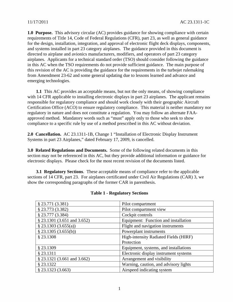
11172011 AC 231311-1C
10 Purpose This advisory circular (AC) provides guidance for showing compliance with certain requirements of Title 14 Code of Federal Regulations (CFR) part 23 as well as general guidance for the design installation integration and approval of electronic flight deck displays components and systems installed in part 23 category airplanes The guidance provided in this document is directed to airplane and avionics manufacturers modifiers and operators of part 23 category airplanes Applicants for a technical standard order (TSO) should consider following the guidance in this AC when the TSO requirements do not provide sufficient guidance The main purpose of this revision of the AC is providing the guidance for the requirements in the turbojet rulemaking from Amendment 23-62 and some general updating due to lessons learned and advance and emerging technologies
11 This AC provides an acceptable means but not the only means of showing compliance with 14 CFR applicable to installing electronic displays in part 23 airplanes The applicant remains responsible for regulatory compliance and should work closely with their geographic Aircraft Certification Office (ACO) to ensure regulatory compliance This material is neither mandatory nor regulatory in nature and does not constitute a regulation You may follow an alternate FAA-approved method Mandatory words such as ldquomustrdquo apply only to those who seek to show compliance to a specific rule by use of a method prescribed in this AC without deviation
20 Cancellation AC 231311-1B Change 1 ldquoInstallation of Electronic Display Instrument Systems in part 23 Airplanesrdquo dated February 17 2009 is cancelled
30 Related Regulations and Documents Some of the following related documents in this section may not be referenced in this AC but they provide additional information or guidance for electronic displays Please check for the most recent revision of the documents listed
31 Regulatory Sections These acceptable means of compliance refer to the applicable sections of 14 CFR part 23 For airplanes certificated under Civil Air Regulations (CAR) 3 we show the corresponding paragraphs of the former CAR in parenthesis
Table 1 - Regulatory Sections
sect 23771 (3381) Pilot compartment sect 23773 (3382) Pilot compartment view sect 23777 (3384) Cockpit controls sect 231301 (3651 and 3652) Equipment Function and installation sect 231303 (3655(a)) Flight and navigation instruments sect 231305 (3655(b)) Powerplant instruments sect 231308 High-intensity Radiated Fields (HIRF)
Protection sect 231309 Equipment systems and installations sect 231311 Electronic display instrument systems sect 231321 (3661 and 3662) Arrangement and visibility sect 231322 Warning caution and advisory lights sect 231323 (3663) Airspeed indicating system
1
11172011 AC 231311-1C
sect 231326 Pitot heat indication systems sect 231329 Automatic pilot system sect 231331 (3668) Instruments using a power source sect 231335 (3669) Flight director systems sect 231337 (3671 3672 3673 3674 and 3675)
Powerplant instruments installation
sect 231351 (3681 3682 3685 and 3686) Electrical Systems and Equipment General
sect 231353 (3683) Storage battery design and installation sect 231357 (3690 3691 and 3692) Circuit protective devices sect 231359 Electrical system fire protection sect 231361 (3688) Master switch arrangement sect 231365 (3693) Electric cables and equipment sect 231367 (3694 and 3695) Switches sect 231381 (3696 and 3697) Instrument lights sect 231431 (3721) Electronic equipment sect 231501 (3735 and 3737) Operating Limitations and Information General sect 231523 Minimum flight crew sect 231525 (3750) Kinds of operation sect 231529 Instructions for Continued Airworthiness sect 231541 (3755) Markings and Placards General sect 231543 (3756) Instrument markings General sect 231545 (3757) Airspeed indicator sect 231549 (3759) Powerplant and auxiliary power unit instruments sect 231551 (3760) Oil quantity indicator sect 231553 (3761) Fuel quantity indicator sect 231555 (3762) Control markings sect 231559 (3772) Operating limitations placard sect 231581 (3777) Airplane Flight Manual and Approved Manual
Material General
sect 231583 (3761 and 3778) Operating limitations sect 231585 Operating procedures sect 91205 Powered civil aircraft with standard category
US airworthiness certificates Instrument and equipment requirements
sect 121305 Flight and navigational equipment sect 135149 Equipment requirements General
2
11172011 AC 231311-1C
sect 135159 Equipment requirements Carrying passengers under Visual Flight Rules (VFR) at night or under VFR over-the-top conditions
sect 135163 Equipment requirements Aircraft carrying passengers under Instrument Flight Rules (IFR)
32 Advisory Circulars and Related Documents You may access the latest version of the ACs notices orders and policy statements on the FAA website wwwfaagov
Table 2 - Advisory Circulars and Related Documents
AC 20-88A Guidelines on the Marking of Aircraft Powerplant Instruments (Displays)
AC 20-115B RTCA Inc RTCADO-178B AC 20-136A Protection of Aircraft ElectricalElectronic Systems Against the
Indirect Effects of Lightning AC 20-138B Airworthiness Approval of Positioning and Navigation Systems AC 20-140A Guidelines for Design Approval of Aircraft Data Link
Communication Systems Supporting Air Traffic Services (ATS) AC 20-149 Safety and Interoperability Requirements for Initial Domestic
Flight Information Service - Broadcast AC 20-152 RTCA Inc Document RTCADO-254 Design Assurance
Guidance for Airborne Electronic Hardware AC 20-153A Acceptance of Aeronautical Data Processes and Associated
Navigation Databases
AC 20-155 SAE Documents to Support Aircraft Lightning Protection Certification
AC 20-158 The Certification of Aircraft Electrical and Electronic Systems for Operation in the High-Intensity Radiated Fields (HIRF) Environment
AC 20-167 Airworthiness Approval of Enhanced Vision System Synthetic Vision System Combined Vision System and Enhanced Flight Vision System Equipment
3
11172011 AC 231311-1C
AC 20-170 Integrated Modular Avionics Development Verification Integration and Approval Using RTCADO-297 and Technical Standard Order C153
AC 21-16F RTCA Document DO-160 versions D E and F ldquoEnvironmental Conditions and Test Procedures for Airborne Equipment
AC 23-8C Flight Test Guide for Certification of Part 23 Airplanes AC 23-15A Small Airplane Certification Compliance Program AC 23-17C Systems and Equipment Guide for Certification of Part 23
Airplanes AC 23-18 Installation of Terrain Awareness and Warning System (TAWS)
Approved for Part 23 Airplanes AC 23-22 Guidance for Approved Model List (AML) Supplemental Type
Certificate (STC) Approval of Part 23 Airplane Avionics Installations
AC 23-23 Standardization Guide for Integrated Cockpits in Part 23 Airplanes
AC 231309-1E System Safety Analysis and Assessment for Part 23 Airplanes AC 25-11A Electronic Flight Deck Displays AC 90-106 Enhanced Flight Vision Systems AC 91-75 Attitude Indicator AC 91-78 Use of Class 1 or Class 2 Electronic Flight Bag (EFB) AC 120-64 Operational Use and Modification of Electronic Checklists AC 120-76A Guidelines for the Certification Airworthiness and Operational
Approval of Electronic Flight Bag Computing Devices Order 811049 Software Approval Guidelines dated June 3 2003 Order 8110105 Simple and Complex Electronic Hardware Approval Guidance PS-ACE100-2001-004 Guidance for Reviewing Certification Plans to Address Human
Factors for Certification of Part 23 Small Airplanes
33 Technical Standard Orders (TSO) You may access the TSOs on the FAA website wwwfaagov The following is a list of the FAA TSOs that are referenced in this AC For a complete list of TSOs that are related to this AC see AC 20-110L ldquoIndex of Aviation Technical Standards Ordersrdquo or the web site for the most current list
a TSO-C63c Airborne Weather and Ground Mapping Pulsed Radars
b TSO-C113 Airborne Multipurpose Electronic Displays
c TSO-C153 Integrated Modular Avionics Hardware Elements
d TSO-C157 Aircraft Flight Information Services-Broadcast (FIS-B) Data Link Systems and Equipment
4
11172011 AC 231311-1C
e TSO-C165 Electronic Map Display Equipment for Graphical Depiction of Aircraft Position
34 Industry Documents You may obtain copies of current editions of the following publications
341 RTCA Documents The following RTCA documents are available from RTCA Inc 1828 L Street NW Suite 805 Washington DC 20036-4001 or at their website at wwwrtcaorg
a RTCADO-160G Environmental Conditions and Test Procedures for Airborne Equipment
b RTCADO-178B Software Considerations in Airborne Systems and Equipment Certification
c RTCADO-187 Minimum Operational Performance Standards for Airborne Area Navigation Equipment Using Multi-Sensor Inputs
d RTCADO-200A Standards for Processing Aeronautical Data
e RTCADO-201A Standards for Aeronautical Information
f RTCADO-254 Design Assurance Guidance for Airborne Electronic Hardware
g RTCADO-257A Minimum Operational Performance Standards for the Depiction of Navigation Information on Electronic Maps
h RTCADO-267A Minimum Aviation System Performance Standards (MASPS) for Flight Information Services-Broadcast (FIS-B) Data Link
i RTCADO-297 Integrated Modular Avionics (IMA) Development Guidance and Certification Considerations
j RTCADO-313 Certification Guidance for Installation of Non-Essential Non-Required Aircraft Cabin Systems and Equipment
k RTCADO-315A Minimum Aviation Performance Standards (MASPS) for Enhanced Vision Systems Synthetic Vision Systems Combined Vision Systems and Enhanced Flight Vision Systems
342 Society of Automotive Engineers (SAE) Inc The following Society of Automotive Engineers (SAE) Inc documents are available from SAE 400 Commonwealth Drive Warrendale PA 15096-0001 or from their website at wwwsaeorg
5
11172011 AC 231311-1C
a ARP 268G Location and Actuation of Flight Deck Controls for Transport Aircraft
b ARP 450D Flight Deck Visual Audible and Tactile Signals
c ARP 926B FaultFailure Analysis Procedure
d AIR 1093A Numeral Letter and Symbol Dimensions for Aircraft Instrument Displays
e ARP 1161A Crew Station LightingmdashCommercial Aircraft
f ARP 1782A Photometric and Colorimetric Measurement Procedures for Airborne Direct View CRT [Cathode Ray Tube] Displays
g ARP 1834A FaultFailure Analysis for Digital Systems and Equipment
h ARP 1874 Design Objectives for CRT Displays for Part 25 (Transport) Aircraft
i ARP 4032A Human Engineering Considerations in the Application of Color to Electronic Aircraft Displays
j ARP 4033 Pilot System Integration
k ARP 4067 Design Objectives for CRT Displays for Part 23 Aircraft
l ARP 4101 Flight Deck Layout and Facilities
m ARP 4102 Flight Deck Panels Controls and Displays
n ARP 41027 Electronic Displays
o ARP 4103 Flight Deck Lighting for Commercial Transport Aircraft
p ARP 4105B Abbreviations and Acronyms for Use on the Flight Deck
q ARP 4155A Human Interface Design Methodology for Integrated Display Symbology
r ARP 4256A Design Objectives for Liquid Crystal Displays for Part 25 (Transport) Aircraft
s ARP 4260A Photometric and Colorimetric Measurement Procedures for Airborne Electronic Flat Panel Displays
6
11172011 AC 231311-1C
t ARP 4754 Certification Considerations for Highly Integrated or Complex Aircraft Systems
u ARP 4761 Guidelines and Methods for Conducting the Safety Assessment Process on Civil Airborne Systems and Equipment
v ARP 5287 Optical Measurement Procedures for Airborne Head-Up Display (HUD)
w ARP 5288 Transport Category Airplane Head Up Display (HUD) Systems
x ARP 5289 Electronic Aeronautical Symbols
y ARP 5364 Human Factor Considerations in the Design of Multifunction Display Systems for Civil Aircraft
z ARP 5365 Human Interface Criteria for Cockpit Display of Traffic Information
aa ARP 5430 Human Interface Criteria for Vertical Situation Awareness Displays
bb ARP 5677 Human Engineering Considerations for Cockpit Integration of EnhancedSynthetic Vision Systems
cc AS 5703 Minimum Performance Standard for Enhanced Vision System
dd AS 8034A Minimum Performance Standard for Airborne Multipurpose Electronic Displays
ee AS 8055 Minimum Performance Standard for Airborne Head Up Display (HUD)
343 General Aviation Manufacturers Association (GAMA) The following documents are available from the GAMA 1400 K St NW Suite 801 Washington DC 2005 or from their website at wwwgamaaeroindustry-standards
a General Aviation Manufacturers Association (GAMA) Publication No 10 Recommended Practices and Guidelines for Part 23 CockpitFlight Deck Design
b General Aviation Manufacturers Association (GAMA) Publication No 12 Recommended Practices and Guidelines for an Integrated CockpitFlightdeck in a 14 CFR Part 23 Certificated Airplane
7
11172011 AC 231311-1C
40 Background
a Amendment 23-41 effective November 26 1990 established airworthiness standards in sect 231311 for installing electronic display instrument systems in normal utility acrobatic and commuter category airplanes The first electronic displays developed were direct replacements for the conventional electromechanical components with later designs providing more extensive information integration Before Amendment 23-41 most electronic display instrument systems were approved by special condition for installation in part 23 airplanes Amendment 23-49 effective March 11 1996 further amended part 23 to harmonize 14 CFR with the Joint Aviation Requirements (JAR) Section 231311 Amendment 23-49 removed redundant requirements and clarified which secondary instruments are required including the visibility requirements for those instruments
b Amendment 23-62 made several changes that affect the installation of electronic displays Guidance relative to electronic displays of those sections is also included in this AC The significant changes were
(1) Clarified requirements for trend information and appropriate sensory cues
(2) Incorporated equivalent visual displays of the instrument markings on electronic displays
(3) Allowed an applicant to take credit for reversionary or secondary flight displays on a multi-function flight display (MFD) that provides a secondary means of primary flight information (PFI)
(4) Revised some redundancy requirements to be only applicable for IFR operations
(5) Accommodated new technology for magnetic direction indicator
(6) Updated the terminology for system safety assessment
(7) Revised requirements for instruments using power source(s) and
(8) Revised requirements for storage battery backup times
50 Scope This AC is generally applicable only to an applicant seeking issuance of certain type certificates These include a type certificate (TC) an amended type certificate (ATC) or a supplemental type certificate (STC) for the approval of a new type design or a change in the type design This AC does not completely address Synthetic Vision Systems (SVS) or Enhanced Vision Systems (EVS) and Head-Up Displays (HUD) Contact the Small Airplane Directorate if there are any conflicts with other guidance and this AC The Small Airplane Directorate will coordinate and resolve the conflicts among the points of contact of the other documents
8
11172011 AC 231311-1C
60 AcronymsDefinitions
61 Acronyms
a AC Advisory Circular
b ACO Aircraft Certification Office
c ADC Air Data Computer
d ADI Attitude Direction Indicator
e ADDS Aviation Digital Data Service
f AFM Airplane Flight Manual
g AFMS Airplane Flight Manual Supplement
h AHRS Attitude Heading Reference System
i ARD Aerospace Research Document
j ARP Aerospace Recommended Practice
k AS Aerospace Standard
l ASTC Amended Supplemental Type Certificate
m ATC Amended Type Certificate
n CAR Civil Air Regulations
o CDI Course Deviation Indicator
p CFR Code of Federal Regulations
q CIP Current Icing Potential
r CL Center Line
s CRT Cathode-Ray Tubes
t DN Down
u EADI Electronic Attitude Direction Indicator
9
11172011 AC 231311-1C
v EHSI Electronic Horizontal Situation Indicator
w EICAS Engine Indication and Crew Alert System
x ELOS Equivalent Level of Safety
y EVS Enhanced Vision Systems
z FAA Federal Aviation Administration
aa FD Flight Director
bb FHA Functional Hazard Assessment
cc FLS Field-Loadable Software
dd FMEA Failure Modes and Effects Analysis
ee FOV Field-Of-View
ff GPS Global Positioning System
gg HIRF High Intensity Radiated Fields
hh HUD Head-Up Display
ii HSI Horizontal Situation Indicators
jj ICAO International Civil Aviation Organization
kk IFR Instrument Flight Rules
ll ILS Instrument Landing System
mm IMA Integrated Modular Avionics
nn IMC Instrument Meteorological Conditions
oo JAR Joint Aviation Requirements
pp LCD Liquid Crystal Displays
qq LED Light Emitting Diodes
rr LT Left
10
11172011 AC 231311-1C
ss METAR ICAO Routine Aviation Weather Report
tt MFD Multifunction Flight Display
uu ND Navigation Display
vv NOM Nominal
ww PFD Primary Flight Display
xx PFI Primary Flight Information
yy POH Pilots Operating Handbook
zz RAIM Receiver Autonomous Integrity Monitoring (used with GPS)
aaa RT Right
bbb SAE Society of Automotive Engineers
ccc STC Supplemental Type Certificate
ddd SVS Synthetic Vision Systems
eee TAS Traffic Advisory System
fff TAWS Terrain Awareness Warning System
ggg TFR Temporary Flight Restrictions
hhh TC Type Certificate
iii TCAS Traffic Alert and Collision Avoidance System
jjj TSO Technical Standard Order
kkk UL Underwriterrsquos Laboratories
lll VOR Very High Frequency Omni-Directional Range
mmm VFR Visual Flight Rules
nnn VMC Visual Meteorological Conditions
ooo VFE Maximum flap extended speed
11
11172011 AC 231311-1C
ppp VMO Maximum operating limit speed
qqq VNE Never-exceed speed
rrr VNO Maximum structural cruising speed
sss VS0 The stalling speed or the minimum steady flight speed in the landing configuration
ttt VS1 The stalling speed or the minimum steady flight speed obtained in a specific configuration
uuu WAAS Wide Area Augmentation System
62 Definitions This section contains definitions for terms in this document
a Accuracy A degree of conformance between the estimated or measured value and the true value
b Adverse Operating Condition A set of environmental or operational circumstances applicable to the airplane combined with a failure or other emergency situation that results in a significant increase in normal flight crew workload
c Component Any self-contained part combination of parts subassemblies or units that perform a distinct function necessary to the operation of the system
d Continued Safe Flight and Landing This phrase means the airplane can continue controlled flight and landing possibly using emergency procedures without requiring exceptional pilot skill or strength On landing some airplane damage may occur as a result of a Failure Condition
e Conventional A system is considered ldquoConventionalrdquo if its function the technological means to implement its function and its intended use are all the same as or closely similar to that of previously approved systems that are commonly used The systems that have established an adequate service history and the means of compliance for approval are generally accepted as Conventional
f Critical Usually a function whose loss would prevent the continued safe flight and landing of the airplane
Note The term ldquocritical functionrdquo is associated with a catastrophic failure condition Newer documents may not refer specifically to the term ldquocritical functionrdquo
g Criticality Indication of the hazard level associated with a function hardware software etc considering abnormal behavior (of this function hardware software etc) alone in
12
11172011 AC 231311-1C
combination or in combination with external events Criticality is a failure classification that could be no safety effect minor major hazardous and catastrophic See AC 231309-1E for more guidance
h Design-Eye Box A three-dimensional volume of space surrounding the design eye reference point that designers and evaluators use to determine the acceptability of display and control locations
i Design-Eye Reference Point A single reference point in space selected by the designer where the midpoint between the pilotrsquos eyes is assumed to be located when the pilot is properly seated at the pilotrsquos station
j Development Assurance All those planned and systematic actions used to substantiate to an adequate level of confidence that errors in requirements design and implementation have been identified and corrected such that the system satisfies the applicable certification basis
k Enhanced Vision System An electronic means to provide a display of the forward external scene topography (the natural or manmade features of a place or region especially in a way to show their relative positions and elevation) through the use of imaging sensors such as a forward looking infrared millimeter wave radiometry millimeter wave radar low light level image intensifying
l Equipment Essential to Safe Operation Equipment installed to comply with the applicable certification requirements of 14 CFR part 23 or operational requirements of 14 CFR parts 91 and 135
m Error An omitted or incorrect action by a pilot or maintenance person or a mistake in requirements design or implementation
n Failure An occurrence that affects the operation of a component part or element such that it can no longer function as intended (this includes both loss of function and malfunction
o Failure Condition A condition affecting either the airplane or its occupants or both either direct or consequential caused or contributed to by one or more failures or errors considering flight phase and relevant adverse operational or environmental conditions or external events Failure conditions may be classified according to their severity See AC 231309-1E for more information on definitions of failure conditions
p Field-of-View The angular extent of the display that can be seen by either pilot with the pilot seated at the pilotrsquos station See section 15 for more information on the field-of view
q Fix A generic name for a geographical position A fix may also be referred to as a waypoint intersection reporting point etc
13
11172011 AC 231311-1C
r Flight Plan Refers to any sequence of fixes that are interconnected by the desired path Flight plans may range from the simplest that include only the aircraftrsquos present position the active waypoint and the desired path between them to more complicated plans that include departure and destination airports with multiple intermediate fixes
s Function The lowest defined level of a specific action of a system equipment and pilot performance aboard the airplane that by itself provides a complete recognizable operational capability (for example an airplane heading is a function) One or more systems may contain a specific function or one system may contain multiple functions
t Functional Hazard Assessment A systematic comprehensive examination of airplane and system functions to identify potential minor major hazardous and catastrophic failure conditions that may arise as a result of a malfunction or a failure to function
u Hardware An object that has physical being Generally refers to circuit cards power supplies etc
v Hazard Any condition that compromises the overall safety of the airplane or that significantly reduces the ability of the pilot to cope with adverse operating conditions
w Head-Up Display A transparent optical display system located level with and between the pilot and the forward windscreen The HUD displays a combination of control performance navigation and command information superimposed on the external field of view It includes the display element sensors computers and power supplies indications and controls It is integrated with airborne attitude air data and navigation systems and as a display of command information is considered a component of the flight guidance system
x Independent A component part element or system that is not relying on some other component part element or system for accomplishing its function This design concept ensures that the failure of one item does not cause a failure of another item For redundancy each means of accomplishing the same function need not necessarily be identical
y Indicator A means for displaying information of a parameter More than one indicator could be depicted on one display For example a primary flight display may have indicators for attitude altitude airspeed heading and navigation
z Instrument An electrical or mechanical measurement device In sect 231311 it is defined as Devices physically contained in one unit and devices composed of two or more physically separate units or components connected together (One example is a remote indicating gyroscopic direction indicator that includes a magnetic sensing element a gyroscopic unit an amplifier and an indicator connected together)
aa Map Orientation Refers to the rule that determines the directional relation of the map to the upper part of the display depiction Using a north-up rule the north side of the map would be toward the top of the display and the south side of the map would be at the bottom Using
14
11172011 AC 231311-1C
a desired path-up rule the map would be oriented so the desired path would be vertical on the map and pointing straight up toward the top of the display
bb Map Range The geographic extent of the map region (for example the distance covered by the map representation in either the vertical or horizontal direction)
cc Malfunction Failure of a system subsystem unit or part to operate in the normal or usual manner A condition whereby the operation is outside specified limits
dd Multi-Function Display Any physical display unit other than the PFD used to present various information on which the layout may be reconfigured
ee Navigation The process of planning tracking and controlling the course of an airplane from one place to another
ff Navigation Display The display or suite of instruments by which navigation data is presented to the pilot
gg Navigation Information Information that aids the flightcrew in determining the aircraftrsquos location in a given environment (for example on flight plans VORs GPSs features on the airport surface including taxiway signage etc)
hh Primary As used for instruments it is defined in sect 231311(c) as the ldquodisplay of a parameter that is located in the instrument panel such that the pilot looks at it first when wanting to view that parameterrdquo
ii Primary Flight Display (PFD) A single physical unit that always provides the primary display of all the following altitude airspeed aircraft heading (direction) and attitude located directly in front of the pilot in a fixed layout in accordance with sect 231321 It may provide other information pertinent to guidance and fundamental control of flight of the airplane such as critical engine parameters
jj Primary Flight Information (PFI) A PFI refers to those functions or parameters required by the airworthiness and operational rules such as airspeed altitude attitude and heading (direction) that are on the PFD
kk Primary Function (PF) This definition is applicable in the case when there is more than one function available for same function A function that is installed to comply with the applicable regulations for the required function and one that provides the most pertinent controls or information instantly and directly to the pilot For example the PFD is a single physical unit that always provides the primary display and it complies with the requirements of all the following altitude airspeed aircraft heading (direction) and attitude This PFD is located directly in front of the pilot and used instantly and first by the pilot A standby (additional) PFD that is intended to be used in the event of failure of the PFD is an example of a secondary system
15
11172011 AC 231311-1C
ll Primary Navigation Where the pilot looks first for a display of navigation information such as on an HSI or CDI It displays vertical and lateral deviation and it may have the digital distance indication tofrom the selected fix
mm Redundancy The presence of more than one independent means for accomplishing a given function Each means of accomplishing the function need not necessarily be identical
nn Reversionary Display A secondary means to provide information initially presented on the PFD or MFD by the transfer of information to an alternate display
oo Scale The relative proportion of the linear dimensions of objects on a display to the dimensions of the corresponding objects and distances being represented (for example 1 inch = 100 nautical miles)
pp Secondary Display A means to present information on another display A display that can be used for backup or secondary purposes such as in the event of a failure of another display
qq Standby Instrument A dedicated instrument that is always available that presents primary flight information
rr Supplemental Function A function that is not required or intended to meet all the airworthiness and operational requirements It is usually installed for additional situational awareness
ss System A combination of components parts and elements that is interconnected to perform one or more functions
tt Synthetic Vision System A computer-generated image of the external scene topography from the perspective of the flight deck that is derived from aircraft attitude high precision navigation solution and database of terrain obstacles and relevant cultural features
Note ldquoTopographyrdquo defined as maps or charts of natural and man-made features of a place or region especially in a way to show their relative positions and elevations as applicable whenever deemed appropriate and practicable
uu Track The projection on the earthrsquos surface of the path of an aircraft the direction of which is usually expressed in degrees from north (true magnetic or grid) A track is the actual flight path of an aircraft over the surface of the earth
Note For more definitions related to safety assessments refer to AC 231309-1E for the appropriate definitions
vv Warning A clear and unambiguous indication to the pilot of a failure that requires immediate corrective action An inherent characteristic of the airplane or a device that will give
16
11172011 AC 231311-1C
clearly distinguishable indications of malfunction or misleading information may provide this warning
70 Display Description The following paragraphs give a brief description of an electronic display They do not cover all the capabilities and details of these displays or the information presented on them
71 General Electronic displays have replaced many of the traditional electromechanical and analog instruments These displays also augment andor combine the functionality of conventional systems such as radios and navigational systems The major display technologies now used are multicolor CRTs LCDs electro luminescence plasma and LEDs The initial electronic displays mimicked the traditional mechanical and electromechanical flight and powerplant instruments The colors symbols and formats on these initial electronic displays are similar to those on traditional conventional instruments Modern electronic displays provide integration and formats that often differ from traditional instruments
72 Display Configuration Electronic displays may be installed in several configurations A basic electronic display may provide only one flight or powerplant parameter while more sophisticated systems integrate many parameters on one electronic display One of the major design goals for these systems is eliminating separate conventional gauges instruments and annunciators Recent installations show a trend toward a higher degree of integration For example an integrated primary flight display provides several parameters such as attitude heading (direction) airspeed and altitude Integration of various systems should include analysis to ensure that complexity and workload are compatible with general aviation pilots capabilities For more guidance on IMA that implement TSO authorized hardware elements see TSO-C153 and AC 20shy170
80 Flight Displays
81 Instrument Requirements
a Sections 231303 231305 231311 and 231321 with the applicable operating rules (14 CFR parts 91 121 and 135) incorporate flight and powerplant instrument requirements for part 23 airplanes The navigation equipment requirements are given in operational rules specified in sectsect 91205 121303 121305 121307 135143 135149 135159 135161 and 135165 Display requirements for navigation information are dependent on the navigation system installed in the aircraft Instruments and equipment required for flights under parts 91 121 and 135 may be affected by the electronic display installation These instruments and equipment include gyroscopic bank and pitch gyroscopic direction gyroscopic rate-of-turn slip-skid instruments and other required communication and navigational equipment
b There have been applications to install equipment such as flight and navigation displays as non-required These applications request approval for these installations as situation awareness (SA) only It is not acceptable to label a display as ldquoSA-Onlyrdquo and assume that its failure condition is acceptable Installing displays that provide PFI that are more compelling than
17
11172011 AC 231311-1C
the required primary PFI displays but they do not meet the appropriate operational and airworthiness requirements and labeling them as ldquoSupplementalrdquo or ldquoSA-Only is not acceptable Section 136 provides more guidance
c The basis for certification has been that the equipment should perform its intended function and not present a hazard Instruments that aid situation awareness should be certified under the part 23 requirements including sect 231301 and sect 231309 These displays could provide hazardous misleading information PFI is essential for safe operation An instrument that provides PFI should meet the minimum standards of applicable TSOs or an equivalent standard It also should meet the guidance in AC 231309-1E AC 23-17C and the guidance in this AC
82 Primary Flight Information (PFI) PFI refers to those functions or parameters that are required by the airworthiness and operational rules such as airspeed altitude attitude and heading (direction) It may provide other information pertinent to guidance and fundamental control of flight such as critical engine parameters Attitude airspeed altitude and heading (direction) are the PFI required in sect 231311(a)(3) and (5) and they must be arranged according to sect 231321 in the ldquobasic Trdquo arrangement Direction should be heading with track presented if available as a selectable option The horizon reference line on the PFD should be at least 325 inches wide in straight and level flight for integrated displays This recommendation is not intended to prevent replacement of mechanical instruments with an electronic display of a similar horizon reference line When the true horizon is no longer on the display the artificial horizon line should provide a distinctive demarcation between sky and ground (or the background) Display of PFI on reversionary or standby displays should be arranged in the basic T-configuration but it is not required The standby instrument or displays of PFI location should meet the FOV guidance criteria in section 15
821 Acceptable Methods for Compliance with sect 231311(b) There are three acceptable methods for meeting the attitude requirements which is considered information essential for continued safe flight and landing Compliance can be accomplished by using dedicated standby instruments dual PFDs or reversionary displays that present primary flight information Electronic display systems without dedicated standby instruments should have at least two independent displays able to provide PFI to the pilot These displays should be powered such that any single failure of the power generation and distribution systems cannot remove the display of PFI from both displays Section 231311(b) in Amendment 23-62 states ldquoThe electronic display indicators including their systems and installations and considering other airplane systems must be designed so that one display of information essential for continued safe flight and landing will be available within one second to the crew by a single pilot action or by automatic means for continued safe operation after any single failure or probable combination of failuresrdquo
83 Standby Instruments The purpose of standby instruments or another independent PFD is to ensure that PFI is available to the pilot during all phases of flight and during system failures Individual indicators should be a minimum of 2 inches in diameter or if combined a minimum diameter of 3 inches (or equivalent) displayed
831 Dual PFDs Electronic display systems with dual PFDs should incorporate dual independently powered sensors that provide primary flight parameters such as AHRS with
18
11172011 AC 231311-1C
comparators and dual ADC Dual PFDs with dual AHRSs and ADCs which include checking and are powered by multiple power sources and distribution systems are significantly more reliable than presently certified mechanical systems
832 PFD and Autopilot with an AHRS For normal operation when using a single AHRS to drive the PFD and the autopilot simultaneously the installation must mitigate hazardous or catastrophic system level failures An example configuration supporting proper mitigation would include all of the following
a A dedicated standby attitude instrument within the primary maximum FOV or independent reversionary attitude display
b An AHRS with appropriate comparator or monitor of equivalent performance
c Appropriate system warningcaution annunciation associated with an AHRS malfunction
d If an aircraft is equipped with multiple AHRS it may be acceptable when one AHRS fails to drive both the autopilot and the PFD from a single AHRS as long as an AHRS independent attitude display (required for some aircraft classes) is located in the primary maximum field of view The failure must be annunciated to the pilot and the pilot must be able to select the non-failed AHRS For aircraft that do not have an independent attitude indicator when one AHRS fails the autopilot should be manually or automatically disengaged The autopilot may be reengaged if appropriate mitigation is available (for example see a through c above) The AFM or supplemental AFM should contain the appropriate procedures applicable to the equipment installed See section 110 for additional guidance AC 231309-1E guidance should be considered for these configurations
e Displays not meeting FOV guidance criteria may require additional human factors airworthiness evaluation by the certification authority See section 15 for additional guidance
84 Reversionary Flight Displays Instead of Standby Instruments or Dual PFDs
841 General Requirements
a Reversionary flight displays provide a secondary means to provide PFI through alternate display formats on another PFD or MFD by the transfer of information to an alternate display or by some other means The function of an MFD system is to provide the pilot access to various data or combinations of data used to fly the aircraft to navigate to communicate andor to manage aircraft systems The MFD would also present PFI as needed to ensure continuity of operations 14 CFR part 23 sect 231311(b) Amendment 23-62 states the electronic display indicators including their systems and installations and considering other airplane systems must be designed so that one display of information essential for continued safe flight and landing will be available within one second to the crew by a single pilot action or by automatic means for continued
19
11172011 AC 231311-1C
safe operation after any single failure or probable combination of failures To meet the requirements of sect 231311(b) a full-time standby display another independent PFD or an independent reversionary attitude display must be installed Reversionary modes could be automatically and manually selected or only manually selected
b Reversionary configurations are significantly more reliable than presently certified mechanical systems and the skills required while flying in reversionary mode are identical with those used when flying in primary mode Traditional external standby flight instruments (either electronic or mechanical) offer potential safety problems associated with delay in pilot reaction The pilot may delay a decision to transition to standby instruments and to transition to partial panel techniques as opposed to the simple action the pilot would take to switch displays A nearly identical format on the reversionary display of all PFI that is also shown on the PFD provides a significant safety enhancement over standby instruments This is especially true when the size location arrangement and information provided by the standby instruments are significantly different from those on the PFD
c Reversionary display modes should provide consistent display formats to the PFD The reversionary flight information should be presented by an independent source and display to prevent complete loss of PFI due to a single failure The reversionary configuration should have two independent displays that incorporate dual-independently powered AHRS and dual ADC subsystems that provide PFIs The reversionary system response time should provide flight critical information on the MFD in less than one second after a single pilot action or an automatic operation
d A reversionary configuration should have a single pilot action that would force both the PFD and MFD displays into reversionary mode operation However the PFI should be presented in similar format and sufficient size in the reversionary mode as it is in normal mode to allow the pilot to enhance the control of the airplane This reversionary configuration should provide backup information essential to continued safe flight and landing with an intuitive control that allows instant simultaneous access to reversionary mode on both the PFD and MFD displays The single pilot action should be easily recognized readily accessible and have the control within the pilotrsquos primary optimum field of view An acceptable method for the single pilot action is the red color andor lighted red ldquohalordquo ring that announces its position on the panel at all times
842 Reversionary Methods
a One method is to have an automatic reversionary display with a single pilot action that would force both the PFD and MFD displays into reversionary mode operation If PFI on another display is not provided provide automatic switching to ensure PFI is available to the pilot Automatic reversion must provide a complete display of PFI on the remaining display within one second if a fault is detected
b Most possible faults should be covered by this automatic reversionary capability Only a total loss of the display may not be reliably detected automatically but such a failure condition would be obvious to the pilot Faults that result in automatic switching should be extensive enough to ensure PFI availability meets the requirements of sect 231309 If such a
20
11172011 AC 231311-1C
malfunction occurs a single pilot action should provide a full display of the essential information on the remaining display within one second All modes sources frequencies flight plan data etc should be similar as they were on the PFD before the failure
c Another reversionary method would include a means to access the reversionary mode manually through a single pilot action Manual activation of the reversionary mode on the MFD through single action by the pilot is acceptable when procedures to activate the PFI on the MFD are accomplished before entering critical phases of flight The PFI would be presented continuously on the reversionary display during critical phases of flight (for example takeoff landing and missed or final approach)
85 Display of Attitude For flights under IFR conditions in part 91 and part 135 operations and under VFR at night for part 135 operations attitude information is required The loss of all attitude information or the presentation of misleading attitude information could result in a catastrophic failure condition where the pilot could not continue safe flight and landing of the airplane It is recommended that the display of attitude follows the guidelines (below) that are also in GAMA Publication 12
a The pitch ladder should be caged to the center of the display
b At pitch attitudes when the true horizon line would not normally be displayed some sky or ground should be indicated on the PFD pitch display (minimum 38 inches and maximum of 115 percent of the display) and the horizon line should indicate off-scale
c With the airplane symbol on the horizon line the range of visible pitch attitude should be at least + 25 to -15 degrees but not to exceed a total pitch range of 50 degrees
d Bank angle presentations should use a roll pointer however roll pointers and sky-pointers should not be mixed in the same flight deckcockpit
e Roll scale indices should be placed at 10 20 30 60 and 90 degrees An index may also be placed at 45 degrees
86 Display of Direction (Heading or Track)
861 General
a The loss of direction (heading or track) information could result in reduced capability of the pilot to cope with adverse operating conditions The orientation of any secondary navigation display is optional (for example Track-up North-up Heading-Up) For flights under IFR conditions a stabilized heading indicator must provide the primary display of the direction parameter A magnetic direction indicator or track may provide the reversionary display of direction
21
11172011 AC 231311-1C
b The heading display should provide a clear and unmistakable display of aircraft symbol and heading HSI should provide a clear and unmistakable display of aircraft position heading and track (an option if available) relative to the desired coursetrack Section 17 contains more guidance on symbology Direction should be heading when track is presented if available as a selectable option with the data source clearly indicated On the primary display the heading scale should have a mode that presents at least 120 degrees of arc Other display formats may be acceptable and have been previously approved but they need to be evaluated from a human factor perspective
862 Hazardous Misleading Heading Information
a The FHA for the failure effects of hazardous misleading heading information from an AHRS is clarified in AC 23-17C This policy is specifically about the application of AC 231309-1E for an airplane with the certification basis of Amendments 23-41 or later This clarification is limited to installations approved for operation in IMC under IFR For operations limited to VFR a misleading heading indication is not considered hazardous
b Develop an FHA and the related safety assessments for the specific airplane type and configuration since there can be many combinations of failures various mitigating factors and other functions available to a pilot These many factors affect the criticality of the heading indication therefore use a safety assessment process from AC 231309-1E to classify the failure conditions for misleading heading information
c A hazardously misleading heading is usually when the accuracy error is greater than 10 degrees on the primary heading instrument and it is an undetected error The safety assessment process should consider appropriate mitigating factors For Class I part 23 airplanes the failure condition for misleading hazardous heading is usually considered major
87 Display of Altitude Airspeed and Magnetic Compass Information The original requirements of CAR 3 were adopted and later recodified into part 23 sect 231303 paragraphs (a) (b) and (c) At that time pneumatically driven displays provided airspeed and altitude functions Since then the FAA envisioned airspeed altitude and magnetic compass information would remain available to the pilot with the loss of the airplanes primary electrical power For electronic displays sect 231311(a)(3) requires the primary display of attitude airspeed and altitude to be uninhibited in any normal mode of operation Section 231311(a)(5) as amended by Amendment 23-62 requires an independent magnetic direction indicator and either an independent secondary mechanical altimeter airspeed indicator and attitude instrument or electronic display parameters for the altitude airspeed and attitude that are independent from the airplanes primary electrical power system Primary altitude or airspeed displays that require electrical power are acceptable if means are provided for their continued operation upon loss of the airplanersquos primary electrical power or if pneumatically driven instruments are available for the pilotrsquos use A standby or reversionary integrated display of altitude attitude and airspeed instead of individual electronic display indicators for airspeed altitude and attitude is acceptable under one condition The condition is that the standby or reversionary integrated display and the primary display are powered such that at least one integrated display with attitude altitude and airspeed is available after failure of any power source or distribution path
22
11172011 AC 231311-1C
88 Accuracy of the Magnetic Heading System
881 General
a The operating rules such as part 91 and part 135 specify the minimum required equipment that must be installed in part 23 airplanes based on the operation such as VFR or IFR Under VFR operation part 91 sect 91205 requires a magnetic direction indicator (that is normally intended to be a compass) for heading information Under IFR operation part 91 sect 91205 requires a gyroscopically stabilized heading system Section 231303(c) Amendment 23-62 amended the requirement from ldquoA direction indicator (non-stabilized magnetic compass)rdquo to ldquoA magnetic direction indicatorrdquo As new technology becomes more affordable for part 23 airplanes many electronic flight instrument systems will use magnetically stabilized direction indicators (or electric compass systems) to measure and indicate the airplane heading to provide better performance
b The general airworthiness requirements in part 23 sect 231301 and sect 231525 determine the flight instrument and equipment accuracy requirements for part 23 airplanes Part 23 does not prescribe specific accuracy requirements for magnetic gyroscopically stabilized heading systems Specific accuracy requirements for avionics may be found in the related TSO and as acceptable means of compliance to sect 231301 in ACs notices or policy statementsletters
882 Magnetic Non-Stabilized Direction Indicator A magnetic non-stabilized direction indicator that is required by sect 231303 should have an accuracy of 10 degrees or have a correction card placard (reference sect 231327) or a back-up gyroscopic direction indicator provided the indicator is accurate better than 10 degrees If the sole purpose of the gyroscopic direction indicator is for backing up the magnetic non-stabilized direction indicator then the accuracy of presentation of headings can also be to 10 degrees However if a gyroscopic direction indicator is installed to meet the IFR operating rules then the installation requirements are defined by sect 231301
883 Magnetic Gyroscopically Stabilized Direction Indicator As installed final accuracy for a magnetic gyroscopically stabilized direction indicator of plusmn4 degrees on the ground or plusmn6 degrees in normal level flight on any heading would meet the requirements of part 23 sect 231301 This accuracy applies after compensation It should include cumulative errors in all combinations due to several factors These consist of the equipment itself the current flow in any item of electrical equipment and its associated wiring the movement of any part (for example controls or undercarriage) and the proximity of any item of equipment containing magnetic material to the magnetic sensor
884 Comparator Monitor
a For systems installations that include two magnetic gyroscopically stabilized heading systems and a comparator that monitors the differences between the headings of the two
23
11172011 AC 231311-1C
systems the comparator trip point set as follows would meet the requirements of part 23 sect 231301
(1) 6 degrees in stabilized level flight
(2) 6 degrees plus one half of the bank angle or
(3) 12 degrees with a bank angle greater than 6 degrees
(4) The alert function can be disabled at a bank angle greater than 20 degrees
(5) An alert is provided if the condition exceeds 60 seconds but it allows two minutes for a turn error as stated in the TSO
b The 6-degree trip point during level flight allows a heading error of as much as 12 degrees on one of the systems This would comprise one system at the 6 degrees in-flight tolerance limit while the other system presumably with some malfunction could have an error of 12 degrees in the same direction before the comparator monitor alert is tripped
89 Rate-of-Turn Instrument
a Under sectsect 91205 and 135159 a rate-of-turn instrument is not required if a third attitude instrument usable through flight attitudes of 360 degrees of pitch-and-roll is installed following the instrument requirements prescribed in sect 121305(j) If required place the rate-of-turn indicator near the heading indicator
b A second approved attitude indicator may substitute for the rate-of-turn instrument AC 91-75 Attitude Indicator provides one method This AC is applicable to part 23 certificated airplanes (or airplanes certificated under earlier equivalent regulations) that weigh less than 12500 pounds and are operated under part 91 The second approved attitude indicator must be powered by an independent power source from the primary attitude indicator This can be accomplished by using independent standby instruments another independent PFD or independent reversionary attitude display Most of the installations with electronic displays that meet the requirements of sect 231311 and this AC should comply with AC 91-75
810 Slip-Skid Instrument The slip-skid information is required by sectsect 91205(d)(4) and 135159(b) as applicable The FAA suggests locating the slip-skid display directly below or near the rate-of-turn instrument if installed or under or within the primary attitude display
811 Vertical Speed Indicator If provided present the vertical speed indicator to the right or directly below the altitude indicator with a scale appropriate to the performance of the aircraft
24
11172011 AC 231311-1C
90 Powerplant Displays
91 General
a This section defines a means of presenting powerplant performance and condition information about the airplanes operation It also provides guidelines about when these functions should be displayed to the pilot In general there have been two methods used to accomplish this These methods include (1) display raw engine parameters to the pilot for interpretation or (2) collect powerplant data and have an automatic monitoring system interpret and report the powerplant condition to the pilot Use the following evaluation criteria when considering the installation of electronic powerplant displays
b There is a need to evaluate each airframe engine and airframeengine interface with the operational characteristics of these systems to determine the primary powerplant parameter requirements For this evaluation and as used in this section a primary powerplant parameter is needed to start the engine and to set and monitor engine power within powerplant limitations Appropriate procedures for operation of an integrated electronic powerplant display system should be in the AFM
c For multiengine airplanes a failure or malfunction affecting the display or accuracy of any propulsion system parameter for one engine should not cause the loss of display or accuracy of any parameter for the remaining engine(s) If multiple propulsion parameters are integrated on one display and the display fails it is acceptable to provide a secondary propulsion parameter display
92 Loss of Critical Powerplant Information
a No single failure malfunction or probable combination of failures should result in either the loss of critical powerplant information or an erroneous display of powerplant parameters that would jeopardize continued safe flight and landing of the airplane Usually for engines that do not generally rely on the pilot to prevent exceeding their limits in normal operations or engines such as with electronic engine controls featuring engine limit protection the loss of powerplant displays should not cause immediate jeopardy to continued safe flight and landing
b A secondary display providing powerplant parameters for cases of loss of a primary powerplant display may be used provided it is located so the pilot can adequately view the powerplant parameters
c Throttle or power lever position may be used in place of lost powerplant display parameters This would apply if throttle position or power lever position provides a positive indication of the powerplant power level required to maintain safe flight to a landing and if the throttle has a means to preclude exceeding powerplant operating limits
25
11172011 AC 231311-1C
93 Powerplant Information
a Presentation of primary powerplant parameters continuously when they are required unless the monitor provides an adequate alert of the function Also provide a manual select option for the pilot to present the information A parameter defined as primary for engine start but not for other normal engine operation may only have to be presented continuously during engine start
b Before and upon reaching or exceeding any operating limit the display should present the required powerplant parameters without pilot action Timely alerts for each phase of flight should be provided when any operating limit is reached or exceeded for the required powerplant parameter The alerts should be in a form that enables the pilot to identify and carry out the necessary and appropriate actions The required powerplant information should be presented continuously during a critical takeoff and landing phase of flight to minimize pilot distraction until an established rate of climb or minimum altitude is achieved
c Displays that provide multiple powerplant parameters should be designed such that any parameter display or alert will not suppress another display or alert that also requires immediate crew awareness necessary to conduct safe operation of the aircraft and engine(s) Alerts that could cause subsequent activation of other displays or alerts should be presented in a manner and form to ensure appropriate identification and prioritization of all significant hazards and required crew actions See section 18 for more guidance on annunciation
94 Digital Reading Alphanumeric Displays
a Digital reading alphanumeric displays are most valuable when integrated with an analog display by adding a precise quantitative indication to complement an analog displays qualitative indication Proper integration should include a means for pilots to clearly associate the analog and digital indications (eg via close proximity) Digital reading alphanumeric powerplant displays formats should not be used in place of analog formats to indicate values of engine parameters where trend or rate-of-change information is important for safety or when the pilot needs to monitor parameters with a quick glance Digital reading alphanumeric displays limit the pilots ability to assess trend information and result in reduced crew awareness Digital reading alphanumeric displays are also limited in their ability to allow the pilot to easily compare parameters from multiple engines or to check the general proximity of differing parameters against their individual limits While these shortcomings can be compensated for with more design provisions use digital reading alphanumeric displays with caution and carefully evaluate each airframe engine and airframeengine integration
b Section 231311(a)(6) Amendment 23-62 requires sensory cues that provide a quick glance sense of rate and where appropriate trend information to the parameter being displayed to the pilot Section 231311(a)(7) requires incorporated equivalent visual displays of the instrument markings required by sectsect 231541 through 231553 or visual displays that alert the pilot to abnormal operational values or approaches to established limitation values for each parameter required to be displayed by this part
26
11172011 AC 231311-1C
c An ELOS will be necessary for digital -reading alphanumeric only displays that are not associated with any scale tape or pointer It may be difficult for pilots to determine the margin relative to targets or limits or compare between parameters To comply with sect 231311(a)(7) a scale dial or tape will be needed to accomplish the intended pilot task In order to demonstrate an equivalency a human factor andor pilot evaluations will be needed that will consider the following factors These are subject to evaluation on a case-by-case basis
(1) The visibility and relative location of the indicated parameter should be reviewed including appropriate conditions of lighting and instrument panel vibration
(2) The ability to assess necessary trend or rate-of-change information quickly including when this information may be needed during in-flight engine restarts
(3) The ability to assess how close the indicated parameter is relative to a limit
(4) The value to the crew of quickly and accurately comparing engine-to-engine data for multiengine aircraft
(5) Engine design features or characteristics that would forewarn the crew before the parameter reaches the operating limit (for example redline)
(6) The use of color in accordance with sect 231549 to indicate the state of operation a green indication would indicate normal operation a yellow indication would indicate operation in a takeoff or precautionary range and a red indication would indicate operation outside of the safe operating limits
95 Marking of Powerplant Parameters Mark powerplant parameters on electronic displays in accordance with sect 231549 AC 20-88A provides alternate methods of marking electronic powerplant displays Alternate methods of marking the displays may be performed However the FAA may evaluate these markings on a case-by-case basis depending on each airframe engine integration and appropriate human factors considerations Alternate markings that do not comply with the requirements of sect 231549 require an ELOS
100 Electronic Displays for Navigation Information
101 Guidance Information Navigation information used by the pilot for steering commands and to monitor deviation from a navigation path should be in the pilots primary FOV Warnings and cautions should also be in the primary FOV For more guidance on FOV see section 15 and Table 3 of this AC
102 Display Integration
a Navigation guidance information may be integrated with the PFDs Common examples include HSIs that combine inputs from a directional gyro with a course deviation
27
11172011 AC 231311-1C
indicator or an FD integrated with the ADI Additionally information from more than one navigation source may be displayed separately or simultaneously
b If information from more than one navigation source can be presented the selected source should be continuously indicated to the pilot If multiple sources can be presented simultaneously the display should indicate unambiguously what information is provided by each source and which one has been selected for guidance Some airplanes are equipped with an autopilot andor FD coupled to the lateral and vertical guidance system On these airplanes the input to the autopilot andor FD should coincide with the navigation source selected on the PFD or primary navigational display
103 Reversionary Navigation Displays Reversionary requirements for navigation display information depend on the rules under which the aircraft is operated and the hazards associated with the loss of or misleading information from the display The integration of non-navigation information (for example traffic weather or flight parameters) may affect the hazards associated with the loss of or misleading information from the display In these cases the applicant should perform a system safety assessment following AC 231309-1E For more guidance on safety assessments see AC 231309-1E and section 26 of this AC for more guidance
104 Navigation Database For area navigation equipment the navigation database is an essential component of the equipment Guidelines for the navigation database can be found in RTCADO-200A See AC 20-138 and AC 20-153 for more guidance and information
110 Aircraft Flight Manual (AFM) For equipment required for IFR approval the AFM or supplemental AFM should contain the limitations and the operating and emergency procedures applicable to the equipment installed Installations limited to VFR use only may require an AFM or supplemental AFM depending on the complexity of the installation and the need to identify necessary limitation and operating procedures AC 23-8C contains more policy and guidance on AFMs
120 Electronic Checklist and Charts Policy and guidance on electronic checklist and charts on electronic displays are contained in AC 23-8C AC 91-78 AC 120-64 and AC 120-76A
130 General Human Factors Considerations for Design of Electronic Displays
131 General Electronic displays can provide many innovative display flexibilities and features that were not possible with traditional displays Technology improvements in display design and integration can enhance pilot performance and improve situation awareness when innovations are designed using sound processes and appropriate design criteria that account for human performance The applicant should ensure that human performance considerations are adequately addressed throughout the design process Early FAA involvement and an effective working relationship between the FAA and the applicant will aid in the timely identification and resolution of human factors related issues The FAA encourages the applicant to develop human performance considerations including evaluation plans and present them to the FAA early in the certification process
28
11172011 AC 231311-1C
132 Human Factors for Certification of the Part 23 Small Airplanes Policy statement number PS-ACE100-2001-004 provides guidance for human factor certification plan or the human factor components of a general certification plan when one is submitted as part of a TC STC or ATC project The application of this guidance will ensure that human factors issues are adequately considered and addressed throughout the certification program
133 CockpitFlight Deck Design GAMA Publication No 10 The purpose of GAMA Publication No 10 is to provide manufacturers of small aircraft and systems with human factors recommendations for the design of cockpitsflight decks and their associated equipment This publication was developed as a cooperative effort between the FAA and industry
134 SAEs and RTCAs Recommended Practices and Standards Evaluation of the electronic display system should consider airworthiness regulations recommended practices and standards from industry documents as listed in section 3 of this AC
135 Human Factors Compliance Considerations
a The applicant should identify all human factors related regulations that apply to the installation and operation of the display system or component being certified The applicant should document how the system or component complies with each of these regulations A partial list of relevant regulations is contained in policy statement PS-ACE100-2001-004 The FAA and the applicant should develop and agree on a plan to describe how the applicant intends to show compliance with the relevant regulations It should contain enough detail to assure that human factors compliance considerations have been adequately addressed The test plan should also allow enough time to accomplish all necessary testing agreed to by the applicant and the FAA
b The applicant should assure the following
(1) The intended use of the system does not require any exceptional skill or generate any unreasonable workload for the pilot
(2) The use of the display does not require unreasonable training requirements to adequately show that the pilot can understand and properly operate the system in all operational environments
(3) The design characteristics of the display system should support error avoidance and management (detection recovery etc)
(4) The display system is integrated and is consistent or compatible with other cockpit controls and displays and it creates no more burden on the pilot regarding the new display system or operation of other systems
(5) If a failure occurs it does not prevent the pilot from safely operating the airplane
29
11172011 AC 231311-1C
c Manufacturers should provide design rationale for their decisions regarding new or unique features in a display Evaluation should be conducted to collect data in support of the new or unique features to assure they have no unsafe or misleading design characteristics The design teams including pilots should concur with the conclusion found with the data collected
d The applicant should conduct display evaluations with several human factors and pilots representatives whom are intended users of the system For systems that contain new or unique features a greater number of evaluators should be considered Allow a reasonable amount of training time to learn all required features of the display system The evaluators should be familiar with the guidance contained in this AC before the evaluation Evaluators should also be familiar with human factors display regulations guidance standards and recommendations contained under sections 3
136 Intended Function One of the regulations applicable to displays is sect 231301 As part of showing compliance with sect 231301 the display system must be of a type and design appropriate to its intended function when used by representative general aviation pilots An AFM AFMS or Pilotrsquos Guide may be used to describe the intended function
1361 Demonstrate Compliance To show compliance with sect 231301 an applicant must show that the design is appropriate for its intended function The applicantrsquos statement of intended function should be specific and detailed enough for the certification authority to evaluate the intended function(s) and to evaluate whether the associated pilot tasks (if any) can be adequately achieved This is important for systems with a pilot interface component as the certification authority should evaluate the intended function from the pilotrsquos perspective as well as from a systems perspective There are several safety concerns including the concern that the pilot could rely on a display that does not meet minimum safety standards For example applicants should elaborate on a statement that a new display system is intended to ldquoenhance situation awarenessrdquo since a wide variety of different displays from terrain awareness vertical profile and even the primary flight displays enhance situation awareness in different ways Applicants should provide a greater level of detail to identify the specific aspect(s) of situation awareness that are to be enhanced and show how the design supports those aspects Similarly the terms ldquosupplementalrdquo ldquonon-essentialrdquo ldquosecondaryrdquo etc in isolation would not be acceptable as statements of intended function While the statement of intended function must be submitted by the applicant the certification authority will make the final determination of compliance to the rule specifically on the acceptability of the proposed intended function
1362 Intended Function(s) and Associated Task(s)
a List the intended function(s) and associated task(s) for the major pilot interfaces focusing on new or unique features that affect the pilot interface A system may have multiple intended functions provided each function is documented and all information depicted or indicated to the pilot supports one or more of the documented intended functions See PS-ACE100shy2001-004 paragraph 2a Intended Function for more guidance
b You may use the following information to evaluate whether the statement of intended function and associated task is sufficiently specific and detailed
30
11172011 AC 231311-1C
(1) Does each feature and function include a statement of the intended function Is there a description of the task associated with this featurefunction
(2) What assessments decisions or actions are required from the pilot for these intended functions
(3) What other information is required for use with these intended functions (for example other cockpit systems) assumed to be used in combination with the system
(4) Is the operational environment in which these intended functions are to be used adequately described (for example VFR IFR phase of flight etc)
1363 Method(s) of Compliance The method(s) of compliance should be adequate to enable the certification authority to determine the following
a Is the system providing sufficient and appropriate information to support the intended functions and to achieve the associated tasks
b Is the level of detail accuracy integrity reliability timeliness and update rate of the information matched appropriately to the task associated with the intended function
c Does the use of the system impair the pilotrsquos ability to use other systems or do other tasks
d Does the system or the use of the system impair the safe operation or the intended function of other systems or equipment
1364 Labeling All displays and controls whose function is not obvious should be labeled and identified by function or operating limitations or any combination The assumptions andor limitations should be adequately documented in the AFM AFM Supplement andor Pilot Operating Manual (as negotiated with the ACO) This applies to the manufacturer of the equipment and not to the installer The installer is required to verify the intended function and to make any placards or flight manual limitations according to subpart G of part 23 that the installed equipment makes necessary
140 Location and Configuration of Displays
141 Display Usability Displays should be located such that the pilot(s) can monitor them with minimal head and eye movement between displays Flight information should be legible accurate easily interpreted sufficiently free of visual cutoff (viewing angle) parallax and distortion for the pilot to correctly interpret it
142 Basic T Configuration The basic T-configuration should be used for airplanes certificated under sect 231321 Amendment 23-14 or a later amendment The basic T-configuration
31
11172011 AC 231311-1C
is defined as an arrangement where the airspeed and altitude data are centered respectively directly to the left and right of the attitude data with the direction data located directly below the attitude data
143 Deviations from the Basic T Configuration
a Deviations from the basic T-configuration have been approved for individual instrument arrangements if the droop angle (angle below the sect 231321(d) position) is 15 degrees or less or if the elevated angle is 10 degrees or less These angles are measured from a horizontal reference line that passes through the center of the attitude reference data with lines passing through the center of the airspeed and altitude data
b Unique displays or arrangements for attitude altitude airspeed and navigation data integration of combinations of these functions or rearrangement of them from the basic T-configuration may be approved when an equivalent level of safety and a human factors evaluation are provided This evaluation should consider the different types of airplane operations as defined by sect 231559(b) Coordination with the Small Airplane Directorate is required Deviations beyond these limits may be approved for individual flight instruments through a human factors evaluation and display installation evaluation considering the following items
(1) The display arrangement and its alignment to the normal line of the pilots vision
(2) The cockpit view
(3) The integration of other functions within the displays
(4) The data presented format symbology etc within the display and
(5) The ease of manipulating controls associated with the displays
150 Pilot Field-of-View Considerations
151 General
a This guidance is specifically intended to address the visibility and placement of information used by the pilot Past practice has typically involved FAA flight test pilots working with applicants to conduct qualitative assessments of the proposed equipment locations This is intended primarily for new aircraft development programs but it could also be used for extensive modifications to existing cockpits Part 23 rules do not require the applicant to establish a cockpit design eye reference point from which to measure viewing distances and angular displacement to various cockpit equipments However we recommend you facilitate quantitative assessments of equipment locations for new instrument panel designs These evaluations typically involve the pilotrsquos subjective assessment of the applicantrsquos cockpit to ensure it meets the intent of sect 231321(a) which states the pilot should be able to use all the required instruments with ldquominimum head and eye movementrdquo
32
11172011 AC 231311-1C
b Many other factors need to be considered when determining the acceptability of displayed information in the cockpit These factors can include the following
(1) Readability
(2) Clutter
(3) Pilot scan pattern
(4) Pilot workload
(5) Parallax
(6) Frequency of use and criticality
(7) Attention-getting
(8) Out-the-window correlation
(9) Pilot disorientation and
(10) Illumination and glare
152 Primary Field-of-View Primary optimum FOV is based on the vertical and horizontal visual fields from the design eye reference point that can be accommodated with eye rotation only With the normal line-of-sight established at 15 degrees below the horizontal plane the values for the vertical and horizontal (relative to normal line-of-sight forward of the aircraft) are +-15 degrees as shown in figure 1 This area is normally reserved for primary flight information and high priority alerts Table 3 also provides examples of information recommended for inclusion in this visual field In most applications critical information that is considered to be essential for safe flight with warning or cautionary information that requires immediate pilot action or awareness should be placed in the primary FOV
153 Primary Maximum Field-of-View Primary maximum FOV is based on the vertical and horizontal visual fields from the design eye reference point that can be accommodated with eye rotation and minimal head rotation These values are +-35 degrees horizontal and +40 degrees up and -20 degrees down vertical as shown in figure 1 These areas are normally used for important and frequently used information A pilotrsquos visual scan and head rotation is minimized when information is placed in this area Placement of information in this area also reduces the potential for spatial disorientation Table 3 provides examples of information recommended for inclusion in this visual field
33
Optimum
Hori
NOM
Vertical Field
Optimum
Horizontal
11172011 AC 231311-1C
Figure 1 Primary Field-of-View
154 Recommended Location for Displaying Information Table 3 contains the recommended location for displaying information intended for new panel layout with integrated electronic displays however these guidelines should be followed for other installations as practicable Deviations beyond these limits may be approved for individual flight instruments depending on the combination of factors listed in section 151 These deviations need a display installation evaluation It may not be practicable for retrofit installations with new electronic displays such as with ATC STC and field approvals to comply with the values in the table This is due to limitations in the systems and incompatible technologies between the aircraft and the system being added In such cases for any given item the angular deviations should not increase from what was originally found to be acceptable and the display characteristics should be at least as good as the original display For retrofit installations it may be acceptable for installations to fall outside the recommended data in table 3 These deviations may need an evaluation by the certification authority Factors to consider during this evaluation include the distinguishing ability attention-getting quality readability etc The FOV angles should be applied for installation approvals where a design eye reference point exists For installation approvals where no design eye reference point is defined the linear panel distances from center in table 3 should be used
34
11172011 AC 231311-1C
Table 3 ndash Field-of-View
Data Recommended Field-of-View FOV Degree from Pilot View Centerline (Note 1)
Approx Distance (inches) From Reference Center Line (Note 1)
PFI ndash Basic T ndash Electronic or Mechanical 4 (Note 2) 2 (Note 2) Navigation Course Error Data (HSI CDI FD)
15 8
Autopilot and Flight Director Modes 15 8 Navigation Source Annunciation 15 (Note 3) 8 (Note 3) System Warnings and Cautions-Including Failure Annunciation
15 (Note 4) 8 (Note 4)
Required Powerplant 35 21 Advisories Annunciations 35 21
Standby Instruments 35 (Note 5) 21 (Note 5) Reversionary Display for PFI 35 21
Note 1 The FOV angles and approximate distance from center reference line based on a viewing distance of 30 inches from the panel are defined as acceptable angles and distance to each data source from the center of basic T or pilot view centerline Distances are measured center-to-center of the display in question and measured horizontally Vertical placement in the panel can be from just below the basic T to the glare shield
Note 2 Display PFI as close to the center of reference as possible
Note 3 The navigation source annunciation should be on or near the affected display and should appear on the same side of the basic T as the affected display The guidelines for the proximity to the affected display depend on the size color and distinguishing characteristics of the source annunciation
Note 4 Warnings and cautions annunciations should be within 15 degrees Some annunciations may be acceptable within 35 degrees if they are associated with a unique aural tone or a master warningcaution annunciations that is within 15 degrees and with a pilot evaluation If an aural tone is used it should be readily distinguishable from all other cockpit sounds and provide unambiguous information to direct the pilotrsquos attention to a visual indication of the condition
Note 5 Install the standby instruments as close as practicable to the PFI
35
11172011 AC 231311-1C
160 Luminance
161 Visual Performance All displayed information such as symbols graphics and alphanumeric characters should be clearly differentiated from one another and legible under all ambient illumination conditions TSO-C113 and SAE documents Aerospace Standard (AS) 8034 and ARPs 1668B 4067 and 4256 may be used as guidelines for evaluating the visual performance parameters of the electronic displays relative to viewing photo colorimetric luminance characteristics etc These conditions range from the night environment to direct sunlight through any window with the operational brightness at the luminance expected at the displayrsquos useful endshyof-life state The end-of-life luminance level represents the expected value of the display brightness or minimum acceptable output that is established by the manufacturer The display luminance should sufficiently provide a comfortable level of viewing with rapid adaptation when transitioning from looking outside the cockpit
162 Luminance Level The luminance level of some displays will gradually diminish over the life of the unit As part of the continued airworthiness requirements of sect 231529 consider establishing an operational in-flight evaluation or maintenance evaluation to determine the minimum luminance level appropriate for the type of display flight deck location method of format symbology color used etc Although automatic luminance control compensation is not required incorporating such a system may decrease pilot workload Regardless of whether an automatic luminance control is incorporated provide a manual luminance control that is not adversely affected by failure of any automatic luminance control Luminance control should not result in some information disappearing while other information remains visible
170 Symbology and Format
171 Symbol Attributes To minimize confusion or misinterpretation symbols should be easy to discern consistent within the cockpit and learned with minimal training Symbols should be positioned with sufficient accuracy to avoid interpretation errors or significantly increase interpretation time Symbols should not have shapes colors or other attributes that are ambiguous or could be confused with the meaning of similar symbols Symbols that represent physical objects (for example navigational aids and traffic) should not be misleading as to the objectrsquos physical characteristics (including position size envelope and orientation) Electronic displays in the cockpit should use symbology consistent with their intended function Clearly define and appropriately classify the function of symbology for the pilot The shape dynamics and other symbol characteristics representing the same function on more than one display on the same flight deck should be consistent Different symbols among different displays for the same functions may be acceptable only if it can be clearly shown that the pilot can quickly and consistently recognize interpret and respond correctly without incurring excessive pilot workload For example to indicate bank angle on the attitude displays in the cockpit the type of pointer ground (fix) or sky (moveable) should be similar for ease of interpretation and to minimize confusion
172 Symbol Standards Symbols should be based on established industry standards The symbols in the following SAE documents have been found to be acceptable for compliance to the regulations SAE ARP 41027 ARP 5289 and SAE ARP 5288 For example the use of flashing letters such as an ldquoXrdquo should be consistent One benefit of symbol standards versus other
36
11172011 AC 231311-1C
information formats is the compact encoding of information which minimizes clutter However the symbolic encoding of information should remain simple enough for pilots to learn and recall
173 Clutter Powerful formats are possible with an electronic display system but excessive information on a limited display size can result in clutter and reduce the efficiency of the pilot cues The density of information on the display should be compatible with the pilots ability to recognize essential information and to minimize misinterpretation Symbols and markings that are displayed during specific phases of flight may be removed at other times to reduce clutter Establish an information prioritization scheme to ensure the clear presentation of essential information Clutter should be a major consideration during the reversionary or compacted modes When combining essential information on a display after another display or unit fails the display format should not be confusing and the information should still be usable including unusual attitude If clutter is anticipated provide a means to manually remove the clutter (decluttering) Automatic decluttering such as during specific phases of flight or during certain alerts may also be appropriate
174 Unusual Attitude and Automatic Declutter of the PFD
a All primary attitude displays should provide an immediately discernible attitude recognition capability that fosters a safe and effective unusual attitude recovery capability The display should provide sufficient cues to enable the pilot to maintain full-time attitude awareness and to minimize potential for spatial disorientation The display should support the initiation of recovery from unusual attitudes within 1 second with a minimum correct response rate of 95 percent Additional information included on primary flight reference display(s) should not interfere with maintaining attitude awareness recovering from an unusual attitude or the interpretation of any PFI
b The PFD may require an automatic declutter function during unusual attitudes Unusual attitudes generally exceed 70 degrees of bank or +-30 degrees of pitch but may vary with airplane performance The approved configuration (whether basic-T configuration or a new configuration) should be preserved Basic navigation information on the primary navigation display does not need to be decluttered Flight guidance displayed to assist in unusual attitude recovery should be red and point to the correct direction for proper recovery SVS information on the display may need to be removed if the attitude source is no longer available See AC 20-167 for additional guidance on removing SVS information
Note Not applicable to aerobatic category airplanes
175 Digital Read-Out Alphanumeric-Only Display of Airspeed and Altitude Digital read-out presentation of airspeed and altitude should convey to the pilot a quick-glance sense of rate and trend information For airspeed and altitude digital read-out alphanumeric displays may not be adequate on the primary display or on the standby instruments but it is acceptable on a display used as supplementary information If the applicant proposes a digital read-out alphanumeric display they should show that the pilot response is equal to or better than the response with analog data (symbology) using a human factors evaluation
37
11172011 AC 231311-1C
176 Round Dial and Moving Scale Display The display of a round dial moving pointer with a digital read-out is acceptable To accommodate a larger operating range on a linear tape adopt a moving scale display with the present value on a digital readout Since the moving scale display typically does not provide any inherent visual cue of the relationship of present value to low or high airspeed limits quick-glance awareness cues may be needed
177 Low-Speed and High-Speed Awareness Cues (Linear Tape Displays)
a Airspeed displays with fixed pointers and moving scales should provide appropriate low-speed and high-speed awareness cues Conventional mechanical airspeed indicators for part 23 airplanes include simple green and white speed arcs that when combined with a moving pointer provide pilots with adequate low-speed awareness Airspeed displays incorporating fixed pointers and moving scales require more cues than conventional indicators to compensate for their deficiencies For part 23 airplanes prominent green and white arcs provide the pilot with speed cues but not enough to be considered equivalent Therefore low-speed awareness cues are necessary for part 23 airplanes
b The low-speed awareness cues should include a red arc starting at VSO and extending down toward zero airspeed During takeoff the red arc indication of low speed should not be displayed The applicant may choose an optional yellow band from VS1 down to VSO The applicant may choose a single conservative stall speed value to account for various weight and flap configurations (reference sect 231545(a)(4)) For most part 23 airplanes a fixed value at gross weight and full flaps is acceptable since this has been an adequate safety standard for mechanical gauges Incorporate a red arc or red barber pole extending from VNE or VMO upward to the end of the airspeed tape
Note The red arc below the stall speed is intended for low speed awareness only and is not intended to limit flight operation
1771 VNE Airplanes The applicant should show compliance with sectsect 231311(a)(6) and 231545 (paragraphs (a) through (d)) and incorporate the following speed awareness cues for VNE airplanes as shown in figure 2
a Incorporate red band from VSO to 0 (or minimum number)
b Incorporate red band from VNE to the top of the airspeed tape
38
11172011 AC 231311-1C
c Yellow band is optional in the low speed range from VSO to VS1 Use of the yellow band is discouraged (due to clutter) for twin-engine airplanes that incorporate a red and blue line in accordance with sect 231545 for one-engine-inoperative speeds
Red
Yellow
Green
Blank or optional yellow arc
Red
VNE
VNO
VFE
VS1
VSO
Figure 2 Low-Speed and High Speed Awareness for VNE Airplanes
39
D D
D
11172011 AC 231311-1C
1772 VMO Airplanes The applicant should show compliance with sectsect 231311(a)(6) and 231545 (paragraphs (a) through (d)) and incorporate the following speed awareness cues for VMO airplanes as shown in figure 3
a Incorporate red band from VSO to 0 (or minimum number)
b Incorporate red band from VMO to the top of the airspeed tape
c The green arc for normal operations is not required but it may be used if previously approved
d The yellow band is optional in the low speed range from VSO to VS1
Note On commuter category VMO
airplanes bugs should be provided for setting V1 and V2 This is a blank
area represented by a black arc
Red
Black
VFE
VS1
Blank or optional yellow arc
VSO
Red
Figure 3 Low-Speed and High Speed Awareness for VMO Airplanes
40
11172011 AC 231311-1C
1773 Primary Flight Display
a Low-speed awareness is an important PFD display function Stalls remain in the top five causes of fatal accidents for all types of part 23 airplanes so it makes sense to use the expanded display capability of new part 23 electronic PFDs to address low-speed awareness more effectively
b Newer part 23 airplanes are required to also have a stall warning that sounds at 5-10 percent above stall This was the best that could be afforded with existing technology Unfortunately most stalls occur in VMC and the pilot probably is not looking at the airspeed indicator when the airplane is slowing to a stall
c With electronic displays designers are not constrained to simply reproducing the old round-dial type displays The displays can have features that were not possible on conventional instruments Applicants should consider using the display capabilities to direct the pilotrsquos attention away from looking out the window or fixating on flight or navigation displays such as the FD or HSI One example the applicants might consider is flashing a large red ldquoSTALLrdquo in the center of the PFD and MFD These should be large enough to direct the pilotrsquos attention using peripheral vision Another example is to display an AOA or AOA-like display above the airplane symbol (or equivalent) essentially showing the stall margin Pilots prefer an AOA scheme so they can see their stall margin diminishing and take corrective action based on a trend
178 Linear Tape Altimeter Displays
a Linear tape altimeter displays should include enhancements denoting standard 500- and 1000-foot increments These displays should convey unambiguously at a glance the present altitude Combining altimeter scale length and markings therefore should be enough to allow sufficient resolution for precise manual altitude tracking in level flight They should also have enough scale length and markings to reinforce the pilotrsquos sense of altitude The scale length should also allow sufficient look-ahead room to adequately predict and accomplish level off Pilot evaluations have shown that in addition to the appropriate altitude markings commensurate with aircraft performance an altitude reference bug is recommended to provide acceptable cues
b Display a trend indicator unless a Vertical Speed Indicator is located adjacent and to the right of the altimeter A six-second altitude-trend indicator is typical but other trend values may be more appropriate depending on the airplane performance and altitude tape scaling
179 Standardization Guide for Integrated Cockpits in Part 23 Airplanes GAMA Publication No 12 ldquoRecommended Practices and Guidelines for an Integrated FlightdeckCockpit in a 14 CFR part 23 (or equivalent) Certificated Airplanerdquo is an acceptable means for showing compliance with applicable requirements for electronic displays in part 23 airplanes AC 23-23 or GAMA Publication No 12 and this AC should not conflict with one another GAMA Publication No 12 provides more specifics in certain areas for standardization for pilot transitions from various cockpits These specifics are acceptable but they do not cover all the issues for the installation of
41
11172011 AC 231311-1C
electronic displays One significant benefit of AC 23-23 to standardization between cockpit designs is that it should improve pilot performance (that is reduce pilot errors tasks performance times etc) when transitioning between different aircraft systems
1710 Alternative Formats Alternative formats or arrangements to those described above should have an adequate human factors evaluation completed to show that pilot response is timely and accurate to at least the level of the existing conventional displays Human factors criteria should be defined as part of the design process Because displays are a function of the specific cockpit layout and configuration human factors evidence needs to be provided during certification Specific human factors evaluations and studies that have been performed may support the configuration of displays and their location in the cockpit Validating these evaluationsstudies on each airplane during the certification process is an alternative
1711 Integration of Display Parameters Integration of several display parameters into one common display provides distinct benefits but it raises some certification issues New approaches presenting data and commands to the pilot are encouraged To overcome the issues that may occur as a result of this integration present the data and commands in a simple format to alleviate any increase in pilot workload The overall goal is to meet or exceed the existing cockpit performance levels currently in operational use while maintaining pilot workload at acceptable levels
1712 Overlays
a If overlays are provided the display format should allow the pilot to overlay weather or other graphics relevant to the flight path on one display without ambiguity Each new graphic should be evaluated both individually and with allowed combinations of other weather terrain and navigation symbology to guard against confusing the pilot or cluttering the screen When overlaying two or more functions using the same or similar color to convey different information is not recommended If the same or similar colors are required then retain the meaning of the different information Patterning bordering or blanking may be used to clearly depict the different sets of data
b If there are multiple depictions such as inset inlays or overlayed depictions the orientation (for example heading up track up North up etc) should be the same for each depiction This does not apply to other systems where the pilot and copilot may select different presentations of the same information and are used exclusively by that pilot For more information see TSO-165
c The ability to perform overlays is one of the greatest strengths of an electronic display but it also creates the potential to produce cluttered or misleading information Therefore the number of overlays should not cause the information displayed to become unusable through cluttering or obscuration Combinations of multiple data presentations should not cause conflicting interpretation of the symbology or icons
1713 Scaling Symbol attributes that use scaling and dynamics should be appropriate for the performance level of the airplane Conflicting range scaling should not occur Provide map range
42
11172011 AC 231311-1C
Always display the range scale for the primary navigation display in the same location on that manufacturerrsquos product
180 Annunciation
181 General The electronic display system should provide the pilot with visibly discernible annunciators that will indicate the system operating modes The visual annunciators should be distinctive under all normal lighting conditions Under night lighting with the display average brightness at the lowest usable level for prolonged flight visual annunciators should be usable Consistently locate annunciations in a specific area of the electronic display to ensure proper interpretation by the pilot Using the display selection control position as annunciation is acceptable only under certain conditions For the flight director it is acceptable if the control position is appropriately labeled to indicate the function The control position should be in direct view of the pilot and it should be obvious under all lighting conditions When a failure occurs or when using reversionary modes an annunciation of abnormal system status must be provided in accordance with sect 231311(a)(7) The display is not to provide any misleading information Evaluate annunciations that require pilot action to determine if the required actions could be accomplished in a timely manner without exceptional pilot skill A failure of any PFI sensor input to the PFD should be appropriately annunciated on the PFD
182 Multiple System Configurations Where multiple system configurations and more than one sensor input are available for source selection the switching configuration by annunciation or by selector switch position should be readily visible readable and should not be misleading to the pilot using the system Labels for mode and source selection annunciators should be compatible throughout the cockpit To ensure the pilot can properly interpret the system status cautionary annunciation methods should be consistent when numerous interface-switching configurations are possible
183 Alerting Messages Alerting messages should differentiate between normal and abnormal indications Abnormal indications should be clear and unmistakable using techniques such as different shapes sizes colors flashing boxing outlining etc Provide individual alerts for each function essential for safe operation
184 Visual Crew Alerting and Display Prioritization Due to the ability to display information from several sources on an integrated display a prioritization scheme ensures the continuous availability of essential information to the pilot Prioritization of warnings and caution alerts such as TAWS Predictive Windshear System (PWS) TCAS and Reactive Windshear System (RWS) have been established for small airplane applications and are shown in AC 23-18 Crew alerting information systems require appropriate prioritization of warning caution or advisory information This prioritization includes both visual and aural alerts Layering the new information over an existing moving map display or an existing weather display as a result of an automatic pop-up capability is a common technique Annunciation of any system level warning caution and advisory alert should be compatible with the alert schematic Prioritize systems information displayed on the MFD to allow ready access to critical information Less critical
43
11172011 AC 231311-1C
information may be less accessible Provide a means for the pilot to select higher priority information as needed with a single entry on the MFD control panel or keypad
185 Visual Alerts for Warnings Visual alerts for warnings that require immediate pilot action should be annunciated with an aural warning Terrain traffic and weather are typically displayed in a layered format on the ND although weather and terrain cannot be displayed at the same time in many current designs A threat should trigger an automatic pop-up and the appropriate display on the ND as well as the appropriate aural alert Subsequent alerts of a higher priority may override the visual display but the active aural alert should finish before another aural alert of equal or less urgency begins However active alerts should be interrupted by alerts from higher urgency levels if the delay to annunciate the higher-priority alert impacts the timely response of the pilot(s) When multiple alerts exist in the same category (for example multiple warning alerts) a means for the pilot to determine the most recent or most urgent should be provided Other MFD functions such as checklists synoptic and expanded systems information should only be shown when selected by the crew or displayed by phase of flight
186 Supplementary Monitoring of System Status through Independent Sensors Electronic displays may present system parameters such as engine instruments that can serve as supplementary information to the certified aircraft systems This information may use sensors that are completely independent from the originally approved sensors When supplementary information is presented using independent sensors the presentation cannot interfere or conflict with the primary information The electronic display should clearly annunciate andor display any exceedance to the pilot in the appropriate color following sectsect 231322 and 231549 The AFMS andor the Pilot Operating Handbook must clearly identify the relationship and procedures associated with those annunciations
190 Lag Time and Data Update
a The display of information essential to the safety of flight should be thoroughly responsive and accurate to the operational requirements Electronic display system delay effects of essential information including attitude airspeed altitude heading and specific propulsion parameters should not degrade the pilots ability to control the airplane Any lag introduced by the display system should be consistent with the airplane control task associated with that parameter Update rates of data on displays should be fast enough so that required symbol motion is free from objectionable lag or stepping
b SAE ARPs provide recommended lag times for display of the format and primary flight data and minimum rates for data updates to meet symbol motion A 50-60 Hz refresh rate is typically enough to remove traces of visible flicker on the display Frequencies above 55 Hz for stroke symbology or non-interlaced raster and 3060 Hz for interlace raster are generally satisfactory Some map information may be judged as adequate for enroute navigation displays with update rates of at least 1 Hz depending on the specific aircraft Update other critical data such as attitude heading or air data symbology at a rate of at least 15 Hz depending on the airplane
44
11172011 AC 231311-1C
200 Controls
a Display controls should be clearly visible labeled and usable by the pilot with the least practicable deviation from the normal position and from the line of vision when the pilot is looking forward along the flight path Controls should have an appropriate amount of tactile feel (for example detents friction stops or damping etc) so they can be changed without undue concentration which minimizes the potential for inadvertent changes Design controls for the pilot to be intuitive that is so the pilot can rapidly accurately identify and select all of the functions of the display control The controls should be identified easily and located in all lighting conditions allow differentiation of one control from another and have feedback through the system appropriate for the function being controlled
b Soft controls and cursor control devices development assurance levels should be commensurate with the level of criticality of the airplane system they will control Redundant methods of controlling the system may lessen the criticality required of the display control The final display response to control input should be fast enough to prevent undue concentration being required when the pilot sets values or display parameters The applicant should show by test andor demonstration in representative motion environment(s) (for example turbulence) that the display control is acceptable for controlling all functions that the pilot may access during these conditions
210 Test Functions The electronic display should incorporate a pilot selectable or automatic test mode such as built in testers that exercise the system to a depth appropriate to the system design Include this function even if the system failure analysis is not dependent on such a mode or if display test is also a maintenance function The test mode (or a sub mode) should display warning flags in their proper locations Exercise alerting and annunciation functions that are necessary to alert the pilot of unsafe conditions It is acceptable to incorporate the display test with a centralized cockpit light test switch to have the display test function disabled when airborne The test mode may provide a convenient means to display the software configuration
220 Color Standardization
221 General Color is considered an enhancement for understanding the display information that leads to performance improvement Select color to minimize display interpretation errors A proliferation of color sets can ultimately reduce safety rather than increase it Using contrast between basic colors provides a better differentiation of display elements than arbitrarily using colors near to each other in the color table Before defining the color standard for a specific display establish a consistent color philosophy throughout the display The FAA does not intend to limit electronic displays to the below listed colors although these have been shown to work well The following section depicts colors found acceptable for compliance with sect 231322 and other recommended colors as related to their functional meaning for electronic display systems Deviations may be approved with acceptable justification The use of the colors red and yellow for other than warnings and cautions is discouraged See TSO-C113 and TSO-C63 for additional guidance
45
11172011 AC 231311-1C
222 Color for Display Features Color code display features should be as indicated in the table below
Table 4 ndash Color for Display Features
Warnings Red Flight envelope and system limits Red Cautions abnormal sources AmberYellow Earth TanBrown Scales and associated figures White Engaged modes flight guidance Green Sky CyanBlue ILS deviation pointer Magenta Flight director bar MagentaGreen Pilot selectable references (bugs) Magenta
223 Color Sets One of the following color sets should be used as indicated in the table below
Table 5 ndash Color Sets
Color Set 1 Color Set 2
Fixed reference symbols that is lubber lines
White Yellow1
Current data values White Green Armed modes White Cyan Selected data values Green Cyan Selected heading Magenta2 Cyan Active routeflight plan Magenta White
1 The extensive use of the color yellow for other than cautionabnormal information is discouraged
2 In color set 1 magenta is associated with those analog parameters that constitute fly to or keep centered type information
46
11172011 AC 231311-1C
224 Color for Depiction of Weather Precipitation and Turbulence The depiction of weather precipitation and turbulence should be coded as indicated in the table below
Table 6 ndash Color for Depiction of Weather Precipitation and Turbulence
Precipitation 0-1 mmhr Black
1-4 mmhr Green
4-12 mmhr AmberYellow
12-50 mmhr Red
Above 50 mmhr Red or Magenta Turbulence mmhr White or Magenta Icing mmhr Light Blue
Note A background color (neutral color) will enhance display presentation
225 Color Deviation When the color assignments deviate from the above color set the applicant should ensure the chosen color assignments are not susceptible to confusion of symbol meaning and increased workload Where appropriate color assignment should be consistent with other color displays in the panel Luminance and color differences should not be confusing or ambiguous under any operating ambient illumination conditions The specific colors should be consistent with change in brightness on the displays over the full range of ambient light conditions Under high and low levels of lighting color degradation should not prevent the pilot from properly interpreting display information Where precipitation is integrated with other information the precipitation colors can be presented at half intensity Service experience has shown that this provides enhanced presentation and reduced ambiguity Warnings should be at full intensity
226 Enhancement Color is an enhancement for understanding the display information that leads to performance improvement but it should not be the sole means of discrimination of critical information Use symbols or letters as well as color to further enhance the effectiveness of the display Use of color alone has been shown to be less effective than when used with distinct symbol (object graphic or letter) Color degradation should be obvious and should not preclude the pilot from interpreting the remaining display information Displays should remain legible stable and unambiguous when operating in a degraded mode
227 Color for Warnings and Cautions For warnings and cautions sect 231322 provides specific requirements for assigning red and amber for visual annunciations Use red as the warning annunciation for emergency operating conditions when immediate pilot recognition is required and
47
11172011 AC 231311-1C
immediate correction or compensatory action may be required Use amber for the cautionary annunciation for abnormal operating conditions when immediate pilot awareness is required and subsequent pilot action may be required Use white or another unique color for advisory annunciations of operating conditions that require pilot awareness and possibly action Use green for indication of safe operating conditions
228 Airplane Flight Manual Include a complete list of warnings cautions and annunciation messages in the AFM supplemental AFM and placards If the manufacturers Pilot Operating Guide is found adequate and acceptable it may be referenced in the AFM or supplemental AFM as a means to satisfy this requirement
229 Color for Aviation Routine Weather For electronic color graphic display of aviation routine weather to surface meteorological data see TSO-C157 and AC 20-149 for guidance
230 General Installation Requirements The TCSTCATCASTC applicant must show that the installed electronic display system configuration (including hardware and software) meets the appropriate airplane certification basis This demonstration must include applicable TSO-C113 and functional TSO(s) or equivalent functional performance interoperability aircraft-level and system-level safety assessments environmental qualification system integration test flight test software assurance hardware assurance and other certification activities (as required to show compliance to the regulations) TCSTCATCASTC applicants may use TSO data to support airworthiness assessments if they show that the TSO requirements apply to the installation
240 Aircraft Electrical Power Source
241 Electrical Power Install each electronic display instrument system so that it receives electrical power from a bus that provides the necessary reliability according to the sect 231309 safety assessment without jeopardizing other essential or critical electrical loads connected to that bus The applicant should provide a means to indicate when adequate power is available for proper operation of the instrument
242 Power Interruptions Use techniques that reduce the momentary power interruptions or design the equipment so momentary power interruptions will not adversely affect the availability or integrity of essential information required for continued safe flight and landing The category selected from RTCADO-160 for momentary power interruptions should be appropriate for the intended use RTCADO-160 provides information that may be used for an acceptable means of qualifying display equipment such that they perform their intended function when subjected to anomalous input power Large electrical loads required to restart an engine (for example turboprops and small jets) should not affect the availability or integrity of essential information required for continued safe flight and landing
243 Independent Power Source
a Each reversionary or standby display providing primary flight information should be powered from a power source independent of the source for the primary display It should function independently from the power source of the primary display such as a second alternator or battery
48
11172011 AC 231311-1C
b Section 231331(c) Amendment 23-62 requires for certification of IFR operations and for the heading altitude airspeed and attitude there must be at least
(1) Two independent sources of power (not driven by the same engine on multiengine airplanes) and a manual or an automatic means to select each power source or
(2) A separate display of parameters for heading altitude airspeed and attitude that has a power source independent from the airplanes primary electrical power system
c Section 231353(h) Amendment 23-62 requires in the event of a complete loss of the primary electrical power generating system the battery must be capable of providing electrical power to those loads that are essential to continued safe flight and landing for
(1) At least 30 minutes for airplanes that are certificated with a maximum altitude of 25000 feet or less and
(2) At least 60 minutes for airplanes that are certificated with a maximum altitude over 25000 feet
Note The time period includes the time to recognize the loss of generated power and to take appropriate load shedding action
d The airplanes primary electrical power includes the airplanes electrical generating system and the airplanes starter battery when only one battery is installed The starter battery is not considered an acceptable standby power source unless a proper state of charge is monitored and displayed to the pilot The aircraft battery used for starting may satisfy the requirements of sect 231353(h) provided its adequacy is shown through a system safety analysis under sect 231309 In this case an ELOS may be required AC 23-17C provides more guidance
e The intent of this guidance may be met by a power generation and distribution architecture with multiple power sources and multiple distribution paths The paths must be designed such that any single failure of a power generation or distribution component does not adversely affect the primary reversionary or standby displays It does not need independent power generation sources for the primary and reversionary or standby displays for single engine airplanes if there is a different dedicated source
f For single engine airplanes where the engine drives the power generation devices the engine is not considered to be a single power source for this guidance For example a single-engine airplane with two engine driven alternators one powering a PFD and the other powering a reversionary PFD is considered to meet this guidance However this does not exempt the applicant from the sect 231353(h) requirements
49
11172011 AC 231311-1C
250 Safety Assessments
251 Regulations Before and After Amendment 23-41 Part 23 regulations issued before Amendment 23-41 were based on single-fault or fail-safe concepts A single failure would cause the loss of only one primary instrument function Only mechanical or electromechanical instruments that function independently of the primary parameter display were envisioned that is flight and powerplant instruments were isolated and independent Sometimes several other instrument functions (indication of the function display or indicator) are housed in a common case Since electronic displays permit presentation of several parameters on one display a failure in the electronic display may affect more than one required parameter Section 231309 Amendment 23-41 and later allowed approval of more advanced and complex systems Amendment 23-41 and later also incorporated sect 231311 into part 23 which provides the standards for electronic displays
252 Common-Mode Failures Section 231311(b) states that the electronic display indicators including their systems and installations and considering other airplane systems must be designed so that one display of information essential for continued safe flight and landing will be available within one second to the crew by a single pilot action or by automatic means for continued safe operation after any single failure or probable combination of failures In general without considering specific characteristics of an airplane design information essential to continued safe flight and landing that should be considered are attitude airspeed altitude warnings and any applicable propulsion parameter(s) Common-mode failures should be addressed See AC 231309-1E for more guidance
253 Safety Analysis
a AC 231309-1E describes safety assessment methods for identifying and classifying each failure condition and choosing the method(s) of safety assessment Certification of electronic display systems may involve new and complex technology that may not use traditional service-proven design concepts In this case technically qualified judgment can be enhanced when a quantitative analysis is included in the safety assessment whether or not a quantitative analysis is required by sect 231309
b The use of electronic displays allows a higher degree of integration than was practical with previous electromechanical instruments Evaluating failure states and determining display function criticality in highly integrated systems may be complex Safety assessment determination should refer to the display function and include all causes that could affect the displays of that function not only the display equipment
c Installing electronic systems in cockpits creates complex functional interrelationships between the pilots and the display and control systems The FHA identifies the failure conditions for all display functions analyzes the effects on the aircraft and pilot and assigns the corresponding criticality classification (no safety effect minor major hazardous catastrophic) It also considers both loss of functions malfunctions and situations that provide misleading information
50
11172011 AC 231311-1C
d A pilot initiated preflight test may be used to reduce failure exposure times associated with the safety analysis required under sect 231309 If the pilot is required to test a system before each flight assume for the safety analysis the pilot will accomplish this test at least once a day providing the preflight test is conveniently and acceptably implemented
260 Software and Hardware Development Assurance
261 General Applicants must show compliance with sect 231309 regardless of the intended function of the display system The equipment should be designed to the appropriate software and hardware development assurance level(s) based on the intended function and application of the equipment including the aircraft class in which it is to be installed (see AC 231309-1E Figure 2) The appropriate development assurance level(s) are determined by an analysis of the failure modes of the equipment and a categorization of the effects of the failure on the operation of the aircraft For the analysis for displays a failure is defined as either a loss of function or the output of misleading information Flight guidance information must meet the appropriate design assurance levels required for that function
262 Software Guidance
2621 General AC 20-115B addresses how RTCADO-178B provides an acceptable means for showing that software complies with pertinent airworthiness requirements All software used in electronic displays systems should be developed to the guidance of RTCADO-178B Software Considerations in Airborne Systems and Equipment Certification dated December 1 1992 or another acceptable means of compliance as agreed to between the applicant and the appropriate FAA ACO
2622 Software Levels Determine all software levels by appropriate safety assessments (see AC 231309-1E Figure 2) and any more requirements such as those specified by functional TSOs
2623 Field-Loadable Software (FLS) Many electronic displays systems use FLS as part of the TCATCSTCASTC installation FLS is software that can be loaded without removal of the equipment from the aircraft installation FLS might also include software loaded into a line replaceable unit (LRU) or hardware element at a repair station or shop FLS can refer to either executable code or data When obtaining certification approval for use of the FLS capability refer to the guidance in Order 811049 and AC 20-170
263 Electronic Hardware Guidance If the electronic display system contains electronic devices whose functions cannot feasibly be evaluated by test andor analysis the electronic devices should comply with AC 23-1309-1E 8110105 CHG 1 and AC 20-152 which addresses how to use RTCADO-254 These documents provide acceptable means for showing that complex hardware complies with the pertinent airworthiness requirements Determine the hardware levels for all hardware by the appropriate safety assessments (see AC 231309-1E Figure 2) and any more requirements such as those specified by functional TSOs
51
11172011 AC 231311-1C
270 Environmental Conditions
271 General The equipment environmental limits established by the manufacturer should be compatible with the operating environment of the airplane Evaluation of the equipment installation should consider factors such as the maximum operating altitude of the airplane and whether the equipment is located within a temperature and pressure-controlled area Applicable methods for testing the performance characteristics of equipment for specified environmental conditions are provided in RTCADO-160F Either test or analysis or both ensures the compatibility between the operational environment and the environmental equipment category of the laboratory tests
272 Temperature Electronic systems reliability is strongly related to the temperature of the solid-state components in the system Component temperatures are dependent on internal thermal design and external cooling In evaluating the temperature environment consider the additional heat generated by the equipment especially in a location where airflow is restricted To determine if adequate cooling is provided the evaluation should make maximum use of previous data from comparable installations thus limiting ground or flight tests to those installations that cannot be verified conveniently by other means When the equipment-operating environment cannot be verified from previous experience or from an evaluation of temperature values in that equipment location a cooling test should be conducted
273 Attitude Information It is recommended that attitude information continue to be presented for a minimum of 30 to 60 minutes after the in-flight loss of cooling for the primary instrument when operating in the normal operating environment (temperaturealtitude) If proper performance of the flight instrument function(s) is adversely affected due to in-flight loss of cooling such failure conditions should be annunciated The applicant should consider automatic over-temperature shutdown of the system a failure condition The subsequent pilot actions should be documented in the AFM or on placards These actions may include procedures to allow possible recovery of a system that has an over-temperature shutdown condition
274 Annunciation Annunciation of in-flight loss of cooling or fan monitors may not be required if it is shown by a safety analysis or test demonstration that a hazardous or catastrophic failure condition does not occur The safety analysis should consider the reliability of the fans redundancies of the functions reversionary features (such as the ability to transfer critical functions) the annunciation of over-temperature and its response time and the availability of other flight instrumentation In some systems cooling fans may only be installed to extend the life of the components and not to prevent a failure condition or shutdown of the equipment These types of installations do not require fan monitors or temperature sensors If the cooling fans are needed to prevent a hazardous or catastrophic failure condition install fan monitors or another method to determine the status of the cooling fan during preflight checks
280 Electromagnetic Protection Current trends indicate increasing reliance on electrical and electronic systems for safe operations For systems that perform flight propulsion navigation and instrumentation functions consider electromagnetic effects AC 20-136A AC 20-155 AC 20-158 AC 231309-1E and AC 23-17C provide more guidance for lightning and HIRF protection
52
11172011 AC 231311-1C
290 Electromagnetic Interference The electronic display instrument system should not be the source of detrimental conducted or radiated interference Conducted or radiated interference from other equipment or systems installed in the airplane should not adversely affect the displays
300 Implosion Protection Design and construct the display unit to prevent implosion when the unit is operating over the range of normal and abnormal operating environments in the airplane When a display unit has a component containing lower pressure than the ambient atmospheric pressure and it is susceptible to implosion no incapacitation of the pilot or adjacent equipment should result if an implosion occurs Test the display unit for the most severe environmental conditions of pressure and temperature levels Also test for variations in both normal and abnormal operating conditions (including overpressure and decompression) as specified by RTCADO-160F Similarity of a particular display to a unit already tested may be used to comply with this requirement
310 Configuration Management by Electronic Identification Guidance Configuration management may be necessary because the system may contain many hardware elements and functional software components with multiple approved configurations Identification of software components field-loaded into hardware elements may be implemented by electronic means Section 21607 requires equipment with a TSO to be permanently and legibly marked with specific information Compliance with sect 21607 may be shown when an electronic identification query system stored in non-volatile memory provides the required information This approach is commonly referred to as an ldquoelectronic TSO nameplaterdquo The electronic identification system must be verifiable on board the aircraft when the aircraft is on the ground at any geographic location The system must provide the specific information required by sect 21607 for all applicable functional TSOs being integrated All hardware elements that support a functional TSO must have a physical TSO nameplate Even when electronic identification (that is electronic nameplate) is used a physical TSO nameplate must be included on supporting hardware elements See AC 20-170 for more guidance
53
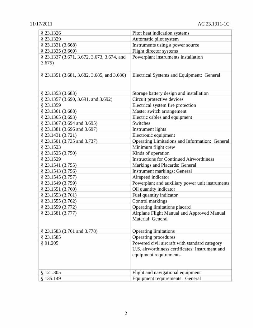
11172011 AC 231311-1C
sect 231326 Pitot heat indication systems sect 231329 Automatic pilot system sect 231331 (3668) Instruments using a power source sect 231335 (3669) Flight director systems sect 231337 (3671 3672 3673 3674 and 3675)
Powerplant instruments installation
sect 231351 (3681 3682 3685 and 3686) Electrical Systems and Equipment General
sect 231353 (3683) Storage battery design and installation sect 231357 (3690 3691 and 3692) Circuit protective devices sect 231359 Electrical system fire protection sect 231361 (3688) Master switch arrangement sect 231365 (3693) Electric cables and equipment sect 231367 (3694 and 3695) Switches sect 231381 (3696 and 3697) Instrument lights sect 231431 (3721) Electronic equipment sect 231501 (3735 and 3737) Operating Limitations and Information General sect 231523 Minimum flight crew sect 231525 (3750) Kinds of operation sect 231529 Instructions for Continued Airworthiness sect 231541 (3755) Markings and Placards General sect 231543 (3756) Instrument markings General sect 231545 (3757) Airspeed indicator sect 231549 (3759) Powerplant and auxiliary power unit instruments sect 231551 (3760) Oil quantity indicator sect 231553 (3761) Fuel quantity indicator sect 231555 (3762) Control markings sect 231559 (3772) Operating limitations placard sect 231581 (3777) Airplane Flight Manual and Approved Manual
Material General
sect 231583 (3761 and 3778) Operating limitations sect 231585 Operating procedures sect 91205 Powered civil aircraft with standard category
US airworthiness certificates Instrument and equipment requirements
sect 121305 Flight and navigational equipment sect 135149 Equipment requirements General
2
11172011 AC 231311-1C
sect 135159 Equipment requirements Carrying passengers under Visual Flight Rules (VFR) at night or under VFR over-the-top conditions
sect 135163 Equipment requirements Aircraft carrying passengers under Instrument Flight Rules (IFR)
32 Advisory Circulars and Related Documents You may access the latest version of the ACs notices orders and policy statements on the FAA website wwwfaagov
Table 2 - Advisory Circulars and Related Documents
AC 20-88A Guidelines on the Marking of Aircraft Powerplant Instruments (Displays)
AC 20-115B RTCA Inc RTCADO-178B AC 20-136A Protection of Aircraft ElectricalElectronic Systems Against the
Indirect Effects of Lightning AC 20-138B Airworthiness Approval of Positioning and Navigation Systems AC 20-140A Guidelines for Design Approval of Aircraft Data Link
Communication Systems Supporting Air Traffic Services (ATS) AC 20-149 Safety and Interoperability Requirements for Initial Domestic
Flight Information Service - Broadcast AC 20-152 RTCA Inc Document RTCADO-254 Design Assurance
Guidance for Airborne Electronic Hardware AC 20-153A Acceptance of Aeronautical Data Processes and Associated
Navigation Databases
AC 20-155 SAE Documents to Support Aircraft Lightning Protection Certification
AC 20-158 The Certification of Aircraft Electrical and Electronic Systems for Operation in the High-Intensity Radiated Fields (HIRF) Environment
AC 20-167 Airworthiness Approval of Enhanced Vision System Synthetic Vision System Combined Vision System and Enhanced Flight Vision System Equipment
3
11172011 AC 231311-1C
AC 20-170 Integrated Modular Avionics Development Verification Integration and Approval Using RTCADO-297 and Technical Standard Order C153
AC 21-16F RTCA Document DO-160 versions D E and F ldquoEnvironmental Conditions and Test Procedures for Airborne Equipment
AC 23-8C Flight Test Guide for Certification of Part 23 Airplanes AC 23-15A Small Airplane Certification Compliance Program AC 23-17C Systems and Equipment Guide for Certification of Part 23
Airplanes AC 23-18 Installation of Terrain Awareness and Warning System (TAWS)
Approved for Part 23 Airplanes AC 23-22 Guidance for Approved Model List (AML) Supplemental Type
Certificate (STC) Approval of Part 23 Airplane Avionics Installations
AC 23-23 Standardization Guide for Integrated Cockpits in Part 23 Airplanes
AC 231309-1E System Safety Analysis and Assessment for Part 23 Airplanes AC 25-11A Electronic Flight Deck Displays AC 90-106 Enhanced Flight Vision Systems AC 91-75 Attitude Indicator AC 91-78 Use of Class 1 or Class 2 Electronic Flight Bag (EFB) AC 120-64 Operational Use and Modification of Electronic Checklists AC 120-76A Guidelines for the Certification Airworthiness and Operational
Approval of Electronic Flight Bag Computing Devices Order 811049 Software Approval Guidelines dated June 3 2003 Order 8110105 Simple and Complex Electronic Hardware Approval Guidance PS-ACE100-2001-004 Guidance for Reviewing Certification Plans to Address Human
Factors for Certification of Part 23 Small Airplanes
33 Technical Standard Orders (TSO) You may access the TSOs on the FAA website wwwfaagov The following is a list of the FAA TSOs that are referenced in this AC For a complete list of TSOs that are related to this AC see AC 20-110L ldquoIndex of Aviation Technical Standards Ordersrdquo or the web site for the most current list
a TSO-C63c Airborne Weather and Ground Mapping Pulsed Radars
b TSO-C113 Airborne Multipurpose Electronic Displays
c TSO-C153 Integrated Modular Avionics Hardware Elements
d TSO-C157 Aircraft Flight Information Services-Broadcast (FIS-B) Data Link Systems and Equipment
4
11172011 AC 231311-1C
e TSO-C165 Electronic Map Display Equipment for Graphical Depiction of Aircraft Position
34 Industry Documents You may obtain copies of current editions of the following publications
341 RTCA Documents The following RTCA documents are available from RTCA Inc 1828 L Street NW Suite 805 Washington DC 20036-4001 or at their website at wwwrtcaorg
a RTCADO-160G Environmental Conditions and Test Procedures for Airborne Equipment
b RTCADO-178B Software Considerations in Airborne Systems and Equipment Certification
c RTCADO-187 Minimum Operational Performance Standards for Airborne Area Navigation Equipment Using Multi-Sensor Inputs
d RTCADO-200A Standards for Processing Aeronautical Data
e RTCADO-201A Standards for Aeronautical Information
f RTCADO-254 Design Assurance Guidance for Airborne Electronic Hardware
g RTCADO-257A Minimum Operational Performance Standards for the Depiction of Navigation Information on Electronic Maps
h RTCADO-267A Minimum Aviation System Performance Standards (MASPS) for Flight Information Services-Broadcast (FIS-B) Data Link
i RTCADO-297 Integrated Modular Avionics (IMA) Development Guidance and Certification Considerations
j RTCADO-313 Certification Guidance for Installation of Non-Essential Non-Required Aircraft Cabin Systems and Equipment
k RTCADO-315A Minimum Aviation Performance Standards (MASPS) for Enhanced Vision Systems Synthetic Vision Systems Combined Vision Systems and Enhanced Flight Vision Systems
342 Society of Automotive Engineers (SAE) Inc The following Society of Automotive Engineers (SAE) Inc documents are available from SAE 400 Commonwealth Drive Warrendale PA 15096-0001 or from their website at wwwsaeorg
5
11172011 AC 231311-1C
a ARP 268G Location and Actuation of Flight Deck Controls for Transport Aircraft
b ARP 450D Flight Deck Visual Audible and Tactile Signals
c ARP 926B FaultFailure Analysis Procedure
d AIR 1093A Numeral Letter and Symbol Dimensions for Aircraft Instrument Displays
e ARP 1161A Crew Station LightingmdashCommercial Aircraft
f ARP 1782A Photometric and Colorimetric Measurement Procedures for Airborne Direct View CRT [Cathode Ray Tube] Displays
g ARP 1834A FaultFailure Analysis for Digital Systems and Equipment
h ARP 1874 Design Objectives for CRT Displays for Part 25 (Transport) Aircraft
i ARP 4032A Human Engineering Considerations in the Application of Color to Electronic Aircraft Displays
j ARP 4033 Pilot System Integration
k ARP 4067 Design Objectives for CRT Displays for Part 23 Aircraft
l ARP 4101 Flight Deck Layout and Facilities
m ARP 4102 Flight Deck Panels Controls and Displays
n ARP 41027 Electronic Displays
o ARP 4103 Flight Deck Lighting for Commercial Transport Aircraft
p ARP 4105B Abbreviations and Acronyms for Use on the Flight Deck
q ARP 4155A Human Interface Design Methodology for Integrated Display Symbology
r ARP 4256A Design Objectives for Liquid Crystal Displays for Part 25 (Transport) Aircraft
s ARP 4260A Photometric and Colorimetric Measurement Procedures for Airborne Electronic Flat Panel Displays
6
11172011 AC 231311-1C
t ARP 4754 Certification Considerations for Highly Integrated or Complex Aircraft Systems
u ARP 4761 Guidelines and Methods for Conducting the Safety Assessment Process on Civil Airborne Systems and Equipment
v ARP 5287 Optical Measurement Procedures for Airborne Head-Up Display (HUD)
w ARP 5288 Transport Category Airplane Head Up Display (HUD) Systems
x ARP 5289 Electronic Aeronautical Symbols
y ARP 5364 Human Factor Considerations in the Design of Multifunction Display Systems for Civil Aircraft
z ARP 5365 Human Interface Criteria for Cockpit Display of Traffic Information
aa ARP 5430 Human Interface Criteria for Vertical Situation Awareness Displays
bb ARP 5677 Human Engineering Considerations for Cockpit Integration of EnhancedSynthetic Vision Systems
cc AS 5703 Minimum Performance Standard for Enhanced Vision System
dd AS 8034A Minimum Performance Standard for Airborne Multipurpose Electronic Displays
ee AS 8055 Minimum Performance Standard for Airborne Head Up Display (HUD)
343 General Aviation Manufacturers Association (GAMA) The following documents are available from the GAMA 1400 K St NW Suite 801 Washington DC 2005 or from their website at wwwgamaaeroindustry-standards
a General Aviation Manufacturers Association (GAMA) Publication No 10 Recommended Practices and Guidelines for Part 23 CockpitFlight Deck Design
b General Aviation Manufacturers Association (GAMA) Publication No 12 Recommended Practices and Guidelines for an Integrated CockpitFlightdeck in a 14 CFR Part 23 Certificated Airplane
7
11172011 AC 231311-1C
40 Background
a Amendment 23-41 effective November 26 1990 established airworthiness standards in sect 231311 for installing electronic display instrument systems in normal utility acrobatic and commuter category airplanes The first electronic displays developed were direct replacements for the conventional electromechanical components with later designs providing more extensive information integration Before Amendment 23-41 most electronic display instrument systems were approved by special condition for installation in part 23 airplanes Amendment 23-49 effective March 11 1996 further amended part 23 to harmonize 14 CFR with the Joint Aviation Requirements (JAR) Section 231311 Amendment 23-49 removed redundant requirements and clarified which secondary instruments are required including the visibility requirements for those instruments
b Amendment 23-62 made several changes that affect the installation of electronic displays Guidance relative to electronic displays of those sections is also included in this AC The significant changes were
(1) Clarified requirements for trend information and appropriate sensory cues
(2) Incorporated equivalent visual displays of the instrument markings on electronic displays
(3) Allowed an applicant to take credit for reversionary or secondary flight displays on a multi-function flight display (MFD) that provides a secondary means of primary flight information (PFI)
(4) Revised some redundancy requirements to be only applicable for IFR operations
(5) Accommodated new technology for magnetic direction indicator
(6) Updated the terminology for system safety assessment
(7) Revised requirements for instruments using power source(s) and
(8) Revised requirements for storage battery backup times
50 Scope This AC is generally applicable only to an applicant seeking issuance of certain type certificates These include a type certificate (TC) an amended type certificate (ATC) or a supplemental type certificate (STC) for the approval of a new type design or a change in the type design This AC does not completely address Synthetic Vision Systems (SVS) or Enhanced Vision Systems (EVS) and Head-Up Displays (HUD) Contact the Small Airplane Directorate if there are any conflicts with other guidance and this AC The Small Airplane Directorate will coordinate and resolve the conflicts among the points of contact of the other documents
8
11172011 AC 231311-1C
60 AcronymsDefinitions
61 Acronyms
a AC Advisory Circular
b ACO Aircraft Certification Office
c ADC Air Data Computer
d ADI Attitude Direction Indicator
e ADDS Aviation Digital Data Service
f AFM Airplane Flight Manual
g AFMS Airplane Flight Manual Supplement
h AHRS Attitude Heading Reference System
i ARD Aerospace Research Document
j ARP Aerospace Recommended Practice
k AS Aerospace Standard
l ASTC Amended Supplemental Type Certificate
m ATC Amended Type Certificate
n CAR Civil Air Regulations
o CDI Course Deviation Indicator
p CFR Code of Federal Regulations
q CIP Current Icing Potential
r CL Center Line
s CRT Cathode-Ray Tubes
t DN Down
u EADI Electronic Attitude Direction Indicator
9
11172011 AC 231311-1C
v EHSI Electronic Horizontal Situation Indicator
w EICAS Engine Indication and Crew Alert System
x ELOS Equivalent Level of Safety
y EVS Enhanced Vision Systems
z FAA Federal Aviation Administration
aa FD Flight Director
bb FHA Functional Hazard Assessment
cc FLS Field-Loadable Software
dd FMEA Failure Modes and Effects Analysis
ee FOV Field-Of-View
ff GPS Global Positioning System
gg HIRF High Intensity Radiated Fields
hh HUD Head-Up Display
ii HSI Horizontal Situation Indicators
jj ICAO International Civil Aviation Organization
kk IFR Instrument Flight Rules
ll ILS Instrument Landing System
mm IMA Integrated Modular Avionics
nn IMC Instrument Meteorological Conditions
oo JAR Joint Aviation Requirements
pp LCD Liquid Crystal Displays
qq LED Light Emitting Diodes
rr LT Left
10
11172011 AC 231311-1C
ss METAR ICAO Routine Aviation Weather Report
tt MFD Multifunction Flight Display
uu ND Navigation Display
vv NOM Nominal
ww PFD Primary Flight Display
xx PFI Primary Flight Information
yy POH Pilots Operating Handbook
zz RAIM Receiver Autonomous Integrity Monitoring (used with GPS)
aaa RT Right
bbb SAE Society of Automotive Engineers
ccc STC Supplemental Type Certificate
ddd SVS Synthetic Vision Systems
eee TAS Traffic Advisory System
fff TAWS Terrain Awareness Warning System
ggg TFR Temporary Flight Restrictions
hhh TC Type Certificate
iii TCAS Traffic Alert and Collision Avoidance System
jjj TSO Technical Standard Order
kkk UL Underwriterrsquos Laboratories
lll VOR Very High Frequency Omni-Directional Range
mmm VFR Visual Flight Rules
nnn VMC Visual Meteorological Conditions
ooo VFE Maximum flap extended speed
11
11172011 AC 231311-1C
ppp VMO Maximum operating limit speed
qqq VNE Never-exceed speed
rrr VNO Maximum structural cruising speed
sss VS0 The stalling speed or the minimum steady flight speed in the landing configuration
ttt VS1 The stalling speed or the minimum steady flight speed obtained in a specific configuration
uuu WAAS Wide Area Augmentation System
62 Definitions This section contains definitions for terms in this document
a Accuracy A degree of conformance between the estimated or measured value and the true value
b Adverse Operating Condition A set of environmental or operational circumstances applicable to the airplane combined with a failure or other emergency situation that results in a significant increase in normal flight crew workload
c Component Any self-contained part combination of parts subassemblies or units that perform a distinct function necessary to the operation of the system
d Continued Safe Flight and Landing This phrase means the airplane can continue controlled flight and landing possibly using emergency procedures without requiring exceptional pilot skill or strength On landing some airplane damage may occur as a result of a Failure Condition
e Conventional A system is considered ldquoConventionalrdquo if its function the technological means to implement its function and its intended use are all the same as or closely similar to that of previously approved systems that are commonly used The systems that have established an adequate service history and the means of compliance for approval are generally accepted as Conventional
f Critical Usually a function whose loss would prevent the continued safe flight and landing of the airplane
Note The term ldquocritical functionrdquo is associated with a catastrophic failure condition Newer documents may not refer specifically to the term ldquocritical functionrdquo
g Criticality Indication of the hazard level associated with a function hardware software etc considering abnormal behavior (of this function hardware software etc) alone in
12
11172011 AC 231311-1C
combination or in combination with external events Criticality is a failure classification that could be no safety effect minor major hazardous and catastrophic See AC 231309-1E for more guidance
h Design-Eye Box A three-dimensional volume of space surrounding the design eye reference point that designers and evaluators use to determine the acceptability of display and control locations
i Design-Eye Reference Point A single reference point in space selected by the designer where the midpoint between the pilotrsquos eyes is assumed to be located when the pilot is properly seated at the pilotrsquos station
j Development Assurance All those planned and systematic actions used to substantiate to an adequate level of confidence that errors in requirements design and implementation have been identified and corrected such that the system satisfies the applicable certification basis
k Enhanced Vision System An electronic means to provide a display of the forward external scene topography (the natural or manmade features of a place or region especially in a way to show their relative positions and elevation) through the use of imaging sensors such as a forward looking infrared millimeter wave radiometry millimeter wave radar low light level image intensifying
l Equipment Essential to Safe Operation Equipment installed to comply with the applicable certification requirements of 14 CFR part 23 or operational requirements of 14 CFR parts 91 and 135
m Error An omitted or incorrect action by a pilot or maintenance person or a mistake in requirements design or implementation
n Failure An occurrence that affects the operation of a component part or element such that it can no longer function as intended (this includes both loss of function and malfunction
o Failure Condition A condition affecting either the airplane or its occupants or both either direct or consequential caused or contributed to by one or more failures or errors considering flight phase and relevant adverse operational or environmental conditions or external events Failure conditions may be classified according to their severity See AC 231309-1E for more information on definitions of failure conditions
p Field-of-View The angular extent of the display that can be seen by either pilot with the pilot seated at the pilotrsquos station See section 15 for more information on the field-of view
q Fix A generic name for a geographical position A fix may also be referred to as a waypoint intersection reporting point etc
13
11172011 AC 231311-1C
r Flight Plan Refers to any sequence of fixes that are interconnected by the desired path Flight plans may range from the simplest that include only the aircraftrsquos present position the active waypoint and the desired path between them to more complicated plans that include departure and destination airports with multiple intermediate fixes
s Function The lowest defined level of a specific action of a system equipment and pilot performance aboard the airplane that by itself provides a complete recognizable operational capability (for example an airplane heading is a function) One or more systems may contain a specific function or one system may contain multiple functions
t Functional Hazard Assessment A systematic comprehensive examination of airplane and system functions to identify potential minor major hazardous and catastrophic failure conditions that may arise as a result of a malfunction or a failure to function
u Hardware An object that has physical being Generally refers to circuit cards power supplies etc
v Hazard Any condition that compromises the overall safety of the airplane or that significantly reduces the ability of the pilot to cope with adverse operating conditions
w Head-Up Display A transparent optical display system located level with and between the pilot and the forward windscreen The HUD displays a combination of control performance navigation and command information superimposed on the external field of view It includes the display element sensors computers and power supplies indications and controls It is integrated with airborne attitude air data and navigation systems and as a display of command information is considered a component of the flight guidance system
x Independent A component part element or system that is not relying on some other component part element or system for accomplishing its function This design concept ensures that the failure of one item does not cause a failure of another item For redundancy each means of accomplishing the same function need not necessarily be identical
y Indicator A means for displaying information of a parameter More than one indicator could be depicted on one display For example a primary flight display may have indicators for attitude altitude airspeed heading and navigation
z Instrument An electrical or mechanical measurement device In sect 231311 it is defined as Devices physically contained in one unit and devices composed of two or more physically separate units or components connected together (One example is a remote indicating gyroscopic direction indicator that includes a magnetic sensing element a gyroscopic unit an amplifier and an indicator connected together)
aa Map Orientation Refers to the rule that determines the directional relation of the map to the upper part of the display depiction Using a north-up rule the north side of the map would be toward the top of the display and the south side of the map would be at the bottom Using
14
11172011 AC 231311-1C
a desired path-up rule the map would be oriented so the desired path would be vertical on the map and pointing straight up toward the top of the display
bb Map Range The geographic extent of the map region (for example the distance covered by the map representation in either the vertical or horizontal direction)
cc Malfunction Failure of a system subsystem unit or part to operate in the normal or usual manner A condition whereby the operation is outside specified limits
dd Multi-Function Display Any physical display unit other than the PFD used to present various information on which the layout may be reconfigured
ee Navigation The process of planning tracking and controlling the course of an airplane from one place to another
ff Navigation Display The display or suite of instruments by which navigation data is presented to the pilot
gg Navigation Information Information that aids the flightcrew in determining the aircraftrsquos location in a given environment (for example on flight plans VORs GPSs features on the airport surface including taxiway signage etc)
hh Primary As used for instruments it is defined in sect 231311(c) as the ldquodisplay of a parameter that is located in the instrument panel such that the pilot looks at it first when wanting to view that parameterrdquo
ii Primary Flight Display (PFD) A single physical unit that always provides the primary display of all the following altitude airspeed aircraft heading (direction) and attitude located directly in front of the pilot in a fixed layout in accordance with sect 231321 It may provide other information pertinent to guidance and fundamental control of flight of the airplane such as critical engine parameters
jj Primary Flight Information (PFI) A PFI refers to those functions or parameters required by the airworthiness and operational rules such as airspeed altitude attitude and heading (direction) that are on the PFD
kk Primary Function (PF) This definition is applicable in the case when there is more than one function available for same function A function that is installed to comply with the applicable regulations for the required function and one that provides the most pertinent controls or information instantly and directly to the pilot For example the PFD is a single physical unit that always provides the primary display and it complies with the requirements of all the following altitude airspeed aircraft heading (direction) and attitude This PFD is located directly in front of the pilot and used instantly and first by the pilot A standby (additional) PFD that is intended to be used in the event of failure of the PFD is an example of a secondary system
15
11172011 AC 231311-1C
ll Primary Navigation Where the pilot looks first for a display of navigation information such as on an HSI or CDI It displays vertical and lateral deviation and it may have the digital distance indication tofrom the selected fix
mm Redundancy The presence of more than one independent means for accomplishing a given function Each means of accomplishing the function need not necessarily be identical
nn Reversionary Display A secondary means to provide information initially presented on the PFD or MFD by the transfer of information to an alternate display
oo Scale The relative proportion of the linear dimensions of objects on a display to the dimensions of the corresponding objects and distances being represented (for example 1 inch = 100 nautical miles)
pp Secondary Display A means to present information on another display A display that can be used for backup or secondary purposes such as in the event of a failure of another display
qq Standby Instrument A dedicated instrument that is always available that presents primary flight information
rr Supplemental Function A function that is not required or intended to meet all the airworthiness and operational requirements It is usually installed for additional situational awareness
ss System A combination of components parts and elements that is interconnected to perform one or more functions
tt Synthetic Vision System A computer-generated image of the external scene topography from the perspective of the flight deck that is derived from aircraft attitude high precision navigation solution and database of terrain obstacles and relevant cultural features
Note ldquoTopographyrdquo defined as maps or charts of natural and man-made features of a place or region especially in a way to show their relative positions and elevations as applicable whenever deemed appropriate and practicable
uu Track The projection on the earthrsquos surface of the path of an aircraft the direction of which is usually expressed in degrees from north (true magnetic or grid) A track is the actual flight path of an aircraft over the surface of the earth
Note For more definitions related to safety assessments refer to AC 231309-1E for the appropriate definitions
vv Warning A clear and unambiguous indication to the pilot of a failure that requires immediate corrective action An inherent characteristic of the airplane or a device that will give
16
11172011 AC 231311-1C
clearly distinguishable indications of malfunction or misleading information may provide this warning
70 Display Description The following paragraphs give a brief description of an electronic display They do not cover all the capabilities and details of these displays or the information presented on them
71 General Electronic displays have replaced many of the traditional electromechanical and analog instruments These displays also augment andor combine the functionality of conventional systems such as radios and navigational systems The major display technologies now used are multicolor CRTs LCDs electro luminescence plasma and LEDs The initial electronic displays mimicked the traditional mechanical and electromechanical flight and powerplant instruments The colors symbols and formats on these initial electronic displays are similar to those on traditional conventional instruments Modern electronic displays provide integration and formats that often differ from traditional instruments
72 Display Configuration Electronic displays may be installed in several configurations A basic electronic display may provide only one flight or powerplant parameter while more sophisticated systems integrate many parameters on one electronic display One of the major design goals for these systems is eliminating separate conventional gauges instruments and annunciators Recent installations show a trend toward a higher degree of integration For example an integrated primary flight display provides several parameters such as attitude heading (direction) airspeed and altitude Integration of various systems should include analysis to ensure that complexity and workload are compatible with general aviation pilots capabilities For more guidance on IMA that implement TSO authorized hardware elements see TSO-C153 and AC 20shy170
80 Flight Displays
81 Instrument Requirements
a Sections 231303 231305 231311 and 231321 with the applicable operating rules (14 CFR parts 91 121 and 135) incorporate flight and powerplant instrument requirements for part 23 airplanes The navigation equipment requirements are given in operational rules specified in sectsect 91205 121303 121305 121307 135143 135149 135159 135161 and 135165 Display requirements for navigation information are dependent on the navigation system installed in the aircraft Instruments and equipment required for flights under parts 91 121 and 135 may be affected by the electronic display installation These instruments and equipment include gyroscopic bank and pitch gyroscopic direction gyroscopic rate-of-turn slip-skid instruments and other required communication and navigational equipment
b There have been applications to install equipment such as flight and navigation displays as non-required These applications request approval for these installations as situation awareness (SA) only It is not acceptable to label a display as ldquoSA-Onlyrdquo and assume that its failure condition is acceptable Installing displays that provide PFI that are more compelling than
17
11172011 AC 231311-1C
the required primary PFI displays but they do not meet the appropriate operational and airworthiness requirements and labeling them as ldquoSupplementalrdquo or ldquoSA-Only is not acceptable Section 136 provides more guidance
c The basis for certification has been that the equipment should perform its intended function and not present a hazard Instruments that aid situation awareness should be certified under the part 23 requirements including sect 231301 and sect 231309 These displays could provide hazardous misleading information PFI is essential for safe operation An instrument that provides PFI should meet the minimum standards of applicable TSOs or an equivalent standard It also should meet the guidance in AC 231309-1E AC 23-17C and the guidance in this AC
82 Primary Flight Information (PFI) PFI refers to those functions or parameters that are required by the airworthiness and operational rules such as airspeed altitude attitude and heading (direction) It may provide other information pertinent to guidance and fundamental control of flight such as critical engine parameters Attitude airspeed altitude and heading (direction) are the PFI required in sect 231311(a)(3) and (5) and they must be arranged according to sect 231321 in the ldquobasic Trdquo arrangement Direction should be heading with track presented if available as a selectable option The horizon reference line on the PFD should be at least 325 inches wide in straight and level flight for integrated displays This recommendation is not intended to prevent replacement of mechanical instruments with an electronic display of a similar horizon reference line When the true horizon is no longer on the display the artificial horizon line should provide a distinctive demarcation between sky and ground (or the background) Display of PFI on reversionary or standby displays should be arranged in the basic T-configuration but it is not required The standby instrument or displays of PFI location should meet the FOV guidance criteria in section 15
821 Acceptable Methods for Compliance with sect 231311(b) There are three acceptable methods for meeting the attitude requirements which is considered information essential for continued safe flight and landing Compliance can be accomplished by using dedicated standby instruments dual PFDs or reversionary displays that present primary flight information Electronic display systems without dedicated standby instruments should have at least two independent displays able to provide PFI to the pilot These displays should be powered such that any single failure of the power generation and distribution systems cannot remove the display of PFI from both displays Section 231311(b) in Amendment 23-62 states ldquoThe electronic display indicators including their systems and installations and considering other airplane systems must be designed so that one display of information essential for continued safe flight and landing will be available within one second to the crew by a single pilot action or by automatic means for continued safe operation after any single failure or probable combination of failuresrdquo
83 Standby Instruments The purpose of standby instruments or another independent PFD is to ensure that PFI is available to the pilot during all phases of flight and during system failures Individual indicators should be a minimum of 2 inches in diameter or if combined a minimum diameter of 3 inches (or equivalent) displayed
831 Dual PFDs Electronic display systems with dual PFDs should incorporate dual independently powered sensors that provide primary flight parameters such as AHRS with
18
11172011 AC 231311-1C
comparators and dual ADC Dual PFDs with dual AHRSs and ADCs which include checking and are powered by multiple power sources and distribution systems are significantly more reliable than presently certified mechanical systems
832 PFD and Autopilot with an AHRS For normal operation when using a single AHRS to drive the PFD and the autopilot simultaneously the installation must mitigate hazardous or catastrophic system level failures An example configuration supporting proper mitigation would include all of the following
a A dedicated standby attitude instrument within the primary maximum FOV or independent reversionary attitude display
b An AHRS with appropriate comparator or monitor of equivalent performance
c Appropriate system warningcaution annunciation associated with an AHRS malfunction
d If an aircraft is equipped with multiple AHRS it may be acceptable when one AHRS fails to drive both the autopilot and the PFD from a single AHRS as long as an AHRS independent attitude display (required for some aircraft classes) is located in the primary maximum field of view The failure must be annunciated to the pilot and the pilot must be able to select the non-failed AHRS For aircraft that do not have an independent attitude indicator when one AHRS fails the autopilot should be manually or automatically disengaged The autopilot may be reengaged if appropriate mitigation is available (for example see a through c above) The AFM or supplemental AFM should contain the appropriate procedures applicable to the equipment installed See section 110 for additional guidance AC 231309-1E guidance should be considered for these configurations
e Displays not meeting FOV guidance criteria may require additional human factors airworthiness evaluation by the certification authority See section 15 for additional guidance
84 Reversionary Flight Displays Instead of Standby Instruments or Dual PFDs
841 General Requirements
a Reversionary flight displays provide a secondary means to provide PFI through alternate display formats on another PFD or MFD by the transfer of information to an alternate display or by some other means The function of an MFD system is to provide the pilot access to various data or combinations of data used to fly the aircraft to navigate to communicate andor to manage aircraft systems The MFD would also present PFI as needed to ensure continuity of operations 14 CFR part 23 sect 231311(b) Amendment 23-62 states the electronic display indicators including their systems and installations and considering other airplane systems must be designed so that one display of information essential for continued safe flight and landing will be available within one second to the crew by a single pilot action or by automatic means for continued
19
11172011 AC 231311-1C
safe operation after any single failure or probable combination of failures To meet the requirements of sect 231311(b) a full-time standby display another independent PFD or an independent reversionary attitude display must be installed Reversionary modes could be automatically and manually selected or only manually selected
b Reversionary configurations are significantly more reliable than presently certified mechanical systems and the skills required while flying in reversionary mode are identical with those used when flying in primary mode Traditional external standby flight instruments (either electronic or mechanical) offer potential safety problems associated with delay in pilot reaction The pilot may delay a decision to transition to standby instruments and to transition to partial panel techniques as opposed to the simple action the pilot would take to switch displays A nearly identical format on the reversionary display of all PFI that is also shown on the PFD provides a significant safety enhancement over standby instruments This is especially true when the size location arrangement and information provided by the standby instruments are significantly different from those on the PFD
c Reversionary display modes should provide consistent display formats to the PFD The reversionary flight information should be presented by an independent source and display to prevent complete loss of PFI due to a single failure The reversionary configuration should have two independent displays that incorporate dual-independently powered AHRS and dual ADC subsystems that provide PFIs The reversionary system response time should provide flight critical information on the MFD in less than one second after a single pilot action or an automatic operation
d A reversionary configuration should have a single pilot action that would force both the PFD and MFD displays into reversionary mode operation However the PFI should be presented in similar format and sufficient size in the reversionary mode as it is in normal mode to allow the pilot to enhance the control of the airplane This reversionary configuration should provide backup information essential to continued safe flight and landing with an intuitive control that allows instant simultaneous access to reversionary mode on both the PFD and MFD displays The single pilot action should be easily recognized readily accessible and have the control within the pilotrsquos primary optimum field of view An acceptable method for the single pilot action is the red color andor lighted red ldquohalordquo ring that announces its position on the panel at all times
842 Reversionary Methods
a One method is to have an automatic reversionary display with a single pilot action that would force both the PFD and MFD displays into reversionary mode operation If PFI on another display is not provided provide automatic switching to ensure PFI is available to the pilot Automatic reversion must provide a complete display of PFI on the remaining display within one second if a fault is detected
b Most possible faults should be covered by this automatic reversionary capability Only a total loss of the display may not be reliably detected automatically but such a failure condition would be obvious to the pilot Faults that result in automatic switching should be extensive enough to ensure PFI availability meets the requirements of sect 231309 If such a
20
11172011 AC 231311-1C
malfunction occurs a single pilot action should provide a full display of the essential information on the remaining display within one second All modes sources frequencies flight plan data etc should be similar as they were on the PFD before the failure
c Another reversionary method would include a means to access the reversionary mode manually through a single pilot action Manual activation of the reversionary mode on the MFD through single action by the pilot is acceptable when procedures to activate the PFI on the MFD are accomplished before entering critical phases of flight The PFI would be presented continuously on the reversionary display during critical phases of flight (for example takeoff landing and missed or final approach)
85 Display of Attitude For flights under IFR conditions in part 91 and part 135 operations and under VFR at night for part 135 operations attitude information is required The loss of all attitude information or the presentation of misleading attitude information could result in a catastrophic failure condition where the pilot could not continue safe flight and landing of the airplane It is recommended that the display of attitude follows the guidelines (below) that are also in GAMA Publication 12
a The pitch ladder should be caged to the center of the display
b At pitch attitudes when the true horizon line would not normally be displayed some sky or ground should be indicated on the PFD pitch display (minimum 38 inches and maximum of 115 percent of the display) and the horizon line should indicate off-scale
c With the airplane symbol on the horizon line the range of visible pitch attitude should be at least + 25 to -15 degrees but not to exceed a total pitch range of 50 degrees
d Bank angle presentations should use a roll pointer however roll pointers and sky-pointers should not be mixed in the same flight deckcockpit
e Roll scale indices should be placed at 10 20 30 60 and 90 degrees An index may also be placed at 45 degrees
86 Display of Direction (Heading or Track)
861 General
a The loss of direction (heading or track) information could result in reduced capability of the pilot to cope with adverse operating conditions The orientation of any secondary navigation display is optional (for example Track-up North-up Heading-Up) For flights under IFR conditions a stabilized heading indicator must provide the primary display of the direction parameter A magnetic direction indicator or track may provide the reversionary display of direction
21
11172011 AC 231311-1C
b The heading display should provide a clear and unmistakable display of aircraft symbol and heading HSI should provide a clear and unmistakable display of aircraft position heading and track (an option if available) relative to the desired coursetrack Section 17 contains more guidance on symbology Direction should be heading when track is presented if available as a selectable option with the data source clearly indicated On the primary display the heading scale should have a mode that presents at least 120 degrees of arc Other display formats may be acceptable and have been previously approved but they need to be evaluated from a human factor perspective
862 Hazardous Misleading Heading Information
a The FHA for the failure effects of hazardous misleading heading information from an AHRS is clarified in AC 23-17C This policy is specifically about the application of AC 231309-1E for an airplane with the certification basis of Amendments 23-41 or later This clarification is limited to installations approved for operation in IMC under IFR For operations limited to VFR a misleading heading indication is not considered hazardous
b Develop an FHA and the related safety assessments for the specific airplane type and configuration since there can be many combinations of failures various mitigating factors and other functions available to a pilot These many factors affect the criticality of the heading indication therefore use a safety assessment process from AC 231309-1E to classify the failure conditions for misleading heading information
c A hazardously misleading heading is usually when the accuracy error is greater than 10 degrees on the primary heading instrument and it is an undetected error The safety assessment process should consider appropriate mitigating factors For Class I part 23 airplanes the failure condition for misleading hazardous heading is usually considered major
87 Display of Altitude Airspeed and Magnetic Compass Information The original requirements of CAR 3 were adopted and later recodified into part 23 sect 231303 paragraphs (a) (b) and (c) At that time pneumatically driven displays provided airspeed and altitude functions Since then the FAA envisioned airspeed altitude and magnetic compass information would remain available to the pilot with the loss of the airplanes primary electrical power For electronic displays sect 231311(a)(3) requires the primary display of attitude airspeed and altitude to be uninhibited in any normal mode of operation Section 231311(a)(5) as amended by Amendment 23-62 requires an independent magnetic direction indicator and either an independent secondary mechanical altimeter airspeed indicator and attitude instrument or electronic display parameters for the altitude airspeed and attitude that are independent from the airplanes primary electrical power system Primary altitude or airspeed displays that require electrical power are acceptable if means are provided for their continued operation upon loss of the airplanersquos primary electrical power or if pneumatically driven instruments are available for the pilotrsquos use A standby or reversionary integrated display of altitude attitude and airspeed instead of individual electronic display indicators for airspeed altitude and attitude is acceptable under one condition The condition is that the standby or reversionary integrated display and the primary display are powered such that at least one integrated display with attitude altitude and airspeed is available after failure of any power source or distribution path
22
11172011 AC 231311-1C
88 Accuracy of the Magnetic Heading System
881 General
a The operating rules such as part 91 and part 135 specify the minimum required equipment that must be installed in part 23 airplanes based on the operation such as VFR or IFR Under VFR operation part 91 sect 91205 requires a magnetic direction indicator (that is normally intended to be a compass) for heading information Under IFR operation part 91 sect 91205 requires a gyroscopically stabilized heading system Section 231303(c) Amendment 23-62 amended the requirement from ldquoA direction indicator (non-stabilized magnetic compass)rdquo to ldquoA magnetic direction indicatorrdquo As new technology becomes more affordable for part 23 airplanes many electronic flight instrument systems will use magnetically stabilized direction indicators (or electric compass systems) to measure and indicate the airplane heading to provide better performance
b The general airworthiness requirements in part 23 sect 231301 and sect 231525 determine the flight instrument and equipment accuracy requirements for part 23 airplanes Part 23 does not prescribe specific accuracy requirements for magnetic gyroscopically stabilized heading systems Specific accuracy requirements for avionics may be found in the related TSO and as acceptable means of compliance to sect 231301 in ACs notices or policy statementsletters
882 Magnetic Non-Stabilized Direction Indicator A magnetic non-stabilized direction indicator that is required by sect 231303 should have an accuracy of 10 degrees or have a correction card placard (reference sect 231327) or a back-up gyroscopic direction indicator provided the indicator is accurate better than 10 degrees If the sole purpose of the gyroscopic direction indicator is for backing up the magnetic non-stabilized direction indicator then the accuracy of presentation of headings can also be to 10 degrees However if a gyroscopic direction indicator is installed to meet the IFR operating rules then the installation requirements are defined by sect 231301
883 Magnetic Gyroscopically Stabilized Direction Indicator As installed final accuracy for a magnetic gyroscopically stabilized direction indicator of plusmn4 degrees on the ground or plusmn6 degrees in normal level flight on any heading would meet the requirements of part 23 sect 231301 This accuracy applies after compensation It should include cumulative errors in all combinations due to several factors These consist of the equipment itself the current flow in any item of electrical equipment and its associated wiring the movement of any part (for example controls or undercarriage) and the proximity of any item of equipment containing magnetic material to the magnetic sensor
884 Comparator Monitor
a For systems installations that include two magnetic gyroscopically stabilized heading systems and a comparator that monitors the differences between the headings of the two
23
11172011 AC 231311-1C
systems the comparator trip point set as follows would meet the requirements of part 23 sect 231301
(1) 6 degrees in stabilized level flight
(2) 6 degrees plus one half of the bank angle or
(3) 12 degrees with a bank angle greater than 6 degrees
(4) The alert function can be disabled at a bank angle greater than 20 degrees
(5) An alert is provided if the condition exceeds 60 seconds but it allows two minutes for a turn error as stated in the TSO
b The 6-degree trip point during level flight allows a heading error of as much as 12 degrees on one of the systems This would comprise one system at the 6 degrees in-flight tolerance limit while the other system presumably with some malfunction could have an error of 12 degrees in the same direction before the comparator monitor alert is tripped
89 Rate-of-Turn Instrument
a Under sectsect 91205 and 135159 a rate-of-turn instrument is not required if a third attitude instrument usable through flight attitudes of 360 degrees of pitch-and-roll is installed following the instrument requirements prescribed in sect 121305(j) If required place the rate-of-turn indicator near the heading indicator
b A second approved attitude indicator may substitute for the rate-of-turn instrument AC 91-75 Attitude Indicator provides one method This AC is applicable to part 23 certificated airplanes (or airplanes certificated under earlier equivalent regulations) that weigh less than 12500 pounds and are operated under part 91 The second approved attitude indicator must be powered by an independent power source from the primary attitude indicator This can be accomplished by using independent standby instruments another independent PFD or independent reversionary attitude display Most of the installations with electronic displays that meet the requirements of sect 231311 and this AC should comply with AC 91-75
810 Slip-Skid Instrument The slip-skid information is required by sectsect 91205(d)(4) and 135159(b) as applicable The FAA suggests locating the slip-skid display directly below or near the rate-of-turn instrument if installed or under or within the primary attitude display
811 Vertical Speed Indicator If provided present the vertical speed indicator to the right or directly below the altitude indicator with a scale appropriate to the performance of the aircraft
24
11172011 AC 231311-1C
90 Powerplant Displays
91 General
a This section defines a means of presenting powerplant performance and condition information about the airplanes operation It also provides guidelines about when these functions should be displayed to the pilot In general there have been two methods used to accomplish this These methods include (1) display raw engine parameters to the pilot for interpretation or (2) collect powerplant data and have an automatic monitoring system interpret and report the powerplant condition to the pilot Use the following evaluation criteria when considering the installation of electronic powerplant displays
b There is a need to evaluate each airframe engine and airframeengine interface with the operational characteristics of these systems to determine the primary powerplant parameter requirements For this evaluation and as used in this section a primary powerplant parameter is needed to start the engine and to set and monitor engine power within powerplant limitations Appropriate procedures for operation of an integrated electronic powerplant display system should be in the AFM
c For multiengine airplanes a failure or malfunction affecting the display or accuracy of any propulsion system parameter for one engine should not cause the loss of display or accuracy of any parameter for the remaining engine(s) If multiple propulsion parameters are integrated on one display and the display fails it is acceptable to provide a secondary propulsion parameter display
92 Loss of Critical Powerplant Information
a No single failure malfunction or probable combination of failures should result in either the loss of critical powerplant information or an erroneous display of powerplant parameters that would jeopardize continued safe flight and landing of the airplane Usually for engines that do not generally rely on the pilot to prevent exceeding their limits in normal operations or engines such as with electronic engine controls featuring engine limit protection the loss of powerplant displays should not cause immediate jeopardy to continued safe flight and landing
b A secondary display providing powerplant parameters for cases of loss of a primary powerplant display may be used provided it is located so the pilot can adequately view the powerplant parameters
c Throttle or power lever position may be used in place of lost powerplant display parameters This would apply if throttle position or power lever position provides a positive indication of the powerplant power level required to maintain safe flight to a landing and if the throttle has a means to preclude exceeding powerplant operating limits
25
11172011 AC 231311-1C
93 Powerplant Information
a Presentation of primary powerplant parameters continuously when they are required unless the monitor provides an adequate alert of the function Also provide a manual select option for the pilot to present the information A parameter defined as primary for engine start but not for other normal engine operation may only have to be presented continuously during engine start
b Before and upon reaching or exceeding any operating limit the display should present the required powerplant parameters without pilot action Timely alerts for each phase of flight should be provided when any operating limit is reached or exceeded for the required powerplant parameter The alerts should be in a form that enables the pilot to identify and carry out the necessary and appropriate actions The required powerplant information should be presented continuously during a critical takeoff and landing phase of flight to minimize pilot distraction until an established rate of climb or minimum altitude is achieved
c Displays that provide multiple powerplant parameters should be designed such that any parameter display or alert will not suppress another display or alert that also requires immediate crew awareness necessary to conduct safe operation of the aircraft and engine(s) Alerts that could cause subsequent activation of other displays or alerts should be presented in a manner and form to ensure appropriate identification and prioritization of all significant hazards and required crew actions See section 18 for more guidance on annunciation
94 Digital Reading Alphanumeric Displays
a Digital reading alphanumeric displays are most valuable when integrated with an analog display by adding a precise quantitative indication to complement an analog displays qualitative indication Proper integration should include a means for pilots to clearly associate the analog and digital indications (eg via close proximity) Digital reading alphanumeric powerplant displays formats should not be used in place of analog formats to indicate values of engine parameters where trend or rate-of-change information is important for safety or when the pilot needs to monitor parameters with a quick glance Digital reading alphanumeric displays limit the pilots ability to assess trend information and result in reduced crew awareness Digital reading alphanumeric displays are also limited in their ability to allow the pilot to easily compare parameters from multiple engines or to check the general proximity of differing parameters against their individual limits While these shortcomings can be compensated for with more design provisions use digital reading alphanumeric displays with caution and carefully evaluate each airframe engine and airframeengine integration
b Section 231311(a)(6) Amendment 23-62 requires sensory cues that provide a quick glance sense of rate and where appropriate trend information to the parameter being displayed to the pilot Section 231311(a)(7) requires incorporated equivalent visual displays of the instrument markings required by sectsect 231541 through 231553 or visual displays that alert the pilot to abnormal operational values or approaches to established limitation values for each parameter required to be displayed by this part
26
11172011 AC 231311-1C
c An ELOS will be necessary for digital -reading alphanumeric only displays that are not associated with any scale tape or pointer It may be difficult for pilots to determine the margin relative to targets or limits or compare between parameters To comply with sect 231311(a)(7) a scale dial or tape will be needed to accomplish the intended pilot task In order to demonstrate an equivalency a human factor andor pilot evaluations will be needed that will consider the following factors These are subject to evaluation on a case-by-case basis
(1) The visibility and relative location of the indicated parameter should be reviewed including appropriate conditions of lighting and instrument panel vibration
(2) The ability to assess necessary trend or rate-of-change information quickly including when this information may be needed during in-flight engine restarts
(3) The ability to assess how close the indicated parameter is relative to a limit
(4) The value to the crew of quickly and accurately comparing engine-to-engine data for multiengine aircraft
(5) Engine design features or characteristics that would forewarn the crew before the parameter reaches the operating limit (for example redline)
(6) The use of color in accordance with sect 231549 to indicate the state of operation a green indication would indicate normal operation a yellow indication would indicate operation in a takeoff or precautionary range and a red indication would indicate operation outside of the safe operating limits
95 Marking of Powerplant Parameters Mark powerplant parameters on electronic displays in accordance with sect 231549 AC 20-88A provides alternate methods of marking electronic powerplant displays Alternate methods of marking the displays may be performed However the FAA may evaluate these markings on a case-by-case basis depending on each airframe engine integration and appropriate human factors considerations Alternate markings that do not comply with the requirements of sect 231549 require an ELOS
100 Electronic Displays for Navigation Information
101 Guidance Information Navigation information used by the pilot for steering commands and to monitor deviation from a navigation path should be in the pilots primary FOV Warnings and cautions should also be in the primary FOV For more guidance on FOV see section 15 and Table 3 of this AC
102 Display Integration
a Navigation guidance information may be integrated with the PFDs Common examples include HSIs that combine inputs from a directional gyro with a course deviation
27
11172011 AC 231311-1C
indicator or an FD integrated with the ADI Additionally information from more than one navigation source may be displayed separately or simultaneously
b If information from more than one navigation source can be presented the selected source should be continuously indicated to the pilot If multiple sources can be presented simultaneously the display should indicate unambiguously what information is provided by each source and which one has been selected for guidance Some airplanes are equipped with an autopilot andor FD coupled to the lateral and vertical guidance system On these airplanes the input to the autopilot andor FD should coincide with the navigation source selected on the PFD or primary navigational display
103 Reversionary Navigation Displays Reversionary requirements for navigation display information depend on the rules under which the aircraft is operated and the hazards associated with the loss of or misleading information from the display The integration of non-navigation information (for example traffic weather or flight parameters) may affect the hazards associated with the loss of or misleading information from the display In these cases the applicant should perform a system safety assessment following AC 231309-1E For more guidance on safety assessments see AC 231309-1E and section 26 of this AC for more guidance
104 Navigation Database For area navigation equipment the navigation database is an essential component of the equipment Guidelines for the navigation database can be found in RTCADO-200A See AC 20-138 and AC 20-153 for more guidance and information
110 Aircraft Flight Manual (AFM) For equipment required for IFR approval the AFM or supplemental AFM should contain the limitations and the operating and emergency procedures applicable to the equipment installed Installations limited to VFR use only may require an AFM or supplemental AFM depending on the complexity of the installation and the need to identify necessary limitation and operating procedures AC 23-8C contains more policy and guidance on AFMs
120 Electronic Checklist and Charts Policy and guidance on electronic checklist and charts on electronic displays are contained in AC 23-8C AC 91-78 AC 120-64 and AC 120-76A
130 General Human Factors Considerations for Design of Electronic Displays
131 General Electronic displays can provide many innovative display flexibilities and features that were not possible with traditional displays Technology improvements in display design and integration can enhance pilot performance and improve situation awareness when innovations are designed using sound processes and appropriate design criteria that account for human performance The applicant should ensure that human performance considerations are adequately addressed throughout the design process Early FAA involvement and an effective working relationship between the FAA and the applicant will aid in the timely identification and resolution of human factors related issues The FAA encourages the applicant to develop human performance considerations including evaluation plans and present them to the FAA early in the certification process
28
11172011 AC 231311-1C
132 Human Factors for Certification of the Part 23 Small Airplanes Policy statement number PS-ACE100-2001-004 provides guidance for human factor certification plan or the human factor components of a general certification plan when one is submitted as part of a TC STC or ATC project The application of this guidance will ensure that human factors issues are adequately considered and addressed throughout the certification program
133 CockpitFlight Deck Design GAMA Publication No 10 The purpose of GAMA Publication No 10 is to provide manufacturers of small aircraft and systems with human factors recommendations for the design of cockpitsflight decks and their associated equipment This publication was developed as a cooperative effort between the FAA and industry
134 SAEs and RTCAs Recommended Practices and Standards Evaluation of the electronic display system should consider airworthiness regulations recommended practices and standards from industry documents as listed in section 3 of this AC
135 Human Factors Compliance Considerations
a The applicant should identify all human factors related regulations that apply to the installation and operation of the display system or component being certified The applicant should document how the system or component complies with each of these regulations A partial list of relevant regulations is contained in policy statement PS-ACE100-2001-004 The FAA and the applicant should develop and agree on a plan to describe how the applicant intends to show compliance with the relevant regulations It should contain enough detail to assure that human factors compliance considerations have been adequately addressed The test plan should also allow enough time to accomplish all necessary testing agreed to by the applicant and the FAA
b The applicant should assure the following
(1) The intended use of the system does not require any exceptional skill or generate any unreasonable workload for the pilot
(2) The use of the display does not require unreasonable training requirements to adequately show that the pilot can understand and properly operate the system in all operational environments
(3) The design characteristics of the display system should support error avoidance and management (detection recovery etc)
(4) The display system is integrated and is consistent or compatible with other cockpit controls and displays and it creates no more burden on the pilot regarding the new display system or operation of other systems
(5) If a failure occurs it does not prevent the pilot from safely operating the airplane
29
11172011 AC 231311-1C
c Manufacturers should provide design rationale for their decisions regarding new or unique features in a display Evaluation should be conducted to collect data in support of the new or unique features to assure they have no unsafe or misleading design characteristics The design teams including pilots should concur with the conclusion found with the data collected
d The applicant should conduct display evaluations with several human factors and pilots representatives whom are intended users of the system For systems that contain new or unique features a greater number of evaluators should be considered Allow a reasonable amount of training time to learn all required features of the display system The evaluators should be familiar with the guidance contained in this AC before the evaluation Evaluators should also be familiar with human factors display regulations guidance standards and recommendations contained under sections 3
136 Intended Function One of the regulations applicable to displays is sect 231301 As part of showing compliance with sect 231301 the display system must be of a type and design appropriate to its intended function when used by representative general aviation pilots An AFM AFMS or Pilotrsquos Guide may be used to describe the intended function
1361 Demonstrate Compliance To show compliance with sect 231301 an applicant must show that the design is appropriate for its intended function The applicantrsquos statement of intended function should be specific and detailed enough for the certification authority to evaluate the intended function(s) and to evaluate whether the associated pilot tasks (if any) can be adequately achieved This is important for systems with a pilot interface component as the certification authority should evaluate the intended function from the pilotrsquos perspective as well as from a systems perspective There are several safety concerns including the concern that the pilot could rely on a display that does not meet minimum safety standards For example applicants should elaborate on a statement that a new display system is intended to ldquoenhance situation awarenessrdquo since a wide variety of different displays from terrain awareness vertical profile and even the primary flight displays enhance situation awareness in different ways Applicants should provide a greater level of detail to identify the specific aspect(s) of situation awareness that are to be enhanced and show how the design supports those aspects Similarly the terms ldquosupplementalrdquo ldquonon-essentialrdquo ldquosecondaryrdquo etc in isolation would not be acceptable as statements of intended function While the statement of intended function must be submitted by the applicant the certification authority will make the final determination of compliance to the rule specifically on the acceptability of the proposed intended function
1362 Intended Function(s) and Associated Task(s)
a List the intended function(s) and associated task(s) for the major pilot interfaces focusing on new or unique features that affect the pilot interface A system may have multiple intended functions provided each function is documented and all information depicted or indicated to the pilot supports one or more of the documented intended functions See PS-ACE100shy2001-004 paragraph 2a Intended Function for more guidance
b You may use the following information to evaluate whether the statement of intended function and associated task is sufficiently specific and detailed
30
11172011 AC 231311-1C
(1) Does each feature and function include a statement of the intended function Is there a description of the task associated with this featurefunction
(2) What assessments decisions or actions are required from the pilot for these intended functions
(3) What other information is required for use with these intended functions (for example other cockpit systems) assumed to be used in combination with the system
(4) Is the operational environment in which these intended functions are to be used adequately described (for example VFR IFR phase of flight etc)
1363 Method(s) of Compliance The method(s) of compliance should be adequate to enable the certification authority to determine the following
a Is the system providing sufficient and appropriate information to support the intended functions and to achieve the associated tasks
b Is the level of detail accuracy integrity reliability timeliness and update rate of the information matched appropriately to the task associated with the intended function
c Does the use of the system impair the pilotrsquos ability to use other systems or do other tasks
d Does the system or the use of the system impair the safe operation or the intended function of other systems or equipment
1364 Labeling All displays and controls whose function is not obvious should be labeled and identified by function or operating limitations or any combination The assumptions andor limitations should be adequately documented in the AFM AFM Supplement andor Pilot Operating Manual (as negotiated with the ACO) This applies to the manufacturer of the equipment and not to the installer The installer is required to verify the intended function and to make any placards or flight manual limitations according to subpart G of part 23 that the installed equipment makes necessary
140 Location and Configuration of Displays
141 Display Usability Displays should be located such that the pilot(s) can monitor them with minimal head and eye movement between displays Flight information should be legible accurate easily interpreted sufficiently free of visual cutoff (viewing angle) parallax and distortion for the pilot to correctly interpret it
142 Basic T Configuration The basic T-configuration should be used for airplanes certificated under sect 231321 Amendment 23-14 or a later amendment The basic T-configuration
31
11172011 AC 231311-1C
is defined as an arrangement where the airspeed and altitude data are centered respectively directly to the left and right of the attitude data with the direction data located directly below the attitude data
143 Deviations from the Basic T Configuration
a Deviations from the basic T-configuration have been approved for individual instrument arrangements if the droop angle (angle below the sect 231321(d) position) is 15 degrees or less or if the elevated angle is 10 degrees or less These angles are measured from a horizontal reference line that passes through the center of the attitude reference data with lines passing through the center of the airspeed and altitude data
b Unique displays or arrangements for attitude altitude airspeed and navigation data integration of combinations of these functions or rearrangement of them from the basic T-configuration may be approved when an equivalent level of safety and a human factors evaluation are provided This evaluation should consider the different types of airplane operations as defined by sect 231559(b) Coordination with the Small Airplane Directorate is required Deviations beyond these limits may be approved for individual flight instruments through a human factors evaluation and display installation evaluation considering the following items
(1) The display arrangement and its alignment to the normal line of the pilots vision
(2) The cockpit view
(3) The integration of other functions within the displays
(4) The data presented format symbology etc within the display and
(5) The ease of manipulating controls associated with the displays
150 Pilot Field-of-View Considerations
151 General
a This guidance is specifically intended to address the visibility and placement of information used by the pilot Past practice has typically involved FAA flight test pilots working with applicants to conduct qualitative assessments of the proposed equipment locations This is intended primarily for new aircraft development programs but it could also be used for extensive modifications to existing cockpits Part 23 rules do not require the applicant to establish a cockpit design eye reference point from which to measure viewing distances and angular displacement to various cockpit equipments However we recommend you facilitate quantitative assessments of equipment locations for new instrument panel designs These evaluations typically involve the pilotrsquos subjective assessment of the applicantrsquos cockpit to ensure it meets the intent of sect 231321(a) which states the pilot should be able to use all the required instruments with ldquominimum head and eye movementrdquo
32
11172011 AC 231311-1C
b Many other factors need to be considered when determining the acceptability of displayed information in the cockpit These factors can include the following
(1) Readability
(2) Clutter
(3) Pilot scan pattern
(4) Pilot workload
(5) Parallax
(6) Frequency of use and criticality
(7) Attention-getting
(8) Out-the-window correlation
(9) Pilot disorientation and
(10) Illumination and glare
152 Primary Field-of-View Primary optimum FOV is based on the vertical and horizontal visual fields from the design eye reference point that can be accommodated with eye rotation only With the normal line-of-sight established at 15 degrees below the horizontal plane the values for the vertical and horizontal (relative to normal line-of-sight forward of the aircraft) are +-15 degrees as shown in figure 1 This area is normally reserved for primary flight information and high priority alerts Table 3 also provides examples of information recommended for inclusion in this visual field In most applications critical information that is considered to be essential for safe flight with warning or cautionary information that requires immediate pilot action or awareness should be placed in the primary FOV
153 Primary Maximum Field-of-View Primary maximum FOV is based on the vertical and horizontal visual fields from the design eye reference point that can be accommodated with eye rotation and minimal head rotation These values are +-35 degrees horizontal and +40 degrees up and -20 degrees down vertical as shown in figure 1 These areas are normally used for important and frequently used information A pilotrsquos visual scan and head rotation is minimized when information is placed in this area Placement of information in this area also reduces the potential for spatial disorientation Table 3 provides examples of information recommended for inclusion in this visual field
33
Optimum
Hori
NOM
Vertical Field
Optimum
Horizontal
11172011 AC 231311-1C
Figure 1 Primary Field-of-View
154 Recommended Location for Displaying Information Table 3 contains the recommended location for displaying information intended for new panel layout with integrated electronic displays however these guidelines should be followed for other installations as practicable Deviations beyond these limits may be approved for individual flight instruments depending on the combination of factors listed in section 151 These deviations need a display installation evaluation It may not be practicable for retrofit installations with new electronic displays such as with ATC STC and field approvals to comply with the values in the table This is due to limitations in the systems and incompatible technologies between the aircraft and the system being added In such cases for any given item the angular deviations should not increase from what was originally found to be acceptable and the display characteristics should be at least as good as the original display For retrofit installations it may be acceptable for installations to fall outside the recommended data in table 3 These deviations may need an evaluation by the certification authority Factors to consider during this evaluation include the distinguishing ability attention-getting quality readability etc The FOV angles should be applied for installation approvals where a design eye reference point exists For installation approvals where no design eye reference point is defined the linear panel distances from center in table 3 should be used
34
11172011 AC 231311-1C
Table 3 ndash Field-of-View
Data Recommended Field-of-View FOV Degree from Pilot View Centerline (Note 1)
Approx Distance (inches) From Reference Center Line (Note 1)
PFI ndash Basic T ndash Electronic or Mechanical 4 (Note 2) 2 (Note 2) Navigation Course Error Data (HSI CDI FD)
15 8
Autopilot and Flight Director Modes 15 8 Navigation Source Annunciation 15 (Note 3) 8 (Note 3) System Warnings and Cautions-Including Failure Annunciation
15 (Note 4) 8 (Note 4)
Required Powerplant 35 21 Advisories Annunciations 35 21
Standby Instruments 35 (Note 5) 21 (Note 5) Reversionary Display for PFI 35 21
Note 1 The FOV angles and approximate distance from center reference line based on a viewing distance of 30 inches from the panel are defined as acceptable angles and distance to each data source from the center of basic T or pilot view centerline Distances are measured center-to-center of the display in question and measured horizontally Vertical placement in the panel can be from just below the basic T to the glare shield
Note 2 Display PFI as close to the center of reference as possible
Note 3 The navigation source annunciation should be on or near the affected display and should appear on the same side of the basic T as the affected display The guidelines for the proximity to the affected display depend on the size color and distinguishing characteristics of the source annunciation
Note 4 Warnings and cautions annunciations should be within 15 degrees Some annunciations may be acceptable within 35 degrees if they are associated with a unique aural tone or a master warningcaution annunciations that is within 15 degrees and with a pilot evaluation If an aural tone is used it should be readily distinguishable from all other cockpit sounds and provide unambiguous information to direct the pilotrsquos attention to a visual indication of the condition
Note 5 Install the standby instruments as close as practicable to the PFI
35
11172011 AC 231311-1C
160 Luminance
161 Visual Performance All displayed information such as symbols graphics and alphanumeric characters should be clearly differentiated from one another and legible under all ambient illumination conditions TSO-C113 and SAE documents Aerospace Standard (AS) 8034 and ARPs 1668B 4067 and 4256 may be used as guidelines for evaluating the visual performance parameters of the electronic displays relative to viewing photo colorimetric luminance characteristics etc These conditions range from the night environment to direct sunlight through any window with the operational brightness at the luminance expected at the displayrsquos useful endshyof-life state The end-of-life luminance level represents the expected value of the display brightness or minimum acceptable output that is established by the manufacturer The display luminance should sufficiently provide a comfortable level of viewing with rapid adaptation when transitioning from looking outside the cockpit
162 Luminance Level The luminance level of some displays will gradually diminish over the life of the unit As part of the continued airworthiness requirements of sect 231529 consider establishing an operational in-flight evaluation or maintenance evaluation to determine the minimum luminance level appropriate for the type of display flight deck location method of format symbology color used etc Although automatic luminance control compensation is not required incorporating such a system may decrease pilot workload Regardless of whether an automatic luminance control is incorporated provide a manual luminance control that is not adversely affected by failure of any automatic luminance control Luminance control should not result in some information disappearing while other information remains visible
170 Symbology and Format
171 Symbol Attributes To minimize confusion or misinterpretation symbols should be easy to discern consistent within the cockpit and learned with minimal training Symbols should be positioned with sufficient accuracy to avoid interpretation errors or significantly increase interpretation time Symbols should not have shapes colors or other attributes that are ambiguous or could be confused with the meaning of similar symbols Symbols that represent physical objects (for example navigational aids and traffic) should not be misleading as to the objectrsquos physical characteristics (including position size envelope and orientation) Electronic displays in the cockpit should use symbology consistent with their intended function Clearly define and appropriately classify the function of symbology for the pilot The shape dynamics and other symbol characteristics representing the same function on more than one display on the same flight deck should be consistent Different symbols among different displays for the same functions may be acceptable only if it can be clearly shown that the pilot can quickly and consistently recognize interpret and respond correctly without incurring excessive pilot workload For example to indicate bank angle on the attitude displays in the cockpit the type of pointer ground (fix) or sky (moveable) should be similar for ease of interpretation and to minimize confusion
172 Symbol Standards Symbols should be based on established industry standards The symbols in the following SAE documents have been found to be acceptable for compliance to the regulations SAE ARP 41027 ARP 5289 and SAE ARP 5288 For example the use of flashing letters such as an ldquoXrdquo should be consistent One benefit of symbol standards versus other
36
11172011 AC 231311-1C
information formats is the compact encoding of information which minimizes clutter However the symbolic encoding of information should remain simple enough for pilots to learn and recall
173 Clutter Powerful formats are possible with an electronic display system but excessive information on a limited display size can result in clutter and reduce the efficiency of the pilot cues The density of information on the display should be compatible with the pilots ability to recognize essential information and to minimize misinterpretation Symbols and markings that are displayed during specific phases of flight may be removed at other times to reduce clutter Establish an information prioritization scheme to ensure the clear presentation of essential information Clutter should be a major consideration during the reversionary or compacted modes When combining essential information on a display after another display or unit fails the display format should not be confusing and the information should still be usable including unusual attitude If clutter is anticipated provide a means to manually remove the clutter (decluttering) Automatic decluttering such as during specific phases of flight or during certain alerts may also be appropriate
174 Unusual Attitude and Automatic Declutter of the PFD
a All primary attitude displays should provide an immediately discernible attitude recognition capability that fosters a safe and effective unusual attitude recovery capability The display should provide sufficient cues to enable the pilot to maintain full-time attitude awareness and to minimize potential for spatial disorientation The display should support the initiation of recovery from unusual attitudes within 1 second with a minimum correct response rate of 95 percent Additional information included on primary flight reference display(s) should not interfere with maintaining attitude awareness recovering from an unusual attitude or the interpretation of any PFI
b The PFD may require an automatic declutter function during unusual attitudes Unusual attitudes generally exceed 70 degrees of bank or +-30 degrees of pitch but may vary with airplane performance The approved configuration (whether basic-T configuration or a new configuration) should be preserved Basic navigation information on the primary navigation display does not need to be decluttered Flight guidance displayed to assist in unusual attitude recovery should be red and point to the correct direction for proper recovery SVS information on the display may need to be removed if the attitude source is no longer available See AC 20-167 for additional guidance on removing SVS information
Note Not applicable to aerobatic category airplanes
175 Digital Read-Out Alphanumeric-Only Display of Airspeed and Altitude Digital read-out presentation of airspeed and altitude should convey to the pilot a quick-glance sense of rate and trend information For airspeed and altitude digital read-out alphanumeric displays may not be adequate on the primary display or on the standby instruments but it is acceptable on a display used as supplementary information If the applicant proposes a digital read-out alphanumeric display they should show that the pilot response is equal to or better than the response with analog data (symbology) using a human factors evaluation
37
11172011 AC 231311-1C
176 Round Dial and Moving Scale Display The display of a round dial moving pointer with a digital read-out is acceptable To accommodate a larger operating range on a linear tape adopt a moving scale display with the present value on a digital readout Since the moving scale display typically does not provide any inherent visual cue of the relationship of present value to low or high airspeed limits quick-glance awareness cues may be needed
177 Low-Speed and High-Speed Awareness Cues (Linear Tape Displays)
a Airspeed displays with fixed pointers and moving scales should provide appropriate low-speed and high-speed awareness cues Conventional mechanical airspeed indicators for part 23 airplanes include simple green and white speed arcs that when combined with a moving pointer provide pilots with adequate low-speed awareness Airspeed displays incorporating fixed pointers and moving scales require more cues than conventional indicators to compensate for their deficiencies For part 23 airplanes prominent green and white arcs provide the pilot with speed cues but not enough to be considered equivalent Therefore low-speed awareness cues are necessary for part 23 airplanes
b The low-speed awareness cues should include a red arc starting at VSO and extending down toward zero airspeed During takeoff the red arc indication of low speed should not be displayed The applicant may choose an optional yellow band from VS1 down to VSO The applicant may choose a single conservative stall speed value to account for various weight and flap configurations (reference sect 231545(a)(4)) For most part 23 airplanes a fixed value at gross weight and full flaps is acceptable since this has been an adequate safety standard for mechanical gauges Incorporate a red arc or red barber pole extending from VNE or VMO upward to the end of the airspeed tape
Note The red arc below the stall speed is intended for low speed awareness only and is not intended to limit flight operation
1771 VNE Airplanes The applicant should show compliance with sectsect 231311(a)(6) and 231545 (paragraphs (a) through (d)) and incorporate the following speed awareness cues for VNE airplanes as shown in figure 2
a Incorporate red band from VSO to 0 (or minimum number)
b Incorporate red band from VNE to the top of the airspeed tape
38
11172011 AC 231311-1C
c Yellow band is optional in the low speed range from VSO to VS1 Use of the yellow band is discouraged (due to clutter) for twin-engine airplanes that incorporate a red and blue line in accordance with sect 231545 for one-engine-inoperative speeds
Red
Yellow
Green
Blank or optional yellow arc
Red
VNE
VNO
VFE
VS1
VSO
Figure 2 Low-Speed and High Speed Awareness for VNE Airplanes
39
D D
D
11172011 AC 231311-1C
1772 VMO Airplanes The applicant should show compliance with sectsect 231311(a)(6) and 231545 (paragraphs (a) through (d)) and incorporate the following speed awareness cues for VMO airplanes as shown in figure 3
a Incorporate red band from VSO to 0 (or minimum number)
b Incorporate red band from VMO to the top of the airspeed tape
c The green arc for normal operations is not required but it may be used if previously approved
d The yellow band is optional in the low speed range from VSO to VS1
Note On commuter category VMO
airplanes bugs should be provided for setting V1 and V2 This is a blank
area represented by a black arc
Red
Black
VFE
VS1
Blank or optional yellow arc
VSO
Red
Figure 3 Low-Speed and High Speed Awareness for VMO Airplanes
40
11172011 AC 231311-1C
1773 Primary Flight Display
a Low-speed awareness is an important PFD display function Stalls remain in the top five causes of fatal accidents for all types of part 23 airplanes so it makes sense to use the expanded display capability of new part 23 electronic PFDs to address low-speed awareness more effectively
b Newer part 23 airplanes are required to also have a stall warning that sounds at 5-10 percent above stall This was the best that could be afforded with existing technology Unfortunately most stalls occur in VMC and the pilot probably is not looking at the airspeed indicator when the airplane is slowing to a stall
c With electronic displays designers are not constrained to simply reproducing the old round-dial type displays The displays can have features that were not possible on conventional instruments Applicants should consider using the display capabilities to direct the pilotrsquos attention away from looking out the window or fixating on flight or navigation displays such as the FD or HSI One example the applicants might consider is flashing a large red ldquoSTALLrdquo in the center of the PFD and MFD These should be large enough to direct the pilotrsquos attention using peripheral vision Another example is to display an AOA or AOA-like display above the airplane symbol (or equivalent) essentially showing the stall margin Pilots prefer an AOA scheme so they can see their stall margin diminishing and take corrective action based on a trend
178 Linear Tape Altimeter Displays
a Linear tape altimeter displays should include enhancements denoting standard 500- and 1000-foot increments These displays should convey unambiguously at a glance the present altitude Combining altimeter scale length and markings therefore should be enough to allow sufficient resolution for precise manual altitude tracking in level flight They should also have enough scale length and markings to reinforce the pilotrsquos sense of altitude The scale length should also allow sufficient look-ahead room to adequately predict and accomplish level off Pilot evaluations have shown that in addition to the appropriate altitude markings commensurate with aircraft performance an altitude reference bug is recommended to provide acceptable cues
b Display a trend indicator unless a Vertical Speed Indicator is located adjacent and to the right of the altimeter A six-second altitude-trend indicator is typical but other trend values may be more appropriate depending on the airplane performance and altitude tape scaling
179 Standardization Guide for Integrated Cockpits in Part 23 Airplanes GAMA Publication No 12 ldquoRecommended Practices and Guidelines for an Integrated FlightdeckCockpit in a 14 CFR part 23 (or equivalent) Certificated Airplanerdquo is an acceptable means for showing compliance with applicable requirements for electronic displays in part 23 airplanes AC 23-23 or GAMA Publication No 12 and this AC should not conflict with one another GAMA Publication No 12 provides more specifics in certain areas for standardization for pilot transitions from various cockpits These specifics are acceptable but they do not cover all the issues for the installation of
41
11172011 AC 231311-1C
electronic displays One significant benefit of AC 23-23 to standardization between cockpit designs is that it should improve pilot performance (that is reduce pilot errors tasks performance times etc) when transitioning between different aircraft systems
1710 Alternative Formats Alternative formats or arrangements to those described above should have an adequate human factors evaluation completed to show that pilot response is timely and accurate to at least the level of the existing conventional displays Human factors criteria should be defined as part of the design process Because displays are a function of the specific cockpit layout and configuration human factors evidence needs to be provided during certification Specific human factors evaluations and studies that have been performed may support the configuration of displays and their location in the cockpit Validating these evaluationsstudies on each airplane during the certification process is an alternative
1711 Integration of Display Parameters Integration of several display parameters into one common display provides distinct benefits but it raises some certification issues New approaches presenting data and commands to the pilot are encouraged To overcome the issues that may occur as a result of this integration present the data and commands in a simple format to alleviate any increase in pilot workload The overall goal is to meet or exceed the existing cockpit performance levels currently in operational use while maintaining pilot workload at acceptable levels
1712 Overlays
a If overlays are provided the display format should allow the pilot to overlay weather or other graphics relevant to the flight path on one display without ambiguity Each new graphic should be evaluated both individually and with allowed combinations of other weather terrain and navigation symbology to guard against confusing the pilot or cluttering the screen When overlaying two or more functions using the same or similar color to convey different information is not recommended If the same or similar colors are required then retain the meaning of the different information Patterning bordering or blanking may be used to clearly depict the different sets of data
b If there are multiple depictions such as inset inlays or overlayed depictions the orientation (for example heading up track up North up etc) should be the same for each depiction This does not apply to other systems where the pilot and copilot may select different presentations of the same information and are used exclusively by that pilot For more information see TSO-165
c The ability to perform overlays is one of the greatest strengths of an electronic display but it also creates the potential to produce cluttered or misleading information Therefore the number of overlays should not cause the information displayed to become unusable through cluttering or obscuration Combinations of multiple data presentations should not cause conflicting interpretation of the symbology or icons
1713 Scaling Symbol attributes that use scaling and dynamics should be appropriate for the performance level of the airplane Conflicting range scaling should not occur Provide map range
42
11172011 AC 231311-1C
Always display the range scale for the primary navigation display in the same location on that manufacturerrsquos product
180 Annunciation
181 General The electronic display system should provide the pilot with visibly discernible annunciators that will indicate the system operating modes The visual annunciators should be distinctive under all normal lighting conditions Under night lighting with the display average brightness at the lowest usable level for prolonged flight visual annunciators should be usable Consistently locate annunciations in a specific area of the electronic display to ensure proper interpretation by the pilot Using the display selection control position as annunciation is acceptable only under certain conditions For the flight director it is acceptable if the control position is appropriately labeled to indicate the function The control position should be in direct view of the pilot and it should be obvious under all lighting conditions When a failure occurs or when using reversionary modes an annunciation of abnormal system status must be provided in accordance with sect 231311(a)(7) The display is not to provide any misleading information Evaluate annunciations that require pilot action to determine if the required actions could be accomplished in a timely manner without exceptional pilot skill A failure of any PFI sensor input to the PFD should be appropriately annunciated on the PFD
182 Multiple System Configurations Where multiple system configurations and more than one sensor input are available for source selection the switching configuration by annunciation or by selector switch position should be readily visible readable and should not be misleading to the pilot using the system Labels for mode and source selection annunciators should be compatible throughout the cockpit To ensure the pilot can properly interpret the system status cautionary annunciation methods should be consistent when numerous interface-switching configurations are possible
183 Alerting Messages Alerting messages should differentiate between normal and abnormal indications Abnormal indications should be clear and unmistakable using techniques such as different shapes sizes colors flashing boxing outlining etc Provide individual alerts for each function essential for safe operation
184 Visual Crew Alerting and Display Prioritization Due to the ability to display information from several sources on an integrated display a prioritization scheme ensures the continuous availability of essential information to the pilot Prioritization of warnings and caution alerts such as TAWS Predictive Windshear System (PWS) TCAS and Reactive Windshear System (RWS) have been established for small airplane applications and are shown in AC 23-18 Crew alerting information systems require appropriate prioritization of warning caution or advisory information This prioritization includes both visual and aural alerts Layering the new information over an existing moving map display or an existing weather display as a result of an automatic pop-up capability is a common technique Annunciation of any system level warning caution and advisory alert should be compatible with the alert schematic Prioritize systems information displayed on the MFD to allow ready access to critical information Less critical
43
11172011 AC 231311-1C
information may be less accessible Provide a means for the pilot to select higher priority information as needed with a single entry on the MFD control panel or keypad
185 Visual Alerts for Warnings Visual alerts for warnings that require immediate pilot action should be annunciated with an aural warning Terrain traffic and weather are typically displayed in a layered format on the ND although weather and terrain cannot be displayed at the same time in many current designs A threat should trigger an automatic pop-up and the appropriate display on the ND as well as the appropriate aural alert Subsequent alerts of a higher priority may override the visual display but the active aural alert should finish before another aural alert of equal or less urgency begins However active alerts should be interrupted by alerts from higher urgency levels if the delay to annunciate the higher-priority alert impacts the timely response of the pilot(s) When multiple alerts exist in the same category (for example multiple warning alerts) a means for the pilot to determine the most recent or most urgent should be provided Other MFD functions such as checklists synoptic and expanded systems information should only be shown when selected by the crew or displayed by phase of flight
186 Supplementary Monitoring of System Status through Independent Sensors Electronic displays may present system parameters such as engine instruments that can serve as supplementary information to the certified aircraft systems This information may use sensors that are completely independent from the originally approved sensors When supplementary information is presented using independent sensors the presentation cannot interfere or conflict with the primary information The electronic display should clearly annunciate andor display any exceedance to the pilot in the appropriate color following sectsect 231322 and 231549 The AFMS andor the Pilot Operating Handbook must clearly identify the relationship and procedures associated with those annunciations
190 Lag Time and Data Update
a The display of information essential to the safety of flight should be thoroughly responsive and accurate to the operational requirements Electronic display system delay effects of essential information including attitude airspeed altitude heading and specific propulsion parameters should not degrade the pilots ability to control the airplane Any lag introduced by the display system should be consistent with the airplane control task associated with that parameter Update rates of data on displays should be fast enough so that required symbol motion is free from objectionable lag or stepping
b SAE ARPs provide recommended lag times for display of the format and primary flight data and minimum rates for data updates to meet symbol motion A 50-60 Hz refresh rate is typically enough to remove traces of visible flicker on the display Frequencies above 55 Hz for stroke symbology or non-interlaced raster and 3060 Hz for interlace raster are generally satisfactory Some map information may be judged as adequate for enroute navigation displays with update rates of at least 1 Hz depending on the specific aircraft Update other critical data such as attitude heading or air data symbology at a rate of at least 15 Hz depending on the airplane
44
11172011 AC 231311-1C
200 Controls
a Display controls should be clearly visible labeled and usable by the pilot with the least practicable deviation from the normal position and from the line of vision when the pilot is looking forward along the flight path Controls should have an appropriate amount of tactile feel (for example detents friction stops or damping etc) so they can be changed without undue concentration which minimizes the potential for inadvertent changes Design controls for the pilot to be intuitive that is so the pilot can rapidly accurately identify and select all of the functions of the display control The controls should be identified easily and located in all lighting conditions allow differentiation of one control from another and have feedback through the system appropriate for the function being controlled
b Soft controls and cursor control devices development assurance levels should be commensurate with the level of criticality of the airplane system they will control Redundant methods of controlling the system may lessen the criticality required of the display control The final display response to control input should be fast enough to prevent undue concentration being required when the pilot sets values or display parameters The applicant should show by test andor demonstration in representative motion environment(s) (for example turbulence) that the display control is acceptable for controlling all functions that the pilot may access during these conditions
210 Test Functions The electronic display should incorporate a pilot selectable or automatic test mode such as built in testers that exercise the system to a depth appropriate to the system design Include this function even if the system failure analysis is not dependent on such a mode or if display test is also a maintenance function The test mode (or a sub mode) should display warning flags in their proper locations Exercise alerting and annunciation functions that are necessary to alert the pilot of unsafe conditions It is acceptable to incorporate the display test with a centralized cockpit light test switch to have the display test function disabled when airborne The test mode may provide a convenient means to display the software configuration
220 Color Standardization
221 General Color is considered an enhancement for understanding the display information that leads to performance improvement Select color to minimize display interpretation errors A proliferation of color sets can ultimately reduce safety rather than increase it Using contrast between basic colors provides a better differentiation of display elements than arbitrarily using colors near to each other in the color table Before defining the color standard for a specific display establish a consistent color philosophy throughout the display The FAA does not intend to limit electronic displays to the below listed colors although these have been shown to work well The following section depicts colors found acceptable for compliance with sect 231322 and other recommended colors as related to their functional meaning for electronic display systems Deviations may be approved with acceptable justification The use of the colors red and yellow for other than warnings and cautions is discouraged See TSO-C113 and TSO-C63 for additional guidance
45
11172011 AC 231311-1C
222 Color for Display Features Color code display features should be as indicated in the table below
Table 4 ndash Color for Display Features
Warnings Red Flight envelope and system limits Red Cautions abnormal sources AmberYellow Earth TanBrown Scales and associated figures White Engaged modes flight guidance Green Sky CyanBlue ILS deviation pointer Magenta Flight director bar MagentaGreen Pilot selectable references (bugs) Magenta
223 Color Sets One of the following color sets should be used as indicated in the table below
Table 5 ndash Color Sets
Color Set 1 Color Set 2
Fixed reference symbols that is lubber lines
White Yellow1
Current data values White Green Armed modes White Cyan Selected data values Green Cyan Selected heading Magenta2 Cyan Active routeflight plan Magenta White
1 The extensive use of the color yellow for other than cautionabnormal information is discouraged
2 In color set 1 magenta is associated with those analog parameters that constitute fly to or keep centered type information
46
11172011 AC 231311-1C
224 Color for Depiction of Weather Precipitation and Turbulence The depiction of weather precipitation and turbulence should be coded as indicated in the table below
Table 6 ndash Color for Depiction of Weather Precipitation and Turbulence
Precipitation 0-1 mmhr Black
1-4 mmhr Green
4-12 mmhr AmberYellow
12-50 mmhr Red
Above 50 mmhr Red or Magenta Turbulence mmhr White or Magenta Icing mmhr Light Blue
Note A background color (neutral color) will enhance display presentation
225 Color Deviation When the color assignments deviate from the above color set the applicant should ensure the chosen color assignments are not susceptible to confusion of symbol meaning and increased workload Where appropriate color assignment should be consistent with other color displays in the panel Luminance and color differences should not be confusing or ambiguous under any operating ambient illumination conditions The specific colors should be consistent with change in brightness on the displays over the full range of ambient light conditions Under high and low levels of lighting color degradation should not prevent the pilot from properly interpreting display information Where precipitation is integrated with other information the precipitation colors can be presented at half intensity Service experience has shown that this provides enhanced presentation and reduced ambiguity Warnings should be at full intensity
226 Enhancement Color is an enhancement for understanding the display information that leads to performance improvement but it should not be the sole means of discrimination of critical information Use symbols or letters as well as color to further enhance the effectiveness of the display Use of color alone has been shown to be less effective than when used with distinct symbol (object graphic or letter) Color degradation should be obvious and should not preclude the pilot from interpreting the remaining display information Displays should remain legible stable and unambiguous when operating in a degraded mode
227 Color for Warnings and Cautions For warnings and cautions sect 231322 provides specific requirements for assigning red and amber for visual annunciations Use red as the warning annunciation for emergency operating conditions when immediate pilot recognition is required and
47
11172011 AC 231311-1C
immediate correction or compensatory action may be required Use amber for the cautionary annunciation for abnormal operating conditions when immediate pilot awareness is required and subsequent pilot action may be required Use white or another unique color for advisory annunciations of operating conditions that require pilot awareness and possibly action Use green for indication of safe operating conditions
228 Airplane Flight Manual Include a complete list of warnings cautions and annunciation messages in the AFM supplemental AFM and placards If the manufacturers Pilot Operating Guide is found adequate and acceptable it may be referenced in the AFM or supplemental AFM as a means to satisfy this requirement
229 Color for Aviation Routine Weather For electronic color graphic display of aviation routine weather to surface meteorological data see TSO-C157 and AC 20-149 for guidance
230 General Installation Requirements The TCSTCATCASTC applicant must show that the installed electronic display system configuration (including hardware and software) meets the appropriate airplane certification basis This demonstration must include applicable TSO-C113 and functional TSO(s) or equivalent functional performance interoperability aircraft-level and system-level safety assessments environmental qualification system integration test flight test software assurance hardware assurance and other certification activities (as required to show compliance to the regulations) TCSTCATCASTC applicants may use TSO data to support airworthiness assessments if they show that the TSO requirements apply to the installation
240 Aircraft Electrical Power Source
241 Electrical Power Install each electronic display instrument system so that it receives electrical power from a bus that provides the necessary reliability according to the sect 231309 safety assessment without jeopardizing other essential or critical electrical loads connected to that bus The applicant should provide a means to indicate when adequate power is available for proper operation of the instrument
242 Power Interruptions Use techniques that reduce the momentary power interruptions or design the equipment so momentary power interruptions will not adversely affect the availability or integrity of essential information required for continued safe flight and landing The category selected from RTCADO-160 for momentary power interruptions should be appropriate for the intended use RTCADO-160 provides information that may be used for an acceptable means of qualifying display equipment such that they perform their intended function when subjected to anomalous input power Large electrical loads required to restart an engine (for example turboprops and small jets) should not affect the availability or integrity of essential information required for continued safe flight and landing
243 Independent Power Source
a Each reversionary or standby display providing primary flight information should be powered from a power source independent of the source for the primary display It should function independently from the power source of the primary display such as a second alternator or battery
48
11172011 AC 231311-1C
b Section 231331(c) Amendment 23-62 requires for certification of IFR operations and for the heading altitude airspeed and attitude there must be at least
(1) Two independent sources of power (not driven by the same engine on multiengine airplanes) and a manual or an automatic means to select each power source or
(2) A separate display of parameters for heading altitude airspeed and attitude that has a power source independent from the airplanes primary electrical power system
c Section 231353(h) Amendment 23-62 requires in the event of a complete loss of the primary electrical power generating system the battery must be capable of providing electrical power to those loads that are essential to continued safe flight and landing for
(1) At least 30 minutes for airplanes that are certificated with a maximum altitude of 25000 feet or less and
(2) At least 60 minutes for airplanes that are certificated with a maximum altitude over 25000 feet
Note The time period includes the time to recognize the loss of generated power and to take appropriate load shedding action
d The airplanes primary electrical power includes the airplanes electrical generating system and the airplanes starter battery when only one battery is installed The starter battery is not considered an acceptable standby power source unless a proper state of charge is monitored and displayed to the pilot The aircraft battery used for starting may satisfy the requirements of sect 231353(h) provided its adequacy is shown through a system safety analysis under sect 231309 In this case an ELOS may be required AC 23-17C provides more guidance
e The intent of this guidance may be met by a power generation and distribution architecture with multiple power sources and multiple distribution paths The paths must be designed such that any single failure of a power generation or distribution component does not adversely affect the primary reversionary or standby displays It does not need independent power generation sources for the primary and reversionary or standby displays for single engine airplanes if there is a different dedicated source
f For single engine airplanes where the engine drives the power generation devices the engine is not considered to be a single power source for this guidance For example a single-engine airplane with two engine driven alternators one powering a PFD and the other powering a reversionary PFD is considered to meet this guidance However this does not exempt the applicant from the sect 231353(h) requirements
49
11172011 AC 231311-1C
250 Safety Assessments
251 Regulations Before and After Amendment 23-41 Part 23 regulations issued before Amendment 23-41 were based on single-fault or fail-safe concepts A single failure would cause the loss of only one primary instrument function Only mechanical or electromechanical instruments that function independently of the primary parameter display were envisioned that is flight and powerplant instruments were isolated and independent Sometimes several other instrument functions (indication of the function display or indicator) are housed in a common case Since electronic displays permit presentation of several parameters on one display a failure in the electronic display may affect more than one required parameter Section 231309 Amendment 23-41 and later allowed approval of more advanced and complex systems Amendment 23-41 and later also incorporated sect 231311 into part 23 which provides the standards for electronic displays
252 Common-Mode Failures Section 231311(b) states that the electronic display indicators including their systems and installations and considering other airplane systems must be designed so that one display of information essential for continued safe flight and landing will be available within one second to the crew by a single pilot action or by automatic means for continued safe operation after any single failure or probable combination of failures In general without considering specific characteristics of an airplane design information essential to continued safe flight and landing that should be considered are attitude airspeed altitude warnings and any applicable propulsion parameter(s) Common-mode failures should be addressed See AC 231309-1E for more guidance
253 Safety Analysis
a AC 231309-1E describes safety assessment methods for identifying and classifying each failure condition and choosing the method(s) of safety assessment Certification of electronic display systems may involve new and complex technology that may not use traditional service-proven design concepts In this case technically qualified judgment can be enhanced when a quantitative analysis is included in the safety assessment whether or not a quantitative analysis is required by sect 231309
b The use of electronic displays allows a higher degree of integration than was practical with previous electromechanical instruments Evaluating failure states and determining display function criticality in highly integrated systems may be complex Safety assessment determination should refer to the display function and include all causes that could affect the displays of that function not only the display equipment
c Installing electronic systems in cockpits creates complex functional interrelationships between the pilots and the display and control systems The FHA identifies the failure conditions for all display functions analyzes the effects on the aircraft and pilot and assigns the corresponding criticality classification (no safety effect minor major hazardous catastrophic) It also considers both loss of functions malfunctions and situations that provide misleading information
50
11172011 AC 231311-1C
d A pilot initiated preflight test may be used to reduce failure exposure times associated with the safety analysis required under sect 231309 If the pilot is required to test a system before each flight assume for the safety analysis the pilot will accomplish this test at least once a day providing the preflight test is conveniently and acceptably implemented
260 Software and Hardware Development Assurance
261 General Applicants must show compliance with sect 231309 regardless of the intended function of the display system The equipment should be designed to the appropriate software and hardware development assurance level(s) based on the intended function and application of the equipment including the aircraft class in which it is to be installed (see AC 231309-1E Figure 2) The appropriate development assurance level(s) are determined by an analysis of the failure modes of the equipment and a categorization of the effects of the failure on the operation of the aircraft For the analysis for displays a failure is defined as either a loss of function or the output of misleading information Flight guidance information must meet the appropriate design assurance levels required for that function
262 Software Guidance
2621 General AC 20-115B addresses how RTCADO-178B provides an acceptable means for showing that software complies with pertinent airworthiness requirements All software used in electronic displays systems should be developed to the guidance of RTCADO-178B Software Considerations in Airborne Systems and Equipment Certification dated December 1 1992 or another acceptable means of compliance as agreed to between the applicant and the appropriate FAA ACO
2622 Software Levels Determine all software levels by appropriate safety assessments (see AC 231309-1E Figure 2) and any more requirements such as those specified by functional TSOs
2623 Field-Loadable Software (FLS) Many electronic displays systems use FLS as part of the TCATCSTCASTC installation FLS is software that can be loaded without removal of the equipment from the aircraft installation FLS might also include software loaded into a line replaceable unit (LRU) or hardware element at a repair station or shop FLS can refer to either executable code or data When obtaining certification approval for use of the FLS capability refer to the guidance in Order 811049 and AC 20-170
263 Electronic Hardware Guidance If the electronic display system contains electronic devices whose functions cannot feasibly be evaluated by test andor analysis the electronic devices should comply with AC 23-1309-1E 8110105 CHG 1 and AC 20-152 which addresses how to use RTCADO-254 These documents provide acceptable means for showing that complex hardware complies with the pertinent airworthiness requirements Determine the hardware levels for all hardware by the appropriate safety assessments (see AC 231309-1E Figure 2) and any more requirements such as those specified by functional TSOs
51
11172011 AC 231311-1C
270 Environmental Conditions
271 General The equipment environmental limits established by the manufacturer should be compatible with the operating environment of the airplane Evaluation of the equipment installation should consider factors such as the maximum operating altitude of the airplane and whether the equipment is located within a temperature and pressure-controlled area Applicable methods for testing the performance characteristics of equipment for specified environmental conditions are provided in RTCADO-160F Either test or analysis or both ensures the compatibility between the operational environment and the environmental equipment category of the laboratory tests
272 Temperature Electronic systems reliability is strongly related to the temperature of the solid-state components in the system Component temperatures are dependent on internal thermal design and external cooling In evaluating the temperature environment consider the additional heat generated by the equipment especially in a location where airflow is restricted To determine if adequate cooling is provided the evaluation should make maximum use of previous data from comparable installations thus limiting ground or flight tests to those installations that cannot be verified conveniently by other means When the equipment-operating environment cannot be verified from previous experience or from an evaluation of temperature values in that equipment location a cooling test should be conducted
273 Attitude Information It is recommended that attitude information continue to be presented for a minimum of 30 to 60 minutes after the in-flight loss of cooling for the primary instrument when operating in the normal operating environment (temperaturealtitude) If proper performance of the flight instrument function(s) is adversely affected due to in-flight loss of cooling such failure conditions should be annunciated The applicant should consider automatic over-temperature shutdown of the system a failure condition The subsequent pilot actions should be documented in the AFM or on placards These actions may include procedures to allow possible recovery of a system that has an over-temperature shutdown condition
274 Annunciation Annunciation of in-flight loss of cooling or fan monitors may not be required if it is shown by a safety analysis or test demonstration that a hazardous or catastrophic failure condition does not occur The safety analysis should consider the reliability of the fans redundancies of the functions reversionary features (such as the ability to transfer critical functions) the annunciation of over-temperature and its response time and the availability of other flight instrumentation In some systems cooling fans may only be installed to extend the life of the components and not to prevent a failure condition or shutdown of the equipment These types of installations do not require fan monitors or temperature sensors If the cooling fans are needed to prevent a hazardous or catastrophic failure condition install fan monitors or another method to determine the status of the cooling fan during preflight checks
280 Electromagnetic Protection Current trends indicate increasing reliance on electrical and electronic systems for safe operations For systems that perform flight propulsion navigation and instrumentation functions consider electromagnetic effects AC 20-136A AC 20-155 AC 20-158 AC 231309-1E and AC 23-17C provide more guidance for lightning and HIRF protection
52
11172011 AC 231311-1C
290 Electromagnetic Interference The electronic display instrument system should not be the source of detrimental conducted or radiated interference Conducted or radiated interference from other equipment or systems installed in the airplane should not adversely affect the displays
300 Implosion Protection Design and construct the display unit to prevent implosion when the unit is operating over the range of normal and abnormal operating environments in the airplane When a display unit has a component containing lower pressure than the ambient atmospheric pressure and it is susceptible to implosion no incapacitation of the pilot or adjacent equipment should result if an implosion occurs Test the display unit for the most severe environmental conditions of pressure and temperature levels Also test for variations in both normal and abnormal operating conditions (including overpressure and decompression) as specified by RTCADO-160F Similarity of a particular display to a unit already tested may be used to comply with this requirement
310 Configuration Management by Electronic Identification Guidance Configuration management may be necessary because the system may contain many hardware elements and functional software components with multiple approved configurations Identification of software components field-loaded into hardware elements may be implemented by electronic means Section 21607 requires equipment with a TSO to be permanently and legibly marked with specific information Compliance with sect 21607 may be shown when an electronic identification query system stored in non-volatile memory provides the required information This approach is commonly referred to as an ldquoelectronic TSO nameplaterdquo The electronic identification system must be verifiable on board the aircraft when the aircraft is on the ground at any geographic location The system must provide the specific information required by sect 21607 for all applicable functional TSOs being integrated All hardware elements that support a functional TSO must have a physical TSO nameplate Even when electronic identification (that is electronic nameplate) is used a physical TSO nameplate must be included on supporting hardware elements See AC 20-170 for more guidance
53
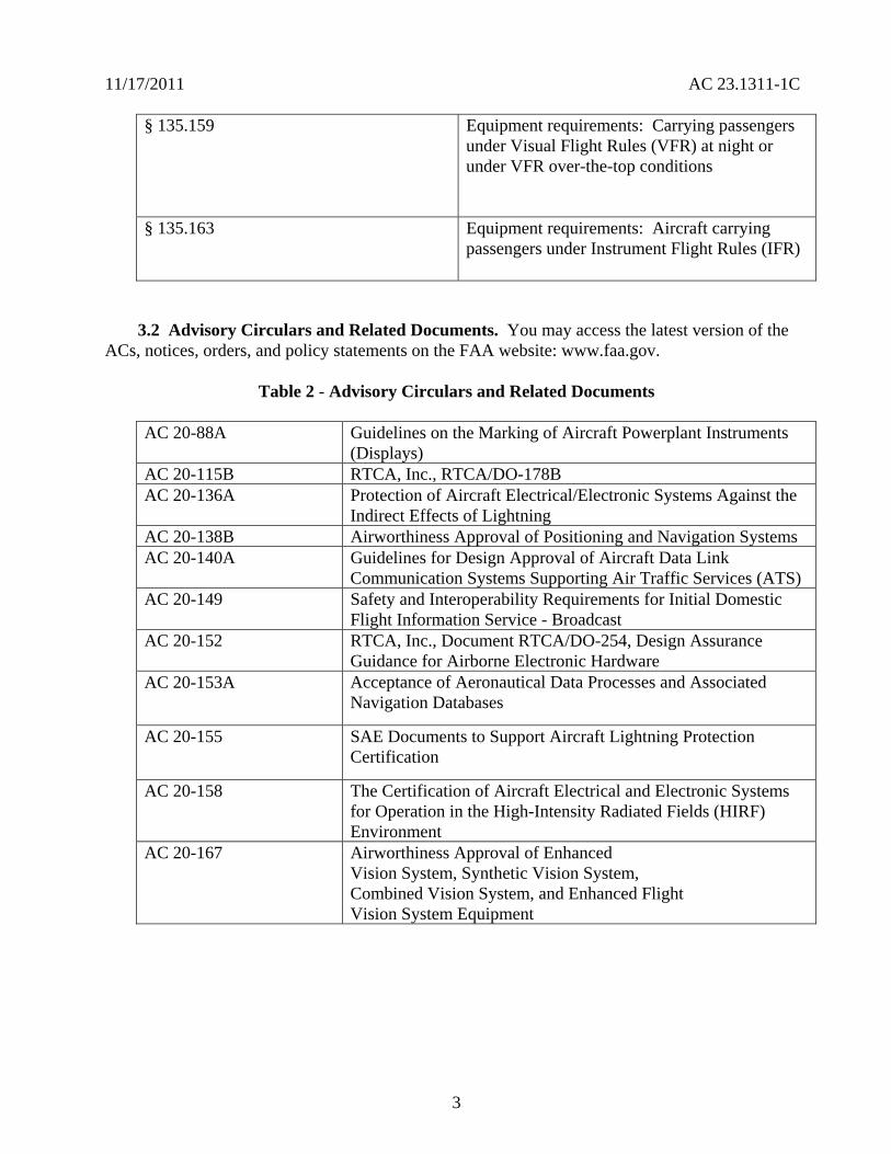
11172011 AC 231311-1C
sect 135159 Equipment requirements Carrying passengers under Visual Flight Rules (VFR) at night or under VFR over-the-top conditions
sect 135163 Equipment requirements Aircraft carrying passengers under Instrument Flight Rules (IFR)
32 Advisory Circulars and Related Documents You may access the latest version of the ACs notices orders and policy statements on the FAA website wwwfaagov
Table 2 - Advisory Circulars and Related Documents
AC 20-88A Guidelines on the Marking of Aircraft Powerplant Instruments (Displays)
AC 20-115B RTCA Inc RTCADO-178B AC 20-136A Protection of Aircraft ElectricalElectronic Systems Against the
Indirect Effects of Lightning AC 20-138B Airworthiness Approval of Positioning and Navigation Systems AC 20-140A Guidelines for Design Approval of Aircraft Data Link
Communication Systems Supporting Air Traffic Services (ATS) AC 20-149 Safety and Interoperability Requirements for Initial Domestic
Flight Information Service - Broadcast AC 20-152 RTCA Inc Document RTCADO-254 Design Assurance
Guidance for Airborne Electronic Hardware AC 20-153A Acceptance of Aeronautical Data Processes and Associated
Navigation Databases
AC 20-155 SAE Documents to Support Aircraft Lightning Protection Certification
AC 20-158 The Certification of Aircraft Electrical and Electronic Systems for Operation in the High-Intensity Radiated Fields (HIRF) Environment
AC 20-167 Airworthiness Approval of Enhanced Vision System Synthetic Vision System Combined Vision System and Enhanced Flight Vision System Equipment
3
11172011 AC 231311-1C
AC 20-170 Integrated Modular Avionics Development Verification Integration and Approval Using RTCADO-297 and Technical Standard Order C153
AC 21-16F RTCA Document DO-160 versions D E and F ldquoEnvironmental Conditions and Test Procedures for Airborne Equipment
AC 23-8C Flight Test Guide for Certification of Part 23 Airplanes AC 23-15A Small Airplane Certification Compliance Program AC 23-17C Systems and Equipment Guide for Certification of Part 23
Airplanes AC 23-18 Installation of Terrain Awareness and Warning System (TAWS)
Approved for Part 23 Airplanes AC 23-22 Guidance for Approved Model List (AML) Supplemental Type
Certificate (STC) Approval of Part 23 Airplane Avionics Installations
AC 23-23 Standardization Guide for Integrated Cockpits in Part 23 Airplanes
AC 231309-1E System Safety Analysis and Assessment for Part 23 Airplanes AC 25-11A Electronic Flight Deck Displays AC 90-106 Enhanced Flight Vision Systems AC 91-75 Attitude Indicator AC 91-78 Use of Class 1 or Class 2 Electronic Flight Bag (EFB) AC 120-64 Operational Use and Modification of Electronic Checklists AC 120-76A Guidelines for the Certification Airworthiness and Operational
Approval of Electronic Flight Bag Computing Devices Order 811049 Software Approval Guidelines dated June 3 2003 Order 8110105 Simple and Complex Electronic Hardware Approval Guidance PS-ACE100-2001-004 Guidance for Reviewing Certification Plans to Address Human
Factors for Certification of Part 23 Small Airplanes
33 Technical Standard Orders (TSO) You may access the TSOs on the FAA website wwwfaagov The following is a list of the FAA TSOs that are referenced in this AC For a complete list of TSOs that are related to this AC see AC 20-110L ldquoIndex of Aviation Technical Standards Ordersrdquo or the web site for the most current list
a TSO-C63c Airborne Weather and Ground Mapping Pulsed Radars
b TSO-C113 Airborne Multipurpose Electronic Displays
c TSO-C153 Integrated Modular Avionics Hardware Elements
d TSO-C157 Aircraft Flight Information Services-Broadcast (FIS-B) Data Link Systems and Equipment
4
11172011 AC 231311-1C
e TSO-C165 Electronic Map Display Equipment for Graphical Depiction of Aircraft Position
34 Industry Documents You may obtain copies of current editions of the following publications
341 RTCA Documents The following RTCA documents are available from RTCA Inc 1828 L Street NW Suite 805 Washington DC 20036-4001 or at their website at wwwrtcaorg
a RTCADO-160G Environmental Conditions and Test Procedures for Airborne Equipment
b RTCADO-178B Software Considerations in Airborne Systems and Equipment Certification
c RTCADO-187 Minimum Operational Performance Standards for Airborne Area Navigation Equipment Using Multi-Sensor Inputs
d RTCADO-200A Standards for Processing Aeronautical Data
e RTCADO-201A Standards for Aeronautical Information
f RTCADO-254 Design Assurance Guidance for Airborne Electronic Hardware
g RTCADO-257A Minimum Operational Performance Standards for the Depiction of Navigation Information on Electronic Maps
h RTCADO-267A Minimum Aviation System Performance Standards (MASPS) for Flight Information Services-Broadcast (FIS-B) Data Link
i RTCADO-297 Integrated Modular Avionics (IMA) Development Guidance and Certification Considerations
j RTCADO-313 Certification Guidance for Installation of Non-Essential Non-Required Aircraft Cabin Systems and Equipment
k RTCADO-315A Minimum Aviation Performance Standards (MASPS) for Enhanced Vision Systems Synthetic Vision Systems Combined Vision Systems and Enhanced Flight Vision Systems
342 Society of Automotive Engineers (SAE) Inc The following Society of Automotive Engineers (SAE) Inc documents are available from SAE 400 Commonwealth Drive Warrendale PA 15096-0001 or from their website at wwwsaeorg
5
11172011 AC 231311-1C
a ARP 268G Location and Actuation of Flight Deck Controls for Transport Aircraft
b ARP 450D Flight Deck Visual Audible and Tactile Signals
c ARP 926B FaultFailure Analysis Procedure
d AIR 1093A Numeral Letter and Symbol Dimensions for Aircraft Instrument Displays
e ARP 1161A Crew Station LightingmdashCommercial Aircraft
f ARP 1782A Photometric and Colorimetric Measurement Procedures for Airborne Direct View CRT [Cathode Ray Tube] Displays
g ARP 1834A FaultFailure Analysis for Digital Systems and Equipment
h ARP 1874 Design Objectives for CRT Displays for Part 25 (Transport) Aircraft
i ARP 4032A Human Engineering Considerations in the Application of Color to Electronic Aircraft Displays
j ARP 4033 Pilot System Integration
k ARP 4067 Design Objectives for CRT Displays for Part 23 Aircraft
l ARP 4101 Flight Deck Layout and Facilities
m ARP 4102 Flight Deck Panels Controls and Displays
n ARP 41027 Electronic Displays
o ARP 4103 Flight Deck Lighting for Commercial Transport Aircraft
p ARP 4105B Abbreviations and Acronyms for Use on the Flight Deck
q ARP 4155A Human Interface Design Methodology for Integrated Display Symbology
r ARP 4256A Design Objectives for Liquid Crystal Displays for Part 25 (Transport) Aircraft
s ARP 4260A Photometric and Colorimetric Measurement Procedures for Airborne Electronic Flat Panel Displays
6
11172011 AC 231311-1C
t ARP 4754 Certification Considerations for Highly Integrated or Complex Aircraft Systems
u ARP 4761 Guidelines and Methods for Conducting the Safety Assessment Process on Civil Airborne Systems and Equipment
v ARP 5287 Optical Measurement Procedures for Airborne Head-Up Display (HUD)
w ARP 5288 Transport Category Airplane Head Up Display (HUD) Systems
x ARP 5289 Electronic Aeronautical Symbols
y ARP 5364 Human Factor Considerations in the Design of Multifunction Display Systems for Civil Aircraft
z ARP 5365 Human Interface Criteria for Cockpit Display of Traffic Information
aa ARP 5430 Human Interface Criteria for Vertical Situation Awareness Displays
bb ARP 5677 Human Engineering Considerations for Cockpit Integration of EnhancedSynthetic Vision Systems
cc AS 5703 Minimum Performance Standard for Enhanced Vision System
dd AS 8034A Minimum Performance Standard for Airborne Multipurpose Electronic Displays
ee AS 8055 Minimum Performance Standard for Airborne Head Up Display (HUD)
343 General Aviation Manufacturers Association (GAMA) The following documents are available from the GAMA 1400 K St NW Suite 801 Washington DC 2005 or from their website at wwwgamaaeroindustry-standards
a General Aviation Manufacturers Association (GAMA) Publication No 10 Recommended Practices and Guidelines for Part 23 CockpitFlight Deck Design
b General Aviation Manufacturers Association (GAMA) Publication No 12 Recommended Practices and Guidelines for an Integrated CockpitFlightdeck in a 14 CFR Part 23 Certificated Airplane
7
11172011 AC 231311-1C
40 Background
a Amendment 23-41 effective November 26 1990 established airworthiness standards in sect 231311 for installing electronic display instrument systems in normal utility acrobatic and commuter category airplanes The first electronic displays developed were direct replacements for the conventional electromechanical components with later designs providing more extensive information integration Before Amendment 23-41 most electronic display instrument systems were approved by special condition for installation in part 23 airplanes Amendment 23-49 effective March 11 1996 further amended part 23 to harmonize 14 CFR with the Joint Aviation Requirements (JAR) Section 231311 Amendment 23-49 removed redundant requirements and clarified which secondary instruments are required including the visibility requirements for those instruments
b Amendment 23-62 made several changes that affect the installation of electronic displays Guidance relative to electronic displays of those sections is also included in this AC The significant changes were
(1) Clarified requirements for trend information and appropriate sensory cues
(2) Incorporated equivalent visual displays of the instrument markings on electronic displays
(3) Allowed an applicant to take credit for reversionary or secondary flight displays on a multi-function flight display (MFD) that provides a secondary means of primary flight information (PFI)
(4) Revised some redundancy requirements to be only applicable for IFR operations
(5) Accommodated new technology for magnetic direction indicator
(6) Updated the terminology for system safety assessment
(7) Revised requirements for instruments using power source(s) and
(8) Revised requirements for storage battery backup times
50 Scope This AC is generally applicable only to an applicant seeking issuance of certain type certificates These include a type certificate (TC) an amended type certificate (ATC) or a supplemental type certificate (STC) for the approval of a new type design or a change in the type design This AC does not completely address Synthetic Vision Systems (SVS) or Enhanced Vision Systems (EVS) and Head-Up Displays (HUD) Contact the Small Airplane Directorate if there are any conflicts with other guidance and this AC The Small Airplane Directorate will coordinate and resolve the conflicts among the points of contact of the other documents
8
11172011 AC 231311-1C
60 AcronymsDefinitions
61 Acronyms
a AC Advisory Circular
b ACO Aircraft Certification Office
c ADC Air Data Computer
d ADI Attitude Direction Indicator
e ADDS Aviation Digital Data Service
f AFM Airplane Flight Manual
g AFMS Airplane Flight Manual Supplement
h AHRS Attitude Heading Reference System
i ARD Aerospace Research Document
j ARP Aerospace Recommended Practice
k AS Aerospace Standard
l ASTC Amended Supplemental Type Certificate
m ATC Amended Type Certificate
n CAR Civil Air Regulations
o CDI Course Deviation Indicator
p CFR Code of Federal Regulations
q CIP Current Icing Potential
r CL Center Line
s CRT Cathode-Ray Tubes
t DN Down
u EADI Electronic Attitude Direction Indicator
9
11172011 AC 231311-1C
v EHSI Electronic Horizontal Situation Indicator
w EICAS Engine Indication and Crew Alert System
x ELOS Equivalent Level of Safety
y EVS Enhanced Vision Systems
z FAA Federal Aviation Administration
aa FD Flight Director
bb FHA Functional Hazard Assessment
cc FLS Field-Loadable Software
dd FMEA Failure Modes and Effects Analysis
ee FOV Field-Of-View
ff GPS Global Positioning System
gg HIRF High Intensity Radiated Fields
hh HUD Head-Up Display
ii HSI Horizontal Situation Indicators
jj ICAO International Civil Aviation Organization
kk IFR Instrument Flight Rules
ll ILS Instrument Landing System
mm IMA Integrated Modular Avionics
nn IMC Instrument Meteorological Conditions
oo JAR Joint Aviation Requirements
pp LCD Liquid Crystal Displays
qq LED Light Emitting Diodes
rr LT Left
10
11172011 AC 231311-1C
ss METAR ICAO Routine Aviation Weather Report
tt MFD Multifunction Flight Display
uu ND Navigation Display
vv NOM Nominal
ww PFD Primary Flight Display
xx PFI Primary Flight Information
yy POH Pilots Operating Handbook
zz RAIM Receiver Autonomous Integrity Monitoring (used with GPS)
aaa RT Right
bbb SAE Society of Automotive Engineers
ccc STC Supplemental Type Certificate
ddd SVS Synthetic Vision Systems
eee TAS Traffic Advisory System
fff TAWS Terrain Awareness Warning System
ggg TFR Temporary Flight Restrictions
hhh TC Type Certificate
iii TCAS Traffic Alert and Collision Avoidance System
jjj TSO Technical Standard Order
kkk UL Underwriterrsquos Laboratories
lll VOR Very High Frequency Omni-Directional Range
mmm VFR Visual Flight Rules
nnn VMC Visual Meteorological Conditions
ooo VFE Maximum flap extended speed
11
11172011 AC 231311-1C
ppp VMO Maximum operating limit speed
qqq VNE Never-exceed speed
rrr VNO Maximum structural cruising speed
sss VS0 The stalling speed or the minimum steady flight speed in the landing configuration
ttt VS1 The stalling speed or the minimum steady flight speed obtained in a specific configuration
uuu WAAS Wide Area Augmentation System
62 Definitions This section contains definitions for terms in this document
a Accuracy A degree of conformance between the estimated or measured value and the true value
b Adverse Operating Condition A set of environmental or operational circumstances applicable to the airplane combined with a failure or other emergency situation that results in a significant increase in normal flight crew workload
c Component Any self-contained part combination of parts subassemblies or units that perform a distinct function necessary to the operation of the system
d Continued Safe Flight and Landing This phrase means the airplane can continue controlled flight and landing possibly using emergency procedures without requiring exceptional pilot skill or strength On landing some airplane damage may occur as a result of a Failure Condition
e Conventional A system is considered ldquoConventionalrdquo if its function the technological means to implement its function and its intended use are all the same as or closely similar to that of previously approved systems that are commonly used The systems that have established an adequate service history and the means of compliance for approval are generally accepted as Conventional
f Critical Usually a function whose loss would prevent the continued safe flight and landing of the airplane
Note The term ldquocritical functionrdquo is associated with a catastrophic failure condition Newer documents may not refer specifically to the term ldquocritical functionrdquo
g Criticality Indication of the hazard level associated with a function hardware software etc considering abnormal behavior (of this function hardware software etc) alone in
12
11172011 AC 231311-1C
combination or in combination with external events Criticality is a failure classification that could be no safety effect minor major hazardous and catastrophic See AC 231309-1E for more guidance
h Design-Eye Box A three-dimensional volume of space surrounding the design eye reference point that designers and evaluators use to determine the acceptability of display and control locations
i Design-Eye Reference Point A single reference point in space selected by the designer where the midpoint between the pilotrsquos eyes is assumed to be located when the pilot is properly seated at the pilotrsquos station
j Development Assurance All those planned and systematic actions used to substantiate to an adequate level of confidence that errors in requirements design and implementation have been identified and corrected such that the system satisfies the applicable certification basis
k Enhanced Vision System An electronic means to provide a display of the forward external scene topography (the natural or manmade features of a place or region especially in a way to show their relative positions and elevation) through the use of imaging sensors such as a forward looking infrared millimeter wave radiometry millimeter wave radar low light level image intensifying
l Equipment Essential to Safe Operation Equipment installed to comply with the applicable certification requirements of 14 CFR part 23 or operational requirements of 14 CFR parts 91 and 135
m Error An omitted or incorrect action by a pilot or maintenance person or a mistake in requirements design or implementation
n Failure An occurrence that affects the operation of a component part or element such that it can no longer function as intended (this includes both loss of function and malfunction
o Failure Condition A condition affecting either the airplane or its occupants or both either direct or consequential caused or contributed to by one or more failures or errors considering flight phase and relevant adverse operational or environmental conditions or external events Failure conditions may be classified according to their severity See AC 231309-1E for more information on definitions of failure conditions
p Field-of-View The angular extent of the display that can be seen by either pilot with the pilot seated at the pilotrsquos station See section 15 for more information on the field-of view
q Fix A generic name for a geographical position A fix may also be referred to as a waypoint intersection reporting point etc
13
11172011 AC 231311-1C
r Flight Plan Refers to any sequence of fixes that are interconnected by the desired path Flight plans may range from the simplest that include only the aircraftrsquos present position the active waypoint and the desired path between them to more complicated plans that include departure and destination airports with multiple intermediate fixes
s Function The lowest defined level of a specific action of a system equipment and pilot performance aboard the airplane that by itself provides a complete recognizable operational capability (for example an airplane heading is a function) One or more systems may contain a specific function or one system may contain multiple functions
t Functional Hazard Assessment A systematic comprehensive examination of airplane and system functions to identify potential minor major hazardous and catastrophic failure conditions that may arise as a result of a malfunction or a failure to function
u Hardware An object that has physical being Generally refers to circuit cards power supplies etc
v Hazard Any condition that compromises the overall safety of the airplane or that significantly reduces the ability of the pilot to cope with adverse operating conditions
w Head-Up Display A transparent optical display system located level with and between the pilot and the forward windscreen The HUD displays a combination of control performance navigation and command information superimposed on the external field of view It includes the display element sensors computers and power supplies indications and controls It is integrated with airborne attitude air data and navigation systems and as a display of command information is considered a component of the flight guidance system
x Independent A component part element or system that is not relying on some other component part element or system for accomplishing its function This design concept ensures that the failure of one item does not cause a failure of another item For redundancy each means of accomplishing the same function need not necessarily be identical
y Indicator A means for displaying information of a parameter More than one indicator could be depicted on one display For example a primary flight display may have indicators for attitude altitude airspeed heading and navigation
z Instrument An electrical or mechanical measurement device In sect 231311 it is defined as Devices physically contained in one unit and devices composed of two or more physically separate units or components connected together (One example is a remote indicating gyroscopic direction indicator that includes a magnetic sensing element a gyroscopic unit an amplifier and an indicator connected together)
aa Map Orientation Refers to the rule that determines the directional relation of the map to the upper part of the display depiction Using a north-up rule the north side of the map would be toward the top of the display and the south side of the map would be at the bottom Using
14
11172011 AC 231311-1C
a desired path-up rule the map would be oriented so the desired path would be vertical on the map and pointing straight up toward the top of the display
bb Map Range The geographic extent of the map region (for example the distance covered by the map representation in either the vertical or horizontal direction)
cc Malfunction Failure of a system subsystem unit or part to operate in the normal or usual manner A condition whereby the operation is outside specified limits
dd Multi-Function Display Any physical display unit other than the PFD used to present various information on which the layout may be reconfigured
ee Navigation The process of planning tracking and controlling the course of an airplane from one place to another
ff Navigation Display The display or suite of instruments by which navigation data is presented to the pilot
gg Navigation Information Information that aids the flightcrew in determining the aircraftrsquos location in a given environment (for example on flight plans VORs GPSs features on the airport surface including taxiway signage etc)
hh Primary As used for instruments it is defined in sect 231311(c) as the ldquodisplay of a parameter that is located in the instrument panel such that the pilot looks at it first when wanting to view that parameterrdquo
ii Primary Flight Display (PFD) A single physical unit that always provides the primary display of all the following altitude airspeed aircraft heading (direction) and attitude located directly in front of the pilot in a fixed layout in accordance with sect 231321 It may provide other information pertinent to guidance and fundamental control of flight of the airplane such as critical engine parameters
jj Primary Flight Information (PFI) A PFI refers to those functions or parameters required by the airworthiness and operational rules such as airspeed altitude attitude and heading (direction) that are on the PFD
kk Primary Function (PF) This definition is applicable in the case when there is more than one function available for same function A function that is installed to comply with the applicable regulations for the required function and one that provides the most pertinent controls or information instantly and directly to the pilot For example the PFD is a single physical unit that always provides the primary display and it complies with the requirements of all the following altitude airspeed aircraft heading (direction) and attitude This PFD is located directly in front of the pilot and used instantly and first by the pilot A standby (additional) PFD that is intended to be used in the event of failure of the PFD is an example of a secondary system
15
11172011 AC 231311-1C
ll Primary Navigation Where the pilot looks first for a display of navigation information such as on an HSI or CDI It displays vertical and lateral deviation and it may have the digital distance indication tofrom the selected fix
mm Redundancy The presence of more than one independent means for accomplishing a given function Each means of accomplishing the function need not necessarily be identical
nn Reversionary Display A secondary means to provide information initially presented on the PFD or MFD by the transfer of information to an alternate display
oo Scale The relative proportion of the linear dimensions of objects on a display to the dimensions of the corresponding objects and distances being represented (for example 1 inch = 100 nautical miles)
pp Secondary Display A means to present information on another display A display that can be used for backup or secondary purposes such as in the event of a failure of another display
qq Standby Instrument A dedicated instrument that is always available that presents primary flight information
rr Supplemental Function A function that is not required or intended to meet all the airworthiness and operational requirements It is usually installed for additional situational awareness
ss System A combination of components parts and elements that is interconnected to perform one or more functions
tt Synthetic Vision System A computer-generated image of the external scene topography from the perspective of the flight deck that is derived from aircraft attitude high precision navigation solution and database of terrain obstacles and relevant cultural features
Note ldquoTopographyrdquo defined as maps or charts of natural and man-made features of a place or region especially in a way to show their relative positions and elevations as applicable whenever deemed appropriate and practicable
uu Track The projection on the earthrsquos surface of the path of an aircraft the direction of which is usually expressed in degrees from north (true magnetic or grid) A track is the actual flight path of an aircraft over the surface of the earth
Note For more definitions related to safety assessments refer to AC 231309-1E for the appropriate definitions
vv Warning A clear and unambiguous indication to the pilot of a failure that requires immediate corrective action An inherent characteristic of the airplane or a device that will give
16
11172011 AC 231311-1C
clearly distinguishable indications of malfunction or misleading information may provide this warning
70 Display Description The following paragraphs give a brief description of an electronic display They do not cover all the capabilities and details of these displays or the information presented on them
71 General Electronic displays have replaced many of the traditional electromechanical and analog instruments These displays also augment andor combine the functionality of conventional systems such as radios and navigational systems The major display technologies now used are multicolor CRTs LCDs electro luminescence plasma and LEDs The initial electronic displays mimicked the traditional mechanical and electromechanical flight and powerplant instruments The colors symbols and formats on these initial electronic displays are similar to those on traditional conventional instruments Modern electronic displays provide integration and formats that often differ from traditional instruments
72 Display Configuration Electronic displays may be installed in several configurations A basic electronic display may provide only one flight or powerplant parameter while more sophisticated systems integrate many parameters on one electronic display One of the major design goals for these systems is eliminating separate conventional gauges instruments and annunciators Recent installations show a trend toward a higher degree of integration For example an integrated primary flight display provides several parameters such as attitude heading (direction) airspeed and altitude Integration of various systems should include analysis to ensure that complexity and workload are compatible with general aviation pilots capabilities For more guidance on IMA that implement TSO authorized hardware elements see TSO-C153 and AC 20shy170
80 Flight Displays
81 Instrument Requirements
a Sections 231303 231305 231311 and 231321 with the applicable operating rules (14 CFR parts 91 121 and 135) incorporate flight and powerplant instrument requirements for part 23 airplanes The navigation equipment requirements are given in operational rules specified in sectsect 91205 121303 121305 121307 135143 135149 135159 135161 and 135165 Display requirements for navigation information are dependent on the navigation system installed in the aircraft Instruments and equipment required for flights under parts 91 121 and 135 may be affected by the electronic display installation These instruments and equipment include gyroscopic bank and pitch gyroscopic direction gyroscopic rate-of-turn slip-skid instruments and other required communication and navigational equipment
b There have been applications to install equipment such as flight and navigation displays as non-required These applications request approval for these installations as situation awareness (SA) only It is not acceptable to label a display as ldquoSA-Onlyrdquo and assume that its failure condition is acceptable Installing displays that provide PFI that are more compelling than
17
11172011 AC 231311-1C
the required primary PFI displays but they do not meet the appropriate operational and airworthiness requirements and labeling them as ldquoSupplementalrdquo or ldquoSA-Only is not acceptable Section 136 provides more guidance
c The basis for certification has been that the equipment should perform its intended function and not present a hazard Instruments that aid situation awareness should be certified under the part 23 requirements including sect 231301 and sect 231309 These displays could provide hazardous misleading information PFI is essential for safe operation An instrument that provides PFI should meet the minimum standards of applicable TSOs or an equivalent standard It also should meet the guidance in AC 231309-1E AC 23-17C and the guidance in this AC
82 Primary Flight Information (PFI) PFI refers to those functions or parameters that are required by the airworthiness and operational rules such as airspeed altitude attitude and heading (direction) It may provide other information pertinent to guidance and fundamental control of flight such as critical engine parameters Attitude airspeed altitude and heading (direction) are the PFI required in sect 231311(a)(3) and (5) and they must be arranged according to sect 231321 in the ldquobasic Trdquo arrangement Direction should be heading with track presented if available as a selectable option The horizon reference line on the PFD should be at least 325 inches wide in straight and level flight for integrated displays This recommendation is not intended to prevent replacement of mechanical instruments with an electronic display of a similar horizon reference line When the true horizon is no longer on the display the artificial horizon line should provide a distinctive demarcation between sky and ground (or the background) Display of PFI on reversionary or standby displays should be arranged in the basic T-configuration but it is not required The standby instrument or displays of PFI location should meet the FOV guidance criteria in section 15
821 Acceptable Methods for Compliance with sect 231311(b) There are three acceptable methods for meeting the attitude requirements which is considered information essential for continued safe flight and landing Compliance can be accomplished by using dedicated standby instruments dual PFDs or reversionary displays that present primary flight information Electronic display systems without dedicated standby instruments should have at least two independent displays able to provide PFI to the pilot These displays should be powered such that any single failure of the power generation and distribution systems cannot remove the display of PFI from both displays Section 231311(b) in Amendment 23-62 states ldquoThe electronic display indicators including their systems and installations and considering other airplane systems must be designed so that one display of information essential for continued safe flight and landing will be available within one second to the crew by a single pilot action or by automatic means for continued safe operation after any single failure or probable combination of failuresrdquo
83 Standby Instruments The purpose of standby instruments or another independent PFD is to ensure that PFI is available to the pilot during all phases of flight and during system failures Individual indicators should be a minimum of 2 inches in diameter or if combined a minimum diameter of 3 inches (or equivalent) displayed
831 Dual PFDs Electronic display systems with dual PFDs should incorporate dual independently powered sensors that provide primary flight parameters such as AHRS with
18
11172011 AC 231311-1C
comparators and dual ADC Dual PFDs with dual AHRSs and ADCs which include checking and are powered by multiple power sources and distribution systems are significantly more reliable than presently certified mechanical systems
832 PFD and Autopilot with an AHRS For normal operation when using a single AHRS to drive the PFD and the autopilot simultaneously the installation must mitigate hazardous or catastrophic system level failures An example configuration supporting proper mitigation would include all of the following
a A dedicated standby attitude instrument within the primary maximum FOV or independent reversionary attitude display
b An AHRS with appropriate comparator or monitor of equivalent performance
c Appropriate system warningcaution annunciation associated with an AHRS malfunction
d If an aircraft is equipped with multiple AHRS it may be acceptable when one AHRS fails to drive both the autopilot and the PFD from a single AHRS as long as an AHRS independent attitude display (required for some aircraft classes) is located in the primary maximum field of view The failure must be annunciated to the pilot and the pilot must be able to select the non-failed AHRS For aircraft that do not have an independent attitude indicator when one AHRS fails the autopilot should be manually or automatically disengaged The autopilot may be reengaged if appropriate mitigation is available (for example see a through c above) The AFM or supplemental AFM should contain the appropriate procedures applicable to the equipment installed See section 110 for additional guidance AC 231309-1E guidance should be considered for these configurations
e Displays not meeting FOV guidance criteria may require additional human factors airworthiness evaluation by the certification authority See section 15 for additional guidance
84 Reversionary Flight Displays Instead of Standby Instruments or Dual PFDs
841 General Requirements
a Reversionary flight displays provide a secondary means to provide PFI through alternate display formats on another PFD or MFD by the transfer of information to an alternate display or by some other means The function of an MFD system is to provide the pilot access to various data or combinations of data used to fly the aircraft to navigate to communicate andor to manage aircraft systems The MFD would also present PFI as needed to ensure continuity of operations 14 CFR part 23 sect 231311(b) Amendment 23-62 states the electronic display indicators including their systems and installations and considering other airplane systems must be designed so that one display of information essential for continued safe flight and landing will be available within one second to the crew by a single pilot action or by automatic means for continued
19
11172011 AC 231311-1C
safe operation after any single failure or probable combination of failures To meet the requirements of sect 231311(b) a full-time standby display another independent PFD or an independent reversionary attitude display must be installed Reversionary modes could be automatically and manually selected or only manually selected
b Reversionary configurations are significantly more reliable than presently certified mechanical systems and the skills required while flying in reversionary mode are identical with those used when flying in primary mode Traditional external standby flight instruments (either electronic or mechanical) offer potential safety problems associated with delay in pilot reaction The pilot may delay a decision to transition to standby instruments and to transition to partial panel techniques as opposed to the simple action the pilot would take to switch displays A nearly identical format on the reversionary display of all PFI that is also shown on the PFD provides a significant safety enhancement over standby instruments This is especially true when the size location arrangement and information provided by the standby instruments are significantly different from those on the PFD
c Reversionary display modes should provide consistent display formats to the PFD The reversionary flight information should be presented by an independent source and display to prevent complete loss of PFI due to a single failure The reversionary configuration should have two independent displays that incorporate dual-independently powered AHRS and dual ADC subsystems that provide PFIs The reversionary system response time should provide flight critical information on the MFD in less than one second after a single pilot action or an automatic operation
d A reversionary configuration should have a single pilot action that would force both the PFD and MFD displays into reversionary mode operation However the PFI should be presented in similar format and sufficient size in the reversionary mode as it is in normal mode to allow the pilot to enhance the control of the airplane This reversionary configuration should provide backup information essential to continued safe flight and landing with an intuitive control that allows instant simultaneous access to reversionary mode on both the PFD and MFD displays The single pilot action should be easily recognized readily accessible and have the control within the pilotrsquos primary optimum field of view An acceptable method for the single pilot action is the red color andor lighted red ldquohalordquo ring that announces its position on the panel at all times
842 Reversionary Methods
a One method is to have an automatic reversionary display with a single pilot action that would force both the PFD and MFD displays into reversionary mode operation If PFI on another display is not provided provide automatic switching to ensure PFI is available to the pilot Automatic reversion must provide a complete display of PFI on the remaining display within one second if a fault is detected
b Most possible faults should be covered by this automatic reversionary capability Only a total loss of the display may not be reliably detected automatically but such a failure condition would be obvious to the pilot Faults that result in automatic switching should be extensive enough to ensure PFI availability meets the requirements of sect 231309 If such a
20
11172011 AC 231311-1C
malfunction occurs a single pilot action should provide a full display of the essential information on the remaining display within one second All modes sources frequencies flight plan data etc should be similar as they were on the PFD before the failure
c Another reversionary method would include a means to access the reversionary mode manually through a single pilot action Manual activation of the reversionary mode on the MFD through single action by the pilot is acceptable when procedures to activate the PFI on the MFD are accomplished before entering critical phases of flight The PFI would be presented continuously on the reversionary display during critical phases of flight (for example takeoff landing and missed or final approach)
85 Display of Attitude For flights under IFR conditions in part 91 and part 135 operations and under VFR at night for part 135 operations attitude information is required The loss of all attitude information or the presentation of misleading attitude information could result in a catastrophic failure condition where the pilot could not continue safe flight and landing of the airplane It is recommended that the display of attitude follows the guidelines (below) that are also in GAMA Publication 12
a The pitch ladder should be caged to the center of the display
b At pitch attitudes when the true horizon line would not normally be displayed some sky or ground should be indicated on the PFD pitch display (minimum 38 inches and maximum of 115 percent of the display) and the horizon line should indicate off-scale
c With the airplane symbol on the horizon line the range of visible pitch attitude should be at least + 25 to -15 degrees but not to exceed a total pitch range of 50 degrees
d Bank angle presentations should use a roll pointer however roll pointers and sky-pointers should not be mixed in the same flight deckcockpit
e Roll scale indices should be placed at 10 20 30 60 and 90 degrees An index may also be placed at 45 degrees
86 Display of Direction (Heading or Track)
861 General
a The loss of direction (heading or track) information could result in reduced capability of the pilot to cope with adverse operating conditions The orientation of any secondary navigation display is optional (for example Track-up North-up Heading-Up) For flights under IFR conditions a stabilized heading indicator must provide the primary display of the direction parameter A magnetic direction indicator or track may provide the reversionary display of direction
21
11172011 AC 231311-1C
b The heading display should provide a clear and unmistakable display of aircraft symbol and heading HSI should provide a clear and unmistakable display of aircraft position heading and track (an option if available) relative to the desired coursetrack Section 17 contains more guidance on symbology Direction should be heading when track is presented if available as a selectable option with the data source clearly indicated On the primary display the heading scale should have a mode that presents at least 120 degrees of arc Other display formats may be acceptable and have been previously approved but they need to be evaluated from a human factor perspective
862 Hazardous Misleading Heading Information
a The FHA for the failure effects of hazardous misleading heading information from an AHRS is clarified in AC 23-17C This policy is specifically about the application of AC 231309-1E for an airplane with the certification basis of Amendments 23-41 or later This clarification is limited to installations approved for operation in IMC under IFR For operations limited to VFR a misleading heading indication is not considered hazardous
b Develop an FHA and the related safety assessments for the specific airplane type and configuration since there can be many combinations of failures various mitigating factors and other functions available to a pilot These many factors affect the criticality of the heading indication therefore use a safety assessment process from AC 231309-1E to classify the failure conditions for misleading heading information
c A hazardously misleading heading is usually when the accuracy error is greater than 10 degrees on the primary heading instrument and it is an undetected error The safety assessment process should consider appropriate mitigating factors For Class I part 23 airplanes the failure condition for misleading hazardous heading is usually considered major
87 Display of Altitude Airspeed and Magnetic Compass Information The original requirements of CAR 3 were adopted and later recodified into part 23 sect 231303 paragraphs (a) (b) and (c) At that time pneumatically driven displays provided airspeed and altitude functions Since then the FAA envisioned airspeed altitude and magnetic compass information would remain available to the pilot with the loss of the airplanes primary electrical power For electronic displays sect 231311(a)(3) requires the primary display of attitude airspeed and altitude to be uninhibited in any normal mode of operation Section 231311(a)(5) as amended by Amendment 23-62 requires an independent magnetic direction indicator and either an independent secondary mechanical altimeter airspeed indicator and attitude instrument or electronic display parameters for the altitude airspeed and attitude that are independent from the airplanes primary electrical power system Primary altitude or airspeed displays that require electrical power are acceptable if means are provided for their continued operation upon loss of the airplanersquos primary electrical power or if pneumatically driven instruments are available for the pilotrsquos use A standby or reversionary integrated display of altitude attitude and airspeed instead of individual electronic display indicators for airspeed altitude and attitude is acceptable under one condition The condition is that the standby or reversionary integrated display and the primary display are powered such that at least one integrated display with attitude altitude and airspeed is available after failure of any power source or distribution path
22
11172011 AC 231311-1C
88 Accuracy of the Magnetic Heading System
881 General
a The operating rules such as part 91 and part 135 specify the minimum required equipment that must be installed in part 23 airplanes based on the operation such as VFR or IFR Under VFR operation part 91 sect 91205 requires a magnetic direction indicator (that is normally intended to be a compass) for heading information Under IFR operation part 91 sect 91205 requires a gyroscopically stabilized heading system Section 231303(c) Amendment 23-62 amended the requirement from ldquoA direction indicator (non-stabilized magnetic compass)rdquo to ldquoA magnetic direction indicatorrdquo As new technology becomes more affordable for part 23 airplanes many electronic flight instrument systems will use magnetically stabilized direction indicators (or electric compass systems) to measure and indicate the airplane heading to provide better performance
b The general airworthiness requirements in part 23 sect 231301 and sect 231525 determine the flight instrument and equipment accuracy requirements for part 23 airplanes Part 23 does not prescribe specific accuracy requirements for magnetic gyroscopically stabilized heading systems Specific accuracy requirements for avionics may be found in the related TSO and as acceptable means of compliance to sect 231301 in ACs notices or policy statementsletters
882 Magnetic Non-Stabilized Direction Indicator A magnetic non-stabilized direction indicator that is required by sect 231303 should have an accuracy of 10 degrees or have a correction card placard (reference sect 231327) or a back-up gyroscopic direction indicator provided the indicator is accurate better than 10 degrees If the sole purpose of the gyroscopic direction indicator is for backing up the magnetic non-stabilized direction indicator then the accuracy of presentation of headings can also be to 10 degrees However if a gyroscopic direction indicator is installed to meet the IFR operating rules then the installation requirements are defined by sect 231301
883 Magnetic Gyroscopically Stabilized Direction Indicator As installed final accuracy for a magnetic gyroscopically stabilized direction indicator of plusmn4 degrees on the ground or plusmn6 degrees in normal level flight on any heading would meet the requirements of part 23 sect 231301 This accuracy applies after compensation It should include cumulative errors in all combinations due to several factors These consist of the equipment itself the current flow in any item of electrical equipment and its associated wiring the movement of any part (for example controls or undercarriage) and the proximity of any item of equipment containing magnetic material to the magnetic sensor
884 Comparator Monitor
a For systems installations that include two magnetic gyroscopically stabilized heading systems and a comparator that monitors the differences between the headings of the two
23
11172011 AC 231311-1C
systems the comparator trip point set as follows would meet the requirements of part 23 sect 231301
(1) 6 degrees in stabilized level flight
(2) 6 degrees plus one half of the bank angle or
(3) 12 degrees with a bank angle greater than 6 degrees
(4) The alert function can be disabled at a bank angle greater than 20 degrees
(5) An alert is provided if the condition exceeds 60 seconds but it allows two minutes for a turn error as stated in the TSO
b The 6-degree trip point during level flight allows a heading error of as much as 12 degrees on one of the systems This would comprise one system at the 6 degrees in-flight tolerance limit while the other system presumably with some malfunction could have an error of 12 degrees in the same direction before the comparator monitor alert is tripped
89 Rate-of-Turn Instrument
a Under sectsect 91205 and 135159 a rate-of-turn instrument is not required if a third attitude instrument usable through flight attitudes of 360 degrees of pitch-and-roll is installed following the instrument requirements prescribed in sect 121305(j) If required place the rate-of-turn indicator near the heading indicator
b A second approved attitude indicator may substitute for the rate-of-turn instrument AC 91-75 Attitude Indicator provides one method This AC is applicable to part 23 certificated airplanes (or airplanes certificated under earlier equivalent regulations) that weigh less than 12500 pounds and are operated under part 91 The second approved attitude indicator must be powered by an independent power source from the primary attitude indicator This can be accomplished by using independent standby instruments another independent PFD or independent reversionary attitude display Most of the installations with electronic displays that meet the requirements of sect 231311 and this AC should comply with AC 91-75
810 Slip-Skid Instrument The slip-skid information is required by sectsect 91205(d)(4) and 135159(b) as applicable The FAA suggests locating the slip-skid display directly below or near the rate-of-turn instrument if installed or under or within the primary attitude display
811 Vertical Speed Indicator If provided present the vertical speed indicator to the right or directly below the altitude indicator with a scale appropriate to the performance of the aircraft
24
11172011 AC 231311-1C
90 Powerplant Displays
91 General
a This section defines a means of presenting powerplant performance and condition information about the airplanes operation It also provides guidelines about when these functions should be displayed to the pilot In general there have been two methods used to accomplish this These methods include (1) display raw engine parameters to the pilot for interpretation or (2) collect powerplant data and have an automatic monitoring system interpret and report the powerplant condition to the pilot Use the following evaluation criteria when considering the installation of electronic powerplant displays
b There is a need to evaluate each airframe engine and airframeengine interface with the operational characteristics of these systems to determine the primary powerplant parameter requirements For this evaluation and as used in this section a primary powerplant parameter is needed to start the engine and to set and monitor engine power within powerplant limitations Appropriate procedures for operation of an integrated electronic powerplant display system should be in the AFM
c For multiengine airplanes a failure or malfunction affecting the display or accuracy of any propulsion system parameter for one engine should not cause the loss of display or accuracy of any parameter for the remaining engine(s) If multiple propulsion parameters are integrated on one display and the display fails it is acceptable to provide a secondary propulsion parameter display
92 Loss of Critical Powerplant Information
a No single failure malfunction or probable combination of failures should result in either the loss of critical powerplant information or an erroneous display of powerplant parameters that would jeopardize continued safe flight and landing of the airplane Usually for engines that do not generally rely on the pilot to prevent exceeding their limits in normal operations or engines such as with electronic engine controls featuring engine limit protection the loss of powerplant displays should not cause immediate jeopardy to continued safe flight and landing
b A secondary display providing powerplant parameters for cases of loss of a primary powerplant display may be used provided it is located so the pilot can adequately view the powerplant parameters
c Throttle or power lever position may be used in place of lost powerplant display parameters This would apply if throttle position or power lever position provides a positive indication of the powerplant power level required to maintain safe flight to a landing and if the throttle has a means to preclude exceeding powerplant operating limits
25
11172011 AC 231311-1C
93 Powerplant Information
a Presentation of primary powerplant parameters continuously when they are required unless the monitor provides an adequate alert of the function Also provide a manual select option for the pilot to present the information A parameter defined as primary for engine start but not for other normal engine operation may only have to be presented continuously during engine start
b Before and upon reaching or exceeding any operating limit the display should present the required powerplant parameters without pilot action Timely alerts for each phase of flight should be provided when any operating limit is reached or exceeded for the required powerplant parameter The alerts should be in a form that enables the pilot to identify and carry out the necessary and appropriate actions The required powerplant information should be presented continuously during a critical takeoff and landing phase of flight to minimize pilot distraction until an established rate of climb or minimum altitude is achieved
c Displays that provide multiple powerplant parameters should be designed such that any parameter display or alert will not suppress another display or alert that also requires immediate crew awareness necessary to conduct safe operation of the aircraft and engine(s) Alerts that could cause subsequent activation of other displays or alerts should be presented in a manner and form to ensure appropriate identification and prioritization of all significant hazards and required crew actions See section 18 for more guidance on annunciation
94 Digital Reading Alphanumeric Displays
a Digital reading alphanumeric displays are most valuable when integrated with an analog display by adding a precise quantitative indication to complement an analog displays qualitative indication Proper integration should include a means for pilots to clearly associate the analog and digital indications (eg via close proximity) Digital reading alphanumeric powerplant displays formats should not be used in place of analog formats to indicate values of engine parameters where trend or rate-of-change information is important for safety or when the pilot needs to monitor parameters with a quick glance Digital reading alphanumeric displays limit the pilots ability to assess trend information and result in reduced crew awareness Digital reading alphanumeric displays are also limited in their ability to allow the pilot to easily compare parameters from multiple engines or to check the general proximity of differing parameters against their individual limits While these shortcomings can be compensated for with more design provisions use digital reading alphanumeric displays with caution and carefully evaluate each airframe engine and airframeengine integration
b Section 231311(a)(6) Amendment 23-62 requires sensory cues that provide a quick glance sense of rate and where appropriate trend information to the parameter being displayed to the pilot Section 231311(a)(7) requires incorporated equivalent visual displays of the instrument markings required by sectsect 231541 through 231553 or visual displays that alert the pilot to abnormal operational values or approaches to established limitation values for each parameter required to be displayed by this part
26
11172011 AC 231311-1C
c An ELOS will be necessary for digital -reading alphanumeric only displays that are not associated with any scale tape or pointer It may be difficult for pilots to determine the margin relative to targets or limits or compare between parameters To comply with sect 231311(a)(7) a scale dial or tape will be needed to accomplish the intended pilot task In order to demonstrate an equivalency a human factor andor pilot evaluations will be needed that will consider the following factors These are subject to evaluation on a case-by-case basis
(1) The visibility and relative location of the indicated parameter should be reviewed including appropriate conditions of lighting and instrument panel vibration
(2) The ability to assess necessary trend or rate-of-change information quickly including when this information may be needed during in-flight engine restarts
(3) The ability to assess how close the indicated parameter is relative to a limit
(4) The value to the crew of quickly and accurately comparing engine-to-engine data for multiengine aircraft
(5) Engine design features or characteristics that would forewarn the crew before the parameter reaches the operating limit (for example redline)
(6) The use of color in accordance with sect 231549 to indicate the state of operation a green indication would indicate normal operation a yellow indication would indicate operation in a takeoff or precautionary range and a red indication would indicate operation outside of the safe operating limits
95 Marking of Powerplant Parameters Mark powerplant parameters on electronic displays in accordance with sect 231549 AC 20-88A provides alternate methods of marking electronic powerplant displays Alternate methods of marking the displays may be performed However the FAA may evaluate these markings on a case-by-case basis depending on each airframe engine integration and appropriate human factors considerations Alternate markings that do not comply with the requirements of sect 231549 require an ELOS
100 Electronic Displays for Navigation Information
101 Guidance Information Navigation information used by the pilot for steering commands and to monitor deviation from a navigation path should be in the pilots primary FOV Warnings and cautions should also be in the primary FOV For more guidance on FOV see section 15 and Table 3 of this AC
102 Display Integration
a Navigation guidance information may be integrated with the PFDs Common examples include HSIs that combine inputs from a directional gyro with a course deviation
27
11172011 AC 231311-1C
indicator or an FD integrated with the ADI Additionally information from more than one navigation source may be displayed separately or simultaneously
b If information from more than one navigation source can be presented the selected source should be continuously indicated to the pilot If multiple sources can be presented simultaneously the display should indicate unambiguously what information is provided by each source and which one has been selected for guidance Some airplanes are equipped with an autopilot andor FD coupled to the lateral and vertical guidance system On these airplanes the input to the autopilot andor FD should coincide with the navigation source selected on the PFD or primary navigational display
103 Reversionary Navigation Displays Reversionary requirements for navigation display information depend on the rules under which the aircraft is operated and the hazards associated with the loss of or misleading information from the display The integration of non-navigation information (for example traffic weather or flight parameters) may affect the hazards associated with the loss of or misleading information from the display In these cases the applicant should perform a system safety assessment following AC 231309-1E For more guidance on safety assessments see AC 231309-1E and section 26 of this AC for more guidance
104 Navigation Database For area navigation equipment the navigation database is an essential component of the equipment Guidelines for the navigation database can be found in RTCADO-200A See AC 20-138 and AC 20-153 for more guidance and information
110 Aircraft Flight Manual (AFM) For equipment required for IFR approval the AFM or supplemental AFM should contain the limitations and the operating and emergency procedures applicable to the equipment installed Installations limited to VFR use only may require an AFM or supplemental AFM depending on the complexity of the installation and the need to identify necessary limitation and operating procedures AC 23-8C contains more policy and guidance on AFMs
120 Electronic Checklist and Charts Policy and guidance on electronic checklist and charts on electronic displays are contained in AC 23-8C AC 91-78 AC 120-64 and AC 120-76A
130 General Human Factors Considerations for Design of Electronic Displays
131 General Electronic displays can provide many innovative display flexibilities and features that were not possible with traditional displays Technology improvements in display design and integration can enhance pilot performance and improve situation awareness when innovations are designed using sound processes and appropriate design criteria that account for human performance The applicant should ensure that human performance considerations are adequately addressed throughout the design process Early FAA involvement and an effective working relationship between the FAA and the applicant will aid in the timely identification and resolution of human factors related issues The FAA encourages the applicant to develop human performance considerations including evaluation plans and present them to the FAA early in the certification process
28
11172011 AC 231311-1C
132 Human Factors for Certification of the Part 23 Small Airplanes Policy statement number PS-ACE100-2001-004 provides guidance for human factor certification plan or the human factor components of a general certification plan when one is submitted as part of a TC STC or ATC project The application of this guidance will ensure that human factors issues are adequately considered and addressed throughout the certification program
133 CockpitFlight Deck Design GAMA Publication No 10 The purpose of GAMA Publication No 10 is to provide manufacturers of small aircraft and systems with human factors recommendations for the design of cockpitsflight decks and their associated equipment This publication was developed as a cooperative effort between the FAA and industry
134 SAEs and RTCAs Recommended Practices and Standards Evaluation of the electronic display system should consider airworthiness regulations recommended practices and standards from industry documents as listed in section 3 of this AC
135 Human Factors Compliance Considerations
a The applicant should identify all human factors related regulations that apply to the installation and operation of the display system or component being certified The applicant should document how the system or component complies with each of these regulations A partial list of relevant regulations is contained in policy statement PS-ACE100-2001-004 The FAA and the applicant should develop and agree on a plan to describe how the applicant intends to show compliance with the relevant regulations It should contain enough detail to assure that human factors compliance considerations have been adequately addressed The test plan should also allow enough time to accomplish all necessary testing agreed to by the applicant and the FAA
b The applicant should assure the following
(1) The intended use of the system does not require any exceptional skill or generate any unreasonable workload for the pilot
(2) The use of the display does not require unreasonable training requirements to adequately show that the pilot can understand and properly operate the system in all operational environments
(3) The design characteristics of the display system should support error avoidance and management (detection recovery etc)
(4) The display system is integrated and is consistent or compatible with other cockpit controls and displays and it creates no more burden on the pilot regarding the new display system or operation of other systems
(5) If a failure occurs it does not prevent the pilot from safely operating the airplane
29
11172011 AC 231311-1C
c Manufacturers should provide design rationale for their decisions regarding new or unique features in a display Evaluation should be conducted to collect data in support of the new or unique features to assure they have no unsafe or misleading design characteristics The design teams including pilots should concur with the conclusion found with the data collected
d The applicant should conduct display evaluations with several human factors and pilots representatives whom are intended users of the system For systems that contain new or unique features a greater number of evaluators should be considered Allow a reasonable amount of training time to learn all required features of the display system The evaluators should be familiar with the guidance contained in this AC before the evaluation Evaluators should also be familiar with human factors display regulations guidance standards and recommendations contained under sections 3
136 Intended Function One of the regulations applicable to displays is sect 231301 As part of showing compliance with sect 231301 the display system must be of a type and design appropriate to its intended function when used by representative general aviation pilots An AFM AFMS or Pilotrsquos Guide may be used to describe the intended function
1361 Demonstrate Compliance To show compliance with sect 231301 an applicant must show that the design is appropriate for its intended function The applicantrsquos statement of intended function should be specific and detailed enough for the certification authority to evaluate the intended function(s) and to evaluate whether the associated pilot tasks (if any) can be adequately achieved This is important for systems with a pilot interface component as the certification authority should evaluate the intended function from the pilotrsquos perspective as well as from a systems perspective There are several safety concerns including the concern that the pilot could rely on a display that does not meet minimum safety standards For example applicants should elaborate on a statement that a new display system is intended to ldquoenhance situation awarenessrdquo since a wide variety of different displays from terrain awareness vertical profile and even the primary flight displays enhance situation awareness in different ways Applicants should provide a greater level of detail to identify the specific aspect(s) of situation awareness that are to be enhanced and show how the design supports those aspects Similarly the terms ldquosupplementalrdquo ldquonon-essentialrdquo ldquosecondaryrdquo etc in isolation would not be acceptable as statements of intended function While the statement of intended function must be submitted by the applicant the certification authority will make the final determination of compliance to the rule specifically on the acceptability of the proposed intended function
1362 Intended Function(s) and Associated Task(s)
a List the intended function(s) and associated task(s) for the major pilot interfaces focusing on new or unique features that affect the pilot interface A system may have multiple intended functions provided each function is documented and all information depicted or indicated to the pilot supports one or more of the documented intended functions See PS-ACE100shy2001-004 paragraph 2a Intended Function for more guidance
b You may use the following information to evaluate whether the statement of intended function and associated task is sufficiently specific and detailed
30
11172011 AC 231311-1C
(1) Does each feature and function include a statement of the intended function Is there a description of the task associated with this featurefunction
(2) What assessments decisions or actions are required from the pilot for these intended functions
(3) What other information is required for use with these intended functions (for example other cockpit systems) assumed to be used in combination with the system
(4) Is the operational environment in which these intended functions are to be used adequately described (for example VFR IFR phase of flight etc)
1363 Method(s) of Compliance The method(s) of compliance should be adequate to enable the certification authority to determine the following
a Is the system providing sufficient and appropriate information to support the intended functions and to achieve the associated tasks
b Is the level of detail accuracy integrity reliability timeliness and update rate of the information matched appropriately to the task associated with the intended function
c Does the use of the system impair the pilotrsquos ability to use other systems or do other tasks
d Does the system or the use of the system impair the safe operation or the intended function of other systems or equipment
1364 Labeling All displays and controls whose function is not obvious should be labeled and identified by function or operating limitations or any combination The assumptions andor limitations should be adequately documented in the AFM AFM Supplement andor Pilot Operating Manual (as negotiated with the ACO) This applies to the manufacturer of the equipment and not to the installer The installer is required to verify the intended function and to make any placards or flight manual limitations according to subpart G of part 23 that the installed equipment makes necessary
140 Location and Configuration of Displays
141 Display Usability Displays should be located such that the pilot(s) can monitor them with minimal head and eye movement between displays Flight information should be legible accurate easily interpreted sufficiently free of visual cutoff (viewing angle) parallax and distortion for the pilot to correctly interpret it
142 Basic T Configuration The basic T-configuration should be used for airplanes certificated under sect 231321 Amendment 23-14 or a later amendment The basic T-configuration
31
11172011 AC 231311-1C
is defined as an arrangement where the airspeed and altitude data are centered respectively directly to the left and right of the attitude data with the direction data located directly below the attitude data
143 Deviations from the Basic T Configuration
a Deviations from the basic T-configuration have been approved for individual instrument arrangements if the droop angle (angle below the sect 231321(d) position) is 15 degrees or less or if the elevated angle is 10 degrees or less These angles are measured from a horizontal reference line that passes through the center of the attitude reference data with lines passing through the center of the airspeed and altitude data
b Unique displays or arrangements for attitude altitude airspeed and navigation data integration of combinations of these functions or rearrangement of them from the basic T-configuration may be approved when an equivalent level of safety and a human factors evaluation are provided This evaluation should consider the different types of airplane operations as defined by sect 231559(b) Coordination with the Small Airplane Directorate is required Deviations beyond these limits may be approved for individual flight instruments through a human factors evaluation and display installation evaluation considering the following items
(1) The display arrangement and its alignment to the normal line of the pilots vision
(2) The cockpit view
(3) The integration of other functions within the displays
(4) The data presented format symbology etc within the display and
(5) The ease of manipulating controls associated with the displays
150 Pilot Field-of-View Considerations
151 General
a This guidance is specifically intended to address the visibility and placement of information used by the pilot Past practice has typically involved FAA flight test pilots working with applicants to conduct qualitative assessments of the proposed equipment locations This is intended primarily for new aircraft development programs but it could also be used for extensive modifications to existing cockpits Part 23 rules do not require the applicant to establish a cockpit design eye reference point from which to measure viewing distances and angular displacement to various cockpit equipments However we recommend you facilitate quantitative assessments of equipment locations for new instrument panel designs These evaluations typically involve the pilotrsquos subjective assessment of the applicantrsquos cockpit to ensure it meets the intent of sect 231321(a) which states the pilot should be able to use all the required instruments with ldquominimum head and eye movementrdquo
32
11172011 AC 231311-1C
b Many other factors need to be considered when determining the acceptability of displayed information in the cockpit These factors can include the following
(1) Readability
(2) Clutter
(3) Pilot scan pattern
(4) Pilot workload
(5) Parallax
(6) Frequency of use and criticality
(7) Attention-getting
(8) Out-the-window correlation
(9) Pilot disorientation and
(10) Illumination and glare
152 Primary Field-of-View Primary optimum FOV is based on the vertical and horizontal visual fields from the design eye reference point that can be accommodated with eye rotation only With the normal line-of-sight established at 15 degrees below the horizontal plane the values for the vertical and horizontal (relative to normal line-of-sight forward of the aircraft) are +-15 degrees as shown in figure 1 This area is normally reserved for primary flight information and high priority alerts Table 3 also provides examples of information recommended for inclusion in this visual field In most applications critical information that is considered to be essential for safe flight with warning or cautionary information that requires immediate pilot action or awareness should be placed in the primary FOV
153 Primary Maximum Field-of-View Primary maximum FOV is based on the vertical and horizontal visual fields from the design eye reference point that can be accommodated with eye rotation and minimal head rotation These values are +-35 degrees horizontal and +40 degrees up and -20 degrees down vertical as shown in figure 1 These areas are normally used for important and frequently used information A pilotrsquos visual scan and head rotation is minimized when information is placed in this area Placement of information in this area also reduces the potential for spatial disorientation Table 3 provides examples of information recommended for inclusion in this visual field
33
Optimum
Hori
NOM
Vertical Field
Optimum
Horizontal
11172011 AC 231311-1C
Figure 1 Primary Field-of-View
154 Recommended Location for Displaying Information Table 3 contains the recommended location for displaying information intended for new panel layout with integrated electronic displays however these guidelines should be followed for other installations as practicable Deviations beyond these limits may be approved for individual flight instruments depending on the combination of factors listed in section 151 These deviations need a display installation evaluation It may not be practicable for retrofit installations with new electronic displays such as with ATC STC and field approvals to comply with the values in the table This is due to limitations in the systems and incompatible technologies between the aircraft and the system being added In such cases for any given item the angular deviations should not increase from what was originally found to be acceptable and the display characteristics should be at least as good as the original display For retrofit installations it may be acceptable for installations to fall outside the recommended data in table 3 These deviations may need an evaluation by the certification authority Factors to consider during this evaluation include the distinguishing ability attention-getting quality readability etc The FOV angles should be applied for installation approvals where a design eye reference point exists For installation approvals where no design eye reference point is defined the linear panel distances from center in table 3 should be used
34
11172011 AC 231311-1C
Table 3 ndash Field-of-View
Data Recommended Field-of-View FOV Degree from Pilot View Centerline (Note 1)
Approx Distance (inches) From Reference Center Line (Note 1)
PFI ndash Basic T ndash Electronic or Mechanical 4 (Note 2) 2 (Note 2) Navigation Course Error Data (HSI CDI FD)
15 8
Autopilot and Flight Director Modes 15 8 Navigation Source Annunciation 15 (Note 3) 8 (Note 3) System Warnings and Cautions-Including Failure Annunciation
15 (Note 4) 8 (Note 4)
Required Powerplant 35 21 Advisories Annunciations 35 21
Standby Instruments 35 (Note 5) 21 (Note 5) Reversionary Display for PFI 35 21
Note 1 The FOV angles and approximate distance from center reference line based on a viewing distance of 30 inches from the panel are defined as acceptable angles and distance to each data source from the center of basic T or pilot view centerline Distances are measured center-to-center of the display in question and measured horizontally Vertical placement in the panel can be from just below the basic T to the glare shield
Note 2 Display PFI as close to the center of reference as possible
Note 3 The navigation source annunciation should be on or near the affected display and should appear on the same side of the basic T as the affected display The guidelines for the proximity to the affected display depend on the size color and distinguishing characteristics of the source annunciation
Note 4 Warnings and cautions annunciations should be within 15 degrees Some annunciations may be acceptable within 35 degrees if they are associated with a unique aural tone or a master warningcaution annunciations that is within 15 degrees and with a pilot evaluation If an aural tone is used it should be readily distinguishable from all other cockpit sounds and provide unambiguous information to direct the pilotrsquos attention to a visual indication of the condition
Note 5 Install the standby instruments as close as practicable to the PFI
35
11172011 AC 231311-1C
160 Luminance
161 Visual Performance All displayed information such as symbols graphics and alphanumeric characters should be clearly differentiated from one another and legible under all ambient illumination conditions TSO-C113 and SAE documents Aerospace Standard (AS) 8034 and ARPs 1668B 4067 and 4256 may be used as guidelines for evaluating the visual performance parameters of the electronic displays relative to viewing photo colorimetric luminance characteristics etc These conditions range from the night environment to direct sunlight through any window with the operational brightness at the luminance expected at the displayrsquos useful endshyof-life state The end-of-life luminance level represents the expected value of the display brightness or minimum acceptable output that is established by the manufacturer The display luminance should sufficiently provide a comfortable level of viewing with rapid adaptation when transitioning from looking outside the cockpit
162 Luminance Level The luminance level of some displays will gradually diminish over the life of the unit As part of the continued airworthiness requirements of sect 231529 consider establishing an operational in-flight evaluation or maintenance evaluation to determine the minimum luminance level appropriate for the type of display flight deck location method of format symbology color used etc Although automatic luminance control compensation is not required incorporating such a system may decrease pilot workload Regardless of whether an automatic luminance control is incorporated provide a manual luminance control that is not adversely affected by failure of any automatic luminance control Luminance control should not result in some information disappearing while other information remains visible
170 Symbology and Format
171 Symbol Attributes To minimize confusion or misinterpretation symbols should be easy to discern consistent within the cockpit and learned with minimal training Symbols should be positioned with sufficient accuracy to avoid interpretation errors or significantly increase interpretation time Symbols should not have shapes colors or other attributes that are ambiguous or could be confused with the meaning of similar symbols Symbols that represent physical objects (for example navigational aids and traffic) should not be misleading as to the objectrsquos physical characteristics (including position size envelope and orientation) Electronic displays in the cockpit should use symbology consistent with their intended function Clearly define and appropriately classify the function of symbology for the pilot The shape dynamics and other symbol characteristics representing the same function on more than one display on the same flight deck should be consistent Different symbols among different displays for the same functions may be acceptable only if it can be clearly shown that the pilot can quickly and consistently recognize interpret and respond correctly without incurring excessive pilot workload For example to indicate bank angle on the attitude displays in the cockpit the type of pointer ground (fix) or sky (moveable) should be similar for ease of interpretation and to minimize confusion
172 Symbol Standards Symbols should be based on established industry standards The symbols in the following SAE documents have been found to be acceptable for compliance to the regulations SAE ARP 41027 ARP 5289 and SAE ARP 5288 For example the use of flashing letters such as an ldquoXrdquo should be consistent One benefit of symbol standards versus other
36
11172011 AC 231311-1C
information formats is the compact encoding of information which minimizes clutter However the symbolic encoding of information should remain simple enough for pilots to learn and recall
173 Clutter Powerful formats are possible with an electronic display system but excessive information on a limited display size can result in clutter and reduce the efficiency of the pilot cues The density of information on the display should be compatible with the pilots ability to recognize essential information and to minimize misinterpretation Symbols and markings that are displayed during specific phases of flight may be removed at other times to reduce clutter Establish an information prioritization scheme to ensure the clear presentation of essential information Clutter should be a major consideration during the reversionary or compacted modes When combining essential information on a display after another display or unit fails the display format should not be confusing and the information should still be usable including unusual attitude If clutter is anticipated provide a means to manually remove the clutter (decluttering) Automatic decluttering such as during specific phases of flight or during certain alerts may also be appropriate
174 Unusual Attitude and Automatic Declutter of the PFD
a All primary attitude displays should provide an immediately discernible attitude recognition capability that fosters a safe and effective unusual attitude recovery capability The display should provide sufficient cues to enable the pilot to maintain full-time attitude awareness and to minimize potential for spatial disorientation The display should support the initiation of recovery from unusual attitudes within 1 second with a minimum correct response rate of 95 percent Additional information included on primary flight reference display(s) should not interfere with maintaining attitude awareness recovering from an unusual attitude or the interpretation of any PFI
b The PFD may require an automatic declutter function during unusual attitudes Unusual attitudes generally exceed 70 degrees of bank or +-30 degrees of pitch but may vary with airplane performance The approved configuration (whether basic-T configuration or a new configuration) should be preserved Basic navigation information on the primary navigation display does not need to be decluttered Flight guidance displayed to assist in unusual attitude recovery should be red and point to the correct direction for proper recovery SVS information on the display may need to be removed if the attitude source is no longer available See AC 20-167 for additional guidance on removing SVS information
Note Not applicable to aerobatic category airplanes
175 Digital Read-Out Alphanumeric-Only Display of Airspeed and Altitude Digital read-out presentation of airspeed and altitude should convey to the pilot a quick-glance sense of rate and trend information For airspeed and altitude digital read-out alphanumeric displays may not be adequate on the primary display or on the standby instruments but it is acceptable on a display used as supplementary information If the applicant proposes a digital read-out alphanumeric display they should show that the pilot response is equal to or better than the response with analog data (symbology) using a human factors evaluation
37
11172011 AC 231311-1C
176 Round Dial and Moving Scale Display The display of a round dial moving pointer with a digital read-out is acceptable To accommodate a larger operating range on a linear tape adopt a moving scale display with the present value on a digital readout Since the moving scale display typically does not provide any inherent visual cue of the relationship of present value to low or high airspeed limits quick-glance awareness cues may be needed
177 Low-Speed and High-Speed Awareness Cues (Linear Tape Displays)
a Airspeed displays with fixed pointers and moving scales should provide appropriate low-speed and high-speed awareness cues Conventional mechanical airspeed indicators for part 23 airplanes include simple green and white speed arcs that when combined with a moving pointer provide pilots with adequate low-speed awareness Airspeed displays incorporating fixed pointers and moving scales require more cues than conventional indicators to compensate for their deficiencies For part 23 airplanes prominent green and white arcs provide the pilot with speed cues but not enough to be considered equivalent Therefore low-speed awareness cues are necessary for part 23 airplanes
b The low-speed awareness cues should include a red arc starting at VSO and extending down toward zero airspeed During takeoff the red arc indication of low speed should not be displayed The applicant may choose an optional yellow band from VS1 down to VSO The applicant may choose a single conservative stall speed value to account for various weight and flap configurations (reference sect 231545(a)(4)) For most part 23 airplanes a fixed value at gross weight and full flaps is acceptable since this has been an adequate safety standard for mechanical gauges Incorporate a red arc or red barber pole extending from VNE or VMO upward to the end of the airspeed tape
Note The red arc below the stall speed is intended for low speed awareness only and is not intended to limit flight operation
1771 VNE Airplanes The applicant should show compliance with sectsect 231311(a)(6) and 231545 (paragraphs (a) through (d)) and incorporate the following speed awareness cues for VNE airplanes as shown in figure 2
a Incorporate red band from VSO to 0 (or minimum number)
b Incorporate red band from VNE to the top of the airspeed tape
38
11172011 AC 231311-1C
c Yellow band is optional in the low speed range from VSO to VS1 Use of the yellow band is discouraged (due to clutter) for twin-engine airplanes that incorporate a red and blue line in accordance with sect 231545 for one-engine-inoperative speeds
Red
Yellow
Green
Blank or optional yellow arc
Red
VNE
VNO
VFE
VS1
VSO
Figure 2 Low-Speed and High Speed Awareness for VNE Airplanes
39
D D
D
11172011 AC 231311-1C
1772 VMO Airplanes The applicant should show compliance with sectsect 231311(a)(6) and 231545 (paragraphs (a) through (d)) and incorporate the following speed awareness cues for VMO airplanes as shown in figure 3
a Incorporate red band from VSO to 0 (or minimum number)
b Incorporate red band from VMO to the top of the airspeed tape
c The green arc for normal operations is not required but it may be used if previously approved
d The yellow band is optional in the low speed range from VSO to VS1
Note On commuter category VMO
airplanes bugs should be provided for setting V1 and V2 This is a blank
area represented by a black arc
Red
Black
VFE
VS1
Blank or optional yellow arc
VSO
Red
Figure 3 Low-Speed and High Speed Awareness for VMO Airplanes
40
11172011 AC 231311-1C
1773 Primary Flight Display
a Low-speed awareness is an important PFD display function Stalls remain in the top five causes of fatal accidents for all types of part 23 airplanes so it makes sense to use the expanded display capability of new part 23 electronic PFDs to address low-speed awareness more effectively
b Newer part 23 airplanes are required to also have a stall warning that sounds at 5-10 percent above stall This was the best that could be afforded with existing technology Unfortunately most stalls occur in VMC and the pilot probably is not looking at the airspeed indicator when the airplane is slowing to a stall
c With electronic displays designers are not constrained to simply reproducing the old round-dial type displays The displays can have features that were not possible on conventional instruments Applicants should consider using the display capabilities to direct the pilotrsquos attention away from looking out the window or fixating on flight or navigation displays such as the FD or HSI One example the applicants might consider is flashing a large red ldquoSTALLrdquo in the center of the PFD and MFD These should be large enough to direct the pilotrsquos attention using peripheral vision Another example is to display an AOA or AOA-like display above the airplane symbol (or equivalent) essentially showing the stall margin Pilots prefer an AOA scheme so they can see their stall margin diminishing and take corrective action based on a trend
178 Linear Tape Altimeter Displays
a Linear tape altimeter displays should include enhancements denoting standard 500- and 1000-foot increments These displays should convey unambiguously at a glance the present altitude Combining altimeter scale length and markings therefore should be enough to allow sufficient resolution for precise manual altitude tracking in level flight They should also have enough scale length and markings to reinforce the pilotrsquos sense of altitude The scale length should also allow sufficient look-ahead room to adequately predict and accomplish level off Pilot evaluations have shown that in addition to the appropriate altitude markings commensurate with aircraft performance an altitude reference bug is recommended to provide acceptable cues
b Display a trend indicator unless a Vertical Speed Indicator is located adjacent and to the right of the altimeter A six-second altitude-trend indicator is typical but other trend values may be more appropriate depending on the airplane performance and altitude tape scaling
179 Standardization Guide for Integrated Cockpits in Part 23 Airplanes GAMA Publication No 12 ldquoRecommended Practices and Guidelines for an Integrated FlightdeckCockpit in a 14 CFR part 23 (or equivalent) Certificated Airplanerdquo is an acceptable means for showing compliance with applicable requirements for electronic displays in part 23 airplanes AC 23-23 or GAMA Publication No 12 and this AC should not conflict with one another GAMA Publication No 12 provides more specifics in certain areas for standardization for pilot transitions from various cockpits These specifics are acceptable but they do not cover all the issues for the installation of
41
11172011 AC 231311-1C
electronic displays One significant benefit of AC 23-23 to standardization between cockpit designs is that it should improve pilot performance (that is reduce pilot errors tasks performance times etc) when transitioning between different aircraft systems
1710 Alternative Formats Alternative formats or arrangements to those described above should have an adequate human factors evaluation completed to show that pilot response is timely and accurate to at least the level of the existing conventional displays Human factors criteria should be defined as part of the design process Because displays are a function of the specific cockpit layout and configuration human factors evidence needs to be provided during certification Specific human factors evaluations and studies that have been performed may support the configuration of displays and their location in the cockpit Validating these evaluationsstudies on each airplane during the certification process is an alternative
1711 Integration of Display Parameters Integration of several display parameters into one common display provides distinct benefits but it raises some certification issues New approaches presenting data and commands to the pilot are encouraged To overcome the issues that may occur as a result of this integration present the data and commands in a simple format to alleviate any increase in pilot workload The overall goal is to meet or exceed the existing cockpit performance levels currently in operational use while maintaining pilot workload at acceptable levels
1712 Overlays
a If overlays are provided the display format should allow the pilot to overlay weather or other graphics relevant to the flight path on one display without ambiguity Each new graphic should be evaluated both individually and with allowed combinations of other weather terrain and navigation symbology to guard against confusing the pilot or cluttering the screen When overlaying two or more functions using the same or similar color to convey different information is not recommended If the same or similar colors are required then retain the meaning of the different information Patterning bordering or blanking may be used to clearly depict the different sets of data
b If there are multiple depictions such as inset inlays or overlayed depictions the orientation (for example heading up track up North up etc) should be the same for each depiction This does not apply to other systems where the pilot and copilot may select different presentations of the same information and are used exclusively by that pilot For more information see TSO-165
c The ability to perform overlays is one of the greatest strengths of an electronic display but it also creates the potential to produce cluttered or misleading information Therefore the number of overlays should not cause the information displayed to become unusable through cluttering or obscuration Combinations of multiple data presentations should not cause conflicting interpretation of the symbology or icons
1713 Scaling Symbol attributes that use scaling and dynamics should be appropriate for the performance level of the airplane Conflicting range scaling should not occur Provide map range
42
11172011 AC 231311-1C
Always display the range scale for the primary navigation display in the same location on that manufacturerrsquos product
180 Annunciation
181 General The electronic display system should provide the pilot with visibly discernible annunciators that will indicate the system operating modes The visual annunciators should be distinctive under all normal lighting conditions Under night lighting with the display average brightness at the lowest usable level for prolonged flight visual annunciators should be usable Consistently locate annunciations in a specific area of the electronic display to ensure proper interpretation by the pilot Using the display selection control position as annunciation is acceptable only under certain conditions For the flight director it is acceptable if the control position is appropriately labeled to indicate the function The control position should be in direct view of the pilot and it should be obvious under all lighting conditions When a failure occurs or when using reversionary modes an annunciation of abnormal system status must be provided in accordance with sect 231311(a)(7) The display is not to provide any misleading information Evaluate annunciations that require pilot action to determine if the required actions could be accomplished in a timely manner without exceptional pilot skill A failure of any PFI sensor input to the PFD should be appropriately annunciated on the PFD
182 Multiple System Configurations Where multiple system configurations and more than one sensor input are available for source selection the switching configuration by annunciation or by selector switch position should be readily visible readable and should not be misleading to the pilot using the system Labels for mode and source selection annunciators should be compatible throughout the cockpit To ensure the pilot can properly interpret the system status cautionary annunciation methods should be consistent when numerous interface-switching configurations are possible
183 Alerting Messages Alerting messages should differentiate between normal and abnormal indications Abnormal indications should be clear and unmistakable using techniques such as different shapes sizes colors flashing boxing outlining etc Provide individual alerts for each function essential for safe operation
184 Visual Crew Alerting and Display Prioritization Due to the ability to display information from several sources on an integrated display a prioritization scheme ensures the continuous availability of essential information to the pilot Prioritization of warnings and caution alerts such as TAWS Predictive Windshear System (PWS) TCAS and Reactive Windshear System (RWS) have been established for small airplane applications and are shown in AC 23-18 Crew alerting information systems require appropriate prioritization of warning caution or advisory information This prioritization includes both visual and aural alerts Layering the new information over an existing moving map display or an existing weather display as a result of an automatic pop-up capability is a common technique Annunciation of any system level warning caution and advisory alert should be compatible with the alert schematic Prioritize systems information displayed on the MFD to allow ready access to critical information Less critical
43
11172011 AC 231311-1C
information may be less accessible Provide a means for the pilot to select higher priority information as needed with a single entry on the MFD control panel or keypad
185 Visual Alerts for Warnings Visual alerts for warnings that require immediate pilot action should be annunciated with an aural warning Terrain traffic and weather are typically displayed in a layered format on the ND although weather and terrain cannot be displayed at the same time in many current designs A threat should trigger an automatic pop-up and the appropriate display on the ND as well as the appropriate aural alert Subsequent alerts of a higher priority may override the visual display but the active aural alert should finish before another aural alert of equal or less urgency begins However active alerts should be interrupted by alerts from higher urgency levels if the delay to annunciate the higher-priority alert impacts the timely response of the pilot(s) When multiple alerts exist in the same category (for example multiple warning alerts) a means for the pilot to determine the most recent or most urgent should be provided Other MFD functions such as checklists synoptic and expanded systems information should only be shown when selected by the crew or displayed by phase of flight
186 Supplementary Monitoring of System Status through Independent Sensors Electronic displays may present system parameters such as engine instruments that can serve as supplementary information to the certified aircraft systems This information may use sensors that are completely independent from the originally approved sensors When supplementary information is presented using independent sensors the presentation cannot interfere or conflict with the primary information The electronic display should clearly annunciate andor display any exceedance to the pilot in the appropriate color following sectsect 231322 and 231549 The AFMS andor the Pilot Operating Handbook must clearly identify the relationship and procedures associated with those annunciations
190 Lag Time and Data Update
a The display of information essential to the safety of flight should be thoroughly responsive and accurate to the operational requirements Electronic display system delay effects of essential information including attitude airspeed altitude heading and specific propulsion parameters should not degrade the pilots ability to control the airplane Any lag introduced by the display system should be consistent with the airplane control task associated with that parameter Update rates of data on displays should be fast enough so that required symbol motion is free from objectionable lag or stepping
b SAE ARPs provide recommended lag times for display of the format and primary flight data and minimum rates for data updates to meet symbol motion A 50-60 Hz refresh rate is typically enough to remove traces of visible flicker on the display Frequencies above 55 Hz for stroke symbology or non-interlaced raster and 3060 Hz for interlace raster are generally satisfactory Some map information may be judged as adequate for enroute navigation displays with update rates of at least 1 Hz depending on the specific aircraft Update other critical data such as attitude heading or air data symbology at a rate of at least 15 Hz depending on the airplane
44
11172011 AC 231311-1C
200 Controls
a Display controls should be clearly visible labeled and usable by the pilot with the least practicable deviation from the normal position and from the line of vision when the pilot is looking forward along the flight path Controls should have an appropriate amount of tactile feel (for example detents friction stops or damping etc) so they can be changed without undue concentration which minimizes the potential for inadvertent changes Design controls for the pilot to be intuitive that is so the pilot can rapidly accurately identify and select all of the functions of the display control The controls should be identified easily and located in all lighting conditions allow differentiation of one control from another and have feedback through the system appropriate for the function being controlled
b Soft controls and cursor control devices development assurance levels should be commensurate with the level of criticality of the airplane system they will control Redundant methods of controlling the system may lessen the criticality required of the display control The final display response to control input should be fast enough to prevent undue concentration being required when the pilot sets values or display parameters The applicant should show by test andor demonstration in representative motion environment(s) (for example turbulence) that the display control is acceptable for controlling all functions that the pilot may access during these conditions
210 Test Functions The electronic display should incorporate a pilot selectable or automatic test mode such as built in testers that exercise the system to a depth appropriate to the system design Include this function even if the system failure analysis is not dependent on such a mode or if display test is also a maintenance function The test mode (or a sub mode) should display warning flags in their proper locations Exercise alerting and annunciation functions that are necessary to alert the pilot of unsafe conditions It is acceptable to incorporate the display test with a centralized cockpit light test switch to have the display test function disabled when airborne The test mode may provide a convenient means to display the software configuration
220 Color Standardization
221 General Color is considered an enhancement for understanding the display information that leads to performance improvement Select color to minimize display interpretation errors A proliferation of color sets can ultimately reduce safety rather than increase it Using contrast between basic colors provides a better differentiation of display elements than arbitrarily using colors near to each other in the color table Before defining the color standard for a specific display establish a consistent color philosophy throughout the display The FAA does not intend to limit electronic displays to the below listed colors although these have been shown to work well The following section depicts colors found acceptable for compliance with sect 231322 and other recommended colors as related to their functional meaning for electronic display systems Deviations may be approved with acceptable justification The use of the colors red and yellow for other than warnings and cautions is discouraged See TSO-C113 and TSO-C63 for additional guidance
45
11172011 AC 231311-1C
222 Color for Display Features Color code display features should be as indicated in the table below
Table 4 ndash Color for Display Features
Warnings Red Flight envelope and system limits Red Cautions abnormal sources AmberYellow Earth TanBrown Scales and associated figures White Engaged modes flight guidance Green Sky CyanBlue ILS deviation pointer Magenta Flight director bar MagentaGreen Pilot selectable references (bugs) Magenta
223 Color Sets One of the following color sets should be used as indicated in the table below
Table 5 ndash Color Sets
Color Set 1 Color Set 2
Fixed reference symbols that is lubber lines
White Yellow1
Current data values White Green Armed modes White Cyan Selected data values Green Cyan Selected heading Magenta2 Cyan Active routeflight plan Magenta White
1 The extensive use of the color yellow for other than cautionabnormal information is discouraged
2 In color set 1 magenta is associated with those analog parameters that constitute fly to or keep centered type information
46
11172011 AC 231311-1C
224 Color for Depiction of Weather Precipitation and Turbulence The depiction of weather precipitation and turbulence should be coded as indicated in the table below
Table 6 ndash Color for Depiction of Weather Precipitation and Turbulence
Precipitation 0-1 mmhr Black
1-4 mmhr Green
4-12 mmhr AmberYellow
12-50 mmhr Red
Above 50 mmhr Red or Magenta Turbulence mmhr White or Magenta Icing mmhr Light Blue
Note A background color (neutral color) will enhance display presentation
225 Color Deviation When the color assignments deviate from the above color set the applicant should ensure the chosen color assignments are not susceptible to confusion of symbol meaning and increased workload Where appropriate color assignment should be consistent with other color displays in the panel Luminance and color differences should not be confusing or ambiguous under any operating ambient illumination conditions The specific colors should be consistent with change in brightness on the displays over the full range of ambient light conditions Under high and low levels of lighting color degradation should not prevent the pilot from properly interpreting display information Where precipitation is integrated with other information the precipitation colors can be presented at half intensity Service experience has shown that this provides enhanced presentation and reduced ambiguity Warnings should be at full intensity
226 Enhancement Color is an enhancement for understanding the display information that leads to performance improvement but it should not be the sole means of discrimination of critical information Use symbols or letters as well as color to further enhance the effectiveness of the display Use of color alone has been shown to be less effective than when used with distinct symbol (object graphic or letter) Color degradation should be obvious and should not preclude the pilot from interpreting the remaining display information Displays should remain legible stable and unambiguous when operating in a degraded mode
227 Color for Warnings and Cautions For warnings and cautions sect 231322 provides specific requirements for assigning red and amber for visual annunciations Use red as the warning annunciation for emergency operating conditions when immediate pilot recognition is required and
47
11172011 AC 231311-1C
immediate correction or compensatory action may be required Use amber for the cautionary annunciation for abnormal operating conditions when immediate pilot awareness is required and subsequent pilot action may be required Use white or another unique color for advisory annunciations of operating conditions that require pilot awareness and possibly action Use green for indication of safe operating conditions
228 Airplane Flight Manual Include a complete list of warnings cautions and annunciation messages in the AFM supplemental AFM and placards If the manufacturers Pilot Operating Guide is found adequate and acceptable it may be referenced in the AFM or supplemental AFM as a means to satisfy this requirement
229 Color for Aviation Routine Weather For electronic color graphic display of aviation routine weather to surface meteorological data see TSO-C157 and AC 20-149 for guidance
230 General Installation Requirements The TCSTCATCASTC applicant must show that the installed electronic display system configuration (including hardware and software) meets the appropriate airplane certification basis This demonstration must include applicable TSO-C113 and functional TSO(s) or equivalent functional performance interoperability aircraft-level and system-level safety assessments environmental qualification system integration test flight test software assurance hardware assurance and other certification activities (as required to show compliance to the regulations) TCSTCATCASTC applicants may use TSO data to support airworthiness assessments if they show that the TSO requirements apply to the installation
240 Aircraft Electrical Power Source
241 Electrical Power Install each electronic display instrument system so that it receives electrical power from a bus that provides the necessary reliability according to the sect 231309 safety assessment without jeopardizing other essential or critical electrical loads connected to that bus The applicant should provide a means to indicate when adequate power is available for proper operation of the instrument
242 Power Interruptions Use techniques that reduce the momentary power interruptions or design the equipment so momentary power interruptions will not adversely affect the availability or integrity of essential information required for continued safe flight and landing The category selected from RTCADO-160 for momentary power interruptions should be appropriate for the intended use RTCADO-160 provides information that may be used for an acceptable means of qualifying display equipment such that they perform their intended function when subjected to anomalous input power Large electrical loads required to restart an engine (for example turboprops and small jets) should not affect the availability or integrity of essential information required for continued safe flight and landing
243 Independent Power Source
a Each reversionary or standby display providing primary flight information should be powered from a power source independent of the source for the primary display It should function independently from the power source of the primary display such as a second alternator or battery
48
11172011 AC 231311-1C
b Section 231331(c) Amendment 23-62 requires for certification of IFR operations and for the heading altitude airspeed and attitude there must be at least
(1) Two independent sources of power (not driven by the same engine on multiengine airplanes) and a manual or an automatic means to select each power source or
(2) A separate display of parameters for heading altitude airspeed and attitude that has a power source independent from the airplanes primary electrical power system
c Section 231353(h) Amendment 23-62 requires in the event of a complete loss of the primary electrical power generating system the battery must be capable of providing electrical power to those loads that are essential to continued safe flight and landing for
(1) At least 30 minutes for airplanes that are certificated with a maximum altitude of 25000 feet or less and
(2) At least 60 minutes for airplanes that are certificated with a maximum altitude over 25000 feet
Note The time period includes the time to recognize the loss of generated power and to take appropriate load shedding action
d The airplanes primary electrical power includes the airplanes electrical generating system and the airplanes starter battery when only one battery is installed The starter battery is not considered an acceptable standby power source unless a proper state of charge is monitored and displayed to the pilot The aircraft battery used for starting may satisfy the requirements of sect 231353(h) provided its adequacy is shown through a system safety analysis under sect 231309 In this case an ELOS may be required AC 23-17C provides more guidance
e The intent of this guidance may be met by a power generation and distribution architecture with multiple power sources and multiple distribution paths The paths must be designed such that any single failure of a power generation or distribution component does not adversely affect the primary reversionary or standby displays It does not need independent power generation sources for the primary and reversionary or standby displays for single engine airplanes if there is a different dedicated source
f For single engine airplanes where the engine drives the power generation devices the engine is not considered to be a single power source for this guidance For example a single-engine airplane with two engine driven alternators one powering a PFD and the other powering a reversionary PFD is considered to meet this guidance However this does not exempt the applicant from the sect 231353(h) requirements
49
11172011 AC 231311-1C
250 Safety Assessments
251 Regulations Before and After Amendment 23-41 Part 23 regulations issued before Amendment 23-41 were based on single-fault or fail-safe concepts A single failure would cause the loss of only one primary instrument function Only mechanical or electromechanical instruments that function independently of the primary parameter display were envisioned that is flight and powerplant instruments were isolated and independent Sometimes several other instrument functions (indication of the function display or indicator) are housed in a common case Since electronic displays permit presentation of several parameters on one display a failure in the electronic display may affect more than one required parameter Section 231309 Amendment 23-41 and later allowed approval of more advanced and complex systems Amendment 23-41 and later also incorporated sect 231311 into part 23 which provides the standards for electronic displays
252 Common-Mode Failures Section 231311(b) states that the electronic display indicators including their systems and installations and considering other airplane systems must be designed so that one display of information essential for continued safe flight and landing will be available within one second to the crew by a single pilot action or by automatic means for continued safe operation after any single failure or probable combination of failures In general without considering specific characteristics of an airplane design information essential to continued safe flight and landing that should be considered are attitude airspeed altitude warnings and any applicable propulsion parameter(s) Common-mode failures should be addressed See AC 231309-1E for more guidance
253 Safety Analysis
a AC 231309-1E describes safety assessment methods for identifying and classifying each failure condition and choosing the method(s) of safety assessment Certification of electronic display systems may involve new and complex technology that may not use traditional service-proven design concepts In this case technically qualified judgment can be enhanced when a quantitative analysis is included in the safety assessment whether or not a quantitative analysis is required by sect 231309
b The use of electronic displays allows a higher degree of integration than was practical with previous electromechanical instruments Evaluating failure states and determining display function criticality in highly integrated systems may be complex Safety assessment determination should refer to the display function and include all causes that could affect the displays of that function not only the display equipment
c Installing electronic systems in cockpits creates complex functional interrelationships between the pilots and the display and control systems The FHA identifies the failure conditions for all display functions analyzes the effects on the aircraft and pilot and assigns the corresponding criticality classification (no safety effect minor major hazardous catastrophic) It also considers both loss of functions malfunctions and situations that provide misleading information
50
11172011 AC 231311-1C
d A pilot initiated preflight test may be used to reduce failure exposure times associated with the safety analysis required under sect 231309 If the pilot is required to test a system before each flight assume for the safety analysis the pilot will accomplish this test at least once a day providing the preflight test is conveniently and acceptably implemented
260 Software and Hardware Development Assurance
261 General Applicants must show compliance with sect 231309 regardless of the intended function of the display system The equipment should be designed to the appropriate software and hardware development assurance level(s) based on the intended function and application of the equipment including the aircraft class in which it is to be installed (see AC 231309-1E Figure 2) The appropriate development assurance level(s) are determined by an analysis of the failure modes of the equipment and a categorization of the effects of the failure on the operation of the aircraft For the analysis for displays a failure is defined as either a loss of function or the output of misleading information Flight guidance information must meet the appropriate design assurance levels required for that function
262 Software Guidance
2621 General AC 20-115B addresses how RTCADO-178B provides an acceptable means for showing that software complies with pertinent airworthiness requirements All software used in electronic displays systems should be developed to the guidance of RTCADO-178B Software Considerations in Airborne Systems and Equipment Certification dated December 1 1992 or another acceptable means of compliance as agreed to between the applicant and the appropriate FAA ACO
2622 Software Levels Determine all software levels by appropriate safety assessments (see AC 231309-1E Figure 2) and any more requirements such as those specified by functional TSOs
2623 Field-Loadable Software (FLS) Many electronic displays systems use FLS as part of the TCATCSTCASTC installation FLS is software that can be loaded without removal of the equipment from the aircraft installation FLS might also include software loaded into a line replaceable unit (LRU) or hardware element at a repair station or shop FLS can refer to either executable code or data When obtaining certification approval for use of the FLS capability refer to the guidance in Order 811049 and AC 20-170
263 Electronic Hardware Guidance If the electronic display system contains electronic devices whose functions cannot feasibly be evaluated by test andor analysis the electronic devices should comply with AC 23-1309-1E 8110105 CHG 1 and AC 20-152 which addresses how to use RTCADO-254 These documents provide acceptable means for showing that complex hardware complies with the pertinent airworthiness requirements Determine the hardware levels for all hardware by the appropriate safety assessments (see AC 231309-1E Figure 2) and any more requirements such as those specified by functional TSOs
51
11172011 AC 231311-1C
270 Environmental Conditions
271 General The equipment environmental limits established by the manufacturer should be compatible with the operating environment of the airplane Evaluation of the equipment installation should consider factors such as the maximum operating altitude of the airplane and whether the equipment is located within a temperature and pressure-controlled area Applicable methods for testing the performance characteristics of equipment for specified environmental conditions are provided in RTCADO-160F Either test or analysis or both ensures the compatibility between the operational environment and the environmental equipment category of the laboratory tests
272 Temperature Electronic systems reliability is strongly related to the temperature of the solid-state components in the system Component temperatures are dependent on internal thermal design and external cooling In evaluating the temperature environment consider the additional heat generated by the equipment especially in a location where airflow is restricted To determine if adequate cooling is provided the evaluation should make maximum use of previous data from comparable installations thus limiting ground or flight tests to those installations that cannot be verified conveniently by other means When the equipment-operating environment cannot be verified from previous experience or from an evaluation of temperature values in that equipment location a cooling test should be conducted
273 Attitude Information It is recommended that attitude information continue to be presented for a minimum of 30 to 60 minutes after the in-flight loss of cooling for the primary instrument when operating in the normal operating environment (temperaturealtitude) If proper performance of the flight instrument function(s) is adversely affected due to in-flight loss of cooling such failure conditions should be annunciated The applicant should consider automatic over-temperature shutdown of the system a failure condition The subsequent pilot actions should be documented in the AFM or on placards These actions may include procedures to allow possible recovery of a system that has an over-temperature shutdown condition
274 Annunciation Annunciation of in-flight loss of cooling or fan monitors may not be required if it is shown by a safety analysis or test demonstration that a hazardous or catastrophic failure condition does not occur The safety analysis should consider the reliability of the fans redundancies of the functions reversionary features (such as the ability to transfer critical functions) the annunciation of over-temperature and its response time and the availability of other flight instrumentation In some systems cooling fans may only be installed to extend the life of the components and not to prevent a failure condition or shutdown of the equipment These types of installations do not require fan monitors or temperature sensors If the cooling fans are needed to prevent a hazardous or catastrophic failure condition install fan monitors or another method to determine the status of the cooling fan during preflight checks
280 Electromagnetic Protection Current trends indicate increasing reliance on electrical and electronic systems for safe operations For systems that perform flight propulsion navigation and instrumentation functions consider electromagnetic effects AC 20-136A AC 20-155 AC 20-158 AC 231309-1E and AC 23-17C provide more guidance for lightning and HIRF protection
52
11172011 AC 231311-1C
290 Electromagnetic Interference The electronic display instrument system should not be the source of detrimental conducted or radiated interference Conducted or radiated interference from other equipment or systems installed in the airplane should not adversely affect the displays
300 Implosion Protection Design and construct the display unit to prevent implosion when the unit is operating over the range of normal and abnormal operating environments in the airplane When a display unit has a component containing lower pressure than the ambient atmospheric pressure and it is susceptible to implosion no incapacitation of the pilot or adjacent equipment should result if an implosion occurs Test the display unit for the most severe environmental conditions of pressure and temperature levels Also test for variations in both normal and abnormal operating conditions (including overpressure and decompression) as specified by RTCADO-160F Similarity of a particular display to a unit already tested may be used to comply with this requirement
310 Configuration Management by Electronic Identification Guidance Configuration management may be necessary because the system may contain many hardware elements and functional software components with multiple approved configurations Identification of software components field-loaded into hardware elements may be implemented by electronic means Section 21607 requires equipment with a TSO to be permanently and legibly marked with specific information Compliance with sect 21607 may be shown when an electronic identification query system stored in non-volatile memory provides the required information This approach is commonly referred to as an ldquoelectronic TSO nameplaterdquo The electronic identification system must be verifiable on board the aircraft when the aircraft is on the ground at any geographic location The system must provide the specific information required by sect 21607 for all applicable functional TSOs being integrated All hardware elements that support a functional TSO must have a physical TSO nameplate Even when electronic identification (that is electronic nameplate) is used a physical TSO nameplate must be included on supporting hardware elements See AC 20-170 for more guidance
53
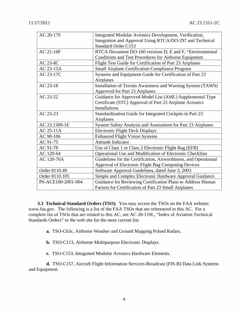
11172011 AC 231311-1C
AC 20-170 Integrated Modular Avionics Development Verification Integration and Approval Using RTCADO-297 and Technical Standard Order C153
AC 21-16F RTCA Document DO-160 versions D E and F ldquoEnvironmental Conditions and Test Procedures for Airborne Equipment
AC 23-8C Flight Test Guide for Certification of Part 23 Airplanes AC 23-15A Small Airplane Certification Compliance Program AC 23-17C Systems and Equipment Guide for Certification of Part 23
Airplanes AC 23-18 Installation of Terrain Awareness and Warning System (TAWS)
Approved for Part 23 Airplanes AC 23-22 Guidance for Approved Model List (AML) Supplemental Type
Certificate (STC) Approval of Part 23 Airplane Avionics Installations
AC 23-23 Standardization Guide for Integrated Cockpits in Part 23 Airplanes
AC 231309-1E System Safety Analysis and Assessment for Part 23 Airplanes AC 25-11A Electronic Flight Deck Displays AC 90-106 Enhanced Flight Vision Systems AC 91-75 Attitude Indicator AC 91-78 Use of Class 1 or Class 2 Electronic Flight Bag (EFB) AC 120-64 Operational Use and Modification of Electronic Checklists AC 120-76A Guidelines for the Certification Airworthiness and Operational
Approval of Electronic Flight Bag Computing Devices Order 811049 Software Approval Guidelines dated June 3 2003 Order 8110105 Simple and Complex Electronic Hardware Approval Guidance PS-ACE100-2001-004 Guidance for Reviewing Certification Plans to Address Human
Factors for Certification of Part 23 Small Airplanes
33 Technical Standard Orders (TSO) You may access the TSOs on the FAA website wwwfaagov The following is a list of the FAA TSOs that are referenced in this AC For a complete list of TSOs that are related to this AC see AC 20-110L ldquoIndex of Aviation Technical Standards Ordersrdquo or the web site for the most current list
a TSO-C63c Airborne Weather and Ground Mapping Pulsed Radars
b TSO-C113 Airborne Multipurpose Electronic Displays
c TSO-C153 Integrated Modular Avionics Hardware Elements
d TSO-C157 Aircraft Flight Information Services-Broadcast (FIS-B) Data Link Systems and Equipment
4
11172011 AC 231311-1C
e TSO-C165 Electronic Map Display Equipment for Graphical Depiction of Aircraft Position
34 Industry Documents You may obtain copies of current editions of the following publications
341 RTCA Documents The following RTCA documents are available from RTCA Inc 1828 L Street NW Suite 805 Washington DC 20036-4001 or at their website at wwwrtcaorg
a RTCADO-160G Environmental Conditions and Test Procedures for Airborne Equipment
b RTCADO-178B Software Considerations in Airborne Systems and Equipment Certification
c RTCADO-187 Minimum Operational Performance Standards for Airborne Area Navigation Equipment Using Multi-Sensor Inputs
d RTCADO-200A Standards for Processing Aeronautical Data
e RTCADO-201A Standards for Aeronautical Information
f RTCADO-254 Design Assurance Guidance for Airborne Electronic Hardware
g RTCADO-257A Minimum Operational Performance Standards for the Depiction of Navigation Information on Electronic Maps
h RTCADO-267A Minimum Aviation System Performance Standards (MASPS) for Flight Information Services-Broadcast (FIS-B) Data Link
i RTCADO-297 Integrated Modular Avionics (IMA) Development Guidance and Certification Considerations
j RTCADO-313 Certification Guidance for Installation of Non-Essential Non-Required Aircraft Cabin Systems and Equipment
k RTCADO-315A Minimum Aviation Performance Standards (MASPS) for Enhanced Vision Systems Synthetic Vision Systems Combined Vision Systems and Enhanced Flight Vision Systems
342 Society of Automotive Engineers (SAE) Inc The following Society of Automotive Engineers (SAE) Inc documents are available from SAE 400 Commonwealth Drive Warrendale PA 15096-0001 or from their website at wwwsaeorg
5
11172011 AC 231311-1C
a ARP 268G Location and Actuation of Flight Deck Controls for Transport Aircraft
b ARP 450D Flight Deck Visual Audible and Tactile Signals
c ARP 926B FaultFailure Analysis Procedure
d AIR 1093A Numeral Letter and Symbol Dimensions for Aircraft Instrument Displays
e ARP 1161A Crew Station LightingmdashCommercial Aircraft
f ARP 1782A Photometric and Colorimetric Measurement Procedures for Airborne Direct View CRT [Cathode Ray Tube] Displays
g ARP 1834A FaultFailure Analysis for Digital Systems and Equipment
h ARP 1874 Design Objectives for CRT Displays for Part 25 (Transport) Aircraft
i ARP 4032A Human Engineering Considerations in the Application of Color to Electronic Aircraft Displays
j ARP 4033 Pilot System Integration
k ARP 4067 Design Objectives for CRT Displays for Part 23 Aircraft
l ARP 4101 Flight Deck Layout and Facilities
m ARP 4102 Flight Deck Panels Controls and Displays
n ARP 41027 Electronic Displays
o ARP 4103 Flight Deck Lighting for Commercial Transport Aircraft
p ARP 4105B Abbreviations and Acronyms for Use on the Flight Deck
q ARP 4155A Human Interface Design Methodology for Integrated Display Symbology
r ARP 4256A Design Objectives for Liquid Crystal Displays for Part 25 (Transport) Aircraft
s ARP 4260A Photometric and Colorimetric Measurement Procedures for Airborne Electronic Flat Panel Displays
6
11172011 AC 231311-1C
t ARP 4754 Certification Considerations for Highly Integrated or Complex Aircraft Systems
u ARP 4761 Guidelines and Methods for Conducting the Safety Assessment Process on Civil Airborne Systems and Equipment
v ARP 5287 Optical Measurement Procedures for Airborne Head-Up Display (HUD)
w ARP 5288 Transport Category Airplane Head Up Display (HUD) Systems
x ARP 5289 Electronic Aeronautical Symbols
y ARP 5364 Human Factor Considerations in the Design of Multifunction Display Systems for Civil Aircraft
z ARP 5365 Human Interface Criteria for Cockpit Display of Traffic Information
aa ARP 5430 Human Interface Criteria for Vertical Situation Awareness Displays
bb ARP 5677 Human Engineering Considerations for Cockpit Integration of EnhancedSynthetic Vision Systems
cc AS 5703 Minimum Performance Standard for Enhanced Vision System
dd AS 8034A Minimum Performance Standard for Airborne Multipurpose Electronic Displays
ee AS 8055 Minimum Performance Standard for Airborne Head Up Display (HUD)
343 General Aviation Manufacturers Association (GAMA) The following documents are available from the GAMA 1400 K St NW Suite 801 Washington DC 2005 or from their website at wwwgamaaeroindustry-standards
a General Aviation Manufacturers Association (GAMA) Publication No 10 Recommended Practices and Guidelines for Part 23 CockpitFlight Deck Design
b General Aviation Manufacturers Association (GAMA) Publication No 12 Recommended Practices and Guidelines for an Integrated CockpitFlightdeck in a 14 CFR Part 23 Certificated Airplane
7
11172011 AC 231311-1C
40 Background
a Amendment 23-41 effective November 26 1990 established airworthiness standards in sect 231311 for installing electronic display instrument systems in normal utility acrobatic and commuter category airplanes The first electronic displays developed were direct replacements for the conventional electromechanical components with later designs providing more extensive information integration Before Amendment 23-41 most electronic display instrument systems were approved by special condition for installation in part 23 airplanes Amendment 23-49 effective March 11 1996 further amended part 23 to harmonize 14 CFR with the Joint Aviation Requirements (JAR) Section 231311 Amendment 23-49 removed redundant requirements and clarified which secondary instruments are required including the visibility requirements for those instruments
b Amendment 23-62 made several changes that affect the installation of electronic displays Guidance relative to electronic displays of those sections is also included in this AC The significant changes were
(1) Clarified requirements for trend information and appropriate sensory cues
(2) Incorporated equivalent visual displays of the instrument markings on electronic displays
(3) Allowed an applicant to take credit for reversionary or secondary flight displays on a multi-function flight display (MFD) that provides a secondary means of primary flight information (PFI)
(4) Revised some redundancy requirements to be only applicable for IFR operations
(5) Accommodated new technology for magnetic direction indicator
(6) Updated the terminology for system safety assessment
(7) Revised requirements for instruments using power source(s) and
(8) Revised requirements for storage battery backup times
50 Scope This AC is generally applicable only to an applicant seeking issuance of certain type certificates These include a type certificate (TC) an amended type certificate (ATC) or a supplemental type certificate (STC) for the approval of a new type design or a change in the type design This AC does not completely address Synthetic Vision Systems (SVS) or Enhanced Vision Systems (EVS) and Head-Up Displays (HUD) Contact the Small Airplane Directorate if there are any conflicts with other guidance and this AC The Small Airplane Directorate will coordinate and resolve the conflicts among the points of contact of the other documents
8
11172011 AC 231311-1C
60 AcronymsDefinitions
61 Acronyms
a AC Advisory Circular
b ACO Aircraft Certification Office
c ADC Air Data Computer
d ADI Attitude Direction Indicator
e ADDS Aviation Digital Data Service
f AFM Airplane Flight Manual
g AFMS Airplane Flight Manual Supplement
h AHRS Attitude Heading Reference System
i ARD Aerospace Research Document
j ARP Aerospace Recommended Practice
k AS Aerospace Standard
l ASTC Amended Supplemental Type Certificate
m ATC Amended Type Certificate
n CAR Civil Air Regulations
o CDI Course Deviation Indicator
p CFR Code of Federal Regulations
q CIP Current Icing Potential
r CL Center Line
s CRT Cathode-Ray Tubes
t DN Down
u EADI Electronic Attitude Direction Indicator
9
11172011 AC 231311-1C
v EHSI Electronic Horizontal Situation Indicator
w EICAS Engine Indication and Crew Alert System
x ELOS Equivalent Level of Safety
y EVS Enhanced Vision Systems
z FAA Federal Aviation Administration
aa FD Flight Director
bb FHA Functional Hazard Assessment
cc FLS Field-Loadable Software
dd FMEA Failure Modes and Effects Analysis
ee FOV Field-Of-View
ff GPS Global Positioning System
gg HIRF High Intensity Radiated Fields
hh HUD Head-Up Display
ii HSI Horizontal Situation Indicators
jj ICAO International Civil Aviation Organization
kk IFR Instrument Flight Rules
ll ILS Instrument Landing System
mm IMA Integrated Modular Avionics
nn IMC Instrument Meteorological Conditions
oo JAR Joint Aviation Requirements
pp LCD Liquid Crystal Displays
qq LED Light Emitting Diodes
rr LT Left
10
11172011 AC 231311-1C
ss METAR ICAO Routine Aviation Weather Report
tt MFD Multifunction Flight Display
uu ND Navigation Display
vv NOM Nominal
ww PFD Primary Flight Display
xx PFI Primary Flight Information
yy POH Pilots Operating Handbook
zz RAIM Receiver Autonomous Integrity Monitoring (used with GPS)
aaa RT Right
bbb SAE Society of Automotive Engineers
ccc STC Supplemental Type Certificate
ddd SVS Synthetic Vision Systems
eee TAS Traffic Advisory System
fff TAWS Terrain Awareness Warning System
ggg TFR Temporary Flight Restrictions
hhh TC Type Certificate
iii TCAS Traffic Alert and Collision Avoidance System
jjj TSO Technical Standard Order
kkk UL Underwriterrsquos Laboratories
lll VOR Very High Frequency Omni-Directional Range
mmm VFR Visual Flight Rules
nnn VMC Visual Meteorological Conditions
ooo VFE Maximum flap extended speed
11
11172011 AC 231311-1C
ppp VMO Maximum operating limit speed
qqq VNE Never-exceed speed
rrr VNO Maximum structural cruising speed
sss VS0 The stalling speed or the minimum steady flight speed in the landing configuration
ttt VS1 The stalling speed or the minimum steady flight speed obtained in a specific configuration
uuu WAAS Wide Area Augmentation System
62 Definitions This section contains definitions for terms in this document
a Accuracy A degree of conformance between the estimated or measured value and the true value
b Adverse Operating Condition A set of environmental or operational circumstances applicable to the airplane combined with a failure or other emergency situation that results in a significant increase in normal flight crew workload
c Component Any self-contained part combination of parts subassemblies or units that perform a distinct function necessary to the operation of the system
d Continued Safe Flight and Landing This phrase means the airplane can continue controlled flight and landing possibly using emergency procedures without requiring exceptional pilot skill or strength On landing some airplane damage may occur as a result of a Failure Condition
e Conventional A system is considered ldquoConventionalrdquo if its function the technological means to implement its function and its intended use are all the same as or closely similar to that of previously approved systems that are commonly used The systems that have established an adequate service history and the means of compliance for approval are generally accepted as Conventional
f Critical Usually a function whose loss would prevent the continued safe flight and landing of the airplane
Note The term ldquocritical functionrdquo is associated with a catastrophic failure condition Newer documents may not refer specifically to the term ldquocritical functionrdquo
g Criticality Indication of the hazard level associated with a function hardware software etc considering abnormal behavior (of this function hardware software etc) alone in
12
11172011 AC 231311-1C
combination or in combination with external events Criticality is a failure classification that could be no safety effect minor major hazardous and catastrophic See AC 231309-1E for more guidance
h Design-Eye Box A three-dimensional volume of space surrounding the design eye reference point that designers and evaluators use to determine the acceptability of display and control locations
i Design-Eye Reference Point A single reference point in space selected by the designer where the midpoint between the pilotrsquos eyes is assumed to be located when the pilot is properly seated at the pilotrsquos station
j Development Assurance All those planned and systematic actions used to substantiate to an adequate level of confidence that errors in requirements design and implementation have been identified and corrected such that the system satisfies the applicable certification basis
k Enhanced Vision System An electronic means to provide a display of the forward external scene topography (the natural or manmade features of a place or region especially in a way to show their relative positions and elevation) through the use of imaging sensors such as a forward looking infrared millimeter wave radiometry millimeter wave radar low light level image intensifying
l Equipment Essential to Safe Operation Equipment installed to comply with the applicable certification requirements of 14 CFR part 23 or operational requirements of 14 CFR parts 91 and 135
m Error An omitted or incorrect action by a pilot or maintenance person or a mistake in requirements design or implementation
n Failure An occurrence that affects the operation of a component part or element such that it can no longer function as intended (this includes both loss of function and malfunction
o Failure Condition A condition affecting either the airplane or its occupants or both either direct or consequential caused or contributed to by one or more failures or errors considering flight phase and relevant adverse operational or environmental conditions or external events Failure conditions may be classified according to their severity See AC 231309-1E for more information on definitions of failure conditions
p Field-of-View The angular extent of the display that can be seen by either pilot with the pilot seated at the pilotrsquos station See section 15 for more information on the field-of view
q Fix A generic name for a geographical position A fix may also be referred to as a waypoint intersection reporting point etc
13
11172011 AC 231311-1C
r Flight Plan Refers to any sequence of fixes that are interconnected by the desired path Flight plans may range from the simplest that include only the aircraftrsquos present position the active waypoint and the desired path between them to more complicated plans that include departure and destination airports with multiple intermediate fixes
s Function The lowest defined level of a specific action of a system equipment and pilot performance aboard the airplane that by itself provides a complete recognizable operational capability (for example an airplane heading is a function) One or more systems may contain a specific function or one system may contain multiple functions
t Functional Hazard Assessment A systematic comprehensive examination of airplane and system functions to identify potential minor major hazardous and catastrophic failure conditions that may arise as a result of a malfunction or a failure to function
u Hardware An object that has physical being Generally refers to circuit cards power supplies etc
v Hazard Any condition that compromises the overall safety of the airplane or that significantly reduces the ability of the pilot to cope with adverse operating conditions
w Head-Up Display A transparent optical display system located level with and between the pilot and the forward windscreen The HUD displays a combination of control performance navigation and command information superimposed on the external field of view It includes the display element sensors computers and power supplies indications and controls It is integrated with airborne attitude air data and navigation systems and as a display of command information is considered a component of the flight guidance system
x Independent A component part element or system that is not relying on some other component part element or system for accomplishing its function This design concept ensures that the failure of one item does not cause a failure of another item For redundancy each means of accomplishing the same function need not necessarily be identical
y Indicator A means for displaying information of a parameter More than one indicator could be depicted on one display For example a primary flight display may have indicators for attitude altitude airspeed heading and navigation
z Instrument An electrical or mechanical measurement device In sect 231311 it is defined as Devices physically contained in one unit and devices composed of two or more physically separate units or components connected together (One example is a remote indicating gyroscopic direction indicator that includes a magnetic sensing element a gyroscopic unit an amplifier and an indicator connected together)
aa Map Orientation Refers to the rule that determines the directional relation of the map to the upper part of the display depiction Using a north-up rule the north side of the map would be toward the top of the display and the south side of the map would be at the bottom Using
14
11172011 AC 231311-1C
a desired path-up rule the map would be oriented so the desired path would be vertical on the map and pointing straight up toward the top of the display
bb Map Range The geographic extent of the map region (for example the distance covered by the map representation in either the vertical or horizontal direction)
cc Malfunction Failure of a system subsystem unit or part to operate in the normal or usual manner A condition whereby the operation is outside specified limits
dd Multi-Function Display Any physical display unit other than the PFD used to present various information on which the layout may be reconfigured
ee Navigation The process of planning tracking and controlling the course of an airplane from one place to another
ff Navigation Display The display or suite of instruments by which navigation data is presented to the pilot
gg Navigation Information Information that aids the flightcrew in determining the aircraftrsquos location in a given environment (for example on flight plans VORs GPSs features on the airport surface including taxiway signage etc)
hh Primary As used for instruments it is defined in sect 231311(c) as the ldquodisplay of a parameter that is located in the instrument panel such that the pilot looks at it first when wanting to view that parameterrdquo
ii Primary Flight Display (PFD) A single physical unit that always provides the primary display of all the following altitude airspeed aircraft heading (direction) and attitude located directly in front of the pilot in a fixed layout in accordance with sect 231321 It may provide other information pertinent to guidance and fundamental control of flight of the airplane such as critical engine parameters
jj Primary Flight Information (PFI) A PFI refers to those functions or parameters required by the airworthiness and operational rules such as airspeed altitude attitude and heading (direction) that are on the PFD
kk Primary Function (PF) This definition is applicable in the case when there is more than one function available for same function A function that is installed to comply with the applicable regulations for the required function and one that provides the most pertinent controls or information instantly and directly to the pilot For example the PFD is a single physical unit that always provides the primary display and it complies with the requirements of all the following altitude airspeed aircraft heading (direction) and attitude This PFD is located directly in front of the pilot and used instantly and first by the pilot A standby (additional) PFD that is intended to be used in the event of failure of the PFD is an example of a secondary system
15
11172011 AC 231311-1C
ll Primary Navigation Where the pilot looks first for a display of navigation information such as on an HSI or CDI It displays vertical and lateral deviation and it may have the digital distance indication tofrom the selected fix
mm Redundancy The presence of more than one independent means for accomplishing a given function Each means of accomplishing the function need not necessarily be identical
nn Reversionary Display A secondary means to provide information initially presented on the PFD or MFD by the transfer of information to an alternate display
oo Scale The relative proportion of the linear dimensions of objects on a display to the dimensions of the corresponding objects and distances being represented (for example 1 inch = 100 nautical miles)
pp Secondary Display A means to present information on another display A display that can be used for backup or secondary purposes such as in the event of a failure of another display
qq Standby Instrument A dedicated instrument that is always available that presents primary flight information
rr Supplemental Function A function that is not required or intended to meet all the airworthiness and operational requirements It is usually installed for additional situational awareness
ss System A combination of components parts and elements that is interconnected to perform one or more functions
tt Synthetic Vision System A computer-generated image of the external scene topography from the perspective of the flight deck that is derived from aircraft attitude high precision navigation solution and database of terrain obstacles and relevant cultural features
Note ldquoTopographyrdquo defined as maps or charts of natural and man-made features of a place or region especially in a way to show their relative positions and elevations as applicable whenever deemed appropriate and practicable
uu Track The projection on the earthrsquos surface of the path of an aircraft the direction of which is usually expressed in degrees from north (true magnetic or grid) A track is the actual flight path of an aircraft over the surface of the earth
Note For more definitions related to safety assessments refer to AC 231309-1E for the appropriate definitions
vv Warning A clear and unambiguous indication to the pilot of a failure that requires immediate corrective action An inherent characteristic of the airplane or a device that will give
16
11172011 AC 231311-1C
clearly distinguishable indications of malfunction or misleading information may provide this warning
70 Display Description The following paragraphs give a brief description of an electronic display They do not cover all the capabilities and details of these displays or the information presented on them
71 General Electronic displays have replaced many of the traditional electromechanical and analog instruments These displays also augment andor combine the functionality of conventional systems such as radios and navigational systems The major display technologies now used are multicolor CRTs LCDs electro luminescence plasma and LEDs The initial electronic displays mimicked the traditional mechanical and electromechanical flight and powerplant instruments The colors symbols and formats on these initial electronic displays are similar to those on traditional conventional instruments Modern electronic displays provide integration and formats that often differ from traditional instruments
72 Display Configuration Electronic displays may be installed in several configurations A basic electronic display may provide only one flight or powerplant parameter while more sophisticated systems integrate many parameters on one electronic display One of the major design goals for these systems is eliminating separate conventional gauges instruments and annunciators Recent installations show a trend toward a higher degree of integration For example an integrated primary flight display provides several parameters such as attitude heading (direction) airspeed and altitude Integration of various systems should include analysis to ensure that complexity and workload are compatible with general aviation pilots capabilities For more guidance on IMA that implement TSO authorized hardware elements see TSO-C153 and AC 20shy170
80 Flight Displays
81 Instrument Requirements
a Sections 231303 231305 231311 and 231321 with the applicable operating rules (14 CFR parts 91 121 and 135) incorporate flight and powerplant instrument requirements for part 23 airplanes The navigation equipment requirements are given in operational rules specified in sectsect 91205 121303 121305 121307 135143 135149 135159 135161 and 135165 Display requirements for navigation information are dependent on the navigation system installed in the aircraft Instruments and equipment required for flights under parts 91 121 and 135 may be affected by the electronic display installation These instruments and equipment include gyroscopic bank and pitch gyroscopic direction gyroscopic rate-of-turn slip-skid instruments and other required communication and navigational equipment
b There have been applications to install equipment such as flight and navigation displays as non-required These applications request approval for these installations as situation awareness (SA) only It is not acceptable to label a display as ldquoSA-Onlyrdquo and assume that its failure condition is acceptable Installing displays that provide PFI that are more compelling than
17
11172011 AC 231311-1C
the required primary PFI displays but they do not meet the appropriate operational and airworthiness requirements and labeling them as ldquoSupplementalrdquo or ldquoSA-Only is not acceptable Section 136 provides more guidance
c The basis for certification has been that the equipment should perform its intended function and not present a hazard Instruments that aid situation awareness should be certified under the part 23 requirements including sect 231301 and sect 231309 These displays could provide hazardous misleading information PFI is essential for safe operation An instrument that provides PFI should meet the minimum standards of applicable TSOs or an equivalent standard It also should meet the guidance in AC 231309-1E AC 23-17C and the guidance in this AC
82 Primary Flight Information (PFI) PFI refers to those functions or parameters that are required by the airworthiness and operational rules such as airspeed altitude attitude and heading (direction) It may provide other information pertinent to guidance and fundamental control of flight such as critical engine parameters Attitude airspeed altitude and heading (direction) are the PFI required in sect 231311(a)(3) and (5) and they must be arranged according to sect 231321 in the ldquobasic Trdquo arrangement Direction should be heading with track presented if available as a selectable option The horizon reference line on the PFD should be at least 325 inches wide in straight and level flight for integrated displays This recommendation is not intended to prevent replacement of mechanical instruments with an electronic display of a similar horizon reference line When the true horizon is no longer on the display the artificial horizon line should provide a distinctive demarcation between sky and ground (or the background) Display of PFI on reversionary or standby displays should be arranged in the basic T-configuration but it is not required The standby instrument or displays of PFI location should meet the FOV guidance criteria in section 15
821 Acceptable Methods for Compliance with sect 231311(b) There are three acceptable methods for meeting the attitude requirements which is considered information essential for continued safe flight and landing Compliance can be accomplished by using dedicated standby instruments dual PFDs or reversionary displays that present primary flight information Electronic display systems without dedicated standby instruments should have at least two independent displays able to provide PFI to the pilot These displays should be powered such that any single failure of the power generation and distribution systems cannot remove the display of PFI from both displays Section 231311(b) in Amendment 23-62 states ldquoThe electronic display indicators including their systems and installations and considering other airplane systems must be designed so that one display of information essential for continued safe flight and landing will be available within one second to the crew by a single pilot action or by automatic means for continued safe operation after any single failure or probable combination of failuresrdquo
83 Standby Instruments The purpose of standby instruments or another independent PFD is to ensure that PFI is available to the pilot during all phases of flight and during system failures Individual indicators should be a minimum of 2 inches in diameter or if combined a minimum diameter of 3 inches (or equivalent) displayed
831 Dual PFDs Electronic display systems with dual PFDs should incorporate dual independently powered sensors that provide primary flight parameters such as AHRS with
18
11172011 AC 231311-1C
comparators and dual ADC Dual PFDs with dual AHRSs and ADCs which include checking and are powered by multiple power sources and distribution systems are significantly more reliable than presently certified mechanical systems
832 PFD and Autopilot with an AHRS For normal operation when using a single AHRS to drive the PFD and the autopilot simultaneously the installation must mitigate hazardous or catastrophic system level failures An example configuration supporting proper mitigation would include all of the following
a A dedicated standby attitude instrument within the primary maximum FOV or independent reversionary attitude display
b An AHRS with appropriate comparator or monitor of equivalent performance
c Appropriate system warningcaution annunciation associated with an AHRS malfunction
d If an aircraft is equipped with multiple AHRS it may be acceptable when one AHRS fails to drive both the autopilot and the PFD from a single AHRS as long as an AHRS independent attitude display (required for some aircraft classes) is located in the primary maximum field of view The failure must be annunciated to the pilot and the pilot must be able to select the non-failed AHRS For aircraft that do not have an independent attitude indicator when one AHRS fails the autopilot should be manually or automatically disengaged The autopilot may be reengaged if appropriate mitigation is available (for example see a through c above) The AFM or supplemental AFM should contain the appropriate procedures applicable to the equipment installed See section 110 for additional guidance AC 231309-1E guidance should be considered for these configurations
e Displays not meeting FOV guidance criteria may require additional human factors airworthiness evaluation by the certification authority See section 15 for additional guidance
84 Reversionary Flight Displays Instead of Standby Instruments or Dual PFDs
841 General Requirements
a Reversionary flight displays provide a secondary means to provide PFI through alternate display formats on another PFD or MFD by the transfer of information to an alternate display or by some other means The function of an MFD system is to provide the pilot access to various data or combinations of data used to fly the aircraft to navigate to communicate andor to manage aircraft systems The MFD would also present PFI as needed to ensure continuity of operations 14 CFR part 23 sect 231311(b) Amendment 23-62 states the electronic display indicators including their systems and installations and considering other airplane systems must be designed so that one display of information essential for continued safe flight and landing will be available within one second to the crew by a single pilot action or by automatic means for continued
19
11172011 AC 231311-1C
safe operation after any single failure or probable combination of failures To meet the requirements of sect 231311(b) a full-time standby display another independent PFD or an independent reversionary attitude display must be installed Reversionary modes could be automatically and manually selected or only manually selected
b Reversionary configurations are significantly more reliable than presently certified mechanical systems and the skills required while flying in reversionary mode are identical with those used when flying in primary mode Traditional external standby flight instruments (either electronic or mechanical) offer potential safety problems associated with delay in pilot reaction The pilot may delay a decision to transition to standby instruments and to transition to partial panel techniques as opposed to the simple action the pilot would take to switch displays A nearly identical format on the reversionary display of all PFI that is also shown on the PFD provides a significant safety enhancement over standby instruments This is especially true when the size location arrangement and information provided by the standby instruments are significantly different from those on the PFD
c Reversionary display modes should provide consistent display formats to the PFD The reversionary flight information should be presented by an independent source and display to prevent complete loss of PFI due to a single failure The reversionary configuration should have two independent displays that incorporate dual-independently powered AHRS and dual ADC subsystems that provide PFIs The reversionary system response time should provide flight critical information on the MFD in less than one second after a single pilot action or an automatic operation
d A reversionary configuration should have a single pilot action that would force both the PFD and MFD displays into reversionary mode operation However the PFI should be presented in similar format and sufficient size in the reversionary mode as it is in normal mode to allow the pilot to enhance the control of the airplane This reversionary configuration should provide backup information essential to continued safe flight and landing with an intuitive control that allows instant simultaneous access to reversionary mode on both the PFD and MFD displays The single pilot action should be easily recognized readily accessible and have the control within the pilotrsquos primary optimum field of view An acceptable method for the single pilot action is the red color andor lighted red ldquohalordquo ring that announces its position on the panel at all times
842 Reversionary Methods
a One method is to have an automatic reversionary display with a single pilot action that would force both the PFD and MFD displays into reversionary mode operation If PFI on another display is not provided provide automatic switching to ensure PFI is available to the pilot Automatic reversion must provide a complete display of PFI on the remaining display within one second if a fault is detected
b Most possible faults should be covered by this automatic reversionary capability Only a total loss of the display may not be reliably detected automatically but such a failure condition would be obvious to the pilot Faults that result in automatic switching should be extensive enough to ensure PFI availability meets the requirements of sect 231309 If such a
20
11172011 AC 231311-1C
malfunction occurs a single pilot action should provide a full display of the essential information on the remaining display within one second All modes sources frequencies flight plan data etc should be similar as they were on the PFD before the failure
c Another reversionary method would include a means to access the reversionary mode manually through a single pilot action Manual activation of the reversionary mode on the MFD through single action by the pilot is acceptable when procedures to activate the PFI on the MFD are accomplished before entering critical phases of flight The PFI would be presented continuously on the reversionary display during critical phases of flight (for example takeoff landing and missed or final approach)
85 Display of Attitude For flights under IFR conditions in part 91 and part 135 operations and under VFR at night for part 135 operations attitude information is required The loss of all attitude information or the presentation of misleading attitude information could result in a catastrophic failure condition where the pilot could not continue safe flight and landing of the airplane It is recommended that the display of attitude follows the guidelines (below) that are also in GAMA Publication 12
a The pitch ladder should be caged to the center of the display
b At pitch attitudes when the true horizon line would not normally be displayed some sky or ground should be indicated on the PFD pitch display (minimum 38 inches and maximum of 115 percent of the display) and the horizon line should indicate off-scale
c With the airplane symbol on the horizon line the range of visible pitch attitude should be at least + 25 to -15 degrees but not to exceed a total pitch range of 50 degrees
d Bank angle presentations should use a roll pointer however roll pointers and sky-pointers should not be mixed in the same flight deckcockpit
e Roll scale indices should be placed at 10 20 30 60 and 90 degrees An index may also be placed at 45 degrees
86 Display of Direction (Heading or Track)
861 General
a The loss of direction (heading or track) information could result in reduced capability of the pilot to cope with adverse operating conditions The orientation of any secondary navigation display is optional (for example Track-up North-up Heading-Up) For flights under IFR conditions a stabilized heading indicator must provide the primary display of the direction parameter A magnetic direction indicator or track may provide the reversionary display of direction
21
11172011 AC 231311-1C
b The heading display should provide a clear and unmistakable display of aircraft symbol and heading HSI should provide a clear and unmistakable display of aircraft position heading and track (an option if available) relative to the desired coursetrack Section 17 contains more guidance on symbology Direction should be heading when track is presented if available as a selectable option with the data source clearly indicated On the primary display the heading scale should have a mode that presents at least 120 degrees of arc Other display formats may be acceptable and have been previously approved but they need to be evaluated from a human factor perspective
862 Hazardous Misleading Heading Information
a The FHA for the failure effects of hazardous misleading heading information from an AHRS is clarified in AC 23-17C This policy is specifically about the application of AC 231309-1E for an airplane with the certification basis of Amendments 23-41 or later This clarification is limited to installations approved for operation in IMC under IFR For operations limited to VFR a misleading heading indication is not considered hazardous
b Develop an FHA and the related safety assessments for the specific airplane type and configuration since there can be many combinations of failures various mitigating factors and other functions available to a pilot These many factors affect the criticality of the heading indication therefore use a safety assessment process from AC 231309-1E to classify the failure conditions for misleading heading information
c A hazardously misleading heading is usually when the accuracy error is greater than 10 degrees on the primary heading instrument and it is an undetected error The safety assessment process should consider appropriate mitigating factors For Class I part 23 airplanes the failure condition for misleading hazardous heading is usually considered major
87 Display of Altitude Airspeed and Magnetic Compass Information The original requirements of CAR 3 were adopted and later recodified into part 23 sect 231303 paragraphs (a) (b) and (c) At that time pneumatically driven displays provided airspeed and altitude functions Since then the FAA envisioned airspeed altitude and magnetic compass information would remain available to the pilot with the loss of the airplanes primary electrical power For electronic displays sect 231311(a)(3) requires the primary display of attitude airspeed and altitude to be uninhibited in any normal mode of operation Section 231311(a)(5) as amended by Amendment 23-62 requires an independent magnetic direction indicator and either an independent secondary mechanical altimeter airspeed indicator and attitude instrument or electronic display parameters for the altitude airspeed and attitude that are independent from the airplanes primary electrical power system Primary altitude or airspeed displays that require electrical power are acceptable if means are provided for their continued operation upon loss of the airplanersquos primary electrical power or if pneumatically driven instruments are available for the pilotrsquos use A standby or reversionary integrated display of altitude attitude and airspeed instead of individual electronic display indicators for airspeed altitude and attitude is acceptable under one condition The condition is that the standby or reversionary integrated display and the primary display are powered such that at least one integrated display with attitude altitude and airspeed is available after failure of any power source or distribution path
22
11172011 AC 231311-1C
88 Accuracy of the Magnetic Heading System
881 General
a The operating rules such as part 91 and part 135 specify the minimum required equipment that must be installed in part 23 airplanes based on the operation such as VFR or IFR Under VFR operation part 91 sect 91205 requires a magnetic direction indicator (that is normally intended to be a compass) for heading information Under IFR operation part 91 sect 91205 requires a gyroscopically stabilized heading system Section 231303(c) Amendment 23-62 amended the requirement from ldquoA direction indicator (non-stabilized magnetic compass)rdquo to ldquoA magnetic direction indicatorrdquo As new technology becomes more affordable for part 23 airplanes many electronic flight instrument systems will use magnetically stabilized direction indicators (or electric compass systems) to measure and indicate the airplane heading to provide better performance
b The general airworthiness requirements in part 23 sect 231301 and sect 231525 determine the flight instrument and equipment accuracy requirements for part 23 airplanes Part 23 does not prescribe specific accuracy requirements for magnetic gyroscopically stabilized heading systems Specific accuracy requirements for avionics may be found in the related TSO and as acceptable means of compliance to sect 231301 in ACs notices or policy statementsletters
882 Magnetic Non-Stabilized Direction Indicator A magnetic non-stabilized direction indicator that is required by sect 231303 should have an accuracy of 10 degrees or have a correction card placard (reference sect 231327) or a back-up gyroscopic direction indicator provided the indicator is accurate better than 10 degrees If the sole purpose of the gyroscopic direction indicator is for backing up the magnetic non-stabilized direction indicator then the accuracy of presentation of headings can also be to 10 degrees However if a gyroscopic direction indicator is installed to meet the IFR operating rules then the installation requirements are defined by sect 231301
883 Magnetic Gyroscopically Stabilized Direction Indicator As installed final accuracy for a magnetic gyroscopically stabilized direction indicator of plusmn4 degrees on the ground or plusmn6 degrees in normal level flight on any heading would meet the requirements of part 23 sect 231301 This accuracy applies after compensation It should include cumulative errors in all combinations due to several factors These consist of the equipment itself the current flow in any item of electrical equipment and its associated wiring the movement of any part (for example controls or undercarriage) and the proximity of any item of equipment containing magnetic material to the magnetic sensor
884 Comparator Monitor
a For systems installations that include two magnetic gyroscopically stabilized heading systems and a comparator that monitors the differences between the headings of the two
23
11172011 AC 231311-1C
systems the comparator trip point set as follows would meet the requirements of part 23 sect 231301
(1) 6 degrees in stabilized level flight
(2) 6 degrees plus one half of the bank angle or
(3) 12 degrees with a bank angle greater than 6 degrees
(4) The alert function can be disabled at a bank angle greater than 20 degrees
(5) An alert is provided if the condition exceeds 60 seconds but it allows two minutes for a turn error as stated in the TSO
b The 6-degree trip point during level flight allows a heading error of as much as 12 degrees on one of the systems This would comprise one system at the 6 degrees in-flight tolerance limit while the other system presumably with some malfunction could have an error of 12 degrees in the same direction before the comparator monitor alert is tripped
89 Rate-of-Turn Instrument
a Under sectsect 91205 and 135159 a rate-of-turn instrument is not required if a third attitude instrument usable through flight attitudes of 360 degrees of pitch-and-roll is installed following the instrument requirements prescribed in sect 121305(j) If required place the rate-of-turn indicator near the heading indicator
b A second approved attitude indicator may substitute for the rate-of-turn instrument AC 91-75 Attitude Indicator provides one method This AC is applicable to part 23 certificated airplanes (or airplanes certificated under earlier equivalent regulations) that weigh less than 12500 pounds and are operated under part 91 The second approved attitude indicator must be powered by an independent power source from the primary attitude indicator This can be accomplished by using independent standby instruments another independent PFD or independent reversionary attitude display Most of the installations with electronic displays that meet the requirements of sect 231311 and this AC should comply with AC 91-75
810 Slip-Skid Instrument The slip-skid information is required by sectsect 91205(d)(4) and 135159(b) as applicable The FAA suggests locating the slip-skid display directly below or near the rate-of-turn instrument if installed or under or within the primary attitude display
811 Vertical Speed Indicator If provided present the vertical speed indicator to the right or directly below the altitude indicator with a scale appropriate to the performance of the aircraft
24
11172011 AC 231311-1C
90 Powerplant Displays
91 General
a This section defines a means of presenting powerplant performance and condition information about the airplanes operation It also provides guidelines about when these functions should be displayed to the pilot In general there have been two methods used to accomplish this These methods include (1) display raw engine parameters to the pilot for interpretation or (2) collect powerplant data and have an automatic monitoring system interpret and report the powerplant condition to the pilot Use the following evaluation criteria when considering the installation of electronic powerplant displays
b There is a need to evaluate each airframe engine and airframeengine interface with the operational characteristics of these systems to determine the primary powerplant parameter requirements For this evaluation and as used in this section a primary powerplant parameter is needed to start the engine and to set and monitor engine power within powerplant limitations Appropriate procedures for operation of an integrated electronic powerplant display system should be in the AFM
c For multiengine airplanes a failure or malfunction affecting the display or accuracy of any propulsion system parameter for one engine should not cause the loss of display or accuracy of any parameter for the remaining engine(s) If multiple propulsion parameters are integrated on one display and the display fails it is acceptable to provide a secondary propulsion parameter display
92 Loss of Critical Powerplant Information
a No single failure malfunction or probable combination of failures should result in either the loss of critical powerplant information or an erroneous display of powerplant parameters that would jeopardize continued safe flight and landing of the airplane Usually for engines that do not generally rely on the pilot to prevent exceeding their limits in normal operations or engines such as with electronic engine controls featuring engine limit protection the loss of powerplant displays should not cause immediate jeopardy to continued safe flight and landing
b A secondary display providing powerplant parameters for cases of loss of a primary powerplant display may be used provided it is located so the pilot can adequately view the powerplant parameters
c Throttle or power lever position may be used in place of lost powerplant display parameters This would apply if throttle position or power lever position provides a positive indication of the powerplant power level required to maintain safe flight to a landing and if the throttle has a means to preclude exceeding powerplant operating limits
25
11172011 AC 231311-1C
93 Powerplant Information
a Presentation of primary powerplant parameters continuously when they are required unless the monitor provides an adequate alert of the function Also provide a manual select option for the pilot to present the information A parameter defined as primary for engine start but not for other normal engine operation may only have to be presented continuously during engine start
b Before and upon reaching or exceeding any operating limit the display should present the required powerplant parameters without pilot action Timely alerts for each phase of flight should be provided when any operating limit is reached or exceeded for the required powerplant parameter The alerts should be in a form that enables the pilot to identify and carry out the necessary and appropriate actions The required powerplant information should be presented continuously during a critical takeoff and landing phase of flight to minimize pilot distraction until an established rate of climb or minimum altitude is achieved
c Displays that provide multiple powerplant parameters should be designed such that any parameter display or alert will not suppress another display or alert that also requires immediate crew awareness necessary to conduct safe operation of the aircraft and engine(s) Alerts that could cause subsequent activation of other displays or alerts should be presented in a manner and form to ensure appropriate identification and prioritization of all significant hazards and required crew actions See section 18 for more guidance on annunciation
94 Digital Reading Alphanumeric Displays
a Digital reading alphanumeric displays are most valuable when integrated with an analog display by adding a precise quantitative indication to complement an analog displays qualitative indication Proper integration should include a means for pilots to clearly associate the analog and digital indications (eg via close proximity) Digital reading alphanumeric powerplant displays formats should not be used in place of analog formats to indicate values of engine parameters where trend or rate-of-change information is important for safety or when the pilot needs to monitor parameters with a quick glance Digital reading alphanumeric displays limit the pilots ability to assess trend information and result in reduced crew awareness Digital reading alphanumeric displays are also limited in their ability to allow the pilot to easily compare parameters from multiple engines or to check the general proximity of differing parameters against their individual limits While these shortcomings can be compensated for with more design provisions use digital reading alphanumeric displays with caution and carefully evaluate each airframe engine and airframeengine integration
b Section 231311(a)(6) Amendment 23-62 requires sensory cues that provide a quick glance sense of rate and where appropriate trend information to the parameter being displayed to the pilot Section 231311(a)(7) requires incorporated equivalent visual displays of the instrument markings required by sectsect 231541 through 231553 or visual displays that alert the pilot to abnormal operational values or approaches to established limitation values for each parameter required to be displayed by this part
26
11172011 AC 231311-1C
c An ELOS will be necessary for digital -reading alphanumeric only displays that are not associated with any scale tape or pointer It may be difficult for pilots to determine the margin relative to targets or limits or compare between parameters To comply with sect 231311(a)(7) a scale dial or tape will be needed to accomplish the intended pilot task In order to demonstrate an equivalency a human factor andor pilot evaluations will be needed that will consider the following factors These are subject to evaluation on a case-by-case basis
(1) The visibility and relative location of the indicated parameter should be reviewed including appropriate conditions of lighting and instrument panel vibration
(2) The ability to assess necessary trend or rate-of-change information quickly including when this information may be needed during in-flight engine restarts
(3) The ability to assess how close the indicated parameter is relative to a limit
(4) The value to the crew of quickly and accurately comparing engine-to-engine data for multiengine aircraft
(5) Engine design features or characteristics that would forewarn the crew before the parameter reaches the operating limit (for example redline)
(6) The use of color in accordance with sect 231549 to indicate the state of operation a green indication would indicate normal operation a yellow indication would indicate operation in a takeoff or precautionary range and a red indication would indicate operation outside of the safe operating limits
95 Marking of Powerplant Parameters Mark powerplant parameters on electronic displays in accordance with sect 231549 AC 20-88A provides alternate methods of marking electronic powerplant displays Alternate methods of marking the displays may be performed However the FAA may evaluate these markings on a case-by-case basis depending on each airframe engine integration and appropriate human factors considerations Alternate markings that do not comply with the requirements of sect 231549 require an ELOS
100 Electronic Displays for Navigation Information
101 Guidance Information Navigation information used by the pilot for steering commands and to monitor deviation from a navigation path should be in the pilots primary FOV Warnings and cautions should also be in the primary FOV For more guidance on FOV see section 15 and Table 3 of this AC
102 Display Integration
a Navigation guidance information may be integrated with the PFDs Common examples include HSIs that combine inputs from a directional gyro with a course deviation
27
11172011 AC 231311-1C
indicator or an FD integrated with the ADI Additionally information from more than one navigation source may be displayed separately or simultaneously
b If information from more than one navigation source can be presented the selected source should be continuously indicated to the pilot If multiple sources can be presented simultaneously the display should indicate unambiguously what information is provided by each source and which one has been selected for guidance Some airplanes are equipped with an autopilot andor FD coupled to the lateral and vertical guidance system On these airplanes the input to the autopilot andor FD should coincide with the navigation source selected on the PFD or primary navigational display
103 Reversionary Navigation Displays Reversionary requirements for navigation display information depend on the rules under which the aircraft is operated and the hazards associated with the loss of or misleading information from the display The integration of non-navigation information (for example traffic weather or flight parameters) may affect the hazards associated with the loss of or misleading information from the display In these cases the applicant should perform a system safety assessment following AC 231309-1E For more guidance on safety assessments see AC 231309-1E and section 26 of this AC for more guidance
104 Navigation Database For area navigation equipment the navigation database is an essential component of the equipment Guidelines for the navigation database can be found in RTCADO-200A See AC 20-138 and AC 20-153 for more guidance and information
110 Aircraft Flight Manual (AFM) For equipment required for IFR approval the AFM or supplemental AFM should contain the limitations and the operating and emergency procedures applicable to the equipment installed Installations limited to VFR use only may require an AFM or supplemental AFM depending on the complexity of the installation and the need to identify necessary limitation and operating procedures AC 23-8C contains more policy and guidance on AFMs
120 Electronic Checklist and Charts Policy and guidance on electronic checklist and charts on electronic displays are contained in AC 23-8C AC 91-78 AC 120-64 and AC 120-76A
130 General Human Factors Considerations for Design of Electronic Displays
131 General Electronic displays can provide many innovative display flexibilities and features that were not possible with traditional displays Technology improvements in display design and integration can enhance pilot performance and improve situation awareness when innovations are designed using sound processes and appropriate design criteria that account for human performance The applicant should ensure that human performance considerations are adequately addressed throughout the design process Early FAA involvement and an effective working relationship between the FAA and the applicant will aid in the timely identification and resolution of human factors related issues The FAA encourages the applicant to develop human performance considerations including evaluation plans and present them to the FAA early in the certification process
28
11172011 AC 231311-1C
132 Human Factors for Certification of the Part 23 Small Airplanes Policy statement number PS-ACE100-2001-004 provides guidance for human factor certification plan or the human factor components of a general certification plan when one is submitted as part of a TC STC or ATC project The application of this guidance will ensure that human factors issues are adequately considered and addressed throughout the certification program
133 CockpitFlight Deck Design GAMA Publication No 10 The purpose of GAMA Publication No 10 is to provide manufacturers of small aircraft and systems with human factors recommendations for the design of cockpitsflight decks and their associated equipment This publication was developed as a cooperative effort between the FAA and industry
134 SAEs and RTCAs Recommended Practices and Standards Evaluation of the electronic display system should consider airworthiness regulations recommended practices and standards from industry documents as listed in section 3 of this AC
135 Human Factors Compliance Considerations
a The applicant should identify all human factors related regulations that apply to the installation and operation of the display system or component being certified The applicant should document how the system or component complies with each of these regulations A partial list of relevant regulations is contained in policy statement PS-ACE100-2001-004 The FAA and the applicant should develop and agree on a plan to describe how the applicant intends to show compliance with the relevant regulations It should contain enough detail to assure that human factors compliance considerations have been adequately addressed The test plan should also allow enough time to accomplish all necessary testing agreed to by the applicant and the FAA
b The applicant should assure the following
(1) The intended use of the system does not require any exceptional skill or generate any unreasonable workload for the pilot
(2) The use of the display does not require unreasonable training requirements to adequately show that the pilot can understand and properly operate the system in all operational environments
(3) The design characteristics of the display system should support error avoidance and management (detection recovery etc)
(4) The display system is integrated and is consistent or compatible with other cockpit controls and displays and it creates no more burden on the pilot regarding the new display system or operation of other systems
(5) If a failure occurs it does not prevent the pilot from safely operating the airplane
29
11172011 AC 231311-1C
c Manufacturers should provide design rationale for their decisions regarding new or unique features in a display Evaluation should be conducted to collect data in support of the new or unique features to assure they have no unsafe or misleading design characteristics The design teams including pilots should concur with the conclusion found with the data collected
d The applicant should conduct display evaluations with several human factors and pilots representatives whom are intended users of the system For systems that contain new or unique features a greater number of evaluators should be considered Allow a reasonable amount of training time to learn all required features of the display system The evaluators should be familiar with the guidance contained in this AC before the evaluation Evaluators should also be familiar with human factors display regulations guidance standards and recommendations contained under sections 3
136 Intended Function One of the regulations applicable to displays is sect 231301 As part of showing compliance with sect 231301 the display system must be of a type and design appropriate to its intended function when used by representative general aviation pilots An AFM AFMS or Pilotrsquos Guide may be used to describe the intended function
1361 Demonstrate Compliance To show compliance with sect 231301 an applicant must show that the design is appropriate for its intended function The applicantrsquos statement of intended function should be specific and detailed enough for the certification authority to evaluate the intended function(s) and to evaluate whether the associated pilot tasks (if any) can be adequately achieved This is important for systems with a pilot interface component as the certification authority should evaluate the intended function from the pilotrsquos perspective as well as from a systems perspective There are several safety concerns including the concern that the pilot could rely on a display that does not meet minimum safety standards For example applicants should elaborate on a statement that a new display system is intended to ldquoenhance situation awarenessrdquo since a wide variety of different displays from terrain awareness vertical profile and even the primary flight displays enhance situation awareness in different ways Applicants should provide a greater level of detail to identify the specific aspect(s) of situation awareness that are to be enhanced and show how the design supports those aspects Similarly the terms ldquosupplementalrdquo ldquonon-essentialrdquo ldquosecondaryrdquo etc in isolation would not be acceptable as statements of intended function While the statement of intended function must be submitted by the applicant the certification authority will make the final determination of compliance to the rule specifically on the acceptability of the proposed intended function
1362 Intended Function(s) and Associated Task(s)
a List the intended function(s) and associated task(s) for the major pilot interfaces focusing on new or unique features that affect the pilot interface A system may have multiple intended functions provided each function is documented and all information depicted or indicated to the pilot supports one or more of the documented intended functions See PS-ACE100shy2001-004 paragraph 2a Intended Function for more guidance
b You may use the following information to evaluate whether the statement of intended function and associated task is sufficiently specific and detailed
30
11172011 AC 231311-1C
(1) Does each feature and function include a statement of the intended function Is there a description of the task associated with this featurefunction
(2) What assessments decisions or actions are required from the pilot for these intended functions
(3) What other information is required for use with these intended functions (for example other cockpit systems) assumed to be used in combination with the system
(4) Is the operational environment in which these intended functions are to be used adequately described (for example VFR IFR phase of flight etc)
1363 Method(s) of Compliance The method(s) of compliance should be adequate to enable the certification authority to determine the following
a Is the system providing sufficient and appropriate information to support the intended functions and to achieve the associated tasks
b Is the level of detail accuracy integrity reliability timeliness and update rate of the information matched appropriately to the task associated with the intended function
c Does the use of the system impair the pilotrsquos ability to use other systems or do other tasks
d Does the system or the use of the system impair the safe operation or the intended function of other systems or equipment
1364 Labeling All displays and controls whose function is not obvious should be labeled and identified by function or operating limitations or any combination The assumptions andor limitations should be adequately documented in the AFM AFM Supplement andor Pilot Operating Manual (as negotiated with the ACO) This applies to the manufacturer of the equipment and not to the installer The installer is required to verify the intended function and to make any placards or flight manual limitations according to subpart G of part 23 that the installed equipment makes necessary
140 Location and Configuration of Displays
141 Display Usability Displays should be located such that the pilot(s) can monitor them with minimal head and eye movement between displays Flight information should be legible accurate easily interpreted sufficiently free of visual cutoff (viewing angle) parallax and distortion for the pilot to correctly interpret it
142 Basic T Configuration The basic T-configuration should be used for airplanes certificated under sect 231321 Amendment 23-14 or a later amendment The basic T-configuration
31
11172011 AC 231311-1C
is defined as an arrangement where the airspeed and altitude data are centered respectively directly to the left and right of the attitude data with the direction data located directly below the attitude data
143 Deviations from the Basic T Configuration
a Deviations from the basic T-configuration have been approved for individual instrument arrangements if the droop angle (angle below the sect 231321(d) position) is 15 degrees or less or if the elevated angle is 10 degrees or less These angles are measured from a horizontal reference line that passes through the center of the attitude reference data with lines passing through the center of the airspeed and altitude data
b Unique displays or arrangements for attitude altitude airspeed and navigation data integration of combinations of these functions or rearrangement of them from the basic T-configuration may be approved when an equivalent level of safety and a human factors evaluation are provided This evaluation should consider the different types of airplane operations as defined by sect 231559(b) Coordination with the Small Airplane Directorate is required Deviations beyond these limits may be approved for individual flight instruments through a human factors evaluation and display installation evaluation considering the following items
(1) The display arrangement and its alignment to the normal line of the pilots vision
(2) The cockpit view
(3) The integration of other functions within the displays
(4) The data presented format symbology etc within the display and
(5) The ease of manipulating controls associated with the displays
150 Pilot Field-of-View Considerations
151 General
a This guidance is specifically intended to address the visibility and placement of information used by the pilot Past practice has typically involved FAA flight test pilots working with applicants to conduct qualitative assessments of the proposed equipment locations This is intended primarily for new aircraft development programs but it could also be used for extensive modifications to existing cockpits Part 23 rules do not require the applicant to establish a cockpit design eye reference point from which to measure viewing distances and angular displacement to various cockpit equipments However we recommend you facilitate quantitative assessments of equipment locations for new instrument panel designs These evaluations typically involve the pilotrsquos subjective assessment of the applicantrsquos cockpit to ensure it meets the intent of sect 231321(a) which states the pilot should be able to use all the required instruments with ldquominimum head and eye movementrdquo
32
11172011 AC 231311-1C
b Many other factors need to be considered when determining the acceptability of displayed information in the cockpit These factors can include the following
(1) Readability
(2) Clutter
(3) Pilot scan pattern
(4) Pilot workload
(5) Parallax
(6) Frequency of use and criticality
(7) Attention-getting
(8) Out-the-window correlation
(9) Pilot disorientation and
(10) Illumination and glare
152 Primary Field-of-View Primary optimum FOV is based on the vertical and horizontal visual fields from the design eye reference point that can be accommodated with eye rotation only With the normal line-of-sight established at 15 degrees below the horizontal plane the values for the vertical and horizontal (relative to normal line-of-sight forward of the aircraft) are +-15 degrees as shown in figure 1 This area is normally reserved for primary flight information and high priority alerts Table 3 also provides examples of information recommended for inclusion in this visual field In most applications critical information that is considered to be essential for safe flight with warning or cautionary information that requires immediate pilot action or awareness should be placed in the primary FOV
153 Primary Maximum Field-of-View Primary maximum FOV is based on the vertical and horizontal visual fields from the design eye reference point that can be accommodated with eye rotation and minimal head rotation These values are +-35 degrees horizontal and +40 degrees up and -20 degrees down vertical as shown in figure 1 These areas are normally used for important and frequently used information A pilotrsquos visual scan and head rotation is minimized when information is placed in this area Placement of information in this area also reduces the potential for spatial disorientation Table 3 provides examples of information recommended for inclusion in this visual field
33
Optimum
Hori
NOM
Vertical Field
Optimum
Horizontal
11172011 AC 231311-1C
Figure 1 Primary Field-of-View
154 Recommended Location for Displaying Information Table 3 contains the recommended location for displaying information intended for new panel layout with integrated electronic displays however these guidelines should be followed for other installations as practicable Deviations beyond these limits may be approved for individual flight instruments depending on the combination of factors listed in section 151 These deviations need a display installation evaluation It may not be practicable for retrofit installations with new electronic displays such as with ATC STC and field approvals to comply with the values in the table This is due to limitations in the systems and incompatible technologies between the aircraft and the system being added In such cases for any given item the angular deviations should not increase from what was originally found to be acceptable and the display characteristics should be at least as good as the original display For retrofit installations it may be acceptable for installations to fall outside the recommended data in table 3 These deviations may need an evaluation by the certification authority Factors to consider during this evaluation include the distinguishing ability attention-getting quality readability etc The FOV angles should be applied for installation approvals where a design eye reference point exists For installation approvals where no design eye reference point is defined the linear panel distances from center in table 3 should be used
34
11172011 AC 231311-1C
Table 3 ndash Field-of-View
Data Recommended Field-of-View FOV Degree from Pilot View Centerline (Note 1)
Approx Distance (inches) From Reference Center Line (Note 1)
PFI ndash Basic T ndash Electronic or Mechanical 4 (Note 2) 2 (Note 2) Navigation Course Error Data (HSI CDI FD)
15 8
Autopilot and Flight Director Modes 15 8 Navigation Source Annunciation 15 (Note 3) 8 (Note 3) System Warnings and Cautions-Including Failure Annunciation
15 (Note 4) 8 (Note 4)
Required Powerplant 35 21 Advisories Annunciations 35 21
Standby Instruments 35 (Note 5) 21 (Note 5) Reversionary Display for PFI 35 21
Note 1 The FOV angles and approximate distance from center reference line based on a viewing distance of 30 inches from the panel are defined as acceptable angles and distance to each data source from the center of basic T or pilot view centerline Distances are measured center-to-center of the display in question and measured horizontally Vertical placement in the panel can be from just below the basic T to the glare shield
Note 2 Display PFI as close to the center of reference as possible
Note 3 The navigation source annunciation should be on or near the affected display and should appear on the same side of the basic T as the affected display The guidelines for the proximity to the affected display depend on the size color and distinguishing characteristics of the source annunciation
Note 4 Warnings and cautions annunciations should be within 15 degrees Some annunciations may be acceptable within 35 degrees if they are associated with a unique aural tone or a master warningcaution annunciations that is within 15 degrees and with a pilot evaluation If an aural tone is used it should be readily distinguishable from all other cockpit sounds and provide unambiguous information to direct the pilotrsquos attention to a visual indication of the condition
Note 5 Install the standby instruments as close as practicable to the PFI
35
11172011 AC 231311-1C
160 Luminance
161 Visual Performance All displayed information such as symbols graphics and alphanumeric characters should be clearly differentiated from one another and legible under all ambient illumination conditions TSO-C113 and SAE documents Aerospace Standard (AS) 8034 and ARPs 1668B 4067 and 4256 may be used as guidelines for evaluating the visual performance parameters of the electronic displays relative to viewing photo colorimetric luminance characteristics etc These conditions range from the night environment to direct sunlight through any window with the operational brightness at the luminance expected at the displayrsquos useful endshyof-life state The end-of-life luminance level represents the expected value of the display brightness or minimum acceptable output that is established by the manufacturer The display luminance should sufficiently provide a comfortable level of viewing with rapid adaptation when transitioning from looking outside the cockpit
162 Luminance Level The luminance level of some displays will gradually diminish over the life of the unit As part of the continued airworthiness requirements of sect 231529 consider establishing an operational in-flight evaluation or maintenance evaluation to determine the minimum luminance level appropriate for the type of display flight deck location method of format symbology color used etc Although automatic luminance control compensation is not required incorporating such a system may decrease pilot workload Regardless of whether an automatic luminance control is incorporated provide a manual luminance control that is not adversely affected by failure of any automatic luminance control Luminance control should not result in some information disappearing while other information remains visible
170 Symbology and Format
171 Symbol Attributes To minimize confusion or misinterpretation symbols should be easy to discern consistent within the cockpit and learned with minimal training Symbols should be positioned with sufficient accuracy to avoid interpretation errors or significantly increase interpretation time Symbols should not have shapes colors or other attributes that are ambiguous or could be confused with the meaning of similar symbols Symbols that represent physical objects (for example navigational aids and traffic) should not be misleading as to the objectrsquos physical characteristics (including position size envelope and orientation) Electronic displays in the cockpit should use symbology consistent with their intended function Clearly define and appropriately classify the function of symbology for the pilot The shape dynamics and other symbol characteristics representing the same function on more than one display on the same flight deck should be consistent Different symbols among different displays for the same functions may be acceptable only if it can be clearly shown that the pilot can quickly and consistently recognize interpret and respond correctly without incurring excessive pilot workload For example to indicate bank angle on the attitude displays in the cockpit the type of pointer ground (fix) or sky (moveable) should be similar for ease of interpretation and to minimize confusion
172 Symbol Standards Symbols should be based on established industry standards The symbols in the following SAE documents have been found to be acceptable for compliance to the regulations SAE ARP 41027 ARP 5289 and SAE ARP 5288 For example the use of flashing letters such as an ldquoXrdquo should be consistent One benefit of symbol standards versus other
36
11172011 AC 231311-1C
information formats is the compact encoding of information which minimizes clutter However the symbolic encoding of information should remain simple enough for pilots to learn and recall
173 Clutter Powerful formats are possible with an electronic display system but excessive information on a limited display size can result in clutter and reduce the efficiency of the pilot cues The density of information on the display should be compatible with the pilots ability to recognize essential information and to minimize misinterpretation Symbols and markings that are displayed during specific phases of flight may be removed at other times to reduce clutter Establish an information prioritization scheme to ensure the clear presentation of essential information Clutter should be a major consideration during the reversionary or compacted modes When combining essential information on a display after another display or unit fails the display format should not be confusing and the information should still be usable including unusual attitude If clutter is anticipated provide a means to manually remove the clutter (decluttering) Automatic decluttering such as during specific phases of flight or during certain alerts may also be appropriate
174 Unusual Attitude and Automatic Declutter of the PFD
a All primary attitude displays should provide an immediately discernible attitude recognition capability that fosters a safe and effective unusual attitude recovery capability The display should provide sufficient cues to enable the pilot to maintain full-time attitude awareness and to minimize potential for spatial disorientation The display should support the initiation of recovery from unusual attitudes within 1 second with a minimum correct response rate of 95 percent Additional information included on primary flight reference display(s) should not interfere with maintaining attitude awareness recovering from an unusual attitude or the interpretation of any PFI
b The PFD may require an automatic declutter function during unusual attitudes Unusual attitudes generally exceed 70 degrees of bank or +-30 degrees of pitch but may vary with airplane performance The approved configuration (whether basic-T configuration or a new configuration) should be preserved Basic navigation information on the primary navigation display does not need to be decluttered Flight guidance displayed to assist in unusual attitude recovery should be red and point to the correct direction for proper recovery SVS information on the display may need to be removed if the attitude source is no longer available See AC 20-167 for additional guidance on removing SVS information
Note Not applicable to aerobatic category airplanes
175 Digital Read-Out Alphanumeric-Only Display of Airspeed and Altitude Digital read-out presentation of airspeed and altitude should convey to the pilot a quick-glance sense of rate and trend information For airspeed and altitude digital read-out alphanumeric displays may not be adequate on the primary display or on the standby instruments but it is acceptable on a display used as supplementary information If the applicant proposes a digital read-out alphanumeric display they should show that the pilot response is equal to or better than the response with analog data (symbology) using a human factors evaluation
37
11172011 AC 231311-1C
176 Round Dial and Moving Scale Display The display of a round dial moving pointer with a digital read-out is acceptable To accommodate a larger operating range on a linear tape adopt a moving scale display with the present value on a digital readout Since the moving scale display typically does not provide any inherent visual cue of the relationship of present value to low or high airspeed limits quick-glance awareness cues may be needed
177 Low-Speed and High-Speed Awareness Cues (Linear Tape Displays)
a Airspeed displays with fixed pointers and moving scales should provide appropriate low-speed and high-speed awareness cues Conventional mechanical airspeed indicators for part 23 airplanes include simple green and white speed arcs that when combined with a moving pointer provide pilots with adequate low-speed awareness Airspeed displays incorporating fixed pointers and moving scales require more cues than conventional indicators to compensate for their deficiencies For part 23 airplanes prominent green and white arcs provide the pilot with speed cues but not enough to be considered equivalent Therefore low-speed awareness cues are necessary for part 23 airplanes
b The low-speed awareness cues should include a red arc starting at VSO and extending down toward zero airspeed During takeoff the red arc indication of low speed should not be displayed The applicant may choose an optional yellow band from VS1 down to VSO The applicant may choose a single conservative stall speed value to account for various weight and flap configurations (reference sect 231545(a)(4)) For most part 23 airplanes a fixed value at gross weight and full flaps is acceptable since this has been an adequate safety standard for mechanical gauges Incorporate a red arc or red barber pole extending from VNE or VMO upward to the end of the airspeed tape
Note The red arc below the stall speed is intended for low speed awareness only and is not intended to limit flight operation
1771 VNE Airplanes The applicant should show compliance with sectsect 231311(a)(6) and 231545 (paragraphs (a) through (d)) and incorporate the following speed awareness cues for VNE airplanes as shown in figure 2
a Incorporate red band from VSO to 0 (or minimum number)
b Incorporate red band from VNE to the top of the airspeed tape
38
11172011 AC 231311-1C
c Yellow band is optional in the low speed range from VSO to VS1 Use of the yellow band is discouraged (due to clutter) for twin-engine airplanes that incorporate a red and blue line in accordance with sect 231545 for one-engine-inoperative speeds
Red
Yellow
Green
Blank or optional yellow arc
Red
VNE
VNO
VFE
VS1
VSO
Figure 2 Low-Speed and High Speed Awareness for VNE Airplanes
39
D D
D
11172011 AC 231311-1C
1772 VMO Airplanes The applicant should show compliance with sectsect 231311(a)(6) and 231545 (paragraphs (a) through (d)) and incorporate the following speed awareness cues for VMO airplanes as shown in figure 3
a Incorporate red band from VSO to 0 (or minimum number)
b Incorporate red band from VMO to the top of the airspeed tape
c The green arc for normal operations is not required but it may be used if previously approved
d The yellow band is optional in the low speed range from VSO to VS1
Note On commuter category VMO
airplanes bugs should be provided for setting V1 and V2 This is a blank
area represented by a black arc
Red
Black
VFE
VS1
Blank or optional yellow arc
VSO
Red
Figure 3 Low-Speed and High Speed Awareness for VMO Airplanes
40
11172011 AC 231311-1C
1773 Primary Flight Display
a Low-speed awareness is an important PFD display function Stalls remain in the top five causes of fatal accidents for all types of part 23 airplanes so it makes sense to use the expanded display capability of new part 23 electronic PFDs to address low-speed awareness more effectively
b Newer part 23 airplanes are required to also have a stall warning that sounds at 5-10 percent above stall This was the best that could be afforded with existing technology Unfortunately most stalls occur in VMC and the pilot probably is not looking at the airspeed indicator when the airplane is slowing to a stall
c With electronic displays designers are not constrained to simply reproducing the old round-dial type displays The displays can have features that were not possible on conventional instruments Applicants should consider using the display capabilities to direct the pilotrsquos attention away from looking out the window or fixating on flight or navigation displays such as the FD or HSI One example the applicants might consider is flashing a large red ldquoSTALLrdquo in the center of the PFD and MFD These should be large enough to direct the pilotrsquos attention using peripheral vision Another example is to display an AOA or AOA-like display above the airplane symbol (or equivalent) essentially showing the stall margin Pilots prefer an AOA scheme so they can see their stall margin diminishing and take corrective action based on a trend
178 Linear Tape Altimeter Displays
a Linear tape altimeter displays should include enhancements denoting standard 500- and 1000-foot increments These displays should convey unambiguously at a glance the present altitude Combining altimeter scale length and markings therefore should be enough to allow sufficient resolution for precise manual altitude tracking in level flight They should also have enough scale length and markings to reinforce the pilotrsquos sense of altitude The scale length should also allow sufficient look-ahead room to adequately predict and accomplish level off Pilot evaluations have shown that in addition to the appropriate altitude markings commensurate with aircraft performance an altitude reference bug is recommended to provide acceptable cues
b Display a trend indicator unless a Vertical Speed Indicator is located adjacent and to the right of the altimeter A six-second altitude-trend indicator is typical but other trend values may be more appropriate depending on the airplane performance and altitude tape scaling
179 Standardization Guide for Integrated Cockpits in Part 23 Airplanes GAMA Publication No 12 ldquoRecommended Practices and Guidelines for an Integrated FlightdeckCockpit in a 14 CFR part 23 (or equivalent) Certificated Airplanerdquo is an acceptable means for showing compliance with applicable requirements for electronic displays in part 23 airplanes AC 23-23 or GAMA Publication No 12 and this AC should not conflict with one another GAMA Publication No 12 provides more specifics in certain areas for standardization for pilot transitions from various cockpits These specifics are acceptable but they do not cover all the issues for the installation of
41
11172011 AC 231311-1C
electronic displays One significant benefit of AC 23-23 to standardization between cockpit designs is that it should improve pilot performance (that is reduce pilot errors tasks performance times etc) when transitioning between different aircraft systems
1710 Alternative Formats Alternative formats or arrangements to those described above should have an adequate human factors evaluation completed to show that pilot response is timely and accurate to at least the level of the existing conventional displays Human factors criteria should be defined as part of the design process Because displays are a function of the specific cockpit layout and configuration human factors evidence needs to be provided during certification Specific human factors evaluations and studies that have been performed may support the configuration of displays and their location in the cockpit Validating these evaluationsstudies on each airplane during the certification process is an alternative
1711 Integration of Display Parameters Integration of several display parameters into one common display provides distinct benefits but it raises some certification issues New approaches presenting data and commands to the pilot are encouraged To overcome the issues that may occur as a result of this integration present the data and commands in a simple format to alleviate any increase in pilot workload The overall goal is to meet or exceed the existing cockpit performance levels currently in operational use while maintaining pilot workload at acceptable levels
1712 Overlays
a If overlays are provided the display format should allow the pilot to overlay weather or other graphics relevant to the flight path on one display without ambiguity Each new graphic should be evaluated both individually and with allowed combinations of other weather terrain and navigation symbology to guard against confusing the pilot or cluttering the screen When overlaying two or more functions using the same or similar color to convey different information is not recommended If the same or similar colors are required then retain the meaning of the different information Patterning bordering or blanking may be used to clearly depict the different sets of data
b If there are multiple depictions such as inset inlays or overlayed depictions the orientation (for example heading up track up North up etc) should be the same for each depiction This does not apply to other systems where the pilot and copilot may select different presentations of the same information and are used exclusively by that pilot For more information see TSO-165
c The ability to perform overlays is one of the greatest strengths of an electronic display but it also creates the potential to produce cluttered or misleading information Therefore the number of overlays should not cause the information displayed to become unusable through cluttering or obscuration Combinations of multiple data presentations should not cause conflicting interpretation of the symbology or icons
1713 Scaling Symbol attributes that use scaling and dynamics should be appropriate for the performance level of the airplane Conflicting range scaling should not occur Provide map range
42
11172011 AC 231311-1C
Always display the range scale for the primary navigation display in the same location on that manufacturerrsquos product
180 Annunciation
181 General The electronic display system should provide the pilot with visibly discernible annunciators that will indicate the system operating modes The visual annunciators should be distinctive under all normal lighting conditions Under night lighting with the display average brightness at the lowest usable level for prolonged flight visual annunciators should be usable Consistently locate annunciations in a specific area of the electronic display to ensure proper interpretation by the pilot Using the display selection control position as annunciation is acceptable only under certain conditions For the flight director it is acceptable if the control position is appropriately labeled to indicate the function The control position should be in direct view of the pilot and it should be obvious under all lighting conditions When a failure occurs or when using reversionary modes an annunciation of abnormal system status must be provided in accordance with sect 231311(a)(7) The display is not to provide any misleading information Evaluate annunciations that require pilot action to determine if the required actions could be accomplished in a timely manner without exceptional pilot skill A failure of any PFI sensor input to the PFD should be appropriately annunciated on the PFD
182 Multiple System Configurations Where multiple system configurations and more than one sensor input are available for source selection the switching configuration by annunciation or by selector switch position should be readily visible readable and should not be misleading to the pilot using the system Labels for mode and source selection annunciators should be compatible throughout the cockpit To ensure the pilot can properly interpret the system status cautionary annunciation methods should be consistent when numerous interface-switching configurations are possible
183 Alerting Messages Alerting messages should differentiate between normal and abnormal indications Abnormal indications should be clear and unmistakable using techniques such as different shapes sizes colors flashing boxing outlining etc Provide individual alerts for each function essential for safe operation
184 Visual Crew Alerting and Display Prioritization Due to the ability to display information from several sources on an integrated display a prioritization scheme ensures the continuous availability of essential information to the pilot Prioritization of warnings and caution alerts such as TAWS Predictive Windshear System (PWS) TCAS and Reactive Windshear System (RWS) have been established for small airplane applications and are shown in AC 23-18 Crew alerting information systems require appropriate prioritization of warning caution or advisory information This prioritization includes both visual and aural alerts Layering the new information over an existing moving map display or an existing weather display as a result of an automatic pop-up capability is a common technique Annunciation of any system level warning caution and advisory alert should be compatible with the alert schematic Prioritize systems information displayed on the MFD to allow ready access to critical information Less critical
43
11172011 AC 231311-1C
information may be less accessible Provide a means for the pilot to select higher priority information as needed with a single entry on the MFD control panel or keypad
185 Visual Alerts for Warnings Visual alerts for warnings that require immediate pilot action should be annunciated with an aural warning Terrain traffic and weather are typically displayed in a layered format on the ND although weather and terrain cannot be displayed at the same time in many current designs A threat should trigger an automatic pop-up and the appropriate display on the ND as well as the appropriate aural alert Subsequent alerts of a higher priority may override the visual display but the active aural alert should finish before another aural alert of equal or less urgency begins However active alerts should be interrupted by alerts from higher urgency levels if the delay to annunciate the higher-priority alert impacts the timely response of the pilot(s) When multiple alerts exist in the same category (for example multiple warning alerts) a means for the pilot to determine the most recent or most urgent should be provided Other MFD functions such as checklists synoptic and expanded systems information should only be shown when selected by the crew or displayed by phase of flight
186 Supplementary Monitoring of System Status through Independent Sensors Electronic displays may present system parameters such as engine instruments that can serve as supplementary information to the certified aircraft systems This information may use sensors that are completely independent from the originally approved sensors When supplementary information is presented using independent sensors the presentation cannot interfere or conflict with the primary information The electronic display should clearly annunciate andor display any exceedance to the pilot in the appropriate color following sectsect 231322 and 231549 The AFMS andor the Pilot Operating Handbook must clearly identify the relationship and procedures associated with those annunciations
190 Lag Time and Data Update
a The display of information essential to the safety of flight should be thoroughly responsive and accurate to the operational requirements Electronic display system delay effects of essential information including attitude airspeed altitude heading and specific propulsion parameters should not degrade the pilots ability to control the airplane Any lag introduced by the display system should be consistent with the airplane control task associated with that parameter Update rates of data on displays should be fast enough so that required symbol motion is free from objectionable lag or stepping
b SAE ARPs provide recommended lag times for display of the format and primary flight data and minimum rates for data updates to meet symbol motion A 50-60 Hz refresh rate is typically enough to remove traces of visible flicker on the display Frequencies above 55 Hz for stroke symbology or non-interlaced raster and 3060 Hz for interlace raster are generally satisfactory Some map information may be judged as adequate for enroute navigation displays with update rates of at least 1 Hz depending on the specific aircraft Update other critical data such as attitude heading or air data symbology at a rate of at least 15 Hz depending on the airplane
44
11172011 AC 231311-1C
200 Controls
a Display controls should be clearly visible labeled and usable by the pilot with the least practicable deviation from the normal position and from the line of vision when the pilot is looking forward along the flight path Controls should have an appropriate amount of tactile feel (for example detents friction stops or damping etc) so they can be changed without undue concentration which minimizes the potential for inadvertent changes Design controls for the pilot to be intuitive that is so the pilot can rapidly accurately identify and select all of the functions of the display control The controls should be identified easily and located in all lighting conditions allow differentiation of one control from another and have feedback through the system appropriate for the function being controlled
b Soft controls and cursor control devices development assurance levels should be commensurate with the level of criticality of the airplane system they will control Redundant methods of controlling the system may lessen the criticality required of the display control The final display response to control input should be fast enough to prevent undue concentration being required when the pilot sets values or display parameters The applicant should show by test andor demonstration in representative motion environment(s) (for example turbulence) that the display control is acceptable for controlling all functions that the pilot may access during these conditions
210 Test Functions The electronic display should incorporate a pilot selectable or automatic test mode such as built in testers that exercise the system to a depth appropriate to the system design Include this function even if the system failure analysis is not dependent on such a mode or if display test is also a maintenance function The test mode (or a sub mode) should display warning flags in their proper locations Exercise alerting and annunciation functions that are necessary to alert the pilot of unsafe conditions It is acceptable to incorporate the display test with a centralized cockpit light test switch to have the display test function disabled when airborne The test mode may provide a convenient means to display the software configuration
220 Color Standardization
221 General Color is considered an enhancement for understanding the display information that leads to performance improvement Select color to minimize display interpretation errors A proliferation of color sets can ultimately reduce safety rather than increase it Using contrast between basic colors provides a better differentiation of display elements than arbitrarily using colors near to each other in the color table Before defining the color standard for a specific display establish a consistent color philosophy throughout the display The FAA does not intend to limit electronic displays to the below listed colors although these have been shown to work well The following section depicts colors found acceptable for compliance with sect 231322 and other recommended colors as related to their functional meaning for electronic display systems Deviations may be approved with acceptable justification The use of the colors red and yellow for other than warnings and cautions is discouraged See TSO-C113 and TSO-C63 for additional guidance
45
11172011 AC 231311-1C
222 Color for Display Features Color code display features should be as indicated in the table below
Table 4 ndash Color for Display Features
Warnings Red Flight envelope and system limits Red Cautions abnormal sources AmberYellow Earth TanBrown Scales and associated figures White Engaged modes flight guidance Green Sky CyanBlue ILS deviation pointer Magenta Flight director bar MagentaGreen Pilot selectable references (bugs) Magenta
223 Color Sets One of the following color sets should be used as indicated in the table below
Table 5 ndash Color Sets
Color Set 1 Color Set 2
Fixed reference symbols that is lubber lines
White Yellow1
Current data values White Green Armed modes White Cyan Selected data values Green Cyan Selected heading Magenta2 Cyan Active routeflight plan Magenta White
1 The extensive use of the color yellow for other than cautionabnormal information is discouraged
2 In color set 1 magenta is associated with those analog parameters that constitute fly to or keep centered type information
46
11172011 AC 231311-1C
224 Color for Depiction of Weather Precipitation and Turbulence The depiction of weather precipitation and turbulence should be coded as indicated in the table below
Table 6 ndash Color for Depiction of Weather Precipitation and Turbulence
Precipitation 0-1 mmhr Black
1-4 mmhr Green
4-12 mmhr AmberYellow
12-50 mmhr Red
Above 50 mmhr Red or Magenta Turbulence mmhr White or Magenta Icing mmhr Light Blue
Note A background color (neutral color) will enhance display presentation
225 Color Deviation When the color assignments deviate from the above color set the applicant should ensure the chosen color assignments are not susceptible to confusion of symbol meaning and increased workload Where appropriate color assignment should be consistent with other color displays in the panel Luminance and color differences should not be confusing or ambiguous under any operating ambient illumination conditions The specific colors should be consistent with change in brightness on the displays over the full range of ambient light conditions Under high and low levels of lighting color degradation should not prevent the pilot from properly interpreting display information Where precipitation is integrated with other information the precipitation colors can be presented at half intensity Service experience has shown that this provides enhanced presentation and reduced ambiguity Warnings should be at full intensity
226 Enhancement Color is an enhancement for understanding the display information that leads to performance improvement but it should not be the sole means of discrimination of critical information Use symbols or letters as well as color to further enhance the effectiveness of the display Use of color alone has been shown to be less effective than when used with distinct symbol (object graphic or letter) Color degradation should be obvious and should not preclude the pilot from interpreting the remaining display information Displays should remain legible stable and unambiguous when operating in a degraded mode
227 Color for Warnings and Cautions For warnings and cautions sect 231322 provides specific requirements for assigning red and amber for visual annunciations Use red as the warning annunciation for emergency operating conditions when immediate pilot recognition is required and
47
11172011 AC 231311-1C
immediate correction or compensatory action may be required Use amber for the cautionary annunciation for abnormal operating conditions when immediate pilot awareness is required and subsequent pilot action may be required Use white or another unique color for advisory annunciations of operating conditions that require pilot awareness and possibly action Use green for indication of safe operating conditions
228 Airplane Flight Manual Include a complete list of warnings cautions and annunciation messages in the AFM supplemental AFM and placards If the manufacturers Pilot Operating Guide is found adequate and acceptable it may be referenced in the AFM or supplemental AFM as a means to satisfy this requirement
229 Color for Aviation Routine Weather For electronic color graphic display of aviation routine weather to surface meteorological data see TSO-C157 and AC 20-149 for guidance
230 General Installation Requirements The TCSTCATCASTC applicant must show that the installed electronic display system configuration (including hardware and software) meets the appropriate airplane certification basis This demonstration must include applicable TSO-C113 and functional TSO(s) or equivalent functional performance interoperability aircraft-level and system-level safety assessments environmental qualification system integration test flight test software assurance hardware assurance and other certification activities (as required to show compliance to the regulations) TCSTCATCASTC applicants may use TSO data to support airworthiness assessments if they show that the TSO requirements apply to the installation
240 Aircraft Electrical Power Source
241 Electrical Power Install each electronic display instrument system so that it receives electrical power from a bus that provides the necessary reliability according to the sect 231309 safety assessment without jeopardizing other essential or critical electrical loads connected to that bus The applicant should provide a means to indicate when adequate power is available for proper operation of the instrument
242 Power Interruptions Use techniques that reduce the momentary power interruptions or design the equipment so momentary power interruptions will not adversely affect the availability or integrity of essential information required for continued safe flight and landing The category selected from RTCADO-160 for momentary power interruptions should be appropriate for the intended use RTCADO-160 provides information that may be used for an acceptable means of qualifying display equipment such that they perform their intended function when subjected to anomalous input power Large electrical loads required to restart an engine (for example turboprops and small jets) should not affect the availability or integrity of essential information required for continued safe flight and landing
243 Independent Power Source
a Each reversionary or standby display providing primary flight information should be powered from a power source independent of the source for the primary display It should function independently from the power source of the primary display such as a second alternator or battery
48
11172011 AC 231311-1C
b Section 231331(c) Amendment 23-62 requires for certification of IFR operations and for the heading altitude airspeed and attitude there must be at least
(1) Two independent sources of power (not driven by the same engine on multiengine airplanes) and a manual or an automatic means to select each power source or
(2) A separate display of parameters for heading altitude airspeed and attitude that has a power source independent from the airplanes primary electrical power system
c Section 231353(h) Amendment 23-62 requires in the event of a complete loss of the primary electrical power generating system the battery must be capable of providing electrical power to those loads that are essential to continued safe flight and landing for
(1) At least 30 minutes for airplanes that are certificated with a maximum altitude of 25000 feet or less and
(2) At least 60 minutes for airplanes that are certificated with a maximum altitude over 25000 feet
Note The time period includes the time to recognize the loss of generated power and to take appropriate load shedding action
d The airplanes primary electrical power includes the airplanes electrical generating system and the airplanes starter battery when only one battery is installed The starter battery is not considered an acceptable standby power source unless a proper state of charge is monitored and displayed to the pilot The aircraft battery used for starting may satisfy the requirements of sect 231353(h) provided its adequacy is shown through a system safety analysis under sect 231309 In this case an ELOS may be required AC 23-17C provides more guidance
e The intent of this guidance may be met by a power generation and distribution architecture with multiple power sources and multiple distribution paths The paths must be designed such that any single failure of a power generation or distribution component does not adversely affect the primary reversionary or standby displays It does not need independent power generation sources for the primary and reversionary or standby displays for single engine airplanes if there is a different dedicated source
f For single engine airplanes where the engine drives the power generation devices the engine is not considered to be a single power source for this guidance For example a single-engine airplane with two engine driven alternators one powering a PFD and the other powering a reversionary PFD is considered to meet this guidance However this does not exempt the applicant from the sect 231353(h) requirements
49
11172011 AC 231311-1C
250 Safety Assessments
251 Regulations Before and After Amendment 23-41 Part 23 regulations issued before Amendment 23-41 were based on single-fault or fail-safe concepts A single failure would cause the loss of only one primary instrument function Only mechanical or electromechanical instruments that function independently of the primary parameter display were envisioned that is flight and powerplant instruments were isolated and independent Sometimes several other instrument functions (indication of the function display or indicator) are housed in a common case Since electronic displays permit presentation of several parameters on one display a failure in the electronic display may affect more than one required parameter Section 231309 Amendment 23-41 and later allowed approval of more advanced and complex systems Amendment 23-41 and later also incorporated sect 231311 into part 23 which provides the standards for electronic displays
252 Common-Mode Failures Section 231311(b) states that the electronic display indicators including their systems and installations and considering other airplane systems must be designed so that one display of information essential for continued safe flight and landing will be available within one second to the crew by a single pilot action or by automatic means for continued safe operation after any single failure or probable combination of failures In general without considering specific characteristics of an airplane design information essential to continued safe flight and landing that should be considered are attitude airspeed altitude warnings and any applicable propulsion parameter(s) Common-mode failures should be addressed See AC 231309-1E for more guidance
253 Safety Analysis
a AC 231309-1E describes safety assessment methods for identifying and classifying each failure condition and choosing the method(s) of safety assessment Certification of electronic display systems may involve new and complex technology that may not use traditional service-proven design concepts In this case technically qualified judgment can be enhanced when a quantitative analysis is included in the safety assessment whether or not a quantitative analysis is required by sect 231309
b The use of electronic displays allows a higher degree of integration than was practical with previous electromechanical instruments Evaluating failure states and determining display function criticality in highly integrated systems may be complex Safety assessment determination should refer to the display function and include all causes that could affect the displays of that function not only the display equipment
c Installing electronic systems in cockpits creates complex functional interrelationships between the pilots and the display and control systems The FHA identifies the failure conditions for all display functions analyzes the effects on the aircraft and pilot and assigns the corresponding criticality classification (no safety effect minor major hazardous catastrophic) It also considers both loss of functions malfunctions and situations that provide misleading information
50
11172011 AC 231311-1C
d A pilot initiated preflight test may be used to reduce failure exposure times associated with the safety analysis required under sect 231309 If the pilot is required to test a system before each flight assume for the safety analysis the pilot will accomplish this test at least once a day providing the preflight test is conveniently and acceptably implemented
260 Software and Hardware Development Assurance
261 General Applicants must show compliance with sect 231309 regardless of the intended function of the display system The equipment should be designed to the appropriate software and hardware development assurance level(s) based on the intended function and application of the equipment including the aircraft class in which it is to be installed (see AC 231309-1E Figure 2) The appropriate development assurance level(s) are determined by an analysis of the failure modes of the equipment and a categorization of the effects of the failure on the operation of the aircraft For the analysis for displays a failure is defined as either a loss of function or the output of misleading information Flight guidance information must meet the appropriate design assurance levels required for that function
262 Software Guidance
2621 General AC 20-115B addresses how RTCADO-178B provides an acceptable means for showing that software complies with pertinent airworthiness requirements All software used in electronic displays systems should be developed to the guidance of RTCADO-178B Software Considerations in Airborne Systems and Equipment Certification dated December 1 1992 or another acceptable means of compliance as agreed to between the applicant and the appropriate FAA ACO
2622 Software Levels Determine all software levels by appropriate safety assessments (see AC 231309-1E Figure 2) and any more requirements such as those specified by functional TSOs
2623 Field-Loadable Software (FLS) Many electronic displays systems use FLS as part of the TCATCSTCASTC installation FLS is software that can be loaded without removal of the equipment from the aircraft installation FLS might also include software loaded into a line replaceable unit (LRU) or hardware element at a repair station or shop FLS can refer to either executable code or data When obtaining certification approval for use of the FLS capability refer to the guidance in Order 811049 and AC 20-170
263 Electronic Hardware Guidance If the electronic display system contains electronic devices whose functions cannot feasibly be evaluated by test andor analysis the electronic devices should comply with AC 23-1309-1E 8110105 CHG 1 and AC 20-152 which addresses how to use RTCADO-254 These documents provide acceptable means for showing that complex hardware complies with the pertinent airworthiness requirements Determine the hardware levels for all hardware by the appropriate safety assessments (see AC 231309-1E Figure 2) and any more requirements such as those specified by functional TSOs
51
11172011 AC 231311-1C
270 Environmental Conditions
271 General The equipment environmental limits established by the manufacturer should be compatible with the operating environment of the airplane Evaluation of the equipment installation should consider factors such as the maximum operating altitude of the airplane and whether the equipment is located within a temperature and pressure-controlled area Applicable methods for testing the performance characteristics of equipment for specified environmental conditions are provided in RTCADO-160F Either test or analysis or both ensures the compatibility between the operational environment and the environmental equipment category of the laboratory tests
272 Temperature Electronic systems reliability is strongly related to the temperature of the solid-state components in the system Component temperatures are dependent on internal thermal design and external cooling In evaluating the temperature environment consider the additional heat generated by the equipment especially in a location where airflow is restricted To determine if adequate cooling is provided the evaluation should make maximum use of previous data from comparable installations thus limiting ground or flight tests to those installations that cannot be verified conveniently by other means When the equipment-operating environment cannot be verified from previous experience or from an evaluation of temperature values in that equipment location a cooling test should be conducted
273 Attitude Information It is recommended that attitude information continue to be presented for a minimum of 30 to 60 minutes after the in-flight loss of cooling for the primary instrument when operating in the normal operating environment (temperaturealtitude) If proper performance of the flight instrument function(s) is adversely affected due to in-flight loss of cooling such failure conditions should be annunciated The applicant should consider automatic over-temperature shutdown of the system a failure condition The subsequent pilot actions should be documented in the AFM or on placards These actions may include procedures to allow possible recovery of a system that has an over-temperature shutdown condition
274 Annunciation Annunciation of in-flight loss of cooling or fan monitors may not be required if it is shown by a safety analysis or test demonstration that a hazardous or catastrophic failure condition does not occur The safety analysis should consider the reliability of the fans redundancies of the functions reversionary features (such as the ability to transfer critical functions) the annunciation of over-temperature and its response time and the availability of other flight instrumentation In some systems cooling fans may only be installed to extend the life of the components and not to prevent a failure condition or shutdown of the equipment These types of installations do not require fan monitors or temperature sensors If the cooling fans are needed to prevent a hazardous or catastrophic failure condition install fan monitors or another method to determine the status of the cooling fan during preflight checks
280 Electromagnetic Protection Current trends indicate increasing reliance on electrical and electronic systems for safe operations For systems that perform flight propulsion navigation and instrumentation functions consider electromagnetic effects AC 20-136A AC 20-155 AC 20-158 AC 231309-1E and AC 23-17C provide more guidance for lightning and HIRF protection
52
11172011 AC 231311-1C
290 Electromagnetic Interference The electronic display instrument system should not be the source of detrimental conducted or radiated interference Conducted or radiated interference from other equipment or systems installed in the airplane should not adversely affect the displays
300 Implosion Protection Design and construct the display unit to prevent implosion when the unit is operating over the range of normal and abnormal operating environments in the airplane When a display unit has a component containing lower pressure than the ambient atmospheric pressure and it is susceptible to implosion no incapacitation of the pilot or adjacent equipment should result if an implosion occurs Test the display unit for the most severe environmental conditions of pressure and temperature levels Also test for variations in both normal and abnormal operating conditions (including overpressure and decompression) as specified by RTCADO-160F Similarity of a particular display to a unit already tested may be used to comply with this requirement
310 Configuration Management by Electronic Identification Guidance Configuration management may be necessary because the system may contain many hardware elements and functional software components with multiple approved configurations Identification of software components field-loaded into hardware elements may be implemented by electronic means Section 21607 requires equipment with a TSO to be permanently and legibly marked with specific information Compliance with sect 21607 may be shown when an electronic identification query system stored in non-volatile memory provides the required information This approach is commonly referred to as an ldquoelectronic TSO nameplaterdquo The electronic identification system must be verifiable on board the aircraft when the aircraft is on the ground at any geographic location The system must provide the specific information required by sect 21607 for all applicable functional TSOs being integrated All hardware elements that support a functional TSO must have a physical TSO nameplate Even when electronic identification (that is electronic nameplate) is used a physical TSO nameplate must be included on supporting hardware elements See AC 20-170 for more guidance
53
11172011 AC 231311-1C
e TSO-C165 Electronic Map Display Equipment for Graphical Depiction of Aircraft Position
34 Industry Documents You may obtain copies of current editions of the following publications
341 RTCA Documents The following RTCA documents are available from RTCA Inc 1828 L Street NW Suite 805 Washington DC 20036-4001 or at their website at wwwrtcaorg
a RTCADO-160G Environmental Conditions and Test Procedures for Airborne Equipment
b RTCADO-178B Software Considerations in Airborne Systems and Equipment Certification
c RTCADO-187 Minimum Operational Performance Standards for Airborne Area Navigation Equipment Using Multi-Sensor Inputs
d RTCADO-200A Standards for Processing Aeronautical Data
e RTCADO-201A Standards for Aeronautical Information
f RTCADO-254 Design Assurance Guidance for Airborne Electronic Hardware
g RTCADO-257A Minimum Operational Performance Standards for the Depiction of Navigation Information on Electronic Maps
h RTCADO-267A Minimum Aviation System Performance Standards (MASPS) for Flight Information Services-Broadcast (FIS-B) Data Link
i RTCADO-297 Integrated Modular Avionics (IMA) Development Guidance and Certification Considerations
j RTCADO-313 Certification Guidance for Installation of Non-Essential Non-Required Aircraft Cabin Systems and Equipment
k RTCADO-315A Minimum Aviation Performance Standards (MASPS) for Enhanced Vision Systems Synthetic Vision Systems Combined Vision Systems and Enhanced Flight Vision Systems
342 Society of Automotive Engineers (SAE) Inc The following Society of Automotive Engineers (SAE) Inc documents are available from SAE 400 Commonwealth Drive Warrendale PA 15096-0001 or from their website at wwwsaeorg
5
11172011 AC 231311-1C
a ARP 268G Location and Actuation of Flight Deck Controls for Transport Aircraft
b ARP 450D Flight Deck Visual Audible and Tactile Signals
c ARP 926B FaultFailure Analysis Procedure
d AIR 1093A Numeral Letter and Symbol Dimensions for Aircraft Instrument Displays
e ARP 1161A Crew Station LightingmdashCommercial Aircraft
f ARP 1782A Photometric and Colorimetric Measurement Procedures for Airborne Direct View CRT [Cathode Ray Tube] Displays
g ARP 1834A FaultFailure Analysis for Digital Systems and Equipment
h ARP 1874 Design Objectives for CRT Displays for Part 25 (Transport) Aircraft
i ARP 4032A Human Engineering Considerations in the Application of Color to Electronic Aircraft Displays
j ARP 4033 Pilot System Integration
k ARP 4067 Design Objectives for CRT Displays for Part 23 Aircraft
l ARP 4101 Flight Deck Layout and Facilities
m ARP 4102 Flight Deck Panels Controls and Displays
n ARP 41027 Electronic Displays
o ARP 4103 Flight Deck Lighting for Commercial Transport Aircraft
p ARP 4105B Abbreviations and Acronyms for Use on the Flight Deck
q ARP 4155A Human Interface Design Methodology for Integrated Display Symbology
r ARP 4256A Design Objectives for Liquid Crystal Displays for Part 25 (Transport) Aircraft
s ARP 4260A Photometric and Colorimetric Measurement Procedures for Airborne Electronic Flat Panel Displays
6
11172011 AC 231311-1C
t ARP 4754 Certification Considerations for Highly Integrated or Complex Aircraft Systems
u ARP 4761 Guidelines and Methods for Conducting the Safety Assessment Process on Civil Airborne Systems and Equipment
v ARP 5287 Optical Measurement Procedures for Airborne Head-Up Display (HUD)
w ARP 5288 Transport Category Airplane Head Up Display (HUD) Systems
x ARP 5289 Electronic Aeronautical Symbols
y ARP 5364 Human Factor Considerations in the Design of Multifunction Display Systems for Civil Aircraft
z ARP 5365 Human Interface Criteria for Cockpit Display of Traffic Information
aa ARP 5430 Human Interface Criteria for Vertical Situation Awareness Displays
bb ARP 5677 Human Engineering Considerations for Cockpit Integration of EnhancedSynthetic Vision Systems
cc AS 5703 Minimum Performance Standard for Enhanced Vision System
dd AS 8034A Minimum Performance Standard for Airborne Multipurpose Electronic Displays
ee AS 8055 Minimum Performance Standard for Airborne Head Up Display (HUD)
343 General Aviation Manufacturers Association (GAMA) The following documents are available from the GAMA 1400 K St NW Suite 801 Washington DC 2005 or from their website at wwwgamaaeroindustry-standards
a General Aviation Manufacturers Association (GAMA) Publication No 10 Recommended Practices and Guidelines for Part 23 CockpitFlight Deck Design
b General Aviation Manufacturers Association (GAMA) Publication No 12 Recommended Practices and Guidelines for an Integrated CockpitFlightdeck in a 14 CFR Part 23 Certificated Airplane
7
11172011 AC 231311-1C
40 Background
a Amendment 23-41 effective November 26 1990 established airworthiness standards in sect 231311 for installing electronic display instrument systems in normal utility acrobatic and commuter category airplanes The first electronic displays developed were direct replacements for the conventional electromechanical components with later designs providing more extensive information integration Before Amendment 23-41 most electronic display instrument systems were approved by special condition for installation in part 23 airplanes Amendment 23-49 effective March 11 1996 further amended part 23 to harmonize 14 CFR with the Joint Aviation Requirements (JAR) Section 231311 Amendment 23-49 removed redundant requirements and clarified which secondary instruments are required including the visibility requirements for those instruments
b Amendment 23-62 made several changes that affect the installation of electronic displays Guidance relative to electronic displays of those sections is also included in this AC The significant changes were
(1) Clarified requirements for trend information and appropriate sensory cues
(2) Incorporated equivalent visual displays of the instrument markings on electronic displays
(3) Allowed an applicant to take credit for reversionary or secondary flight displays on a multi-function flight display (MFD) that provides a secondary means of primary flight information (PFI)
(4) Revised some redundancy requirements to be only applicable for IFR operations
(5) Accommodated new technology for magnetic direction indicator
(6) Updated the terminology for system safety assessment
(7) Revised requirements for instruments using power source(s) and
(8) Revised requirements for storage battery backup times
50 Scope This AC is generally applicable only to an applicant seeking issuance of certain type certificates These include a type certificate (TC) an amended type certificate (ATC) or a supplemental type certificate (STC) for the approval of a new type design or a change in the type design This AC does not completely address Synthetic Vision Systems (SVS) or Enhanced Vision Systems (EVS) and Head-Up Displays (HUD) Contact the Small Airplane Directorate if there are any conflicts with other guidance and this AC The Small Airplane Directorate will coordinate and resolve the conflicts among the points of contact of the other documents
8
11172011 AC 231311-1C
60 AcronymsDefinitions
61 Acronyms
a AC Advisory Circular
b ACO Aircraft Certification Office
c ADC Air Data Computer
d ADI Attitude Direction Indicator
e ADDS Aviation Digital Data Service
f AFM Airplane Flight Manual
g AFMS Airplane Flight Manual Supplement
h AHRS Attitude Heading Reference System
i ARD Aerospace Research Document
j ARP Aerospace Recommended Practice
k AS Aerospace Standard
l ASTC Amended Supplemental Type Certificate
m ATC Amended Type Certificate
n CAR Civil Air Regulations
o CDI Course Deviation Indicator
p CFR Code of Federal Regulations
q CIP Current Icing Potential
r CL Center Line
s CRT Cathode-Ray Tubes
t DN Down
u EADI Electronic Attitude Direction Indicator
9
11172011 AC 231311-1C
v EHSI Electronic Horizontal Situation Indicator
w EICAS Engine Indication and Crew Alert System
x ELOS Equivalent Level of Safety
y EVS Enhanced Vision Systems
z FAA Federal Aviation Administration
aa FD Flight Director
bb FHA Functional Hazard Assessment
cc FLS Field-Loadable Software
dd FMEA Failure Modes and Effects Analysis
ee FOV Field-Of-View
ff GPS Global Positioning System
gg HIRF High Intensity Radiated Fields
hh HUD Head-Up Display
ii HSI Horizontal Situation Indicators
jj ICAO International Civil Aviation Organization
kk IFR Instrument Flight Rules
ll ILS Instrument Landing System
mm IMA Integrated Modular Avionics
nn IMC Instrument Meteorological Conditions
oo JAR Joint Aviation Requirements
pp LCD Liquid Crystal Displays
qq LED Light Emitting Diodes
rr LT Left
10
11172011 AC 231311-1C
ss METAR ICAO Routine Aviation Weather Report
tt MFD Multifunction Flight Display
uu ND Navigation Display
vv NOM Nominal
ww PFD Primary Flight Display
xx PFI Primary Flight Information
yy POH Pilots Operating Handbook
zz RAIM Receiver Autonomous Integrity Monitoring (used with GPS)
aaa RT Right
bbb SAE Society of Automotive Engineers
ccc STC Supplemental Type Certificate
ddd SVS Synthetic Vision Systems
eee TAS Traffic Advisory System
fff TAWS Terrain Awareness Warning System
ggg TFR Temporary Flight Restrictions
hhh TC Type Certificate
iii TCAS Traffic Alert and Collision Avoidance System
jjj TSO Technical Standard Order
kkk UL Underwriterrsquos Laboratories
lll VOR Very High Frequency Omni-Directional Range
mmm VFR Visual Flight Rules
nnn VMC Visual Meteorological Conditions
ooo VFE Maximum flap extended speed
11
11172011 AC 231311-1C
ppp VMO Maximum operating limit speed
qqq VNE Never-exceed speed
rrr VNO Maximum structural cruising speed
sss VS0 The stalling speed or the minimum steady flight speed in the landing configuration
ttt VS1 The stalling speed or the minimum steady flight speed obtained in a specific configuration
uuu WAAS Wide Area Augmentation System
62 Definitions This section contains definitions for terms in this document
a Accuracy A degree of conformance between the estimated or measured value and the true value
b Adverse Operating Condition A set of environmental or operational circumstances applicable to the airplane combined with a failure or other emergency situation that results in a significant increase in normal flight crew workload
c Component Any self-contained part combination of parts subassemblies or units that perform a distinct function necessary to the operation of the system
d Continued Safe Flight and Landing This phrase means the airplane can continue controlled flight and landing possibly using emergency procedures without requiring exceptional pilot skill or strength On landing some airplane damage may occur as a result of a Failure Condition
e Conventional A system is considered ldquoConventionalrdquo if its function the technological means to implement its function and its intended use are all the same as or closely similar to that of previously approved systems that are commonly used The systems that have established an adequate service history and the means of compliance for approval are generally accepted as Conventional
f Critical Usually a function whose loss would prevent the continued safe flight and landing of the airplane
Note The term ldquocritical functionrdquo is associated with a catastrophic failure condition Newer documents may not refer specifically to the term ldquocritical functionrdquo
g Criticality Indication of the hazard level associated with a function hardware software etc considering abnormal behavior (of this function hardware software etc) alone in
12
11172011 AC 231311-1C
combination or in combination with external events Criticality is a failure classification that could be no safety effect minor major hazardous and catastrophic See AC 231309-1E for more guidance
h Design-Eye Box A three-dimensional volume of space surrounding the design eye reference point that designers and evaluators use to determine the acceptability of display and control locations
i Design-Eye Reference Point A single reference point in space selected by the designer where the midpoint between the pilotrsquos eyes is assumed to be located when the pilot is properly seated at the pilotrsquos station
j Development Assurance All those planned and systematic actions used to substantiate to an adequate level of confidence that errors in requirements design and implementation have been identified and corrected such that the system satisfies the applicable certification basis
k Enhanced Vision System An electronic means to provide a display of the forward external scene topography (the natural or manmade features of a place or region especially in a way to show their relative positions and elevation) through the use of imaging sensors such as a forward looking infrared millimeter wave radiometry millimeter wave radar low light level image intensifying
l Equipment Essential to Safe Operation Equipment installed to comply with the applicable certification requirements of 14 CFR part 23 or operational requirements of 14 CFR parts 91 and 135
m Error An omitted or incorrect action by a pilot or maintenance person or a mistake in requirements design or implementation
n Failure An occurrence that affects the operation of a component part or element such that it can no longer function as intended (this includes both loss of function and malfunction
o Failure Condition A condition affecting either the airplane or its occupants or both either direct or consequential caused or contributed to by one or more failures or errors considering flight phase and relevant adverse operational or environmental conditions or external events Failure conditions may be classified according to their severity See AC 231309-1E for more information on definitions of failure conditions
p Field-of-View The angular extent of the display that can be seen by either pilot with the pilot seated at the pilotrsquos station See section 15 for more information on the field-of view
q Fix A generic name for a geographical position A fix may also be referred to as a waypoint intersection reporting point etc
13
11172011 AC 231311-1C
r Flight Plan Refers to any sequence of fixes that are interconnected by the desired path Flight plans may range from the simplest that include only the aircraftrsquos present position the active waypoint and the desired path between them to more complicated plans that include departure and destination airports with multiple intermediate fixes
s Function The lowest defined level of a specific action of a system equipment and pilot performance aboard the airplane that by itself provides a complete recognizable operational capability (for example an airplane heading is a function) One or more systems may contain a specific function or one system may contain multiple functions
t Functional Hazard Assessment A systematic comprehensive examination of airplane and system functions to identify potential minor major hazardous and catastrophic failure conditions that may arise as a result of a malfunction or a failure to function
u Hardware An object that has physical being Generally refers to circuit cards power supplies etc
v Hazard Any condition that compromises the overall safety of the airplane or that significantly reduces the ability of the pilot to cope with adverse operating conditions
w Head-Up Display A transparent optical display system located level with and between the pilot and the forward windscreen The HUD displays a combination of control performance navigation and command information superimposed on the external field of view It includes the display element sensors computers and power supplies indications and controls It is integrated with airborne attitude air data and navigation systems and as a display of command information is considered a component of the flight guidance system
x Independent A component part element or system that is not relying on some other component part element or system for accomplishing its function This design concept ensures that the failure of one item does not cause a failure of another item For redundancy each means of accomplishing the same function need not necessarily be identical
y Indicator A means for displaying information of a parameter More than one indicator could be depicted on one display For example a primary flight display may have indicators for attitude altitude airspeed heading and navigation
z Instrument An electrical or mechanical measurement device In sect 231311 it is defined as Devices physically contained in one unit and devices composed of two or more physically separate units or components connected together (One example is a remote indicating gyroscopic direction indicator that includes a magnetic sensing element a gyroscopic unit an amplifier and an indicator connected together)
aa Map Orientation Refers to the rule that determines the directional relation of the map to the upper part of the display depiction Using a north-up rule the north side of the map would be toward the top of the display and the south side of the map would be at the bottom Using
14
11172011 AC 231311-1C
a desired path-up rule the map would be oriented so the desired path would be vertical on the map and pointing straight up toward the top of the display
bb Map Range The geographic extent of the map region (for example the distance covered by the map representation in either the vertical or horizontal direction)
cc Malfunction Failure of a system subsystem unit or part to operate in the normal or usual manner A condition whereby the operation is outside specified limits
dd Multi-Function Display Any physical display unit other than the PFD used to present various information on which the layout may be reconfigured
ee Navigation The process of planning tracking and controlling the course of an airplane from one place to another
ff Navigation Display The display or suite of instruments by which navigation data is presented to the pilot
gg Navigation Information Information that aids the flightcrew in determining the aircraftrsquos location in a given environment (for example on flight plans VORs GPSs features on the airport surface including taxiway signage etc)
hh Primary As used for instruments it is defined in sect 231311(c) as the ldquodisplay of a parameter that is located in the instrument panel such that the pilot looks at it first when wanting to view that parameterrdquo
ii Primary Flight Display (PFD) A single physical unit that always provides the primary display of all the following altitude airspeed aircraft heading (direction) and attitude located directly in front of the pilot in a fixed layout in accordance with sect 231321 It may provide other information pertinent to guidance and fundamental control of flight of the airplane such as critical engine parameters
jj Primary Flight Information (PFI) A PFI refers to those functions or parameters required by the airworthiness and operational rules such as airspeed altitude attitude and heading (direction) that are on the PFD
kk Primary Function (PF) This definition is applicable in the case when there is more than one function available for same function A function that is installed to comply with the applicable regulations for the required function and one that provides the most pertinent controls or information instantly and directly to the pilot For example the PFD is a single physical unit that always provides the primary display and it complies with the requirements of all the following altitude airspeed aircraft heading (direction) and attitude This PFD is located directly in front of the pilot and used instantly and first by the pilot A standby (additional) PFD that is intended to be used in the event of failure of the PFD is an example of a secondary system
15
11172011 AC 231311-1C
ll Primary Navigation Where the pilot looks first for a display of navigation information such as on an HSI or CDI It displays vertical and lateral deviation and it may have the digital distance indication tofrom the selected fix
mm Redundancy The presence of more than one independent means for accomplishing a given function Each means of accomplishing the function need not necessarily be identical
nn Reversionary Display A secondary means to provide information initially presented on the PFD or MFD by the transfer of information to an alternate display
oo Scale The relative proportion of the linear dimensions of objects on a display to the dimensions of the corresponding objects and distances being represented (for example 1 inch = 100 nautical miles)
pp Secondary Display A means to present information on another display A display that can be used for backup or secondary purposes such as in the event of a failure of another display
qq Standby Instrument A dedicated instrument that is always available that presents primary flight information
rr Supplemental Function A function that is not required or intended to meet all the airworthiness and operational requirements It is usually installed for additional situational awareness
ss System A combination of components parts and elements that is interconnected to perform one or more functions
tt Synthetic Vision System A computer-generated image of the external scene topography from the perspective of the flight deck that is derived from aircraft attitude high precision navigation solution and database of terrain obstacles and relevant cultural features
Note ldquoTopographyrdquo defined as maps or charts of natural and man-made features of a place or region especially in a way to show their relative positions and elevations as applicable whenever deemed appropriate and practicable
uu Track The projection on the earthrsquos surface of the path of an aircraft the direction of which is usually expressed in degrees from north (true magnetic or grid) A track is the actual flight path of an aircraft over the surface of the earth
Note For more definitions related to safety assessments refer to AC 231309-1E for the appropriate definitions
vv Warning A clear and unambiguous indication to the pilot of a failure that requires immediate corrective action An inherent characteristic of the airplane or a device that will give
16
11172011 AC 231311-1C
clearly distinguishable indications of malfunction or misleading information may provide this warning
70 Display Description The following paragraphs give a brief description of an electronic display They do not cover all the capabilities and details of these displays or the information presented on them
71 General Electronic displays have replaced many of the traditional electromechanical and analog instruments These displays also augment andor combine the functionality of conventional systems such as radios and navigational systems The major display technologies now used are multicolor CRTs LCDs electro luminescence plasma and LEDs The initial electronic displays mimicked the traditional mechanical and electromechanical flight and powerplant instruments The colors symbols and formats on these initial electronic displays are similar to those on traditional conventional instruments Modern electronic displays provide integration and formats that often differ from traditional instruments
72 Display Configuration Electronic displays may be installed in several configurations A basic electronic display may provide only one flight or powerplant parameter while more sophisticated systems integrate many parameters on one electronic display One of the major design goals for these systems is eliminating separate conventional gauges instruments and annunciators Recent installations show a trend toward a higher degree of integration For example an integrated primary flight display provides several parameters such as attitude heading (direction) airspeed and altitude Integration of various systems should include analysis to ensure that complexity and workload are compatible with general aviation pilots capabilities For more guidance on IMA that implement TSO authorized hardware elements see TSO-C153 and AC 20shy170
80 Flight Displays
81 Instrument Requirements
a Sections 231303 231305 231311 and 231321 with the applicable operating rules (14 CFR parts 91 121 and 135) incorporate flight and powerplant instrument requirements for part 23 airplanes The navigation equipment requirements are given in operational rules specified in sectsect 91205 121303 121305 121307 135143 135149 135159 135161 and 135165 Display requirements for navigation information are dependent on the navigation system installed in the aircraft Instruments and equipment required for flights under parts 91 121 and 135 may be affected by the electronic display installation These instruments and equipment include gyroscopic bank and pitch gyroscopic direction gyroscopic rate-of-turn slip-skid instruments and other required communication and navigational equipment
b There have been applications to install equipment such as flight and navigation displays as non-required These applications request approval for these installations as situation awareness (SA) only It is not acceptable to label a display as ldquoSA-Onlyrdquo and assume that its failure condition is acceptable Installing displays that provide PFI that are more compelling than
17
11172011 AC 231311-1C
the required primary PFI displays but they do not meet the appropriate operational and airworthiness requirements and labeling them as ldquoSupplementalrdquo or ldquoSA-Only is not acceptable Section 136 provides more guidance
c The basis for certification has been that the equipment should perform its intended function and not present a hazard Instruments that aid situation awareness should be certified under the part 23 requirements including sect 231301 and sect 231309 These displays could provide hazardous misleading information PFI is essential for safe operation An instrument that provides PFI should meet the minimum standards of applicable TSOs or an equivalent standard It also should meet the guidance in AC 231309-1E AC 23-17C and the guidance in this AC
82 Primary Flight Information (PFI) PFI refers to those functions or parameters that are required by the airworthiness and operational rules such as airspeed altitude attitude and heading (direction) It may provide other information pertinent to guidance and fundamental control of flight such as critical engine parameters Attitude airspeed altitude and heading (direction) are the PFI required in sect 231311(a)(3) and (5) and they must be arranged according to sect 231321 in the ldquobasic Trdquo arrangement Direction should be heading with track presented if available as a selectable option The horizon reference line on the PFD should be at least 325 inches wide in straight and level flight for integrated displays This recommendation is not intended to prevent replacement of mechanical instruments with an electronic display of a similar horizon reference line When the true horizon is no longer on the display the artificial horizon line should provide a distinctive demarcation between sky and ground (or the background) Display of PFI on reversionary or standby displays should be arranged in the basic T-configuration but it is not required The standby instrument or displays of PFI location should meet the FOV guidance criteria in section 15
821 Acceptable Methods for Compliance with sect 231311(b) There are three acceptable methods for meeting the attitude requirements which is considered information essential for continued safe flight and landing Compliance can be accomplished by using dedicated standby instruments dual PFDs or reversionary displays that present primary flight information Electronic display systems without dedicated standby instruments should have at least two independent displays able to provide PFI to the pilot These displays should be powered such that any single failure of the power generation and distribution systems cannot remove the display of PFI from both displays Section 231311(b) in Amendment 23-62 states ldquoThe electronic display indicators including their systems and installations and considering other airplane systems must be designed so that one display of information essential for continued safe flight and landing will be available within one second to the crew by a single pilot action or by automatic means for continued safe operation after any single failure or probable combination of failuresrdquo
83 Standby Instruments The purpose of standby instruments or another independent PFD is to ensure that PFI is available to the pilot during all phases of flight and during system failures Individual indicators should be a minimum of 2 inches in diameter or if combined a minimum diameter of 3 inches (or equivalent) displayed
831 Dual PFDs Electronic display systems with dual PFDs should incorporate dual independently powered sensors that provide primary flight parameters such as AHRS with
18
11172011 AC 231311-1C
comparators and dual ADC Dual PFDs with dual AHRSs and ADCs which include checking and are powered by multiple power sources and distribution systems are significantly more reliable than presently certified mechanical systems
832 PFD and Autopilot with an AHRS For normal operation when using a single AHRS to drive the PFD and the autopilot simultaneously the installation must mitigate hazardous or catastrophic system level failures An example configuration supporting proper mitigation would include all of the following
a A dedicated standby attitude instrument within the primary maximum FOV or independent reversionary attitude display
b An AHRS with appropriate comparator or monitor of equivalent performance
c Appropriate system warningcaution annunciation associated with an AHRS malfunction
d If an aircraft is equipped with multiple AHRS it may be acceptable when one AHRS fails to drive both the autopilot and the PFD from a single AHRS as long as an AHRS independent attitude display (required for some aircraft classes) is located in the primary maximum field of view The failure must be annunciated to the pilot and the pilot must be able to select the non-failed AHRS For aircraft that do not have an independent attitude indicator when one AHRS fails the autopilot should be manually or automatically disengaged The autopilot may be reengaged if appropriate mitigation is available (for example see a through c above) The AFM or supplemental AFM should contain the appropriate procedures applicable to the equipment installed See section 110 for additional guidance AC 231309-1E guidance should be considered for these configurations
e Displays not meeting FOV guidance criteria may require additional human factors airworthiness evaluation by the certification authority See section 15 for additional guidance
84 Reversionary Flight Displays Instead of Standby Instruments or Dual PFDs
841 General Requirements
a Reversionary flight displays provide a secondary means to provide PFI through alternate display formats on another PFD or MFD by the transfer of information to an alternate display or by some other means The function of an MFD system is to provide the pilot access to various data or combinations of data used to fly the aircraft to navigate to communicate andor to manage aircraft systems The MFD would also present PFI as needed to ensure continuity of operations 14 CFR part 23 sect 231311(b) Amendment 23-62 states the electronic display indicators including their systems and installations and considering other airplane systems must be designed so that one display of information essential for continued safe flight and landing will be available within one second to the crew by a single pilot action or by automatic means for continued
19
11172011 AC 231311-1C
safe operation after any single failure or probable combination of failures To meet the requirements of sect 231311(b) a full-time standby display another independent PFD or an independent reversionary attitude display must be installed Reversionary modes could be automatically and manually selected or only manually selected
b Reversionary configurations are significantly more reliable than presently certified mechanical systems and the skills required while flying in reversionary mode are identical with those used when flying in primary mode Traditional external standby flight instruments (either electronic or mechanical) offer potential safety problems associated with delay in pilot reaction The pilot may delay a decision to transition to standby instruments and to transition to partial panel techniques as opposed to the simple action the pilot would take to switch displays A nearly identical format on the reversionary display of all PFI that is also shown on the PFD provides a significant safety enhancement over standby instruments This is especially true when the size location arrangement and information provided by the standby instruments are significantly different from those on the PFD
c Reversionary display modes should provide consistent display formats to the PFD The reversionary flight information should be presented by an independent source and display to prevent complete loss of PFI due to a single failure The reversionary configuration should have two independent displays that incorporate dual-independently powered AHRS and dual ADC subsystems that provide PFIs The reversionary system response time should provide flight critical information on the MFD in less than one second after a single pilot action or an automatic operation
d A reversionary configuration should have a single pilot action that would force both the PFD and MFD displays into reversionary mode operation However the PFI should be presented in similar format and sufficient size in the reversionary mode as it is in normal mode to allow the pilot to enhance the control of the airplane This reversionary configuration should provide backup information essential to continued safe flight and landing with an intuitive control that allows instant simultaneous access to reversionary mode on both the PFD and MFD displays The single pilot action should be easily recognized readily accessible and have the control within the pilotrsquos primary optimum field of view An acceptable method for the single pilot action is the red color andor lighted red ldquohalordquo ring that announces its position on the panel at all times
842 Reversionary Methods
a One method is to have an automatic reversionary display with a single pilot action that would force both the PFD and MFD displays into reversionary mode operation If PFI on another display is not provided provide automatic switching to ensure PFI is available to the pilot Automatic reversion must provide a complete display of PFI on the remaining display within one second if a fault is detected
b Most possible faults should be covered by this automatic reversionary capability Only a total loss of the display may not be reliably detected automatically but such a failure condition would be obvious to the pilot Faults that result in automatic switching should be extensive enough to ensure PFI availability meets the requirements of sect 231309 If such a
20
11172011 AC 231311-1C
malfunction occurs a single pilot action should provide a full display of the essential information on the remaining display within one second All modes sources frequencies flight plan data etc should be similar as they were on the PFD before the failure
c Another reversionary method would include a means to access the reversionary mode manually through a single pilot action Manual activation of the reversionary mode on the MFD through single action by the pilot is acceptable when procedures to activate the PFI on the MFD are accomplished before entering critical phases of flight The PFI would be presented continuously on the reversionary display during critical phases of flight (for example takeoff landing and missed or final approach)
85 Display of Attitude For flights under IFR conditions in part 91 and part 135 operations and under VFR at night for part 135 operations attitude information is required The loss of all attitude information or the presentation of misleading attitude information could result in a catastrophic failure condition where the pilot could not continue safe flight and landing of the airplane It is recommended that the display of attitude follows the guidelines (below) that are also in GAMA Publication 12
a The pitch ladder should be caged to the center of the display
b At pitch attitudes when the true horizon line would not normally be displayed some sky or ground should be indicated on the PFD pitch display (minimum 38 inches and maximum of 115 percent of the display) and the horizon line should indicate off-scale
c With the airplane symbol on the horizon line the range of visible pitch attitude should be at least + 25 to -15 degrees but not to exceed a total pitch range of 50 degrees
d Bank angle presentations should use a roll pointer however roll pointers and sky-pointers should not be mixed in the same flight deckcockpit
e Roll scale indices should be placed at 10 20 30 60 and 90 degrees An index may also be placed at 45 degrees
86 Display of Direction (Heading or Track)
861 General
a The loss of direction (heading or track) information could result in reduced capability of the pilot to cope with adverse operating conditions The orientation of any secondary navigation display is optional (for example Track-up North-up Heading-Up) For flights under IFR conditions a stabilized heading indicator must provide the primary display of the direction parameter A magnetic direction indicator or track may provide the reversionary display of direction
21
11172011 AC 231311-1C
b The heading display should provide a clear and unmistakable display of aircraft symbol and heading HSI should provide a clear and unmistakable display of aircraft position heading and track (an option if available) relative to the desired coursetrack Section 17 contains more guidance on symbology Direction should be heading when track is presented if available as a selectable option with the data source clearly indicated On the primary display the heading scale should have a mode that presents at least 120 degrees of arc Other display formats may be acceptable and have been previously approved but they need to be evaluated from a human factor perspective
862 Hazardous Misleading Heading Information
a The FHA for the failure effects of hazardous misleading heading information from an AHRS is clarified in AC 23-17C This policy is specifically about the application of AC 231309-1E for an airplane with the certification basis of Amendments 23-41 or later This clarification is limited to installations approved for operation in IMC under IFR For operations limited to VFR a misleading heading indication is not considered hazardous
b Develop an FHA and the related safety assessments for the specific airplane type and configuration since there can be many combinations of failures various mitigating factors and other functions available to a pilot These many factors affect the criticality of the heading indication therefore use a safety assessment process from AC 231309-1E to classify the failure conditions for misleading heading information
c A hazardously misleading heading is usually when the accuracy error is greater than 10 degrees on the primary heading instrument and it is an undetected error The safety assessment process should consider appropriate mitigating factors For Class I part 23 airplanes the failure condition for misleading hazardous heading is usually considered major
87 Display of Altitude Airspeed and Magnetic Compass Information The original requirements of CAR 3 were adopted and later recodified into part 23 sect 231303 paragraphs (a) (b) and (c) At that time pneumatically driven displays provided airspeed and altitude functions Since then the FAA envisioned airspeed altitude and magnetic compass information would remain available to the pilot with the loss of the airplanes primary electrical power For electronic displays sect 231311(a)(3) requires the primary display of attitude airspeed and altitude to be uninhibited in any normal mode of operation Section 231311(a)(5) as amended by Amendment 23-62 requires an independent magnetic direction indicator and either an independent secondary mechanical altimeter airspeed indicator and attitude instrument or electronic display parameters for the altitude airspeed and attitude that are independent from the airplanes primary electrical power system Primary altitude or airspeed displays that require electrical power are acceptable if means are provided for their continued operation upon loss of the airplanersquos primary electrical power or if pneumatically driven instruments are available for the pilotrsquos use A standby or reversionary integrated display of altitude attitude and airspeed instead of individual electronic display indicators for airspeed altitude and attitude is acceptable under one condition The condition is that the standby or reversionary integrated display and the primary display are powered such that at least one integrated display with attitude altitude and airspeed is available after failure of any power source or distribution path
22
11172011 AC 231311-1C
88 Accuracy of the Magnetic Heading System
881 General
a The operating rules such as part 91 and part 135 specify the minimum required equipment that must be installed in part 23 airplanes based on the operation such as VFR or IFR Under VFR operation part 91 sect 91205 requires a magnetic direction indicator (that is normally intended to be a compass) for heading information Under IFR operation part 91 sect 91205 requires a gyroscopically stabilized heading system Section 231303(c) Amendment 23-62 amended the requirement from ldquoA direction indicator (non-stabilized magnetic compass)rdquo to ldquoA magnetic direction indicatorrdquo As new technology becomes more affordable for part 23 airplanes many electronic flight instrument systems will use magnetically stabilized direction indicators (or electric compass systems) to measure and indicate the airplane heading to provide better performance
b The general airworthiness requirements in part 23 sect 231301 and sect 231525 determine the flight instrument and equipment accuracy requirements for part 23 airplanes Part 23 does not prescribe specific accuracy requirements for magnetic gyroscopically stabilized heading systems Specific accuracy requirements for avionics may be found in the related TSO and as acceptable means of compliance to sect 231301 in ACs notices or policy statementsletters
882 Magnetic Non-Stabilized Direction Indicator A magnetic non-stabilized direction indicator that is required by sect 231303 should have an accuracy of 10 degrees or have a correction card placard (reference sect 231327) or a back-up gyroscopic direction indicator provided the indicator is accurate better than 10 degrees If the sole purpose of the gyroscopic direction indicator is for backing up the magnetic non-stabilized direction indicator then the accuracy of presentation of headings can also be to 10 degrees However if a gyroscopic direction indicator is installed to meet the IFR operating rules then the installation requirements are defined by sect 231301
883 Magnetic Gyroscopically Stabilized Direction Indicator As installed final accuracy for a magnetic gyroscopically stabilized direction indicator of plusmn4 degrees on the ground or plusmn6 degrees in normal level flight on any heading would meet the requirements of part 23 sect 231301 This accuracy applies after compensation It should include cumulative errors in all combinations due to several factors These consist of the equipment itself the current flow in any item of electrical equipment and its associated wiring the movement of any part (for example controls or undercarriage) and the proximity of any item of equipment containing magnetic material to the magnetic sensor
884 Comparator Monitor
a For systems installations that include two magnetic gyroscopically stabilized heading systems and a comparator that monitors the differences between the headings of the two
23
11172011 AC 231311-1C
systems the comparator trip point set as follows would meet the requirements of part 23 sect 231301
(1) 6 degrees in stabilized level flight
(2) 6 degrees plus one half of the bank angle or
(3) 12 degrees with a bank angle greater than 6 degrees
(4) The alert function can be disabled at a bank angle greater than 20 degrees
(5) An alert is provided if the condition exceeds 60 seconds but it allows two minutes for a turn error as stated in the TSO
b The 6-degree trip point during level flight allows a heading error of as much as 12 degrees on one of the systems This would comprise one system at the 6 degrees in-flight tolerance limit while the other system presumably with some malfunction could have an error of 12 degrees in the same direction before the comparator monitor alert is tripped
89 Rate-of-Turn Instrument
a Under sectsect 91205 and 135159 a rate-of-turn instrument is not required if a third attitude instrument usable through flight attitudes of 360 degrees of pitch-and-roll is installed following the instrument requirements prescribed in sect 121305(j) If required place the rate-of-turn indicator near the heading indicator
b A second approved attitude indicator may substitute for the rate-of-turn instrument AC 91-75 Attitude Indicator provides one method This AC is applicable to part 23 certificated airplanes (or airplanes certificated under earlier equivalent regulations) that weigh less than 12500 pounds and are operated under part 91 The second approved attitude indicator must be powered by an independent power source from the primary attitude indicator This can be accomplished by using independent standby instruments another independent PFD or independent reversionary attitude display Most of the installations with electronic displays that meet the requirements of sect 231311 and this AC should comply with AC 91-75
810 Slip-Skid Instrument The slip-skid information is required by sectsect 91205(d)(4) and 135159(b) as applicable The FAA suggests locating the slip-skid display directly below or near the rate-of-turn instrument if installed or under or within the primary attitude display
811 Vertical Speed Indicator If provided present the vertical speed indicator to the right or directly below the altitude indicator with a scale appropriate to the performance of the aircraft
24
11172011 AC 231311-1C
90 Powerplant Displays
91 General
a This section defines a means of presenting powerplant performance and condition information about the airplanes operation It also provides guidelines about when these functions should be displayed to the pilot In general there have been two methods used to accomplish this These methods include (1) display raw engine parameters to the pilot for interpretation or (2) collect powerplant data and have an automatic monitoring system interpret and report the powerplant condition to the pilot Use the following evaluation criteria when considering the installation of electronic powerplant displays
b There is a need to evaluate each airframe engine and airframeengine interface with the operational characteristics of these systems to determine the primary powerplant parameter requirements For this evaluation and as used in this section a primary powerplant parameter is needed to start the engine and to set and monitor engine power within powerplant limitations Appropriate procedures for operation of an integrated electronic powerplant display system should be in the AFM
c For multiengine airplanes a failure or malfunction affecting the display or accuracy of any propulsion system parameter for one engine should not cause the loss of display or accuracy of any parameter for the remaining engine(s) If multiple propulsion parameters are integrated on one display and the display fails it is acceptable to provide a secondary propulsion parameter display
92 Loss of Critical Powerplant Information
a No single failure malfunction or probable combination of failures should result in either the loss of critical powerplant information or an erroneous display of powerplant parameters that would jeopardize continued safe flight and landing of the airplane Usually for engines that do not generally rely on the pilot to prevent exceeding their limits in normal operations or engines such as with electronic engine controls featuring engine limit protection the loss of powerplant displays should not cause immediate jeopardy to continued safe flight and landing
b A secondary display providing powerplant parameters for cases of loss of a primary powerplant display may be used provided it is located so the pilot can adequately view the powerplant parameters
c Throttle or power lever position may be used in place of lost powerplant display parameters This would apply if throttle position or power lever position provides a positive indication of the powerplant power level required to maintain safe flight to a landing and if the throttle has a means to preclude exceeding powerplant operating limits
25
11172011 AC 231311-1C
93 Powerplant Information
a Presentation of primary powerplant parameters continuously when they are required unless the monitor provides an adequate alert of the function Also provide a manual select option for the pilot to present the information A parameter defined as primary for engine start but not for other normal engine operation may only have to be presented continuously during engine start
b Before and upon reaching or exceeding any operating limit the display should present the required powerplant parameters without pilot action Timely alerts for each phase of flight should be provided when any operating limit is reached or exceeded for the required powerplant parameter The alerts should be in a form that enables the pilot to identify and carry out the necessary and appropriate actions The required powerplant information should be presented continuously during a critical takeoff and landing phase of flight to minimize pilot distraction until an established rate of climb or minimum altitude is achieved
c Displays that provide multiple powerplant parameters should be designed such that any parameter display or alert will not suppress another display or alert that also requires immediate crew awareness necessary to conduct safe operation of the aircraft and engine(s) Alerts that could cause subsequent activation of other displays or alerts should be presented in a manner and form to ensure appropriate identification and prioritization of all significant hazards and required crew actions See section 18 for more guidance on annunciation
94 Digital Reading Alphanumeric Displays
a Digital reading alphanumeric displays are most valuable when integrated with an analog display by adding a precise quantitative indication to complement an analog displays qualitative indication Proper integration should include a means for pilots to clearly associate the analog and digital indications (eg via close proximity) Digital reading alphanumeric powerplant displays formats should not be used in place of analog formats to indicate values of engine parameters where trend or rate-of-change information is important for safety or when the pilot needs to monitor parameters with a quick glance Digital reading alphanumeric displays limit the pilots ability to assess trend information and result in reduced crew awareness Digital reading alphanumeric displays are also limited in their ability to allow the pilot to easily compare parameters from multiple engines or to check the general proximity of differing parameters against their individual limits While these shortcomings can be compensated for with more design provisions use digital reading alphanumeric displays with caution and carefully evaluate each airframe engine and airframeengine integration
b Section 231311(a)(6) Amendment 23-62 requires sensory cues that provide a quick glance sense of rate and where appropriate trend information to the parameter being displayed to the pilot Section 231311(a)(7) requires incorporated equivalent visual displays of the instrument markings required by sectsect 231541 through 231553 or visual displays that alert the pilot to abnormal operational values or approaches to established limitation values for each parameter required to be displayed by this part
26
11172011 AC 231311-1C
c An ELOS will be necessary for digital -reading alphanumeric only displays that are not associated with any scale tape or pointer It may be difficult for pilots to determine the margin relative to targets or limits or compare between parameters To comply with sect 231311(a)(7) a scale dial or tape will be needed to accomplish the intended pilot task In order to demonstrate an equivalency a human factor andor pilot evaluations will be needed that will consider the following factors These are subject to evaluation on a case-by-case basis
(1) The visibility and relative location of the indicated parameter should be reviewed including appropriate conditions of lighting and instrument panel vibration
(2) The ability to assess necessary trend or rate-of-change information quickly including when this information may be needed during in-flight engine restarts
(3) The ability to assess how close the indicated parameter is relative to a limit
(4) The value to the crew of quickly and accurately comparing engine-to-engine data for multiengine aircraft
(5) Engine design features or characteristics that would forewarn the crew before the parameter reaches the operating limit (for example redline)
(6) The use of color in accordance with sect 231549 to indicate the state of operation a green indication would indicate normal operation a yellow indication would indicate operation in a takeoff or precautionary range and a red indication would indicate operation outside of the safe operating limits
95 Marking of Powerplant Parameters Mark powerplant parameters on electronic displays in accordance with sect 231549 AC 20-88A provides alternate methods of marking electronic powerplant displays Alternate methods of marking the displays may be performed However the FAA may evaluate these markings on a case-by-case basis depending on each airframe engine integration and appropriate human factors considerations Alternate markings that do not comply with the requirements of sect 231549 require an ELOS
100 Electronic Displays for Navigation Information
101 Guidance Information Navigation information used by the pilot for steering commands and to monitor deviation from a navigation path should be in the pilots primary FOV Warnings and cautions should also be in the primary FOV For more guidance on FOV see section 15 and Table 3 of this AC
102 Display Integration
a Navigation guidance information may be integrated with the PFDs Common examples include HSIs that combine inputs from a directional gyro with a course deviation
27
11172011 AC 231311-1C
indicator or an FD integrated with the ADI Additionally information from more than one navigation source may be displayed separately or simultaneously
b If information from more than one navigation source can be presented the selected source should be continuously indicated to the pilot If multiple sources can be presented simultaneously the display should indicate unambiguously what information is provided by each source and which one has been selected for guidance Some airplanes are equipped with an autopilot andor FD coupled to the lateral and vertical guidance system On these airplanes the input to the autopilot andor FD should coincide with the navigation source selected on the PFD or primary navigational display
103 Reversionary Navigation Displays Reversionary requirements for navigation display information depend on the rules under which the aircraft is operated and the hazards associated with the loss of or misleading information from the display The integration of non-navigation information (for example traffic weather or flight parameters) may affect the hazards associated with the loss of or misleading information from the display In these cases the applicant should perform a system safety assessment following AC 231309-1E For more guidance on safety assessments see AC 231309-1E and section 26 of this AC for more guidance
104 Navigation Database For area navigation equipment the navigation database is an essential component of the equipment Guidelines for the navigation database can be found in RTCADO-200A See AC 20-138 and AC 20-153 for more guidance and information
110 Aircraft Flight Manual (AFM) For equipment required for IFR approval the AFM or supplemental AFM should contain the limitations and the operating and emergency procedures applicable to the equipment installed Installations limited to VFR use only may require an AFM or supplemental AFM depending on the complexity of the installation and the need to identify necessary limitation and operating procedures AC 23-8C contains more policy and guidance on AFMs
120 Electronic Checklist and Charts Policy and guidance on electronic checklist and charts on electronic displays are contained in AC 23-8C AC 91-78 AC 120-64 and AC 120-76A
130 General Human Factors Considerations for Design of Electronic Displays
131 General Electronic displays can provide many innovative display flexibilities and features that were not possible with traditional displays Technology improvements in display design and integration can enhance pilot performance and improve situation awareness when innovations are designed using sound processes and appropriate design criteria that account for human performance The applicant should ensure that human performance considerations are adequately addressed throughout the design process Early FAA involvement and an effective working relationship between the FAA and the applicant will aid in the timely identification and resolution of human factors related issues The FAA encourages the applicant to develop human performance considerations including evaluation plans and present them to the FAA early in the certification process
28
11172011 AC 231311-1C
132 Human Factors for Certification of the Part 23 Small Airplanes Policy statement number PS-ACE100-2001-004 provides guidance for human factor certification plan or the human factor components of a general certification plan when one is submitted as part of a TC STC or ATC project The application of this guidance will ensure that human factors issues are adequately considered and addressed throughout the certification program
133 CockpitFlight Deck Design GAMA Publication No 10 The purpose of GAMA Publication No 10 is to provide manufacturers of small aircraft and systems with human factors recommendations for the design of cockpitsflight decks and their associated equipment This publication was developed as a cooperative effort between the FAA and industry
134 SAEs and RTCAs Recommended Practices and Standards Evaluation of the electronic display system should consider airworthiness regulations recommended practices and standards from industry documents as listed in section 3 of this AC
135 Human Factors Compliance Considerations
a The applicant should identify all human factors related regulations that apply to the installation and operation of the display system or component being certified The applicant should document how the system or component complies with each of these regulations A partial list of relevant regulations is contained in policy statement PS-ACE100-2001-004 The FAA and the applicant should develop and agree on a plan to describe how the applicant intends to show compliance with the relevant regulations It should contain enough detail to assure that human factors compliance considerations have been adequately addressed The test plan should also allow enough time to accomplish all necessary testing agreed to by the applicant and the FAA
b The applicant should assure the following
(1) The intended use of the system does not require any exceptional skill or generate any unreasonable workload for the pilot
(2) The use of the display does not require unreasonable training requirements to adequately show that the pilot can understand and properly operate the system in all operational environments
(3) The design characteristics of the display system should support error avoidance and management (detection recovery etc)
(4) The display system is integrated and is consistent or compatible with other cockpit controls and displays and it creates no more burden on the pilot regarding the new display system or operation of other systems
(5) If a failure occurs it does not prevent the pilot from safely operating the airplane
29
11172011 AC 231311-1C
c Manufacturers should provide design rationale for their decisions regarding new or unique features in a display Evaluation should be conducted to collect data in support of the new or unique features to assure they have no unsafe or misleading design characteristics The design teams including pilots should concur with the conclusion found with the data collected
d The applicant should conduct display evaluations with several human factors and pilots representatives whom are intended users of the system For systems that contain new or unique features a greater number of evaluators should be considered Allow a reasonable amount of training time to learn all required features of the display system The evaluators should be familiar with the guidance contained in this AC before the evaluation Evaluators should also be familiar with human factors display regulations guidance standards and recommendations contained under sections 3
136 Intended Function One of the regulations applicable to displays is sect 231301 As part of showing compliance with sect 231301 the display system must be of a type and design appropriate to its intended function when used by representative general aviation pilots An AFM AFMS or Pilotrsquos Guide may be used to describe the intended function
1361 Demonstrate Compliance To show compliance with sect 231301 an applicant must show that the design is appropriate for its intended function The applicantrsquos statement of intended function should be specific and detailed enough for the certification authority to evaluate the intended function(s) and to evaluate whether the associated pilot tasks (if any) can be adequately achieved This is important for systems with a pilot interface component as the certification authority should evaluate the intended function from the pilotrsquos perspective as well as from a systems perspective There are several safety concerns including the concern that the pilot could rely on a display that does not meet minimum safety standards For example applicants should elaborate on a statement that a new display system is intended to ldquoenhance situation awarenessrdquo since a wide variety of different displays from terrain awareness vertical profile and even the primary flight displays enhance situation awareness in different ways Applicants should provide a greater level of detail to identify the specific aspect(s) of situation awareness that are to be enhanced and show how the design supports those aspects Similarly the terms ldquosupplementalrdquo ldquonon-essentialrdquo ldquosecondaryrdquo etc in isolation would not be acceptable as statements of intended function While the statement of intended function must be submitted by the applicant the certification authority will make the final determination of compliance to the rule specifically on the acceptability of the proposed intended function
1362 Intended Function(s) and Associated Task(s)
a List the intended function(s) and associated task(s) for the major pilot interfaces focusing on new or unique features that affect the pilot interface A system may have multiple intended functions provided each function is documented and all information depicted or indicated to the pilot supports one or more of the documented intended functions See PS-ACE100shy2001-004 paragraph 2a Intended Function for more guidance
b You may use the following information to evaluate whether the statement of intended function and associated task is sufficiently specific and detailed
30
11172011 AC 231311-1C
(1) Does each feature and function include a statement of the intended function Is there a description of the task associated with this featurefunction
(2) What assessments decisions or actions are required from the pilot for these intended functions
(3) What other information is required for use with these intended functions (for example other cockpit systems) assumed to be used in combination with the system
(4) Is the operational environment in which these intended functions are to be used adequately described (for example VFR IFR phase of flight etc)
1363 Method(s) of Compliance The method(s) of compliance should be adequate to enable the certification authority to determine the following
a Is the system providing sufficient and appropriate information to support the intended functions and to achieve the associated tasks
b Is the level of detail accuracy integrity reliability timeliness and update rate of the information matched appropriately to the task associated with the intended function
c Does the use of the system impair the pilotrsquos ability to use other systems or do other tasks
d Does the system or the use of the system impair the safe operation or the intended function of other systems or equipment
1364 Labeling All displays and controls whose function is not obvious should be labeled and identified by function or operating limitations or any combination The assumptions andor limitations should be adequately documented in the AFM AFM Supplement andor Pilot Operating Manual (as negotiated with the ACO) This applies to the manufacturer of the equipment and not to the installer The installer is required to verify the intended function and to make any placards or flight manual limitations according to subpart G of part 23 that the installed equipment makes necessary
140 Location and Configuration of Displays
141 Display Usability Displays should be located such that the pilot(s) can monitor them with minimal head and eye movement between displays Flight information should be legible accurate easily interpreted sufficiently free of visual cutoff (viewing angle) parallax and distortion for the pilot to correctly interpret it
142 Basic T Configuration The basic T-configuration should be used for airplanes certificated under sect 231321 Amendment 23-14 or a later amendment The basic T-configuration
31
11172011 AC 231311-1C
is defined as an arrangement where the airspeed and altitude data are centered respectively directly to the left and right of the attitude data with the direction data located directly below the attitude data
143 Deviations from the Basic T Configuration
a Deviations from the basic T-configuration have been approved for individual instrument arrangements if the droop angle (angle below the sect 231321(d) position) is 15 degrees or less or if the elevated angle is 10 degrees or less These angles are measured from a horizontal reference line that passes through the center of the attitude reference data with lines passing through the center of the airspeed and altitude data
b Unique displays or arrangements for attitude altitude airspeed and navigation data integration of combinations of these functions or rearrangement of them from the basic T-configuration may be approved when an equivalent level of safety and a human factors evaluation are provided This evaluation should consider the different types of airplane operations as defined by sect 231559(b) Coordination with the Small Airplane Directorate is required Deviations beyond these limits may be approved for individual flight instruments through a human factors evaluation and display installation evaluation considering the following items
(1) The display arrangement and its alignment to the normal line of the pilots vision
(2) The cockpit view
(3) The integration of other functions within the displays
(4) The data presented format symbology etc within the display and
(5) The ease of manipulating controls associated with the displays
150 Pilot Field-of-View Considerations
151 General
a This guidance is specifically intended to address the visibility and placement of information used by the pilot Past practice has typically involved FAA flight test pilots working with applicants to conduct qualitative assessments of the proposed equipment locations This is intended primarily for new aircraft development programs but it could also be used for extensive modifications to existing cockpits Part 23 rules do not require the applicant to establish a cockpit design eye reference point from which to measure viewing distances and angular displacement to various cockpit equipments However we recommend you facilitate quantitative assessments of equipment locations for new instrument panel designs These evaluations typically involve the pilotrsquos subjective assessment of the applicantrsquos cockpit to ensure it meets the intent of sect 231321(a) which states the pilot should be able to use all the required instruments with ldquominimum head and eye movementrdquo
32
11172011 AC 231311-1C
b Many other factors need to be considered when determining the acceptability of displayed information in the cockpit These factors can include the following
(1) Readability
(2) Clutter
(3) Pilot scan pattern
(4) Pilot workload
(5) Parallax
(6) Frequency of use and criticality
(7) Attention-getting
(8) Out-the-window correlation
(9) Pilot disorientation and
(10) Illumination and glare
152 Primary Field-of-View Primary optimum FOV is based on the vertical and horizontal visual fields from the design eye reference point that can be accommodated with eye rotation only With the normal line-of-sight established at 15 degrees below the horizontal plane the values for the vertical and horizontal (relative to normal line-of-sight forward of the aircraft) are +-15 degrees as shown in figure 1 This area is normally reserved for primary flight information and high priority alerts Table 3 also provides examples of information recommended for inclusion in this visual field In most applications critical information that is considered to be essential for safe flight with warning or cautionary information that requires immediate pilot action or awareness should be placed in the primary FOV
153 Primary Maximum Field-of-View Primary maximum FOV is based on the vertical and horizontal visual fields from the design eye reference point that can be accommodated with eye rotation and minimal head rotation These values are +-35 degrees horizontal and +40 degrees up and -20 degrees down vertical as shown in figure 1 These areas are normally used for important and frequently used information A pilotrsquos visual scan and head rotation is minimized when information is placed in this area Placement of information in this area also reduces the potential for spatial disorientation Table 3 provides examples of information recommended for inclusion in this visual field
33
Optimum
Hori
NOM
Vertical Field
Optimum
Horizontal
11172011 AC 231311-1C
Figure 1 Primary Field-of-View
154 Recommended Location for Displaying Information Table 3 contains the recommended location for displaying information intended for new panel layout with integrated electronic displays however these guidelines should be followed for other installations as practicable Deviations beyond these limits may be approved for individual flight instruments depending on the combination of factors listed in section 151 These deviations need a display installation evaluation It may not be practicable for retrofit installations with new electronic displays such as with ATC STC and field approvals to comply with the values in the table This is due to limitations in the systems and incompatible technologies between the aircraft and the system being added In such cases for any given item the angular deviations should not increase from what was originally found to be acceptable and the display characteristics should be at least as good as the original display For retrofit installations it may be acceptable for installations to fall outside the recommended data in table 3 These deviations may need an evaluation by the certification authority Factors to consider during this evaluation include the distinguishing ability attention-getting quality readability etc The FOV angles should be applied for installation approvals where a design eye reference point exists For installation approvals where no design eye reference point is defined the linear panel distances from center in table 3 should be used
34
11172011 AC 231311-1C
Table 3 ndash Field-of-View
Data Recommended Field-of-View FOV Degree from Pilot View Centerline (Note 1)
Approx Distance (inches) From Reference Center Line (Note 1)
PFI ndash Basic T ndash Electronic or Mechanical 4 (Note 2) 2 (Note 2) Navigation Course Error Data (HSI CDI FD)
15 8
Autopilot and Flight Director Modes 15 8 Navigation Source Annunciation 15 (Note 3) 8 (Note 3) System Warnings and Cautions-Including Failure Annunciation
15 (Note 4) 8 (Note 4)
Required Powerplant 35 21 Advisories Annunciations 35 21
Standby Instruments 35 (Note 5) 21 (Note 5) Reversionary Display for PFI 35 21
Note 1 The FOV angles and approximate distance from center reference line based on a viewing distance of 30 inches from the panel are defined as acceptable angles and distance to each data source from the center of basic T or pilot view centerline Distances are measured center-to-center of the display in question and measured horizontally Vertical placement in the panel can be from just below the basic T to the glare shield
Note 2 Display PFI as close to the center of reference as possible
Note 3 The navigation source annunciation should be on or near the affected display and should appear on the same side of the basic T as the affected display The guidelines for the proximity to the affected display depend on the size color and distinguishing characteristics of the source annunciation
Note 4 Warnings and cautions annunciations should be within 15 degrees Some annunciations may be acceptable within 35 degrees if they are associated with a unique aural tone or a master warningcaution annunciations that is within 15 degrees and with a pilot evaluation If an aural tone is used it should be readily distinguishable from all other cockpit sounds and provide unambiguous information to direct the pilotrsquos attention to a visual indication of the condition
Note 5 Install the standby instruments as close as practicable to the PFI
35
11172011 AC 231311-1C
160 Luminance
161 Visual Performance All displayed information such as symbols graphics and alphanumeric characters should be clearly differentiated from one another and legible under all ambient illumination conditions TSO-C113 and SAE documents Aerospace Standard (AS) 8034 and ARPs 1668B 4067 and 4256 may be used as guidelines for evaluating the visual performance parameters of the electronic displays relative to viewing photo colorimetric luminance characteristics etc These conditions range from the night environment to direct sunlight through any window with the operational brightness at the luminance expected at the displayrsquos useful endshyof-life state The end-of-life luminance level represents the expected value of the display brightness or minimum acceptable output that is established by the manufacturer The display luminance should sufficiently provide a comfortable level of viewing with rapid adaptation when transitioning from looking outside the cockpit
162 Luminance Level The luminance level of some displays will gradually diminish over the life of the unit As part of the continued airworthiness requirements of sect 231529 consider establishing an operational in-flight evaluation or maintenance evaluation to determine the minimum luminance level appropriate for the type of display flight deck location method of format symbology color used etc Although automatic luminance control compensation is not required incorporating such a system may decrease pilot workload Regardless of whether an automatic luminance control is incorporated provide a manual luminance control that is not adversely affected by failure of any automatic luminance control Luminance control should not result in some information disappearing while other information remains visible
170 Symbology and Format
171 Symbol Attributes To minimize confusion or misinterpretation symbols should be easy to discern consistent within the cockpit and learned with minimal training Symbols should be positioned with sufficient accuracy to avoid interpretation errors or significantly increase interpretation time Symbols should not have shapes colors or other attributes that are ambiguous or could be confused with the meaning of similar symbols Symbols that represent physical objects (for example navigational aids and traffic) should not be misleading as to the objectrsquos physical characteristics (including position size envelope and orientation) Electronic displays in the cockpit should use symbology consistent with their intended function Clearly define and appropriately classify the function of symbology for the pilot The shape dynamics and other symbol characteristics representing the same function on more than one display on the same flight deck should be consistent Different symbols among different displays for the same functions may be acceptable only if it can be clearly shown that the pilot can quickly and consistently recognize interpret and respond correctly without incurring excessive pilot workload For example to indicate bank angle on the attitude displays in the cockpit the type of pointer ground (fix) or sky (moveable) should be similar for ease of interpretation and to minimize confusion
172 Symbol Standards Symbols should be based on established industry standards The symbols in the following SAE documents have been found to be acceptable for compliance to the regulations SAE ARP 41027 ARP 5289 and SAE ARP 5288 For example the use of flashing letters such as an ldquoXrdquo should be consistent One benefit of symbol standards versus other
36
11172011 AC 231311-1C
information formats is the compact encoding of information which minimizes clutter However the symbolic encoding of information should remain simple enough for pilots to learn and recall
173 Clutter Powerful formats are possible with an electronic display system but excessive information on a limited display size can result in clutter and reduce the efficiency of the pilot cues The density of information on the display should be compatible with the pilots ability to recognize essential information and to minimize misinterpretation Symbols and markings that are displayed during specific phases of flight may be removed at other times to reduce clutter Establish an information prioritization scheme to ensure the clear presentation of essential information Clutter should be a major consideration during the reversionary or compacted modes When combining essential information on a display after another display or unit fails the display format should not be confusing and the information should still be usable including unusual attitude If clutter is anticipated provide a means to manually remove the clutter (decluttering) Automatic decluttering such as during specific phases of flight or during certain alerts may also be appropriate
174 Unusual Attitude and Automatic Declutter of the PFD
a All primary attitude displays should provide an immediately discernible attitude recognition capability that fosters a safe and effective unusual attitude recovery capability The display should provide sufficient cues to enable the pilot to maintain full-time attitude awareness and to minimize potential for spatial disorientation The display should support the initiation of recovery from unusual attitudes within 1 second with a minimum correct response rate of 95 percent Additional information included on primary flight reference display(s) should not interfere with maintaining attitude awareness recovering from an unusual attitude or the interpretation of any PFI
b The PFD may require an automatic declutter function during unusual attitudes Unusual attitudes generally exceed 70 degrees of bank or +-30 degrees of pitch but may vary with airplane performance The approved configuration (whether basic-T configuration or a new configuration) should be preserved Basic navigation information on the primary navigation display does not need to be decluttered Flight guidance displayed to assist in unusual attitude recovery should be red and point to the correct direction for proper recovery SVS information on the display may need to be removed if the attitude source is no longer available See AC 20-167 for additional guidance on removing SVS information
Note Not applicable to aerobatic category airplanes
175 Digital Read-Out Alphanumeric-Only Display of Airspeed and Altitude Digital read-out presentation of airspeed and altitude should convey to the pilot a quick-glance sense of rate and trend information For airspeed and altitude digital read-out alphanumeric displays may not be adequate on the primary display or on the standby instruments but it is acceptable on a display used as supplementary information If the applicant proposes a digital read-out alphanumeric display they should show that the pilot response is equal to or better than the response with analog data (symbology) using a human factors evaluation
37
11172011 AC 231311-1C
176 Round Dial and Moving Scale Display The display of a round dial moving pointer with a digital read-out is acceptable To accommodate a larger operating range on a linear tape adopt a moving scale display with the present value on a digital readout Since the moving scale display typically does not provide any inherent visual cue of the relationship of present value to low or high airspeed limits quick-glance awareness cues may be needed
177 Low-Speed and High-Speed Awareness Cues (Linear Tape Displays)
a Airspeed displays with fixed pointers and moving scales should provide appropriate low-speed and high-speed awareness cues Conventional mechanical airspeed indicators for part 23 airplanes include simple green and white speed arcs that when combined with a moving pointer provide pilots with adequate low-speed awareness Airspeed displays incorporating fixed pointers and moving scales require more cues than conventional indicators to compensate for their deficiencies For part 23 airplanes prominent green and white arcs provide the pilot with speed cues but not enough to be considered equivalent Therefore low-speed awareness cues are necessary for part 23 airplanes
b The low-speed awareness cues should include a red arc starting at VSO and extending down toward zero airspeed During takeoff the red arc indication of low speed should not be displayed The applicant may choose an optional yellow band from VS1 down to VSO The applicant may choose a single conservative stall speed value to account for various weight and flap configurations (reference sect 231545(a)(4)) For most part 23 airplanes a fixed value at gross weight and full flaps is acceptable since this has been an adequate safety standard for mechanical gauges Incorporate a red arc or red barber pole extending from VNE or VMO upward to the end of the airspeed tape
Note The red arc below the stall speed is intended for low speed awareness only and is not intended to limit flight operation
1771 VNE Airplanes The applicant should show compliance with sectsect 231311(a)(6) and 231545 (paragraphs (a) through (d)) and incorporate the following speed awareness cues for VNE airplanes as shown in figure 2
a Incorporate red band from VSO to 0 (or minimum number)
b Incorporate red band from VNE to the top of the airspeed tape
38
11172011 AC 231311-1C
c Yellow band is optional in the low speed range from VSO to VS1 Use of the yellow band is discouraged (due to clutter) for twin-engine airplanes that incorporate a red and blue line in accordance with sect 231545 for one-engine-inoperative speeds
Red
Yellow
Green
Blank or optional yellow arc
Red
VNE
VNO
VFE
VS1
VSO
Figure 2 Low-Speed and High Speed Awareness for VNE Airplanes
39
D D
D
11172011 AC 231311-1C
1772 VMO Airplanes The applicant should show compliance with sectsect 231311(a)(6) and 231545 (paragraphs (a) through (d)) and incorporate the following speed awareness cues for VMO airplanes as shown in figure 3
a Incorporate red band from VSO to 0 (or minimum number)
b Incorporate red band from VMO to the top of the airspeed tape
c The green arc for normal operations is not required but it may be used if previously approved
d The yellow band is optional in the low speed range from VSO to VS1
Note On commuter category VMO
airplanes bugs should be provided for setting V1 and V2 This is a blank
area represented by a black arc
Red
Black
VFE
VS1
Blank or optional yellow arc
VSO
Red
Figure 3 Low-Speed and High Speed Awareness for VMO Airplanes
40
11172011 AC 231311-1C
1773 Primary Flight Display
a Low-speed awareness is an important PFD display function Stalls remain in the top five causes of fatal accidents for all types of part 23 airplanes so it makes sense to use the expanded display capability of new part 23 electronic PFDs to address low-speed awareness more effectively
b Newer part 23 airplanes are required to also have a stall warning that sounds at 5-10 percent above stall This was the best that could be afforded with existing technology Unfortunately most stalls occur in VMC and the pilot probably is not looking at the airspeed indicator when the airplane is slowing to a stall
c With electronic displays designers are not constrained to simply reproducing the old round-dial type displays The displays can have features that were not possible on conventional instruments Applicants should consider using the display capabilities to direct the pilotrsquos attention away from looking out the window or fixating on flight or navigation displays such as the FD or HSI One example the applicants might consider is flashing a large red ldquoSTALLrdquo in the center of the PFD and MFD These should be large enough to direct the pilotrsquos attention using peripheral vision Another example is to display an AOA or AOA-like display above the airplane symbol (or equivalent) essentially showing the stall margin Pilots prefer an AOA scheme so they can see their stall margin diminishing and take corrective action based on a trend
178 Linear Tape Altimeter Displays
a Linear tape altimeter displays should include enhancements denoting standard 500- and 1000-foot increments These displays should convey unambiguously at a glance the present altitude Combining altimeter scale length and markings therefore should be enough to allow sufficient resolution for precise manual altitude tracking in level flight They should also have enough scale length and markings to reinforce the pilotrsquos sense of altitude The scale length should also allow sufficient look-ahead room to adequately predict and accomplish level off Pilot evaluations have shown that in addition to the appropriate altitude markings commensurate with aircraft performance an altitude reference bug is recommended to provide acceptable cues
b Display a trend indicator unless a Vertical Speed Indicator is located adjacent and to the right of the altimeter A six-second altitude-trend indicator is typical but other trend values may be more appropriate depending on the airplane performance and altitude tape scaling
179 Standardization Guide for Integrated Cockpits in Part 23 Airplanes GAMA Publication No 12 ldquoRecommended Practices and Guidelines for an Integrated FlightdeckCockpit in a 14 CFR part 23 (or equivalent) Certificated Airplanerdquo is an acceptable means for showing compliance with applicable requirements for electronic displays in part 23 airplanes AC 23-23 or GAMA Publication No 12 and this AC should not conflict with one another GAMA Publication No 12 provides more specifics in certain areas for standardization for pilot transitions from various cockpits These specifics are acceptable but they do not cover all the issues for the installation of
41
11172011 AC 231311-1C
electronic displays One significant benefit of AC 23-23 to standardization between cockpit designs is that it should improve pilot performance (that is reduce pilot errors tasks performance times etc) when transitioning between different aircraft systems
1710 Alternative Formats Alternative formats or arrangements to those described above should have an adequate human factors evaluation completed to show that pilot response is timely and accurate to at least the level of the existing conventional displays Human factors criteria should be defined as part of the design process Because displays are a function of the specific cockpit layout and configuration human factors evidence needs to be provided during certification Specific human factors evaluations and studies that have been performed may support the configuration of displays and their location in the cockpit Validating these evaluationsstudies on each airplane during the certification process is an alternative
1711 Integration of Display Parameters Integration of several display parameters into one common display provides distinct benefits but it raises some certification issues New approaches presenting data and commands to the pilot are encouraged To overcome the issues that may occur as a result of this integration present the data and commands in a simple format to alleviate any increase in pilot workload The overall goal is to meet or exceed the existing cockpit performance levels currently in operational use while maintaining pilot workload at acceptable levels
1712 Overlays
a If overlays are provided the display format should allow the pilot to overlay weather or other graphics relevant to the flight path on one display without ambiguity Each new graphic should be evaluated both individually and with allowed combinations of other weather terrain and navigation symbology to guard against confusing the pilot or cluttering the screen When overlaying two or more functions using the same or similar color to convey different information is not recommended If the same or similar colors are required then retain the meaning of the different information Patterning bordering or blanking may be used to clearly depict the different sets of data
b If there are multiple depictions such as inset inlays or overlayed depictions the orientation (for example heading up track up North up etc) should be the same for each depiction This does not apply to other systems where the pilot and copilot may select different presentations of the same information and are used exclusively by that pilot For more information see TSO-165
c The ability to perform overlays is one of the greatest strengths of an electronic display but it also creates the potential to produce cluttered or misleading information Therefore the number of overlays should not cause the information displayed to become unusable through cluttering or obscuration Combinations of multiple data presentations should not cause conflicting interpretation of the symbology or icons
1713 Scaling Symbol attributes that use scaling and dynamics should be appropriate for the performance level of the airplane Conflicting range scaling should not occur Provide map range
42
11172011 AC 231311-1C
Always display the range scale for the primary navigation display in the same location on that manufacturerrsquos product
180 Annunciation
181 General The electronic display system should provide the pilot with visibly discernible annunciators that will indicate the system operating modes The visual annunciators should be distinctive under all normal lighting conditions Under night lighting with the display average brightness at the lowest usable level for prolonged flight visual annunciators should be usable Consistently locate annunciations in a specific area of the electronic display to ensure proper interpretation by the pilot Using the display selection control position as annunciation is acceptable only under certain conditions For the flight director it is acceptable if the control position is appropriately labeled to indicate the function The control position should be in direct view of the pilot and it should be obvious under all lighting conditions When a failure occurs or when using reversionary modes an annunciation of abnormal system status must be provided in accordance with sect 231311(a)(7) The display is not to provide any misleading information Evaluate annunciations that require pilot action to determine if the required actions could be accomplished in a timely manner without exceptional pilot skill A failure of any PFI sensor input to the PFD should be appropriately annunciated on the PFD
182 Multiple System Configurations Where multiple system configurations and more than one sensor input are available for source selection the switching configuration by annunciation or by selector switch position should be readily visible readable and should not be misleading to the pilot using the system Labels for mode and source selection annunciators should be compatible throughout the cockpit To ensure the pilot can properly interpret the system status cautionary annunciation methods should be consistent when numerous interface-switching configurations are possible
183 Alerting Messages Alerting messages should differentiate between normal and abnormal indications Abnormal indications should be clear and unmistakable using techniques such as different shapes sizes colors flashing boxing outlining etc Provide individual alerts for each function essential for safe operation
184 Visual Crew Alerting and Display Prioritization Due to the ability to display information from several sources on an integrated display a prioritization scheme ensures the continuous availability of essential information to the pilot Prioritization of warnings and caution alerts such as TAWS Predictive Windshear System (PWS) TCAS and Reactive Windshear System (RWS) have been established for small airplane applications and are shown in AC 23-18 Crew alerting information systems require appropriate prioritization of warning caution or advisory information This prioritization includes both visual and aural alerts Layering the new information over an existing moving map display or an existing weather display as a result of an automatic pop-up capability is a common technique Annunciation of any system level warning caution and advisory alert should be compatible with the alert schematic Prioritize systems information displayed on the MFD to allow ready access to critical information Less critical
43
11172011 AC 231311-1C
information may be less accessible Provide a means for the pilot to select higher priority information as needed with a single entry on the MFD control panel or keypad
185 Visual Alerts for Warnings Visual alerts for warnings that require immediate pilot action should be annunciated with an aural warning Terrain traffic and weather are typically displayed in a layered format on the ND although weather and terrain cannot be displayed at the same time in many current designs A threat should trigger an automatic pop-up and the appropriate display on the ND as well as the appropriate aural alert Subsequent alerts of a higher priority may override the visual display but the active aural alert should finish before another aural alert of equal or less urgency begins However active alerts should be interrupted by alerts from higher urgency levels if the delay to annunciate the higher-priority alert impacts the timely response of the pilot(s) When multiple alerts exist in the same category (for example multiple warning alerts) a means for the pilot to determine the most recent or most urgent should be provided Other MFD functions such as checklists synoptic and expanded systems information should only be shown when selected by the crew or displayed by phase of flight
186 Supplementary Monitoring of System Status through Independent Sensors Electronic displays may present system parameters such as engine instruments that can serve as supplementary information to the certified aircraft systems This information may use sensors that are completely independent from the originally approved sensors When supplementary information is presented using independent sensors the presentation cannot interfere or conflict with the primary information The electronic display should clearly annunciate andor display any exceedance to the pilot in the appropriate color following sectsect 231322 and 231549 The AFMS andor the Pilot Operating Handbook must clearly identify the relationship and procedures associated with those annunciations
190 Lag Time and Data Update
a The display of information essential to the safety of flight should be thoroughly responsive and accurate to the operational requirements Electronic display system delay effects of essential information including attitude airspeed altitude heading and specific propulsion parameters should not degrade the pilots ability to control the airplane Any lag introduced by the display system should be consistent with the airplane control task associated with that parameter Update rates of data on displays should be fast enough so that required symbol motion is free from objectionable lag or stepping
b SAE ARPs provide recommended lag times for display of the format and primary flight data and minimum rates for data updates to meet symbol motion A 50-60 Hz refresh rate is typically enough to remove traces of visible flicker on the display Frequencies above 55 Hz for stroke symbology or non-interlaced raster and 3060 Hz for interlace raster are generally satisfactory Some map information may be judged as adequate for enroute navigation displays with update rates of at least 1 Hz depending on the specific aircraft Update other critical data such as attitude heading or air data symbology at a rate of at least 15 Hz depending on the airplane
44
11172011 AC 231311-1C
200 Controls
a Display controls should be clearly visible labeled and usable by the pilot with the least practicable deviation from the normal position and from the line of vision when the pilot is looking forward along the flight path Controls should have an appropriate amount of tactile feel (for example detents friction stops or damping etc) so they can be changed without undue concentration which minimizes the potential for inadvertent changes Design controls for the pilot to be intuitive that is so the pilot can rapidly accurately identify and select all of the functions of the display control The controls should be identified easily and located in all lighting conditions allow differentiation of one control from another and have feedback through the system appropriate for the function being controlled
b Soft controls and cursor control devices development assurance levels should be commensurate with the level of criticality of the airplane system they will control Redundant methods of controlling the system may lessen the criticality required of the display control The final display response to control input should be fast enough to prevent undue concentration being required when the pilot sets values or display parameters The applicant should show by test andor demonstration in representative motion environment(s) (for example turbulence) that the display control is acceptable for controlling all functions that the pilot may access during these conditions
210 Test Functions The electronic display should incorporate a pilot selectable or automatic test mode such as built in testers that exercise the system to a depth appropriate to the system design Include this function even if the system failure analysis is not dependent on such a mode or if display test is also a maintenance function The test mode (or a sub mode) should display warning flags in their proper locations Exercise alerting and annunciation functions that are necessary to alert the pilot of unsafe conditions It is acceptable to incorporate the display test with a centralized cockpit light test switch to have the display test function disabled when airborne The test mode may provide a convenient means to display the software configuration
220 Color Standardization
221 General Color is considered an enhancement for understanding the display information that leads to performance improvement Select color to minimize display interpretation errors A proliferation of color sets can ultimately reduce safety rather than increase it Using contrast between basic colors provides a better differentiation of display elements than arbitrarily using colors near to each other in the color table Before defining the color standard for a specific display establish a consistent color philosophy throughout the display The FAA does not intend to limit electronic displays to the below listed colors although these have been shown to work well The following section depicts colors found acceptable for compliance with sect 231322 and other recommended colors as related to their functional meaning for electronic display systems Deviations may be approved with acceptable justification The use of the colors red and yellow for other than warnings and cautions is discouraged See TSO-C113 and TSO-C63 for additional guidance
45
11172011 AC 231311-1C
222 Color for Display Features Color code display features should be as indicated in the table below
Table 4 ndash Color for Display Features
Warnings Red Flight envelope and system limits Red Cautions abnormal sources AmberYellow Earth TanBrown Scales and associated figures White Engaged modes flight guidance Green Sky CyanBlue ILS deviation pointer Magenta Flight director bar MagentaGreen Pilot selectable references (bugs) Magenta
223 Color Sets One of the following color sets should be used as indicated in the table below
Table 5 ndash Color Sets
Color Set 1 Color Set 2
Fixed reference symbols that is lubber lines
White Yellow1
Current data values White Green Armed modes White Cyan Selected data values Green Cyan Selected heading Magenta2 Cyan Active routeflight plan Magenta White
1 The extensive use of the color yellow for other than cautionabnormal information is discouraged
2 In color set 1 magenta is associated with those analog parameters that constitute fly to or keep centered type information
46
11172011 AC 231311-1C
224 Color for Depiction of Weather Precipitation and Turbulence The depiction of weather precipitation and turbulence should be coded as indicated in the table below
Table 6 ndash Color for Depiction of Weather Precipitation and Turbulence
Precipitation 0-1 mmhr Black
1-4 mmhr Green
4-12 mmhr AmberYellow
12-50 mmhr Red
Above 50 mmhr Red or Magenta Turbulence mmhr White or Magenta Icing mmhr Light Blue
Note A background color (neutral color) will enhance display presentation
225 Color Deviation When the color assignments deviate from the above color set the applicant should ensure the chosen color assignments are not susceptible to confusion of symbol meaning and increased workload Where appropriate color assignment should be consistent with other color displays in the panel Luminance and color differences should not be confusing or ambiguous under any operating ambient illumination conditions The specific colors should be consistent with change in brightness on the displays over the full range of ambient light conditions Under high and low levels of lighting color degradation should not prevent the pilot from properly interpreting display information Where precipitation is integrated with other information the precipitation colors can be presented at half intensity Service experience has shown that this provides enhanced presentation and reduced ambiguity Warnings should be at full intensity
226 Enhancement Color is an enhancement for understanding the display information that leads to performance improvement but it should not be the sole means of discrimination of critical information Use symbols or letters as well as color to further enhance the effectiveness of the display Use of color alone has been shown to be less effective than when used with distinct symbol (object graphic or letter) Color degradation should be obvious and should not preclude the pilot from interpreting the remaining display information Displays should remain legible stable and unambiguous when operating in a degraded mode
227 Color for Warnings and Cautions For warnings and cautions sect 231322 provides specific requirements for assigning red and amber for visual annunciations Use red as the warning annunciation for emergency operating conditions when immediate pilot recognition is required and
47
11172011 AC 231311-1C
immediate correction or compensatory action may be required Use amber for the cautionary annunciation for abnormal operating conditions when immediate pilot awareness is required and subsequent pilot action may be required Use white or another unique color for advisory annunciations of operating conditions that require pilot awareness and possibly action Use green for indication of safe operating conditions
228 Airplane Flight Manual Include a complete list of warnings cautions and annunciation messages in the AFM supplemental AFM and placards If the manufacturers Pilot Operating Guide is found adequate and acceptable it may be referenced in the AFM or supplemental AFM as a means to satisfy this requirement
229 Color for Aviation Routine Weather For electronic color graphic display of aviation routine weather to surface meteorological data see TSO-C157 and AC 20-149 for guidance
230 General Installation Requirements The TCSTCATCASTC applicant must show that the installed electronic display system configuration (including hardware and software) meets the appropriate airplane certification basis This demonstration must include applicable TSO-C113 and functional TSO(s) or equivalent functional performance interoperability aircraft-level and system-level safety assessments environmental qualification system integration test flight test software assurance hardware assurance and other certification activities (as required to show compliance to the regulations) TCSTCATCASTC applicants may use TSO data to support airworthiness assessments if they show that the TSO requirements apply to the installation
240 Aircraft Electrical Power Source
241 Electrical Power Install each electronic display instrument system so that it receives electrical power from a bus that provides the necessary reliability according to the sect 231309 safety assessment without jeopardizing other essential or critical electrical loads connected to that bus The applicant should provide a means to indicate when adequate power is available for proper operation of the instrument
242 Power Interruptions Use techniques that reduce the momentary power interruptions or design the equipment so momentary power interruptions will not adversely affect the availability or integrity of essential information required for continued safe flight and landing The category selected from RTCADO-160 for momentary power interruptions should be appropriate for the intended use RTCADO-160 provides information that may be used for an acceptable means of qualifying display equipment such that they perform their intended function when subjected to anomalous input power Large electrical loads required to restart an engine (for example turboprops and small jets) should not affect the availability or integrity of essential information required for continued safe flight and landing
243 Independent Power Source
a Each reversionary or standby display providing primary flight information should be powered from a power source independent of the source for the primary display It should function independently from the power source of the primary display such as a second alternator or battery
48
11172011 AC 231311-1C
b Section 231331(c) Amendment 23-62 requires for certification of IFR operations and for the heading altitude airspeed and attitude there must be at least
(1) Two independent sources of power (not driven by the same engine on multiengine airplanes) and a manual or an automatic means to select each power source or
(2) A separate display of parameters for heading altitude airspeed and attitude that has a power source independent from the airplanes primary electrical power system
c Section 231353(h) Amendment 23-62 requires in the event of a complete loss of the primary electrical power generating system the battery must be capable of providing electrical power to those loads that are essential to continued safe flight and landing for
(1) At least 30 minutes for airplanes that are certificated with a maximum altitude of 25000 feet or less and
(2) At least 60 minutes for airplanes that are certificated with a maximum altitude over 25000 feet
Note The time period includes the time to recognize the loss of generated power and to take appropriate load shedding action
d The airplanes primary electrical power includes the airplanes electrical generating system and the airplanes starter battery when only one battery is installed The starter battery is not considered an acceptable standby power source unless a proper state of charge is monitored and displayed to the pilot The aircraft battery used for starting may satisfy the requirements of sect 231353(h) provided its adequacy is shown through a system safety analysis under sect 231309 In this case an ELOS may be required AC 23-17C provides more guidance
e The intent of this guidance may be met by a power generation and distribution architecture with multiple power sources and multiple distribution paths The paths must be designed such that any single failure of a power generation or distribution component does not adversely affect the primary reversionary or standby displays It does not need independent power generation sources for the primary and reversionary or standby displays for single engine airplanes if there is a different dedicated source
f For single engine airplanes where the engine drives the power generation devices the engine is not considered to be a single power source for this guidance For example a single-engine airplane with two engine driven alternators one powering a PFD and the other powering a reversionary PFD is considered to meet this guidance However this does not exempt the applicant from the sect 231353(h) requirements
49
11172011 AC 231311-1C
250 Safety Assessments
251 Regulations Before and After Amendment 23-41 Part 23 regulations issued before Amendment 23-41 were based on single-fault or fail-safe concepts A single failure would cause the loss of only one primary instrument function Only mechanical or electromechanical instruments that function independently of the primary parameter display were envisioned that is flight and powerplant instruments were isolated and independent Sometimes several other instrument functions (indication of the function display or indicator) are housed in a common case Since electronic displays permit presentation of several parameters on one display a failure in the electronic display may affect more than one required parameter Section 231309 Amendment 23-41 and later allowed approval of more advanced and complex systems Amendment 23-41 and later also incorporated sect 231311 into part 23 which provides the standards for electronic displays
252 Common-Mode Failures Section 231311(b) states that the electronic display indicators including their systems and installations and considering other airplane systems must be designed so that one display of information essential for continued safe flight and landing will be available within one second to the crew by a single pilot action or by automatic means for continued safe operation after any single failure or probable combination of failures In general without considering specific characteristics of an airplane design information essential to continued safe flight and landing that should be considered are attitude airspeed altitude warnings and any applicable propulsion parameter(s) Common-mode failures should be addressed See AC 231309-1E for more guidance
253 Safety Analysis
a AC 231309-1E describes safety assessment methods for identifying and classifying each failure condition and choosing the method(s) of safety assessment Certification of electronic display systems may involve new and complex technology that may not use traditional service-proven design concepts In this case technically qualified judgment can be enhanced when a quantitative analysis is included in the safety assessment whether or not a quantitative analysis is required by sect 231309
b The use of electronic displays allows a higher degree of integration than was practical with previous electromechanical instruments Evaluating failure states and determining display function criticality in highly integrated systems may be complex Safety assessment determination should refer to the display function and include all causes that could affect the displays of that function not only the display equipment
c Installing electronic systems in cockpits creates complex functional interrelationships between the pilots and the display and control systems The FHA identifies the failure conditions for all display functions analyzes the effects on the aircraft and pilot and assigns the corresponding criticality classification (no safety effect minor major hazardous catastrophic) It also considers both loss of functions malfunctions and situations that provide misleading information
50
11172011 AC 231311-1C
d A pilot initiated preflight test may be used to reduce failure exposure times associated with the safety analysis required under sect 231309 If the pilot is required to test a system before each flight assume for the safety analysis the pilot will accomplish this test at least once a day providing the preflight test is conveniently and acceptably implemented
260 Software and Hardware Development Assurance
261 General Applicants must show compliance with sect 231309 regardless of the intended function of the display system The equipment should be designed to the appropriate software and hardware development assurance level(s) based on the intended function and application of the equipment including the aircraft class in which it is to be installed (see AC 231309-1E Figure 2) The appropriate development assurance level(s) are determined by an analysis of the failure modes of the equipment and a categorization of the effects of the failure on the operation of the aircraft For the analysis for displays a failure is defined as either a loss of function or the output of misleading information Flight guidance information must meet the appropriate design assurance levels required for that function
262 Software Guidance
2621 General AC 20-115B addresses how RTCADO-178B provides an acceptable means for showing that software complies with pertinent airworthiness requirements All software used in electronic displays systems should be developed to the guidance of RTCADO-178B Software Considerations in Airborne Systems and Equipment Certification dated December 1 1992 or another acceptable means of compliance as agreed to between the applicant and the appropriate FAA ACO
2622 Software Levels Determine all software levels by appropriate safety assessments (see AC 231309-1E Figure 2) and any more requirements such as those specified by functional TSOs
2623 Field-Loadable Software (FLS) Many electronic displays systems use FLS as part of the TCATCSTCASTC installation FLS is software that can be loaded without removal of the equipment from the aircraft installation FLS might also include software loaded into a line replaceable unit (LRU) or hardware element at a repair station or shop FLS can refer to either executable code or data When obtaining certification approval for use of the FLS capability refer to the guidance in Order 811049 and AC 20-170
263 Electronic Hardware Guidance If the electronic display system contains electronic devices whose functions cannot feasibly be evaluated by test andor analysis the electronic devices should comply with AC 23-1309-1E 8110105 CHG 1 and AC 20-152 which addresses how to use RTCADO-254 These documents provide acceptable means for showing that complex hardware complies with the pertinent airworthiness requirements Determine the hardware levels for all hardware by the appropriate safety assessments (see AC 231309-1E Figure 2) and any more requirements such as those specified by functional TSOs
51
11172011 AC 231311-1C
270 Environmental Conditions
271 General The equipment environmental limits established by the manufacturer should be compatible with the operating environment of the airplane Evaluation of the equipment installation should consider factors such as the maximum operating altitude of the airplane and whether the equipment is located within a temperature and pressure-controlled area Applicable methods for testing the performance characteristics of equipment for specified environmental conditions are provided in RTCADO-160F Either test or analysis or both ensures the compatibility between the operational environment and the environmental equipment category of the laboratory tests
272 Temperature Electronic systems reliability is strongly related to the temperature of the solid-state components in the system Component temperatures are dependent on internal thermal design and external cooling In evaluating the temperature environment consider the additional heat generated by the equipment especially in a location where airflow is restricted To determine if adequate cooling is provided the evaluation should make maximum use of previous data from comparable installations thus limiting ground or flight tests to those installations that cannot be verified conveniently by other means When the equipment-operating environment cannot be verified from previous experience or from an evaluation of temperature values in that equipment location a cooling test should be conducted
273 Attitude Information It is recommended that attitude information continue to be presented for a minimum of 30 to 60 minutes after the in-flight loss of cooling for the primary instrument when operating in the normal operating environment (temperaturealtitude) If proper performance of the flight instrument function(s) is adversely affected due to in-flight loss of cooling such failure conditions should be annunciated The applicant should consider automatic over-temperature shutdown of the system a failure condition The subsequent pilot actions should be documented in the AFM or on placards These actions may include procedures to allow possible recovery of a system that has an over-temperature shutdown condition
274 Annunciation Annunciation of in-flight loss of cooling or fan monitors may not be required if it is shown by a safety analysis or test demonstration that a hazardous or catastrophic failure condition does not occur The safety analysis should consider the reliability of the fans redundancies of the functions reversionary features (such as the ability to transfer critical functions) the annunciation of over-temperature and its response time and the availability of other flight instrumentation In some systems cooling fans may only be installed to extend the life of the components and not to prevent a failure condition or shutdown of the equipment These types of installations do not require fan monitors or temperature sensors If the cooling fans are needed to prevent a hazardous or catastrophic failure condition install fan monitors or another method to determine the status of the cooling fan during preflight checks
280 Electromagnetic Protection Current trends indicate increasing reliance on electrical and electronic systems for safe operations For systems that perform flight propulsion navigation and instrumentation functions consider electromagnetic effects AC 20-136A AC 20-155 AC 20-158 AC 231309-1E and AC 23-17C provide more guidance for lightning and HIRF protection
52
11172011 AC 231311-1C
290 Electromagnetic Interference The electronic display instrument system should not be the source of detrimental conducted or radiated interference Conducted or radiated interference from other equipment or systems installed in the airplane should not adversely affect the displays
300 Implosion Protection Design and construct the display unit to prevent implosion when the unit is operating over the range of normal and abnormal operating environments in the airplane When a display unit has a component containing lower pressure than the ambient atmospheric pressure and it is susceptible to implosion no incapacitation of the pilot or adjacent equipment should result if an implosion occurs Test the display unit for the most severe environmental conditions of pressure and temperature levels Also test for variations in both normal and abnormal operating conditions (including overpressure and decompression) as specified by RTCADO-160F Similarity of a particular display to a unit already tested may be used to comply with this requirement
310 Configuration Management by Electronic Identification Guidance Configuration management may be necessary because the system may contain many hardware elements and functional software components with multiple approved configurations Identification of software components field-loaded into hardware elements may be implemented by electronic means Section 21607 requires equipment with a TSO to be permanently and legibly marked with specific information Compliance with sect 21607 may be shown when an electronic identification query system stored in non-volatile memory provides the required information This approach is commonly referred to as an ldquoelectronic TSO nameplaterdquo The electronic identification system must be verifiable on board the aircraft when the aircraft is on the ground at any geographic location The system must provide the specific information required by sect 21607 for all applicable functional TSOs being integrated All hardware elements that support a functional TSO must have a physical TSO nameplate Even when electronic identification (that is electronic nameplate) is used a physical TSO nameplate must be included on supporting hardware elements See AC 20-170 for more guidance
53

11172011 AC 231311-1C
a ARP 268G Location and Actuation of Flight Deck Controls for Transport Aircraft
b ARP 450D Flight Deck Visual Audible and Tactile Signals
c ARP 926B FaultFailure Analysis Procedure
d AIR 1093A Numeral Letter and Symbol Dimensions for Aircraft Instrument Displays
e ARP 1161A Crew Station LightingmdashCommercial Aircraft
f ARP 1782A Photometric and Colorimetric Measurement Procedures for Airborne Direct View CRT [Cathode Ray Tube] Displays
g ARP 1834A FaultFailure Analysis for Digital Systems and Equipment
h ARP 1874 Design Objectives for CRT Displays for Part 25 (Transport) Aircraft
i ARP 4032A Human Engineering Considerations in the Application of Color to Electronic Aircraft Displays
j ARP 4033 Pilot System Integration
k ARP 4067 Design Objectives for CRT Displays for Part 23 Aircraft
l ARP 4101 Flight Deck Layout and Facilities
m ARP 4102 Flight Deck Panels Controls and Displays
n ARP 41027 Electronic Displays
o ARP 4103 Flight Deck Lighting for Commercial Transport Aircraft
p ARP 4105B Abbreviations and Acronyms for Use on the Flight Deck
q ARP 4155A Human Interface Design Methodology for Integrated Display Symbology
r ARP 4256A Design Objectives for Liquid Crystal Displays for Part 25 (Transport) Aircraft
s ARP 4260A Photometric and Colorimetric Measurement Procedures for Airborne Electronic Flat Panel Displays
6
11172011 AC 231311-1C
t ARP 4754 Certification Considerations for Highly Integrated or Complex Aircraft Systems
u ARP 4761 Guidelines and Methods for Conducting the Safety Assessment Process on Civil Airborne Systems and Equipment
v ARP 5287 Optical Measurement Procedures for Airborne Head-Up Display (HUD)
w ARP 5288 Transport Category Airplane Head Up Display (HUD) Systems
x ARP 5289 Electronic Aeronautical Symbols
y ARP 5364 Human Factor Considerations in the Design of Multifunction Display Systems for Civil Aircraft
z ARP 5365 Human Interface Criteria for Cockpit Display of Traffic Information
aa ARP 5430 Human Interface Criteria for Vertical Situation Awareness Displays
bb ARP 5677 Human Engineering Considerations for Cockpit Integration of EnhancedSynthetic Vision Systems
cc AS 5703 Minimum Performance Standard for Enhanced Vision System
dd AS 8034A Minimum Performance Standard for Airborne Multipurpose Electronic Displays
ee AS 8055 Minimum Performance Standard for Airborne Head Up Display (HUD)
343 General Aviation Manufacturers Association (GAMA) The following documents are available from the GAMA 1400 K St NW Suite 801 Washington DC 2005 or from their website at wwwgamaaeroindustry-standards
a General Aviation Manufacturers Association (GAMA) Publication No 10 Recommended Practices and Guidelines for Part 23 CockpitFlight Deck Design
b General Aviation Manufacturers Association (GAMA) Publication No 12 Recommended Practices and Guidelines for an Integrated CockpitFlightdeck in a 14 CFR Part 23 Certificated Airplane
7
11172011 AC 231311-1C
40 Background
a Amendment 23-41 effective November 26 1990 established airworthiness standards in sect 231311 for installing electronic display instrument systems in normal utility acrobatic and commuter category airplanes The first electronic displays developed were direct replacements for the conventional electromechanical components with later designs providing more extensive information integration Before Amendment 23-41 most electronic display instrument systems were approved by special condition for installation in part 23 airplanes Amendment 23-49 effective March 11 1996 further amended part 23 to harmonize 14 CFR with the Joint Aviation Requirements (JAR) Section 231311 Amendment 23-49 removed redundant requirements and clarified which secondary instruments are required including the visibility requirements for those instruments
b Amendment 23-62 made several changes that affect the installation of electronic displays Guidance relative to electronic displays of those sections is also included in this AC The significant changes were
(1) Clarified requirements for trend information and appropriate sensory cues
(2) Incorporated equivalent visual displays of the instrument markings on electronic displays
(3) Allowed an applicant to take credit for reversionary or secondary flight displays on a multi-function flight display (MFD) that provides a secondary means of primary flight information (PFI)
(4) Revised some redundancy requirements to be only applicable for IFR operations
(5) Accommodated new technology for magnetic direction indicator
(6) Updated the terminology for system safety assessment
(7) Revised requirements for instruments using power source(s) and
(8) Revised requirements for storage battery backup times
50 Scope This AC is generally applicable only to an applicant seeking issuance of certain type certificates These include a type certificate (TC) an amended type certificate (ATC) or a supplemental type certificate (STC) for the approval of a new type design or a change in the type design This AC does not completely address Synthetic Vision Systems (SVS) or Enhanced Vision Systems (EVS) and Head-Up Displays (HUD) Contact the Small Airplane Directorate if there are any conflicts with other guidance and this AC The Small Airplane Directorate will coordinate and resolve the conflicts among the points of contact of the other documents
8
11172011 AC 231311-1C
60 AcronymsDefinitions
61 Acronyms
a AC Advisory Circular
b ACO Aircraft Certification Office
c ADC Air Data Computer
d ADI Attitude Direction Indicator
e ADDS Aviation Digital Data Service
f AFM Airplane Flight Manual
g AFMS Airplane Flight Manual Supplement
h AHRS Attitude Heading Reference System
i ARD Aerospace Research Document
j ARP Aerospace Recommended Practice
k AS Aerospace Standard
l ASTC Amended Supplemental Type Certificate
m ATC Amended Type Certificate
n CAR Civil Air Regulations
o CDI Course Deviation Indicator
p CFR Code of Federal Regulations
q CIP Current Icing Potential
r CL Center Line
s CRT Cathode-Ray Tubes
t DN Down
u EADI Electronic Attitude Direction Indicator
9
11172011 AC 231311-1C
v EHSI Electronic Horizontal Situation Indicator
w EICAS Engine Indication and Crew Alert System
x ELOS Equivalent Level of Safety
y EVS Enhanced Vision Systems
z FAA Federal Aviation Administration
aa FD Flight Director
bb FHA Functional Hazard Assessment
cc FLS Field-Loadable Software
dd FMEA Failure Modes and Effects Analysis
ee FOV Field-Of-View
ff GPS Global Positioning System
gg HIRF High Intensity Radiated Fields
hh HUD Head-Up Display
ii HSI Horizontal Situation Indicators
jj ICAO International Civil Aviation Organization
kk IFR Instrument Flight Rules
ll ILS Instrument Landing System
mm IMA Integrated Modular Avionics
nn IMC Instrument Meteorological Conditions
oo JAR Joint Aviation Requirements
pp LCD Liquid Crystal Displays
qq LED Light Emitting Diodes
rr LT Left
10
11172011 AC 231311-1C
ss METAR ICAO Routine Aviation Weather Report
tt MFD Multifunction Flight Display
uu ND Navigation Display
vv NOM Nominal
ww PFD Primary Flight Display
xx PFI Primary Flight Information
yy POH Pilots Operating Handbook
zz RAIM Receiver Autonomous Integrity Monitoring (used with GPS)
aaa RT Right
bbb SAE Society of Automotive Engineers
ccc STC Supplemental Type Certificate
ddd SVS Synthetic Vision Systems
eee TAS Traffic Advisory System
fff TAWS Terrain Awareness Warning System
ggg TFR Temporary Flight Restrictions
hhh TC Type Certificate
iii TCAS Traffic Alert and Collision Avoidance System
jjj TSO Technical Standard Order
kkk UL Underwriterrsquos Laboratories
lll VOR Very High Frequency Omni-Directional Range
mmm VFR Visual Flight Rules
nnn VMC Visual Meteorological Conditions
ooo VFE Maximum flap extended speed
11
11172011 AC 231311-1C
ppp VMO Maximum operating limit speed
qqq VNE Never-exceed speed
rrr VNO Maximum structural cruising speed
sss VS0 The stalling speed or the minimum steady flight speed in the landing configuration
ttt VS1 The stalling speed or the minimum steady flight speed obtained in a specific configuration
uuu WAAS Wide Area Augmentation System
62 Definitions This section contains definitions for terms in this document
a Accuracy A degree of conformance between the estimated or measured value and the true value
b Adverse Operating Condition A set of environmental or operational circumstances applicable to the airplane combined with a failure or other emergency situation that results in a significant increase in normal flight crew workload
c Component Any self-contained part combination of parts subassemblies or units that perform a distinct function necessary to the operation of the system
d Continued Safe Flight and Landing This phrase means the airplane can continue controlled flight and landing possibly using emergency procedures without requiring exceptional pilot skill or strength On landing some airplane damage may occur as a result of a Failure Condition
e Conventional A system is considered ldquoConventionalrdquo if its function the technological means to implement its function and its intended use are all the same as or closely similar to that of previously approved systems that are commonly used The systems that have established an adequate service history and the means of compliance for approval are generally accepted as Conventional
f Critical Usually a function whose loss would prevent the continued safe flight and landing of the airplane
Note The term ldquocritical functionrdquo is associated with a catastrophic failure condition Newer documents may not refer specifically to the term ldquocritical functionrdquo
g Criticality Indication of the hazard level associated with a function hardware software etc considering abnormal behavior (of this function hardware software etc) alone in
12
11172011 AC 231311-1C
combination or in combination with external events Criticality is a failure classification that could be no safety effect minor major hazardous and catastrophic See AC 231309-1E for more guidance
h Design-Eye Box A three-dimensional volume of space surrounding the design eye reference point that designers and evaluators use to determine the acceptability of display and control locations
i Design-Eye Reference Point A single reference point in space selected by the designer where the midpoint between the pilotrsquos eyes is assumed to be located when the pilot is properly seated at the pilotrsquos station
j Development Assurance All those planned and systematic actions used to substantiate to an adequate level of confidence that errors in requirements design and implementation have been identified and corrected such that the system satisfies the applicable certification basis
k Enhanced Vision System An electronic means to provide a display of the forward external scene topography (the natural or manmade features of a place or region especially in a way to show their relative positions and elevation) through the use of imaging sensors such as a forward looking infrared millimeter wave radiometry millimeter wave radar low light level image intensifying
l Equipment Essential to Safe Operation Equipment installed to comply with the applicable certification requirements of 14 CFR part 23 or operational requirements of 14 CFR parts 91 and 135
m Error An omitted or incorrect action by a pilot or maintenance person or a mistake in requirements design or implementation
n Failure An occurrence that affects the operation of a component part or element such that it can no longer function as intended (this includes both loss of function and malfunction
o Failure Condition A condition affecting either the airplane or its occupants or both either direct or consequential caused or contributed to by one or more failures or errors considering flight phase and relevant adverse operational or environmental conditions or external events Failure conditions may be classified according to their severity See AC 231309-1E for more information on definitions of failure conditions
p Field-of-View The angular extent of the display that can be seen by either pilot with the pilot seated at the pilotrsquos station See section 15 for more information on the field-of view
q Fix A generic name for a geographical position A fix may also be referred to as a waypoint intersection reporting point etc
13
11172011 AC 231311-1C
r Flight Plan Refers to any sequence of fixes that are interconnected by the desired path Flight plans may range from the simplest that include only the aircraftrsquos present position the active waypoint and the desired path between them to more complicated plans that include departure and destination airports with multiple intermediate fixes
s Function The lowest defined level of a specific action of a system equipment and pilot performance aboard the airplane that by itself provides a complete recognizable operational capability (for example an airplane heading is a function) One or more systems may contain a specific function or one system may contain multiple functions
t Functional Hazard Assessment A systematic comprehensive examination of airplane and system functions to identify potential minor major hazardous and catastrophic failure conditions that may arise as a result of a malfunction or a failure to function
u Hardware An object that has physical being Generally refers to circuit cards power supplies etc
v Hazard Any condition that compromises the overall safety of the airplane or that significantly reduces the ability of the pilot to cope with adverse operating conditions
w Head-Up Display A transparent optical display system located level with and between the pilot and the forward windscreen The HUD displays a combination of control performance navigation and command information superimposed on the external field of view It includes the display element sensors computers and power supplies indications and controls It is integrated with airborne attitude air data and navigation systems and as a display of command information is considered a component of the flight guidance system
x Independent A component part element or system that is not relying on some other component part element or system for accomplishing its function This design concept ensures that the failure of one item does not cause a failure of another item For redundancy each means of accomplishing the same function need not necessarily be identical
y Indicator A means for displaying information of a parameter More than one indicator could be depicted on one display For example a primary flight display may have indicators for attitude altitude airspeed heading and navigation
z Instrument An electrical or mechanical measurement device In sect 231311 it is defined as Devices physically contained in one unit and devices composed of two or more physically separate units or components connected together (One example is a remote indicating gyroscopic direction indicator that includes a magnetic sensing element a gyroscopic unit an amplifier and an indicator connected together)
aa Map Orientation Refers to the rule that determines the directional relation of the map to the upper part of the display depiction Using a north-up rule the north side of the map would be toward the top of the display and the south side of the map would be at the bottom Using
14
11172011 AC 231311-1C
a desired path-up rule the map would be oriented so the desired path would be vertical on the map and pointing straight up toward the top of the display
bb Map Range The geographic extent of the map region (for example the distance covered by the map representation in either the vertical or horizontal direction)
cc Malfunction Failure of a system subsystem unit or part to operate in the normal or usual manner A condition whereby the operation is outside specified limits
dd Multi-Function Display Any physical display unit other than the PFD used to present various information on which the layout may be reconfigured
ee Navigation The process of planning tracking and controlling the course of an airplane from one place to another
ff Navigation Display The display or suite of instruments by which navigation data is presented to the pilot
gg Navigation Information Information that aids the flightcrew in determining the aircraftrsquos location in a given environment (for example on flight plans VORs GPSs features on the airport surface including taxiway signage etc)
hh Primary As used for instruments it is defined in sect 231311(c) as the ldquodisplay of a parameter that is located in the instrument panel such that the pilot looks at it first when wanting to view that parameterrdquo
ii Primary Flight Display (PFD) A single physical unit that always provides the primary display of all the following altitude airspeed aircraft heading (direction) and attitude located directly in front of the pilot in a fixed layout in accordance with sect 231321 It may provide other information pertinent to guidance and fundamental control of flight of the airplane such as critical engine parameters
jj Primary Flight Information (PFI) A PFI refers to those functions or parameters required by the airworthiness and operational rules such as airspeed altitude attitude and heading (direction) that are on the PFD
kk Primary Function (PF) This definition is applicable in the case when there is more than one function available for same function A function that is installed to comply with the applicable regulations for the required function and one that provides the most pertinent controls or information instantly and directly to the pilot For example the PFD is a single physical unit that always provides the primary display and it complies with the requirements of all the following altitude airspeed aircraft heading (direction) and attitude This PFD is located directly in front of the pilot and used instantly and first by the pilot A standby (additional) PFD that is intended to be used in the event of failure of the PFD is an example of a secondary system
15
11172011 AC 231311-1C
ll Primary Navigation Where the pilot looks first for a display of navigation information such as on an HSI or CDI It displays vertical and lateral deviation and it may have the digital distance indication tofrom the selected fix
mm Redundancy The presence of more than one independent means for accomplishing a given function Each means of accomplishing the function need not necessarily be identical
nn Reversionary Display A secondary means to provide information initially presented on the PFD or MFD by the transfer of information to an alternate display
oo Scale The relative proportion of the linear dimensions of objects on a display to the dimensions of the corresponding objects and distances being represented (for example 1 inch = 100 nautical miles)
pp Secondary Display A means to present information on another display A display that can be used for backup or secondary purposes such as in the event of a failure of another display
qq Standby Instrument A dedicated instrument that is always available that presents primary flight information
rr Supplemental Function A function that is not required or intended to meet all the airworthiness and operational requirements It is usually installed for additional situational awareness
ss System A combination of components parts and elements that is interconnected to perform one or more functions
tt Synthetic Vision System A computer-generated image of the external scene topography from the perspective of the flight deck that is derived from aircraft attitude high precision navigation solution and database of terrain obstacles and relevant cultural features
Note ldquoTopographyrdquo defined as maps or charts of natural and man-made features of a place or region especially in a way to show their relative positions and elevations as applicable whenever deemed appropriate and practicable
uu Track The projection on the earthrsquos surface of the path of an aircraft the direction of which is usually expressed in degrees from north (true magnetic or grid) A track is the actual flight path of an aircraft over the surface of the earth
Note For more definitions related to safety assessments refer to AC 231309-1E for the appropriate definitions
vv Warning A clear and unambiguous indication to the pilot of a failure that requires immediate corrective action An inherent characteristic of the airplane or a device that will give
16
11172011 AC 231311-1C
clearly distinguishable indications of malfunction or misleading information may provide this warning
70 Display Description The following paragraphs give a brief description of an electronic display They do not cover all the capabilities and details of these displays or the information presented on them
71 General Electronic displays have replaced many of the traditional electromechanical and analog instruments These displays also augment andor combine the functionality of conventional systems such as radios and navigational systems The major display technologies now used are multicolor CRTs LCDs electro luminescence plasma and LEDs The initial electronic displays mimicked the traditional mechanical and electromechanical flight and powerplant instruments The colors symbols and formats on these initial electronic displays are similar to those on traditional conventional instruments Modern electronic displays provide integration and formats that often differ from traditional instruments
72 Display Configuration Electronic displays may be installed in several configurations A basic electronic display may provide only one flight or powerplant parameter while more sophisticated systems integrate many parameters on one electronic display One of the major design goals for these systems is eliminating separate conventional gauges instruments and annunciators Recent installations show a trend toward a higher degree of integration For example an integrated primary flight display provides several parameters such as attitude heading (direction) airspeed and altitude Integration of various systems should include analysis to ensure that complexity and workload are compatible with general aviation pilots capabilities For more guidance on IMA that implement TSO authorized hardware elements see TSO-C153 and AC 20shy170
80 Flight Displays
81 Instrument Requirements
a Sections 231303 231305 231311 and 231321 with the applicable operating rules (14 CFR parts 91 121 and 135) incorporate flight and powerplant instrument requirements for part 23 airplanes The navigation equipment requirements are given in operational rules specified in sectsect 91205 121303 121305 121307 135143 135149 135159 135161 and 135165 Display requirements for navigation information are dependent on the navigation system installed in the aircraft Instruments and equipment required for flights under parts 91 121 and 135 may be affected by the electronic display installation These instruments and equipment include gyroscopic bank and pitch gyroscopic direction gyroscopic rate-of-turn slip-skid instruments and other required communication and navigational equipment
b There have been applications to install equipment such as flight and navigation displays as non-required These applications request approval for these installations as situation awareness (SA) only It is not acceptable to label a display as ldquoSA-Onlyrdquo and assume that its failure condition is acceptable Installing displays that provide PFI that are more compelling than
17
11172011 AC 231311-1C
the required primary PFI displays but they do not meet the appropriate operational and airworthiness requirements and labeling them as ldquoSupplementalrdquo or ldquoSA-Only is not acceptable Section 136 provides more guidance
c The basis for certification has been that the equipment should perform its intended function and not present a hazard Instruments that aid situation awareness should be certified under the part 23 requirements including sect 231301 and sect 231309 These displays could provide hazardous misleading information PFI is essential for safe operation An instrument that provides PFI should meet the minimum standards of applicable TSOs or an equivalent standard It also should meet the guidance in AC 231309-1E AC 23-17C and the guidance in this AC
82 Primary Flight Information (PFI) PFI refers to those functions or parameters that are required by the airworthiness and operational rules such as airspeed altitude attitude and heading (direction) It may provide other information pertinent to guidance and fundamental control of flight such as critical engine parameters Attitude airspeed altitude and heading (direction) are the PFI required in sect 231311(a)(3) and (5) and they must be arranged according to sect 231321 in the ldquobasic Trdquo arrangement Direction should be heading with track presented if available as a selectable option The horizon reference line on the PFD should be at least 325 inches wide in straight and level flight for integrated displays This recommendation is not intended to prevent replacement of mechanical instruments with an electronic display of a similar horizon reference line When the true horizon is no longer on the display the artificial horizon line should provide a distinctive demarcation between sky and ground (or the background) Display of PFI on reversionary or standby displays should be arranged in the basic T-configuration but it is not required The standby instrument or displays of PFI location should meet the FOV guidance criteria in section 15
821 Acceptable Methods for Compliance with sect 231311(b) There are three acceptable methods for meeting the attitude requirements which is considered information essential for continued safe flight and landing Compliance can be accomplished by using dedicated standby instruments dual PFDs or reversionary displays that present primary flight information Electronic display systems without dedicated standby instruments should have at least two independent displays able to provide PFI to the pilot These displays should be powered such that any single failure of the power generation and distribution systems cannot remove the display of PFI from both displays Section 231311(b) in Amendment 23-62 states ldquoThe electronic display indicators including their systems and installations and considering other airplane systems must be designed so that one display of information essential for continued safe flight and landing will be available within one second to the crew by a single pilot action or by automatic means for continued safe operation after any single failure or probable combination of failuresrdquo
83 Standby Instruments The purpose of standby instruments or another independent PFD is to ensure that PFI is available to the pilot during all phases of flight and during system failures Individual indicators should be a minimum of 2 inches in diameter or if combined a minimum diameter of 3 inches (or equivalent) displayed
831 Dual PFDs Electronic display systems with dual PFDs should incorporate dual independently powered sensors that provide primary flight parameters such as AHRS with
18
11172011 AC 231311-1C
comparators and dual ADC Dual PFDs with dual AHRSs and ADCs which include checking and are powered by multiple power sources and distribution systems are significantly more reliable than presently certified mechanical systems
832 PFD and Autopilot with an AHRS For normal operation when using a single AHRS to drive the PFD and the autopilot simultaneously the installation must mitigate hazardous or catastrophic system level failures An example configuration supporting proper mitigation would include all of the following
a A dedicated standby attitude instrument within the primary maximum FOV or independent reversionary attitude display
b An AHRS with appropriate comparator or monitor of equivalent performance
c Appropriate system warningcaution annunciation associated with an AHRS malfunction
d If an aircraft is equipped with multiple AHRS it may be acceptable when one AHRS fails to drive both the autopilot and the PFD from a single AHRS as long as an AHRS independent attitude display (required for some aircraft classes) is located in the primary maximum field of view The failure must be annunciated to the pilot and the pilot must be able to select the non-failed AHRS For aircraft that do not have an independent attitude indicator when one AHRS fails the autopilot should be manually or automatically disengaged The autopilot may be reengaged if appropriate mitigation is available (for example see a through c above) The AFM or supplemental AFM should contain the appropriate procedures applicable to the equipment installed See section 110 for additional guidance AC 231309-1E guidance should be considered for these configurations
e Displays not meeting FOV guidance criteria may require additional human factors airworthiness evaluation by the certification authority See section 15 for additional guidance
84 Reversionary Flight Displays Instead of Standby Instruments or Dual PFDs
841 General Requirements
a Reversionary flight displays provide a secondary means to provide PFI through alternate display formats on another PFD or MFD by the transfer of information to an alternate display or by some other means The function of an MFD system is to provide the pilot access to various data or combinations of data used to fly the aircraft to navigate to communicate andor to manage aircraft systems The MFD would also present PFI as needed to ensure continuity of operations 14 CFR part 23 sect 231311(b) Amendment 23-62 states the electronic display indicators including their systems and installations and considering other airplane systems must be designed so that one display of information essential for continued safe flight and landing will be available within one second to the crew by a single pilot action or by automatic means for continued
19
11172011 AC 231311-1C
safe operation after any single failure or probable combination of failures To meet the requirements of sect 231311(b) a full-time standby display another independent PFD or an independent reversionary attitude display must be installed Reversionary modes could be automatically and manually selected or only manually selected
b Reversionary configurations are significantly more reliable than presently certified mechanical systems and the skills required while flying in reversionary mode are identical with those used when flying in primary mode Traditional external standby flight instruments (either electronic or mechanical) offer potential safety problems associated with delay in pilot reaction The pilot may delay a decision to transition to standby instruments and to transition to partial panel techniques as opposed to the simple action the pilot would take to switch displays A nearly identical format on the reversionary display of all PFI that is also shown on the PFD provides a significant safety enhancement over standby instruments This is especially true when the size location arrangement and information provided by the standby instruments are significantly different from those on the PFD
c Reversionary display modes should provide consistent display formats to the PFD The reversionary flight information should be presented by an independent source and display to prevent complete loss of PFI due to a single failure The reversionary configuration should have two independent displays that incorporate dual-independently powered AHRS and dual ADC subsystems that provide PFIs The reversionary system response time should provide flight critical information on the MFD in less than one second after a single pilot action or an automatic operation
d A reversionary configuration should have a single pilot action that would force both the PFD and MFD displays into reversionary mode operation However the PFI should be presented in similar format and sufficient size in the reversionary mode as it is in normal mode to allow the pilot to enhance the control of the airplane This reversionary configuration should provide backup information essential to continued safe flight and landing with an intuitive control that allows instant simultaneous access to reversionary mode on both the PFD and MFD displays The single pilot action should be easily recognized readily accessible and have the control within the pilotrsquos primary optimum field of view An acceptable method for the single pilot action is the red color andor lighted red ldquohalordquo ring that announces its position on the panel at all times
842 Reversionary Methods
a One method is to have an automatic reversionary display with a single pilot action that would force both the PFD and MFD displays into reversionary mode operation If PFI on another display is not provided provide automatic switching to ensure PFI is available to the pilot Automatic reversion must provide a complete display of PFI on the remaining display within one second if a fault is detected
b Most possible faults should be covered by this automatic reversionary capability Only a total loss of the display may not be reliably detected automatically but such a failure condition would be obvious to the pilot Faults that result in automatic switching should be extensive enough to ensure PFI availability meets the requirements of sect 231309 If such a
20
11172011 AC 231311-1C
malfunction occurs a single pilot action should provide a full display of the essential information on the remaining display within one second All modes sources frequencies flight plan data etc should be similar as they were on the PFD before the failure
c Another reversionary method would include a means to access the reversionary mode manually through a single pilot action Manual activation of the reversionary mode on the MFD through single action by the pilot is acceptable when procedures to activate the PFI on the MFD are accomplished before entering critical phases of flight The PFI would be presented continuously on the reversionary display during critical phases of flight (for example takeoff landing and missed or final approach)
85 Display of Attitude For flights under IFR conditions in part 91 and part 135 operations and under VFR at night for part 135 operations attitude information is required The loss of all attitude information or the presentation of misleading attitude information could result in a catastrophic failure condition where the pilot could not continue safe flight and landing of the airplane It is recommended that the display of attitude follows the guidelines (below) that are also in GAMA Publication 12
a The pitch ladder should be caged to the center of the display
b At pitch attitudes when the true horizon line would not normally be displayed some sky or ground should be indicated on the PFD pitch display (minimum 38 inches and maximum of 115 percent of the display) and the horizon line should indicate off-scale
c With the airplane symbol on the horizon line the range of visible pitch attitude should be at least + 25 to -15 degrees but not to exceed a total pitch range of 50 degrees
d Bank angle presentations should use a roll pointer however roll pointers and sky-pointers should not be mixed in the same flight deckcockpit
e Roll scale indices should be placed at 10 20 30 60 and 90 degrees An index may also be placed at 45 degrees
86 Display of Direction (Heading or Track)
861 General
a The loss of direction (heading or track) information could result in reduced capability of the pilot to cope with adverse operating conditions The orientation of any secondary navigation display is optional (for example Track-up North-up Heading-Up) For flights under IFR conditions a stabilized heading indicator must provide the primary display of the direction parameter A magnetic direction indicator or track may provide the reversionary display of direction
21
11172011 AC 231311-1C
b The heading display should provide a clear and unmistakable display of aircraft symbol and heading HSI should provide a clear and unmistakable display of aircraft position heading and track (an option if available) relative to the desired coursetrack Section 17 contains more guidance on symbology Direction should be heading when track is presented if available as a selectable option with the data source clearly indicated On the primary display the heading scale should have a mode that presents at least 120 degrees of arc Other display formats may be acceptable and have been previously approved but they need to be evaluated from a human factor perspective
862 Hazardous Misleading Heading Information
a The FHA for the failure effects of hazardous misleading heading information from an AHRS is clarified in AC 23-17C This policy is specifically about the application of AC 231309-1E for an airplane with the certification basis of Amendments 23-41 or later This clarification is limited to installations approved for operation in IMC under IFR For operations limited to VFR a misleading heading indication is not considered hazardous
b Develop an FHA and the related safety assessments for the specific airplane type and configuration since there can be many combinations of failures various mitigating factors and other functions available to a pilot These many factors affect the criticality of the heading indication therefore use a safety assessment process from AC 231309-1E to classify the failure conditions for misleading heading information
c A hazardously misleading heading is usually when the accuracy error is greater than 10 degrees on the primary heading instrument and it is an undetected error The safety assessment process should consider appropriate mitigating factors For Class I part 23 airplanes the failure condition for misleading hazardous heading is usually considered major
87 Display of Altitude Airspeed and Magnetic Compass Information The original requirements of CAR 3 were adopted and later recodified into part 23 sect 231303 paragraphs (a) (b) and (c) At that time pneumatically driven displays provided airspeed and altitude functions Since then the FAA envisioned airspeed altitude and magnetic compass information would remain available to the pilot with the loss of the airplanes primary electrical power For electronic displays sect 231311(a)(3) requires the primary display of attitude airspeed and altitude to be uninhibited in any normal mode of operation Section 231311(a)(5) as amended by Amendment 23-62 requires an independent magnetic direction indicator and either an independent secondary mechanical altimeter airspeed indicator and attitude instrument or electronic display parameters for the altitude airspeed and attitude that are independent from the airplanes primary electrical power system Primary altitude or airspeed displays that require electrical power are acceptable if means are provided for their continued operation upon loss of the airplanersquos primary electrical power or if pneumatically driven instruments are available for the pilotrsquos use A standby or reversionary integrated display of altitude attitude and airspeed instead of individual electronic display indicators for airspeed altitude and attitude is acceptable under one condition The condition is that the standby or reversionary integrated display and the primary display are powered such that at least one integrated display with attitude altitude and airspeed is available after failure of any power source or distribution path
22
11172011 AC 231311-1C
88 Accuracy of the Magnetic Heading System
881 General
a The operating rules such as part 91 and part 135 specify the minimum required equipment that must be installed in part 23 airplanes based on the operation such as VFR or IFR Under VFR operation part 91 sect 91205 requires a magnetic direction indicator (that is normally intended to be a compass) for heading information Under IFR operation part 91 sect 91205 requires a gyroscopically stabilized heading system Section 231303(c) Amendment 23-62 amended the requirement from ldquoA direction indicator (non-stabilized magnetic compass)rdquo to ldquoA magnetic direction indicatorrdquo As new technology becomes more affordable for part 23 airplanes many electronic flight instrument systems will use magnetically stabilized direction indicators (or electric compass systems) to measure and indicate the airplane heading to provide better performance
b The general airworthiness requirements in part 23 sect 231301 and sect 231525 determine the flight instrument and equipment accuracy requirements for part 23 airplanes Part 23 does not prescribe specific accuracy requirements for magnetic gyroscopically stabilized heading systems Specific accuracy requirements for avionics may be found in the related TSO and as acceptable means of compliance to sect 231301 in ACs notices or policy statementsletters
882 Magnetic Non-Stabilized Direction Indicator A magnetic non-stabilized direction indicator that is required by sect 231303 should have an accuracy of 10 degrees or have a correction card placard (reference sect 231327) or a back-up gyroscopic direction indicator provided the indicator is accurate better than 10 degrees If the sole purpose of the gyroscopic direction indicator is for backing up the magnetic non-stabilized direction indicator then the accuracy of presentation of headings can also be to 10 degrees However if a gyroscopic direction indicator is installed to meet the IFR operating rules then the installation requirements are defined by sect 231301
883 Magnetic Gyroscopically Stabilized Direction Indicator As installed final accuracy for a magnetic gyroscopically stabilized direction indicator of plusmn4 degrees on the ground or plusmn6 degrees in normal level flight on any heading would meet the requirements of part 23 sect 231301 This accuracy applies after compensation It should include cumulative errors in all combinations due to several factors These consist of the equipment itself the current flow in any item of electrical equipment and its associated wiring the movement of any part (for example controls or undercarriage) and the proximity of any item of equipment containing magnetic material to the magnetic sensor
884 Comparator Monitor
a For systems installations that include two magnetic gyroscopically stabilized heading systems and a comparator that monitors the differences between the headings of the two
23
11172011 AC 231311-1C
systems the comparator trip point set as follows would meet the requirements of part 23 sect 231301
(1) 6 degrees in stabilized level flight
(2) 6 degrees plus one half of the bank angle or
(3) 12 degrees with a bank angle greater than 6 degrees
(4) The alert function can be disabled at a bank angle greater than 20 degrees
(5) An alert is provided if the condition exceeds 60 seconds but it allows two minutes for a turn error as stated in the TSO
b The 6-degree trip point during level flight allows a heading error of as much as 12 degrees on one of the systems This would comprise one system at the 6 degrees in-flight tolerance limit while the other system presumably with some malfunction could have an error of 12 degrees in the same direction before the comparator monitor alert is tripped
89 Rate-of-Turn Instrument
a Under sectsect 91205 and 135159 a rate-of-turn instrument is not required if a third attitude instrument usable through flight attitudes of 360 degrees of pitch-and-roll is installed following the instrument requirements prescribed in sect 121305(j) If required place the rate-of-turn indicator near the heading indicator
b A second approved attitude indicator may substitute for the rate-of-turn instrument AC 91-75 Attitude Indicator provides one method This AC is applicable to part 23 certificated airplanes (or airplanes certificated under earlier equivalent regulations) that weigh less than 12500 pounds and are operated under part 91 The second approved attitude indicator must be powered by an independent power source from the primary attitude indicator This can be accomplished by using independent standby instruments another independent PFD or independent reversionary attitude display Most of the installations with electronic displays that meet the requirements of sect 231311 and this AC should comply with AC 91-75
810 Slip-Skid Instrument The slip-skid information is required by sectsect 91205(d)(4) and 135159(b) as applicable The FAA suggests locating the slip-skid display directly below or near the rate-of-turn instrument if installed or under or within the primary attitude display
811 Vertical Speed Indicator If provided present the vertical speed indicator to the right or directly below the altitude indicator with a scale appropriate to the performance of the aircraft
24
11172011 AC 231311-1C
90 Powerplant Displays
91 General
a This section defines a means of presenting powerplant performance and condition information about the airplanes operation It also provides guidelines about when these functions should be displayed to the pilot In general there have been two methods used to accomplish this These methods include (1) display raw engine parameters to the pilot for interpretation or (2) collect powerplant data and have an automatic monitoring system interpret and report the powerplant condition to the pilot Use the following evaluation criteria when considering the installation of electronic powerplant displays
b There is a need to evaluate each airframe engine and airframeengine interface with the operational characteristics of these systems to determine the primary powerplant parameter requirements For this evaluation and as used in this section a primary powerplant parameter is needed to start the engine and to set and monitor engine power within powerplant limitations Appropriate procedures for operation of an integrated electronic powerplant display system should be in the AFM
c For multiengine airplanes a failure or malfunction affecting the display or accuracy of any propulsion system parameter for one engine should not cause the loss of display or accuracy of any parameter for the remaining engine(s) If multiple propulsion parameters are integrated on one display and the display fails it is acceptable to provide a secondary propulsion parameter display
92 Loss of Critical Powerplant Information
a No single failure malfunction or probable combination of failures should result in either the loss of critical powerplant information or an erroneous display of powerplant parameters that would jeopardize continued safe flight and landing of the airplane Usually for engines that do not generally rely on the pilot to prevent exceeding their limits in normal operations or engines such as with electronic engine controls featuring engine limit protection the loss of powerplant displays should not cause immediate jeopardy to continued safe flight and landing
b A secondary display providing powerplant parameters for cases of loss of a primary powerplant display may be used provided it is located so the pilot can adequately view the powerplant parameters
c Throttle or power lever position may be used in place of lost powerplant display parameters This would apply if throttle position or power lever position provides a positive indication of the powerplant power level required to maintain safe flight to a landing and if the throttle has a means to preclude exceeding powerplant operating limits
25
11172011 AC 231311-1C
93 Powerplant Information
a Presentation of primary powerplant parameters continuously when they are required unless the monitor provides an adequate alert of the function Also provide a manual select option for the pilot to present the information A parameter defined as primary for engine start but not for other normal engine operation may only have to be presented continuously during engine start
b Before and upon reaching or exceeding any operating limit the display should present the required powerplant parameters without pilot action Timely alerts for each phase of flight should be provided when any operating limit is reached or exceeded for the required powerplant parameter The alerts should be in a form that enables the pilot to identify and carry out the necessary and appropriate actions The required powerplant information should be presented continuously during a critical takeoff and landing phase of flight to minimize pilot distraction until an established rate of climb or minimum altitude is achieved
c Displays that provide multiple powerplant parameters should be designed such that any parameter display or alert will not suppress another display or alert that also requires immediate crew awareness necessary to conduct safe operation of the aircraft and engine(s) Alerts that could cause subsequent activation of other displays or alerts should be presented in a manner and form to ensure appropriate identification and prioritization of all significant hazards and required crew actions See section 18 for more guidance on annunciation
94 Digital Reading Alphanumeric Displays
a Digital reading alphanumeric displays are most valuable when integrated with an analog display by adding a precise quantitative indication to complement an analog displays qualitative indication Proper integration should include a means for pilots to clearly associate the analog and digital indications (eg via close proximity) Digital reading alphanumeric powerplant displays formats should not be used in place of analog formats to indicate values of engine parameters where trend or rate-of-change information is important for safety or when the pilot needs to monitor parameters with a quick glance Digital reading alphanumeric displays limit the pilots ability to assess trend information and result in reduced crew awareness Digital reading alphanumeric displays are also limited in their ability to allow the pilot to easily compare parameters from multiple engines or to check the general proximity of differing parameters against their individual limits While these shortcomings can be compensated for with more design provisions use digital reading alphanumeric displays with caution and carefully evaluate each airframe engine and airframeengine integration
b Section 231311(a)(6) Amendment 23-62 requires sensory cues that provide a quick glance sense of rate and where appropriate trend information to the parameter being displayed to the pilot Section 231311(a)(7) requires incorporated equivalent visual displays of the instrument markings required by sectsect 231541 through 231553 or visual displays that alert the pilot to abnormal operational values or approaches to established limitation values for each parameter required to be displayed by this part
26
11172011 AC 231311-1C
c An ELOS will be necessary for digital -reading alphanumeric only displays that are not associated with any scale tape or pointer It may be difficult for pilots to determine the margin relative to targets or limits or compare between parameters To comply with sect 231311(a)(7) a scale dial or tape will be needed to accomplish the intended pilot task In order to demonstrate an equivalency a human factor andor pilot evaluations will be needed that will consider the following factors These are subject to evaluation on a case-by-case basis
(1) The visibility and relative location of the indicated parameter should be reviewed including appropriate conditions of lighting and instrument panel vibration
(2) The ability to assess necessary trend or rate-of-change information quickly including when this information may be needed during in-flight engine restarts
(3) The ability to assess how close the indicated parameter is relative to a limit
(4) The value to the crew of quickly and accurately comparing engine-to-engine data for multiengine aircraft
(5) Engine design features or characteristics that would forewarn the crew before the parameter reaches the operating limit (for example redline)
(6) The use of color in accordance with sect 231549 to indicate the state of operation a green indication would indicate normal operation a yellow indication would indicate operation in a takeoff or precautionary range and a red indication would indicate operation outside of the safe operating limits
95 Marking of Powerplant Parameters Mark powerplant parameters on electronic displays in accordance with sect 231549 AC 20-88A provides alternate methods of marking electronic powerplant displays Alternate methods of marking the displays may be performed However the FAA may evaluate these markings on a case-by-case basis depending on each airframe engine integration and appropriate human factors considerations Alternate markings that do not comply with the requirements of sect 231549 require an ELOS
100 Electronic Displays for Navigation Information
101 Guidance Information Navigation information used by the pilot for steering commands and to monitor deviation from a navigation path should be in the pilots primary FOV Warnings and cautions should also be in the primary FOV For more guidance on FOV see section 15 and Table 3 of this AC
102 Display Integration
a Navigation guidance information may be integrated with the PFDs Common examples include HSIs that combine inputs from a directional gyro with a course deviation
27
11172011 AC 231311-1C
indicator or an FD integrated with the ADI Additionally information from more than one navigation source may be displayed separately or simultaneously
b If information from more than one navigation source can be presented the selected source should be continuously indicated to the pilot If multiple sources can be presented simultaneously the display should indicate unambiguously what information is provided by each source and which one has been selected for guidance Some airplanes are equipped with an autopilot andor FD coupled to the lateral and vertical guidance system On these airplanes the input to the autopilot andor FD should coincide with the navigation source selected on the PFD or primary navigational display
103 Reversionary Navigation Displays Reversionary requirements for navigation display information depend on the rules under which the aircraft is operated and the hazards associated with the loss of or misleading information from the display The integration of non-navigation information (for example traffic weather or flight parameters) may affect the hazards associated with the loss of or misleading information from the display In these cases the applicant should perform a system safety assessment following AC 231309-1E For more guidance on safety assessments see AC 231309-1E and section 26 of this AC for more guidance
104 Navigation Database For area navigation equipment the navigation database is an essential component of the equipment Guidelines for the navigation database can be found in RTCADO-200A See AC 20-138 and AC 20-153 for more guidance and information
110 Aircraft Flight Manual (AFM) For equipment required for IFR approval the AFM or supplemental AFM should contain the limitations and the operating and emergency procedures applicable to the equipment installed Installations limited to VFR use only may require an AFM or supplemental AFM depending on the complexity of the installation and the need to identify necessary limitation and operating procedures AC 23-8C contains more policy and guidance on AFMs
120 Electronic Checklist and Charts Policy and guidance on electronic checklist and charts on electronic displays are contained in AC 23-8C AC 91-78 AC 120-64 and AC 120-76A
130 General Human Factors Considerations for Design of Electronic Displays
131 General Electronic displays can provide many innovative display flexibilities and features that were not possible with traditional displays Technology improvements in display design and integration can enhance pilot performance and improve situation awareness when innovations are designed using sound processes and appropriate design criteria that account for human performance The applicant should ensure that human performance considerations are adequately addressed throughout the design process Early FAA involvement and an effective working relationship between the FAA and the applicant will aid in the timely identification and resolution of human factors related issues The FAA encourages the applicant to develop human performance considerations including evaluation plans and present them to the FAA early in the certification process
28
11172011 AC 231311-1C
132 Human Factors for Certification of the Part 23 Small Airplanes Policy statement number PS-ACE100-2001-004 provides guidance for human factor certification plan or the human factor components of a general certification plan when one is submitted as part of a TC STC or ATC project The application of this guidance will ensure that human factors issues are adequately considered and addressed throughout the certification program
133 CockpitFlight Deck Design GAMA Publication No 10 The purpose of GAMA Publication No 10 is to provide manufacturers of small aircraft and systems with human factors recommendations for the design of cockpitsflight decks and their associated equipment This publication was developed as a cooperative effort between the FAA and industry
134 SAEs and RTCAs Recommended Practices and Standards Evaluation of the electronic display system should consider airworthiness regulations recommended practices and standards from industry documents as listed in section 3 of this AC
135 Human Factors Compliance Considerations
a The applicant should identify all human factors related regulations that apply to the installation and operation of the display system or component being certified The applicant should document how the system or component complies with each of these regulations A partial list of relevant regulations is contained in policy statement PS-ACE100-2001-004 The FAA and the applicant should develop and agree on a plan to describe how the applicant intends to show compliance with the relevant regulations It should contain enough detail to assure that human factors compliance considerations have been adequately addressed The test plan should also allow enough time to accomplish all necessary testing agreed to by the applicant and the FAA
b The applicant should assure the following
(1) The intended use of the system does not require any exceptional skill or generate any unreasonable workload for the pilot
(2) The use of the display does not require unreasonable training requirements to adequately show that the pilot can understand and properly operate the system in all operational environments
(3) The design characteristics of the display system should support error avoidance and management (detection recovery etc)
(4) The display system is integrated and is consistent or compatible with other cockpit controls and displays and it creates no more burden on the pilot regarding the new display system or operation of other systems
(5) If a failure occurs it does not prevent the pilot from safely operating the airplane
29
11172011 AC 231311-1C
c Manufacturers should provide design rationale for their decisions regarding new or unique features in a display Evaluation should be conducted to collect data in support of the new or unique features to assure they have no unsafe or misleading design characteristics The design teams including pilots should concur with the conclusion found with the data collected
d The applicant should conduct display evaluations with several human factors and pilots representatives whom are intended users of the system For systems that contain new or unique features a greater number of evaluators should be considered Allow a reasonable amount of training time to learn all required features of the display system The evaluators should be familiar with the guidance contained in this AC before the evaluation Evaluators should also be familiar with human factors display regulations guidance standards and recommendations contained under sections 3
136 Intended Function One of the regulations applicable to displays is sect 231301 As part of showing compliance with sect 231301 the display system must be of a type and design appropriate to its intended function when used by representative general aviation pilots An AFM AFMS or Pilotrsquos Guide may be used to describe the intended function
1361 Demonstrate Compliance To show compliance with sect 231301 an applicant must show that the design is appropriate for its intended function The applicantrsquos statement of intended function should be specific and detailed enough for the certification authority to evaluate the intended function(s) and to evaluate whether the associated pilot tasks (if any) can be adequately achieved This is important for systems with a pilot interface component as the certification authority should evaluate the intended function from the pilotrsquos perspective as well as from a systems perspective There are several safety concerns including the concern that the pilot could rely on a display that does not meet minimum safety standards For example applicants should elaborate on a statement that a new display system is intended to ldquoenhance situation awarenessrdquo since a wide variety of different displays from terrain awareness vertical profile and even the primary flight displays enhance situation awareness in different ways Applicants should provide a greater level of detail to identify the specific aspect(s) of situation awareness that are to be enhanced and show how the design supports those aspects Similarly the terms ldquosupplementalrdquo ldquonon-essentialrdquo ldquosecondaryrdquo etc in isolation would not be acceptable as statements of intended function While the statement of intended function must be submitted by the applicant the certification authority will make the final determination of compliance to the rule specifically on the acceptability of the proposed intended function
1362 Intended Function(s) and Associated Task(s)
a List the intended function(s) and associated task(s) for the major pilot interfaces focusing on new or unique features that affect the pilot interface A system may have multiple intended functions provided each function is documented and all information depicted or indicated to the pilot supports one or more of the documented intended functions See PS-ACE100shy2001-004 paragraph 2a Intended Function for more guidance
b You may use the following information to evaluate whether the statement of intended function and associated task is sufficiently specific and detailed
30
11172011 AC 231311-1C
(1) Does each feature and function include a statement of the intended function Is there a description of the task associated with this featurefunction
(2) What assessments decisions or actions are required from the pilot for these intended functions
(3) What other information is required for use with these intended functions (for example other cockpit systems) assumed to be used in combination with the system
(4) Is the operational environment in which these intended functions are to be used adequately described (for example VFR IFR phase of flight etc)
1363 Method(s) of Compliance The method(s) of compliance should be adequate to enable the certification authority to determine the following
a Is the system providing sufficient and appropriate information to support the intended functions and to achieve the associated tasks
b Is the level of detail accuracy integrity reliability timeliness and update rate of the information matched appropriately to the task associated with the intended function
c Does the use of the system impair the pilotrsquos ability to use other systems or do other tasks
d Does the system or the use of the system impair the safe operation or the intended function of other systems or equipment
1364 Labeling All displays and controls whose function is not obvious should be labeled and identified by function or operating limitations or any combination The assumptions andor limitations should be adequately documented in the AFM AFM Supplement andor Pilot Operating Manual (as negotiated with the ACO) This applies to the manufacturer of the equipment and not to the installer The installer is required to verify the intended function and to make any placards or flight manual limitations according to subpart G of part 23 that the installed equipment makes necessary
140 Location and Configuration of Displays
141 Display Usability Displays should be located such that the pilot(s) can monitor them with minimal head and eye movement between displays Flight information should be legible accurate easily interpreted sufficiently free of visual cutoff (viewing angle) parallax and distortion for the pilot to correctly interpret it
142 Basic T Configuration The basic T-configuration should be used for airplanes certificated under sect 231321 Amendment 23-14 or a later amendment The basic T-configuration
31
11172011 AC 231311-1C
is defined as an arrangement where the airspeed and altitude data are centered respectively directly to the left and right of the attitude data with the direction data located directly below the attitude data
143 Deviations from the Basic T Configuration
a Deviations from the basic T-configuration have been approved for individual instrument arrangements if the droop angle (angle below the sect 231321(d) position) is 15 degrees or less or if the elevated angle is 10 degrees or less These angles are measured from a horizontal reference line that passes through the center of the attitude reference data with lines passing through the center of the airspeed and altitude data
b Unique displays or arrangements for attitude altitude airspeed and navigation data integration of combinations of these functions or rearrangement of them from the basic T-configuration may be approved when an equivalent level of safety and a human factors evaluation are provided This evaluation should consider the different types of airplane operations as defined by sect 231559(b) Coordination with the Small Airplane Directorate is required Deviations beyond these limits may be approved for individual flight instruments through a human factors evaluation and display installation evaluation considering the following items
(1) The display arrangement and its alignment to the normal line of the pilots vision
(2) The cockpit view
(3) The integration of other functions within the displays
(4) The data presented format symbology etc within the display and
(5) The ease of manipulating controls associated with the displays
150 Pilot Field-of-View Considerations
151 General
a This guidance is specifically intended to address the visibility and placement of information used by the pilot Past practice has typically involved FAA flight test pilots working with applicants to conduct qualitative assessments of the proposed equipment locations This is intended primarily for new aircraft development programs but it could also be used for extensive modifications to existing cockpits Part 23 rules do not require the applicant to establish a cockpit design eye reference point from which to measure viewing distances and angular displacement to various cockpit equipments However we recommend you facilitate quantitative assessments of equipment locations for new instrument panel designs These evaluations typically involve the pilotrsquos subjective assessment of the applicantrsquos cockpit to ensure it meets the intent of sect 231321(a) which states the pilot should be able to use all the required instruments with ldquominimum head and eye movementrdquo
32
11172011 AC 231311-1C
b Many other factors need to be considered when determining the acceptability of displayed information in the cockpit These factors can include the following
(1) Readability
(2) Clutter
(3) Pilot scan pattern
(4) Pilot workload
(5) Parallax
(6) Frequency of use and criticality
(7) Attention-getting
(8) Out-the-window correlation
(9) Pilot disorientation and
(10) Illumination and glare
152 Primary Field-of-View Primary optimum FOV is based on the vertical and horizontal visual fields from the design eye reference point that can be accommodated with eye rotation only With the normal line-of-sight established at 15 degrees below the horizontal plane the values for the vertical and horizontal (relative to normal line-of-sight forward of the aircraft) are +-15 degrees as shown in figure 1 This area is normally reserved for primary flight information and high priority alerts Table 3 also provides examples of information recommended for inclusion in this visual field In most applications critical information that is considered to be essential for safe flight with warning or cautionary information that requires immediate pilot action or awareness should be placed in the primary FOV
153 Primary Maximum Field-of-View Primary maximum FOV is based on the vertical and horizontal visual fields from the design eye reference point that can be accommodated with eye rotation and minimal head rotation These values are +-35 degrees horizontal and +40 degrees up and -20 degrees down vertical as shown in figure 1 These areas are normally used for important and frequently used information A pilotrsquos visual scan and head rotation is minimized when information is placed in this area Placement of information in this area also reduces the potential for spatial disorientation Table 3 provides examples of information recommended for inclusion in this visual field
33
Optimum
Hori
NOM
Vertical Field
Optimum
Horizontal
11172011 AC 231311-1C
Figure 1 Primary Field-of-View
154 Recommended Location for Displaying Information Table 3 contains the recommended location for displaying information intended for new panel layout with integrated electronic displays however these guidelines should be followed for other installations as practicable Deviations beyond these limits may be approved for individual flight instruments depending on the combination of factors listed in section 151 These deviations need a display installation evaluation It may not be practicable for retrofit installations with new electronic displays such as with ATC STC and field approvals to comply with the values in the table This is due to limitations in the systems and incompatible technologies between the aircraft and the system being added In such cases for any given item the angular deviations should not increase from what was originally found to be acceptable and the display characteristics should be at least as good as the original display For retrofit installations it may be acceptable for installations to fall outside the recommended data in table 3 These deviations may need an evaluation by the certification authority Factors to consider during this evaluation include the distinguishing ability attention-getting quality readability etc The FOV angles should be applied for installation approvals where a design eye reference point exists For installation approvals where no design eye reference point is defined the linear panel distances from center in table 3 should be used
34
11172011 AC 231311-1C
Table 3 ndash Field-of-View
Data Recommended Field-of-View FOV Degree from Pilot View Centerline (Note 1)
Approx Distance (inches) From Reference Center Line (Note 1)
PFI ndash Basic T ndash Electronic or Mechanical 4 (Note 2) 2 (Note 2) Navigation Course Error Data (HSI CDI FD)
15 8
Autopilot and Flight Director Modes 15 8 Navigation Source Annunciation 15 (Note 3) 8 (Note 3) System Warnings and Cautions-Including Failure Annunciation
15 (Note 4) 8 (Note 4)
Required Powerplant 35 21 Advisories Annunciations 35 21
Standby Instruments 35 (Note 5) 21 (Note 5) Reversionary Display for PFI 35 21
Note 1 The FOV angles and approximate distance from center reference line based on a viewing distance of 30 inches from the panel are defined as acceptable angles and distance to each data source from the center of basic T or pilot view centerline Distances are measured center-to-center of the display in question and measured horizontally Vertical placement in the panel can be from just below the basic T to the glare shield
Note 2 Display PFI as close to the center of reference as possible
Note 3 The navigation source annunciation should be on or near the affected display and should appear on the same side of the basic T as the affected display The guidelines for the proximity to the affected display depend on the size color and distinguishing characteristics of the source annunciation
Note 4 Warnings and cautions annunciations should be within 15 degrees Some annunciations may be acceptable within 35 degrees if they are associated with a unique aural tone or a master warningcaution annunciations that is within 15 degrees and with a pilot evaluation If an aural tone is used it should be readily distinguishable from all other cockpit sounds and provide unambiguous information to direct the pilotrsquos attention to a visual indication of the condition
Note 5 Install the standby instruments as close as practicable to the PFI
35
11172011 AC 231311-1C
160 Luminance
161 Visual Performance All displayed information such as symbols graphics and alphanumeric characters should be clearly differentiated from one another and legible under all ambient illumination conditions TSO-C113 and SAE documents Aerospace Standard (AS) 8034 and ARPs 1668B 4067 and 4256 may be used as guidelines for evaluating the visual performance parameters of the electronic displays relative to viewing photo colorimetric luminance characteristics etc These conditions range from the night environment to direct sunlight through any window with the operational brightness at the luminance expected at the displayrsquos useful endshyof-life state The end-of-life luminance level represents the expected value of the display brightness or minimum acceptable output that is established by the manufacturer The display luminance should sufficiently provide a comfortable level of viewing with rapid adaptation when transitioning from looking outside the cockpit
162 Luminance Level The luminance level of some displays will gradually diminish over the life of the unit As part of the continued airworthiness requirements of sect 231529 consider establishing an operational in-flight evaluation or maintenance evaluation to determine the minimum luminance level appropriate for the type of display flight deck location method of format symbology color used etc Although automatic luminance control compensation is not required incorporating such a system may decrease pilot workload Regardless of whether an automatic luminance control is incorporated provide a manual luminance control that is not adversely affected by failure of any automatic luminance control Luminance control should not result in some information disappearing while other information remains visible
170 Symbology and Format
171 Symbol Attributes To minimize confusion or misinterpretation symbols should be easy to discern consistent within the cockpit and learned with minimal training Symbols should be positioned with sufficient accuracy to avoid interpretation errors or significantly increase interpretation time Symbols should not have shapes colors or other attributes that are ambiguous or could be confused with the meaning of similar symbols Symbols that represent physical objects (for example navigational aids and traffic) should not be misleading as to the objectrsquos physical characteristics (including position size envelope and orientation) Electronic displays in the cockpit should use symbology consistent with their intended function Clearly define and appropriately classify the function of symbology for the pilot The shape dynamics and other symbol characteristics representing the same function on more than one display on the same flight deck should be consistent Different symbols among different displays for the same functions may be acceptable only if it can be clearly shown that the pilot can quickly and consistently recognize interpret and respond correctly without incurring excessive pilot workload For example to indicate bank angle on the attitude displays in the cockpit the type of pointer ground (fix) or sky (moveable) should be similar for ease of interpretation and to minimize confusion
172 Symbol Standards Symbols should be based on established industry standards The symbols in the following SAE documents have been found to be acceptable for compliance to the regulations SAE ARP 41027 ARP 5289 and SAE ARP 5288 For example the use of flashing letters such as an ldquoXrdquo should be consistent One benefit of symbol standards versus other
36
11172011 AC 231311-1C
information formats is the compact encoding of information which minimizes clutter However the symbolic encoding of information should remain simple enough for pilots to learn and recall
173 Clutter Powerful formats are possible with an electronic display system but excessive information on a limited display size can result in clutter and reduce the efficiency of the pilot cues The density of information on the display should be compatible with the pilots ability to recognize essential information and to minimize misinterpretation Symbols and markings that are displayed during specific phases of flight may be removed at other times to reduce clutter Establish an information prioritization scheme to ensure the clear presentation of essential information Clutter should be a major consideration during the reversionary or compacted modes When combining essential information on a display after another display or unit fails the display format should not be confusing and the information should still be usable including unusual attitude If clutter is anticipated provide a means to manually remove the clutter (decluttering) Automatic decluttering such as during specific phases of flight or during certain alerts may also be appropriate
174 Unusual Attitude and Automatic Declutter of the PFD
a All primary attitude displays should provide an immediately discernible attitude recognition capability that fosters a safe and effective unusual attitude recovery capability The display should provide sufficient cues to enable the pilot to maintain full-time attitude awareness and to minimize potential for spatial disorientation The display should support the initiation of recovery from unusual attitudes within 1 second with a minimum correct response rate of 95 percent Additional information included on primary flight reference display(s) should not interfere with maintaining attitude awareness recovering from an unusual attitude or the interpretation of any PFI
b The PFD may require an automatic declutter function during unusual attitudes Unusual attitudes generally exceed 70 degrees of bank or +-30 degrees of pitch but may vary with airplane performance The approved configuration (whether basic-T configuration or a new configuration) should be preserved Basic navigation information on the primary navigation display does not need to be decluttered Flight guidance displayed to assist in unusual attitude recovery should be red and point to the correct direction for proper recovery SVS information on the display may need to be removed if the attitude source is no longer available See AC 20-167 for additional guidance on removing SVS information
Note Not applicable to aerobatic category airplanes
175 Digital Read-Out Alphanumeric-Only Display of Airspeed and Altitude Digital read-out presentation of airspeed and altitude should convey to the pilot a quick-glance sense of rate and trend information For airspeed and altitude digital read-out alphanumeric displays may not be adequate on the primary display or on the standby instruments but it is acceptable on a display used as supplementary information If the applicant proposes a digital read-out alphanumeric display they should show that the pilot response is equal to or better than the response with analog data (symbology) using a human factors evaluation
37
11172011 AC 231311-1C
176 Round Dial and Moving Scale Display The display of a round dial moving pointer with a digital read-out is acceptable To accommodate a larger operating range on a linear tape adopt a moving scale display with the present value on a digital readout Since the moving scale display typically does not provide any inherent visual cue of the relationship of present value to low or high airspeed limits quick-glance awareness cues may be needed
177 Low-Speed and High-Speed Awareness Cues (Linear Tape Displays)
a Airspeed displays with fixed pointers and moving scales should provide appropriate low-speed and high-speed awareness cues Conventional mechanical airspeed indicators for part 23 airplanes include simple green and white speed arcs that when combined with a moving pointer provide pilots with adequate low-speed awareness Airspeed displays incorporating fixed pointers and moving scales require more cues than conventional indicators to compensate for their deficiencies For part 23 airplanes prominent green and white arcs provide the pilot with speed cues but not enough to be considered equivalent Therefore low-speed awareness cues are necessary for part 23 airplanes
b The low-speed awareness cues should include a red arc starting at VSO and extending down toward zero airspeed During takeoff the red arc indication of low speed should not be displayed The applicant may choose an optional yellow band from VS1 down to VSO The applicant may choose a single conservative stall speed value to account for various weight and flap configurations (reference sect 231545(a)(4)) For most part 23 airplanes a fixed value at gross weight and full flaps is acceptable since this has been an adequate safety standard for mechanical gauges Incorporate a red arc or red barber pole extending from VNE or VMO upward to the end of the airspeed tape
Note The red arc below the stall speed is intended for low speed awareness only and is not intended to limit flight operation
1771 VNE Airplanes The applicant should show compliance with sectsect 231311(a)(6) and 231545 (paragraphs (a) through (d)) and incorporate the following speed awareness cues for VNE airplanes as shown in figure 2
a Incorporate red band from VSO to 0 (or minimum number)
b Incorporate red band from VNE to the top of the airspeed tape
38
11172011 AC 231311-1C
c Yellow band is optional in the low speed range from VSO to VS1 Use of the yellow band is discouraged (due to clutter) for twin-engine airplanes that incorporate a red and blue line in accordance with sect 231545 for one-engine-inoperative speeds
Red
Yellow
Green
Blank or optional yellow arc
Red
VNE
VNO
VFE
VS1
VSO
Figure 2 Low-Speed and High Speed Awareness for VNE Airplanes
39
D D
D
11172011 AC 231311-1C
1772 VMO Airplanes The applicant should show compliance with sectsect 231311(a)(6) and 231545 (paragraphs (a) through (d)) and incorporate the following speed awareness cues for VMO airplanes as shown in figure 3
a Incorporate red band from VSO to 0 (or minimum number)
b Incorporate red band from VMO to the top of the airspeed tape
c The green arc for normal operations is not required but it may be used if previously approved
d The yellow band is optional in the low speed range from VSO to VS1
Note On commuter category VMO
airplanes bugs should be provided for setting V1 and V2 This is a blank
area represented by a black arc
Red
Black
VFE
VS1
Blank or optional yellow arc
VSO
Red
Figure 3 Low-Speed and High Speed Awareness for VMO Airplanes
40
11172011 AC 231311-1C
1773 Primary Flight Display
a Low-speed awareness is an important PFD display function Stalls remain in the top five causes of fatal accidents for all types of part 23 airplanes so it makes sense to use the expanded display capability of new part 23 electronic PFDs to address low-speed awareness more effectively
b Newer part 23 airplanes are required to also have a stall warning that sounds at 5-10 percent above stall This was the best that could be afforded with existing technology Unfortunately most stalls occur in VMC and the pilot probably is not looking at the airspeed indicator when the airplane is slowing to a stall
c With electronic displays designers are not constrained to simply reproducing the old round-dial type displays The displays can have features that were not possible on conventional instruments Applicants should consider using the display capabilities to direct the pilotrsquos attention away from looking out the window or fixating on flight or navigation displays such as the FD or HSI One example the applicants might consider is flashing a large red ldquoSTALLrdquo in the center of the PFD and MFD These should be large enough to direct the pilotrsquos attention using peripheral vision Another example is to display an AOA or AOA-like display above the airplane symbol (or equivalent) essentially showing the stall margin Pilots prefer an AOA scheme so they can see their stall margin diminishing and take corrective action based on a trend
178 Linear Tape Altimeter Displays
a Linear tape altimeter displays should include enhancements denoting standard 500- and 1000-foot increments These displays should convey unambiguously at a glance the present altitude Combining altimeter scale length and markings therefore should be enough to allow sufficient resolution for precise manual altitude tracking in level flight They should also have enough scale length and markings to reinforce the pilotrsquos sense of altitude The scale length should also allow sufficient look-ahead room to adequately predict and accomplish level off Pilot evaluations have shown that in addition to the appropriate altitude markings commensurate with aircraft performance an altitude reference bug is recommended to provide acceptable cues
b Display a trend indicator unless a Vertical Speed Indicator is located adjacent and to the right of the altimeter A six-second altitude-trend indicator is typical but other trend values may be more appropriate depending on the airplane performance and altitude tape scaling
179 Standardization Guide for Integrated Cockpits in Part 23 Airplanes GAMA Publication No 12 ldquoRecommended Practices and Guidelines for an Integrated FlightdeckCockpit in a 14 CFR part 23 (or equivalent) Certificated Airplanerdquo is an acceptable means for showing compliance with applicable requirements for electronic displays in part 23 airplanes AC 23-23 or GAMA Publication No 12 and this AC should not conflict with one another GAMA Publication No 12 provides more specifics in certain areas for standardization for pilot transitions from various cockpits These specifics are acceptable but they do not cover all the issues for the installation of
41
11172011 AC 231311-1C
electronic displays One significant benefit of AC 23-23 to standardization between cockpit designs is that it should improve pilot performance (that is reduce pilot errors tasks performance times etc) when transitioning between different aircraft systems
1710 Alternative Formats Alternative formats or arrangements to those described above should have an adequate human factors evaluation completed to show that pilot response is timely and accurate to at least the level of the existing conventional displays Human factors criteria should be defined as part of the design process Because displays are a function of the specific cockpit layout and configuration human factors evidence needs to be provided during certification Specific human factors evaluations and studies that have been performed may support the configuration of displays and their location in the cockpit Validating these evaluationsstudies on each airplane during the certification process is an alternative
1711 Integration of Display Parameters Integration of several display parameters into one common display provides distinct benefits but it raises some certification issues New approaches presenting data and commands to the pilot are encouraged To overcome the issues that may occur as a result of this integration present the data and commands in a simple format to alleviate any increase in pilot workload The overall goal is to meet or exceed the existing cockpit performance levels currently in operational use while maintaining pilot workload at acceptable levels
1712 Overlays
a If overlays are provided the display format should allow the pilot to overlay weather or other graphics relevant to the flight path on one display without ambiguity Each new graphic should be evaluated both individually and with allowed combinations of other weather terrain and navigation symbology to guard against confusing the pilot or cluttering the screen When overlaying two or more functions using the same or similar color to convey different information is not recommended If the same or similar colors are required then retain the meaning of the different information Patterning bordering or blanking may be used to clearly depict the different sets of data
b If there are multiple depictions such as inset inlays or overlayed depictions the orientation (for example heading up track up North up etc) should be the same for each depiction This does not apply to other systems where the pilot and copilot may select different presentations of the same information and are used exclusively by that pilot For more information see TSO-165
c The ability to perform overlays is one of the greatest strengths of an electronic display but it also creates the potential to produce cluttered or misleading information Therefore the number of overlays should not cause the information displayed to become unusable through cluttering or obscuration Combinations of multiple data presentations should not cause conflicting interpretation of the symbology or icons
1713 Scaling Symbol attributes that use scaling and dynamics should be appropriate for the performance level of the airplane Conflicting range scaling should not occur Provide map range
42
11172011 AC 231311-1C
Always display the range scale for the primary navigation display in the same location on that manufacturerrsquos product
180 Annunciation
181 General The electronic display system should provide the pilot with visibly discernible annunciators that will indicate the system operating modes The visual annunciators should be distinctive under all normal lighting conditions Under night lighting with the display average brightness at the lowest usable level for prolonged flight visual annunciators should be usable Consistently locate annunciations in a specific area of the electronic display to ensure proper interpretation by the pilot Using the display selection control position as annunciation is acceptable only under certain conditions For the flight director it is acceptable if the control position is appropriately labeled to indicate the function The control position should be in direct view of the pilot and it should be obvious under all lighting conditions When a failure occurs or when using reversionary modes an annunciation of abnormal system status must be provided in accordance with sect 231311(a)(7) The display is not to provide any misleading information Evaluate annunciations that require pilot action to determine if the required actions could be accomplished in a timely manner without exceptional pilot skill A failure of any PFI sensor input to the PFD should be appropriately annunciated on the PFD
182 Multiple System Configurations Where multiple system configurations and more than one sensor input are available for source selection the switching configuration by annunciation or by selector switch position should be readily visible readable and should not be misleading to the pilot using the system Labels for mode and source selection annunciators should be compatible throughout the cockpit To ensure the pilot can properly interpret the system status cautionary annunciation methods should be consistent when numerous interface-switching configurations are possible
183 Alerting Messages Alerting messages should differentiate between normal and abnormal indications Abnormal indications should be clear and unmistakable using techniques such as different shapes sizes colors flashing boxing outlining etc Provide individual alerts for each function essential for safe operation
184 Visual Crew Alerting and Display Prioritization Due to the ability to display information from several sources on an integrated display a prioritization scheme ensures the continuous availability of essential information to the pilot Prioritization of warnings and caution alerts such as TAWS Predictive Windshear System (PWS) TCAS and Reactive Windshear System (RWS) have been established for small airplane applications and are shown in AC 23-18 Crew alerting information systems require appropriate prioritization of warning caution or advisory information This prioritization includes both visual and aural alerts Layering the new information over an existing moving map display or an existing weather display as a result of an automatic pop-up capability is a common technique Annunciation of any system level warning caution and advisory alert should be compatible with the alert schematic Prioritize systems information displayed on the MFD to allow ready access to critical information Less critical
43
11172011 AC 231311-1C
information may be less accessible Provide a means for the pilot to select higher priority information as needed with a single entry on the MFD control panel or keypad
185 Visual Alerts for Warnings Visual alerts for warnings that require immediate pilot action should be annunciated with an aural warning Terrain traffic and weather are typically displayed in a layered format on the ND although weather and terrain cannot be displayed at the same time in many current designs A threat should trigger an automatic pop-up and the appropriate display on the ND as well as the appropriate aural alert Subsequent alerts of a higher priority may override the visual display but the active aural alert should finish before another aural alert of equal or less urgency begins However active alerts should be interrupted by alerts from higher urgency levels if the delay to annunciate the higher-priority alert impacts the timely response of the pilot(s) When multiple alerts exist in the same category (for example multiple warning alerts) a means for the pilot to determine the most recent or most urgent should be provided Other MFD functions such as checklists synoptic and expanded systems information should only be shown when selected by the crew or displayed by phase of flight
186 Supplementary Monitoring of System Status through Independent Sensors Electronic displays may present system parameters such as engine instruments that can serve as supplementary information to the certified aircraft systems This information may use sensors that are completely independent from the originally approved sensors When supplementary information is presented using independent sensors the presentation cannot interfere or conflict with the primary information The electronic display should clearly annunciate andor display any exceedance to the pilot in the appropriate color following sectsect 231322 and 231549 The AFMS andor the Pilot Operating Handbook must clearly identify the relationship and procedures associated with those annunciations
190 Lag Time and Data Update
a The display of information essential to the safety of flight should be thoroughly responsive and accurate to the operational requirements Electronic display system delay effects of essential information including attitude airspeed altitude heading and specific propulsion parameters should not degrade the pilots ability to control the airplane Any lag introduced by the display system should be consistent with the airplane control task associated with that parameter Update rates of data on displays should be fast enough so that required symbol motion is free from objectionable lag or stepping
b SAE ARPs provide recommended lag times for display of the format and primary flight data and minimum rates for data updates to meet symbol motion A 50-60 Hz refresh rate is typically enough to remove traces of visible flicker on the display Frequencies above 55 Hz for stroke symbology or non-interlaced raster and 3060 Hz for interlace raster are generally satisfactory Some map information may be judged as adequate for enroute navigation displays with update rates of at least 1 Hz depending on the specific aircraft Update other critical data such as attitude heading or air data symbology at a rate of at least 15 Hz depending on the airplane
44
11172011 AC 231311-1C
200 Controls
a Display controls should be clearly visible labeled and usable by the pilot with the least practicable deviation from the normal position and from the line of vision when the pilot is looking forward along the flight path Controls should have an appropriate amount of tactile feel (for example detents friction stops or damping etc) so they can be changed without undue concentration which minimizes the potential for inadvertent changes Design controls for the pilot to be intuitive that is so the pilot can rapidly accurately identify and select all of the functions of the display control The controls should be identified easily and located in all lighting conditions allow differentiation of one control from another and have feedback through the system appropriate for the function being controlled
b Soft controls and cursor control devices development assurance levels should be commensurate with the level of criticality of the airplane system they will control Redundant methods of controlling the system may lessen the criticality required of the display control The final display response to control input should be fast enough to prevent undue concentration being required when the pilot sets values or display parameters The applicant should show by test andor demonstration in representative motion environment(s) (for example turbulence) that the display control is acceptable for controlling all functions that the pilot may access during these conditions
210 Test Functions The electronic display should incorporate a pilot selectable or automatic test mode such as built in testers that exercise the system to a depth appropriate to the system design Include this function even if the system failure analysis is not dependent on such a mode or if display test is also a maintenance function The test mode (or a sub mode) should display warning flags in their proper locations Exercise alerting and annunciation functions that are necessary to alert the pilot of unsafe conditions It is acceptable to incorporate the display test with a centralized cockpit light test switch to have the display test function disabled when airborne The test mode may provide a convenient means to display the software configuration
220 Color Standardization
221 General Color is considered an enhancement for understanding the display information that leads to performance improvement Select color to minimize display interpretation errors A proliferation of color sets can ultimately reduce safety rather than increase it Using contrast between basic colors provides a better differentiation of display elements than arbitrarily using colors near to each other in the color table Before defining the color standard for a specific display establish a consistent color philosophy throughout the display The FAA does not intend to limit electronic displays to the below listed colors although these have been shown to work well The following section depicts colors found acceptable for compliance with sect 231322 and other recommended colors as related to their functional meaning for electronic display systems Deviations may be approved with acceptable justification The use of the colors red and yellow for other than warnings and cautions is discouraged See TSO-C113 and TSO-C63 for additional guidance
45
11172011 AC 231311-1C
222 Color for Display Features Color code display features should be as indicated in the table below
Table 4 ndash Color for Display Features
Warnings Red Flight envelope and system limits Red Cautions abnormal sources AmberYellow Earth TanBrown Scales and associated figures White Engaged modes flight guidance Green Sky CyanBlue ILS deviation pointer Magenta Flight director bar MagentaGreen Pilot selectable references (bugs) Magenta
223 Color Sets One of the following color sets should be used as indicated in the table below
Table 5 ndash Color Sets
Color Set 1 Color Set 2
Fixed reference symbols that is lubber lines
White Yellow1
Current data values White Green Armed modes White Cyan Selected data values Green Cyan Selected heading Magenta2 Cyan Active routeflight plan Magenta White
1 The extensive use of the color yellow for other than cautionabnormal information is discouraged
2 In color set 1 magenta is associated with those analog parameters that constitute fly to or keep centered type information
46
11172011 AC 231311-1C
224 Color for Depiction of Weather Precipitation and Turbulence The depiction of weather precipitation and turbulence should be coded as indicated in the table below
Table 6 ndash Color for Depiction of Weather Precipitation and Turbulence
Precipitation 0-1 mmhr Black
1-4 mmhr Green
4-12 mmhr AmberYellow
12-50 mmhr Red
Above 50 mmhr Red or Magenta Turbulence mmhr White or Magenta Icing mmhr Light Blue
Note A background color (neutral color) will enhance display presentation
225 Color Deviation When the color assignments deviate from the above color set the applicant should ensure the chosen color assignments are not susceptible to confusion of symbol meaning and increased workload Where appropriate color assignment should be consistent with other color displays in the panel Luminance and color differences should not be confusing or ambiguous under any operating ambient illumination conditions The specific colors should be consistent with change in brightness on the displays over the full range of ambient light conditions Under high and low levels of lighting color degradation should not prevent the pilot from properly interpreting display information Where precipitation is integrated with other information the precipitation colors can be presented at half intensity Service experience has shown that this provides enhanced presentation and reduced ambiguity Warnings should be at full intensity
226 Enhancement Color is an enhancement for understanding the display information that leads to performance improvement but it should not be the sole means of discrimination of critical information Use symbols or letters as well as color to further enhance the effectiveness of the display Use of color alone has been shown to be less effective than when used with distinct symbol (object graphic or letter) Color degradation should be obvious and should not preclude the pilot from interpreting the remaining display information Displays should remain legible stable and unambiguous when operating in a degraded mode
227 Color for Warnings and Cautions For warnings and cautions sect 231322 provides specific requirements for assigning red and amber for visual annunciations Use red as the warning annunciation for emergency operating conditions when immediate pilot recognition is required and
47
11172011 AC 231311-1C
immediate correction or compensatory action may be required Use amber for the cautionary annunciation for abnormal operating conditions when immediate pilot awareness is required and subsequent pilot action may be required Use white or another unique color for advisory annunciations of operating conditions that require pilot awareness and possibly action Use green for indication of safe operating conditions
228 Airplane Flight Manual Include a complete list of warnings cautions and annunciation messages in the AFM supplemental AFM and placards If the manufacturers Pilot Operating Guide is found adequate and acceptable it may be referenced in the AFM or supplemental AFM as a means to satisfy this requirement
229 Color for Aviation Routine Weather For electronic color graphic display of aviation routine weather to surface meteorological data see TSO-C157 and AC 20-149 for guidance
230 General Installation Requirements The TCSTCATCASTC applicant must show that the installed electronic display system configuration (including hardware and software) meets the appropriate airplane certification basis This demonstration must include applicable TSO-C113 and functional TSO(s) or equivalent functional performance interoperability aircraft-level and system-level safety assessments environmental qualification system integration test flight test software assurance hardware assurance and other certification activities (as required to show compliance to the regulations) TCSTCATCASTC applicants may use TSO data to support airworthiness assessments if they show that the TSO requirements apply to the installation
240 Aircraft Electrical Power Source
241 Electrical Power Install each electronic display instrument system so that it receives electrical power from a bus that provides the necessary reliability according to the sect 231309 safety assessment without jeopardizing other essential or critical electrical loads connected to that bus The applicant should provide a means to indicate when adequate power is available for proper operation of the instrument
242 Power Interruptions Use techniques that reduce the momentary power interruptions or design the equipment so momentary power interruptions will not adversely affect the availability or integrity of essential information required for continued safe flight and landing The category selected from RTCADO-160 for momentary power interruptions should be appropriate for the intended use RTCADO-160 provides information that may be used for an acceptable means of qualifying display equipment such that they perform their intended function when subjected to anomalous input power Large electrical loads required to restart an engine (for example turboprops and small jets) should not affect the availability or integrity of essential information required for continued safe flight and landing
243 Independent Power Source
a Each reversionary or standby display providing primary flight information should be powered from a power source independent of the source for the primary display It should function independently from the power source of the primary display such as a second alternator or battery
48
11172011 AC 231311-1C
b Section 231331(c) Amendment 23-62 requires for certification of IFR operations and for the heading altitude airspeed and attitude there must be at least
(1) Two independent sources of power (not driven by the same engine on multiengine airplanes) and a manual or an automatic means to select each power source or
(2) A separate display of parameters for heading altitude airspeed and attitude that has a power source independent from the airplanes primary electrical power system
c Section 231353(h) Amendment 23-62 requires in the event of a complete loss of the primary electrical power generating system the battery must be capable of providing electrical power to those loads that are essential to continued safe flight and landing for
(1) At least 30 minutes for airplanes that are certificated with a maximum altitude of 25000 feet or less and
(2) At least 60 minutes for airplanes that are certificated with a maximum altitude over 25000 feet
Note The time period includes the time to recognize the loss of generated power and to take appropriate load shedding action
d The airplanes primary electrical power includes the airplanes electrical generating system and the airplanes starter battery when only one battery is installed The starter battery is not considered an acceptable standby power source unless a proper state of charge is monitored and displayed to the pilot The aircraft battery used for starting may satisfy the requirements of sect 231353(h) provided its adequacy is shown through a system safety analysis under sect 231309 In this case an ELOS may be required AC 23-17C provides more guidance
e The intent of this guidance may be met by a power generation and distribution architecture with multiple power sources and multiple distribution paths The paths must be designed such that any single failure of a power generation or distribution component does not adversely affect the primary reversionary or standby displays It does not need independent power generation sources for the primary and reversionary or standby displays for single engine airplanes if there is a different dedicated source
f For single engine airplanes where the engine drives the power generation devices the engine is not considered to be a single power source for this guidance For example a single-engine airplane with two engine driven alternators one powering a PFD and the other powering a reversionary PFD is considered to meet this guidance However this does not exempt the applicant from the sect 231353(h) requirements
49
11172011 AC 231311-1C
250 Safety Assessments
251 Regulations Before and After Amendment 23-41 Part 23 regulations issued before Amendment 23-41 were based on single-fault or fail-safe concepts A single failure would cause the loss of only one primary instrument function Only mechanical or electromechanical instruments that function independently of the primary parameter display were envisioned that is flight and powerplant instruments were isolated and independent Sometimes several other instrument functions (indication of the function display or indicator) are housed in a common case Since electronic displays permit presentation of several parameters on one display a failure in the electronic display may affect more than one required parameter Section 231309 Amendment 23-41 and later allowed approval of more advanced and complex systems Amendment 23-41 and later also incorporated sect 231311 into part 23 which provides the standards for electronic displays
252 Common-Mode Failures Section 231311(b) states that the electronic display indicators including their systems and installations and considering other airplane systems must be designed so that one display of information essential for continued safe flight and landing will be available within one second to the crew by a single pilot action or by automatic means for continued safe operation after any single failure or probable combination of failures In general without considering specific characteristics of an airplane design information essential to continued safe flight and landing that should be considered are attitude airspeed altitude warnings and any applicable propulsion parameter(s) Common-mode failures should be addressed See AC 231309-1E for more guidance
253 Safety Analysis
a AC 231309-1E describes safety assessment methods for identifying and classifying each failure condition and choosing the method(s) of safety assessment Certification of electronic display systems may involve new and complex technology that may not use traditional service-proven design concepts In this case technically qualified judgment can be enhanced when a quantitative analysis is included in the safety assessment whether or not a quantitative analysis is required by sect 231309
b The use of electronic displays allows a higher degree of integration than was practical with previous electromechanical instruments Evaluating failure states and determining display function criticality in highly integrated systems may be complex Safety assessment determination should refer to the display function and include all causes that could affect the displays of that function not only the display equipment
c Installing electronic systems in cockpits creates complex functional interrelationships between the pilots and the display and control systems The FHA identifies the failure conditions for all display functions analyzes the effects on the aircraft and pilot and assigns the corresponding criticality classification (no safety effect minor major hazardous catastrophic) It also considers both loss of functions malfunctions and situations that provide misleading information
50
11172011 AC 231311-1C
d A pilot initiated preflight test may be used to reduce failure exposure times associated with the safety analysis required under sect 231309 If the pilot is required to test a system before each flight assume for the safety analysis the pilot will accomplish this test at least once a day providing the preflight test is conveniently and acceptably implemented
260 Software and Hardware Development Assurance
261 General Applicants must show compliance with sect 231309 regardless of the intended function of the display system The equipment should be designed to the appropriate software and hardware development assurance level(s) based on the intended function and application of the equipment including the aircraft class in which it is to be installed (see AC 231309-1E Figure 2) The appropriate development assurance level(s) are determined by an analysis of the failure modes of the equipment and a categorization of the effects of the failure on the operation of the aircraft For the analysis for displays a failure is defined as either a loss of function or the output of misleading information Flight guidance information must meet the appropriate design assurance levels required for that function
262 Software Guidance
2621 General AC 20-115B addresses how RTCADO-178B provides an acceptable means for showing that software complies with pertinent airworthiness requirements All software used in electronic displays systems should be developed to the guidance of RTCADO-178B Software Considerations in Airborne Systems and Equipment Certification dated December 1 1992 or another acceptable means of compliance as agreed to between the applicant and the appropriate FAA ACO
2622 Software Levels Determine all software levels by appropriate safety assessments (see AC 231309-1E Figure 2) and any more requirements such as those specified by functional TSOs
2623 Field-Loadable Software (FLS) Many electronic displays systems use FLS as part of the TCATCSTCASTC installation FLS is software that can be loaded without removal of the equipment from the aircraft installation FLS might also include software loaded into a line replaceable unit (LRU) or hardware element at a repair station or shop FLS can refer to either executable code or data When obtaining certification approval for use of the FLS capability refer to the guidance in Order 811049 and AC 20-170
263 Electronic Hardware Guidance If the electronic display system contains electronic devices whose functions cannot feasibly be evaluated by test andor analysis the electronic devices should comply with AC 23-1309-1E 8110105 CHG 1 and AC 20-152 which addresses how to use RTCADO-254 These documents provide acceptable means for showing that complex hardware complies with the pertinent airworthiness requirements Determine the hardware levels for all hardware by the appropriate safety assessments (see AC 231309-1E Figure 2) and any more requirements such as those specified by functional TSOs
51
11172011 AC 231311-1C
270 Environmental Conditions
271 General The equipment environmental limits established by the manufacturer should be compatible with the operating environment of the airplane Evaluation of the equipment installation should consider factors such as the maximum operating altitude of the airplane and whether the equipment is located within a temperature and pressure-controlled area Applicable methods for testing the performance characteristics of equipment for specified environmental conditions are provided in RTCADO-160F Either test or analysis or both ensures the compatibility between the operational environment and the environmental equipment category of the laboratory tests
272 Temperature Electronic systems reliability is strongly related to the temperature of the solid-state components in the system Component temperatures are dependent on internal thermal design and external cooling In evaluating the temperature environment consider the additional heat generated by the equipment especially in a location where airflow is restricted To determine if adequate cooling is provided the evaluation should make maximum use of previous data from comparable installations thus limiting ground or flight tests to those installations that cannot be verified conveniently by other means When the equipment-operating environment cannot be verified from previous experience or from an evaluation of temperature values in that equipment location a cooling test should be conducted
273 Attitude Information It is recommended that attitude information continue to be presented for a minimum of 30 to 60 minutes after the in-flight loss of cooling for the primary instrument when operating in the normal operating environment (temperaturealtitude) If proper performance of the flight instrument function(s) is adversely affected due to in-flight loss of cooling such failure conditions should be annunciated The applicant should consider automatic over-temperature shutdown of the system a failure condition The subsequent pilot actions should be documented in the AFM or on placards These actions may include procedures to allow possible recovery of a system that has an over-temperature shutdown condition
274 Annunciation Annunciation of in-flight loss of cooling or fan monitors may not be required if it is shown by a safety analysis or test demonstration that a hazardous or catastrophic failure condition does not occur The safety analysis should consider the reliability of the fans redundancies of the functions reversionary features (such as the ability to transfer critical functions) the annunciation of over-temperature and its response time and the availability of other flight instrumentation In some systems cooling fans may only be installed to extend the life of the components and not to prevent a failure condition or shutdown of the equipment These types of installations do not require fan monitors or temperature sensors If the cooling fans are needed to prevent a hazardous or catastrophic failure condition install fan monitors or another method to determine the status of the cooling fan during preflight checks
280 Electromagnetic Protection Current trends indicate increasing reliance on electrical and electronic systems for safe operations For systems that perform flight propulsion navigation and instrumentation functions consider electromagnetic effects AC 20-136A AC 20-155 AC 20-158 AC 231309-1E and AC 23-17C provide more guidance for lightning and HIRF protection
52
11172011 AC 231311-1C
290 Electromagnetic Interference The electronic display instrument system should not be the source of detrimental conducted or radiated interference Conducted or radiated interference from other equipment or systems installed in the airplane should not adversely affect the displays
300 Implosion Protection Design and construct the display unit to prevent implosion when the unit is operating over the range of normal and abnormal operating environments in the airplane When a display unit has a component containing lower pressure than the ambient atmospheric pressure and it is susceptible to implosion no incapacitation of the pilot or adjacent equipment should result if an implosion occurs Test the display unit for the most severe environmental conditions of pressure and temperature levels Also test for variations in both normal and abnormal operating conditions (including overpressure and decompression) as specified by RTCADO-160F Similarity of a particular display to a unit already tested may be used to comply with this requirement
310 Configuration Management by Electronic Identification Guidance Configuration management may be necessary because the system may contain many hardware elements and functional software components with multiple approved configurations Identification of software components field-loaded into hardware elements may be implemented by electronic means Section 21607 requires equipment with a TSO to be permanently and legibly marked with specific information Compliance with sect 21607 may be shown when an electronic identification query system stored in non-volatile memory provides the required information This approach is commonly referred to as an ldquoelectronic TSO nameplaterdquo The electronic identification system must be verifiable on board the aircraft when the aircraft is on the ground at any geographic location The system must provide the specific information required by sect 21607 for all applicable functional TSOs being integrated All hardware elements that support a functional TSO must have a physical TSO nameplate Even when electronic identification (that is electronic nameplate) is used a physical TSO nameplate must be included on supporting hardware elements See AC 20-170 for more guidance
53
11172011 AC 231311-1C
clearly distinguishable indications of malfunction or misleading information may provide this warning
70 Display Description The following paragraphs give a brief description of an electronic display They do not cover all the capabilities and details of these displays or the information presented on them
71 General Electronic displays have replaced many of the traditional electromechanical and analog instruments These displays also augment andor combine the functionality of conventional systems such as radios and navigational systems The major display technologies now used are multicolor CRTs LCDs electro luminescence plasma and LEDs The initial electronic displays mimicked the traditional mechanical and electromechanical flight and powerplant instruments The colors symbols and formats on these initial electronic displays are similar to those on traditional conventional instruments Modern electronic displays provide integration and formats that often differ from traditional instruments
72 Display Configuration Electronic displays may be installed in several configurations A basic electronic display may provide only one flight or powerplant parameter while more sophisticated systems integrate many parameters on one electronic display One of the major design goals for these systems is eliminating separate conventional gauges instruments and annunciators Recent installations show a trend toward a higher degree of integration For example an integrated primary flight display provides several parameters such as attitude heading (direction) airspeed and altitude Integration of various systems should include analysis to ensure that complexity and workload are compatible with general aviation pilots capabilities For more guidance on IMA that implement TSO authorized hardware elements see TSO-C153 and AC 20shy170
80 Flight Displays
81 Instrument Requirements
a Sections 231303 231305 231311 and 231321 with the applicable operating rules (14 CFR parts 91 121 and 135) incorporate flight and powerplant instrument requirements for part 23 airplanes The navigation equipment requirements are given in operational rules specified in sectsect 91205 121303 121305 121307 135143 135149 135159 135161 and 135165 Display requirements for navigation information are dependent on the navigation system installed in the aircraft Instruments and equipment required for flights under parts 91 121 and 135 may be affected by the electronic display installation These instruments and equipment include gyroscopic bank and pitch gyroscopic direction gyroscopic rate-of-turn slip-skid instruments and other required communication and navigational equipment
b There have been applications to install equipment such as flight and navigation displays as non-required These applications request approval for these installations as situation awareness (SA) only It is not acceptable to label a display as ldquoSA-Onlyrdquo and assume that its failure condition is acceptable Installing displays that provide PFI that are more compelling than
17
11172011 AC 231311-1C
the required primary PFI displays but they do not meet the appropriate operational and airworthiness requirements and labeling them as ldquoSupplementalrdquo or ldquoSA-Only is not acceptable Section 136 provides more guidance
c The basis for certification has been that the equipment should perform its intended function and not present a hazard Instruments that aid situation awareness should be certified under the part 23 requirements including sect 231301 and sect 231309 These displays could provide hazardous misleading information PFI is essential for safe operation An instrument that provides PFI should meet the minimum standards of applicable TSOs or an equivalent standard It also should meet the guidance in AC 231309-1E AC 23-17C and the guidance in this AC
82 Primary Flight Information (PFI) PFI refers to those functions or parameters that are required by the airworthiness and operational rules such as airspeed altitude attitude and heading (direction) It may provide other information pertinent to guidance and fundamental control of flight such as critical engine parameters Attitude airspeed altitude and heading (direction) are the PFI required in sect 231311(a)(3) and (5) and they must be arranged according to sect 231321 in the ldquobasic Trdquo arrangement Direction should be heading with track presented if available as a selectable option The horizon reference line on the PFD should be at least 325 inches wide in straight and level flight for integrated displays This recommendation is not intended to prevent replacement of mechanical instruments with an electronic display of a similar horizon reference line When the true horizon is no longer on the display the artificial horizon line should provide a distinctive demarcation between sky and ground (or the background) Display of PFI on reversionary or standby displays should be arranged in the basic T-configuration but it is not required The standby instrument or displays of PFI location should meet the FOV guidance criteria in section 15
821 Acceptable Methods for Compliance with sect 231311(b) There are three acceptable methods for meeting the attitude requirements which is considered information essential for continued safe flight and landing Compliance can be accomplished by using dedicated standby instruments dual PFDs or reversionary displays that present primary flight information Electronic display systems without dedicated standby instruments should have at least two independent displays able to provide PFI to the pilot These displays should be powered such that any single failure of the power generation and distribution systems cannot remove the display of PFI from both displays Section 231311(b) in Amendment 23-62 states ldquoThe electronic display indicators including their systems and installations and considering other airplane systems must be designed so that one display of information essential for continued safe flight and landing will be available within one second to the crew by a single pilot action or by automatic means for continued safe operation after any single failure or probable combination of failuresrdquo
83 Standby Instruments The purpose of standby instruments or another independent PFD is to ensure that PFI is available to the pilot during all phases of flight and during system failures Individual indicators should be a minimum of 2 inches in diameter or if combined a minimum diameter of 3 inches (or equivalent) displayed
831 Dual PFDs Electronic display systems with dual PFDs should incorporate dual independently powered sensors that provide primary flight parameters such as AHRS with
18
11172011 AC 231311-1C
comparators and dual ADC Dual PFDs with dual AHRSs and ADCs which include checking and are powered by multiple power sources and distribution systems are significantly more reliable than presently certified mechanical systems
832 PFD and Autopilot with an AHRS For normal operation when using a single AHRS to drive the PFD and the autopilot simultaneously the installation must mitigate hazardous or catastrophic system level failures An example configuration supporting proper mitigation would include all of the following
a A dedicated standby attitude instrument within the primary maximum FOV or independent reversionary attitude display
b An AHRS with appropriate comparator or monitor of equivalent performance
c Appropriate system warningcaution annunciation associated with an AHRS malfunction
d If an aircraft is equipped with multiple AHRS it may be acceptable when one AHRS fails to drive both the autopilot and the PFD from a single AHRS as long as an AHRS independent attitude display (required for some aircraft classes) is located in the primary maximum field of view The failure must be annunciated to the pilot and the pilot must be able to select the non-failed AHRS For aircraft that do not have an independent attitude indicator when one AHRS fails the autopilot should be manually or automatically disengaged The autopilot may be reengaged if appropriate mitigation is available (for example see a through c above) The AFM or supplemental AFM should contain the appropriate procedures applicable to the equipment installed See section 110 for additional guidance AC 231309-1E guidance should be considered for these configurations
e Displays not meeting FOV guidance criteria may require additional human factors airworthiness evaluation by the certification authority See section 15 for additional guidance
84 Reversionary Flight Displays Instead of Standby Instruments or Dual PFDs
841 General Requirements
a Reversionary flight displays provide a secondary means to provide PFI through alternate display formats on another PFD or MFD by the transfer of information to an alternate display or by some other means The function of an MFD system is to provide the pilot access to various data or combinations of data used to fly the aircraft to navigate to communicate andor to manage aircraft systems The MFD would also present PFI as needed to ensure continuity of operations 14 CFR part 23 sect 231311(b) Amendment 23-62 states the electronic display indicators including their systems and installations and considering other airplane systems must be designed so that one display of information essential for continued safe flight and landing will be available within one second to the crew by a single pilot action or by automatic means for continued
19
11172011 AC 231311-1C
safe operation after any single failure or probable combination of failures To meet the requirements of sect 231311(b) a full-time standby display another independent PFD or an independent reversionary attitude display must be installed Reversionary modes could be automatically and manually selected or only manually selected
b Reversionary configurations are significantly more reliable than presently certified mechanical systems and the skills required while flying in reversionary mode are identical with those used when flying in primary mode Traditional external standby flight instruments (either electronic or mechanical) offer potential safety problems associated with delay in pilot reaction The pilot may delay a decision to transition to standby instruments and to transition to partial panel techniques as opposed to the simple action the pilot would take to switch displays A nearly identical format on the reversionary display of all PFI that is also shown on the PFD provides a significant safety enhancement over standby instruments This is especially true when the size location arrangement and information provided by the standby instruments are significantly different from those on the PFD
c Reversionary display modes should provide consistent display formats to the PFD The reversionary flight information should be presented by an independent source and display to prevent complete loss of PFI due to a single failure The reversionary configuration should have two independent displays that incorporate dual-independently powered AHRS and dual ADC subsystems that provide PFIs The reversionary system response time should provide flight critical information on the MFD in less than one second after a single pilot action or an automatic operation
d A reversionary configuration should have a single pilot action that would force both the PFD and MFD displays into reversionary mode operation However the PFI should be presented in similar format and sufficient size in the reversionary mode as it is in normal mode to allow the pilot to enhance the control of the airplane This reversionary configuration should provide backup information essential to continued safe flight and landing with an intuitive control that allows instant simultaneous access to reversionary mode on both the PFD and MFD displays The single pilot action should be easily recognized readily accessible and have the control within the pilotrsquos primary optimum field of view An acceptable method for the single pilot action is the red color andor lighted red ldquohalordquo ring that announces its position on the panel at all times
842 Reversionary Methods
a One method is to have an automatic reversionary display with a single pilot action that would force both the PFD and MFD displays into reversionary mode operation If PFI on another display is not provided provide automatic switching to ensure PFI is available to the pilot Automatic reversion must provide a complete display of PFI on the remaining display within one second if a fault is detected
b Most possible faults should be covered by this automatic reversionary capability Only a total loss of the display may not be reliably detected automatically but such a failure condition would be obvious to the pilot Faults that result in automatic switching should be extensive enough to ensure PFI availability meets the requirements of sect 231309 If such a
20
11172011 AC 231311-1C
malfunction occurs a single pilot action should provide a full display of the essential information on the remaining display within one second All modes sources frequencies flight plan data etc should be similar as they were on the PFD before the failure
c Another reversionary method would include a means to access the reversionary mode manually through a single pilot action Manual activation of the reversionary mode on the MFD through single action by the pilot is acceptable when procedures to activate the PFI on the MFD are accomplished before entering critical phases of flight The PFI would be presented continuously on the reversionary display during critical phases of flight (for example takeoff landing and missed or final approach)
85 Display of Attitude For flights under IFR conditions in part 91 and part 135 operations and under VFR at night for part 135 operations attitude information is required The loss of all attitude information or the presentation of misleading attitude information could result in a catastrophic failure condition where the pilot could not continue safe flight and landing of the airplane It is recommended that the display of attitude follows the guidelines (below) that are also in GAMA Publication 12
a The pitch ladder should be caged to the center of the display
b At pitch attitudes when the true horizon line would not normally be displayed some sky or ground should be indicated on the PFD pitch display (minimum 38 inches and maximum of 115 percent of the display) and the horizon line should indicate off-scale
c With the airplane symbol on the horizon line the range of visible pitch attitude should be at least + 25 to -15 degrees but not to exceed a total pitch range of 50 degrees
d Bank angle presentations should use a roll pointer however roll pointers and sky-pointers should not be mixed in the same flight deckcockpit
e Roll scale indices should be placed at 10 20 30 60 and 90 degrees An index may also be placed at 45 degrees
86 Display of Direction (Heading or Track)
861 General
a The loss of direction (heading or track) information could result in reduced capability of the pilot to cope with adverse operating conditions The orientation of any secondary navigation display is optional (for example Track-up North-up Heading-Up) For flights under IFR conditions a stabilized heading indicator must provide the primary display of the direction parameter A magnetic direction indicator or track may provide the reversionary display of direction
21
11172011 AC 231311-1C
b The heading display should provide a clear and unmistakable display of aircraft symbol and heading HSI should provide a clear and unmistakable display of aircraft position heading and track (an option if available) relative to the desired coursetrack Section 17 contains more guidance on symbology Direction should be heading when track is presented if available as a selectable option with the data source clearly indicated On the primary display the heading scale should have a mode that presents at least 120 degrees of arc Other display formats may be acceptable and have been previously approved but they need to be evaluated from a human factor perspective
862 Hazardous Misleading Heading Information
a The FHA for the failure effects of hazardous misleading heading information from an AHRS is clarified in AC 23-17C This policy is specifically about the application of AC 231309-1E for an airplane with the certification basis of Amendments 23-41 or later This clarification is limited to installations approved for operation in IMC under IFR For operations limited to VFR a misleading heading indication is not considered hazardous
b Develop an FHA and the related safety assessments for the specific airplane type and configuration since there can be many combinations of failures various mitigating factors and other functions available to a pilot These many factors affect the criticality of the heading indication therefore use a safety assessment process from AC 231309-1E to classify the failure conditions for misleading heading information
c A hazardously misleading heading is usually when the accuracy error is greater than 10 degrees on the primary heading instrument and it is an undetected error The safety assessment process should consider appropriate mitigating factors For Class I part 23 airplanes the failure condition for misleading hazardous heading is usually considered major
87 Display of Altitude Airspeed and Magnetic Compass Information The original requirements of CAR 3 were adopted and later recodified into part 23 sect 231303 paragraphs (a) (b) and (c) At that time pneumatically driven displays provided airspeed and altitude functions Since then the FAA envisioned airspeed altitude and magnetic compass information would remain available to the pilot with the loss of the airplanes primary electrical power For electronic displays sect 231311(a)(3) requires the primary display of attitude airspeed and altitude to be uninhibited in any normal mode of operation Section 231311(a)(5) as amended by Amendment 23-62 requires an independent magnetic direction indicator and either an independent secondary mechanical altimeter airspeed indicator and attitude instrument or electronic display parameters for the altitude airspeed and attitude that are independent from the airplanes primary electrical power system Primary altitude or airspeed displays that require electrical power are acceptable if means are provided for their continued operation upon loss of the airplanersquos primary electrical power or if pneumatically driven instruments are available for the pilotrsquos use A standby or reversionary integrated display of altitude attitude and airspeed instead of individual electronic display indicators for airspeed altitude and attitude is acceptable under one condition The condition is that the standby or reversionary integrated display and the primary display are powered such that at least one integrated display with attitude altitude and airspeed is available after failure of any power source or distribution path
22
11172011 AC 231311-1C
88 Accuracy of the Magnetic Heading System
881 General
a The operating rules such as part 91 and part 135 specify the minimum required equipment that must be installed in part 23 airplanes based on the operation such as VFR or IFR Under VFR operation part 91 sect 91205 requires a magnetic direction indicator (that is normally intended to be a compass) for heading information Under IFR operation part 91 sect 91205 requires a gyroscopically stabilized heading system Section 231303(c) Amendment 23-62 amended the requirement from ldquoA direction indicator (non-stabilized magnetic compass)rdquo to ldquoA magnetic direction indicatorrdquo As new technology becomes more affordable for part 23 airplanes many electronic flight instrument systems will use magnetically stabilized direction indicators (or electric compass systems) to measure and indicate the airplane heading to provide better performance
b The general airworthiness requirements in part 23 sect 231301 and sect 231525 determine the flight instrument and equipment accuracy requirements for part 23 airplanes Part 23 does not prescribe specific accuracy requirements for magnetic gyroscopically stabilized heading systems Specific accuracy requirements for avionics may be found in the related TSO and as acceptable means of compliance to sect 231301 in ACs notices or policy statementsletters
882 Magnetic Non-Stabilized Direction Indicator A magnetic non-stabilized direction indicator that is required by sect 231303 should have an accuracy of 10 degrees or have a correction card placard (reference sect 231327) or a back-up gyroscopic direction indicator provided the indicator is accurate better than 10 degrees If the sole purpose of the gyroscopic direction indicator is for backing up the magnetic non-stabilized direction indicator then the accuracy of presentation of headings can also be to 10 degrees However if a gyroscopic direction indicator is installed to meet the IFR operating rules then the installation requirements are defined by sect 231301
883 Magnetic Gyroscopically Stabilized Direction Indicator As installed final accuracy for a magnetic gyroscopically stabilized direction indicator of plusmn4 degrees on the ground or plusmn6 degrees in normal level flight on any heading would meet the requirements of part 23 sect 231301 This accuracy applies after compensation It should include cumulative errors in all combinations due to several factors These consist of the equipment itself the current flow in any item of electrical equipment and its associated wiring the movement of any part (for example controls or undercarriage) and the proximity of any item of equipment containing magnetic material to the magnetic sensor
884 Comparator Monitor
a For systems installations that include two magnetic gyroscopically stabilized heading systems and a comparator that monitors the differences between the headings of the two
23
11172011 AC 231311-1C
systems the comparator trip point set as follows would meet the requirements of part 23 sect 231301
(1) 6 degrees in stabilized level flight
(2) 6 degrees plus one half of the bank angle or
(3) 12 degrees with a bank angle greater than 6 degrees
(4) The alert function can be disabled at a bank angle greater than 20 degrees
(5) An alert is provided if the condition exceeds 60 seconds but it allows two minutes for a turn error as stated in the TSO
b The 6-degree trip point during level flight allows a heading error of as much as 12 degrees on one of the systems This would comprise one system at the 6 degrees in-flight tolerance limit while the other system presumably with some malfunction could have an error of 12 degrees in the same direction before the comparator monitor alert is tripped
89 Rate-of-Turn Instrument
a Under sectsect 91205 and 135159 a rate-of-turn instrument is not required if a third attitude instrument usable through flight attitudes of 360 degrees of pitch-and-roll is installed following the instrument requirements prescribed in sect 121305(j) If required place the rate-of-turn indicator near the heading indicator
b A second approved attitude indicator may substitute for the rate-of-turn instrument AC 91-75 Attitude Indicator provides one method This AC is applicable to part 23 certificated airplanes (or airplanes certificated under earlier equivalent regulations) that weigh less than 12500 pounds and are operated under part 91 The second approved attitude indicator must be powered by an independent power source from the primary attitude indicator This can be accomplished by using independent standby instruments another independent PFD or independent reversionary attitude display Most of the installations with electronic displays that meet the requirements of sect 231311 and this AC should comply with AC 91-75
810 Slip-Skid Instrument The slip-skid information is required by sectsect 91205(d)(4) and 135159(b) as applicable The FAA suggests locating the slip-skid display directly below or near the rate-of-turn instrument if installed or under or within the primary attitude display
811 Vertical Speed Indicator If provided present the vertical speed indicator to the right or directly below the altitude indicator with a scale appropriate to the performance of the aircraft
24
11172011 AC 231311-1C
90 Powerplant Displays
91 General
a This section defines a means of presenting powerplant performance and condition information about the airplanes operation It also provides guidelines about when these functions should be displayed to the pilot In general there have been two methods used to accomplish this These methods include (1) display raw engine parameters to the pilot for interpretation or (2) collect powerplant data and have an automatic monitoring system interpret and report the powerplant condition to the pilot Use the following evaluation criteria when considering the installation of electronic powerplant displays
b There is a need to evaluate each airframe engine and airframeengine interface with the operational characteristics of these systems to determine the primary powerplant parameter requirements For this evaluation and as used in this section a primary powerplant parameter is needed to start the engine and to set and monitor engine power within powerplant limitations Appropriate procedures for operation of an integrated electronic powerplant display system should be in the AFM
c For multiengine airplanes a failure or malfunction affecting the display or accuracy of any propulsion system parameter for one engine should not cause the loss of display or accuracy of any parameter for the remaining engine(s) If multiple propulsion parameters are integrated on one display and the display fails it is acceptable to provide a secondary propulsion parameter display
92 Loss of Critical Powerplant Information
a No single failure malfunction or probable combination of failures should result in either the loss of critical powerplant information or an erroneous display of powerplant parameters that would jeopardize continued safe flight and landing of the airplane Usually for engines that do not generally rely on the pilot to prevent exceeding their limits in normal operations or engines such as with electronic engine controls featuring engine limit protection the loss of powerplant displays should not cause immediate jeopardy to continued safe flight and landing
b A secondary display providing powerplant parameters for cases of loss of a primary powerplant display may be used provided it is located so the pilot can adequately view the powerplant parameters
c Throttle or power lever position may be used in place of lost powerplant display parameters This would apply if throttle position or power lever position provides a positive indication of the powerplant power level required to maintain safe flight to a landing and if the throttle has a means to preclude exceeding powerplant operating limits
25
11172011 AC 231311-1C
93 Powerplant Information
a Presentation of primary powerplant parameters continuously when they are required unless the monitor provides an adequate alert of the function Also provide a manual select option for the pilot to present the information A parameter defined as primary for engine start but not for other normal engine operation may only have to be presented continuously during engine start
b Before and upon reaching or exceeding any operating limit the display should present the required powerplant parameters without pilot action Timely alerts for each phase of flight should be provided when any operating limit is reached or exceeded for the required powerplant parameter The alerts should be in a form that enables the pilot to identify and carry out the necessary and appropriate actions The required powerplant information should be presented continuously during a critical takeoff and landing phase of flight to minimize pilot distraction until an established rate of climb or minimum altitude is achieved
c Displays that provide multiple powerplant parameters should be designed such that any parameter display or alert will not suppress another display or alert that also requires immediate crew awareness necessary to conduct safe operation of the aircraft and engine(s) Alerts that could cause subsequent activation of other displays or alerts should be presented in a manner and form to ensure appropriate identification and prioritization of all significant hazards and required crew actions See section 18 for more guidance on annunciation
94 Digital Reading Alphanumeric Displays
a Digital reading alphanumeric displays are most valuable when integrated with an analog display by adding a precise quantitative indication to complement an analog displays qualitative indication Proper integration should include a means for pilots to clearly associate the analog and digital indications (eg via close proximity) Digital reading alphanumeric powerplant displays formats should not be used in place of analog formats to indicate values of engine parameters where trend or rate-of-change information is important for safety or when the pilot needs to monitor parameters with a quick glance Digital reading alphanumeric displays limit the pilots ability to assess trend information and result in reduced crew awareness Digital reading alphanumeric displays are also limited in their ability to allow the pilot to easily compare parameters from multiple engines or to check the general proximity of differing parameters against their individual limits While these shortcomings can be compensated for with more design provisions use digital reading alphanumeric displays with caution and carefully evaluate each airframe engine and airframeengine integration
b Section 231311(a)(6) Amendment 23-62 requires sensory cues that provide a quick glance sense of rate and where appropriate trend information to the parameter being displayed to the pilot Section 231311(a)(7) requires incorporated equivalent visual displays of the instrument markings required by sectsect 231541 through 231553 or visual displays that alert the pilot to abnormal operational values or approaches to established limitation values for each parameter required to be displayed by this part
26
11172011 AC 231311-1C
c An ELOS will be necessary for digital -reading alphanumeric only displays that are not associated with any scale tape or pointer It may be difficult for pilots to determine the margin relative to targets or limits or compare between parameters To comply with sect 231311(a)(7) a scale dial or tape will be needed to accomplish the intended pilot task In order to demonstrate an equivalency a human factor andor pilot evaluations will be needed that will consider the following factors These are subject to evaluation on a case-by-case basis
(1) The visibility and relative location of the indicated parameter should be reviewed including appropriate conditions of lighting and instrument panel vibration
(2) The ability to assess necessary trend or rate-of-change information quickly including when this information may be needed during in-flight engine restarts
(3) The ability to assess how close the indicated parameter is relative to a limit
(4) The value to the crew of quickly and accurately comparing engine-to-engine data for multiengine aircraft
(5) Engine design features or characteristics that would forewarn the crew before the parameter reaches the operating limit (for example redline)
(6) The use of color in accordance with sect 231549 to indicate the state of operation a green indication would indicate normal operation a yellow indication would indicate operation in a takeoff or precautionary range and a red indication would indicate operation outside of the safe operating limits
95 Marking of Powerplant Parameters Mark powerplant parameters on electronic displays in accordance with sect 231549 AC 20-88A provides alternate methods of marking electronic powerplant displays Alternate methods of marking the displays may be performed However the FAA may evaluate these markings on a case-by-case basis depending on each airframe engine integration and appropriate human factors considerations Alternate markings that do not comply with the requirements of sect 231549 require an ELOS
100 Electronic Displays for Navigation Information
101 Guidance Information Navigation information used by the pilot for steering commands and to monitor deviation from a navigation path should be in the pilots primary FOV Warnings and cautions should also be in the primary FOV For more guidance on FOV see section 15 and Table 3 of this AC
102 Display Integration
a Navigation guidance information may be integrated with the PFDs Common examples include HSIs that combine inputs from a directional gyro with a course deviation
27
11172011 AC 231311-1C
indicator or an FD integrated with the ADI Additionally information from more than one navigation source may be displayed separately or simultaneously
b If information from more than one navigation source can be presented the selected source should be continuously indicated to the pilot If multiple sources can be presented simultaneously the display should indicate unambiguously what information is provided by each source and which one has been selected for guidance Some airplanes are equipped with an autopilot andor FD coupled to the lateral and vertical guidance system On these airplanes the input to the autopilot andor FD should coincide with the navigation source selected on the PFD or primary navigational display
103 Reversionary Navigation Displays Reversionary requirements for navigation display information depend on the rules under which the aircraft is operated and the hazards associated with the loss of or misleading information from the display The integration of non-navigation information (for example traffic weather or flight parameters) may affect the hazards associated with the loss of or misleading information from the display In these cases the applicant should perform a system safety assessment following AC 231309-1E For more guidance on safety assessments see AC 231309-1E and section 26 of this AC for more guidance
104 Navigation Database For area navigation equipment the navigation database is an essential component of the equipment Guidelines for the navigation database can be found in RTCADO-200A See AC 20-138 and AC 20-153 for more guidance and information
110 Aircraft Flight Manual (AFM) For equipment required for IFR approval the AFM or supplemental AFM should contain the limitations and the operating and emergency procedures applicable to the equipment installed Installations limited to VFR use only may require an AFM or supplemental AFM depending on the complexity of the installation and the need to identify necessary limitation and operating procedures AC 23-8C contains more policy and guidance on AFMs
120 Electronic Checklist and Charts Policy and guidance on electronic checklist and charts on electronic displays are contained in AC 23-8C AC 91-78 AC 120-64 and AC 120-76A
130 General Human Factors Considerations for Design of Electronic Displays
131 General Electronic displays can provide many innovative display flexibilities and features that were not possible with traditional displays Technology improvements in display design and integration can enhance pilot performance and improve situation awareness when innovations are designed using sound processes and appropriate design criteria that account for human performance The applicant should ensure that human performance considerations are adequately addressed throughout the design process Early FAA involvement and an effective working relationship between the FAA and the applicant will aid in the timely identification and resolution of human factors related issues The FAA encourages the applicant to develop human performance considerations including evaluation plans and present them to the FAA early in the certification process
28
11172011 AC 231311-1C
132 Human Factors for Certification of the Part 23 Small Airplanes Policy statement number PS-ACE100-2001-004 provides guidance for human factor certification plan or the human factor components of a general certification plan when one is submitted as part of a TC STC or ATC project The application of this guidance will ensure that human factors issues are adequately considered and addressed throughout the certification program
133 CockpitFlight Deck Design GAMA Publication No 10 The purpose of GAMA Publication No 10 is to provide manufacturers of small aircraft and systems with human factors recommendations for the design of cockpitsflight decks and their associated equipment This publication was developed as a cooperative effort between the FAA and industry
134 SAEs and RTCAs Recommended Practices and Standards Evaluation of the electronic display system should consider airworthiness regulations recommended practices and standards from industry documents as listed in section 3 of this AC
135 Human Factors Compliance Considerations
a The applicant should identify all human factors related regulations that apply to the installation and operation of the display system or component being certified The applicant should document how the system or component complies with each of these regulations A partial list of relevant regulations is contained in policy statement PS-ACE100-2001-004 The FAA and the applicant should develop and agree on a plan to describe how the applicant intends to show compliance with the relevant regulations It should contain enough detail to assure that human factors compliance considerations have been adequately addressed The test plan should also allow enough time to accomplish all necessary testing agreed to by the applicant and the FAA
b The applicant should assure the following
(1) The intended use of the system does not require any exceptional skill or generate any unreasonable workload for the pilot
(2) The use of the display does not require unreasonable training requirements to adequately show that the pilot can understand and properly operate the system in all operational environments
(3) The design characteristics of the display system should support error avoidance and management (detection recovery etc)
(4) The display system is integrated and is consistent or compatible with other cockpit controls and displays and it creates no more burden on the pilot regarding the new display system or operation of other systems
(5) If a failure occurs it does not prevent the pilot from safely operating the airplane
29
11172011 AC 231311-1C
c Manufacturers should provide design rationale for their decisions regarding new or unique features in a display Evaluation should be conducted to collect data in support of the new or unique features to assure they have no unsafe or misleading design characteristics The design teams including pilots should concur with the conclusion found with the data collected
d The applicant should conduct display evaluations with several human factors and pilots representatives whom are intended users of the system For systems that contain new or unique features a greater number of evaluators should be considered Allow a reasonable amount of training time to learn all required features of the display system The evaluators should be familiar with the guidance contained in this AC before the evaluation Evaluators should also be familiar with human factors display regulations guidance standards and recommendations contained under sections 3
136 Intended Function One of the regulations applicable to displays is sect 231301 As part of showing compliance with sect 231301 the display system must be of a type and design appropriate to its intended function when used by representative general aviation pilots An AFM AFMS or Pilotrsquos Guide may be used to describe the intended function
1361 Demonstrate Compliance To show compliance with sect 231301 an applicant must show that the design is appropriate for its intended function The applicantrsquos statement of intended function should be specific and detailed enough for the certification authority to evaluate the intended function(s) and to evaluate whether the associated pilot tasks (if any) can be adequately achieved This is important for systems with a pilot interface component as the certification authority should evaluate the intended function from the pilotrsquos perspective as well as from a systems perspective There are several safety concerns including the concern that the pilot could rely on a display that does not meet minimum safety standards For example applicants should elaborate on a statement that a new display system is intended to ldquoenhance situation awarenessrdquo since a wide variety of different displays from terrain awareness vertical profile and even the primary flight displays enhance situation awareness in different ways Applicants should provide a greater level of detail to identify the specific aspect(s) of situation awareness that are to be enhanced and show how the design supports those aspects Similarly the terms ldquosupplementalrdquo ldquonon-essentialrdquo ldquosecondaryrdquo etc in isolation would not be acceptable as statements of intended function While the statement of intended function must be submitted by the applicant the certification authority will make the final determination of compliance to the rule specifically on the acceptability of the proposed intended function
1362 Intended Function(s) and Associated Task(s)
a List the intended function(s) and associated task(s) for the major pilot interfaces focusing on new or unique features that affect the pilot interface A system may have multiple intended functions provided each function is documented and all information depicted or indicated to the pilot supports one or more of the documented intended functions See PS-ACE100shy2001-004 paragraph 2a Intended Function for more guidance
b You may use the following information to evaluate whether the statement of intended function and associated task is sufficiently specific and detailed
30
11172011 AC 231311-1C
(1) Does each feature and function include a statement of the intended function Is there a description of the task associated with this featurefunction
(2) What assessments decisions or actions are required from the pilot for these intended functions
(3) What other information is required for use with these intended functions (for example other cockpit systems) assumed to be used in combination with the system
(4) Is the operational environment in which these intended functions are to be used adequately described (for example VFR IFR phase of flight etc)
1363 Method(s) of Compliance The method(s) of compliance should be adequate to enable the certification authority to determine the following
a Is the system providing sufficient and appropriate information to support the intended functions and to achieve the associated tasks
b Is the level of detail accuracy integrity reliability timeliness and update rate of the information matched appropriately to the task associated with the intended function
c Does the use of the system impair the pilotrsquos ability to use other systems or do other tasks
d Does the system or the use of the system impair the safe operation or the intended function of other systems or equipment
1364 Labeling All displays and controls whose function is not obvious should be labeled and identified by function or operating limitations or any combination The assumptions andor limitations should be adequately documented in the AFM AFM Supplement andor Pilot Operating Manual (as negotiated with the ACO) This applies to the manufacturer of the equipment and not to the installer The installer is required to verify the intended function and to make any placards or flight manual limitations according to subpart G of part 23 that the installed equipment makes necessary
140 Location and Configuration of Displays
141 Display Usability Displays should be located such that the pilot(s) can monitor them with minimal head and eye movement between displays Flight information should be legible accurate easily interpreted sufficiently free of visual cutoff (viewing angle) parallax and distortion for the pilot to correctly interpret it
142 Basic T Configuration The basic T-configuration should be used for airplanes certificated under sect 231321 Amendment 23-14 or a later amendment The basic T-configuration
31
11172011 AC 231311-1C
is defined as an arrangement where the airspeed and altitude data are centered respectively directly to the left and right of the attitude data with the direction data located directly below the attitude data
143 Deviations from the Basic T Configuration
a Deviations from the basic T-configuration have been approved for individual instrument arrangements if the droop angle (angle below the sect 231321(d) position) is 15 degrees or less or if the elevated angle is 10 degrees or less These angles are measured from a horizontal reference line that passes through the center of the attitude reference data with lines passing through the center of the airspeed and altitude data
b Unique displays or arrangements for attitude altitude airspeed and navigation data integration of combinations of these functions or rearrangement of them from the basic T-configuration may be approved when an equivalent level of safety and a human factors evaluation are provided This evaluation should consider the different types of airplane operations as defined by sect 231559(b) Coordination with the Small Airplane Directorate is required Deviations beyond these limits may be approved for individual flight instruments through a human factors evaluation and display installation evaluation considering the following items
(1) The display arrangement and its alignment to the normal line of the pilots vision
(2) The cockpit view
(3) The integration of other functions within the displays
(4) The data presented format symbology etc within the display and
(5) The ease of manipulating controls associated with the displays
150 Pilot Field-of-View Considerations
151 General
a This guidance is specifically intended to address the visibility and placement of information used by the pilot Past practice has typically involved FAA flight test pilots working with applicants to conduct qualitative assessments of the proposed equipment locations This is intended primarily for new aircraft development programs but it could also be used for extensive modifications to existing cockpits Part 23 rules do not require the applicant to establish a cockpit design eye reference point from which to measure viewing distances and angular displacement to various cockpit equipments However we recommend you facilitate quantitative assessments of equipment locations for new instrument panel designs These evaluations typically involve the pilotrsquos subjective assessment of the applicantrsquos cockpit to ensure it meets the intent of sect 231321(a) which states the pilot should be able to use all the required instruments with ldquominimum head and eye movementrdquo
32
11172011 AC 231311-1C
b Many other factors need to be considered when determining the acceptability of displayed information in the cockpit These factors can include the following
(1) Readability
(2) Clutter
(3) Pilot scan pattern
(4) Pilot workload
(5) Parallax
(6) Frequency of use and criticality
(7) Attention-getting
(8) Out-the-window correlation
(9) Pilot disorientation and
(10) Illumination and glare
152 Primary Field-of-View Primary optimum FOV is based on the vertical and horizontal visual fields from the design eye reference point that can be accommodated with eye rotation only With the normal line-of-sight established at 15 degrees below the horizontal plane the values for the vertical and horizontal (relative to normal line-of-sight forward of the aircraft) are +-15 degrees as shown in figure 1 This area is normally reserved for primary flight information and high priority alerts Table 3 also provides examples of information recommended for inclusion in this visual field In most applications critical information that is considered to be essential for safe flight with warning or cautionary information that requires immediate pilot action or awareness should be placed in the primary FOV
153 Primary Maximum Field-of-View Primary maximum FOV is based on the vertical and horizontal visual fields from the design eye reference point that can be accommodated with eye rotation and minimal head rotation These values are +-35 degrees horizontal and +40 degrees up and -20 degrees down vertical as shown in figure 1 These areas are normally used for important and frequently used information A pilotrsquos visual scan and head rotation is minimized when information is placed in this area Placement of information in this area also reduces the potential for spatial disorientation Table 3 provides examples of information recommended for inclusion in this visual field
33
Optimum
Hori
NOM
Vertical Field
Optimum
Horizontal
11172011 AC 231311-1C
Figure 1 Primary Field-of-View
154 Recommended Location for Displaying Information Table 3 contains the recommended location for displaying information intended for new panel layout with integrated electronic displays however these guidelines should be followed for other installations as practicable Deviations beyond these limits may be approved for individual flight instruments depending on the combination of factors listed in section 151 These deviations need a display installation evaluation It may not be practicable for retrofit installations with new electronic displays such as with ATC STC and field approvals to comply with the values in the table This is due to limitations in the systems and incompatible technologies between the aircraft and the system being added In such cases for any given item the angular deviations should not increase from what was originally found to be acceptable and the display characteristics should be at least as good as the original display For retrofit installations it may be acceptable for installations to fall outside the recommended data in table 3 These deviations may need an evaluation by the certification authority Factors to consider during this evaluation include the distinguishing ability attention-getting quality readability etc The FOV angles should be applied for installation approvals where a design eye reference point exists For installation approvals where no design eye reference point is defined the linear panel distances from center in table 3 should be used
34
11172011 AC 231311-1C
Table 3 ndash Field-of-View
Data Recommended Field-of-View FOV Degree from Pilot View Centerline (Note 1)
Approx Distance (inches) From Reference Center Line (Note 1)
PFI ndash Basic T ndash Electronic or Mechanical 4 (Note 2) 2 (Note 2) Navigation Course Error Data (HSI CDI FD)
15 8
Autopilot and Flight Director Modes 15 8 Navigation Source Annunciation 15 (Note 3) 8 (Note 3) System Warnings and Cautions-Including Failure Annunciation
15 (Note 4) 8 (Note 4)
Required Powerplant 35 21 Advisories Annunciations 35 21
Standby Instruments 35 (Note 5) 21 (Note 5) Reversionary Display for PFI 35 21
Note 1 The FOV angles and approximate distance from center reference line based on a viewing distance of 30 inches from the panel are defined as acceptable angles and distance to each data source from the center of basic T or pilot view centerline Distances are measured center-to-center of the display in question and measured horizontally Vertical placement in the panel can be from just below the basic T to the glare shield
Note 2 Display PFI as close to the center of reference as possible
Note 3 The navigation source annunciation should be on or near the affected display and should appear on the same side of the basic T as the affected display The guidelines for the proximity to the affected display depend on the size color and distinguishing characteristics of the source annunciation
Note 4 Warnings and cautions annunciations should be within 15 degrees Some annunciations may be acceptable within 35 degrees if they are associated with a unique aural tone or a master warningcaution annunciations that is within 15 degrees and with a pilot evaluation If an aural tone is used it should be readily distinguishable from all other cockpit sounds and provide unambiguous information to direct the pilotrsquos attention to a visual indication of the condition
Note 5 Install the standby instruments as close as practicable to the PFI
35
11172011 AC 231311-1C
160 Luminance
161 Visual Performance All displayed information such as symbols graphics and alphanumeric characters should be clearly differentiated from one another and legible under all ambient illumination conditions TSO-C113 and SAE documents Aerospace Standard (AS) 8034 and ARPs 1668B 4067 and 4256 may be used as guidelines for evaluating the visual performance parameters of the electronic displays relative to viewing photo colorimetric luminance characteristics etc These conditions range from the night environment to direct sunlight through any window with the operational brightness at the luminance expected at the displayrsquos useful endshyof-life state The end-of-life luminance level represents the expected value of the display brightness or minimum acceptable output that is established by the manufacturer The display luminance should sufficiently provide a comfortable level of viewing with rapid adaptation when transitioning from looking outside the cockpit
162 Luminance Level The luminance level of some displays will gradually diminish over the life of the unit As part of the continued airworthiness requirements of sect 231529 consider establishing an operational in-flight evaluation or maintenance evaluation to determine the minimum luminance level appropriate for the type of display flight deck location method of format symbology color used etc Although automatic luminance control compensation is not required incorporating such a system may decrease pilot workload Regardless of whether an automatic luminance control is incorporated provide a manual luminance control that is not adversely affected by failure of any automatic luminance control Luminance control should not result in some information disappearing while other information remains visible
170 Symbology and Format
171 Symbol Attributes To minimize confusion or misinterpretation symbols should be easy to discern consistent within the cockpit and learned with minimal training Symbols should be positioned with sufficient accuracy to avoid interpretation errors or significantly increase interpretation time Symbols should not have shapes colors or other attributes that are ambiguous or could be confused with the meaning of similar symbols Symbols that represent physical objects (for example navigational aids and traffic) should not be misleading as to the objectrsquos physical characteristics (including position size envelope and orientation) Electronic displays in the cockpit should use symbology consistent with their intended function Clearly define and appropriately classify the function of symbology for the pilot The shape dynamics and other symbol characteristics representing the same function on more than one display on the same flight deck should be consistent Different symbols among different displays for the same functions may be acceptable only if it can be clearly shown that the pilot can quickly and consistently recognize interpret and respond correctly without incurring excessive pilot workload For example to indicate bank angle on the attitude displays in the cockpit the type of pointer ground (fix) or sky (moveable) should be similar for ease of interpretation and to minimize confusion
172 Symbol Standards Symbols should be based on established industry standards The symbols in the following SAE documents have been found to be acceptable for compliance to the regulations SAE ARP 41027 ARP 5289 and SAE ARP 5288 For example the use of flashing letters such as an ldquoXrdquo should be consistent One benefit of symbol standards versus other
36
11172011 AC 231311-1C
information formats is the compact encoding of information which minimizes clutter However the symbolic encoding of information should remain simple enough for pilots to learn and recall
173 Clutter Powerful formats are possible with an electronic display system but excessive information on a limited display size can result in clutter and reduce the efficiency of the pilot cues The density of information on the display should be compatible with the pilots ability to recognize essential information and to minimize misinterpretation Symbols and markings that are displayed during specific phases of flight may be removed at other times to reduce clutter Establish an information prioritization scheme to ensure the clear presentation of essential information Clutter should be a major consideration during the reversionary or compacted modes When combining essential information on a display after another display or unit fails the display format should not be confusing and the information should still be usable including unusual attitude If clutter is anticipated provide a means to manually remove the clutter (decluttering) Automatic decluttering such as during specific phases of flight or during certain alerts may also be appropriate
174 Unusual Attitude and Automatic Declutter of the PFD
a All primary attitude displays should provide an immediately discernible attitude recognition capability that fosters a safe and effective unusual attitude recovery capability The display should provide sufficient cues to enable the pilot to maintain full-time attitude awareness and to minimize potential for spatial disorientation The display should support the initiation of recovery from unusual attitudes within 1 second with a minimum correct response rate of 95 percent Additional information included on primary flight reference display(s) should not interfere with maintaining attitude awareness recovering from an unusual attitude or the interpretation of any PFI
b The PFD may require an automatic declutter function during unusual attitudes Unusual attitudes generally exceed 70 degrees of bank or +-30 degrees of pitch but may vary with airplane performance The approved configuration (whether basic-T configuration or a new configuration) should be preserved Basic navigation information on the primary navigation display does not need to be decluttered Flight guidance displayed to assist in unusual attitude recovery should be red and point to the correct direction for proper recovery SVS information on the display may need to be removed if the attitude source is no longer available See AC 20-167 for additional guidance on removing SVS information
Note Not applicable to aerobatic category airplanes
175 Digital Read-Out Alphanumeric-Only Display of Airspeed and Altitude Digital read-out presentation of airspeed and altitude should convey to the pilot a quick-glance sense of rate and trend information For airspeed and altitude digital read-out alphanumeric displays may not be adequate on the primary display or on the standby instruments but it is acceptable on a display used as supplementary information If the applicant proposes a digital read-out alphanumeric display they should show that the pilot response is equal to or better than the response with analog data (symbology) using a human factors evaluation
37
11172011 AC 231311-1C
176 Round Dial and Moving Scale Display The display of a round dial moving pointer with a digital read-out is acceptable To accommodate a larger operating range on a linear tape adopt a moving scale display with the present value on a digital readout Since the moving scale display typically does not provide any inherent visual cue of the relationship of present value to low or high airspeed limits quick-glance awareness cues may be needed
177 Low-Speed and High-Speed Awareness Cues (Linear Tape Displays)
a Airspeed displays with fixed pointers and moving scales should provide appropriate low-speed and high-speed awareness cues Conventional mechanical airspeed indicators for part 23 airplanes include simple green and white speed arcs that when combined with a moving pointer provide pilots with adequate low-speed awareness Airspeed displays incorporating fixed pointers and moving scales require more cues than conventional indicators to compensate for their deficiencies For part 23 airplanes prominent green and white arcs provide the pilot with speed cues but not enough to be considered equivalent Therefore low-speed awareness cues are necessary for part 23 airplanes
b The low-speed awareness cues should include a red arc starting at VSO and extending down toward zero airspeed During takeoff the red arc indication of low speed should not be displayed The applicant may choose an optional yellow band from VS1 down to VSO The applicant may choose a single conservative stall speed value to account for various weight and flap configurations (reference sect 231545(a)(4)) For most part 23 airplanes a fixed value at gross weight and full flaps is acceptable since this has been an adequate safety standard for mechanical gauges Incorporate a red arc or red barber pole extending from VNE or VMO upward to the end of the airspeed tape
Note The red arc below the stall speed is intended for low speed awareness only and is not intended to limit flight operation
1771 VNE Airplanes The applicant should show compliance with sectsect 231311(a)(6) and 231545 (paragraphs (a) through (d)) and incorporate the following speed awareness cues for VNE airplanes as shown in figure 2
a Incorporate red band from VSO to 0 (or minimum number)
b Incorporate red band from VNE to the top of the airspeed tape
38
11172011 AC 231311-1C
c Yellow band is optional in the low speed range from VSO to VS1 Use of the yellow band is discouraged (due to clutter) for twin-engine airplanes that incorporate a red and blue line in accordance with sect 231545 for one-engine-inoperative speeds
Red
Yellow
Green
Blank or optional yellow arc
Red
VNE
VNO
VFE
VS1
VSO
Figure 2 Low-Speed and High Speed Awareness for VNE Airplanes
39
D D
D
11172011 AC 231311-1C
1772 VMO Airplanes The applicant should show compliance with sectsect 231311(a)(6) and 231545 (paragraphs (a) through (d)) and incorporate the following speed awareness cues for VMO airplanes as shown in figure 3
a Incorporate red band from VSO to 0 (or minimum number)
b Incorporate red band from VMO to the top of the airspeed tape
c The green arc for normal operations is not required but it may be used if previously approved
d The yellow band is optional in the low speed range from VSO to VS1
Note On commuter category VMO
airplanes bugs should be provided for setting V1 and V2 This is a blank
area represented by a black arc
Red
Black
VFE
VS1
Blank or optional yellow arc
VSO
Red
Figure 3 Low-Speed and High Speed Awareness for VMO Airplanes
40
11172011 AC 231311-1C
1773 Primary Flight Display
a Low-speed awareness is an important PFD display function Stalls remain in the top five causes of fatal accidents for all types of part 23 airplanes so it makes sense to use the expanded display capability of new part 23 electronic PFDs to address low-speed awareness more effectively
b Newer part 23 airplanes are required to also have a stall warning that sounds at 5-10 percent above stall This was the best that could be afforded with existing technology Unfortunately most stalls occur in VMC and the pilot probably is not looking at the airspeed indicator when the airplane is slowing to a stall
c With electronic displays designers are not constrained to simply reproducing the old round-dial type displays The displays can have features that were not possible on conventional instruments Applicants should consider using the display capabilities to direct the pilotrsquos attention away from looking out the window or fixating on flight or navigation displays such as the FD or HSI One example the applicants might consider is flashing a large red ldquoSTALLrdquo in the center of the PFD and MFD These should be large enough to direct the pilotrsquos attention using peripheral vision Another example is to display an AOA or AOA-like display above the airplane symbol (or equivalent) essentially showing the stall margin Pilots prefer an AOA scheme so they can see their stall margin diminishing and take corrective action based on a trend
178 Linear Tape Altimeter Displays
a Linear tape altimeter displays should include enhancements denoting standard 500- and 1000-foot increments These displays should convey unambiguously at a glance the present altitude Combining altimeter scale length and markings therefore should be enough to allow sufficient resolution for precise manual altitude tracking in level flight They should also have enough scale length and markings to reinforce the pilotrsquos sense of altitude The scale length should also allow sufficient look-ahead room to adequately predict and accomplish level off Pilot evaluations have shown that in addition to the appropriate altitude markings commensurate with aircraft performance an altitude reference bug is recommended to provide acceptable cues
b Display a trend indicator unless a Vertical Speed Indicator is located adjacent and to the right of the altimeter A six-second altitude-trend indicator is typical but other trend values may be more appropriate depending on the airplane performance and altitude tape scaling
179 Standardization Guide for Integrated Cockpits in Part 23 Airplanes GAMA Publication No 12 ldquoRecommended Practices and Guidelines for an Integrated FlightdeckCockpit in a 14 CFR part 23 (or equivalent) Certificated Airplanerdquo is an acceptable means for showing compliance with applicable requirements for electronic displays in part 23 airplanes AC 23-23 or GAMA Publication No 12 and this AC should not conflict with one another GAMA Publication No 12 provides more specifics in certain areas for standardization for pilot transitions from various cockpits These specifics are acceptable but they do not cover all the issues for the installation of
41
11172011 AC 231311-1C
electronic displays One significant benefit of AC 23-23 to standardization between cockpit designs is that it should improve pilot performance (that is reduce pilot errors tasks performance times etc) when transitioning between different aircraft systems
1710 Alternative Formats Alternative formats or arrangements to those described above should have an adequate human factors evaluation completed to show that pilot response is timely and accurate to at least the level of the existing conventional displays Human factors criteria should be defined as part of the design process Because displays are a function of the specific cockpit layout and configuration human factors evidence needs to be provided during certification Specific human factors evaluations and studies that have been performed may support the configuration of displays and their location in the cockpit Validating these evaluationsstudies on each airplane during the certification process is an alternative
1711 Integration of Display Parameters Integration of several display parameters into one common display provides distinct benefits but it raises some certification issues New approaches presenting data and commands to the pilot are encouraged To overcome the issues that may occur as a result of this integration present the data and commands in a simple format to alleviate any increase in pilot workload The overall goal is to meet or exceed the existing cockpit performance levels currently in operational use while maintaining pilot workload at acceptable levels
1712 Overlays
a If overlays are provided the display format should allow the pilot to overlay weather or other graphics relevant to the flight path on one display without ambiguity Each new graphic should be evaluated both individually and with allowed combinations of other weather terrain and navigation symbology to guard against confusing the pilot or cluttering the screen When overlaying two or more functions using the same or similar color to convey different information is not recommended If the same or similar colors are required then retain the meaning of the different information Patterning bordering or blanking may be used to clearly depict the different sets of data
b If there are multiple depictions such as inset inlays or overlayed depictions the orientation (for example heading up track up North up etc) should be the same for each depiction This does not apply to other systems where the pilot and copilot may select different presentations of the same information and are used exclusively by that pilot For more information see TSO-165
c The ability to perform overlays is one of the greatest strengths of an electronic display but it also creates the potential to produce cluttered or misleading information Therefore the number of overlays should not cause the information displayed to become unusable through cluttering or obscuration Combinations of multiple data presentations should not cause conflicting interpretation of the symbology or icons
1713 Scaling Symbol attributes that use scaling and dynamics should be appropriate for the performance level of the airplane Conflicting range scaling should not occur Provide map range
42
11172011 AC 231311-1C
Always display the range scale for the primary navigation display in the same location on that manufacturerrsquos product
180 Annunciation
181 General The electronic display system should provide the pilot with visibly discernible annunciators that will indicate the system operating modes The visual annunciators should be distinctive under all normal lighting conditions Under night lighting with the display average brightness at the lowest usable level for prolonged flight visual annunciators should be usable Consistently locate annunciations in a specific area of the electronic display to ensure proper interpretation by the pilot Using the display selection control position as annunciation is acceptable only under certain conditions For the flight director it is acceptable if the control position is appropriately labeled to indicate the function The control position should be in direct view of the pilot and it should be obvious under all lighting conditions When a failure occurs or when using reversionary modes an annunciation of abnormal system status must be provided in accordance with sect 231311(a)(7) The display is not to provide any misleading information Evaluate annunciations that require pilot action to determine if the required actions could be accomplished in a timely manner without exceptional pilot skill A failure of any PFI sensor input to the PFD should be appropriately annunciated on the PFD
182 Multiple System Configurations Where multiple system configurations and more than one sensor input are available for source selection the switching configuration by annunciation or by selector switch position should be readily visible readable and should not be misleading to the pilot using the system Labels for mode and source selection annunciators should be compatible throughout the cockpit To ensure the pilot can properly interpret the system status cautionary annunciation methods should be consistent when numerous interface-switching configurations are possible
183 Alerting Messages Alerting messages should differentiate between normal and abnormal indications Abnormal indications should be clear and unmistakable using techniques such as different shapes sizes colors flashing boxing outlining etc Provide individual alerts for each function essential for safe operation
184 Visual Crew Alerting and Display Prioritization Due to the ability to display information from several sources on an integrated display a prioritization scheme ensures the continuous availability of essential information to the pilot Prioritization of warnings and caution alerts such as TAWS Predictive Windshear System (PWS) TCAS and Reactive Windshear System (RWS) have been established for small airplane applications and are shown in AC 23-18 Crew alerting information systems require appropriate prioritization of warning caution or advisory information This prioritization includes both visual and aural alerts Layering the new information over an existing moving map display or an existing weather display as a result of an automatic pop-up capability is a common technique Annunciation of any system level warning caution and advisory alert should be compatible with the alert schematic Prioritize systems information displayed on the MFD to allow ready access to critical information Less critical
43
11172011 AC 231311-1C
information may be less accessible Provide a means for the pilot to select higher priority information as needed with a single entry on the MFD control panel or keypad
185 Visual Alerts for Warnings Visual alerts for warnings that require immediate pilot action should be annunciated with an aural warning Terrain traffic and weather are typically displayed in a layered format on the ND although weather and terrain cannot be displayed at the same time in many current designs A threat should trigger an automatic pop-up and the appropriate display on the ND as well as the appropriate aural alert Subsequent alerts of a higher priority may override the visual display but the active aural alert should finish before another aural alert of equal or less urgency begins However active alerts should be interrupted by alerts from higher urgency levels if the delay to annunciate the higher-priority alert impacts the timely response of the pilot(s) When multiple alerts exist in the same category (for example multiple warning alerts) a means for the pilot to determine the most recent or most urgent should be provided Other MFD functions such as checklists synoptic and expanded systems information should only be shown when selected by the crew or displayed by phase of flight
186 Supplementary Monitoring of System Status through Independent Sensors Electronic displays may present system parameters such as engine instruments that can serve as supplementary information to the certified aircraft systems This information may use sensors that are completely independent from the originally approved sensors When supplementary information is presented using independent sensors the presentation cannot interfere or conflict with the primary information The electronic display should clearly annunciate andor display any exceedance to the pilot in the appropriate color following sectsect 231322 and 231549 The AFMS andor the Pilot Operating Handbook must clearly identify the relationship and procedures associated with those annunciations
190 Lag Time and Data Update
a The display of information essential to the safety of flight should be thoroughly responsive and accurate to the operational requirements Electronic display system delay effects of essential information including attitude airspeed altitude heading and specific propulsion parameters should not degrade the pilots ability to control the airplane Any lag introduced by the display system should be consistent with the airplane control task associated with that parameter Update rates of data on displays should be fast enough so that required symbol motion is free from objectionable lag or stepping
b SAE ARPs provide recommended lag times for display of the format and primary flight data and minimum rates for data updates to meet symbol motion A 50-60 Hz refresh rate is typically enough to remove traces of visible flicker on the display Frequencies above 55 Hz for stroke symbology or non-interlaced raster and 3060 Hz for interlace raster are generally satisfactory Some map information may be judged as adequate for enroute navigation displays with update rates of at least 1 Hz depending on the specific aircraft Update other critical data such as attitude heading or air data symbology at a rate of at least 15 Hz depending on the airplane
44
11172011 AC 231311-1C
200 Controls
a Display controls should be clearly visible labeled and usable by the pilot with the least practicable deviation from the normal position and from the line of vision when the pilot is looking forward along the flight path Controls should have an appropriate amount of tactile feel (for example detents friction stops or damping etc) so they can be changed without undue concentration which minimizes the potential for inadvertent changes Design controls for the pilot to be intuitive that is so the pilot can rapidly accurately identify and select all of the functions of the display control The controls should be identified easily and located in all lighting conditions allow differentiation of one control from another and have feedback through the system appropriate for the function being controlled
b Soft controls and cursor control devices development assurance levels should be commensurate with the level of criticality of the airplane system they will control Redundant methods of controlling the system may lessen the criticality required of the display control The final display response to control input should be fast enough to prevent undue concentration being required when the pilot sets values or display parameters The applicant should show by test andor demonstration in representative motion environment(s) (for example turbulence) that the display control is acceptable for controlling all functions that the pilot may access during these conditions
210 Test Functions The electronic display should incorporate a pilot selectable or automatic test mode such as built in testers that exercise the system to a depth appropriate to the system design Include this function even if the system failure analysis is not dependent on such a mode or if display test is also a maintenance function The test mode (or a sub mode) should display warning flags in their proper locations Exercise alerting and annunciation functions that are necessary to alert the pilot of unsafe conditions It is acceptable to incorporate the display test with a centralized cockpit light test switch to have the display test function disabled when airborne The test mode may provide a convenient means to display the software configuration
220 Color Standardization
221 General Color is considered an enhancement for understanding the display information that leads to performance improvement Select color to minimize display interpretation errors A proliferation of color sets can ultimately reduce safety rather than increase it Using contrast between basic colors provides a better differentiation of display elements than arbitrarily using colors near to each other in the color table Before defining the color standard for a specific display establish a consistent color philosophy throughout the display The FAA does not intend to limit electronic displays to the below listed colors although these have been shown to work well The following section depicts colors found acceptable for compliance with sect 231322 and other recommended colors as related to their functional meaning for electronic display systems Deviations may be approved with acceptable justification The use of the colors red and yellow for other than warnings and cautions is discouraged See TSO-C113 and TSO-C63 for additional guidance
45
11172011 AC 231311-1C
222 Color for Display Features Color code display features should be as indicated in the table below
Table 4 ndash Color for Display Features
Warnings Red Flight envelope and system limits Red Cautions abnormal sources AmberYellow Earth TanBrown Scales and associated figures White Engaged modes flight guidance Green Sky CyanBlue ILS deviation pointer Magenta Flight director bar MagentaGreen Pilot selectable references (bugs) Magenta
223 Color Sets One of the following color sets should be used as indicated in the table below
Table 5 ndash Color Sets
Color Set 1 Color Set 2
Fixed reference symbols that is lubber lines
White Yellow1
Current data values White Green Armed modes White Cyan Selected data values Green Cyan Selected heading Magenta2 Cyan Active routeflight plan Magenta White
1 The extensive use of the color yellow for other than cautionabnormal information is discouraged
2 In color set 1 magenta is associated with those analog parameters that constitute fly to or keep centered type information
46
11172011 AC 231311-1C
224 Color for Depiction of Weather Precipitation and Turbulence The depiction of weather precipitation and turbulence should be coded as indicated in the table below
Table 6 ndash Color for Depiction of Weather Precipitation and Turbulence
Precipitation 0-1 mmhr Black
1-4 mmhr Green
4-12 mmhr AmberYellow
12-50 mmhr Red
Above 50 mmhr Red or Magenta Turbulence mmhr White or Magenta Icing mmhr Light Blue
Note A background color (neutral color) will enhance display presentation
225 Color Deviation When the color assignments deviate from the above color set the applicant should ensure the chosen color assignments are not susceptible to confusion of symbol meaning and increased workload Where appropriate color assignment should be consistent with other color displays in the panel Luminance and color differences should not be confusing or ambiguous under any operating ambient illumination conditions The specific colors should be consistent with change in brightness on the displays over the full range of ambient light conditions Under high and low levels of lighting color degradation should not prevent the pilot from properly interpreting display information Where precipitation is integrated with other information the precipitation colors can be presented at half intensity Service experience has shown that this provides enhanced presentation and reduced ambiguity Warnings should be at full intensity
226 Enhancement Color is an enhancement for understanding the display information that leads to performance improvement but it should not be the sole means of discrimination of critical information Use symbols or letters as well as color to further enhance the effectiveness of the display Use of color alone has been shown to be less effective than when used with distinct symbol (object graphic or letter) Color degradation should be obvious and should not preclude the pilot from interpreting the remaining display information Displays should remain legible stable and unambiguous when operating in a degraded mode
227 Color for Warnings and Cautions For warnings and cautions sect 231322 provides specific requirements for assigning red and amber for visual annunciations Use red as the warning annunciation for emergency operating conditions when immediate pilot recognition is required and
47
11172011 AC 231311-1C
immediate correction or compensatory action may be required Use amber for the cautionary annunciation for abnormal operating conditions when immediate pilot awareness is required and subsequent pilot action may be required Use white or another unique color for advisory annunciations of operating conditions that require pilot awareness and possibly action Use green for indication of safe operating conditions
228 Airplane Flight Manual Include a complete list of warnings cautions and annunciation messages in the AFM supplemental AFM and placards If the manufacturers Pilot Operating Guide is found adequate and acceptable it may be referenced in the AFM or supplemental AFM as a means to satisfy this requirement
229 Color for Aviation Routine Weather For electronic color graphic display of aviation routine weather to surface meteorological data see TSO-C157 and AC 20-149 for guidance
230 General Installation Requirements The TCSTCATCASTC applicant must show that the installed electronic display system configuration (including hardware and software) meets the appropriate airplane certification basis This demonstration must include applicable TSO-C113 and functional TSO(s) or equivalent functional performance interoperability aircraft-level and system-level safety assessments environmental qualification system integration test flight test software assurance hardware assurance and other certification activities (as required to show compliance to the regulations) TCSTCATCASTC applicants may use TSO data to support airworthiness assessments if they show that the TSO requirements apply to the installation
240 Aircraft Electrical Power Source
241 Electrical Power Install each electronic display instrument system so that it receives electrical power from a bus that provides the necessary reliability according to the sect 231309 safety assessment without jeopardizing other essential or critical electrical loads connected to that bus The applicant should provide a means to indicate when adequate power is available for proper operation of the instrument
242 Power Interruptions Use techniques that reduce the momentary power interruptions or design the equipment so momentary power interruptions will not adversely affect the availability or integrity of essential information required for continued safe flight and landing The category selected from RTCADO-160 for momentary power interruptions should be appropriate for the intended use RTCADO-160 provides information that may be used for an acceptable means of qualifying display equipment such that they perform their intended function when subjected to anomalous input power Large electrical loads required to restart an engine (for example turboprops and small jets) should not affect the availability or integrity of essential information required for continued safe flight and landing
243 Independent Power Source
a Each reversionary or standby display providing primary flight information should be powered from a power source independent of the source for the primary display It should function independently from the power source of the primary display such as a second alternator or battery
48
11172011 AC 231311-1C
b Section 231331(c) Amendment 23-62 requires for certification of IFR operations and for the heading altitude airspeed and attitude there must be at least
(1) Two independent sources of power (not driven by the same engine on multiengine airplanes) and a manual or an automatic means to select each power source or
(2) A separate display of parameters for heading altitude airspeed and attitude that has a power source independent from the airplanes primary electrical power system
c Section 231353(h) Amendment 23-62 requires in the event of a complete loss of the primary electrical power generating system the battery must be capable of providing electrical power to those loads that are essential to continued safe flight and landing for
(1) At least 30 minutes for airplanes that are certificated with a maximum altitude of 25000 feet or less and
(2) At least 60 minutes for airplanes that are certificated with a maximum altitude over 25000 feet
Note The time period includes the time to recognize the loss of generated power and to take appropriate load shedding action
d The airplanes primary electrical power includes the airplanes electrical generating system and the airplanes starter battery when only one battery is installed The starter battery is not considered an acceptable standby power source unless a proper state of charge is monitored and displayed to the pilot The aircraft battery used for starting may satisfy the requirements of sect 231353(h) provided its adequacy is shown through a system safety analysis under sect 231309 In this case an ELOS may be required AC 23-17C provides more guidance
e The intent of this guidance may be met by a power generation and distribution architecture with multiple power sources and multiple distribution paths The paths must be designed such that any single failure of a power generation or distribution component does not adversely affect the primary reversionary or standby displays It does not need independent power generation sources for the primary and reversionary or standby displays for single engine airplanes if there is a different dedicated source
f For single engine airplanes where the engine drives the power generation devices the engine is not considered to be a single power source for this guidance For example a single-engine airplane with two engine driven alternators one powering a PFD and the other powering a reversionary PFD is considered to meet this guidance However this does not exempt the applicant from the sect 231353(h) requirements
49
11172011 AC 231311-1C
250 Safety Assessments
251 Regulations Before and After Amendment 23-41 Part 23 regulations issued before Amendment 23-41 were based on single-fault or fail-safe concepts A single failure would cause the loss of only one primary instrument function Only mechanical or electromechanical instruments that function independently of the primary parameter display were envisioned that is flight and powerplant instruments were isolated and independent Sometimes several other instrument functions (indication of the function display or indicator) are housed in a common case Since electronic displays permit presentation of several parameters on one display a failure in the electronic display may affect more than one required parameter Section 231309 Amendment 23-41 and later allowed approval of more advanced and complex systems Amendment 23-41 and later also incorporated sect 231311 into part 23 which provides the standards for electronic displays
252 Common-Mode Failures Section 231311(b) states that the electronic display indicators including their systems and installations and considering other airplane systems must be designed so that one display of information essential for continued safe flight and landing will be available within one second to the crew by a single pilot action or by automatic means for continued safe operation after any single failure or probable combination of failures In general without considering specific characteristics of an airplane design information essential to continued safe flight and landing that should be considered are attitude airspeed altitude warnings and any applicable propulsion parameter(s) Common-mode failures should be addressed See AC 231309-1E for more guidance
253 Safety Analysis
a AC 231309-1E describes safety assessment methods for identifying and classifying each failure condition and choosing the method(s) of safety assessment Certification of electronic display systems may involve new and complex technology that may not use traditional service-proven design concepts In this case technically qualified judgment can be enhanced when a quantitative analysis is included in the safety assessment whether or not a quantitative analysis is required by sect 231309
b The use of electronic displays allows a higher degree of integration than was practical with previous electromechanical instruments Evaluating failure states and determining display function criticality in highly integrated systems may be complex Safety assessment determination should refer to the display function and include all causes that could affect the displays of that function not only the display equipment
c Installing electronic systems in cockpits creates complex functional interrelationships between the pilots and the display and control systems The FHA identifies the failure conditions for all display functions analyzes the effects on the aircraft and pilot and assigns the corresponding criticality classification (no safety effect minor major hazardous catastrophic) It also considers both loss of functions malfunctions and situations that provide misleading information
50
11172011 AC 231311-1C
d A pilot initiated preflight test may be used to reduce failure exposure times associated with the safety analysis required under sect 231309 If the pilot is required to test a system before each flight assume for the safety analysis the pilot will accomplish this test at least once a day providing the preflight test is conveniently and acceptably implemented
260 Software and Hardware Development Assurance
261 General Applicants must show compliance with sect 231309 regardless of the intended function of the display system The equipment should be designed to the appropriate software and hardware development assurance level(s) based on the intended function and application of the equipment including the aircraft class in which it is to be installed (see AC 231309-1E Figure 2) The appropriate development assurance level(s) are determined by an analysis of the failure modes of the equipment and a categorization of the effects of the failure on the operation of the aircraft For the analysis for displays a failure is defined as either a loss of function or the output of misleading information Flight guidance information must meet the appropriate design assurance levels required for that function
262 Software Guidance
2621 General AC 20-115B addresses how RTCADO-178B provides an acceptable means for showing that software complies with pertinent airworthiness requirements All software used in electronic displays systems should be developed to the guidance of RTCADO-178B Software Considerations in Airborne Systems and Equipment Certification dated December 1 1992 or another acceptable means of compliance as agreed to between the applicant and the appropriate FAA ACO
2622 Software Levels Determine all software levels by appropriate safety assessments (see AC 231309-1E Figure 2) and any more requirements such as those specified by functional TSOs
2623 Field-Loadable Software (FLS) Many electronic displays systems use FLS as part of the TCATCSTCASTC installation FLS is software that can be loaded without removal of the equipment from the aircraft installation FLS might also include software loaded into a line replaceable unit (LRU) or hardware element at a repair station or shop FLS can refer to either executable code or data When obtaining certification approval for use of the FLS capability refer to the guidance in Order 811049 and AC 20-170
263 Electronic Hardware Guidance If the electronic display system contains electronic devices whose functions cannot feasibly be evaluated by test andor analysis the electronic devices should comply with AC 23-1309-1E 8110105 CHG 1 and AC 20-152 which addresses how to use RTCADO-254 These documents provide acceptable means for showing that complex hardware complies with the pertinent airworthiness requirements Determine the hardware levels for all hardware by the appropriate safety assessments (see AC 231309-1E Figure 2) and any more requirements such as those specified by functional TSOs
51
11172011 AC 231311-1C
270 Environmental Conditions
271 General The equipment environmental limits established by the manufacturer should be compatible with the operating environment of the airplane Evaluation of the equipment installation should consider factors such as the maximum operating altitude of the airplane and whether the equipment is located within a temperature and pressure-controlled area Applicable methods for testing the performance characteristics of equipment for specified environmental conditions are provided in RTCADO-160F Either test or analysis or both ensures the compatibility between the operational environment and the environmental equipment category of the laboratory tests
272 Temperature Electronic systems reliability is strongly related to the temperature of the solid-state components in the system Component temperatures are dependent on internal thermal design and external cooling In evaluating the temperature environment consider the additional heat generated by the equipment especially in a location where airflow is restricted To determine if adequate cooling is provided the evaluation should make maximum use of previous data from comparable installations thus limiting ground or flight tests to those installations that cannot be verified conveniently by other means When the equipment-operating environment cannot be verified from previous experience or from an evaluation of temperature values in that equipment location a cooling test should be conducted
273 Attitude Information It is recommended that attitude information continue to be presented for a minimum of 30 to 60 minutes after the in-flight loss of cooling for the primary instrument when operating in the normal operating environment (temperaturealtitude) If proper performance of the flight instrument function(s) is adversely affected due to in-flight loss of cooling such failure conditions should be annunciated The applicant should consider automatic over-temperature shutdown of the system a failure condition The subsequent pilot actions should be documented in the AFM or on placards These actions may include procedures to allow possible recovery of a system that has an over-temperature shutdown condition
274 Annunciation Annunciation of in-flight loss of cooling or fan monitors may not be required if it is shown by a safety analysis or test demonstration that a hazardous or catastrophic failure condition does not occur The safety analysis should consider the reliability of the fans redundancies of the functions reversionary features (such as the ability to transfer critical functions) the annunciation of over-temperature and its response time and the availability of other flight instrumentation In some systems cooling fans may only be installed to extend the life of the components and not to prevent a failure condition or shutdown of the equipment These types of installations do not require fan monitors or temperature sensors If the cooling fans are needed to prevent a hazardous or catastrophic failure condition install fan monitors or another method to determine the status of the cooling fan during preflight checks
280 Electromagnetic Protection Current trends indicate increasing reliance on electrical and electronic systems for safe operations For systems that perform flight propulsion navigation and instrumentation functions consider electromagnetic effects AC 20-136A AC 20-155 AC 20-158 AC 231309-1E and AC 23-17C provide more guidance for lightning and HIRF protection
52
11172011 AC 231311-1C
290 Electromagnetic Interference The electronic display instrument system should not be the source of detrimental conducted or radiated interference Conducted or radiated interference from other equipment or systems installed in the airplane should not adversely affect the displays
300 Implosion Protection Design and construct the display unit to prevent implosion when the unit is operating over the range of normal and abnormal operating environments in the airplane When a display unit has a component containing lower pressure than the ambient atmospheric pressure and it is susceptible to implosion no incapacitation of the pilot or adjacent equipment should result if an implosion occurs Test the display unit for the most severe environmental conditions of pressure and temperature levels Also test for variations in both normal and abnormal operating conditions (including overpressure and decompression) as specified by RTCADO-160F Similarity of a particular display to a unit already tested may be used to comply with this requirement
310 Configuration Management by Electronic Identification Guidance Configuration management may be necessary because the system may contain many hardware elements and functional software components with multiple approved configurations Identification of software components field-loaded into hardware elements may be implemented by electronic means Section 21607 requires equipment with a TSO to be permanently and legibly marked with specific information Compliance with sect 21607 may be shown when an electronic identification query system stored in non-volatile memory provides the required information This approach is commonly referred to as an ldquoelectronic TSO nameplaterdquo The electronic identification system must be verifiable on board the aircraft when the aircraft is on the ground at any geographic location The system must provide the specific information required by sect 21607 for all applicable functional TSOs being integrated All hardware elements that support a functional TSO must have a physical TSO nameplate Even when electronic identification (that is electronic nameplate) is used a physical TSO nameplate must be included on supporting hardware elements See AC 20-170 for more guidance
53

11172011 AC 231311-1C
the required primary PFI displays but they do not meet the appropriate operational and airworthiness requirements and labeling them as ldquoSupplementalrdquo or ldquoSA-Only is not acceptable Section 136 provides more guidance
c The basis for certification has been that the equipment should perform its intended function and not present a hazard Instruments that aid situation awareness should be certified under the part 23 requirements including sect 231301 and sect 231309 These displays could provide hazardous misleading information PFI is essential for safe operation An instrument that provides PFI should meet the minimum standards of applicable TSOs or an equivalent standard It also should meet the guidance in AC 231309-1E AC 23-17C and the guidance in this AC
82 Primary Flight Information (PFI) PFI refers to those functions or parameters that are required by the airworthiness and operational rules such as airspeed altitude attitude and heading (direction) It may provide other information pertinent to guidance and fundamental control of flight such as critical engine parameters Attitude airspeed altitude and heading (direction) are the PFI required in sect 231311(a)(3) and (5) and they must be arranged according to sect 231321 in the ldquobasic Trdquo arrangement Direction should be heading with track presented if available as a selectable option The horizon reference line on the PFD should be at least 325 inches wide in straight and level flight for integrated displays This recommendation is not intended to prevent replacement of mechanical instruments with an electronic display of a similar horizon reference line When the true horizon is no longer on the display the artificial horizon line should provide a distinctive demarcation between sky and ground (or the background) Display of PFI on reversionary or standby displays should be arranged in the basic T-configuration but it is not required The standby instrument or displays of PFI location should meet the FOV guidance criteria in section 15
821 Acceptable Methods for Compliance with sect 231311(b) There are three acceptable methods for meeting the attitude requirements which is considered information essential for continued safe flight and landing Compliance can be accomplished by using dedicated standby instruments dual PFDs or reversionary displays that present primary flight information Electronic display systems without dedicated standby instruments should have at least two independent displays able to provide PFI to the pilot These displays should be powered such that any single failure of the power generation and distribution systems cannot remove the display of PFI from both displays Section 231311(b) in Amendment 23-62 states ldquoThe electronic display indicators including their systems and installations and considering other airplane systems must be designed so that one display of information essential for continued safe flight and landing will be available within one second to the crew by a single pilot action or by automatic means for continued safe operation after any single failure or probable combination of failuresrdquo
83 Standby Instruments The purpose of standby instruments or another independent PFD is to ensure that PFI is available to the pilot during all phases of flight and during system failures Individual indicators should be a minimum of 2 inches in diameter or if combined a minimum diameter of 3 inches (or equivalent) displayed
831 Dual PFDs Electronic display systems with dual PFDs should incorporate dual independently powered sensors that provide primary flight parameters such as AHRS with
18
11172011 AC 231311-1C
comparators and dual ADC Dual PFDs with dual AHRSs and ADCs which include checking and are powered by multiple power sources and distribution systems are significantly more reliable than presently certified mechanical systems
832 PFD and Autopilot with an AHRS For normal operation when using a single AHRS to drive the PFD and the autopilot simultaneously the installation must mitigate hazardous or catastrophic system level failures An example configuration supporting proper mitigation would include all of the following
a A dedicated standby attitude instrument within the primary maximum FOV or independent reversionary attitude display
b An AHRS with appropriate comparator or monitor of equivalent performance
c Appropriate system warningcaution annunciation associated with an AHRS malfunction
d If an aircraft is equipped with multiple AHRS it may be acceptable when one AHRS fails to drive both the autopilot and the PFD from a single AHRS as long as an AHRS independent attitude display (required for some aircraft classes) is located in the primary maximum field of view The failure must be annunciated to the pilot and the pilot must be able to select the non-failed AHRS For aircraft that do not have an independent attitude indicator when one AHRS fails the autopilot should be manually or automatically disengaged The autopilot may be reengaged if appropriate mitigation is available (for example see a through c above) The AFM or supplemental AFM should contain the appropriate procedures applicable to the equipment installed See section 110 for additional guidance AC 231309-1E guidance should be considered for these configurations
e Displays not meeting FOV guidance criteria may require additional human factors airworthiness evaluation by the certification authority See section 15 for additional guidance
84 Reversionary Flight Displays Instead of Standby Instruments or Dual PFDs
841 General Requirements
a Reversionary flight displays provide a secondary means to provide PFI through alternate display formats on another PFD or MFD by the transfer of information to an alternate display or by some other means The function of an MFD system is to provide the pilot access to various data or combinations of data used to fly the aircraft to navigate to communicate andor to manage aircraft systems The MFD would also present PFI as needed to ensure continuity of operations 14 CFR part 23 sect 231311(b) Amendment 23-62 states the electronic display indicators including their systems and installations and considering other airplane systems must be designed so that one display of information essential for continued safe flight and landing will be available within one second to the crew by a single pilot action or by automatic means for continued
19
11172011 AC 231311-1C
safe operation after any single failure or probable combination of failures To meet the requirements of sect 231311(b) a full-time standby display another independent PFD or an independent reversionary attitude display must be installed Reversionary modes could be automatically and manually selected or only manually selected
b Reversionary configurations are significantly more reliable than presently certified mechanical systems and the skills required while flying in reversionary mode are identical with those used when flying in primary mode Traditional external standby flight instruments (either electronic or mechanical) offer potential safety problems associated with delay in pilot reaction The pilot may delay a decision to transition to standby instruments and to transition to partial panel techniques as opposed to the simple action the pilot would take to switch displays A nearly identical format on the reversionary display of all PFI that is also shown on the PFD provides a significant safety enhancement over standby instruments This is especially true when the size location arrangement and information provided by the standby instruments are significantly different from those on the PFD
c Reversionary display modes should provide consistent display formats to the PFD The reversionary flight information should be presented by an independent source and display to prevent complete loss of PFI due to a single failure The reversionary configuration should have two independent displays that incorporate dual-independently powered AHRS and dual ADC subsystems that provide PFIs The reversionary system response time should provide flight critical information on the MFD in less than one second after a single pilot action or an automatic operation
d A reversionary configuration should have a single pilot action that would force both the PFD and MFD displays into reversionary mode operation However the PFI should be presented in similar format and sufficient size in the reversionary mode as it is in normal mode to allow the pilot to enhance the control of the airplane This reversionary configuration should provide backup information essential to continued safe flight and landing with an intuitive control that allows instant simultaneous access to reversionary mode on both the PFD and MFD displays The single pilot action should be easily recognized readily accessible and have the control within the pilotrsquos primary optimum field of view An acceptable method for the single pilot action is the red color andor lighted red ldquohalordquo ring that announces its position on the panel at all times
842 Reversionary Methods
a One method is to have an automatic reversionary display with a single pilot action that would force both the PFD and MFD displays into reversionary mode operation If PFI on another display is not provided provide automatic switching to ensure PFI is available to the pilot Automatic reversion must provide a complete display of PFI on the remaining display within one second if a fault is detected
b Most possible faults should be covered by this automatic reversionary capability Only a total loss of the display may not be reliably detected automatically but such a failure condition would be obvious to the pilot Faults that result in automatic switching should be extensive enough to ensure PFI availability meets the requirements of sect 231309 If such a
20
11172011 AC 231311-1C
malfunction occurs a single pilot action should provide a full display of the essential information on the remaining display within one second All modes sources frequencies flight plan data etc should be similar as they were on the PFD before the failure
c Another reversionary method would include a means to access the reversionary mode manually through a single pilot action Manual activation of the reversionary mode on the MFD through single action by the pilot is acceptable when procedures to activate the PFI on the MFD are accomplished before entering critical phases of flight The PFI would be presented continuously on the reversionary display during critical phases of flight (for example takeoff landing and missed or final approach)
85 Display of Attitude For flights under IFR conditions in part 91 and part 135 operations and under VFR at night for part 135 operations attitude information is required The loss of all attitude information or the presentation of misleading attitude information could result in a catastrophic failure condition where the pilot could not continue safe flight and landing of the airplane It is recommended that the display of attitude follows the guidelines (below) that are also in GAMA Publication 12
a The pitch ladder should be caged to the center of the display
b At pitch attitudes when the true horizon line would not normally be displayed some sky or ground should be indicated on the PFD pitch display (minimum 38 inches and maximum of 115 percent of the display) and the horizon line should indicate off-scale
c With the airplane symbol on the horizon line the range of visible pitch attitude should be at least + 25 to -15 degrees but not to exceed a total pitch range of 50 degrees
d Bank angle presentations should use a roll pointer however roll pointers and sky-pointers should not be mixed in the same flight deckcockpit
e Roll scale indices should be placed at 10 20 30 60 and 90 degrees An index may also be placed at 45 degrees
86 Display of Direction (Heading or Track)
861 General
a The loss of direction (heading or track) information could result in reduced capability of the pilot to cope with adverse operating conditions The orientation of any secondary navigation display is optional (for example Track-up North-up Heading-Up) For flights under IFR conditions a stabilized heading indicator must provide the primary display of the direction parameter A magnetic direction indicator or track may provide the reversionary display of direction
21
11172011 AC 231311-1C
b The heading display should provide a clear and unmistakable display of aircraft symbol and heading HSI should provide a clear and unmistakable display of aircraft position heading and track (an option if available) relative to the desired coursetrack Section 17 contains more guidance on symbology Direction should be heading when track is presented if available as a selectable option with the data source clearly indicated On the primary display the heading scale should have a mode that presents at least 120 degrees of arc Other display formats may be acceptable and have been previously approved but they need to be evaluated from a human factor perspective
862 Hazardous Misleading Heading Information
a The FHA for the failure effects of hazardous misleading heading information from an AHRS is clarified in AC 23-17C This policy is specifically about the application of AC 231309-1E for an airplane with the certification basis of Amendments 23-41 or later This clarification is limited to installations approved for operation in IMC under IFR For operations limited to VFR a misleading heading indication is not considered hazardous
b Develop an FHA and the related safety assessments for the specific airplane type and configuration since there can be many combinations of failures various mitigating factors and other functions available to a pilot These many factors affect the criticality of the heading indication therefore use a safety assessment process from AC 231309-1E to classify the failure conditions for misleading heading information
c A hazardously misleading heading is usually when the accuracy error is greater than 10 degrees on the primary heading instrument and it is an undetected error The safety assessment process should consider appropriate mitigating factors For Class I part 23 airplanes the failure condition for misleading hazardous heading is usually considered major
87 Display of Altitude Airspeed and Magnetic Compass Information The original requirements of CAR 3 were adopted and later recodified into part 23 sect 231303 paragraphs (a) (b) and (c) At that time pneumatically driven displays provided airspeed and altitude functions Since then the FAA envisioned airspeed altitude and magnetic compass information would remain available to the pilot with the loss of the airplanes primary electrical power For electronic displays sect 231311(a)(3) requires the primary display of attitude airspeed and altitude to be uninhibited in any normal mode of operation Section 231311(a)(5) as amended by Amendment 23-62 requires an independent magnetic direction indicator and either an independent secondary mechanical altimeter airspeed indicator and attitude instrument or electronic display parameters for the altitude airspeed and attitude that are independent from the airplanes primary electrical power system Primary altitude or airspeed displays that require electrical power are acceptable if means are provided for their continued operation upon loss of the airplanersquos primary electrical power or if pneumatically driven instruments are available for the pilotrsquos use A standby or reversionary integrated display of altitude attitude and airspeed instead of individual electronic display indicators for airspeed altitude and attitude is acceptable under one condition The condition is that the standby or reversionary integrated display and the primary display are powered such that at least one integrated display with attitude altitude and airspeed is available after failure of any power source or distribution path
22
11172011 AC 231311-1C
88 Accuracy of the Magnetic Heading System
881 General
a The operating rules such as part 91 and part 135 specify the minimum required equipment that must be installed in part 23 airplanes based on the operation such as VFR or IFR Under VFR operation part 91 sect 91205 requires a magnetic direction indicator (that is normally intended to be a compass) for heading information Under IFR operation part 91 sect 91205 requires a gyroscopically stabilized heading system Section 231303(c) Amendment 23-62 amended the requirement from ldquoA direction indicator (non-stabilized magnetic compass)rdquo to ldquoA magnetic direction indicatorrdquo As new technology becomes more affordable for part 23 airplanes many electronic flight instrument systems will use magnetically stabilized direction indicators (or electric compass systems) to measure and indicate the airplane heading to provide better performance
b The general airworthiness requirements in part 23 sect 231301 and sect 231525 determine the flight instrument and equipment accuracy requirements for part 23 airplanes Part 23 does not prescribe specific accuracy requirements for magnetic gyroscopically stabilized heading systems Specific accuracy requirements for avionics may be found in the related TSO and as acceptable means of compliance to sect 231301 in ACs notices or policy statementsletters
882 Magnetic Non-Stabilized Direction Indicator A magnetic non-stabilized direction indicator that is required by sect 231303 should have an accuracy of 10 degrees or have a correction card placard (reference sect 231327) or a back-up gyroscopic direction indicator provided the indicator is accurate better than 10 degrees If the sole purpose of the gyroscopic direction indicator is for backing up the magnetic non-stabilized direction indicator then the accuracy of presentation of headings can also be to 10 degrees However if a gyroscopic direction indicator is installed to meet the IFR operating rules then the installation requirements are defined by sect 231301
883 Magnetic Gyroscopically Stabilized Direction Indicator As installed final accuracy for a magnetic gyroscopically stabilized direction indicator of plusmn4 degrees on the ground or plusmn6 degrees in normal level flight on any heading would meet the requirements of part 23 sect 231301 This accuracy applies after compensation It should include cumulative errors in all combinations due to several factors These consist of the equipment itself the current flow in any item of electrical equipment and its associated wiring the movement of any part (for example controls or undercarriage) and the proximity of any item of equipment containing magnetic material to the magnetic sensor
884 Comparator Monitor
a For systems installations that include two magnetic gyroscopically stabilized heading systems and a comparator that monitors the differences between the headings of the two
23
11172011 AC 231311-1C
systems the comparator trip point set as follows would meet the requirements of part 23 sect 231301
(1) 6 degrees in stabilized level flight
(2) 6 degrees plus one half of the bank angle or
(3) 12 degrees with a bank angle greater than 6 degrees
(4) The alert function can be disabled at a bank angle greater than 20 degrees
(5) An alert is provided if the condition exceeds 60 seconds but it allows two minutes for a turn error as stated in the TSO
b The 6-degree trip point during level flight allows a heading error of as much as 12 degrees on one of the systems This would comprise one system at the 6 degrees in-flight tolerance limit while the other system presumably with some malfunction could have an error of 12 degrees in the same direction before the comparator monitor alert is tripped
89 Rate-of-Turn Instrument
a Under sectsect 91205 and 135159 a rate-of-turn instrument is not required if a third attitude instrument usable through flight attitudes of 360 degrees of pitch-and-roll is installed following the instrument requirements prescribed in sect 121305(j) If required place the rate-of-turn indicator near the heading indicator
b A second approved attitude indicator may substitute for the rate-of-turn instrument AC 91-75 Attitude Indicator provides one method This AC is applicable to part 23 certificated airplanes (or airplanes certificated under earlier equivalent regulations) that weigh less than 12500 pounds and are operated under part 91 The second approved attitude indicator must be powered by an independent power source from the primary attitude indicator This can be accomplished by using independent standby instruments another independent PFD or independent reversionary attitude display Most of the installations with electronic displays that meet the requirements of sect 231311 and this AC should comply with AC 91-75
810 Slip-Skid Instrument The slip-skid information is required by sectsect 91205(d)(4) and 135159(b) as applicable The FAA suggests locating the slip-skid display directly below or near the rate-of-turn instrument if installed or under or within the primary attitude display
811 Vertical Speed Indicator If provided present the vertical speed indicator to the right or directly below the altitude indicator with a scale appropriate to the performance of the aircraft
24
11172011 AC 231311-1C
90 Powerplant Displays
91 General
a This section defines a means of presenting powerplant performance and condition information about the airplanes operation It also provides guidelines about when these functions should be displayed to the pilot In general there have been two methods used to accomplish this These methods include (1) display raw engine parameters to the pilot for interpretation or (2) collect powerplant data and have an automatic monitoring system interpret and report the powerplant condition to the pilot Use the following evaluation criteria when considering the installation of electronic powerplant displays
b There is a need to evaluate each airframe engine and airframeengine interface with the operational characteristics of these systems to determine the primary powerplant parameter requirements For this evaluation and as used in this section a primary powerplant parameter is needed to start the engine and to set and monitor engine power within powerplant limitations Appropriate procedures for operation of an integrated electronic powerplant display system should be in the AFM
c For multiengine airplanes a failure or malfunction affecting the display or accuracy of any propulsion system parameter for one engine should not cause the loss of display or accuracy of any parameter for the remaining engine(s) If multiple propulsion parameters are integrated on one display and the display fails it is acceptable to provide a secondary propulsion parameter display
92 Loss of Critical Powerplant Information
a No single failure malfunction or probable combination of failures should result in either the loss of critical powerplant information or an erroneous display of powerplant parameters that would jeopardize continued safe flight and landing of the airplane Usually for engines that do not generally rely on the pilot to prevent exceeding their limits in normal operations or engines such as with electronic engine controls featuring engine limit protection the loss of powerplant displays should not cause immediate jeopardy to continued safe flight and landing
b A secondary display providing powerplant parameters for cases of loss of a primary powerplant display may be used provided it is located so the pilot can adequately view the powerplant parameters
c Throttle or power lever position may be used in place of lost powerplant display parameters This would apply if throttle position or power lever position provides a positive indication of the powerplant power level required to maintain safe flight to a landing and if the throttle has a means to preclude exceeding powerplant operating limits
25
11172011 AC 231311-1C
93 Powerplant Information
a Presentation of primary powerplant parameters continuously when they are required unless the monitor provides an adequate alert of the function Also provide a manual select option for the pilot to present the information A parameter defined as primary for engine start but not for other normal engine operation may only have to be presented continuously during engine start
b Before and upon reaching or exceeding any operating limit the display should present the required powerplant parameters without pilot action Timely alerts for each phase of flight should be provided when any operating limit is reached or exceeded for the required powerplant parameter The alerts should be in a form that enables the pilot to identify and carry out the necessary and appropriate actions The required powerplant information should be presented continuously during a critical takeoff and landing phase of flight to minimize pilot distraction until an established rate of climb or minimum altitude is achieved
c Displays that provide multiple powerplant parameters should be designed such that any parameter display or alert will not suppress another display or alert that also requires immediate crew awareness necessary to conduct safe operation of the aircraft and engine(s) Alerts that could cause subsequent activation of other displays or alerts should be presented in a manner and form to ensure appropriate identification and prioritization of all significant hazards and required crew actions See section 18 for more guidance on annunciation
94 Digital Reading Alphanumeric Displays
a Digital reading alphanumeric displays are most valuable when integrated with an analog display by adding a precise quantitative indication to complement an analog displays qualitative indication Proper integration should include a means for pilots to clearly associate the analog and digital indications (eg via close proximity) Digital reading alphanumeric powerplant displays formats should not be used in place of analog formats to indicate values of engine parameters where trend or rate-of-change information is important for safety or when the pilot needs to monitor parameters with a quick glance Digital reading alphanumeric displays limit the pilots ability to assess trend information and result in reduced crew awareness Digital reading alphanumeric displays are also limited in their ability to allow the pilot to easily compare parameters from multiple engines or to check the general proximity of differing parameters against their individual limits While these shortcomings can be compensated for with more design provisions use digital reading alphanumeric displays with caution and carefully evaluate each airframe engine and airframeengine integration
b Section 231311(a)(6) Amendment 23-62 requires sensory cues that provide a quick glance sense of rate and where appropriate trend information to the parameter being displayed to the pilot Section 231311(a)(7) requires incorporated equivalent visual displays of the instrument markings required by sectsect 231541 through 231553 or visual displays that alert the pilot to abnormal operational values or approaches to established limitation values for each parameter required to be displayed by this part
26
11172011 AC 231311-1C
c An ELOS will be necessary for digital -reading alphanumeric only displays that are not associated with any scale tape or pointer It may be difficult for pilots to determine the margin relative to targets or limits or compare between parameters To comply with sect 231311(a)(7) a scale dial or tape will be needed to accomplish the intended pilot task In order to demonstrate an equivalency a human factor andor pilot evaluations will be needed that will consider the following factors These are subject to evaluation on a case-by-case basis
(1) The visibility and relative location of the indicated parameter should be reviewed including appropriate conditions of lighting and instrument panel vibration
(2) The ability to assess necessary trend or rate-of-change information quickly including when this information may be needed during in-flight engine restarts
(3) The ability to assess how close the indicated parameter is relative to a limit
(4) The value to the crew of quickly and accurately comparing engine-to-engine data for multiengine aircraft
(5) Engine design features or characteristics that would forewarn the crew before the parameter reaches the operating limit (for example redline)
(6) The use of color in accordance with sect 231549 to indicate the state of operation a green indication would indicate normal operation a yellow indication would indicate operation in a takeoff or precautionary range and a red indication would indicate operation outside of the safe operating limits
95 Marking of Powerplant Parameters Mark powerplant parameters on electronic displays in accordance with sect 231549 AC 20-88A provides alternate methods of marking electronic powerplant displays Alternate methods of marking the displays may be performed However the FAA may evaluate these markings on a case-by-case basis depending on each airframe engine integration and appropriate human factors considerations Alternate markings that do not comply with the requirements of sect 231549 require an ELOS
100 Electronic Displays for Navigation Information
101 Guidance Information Navigation information used by the pilot for steering commands and to monitor deviation from a navigation path should be in the pilots primary FOV Warnings and cautions should also be in the primary FOV For more guidance on FOV see section 15 and Table 3 of this AC
102 Display Integration
a Navigation guidance information may be integrated with the PFDs Common examples include HSIs that combine inputs from a directional gyro with a course deviation
27
11172011 AC 231311-1C
indicator or an FD integrated with the ADI Additionally information from more than one navigation source may be displayed separately or simultaneously
b If information from more than one navigation source can be presented the selected source should be continuously indicated to the pilot If multiple sources can be presented simultaneously the display should indicate unambiguously what information is provided by each source and which one has been selected for guidance Some airplanes are equipped with an autopilot andor FD coupled to the lateral and vertical guidance system On these airplanes the input to the autopilot andor FD should coincide with the navigation source selected on the PFD or primary navigational display
103 Reversionary Navigation Displays Reversionary requirements for navigation display information depend on the rules under which the aircraft is operated and the hazards associated with the loss of or misleading information from the display The integration of non-navigation information (for example traffic weather or flight parameters) may affect the hazards associated with the loss of or misleading information from the display In these cases the applicant should perform a system safety assessment following AC 231309-1E For more guidance on safety assessments see AC 231309-1E and section 26 of this AC for more guidance
104 Navigation Database For area navigation equipment the navigation database is an essential component of the equipment Guidelines for the navigation database can be found in RTCADO-200A See AC 20-138 and AC 20-153 for more guidance and information
110 Aircraft Flight Manual (AFM) For equipment required for IFR approval the AFM or supplemental AFM should contain the limitations and the operating and emergency procedures applicable to the equipment installed Installations limited to VFR use only may require an AFM or supplemental AFM depending on the complexity of the installation and the need to identify necessary limitation and operating procedures AC 23-8C contains more policy and guidance on AFMs
120 Electronic Checklist and Charts Policy and guidance on electronic checklist and charts on electronic displays are contained in AC 23-8C AC 91-78 AC 120-64 and AC 120-76A
130 General Human Factors Considerations for Design of Electronic Displays
131 General Electronic displays can provide many innovative display flexibilities and features that were not possible with traditional displays Technology improvements in display design and integration can enhance pilot performance and improve situation awareness when innovations are designed using sound processes and appropriate design criteria that account for human performance The applicant should ensure that human performance considerations are adequately addressed throughout the design process Early FAA involvement and an effective working relationship between the FAA and the applicant will aid in the timely identification and resolution of human factors related issues The FAA encourages the applicant to develop human performance considerations including evaluation plans and present them to the FAA early in the certification process
28
11172011 AC 231311-1C
132 Human Factors for Certification of the Part 23 Small Airplanes Policy statement number PS-ACE100-2001-004 provides guidance for human factor certification plan or the human factor components of a general certification plan when one is submitted as part of a TC STC or ATC project The application of this guidance will ensure that human factors issues are adequately considered and addressed throughout the certification program
133 CockpitFlight Deck Design GAMA Publication No 10 The purpose of GAMA Publication No 10 is to provide manufacturers of small aircraft and systems with human factors recommendations for the design of cockpitsflight decks and their associated equipment This publication was developed as a cooperative effort between the FAA and industry
134 SAEs and RTCAs Recommended Practices and Standards Evaluation of the electronic display system should consider airworthiness regulations recommended practices and standards from industry documents as listed in section 3 of this AC
135 Human Factors Compliance Considerations
a The applicant should identify all human factors related regulations that apply to the installation and operation of the display system or component being certified The applicant should document how the system or component complies with each of these regulations A partial list of relevant regulations is contained in policy statement PS-ACE100-2001-004 The FAA and the applicant should develop and agree on a plan to describe how the applicant intends to show compliance with the relevant regulations It should contain enough detail to assure that human factors compliance considerations have been adequately addressed The test plan should also allow enough time to accomplish all necessary testing agreed to by the applicant and the FAA
b The applicant should assure the following
(1) The intended use of the system does not require any exceptional skill or generate any unreasonable workload for the pilot
(2) The use of the display does not require unreasonable training requirements to adequately show that the pilot can understand and properly operate the system in all operational environments
(3) The design characteristics of the display system should support error avoidance and management (detection recovery etc)
(4) The display system is integrated and is consistent or compatible with other cockpit controls and displays and it creates no more burden on the pilot regarding the new display system or operation of other systems
(5) If a failure occurs it does not prevent the pilot from safely operating the airplane
29
11172011 AC 231311-1C
c Manufacturers should provide design rationale for their decisions regarding new or unique features in a display Evaluation should be conducted to collect data in support of the new or unique features to assure they have no unsafe or misleading design characteristics The design teams including pilots should concur with the conclusion found with the data collected
d The applicant should conduct display evaluations with several human factors and pilots representatives whom are intended users of the system For systems that contain new or unique features a greater number of evaluators should be considered Allow a reasonable amount of training time to learn all required features of the display system The evaluators should be familiar with the guidance contained in this AC before the evaluation Evaluators should also be familiar with human factors display regulations guidance standards and recommendations contained under sections 3
136 Intended Function One of the regulations applicable to displays is sect 231301 As part of showing compliance with sect 231301 the display system must be of a type and design appropriate to its intended function when used by representative general aviation pilots An AFM AFMS or Pilotrsquos Guide may be used to describe the intended function
1361 Demonstrate Compliance To show compliance with sect 231301 an applicant must show that the design is appropriate for its intended function The applicantrsquos statement of intended function should be specific and detailed enough for the certification authority to evaluate the intended function(s) and to evaluate whether the associated pilot tasks (if any) can be adequately achieved This is important for systems with a pilot interface component as the certification authority should evaluate the intended function from the pilotrsquos perspective as well as from a systems perspective There are several safety concerns including the concern that the pilot could rely on a display that does not meet minimum safety standards For example applicants should elaborate on a statement that a new display system is intended to ldquoenhance situation awarenessrdquo since a wide variety of different displays from terrain awareness vertical profile and even the primary flight displays enhance situation awareness in different ways Applicants should provide a greater level of detail to identify the specific aspect(s) of situation awareness that are to be enhanced and show how the design supports those aspects Similarly the terms ldquosupplementalrdquo ldquonon-essentialrdquo ldquosecondaryrdquo etc in isolation would not be acceptable as statements of intended function While the statement of intended function must be submitted by the applicant the certification authority will make the final determination of compliance to the rule specifically on the acceptability of the proposed intended function
1362 Intended Function(s) and Associated Task(s)
a List the intended function(s) and associated task(s) for the major pilot interfaces focusing on new or unique features that affect the pilot interface A system may have multiple intended functions provided each function is documented and all information depicted or indicated to the pilot supports one or more of the documented intended functions See PS-ACE100shy2001-004 paragraph 2a Intended Function for more guidance
b You may use the following information to evaluate whether the statement of intended function and associated task is sufficiently specific and detailed
30
11172011 AC 231311-1C
(1) Does each feature and function include a statement of the intended function Is there a description of the task associated with this featurefunction
(2) What assessments decisions or actions are required from the pilot for these intended functions
(3) What other information is required for use with these intended functions (for example other cockpit systems) assumed to be used in combination with the system
(4) Is the operational environment in which these intended functions are to be used adequately described (for example VFR IFR phase of flight etc)
1363 Method(s) of Compliance The method(s) of compliance should be adequate to enable the certification authority to determine the following
a Is the system providing sufficient and appropriate information to support the intended functions and to achieve the associated tasks
b Is the level of detail accuracy integrity reliability timeliness and update rate of the information matched appropriately to the task associated with the intended function
c Does the use of the system impair the pilotrsquos ability to use other systems or do other tasks
d Does the system or the use of the system impair the safe operation or the intended function of other systems or equipment
1364 Labeling All displays and controls whose function is not obvious should be labeled and identified by function or operating limitations or any combination The assumptions andor limitations should be adequately documented in the AFM AFM Supplement andor Pilot Operating Manual (as negotiated with the ACO) This applies to the manufacturer of the equipment and not to the installer The installer is required to verify the intended function and to make any placards or flight manual limitations according to subpart G of part 23 that the installed equipment makes necessary
140 Location and Configuration of Displays
141 Display Usability Displays should be located such that the pilot(s) can monitor them with minimal head and eye movement between displays Flight information should be legible accurate easily interpreted sufficiently free of visual cutoff (viewing angle) parallax and distortion for the pilot to correctly interpret it
142 Basic T Configuration The basic T-configuration should be used for airplanes certificated under sect 231321 Amendment 23-14 or a later amendment The basic T-configuration
31
11172011 AC 231311-1C
is defined as an arrangement where the airspeed and altitude data are centered respectively directly to the left and right of the attitude data with the direction data located directly below the attitude data
143 Deviations from the Basic T Configuration
a Deviations from the basic T-configuration have been approved for individual instrument arrangements if the droop angle (angle below the sect 231321(d) position) is 15 degrees or less or if the elevated angle is 10 degrees or less These angles are measured from a horizontal reference line that passes through the center of the attitude reference data with lines passing through the center of the airspeed and altitude data
b Unique displays or arrangements for attitude altitude airspeed and navigation data integration of combinations of these functions or rearrangement of them from the basic T-configuration may be approved when an equivalent level of safety and a human factors evaluation are provided This evaluation should consider the different types of airplane operations as defined by sect 231559(b) Coordination with the Small Airplane Directorate is required Deviations beyond these limits may be approved for individual flight instruments through a human factors evaluation and display installation evaluation considering the following items
(1) The display arrangement and its alignment to the normal line of the pilots vision
(2) The cockpit view
(3) The integration of other functions within the displays
(4) The data presented format symbology etc within the display and
(5) The ease of manipulating controls associated with the displays
150 Pilot Field-of-View Considerations
151 General
a This guidance is specifically intended to address the visibility and placement of information used by the pilot Past practice has typically involved FAA flight test pilots working with applicants to conduct qualitative assessments of the proposed equipment locations This is intended primarily for new aircraft development programs but it could also be used for extensive modifications to existing cockpits Part 23 rules do not require the applicant to establish a cockpit design eye reference point from which to measure viewing distances and angular displacement to various cockpit equipments However we recommend you facilitate quantitative assessments of equipment locations for new instrument panel designs These evaluations typically involve the pilotrsquos subjective assessment of the applicantrsquos cockpit to ensure it meets the intent of sect 231321(a) which states the pilot should be able to use all the required instruments with ldquominimum head and eye movementrdquo
32
11172011 AC 231311-1C
b Many other factors need to be considered when determining the acceptability of displayed information in the cockpit These factors can include the following
(1) Readability
(2) Clutter
(3) Pilot scan pattern
(4) Pilot workload
(5) Parallax
(6) Frequency of use and criticality
(7) Attention-getting
(8) Out-the-window correlation
(9) Pilot disorientation and
(10) Illumination and glare
152 Primary Field-of-View Primary optimum FOV is based on the vertical and horizontal visual fields from the design eye reference point that can be accommodated with eye rotation only With the normal line-of-sight established at 15 degrees below the horizontal plane the values for the vertical and horizontal (relative to normal line-of-sight forward of the aircraft) are +-15 degrees as shown in figure 1 This area is normally reserved for primary flight information and high priority alerts Table 3 also provides examples of information recommended for inclusion in this visual field In most applications critical information that is considered to be essential for safe flight with warning or cautionary information that requires immediate pilot action or awareness should be placed in the primary FOV
153 Primary Maximum Field-of-View Primary maximum FOV is based on the vertical and horizontal visual fields from the design eye reference point that can be accommodated with eye rotation and minimal head rotation These values are +-35 degrees horizontal and +40 degrees up and -20 degrees down vertical as shown in figure 1 These areas are normally used for important and frequently used information A pilotrsquos visual scan and head rotation is minimized when information is placed in this area Placement of information in this area also reduces the potential for spatial disorientation Table 3 provides examples of information recommended for inclusion in this visual field
33
Optimum
Hori
NOM
Vertical Field
Optimum
Horizontal
11172011 AC 231311-1C
Figure 1 Primary Field-of-View
154 Recommended Location for Displaying Information Table 3 contains the recommended location for displaying information intended for new panel layout with integrated electronic displays however these guidelines should be followed for other installations as practicable Deviations beyond these limits may be approved for individual flight instruments depending on the combination of factors listed in section 151 These deviations need a display installation evaluation It may not be practicable for retrofit installations with new electronic displays such as with ATC STC and field approvals to comply with the values in the table This is due to limitations in the systems and incompatible technologies between the aircraft and the system being added In such cases for any given item the angular deviations should not increase from what was originally found to be acceptable and the display characteristics should be at least as good as the original display For retrofit installations it may be acceptable for installations to fall outside the recommended data in table 3 These deviations may need an evaluation by the certification authority Factors to consider during this evaluation include the distinguishing ability attention-getting quality readability etc The FOV angles should be applied for installation approvals where a design eye reference point exists For installation approvals where no design eye reference point is defined the linear panel distances from center in table 3 should be used
34
11172011 AC 231311-1C
Table 3 ndash Field-of-View
Data Recommended Field-of-View FOV Degree from Pilot View Centerline (Note 1)
Approx Distance (inches) From Reference Center Line (Note 1)
PFI ndash Basic T ndash Electronic or Mechanical 4 (Note 2) 2 (Note 2) Navigation Course Error Data (HSI CDI FD)
15 8
Autopilot and Flight Director Modes 15 8 Navigation Source Annunciation 15 (Note 3) 8 (Note 3) System Warnings and Cautions-Including Failure Annunciation
15 (Note 4) 8 (Note 4)
Required Powerplant 35 21 Advisories Annunciations 35 21
Standby Instruments 35 (Note 5) 21 (Note 5) Reversionary Display for PFI 35 21
Note 1 The FOV angles and approximate distance from center reference line based on a viewing distance of 30 inches from the panel are defined as acceptable angles and distance to each data source from the center of basic T or pilot view centerline Distances are measured center-to-center of the display in question and measured horizontally Vertical placement in the panel can be from just below the basic T to the glare shield
Note 2 Display PFI as close to the center of reference as possible
Note 3 The navigation source annunciation should be on or near the affected display and should appear on the same side of the basic T as the affected display The guidelines for the proximity to the affected display depend on the size color and distinguishing characteristics of the source annunciation
Note 4 Warnings and cautions annunciations should be within 15 degrees Some annunciations may be acceptable within 35 degrees if they are associated with a unique aural tone or a master warningcaution annunciations that is within 15 degrees and with a pilot evaluation If an aural tone is used it should be readily distinguishable from all other cockpit sounds and provide unambiguous information to direct the pilotrsquos attention to a visual indication of the condition
Note 5 Install the standby instruments as close as practicable to the PFI
35
11172011 AC 231311-1C
160 Luminance
161 Visual Performance All displayed information such as symbols graphics and alphanumeric characters should be clearly differentiated from one another and legible under all ambient illumination conditions TSO-C113 and SAE documents Aerospace Standard (AS) 8034 and ARPs 1668B 4067 and 4256 may be used as guidelines for evaluating the visual performance parameters of the electronic displays relative to viewing photo colorimetric luminance characteristics etc These conditions range from the night environment to direct sunlight through any window with the operational brightness at the luminance expected at the displayrsquos useful endshyof-life state The end-of-life luminance level represents the expected value of the display brightness or minimum acceptable output that is established by the manufacturer The display luminance should sufficiently provide a comfortable level of viewing with rapid adaptation when transitioning from looking outside the cockpit
162 Luminance Level The luminance level of some displays will gradually diminish over the life of the unit As part of the continued airworthiness requirements of sect 231529 consider establishing an operational in-flight evaluation or maintenance evaluation to determine the minimum luminance level appropriate for the type of display flight deck location method of format symbology color used etc Although automatic luminance control compensation is not required incorporating such a system may decrease pilot workload Regardless of whether an automatic luminance control is incorporated provide a manual luminance control that is not adversely affected by failure of any automatic luminance control Luminance control should not result in some information disappearing while other information remains visible
170 Symbology and Format
171 Symbol Attributes To minimize confusion or misinterpretation symbols should be easy to discern consistent within the cockpit and learned with minimal training Symbols should be positioned with sufficient accuracy to avoid interpretation errors or significantly increase interpretation time Symbols should not have shapes colors or other attributes that are ambiguous or could be confused with the meaning of similar symbols Symbols that represent physical objects (for example navigational aids and traffic) should not be misleading as to the objectrsquos physical characteristics (including position size envelope and orientation) Electronic displays in the cockpit should use symbology consistent with their intended function Clearly define and appropriately classify the function of symbology for the pilot The shape dynamics and other symbol characteristics representing the same function on more than one display on the same flight deck should be consistent Different symbols among different displays for the same functions may be acceptable only if it can be clearly shown that the pilot can quickly and consistently recognize interpret and respond correctly without incurring excessive pilot workload For example to indicate bank angle on the attitude displays in the cockpit the type of pointer ground (fix) or sky (moveable) should be similar for ease of interpretation and to minimize confusion
172 Symbol Standards Symbols should be based on established industry standards The symbols in the following SAE documents have been found to be acceptable for compliance to the regulations SAE ARP 41027 ARP 5289 and SAE ARP 5288 For example the use of flashing letters such as an ldquoXrdquo should be consistent One benefit of symbol standards versus other
36
11172011 AC 231311-1C
information formats is the compact encoding of information which minimizes clutter However the symbolic encoding of information should remain simple enough for pilots to learn and recall
173 Clutter Powerful formats are possible with an electronic display system but excessive information on a limited display size can result in clutter and reduce the efficiency of the pilot cues The density of information on the display should be compatible with the pilots ability to recognize essential information and to minimize misinterpretation Symbols and markings that are displayed during specific phases of flight may be removed at other times to reduce clutter Establish an information prioritization scheme to ensure the clear presentation of essential information Clutter should be a major consideration during the reversionary or compacted modes When combining essential information on a display after another display or unit fails the display format should not be confusing and the information should still be usable including unusual attitude If clutter is anticipated provide a means to manually remove the clutter (decluttering) Automatic decluttering such as during specific phases of flight or during certain alerts may also be appropriate
174 Unusual Attitude and Automatic Declutter of the PFD
a All primary attitude displays should provide an immediately discernible attitude recognition capability that fosters a safe and effective unusual attitude recovery capability The display should provide sufficient cues to enable the pilot to maintain full-time attitude awareness and to minimize potential for spatial disorientation The display should support the initiation of recovery from unusual attitudes within 1 second with a minimum correct response rate of 95 percent Additional information included on primary flight reference display(s) should not interfere with maintaining attitude awareness recovering from an unusual attitude or the interpretation of any PFI
b The PFD may require an automatic declutter function during unusual attitudes Unusual attitudes generally exceed 70 degrees of bank or +-30 degrees of pitch but may vary with airplane performance The approved configuration (whether basic-T configuration or a new configuration) should be preserved Basic navigation information on the primary navigation display does not need to be decluttered Flight guidance displayed to assist in unusual attitude recovery should be red and point to the correct direction for proper recovery SVS information on the display may need to be removed if the attitude source is no longer available See AC 20-167 for additional guidance on removing SVS information
Note Not applicable to aerobatic category airplanes
175 Digital Read-Out Alphanumeric-Only Display of Airspeed and Altitude Digital read-out presentation of airspeed and altitude should convey to the pilot a quick-glance sense of rate and trend information For airspeed and altitude digital read-out alphanumeric displays may not be adequate on the primary display or on the standby instruments but it is acceptable on a display used as supplementary information If the applicant proposes a digital read-out alphanumeric display they should show that the pilot response is equal to or better than the response with analog data (symbology) using a human factors evaluation
37
11172011 AC 231311-1C
176 Round Dial and Moving Scale Display The display of a round dial moving pointer with a digital read-out is acceptable To accommodate a larger operating range on a linear tape adopt a moving scale display with the present value on a digital readout Since the moving scale display typically does not provide any inherent visual cue of the relationship of present value to low or high airspeed limits quick-glance awareness cues may be needed
177 Low-Speed and High-Speed Awareness Cues (Linear Tape Displays)
a Airspeed displays with fixed pointers and moving scales should provide appropriate low-speed and high-speed awareness cues Conventional mechanical airspeed indicators for part 23 airplanes include simple green and white speed arcs that when combined with a moving pointer provide pilots with adequate low-speed awareness Airspeed displays incorporating fixed pointers and moving scales require more cues than conventional indicators to compensate for their deficiencies For part 23 airplanes prominent green and white arcs provide the pilot with speed cues but not enough to be considered equivalent Therefore low-speed awareness cues are necessary for part 23 airplanes
b The low-speed awareness cues should include a red arc starting at VSO and extending down toward zero airspeed During takeoff the red arc indication of low speed should not be displayed The applicant may choose an optional yellow band from VS1 down to VSO The applicant may choose a single conservative stall speed value to account for various weight and flap configurations (reference sect 231545(a)(4)) For most part 23 airplanes a fixed value at gross weight and full flaps is acceptable since this has been an adequate safety standard for mechanical gauges Incorporate a red arc or red barber pole extending from VNE or VMO upward to the end of the airspeed tape
Note The red arc below the stall speed is intended for low speed awareness only and is not intended to limit flight operation
1771 VNE Airplanes The applicant should show compliance with sectsect 231311(a)(6) and 231545 (paragraphs (a) through (d)) and incorporate the following speed awareness cues for VNE airplanes as shown in figure 2
a Incorporate red band from VSO to 0 (or minimum number)
b Incorporate red band from VNE to the top of the airspeed tape
38
11172011 AC 231311-1C
c Yellow band is optional in the low speed range from VSO to VS1 Use of the yellow band is discouraged (due to clutter) for twin-engine airplanes that incorporate a red and blue line in accordance with sect 231545 for one-engine-inoperative speeds
Red
Yellow
Green
Blank or optional yellow arc
Red
VNE
VNO
VFE
VS1
VSO
Figure 2 Low-Speed and High Speed Awareness for VNE Airplanes
39
D D
D
11172011 AC 231311-1C
1772 VMO Airplanes The applicant should show compliance with sectsect 231311(a)(6) and 231545 (paragraphs (a) through (d)) and incorporate the following speed awareness cues for VMO airplanes as shown in figure 3
a Incorporate red band from VSO to 0 (or minimum number)
b Incorporate red band from VMO to the top of the airspeed tape
c The green arc for normal operations is not required but it may be used if previously approved
d The yellow band is optional in the low speed range from VSO to VS1
Note On commuter category VMO
airplanes bugs should be provided for setting V1 and V2 This is a blank
area represented by a black arc
Red
Black
VFE
VS1
Blank or optional yellow arc
VSO
Red
Figure 3 Low-Speed and High Speed Awareness for VMO Airplanes
40
11172011 AC 231311-1C
1773 Primary Flight Display
a Low-speed awareness is an important PFD display function Stalls remain in the top five causes of fatal accidents for all types of part 23 airplanes so it makes sense to use the expanded display capability of new part 23 electronic PFDs to address low-speed awareness more effectively
b Newer part 23 airplanes are required to also have a stall warning that sounds at 5-10 percent above stall This was the best that could be afforded with existing technology Unfortunately most stalls occur in VMC and the pilot probably is not looking at the airspeed indicator when the airplane is slowing to a stall
c With electronic displays designers are not constrained to simply reproducing the old round-dial type displays The displays can have features that were not possible on conventional instruments Applicants should consider using the display capabilities to direct the pilotrsquos attention away from looking out the window or fixating on flight or navigation displays such as the FD or HSI One example the applicants might consider is flashing a large red ldquoSTALLrdquo in the center of the PFD and MFD These should be large enough to direct the pilotrsquos attention using peripheral vision Another example is to display an AOA or AOA-like display above the airplane symbol (or equivalent) essentially showing the stall margin Pilots prefer an AOA scheme so they can see their stall margin diminishing and take corrective action based on a trend
178 Linear Tape Altimeter Displays
a Linear tape altimeter displays should include enhancements denoting standard 500- and 1000-foot increments These displays should convey unambiguously at a glance the present altitude Combining altimeter scale length and markings therefore should be enough to allow sufficient resolution for precise manual altitude tracking in level flight They should also have enough scale length and markings to reinforce the pilotrsquos sense of altitude The scale length should also allow sufficient look-ahead room to adequately predict and accomplish level off Pilot evaluations have shown that in addition to the appropriate altitude markings commensurate with aircraft performance an altitude reference bug is recommended to provide acceptable cues
b Display a trend indicator unless a Vertical Speed Indicator is located adjacent and to the right of the altimeter A six-second altitude-trend indicator is typical but other trend values may be more appropriate depending on the airplane performance and altitude tape scaling
179 Standardization Guide for Integrated Cockpits in Part 23 Airplanes GAMA Publication No 12 ldquoRecommended Practices and Guidelines for an Integrated FlightdeckCockpit in a 14 CFR part 23 (or equivalent) Certificated Airplanerdquo is an acceptable means for showing compliance with applicable requirements for electronic displays in part 23 airplanes AC 23-23 or GAMA Publication No 12 and this AC should not conflict with one another GAMA Publication No 12 provides more specifics in certain areas for standardization for pilot transitions from various cockpits These specifics are acceptable but they do not cover all the issues for the installation of
41
11172011 AC 231311-1C
electronic displays One significant benefit of AC 23-23 to standardization between cockpit designs is that it should improve pilot performance (that is reduce pilot errors tasks performance times etc) when transitioning between different aircraft systems
1710 Alternative Formats Alternative formats or arrangements to those described above should have an adequate human factors evaluation completed to show that pilot response is timely and accurate to at least the level of the existing conventional displays Human factors criteria should be defined as part of the design process Because displays are a function of the specific cockpit layout and configuration human factors evidence needs to be provided during certification Specific human factors evaluations and studies that have been performed may support the configuration of displays and their location in the cockpit Validating these evaluationsstudies on each airplane during the certification process is an alternative
1711 Integration of Display Parameters Integration of several display parameters into one common display provides distinct benefits but it raises some certification issues New approaches presenting data and commands to the pilot are encouraged To overcome the issues that may occur as a result of this integration present the data and commands in a simple format to alleviate any increase in pilot workload The overall goal is to meet or exceed the existing cockpit performance levels currently in operational use while maintaining pilot workload at acceptable levels
1712 Overlays
a If overlays are provided the display format should allow the pilot to overlay weather or other graphics relevant to the flight path on one display without ambiguity Each new graphic should be evaluated both individually and with allowed combinations of other weather terrain and navigation symbology to guard against confusing the pilot or cluttering the screen When overlaying two or more functions using the same or similar color to convey different information is not recommended If the same or similar colors are required then retain the meaning of the different information Patterning bordering or blanking may be used to clearly depict the different sets of data
b If there are multiple depictions such as inset inlays or overlayed depictions the orientation (for example heading up track up North up etc) should be the same for each depiction This does not apply to other systems where the pilot and copilot may select different presentations of the same information and are used exclusively by that pilot For more information see TSO-165
c The ability to perform overlays is one of the greatest strengths of an electronic display but it also creates the potential to produce cluttered or misleading information Therefore the number of overlays should not cause the information displayed to become unusable through cluttering or obscuration Combinations of multiple data presentations should not cause conflicting interpretation of the symbology or icons
1713 Scaling Symbol attributes that use scaling and dynamics should be appropriate for the performance level of the airplane Conflicting range scaling should not occur Provide map range
42
11172011 AC 231311-1C
Always display the range scale for the primary navigation display in the same location on that manufacturerrsquos product
180 Annunciation
181 General The electronic display system should provide the pilot with visibly discernible annunciators that will indicate the system operating modes The visual annunciators should be distinctive under all normal lighting conditions Under night lighting with the display average brightness at the lowest usable level for prolonged flight visual annunciators should be usable Consistently locate annunciations in a specific area of the electronic display to ensure proper interpretation by the pilot Using the display selection control position as annunciation is acceptable only under certain conditions For the flight director it is acceptable if the control position is appropriately labeled to indicate the function The control position should be in direct view of the pilot and it should be obvious under all lighting conditions When a failure occurs or when using reversionary modes an annunciation of abnormal system status must be provided in accordance with sect 231311(a)(7) The display is not to provide any misleading information Evaluate annunciations that require pilot action to determine if the required actions could be accomplished in a timely manner without exceptional pilot skill A failure of any PFI sensor input to the PFD should be appropriately annunciated on the PFD
182 Multiple System Configurations Where multiple system configurations and more than one sensor input are available for source selection the switching configuration by annunciation or by selector switch position should be readily visible readable and should not be misleading to the pilot using the system Labels for mode and source selection annunciators should be compatible throughout the cockpit To ensure the pilot can properly interpret the system status cautionary annunciation methods should be consistent when numerous interface-switching configurations are possible
183 Alerting Messages Alerting messages should differentiate between normal and abnormal indications Abnormal indications should be clear and unmistakable using techniques such as different shapes sizes colors flashing boxing outlining etc Provide individual alerts for each function essential for safe operation
184 Visual Crew Alerting and Display Prioritization Due to the ability to display information from several sources on an integrated display a prioritization scheme ensures the continuous availability of essential information to the pilot Prioritization of warnings and caution alerts such as TAWS Predictive Windshear System (PWS) TCAS and Reactive Windshear System (RWS) have been established for small airplane applications and are shown in AC 23-18 Crew alerting information systems require appropriate prioritization of warning caution or advisory information This prioritization includes both visual and aural alerts Layering the new information over an existing moving map display or an existing weather display as a result of an automatic pop-up capability is a common technique Annunciation of any system level warning caution and advisory alert should be compatible with the alert schematic Prioritize systems information displayed on the MFD to allow ready access to critical information Less critical
43
11172011 AC 231311-1C
information may be less accessible Provide a means for the pilot to select higher priority information as needed with a single entry on the MFD control panel or keypad
185 Visual Alerts for Warnings Visual alerts for warnings that require immediate pilot action should be annunciated with an aural warning Terrain traffic and weather are typically displayed in a layered format on the ND although weather and terrain cannot be displayed at the same time in many current designs A threat should trigger an automatic pop-up and the appropriate display on the ND as well as the appropriate aural alert Subsequent alerts of a higher priority may override the visual display but the active aural alert should finish before another aural alert of equal or less urgency begins However active alerts should be interrupted by alerts from higher urgency levels if the delay to annunciate the higher-priority alert impacts the timely response of the pilot(s) When multiple alerts exist in the same category (for example multiple warning alerts) a means for the pilot to determine the most recent or most urgent should be provided Other MFD functions such as checklists synoptic and expanded systems information should only be shown when selected by the crew or displayed by phase of flight
186 Supplementary Monitoring of System Status through Independent Sensors Electronic displays may present system parameters such as engine instruments that can serve as supplementary information to the certified aircraft systems This information may use sensors that are completely independent from the originally approved sensors When supplementary information is presented using independent sensors the presentation cannot interfere or conflict with the primary information The electronic display should clearly annunciate andor display any exceedance to the pilot in the appropriate color following sectsect 231322 and 231549 The AFMS andor the Pilot Operating Handbook must clearly identify the relationship and procedures associated with those annunciations
190 Lag Time and Data Update
a The display of information essential to the safety of flight should be thoroughly responsive and accurate to the operational requirements Electronic display system delay effects of essential information including attitude airspeed altitude heading and specific propulsion parameters should not degrade the pilots ability to control the airplane Any lag introduced by the display system should be consistent with the airplane control task associated with that parameter Update rates of data on displays should be fast enough so that required symbol motion is free from objectionable lag or stepping
b SAE ARPs provide recommended lag times for display of the format and primary flight data and minimum rates for data updates to meet symbol motion A 50-60 Hz refresh rate is typically enough to remove traces of visible flicker on the display Frequencies above 55 Hz for stroke symbology or non-interlaced raster and 3060 Hz for interlace raster are generally satisfactory Some map information may be judged as adequate for enroute navigation displays with update rates of at least 1 Hz depending on the specific aircraft Update other critical data such as attitude heading or air data symbology at a rate of at least 15 Hz depending on the airplane
44
11172011 AC 231311-1C
200 Controls
a Display controls should be clearly visible labeled and usable by the pilot with the least practicable deviation from the normal position and from the line of vision when the pilot is looking forward along the flight path Controls should have an appropriate amount of tactile feel (for example detents friction stops or damping etc) so they can be changed without undue concentration which minimizes the potential for inadvertent changes Design controls for the pilot to be intuitive that is so the pilot can rapidly accurately identify and select all of the functions of the display control The controls should be identified easily and located in all lighting conditions allow differentiation of one control from another and have feedback through the system appropriate for the function being controlled
b Soft controls and cursor control devices development assurance levels should be commensurate with the level of criticality of the airplane system they will control Redundant methods of controlling the system may lessen the criticality required of the display control The final display response to control input should be fast enough to prevent undue concentration being required when the pilot sets values or display parameters The applicant should show by test andor demonstration in representative motion environment(s) (for example turbulence) that the display control is acceptable for controlling all functions that the pilot may access during these conditions
210 Test Functions The electronic display should incorporate a pilot selectable or automatic test mode such as built in testers that exercise the system to a depth appropriate to the system design Include this function even if the system failure analysis is not dependent on such a mode or if display test is also a maintenance function The test mode (or a sub mode) should display warning flags in their proper locations Exercise alerting and annunciation functions that are necessary to alert the pilot of unsafe conditions It is acceptable to incorporate the display test with a centralized cockpit light test switch to have the display test function disabled when airborne The test mode may provide a convenient means to display the software configuration
220 Color Standardization
221 General Color is considered an enhancement for understanding the display information that leads to performance improvement Select color to minimize display interpretation errors A proliferation of color sets can ultimately reduce safety rather than increase it Using contrast between basic colors provides a better differentiation of display elements than arbitrarily using colors near to each other in the color table Before defining the color standard for a specific display establish a consistent color philosophy throughout the display The FAA does not intend to limit electronic displays to the below listed colors although these have been shown to work well The following section depicts colors found acceptable for compliance with sect 231322 and other recommended colors as related to their functional meaning for electronic display systems Deviations may be approved with acceptable justification The use of the colors red and yellow for other than warnings and cautions is discouraged See TSO-C113 and TSO-C63 for additional guidance
45
11172011 AC 231311-1C
222 Color for Display Features Color code display features should be as indicated in the table below
Table 4 ndash Color for Display Features
Warnings Red Flight envelope and system limits Red Cautions abnormal sources AmberYellow Earth TanBrown Scales and associated figures White Engaged modes flight guidance Green Sky CyanBlue ILS deviation pointer Magenta Flight director bar MagentaGreen Pilot selectable references (bugs) Magenta
223 Color Sets One of the following color sets should be used as indicated in the table below
Table 5 ndash Color Sets
Color Set 1 Color Set 2
Fixed reference symbols that is lubber lines
White Yellow1
Current data values White Green Armed modes White Cyan Selected data values Green Cyan Selected heading Magenta2 Cyan Active routeflight plan Magenta White
1 The extensive use of the color yellow for other than cautionabnormal information is discouraged
2 In color set 1 magenta is associated with those analog parameters that constitute fly to or keep centered type information
46
11172011 AC 231311-1C
224 Color for Depiction of Weather Precipitation and Turbulence The depiction of weather precipitation and turbulence should be coded as indicated in the table below
Table 6 ndash Color for Depiction of Weather Precipitation and Turbulence
Precipitation 0-1 mmhr Black
1-4 mmhr Green
4-12 mmhr AmberYellow
12-50 mmhr Red
Above 50 mmhr Red or Magenta Turbulence mmhr White or Magenta Icing mmhr Light Blue
Note A background color (neutral color) will enhance display presentation
225 Color Deviation When the color assignments deviate from the above color set the applicant should ensure the chosen color assignments are not susceptible to confusion of symbol meaning and increased workload Where appropriate color assignment should be consistent with other color displays in the panel Luminance and color differences should not be confusing or ambiguous under any operating ambient illumination conditions The specific colors should be consistent with change in brightness on the displays over the full range of ambient light conditions Under high and low levels of lighting color degradation should not prevent the pilot from properly interpreting display information Where precipitation is integrated with other information the precipitation colors can be presented at half intensity Service experience has shown that this provides enhanced presentation and reduced ambiguity Warnings should be at full intensity
226 Enhancement Color is an enhancement for understanding the display information that leads to performance improvement but it should not be the sole means of discrimination of critical information Use symbols or letters as well as color to further enhance the effectiveness of the display Use of color alone has been shown to be less effective than when used with distinct symbol (object graphic or letter) Color degradation should be obvious and should not preclude the pilot from interpreting the remaining display information Displays should remain legible stable and unambiguous when operating in a degraded mode
227 Color for Warnings and Cautions For warnings and cautions sect 231322 provides specific requirements for assigning red and amber for visual annunciations Use red as the warning annunciation for emergency operating conditions when immediate pilot recognition is required and
47
11172011 AC 231311-1C
immediate correction or compensatory action may be required Use amber for the cautionary annunciation for abnormal operating conditions when immediate pilot awareness is required and subsequent pilot action may be required Use white or another unique color for advisory annunciations of operating conditions that require pilot awareness and possibly action Use green for indication of safe operating conditions
228 Airplane Flight Manual Include a complete list of warnings cautions and annunciation messages in the AFM supplemental AFM and placards If the manufacturers Pilot Operating Guide is found adequate and acceptable it may be referenced in the AFM or supplemental AFM as a means to satisfy this requirement
229 Color for Aviation Routine Weather For electronic color graphic display of aviation routine weather to surface meteorological data see TSO-C157 and AC 20-149 for guidance
230 General Installation Requirements The TCSTCATCASTC applicant must show that the installed electronic display system configuration (including hardware and software) meets the appropriate airplane certification basis This demonstration must include applicable TSO-C113 and functional TSO(s) or equivalent functional performance interoperability aircraft-level and system-level safety assessments environmental qualification system integration test flight test software assurance hardware assurance and other certification activities (as required to show compliance to the regulations) TCSTCATCASTC applicants may use TSO data to support airworthiness assessments if they show that the TSO requirements apply to the installation
240 Aircraft Electrical Power Source
241 Electrical Power Install each electronic display instrument system so that it receives electrical power from a bus that provides the necessary reliability according to the sect 231309 safety assessment without jeopardizing other essential or critical electrical loads connected to that bus The applicant should provide a means to indicate when adequate power is available for proper operation of the instrument
242 Power Interruptions Use techniques that reduce the momentary power interruptions or design the equipment so momentary power interruptions will not adversely affect the availability or integrity of essential information required for continued safe flight and landing The category selected from RTCADO-160 for momentary power interruptions should be appropriate for the intended use RTCADO-160 provides information that may be used for an acceptable means of qualifying display equipment such that they perform their intended function when subjected to anomalous input power Large electrical loads required to restart an engine (for example turboprops and small jets) should not affect the availability or integrity of essential information required for continued safe flight and landing
243 Independent Power Source
a Each reversionary or standby display providing primary flight information should be powered from a power source independent of the source for the primary display It should function independently from the power source of the primary display such as a second alternator or battery
48
11172011 AC 231311-1C
b Section 231331(c) Amendment 23-62 requires for certification of IFR operations and for the heading altitude airspeed and attitude there must be at least
(1) Two independent sources of power (not driven by the same engine on multiengine airplanes) and a manual or an automatic means to select each power source or
(2) A separate display of parameters for heading altitude airspeed and attitude that has a power source independent from the airplanes primary electrical power system
c Section 231353(h) Amendment 23-62 requires in the event of a complete loss of the primary electrical power generating system the battery must be capable of providing electrical power to those loads that are essential to continued safe flight and landing for
(1) At least 30 minutes for airplanes that are certificated with a maximum altitude of 25000 feet or less and
(2) At least 60 minutes for airplanes that are certificated with a maximum altitude over 25000 feet
Note The time period includes the time to recognize the loss of generated power and to take appropriate load shedding action
d The airplanes primary electrical power includes the airplanes electrical generating system and the airplanes starter battery when only one battery is installed The starter battery is not considered an acceptable standby power source unless a proper state of charge is monitored and displayed to the pilot The aircraft battery used for starting may satisfy the requirements of sect 231353(h) provided its adequacy is shown through a system safety analysis under sect 231309 In this case an ELOS may be required AC 23-17C provides more guidance
e The intent of this guidance may be met by a power generation and distribution architecture with multiple power sources and multiple distribution paths The paths must be designed such that any single failure of a power generation or distribution component does not adversely affect the primary reversionary or standby displays It does not need independent power generation sources for the primary and reversionary or standby displays for single engine airplanes if there is a different dedicated source
f For single engine airplanes where the engine drives the power generation devices the engine is not considered to be a single power source for this guidance For example a single-engine airplane with two engine driven alternators one powering a PFD and the other powering a reversionary PFD is considered to meet this guidance However this does not exempt the applicant from the sect 231353(h) requirements
49
11172011 AC 231311-1C
250 Safety Assessments
251 Regulations Before and After Amendment 23-41 Part 23 regulations issued before Amendment 23-41 were based on single-fault or fail-safe concepts A single failure would cause the loss of only one primary instrument function Only mechanical or electromechanical instruments that function independently of the primary parameter display were envisioned that is flight and powerplant instruments were isolated and independent Sometimes several other instrument functions (indication of the function display or indicator) are housed in a common case Since electronic displays permit presentation of several parameters on one display a failure in the electronic display may affect more than one required parameter Section 231309 Amendment 23-41 and later allowed approval of more advanced and complex systems Amendment 23-41 and later also incorporated sect 231311 into part 23 which provides the standards for electronic displays
252 Common-Mode Failures Section 231311(b) states that the electronic display indicators including their systems and installations and considering other airplane systems must be designed so that one display of information essential for continued safe flight and landing will be available within one second to the crew by a single pilot action or by automatic means for continued safe operation after any single failure or probable combination of failures In general without considering specific characteristics of an airplane design information essential to continued safe flight and landing that should be considered are attitude airspeed altitude warnings and any applicable propulsion parameter(s) Common-mode failures should be addressed See AC 231309-1E for more guidance
253 Safety Analysis
a AC 231309-1E describes safety assessment methods for identifying and classifying each failure condition and choosing the method(s) of safety assessment Certification of electronic display systems may involve new and complex technology that may not use traditional service-proven design concepts In this case technically qualified judgment can be enhanced when a quantitative analysis is included in the safety assessment whether or not a quantitative analysis is required by sect 231309
b The use of electronic displays allows a higher degree of integration than was practical with previous electromechanical instruments Evaluating failure states and determining display function criticality in highly integrated systems may be complex Safety assessment determination should refer to the display function and include all causes that could affect the displays of that function not only the display equipment
c Installing electronic systems in cockpits creates complex functional interrelationships between the pilots and the display and control systems The FHA identifies the failure conditions for all display functions analyzes the effects on the aircraft and pilot and assigns the corresponding criticality classification (no safety effect minor major hazardous catastrophic) It also considers both loss of functions malfunctions and situations that provide misleading information
50
11172011 AC 231311-1C
d A pilot initiated preflight test may be used to reduce failure exposure times associated with the safety analysis required under sect 231309 If the pilot is required to test a system before each flight assume for the safety analysis the pilot will accomplish this test at least once a day providing the preflight test is conveniently and acceptably implemented
260 Software and Hardware Development Assurance
261 General Applicants must show compliance with sect 231309 regardless of the intended function of the display system The equipment should be designed to the appropriate software and hardware development assurance level(s) based on the intended function and application of the equipment including the aircraft class in which it is to be installed (see AC 231309-1E Figure 2) The appropriate development assurance level(s) are determined by an analysis of the failure modes of the equipment and a categorization of the effects of the failure on the operation of the aircraft For the analysis for displays a failure is defined as either a loss of function or the output of misleading information Flight guidance information must meet the appropriate design assurance levels required for that function
262 Software Guidance
2621 General AC 20-115B addresses how RTCADO-178B provides an acceptable means for showing that software complies with pertinent airworthiness requirements All software used in electronic displays systems should be developed to the guidance of RTCADO-178B Software Considerations in Airborne Systems and Equipment Certification dated December 1 1992 or another acceptable means of compliance as agreed to between the applicant and the appropriate FAA ACO
2622 Software Levels Determine all software levels by appropriate safety assessments (see AC 231309-1E Figure 2) and any more requirements such as those specified by functional TSOs
2623 Field-Loadable Software (FLS) Many electronic displays systems use FLS as part of the TCATCSTCASTC installation FLS is software that can be loaded without removal of the equipment from the aircraft installation FLS might also include software loaded into a line replaceable unit (LRU) or hardware element at a repair station or shop FLS can refer to either executable code or data When obtaining certification approval for use of the FLS capability refer to the guidance in Order 811049 and AC 20-170
263 Electronic Hardware Guidance If the electronic display system contains electronic devices whose functions cannot feasibly be evaluated by test andor analysis the electronic devices should comply with AC 23-1309-1E 8110105 CHG 1 and AC 20-152 which addresses how to use RTCADO-254 These documents provide acceptable means for showing that complex hardware complies with the pertinent airworthiness requirements Determine the hardware levels for all hardware by the appropriate safety assessments (see AC 231309-1E Figure 2) and any more requirements such as those specified by functional TSOs
51
11172011 AC 231311-1C
270 Environmental Conditions
271 General The equipment environmental limits established by the manufacturer should be compatible with the operating environment of the airplane Evaluation of the equipment installation should consider factors such as the maximum operating altitude of the airplane and whether the equipment is located within a temperature and pressure-controlled area Applicable methods for testing the performance characteristics of equipment for specified environmental conditions are provided in RTCADO-160F Either test or analysis or both ensures the compatibility between the operational environment and the environmental equipment category of the laboratory tests
272 Temperature Electronic systems reliability is strongly related to the temperature of the solid-state components in the system Component temperatures are dependent on internal thermal design and external cooling In evaluating the temperature environment consider the additional heat generated by the equipment especially in a location where airflow is restricted To determine if adequate cooling is provided the evaluation should make maximum use of previous data from comparable installations thus limiting ground or flight tests to those installations that cannot be verified conveniently by other means When the equipment-operating environment cannot be verified from previous experience or from an evaluation of temperature values in that equipment location a cooling test should be conducted
273 Attitude Information It is recommended that attitude information continue to be presented for a minimum of 30 to 60 minutes after the in-flight loss of cooling for the primary instrument when operating in the normal operating environment (temperaturealtitude) If proper performance of the flight instrument function(s) is adversely affected due to in-flight loss of cooling such failure conditions should be annunciated The applicant should consider automatic over-temperature shutdown of the system a failure condition The subsequent pilot actions should be documented in the AFM or on placards These actions may include procedures to allow possible recovery of a system that has an over-temperature shutdown condition
274 Annunciation Annunciation of in-flight loss of cooling or fan monitors may not be required if it is shown by a safety analysis or test demonstration that a hazardous or catastrophic failure condition does not occur The safety analysis should consider the reliability of the fans redundancies of the functions reversionary features (such as the ability to transfer critical functions) the annunciation of over-temperature and its response time and the availability of other flight instrumentation In some systems cooling fans may only be installed to extend the life of the components and not to prevent a failure condition or shutdown of the equipment These types of installations do not require fan monitors or temperature sensors If the cooling fans are needed to prevent a hazardous or catastrophic failure condition install fan monitors or another method to determine the status of the cooling fan during preflight checks
280 Electromagnetic Protection Current trends indicate increasing reliance on electrical and electronic systems for safe operations For systems that perform flight propulsion navigation and instrumentation functions consider electromagnetic effects AC 20-136A AC 20-155 AC 20-158 AC 231309-1E and AC 23-17C provide more guidance for lightning and HIRF protection
52
11172011 AC 231311-1C
290 Electromagnetic Interference The electronic display instrument system should not be the source of detrimental conducted or radiated interference Conducted or radiated interference from other equipment or systems installed in the airplane should not adversely affect the displays
300 Implosion Protection Design and construct the display unit to prevent implosion when the unit is operating over the range of normal and abnormal operating environments in the airplane When a display unit has a component containing lower pressure than the ambient atmospheric pressure and it is susceptible to implosion no incapacitation of the pilot or adjacent equipment should result if an implosion occurs Test the display unit for the most severe environmental conditions of pressure and temperature levels Also test for variations in both normal and abnormal operating conditions (including overpressure and decompression) as specified by RTCADO-160F Similarity of a particular display to a unit already tested may be used to comply with this requirement
310 Configuration Management by Electronic Identification Guidance Configuration management may be necessary because the system may contain many hardware elements and functional software components with multiple approved configurations Identification of software components field-loaded into hardware elements may be implemented by electronic means Section 21607 requires equipment with a TSO to be permanently and legibly marked with specific information Compliance with sect 21607 may be shown when an electronic identification query system stored in non-volatile memory provides the required information This approach is commonly referred to as an ldquoelectronic TSO nameplaterdquo The electronic identification system must be verifiable on board the aircraft when the aircraft is on the ground at any geographic location The system must provide the specific information required by sect 21607 for all applicable functional TSOs being integrated All hardware elements that support a functional TSO must have a physical TSO nameplate Even when electronic identification (that is electronic nameplate) is used a physical TSO nameplate must be included on supporting hardware elements See AC 20-170 for more guidance
53
11172011 AC 231311-1C
c Manufacturers should provide design rationale for their decisions regarding new or unique features in a display Evaluation should be conducted to collect data in support of the new or unique features to assure they have no unsafe or misleading design characteristics The design teams including pilots should concur with the conclusion found with the data collected
d The applicant should conduct display evaluations with several human factors and pilots representatives whom are intended users of the system For systems that contain new or unique features a greater number of evaluators should be considered Allow a reasonable amount of training time to learn all required features of the display system The evaluators should be familiar with the guidance contained in this AC before the evaluation Evaluators should also be familiar with human factors display regulations guidance standards and recommendations contained under sections 3
136 Intended Function One of the regulations applicable to displays is sect 231301 As part of showing compliance with sect 231301 the display system must be of a type and design appropriate to its intended function when used by representative general aviation pilots An AFM AFMS or Pilotrsquos Guide may be used to describe the intended function
1361 Demonstrate Compliance To show compliance with sect 231301 an applicant must show that the design is appropriate for its intended function The applicantrsquos statement of intended function should be specific and detailed enough for the certification authority to evaluate the intended function(s) and to evaluate whether the associated pilot tasks (if any) can be adequately achieved This is important for systems with a pilot interface component as the certification authority should evaluate the intended function from the pilotrsquos perspective as well as from a systems perspective There are several safety concerns including the concern that the pilot could rely on a display that does not meet minimum safety standards For example applicants should elaborate on a statement that a new display system is intended to ldquoenhance situation awarenessrdquo since a wide variety of different displays from terrain awareness vertical profile and even the primary flight displays enhance situation awareness in different ways Applicants should provide a greater level of detail to identify the specific aspect(s) of situation awareness that are to be enhanced and show how the design supports those aspects Similarly the terms ldquosupplementalrdquo ldquonon-essentialrdquo ldquosecondaryrdquo etc in isolation would not be acceptable as statements of intended function While the statement of intended function must be submitted by the applicant the certification authority will make the final determination of compliance to the rule specifically on the acceptability of the proposed intended function
1362 Intended Function(s) and Associated Task(s)
a List the intended function(s) and associated task(s) for the major pilot interfaces focusing on new or unique features that affect the pilot interface A system may have multiple intended functions provided each function is documented and all information depicted or indicated to the pilot supports one or more of the documented intended functions See PS-ACE100shy2001-004 paragraph 2a Intended Function for more guidance
b You may use the following information to evaluate whether the statement of intended function and associated task is sufficiently specific and detailed
30
11172011 AC 231311-1C
(1) Does each feature and function include a statement of the intended function Is there a description of the task associated with this featurefunction
(2) What assessments decisions or actions are required from the pilot for these intended functions
(3) What other information is required for use with these intended functions (for example other cockpit systems) assumed to be used in combination with the system
(4) Is the operational environment in which these intended functions are to be used adequately described (for example VFR IFR phase of flight etc)
1363 Method(s) of Compliance The method(s) of compliance should be adequate to enable the certification authority to determine the following
a Is the system providing sufficient and appropriate information to support the intended functions and to achieve the associated tasks
b Is the level of detail accuracy integrity reliability timeliness and update rate of the information matched appropriately to the task associated with the intended function
c Does the use of the system impair the pilotrsquos ability to use other systems or do other tasks
d Does the system or the use of the system impair the safe operation or the intended function of other systems or equipment
1364 Labeling All displays and controls whose function is not obvious should be labeled and identified by function or operating limitations or any combination The assumptions andor limitations should be adequately documented in the AFM AFM Supplement andor Pilot Operating Manual (as negotiated with the ACO) This applies to the manufacturer of the equipment and not to the installer The installer is required to verify the intended function and to make any placards or flight manual limitations according to subpart G of part 23 that the installed equipment makes necessary
140 Location and Configuration of Displays
141 Display Usability Displays should be located such that the pilot(s) can monitor them with minimal head and eye movement between displays Flight information should be legible accurate easily interpreted sufficiently free of visual cutoff (viewing angle) parallax and distortion for the pilot to correctly interpret it
142 Basic T Configuration The basic T-configuration should be used for airplanes certificated under sect 231321 Amendment 23-14 or a later amendment The basic T-configuration
31
11172011 AC 231311-1C
is defined as an arrangement where the airspeed and altitude data are centered respectively directly to the left and right of the attitude data with the direction data located directly below the attitude data
143 Deviations from the Basic T Configuration
a Deviations from the basic T-configuration have been approved for individual instrument arrangements if the droop angle (angle below the sect 231321(d) position) is 15 degrees or less or if the elevated angle is 10 degrees or less These angles are measured from a horizontal reference line that passes through the center of the attitude reference data with lines passing through the center of the airspeed and altitude data
b Unique displays or arrangements for attitude altitude airspeed and navigation data integration of combinations of these functions or rearrangement of them from the basic T-configuration may be approved when an equivalent level of safety and a human factors evaluation are provided This evaluation should consider the different types of airplane operations as defined by sect 231559(b) Coordination with the Small Airplane Directorate is required Deviations beyond these limits may be approved for individual flight instruments through a human factors evaluation and display installation evaluation considering the following items
(1) The display arrangement and its alignment to the normal line of the pilots vision
(2) The cockpit view
(3) The integration of other functions within the displays
(4) The data presented format symbology etc within the display and
(5) The ease of manipulating controls associated with the displays
150 Pilot Field-of-View Considerations
151 General
a This guidance is specifically intended to address the visibility and placement of information used by the pilot Past practice has typically involved FAA flight test pilots working with applicants to conduct qualitative assessments of the proposed equipment locations This is intended primarily for new aircraft development programs but it could also be used for extensive modifications to existing cockpits Part 23 rules do not require the applicant to establish a cockpit design eye reference point from which to measure viewing distances and angular displacement to various cockpit equipments However we recommend you facilitate quantitative assessments of equipment locations for new instrument panel designs These evaluations typically involve the pilotrsquos subjective assessment of the applicantrsquos cockpit to ensure it meets the intent of sect 231321(a) which states the pilot should be able to use all the required instruments with ldquominimum head and eye movementrdquo
32
11172011 AC 231311-1C
b Many other factors need to be considered when determining the acceptability of displayed information in the cockpit These factors can include the following
(1) Readability
(2) Clutter
(3) Pilot scan pattern
(4) Pilot workload
(5) Parallax
(6) Frequency of use and criticality
(7) Attention-getting
(8) Out-the-window correlation
(9) Pilot disorientation and
(10) Illumination and glare
152 Primary Field-of-View Primary optimum FOV is based on the vertical and horizontal visual fields from the design eye reference point that can be accommodated with eye rotation only With the normal line-of-sight established at 15 degrees below the horizontal plane the values for the vertical and horizontal (relative to normal line-of-sight forward of the aircraft) are +-15 degrees as shown in figure 1 This area is normally reserved for primary flight information and high priority alerts Table 3 also provides examples of information recommended for inclusion in this visual field In most applications critical information that is considered to be essential for safe flight with warning or cautionary information that requires immediate pilot action or awareness should be placed in the primary FOV
153 Primary Maximum Field-of-View Primary maximum FOV is based on the vertical and horizontal visual fields from the design eye reference point that can be accommodated with eye rotation and minimal head rotation These values are +-35 degrees horizontal and +40 degrees up and -20 degrees down vertical as shown in figure 1 These areas are normally used for important and frequently used information A pilotrsquos visual scan and head rotation is minimized when information is placed in this area Placement of information in this area also reduces the potential for spatial disorientation Table 3 provides examples of information recommended for inclusion in this visual field
33
Optimum
Hori
NOM
Vertical Field
Optimum
Horizontal
11172011 AC 231311-1C
Figure 1 Primary Field-of-View
154 Recommended Location for Displaying Information Table 3 contains the recommended location for displaying information intended for new panel layout with integrated electronic displays however these guidelines should be followed for other installations as practicable Deviations beyond these limits may be approved for individual flight instruments depending on the combination of factors listed in section 151 These deviations need a display installation evaluation It may not be practicable for retrofit installations with new electronic displays such as with ATC STC and field approvals to comply with the values in the table This is due to limitations in the systems and incompatible technologies between the aircraft and the system being added In such cases for any given item the angular deviations should not increase from what was originally found to be acceptable and the display characteristics should be at least as good as the original display For retrofit installations it may be acceptable for installations to fall outside the recommended data in table 3 These deviations may need an evaluation by the certification authority Factors to consider during this evaluation include the distinguishing ability attention-getting quality readability etc The FOV angles should be applied for installation approvals where a design eye reference point exists For installation approvals where no design eye reference point is defined the linear panel distances from center in table 3 should be used
34
11172011 AC 231311-1C
Table 3 ndash Field-of-View
Data Recommended Field-of-View FOV Degree from Pilot View Centerline (Note 1)
Approx Distance (inches) From Reference Center Line (Note 1)
PFI ndash Basic T ndash Electronic or Mechanical 4 (Note 2) 2 (Note 2) Navigation Course Error Data (HSI CDI FD)
15 8
Autopilot and Flight Director Modes 15 8 Navigation Source Annunciation 15 (Note 3) 8 (Note 3) System Warnings and Cautions-Including Failure Annunciation
15 (Note 4) 8 (Note 4)
Required Powerplant 35 21 Advisories Annunciations 35 21
Standby Instruments 35 (Note 5) 21 (Note 5) Reversionary Display for PFI 35 21
Note 1 The FOV angles and approximate distance from center reference line based on a viewing distance of 30 inches from the panel are defined as acceptable angles and distance to each data source from the center of basic T or pilot view centerline Distances are measured center-to-center of the display in question and measured horizontally Vertical placement in the panel can be from just below the basic T to the glare shield
Note 2 Display PFI as close to the center of reference as possible
Note 3 The navigation source annunciation should be on or near the affected display and should appear on the same side of the basic T as the affected display The guidelines for the proximity to the affected display depend on the size color and distinguishing characteristics of the source annunciation
Note 4 Warnings and cautions annunciations should be within 15 degrees Some annunciations may be acceptable within 35 degrees if they are associated with a unique aural tone or a master warningcaution annunciations that is within 15 degrees and with a pilot evaluation If an aural tone is used it should be readily distinguishable from all other cockpit sounds and provide unambiguous information to direct the pilotrsquos attention to a visual indication of the condition
Note 5 Install the standby instruments as close as practicable to the PFI
35
11172011 AC 231311-1C
160 Luminance
161 Visual Performance All displayed information such as symbols graphics and alphanumeric characters should be clearly differentiated from one another and legible under all ambient illumination conditions TSO-C113 and SAE documents Aerospace Standard (AS) 8034 and ARPs 1668B 4067 and 4256 may be used as guidelines for evaluating the visual performance parameters of the electronic displays relative to viewing photo colorimetric luminance characteristics etc These conditions range from the night environment to direct sunlight through any window with the operational brightness at the luminance expected at the displayrsquos useful endshyof-life state The end-of-life luminance level represents the expected value of the display brightness or minimum acceptable output that is established by the manufacturer The display luminance should sufficiently provide a comfortable level of viewing with rapid adaptation when transitioning from looking outside the cockpit
162 Luminance Level The luminance level of some displays will gradually diminish over the life of the unit As part of the continued airworthiness requirements of sect 231529 consider establishing an operational in-flight evaluation or maintenance evaluation to determine the minimum luminance level appropriate for the type of display flight deck location method of format symbology color used etc Although automatic luminance control compensation is not required incorporating such a system may decrease pilot workload Regardless of whether an automatic luminance control is incorporated provide a manual luminance control that is not adversely affected by failure of any automatic luminance control Luminance control should not result in some information disappearing while other information remains visible
170 Symbology and Format
171 Symbol Attributes To minimize confusion or misinterpretation symbols should be easy to discern consistent within the cockpit and learned with minimal training Symbols should be positioned with sufficient accuracy to avoid interpretation errors or significantly increase interpretation time Symbols should not have shapes colors or other attributes that are ambiguous or could be confused with the meaning of similar symbols Symbols that represent physical objects (for example navigational aids and traffic) should not be misleading as to the objectrsquos physical characteristics (including position size envelope and orientation) Electronic displays in the cockpit should use symbology consistent with their intended function Clearly define and appropriately classify the function of symbology for the pilot The shape dynamics and other symbol characteristics representing the same function on more than one display on the same flight deck should be consistent Different symbols among different displays for the same functions may be acceptable only if it can be clearly shown that the pilot can quickly and consistently recognize interpret and respond correctly without incurring excessive pilot workload For example to indicate bank angle on the attitude displays in the cockpit the type of pointer ground (fix) or sky (moveable) should be similar for ease of interpretation and to minimize confusion
172 Symbol Standards Symbols should be based on established industry standards The symbols in the following SAE documents have been found to be acceptable for compliance to the regulations SAE ARP 41027 ARP 5289 and SAE ARP 5288 For example the use of flashing letters such as an ldquoXrdquo should be consistent One benefit of symbol standards versus other
36
11172011 AC 231311-1C
information formats is the compact encoding of information which minimizes clutter However the symbolic encoding of information should remain simple enough for pilots to learn and recall
173 Clutter Powerful formats are possible with an electronic display system but excessive information on a limited display size can result in clutter and reduce the efficiency of the pilot cues The density of information on the display should be compatible with the pilots ability to recognize essential information and to minimize misinterpretation Symbols and markings that are displayed during specific phases of flight may be removed at other times to reduce clutter Establish an information prioritization scheme to ensure the clear presentation of essential information Clutter should be a major consideration during the reversionary or compacted modes When combining essential information on a display after another display or unit fails the display format should not be confusing and the information should still be usable including unusual attitude If clutter is anticipated provide a means to manually remove the clutter (decluttering) Automatic decluttering such as during specific phases of flight or during certain alerts may also be appropriate
174 Unusual Attitude and Automatic Declutter of the PFD
a All primary attitude displays should provide an immediately discernible attitude recognition capability that fosters a safe and effective unusual attitude recovery capability The display should provide sufficient cues to enable the pilot to maintain full-time attitude awareness and to minimize potential for spatial disorientation The display should support the initiation of recovery from unusual attitudes within 1 second with a minimum correct response rate of 95 percent Additional information included on primary flight reference display(s) should not interfere with maintaining attitude awareness recovering from an unusual attitude or the interpretation of any PFI
b The PFD may require an automatic declutter function during unusual attitudes Unusual attitudes generally exceed 70 degrees of bank or +-30 degrees of pitch but may vary with airplane performance The approved configuration (whether basic-T configuration or a new configuration) should be preserved Basic navigation information on the primary navigation display does not need to be decluttered Flight guidance displayed to assist in unusual attitude recovery should be red and point to the correct direction for proper recovery SVS information on the display may need to be removed if the attitude source is no longer available See AC 20-167 for additional guidance on removing SVS information
Note Not applicable to aerobatic category airplanes
175 Digital Read-Out Alphanumeric-Only Display of Airspeed and Altitude Digital read-out presentation of airspeed and altitude should convey to the pilot a quick-glance sense of rate and trend information For airspeed and altitude digital read-out alphanumeric displays may not be adequate on the primary display or on the standby instruments but it is acceptable on a display used as supplementary information If the applicant proposes a digital read-out alphanumeric display they should show that the pilot response is equal to or better than the response with analog data (symbology) using a human factors evaluation
37
11172011 AC 231311-1C
176 Round Dial and Moving Scale Display The display of a round dial moving pointer with a digital read-out is acceptable To accommodate a larger operating range on a linear tape adopt a moving scale display with the present value on a digital readout Since the moving scale display typically does not provide any inherent visual cue of the relationship of present value to low or high airspeed limits quick-glance awareness cues may be needed
177 Low-Speed and High-Speed Awareness Cues (Linear Tape Displays)
a Airspeed displays with fixed pointers and moving scales should provide appropriate low-speed and high-speed awareness cues Conventional mechanical airspeed indicators for part 23 airplanes include simple green and white speed arcs that when combined with a moving pointer provide pilots with adequate low-speed awareness Airspeed displays incorporating fixed pointers and moving scales require more cues than conventional indicators to compensate for their deficiencies For part 23 airplanes prominent green and white arcs provide the pilot with speed cues but not enough to be considered equivalent Therefore low-speed awareness cues are necessary for part 23 airplanes
b The low-speed awareness cues should include a red arc starting at VSO and extending down toward zero airspeed During takeoff the red arc indication of low speed should not be displayed The applicant may choose an optional yellow band from VS1 down to VSO The applicant may choose a single conservative stall speed value to account for various weight and flap configurations (reference sect 231545(a)(4)) For most part 23 airplanes a fixed value at gross weight and full flaps is acceptable since this has been an adequate safety standard for mechanical gauges Incorporate a red arc or red barber pole extending from VNE or VMO upward to the end of the airspeed tape
Note The red arc below the stall speed is intended for low speed awareness only and is not intended to limit flight operation
1771 VNE Airplanes The applicant should show compliance with sectsect 231311(a)(6) and 231545 (paragraphs (a) through (d)) and incorporate the following speed awareness cues for VNE airplanes as shown in figure 2
a Incorporate red band from VSO to 0 (or minimum number)
b Incorporate red band from VNE to the top of the airspeed tape
38
11172011 AC 231311-1C
c Yellow band is optional in the low speed range from VSO to VS1 Use of the yellow band is discouraged (due to clutter) for twin-engine airplanes that incorporate a red and blue line in accordance with sect 231545 for one-engine-inoperative speeds
Red
Yellow
Green
Blank or optional yellow arc
Red
VNE
VNO
VFE
VS1
VSO
Figure 2 Low-Speed and High Speed Awareness for VNE Airplanes
39
D D
D
11172011 AC 231311-1C
1772 VMO Airplanes The applicant should show compliance with sectsect 231311(a)(6) and 231545 (paragraphs (a) through (d)) and incorporate the following speed awareness cues for VMO airplanes as shown in figure 3
a Incorporate red band from VSO to 0 (or minimum number)
b Incorporate red band from VMO to the top of the airspeed tape
c The green arc for normal operations is not required but it may be used if previously approved
d The yellow band is optional in the low speed range from VSO to VS1
Note On commuter category VMO
airplanes bugs should be provided for setting V1 and V2 This is a blank
area represented by a black arc
Red
Black
VFE
VS1
Blank or optional yellow arc
VSO
Red
Figure 3 Low-Speed and High Speed Awareness for VMO Airplanes
40
11172011 AC 231311-1C
1773 Primary Flight Display
a Low-speed awareness is an important PFD display function Stalls remain in the top five causes of fatal accidents for all types of part 23 airplanes so it makes sense to use the expanded display capability of new part 23 electronic PFDs to address low-speed awareness more effectively
b Newer part 23 airplanes are required to also have a stall warning that sounds at 5-10 percent above stall This was the best that could be afforded with existing technology Unfortunately most stalls occur in VMC and the pilot probably is not looking at the airspeed indicator when the airplane is slowing to a stall
c With electronic displays designers are not constrained to simply reproducing the old round-dial type displays The displays can have features that were not possible on conventional instruments Applicants should consider using the display capabilities to direct the pilotrsquos attention away from looking out the window or fixating on flight or navigation displays such as the FD or HSI One example the applicants might consider is flashing a large red ldquoSTALLrdquo in the center of the PFD and MFD These should be large enough to direct the pilotrsquos attention using peripheral vision Another example is to display an AOA or AOA-like display above the airplane symbol (or equivalent) essentially showing the stall margin Pilots prefer an AOA scheme so they can see their stall margin diminishing and take corrective action based on a trend
178 Linear Tape Altimeter Displays
a Linear tape altimeter displays should include enhancements denoting standard 500- and 1000-foot increments These displays should convey unambiguously at a glance the present altitude Combining altimeter scale length and markings therefore should be enough to allow sufficient resolution for precise manual altitude tracking in level flight They should also have enough scale length and markings to reinforce the pilotrsquos sense of altitude The scale length should also allow sufficient look-ahead room to adequately predict and accomplish level off Pilot evaluations have shown that in addition to the appropriate altitude markings commensurate with aircraft performance an altitude reference bug is recommended to provide acceptable cues
b Display a trend indicator unless a Vertical Speed Indicator is located adjacent and to the right of the altimeter A six-second altitude-trend indicator is typical but other trend values may be more appropriate depending on the airplane performance and altitude tape scaling
179 Standardization Guide for Integrated Cockpits in Part 23 Airplanes GAMA Publication No 12 ldquoRecommended Practices and Guidelines for an Integrated FlightdeckCockpit in a 14 CFR part 23 (or equivalent) Certificated Airplanerdquo is an acceptable means for showing compliance with applicable requirements for electronic displays in part 23 airplanes AC 23-23 or GAMA Publication No 12 and this AC should not conflict with one another GAMA Publication No 12 provides more specifics in certain areas for standardization for pilot transitions from various cockpits These specifics are acceptable but they do not cover all the issues for the installation of
41
11172011 AC 231311-1C
electronic displays One significant benefit of AC 23-23 to standardization between cockpit designs is that it should improve pilot performance (that is reduce pilot errors tasks performance times etc) when transitioning between different aircraft systems
1710 Alternative Formats Alternative formats or arrangements to those described above should have an adequate human factors evaluation completed to show that pilot response is timely and accurate to at least the level of the existing conventional displays Human factors criteria should be defined as part of the design process Because displays are a function of the specific cockpit layout and configuration human factors evidence needs to be provided during certification Specific human factors evaluations and studies that have been performed may support the configuration of displays and their location in the cockpit Validating these evaluationsstudies on each airplane during the certification process is an alternative
1711 Integration of Display Parameters Integration of several display parameters into one common display provides distinct benefits but it raises some certification issues New approaches presenting data and commands to the pilot are encouraged To overcome the issues that may occur as a result of this integration present the data and commands in a simple format to alleviate any increase in pilot workload The overall goal is to meet or exceed the existing cockpit performance levels currently in operational use while maintaining pilot workload at acceptable levels
1712 Overlays
a If overlays are provided the display format should allow the pilot to overlay weather or other graphics relevant to the flight path on one display without ambiguity Each new graphic should be evaluated both individually and with allowed combinations of other weather terrain and navigation symbology to guard against confusing the pilot or cluttering the screen When overlaying two or more functions using the same or similar color to convey different information is not recommended If the same or similar colors are required then retain the meaning of the different information Patterning bordering or blanking may be used to clearly depict the different sets of data
b If there are multiple depictions such as inset inlays or overlayed depictions the orientation (for example heading up track up North up etc) should be the same for each depiction This does not apply to other systems where the pilot and copilot may select different presentations of the same information and are used exclusively by that pilot For more information see TSO-165
c The ability to perform overlays is one of the greatest strengths of an electronic display but it also creates the potential to produce cluttered or misleading information Therefore the number of overlays should not cause the information displayed to become unusable through cluttering or obscuration Combinations of multiple data presentations should not cause conflicting interpretation of the symbology or icons
1713 Scaling Symbol attributes that use scaling and dynamics should be appropriate for the performance level of the airplane Conflicting range scaling should not occur Provide map range
42
11172011 AC 231311-1C
Always display the range scale for the primary navigation display in the same location on that manufacturerrsquos product
180 Annunciation
181 General The electronic display system should provide the pilot with visibly discernible annunciators that will indicate the system operating modes The visual annunciators should be distinctive under all normal lighting conditions Under night lighting with the display average brightness at the lowest usable level for prolonged flight visual annunciators should be usable Consistently locate annunciations in a specific area of the electronic display to ensure proper interpretation by the pilot Using the display selection control position as annunciation is acceptable only under certain conditions For the flight director it is acceptable if the control position is appropriately labeled to indicate the function The control position should be in direct view of the pilot and it should be obvious under all lighting conditions When a failure occurs or when using reversionary modes an annunciation of abnormal system status must be provided in accordance with sect 231311(a)(7) The display is not to provide any misleading information Evaluate annunciations that require pilot action to determine if the required actions could be accomplished in a timely manner without exceptional pilot skill A failure of any PFI sensor input to the PFD should be appropriately annunciated on the PFD
182 Multiple System Configurations Where multiple system configurations and more than one sensor input are available for source selection the switching configuration by annunciation or by selector switch position should be readily visible readable and should not be misleading to the pilot using the system Labels for mode and source selection annunciators should be compatible throughout the cockpit To ensure the pilot can properly interpret the system status cautionary annunciation methods should be consistent when numerous interface-switching configurations are possible
183 Alerting Messages Alerting messages should differentiate between normal and abnormal indications Abnormal indications should be clear and unmistakable using techniques such as different shapes sizes colors flashing boxing outlining etc Provide individual alerts for each function essential for safe operation
184 Visual Crew Alerting and Display Prioritization Due to the ability to display information from several sources on an integrated display a prioritization scheme ensures the continuous availability of essential information to the pilot Prioritization of warnings and caution alerts such as TAWS Predictive Windshear System (PWS) TCAS and Reactive Windshear System (RWS) have been established for small airplane applications and are shown in AC 23-18 Crew alerting information systems require appropriate prioritization of warning caution or advisory information This prioritization includes both visual and aural alerts Layering the new information over an existing moving map display or an existing weather display as a result of an automatic pop-up capability is a common technique Annunciation of any system level warning caution and advisory alert should be compatible with the alert schematic Prioritize systems information displayed on the MFD to allow ready access to critical information Less critical
43
11172011 AC 231311-1C
information may be less accessible Provide a means for the pilot to select higher priority information as needed with a single entry on the MFD control panel or keypad
185 Visual Alerts for Warnings Visual alerts for warnings that require immediate pilot action should be annunciated with an aural warning Terrain traffic and weather are typically displayed in a layered format on the ND although weather and terrain cannot be displayed at the same time in many current designs A threat should trigger an automatic pop-up and the appropriate display on the ND as well as the appropriate aural alert Subsequent alerts of a higher priority may override the visual display but the active aural alert should finish before another aural alert of equal or less urgency begins However active alerts should be interrupted by alerts from higher urgency levels if the delay to annunciate the higher-priority alert impacts the timely response of the pilot(s) When multiple alerts exist in the same category (for example multiple warning alerts) a means for the pilot to determine the most recent or most urgent should be provided Other MFD functions such as checklists synoptic and expanded systems information should only be shown when selected by the crew or displayed by phase of flight
186 Supplementary Monitoring of System Status through Independent Sensors Electronic displays may present system parameters such as engine instruments that can serve as supplementary information to the certified aircraft systems This information may use sensors that are completely independent from the originally approved sensors When supplementary information is presented using independent sensors the presentation cannot interfere or conflict with the primary information The electronic display should clearly annunciate andor display any exceedance to the pilot in the appropriate color following sectsect 231322 and 231549 The AFMS andor the Pilot Operating Handbook must clearly identify the relationship and procedures associated with those annunciations
190 Lag Time and Data Update
a The display of information essential to the safety of flight should be thoroughly responsive and accurate to the operational requirements Electronic display system delay effects of essential information including attitude airspeed altitude heading and specific propulsion parameters should not degrade the pilots ability to control the airplane Any lag introduced by the display system should be consistent with the airplane control task associated with that parameter Update rates of data on displays should be fast enough so that required symbol motion is free from objectionable lag or stepping
b SAE ARPs provide recommended lag times for display of the format and primary flight data and minimum rates for data updates to meet symbol motion A 50-60 Hz refresh rate is typically enough to remove traces of visible flicker on the display Frequencies above 55 Hz for stroke symbology or non-interlaced raster and 3060 Hz for interlace raster are generally satisfactory Some map information may be judged as adequate for enroute navigation displays with update rates of at least 1 Hz depending on the specific aircraft Update other critical data such as attitude heading or air data symbology at a rate of at least 15 Hz depending on the airplane
44
11172011 AC 231311-1C
200 Controls
a Display controls should be clearly visible labeled and usable by the pilot with the least practicable deviation from the normal position and from the line of vision when the pilot is looking forward along the flight path Controls should have an appropriate amount of tactile feel (for example detents friction stops or damping etc) so they can be changed without undue concentration which minimizes the potential for inadvertent changes Design controls for the pilot to be intuitive that is so the pilot can rapidly accurately identify and select all of the functions of the display control The controls should be identified easily and located in all lighting conditions allow differentiation of one control from another and have feedback through the system appropriate for the function being controlled
b Soft controls and cursor control devices development assurance levels should be commensurate with the level of criticality of the airplane system they will control Redundant methods of controlling the system may lessen the criticality required of the display control The final display response to control input should be fast enough to prevent undue concentration being required when the pilot sets values or display parameters The applicant should show by test andor demonstration in representative motion environment(s) (for example turbulence) that the display control is acceptable for controlling all functions that the pilot may access during these conditions
210 Test Functions The electronic display should incorporate a pilot selectable or automatic test mode such as built in testers that exercise the system to a depth appropriate to the system design Include this function even if the system failure analysis is not dependent on such a mode or if display test is also a maintenance function The test mode (or a sub mode) should display warning flags in their proper locations Exercise alerting and annunciation functions that are necessary to alert the pilot of unsafe conditions It is acceptable to incorporate the display test with a centralized cockpit light test switch to have the display test function disabled when airborne The test mode may provide a convenient means to display the software configuration
220 Color Standardization
221 General Color is considered an enhancement for understanding the display information that leads to performance improvement Select color to minimize display interpretation errors A proliferation of color sets can ultimately reduce safety rather than increase it Using contrast between basic colors provides a better differentiation of display elements than arbitrarily using colors near to each other in the color table Before defining the color standard for a specific display establish a consistent color philosophy throughout the display The FAA does not intend to limit electronic displays to the below listed colors although these have been shown to work well The following section depicts colors found acceptable for compliance with sect 231322 and other recommended colors as related to their functional meaning for electronic display systems Deviations may be approved with acceptable justification The use of the colors red and yellow for other than warnings and cautions is discouraged See TSO-C113 and TSO-C63 for additional guidance
45
11172011 AC 231311-1C
222 Color for Display Features Color code display features should be as indicated in the table below
Table 4 ndash Color for Display Features
Warnings Red Flight envelope and system limits Red Cautions abnormal sources AmberYellow Earth TanBrown Scales and associated figures White Engaged modes flight guidance Green Sky CyanBlue ILS deviation pointer Magenta Flight director bar MagentaGreen Pilot selectable references (bugs) Magenta
223 Color Sets One of the following color sets should be used as indicated in the table below
Table 5 ndash Color Sets
Color Set 1 Color Set 2
Fixed reference symbols that is lubber lines
White Yellow1
Current data values White Green Armed modes White Cyan Selected data values Green Cyan Selected heading Magenta2 Cyan Active routeflight plan Magenta White
1 The extensive use of the color yellow for other than cautionabnormal information is discouraged
2 In color set 1 magenta is associated with those analog parameters that constitute fly to or keep centered type information
46
11172011 AC 231311-1C
224 Color for Depiction of Weather Precipitation and Turbulence The depiction of weather precipitation and turbulence should be coded as indicated in the table below
Table 6 ndash Color for Depiction of Weather Precipitation and Turbulence
Precipitation 0-1 mmhr Black
1-4 mmhr Green
4-12 mmhr AmberYellow
12-50 mmhr Red
Above 50 mmhr Red or Magenta Turbulence mmhr White or Magenta Icing mmhr Light Blue
Note A background color (neutral color) will enhance display presentation
225 Color Deviation When the color assignments deviate from the above color set the applicant should ensure the chosen color assignments are not susceptible to confusion of symbol meaning and increased workload Where appropriate color assignment should be consistent with other color displays in the panel Luminance and color differences should not be confusing or ambiguous under any operating ambient illumination conditions The specific colors should be consistent with change in brightness on the displays over the full range of ambient light conditions Under high and low levels of lighting color degradation should not prevent the pilot from properly interpreting display information Where precipitation is integrated with other information the precipitation colors can be presented at half intensity Service experience has shown that this provides enhanced presentation and reduced ambiguity Warnings should be at full intensity
226 Enhancement Color is an enhancement for understanding the display information that leads to performance improvement but it should not be the sole means of discrimination of critical information Use symbols or letters as well as color to further enhance the effectiveness of the display Use of color alone has been shown to be less effective than when used with distinct symbol (object graphic or letter) Color degradation should be obvious and should not preclude the pilot from interpreting the remaining display information Displays should remain legible stable and unambiguous when operating in a degraded mode
227 Color for Warnings and Cautions For warnings and cautions sect 231322 provides specific requirements for assigning red and amber for visual annunciations Use red as the warning annunciation for emergency operating conditions when immediate pilot recognition is required and
47
11172011 AC 231311-1C
immediate correction or compensatory action may be required Use amber for the cautionary annunciation for abnormal operating conditions when immediate pilot awareness is required and subsequent pilot action may be required Use white or another unique color for advisory annunciations of operating conditions that require pilot awareness and possibly action Use green for indication of safe operating conditions
228 Airplane Flight Manual Include a complete list of warnings cautions and annunciation messages in the AFM supplemental AFM and placards If the manufacturers Pilot Operating Guide is found adequate and acceptable it may be referenced in the AFM or supplemental AFM as a means to satisfy this requirement
229 Color for Aviation Routine Weather For electronic color graphic display of aviation routine weather to surface meteorological data see TSO-C157 and AC 20-149 for guidance
230 General Installation Requirements The TCSTCATCASTC applicant must show that the installed electronic display system configuration (including hardware and software) meets the appropriate airplane certification basis This demonstration must include applicable TSO-C113 and functional TSO(s) or equivalent functional performance interoperability aircraft-level and system-level safety assessments environmental qualification system integration test flight test software assurance hardware assurance and other certification activities (as required to show compliance to the regulations) TCSTCATCASTC applicants may use TSO data to support airworthiness assessments if they show that the TSO requirements apply to the installation
240 Aircraft Electrical Power Source
241 Electrical Power Install each electronic display instrument system so that it receives electrical power from a bus that provides the necessary reliability according to the sect 231309 safety assessment without jeopardizing other essential or critical electrical loads connected to that bus The applicant should provide a means to indicate when adequate power is available for proper operation of the instrument
242 Power Interruptions Use techniques that reduce the momentary power interruptions or design the equipment so momentary power interruptions will not adversely affect the availability or integrity of essential information required for continued safe flight and landing The category selected from RTCADO-160 for momentary power interruptions should be appropriate for the intended use RTCADO-160 provides information that may be used for an acceptable means of qualifying display equipment such that they perform their intended function when subjected to anomalous input power Large electrical loads required to restart an engine (for example turboprops and small jets) should not affect the availability or integrity of essential information required for continued safe flight and landing
243 Independent Power Source
a Each reversionary or standby display providing primary flight information should be powered from a power source independent of the source for the primary display It should function independently from the power source of the primary display such as a second alternator or battery
48
11172011 AC 231311-1C
b Section 231331(c) Amendment 23-62 requires for certification of IFR operations and for the heading altitude airspeed and attitude there must be at least
(1) Two independent sources of power (not driven by the same engine on multiengine airplanes) and a manual or an automatic means to select each power source or
(2) A separate display of parameters for heading altitude airspeed and attitude that has a power source independent from the airplanes primary electrical power system
c Section 231353(h) Amendment 23-62 requires in the event of a complete loss of the primary electrical power generating system the battery must be capable of providing electrical power to those loads that are essential to continued safe flight and landing for
(1) At least 30 minutes for airplanes that are certificated with a maximum altitude of 25000 feet or less and
(2) At least 60 minutes for airplanes that are certificated with a maximum altitude over 25000 feet
Note The time period includes the time to recognize the loss of generated power and to take appropriate load shedding action
d The airplanes primary electrical power includes the airplanes electrical generating system and the airplanes starter battery when only one battery is installed The starter battery is not considered an acceptable standby power source unless a proper state of charge is monitored and displayed to the pilot The aircraft battery used for starting may satisfy the requirements of sect 231353(h) provided its adequacy is shown through a system safety analysis under sect 231309 In this case an ELOS may be required AC 23-17C provides more guidance
e The intent of this guidance may be met by a power generation and distribution architecture with multiple power sources and multiple distribution paths The paths must be designed such that any single failure of a power generation or distribution component does not adversely affect the primary reversionary or standby displays It does not need independent power generation sources for the primary and reversionary or standby displays for single engine airplanes if there is a different dedicated source
f For single engine airplanes where the engine drives the power generation devices the engine is not considered to be a single power source for this guidance For example a single-engine airplane with two engine driven alternators one powering a PFD and the other powering a reversionary PFD is considered to meet this guidance However this does not exempt the applicant from the sect 231353(h) requirements
49
11172011 AC 231311-1C
250 Safety Assessments
251 Regulations Before and After Amendment 23-41 Part 23 regulations issued before Amendment 23-41 were based on single-fault or fail-safe concepts A single failure would cause the loss of only one primary instrument function Only mechanical or electromechanical instruments that function independently of the primary parameter display were envisioned that is flight and powerplant instruments were isolated and independent Sometimes several other instrument functions (indication of the function display or indicator) are housed in a common case Since electronic displays permit presentation of several parameters on one display a failure in the electronic display may affect more than one required parameter Section 231309 Amendment 23-41 and later allowed approval of more advanced and complex systems Amendment 23-41 and later also incorporated sect 231311 into part 23 which provides the standards for electronic displays
252 Common-Mode Failures Section 231311(b) states that the electronic display indicators including their systems and installations and considering other airplane systems must be designed so that one display of information essential for continued safe flight and landing will be available within one second to the crew by a single pilot action or by automatic means for continued safe operation after any single failure or probable combination of failures In general without considering specific characteristics of an airplane design information essential to continued safe flight and landing that should be considered are attitude airspeed altitude warnings and any applicable propulsion parameter(s) Common-mode failures should be addressed See AC 231309-1E for more guidance
253 Safety Analysis
a AC 231309-1E describes safety assessment methods for identifying and classifying each failure condition and choosing the method(s) of safety assessment Certification of electronic display systems may involve new and complex technology that may not use traditional service-proven design concepts In this case technically qualified judgment can be enhanced when a quantitative analysis is included in the safety assessment whether or not a quantitative analysis is required by sect 231309
b The use of electronic displays allows a higher degree of integration than was practical with previous electromechanical instruments Evaluating failure states and determining display function criticality in highly integrated systems may be complex Safety assessment determination should refer to the display function and include all causes that could affect the displays of that function not only the display equipment
c Installing electronic systems in cockpits creates complex functional interrelationships between the pilots and the display and control systems The FHA identifies the failure conditions for all display functions analyzes the effects on the aircraft and pilot and assigns the corresponding criticality classification (no safety effect minor major hazardous catastrophic) It also considers both loss of functions malfunctions and situations that provide misleading information
50
11172011 AC 231311-1C
d A pilot initiated preflight test may be used to reduce failure exposure times associated with the safety analysis required under sect 231309 If the pilot is required to test a system before each flight assume for the safety analysis the pilot will accomplish this test at least once a day providing the preflight test is conveniently and acceptably implemented
260 Software and Hardware Development Assurance
261 General Applicants must show compliance with sect 231309 regardless of the intended function of the display system The equipment should be designed to the appropriate software and hardware development assurance level(s) based on the intended function and application of the equipment including the aircraft class in which it is to be installed (see AC 231309-1E Figure 2) The appropriate development assurance level(s) are determined by an analysis of the failure modes of the equipment and a categorization of the effects of the failure on the operation of the aircraft For the analysis for displays a failure is defined as either a loss of function or the output of misleading information Flight guidance information must meet the appropriate design assurance levels required for that function
262 Software Guidance
2621 General AC 20-115B addresses how RTCADO-178B provides an acceptable means for showing that software complies with pertinent airworthiness requirements All software used in electronic displays systems should be developed to the guidance of RTCADO-178B Software Considerations in Airborne Systems and Equipment Certification dated December 1 1992 or another acceptable means of compliance as agreed to between the applicant and the appropriate FAA ACO
2622 Software Levels Determine all software levels by appropriate safety assessments (see AC 231309-1E Figure 2) and any more requirements such as those specified by functional TSOs
2623 Field-Loadable Software (FLS) Many electronic displays systems use FLS as part of the TCATCSTCASTC installation FLS is software that can be loaded without removal of the equipment from the aircraft installation FLS might also include software loaded into a line replaceable unit (LRU) or hardware element at a repair station or shop FLS can refer to either executable code or data When obtaining certification approval for use of the FLS capability refer to the guidance in Order 811049 and AC 20-170
263 Electronic Hardware Guidance If the electronic display system contains electronic devices whose functions cannot feasibly be evaluated by test andor analysis the electronic devices should comply with AC 23-1309-1E 8110105 CHG 1 and AC 20-152 which addresses how to use RTCADO-254 These documents provide acceptable means for showing that complex hardware complies with the pertinent airworthiness requirements Determine the hardware levels for all hardware by the appropriate safety assessments (see AC 231309-1E Figure 2) and any more requirements such as those specified by functional TSOs
51
11172011 AC 231311-1C
270 Environmental Conditions
271 General The equipment environmental limits established by the manufacturer should be compatible with the operating environment of the airplane Evaluation of the equipment installation should consider factors such as the maximum operating altitude of the airplane and whether the equipment is located within a temperature and pressure-controlled area Applicable methods for testing the performance characteristics of equipment for specified environmental conditions are provided in RTCADO-160F Either test or analysis or both ensures the compatibility between the operational environment and the environmental equipment category of the laboratory tests
272 Temperature Electronic systems reliability is strongly related to the temperature of the solid-state components in the system Component temperatures are dependent on internal thermal design and external cooling In evaluating the temperature environment consider the additional heat generated by the equipment especially in a location where airflow is restricted To determine if adequate cooling is provided the evaluation should make maximum use of previous data from comparable installations thus limiting ground or flight tests to those installations that cannot be verified conveniently by other means When the equipment-operating environment cannot be verified from previous experience or from an evaluation of temperature values in that equipment location a cooling test should be conducted
273 Attitude Information It is recommended that attitude information continue to be presented for a minimum of 30 to 60 minutes after the in-flight loss of cooling for the primary instrument when operating in the normal operating environment (temperaturealtitude) If proper performance of the flight instrument function(s) is adversely affected due to in-flight loss of cooling such failure conditions should be annunciated The applicant should consider automatic over-temperature shutdown of the system a failure condition The subsequent pilot actions should be documented in the AFM or on placards These actions may include procedures to allow possible recovery of a system that has an over-temperature shutdown condition
274 Annunciation Annunciation of in-flight loss of cooling or fan monitors may not be required if it is shown by a safety analysis or test demonstration that a hazardous or catastrophic failure condition does not occur The safety analysis should consider the reliability of the fans redundancies of the functions reversionary features (such as the ability to transfer critical functions) the annunciation of over-temperature and its response time and the availability of other flight instrumentation In some systems cooling fans may only be installed to extend the life of the components and not to prevent a failure condition or shutdown of the equipment These types of installations do not require fan monitors or temperature sensors If the cooling fans are needed to prevent a hazardous or catastrophic failure condition install fan monitors or another method to determine the status of the cooling fan during preflight checks
280 Electromagnetic Protection Current trends indicate increasing reliance on electrical and electronic systems for safe operations For systems that perform flight propulsion navigation and instrumentation functions consider electromagnetic effects AC 20-136A AC 20-155 AC 20-158 AC 231309-1E and AC 23-17C provide more guidance for lightning and HIRF protection
52
11172011 AC 231311-1C
290 Electromagnetic Interference The electronic display instrument system should not be the source of detrimental conducted or radiated interference Conducted or radiated interference from other equipment or systems installed in the airplane should not adversely affect the displays
300 Implosion Protection Design and construct the display unit to prevent implosion when the unit is operating over the range of normal and abnormal operating environments in the airplane When a display unit has a component containing lower pressure than the ambient atmospheric pressure and it is susceptible to implosion no incapacitation of the pilot or adjacent equipment should result if an implosion occurs Test the display unit for the most severe environmental conditions of pressure and temperature levels Also test for variations in both normal and abnormal operating conditions (including overpressure and decompression) as specified by RTCADO-160F Similarity of a particular display to a unit already tested may be used to comply with this requirement
310 Configuration Management by Electronic Identification Guidance Configuration management may be necessary because the system may contain many hardware elements and functional software components with multiple approved configurations Identification of software components field-loaded into hardware elements may be implemented by electronic means Section 21607 requires equipment with a TSO to be permanently and legibly marked with specific information Compliance with sect 21607 may be shown when an electronic identification query system stored in non-volatile memory provides the required information This approach is commonly referred to as an ldquoelectronic TSO nameplaterdquo The electronic identification system must be verifiable on board the aircraft when the aircraft is on the ground at any geographic location The system must provide the specific information required by sect 21607 for all applicable functional TSOs being integrated All hardware elements that support a functional TSO must have a physical TSO nameplate Even when electronic identification (that is electronic nameplate) is used a physical TSO nameplate must be included on supporting hardware elements See AC 20-170 for more guidance
53

11172011 AC 231311-1C
(1) Does each feature and function include a statement of the intended function Is there a description of the task associated with this featurefunction
(2) What assessments decisions or actions are required from the pilot for these intended functions
(3) What other information is required for use with these intended functions (for example other cockpit systems) assumed to be used in combination with the system
(4) Is the operational environment in which these intended functions are to be used adequately described (for example VFR IFR phase of flight etc)
1363 Method(s) of Compliance The method(s) of compliance should be adequate to enable the certification authority to determine the following
a Is the system providing sufficient and appropriate information to support the intended functions and to achieve the associated tasks
b Is the level of detail accuracy integrity reliability timeliness and update rate of the information matched appropriately to the task associated with the intended function
c Does the use of the system impair the pilotrsquos ability to use other systems or do other tasks
d Does the system or the use of the system impair the safe operation or the intended function of other systems or equipment
1364 Labeling All displays and controls whose function is not obvious should be labeled and identified by function or operating limitations or any combination The assumptions andor limitations should be adequately documented in the AFM AFM Supplement andor Pilot Operating Manual (as negotiated with the ACO) This applies to the manufacturer of the equipment and not to the installer The installer is required to verify the intended function and to make any placards or flight manual limitations according to subpart G of part 23 that the installed equipment makes necessary
140 Location and Configuration of Displays
141 Display Usability Displays should be located such that the pilot(s) can monitor them with minimal head and eye movement between displays Flight information should be legible accurate easily interpreted sufficiently free of visual cutoff (viewing angle) parallax and distortion for the pilot to correctly interpret it
142 Basic T Configuration The basic T-configuration should be used for airplanes certificated under sect 231321 Amendment 23-14 or a later amendment The basic T-configuration
31
11172011 AC 231311-1C
is defined as an arrangement where the airspeed and altitude data are centered respectively directly to the left and right of the attitude data with the direction data located directly below the attitude data
143 Deviations from the Basic T Configuration
a Deviations from the basic T-configuration have been approved for individual instrument arrangements if the droop angle (angle below the sect 231321(d) position) is 15 degrees or less or if the elevated angle is 10 degrees or less These angles are measured from a horizontal reference line that passes through the center of the attitude reference data with lines passing through the center of the airspeed and altitude data
b Unique displays or arrangements for attitude altitude airspeed and navigation data integration of combinations of these functions or rearrangement of them from the basic T-configuration may be approved when an equivalent level of safety and a human factors evaluation are provided This evaluation should consider the different types of airplane operations as defined by sect 231559(b) Coordination with the Small Airplane Directorate is required Deviations beyond these limits may be approved for individual flight instruments through a human factors evaluation and display installation evaluation considering the following items
(1) The display arrangement and its alignment to the normal line of the pilots vision
(2) The cockpit view
(3) The integration of other functions within the displays
(4) The data presented format symbology etc within the display and
(5) The ease of manipulating controls associated with the displays
150 Pilot Field-of-View Considerations
151 General
a This guidance is specifically intended to address the visibility and placement of information used by the pilot Past practice has typically involved FAA flight test pilots working with applicants to conduct qualitative assessments of the proposed equipment locations This is intended primarily for new aircraft development programs but it could also be used for extensive modifications to existing cockpits Part 23 rules do not require the applicant to establish a cockpit design eye reference point from which to measure viewing distances and angular displacement to various cockpit equipments However we recommend you facilitate quantitative assessments of equipment locations for new instrument panel designs These evaluations typically involve the pilotrsquos subjective assessment of the applicantrsquos cockpit to ensure it meets the intent of sect 231321(a) which states the pilot should be able to use all the required instruments with ldquominimum head and eye movementrdquo
32
11172011 AC 231311-1C
b Many other factors need to be considered when determining the acceptability of displayed information in the cockpit These factors can include the following
(1) Readability
(2) Clutter
(3) Pilot scan pattern
(4) Pilot workload
(5) Parallax
(6) Frequency of use and criticality
(7) Attention-getting
(8) Out-the-window correlation
(9) Pilot disorientation and
(10) Illumination and glare
152 Primary Field-of-View Primary optimum FOV is based on the vertical and horizontal visual fields from the design eye reference point that can be accommodated with eye rotation only With the normal line-of-sight established at 15 degrees below the horizontal plane the values for the vertical and horizontal (relative to normal line-of-sight forward of the aircraft) are +-15 degrees as shown in figure 1 This area is normally reserved for primary flight information and high priority alerts Table 3 also provides examples of information recommended for inclusion in this visual field In most applications critical information that is considered to be essential for safe flight with warning or cautionary information that requires immediate pilot action or awareness should be placed in the primary FOV
153 Primary Maximum Field-of-View Primary maximum FOV is based on the vertical and horizontal visual fields from the design eye reference point that can be accommodated with eye rotation and minimal head rotation These values are +-35 degrees horizontal and +40 degrees up and -20 degrees down vertical as shown in figure 1 These areas are normally used for important and frequently used information A pilotrsquos visual scan and head rotation is minimized when information is placed in this area Placement of information in this area also reduces the potential for spatial disorientation Table 3 provides examples of information recommended for inclusion in this visual field
33
Optimum
Hori
NOM
Vertical Field
Optimum
Horizontal
11172011 AC 231311-1C
Figure 1 Primary Field-of-View
154 Recommended Location for Displaying Information Table 3 contains the recommended location for displaying information intended for new panel layout with integrated electronic displays however these guidelines should be followed for other installations as practicable Deviations beyond these limits may be approved for individual flight instruments depending on the combination of factors listed in section 151 These deviations need a display installation evaluation It may not be practicable for retrofit installations with new electronic displays such as with ATC STC and field approvals to comply with the values in the table This is due to limitations in the systems and incompatible technologies between the aircraft and the system being added In such cases for any given item the angular deviations should not increase from what was originally found to be acceptable and the display characteristics should be at least as good as the original display For retrofit installations it may be acceptable for installations to fall outside the recommended data in table 3 These deviations may need an evaluation by the certification authority Factors to consider during this evaluation include the distinguishing ability attention-getting quality readability etc The FOV angles should be applied for installation approvals where a design eye reference point exists For installation approvals where no design eye reference point is defined the linear panel distances from center in table 3 should be used
34
11172011 AC 231311-1C
Table 3 ndash Field-of-View
Data Recommended Field-of-View FOV Degree from Pilot View Centerline (Note 1)
Approx Distance (inches) From Reference Center Line (Note 1)
PFI ndash Basic T ndash Electronic or Mechanical 4 (Note 2) 2 (Note 2) Navigation Course Error Data (HSI CDI FD)
15 8
Autopilot and Flight Director Modes 15 8 Navigation Source Annunciation 15 (Note 3) 8 (Note 3) System Warnings and Cautions-Including Failure Annunciation
15 (Note 4) 8 (Note 4)
Required Powerplant 35 21 Advisories Annunciations 35 21
Standby Instruments 35 (Note 5) 21 (Note 5) Reversionary Display for PFI 35 21
Note 1 The FOV angles and approximate distance from center reference line based on a viewing distance of 30 inches from the panel are defined as acceptable angles and distance to each data source from the center of basic T or pilot view centerline Distances are measured center-to-center of the display in question and measured horizontally Vertical placement in the panel can be from just below the basic T to the glare shield
Note 2 Display PFI as close to the center of reference as possible
Note 3 The navigation source annunciation should be on or near the affected display and should appear on the same side of the basic T as the affected display The guidelines for the proximity to the affected display depend on the size color and distinguishing characteristics of the source annunciation
Note 4 Warnings and cautions annunciations should be within 15 degrees Some annunciations may be acceptable within 35 degrees if they are associated with a unique aural tone or a master warningcaution annunciations that is within 15 degrees and with a pilot evaluation If an aural tone is used it should be readily distinguishable from all other cockpit sounds and provide unambiguous information to direct the pilotrsquos attention to a visual indication of the condition
Note 5 Install the standby instruments as close as practicable to the PFI
35
11172011 AC 231311-1C
160 Luminance
161 Visual Performance All displayed information such as symbols graphics and alphanumeric characters should be clearly differentiated from one another and legible under all ambient illumination conditions TSO-C113 and SAE documents Aerospace Standard (AS) 8034 and ARPs 1668B 4067 and 4256 may be used as guidelines for evaluating the visual performance parameters of the electronic displays relative to viewing photo colorimetric luminance characteristics etc These conditions range from the night environment to direct sunlight through any window with the operational brightness at the luminance expected at the displayrsquos useful endshyof-life state The end-of-life luminance level represents the expected value of the display brightness or minimum acceptable output that is established by the manufacturer The display luminance should sufficiently provide a comfortable level of viewing with rapid adaptation when transitioning from looking outside the cockpit
162 Luminance Level The luminance level of some displays will gradually diminish over the life of the unit As part of the continued airworthiness requirements of sect 231529 consider establishing an operational in-flight evaluation or maintenance evaluation to determine the minimum luminance level appropriate for the type of display flight deck location method of format symbology color used etc Although automatic luminance control compensation is not required incorporating such a system may decrease pilot workload Regardless of whether an automatic luminance control is incorporated provide a manual luminance control that is not adversely affected by failure of any automatic luminance control Luminance control should not result in some information disappearing while other information remains visible
170 Symbology and Format
171 Symbol Attributes To minimize confusion or misinterpretation symbols should be easy to discern consistent within the cockpit and learned with minimal training Symbols should be positioned with sufficient accuracy to avoid interpretation errors or significantly increase interpretation time Symbols should not have shapes colors or other attributes that are ambiguous or could be confused with the meaning of similar symbols Symbols that represent physical objects (for example navigational aids and traffic) should not be misleading as to the objectrsquos physical characteristics (including position size envelope and orientation) Electronic displays in the cockpit should use symbology consistent with their intended function Clearly define and appropriately classify the function of symbology for the pilot The shape dynamics and other symbol characteristics representing the same function on more than one display on the same flight deck should be consistent Different symbols among different displays for the same functions may be acceptable only if it can be clearly shown that the pilot can quickly and consistently recognize interpret and respond correctly without incurring excessive pilot workload For example to indicate bank angle on the attitude displays in the cockpit the type of pointer ground (fix) or sky (moveable) should be similar for ease of interpretation and to minimize confusion
172 Symbol Standards Symbols should be based on established industry standards The symbols in the following SAE documents have been found to be acceptable for compliance to the regulations SAE ARP 41027 ARP 5289 and SAE ARP 5288 For example the use of flashing letters such as an ldquoXrdquo should be consistent One benefit of symbol standards versus other
36
11172011 AC 231311-1C
information formats is the compact encoding of information which minimizes clutter However the symbolic encoding of information should remain simple enough for pilots to learn and recall
173 Clutter Powerful formats are possible with an electronic display system but excessive information on a limited display size can result in clutter and reduce the efficiency of the pilot cues The density of information on the display should be compatible with the pilots ability to recognize essential information and to minimize misinterpretation Symbols and markings that are displayed during specific phases of flight may be removed at other times to reduce clutter Establish an information prioritization scheme to ensure the clear presentation of essential information Clutter should be a major consideration during the reversionary or compacted modes When combining essential information on a display after another display or unit fails the display format should not be confusing and the information should still be usable including unusual attitude If clutter is anticipated provide a means to manually remove the clutter (decluttering) Automatic decluttering such as during specific phases of flight or during certain alerts may also be appropriate
174 Unusual Attitude and Automatic Declutter of the PFD
a All primary attitude displays should provide an immediately discernible attitude recognition capability that fosters a safe and effective unusual attitude recovery capability The display should provide sufficient cues to enable the pilot to maintain full-time attitude awareness and to minimize potential for spatial disorientation The display should support the initiation of recovery from unusual attitudes within 1 second with a minimum correct response rate of 95 percent Additional information included on primary flight reference display(s) should not interfere with maintaining attitude awareness recovering from an unusual attitude or the interpretation of any PFI
b The PFD may require an automatic declutter function during unusual attitudes Unusual attitudes generally exceed 70 degrees of bank or +-30 degrees of pitch but may vary with airplane performance The approved configuration (whether basic-T configuration or a new configuration) should be preserved Basic navigation information on the primary navigation display does not need to be decluttered Flight guidance displayed to assist in unusual attitude recovery should be red and point to the correct direction for proper recovery SVS information on the display may need to be removed if the attitude source is no longer available See AC 20-167 for additional guidance on removing SVS information
Note Not applicable to aerobatic category airplanes
175 Digital Read-Out Alphanumeric-Only Display of Airspeed and Altitude Digital read-out presentation of airspeed and altitude should convey to the pilot a quick-glance sense of rate and trend information For airspeed and altitude digital read-out alphanumeric displays may not be adequate on the primary display or on the standby instruments but it is acceptable on a display used as supplementary information If the applicant proposes a digital read-out alphanumeric display they should show that the pilot response is equal to or better than the response with analog data (symbology) using a human factors evaluation
37
11172011 AC 231311-1C
176 Round Dial and Moving Scale Display The display of a round dial moving pointer with a digital read-out is acceptable To accommodate a larger operating range on a linear tape adopt a moving scale display with the present value on a digital readout Since the moving scale display typically does not provide any inherent visual cue of the relationship of present value to low or high airspeed limits quick-glance awareness cues may be needed
177 Low-Speed and High-Speed Awareness Cues (Linear Tape Displays)
a Airspeed displays with fixed pointers and moving scales should provide appropriate low-speed and high-speed awareness cues Conventional mechanical airspeed indicators for part 23 airplanes include simple green and white speed arcs that when combined with a moving pointer provide pilots with adequate low-speed awareness Airspeed displays incorporating fixed pointers and moving scales require more cues than conventional indicators to compensate for their deficiencies For part 23 airplanes prominent green and white arcs provide the pilot with speed cues but not enough to be considered equivalent Therefore low-speed awareness cues are necessary for part 23 airplanes
b The low-speed awareness cues should include a red arc starting at VSO and extending down toward zero airspeed During takeoff the red arc indication of low speed should not be displayed The applicant may choose an optional yellow band from VS1 down to VSO The applicant may choose a single conservative stall speed value to account for various weight and flap configurations (reference sect 231545(a)(4)) For most part 23 airplanes a fixed value at gross weight and full flaps is acceptable since this has been an adequate safety standard for mechanical gauges Incorporate a red arc or red barber pole extending from VNE or VMO upward to the end of the airspeed tape
Note The red arc below the stall speed is intended for low speed awareness only and is not intended to limit flight operation
1771 VNE Airplanes The applicant should show compliance with sectsect 231311(a)(6) and 231545 (paragraphs (a) through (d)) and incorporate the following speed awareness cues for VNE airplanes as shown in figure 2
a Incorporate red band from VSO to 0 (or minimum number)
b Incorporate red band from VNE to the top of the airspeed tape
38
11172011 AC 231311-1C
c Yellow band is optional in the low speed range from VSO to VS1 Use of the yellow band is discouraged (due to clutter) for twin-engine airplanes that incorporate a red and blue line in accordance with sect 231545 for one-engine-inoperative speeds
Red
Yellow
Green
Blank or optional yellow arc
Red
VNE
VNO
VFE
VS1
VSO
Figure 2 Low-Speed and High Speed Awareness for VNE Airplanes
39
D D
D
11172011 AC 231311-1C
1772 VMO Airplanes The applicant should show compliance with sectsect 231311(a)(6) and 231545 (paragraphs (a) through (d)) and incorporate the following speed awareness cues for VMO airplanes as shown in figure 3
a Incorporate red band from VSO to 0 (or minimum number)
b Incorporate red band from VMO to the top of the airspeed tape
c The green arc for normal operations is not required but it may be used if previously approved
d The yellow band is optional in the low speed range from VSO to VS1
Note On commuter category VMO
airplanes bugs should be provided for setting V1 and V2 This is a blank
area represented by a black arc
Red
Black
VFE
VS1
Blank or optional yellow arc
VSO
Red
Figure 3 Low-Speed and High Speed Awareness for VMO Airplanes
40
11172011 AC 231311-1C
1773 Primary Flight Display
a Low-speed awareness is an important PFD display function Stalls remain in the top five causes of fatal accidents for all types of part 23 airplanes so it makes sense to use the expanded display capability of new part 23 electronic PFDs to address low-speed awareness more effectively
b Newer part 23 airplanes are required to also have a stall warning that sounds at 5-10 percent above stall This was the best that could be afforded with existing technology Unfortunately most stalls occur in VMC and the pilot probably is not looking at the airspeed indicator when the airplane is slowing to a stall
c With electronic displays designers are not constrained to simply reproducing the old round-dial type displays The displays can have features that were not possible on conventional instruments Applicants should consider using the display capabilities to direct the pilotrsquos attention away from looking out the window or fixating on flight or navigation displays such as the FD or HSI One example the applicants might consider is flashing a large red ldquoSTALLrdquo in the center of the PFD and MFD These should be large enough to direct the pilotrsquos attention using peripheral vision Another example is to display an AOA or AOA-like display above the airplane symbol (or equivalent) essentially showing the stall margin Pilots prefer an AOA scheme so they can see their stall margin diminishing and take corrective action based on a trend
178 Linear Tape Altimeter Displays
a Linear tape altimeter displays should include enhancements denoting standard 500- and 1000-foot increments These displays should convey unambiguously at a glance the present altitude Combining altimeter scale length and markings therefore should be enough to allow sufficient resolution for precise manual altitude tracking in level flight They should also have enough scale length and markings to reinforce the pilotrsquos sense of altitude The scale length should also allow sufficient look-ahead room to adequately predict and accomplish level off Pilot evaluations have shown that in addition to the appropriate altitude markings commensurate with aircraft performance an altitude reference bug is recommended to provide acceptable cues
b Display a trend indicator unless a Vertical Speed Indicator is located adjacent and to the right of the altimeter A six-second altitude-trend indicator is typical but other trend values may be more appropriate depending on the airplane performance and altitude tape scaling
179 Standardization Guide for Integrated Cockpits in Part 23 Airplanes GAMA Publication No 12 ldquoRecommended Practices and Guidelines for an Integrated FlightdeckCockpit in a 14 CFR part 23 (or equivalent) Certificated Airplanerdquo is an acceptable means for showing compliance with applicable requirements for electronic displays in part 23 airplanes AC 23-23 or GAMA Publication No 12 and this AC should not conflict with one another GAMA Publication No 12 provides more specifics in certain areas for standardization for pilot transitions from various cockpits These specifics are acceptable but they do not cover all the issues for the installation of
41
11172011 AC 231311-1C
electronic displays One significant benefit of AC 23-23 to standardization between cockpit designs is that it should improve pilot performance (that is reduce pilot errors tasks performance times etc) when transitioning between different aircraft systems
1710 Alternative Formats Alternative formats or arrangements to those described above should have an adequate human factors evaluation completed to show that pilot response is timely and accurate to at least the level of the existing conventional displays Human factors criteria should be defined as part of the design process Because displays are a function of the specific cockpit layout and configuration human factors evidence needs to be provided during certification Specific human factors evaluations and studies that have been performed may support the configuration of displays and their location in the cockpit Validating these evaluationsstudies on each airplane during the certification process is an alternative
1711 Integration of Display Parameters Integration of several display parameters into one common display provides distinct benefits but it raises some certification issues New approaches presenting data and commands to the pilot are encouraged To overcome the issues that may occur as a result of this integration present the data and commands in a simple format to alleviate any increase in pilot workload The overall goal is to meet or exceed the existing cockpit performance levels currently in operational use while maintaining pilot workload at acceptable levels
1712 Overlays
a If overlays are provided the display format should allow the pilot to overlay weather or other graphics relevant to the flight path on one display without ambiguity Each new graphic should be evaluated both individually and with allowed combinations of other weather terrain and navigation symbology to guard against confusing the pilot or cluttering the screen When overlaying two or more functions using the same or similar color to convey different information is not recommended If the same or similar colors are required then retain the meaning of the different information Patterning bordering or blanking may be used to clearly depict the different sets of data
b If there are multiple depictions such as inset inlays or overlayed depictions the orientation (for example heading up track up North up etc) should be the same for each depiction This does not apply to other systems where the pilot and copilot may select different presentations of the same information and are used exclusively by that pilot For more information see TSO-165
c The ability to perform overlays is one of the greatest strengths of an electronic display but it also creates the potential to produce cluttered or misleading information Therefore the number of overlays should not cause the information displayed to become unusable through cluttering or obscuration Combinations of multiple data presentations should not cause conflicting interpretation of the symbology or icons
1713 Scaling Symbol attributes that use scaling and dynamics should be appropriate for the performance level of the airplane Conflicting range scaling should not occur Provide map range
42
11172011 AC 231311-1C
Always display the range scale for the primary navigation display in the same location on that manufacturerrsquos product
180 Annunciation
181 General The electronic display system should provide the pilot with visibly discernible annunciators that will indicate the system operating modes The visual annunciators should be distinctive under all normal lighting conditions Under night lighting with the display average brightness at the lowest usable level for prolonged flight visual annunciators should be usable Consistently locate annunciations in a specific area of the electronic display to ensure proper interpretation by the pilot Using the display selection control position as annunciation is acceptable only under certain conditions For the flight director it is acceptable if the control position is appropriately labeled to indicate the function The control position should be in direct view of the pilot and it should be obvious under all lighting conditions When a failure occurs or when using reversionary modes an annunciation of abnormal system status must be provided in accordance with sect 231311(a)(7) The display is not to provide any misleading information Evaluate annunciations that require pilot action to determine if the required actions could be accomplished in a timely manner without exceptional pilot skill A failure of any PFI sensor input to the PFD should be appropriately annunciated on the PFD
182 Multiple System Configurations Where multiple system configurations and more than one sensor input are available for source selection the switching configuration by annunciation or by selector switch position should be readily visible readable and should not be misleading to the pilot using the system Labels for mode and source selection annunciators should be compatible throughout the cockpit To ensure the pilot can properly interpret the system status cautionary annunciation methods should be consistent when numerous interface-switching configurations are possible
183 Alerting Messages Alerting messages should differentiate between normal and abnormal indications Abnormal indications should be clear and unmistakable using techniques such as different shapes sizes colors flashing boxing outlining etc Provide individual alerts for each function essential for safe operation
184 Visual Crew Alerting and Display Prioritization Due to the ability to display information from several sources on an integrated display a prioritization scheme ensures the continuous availability of essential information to the pilot Prioritization of warnings and caution alerts such as TAWS Predictive Windshear System (PWS) TCAS and Reactive Windshear System (RWS) have been established for small airplane applications and are shown in AC 23-18 Crew alerting information systems require appropriate prioritization of warning caution or advisory information This prioritization includes both visual and aural alerts Layering the new information over an existing moving map display or an existing weather display as a result of an automatic pop-up capability is a common technique Annunciation of any system level warning caution and advisory alert should be compatible with the alert schematic Prioritize systems information displayed on the MFD to allow ready access to critical information Less critical
43
11172011 AC 231311-1C
information may be less accessible Provide a means for the pilot to select higher priority information as needed with a single entry on the MFD control panel or keypad
185 Visual Alerts for Warnings Visual alerts for warnings that require immediate pilot action should be annunciated with an aural warning Terrain traffic and weather are typically displayed in a layered format on the ND although weather and terrain cannot be displayed at the same time in many current designs A threat should trigger an automatic pop-up and the appropriate display on the ND as well as the appropriate aural alert Subsequent alerts of a higher priority may override the visual display but the active aural alert should finish before another aural alert of equal or less urgency begins However active alerts should be interrupted by alerts from higher urgency levels if the delay to annunciate the higher-priority alert impacts the timely response of the pilot(s) When multiple alerts exist in the same category (for example multiple warning alerts) a means for the pilot to determine the most recent or most urgent should be provided Other MFD functions such as checklists synoptic and expanded systems information should only be shown when selected by the crew or displayed by phase of flight
186 Supplementary Monitoring of System Status through Independent Sensors Electronic displays may present system parameters such as engine instruments that can serve as supplementary information to the certified aircraft systems This information may use sensors that are completely independent from the originally approved sensors When supplementary information is presented using independent sensors the presentation cannot interfere or conflict with the primary information The electronic display should clearly annunciate andor display any exceedance to the pilot in the appropriate color following sectsect 231322 and 231549 The AFMS andor the Pilot Operating Handbook must clearly identify the relationship and procedures associated with those annunciations
190 Lag Time and Data Update
a The display of information essential to the safety of flight should be thoroughly responsive and accurate to the operational requirements Electronic display system delay effects of essential information including attitude airspeed altitude heading and specific propulsion parameters should not degrade the pilots ability to control the airplane Any lag introduced by the display system should be consistent with the airplane control task associated with that parameter Update rates of data on displays should be fast enough so that required symbol motion is free from objectionable lag or stepping
b SAE ARPs provide recommended lag times for display of the format and primary flight data and minimum rates for data updates to meet symbol motion A 50-60 Hz refresh rate is typically enough to remove traces of visible flicker on the display Frequencies above 55 Hz for stroke symbology or non-interlaced raster and 3060 Hz for interlace raster are generally satisfactory Some map information may be judged as adequate for enroute navigation displays with update rates of at least 1 Hz depending on the specific aircraft Update other critical data such as attitude heading or air data symbology at a rate of at least 15 Hz depending on the airplane
44
11172011 AC 231311-1C
200 Controls
a Display controls should be clearly visible labeled and usable by the pilot with the least practicable deviation from the normal position and from the line of vision when the pilot is looking forward along the flight path Controls should have an appropriate amount of tactile feel (for example detents friction stops or damping etc) so they can be changed without undue concentration which minimizes the potential for inadvertent changes Design controls for the pilot to be intuitive that is so the pilot can rapidly accurately identify and select all of the functions of the display control The controls should be identified easily and located in all lighting conditions allow differentiation of one control from another and have feedback through the system appropriate for the function being controlled
b Soft controls and cursor control devices development assurance levels should be commensurate with the level of criticality of the airplane system they will control Redundant methods of controlling the system may lessen the criticality required of the display control The final display response to control input should be fast enough to prevent undue concentration being required when the pilot sets values or display parameters The applicant should show by test andor demonstration in representative motion environment(s) (for example turbulence) that the display control is acceptable for controlling all functions that the pilot may access during these conditions
210 Test Functions The electronic display should incorporate a pilot selectable or automatic test mode such as built in testers that exercise the system to a depth appropriate to the system design Include this function even if the system failure analysis is not dependent on such a mode or if display test is also a maintenance function The test mode (or a sub mode) should display warning flags in their proper locations Exercise alerting and annunciation functions that are necessary to alert the pilot of unsafe conditions It is acceptable to incorporate the display test with a centralized cockpit light test switch to have the display test function disabled when airborne The test mode may provide a convenient means to display the software configuration
220 Color Standardization
221 General Color is considered an enhancement for understanding the display information that leads to performance improvement Select color to minimize display interpretation errors A proliferation of color sets can ultimately reduce safety rather than increase it Using contrast between basic colors provides a better differentiation of display elements than arbitrarily using colors near to each other in the color table Before defining the color standard for a specific display establish a consistent color philosophy throughout the display The FAA does not intend to limit electronic displays to the below listed colors although these have been shown to work well The following section depicts colors found acceptable for compliance with sect 231322 and other recommended colors as related to their functional meaning for electronic display systems Deviations may be approved with acceptable justification The use of the colors red and yellow for other than warnings and cautions is discouraged See TSO-C113 and TSO-C63 for additional guidance
45
11172011 AC 231311-1C
222 Color for Display Features Color code display features should be as indicated in the table below
Table 4 ndash Color for Display Features
Warnings Red Flight envelope and system limits Red Cautions abnormal sources AmberYellow Earth TanBrown Scales and associated figures White Engaged modes flight guidance Green Sky CyanBlue ILS deviation pointer Magenta Flight director bar MagentaGreen Pilot selectable references (bugs) Magenta
223 Color Sets One of the following color sets should be used as indicated in the table below
Table 5 ndash Color Sets
Color Set 1 Color Set 2
Fixed reference symbols that is lubber lines
White Yellow1
Current data values White Green Armed modes White Cyan Selected data values Green Cyan Selected heading Magenta2 Cyan Active routeflight plan Magenta White
1 The extensive use of the color yellow for other than cautionabnormal information is discouraged
2 In color set 1 magenta is associated with those analog parameters that constitute fly to or keep centered type information
46
11172011 AC 231311-1C
224 Color for Depiction of Weather Precipitation and Turbulence The depiction of weather precipitation and turbulence should be coded as indicated in the table below
Table 6 ndash Color for Depiction of Weather Precipitation and Turbulence
Precipitation 0-1 mmhr Black
1-4 mmhr Green
4-12 mmhr AmberYellow
12-50 mmhr Red
Above 50 mmhr Red or Magenta Turbulence mmhr White or Magenta Icing mmhr Light Blue
Note A background color (neutral color) will enhance display presentation
225 Color Deviation When the color assignments deviate from the above color set the applicant should ensure the chosen color assignments are not susceptible to confusion of symbol meaning and increased workload Where appropriate color assignment should be consistent with other color displays in the panel Luminance and color differences should not be confusing or ambiguous under any operating ambient illumination conditions The specific colors should be consistent with change in brightness on the displays over the full range of ambient light conditions Under high and low levels of lighting color degradation should not prevent the pilot from properly interpreting display information Where precipitation is integrated with other information the precipitation colors can be presented at half intensity Service experience has shown that this provides enhanced presentation and reduced ambiguity Warnings should be at full intensity
226 Enhancement Color is an enhancement for understanding the display information that leads to performance improvement but it should not be the sole means of discrimination of critical information Use symbols or letters as well as color to further enhance the effectiveness of the display Use of color alone has been shown to be less effective than when used with distinct symbol (object graphic or letter) Color degradation should be obvious and should not preclude the pilot from interpreting the remaining display information Displays should remain legible stable and unambiguous when operating in a degraded mode
227 Color for Warnings and Cautions For warnings and cautions sect 231322 provides specific requirements for assigning red and amber for visual annunciations Use red as the warning annunciation for emergency operating conditions when immediate pilot recognition is required and
47
11172011 AC 231311-1C
immediate correction or compensatory action may be required Use amber for the cautionary annunciation for abnormal operating conditions when immediate pilot awareness is required and subsequent pilot action may be required Use white or another unique color for advisory annunciations of operating conditions that require pilot awareness and possibly action Use green for indication of safe operating conditions
228 Airplane Flight Manual Include a complete list of warnings cautions and annunciation messages in the AFM supplemental AFM and placards If the manufacturers Pilot Operating Guide is found adequate and acceptable it may be referenced in the AFM or supplemental AFM as a means to satisfy this requirement
229 Color for Aviation Routine Weather For electronic color graphic display of aviation routine weather to surface meteorological data see TSO-C157 and AC 20-149 for guidance
230 General Installation Requirements The TCSTCATCASTC applicant must show that the installed electronic display system configuration (including hardware and software) meets the appropriate airplane certification basis This demonstration must include applicable TSO-C113 and functional TSO(s) or equivalent functional performance interoperability aircraft-level and system-level safety assessments environmental qualification system integration test flight test software assurance hardware assurance and other certification activities (as required to show compliance to the regulations) TCSTCATCASTC applicants may use TSO data to support airworthiness assessments if they show that the TSO requirements apply to the installation
240 Aircraft Electrical Power Source
241 Electrical Power Install each electronic display instrument system so that it receives electrical power from a bus that provides the necessary reliability according to the sect 231309 safety assessment without jeopardizing other essential or critical electrical loads connected to that bus The applicant should provide a means to indicate when adequate power is available for proper operation of the instrument
242 Power Interruptions Use techniques that reduce the momentary power interruptions or design the equipment so momentary power interruptions will not adversely affect the availability or integrity of essential information required for continued safe flight and landing The category selected from RTCADO-160 for momentary power interruptions should be appropriate for the intended use RTCADO-160 provides information that may be used for an acceptable means of qualifying display equipment such that they perform their intended function when subjected to anomalous input power Large electrical loads required to restart an engine (for example turboprops and small jets) should not affect the availability or integrity of essential information required for continued safe flight and landing
243 Independent Power Source
a Each reversionary or standby display providing primary flight information should be powered from a power source independent of the source for the primary display It should function independently from the power source of the primary display such as a second alternator or battery
48
11172011 AC 231311-1C
b Section 231331(c) Amendment 23-62 requires for certification of IFR operations and for the heading altitude airspeed and attitude there must be at least
(1) Two independent sources of power (not driven by the same engine on multiengine airplanes) and a manual or an automatic means to select each power source or
(2) A separate display of parameters for heading altitude airspeed and attitude that has a power source independent from the airplanes primary electrical power system
c Section 231353(h) Amendment 23-62 requires in the event of a complete loss of the primary electrical power generating system the battery must be capable of providing electrical power to those loads that are essential to continued safe flight and landing for
(1) At least 30 minutes for airplanes that are certificated with a maximum altitude of 25000 feet or less and
(2) At least 60 minutes for airplanes that are certificated with a maximum altitude over 25000 feet
Note The time period includes the time to recognize the loss of generated power and to take appropriate load shedding action
d The airplanes primary electrical power includes the airplanes electrical generating system and the airplanes starter battery when only one battery is installed The starter battery is not considered an acceptable standby power source unless a proper state of charge is monitored and displayed to the pilot The aircraft battery used for starting may satisfy the requirements of sect 231353(h) provided its adequacy is shown through a system safety analysis under sect 231309 In this case an ELOS may be required AC 23-17C provides more guidance
e The intent of this guidance may be met by a power generation and distribution architecture with multiple power sources and multiple distribution paths The paths must be designed such that any single failure of a power generation or distribution component does not adversely affect the primary reversionary or standby displays It does not need independent power generation sources for the primary and reversionary or standby displays for single engine airplanes if there is a different dedicated source
f For single engine airplanes where the engine drives the power generation devices the engine is not considered to be a single power source for this guidance For example a single-engine airplane with two engine driven alternators one powering a PFD and the other powering a reversionary PFD is considered to meet this guidance However this does not exempt the applicant from the sect 231353(h) requirements
49
11172011 AC 231311-1C
250 Safety Assessments
251 Regulations Before and After Amendment 23-41 Part 23 regulations issued before Amendment 23-41 were based on single-fault or fail-safe concepts A single failure would cause the loss of only one primary instrument function Only mechanical or electromechanical instruments that function independently of the primary parameter display were envisioned that is flight and powerplant instruments were isolated and independent Sometimes several other instrument functions (indication of the function display or indicator) are housed in a common case Since electronic displays permit presentation of several parameters on one display a failure in the electronic display may affect more than one required parameter Section 231309 Amendment 23-41 and later allowed approval of more advanced and complex systems Amendment 23-41 and later also incorporated sect 231311 into part 23 which provides the standards for electronic displays
252 Common-Mode Failures Section 231311(b) states that the electronic display indicators including their systems and installations and considering other airplane systems must be designed so that one display of information essential for continued safe flight and landing will be available within one second to the crew by a single pilot action or by automatic means for continued safe operation after any single failure or probable combination of failures In general without considering specific characteristics of an airplane design information essential to continued safe flight and landing that should be considered are attitude airspeed altitude warnings and any applicable propulsion parameter(s) Common-mode failures should be addressed See AC 231309-1E for more guidance
253 Safety Analysis
a AC 231309-1E describes safety assessment methods for identifying and classifying each failure condition and choosing the method(s) of safety assessment Certification of electronic display systems may involve new and complex technology that may not use traditional service-proven design concepts In this case technically qualified judgment can be enhanced when a quantitative analysis is included in the safety assessment whether or not a quantitative analysis is required by sect 231309
b The use of electronic displays allows a higher degree of integration than was practical with previous electromechanical instruments Evaluating failure states and determining display function criticality in highly integrated systems may be complex Safety assessment determination should refer to the display function and include all causes that could affect the displays of that function not only the display equipment
c Installing electronic systems in cockpits creates complex functional interrelationships between the pilots and the display and control systems The FHA identifies the failure conditions for all display functions analyzes the effects on the aircraft and pilot and assigns the corresponding criticality classification (no safety effect minor major hazardous catastrophic) It also considers both loss of functions malfunctions and situations that provide misleading information
50
11172011 AC 231311-1C
d A pilot initiated preflight test may be used to reduce failure exposure times associated with the safety analysis required under sect 231309 If the pilot is required to test a system before each flight assume for the safety analysis the pilot will accomplish this test at least once a day providing the preflight test is conveniently and acceptably implemented
260 Software and Hardware Development Assurance
261 General Applicants must show compliance with sect 231309 regardless of the intended function of the display system The equipment should be designed to the appropriate software and hardware development assurance level(s) based on the intended function and application of the equipment including the aircraft class in which it is to be installed (see AC 231309-1E Figure 2) The appropriate development assurance level(s) are determined by an analysis of the failure modes of the equipment and a categorization of the effects of the failure on the operation of the aircraft For the analysis for displays a failure is defined as either a loss of function or the output of misleading information Flight guidance information must meet the appropriate design assurance levels required for that function
262 Software Guidance
2621 General AC 20-115B addresses how RTCADO-178B provides an acceptable means for showing that software complies with pertinent airworthiness requirements All software used in electronic displays systems should be developed to the guidance of RTCADO-178B Software Considerations in Airborne Systems and Equipment Certification dated December 1 1992 or another acceptable means of compliance as agreed to between the applicant and the appropriate FAA ACO
2622 Software Levels Determine all software levels by appropriate safety assessments (see AC 231309-1E Figure 2) and any more requirements such as those specified by functional TSOs
2623 Field-Loadable Software (FLS) Many electronic displays systems use FLS as part of the TCATCSTCASTC installation FLS is software that can be loaded without removal of the equipment from the aircraft installation FLS might also include software loaded into a line replaceable unit (LRU) or hardware element at a repair station or shop FLS can refer to either executable code or data When obtaining certification approval for use of the FLS capability refer to the guidance in Order 811049 and AC 20-170
263 Electronic Hardware Guidance If the electronic display system contains electronic devices whose functions cannot feasibly be evaluated by test andor analysis the electronic devices should comply with AC 23-1309-1E 8110105 CHG 1 and AC 20-152 which addresses how to use RTCADO-254 These documents provide acceptable means for showing that complex hardware complies with the pertinent airworthiness requirements Determine the hardware levels for all hardware by the appropriate safety assessments (see AC 231309-1E Figure 2) and any more requirements such as those specified by functional TSOs
51
11172011 AC 231311-1C
270 Environmental Conditions
271 General The equipment environmental limits established by the manufacturer should be compatible with the operating environment of the airplane Evaluation of the equipment installation should consider factors such as the maximum operating altitude of the airplane and whether the equipment is located within a temperature and pressure-controlled area Applicable methods for testing the performance characteristics of equipment for specified environmental conditions are provided in RTCADO-160F Either test or analysis or both ensures the compatibility between the operational environment and the environmental equipment category of the laboratory tests
272 Temperature Electronic systems reliability is strongly related to the temperature of the solid-state components in the system Component temperatures are dependent on internal thermal design and external cooling In evaluating the temperature environment consider the additional heat generated by the equipment especially in a location where airflow is restricted To determine if adequate cooling is provided the evaluation should make maximum use of previous data from comparable installations thus limiting ground or flight tests to those installations that cannot be verified conveniently by other means When the equipment-operating environment cannot be verified from previous experience or from an evaluation of temperature values in that equipment location a cooling test should be conducted
273 Attitude Information It is recommended that attitude information continue to be presented for a minimum of 30 to 60 minutes after the in-flight loss of cooling for the primary instrument when operating in the normal operating environment (temperaturealtitude) If proper performance of the flight instrument function(s) is adversely affected due to in-flight loss of cooling such failure conditions should be annunciated The applicant should consider automatic over-temperature shutdown of the system a failure condition The subsequent pilot actions should be documented in the AFM or on placards These actions may include procedures to allow possible recovery of a system that has an over-temperature shutdown condition
274 Annunciation Annunciation of in-flight loss of cooling or fan monitors may not be required if it is shown by a safety analysis or test demonstration that a hazardous or catastrophic failure condition does not occur The safety analysis should consider the reliability of the fans redundancies of the functions reversionary features (such as the ability to transfer critical functions) the annunciation of over-temperature and its response time and the availability of other flight instrumentation In some systems cooling fans may only be installed to extend the life of the components and not to prevent a failure condition or shutdown of the equipment These types of installations do not require fan monitors or temperature sensors If the cooling fans are needed to prevent a hazardous or catastrophic failure condition install fan monitors or another method to determine the status of the cooling fan during preflight checks
280 Electromagnetic Protection Current trends indicate increasing reliance on electrical and electronic systems for safe operations For systems that perform flight propulsion navigation and instrumentation functions consider electromagnetic effects AC 20-136A AC 20-155 AC 20-158 AC 231309-1E and AC 23-17C provide more guidance for lightning and HIRF protection
52
11172011 AC 231311-1C
290 Electromagnetic Interference The electronic display instrument system should not be the source of detrimental conducted or radiated interference Conducted or radiated interference from other equipment or systems installed in the airplane should not adversely affect the displays
300 Implosion Protection Design and construct the display unit to prevent implosion when the unit is operating over the range of normal and abnormal operating environments in the airplane When a display unit has a component containing lower pressure than the ambient atmospheric pressure and it is susceptible to implosion no incapacitation of the pilot or adjacent equipment should result if an implosion occurs Test the display unit for the most severe environmental conditions of pressure and temperature levels Also test for variations in both normal and abnormal operating conditions (including overpressure and decompression) as specified by RTCADO-160F Similarity of a particular display to a unit already tested may be used to comply with this requirement
310 Configuration Management by Electronic Identification Guidance Configuration management may be necessary because the system may contain many hardware elements and functional software components with multiple approved configurations Identification of software components field-loaded into hardware elements may be implemented by electronic means Section 21607 requires equipment with a TSO to be permanently and legibly marked with specific information Compliance with sect 21607 may be shown when an electronic identification query system stored in non-volatile memory provides the required information This approach is commonly referred to as an ldquoelectronic TSO nameplaterdquo The electronic identification system must be verifiable on board the aircraft when the aircraft is on the ground at any geographic location The system must provide the specific information required by sect 21607 for all applicable functional TSOs being integrated All hardware elements that support a functional TSO must have a physical TSO nameplate Even when electronic identification (that is electronic nameplate) is used a physical TSO nameplate must be included on supporting hardware elements See AC 20-170 for more guidance
53
11172011 AC 231311-1C
b Many other factors need to be considered when determining the acceptability of displayed information in the cockpit These factors can include the following
(1) Readability
(2) Clutter
(3) Pilot scan pattern
(4) Pilot workload
(5) Parallax
(6) Frequency of use and criticality
(7) Attention-getting
(8) Out-the-window correlation
(9) Pilot disorientation and
(10) Illumination and glare
152 Primary Field-of-View Primary optimum FOV is based on the vertical and horizontal visual fields from the design eye reference point that can be accommodated with eye rotation only With the normal line-of-sight established at 15 degrees below the horizontal plane the values for the vertical and horizontal (relative to normal line-of-sight forward of the aircraft) are +-15 degrees as shown in figure 1 This area is normally reserved for primary flight information and high priority alerts Table 3 also provides examples of information recommended for inclusion in this visual field In most applications critical information that is considered to be essential for safe flight with warning or cautionary information that requires immediate pilot action or awareness should be placed in the primary FOV
153 Primary Maximum Field-of-View Primary maximum FOV is based on the vertical and horizontal visual fields from the design eye reference point that can be accommodated with eye rotation and minimal head rotation These values are +-35 degrees horizontal and +40 degrees up and -20 degrees down vertical as shown in figure 1 These areas are normally used for important and frequently used information A pilotrsquos visual scan and head rotation is minimized when information is placed in this area Placement of information in this area also reduces the potential for spatial disorientation Table 3 provides examples of information recommended for inclusion in this visual field
33
Optimum
Hori
NOM
Vertical Field
Optimum
Horizontal
11172011 AC 231311-1C
Figure 1 Primary Field-of-View
154 Recommended Location for Displaying Information Table 3 contains the recommended location for displaying information intended for new panel layout with integrated electronic displays however these guidelines should be followed for other installations as practicable Deviations beyond these limits may be approved for individual flight instruments depending on the combination of factors listed in section 151 These deviations need a display installation evaluation It may not be practicable for retrofit installations with new electronic displays such as with ATC STC and field approvals to comply with the values in the table This is due to limitations in the systems and incompatible technologies between the aircraft and the system being added In such cases for any given item the angular deviations should not increase from what was originally found to be acceptable and the display characteristics should be at least as good as the original display For retrofit installations it may be acceptable for installations to fall outside the recommended data in table 3 These deviations may need an evaluation by the certification authority Factors to consider during this evaluation include the distinguishing ability attention-getting quality readability etc The FOV angles should be applied for installation approvals where a design eye reference point exists For installation approvals where no design eye reference point is defined the linear panel distances from center in table 3 should be used
34
11172011 AC 231311-1C
Table 3 ndash Field-of-View
Data Recommended Field-of-View FOV Degree from Pilot View Centerline (Note 1)
Approx Distance (inches) From Reference Center Line (Note 1)
PFI ndash Basic T ndash Electronic or Mechanical 4 (Note 2) 2 (Note 2) Navigation Course Error Data (HSI CDI FD)
15 8
Autopilot and Flight Director Modes 15 8 Navigation Source Annunciation 15 (Note 3) 8 (Note 3) System Warnings and Cautions-Including Failure Annunciation
15 (Note 4) 8 (Note 4)
Required Powerplant 35 21 Advisories Annunciations 35 21
Standby Instruments 35 (Note 5) 21 (Note 5) Reversionary Display for PFI 35 21
Note 1 The FOV angles and approximate distance from center reference line based on a viewing distance of 30 inches from the panel are defined as acceptable angles and distance to each data source from the center of basic T or pilot view centerline Distances are measured center-to-center of the display in question and measured horizontally Vertical placement in the panel can be from just below the basic T to the glare shield
Note 2 Display PFI as close to the center of reference as possible
Note 3 The navigation source annunciation should be on or near the affected display and should appear on the same side of the basic T as the affected display The guidelines for the proximity to the affected display depend on the size color and distinguishing characteristics of the source annunciation
Note 4 Warnings and cautions annunciations should be within 15 degrees Some annunciations may be acceptable within 35 degrees if they are associated with a unique aural tone or a master warningcaution annunciations that is within 15 degrees and with a pilot evaluation If an aural tone is used it should be readily distinguishable from all other cockpit sounds and provide unambiguous information to direct the pilotrsquos attention to a visual indication of the condition
Note 5 Install the standby instruments as close as practicable to the PFI
35
11172011 AC 231311-1C
160 Luminance
161 Visual Performance All displayed information such as symbols graphics and alphanumeric characters should be clearly differentiated from one another and legible under all ambient illumination conditions TSO-C113 and SAE documents Aerospace Standard (AS) 8034 and ARPs 1668B 4067 and 4256 may be used as guidelines for evaluating the visual performance parameters of the electronic displays relative to viewing photo colorimetric luminance characteristics etc These conditions range from the night environment to direct sunlight through any window with the operational brightness at the luminance expected at the displayrsquos useful endshyof-life state The end-of-life luminance level represents the expected value of the display brightness or minimum acceptable output that is established by the manufacturer The display luminance should sufficiently provide a comfortable level of viewing with rapid adaptation when transitioning from looking outside the cockpit
162 Luminance Level The luminance level of some displays will gradually diminish over the life of the unit As part of the continued airworthiness requirements of sect 231529 consider establishing an operational in-flight evaluation or maintenance evaluation to determine the minimum luminance level appropriate for the type of display flight deck location method of format symbology color used etc Although automatic luminance control compensation is not required incorporating such a system may decrease pilot workload Regardless of whether an automatic luminance control is incorporated provide a manual luminance control that is not adversely affected by failure of any automatic luminance control Luminance control should not result in some information disappearing while other information remains visible
170 Symbology and Format
171 Symbol Attributes To minimize confusion or misinterpretation symbols should be easy to discern consistent within the cockpit and learned with minimal training Symbols should be positioned with sufficient accuracy to avoid interpretation errors or significantly increase interpretation time Symbols should not have shapes colors or other attributes that are ambiguous or could be confused with the meaning of similar symbols Symbols that represent physical objects (for example navigational aids and traffic) should not be misleading as to the objectrsquos physical characteristics (including position size envelope and orientation) Electronic displays in the cockpit should use symbology consistent with their intended function Clearly define and appropriately classify the function of symbology for the pilot The shape dynamics and other symbol characteristics representing the same function on more than one display on the same flight deck should be consistent Different symbols among different displays for the same functions may be acceptable only if it can be clearly shown that the pilot can quickly and consistently recognize interpret and respond correctly without incurring excessive pilot workload For example to indicate bank angle on the attitude displays in the cockpit the type of pointer ground (fix) or sky (moveable) should be similar for ease of interpretation and to minimize confusion
172 Symbol Standards Symbols should be based on established industry standards The symbols in the following SAE documents have been found to be acceptable for compliance to the regulations SAE ARP 41027 ARP 5289 and SAE ARP 5288 For example the use of flashing letters such as an ldquoXrdquo should be consistent One benefit of symbol standards versus other
36
11172011 AC 231311-1C
information formats is the compact encoding of information which minimizes clutter However the symbolic encoding of information should remain simple enough for pilots to learn and recall
173 Clutter Powerful formats are possible with an electronic display system but excessive information on a limited display size can result in clutter and reduce the efficiency of the pilot cues The density of information on the display should be compatible with the pilots ability to recognize essential information and to minimize misinterpretation Symbols and markings that are displayed during specific phases of flight may be removed at other times to reduce clutter Establish an information prioritization scheme to ensure the clear presentation of essential information Clutter should be a major consideration during the reversionary or compacted modes When combining essential information on a display after another display or unit fails the display format should not be confusing and the information should still be usable including unusual attitude If clutter is anticipated provide a means to manually remove the clutter (decluttering) Automatic decluttering such as during specific phases of flight or during certain alerts may also be appropriate
174 Unusual Attitude and Automatic Declutter of the PFD
a All primary attitude displays should provide an immediately discernible attitude recognition capability that fosters a safe and effective unusual attitude recovery capability The display should provide sufficient cues to enable the pilot to maintain full-time attitude awareness and to minimize potential for spatial disorientation The display should support the initiation of recovery from unusual attitudes within 1 second with a minimum correct response rate of 95 percent Additional information included on primary flight reference display(s) should not interfere with maintaining attitude awareness recovering from an unusual attitude or the interpretation of any PFI
b The PFD may require an automatic declutter function during unusual attitudes Unusual attitudes generally exceed 70 degrees of bank or +-30 degrees of pitch but may vary with airplane performance The approved configuration (whether basic-T configuration or a new configuration) should be preserved Basic navigation information on the primary navigation display does not need to be decluttered Flight guidance displayed to assist in unusual attitude recovery should be red and point to the correct direction for proper recovery SVS information on the display may need to be removed if the attitude source is no longer available See AC 20-167 for additional guidance on removing SVS information
Note Not applicable to aerobatic category airplanes
175 Digital Read-Out Alphanumeric-Only Display of Airspeed and Altitude Digital read-out presentation of airspeed and altitude should convey to the pilot a quick-glance sense of rate and trend information For airspeed and altitude digital read-out alphanumeric displays may not be adequate on the primary display or on the standby instruments but it is acceptable on a display used as supplementary information If the applicant proposes a digital read-out alphanumeric display they should show that the pilot response is equal to or better than the response with analog data (symbology) using a human factors evaluation
37
11172011 AC 231311-1C
176 Round Dial and Moving Scale Display The display of a round dial moving pointer with a digital read-out is acceptable To accommodate a larger operating range on a linear tape adopt a moving scale display with the present value on a digital readout Since the moving scale display typically does not provide any inherent visual cue of the relationship of present value to low or high airspeed limits quick-glance awareness cues may be needed
177 Low-Speed and High-Speed Awareness Cues (Linear Tape Displays)
a Airspeed displays with fixed pointers and moving scales should provide appropriate low-speed and high-speed awareness cues Conventional mechanical airspeed indicators for part 23 airplanes include simple green and white speed arcs that when combined with a moving pointer provide pilots with adequate low-speed awareness Airspeed displays incorporating fixed pointers and moving scales require more cues than conventional indicators to compensate for their deficiencies For part 23 airplanes prominent green and white arcs provide the pilot with speed cues but not enough to be considered equivalent Therefore low-speed awareness cues are necessary for part 23 airplanes
b The low-speed awareness cues should include a red arc starting at VSO and extending down toward zero airspeed During takeoff the red arc indication of low speed should not be displayed The applicant may choose an optional yellow band from VS1 down to VSO The applicant may choose a single conservative stall speed value to account for various weight and flap configurations (reference sect 231545(a)(4)) For most part 23 airplanes a fixed value at gross weight and full flaps is acceptable since this has been an adequate safety standard for mechanical gauges Incorporate a red arc or red barber pole extending from VNE or VMO upward to the end of the airspeed tape
Note The red arc below the stall speed is intended for low speed awareness only and is not intended to limit flight operation
1771 VNE Airplanes The applicant should show compliance with sectsect 231311(a)(6) and 231545 (paragraphs (a) through (d)) and incorporate the following speed awareness cues for VNE airplanes as shown in figure 2
a Incorporate red band from VSO to 0 (or minimum number)
b Incorporate red band from VNE to the top of the airspeed tape
38
11172011 AC 231311-1C
c Yellow band is optional in the low speed range from VSO to VS1 Use of the yellow band is discouraged (due to clutter) for twin-engine airplanes that incorporate a red and blue line in accordance with sect 231545 for one-engine-inoperative speeds
Red
Yellow
Green
Blank or optional yellow arc
Red
VNE
VNO
VFE
VS1
VSO
Figure 2 Low-Speed and High Speed Awareness for VNE Airplanes
39
D D
D
11172011 AC 231311-1C
1772 VMO Airplanes The applicant should show compliance with sectsect 231311(a)(6) and 231545 (paragraphs (a) through (d)) and incorporate the following speed awareness cues for VMO airplanes as shown in figure 3
a Incorporate red band from VSO to 0 (or minimum number)
b Incorporate red band from VMO to the top of the airspeed tape
c The green arc for normal operations is not required but it may be used if previously approved
d The yellow band is optional in the low speed range from VSO to VS1
Note On commuter category VMO
airplanes bugs should be provided for setting V1 and V2 This is a blank
area represented by a black arc
Red
Black
VFE
VS1
Blank or optional yellow arc
VSO
Red
Figure 3 Low-Speed and High Speed Awareness for VMO Airplanes
40
11172011 AC 231311-1C
1773 Primary Flight Display
a Low-speed awareness is an important PFD display function Stalls remain in the top five causes of fatal accidents for all types of part 23 airplanes so it makes sense to use the expanded display capability of new part 23 electronic PFDs to address low-speed awareness more effectively
b Newer part 23 airplanes are required to also have a stall warning that sounds at 5-10 percent above stall This was the best that could be afforded with existing technology Unfortunately most stalls occur in VMC and the pilot probably is not looking at the airspeed indicator when the airplane is slowing to a stall
c With electronic displays designers are not constrained to simply reproducing the old round-dial type displays The displays can have features that were not possible on conventional instruments Applicants should consider using the display capabilities to direct the pilotrsquos attention away from looking out the window or fixating on flight or navigation displays such as the FD or HSI One example the applicants might consider is flashing a large red ldquoSTALLrdquo in the center of the PFD and MFD These should be large enough to direct the pilotrsquos attention using peripheral vision Another example is to display an AOA or AOA-like display above the airplane symbol (or equivalent) essentially showing the stall margin Pilots prefer an AOA scheme so they can see their stall margin diminishing and take corrective action based on a trend
178 Linear Tape Altimeter Displays
a Linear tape altimeter displays should include enhancements denoting standard 500- and 1000-foot increments These displays should convey unambiguously at a glance the present altitude Combining altimeter scale length and markings therefore should be enough to allow sufficient resolution for precise manual altitude tracking in level flight They should also have enough scale length and markings to reinforce the pilotrsquos sense of altitude The scale length should also allow sufficient look-ahead room to adequately predict and accomplish level off Pilot evaluations have shown that in addition to the appropriate altitude markings commensurate with aircraft performance an altitude reference bug is recommended to provide acceptable cues
b Display a trend indicator unless a Vertical Speed Indicator is located adjacent and to the right of the altimeter A six-second altitude-trend indicator is typical but other trend values may be more appropriate depending on the airplane performance and altitude tape scaling
179 Standardization Guide for Integrated Cockpits in Part 23 Airplanes GAMA Publication No 12 ldquoRecommended Practices and Guidelines for an Integrated FlightdeckCockpit in a 14 CFR part 23 (or equivalent) Certificated Airplanerdquo is an acceptable means for showing compliance with applicable requirements for electronic displays in part 23 airplanes AC 23-23 or GAMA Publication No 12 and this AC should not conflict with one another GAMA Publication No 12 provides more specifics in certain areas for standardization for pilot transitions from various cockpits These specifics are acceptable but they do not cover all the issues for the installation of
41
11172011 AC 231311-1C
electronic displays One significant benefit of AC 23-23 to standardization between cockpit designs is that it should improve pilot performance (that is reduce pilot errors tasks performance times etc) when transitioning between different aircraft systems
1710 Alternative Formats Alternative formats or arrangements to those described above should have an adequate human factors evaluation completed to show that pilot response is timely and accurate to at least the level of the existing conventional displays Human factors criteria should be defined as part of the design process Because displays are a function of the specific cockpit layout and configuration human factors evidence needs to be provided during certification Specific human factors evaluations and studies that have been performed may support the configuration of displays and their location in the cockpit Validating these evaluationsstudies on each airplane during the certification process is an alternative
1711 Integration of Display Parameters Integration of several display parameters into one common display provides distinct benefits but it raises some certification issues New approaches presenting data and commands to the pilot are encouraged To overcome the issues that may occur as a result of this integration present the data and commands in a simple format to alleviate any increase in pilot workload The overall goal is to meet or exceed the existing cockpit performance levels currently in operational use while maintaining pilot workload at acceptable levels
1712 Overlays
a If overlays are provided the display format should allow the pilot to overlay weather or other graphics relevant to the flight path on one display without ambiguity Each new graphic should be evaluated both individually and with allowed combinations of other weather terrain and navigation symbology to guard against confusing the pilot or cluttering the screen When overlaying two or more functions using the same or similar color to convey different information is not recommended If the same or similar colors are required then retain the meaning of the different information Patterning bordering or blanking may be used to clearly depict the different sets of data
b If there are multiple depictions such as inset inlays or overlayed depictions the orientation (for example heading up track up North up etc) should be the same for each depiction This does not apply to other systems where the pilot and copilot may select different presentations of the same information and are used exclusively by that pilot For more information see TSO-165
c The ability to perform overlays is one of the greatest strengths of an electronic display but it also creates the potential to produce cluttered or misleading information Therefore the number of overlays should not cause the information displayed to become unusable through cluttering or obscuration Combinations of multiple data presentations should not cause conflicting interpretation of the symbology or icons
1713 Scaling Symbol attributes that use scaling and dynamics should be appropriate for the performance level of the airplane Conflicting range scaling should not occur Provide map range
42
11172011 AC 231311-1C
Always display the range scale for the primary navigation display in the same location on that manufacturerrsquos product
180 Annunciation
181 General The electronic display system should provide the pilot with visibly discernible annunciators that will indicate the system operating modes The visual annunciators should be distinctive under all normal lighting conditions Under night lighting with the display average brightness at the lowest usable level for prolonged flight visual annunciators should be usable Consistently locate annunciations in a specific area of the electronic display to ensure proper interpretation by the pilot Using the display selection control position as annunciation is acceptable only under certain conditions For the flight director it is acceptable if the control position is appropriately labeled to indicate the function The control position should be in direct view of the pilot and it should be obvious under all lighting conditions When a failure occurs or when using reversionary modes an annunciation of abnormal system status must be provided in accordance with sect 231311(a)(7) The display is not to provide any misleading information Evaluate annunciations that require pilot action to determine if the required actions could be accomplished in a timely manner without exceptional pilot skill A failure of any PFI sensor input to the PFD should be appropriately annunciated on the PFD
182 Multiple System Configurations Where multiple system configurations and more than one sensor input are available for source selection the switching configuration by annunciation or by selector switch position should be readily visible readable and should not be misleading to the pilot using the system Labels for mode and source selection annunciators should be compatible throughout the cockpit To ensure the pilot can properly interpret the system status cautionary annunciation methods should be consistent when numerous interface-switching configurations are possible
183 Alerting Messages Alerting messages should differentiate between normal and abnormal indications Abnormal indications should be clear and unmistakable using techniques such as different shapes sizes colors flashing boxing outlining etc Provide individual alerts for each function essential for safe operation
184 Visual Crew Alerting and Display Prioritization Due to the ability to display information from several sources on an integrated display a prioritization scheme ensures the continuous availability of essential information to the pilot Prioritization of warnings and caution alerts such as TAWS Predictive Windshear System (PWS) TCAS and Reactive Windshear System (RWS) have been established for small airplane applications and are shown in AC 23-18 Crew alerting information systems require appropriate prioritization of warning caution or advisory information This prioritization includes both visual and aural alerts Layering the new information over an existing moving map display or an existing weather display as a result of an automatic pop-up capability is a common technique Annunciation of any system level warning caution and advisory alert should be compatible with the alert schematic Prioritize systems information displayed on the MFD to allow ready access to critical information Less critical
43
11172011 AC 231311-1C
information may be less accessible Provide a means for the pilot to select higher priority information as needed with a single entry on the MFD control panel or keypad
185 Visual Alerts for Warnings Visual alerts for warnings that require immediate pilot action should be annunciated with an aural warning Terrain traffic and weather are typically displayed in a layered format on the ND although weather and terrain cannot be displayed at the same time in many current designs A threat should trigger an automatic pop-up and the appropriate display on the ND as well as the appropriate aural alert Subsequent alerts of a higher priority may override the visual display but the active aural alert should finish before another aural alert of equal or less urgency begins However active alerts should be interrupted by alerts from higher urgency levels if the delay to annunciate the higher-priority alert impacts the timely response of the pilot(s) When multiple alerts exist in the same category (for example multiple warning alerts) a means for the pilot to determine the most recent or most urgent should be provided Other MFD functions such as checklists synoptic and expanded systems information should only be shown when selected by the crew or displayed by phase of flight
186 Supplementary Monitoring of System Status through Independent Sensors Electronic displays may present system parameters such as engine instruments that can serve as supplementary information to the certified aircraft systems This information may use sensors that are completely independent from the originally approved sensors When supplementary information is presented using independent sensors the presentation cannot interfere or conflict with the primary information The electronic display should clearly annunciate andor display any exceedance to the pilot in the appropriate color following sectsect 231322 and 231549 The AFMS andor the Pilot Operating Handbook must clearly identify the relationship and procedures associated with those annunciations
190 Lag Time and Data Update
a The display of information essential to the safety of flight should be thoroughly responsive and accurate to the operational requirements Electronic display system delay effects of essential information including attitude airspeed altitude heading and specific propulsion parameters should not degrade the pilots ability to control the airplane Any lag introduced by the display system should be consistent with the airplane control task associated with that parameter Update rates of data on displays should be fast enough so that required symbol motion is free from objectionable lag or stepping
b SAE ARPs provide recommended lag times for display of the format and primary flight data and minimum rates for data updates to meet symbol motion A 50-60 Hz refresh rate is typically enough to remove traces of visible flicker on the display Frequencies above 55 Hz for stroke symbology or non-interlaced raster and 3060 Hz for interlace raster are generally satisfactory Some map information may be judged as adequate for enroute navigation displays with update rates of at least 1 Hz depending on the specific aircraft Update other critical data such as attitude heading or air data symbology at a rate of at least 15 Hz depending on the airplane
44
11172011 AC 231311-1C
200 Controls
a Display controls should be clearly visible labeled and usable by the pilot with the least practicable deviation from the normal position and from the line of vision when the pilot is looking forward along the flight path Controls should have an appropriate amount of tactile feel (for example detents friction stops or damping etc) so they can be changed without undue concentration which minimizes the potential for inadvertent changes Design controls for the pilot to be intuitive that is so the pilot can rapidly accurately identify and select all of the functions of the display control The controls should be identified easily and located in all lighting conditions allow differentiation of one control from another and have feedback through the system appropriate for the function being controlled
b Soft controls and cursor control devices development assurance levels should be commensurate with the level of criticality of the airplane system they will control Redundant methods of controlling the system may lessen the criticality required of the display control The final display response to control input should be fast enough to prevent undue concentration being required when the pilot sets values or display parameters The applicant should show by test andor demonstration in representative motion environment(s) (for example turbulence) that the display control is acceptable for controlling all functions that the pilot may access during these conditions
210 Test Functions The electronic display should incorporate a pilot selectable or automatic test mode such as built in testers that exercise the system to a depth appropriate to the system design Include this function even if the system failure analysis is not dependent on such a mode or if display test is also a maintenance function The test mode (or a sub mode) should display warning flags in their proper locations Exercise alerting and annunciation functions that are necessary to alert the pilot of unsafe conditions It is acceptable to incorporate the display test with a centralized cockpit light test switch to have the display test function disabled when airborne The test mode may provide a convenient means to display the software configuration
220 Color Standardization
221 General Color is considered an enhancement for understanding the display information that leads to performance improvement Select color to minimize display interpretation errors A proliferation of color sets can ultimately reduce safety rather than increase it Using contrast between basic colors provides a better differentiation of display elements than arbitrarily using colors near to each other in the color table Before defining the color standard for a specific display establish a consistent color philosophy throughout the display The FAA does not intend to limit electronic displays to the below listed colors although these have been shown to work well The following section depicts colors found acceptable for compliance with sect 231322 and other recommended colors as related to their functional meaning for electronic display systems Deviations may be approved with acceptable justification The use of the colors red and yellow for other than warnings and cautions is discouraged See TSO-C113 and TSO-C63 for additional guidance
45
11172011 AC 231311-1C
222 Color for Display Features Color code display features should be as indicated in the table below
Table 4 ndash Color for Display Features
Warnings Red Flight envelope and system limits Red Cautions abnormal sources AmberYellow Earth TanBrown Scales and associated figures White Engaged modes flight guidance Green Sky CyanBlue ILS deviation pointer Magenta Flight director bar MagentaGreen Pilot selectable references (bugs) Magenta
223 Color Sets One of the following color sets should be used as indicated in the table below
Table 5 ndash Color Sets
Color Set 1 Color Set 2
Fixed reference symbols that is lubber lines
White Yellow1
Current data values White Green Armed modes White Cyan Selected data values Green Cyan Selected heading Magenta2 Cyan Active routeflight plan Magenta White
1 The extensive use of the color yellow for other than cautionabnormal information is discouraged
2 In color set 1 magenta is associated with those analog parameters that constitute fly to or keep centered type information
46
11172011 AC 231311-1C
224 Color for Depiction of Weather Precipitation and Turbulence The depiction of weather precipitation and turbulence should be coded as indicated in the table below
Table 6 ndash Color for Depiction of Weather Precipitation and Turbulence
Precipitation 0-1 mmhr Black
1-4 mmhr Green
4-12 mmhr AmberYellow
12-50 mmhr Red
Above 50 mmhr Red or Magenta Turbulence mmhr White or Magenta Icing mmhr Light Blue
Note A background color (neutral color) will enhance display presentation
225 Color Deviation When the color assignments deviate from the above color set the applicant should ensure the chosen color assignments are not susceptible to confusion of symbol meaning and increased workload Where appropriate color assignment should be consistent with other color displays in the panel Luminance and color differences should not be confusing or ambiguous under any operating ambient illumination conditions The specific colors should be consistent with change in brightness on the displays over the full range of ambient light conditions Under high and low levels of lighting color degradation should not prevent the pilot from properly interpreting display information Where precipitation is integrated with other information the precipitation colors can be presented at half intensity Service experience has shown that this provides enhanced presentation and reduced ambiguity Warnings should be at full intensity
226 Enhancement Color is an enhancement for understanding the display information that leads to performance improvement but it should not be the sole means of discrimination of critical information Use symbols or letters as well as color to further enhance the effectiveness of the display Use of color alone has been shown to be less effective than when used with distinct symbol (object graphic or letter) Color degradation should be obvious and should not preclude the pilot from interpreting the remaining display information Displays should remain legible stable and unambiguous when operating in a degraded mode
227 Color for Warnings and Cautions For warnings and cautions sect 231322 provides specific requirements for assigning red and amber for visual annunciations Use red as the warning annunciation for emergency operating conditions when immediate pilot recognition is required and
47
11172011 AC 231311-1C
immediate correction or compensatory action may be required Use amber for the cautionary annunciation for abnormal operating conditions when immediate pilot awareness is required and subsequent pilot action may be required Use white or another unique color for advisory annunciations of operating conditions that require pilot awareness and possibly action Use green for indication of safe operating conditions
228 Airplane Flight Manual Include a complete list of warnings cautions and annunciation messages in the AFM supplemental AFM and placards If the manufacturers Pilot Operating Guide is found adequate and acceptable it may be referenced in the AFM or supplemental AFM as a means to satisfy this requirement
229 Color for Aviation Routine Weather For electronic color graphic display of aviation routine weather to surface meteorological data see TSO-C157 and AC 20-149 for guidance
230 General Installation Requirements The TCSTCATCASTC applicant must show that the installed electronic display system configuration (including hardware and software) meets the appropriate airplane certification basis This demonstration must include applicable TSO-C113 and functional TSO(s) or equivalent functional performance interoperability aircraft-level and system-level safety assessments environmental qualification system integration test flight test software assurance hardware assurance and other certification activities (as required to show compliance to the regulations) TCSTCATCASTC applicants may use TSO data to support airworthiness assessments if they show that the TSO requirements apply to the installation
240 Aircraft Electrical Power Source
241 Electrical Power Install each electronic display instrument system so that it receives electrical power from a bus that provides the necessary reliability according to the sect 231309 safety assessment without jeopardizing other essential or critical electrical loads connected to that bus The applicant should provide a means to indicate when adequate power is available for proper operation of the instrument
242 Power Interruptions Use techniques that reduce the momentary power interruptions or design the equipment so momentary power interruptions will not adversely affect the availability or integrity of essential information required for continued safe flight and landing The category selected from RTCADO-160 for momentary power interruptions should be appropriate for the intended use RTCADO-160 provides information that may be used for an acceptable means of qualifying display equipment such that they perform their intended function when subjected to anomalous input power Large electrical loads required to restart an engine (for example turboprops and small jets) should not affect the availability or integrity of essential information required for continued safe flight and landing
243 Independent Power Source
a Each reversionary or standby display providing primary flight information should be powered from a power source independent of the source for the primary display It should function independently from the power source of the primary display such as a second alternator or battery
48
11172011 AC 231311-1C
b Section 231331(c) Amendment 23-62 requires for certification of IFR operations and for the heading altitude airspeed and attitude there must be at least
(1) Two independent sources of power (not driven by the same engine on multiengine airplanes) and a manual or an automatic means to select each power source or
(2) A separate display of parameters for heading altitude airspeed and attitude that has a power source independent from the airplanes primary electrical power system
c Section 231353(h) Amendment 23-62 requires in the event of a complete loss of the primary electrical power generating system the battery must be capable of providing electrical power to those loads that are essential to continued safe flight and landing for
(1) At least 30 minutes for airplanes that are certificated with a maximum altitude of 25000 feet or less and
(2) At least 60 minutes for airplanes that are certificated with a maximum altitude over 25000 feet
Note The time period includes the time to recognize the loss of generated power and to take appropriate load shedding action
d The airplanes primary electrical power includes the airplanes electrical generating system and the airplanes starter battery when only one battery is installed The starter battery is not considered an acceptable standby power source unless a proper state of charge is monitored and displayed to the pilot The aircraft battery used for starting may satisfy the requirements of sect 231353(h) provided its adequacy is shown through a system safety analysis under sect 231309 In this case an ELOS may be required AC 23-17C provides more guidance
e The intent of this guidance may be met by a power generation and distribution architecture with multiple power sources and multiple distribution paths The paths must be designed such that any single failure of a power generation or distribution component does not adversely affect the primary reversionary or standby displays It does not need independent power generation sources for the primary and reversionary or standby displays for single engine airplanes if there is a different dedicated source
f For single engine airplanes where the engine drives the power generation devices the engine is not considered to be a single power source for this guidance For example a single-engine airplane with two engine driven alternators one powering a PFD and the other powering a reversionary PFD is considered to meet this guidance However this does not exempt the applicant from the sect 231353(h) requirements
49
11172011 AC 231311-1C
250 Safety Assessments
251 Regulations Before and After Amendment 23-41 Part 23 regulations issued before Amendment 23-41 were based on single-fault or fail-safe concepts A single failure would cause the loss of only one primary instrument function Only mechanical or electromechanical instruments that function independently of the primary parameter display were envisioned that is flight and powerplant instruments were isolated and independent Sometimes several other instrument functions (indication of the function display or indicator) are housed in a common case Since electronic displays permit presentation of several parameters on one display a failure in the electronic display may affect more than one required parameter Section 231309 Amendment 23-41 and later allowed approval of more advanced and complex systems Amendment 23-41 and later also incorporated sect 231311 into part 23 which provides the standards for electronic displays
252 Common-Mode Failures Section 231311(b) states that the electronic display indicators including their systems and installations and considering other airplane systems must be designed so that one display of information essential for continued safe flight and landing will be available within one second to the crew by a single pilot action or by automatic means for continued safe operation after any single failure or probable combination of failures In general without considering specific characteristics of an airplane design information essential to continued safe flight and landing that should be considered are attitude airspeed altitude warnings and any applicable propulsion parameter(s) Common-mode failures should be addressed See AC 231309-1E for more guidance
253 Safety Analysis
a AC 231309-1E describes safety assessment methods for identifying and classifying each failure condition and choosing the method(s) of safety assessment Certification of electronic display systems may involve new and complex technology that may not use traditional service-proven design concepts In this case technically qualified judgment can be enhanced when a quantitative analysis is included in the safety assessment whether or not a quantitative analysis is required by sect 231309
b The use of electronic displays allows a higher degree of integration than was practical with previous electromechanical instruments Evaluating failure states and determining display function criticality in highly integrated systems may be complex Safety assessment determination should refer to the display function and include all causes that could affect the displays of that function not only the display equipment
c Installing electronic systems in cockpits creates complex functional interrelationships between the pilots and the display and control systems The FHA identifies the failure conditions for all display functions analyzes the effects on the aircraft and pilot and assigns the corresponding criticality classification (no safety effect minor major hazardous catastrophic) It also considers both loss of functions malfunctions and situations that provide misleading information
50
11172011 AC 231311-1C
d A pilot initiated preflight test may be used to reduce failure exposure times associated with the safety analysis required under sect 231309 If the pilot is required to test a system before each flight assume for the safety analysis the pilot will accomplish this test at least once a day providing the preflight test is conveniently and acceptably implemented
260 Software and Hardware Development Assurance
261 General Applicants must show compliance with sect 231309 regardless of the intended function of the display system The equipment should be designed to the appropriate software and hardware development assurance level(s) based on the intended function and application of the equipment including the aircraft class in which it is to be installed (see AC 231309-1E Figure 2) The appropriate development assurance level(s) are determined by an analysis of the failure modes of the equipment and a categorization of the effects of the failure on the operation of the aircraft For the analysis for displays a failure is defined as either a loss of function or the output of misleading information Flight guidance information must meet the appropriate design assurance levels required for that function
262 Software Guidance
2621 General AC 20-115B addresses how RTCADO-178B provides an acceptable means for showing that software complies with pertinent airworthiness requirements All software used in electronic displays systems should be developed to the guidance of RTCADO-178B Software Considerations in Airborne Systems and Equipment Certification dated December 1 1992 or another acceptable means of compliance as agreed to between the applicant and the appropriate FAA ACO
2622 Software Levels Determine all software levels by appropriate safety assessments (see AC 231309-1E Figure 2) and any more requirements such as those specified by functional TSOs
2623 Field-Loadable Software (FLS) Many electronic displays systems use FLS as part of the TCATCSTCASTC installation FLS is software that can be loaded without removal of the equipment from the aircraft installation FLS might also include software loaded into a line replaceable unit (LRU) or hardware element at a repair station or shop FLS can refer to either executable code or data When obtaining certification approval for use of the FLS capability refer to the guidance in Order 811049 and AC 20-170
263 Electronic Hardware Guidance If the electronic display system contains electronic devices whose functions cannot feasibly be evaluated by test andor analysis the electronic devices should comply with AC 23-1309-1E 8110105 CHG 1 and AC 20-152 which addresses how to use RTCADO-254 These documents provide acceptable means for showing that complex hardware complies with the pertinent airworthiness requirements Determine the hardware levels for all hardware by the appropriate safety assessments (see AC 231309-1E Figure 2) and any more requirements such as those specified by functional TSOs
51
11172011 AC 231311-1C
270 Environmental Conditions
271 General The equipment environmental limits established by the manufacturer should be compatible with the operating environment of the airplane Evaluation of the equipment installation should consider factors such as the maximum operating altitude of the airplane and whether the equipment is located within a temperature and pressure-controlled area Applicable methods for testing the performance characteristics of equipment for specified environmental conditions are provided in RTCADO-160F Either test or analysis or both ensures the compatibility between the operational environment and the environmental equipment category of the laboratory tests
272 Temperature Electronic systems reliability is strongly related to the temperature of the solid-state components in the system Component temperatures are dependent on internal thermal design and external cooling In evaluating the temperature environment consider the additional heat generated by the equipment especially in a location where airflow is restricted To determine if adequate cooling is provided the evaluation should make maximum use of previous data from comparable installations thus limiting ground or flight tests to those installations that cannot be verified conveniently by other means When the equipment-operating environment cannot be verified from previous experience or from an evaluation of temperature values in that equipment location a cooling test should be conducted
273 Attitude Information It is recommended that attitude information continue to be presented for a minimum of 30 to 60 minutes after the in-flight loss of cooling for the primary instrument when operating in the normal operating environment (temperaturealtitude) If proper performance of the flight instrument function(s) is adversely affected due to in-flight loss of cooling such failure conditions should be annunciated The applicant should consider automatic over-temperature shutdown of the system a failure condition The subsequent pilot actions should be documented in the AFM or on placards These actions may include procedures to allow possible recovery of a system that has an over-temperature shutdown condition
274 Annunciation Annunciation of in-flight loss of cooling or fan monitors may not be required if it is shown by a safety analysis or test demonstration that a hazardous or catastrophic failure condition does not occur The safety analysis should consider the reliability of the fans redundancies of the functions reversionary features (such as the ability to transfer critical functions) the annunciation of over-temperature and its response time and the availability of other flight instrumentation In some systems cooling fans may only be installed to extend the life of the components and not to prevent a failure condition or shutdown of the equipment These types of installations do not require fan monitors or temperature sensors If the cooling fans are needed to prevent a hazardous or catastrophic failure condition install fan monitors or another method to determine the status of the cooling fan during preflight checks
280 Electromagnetic Protection Current trends indicate increasing reliance on electrical and electronic systems for safe operations For systems that perform flight propulsion navigation and instrumentation functions consider electromagnetic effects AC 20-136A AC 20-155 AC 20-158 AC 231309-1E and AC 23-17C provide more guidance for lightning and HIRF protection
52
11172011 AC 231311-1C
290 Electromagnetic Interference The electronic display instrument system should not be the source of detrimental conducted or radiated interference Conducted or radiated interference from other equipment or systems installed in the airplane should not adversely affect the displays
300 Implosion Protection Design and construct the display unit to prevent implosion when the unit is operating over the range of normal and abnormal operating environments in the airplane When a display unit has a component containing lower pressure than the ambient atmospheric pressure and it is susceptible to implosion no incapacitation of the pilot or adjacent equipment should result if an implosion occurs Test the display unit for the most severe environmental conditions of pressure and temperature levels Also test for variations in both normal and abnormal operating conditions (including overpressure and decompression) as specified by RTCADO-160F Similarity of a particular display to a unit already tested may be used to comply with this requirement
310 Configuration Management by Electronic Identification Guidance Configuration management may be necessary because the system may contain many hardware elements and functional software components with multiple approved configurations Identification of software components field-loaded into hardware elements may be implemented by electronic means Section 21607 requires equipment with a TSO to be permanently and legibly marked with specific information Compliance with sect 21607 may be shown when an electronic identification query system stored in non-volatile memory provides the required information This approach is commonly referred to as an ldquoelectronic TSO nameplaterdquo The electronic identification system must be verifiable on board the aircraft when the aircraft is on the ground at any geographic location The system must provide the specific information required by sect 21607 for all applicable functional TSOs being integrated All hardware elements that support a functional TSO must have a physical TSO nameplate Even when electronic identification (that is electronic nameplate) is used a physical TSO nameplate must be included on supporting hardware elements See AC 20-170 for more guidance
53
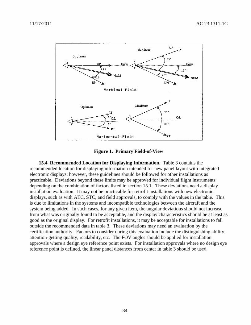
Optimum
Hori
NOM
Vertical Field
Optimum
Horizontal
11172011 AC 231311-1C
Figure 1 Primary Field-of-View
154 Recommended Location for Displaying Information Table 3 contains the recommended location for displaying information intended for new panel layout with integrated electronic displays however these guidelines should be followed for other installations as practicable Deviations beyond these limits may be approved for individual flight instruments depending on the combination of factors listed in section 151 These deviations need a display installation evaluation It may not be practicable for retrofit installations with new electronic displays such as with ATC STC and field approvals to comply with the values in the table This is due to limitations in the systems and incompatible technologies between the aircraft and the system being added In such cases for any given item the angular deviations should not increase from what was originally found to be acceptable and the display characteristics should be at least as good as the original display For retrofit installations it may be acceptable for installations to fall outside the recommended data in table 3 These deviations may need an evaluation by the certification authority Factors to consider during this evaluation include the distinguishing ability attention-getting quality readability etc The FOV angles should be applied for installation approvals where a design eye reference point exists For installation approvals where no design eye reference point is defined the linear panel distances from center in table 3 should be used
34
11172011 AC 231311-1C
Table 3 ndash Field-of-View
Data Recommended Field-of-View FOV Degree from Pilot View Centerline (Note 1)
Approx Distance (inches) From Reference Center Line (Note 1)
PFI ndash Basic T ndash Electronic or Mechanical 4 (Note 2) 2 (Note 2) Navigation Course Error Data (HSI CDI FD)
15 8
Autopilot and Flight Director Modes 15 8 Navigation Source Annunciation 15 (Note 3) 8 (Note 3) System Warnings and Cautions-Including Failure Annunciation
15 (Note 4) 8 (Note 4)
Required Powerplant 35 21 Advisories Annunciations 35 21
Standby Instruments 35 (Note 5) 21 (Note 5) Reversionary Display for PFI 35 21
Note 1 The FOV angles and approximate distance from center reference line based on a viewing distance of 30 inches from the panel are defined as acceptable angles and distance to each data source from the center of basic T or pilot view centerline Distances are measured center-to-center of the display in question and measured horizontally Vertical placement in the panel can be from just below the basic T to the glare shield
Note 2 Display PFI as close to the center of reference as possible
Note 3 The navigation source annunciation should be on or near the affected display and should appear on the same side of the basic T as the affected display The guidelines for the proximity to the affected display depend on the size color and distinguishing characteristics of the source annunciation
Note 4 Warnings and cautions annunciations should be within 15 degrees Some annunciations may be acceptable within 35 degrees if they are associated with a unique aural tone or a master warningcaution annunciations that is within 15 degrees and with a pilot evaluation If an aural tone is used it should be readily distinguishable from all other cockpit sounds and provide unambiguous information to direct the pilotrsquos attention to a visual indication of the condition
Note 5 Install the standby instruments as close as practicable to the PFI
35
11172011 AC 231311-1C
160 Luminance
161 Visual Performance All displayed information such as symbols graphics and alphanumeric characters should be clearly differentiated from one another and legible under all ambient illumination conditions TSO-C113 and SAE documents Aerospace Standard (AS) 8034 and ARPs 1668B 4067 and 4256 may be used as guidelines for evaluating the visual performance parameters of the electronic displays relative to viewing photo colorimetric luminance characteristics etc These conditions range from the night environment to direct sunlight through any window with the operational brightness at the luminance expected at the displayrsquos useful endshyof-life state The end-of-life luminance level represents the expected value of the display brightness or minimum acceptable output that is established by the manufacturer The display luminance should sufficiently provide a comfortable level of viewing with rapid adaptation when transitioning from looking outside the cockpit
162 Luminance Level The luminance level of some displays will gradually diminish over the life of the unit As part of the continued airworthiness requirements of sect 231529 consider establishing an operational in-flight evaluation or maintenance evaluation to determine the minimum luminance level appropriate for the type of display flight deck location method of format symbology color used etc Although automatic luminance control compensation is not required incorporating such a system may decrease pilot workload Regardless of whether an automatic luminance control is incorporated provide a manual luminance control that is not adversely affected by failure of any automatic luminance control Luminance control should not result in some information disappearing while other information remains visible
170 Symbology and Format
171 Symbol Attributes To minimize confusion or misinterpretation symbols should be easy to discern consistent within the cockpit and learned with minimal training Symbols should be positioned with sufficient accuracy to avoid interpretation errors or significantly increase interpretation time Symbols should not have shapes colors or other attributes that are ambiguous or could be confused with the meaning of similar symbols Symbols that represent physical objects (for example navigational aids and traffic) should not be misleading as to the objectrsquos physical characteristics (including position size envelope and orientation) Electronic displays in the cockpit should use symbology consistent with their intended function Clearly define and appropriately classify the function of symbology for the pilot The shape dynamics and other symbol characteristics representing the same function on more than one display on the same flight deck should be consistent Different symbols among different displays for the same functions may be acceptable only if it can be clearly shown that the pilot can quickly and consistently recognize interpret and respond correctly without incurring excessive pilot workload For example to indicate bank angle on the attitude displays in the cockpit the type of pointer ground (fix) or sky (moveable) should be similar for ease of interpretation and to minimize confusion
172 Symbol Standards Symbols should be based on established industry standards The symbols in the following SAE documents have been found to be acceptable for compliance to the regulations SAE ARP 41027 ARP 5289 and SAE ARP 5288 For example the use of flashing letters such as an ldquoXrdquo should be consistent One benefit of symbol standards versus other
36
11172011 AC 231311-1C
information formats is the compact encoding of information which minimizes clutter However the symbolic encoding of information should remain simple enough for pilots to learn and recall
173 Clutter Powerful formats are possible with an electronic display system but excessive information on a limited display size can result in clutter and reduce the efficiency of the pilot cues The density of information on the display should be compatible with the pilots ability to recognize essential information and to minimize misinterpretation Symbols and markings that are displayed during specific phases of flight may be removed at other times to reduce clutter Establish an information prioritization scheme to ensure the clear presentation of essential information Clutter should be a major consideration during the reversionary or compacted modes When combining essential information on a display after another display or unit fails the display format should not be confusing and the information should still be usable including unusual attitude If clutter is anticipated provide a means to manually remove the clutter (decluttering) Automatic decluttering such as during specific phases of flight or during certain alerts may also be appropriate
174 Unusual Attitude and Automatic Declutter of the PFD
a All primary attitude displays should provide an immediately discernible attitude recognition capability that fosters a safe and effective unusual attitude recovery capability The display should provide sufficient cues to enable the pilot to maintain full-time attitude awareness and to minimize potential for spatial disorientation The display should support the initiation of recovery from unusual attitudes within 1 second with a minimum correct response rate of 95 percent Additional information included on primary flight reference display(s) should not interfere with maintaining attitude awareness recovering from an unusual attitude or the interpretation of any PFI
b The PFD may require an automatic declutter function during unusual attitudes Unusual attitudes generally exceed 70 degrees of bank or +-30 degrees of pitch but may vary with airplane performance The approved configuration (whether basic-T configuration or a new configuration) should be preserved Basic navigation information on the primary navigation display does not need to be decluttered Flight guidance displayed to assist in unusual attitude recovery should be red and point to the correct direction for proper recovery SVS information on the display may need to be removed if the attitude source is no longer available See AC 20-167 for additional guidance on removing SVS information
Note Not applicable to aerobatic category airplanes
175 Digital Read-Out Alphanumeric-Only Display of Airspeed and Altitude Digital read-out presentation of airspeed and altitude should convey to the pilot a quick-glance sense of rate and trend information For airspeed and altitude digital read-out alphanumeric displays may not be adequate on the primary display or on the standby instruments but it is acceptable on a display used as supplementary information If the applicant proposes a digital read-out alphanumeric display they should show that the pilot response is equal to or better than the response with analog data (symbology) using a human factors evaluation
37
11172011 AC 231311-1C
176 Round Dial and Moving Scale Display The display of a round dial moving pointer with a digital read-out is acceptable To accommodate a larger operating range on a linear tape adopt a moving scale display with the present value on a digital readout Since the moving scale display typically does not provide any inherent visual cue of the relationship of present value to low or high airspeed limits quick-glance awareness cues may be needed
177 Low-Speed and High-Speed Awareness Cues (Linear Tape Displays)
a Airspeed displays with fixed pointers and moving scales should provide appropriate low-speed and high-speed awareness cues Conventional mechanical airspeed indicators for part 23 airplanes include simple green and white speed arcs that when combined with a moving pointer provide pilots with adequate low-speed awareness Airspeed displays incorporating fixed pointers and moving scales require more cues than conventional indicators to compensate for their deficiencies For part 23 airplanes prominent green and white arcs provide the pilot with speed cues but not enough to be considered equivalent Therefore low-speed awareness cues are necessary for part 23 airplanes
b The low-speed awareness cues should include a red arc starting at VSO and extending down toward zero airspeed During takeoff the red arc indication of low speed should not be displayed The applicant may choose an optional yellow band from VS1 down to VSO The applicant may choose a single conservative stall speed value to account for various weight and flap configurations (reference sect 231545(a)(4)) For most part 23 airplanes a fixed value at gross weight and full flaps is acceptable since this has been an adequate safety standard for mechanical gauges Incorporate a red arc or red barber pole extending from VNE or VMO upward to the end of the airspeed tape
Note The red arc below the stall speed is intended for low speed awareness only and is not intended to limit flight operation
1771 VNE Airplanes The applicant should show compliance with sectsect 231311(a)(6) and 231545 (paragraphs (a) through (d)) and incorporate the following speed awareness cues for VNE airplanes as shown in figure 2
a Incorporate red band from VSO to 0 (or minimum number)
b Incorporate red band from VNE to the top of the airspeed tape
38
11172011 AC 231311-1C
c Yellow band is optional in the low speed range from VSO to VS1 Use of the yellow band is discouraged (due to clutter) for twin-engine airplanes that incorporate a red and blue line in accordance with sect 231545 for one-engine-inoperative speeds
Red
Yellow
Green
Blank or optional yellow arc
Red
VNE
VNO
VFE
VS1
VSO
Figure 2 Low-Speed and High Speed Awareness for VNE Airplanes
39
D D
D
11172011 AC 231311-1C
1772 VMO Airplanes The applicant should show compliance with sectsect 231311(a)(6) and 231545 (paragraphs (a) through (d)) and incorporate the following speed awareness cues for VMO airplanes as shown in figure 3
a Incorporate red band from VSO to 0 (or minimum number)
b Incorporate red band from VMO to the top of the airspeed tape
c The green arc for normal operations is not required but it may be used if previously approved
d The yellow band is optional in the low speed range from VSO to VS1
Note On commuter category VMO
airplanes bugs should be provided for setting V1 and V2 This is a blank
area represented by a black arc
Red
Black
VFE
VS1
Blank or optional yellow arc
VSO
Red
Figure 3 Low-Speed and High Speed Awareness for VMO Airplanes
40
11172011 AC 231311-1C
1773 Primary Flight Display
a Low-speed awareness is an important PFD display function Stalls remain in the top five causes of fatal accidents for all types of part 23 airplanes so it makes sense to use the expanded display capability of new part 23 electronic PFDs to address low-speed awareness more effectively
b Newer part 23 airplanes are required to also have a stall warning that sounds at 5-10 percent above stall This was the best that could be afforded with existing technology Unfortunately most stalls occur in VMC and the pilot probably is not looking at the airspeed indicator when the airplane is slowing to a stall
c With electronic displays designers are not constrained to simply reproducing the old round-dial type displays The displays can have features that were not possible on conventional instruments Applicants should consider using the display capabilities to direct the pilotrsquos attention away from looking out the window or fixating on flight or navigation displays such as the FD or HSI One example the applicants might consider is flashing a large red ldquoSTALLrdquo in the center of the PFD and MFD These should be large enough to direct the pilotrsquos attention using peripheral vision Another example is to display an AOA or AOA-like display above the airplane symbol (or equivalent) essentially showing the stall margin Pilots prefer an AOA scheme so they can see their stall margin diminishing and take corrective action based on a trend
178 Linear Tape Altimeter Displays
a Linear tape altimeter displays should include enhancements denoting standard 500- and 1000-foot increments These displays should convey unambiguously at a glance the present altitude Combining altimeter scale length and markings therefore should be enough to allow sufficient resolution for precise manual altitude tracking in level flight They should also have enough scale length and markings to reinforce the pilotrsquos sense of altitude The scale length should also allow sufficient look-ahead room to adequately predict and accomplish level off Pilot evaluations have shown that in addition to the appropriate altitude markings commensurate with aircraft performance an altitude reference bug is recommended to provide acceptable cues
b Display a trend indicator unless a Vertical Speed Indicator is located adjacent and to the right of the altimeter A six-second altitude-trend indicator is typical but other trend values may be more appropriate depending on the airplane performance and altitude tape scaling
179 Standardization Guide for Integrated Cockpits in Part 23 Airplanes GAMA Publication No 12 ldquoRecommended Practices and Guidelines for an Integrated FlightdeckCockpit in a 14 CFR part 23 (or equivalent) Certificated Airplanerdquo is an acceptable means for showing compliance with applicable requirements for electronic displays in part 23 airplanes AC 23-23 or GAMA Publication No 12 and this AC should not conflict with one another GAMA Publication No 12 provides more specifics in certain areas for standardization for pilot transitions from various cockpits These specifics are acceptable but they do not cover all the issues for the installation of
41
11172011 AC 231311-1C
electronic displays One significant benefit of AC 23-23 to standardization between cockpit designs is that it should improve pilot performance (that is reduce pilot errors tasks performance times etc) when transitioning between different aircraft systems
1710 Alternative Formats Alternative formats or arrangements to those described above should have an adequate human factors evaluation completed to show that pilot response is timely and accurate to at least the level of the existing conventional displays Human factors criteria should be defined as part of the design process Because displays are a function of the specific cockpit layout and configuration human factors evidence needs to be provided during certification Specific human factors evaluations and studies that have been performed may support the configuration of displays and their location in the cockpit Validating these evaluationsstudies on each airplane during the certification process is an alternative
1711 Integration of Display Parameters Integration of several display parameters into one common display provides distinct benefits but it raises some certification issues New approaches presenting data and commands to the pilot are encouraged To overcome the issues that may occur as a result of this integration present the data and commands in a simple format to alleviate any increase in pilot workload The overall goal is to meet or exceed the existing cockpit performance levels currently in operational use while maintaining pilot workload at acceptable levels
1712 Overlays
a If overlays are provided the display format should allow the pilot to overlay weather or other graphics relevant to the flight path on one display without ambiguity Each new graphic should be evaluated both individually and with allowed combinations of other weather terrain and navigation symbology to guard against confusing the pilot or cluttering the screen When overlaying two or more functions using the same or similar color to convey different information is not recommended If the same or similar colors are required then retain the meaning of the different information Patterning bordering or blanking may be used to clearly depict the different sets of data
b If there are multiple depictions such as inset inlays or overlayed depictions the orientation (for example heading up track up North up etc) should be the same for each depiction This does not apply to other systems where the pilot and copilot may select different presentations of the same information and are used exclusively by that pilot For more information see TSO-165
c The ability to perform overlays is one of the greatest strengths of an electronic display but it also creates the potential to produce cluttered or misleading information Therefore the number of overlays should not cause the information displayed to become unusable through cluttering or obscuration Combinations of multiple data presentations should not cause conflicting interpretation of the symbology or icons
1713 Scaling Symbol attributes that use scaling and dynamics should be appropriate for the performance level of the airplane Conflicting range scaling should not occur Provide map range
42
11172011 AC 231311-1C
Always display the range scale for the primary navigation display in the same location on that manufacturerrsquos product
180 Annunciation
181 General The electronic display system should provide the pilot with visibly discernible annunciators that will indicate the system operating modes The visual annunciators should be distinctive under all normal lighting conditions Under night lighting with the display average brightness at the lowest usable level for prolonged flight visual annunciators should be usable Consistently locate annunciations in a specific area of the electronic display to ensure proper interpretation by the pilot Using the display selection control position as annunciation is acceptable only under certain conditions For the flight director it is acceptable if the control position is appropriately labeled to indicate the function The control position should be in direct view of the pilot and it should be obvious under all lighting conditions When a failure occurs or when using reversionary modes an annunciation of abnormal system status must be provided in accordance with sect 231311(a)(7) The display is not to provide any misleading information Evaluate annunciations that require pilot action to determine if the required actions could be accomplished in a timely manner without exceptional pilot skill A failure of any PFI sensor input to the PFD should be appropriately annunciated on the PFD
182 Multiple System Configurations Where multiple system configurations and more than one sensor input are available for source selection the switching configuration by annunciation or by selector switch position should be readily visible readable and should not be misleading to the pilot using the system Labels for mode and source selection annunciators should be compatible throughout the cockpit To ensure the pilot can properly interpret the system status cautionary annunciation methods should be consistent when numerous interface-switching configurations are possible
183 Alerting Messages Alerting messages should differentiate between normal and abnormal indications Abnormal indications should be clear and unmistakable using techniques such as different shapes sizes colors flashing boxing outlining etc Provide individual alerts for each function essential for safe operation
184 Visual Crew Alerting and Display Prioritization Due to the ability to display information from several sources on an integrated display a prioritization scheme ensures the continuous availability of essential information to the pilot Prioritization of warnings and caution alerts such as TAWS Predictive Windshear System (PWS) TCAS and Reactive Windshear System (RWS) have been established for small airplane applications and are shown in AC 23-18 Crew alerting information systems require appropriate prioritization of warning caution or advisory information This prioritization includes both visual and aural alerts Layering the new information over an existing moving map display or an existing weather display as a result of an automatic pop-up capability is a common technique Annunciation of any system level warning caution and advisory alert should be compatible with the alert schematic Prioritize systems information displayed on the MFD to allow ready access to critical information Less critical
43
11172011 AC 231311-1C
information may be less accessible Provide a means for the pilot to select higher priority information as needed with a single entry on the MFD control panel or keypad
185 Visual Alerts for Warnings Visual alerts for warnings that require immediate pilot action should be annunciated with an aural warning Terrain traffic and weather are typically displayed in a layered format on the ND although weather and terrain cannot be displayed at the same time in many current designs A threat should trigger an automatic pop-up and the appropriate display on the ND as well as the appropriate aural alert Subsequent alerts of a higher priority may override the visual display but the active aural alert should finish before another aural alert of equal or less urgency begins However active alerts should be interrupted by alerts from higher urgency levels if the delay to annunciate the higher-priority alert impacts the timely response of the pilot(s) When multiple alerts exist in the same category (for example multiple warning alerts) a means for the pilot to determine the most recent or most urgent should be provided Other MFD functions such as checklists synoptic and expanded systems information should only be shown when selected by the crew or displayed by phase of flight
186 Supplementary Monitoring of System Status through Independent Sensors Electronic displays may present system parameters such as engine instruments that can serve as supplementary information to the certified aircraft systems This information may use sensors that are completely independent from the originally approved sensors When supplementary information is presented using independent sensors the presentation cannot interfere or conflict with the primary information The electronic display should clearly annunciate andor display any exceedance to the pilot in the appropriate color following sectsect 231322 and 231549 The AFMS andor the Pilot Operating Handbook must clearly identify the relationship and procedures associated with those annunciations
190 Lag Time and Data Update
a The display of information essential to the safety of flight should be thoroughly responsive and accurate to the operational requirements Electronic display system delay effects of essential information including attitude airspeed altitude heading and specific propulsion parameters should not degrade the pilots ability to control the airplane Any lag introduced by the display system should be consistent with the airplane control task associated with that parameter Update rates of data on displays should be fast enough so that required symbol motion is free from objectionable lag or stepping
b SAE ARPs provide recommended lag times for display of the format and primary flight data and minimum rates for data updates to meet symbol motion A 50-60 Hz refresh rate is typically enough to remove traces of visible flicker on the display Frequencies above 55 Hz for stroke symbology or non-interlaced raster and 3060 Hz for interlace raster are generally satisfactory Some map information may be judged as adequate for enroute navigation displays with update rates of at least 1 Hz depending on the specific aircraft Update other critical data such as attitude heading or air data symbology at a rate of at least 15 Hz depending on the airplane
44
11172011 AC 231311-1C
200 Controls
a Display controls should be clearly visible labeled and usable by the pilot with the least practicable deviation from the normal position and from the line of vision when the pilot is looking forward along the flight path Controls should have an appropriate amount of tactile feel (for example detents friction stops or damping etc) so they can be changed without undue concentration which minimizes the potential for inadvertent changes Design controls for the pilot to be intuitive that is so the pilot can rapidly accurately identify and select all of the functions of the display control The controls should be identified easily and located in all lighting conditions allow differentiation of one control from another and have feedback through the system appropriate for the function being controlled
b Soft controls and cursor control devices development assurance levels should be commensurate with the level of criticality of the airplane system they will control Redundant methods of controlling the system may lessen the criticality required of the display control The final display response to control input should be fast enough to prevent undue concentration being required when the pilot sets values or display parameters The applicant should show by test andor demonstration in representative motion environment(s) (for example turbulence) that the display control is acceptable for controlling all functions that the pilot may access during these conditions
210 Test Functions The electronic display should incorporate a pilot selectable or automatic test mode such as built in testers that exercise the system to a depth appropriate to the system design Include this function even if the system failure analysis is not dependent on such a mode or if display test is also a maintenance function The test mode (or a sub mode) should display warning flags in their proper locations Exercise alerting and annunciation functions that are necessary to alert the pilot of unsafe conditions It is acceptable to incorporate the display test with a centralized cockpit light test switch to have the display test function disabled when airborne The test mode may provide a convenient means to display the software configuration
220 Color Standardization
221 General Color is considered an enhancement for understanding the display information that leads to performance improvement Select color to minimize display interpretation errors A proliferation of color sets can ultimately reduce safety rather than increase it Using contrast between basic colors provides a better differentiation of display elements than arbitrarily using colors near to each other in the color table Before defining the color standard for a specific display establish a consistent color philosophy throughout the display The FAA does not intend to limit electronic displays to the below listed colors although these have been shown to work well The following section depicts colors found acceptable for compliance with sect 231322 and other recommended colors as related to their functional meaning for electronic display systems Deviations may be approved with acceptable justification The use of the colors red and yellow for other than warnings and cautions is discouraged See TSO-C113 and TSO-C63 for additional guidance
45
11172011 AC 231311-1C
222 Color for Display Features Color code display features should be as indicated in the table below
Table 4 ndash Color for Display Features
Warnings Red Flight envelope and system limits Red Cautions abnormal sources AmberYellow Earth TanBrown Scales and associated figures White Engaged modes flight guidance Green Sky CyanBlue ILS deviation pointer Magenta Flight director bar MagentaGreen Pilot selectable references (bugs) Magenta
223 Color Sets One of the following color sets should be used as indicated in the table below
Table 5 ndash Color Sets
Color Set 1 Color Set 2
Fixed reference symbols that is lubber lines
White Yellow1
Current data values White Green Armed modes White Cyan Selected data values Green Cyan Selected heading Magenta2 Cyan Active routeflight plan Magenta White
1 The extensive use of the color yellow for other than cautionabnormal information is discouraged
2 In color set 1 magenta is associated with those analog parameters that constitute fly to or keep centered type information
46
11172011 AC 231311-1C
224 Color for Depiction of Weather Precipitation and Turbulence The depiction of weather precipitation and turbulence should be coded as indicated in the table below
Table 6 ndash Color for Depiction of Weather Precipitation and Turbulence
Precipitation 0-1 mmhr Black
1-4 mmhr Green
4-12 mmhr AmberYellow
12-50 mmhr Red
Above 50 mmhr Red or Magenta Turbulence mmhr White or Magenta Icing mmhr Light Blue
Note A background color (neutral color) will enhance display presentation
225 Color Deviation When the color assignments deviate from the above color set the applicant should ensure the chosen color assignments are not susceptible to confusion of symbol meaning and increased workload Where appropriate color assignment should be consistent with other color displays in the panel Luminance and color differences should not be confusing or ambiguous under any operating ambient illumination conditions The specific colors should be consistent with change in brightness on the displays over the full range of ambient light conditions Under high and low levels of lighting color degradation should not prevent the pilot from properly interpreting display information Where precipitation is integrated with other information the precipitation colors can be presented at half intensity Service experience has shown that this provides enhanced presentation and reduced ambiguity Warnings should be at full intensity
226 Enhancement Color is an enhancement for understanding the display information that leads to performance improvement but it should not be the sole means of discrimination of critical information Use symbols or letters as well as color to further enhance the effectiveness of the display Use of color alone has been shown to be less effective than when used with distinct symbol (object graphic or letter) Color degradation should be obvious and should not preclude the pilot from interpreting the remaining display information Displays should remain legible stable and unambiguous when operating in a degraded mode
227 Color for Warnings and Cautions For warnings and cautions sect 231322 provides specific requirements for assigning red and amber for visual annunciations Use red as the warning annunciation for emergency operating conditions when immediate pilot recognition is required and
47
11172011 AC 231311-1C
immediate correction or compensatory action may be required Use amber for the cautionary annunciation for abnormal operating conditions when immediate pilot awareness is required and subsequent pilot action may be required Use white or another unique color for advisory annunciations of operating conditions that require pilot awareness and possibly action Use green for indication of safe operating conditions
228 Airplane Flight Manual Include a complete list of warnings cautions and annunciation messages in the AFM supplemental AFM and placards If the manufacturers Pilot Operating Guide is found adequate and acceptable it may be referenced in the AFM or supplemental AFM as a means to satisfy this requirement
229 Color for Aviation Routine Weather For electronic color graphic display of aviation routine weather to surface meteorological data see TSO-C157 and AC 20-149 for guidance
230 General Installation Requirements The TCSTCATCASTC applicant must show that the installed electronic display system configuration (including hardware and software) meets the appropriate airplane certification basis This demonstration must include applicable TSO-C113 and functional TSO(s) or equivalent functional performance interoperability aircraft-level and system-level safety assessments environmental qualification system integration test flight test software assurance hardware assurance and other certification activities (as required to show compliance to the regulations) TCSTCATCASTC applicants may use TSO data to support airworthiness assessments if they show that the TSO requirements apply to the installation
240 Aircraft Electrical Power Source
241 Electrical Power Install each electronic display instrument system so that it receives electrical power from a bus that provides the necessary reliability according to the sect 231309 safety assessment without jeopardizing other essential or critical electrical loads connected to that bus The applicant should provide a means to indicate when adequate power is available for proper operation of the instrument
242 Power Interruptions Use techniques that reduce the momentary power interruptions or design the equipment so momentary power interruptions will not adversely affect the availability or integrity of essential information required for continued safe flight and landing The category selected from RTCADO-160 for momentary power interruptions should be appropriate for the intended use RTCADO-160 provides information that may be used for an acceptable means of qualifying display equipment such that they perform their intended function when subjected to anomalous input power Large electrical loads required to restart an engine (for example turboprops and small jets) should not affect the availability or integrity of essential information required for continued safe flight and landing
243 Independent Power Source
a Each reversionary or standby display providing primary flight information should be powered from a power source independent of the source for the primary display It should function independently from the power source of the primary display such as a second alternator or battery
48
11172011 AC 231311-1C
b Section 231331(c) Amendment 23-62 requires for certification of IFR operations and for the heading altitude airspeed and attitude there must be at least
(1) Two independent sources of power (not driven by the same engine on multiengine airplanes) and a manual or an automatic means to select each power source or
(2) A separate display of parameters for heading altitude airspeed and attitude that has a power source independent from the airplanes primary electrical power system
c Section 231353(h) Amendment 23-62 requires in the event of a complete loss of the primary electrical power generating system the battery must be capable of providing electrical power to those loads that are essential to continued safe flight and landing for
(1) At least 30 minutes for airplanes that are certificated with a maximum altitude of 25000 feet or less and
(2) At least 60 minutes for airplanes that are certificated with a maximum altitude over 25000 feet
Note The time period includes the time to recognize the loss of generated power and to take appropriate load shedding action
d The airplanes primary electrical power includes the airplanes electrical generating system and the airplanes starter battery when only one battery is installed The starter battery is not considered an acceptable standby power source unless a proper state of charge is monitored and displayed to the pilot The aircraft battery used for starting may satisfy the requirements of sect 231353(h) provided its adequacy is shown through a system safety analysis under sect 231309 In this case an ELOS may be required AC 23-17C provides more guidance
e The intent of this guidance may be met by a power generation and distribution architecture with multiple power sources and multiple distribution paths The paths must be designed such that any single failure of a power generation or distribution component does not adversely affect the primary reversionary or standby displays It does not need independent power generation sources for the primary and reversionary or standby displays for single engine airplanes if there is a different dedicated source
f For single engine airplanes where the engine drives the power generation devices the engine is not considered to be a single power source for this guidance For example a single-engine airplane with two engine driven alternators one powering a PFD and the other powering a reversionary PFD is considered to meet this guidance However this does not exempt the applicant from the sect 231353(h) requirements
49
11172011 AC 231311-1C
250 Safety Assessments
251 Regulations Before and After Amendment 23-41 Part 23 regulations issued before Amendment 23-41 were based on single-fault or fail-safe concepts A single failure would cause the loss of only one primary instrument function Only mechanical or electromechanical instruments that function independently of the primary parameter display were envisioned that is flight and powerplant instruments were isolated and independent Sometimes several other instrument functions (indication of the function display or indicator) are housed in a common case Since electronic displays permit presentation of several parameters on one display a failure in the electronic display may affect more than one required parameter Section 231309 Amendment 23-41 and later allowed approval of more advanced and complex systems Amendment 23-41 and later also incorporated sect 231311 into part 23 which provides the standards for electronic displays
252 Common-Mode Failures Section 231311(b) states that the electronic display indicators including their systems and installations and considering other airplane systems must be designed so that one display of information essential for continued safe flight and landing will be available within one second to the crew by a single pilot action or by automatic means for continued safe operation after any single failure or probable combination of failures In general without considering specific characteristics of an airplane design information essential to continued safe flight and landing that should be considered are attitude airspeed altitude warnings and any applicable propulsion parameter(s) Common-mode failures should be addressed See AC 231309-1E for more guidance
253 Safety Analysis
a AC 231309-1E describes safety assessment methods for identifying and classifying each failure condition and choosing the method(s) of safety assessment Certification of electronic display systems may involve new and complex technology that may not use traditional service-proven design concepts In this case technically qualified judgment can be enhanced when a quantitative analysis is included in the safety assessment whether or not a quantitative analysis is required by sect 231309
b The use of electronic displays allows a higher degree of integration than was practical with previous electromechanical instruments Evaluating failure states and determining display function criticality in highly integrated systems may be complex Safety assessment determination should refer to the display function and include all causes that could affect the displays of that function not only the display equipment
c Installing electronic systems in cockpits creates complex functional interrelationships between the pilots and the display and control systems The FHA identifies the failure conditions for all display functions analyzes the effects on the aircraft and pilot and assigns the corresponding criticality classification (no safety effect minor major hazardous catastrophic) It also considers both loss of functions malfunctions and situations that provide misleading information
50
11172011 AC 231311-1C
d A pilot initiated preflight test may be used to reduce failure exposure times associated with the safety analysis required under sect 231309 If the pilot is required to test a system before each flight assume for the safety analysis the pilot will accomplish this test at least once a day providing the preflight test is conveniently and acceptably implemented
260 Software and Hardware Development Assurance
261 General Applicants must show compliance with sect 231309 regardless of the intended function of the display system The equipment should be designed to the appropriate software and hardware development assurance level(s) based on the intended function and application of the equipment including the aircraft class in which it is to be installed (see AC 231309-1E Figure 2) The appropriate development assurance level(s) are determined by an analysis of the failure modes of the equipment and a categorization of the effects of the failure on the operation of the aircraft For the analysis for displays a failure is defined as either a loss of function or the output of misleading information Flight guidance information must meet the appropriate design assurance levels required for that function
262 Software Guidance
2621 General AC 20-115B addresses how RTCADO-178B provides an acceptable means for showing that software complies with pertinent airworthiness requirements All software used in electronic displays systems should be developed to the guidance of RTCADO-178B Software Considerations in Airborne Systems and Equipment Certification dated December 1 1992 or another acceptable means of compliance as agreed to between the applicant and the appropriate FAA ACO
2622 Software Levels Determine all software levels by appropriate safety assessments (see AC 231309-1E Figure 2) and any more requirements such as those specified by functional TSOs
2623 Field-Loadable Software (FLS) Many electronic displays systems use FLS as part of the TCATCSTCASTC installation FLS is software that can be loaded without removal of the equipment from the aircraft installation FLS might also include software loaded into a line replaceable unit (LRU) or hardware element at a repair station or shop FLS can refer to either executable code or data When obtaining certification approval for use of the FLS capability refer to the guidance in Order 811049 and AC 20-170
263 Electronic Hardware Guidance If the electronic display system contains electronic devices whose functions cannot feasibly be evaluated by test andor analysis the electronic devices should comply with AC 23-1309-1E 8110105 CHG 1 and AC 20-152 which addresses how to use RTCADO-254 These documents provide acceptable means for showing that complex hardware complies with the pertinent airworthiness requirements Determine the hardware levels for all hardware by the appropriate safety assessments (see AC 231309-1E Figure 2) and any more requirements such as those specified by functional TSOs
51
11172011 AC 231311-1C
270 Environmental Conditions
271 General The equipment environmental limits established by the manufacturer should be compatible with the operating environment of the airplane Evaluation of the equipment installation should consider factors such as the maximum operating altitude of the airplane and whether the equipment is located within a temperature and pressure-controlled area Applicable methods for testing the performance characteristics of equipment for specified environmental conditions are provided in RTCADO-160F Either test or analysis or both ensures the compatibility between the operational environment and the environmental equipment category of the laboratory tests
272 Temperature Electronic systems reliability is strongly related to the temperature of the solid-state components in the system Component temperatures are dependent on internal thermal design and external cooling In evaluating the temperature environment consider the additional heat generated by the equipment especially in a location where airflow is restricted To determine if adequate cooling is provided the evaluation should make maximum use of previous data from comparable installations thus limiting ground or flight tests to those installations that cannot be verified conveniently by other means When the equipment-operating environment cannot be verified from previous experience or from an evaluation of temperature values in that equipment location a cooling test should be conducted
273 Attitude Information It is recommended that attitude information continue to be presented for a minimum of 30 to 60 minutes after the in-flight loss of cooling for the primary instrument when operating in the normal operating environment (temperaturealtitude) If proper performance of the flight instrument function(s) is adversely affected due to in-flight loss of cooling such failure conditions should be annunciated The applicant should consider automatic over-temperature shutdown of the system a failure condition The subsequent pilot actions should be documented in the AFM or on placards These actions may include procedures to allow possible recovery of a system that has an over-temperature shutdown condition
274 Annunciation Annunciation of in-flight loss of cooling or fan monitors may not be required if it is shown by a safety analysis or test demonstration that a hazardous or catastrophic failure condition does not occur The safety analysis should consider the reliability of the fans redundancies of the functions reversionary features (such as the ability to transfer critical functions) the annunciation of over-temperature and its response time and the availability of other flight instrumentation In some systems cooling fans may only be installed to extend the life of the components and not to prevent a failure condition or shutdown of the equipment These types of installations do not require fan monitors or temperature sensors If the cooling fans are needed to prevent a hazardous or catastrophic failure condition install fan monitors or another method to determine the status of the cooling fan during preflight checks
280 Electromagnetic Protection Current trends indicate increasing reliance on electrical and electronic systems for safe operations For systems that perform flight propulsion navigation and instrumentation functions consider electromagnetic effects AC 20-136A AC 20-155 AC 20-158 AC 231309-1E and AC 23-17C provide more guidance for lightning and HIRF protection
52
11172011 AC 231311-1C
290 Electromagnetic Interference The electronic display instrument system should not be the source of detrimental conducted or radiated interference Conducted or radiated interference from other equipment or systems installed in the airplane should not adversely affect the displays
300 Implosion Protection Design and construct the display unit to prevent implosion when the unit is operating over the range of normal and abnormal operating environments in the airplane When a display unit has a component containing lower pressure than the ambient atmospheric pressure and it is susceptible to implosion no incapacitation of the pilot or adjacent equipment should result if an implosion occurs Test the display unit for the most severe environmental conditions of pressure and temperature levels Also test for variations in both normal and abnormal operating conditions (including overpressure and decompression) as specified by RTCADO-160F Similarity of a particular display to a unit already tested may be used to comply with this requirement
310 Configuration Management by Electronic Identification Guidance Configuration management may be necessary because the system may contain many hardware elements and functional software components with multiple approved configurations Identification of software components field-loaded into hardware elements may be implemented by electronic means Section 21607 requires equipment with a TSO to be permanently and legibly marked with specific information Compliance with sect 21607 may be shown when an electronic identification query system stored in non-volatile memory provides the required information This approach is commonly referred to as an ldquoelectronic TSO nameplaterdquo The electronic identification system must be verifiable on board the aircraft when the aircraft is on the ground at any geographic location The system must provide the specific information required by sect 21607 for all applicable functional TSOs being integrated All hardware elements that support a functional TSO must have a physical TSO nameplate Even when electronic identification (that is electronic nameplate) is used a physical TSO nameplate must be included on supporting hardware elements See AC 20-170 for more guidance
53
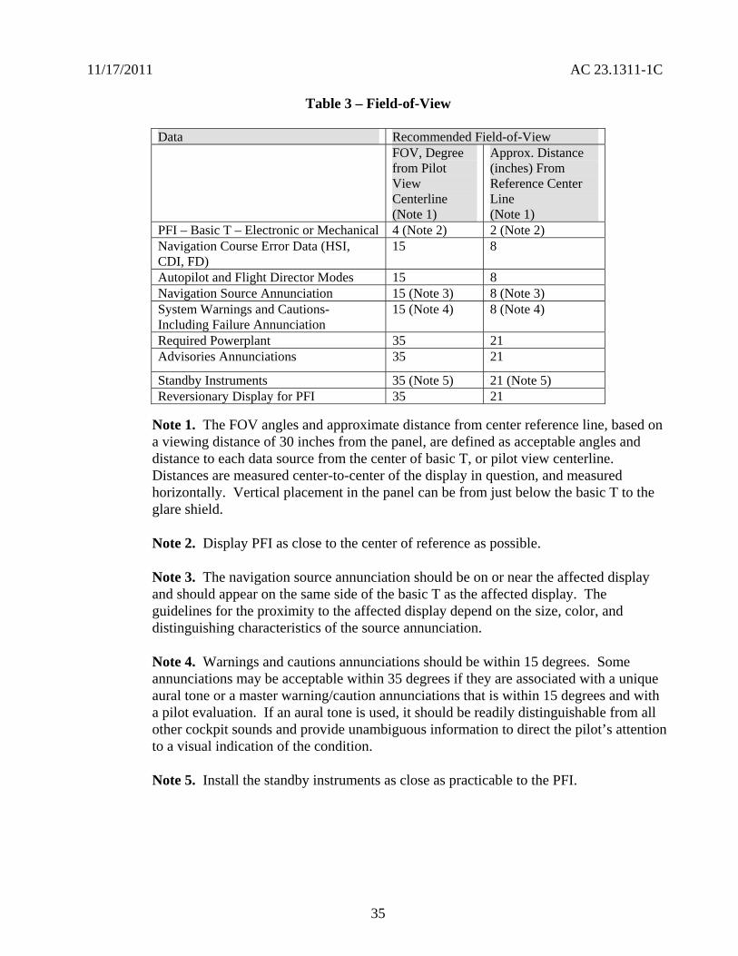
11172011 AC 231311-1C
Table 3 ndash Field-of-View
Data Recommended Field-of-View FOV Degree from Pilot View Centerline (Note 1)
Approx Distance (inches) From Reference Center Line (Note 1)
PFI ndash Basic T ndash Electronic or Mechanical 4 (Note 2) 2 (Note 2) Navigation Course Error Data (HSI CDI FD)
15 8
Autopilot and Flight Director Modes 15 8 Navigation Source Annunciation 15 (Note 3) 8 (Note 3) System Warnings and Cautions-Including Failure Annunciation
15 (Note 4) 8 (Note 4)
Required Powerplant 35 21 Advisories Annunciations 35 21
Standby Instruments 35 (Note 5) 21 (Note 5) Reversionary Display for PFI 35 21
Note 1 The FOV angles and approximate distance from center reference line based on a viewing distance of 30 inches from the panel are defined as acceptable angles and distance to each data source from the center of basic T or pilot view centerline Distances are measured center-to-center of the display in question and measured horizontally Vertical placement in the panel can be from just below the basic T to the glare shield
Note 2 Display PFI as close to the center of reference as possible
Note 3 The navigation source annunciation should be on or near the affected display and should appear on the same side of the basic T as the affected display The guidelines for the proximity to the affected display depend on the size color and distinguishing characteristics of the source annunciation
Note 4 Warnings and cautions annunciations should be within 15 degrees Some annunciations may be acceptable within 35 degrees if they are associated with a unique aural tone or a master warningcaution annunciations that is within 15 degrees and with a pilot evaluation If an aural tone is used it should be readily distinguishable from all other cockpit sounds and provide unambiguous information to direct the pilotrsquos attention to a visual indication of the condition
Note 5 Install the standby instruments as close as practicable to the PFI
35
11172011 AC 231311-1C
160 Luminance
161 Visual Performance All displayed information such as symbols graphics and alphanumeric characters should be clearly differentiated from one another and legible under all ambient illumination conditions TSO-C113 and SAE documents Aerospace Standard (AS) 8034 and ARPs 1668B 4067 and 4256 may be used as guidelines for evaluating the visual performance parameters of the electronic displays relative to viewing photo colorimetric luminance characteristics etc These conditions range from the night environment to direct sunlight through any window with the operational brightness at the luminance expected at the displayrsquos useful endshyof-life state The end-of-life luminance level represents the expected value of the display brightness or minimum acceptable output that is established by the manufacturer The display luminance should sufficiently provide a comfortable level of viewing with rapid adaptation when transitioning from looking outside the cockpit
162 Luminance Level The luminance level of some displays will gradually diminish over the life of the unit As part of the continued airworthiness requirements of sect 231529 consider establishing an operational in-flight evaluation or maintenance evaluation to determine the minimum luminance level appropriate for the type of display flight deck location method of format symbology color used etc Although automatic luminance control compensation is not required incorporating such a system may decrease pilot workload Regardless of whether an automatic luminance control is incorporated provide a manual luminance control that is not adversely affected by failure of any automatic luminance control Luminance control should not result in some information disappearing while other information remains visible
170 Symbology and Format
171 Symbol Attributes To minimize confusion or misinterpretation symbols should be easy to discern consistent within the cockpit and learned with minimal training Symbols should be positioned with sufficient accuracy to avoid interpretation errors or significantly increase interpretation time Symbols should not have shapes colors or other attributes that are ambiguous or could be confused with the meaning of similar symbols Symbols that represent physical objects (for example navigational aids and traffic) should not be misleading as to the objectrsquos physical characteristics (including position size envelope and orientation) Electronic displays in the cockpit should use symbology consistent with their intended function Clearly define and appropriately classify the function of symbology for the pilot The shape dynamics and other symbol characteristics representing the same function on more than one display on the same flight deck should be consistent Different symbols among different displays for the same functions may be acceptable only if it can be clearly shown that the pilot can quickly and consistently recognize interpret and respond correctly without incurring excessive pilot workload For example to indicate bank angle on the attitude displays in the cockpit the type of pointer ground (fix) or sky (moveable) should be similar for ease of interpretation and to minimize confusion
172 Symbol Standards Symbols should be based on established industry standards The symbols in the following SAE documents have been found to be acceptable for compliance to the regulations SAE ARP 41027 ARP 5289 and SAE ARP 5288 For example the use of flashing letters such as an ldquoXrdquo should be consistent One benefit of symbol standards versus other
36
11172011 AC 231311-1C
information formats is the compact encoding of information which minimizes clutter However the symbolic encoding of information should remain simple enough for pilots to learn and recall
173 Clutter Powerful formats are possible with an electronic display system but excessive information on a limited display size can result in clutter and reduce the efficiency of the pilot cues The density of information on the display should be compatible with the pilots ability to recognize essential information and to minimize misinterpretation Symbols and markings that are displayed during specific phases of flight may be removed at other times to reduce clutter Establish an information prioritization scheme to ensure the clear presentation of essential information Clutter should be a major consideration during the reversionary or compacted modes When combining essential information on a display after another display or unit fails the display format should not be confusing and the information should still be usable including unusual attitude If clutter is anticipated provide a means to manually remove the clutter (decluttering) Automatic decluttering such as during specific phases of flight or during certain alerts may also be appropriate
174 Unusual Attitude and Automatic Declutter of the PFD
a All primary attitude displays should provide an immediately discernible attitude recognition capability that fosters a safe and effective unusual attitude recovery capability The display should provide sufficient cues to enable the pilot to maintain full-time attitude awareness and to minimize potential for spatial disorientation The display should support the initiation of recovery from unusual attitudes within 1 second with a minimum correct response rate of 95 percent Additional information included on primary flight reference display(s) should not interfere with maintaining attitude awareness recovering from an unusual attitude or the interpretation of any PFI
b The PFD may require an automatic declutter function during unusual attitudes Unusual attitudes generally exceed 70 degrees of bank or +-30 degrees of pitch but may vary with airplane performance The approved configuration (whether basic-T configuration or a new configuration) should be preserved Basic navigation information on the primary navigation display does not need to be decluttered Flight guidance displayed to assist in unusual attitude recovery should be red and point to the correct direction for proper recovery SVS information on the display may need to be removed if the attitude source is no longer available See AC 20-167 for additional guidance on removing SVS information
Note Not applicable to aerobatic category airplanes
175 Digital Read-Out Alphanumeric-Only Display of Airspeed and Altitude Digital read-out presentation of airspeed and altitude should convey to the pilot a quick-glance sense of rate and trend information For airspeed and altitude digital read-out alphanumeric displays may not be adequate on the primary display or on the standby instruments but it is acceptable on a display used as supplementary information If the applicant proposes a digital read-out alphanumeric display they should show that the pilot response is equal to or better than the response with analog data (symbology) using a human factors evaluation
37
11172011 AC 231311-1C
176 Round Dial and Moving Scale Display The display of a round dial moving pointer with a digital read-out is acceptable To accommodate a larger operating range on a linear tape adopt a moving scale display with the present value on a digital readout Since the moving scale display typically does not provide any inherent visual cue of the relationship of present value to low or high airspeed limits quick-glance awareness cues may be needed
177 Low-Speed and High-Speed Awareness Cues (Linear Tape Displays)
a Airspeed displays with fixed pointers and moving scales should provide appropriate low-speed and high-speed awareness cues Conventional mechanical airspeed indicators for part 23 airplanes include simple green and white speed arcs that when combined with a moving pointer provide pilots with adequate low-speed awareness Airspeed displays incorporating fixed pointers and moving scales require more cues than conventional indicators to compensate for their deficiencies For part 23 airplanes prominent green and white arcs provide the pilot with speed cues but not enough to be considered equivalent Therefore low-speed awareness cues are necessary for part 23 airplanes
b The low-speed awareness cues should include a red arc starting at VSO and extending down toward zero airspeed During takeoff the red arc indication of low speed should not be displayed The applicant may choose an optional yellow band from VS1 down to VSO The applicant may choose a single conservative stall speed value to account for various weight and flap configurations (reference sect 231545(a)(4)) For most part 23 airplanes a fixed value at gross weight and full flaps is acceptable since this has been an adequate safety standard for mechanical gauges Incorporate a red arc or red barber pole extending from VNE or VMO upward to the end of the airspeed tape
Note The red arc below the stall speed is intended for low speed awareness only and is not intended to limit flight operation
1771 VNE Airplanes The applicant should show compliance with sectsect 231311(a)(6) and 231545 (paragraphs (a) through (d)) and incorporate the following speed awareness cues for VNE airplanes as shown in figure 2
a Incorporate red band from VSO to 0 (or minimum number)
b Incorporate red band from VNE to the top of the airspeed tape
38
11172011 AC 231311-1C
c Yellow band is optional in the low speed range from VSO to VS1 Use of the yellow band is discouraged (due to clutter) for twin-engine airplanes that incorporate a red and blue line in accordance with sect 231545 for one-engine-inoperative speeds
Red
Yellow
Green
Blank or optional yellow arc
Red
VNE
VNO
VFE
VS1
VSO
Figure 2 Low-Speed and High Speed Awareness for VNE Airplanes
39
D D
D
11172011 AC 231311-1C
1772 VMO Airplanes The applicant should show compliance with sectsect 231311(a)(6) and 231545 (paragraphs (a) through (d)) and incorporate the following speed awareness cues for VMO airplanes as shown in figure 3
a Incorporate red band from VSO to 0 (or minimum number)
b Incorporate red band from VMO to the top of the airspeed tape
c The green arc for normal operations is not required but it may be used if previously approved
d The yellow band is optional in the low speed range from VSO to VS1
Note On commuter category VMO
airplanes bugs should be provided for setting V1 and V2 This is a blank
area represented by a black arc
Red
Black
VFE
VS1
Blank or optional yellow arc
VSO
Red
Figure 3 Low-Speed and High Speed Awareness for VMO Airplanes
40
11172011 AC 231311-1C
1773 Primary Flight Display
a Low-speed awareness is an important PFD display function Stalls remain in the top five causes of fatal accidents for all types of part 23 airplanes so it makes sense to use the expanded display capability of new part 23 electronic PFDs to address low-speed awareness more effectively
b Newer part 23 airplanes are required to also have a stall warning that sounds at 5-10 percent above stall This was the best that could be afforded with existing technology Unfortunately most stalls occur in VMC and the pilot probably is not looking at the airspeed indicator when the airplane is slowing to a stall
c With electronic displays designers are not constrained to simply reproducing the old round-dial type displays The displays can have features that were not possible on conventional instruments Applicants should consider using the display capabilities to direct the pilotrsquos attention away from looking out the window or fixating on flight or navigation displays such as the FD or HSI One example the applicants might consider is flashing a large red ldquoSTALLrdquo in the center of the PFD and MFD These should be large enough to direct the pilotrsquos attention using peripheral vision Another example is to display an AOA or AOA-like display above the airplane symbol (or equivalent) essentially showing the stall margin Pilots prefer an AOA scheme so they can see their stall margin diminishing and take corrective action based on a trend
178 Linear Tape Altimeter Displays
a Linear tape altimeter displays should include enhancements denoting standard 500- and 1000-foot increments These displays should convey unambiguously at a glance the present altitude Combining altimeter scale length and markings therefore should be enough to allow sufficient resolution for precise manual altitude tracking in level flight They should also have enough scale length and markings to reinforce the pilotrsquos sense of altitude The scale length should also allow sufficient look-ahead room to adequately predict and accomplish level off Pilot evaluations have shown that in addition to the appropriate altitude markings commensurate with aircraft performance an altitude reference bug is recommended to provide acceptable cues
b Display a trend indicator unless a Vertical Speed Indicator is located adjacent and to the right of the altimeter A six-second altitude-trend indicator is typical but other trend values may be more appropriate depending on the airplane performance and altitude tape scaling
179 Standardization Guide for Integrated Cockpits in Part 23 Airplanes GAMA Publication No 12 ldquoRecommended Practices and Guidelines for an Integrated FlightdeckCockpit in a 14 CFR part 23 (or equivalent) Certificated Airplanerdquo is an acceptable means for showing compliance with applicable requirements for electronic displays in part 23 airplanes AC 23-23 or GAMA Publication No 12 and this AC should not conflict with one another GAMA Publication No 12 provides more specifics in certain areas for standardization for pilot transitions from various cockpits These specifics are acceptable but they do not cover all the issues for the installation of
41
11172011 AC 231311-1C
electronic displays One significant benefit of AC 23-23 to standardization between cockpit designs is that it should improve pilot performance (that is reduce pilot errors tasks performance times etc) when transitioning between different aircraft systems
1710 Alternative Formats Alternative formats or arrangements to those described above should have an adequate human factors evaluation completed to show that pilot response is timely and accurate to at least the level of the existing conventional displays Human factors criteria should be defined as part of the design process Because displays are a function of the specific cockpit layout and configuration human factors evidence needs to be provided during certification Specific human factors evaluations and studies that have been performed may support the configuration of displays and their location in the cockpit Validating these evaluationsstudies on each airplane during the certification process is an alternative
1711 Integration of Display Parameters Integration of several display parameters into one common display provides distinct benefits but it raises some certification issues New approaches presenting data and commands to the pilot are encouraged To overcome the issues that may occur as a result of this integration present the data and commands in a simple format to alleviate any increase in pilot workload The overall goal is to meet or exceed the existing cockpit performance levels currently in operational use while maintaining pilot workload at acceptable levels
1712 Overlays
a If overlays are provided the display format should allow the pilot to overlay weather or other graphics relevant to the flight path on one display without ambiguity Each new graphic should be evaluated both individually and with allowed combinations of other weather terrain and navigation symbology to guard against confusing the pilot or cluttering the screen When overlaying two or more functions using the same or similar color to convey different information is not recommended If the same or similar colors are required then retain the meaning of the different information Patterning bordering or blanking may be used to clearly depict the different sets of data
b If there are multiple depictions such as inset inlays or overlayed depictions the orientation (for example heading up track up North up etc) should be the same for each depiction This does not apply to other systems where the pilot and copilot may select different presentations of the same information and are used exclusively by that pilot For more information see TSO-165
c The ability to perform overlays is one of the greatest strengths of an electronic display but it also creates the potential to produce cluttered or misleading information Therefore the number of overlays should not cause the information displayed to become unusable through cluttering or obscuration Combinations of multiple data presentations should not cause conflicting interpretation of the symbology or icons
1713 Scaling Symbol attributes that use scaling and dynamics should be appropriate for the performance level of the airplane Conflicting range scaling should not occur Provide map range
42
11172011 AC 231311-1C
Always display the range scale for the primary navigation display in the same location on that manufacturerrsquos product
180 Annunciation
181 General The electronic display system should provide the pilot with visibly discernible annunciators that will indicate the system operating modes The visual annunciators should be distinctive under all normal lighting conditions Under night lighting with the display average brightness at the lowest usable level for prolonged flight visual annunciators should be usable Consistently locate annunciations in a specific area of the electronic display to ensure proper interpretation by the pilot Using the display selection control position as annunciation is acceptable only under certain conditions For the flight director it is acceptable if the control position is appropriately labeled to indicate the function The control position should be in direct view of the pilot and it should be obvious under all lighting conditions When a failure occurs or when using reversionary modes an annunciation of abnormal system status must be provided in accordance with sect 231311(a)(7) The display is not to provide any misleading information Evaluate annunciations that require pilot action to determine if the required actions could be accomplished in a timely manner without exceptional pilot skill A failure of any PFI sensor input to the PFD should be appropriately annunciated on the PFD
182 Multiple System Configurations Where multiple system configurations and more than one sensor input are available for source selection the switching configuration by annunciation or by selector switch position should be readily visible readable and should not be misleading to the pilot using the system Labels for mode and source selection annunciators should be compatible throughout the cockpit To ensure the pilot can properly interpret the system status cautionary annunciation methods should be consistent when numerous interface-switching configurations are possible
183 Alerting Messages Alerting messages should differentiate between normal and abnormal indications Abnormal indications should be clear and unmistakable using techniques such as different shapes sizes colors flashing boxing outlining etc Provide individual alerts for each function essential for safe operation
184 Visual Crew Alerting and Display Prioritization Due to the ability to display information from several sources on an integrated display a prioritization scheme ensures the continuous availability of essential information to the pilot Prioritization of warnings and caution alerts such as TAWS Predictive Windshear System (PWS) TCAS and Reactive Windshear System (RWS) have been established for small airplane applications and are shown in AC 23-18 Crew alerting information systems require appropriate prioritization of warning caution or advisory information This prioritization includes both visual and aural alerts Layering the new information over an existing moving map display or an existing weather display as a result of an automatic pop-up capability is a common technique Annunciation of any system level warning caution and advisory alert should be compatible with the alert schematic Prioritize systems information displayed on the MFD to allow ready access to critical information Less critical
43
11172011 AC 231311-1C
information may be less accessible Provide a means for the pilot to select higher priority information as needed with a single entry on the MFD control panel or keypad
185 Visual Alerts for Warnings Visual alerts for warnings that require immediate pilot action should be annunciated with an aural warning Terrain traffic and weather are typically displayed in a layered format on the ND although weather and terrain cannot be displayed at the same time in many current designs A threat should trigger an automatic pop-up and the appropriate display on the ND as well as the appropriate aural alert Subsequent alerts of a higher priority may override the visual display but the active aural alert should finish before another aural alert of equal or less urgency begins However active alerts should be interrupted by alerts from higher urgency levels if the delay to annunciate the higher-priority alert impacts the timely response of the pilot(s) When multiple alerts exist in the same category (for example multiple warning alerts) a means for the pilot to determine the most recent or most urgent should be provided Other MFD functions such as checklists synoptic and expanded systems information should only be shown when selected by the crew or displayed by phase of flight
186 Supplementary Monitoring of System Status through Independent Sensors Electronic displays may present system parameters such as engine instruments that can serve as supplementary information to the certified aircraft systems This information may use sensors that are completely independent from the originally approved sensors When supplementary information is presented using independent sensors the presentation cannot interfere or conflict with the primary information The electronic display should clearly annunciate andor display any exceedance to the pilot in the appropriate color following sectsect 231322 and 231549 The AFMS andor the Pilot Operating Handbook must clearly identify the relationship and procedures associated with those annunciations
190 Lag Time and Data Update
a The display of information essential to the safety of flight should be thoroughly responsive and accurate to the operational requirements Electronic display system delay effects of essential information including attitude airspeed altitude heading and specific propulsion parameters should not degrade the pilots ability to control the airplane Any lag introduced by the display system should be consistent with the airplane control task associated with that parameter Update rates of data on displays should be fast enough so that required symbol motion is free from objectionable lag or stepping
b SAE ARPs provide recommended lag times for display of the format and primary flight data and minimum rates for data updates to meet symbol motion A 50-60 Hz refresh rate is typically enough to remove traces of visible flicker on the display Frequencies above 55 Hz for stroke symbology or non-interlaced raster and 3060 Hz for interlace raster are generally satisfactory Some map information may be judged as adequate for enroute navigation displays with update rates of at least 1 Hz depending on the specific aircraft Update other critical data such as attitude heading or air data symbology at a rate of at least 15 Hz depending on the airplane
44
11172011 AC 231311-1C
200 Controls
a Display controls should be clearly visible labeled and usable by the pilot with the least practicable deviation from the normal position and from the line of vision when the pilot is looking forward along the flight path Controls should have an appropriate amount of tactile feel (for example detents friction stops or damping etc) so they can be changed without undue concentration which minimizes the potential for inadvertent changes Design controls for the pilot to be intuitive that is so the pilot can rapidly accurately identify and select all of the functions of the display control The controls should be identified easily and located in all lighting conditions allow differentiation of one control from another and have feedback through the system appropriate for the function being controlled
b Soft controls and cursor control devices development assurance levels should be commensurate with the level of criticality of the airplane system they will control Redundant methods of controlling the system may lessen the criticality required of the display control The final display response to control input should be fast enough to prevent undue concentration being required when the pilot sets values or display parameters The applicant should show by test andor demonstration in representative motion environment(s) (for example turbulence) that the display control is acceptable for controlling all functions that the pilot may access during these conditions
210 Test Functions The electronic display should incorporate a pilot selectable or automatic test mode such as built in testers that exercise the system to a depth appropriate to the system design Include this function even if the system failure analysis is not dependent on such a mode or if display test is also a maintenance function The test mode (or a sub mode) should display warning flags in their proper locations Exercise alerting and annunciation functions that are necessary to alert the pilot of unsafe conditions It is acceptable to incorporate the display test with a centralized cockpit light test switch to have the display test function disabled when airborne The test mode may provide a convenient means to display the software configuration
220 Color Standardization
221 General Color is considered an enhancement for understanding the display information that leads to performance improvement Select color to minimize display interpretation errors A proliferation of color sets can ultimately reduce safety rather than increase it Using contrast between basic colors provides a better differentiation of display elements than arbitrarily using colors near to each other in the color table Before defining the color standard for a specific display establish a consistent color philosophy throughout the display The FAA does not intend to limit electronic displays to the below listed colors although these have been shown to work well The following section depicts colors found acceptable for compliance with sect 231322 and other recommended colors as related to their functional meaning for electronic display systems Deviations may be approved with acceptable justification The use of the colors red and yellow for other than warnings and cautions is discouraged See TSO-C113 and TSO-C63 for additional guidance
45
11172011 AC 231311-1C
222 Color for Display Features Color code display features should be as indicated in the table below
Table 4 ndash Color for Display Features
Warnings Red Flight envelope and system limits Red Cautions abnormal sources AmberYellow Earth TanBrown Scales and associated figures White Engaged modes flight guidance Green Sky CyanBlue ILS deviation pointer Magenta Flight director bar MagentaGreen Pilot selectable references (bugs) Magenta
223 Color Sets One of the following color sets should be used as indicated in the table below
Table 5 ndash Color Sets
Color Set 1 Color Set 2
Fixed reference symbols that is lubber lines
White Yellow1
Current data values White Green Armed modes White Cyan Selected data values Green Cyan Selected heading Magenta2 Cyan Active routeflight plan Magenta White
1 The extensive use of the color yellow for other than cautionabnormal information is discouraged
2 In color set 1 magenta is associated with those analog parameters that constitute fly to or keep centered type information
46
11172011 AC 231311-1C
224 Color for Depiction of Weather Precipitation and Turbulence The depiction of weather precipitation and turbulence should be coded as indicated in the table below
Table 6 ndash Color for Depiction of Weather Precipitation and Turbulence
Precipitation 0-1 mmhr Black
1-4 mmhr Green
4-12 mmhr AmberYellow
12-50 mmhr Red
Above 50 mmhr Red or Magenta Turbulence mmhr White or Magenta Icing mmhr Light Blue
Note A background color (neutral color) will enhance display presentation
225 Color Deviation When the color assignments deviate from the above color set the applicant should ensure the chosen color assignments are not susceptible to confusion of symbol meaning and increased workload Where appropriate color assignment should be consistent with other color displays in the panel Luminance and color differences should not be confusing or ambiguous under any operating ambient illumination conditions The specific colors should be consistent with change in brightness on the displays over the full range of ambient light conditions Under high and low levels of lighting color degradation should not prevent the pilot from properly interpreting display information Where precipitation is integrated with other information the precipitation colors can be presented at half intensity Service experience has shown that this provides enhanced presentation and reduced ambiguity Warnings should be at full intensity
226 Enhancement Color is an enhancement for understanding the display information that leads to performance improvement but it should not be the sole means of discrimination of critical information Use symbols or letters as well as color to further enhance the effectiveness of the display Use of color alone has been shown to be less effective than when used with distinct symbol (object graphic or letter) Color degradation should be obvious and should not preclude the pilot from interpreting the remaining display information Displays should remain legible stable and unambiguous when operating in a degraded mode
227 Color for Warnings and Cautions For warnings and cautions sect 231322 provides specific requirements for assigning red and amber for visual annunciations Use red as the warning annunciation for emergency operating conditions when immediate pilot recognition is required and
47
11172011 AC 231311-1C
immediate correction or compensatory action may be required Use amber for the cautionary annunciation for abnormal operating conditions when immediate pilot awareness is required and subsequent pilot action may be required Use white or another unique color for advisory annunciations of operating conditions that require pilot awareness and possibly action Use green for indication of safe operating conditions
228 Airplane Flight Manual Include a complete list of warnings cautions and annunciation messages in the AFM supplemental AFM and placards If the manufacturers Pilot Operating Guide is found adequate and acceptable it may be referenced in the AFM or supplemental AFM as a means to satisfy this requirement
229 Color for Aviation Routine Weather For electronic color graphic display of aviation routine weather to surface meteorological data see TSO-C157 and AC 20-149 for guidance
230 General Installation Requirements The TCSTCATCASTC applicant must show that the installed electronic display system configuration (including hardware and software) meets the appropriate airplane certification basis This demonstration must include applicable TSO-C113 and functional TSO(s) or equivalent functional performance interoperability aircraft-level and system-level safety assessments environmental qualification system integration test flight test software assurance hardware assurance and other certification activities (as required to show compliance to the regulations) TCSTCATCASTC applicants may use TSO data to support airworthiness assessments if they show that the TSO requirements apply to the installation
240 Aircraft Electrical Power Source
241 Electrical Power Install each electronic display instrument system so that it receives electrical power from a bus that provides the necessary reliability according to the sect 231309 safety assessment without jeopardizing other essential or critical electrical loads connected to that bus The applicant should provide a means to indicate when adequate power is available for proper operation of the instrument
242 Power Interruptions Use techniques that reduce the momentary power interruptions or design the equipment so momentary power interruptions will not adversely affect the availability or integrity of essential information required for continued safe flight and landing The category selected from RTCADO-160 for momentary power interruptions should be appropriate for the intended use RTCADO-160 provides information that may be used for an acceptable means of qualifying display equipment such that they perform their intended function when subjected to anomalous input power Large electrical loads required to restart an engine (for example turboprops and small jets) should not affect the availability or integrity of essential information required for continued safe flight and landing
243 Independent Power Source
a Each reversionary or standby display providing primary flight information should be powered from a power source independent of the source for the primary display It should function independently from the power source of the primary display such as a second alternator or battery
48
11172011 AC 231311-1C
b Section 231331(c) Amendment 23-62 requires for certification of IFR operations and for the heading altitude airspeed and attitude there must be at least
(1) Two independent sources of power (not driven by the same engine on multiengine airplanes) and a manual or an automatic means to select each power source or
(2) A separate display of parameters for heading altitude airspeed and attitude that has a power source independent from the airplanes primary electrical power system
c Section 231353(h) Amendment 23-62 requires in the event of a complete loss of the primary electrical power generating system the battery must be capable of providing electrical power to those loads that are essential to continued safe flight and landing for
(1) At least 30 minutes for airplanes that are certificated with a maximum altitude of 25000 feet or less and
(2) At least 60 minutes for airplanes that are certificated with a maximum altitude over 25000 feet
Note The time period includes the time to recognize the loss of generated power and to take appropriate load shedding action
d The airplanes primary electrical power includes the airplanes electrical generating system and the airplanes starter battery when only one battery is installed The starter battery is not considered an acceptable standby power source unless a proper state of charge is monitored and displayed to the pilot The aircraft battery used for starting may satisfy the requirements of sect 231353(h) provided its adequacy is shown through a system safety analysis under sect 231309 In this case an ELOS may be required AC 23-17C provides more guidance
e The intent of this guidance may be met by a power generation and distribution architecture with multiple power sources and multiple distribution paths The paths must be designed such that any single failure of a power generation or distribution component does not adversely affect the primary reversionary or standby displays It does not need independent power generation sources for the primary and reversionary or standby displays for single engine airplanes if there is a different dedicated source
f For single engine airplanes where the engine drives the power generation devices the engine is not considered to be a single power source for this guidance For example a single-engine airplane with two engine driven alternators one powering a PFD and the other powering a reversionary PFD is considered to meet this guidance However this does not exempt the applicant from the sect 231353(h) requirements
49
11172011 AC 231311-1C
250 Safety Assessments
251 Regulations Before and After Amendment 23-41 Part 23 regulations issued before Amendment 23-41 were based on single-fault or fail-safe concepts A single failure would cause the loss of only one primary instrument function Only mechanical or electromechanical instruments that function independently of the primary parameter display were envisioned that is flight and powerplant instruments were isolated and independent Sometimes several other instrument functions (indication of the function display or indicator) are housed in a common case Since electronic displays permit presentation of several parameters on one display a failure in the electronic display may affect more than one required parameter Section 231309 Amendment 23-41 and later allowed approval of more advanced and complex systems Amendment 23-41 and later also incorporated sect 231311 into part 23 which provides the standards for electronic displays
252 Common-Mode Failures Section 231311(b) states that the electronic display indicators including their systems and installations and considering other airplane systems must be designed so that one display of information essential for continued safe flight and landing will be available within one second to the crew by a single pilot action or by automatic means for continued safe operation after any single failure or probable combination of failures In general without considering specific characteristics of an airplane design information essential to continued safe flight and landing that should be considered are attitude airspeed altitude warnings and any applicable propulsion parameter(s) Common-mode failures should be addressed See AC 231309-1E for more guidance
253 Safety Analysis
a AC 231309-1E describes safety assessment methods for identifying and classifying each failure condition and choosing the method(s) of safety assessment Certification of electronic display systems may involve new and complex technology that may not use traditional service-proven design concepts In this case technically qualified judgment can be enhanced when a quantitative analysis is included in the safety assessment whether or not a quantitative analysis is required by sect 231309
b The use of electronic displays allows a higher degree of integration than was practical with previous electromechanical instruments Evaluating failure states and determining display function criticality in highly integrated systems may be complex Safety assessment determination should refer to the display function and include all causes that could affect the displays of that function not only the display equipment
c Installing electronic systems in cockpits creates complex functional interrelationships between the pilots and the display and control systems The FHA identifies the failure conditions for all display functions analyzes the effects on the aircraft and pilot and assigns the corresponding criticality classification (no safety effect minor major hazardous catastrophic) It also considers both loss of functions malfunctions and situations that provide misleading information
50
11172011 AC 231311-1C
d A pilot initiated preflight test may be used to reduce failure exposure times associated with the safety analysis required under sect 231309 If the pilot is required to test a system before each flight assume for the safety analysis the pilot will accomplish this test at least once a day providing the preflight test is conveniently and acceptably implemented
260 Software and Hardware Development Assurance
261 General Applicants must show compliance with sect 231309 regardless of the intended function of the display system The equipment should be designed to the appropriate software and hardware development assurance level(s) based on the intended function and application of the equipment including the aircraft class in which it is to be installed (see AC 231309-1E Figure 2) The appropriate development assurance level(s) are determined by an analysis of the failure modes of the equipment and a categorization of the effects of the failure on the operation of the aircraft For the analysis for displays a failure is defined as either a loss of function or the output of misleading information Flight guidance information must meet the appropriate design assurance levels required for that function
262 Software Guidance
2621 General AC 20-115B addresses how RTCADO-178B provides an acceptable means for showing that software complies with pertinent airworthiness requirements All software used in electronic displays systems should be developed to the guidance of RTCADO-178B Software Considerations in Airborne Systems and Equipment Certification dated December 1 1992 or another acceptable means of compliance as agreed to between the applicant and the appropriate FAA ACO
2622 Software Levels Determine all software levels by appropriate safety assessments (see AC 231309-1E Figure 2) and any more requirements such as those specified by functional TSOs
2623 Field-Loadable Software (FLS) Many electronic displays systems use FLS as part of the TCATCSTCASTC installation FLS is software that can be loaded without removal of the equipment from the aircraft installation FLS might also include software loaded into a line replaceable unit (LRU) or hardware element at a repair station or shop FLS can refer to either executable code or data When obtaining certification approval for use of the FLS capability refer to the guidance in Order 811049 and AC 20-170
263 Electronic Hardware Guidance If the electronic display system contains electronic devices whose functions cannot feasibly be evaluated by test andor analysis the electronic devices should comply with AC 23-1309-1E 8110105 CHG 1 and AC 20-152 which addresses how to use RTCADO-254 These documents provide acceptable means for showing that complex hardware complies with the pertinent airworthiness requirements Determine the hardware levels for all hardware by the appropriate safety assessments (see AC 231309-1E Figure 2) and any more requirements such as those specified by functional TSOs
51
11172011 AC 231311-1C
270 Environmental Conditions
271 General The equipment environmental limits established by the manufacturer should be compatible with the operating environment of the airplane Evaluation of the equipment installation should consider factors such as the maximum operating altitude of the airplane and whether the equipment is located within a temperature and pressure-controlled area Applicable methods for testing the performance characteristics of equipment for specified environmental conditions are provided in RTCADO-160F Either test or analysis or both ensures the compatibility between the operational environment and the environmental equipment category of the laboratory tests
272 Temperature Electronic systems reliability is strongly related to the temperature of the solid-state components in the system Component temperatures are dependent on internal thermal design and external cooling In evaluating the temperature environment consider the additional heat generated by the equipment especially in a location where airflow is restricted To determine if adequate cooling is provided the evaluation should make maximum use of previous data from comparable installations thus limiting ground or flight tests to those installations that cannot be verified conveniently by other means When the equipment-operating environment cannot be verified from previous experience or from an evaluation of temperature values in that equipment location a cooling test should be conducted
273 Attitude Information It is recommended that attitude information continue to be presented for a minimum of 30 to 60 minutes after the in-flight loss of cooling for the primary instrument when operating in the normal operating environment (temperaturealtitude) If proper performance of the flight instrument function(s) is adversely affected due to in-flight loss of cooling such failure conditions should be annunciated The applicant should consider automatic over-temperature shutdown of the system a failure condition The subsequent pilot actions should be documented in the AFM or on placards These actions may include procedures to allow possible recovery of a system that has an over-temperature shutdown condition
274 Annunciation Annunciation of in-flight loss of cooling or fan monitors may not be required if it is shown by a safety analysis or test demonstration that a hazardous or catastrophic failure condition does not occur The safety analysis should consider the reliability of the fans redundancies of the functions reversionary features (such as the ability to transfer critical functions) the annunciation of over-temperature and its response time and the availability of other flight instrumentation In some systems cooling fans may only be installed to extend the life of the components and not to prevent a failure condition or shutdown of the equipment These types of installations do not require fan monitors or temperature sensors If the cooling fans are needed to prevent a hazardous or catastrophic failure condition install fan monitors or another method to determine the status of the cooling fan during preflight checks
280 Electromagnetic Protection Current trends indicate increasing reliance on electrical and electronic systems for safe operations For systems that perform flight propulsion navigation and instrumentation functions consider electromagnetic effects AC 20-136A AC 20-155 AC 20-158 AC 231309-1E and AC 23-17C provide more guidance for lightning and HIRF protection
52
11172011 AC 231311-1C
290 Electromagnetic Interference The electronic display instrument system should not be the source of detrimental conducted or radiated interference Conducted or radiated interference from other equipment or systems installed in the airplane should not adversely affect the displays
300 Implosion Protection Design and construct the display unit to prevent implosion when the unit is operating over the range of normal and abnormal operating environments in the airplane When a display unit has a component containing lower pressure than the ambient atmospheric pressure and it is susceptible to implosion no incapacitation of the pilot or adjacent equipment should result if an implosion occurs Test the display unit for the most severe environmental conditions of pressure and temperature levels Also test for variations in both normal and abnormal operating conditions (including overpressure and decompression) as specified by RTCADO-160F Similarity of a particular display to a unit already tested may be used to comply with this requirement
310 Configuration Management by Electronic Identification Guidance Configuration management may be necessary because the system may contain many hardware elements and functional software components with multiple approved configurations Identification of software components field-loaded into hardware elements may be implemented by electronic means Section 21607 requires equipment with a TSO to be permanently and legibly marked with specific information Compliance with sect 21607 may be shown when an electronic identification query system stored in non-volatile memory provides the required information This approach is commonly referred to as an ldquoelectronic TSO nameplaterdquo The electronic identification system must be verifiable on board the aircraft when the aircraft is on the ground at any geographic location The system must provide the specific information required by sect 21607 for all applicable functional TSOs being integrated All hardware elements that support a functional TSO must have a physical TSO nameplate Even when electronic identification (that is electronic nameplate) is used a physical TSO nameplate must be included on supporting hardware elements See AC 20-170 for more guidance
53
11172011 AC 231311-1C
176 Round Dial and Moving Scale Display The display of a round dial moving pointer with a digital read-out is acceptable To accommodate a larger operating range on a linear tape adopt a moving scale display with the present value on a digital readout Since the moving scale display typically does not provide any inherent visual cue of the relationship of present value to low or high airspeed limits quick-glance awareness cues may be needed
177 Low-Speed and High-Speed Awareness Cues (Linear Tape Displays)
a Airspeed displays with fixed pointers and moving scales should provide appropriate low-speed and high-speed awareness cues Conventional mechanical airspeed indicators for part 23 airplanes include simple green and white speed arcs that when combined with a moving pointer provide pilots with adequate low-speed awareness Airspeed displays incorporating fixed pointers and moving scales require more cues than conventional indicators to compensate for their deficiencies For part 23 airplanes prominent green and white arcs provide the pilot with speed cues but not enough to be considered equivalent Therefore low-speed awareness cues are necessary for part 23 airplanes
b The low-speed awareness cues should include a red arc starting at VSO and extending down toward zero airspeed During takeoff the red arc indication of low speed should not be displayed The applicant may choose an optional yellow band from VS1 down to VSO The applicant may choose a single conservative stall speed value to account for various weight and flap configurations (reference sect 231545(a)(4)) For most part 23 airplanes a fixed value at gross weight and full flaps is acceptable since this has been an adequate safety standard for mechanical gauges Incorporate a red arc or red barber pole extending from VNE or VMO upward to the end of the airspeed tape
Note The red arc below the stall speed is intended for low speed awareness only and is not intended to limit flight operation
1771 VNE Airplanes The applicant should show compliance with sectsect 231311(a)(6) and 231545 (paragraphs (a) through (d)) and incorporate the following speed awareness cues for VNE airplanes as shown in figure 2
a Incorporate red band from VSO to 0 (or minimum number)
b Incorporate red band from VNE to the top of the airspeed tape
38
11172011 AC 231311-1C
c Yellow band is optional in the low speed range from VSO to VS1 Use of the yellow band is discouraged (due to clutter) for twin-engine airplanes that incorporate a red and blue line in accordance with sect 231545 for one-engine-inoperative speeds
Red
Yellow
Green
Blank or optional yellow arc
Red
VNE
VNO
VFE
VS1
VSO
Figure 2 Low-Speed and High Speed Awareness for VNE Airplanes
39
D D
D
11172011 AC 231311-1C
1772 VMO Airplanes The applicant should show compliance with sectsect 231311(a)(6) and 231545 (paragraphs (a) through (d)) and incorporate the following speed awareness cues for VMO airplanes as shown in figure 3
a Incorporate red band from VSO to 0 (or minimum number)
b Incorporate red band from VMO to the top of the airspeed tape
c The green arc for normal operations is not required but it may be used if previously approved
d The yellow band is optional in the low speed range from VSO to VS1
Note On commuter category VMO
airplanes bugs should be provided for setting V1 and V2 This is a blank
area represented by a black arc
Red
Black
VFE
VS1
Blank or optional yellow arc
VSO
Red
Figure 3 Low-Speed and High Speed Awareness for VMO Airplanes
40
11172011 AC 231311-1C
1773 Primary Flight Display
a Low-speed awareness is an important PFD display function Stalls remain in the top five causes of fatal accidents for all types of part 23 airplanes so it makes sense to use the expanded display capability of new part 23 electronic PFDs to address low-speed awareness more effectively
b Newer part 23 airplanes are required to also have a stall warning that sounds at 5-10 percent above stall This was the best that could be afforded with existing technology Unfortunately most stalls occur in VMC and the pilot probably is not looking at the airspeed indicator when the airplane is slowing to a stall
c With electronic displays designers are not constrained to simply reproducing the old round-dial type displays The displays can have features that were not possible on conventional instruments Applicants should consider using the display capabilities to direct the pilotrsquos attention away from looking out the window or fixating on flight or navigation displays such as the FD or HSI One example the applicants might consider is flashing a large red ldquoSTALLrdquo in the center of the PFD and MFD These should be large enough to direct the pilotrsquos attention using peripheral vision Another example is to display an AOA or AOA-like display above the airplane symbol (or equivalent) essentially showing the stall margin Pilots prefer an AOA scheme so they can see their stall margin diminishing and take corrective action based on a trend
178 Linear Tape Altimeter Displays
a Linear tape altimeter displays should include enhancements denoting standard 500- and 1000-foot increments These displays should convey unambiguously at a glance the present altitude Combining altimeter scale length and markings therefore should be enough to allow sufficient resolution for precise manual altitude tracking in level flight They should also have enough scale length and markings to reinforce the pilotrsquos sense of altitude The scale length should also allow sufficient look-ahead room to adequately predict and accomplish level off Pilot evaluations have shown that in addition to the appropriate altitude markings commensurate with aircraft performance an altitude reference bug is recommended to provide acceptable cues
b Display a trend indicator unless a Vertical Speed Indicator is located adjacent and to the right of the altimeter A six-second altitude-trend indicator is typical but other trend values may be more appropriate depending on the airplane performance and altitude tape scaling
179 Standardization Guide for Integrated Cockpits in Part 23 Airplanes GAMA Publication No 12 ldquoRecommended Practices and Guidelines for an Integrated FlightdeckCockpit in a 14 CFR part 23 (or equivalent) Certificated Airplanerdquo is an acceptable means for showing compliance with applicable requirements for electronic displays in part 23 airplanes AC 23-23 or GAMA Publication No 12 and this AC should not conflict with one another GAMA Publication No 12 provides more specifics in certain areas for standardization for pilot transitions from various cockpits These specifics are acceptable but they do not cover all the issues for the installation of
41
11172011 AC 231311-1C
electronic displays One significant benefit of AC 23-23 to standardization between cockpit designs is that it should improve pilot performance (that is reduce pilot errors tasks performance times etc) when transitioning between different aircraft systems
1710 Alternative Formats Alternative formats or arrangements to those described above should have an adequate human factors evaluation completed to show that pilot response is timely and accurate to at least the level of the existing conventional displays Human factors criteria should be defined as part of the design process Because displays are a function of the specific cockpit layout and configuration human factors evidence needs to be provided during certification Specific human factors evaluations and studies that have been performed may support the configuration of displays and their location in the cockpit Validating these evaluationsstudies on each airplane during the certification process is an alternative
1711 Integration of Display Parameters Integration of several display parameters into one common display provides distinct benefits but it raises some certification issues New approaches presenting data and commands to the pilot are encouraged To overcome the issues that may occur as a result of this integration present the data and commands in a simple format to alleviate any increase in pilot workload The overall goal is to meet or exceed the existing cockpit performance levels currently in operational use while maintaining pilot workload at acceptable levels
1712 Overlays
a If overlays are provided the display format should allow the pilot to overlay weather or other graphics relevant to the flight path on one display without ambiguity Each new graphic should be evaluated both individually and with allowed combinations of other weather terrain and navigation symbology to guard against confusing the pilot or cluttering the screen When overlaying two or more functions using the same or similar color to convey different information is not recommended If the same or similar colors are required then retain the meaning of the different information Patterning bordering or blanking may be used to clearly depict the different sets of data
b If there are multiple depictions such as inset inlays or overlayed depictions the orientation (for example heading up track up North up etc) should be the same for each depiction This does not apply to other systems where the pilot and copilot may select different presentations of the same information and are used exclusively by that pilot For more information see TSO-165
c The ability to perform overlays is one of the greatest strengths of an electronic display but it also creates the potential to produce cluttered or misleading information Therefore the number of overlays should not cause the information displayed to become unusable through cluttering or obscuration Combinations of multiple data presentations should not cause conflicting interpretation of the symbology or icons
1713 Scaling Symbol attributes that use scaling and dynamics should be appropriate for the performance level of the airplane Conflicting range scaling should not occur Provide map range
42
11172011 AC 231311-1C
Always display the range scale for the primary navigation display in the same location on that manufacturerrsquos product
180 Annunciation
181 General The electronic display system should provide the pilot with visibly discernible annunciators that will indicate the system operating modes The visual annunciators should be distinctive under all normal lighting conditions Under night lighting with the display average brightness at the lowest usable level for prolonged flight visual annunciators should be usable Consistently locate annunciations in a specific area of the electronic display to ensure proper interpretation by the pilot Using the display selection control position as annunciation is acceptable only under certain conditions For the flight director it is acceptable if the control position is appropriately labeled to indicate the function The control position should be in direct view of the pilot and it should be obvious under all lighting conditions When a failure occurs or when using reversionary modes an annunciation of abnormal system status must be provided in accordance with sect 231311(a)(7) The display is not to provide any misleading information Evaluate annunciations that require pilot action to determine if the required actions could be accomplished in a timely manner without exceptional pilot skill A failure of any PFI sensor input to the PFD should be appropriately annunciated on the PFD
182 Multiple System Configurations Where multiple system configurations and more than one sensor input are available for source selection the switching configuration by annunciation or by selector switch position should be readily visible readable and should not be misleading to the pilot using the system Labels for mode and source selection annunciators should be compatible throughout the cockpit To ensure the pilot can properly interpret the system status cautionary annunciation methods should be consistent when numerous interface-switching configurations are possible
183 Alerting Messages Alerting messages should differentiate between normal and abnormal indications Abnormal indications should be clear and unmistakable using techniques such as different shapes sizes colors flashing boxing outlining etc Provide individual alerts for each function essential for safe operation
184 Visual Crew Alerting and Display Prioritization Due to the ability to display information from several sources on an integrated display a prioritization scheme ensures the continuous availability of essential information to the pilot Prioritization of warnings and caution alerts such as TAWS Predictive Windshear System (PWS) TCAS and Reactive Windshear System (RWS) have been established for small airplane applications and are shown in AC 23-18 Crew alerting information systems require appropriate prioritization of warning caution or advisory information This prioritization includes both visual and aural alerts Layering the new information over an existing moving map display or an existing weather display as a result of an automatic pop-up capability is a common technique Annunciation of any system level warning caution and advisory alert should be compatible with the alert schematic Prioritize systems information displayed on the MFD to allow ready access to critical information Less critical
43
11172011 AC 231311-1C
information may be less accessible Provide a means for the pilot to select higher priority information as needed with a single entry on the MFD control panel or keypad
185 Visual Alerts for Warnings Visual alerts for warnings that require immediate pilot action should be annunciated with an aural warning Terrain traffic and weather are typically displayed in a layered format on the ND although weather and terrain cannot be displayed at the same time in many current designs A threat should trigger an automatic pop-up and the appropriate display on the ND as well as the appropriate aural alert Subsequent alerts of a higher priority may override the visual display but the active aural alert should finish before another aural alert of equal or less urgency begins However active alerts should be interrupted by alerts from higher urgency levels if the delay to annunciate the higher-priority alert impacts the timely response of the pilot(s) When multiple alerts exist in the same category (for example multiple warning alerts) a means for the pilot to determine the most recent or most urgent should be provided Other MFD functions such as checklists synoptic and expanded systems information should only be shown when selected by the crew or displayed by phase of flight
186 Supplementary Monitoring of System Status through Independent Sensors Electronic displays may present system parameters such as engine instruments that can serve as supplementary information to the certified aircraft systems This information may use sensors that are completely independent from the originally approved sensors When supplementary information is presented using independent sensors the presentation cannot interfere or conflict with the primary information The electronic display should clearly annunciate andor display any exceedance to the pilot in the appropriate color following sectsect 231322 and 231549 The AFMS andor the Pilot Operating Handbook must clearly identify the relationship and procedures associated with those annunciations
190 Lag Time and Data Update
a The display of information essential to the safety of flight should be thoroughly responsive and accurate to the operational requirements Electronic display system delay effects of essential information including attitude airspeed altitude heading and specific propulsion parameters should not degrade the pilots ability to control the airplane Any lag introduced by the display system should be consistent with the airplane control task associated with that parameter Update rates of data on displays should be fast enough so that required symbol motion is free from objectionable lag or stepping
b SAE ARPs provide recommended lag times for display of the format and primary flight data and minimum rates for data updates to meet symbol motion A 50-60 Hz refresh rate is typically enough to remove traces of visible flicker on the display Frequencies above 55 Hz for stroke symbology or non-interlaced raster and 3060 Hz for interlace raster are generally satisfactory Some map information may be judged as adequate for enroute navigation displays with update rates of at least 1 Hz depending on the specific aircraft Update other critical data such as attitude heading or air data symbology at a rate of at least 15 Hz depending on the airplane
44
11172011 AC 231311-1C
200 Controls
a Display controls should be clearly visible labeled and usable by the pilot with the least practicable deviation from the normal position and from the line of vision when the pilot is looking forward along the flight path Controls should have an appropriate amount of tactile feel (for example detents friction stops or damping etc) so they can be changed without undue concentration which minimizes the potential for inadvertent changes Design controls for the pilot to be intuitive that is so the pilot can rapidly accurately identify and select all of the functions of the display control The controls should be identified easily and located in all lighting conditions allow differentiation of one control from another and have feedback through the system appropriate for the function being controlled
b Soft controls and cursor control devices development assurance levels should be commensurate with the level of criticality of the airplane system they will control Redundant methods of controlling the system may lessen the criticality required of the display control The final display response to control input should be fast enough to prevent undue concentration being required when the pilot sets values or display parameters The applicant should show by test andor demonstration in representative motion environment(s) (for example turbulence) that the display control is acceptable for controlling all functions that the pilot may access during these conditions
210 Test Functions The electronic display should incorporate a pilot selectable or automatic test mode such as built in testers that exercise the system to a depth appropriate to the system design Include this function even if the system failure analysis is not dependent on such a mode or if display test is also a maintenance function The test mode (or a sub mode) should display warning flags in their proper locations Exercise alerting and annunciation functions that are necessary to alert the pilot of unsafe conditions It is acceptable to incorporate the display test with a centralized cockpit light test switch to have the display test function disabled when airborne The test mode may provide a convenient means to display the software configuration
220 Color Standardization
221 General Color is considered an enhancement for understanding the display information that leads to performance improvement Select color to minimize display interpretation errors A proliferation of color sets can ultimately reduce safety rather than increase it Using contrast between basic colors provides a better differentiation of display elements than arbitrarily using colors near to each other in the color table Before defining the color standard for a specific display establish a consistent color philosophy throughout the display The FAA does not intend to limit electronic displays to the below listed colors although these have been shown to work well The following section depicts colors found acceptable for compliance with sect 231322 and other recommended colors as related to their functional meaning for electronic display systems Deviations may be approved with acceptable justification The use of the colors red and yellow for other than warnings and cautions is discouraged See TSO-C113 and TSO-C63 for additional guidance
45
11172011 AC 231311-1C
222 Color for Display Features Color code display features should be as indicated in the table below
Table 4 ndash Color for Display Features
Warnings Red Flight envelope and system limits Red Cautions abnormal sources AmberYellow Earth TanBrown Scales and associated figures White Engaged modes flight guidance Green Sky CyanBlue ILS deviation pointer Magenta Flight director bar MagentaGreen Pilot selectable references (bugs) Magenta
223 Color Sets One of the following color sets should be used as indicated in the table below
Table 5 ndash Color Sets
Color Set 1 Color Set 2
Fixed reference symbols that is lubber lines
White Yellow1
Current data values White Green Armed modes White Cyan Selected data values Green Cyan Selected heading Magenta2 Cyan Active routeflight plan Magenta White
1 The extensive use of the color yellow for other than cautionabnormal information is discouraged
2 In color set 1 magenta is associated with those analog parameters that constitute fly to or keep centered type information
46
11172011 AC 231311-1C
224 Color for Depiction of Weather Precipitation and Turbulence The depiction of weather precipitation and turbulence should be coded as indicated in the table below
Table 6 ndash Color for Depiction of Weather Precipitation and Turbulence
Precipitation 0-1 mmhr Black
1-4 mmhr Green
4-12 mmhr AmberYellow
12-50 mmhr Red
Above 50 mmhr Red or Magenta Turbulence mmhr White or Magenta Icing mmhr Light Blue
Note A background color (neutral color) will enhance display presentation
225 Color Deviation When the color assignments deviate from the above color set the applicant should ensure the chosen color assignments are not susceptible to confusion of symbol meaning and increased workload Where appropriate color assignment should be consistent with other color displays in the panel Luminance and color differences should not be confusing or ambiguous under any operating ambient illumination conditions The specific colors should be consistent with change in brightness on the displays over the full range of ambient light conditions Under high and low levels of lighting color degradation should not prevent the pilot from properly interpreting display information Where precipitation is integrated with other information the precipitation colors can be presented at half intensity Service experience has shown that this provides enhanced presentation and reduced ambiguity Warnings should be at full intensity
226 Enhancement Color is an enhancement for understanding the display information that leads to performance improvement but it should not be the sole means of discrimination of critical information Use symbols or letters as well as color to further enhance the effectiveness of the display Use of color alone has been shown to be less effective than when used with distinct symbol (object graphic or letter) Color degradation should be obvious and should not preclude the pilot from interpreting the remaining display information Displays should remain legible stable and unambiguous when operating in a degraded mode
227 Color for Warnings and Cautions For warnings and cautions sect 231322 provides specific requirements for assigning red and amber for visual annunciations Use red as the warning annunciation for emergency operating conditions when immediate pilot recognition is required and
47
11172011 AC 231311-1C
immediate correction or compensatory action may be required Use amber for the cautionary annunciation for abnormal operating conditions when immediate pilot awareness is required and subsequent pilot action may be required Use white or another unique color for advisory annunciations of operating conditions that require pilot awareness and possibly action Use green for indication of safe operating conditions
228 Airplane Flight Manual Include a complete list of warnings cautions and annunciation messages in the AFM supplemental AFM and placards If the manufacturers Pilot Operating Guide is found adequate and acceptable it may be referenced in the AFM or supplemental AFM as a means to satisfy this requirement
229 Color for Aviation Routine Weather For electronic color graphic display of aviation routine weather to surface meteorological data see TSO-C157 and AC 20-149 for guidance
230 General Installation Requirements The TCSTCATCASTC applicant must show that the installed electronic display system configuration (including hardware and software) meets the appropriate airplane certification basis This demonstration must include applicable TSO-C113 and functional TSO(s) or equivalent functional performance interoperability aircraft-level and system-level safety assessments environmental qualification system integration test flight test software assurance hardware assurance and other certification activities (as required to show compliance to the regulations) TCSTCATCASTC applicants may use TSO data to support airworthiness assessments if they show that the TSO requirements apply to the installation
240 Aircraft Electrical Power Source
241 Electrical Power Install each electronic display instrument system so that it receives electrical power from a bus that provides the necessary reliability according to the sect 231309 safety assessment without jeopardizing other essential or critical electrical loads connected to that bus The applicant should provide a means to indicate when adequate power is available for proper operation of the instrument
242 Power Interruptions Use techniques that reduce the momentary power interruptions or design the equipment so momentary power interruptions will not adversely affect the availability or integrity of essential information required for continued safe flight and landing The category selected from RTCADO-160 for momentary power interruptions should be appropriate for the intended use RTCADO-160 provides information that may be used for an acceptable means of qualifying display equipment such that they perform their intended function when subjected to anomalous input power Large electrical loads required to restart an engine (for example turboprops and small jets) should not affect the availability or integrity of essential information required for continued safe flight and landing
243 Independent Power Source
a Each reversionary or standby display providing primary flight information should be powered from a power source independent of the source for the primary display It should function independently from the power source of the primary display such as a second alternator or battery
48
11172011 AC 231311-1C
b Section 231331(c) Amendment 23-62 requires for certification of IFR operations and for the heading altitude airspeed and attitude there must be at least
(1) Two independent sources of power (not driven by the same engine on multiengine airplanes) and a manual or an automatic means to select each power source or
(2) A separate display of parameters for heading altitude airspeed and attitude that has a power source independent from the airplanes primary electrical power system
c Section 231353(h) Amendment 23-62 requires in the event of a complete loss of the primary electrical power generating system the battery must be capable of providing electrical power to those loads that are essential to continued safe flight and landing for
(1) At least 30 minutes for airplanes that are certificated with a maximum altitude of 25000 feet or less and
(2) At least 60 minutes for airplanes that are certificated with a maximum altitude over 25000 feet
Note The time period includes the time to recognize the loss of generated power and to take appropriate load shedding action
d The airplanes primary electrical power includes the airplanes electrical generating system and the airplanes starter battery when only one battery is installed The starter battery is not considered an acceptable standby power source unless a proper state of charge is monitored and displayed to the pilot The aircraft battery used for starting may satisfy the requirements of sect 231353(h) provided its adequacy is shown through a system safety analysis under sect 231309 In this case an ELOS may be required AC 23-17C provides more guidance
e The intent of this guidance may be met by a power generation and distribution architecture with multiple power sources and multiple distribution paths The paths must be designed such that any single failure of a power generation or distribution component does not adversely affect the primary reversionary or standby displays It does not need independent power generation sources for the primary and reversionary or standby displays for single engine airplanes if there is a different dedicated source
f For single engine airplanes where the engine drives the power generation devices the engine is not considered to be a single power source for this guidance For example a single-engine airplane with two engine driven alternators one powering a PFD and the other powering a reversionary PFD is considered to meet this guidance However this does not exempt the applicant from the sect 231353(h) requirements
49
11172011 AC 231311-1C
250 Safety Assessments
251 Regulations Before and After Amendment 23-41 Part 23 regulations issued before Amendment 23-41 were based on single-fault or fail-safe concepts A single failure would cause the loss of only one primary instrument function Only mechanical or electromechanical instruments that function independently of the primary parameter display were envisioned that is flight and powerplant instruments were isolated and independent Sometimes several other instrument functions (indication of the function display or indicator) are housed in a common case Since electronic displays permit presentation of several parameters on one display a failure in the electronic display may affect more than one required parameter Section 231309 Amendment 23-41 and later allowed approval of more advanced and complex systems Amendment 23-41 and later also incorporated sect 231311 into part 23 which provides the standards for electronic displays
252 Common-Mode Failures Section 231311(b) states that the electronic display indicators including their systems and installations and considering other airplane systems must be designed so that one display of information essential for continued safe flight and landing will be available within one second to the crew by a single pilot action or by automatic means for continued safe operation after any single failure or probable combination of failures In general without considering specific characteristics of an airplane design information essential to continued safe flight and landing that should be considered are attitude airspeed altitude warnings and any applicable propulsion parameter(s) Common-mode failures should be addressed See AC 231309-1E for more guidance
253 Safety Analysis
a AC 231309-1E describes safety assessment methods for identifying and classifying each failure condition and choosing the method(s) of safety assessment Certification of electronic display systems may involve new and complex technology that may not use traditional service-proven design concepts In this case technically qualified judgment can be enhanced when a quantitative analysis is included in the safety assessment whether or not a quantitative analysis is required by sect 231309
b The use of electronic displays allows a higher degree of integration than was practical with previous electromechanical instruments Evaluating failure states and determining display function criticality in highly integrated systems may be complex Safety assessment determination should refer to the display function and include all causes that could affect the displays of that function not only the display equipment
c Installing electronic systems in cockpits creates complex functional interrelationships between the pilots and the display and control systems The FHA identifies the failure conditions for all display functions analyzes the effects on the aircraft and pilot and assigns the corresponding criticality classification (no safety effect minor major hazardous catastrophic) It also considers both loss of functions malfunctions and situations that provide misleading information
50
11172011 AC 231311-1C
d A pilot initiated preflight test may be used to reduce failure exposure times associated with the safety analysis required under sect 231309 If the pilot is required to test a system before each flight assume for the safety analysis the pilot will accomplish this test at least once a day providing the preflight test is conveniently and acceptably implemented
260 Software and Hardware Development Assurance
261 General Applicants must show compliance with sect 231309 regardless of the intended function of the display system The equipment should be designed to the appropriate software and hardware development assurance level(s) based on the intended function and application of the equipment including the aircraft class in which it is to be installed (see AC 231309-1E Figure 2) The appropriate development assurance level(s) are determined by an analysis of the failure modes of the equipment and a categorization of the effects of the failure on the operation of the aircraft For the analysis for displays a failure is defined as either a loss of function or the output of misleading information Flight guidance information must meet the appropriate design assurance levels required for that function
262 Software Guidance
2621 General AC 20-115B addresses how RTCADO-178B provides an acceptable means for showing that software complies with pertinent airworthiness requirements All software used in electronic displays systems should be developed to the guidance of RTCADO-178B Software Considerations in Airborne Systems and Equipment Certification dated December 1 1992 or another acceptable means of compliance as agreed to between the applicant and the appropriate FAA ACO
2622 Software Levels Determine all software levels by appropriate safety assessments (see AC 231309-1E Figure 2) and any more requirements such as those specified by functional TSOs
2623 Field-Loadable Software (FLS) Many electronic displays systems use FLS as part of the TCATCSTCASTC installation FLS is software that can be loaded without removal of the equipment from the aircraft installation FLS might also include software loaded into a line replaceable unit (LRU) or hardware element at a repair station or shop FLS can refer to either executable code or data When obtaining certification approval for use of the FLS capability refer to the guidance in Order 811049 and AC 20-170
263 Electronic Hardware Guidance If the electronic display system contains electronic devices whose functions cannot feasibly be evaluated by test andor analysis the electronic devices should comply with AC 23-1309-1E 8110105 CHG 1 and AC 20-152 which addresses how to use RTCADO-254 These documents provide acceptable means for showing that complex hardware complies with the pertinent airworthiness requirements Determine the hardware levels for all hardware by the appropriate safety assessments (see AC 231309-1E Figure 2) and any more requirements such as those specified by functional TSOs
51
11172011 AC 231311-1C
270 Environmental Conditions
271 General The equipment environmental limits established by the manufacturer should be compatible with the operating environment of the airplane Evaluation of the equipment installation should consider factors such as the maximum operating altitude of the airplane and whether the equipment is located within a temperature and pressure-controlled area Applicable methods for testing the performance characteristics of equipment for specified environmental conditions are provided in RTCADO-160F Either test or analysis or both ensures the compatibility between the operational environment and the environmental equipment category of the laboratory tests
272 Temperature Electronic systems reliability is strongly related to the temperature of the solid-state components in the system Component temperatures are dependent on internal thermal design and external cooling In evaluating the temperature environment consider the additional heat generated by the equipment especially in a location where airflow is restricted To determine if adequate cooling is provided the evaluation should make maximum use of previous data from comparable installations thus limiting ground or flight tests to those installations that cannot be verified conveniently by other means When the equipment-operating environment cannot be verified from previous experience or from an evaluation of temperature values in that equipment location a cooling test should be conducted
273 Attitude Information It is recommended that attitude information continue to be presented for a minimum of 30 to 60 minutes after the in-flight loss of cooling for the primary instrument when operating in the normal operating environment (temperaturealtitude) If proper performance of the flight instrument function(s) is adversely affected due to in-flight loss of cooling such failure conditions should be annunciated The applicant should consider automatic over-temperature shutdown of the system a failure condition The subsequent pilot actions should be documented in the AFM or on placards These actions may include procedures to allow possible recovery of a system that has an over-temperature shutdown condition
274 Annunciation Annunciation of in-flight loss of cooling or fan monitors may not be required if it is shown by a safety analysis or test demonstration that a hazardous or catastrophic failure condition does not occur The safety analysis should consider the reliability of the fans redundancies of the functions reversionary features (such as the ability to transfer critical functions) the annunciation of over-temperature and its response time and the availability of other flight instrumentation In some systems cooling fans may only be installed to extend the life of the components and not to prevent a failure condition or shutdown of the equipment These types of installations do not require fan monitors or temperature sensors If the cooling fans are needed to prevent a hazardous or catastrophic failure condition install fan monitors or another method to determine the status of the cooling fan during preflight checks
280 Electromagnetic Protection Current trends indicate increasing reliance on electrical and electronic systems for safe operations For systems that perform flight propulsion navigation and instrumentation functions consider electromagnetic effects AC 20-136A AC 20-155 AC 20-158 AC 231309-1E and AC 23-17C provide more guidance for lightning and HIRF protection
52
11172011 AC 231311-1C
290 Electromagnetic Interference The electronic display instrument system should not be the source of detrimental conducted or radiated interference Conducted or radiated interference from other equipment or systems installed in the airplane should not adversely affect the displays
300 Implosion Protection Design and construct the display unit to prevent implosion when the unit is operating over the range of normal and abnormal operating environments in the airplane When a display unit has a component containing lower pressure than the ambient atmospheric pressure and it is susceptible to implosion no incapacitation of the pilot or adjacent equipment should result if an implosion occurs Test the display unit for the most severe environmental conditions of pressure and temperature levels Also test for variations in both normal and abnormal operating conditions (including overpressure and decompression) as specified by RTCADO-160F Similarity of a particular display to a unit already tested may be used to comply with this requirement
310 Configuration Management by Electronic Identification Guidance Configuration management may be necessary because the system may contain many hardware elements and functional software components with multiple approved configurations Identification of software components field-loaded into hardware elements may be implemented by electronic means Section 21607 requires equipment with a TSO to be permanently and legibly marked with specific information Compliance with sect 21607 may be shown when an electronic identification query system stored in non-volatile memory provides the required information This approach is commonly referred to as an ldquoelectronic TSO nameplaterdquo The electronic identification system must be verifiable on board the aircraft when the aircraft is on the ground at any geographic location The system must provide the specific information required by sect 21607 for all applicable functional TSOs being integrated All hardware elements that support a functional TSO must have a physical TSO nameplate Even when electronic identification (that is electronic nameplate) is used a physical TSO nameplate must be included on supporting hardware elements See AC 20-170 for more guidance
53
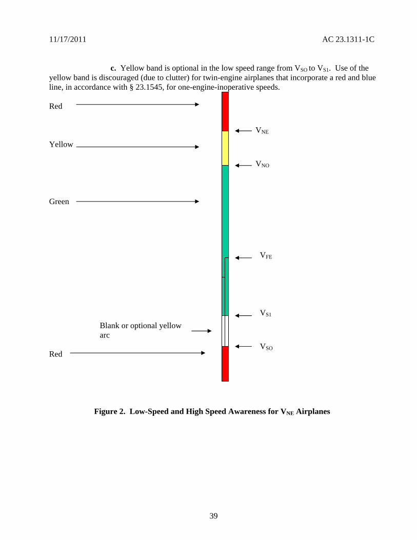
11172011 AC 231311-1C
c Yellow band is optional in the low speed range from VSO to VS1 Use of the yellow band is discouraged (due to clutter) for twin-engine airplanes that incorporate a red and blue line in accordance with sect 231545 for one-engine-inoperative speeds
Red
Yellow
Green
Blank or optional yellow arc
Red
VNE
VNO
VFE
VS1
VSO
Figure 2 Low-Speed and High Speed Awareness for VNE Airplanes
39
D D
D
11172011 AC 231311-1C
1772 VMO Airplanes The applicant should show compliance with sectsect 231311(a)(6) and 231545 (paragraphs (a) through (d)) and incorporate the following speed awareness cues for VMO airplanes as shown in figure 3
a Incorporate red band from VSO to 0 (or minimum number)
b Incorporate red band from VMO to the top of the airspeed tape
c The green arc for normal operations is not required but it may be used if previously approved
d The yellow band is optional in the low speed range from VSO to VS1
Note On commuter category VMO
airplanes bugs should be provided for setting V1 and V2 This is a blank
area represented by a black arc
Red
Black
VFE
VS1
Blank or optional yellow arc
VSO
Red
Figure 3 Low-Speed and High Speed Awareness for VMO Airplanes
40
11172011 AC 231311-1C
1773 Primary Flight Display
a Low-speed awareness is an important PFD display function Stalls remain in the top five causes of fatal accidents for all types of part 23 airplanes so it makes sense to use the expanded display capability of new part 23 electronic PFDs to address low-speed awareness more effectively
b Newer part 23 airplanes are required to also have a stall warning that sounds at 5-10 percent above stall This was the best that could be afforded with existing technology Unfortunately most stalls occur in VMC and the pilot probably is not looking at the airspeed indicator when the airplane is slowing to a stall
c With electronic displays designers are not constrained to simply reproducing the old round-dial type displays The displays can have features that were not possible on conventional instruments Applicants should consider using the display capabilities to direct the pilotrsquos attention away from looking out the window or fixating on flight or navigation displays such as the FD or HSI One example the applicants might consider is flashing a large red ldquoSTALLrdquo in the center of the PFD and MFD These should be large enough to direct the pilotrsquos attention using peripheral vision Another example is to display an AOA or AOA-like display above the airplane symbol (or equivalent) essentially showing the stall margin Pilots prefer an AOA scheme so they can see their stall margin diminishing and take corrective action based on a trend
178 Linear Tape Altimeter Displays
a Linear tape altimeter displays should include enhancements denoting standard 500- and 1000-foot increments These displays should convey unambiguously at a glance the present altitude Combining altimeter scale length and markings therefore should be enough to allow sufficient resolution for precise manual altitude tracking in level flight They should also have enough scale length and markings to reinforce the pilotrsquos sense of altitude The scale length should also allow sufficient look-ahead room to adequately predict and accomplish level off Pilot evaluations have shown that in addition to the appropriate altitude markings commensurate with aircraft performance an altitude reference bug is recommended to provide acceptable cues
b Display a trend indicator unless a Vertical Speed Indicator is located adjacent and to the right of the altimeter A six-second altitude-trend indicator is typical but other trend values may be more appropriate depending on the airplane performance and altitude tape scaling
179 Standardization Guide for Integrated Cockpits in Part 23 Airplanes GAMA Publication No 12 ldquoRecommended Practices and Guidelines for an Integrated FlightdeckCockpit in a 14 CFR part 23 (or equivalent) Certificated Airplanerdquo is an acceptable means for showing compliance with applicable requirements for electronic displays in part 23 airplanes AC 23-23 or GAMA Publication No 12 and this AC should not conflict with one another GAMA Publication No 12 provides more specifics in certain areas for standardization for pilot transitions from various cockpits These specifics are acceptable but they do not cover all the issues for the installation of
41
11172011 AC 231311-1C
electronic displays One significant benefit of AC 23-23 to standardization between cockpit designs is that it should improve pilot performance (that is reduce pilot errors tasks performance times etc) when transitioning between different aircraft systems
1710 Alternative Formats Alternative formats or arrangements to those described above should have an adequate human factors evaluation completed to show that pilot response is timely and accurate to at least the level of the existing conventional displays Human factors criteria should be defined as part of the design process Because displays are a function of the specific cockpit layout and configuration human factors evidence needs to be provided during certification Specific human factors evaluations and studies that have been performed may support the configuration of displays and their location in the cockpit Validating these evaluationsstudies on each airplane during the certification process is an alternative
1711 Integration of Display Parameters Integration of several display parameters into one common display provides distinct benefits but it raises some certification issues New approaches presenting data and commands to the pilot are encouraged To overcome the issues that may occur as a result of this integration present the data and commands in a simple format to alleviate any increase in pilot workload The overall goal is to meet or exceed the existing cockpit performance levels currently in operational use while maintaining pilot workload at acceptable levels
1712 Overlays
a If overlays are provided the display format should allow the pilot to overlay weather or other graphics relevant to the flight path on one display without ambiguity Each new graphic should be evaluated both individually and with allowed combinations of other weather terrain and navigation symbology to guard against confusing the pilot or cluttering the screen When overlaying two or more functions using the same or similar color to convey different information is not recommended If the same or similar colors are required then retain the meaning of the different information Patterning bordering or blanking may be used to clearly depict the different sets of data
b If there are multiple depictions such as inset inlays or overlayed depictions the orientation (for example heading up track up North up etc) should be the same for each depiction This does not apply to other systems where the pilot and copilot may select different presentations of the same information and are used exclusively by that pilot For more information see TSO-165
c The ability to perform overlays is one of the greatest strengths of an electronic display but it also creates the potential to produce cluttered or misleading information Therefore the number of overlays should not cause the information displayed to become unusable through cluttering or obscuration Combinations of multiple data presentations should not cause conflicting interpretation of the symbology or icons
1713 Scaling Symbol attributes that use scaling and dynamics should be appropriate for the performance level of the airplane Conflicting range scaling should not occur Provide map range
42
11172011 AC 231311-1C
Always display the range scale for the primary navigation display in the same location on that manufacturerrsquos product
180 Annunciation
181 General The electronic display system should provide the pilot with visibly discernible annunciators that will indicate the system operating modes The visual annunciators should be distinctive under all normal lighting conditions Under night lighting with the display average brightness at the lowest usable level for prolonged flight visual annunciators should be usable Consistently locate annunciations in a specific area of the electronic display to ensure proper interpretation by the pilot Using the display selection control position as annunciation is acceptable only under certain conditions For the flight director it is acceptable if the control position is appropriately labeled to indicate the function The control position should be in direct view of the pilot and it should be obvious under all lighting conditions When a failure occurs or when using reversionary modes an annunciation of abnormal system status must be provided in accordance with sect 231311(a)(7) The display is not to provide any misleading information Evaluate annunciations that require pilot action to determine if the required actions could be accomplished in a timely manner without exceptional pilot skill A failure of any PFI sensor input to the PFD should be appropriately annunciated on the PFD
182 Multiple System Configurations Where multiple system configurations and more than one sensor input are available for source selection the switching configuration by annunciation or by selector switch position should be readily visible readable and should not be misleading to the pilot using the system Labels for mode and source selection annunciators should be compatible throughout the cockpit To ensure the pilot can properly interpret the system status cautionary annunciation methods should be consistent when numerous interface-switching configurations are possible
183 Alerting Messages Alerting messages should differentiate between normal and abnormal indications Abnormal indications should be clear and unmistakable using techniques such as different shapes sizes colors flashing boxing outlining etc Provide individual alerts for each function essential for safe operation
184 Visual Crew Alerting and Display Prioritization Due to the ability to display information from several sources on an integrated display a prioritization scheme ensures the continuous availability of essential information to the pilot Prioritization of warnings and caution alerts such as TAWS Predictive Windshear System (PWS) TCAS and Reactive Windshear System (RWS) have been established for small airplane applications and are shown in AC 23-18 Crew alerting information systems require appropriate prioritization of warning caution or advisory information This prioritization includes both visual and aural alerts Layering the new information over an existing moving map display or an existing weather display as a result of an automatic pop-up capability is a common technique Annunciation of any system level warning caution and advisory alert should be compatible with the alert schematic Prioritize systems information displayed on the MFD to allow ready access to critical information Less critical
43
11172011 AC 231311-1C
information may be less accessible Provide a means for the pilot to select higher priority information as needed with a single entry on the MFD control panel or keypad
185 Visual Alerts for Warnings Visual alerts for warnings that require immediate pilot action should be annunciated with an aural warning Terrain traffic and weather are typically displayed in a layered format on the ND although weather and terrain cannot be displayed at the same time in many current designs A threat should trigger an automatic pop-up and the appropriate display on the ND as well as the appropriate aural alert Subsequent alerts of a higher priority may override the visual display but the active aural alert should finish before another aural alert of equal or less urgency begins However active alerts should be interrupted by alerts from higher urgency levels if the delay to annunciate the higher-priority alert impacts the timely response of the pilot(s) When multiple alerts exist in the same category (for example multiple warning alerts) a means for the pilot to determine the most recent or most urgent should be provided Other MFD functions such as checklists synoptic and expanded systems information should only be shown when selected by the crew or displayed by phase of flight
186 Supplementary Monitoring of System Status through Independent Sensors Electronic displays may present system parameters such as engine instruments that can serve as supplementary information to the certified aircraft systems This information may use sensors that are completely independent from the originally approved sensors When supplementary information is presented using independent sensors the presentation cannot interfere or conflict with the primary information The electronic display should clearly annunciate andor display any exceedance to the pilot in the appropriate color following sectsect 231322 and 231549 The AFMS andor the Pilot Operating Handbook must clearly identify the relationship and procedures associated with those annunciations
190 Lag Time and Data Update
a The display of information essential to the safety of flight should be thoroughly responsive and accurate to the operational requirements Electronic display system delay effects of essential information including attitude airspeed altitude heading and specific propulsion parameters should not degrade the pilots ability to control the airplane Any lag introduced by the display system should be consistent with the airplane control task associated with that parameter Update rates of data on displays should be fast enough so that required symbol motion is free from objectionable lag or stepping
b SAE ARPs provide recommended lag times for display of the format and primary flight data and minimum rates for data updates to meet symbol motion A 50-60 Hz refresh rate is typically enough to remove traces of visible flicker on the display Frequencies above 55 Hz for stroke symbology or non-interlaced raster and 3060 Hz for interlace raster are generally satisfactory Some map information may be judged as adequate for enroute navigation displays with update rates of at least 1 Hz depending on the specific aircraft Update other critical data such as attitude heading or air data symbology at a rate of at least 15 Hz depending on the airplane
44
11172011 AC 231311-1C
200 Controls
a Display controls should be clearly visible labeled and usable by the pilot with the least practicable deviation from the normal position and from the line of vision when the pilot is looking forward along the flight path Controls should have an appropriate amount of tactile feel (for example detents friction stops or damping etc) so they can be changed without undue concentration which minimizes the potential for inadvertent changes Design controls for the pilot to be intuitive that is so the pilot can rapidly accurately identify and select all of the functions of the display control The controls should be identified easily and located in all lighting conditions allow differentiation of one control from another and have feedback through the system appropriate for the function being controlled
b Soft controls and cursor control devices development assurance levels should be commensurate with the level of criticality of the airplane system they will control Redundant methods of controlling the system may lessen the criticality required of the display control The final display response to control input should be fast enough to prevent undue concentration being required when the pilot sets values or display parameters The applicant should show by test andor demonstration in representative motion environment(s) (for example turbulence) that the display control is acceptable for controlling all functions that the pilot may access during these conditions
210 Test Functions The electronic display should incorporate a pilot selectable or automatic test mode such as built in testers that exercise the system to a depth appropriate to the system design Include this function even if the system failure analysis is not dependent on such a mode or if display test is also a maintenance function The test mode (or a sub mode) should display warning flags in their proper locations Exercise alerting and annunciation functions that are necessary to alert the pilot of unsafe conditions It is acceptable to incorporate the display test with a centralized cockpit light test switch to have the display test function disabled when airborne The test mode may provide a convenient means to display the software configuration
220 Color Standardization
221 General Color is considered an enhancement for understanding the display information that leads to performance improvement Select color to minimize display interpretation errors A proliferation of color sets can ultimately reduce safety rather than increase it Using contrast between basic colors provides a better differentiation of display elements than arbitrarily using colors near to each other in the color table Before defining the color standard for a specific display establish a consistent color philosophy throughout the display The FAA does not intend to limit electronic displays to the below listed colors although these have been shown to work well The following section depicts colors found acceptable for compliance with sect 231322 and other recommended colors as related to their functional meaning for electronic display systems Deviations may be approved with acceptable justification The use of the colors red and yellow for other than warnings and cautions is discouraged See TSO-C113 and TSO-C63 for additional guidance
45
11172011 AC 231311-1C
222 Color for Display Features Color code display features should be as indicated in the table below
Table 4 ndash Color for Display Features
Warnings Red Flight envelope and system limits Red Cautions abnormal sources AmberYellow Earth TanBrown Scales and associated figures White Engaged modes flight guidance Green Sky CyanBlue ILS deviation pointer Magenta Flight director bar MagentaGreen Pilot selectable references (bugs) Magenta
223 Color Sets One of the following color sets should be used as indicated in the table below
Table 5 ndash Color Sets
Color Set 1 Color Set 2
Fixed reference symbols that is lubber lines
White Yellow1
Current data values White Green Armed modes White Cyan Selected data values Green Cyan Selected heading Magenta2 Cyan Active routeflight plan Magenta White
1 The extensive use of the color yellow for other than cautionabnormal information is discouraged
2 In color set 1 magenta is associated with those analog parameters that constitute fly to or keep centered type information
46
11172011 AC 231311-1C
224 Color for Depiction of Weather Precipitation and Turbulence The depiction of weather precipitation and turbulence should be coded as indicated in the table below
Table 6 ndash Color for Depiction of Weather Precipitation and Turbulence
Precipitation 0-1 mmhr Black
1-4 mmhr Green
4-12 mmhr AmberYellow
12-50 mmhr Red
Above 50 mmhr Red or Magenta Turbulence mmhr White or Magenta Icing mmhr Light Blue
Note A background color (neutral color) will enhance display presentation
225 Color Deviation When the color assignments deviate from the above color set the applicant should ensure the chosen color assignments are not susceptible to confusion of symbol meaning and increased workload Where appropriate color assignment should be consistent with other color displays in the panel Luminance and color differences should not be confusing or ambiguous under any operating ambient illumination conditions The specific colors should be consistent with change in brightness on the displays over the full range of ambient light conditions Under high and low levels of lighting color degradation should not prevent the pilot from properly interpreting display information Where precipitation is integrated with other information the precipitation colors can be presented at half intensity Service experience has shown that this provides enhanced presentation and reduced ambiguity Warnings should be at full intensity
226 Enhancement Color is an enhancement for understanding the display information that leads to performance improvement but it should not be the sole means of discrimination of critical information Use symbols or letters as well as color to further enhance the effectiveness of the display Use of color alone has been shown to be less effective than when used with distinct symbol (object graphic or letter) Color degradation should be obvious and should not preclude the pilot from interpreting the remaining display information Displays should remain legible stable and unambiguous when operating in a degraded mode
227 Color for Warnings and Cautions For warnings and cautions sect 231322 provides specific requirements for assigning red and amber for visual annunciations Use red as the warning annunciation for emergency operating conditions when immediate pilot recognition is required and
47
11172011 AC 231311-1C
immediate correction or compensatory action may be required Use amber for the cautionary annunciation for abnormal operating conditions when immediate pilot awareness is required and subsequent pilot action may be required Use white or another unique color for advisory annunciations of operating conditions that require pilot awareness and possibly action Use green for indication of safe operating conditions
228 Airplane Flight Manual Include a complete list of warnings cautions and annunciation messages in the AFM supplemental AFM and placards If the manufacturers Pilot Operating Guide is found adequate and acceptable it may be referenced in the AFM or supplemental AFM as a means to satisfy this requirement
229 Color for Aviation Routine Weather For electronic color graphic display of aviation routine weather to surface meteorological data see TSO-C157 and AC 20-149 for guidance
230 General Installation Requirements The TCSTCATCASTC applicant must show that the installed electronic display system configuration (including hardware and software) meets the appropriate airplane certification basis This demonstration must include applicable TSO-C113 and functional TSO(s) or equivalent functional performance interoperability aircraft-level and system-level safety assessments environmental qualification system integration test flight test software assurance hardware assurance and other certification activities (as required to show compliance to the regulations) TCSTCATCASTC applicants may use TSO data to support airworthiness assessments if they show that the TSO requirements apply to the installation
240 Aircraft Electrical Power Source
241 Electrical Power Install each electronic display instrument system so that it receives electrical power from a bus that provides the necessary reliability according to the sect 231309 safety assessment without jeopardizing other essential or critical electrical loads connected to that bus The applicant should provide a means to indicate when adequate power is available for proper operation of the instrument
242 Power Interruptions Use techniques that reduce the momentary power interruptions or design the equipment so momentary power interruptions will not adversely affect the availability or integrity of essential information required for continued safe flight and landing The category selected from RTCADO-160 for momentary power interruptions should be appropriate for the intended use RTCADO-160 provides information that may be used for an acceptable means of qualifying display equipment such that they perform their intended function when subjected to anomalous input power Large electrical loads required to restart an engine (for example turboprops and small jets) should not affect the availability or integrity of essential information required for continued safe flight and landing
243 Independent Power Source
a Each reversionary or standby display providing primary flight information should be powered from a power source independent of the source for the primary display It should function independently from the power source of the primary display such as a second alternator or battery
48
11172011 AC 231311-1C
b Section 231331(c) Amendment 23-62 requires for certification of IFR operations and for the heading altitude airspeed and attitude there must be at least
(1) Two independent sources of power (not driven by the same engine on multiengine airplanes) and a manual or an automatic means to select each power source or
(2) A separate display of parameters for heading altitude airspeed and attitude that has a power source independent from the airplanes primary electrical power system
c Section 231353(h) Amendment 23-62 requires in the event of a complete loss of the primary electrical power generating system the battery must be capable of providing electrical power to those loads that are essential to continued safe flight and landing for
(1) At least 30 minutes for airplanes that are certificated with a maximum altitude of 25000 feet or less and
(2) At least 60 minutes for airplanes that are certificated with a maximum altitude over 25000 feet
Note The time period includes the time to recognize the loss of generated power and to take appropriate load shedding action
d The airplanes primary electrical power includes the airplanes electrical generating system and the airplanes starter battery when only one battery is installed The starter battery is not considered an acceptable standby power source unless a proper state of charge is monitored and displayed to the pilot The aircraft battery used for starting may satisfy the requirements of sect 231353(h) provided its adequacy is shown through a system safety analysis under sect 231309 In this case an ELOS may be required AC 23-17C provides more guidance
e The intent of this guidance may be met by a power generation and distribution architecture with multiple power sources and multiple distribution paths The paths must be designed such that any single failure of a power generation or distribution component does not adversely affect the primary reversionary or standby displays It does not need independent power generation sources for the primary and reversionary or standby displays for single engine airplanes if there is a different dedicated source
f For single engine airplanes where the engine drives the power generation devices the engine is not considered to be a single power source for this guidance For example a single-engine airplane with two engine driven alternators one powering a PFD and the other powering a reversionary PFD is considered to meet this guidance However this does not exempt the applicant from the sect 231353(h) requirements
49
11172011 AC 231311-1C
250 Safety Assessments
251 Regulations Before and After Amendment 23-41 Part 23 regulations issued before Amendment 23-41 were based on single-fault or fail-safe concepts A single failure would cause the loss of only one primary instrument function Only mechanical or electromechanical instruments that function independently of the primary parameter display were envisioned that is flight and powerplant instruments were isolated and independent Sometimes several other instrument functions (indication of the function display or indicator) are housed in a common case Since electronic displays permit presentation of several parameters on one display a failure in the electronic display may affect more than one required parameter Section 231309 Amendment 23-41 and later allowed approval of more advanced and complex systems Amendment 23-41 and later also incorporated sect 231311 into part 23 which provides the standards for electronic displays
252 Common-Mode Failures Section 231311(b) states that the electronic display indicators including their systems and installations and considering other airplane systems must be designed so that one display of information essential for continued safe flight and landing will be available within one second to the crew by a single pilot action or by automatic means for continued safe operation after any single failure or probable combination of failures In general without considering specific characteristics of an airplane design information essential to continued safe flight and landing that should be considered are attitude airspeed altitude warnings and any applicable propulsion parameter(s) Common-mode failures should be addressed See AC 231309-1E for more guidance
253 Safety Analysis
a AC 231309-1E describes safety assessment methods for identifying and classifying each failure condition and choosing the method(s) of safety assessment Certification of electronic display systems may involve new and complex technology that may not use traditional service-proven design concepts In this case technically qualified judgment can be enhanced when a quantitative analysis is included in the safety assessment whether or not a quantitative analysis is required by sect 231309
b The use of electronic displays allows a higher degree of integration than was practical with previous electromechanical instruments Evaluating failure states and determining display function criticality in highly integrated systems may be complex Safety assessment determination should refer to the display function and include all causes that could affect the displays of that function not only the display equipment
c Installing electronic systems in cockpits creates complex functional interrelationships between the pilots and the display and control systems The FHA identifies the failure conditions for all display functions analyzes the effects on the aircraft and pilot and assigns the corresponding criticality classification (no safety effect minor major hazardous catastrophic) It also considers both loss of functions malfunctions and situations that provide misleading information
50
11172011 AC 231311-1C
d A pilot initiated preflight test may be used to reduce failure exposure times associated with the safety analysis required under sect 231309 If the pilot is required to test a system before each flight assume for the safety analysis the pilot will accomplish this test at least once a day providing the preflight test is conveniently and acceptably implemented
260 Software and Hardware Development Assurance
261 General Applicants must show compliance with sect 231309 regardless of the intended function of the display system The equipment should be designed to the appropriate software and hardware development assurance level(s) based on the intended function and application of the equipment including the aircraft class in which it is to be installed (see AC 231309-1E Figure 2) The appropriate development assurance level(s) are determined by an analysis of the failure modes of the equipment and a categorization of the effects of the failure on the operation of the aircraft For the analysis for displays a failure is defined as either a loss of function or the output of misleading information Flight guidance information must meet the appropriate design assurance levels required for that function
262 Software Guidance
2621 General AC 20-115B addresses how RTCADO-178B provides an acceptable means for showing that software complies with pertinent airworthiness requirements All software used in electronic displays systems should be developed to the guidance of RTCADO-178B Software Considerations in Airborne Systems and Equipment Certification dated December 1 1992 or another acceptable means of compliance as agreed to between the applicant and the appropriate FAA ACO
2622 Software Levels Determine all software levels by appropriate safety assessments (see AC 231309-1E Figure 2) and any more requirements such as those specified by functional TSOs
2623 Field-Loadable Software (FLS) Many electronic displays systems use FLS as part of the TCATCSTCASTC installation FLS is software that can be loaded without removal of the equipment from the aircraft installation FLS might also include software loaded into a line replaceable unit (LRU) or hardware element at a repair station or shop FLS can refer to either executable code or data When obtaining certification approval for use of the FLS capability refer to the guidance in Order 811049 and AC 20-170
263 Electronic Hardware Guidance If the electronic display system contains electronic devices whose functions cannot feasibly be evaluated by test andor analysis the electronic devices should comply with AC 23-1309-1E 8110105 CHG 1 and AC 20-152 which addresses how to use RTCADO-254 These documents provide acceptable means for showing that complex hardware complies with the pertinent airworthiness requirements Determine the hardware levels for all hardware by the appropriate safety assessments (see AC 231309-1E Figure 2) and any more requirements such as those specified by functional TSOs
51
11172011 AC 231311-1C
270 Environmental Conditions
271 General The equipment environmental limits established by the manufacturer should be compatible with the operating environment of the airplane Evaluation of the equipment installation should consider factors such as the maximum operating altitude of the airplane and whether the equipment is located within a temperature and pressure-controlled area Applicable methods for testing the performance characteristics of equipment for specified environmental conditions are provided in RTCADO-160F Either test or analysis or both ensures the compatibility between the operational environment and the environmental equipment category of the laboratory tests
272 Temperature Electronic systems reliability is strongly related to the temperature of the solid-state components in the system Component temperatures are dependent on internal thermal design and external cooling In evaluating the temperature environment consider the additional heat generated by the equipment especially in a location where airflow is restricted To determine if adequate cooling is provided the evaluation should make maximum use of previous data from comparable installations thus limiting ground or flight tests to those installations that cannot be verified conveniently by other means When the equipment-operating environment cannot be verified from previous experience or from an evaluation of temperature values in that equipment location a cooling test should be conducted
273 Attitude Information It is recommended that attitude information continue to be presented for a minimum of 30 to 60 minutes after the in-flight loss of cooling for the primary instrument when operating in the normal operating environment (temperaturealtitude) If proper performance of the flight instrument function(s) is adversely affected due to in-flight loss of cooling such failure conditions should be annunciated The applicant should consider automatic over-temperature shutdown of the system a failure condition The subsequent pilot actions should be documented in the AFM or on placards These actions may include procedures to allow possible recovery of a system that has an over-temperature shutdown condition
274 Annunciation Annunciation of in-flight loss of cooling or fan monitors may not be required if it is shown by a safety analysis or test demonstration that a hazardous or catastrophic failure condition does not occur The safety analysis should consider the reliability of the fans redundancies of the functions reversionary features (such as the ability to transfer critical functions) the annunciation of over-temperature and its response time and the availability of other flight instrumentation In some systems cooling fans may only be installed to extend the life of the components and not to prevent a failure condition or shutdown of the equipment These types of installations do not require fan monitors or temperature sensors If the cooling fans are needed to prevent a hazardous or catastrophic failure condition install fan monitors or another method to determine the status of the cooling fan during preflight checks
280 Electromagnetic Protection Current trends indicate increasing reliance on electrical and electronic systems for safe operations For systems that perform flight propulsion navigation and instrumentation functions consider electromagnetic effects AC 20-136A AC 20-155 AC 20-158 AC 231309-1E and AC 23-17C provide more guidance for lightning and HIRF protection
52
11172011 AC 231311-1C
290 Electromagnetic Interference The electronic display instrument system should not be the source of detrimental conducted or radiated interference Conducted or radiated interference from other equipment or systems installed in the airplane should not adversely affect the displays
300 Implosion Protection Design and construct the display unit to prevent implosion when the unit is operating over the range of normal and abnormal operating environments in the airplane When a display unit has a component containing lower pressure than the ambient atmospheric pressure and it is susceptible to implosion no incapacitation of the pilot or adjacent equipment should result if an implosion occurs Test the display unit for the most severe environmental conditions of pressure and temperature levels Also test for variations in both normal and abnormal operating conditions (including overpressure and decompression) as specified by RTCADO-160F Similarity of a particular display to a unit already tested may be used to comply with this requirement
310 Configuration Management by Electronic Identification Guidance Configuration management may be necessary because the system may contain many hardware elements and functional software components with multiple approved configurations Identification of software components field-loaded into hardware elements may be implemented by electronic means Section 21607 requires equipment with a TSO to be permanently and legibly marked with specific information Compliance with sect 21607 may be shown when an electronic identification query system stored in non-volatile memory provides the required information This approach is commonly referred to as an ldquoelectronic TSO nameplaterdquo The electronic identification system must be verifiable on board the aircraft when the aircraft is on the ground at any geographic location The system must provide the specific information required by sect 21607 for all applicable functional TSOs being integrated All hardware elements that support a functional TSO must have a physical TSO nameplate Even when electronic identification (that is electronic nameplate) is used a physical TSO nameplate must be included on supporting hardware elements See AC 20-170 for more guidance
53
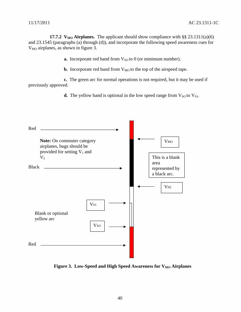
11172011 AC 231311-1C
200 Controls
a Display controls should be clearly visible labeled and usable by the pilot with the least practicable deviation from the normal position and from the line of vision when the pilot is looking forward along the flight path Controls should have an appropriate amount of tactile feel (for example detents friction stops or damping etc) so they can be changed without undue concentration which minimizes the potential for inadvertent changes Design controls for the pilot to be intuitive that is so the pilot can rapidly accurately identify and select all of the functions of the display control The controls should be identified easily and located in all lighting conditions allow differentiation of one control from another and have feedback through the system appropriate for the function being controlled
b Soft controls and cursor control devices development assurance levels should be commensurate with the level of criticality of the airplane system they will control Redundant methods of controlling the system may lessen the criticality required of the display control The final display response to control input should be fast enough to prevent undue concentration being required when the pilot sets values or display parameters The applicant should show by test andor demonstration in representative motion environment(s) (for example turbulence) that the display control is acceptable for controlling all functions that the pilot may access during these conditions
210 Test Functions The electronic display should incorporate a pilot selectable or automatic test mode such as built in testers that exercise the system to a depth appropriate to the system design Include this function even if the system failure analysis is not dependent on such a mode or if display test is also a maintenance function The test mode (or a sub mode) should display warning flags in their proper locations Exercise alerting and annunciation functions that are necessary to alert the pilot of unsafe conditions It is acceptable to incorporate the display test with a centralized cockpit light test switch to have the display test function disabled when airborne The test mode may provide a convenient means to display the software configuration
220 Color Standardization
221 General Color is considered an enhancement for understanding the display information that leads to performance improvement Select color to minimize display interpretation errors A proliferation of color sets can ultimately reduce safety rather than increase it Using contrast between basic colors provides a better differentiation of display elements than arbitrarily using colors near to each other in the color table Before defining the color standard for a specific display establish a consistent color philosophy throughout the display The FAA does not intend to limit electronic displays to the below listed colors although these have been shown to work well The following section depicts colors found acceptable for compliance with sect 231322 and other recommended colors as related to their functional meaning for electronic display systems Deviations may be approved with acceptable justification The use of the colors red and yellow for other than warnings and cautions is discouraged See TSO-C113 and TSO-C63 for additional guidance
45
11172011 AC 231311-1C
222 Color for Display Features Color code display features should be as indicated in the table below
Table 4 ndash Color for Display Features
Warnings Red Flight envelope and system limits Red Cautions abnormal sources AmberYellow Earth TanBrown Scales and associated figures White Engaged modes flight guidance Green Sky CyanBlue ILS deviation pointer Magenta Flight director bar MagentaGreen Pilot selectable references (bugs) Magenta
223 Color Sets One of the following color sets should be used as indicated in the table below
Table 5 ndash Color Sets
Color Set 1 Color Set 2
Fixed reference symbols that is lubber lines
White Yellow1
Current data values White Green Armed modes White Cyan Selected data values Green Cyan Selected heading Magenta2 Cyan Active routeflight plan Magenta White
1 The extensive use of the color yellow for other than cautionabnormal information is discouraged
2 In color set 1 magenta is associated with those analog parameters that constitute fly to or keep centered type information
46
11172011 AC 231311-1C
224 Color for Depiction of Weather Precipitation and Turbulence The depiction of weather precipitation and turbulence should be coded as indicated in the table below
Table 6 ndash Color for Depiction of Weather Precipitation and Turbulence
Precipitation 0-1 mmhr Black
1-4 mmhr Green
4-12 mmhr AmberYellow
12-50 mmhr Red
Above 50 mmhr Red or Magenta Turbulence mmhr White or Magenta Icing mmhr Light Blue
Note A background color (neutral color) will enhance display presentation
225 Color Deviation When the color assignments deviate from the above color set the applicant should ensure the chosen color assignments are not susceptible to confusion of symbol meaning and increased workload Where appropriate color assignment should be consistent with other color displays in the panel Luminance and color differences should not be confusing or ambiguous under any operating ambient illumination conditions The specific colors should be consistent with change in brightness on the displays over the full range of ambient light conditions Under high and low levels of lighting color degradation should not prevent the pilot from properly interpreting display information Where precipitation is integrated with other information the precipitation colors can be presented at half intensity Service experience has shown that this provides enhanced presentation and reduced ambiguity Warnings should be at full intensity
226 Enhancement Color is an enhancement for understanding the display information that leads to performance improvement but it should not be the sole means of discrimination of critical information Use symbols or letters as well as color to further enhance the effectiveness of the display Use of color alone has been shown to be less effective than when used with distinct symbol (object graphic or letter) Color degradation should be obvious and should not preclude the pilot from interpreting the remaining display information Displays should remain legible stable and unambiguous when operating in a degraded mode
227 Color for Warnings and Cautions For warnings and cautions sect 231322 provides specific requirements for assigning red and amber for visual annunciations Use red as the warning annunciation for emergency operating conditions when immediate pilot recognition is required and
47
11172011 AC 231311-1C
immediate correction or compensatory action may be required Use amber for the cautionary annunciation for abnormal operating conditions when immediate pilot awareness is required and subsequent pilot action may be required Use white or another unique color for advisory annunciations of operating conditions that require pilot awareness and possibly action Use green for indication of safe operating conditions
228 Airplane Flight Manual Include a complete list of warnings cautions and annunciation messages in the AFM supplemental AFM and placards If the manufacturers Pilot Operating Guide is found adequate and acceptable it may be referenced in the AFM or supplemental AFM as a means to satisfy this requirement
229 Color for Aviation Routine Weather For electronic color graphic display of aviation routine weather to surface meteorological data see TSO-C157 and AC 20-149 for guidance
230 General Installation Requirements The TCSTCATCASTC applicant must show that the installed electronic display system configuration (including hardware and software) meets the appropriate airplane certification basis This demonstration must include applicable TSO-C113 and functional TSO(s) or equivalent functional performance interoperability aircraft-level and system-level safety assessments environmental qualification system integration test flight test software assurance hardware assurance and other certification activities (as required to show compliance to the regulations) TCSTCATCASTC applicants may use TSO data to support airworthiness assessments if they show that the TSO requirements apply to the installation
240 Aircraft Electrical Power Source
241 Electrical Power Install each electronic display instrument system so that it receives electrical power from a bus that provides the necessary reliability according to the sect 231309 safety assessment without jeopardizing other essential or critical electrical loads connected to that bus The applicant should provide a means to indicate when adequate power is available for proper operation of the instrument
242 Power Interruptions Use techniques that reduce the momentary power interruptions or design the equipment so momentary power interruptions will not adversely affect the availability or integrity of essential information required for continued safe flight and landing The category selected from RTCADO-160 for momentary power interruptions should be appropriate for the intended use RTCADO-160 provides information that may be used for an acceptable means of qualifying display equipment such that they perform their intended function when subjected to anomalous input power Large electrical loads required to restart an engine (for example turboprops and small jets) should not affect the availability or integrity of essential information required for continued safe flight and landing
243 Independent Power Source
a Each reversionary or standby display providing primary flight information should be powered from a power source independent of the source for the primary display It should function independently from the power source of the primary display such as a second alternator or battery
48
11172011 AC 231311-1C
b Section 231331(c) Amendment 23-62 requires for certification of IFR operations and for the heading altitude airspeed and attitude there must be at least
(1) Two independent sources of power (not driven by the same engine on multiengine airplanes) and a manual or an automatic means to select each power source or
(2) A separate display of parameters for heading altitude airspeed and attitude that has a power source independent from the airplanes primary electrical power system
c Section 231353(h) Amendment 23-62 requires in the event of a complete loss of the primary electrical power generating system the battery must be capable of providing electrical power to those loads that are essential to continued safe flight and landing for
(1) At least 30 minutes for airplanes that are certificated with a maximum altitude of 25000 feet or less and
(2) At least 60 minutes for airplanes that are certificated with a maximum altitude over 25000 feet
Note The time period includes the time to recognize the loss of generated power and to take appropriate load shedding action
d The airplanes primary electrical power includes the airplanes electrical generating system and the airplanes starter battery when only one battery is installed The starter battery is not considered an acceptable standby power source unless a proper state of charge is monitored and displayed to the pilot The aircraft battery used for starting may satisfy the requirements of sect 231353(h) provided its adequacy is shown through a system safety analysis under sect 231309 In this case an ELOS may be required AC 23-17C provides more guidance
e The intent of this guidance may be met by a power generation and distribution architecture with multiple power sources and multiple distribution paths The paths must be designed such that any single failure of a power generation or distribution component does not adversely affect the primary reversionary or standby displays It does not need independent power generation sources for the primary and reversionary or standby displays for single engine airplanes if there is a different dedicated source
f For single engine airplanes where the engine drives the power generation devices the engine is not considered to be a single power source for this guidance For example a single-engine airplane with two engine driven alternators one powering a PFD and the other powering a reversionary PFD is considered to meet this guidance However this does not exempt the applicant from the sect 231353(h) requirements
49
11172011 AC 231311-1C
250 Safety Assessments
251 Regulations Before and After Amendment 23-41 Part 23 regulations issued before Amendment 23-41 were based on single-fault or fail-safe concepts A single failure would cause the loss of only one primary instrument function Only mechanical or electromechanical instruments that function independently of the primary parameter display were envisioned that is flight and powerplant instruments were isolated and independent Sometimes several other instrument functions (indication of the function display or indicator) are housed in a common case Since electronic displays permit presentation of several parameters on one display a failure in the electronic display may affect more than one required parameter Section 231309 Amendment 23-41 and later allowed approval of more advanced and complex systems Amendment 23-41 and later also incorporated sect 231311 into part 23 which provides the standards for electronic displays
252 Common-Mode Failures Section 231311(b) states that the electronic display indicators including their systems and installations and considering other airplane systems must be designed so that one display of information essential for continued safe flight and landing will be available within one second to the crew by a single pilot action or by automatic means for continued safe operation after any single failure or probable combination of failures In general without considering specific characteristics of an airplane design information essential to continued safe flight and landing that should be considered are attitude airspeed altitude warnings and any applicable propulsion parameter(s) Common-mode failures should be addressed See AC 231309-1E for more guidance
253 Safety Analysis
a AC 231309-1E describes safety assessment methods for identifying and classifying each failure condition and choosing the method(s) of safety assessment Certification of electronic display systems may involve new and complex technology that may not use traditional service-proven design concepts In this case technically qualified judgment can be enhanced when a quantitative analysis is included in the safety assessment whether or not a quantitative analysis is required by sect 231309
b The use of electronic displays allows a higher degree of integration than was practical with previous electromechanical instruments Evaluating failure states and determining display function criticality in highly integrated systems may be complex Safety assessment determination should refer to the display function and include all causes that could affect the displays of that function not only the display equipment
c Installing electronic systems in cockpits creates complex functional interrelationships between the pilots and the display and control systems The FHA identifies the failure conditions for all display functions analyzes the effects on the aircraft and pilot and assigns the corresponding criticality classification (no safety effect minor major hazardous catastrophic) It also considers both loss of functions malfunctions and situations that provide misleading information
50
11172011 AC 231311-1C
d A pilot initiated preflight test may be used to reduce failure exposure times associated with the safety analysis required under sect 231309 If the pilot is required to test a system before each flight assume for the safety analysis the pilot will accomplish this test at least once a day providing the preflight test is conveniently and acceptably implemented
260 Software and Hardware Development Assurance
261 General Applicants must show compliance with sect 231309 regardless of the intended function of the display system The equipment should be designed to the appropriate software and hardware development assurance level(s) based on the intended function and application of the equipment including the aircraft class in which it is to be installed (see AC 231309-1E Figure 2) The appropriate development assurance level(s) are determined by an analysis of the failure modes of the equipment and a categorization of the effects of the failure on the operation of the aircraft For the analysis for displays a failure is defined as either a loss of function or the output of misleading information Flight guidance information must meet the appropriate design assurance levels required for that function
262 Software Guidance
2621 General AC 20-115B addresses how RTCADO-178B provides an acceptable means for showing that software complies with pertinent airworthiness requirements All software used in electronic displays systems should be developed to the guidance of RTCADO-178B Software Considerations in Airborne Systems and Equipment Certification dated December 1 1992 or another acceptable means of compliance as agreed to between the applicant and the appropriate FAA ACO
2622 Software Levels Determine all software levels by appropriate safety assessments (see AC 231309-1E Figure 2) and any more requirements such as those specified by functional TSOs
2623 Field-Loadable Software (FLS) Many electronic displays systems use FLS as part of the TCATCSTCASTC installation FLS is software that can be loaded without removal of the equipment from the aircraft installation FLS might also include software loaded into a line replaceable unit (LRU) or hardware element at a repair station or shop FLS can refer to either executable code or data When obtaining certification approval for use of the FLS capability refer to the guidance in Order 811049 and AC 20-170
263 Electronic Hardware Guidance If the electronic display system contains electronic devices whose functions cannot feasibly be evaluated by test andor analysis the electronic devices should comply with AC 23-1309-1E 8110105 CHG 1 and AC 20-152 which addresses how to use RTCADO-254 These documents provide acceptable means for showing that complex hardware complies with the pertinent airworthiness requirements Determine the hardware levels for all hardware by the appropriate safety assessments (see AC 231309-1E Figure 2) and any more requirements such as those specified by functional TSOs
51
11172011 AC 231311-1C
270 Environmental Conditions
271 General The equipment environmental limits established by the manufacturer should be compatible with the operating environment of the airplane Evaluation of the equipment installation should consider factors such as the maximum operating altitude of the airplane and whether the equipment is located within a temperature and pressure-controlled area Applicable methods for testing the performance characteristics of equipment for specified environmental conditions are provided in RTCADO-160F Either test or analysis or both ensures the compatibility between the operational environment and the environmental equipment category of the laboratory tests
272 Temperature Electronic systems reliability is strongly related to the temperature of the solid-state components in the system Component temperatures are dependent on internal thermal design and external cooling In evaluating the temperature environment consider the additional heat generated by the equipment especially in a location where airflow is restricted To determine if adequate cooling is provided the evaluation should make maximum use of previous data from comparable installations thus limiting ground or flight tests to those installations that cannot be verified conveniently by other means When the equipment-operating environment cannot be verified from previous experience or from an evaluation of temperature values in that equipment location a cooling test should be conducted
273 Attitude Information It is recommended that attitude information continue to be presented for a minimum of 30 to 60 minutes after the in-flight loss of cooling for the primary instrument when operating in the normal operating environment (temperaturealtitude) If proper performance of the flight instrument function(s) is adversely affected due to in-flight loss of cooling such failure conditions should be annunciated The applicant should consider automatic over-temperature shutdown of the system a failure condition The subsequent pilot actions should be documented in the AFM or on placards These actions may include procedures to allow possible recovery of a system that has an over-temperature shutdown condition
274 Annunciation Annunciation of in-flight loss of cooling or fan monitors may not be required if it is shown by a safety analysis or test demonstration that a hazardous or catastrophic failure condition does not occur The safety analysis should consider the reliability of the fans redundancies of the functions reversionary features (such as the ability to transfer critical functions) the annunciation of over-temperature and its response time and the availability of other flight instrumentation In some systems cooling fans may only be installed to extend the life of the components and not to prevent a failure condition or shutdown of the equipment These types of installations do not require fan monitors or temperature sensors If the cooling fans are needed to prevent a hazardous or catastrophic failure condition install fan monitors or another method to determine the status of the cooling fan during preflight checks
280 Electromagnetic Protection Current trends indicate increasing reliance on electrical and electronic systems for safe operations For systems that perform flight propulsion navigation and instrumentation functions consider electromagnetic effects AC 20-136A AC 20-155 AC 20-158 AC 231309-1E and AC 23-17C provide more guidance for lightning and HIRF protection
52
11172011 AC 231311-1C
290 Electromagnetic Interference The electronic display instrument system should not be the source of detrimental conducted or radiated interference Conducted or radiated interference from other equipment or systems installed in the airplane should not adversely affect the displays
300 Implosion Protection Design and construct the display unit to prevent implosion when the unit is operating over the range of normal and abnormal operating environments in the airplane When a display unit has a component containing lower pressure than the ambient atmospheric pressure and it is susceptible to implosion no incapacitation of the pilot or adjacent equipment should result if an implosion occurs Test the display unit for the most severe environmental conditions of pressure and temperature levels Also test for variations in both normal and abnormal operating conditions (including overpressure and decompression) as specified by RTCADO-160F Similarity of a particular display to a unit already tested may be used to comply with this requirement
310 Configuration Management by Electronic Identification Guidance Configuration management may be necessary because the system may contain many hardware elements and functional software components with multiple approved configurations Identification of software components field-loaded into hardware elements may be implemented by electronic means Section 21607 requires equipment with a TSO to be permanently and legibly marked with specific information Compliance with sect 21607 may be shown when an electronic identification query system stored in non-volatile memory provides the required information This approach is commonly referred to as an ldquoelectronic TSO nameplaterdquo The electronic identification system must be verifiable on board the aircraft when the aircraft is on the ground at any geographic location The system must provide the specific information required by sect 21607 for all applicable functional TSOs being integrated All hardware elements that support a functional TSO must have a physical TSO nameplate Even when electronic identification (that is electronic nameplate) is used a physical TSO nameplate must be included on supporting hardware elements See AC 20-170 for more guidance
53
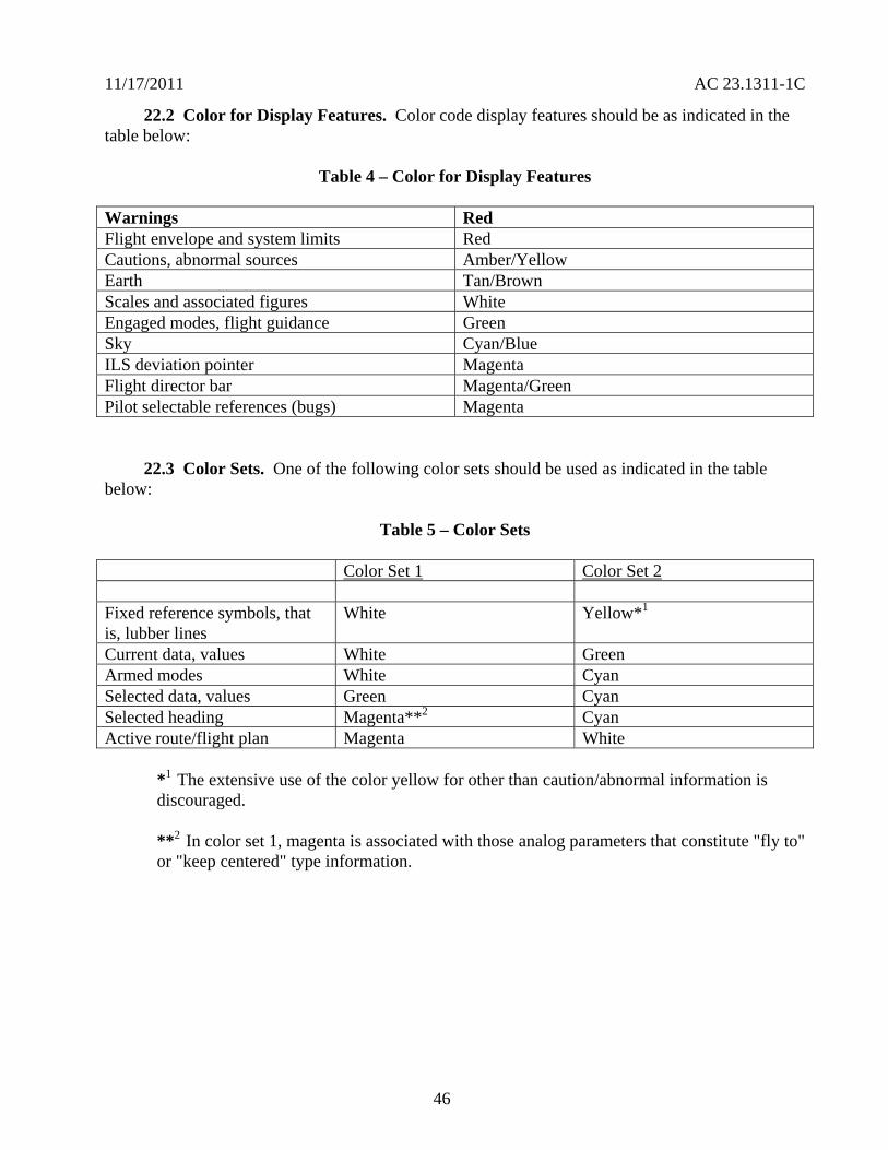
11172011 AC 231311-1C
222 Color for Display Features Color code display features should be as indicated in the table below
Table 4 ndash Color for Display Features
Warnings Red Flight envelope and system limits Red Cautions abnormal sources AmberYellow Earth TanBrown Scales and associated figures White Engaged modes flight guidance Green Sky CyanBlue ILS deviation pointer Magenta Flight director bar MagentaGreen Pilot selectable references (bugs) Magenta
223 Color Sets One of the following color sets should be used as indicated in the table below
Table 5 ndash Color Sets
Color Set 1 Color Set 2
Fixed reference symbols that is lubber lines
White Yellow1
Current data values White Green Armed modes White Cyan Selected data values Green Cyan Selected heading Magenta2 Cyan Active routeflight plan Magenta White
1 The extensive use of the color yellow for other than cautionabnormal information is discouraged
2 In color set 1 magenta is associated with those analog parameters that constitute fly to or keep centered type information
46
11172011 AC 231311-1C
224 Color for Depiction of Weather Precipitation and Turbulence The depiction of weather precipitation and turbulence should be coded as indicated in the table below
Table 6 ndash Color for Depiction of Weather Precipitation and Turbulence
Precipitation 0-1 mmhr Black
1-4 mmhr Green
4-12 mmhr AmberYellow
12-50 mmhr Red
Above 50 mmhr Red or Magenta Turbulence mmhr White or Magenta Icing mmhr Light Blue
Note A background color (neutral color) will enhance display presentation
225 Color Deviation When the color assignments deviate from the above color set the applicant should ensure the chosen color assignments are not susceptible to confusion of symbol meaning and increased workload Where appropriate color assignment should be consistent with other color displays in the panel Luminance and color differences should not be confusing or ambiguous under any operating ambient illumination conditions The specific colors should be consistent with change in brightness on the displays over the full range of ambient light conditions Under high and low levels of lighting color degradation should not prevent the pilot from properly interpreting display information Where precipitation is integrated with other information the precipitation colors can be presented at half intensity Service experience has shown that this provides enhanced presentation and reduced ambiguity Warnings should be at full intensity
226 Enhancement Color is an enhancement for understanding the display information that leads to performance improvement but it should not be the sole means of discrimination of critical information Use symbols or letters as well as color to further enhance the effectiveness of the display Use of color alone has been shown to be less effective than when used with distinct symbol (object graphic or letter) Color degradation should be obvious and should not preclude the pilot from interpreting the remaining display information Displays should remain legible stable and unambiguous when operating in a degraded mode
227 Color for Warnings and Cautions For warnings and cautions sect 231322 provides specific requirements for assigning red and amber for visual annunciations Use red as the warning annunciation for emergency operating conditions when immediate pilot recognition is required and
47
11172011 AC 231311-1C
immediate correction or compensatory action may be required Use amber for the cautionary annunciation for abnormal operating conditions when immediate pilot awareness is required and subsequent pilot action may be required Use white or another unique color for advisory annunciations of operating conditions that require pilot awareness and possibly action Use green for indication of safe operating conditions
228 Airplane Flight Manual Include a complete list of warnings cautions and annunciation messages in the AFM supplemental AFM and placards If the manufacturers Pilot Operating Guide is found adequate and acceptable it may be referenced in the AFM or supplemental AFM as a means to satisfy this requirement
229 Color for Aviation Routine Weather For electronic color graphic display of aviation routine weather to surface meteorological data see TSO-C157 and AC 20-149 for guidance
230 General Installation Requirements The TCSTCATCASTC applicant must show that the installed electronic display system configuration (including hardware and software) meets the appropriate airplane certification basis This demonstration must include applicable TSO-C113 and functional TSO(s) or equivalent functional performance interoperability aircraft-level and system-level safety assessments environmental qualification system integration test flight test software assurance hardware assurance and other certification activities (as required to show compliance to the regulations) TCSTCATCASTC applicants may use TSO data to support airworthiness assessments if they show that the TSO requirements apply to the installation
240 Aircraft Electrical Power Source
241 Electrical Power Install each electronic display instrument system so that it receives electrical power from a bus that provides the necessary reliability according to the sect 231309 safety assessment without jeopardizing other essential or critical electrical loads connected to that bus The applicant should provide a means to indicate when adequate power is available for proper operation of the instrument
242 Power Interruptions Use techniques that reduce the momentary power interruptions or design the equipment so momentary power interruptions will not adversely affect the availability or integrity of essential information required for continued safe flight and landing The category selected from RTCADO-160 for momentary power interruptions should be appropriate for the intended use RTCADO-160 provides information that may be used for an acceptable means of qualifying display equipment such that they perform their intended function when subjected to anomalous input power Large electrical loads required to restart an engine (for example turboprops and small jets) should not affect the availability or integrity of essential information required for continued safe flight and landing
243 Independent Power Source
a Each reversionary or standby display providing primary flight information should be powered from a power source independent of the source for the primary display It should function independently from the power source of the primary display such as a second alternator or battery
48
11172011 AC 231311-1C
b Section 231331(c) Amendment 23-62 requires for certification of IFR operations and for the heading altitude airspeed and attitude there must be at least
(1) Two independent sources of power (not driven by the same engine on multiengine airplanes) and a manual or an automatic means to select each power source or
(2) A separate display of parameters for heading altitude airspeed and attitude that has a power source independent from the airplanes primary electrical power system
c Section 231353(h) Amendment 23-62 requires in the event of a complete loss of the primary electrical power generating system the battery must be capable of providing electrical power to those loads that are essential to continued safe flight and landing for
(1) At least 30 minutes for airplanes that are certificated with a maximum altitude of 25000 feet or less and
(2) At least 60 minutes for airplanes that are certificated with a maximum altitude over 25000 feet
Note The time period includes the time to recognize the loss of generated power and to take appropriate load shedding action
d The airplanes primary electrical power includes the airplanes electrical generating system and the airplanes starter battery when only one battery is installed The starter battery is not considered an acceptable standby power source unless a proper state of charge is monitored and displayed to the pilot The aircraft battery used for starting may satisfy the requirements of sect 231353(h) provided its adequacy is shown through a system safety analysis under sect 231309 In this case an ELOS may be required AC 23-17C provides more guidance
e The intent of this guidance may be met by a power generation and distribution architecture with multiple power sources and multiple distribution paths The paths must be designed such that any single failure of a power generation or distribution component does not adversely affect the primary reversionary or standby displays It does not need independent power generation sources for the primary and reversionary or standby displays for single engine airplanes if there is a different dedicated source
f For single engine airplanes where the engine drives the power generation devices the engine is not considered to be a single power source for this guidance For example a single-engine airplane with two engine driven alternators one powering a PFD and the other powering a reversionary PFD is considered to meet this guidance However this does not exempt the applicant from the sect 231353(h) requirements
49
11172011 AC 231311-1C
250 Safety Assessments
251 Regulations Before and After Amendment 23-41 Part 23 regulations issued before Amendment 23-41 were based on single-fault or fail-safe concepts A single failure would cause the loss of only one primary instrument function Only mechanical or electromechanical instruments that function independently of the primary parameter display were envisioned that is flight and powerplant instruments were isolated and independent Sometimes several other instrument functions (indication of the function display or indicator) are housed in a common case Since electronic displays permit presentation of several parameters on one display a failure in the electronic display may affect more than one required parameter Section 231309 Amendment 23-41 and later allowed approval of more advanced and complex systems Amendment 23-41 and later also incorporated sect 231311 into part 23 which provides the standards for electronic displays
252 Common-Mode Failures Section 231311(b) states that the electronic display indicators including their systems and installations and considering other airplane systems must be designed so that one display of information essential for continued safe flight and landing will be available within one second to the crew by a single pilot action or by automatic means for continued safe operation after any single failure or probable combination of failures In general without considering specific characteristics of an airplane design information essential to continued safe flight and landing that should be considered are attitude airspeed altitude warnings and any applicable propulsion parameter(s) Common-mode failures should be addressed See AC 231309-1E for more guidance
253 Safety Analysis
a AC 231309-1E describes safety assessment methods for identifying and classifying each failure condition and choosing the method(s) of safety assessment Certification of electronic display systems may involve new and complex technology that may not use traditional service-proven design concepts In this case technically qualified judgment can be enhanced when a quantitative analysis is included in the safety assessment whether or not a quantitative analysis is required by sect 231309
b The use of electronic displays allows a higher degree of integration than was practical with previous electromechanical instruments Evaluating failure states and determining display function criticality in highly integrated systems may be complex Safety assessment determination should refer to the display function and include all causes that could affect the displays of that function not only the display equipment
c Installing electronic systems in cockpits creates complex functional interrelationships between the pilots and the display and control systems The FHA identifies the failure conditions for all display functions analyzes the effects on the aircraft and pilot and assigns the corresponding criticality classification (no safety effect minor major hazardous catastrophic) It also considers both loss of functions malfunctions and situations that provide misleading information
50
11172011 AC 231311-1C
d A pilot initiated preflight test may be used to reduce failure exposure times associated with the safety analysis required under sect 231309 If the pilot is required to test a system before each flight assume for the safety analysis the pilot will accomplish this test at least once a day providing the preflight test is conveniently and acceptably implemented
260 Software and Hardware Development Assurance
261 General Applicants must show compliance with sect 231309 regardless of the intended function of the display system The equipment should be designed to the appropriate software and hardware development assurance level(s) based on the intended function and application of the equipment including the aircraft class in which it is to be installed (see AC 231309-1E Figure 2) The appropriate development assurance level(s) are determined by an analysis of the failure modes of the equipment and a categorization of the effects of the failure on the operation of the aircraft For the analysis for displays a failure is defined as either a loss of function or the output of misleading information Flight guidance information must meet the appropriate design assurance levels required for that function
262 Software Guidance
2621 General AC 20-115B addresses how RTCADO-178B provides an acceptable means for showing that software complies with pertinent airworthiness requirements All software used in electronic displays systems should be developed to the guidance of RTCADO-178B Software Considerations in Airborne Systems and Equipment Certification dated December 1 1992 or another acceptable means of compliance as agreed to between the applicant and the appropriate FAA ACO
2622 Software Levels Determine all software levels by appropriate safety assessments (see AC 231309-1E Figure 2) and any more requirements such as those specified by functional TSOs
2623 Field-Loadable Software (FLS) Many electronic displays systems use FLS as part of the TCATCSTCASTC installation FLS is software that can be loaded without removal of the equipment from the aircraft installation FLS might also include software loaded into a line replaceable unit (LRU) or hardware element at a repair station or shop FLS can refer to either executable code or data When obtaining certification approval for use of the FLS capability refer to the guidance in Order 811049 and AC 20-170
263 Electronic Hardware Guidance If the electronic display system contains electronic devices whose functions cannot feasibly be evaluated by test andor analysis the electronic devices should comply with AC 23-1309-1E 8110105 CHG 1 and AC 20-152 which addresses how to use RTCADO-254 These documents provide acceptable means for showing that complex hardware complies with the pertinent airworthiness requirements Determine the hardware levels for all hardware by the appropriate safety assessments (see AC 231309-1E Figure 2) and any more requirements such as those specified by functional TSOs
51
11172011 AC 231311-1C
270 Environmental Conditions
271 General The equipment environmental limits established by the manufacturer should be compatible with the operating environment of the airplane Evaluation of the equipment installation should consider factors such as the maximum operating altitude of the airplane and whether the equipment is located within a temperature and pressure-controlled area Applicable methods for testing the performance characteristics of equipment for specified environmental conditions are provided in RTCADO-160F Either test or analysis or both ensures the compatibility between the operational environment and the environmental equipment category of the laboratory tests
272 Temperature Electronic systems reliability is strongly related to the temperature of the solid-state components in the system Component temperatures are dependent on internal thermal design and external cooling In evaluating the temperature environment consider the additional heat generated by the equipment especially in a location where airflow is restricted To determine if adequate cooling is provided the evaluation should make maximum use of previous data from comparable installations thus limiting ground or flight tests to those installations that cannot be verified conveniently by other means When the equipment-operating environment cannot be verified from previous experience or from an evaluation of temperature values in that equipment location a cooling test should be conducted
273 Attitude Information It is recommended that attitude information continue to be presented for a minimum of 30 to 60 minutes after the in-flight loss of cooling for the primary instrument when operating in the normal operating environment (temperaturealtitude) If proper performance of the flight instrument function(s) is adversely affected due to in-flight loss of cooling such failure conditions should be annunciated The applicant should consider automatic over-temperature shutdown of the system a failure condition The subsequent pilot actions should be documented in the AFM or on placards These actions may include procedures to allow possible recovery of a system that has an over-temperature shutdown condition
274 Annunciation Annunciation of in-flight loss of cooling or fan monitors may not be required if it is shown by a safety analysis or test demonstration that a hazardous or catastrophic failure condition does not occur The safety analysis should consider the reliability of the fans redundancies of the functions reversionary features (such as the ability to transfer critical functions) the annunciation of over-temperature and its response time and the availability of other flight instrumentation In some systems cooling fans may only be installed to extend the life of the components and not to prevent a failure condition or shutdown of the equipment These types of installations do not require fan monitors or temperature sensors If the cooling fans are needed to prevent a hazardous or catastrophic failure condition install fan monitors or another method to determine the status of the cooling fan during preflight checks
280 Electromagnetic Protection Current trends indicate increasing reliance on electrical and electronic systems for safe operations For systems that perform flight propulsion navigation and instrumentation functions consider electromagnetic effects AC 20-136A AC 20-155 AC 20-158 AC 231309-1E and AC 23-17C provide more guidance for lightning and HIRF protection
52
11172011 AC 231311-1C
290 Electromagnetic Interference The electronic display instrument system should not be the source of detrimental conducted or radiated interference Conducted or radiated interference from other equipment or systems installed in the airplane should not adversely affect the displays
300 Implosion Protection Design and construct the display unit to prevent implosion when the unit is operating over the range of normal and abnormal operating environments in the airplane When a display unit has a component containing lower pressure than the ambient atmospheric pressure and it is susceptible to implosion no incapacitation of the pilot or adjacent equipment should result if an implosion occurs Test the display unit for the most severe environmental conditions of pressure and temperature levels Also test for variations in both normal and abnormal operating conditions (including overpressure and decompression) as specified by RTCADO-160F Similarity of a particular display to a unit already tested may be used to comply with this requirement
310 Configuration Management by Electronic Identification Guidance Configuration management may be necessary because the system may contain many hardware elements and functional software components with multiple approved configurations Identification of software components field-loaded into hardware elements may be implemented by electronic means Section 21607 requires equipment with a TSO to be permanently and legibly marked with specific information Compliance with sect 21607 may be shown when an electronic identification query system stored in non-volatile memory provides the required information This approach is commonly referred to as an ldquoelectronic TSO nameplaterdquo The electronic identification system must be verifiable on board the aircraft when the aircraft is on the ground at any geographic location The system must provide the specific information required by sect 21607 for all applicable functional TSOs being integrated All hardware elements that support a functional TSO must have a physical TSO nameplate Even when electronic identification (that is electronic nameplate) is used a physical TSO nameplate must be included on supporting hardware elements See AC 20-170 for more guidance
53
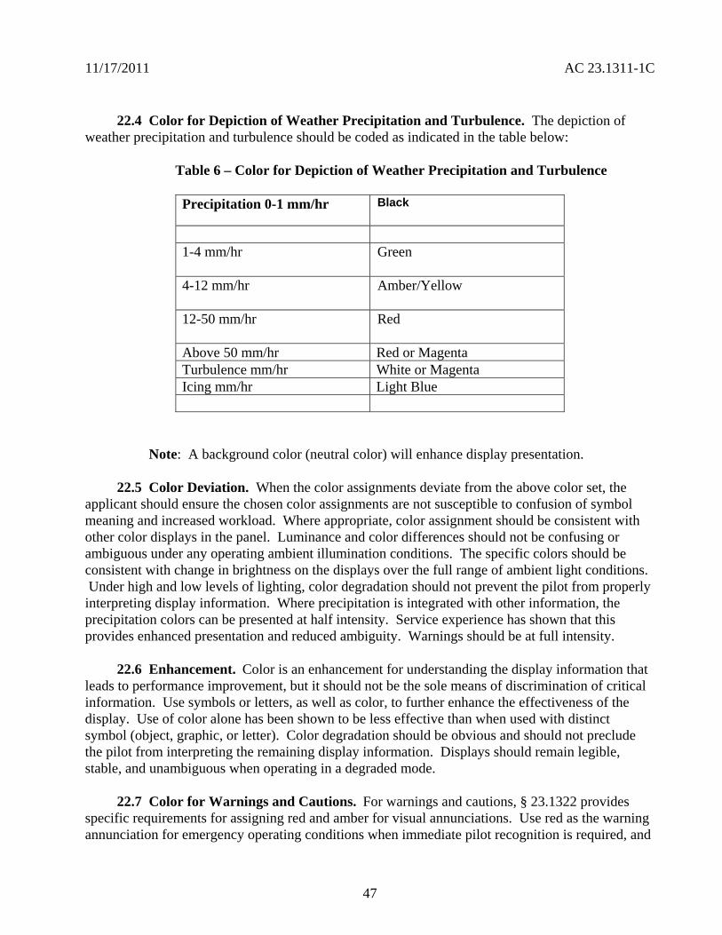
11172011 AC 231311-1C
224 Color for Depiction of Weather Precipitation and Turbulence The depiction of weather precipitation and turbulence should be coded as indicated in the table below
Table 6 ndash Color for Depiction of Weather Precipitation and Turbulence
Precipitation 0-1 mmhr Black
1-4 mmhr Green
4-12 mmhr AmberYellow
12-50 mmhr Red
Above 50 mmhr Red or Magenta Turbulence mmhr White or Magenta Icing mmhr Light Blue
Note A background color (neutral color) will enhance display presentation
225 Color Deviation When the color assignments deviate from the above color set the applicant should ensure the chosen color assignments are not susceptible to confusion of symbol meaning and increased workload Where appropriate color assignment should be consistent with other color displays in the panel Luminance and color differences should not be confusing or ambiguous under any operating ambient illumination conditions The specific colors should be consistent with change in brightness on the displays over the full range of ambient light conditions Under high and low levels of lighting color degradation should not prevent the pilot from properly interpreting display information Where precipitation is integrated with other information the precipitation colors can be presented at half intensity Service experience has shown that this provides enhanced presentation and reduced ambiguity Warnings should be at full intensity
226 Enhancement Color is an enhancement for understanding the display information that leads to performance improvement but it should not be the sole means of discrimination of critical information Use symbols or letters as well as color to further enhance the effectiveness of the display Use of color alone has been shown to be less effective than when used with distinct symbol (object graphic or letter) Color degradation should be obvious and should not preclude the pilot from interpreting the remaining display information Displays should remain legible stable and unambiguous when operating in a degraded mode
227 Color for Warnings and Cautions For warnings and cautions sect 231322 provides specific requirements for assigning red and amber for visual annunciations Use red as the warning annunciation for emergency operating conditions when immediate pilot recognition is required and
47
11172011 AC 231311-1C
immediate correction or compensatory action may be required Use amber for the cautionary annunciation for abnormal operating conditions when immediate pilot awareness is required and subsequent pilot action may be required Use white or another unique color for advisory annunciations of operating conditions that require pilot awareness and possibly action Use green for indication of safe operating conditions
228 Airplane Flight Manual Include a complete list of warnings cautions and annunciation messages in the AFM supplemental AFM and placards If the manufacturers Pilot Operating Guide is found adequate and acceptable it may be referenced in the AFM or supplemental AFM as a means to satisfy this requirement
229 Color for Aviation Routine Weather For electronic color graphic display of aviation routine weather to surface meteorological data see TSO-C157 and AC 20-149 for guidance
230 General Installation Requirements The TCSTCATCASTC applicant must show that the installed electronic display system configuration (including hardware and software) meets the appropriate airplane certification basis This demonstration must include applicable TSO-C113 and functional TSO(s) or equivalent functional performance interoperability aircraft-level and system-level safety assessments environmental qualification system integration test flight test software assurance hardware assurance and other certification activities (as required to show compliance to the regulations) TCSTCATCASTC applicants may use TSO data to support airworthiness assessments if they show that the TSO requirements apply to the installation
240 Aircraft Electrical Power Source
241 Electrical Power Install each electronic display instrument system so that it receives electrical power from a bus that provides the necessary reliability according to the sect 231309 safety assessment without jeopardizing other essential or critical electrical loads connected to that bus The applicant should provide a means to indicate when adequate power is available for proper operation of the instrument
242 Power Interruptions Use techniques that reduce the momentary power interruptions or design the equipment so momentary power interruptions will not adversely affect the availability or integrity of essential information required for continued safe flight and landing The category selected from RTCADO-160 for momentary power interruptions should be appropriate for the intended use RTCADO-160 provides information that may be used for an acceptable means of qualifying display equipment such that they perform their intended function when subjected to anomalous input power Large electrical loads required to restart an engine (for example turboprops and small jets) should not affect the availability or integrity of essential information required for continued safe flight and landing
243 Independent Power Source
a Each reversionary or standby display providing primary flight information should be powered from a power source independent of the source for the primary display It should function independently from the power source of the primary display such as a second alternator or battery
48
11172011 AC 231311-1C
b Section 231331(c) Amendment 23-62 requires for certification of IFR operations and for the heading altitude airspeed and attitude there must be at least
(1) Two independent sources of power (not driven by the same engine on multiengine airplanes) and a manual or an automatic means to select each power source or
(2) A separate display of parameters for heading altitude airspeed and attitude that has a power source independent from the airplanes primary electrical power system
c Section 231353(h) Amendment 23-62 requires in the event of a complete loss of the primary electrical power generating system the battery must be capable of providing electrical power to those loads that are essential to continued safe flight and landing for
(1) At least 30 minutes for airplanes that are certificated with a maximum altitude of 25000 feet or less and
(2) At least 60 minutes for airplanes that are certificated with a maximum altitude over 25000 feet
Note The time period includes the time to recognize the loss of generated power and to take appropriate load shedding action
d The airplanes primary electrical power includes the airplanes electrical generating system and the airplanes starter battery when only one battery is installed The starter battery is not considered an acceptable standby power source unless a proper state of charge is monitored and displayed to the pilot The aircraft battery used for starting may satisfy the requirements of sect 231353(h) provided its adequacy is shown through a system safety analysis under sect 231309 In this case an ELOS may be required AC 23-17C provides more guidance
e The intent of this guidance may be met by a power generation and distribution architecture with multiple power sources and multiple distribution paths The paths must be designed such that any single failure of a power generation or distribution component does not adversely affect the primary reversionary or standby displays It does not need independent power generation sources for the primary and reversionary or standby displays for single engine airplanes if there is a different dedicated source
f For single engine airplanes where the engine drives the power generation devices the engine is not considered to be a single power source for this guidance For example a single-engine airplane with two engine driven alternators one powering a PFD and the other powering a reversionary PFD is considered to meet this guidance However this does not exempt the applicant from the sect 231353(h) requirements
49
11172011 AC 231311-1C
250 Safety Assessments
251 Regulations Before and After Amendment 23-41 Part 23 regulations issued before Amendment 23-41 were based on single-fault or fail-safe concepts A single failure would cause the loss of only one primary instrument function Only mechanical or electromechanical instruments that function independently of the primary parameter display were envisioned that is flight and powerplant instruments were isolated and independent Sometimes several other instrument functions (indication of the function display or indicator) are housed in a common case Since electronic displays permit presentation of several parameters on one display a failure in the electronic display may affect more than one required parameter Section 231309 Amendment 23-41 and later allowed approval of more advanced and complex systems Amendment 23-41 and later also incorporated sect 231311 into part 23 which provides the standards for electronic displays
252 Common-Mode Failures Section 231311(b) states that the electronic display indicators including their systems and installations and considering other airplane systems must be designed so that one display of information essential for continued safe flight and landing will be available within one second to the crew by a single pilot action or by automatic means for continued safe operation after any single failure or probable combination of failures In general without considering specific characteristics of an airplane design information essential to continued safe flight and landing that should be considered are attitude airspeed altitude warnings and any applicable propulsion parameter(s) Common-mode failures should be addressed See AC 231309-1E for more guidance
253 Safety Analysis
a AC 231309-1E describes safety assessment methods for identifying and classifying each failure condition and choosing the method(s) of safety assessment Certification of electronic display systems may involve new and complex technology that may not use traditional service-proven design concepts In this case technically qualified judgment can be enhanced when a quantitative analysis is included in the safety assessment whether or not a quantitative analysis is required by sect 231309
b The use of electronic displays allows a higher degree of integration than was practical with previous electromechanical instruments Evaluating failure states and determining display function criticality in highly integrated systems may be complex Safety assessment determination should refer to the display function and include all causes that could affect the displays of that function not only the display equipment
c Installing electronic systems in cockpits creates complex functional interrelationships between the pilots and the display and control systems The FHA identifies the failure conditions for all display functions analyzes the effects on the aircraft and pilot and assigns the corresponding criticality classification (no safety effect minor major hazardous catastrophic) It also considers both loss of functions malfunctions and situations that provide misleading information
50
11172011 AC 231311-1C
d A pilot initiated preflight test may be used to reduce failure exposure times associated with the safety analysis required under sect 231309 If the pilot is required to test a system before each flight assume for the safety analysis the pilot will accomplish this test at least once a day providing the preflight test is conveniently and acceptably implemented
260 Software and Hardware Development Assurance
261 General Applicants must show compliance with sect 231309 regardless of the intended function of the display system The equipment should be designed to the appropriate software and hardware development assurance level(s) based on the intended function and application of the equipment including the aircraft class in which it is to be installed (see AC 231309-1E Figure 2) The appropriate development assurance level(s) are determined by an analysis of the failure modes of the equipment and a categorization of the effects of the failure on the operation of the aircraft For the analysis for displays a failure is defined as either a loss of function or the output of misleading information Flight guidance information must meet the appropriate design assurance levels required for that function
262 Software Guidance
2621 General AC 20-115B addresses how RTCADO-178B provides an acceptable means for showing that software complies with pertinent airworthiness requirements All software used in electronic displays systems should be developed to the guidance of RTCADO-178B Software Considerations in Airborne Systems and Equipment Certification dated December 1 1992 or another acceptable means of compliance as agreed to between the applicant and the appropriate FAA ACO
2622 Software Levels Determine all software levels by appropriate safety assessments (see AC 231309-1E Figure 2) and any more requirements such as those specified by functional TSOs
2623 Field-Loadable Software (FLS) Many electronic displays systems use FLS as part of the TCATCSTCASTC installation FLS is software that can be loaded without removal of the equipment from the aircraft installation FLS might also include software loaded into a line replaceable unit (LRU) or hardware element at a repair station or shop FLS can refer to either executable code or data When obtaining certification approval for use of the FLS capability refer to the guidance in Order 811049 and AC 20-170
263 Electronic Hardware Guidance If the electronic display system contains electronic devices whose functions cannot feasibly be evaluated by test andor analysis the electronic devices should comply with AC 23-1309-1E 8110105 CHG 1 and AC 20-152 which addresses how to use RTCADO-254 These documents provide acceptable means for showing that complex hardware complies with the pertinent airworthiness requirements Determine the hardware levels for all hardware by the appropriate safety assessments (see AC 231309-1E Figure 2) and any more requirements such as those specified by functional TSOs
51
11172011 AC 231311-1C
270 Environmental Conditions
271 General The equipment environmental limits established by the manufacturer should be compatible with the operating environment of the airplane Evaluation of the equipment installation should consider factors such as the maximum operating altitude of the airplane and whether the equipment is located within a temperature and pressure-controlled area Applicable methods for testing the performance characteristics of equipment for specified environmental conditions are provided in RTCADO-160F Either test or analysis or both ensures the compatibility between the operational environment and the environmental equipment category of the laboratory tests
272 Temperature Electronic systems reliability is strongly related to the temperature of the solid-state components in the system Component temperatures are dependent on internal thermal design and external cooling In evaluating the temperature environment consider the additional heat generated by the equipment especially in a location where airflow is restricted To determine if adequate cooling is provided the evaluation should make maximum use of previous data from comparable installations thus limiting ground or flight tests to those installations that cannot be verified conveniently by other means When the equipment-operating environment cannot be verified from previous experience or from an evaluation of temperature values in that equipment location a cooling test should be conducted
273 Attitude Information It is recommended that attitude information continue to be presented for a minimum of 30 to 60 minutes after the in-flight loss of cooling for the primary instrument when operating in the normal operating environment (temperaturealtitude) If proper performance of the flight instrument function(s) is adversely affected due to in-flight loss of cooling such failure conditions should be annunciated The applicant should consider automatic over-temperature shutdown of the system a failure condition The subsequent pilot actions should be documented in the AFM or on placards These actions may include procedures to allow possible recovery of a system that has an over-temperature shutdown condition
274 Annunciation Annunciation of in-flight loss of cooling or fan monitors may not be required if it is shown by a safety analysis or test demonstration that a hazardous or catastrophic failure condition does not occur The safety analysis should consider the reliability of the fans redundancies of the functions reversionary features (such as the ability to transfer critical functions) the annunciation of over-temperature and its response time and the availability of other flight instrumentation In some systems cooling fans may only be installed to extend the life of the components and not to prevent a failure condition or shutdown of the equipment These types of installations do not require fan monitors or temperature sensors If the cooling fans are needed to prevent a hazardous or catastrophic failure condition install fan monitors or another method to determine the status of the cooling fan during preflight checks
280 Electromagnetic Protection Current trends indicate increasing reliance on electrical and electronic systems for safe operations For systems that perform flight propulsion navigation and instrumentation functions consider electromagnetic effects AC 20-136A AC 20-155 AC 20-158 AC 231309-1E and AC 23-17C provide more guidance for lightning and HIRF protection
52
11172011 AC 231311-1C
290 Electromagnetic Interference The electronic display instrument system should not be the source of detrimental conducted or radiated interference Conducted or radiated interference from other equipment or systems installed in the airplane should not adversely affect the displays
300 Implosion Protection Design and construct the display unit to prevent implosion when the unit is operating over the range of normal and abnormal operating environments in the airplane When a display unit has a component containing lower pressure than the ambient atmospheric pressure and it is susceptible to implosion no incapacitation of the pilot or adjacent equipment should result if an implosion occurs Test the display unit for the most severe environmental conditions of pressure and temperature levels Also test for variations in both normal and abnormal operating conditions (including overpressure and decompression) as specified by RTCADO-160F Similarity of a particular display to a unit already tested may be used to comply with this requirement
310 Configuration Management by Electronic Identification Guidance Configuration management may be necessary because the system may contain many hardware elements and functional software components with multiple approved configurations Identification of software components field-loaded into hardware elements may be implemented by electronic means Section 21607 requires equipment with a TSO to be permanently and legibly marked with specific information Compliance with sect 21607 may be shown when an electronic identification query system stored in non-volatile memory provides the required information This approach is commonly referred to as an ldquoelectronic TSO nameplaterdquo The electronic identification system must be verifiable on board the aircraft when the aircraft is on the ground at any geographic location The system must provide the specific information required by sect 21607 for all applicable functional TSOs being integrated All hardware elements that support a functional TSO must have a physical TSO nameplate Even when electronic identification (that is electronic nameplate) is used a physical TSO nameplate must be included on supporting hardware elements See AC 20-170 for more guidance
53
11172011 AC 231311-1C
d A pilot initiated preflight test may be used to reduce failure exposure times associated with the safety analysis required under sect 231309 If the pilot is required to test a system before each flight assume for the safety analysis the pilot will accomplish this test at least once a day providing the preflight test is conveniently and acceptably implemented
260 Software and Hardware Development Assurance
261 General Applicants must show compliance with sect 231309 regardless of the intended function of the display system The equipment should be designed to the appropriate software and hardware development assurance level(s) based on the intended function and application of the equipment including the aircraft class in which it is to be installed (see AC 231309-1E Figure 2) The appropriate development assurance level(s) are determined by an analysis of the failure modes of the equipment and a categorization of the effects of the failure on the operation of the aircraft For the analysis for displays a failure is defined as either a loss of function or the output of misleading information Flight guidance information must meet the appropriate design assurance levels required for that function
262 Software Guidance
2621 General AC 20-115B addresses how RTCADO-178B provides an acceptable means for showing that software complies with pertinent airworthiness requirements All software used in electronic displays systems should be developed to the guidance of RTCADO-178B Software Considerations in Airborne Systems and Equipment Certification dated December 1 1992 or another acceptable means of compliance as agreed to between the applicant and the appropriate FAA ACO
2622 Software Levels Determine all software levels by appropriate safety assessments (see AC 231309-1E Figure 2) and any more requirements such as those specified by functional TSOs
2623 Field-Loadable Software (FLS) Many electronic displays systems use FLS as part of the TCATCSTCASTC installation FLS is software that can be loaded without removal of the equipment from the aircraft installation FLS might also include software loaded into a line replaceable unit (LRU) or hardware element at a repair station or shop FLS can refer to either executable code or data When obtaining certification approval for use of the FLS capability refer to the guidance in Order 811049 and AC 20-170
263 Electronic Hardware Guidance If the electronic display system contains electronic devices whose functions cannot feasibly be evaluated by test andor analysis the electronic devices should comply with AC 23-1309-1E 8110105 CHG 1 and AC 20-152 which addresses how to use RTCADO-254 These documents provide acceptable means for showing that complex hardware complies with the pertinent airworthiness requirements Determine the hardware levels for all hardware by the appropriate safety assessments (see AC 231309-1E Figure 2) and any more requirements such as those specified by functional TSOs
51
11172011 AC 231311-1C
270 Environmental Conditions
271 General The equipment environmental limits established by the manufacturer should be compatible with the operating environment of the airplane Evaluation of the equipment installation should consider factors such as the maximum operating altitude of the airplane and whether the equipment is located within a temperature and pressure-controlled area Applicable methods for testing the performance characteristics of equipment for specified environmental conditions are provided in RTCADO-160F Either test or analysis or both ensures the compatibility between the operational environment and the environmental equipment category of the laboratory tests
272 Temperature Electronic systems reliability is strongly related to the temperature of the solid-state components in the system Component temperatures are dependent on internal thermal design and external cooling In evaluating the temperature environment consider the additional heat generated by the equipment especially in a location where airflow is restricted To determine if adequate cooling is provided the evaluation should make maximum use of previous data from comparable installations thus limiting ground or flight tests to those installations that cannot be verified conveniently by other means When the equipment-operating environment cannot be verified from previous experience or from an evaluation of temperature values in that equipment location a cooling test should be conducted
273 Attitude Information It is recommended that attitude information continue to be presented for a minimum of 30 to 60 minutes after the in-flight loss of cooling for the primary instrument when operating in the normal operating environment (temperaturealtitude) If proper performance of the flight instrument function(s) is adversely affected due to in-flight loss of cooling such failure conditions should be annunciated The applicant should consider automatic over-temperature shutdown of the system a failure condition The subsequent pilot actions should be documented in the AFM or on placards These actions may include procedures to allow possible recovery of a system that has an over-temperature shutdown condition
274 Annunciation Annunciation of in-flight loss of cooling or fan monitors may not be required if it is shown by a safety analysis or test demonstration that a hazardous or catastrophic failure condition does not occur The safety analysis should consider the reliability of the fans redundancies of the functions reversionary features (such as the ability to transfer critical functions) the annunciation of over-temperature and its response time and the availability of other flight instrumentation In some systems cooling fans may only be installed to extend the life of the components and not to prevent a failure condition or shutdown of the equipment These types of installations do not require fan monitors or temperature sensors If the cooling fans are needed to prevent a hazardous or catastrophic failure condition install fan monitors or another method to determine the status of the cooling fan during preflight checks
280 Electromagnetic Protection Current trends indicate increasing reliance on electrical and electronic systems for safe operations For systems that perform flight propulsion navigation and instrumentation functions consider electromagnetic effects AC 20-136A AC 20-155 AC 20-158 AC 231309-1E and AC 23-17C provide more guidance for lightning and HIRF protection
52
11172011 AC 231311-1C
290 Electromagnetic Interference The electronic display instrument system should not be the source of detrimental conducted or radiated interference Conducted or radiated interference from other equipment or systems installed in the airplane should not adversely affect the displays
300 Implosion Protection Design and construct the display unit to prevent implosion when the unit is operating over the range of normal and abnormal operating environments in the airplane When a display unit has a component containing lower pressure than the ambient atmospheric pressure and it is susceptible to implosion no incapacitation of the pilot or adjacent equipment should result if an implosion occurs Test the display unit for the most severe environmental conditions of pressure and temperature levels Also test for variations in both normal and abnormal operating conditions (including overpressure and decompression) as specified by RTCADO-160F Similarity of a particular display to a unit already tested may be used to comply with this requirement
310 Configuration Management by Electronic Identification Guidance Configuration management may be necessary because the system may contain many hardware elements and functional software components with multiple approved configurations Identification of software components field-loaded into hardware elements may be implemented by electronic means Section 21607 requires equipment with a TSO to be permanently and legibly marked with specific information Compliance with sect 21607 may be shown when an electronic identification query system stored in non-volatile memory provides the required information This approach is commonly referred to as an ldquoelectronic TSO nameplaterdquo The electronic identification system must be verifiable on board the aircraft when the aircraft is on the ground at any geographic location The system must provide the specific information required by sect 21607 for all applicable functional TSOs being integrated All hardware elements that support a functional TSO must have a physical TSO nameplate Even when electronic identification (that is electronic nameplate) is used a physical TSO nameplate must be included on supporting hardware elements See AC 20-170 for more guidance
53

11172011 AC 231311-1C
270 Environmental Conditions
271 General The equipment environmental limits established by the manufacturer should be compatible with the operating environment of the airplane Evaluation of the equipment installation should consider factors such as the maximum operating altitude of the airplane and whether the equipment is located within a temperature and pressure-controlled area Applicable methods for testing the performance characteristics of equipment for specified environmental conditions are provided in RTCADO-160F Either test or analysis or both ensures the compatibility between the operational environment and the environmental equipment category of the laboratory tests
272 Temperature Electronic systems reliability is strongly related to the temperature of the solid-state components in the system Component temperatures are dependent on internal thermal design and external cooling In evaluating the temperature environment consider the additional heat generated by the equipment especially in a location where airflow is restricted To determine if adequate cooling is provided the evaluation should make maximum use of previous data from comparable installations thus limiting ground or flight tests to those installations that cannot be verified conveniently by other means When the equipment-operating environment cannot be verified from previous experience or from an evaluation of temperature values in that equipment location a cooling test should be conducted
273 Attitude Information It is recommended that attitude information continue to be presented for a minimum of 30 to 60 minutes after the in-flight loss of cooling for the primary instrument when operating in the normal operating environment (temperaturealtitude) If proper performance of the flight instrument function(s) is adversely affected due to in-flight loss of cooling such failure conditions should be annunciated The applicant should consider automatic over-temperature shutdown of the system a failure condition The subsequent pilot actions should be documented in the AFM or on placards These actions may include procedures to allow possible recovery of a system that has an over-temperature shutdown condition
274 Annunciation Annunciation of in-flight loss of cooling or fan monitors may not be required if it is shown by a safety analysis or test demonstration that a hazardous or catastrophic failure condition does not occur The safety analysis should consider the reliability of the fans redundancies of the functions reversionary features (such as the ability to transfer critical functions) the annunciation of over-temperature and its response time and the availability of other flight instrumentation In some systems cooling fans may only be installed to extend the life of the components and not to prevent a failure condition or shutdown of the equipment These types of installations do not require fan monitors or temperature sensors If the cooling fans are needed to prevent a hazardous or catastrophic failure condition install fan monitors or another method to determine the status of the cooling fan during preflight checks
280 Electromagnetic Protection Current trends indicate increasing reliance on electrical and electronic systems for safe operations For systems that perform flight propulsion navigation and instrumentation functions consider electromagnetic effects AC 20-136A AC 20-155 AC 20-158 AC 231309-1E and AC 23-17C provide more guidance for lightning and HIRF protection
52
11172011 AC 231311-1C
290 Electromagnetic Interference The electronic display instrument system should not be the source of detrimental conducted or radiated interference Conducted or radiated interference from other equipment or systems installed in the airplane should not adversely affect the displays
300 Implosion Protection Design and construct the display unit to prevent implosion when the unit is operating over the range of normal and abnormal operating environments in the airplane When a display unit has a component containing lower pressure than the ambient atmospheric pressure and it is susceptible to implosion no incapacitation of the pilot or adjacent equipment should result if an implosion occurs Test the display unit for the most severe environmental conditions of pressure and temperature levels Also test for variations in both normal and abnormal operating conditions (including overpressure and decompression) as specified by RTCADO-160F Similarity of a particular display to a unit already tested may be used to comply with this requirement
310 Configuration Management by Electronic Identification Guidance Configuration management may be necessary because the system may contain many hardware elements and functional software components with multiple approved configurations Identification of software components field-loaded into hardware elements may be implemented by electronic means Section 21607 requires equipment with a TSO to be permanently and legibly marked with specific information Compliance with sect 21607 may be shown when an electronic identification query system stored in non-volatile memory provides the required information This approach is commonly referred to as an ldquoelectronic TSO nameplaterdquo The electronic identification system must be verifiable on board the aircraft when the aircraft is on the ground at any geographic location The system must provide the specific information required by sect 21607 for all applicable functional TSOs being integrated All hardware elements that support a functional TSO must have a physical TSO nameplate Even when electronic identification (that is electronic nameplate) is used a physical TSO nameplate must be included on supporting hardware elements See AC 20-170 for more guidance
53