Embed Size (px)
Citation preview
Preliminary Investigation Caltrans Division of Research and Innovation Produced by CTC & Associates LLC
Alternative Methods to Collect Design-Grade Survey Data
Requested by
James M. Appleton, Chief, Office of Photogrammetry
December 29, 2009 The Caltrans Division of Research and Innovation (DRI) receives and evaluates numerous research problem statements for funding every year. DRI conducts Preliminary Investigations on these problem statements to better scope and prioritize the proposed research in light of existing credible work on the topics nationally and internationally. Online and print sources for Preliminary Investigations include the National Cooperative Highway Research Program (NCHRP) and other Transportation Research Board (TRB) programs, the American Association of State Highway and Transportation Officials (AASHTO), the research and practices of other transportation agencies, and related academic and industry research. The views and conclusions in cited works, while generally peer reviewed or published by authoritative sources, may not be accepted without qualification by all experts in the field.
Executive Summary
Background Worker safety is a paramount concern for Caltrans, and deploying survey crews on heavily trafficked roads and highways can put personnel at significant risk. Caltrans is interested in alternatives to traditional methods to collect design-grade survey data. Generally, such data would need to be accurate to within 0.1 foot or better. A promising alternative is aerial surveying, which is achieved by equipping aircraft to collect data via digital photography and LiDAR (Light Detection and Ranging, a remote measuring system analogous to radar, but which uses laser light instead of radio signals). However, many believe that the most advanced LiDAR/digital photography methods cannot deliver survey data to the agency’s required accuracy level, or if they can, not without deploying enough support workers on the ground to yield any gains in safety. The costs of such systems are another concern. To build a foundation for informed decision making, Caltrans requested a Preliminary Investigation to scope the feasibility of alternative surveying strategies: What experiences have other transportation agencies and industry representatives had in trying to develop or deploy aircraft-based LiDAR and digital photography to collect design-grade survey data? What were their successes and what were their challenges? Finally, what technologies other than aerial LiDAR and digital photography might help Caltrans address its safety concerns related to traditional surveying? Summary of Findings We conducted Interviews with Practitioners and Experts regarding aerial surveying; among these were representatives of two transportation agencies, two companies offering aerial surveying solutions and two representatives from the American Society for Photogrammetry and Remote Sensing (ASPRS). We also conducted an Online Survey from which we collected additional expert perspective on this topic. Based on collected feedback, we also found more information on an alternative technology, Mobile LiDAR. We finally provided selected Internet Resources. Each section of the report is summarized here. Interviews with Practitioners and Experts on Aerial LiDAR
• State agencies. o Ohio DOT has developed its own fixed-wing LiDAR surveying collection system. The agency
indicated that the system can achieve accuracy of 0.1 foot or better on clean surfaces and has been used for four years.
2
o Virginia DOT outsources LiDAR surveying to Tuck Mapping Solutions. For paved surfaces or bare earth, the helicopter-based LiDAR/digital photography system can achieve accuracy of 0.05 to 0.1 foot on paved surfaces or bare earth, and 0.1 to 0.2 foot on grassy surfaces.
• Companies. o Tuck Mapping Solutions provided details of its LiDAR/digital photography system, which has
been used in Virginia; North Carolina; Connecticut; Illinois; and Washington, D.C.; and by the U.S. military.
o Topographic Imaging Inc. discussed aerial LiDAR/digital photography and considerations needed to achieve design-grade accuracy.
• ASPRS. o The chair of ASPRS Photogrammetric Applications Division’s LiDAR Committee said that 0.1-
foot accuracy with aerial LiDAR/digital photography was possible, but cautioned about the challenges and factors that need to be considered.
o The assistant director of ASPRS’s Photogrammetric Applications Division said that aerial LiDAR was not the best solution for 0.1-foot accuracy and suggested mobile (vehicle-based) LiDAR mapping as a better alternative.
Survey of Practice on Aerial LiDAR
• We surveyed photogrammetry personnel from state DOTs as well as industry representatives on the use of aerial LiDAR/digital photography to collect design-grade data. Key findings included:
o Among survey respondents, Virginia and Ohio have active aerial LiDAR/digital photography collection programs; Tennessee and Connecticut have trials in progress; Wisconsin performed a trial but is not using the technology now; and several other states are not using LiDAR for design-grade survey data.
o Technology issues and challenges include accuracy concerns, high data processing loads, ground conditions adverse to data collection (weather and tree canopy), and technical issues surrounding digital photography.
o Cost was the most common shared concern about aerial LiDAR. o Implementation advice from respondents included suggestions to test data collection systems
before purchasing them, to include “no payment” clauses for those that don’t perform to specification, to develop clear specifications, and to consider handling these services in-house to help control quality.
Mobile LiDAR
• Caltrans District 4 has developed draft guidelines to assess mobile LiDAR scanning data recently collected in California.
• Terrametrix uses a vehicle-mounted system that simultaneously collects LiDAR, video and positioning data from a vehicle moving at traffic speeds. The system does not require road closures and yields accuracy to 0.02 to 0.03 foot.
• Two mobile LiDAR systems available on the market are 3D Laser Mapping’s StreetMapper and Ambercore’s TITAN.
Resources
• The Project Development and Design Manual, published by the Federal Lands Highway Divisions of the Federal Highway Administration, addresses aerial topographical surveys, including their benefits and limitations, and addresses the technical aspects of LiDAR surveying.
• The web site of ASPRS Photogrammetric Applications Division’s LiDAR Committee describes efforts to advance and promote aerial surveying using LiDAR.
• The Basics of Aerial LiDAR, published by Ohio DOT, includes graphical representation of LiDAR data.

3
Gaps in Findings There remains no clear consensus on key issues surrounding this Preliminary Investigation. The fundamental question of whether design-grade survey data can be collected with aerial LiDAR and digital photography is at once answered with a “yes,” “no,” “in some cases” and “not at a reasonable cost,” depending on the respondent. Those interviewed generally agreed that the necessary technology is available, but they did not agreed on what costs are justified, how much ground support is needed or acceptable, or whether other alternatives are preferable. No promising aerial solutions other than LiDAR and digital photography were discovered in this investigation, although mobile LiDAR was suggested by several individuals as a possible solution to explore further. There is also a lack of consensus on best practices from a technical standpoint: Some advocate a fixed-wing platform, and others a rotary wing (helicopter); some see a need for full-scale digital photography with LiDAR, and others only limited photography to supplement the LiDAR data. Also, while many cite costs as an important issue, there are few hard figures available. Since costs are highly variable and involve pricing from the private sector, actual dollar amounts were not easy to obtain. Next Steps Caltrans might consider the following related to implementing aerial LiDAR and digital photography for collecting design-grade survey data:
• All of the interview participants expressed a willingness to discuss their experiences in more detail and share their expertise with Caltrans.
• Five agencies noted in this Preliminary Investigation (Connecticut, Ohio, Tennessee, Virginia and Wisconsin) have hands-on experience with this technology and would be able to provide detailed answers and advice to help guide Caltrans in its next steps.
• The aerial LiDAR implementation advice (see page 9 of this Preliminary Investigation) would be useful for Caltrans to review and consider. In particular, the suggestions to thoroughly investigate and test any system under consideration before purchasing and to build no-payment clauses into contracts if promised accuracy cannot be delivered both seem prudent.
• Caltrans might consider whether purchasing an aerial LiDAR system or outsourcing would better fit its needs.
• Caltrans might also want to weigh the cost and safety benefits of mobile LiDAR as another alternative to traditional surveying. Work has already begun in Caltrans District 4 to determine the use of mobile LiDAR data.
• Caltrans might also want to clearly define the instances with the greatest need for an aerial system to collect design-grade survey data. For example, it may be more difficult to use such a system on a new construction site that has large amounts of vegetation, but such a site might have little or no traffic and therefore pose little safety risk for traditional ground-based surveying.

4
Contacts During the course of this Preliminary Investigation, we spoke to or corresponded with the following individuals: State Agencies
Caltrans Tom Taylor Branch Chief Survey Coordination and New Technology, District 4 (510) 286-5294, [email protected] Ohio DOT John Ray Administrator Office of Aerial Engineering (614) 275-1357, [email protected] Jeffrey Syar Aerial Engineering Mapping Manager (614) 275-1373, [email protected] Virginia DOT Michael Zmuda State Survey Engineer (804) 786-2565, [email protected]
Companies Tuck Mapping Solutions (aerial LiDAR) Bobby Tuck President (276) 523-4669, [email protected] Topographic Imaging Inc. (aerial LiDAR) Colleen Blaylock (713) 861-7788, [email protected] Larry Schaner (713) 861-7788 Terrametrix (mobile LiDAR) Michael Frecks President (402) 618-1099, [email protected]
American Society for Photogrammetry and Remote Sensing
ASPRS Photogrammetric Applications Division LiDAR Committee Randy Rhoads Committee Chair, Account Manager for Optimal Geomatics (256) 882-7788, [email protected] ASPRS Photogrammetric Applications Division Lewis Graham Assistant Director President of GeoCue Corporation (256) 461-8289, [email protected]
5
Interviews with Practitioners and Experts on Aerial LiDAR
State Transportation Agencies We spoke with representatives from both Ohio and Virginia DOTs. Both agencies reported that they are using LiDAR and digital photography to capture design-grade survey data. Ohio DOT uses a higher-altitude fixed-wing system owned by the agency; Virginia DOT outsources its surveying to a company that uses a rotary-wing system which operates at lower altitudes. Ohio DOT Office of Aerial Engineering, http://www2.dot.state.oh.us/aerial/Home.asp We interviewed office administrator John Ray and corresponded with Jeffrey Syar via e-mail. According to Ray, Ohio DOT has been collecting aerial survey data via LiDAR for at least four years. The agency owns the system, having developed it with Ohio State University. Ohio DOT achieves 0.1-foot accuracy or better on clean surfaces, but weather and vegetation can make it difficult to achieve that level of accuracy. The system operates on a fixed-wing aircraft at a typical altitude of 2,000 feet with very little ground support required. Collection protocols include sufficient flight lines and cross flights, with 50 percent sidelap, to achieve sufficient data density. Ohio DOT also uses limited digital photography to help explain hard-to-interpret data. However, the agency does not operate full-scale photography and LiDAR simultaneously. Ohio DOT’s advice for potential users of this or similar technology includes:
• As with photogrammetry, pay significant attention to detail and to data processing in order to achieve a high-quality product. Rigorous post-flight protocols involve adjusting flight lines and modeling key points to define surface properties.
• Make use of a real-time kinematic position system. Ohio uses Trimble’s Virtual Reference Station. • Properly installation and calibrate the system. These steps can affect the results. • Run test projects before making a large capital investment in LiDAR data collection systems. Some makes
and models are known for having technical issues. All survey data collected by aerial LiDAR or any other source must meet Ohio DOT’s Mapping Specifications. These are available online at http://www.dot.state.oh.us/Divisions/ProdMgt/Aerial/Documents/Mapping%20Specifications%20July%2017-2009.pdf. A revised specification is expected in early 2010. Ohio DOT responded to the online survey conducted as part of this Preliminary Investigation; please see page 12. Virginia DOT Survey Section, http://www.virginiadot.org/business/locdes/manual-survey-index.asp State Survey Engineer Michael Zmuda provided an overview of Virginia DOT’s aerial surveying using LiDAR and digital photography. Virginia DOT outsources its LiDAR/digital photography data collection, contracting almost exclusively with Tuck Mapping Solutions. (See the next interview in this Preliminary Investigation for more details on Tuck Mapping Solutions.) The rotary-wing LiDAR/digital photography system can get accuracy of 0.05 to 0.1 foot on paved surfaces or bare earth, and 0.1 to 0.2 foot on grassy surfaces. The aircraft can fly as low as 500 feet above ground level. Virginia uses the system to protect its workers from risky and hazardous situations. In one example, the agency used it to survey a widening project along nine miles of Interstate 91. Zmuda said that some ground control is needed to tie the LiDAR data to known values on the ground, but described the process as “surveyors setting up control points and then getting out of the way.”
6
The digital photography data collected complements the LiDAR data, providing planimetric information, supporting quality assurance and quality control measures and verifying through imagery what the LiDAR is indicating. Virginia DOT requires an aerial survey project to include the signature and seal of a licensed surveyor. All survey data collected by aerial LiDAR or any other source must meet the requirements of Virginia DOT’s Survey Manual, available at http://www.extranet.vdot.state.va.us/locdes/Electronic%20Pubs/survey_manual/vdot_survey_manual.pdf, and National Map Accuracy Standards as outlined in the 1968 Reference Guide Outline Specifications for Aerial Surveys and Mapping, published by the U.S. Department of Transportation. Virginia DOT also responded to the online survey conducted as part of this Preliminary Investigation; please see page 13. Companies We spoke with representatives from two companies that provide aerial mapping products and solutions. Highlights of the interviews follow. Tuck Mapping Solutions Big Stone Gap, VA, http://www.tuckmapping.com/ President Bobby Tuck provided further technical details of the company’s LiDAR/digital photography system. In addition to using its rotary-wing system with Virginia DOT, as noted above, Tuck Mapping Solutions has also collected design-grade aerial survey data for Connecticut, Illinois, North Carolina and Washington, D.C., DOTs and for the U.S. military. Two military deployments were in California: the Marine Corps Air Ground Combat Center in Twentynine Palms and the Marine Corps Mountain Warfare Training Center in Bridgeport. Tuck described achieving half-inch (0.04-foot) accuracy as well within the capabilities of the system, with limited ground support required. He described a survey project in Connecticut where only 30 ground control points were required over a 62-mile corridor. The data collection was completed in a day and a half. The system is designed to help remove biases and errors imposed by the data collection devices and the global positioning system. Tuck followed up his interview with these comments via e-mail:
I have enclosed some screen shots from I-66 in Washington, D.C., and also an accuracy assessment chart that we keep on our projects. The sensor that would be used is the Riegl 560 Full Waveform scanner that outputs 240,000 pulses per second and the result is typically 30-50 points per meter on the ground. We also have a DSS322 digital camera taking imagery at the same time as the LiDAR. We will average one or two points per mile, depending on the length of the project.
The images referenced by Tuck are Appendix A to this Preliminary Investigation. Topographic Imaging Inc. Houston, TX, http://www.lidarmapping.com/ We spoke both to Colleen Blaylock and Larry Schaner at Topographic Imaging, Inc. They discussed this technology and the steps that are required to achieve the level of accuracy that Caltrans requires. Blaylock stressed the need for using LiDAR in conjunction with digital imaging. She also addressed some of the complicating factors, including tree canopy penetration, which can vary throughout the year in different parts of the country. Schaner addressed some of the nuances of achieving desired accuracy. He stressed the need for calibration of instruments on every flight and the need to validate collected data. The internal accuracy of LiDAR data is very high, but LiDAR data still need to be tied to known positions on the ground. Schaner discussed an important reason to use digital imaging in conjunction with LiDAR. As an automated system, LiDAR cannot look for high points or low points as a human surveyor would. Therefore, depending on the density of LiDAR data points and which locations on the ground the system happens to sample, high points and low points

7
may be missed with LiDAR. By using stereo digital imagery, it becomes possible for technicians to identify these critical high and low points, as well as other features, that LiDAR is not equipped to seek or recognize. American Society for Photogrammetry and Remote Sensing We spoke to two individuals from private industry in their capacity as representatives of the American Society for Photogrammetry and Remote Sensing (http://www.asprs.org/). ASPRS seeks to promote and advance the use of imaging and geospatial information. ASPRS Photogrammetric Applications Division LiDAR Committee Randy Rhoads, chair of the LiDAR Committee, said that collecting design-grade data to 0.1-foot accuracy through aerial techniques is challenging but possible. It is highly dependent on a number of factors, and among the major challenges are cost and the amount of ground support that a user is willing to deploy. Rhoads said that the survey needs for any project should be evaluated carefully, and that aerial surveying is likely appropriate only some of the time. One example where it could be the right tool is a lane expansion project, where closing lanes for ground-based surveying would have large impacts on traffic and mobility. In other cases, though, mobile LiDAR, or LiDAR mounted on a moving ground vehicle, might be sufficient and could yield a much higher return on an agency’s investment. ASPRS Photogrammetric Applications Division Lewis Graham, ASPRS Photogrammetric Applications Division assistant director, said that airborne LiDAR and digital photography were not appropriate for achieving 0.1-foot accuracy. Based on his experience with a wide variety of systems, he said 8 cm (0.26-foot) accuracy was possible to achieve with fixed-wing aircraft and 4 cm (0.13-foot) with rotary-wing. He also said 2 cm (0.07-foot) accuracy could be achieved, but only with heavy ground control. He said that mobile LiDAR could be a much more appropriate solution when traditional stationary surveying methods were not desired. Based on input from both Rhoads and Graham, we investigated the alternative technology of mobile LiDAR in further detail. Please see page 15 of this report.
8
Survey of Practice on Aerial LiDAR We conducted a brief online survey of individuals who were likely to have experience in either developing or deploying an aerial LiDAR/digital photography system. The list included representatives from the photogrammetry departments of most state transportation agencies as well as individuals from across private industry. The survey consisted of the following questions:
1a. Transportation Agencies. Is your agency now using or has it considered using aerial LiDAR combined with aerial digital photography to produce design-grade survey data?
1b. Others. If you are not with a transportation agency, do you know of any agencies or other entities that are using or have considered using such technology?
2. Please briefly describe the design-grade aerial LiDAR survey technology used. Include in your description the aircraft’s typical operating altitude, degree of measurement accuracy and level of ground support required.
3. Please provide contact information for the technology vendor. 4. Have you encountered any challenges in developing, implementing or maintaining design-grade aerial
LiDAR surveying in combination with digital photography? Please describe. 5. Are you aware of any research into hybrid LiDAR/digital photography systems for the production of
design-grade surface data? Please describe. 6. What advice would you offer to a transportation agency preparing to develop and implement design-grade
aerial LiDAR surveying? Fifteen individuals responded: three from California agencies (two from Caltrans and one from the California Department of Water Resources); 10 from other state transportation agencies (Alaska, Nevada, North Carolina, Ohio, Pennsylvania, Tennessee, Virginia, Washington and Wisconsin); and two from private companies (Intergraph Corporation and Towill Inc.). See Survey Results below for the full text of these survey responses. Key findings from the survey are:
Implementation Among DOTs Responding to the Survey
• Virginia and Ohio DOTs have active systems to use aerial LiDAR/digital photography to collect design-grade survey data.
• Tennessee DOT is currently exploring options in this area, and Connecticut DOT recently completed a project but has not compiled data yet. Neither agency has conclusions to share at this time.
• Wisconsin DOT tried an implementation project that produced results which met the agency’s specifications but was found not to be cost-effective.
• Alaska DOT uses LiDAR for construction of rural roads; the vendor web site provided by Alaska claims accuracy to 5 cm (about 0.16 foot). North Carolina DOT uses aerial LiDAR for preliminary design-scale mapping and for orthorectification.
• California, Pennsylvania, Washington and Nevada DOTs are not using LiDAR for design-grade survey data. Nevada reports that aerial photography is meeting its mapping requirements.
Technology Details of Current or Past Deployments
• Alaska, Connecticut, Ohio and Wisconsin DOTs described their specific technology in detail in their individual survey responses.
o Alaska: We have used LiDAR to produce a bare earth model to 2-foot contour intervals. This is sufficient for most rural roads with profile adjustments during the construction phase to control quantity overruns. Fixed-wing aircraft altitude is about 3,000 feet. See http://www.aerometric.com/lidar.htm. Control is photo panel about every two miles, two base stations within 20 miles or so of aircraft; one is for backup.
o Connecticut: We have a project that has been flown but not compiled yet. It involves about 60 miles of railroad corridor. We expect that the nominal vertical accuracy of the LiDAR surface points to be 0.05 feet with a contour interval of 0.5 feet. The digital photography was acquired using a medium format camera. It will be suitable for 40-foot scale (0.25-foot pixel resolution)
9
orthophotography from which planimetric vector detail will be compiled. The LiDAR was supposedly flown at two altitudes via helicopter 500 feet above ground level for the surface and 1,000 feet above ground level for orthorectification over a wider project mapping coverage, as was the imagery.
o Ohio: We use an airborne LiDAR system in a fixed-wing aircraft typically at 2,000 feet above ground level to generate LiDAR data for design applications. Current operations yield data with a Dz1 less than 0.01 feet and a root mean squared error less than 0.12 feet on a routine basis for ”clean” surfaces.
o Wisconsin: WisDOT has contracted for two LiDAR projects (in 2003 and 2004) that were supplemented with photogrammetric breaklines to meet +/- 0.3 feet root mean squared error (1 sigma = 67 percent confidence) design standards. One was flown at 1,500 and 3,300 feet above ground level (for comparison) and the second was 2,500 feet above ground level. Two base stations operating at 1-second collection rate along a 2-mile project and a 17-mile project.
• Ohio DOT suggests considering sidelap together with pulse rate. Other technical details that should be considered are equipment installation, flight configuration, GPS parameters and processing techniques.
Technology Issues and Challenges
• Alaska DOT cites accuracy limitations on LiDAR. • Nevada DOT describes the challenges of digital photography over film photography for aerial mapping. • North Carolina DOT says that a great deal of effort is required to make LiDAR data accurate enough for
final design-level mapping. • Virginia DOT describes the required data processing time as a challenge, noting the huge volume of data
produced. • Virginia DOT notes the importance of having ample global positioning system ground stations. • Washington DOT notes that adverse weather and dense tree canopy are technical barriers. • Intergraph Corporation says, “Aerial LiDAR data by itself is probably inadequate to satisfy the design-
grade accuracy requirement. It has excellent relative accuracy but absolute positional accuracy is generally insufficient. However, combination of the LiDAR data with high accuracy metric aerial imagery has potential to address this limitation.” Intergraph describes its product line in further detail.
• Towill cites the need for a clear definition of “design-grade aerial LiDAR” data. • Towill also describes the comparative benefits of rotary versus fixed-wing aircraft for LiDAR applications. • Towill says that “the most efficient technology available that combines LiDAR with digital photography is
one that collects both data sets simultaneously.” Towill describes its technical approach and related considerations in detail.
Cost Issues
• California DOT advises to ask the question whether implementing this technology will be worth the cost. Pennsylvania and Wisconsin DOTs question the cost benefits as well.
• Virginia DOT describes costs as a challenge, noting that proper funding is a must. Washington DOT cites cost issues as well.
• Tennessee DOT says, “If you can afford it, get it.” • Wisconsin DOT reports that its past projects were not large enough to make LiDAR a cost-effective
solution.
Implementation Advice • Ohio and Pennsylvania advise users to thoroughly investigate and test any system under consideration. • Washington recommends agencies consider providing this service in-house to control quality and quantity.
1 ODOT’s Mapping Specifications defines Dz as the “mathematical difference between elevations from the Check Points and elevations produced from the Triangulated Irregular Network at the same horizontal location.” See http://www.dot.state.oh.us/Divisions/ProdMgt/Aerial/Documents/Mapping%20Specifications%20July%2017-2009.pdf.

10
• Wisconsin noted that its first project included a “no payment” clause if required accuracy could not be met, and costs were not permitted to exceed conventional expectations.
• Towill advises users to develop a clear specification that ensures a quality product while allowing the vendor to be innovative with its approach. “The benefits of safety, costs, and schedule can be obtained using such a system as long as a small amount of field verification is performed to fill in any small deficiencies.”
Survey Results The full text of each survey response is provided below. For reference, we have included an abbreviated version of each question before the response. California Agency Responses Caltrans, Division of Right of Way and Land Surveys, Kevin Akin. (916) 227-7650, [email protected]. 1a. Transportation Agencies: Using or considering aerial LiDAR/digital photography? No. Still uncertain
of the accuracies of the data produced. Do not have a workflow developed to use the data. 1b. Know of others using or considering this technology? [No response.] 2. Describe the technology: [No response.] 3. Vendor contact information: [No response.] 4. Describe challenges: Higher altitude LiDAR has not been accurate enough. 5. Knowledge of research: No. 6. Advice on development and implementation: It is worth doing. Caltrans, Division of Right of Way and Land Surveys, Paul Fredrickson, (916) 227-9440, [email protected]. 1a. Transportation Agencies: Using or considering aerial LiDAR/digital photography? No. Aerial LiDAR
is not perceived to produce design-grade data. 1b. Know of others using or considering this technology? [No response.] 2. Describe the technology: [No response.] 3. Vendor contact information: [No response.] 4. Describe challenges: [No response.] 5. Knowledge of research: [No response.] 6. Advice on development and implementation: [No response.] California Department of Water Resources, Ruppert Grauberger, (916) 653-2698, [email protected]. 1a. Transportation Agencies: Using or considering aerial LiDAR/digital photography? [No response.] 1b. Know of others using or considering this technology? No. 2. Describe the technology: [No response.] 3. Vendor contact information: [No response.] 4. Describe challenges: [No response.] 5. Knowledge of research: No. 6. Advice on development and implementation: [No response.] Other State DOT Responses Alaska Department of Transportation, James Sweeney, (907) 451-5322, [email protected]. 1a. Transportation Agencies: Using or considering aerial LiDAR/digital photography? Yes. 1b. Know of others using or considering this technology? [No response.]
11
2. Describe the technology: We have used LiDAR to produce a bare earth model to 2-foot contour intervals.
This is sufficient for most rural roads with profile adjustments during the construction phase to control quantity overruns. Fixed-wing aircraft altitude is about 3,000 feet. See http://www.aerometric.com/lidar.htm. Control is photo panel about every two miles, two base stations within 20 miles or so of aircraft; one is for backup. Usually contract proposals are for a LiDAR service provider, photogrammetry provider teamed with a local survey firm for ground control, base stations, photo panels and check cross sections for quality control.
3. Vendor contact information: http://www.aerometric.com/lidar.htm http://www.dowlhkm.com/services/land_surveying.html
4. Describe challenges: Weather is more a problem with photogrammetry, just getting clear weather at a good sun angle during leaf off conditions before or after snow cover. We have not seen digital cameras used in conjunction with LiDAR, as the cameras are so expensive. The process we see is the use of a calibrated film camera. The photo is digitized and relief displacement corrections are made with software that references the LiDAR digital terrain model.
5. Knowledge of research: http://www.intrans.iastate.edu/research/detail.cfm?projectID=457. Also search using Google, the National Transportation Library (TRIS), the American Society of Civil Engineers library and TRB databases.
6. Advice on development and implementation: LiDAR can be very economical and fast, but has accuracy limitations that limit its use to location surveys or to projects where accuracy limitations can be remedied by other measures, such as construction phase on-the-fly changes.
Connecticut Department of Transportation, Robert J. Baron, [email protected]. 1a. Transportation Agencies: Using or considering aerial LiDAR/digital photography? Yes. 1b. Know of others using or considering this technology? [No response.] 2. Describe the technology: We have a project that has been flown but not compiled yet. It involves about 60
miles of railroad corridor. We expect that the nominal vertical accuracy of the LiDAR surface points to be 0.05 feet with a contour interval of 0.5 feet. The digital photography was acquired using a medium format camera. It will be suitable for 40-foot scale (0.25-foot pixel resolution) orthophotography from which planimetric vector detail will be compiled. The LiDAR was supposedly flown at two altitudes via helicopter 500 feet above ground level for the surface and 1,000 feet above ground level for orthorectification over a wider project mapping coverage, as was the imagery. Once we get some product to evaluate, I can complete the rest of this survey.
3. Vendor contact information: [No response.] 4. Describe challenges: [No response.] 5. Knowledge of research: Try Tuck Mapping out of Virginia. 6. Advice on development and implementation: Too early to tell. Nevada Department of Transportation, Paul Cote, (775) 888-7162, [email protected]. 1a. Transportation Agencies: Using or considering aerial LiDAR/digital photography? We are not using
aerial LiDAR at this time. The aerial photography process is meeting our mapping requirements. 1b. Know of others using or considering this technology? [No response.] 2. Describe the technology: [No response.] 3. Vendor contact information: [No response.] 4. Describe challenges: We have used digital photography for mapping and GIS projects. The imagery is very
good. The drawback is with a digital camera you need two images compared to one image from film. The photogrammetry process is slower. The narrow image makes it harder to see the ground. The GIS application the digital cameras have worked well, but you are working with more images.
5. Knowledge of research: No.

12
6. Advice on development and implementation: None. North Carolina Department of Transportation, Photogrammetry Unit, Keith Johnston, (919) 250-4170, [email protected]. 1a. Transportation Agencies: Using or considering aerial LiDAR/digital photography? No. North Carolina
has statewide LiDAR (acquired for portions of state in 2001, 2002 and 2005) that NCDOT Photogrammetry uses for functional and preliminary design-scale mapping and for orthorectification. A lot of effort is required to make LiDAR data accurate enough for final design-level mapping. Photogrammetry digital terrain models work fine for the natural ground portion, and ground surveys are needed to meet pavement elevation and hydro invert elevations. There don’t seem to be turnkey systems, except possibly helicopter platform-based LiDAR systems available to meet final design accuracy.
1b. Know of others using or considering this technology? [No response.] 2. Describe the technology: [No response.] 3. Vendor contact information: [No response.] 4. Describe challenges: [No response.] 5. Knowledge of research: Ohio DOT. 6. Advice on development and implementation: [No response.] Ohio Department of Transportation, John Ray, (614) 275-1357, [email protected]. 1a. Transportation Agencies: Using or considering aerial LiDAR/digital photography? Yes. 1b. Know of others using or considering this technology? [No response.] 2. Describe the technology: We use an airborne LiDAR system in a fixed-wing aircraft typically at 2,000 feet
above ground level to generate LiDAR data for design applications. Current operations yield data with a Dz less than 0.01 feet and a root mean squared error less than 0.12 feet on a routine basis for “clean” surfaces.
3. Vendor contact information: James Green, Optech, (905) 532-3742 or (416) 618-4120, [email protected]. 4. Describe challenges: We worked with the Ohio State University and also performed our own research to
develop processes and procedures that generate acceptable results. 5. Knowledge of research: Not aware of any specific research. 6. Advice on development and implementation: Thoroughly investigate and test the system you intend to
purchase. Not all systems generate the same quality data. Don't get caught up in the pulse rate hype! A lower pulse rate with more sidelap may actually produce a better end product. You will likely find that it is necessary to address details such as equipment installation, flight configuration, GPS parameters, as well as processing techniques in order to obtain design quality products.
Pennsylvania Department of Transportation, Brad Foltz, [email protected]. 1a. Transportation Agencies: Using or considering aerial LiDAR/digital photography? No. Have not seen
a proven cost savings to use LiDAR versus conventional softcopy workstations. 1b. Know of others using or considering this technology? [No response.] 2. Describe the technology: [No response.] 3. Vendor contact information: [No response.] 4. Describe challenges: We have not received design-grade LiDAR files. 5. Knowledge of research: No, but possibly Ohio and Iowa DOTs. 6. Advice on development and implementation: Be sure the system is tested. How will the LiDAR system
be tested prior to scanning a project site? Tennessee Department of Transportation, Dana Sommer, [email protected]. 1a. Transportation Agencies: Using or considering aerial LiDAR/digital photography? Yes. 1b. Know of others using or considering this technology? No. 2. Describe the technology: [No response.]
13
3. Vendor contact information: [No response.] 4. Describe challenges: We are just now exploring some LiDAR options and thus do not yet have a finished
product in house. 5. Knowledge of research: No. 6. Advice on development and implementation: If you can afford it, get it. Virginia Department of Transportation, Michael Zmuda, (804) 786-2565, [email protected]. 1a. Transportation Agencies: Using or considering aerial LiDAR/digital photography? Yes. 1b. Know of others using or considering this technology? [No response.] 2. Describe the technology: Helicopter LiDAR, fixed wing. 3. Vendor contact information: Ken Sorrel, Tuck Mapping, (276) 523-4669, [email protected]. 4. Describe challenges: Money and processing time of data. Amount of data produced is huge. 5. Knowledge of research: Yes, contact Tuck Mapping. 6. Advice on development and implementation: Proper funding is a must. Have ample GPS ground stations. Washington Department of Transportation, Aerial Photography Branch, James A. Walker, (360) 596-8910, [email protected]. 1a. Transportation Agencies: Using or considering aerial LiDAR/digital photography? No. Cost issues at
this time. Technical barriers such as adverse weather and dense tree canopy. 1b. Know of others using or considering this technology? [No response.] 2. Describe the technology: [No response.] 3. Vendor contact information: [No response.] 4. Describe challenges: We are aware that outsourcing from the private sector is not satisfactory based on
their record of reliable data and response times. 5. Knowledge of research: We are evaluating two systems at this time using our existing aerial platform and
camera system. 6. Advice on development and implementation: Recommend a thorough examination of providing this
service in house to control quality and quantity. Wisconsin Department of Transportation, Kimberly Schauder (responding with Cindy McCallum and Tiffany Novinska), (608) 246-7980, [email protected]. 1a. Transportation Agencies: Using or considering aerial LiDAR/digital photography? Yes. 1b. Know of others using or considering this technology? [No response.] 2. Describe the technology: WisDOT has contracted for two LiDAR projects (in 2003 and 2004) that were
supplemented with photogrammetric breaklines to meet +/- 0.3 feet root mean squared error (1 sigma = 67 percent confidence) design standards. One was flown at 1,500 and 3,300 feet above ground level (for comparison) and the second was 2,500 feet above ground level. Two base stations operating at 1-second collection rate along a 2-mile project and a 17-mile project.
3. Vendor contact information: Steve Root, Woolpert, (608) 215-7902, [email protected]. 4. Describe challenges: The results met specifications, but projects were not large enough for LiDAR to be a
cost-effective solution over conventional photogrammetry. WisDOT has not contracted for LiDAR to supplement digital (and analytical compilation) methods.
5. Knowledge of research: WisDOT has not actively investigated current research, but we have consultants ready to tell us more if we are interested.
6. Advice on development and implementation: Asking for others’ experiences is a good start. WisDOT’s first project included a “no payment” if required accuracy not met and cost could not exceed conventional expectations.

14
Company Responses Intergraph Corporation, Alistair Stuart, (720) 221-8518, [email protected]. 1a. Transportation Agencies: Using or considering aerial LiDAR/digital photography? [No response.] 1b. Know of others using or considering this technology? [No response.] 2. Describe the technology: [No response.] 3. Vendor contact information: [No response.] 4. Describe challenges: [No response.] 5. Knowledge of research: Intergraph’s Z/I Imaging group manufactures large format digital aerial sensors
for the photogrammetry and remote sensing community, including the Digital Mapping Camera and RMK D digital camera systems. It is presently researching potential hardware solutions, based on the new RMK D development platform, for the simultaneous acquisition of aerial LiDAR data and metric aerial imagery for a variety of engineering survey and mapping applications.
6. Advice on development and implementation: Aerial LiDAR data by itself is probably inadequate to satisfy the design-grade accuracy requirement. It has excellent relative accuracy but absolute positional accuracy is generally insufficient. However, combination of the LiDAR data with high accuracy metric aerial imagery has potential to address this limitation.
Towill Inc., Warren McKean, (415) 740-6336, [email protected]. 1a. Transportation Agencies: Using or considering aerial LiDAR/digital photography? [No response.] 1b. Know of others using or considering this technology? [No response.] 2. Describe the technology: The definition of “design-grade aerial LiDAR” needs to be clearly specified. The
best accuracy obtainable by aerial LiDAR, in my opinion is about ± 0.4 feet standard error. Towill owns an Optech M200 LiDAR system that can be mounted in fixed- or rotary-winged aircraft. Rotary-winged aircraft can facilitate the best accuracy when the air is calm. Rotary-winged aircraft are also best-suited to a winding roadway alignment, and they are able to fly much closer to the ground. The altitude selected for a flight depends on several factors including terrain, ground cover, corridor width, overlap requirements, accuracy, etc. Ground support is minimal with one or two GPS base stations (or CORS), a small calibration field, and fuel support when a local airport is not available.
3. Vendor contact information: Please contact Towill at address above. 4. Describe challenges: The most efficient technology available that combines LiDAR with digital
photography is one that collects both data sets simultaneously. Since the data acquisition parameters are different for the two systems, a compromise must be reached to combine them into a single operation. The format of the camera should be selected to nearly match the coverage of the LiDAR. The resolution of the camera should be designed to meet the image requirements at the altitude selected for the LiDAR. LiDAR can be acquired during weather conditions unsuitable for aerial photography, so a decision must be made to hold an entire project because of weather (or lighting conditions) or return to a site with a camera at a later date. High-definition videography has proven to be very useful for many linear projects and is much less expensive to acquire.
5. Knowledge of research: Most LiDAR systems can be configured to obtain digital imagery simultaneously with the LiDAR. The size and format of the camera are the primary parameters to consider. Combining LiDAR with digital imagery is not a new technology; we have been successfully providing this service for years.
6. Advice on development and implementation: Develop a clear specification that ensures a quality product while allowing the vendor to be innovative with his approach. It must be recognized that a remote data acquisition system will not be as accurate or contain the precise attribution of a field surveyor walking the site. The benefits of safety, costs and schedule can be obtained using such a system as long as a small amount of field verification is performed to fill in any small deficiencies.

15
Mobile LiDAR Based on suggestions from the ASPRS representatives interviewed for this investigation, we looked into mobile LiDAR as an alternative to traditional surveying that may have the desired cost and safety benefits. Caltrans We spoke with Tom Taylor of Caltrans District 4 in the Bay Area. Caltrans is currently examining mobile LiDAR project data collected in trials in northern and Southern California. The goal is to assess the accuracy of these systems and determine whether they will be appropriate for use in the district. Draft guidelines developed by Caltrans, Terrametrix (see below) and others will help in assessment of the data. These guidelines are attached as Appendix B to this Preliminary Investigation. Terrametrix Omaha, NE, http://www.terrametrix3d.com/ Terrametrix’s Michael Frecks described the company’s process for collecting data using a vehicle-mounted system that simultaneous collects LiDAR, video and positioning data from a vehicle moving at traffic speeds. The system does not require roads to be closed during surveying and yields accuracy to 0.02 to 0.03 foot. Frecks said that the service is priced at $800 per lane mile plus a startup fee of $8,000. Terrametrix can deliver point data to customers if desired, or for an addition fee of $500 to $800 per lane mile can deliver rendered MicroStation or CAD drawings. Terrametrix has surveyed several projects for the Kansas DOT in the Wichita and Kansas City areas. StreetMapper http://www.3dlasermapping.com/uk/mobile/streetmapper/home.htm One of the available mobile LiDAR systems is StreetMapper, produced by 3D Laser Mapping of Nottingham, England. System specifications are available at http://www.3dlasermapping.com/uk/mobile/brochure/StreetMapper%20360.pdf. TITAN http://www.ambercore.com/titan.php Another mobile LiDAR system is TITAN, produced by Ambercore Software of Ottawa, Canada. System details are available at http://www.ambercore.com/infrastructure.php.

16
Resources Selected Internet resources providing additional background information on LiDAR and aerial surveying are presented here. Project Development and Design Manual Federal Lands Highway Divisions of the Federal Highway Administration http://flh.fhwa.dot.gov/resources/manuals/pddm/ The Project Development and Design Manual provides current policies and guidance for the interdisciplinary project development and design-related activities performed by Federal Lands Highway Divisions and their consultants. It also serves as a guide for administrators, public officials and others responsible for advancing projects through the project development process. It addresses aerial topographical surveys, including their benefits and limitation, in section 5.4.2, and it addresses LiDAR in particular in section 5.4.2.3.
5.4.2 Topographic Surveys—Aerial The choice of topographic survey by ground or aerial methods is determined by the needs of the project and cost considerations. Each project has a unique set of conditions that will determine which mapping techniques should be used. Consider using photogrammetry where the needed benefits are:
• A cost-efficient surveying method for mapping large areas; • May be safer than other surveying methods, especially in dangerous locations; • Enables field crews to survey and map inaccessible areas; • Creates a photographic record of the project site (referred to as a snapshot in time); and • Produces useful digital products (e.g., orthophotos, Digital Terrain Models (DTM)).
Photogrammetry is not the best solution for all mapping situations. Photogrammetry may not be appropriate for conditions where:
• The accuracy required for a mapping project is greater than the accuracy achievable with photogrammetric methods;
• The density of vegetation is too great to provide a reasonable depiction of the ground surface; • Conditions of light or weather preclude collection of usable photography; or • The scope of the work is not large enough to justify the costs of surveying the photo control and
performing the subsequent photogrammetric process. However, when unsafe field conditions are encountered, safety outweighs cost in the decision process.
Where applicable, utilize the following photogrammetric products: • Stock aerial photography (existing or commercial), • New aerial photography, • Topographic mapping, • Digital terrain models (DTM), • Digital orthophotography, • Satellite imagery, and • Light Detection and Ranging (LiDAR).
5.4.2.3 LiDAR Mapping Airborne Light Detection and Ranging (LiDAR) systems are increasingly applied on FLH projects due to their highly efficient capability of collecting digital elevation model (DEM) data. LiDAR is an active sensor system that uses laser light to measure distances. When mounted in an airborne platform (fixed wing or rotary wing), this device can rapidly measure distances between the sensor on the airborne platform and points on the ground, building, tree, etc., to collect and generate densely spaced and highly accurate elevation data. In order to achieve these accuracies, LiDAR systems rely on the Global Positioning System (GPS) and an Inertial Measurement Unit (IMU) to accurately position the sensor during flight. Three measurement components make up the LiDAR system:

17
• GPS for horizontal and vertical position, • Inertial Measurement Unit for angular attitude, and • Laser scanner for ranging to points on the ground.
The LiDAR laser scanner is mounted in the bottom of an airplane (similar to an aerial camera) or helicopter, along with an Inertial Measurement Unit and GPS receiver and antenna. LiDAR systems record multiple returns for each laser pulse, along with the signal strength of the reflected light. The first pulse return (or 1st return) of LiDAR data measures the elevations of the canopy, building roof elevations and other unobstructed surfaces. While in flight, the system gathers information on a massive base of scattered ground points and stores them in digital format. The Inertial Measurement Unit (IMU) records the pitch, roll and heading of the platform. Kinematic GPS provides spatial position of the aircraft. Additionally, many systems include a digital camera to capture photographic imagery of the terrain that is being scanned. Some systems have incorporated a video camera for reviewing areas collected. The raw LiDAR data are then combined with GPS positional data to georeference the data sets. Once the flight data is recorded, appropriate software processes the data that can be displayed on the computer monitor. This data can then be edited and processed to generate surface models, elevation models and contours. Exhibit 5.4–B illustrates the LiDAR System Components. LiDAR system tolerance for inclement weather conditions (e.g., high winds, wet snow, rain, fog, high humidity, low cloud cover) is generally higher than that of other photogrammetric methods. High point densities sometimes allow satisfactory data collection in areas of dense foliage where aerial photography would not produce satisfactory results. When planning missions, care must be taken regarding both natural (vegetative) and manmade (structure) ground cover. Pulse width, beam divergence, first and last pulse return discrimination, and choice of the postprocessing algorithms may all affect the accuracy of LiDAR-derived data in areas of dense foliage. Regardless of the data collection methods used (i.e., LiDAR, Aerial Photogrammetry, Ground Surveying), all topographic surveys for FLH projects are required to meet specific accuracy standards, as detailed in Section 5.3.2, with the same testing and reporting expectations. In the following sections, considerations that are unique to LiDAR are described that should be evaluated in the project planning, data collection and testing.
ASPRS LiDAR Committee http://www.asprs.org/society/committees/lidar/ ASPRS formed its LiDAR Committee to address the increasing use of laser scanning technology by establishing “professional practices and guidelines covering the proper planning, implementation, data processing and QA/QC of laser/LiDAR data in various mapping projects. Further adoption of Airborne Laser Scanning and Terrestrial Laser Scanning technologies by data users and mapping practitioners require common data exchange formats, sensor calibration routines, uniform data analysis, and accuracy assessments. The committee has several initiatives under way in conjunction with sensor manufacturers, data providers and data users to address these issues.” Basics of Aerial LiDAR Ohio DOT http://www.dot.state.oh.us/Divisions/ProdMgt/Aerial/Pages/LiDARBasicS.aspx Ohio DOT created this informative introduction to aerial LiDAR. It includes graphical representations of the aerial LiDAR data discussed throughout this Preliminary Investigation.
LiDAR is an acronym for Light Detection And Ranging. Airborne LiDAR technology is being used by ODOT to perform aerial surveying. The airborne LiDAR system is mounted in an airplane looking downward. The sensor oscillates back and forth scanning the terrain to produce millions of 3-D positions per project.
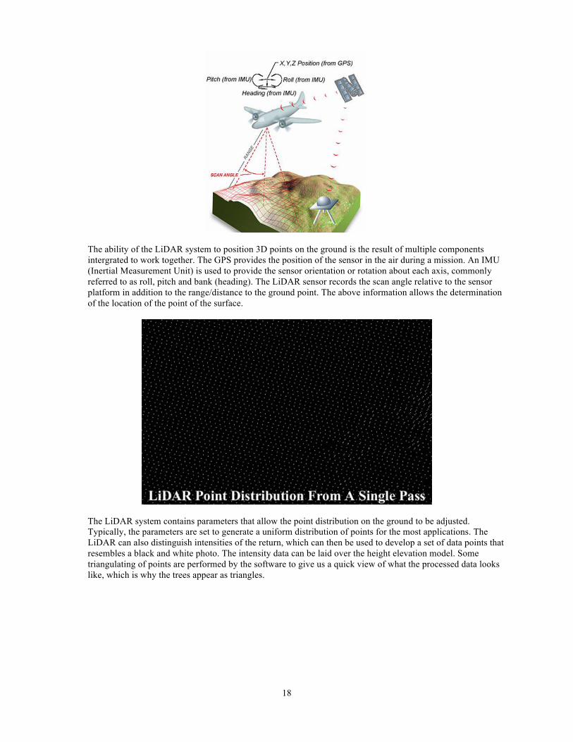
18
The ability of the LiDAR system to position 3D points on the ground is the result of multiple components intergrated to work together. The GPS provides the position of the sensor in the air during a mission. An IMU (Inertial Measurement Unit) is used to provide the sensor orientation or rotation about each axis, commonly referred to as roll, pitch and bank (heading). The LiDAR sensor records the scan angle relative to the sensor platform in addition to the range/distance to the ground point. The above information allows the determination of the location of the point of the surface.
The LiDAR system contains parameters that allow the point distribution on the ground to be adjusted. Typically, the parameters are set to generate a uniform distribution of points for the most applications. The LiDAR can also distinguish intensities of the return, which can then be used to develop a set of data points that resembles a black and white photo. The intensity data can be laid over the height elevation model. Some triangulating of points are performed by the software to give us a quick view of what the processed data looks like, which is why the trees appear as triangles.
19
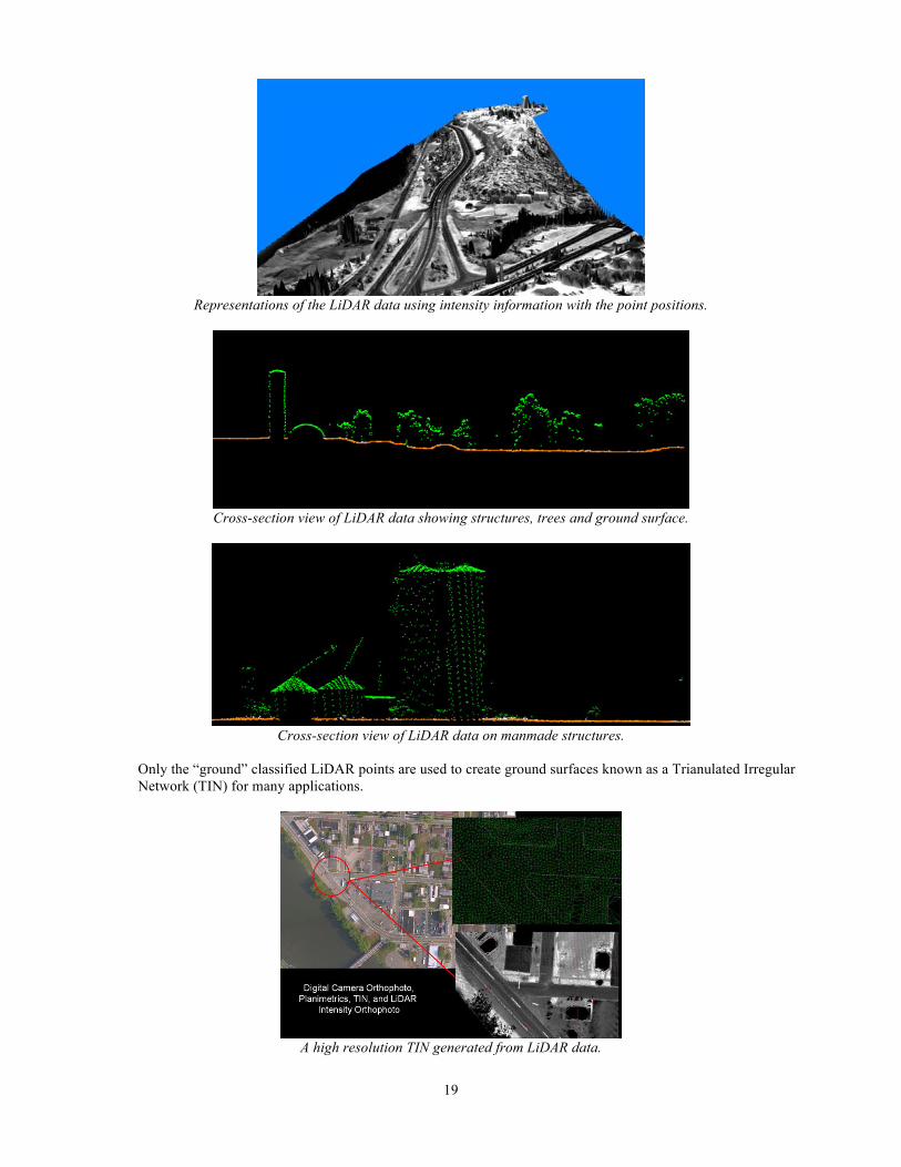
Representations of the LiDAR data using intensity information with the point positions.
Cross-section view of LiDAR data showing structures, trees and ground surface.
Cross-section view of LiDAR data on manmade structures.
Only the “ground” classified LiDAR points are used to create ground surfaces known as a Trianulated Irregular Network (TIN) for many applications.
A high resolution TIN generated from LiDAR data.
20
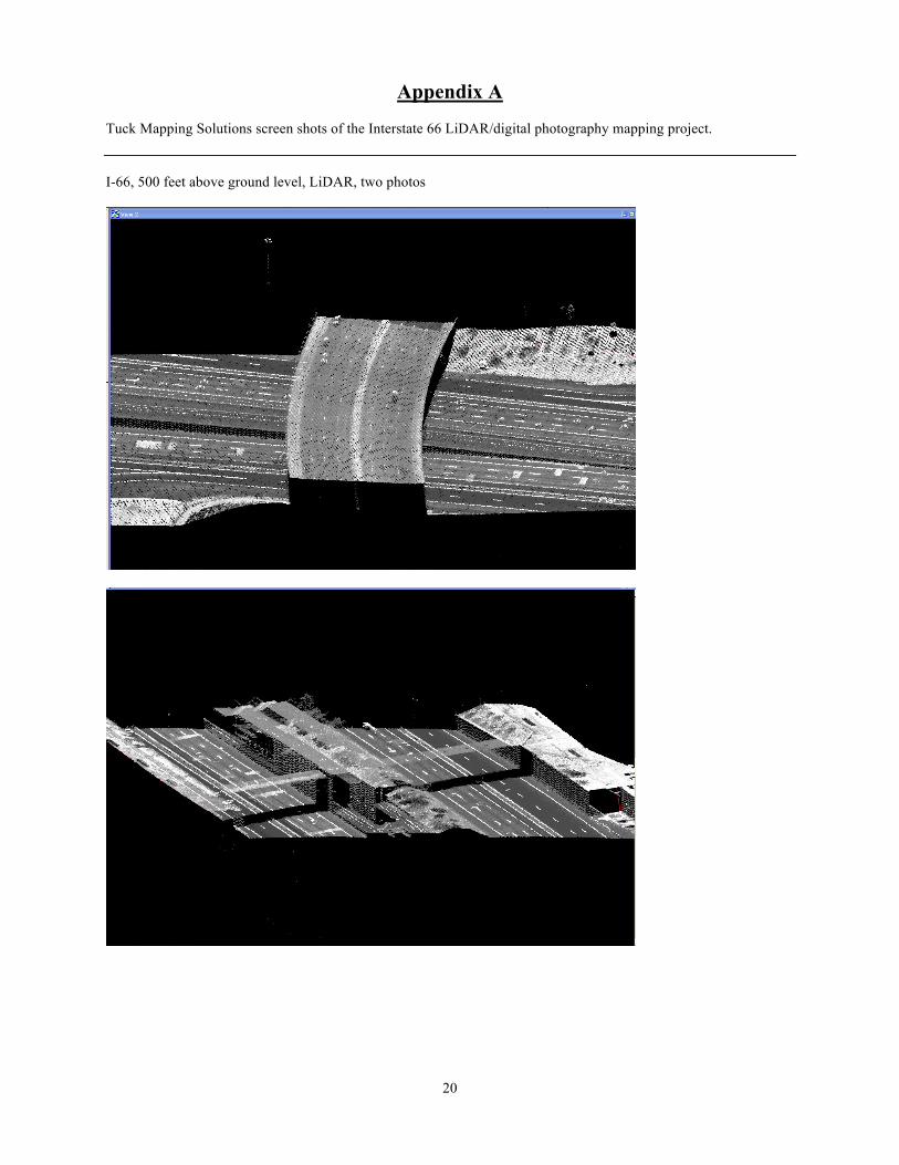
Appendix A Tuck Mapping Solutions screen shots of the Interstate 66 LiDAR/digital photography mapping project. I-66, 500 feet above ground level, LiDAR, two photos

21
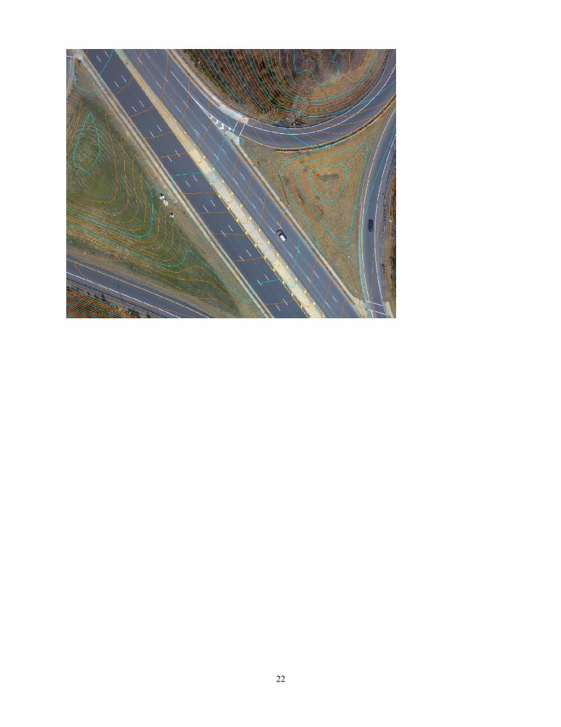
I-66, contours, three photos
22
Appendix B
Mobile Terrestrial Laser Scanning Guidelines Caltrans – District 4
Caltrans District 4 – Interim Mobile Terrestrial Laser Scanning Guidelines
Caltrans District 4 (San Francisco Bay Area) is seeing an increase in request for use of Mobile Terrestrial Laser Scanning (MTLS) on projects on the State Highway System (SHS). These requests are coming from Local Agencies, consultants, and internal Caltrans professionals. Because of the increase in the requests for the use of MTLS it has become necessary to establish interim guidelines for appropriate projects for its use as well as appropriate standards and specifications. MTLS is an emerging technology that combines the use of a laser scanner(s), the Global Navigation Satellite Systems (GNSS), and an Inertial Measurement Unit (IMU) on a mobile platform to produce accurate and precise geospatial data. The data is initially adjusted by post-processed kinematic GNSS procedures from separate GNSS base stations placed throughout the project area. Then the GNSS solution is combined with the IMU information to produce geospatial data in the form of a point cloud. This point cloud is then adjusted by a local transformation to well defined points throughout the project area to produce the final geospatial values. The final values are then compared to independent check point measurements. The use of the MTLS shall adhere to all of the requirements stated in the Caltrans Surveys Manual (CSM) and the Caltrans Safety Manual. Additionally, the accuracy standards of the MTLS products shall meet the requirements as stated in the Federal Geographic Data Committee’s Geospatial Positioning Accuracy Standards. Part 3 of these standards is the National Standard for Spatial Data Accuracy (NSSDA). Note: These Guidelines are based on anecdotal information from a few projects that have shown good results. As more information and analysis is performed revised guidelines will be written. Note: A California Licensed Land Surveyor is required to be in responsible charge of a MTLS whenever the activities are part of those listed in Section 8726 of the Business and Professions Code. http://www.leginfo.ca.gov/cgi-bin/waisgate?WAISdocID=47910823817+0+0+0&WAISaction=retrieve Note: The approval authority of the use of MTLS on the SHS in District 4 is the District Field Surveys Office Chief.
Mobile Terrestrial Laser Scanning Guidelines
Caltrans – District 4
2
Note: This document is the result of a collaborative effort between URS, Terrametrix3D, David Evans and Associates, Psomas, WHPacific, and Caltrans staff. Note: These guidelines will be superseded by statewide standards and specifications produced by Caltrans’ Office of Land Surveys and approved by Caltrans’ Surveys Management Board when produced.
I.) Background
Description of a Laser Scanner A basic laser scanner instrument combines a pulsed laser emitting the beam, a scanner deflecting the beam towards the scanned area, and an optical receiver subsystem, which detects the laser pulse reflected from the target. One type of system calculates the final xyz values from the time of flight of the laser. Since the speed of light is known, the travel time of the laser pulse can be converted to a precise range measurement. Combining the laser range, scan angle, laser position from GNSS and orientation of the laser platform from IMU, highly accurate xyz-coordinates of the topographic points for each laser pulse can be calculated. The laser pulse repetition rate in combination with scanning mirror deflecting pattern determine lidar data collection rate. In the most advanced commercially available lidar systems, the data measurement rate is typically 50,000 - 200,000 measurements per second, which allows the user to collect highly accurate data of required ground point density within very short period of time. A second type of system uses phase-based algorithms to calculate the range component described above instead of time of flight. Description of GNSS
GNSS are satellite systems that are used for positioning, navigation, and timing applications. These systems at present include the U.S.’s Global Positioning System (GPS), Russia’s GLONASS, the European Union’s Galileo, and the Chinese Beidou system. These systems send out encoded signals that have a well-defined wavelength. A GNSS receiver receives these signals and trilaterates its position, as well as calculates its heading and its precise time. Description of IMU and its use in the MTLS An IMU is a navigation aid that uses a computer, motion sensors (accelerometers) and rotation sensors (gyroscopes) to continuously calculate
Mobile Terrestrial Laser Scanning Guidelines
Caltrans – District 4
3
the position, orientation, and velocity (direction and speed of movement) of a moving object without the need for external references. It is used on vehicles such as ships, aircraft, submarines, guided missiles, spacecraft, and MTLS systems. Within the MTLS it aids the system to calulate its xyz positions during periods of reduced or no GNSS reception.
II.) Project Selection
The following are factors to consider when determining if MTLS is appropriate for a particular SHS project:
• Safety • Project time constraints • GPS data collection environment • Length/size of project • MTLS system availability • Traffic volumes and times
Typical transportation projects (data) for the use of MTLS include:
• Asset management • Planning maps • Forensic surveys • Base maps • Deformation surveys • Design surveys • As-builts • Bridge clearance surveys • Line of sight analysis • Quarries and earth-moving volumes • Urban mapping and modeling • Coastal zone erosion analysis
Note: The value of the collected data is multiplied when it is “mined” for data for various uses and customers beyond its initial intended use.
III.) Equipment
Note: The MTLS equipment should be able to produce data for the intended use. All of the equipment used to collect MTLS data, to control the data, and to collect the quality control check shots should be able to collect the data at the accuracy
Mobile Terrestrial Laser Scanning Guidelines
Caltrans – District 4
4
standards described below. This determination will be from the stated specifications for the equipment by the manufacture. The data collection equipment including scanners, Global Navigation Satellite System (GNSS) units, and the Inertial Measurement Unit (IMU) shall also have the following requirements.
A.) Scanners Eye safety The OSHA and Cal-OSHA guidelines shall be strictly followed for eye safety. Below is information for OSHA STD 01-05-001 STD 01-05-001 - PUB 8-1.7 - Guidelines for Laser Safety and Hazard Assessment
• Record Type: Instruction • Directive Number: STD 01-05-001 • Old Directive Number: PUB 8-1.7 • Title: Guidelines for Laser Safety and Hazard Assessment • Information Date: 08/05/1991
• Status: Archived
OSHA Instruction PUB 8-1.7 August 5, 1991 Directorate of Technical Support
Subject: Guidelines for Laser Safety and Hazard Assessment
A. PURPOSE. This instruction provides guidelines to Federal OSHA and Plan States compliance officers, 7(c)(1) consultants, and employee for the assessment of laser safety. Additionally, the eye safety of the traveling public and other people should be considered at all times and the equipment operated in a way to ensure the eye safety of all.
Scan Density
Mobile Terrestrial Laser Scanning Guidelines
Caltrans – District 4
5
The scan density is ultimately dependant on the traveling speed of the MTLS system. The speed of the vehicle while collecting data shall not exceed the systems ability to collect data at the required density to model specific features. Useful Range of Scanner
Since a laser scanner is capable of scanning features over long distances, and since the accuracy of the scan data diminishes beyond a certain distance, care should be taken to ensure that the final dataset does not include any portion of point cloud data whose accuracy is compromised by the fact that it is outside the useful range of the scanner. The useful range will be determined by factors such as the range and accuracy specifications of the individual scanner as well as the accuracy requirements of the individual project. Methods for accomplishing this might include the implementation of range and/or intensity filtering during data collection or culling any out-of-useful range data during post processing.
B.) GNSS The GNSS equipment shall correspond with the requirements stated in Chapter 6, “GPS Surveys” of the CSM. Additional GNSS equipment requirements:
• Dual frequency GNSS receiver able to receive data at 1 epoch per second or faster
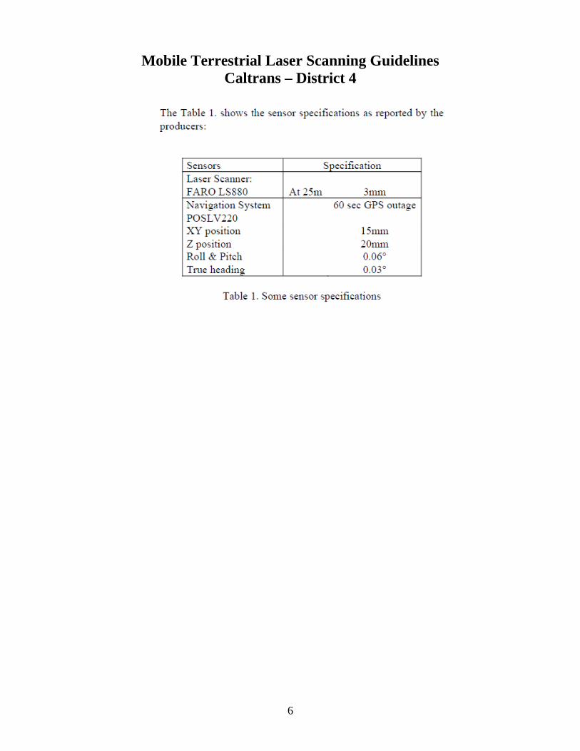
C.) IMU Below is an example of a manufacture’s specifications.
Mobile Terrestrial Laser Scanning Guidelines
Caltrans – District 4
6
Mobile Terrestrial Laser Scanning Guidelines
Caltrans – District 4
7
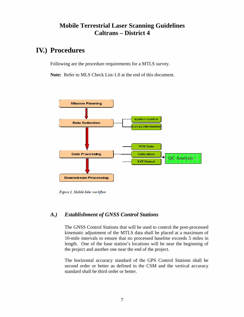
IV.) Procedures Following are the procedure requirements for a MTLS survey.
Note: Refer to MLS Check List-1.0 at the end of this document.
A.) Establishment of GNSS Control Stations
The GNSS Control Stations that will be used to control the post-processed kinematic adjustment of the MTLS data shall be placed at a maximum of 10-mile intervals to ensure that no processed baseline exceeds 5 miles in length. One of the base station’s locations will be near the beginning of the project and another one near the end of the project. The horizontal accuracy standard of the GPS Control Stations shall be second order or better as defined in the CSM and the vertical accuracy standard shall be third order or better.
QC Analysis
Mobile Terrestrial Laser Scanning Guidelines
Caltrans – District 4
8
B.) Mission Planning
Before the MTLS project commences a mission planning session should be conducted to assure that there are enough satellites available during the data collection and that the PDOP meets the requirements. During the data collection there shall be a minimum of 5 satellites in view for the GPS Control Stations and the GPS unit in the MTLS system. Additionally, the maximum PDOP during acquisition shall be 5. Also, the project area shall be reconnoitered to determine the best time to collect the data to minimize excessive “noise” in the data collection from surrounding traffic or other factors.
C.) Calibration of Equipment
Before and after collecting the MTLS data all of the equipment in the MTLS system shall be calibrated to the manufacture’s specifications.
D.) Test Run
In order to assure the accurate collection of the MTLS data a test run of data collection shall be conducted. The test run shall be of sufficient length and duration to assure that the system is functioning correctly and that the system is collecting data correctly. Parameters:
• Length • Known datum information on targets or physical features
E.) Redundancy
The collection of the MTLS data shall be conducted in such a way as to ensure redundancy of the data. This means that data should be collected so that there is an overlap, which means that either more that one pass in the same direction on the SHS project or overlapping passes in the opposite direction or both shall be collected. Redundancy parameters:
• Overlap dimensions: minimum of 20% sidelap
Mobile Terrestrial Laser Scanning Guidelines
Caltrans – District 4
9
• Time between runs: Sufficient time to ensure that the satellite constellation has at least 3 different satellites
F.) Monitoring of Data Collection
Monitoring various component operations during the scan session is an important step in the QA/QC process. The system operator should be aware and note when the system encountered the most difficulty and be prepared to take appropriate action in adverse circumstances. The MTLS equipment shall be monitored throughout the data collection to track the following as well as any other factor that needs monitoring:
• The loss of GPS reception and how long the IMU has drifted without correction.
• Vehicle Speed • Proper functioning of the laser scanner
V.) Local Transformation A.) Description
In order to increase the accuracy of the collected and adjusted geospatial data a local transformation of the point clouds shall be conducted. There may be many different types of local transformations that may be employed, however, the most common is a least squares adjustment of the horizontal and vertical residuals between established Local Transformation Points and the corresponding values from the point clouds to produce the transformation parameters of translation, rotation, and scale for the horizontal values and an inclined plane for the vertical values. These parameters are then applied to the point cloud to produce more accurate final geospatial data.
B.) Placement of Local Transformation Points
The Local Transformation Points shall be evenly spaced throughout the project to ensure that the project is “bracketed”. The maximum distance spacing between these points shall be a 500 feet on both sides of the SHS project, wherever possible.

Mobile Terrestrial Laser Scanning Guidelines
Caltrans – District 4
10
C.) Local Transformation Points Accuracy
The Local Transformation Points shall be surveyed to third order or better for both the horizontal and vertical values as described in the CSM.
VI.) Quality Management Plan
The MTLS data provider shall provide to the District 4 Surveys Office Chief a Quality Management Plan (QMP) that includes descriptions of the proposed quality control and quality assurance plan. The QMP shall include the requirements set forth in this document as well as other project specific QC/QA measures. See checklist. The District 4 Surveys Office Chief shall conduct an Independent Quality Assurance (IQA) review of the QMP.
A.) National Standard for Spatial Data Accuracy (NSSDA)
The accuracy claimed of the finished MTLS geospatial data shall conform to the requirements stated in the NSSDA. The NSSDA requirements can be found at the following link: http://www.fgdc.gov/standards/projects/FGDC-standards-projects/accuracy/part3/chapter3
B.) Number of Check Points Measurements
According to the NSSDA, a minimum of 20 check points shall be tested, distributed to reflect the geographic area of interest and the distribution of error in the data sets. Check point elevations shall be established with methods that produce a greater accuracy than the MTLS system provide. The preferred method is differential leveling to Caltrans Third Order Specifications.
Mobile Terrestrial Laser Scanning Guidelines
Caltrans – District 4
11
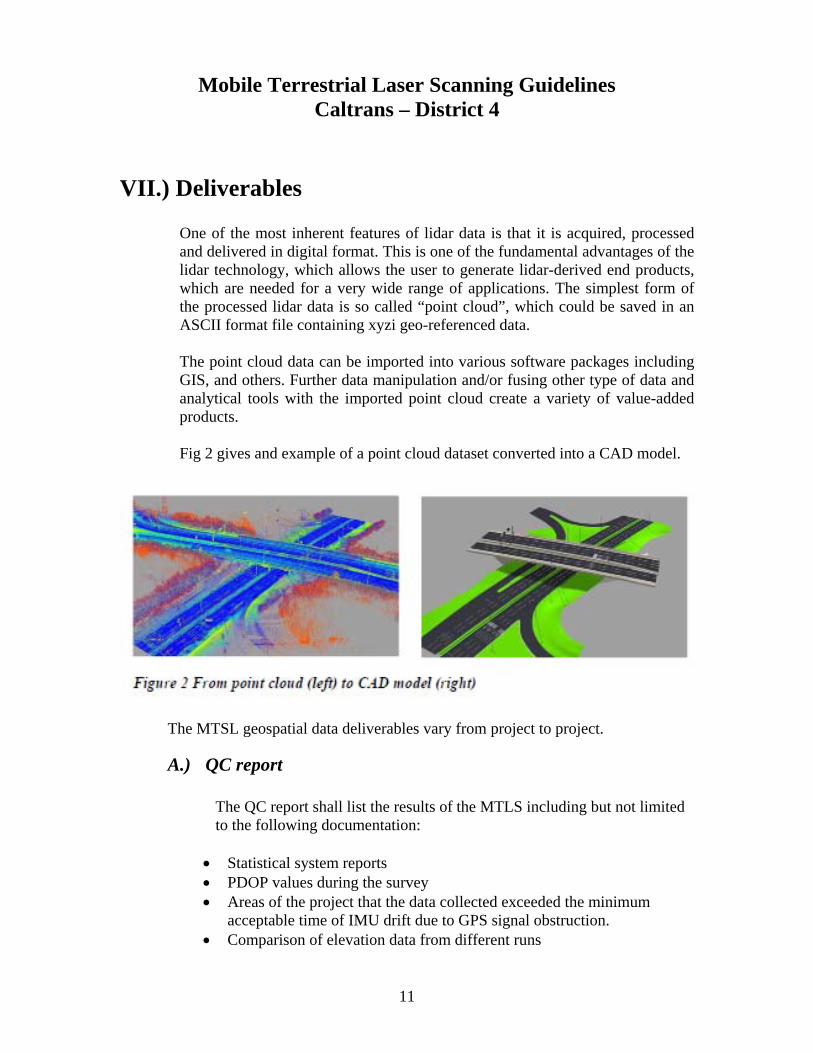
VII.) Deliverables One of the most inherent features of lidar data is that it is acquired, processed and delivered in digital format. This is one of the fundamental advantages of the lidar technology, which allows the user to generate lidar-derived end products, which are needed for a very wide range of applications. The simplest form of the processed lidar data is so called “point cloud”, which could be saved in an ASCII format file containing xyzi geo-referenced data. The point cloud data can be imported into various software packages including GIS, and others. Further data manipulation and/or fusing other type of data and analytical tools with the imported point cloud create a variety of value-added products. Fig 2 gives and example of a point cloud dataset converted into a CAD model.
The MTSL geospatial data deliverables vary from project to project.
A.) QC report The QC report shall list the results of the MTLS including but not limited to the following documentation:
• Statistical system reports • PDOP values during the survey • Areas of the project that the data collected exceeded the minimum
acceptable time of IMU drift due to GPS signal obstruction. • Comparison of elevation data from different runs
Mobile Terrestrial Laser Scanning Guidelines
Caltrans – District 4
12
• Comparison of points at the area of overlap if more than one base is used.
• Statistical comparison of point cloud data and check points • Statistical comparison of adjusted point cloud data and redundant check
points
B.) Point Cloud
• When delivered the point cloud shall be filtered to one layer of points that represents the mean value of all the scans.
• The “noise” caused by moving vehicles and pedestrians shall be removed.
C.) Additional Deliverables Additional products may be delivered as required by the customer.
Mobile Terrestrial Laser Scanning Guidelines
Caltrans – District 4
13
MTLS Check List 1.0
Materials Needed for Mobile Mapping Projects A. Materials needed BEFORE the mission:
1) Who is the Project Manager? 2) Purpose of project mapping 3) Map units 4) Project coordinate system 5) Scanner calibration data 6) Proposed driving plan 7) GNSS visibility report 8) Suitable driving speed to obtain required point density 9) Proposed base station locations 10) Proposed Ground Control Points (GCPs) 11) Proposed schedule for delivery of Items B and C to the client 12) Driving Plan
B. Materials needed AFTER the mission and BEFORE vectoring:
1) GNSS accuracy report The GNSS Accuracy Report should contain the following: a. Forward/Reverse or Combined Separation plot b. Number of Satellites Bar plot c. PDOP, HDOP, VDOP plots d. L1 Satellite Lock/Elevation plot e. Estimated Position Accuracy plot
2) IMU accuracy report The IMU Accuracy Report should contain the following: a. IMU Position RMS plot b. GNSS/IMU Position Differences plot
3) Control report The Control Report should contain the following: a. Table showing the dZ between GCPs and known points b. Average, Minimum and Maximum dZ c. Average magnitude, RMS and standard deviation
C. Materials needed AFTER vectoring has been completed:

Mobile Terrestrial Laser Scanning Guidelines
Caltrans – District 4
14
1) Classified point cloud (LAS and/or ASCII) 2) Georeferenced digital photographs/video

![ResearchReports … · 2019. 11. 12. · ResearchReports InterculturalProfilesandAdaptationAmongImmigrantandAutochthonous Adolescents CristianoInguglia*a,PasqualeMussoa [a]DepartmentofPsychological](https://img.pdfslide.net/doc/110x75/60817c6fdf091e14725176e4/researchreports-2019-11-12-researchreports-interculturalprofilesandadaptationamongimmigrantandautochthonous.jpg)


![Rhoads, David - Marcos Como Relato[1]](https://img.pdfslide.net/doc/110x75/557202b74979599169a3fa8f/rhoads-david-marcos-como-relato1.jpg)