Embed Size (px)
Citation preview
AIAA 2006-2082 Structural Configuration Analysis of Crew Exploration Vehicle Concepts V. Mukhopadhyay NASA Langley Research Center, Hampton, VA
47th AIAA/ASME/ASCE/AHS/ASC Structures, Structural Dynamics and
Materials Conference, 1-4 May 2006, Newport, RI
For permission to copy or to republish, write to American Institute of Aeronautics and Astronautics, 1801 Alexander Bell Drive, Suite 500, Reston VA 20191-4344
0 American Institute of Aeronautics and Astronautics
https://ntrs.nasa.gov/search.jsp?R=20060018287 2018-06-13T02:45:40+00:00Z
AIAA 2006-2082: Tracking No: 48762 ID Mukhopadhyay 12311 /Due April 4, 2006 /LF 99 ID 2720 Structural Configuration Analysis of Crew Exploration Vehicle Concepts
Vivek Mukhopadhyay*
NASA Langley Research Center, Hampton, VA
Abstract Structural configuration modeling and finite element analysis of crew exploration vehicle (CEV)
concepts are presented. In the structural configuration design approach, parametric solid models of the pressurized shell and tanks are developed. The CEV internal cabin pressure is same as in the International Space Station (ISS) to enable docking with the ISS without an intermediate airlock. Effects of this internal pressure load on the stress distribution, factor of safety, mass and deflections are investigated. Uniform 7 mm thick skin shell, 5 mm thick shell with ribs and frames, and isogrid skin construction options are investigated. From this limited study, the isogrid construction appears to provide most strength/mass ratio. Initial finite element analysis results on the service module tanks are also presented. These rapid finite element analyses, stress and factor of safety distribution results are presented as a part of lessons learned and to build up a structural mass estimation and sizing database for future technology support. This rapid structural analysis process may also facilitate better definition of the vehicles and components for rapid prototyping. However, these structural analysis results are highly conceptual and exploratory in nature and do not reflect current configuration designs being conducted at the program level by NASA and industry.
I. Introduction factor of safety distribution and mass. These results are presented as a part of lessons learned and to build up a structural sizing database for future technology support. However, these structural analysis results are highly conceptual and exploratory in nature and do not reflect the current configuration designs being conducted at the program level by NASA and the aerospace industry.
A comprehensive plan for the development of a lunar outpost was prepared by the Johnson Space Center Exploration study team1 as early as in May 1992. In the recent Exploration and Space Architecture Study2 (ESAS) report, details of the current space exploration strategy and technical approaches were outlined. Initial design specifications for the development of a Crew Exploration Vehicle (CEV) are also available in this report. The CEV internal cabin design pressure is specified to be the same as in the International Space Station (ISS) to enable docking with the ISS without an intermediate airlock2,3. In order to carry this pressure load in a conical shaped capsule without significant structural mass penalty4,5, extensive structural analysis, design, fabrication and testing efforts would be required. With the current structural technology and design tools, there is opportunity for developing significantly efficient structural configurations for these vehicles. This paper will present some initial structural configuration modeling and analysis of a notional crew capsule inner shell and other pressurized components. First, some parametric solid models are developed6 for visualization of vehicle configuration options. These parametric solid models are then used for the finite element analysis7. Uniform shell, isogrid plate and rib-spar constructions are investigated in order to examine their effects on the stress distribution, deflection,
II. Structural Analysis Process
The initial assumptions for overall sizing and loads are as follows. 1. The CEV maximum outer diameter is 5.5 meters. 2. The CEV internal cabin pressure is 1.0139E+05 Newtons/meter2 or 14.7 pounds/square inch (psi). The liquid oxygen tank internal pressure is 2.069E+05 N/m2 (30 psi). The high pressure gas storage tanks carry 2.069E+06 N/m2 (300 psi) internal pressure. 3. Aluminum alloy material properties are used for the CEV crew cabin. For high pressure gas storage tanks, titanium alloy material properties are used. Thermal effects or external loads are not included at this stage. The structural finite element analysis process steps are as follows. 1. Generate parametric solid models of the vehicle outer shell, and pressurized tank components. ------------------------------------------------------------- 2. Analyze solid and shell finite element models (FEM) of vehicle components and compute stress, *Research Engineer, Aero. Systems Analysis
Branch/442, Associate fellow.
1 American Institute of Aeronautics and Astronautics
The solid modeling tool6 used for this analysis can also be used for computation of mass, moment of inertia, center of gravity location, etc. It can also be used for creating engineering drawing for prototype development. A sample drawing of the command module cross section is shown in Figure 2. The inner pressurized module is used for the structural analysis.
deflection and safety factors, based on the internal pressure load. 3. Resize solid or shell models, choose materials and skin thickness that would exhibit reasonable factor of safety based on the material yield stress. 4. Investigate packaging volume and interference issues of vehicles and internal components. 5. Show summary of results in Table 1. 6.Modify FEM models for future structural analysis with all external loads, for sizing, stability and optimization studies.
III. Inner Shell with Cutouts
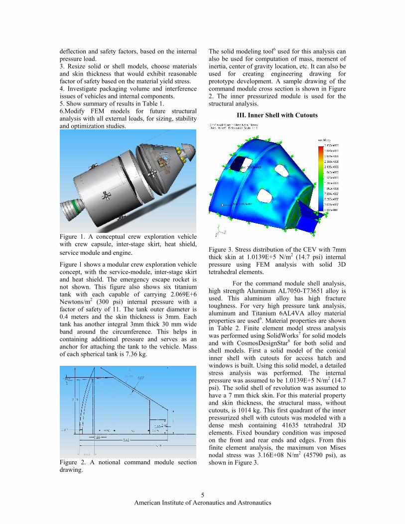
Figure 1. A conceptual crew exploration vehicle with crew capsule, inter-stage skirt, heat shield, service module and engine. Figure 3. Stress distribution of the CEV with 7mm
thick skin at 1.0139E+5 N/m2 (14.7 psi) internal pressure using FEM analysis with solid 3D tetrahedral elements.
Figure 1 shows a modular crew exploration vehicle concept, with the service-module, inter-stage skirt and heat shield. The emergency escape rocket is not shown. This figure also shows six titanium tank with each capable of carrying 2.069E+6 Newtons/m2 (300 psi) internal pressure with a factor of safety of 11. The tank outer diameter is 0.4 meters and the skin thickness is 3mm. Each tank has another integral 3mm thick 30 mm wide band around the circumference. This helps in containing additional pressure and serves as an anchor for attaching the tank to the vehicle. Mass of each spherical tank is 7.36 kg.
For the command module shell analysis, high strength Aluminum AL7050-T73651 alloy is used. This aluminum alloy has high fracture toughness. For very high pressure tank analysis, aluminum and Titanium 6AL4VA alloy material properties are used6. Material properties are shown in Table 2. Finite element model stress analysis was performed using SolidWorks7 for solid models and with CosmosDesignStar8 for both solid and shell models. First a solid model of the conical inner shell with cutouts for access hatch and windows is built. Using this solid model, a detailed stress analysis was performed. The internal pressure was assumed to be 1.0139E+5 N/m2 (14.7 psi). The solid shell of revolution was assumed to have a 7 mm thick skin. For this material property and skin thickness, the structural mass, without cutouts, is 1014 kg. This first quadrant of the inner pressurized shell with cutouts was modeled with a dense mesh containing 41635 tetrahedral 3D elements. Fixed boundary condition was imposed on the front and rear ends and edges. From this finite element analysis, the maximum von Mises nodal stress was 3.16E+08 N/m2 (45790 psi), as shown in Figure 3. Figure 2. A notional command module section
drawing.
5 American Institute of Aeronautics and Astronautics
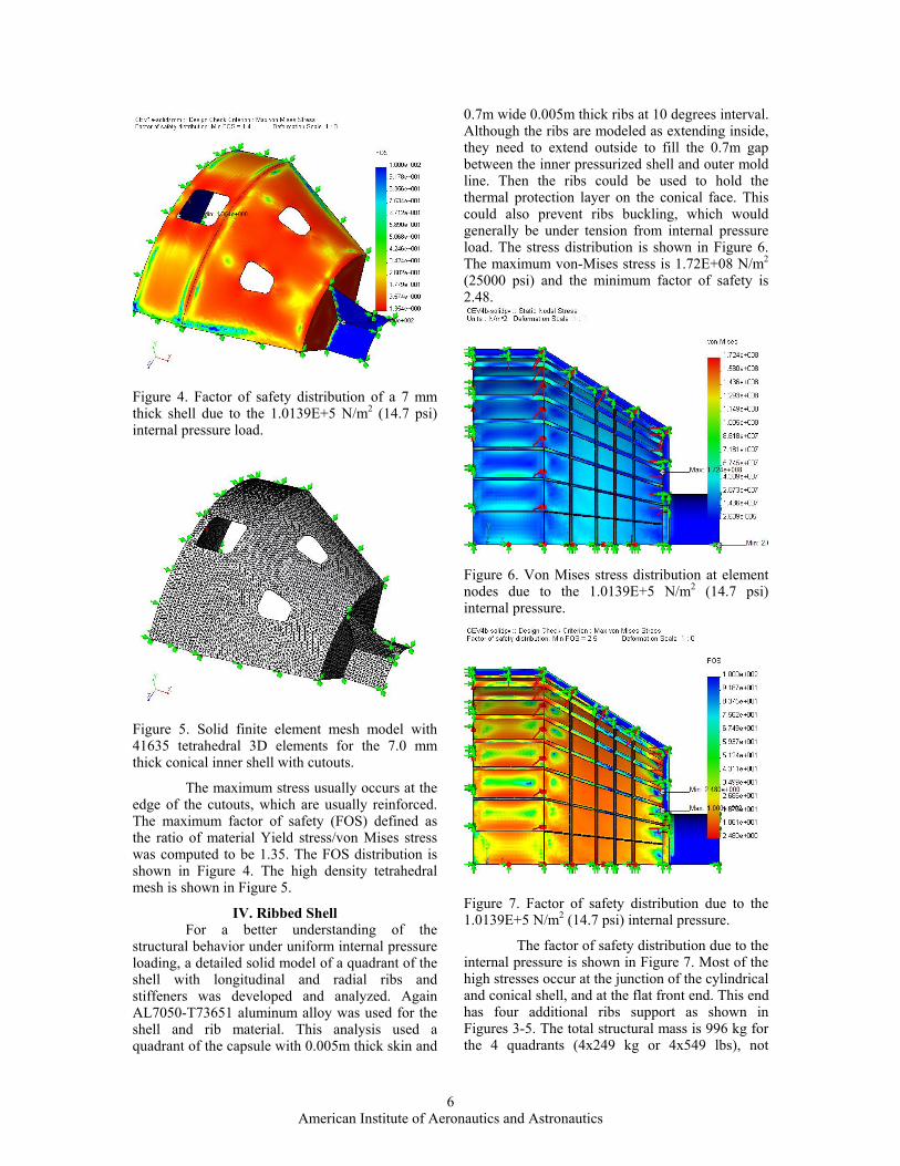
Figure 4. Factor of safety distribution of a 7 mm thick shell due to the 1.0139E+5 N/m2 (14.7 psi) internal pressure load.
Figure 5. Solid finite element mesh model with 41635 tetrahedral 3D elements for the 7.0 mm thick conical inner shell with cutouts.
The maximum stress usually occurs at the edge of the cutouts, which are usually reinforced. The maximum factor of safety (FOS) defined as the ratio of material Yield stress/von Mises stress was computed to be 1.35. The FOS distribution is shown in Figure 4. The high density tetrahedral mesh is shown in Figure 5.
IV. Ribbed Shell For a better understanding of the
structural behavior under uniform internal pressure loading, a detailed solid model of a quadrant of the shell with longitudinal and radial ribs and stiffeners was developed and analyzed. Again AL7050-T73651 aluminum alloy was used for the shell and rib material. This analysis used a quadrant of the capsule with 0.005m thick skin and
0.7m wide 0.005m thick ribs at 10 degrees interval. Although the ribs are modeled as extending inside, they need to extend outside to fill the 0.7m gap between the inner pressurized shell and outer mold line. Then the ribs could be used to hold the thermal protection layer on the conical face. This could also prevent ribs buckling, which would generally be under tension from internal pressure load. The stress distribution is shown in Figure 6. The maximum von-Mises stress is 1.72E+08 N/m2 (25000 psi) and the minimum factor of safety is 2.48.
Figure 6. Von Mises stress distribution at element nodes due to the 1.0139E+5 N/m2 (14.7 psi) internal pressure.
Figure 7. Factor of safety distribution due to the 1.0139E+5 N/m2 (14.7 psi) internal pressure.
The factor of safety distribution due to the internal pressure is shown in Figure 7. Most of the high stresses occur at the junction of the cylindrical and conical shell, and at the flat front end. This end has four additional ribs support as shown in Figures 3-5. The total structural mass is 996 kg for the 4 quadrants (4x249 kg or 4x549 lbs), not
6 American Institute of Aeronautics and Astronautics
including ribs for the back shell end. The back shell end is assumed to be fixed for all the FEM analyses boundary conditions. The maximum deflection under this boundary condition is 1.93 mm. Minimizing deflection is important in order to avoid de-bonding of the thermal protection material.
Figure 9. Von-Mises Stress distribution due to the 1.0139E+5 N/m2 (14.7 psi) normal pressure.
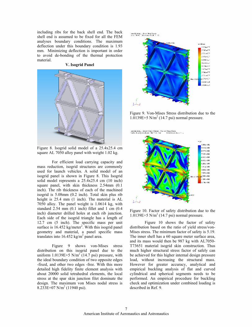
V. Isogrid Panel
Figure 10. Factor of safety distribution due to the 1.0139E+5 N/m2 (14.7 psi) normal pressure.
Figure 8. Isogrid solid model of a 25.4x25.4 cm square AL 7050 alloy panel with weight 1.02 kg.
For efficient load carrying capacity and mass reduction, isogrid structures are commonly used for launch vehicles. A solid model of an isogrid panel is shown in Figure 8. This Isogrid solid model represents a 25.4x25.4 cm (10 inch) square panel, with skin thickness 2.54mm (0.1 inch). The rib thickness of each of the machined isogrid is 5.08mm (0.2 inch). Total skin plus rib height is 25.4 mm (1 inch). The material is AL 7050 alloy. The panel weight is 1.0614 kg, with standard 2.54 mm (0.1 inch) fillet and 1 cm (0.4 inch) diameter drilled holes at each rib junction. Each side of the isogrid triangle has a length of 12.7 cm (5 inch). The specific mass per unit surface is 16.452 kg/meter2. With this isogrid panel geometry and material, a panel specific mass translates into 16.452 kg/m2 panel area.
Figure 10 shows the factor of safety distribution based on the ratio of yield stress/von-Mises stress. The minimum factor of safety is 5.19. The inner shell has a 60 square meter surface area, and its mass would then be 987 kg with AL7050-T73651 material isogrid skin construction. Thus much higher structural stress factor of safely can be achieved for this higher internal design pressure load, without increasing the structural mass. However for greater accuracy, analytical and empirical buckling analysis of flat and curved cylindrical and spherical segments needs to be performed. An empirical procedure for buckling check and optimization under combined loading is described in Ref. 9.
Figure 9 shows von-Mises stress
distribution on this isogrid panel due to the uniform 1.0139E+5 N/m2 (14.7 psi) pressure, with the ideal boundary condition of two opposite edges -fixed, and other two edges -free. With this more detailed high fidelity finite element analysis with about 20000 solid tetrahedral elements, the local stress at the spar skin junction filet dominate the design. The maximum von Mises nodal stress is 8.233E+07 N/m2 (11940 psi).
7 American Institute of Aeronautics and Astronautics
VI. Pressurized Tanks
Figure 11 Partitioned Service modules with internal spherical tank assembly and docking adapter.
Preliminary results from the structural analysis of pressurized components of a service module concept is presented in this section. Figure 11 shows this service module concept consisting of six segments. Each segment houses two spherical tanks. These 12 spherical tanks are sized to make maximum use of the volume available within the 5.5 diameter outer shell. Each 1.8 meter diameter spherical tank is modeled with 3 mm thick skin made of titanium. Each tank has a retaining band for strength and attachment to main frame. The mass of each tank is 147.7 kg. Each tank can withstand an internal pressure of 30 psi, with a yield stress factor of safety of 3.8. Each spherical tank provides an internal volume of 3 cubic meters. The total structural weight is 5916 kg.
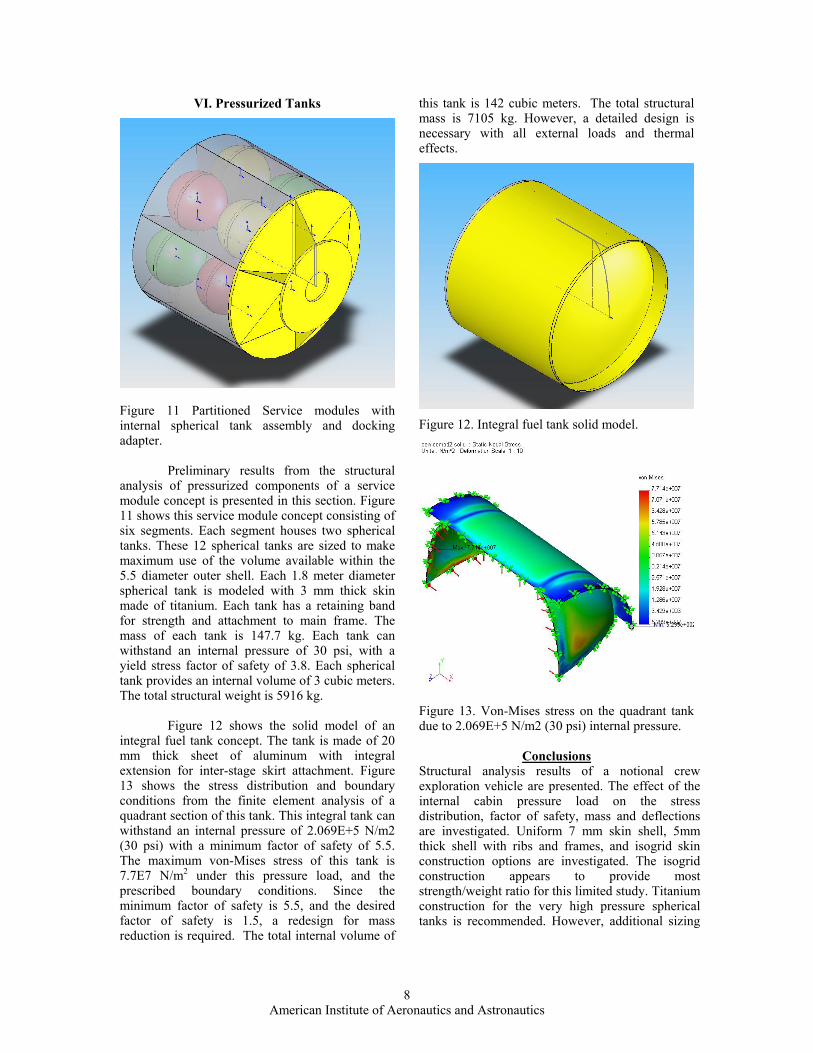
Figure 12 shows the solid model of an integral fuel tank concept. The tank is made of 20 mm thick sheet of aluminum with integral extension for inter-stage skirt attachment. Figure 13 shows the stress distribution and boundary conditions from the finite element analysis of a quadrant section of this tank. This integral tank can withstand an internal pressure of 2.069E+5 N/m2 (30 psi) with a minimum factor of safety of 5.5. The maximum von-Mises stress of this tank is 7.7E7 N/m2 under this pressure load, and the prescribed boundary conditions. Since the minimum factor of safety is 5.5, and the desired factor of safety is 1.5, a redesign for mass reduction is required. The total internal volume of
this tank is 142 cubic meters. The total structural mass is 7105 kg. However, a detailed design is necessary with all external loads and thermal effects.
Figure 12. Integral fuel tank solid model.
Figure 13. Von-Mises stress on the quadrant tank due to 2.069E+5 N/m2 (30 psi) internal pressure.
Conclusions Structural analysis results of a notional crew exploration vehicle are presented. The effect of the internal cabin pressure load on the stress distribution, factor of safety, mass and deflections are investigated. Uniform 7 mm skin shell, 5mm thick shell with ribs and frames, and isogrid skin construction options are investigated. The isogrid construction appears to provide most strength/weight ratio for this limited study. Titanium construction for the very high pressure spherical tanks is recommended. However, additional sizing
8 American Institute of Aeronautics and Astronautics
and optimization studies with all possible design loads are necessary.
Acknowledgement The author wishes to thank Dr. Dauglas Stanley, Georgia Institute of Technology, John Connolly, James R. Geffre, Johnson Space Center, Rudolph J. Soucillo, and Roger A. Lepsch, Langley Research Center, for the inspiration and partial funding during the Exploration Systems Architecture Study (ESAS) and Lunar Surface Access Module (LSAM) study. Additional funding was provided by Fay Collier, William Kimmel, and the Systems Analysis and Concepts Directorate.
References 1. First Lunar outpost Phase-I Report No. EXPO-T2-920004, July 1992, Johnson Space Center, Houston, TX May1992. 2. NASA's Exploration Systems Architecture Study Final Report. NASA-TM-2005-214062, November 2005. 3. Griffin, Michael D., and French, James, R., “Space Vehicle Design,” Second Edition, AIAA Publication, Reston, VA, 1991. 4. Mukhopadhyay, V., Sobieszczanski-Sobieski, J., Kosaka, I., Quinn, G., and Vanderplaats, G., “Analysis, Design and Optimization of Non-cylindrical Fuselage for Blended-Wing-Body Vehicle,” Journal of Aircraft, Vol. 41, No: 4, July-August, 2004, pp. 925-930. 5. Glaessgen, E. H., Reeder, J. R., Sleight, D. W., Wang, J. T., Raju, I.S., Harris, C. E., “Debonding Failure of Sandwich Composite Cryogenic Fuel tank with Internal Core Pressure,” Journal of Spacecraft and Rocket, Vol. 42, No. 4, July- August, 2005, pp. 613-627. 6. Aerospace Design Engineer’s guide, 5th Edition. AIAA Publications, Reston, Virginia, September 2003. 7. SolidWorks User Manual, SolidWorks Corporation, Concord, Massachusetts. 8. CosmosM/CosmosDesignStar User manual, Structural Research and Analysis Corp. Los Angeles, California (http://www.cosmosm.com). 9. Greenberg, H. Stanley, “Structural Analysis techniques for preliminary Design of Launch vehicles,” NASA Langley Short Course, Oct. 3-6, 2005.
9 American Institute of Aeronautics and Astronautics
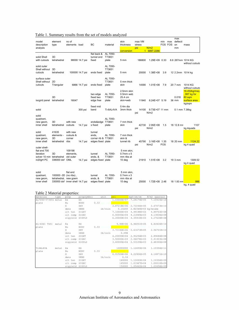
Table 1. Summary results from the set of models analyzed model description
element type
no of elements load BC material
skin thickness
max VM stress
min FOS
max FOS
max deflection mass
analysis psi N/m2 mmconversion 1 6897.2286
solid Shell with cutouts
3D tetrahedral 98000 14.7 psi
flat back & tunnel end fixed
AL 7050-T73651 plate 5 mm 186800 1.29E+09 0.33 8.6 267mm 1014 KG
without cutoutssolid outer Shell without cutouts
3D tetrahedral 100000 14.7 psi ends fixed
AL 7050-T73651 plate 5 mm 20000 1.38E+08 3.9 12 2.2mm 1014 kg
surface outer Shell without cutouts
2D Triangular 6866 14.7 psi ends fixed
AL 7050-T73651 plate
5 mm thick skin 14590 1.01E+08 7.9 20 7 mm 1014 KG
without cutouts
isogrid panel3D tetrahedral 16047
two edge fixed two edge free
AL 7050-T73651 plate
2.5mm skin 0.5mm web 25.4 cm skin+web 11940 8.24E+07 5.19 36
0.018 mm
16.452kg/msq, 987 kg for 60 sqm surface areakg/sqm
solid 300 psifixed mid band Ti-6AL4VA
0.4m dia 3mm thick 14100 9.73E+07 11 mm 0.1 mm 7.36kg
psi N/m2solid quadrant, new geom, inner shell
3D tetrahedral
with new cutouts 14.7 psi
ends&edges fixed
AL 7050-T73651 plate
7 mm thick skin 42730 2.95E+08 1.5 18 12.8 mm 1107
psi N/m2 kg 4quadssolid quadrant, new geom, inner shell
41635 elements - 3D tetrahedral
with new cutouts & corner ribs 14.7 psi
tunnel ends, corner rib & edges fixed
AL 7050-T73651 plate
7 mm thick skin & tunnel rib 45790 3.16E+08 1.35 18 20 mm 1124.22
psi N/m2 FOS kg 4 quadouter shell-flat end 700 iteration solver 10 min in20gH PC
3D tetrahedral 336000 dof
109198 elements, old outer OML 14.7 psi
tunnel ends, & edges fixed
AL 7050-T73651 plate
5 mm skin, 0.7mm x 5 mm ribs at 10 deg 21910 1.51E+08 3.2 19 3 mm 1309.52
kg 4 quad
solid quadrant, new geom, inner shell
100000 -3D tetrahedral, 330000 dof
flat end (no ribs) , new goem inner shell 14.7 psi
tunnel ends, & edges fixed
AL 7050-T73651 plate
5 mm skin, 0.7mm x 5 mm ribs at 10 deg 25000 1.72E+08 2.48 18 1.93 mm 996
kg, 4 quad Table 2 Material properties: material type prop propsymbol unit psi kgf/cm/cm N/m2 (pascal)AL7050-T73651 metal Ex EX 1.03000E+07 7.24174E+05 7.10415E+10plate Nu NUXY 0.33 psi conv 1 7.030814E-02 6.897229E+03
G GXY 3.87218E+06 2.72246E+05 2.67073E+10dens DENS lb/cuin 0.10200 2.82340E+03 kg/mcubeult ten SIGXT 7.10000E+04 4.99188E+03 4.89703E+08ult comp SIGXC 6.00000E+04 4.21849E+03 4.13834E+08sigyield SIGYLD 6.20000E+04 4.35910E+03 4.27628E+08
AL-6061 T651 metal Ex EX 9.90E+06 6.96051E+05 6.82826E+10plate Nu NUXY 0.33 conversi 14.7 1.033530 101389.260339
G GXY 3.72180E+06 2.61673E+05 2.56701E+10dens DENS lb/cuin 0.098ult ten SIGXT 4.20000E+04 2.95294E+03 2.89684E+08ult comp SIGXC 3.50000E+04 2.46078E+03 2.41403E+08sigyield SIGYLD 3.60000E+04 2.53109E+03 2.48300E+08
Ti6AL4VA metal Ex EX 16000000 1.12493E+06 1.10356E+11plate Nu NUXY 0.33 conversi 30 2.109244 206916.857834
G GXY 6.01504E+06 4.22906E+05 4.14871E+10dens DENS lb/cuin 0.16ult ten SIGXT 160000 1.12493E+04 1.10356E+09ult comp SIGXC 145000 1.01947E+04 1.00010E+09sigyield SIGYLD 150000 1.05462E+04 1.03458E+09
9 American Institute of Aeronautics and Astronautics