Embed Size (px)
Citation preview
AiMT Advances in Military Technology Vol. 9, No. 2, December 2014
Safety Concept and Partial Factors for Bridge
Assessment under Military Loading
R. Lenner1*, M. Keuser1 and M. Sykora2
1 Department of Concrete Constructions, Institute of Structural Engineering, University of Bundeswehr, 85577 Neubiberg, Germany
2 Department of Structural Reliability, Klokner Institute, Czech Technical University in Prague, Solinova 7, 166 08 Prague, Czech Republic
The manuscript was received on 11 October 2013 and was accepted after revision for publication on 25 November 2014.
Abstract:
The use of civilian bridges by military vehicles is in the NATO countries regulated and governed by STANAG 2021. This standard, however, does not fully deliver some of the essential aspects important for safe and reliable crossing of military vehicles over existing bridges. This paper aims at investigating the military loads and at developing partial factors that can be utilized during the assessment of bridges for military traffic. A number of factors must be taken into account including target reliability index and uncertainties related to dynamic amplification factor, static load due to military vehicle and applied model for load effect. The results show that the military partial factors can be generally considered in a range close to or smaller than those values given in civilian codes.
Keywords:
Bridge assessment, military traffic, load simulation, safety concept
1. Introduction It is a recognized phenomenon that assessment of existing bridges is becoming increasingly important throughout the world. Due to the aging infrastructure, increased civilian traffic loads and intensity, many structures are yielded as obsolete. When the performance of existing bridges calculated according to the most current design codes is considered, then many of those bridges show an inadequate performance to the design loading. Many researchers have recognized this fact and there is a significant effort beyond establishing and improving possible methods for bridge structural assessment,
* Corresponding author: Department of Concrete Constructions, Structural Engineering Institute, University of Bundeswehr in Munich, Werner-Heisenberg-Weg 38, 85577 Neubiberg, Germany, +498960043469, [email protected]
6 R. Lenner, M. Keuser and M. Sykora
assessment of remaining service life and proposing improved repair and maintenance techniques.
The topic of improving assessment methods and updating partial factors to reflect the changing traffic and bridge conditions is not restricted to civilian engineering professionals and scientists, but it is also interesting for military community considering the fact, that the military frequently utilize bridges built and maintained by civilian authorities. There has been a simultaneous increased effort in establishing a proper safety format for assessment of bridges under military loading.
The current standard for the assessment of existing civilian and military bridges is STANAG 2021 [1]. This regulation is a NATO Standardization Agreement and provides guidance on assessment of military vehicles, bridges, rafts and ferries. However, in the respect of national interests there are no in-depth provisions regarding the safety and more importantly no provided partial factors. It is assumed that military engineers would utilize the current civilian structural standards. Given the fact that most European countries within NATO are using Eurocodes for bridge design (EN 1990 [2], etc.), it is expected that the NATO military engineers in Europe would use the Eurocode civilian provisions for the military bridge assessment.
Eurocodes and their national versions were never calibrated for the assessment of existing bridges under military loading and fundamental differences exist between the two traffic models. The main differences between them are as follows:
• The civilian loading is described by loading models developed to represent the complete actual and future predicted traffic. The military loading is distributed in defined time invariant classes.
• Dynamic effects are included in traffic models in current bridge codes. There are no specific dynamic allowances in STANAG 2021.
• The characteristic value of civilian traffic load corresponds to a 1000-year return period while a nominal (mean) value is considered for military vehicles; considerable reliability margin is thus included already in the characteristic value of civilian traffic load.
There are substantial differences in the treatment of bridges under civilian and military traffic. It is therefore inconsistent to use partial factors intended for civilian traffic when assessing bridges under military loading. With the help of simple statics, traffic modelling and structural reliability theory, to include the investigations of load models, uncertainties, dynamic load effects and crossing conditions, this work is aimed at developing partial factors, which could be used for the military loading in the defined safety format.
2. Military Bridge Assessment
2.1. Military Load Class
It is necessary to study the process of military load classification as described in STANAG 2021 in order to understand the background of the safety format proposal. On contrary to civilian loading STANAG 2021 operates with prescribed procedures defining the military loading. It is accomplished by the means of vehicle classification in one of the so called Military Load Classes*. STANAG 2021 defines 32 hypothetical MLCs – 16
* Further referenced as MLC in this text
7 7
Safety Concept and Partial Factors for Bridge Assessment under Military Loading
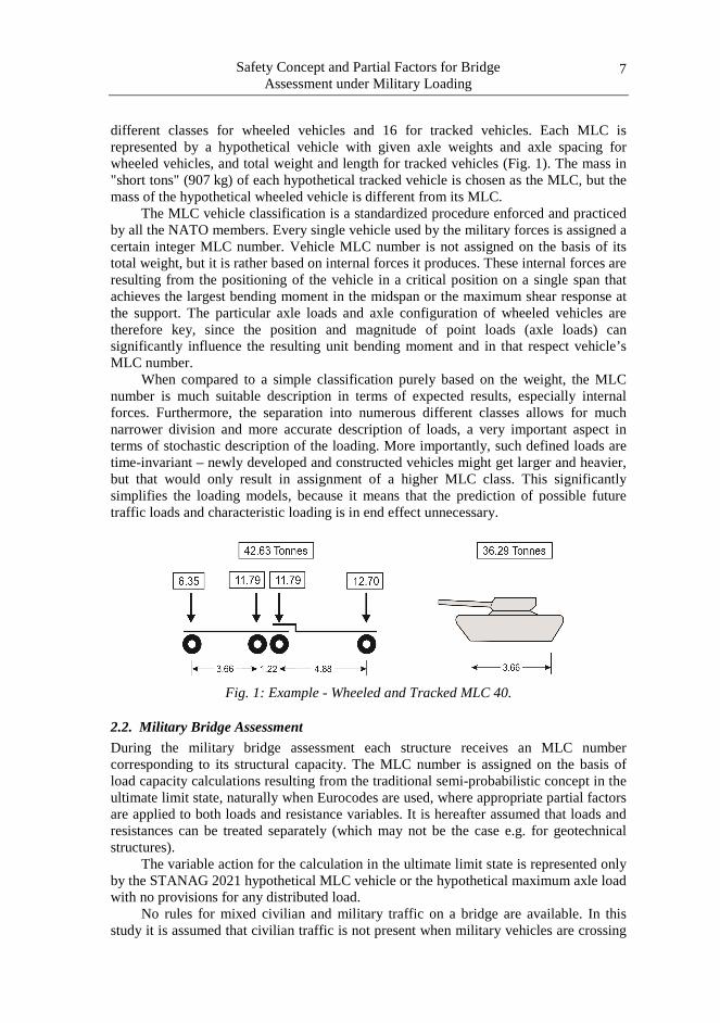
different classes for wheeled vehicles and 16 for tracked vehicles. Each MLC is represented by a hypothetical vehicle with given axle weights and axle spacing for wheeled vehicles, and total weight and length for tracked vehicles (Fig. 1). The mass in "short tons" (907 kg) of each hypothetical tracked vehicle is chosen as the MLC, but the mass of the hypothetical wheeled vehicle is different from its MLC.
The MLC vehicle classification is a standardized procedure enforced and practiced by all the NATO members. Every single vehicle used by the military forces is assigned a certain integer MLC number. Vehicle MLC number is not assigned on the basis of its total weight, but it is rather based on internal forces it produces. These internal forces are resulting from the positioning of the vehicle in a critical position on a single span that achieves the largest bending moment in the midspan or the maximum shear response at the support. The particular axle loads and axle configuration of wheeled vehicles are therefore key, since the position and magnitude of point loads (axle loads) can significantly influence the resulting unit bending moment and in that respect vehicle’s MLC number.
When compared to a simple classification purely based on the weight, the MLC number is much suitable description in terms of expected results, especially internal forces. Furthermore, the separation into numerous different classes allows for much narrower division and more accurate description of loads, a very important aspect in terms of stochastic description of the loading. More importantly, such defined loads are time-invariant – newly developed and constructed vehicles might get larger and heavier, but that would only result in assignment of a higher MLC class. This significantly simplifies the loading models, because it means that the prediction of possible future traffic loads and characteristic loading is in end effect unnecessary.
Fig. 1: Example - Wheeled and Tracked MLC 40.
2.2. Military Bridge Assessment
During the military bridge assessment each structure receives an MLC number corresponding to its structural capacity. The MLC number is assigned on the basis of load capacity calculations resulting from the traditional semi-probabilistic concept in the ultimate limit state, naturally when Eurocodes are used, where appropriate partial factors are applied to both loads and resistance variables. It is hereafter assumed that loads and resistances can be treated separately (which may not be the case e.g. for geotechnical structures).
The variable action for the calculation in the ultimate limit state is represented only by the STANAG 2021 hypothetical MLC vehicle or the hypothetical maximum axle load with no provisions for any distributed load.
No rules for mixed civilian and military traffic on a bridge are available. In this study it is assumed that civilian traffic is not present when military vehicles are crossing
8 R. Lenner, M. Keuser and M. Sykora
the bridge under consideration. In addition to the case of a single standard vehicle on the bridge, an indefinitely long convoy of vehicles with 30.5m spacing between contact points of nearest two vehicles is to be considered. This is particularly important in terms of bending moment for multi-span structures. Shear response is always governed by the maximum number of vehicles that can potentially fit the same span. There are no special considerations provided for extraordinary cases of vehicles spaced possibly closer than the allowable range as dictated by the specific conditions or needs and these have to be regarded on case-specific bases.
STANAG 2021 additionally recognizes a difference between the possible bridge classifications procedures - permanent and temporary classification of bridges. Permanent MLC is achieved through the use of analytical methods. Expedient classification methods may only determine temporary marking and thus the bridge must be reclassified analytically as soon as practically possible. This work is only concerned with the analytical methods of classification.
2.3. Crossing Conditions
In addition to defining the MLC the STANAG 2021 also provides regulation regarding different modes of crossing of military vehicles over bridges. This is to ensure potential maximizing of the allowable load by minimizing load effects resulting from load positioning, dynamic impact and dynamic amplification when dictated by certain tactical or emergency situations, where the crossing of vehicles with higher MLC is necessary. This is accomplished by either controlled crossing conditions or relaxed safety criteria. Normal Crossing: The normal crossing condition is the main crossing mode and should be regarded as standard for the assessment if not stated otherwise. The minimum criteria for safety outlined in STANAG 2021 are valid for this condition. A normal crossing allows for an unrestricted use of bridge by military traffic and for all vehicles or convoys operating at or below the maximum allowable MLC. Only rating associated with the normal crossing may be permanently assigned to a bridge.
Caution Crossing: While maintaining the same safety level as for the normal crossing, the caution crossing allows for a higher allowable MLC by limiting the maximum speed to 5km/h and restricting the use of braking, accelerating and switching gears. Vehicles must drive along the centreline and are only allowed to cross one at a time across each structurally independent span. Rating associated with the caution crossing may be only regarded as temporary.
Risk Crossing: Risk crossing allows for transportation of higher MLC vehicles by adapting the same conditions as the caution crossing (speed up to 5km/h, single vehicle at the centreline of an independent span, no braking, accelerating and changing gears), but additionally decreasing a minimum required safety. It greatly increases the probability of failure, and even if the bridge does not fail, permanent damage to the bridge may occur.
3. Safety Concept for Military Traffic When it comes to the development of proper safety concept, it is proposed in this work to accept the semi-probabilistic safety concept as provided in EN1990 [2] and modify the required partial factors to reflect the characteristic of assessment of existing bridges under military loading according to STANAG 2021. In a semi-probabilistic safety concept a set of partial factors γ resulting from probabilistic analysis serves to achieve certain reliability level for any structure of interest.
9 9
Safety Concept and Partial Factors for Bridge Assessment under Military Loading
It should be noted that the approach for modification of partial factors to reflect specific needs has been pursued by a number of scientists and engineers. There are many, but to mention a few for illustration, for example, Fischer [3] attempted in his thesis to modify the partial factors for existing concrete structures reflecting the existing nature and additionally taking into account various ratios of permanent to variable loading. The procedures of AASHTO LRFR specifications were investigated and modified load factors for load rating in accordance to NYSDOT (New York State Department of Transportation) were developed by essentially assessing the remaining service life of bridges and by utilizing actual traffic measurements from Truck Weight-in-Motion data [4]. Bridges and buildings in terms of resistance and capacity reduction factors are considered in [5], where the proposed method with Bayesian statistical approach, which can systematically account for information obtained prior to inspection and during the inspection, has been used for updating characteristic resistance and selection of safety factors. This indicates that the proposed method of adapting partial factor to reflect specific needs or characteristics is not new, however, the topic of military loading on bridges has been up to this point somewhat neglected and there has been only little work accomplished in this field.
3.1. Partial Factor for Permanent Action
The partial factor for permanent action should reflect the existing state of the bridge. The design value of permanent load is expressed as:
kGd GG ⋅=γ , (1)
and the partial factor is in turn obtained as [6]:
ggEdG γγγ ⋅= , , (2)
where γEd,g stands for partial factor accounting for the model uncertainty in estimation of load effect from the load model and γq is reliability-based partial factor accounting for variability of the permanent action, statistical uncertainty and uncertainties related to the model of permanent action.
Assuming normal distribution of the permanent action, partial factor γg can be written as:
GEg V⋅⋅−= βαγ 1 , (3)
where αE ≈ –0.7 denotes the FORM sensitivity factor approximated in accordance with EN 1990 [2] and Vg stands for the variation coefficient of permanent action G.
Considerations of military traffic pertaining to the crossing over existing concrete bridges expose the following points regarding the safety concept and permanent action:
• Existing bridges can be generally described with higher accuracy and therefore with reduced uncertainty tied to permanent loads [7].
• In accordance with ISO 13822 [8] the target reliability index β for assessment of existing structures can be adjusted by optimization of the total cost related to an assumed remaining working life, topic discussed in detail in Chapter 5.
• Crossing conditions dictate different safety levels and therefore the target reliability index β can be adjusted as well, especially in terms of risk crossing.
This suggests that the partial factor for permanent action can be accordingly adjusted to fit the needs of military tailored semi-probabilistic safety concept by adapting variation coefficient Vg for permanent loads to reflect the existing nature of bridges and
10 R. Lenner, M. Keuser and M. Sykora
defining proper target reliability level especially with consideration to crossing conditions. See [6] for additional details regarding the partial factor for permanent action.
3.2. Partial Factor for Variable Action
The design value for variable action Qd, or the value required for assessment in the ultimate limit state, can be obtained from the characteristic value Qk as follows:
kQd QQ ⋅= γ , (4)
where γQ is the partial factor for variable action that can in turn be defined as [9]:
qqEdQ γγγ ⋅= , , (5)
where γEd,q stands for partial factor accounting for the model uncertainty in estimation of the load effect from the load model; γq is reliability-based partial factor accounting for variability of the variable action, statistical uncertainty and uncertainties related to the model of variable action.
As discussed previously, during the military assessment γQ is generally taken from the current bridge standards. Problematic is that the factor was developed using substantially different properties and assumptions on effects of traffic loads, such as dynamic amplification, characteristic load and time variance of the loading.
It is therefore proposed to assess the design load effect of military traffic Qd on different terms as follows [10]:
MLCQd QQ ⋅= γ , (6)
where the characteristic load effect QMLC is defined as the maximum load effect resulting from a hypothetical STANAG MLC.
It is hereafter assumed according to that the load effect due to the passage of military vehicle(s) Q can be obtained as follows:
MLCE QQ ⋅⋅= δθ , (7)
where θE denotes the model uncertainty in estimation of the load effect from the load model, δ is a dynamic amplification factor and QMLC is a static load effect (including uncertainties in measurements of weights and spacing).
It is further realistically assumed that mean values of the basic variables included in relationship Eq. equal to their characteristic values. Assuming lognormal distributed θE and δ and a normal distribution of QMLC, a lognormal distribution can be considered for the load effect Q since greater variability is commonly associated with both θE and δ rather than with a well-described QMLC.
Based on these assumptions partial factor γQ is proposed to be written as:
)exp( QEQ V⋅⋅−= βαγ , (8)
where αE denotes the FORM sensitivity factor, β target reliability index and VQ coefficient of variation of Q obtained as follows:
2MLC
22QQ VVVV ++≈ δθ , (9)
where Vθ, Vδ and VQMLC are the coefficients of variation of model uncertainty, dynamic amplification and of military static load effect, respectively.
11 11
Safety Concept and Partial Factors for Bridge Assessment under Military Loading
The aim of this work is therefore to investigate the factors such as probabilistic properties of military static load in terms of QMLC and VQMLC, dynamic amplification in terms of δ and Vδ and model uncertainty in terms of θE and Vθ. These factors are required for the proposed modification of variable partial factor within the semi-probabilistic safety format. Additionally, it is necessary to properly define the required target reliability level for each crossing condition as this is also decisive for the determination of actual values of the partial factors.
4. Military Load Effect Considerations The previous section showed the proposed safety concept format for military vehicles. The partial factor γQ is of the largest interest and this chapter aims at investigating all the factors necessary for its calculation.
Each country within NATO poses a database of all vehicles with assigned MLC number, total weight and total length; however, not a single agency collects data for axle loads and axle spacing. Statistical data regarding the classification are also unavailable. A comparison to civilian traffic shows the military traffic as better described in terms of expected loading due to the differentiation in many MLC, although numerical quantification of the description is missing. It is therefore necessary to develop a new method for describing military variable loading in terms of stochastic parameters.
Numerical simulations are performed in order to determine a realistic coefficient of variation VQMLC for military vehicles and traffic. Given the fact that there is a general lack of data about expected military traffic, numerical analysis is chosen as a suitable method to study the potential factors influencing the estimated load effect. Traditionally, for estimation of traffic models, civilian vehicular traffic is measured by using for example Weight-in-Motion technology. Stochastic traffic models can thus be extrapolated. However, this method is deemed difficult to implement because there are virtually no situations where only military vehicles are allowed during the time necessary to collect enough of diverse data. Additionally, military vehicles are divided in many different classes and it is difficult to assign stochastic data to a single class based on a general data sample.
4.1. Numerical Simulations Essentially, the numerical process simulates the classification of a vehicle, where maximum resulting bending moment is calculated on the basis of axle load and configuration. The simulations generate a large number of same class vehicles with statistically assigned properties and calculate the resulting bending moment. Statistical analysis of the results yields the desired information about the sample, such as mean value and standard deviation – properties that are used later in reliability analysis or partial factor development.
The main parameters considered in the study are: • Variation of vehicle load and length • Response of different static systems represented by simple influence lines
As any random variable, the total or axle load is expected to be expressed with mean value, standard deviation and distribution function; the same applies to the total length or individual spacing between the axles. The variation in load (expressed as standard deviation or variation coefficient) could be accounted to, for example, by physical measurements of the axle loads that are necessary for the MLC calculation. This variation is investigated in detail as to quantify its influence on the variable static load.
12 R. Lenner, M. Keuser and M. Sykora
Since axle load and spacing are the main parameters for assigning a MLC number, their variation should be regarded as primary factor in developing probabilistic model of military traffic load.
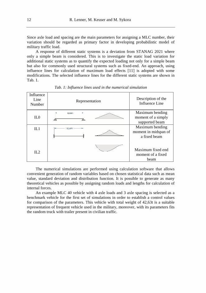
A response of different static systems is a deviation from STANAG 2021 where only a simple beam is considered. This is to investigate the static load variation for additional static systems as to quantify the expected loading not only for a simple beam but also for commonly used structural systems such as fixed-end. An approach, using influence lines for calculation of maximum load effects [11] is adopted with some modifications. The selected influence lines for the different static systems are shown in Tab. 1.
Tab. 1: Influence lines used in the numerical simulation
Influence Line
Number
Representation Description of the
Influence Line
IL0
Maximum bending moment of a simply
supported beam
IL1
Maximum bending moment in midspan of
a fixed beam
IL2
Maximum fixed end moment of a fixed
beam The numerical simulations are performed using calculation software that allows
convenient generation of random variables based on chosen statistical data such as mean value, standard deviation and distribution function. It is possible to generate as many theoretical vehicles as possible by assigning random loads and lengths for calculation of internal forces.
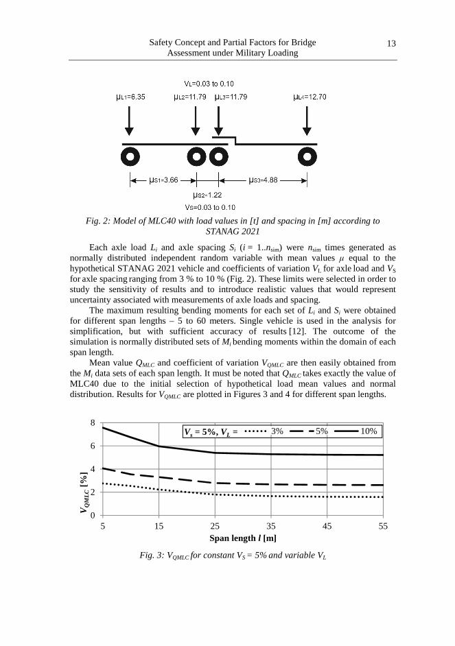
An example MLC 40 vehicle with 4 axle loads and 3 axle spacing is selected as a benchmark vehicle for the first set of simulations in order to establish a control values for comparison of the parameters. This vehicle with total weight of 42,63t is a suitable representation of frequent vehicle used in the military, moreover, with its parameters fits the random truck with trailer present in civilian traffic.
13 13
Safety Concept and Partial Factors for Bridge Assessment under Military Loading
Fig. 2: Model of MLC40 with load values in [t] and spacing in [m] according to STANAG 2021
Each axle load Li and axle spacing Si (i = 1..nsim) were nsim times generated as normally distributed independent random variable with mean values µ equal to the hypothetical STANAG 2021 vehicle and coefficients of variation VL for axle load and VS
for axle spacing ranging from 3 % to 10 % (Fig. 2). These limits were selected in order to study the sensitivity of results and to introduce realistic values that would represent uncertainty associated with measurements of axle loads and spacing.
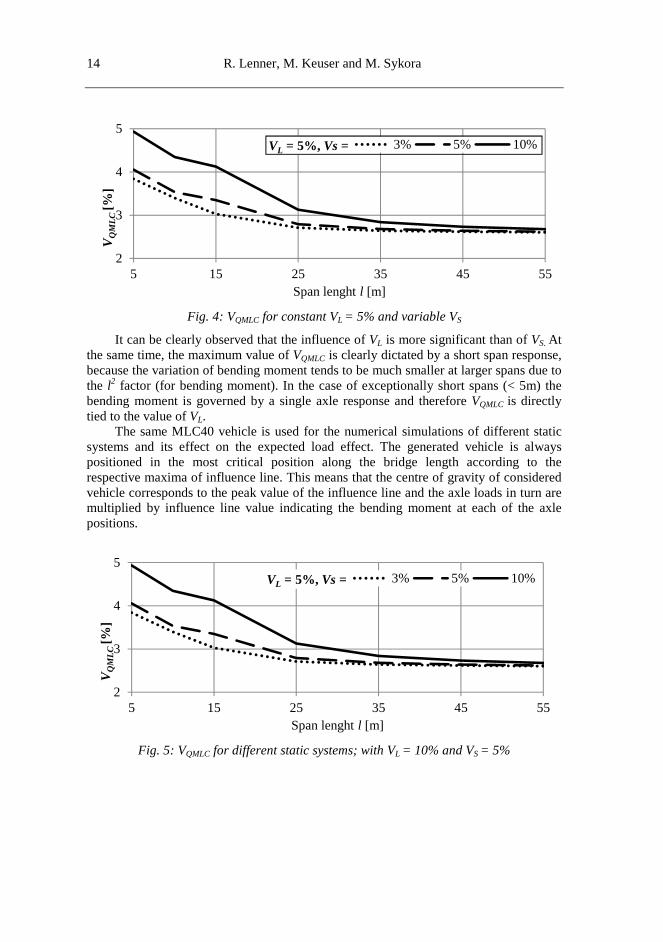
The maximum resulting bending moments for each set of Li and Si were obtained for different span lengths – 5 to 60 meters. Single vehicle is used in the analysis for simplification, but with sufficient accuracy of results [12]. The outcome of the simulation is normally distributed sets of Mi bending moments within the domain of each span length.
Mean value QMLC and coefficient of variation VQMLC are then easily obtained from the Mi data sets of each span length. It must be noted that QMLC takes exactly the value of MLC40 due to the initial selection of hypothetical load mean values and normal distribution. Results for VQMLC are plotted in Figures 3 and 4 for different span lengths.
Fig. 3: VQMLC for constant VS = 5% and variable VL
0
2
4
6
8
5 15 25 35 45 55
VQ
MLC
[%]
Span length l [m]
Vs = 5%, VL = 3% 5% 10%
14 R. Lenner, M. Keuser and M. Sykora
Fig. 4: VQMLC for constant VL = 5% and variable VS
It can be clearly observed that the influence of VL is more significant than of VS. At the same time, the maximum value of VQMLC is clearly dictated by a short span response, because the variation of bending moment tends to be much smaller at larger spans due to the l2 factor (for bending moment). In the case of exceptionally short spans (< 5m) the bending moment is governed by a single axle response and therefore VQMLC is directly tied to the value of VL.
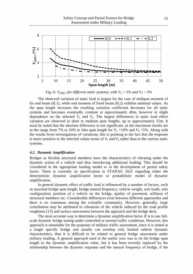
The same MLC40 vehicle is used for the numerical simulations of different static systems and its effect on the expected load effect. The generated vehicle is always positioned in the most critical position along the bridge length according to the respective maxima of influence line. This means that the centre of gravity of considered vehicle corresponds to the peak value of the influence line and the axle loads in turn are multiplied by influence line value indicating the bending moment at each of the axle positions.
Fig. 5: VQMLC for different static systems; with VL = 10% and VS = 5%
2
3
4
5
5 15 25 35 45 55
VQ
MLC
[%]
Span lenght l [m]
VL = 5%, Vs = 3% 5% 10%
2
3
4
5
5 15 25 35 45 55
VQ
MLC
[%]
Span lenght l [m]
VL = 5%, Vs = 3% 5% 10%
15 15
Safety Concept and Partial Factors for Bridge Assessment under Military Loading
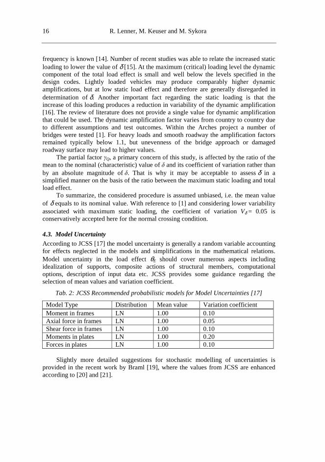
Fig. 6: VQMLC for different static systems; with VL = 5% and VS = 5%
The observed variation of static load is largest for the case of midspan moment of fix end beam (IL1), while end moment of fixed beam (IL2) exhibits minimal values. As the span length increases the resulting variation coefficient decreases for all static systems and becomes eventually constant at approximately 40m, however in slight dependence on the selected VL and VS. The largest differences in static load effect variation are observed in short to medium span lengths, up to approximately 25m. It must be noted that the absolute difference in not significant, as the maximum results are in the range from 7% to 10% at 10m span length for VL =10% and VS =5%. Along with the results from investigations of variations, this is pointing to the fact that the response is more sensitive to the selected values terms of VL and VS rather than to the various static systems.
4.2. Dynamic Amplification
Bridges as flexible structural members have the characteristics of vibrating under the dynamic action of a vehicle and thus introducing additional loading. This should be considered in the appropriate loading model or in the development of partial safety factor. There is currently no specification in STANAG 2021 regarding either the deterministic dynamic amplification factor or probabilistic model of dynamic amplification.
In general dynamic effect of traffic load is influenced by a number of factors, such as maximal bridge span length, bridge natural frequency, vehicle weight, axle loads, axle configuration, position of a vehicle on the bridge, quality of pavement, stiffness of structural members etc. Considerable differences exist between different approaches and there is no consensus among the scientific community. However, generally, large contribution may be attributed to vibrations of the vehicle induced by the road profile roughness [13] and surface unevenness between the approach and the bridge deck.
The most accurate way to determine a dynamic amplification factor δ is to use full-scale dynamic bridge testing under controlled or normal traffic conditions. However, this approach is unsuitable for the purposes of military traffic assessment, since it is aimed at a single specific bridge and usually can envelop only limited vehicle dynamic characteristics, thus it is difficult to be related to general bridge assessment under military loading. A general approach used in the earlier year was to tie the bridge span length to the dynamic amplification value, but it has been recently replaced by the relationship between the dynamic response and the natural frequency of bridge, if the
2
4
6
8
5 10 15 20 25 30 35 40 45 50
VQ
MLC
[%]
Span length [m]
IL0 IL1 IL2
16 R. Lenner, M. Keuser and M. Sykora
frequency is known [14]. Number of recent studies was able to relate the increased static loading to lower the value of δ [15]. At the maximum (critical) loading level the dynamic component of the total load effect is small and well below the levels specified in the design codes. Lightly loaded vehicles may produce comparably higher dynamic amplifications, but at low static load effect and therefore are generally disregarded in determination of δ. Another important fact regarding the static loading is that the increase of this loading produces a reduction in variability of the dynamic amplification [16]. The review of literature does not provide a single value for dynamic amplification that could be used. The dynamic amplification factor varies from country to country due to different assumptions and test outcomes. Within the Arches project a number of bridges were tested [1]. For heavy loads and smooth roadway the amplification factors remained typically below 1.1, but unevenness of the bridge approach or damaged roadway surface may lead to higher values.
The partial factor γQ, a primary concern of this study, is affected by the ratio of the mean to the nominal (characteristic) value of δ and its coefficient of variation rather than by an absolute magnitude of δ. That is why it may be acceptable to assess δ in a simplified manner on the basis of the ratio between the maximum static loading and total load effect.
To summarize, the considered procedure is assumed unbiased, i.e. the mean value of δ equals to its nominal value. With reference to [1] and considering lower variability associated with maximum static loading, the coefficient of variation Vδ = 0.05 is conservatively accepted here for the normal crossing condition.
4.3. Model Uncertainty
According to JCSS [17] the model uncertainty is generally a random variable accounting for effects neglected in the models and simplifications in the mathematical relations. Model uncertainty in the load effect θE should cover numerous aspects including idealization of supports, composite actions of structural members, computational options, description of input data etc. JCSS provides some guidance regarding the selection of mean values and variation coefficient.
Tab. 2: JCSS Recommended probabilistic models for Model Uncertainties [17]
Model Type Distribution Mean value Variation coefficient Moment in frames LN 1.00 0.10 Axial force in frames LN 1.00 0.05 Shear force in frames LN 1.00 0.10 Moments in plates LN 1.00 0.20 Forces in plates LN 1.00 0.10
Slightly more detailed suggestions for stochastic modelling of uncertainties is
provided in the recent work by Braml [19], where the values from JCSS are enhanced according to [20] and [21].
17 17
Safety Concept and Partial Factors for Bridge Assessment under Military Loading
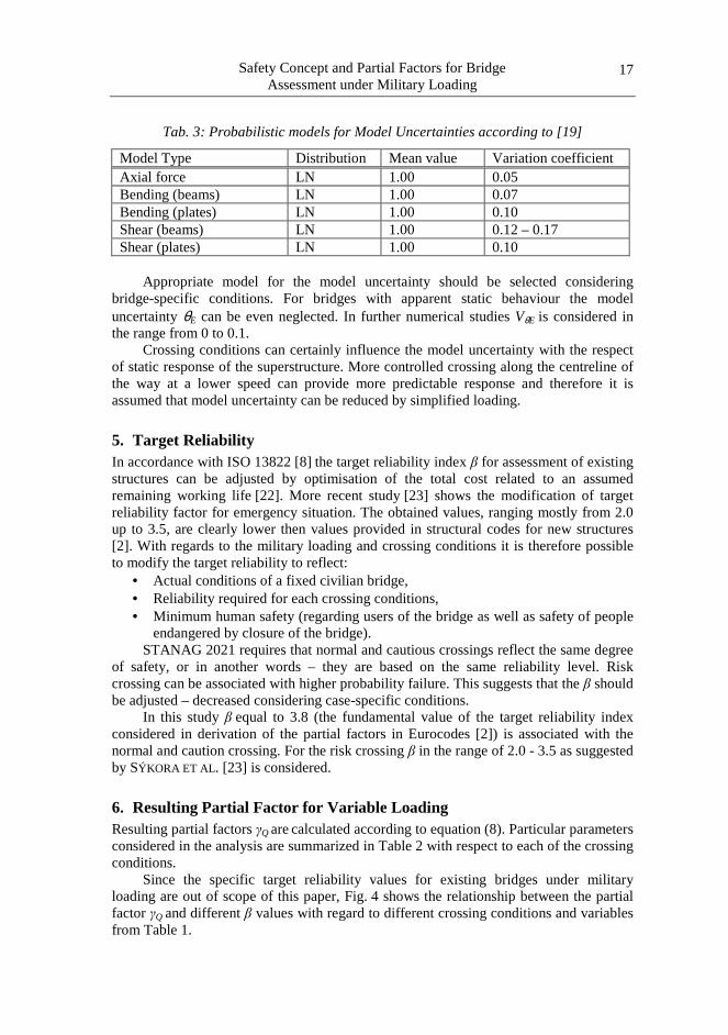
Tab. 3: Probabilistic models for Model Uncertainties according to [19]
Model Type Distribution Mean value Variation coefficient Axial force LN 1.00 0.05 Bending (beams) LN 1.00 0.07 Bending (plates) LN 1.00 0.10 Shear (beams) LN 1.00 0.12 – 0.17 Shear (plates) LN 1.00 0.10
Appropriate model for the model uncertainty should be selected considering
bridge-specific conditions. For bridges with apparent static behaviour the model uncertainty θE can be even neglected. In further numerical studies VθE is considered in the range from 0 to 0.1.
Crossing conditions can certainly influence the model uncertainty with the respect of static response of the superstructure. More controlled crossing along the centreline of the way at a lower speed can provide more predictable response and therefore it is assumed that model uncertainty can be reduced by simplified loading.
5. Target Reliability In accordance with ISO 13822 [8] the target reliability index β for assessment of existing structures can be adjusted by optimisation of the total cost related to an assumed remaining working life [22]. More recent study [23] shows the modification of target reliability factor for emergency situation. The obtained values, ranging mostly from 2.0 up to 3.5, are clearly lower then values provided in structural codes for new structures [2]. With regards to the military loading and crossing conditions it is therefore possible to modify the target reliability to reflect:
• Actual conditions of a fixed civilian bridge, • Reliability required for each crossing conditions, • Minimum human safety (regarding users of the bridge as well as safety of people
endangered by closure of the bridge). STANAG 2021 requires that normal and cautious crossings reflect the same degree
of safety, or in another words – they are based on the same reliability level. Risk crossing can be associated with higher probability failure. This suggests that the β should be adjusted – decreased considering case-specific conditions.
In this study β equal to 3.8 (the fundamental value of the target reliability index considered in derivation of the partial factors in Eurocodes [2]) is associated with the normal and caution crossing. For the risk crossing β in the range of 2.0 - 3.5 as suggested by SÝKORA ET AL. [23] is considered.
6. Resulting Partial Factor for Variable Loading Resulting partial factors γQ are calculated according to equation (8). Particular parameters considered in the analysis are summarized in Table 2 with respect to each of the crossing conditions.
Since the specific target reliability values for existing bridges under military loading are out of scope of this paper, Fig. 4 shows the relationship between the partial factor γQ and different β values with regard to different crossing conditions and variables from Table 1.
18 R. Lenner, M. Keuser and M. Sykora
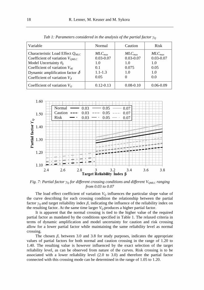
Tab 1: Parameters considered in the analysis of the partial factor γQ
Variable Normal Caution Risk
Characteristic Load Effect QMLC Coefficient of variation VQMLC Model Uncertainty θE
Coefficient of variation VθE
Dynamic amplification factor δ Coefficient of variation Vδ
MLCmax 0.03-0.07 1.0 0.1 1.1-1.3 0.05
MLCmax 0.03-0.07 1.0 0.075 1.0 0
MLCmax 0.03-0.07 1.0 0.05 1.0 0.0
Coefficient of variation VQ 0.12-0.13 0.08-0.10 0.06-0.09
Fig. 7: Partial factor γQ for different crossing conditions and different VQMLC ranging
from 0.03 to 0.07
The load effect coefficient of variation VQ influences the particular slope value of the curve describing for each crossing condition the relationship between the partial factor γQ and target reliability index β, indicating the influence of the reliability index on the resulting factor. At the same time larger VQ produces a higher partial factor.
It is apparent that the normal crossing is tied to the higher value of the required partial factor as mandated by the conditions specified in Table 1. The relaxed criteria in terms of dynamic amplification and model uncertainty for caution and risk crossing allow for a lower partial factor while maintaining the same reliability level as normal crossing.
The chosen β, between 3.0 and 3.8 for study purposes, indicates the appropriate values of partial factors for both normal and caution crossing in the range of 1.20 to 1.40. The resulting value is however influenced by the exact selection of the target reliability level, as can be observed from nature of the curves. Risk crossing is to be associated with a lower reliability level (2.0 to 3.0) and therefore the partial factor connected with this crossing mode can be determined in the range of 1.05 to 1.20.
Normal Caution Risk
0.03 0.03 0.03
0.05 0.05 0.05
0.07 0.07 0.07
19 19
Safety Concept and Partial Factors for Bridge Assessment under Military Loading
7. Conclusions Current partial factors for load effects in Eurocodes are not optimal for reliability verifications of existing bridges under military loads. Modification for specific military use is deemed necessary and a number of different factors must be taken in account in the calibration process. This paper investigated some of the most important aspects affecting the partial factor for military traffic load. The numerical simulation served to investigate stochastic properties of the military load and along with dynamic amplification and model uncertainty allowed for indication of appropriate values of the partial factor.
It is observed that particularly important variable influencing the partial factor is the model uncertainty in load effect. In addition considerable differences in the definition of characteristic value for civilian and military traffic loads affect the value of the partial factor for traffic load. Characteristic civilian traffic is broadly defined with a large return period while a mean value of well-defined military traffic is taken into account. Numerical part of the study indicates that the partial factor of the military traffic load can range from 1.05 up to 1.4 depending on the chosen stochastic properties and a selected target reliability level dependent on crossing conditions.
Dynamic amplification certainly deserves additional work, there is no consensus regarding the specific values of dynamic amplification factor and most of the work was aimed at civilian traffic. Further investigation should be also focused on improvements of the model for uncertainties in a traffic load effect and the development of partial factors for mixed military and civilian traffic on the bridge.
References [1] NATO Standardisation Agreement (STANAG) 2021. Military Load Classification
of Bridges, Ferries, Rafts and Vehicles. Edition 6.
[2] EN 1990:200. Eurocode – Basis of structural design.
[3] FISCHER, A. Modification of partial safety factors for semi-probabilistic design of existing reinforced concrete structures (in German) [PhD Thesis]. Technische Universität Kaiserslautern, 2010.
[4] GHOSN M., SIVAKUMAR, B. and MIAO, F. Calibration of reliability-based load rating method for New York State. In Applications of Statistics and Probability in Civil Engineering. London: Taylor & Francis Group, 2011. p.792-793.
[5] VAL, D. and STEWART, M. Safety Factors for Assessment of Existing Structures. ASCE Journal of Structural Engineering, 2002, vol. 128, no. 2, p. 258-265.
[6] SÝKORA, M., HOLICKÝ, M and MARKOVÁ, J. Verification of Existing Reinforced Concrete Bridges using the Design Value Method. Engineering Structures, 2013, vol. 56, p. 1419-1426.
[7] MALJAARS J., STEENBERGEN R. and ABSPOEL L. Safety Assessment of Existing Highway Bridges and Viaducts. Structural Engineering International, 2012, vol. 1, p. 112-120.
[8] ISO 13822:2010. Bases for design of structures - Assessment of existing structures.
[9] CASPEELE, R., ALLAIX, DL., STEENBERGEN, RDJM. and SYKORA, M. The Design Value Method and Adjusted Partial Factor Approach for Existing Structures. Structural Engineering International, 2013, vol. 23, no. 4, p. 386-393.
20 R. Lenner, M. Keuser and M. Sykora
[10] LENNER, R., SYKORA, M. and KEUSER, M. Partial factors for military loads on bridges. In: Krivanek, V.; Stefek, A. (eds.): In Proc. ICMT'13. Brno: University of Defence, 2013, p. 409-418.
[11] CRESPO-MINGUILLÓN, C. and CASAS, JR. Traffic Loads in EC-1. How do they suit to highway bridges in Spain. In Proceedings of IABSE Colloquium. Delft: The Netherlands, 1996, p. 521-527.
[12] LENNER, R. Safety Concept and Partial Factors for Military Assessment of Existing Concrete Bridges [PhD Thesis]. Universität der Bundeswehr, 2014.
[13] PRATT, M. Traffic load models for bridge design: recent developments and research, Prog Struct Engng Mater, 2001, vol. 3, no. 4, p. 326-334.
[14] PAULTRE, P., CHAALLAL, O. and PROULX, J. Bridge dynamics and dynamic amplification factors – a review of analytical and experimental findings. Canadian Journal of Civil Engineering, 1992, vol. 19, no. 2, p. 260-278.
[15] HWANG, E.S. and NOWAK, AS., Simulation of dynamic load for bridges. ASCE Journal of Structural Engineering, 1991, vol. 113, no. 9, p. 1413-1434.
[16] GONZALES, A., DOWLING, J., O’BRIAN, EJ. and ZNIDARIC, A. Experimental determination of dynamic allowance for traffic loading in bridges, In Transportation Research Board 89th Annual Meeting Compendium of Papers. Washington: National Research Council, 2010.
[17] JCSS:2010. Probabilistic Model Code.
[18] ARCHES. Assessment and Rehabilitation of Central European Highway Structures, Deliverable D 15 [Research Report]. ARCHES-MG-AR04 2009.
[19] BRAML, T., FISCHER, A., KEUSER, M. and SCHNELL, J. Reliability Assessment of Existing Structures under Shear Loading (in German). Beton- und Stahlbetonbau, 2009, vol. 104, no. 12, p. 798-812.
[20] FABER, M. Risk and Safety in Civil, Surveying and Environmental Engineering [Course Notes]. Zürich: ETH, 2005.
[21] HANSEN, M. Influence of inspection measures on concrete members (in German) [PhD Thesis]. Universität Hannover, 2004.
[22] VROUWENVELDER, ACWM. and SCHOLTEN, N. Assessment Criteria for Existing Structures. Structural Engineering International 20 (2010), p. 62-65.
[23] SÝKORA, M., LENNER, R. and MAŇAS, P. Optimum target reliability for bridges considering emergency situations. In Proc. 11th International Probabilistic Workshop. Brno: LITERA, 2013, p. 439-450.