Embed Size (px)
Citation preview

2015 Tenth International Conference on Ecological Vehicles and Renewable Energies (EVER)
Air-Gap Convection in aSwitched Reluctance Machine
Pietro Romanazzi and David A. HoweyUniversity of Oxford
Department of Engineering Science, Parks RoadOxford, OX1 3PJ, UK
Email: [email protected]
Abstract—Switched reluctance machines (SRMs) haverecently become popular in the automotive market as theyare a good alternative to the permanent magnet machinescommonly employed for an electric powertrain. Lumpedparameter thermal networks are usually used for thermalanalysis of motors due to their low computational costand relatively accurate results. A critical aspect to bemodelled is the rotor-stator air-gap heat transfer, and thisis particularly challenging in an SRM due to the salientpole geometry. This work presents firstly a review of theliterature including the most relevant correlations for thisgeometry, and secondly, numerical CFD simulations ofair-gap heat transfer for a typical configuration. A newcorrelation has been derived: Nu = 0.181 Ta0.207m .
Index Terms— air-gap, convection, thermal model,switched reluctance, CFD.
This paper is part of the ADvanced Electric PowertrainTechnology (ADEPT) project which is an EU fundedMarie Curie ITN project, grant number 607361. WithinADEPT a virtual and hardware tool are created to assistthe design and analysis of future electric propulsion,especially within the context of the paradigm shift fromfuel powered combustion engines to alternative energysources (e.g. fuel cells, solar cells, and batteries) invehicles like motorbikes, cars, trucks, boats, planes. Thedesign of these high performance, low cost and cleanpropulsion systems has stipulated an international coop-eration of multiple disciplines such as physics, math-ematics, electrical engineering, mechanical engineeringand specialisms like control engineering and safety. Bycooperation of these disciplines in a structured way, theADEPT program provides a virtual research lab com-munity from labs of European universities and industries[1].
I. INTRODUCTION
Switched reluctance motors (SRMs) are becomingmore popular for traction drives [2] since they are robustand do not require permanent magnets [3]. They have asimple rotor construction and regulated magnetic flux,
which can provide a significantly extended speed range.An optimized SRM design can have power densitiescompetitive with a PM machine [4]. However, hightorque ripple and associated vibration and noise are pos-sible disadvantages [5]. In order to achieve high torquedensities, water cooling is usually employed for tractionmotors in electric powertrains. In order to evaluate thecooling effectiveness, thermal analysis must be carriedout, modelling all the paths that lead the heat from theactive parts to the water jacket and the environment.Lumped parameter thermal networks (LPTN) are oneof the most widely used approaches for thermal anal-ysis due to their low computational cost and relativelyaccurate results. One of the most critical aspects to bemodelled is the air-gap heat transfer [6], [7], and thisis particularly challenging in an SRM due to its salientpole geometry. This heat transfer path is governed byconvection and usually the theory developed by Taylor[8] is applied. Taylor studied the instability developingin an annulus between two smooth cylinders where theinner one is rotating, finding that pairs of counter-rotating
z
r
θ
ω
Fig. 1. Taylor instability
arX
iv:1
502.
0590
2v1
[ph
ysic
s.fl
u-dy
n] 2
0 Fe
b 20
15

vortices appear in the z − r plane (Fig. 1) above aparticular rotational speed.
As derived in [7], assuming the case of adiabaticflow between infinitely long smooth cylinders and verynarrow gaps, i.e. g/Ri ≈ 0 where g is the gap width andRi the inner radius of the annulus, Taylor found that theonset of the instability occurs at Tac = 1, 697, whereTa is a dimensionless group called the Taylor numberwhose definition will be discussed in the next section. Inthe case of non-adiabatic flow, with heat transfer betweenthe fluid flow an the boundary walls, Becker and Kaye[9] derived and proved that the Taylor vortices shouldappear at Tac = 1, 740. After Taylor, many other authorsexplored this particular flow looking for example at theheat transfer between cylinders [10], the modes of theinstability [11] or the effect of an additional axial flow[12], [13], [14]. A wider review of the problem may befound in [15]. In general the following four modes, inorder of increasing rotational speed, are observed [7]:
• Laminar flow• Laminar flow plus Taylor vortices• Turbulent flow plus Taylor vortices• Turbulent flow
The presence of salient poles on the rotor side consid-erably changes the boundary conditions of the problemsince the air flow is no longer driven by a continuous sur-face, and recirculations develop in the slots. This affectsthe critical value for the onset of instability and the rateof convective heat transfer between the rotor and statorsurface, which may increase by up to 50% [16]. Thus, theclassical correlations from the literature (e.g. [17], [18],[19]) seem not to be ideal for this geometry. We focus onthe impact of slots on the heat transfer and flow patternsof an SRM, by first reviewing the most relevant previousworks and then undertaking numerical simulations of theairflow using the commercial CFD code STAR-CCM+v9.06 [20]. Eventually this will enable the constructionof a thermal resistance Rconv = 1
Ahhrepresenting the air-
gap average heat transfer within a LPTN (Fig. 2), whereAh is the heat exchanging area and h is the heat transfercoefficient. Such a resistance would be a function of themachine geometry and speed.
II. LITERATURE REVIEW
Before starting the review we introduce the dynamicparameters that influence the flow field in the air gap.Since for vehicle traction usually an enclosed motorconfiguration is applied, no axial air flow is superim-posed to the Taylor-Couette flow in the annulus. Thus,the tangential Reynolds number Reθ = ωRig
ν is one ofthe main parameters that characterize the flow, whereω is the rotational speed of the internal cylinder and ν
ω
Rconv
TS
TR
Fig. 2. Air-gap equivalent thermal resistance (averaged behaviour)
is the kinematic viscosity of air. However, the Taylornumber is a more appropriate dimensionless group touse an independent variable in annulus geometries, sinceit expresses the ratio of the centrifugal to the viscousforces. In our work we will use the so-called modifiedTaylor number Tam according to the definition intro-duced by Bouafia [21] to take into account the presenceof grooves:
Tam =ω2Rmg
3
ν21
Fg(1)
Where Rm is the mean radius defined as Rm =b/ln((Ri + b)/Ri) with b = A/2πRi, and Fg is ageometric factor:
Fg =π4
1967P
Ri +Ro2Ri
(2)
and
P = 0.0571(1− 0652g
Ri) + 0.00056(1− 0.652
g
Ri)−1
(3)The Nusselt number is the dependent variable; thischaracterizes the heat transfer by convection and thefollowing definition has been used:
Nu =q g
k (TR − TS)=h g
k(4)
where q is the specific heat flux, TR and TS are thesurface temperatures of the rotor and stator side respec-tively and k is the thermal conductivity of air. We referto rotor and stator sides using the subscripts R and Srespectively. Nusselt number will be calculated as theaverage value over the entire internal surface of theannulus. The thermal conductivity k is taken as the meanof the values at the two surface temperatures.
Throughout the literature there are a number of dif-ferent definitions for these parameters [22]. Any systemof definitions may be used as long as consistency ismaintained, however for the case of slotted surfaces weuse the system of [21], as previously defined. Based onthe various experimental geometries presented in Tab. I,we have re-expressed the correlations using a consistent

S
R
LSW Ro
Ri
Fig. 3. Reference geometry
set of definitions of Ta and Nu in order to compare likewith like. The values are also compared with the caseof smooth cylinders using the correlation by Becker andKaye [9]:
Nu = 1 for Tam < TacNu = 0.064 Tam
0.367 for Tac < Tam < 104
Nu = 0.205 Tam0.241 for 104 < Tam < 106
TABLE IGEOMETRY DIMENSIONS FROM LITERATURE RELATED TO FIG. 3
- [mm]
Bouafia Hayase Gazley Hwang[21][23] [24][25] [16] [26]
Case n.a. B C S1-R2 S2-R2 n.a.
g 5 0.05 0.05 0.5 0.5 2
Ri 140 0.95 0.95 63.3 63.3 34
LRW − − − 0.1 0.1 δ 2πRi16
LRD − 0.2 − 0.76 0.76 2
αR − 10◦ − 0◦ 0◦ not given
NR 0 12 0 36 36 16
Ro 145 1.0 1.0 63.8 63.8 36
LSW 8.3 − − − 4.6 −
LSD 15 − 0.2 − 1.5 −
αS 0◦ − 10◦ − 0◦ −
NS 48 0 12 0 23 0
It is worth noting that only Hayase [24], [25] numer-ically simulated a domain geometrically similar to anSRM rotor. However, the simulations were performedconsidering a geometry with an higher ratio of theair gap to the slot height compared to a typical SRMconfiguration. Also Srinivas [27], [28] ran some CFD
simulations of the SRM airgap, although assuming a 2-D and incompressible domain and without reporting anydetail about the heat transfer.
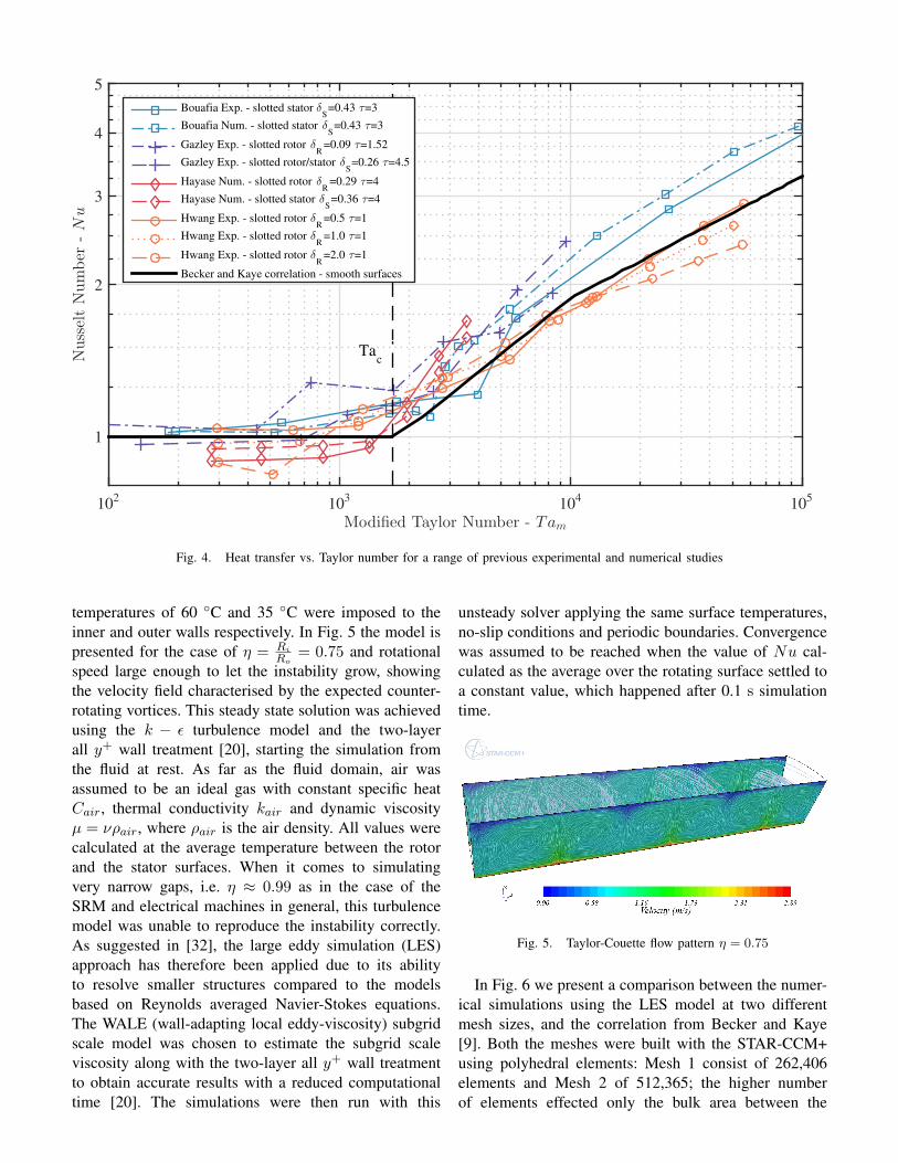
Fig. 4 shows that in the case of slotted surfaces inthe laminar regime Nu is in general less than 1 andincreasing at a small constant rate. However, keepingin consideration the ratios τ = LD
g and δ = LW
2πR1N ,
where N is the number of slots, it seems that the largerthe slot, the lower Nu. This has also been indicatedby Tachibana and Fukui [19] who in their analysis alsotested the influence of gap sizes at low rotational speeds.
As the rotational speed increases beyond a criticalpoint the heat transfer rate suddenly rises since vorticesappear which promote fluid recirculation. However, theresults from the literature give some uncertainty for whatthe critical Tam is. For Hwang [26], Hayase [25] andGazley [16] the instability onset seems to take placefor Tam < Tac. Whereas according to the data fromBouafia [21], [23], the vortices appear for higher valuesof modified Taylor number, and in particular the criticalTam = 3, 900 is measured. This discrepancy is mainlydue to the various configurations studied which differ ingeometry and whether the rotor is the inner or outer sideof the annulus.
An interesting work which has not been shown in Fig.4 is Gardiner and Sabersky [29], where the values lieout of the main area of data due to the fact that thefluid employed was water (Prandtl number Pr = 4.5).However, their measurements show again a similar be-haviour of the heat transfer rate with a sudden increaseat Tam ≈ 3× 10³. More recently the heat transfer in anannulus between coaxial cylinders with slots had beenstudied [13], [30], [14]. However, these works analysea Taylor-Couette-Poiseuille flow, meaning that an axialair flux is superimposed across the Taylor-Couette flowgenerated by the rotation of the internal or externalcylinder.
III. SOFTWARE VALIDATION
Computational fluid dynamics simulations were un-dertaken using CD-adapco’s STAR-CCM+. First, thebaseline scenario of heat transfer between two smoothcylinders with the inner one rotating and heated wassimulated. By assuming circumferential periodicity, thecalculations were confined to 30◦ in the r − θ plane asassumed by Hayase [24], [25]. The axial length of thedomain was set to allow an even number of vorticesto develop [31]. Additionally, to prevent end effects, aperiodic boundary condition was applied to the axialends to create an infinitely long annulus. The no-slipcondition was applied to the outer and inner walls withthe inner wall rotating at a constant speed. Constant
Modified Taylor Number - Tam
102
103
104
105
NusseltNumber
-Nu
1
2
3
4
5
Bouafia Exp. - slotted stator δS=0.43 τ=3
Bouafia Num. - slotted stator δS
=0.43 τ=3
Gazley Exp. - slotted rotor δR
=0.09 τ=1.52
Gazley Exp. - slotted rotor/stator δS=0.26 τ=4.5
Hayase Num. - slotted rotor δR
=0.29 τ=4
Hayase Num. - slotted stator δS=0.36 τ=4
Hwang Exp. - slotted rotor δR
=0.5 τ=1
Hwang Exp. - slotted rotor δR
=1.0 τ=1
Hwang Exp. - slotted rotor δR
=2.0 τ=1
Becker and Kaye correlation - smooth surfaces
Tac
Fig. 4. Heat transfer vs. Taylor number for a range of previous experimental and numerical studies
temperatures of 60 ◦C and 35 ◦C were imposed to theinner and outer walls respectively. In Fig. 5 the model ispresented for the case of η = Ri
Ro= 0.75 and rotational
speed large enough to let the instability grow, showingthe velocity field characterised by the expected counter-rotating vortices. This steady state solution was achievedusing the k − ε turbulence model and the two-layerall y+ wall treatment [20], starting the simulation fromthe fluid at rest. As far as the fluid domain, air wasassumed to be an ideal gas with constant specific heatCair, thermal conductivity kair and dynamic viscosityµ = νρair, where ρair is the air density. All values werecalculated at the average temperature between the rotorand the stator surfaces. When it comes to simulatingvery narrow gaps, i.e. η ≈ 0.99 as in the case of theSRM and electrical machines in general, this turbulencemodel was unable to reproduce the instability correctly.As suggested in [32], the large eddy simulation (LES)approach has therefore been applied due to its abilityto resolve smaller structures compared to the modelsbased on Reynolds averaged Navier-Stokes equations.The WALE (wall-adapting local eddy-viscosity) subgridscale model was chosen to estimate the subgrid scaleviscosity along with the two-layer all y+ wall treatmentto obtain accurate results with a reduced computationaltime [20]. The simulations were then run with this
unsteady solver applying the same surface temperatures,no-slip conditions and periodic boundaries. Convergencewas assumed to be reached when the value of Nu cal-culated as the average over the rotating surface settled toa constant value, which happened after 0.1 s simulationtime.
Fig. 5. Taylor-Couette flow pattern η = 0.75
In Fig. 6 we present a comparison between the numer-ical simulations using the LES model at two differentmesh sizes, and the correlation from Becker and Kaye[9]. Both the meshes were built with the STAR-CCM+using polyhedral elements: Mesh 1 consist of 262,406elements and Mesh 2 of 512,365; the higher numberof elements effected only the bulk area between the

Modified Taylor Number - Tam
103
104
NusseltNumber
-Nu
1
2
3Becker and Kaye correlationMesh 1Mesh 2
Fig. 6. LES model validation and mesh comparison
TABLE IISRM MODEL DIMENSIONS
stator inner radius 95.95 mm
rotor outer radius 95.00 mm
air gap width 0.95 mm
rotor pole height 33.5 mm
rotor pole arc 23◦ -number of slots 6 -
prism layers. To correctly resolve the fields near to theboundaries a finer mesh consisting of 20 prism layerswith a growing factor of 1.2 was applied, with thefirst layer height of 1.2×10⁻⁶ m. This mesh resolutionallowed always a y+ value below 1. The results indicatethat the LES model is able to reproduce the increaseof heat transfer due to the onset of the instability. Theresults are fairly mesh independent as shown in Fig. 6which gives average Nu of the numerical solutions overabout two rotations starting after the fluid flow settled toan almost steady pattern.
IV. RESULTS AND ANALYSIS
A. Modelling the SRM
The case of an 8/6 SRM (8 salient poles on thestator side and 6 on the rotor side) was considered. Thegeometry details were taken from [3] since we are mainlyinterested in SRMs for electric vehicle applications.These dimensions, presented in Table II, are in line withthe general design rules given in [33]. For this researchwe modelled the stator surface to be smooth (assumingthe presence of windings and slot liner). Due to theperiodicity of the structure, only 60◦ of the machine has
Fig. 7. SRM 8/6 meshed model
been studied, applying a periodic boundary conditionon the tangential surfaces. Again, a periodic boundarycondition has been applied at the axial ends to mimican infinitely long annulus and prevent end effects. Thelength of the model was set to accommodate a couple ofcounter-rotating vortices. The no-slip condition was seton the stator and rotor surfaces which are assumed tobe heated at a constant temperature of 60 ◦C and 35 ◦Crespectively. To simulate the motion, the reference framewas set to rotate at a specific ω∗, the outer cylinder wasspinning at ωS = −ω∗ and the inner wall was at ωR = 0relative to the rotating frame. The mesh, consisting of1,450,394 cells, is characterized by two different scales:one finer, keeping the Mesh 1 set up which correctlysimulated Taylor vortices, and one coarser for the slotarea where larger eddies appear. As shown in Fig. 7, 20prism layers was built next to the wall to ensure y+ tobe lower than 1.
B. Results
A number of rotational speeds were tested for theSRM domain, running each simulation using the pre-vious solution as initial condition. In Fig. 8 the velocityfield relative to the rotating frame is presented in ther − θ at Tam = 2, 802. The presence of the slot leadsthe flow to separate, generating some vortices withinthe slot. The simulations showed that in the slot adominant vortex, marked with the number 1 in Fig. 8,
1
ω
2
3
Fig. 8. Velocity field with the reference to the rotor at Tam = 2, 802

Fig. 9. Visualisation of Taylor vortices in the SRM airgap, Tam =11, 208
grows with the increasing rotor speed ω. In the “2” areavarious minor vortices develop, which tend to split andflatten on the trailing and bottom edges of the slot withω. Although in the slot the flow has a prevailing 2Dbehaviour, in the area marked with number 3 a coupleof counter-rotating vortices in the z − r plane werenoticed, growing from low values of Tam (≈ 300).The presence of recirculation flows in the slot seem todelay the appearance of Taylor vortices. The onset ofthe instability was not recorded at Tac but at highervalues of Tam. Moreover, the counter rotating vorticeswere not continuous all around the circumference, butthe simulations showed them to grow only in the gapbetween the rotor pole tip and the stator. This in turnaffected the stability of the structures in the slot. Fig. 9shows the effect of the Taylor vortices on the temperaturefield.
The calculated heat transfer rate is presented in Fig.10. Due to the unsteady solver, the value of Nu is calcu-lated averaging the solution over about three revolutionsafter the transition was resolved (≈ 1 rotation). We cansee that the heat transfer for low value of Tam is belowunity Nu and increases with ω without experiencing theexpected knee indicating a regime change. The surfacesbordering the slot are exposed to recirculation whichreduces the thermal gradient and accordingly the heattransfer rate. As the ratio of such surfaces to the surfaceon the tip of the pole is higher than 1, the effect of theTaylor instability on the overall heat transfer rate is notnoticed.
V. CONCLUSIONS AND FUTURE WORK
In this work the case of heat transfer in the air gapof an SRM was tested. First, our CFD simulations runwith the unsteady LES solver embedded in the com-mercial software STAR-CCM+, showed good agreementbetween the case of heat transfer in smooth narrow gaps.
Modified Taylor Number - Tam
102
103
104
NusseltNumber
-Nu
1
2
3
Becker and Kaye correlation
Numerical simulations: SRM 8/6
SRM 8/6 correlation: Nu = 0.181 Ta0.207m
Fig. 10. Simulated heat transfer vs. Taylor number for an SRM 8/6
For the SRM configuration, the CFD results highlightedthat with the presence of SRM rotor slots the instabilityappears for higher values of Tam, in agreement withwhat was found in previous works. It is important tonotice that through the whole tested range of rotationalspeeds, Nu never exceeded the correlation given byBecker and Kaye [9]. A correlation has been derivedby least-square fitting the data: Nu = 0.181 Ta0.207m
for 102 < Tam < 3 × 10⁴. Future work will aim atanalysing the heat transfer at very high rotational speeds,i.e. 10, 000 rpm which correspond to Tam ∝ 105, andexploring the effect of different slot dimensions (e.g.SRM 6/4).
ACKNOWLEDGMENTS
The authors would like to thank the European Unionfor their funding to this research (FP7 ITN Project607361 ADEPT) and CD-adapco and Dr Brian Tang fortheir support.
REFERENCES
[1] A. Stefanskyi, A. Dziechciarz, F. Chauvicourt, G. E.Sfakianakis, K. Ramakrishnan, K. Niyomsatian, M. Curti,N. Djukic, P. Romanazzi, S. Ayat, S. Wiedemann, W. Peng,and S. Stipetic, “Researchers within the EU funded Marie CurieITN project ADEPT, grant number 607361,” 2013 - 2017.
[2] “ODIN Optimized electric Drivetrain by Integration,” 2013.[Online]. Available: http://www.fp7-odin.eu/
[3] K. M. Rahman, S. Member, B. Fahimi, and G. Suresh, “Ad-vantages of Switched Reluctance Motor Applications to EVand HEV : Design and Control Issues,” IEEE Transactions onIndustry Applications, vol. 36, no. 1, pp. 111–121, 2000.
[4] K. Boynov, J. J. H. Paulides, and E. A. Lomonova, “Com-parative analysis of the SRM as an alternative to the PMmotor for automotive applications,” The International Journalfor Computation and Mathematics in Electrical and ElectronicEngineering, vol. 33, no. 5, pp. 1599–1612, 2014.

[5] F. L. M. Santos, J. Anthonis, F. Naclerio, J. J. C. Gyselinck,H. V. D. Auweraer, and L. C. S. Goes, “Multiphysics NVHModeling : Simulation of a Switched Reluctance Motor for anElectric Vehicle,” IEEE Transactions on Industrial Electronics,vol. 61, no. 1, pp. 469–476, 2014.
[6] D. Staton, A. Boglietti, and A. Cavagnino, “Solving the MoreDifficult Aspects of Electric Motor Thermal Analysis in Smalland Medium Size Industrial Induction Motors,” IEEE Transac-tions on Energy Conversion, vol. 20, no. 3, pp. 620–628, Sep.2005.
[7] D. A. Howey, P. R. N. Childs, and A. S. Holmes, “Air-Gap Con-vection in Rotating Electrical Machines,” IEEE Transactions onIndustrial Electronics, vol. 59, no. 3, pp. 1367–1375, 2012.
[8] G. Taylor, “Stability of a Viscous Liquid contained betweenTwo Rotating Cylinder,” Philosophical Transactions Society ofthe Royal Society of London., vol. 223, no. 1923, pp. 289–343,1923.
[9] K. Becker and J. Kaye, “The influence of a radial temperaturegradient on the instability of a fluid flow in an annulus withan inner rotating cylinder,” Transactions of the ASME, vol. 84,no. 2, pp. 106–110, 1962.
[10] I. S. Bjorklund and W. M. Kays, “Heat transfer betweenconcentric rotating cylinders.” Journal of Heat Transfer, vol. 80,pp. 79–90, 1959.
[11] D. Coles, “Transition in circular Couette flow,” Journal of FluidMechanics, vol. 21, no. 3, pp. 385–425, 1965.
[12] F. Tachibana and S. Fukui, “Convective Heat Transfer of theRotational and Axial Flow between Two Concentric Cylinders,”The The Japan Society of Mechanical Engineers, vol. 7, no. 26,pp. 385–391, 1964.
[13] S. Poncet, S. Haddadi, and S. Viazzo, “Numerical modelingof fluid flow and heat transfer in a narrow Taylor-Couette-Poiseuille system,” International Journal of Heat and FluidFlow, vol. 32, pp. 128–144, 2010.
[14] N. Lancial, F. Torriano, F. Beaubert, S. Harmand, and G. Rol-land, “Study of a Taylor-Couette-Poiseuille Flow in an AnnularChannel with a Slotted Rotor,” in Iternational Conference onElectrical Machines, Berlin, 2014, pp. 1416–1423.
[15] C. D. Andereck and F. Hayot, Ordered and turbulent patternsin Taylor-Couette flow. Plenum Pub Corp, 1992.
[16] C. Gazley, “Heat transfer characteristics of the rotational andaxial flow between concentric cylinder.pdf,” Journal of HeatTransfer, vol. 80, pp. 79–90, 1958.
[17] K. Becker and J. Kaye, “Measurements of adiabatic and diabaticfluid flow in an annulus with an inner rotating cylinder,”Transactions of the ASME, vol. 84, no. 2, pp. 97–105, 1962.
[18] H. Aoki, H. Nohira, and H. Arai, “Convective Heat Transferin an Annulus with an Inner Rotating Cylinder,” The JapanSociety of Mechanical Engineers, vol. 10, no. 39, pp. 523–532,1967.
[19] F. Tachibana, S. Fukui, and H. Mitsumura, “Heat Transfer inan Annulus with an Inner Rotating Cylinder,” The The JapanSociety of Mechanical Engineers JapanSociety Engineers Vol.3,,vol. 3, no. 9, pp. 119–123, 1960.
[20] CD-adapco, “STAR CCM+ v.9.06 User Guide,” 2014. [Online].Available: http://www.cd-adapco.com/
[21] M. Bouafia, Y. Bertin, and J. B. Saulnier, “Analyse experimen-tale des transferts de chaleur en espace annulaire etroit et rainureavec cylindre interieur tournant,” International Journal of Heatand Mass Transfer, vol. 41, no. 10, pp. 1279–1291, 1998.
[22] M. Fenot, Y. Bertin, E. Dorignac, and G. Lalizel, “A reviewof heat transfer between concentric rotating cylinders with orwithout axial flow,” International Journal of Thermal Sciences,vol. 50, no. 7, pp. 1138–1155, Jul. 2011.
[23] M. Bouafia, A. Ziouchi, Y. Bertin, and J.-b. Saulnier, “Etudeexprimentale et numerique des transferts de chaleur en espace
annulaire sans debit axial et avec cylindre interieur tournant,”International Journal of Thermal Sciences, vol. 38, pp. 547–559, 1999.
[24] T. Hayase, J. Humphrey, and R. Greif, “Numerical studyof three-dimensional flow and heat transfer between a fixedouter cylinder and a rotating inner cylinder with cavities,” inProceedings of the 3rd International Symposium on TransportPhenomena and Dynamics of Rotating Machinery, Honolulu,1990, pp. 239–254.
[25] ——, “Numerical calculation of convective heat transfer be-tween rotating coaxial cylinders with periodically embeddedcavities,” Journal of Heat transfer, vol. 114, no. 3, pp. 589–597, 1992.
[26] J. Hwang, D. Lin, and L. Chen, “Heat transfer between rotatingcylinders,” in Proceedings of the 3rd International Symposiumon Transport Phenomena and Dynamics of Rotating Machinery,Honolulu, 1990, pp. 143–155.
[27] K. N. Srinivas and R. Arumugam, “An Investigation into theAir Velocity Distribution Inside Switched Reluctance Motors,”Electric Power Components and Systems, vol. 32, no. January,pp. 893–900, 2004.
[28] ——, “Analysis and characterization of Switched reluctancemotors: Part II - Flow, thermal, and vibration analyses,” IEEETransactions on Magnetics, vol. 41, no. 4, pp. 1321–1332, 2005.
[29] S. Gardiner and R. Sabersky, “Heat transfer in an annulargap,” International Journal of Heat and Mass Transfer, vol. 21,no. 12, pp. 1459–1466, Dec. 1978.
[30] M. Fenot, E. Dorignac, A. Giret, and G. Lalizel, “Convectiveheat transfer in the entry region of an annular channel withslotted rotating inner cylinder,” Applied Thermal Engineering,vol. 54, no. 1, pp. 345–358, May 2013.
[31] R. J. Donnelly and K. W. Schwarz, “Experiments on the stabilityof viscous flow between rotating cylinders,” in Prooceedingsof the Royal Society of London. Series A, Mathematical andPhysical Science, vol. 283, no. 1395, 1965, pp. 531–556.
[32] L. Chandra, F. Roelofs, and E. M. J. Komen, “Unsteady RANSand LES A nalyses of Hooper s Hydraulics Experiment ina Tight Lattice Bare Rod-bundle,” in The 8th InternationalTopical Meeting on Nuclear Thermal-Hydraulics, Operationand Safety (NUTHOS-8), Shanghai, 2010, pp. 1–13.
[33] T. J. E. Miller, Switched reluctance motors and their control.Lebanon: OH: Magna Physics, 1993.


