Embed Size (px)
Citation preview
8/13/2019 Fault Tolerant Switched Reluctance Machine's Comparative Analysis
http://slidepdf.com/reader/full/fault-tolerant-switched-reluctance-machines-comparative-analysis 1/9
Fault Tolerant Switched Reluctance
Machine's Comparative AnalysisM. Ruba and L. Szabó,
Technical University of Cluj,
Department of Electrical Machines,
Cluj, Romania
8/13/2019 Fault Tolerant Switched Reluctance Machine's Comparative Analysis
http://slidepdf.com/reader/full/fault-tolerant-switched-reluctance-machines-comparative-analysis 2/9
Introduction
Fault tolerant concept emerged from IT
More fault tolerant interconnected equipments form a system
Machine design using FLUX 2D
Command system build in Matlab Simulink
Full simulation using FLUX to Simulink Technology
Comparison of the results
8/13/2019 Fault Tolerant Switched Reluctance Machine's Comparative Analysis
http://slidepdf.com/reader/full/fault-tolerant-switched-reluctance-machines-comparative-analysis 3/9
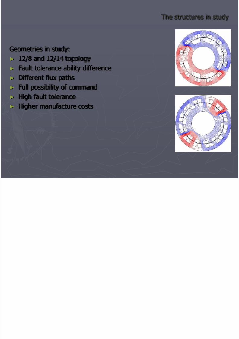
The structures in study
Geometries in study:
12/8 and 12/14 topology
Fault tolerance ability difference
Different flux paths
Full possibility of command
High fault tolerance
Higher manufacture costs
8/13/2019 Fault Tolerant Switched Reluctance Machine's Comparative Analysis
http://slidepdf.com/reader/full/fault-tolerant-switched-reluctance-machines-comparative-analysis 4/9
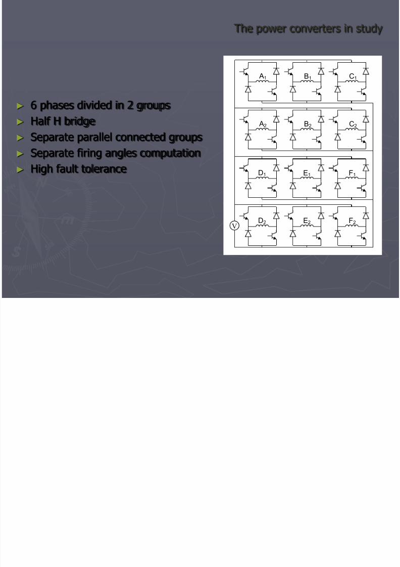
The power converters in study
6 phases divided in 2 groups
Half H bridge
Separate parallel connected groups Separate firing angles computation
High fault tolerance
V
A1
A2
B1
B2
C1
C2
D1
D2
E1
E2
F1
F2
8/13/2019 Fault Tolerant Switched Reluctance Machine's Comparative Analysis
http://slidepdf.com/reader/full/fault-tolerant-switched-reluctance-machines-comparative-analysis 5/9
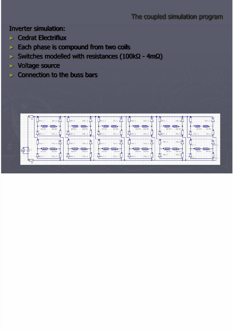
The coupled simulation program Inverter simulation:
Cedrat Electriflux Each phase is compound from two coils
Switches modelled with resistances (100kΩ - 4mΩ)
Voltage source
Connection to the buss bars
8/13/2019 Fault Tolerant Switched Reluctance Machine's Comparative Analysis
http://slidepdf.com/reader/full/fault-tolerant-switched-reluctance-machines-comparative-analysis 6/9
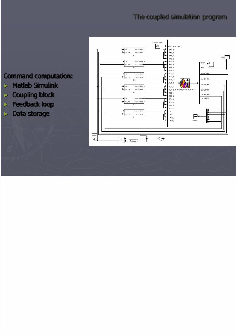
The coupled simulation program
Command computation:
Matlab Simulink
Coupling block
Feedback loop
Data storage
torque
teta
curr BA1PL
curr BB1PL
curr BC1PL
curr BD1PL
RA1_1
RA1_2
RA2_1
RA2_2
RB1_1
RB1_2
RB2_1
RB2_2
RC1_1
RC1_2
RC2_1
RC2_2
RD1_1
RD1_2
RD2_1
RD2_2
VOLTAGE 240v
RE1_1
RE1_2
RE2_1
RE2_2
RF1_1
RF1_2
RF2_1
RF2_2
curr BE1PL
curr BF1PL
teta
250
Voltage value
z
1
Torque
mod
Teta
Cur_PH5
Comand C1
Comand C2
F
Teta
Cur_PH4
Comand C1
Comand C2
E
Teta
Cur_PH3
Comand C1
Comand C2
D
Curr E1
Coupling with Flux2d2
Periode
Teta
Cur_PH2
Comand C1
Comand C2
C
Teta
Cur_PH1
Comand C1
Comand C2
B
Teta
Cur_PH6
Comand C1
Comand C2
A
-1
8/13/2019 Fault Tolerant Switched Reluctance Machine's Comparative Analysis
http://slidepdf.com/reader/full/fault-tolerant-switched-reluctance-machines-comparative-analysis 7/9
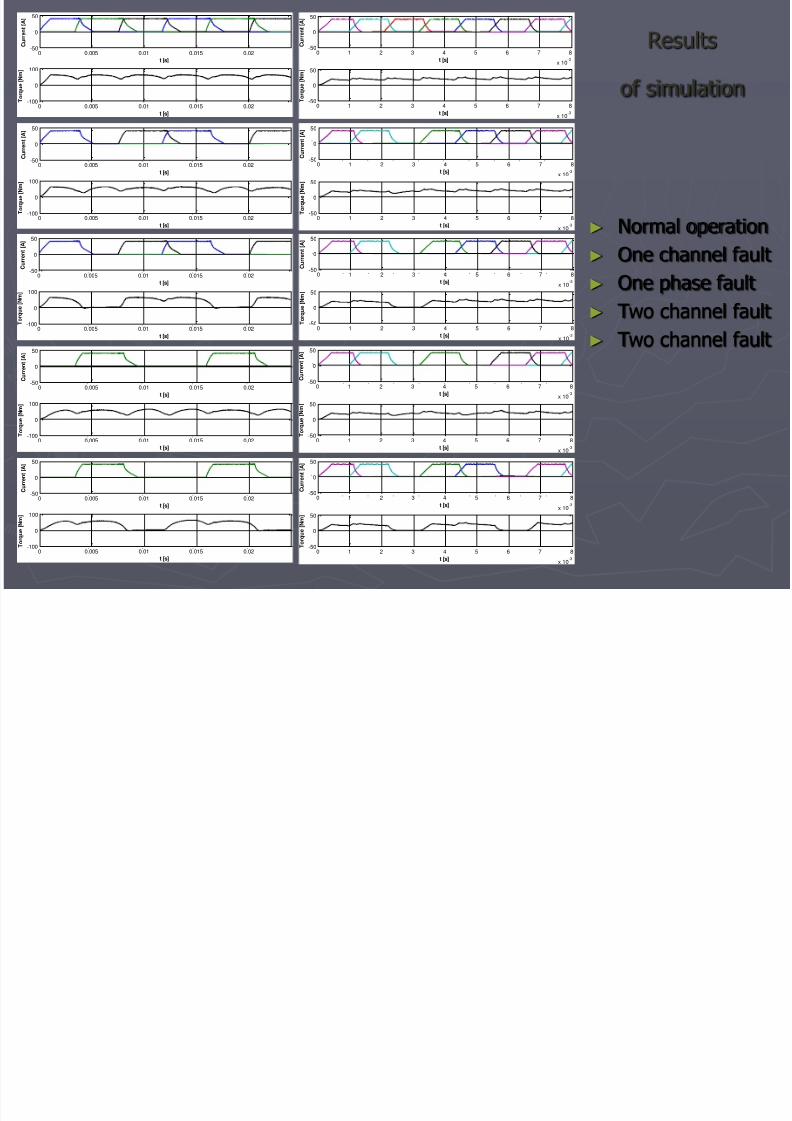
Results
of simulation 0 0.005 0.01 0.015 0.02
-50
0
50
t [s]
C u r r e n t [ A ]
. . . .
. . . .
0 0.005 0.01 0.015 0.02-100
0
100
t [s]
T o r q u e [ N m ]
0 1 2 3 4 5 6 7 8
x 10-3
-50
0
50
t [s]
C u r r e n t [ A ]
0 1 2 3 4 5 6 7 8
x 10-3
-50
0
50
t [s]
T o r q u e [ N m ]
. . . . . . . . .
.
0 0.005 0.01 0.015 0.02-50
0
50
t [s]
C u r r e n t [ A ]
. . . .
. . . .
0 0.005 0.01 0.015 0.02-100
0
100
t [s]
T o r q u e [ N m ]
0 1 2 3 4 5 6 7 8
x 10-3
-50
0
50
t [s]
C u r r e n t
[ A ]
0 1 2 3 4 5 6 7 8
x 10-3
-50
0
50
t [s]
T o r q u e [ N m ]
. . . . . . . . .
.
0 0.005 0.01 0.015 0.02
-50
0
50
t [s]
C u r r e n t [ A ]
. . . .
. . . .
0 0.005 0.01 0.015 0.02-100
0
100
t [s]
T o r q u e [ N m ]
0 1 2 3 4 5 6 7 8x 10
-3
-50
0
50
t [s]
C u r r e n t [ A ]
0 1 2 3 4 5 6 7 8
x 10-3
-50
0
50
t [s]
T o r q u e [ N m ]
. . . . . . . . .
.
0 0.005 0.01 0.015 0.02-50
0
50
t [s]
C u r r e n t [ A ]
. . . .
. . . .
0 0.005 0.01 0.015 0.02-100
0
100
t [s]
T o r q u e [ N m ]
0 1 2 3 4 5 6 7 8
x 10-3
-50
0
50
t [s]
C u r r e n t [ A ]
0 1 2 3 4 5 6 7 8
x 10-3
-50
0
50
t [s]
T o r q u e [ N m ]
. . . . . . . . .
.
0 0.005 0.01 0.015 0.02-50
0
50
t [s]
C u r r e n t [ A ]
0 0.005 0.01 0.015 0.02
-100
0
100
t [s]
T o r q u e [ N m ]
0 1 2 3 4 5 6 7 8
x 10-3
-50
0
50
t [s]
C u r r e n t [ A ]
0 1 2 3 4 5 6 7 8
x 10-3
-50
0
50
t [s]
T o r q u e [ N m ]
.
Normal operation
One channel fault
One phase fault Two channel fault
Two channel fault
8/13/2019 Fault Tolerant Switched Reluctance Machine's Comparative Analysis
http://slidepdf.com/reader/full/fault-tolerant-switched-reluctance-machines-comparative-analysis 8/9
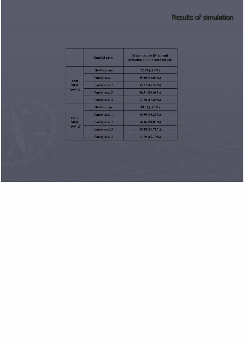
Results of simulation
Studied cases Mean torques [N·m] and
percentage of the rated torque
12/8
SRMtopology
Healthy case 52.21 (100%) Faulty case 1 49.10 (94.04%) Faulty case 2 35.27 (67.55%) Faulty case 3 46.31 (88.69%) Faulty case 4 33.36 (63.89%)
12/14
SRM
topology
Healthy case 19.93 (100%) Faulty case 1 19.59 (98.29%) Faulty case 2 16.16 (81.03%) Faulty case 3 19.28 (96.71%) Faulty case 4 13.79 (69.19%)
8/13/2019 Fault Tolerant Switched Reluctance Machine's Comparative Analysis
http://slidepdf.com/reader/full/fault-tolerant-switched-reluctance-machines-comparative-analysis 9/9
Conclusions
There are significant differences between the behaviour of the twomachine structures in faulty operation
The 12/14 structure has the advantages of better performance
regarding malfunction and lower losses, but has the disadvantagesof higher manufacture costs
Further researches will concern the fault-tolerance some specialSRM topologyes