Embed Size (px)
Citation preview
7/27/2019 Switched Reluctance Drives for Electric Vehicle Applications
http://slidepdf.com/reader/full/switched-reluctance-drives-for-electric-vehicle-applications 1/7
Switched reluctance drives for electric vehicle applications
P.Andrada, M.Torrent, B.Blanqué, J.I.Perat
Department of Electrical EngineeringE.U.P.V.G., Technical University of Catalonia (UPC)
Victor Balaguer s/n, 08800 Vilanova i la Geltrú, Barcelona (Spain) phone:+34 93 8967732, fax:+34 93 8967700, e-mail: [email protected]
Abstract. Electric vehicles are the only alternative for a
clean, efficient and environmentally friendly urban transport
system. With the increasing interest in electric vehicles, a great
effort is required in order to develop electric drives for electricvehicle propulsion. This paper first tries to explain why theswitched reluctance drive is a strong candidate for electricvehicle applications. It then gives switched reluctance drive
design guidelines for battery or fuel cell operated electricvehicles. Finally, it presents the design and simulation of a
switched reluctance motor power train.
Key words
Electric vehicle, electric drives, power drive train,switched reluctance motor.
1. Introduction
Environmental and economic considerations are themajor reasons for the development of electric vehicles.Exhaust emissions from the internal combustion engine
are the main source of urban pollution and one of themost important causes of the greenhouse effect. The
pollution problem only gets worse with increasingnumbers of automobiles. There is also an economicfactor arising from the poor energy conversion efficiencyof the internal combustion engine. When efficiency is
evaluated on the basis of conversion from crude oil toroad load at the wheels, the numbers for electric vehicles
are not significantly higher than for internal combustionengine vehicles (19.64% for electric vehicles, 10.26% for internal combustion engine vehicles). Moreover, efficient power generation at electric plants together with very
high motor and controller efficiency and advancements in power source technology within the vehicle, battery or fuel cell, mean that electric vehicles offer huge possibilities for improving overall efficiency.This paper shows the capabilities of switched reluctancemotors as a power train for battery or fuel cell operatedelectric vehicles and gives design guidelines. The paper
is divided into six sections. Section 2 summarizes basicelectric vehicle dynamics and gives drive specifications.Different alternatives to electric drives for electricvehicles are presented in Section 3. Section 4 revises therelationship between switched reluctance motor drives
and electric traction, and gives design guidelines for sizing switched reluctance motors for electric vehicles. Adesign proposal for a switched reluctance motor and the
simulation of its specified car performances is presentedin Section 5, and the conclusions in Section 6.
2. Basic electric vehicle dynamics and drive
specifications
The motive force at the wheels or road load, F, consists
of gravitational force, rolling resistance of the tyres,aerodinamic drag force, and acceleration force, that is
[1].
dt
dvmk )vv( S C 5 ,0mg ) sinc( F m
20 D0 ++++= ρ β (1)
where c0 is the tyre rolling resistance, is the anglewith respect to the horizontal, m is the gross mass of the
vehicle, g is the acceleration due to gravity, is the air
density, C D is the aerodynamic drag coefficient, S is the
vehicle frontal area, v is the vehicle speed, is the
head-wind speed and k m is the rotational inertiacoefficient. In this paper the parameters affecting drive performance are fixed at the following values: Gross
weight around 1500 kg, cruising speed 120 km/h,maximum speed 180 km/h, and a gradability or climbingcapability of about 40%. These performance parametersare typical for a subcompact car powered by a 1600 to
1800 cm3
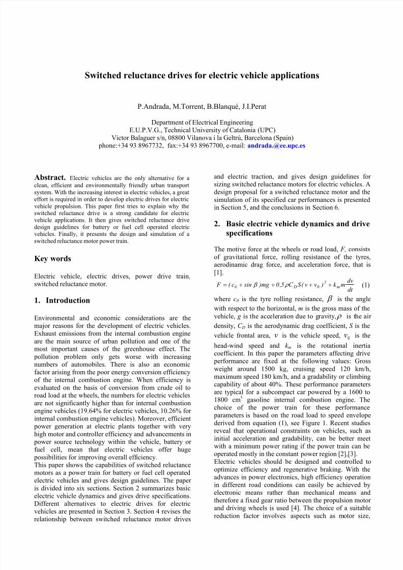
gasoline internal combustion engine. Thechoice of the power train for these performance parameters is based on the road load to speed envelope
derived from equation (1), see Figure 1. Recent studiesreveal that operational constraints on vehicles, such asinitial acceleration and gradability, can be better meetwith a minimum power rating if the power train can beoperated mostly in the constant power region [2],[3].
β
ρ
0v
Electric vehicles should be designed and controlled to
optimize efficiency and regenerative braking. With theadvances in power electronics, high efficiency operationin different road conditions can easily be achieved byelectronic means rather than mechanical means and
therefore a fixed gear ratio between the propulsion motor and driving wheels is used [4]. The choice of a suitable
reduction factor involves aspects such as motor size,
7/27/2019 Switched Reluctance Drives for Electric Vehicle Applications
http://slidepdf.com/reader/full/switched-reluctance-drives-for-electric-vehicle-applications 2/7
Fig. 1. Road load-speed envelope. In red, lines of equal power (10 to 100 kW); in blue road load vs. speed for different percentagegradabililty (0 to 40%).
size, maximum frequency and power loss, mainly in theiron core but also in the power converter. Appropriatevalues for a wheel radius of 0.3 m, are between 5 and 12.
Electric propulsion demands an energy source that could be advanced batteries (NiMH or Li-ion) or preferably afuel cell (PEM) [5],[6]. The voltage at D.C. bus must behigher than 300 V D.C., but if this voltage is notregulated, rated power and torque must be fulfilled at
minimum voltage. Therefore, taking into account theabove car performance parameters, the drive
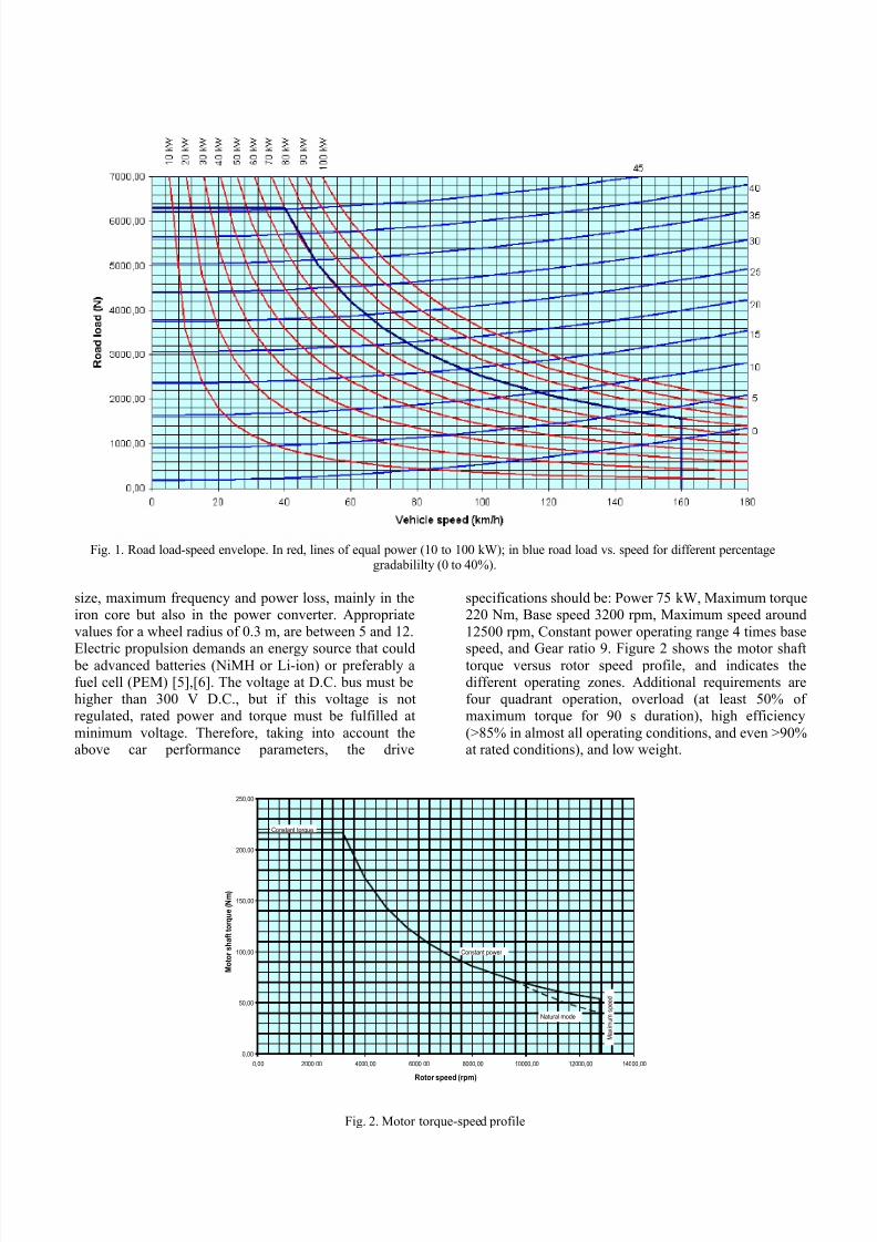
specifications should be: Power 75 kW, Maximum torque220 Nm, Base speed 3200 rpm, Maximum speed around
12500 rpm, Constant power operating range 4 times base
speed, and Gear ratio 9. Figure 2 shows the motor shafttorque versus rotor speed profile, and indicates thedifferent operating zones. Additional requirements arefour quadrant operation, overload (at least 50% of maximum torque for 90 s duration), high efficiency
(>85% in almost all operating conditions, and even >90%at rated conditions), and low weight.
0,00
50,00
100,00
150,00
200,00
250,00
0,00 2000,00 4000,00 6000,00 8000,00 10000,00 12000,00 14000,00
Rotor speed (rpm)
M o t o r s h a f t t o r q u e ( N m )
Constant torque
Constant power
Natural mode
M a x i m u m s
p e e d
Fig. 2. Motor torque-speed profile
7/27/2019 Switched Reluctance Drives for Electric Vehicle Applications
http://slidepdf.com/reader/full/switched-reluctance-drives-for-electric-vehicle-applications 3/7
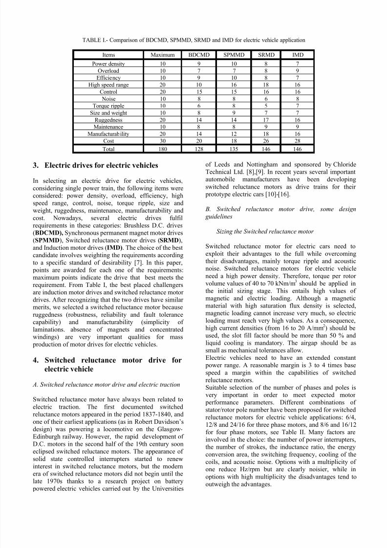
TABLE I.- Comparison of BDCMD, SPMMD, SRMD and IMD for electric vehicle application
Items Maximum BDCMD SPMMD SRMD IMD
Power density 10 9 10 8 7
Overload 10 7 7 8 9
Efficiency 10 9 10 8 7
High speed range 20 10 16 18 16
Control 20 15 15 16 16
Noise 10 8 8 6 8
Torque ripple 10 6 8 5 7
Size and weight 10 8 9 7 7
Ruggedness 20 14 14 17 16
Maintenance 10 8 8 9 9
Manufacturability 20 14 12 18 16
Cost 30 20 18 26 28
Total 180 128 135 146 146
3. Electric drives for electric vehicles
In selecting an electric drive for electric vehicles,considering single power train, the following items wereconsidered: power density, overload, efficiency, highspeed range, control, noise, torque ripple, size andweight, ruggedness, maintenance, manufacturability and
cost. Nowadays, several electric drives fulfilrequirements in these categories: Brushless D.C. drives(BDCMD), Synchronous permanent magnet motor drives(SPMMD), Switched reluctance motor drives (SRMD),and Induction motor drives (IMD). The choice of the bestcandidate involves weighting the requirements according
to a specific standard of desirability [7]. In this paper, points are awarded for each one of the requirements:maximum points indicate the drive that best meets the
requirement. From Table I, the best placed challengersare induction motor drives and switched reluctance motor drives. After recognizing that the two drives have similar merits, we selected a switched reluctance motor because
ruggedness (robustness, reliability and fault tolerancecapability) and manufacturability (simplicity of laminations. absence of magnets and concentratedwindings) are very important qualities for mass production of motor drives for electric vehicles.
4. Switched reluctance motor drive for
electric vehicle
A. Switched reluctance motor drive and electric traction
Switched reluctance motor have always been related to
electric traction. The first documented switchedreluctance motors appeared in the period 1837-1840, andone of their earliest applications (as in Robert Davidson’sdesign) was powering a locomotive on the Glasgow-Edinburgh railway. However, the rapid development of D.C. motors in the second half of the 19th century sooneclipsed switched reluctance motors. The appearance of
solid state controlled interrupters started to renewinterest in switched reluctance motors, but the modernera of switched reluctance motors did not begin until the
late 1970s thanks to a research project on battery powered electric vehicles carried out by the Universities
of Leeds and Nottingham and sponsored by ChlorideTechnical Ltd. [8],[9]. In recent years several importantautomobile manufacturers have been developing
switched reluctance motors as drive trains for their
prototype electric cars [10]-[16].
B. Switched reluctance motor drive, some design guidelines
Sizing the Switched reluctance motor
Switched reluctance motor for electric cars need toexploit their advantages to the full while overcomingtheir disadvantages, mainly torque ripple and acousticnoise. Switched reluctance motors for electric vehicle
need a high power density. Therefore, torque per rotor volume values of 40 to 70 kNm/m
3should be applied in
the initial sizing stage. This entails high values of magnetic and electric loading. Although a magneticmaterial with high saturation flux density is selected,magnetic loading cannot increase very much, so electricloading must reach very high values. As a consequence,
high current densities (from 16 to 20 A/mm2) should be
used, the slot fill factor should be more than 50 % andliquid cooling is mandatory. The airgap should be assmall as mechanical tolerances allow.Electric vehicles need to have an extended constant power range. A reasonable margin is 3 to 4 times base
speed a margin within the capabilities of switchedreluctance motors.Suitable selection of the number of phases and poles isvery important in order to meet expected motor performance parameters. Different combinations of stator/rotor pole number have been proposed for switched
reluctance motors for electric vehicle applications: 6/4,12/8 and 24/16 for three phase motors, and 8/6 and 16/12for four phase motors, see Table II. Many factors areinvolved in the choice: the number of power interrupters,the number of strokes, the inductance ratio, the energyconversion area, the switching frequency, cooling of the
coils, and acoustic noise. Options with a multiplicity of one reduce Hz/rpm but are clearly noisier, while in
options with high multiplicity the disadvantages tend tooutweigh the advantages.
7/27/2019 Switched Reluctance Drives for Electric Vehicle Applications
http://slidepdf.com/reader/full/switched-reluctance-drives-for-electric-vehicle-applications 4/7
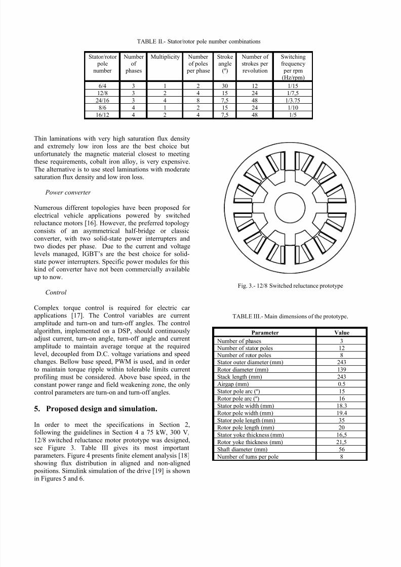
TABLE II.- Stator/rotor pole number combinations
Stator/rotor pole
number
Number of
phases
Multiplicity Number of poles
per phase
Strokeangle
(º)
Number of strokes per
revolution
Switchingfrequency
per rpm(Hz/rpm)
6/4 3 1 2 30 12 1/15
12/8 3 2 4 15 24 1/7,5
24/16 3 4 8 7,5 48 1/3.758/6 4 1 2 15 24 1/10
16/12 4 2 4 7,5 48 1/5
Thin laminations with very high saturation flux densityand extremely low iron loss are the best choice butunfortunately the magnetic material closest to meetingthese requirements, cobalt iron alloy, is very expensive.
The alternative is to use steel laminations with moderatesaturation flux density and low iron loss.
Power converter
Numerous different topologies have been proposed for
electrical vehicle applications powered by switchedreluctance motors [16]. However, the preferred topology
consists of an asymmetrical half-bridge or classicconverter, with two solid-state power interrupters andtwo diodes per phase. Due to the current and voltagelevels managed, IGBT’s are the best choice for solid-
state power interrupters. Specific power modules for thiskind of converter have not been commercially available
up to now.
Control
Complex torque control is required for electric car applications [17]. The Control variables are current
amplitude and turn-on and turn-off angles. The controlalgorithm, implemented on a DSP, should continuouslyadjust current, turn-on angle, turn-off angle and currentamplitude to maintain average torque at the required
level, decoupled from D.C. voltage variations and speedchanges. Bellow base speed, PWM is used, and in order
to maintain torque ripple within tolerable limits current profiling must be considered. Above base speed, in theconstant power range and field weakening zone, the onlycontrol parameters are turn-on and turn-off angles.
5. Proposed design and simulation.
In order to meet the specifications in Section 2,following the guidelines in Section 4 a 75 kW, 300 V,
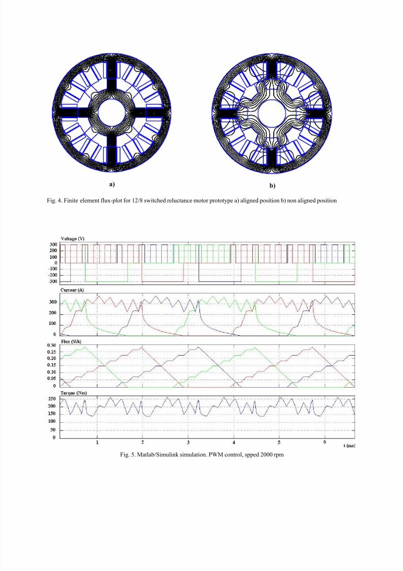
12/8 switched reluctance motor prototype was designed,see Figure 3. Table III gives its most important parameters. Figure 4 presents finite element analysis [18]showing flux distribution in aligned and non-aligned positions. Simulink simulation of the drive [19] is shownin Figures 5 and 6.
Fig. 3.- 12/8 Switched reluctance prototype
TABLE III.- Main dimensions of the prototype.
Parameter Value
Number of phases 3
Number of stator poles 12
Number of rotor poles 8
Stator outer diameter (mm) 243
Rotor diameter (mm) 139
Stack length (mm) 243
Airgap (mm) 0.5
Stator pole arc (º) 15
Rotor pole arc (º) 16Stator pole width (mm) 18.3
Rotor pole width (mm) 19.4
Stator pole length (mm) 35
Rotor pole length (mm) 20
Stator yoke thickness (mm) 16,5
Rotor yoke thickness (mm) 21,5
Shaft diameter (mm) 56
Number of turns per pole 8
7/27/2019 Switched Reluctance Drives for Electric Vehicle Applications
http://slidepdf.com/reader/full/switched-reluctance-drives-for-electric-vehicle-applications 5/7
a) b)
Fig. 4. Finite element flux-plot for 12/8 switched reluctance motor prototype a) aligned position b) non aligned position
Fig. 5. Matlab/Simulink simulation. PWM control, spped 2000 rpm
7/27/2019 Switched Reluctance Drives for Electric Vehicle Applications
http://slidepdf.com/reader/full/switched-reluctance-drives-for-electric-vehicle-applications 6/7
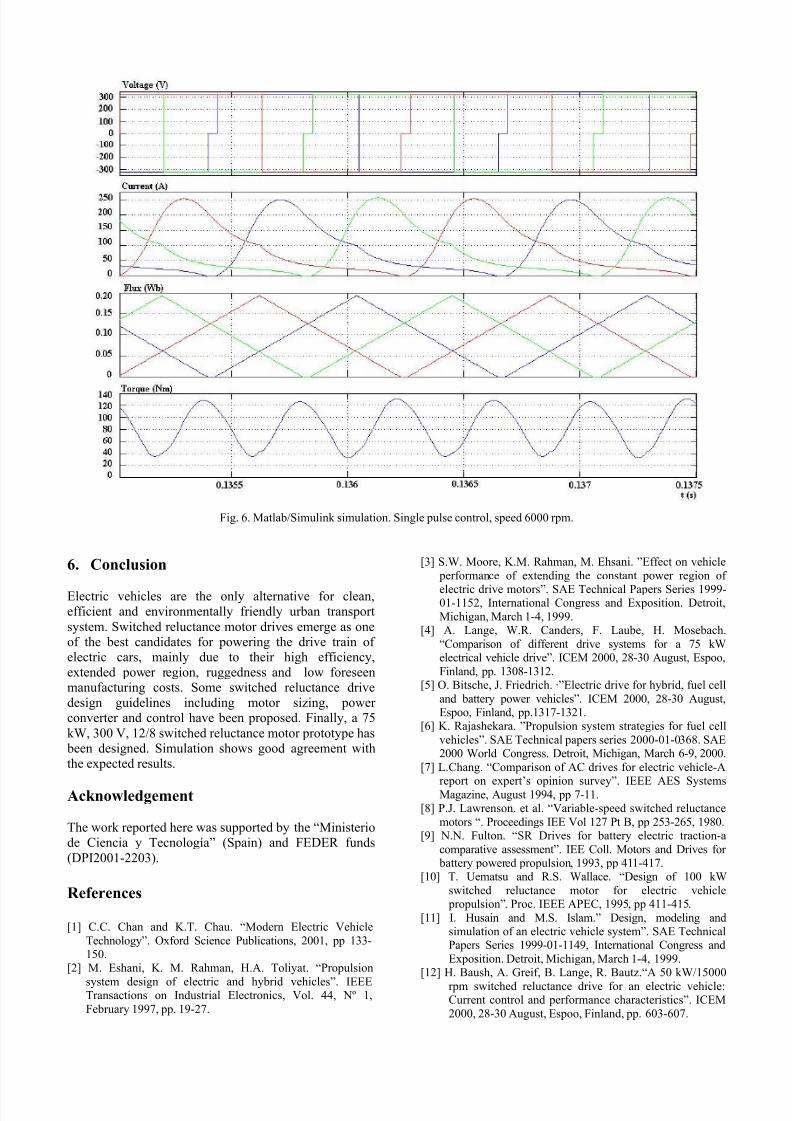
Fig. 6. Matlab/Simulink simulation. Single pulse control, speed 6000 rpm.
6. Conclusion
Electric vehicles are the only alternative for clean,efficient and environmentally friendly urban transport
system. Switched reluctance motor drives emerge as oneof the best candidates for powering the drive train of electric cars, mainly due to their high efficiency,extended power region, ruggedness and low foreseenmanufacturing costs. Some switched reluctance drivedesign guidelines including motor sizing, power converter and control have been proposed. Finally, a 75
kW, 300 V, 12/8 switched reluctance motor prototype has been designed. Simulation shows good agreement withthe expected results.
Acknowledgement
The work reported here was supported by the “Ministeriode Ciencia y Tecnología” (Spain) and FEDER funds
(DPI2001-2203).
References
[1] C.C. Chan and K.T. Chau. “Modern Electric Vehicle
Technology”. Oxford Science Publications, 2001, pp 133-150.
[2] M. Eshani, K. M. Rahman, H.A. Toliyat. “Propulsion
system design of electric and hybrid vehicles”. IEEETransactions on Industrial Electronics, Vol. 44, Nº 1,
February 1997, pp. 19-27.
[3] S.W. Moore, K.M. Rahman, M. Ehsani. ”Effect on vehicle
performance of extending the constant power region of
electric drive motors”. SAE Technical Papers Series 1999-01-1152, International Congress and Exposition. Detroit,
Michigan, March 1-4, 1999.[4] A. Lange, W.R. Canders, F. Laube, H. Mosebach.
“Comparison of different drive systems for a 75 kWelectrical vehicle drive”. ICEM 2000, 28-30 August, Espoo,
Finland, pp. 1308-1312.[5] O. Bitsche, J. Friedrich. ·”Electric drive for hybrid, fuel cell
and battery power vehicles”. ICEM 2000, 28-30 August,Espoo, Finland, pp.1317-1321.
[6] K. Rajashekara. ”Propulsion system strategies for fuel cell
vehicles”. SAE Technical papers series 2000-01-0368. SAE2000 World Congress. Detroit, Michigan, March 6-9, 2000.
[7] L.Chang. “Comparison of AC drives for electric vehicle-A
report on expert’s opinion survey”. IEEE AES SystemsMagazine, August 1994, pp 7-11.[8] P.J. Lawrenson. et al. “Variable-speed switched reluctance
motors “. Proceedings IEE Vol 127 Pt B, pp 253-265, 1980.[9] N.N. Fulton. “SR Drives for battery electric traction-a
comparative assessment”. IEE Coll. Motors and Drives for battery powered propulsion, 1993, pp 411-417.
[10] T. Uematsu and R.S. Wallace. “Design of 100 kW
switched reluctance motor for electric vehicle propulsion”. Proc. IEEE APEC, 1995, pp 411-415.
[11] I. Husain and M.S. Islam.” Design, modeling andsimulation of an electric vehicle system”. SAE TechnicalPapers Series 1999-01-1149, International Congress and
Exposition. Detroit, Michigan, March 1-4, 1999. [12] H. Baush, A. Greif, B. Lange, R. Bautz.“A 50 kW/15000
rpm switched reluctance drive for an electric vehicle:Current control and performance characteristics”. ICEM
2000, 28-30 August, Espoo, Finland, pp. 603-607.

7/27/2019 Switched Reluctance Drives for Electric Vehicle Applications
http://slidepdf.com/reader/full/switched-reluctance-drives-for-electric-vehicle-applications 7/7
[13] H. Bausch, A. Greif, A.B.A. Nickel. “A switchedreluctance and an induction machine in a drive train for an
electrical vehicle under the conditions of car application”.ICEM 2000, 28-30 August, Espoo, Finland, pp. 1313-
1316.[14] R.B.Inderka, J-P. Altendorf, L.Sjöberg, R.W. De Doncker.
Design of a 75 kW Switched Reluctance Drive for
Electric Vehicles”. EVS 18 Berlin 2001.
[15] K.M. Rahman & S.E.Schulz. “Design of high efficiencyand high density switched reluctance motor for vehicle propulsion”. IAS’2001, Chicago, pp.2104-2110.
[16] K.W.E. Cheng, Y.P.B. Yeung, C.Y. Tang, X.D. Xue, D.Sutanto. “Topology analysis of switched reluctance drives
for electric vehicles”. Power Electronics and VariableSpeed Drives, 18-19 September 2000, pp. 512-517.
[17] R. Inderka, M. Menne, R.W. De Donker. “Control of switched reluctance drives for electric vehicleapplications”. IEEE Transactions on Industrial
Electronics, Vol. 49, Nº 1, February 2002, pp. 48-53.
[18] D.C. Meeker “Finite element method magnetics. User’sManual”. December 1998.[19] B.Blanqué, J.I. Perat, M. Torrent, P. Andrada “Simulation
of non-linear switched reluctance motor” SAAEI’02 18-
20 September 2002. Alcalá de Henares, Spain.