Embed Size (px)
Citation preview
For maximum effectiveness and safety, please read these instructions completely before proceeding with installation.
Failure to read these instructions can result in an incorrect installation.
INSTALLATION GUIDE
™Air Lift PERFORMANCE
MN
-766
• (
0214
02)
• E
RN
819
0Kit 75555Audi A4/S4 QuattroB5 Platform front application

1MN-766
Air Lift Performance
TABLE OF CONTENTS
Introduction . . . . . . . . . . . . . . . . . . . . . . . . . . . . . . . . . . . 2Notation Explanation . . . . . . . . . . . . . . . . . . . . . . . . . . . . . . . . . . . . . . . . . . . . . . . . 2 Important Safety Notices . . . . . . . . . . . . . . . . . . . . . . . . . . . . . . . . . . . . . . . . . . . . 2
Installation Diagram . . . . . . . . . . . . . . . . . . . . . . . . . . . . 3Hardware List . . . . . . . . . . . . . . . . . . . . . . . . . . . . . . . . . . . . . . . . . . . . . . . . . . . . . 3Tools List . . . . . . . . . . . . . . . . . . . . . . . . . . . . . . . . . . . . . . . . . . . . . . . . . . . . . . . . . 3
Installing the Air Suspension . . . . . . . . . . . . . . . . . . . . . 4Preparing the Vehicle . . . . . . . . . . . . . . . . . . . . . . . . . . . . . . . . . . . . . . . . . . . . . . . 4Stock Shock Removal . . . . . . . . . . . . . . . . . . . . . . . . . . . . . . . . . . . . . . . . . . . . . . . 4Modifications for Air Suspension . . . . . . . . . . . . . . . . . . . . . . . . . . . . . . . . . . . . . . . 6Installing the Air Suspension . . . . . . . . . . . . . . . . . . . . . . . . . . . . . . . . . . . . . . . . . . 7Damping Adjustment . . . . . . . . . . . . . . . . . . . . . . . . . . . . . . . . . . . . . . . . . . . . . . . . 9Aligning the Vehicle . . . . . . . . . . . . . . . . . . . . . . . . . . . . . . . . . . . . . . . . . . . . . . . . . 9Adjusting Extended or Drop Height Using Lower Mount . . . . . . . . . . . . . . . . . . . . . 9
Before Operating . . . . . . . . . . . . . . . . . . . . . . . . . . . . . . . 12Installation Checklist . . . . . . . . . . . . . . . . . . . . . . . . . . . . . . . . . . . . . . . . . . . . . . . .12Post-installation checklist . . . . . . . . . . . . . . . . . . . . . . . . . . . . . . . . . . . . . . . . . . . .12
Product Use, Maintenance and Servicing . . . . . . . . . . . 13Suggested Driving Air Pressure and Maximum Air Pressure . . . . . . . . . . . . . . . . .13Maintenance Guidelines . . . . . . . . . . . . . . . . . . . . . . . . . . . . . . . . . . . . . . . . . . . . .13Troubleshooting Guide . . . . . . . . . . . . . . . . . . . . . . . . . . . . . . . . . . . . . . . . . . . . . .13Frequently Asked Questions . . . . . . . . . . . . . . . . . . . . . . . . . . . . . . . . . . . . . . . . . .13Tuning the Air Pressure . . . . . . . . . . . . . . . . . . . . . . . . . . . . . . . . . . . . . . . . . . . . . .14Checking for Leaks . . . . . . . . . . . . . . . . . . . . . . . . . . . . . . . . . . . . . . . . . . . . . . . . .14Fixing Leaks . . . . . . . . . . . . . . . . . . . . . . . . . . . . . . . . . . . . . . . . . . . . . . . . . . . . . .14
Warranty and Returns Policy . . . . . . . . . . . . . . . . . . . . . 15
Replacement Information . . . . . . . . . . . . . . . . . . . . . . . . 15
Contact Information . . . . . . . . . . . . . . . . . . . . . . . . . . . . 15
2
Air Lift Performance
MN-766
Air Lift Performance
IntroductionThe purpose of this publication is to assist with the installation, maintenance and troubleshooting of this Audi Lifestyle kit.
It is important to read and understand the entire installation guide before beginning installation or performing any maintenance, service or repair. The information includes a hardware list, tool list, step-by-step installation information, maintenance tips, safety information and a troubleshooting guide.
Air Lift Company reserves the right to make changes and improvements to its products and publications at any time. For the latest version of this manual, contact Air Lift Company at (800) 248-0892 or visit our website at www.airliftcompany.com.
NOTATION EXPLANATIONHazard notations appear in various locations in this publication. Information which is highlighted by one of these notations must be observed to help minimize risk of personal injury or possible improper installation which may render the vehicle unsafe. Notes are used to help emphasize areas of procedural importance and provide helpful suggestions. The following definitions explain the use of these notations as they appear throughout this guide.
INDICATES IMMEDIATE HAZARDS WHICH WILL RESULT IN SEVERE PERSONAL INJURY OR DEATH.
INDICATES HAZARDS OR UNSAFE PRACTICES WHICH COULD RESULT IN SEVERE PERSONAL INJURY OR DEATH.
INDICATES HAZARDS OR UNSAFE PRACTICES WHICH COULD RESULT IN DAMAGE TO THE MACHINE OR MINOR PERSONAL INJURY.
Indicates a procedure, practice or hint which is important to highlight.
IMPORTANT SAFETY NOTICESThe installation of this kit does not alter the Gross Vehicle Weight Rating (GVWR) or payload of the vehicle. Check your vehicle’s owner’s manual and do not exceed the maximum load listed for your vehicle.
Gross Vehicle Weight Rating: The maximum allowable weight of the fully loaded vehicle (including passengers and cargo). This number — along with other weight limits, as well as tire, rim size and inflation pressure data — is shown on the vehicle’s Safety Compliance Certification Label.
Payload: The combined, maximum allowable weight of cargo and passengers that the vehicle is designed to carry. Payload is GVWR minus the Base Curb Weight.
DO NOT INFLATE AIR SPRINGS WHILE OFF OF THE VEHICLE. DAMAGE TO ASSEMBLY MAY RESULT AND VOID WARRANTY.
DO NOT WELD TO, OR MODIFY LIFESTYLE STRUTS/SHOCKS IN ANY WAY. DAMAGE TO UNIT MAY OCCUR AND WILL VOID WARRANTY.
DANGER
NOTE
WARNING
CAUTION
WARNING
CAUTION

3MN-766
Air Lift Performance
Installation Diagram
TOOLS LIST
Description . . . . . . . . . . . . . . . . . . . . . . . . . . . . . . . QtyJack ...................................................1Jack stands or hoist ...........................21/2” Drive ratchet ...............................117mm Socket.....................................112mm Wrench ...................................114mm Wrench ...................................119mm Wrench & socket ....................1Torque wrench...................................1
Item Part # Description . . . . . . . . . . . . . . . . . . . . . . . . . Qty A 35202 ASM, Front Shock, Audi B5 .......................2 B 20997 Leader Hose, 1/4” ID .................................2 C 21810 Union, 1/4” FNPT-1/4” PTC “DOT” ............2 D 21987 Union, 1/4” FNPT X 3/8” Fitting “DOT” ......2 E 26932-009 Shock Adjuster ...........................................2 F Wrench, Collar ...........................................1
HARDWARE LIST
Missing or damaged parts? Call Air Lift customer service at (800) 248-0892 for a replacement part.
STOP!
fig. 1
C OR D
B
A
F
E
4 MN-766
Air Lift Performance
PREPARING THE VEHICLE1. Support vehicle with jack stands or a hoist at approved lifting points. 2. Remove the front wheels
STOCK SHOCK REMOVALIf equipped with headlight alignment system, disconnect range control linkage first.
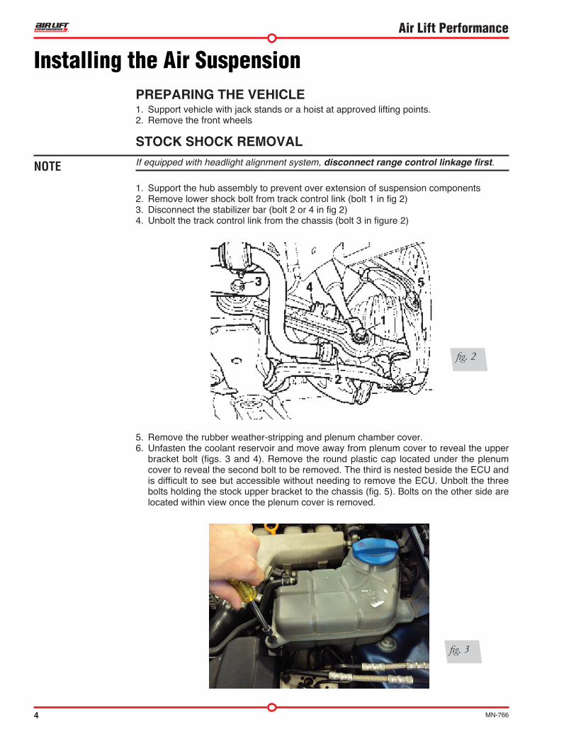
1. Support the hub assembly to prevent over extension of suspension components2. Remove lower shock bolt from track control link (bolt 1 in fig 2)3. Disconnect the stabilizer bar (bolt 2 or 4 in fig 2)4. Unbolt the track control link from the chassis (bolt 3 in figure 2)
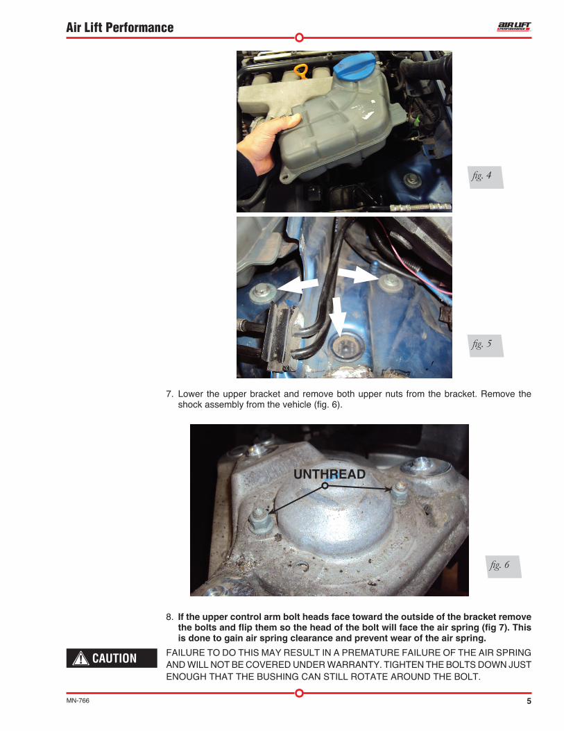
5. Remove the rubber weather-stripping and plenum chamber cover. 6. Unfasten the coolant reservoir and move away from plenum cover to reveal the upper
bracket bolt (figs. 3 and 4). Remove the round plastic cap located under the plenum cover to reveal the second bolt to be removed. The third is nested beside the ECU and is difficult to see but accessible without needing to remove the ECU. Unbolt the three bolts holding the stock upper bracket to the chassis (fig. 5). Bolts on the other side are located within view once the plenum cover is removed.
Installing the Air Suspension
fig. 2
NOTE
fig. 3
5MN-766
Air Lift Performance
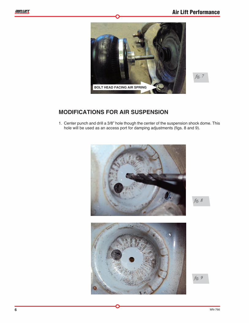
7. Lower the upper bracket and remove both upper nuts from the bracket. Remove the shock assembly from the vehicle (fig. 6).
8. If the upper control arm bolt heads face toward the outside of the bracket remove the bolts and flip them so the head of the bolt will face the air spring (fig 7). This is done to gain air spring clearance and prevent wear of the air spring .
FAILURE TO DO THIS MAY RESULT IN A PREMATURE FAILURE OF THE AIR SPRING AND WILL NOT BE COVERED UNDER WARRANTY. TIGHTEN THE BOLTS DOWN JUST ENOUGH THAT THE BUSHING CAN STILL ROTATE AROUND THE BOLT.
fig. 4
fig. 5
fig. 6
UNTHREAD
CAUTION
6 MN-766
Air Lift Performance
MODIFICATIONS FOR AIR SUSPENSION
1. Center punch and drill a 3/8” hole though the center of the suspension shock dome. This hole will be used as an access port for damping adjustments (figs. 8 and 9).
fig. 8
fig. 9
fig. 7
BOLT HEAD FACING AIR SPRING
7MN-766
Air Lift Performance
INSTALLING THE AIR SUSPENSION
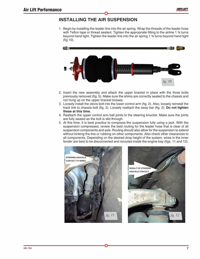
1. Begin by installing the leader line into the air spring. Wrap the threads of the leader hose with Teflon tape or thread sealant. Tighten the appropriate fitting to the airline 1 ¾ turns beyond hand tight. Tighten the leader line into the air spring 1 ¾ turns beyond hand tight (fig 10).
2. Insert the new assembly and attach the upper bracket in place with the three bolts previously removed (fig. 5). Make sure the shims are correctly seated to the chassis and not hung up on the upper bracket bosses.
3. Loosely install the clevis bolt into the lower control arm (fig. 2). Also, loosely reinstall the track link to chassis bolt (fig. 2). Loosely reattach the sway bar (fig. 2). Do not tighten these at this time .
4. Reattach the upper control arm ball joints to the steering knuckle. Make sure the joints are fully seated as the bolt is slid through.
5. At this time, it is best practice to compress the suspension fully using a jack. With the suspension compressed, review the best routing for the leader hose that is clear of all suspension components and axle. Routing should also allow for the suspension to extend without kinking the line or rubbing on other components. Also check other clearances to all components. Depending on the desired drop height of the system, wires in the inner fender are best to be disconnected and rerouted inside the engine bay (figs. 11 and 12).
STEERING KNUCKLE
CONTACT TO WIRES
RESULT OF STEERING
KNUCKLE CONTACT
fig. 11 fig. 12
fig. 10

8 MN-766
Air Lift Performance
6. With the suspension fully compressed, take a measurement from the fender to some reference point – typically the center of the axle. Record this measurement as Max Compression.
7. Cycle the suspension to Max Extension and record the measurement from the same reference points.
8. Add ME and MC then divide by 2. Set the suspension to this point. This position will give 50% stroke in either direction and is a starting point for ride height (fig. 19).
9. With the suspension at this position, loosen and then re-torque the forward control arm to sub-frame bolt to manufacturer’s specifications (Table 1).
Table 1
Torque Specifications
Location Nm ft. lbs.
Shock upper bracket to or upper bracket 20Nm 15 ft./lbs.
Upper bracket to chassis 75 55
Upper control arms to bracket 50Nm + 90° 37 ft./lbs. + 90°
Track control link to shock clevis 90 66
Track control link to subframe 80 59
Guide link to subframe 90Nm + 90° 66 ft./lbs. + 90°
End link to track control link 100Nm 74 ft./lbs.
End link to sway bar 50Nm + 90° 37 ft./lbs. + 90°
Wheels 120 89
fig. 19Formula for Calculating Ride Height
(ME+MC)÷2=MID STROKE
9MN-766
Air Lift Performance
DAMPING ADJUSTMENT
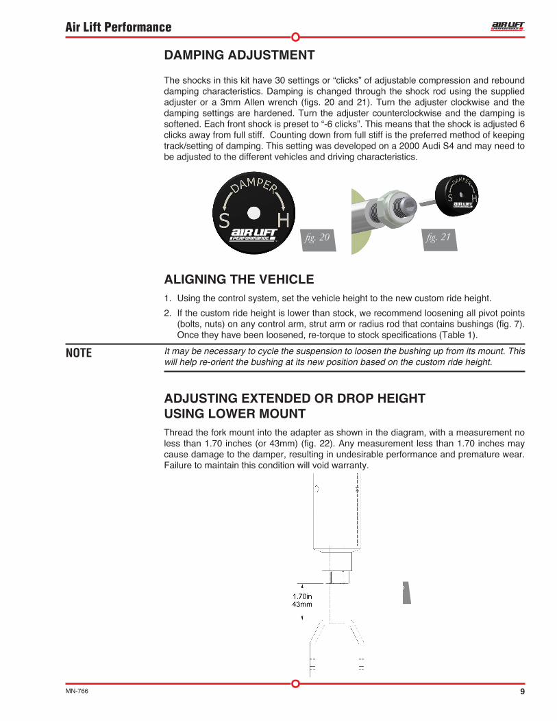
The shocks in this kit have 30 settings or “clicks” of adjustable compression and rebound damping characteristics. Damping is changed through the shock rod using the supplied adjuster or a 3mm Allen wrench (figs. 20 and 21). Turn the adjuster clockwise and the damping settings are hardened. Turn the adjuster counterclockwise and the damping is softened. Each front shock is preset to “-6 clicks”. This means that the shock is adjusted 6 clicks away from full stiff. Counting down from full stiff is the preferred method of keeping track/setting of damping. This setting was developed on a 2000 Audi S4 and may need to be adjusted to the different vehicles and driving characteristics.
fig. 20 fig. 21
fig. 22
NOTE
ALIGNING THE VEHICLE1. Using the control system, set the vehicle height to the new custom ride height.
2. If the custom ride height is lower than stock, we recommend loosening all pivot points (bolts, nuts) on any control arm, strut arm or radius rod that contains bushings (fig. 7). Once they have been loosened, re-torque to stock specifications (Table 1).
It may be necessary to cycle the suspension to loosen the bushing up from its mount. This will help re-orient the bushing at its new position based on the custom ride height.
ADJUSTING EXTENDED OR DROP HEIGHT USING LOWER MOUNTThread the fork mount into the adapter as shown in the diagram, with a measurement no less than 1.70 inches (or 43mm) (fig. 22). Any measurement less than 1.70 inches may cause damage to the damper, resulting in undesirable performance and premature wear. Failure to maintain this condition will void warranty.
10 MN-766
Air Lift Performance
Your struts have been pre-set at the factory to provide maximum drop height while maintaining adequate tire clearance to the air spring. If you wish to gain more extended height (lift), which is the same as reducing drop height, or want to lower the chassis further and there is still adjustment available at the lower mount, please use the following procedure:
1. Support the vehicle with jack stands or a hoist at approved lifting points.
2. Remove the wheel.
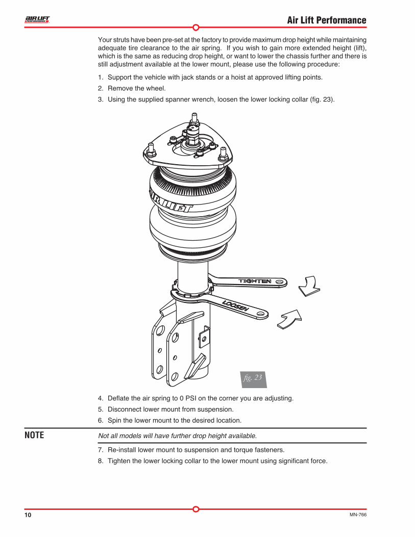
3. Using the supplied spanner wrench, loosen the lower locking collar (fig. 23).
4. Deflate the air spring to 0 PSI on the corner you are adjusting.
5. Disconnect lower mount from suspension.
6. Spin the lower mount to the desired location.
Not all models will have further drop height available.
7. Re-install lower mount to suspension and torque fasteners.
8. Tighten the lower locking collar to the lower mount using significant force.
fig. 23
NOTE
11MN-766
Air Lift Performance
CAUTION
CAUTION
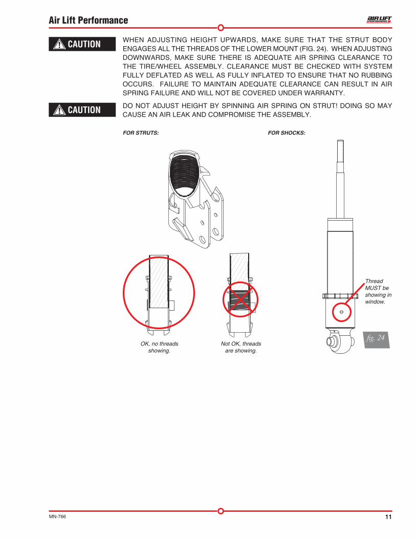
FOR STRUTS: FOR SHOCKS:
Thread MUST be showing in window.
OK, no threads showing.
Not OK, threadsare showing.
fig. 24
WHEN ADJUSTING HEIGHT UPWARDS, MAKE SURE THAT THE STRUT BODY ENGAGES ALL THE THREADS OF THE LOWER MOUNT (FIG. 24). WHEN ADJUSTING DOWNWARDS, MAKE SURE THERE IS ADEQUATE AIR SPRING CLEARANCE TO THE TIRE/WHEEL ASSEMBLY. CLEARANCE MUST BE CHECKED WITH SYSTEM FULLY DEFLATED AS WELL AS FULLY INFLATED TO ENSURE THAT NO RUBBING OCCURS. FAILURE TO MAINTAIN ADEQUATE CLEARANCE CAN RESULT IN AIR SPRING FAILURE AND WILL NOT BE COVERED UNDER WARRANTY.
DO NOT ADJUST HEIGHT BY SPINNING AIR SPRING ON STRUT! DOING SO MAY CAUSE AN AIR LEAK AND COMPROMISE THE ASSEMBLY.
12 MN-766
Air Lift Performance
Before OperatingMAKE SURE THE FRONT WHEELS ARE STRAIGHT WHEN DEFLATING AND REINFLATING AIR BAGS.
1. Inflate and deflate the system (do not exceed 125 PSI) to check for clearance or binding issues. With the air springs deflated, check clearances on everything so as not to pinch brake lines, vent tubes, etc. Clear lines if necessary.
2. Inflate the air springs to 75-90 PSI and check all connections for leaks.
3. Air Lift part #27669 or #27671, AutoPilot V2 Air Management System, is highly recommended for this product.
4. Please familiarize yourself further with this product by reading the Product Use, Maintenance and Servicing section.
CAUTION
Technician’s Signature _________________________________
Date _________________
Clearance test — Inflate the air springs to 75-90 PSI and make sure there is at least a half-inch of clearance from anything that might rub against each sleeve. Be sure to check the tire, brake drum, frame, shock absorbers and brake cables.
Leak test before road test — Inflate the air springs to 75-90 PSI and check all connections for leaks. All leaks must be eliminated before the vehicle is road tested.
Heat test — Be sure there is sufficient clearance from heat sources, at least 6” for air springs and air lines. If a heat shield was included in the kit, install it. If there is no heat shield, but one is required, call Air Lift customer service at (800) 248-0892.
Fastener test — Recheck all bolts for proper torque.
Road test — The vehicle should be road-tested after the preceding tests. Inflate the springs to recommended driving pressures. Drive the vehicle 10 miles and recheck for clearance, loose fasteners and air leaks.
Operating instructions — If professionally installed, the installer should review the operating instructions with the owner. Be sure to provide the owner with all of the paperwork that came with the kit.
INSTALLATION CHECKLIST
Overnight leak down test — Recheck air pressure after the vehicle has been used for 24 hours. If the pressure has dropped more than 5 PSI, then there is a leak that must be fixed. Either fix the leak yourself or return to the installer for service.
Air pressure requirements — Regardless of load, the air pressure should always be adjusted to maintain adequate ride height at all times while driving.
Thirty day or 500 mile test — Recheck the air spring system after 30 days or 500 miles, whichever comes first. If any part shows signs of rubbing or abrasion, the source should be identified and moved, if possible. If it is not possible to relocate the cause of the abrasion, the air spring may need to be remounted. If professionally installed, the installer should be consulted. Check all fasteners for tightness.
POST-INSTALLATION CHECKLIST
13MN-766
Air Lift Performance
MAINTENANCE GUIDELINESBy following these steps, vehicle owners will obtain the longest life and best results from their air spring.
1. Check the air pressure before driving.
2. Never inflate beyond 125 PSI.
3. If you develop an air leak in the system, use a soapy water solution to check all air line connections, before deflating and removing the spring.
4. When increasing load, always adjust the air pressure to maintain normal ride height. Increase or decrease pressure from the system as necessary to attain normal ride height for optimal ride and handling. Remember that loads carried behind the axle (including tongue loads) require more leveling force (pressure) than those carried directly over the axle.
FOR YOUR SAFETY AND TO PREVENT DAMAGE TO YOUR VEHICLE, DO NOT EXCEED MAXIMUM GROSS VEHICLE WEIGHT RATING (GVWR), AS INDICATED BY THE VEHICLE MANUFACTURER. ALTHOUGH YOUR AIR SPRINGS ARE RATED AT A MAXIMUM INFLATION PRESSURE OF 125 PSI, THE AIR PRESSURE ACTUALLY NEEDED IS DEPENDENT ON YOUR LOAD.
5. Always add air to the springs in small quantities, checking the pressure frequently. Sleeves require less air volume than a tire and inflate quickly.
6. Should it become necessary to raise the vehicle by the frame, make sure the control system is turned off before lifting.
TROUBLESHOOTING GUIDE1. Leak test the air line connections, the threaded connection into the air spring, and all fittings
in the control system.
2. Inspect the air lines to be sure none are pinched. Tie straps may be too tight. Loosen or replace the strap and replace leaking components.
3. Inspect the air line for holes and cracks. Replace as needed.
4. Look for a kink or fold in the air line. Reroute as needed.If the preceding steps do not solve the problem, it is possibly caused by a failed air spring — either a factory defect or an operating problem. Please call Air Lift at (800) 248-0892 for assistance.
FREQUENTLY ASKED QUESTIONSQ . Will installing air springs increase the weight ratings of a vehicle? No. Adding air springs will not change the weight ratings (GAWR, GCWR and/or GVWR)
of a vehicle. Exceeding the GVWR is dangerous and voids the Air Lift warranty.
Q . How long should air springs last? If the air springs are properly installed and maintained they can last indefinitely.
NOTE
CAUTION
Product Use, Maintenance and Servicing
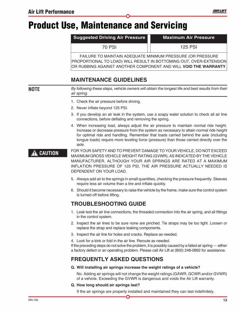
70 PSI 125 PSI
FAILURE TO MAINTAIN ADEQUATE MINIMUM PRESSURE (OR PRESSURE PROPORTIONAL TO LOAD) WILL RESULT IN BOTTOMING OUT, OVER-EXTENSION OR RUBBING AGAINST ANOTHER COMPONENT AND WILL VOID THE WARRANTY.
Maximum Air PressureSuggested Driving Air Pressure
14 MN-766
Air Lift Performance
Q . Will raising the vehicle on a hoist for service work damage the air springs? No. The vehicle can be lifted on a hoist for short-term service work such as tire rotation
or oil changes. However, if the vehicle will be on the hoist for a prolonged period of time, support the axle with jack stands in order to take the tension off of the air springs.
TUNING THE AIR PRESSUREPressure determination comes down to three things — level vehicle, ride comfort, and stability.
1 . Level vehicle If the vehicle’s headlights are shining into the trees or the vehicle is leaning to one side,
then it is not level. Raise the air pressure to correct either of these problems and level the vehicle.
2 . Ride comfort If the vehicle has a rough or harsh ride it may be due to either too much pressure or not
enough. Try different pressures to determine the best ride comfort. See Air Lift suggested driving air pressure.
3 . Stability Stability translates into safety and should be the priority, meaning the driver may need
to sacrifice a perfectly level and comfortable ride. Stability issues include roll control, bounce, dive during braking and sponginess. Tuning out these problems usually requires additional air pressure, strut damping, or both.
CHECKING FOR LEAKS1. Inflate the air spring to 80 PSI.
2. Spray all connections and the inflation valves with a solution of 1/5 liquid dish soap and 4/5 water. Spot leaks easily by looking for bubbles in the soapy water.
3. After the test, deflate the springs to the minimum pressure required to restore the system to normal ride height.
4. Check the air pressure again after 24 hours. A 2 - 4 PSI loss after initial installation is normal. Retest for leaks if the loss is more than 5 lbs.
FIXING LEAKS1. If there is a problem with a swivel fitting:
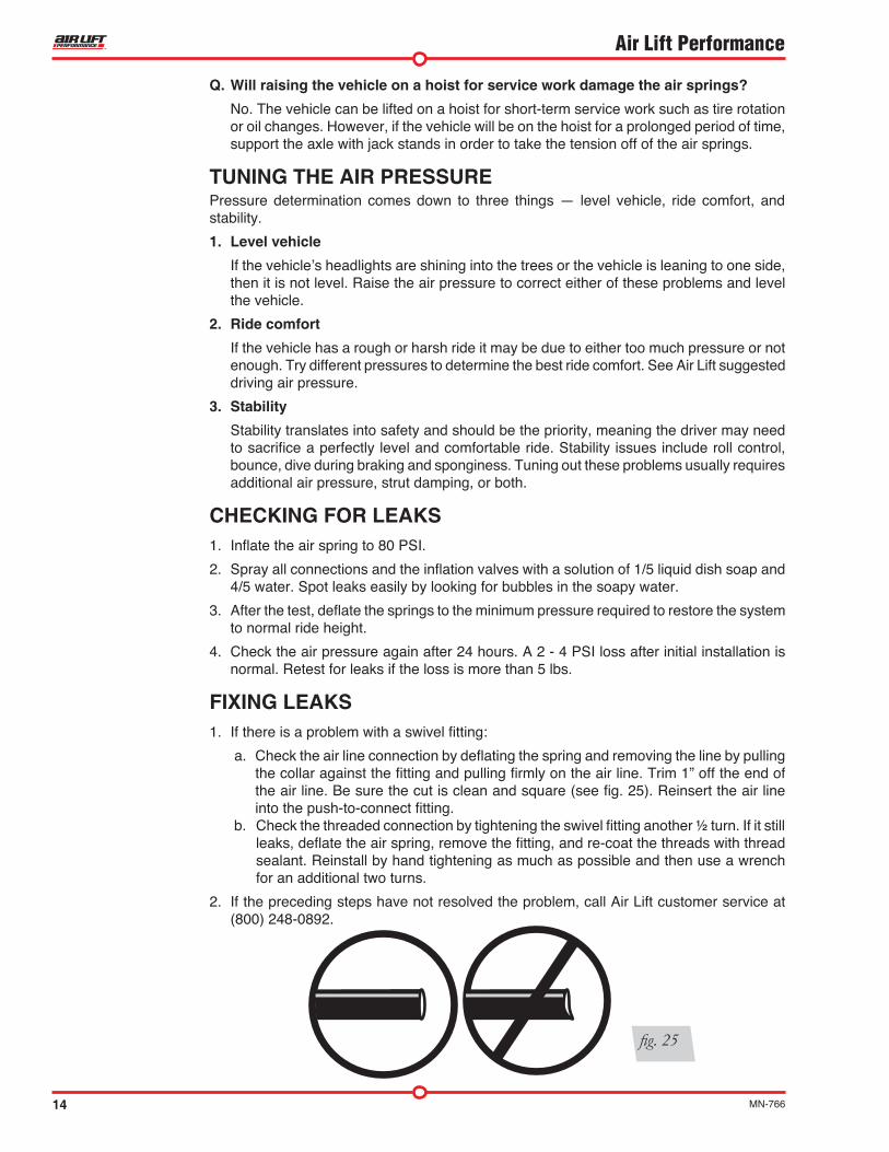
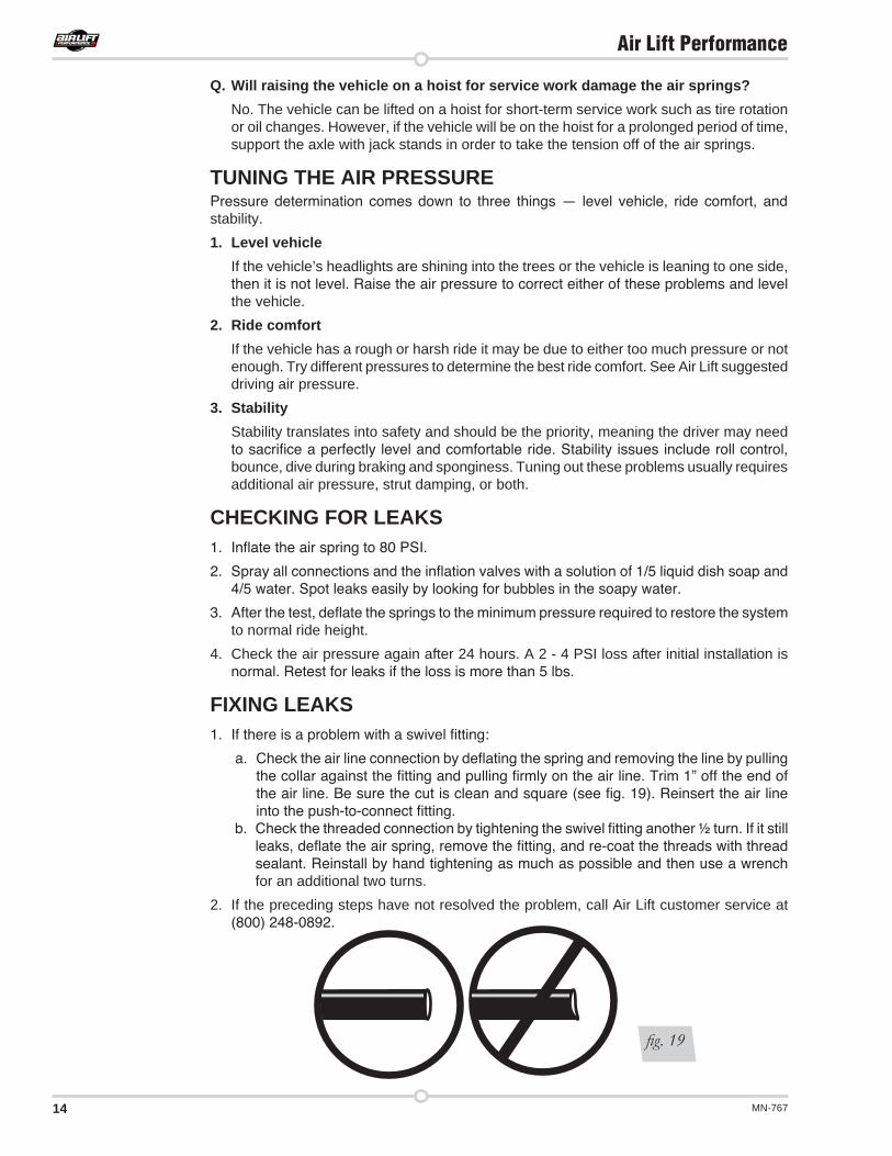
a. Check the air line connection by deflating the spring and removing the line by pulling the collar against the fitting and pulling firmly on the air line. Trim 1” off the end of the air line. Be sure the cut is clean and square (see fig. 25). Reinsert the air line into the push-to-connect fitting.
b. Check the threaded connection by tightening the swivel fitting another ½ turn. If it still leaks, deflate the air spring, remove the fitting, and re-coat the threads with thread sealant. Reinstall by hand tightening as much as possible and then use a wrench for an additional two turns.
2. If the preceding steps have not resolved the problem, call Air Lift customer service at (800) 248-0892.
fig. 25
15MN-766
Air Lift Performance
Contact InformationIf you have any questions, comments or need technical assistance contact our customer service department by calling (800) 248-0892, Monday through Friday, 8 a.m. to 7 p.m. Eastern Time. For calls from outside the USA or Canada, our local number is (517) 322-2144. You may also contact customer service anytime by e-mail at [email protected] inquiries by mail, our address is PO Box 80167, Lansing, MI 48908-0167. Our shipping address for returns is 2727 Snow Road, Lansing, MI 48917. You may also contact our sales team anytime by e-mail at [email protected] or on the web at www.airliftperformance.com.
Replacement InformationIf you need replacement parts, contact the local dealer or call Air Lift customer service at (800) 248-0892. Most parts are immediately available and can be shipped the same day.
Contact Air Lift Company customer service at (800) 248-0892 first if:
Air Lift Company warrants its performance products for one year to the original purchaser against manufacturing defects one year from the date of purchase when used on cars and trucks as specified under normal operating conditions. The warranty does not apply to products that have been improperly applied, improperly installed, or which have not been maintained in accordance with installation instructions furnished with all products. The consumer will be responsible for removing (labor charges) the defective product from the vehicle and returning it, transportation costs prepaid, to the dealer from which it was purchased or to Air Lift Company for verification. Air Lift will repair or replace, at its option, defective products or components. A minimum $10.00 shipping and handling charge will apply to all warranty claims. Before returning any defective product, you must call Air Lift at (800) 248-0892 in the U.S. and Canada (elsewhere, (517) 322-2144) for a Returned Materials Authorization (RMA) number. Returns to Air Lift can be sent to: Air Lift Company • 2727 Snow Road • Lansing, MI • 48917. Product failures resulting from abnormal use or misuse are excluded from this warranty. The loss of use of the product, loss of time, inconvenience, commercial loss or consequential damages is not covered. The consumer is responsible for installation/reinstallation (labor charges) of the product. Air Lift Company reserves the right to change the design of any product without assuming any obligation to modify any product previously manufactured. This warranty gives you specific legal rights and you may also have other rights that may vary from state-to-state. Some states do not allow limitations on how long an implied warranty lasts or allow the exclusion or limitation of incidental or consequential damages. The above limitation or exclusion may not apply to you. There are no warranties, expressed or implied including any implied warranties of merchantability and fitness, which extend beyond this warranty period. There are no warranties that extend beyond the description on the face hereof. Seller disclaims the implied warranty of merchantability. (Dated proof of purchase required.)
Warranty and Returns Policy
• Parts are missing from the kit.• Need technical assistance on installation or
operation.
• Broken or defective parts in the kit.• Wrong parts in the kit.• Have a warranty claim or question.
Contact the retailer where the kit was purchased:
• If it is necessary to return or exchange the kit for any reason.• If there is a problem with shipping if shipped from the retailer.• If there is a problem with the price.
16 MN-766
Air Lift Performance
Notes
17MN-766
Air Lift Performance
Notes
Need Help?Contact our customer service department by calling (800) 248-0892. For calls from outside the USA or Canada, our local number is (517) 322-2144.
Air Lift Performance • 2727 Snow Road • Lansing, MI 48917 or PO Box 80167 • Lansing, MI 48908-0167 Toll Free (800) 248-0892 • Local (517) 322-2144 • Fax (517) 322-0240 • www.airliftperformance.com
Thank you for purchasing Air Lift Performance products!
Printed in the USA
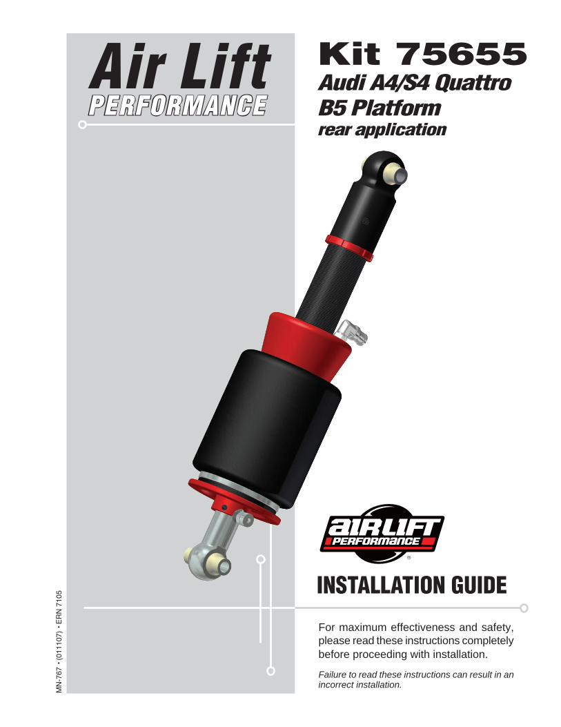
For maximum effectiveness and safety, please read these instructions completely before proceeding with installation.
Failure to read these instructions can result in an incorrect installation.
MN
-767
• (
0111
07)
• E
RN
710
5 INSTALLATION GUIDE
Kit 75655Audi A4/S4 QuattroB5 Platformrear application
Air Lift PERFORMANCE

1MN-767
Air Lift Performance
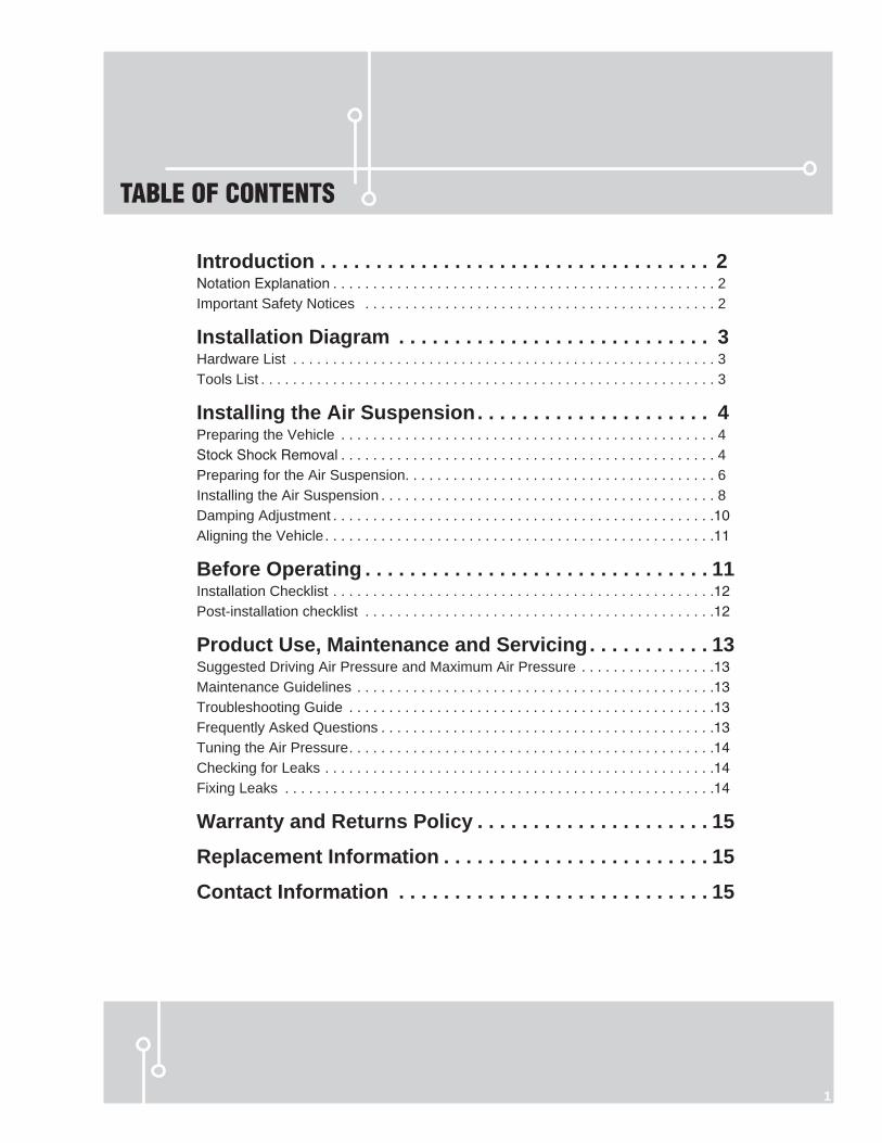
TABLE OF CONTENTS
1
Introduction . . . . . . . . . . . . . . . . . . . . . . . . . . . . . . . . . . . 2Notation Explanation . . . . . . . . . . . . . . . . . . . . . . . . . . . . . . . . . . . . . . . . . . . . . . . . 2 Important Safety Notices . . . . . . . . . . . . . . . . . . . . . . . . . . . . . . . . . . . . . . . . . . . . 2
Installation Diagram . . . . . . . . . . . . . . . . . . . . . . . . . . . . 3Hardware List . . . . . . . . . . . . . . . . . . . . . . . . . . . . . . . . . . . . . . . . . . . . . . . . . . . . . 3Tools List . . . . . . . . . . . . . . . . . . . . . . . . . . . . . . . . . . . . . . . . . . . . . . . . . . . . . . . . . 3
Installing the Air Suspension . . . . . . . . . . . . . . . . . . . . . 4Preparing the Vehicle . . . . . . . . . . . . . . . . . . . . . . . . . . . . . . . . . . . . . . . . . . . . . . . 4Stock Shock Removal . . . . . . . . . . . . . . . . . . . . . . . . . . . . . . . . . . . . . . . . . . . . . . . 4Preparing for the Air Suspension. . . . . . . . . . . . . . . . . . . . . . . . . . . . . . . . . . . . . . . 6Installing the Air Suspension . . . . . . . . . . . . . . . . . . . . . . . . . . . . . . . . . . . . . . . . . . 8Damping Adjustment . . . . . . . . . . . . . . . . . . . . . . . . . . . . . . . . . . . . . . . . . . . . . . . .10Aligning the Vehicle . . . . . . . . . . . . . . . . . . . . . . . . . . . . . . . . . . . . . . . . . . . . . . . . .11
Before Operating . . . . . . . . . . . . . . . . . . . . . . . . . . . . . . . 11Installation Checklist . . . . . . . . . . . . . . . . . . . . . . . . . . . . . . . . . . . . . . . . . . . . . . . .12Post-installation checklist . . . . . . . . . . . . . . . . . . . . . . . . . . . . . . . . . . . . . . . . . . . .12
Product Use, Maintenance and Servicing . . . . . . . . . . . 13Suggested Driving Air Pressure and Maximum Air Pressure . . . . . . . . . . . . . . . . .13Maintenance Guidelines . . . . . . . . . . . . . . . . . . . . . . . . . . . . . . . . . . . . . . . . . . . . .13Troubleshooting Guide . . . . . . . . . . . . . . . . . . . . . . . . . . . . . . . . . . . . . . . . . . . . . .13Frequently Asked Questions . . . . . . . . . . . . . . . . . . . . . . . . . . . . . . . . . . . . . . . . . .13Tuning the Air Pressure . . . . . . . . . . . . . . . . . . . . . . . . . . . . . . . . . . . . . . . . . . . . . .14Checking for Leaks . . . . . . . . . . . . . . . . . . . . . . . . . . . . . . . . . . . . . . . . . . . . . . . . .14Fixing Leaks . . . . . . . . . . . . . . . . . . . . . . . . . . . . . . . . . . . . . . . . . . . . . . . . . . . . . .14
Warranty and Returns Policy . . . . . . . . . . . . . . . . . . . . . 15
Replacement Information . . . . . . . . . . . . . . . . . . . . . . . . 15
Contact Information . . . . . . . . . . . . . . . . . . . . . . . . . . . . 15
2 MN-767
Air Lift Performance
IntroductionThe purpose of this publication is to assist with the installation, maintenance and troubleshooting of this Audi performance kit.
It is important to read and understand the entire installation guide before beginning installation or performing any maintenance, service or repair. The information includes a hardware list, tool list, step-by-step installation information, maintenance tips, safety information and a troubleshooting guide.
Air Lift Company reserves the right to make changes and improvements to its products and publications at any time. For the latest version of this manual, contact Air Lift Company at (800) 248-0892 or visit our website at www.airliftcompany.com.
NOTATION EXPLANATIONHazard notations appear in various locations in this publication. Information which is highlighted by one of these notations must be observed to help minimize risk of personal injury or possible improper installation which may render the vehicle unsafe. Notes are used to help emphasize areas of procedural importance and provide helpful suggestions. The following definitions explain the use of these notations as they appear throughout this guide.
INDICATES IMMEDIATE HAZARDS WHICH WILL RESULT IN SEVERE PERSONAL INJURY OR DEATH.
INDICATES HAZARDS OR UNSAFE PRACTICES WHICH COULD RESULT IN SEVERE PERSONAL INJURY OR DEATH.
INDICATES HAZARDS OR UNSAFE PRACTICES WHICH COULD RESULT IN DAMAGE TO THE MACHINE OR MINOR PERSONAL INJURY.
Indicates a procedure, practice or hint which is important to highlight.
IMPORTANT SAFETY NOTICESThe installation of this kit does not alter the Gross Vehicle Weight Rating (GVWR) or payload of the vehicle. Check your vehicle’s owner’s manual and do not exceed the maximum load listed for your vehicle.
Gross Vehicle Weight Rating: The maximum allowable weight of the fully loaded vehicle (including passengers and cargo). This number — along with other weight limits, as well as tire, rim size and inflation pressure data — is shown on the vehicle’s Safety Compliance Certification Label.
Payload: The combined, maximum allowable weight of cargo and passengers that the vehicle is designed to carry. Payload is GVWR minus the Base Curb Weight.
DO NOT INFLATE AIR SPRINGS WHILE OFF OF THE VEHICLE. DAMAGE TO ASSEMBLY MAY RESULT AND VOID WARRANTY.
DO NOT WELD TO, OR MODIFY LIFESTYLE STRUTS/SHOCKS IN ANY WAY. DAMAGE TO UNIT MAY OCCUR AND WILL VOID WARRANTY.
DANGER
NOTE
WARNING
CAUTION
WARNING
CAUTION
3MN-767
Air Lift Performance
B or C
A
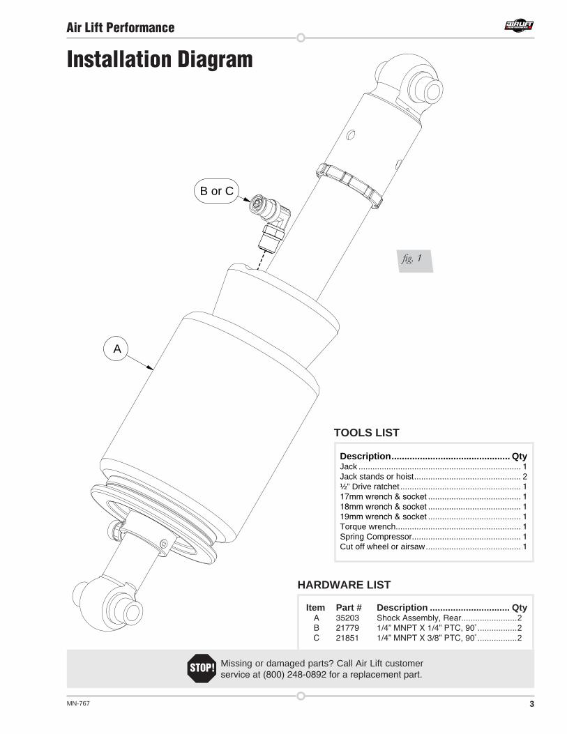
Installation Diagram
TOOLS LIST
Description . . . . . . . . . . . . . . . . . . . . . . . . . . . . . . . . . . . . . . . . . . . . . . QtyJack ...................................................................... 1Jack stands or hoist .............................................. 2½” Drive ratchet .................................................... 117mm wrench & socket ........................................ 118mm wrench & socket ........................................ 119mm wrench & socket ........................................ 1Torque wrench...................................................... 1Spring Compressor............................................... 1Cut off wheel or airsaw ......................................... 1
Item Part # Description . . . . . . . . . . . . . . . . . . . . . . . . . . . . . . . Qty A 35203 Shock Assembly, Rear ........................2 B 21779 1/4” MNPT X 1/4” PTC, 90˚ .................2 C 21851 1/4” MNPT X 3/8” PTC, 90˚ .................2
HARDWARE LIST
Missing or damaged parts? Call Air Lift customer service at (800) 248-0892 for a replacement part.
STOP!
fig. 1
4 MN-767
Air Lift Performance
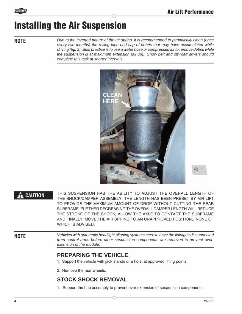
Due to the inverted nature of the air spring, it is recommended to periodically clean (once every two months) the rolling lobe end cap of debris that may have accumulated while driving (fig. 2). Best practice is to use a water hose or compressed air to remove debris while the suspension is at maximum extension (all up). Snow belt and off-road drivers should complete this task at shorter intervals.
THIS SUSPENSION HAS THE ABILITY TO ADJUST THE OVERALL LENGTH OF THE SHOCK/DAMPER ASSEMBLY. THE LENGTH HAS BEEN PRESET BY AIR LIFT TO PROVIDE THE MAXIMUM AMOUNT OF DROP WITHOUT CUTTING THE REAR SUBFRAME. FURTHER DECREASING THE OVERALL DAMPER LENGTH WILL REDUCE THE STROKE OF THE SHOCK, ALLOW THE AXLE TO CONTACT THE SUBFRAME AND FINALLY, MOVE THE AIR SPRING TO AN UNAPPROVED POSITION…NONE OF WHICH IS ADVISED.
Vehicles with automatic headlight aligning systems need to have the linkages disconnected from control arms before other suspension components are removed to prevent over-extension of the module.
PREPARING THE VEHICLE1. Support the vehicle with jack stands or a hoist at approved lifting points.
2. Remove the rear wheels.
STOCK SHOCK REMOVAL1. Support the hub assembly to prevent over extension of suspension components
Installing the Air SuspensionNOTE
CAUTION
NOTE
fig. 2
CLEAN HERE
5MN-767
Air Lift Performance
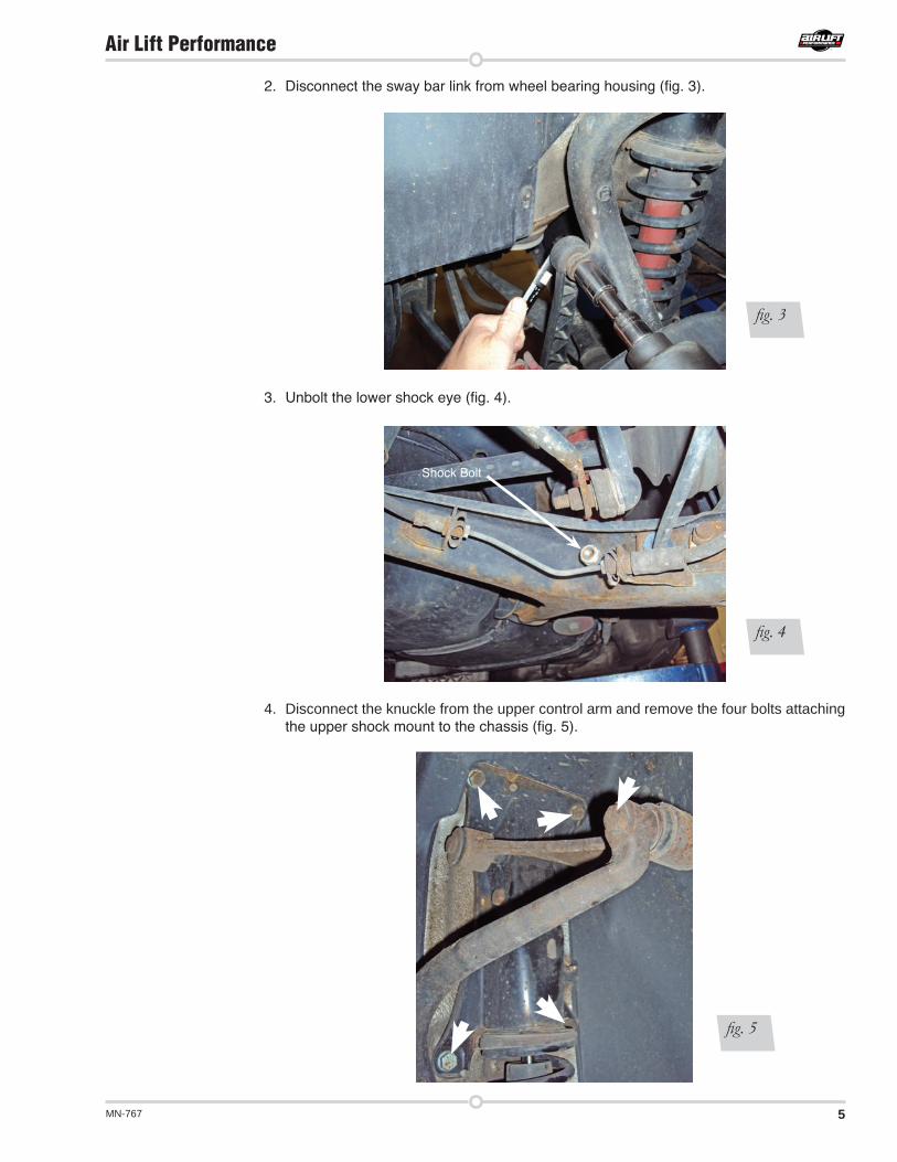
2. Disconnect the sway bar link from wheel bearing housing (fig. 3).
3. Unbolt the lower shock eye (fig. 4).
4. Disconnect the knuckle from the upper control arm and remove the four bolts attaching the upper shock mount to the chassis (fig. 5).
fig. 4
fig. 3
fig. 5
Shock Bolt
6 MN-767
Air Lift Performance
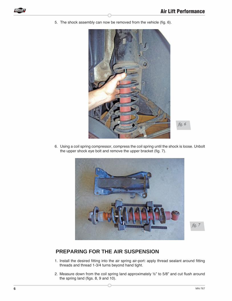
5. The shock assembly can now be removed from the vehicle (fig. 6).
6. Using a coil spring compressor, compress the coil spring until the shock is loose. Unbolt the upper shock eye bolt and remove the upper bracket (fig. 7).
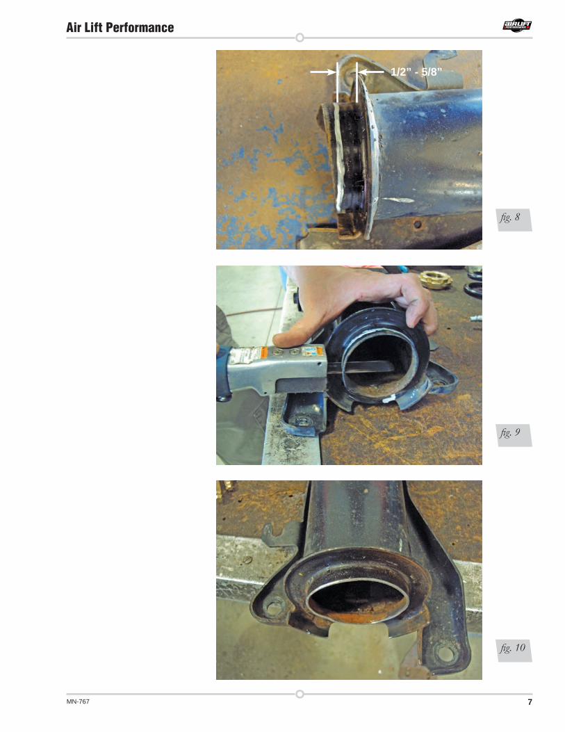
PREPARING FOR THE AIR SUSPENSION1. Install the desired fitting into the air spring air-port: apply thread sealant around fitting
threads and thread 1-3/4 turns beyond hand tight. 2. Measure down from the coil spring land approximately ½” to 5/8” and cut flush around
the spring land (figs. 8, 9 and 10).
fig. 6
fig. 7
7MN-767
Air Lift Performance
fig. 8
fig. 9
fig. 10
1/2” - 5/8”
8 MN-767
Air Lift Performance
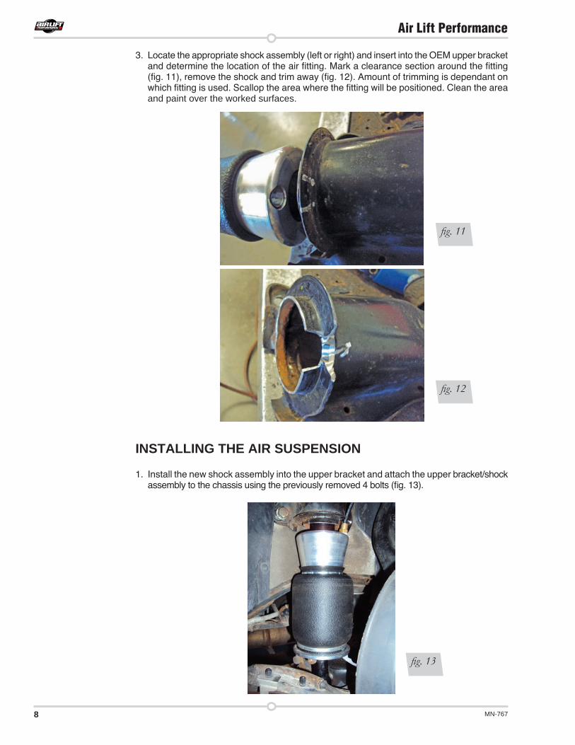
3. Locate the appropriate shock assembly (left or right) and insert into the OEM upper bracket and determine the location of the air fitting. Mark a clearance section around the fitting (fig. 11), remove the shock and trim away (fig. 12). Amount of trimming is dependant on which fitting is used. Scallop the area where the fitting will be positioned. Clean the area and paint over the worked surfaces.
INSTALLING THE AIR SUSPENSION
1. Install the new shock assembly into the upper bracket and attach the upper bracket/shock assembly to the chassis using the previously removed 4 bolts (fig. 13).
fig. 11
fig. 12
fig. 13
9MN-767
Air Lift Performance
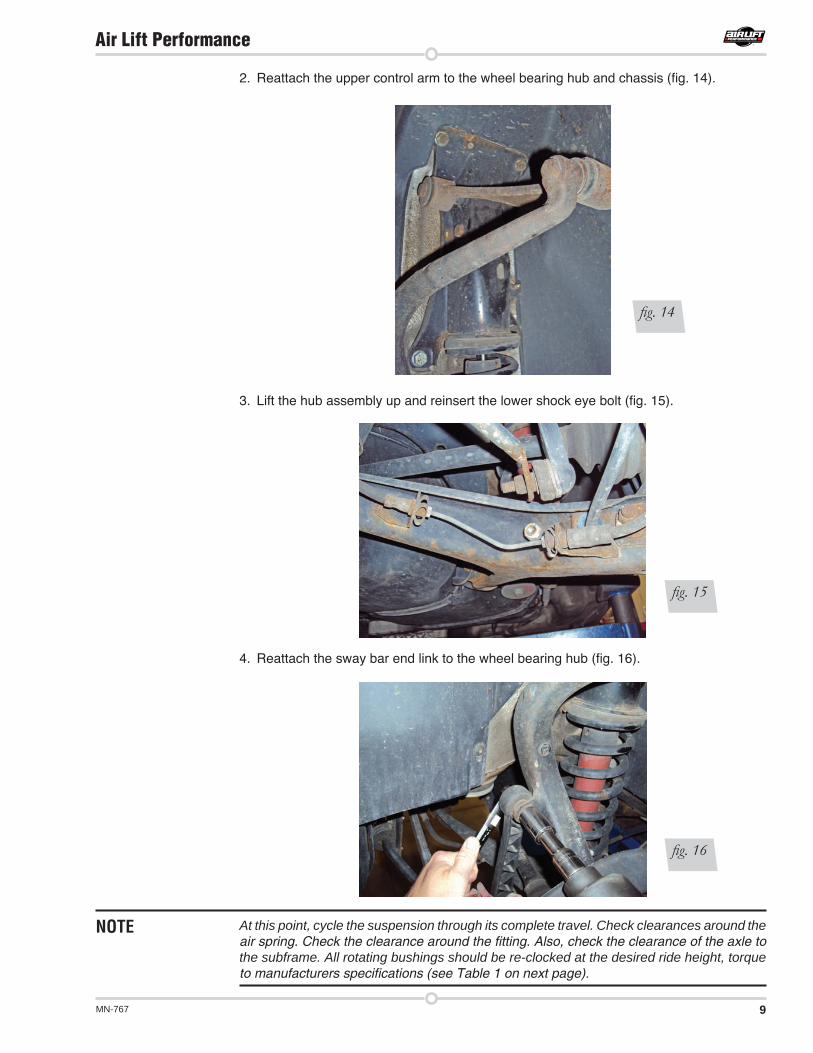
2. Reattach the upper control arm to the wheel bearing hub and chassis (fig. 14).
3. Lift the hub assembly up and reinsert the lower shock eye bolt (fig. 15).
4. Reattach the sway bar end link to the wheel bearing hub (fig. 16).
At this point, cycle the suspension through its complete travel. Check clearances around the air spring. Check the clearance around the fitting. Also, check the clearance of the axle to the subframe. All rotating bushings should be re-clocked at the desired ride height, torque to manufacturers specifications (see Table 1 on next page).
fig. 14
fig. 15
fig. 16
NOTE
10 MN-767
Air Lift Performance
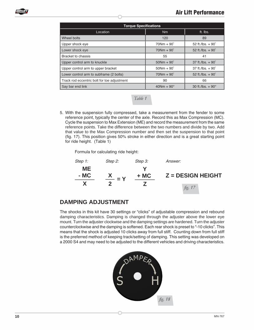
5. With the suspension fully compressed, take a measurement from the fender to some reference point, typically the center of the axle. Record this as Max Compression (MC). Cycle the suspension to Max Extension (ME) and record the measurement from the same reference points. Take the difference between the two numbers and divide by two. Add that value to the Max Compression number and then set the suspension to that point (fig. 17). This position gives 50% stroke in either direction and is a great starting point for ride height. (Table 1)
Formula for calculating ride height:
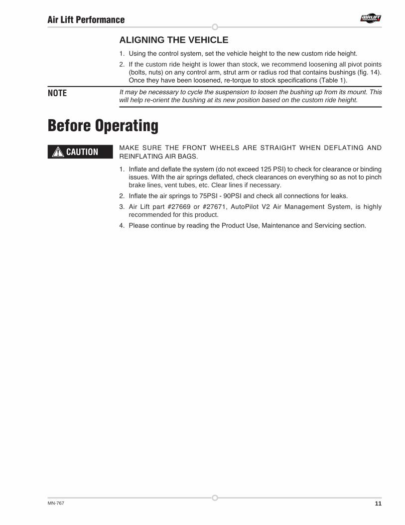
DAMPING ADJUSTMENT The shocks in this kit have 30 settings or “clicks” of adjustable compression and rebound damping characteristics. Damping is changed through the adjuster above the lower eye mount. Turn the adjuster clockwise and the damping settings are hardened. Turn the adjuster counterclockwise and the damping is softened. Each rear shock is preset to “-10 clicks”. This means that the shock is adjusted 10 clicks away from full stiff. Counting down from full stiff is the preferred method of keeping track/setting of damping. This setting was developed on a 2000 S4 and may need to be adjusted to the different vehicles and driving characteristics.
Torque Specifications
Location Nm ft. lbs.
Wheel bolts 120 89
Upper shock eye 70Nm + 90˚ 52 ft./lbs. + 90˚
Lower shock eye 70Nm + 90˚ 52 ft./lbs. + 90˚
Bracket to chassis 55 41
Upper control arm to knuckle 50Nm + 90˚ 37 ft./lbs. + 90˚
Upper control arm to upper bracket 50Nm + 90˚ 37 ft./lbs. + 90˚
Lower control arm to subframe (2 bolts) 70Nm + 90˚ 52 ft./lbs. + 90˚
Track rod eccentric bolt for toe adjustment 90 66
Say bar end link 40Nm + 90° 30 ft./lbs. + 90°
ME- MC
XX = Y 2
fig. 17
Step 1:
+ MCZ
YZ = DESIGN HEIGHT
Step 3: Answer:Step 2:
Table 1
fig. 18
11MN-767
Air Lift Performance
NOTE
MAKE SURE THE FRONT WHEELS ARE STRAIGHT WHEN DEFLATING AND REINFLATING AIR BAGS.
1. Inflate and deflate the system (do not exceed 125 PSI) to check for clearance or binding issues. With the air springs deflated, check clearances on everything so as not to pinch brake lines, vent tubes, etc. Clear lines if necessary.
2. Inflate the air springs to 75PSI - 90PSI and check all connections for leaks.
3. Air Lift part #27669 or #27671, AutoPilot V2 Air Management System, is highly recommended for this product.
4. Please continue by reading the Product Use, Maintenance and Servicing section.
CAUTION
Before Operating
ALIGNING THE VEHICLE1. Using the control system, set the vehicle height to the new custom ride height.
2. If the custom ride height is lower than stock, we recommend loosening all pivot points (bolts, nuts) on any control arm, strut arm or radius rod that contains bushings (fig. 14). Once they have been loosened, re-torque to stock specifications (Table 1).
It may be necessary to cycle the suspension to loosen the bushing up from its mount. This will help re-orient the bushing at its new position based on the custom ride height.
12 MN-767
Air Lift Performance
Technician’s Signature _________________________________
Date _________________
Clearance test — Inflate the air springs to 75-90 PSI and make sure there is at least ½” clearance from anything that might rub against each sleeve. Be sure to check the tire, brake drum, frame, shock absorbers and brake cables.
Leak test before road test — Inflate the air springs to 75PSI - 90PSI and check all connections for leaks. All leaks must be eliminated before the vehicle is road tested.
Heat test — Be sure there is sufficient clearance from heat sources, at least 6” for air springs and air lines. If a heat shield was included in the kit, install it. If there is no heat shield, but one is required, call Air Lift customer service at (800) 248-0892.
Fastener test — Recheck all bolts for proper torque.
Road test — The vehicle should be road tested after the preceding tests. Inflate the springs to recommended driving pressures. Drive the vehicle 10 miles and recheck for clearance, loose fasteners and air leaks.
Operating instructions — If professionally installed, the installer should review the operating instructions with the owner. Be sure to provide the owner with all of the paperwork that came with the kit.
INSTALLATION CHECKLIST
Overnight leak down test — Recheck air pressure after the vehicle has been used for 24 hours. If the pressure has dropped more than 5 PSI, then there is a leak that must be fixed. Either fix the leak yourself or return to the installer for service.
Air pressure requirements — I understand the air pressure requirements of my air spring system. Regardless of load, the air pressure should always be adjusted to maintain adequate ride height at all times while driving.
Thirty day or 500 mile test — I understand that I must recheck the air spring system after 30 days or 500 miles, whichever comes first. If any part shows signs of rubbing or abrasion, the source should be identified and moved, if possible. If it is not possible to relocate the cause of the abrasion, the air spring may need to be remounted. If professionally installed, the installer should be consulted. Check all fasteners for tightness.
POST-INSTALLATION CHECKLIST
13MN-767
Air Lift Performance
MAINTENANCE GUIDELINESBy following these steps, vehicle owners will obtain the longest life and best results from their air spring.
1. Check the air pressure before driving.
2. Never inflate beyond 125 PSI.
3. If you develop an air leak in the system, use a soapy water solution to check all air line connections, before deflating and removing the spring.
4. When increasing load, always adjust the air pressure to maintain normal ride height. Increase or decrease pressure from the system as necessary to attain normal ride height for optimal ride and handling. Remember that loads carried behind the axle (including tongue loads) require more leveling force (pressure) than those carried directly over the axle.
FOR YOUR SAFETY AND TO PREVENT DAMAGE TO YOUR VEHICLE, DO NOT EXCEED MAXIMUM GROSS VEHICLE WEIGHT RATING (GVWR), AS INDICATED BY THE VEHICLE MANUFACTURER. ALTHOUGH YOUR AIR SPRINGS ARE RATED AT A MAXIMUM INFLATION PRESSURE OF 125 PSI, THE AIR PRESSURE ACTUALLY NEEDED IS DEPENDENT ON YOUR LOAD.
5. Always add air to the springs in small quantities, checking the pressure frequently. Sleeves require less air volume than a tire and inflate quickly.
6. Should it become necessary to raise the vehicle by the frame, make sure the control system is turned off before lifting.
TROUBLESHOOTING GUIDE1. Leak test the air line connections, the threaded connection into the air spring, and all fittings
in the control system.
2. Inspect the air lines to be sure none are pinched. Tie straps may be too tight. Loosen or replace the strap and replace leaking components.
3. Inspect the air line for holes and cracks. Replace as needed.
4. Look for a kink or fold in the air line. Reroute as needed.If the preceding steps do not solve the problem, it is possibly caused by a failed air spring — either a factory defect or an operating problem. Please call Air Lift at (800) 248-0892 for assistance.
FREQUENTLY ASKED QUESTIONSQ . Will installing air springs increase the weight ratings of a vehicle? No. Adding air springs will not change the weight ratings (GAWR, GCWR and/or GVWR)
of a vehicle. Exceeding the GVWR is dangerous and voids the Air Lift warranty.
Q . How long should air springs last? If the air springs are properly installed and maintained they can last indefinitely.
NOTE
CAUTION
Product Use, Maintenance and Servicing
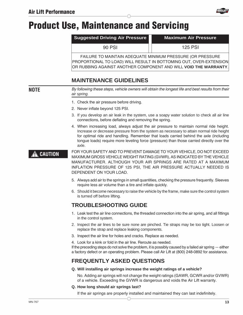
90 PSI 125 PSI
FAILURE TO MAINTAIN ADEQUATE MINIMUM PRESSURE (OR PRESSURE PROPORTIONAL TO LOAD) WILL RESULT IN BOTTOMING OUT, OVER-EXTENSION OR RUBBING AGAINST ANOTHER COMPONENT AND WILL VOID THE WARRANTY.
Maximum Air PressureSuggested Driving Air Pressure
14 MN-767
Air Lift Performance
Q . Will raising the vehicle on a hoist for service work damage the air springs? No. The vehicle can be lifted on a hoist for short-term service work such as tire rotation
or oil changes. However, if the vehicle will be on the hoist for a prolonged period of time, support the axle with jack stands in order to take the tension off of the air springs.
TUNING THE AIR PRESSUREPressure determination comes down to three things — level vehicle, ride comfort, and stability.
1 . Level vehicle If the vehicle’s headlights are shining into the trees or the vehicle is leaning to one side,
then it is not level. Raise the air pressure to correct either of these problems and level the vehicle.
2 . Ride comfort If the vehicle has a rough or harsh ride it may be due to either too much pressure or not
enough. Try different pressures to determine the best ride comfort. See Air Lift suggested driving air pressure.
3 . Stability Stability translates into safety and should be the priority, meaning the driver may need
to sacrifice a perfectly level and comfortable ride. Stability issues include roll control, bounce, dive during braking and sponginess. Tuning out these problems usually requires additional air pressure, strut damping, or both.
CHECKING FOR LEAKS1. Inflate the air spring to 80 PSI.
2. Spray all connections and the inflation valves with a solution of 1/5 liquid dish soap and 4/5 water. Spot leaks easily by looking for bubbles in the soapy water.
3. After the test, deflate the springs to the minimum pressure required to restore the system to normal ride height.
4. Check the air pressure again after 24 hours. A 2 - 4 PSI loss after initial installation is normal. Retest for leaks if the loss is more than 5 lbs.
FIXING LEAKS1. If there is a problem with a swivel fitting:
a. Check the air line connection by deflating the spring and removing the line by pulling the collar against the fitting and pulling firmly on the air line. Trim 1” off the end of the air line. Be sure the cut is clean and square (see fig. 19). Reinsert the air line into the push-to-connect fitting.
b. Check the threaded connection by tightening the swivel fitting another ½ turn. If it still leaks, deflate the air spring, remove the fitting, and re-coat the threads with thread sealant. Reinstall by hand tightening as much as possible and then use a wrench for an additional two turns.
2. If the preceding steps have not resolved the problem, call Air Lift customer service at (800) 248-0892.
fig. 19
15MN-767
Air Lift Performance
Contact InformationIf you have any questions, comments or need technical assistance contact our customer service department by calling (800) 248-0892, Monday through Friday, 8 a.m. to 7 p.m. Eastern Time. For calls from outside the USA or Canada, our local number is (517) 322-2144. You may also contact customer service anytime by e-mail at [email protected] inquiries by mail, our address is PO Box 80167, Lansing, MI 48908-0167. Our shipping address for returns is 2727 Snow Road, Lansing, MI 48917. You may also contact our sales team anytime by e-mail at [email protected] or on the web at www.airliftperformance.com.
Replacement InformationIf you need replacement parts, contact the local dealer or call Air Lift customer service at (800) 248-0892. Most parts are immediately available and can be shipped the same day.
Contact Air Lift Company customer service at (800) 248-0892 first if:
Air Lift Company warrants its performance products for one year to the original purchaser against manufacturing defects one year from the date of purchase when used on cars and trucks as specified under normal operating conditions. The warranty does not apply to products that have been improperly applied, improperly installed, or which have not been maintained in accordance with installation instructions furnished with all products. The consumer will be responsible for removing (labor charges) the defective product from the vehicle and returning it, transportation costs prepaid, to the dealer from which it was purchased or to Air Lift Company for verification. Air Lift will repair or replace, at its option, defective products or components. A minimum $10.00 shipping and handling charge will apply to all warranty claims. Before returning any defective product, you must call Air Lift at (800) 248-0892 in the U.S. and Canada (elsewhere, (517) 322-2144) for a Returned Materials Authorization (RMA) number. Returns to Air Lift can be sent to: Air Lift Company • 2727 Snow Road • Lansing, MI • 48917. Product failures resulting from abnormal use or misuse are excluded from this warranty. The loss of use of the product, loss of time, inconvenience, commercial loss or consequential damages is not covered. The consumer is responsible for installation/reinstallation (labor charges) of the product. Air Lift Company reserves the right to change the design of any product without assuming any obligation to modify any product previously manufactured. This warranty gives you specific legal rights and you may also have other rights that may vary from state-to-state. Some states do not allow limitations on how long an implied warranty lasts or allow the exclusion or limitation of incidental or consequential damages. The above limitation or exclusion may not apply to you. There are no warranties, expressed or implied including any implied warranties of merchantability and fitness, which extend beyond this warranty period. There are no warranties that extend beyond the description on the face hereof. Seller disclaims the implied warranty of merchantability. (Dated proof of purchase required.)
Warranty and Returns Policy
• Parts are missing from the kit.• Need technical assistance on installation or
operation.
• Broken or defective parts in the kit.• Wrong parts in the kit.• Have a warranty claim or question.
Contact the retailer where the kit was purchased:
• If it is necessary to return or exchange the kit for any reason.• If there is a problem with shipping if shipped from the retailer.• If there is a problem with the price.
16 MN-767
Air Lift Performance
NOTES
17MN-767
Air Lift Performance
NOTES
Air Lift Company • 2727 Snow Road • Lansing, MI 48917 or PO Box 80167 • Lansing, MI 48908-0167 Toll Free (800) 248-0892 • Local (517) 322-2144 • Fax (517) 322-0240 • www.airliftperformance.com
Thank you for purchasing Air Lift Performance products!
Printed in the USA
Need Help?Contact our customer service department by calling (800) 248-0892, Monday through Friday, 8 a.m. to 7 p.m. Eastern Time. For calls from outside the USA or Canada, our local number is (517) 322-2144.
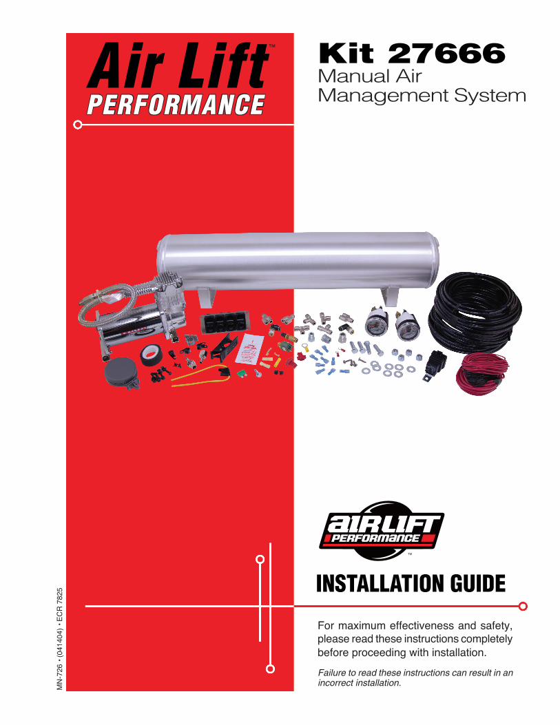
™ Kit 27666Manual Air Management System
For maximum effectiveness and safety, please read these instructions completely before proceeding with installation.
Failure to read these instructions can result in an incorrect installation.
INSTALLATION GUIDE
Air Lift PERFORMANCE
MN
-726
• (
0414
04)
• E
CR
782
5

1MN-726
Air Lift Performance
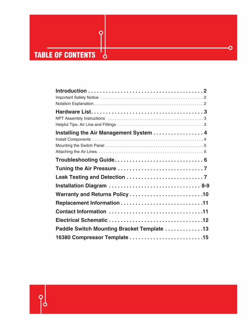
TABLE OF CONTENTS
Introduction . . . . . . . . . . . . . . . . . . . . . . . . . . . . . . . . . . . . . . . 2Important Safety Notice . . . . . . . . . . . . . . . . . . . . . . . . . . . . . . . . . . . . . . . . . . . . . 2Notation Explanation . . . . . . . . . . . . . . . . . . . . . . . . . . . . . . . . . . . . . . . . . . . . . . . . 2
Hardware List . . . . . . . . . . . . . . . . . . . . . . . . . . . . . . . . . . . . . . 3NPT Assembly Instructions . . . . . . . . . . . . . . . . . . . . . . . . . . . . . . . . . . . . . . . . . . 3Helpful Tips: Air Line and Fittings . . . . . . . . . . . . . . . . . . . . . . . . . . . . . . . . . . . . . . 3
Installing the Air Management System . . . . . . . . . . . . . . . . . 4Install Components . . . . . . . . . . . . . . . . . . . . . . . . . . . . . . . . . . . . . . . . . . . . . . . . . 4Mounting the Switch Panel . . . . . . . . . . . . . . . . . . . . . . . . . . . . . . . . . . . . . . . . . . . 5Attaching the Air Lines. . . . . . . . . . . . . . . . . . . . . . . . . . . . . . . . . . . . . . . . . . . . . . . 5
Troubleshooting Guide . . . . . . . . . . . . . . . . . . . . . . . . . . . . . . 6Tuning the Air Pressure . . . . . . . . . . . . . . . . . . . . . . . . . . . . . 7Leak Testing and Detection . . . . . . . . . . . . . . . . . . . . . . . . . . 7Installation Diagram . . . . . . . . . . . . . . . . . . . . . . . . . . . . . . . 8-9Warranty and Returns Policy . . . . . . . . . . . . . . . . . . . . . . . . .10Replacement Information . . . . . . . . . . . . . . . . . . . . . . . . . . . .11Contact Information . . . . . . . . . . . . . . . . . . . . . . . . . . . . . . . .11Electrical Schematic . . . . . . . . . . . . . . . . . . . . . . . . . . . . . . . .12Paddle Switch Mounting Bracket Template . . . . . . . . . . . . .1316380 Compressor Template . . . . . . . . . . . . . . . . . . . . . . . . .15
2 MN-726
Air Lift Performance
IntroductionThe purpose of this publication is to assist with the installation, maintenance and troubleshooting of the Air Management System.
It is important to read and understand the entire installation guide before beginning installation or performing any maintenance, service or repair. The information here includes a hardware list, tool list, step-by-step installation information, maintenance guidelines and troubleshooting guide.
Air Lift Company reserves the right to make changes and improvements to its products and publications at any time. For the latest version of this manual, contact Air Lift Company at (800) 248-0892 or visit our website at www.airliftcompany.com.
IMPORTANT SAFETY NOTICEThe installation of this kit does not alter the Gross Vehicle Weight Rating (GVWR) or payload of the vehicle. Check your vehicle’s owner’s manual and do not exceed the maximum load listed for your vehicle.
Gross Vehicle Weight Rating: The maximum allowable weight of the fully loaded vehicle (including passengers and cargo). This number — along with other weight limits, as well as tire, rim size and inflation pressure data — is shown on the vehicle’s Safety Compliance Certification Label.
Payload: The combined, maximum allowable weight of cargo and passengers that the vehicle is designed to carry. Payload is GVWR minus the Base Curb Weight.
NOTATION EXPLANATIONHazard notations appear in various locations in this publication. Information which is highlighted by one of these notations must be observed to help minimize risk of personal injury or possible improper installation which may render the vehicle unsafe. Notes are used to help emphasize areas of procedural importance and provide helpful suggestions. The following definitions explain the use of these notations as they appear throughout this guide.
INDICATES IMMEDIATE HAZARDS WHICH WILL RESULT IN SEVERE PERSONAL INJURY OR DEATH.
INDICATES HAZARDS OR UNSAFE PRACTICES WHICH COULD RESULT IN SEVERE PERSONAL INJURY OR DEATH.
INDICATES HAZARDS OR UNSAFE PRACTICES WHICH COULD RESULT IN DAMAGE TO THE MACHINE OR MINOR PERSONAL INJURY.
Indicates a procedure, practice or hint which is important to highlight.
DANGER
NOTE
WARNING
CAUTION
3MN-726
Air Lift Performance
Missing or damaged parts? Call Air Lift customer service at (800) 248-0892 for a replacement part.
STOP!
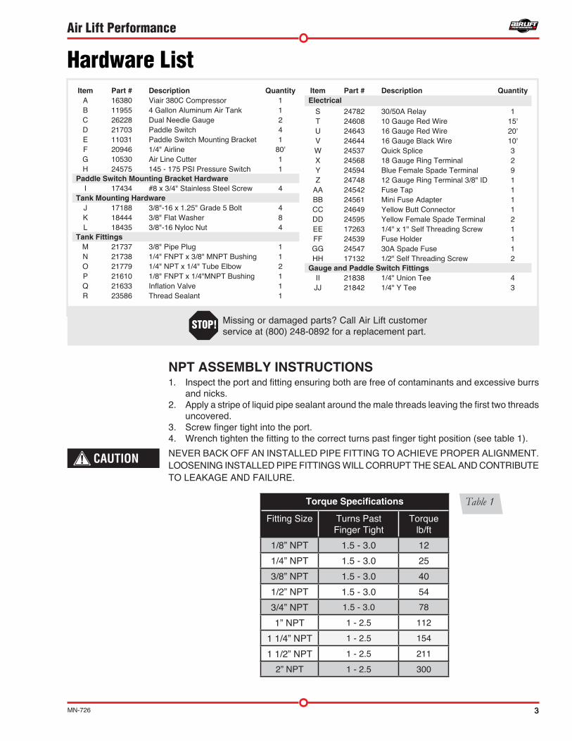
Hardware ListItem Part # Description Quantity
A 16380 Viair 380C Compressor 1B 11955 4 Gallon Aluminum Air Tank 1C 26228 Dual Needle Gauge 2D 21703 Paddle Switch 4E 11031 Paddle Switch Mounting Bracket 1F 20946 1/4" Airline 80'G 10530 Air Line Cutter 1H 24575 145 - 175 PSI Pressure Switch 1
Paddle Switch Mounting Bracket HardwareI 17434 #8 x 3/4" Stainless Steel Screw 4
Tank Mounting HardwareJ 17188 3/8"-16 x 1.25" Grade 5 Bolt 4K 18444 3/8" Flat Washer 8L 18435 3/8"-16 Nyloc Nut 4
Tank FittingsM 21737 3/8" Pipe Plug 1N 21738 1/4" FNPT x 3/8" MNPT Bushing 1O 21779 1/4" NPT x 1/4" Tube Elbow 2P 21610 1/8" FNPT x 1/4"MNPT Bushing 1Q 21633 Inflation Valve 1R 23586 Thread Sealant 1
Item Part # Description QuantityElectrical
S 24782 30/50A Relay 1T 24608 10 Gauge Red Wire 15'U 24643 16 Gauge Red Wire 20'V 24644 16 Gauge Black Wire 10'W 24537 Quick Splice 3X 24568 18 Gauge Ring Terminal 2Y 24594 Blue Female Spade Terminal 9Z 24748 12 Gauge Ring Terminal 3/8" ID 1
AA 24542 Fuse Tap 1BB 24561 Mini Fuse Adapter 1CC 24649 Yellow Butt Connector 1DD 24595 Yellow Female Spade Terminal 2EE 17263 1/4" x 1" Self Threading Screw 1FF 24539 Fuse Holder 1GG 24547 30A Spade Fuse 1HH 17132 1/2" Self Threading Screw 2
Gauge and Paddle Switch FittingsII 21838 1/4" Union Tee 4JJ 21842 1/4" Y Tee 3
NPT ASSEMBLY INSTRUCTIONS1. Inspect the port and fitting ensuring both are free of contaminants and excessive burrs
and nicks.2. Apply a stripe of liquid pipe sealant around the male threads leaving the first two threads
uncovered.3. Screw finger tight into the port.4. Wrench tighten the fitting to the correct turns past finger tight position (see table 1).
NEVER BACK OFF AN INSTALLED PIPE FITTING TO ACHIEVE PROPER ALIGNMENT. LOOSENING INSTALLED PIPE FITTINGS WILL CORRUPT THE SEAL AND CONTRIBUTE TO LEAKAGE AND FAILURE.
CAUTION
Torque Specifications
Fitting Size Turns Past Finger Tight
Torque lb/ft
1/8” NPT 1.5 - 3.0 12
1/4” NPT 1.5 - 3.0 25
3/8” NPT 1.5 - 3.0 40
1/2” NPT 1.5 - 3.0 54
3/4” NPT 1.5 - 3.0 78
1” NPT 1 - 2.5 112
1 1/4” NPT 1 - 2.5 154
1 1/2” NPT 1 - 2.5 211
2” NPT 1 - 2.5 300
Table 1
4 MN-726
Air Lift Performance
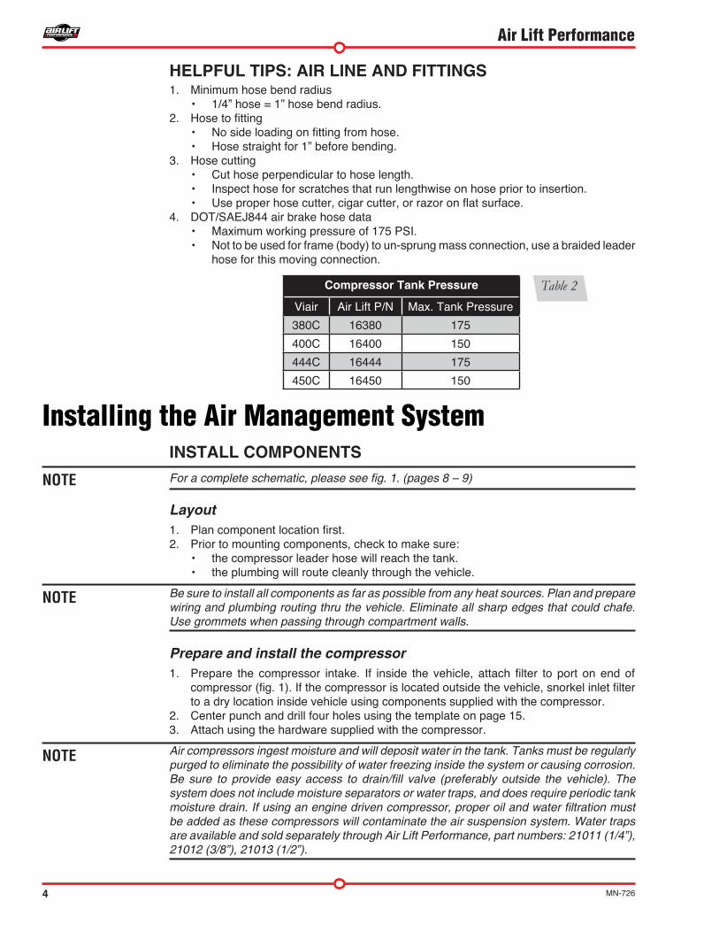
Compressor Tank Pressure
Viair Air Lift P/N Max. Tank Pressure
380C 16380 175
400C 16400 150
444C 16444 175
450C 16450 150
Installing the Air Management SystemINSTALL COMPONENTSFor a complete schematic, please see fig. 1. (pages 8 – 9)
Layout1. Plan component location first. 2. Prior to mounting components, check to make sure:
• the compressor leader hose will reach the tank.• the plumbing will route cleanly through the vehicle.
Be sure to install all components as far as possible from any heat sources. Plan and prepare wiring and plumbing routing thru the vehicle. Eliminate all sharp edges that could chafe. Use grommets when passing through compartment walls.
Prepare and install the compressor1. Prepare the compressor intake. If inside the vehicle, attach filter to port on end of
compressor (fig. 1). If the compressor is located outside the vehicle, snorkel inlet filter to a dry location inside vehicle using components supplied with the compressor.
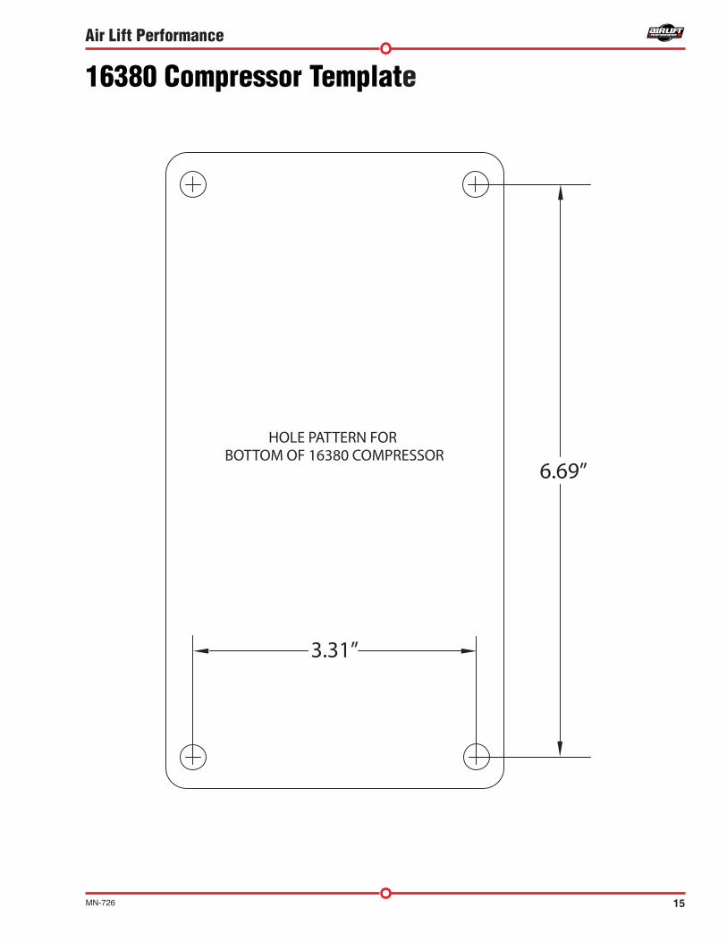
2. Center punch and drill four holes using the template on page 15.3. Attach using the hardware supplied with the compressor.
Air compressors ingest moisture and will deposit water in the tank. Tanks must be regularly purged to eliminate the possibility of water freezing inside the system or causing corrosion. Be sure to provide easy access to drain/fill valve (preferably outside the vehicle). The system does not include moisture separators or water traps, and does require periodic tank moisture drain. If using an engine driven compressor, proper oil and water filtration must be added as these compressors will contaminate the air suspension system. Water traps are available and sold separately through Air Lift Performance, part numbers: 21011 (1/4”), 21012 (3/8”), 21013 (1/2”).
NOTE
NOTE
NOTE
HELPFUL TIPS: AIR LINE AND FITTINGS1. Minimum hose bend radius
• 1/4” hose = 1” hose bend radius.2. Hose to fitting
• No side loading on fitting from hose.• Hose straight for 1” before bending.
3. Hose cutting• Cut hose perpendicular to hose length.• Inspect hose for scratches that run lengthwise on hose prior to insertion.• Use proper hose cutter, cigar cutter, or razor on flat surface.
4. DOT/SAEJ844 air brake hose data• Maximum working pressure of 175 PSI.• Not to be used for frame (body) to un-sprung mass connection, use a braided leader
hose for this moving connection.
Table 2
5MN-726
Air Lift Performance
NOTE
Tank pre-assembly (see fig. 1)
1. Determine tank location and orientation prior to installing fittings.2. Apply thread sealant as necessary to all fittings.3. Install the drain/fill PTC fitting in the lower most tank threaded port.4. Choose a tank threaded port for the compressor fitting.5. Choose the highest tank threaded port for air line supply. 6. Plug any remaining tank ports with hex plugs.
Tank install (see fig. 1)
1. Using the tank feet as a template, drill holes for hardware assembly.2. Attach the tank using the supplied hardware.3. Cut an appropriate length of hose from the manifold port T, to the PTC fitting on the tank.4. Route the drain/fill air line with a schrader valve (preferably outside the vehicle).
When cutting plastic air line, only use a standard hose cutter like (Air Lift part number 10530) or razorblade. Cut all hose ends square and as smoothly as possible. See hose cutting tips on page 4.
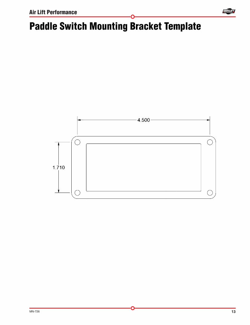
MOUNTING THE SWITCH PANELRefer to the switch panel template on page 13.
1. Find a location to mount the paddle switch mounting bracket (E).2. Snap all four paddle switches (D) into the paddle switch mounting bracket (E) so the
DEL is toward the top.
You may select different locations for the paddle switches. The paddle switches do not need to be used with the supplied paddle switch mounting bracket.
3. Cut six pieces of air line (F) the same length (approximately 3”-6”).4. Push four of these pieces onto the “SUP” port of the switch. Attach two Y fittings (JJ)
to the air lines.5. Push the other two pieces of line into the Y fittings (JJ).6. Attach the last Y fitting (JJ) to the air lines.7. Mount the paddle switch mounting bracket (E) with four screws (I).
ATTACHING THE AIR LINESWHEN CUTTING OR TRIMMING THE AIR LINE, USE AN AIR LINE CUTTER (G), A RAZOR BLADE OR A SHARP KNIFE. A CLEAN, SQUARE CUT WILL ENSURE AGAINST LEAKS. DO NOT USE WIRE CUTTERS OR SCISSORS TO CUT THE AIR LINE. THESE TOOLS MAY FLATTEN OR CRIMP THE AIR LINE, CAUSING IT TO LEAK.1. Run a length of air line (F) from the air fitting on the compressor to the end of the switch
cluster.2. Run a length of air line from the remaining air fittings on the switch to its respective air
spring.3. Repeat step 2 for the remaining air fittings and air springs.4. Use a tee and connect into each one of the air spring lines to connect to it’s respective
gauge port.5. Test and make sure that the switches operate the appropriate air springs.
NOTE
CAUTION
6 MN-726
Air Lift Performance
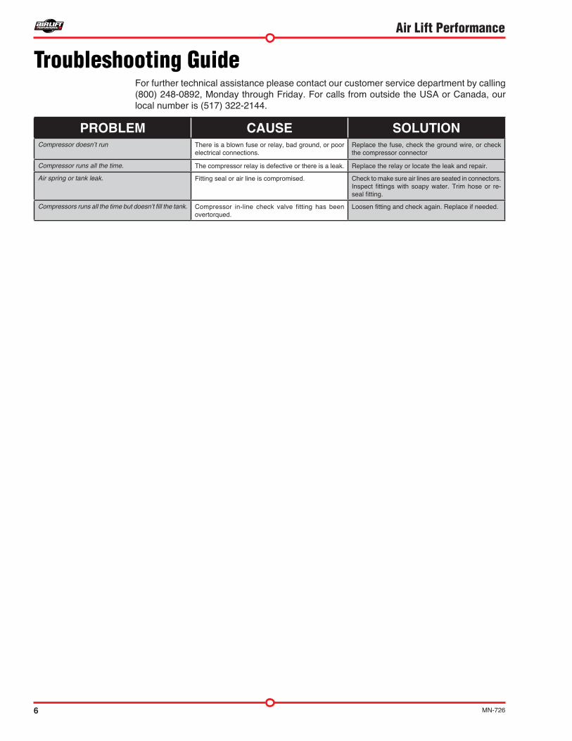
Troubleshooting GuideFor further technical assistance please contact our customer service department by calling (800) 248-0892, Monday through Friday. For calls from outside the USA or Canada, our local number is (517) 322-2144.
PROBLEM CAUSE SOLUTIONCompressor doesn’t run There is a blown fuse or relay, bad ground, or poor
electrical connections.Replace the fuse, check the ground wire, or check the compressor connector
Compressor runs all the time. The compressor relay is defective or there is a leak. Replace the relay or locate the leak and repair.
Air spring or tank leak. Fitting seal or air line is compromised. Check to make sure air lines are seated in connectors. Inspect fittings with soapy water. Trim hose or re-seal fitting.
Compressors runs all the time but doesn’t fill the tank. Compressor in-line check valve fitting has been overtorqued.
Loosen fitting and check again. Replace if needed.
7MN-726
Air Lift Performance
Pressure determination comes down to three things — level vehicle, ride comfort, and stability.
1 . Level vehicle If the vehicle’s headlights are shining into the trees or the vehicle is leaning to one side,
then it is not level. Raise the air pressure to correct either of these problems and level the vehicle.
2 . Ride comfort If the vehicle has a rough or harsh ride it may be due to either too much pressure or
not enough. Try different pressures to determine the best ride comfort.
3 . Stability Stability translates into safety and should be the priority, meaning the driver may need
to sacrifice a perfectly level and comfortable ride. Stability issues include roll control, bounce, dive during braking and sponginess. Tuning out these problems usually requires an increase in pressure.
Tuning the Air Pressure
Leak Testing and DetectionLeak detection1. A leak can be defined as a loss of pressure of more than 5 psi over an 8 hour period.
Be aware that ambient temperature change has an effect on pressure that may seem like a leak. For example: a change of 10˚ Fahrenheit up or down from your baseline will have an approximate gain or loss of indicated pressure of 2 psi. If a leak is suspected after including any temperature change, then proceed to #2.
2. Spray soapy water (1/5 Dawn brand dish soap to 4/5 water) on suspect fittings and hose connections and look for any bubbling caused by air leakage.
3. Fix leaking connection (review pages 3 and 4 for help on NPT fittings and air line connections).
4. Wipe down sprayed connections with rag to remove any residual soapy water.
Dawn brand dish soap will not corrode the metals (aluminum, brass, steel) with which it comes into contact.
NOTE

8 MN-726
Air Lift Performance
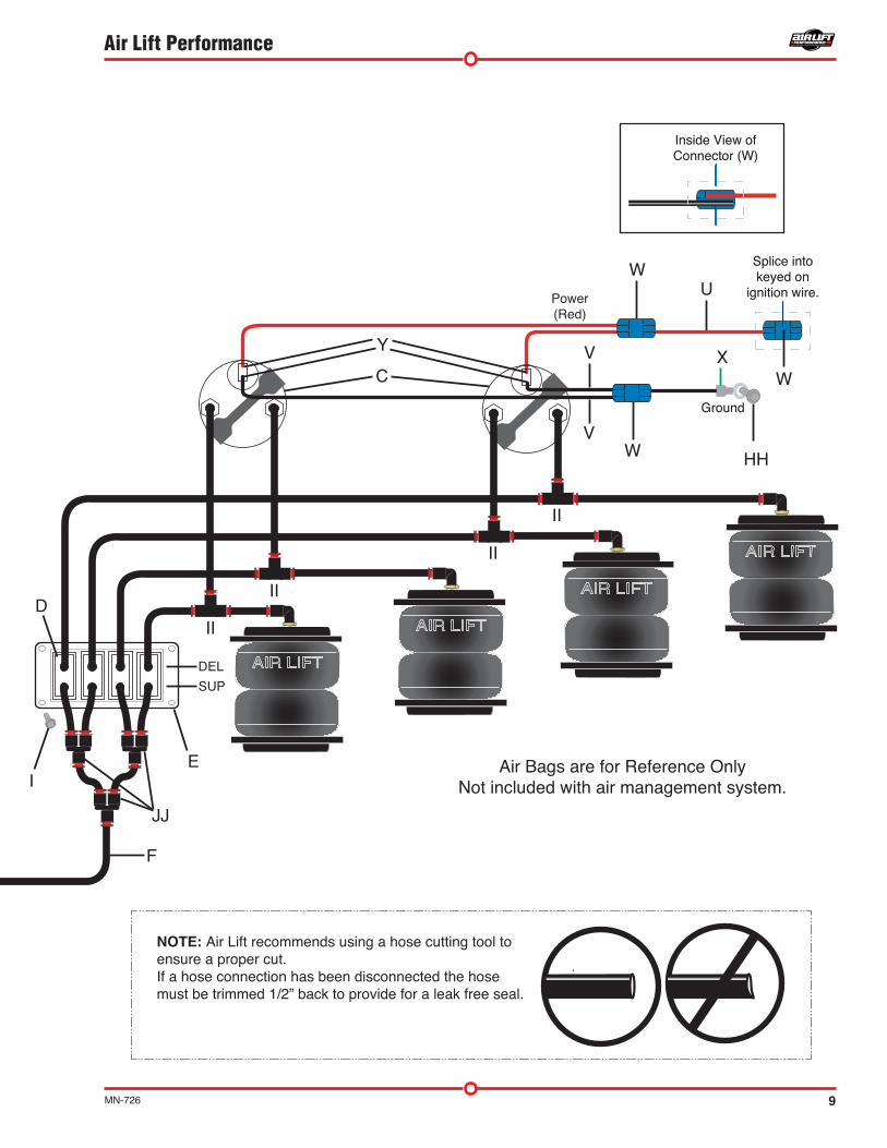
fig. 1
Installation DiagramInside View ofConnector (W)Inside View ofConnector (W)
Air Bags are for Reference OnlyNot included with air management system.
W
Power(Red)
Splice intokeyed on
ignition wire.
Splice intokeyed on
ignition wire.U
HH
GroundGround
DEL
SUP
E
JJ
II
II
II
II
VC
Y
V
D
I
W
W
X
F
A
HH
X
U30 AMP30 AMP
Existing Fuse
CC CCFF
AA or BBGGDD
Attach filter
GroundGround
N
L
J
KJ
L
K
O
F
M
DD
H OPB
Q
W
Refer to electrical schematic on page 12.
NOTE: Air Lift recommends using a hose cutting tool to ensure a proper cut.If a hose connection has been disconnected the hose must be trimmed 1/2” back to provide for a leak free seal.
GroundGround
Splice intokeyed onignition wire.
Splice intokeyed onignition wire.
Connect to battery
9MN-726
Air Lift Performance
Inside View ofConnector (W)Inside View ofConnector (W)
Air Bags are for Reference OnlyNot included with air management system.
W
Power(Red)
Splice intokeyed on
ignition wire.
Splice intokeyed on
ignition wire.U
HH
GroundGround
DEL
SUP
E
JJ
II
II
II
II
VC
Y
V
D
I
W
W
X
F
A
HH
X
U30 AMP30 AMP
Existing Fuse
CC CCFF
AA or BBGGDD
Attach filter
GroundGround
N
L
J
KJ
L
K
O
F
M
DD
H OPB
Q
W
Refer to electrical schematic on page 12.
NOTE: Air Lift recommends using a hose cutting tool to ensure a proper cut.If a hose connection has been disconnected the hose must be trimmed 1/2” back to provide for a leak free seal.
GroundGround
Splice intokeyed onignition wire.
Splice intokeyed onignition wire.
Connect to battery
.
10 MN-726
Air Lift Performance
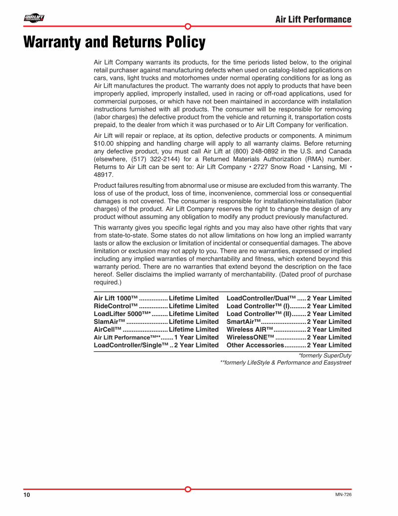
Air Lift Company warrants its products, for the time periods listed below, to the original retail purchaser against manufacturing defects when used on catalog-listed applications on cars, vans, light trucks and motorhomes under normal operating conditions for as long as Air Lift manufactures the product. The warranty does not apply to products that have been improperly applied, improperly installed, used in racing or off-road applications, used for commercial purposes, or which have not been maintained in accordance with installation instructions furnished with all products. The consumer will be responsible for removing (labor charges) the defective product from the vehicle and returning it, transportation costs prepaid, to the dealer from which it was purchased or to Air Lift Company for verification.
Air Lift will repair or replace, at its option, defective products or components. A minimum $10.00 shipping and handling charge will apply to all warranty claims. Before returning any defective product, you must call Air Lift at (800) 248-0892 in the U.S. and Canada (elsewhere, (517) 322-2144) for a Returned Materials Authorization (RMA) number. Returns to Air Lift can be sent to: Air Lift Company • 2727 Snow Road • Lansing, MI • 48917.
Product failures resulting from abnormal use or misuse are excluded from this warranty. The loss of use of the product, loss of time, inconvenience, commercial loss or consequential damages is not covered. The consumer is responsible for installation/reinstallation (labor charges) of the product. Air Lift Company reserves the right to change the design of any product without assuming any obligation to modify any product previously manufactured.
This warranty gives you specific legal rights and you may also have other rights that vary from state-to-state. Some states do not allow limitations on how long an implied warranty lasts or allow the exclusion or limitation of incidental or consequential damages. The above limitation or exclusion may not apply to you. There are no warranties, expressed or implied including any implied warranties of merchantability and fitness, which extend beyond this warranty period. There are no warranties that extend beyond the description on the face hereof. Seller disclaims the implied warranty of merchantability. (Dated proof of purchase required.)
Warranty and Returns Policy
Air Lift 1000™ . . . . . . . . . . . . . . . . Lifetime LimitedRideControl™ . . . . . . . . . . . . . . . . Lifetime LimitedLoadLifter 5000™* . . . . . . . . . Lifetime Limited SlamAir™ . . . . . . . . . . . . . . . . . . . . . . . Lifetime LimitedAirCell™ . . . . . . . . . . . . . . . . . . . . . . . . . Lifetime LimitedAir Lift Performance™** . . . . . . . 1 Year LimitedLoadController/Single™ . . 2 Year Limited
LoadController/Dual™ . . . . . 2 Year LimitedLoad Controller™ (I) . . . . . . . . . 2 Year LimitedLoad Controller™ (II) . . . . . . . . 2 Year LimitedSmartAir™ . . . . . . . . . . . . . . . . . . . . . . . . . 2 Year LimitedWireless AIR™ . . . . . . . . . . . . . . . . . . 2 Year LimitedWirelessONE™ . . . . . . . . . . . . . . . . . 2 Year Limited Other Accessories . . . . . . . . . . . . 2 Year Limited
*formerly SuperDuty**formerly LifeStyle & Performance and Easystreet
11MN-726
Air Lift Performance
Replacement InformationIf you need replacement parts, contact the local dealer or call Air Lift customer service at(800) 248-0892. Most parts are immediately available and can be shipped the same day.
Contact Air Lift Company customer service at (800) 248-0892 first if:• Parts are missing from the kit.• Need technical assistance on installation or operation.• Broken or defective parts in the kit.• Wrong parts in the kit.• Have a warranty claim or question.
Contact the retailer where the kit was purchased:• If it is necessary to return or exchange the kit for any reason.• If there is a problem with shipping if shipped from the retailer.• If there is a problem with the price.
Contact InformationIf you have any questions, comments or need technical assistance contact our customer service department by calling (800) 248-0892, Monday through Friday. For calls from outside the USA or Canada, our local number is (517) 322-2144.
For inquiries by mail, our address is PO Box 80167, Lansing, MI 48908-0167. Our shipping address for returns is 2727 Snow Road, Lansing, MI 48917.
You may also contact us anytime by e-mail at [email protected] or on the web at www.airliftcompany.com.
12 MN-726
Air Lift Performance
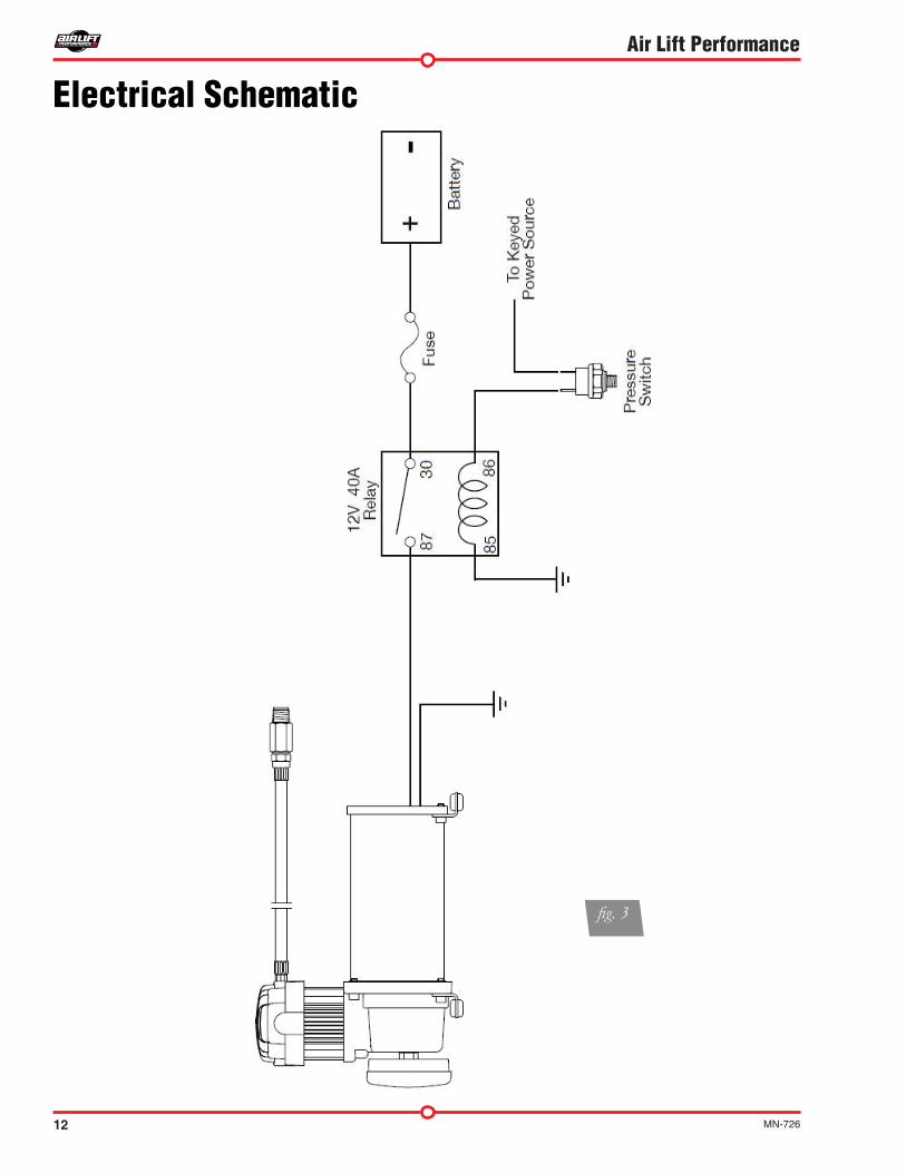
Electrical Schematic
fig. 3
13MN-726
Air Lift Performance
Paddle Switch Mounting Bracket Template

15MN-726
Air Lift Performance
6.69”
3.31”
HOLE PATTERN FOR BOTTOM OF 16380 COMPRESSOR
16380 Compressor Template


Need Help?Contact our customer service department by calling (800) 248-0892, Monday through Friday. For calls from outside the USA or Canada, our local number is (517) 322-2144.
Air Lift Performance • 2727 Snow Road • Lansing, MI 48917 or PO Box 80167 • Lansing, MI 48908-0167 Toll Free (800) 248-0892 • Local (517) 322-2144 • Fax (517) 322-0240 • www.airliftperformance.com
Thank you for purchasing Air Lift Performance products!
Printed in the USA