Embed Size (px)
Citation preview
Let’s get started: Image formation
• How are objects in the world captured in an image?
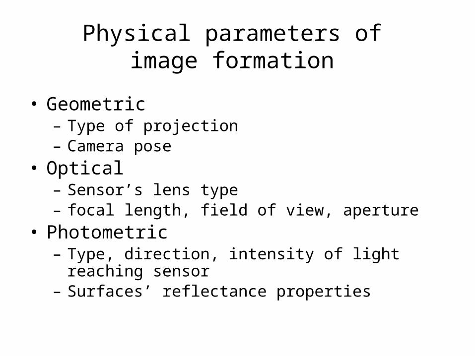
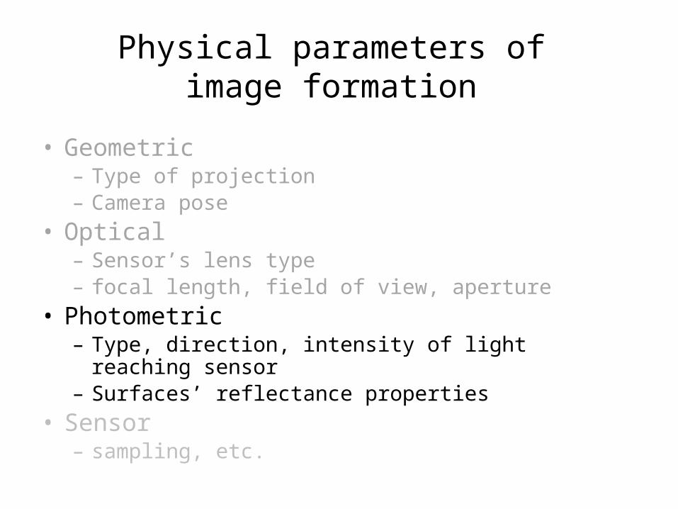
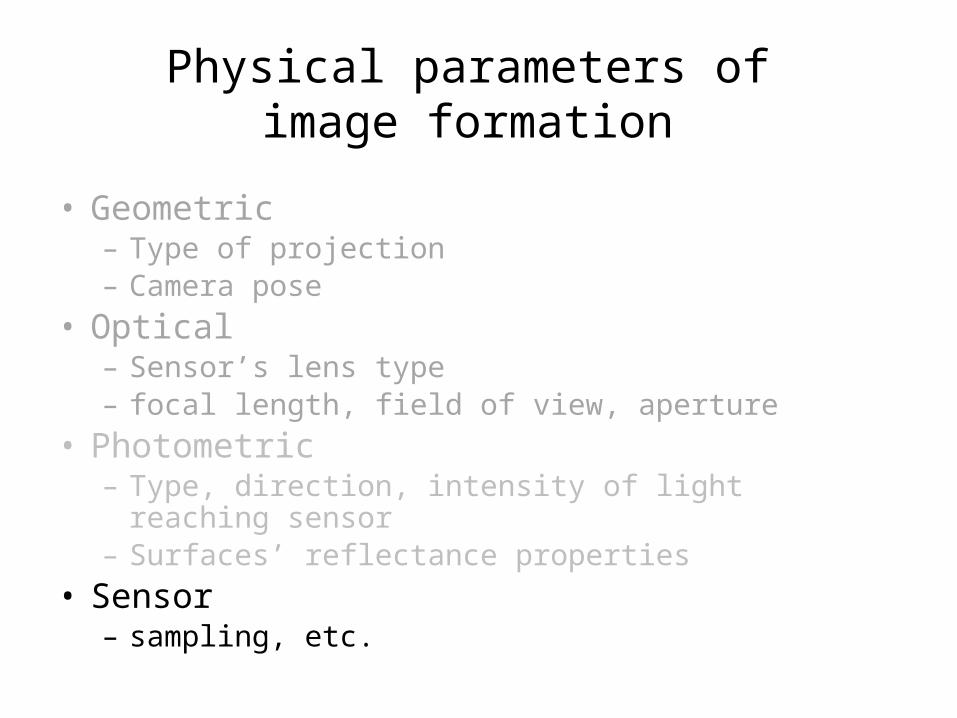
Physical parameters of image formation
• Geometric– Type of projection– Camera pose
• Optical– Sensor’s lens type– focal length, field of view, aperture
• Photometric– Type, direction, intensity of light reaching sensor– Surfaces’ reflectance properties
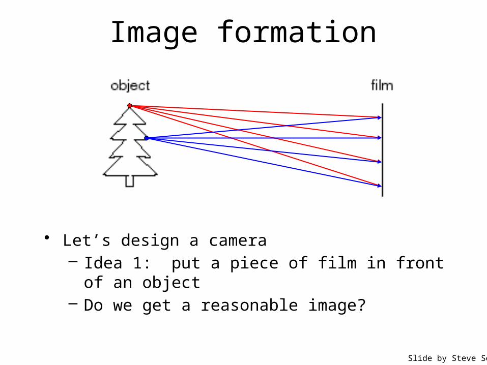
Image formation
• Let’s design a camera– Idea 1: put a piece of film in front of an object– Do we get a reasonable image?
Slide by Steve Seitz
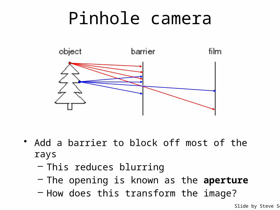
Pinhole camera
Slide by Steve Seitz
• Add a barrier to block off most of the rays– This reduces blurring– The opening is known as the aperture– How does this transform the image?
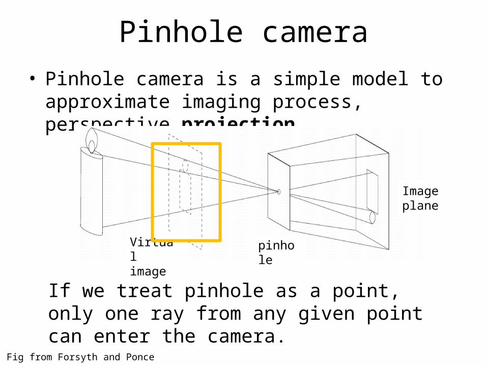
Pinhole camera• Pinhole camera is a simple model to approximate
imaging process, perspective projection.
Fig from Forsyth and Ponce
If we treat pinhole as a point, only one ray from any given point can enter the camera.
Virtual image
pinhole
Image plane
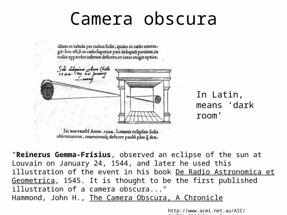
Camera obscura
"Reinerus Gemma-Frisius, observed an eclipse of the sun at Louvain on January 24, 1544, and later he used this illustration of the event in his book De Radio Astronomica et Geometrica, 1545. It is thought to be the first published illustration of a camera obscura..." Hammond, John H., The Camera Obscura, A Chronicle
http://www.acmi.net.au/AIC/CAMERA_OBSCURA.html
In Latin, means ‘dark room’
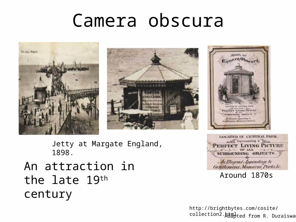
Camera obscura
Jetty at Margate England, 1898.
Adapted from R. Duraiswami
http://brightbytes.com/cosite/collection2.html
Around 1870sAn attraction in the late 19th century
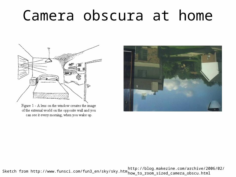
Camera obscura at home
Sketch from http://www.funsci.com/fun3_en/sky/sky.htmhttp://blog.makezine.com/archive/2006/02/how_to_room_sized_camera_obscu.html
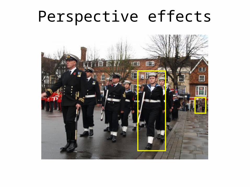
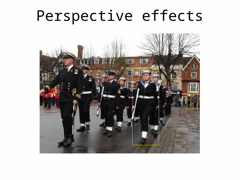
Perspective effects
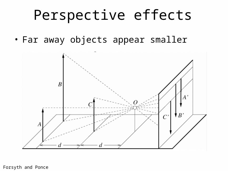
Perspective effects
• Far away objects appear smaller
Forsyth and Ponce
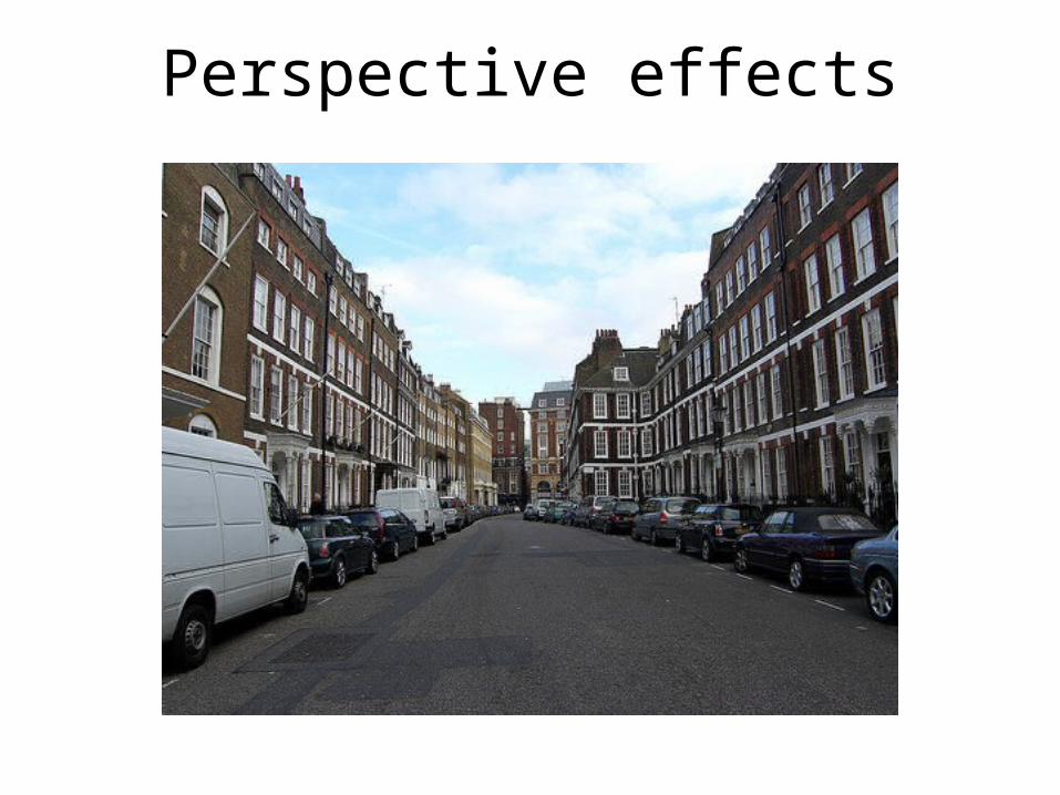
Perspective effects
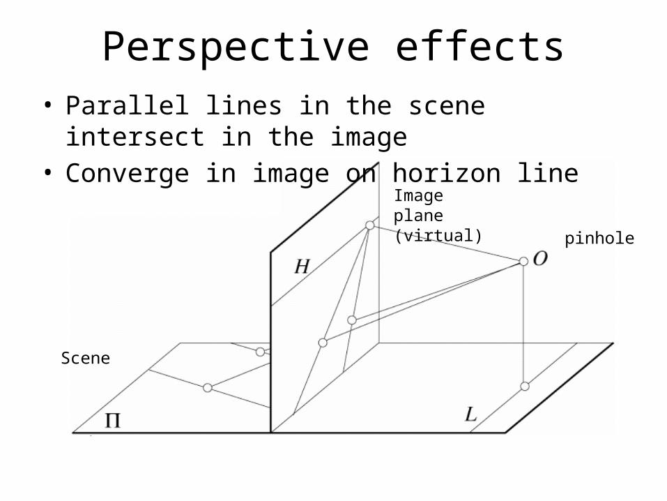
Perspective effects• Parallel lines in the scene intersect in the image• Converge in image on horizon line
Image plane(virtual)
Scene
pinhole
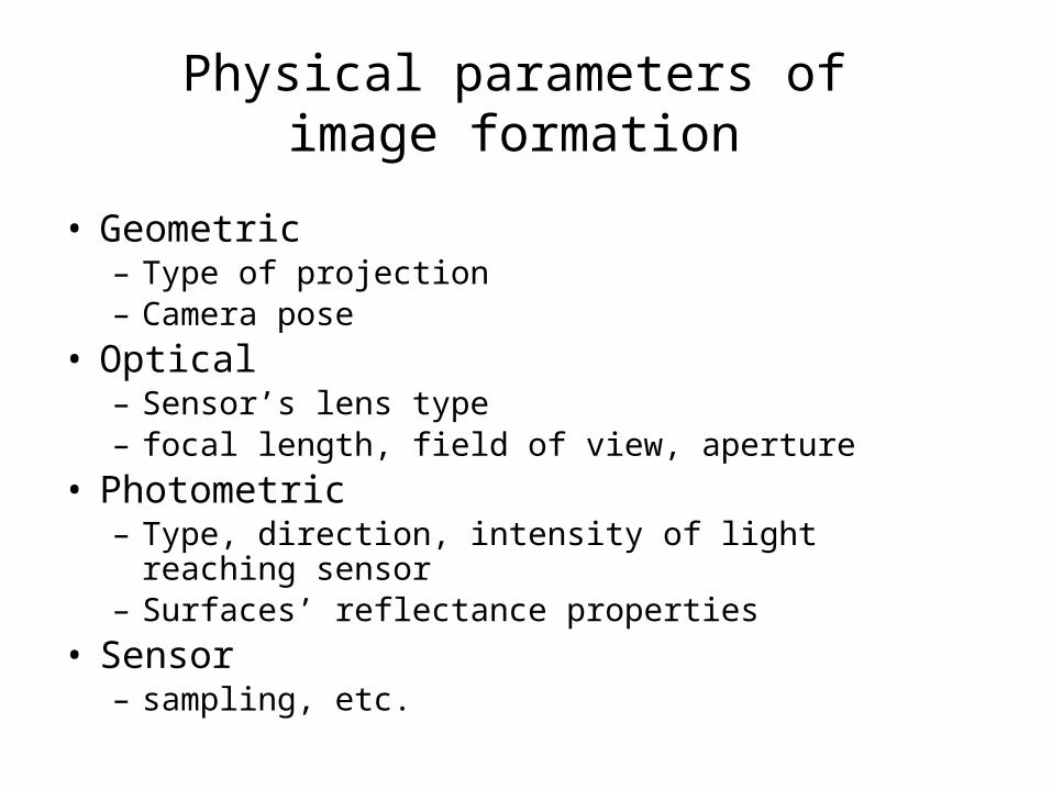
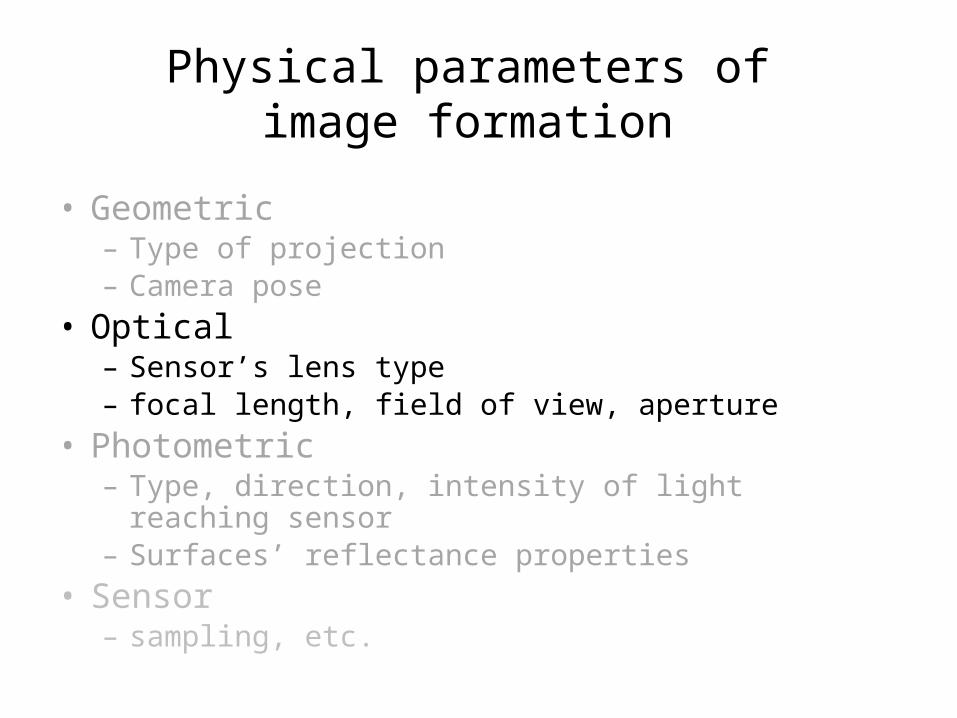
Physical parameters of image formation
• Geometric– Type of projection– Camera pose
• Optical– Sensor’s lens type– focal length, field of view, aperture
• Photometric– Type, direction, intensity of light reaching sensor– Surfaces’ reflectance properties
• Sensor– sampling, etc.
Physical parameters of image formation
• Geometric– Type of projection– Camera pose
• Optical– Sensor’s lens type– focal length, field of view, aperture
• Photometric– Type, direction, intensity of light reaching sensor– Surfaces’ reflectance properties
• Sensor– sampling, etc.
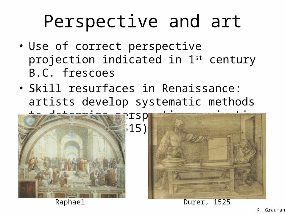
Perspective and art• Use of correct perspective projection indicated in 1st
century B.C. frescoes• Skill resurfaces in Renaissance: artists develop
systematic methods to determine perspective projection (around 1480-1515)
Durer, 1525RaphaelK. Grauman
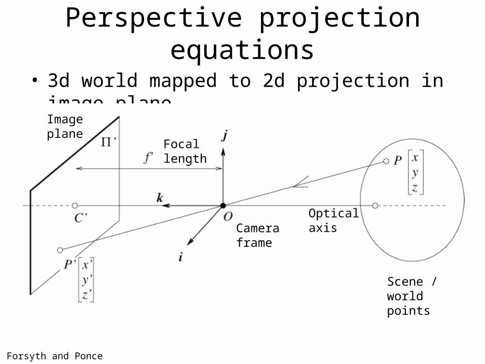
Perspective projection equations
• 3d world mapped to 2d projection in image plane
Forsyth and Ponce
Camera frame
Image plane
Optical axis
Focal length
Scene / world points
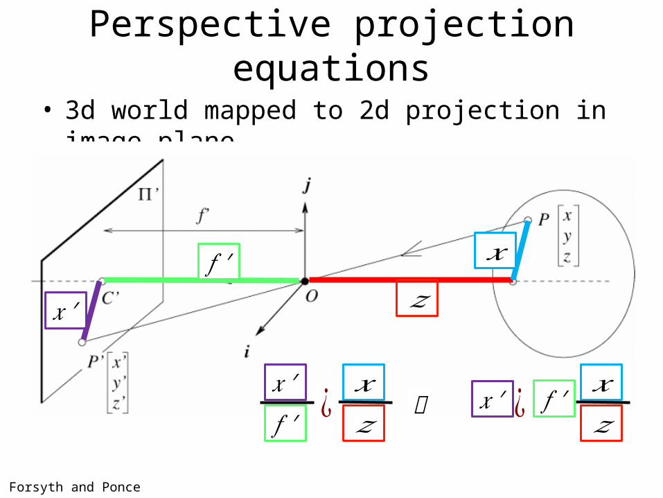
Perspective projection equations
• 3d world mapped to 2d projection in image plane
Forsyth and Ponce
𝑧𝑓 ′ 𝑥
𝑥 ′
𝑧𝑥¿𝑓 ′
𝑥 ′𝑧𝑥¿ 𝑓 ′𝑥 ′
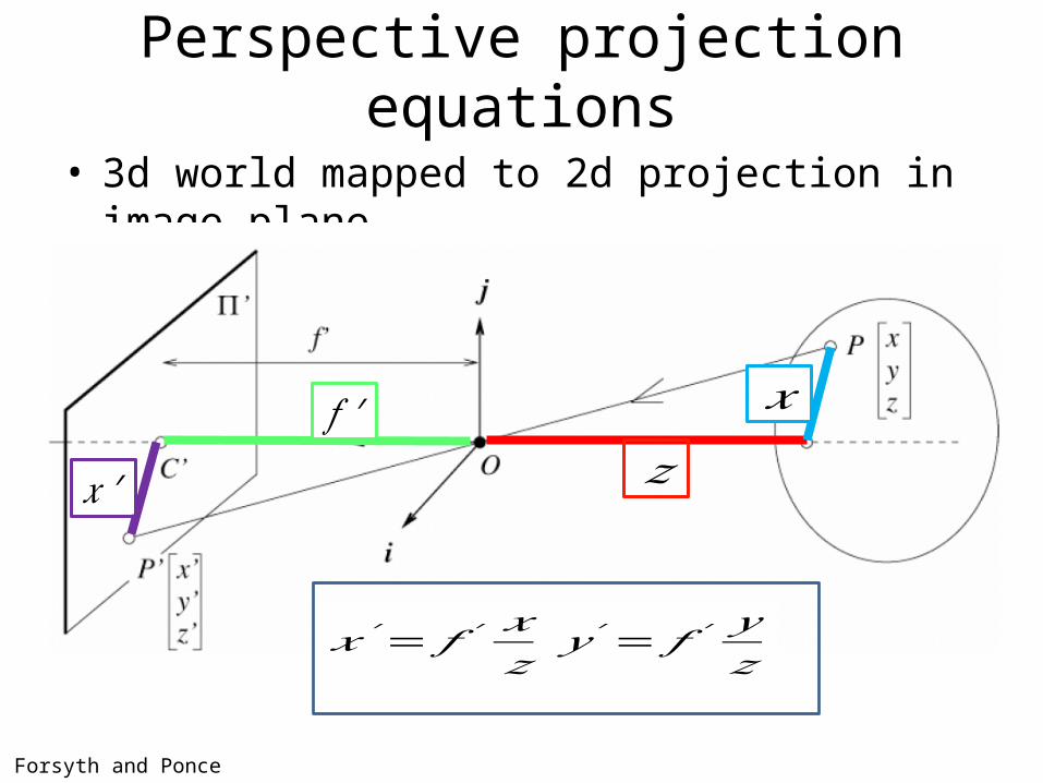
Perspective projection equations
• 3d world mapped to 2d projection in image plane
Forsyth and Ponce
𝑧𝑓 ′ 𝑥
𝑥 ′
𝑥′= 𝑓 ′𝑥𝑧𝑦 ′= 𝑓 ′
𝑦𝑧
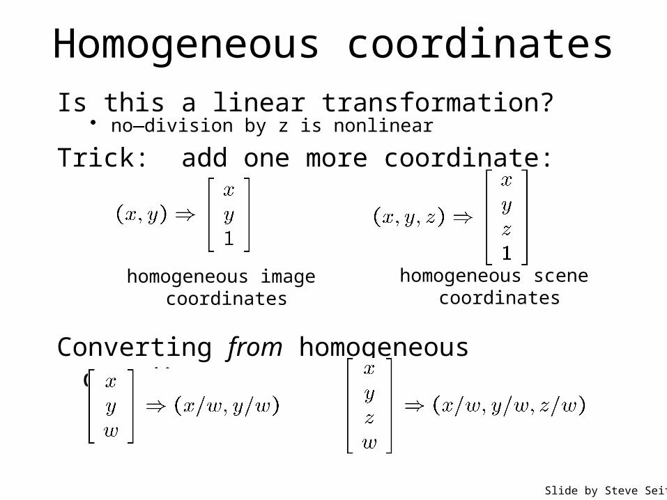
Homogeneous coordinatesIs this a linear transformation?
Trick: add one more coordinate:
homogeneous image coordinates
homogeneous scene coordinates
Converting from homogeneous coordinates
• no—division by z is nonlinear
Slide by Steve Seitz
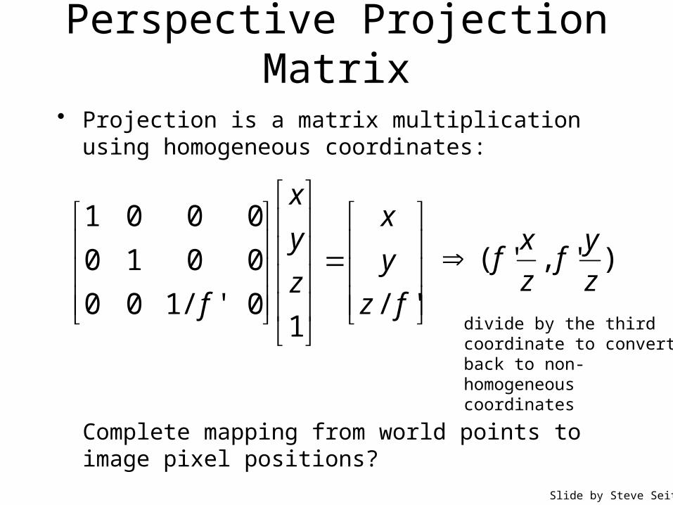
Perspective Projection Matrix
divide by the third coordinate to convert back to non-homogeneous coordinates
• Projection is a matrix multiplication using homogeneous coordinates:
'/1
0'/100
0010
0001
fz
y
x
z
y
x
f
)','(z
yf
z
xf
Slide by Steve Seitz
Complete mapping from world points to image pixel positions?
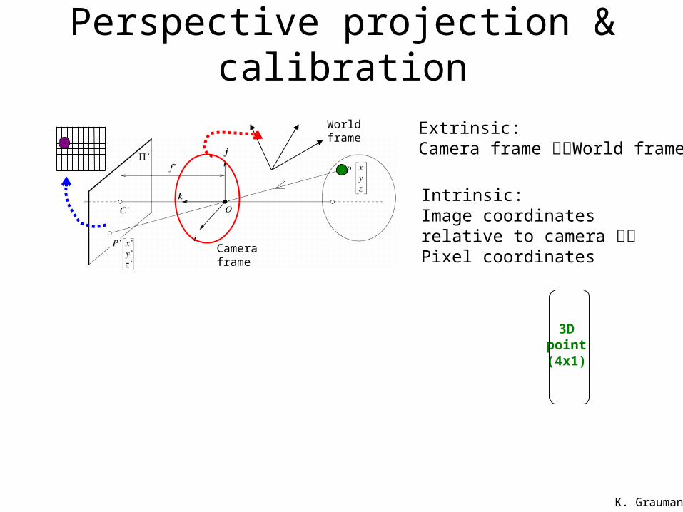
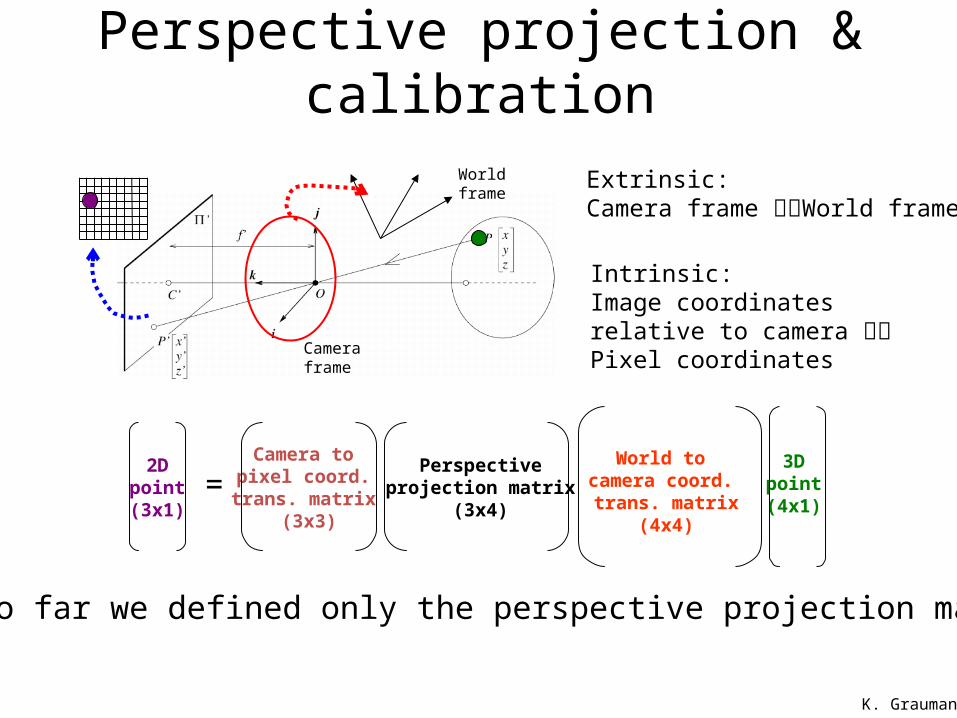
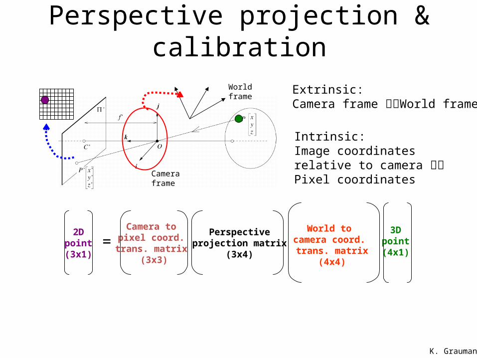
Perspective projection & calibration
Camera frame
Intrinsic:Image coordinates relative to camera Pixel coordinates
Extrinsic:Camera frame World frame
World frame
World to camera coord. trans. matrix
(4x4)
Perspectiveprojection matrix
(3x4)
Camera to pixel coord.
trans. matrix (3x3)
=2D
point(3x1)
3Dpoint(4x1)
K. Grauman
So far we defined only the perspective projection matrix
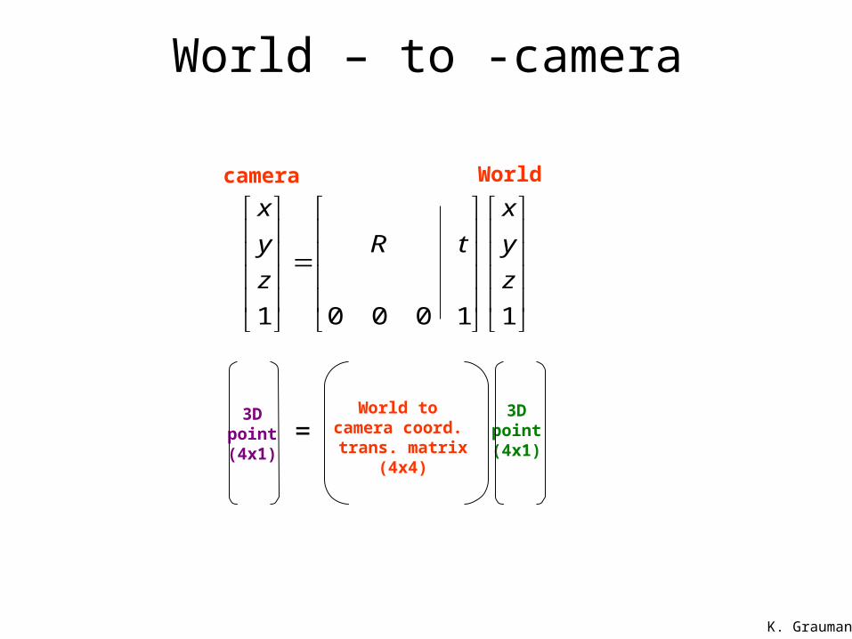
World – to -camera
K. Grauman
1 0 0 0 1 1
x x
y R t y
z z
World to camera coord. trans. matrix
(4x4)
=3D
point(4x1)
3Dpoint(4x1)
Worldcamera

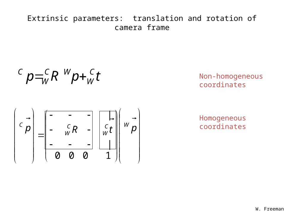
Extrinsic parameters: translation and rotation of camera frame
tpRp CW
WCW
C Non-homogeneous
coordinates
Homogeneous coordinates
ptRp WC
WCW
C
1000|
|
W. Freeman

Perspective projection & calibration
Camera frame
Intrinsic:Image coordinates relative to camera Pixel coordinates
Extrinsic:Camera frame World frame
World frame
World to camera coord. trans. matrix
(4x4)
Perspectiveprojection matrix
(3x4)
Camera to pixel coord.
trans. matrix (3x3)
=2D
point(3x1)
3Dpoint(4x1)
K. Grauman
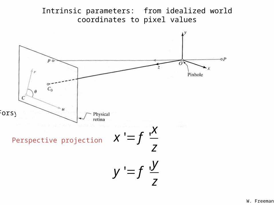
Intrinsic parameters: from idealized world coordinates to pixel values
Forsyth&Ponce
' '
' '
xx f
zy
y fz
Perspective projection
W. Freeman
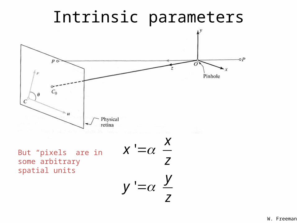
Intrinsic parameters
'
'
xx
zy
yz
But “pixels” are in some arbitrary spatial units
W. Freeman
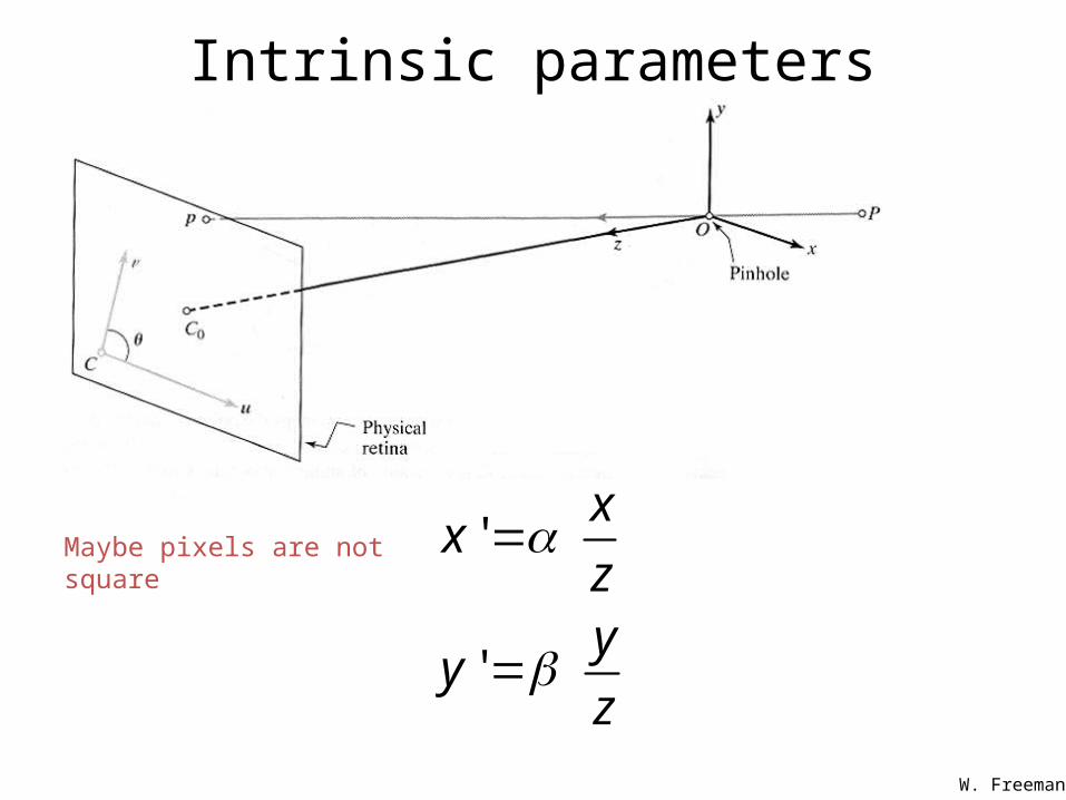
Intrinsic parameters
'
'
xx
zy
yz
Maybe pixels are not square
W. Freeman
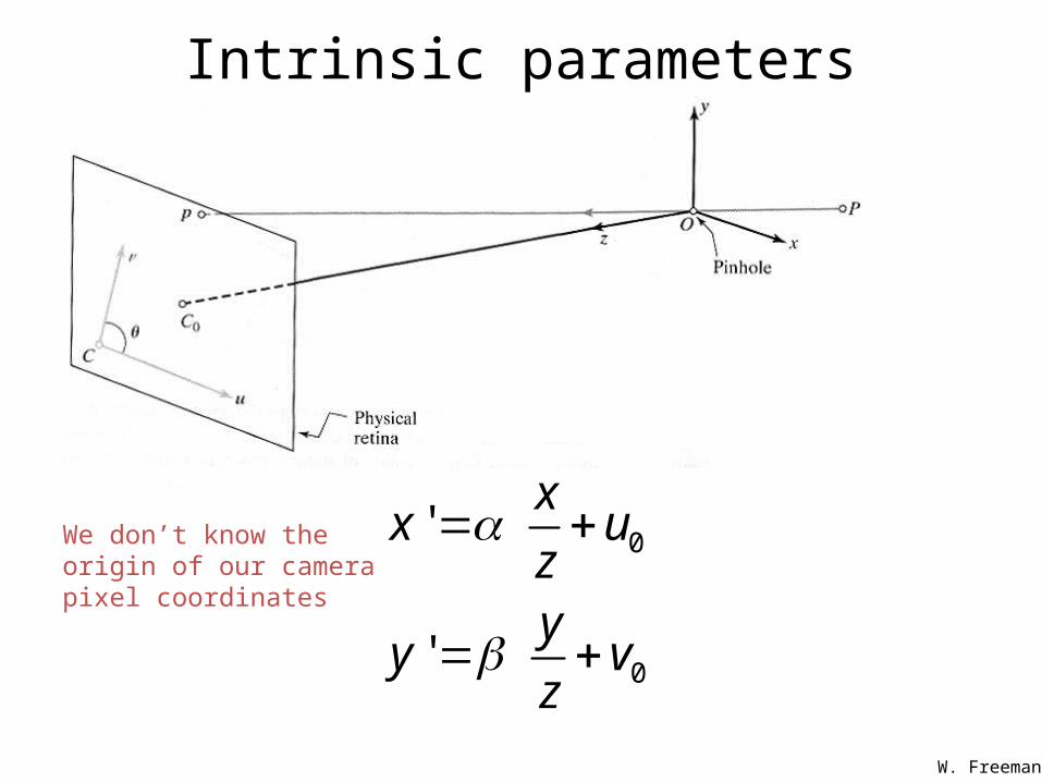
Intrinsic parameters
0
0
'
'
xx u
zy
y vz
We don’t know the origin of our camera pixel coordinates
W. Freeman
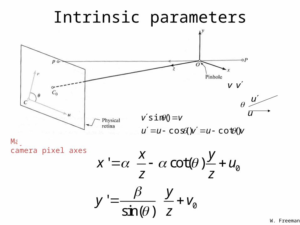
Intrinsic parameters
0
0
' cot( )
' sin( )
x yx u
z zy
y vz
May be skew between camera pixel axes
v
u
v
u
vuvuu
vv
)cot()cos(
)sin(
W. Freeman
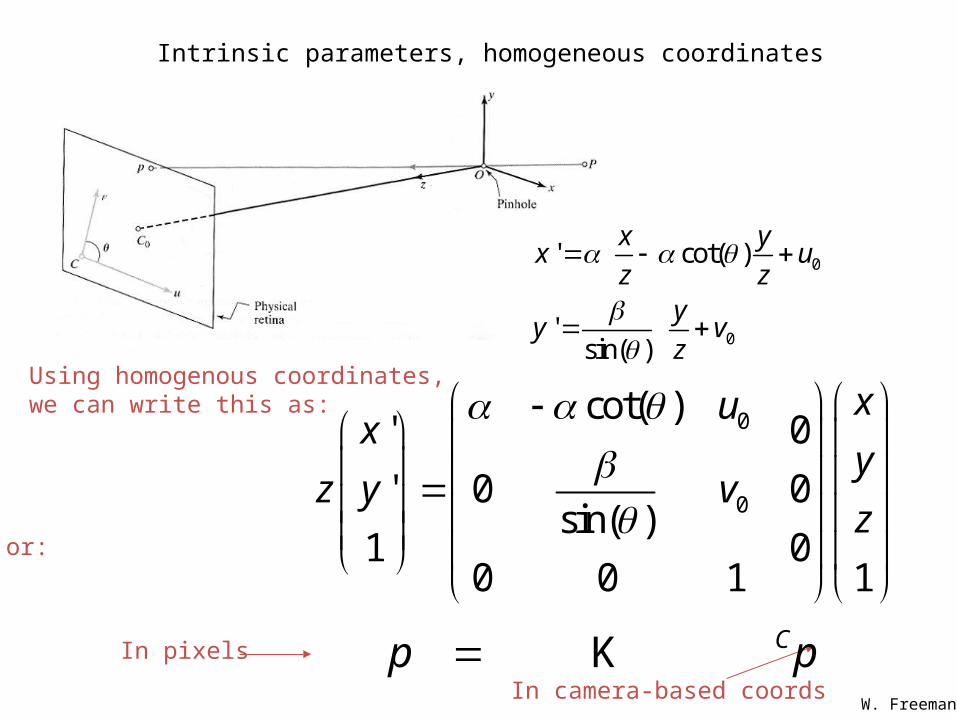
pp C K
Intrinsic parameters, homogeneous coordinates
0
0
' cot( )
' sin( )
x yx u
z zy
y vz
0
0
cot( )' 0
' 0 0sin( )
1 00 0 1 1
xux
yz y v
z
Using homogenous coordinates,we can write this as:
or:
In camera-based coords
In pixels
W. Freeman
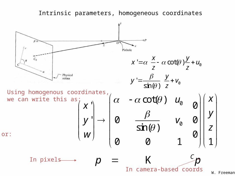
pp C K
Intrinsic parameters, homogeneous coordinates
0
0
' cot( )
' sin( )
x yx u
z zy
y vz
0
0
cot( )' 0
' 0 0sin( )
00 0 1 1
xux
yy v
zw
Using homogenous coordinates,we can write this as:
or:
In camera-based coords
In pixels
W. Freeman
Extrinsic parameters: translation and rotation of camera frame
tpRp CW
WCW
C Non-homogeneous
coordinates
Homogeneous coordinates
ptRp WC
WCW
C
1000|
|
W. Freeman
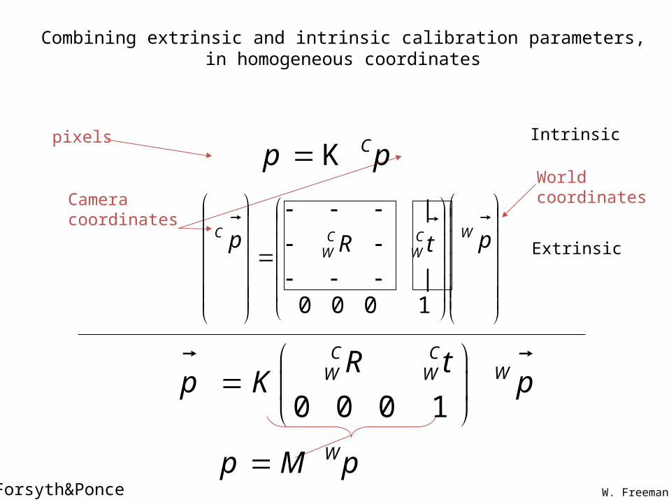
Combining extrinsic and intrinsic calibration parameters, in homogeneous coordinates
Forsyth&Ponce
0 0 0 1
C CWW WR t
p K p
pp CK
pMp W
Intrinsic
Extrinsic
ptRp WC
WCW
C
1000|
|
World coordinatesCamera coordinates
pixels
W. Freeman
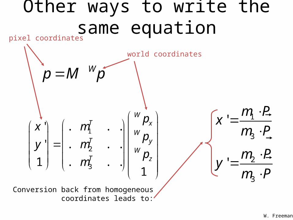
Other ways to write the same equation
1
2
3
' . . .
' . . .
1 . . .1
WT x
WT y
WT z
px m
py m
pm
pMp W
1
3
2
3
'
'
m Px
m P
m Py
m P
pixel coordinates
world coordinates
Conversion back from homogeneous coordinates leads to:
W. Freeman
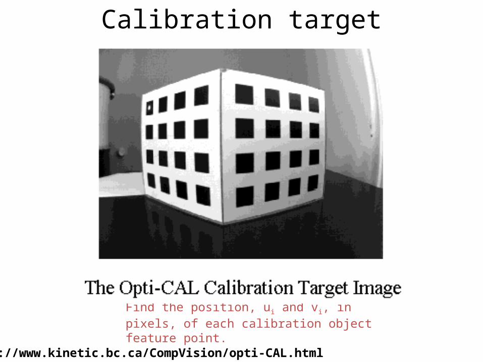
Calibration target
http://www.kinetic.bc.ca/CompVision/opti-CAL.html
Find the position, ui and vi, in pixels, of each calibration object feature point.
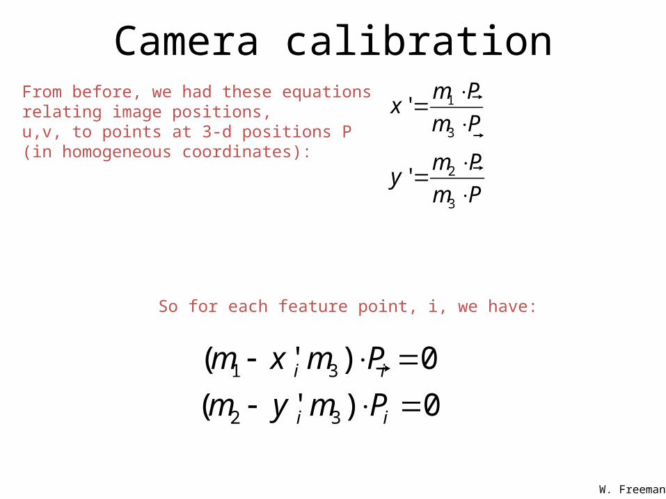
Camera calibration
1 3
2 3
( ' ) 0
( ' ) 0i i
i i
m x m P
m y m P
So for each feature point, i, we have:
1
3
2
3
'
'
m Px
m P
m Py
m P
From before, we had these equations relating image positions,u,v, to points at 3-d positions P (in homogeneous coordinates):
W. Freeman
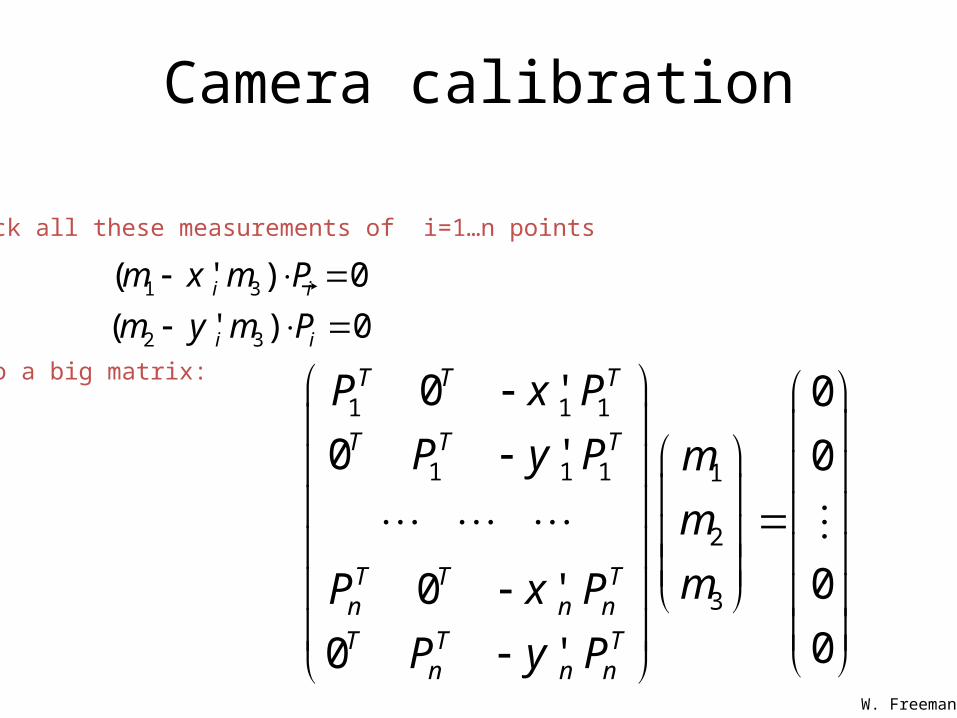
Stack all these measurements of i=1…n points
into a big matrix:
Camera calibration
1 3
2 3
( ' ) 0
( ' ) 0i i
i i
m x m P
m y m P
1 1 1
1 1 1 1
2
3
0 ' 0
0 ' 0
00 '00 '
T T T
T T T
T T Tn n nT T T
n n n
P x P
P y P m
m
mP x P
P y P
W. Freeman

11
12
13
141 1 1 1 1 1 1 1 1 1
211 1 1 1 1 1 1 1 1 1
22
23
24
1 0 0 0 0 ' ' ' '
0 0 0 0 1 ' ' ' '
1 0 0 0 0 ' ' ' '
0 0 0 0 1 ' ' ' '
x y z x y z
x y z x y z
nx ny nz n nx n ny n nz n
nx ny nz n nx n ny n nz n
m
m
m
mP P P x P x P x P x
mP P P y P y P y P y
m
mP P P x P x P x P x
mP P P y P y P y P y
m
31
32
33
34
0
0
0
0
m
m
m
Showing all the elements:
In vector form:Camera calibration
W. Freeman
1 1 1
1 1 1 1
2
3
0 ' 0
0 ' 0
00 '00 '
T T T
T T T
T T Tn n nT T T
n n n
P x P
P y P m
m
mP x P
P y P
We want to solve for the unit vector m (the stacked one)that minimizes 2
Qm
Q m = 0
The minimum eigenvector of the matrix QTQ gives us that(see Forsyth&Ponce, 3.1), because it is the unit vector x that minimizes xT QTQ x.
Camera calibration
W. Freeman
11
12
13
141 1 1 1 1 1 1 1 1 1
211 1 1 1 1 1 1 1 1 1
22
23
24
1 0 0 0 0 ' ' ' '
0 0 0 0 1 ' ' ' '
1 0 0 0 0 ' ' ' '
0 0 0 0 1 ' ' ' '
x y z x y z
x y z x y z
nx ny nz n nx n ny n nz n
nx ny nz n nx n ny n nz n
m
m
m
mP P P x P x P x P x
mP P P y P y P y P y
m
mP P P x P x P x P x
mP P P y P y P y P y
m
31
32
33
34
0
0
0
0
m
m
m
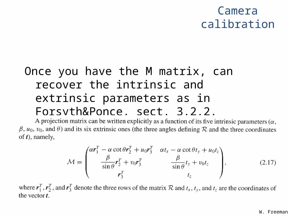
Once you have the M matrix, can recover the intrinsic and extrinsic parameters as in Forsyth&Ponce, sect. 3.2.2.
Camera calibration
W. Freeman
Perspective projection & calibration
Camera frame
Intrinsic:Image coordinates relative to camera Pixel coordinates
Extrinsic:Camera frame World frame
World frame
World to camera coord. trans. matrix
(4x4)
Perspectiveprojection matrix
(3x4)
Camera to pixel coord.
trans. matrix (3x3)
=2D
point(3x1)
3Dpoint(4x1)
K. Grauman
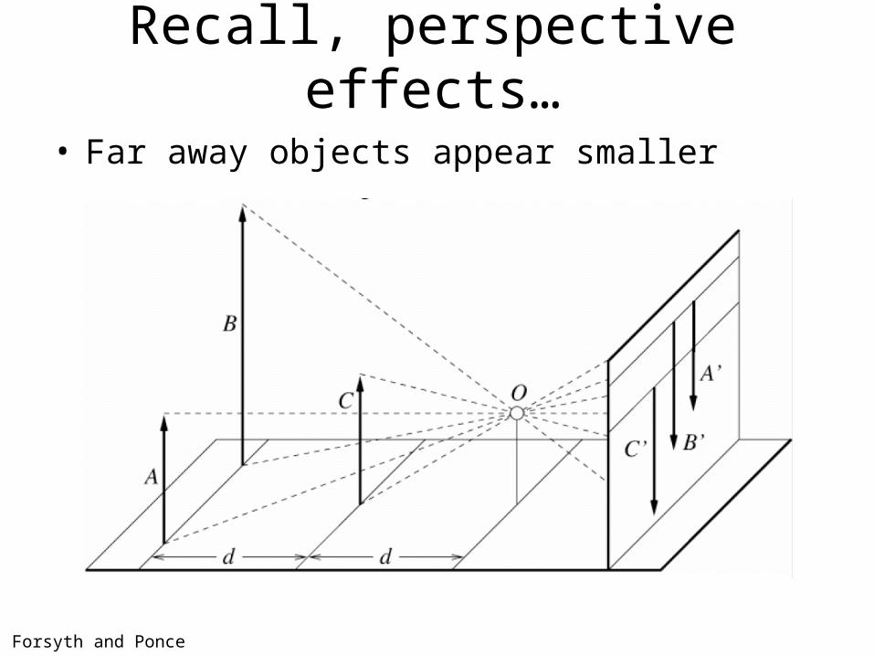
Recall, perspective effects…
• Far away objects appear smaller
Forsyth and Ponce
Perspective effects

Perspective effects
Projection properties• Many-to-one: all points along same ray map to same
point in image• Points ?
– points• Lines ?
– lines (collinearity preserved)• Distances and angles are / are not ? preserved
– are not• Degenerate cases:
– Line through focal point projects to a point.– Plane through focal point projects to line
– Plane perpendicular to image plane projects to part of the image.
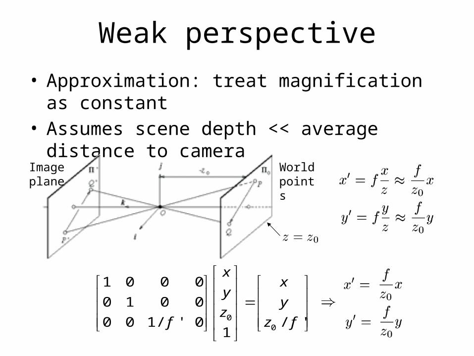
Weak perspective• Approximation: treat magnification as constant• Assumes scene depth << average distance to camera
World points
Image plane
00
1 0 0 0
0 1 0 0
0 0 1/ ' 0 / '1
xx
yy
zf z f
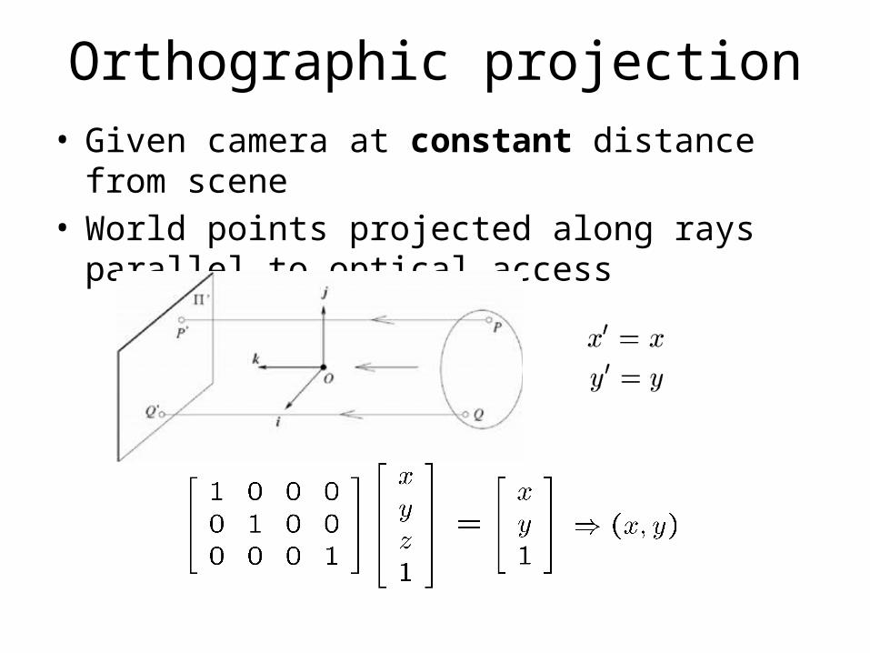
Orthographic projection• Given camera at constant distance from scene• World points projected along rays parallel to optical
access
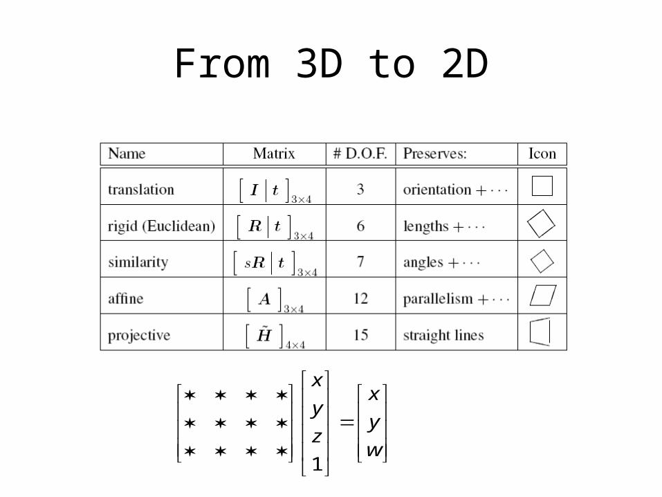
From 3D to 2D
1
xx
yy
zw
Other types of projection
• Lots of intriguing variants…• (I’ll just mention a few fun ones)
S. Seitz
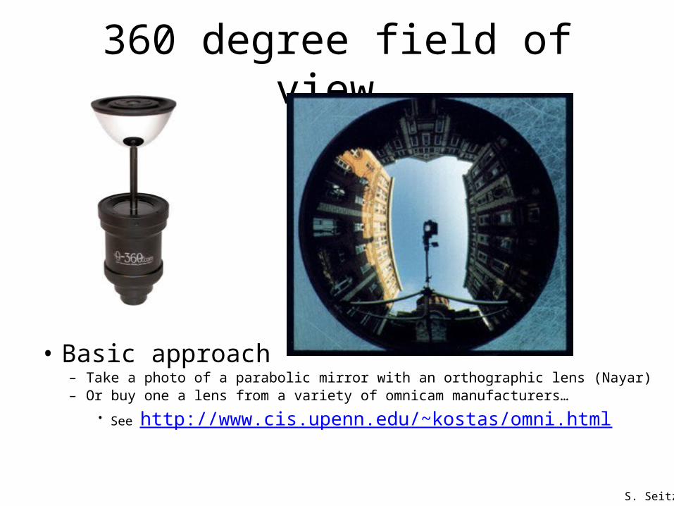
360 degree field of view…
• Basic approach– Take a photo of a parabolic mirror with an orthographic lens (Nayar)– Or buy one a lens from a variety of omnicam manufacturers…
• See http://www.cis.upenn.edu/~kostas/omni.html
S. Seitz
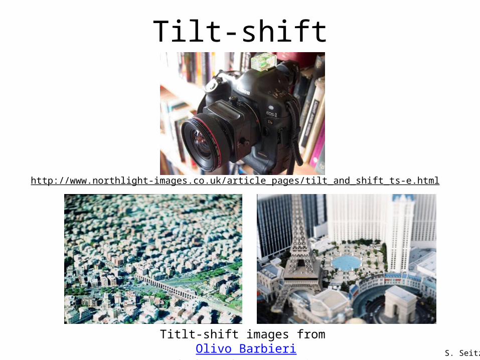
Tilt-shift
Titlt-shift images from Olivo Barbieriand Photoshop imitations
http://www.northlight-images.co.uk/article_pages/tilt_and_shift_ts-e.html
S. Seitz
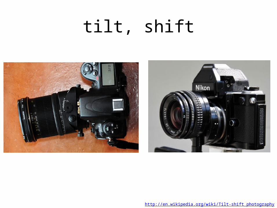
tilt, shift
http://en.wikipedia.org/wiki/Tilt-shift_photography
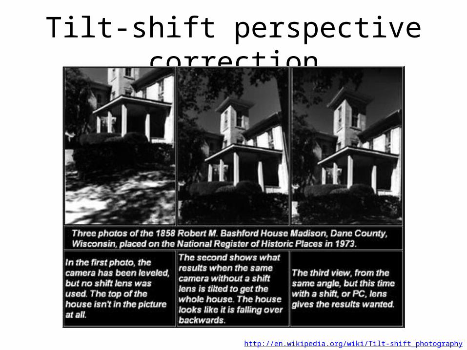
Tilt-shift perspective correction
http://en.wikipedia.org/wiki/Tilt-shift_photography
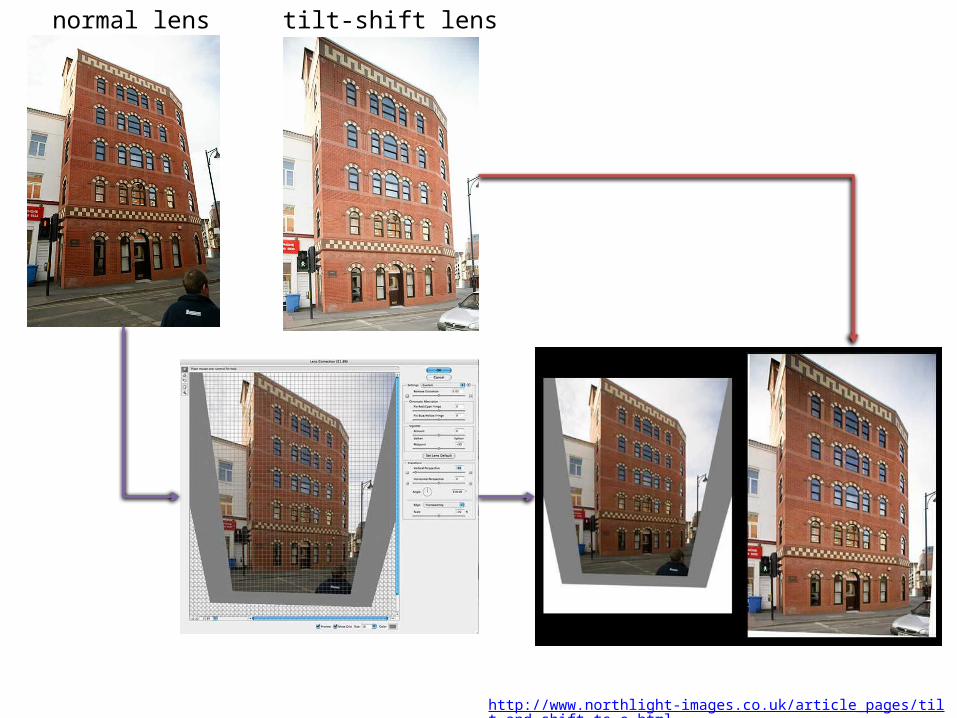
normal lens tilt-shift lens
http://www.northlight-images.co.uk/article_pages/tilt_and_shift_ts-e.html

Rollout Photographs © Justin Kerr
http://research.famsi.org/kerrmaya.html
Rotating sensor (or object)
Also known as “cyclographs”, “peripheral images”
S. Seitz
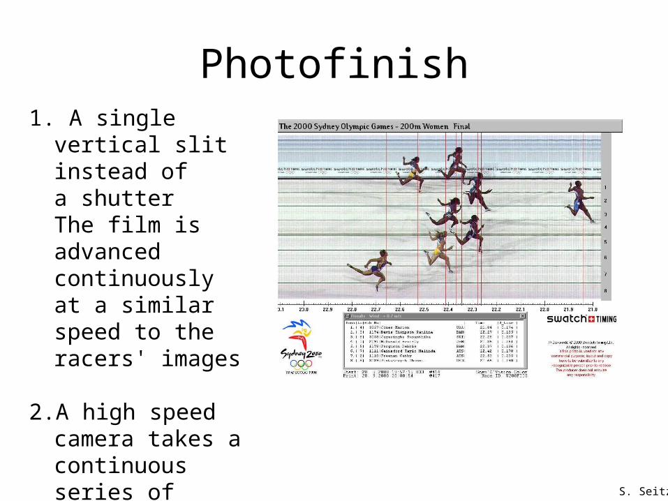
Photofinish
S. Seitz
1. A single vertical slit instead of a shutterThe film is advanced continuously at a similar speed to the racers' images
2. A high speed camera takes a continuous series of partial frame photos at a fast rate
Physical parameters of image formation
• Geometric– Type of projection– Camera pose
• Optical– Sensor’s lens type– focal length, field of view, aperture
• Photometric– Type, direction, intensity of light reaching sensor– Surfaces’ reflectance properties
• Sensor– sampling, etc.
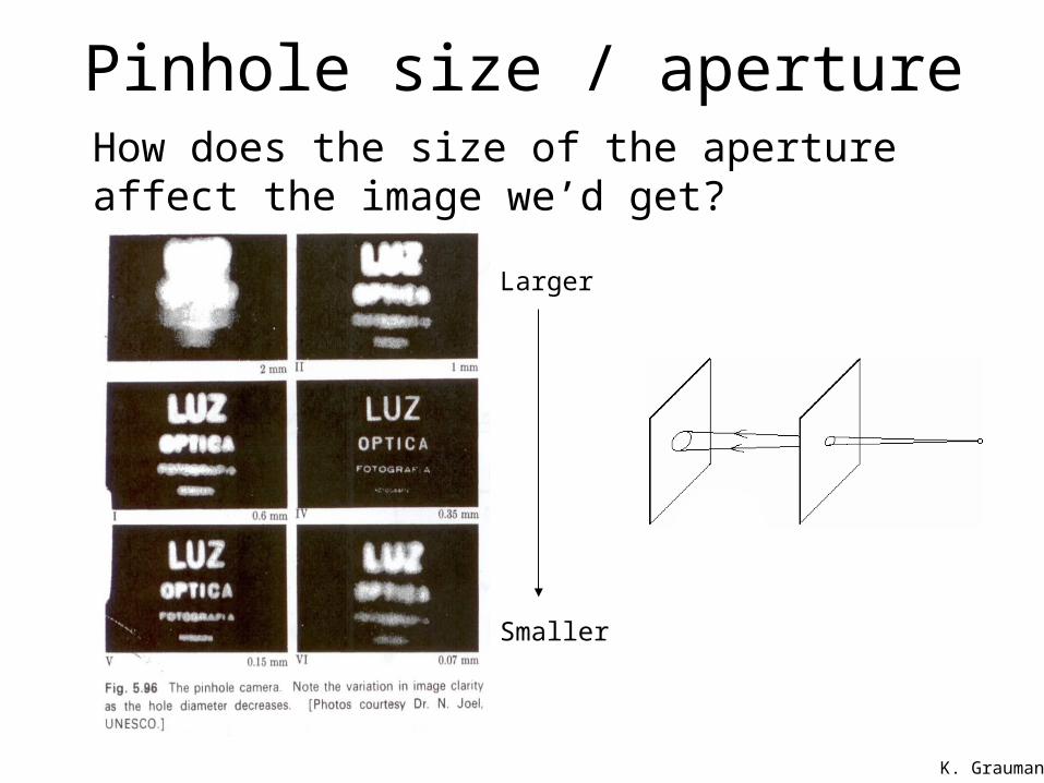
Pinhole size / aperture
Smaller
Larger
How does the size of the aperture affect the image we’d get?
K. Grauman
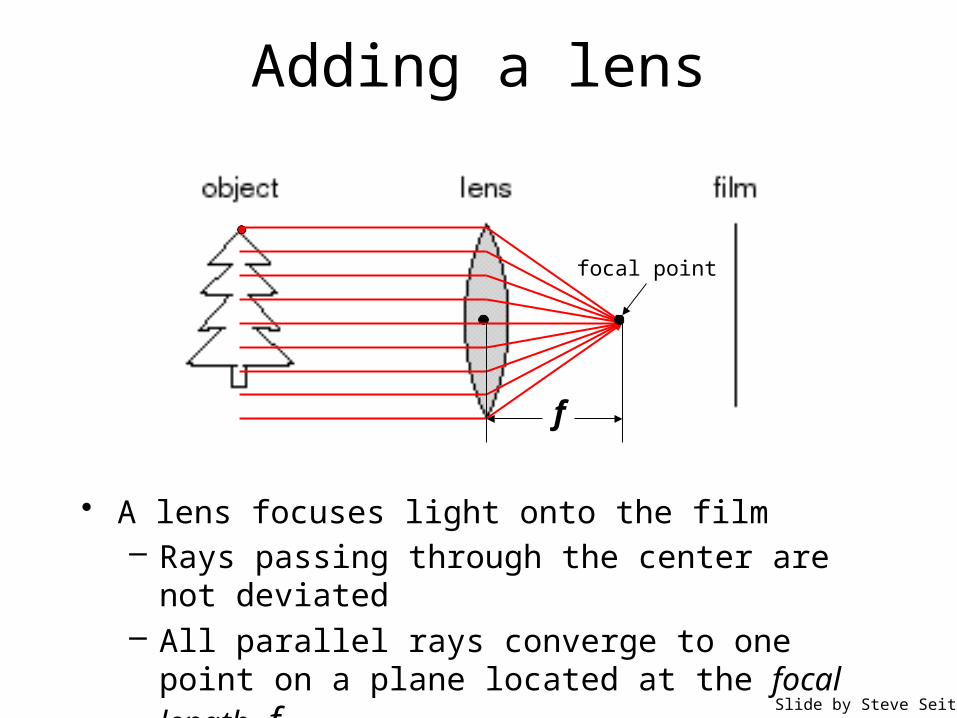
Adding a lens
• A lens focuses light onto the film– Rays passing through the center are not deviated– All parallel rays converge to one point on a plane
located at the focal length fSlide by Steve Seitz
focal point
f
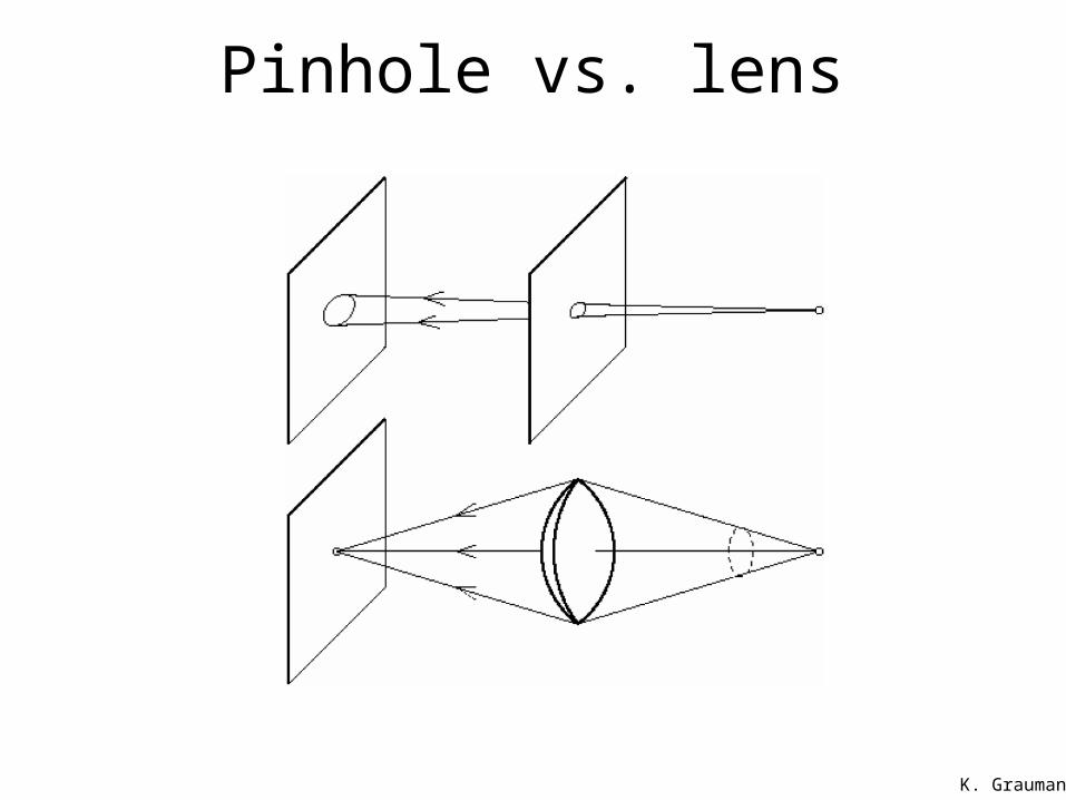
Pinhole vs. lens
K. Grauman
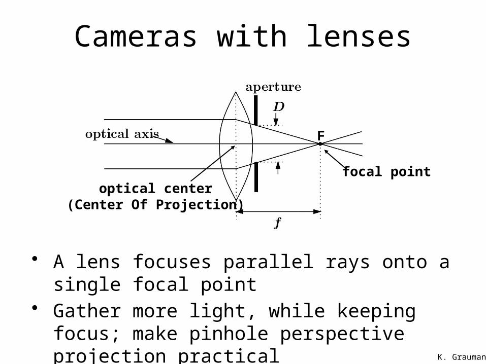
Cameras with lenses
focal point
F
optical center(Center Of Projection)
• A lens focuses parallel rays onto a single focal point• Gather more light, while keeping focus; make
pinhole perspective projection practical
K. Grauman
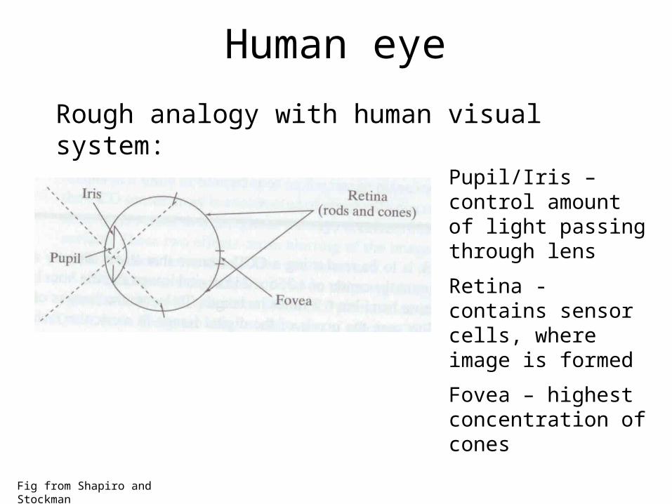
Human eye
Fig from Shapiro and Stockman
Pupil/Iris – control amount of light passing through lens
Retina - contains sensor cells, where image is formed
Fovea – highest concentration of cones
Rough analogy with human visual system:
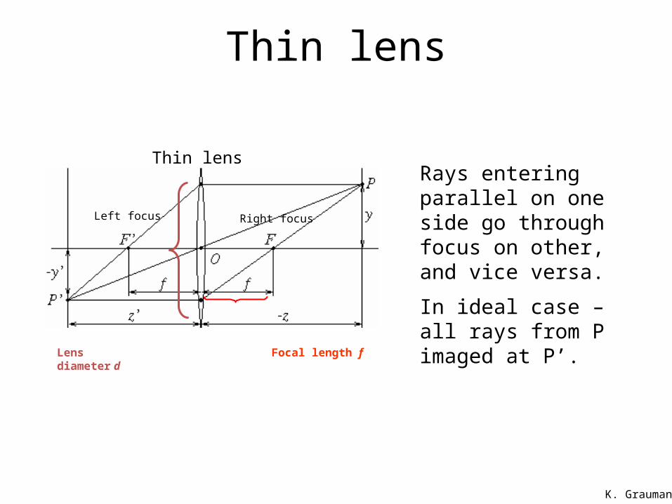
Thin lens
Thin lensRays entering parallel on one side go through focus on other, and vice versa.
In ideal case – all rays from P imaged at P’.
Left focus Right focus
Focal length fLens diameter d
K. Grauman
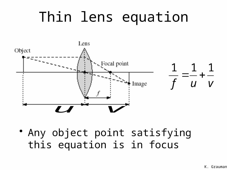
Thin lens equation
• Any object point satisfying this equation is in focus
u v
vuf
111
K. Grauman
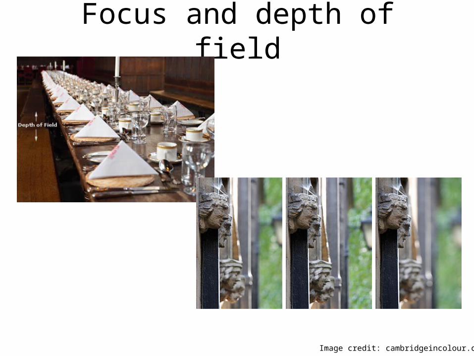
Focus and depth of field
Image credit: cambridgeincolour.com
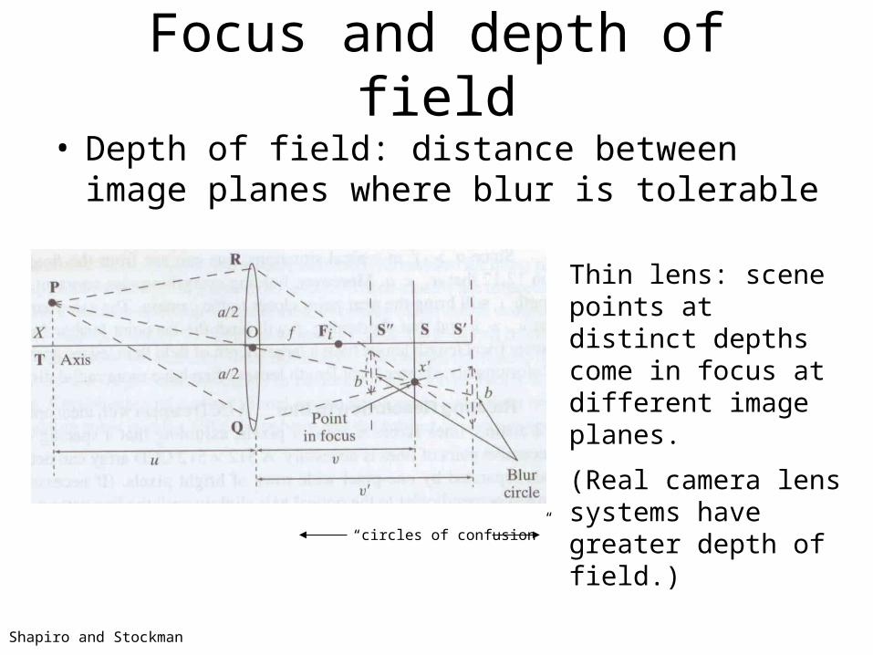
Focus and depth of field• Depth of field: distance between image planes where
blur is tolerable
Thin lens: scene points at distinct depths come in focus at different image planes.
(Real camera lens systems have greater depth of field.)
Shapiro and Stockman
“circles of confusion”
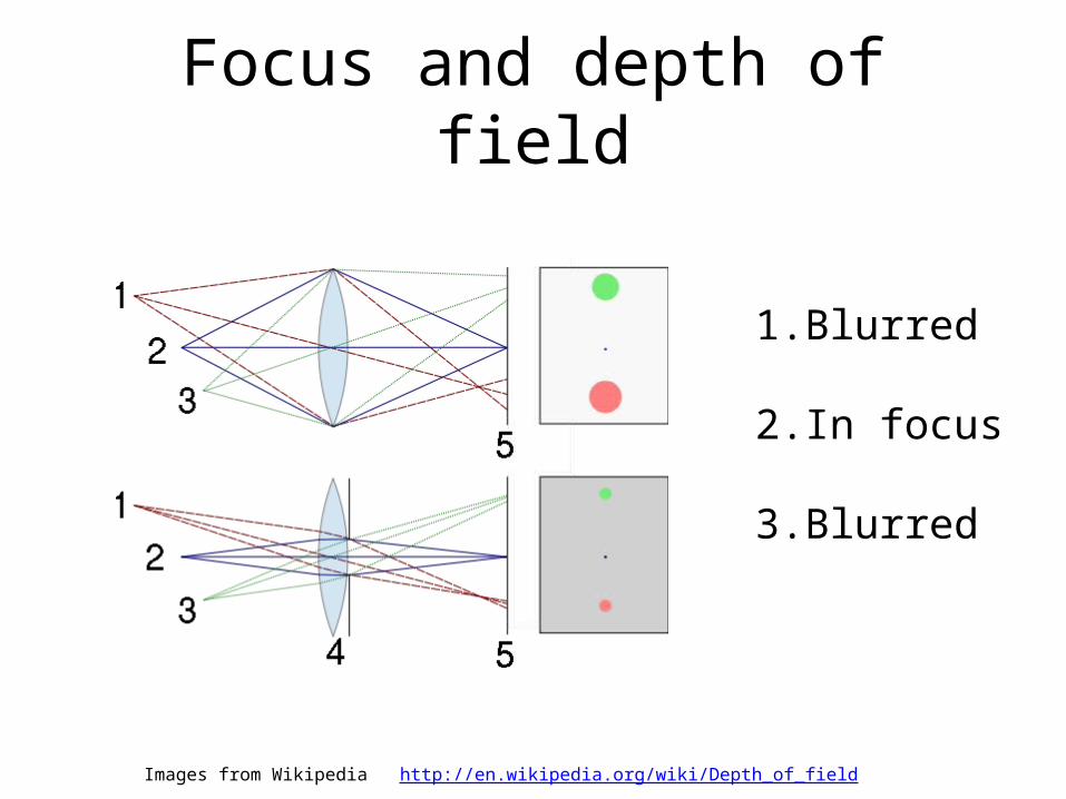
Focus and depth of field
Images from Wikipedia http://en.wikipedia.org/wiki/Depth_of_field
1. Blurred
2. In focus
3. Blurred
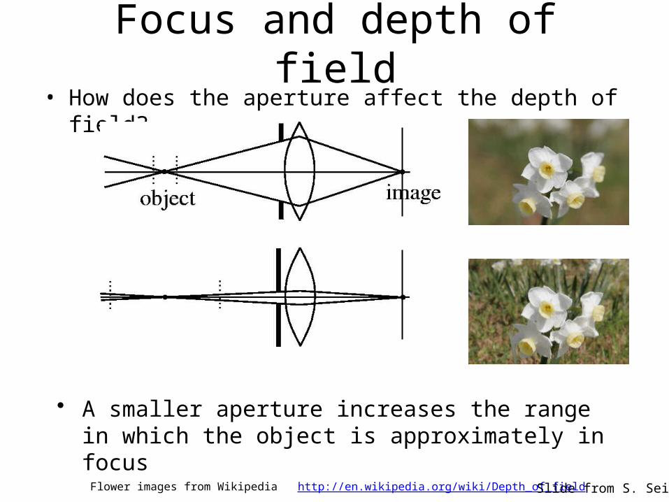
Focus and depth of field• How does the aperture affect the depth of field?
• A smaller aperture increases the range in which the object is approximately in focus
Flower images from Wikipedia http://en.wikipedia.org/wiki/Depth_of_field Slide from S. Seitz
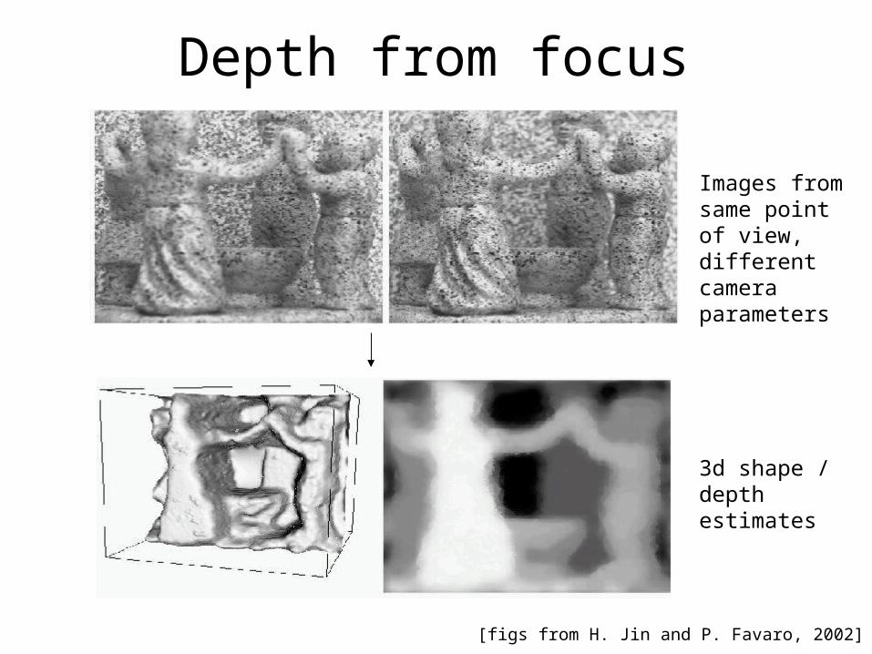
Depth from focus
[figs from H. Jin and P. Favaro, 2002]
Images from same point of view, different camera parameters
3d shape / depth estimates
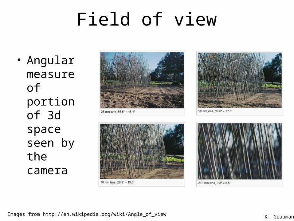
Field of view
• Angular measure of portion of 3d space seen by the camera
Images from http://en.wikipedia.org/wiki/Angle_of_view K. Grauman
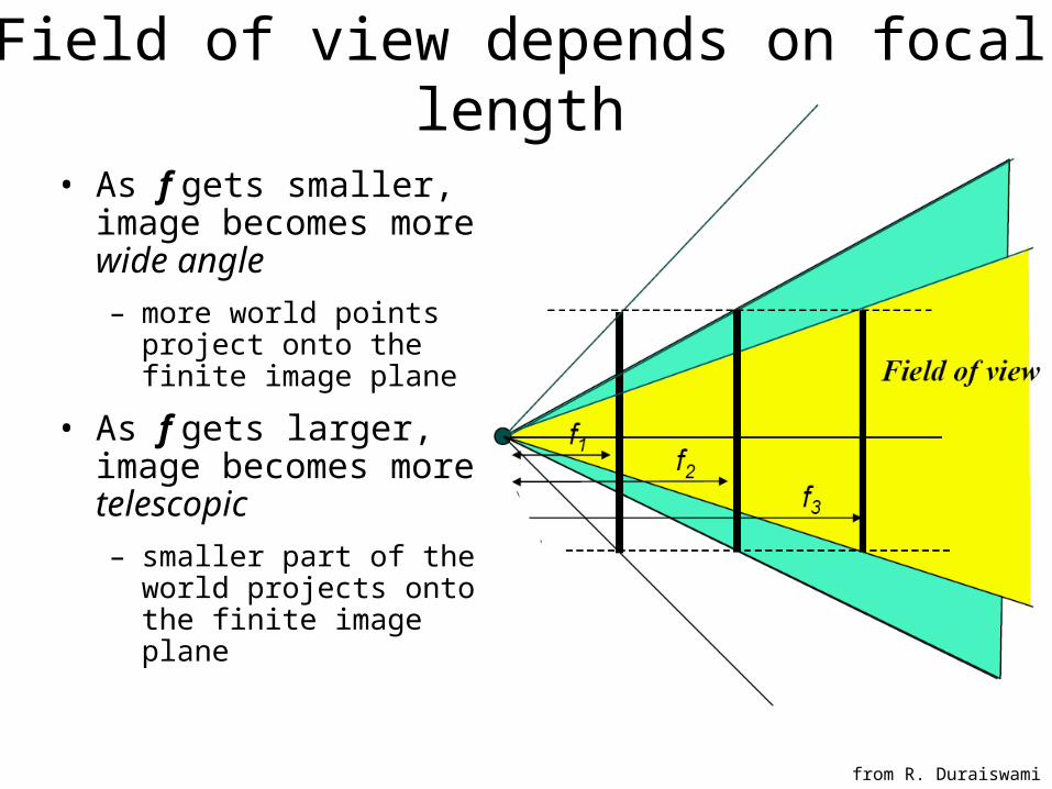
• As f gets smaller, image becomes more wide angle – more world points project
onto the finite image plane
• As f gets larger, image becomes more telescopic – smaller part of the world
projects onto the finite image plane
Field of view depends on focal length
from R. Duraiswami
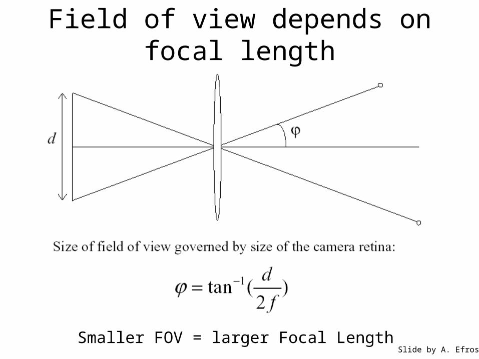
Field of view depends on focal length
Smaller FOV = larger Focal LengthSlide by A. Efros
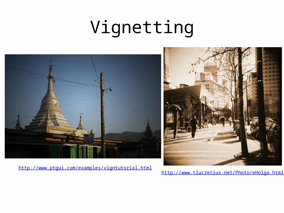
Vignetting
http://www.ptgui.com/examples/vigntutorial.htmlhttp://www.tlucretius.net/Photo/eHolga.html
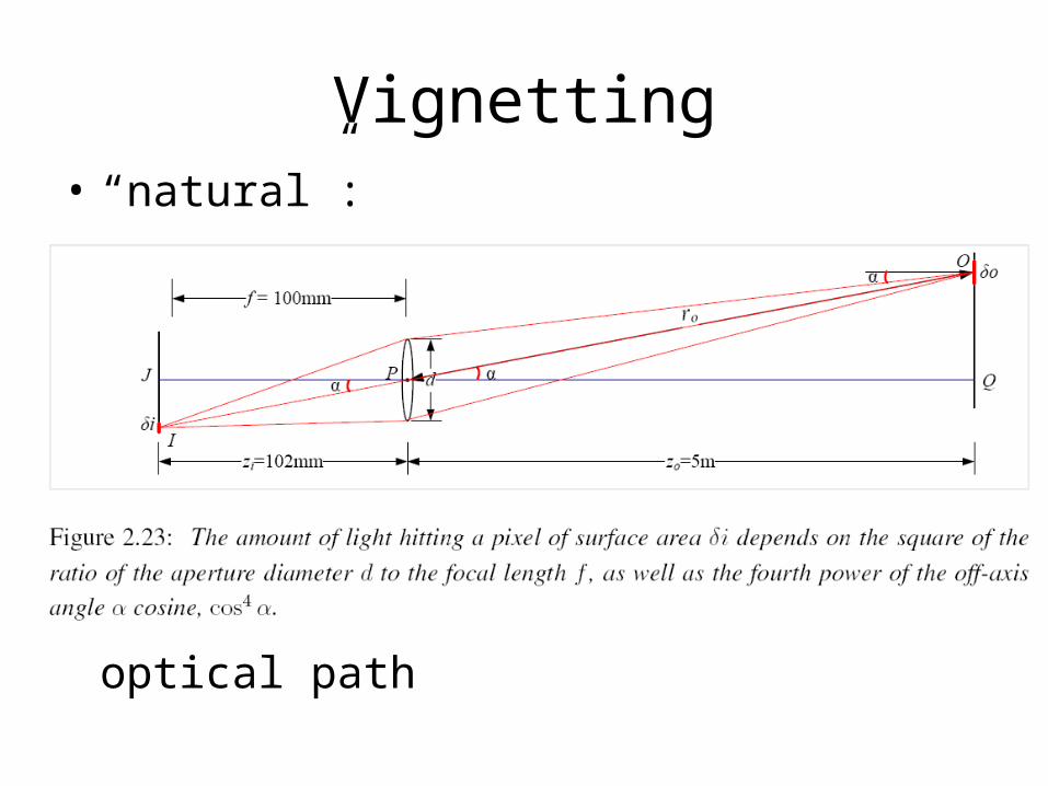
Vignetting• “natural”:
• “mechanical”: intrusion on optical path
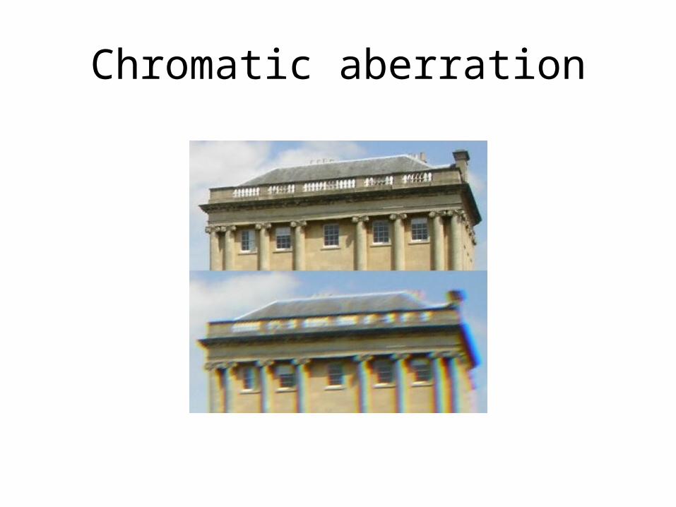
Chromatic aberration
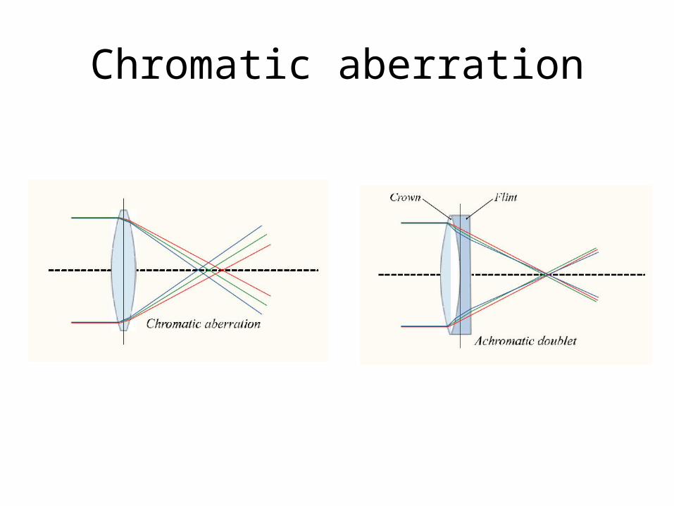
Chromatic aberration
Physical parameters of image formation
• Geometric– Type of projection– Camera pose
• Optical– Sensor’s lens type– focal length, field of view, aperture
• Photometric– Type, direction, intensity of light reaching sensor– Surfaces’ reflectance properties
• Sensor– sampling, etc.
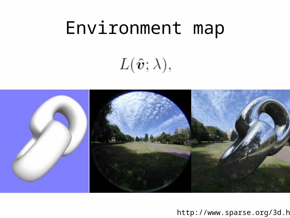
Environment map
http://www.sparse.org/3d.html
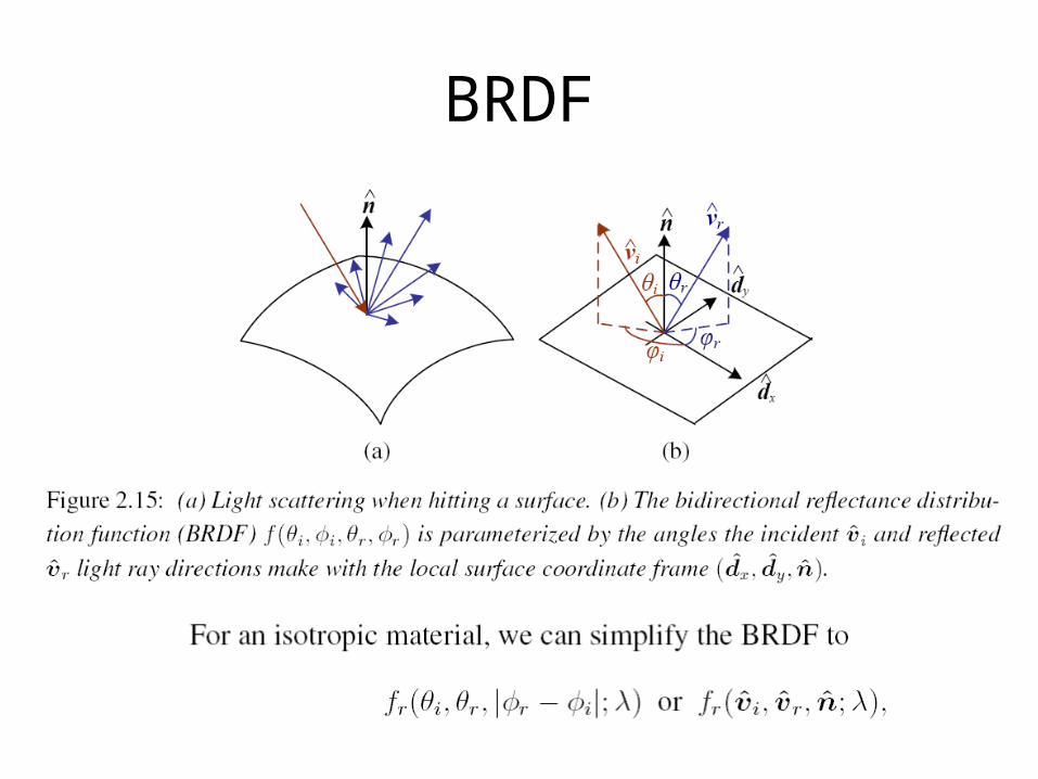
BRDF
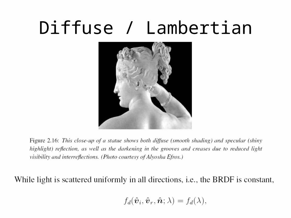
Diffuse / Lambertian
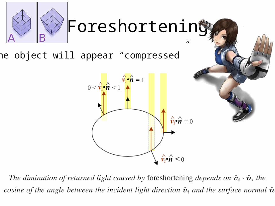
Foreshortening
The object will appear “compressed”
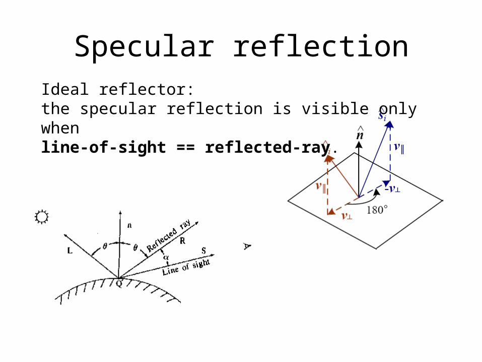
Specular reflectionIdeal reflector: the specular reflection is visible only when line-of-sight == reflected-ray.
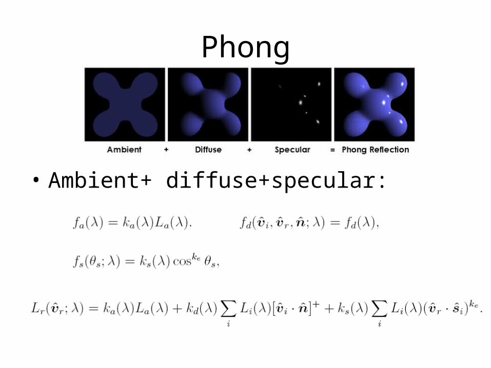
Phong
• Ambient+ diffuse+specular:
Physical parameters of image formation
• Geometric– Type of projection– Camera pose
• Optical– Sensor’s lens type– focal length, field of view, aperture
• Photometric– Type, direction, intensity of light reaching sensor– Surfaces’ reflectance properties
• Sensor– sampling, etc.
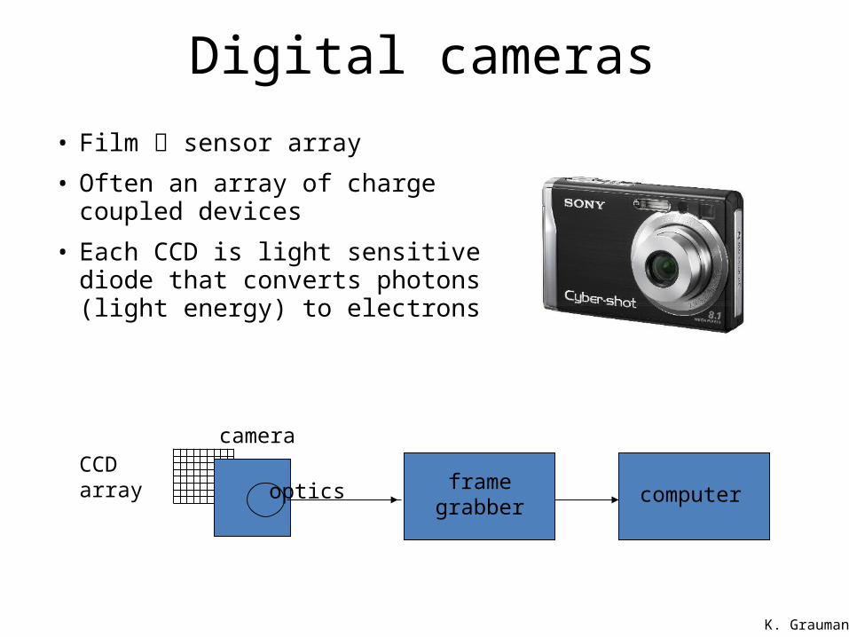
Digital cameras• Film sensor array
• Often an array of charge coupled devices
• Each CCD is light sensitive diode that converts photons (light energy) to electrons
cameraCCD array
optics frame grabber computer
K. Grauman
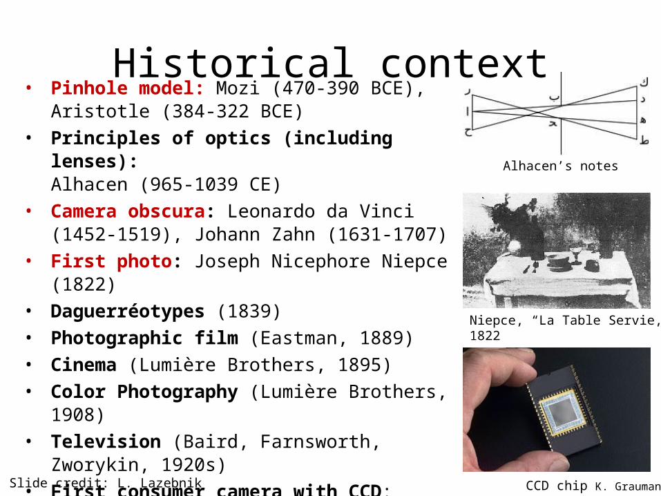
Historical context• Pinhole model: Mozi (470-390 BCE),
Aristotle (384-322 BCE)• Principles of optics (including lenses):
Alhacen (965-1039 CE) • Camera obscura: Leonardo da Vinci
(1452-1519), Johann Zahn (1631-1707)• First photo: Joseph Nicephore Niepce (1822)• Daguerréotypes (1839)• Photographic film (Eastman, 1889)• Cinema (Lumière Brothers, 1895)• Color Photography (Lumière Brothers, 1908)• Television (Baird, Farnsworth, Zworykin, 1920s)• First consumer camera with CCD:
Sony Mavica (1981)• First fully digital camera: Kodak DCS100 (1990)
Niepce, “La Table Servie,” 1822
CCD chip
Alhacen’s notes
Slide credit: L. Lazebnik K. Grauman
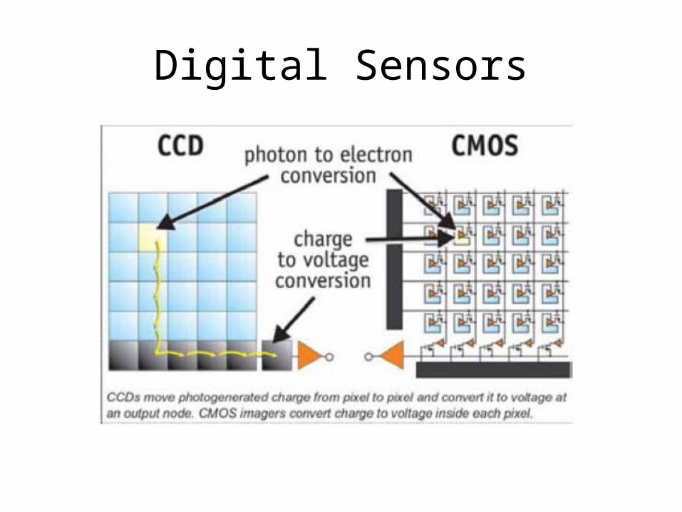
Digital Sensors
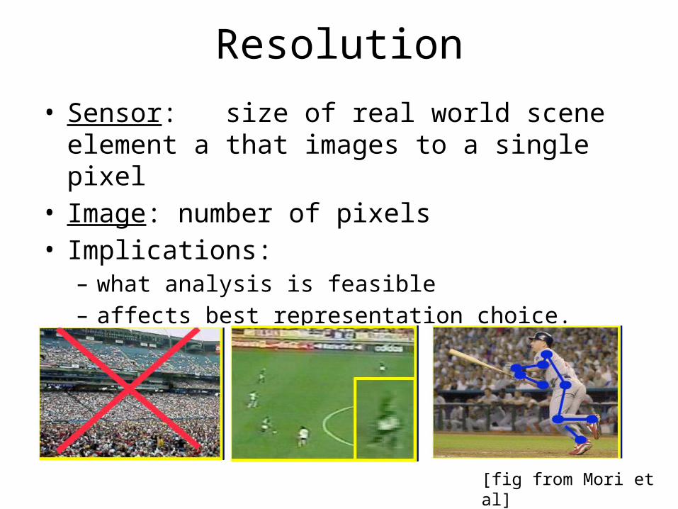
Resolution• Sensor: size of real world scene element a that
images to a single pixel• Image: number of pixels• Implications:
– what analysis is feasible– affects best representation choice.
[fig from Mori et al]
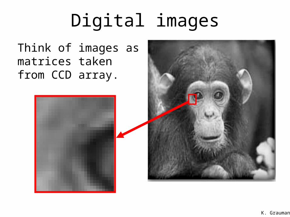
Digital imagesThink of images as matrices taken from CCD array.
K. Grauman
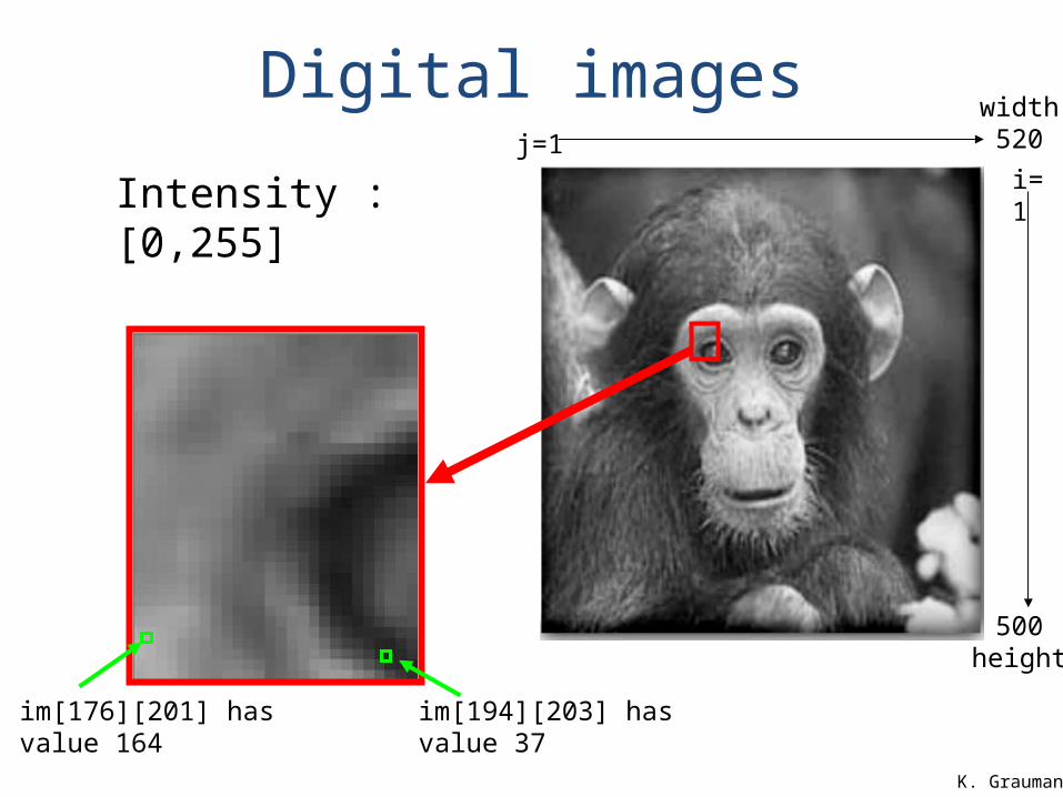
im[176][201] has value 164 im[194][203] has value 37
width 520j=1
500 height
i=1Intensity : [0,255]
Digital images
K. Grauman
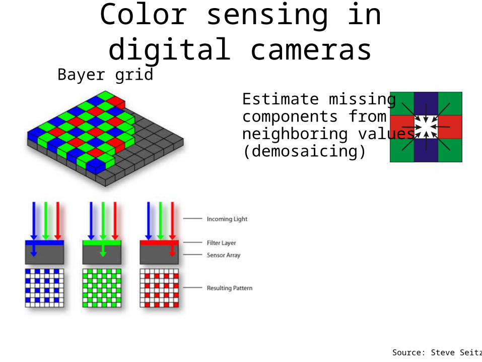
Color sensing in digital cameras
Source: Steve Seitz
Estimate missing components from neighboring values(demosaicing)
Bayer grid
R G B
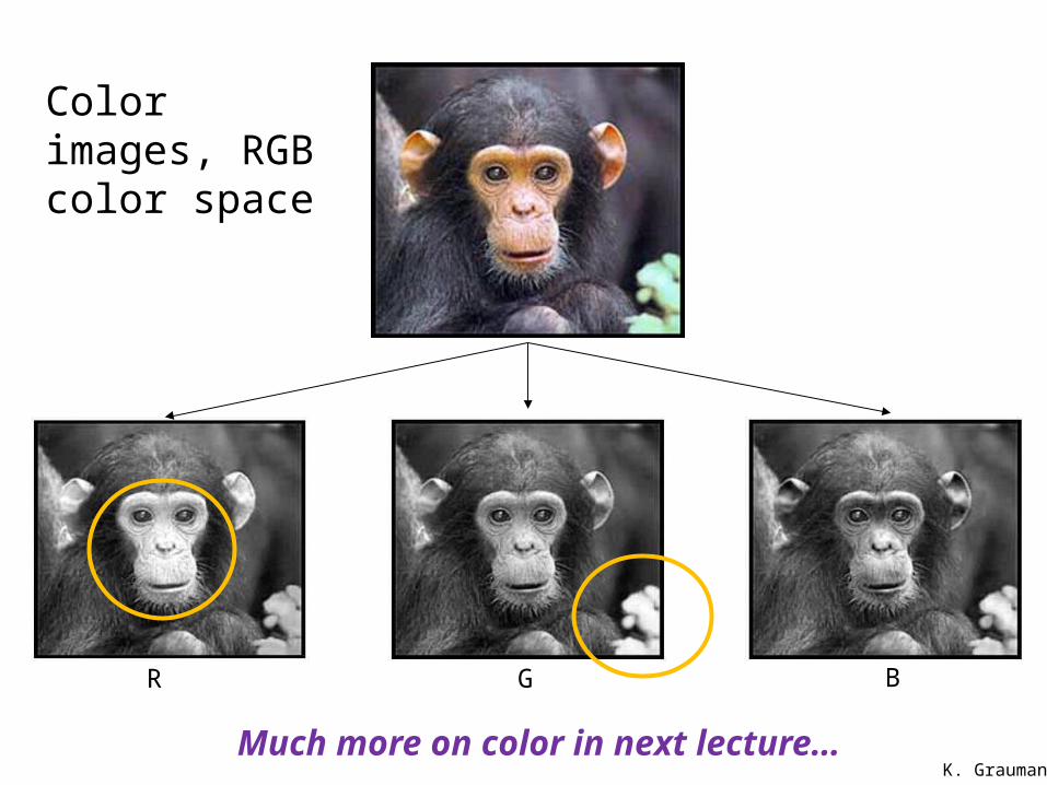
Color images, RGB color space
K. GraumanMuch more on color in next lecture…

Physical parameters of image formation
• Geometric– Type of projection– Camera pose
• Optical– Sensor’s lens type– focal length, field of view, aperture
• Photometric– Type, direction, intensity of light reaching sensor– Surfaces’ reflectance properties
• Sensor– sampling, etc.
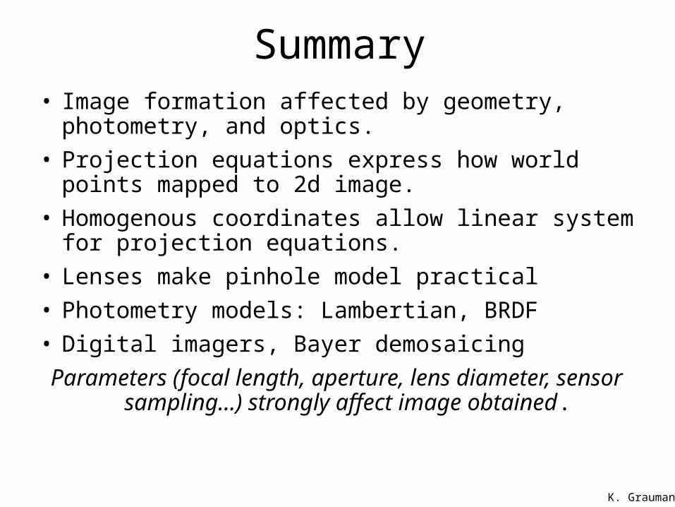
Summary• Image formation affected by geometry, photometry, and
optics.• Projection equations express how world points mapped to
2d image.• Homogenous coordinates allow linear system for
projection equations.• Lenses make pinhole model practical• Photometry models: Lambertian, BRDF• Digital imagers, Bayer demosaicing
Parameters (focal length, aperture, lens diameter, sensor sampling…) strongly affect image obtained.
K. Grauman

Slide Credits
• Trevor Darrell• Bill Freeman• Steve Seitz• Kristen Grauman• Forsyth and Ponce• Rick Szeliski• and others, as marked…


![Maintaining Natural Image Statistics with the Contextual ... · arXiv:1803.04626v3 [cs.CV] 18 Jul 2018. ... Firas Shama, Lihi Zelnik-Manor 1 Introduction \Facts are stubborn things,](https://img.pdfslide.net/doc/110x75/5f86214072e26e33020f045c/maintaining-natural-image-statistics-with-the-contextual-arxiv180304626v3.jpg)