Embed Size (px)
Citation preview
1
All rights reserved by SGCC P1
The Progress on the Electromagnetic Environment Study of UHVDC Transmission
Lines in SGCC
P2 All rights reserved by SGCC
Contents
1 Background
2 Summary for Electromagnetic Environment Studies in China
3 Calculation Studies on Electromagnetic Environment
4 Test Studies on Electromagnetic Environment
5 Experiment on the DC Test Line with High Altitude at Tibet
6 Study on ±800kV DC Line with Vertical Arrangement
7 Study on ±800kV DC line with Double-circuit
8 Conclusion
P3 All rights reserved by SGCC
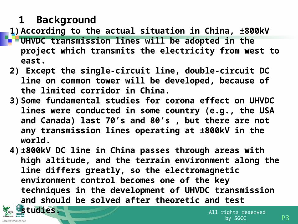
1 Background
1) According to the actual situation in China, ±800kV UHVDC transmission lines will be adopted in the project which transmits the electricity from west to east.
2) Except the single-circuit line, double-circuit DC line on common tower will be developed, because of the limited corridor in China.
3) Some fundamental studies for corona effect on UHVDC lines were conducted in some country (e.g., the USA and Canada) last 70’s and 80’s , but there are not any transmission lines operating at ±800kV in the world.
4) ±800kV DC line in China passes through areas with high altitude, and the terrain environment along the line differs greatly, so the electromagnetic environment control becomes one of the key techniques in the development of UHVDC transmission and should be solved after theoretic and test studies.
P4 All rights reserved by SGCC
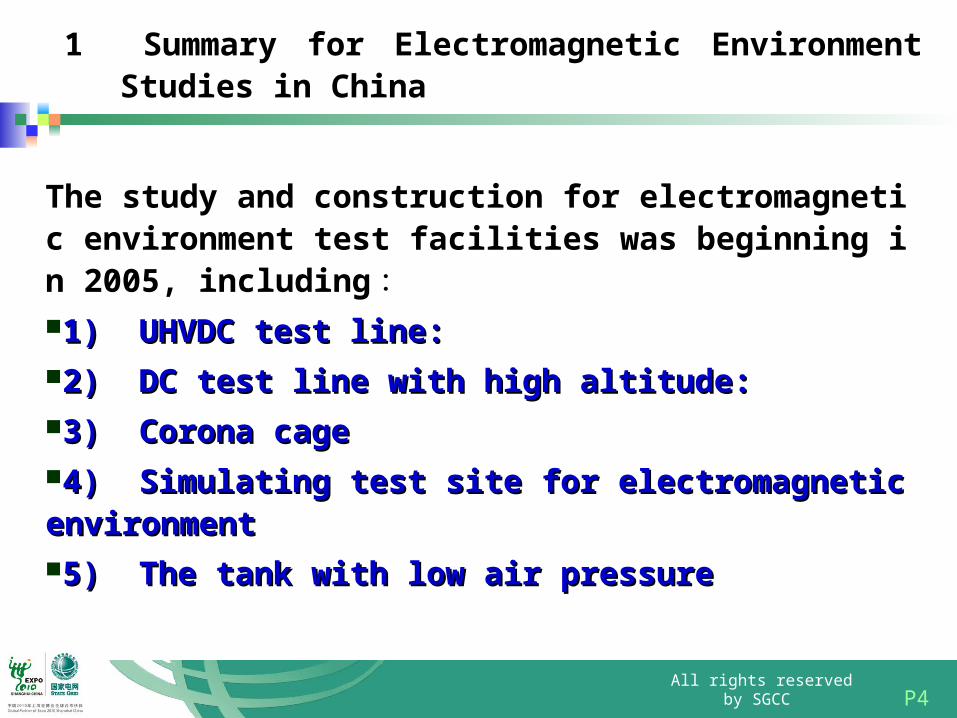
1 Summary for Electromagnetic Environment Studies in China
The study and construction for electromagnetic environment test facilities was beginning in 2005, including :1) UHVDC test line:1) UHVDC test line:2) DC test line with high altitude:2) DC test line with high altitude:3) Corona cage3) Corona cage4) Simulating test site for electromagnetic environment 4) Simulating test site for electromagnetic environment 5) The tank with low air pressure5) The tank with low air pressure
P5 All rights reserved by SGCC
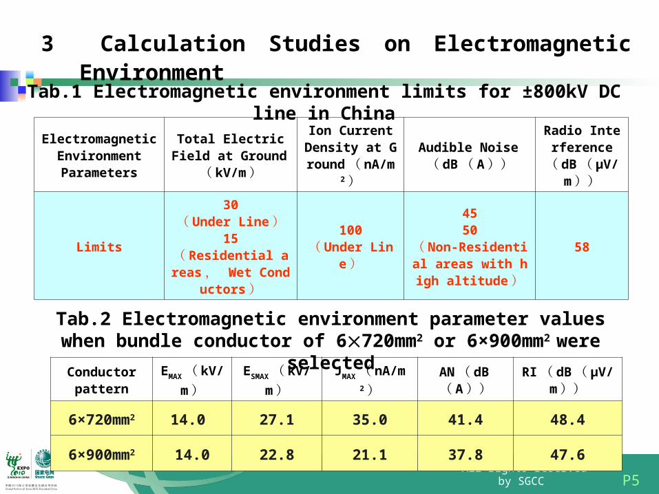
3 Calculation Studies on Electromagnetic Environment
Electromagnetic Environment Parameters
Total Electric Field at Ground( kV/m)
Ion Current Density at Ground( nA/m2)
Audible Noise( dB( A))
Radio Interference
( dB( μV/m))
Limits
30( Under Line)
15( Residential areas , Wet Conducto
rs)
100( Under Lin
e)
4550
( Non-Residential areas with high alt
itude)
58
Tab.1 Electromagnetic environment limits for ±800kV DC line in China
Tab.2 Electromagnetic environment parameter values when bundle conductor of 6720mm2 or 6×900mm2 were selected
Conductor pattern
EMAX( kV/
m)ESMAX( kV/
m)JMAX( nA/m
2)AN( dB( A))
RI( dB( µV/m))
6×720mm2
14.0 27.1 35.0 41.4 48.4
6×900mm2
14.0 22.8 21.1 37.8 47.6
P6 All rights reserved by SGCC
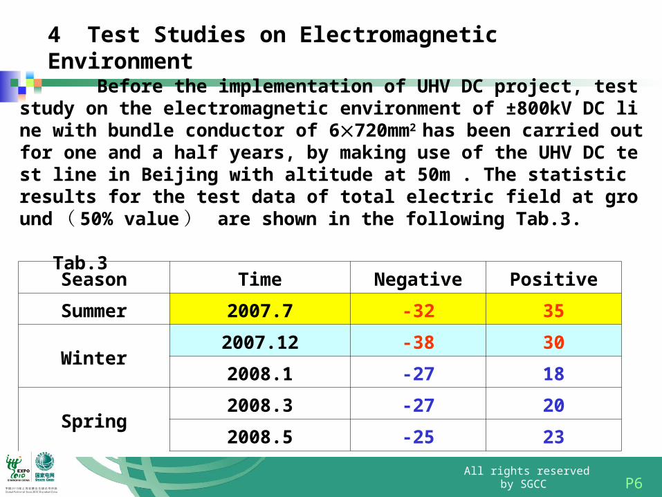
4 Test Studies on Electromagnetic Environment
Before the implementation of UHV DC project, test study on the electromagnetic environment of ±800kV DC line with bundle conductor of 6720mm2 has been carried out for one and a half years, by making use of the UHV DC test line in Beijing with altitude at 50m . The statistic results for the test data of total electric field at ground ( 50% value ) are shown in the following Tab.3. Tab.3
Season Time Negative Positive
Summer 2007.7 -32 35
Winter2007.12 -38 30
2008.1 -27 18
Spring2008.3 -27 20
2008.5 -25 23
P7 All rights reserved by SGCC
4 Test Studies on Electromagnetic Environment
-45
-30
-15
0
15
30
45
-50 -40 -30 -20 -10 0 10 20 30 40 50
di stance f rom the center of test l i ne / m
tota
l el
ectr
ic fi
eld
/kV/
m
20 40~ %40 60~ %60 80~ %>80%
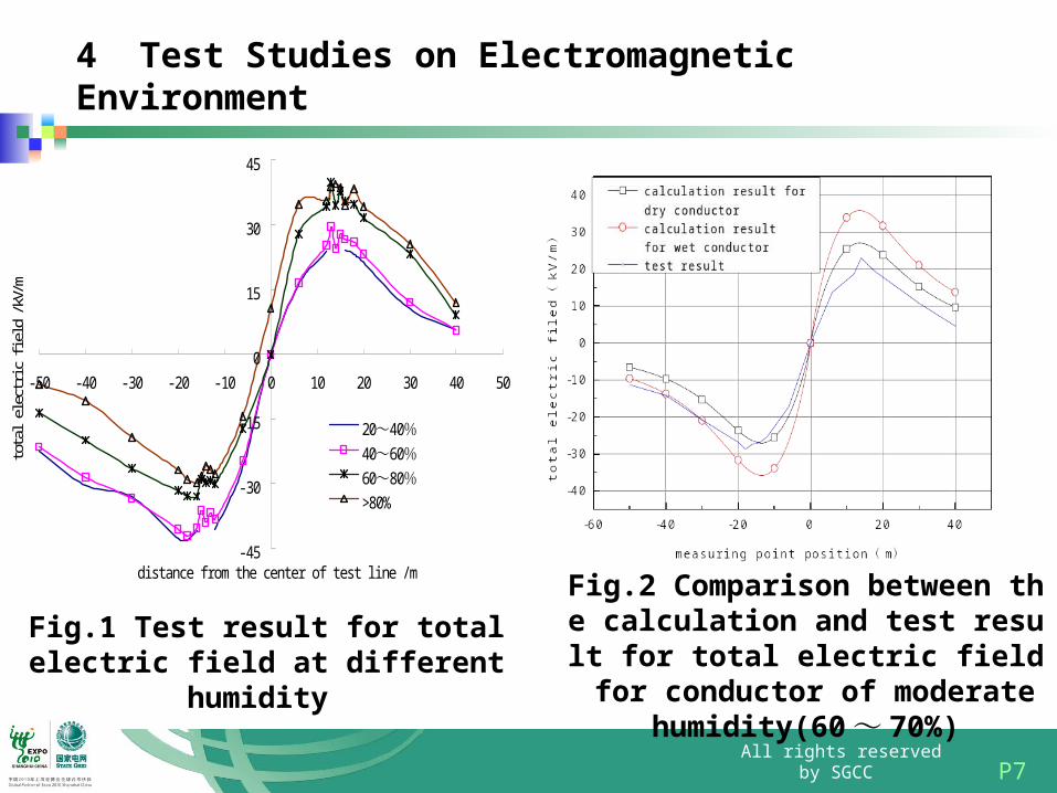
Fig.1 Test result for total electric field at different humidity
Fig.2 Comparison between the calculation and test result for total electric field for conductor of moderate humidit
y(60 ~ 70%)
P8 All rights reserved by SGCC
4 Test Studies on Electromagnetic Environment
38
39
40
41
42
43
44
45
0 5 10 15 20 25di stance f rom proj ecti on of posi t i ve pol e conductor / m
AN /
dB(A
)
t estcal cul at i on
30
35
40
45
50
55
60
-60 -40 -20 0 20 40
Di stance f rom proj ect i on of posi t i ve pol e Conductor / m
RI /
dB(μ
V/m)
CI SPR Formul a
EPRI Formul a
Measured Val ue
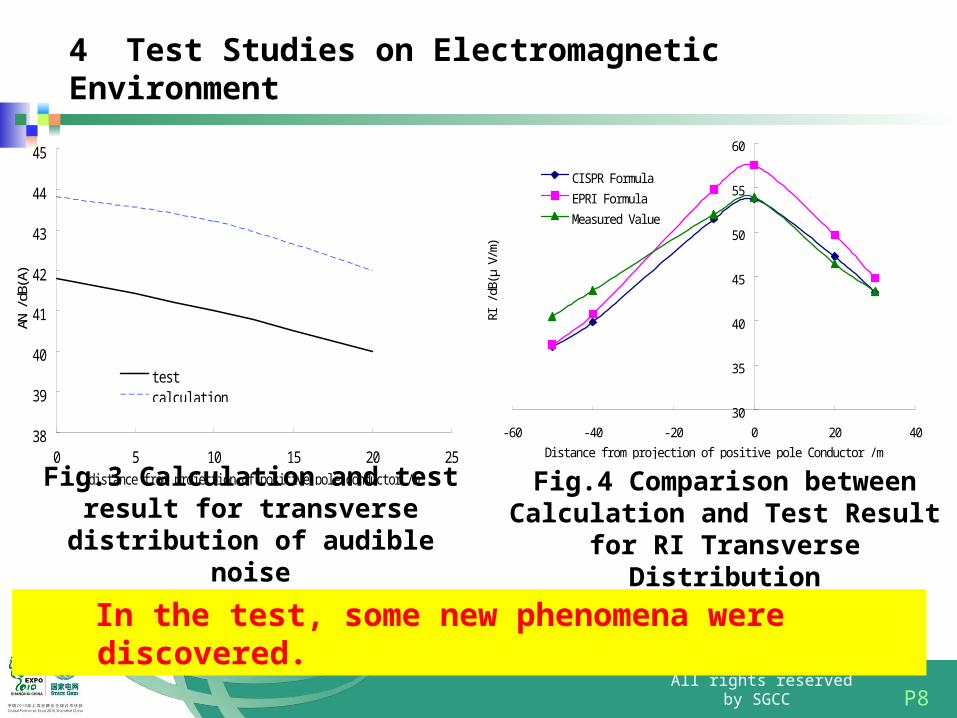
Fig.3 Calculation and test result for transverse distribution of audible noise
Fig.4 Comparison between Calculation and Test Result for RI Transverse
Distribution
In the test, some new phenomena were discovered.
P9 All rights reserved by SGCC
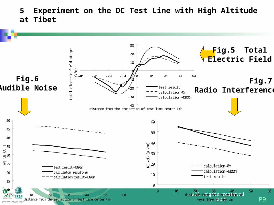
5 Experiment on the DC Test Line with High Altitude at Tibet
-40
-30
-20
-10
0
10
20
30
-40 -30 -20 -10 0 10 20 30 40
di stance f rom the proj ect i on of test l i ne center m( )
tota
l elec
tric
fi
eld
at gr
ound
kV/m
()
test resul t
cal cul at i on-0m
cal cul at i on-4300m
10
15
20
25
30
35
40
45
50
0 10 20 30 40 50 60di stance f rom the proj ect i on of test l i ne center m( )
AN [
dBA
](
)
test resul t-4300mcal cul aton resul t-0mcal cul at i on resul t-4300m
0
10
20
30
40
50
60
0 10 20 30 40 50 60di stance f rom the proj ect i on of
test l i ne center / m
RI /
dBμ
V/m
()
cal cul at i on-0mcal cul at i on-4300mtest resul t
Fig.5 Total Electric Field
Fig.6 Audible Noise
Fig.7 Radio Interference
P10 All rights reserved by SGCC
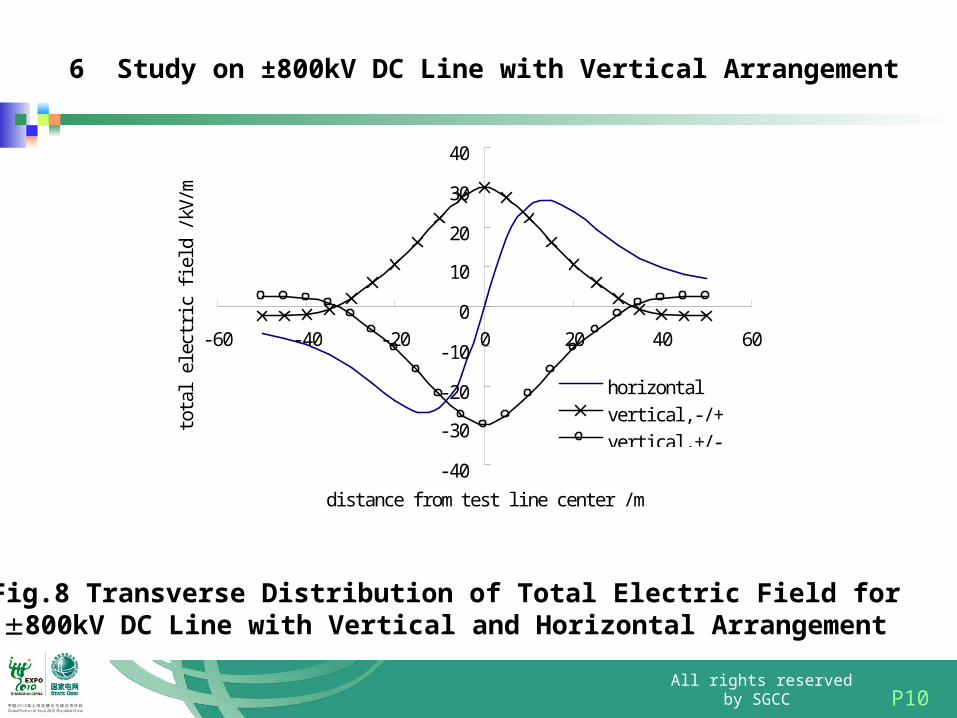
6 Study on ±800kV DC Line with Vertical Arrangement
-40
-30
-20
-10
0
10
20
30
40
-60 -40 -20 0 20 40 60
di stance f rom test l i ne center / m
tota
l el
ectr
ic fi
eld
/kV/
m
hori zontalverti cal , - / +verti cal , +/ -
Fig.8 Transverse Distribution of Total Electric Field for 800kV DC Line with Vertical and Horizontal Arrangement
P11 All rights reserved by SGCC
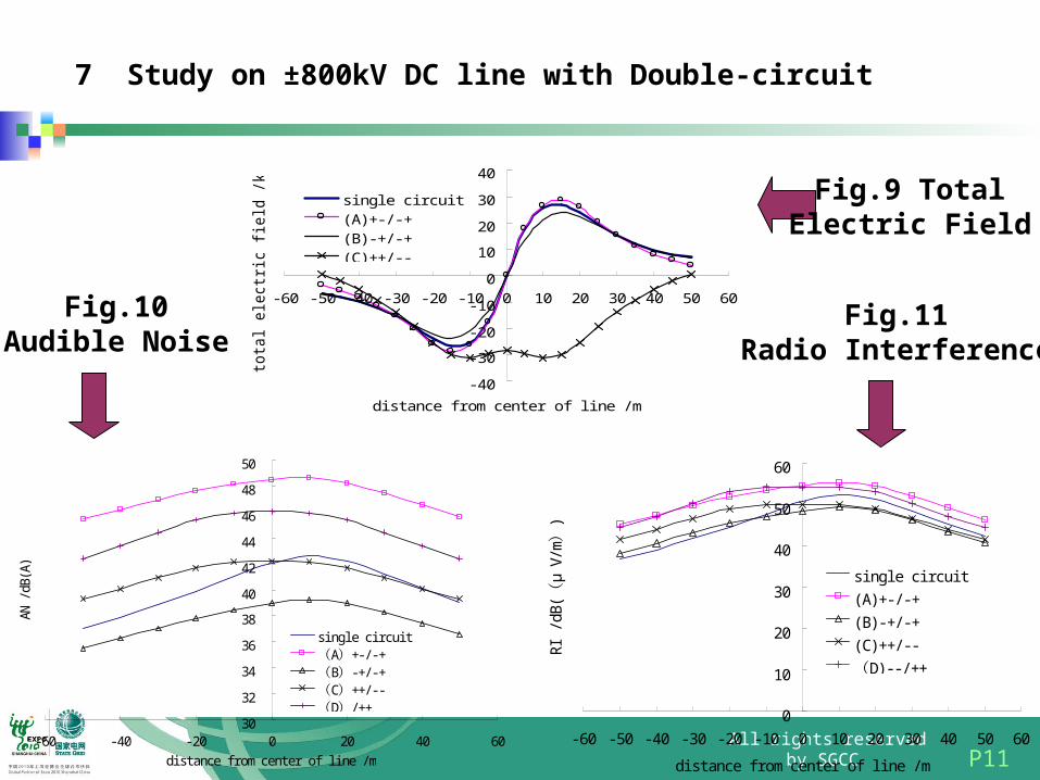
7 Study on ±800kV DC line with Double-circuit
Fig.9 Total Electric Field
Fig.10 Audible Noise
Fig.11 Radio Interference
- 40
- 30
- 20
- 10
0
10
20
30
40
- 60 - 50 - 40 - 30 - 20 - 10 0 10 20 30 40 50 60
di stance f rom center of l i ne / m
total electric fi
eld /kV/m
si ngl e ci rcui t(A)+- / - +(B) - +/ - +(C)++/ - -
30
32
34
36
38
40
42
44
46
48
50
-60 -40 -20 0 20 40 60di stance f rom center of l i ne / m
AN /
dB(A
)
si ngl e ci rcui tA +- / -+( )B -+/ -+( )C ++/ - -( )D / ++( ) 0
10
20
30
40
50
60
- 60 - 50 - 40 - 30 - 20 - 10 0 10 20 30 40 50 60
di stance f rom center of l i ne / m
RI /
dB(
μV/
m)
()
si ngl e ci rcui t
(A)+- / - +
(B) - +/ - +
(C)++/ - -
D) - - / ++(
P12 All rights reserved by SGCC
8 Conclusion
1) The calculation method for the electromagnetic environment of ±800kV DC line that the pole conductors are arranged horizontally or vertically, or double-circuit has been obtained in SGCC.
2) Test facilities such as UHVDC test line at Beijing, DC test line at Tibet with high altitude and corona cage and so on, provide powerful test means for electromagnetic environment study on UHVDC line.
3) The theoretical and test results indicate that, the electromagnetic environment for ±800kV DC line in China is at the same level of that for EHV DC line, and satisfies the limit requirement.
4) The electromagnetic environment of DC line is obviously influenced by the climate and altitude. The systemic theoretical and test study will be continued by using the UHVDC electromagnetic environment test facilities in China.
P13 All rights reserved by SGCC
Thank You