Embed Size (px)
Citation preview

OTCF Coupling Capacitor Voltage Transformers 72.5 kV to 765 kV
INSTRUMENT TRANSFORMERS
1
Designed for long service life
Decades of experience have resulted in strong and reliable units, able to meet the highest standards. These units are manufactured using the most modern insulation impregnation technology and equipment.
Alstom Grid CVT’s provide excellent reliability because the major insulation of the CVT, the capacitor stack, comprised of homogeneously assembled capacitor elements, is extremely surge resistant irrespective of the waveform of the surge voltage.
CVT insulation integrity is assured by the fact that a metallic bellows assembly hermetically seals the oil from the atmosphere.
All external parts are made from marine grade aluminum and stainless steel hardware is used, no painting is required.
Customer Benefits • Conservative and safe design • Extensive field and extreme climate experience, including high seismic regions • Operation as coupling capacitor for power line carrier • Rugged, leak-proof design • Maintenance-free • Easy transport and installation
GRID
In high and extra high voltage transmission systems, capacitor voltage transformers (CVTs) are used to provide potential outputs to metering instruments and protective relays.In addition, when equipped with carrier accessories, CVTs can be used for power line carrier (PLC) coupling.
• For revenue metering and protection in high voltage networks
• PLC application
• Performance: - Vm: 36 to 765 kV- Accuracy classes from 0.15 % to 1.2 %
• Characteristics:
- High quality film / paper-oil insulation - Oil expansion by stainless steel bellows - Superior transient response - Porcelain or composite insulator
• Seismic withstand capability:
The standard OTCF resists medium intensity seismic events. For highly active seismic regions, the design is adapted accordingly.
• Compliance with ANSI / IEEE, IEC or equivalent standards.
OTCF COUPLING CAPACITOR VOLTAGE TRANSFORMERS INSTRUMENT TRANSFORMERS
2
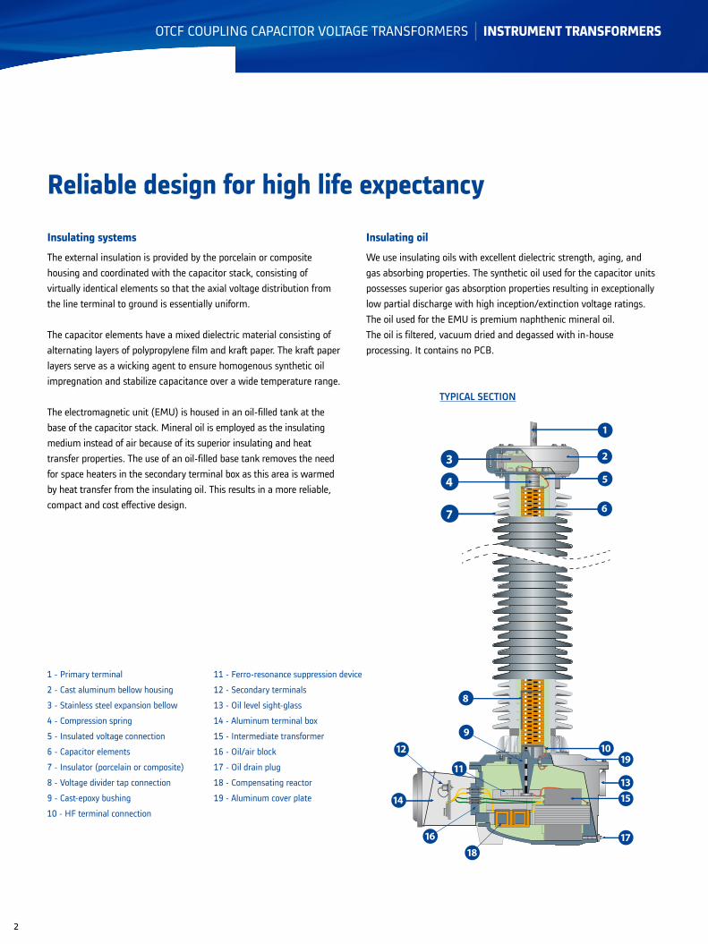
Insulating systems
The external insulation is provided by the porcelain or composite housing and coordinated with the capacitor stack, consisting of virtually identical elements so that the axial voltage distribution from the line terminal to ground is essentially uniform.
The capacitor elements have a mixed dielectric material consisting of alternating layers of polypropylene film and kraft paper. The kraft paper layers serve as a wicking agent to ensure homogenous synthetic oil impregnation and stabilize capacitance over a wide temperature range.
The electromagnetic unit (EMU) is housed in an oil-filled tank at the base of the capacitor stack. Mineral oil is employed as the insulating medium instead of air because of its superior insulating and heat transfer properties. The use of an oil-filled base tank removes the need for space heaters in the secondary terminal box as this area is warmed by heat transfer from the insulating oil. This results in a more reliable, compact and cost effective design.
Reliable design for high life expectancy
1
3
6
2
5
7
8
4
13
1910
17
15
11
9
18
12
14
16
1 - Primary terminal
2 - Cast aluminum bellow housing
3 - Stainless steel expansion bellow
4 - Compression spring
5 - Insulated voltage connection
6 - Capacitor elements
7 - Insulator (porcelain or composite)
8 - Voltage divider tap connection
9 - Cast-epoxy bushing
10 - HF terminal connection
11 - Ferro-resonance suppression device
12 - Secondary terminals
13 - Oil level sight-glass
14 - Aluminum terminal box
15 - Intermediate transformer
16 - Oil/air block
17 - Oil drain plug
18 - Compensating reactor
19 - Aluminum cover plate
TYPICAL SECTION
Insulating oil
We use insulating oils with excellent dielectric strength, aging, and gas absorbing properties. The synthetic oil used for the capacitor units possesses superior gas absorption properties resulting in exceptionally low partial discharge with high inception/extinction voltage ratings.The oil used for the EMU is premium naphthenic mineral oil.The oil is filtered, vacuum dried and degassed with in-house processing. It contains no PCB.

OTCF COUPLING CAPACITOR VOLTAGE TRANSFORMERS INSTRUMENT TRANSFORMERS
3
Capacitor stack
The capacitor stack is a voltage divider which provides a reduced voltage at the interme-diate voltage bushing for a given voltage applied at the primary terminal.
The capacitor stack is a multi-capacitor-unit assembly. Each unit is housed in an individual insulator. A cast aluminum cover is on top of the upper capacitor assembly and is fitted with an aluminum terminal. An adapter for mounting a line trap on top of the CVT can be provided with an optional (and removable) HV terminal.
The capacitor units are mechanically coupled together by means of stainless steel hardware passing through the corrosion resistant cast aluminum bellows housing. The mechani-cal connection also establishes the electrical connection between capacitor units. This facilitates field assembly of the CVT.
Each capacitor unit is hermetically sealed; a stainless steel diaphragm (expansion bellow) preserves oil integrity by maintaining the her-metic seal while allowing for thermal expan-sion and contraction of the oil. The capacitor units operate in a practically pressure-free mode over a very wide ambient temperature range.
Thousands of installed units attest to their reliability
The capacitor stack consists of a series of capacitor elements. The dielectric spacers are a combination of kraft paper and polypropyl-ene film. The ratio of paper/film is carefully determined to provide constant capacitance for a wide range of operating temperature. The aluminum electrodes capacitor elements are precision wound by microprocessor controlled machinery. The capacitor elements are connected with low inductance tinned copper tabs. The stack assemblies are hydraulically compressed and bound with epoxy fiberglass tape to obtain the optimum space factor for capacitance requirement and oil circulation. This capacitor design results in stable accu-racy performance over time and temperature.
After assembly in the insulator, capaci-tor units are individually oven dried under vacuum and then impregnated with the processed synthetic oil.
OTCF COUPLING CAPACITOR VOLTAGE TRANSFORMERS INSTRUMENT TRANSFORMERS
4
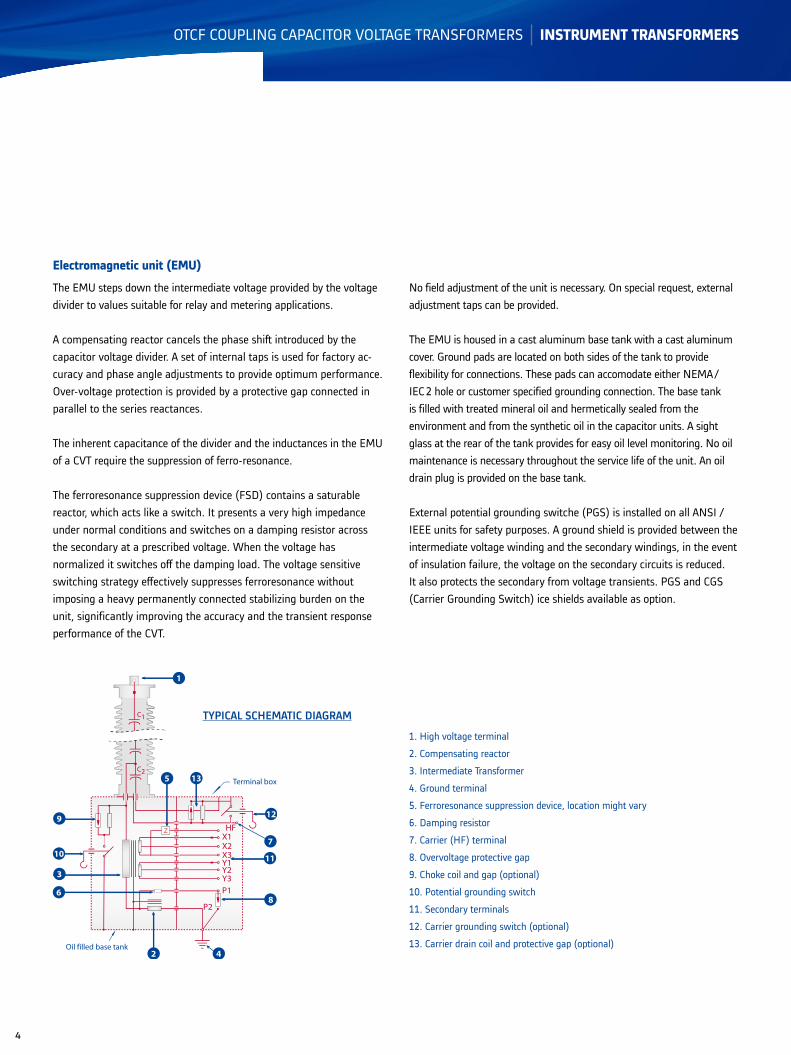
Electromagnetic unit (EMU)
The EMU steps down the intermediate voltage provided by the voltage divider to values suitable for relay and metering applications.
A compensating reactor cancels the phase shift introduced by the capacitor voltage divider. A set of internal taps is used for factory ac-curacy and phase angle adjustments to provide optimum performance. Over-voltage protection is provided by a protective gap connected in parallel to the series reactances.
The inherent capacitance of the divider and the inductances in the EMU of a CVT require the suppression of ferro-resonance.
The ferroresonance suppression device (FSD) contains a saturable reactor, which acts like a switch. It presents a very high impedance under normal conditions and switches on a damping resistor across the secondary at a prescribed voltage. When the voltage has normalized it switches off the damping load. The voltage sensitive switching strategy effectively suppresses ferroresonance without imposing a heavy permanently connected stabilizing burden on the unit, significantly improving the accuracy and the transient response performance of the CVT.
1. High voltage terminal
2. Compensating reactor
3. Intermediate Transformer
4. Ground terminal
5. Ferroresonance suppression device, location might vary
6. Damping resistor
7. Carrier (HF) terminal
8. Overvoltage protective gap
9. Choke coil and gap (optional)
10. Potential grounding switch
11. Secondary terminals
12. Carrier grounding switch (optional)
13. Carrier drain coil and protective gap (optional)
No field adjustment of the unit is necessary. On special request, external adjustment taps can be provided.
The EMU is housed in a cast aluminum base tank with a cast aluminum cover. Ground pads are located on both sides of the tank to provide flexibility for connections. These pads can accomodate either NEMA /IEC 2 hole or customer specified grounding connection. The base tank is filled with treated mineral oil and hermetically sealed from the environment and from the synthetic oil in the capacitor units. A sight glass at the rear of the tank provides for easy oil level monitoring. No oil maintenance is necessary throughout the service life of the unit. An oil drain plug is provided on the base tank.
External potential grounding switche (PGS) is installed on all ANSI / IEEE units for safety purposes. A ground shield is provided between the intermediate voltage winding and the secondary windings, in the event of insulation failure, the voltage on the secondary circuits is reduced. It also protects the secondary from voltage transients. PGS and CGS (Carrier Grounding Switch) ice shields available as option.
X1X2X3Y1Y2Y3
P1
P2
HF
Oil filled base tank
6
C2
C1
1
Terminal box
Z
12
7
11
8
9
10
3
135
42
TYPICAL SCHEMATIC DIAGRAM
OTCF COUPLING CAPACITOR VOLTAGE TRANSFORMERS INSTRUMENT TRANSFORMERS
5
Carrier accessories
When the CVT is equipped with carrier accessories for PLC service, an external carrier grounding switch (CGS) and carrier entrance bushing are provided in the terminal box. The carrier accessories include a carrier drain coil with protective spark gap. A choke coil and a protective spark gap are installed in the base tank when a potential ground switch (PGS) is provided to prevent the loss of the carrier signal when the PGS is in the closed position.
Secondary terminal box
The terminal box is spacious and can accommodate all required connections. The secondaries of the EMU are brought out of the base tank through an oil/air seal block assembly and terminated on separate terminal blocks with 8-32 screws. Other terminals on request. The secondary terminal box area is warmed by heat transfer from the oil filled tank. This prevents condensation in the terminal box and removes the need for a space heater in service. An aluminum gland plate is provided to accommodate customer conduit hubs. The door can be made lockable on request. An interlock with the PGS can be provided on request.
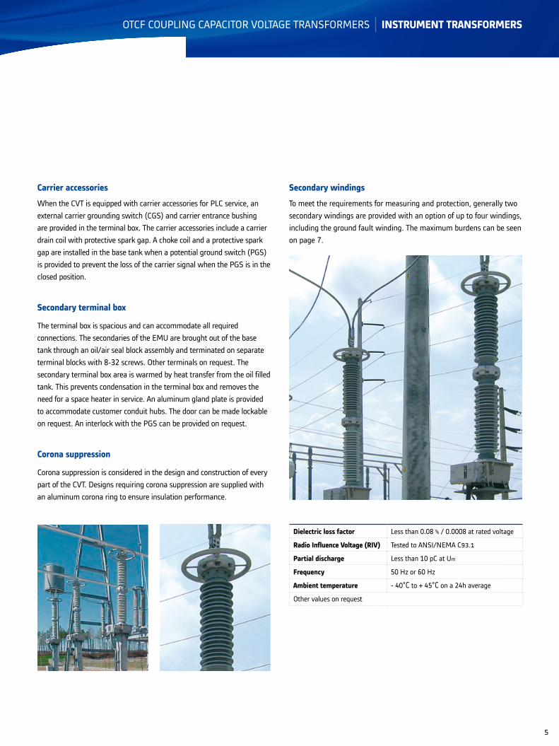
Corona suppression
Corona suppression is considered in the design and construction of every part of the CVT. Designs requiring corona suppression are supplied with an aluminum corona ring to ensure insulation performance.
Dielectric loss factor Less than 0.08 % / 0.0008 at rated voltage
Radio Influence Voltage (RIV) Tested to ANSI/NEMA C93.1
Partial discharge Less than 10 pC at Um
Frequency 50 Hz or 60 Hz
Ambient temperature - 40°C to + 45°C on a 24h average
Other values on request
Secondary windings
To meet the requirements for measuring and protection, generally two secondary windings are provided with an option of up to four windings, including the ground fault winding. The maximum burdens can be seen on page 7.
OTCF COUPLING CAPACITOR VOLTAGE TRANSFORMERS INSTRUMENT TRANSFORMERS
6
Insulator
The outer insulation consists of a high-quality porcelain in grey (ANSI 70) or brown (RAL 8016). High creepage distances are available as standard according to the dimension tables. Extra high creepage distances are available on request.On special request, Alstom Grid can offer CVTs with a composite insulator consisting of an epoxy resin fiberglass tube with silicone rubber sheds.
Ambient conditions
All OTCF are designed to operate in ambient temperature from - 40°C to + 45°C, withstand wind speeds of 100 mph, site location up to 3300 ft and 0.2 g lateral force. Alstom Grid can design to meet unusual site conditions when specified.
Service life and maintenance
OTCF have been designed for a 30 years plus lifetime. They have near-zero maintenance requirements: the oil is hermetically sealed from the air by a stainless steel diaphragm assembly and all external parts are of corrosion-resistant material.
Tests
Routine tests are performed in accordance with national, international and internal quality standards. Each capacitor unit is routine tested for lightning impulse, power-frequency withstand, partial discharge, dissipation factor and capacitance. A routine test report is provided for each unit. Existing type test rep orts can be provided on request.
Partial dischargesFor the capacitor units, the partial discharge intensity is less than 5 pC at 1.2 Um /√ 3 and less than 10 pC at Um after the power frequency voltage test.
Ferro-resonance check After routine accuracy tests, the unit is checked for ferro-resonance suppression by applying secondary short-circuits. The secondary voltage is monitored with an oscilloscope to ensure that the recovery of normal waveform is satisfactory.
Dissipation factor or Tan δDissipation factor measured at the rated voltage is less than 0.08 %.
Inquiry check list
• Applicable standards
• Rated frequency
• Highest system voltage
• Power-frequency withstand test voltage
• Lightning impulse test voltage
• Switching impulse test voltage, if applicable
• Rated capacitance Cn in pF
• Overvoltage factor (ex. 1.5 Un 30 s)
• Voltage ratio
• Number of secondaries
• Accuracy class and rated burden for each secondary winding
• Transient response
• Thermal burden
• Environmental conditions (altitude, temperature, site pollution, seismic conditions…)
• Required creepage distance in mm or in mm/kV
• Options as required:
- HV terminal (material and dimensions)
- Carrier accessories
- Composite insulator (light grey)
- Suspension mounting
- Secondary terminal box heater
- HV and ground connectors
- Line trap adapter
If a line trap is to be mounted on the CVT, please specify the weight and
overall dimensions and load conditions.

OTCF COUPLING CAPACITOR VOLTAGE TRANSFORMERS INSTRUMENT TRANSFORMERS
7
Designation
OTCF ... SRStandard High Capacitance
Relay Accuracy
OTCF ... SIStandard High Capacitance
Intermediate Accuracy
OTCF ... SMStandard High Capacitance
Meter Accuracy
OTCF ... IRIntermediate High Capacitance
Relay Accuracy
OTCF ... IIIntermediate High Capacitance
Intermediate Accuracy
OTCF ... IMIntermediate High Capacitance
Meter Accuracy
OTCF ... ERExtra High Capacitance
Relay Accuracy
OTCF ... EMExtra High Capacitance
Meter Accuracy
Easy transport and installation
CVTs must be transported and stored in the upright position. Multi capacitor unit assemblies are delivered with the upper capacitor units packed in the same crate.
The base unit and upper stack elements can easily be assembled by following the instruction manual. No special tools are required.
The following capacitances are standard for the various voltage levels
Type (Vm [kV])... SR... SM... SI
... IM... II... IR
... ER... EM
Capacitance (pF)*
OTCF 72.5 12500 16700 37500
OTCF 123 7500 10000 22500
OTCF 145 6250 8300 18800
OTCF 170 5250 6700 16200
OTCF 245 3750 5000 11250
OTCF 362 2650 3350 8100
OTCF 550 1750 2250 5400
OTCF 765 4000
*other values on request
The following burdens (as a sum of all windings except the ground fault winding) can be achieved.
TYPE OTCF
SRER
IRSI II SM IM EM
Rated burden according to IEEE
60 Hz 1.2 Z 0.6 Z 0.6 Z 0.3 Z 0.3 ZZ 0.3 ZZ
Thermal burden (VA)
60 Hz 1000 1000 1000 1000 1000 1500
Transient response
Residual voltage
(1 cycle)
9%@ZT (SR)
6%@ZT (ER)
8%@ZT (IR)
9%@ZT (II)9%@ZT 9%@ZT
9%@ZZTor
6.5%@ZT5%@ZZT
Ratings
Capacitive voltage transformers can be rated for metering and/or protection purposes. Accuracy 0.15 on request.

OTCF COUPLING CAPACITOR VOLTAGE TRANSFORMERS INSTRUMENT TRANSFORMERS
Dimensions
The following dimensions refer to standard versions.Other requirements affect dimensions and weights.
Indicative value only - All dimensions must be confirmed with order.
DimensionsMaximum system voltage (Vm) kV 72.5 123 145 170 245 362 550 765Impulse test voltage (BIL) kV 350 550 650 750 1050 1300 1800 2100
OTCF Creepage distance in 63.7 115.9 139.2 170.7 231.9 341.3 512.0 -... SR Dimensions in A 50.6 65.0 73.1 82.2 113.5 148 213.7 -... SI B 22.8 37.2 45.4 54.4 37.2 54.4 54.4 -... II C 19.1 19.1 19.1 19.1 19.1 19.1 19.1 -... IR Ø D Ø 14 Ø 14 Ø 14 Ø 14 Ø 25.5 Ø 34 Ø 34 - E - - - - 11.3 11.3 2 x 11.3 - Total weight (approx.) pound 408 496 505 542 730 811 1.078.0 - Weight of oil (approx.) gal 7.8 8.3 8.8 9.0 10.5 12.0 15 -
OTCF Creepage distance in 63.7 115.9 139.2 170.7 231.9 341.3 512 -... IM Dimensions in A 52 66.4 74.6 83.6 114.9 149.4 215.1 -... SM B 22.8 37.2 45.4 54.4 37.2 54.4 54.4 - C 20.5 20.5 20.5 20.5 20.5 20.5 20.5 - Ø D Ø 14 Ø 14 Ø 14 Ø 14 Ø 25.5 Ø 34 Ø 34 - E - - - - 11.3 11.3 2 x 11.3 - Total weight (approx.) pound 575 668 677 712.0 906 981 1248 - Weight of oil (approx.) gal 11.8 12.8 13.3 13.5 15.1 16.5 19.5 -
OTCF Creepage distance in 62.9 108.5 134.6 172.0 216.9 344.1 516.1 688.2... ER Dimensions in A 51.9 66.3 74.3 84.8 116.3 153.3 221.9 290.5 B 22.8 37.2 45.2 55.7 37.2 55.7 55.7 55.7 C 20.2 20.2 20.2 20.2 20.2 20.2 20.2 20.2 Ø D Ø 17.6 Ø 17.6 Ø 17.6 Ø 17.6 Ø 34 Ø 34 Ø 34 Ø 40 E - - - - 12.9 12.9 2 x 12.9 3 x 12.9 Total weight (approx.) pound 525 611 710 827 970.0 1385 1936 2491 Weight of oil (approx.) gal 10.1 11.7 12.7 14.1 17.4 22.2 30.3 38.4
OTCF Creepage distance in 62.9 108.5 134.6 172.0 216.9 344.1 516.1 688.2... EM Dimensions in A 53.3 67.7 75.7 86.2 117.8 154.7 223.3 291.9 B 22.8 37.2 45.2 55.7 37.2 55.7 55.7 55.7 C 21.6 21.6 21.6 21.6 21.6 21.6 21.6 21.6 Ø D Ø 17.6 Ø 17.6 Ø 17.6 Ø 17.6 Ø 34 Ø 34 Ø 34 Ø 40 E - - - - 12.9 12.9 2 x 12.9 3 x 12.9 Total weight (approx.) pound 694 780 880 996 1140 1554 2105 2661 Weight of oil (approx.) gal 14.6 16.2 17.2 18.6 21.9 26.7 34.8 42.9
Grid
-Pro
duct
s-L3
-OTC
F-AN
SI-7
1508
-201
0-11
-EN
- ©
- Al
stom
Grid
- 20
08. A
lsto
m G
rid, t
he A
lsto
m G
rid lo
go a
nd a
ny a
ltern
ativ
e ve
rsio
n th
ereo
f are
trad
emar
ks a
nd se
rvic
e m
arks
of A
lsto
m G
rid. A
ll tr
ade
nam
es o
r tra
dem
arks
men
tione
d he
rein
whe
ther
regi
ster
ed o
r not
, ar
e th
e pr
oper
ty o
f the
ir ow
ners
. - 3
8919
1982
RCS
PAR
IS O
ur p
olic
y is
one
of c
ontin
uous
dev
elop
men
t. Ac
cord
ingl
y th
e de
sign
of o
ur p
rodu
cts
may
cha
nge
at a
ny ti
me.
Whi
lst e
very
effo
rt is
mad
e to
pro
duce
up
to d
ate
liter
atur
e, th
is b
roch
ure
shou
ld o
nly
be re
gard
ed a
s a
guid
e an
d is
inte
nded
for i
nfor
mat
ion
purp
oses
onl
y. Its
con
tent
s do
not
con
stitu
te a
n of
fer f
or s
ale
or a
dvis
e on
the
appl
icat
ion
of a
ny p
rodu
ct re
ferr
ed to
in it
. We
cann
ot b
e he
ld re
spon
sibl
e fo
r any
relia
nce
on a
ny d
ecis
ions
take
n on
its
cont
ents
with
out s
peci
fic a
dvic
e.
B
B
C
E
D
D
B
A
A
C
Basetankmounting pattern
16.4
11.4
GRID
Alstom Grid Worldwide Contact Centre www.grid.alstom.com/contactcentreTel.: +44 (0) 1785 250 070 www.grid.alstom.com
Alstom Grid Waynesboro One Ritz AvenueWaynesboro, Ga. 30830 Tel.: (706) 554-8800Fax: (706) 554-8808 [email protected]