Embed Size (px)
Citation preview
61
Always read the instructions before use
Safety Precautions
The following safety warnings need to be respected in order to prevent injury and/or damage that might be
caused by incorrect behaviour during repairs, inspections or maintenance to the Yoshi AWS Air Water
System. Please read this manual with care and follow the instructions it contains.
CAUTION
Failure to abide by the instructions indicated with this symbol could cause
serious damage to people or property.
Before commencing an inspection 1. Disconnect the power to the external control box of the YOSHI AWS to prevent the risk of electric shocks;
2. After disconnecting the current, wait for at least one minute to allow any residual electricity to dissipate.
Tecnocasa s.r.l. declines any responsibility for any damage whatsoever caused through the partial or
superficial reading of the information in this manual. The drawings and information in this manual may
change without notice.
YOSHI®AWS D3 Yoshi Air Water System SERVICE MANUAL 8-10-13-16-20-25 HP

62

63
CONTENTS
1 AWS identification ................................................................................................................... 65
Electrical and water connections GHP-AWS ......................................................................... 66 3 AWS unit specifications.......................................................................................................... 67 4 Dimensions ............................................................................................................................. 69 5 Refrigerant system operating .................................................................................................. 70
5.1 Cooling mode .................................................................................................................. 70 5.2 Heating mode .................................................................................................................. 70
6 Control panel........................................................................................................................... 72 6.1 Using the control panel selection keypad........................................................................ 72 6.2 Key functions................................................................................................................... 72 6.3 Control panel root directory ............................................................................................. 73
7 Switching the Yoshi AWS ducted unit on/off ........................................................................... 74 8 Language selection ................................................................................................................ 75 9 Menu ...................................................................................................................................... 78 10 User mode.............................................................................................................................. 79
10.1 Date and time menu ....................................................................................................... 80 10.2 Heating/cooling mode settings (user mode menu).......................................................... 81
11 Programming operating times ................................................................................................ 82 11.1 Timer programming menu .............................................................................................. 82 11.2 Timer setting................................................................................................................... 83 11.3 Time interval setting ....................................................................................................... 83
12 Setting the set point temperature.............................................................................................. 85 12.1 T set heat (heating) ........................................................................................................ 85 12.2 T set cool (cooling) ......................................................................................................... 86
13 Alarms .................................................................................................................................... 87 13.1 Alarms menu .................................................................................................................. 87 13.2 Alarms history menu....................................................................................................... 88 13.3 Alarms reset menu ......................................................................................................... 89 13.4 AWS alarms list .............................................................................................................. 89 13.5 GHP outdoor unit alarms list .......................................................................................... 90
14 Service mode menu ............................................................................................................... 92 14.1 I/O menu (AWS input and output signals) ...................................................................... 93
14.1.1 Analog input menu ........................................................................................................ 93 14.1.2 Digital input menu ......................................................................................................... 95 14.1.3 Digital outputs menu ..................................................................................................... 98
64
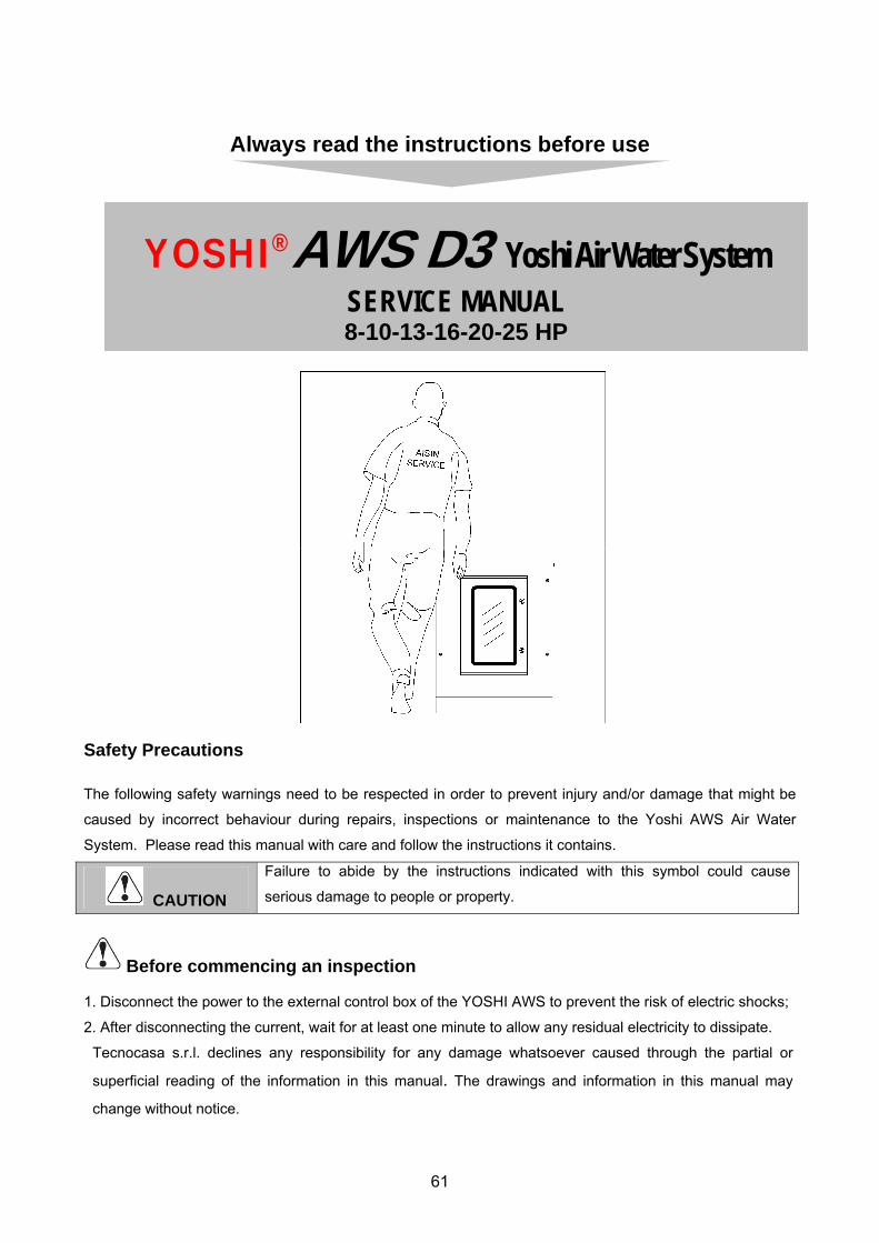
14.2 Pump control ................................................................................................................ 100 14.3 Mode selection ............................................................................................................. 101 14.4 Toffset cooling .............................................................................................................. 101 14.5 Toffset heating.............................................................................................................. 101 14.6 Pump delay .................................................................................................................. 102
15 Disabling the flow switch alarm ............................................................................................ 103 16 Wiring diagrams ................................................................................................................... 106 17 Relation between engine RPM and outside temperature...................................................... 112 18 Contact specifications .......................................................................................................... 118 19 Table temperature – sensor NTC resistor............................................................................ 119 20 Characteristics sensor gas and liquid pipe........................................................................... 120
65
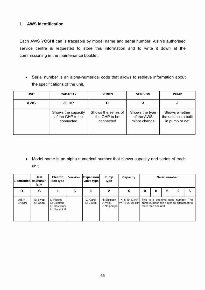
1 AWS identification
Each AWS YOSHI can is traceable by model name and serial number. Aisin’s authorised
service centre is requested to store this information and to write it down at the
commissioning in the maintenance booklet.
• Serial number is an alpha-numerical code that allows to retrieve information about
the specifications of the unit.
• Model name is an alpha-numerical number that shows capacity and series of each
unit.
Shows whether the unit hes a built
in pump or not
Shows the type of the AWS
minor change
Shows the series of the GHP to be
connected
Shows the capacity of the GHP to be
connected
J 3D20 HP AWS PUMP VERSION SERIESCAPACITY UNIT
5
This is a one-time used number. The same number can never be addressed to more than one unit.
X: 8-10-13 HP W: 16-20-25 HP
N: Salmson V: Wilo J: No pompa
C: Carel E: Eliwell
L: Picchio E: Electron C: Castellani H: Stacchiotti
S: Swep O: Onda AISIN
DAIKIN
620 0 XVC 6 L S D
Serial numberCapacity Pump type
Expansion valve type
Version Electric box type Heat
exchaner type
Electronics
66
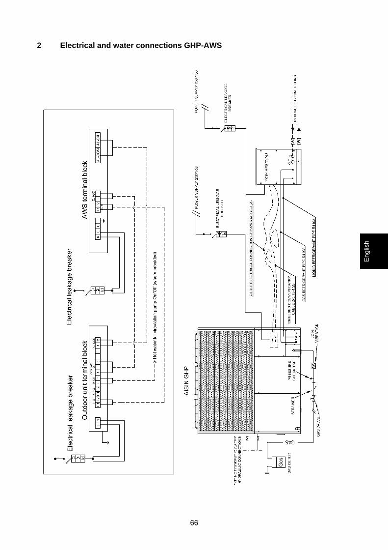
2 Electrical and water connections GHP-AWS
Engl
ish
67
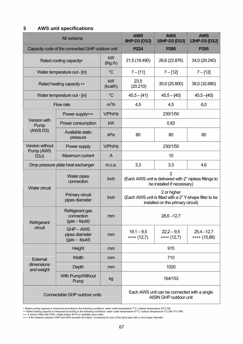
3 AWS unit specifications
All versions AWS 8HP-D3 (D3J)
AWS 10HP-D3 (D3J)
AWS 13HP-D3 (D3J)
Capacity code of the connected GHP outdoor unit P224 P280 P355
Rated cooling capacity∗ kW (frig./h) 21,5 (18.490) 26,6 (22.876) 34,0 (29.240)
Water temperature out - [in] °C 7 – [11] 7 – [12] 7 – [12]
Rated heating capacity ∗∗ kW (kcal/h)
23,5 (20.210) 30,0 (25.800) 38,0 (32.680)
Water temperature out - [in] °C 45,5 – [41] 45,5 – [40] 45,5 –[40]
Flow rate m3/h 4,5 4,5 6,0
Power supply∗∗∗ V/Ph/Hz 230/1/50
Power consumption kW 0,83 Version with Pump
(AWS D3) Available static pressure kPa 80 80 60
Power supply V/Ph/Hz 230/1/50 Version without Pump (AWS
D3J) Maximum current A 10
Drop pressure plate heat exchanger m.c.a. 3,3 3,3 4,6
Water pipes connection Inch
2 (Each AWS unit is delivered with 2” nipless fittings to
be installed if necessary) Water circuit
Primary circuit pipes diameter Inch
2 or higher (Each AWS unit is fitted with a 2” Y-shape filter to be
installed on the primary circuit)
Refrigerant gas connection
(gas – liquid) mm 28,6 –12,7
Refrigerant circuit GHP – AWS
pipes diameter (gas – liquid)
mm 19,1 – 9,5 ∗∗∗∗ (12,7)
22,2 – 9,5 ∗∗∗∗ (12,7)
25,4 –12,7 ∗∗∗∗ (15,88)
Height mm 915
Width mm 710
Depth mm 1020
External dimensions and weight
With Pump/Without Pump kg 164/153
Connectable GHP outdoor units Each AWS unit can be connected with a single AISIN GHP outdoor unit
∗ Rated cooling capacity is measured according to the following conditions: water outlet temperature 7°C; outdoor temperature 35°C DB ∗∗ Rated heating capacity is measured according to the following conditions: water outlet temperature 47°C; outdoor temperature 7°C DB / 6°C WB ∗∗∗ A version fitted with 230V, single phase, 60 Hz is available upon order. ∗∗∗∗ If the distance between GHP and AWS exceeds 40 meters, increasing the size of the liquid pipe with a more larger diameter.
68
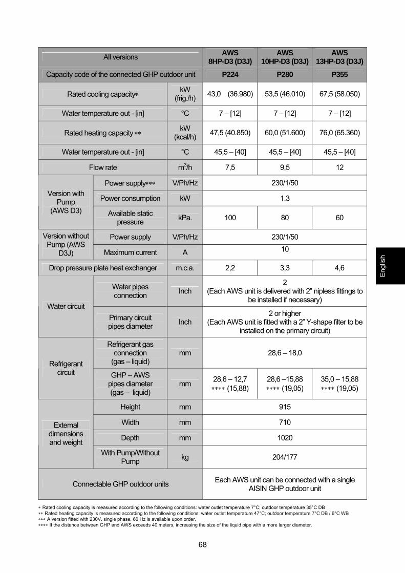
All versions AWS 8HP-D3 (D3J)
AWS 10HP-D3 (D3J)
AWS 13HP-D3 (D3J)
Capacity code of the connected GHP outdoor unit P224 P280 P355
Rated cooling capacity∗ kW (frig./h) 43,0 (36.980) 53,5 (46.010) 67,5 (58.050)
Water temperature out - [in] °C 7 – [12] 7 – [12] 7 – [12]
Rated heating capacity ∗∗ kW (kcal/h) 47,5 (40.850) 60,0 (51.600) 76,0 (65.360)
Water temperature out - [in] °C 45,5 – [40] 45,5 – [40] 45,5 – [40]
Flow rate m3/h 7,5 9,5 12
Power supply∗∗∗ V/Ph/Hz 230/1/50
Power consumption kW 1.3 Version with Pump
(AWS D3) Available static pressure kPa. 100 80 60
Power supply V/Ph/Hz 230/1/50 Version without Pump (AWS
D3J) Maximum current A 10
Drop pressure plate heat exchanger m.c.a. 2,2 3,3 4,6
Water pipes connection Inch
2 (Each AWS unit is delivered with 2” nipless fittings to
be installed if necessary) Water circuit
Primary circuit pipes diameter Inch
2 or higher (Each AWS unit is fitted with a 2” Y-shape filter to be
installed on the primary circuit)
Refrigerant gas connection
(gas – liquid) mm 28,6 – 18,0
Refrigerant circuit GHP – AWS
pipes diameter (gas – liquid)
mm 28,6 – 12,7 ∗∗∗∗ (15,88)
28,6 –15,88 ∗∗∗∗ (19,05)
35,0 – 15,88 ∗∗∗∗ (19,05)
Height mm 915
Width mm 710
Depth mm 1020
External dimensions and weight
With Pump/Without Pump kg 204/177
Connectable GHP outdoor units Each AWS unit can be connected with a single AISIN GHP outdoor unit
∗ Rated cooling capacity is measured according to the following conditions: water outlet temperature 7°C; outdoor temperature 35°C DB ∗∗ Rated heating capacity is measured according to the following conditions: water outlet temperature 47°C; outdoor temperature 7°C DB / 6°C WB ∗∗∗ A version fitted with 230V, single phase, 60 Hz is available upon order. ∗∗∗∗ If the distance between GHP and AWS exceeds 40 meters, increasing the size of the liquid pipe with a more larger diameter.
Engl
ish
69
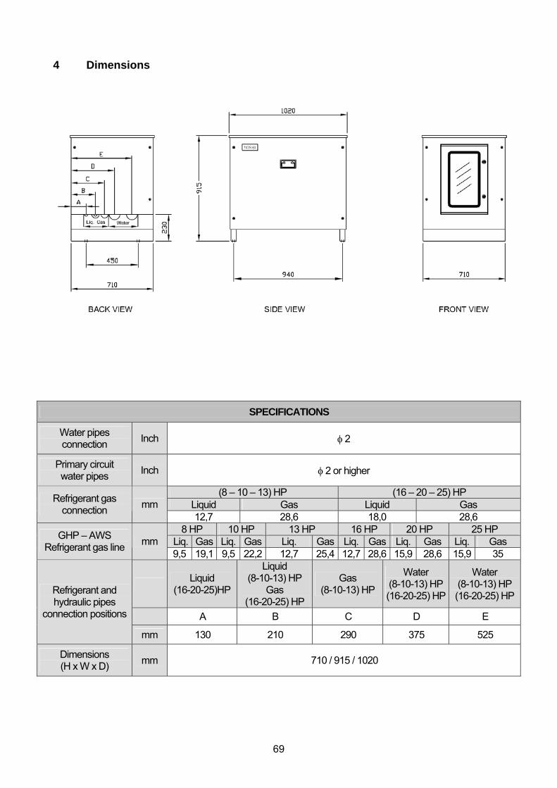
4 Dimensions
SPECIFICATIONS
Water pipes connection Inch φ 2
Primary circuit water pipes Inch φ 2 or higher
(8 – 10 – 13) HP (16 – 20 – 25) HP Liquid Gas Liquid Gas Refrigerant gas
connection mm 12,7 28,6 18,0 28,6
8 HP 10 HP 13 HP 16 HP 20 HP 25 HP Liq. Gas Liq. Gas Liq. Gas Liq. Gas Liq. Gas Liq. Gas GHP – AWS
Refrigerant gas line mm 9,5 19,1 9,5 22,2 12,7 25,4 12,7 28,6 15,9 28,6 15,9 35
Liquid (16-20-25)HP
Liquid (8-10-13) HP
Gas (16-20-25) HP
Gas (8-10-13) HP
Water (8-10-13) HP (16-20-25) HP
Water (8-10-13) HP (16-20-25) HP
A B C D E
Refrigerant and hydraulic pipes
connection positions
mm 130 210 290 375 525
Dimensions (H x W x D) mm 710 / 915 / 1020
70
5 Refrigerant system operating
5.1 Cooling mode The refrigerant (R410A) processed by the GHP flows through electronic expansion valve
and enters the lower part of the AWS unit heat exchanger at low pressure. The gas
evaporates in the plate heat exchanger by taking heat from the counter current water flow.
It goes back to the GHP as overheated steam. The outdoor unit fans create an air flow
through the heat exchanger and thus the refrigerant can condense.
At the same time, the water coming from the buffer tank is cooled and pumped again into
the primary circuit by the AWS built in pump. Flow switch, pressure switch and anti freeze
thermo sensor overlook the water temperature never to drop inside the heat exchanger. In
fact, water may freeze and the heat exchanger can be damaged.
5.2 Heating mode The refrigerant (R410A) processed by the GHP enters the upper part of the AWS unit heat
exchanger as high pressure overheated steam. The gas condenses in the plate heat
exchanger by ceasing heat to the co current water flow. It goes back to the GHP as high
pressure liquid, through the bypass pipe. The two outdoor unit expansion valves divide the
return flow, reducing its pressure. The GHP manages the evaporation through the heat
exchanger and the heat recovery.
At the same time, the water coming from the buffer tank is heated and pumped again into
the primary circuit by the AWS built in pump.
Engl
ish

71
72
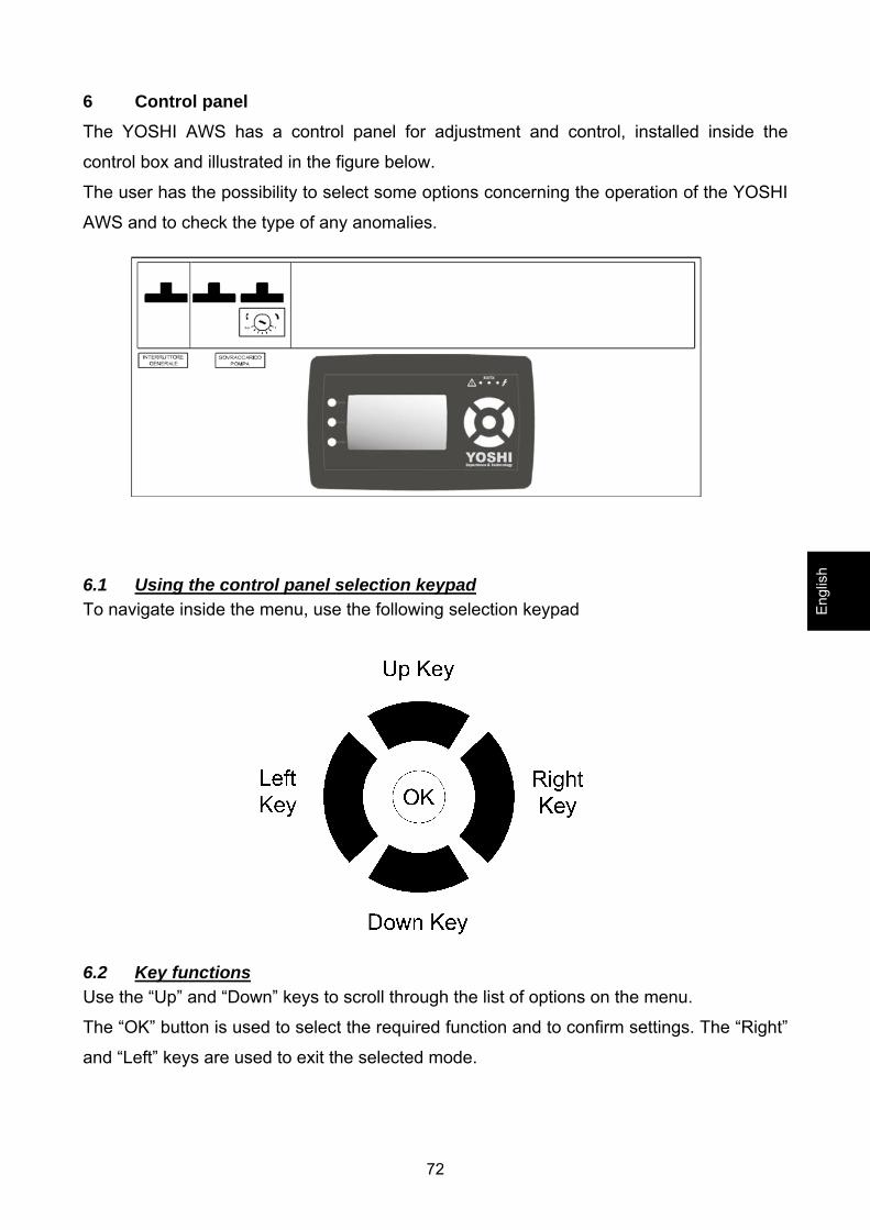
6 Control panel The YOSHI AWS has a control panel for adjustment and control, installed inside the
control box and illustrated in the figure below.
The user has the possibility to select some options concerning the operation of the YOSHI
AWS and to check the type of any anomalies.
6.1 Using the control panel selection keypad To navigate inside the menu, use the following selection keypad
6.2 Key functions Use the “Up” and “Down” keys to scroll through the list of options on the menu.
The “OK” button is used to select the required function and to confirm settings. The “Right”
and “Left” keys are used to exit the selected mode.
Engl
ish
73
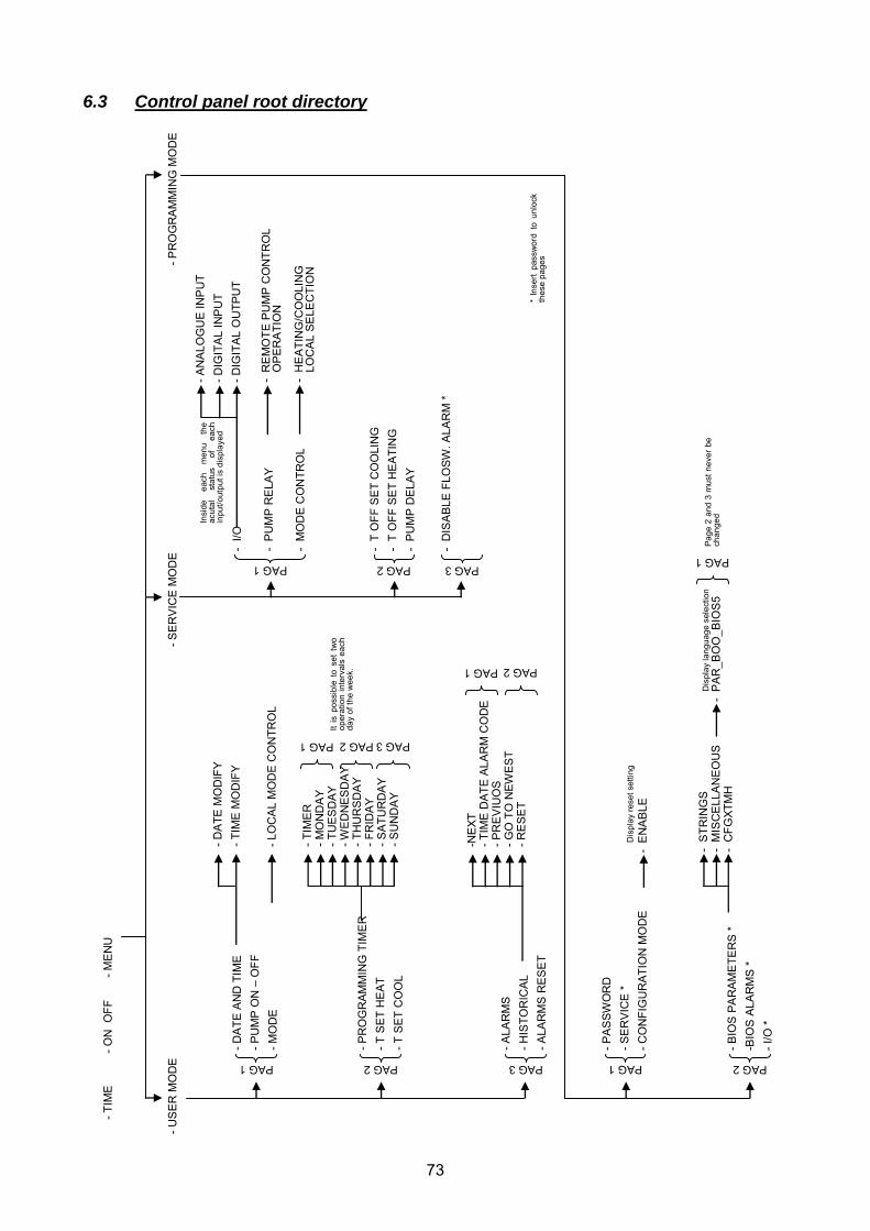
6.3 Control panel root directory
PAG 1
PAG 3PAG 2
-TIM
E
-O
N O
FF
-
ME
NU
-US
ER
MO
DE
-SE
RV
ICE
MO
DE
-P
RO
GR
AM
MIN
G M
OD
E
-DA
TE A
ND
TIM
E-P
UM
P O
N –
OFF
-M
OD
E
-PR
OG
RA
MM
ING
TIM
ER
-T S
ET H
EAT
-T S
ET C
OO
L
-ALA
RM
S-H
ISTO
RIC
AL
-ALA
RM
S R
ES
ET
PAG 1
-DA
TE M
OD
IFY
-TIM
E M
OD
IFY
-LO
CA
L M
OD
E C
ON
TRO
L
-TIM
ER
-MO
ND
AY
-TU
ES
DAY
-WE
DN
ESD
AY
-TH
UR
SD
AY-F
RID
AY
-SA
TUR
DA
Y-S
UN
DA
Y
PAG 1 PAG 2 PAG 3
Itis
poss
ible
tose
t tw
oop
erat
ion
inte
rval
sea
chda
yof
the
wee
k.
-NE
XT-T
IME
DAT
E A
LAR
M C
OD
E-P
RE
VIU
OS
-GO
TO
NEW
EST
-RE
SE
T
PAG 1 PAG 2
-I/O
-P
UM
P R
ELA
Y
-M
OD
E C
ON
TRO
L
-T
OFF
SE
T C
OO
LIN
G-
T O
FF S
ET
HE
ATI
NG
-P
UM
P D
ELA
Y
-D
ISA
BLE
FLO
SW. A
LAR
M *
-AN
ALO
GU
E IN
PU
T-D
IGIT
AL
INP
UT
-DIG
ITA
L O
UTP
UT
PAG 2
Insi
de
each
men
u th
e ac
utal
stat
us
ofea
chin
put/o
utpu
t is
disp
laye
d
-R
EM
OTE
PU
MP
CO
NTR
OL
OP
ER
ATI
ON
-H
EA
TIN
G/C
OO
LIN
G
LOC
AL
SE
LEC
TIO
N
PAG 3
* In
sert
pass
wor
d to
unlo
ckth
ese
page
s
PAG 2PAG 1
-PA
SSW
OR
D-S
ER
VIC
E *
-CO
NFI
GU
RAT
ION
MO
DE
-BIO
S P
AR
AM
ETE
RS
*-B
IOS
ALA
RM
S *
-I/O
*
PAG 1
Page
2 an
d 3
mus
tnev
erbe
chan
ged
-S
TRIN
GS
-M
ISC
ELL
AN
EO
US
-C
FGXT
MH
-P
AR
_BO
O_B
IOS
5D
ispl
ay la
ngua
gese
lect
ion
-E
NA
BLE
Dis
play
rese
t set
ting
74
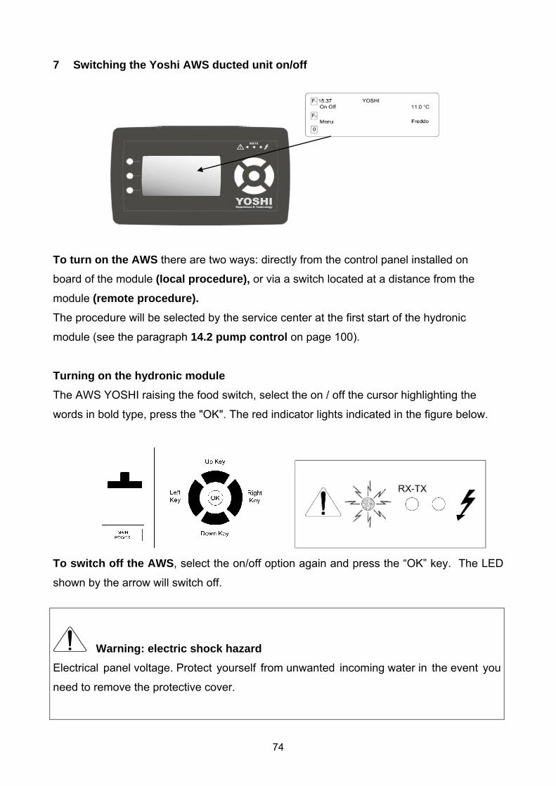
7 Switching the Yoshi AWS ducted unit on/off
To turn on the AWS there are two ways: directly from the control panel installed on
board of the module (local procedure), or via a switch located at a distance from the
module (remote procedure). The procedure will be selected by the service center at the first start of the hydronic
module (see the paragraph 14.2 pump control on page 100).
Turning on the hydronic module
The AWS YOSHI raising the food switch, select the on / off the cursor highlighting the
words in bold type, press the "OK". The red indicator lights indicated in the figure below.
To switch off the AWS, select the on/off option again and press the “OK” key. The LED
shown by the arrow will switch off.
Warning: electric shock hazard
Electrical panel voltage. Protect yourself from unwanted incoming water in the event you
need to remove the protective cover.
75
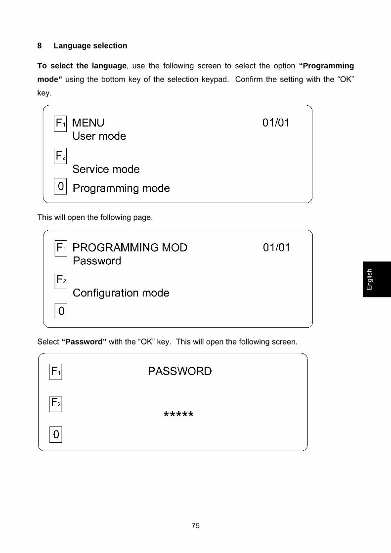
8 Language selection To select the language, use the following screen to select the option “Programming
mode” using the bottom key of the selection keypad. Confirm the setting with the “OK”
key.
This will open the following page.
Select “Password” with the “OK” key. This will open the following screen.
Engl
ish
76
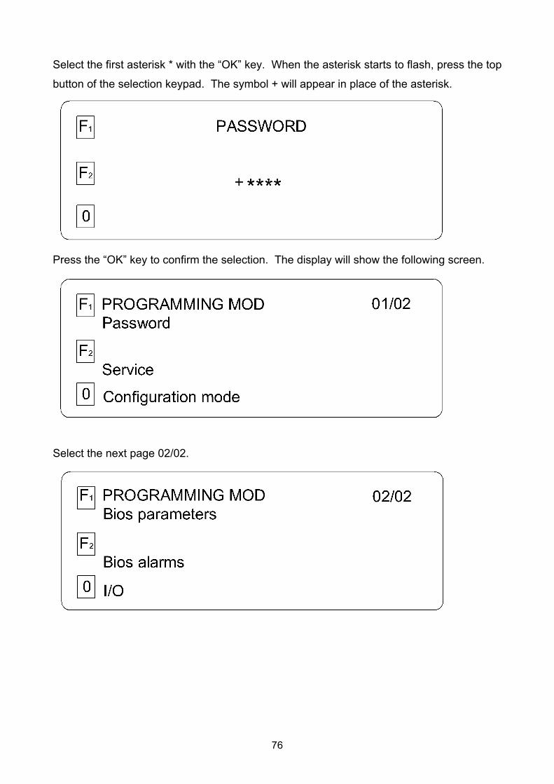
Select the first asterisk * with the “OK” key. When the asterisk starts to flash, press the top
button of the selection keypad. The symbol + will appear in place of the asterisk.
Press the “OK” key to confirm the selection. The display will show the following screen.
Select the next page 02/02.
77
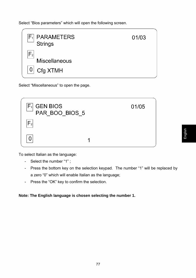
Select “Bios parameters” which will open the following screen.
Select “Miscellaneous” to open the page.
To select Italian as the language:
- Select the number “1” ;
- Press the bottom key on the selection keypad. The number “1” will be replaced by
a zero “0” which will enable Italian as the language;
- Press the “OK” key to confirm the selection.
Note: The English language is chosen selecting the number 1.
Engl
ish
78
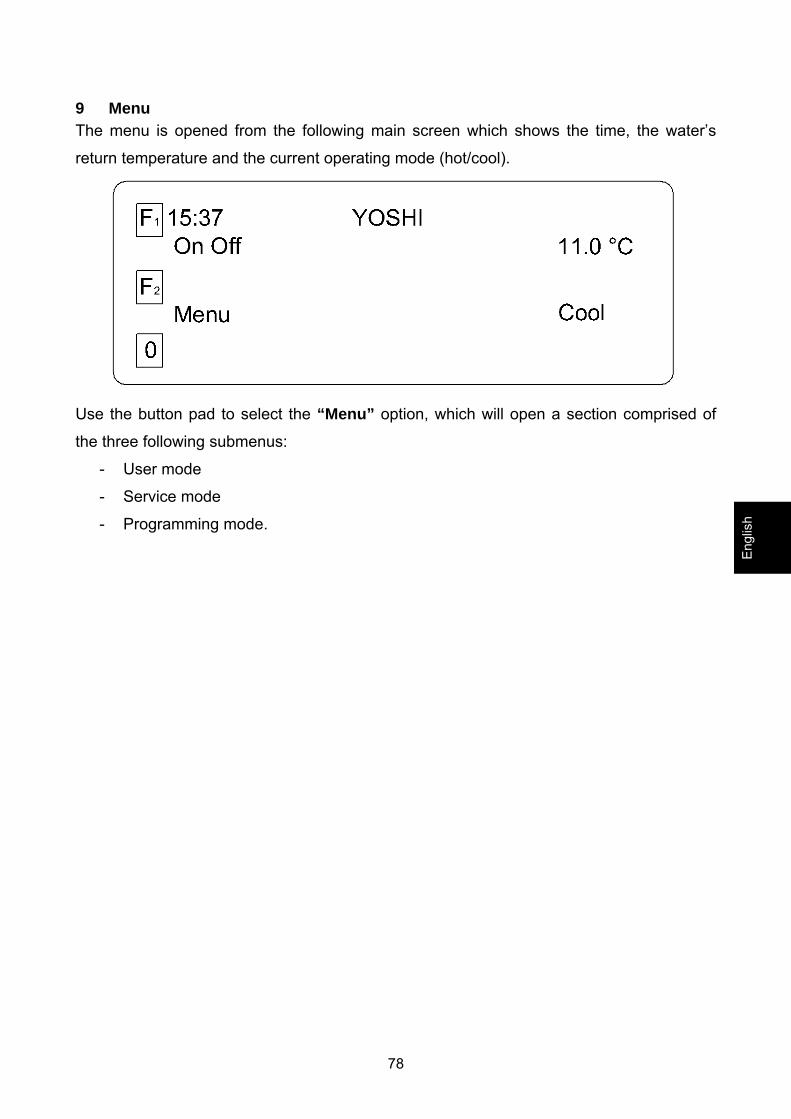
9 Menu The menu is opened from the following main screen which shows the time, the water’s
return temperature and the current operating mode (hot/cool).
Use the button pad to select the “Menu” option, which will open a section comprised of
the three following submenus:
- User mode
- Service mode
- Programming mode.
Engl
ish

79
10 User mode All of the adjustment and control options available to the user are described in this
menu.
The “user mode” menu gives access to the following functions:
Screen 1/3
Screen 2/3
80
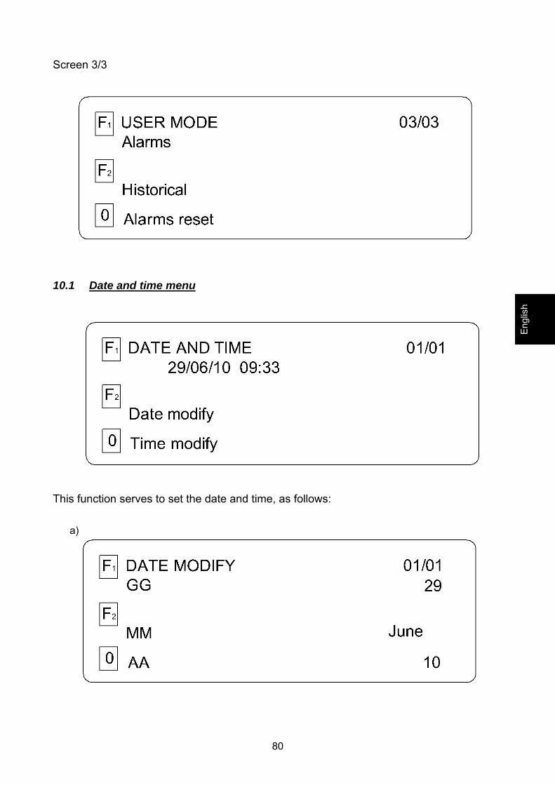
Screen 3/3
10.1 Date and time menu
This function serves to set the date and time, as follows:
a)
Engl
ish

81
b)
10.2 Heating/cooling mode settings (user mode menu) This function serves to choose the cooling or heating mode.
There are two ways to select the operating mode:
Local mode control directly from the control panel installed on board the unit.
To select the required mode, press the “OK” key. Use the up or down key on the pad to
select the operating mode. Press “OK” again to confirm the chosen option.
Remote mode control using a switch installed at a distance from the unit (see at page
74).
.
82
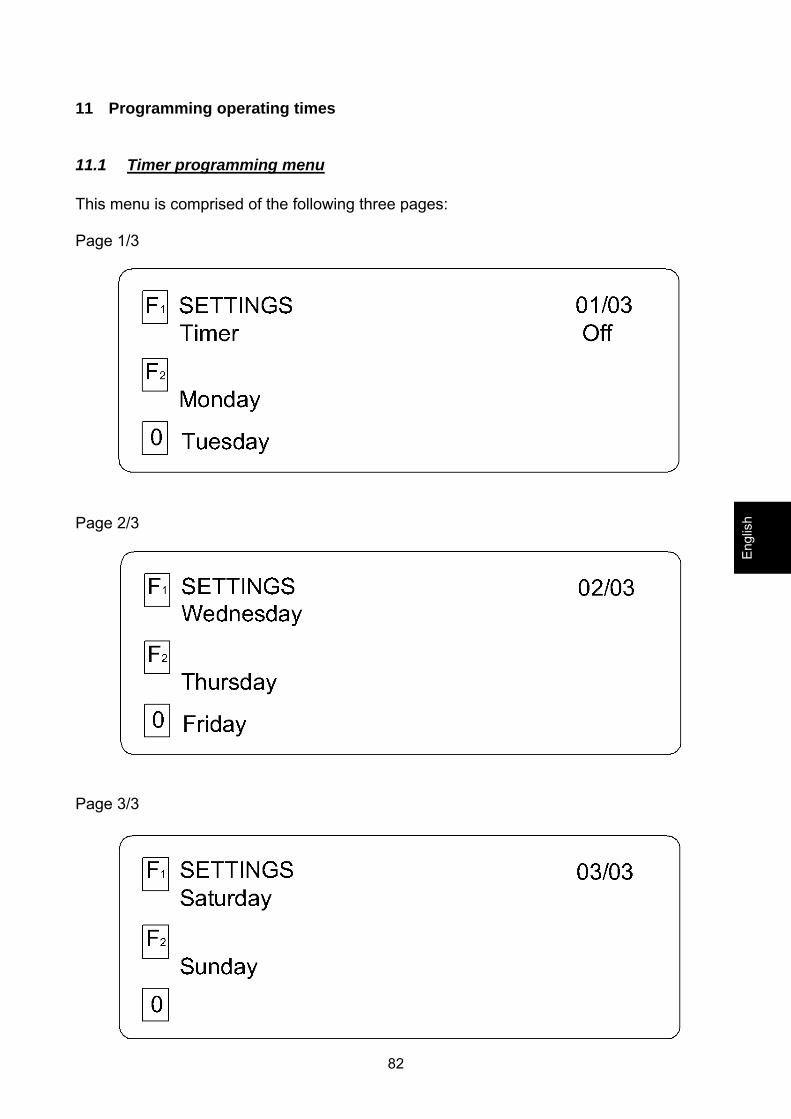
11 Programming operating times
11.1 Timer programming menu This menu is comprised of the following three pages: Page 1/3
Page 2/3
Page 3/3
Engl
ish
83
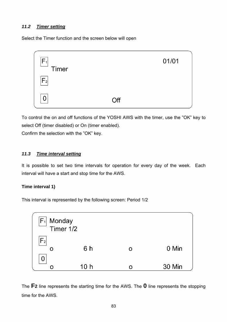
11.2 Timer setting Select the Timer function and the screen below will open
To control the on and off functions of the YOSHI AWS with the timer, use the ”OK” key to
select Off (timer disabled) or On (timer enabled).
Confirm the selection with the ”OK” key.
11.3 Time interval setting It is possible to set two time intervals for operation for every day of the week. Each
interval will have a start and stop time for the AWS.
Time interval 1) This interval is represented by the following screen: Period 1/2
The F2 line represents the starting time for the AWS. The 0 line represents the stopping
time for the AWS.
84
To set the required hour, select the o symbol, press “OK”, and use the up and down keys
on the keypad to select the time. Press the ”OK” key to confirm the setting.
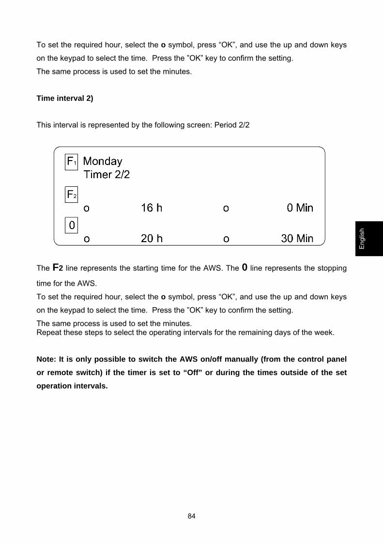
The same process is used to set the minutes. Time interval 2)
This interval is represented by the following screen: Period 2/2
The F2 line represents the starting time for the AWS. The 0 line represents the stopping
time for the AWS.
To set the required hour, select the o symbol, press “OK”, and use the up and down keys
on the keypad to select the time. Press the ”OK” key to confirm the setting.
The same process is used to set the minutes. Repeat these steps to select the operating intervals for the remaining days of the week.
Note: It is only possible to switch the AWS on/off manually (from the control panel or remote switch) if the timer is set to “Off” or during the times outside of the set operation intervals.
Engl
ish
85
12 Setting the set point temperature The default settings for the thermostat set point are:
- COOL mode: T set cool = 11°C -- ΔT = 2°C
- HEAT: T set heat = 42°C -- ΔT = 2°C
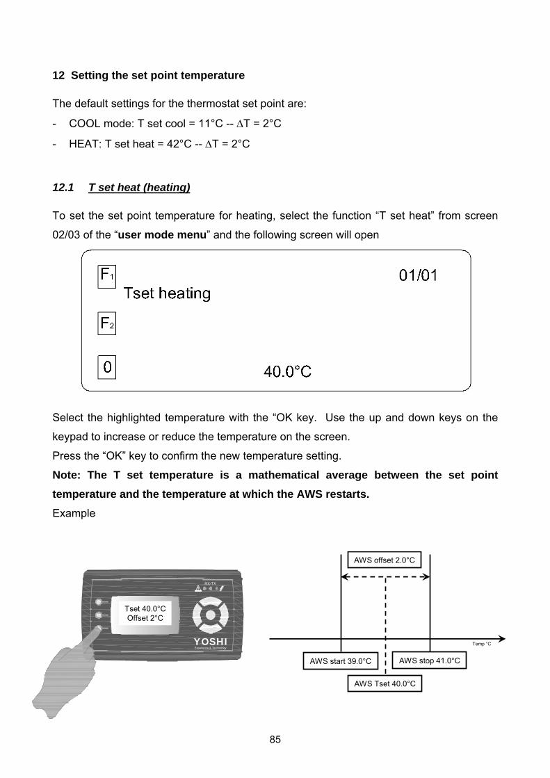
12.1 T set heat (heating) To set the set point temperature for heating, select the function “T set heat” from screen
02/03 of the “user mode menu” and the following screen will open
Select the highlighted temperature with the “OK key. Use the up and down keys on the
keypad to increase or reduce the temperature on the screen.
Press the “OK” key to confirm the new temperature setting.
Note: The T set temperature is a mathematical average between the set point temperature and the temperature at which the AWS restarts. Example
RX-TX
YOSHIExperience & Technology
Tset 40.0°COffset 2°C
AWS Tset 40.0°C
AWS stop 41.0°CAWS start 39.0°C
AWS offset 2.0°C
Temp °C
86
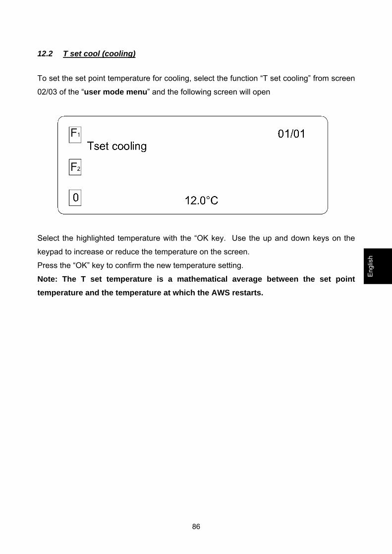
12.2 T set cool (cooling)
To set the set point temperature for cooling, select the function “T set cooling” from screen
02/03 of the “user mode menu” and the following screen will open
Select the highlighted temperature with the “OK key. Use the up and down keys on the
keypad to increase or reduce the temperature on the screen.
Press the “OK” key to confirm the new temperature setting.
Note: The T set temperature is a mathematical average between the set point temperature and the temperature at which the AWS restarts.
Engl
ish

87
13 Alarms
13.1 Alarms menu In case of anomalies on the AISIN GHP outdoor unit or the YOSHI AWS, the LED shown
by the arrow will start to flash. The type of alarm triggered by the anomaly will be shown
on the control panel display.
To see the list of alarms in progress, select the “Alarms” function in screen 03/03 of the
USER MODE MENU and the following screen will open
If no alarms have been recorded, then the display will read “Empty”.
Note: See page 89 for the list of possible recorded alarms for the AWS.
88
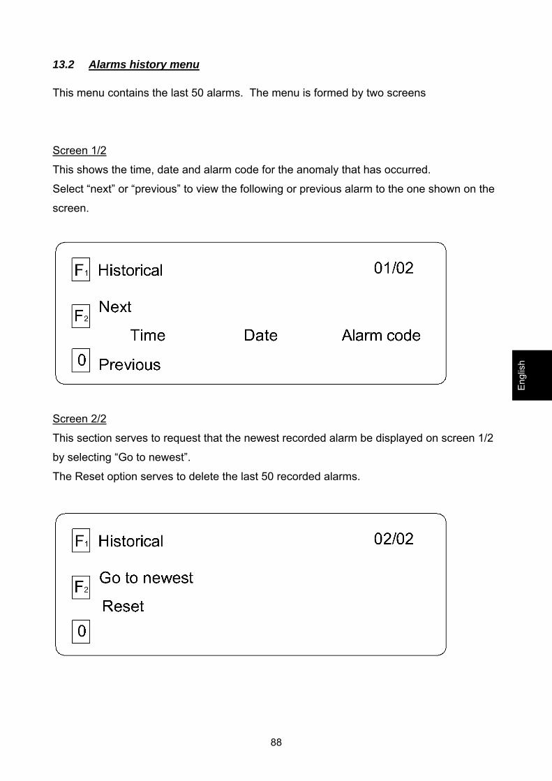
13.2 Alarms history menu This menu contains the last 50 alarms. The menu is formed by two screens
Screen 1/2
This shows the time, date and alarm code for the anomaly that has occurred.
Select “next” or “previous” to view the following or previous alarm to the one shown on the
screen.
Screen 2/2
This section serves to request that the newest recorded alarm be displayed on screen 1/2
by selecting “Go to newest”.
The Reset option serves to delete the last 50 recorded alarms.
Engl
ish
89
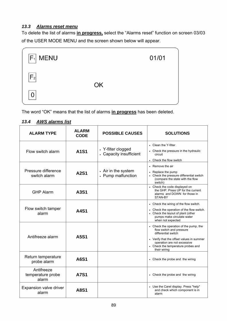
13.3 Alarms reset menu To delete the list of alarms in progress, select the “Alarms reset” function on screen 03/03
of the USER MODE MENU and the screen shown below will appear.
The word “OK” means that the list of alarms in progress has been deleted.
13.4 AWS alarms list
ALARM TYPE ALARM CODE POSSIBLE CAUSES SOLUTIONS
Flow switch alarm A1S1 • Y-filter clogged • Capacity insufficient
• Clean the Y-filter
• Check the pressure in the hydraulic circuit
• Check the flow switch
Pressure difference switch alarm A2S1 • Air in the system
• Pump malfunction
• Remove the air
• Replace the pump • Check the pressure differential switch
(compare the state with the flow switch)
GHP Alarm A3S1 • Check the code displayed on
the GHP. Press UP for the current alarms and DOWN for those in STAN-BY
Flow switch tamper alarm A4S1
• Check the wiring of the flow switch.
• Check the operation of the flow switch. • Check the layout of plant (other
pumps make circulate water when not expected
Antifreeze alarm A5S1
• Check the operation of the pump, the flow switch and pressure differential switch
• Verify that the offset values in summer operation are not excessive
• Check the temperature probes and their wiring
Return temperature probe alarm A6S1 • Check the probe and the wiring
Antifreeze temperature probe
alarm A7S1 • Check the probe and the wiring
Expansion valve driver alarm A8S1
• Use the Carel display. Press "help" and check which component is in alarm
90
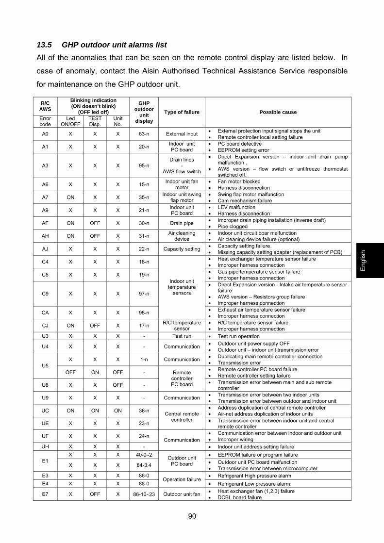
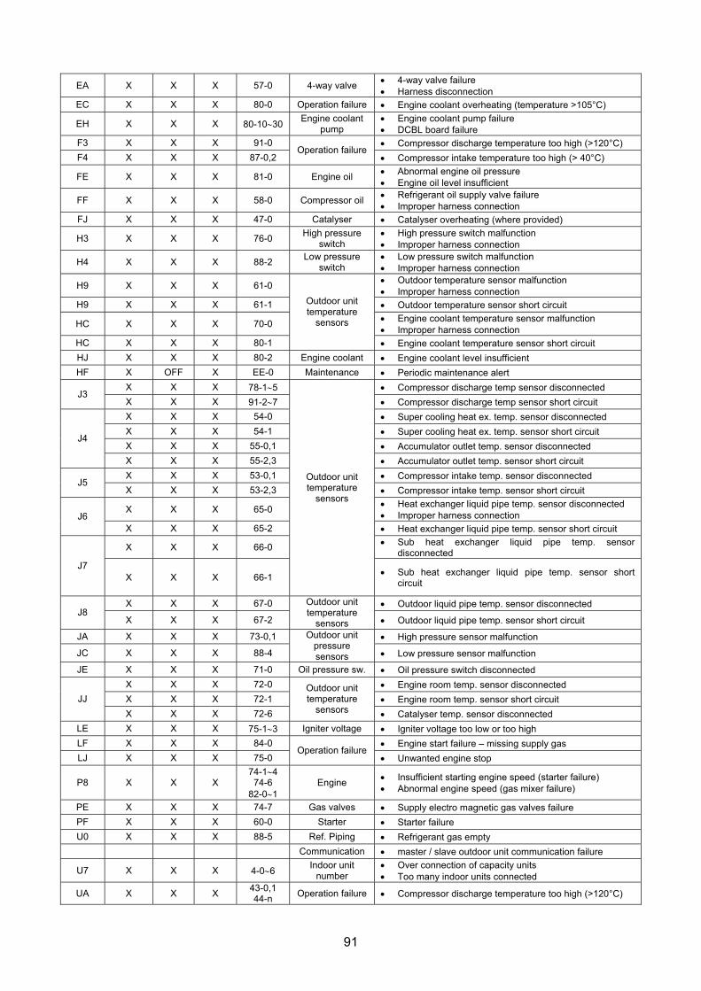
13.5 GHP outdoor unit alarms list All of the anomalies that can be seen on the remote control display are listed below. In
case of anomaly, contact the Aisin Authorised Technical Assistance Service responsible
for maintenance on the GHP outdoor unit.
R/C AWS
Blinking indication (ON doesn’t blink)
(OFF led off) Error code
Led ON/OFF
TEST Disp.
Unit No.
GHP outdoor
unit display
Type of failure Possible cause
A0 X X X 63-n External input • External protection input signal stops the unit • Remote controller local setting failure
A1 X X X 20-n Indoor unit PC board
• PC board defective • EEPROM setting error
A3 X X X 95-n Drain lines
- AWS flow switch
• Direct Expansion version – indoor unit drain pump malfunction .
• AWS version – flow switch or antifreeze thermostat switched off.
A6 X X X 15-n Indoor unit fan motor
• Fan motor blocked • Harness disconnection
A7 ON X X 35-n Indoor unit swing flap motor
• Swing flap motor malfunction • Cam mechanism failure
A9 X X X 21-n Indoor unit PC board
• LEV malfunction • Harness disconnection
AF ON OFF X 30-n Drain pipe • Improper drain piping installation (inverse draft) • Pipe clogged
AH ON OFF X 31-n Air cleaning device
• Indoor unit circuit boar malfunction • Air cleaning device failure (optional)
AJ X X X 22-n Capacity setting • Capacity setting failure • Missing capacity setting adapter (replacement of PCB)
C4 X X X 18-n • Heat exchanger temperature sensor failure • Improper harness connection
C5 X X X 19-n • Gas pipe temperature sensor failure • Improper harness connection
C9 X X X 97-n
• Direct Expansion version - Intake air temperature sensor failure
• AWS version – Resistors group failure • Improper harness connection
CA X X X 98-n
Indoor unit temperature
sensors
• Exhaust air temperature sensor failure • Improper harness connection
CJ ON OFF X 17-n R/C temperature sensor
• R/C temperature sensor failure • Improper harness connection
U3 X X X - Test run • Test run operation
U4 X X X - Communication • Outdoor unit power supply OFF • Outdoor unit – indoor unit transmission error
X X X 1-n Communication • Duplicating main remote controller connection • Transmission error U5
OFF ON OFF - • Remote controller PC board failure • Remote controller setting failure
U8 X X OFF -
Remote controller PC board • Transmission error between main and sub remote
controller
U9 X X X - Communication • Transmission error between two indoor units • Transmission error between outdoor and indoor unit
UC ON ON ON 36-n • Address duplication of central remote controller • Air-net address duplication of indoor units
UE X X X 23-n
Central remote controller • Transmission error between indoor unit and central
remote controller
UF X X X 24-n • Communication error between indoor and outdoor unit • Improper wiring
UH X X X - Communication
• Indoor unit address setting failure X X X 40-0∼2 • EEPROM failure or program failure
E1 X X X 84-3,4
Outdoor unit PC board • Outdoor unit PC board malfunction
• Transmission error between microcomputer E3 X X X 86-0 • Refrigerant High pressure alarm E4 X X X 88-0
Operation failure • Refrigerant Low pressure alarm
E7 X OFF X 86-10∼23 Outdoor unit fan • Heat exchanger fan (1,2,3) failure • DCBL board failure
Engl
ish
91
EA X X X 57-0 4-way valve • 4-way valve failure • Harness disconnection
EC X X X 80-0 Operation failure • Engine coolant overheating (temperature >105°C)
EH X X X 80-10∼30 Engine coolant pump
• Engine coolant pump failure • DCBL board failure
F3 X X X 91-0 • Compressor discharge temperature too high (>120°C) F4 X X X 87-0,2
Operation failure • Compressor intake temperature too high (> 40°C)
FE X X X 81-0 Engine oil • Abnormal engine oil pressure • Engine oil level insufficient
FF X X X 58-0 Compressor oil • Refrigerant oil supply valve failure • Improper harness connection
FJ X X X 47-0 Catalyser • Catalyser overheating (where provided)
H3 X X X 76-0 High pressure switch
• High pressure switch malfunction • Improper harness connection
H4 X X X 88-2 Low pressure switch
• Low pressure switch malfunction • Improper harness connection
H9 X X X 61-0 • Outdoor temperature sensor malfunction • Improper harness connection
H9 X X X 61-1 • Outdoor temperature sensor short circuit
HC X X X 70-0 • Engine coolant temperature sensor malfunction • Improper harness connection
HC X X X 80-1
Outdoor unit temperature
sensors
• Engine coolant temperature sensor short circuit HJ X X X 80-2 Engine coolant • Engine coolant level insufficient HF X OFF X EE-0 Maintenance • Periodic maintenance alert
X X X 78-1∼5 • Compressor discharge temp sensor disconnected J3
X X X 91-2∼7 • Compressor discharge temp sensor short circuit X X X 54-0 • Super cooling heat ex. temp. sensor disconnected X X X 54-1 • Super cooling heat ex. temp. sensor short circuit X X X 55-0,1 • Accumulator outlet temp. sensor disconnected
J4
X X X 55-2,3 • Accumulator outlet temp. sensor short circuit X X X 53-0,1 • Compressor intake temp. sensor disconnected
J5 X X X 53-2,3 • Compressor intake temp. sensor short circuit
X X X 65-0 • Heat exchanger liquid pipe temp. sensor disconnected • Improper harness connection J6
X X X 65-2 • Heat exchanger liquid pipe temp. sensor short circuit
X X X 66-0 • Sub heat exchanger liquid pipe temp. sensor disconnected
J7 X X X 66-1
Outdoor unit temperature
sensors
• Sub heat exchanger liquid pipe temp. sensor short circuit
X X X 67-0 • Outdoor liquid pipe temp. sensor disconnected J8
X X X 67-2
Outdoor unit temperature
sensors • Outdoor liquid pipe temp. sensor short circuit
JA X X X 73-0,1 • High pressure sensor malfunction
JC X X X 88-4
Outdoor unit pressure sensors • Low pressure sensor malfunction
JE X X X 71-0 Oil pressure sw. • Oil pressure switch disconnected X X X 72-0 • Engine room temp. sensor disconnected X X X 72-1 • Engine room temp. sensor short circuit JJ X X X 72-6
Outdoor unit temperature
sensors • Catalyser temp. sensor disconnected LE X X X 75-1∼3 Igniter voltage • Igniter voltage too low or too high LF X X X 84-0 • Engine start failure – missing supply gas LJ X X X 75-0
Operation failure • Unwanted engine stop
P8 X X X 74-1∼4
74-6 82-0∼1
Engine • Insufficient starting engine speed (starter failure) • Abnormal engine speed (gas mixer failure)
PE X X X 74-7 Gas valves • Supply electro magnetic gas valves failure PF X X X 60-0 Starter • Starter failure U0 X X X 88-5 Ref. Piping • Refrigerant gas empty
Communication • master / slave outdoor unit communication failure
U7 X X X 4-0∼6 Indoor unit number
• Over connection of capacity units • Too many indoor units connected
UA X X X 43-0,1 44-n Operation failure • Compressor discharge temperature too high (>120°C)
92
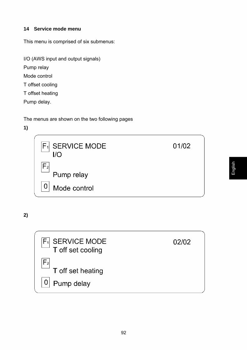
14 Service mode menu This menu is comprised of six submenus:
I/O (AWS input and output signals)
Pump relay
Mode control
T offset cooling
T offset heating
Pump delay.
The menus are shown on the two following pages
1)
2)
Engl
ish

93
14.1 I/O menu (AWS input and output signals) This menu is shown on the following screen
14.1.1 Analog input menu The instructions for this submenu are shown on three screens
1) The display shows the return water temperature.
2) The temperature listed on the display as “antifreeze” shows the water delivery temperature.
94
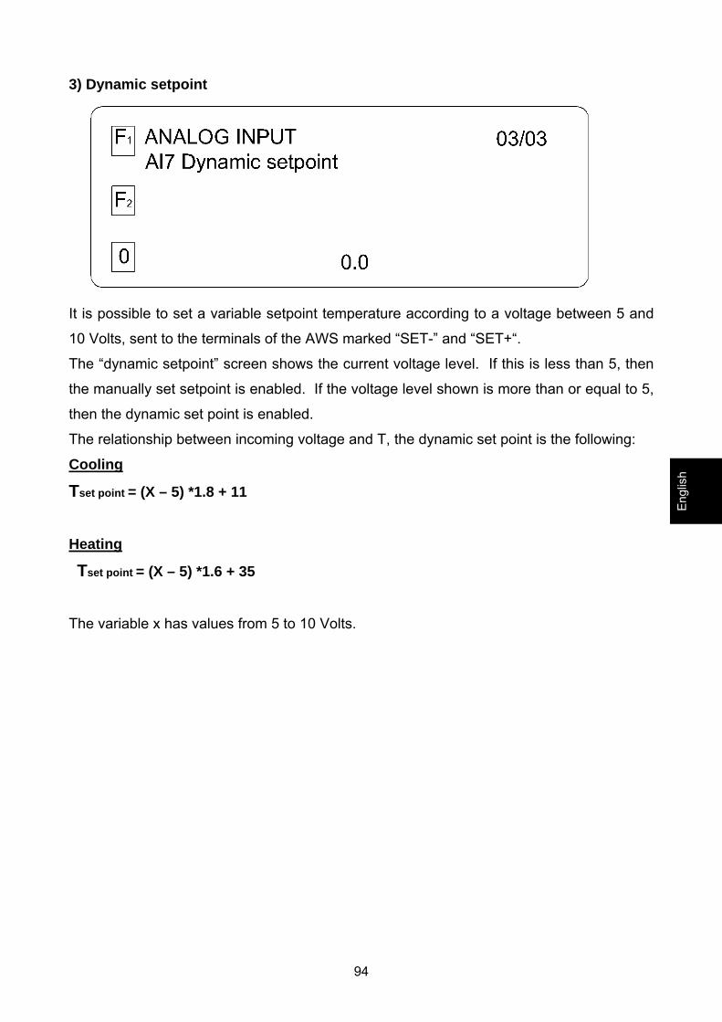
3) Dynamic setpoint
It is possible to set a variable setpoint temperature according to a voltage between 5 and
10 Volts, sent to the terminals of the AWS marked “SET-” and “SET+“.
The “dynamic setpoint” screen shows the current voltage level. If this is less than 5, then
the manually set setpoint is enabled. If the voltage level shown is more than or equal to 5,
then the dynamic set point is enabled.
The relationship between incoming voltage and T, the dynamic set point is the following:
Cooling
Tset point = (X – 5) *1.8 + 11
Heating
Tset point = (X – 5) *1.6 + 35
The variable x has values from 5 to 10 Volts.
Engl
ish
95
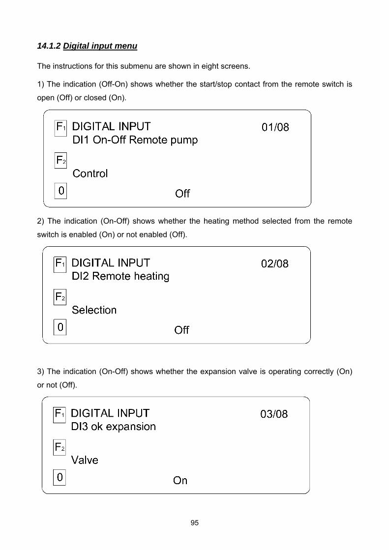
14.1.2 Digital input menu The instructions for this submenu are shown in eight screens. 1) The indication (Off-On) shows whether the start/stop contact from the remote switch is
open (Off) or closed (On).
2) The indication (On-Off) shows whether the heating method selected from the remote
switch is enabled (On) or not enabled (Off).
3) The indication (On-Off) shows whether the expansion valve is operating correctly (On)
or not (Off).
96
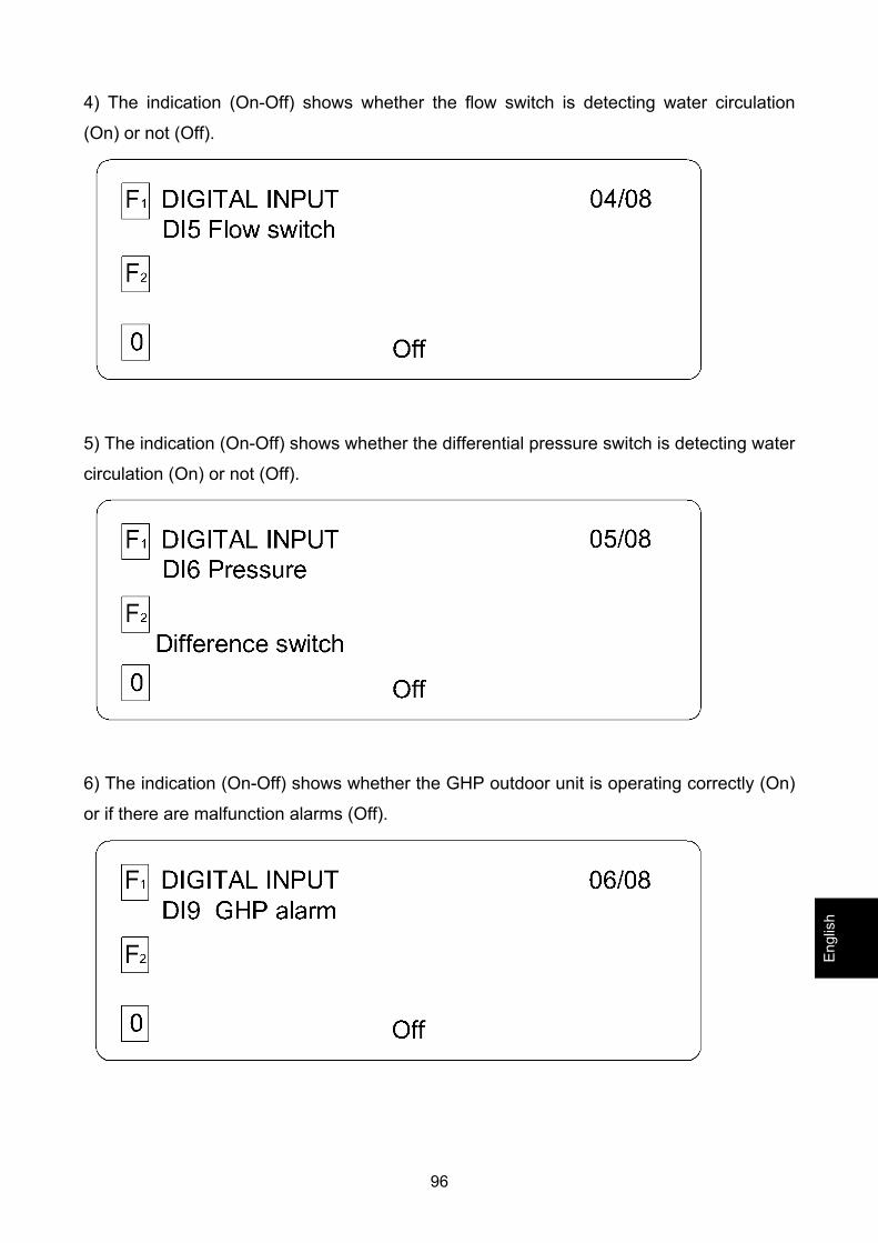
4) The indication (On-Off) shows whether the flow switch is detecting water circulation
(On) or not (Off).
5) The indication (On-Off) shows whether the differential pressure switch is detecting water
circulation (On) or not (Off).
6) The indication (On-Off) shows whether the GHP outdoor unit is operating correctly (On)
or if there are malfunction alarms (Off).
Engl
ish
97
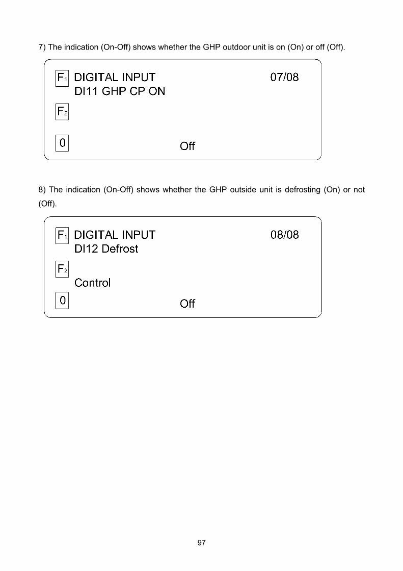
7) The indication (On-Off) shows whether the GHP outdoor unit is on (On) or off (Off).
8) The indication (On-Off) shows whether the GHP outside unit is defrosting (On) or not
(Off).
98
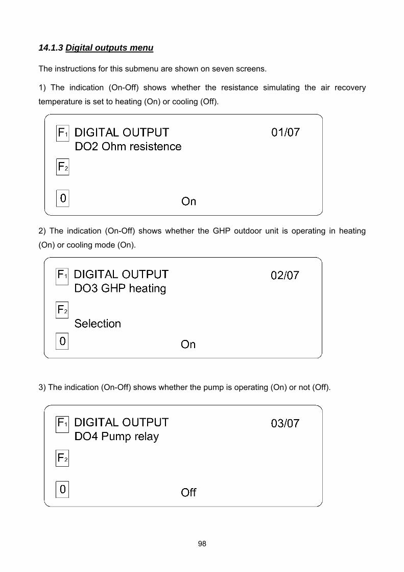
14.1.3 Digital outputs menu The instructions for this submenu are shown on seven screens. 1) The indication (On-Off) shows whether the resistance simulating the air recovery
temperature is set to heating (On) or cooling (Off).
2) The indication (On-Off) shows whether the GHP outdoor unit is operating in heating
(On) or cooling mode (On).
3) The indication (On-Off) shows whether the pump is operating (On) or not (Off).
99
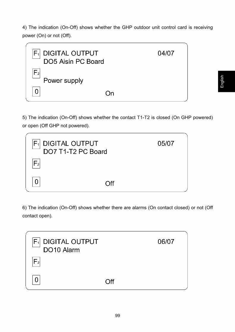
4) The indication (On-Off) shows whether the GHP outdoor unit control card is receiving
power (On) or not (Off).
5) The indication (On-Off) shows whether the contact T1-T2 is closed (On GHP powered)
or open (Off GHP not powered).
6) The indication (On-Off) shows whether there are alarms (On contact closed) or not (Off
contact open).
Engl
ish
100
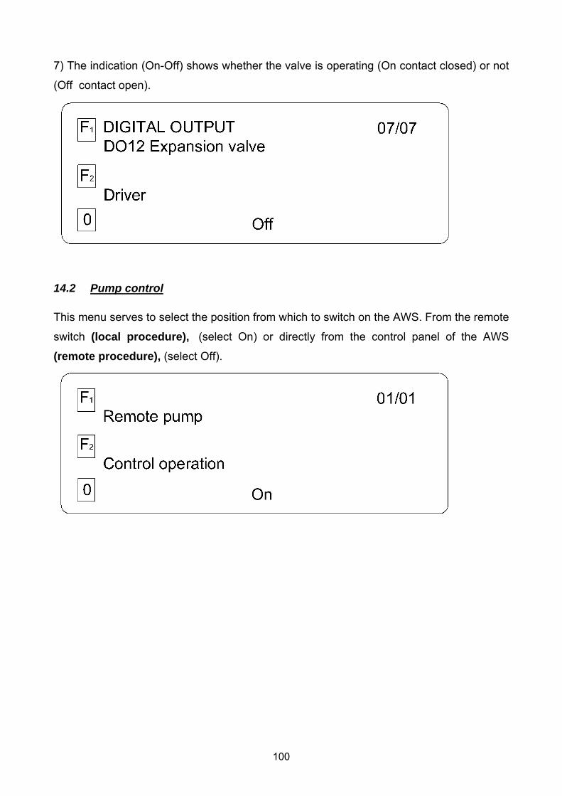
7) The indication (On-Off) shows whether the valve is operating (On contact closed) or not
(Off contact open).
14.2 Pump control This menu serves to select the position from which to switch on the AWS. From the remote
switch (local procedure), (select On) or directly from the control panel of the AWS
(remote procedure), (select Off).
101
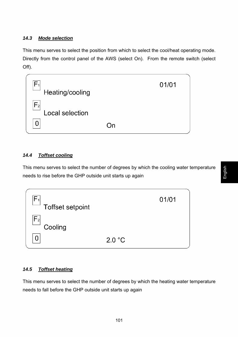
14.3 Mode selection This menu serves to select the position from which to select the cool/heat operating mode.
Directly from the control panel of the AWS (select On). From the remote switch (select
Off).
14.4 Toffset cooling This menu serves to select the number of degrees by which the cooling water temperature
needs to rise before the GHP outside unit starts up again
14.5 Toffset heating This menu serves to select the number of degrees by which the heating water temperature
needs to fall before the GHP outside unit starts up again
Engl
ish
102
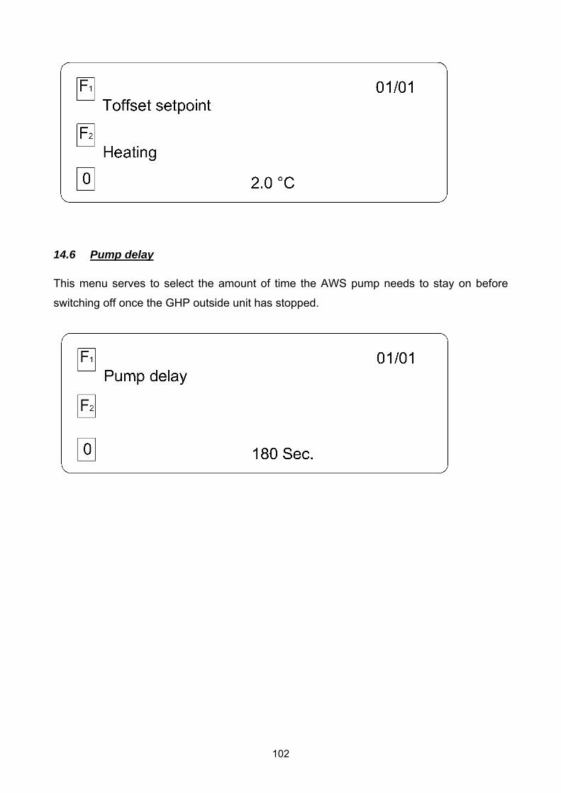
14.6 Pump delay This menu serves to select the amount of time the AWS pump needs to stay on before
switching off once the GHP outside unit has stopped.
103
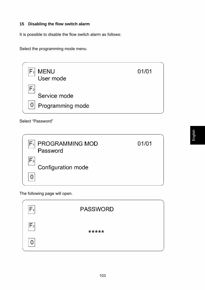
15 Disabling the flow switch alarm It is possible to disable the flow switch alarm as follows:
Select the programming mode menu
Select “Password”
The following page will open.
Engl
ish
104
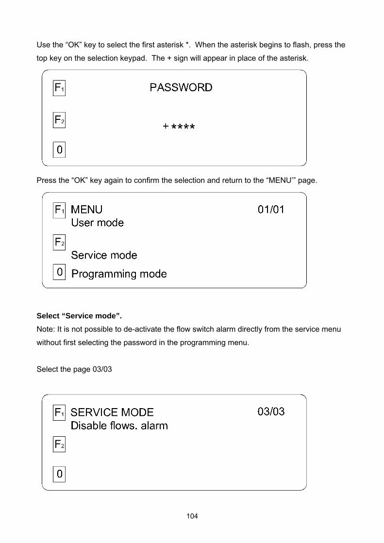
Use the “OK” key to select the first asterisk *. When the asterisk begins to flash, press the
top key on the selection keypad. The + sign will appear in place of the asterisk.
Press the “OK” key again to confirm the selection and return to the “MENU’” page.
Select “Service mode”. Note: It is not possible to de-activate the flow switch alarm directly from the service menu
without first selecting the password in the programming menu.
Select the page 03/03
105
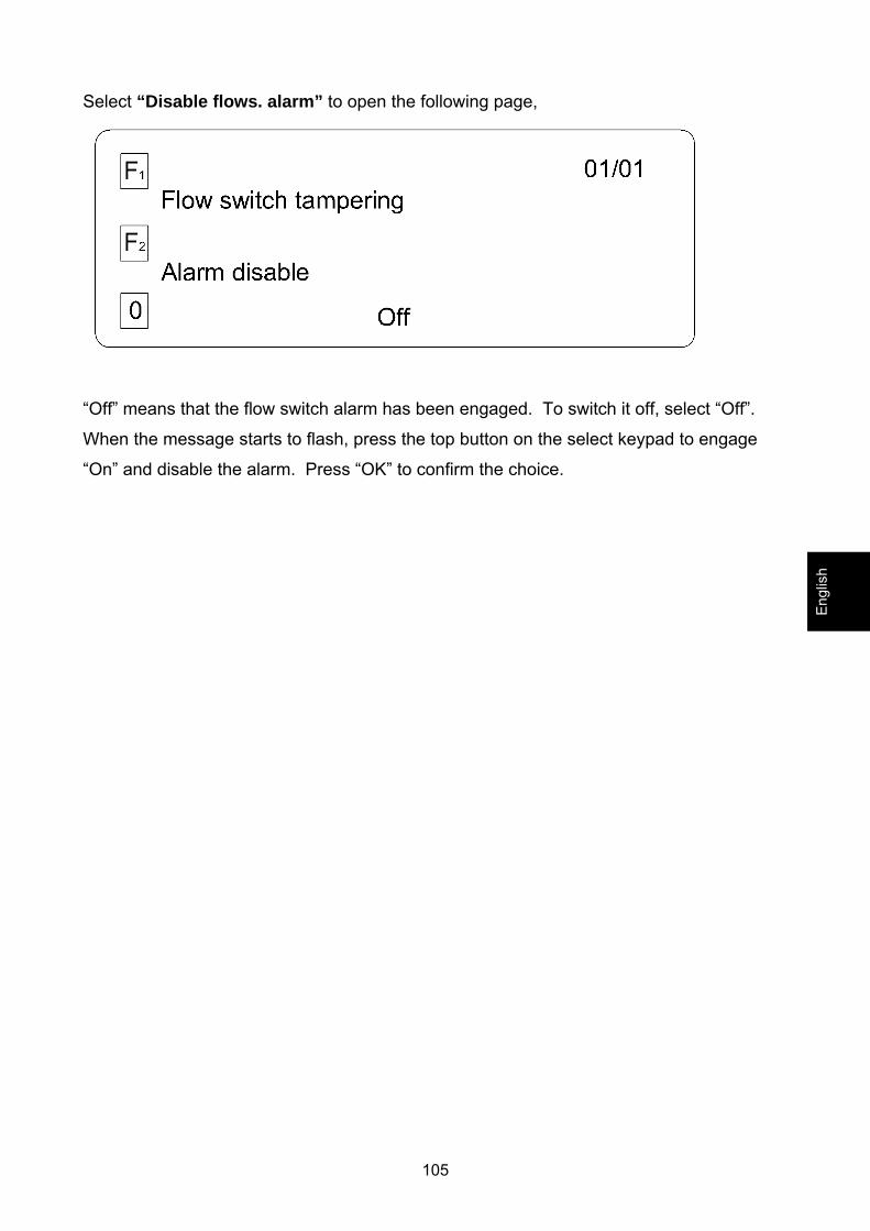
Select “Disable flows. alarm” to open the following page,
“Off” means that the flow switch alarm has been engaged. To switch it off, select “Off”.
When the message starts to flash, press the top button on the select keypad to engage
“On” and disable the alarm. Press “OK” to confirm the choice.
Engl
ish

106
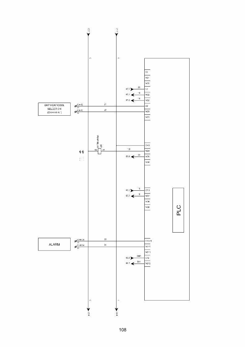
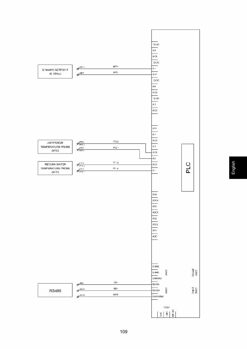
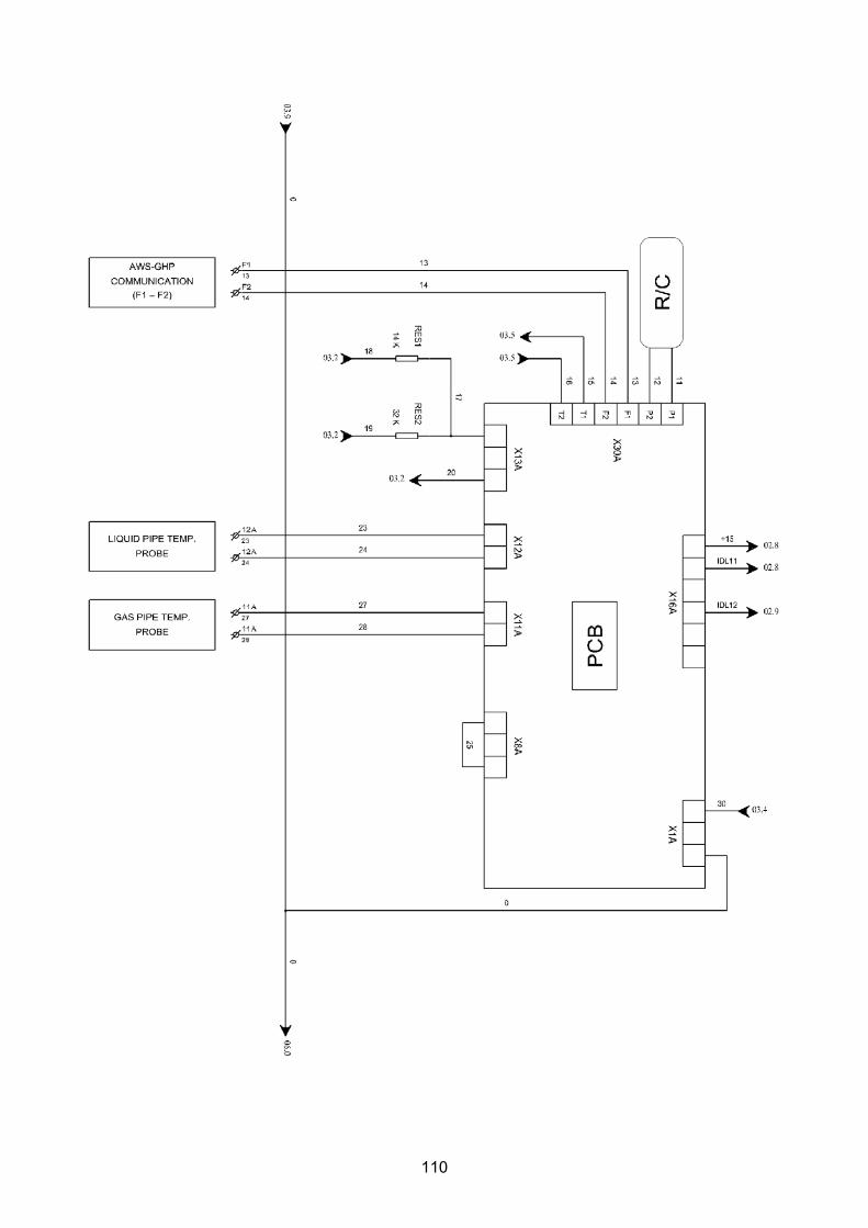
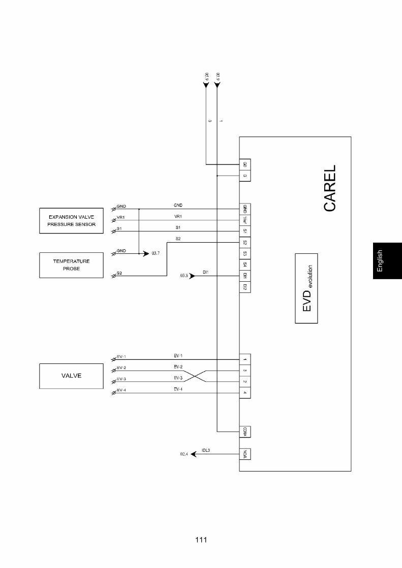
16 Wiring diagrams

107
Engl
ish
108
109
Engl
ish
110
111
Engl
ish
112
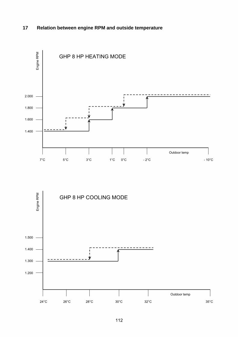
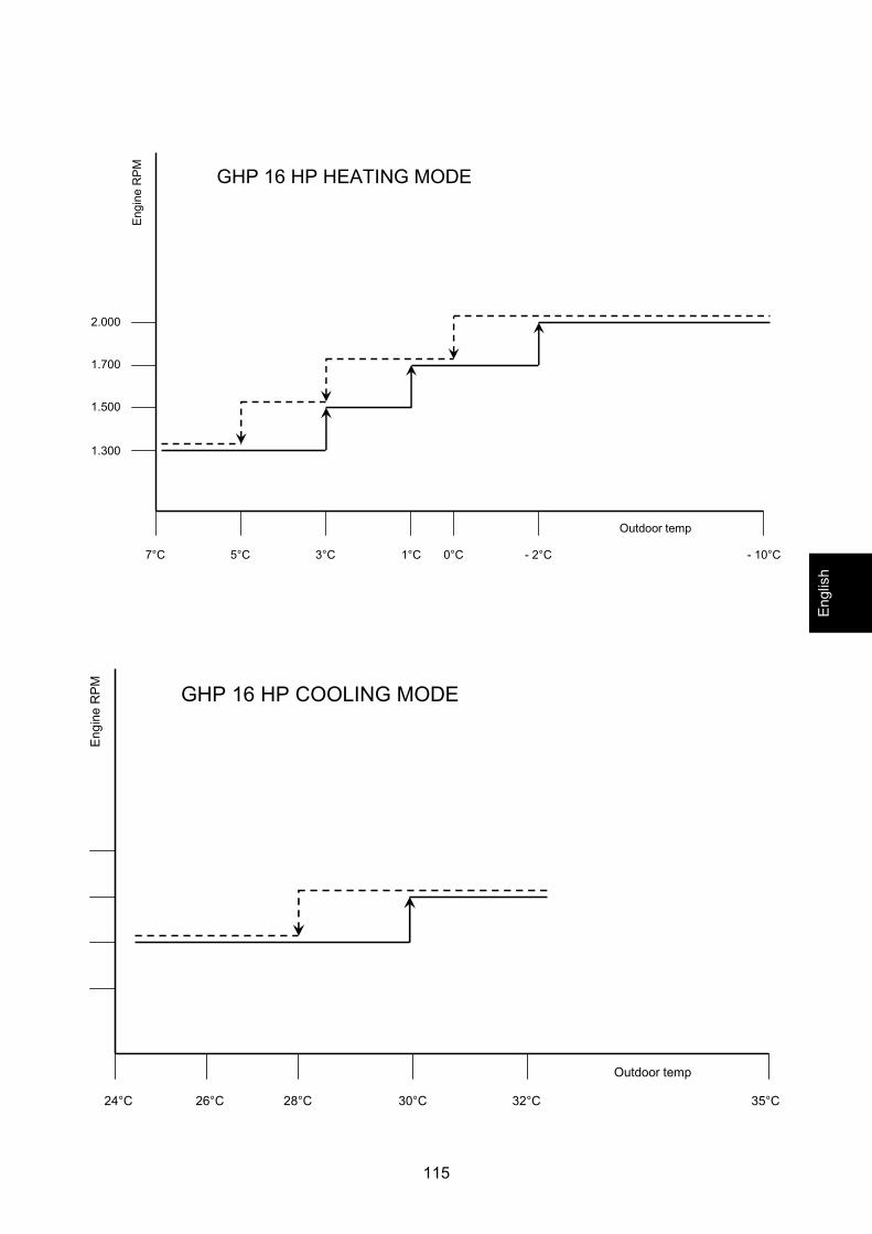
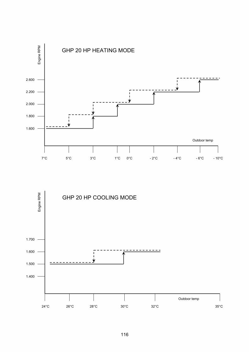
17 Relation between engine RPM and outside temperature
7°C 5°C 3°C 1°C 0°C - 2°C - 10°C
Outdoor temp
Eng
ine
RP
M
1.400
1.600
1.800
2.000
GHP 8 HP HEATING MODE
24°C 26°C 28°C 30°C 32°C 35°C
Outdoor temp
Engi
neR
PM
1.200
1.300
1.400
1.500
GHP 8 HP COOLING MODE

113
7°C 5°C 3°C 1°C 0°C - 2°C - 10°C
Outdoor temp
Eng
ine
RP
M
1.700
1.900
2.100
2.300
2.500
- 4°C - 6°C
GHP 10 HP HEATING MODE
24°C 26°C 28°C 30°C 32°C 35°C
Outdoor temp
Engi
neR
PM
1.500
1.600
1.700
1.800
GHP 10 HP COOLING MODE
Engl
ish

114
7°C 5°C 3°C 1°C 0°C - 2°C - 10°C
Outdoor temp
Eng
ine
RP
M
2.100
2.300
2.500
2.800
GHP 13 HP HEATING MODE
24°C 26°C 28°C 30°C 32°C 35°C
Outdoor temp
Engi
neR
PM
1.900
2.000
2.100
2.200
GHP 13 HP COOLING MODE
115
7°C 5°C 3°C 1°C 0°C - 2°C - 10°C
Outdoor temp
Eng
ine
RP
M
1.300
1.500
1.700
2.000
GHP 16 HP HEATING MODE
24°C 26°C 28°C 30°C 32°C 35°C
Outdoor temp
Engi
neR
PM
GHP 16 HP COOLING MODE
Engl
ish
116
7°C 5°C 3°C 1°C 0°C - 2°C - 10°C
Outdoor temp
Eng
ine
RP
M
1.600
1.800
2.000
2.200
2.600
- 4°C - 6°C
GHP 20 HP HEATING MODE
24°C 26°C 28°C 30°C 32°C 35°C
Outdoor temp
Engi
neR
PM
1.400
1.500
1.600
1.700
GHP 20 HP COOLING MODE

117
7°C 5°C 3°C 1°C 0°C - 2°C - 10°C
Outdoor temp
Eng
ine
RP
M
2.000
2.100
2.400
2.600
GHP 25 HP HEATING MODE
24°C 26°C 28°C 30°C 32°C 35°C
Outdoor temp
Engi
neR
PM
1.900
2.000
2.100
2.200
GHP 25 HP COOLING MODE
Engl
ish
118
18 Contact specifications
Digital Input
AL-COM AL-ON Dry contact (closed 0 Volt – open 24 VAC) REM Dry contact (closed 0 Volt – open 24 VAC) REM1 Dry contact (closed 0 Volt – open 24 VAC) FL-COM FL-ON Dry contact (closed 0 Volt – open 24 VAC) PD-COM PD-ON Dry contact (closed 0 Volt – open 24 VAC) IDLC11-14 IDL11 ( From the board to the PLC ) 15 VDC IDLC11-14 IDL12 ( From the board to the PLC ) 15 VDC
Digital Output
KP (pump relay) Open 24 VAC C H/C Dry contact ( closed 0 Ohm) C7-9 NO13 (contact T1 T2) Dry contact ( closed 0 Ohm) C13-15 NO13 (contact DI1 Valve Driver) Dry contact ( closed 0 Ohm) Alarm Dry contact ( closed 0 Ohm) C4-6 NO5 (Power supply board) Dry contact ( closed 0 Ohm)
Components
PCB – connector X1A When supplied 24 VAC Driver Valve GoG When supplied 24 VAC Pump When supplied 230 VAC single phase
Analogic Input
NTC probe See “table resistor temperature sensor values NTC”
Probe 4-20 mA Pressure Linear 4 mA = 0 BAR 20 mA = 44,8 BAR
119
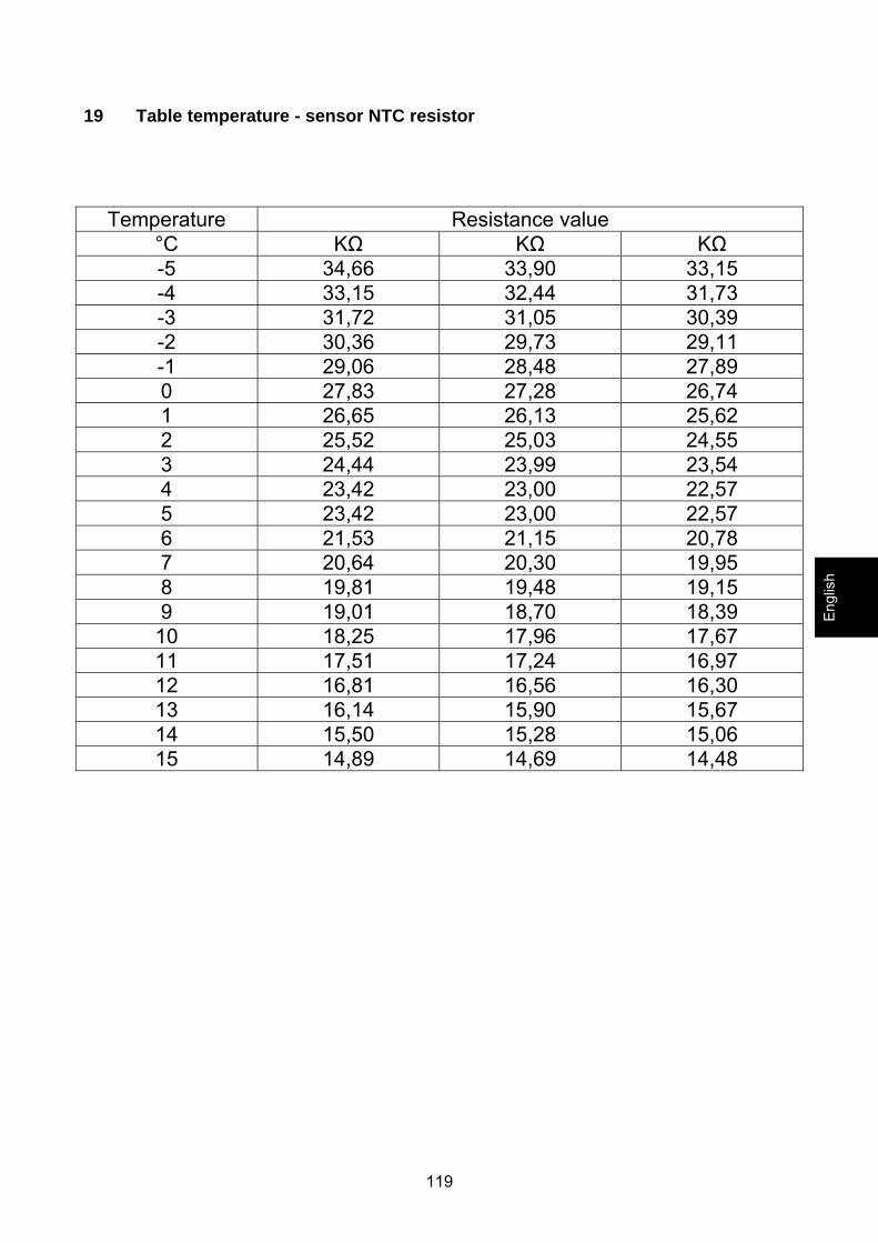
19 Table temperature - sensor NTC resistor
Temperature Resistance value
°C KΩ KΩ KΩ -5 34,66 33,90 33,15 -4 33,15 32,44 31,73 -3 31,72 31,05 30,39 -2 30,36 29,73 29,11 -1 29,06 28,48 27,89 0 27,83 27,28 26,74 1 26,65 26,13 25,62 2 25,52 25,03 24,55 3 24,44 23,99 23,54 4 23,42 23,00 22,57 5 23,42 23,00 22,57 6 21,53 21,15 20,78 7 20,64 20,30 19,95 8 19,81 19,48 19,15 9 19,01 18,70 18,39
10 18,25 17,96 17,67 11 17,51 17,24 16,97 12 16,81 16,56 16,30 13 16,14 15,90 15,67 14 15,50 15,28 15,06 15 14,89 14,69 14,48
Engl
ish
120
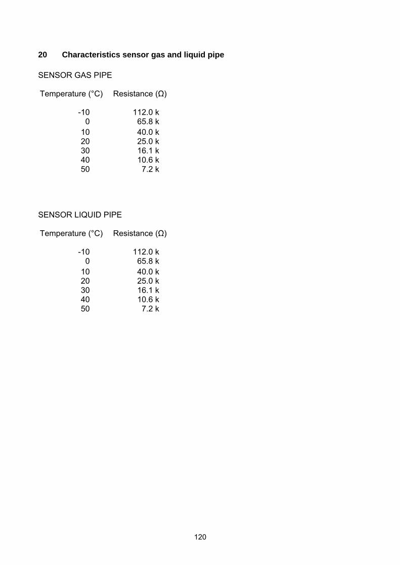
20 Characteristics sensor gas and liquid pipe SENSOR GAS PIPE Temperature (°C) Resistance (Ω)
-10 112.0 k 0 65.8 k
10 40.0 k 20 25.0 k 30 16.1 k 40 10.6 k 50 7.2 k
SENSOR LIQUID PIPE Temperature (°C) Resistance (Ω)
-10 112.0 k 0 65.8 k
10 40.0 k 20 25.0 k 30 16.1 k 40 10.6 k 50 7.2 k

121

122
10/2011
![Oracle Retail Item Planning Configured for COE ... … · 1[]Oracle® Retail Item Planning Configured for COE Installation Guide Release 14.1.3 E76195-01 July 2016](https://img.pdfslide.net/doc/110x75/5fb83f5072283b2524517ed3/oracle-retail-item-planning-configured-for-coe-1oracle-retail-item-planning.jpg)