Embed Size (px)
Citation preview

Manual
AM2232.1.3 Issue : A
© AIRBUS S.A.S. 2008. ALL RIGHTS RESERVED. CONFIDENTIAL AND PROPRIETARY DOCUMENT.
Method_FM0400725_V1.1 Printed Copies are not controlled. Confirm this is the latest issue available through the Portal. Page 1 of 14
Apply Layers and Colors for Material in DMU - for Fuselage
Owner’s Approval: (signed)
Name : PARNAUD Jean-Marie Function : EMSBD
PURPOSE: This document defines the colours and layers, which have to be assigned to the structural parts of thefuselage inside CATIA V5, in order to be able to extract from the DMU the parts contributing to the ESN(Electrical System Network). This method is valid for the concept phase.
SCOPE: The field of this AM is: AIRBUS AF, AD, AE & Supplier. The People concerned by the AM: designer, Group leader, Mock up integrator, SSCI Manager for fuselage. The technical domain concerned by the AM: Engineering.
Authorization: (signed)
Date : 11 December 2008 Name : LECUYER Patrick Function : Head of Methods Development -
Specific Design Process - EMSM

Apply Layers and Colors for Material in DMU - for Fuselage
AM2232.1.3Issue : A
© AIRBUS S.A.S. 2008. ALL RIGHTS RESERVED. CONFIDENTIAL AND PROPRIETARY DOCUMENT.
Method_FM0400725_V1.1 Printed Copies are not controlled. Confirm this is the latest issue available through the Portal. Page 2 of 14
TABLE OF CONTENTS
1 About this Document ........................................................................................................... 5 1.1 Background ......................................................................................................................... 5 1.2 Detailed Purpose................................................................................................................. 5 1.3 Organisation of the Document............................................................................................. 5
2 General Description of the Method...................................................................................... 6 3 Layers, Colors and Material Allocation Table...................................................................... 7 4 Use Case: Colors and Layers Allocation Methods .............................................................. 9
4.1 Layers Allocation Method .................................................................................................... 9 4.1.1 How to Access..................................................................................................................... 9 4.1.2 Actions to Follow ............................................................................................................... 10 4.2 Colors Allocation Method .................................................................................................. 11 4.2.1 Manual Method.................................................................................................................. 11 4.2.1.1 How to Access ...................................................................................................... 11 4.2.1.2 Actions to Follow................................................................................................... 12 4.2.2 Automatic Method ............................................................................................................. 12 Table of References ................................................................................................................... 13 Table of approval ........................................................................................................................ 13 Record of Revisions.................................................................................................................... 14

Apply Layers and Colors for Material in DMU - for Fuselage
AM2232.1.3Issue : A
© AIRBUS S.A.S. 2008. ALL RIGHTS RESERVED. CONFIDENTIAL AND PROPRIETARY DOCUMENT.
Method_FM0400725_V1.1 Printed Copies are not controlled. Confirm this is the latest issue available through the Portal. Page 3 of 14
List of Figures
Figure 1: Layer list menu in Graphic Properties toolbar .................................................................... 9 Figure 2: Named layers toolbar ......................................................................................................... 9 Figure 3: Add new layer in the Named layers toolbar ..................................................................... 10 Figure 4: Apply layer from layers list menu ..................................................................................... 10 Figure 5: Colors list menu in the Graphic Properties toolbar........................................................... 11 Figure 6: Colors definition panel...................................................................................................... 11 Figure 7: Selection of the Part Body before assigning a color ........................................................ 12 Figure 8: Assign the color to a specific layer automatically............................................................. 12
Apply Layers and Colors for Material in DMU - for Fuselage
AM2232.1.3Issue : A
© AIRBUS S.A.S. 2008. ALL RIGHTS RESERVED. CONFIDENTIAL AND PROPRIETARY DOCUMENT.
Method_FM0400725_V1.1 Printed Copies are not controlled. Confirm this is the latest issue available through the Portal. Page 4 of 14
List of Tables
Table 1: Layers, materials and colors ............................................................................................... 7 Table 2: Colors .................................................................................................................................. 8
Apply Layers and Colors for Material in DMU - for Fuselage
AM2232.1.3Issue : A
© AIRBUS S.A.S. 2008. ALL RIGHTS RESERVED. CONFIDENTIAL AND PROPRIETARY DOCUMENT.
Method_FM0400725_V1.1 Printed Copies are not controlled. Confirm this is the latest issue available through the Portal. Page 5 of 14
1 About this Document
1.1 Background AM2232.1 is the current reference document for the use of layers and colors in CATIA V5.
This document defines the colors and layers allocation for structural parts of the fuselage.
This document has to be seen in context with the other modules of AM2232. Especially AM2232.1 "Layers and Colours within CATIA V5" as the father module of this section is closely related to this document.
See AM2232.1 - "Layers and Colours within CATIA V5"
1.2 Detailed Purpose This document proposes to clarify the using of specific layers for structural parts of the fuselage to apply a list of specific material linked to layers and colors, in order to be able to view in the DMU the parts contributing to the Electrical Structure Network (ESN).
This method will allow to identify in the product structure the different material applied on the parts and filter its in the Digital Mock-Up with specific command of CATIA V5 tool.
1.3 Organisation of the Document This document splits roughly in two parts:
Part One (Chapter 2): This part contains description and the layers, materials and colors allocation table
Part Two (Chapter 3): The second part contains the description of how to assign the layer and color information to the part

Apply Layers and Colors for Material in DMU - for Fuselage
AM2232.1.3Issue : A
© AIRBUS S.A.S. 2008. ALL RIGHTS RESERVED. CONFIDENTIAL AND PROPRIETARY DOCUMENT.
Method_FM0400725_V1.1 Printed Copies are not controlled. Confirm this is the latest issue available through the Portal. Page 6 of 14
2 General Description of the Method This document proposes to clarify the using of specific layers for structural parts of the fuselage to apply a list of specific material with layers and colors.
TOOL ACTIONS/EXAMPLE PICTURE
CATIA Assign layers and colors to parts according to the table. Use the layers and colors defined in the following tables to assign a specific layer
and color with the CATIA V5 graphic properties toolbar.
NUANCE
LAYER SYSTEMS
LAYER STRUCTURE
LIST OF MATERIAL COLOR (SEE TABLE 2) RED
(R) GREEN (G)
BLUE (B)
Composite 149 124 Prepegs 4 128 64 64 150 125 RI material 5 255 255 170 151 126 Thermoplastic 6 81 157 81 152 127 Metallic meshes 7 125 0 63
Steels 153 128 Stainless 8 255 0 128 154 129 Non corrosion resistant 9 246 248 204
Light metal 156 131 Aluminium 11 0 128 255 157 132 Aluminium lithium 12 128 0 255 158 133 Magnesium 13 0 128 0 159 134 Titanium 14 0 255 255 160 135 Fibre metal (Glare) 15 211 178 125
Non Ferrous Non light 161 136 Copper 16 255 128 192 162 137 Nickel 17 179 179 255 163 138 Silver 18 0 0 255

Apply Layers and Colors for Material in DMU - for Fuselage
AM2232.1.3Issue : A
© AIRBUS S.A.S. 2008. ALL RIGHTS RESERVED. CONFIDENTIAL AND PROPRIETARY DOCUMENT.
Method_FM0400725_V1.1 Printed Copies are not controlled. Confirm this is the latest issue available through the Portal. Page 7 of 14
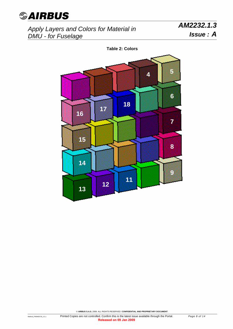
3 Layers, Colors and Material Allocation Table For each structural part of the fuselage, you must apply the layer and color corresponding to the material of the part (described in the Table 1).
These materials must apply only to the parts containing into the structural ATA from 50 to 53 and from 55 to 59 in fuselage and for the system ATA 92 only for mechanical parts (plates, ramps, racks metallic structure) - not applicable to bundles/harnesses.
These layers and colors must apply before the launching of Qchecker and before the validation of the data.
The layer and the color must be applied on the part Body of the part.
Table 1: Layers, materials and colors NUANCE
LAYER SYSTEMS
LAYER STRUCTURE
LIST OF MATERIAL COLOUR (SEE TABLE 2) RED
(R)
GREEN (G)
BLUE (B)
Composite 149 124 Prepegs 4 128 64 64 150 125 RI material 5 255 255 170 151 126 Thermoplastic 6 81 157 81 152 127 Metallic meshes 7 125 0 63
Steels 153 128 Stainless 8 255 0 128 154 129 Non corrosion resistant 9 246 248 204
Light metal 156 131 Aluminium 11 0 128 255 157 132 Aluminium lithium 12 128 0 255 158 133 Magnesium 13 0 128 0 159 134 Titanium 14 0 255 255 160 135 Fibre metal (Glare) 15 211 178 125
Non Ferrous Non light 161 136 Copper 16 255 128 192 162 137 Nickel 17 179 179 255 163 138 Silver 18 0 0 255
Apply Layers and Colors for Material in DMU - for Fuselage
AM2232.1.3Issue : A
© AIRBUS S.A.S. 2008. ALL RIGHTS RESERVED. CONFIDENTIAL AND PROPRIETARY DOCUMENT.
Method_FM0400725_V1.1 Printed Copies are not controlled. Confirm this is the latest issue available through the Portal. Page 8 of 14
Table 2: Colors
5 4
6
18 17
16
7
15 8
14
9 11
12 13

Apply Layers and Colors for Material in DMU - for Fuselage
AM2232.1.3Issue : A
© AIRBUS S.A.S. 2008. ALL RIGHTS RESERVED. CONFIDENTIAL AND PROPRIETARY DOCUMENT.
Method_FM0400725_V1.1 Printed Copies are not controlled. Confirm this is the latest issue available through the Portal. Page 9 of 14
4 Use Case: Colors and Layers Allocation Methods This chapter describes how to apply layers and colors to the Part Body of the part:
− Layers Allocation Method, chapter 4.1 − Colors Layers Allocation Method, chapter 4.1:
• Manual Method, chapter 4.2.1 • Manual Method, chapter 4.2.2
4.1 Layers Allocation Method − The preparation chapter "How to Access" describes how to customize the CATIA V5
layers. − The "Actions to Follow" shows how to assign layers to the Part Body.
4.1.1 How to Access STEP 1 ACTION
Select the layer list from the graphic properties toolbar
The graphic properties toolbar is part of the part design workbench in CATIA V5. Click on the layer list menu of Graphic properties toolbar.
Figure 1: Layer list menu in Graphic Properties toolbar
Select "Other layers". A specific panel "named layers" appears. Define named layers for the material
Select the "New" button to create a new layer:
Figure 2: Named layers toolbar

Apply Layers and Colors for Material in DMU - for Fuselage
AM2232.1.3Issue : A
© AIRBUS S.A.S. 2008. ALL RIGHTS RESERVED. CONFIDENTIAL AND PROPRIETARY DOCUMENT.
Method_FM0400725_V1.1 Printed Copies are not controlled. Confirm this is the latest issue available through the Portal. Page 10 of 14
STEP 1 ACTION
Define named layers for the material (Cont'd)
Specify the name and the value for the layer as defined in the allocation Table 1, by clicking on the number and on the name.
Figure 3: Add new layer in the Named layers toolbar
Select "OK" button to validate the operation.
4.1.2 Actions to Follow STEP 2 ACTION
Load data in design mode
To be able to apply layers, the data needs to be loaded in design mode or open the part in a new window.
Select Part Body to be assigned to a layer
In the CATIA tree select the Part Body and apply the suitable layer according to its material:
Figure 4: Apply layer from layers list menu
You can select the layer from the graphic properties toolbar or from the properties of the Part Body (right click on the Part Body → properties → then graphic thumbnail).

Apply Layers and Colors for Material in DMU - for Fuselage
AM2232.1.3Issue : A
4.2 Colors Allocation Method
4.2.1 Manual Method − The preparation chapter "How to Access" describes how to customize the CATIA V5
colors so that they fit to the values from the allocation Table 2. − The "Action to Follow" chapter shows how to assign layers and colors manually.
4.2.1.1 How to Access STEP 3 ACTION
Select the color list from the graphic properties toolbar
The graphic properties toolbar is part of the part design workbench in CATIA V5. Click on the color list menu of Graphic properties toolbar.
Figure 5: Colors list menu in the Graphic Properties toolbar
Select "More colors". A color overview panel with basic and custom colors pops up.
Define custom colors Select the button. The panel is enlarged:
Figure 6: Colors definition panel
Specify Red, Green, Blue values for all layers as defined in the allocation Table 1 and add them to the "Custom Colors" by clicking on
button.
© AIRBUS S.A.S. 2008. ALL RIGHTS RESERVED. CONFIDENTIAL AND PROPRIETARY DOCUMENT.
Method_FM0400725_V1.1 Printed Copies are not controlled. Confirm this is the latest issue available through the Portal. Page 11 of 14

Apply Layers and Colors for Material in DMU - for Fuselage
AM2232.1.3Issue : A
4.2.1.2 Actions to Follow STEP 4 ACTION
Load data in design mode
To be able to apply colors, the data needs to be loaded in design mode or open the part in a new window.
Select the Part Body and assign the color
In the CATIA tree select the Part Body.
Figure 7: Selection of the Part Body before assigning a color Assign the suitable color from the graphic properties toolbar. You can select the color from the graphic properties toolbar or from the properties of the Part Body (right click on the Part Body → properties → then graphic thumbnail).
4.2.2 Automatic Method Launch the tool via the toolbar icon named Color By Layer from the Mechanical Design > Part Design workbench.
Figure 8: Assign the color to a specific layer automatically
You must activate the CATPart and apply the good layer before launching this tool.
© AIRBUS S.A.S. 2008. ALL RIGHTS RESERVED. CONFIDENTIAL AND PROPRIETARY DOCUMENT.
Method_FM0400725_V1.1 Printed Copies are not controlled. Confirm this is the latest issue available through the Portal. Page 12 of 14

Apply Layers and Colors for Material in DMU - for Fuselage
AM2232.1.3Issue : A
© AIRBUS S.A.S. 2008. ALL RIGHTS RESERVED. CONFIDENTIAL AND PROPRIETARY DOCUMENT.
Method_FM0400725_V1.1 Printed Copies are not controlled. Confirm this is the latest issue available through the Portal. Page 13 of 14
Table of References DOC REFERENCE TITLE
AM2232.1 Layers and Colours within CATIA V5
AP2080 Airbus Reference Language - Glossary of Terms and Expressions
Table of approval
NAME FUNCTION
REY Eric Method & Process - EMSA
AUTHORING
KALMER Klaus Head of Design - EDSB
CARL Alexander Head of Processes, Methods & Tools - TBCEDE
SEMELIN Joël Structural Concept OP CFAO - EDSBIM
DUMONT Denis TBEQI
LAFOND Arnaud EDSIKN
DOUCERON Sylvain Structural Concept - EDSBIO
JARRIGE Jean-Luc Head of M&P Advisory Expert - EMSBD
BLANKE Matthias Process & Method Designer - EMSBD
DEACON Richard EMSA
BERGMANN Jens EMSB
APPROVAL
VON PEIN Arne Process & Method Architect and Designer - EMSE

Apply Layers and Colors for Material in DMU - for Fuselage
AM2232.1.3Issue : A
© AIRBUS S.A.S. 2008. ALL RIGHTS RESERVED. CONFIDENTIAL AND PROPRIETARY DOCUMENT.
Method_FM0400725_V1.1 Printed Copies are not controlled. Confirm this is the latest issue available through the Portal. Page 14 of 14
Record of Revisions
EFFECT ON ISSUE DATE
PAGE PARA
REASONS FOR REVISION
A Sep 2008 Initial issue.
If you have a query concerning the implementation or updating of this document, please contact the Owner on page 1
For general queries or information contact: Airbus Documentation Office address:
Airbus - 31707 Blagnac CEDEX - France
e-mail: [email protected]
This document and all information contained herein is the sole property of AIRBUS S.A.S. No intellectual property rights are granted by the delivery of this document or the disclosure of its content. This document shall not be reproduced or disclosed to a third party without the express written consent of AIRBUS S.A.S. This document and its content shall not be used for any purpose other than that for which it is supplied. The statements made herein do not constitute an offer. They are based on the mentioned assumptions and are expressed in good faith. Where the supporting grounds for these statements are not shown, AIRBUS S.A.S. will be pleased to explain the basis thereof.


